www.sensirion.com D3 Version 1.0 June 2021 1/16 Datasheet SFM3013 series Digital Mass Flow Meter Product Summary Sensirion’s SFM3013 is a versatile, low pressure drop and bidirectional flow meter. Technically it is based on the SFM3003 solution but offers a superior stability against overpressure. The SFM3013 can be calibrated for Heliox gas mixtures as an option. Key characteristics at a glance Benefits of Sensirion’s CMOSens ® Technology Flow range up to 300slm Calibrated for O2, air and mixtures thereof – Heliox available in option I 2 C interface Low pressure drop across the sensor No recalibration needed Up to 1 bar gauge pressure High reliability and long-term stability Best signal-to-noise ratio Industry-proven technology with a track record of more than 15 years Designed for mass production High process capability Scalability Content 1. Ordering Information ................................................................ 2 2. Specifications ........................................................................... 2 3. Measurement Mode ................................................................. 5 4. Digital Interface Description ..................................................... 7 5. Package Outline ....................................................................... 14 6. Shipping Package .................................................................... 14 7. Revision History ....................................................................... 15 8. Important Notices ..................................................................... 16

Welcome message from author
This document is posted to help you gain knowledge. Please leave a comment to let me know what you think about it! Share it to your friends and learn new things together.
Transcript

www.sensirion.com D3 Version 1.0 June 2021 1/16
Datasheet SFM3013 series Digital Mass Flow Meter
Product Summary Sensirion’s SFM3013 is a versatile, low pressure drop and bidirectional flow meter. Technically it is based on the SFM3003 solution but offers a superior stability against overpressure. The SFM3013 can be calibrated for Heliox gas mixtures as an option. Key characteristics at a glance Benefits of Sensirion’s CMOSens® Technology
Flow range up to 300slm
Calibrated for O2, air and mixtures thereof – Heliox available in option
I2C interface
Low pressure drop across the sensor
No recalibration needed
Up to 1 bar gauge pressure
High reliability and long-term stability
Best signal-to-noise ratio
Industry-proven technology with a track record of more than 15 years
Designed for mass production
High process capability
Scalability
Content 1. Ordering Information ................................................................ 2
2. Specifications ........................................................................... 2
3. Measurement Mode ................................................................. 5
4. Digital Interface Description ..................................................... 7
5. Package Outline ....................................................................... 14
6. Shipping Package .................................................................... 14
7. Revision History ....................................................................... 15
8. Important Notices ..................................................................... 16

www.sensirion.com D3 Version 1.0 June 2021 2/16
1. Ordering Information Use the part names and item numbers shown in the following table when ordering the SFM3013. For the latest product information and local distributors, visit www.sensirion.com.
Part name Description Order number
SFM3013-300-CL -30 to 300 slm range, with cap, low pressure drop (only one mesh at inlet) 3.000.387
SFM3013-300-CLM -30 to 300 slm range, with cap, low pressure drop (one mesh at inlet),
calibrated for Heliox 3.000.388
2. Specifications Flow Specification1
Parameter Condition SFM3013-300-CL SFM3013-300-CLM Units Measurement range2
Air/O2: -30 to 300 Air/O2 -30 to 300 HeOx: -30 to 300 slm 3
Typ.4 Max.5 Typ. 4 Max. 5 Typ. 4,6 Max. 5,7
Accuracy10
Span (<300 slm) ±2% ±3.5% ±2% ±3.5% ±7% ±12% m.v.8
Span (<200 slm) ±2% ±2.5% ±2% ±2.5% ±4.5% ±8% m.v.8
Span (<150 slm) ±2% ±2.5% ±2% ±2.5% ±3.5% ±5% m.v.8
Span (<60 slm) ±2% ±2.5% ±2% ±2.5% ±2.5% ±3.5% m.v. 8
Zero point ±0.05 ±0.1 ±0.05 ±0.1 ±0.1 ±0.2 slm 3
Noise Level9,10
Span (<300slm) ±1.5% ±2% ±1.5% ±2% ±2% ±3% m.v. 8
Span (<200slm) ±1% ±1.5% ±1% ±1.5% ±1% ±1.5% m.v. 8
Zero point ±0.05 ±0.1 ±0.05 ±0.1 ±0.05 ±0.1 slm 3
Span shift due to temperature variation
< 0.5% of reading per 10°C TBD
Flow step response time (τ63)
< 3ms
Resolution 16 bit
Calibrated for O2, Air and mixtures of
Air/O2 O2, Air, mixtures of Air/O2, HeOx 80/20, mixtures
of HeOx 80/20 with O2 up to HeOx 20/80
Media compatibility Air, N2, O2, Heliox, non-condensing
Pressure Drop @60slm @200slm @300slm
Measured with air, one mesh at inlet
< 80 / < 0.32 < 500 / < 2.0 < 750 / < 3.0
Pa / inH2O
1 Unless otherwise noted, all sensor specifications are valid at 25°C with VDD = 3.3 V and absolute pressure = 966 mbar. 2 For other ranges contact Sensirion 3 Mass flow measured in liters per minute at standard conditions (T = 20°C and p = 1013 mbar) 4 For “Typ” a CpK of 0.67 is targeted (95% of sensors within the Typ limit) 5 For “Max” no sensor measured outside of these limits will be shipped and a CpK of 1.33 is targeted 6 valid for HeOx 80/20 (Gas 2) 7 valid for all mixtures of HeOx with O2, from HeOx 80/20 to HeOx 20/80 8 Measured value 9 Noise Level is defined as standard deviation over individual sensor readings, measured in “average till read” mode with readout every 3ms. “Typ.”:
average of noise level, “Max.” > 99% of sensors have a noise level below indicated value 10 Span or offset value, whichever is larger

www.sensirion.com D3 Version 1.0 June 2021 3/16
Temperature Specification1
Parameter Value
Measurement range -20 °C to +85 °C
Resolution 16 bit
Accuracy ±2°C for range (-10 °C to +60 °C),
±3°C otherwise
Repeatability 0.1°C
Electrical Specifications
Parameter Symbol Condition Min. Typ. Max Units Comments
Supply Voltage VDD 2.7 3.3 5.5 V
Recommended: 3.3V ± 5% For HeOx only 3.3V ± 5% possible
Power-up/down level VPOR 2.3 2.5 2.7 V
Supply current IDD
Measuring 3.8 5.5 mA VDD 3.3V
Idle state 1.1 mA Sleep mode 1 uA
Timing Specifications
Parameter Symbol Min. Typ. Max. Units Comments
Power-up time tPU 2 ms Time to sensor ready
Soft reset time tSR 2 ms Time between soft reset command or exit sleep mode and sensor ready
Warm-up time tw 30 ms To reach accuracy spec after first measurement command
I2C SCL frequency fI2C 400 1000 kHz
Update rate flow value 1800 2000 2200 Hz
Update rate temperature value
112.5 Hz Temperature value is updated at least every 16 flow values
1 The measured temperature is the temperature of the bulk silicon in the sensor. This temperature value is not only depending on the gas temperature, but also on the sensor’s surroundings. Using the signal to measure solely the gas temperature will need special precautions, such as isolating the sensor from external temperature influences.

www.sensirion.com D3 Version 1.0 June 2021 4/16
Mechanical Specifications Parameter Symbol Min. Typ. Max. Units Condition/Comment
Operating pressure range 0.7 1.3 bar absolute
Allowable overpressure Pmax -0.2 1 bar gauge
Rated burst pressure Pburst >1 bar gauge
Weight m 14.6 g
Materials
Parameter
Wetted materials PPE+PS blend, Si, glass (Si3N4, SiOx), gold, FR4, copper alloy, lead-free solder, epoxy, polyurethane, stainless steel (annealed)
REACH, RoHS REACH and RoHS compliant
Absolute Minimum and Maximum Ratings
Parameter Rating Units
Supply Voltage VDD -0.3 to 5.5 V
Max Voltage on pins (SDA, SCL) -0.3 to VDD+0.3 V
Input current on any pin ±70 mA
Operating temperature range1 -20 to +85 °C
Storage temperature range -20 to +85 °C
Max. humidity for long term exposure 40 °C dew point
ESD HBM (human body model) 2 kV
Pin Assignment The pin assignments of the SFM3013 series can be found in Table 1. The cap of the SFM3013 is compatible with DuraClik™ Wire-to-Board Receptacle Housing, Single Row, 4 Circuits. (Molex product number: 502351-0400).
Name Description
SCL Serial Clock (I2C Interface)
VDD VDD Supply
GND Connect to ground
SDA Bidirectional Serial Data (I2C Interface)
Table 1: SFM3013 series pin assignment
1 For Air and N2. Long term exposure to (high concentrations of) O2 at high temperatures can reduce the product lifetime

www.sensirion.com D3 Version 1.0 June 2021 5/16
3. Measurement Mode After the sensor receives a “start continuous measurement” command (for more details see Section 4.3.1) it enters the corresponding measurement mode and continuously performs a measurement every ~0.5ms. Therefore, a new reading can be obtained every 0.5ms. A single reading consists of three measurement values: flow, temperature, and one value for a status word (for more details on status word see Section 4.3.2).
Averaging of Flow Value Two modes for on-sensor averaging of the flow signal are available:
1) Average-until-read: in this mode, the sensor averages all measured values prior to read out. This averaging mode is the default mode selected upon startup and after a reset.
2) Fixed-N averaging: in this mode, every reading is the average of a fixed number (N) of measured flow values.
Average-Until-Read If the ‘average till read’ option is chosen, the sensor averages all values xi prior to the read out. This has the benefit that the user can read out the sensor at his own desired speed, without losing information and thus preventing aliasing. During the first 64ms of averaging, the averaged value is obtained as the arithmetic mean:
If the period between readouts is longer than 64ms, the sensor will continue to average, but using a different algorithm. In this algorithm, exponential smoothing is used with a smoothing factor 𝛼 = 0.02:
𝑆𝑘 = 𝛼 ∙ 𝑥𝑘 + (1 − 𝛼) ∙ 𝑆𝑘−1, 𝑆0 = 𝑥̅, for 𝑡 > 64 ms
Where S0 is the arithmetic mean value after the first 64ms and the readout value for flow is Sk.
With an exponential smoothing factor of 𝛼 = 0.02, the value read out by the user is an average value of about the last 64ms. In order not to lose information, it is recommended to read out the sensor at least once every 64ms. Please refer to the relevant literature for more information about exponential smoothing.
Average-until-read is the default averaging mode after startup and after a reset. It can further be selected by the user by setting N=0 in the argument for the “Configuration of Averaging” command (for more details see Section 4.3.5).
Fixed-N Averaging Averaging may also be set to a fixed number 1N128 of measurements to be averaged (c.f. Section 4.3.5). This type of averaging is especially suited to avoid any averaging (N=1). If fixed-N averaging is chosen, the update time for new readings is N * 0.5ms accordingly. Averaging has the benefit that the user can read out the sensor at his own desired speed, without losing information and thus preventing aliasing. In this case, the averaged value 𝑥̅ is the arithmetic mean of the individual, ~2kHz measurements xi:
If no averaging is desired, set N to 1.

www.sensirion.com D3 Version 1.0 June 2021 6/16
Sensor Start-Up and Warm-Up Behavior The typical time for system power-up (until the sensor responds to communication requests) is 2ms. The typical time from a soft reset until the sensor responds to communication requests is also 2ms if the SCL line is high.
After reset or start-up of the sensor, the sensor’s internal heater is off and is automatically turned on by performing a Start Continuous Measurement command (see Section 4.3.1). The very first measurement after Start Continuous Measurement is ready after approximately 12ms.
Due to the thermal measurement principle, a total warm-up time of typically 30ms is necessary for an accurate measurement. This includes the 12ms needed for measurement initialization.
Figure 1: Time diagram upon start-up.
Sensor Check at Start-Up The gas flow sensor checks the integrity of its entire memory content (including all lookup tables for all gases and gas mixtures and the entire configuration) at start-up automatically using a CRC check sum. In case the CRC check fails, the I2C-interface is deactivated.
The following command provides a further possibility for an integrity check: Read Product Identifier (command code 0xE102, see Section 4.3.9). Ideally suited to test if the sensor is connected correctly and if the sensor has been assigned the correct I2C-address upon start-up.

www.sensirion.com D3 Version 1.0 June 2021 7/16
4. Digital Interface Description The sensor’s digital interface is compatible with the I2C protocol. This chapter describes the available command set. For detailed information about the I2C protocol, please consult the document "NXP I2C-bus specification and user manual" (http://www.nxp.com/documents/user_manual/UM10204.pdf).
The physical interface consists of two bus lines: a data line (SDA) and a clock line (SCL) which need to be connected via pull-up resistors to the bus voltage of the system.
I2C Address The I2C address for different SFM3013 versions are:
Product Version I2C address (hex) I2C address (binary)
SFM3013-300-CL 0x2F b0101111
SFM3013-300-CLM 0x2F b0101111
Table 2: I2C addresses of the SFM3013 series
In the I2C protocol, a read or write bit follows the I2C address.
I2C Sequences The commands have a length of 16 bits. If commands require an argument, they are followed by a 16-bit argument plus an 8bit checksum:
Figure 2: I2C sequences to send a command with an argument to the sensor.
After that, data is read from the sensor in multiples of 16-bit words, each followed by an 8-bit checksum to ensure communication reliability. I2C sequences can be aborted with a NACK and STOP condition as indicated below.
Figure 3: I2C sequences to read results from the sensor. Dark areas with white text indicate that the sensor controls the SDA (Data) line
I2C master sends the write header and writes a 16-bit command, followed by a 16-bit argument plus a CRC byte if required by the command:
I2C master sends the read header and receives multiple 16-bit words followed by a CRC byte:
www.sensirion.com D3 Version 1.0 June 2021 8/16
I2C Commands The command set consists of a set of various commands, which are described in the following sections:
Various Start continuous measurement commands (one for each gas/gas mixture) Update concentration Stop continuous measurement command Configuration of averaging Read Scale Factor, Offset, and Flow Unit Soft reset Entering and exiting sleep mode Read product identifier
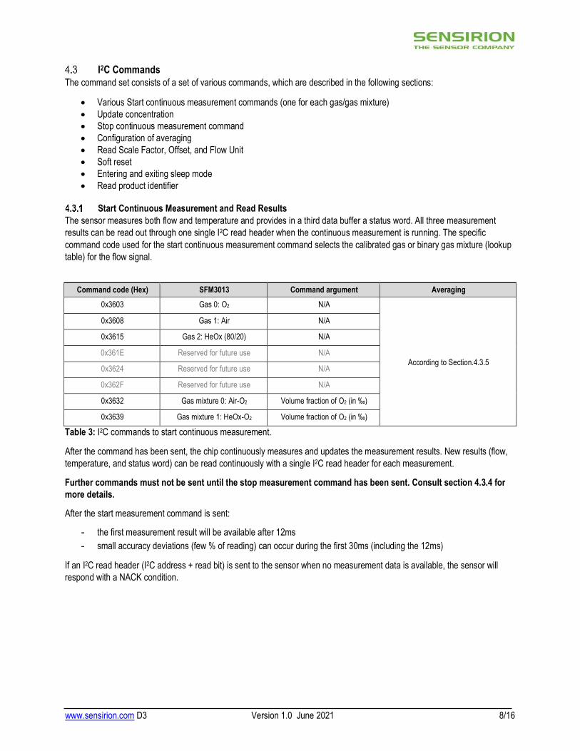
Start Continuous Measurement and Read Results
The sensor measures both flow and temperature and provides in a third data buffer a status word. All three measurement results can be read out through one single I2C read header when the continuous measurement is running. The specific command code used for the start continuous measurement command selects the calibrated gas or binary gas mixture (lookup table) for the flow signal.
Command code (Hex) SFM3013 Command argument Averaging
0x3603 Gas 0: O2 N/A
According to Section.4.3.5
0x3608 Gas 1: Air N/A
0x3615 Gas 2: HeOx (80/20) N/A
0x361E Reserved for future use N/A
0x3624 Reserved for future use N/A
0x362F Reserved for future use N/A
0x3632 Gas mixture 0: Air-O2 Volume fraction of O2 (in ‰)
0x3639 Gas mixture 1: HeOx-O2 Volume fraction of O2 (in ‰)
Table 3: I2C commands to start continuous measurement.
After the command has been sent, the chip continuously measures and updates the measurement results. New results (flow, temperature, and status word) can be read continuously with a single I2C read header for each measurement.
Further commands must not be sent until the stop measurement command has been sent. Consult section 4.3.4 for more details.
After the start measurement command is sent:
- the first measurement result will be available after 12ms - small accuracy deviations (few % of reading) can occur during the first 30ms (including the 12ms)
If an I2C read header (I2C address + read bit) is sent to the sensor when no measurement data is available, the sensor will respond with a NACK condition.
www.sensirion.com D3 Version 1.0 June 2021 9/16
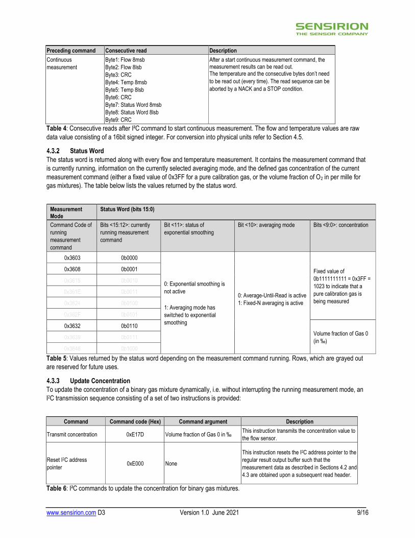
Preceding command Consecutive read Description Continuous measurement
Byte1: Flow 8msb Byte2: Flow 8lsb Byte3: CRC Byte4: Temp 8msb Byte5: Temp 8lsb Byte6: CRC Byte7: Status Word 8msb Byte8: Status Word 8lsb Byte9: CRC
After a start continuous measurement command, the measurement results can be read out. The temperature and the consecutive bytes don’t need to be read out (every time). The read sequence can be aborted by a NACK and a STOP condition.
Table 4: Consecutive reads after I²C command to start continuous measurement. The flow and temperature values are raw data value consisting of a 16bit signed integer. For conversion into physical units refer to Section 4.5.
Status Word The status word is returned along with every flow and temperature measurement. It contains the measurement command that is currently running, information on the currently selected averaging mode, and the defined gas concentration of the current measurement command (either a fixed value of 0x3FF for a pure calibration gas, or the volume fraction of O2 in per mille for gas mixtures). The table below lists the values returned by the status word.
Measurement Mode
Status Word (bits 15:0)
Command Code of running measurement command
Bits <15:12>: currently running measurement command
Bit <11>: status of exponential smoothing
Bit <10>: averaging mode Bits <9:0>: concentration
0x3603 0b0000
0: Exponential smoothing is not active 1: Averaging mode has switched to exponential smoothing
0: Average-Until-Read is active 1: Fixed-N averaging is active
Fixed value of 0b1111111111 = 0x3FF = 1023 to indicate that a pure calibration gas is being measured
0x3608 0b0001
0x3632 0b0110 Volume fraction of Gas 0 (in ‰)
Table 5: Values returned by the status word depending on the measurement command running. Rows, which are grayed out are reserved for future uses.
Update Concentration To update the concentration of a binary gas mixture dynamically, i.e. without interrupting the running measurement mode, an I2C transmission sequence consisting of a set of two instructions is provided:
Command Command code (Hex) Command argument Description
Transmit concentration 0xE17D Volume fraction of Gas 0 in ‰ This instruction transmits the concentration value to the flow sensor.
Reset I2C address pointer 0xE000 None
This instruction resets the I2C address pointer to the regular result output buffer such that the measurement data as described in Sections 4.2 and 4.3 are obtained upon a subsequent read header.
Table 6: I²C commands to update the concentration for binary gas mixtures.
www.sensirion.com D3 Version 1.0 June 2021 10/16
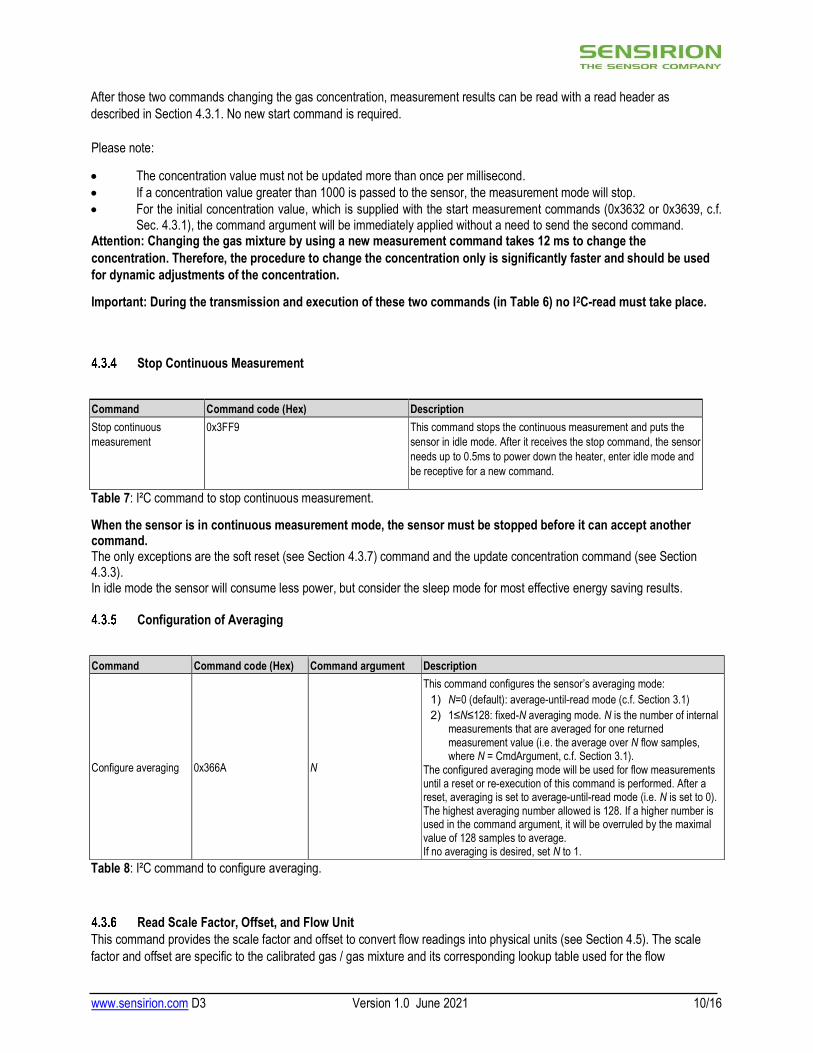
After those two commands changing the gas concentration, measurement results can be read with a read header as described in Section 4.3.1. No new start command is required. Please note:
The concentration value must not be updated more than once per millisecond. If a concentration value greater than 1000 is passed to the sensor, the measurement mode will stop. For the initial concentration value, which is supplied with the start measurement commands (0x3632 or 0x3639, c.f.
Sec. 4.3.1), the command argument will be immediately applied without a need to send the second command. Attention: Changing the gas mixture by using a new measurement command takes 12 ms to change the concentration. Therefore, the procedure to change the concentration only is significantly faster and should be used for dynamic adjustments of the concentration.
Important: During the transmission and execution of these two commands (in Table 6) no I2C-read must take place.
Stop Continuous Measurement
Command Command code (Hex) Description Stop continuous measurement
0x3FF9 This command stops the continuous measurement and puts the sensor in idle mode. After it receives the stop command, the sensor needs up to 0.5ms to power down the heater, enter idle mode and be receptive for a new command.
Table 7: I²C command to stop continuous measurement.
When the sensor is in continuous measurement mode, the sensor must be stopped before it can accept another command. The only exceptions are the soft reset (see Section 4.3.7) command and the update concentration command (see Section 4.3.3). In idle mode the sensor will consume less power, but consider the sleep mode for most effective energy saving results.
Configuration of Averaging
Command Command code (Hex) Command argument Description
Configure averaging 0x366A N
This command configures the sensor’s averaging mode: 1) N=0 (default): average-until-read mode (c.f. Section 3.1) 2) 1≤N≤128: fixed-N averaging mode. N is the number of internal
measurements that are averaged for one returned measurement value (i.e. the average over N flow samples, where N = CmdArgument, c.f. Section 3.1).
The configured averaging mode will be used for flow measurements until a reset or re-execution of this command is performed. After a reset, averaging is set to average-until-read mode (i.e. N is set to 0). The highest averaging number allowed is 128. If a higher number is used in the command argument, it will be overruled by the maximal value of 128 samples to average. If no averaging is desired, set N to 1.
Table 8: I²C command to configure averaging.
Read Scale Factor, Offset, and Flow Unit This command provides the scale factor and offset to convert flow readings into physical units (see Section 4.5). The scale factor and offset are specific to the calibrated gas / gas mixture and its corresponding lookup table used for the flow

www.sensirion.com D3 Version 1.0 June 2021 11/16
measurement. Therefore, the gas / gas mixture needs to be specified in the command argument by the command code of the corresponding start continuous measurement (see Section 4.3.1).
For the SFM3013 series, the flow unit is a fixed value 0x0148 and corresponds to slm: standard liter per minute at 20°C and 1013mbar pressure.
Command Command code (Hex) Command argument (Hex)
Read Scale Factor, Offset, and Flow Unit 0x3661 Command code of desired gas / gas mixture for scale factor, offset and flow unit (Section 4.3.1). The command argument needs to be followed by CRC (Section 4.2)
Preceding command Consecutive read Description Read Scale Factor, Offset, and Flow Unit
Byte1: Scale factor 8msb Byte2: Scale factor 8lsb Byte3: CRC Byte4: Offset 8msb Byte5: Offset 8lsb Byte6: CRC Byte7: Flow Unit 8msb Byte8: Flow Unit 8lsb Byte9: CRC
After a “Read Scale Factor, Offset, and Flow Unit” command, the corresponding results can be read out. The scale factor and offset are a 16-bit signed integer number represented by a two’s complement (ranging from -32’768 to 32’767). The flow unit is a 16-bit identifier.
Table 9: I2C command to read the scale factor, offset, and flow unit. Result of this command.
Soft Reset
Command I2C address + W bit + command code (Hex)
Consecutive read Description
General call reset 0x0006 NA
This sequence resets the sensor with a separate reset block, which is as much as possible detached from the rest of the system on chip. Note that the I2C address is 0x00, which is the general call address, and that the command is 8 bits long. The reset is implemented according to the I2C specification.
Table 10: Reset command
After the reset command the sensor will typically take 2ms to reset. During this time the sensor will not acknowledge its address nor accept commands.
Entering and Exiting Sleep Mode In sleep mode the sensor uses a minimum amount of power. The mode can only be entered from idle mode, i.e. when the sensor is not performing measurements.
This mode is particularly useful for battery operated devices. To minimize the current in this mode, the complexity of the sleep mode circuit has been reduced as much as possible, which is mainly reflected by the way the sensor exits the sleep mode. In sleep mode the sensor cannot be soft reset.

www.sensirion.com D3 Version 1.0 June 2021 12/16
Command Command code (Hex)
Consecutive read Description
Enter Sleep mode 0x3677 NA The sleep command can be sent after a stop continuous measurement command has been issued and the sensor is in idle mode.
Exit Sleep mode NA NA The sensor exits the sleep mode and enters the idle mode when it receives the valid I2C address and a write bit (‘0’). Note that the I2C address is not acknowledged. It is necessary to poll the sensor to see whether the sensor has received the address and has woken up. This should take typically 16ms.
Table 11: Sleep mode commands
Read Product Identifier The product identifier and the serial number can be read out by sending the command below. The command can only be entered from the idle mode, i.e. when the sensor is not performing measurements
Command Command code (Hex) Consecutive read Description
Read product identifier 0xE102
Byte1: Product number [31:24] Byte2: Product number [23:16] Byte3: CRC Byte4: Product number [15:8] Byte5: Product number [7:0] Byte6: CRC Byte7: Serial number [63:56] Byte8: Serial number [55:48] Byte9: CRC Byte10: Serial number [47:40] Byte11: Serial number [39:32] Byte12: CRC Byte13: Serial number [31:24] Byte14: Serial number [23:16] Byte15: CRC Byte16: Serial number [15:8] Byte17: Serial number [7:0] Byte18: CRC
Note that the command need to be preceded with an I2C write header (I2C address + W). The command returns:
- 32-bit unique product and revision number. The number is listed in Table 13 below. Note that the last 8 bits are the revision number and are subject to change as long as the datasheet is preliminary.
- 64-bit unique serial number in the format of an unsigned long integer.
The serial number can be converted from binary into decimal, whereby in decimal it has the following format: yywwxxxxxx, where: yy: last 2 digits of calibration year, ww: calibration week, xxxxxx: unique 6-digit sequential number within the calibration week.
Table 12: Read product identifier command
Product Product number Comment
SFM3013-300-CL 0x04020510 Last two digits: 8x indicating a prototype 1x indicating finalized products, therefore last two bytes expected to change during development SFM3013-300-CLM 0x04020210
Table 13: Product numbers for SFM3013 versions
Checksum Calculation The 8-bit CRC checksum transmitted after each data word is generated by a CRC algorithm. Its properties are listed in Table 14. The CRC covers the contents of the two previously transmitted data bytes. To calculate the checksum, only these two previously transmitted data bytes are used.

www.sensirion.com D3 Version 1.0 June 2021 13/16
Property Value
Name CRC-8
Protected data read data
Width 8 bit
Polynomial 0x31 (x8 + x5 + x4 + 1)
Initialization 0xFF
Reflect input False
Reflect output False
Final XOR 0x00
Example CRC (0xBEEF) = 0x92 Table 14: Checksum definition
Number Format and Conversion to Physical Values The number format of the flow and temperature signals and the conversion to a physical value with a scale factor and an offset where applicable is explained below:
Scale Factors and Offsets
Signal SFM3013-300-CL SFM3013-300-CLM
Comment Scale Factor Offset Scale Factor Offset
Gas 0: O2 170 slm-1 -24576 170 slm-1 -24576 Can be read out using an I2C-command
(c.f. Sec. 4.3.6)
Gas 1: Air 170 slm-1 -24576 170 slm-1 -24576
Gas 2: HeOx (80/20) - - 170 slm-1 -24576
Gas mixture 0: Gas1- Gas0 170 slm-1 -24576 170 slm-1 -24576
Gas mixture 1: Gas2-Gas0 - - 170 slm-1 -24576
Temperature 200 °C-1 0 200 °C-1 0 Table 15: Scale factors and offsets
Flow The digital calibrated gas flow signal read from the sensor is a 16-bit signed integer number represented by a two’s complement (ranging from -32’768 to 32’767). The integer value can be converted to the physical value by subtracting the
offset and dividing it by the scale factor (gas flow in 𝑠𝑙𝑚 =
). The scale factor and offset are specific to
every calibrated gas / gas mixture / lookup table. The flow unit slm signifies standard liters per minute with reference temperature equal to 20°C and reference pressure equal to 1013mbar.
Temperature The digital calibrated temperature signal read from the sensor is a 16-bit signed integer number represented by a two’s complement (ranging from -32’768 to 32’767). The integer value can be converted to the physical value by subtracting the
offset and dividing it by the scale factor (temperature in ℃ =
).
Flow Unit The flow unit is specific to every calibrated gas / gas mixture / lookup table and is specified in Section 4.5.1. It can further be read out using an I2C-command (Section 4.3.6). The flow unit is given by a 16-bit unsigned word, where the information about the unit is encoded in the first 13 bits as follows:

www.sensirion.com D3 Version 1.0 June 2021 14/16
1. Bits <3:0>: unit prefix (multiplier) 2. Bits <7:4>: time base (e.g. per minute) 3. Bits <12:8>: unit (e.g. standard liter)
The allowed values for the 3 unit constituents are given in the table below:
Bits <12:8>
Signification: Unit
Bits <7:4>
Signification: Time Base
Bits <3:0>
Signification: Unit Prefix
overall code (16 bits) Signification: flow unit
0b00001 = 1
standard liter (T0=20°C,
p0=1013mbar)
0b0100 = 4
per minute 0b1000 = 8
10-0 = 1 0b 0000 0001 0100 1000
= 0x0148 = 328
standard liter per minute (slm) with
reference temperature =20°C and reference pressure =1013mbar
Table 16: Possible result(s) for the flow unit
5. Package Outline
6. Shipping Package - Packing units: 20 items/tray. Tray dimensions: 38.3 x 28.3 x 4.7 cm. - Minimal order quantity: 6 trays. Box dimensions for 6 trays: 41 x 31 x 32 cm.

www.sensirion.com D3 Version 1.0 June 2021 15/16
7. Revision History
Date Author Version Changes
06/2021 PSIM V1.0 Preliminary removed, final article number. Specification footnotes completed. MOQ added.

8. Important Notices Warning, personal injury
Do not use this product as safety or emergency stop devices or in any other application where failure of the product could result in personal injury (including death). Do not use this product for applications other than its intended and authorized use. Before installing, handling, using or servicing this product, please consult the datasheet and application notes. Failure to comply with these instructions could result in death or serious injury.
If the Buyer shall purchase or use SENSIRION products for any unintended or unauthorized application, Buyer shall defend, indemnify and hold harmless SENSIRION and its officers, employees, subsidiaries, affiliates and distributors against all claims, costs, damages and expenses, and reasonable attorney fees arising out of, directly or indirectly, any claim of personal injury or death associated with such unintended or unauthorized use, even if SENSIRION shall be allegedly negligent with respect to the design or the manufacture of the product.
ESD Precautions
The inherent design of this component causes it to be sensitive to electrostatic discharge (ESD). To prevent ESD-induced damage and/or degradation, take customary and statutory ESD precautions when handling this product.
Warranty
SENSIRION warrants solely to the original purchaser of this product for a period of 12 months (one year) from the date of delivery that this product shall be of the quality, material and workmanship defined in SENSIRION’s published specifications of the product. Within such period, if proven to be defective, SENSIRION shall repair and/or replace this product, in SENSIRION’s discretion, free of charge to the Buyer, provided that notice in writing describing the defects shall be given to SENSIRION within fourteen (14) days after their appearance;
such defects shall be found, to SENSIRION’s reasonable satisfaction, to have arisen from SENSIRION’s faulty design, material, or workmanship; the defective product shall be returned to SENSIRION’s factory at the Buyer’s expense; and
the warranty period for any repaired or replaced product shall be limited to the unexpired portion of the original period.
This warranty does not apply to any equipment which has not been installed and used within the specifications recommended by SENSIRION for the intended and proper use of the equipment. EXCEPT FOR THE WARRANTIES EXPRESSLY SET FORTH HEREIN, SENSIRION MAKES NO WARRANTIES, EITHER EXPRESS OR IMPLIED, WITH RESPECT TO THE PRODUCT. ANY AND ALL WARRANTIES, INCLUDING WITHOUT LIMITATION, WARRANTIES OF MERCHANTABILITY OR FITNESS FOR A PARTICULAR PURPOSE, ARE EXPRESSLY EXCLUDED AND DECLINED.
SENSIRION is only liable for defects of this product arising under the conditions of operation provided for in the datasheet and proper use of the goods. SENSIRION explicitly disclaims all warranties, express or implied, for any period during which the goods are operated or stored not in accordance with the technical specifications.
SENSIRION does not assume any liability arising out of any application or use of any product or circuit and specifically disclaims any and all liability, including without limitation consequential or incidental damages. All operating parameters, including without limitation recommended parameters, must be validated for each customer’s applications by customer’s technical experts. Recommended parameters can and do vary in different applications.
SENSIRION reserves the right, without further notice, (i) to change the product specifications and/or the information in this document and (ii) to improve reliability, functions and design of this product.
Copyright © 2020, SENSIRION. CMOSens® is a trademark of Sensirion All rights reserved
Headquarters and Subsidiaries
Sensirion AG Laubisruetistr. 50 CH-8712 Staefa ZH Switzerland phone: +41 44 306 40 00 fax: +41 44 306 40 30 [email protected] www.sensirion.com
Sensirion Inc., USA phone: +1 312 690 5858 [email protected] www.sensirion.com
Sensirion Korea Co. Ltd. phone: +82 31 337 7700~3 [email protected] www.sensirion.co.kr
Sensirion Japan Co. Ltd. phone: +81 3 3444 4940 [email protected] www.sensirion.co.jp
Sensirion China Co. Ltd. phone: +86 755 8252 1501 [email protected] www.sensirion.com.cn
Sensirion Taiwan Co. Ltd phone: +886 3 5506701 [email protected] www.sensirion.com To find your local representative, please visit
www.sensirion.com/distributors
Related Documents