1 FEATURES 1 pole, 25A 1 Form A Contact gap 1.5mm (Compliance with European photovoltaic standard VDE0126) High insulation in small package (between coil and contact) - Insulation distance: Clearance > 6.4mm Creepage > 9.5mm - Dielectric strength: 5,000VAC - Surge strength: 8,500V Coil holding voltage can be reduced up to 35% of nominal coil voltage (ambient temperature; +20 °C, contact current; 25A) Power consumption at the lowest coil holding voltage; 96mW * Coil holding voltage is the coil voltage after 100ms of applied nominal coil voltage Flammability UL94V-0 (plastics) Cadmium-free contacts Flux free, cat. RTII protection RoHS compliant Please see page 6 for more information Actual marking does not carry the type name : "FTR" E.g.: Ordering code: FTR-K3AB012W-WG Actual marking: K3AB012W-WG POWER RELAY 1 POLE - 25A - 1.5mm contact gap FTR-K3-WG Series PARTNUMBER INFORMATION FTR-K3 A B 012 W - WG [Example] (a) (b) (c) (d) (e) (f) (a) Relay type FTR-K3 : FTR-K3-Series (b) Contact configuration A : 1 form A / PCB type (c) Coil power B : Standard type (780mW) (d) Coil rated voltage 012 : 5.....48 VDC Coil rating table at page 3 (e) Contact material W : Silver alloy (f) Option code WG : Contact gap 1.5mm

Welcome message from author
This document is posted to help you gain knowledge. Please leave a comment to let me know what you think about it! Share it to your friends and learn new things together.
Transcript

1
FTR-K1 SERIES
FEATURES 1 pole, 25A 1 Form A Contact gap 1.5mm (Compliance with European photovoltaic standard VDE0126) High insulation in small package (between coil and contact) - Insulation distance: Clearance > 6.4mm Creepage > 9.5mm - Dielectric strength: 5,000VAC - Surge strength: 8,500V Coil holding voltage can be reduced up to 35% of nominal coil voltage (ambient temperature; +20 °C, contact current; 25A) Power consumption at the lowest coil holding voltage; 96mW * Coil holding voltage is the coil voltage after 100ms of applied nominal coil voltage Flammability UL94V-0 (plastics) Cadmium-free contacts Flux free, cat. RTII protection RoHS compliant Please see page 6 for more information
Actual marking does not carry the type name : "FTR"E.g.: Ordering code: FTR-K3AB012W-WG Actual marking: K3AB012W-WG
POWER RELAY1 POLE - 25A - 1.5mm contact gap
FTR-K3-WG Series
PARTNUMBER INFORMATIONFTR-K3 A B 012 W - WG
[Example] (a) (b) (c) (d) (e) (f)
(a) Relay type FTR-K3 : FTR-K3-Series
(b) Contact configuration A : 1 form A / PCB type
(c) Coil power B : Standard type (780mW)
(d) Coil rated voltage 012 : 5.....48 VDC Coil rating table at page 3
(e) Contact material W : Silver alloy
(f) Option code WG : Contact gap 1.5mm
2
FTR-K1 SERIES
SPECIFICATION
Item FTR-K3-WG
Contact Data 1 form A
Material Silver alloy
Resistance (initial) Max. 100mΩ at 1A, 6VDC
Contact rating 25A, 250VAC (resistive)
Max. carrying current 25A
Max. switching voltage 250VAC
Max. switching power 6,250VA
Max. switching current 25A
Min. switching load *1 100mA, 5VDC (reference value)
Life Mechanical Min. 2 x 10⁶ operations
Electrical (resistive) 25A / 250VAC, min. 100 x 103 operations
Electrical (inductive)
Endurance: 25A, 250VAC, cos φ = 0.8, min. 30 x 103 operationsOverload: 37.5A, 250VAC, cos φ = 0.8, min. 50 operations
Coil Data Rated power (at 20 °C) Approximately 780mW
Operate power (at 20 °C) Approximately 383mW
Coil power at holding voltage 96mW (35% of nominal coil voltage)
Holding voltage *2 35~120% of nominal coil voltage (25A at +20 °C)40~80% of nominal coil voltage (25A at +85 °C)
Operating temperature range-40 °C to +60 °C (coil nominal voltage)-40 °C to +85 °C (holding voltage; 40~80% of nominal coil voltage)
Timing Data Operate (at nominal voltage) Max. 20ms (without bounce)
Release (at nominal voltage) Max. 10ms (no diode, without bounce)
Insulation Contact gap (initial) Min. 1.5 mm
Resistance Min. 1,000MΩ at 500VDC
Dielectric strengthOpen contacts 2,500VAC, 1min.
Coil and contacts 5,000VAC, 1min.
SuClearance / creepage
rge strength Coil Min. 6.4mm / min. 9.5mm
to contacts 8,500V / 1.2 x 50µs standard wave
Other Vibration resistance Misoperation 10 to 55 to 10Hz single amplitude 0.75 mmEndurance 10 to 55 to 10Hz single amplitude 0.75 mm
Shock resistance Misoperation Min. 200m/s² (11 ± 1ms)
Endurance Min. 1,000m/s² (6 ± 1ms)
Weight Approximately 25 g
*1 Minimum switching loads mentioned above are reference values. Please perform the confirmation test with actualload before production since reference values may vary according to switching frequencies, environmental conditionsand expected reliability levels.*2 Reduction of minimum coil holding voltage to maximum coil voltage range, after 100msec energizing with nominal coil voltage.
FTR-K3-WG SERIES
Care shall be taken on the heat generated on PC board when maximum carrying current exceeds 10A. Please perform the confirmation test with actual conditions.

3
FTR-K1 SERIES
Type Compliance Contact rating
UL UL 508CSA22.2 No.14 (cULus)E63614
25A, 277VAC (General Use, at 85 °C)1HP, 125VAC (at 60 °C) 2HP, 277VAC, 100x103 (at 60 °C)
VDE IEC/EN61810-1 25A, 250VAC (cosφ =1 at 85 °C)
CQC GB15092.1GB/T21711.117002165723
25A, 250VAC
SAFETY STANDARDS
COIL RATING
Coil Code
Rated Coil Voltage (VDC)
Coil Resistance +/- 10% (Ohm)
Must Operate Voltage
(VDC) *1
Must Release Voltage
(VDC) *1
Min. Non Release Voltage
(VDC) *1
Rated Power +/- 10% (mW)
005 5 32 3.5 0.5 1.75
Approx.780
(96)*2
006 6 46 4.2 0.6 2.1
009 9 105 6.3 0.9 3.15
012 12 185 8.4 1.2 4.2
018 18 415 12.6 1.8 6.3
024 24 740 16.8 2.4 8.4
048 48 2,955 33.6 4.8 16.8
Note: All values in the table are valid for 20°C and zero contact current.*1 Specified operate
Please use at rated coil voltage. Please refer to characteristic data and set up adequate voltage in case of use at over voltage.
values are valid for pulse wave voltage.*2 This value is the coil power at 35% of nominal voltage at 20°C.
FTR-K3-WG SERIES

4
FTR-K1 SERIES
CHARACTERISTIC DATA
FTR-K3-WG SERIES
(Characteristic data is not guaranteed value but measured values of samples from production line.)
60
40
80
100
20
00
9876541 32 111213 14151610
60
40
80
100
20
0907050301 020 40 60 80 100
60
40
80
100
20
0 20 3010 40 50 60 70 800
0 20 60 8040 100
0.6
0.8
1.0
1.2
1.4
1.6
1.8
2.0
2.2
25A
1000
100
10
1InitialInitial 5 10
FTR-K3AB012W-WG n=10Switching frequency: 0.17Hz (Duty 50%)25A 250VAC (resistive)
5 10
10
9
8
7
6
5
4
3
2
1
0
100
80
60
40
20
00 0.2 0.4 0.6 0.8 1.0 1.2
25A
0A
0A
Must operate voltage (hot coil)
Must operate voltage(cool coil)
Contact resistanceOperate
Release
10 20 50 100 200 500 1000
100
50
20
10
5
2
1
0.5
0.2
0.1
Coil temperature rise
Electrical life test (resistive load)Operate/release voltage
Distribution of operate/release voltage
Distribution of operate/release time
Distribution of contact resistance
Electrical life test (resistive load)Contact resistance
Operating range Maximum switching power
Coil power (W)
Operations (x 10₄)
Nominal voltage multiplier (%) Time (ms) Contact resistance (mΩ)
Dis
trib
utio
n (%
)
Dis
trib
utio
n (%
)
Dis
trib
utio
n (%
)
Volta
ge (
V)
Cont
act r
esis
tanc
e (m
Ω)
Operations (x 10₄)
Tem
pera
ture
rise
(°C
)
Ambient temperature (°C) Contact voltage (V)
Cont
act c
urre
nt (
A)
Nom
inal
vol
tage
mul
tiplie
r
FTR-K3AB012W-WG n=10Switching frequency: 0.17Hz (Duty 50%)25A 250VAC (resistive)
OperateRelease
OperateRelease
AC resistive

5
FTR-K1 SERIES
DIMENSIONS
FTR-K3-WG SERIES
Dimensions
PC board mounting hole layout (BOTTOM VIEW)
Schematics (BOTTOM VIEW)
12±0.1
22±0.1
5.75±
0.1
6.
25±
0.1
27.6±0.1
(5.05)
1.8 +0.1-04-Ø
4- Pre-solder
4-予備はんだ
0.8 0.31.5
30.4 max.30.1 typ.
16.0 max.15.7 typ.
23.6
max
.23
.3 ty
p.
22
22
121.5
12
27.6
27.6
1.5
0.8
44
1
3
2
12±0.1
22±0.1
5.75±
0.1
6.
25±
0.1
27.6±0.1
(5.05)
1.8 +0.1-04-Ø
4-予備はんだ
4-予備はんだ
0.8 0.31.5
22
22
121.5
12
27.6
27.6
1.5
0.8
4
# 250タブ端子
0.8
10.47.
95
6.35
15.7 +0.3
0.31.5
23.3
+0.3
12.8(10.45)
30.1+0.3
1.51.5
0.8
4
(1.25)
・ Dimensions of the terminals do not include thickness of pre-solder.・ Tolerance of PC board mounting hole layout : ±0.1 unless otherwise specified.
Unit; mm( ): Reference
Cautions ・ All values mentioned in this datasheet are provided under ideal conditions. Please perform the confirmation test before actual use. ・ Reflow soldering is prohibited. ・ Do not use relays in the atmosphere with sulfide gas, chloride gas or nitric oxide. Contact resistance may increase. ・ Do not use silicon or silicon-containing product or materials near relays. It may cause contact failure.
6
FTR-K1 SERIESFTR-K3-WG SERIES
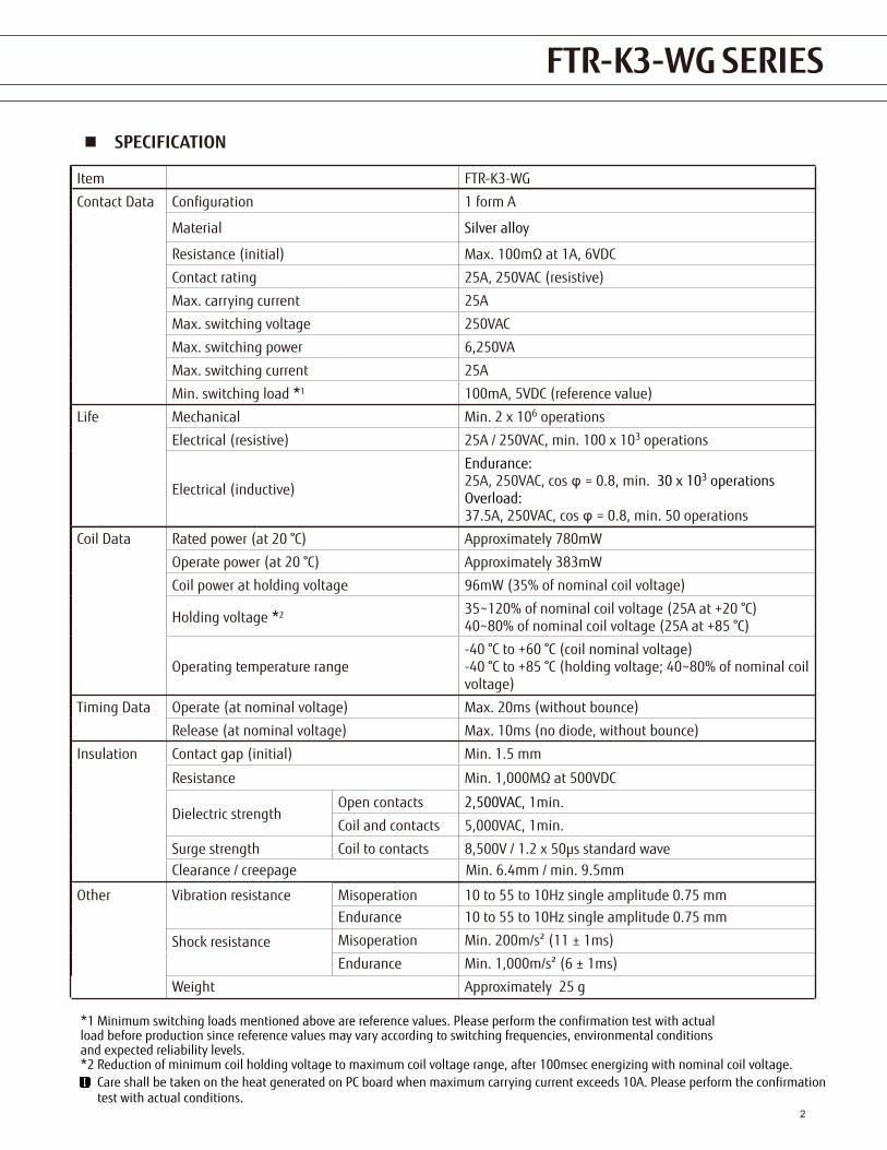
1. General Information All signal and power relays produced by Fujitsu Components are compliant with RoHS directive 2002/95EC including amendments. Cadmium as used in electrical contacts is exempted from the RoHS directives on October 21st, 2005. (Amendment to Directive 2002/95/EC) All of our signal and power relays are lead-free. Please refer to Lead-Free Status Info for older date codes at: http://www.fujitsu.com/us/downloads/MICRO/fcai/relays/lead-free-letter.pdf Lead free solder plating on relay terminals is Sn-3.0Ag-0.5Cu, unless otherwise specified. This material has been verified to be compatible with PbSn assembly process.
2. Recommended Lead Free Solder Profile Recommended solder Sn-3.0Ag-0.5Cu.
RoHS Compliance and Lead Free Information
3. Moisture Sensitivity Moisture Sensitivity Level standard is not applicable to electromechanical relays, unless otherwise indicated.
4. Tin Whiskers Dipped SnAgCu solder is known as presenting a low risk to tin whisker development. No considerable length whisker was found by our in house test.
Flow Solder condition:Pre-heating: maximum 120˚C within 90 sec.Soldering:Relay must be cooled by air immediately after soldering
dip within 5 sec. at 255˚C±5°C solder bath
Solder by Soldering Iron:Soldering Iron 30-60W Temperature: maximum 350-360˚CDuration: maximum 3 sec.

7
FTR-K1 SERIESFTR-K3-WG SERIES
Japan Asia PacificFUJITSU COMPONENT LIMITEDShinagawa Seaside Park Tower 19F,12-4, Higashi-shinagawa 4-chome, Shinagawa-ku,Tokyo,140-0002, JapanTel: (81-3) 3450-1682Fax: (81-3) 3474-2385Email: [email protected]: www.fujitsu.com/jp/fcl/
North and South AmericaFUJITSU COMPONENTS AMERICA, INC2290 North First Street, Suite 212San Jose, CA 95131, USATel: (1-408) 745-4900Fax: (1-408) 745-4970Email: [email protected]: us.fujitsu.com/components
EuropeFUJITSU COMPONENTS EUROPE B.V.Diamantlaan 252132 WV HoofddorpNetherlandsTel: (31-23) 5560910Fax: (31-23) 5560950Email: [email protected]: www.fujitsu.com/uk/components
FUJITSU COMPONENTS ASIA, LTD.102E Pasir Panjang Road#01-01 Citilink Warehouse ComplexSingapore 118529Tel: (65) 6375-8560Fax: (65) 6273-3021Email: [email protected]: www.fujitsu.com/sg/products/devices/components
ChinaFUJITSU ELECTRONIC COMPONENTS (SHANGHAI) CO., LTD.Unit 4306, InterContinental Center100 Yu Tong Road, Shanghai 200070, ChinaTel: (86-21) 3253 0998Fax: (86-21) 3253 0997Email: [email protected]: www.fujitsu.com/cn/products/devices/components/
Hong KongFUJITSU COMPONENTS HONG KONG CO., LTDUnit 506, Inter-Continental PlazaNo.94 Granville Road, Tsim Sha Tsui, Kowloon,Hong KongTel: (852) 2881-8495Tex: (852) 2894-9512Email: [email protected]: www.fujitsu.com/sg/products/devices/components/
KoreaFUJITSU COMPONENTS KOREA LIMITEDAlpha Tower #403, 645 Sampyeong-dong, Bundang-gu, Seongnam-si, Gyeonggi-do, 13524 Korea Tel: (82) 31-708-7108Fax: (82) 31-709-7108Email: [email protected]/sg/products/devices/components/
2019 Fujitsu Components Europe B.V. All rights reserved. All trademarks or registered trademarks are the property of their respective owners.
The contents, data and information in this datasheet are provided by Fujitsu Component Ltd. as a service only to its user and only for general information purposes.The use of the contents, data and information provided in this datasheet is at the users’ own risk.Fujitsu has assembled this datasheet with care and will endeavor to keep the contents, data and information correct, accurate, comprehensive,complete and up to date.Fujitsu Components Europe B.V. and affiliated companies do however not accept any responsibility or liability on their behalf, nor on behalf of its employees, for any loss or damage, direct, indirect or consequential, with respect to this datasheet, its contents, data, and information and related graphics and the correctness, reliability, accuracy, comprehensiveness, usefulness, availability and completeness thereof.Nor do Fujitsu Components Europe B.V. and affiliated companies accept on their behalf, nor on behalf of its employees, any responsibility or liability with respect to these datasheets, its contents, data, information and related graphics and the correctness, reliability, accuracy, comprehensiveness, usefulness, availability and completeness thereof. Rev. June 14, 2019
c
Fujitsu Components International Headquarter Offices
Related Documents