E16x346-Manual_EN_Rev07_2016_01_15 Page 1 of 86 D 71334 Waiblingen-Hegnach Esslinger Str. 26 Tel.: +49 (0)7151/956230 Fax: +49 (0)7151/956250 E-Mail: [email protected] Internet: www.braun-tacho.de Qualität zertifiziert nach ISO 9001 P E E1697 1 2 3 4 Test: A /TL I Auto-Test Test: B /TL II Test: C/TL III P E E1667 1 2 3 4 Trip SP3 RPM P E E1667 1 2 3 4 Trip SP3 RPM P E E1667 1 2 3 4 Trip SP3 RPM Monitor A Monitor B Monitor C SIL3/IEC61508 SIL3/IEC61508 SIL3/IEC61508 SIL3/IEC61508 Test-Generator Datasheet and Manual Protection-System E16x346 with Overspeed Protection and Voters for external Trip Release Conditions Certified by TÜV for IEC61508; SIL3 DIN EN ISO 13849-1:2008; Cat.3 PLe Figure 1: E16x346 System Front View

Welcome message from author
This document is posted to help you gain knowledge. Please leave a comment to let me know what you think about it! Share it to your friends and learn new things together.
Transcript
E16x346-Manual_EN_Rev07_2016_01_15 Page 1 of 86
D 71334 Waiblingen-Hegnach Esslinger Str. 26 Tel.: +49 (0)7151/956230 Fax: +49 (0)7151/956250 E-Mail: [email protected] Internet: www.braun-tacho.de
Qualität zertifiziert nach ISO 9001
P
E
E1697
1
2
3
4
Test: A /TL I
Auto-Test
Test: B /TL II Test: C/TL III
P
E
E1667
1
2
3
4
Trip
SP3
RPM
P
E
E1667
1
2
3
4
Trip
SP3
RPM
P
E
E1667
1
2
3
4
Trip
SP3
RPM
Monitor A Monitor B Monitor C
SIL3/IEC61508 SIL3/IEC61508 SIL3/IEC61508 SIL3/IEC61508
Test-Generator
Datasheet and Manual
Protection-System E16x346 with
Overspeed Protection
and
Voters for external Trip Release Conditions
Certified by TÜV for
IEC61508; SIL3
DIN EN ISO 13849-1:2008; Cat.3 PLe
Figure 1: E16x346 System Front View

E16x346-Manual_EN_Rev07_2016_01_15 Page 2 of 86
Contents Page
1. General Informations ................................................................................................ 5 1.1. List of Figures .............................................................................................................. 5 1.2. List of Abbreviations .................................................................................................... 6
1.3. System Applications and Definitions ...................................................................... 8 1.3.1. System Applications .................................................................................................... 8 1.3.2. Definitions ................................................................................................................... 8
1.4. Key Features of System E16x346 ............................................................................ 9
1.5. Ordering Key for Systems E16x346.abc ............................................................... 10 1.6. Certifications ............................................................................................................. 11 1.6.1. Certification IEC61508; SIL3 ..................................................................................... 11 1.6.2. Certification DIN EN ISO 13849-1:2008; Cat.3 PLe .................................................. 11 1.6.3. TÜV-Certificate .......................................................................................................... 12
1.7. Safety Data................................................................................................................ 13 1.7.1. Safety Data IEC61508; SIL3 ..................................................................................... 13 1.7.2. Safety Data DIN EN ISO 13849-1:2008; Cat.3 PLe .................................................. 13
2. System Structure and I/Os ...................................................................................... 14 2.1. System Structure ....................................................................................................... 14 2.1.1. Speed Sensors .......................................................................................................... 14 2.1.2. System Components ................................................................................................. 14 2.1.3. System Design .......................................................................................................... 14 2.1.4. System Structure Diagrams ...................................................................................... 15 2.1.5. System Wiring Diagrams........................................................................................... 17
2.1.6. Connection of Sensors to the Speed Signal Inputs ................................................... 19 2.2. Inputs of the System ................................................................................................. 20 2.2.1. Speed Signal Inputs .................................................................................................. 20 2.2.2. Direction Signal Inputs (F/R : Forward/Reverse) ....................................................... 20 2.2.3. Input Reset of Alarms ................................................................................................ 20 2.2.4. Input Test Lock .......................................................................................................... 20 2.2.5. Input Start Auto-Test-Sequence ................................................................................ 21 2.2.6. Inputs Test I, Test II , Test III ..................................................................................... 21 2.2.7. Inputs Starter (Override of SP2) ................................................................................ 21 2.2.8. Inputs SP1B valid ...................................................................................................... 21 2.2.9. Inputs Feedback from Solenoid Valve Block ............................................................. 21 2.2.10. Inputs for Voter 1 ....................................................................................................... 22 2.2.11. Inputs for Voters 2 … 6 ............................................................................................. 22 2.2.12. Inputs for Watchdog .................................................................................................. 22
2.3. Outputs of the System ............................................................................................... 23 2.3.1. Outputs System Warning Alarm 1 and System Warning Alarm 2 ............................. 23 2.3.2. Speed Signal Repeater Outputs................................................................................ 23 2.3.3. Outputs Monitor Warning Alarm ................................................................................ 23 2.3.4. Outputs Speed Alarm SP3 ........................................................................................ 23 2.3.5. Analog Outputs for measured speed (Option)........................................................... 24 2.3.6. Outputs Direction Detection ...................................................................................... 24 2.3.7. Speed Trip Logic Output (2oo3 voted) ...................................................................... 24 2.3.8. Outputs Trip-Lines IV, V, VI ....................................................................................... 24 2.3.9. Outputs Trip-Lines I, II, III ........................................................................................ 24 2.3.10. Logic Outputs LO1 through LO6 (voted 2oo3) ......................................................... 24 2.3.11. This chapter is left blank intentionally ....................................................................... 24 2.3.12. Logic Output Watchdog (voted 2oo3) ....................................................................... 25
2.4. Power Supply ............................................................................................................ 25 2.5. Data-Interface ........................................................................................................... 25 2.5.1. Profibus-Interface for Status and Diagnostics of the System .................................... 25 2.5.2. RS232-Interface for Setting of Parameters ............................................................... 25
3. Technical Specifications ........................................................................................ 26 3.1. Technical Data of Inputs ........................................................................................... 26 3.1.1. Technical Data of Speed Signal Inputs ..................................................................... 26 3.1.1.1. Hall Sensor Inputs ..................................................................................................... 26

E16x346-Manual_EN_Rev07_2016_01_15 Page 3 of 86
3.1.1.2. Eddy Current Sensor Inputs resp. MPU (Magnetic Pick-Up) Inputs .......................... 26 3.1.2. Technical Data of Direction Inputs ............................................................................ 26 3.1.3. Technical Data of Binary Inputs (excluding Voter 1) ................................................. 26 3.1.4. Technical Data of Binary Inputs of Voter 1 ................................................................ 26
3.2. Technical Data of Outputs ......................................................................................... 27 3.2.1. Technical Data of Sensor Signal Repeater Outputs .................................................. 27 3.2.2. Technical Data of Analog Outputs............................................................................. 27 3.2.3. Technical Data of Opto-Relay Outputs ...................................................................... 27 3.2.4. Technical Data of Logic Outputs ............................................................................... 27 3.2.5. Technical Data of Trip-Lines IV, V, VI ....................................................................... 27 3.2.6. Technical Data of Trip-Lines I, II, III .......................................................................... 27
3.3. Technical Data of Power Supply ............................................................................... 28 3.4. Installation Conditions ............................................................................................... 28 3.5. Protection Grade ....................................................................................................... 28 3.6. Connectors ................................................................................................................ 28 3.7. Conformity to Standards............................................................................................ 28 3.8. Dimensions of System E16A346 ............................................................................... 29 3.9. Dimensions of System E16E346 ............................................................................... 30 3.10. Dimensions and Features of E16G346 Enclosure .................................................... 31 3.11. Weight of E16x346 .................................................................................................... 31 3.12. Material specifications of E16A346 or E16E346 ....................................................... 31
4. Safety Notes for Installation and Operation .......................................................... 32 4.1. Safety Notes for Installation ...................................................................................... 32 4.1.1. General Instructions .................................................................................................. 32 4.1.2. EMI ............................................................................................................................ 32
4.2. Safety Notes for Operation ........................................................................................ 32 4.2.1. Safety notes for commissioning ................................................................................ 32
5. Description of Monitor E1667 ................................................................................. 33 5.1. Display and Frontside Operational Elements ............................................................ 33 5.1.1. Front View of Monitor E1667 ..................................................................................... 33 5.1.2. Status-LEDs .............................................................................................................. 33 5.1.3. Display during Test Procedures ................................................................................ 33 5.1.4. Values accessible during normal operation .............................................................. 34 5.1.5. Display of Firmware release state and CRC-Parameter-Checksum of Monitor ........ 34 5.1.6. Special Display Mode 1 ............................................................................................. 34 5.1.7. Special Display Mode 2 ............................................................................................. 34 5.1.8. Frontside Reset of Alarms and Event Codes ............................................................ 34 5.1.9. Data Interface ............................................................................................................ 34
5.2. Functions of Monitor 1667 ...................................................................................... 35 5.2.1. Speed Measurement ................................................................................................. 35 5.2.2. Functions for Overspeed Protection .......................................................................... 35 5.2.3. Functions for External Trip by Voters ........................................................................ 35 5.2.4. Selftest of Monitor ..................................................................................................... 35
6. Description of Test-Generator E1697 ................................................................... 36 6.1. Display and Frontside Operational Elements ............................................................ 36 6.1.1. Front View of Test-Generator E1697 ........................................................................ 36 6.1.2. Status-LEDs .............................................................................................................. 36 6.1.3. Display during Test Procedures ................................................................................ 37 6.1.4. Values accessible during normal operation .............................................................. 37 6.1.5. Display of Firmware release state and CRC-Parameter-Checksum of Test-Generator37 6.1.6. Frontside Reset of Alarms and Event Codes ............................................................ 37 6.1.7. Manual Start of a Monitor-Test Sequence ................................................................ 37 6.1.8. Manual Start of a Trip-Line-Test Sequence .............................................................. 37 6.1.9. Data Interface ............................................................................................................ 37
6.2. Functions of Test-Generator 1697 ............................................................................ 38 6.2.1. Test of Feedback Signals .......................................................................................... 38 6.2.2. Monitor-Test Sequence ............................................................................................. 38 6.2.3. Trip-Line-Test Sequence (Test of 2oo3 solenoid valve block) .................................. 39 6.2.4. Cross-check between CPUs of Test-Generator ........................................................ 39 6.2.5. Selftest of CPUs ........................................................................................................ 39

E16x346-Manual_EN_Rev07_2016_01_15 Page 4 of 86
7. Programming of the Modules ................................................................................. 40 7.1. Programming of the Modules via Front Keyboard ..................................................... 40 7.2. Programming of the Modules via PROFIBUS-Interface ............................................ 41 7.3. Programming of the Modules via RS232-Interface ................................................... 41 7.4. Default Values ........................................................................................................... 41 7.5. Behaviour in case of values exceeding limits ............................................................ 41 7.6. Display of parameter values if access is locked ........................................................ 41
8. Parameters of Monitor E1667 ................................................................................. 42 8.1. Summary of parameters and their default values...................................................... 42 8.2. Description of Parameters and their Settings of Monitor E1667 ............................... 46
9. Parameters of Test-Generator E1697 .................................................................... 74 9.1. Summary of parameters and their default values...................................................... 74 9.2. Description of Parameters and their Settings of Test-Generator E1697 ................... 75
10. Event Codes and Troubleshooting ........................................................................ 81 10.1. Event Codes on display of E1667 ............................................................................. 81 10.2. Troubleshooting if display of Monitor reads E.0.4.x.x ............................................... 82 10.3. Event codes on display of E1697 .............................................................................. 83
11. Revision notes ......................................................................................................... 85
E16x346-Manual_EN_Rev07_2016_01_15 Page 5 of 86
1. General Informations
1.1. List of Figures
Figure 1: E16x346 System Front View 1 Figure 2: E16x346 System Structure Diagram 1 of 2 15 Figure 3: E16x346 System Structure Diagram 2 of 2 16 Figure 4: E16x346 System Wiring Diagram 1 of 3 17 Figure 5: E16x346 System Wiring Diagram 2 of 3 18 Figure 6: E16x346 System Wiring Diagram 3 of 3 19 Figure 7: Dimensions of System E16A346 29 Figure 8: Dimensions of System E16E346 30 Figure 9: Dimensions of E16G346 Enclosure 31 Figure 10: Front view of Monitor E1667 33 Figure 11: Front view of Test-Generator E1697 36 Figure 12: SP1 as a variable of the acceleration 54

E16x346-Manual_EN_Rev07_2016_01_15 Page 6 of 86
1.2. List of Abbreviations
Abbreviation Meaning
altern. alternative
API Technical standards of the "American Petroleum Institute"
A5S BRAUN GmbH Sensor series
AWG/kcmil Code number according to the "American Wire Gauge" System
approx. approximately
CCF Common Cause Failure
CPU Central Processing Unit
DCavg Diagnostic Coverage average
DIN Deutsches Institut für Normung (German Institute for Standardization)
dN/dt Change of speed per time unit (Acceleration)
EEPROM Electrically Erasable Programmable Read-Only Memory
EMV Electro magnetic compatibility
EN European Norm
F/R Forward/Reverse (Forward/Backward)
HE Height units
HFT Hardware Failure Tolerance
IEC International Electrotechnical Commission
incl. inclusive
IPxx Ingress Protection Number xx according to DIN EN 60529
ISO International Organization for Standardization
LED Light Emitting Diode
LOx Logic Output x
max. maximum
min. minimum
MPU Magnetic Pick Up
MTTFd Mean Time To Failure dangerous
n Short term for Speed
NEMAx National Electrical Manufacturers Association Number x
PFDavg Probability of Failure on Demand average
PELV Protective Extra Low Voltage
RAM Random Access Memory
RPM Revolutions Per Minute
sec second
SELV Safety Extra Low Voltage
SFF Safe Failure Fraction
SILx Safety Integrity Level x
SPx SetPoint x
SPVx SetPoint Voter x
SP1var SetPoint 1 variable
TE Width unit
TMR Triple Modular Redundant
Tproof Proof Test Interval
UL/cUL Acc. US Underwriter Laboratories resp. Canadian Underwriter Laboratories standards
Vdc Volt direct current
Vpp Volt peak-to-peak
resp. respective
to be continued on next page

E16x346-Manual_EN_Rev07_2016_01_15 Page 7 of 86
Abbreviation Meaning
1oo2 1 out of 2 voting logic
1oo3 1 out of 3 voting logic
2oo2 2 out of 2 voting logic
2oo3 2 out of 3 voting logic
E16x346-Manual_EN_Rev07_2016_01_15 Page 8 of 86
1.3. System Applications and Definitions
1.3.1. System Applications
Protection of rotating machinery such as turbines, expanders, compressors and motors with
safety requirements SIL3/IEC61508 resp. DIN EN ISO 13849:2008 Cat.3 PLe and/or API 670
versus Overspeed and other Critical Conditions.
1.3.2. Definitions
The E16x346 system incorporates one Testgenerator type E1697.32 and three Monitors (A, B
and C) type E1667 for evaluation of speed signals and external trip signals.
The logic blocks of the monitors for the evaluation of the external trip signals are named "Vot-
er".
Each of the monitors represents a "channel" (A,B,C) for the processing of the speed signals
and the external trip signals.
The logic results of the three channels are connected internally to form three 2oo3 trip circuits
I, II and III which are named "Trip-Lines".
The Trip-Lines can be connected for example to a 1oo2 or 2oo3 solenoid valve block .
A released trip status of the Monitors respective of the complete system E16x346 can be
latched, this function is named "Trip-Lock".
Trip is released by shut down of the Trip Circuits (Trip-Lines) to the solenoid valve block if:
2oo3 Monitors detect Overspeed condition
2oo3 sensor signals are detected as faulty by Monitors
2oo3 Monitors detect External Trip-Condition via Voters (1oo2, 2oo2, 2oo3 or 3oo3 se-
lectable)

E16x346-Manual_EN_Rev07_2016_01_15 Page 9 of 86
1.4. Key Features of System E16x346
Trip Release Function is SIL3/IEC61508 and DIN EN ISO 13849:2008 Cat.3 PLe compliant
as stand alone unit (without external testing by DCS or by operator).
Total Response Time to Trip Condition: < 15 milliseconds
Maximum Safety at Maximum Availability by :
TMR (Triple Modular Redundancy) with three Monitors E1667
Triple speed measurement and evaluation by each Monitor
Variable overspeed alarm depending on acceleration
Monitoring versus Lowspeed as protection versus incorrect mounting or malfunction of
speed sensors
Permanent monitoring of speed sensors
Evaluation of external Trip-Condition signals by voters in each monitor. Response to sig-
nals selectable for each voter individually (Logic function, low/high: trip, response time).
Permanent monitoring of monitors by Test-Generator with cyclic full automatic tests or ex-
ternally triggered tests
Permanent monitoring of 2oo3 Solenoid Valve Block by Test-Generator with cyclic full au-
tomatic or externally triggered tests
Each Trip Line (trip circuit) in 2oo3 technique
Trip Lines I, II, III, IV, V, VI are formed by safety relays with force guided contact sets
Trip-Line-Monitoring with Trip-Lock Function (selectable)
The outputs of the Trip Lines to the 2oo3 Solenoid Valve Block are permanently monitored.
If the Trip-Lock Function is engaged, a trip condition is detected and locked if 2oo3 trip
lines are in trip condition
Additional features of the E16x346-System:
Remote test of solenoid valve block by test signals from DCS possible
Display in each module for measured values and diagnostics
Alarm outputs via opto-relays to DCS
Free extra alarm from each monitor
Up to 6 speed setpoints with 2oo3 logic outputs (if voters are not required)
Sensor signal repeater outputs, free floating and push/pull
Optional Analog Output (to represent the speed) 0/4..20 ma for each monitor
Direction alarm (only with sensors type A5S with direction output)
Parameters may be set by front keys (protected by code-digit) or by RS232-Interface

E16x346-Manual_EN_Rev07_2016_01_15 Page 10 of 86
1.5. Ordering Key for Systems E16x346.abc
E16x346.abc
c = 1 : Speed Signal Inputs and power supply for A5S sensors
c = 2 : Speed Signal Inputs and power supply for Eddy Current Sensors
c = 3 : Speed Signal Inputs for MPU (magnetic pick up)
b = 1 : 1 Voter in each Monitor for external trip release condition
b = 2 : 6 Voters in each Monitor for external trip release conditions
a = 0 : without Analog Output (to represent the speed)
a = 1 : 1 Analog Output in each Monitor A, B, C
a = 2 : 1 Analog Output rated SIL3 in each Monitor A, B, C
x = A : Surface Mount Version
x = E : 19-Inch Rack File
x = G : Nema 4 Version with front window (surface mount)
Example:
E16A346.021 : Surface Mount Version, without Analog Output, with 6 Voters,
Speed Signal Inputs and power supply for A5S sensors
E16A346.112 : Surface Mount Version, with Analog Output, with 1 Voter,
Speed Signal Inputs and power supply for eddy current sensors
E16A346.013 : Surface Mount Version, with 1 Voter,
Speed Signal Inputs for MPU

E16x346-Manual_EN_Rev07_2016_01_15 Page 11 of 86
1.6. Certifications
1.6.1. Certification IEC61508; SIL3
The E16x3xx system is certified by TÜV-Nord to be compliant with IEC61508; SIL3 as a stand
alone TMR Trip-System for Overspeed Protection and Voters for external Trip Release Condi-
tions, such as emergency stop, boiler protection etc.
1.6.2. Certification DIN EN ISO 13849-1:2008; Cat.3 PLe
The E16x3xx system is certified by TÜV-Nord to be compliant with DIN EN ISO 13849:2008;
Cat.3 PLe as a stand alone TMR Trip-System for Overspeed Protection and Voters for external
Trip Release Conditions, such as emergency stop, boiler protection etc.
E16x346-Manual_EN_Rev07_2016_01_15 Page 12 of 86
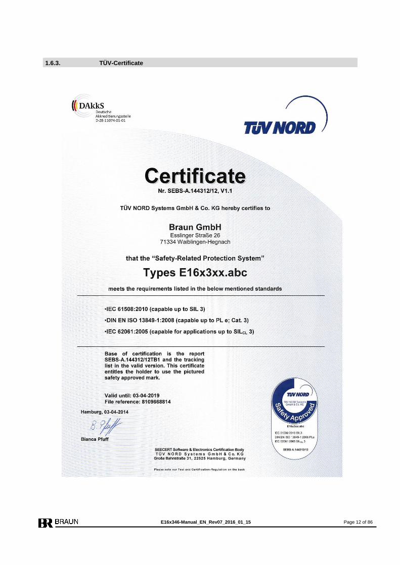
1.6.3. TÜV-Certificate

E16x346-Manual_EN_Rev07_2016_01_15 Page 13 of 86
1.7. Safety Data
1.7.1. Safety Data IEC61508; SIL3
System Type B; HFT = 1; Architecture 2oo3, Service Time 20 years
PFDavg = 8,41* 10-6
at T1 (Proof Check Interval) = 20 years
SFF = 96,7%
1.7.2. Safety Data DIN EN ISO 13849-1:2008; Cat.3 PLe
System Type B; HFT = 1; Architecture 2oo3, Service Time 20 years
MTTFd = 489,5 years
DCavg = 93,18%
CCF = 80
E16x346-Manual_EN_Rev07_2016_01_15 Page 14 of 86
2. System Structure and I/Os
2.1. System Structure
The structure of the system is shown in chapter 2.1.4. (figures 2 and 3).
The wiring of the system is shown in chapter 2.1.5. (figures 4 ,5 and 6).
The indexes ”see 2.x.x” in these figures refer to the corresponding chapters 2.x.x. which de-
scribe the according functions.
2.1.1. Speed Sensors
With versions E16x346.xx1:
Three A5S Differential-Hall-effect sensors, with integrated signal amplifier are placed at the
machine shaft.
The Differential Hall-effect sensors A5S are not susceptible to uniform external magnetic
fields. Air gap variations between machine and sensor do not create false signals.
With versions E16x346.xx2:
Three Speed signals from Eddy Current Sensors are evaluated.
With versions E16x346.xx3:
Three Speed signals from MPU Sensors are evaluated.
2.1.2. System Components
The system comprises three Monitors E1667 for speed monitoring and for monitoring of the
external trip conditions.
The Test-Generator E1697 checks and validates the performance of the monitors, of the Trip-
Lines and of the 2oo3 solenoid valve block by tests.
The Monitors and the Test-Generator are connected via a backplane. The backplane does not
hold any active components.
2.1.3. System Design
The system is available
as 19-Inch Rack File, 3HE 84TE (E16E346) or
for surface mounting (E16A346) or
as NEMA4 version (E16G346).

E16x346-Manual_EN_Rev07_2016_01_15 Page 15 of 86
2.1.4. System Structure Diagrams
Figure 2: E16x346 System Structure Diagram 1 of 2
Speed Signals
see 2.2.1
Direction Signals
see 2.2.2 = terminal blocks
Speed-Trip
Logic Output
in 2oo3
see 2.3.7
Test I
Test II
Test IIII
see 2.2.6
Sensor Signal
Repeater
see 2.3.2
Alarm Reset
see 2.2.3
System
Warning Alarm 1
see 2.3.1
System
Warning Alarm 2
see 2.3.1
Start Auto-Test
see 2.2.5
Test Lock
see 2.2.4
Input
SP1B valid
see 2.2.8
Monitor
Warning Alarm
see 2.3.3
Alarm SP3
see 2.3.4
Starter
Override of SP2
see 2.2.7
Direction
Alarm Output
see 2.3.6
optional
Analog Output
0/4 … 20 ma
see 2.3.5
Trip IV
Trip V
Trip VI in 2oo3 (only 1 of 3 Trip
Lines shown)
see 2.3.8
2oo3
Trip-Line III
Trip-Line II
Trip-Line I
L+
L+
L+
Trip-Line III
Trip-Line II
Trip-Line I
2oo3 Solenoid Valve Block
I
see 2.2.9
III II
Feedback
Trip Lines
see 2.3.9
I II III
Wiring of Trip Relay contacts on System-Backplane forming six 2oo3 Trip Lines
fT
F/R
fB
F/R
fC
B
A C
Pole Wheel
Sensor
to all modules
Test I
Test II
Test III
I
II
III
Feed-
back
Test A
Test B
Test C
A
B
C
Forced
Trip
Data-
Interface
E1697
Test- Generator
Test Frequency fT
F/RfC T
est III
F/RfB
F/RfA fT T
est II
Test I
Test
E1667
Monitor A
Feedback A
Feedback B
Feedback C
SP1B
Starter
I II III IV
Trip- Relays
I
II
III
I II III IV
Trip- Relays
I II III IV
Trip- Relays
I
II
III
E1667
Monitor B
E1667
Monitor C
SP1B
SP1B
Starter
Starter
F/RfC T
est III
F/RfA
F/RfB fT T
est II
Test I
Test
F/RfB T
est III
F/RfA
F/RfC fT T
est II
Test I
Test
F/R
fA
Rev. 00 / 02.2012
spark extinguishing
Data-
Interface
Data-
Interface
Data-
Interface
Speed-
Trip
Trip by
Voter
(from
Diagram 2)
Monitoring
of Trip Lines with Trip-
Lock
Speed-
Trip
Trip by
Voter
(from
Diagram 2)
Monitoring
of Trip Lines with Trip-
Lock
Speed-
Trip
Trip by
Voter
(from
Diagram 2)
Monitoring
of Trip Lines with Trip-
Lock
V
V
V I
A
B
C
A
B
C
A
B
C
A
B
C
A
B
C
A
B
C
ZT
ZT
ZT

E16x346-Manual_EN_Rev07_2016_01_15 Page 16 of 86
Figure 3: E16x346 System Structure Diagram 2 of 2
Input Signals
Voter 1
see 2.2.10
Trip by Voter
(to Diagram 1)
Part of
Monitor A
Part of
Monitor B
Part of
Monitor C
Trip by Voter
(to Diagram 1)
Trip by Voter
(to Diagram 1)
Input
Signals
Voter 2
Input
Signals
Voter 3
Input
Signals
Voter 4
Input
Signals
Voter 5
Input
Signals
Voter 6
Input S
ignals
for
Vote
rs 2 …
6 . see 2
.2.1
1
Soft-
ware-
Voter
Soft-
ware-
Voter
Soft-
ware-
Voter
Soft-
ware-
Voter
Soft-
ware-
Voter
Soft-
ware-
Voter
Soft-
ware-
Voter
Soft-
ware-
Voter
Soft-
ware-
Voter
Soft-
ware-
Voter
Soft-
ware-
Voter
Soft-
ware-
Voter
Soft-
ware-
Voter
Soft-
ware-
Voter
Soft-
ware-
Voter
Soft-
ware-
Voter
Soft-
ware-
Voter
Soft-
ware-
Voter
1
2
3
1
2
3
1
2
3
1
2
3
1
2
3
1
2
3
Logic
Outp
uts
to D
CS
If u
sed a
s O
utp
ut "T
rip o
f V
ote
r" : lo
w =
Trip
If u
sed a
s S
peed A
larm
Outp
ut : lo
w / h
igh at 'n
> S
PV
' sele
cta
ble
see 2
.3.1
0
2oo3
LO1
Trip
Voter 1
altern.
n > SPV1
2oo3
LO2
Trip
Voter 2
altern.
n > SPV2
2oo3
LO3
Trip
Voter 3
altern.
n > SPV3
2oo3
LO4
Trip
Voter 4
altern.
n > SPV4
2oo3
LO5
Trip
Voter 5
altern.
n > SPV5
2oo3
LO6
Trip
Voter 6
altern.
n > SPV6
Rev. 00 / 02.2012

E16x346-Manual_EN_Rev07_2016_01_15 Page 17 of 86
2.1.5. System Wiring Diagrams
Figure 4: E16x346 System Wiring Diagram 1 of 3
all contacts are shown in de-energized status
Ou
tpu
ts
Tri
p L
ine
I,
II,
III
see 2
.3.9
Trip
III
Trip
I
Trip
II
Ou
tpu
ts
Tri
p L
ine
IV,
V,
VI
see 2
.3.8
Ou
tpu
ts
Dir
ecti
on
Ala
rm
from
monitor
see 2
.3.6
Ou
tpu
ts
Sp
eed
Ala
rm S
P3
from
monitor
see 2
.3.4
Ou
tpu
ts
Mo
nit
or
Warn
ing
Ala
rm
from
monitor
see 2
.3.3
Ou
tpu
ts
Syste
m W
arn
ing
Aalr
m
see 2
.3.1
Po
wer
Su
pp
ly
24 v
olts d
c
see 2
.4
Monitor
C
Monitor
A
Monitor
B
Monitor
C
Monitor
A
Monitor
B
Monitor
C
Monitor
A
Monitor
B
Monitor
C
Monitor
A
Monitor
B
Ala
rm 1
Aalrm
2
Speed Signals see 2.2.1
Direction Signals F/R see 2.2.2
Speed Sensor Signal Repeater Outputs see 2.3.3
Connection of sensors see next pages
Monitor
A
Monitor
B
Monitor
C
hig
h =
Test
Lock
see 2
.2.4
hig
h =
Sta
rter
(overr
ide S
P2)
see 2
.2.7
= S
tart
Auto
-Test-
Sequence
see 2
.2.5
hig
h =
Test
of
Trip-L
ine
see 2
.2.6
Trip-L
ine
I
Monitor
C
Monitor
A
Monitor
B
Trip-L
ine
II
Trip-L
ine
III
hig
h =
SP
1B
valid
see 2
.2.8
= R
eset
of
Ala
rms
see 2
.2.3
Feedback-S
ignals
with 2
oo3 s
ole
noid
see 2
.2.9
PE
see 2
.5
L+
M
L+
M
L+
M
Rev. 02 / 09.2012
Logic Signal Inputs (Reference: terminals 3.X1, 3.X9, 3.X15 of Power Supply)
1.X
1_
2.X
1_
3.X
1_
8.X
1_
9.X
1_
14.X
1_
15.X
1_
4.X
1_
5.X
1_
10.X
1_
11.X
1_
16.X
1_
17.X
1_
6.X
1_
7.X
1_
12.X
1_
13.X
1_
18.X
1_
19.X
1_
2.X
14
1.X
14
10.X
2_
14
9.X
2_
8.X
2_
14
7.X
2_
6.X
2_
14
5.X
2_
11.X
2_
14
12.X
2_
14
13.X
2_
14
14.X
2_
14
15.X
2_
14
16.X
2_
14
1.X
7
2.X
7
3.X
7
6.X
8
5.X
8
5.X
7
6.X
7
1.X
8
2.X
8
3.X
8
6.X
9
6.X
14
5.X
9
4.X
8
4.X
7
I
II
III
R
efe
rence
S
peed
S
cre
en
F
/ R
*
S
peed
0 V
+
Supply
S
ensor
connections
Monitor
A
* =
only
with
sensors
A5S
3…
.
Speed S
ignal
Repeate
r O
utp
ut
Monitor
A
1.X
3
2.X
3
3.X
3
5.X
3
4.X
3
6.X
3
7.X
3
E16-System
Diagram 2
1.X
2_
2.X
2_
3.X
2_
4.X
2_
4.X
14
3.X
14
8.X
14
7.X
14
Trip
VI
Trip
IV
Trip
V
R
efe
rence
S
peed
S
cre
en
F
/ R
*
S
peed
0 V
+
Supply
Sensor
connections
Monitor
B
* =
only
with
sensors
A5S
3…
.
Speed S
ignal
Repeate
r O
utp
ut
Monitor
B
1.X
4
2.X
4
3.X
4
5.X
4
4.X
4
6.X
4
7.X
4
R
efe
rence
S
peed
S
cre
en
F
/ R
*
S
peed
0 V
+
Supply
Sensor
connections
Monitor
C
* =
only
with
sensors
A5S
3…
.
Speed S
ignal
Repeate
r O
utp
ut
Monitor
C
1.X
5
2.X
5
3.X
5
5.X
5
4.X
5
6.X
5
7.X
5
20.X
1
L+ E1697
M E1697

E16x346-Manual_EN_Rev07_2016_01_15 Page 18 of 86
Figure 5: E16x346 System Wiring Diagram 2 of 3
optional
Analog Outputs 0/4 … 20 mamps see 2.3.5
(not with versions E16x342.0xx)
Logic Outputs see 2.3.10
Inputs
Voter 2 through 6
only with systems E16x342.x2x see 2.2.11
Inp
uts
of
Vo
ter
1
see 2
.2.1
0
Inp
uts
of
Vo
ter
2
Inp
uts
of
Vo
ter
3
Inp
uts
of
Vo
ter
4
Inp
uts
of
Vo
ter
5
Inp
uts
of
Vo
ter
6
Lo
gic
Ou
tpu
t
Sp
ee
d T
rip
see 2
.3.7
Monitor
A
Monitor
B
Monitor
C
Tri
p V
ote
r 6
altern
ative
n
>
SP
6
LO
6
Tri
p V
ote
r 5
altern
ative
n
>
SP
5
LO
5
Tri
p V
ote
r 4
altern
ative
n
>
SP
4
LO
4
Tri
p V
ote
r 3
altern
ative
n
>
SP
3
LO
3
Tri
p V
ote
r 2
altern
ative
n
>
SP
2
LO
2
Tri
p V
ote
r 1
altern
ative
n
>
SP
1
LO
1
Rev. 00 / 09.2012
X13.1
X13.2
X13.3
X13.4
X13.5
X13.6
X14.5
X15.1
X15.2
X15.3
X15.4
X15.5
X15.6
+
+
+
X
12.4
X
12.5
X
12.6
1
2
3
X
12.1
X
12.2
X
12.3
1
2
3
X
11.4
X
11.5
X
11.6
1
2
3
X
11.1
X
11.2
X
11.3
1
2
3
X
10.4
X
10.5
X
10.6
1
2
3
X
10.1
X
10.2
X
10.3
1
2
3
E16-System
Diagram 1
X10.8
In
pu
ts
Wa
tch
do
g
see 2
.2.1
2
X
12.7
X
12.8
X
10.7
1
2
3
Lo
gic
Ou
tpu
t
Wa
tch
do
g T
rip
see 2
.3.1
2
E16x346-Manual_EN_Rev07_2016_01_15 Page 19 of 86
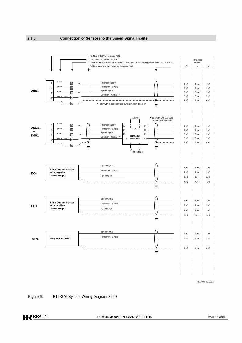
2.1.6. Connection of Sensors to the Speed Signal Inputs
Figure 6: E16x346 System Wiring Diagram 3 of 3
Rev. 00 / 09.2012
B
Terminals Monitor
C A B
Eddy Current Sensor
with negative
power supply
1.X3 1.X4 1.X5
3.X3 3.X4 3.X5
2.X3 2.X4 2.X5 - 24 volts dc
Reference 0 volts
Speed Signal
EC-
4.X3 4.X4 4.X5
Eddy Current Sensor
with positive
power supply 1.X3 1.X4 1.X5
3.X3 3.X4 3.X5
2.X3 2.X4 2.X5
+ 24 volts dc
Reference 0 volts
Speed Signal
EC+
4.X3 4.X4 4.X5
Reference 0 volts
Speed Signal
Direction – Signal *
C
A5S.. B
A
D
S
1
3
4
2*
1.X3 1.X4 1.X5
2.X3 2.X4 2.X5
3.X3 3.X4 3.X5
5.X3 5.X4 5.X5
4.X3 4.X4 4.X5
+ Sensor Supply brown
green
white
yellow or red
Cable screen must be connected to screen bar !
Marks for BRAUN cable leads. Mark D only with sensors equipped with direction detection
Lead colors of BRAUN cables
Pin Nos. of BRAUN Sensors A5S...
Reference 0 volts
Speed Signal
Direction – Signal **
C
A5S1.. +
D461
B
A
D
S
1
3
4
2*
1.X3 1.X4 1.X5
2.X3 2.X4 2.X5
3.X3 3.X4 3.X5
5.X3 5.X4 5.X5
4.X3 4.X4 4.X5
+ Sensor Supply
L+ N 24 volts dc
Alarm
13
10
11 23
25
24 8 6
2 1
D461.11U1
D461.21U1 12** 22 **
** only with D461.21 and sensors with direction
brown
green
white
yellow or red
* only with sensors equipped with direction detection
Magnetic Pick-Up
3.X3 3.X4 3.X5
2.X3 2.X4 2.X5
Reference 0 volts
Speed Signal
MPU
4.X3 4.X4 4.X5

E16x346-Manual_EN_Rev07_2016_01_15 Page 20 of 86
2.2. Inputs of the System
2.2.1. Speed Signal Inputs
The speed signals are internally wired to all three Monitors in parallel.
With versions E16x346.xx1:
The speed signal inputs match the values of sensors A5S…
The speed signal inputs are rated SIL3/IEC61508 if sensors of type A5S. (also via barriers
D461) are connected. For other sensors this is only valid, if the sensor supplier guarantees,
that the sensors will not give erratic speed signals due to a common cause failure. The instruc-
tions of the sensor supplier must be observed.
Technical Data of inputs see 3.1.1.1.
With versions E16x346.xx2:
The signal inputs match the values of eddy current sensors.
The speed signal inputs are rated SIL3/IEC61508, if the sensor supplier guarantees, that the
sensors will not give erratic speed signals due to a common cause failure. The instructions of
the sensor supplier must be observed.
Technical Data of inputs see 3.1.1.2.
With versions E16x346.xx3:
The signal inputs match the values of MPUs.
The speed signal inputs are rated SIL3/IEC61508, if the sensor supplier guarantees, that the
sensors will not give erratic speed signals due to a common cause failure. The instructions of
the sensor supplier must be observed.
Technical Data of inputs see 3.1.1.2.
2.2.2. Direction Signal Inputs (F/R : Forward/Reverse)
The direction signal inputs match the values of BRAUN sensors A5S with incorporated
direction detection.
The direction signals are internally wired to all three Monitors in parallel.
The direction signal inputs are rated SIL3/IEC61508 (valid only for sensors A5S..).
Technical Data of inputs see 3.1.2.
2.2.3. Input Reset of Alarms
The Reset signal is internally connected to all modules in parallel. It resets a no longer prevail-
ing, but latched alarm or trip condition.
A signal transition from low to high will reset a latched alarm.
Minimum Time of Reset Signal: > 1 second to ensure correct reset of all modules.
The input “Reset of Alarms” is rated SIL3/IEC61508 provided that the signal source is rated
SIL3/IEC61508.
Technical Data of input see 3.1.3.
2.2.4. Input Test Lock
A high signal will cancel a running test and inhibit further tests as long as the signal is high. If
the signal is true for more than 60 minutes, the alarms System Warning 1 and System Warning
2 are released.
The input “Test Lock” is rated SIL3/IEC61508 provided that the signal source is rated
SIL3/IEC61508.
Technical Data of input see 3.1.3.
E16x346-Manual_EN_Rev07_2016_01_15 Page 21 of 86
2.2.5. Input Start Auto-Test-Sequence
A signal transition from low to high will start an Auto-Test-Sequence. First the test (if selected,
see step P03.01 of E1697) of the trip lines for the solenoid valve block is performed, two
minutes later the test of the Monitors is performed.
The input “Start Auto-Test-Sequence” is rated SIL3/IEC61508 provided that the signal source is
rated SIL3/IEC61508.
Technical Data of input see 3.1.3.
2.2.6. Inputs Test I, Test II , Test III
The inputs Test I, II, III are enabled, if the Test-Generator E1697 is programmed to external
Trip-Line Test (see parameter P03.01 of E1697).
If the input is high, the corresponding Trip-Line will switch to trip condition.
The inputs may be configured to inhibit simultaneous test of two or three trip lines.
The input “Test I, II, III” are rated SIL3/IEC61508 provided that the signal source is rated
SIL3/IEC61508.
Technical Data of inputs see 3.1.3.
2.2.7. Inputs Starter (Override of SP2)
Each Monitor has one input for the starter condition. As long as the input is high, the starter
condition is true.
During starter condition the monitoring versus lowspeed (SP2) is disabled.
The inputs “Starter” are rated SIL3/IEC61508 provided that the signal source is rated
SIL3/IEC61508.
Technical Data of inputs see 3.1.3.
2.2.8. Inputs SP1B valid
Each Monitor has one input to select SP1B as trip setpoint.
As long as the input is high, setpoint value SP1B (see step P03.03 of E1667) is true.
With open input (low), setpoint value SP1A (see P03.00 of E1667) is true.
The inputs “SP!B valid” are rated SIL3/IEC61508 provided that the signal source is rated
SIL3/IEC61508.
Technical Data of inputs see 3.1.3.
2.2.9. Inputs Feedback from Solenoid Valve Block
The feedback inputs are connected to the Test-Generator E1697.
The inputs are only monitored if the auto test mode for Trip-Line Test resp. test of solenoid
valve block is selected (see step P03.01 of E1697).
The signal truth level (high or low as trip condition) is selectable (see step P03.03 of E1697).
The inputs “Feedback from Solenoid Valve Block” are rated SIL2/IEC61508 provided that the
signal source is rated SIL2/IEC61508.
Technical Data of input see 3.1.3.
E16x346-Manual_EN_Rev07_2016_01_15 Page 22 of 86
2.2.10. Inputs for Voter 1
The input signals for Voter 1 are internally connected to all Monitors in parallel.
The input load of Voter 1 meets the requirements for the redundant outputs of a failsafe PLC
(load > 45 ma per input).
The signal truth level (high or low as trip condition), the voting principle (1oo2, 2oo2, 2oo3,
3oo3) and the response time is selectable. Configuration of the voter is done in steps P10.xx
of E1667.
The inputs “Voter 1” are rated SIL3/IEC61508 provided that the signal source is rated
SIL3/IEC61508.
Technical Data of inputs for Voter 1 see 3.1.4.
2.2.11. Inputs for Voters 2 … 6
The input signals for Voters 2 … 6 are internally connected to all Monitors in parallel.
The signal truth level (high or low : trip condition), the voting principle (1oo2, 2oo2, 2oo3,
3oo3) and the response time is selectable for each voter individually. Configuration of voters is
done in steps P11.xx to P15.xx of E1667.
The inputs “Voter 2…6” are rated SIL3/IEC61508 provided that the signal source is rated
SIL3/IEC61508.
Technical Data of inputs for Voter 2 … 6 see 3.1.3.
Note:
Systems E16x346.x1x do not have inputs for Voters 2 … 6 .
2.2.12. Inputs for Watchdog
The input signals for the Watchdog are internally connected to all monitors in parallel.
Configuration of the Watchdog is done in step P02.00.
The duration time of the Watchdog pulse signal must be minimum 100 milliseconds, signal
may be a positive pulse or a negative pulse (minimum low time = minimum high time = 100
milliseconds).
The inputs “Watchdog” are rated SIL3/IEC61508 provided that the signal source is rated
SIL3/IEC61508.
Technical Data of inputs for Watchdog see 3.1.3
E16x346-Manual_EN_Rev07_2016_01_15 Page 23 of 86
2.3. Outputs of the System
2.3.1. Outputs System Warning Alarm 1 and System Warning Alarm 2
The System Warning Alarm 1 and System Warning Alarm 2 from Testgenerator E1697 are re-
leased if:
a Monitor does not show correct response
a Monitor releases a sensor fault alarm
the feedback signals from the solenoid valve block do not show correct response (if moni-
tored)
one or more Monitors signalize a nonconformity of their voter inputs
If the System Warning Alarm 1 and System Warning Alarm 2 do not have the same status, the
Test-Generator E1697 itself has a malfunction.
The outputs “Warning Alarm 1” and “Warning Alarm 2” are rated SIL3/IEC61508.
Technical Data of outputs see 3.2.3.
2.3.2. Speed Signal Repeater Outputs
Each Monitor repeats the speed signal of its main sensor (Monitor A repeats sensor signal A)
to the periphery.
The Speed Signal Repeater Outputs are rated SIL2/IEC61508.
Technical Data of outputs see 3.2.1.
2.3.3. Outputs Monitor Warning Alarm
The Monitor Warning Alarm (for each Monitor individually) is released if at least one of the fol-
lowing conditions is true:
Monitor releases trip (due to overspeed resp. voter), if selected
Selection in step P02.11 of E1667
Deviation of its own sensors versus both sensors of neighbor Monitors, if monitored
Selection in steps P02.07 through P02.09 of E1667
Measured speed lower than SP2 (after starter condition), if monitored
Selection in step P02.06 of E1667
Sensor Circuit Fault, if monitored
Selections in steps P02.04 and P02.05 of E1667
If starter condition is still true and speed exceeds 50% of nominal speed (as set in step
P01.03), if selected in step P02.06
Note:
The Monitor Warning Alarm is not released, if the Monitor detects a nonconformity at its voter
inputs. This status is forwarded to the Testgenerator E1697 which then releases System Warn-
ing Alarm 1 and System Warning Alarm 2.
The outputs “Monitor Warning Alarm” are rated SIL2/IEC61508.
Technical Data of outputs see 3.2.3.
2.3.4. Outputs Speed Alarm SP3
Each Monitor has a free adjustable speed alarm output SP3.
Configuration of SP3 in steps P05.xx of E1667.
The outputs “Speed Alarm SP3” are rated SIL2/IEC61508.
Technical Data of outputs see 3.2.3.
E16x346-Manual_EN_Rev07_2016_01_15 Page 24 of 86
2.3.5. Analog Outputs for measured speed (Option)
The (optional) analog outputs have a range of 0/4 .. 20 milliamps.
Configuration of the analog output in steps P08.xx of E1667.
The analog outputs of versions E16x346.1xx are rated SIL2/IEC61508.
The analog outputs of Monitors E16x346.2xx are rated SIL3/IEC61508.
Technical Data of outputs see 3.2.2.
2.3.6. Outputs Direction Detection
If operated with sensors A5S with direction signal, the sense of direction is signalized.
Each Monitor votes the direction input signals 2oo3. Each Monitor has a direction detection
output.
The outputs “Direction Detection” are rated SIL2/IEC61508.
Technical Data of outputs see 3.2.3.
2.3.7. Speed Trip Logic Output (2oo3 voted)
Speed Trip Logic Output is released, if minimum 2 of the 3 monitors detect overspeed condi-
tion. If overspeed status is latched, the alarm will persist until reset.
Output high : no overspeed trip
Output low : overspeed trip
The Speed Trip Logic Output is rated SIL2/IEC61508.
Technical Data of output see 3.2.4.
2.3.8. Outputs Trip-Lines IV, V, VI
The Trip-Lines IV, V, VI are 2oo3-circuits formed by contacts of safety trip relays IV and V of
Monitors A,B,C.
Trip is released if minimum two Monitors E1667 are in trip status.
Trip-Lines IV, V, VI are intended to signalize the trip to a DCS or PLC.
The outputs of Trip-Lines IV, V, VI are rated SIL3/IEC61508.
Technical Data of output see 3.2.5.
2.3.9. Outputs Trip-Lines I, II, III
The Trip-Lines I, II, III are 2oo3-circuits formed by contacts of safety trip relays of Monitors
A,B,C.
Trip is released if minimum two Monitors E1667 are in trip status.
Trip-Lines I, II, III are intended to supply shutdown solenoid valves.
The outputs of Trip-Lines I, II, III are rated SIL3/IEC61508.
Technical Data of output see 3.2.6.
2.3.10. Logic Outputs LO1 through LO6 (voted 2oo3)
The logic outputs LO may be assigned to signalize a voter trip or to a speed alarm.
If assigned to Voter Trip: Output high : no trip of Voter
Output low : trip of Voter
If assigned to speed alarm: Output high/low if n > SP is selectable.
The Logic Outputs LO1 through LO6 are rated SIL2/IEC61508.
Technical Data of outputs see 3.2.4.
2.3.11. This chapter is left blank intentionally

E16x346-Manual_EN_Rev07_2016_01_15 Page 25 of 86
2.3.12. Logic Output Watchdog (voted 2oo3)
The Logic Output Watchdog goes low, if a trip is released due to missing Watchdog input sig-
nals.
The Logic Output Watchdog is rated SIL2/IEC61508.
Technical Data of output see 3.2.4.
2.4. Power Supply
Each Monitor must be supplied with 24 volts dc (18..40 volts) from a power supply with protec-
tive separation (SELV or PELV), conforming to IEC 61131-2 requirements.
The Test Generator E1697 is fed by an internal power rail.
Technical Data see 3.3.
2.5. Data-Interface
Each of the Monitors E1667 and the Testgenerator E1697 carry a 9pole Sub-D-connector (
female). Implemented on this connector are a Profibus-Interface (with standard-pinning) and a
RS232-Interface (non standard pinning).
2.5.1. Profibus-Interface for Status and Diagnostics of the System
The Profibus-Interface reflects the standard Profibus DP and serves for the upload of status
and diagnostics of the system to a PLC or DCS.
2.5.2. RS232-Interface for Setting of Parameters
The RS232-Interface in conjunction with the Interface-Software IS-RS232-E16 serves to down-
load parameter values from a PC to the E16 and to retrieve parameter values from the E16 to
a PC. The data communication in between the E16 and the PC is failsafe and fulfills
SIL3/IEC61508 requirements.
E16x346-Manual_EN_Rev07_2016_01_15 Page 26 of 86
3. Technical Specifications
3.1. Technical Data of Inputs
3.1.1. Technical Data of Speed Signal Inputs
3.1.1.1. Hall Sensor Inputs
Maximum Input Frequency : 30 kHz
Maximum Signal Voltage : 30 volts
Input low at : < 3 volts
Input high at : > 7 volts
Impedance : approx. 5 kohms
Minimum pulse high time: 20 microseconds
Minimum pulse low time: 20 microseconds
Sensor Supply : approx. 13 volts, maximum 80 ma
The speed signal inputs have the same reference but are free floating versus all other circuits.
The inputs are fed by an internal isolated power supply of the Monitor.
3.1.1.2. Eddy Current Sensor Inputs resp. MPU (Magnetic Pick-Up) Inputs
Maximum Input Frequency : 30 kHz
Maximum Signal Voltage : 30 volts
Trigger Hysteresis : 0.07 to 2.5 Vpp
Impedance : approx. 47 kohms
Sensor Supply (only with versions E16x346.xx3): approx. 24 volts, maximum 120 ma
The speed signal inputs have the same reference but are free floating versus all other circuits.
The input is supplied by an internal isolated power source of the Monitor.
3.1.2. Technical Data of Direction Inputs
Maximum Signal Voltage : 30 volts
Input low at : < 3 volts
Input high at : > 7 volts
Impedance : approx. 22 kohms
Same Reference as Speed Signal Inputs.
3.1.3. Technical Data of Binary Inputs (excluding Voter 1)
Input high : 18..48 volts (nominal current at 24 volts: 6 ma)
Input low : < 3 volts or open input
Reference : negative pole of power supply
3.1.4. Technical Data of Binary Inputs of Voter 1
Input high : 18..30 volts (nominal current at 24 volts: 45 ma)
Input low : < 3 volts or open input
Reference : negative pole of power supply
E16x346-Manual_EN_Rev07_2016_01_15 Page 27 of 86
3.2. Technical Data of Outputs
3.2.1. Technical Data of Sensor Signal Repeater Outputs
High-Level : > 20 volts with max. load, (maximum 26 volts without load)
Low-Level : < 2 volts, with max. load
Maximum load: 1 kohms
The outputs are short-circuit proof and free floating (also versus each other).
The output is supplied by an internal isolated power source of the Monitor.
3.2.2. Technical Data of Analog Outputs
Range : 0/4…20 ma
Resolution : 12 Bit
Maximum load : versions E1667.1xx : 650 ohms, versions E1667.2xx : 400 ohms
Linearity event : < 0.1%
Temperature stability : ±0,02 %/°C within a range of 0...60°C.
The outputs are short-circuit proof and free floating (also versus each other).
The output is supplied by an internal isolated power source of the Monitor.
3.2.3. Technical Data of Opto-Relay Outputs
Maximum rating : 50 volts dc / 50 ma.
Outputs are passive, short-circuit proof and free floating (also versus each other). They must
be supplied externally.
Note:
In case of short circuit the output is latched to tristate until power supply of the monitor has
been switched off and on.
3.2.4. Technical Data of Logic Outputs
The outputs are fed from the system power supply.
Reference : L- (negative pole of power supply).
High-Level : Power supply L+ minus 2 volts
Low-Level : < 3 volts
Maximum output current : 50 milliamps
Outputs are short-circuit proof.
Note:
In case of short circuit the output is latched to tristate until power supply of the monitor has
been switched off and on.
3.2.5. Technical Data of Trip-Lines IV, V, VI
Maximum rating : 50 volts dc / 300 milliamps.
Outputs are passive, short-circuit proof and free floating. They must be supplied externally.
3.2.6. Technical Data of Trip-Lines I, II, III
Maximum rating : 50 volts dc / 3 amps / 75 watts
Maximum rating for DC13-applications : 24 volts / 3 amps
Outputs are not short-circuit proof (permanent currents exceeding 8 amps will destroy outputs).
Recommended primary fuse rating: 3 amps nominal with max. 6 amps release current.
Impedance: 10 kohms versus L- (negative pole of power supply)
For inductive type loads, external spark extinguishing means must be provided.
Total response time (trip relays de-energize to trip) from trip event until trip circuits are in trip
condition : < 15 milliseconds.
E16x346-Manual_EN_Rev07_2016_01_15 Page 28 of 86
3.3. Technical Data of Power Supply
3x 24 volts dc / 0.5 amps (18…40 volts) from a power supply with protective separation (SELV
or PELV), conforming to IEC 61131-2 requirements.
Maximum consumption of system : 20 watts
3.4. Installation Conditions
Ambient temperature in operation : 0°C..+55°C
Ambient temperature in storage : -20°C..+85°C
Relative humidity: < 75%, non-condensing
To be installed in dry cabinets in air-conditioned rooms
3.5. Protection Grade
Insulation Class III
Version E16A346 and E16E346 : IP20
Version E16G346: IP65 resp. NEMA4
3.6. Connectors
Plug-In Cage-Clamp Connectors, type Phoenix Combicon FK-MLP1,5/…ST-3,5,
fitting for:
Conductor cross section solid min.: 0.2 mm²
Conductor cross section solid max.: 1.5 mm²
Conductor cross section stranded min.: 0.2 mm²
Conductor cross section stranded max.: 1.5 mm²
Conductor cross section stranded, with ferrule without plastic sleeve min.: 0.25 mm²
Conductor cross section stranded, with ferrule without plastic sleeve max.: 1.5 mm²
Conductor cross section stranded, with ferrule with plastic sleeve min.: 0.25 mm²
Conductor cross section stranded, with ferrule with plastic sleeve max.: 0.75 mm²
Conductor cross section acc. to AWG/kcmil min.: No. 24
Conductor cross section acc. to AWG/kcmil max: No. 16
Minimum AWG according to UL/CUL: 28
Maximum AWG according to UL/CUL: 16
3.7. Conformity to Standards
2006/42/EU
SIL3/IEC61508, DIN EN ISO 13849-1:2008 Cat 3 PL e, API 670,
2006/95/EU, EN 61010-1,
2004/108/EU, EN 61000-6-2, EN 61000-6-4, IEC 61326-2
E16x346-Manual_EN_Rev07_2016_01_15 Page 29 of 86
3.8. Dimensions of System E16A346
Figure 7: Dimensions of System E16A346
front view
Heig
ht
incl. b
ackp
lan
e +
te
rmin
als
all dimensions in mm Drawing not to scale
wiring from top and bottom
Ø 13
88
220
201.5
10
9.3
2
1.3
2
1
13
3
19
5
20
6.4
Detail
Mounting holes
to hang the racks to
premounted screws
total depth (incl. Profibus plug with 35° cable outlet)
wiring
side view
wiring
premounted screws or
bolts with nuts
pluggable
terminal
blocks
265
220

E16x346-Manual_EN_Rev07_2016_01_15 Page 30 of 86
3.9. Dimensions of System E16E346
Figure 8: Dimensions of System E16E346
all dimensions in mm resp. (in inch) Drawing not to scale
wiring from rear side
top view
connectors
depth
incl. c
onnecto
rs (e
xcl. w
irin
g s
pace)
mounting holes in rack for screws or bolts with Ø 6 mm
mounting holes ffnungen
483 (incl. mounting lugs)
Dimensions sheet of 19'' rack, 3HE, 84TE for rack or panel mounting
57
.1
456.1
448 +4
13
3 +
2
446
(17,56
)
21
8
(8,5
8)
dimensions for panel cutout
E16x346-Manual_EN_Rev07_2016_01_15 Page 31 of 86
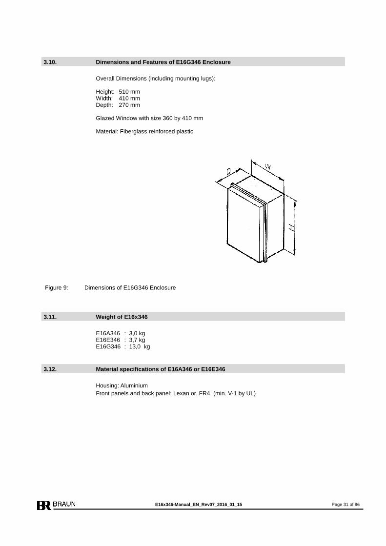
3.10. Dimensions and Features of E16G346 Enclosure
Overall Dimensions (including mounting lugs): Height: 510 mm Width: 410 mm Depth: 270 mm Glazed Window with size 360 by 410 mm Material: Fiberglass reinforced plastic
Figure 9: Dimensions of E16G346 Enclosure
3.11. Weight of E16x346
E16A346 : 3,0 kg E16E346 : 3,7 kg E16G346 : 13,0 kg
3.12. Material specifications of E16A346 or E16E346
Housing: Aluminium
Front panels and back panel: Lexan or. FR4 (min. V-1 by UL)

E16x346-Manual_EN_Rev07_2016_01_15 Page 32 of 86
4. Safety Notes for Installation and Operation
4.1. Safety Notes for Installation
This unit has been designed and inspected according to standards DIN EN 61010-1 (VDE
0411-1). Observe these instructions and wiring diagrams carefully, to ensure this protection.
The installation must be done only by adequately qualified personnel.
4.1.1. General Instructions
Specifically, connect the PE terminal 1.X1 to a safe ground potential.
Do not open the instrument. Connections and all programming are done from outside. When
removing it from its enclosure however, from whatever reason, make sure that power is
switched off.
The instrument may be installed in any position, but not in the immediate neighborhood of in-
terfering sources.
Signal leads must be carefully shielded, and should not be run in bundles with power or relay
control leads.
4.1.2. EMI
The unit complies with all relevant regulations, as determined by the Policy of the European
Committee for Electrotechnical Standardization (CENELEC), for the Electromagnetic Compati-
bility (2004/108/EU). Testing and inspection has been performed according to Standards
EN 61000-4-2 and EN 61000-4-4. Thereby, the product meets all requirements to be marked
by the CE sign.
Strict observance of these instructions during installation and use is an indispensable precon-
dition hereto. Specifically to be observed:
Terminals must be kept off all undue access; power supply and all input and output leads must
be protected against voltage interference, higher than specified operation data, and they must
be protected against electrostatic discharge.
4.2. Safety Notes for Operation
4.2.1. Safety notes for commissioning
On initial operation of the monitored machine the operator must ensure proper function of the
measurement chains. This includes checking of the correct speed display and of the trip re-
lease due to a real overspeed condition.
The parameter settings must be documented and protected against unauthorized changes.

E16x346-Manual_EN_Rev07_2016_01_15 Page 33 of 86
5. Description of Monitor E1667
5.1. Display and Frontside Operational Elements
5.1.1. Front View of Monitor E1667
Figure 10: Front view of Monitor E1667
5.1.2. Status-LEDs
LED1 steady on: Trip
LED2 steady on: no Trip, SP1A is valid
blinking: SP1B is valid
LED3 steady on: n < SP3
blinking: one only of three input channels measures zero speed
LED4 steady on: n > SP3
5.1.3. Display during Test Procedures
FC-1 : Frequency generator tests Input "Forced Trip"
FC-3.1 : Trip-Line I is tested (relay I to Trip-Condition)
FC-3.2 : Trip-Line II is tested (relay II to Trip-Condition)
FC-3.4 : Trip-Line III is tested (relay III to Trip-Condition)
SELF : Monitor self-test
5-digit display
Input keyboard
4 LEDs for status indication
Data Interface 9-pole Sub-D
P
E
E1667
1
2
3
4
Trip
SP3
RPM
E16x346-Manual_EN_Rev07_2016_01_15 Page 34 of 86
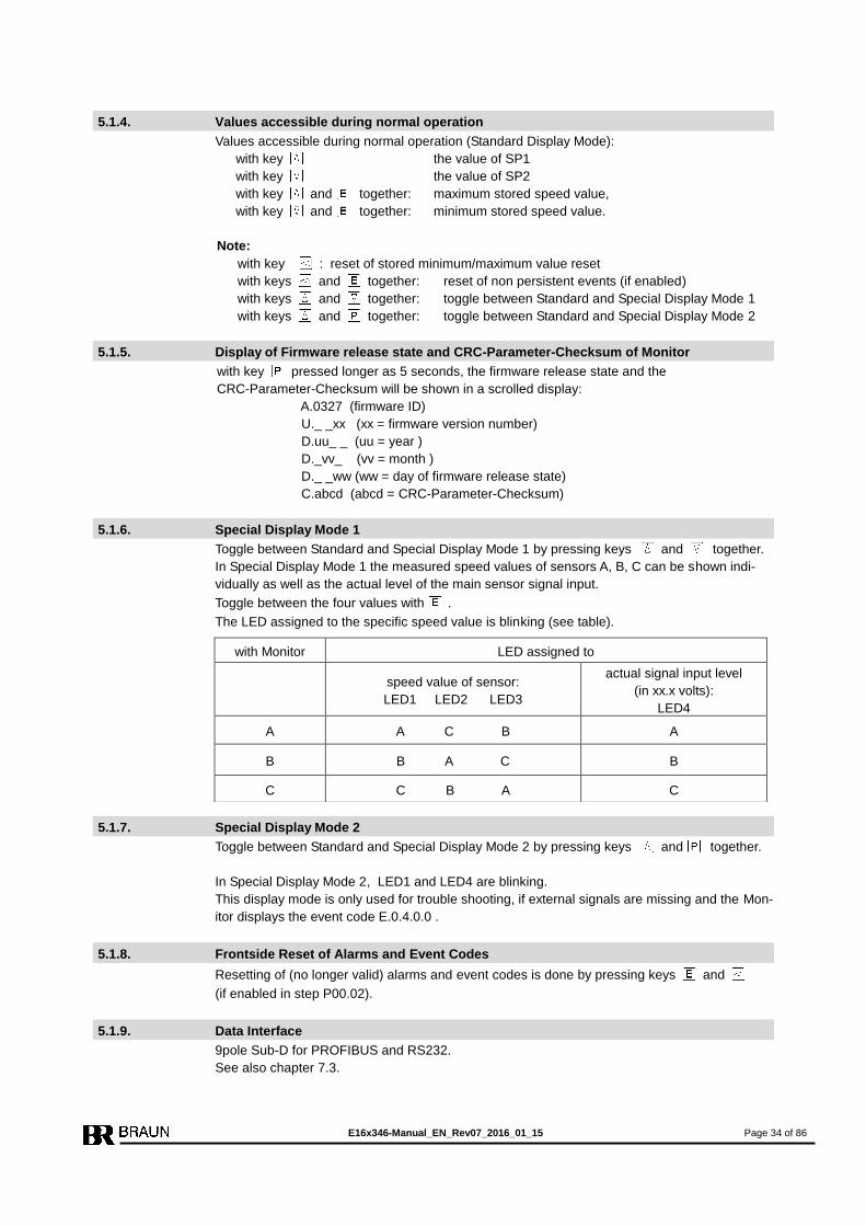
5.1.4. Values accessible during normal operation
Values accessible during normal operation (Standard Display Mode):
with key the value of SP1
with key the value of SP2
with key and together: maximum stored speed value,
with key and together: minimum stored speed value.
Note:
with key : reset of stored minimum/maximum value reset
with keys and together: reset of non persistent events (if enabled)
with keys and together: toggle between Standard and Special Display Mode 1
with keys and together: toggle between Standard and Special Display Mode 2
5.1.5. Display of Firmware release state and CRC-Parameter-Checksum of Monitor
with key pressed longer as 5 seconds, the firmware release state and the
CRC-Parameter-Checksum will be shown in a scrolled display:
A.0327 (firmware ID)
U._ _xx (xx = firmware version number)
D.uu_ _ (uu = year )
D._vv_ (vv = month )
D._ _ww (ww = day of firmware release state)
C.abcd (abcd = CRC-Parameter-Checksum)
5.1.6. Special Display Mode 1
Toggle between Standard and Special Display Mode 1 by pressing keys and together.
In Special Display Mode 1 the measured speed values of sensors A, B, C can be shown indi-
vidually as well as the actual level of the main sensor signal input.
Toggle between the four values with .
The LED assigned to the specific speed value is blinking (see table).
5.1.7. Special Display Mode 2
Toggle between Standard and Special Display Mode 2 by pressing keys and together.
In Special Display Mode 2, LED1 and LED4 are blinking.
This display mode is only used for trouble shooting, if external signals are missing and the Mon-
itor displays the event code E.0.4.0.0 .
5.1.8. Frontside Reset of Alarms and Event Codes
Resetting of (no longer valid) alarms and event codes is done by pressing keys and
(if enabled in step P00.02).
5.1.9. Data Interface
9pole Sub-D for PROFIBUS and RS232.
See also chapter 7.3.
with Monitor LED assigned to
speed value of sensor:
LED1 LED2 LED3
actual signal input level
(in xx.x volts):
LED4
A A C B A
B B A C B
C C B A C
E16x346-Manual_EN_Rev07_2016_01_15 Page 35 of 86
5.2. Functions of Monitor 1667
For a detailed description of the individual functions refer to chapter 8.
5.2.1. Speed Measurement
Each Monitor receives the signal from the three sensors and calculates the speed from each
signal. For the further evaluation it selects (depending on parameter settings) the calculated
speed value derived of its own sensor or the mean value of all three speed values.
Speed calculation is done by measuring the time in between the pulses. The minimum meas-
urement time is 5 milliseconds.
To compensate for an imperfect gear, a predivider may be introduced to reduce the signal fre-
quency to 1 pulse per revolution.
5.2.2. Functions for Overspeed Protection
Overspeed protection is done by :
Monitoring of Sensors
Monitoring versus Lowspeed as protection versus incorrect mounting or fault of speed
sensors.
Monitoring versus overspeed
5.2.3. Functions for External Trip by Voters
Trip is released, if one of the voters detects an external trip condition.
Voters may be configured as 1oo2, 2oo2, 2oo3 or 3oo3. High or low Input-Level as trip condi-
tion and response time is selectable.
5.2.4. Selftest of Monitor
Selftest is performed at an interval of 2 hours. Execution of Selftest is signalized on display
with message SELF. Selftest of the Monitors are inhibited versus each other.
The Selftest routine includes
CPU RAM-Test
CPU EEPROM-Test
CPU Command-Test
CPU Register-Test
Voter Signal-input-Test
If the Selftest detects a malfunction, the Monitor is set to trip-status.

E16x346-Manual_EN_Rev07_2016_01_15 Page 36 of 86
6. Description of Test-Generator E1697
6.1. Display and Frontside Operational Elements
6.1.1. Front View of Test-Generator E1697
Figure 11: Front view of Test-Generator E1697
6.1.2. Status-LEDs
LED1 blinking: Test of Monitor A resp. Trip-Line I
steady on: Monitor A signalizes Trip
LED2 blinking: Test of Monitor B resp. Trip-Line II
steady on: Monitor B signalizes Trip
LED3 blinking: Test of Monitor C resp. Trip-Line II
steady on: Monitor C signalizes Trip
LED4 blinking: LED4 blinking: Test in preparation
steady on: Monitor-AutoTest-Mode on
steady off: Monitor-AutoTest-Mode off
5-digit display
Input keyboard
4 LEDs for status indication
Data Interface 9-pole Sub-D
P
E
E1697
1
2
3
4
Monitor A / TL I
Auto-Test
Monitor B / TL II
Monitor C / TL III

E16x346-Manual_EN_Rev07_2016_01_15 Page 37 of 86
6.1.3. Display during Test Procedures
FC-1 : Frequency generator tests Input "Forced Trip"
FC-3.0 : Trip-Line Test in preparation
FC-3.1 : Test Generator is testing Trip-Line I (relay I of all Monitors to Trip-Condition)
FC-3.2 : Test Generator is testing Trip-Line II (relay II of all Monitors to Trip-Condition)
FC-3.4 : Test Generator is testing Trip-Line III (relay III of all Monitors to Trip-Condition)
FC-3.3 : Inputs Test I and II are active (but test is inhibited)
FC-3.5 : Inputs Test I and III are active (but test is inhibited)
FC-3.6 : Inputs Test II and III are active (but test is inhibited)
FC-3.7 : Inputs Test I and II and III are active (but test is inhibited)
FC-5.1 : Non-coincidence of test outputs detected.
FC-5.2 : Input Test Lock is active
FC-5.6 : Input Test Lock is longer than 10 minutes active
SELF : Test-Generator self-test
6.1.4. Values accessible during normal operation
with key : the value of test-speed 1 resp. SP1A,
with key : the value of test-speed 2 resp. SP1B,
with keys and together: time remaining (in XXXX.X minutes) till start of the next
Monitor-Test-Sequence),
with keys and together: time remaining (in XXXX.X minutes) till start of the next
Trip-Line-Test-Sequence).
6.1.5. Display of Firmware release state and CRC-Parameter-Checksum of Test-Generator
with key pressed longer as 5 seconds, the firmware release state and the
CRC-Parameter-Checksum will be shown in a scrolled display:
A.0339 (firmware ID)
U._ _xx (xx = firmware version number)
D.uu_ _ (uu = year )
D._vv_ (vv = month )
D._ _ww (ww = day of firmware release state)
C.abcd (abcd = CRC-Parameter-Checksum)
6.1.6. Frontside Reset of Alarms and Event Codes
Resetting of (no longer valid) alarms and event messages is done by pressing
keys and simultaneously.
6.1.7. Manual Start of a Monitor-Test Sequence
The test routine can be activated from the front of the test generator by pressing
keys and simultaneously.
6.1.8. Manual Start of a Trip-Line-Test Sequence
The test routine can be activated from the front of the test generator by pressing
keys and simultaneously.
6.1.9. Data Interface
9-pole Sub-D for PROFIBUS and RS232.
See also chapter 7.3.

E16x346-Manual_EN_Rev07_2016_01_15 Page 38 of 86
6.2. Functions of Test-Generator 1697
For a detailed description of the individual functions refer to chapter 9.
6.2.1. Test of Feedback Signals
During normal operation the trip and alarm feedback signals of the Monitors and the Trip-Lines
are permanently checked. If one or more Monitors or Trip-Lines are in alarm or trip status, the
Test-Generator releases its alarm outputs "System Fault 1” and "System Fault 2”.
Monitor Test and Trip-Line Test is inhibited during this status.
6.2.2. Monitor-Test Sequence
During the Monitor-Test Sequence each monitor is sequentially subjected to a test sequence
consisting of two simulated test-speeds followed by a 'Forced Trip' signal.
Step 1: Each Monitor is sequentially provided with a test-speed 1 (n >SP1) to which the
Monitor under test must respond with trip release.
Step 2: Each Monitor is sequentially provided with a test-speed 2 (n < SP1) to which the
Monitor under test must not respond with trip release.
Step 3: The ‘Forced Trip’ control input of each Monitor is sequentially activated to which the
Monitor under test must respond with trip release. During this step the Monitor is
provided with test-speed 2 (n < SP1)
In the event of an incorrect response the test will be discontinued and the Test-Generator re-
leases the System Warning Alarm 1 and 2.
If variable setpoint SP1var is active, the test may be optionally performed according to the fol-
lowing steps:
Step 1: Each Monitor is sequentially provided with a test-speed 1 (SP1A + 5 RPM) to which
the Monitor under test must respond with trip release.
Step 2: Each Monitor is sequentially provided with a test-speed 2 (SP1B - 5 RPM) to which
the Monitor under test must not respond with trip release.
Step 3: The ‘Forced Trip’ control input of each Monitor is sequentially activated to which the
Monitor under test must respond with trip release. During this step the Monitor is
provided with test-speed 2 (SP1B - 5 RPM)
Step 4: Each Monitor is sequentially provided with a test-speed 3 (SP1A - 5 RPM) to which
the Monitor under test must not respond with trip release.
Step 5: Each Monitor is sequentially provided with a test-speed 4 (SP1B + 5 RPM) to which
the Monitor under test must respond with trip release.
The time interval of these tests is programmable (see P02.02). The test sequence may also be
started by an external signal „Start Auto Test Sequence“ or manually via frontside keyboard of
the Test-Generator.
E16x346-Manual_EN_Rev07_2016_01_15 Page 39 of 86
6.2.3. Trip-Line-Test Sequence (Test of 2oo3 solenoid valve block)
The Test-Generator commands the Monitors to put sequentially the trip relays I, II or III to trip
condition.
By doing so the designated Trip-Line to the solenoid valve is in trip condition. The condition of
the 2oo3-solenoid valve must be passed back to the E16 system.
The testing of Trip-Line I must provide the response of Trip I.
The testing of Trip-Line II must provide the response of Trip II.
The testing of Trip-Line III must provide the response of Trip III.
In the event of an incorrect response the test will be discontinued and the Test-Generator re-
leases the alarm System Fault 1 and 2.
Single or multiple Trip-Lines may also be tested by three external test-signals.
6.2.4. Cross-check between CPUs of Test-Generator
The Test-Generator incorporates two redundant CPUs. Both CPUs must perform identically to
release a test sequence. In case of failure of one CPU no test is released, but alarm System
Fault 1 or 2 is released.
6.2.5. Selftest of CPUs
Selftest is performed after each Monitor test sequence. Execution of Selftest is signalized on
display with message SELF.
The Selftest of both CPU routine includes: CPU RAM-Test
CPU EEPROM-Test
CPU Command-Test
CPU Register-Test
If the Selftest detects a malfunction, alarm System Fault 1 or 2 is released.
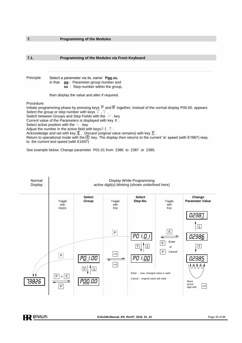
E16x346-Manual_EN_Rev07_2016_01_15 Page 40 of 86
7. Programming of the Modules
7.1. Programming of the Modules via Front Keyboard
Principle:
Select a parameter via its ‚name’ Pgg.ss,
in that gg : Parameter-group number and
ss : Step-number within the group, then display the value and alter if required.
Procedure: Initiate programming phase by pressing keys and together; instead of the normal display P00.00. appears Select the group or step number with keys , . Switch between Groups and Step Fields with the . key Current value of the Parameters is displayed with key . Select active position with the . key Adjust the number in the active field with keys , . Acknowledge and set with key , Discard (original value remains) with key . Return to operational mode with the key. The display then returns to the current ‘is’ speed (with E1667) resp. to the current test-speed (with E1697) See example below: Change parameter P01.01 from 2386 to 2387 or 2385.
Move
active
digit with
Normal Display While Programming Display active digit(s) blinking (shown underlined here)
Select Select Change
Toggle Group Toggle Step-No. Toggle Parameter Value
with with with key(s) Key Key
+
P
P E
E
E : Enter
or
: Cancel P
Enter : new, changed value is valid
Cancel : original value still valid
P
P
E16x346-Manual_EN_Rev07_2016_01_15 Page 41 of 86
7.2. Programming of the Modules via PROFIBUS-Interface
Only possible for OEM with special interface-software by BRAUN.
7.3. Programming of the Modules via RS232-Interface
Only possible for OEM with special interface-software and either
1. adapter cable L3D05 by BRAUN
or
2. customized cable with connections PC (female connector) to E16 (male connector):
PC pin 2 to E16 pin 2
3 to 7
5 to 5 (of 9 pole Sub-D connectors)
Note:
The RS232-Interface serves only for parameter programming purposes, not for transmission
of current data. States, alarms and measurement data are transmitted via PROFIBUS-
Interface only.
7.4. Default Values
If not specified otherwise, the unit is supplied with default values as listed in the summary of
parameters. In process of installation, the setting of its parameters inevitably must be adapted
to the correct values according its application.
7.5. Behaviour in case of values exceeding limits
If the limits are exceeded the Display is blinking. The value will not be accepted.
7.6. Display of parameter values if access is locked
If access is locked parameter values are displayed but cannot be changed.
The values are shown blinking.
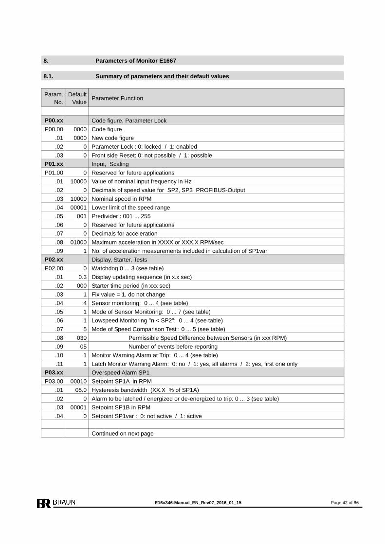
E16x346-Manual_EN_Rev07_2016_01_15 Page 42 of 86
8. Parameters of Monitor E1667
8.1. Summary of parameters and their default values
Param.
No.
Default
Value Parameter Function
P00.xx Code figure, Parameter Lock
P00.00 0000 Code figure
.01 0000 New code figure
.02 0 Parameter Lock : 0: locked / 1: enabled
.03 0 Front side Reset: 0: not possible / 1: possible
P01.xx Input, Scaling
P01.00 0 Reserved for future applications
.01 10000 Value of nominal input frequency in Hz
.02 0 Decimals of speed value for SP2, SP3 PROFIBUS-Output
.03 10000 Nominal speed in RPM
.04 00001 Lower limit of the speed range
.05 001 Predivider : 001 ... 255
.06 0 Reserved for future applications
.07 0 Decimals for acceleration
.08 01000 Maximum acceleration in XXXX or XXX.X RPM/sec
.09 1 No. of acceleration measurements included in calculation of SP1var
P02.xx Display, Starter, Tests
P02.00 0 Watchdog 0 ... 3 (see table)
.01 0.3 Display updating sequence (in x.x sec)
.02 000 Starter time period (in xxx sec)
.03 1 Fix value = 1, do not change
.04 4 Sensor monitoring: 0 ... 4 (see table)
.05 1 Mode of Sensor Monitoring: 0 ... 7 (see table)
.06 1 Lowspeed Monitoring "n < SP2": 0 ... 4 (see table)
.07 5 Mode of Speed Comparison Test : 0 ... 5 (see table)
.08 030 Permissible Speed Difference between Sensors (in xxx RPM)
.09 05 Number of events before reporting
.10 1 Monitor Warning Alarm at Trip: 0 ... 4 (see table)
.11 1 Latch Monitor Warning Alarm: 0: no / 1: yes, all alarms / 2: yes, first one only
P03.xx Overspeed Alarm SP1
P03.00 00010 Setpoint SP1A in RPM
.01 05.0 Hysteresis bandwidth (XX.X % of SP1A)
.02 0 Alarm to be latched / energized or de-energized to trip: 0 ... 3 (see table)
.03 00001 Setpoint SP1B in RPM
.04 0 Setpoint SP1var : 0: not active / 1: active
Continued on next page

E16x346-Manual_EN_Rev07_2016_01_15 Page 43 of 86
Param.
No.
Default
Value Parameter Function
P04.xx Low Speed Alarm SP2
P04.00 00015 Setpoint SP2 in RPM
.01 05.0 Hysteresis bandwidth (XX.X % of SP2)
.02 0 Fix value = 0, do not change
P05.xx Alarm SP3
P05.00 00003 Setpoint SP3 in RPM
.01 05.0 Hysteresis bandwidth (XX.X % of SP3)
.02 1 Hysteresis position: 0: above / 1: below
.03 1 Relay state at "n > SP3" : 0 … 3 (see table)
.04 0 Alarm state at sensor fault: 0: acc. to speed / 1: "n < SP" / 2: "n > SP"
.05 1 Setting of LEDs to status "n > SP3" : 0: LED3 on / 1: LED4 on
P06.xx Eddy sensor
P06.00 00100 Reserved for future application
.01 00.0 Eddy sensor input check: input voltage upper limit in xx.x volts
.01 00.0 input voltage lower limit in xx.x volts
.03 00.0 current drain upper limit in xxx ma
.04 00.0 current drain lower limit in xxx ma
.05 0.0 Eddy sensor input hysteresis in x.x volts
P07.xx Trip-Lines, Forward / Reverse Detection
P07.00 0 Trip-Line Monitoring: 0 ... 3 (see table)
.01 0 Signal level Trip-Feedback: 0: low = Trip / 1: high = Trip
.02 1 Forward / Reverse Detection Input level: 0: low = forward / 1: high = forward
.03 1 Forward / Reverse relay state: 0: de-energized = forward / 1: energized = forward
.04 0 Reserved for future application
P08.xx Analog Output
P08.00 10000 High end speed value
.01 00000 Low end speed value
.02 1 Zero level: 0: dead zero / 1: live zero
.03 0 Output level at sensor fault: 0: no change / 1: min / 2: max
.04 0 Output direction: 0: 0/4 … 20 ma / 1: 20 ... 4/0 ma
.05 1 Output response to test-speed: 0: test-speed / 1: frozen
.06 0 Test of Analog Output value: 0: no / 1: yes
P09.xx Reserved for future application
P09.00 0 Reserved for future application
P10.xx Voter No. 1 and LO1
P10.00 0 Operation Mode: 0 ... 5 (see table)
.01 0 Input Truth Level: 0: high = Trip / 1: low = Trip
.02 0 Voting logic: 0: 1oo2 / 1: 2oo2 / 2: 2oo3 / 3: 3oo3
.03 0 Truth Time until Trip: 0 ... 9 (see table)
.04 0 Trip latched: 0: no / 1: yes
.05 0 Delay of Antivalence Alarm: 0 ... 9 (see table)
.06 00110 Value for setpoint SPV1
Continued on next page
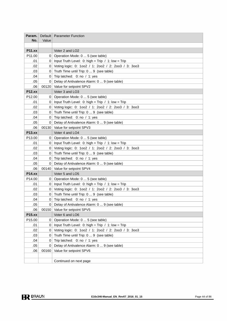
E16x346-Manual_EN_Rev07_2016_01_15 Page 44 of 86
Param.
No.
Default
Value
Parameter Function
P11.xx Voter 2 and LO2
P11.00 0 Operation Mode: 0 ... 5 (see table)
.01 0 Input Truth Level: 0: high = Trip / 1: low = Trip
.02 0 Voting logic: 0: 1oo2 / 1: 2oo2 / 2: 2oo3 / 3: 3oo3
.03 0 Truth Time until Trip: 0 ... 9 (see table)
.04 0 Trip latched: 0: no / 1: yes
.05 0 Delay of Antivalence Alarm: 0 ... 9 (see table)
.06 00120 Value for setpoint SPV2
P12.xx Voter 3 and LO3
P12.00 0 Operation Mode: 0 ... 5 (see table)
.01 0 Input Truth Level: 0: high = Trip / 1: low = Trip
.02 0 Voting logic: 0: 1oo2 / 1: 2oo2 / 2: 2oo3 / 3: 3oo3
.03 0 Truth Time until Trip: 0 ... 9 (see table)
.04 0 Trip latched: 0: no / 1: yes
.05 0 Delay of Antivalence Alarm: 0 ... 9 (see table)
.06 00130 Value for setpoint SPV3
P13.xx Voter 4 and LO4
P13.00 0 Operation Mode: 0 ... 5 (see table)
.01 0 Input Truth Level: 0: high = Trip / 1: low = Trip
.02 0 Voting logic: 0: 1oo2 / 1: 2oo2 / 2: 2oo3 / 3: 3oo3
.03 0 Truth Time until Trip: 0 ... 9 (see table)
.04 0 Trip latched: 0: no / 1: yes
.05 0 Delay of Antivalence Alarm: 0 ... 9 (see table)
.06 00140 Value for setpoint SPV4
P14.xx Voter 5 and LO5
P14.00 0 Operation Mode: 0 ... 5 (see table)
.01 0 Input Truth Level: 0: high = Trip / 1: low = Trip
.02 0 Voting logic: 0: 1oo2 / 1: 2oo2 / 2: 2oo3 / 3: 3oo3
.03 0 Truth Time until Trip: 0 ... 9 (see table)
.04 0 Trip latched: 0: no / 1: yes
.05 0 Delay of Antivalence Alarm: 0 ... 9 (see table)
.06 00150 Value for setpoint SPV5
P15.xx Voter 6 and LO6
P15.00 0 Operation Mode: 0 ... 5 (see table)
.01 0 Input Truth Level: 0: high = Trip / 1: low = Trip
.02 0 Voting logic: 0: 1oo2 / 1: 2oo2 / 2: 2oo3 / 3: 3oo3
.03 0 Truth Time until Trip: 0 ... 9 (see table)
.04 0 Trip latched: 0: no / 1: yes
.05 0 Delay of Antivalence Alarm: 0 ... 9 (see table)
.06 00160 Value for setpoint SPV6
Continued on next page
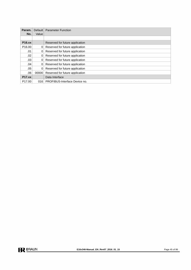
E16x346-Manual_EN_Rev07_2016_01_15 Page 45 of 86
Param.
No.
Default
Value
Parameter Function
P16.xx Reserved for future application
P16.00 0 Reserved for future application
.01 0 Reserved for future application
.02 0 Reserved for future application
.03 0 Reserved for future application
.04 0 Reserved for future application
.05 0 Reserved for future application
.06 00000 Reserved for future application
P17.xx Data Interface
P17.00 016 PROFIBUS-Interface Device no.
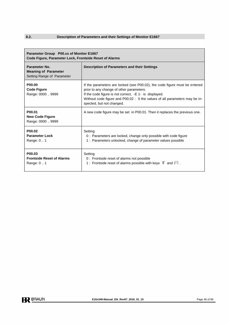
E16x346-Manual_EN_Rev07_2016_01_15 Page 46 of 86
8.2. Description of Parameters and their Settings of Monitor E1667
Parameter Group P00.xx of Monitor E1667
Code Figure, Parameter Lock, Frontside Reset of Alarms
Parameter No.
Meaning of Parameter
Setting Range of Parameter
Description of Parameters and their Settings
P00.00
Code Figure
Range: 0000 .. 9999
If the parameters are locked (see P00.02), the code figure must be entered
prior to any change of other parameters.
If the code figure is not correct, -E 1- is displayed.
Without code figure and P00.02 : 0 the values of all parameters may be in-
spected, but not changed.
P00.01
New Code Figure
Range: 0000 .. 9999
A new code figure may be set in P00.01. Then it replaces the previous one.
P00.02
Parameter Lock
Range: 0 .. 1
Setting
0 : Parameters are locked, change only possible with code figure
1 : Parameters unlocked, change of parameter values possible
P00.03
Frontside Reset of Alarms
Range: 0 .. 1
Setting
0 : Frontside reset of alarms not possible
1 : Frontside reset of alarms possible with keys and .

E16x346-Manual_EN_Rev07_2016_01_15 Page 47 of 86
Parameter Group P01.xx of Monitor E1667
Input Scaling and Measurement Configuration
Parameter No.
Meaning of Parameter
Setting Range of Parameter
Description of Parameters and their Settings
P01.00 Reserved for future applications
Description of Scaling: Scaling defines the relationship between the input signal frequency (in terms of Hz), and the corresponding display (in terms of RPM).
Of course, they must refer to the same operation level. This reference point
is recommended close to the high end of the intended operation range. In
later operation, however, it may be overrun without event.
Example:
1500 Hz corresponds to 3000 RPM :
Step P01.01 : setting 01500
Step P01.03 : setting 03000
P01.01
Nominal Input Frequency [Hz]
Range: 00001 .. 99999
See description of Scaling.
P01.02
Decimals for P01.04, P04.00,
P05.00 and for
PROFIBUS Speed Data Output
Range: 0 .. 1
Setting
0 : Setting range for P01.04, P04.00, P05.00 : 00001 to 99999 RPM
1 : Setting range for P01.04, P04.00, P05.00 : 0000.1 to 9999.9 RPM
P01.03
Nominal speed [RPM]
Range: 00001 .. 99999
See description of Scaling.
P01.04
Lower Limit of the Speed
Range Range as defined in P01.02
If the monitored speed falls below the value entered here the measured val-
ue is given as 0 both for the display and the alarms. The lower limit of the
speed range is entered in units of RPM.

E16x346-Manual_EN_Rev07_2016_01_15 Page 48 of 86
Parameter Group P01.xx (continued) of Monitor E1667
Measurement Configuration
Parameter No.
Meaning of Parameter
Setting Range of Parameter
Description of Parameters and their Settings
P01.05
Predivider Range: 001 .. 255
The predivider is used only if the variable setpoint SP1var is active (P03.04 = 1). The predivider must then be set to the number of teeth of the gear wheel. The acceleration measurement is extended over one full rotation of the ma-chine. Note: The predivider applies only to the primary measurement input. The two other measurement channels are not affected by the predivider.
P01.06
Reserved for future application
P01.07
Decimals for acceleration
Range: 0 .. 1
Setting
0 : setting of acceleration in XXXX RPM/sec
1 : setting of acceleration in XXX.X RPM/sec
P01.08
Maximum acceleration of the
machine [RPM/sec]
Range: 00001 .. 99999 resp.
0000.1 .. 9999.9
Setting is done in RPM/sec.
Value must be set to the maximum possible acceleration (dN/dt max) of the
machine in the worst case scenario.
See also description of step P03.04.
P01.09
No of acceleration measure-
ments included in calculation
of SP1var
Range: 1 .. 5
Recommended value is 1 or 2 measurements (equals to a measurement time of 20 or 40 milliseconds at a speed of 3000 RPM). More measurements included will improve the stability of the calculated set-point SP1var, but also result in a delayed update rate.

E16x346-Manual_EN_Rev07_2016_01_15 Page 49 of 86
Parameter Group P02.xx of Monitor E1667
Display, Starter time, Sensor Failure Monitoring
Parameter No.
Meaning of Parameter
Setting Range of Parameter
Description of Parameters and their Settings
P02.00
Watchdog Range: 0 .. 3
If the Watchdog function is active, the Watchdog inputs must be toggled ac-cording the settings below. If the inputs are not toggled within the time gap, Trip is released. Settings
0 : Watchdog not active 1 : Watchdog active, minimum 1 pulse within one second 2 : Watchdog active, minimum 1 pulse within two seconds
3 : Watchdog active, minimum 1 pulse within four seconds
P02.01
Display updating sequence
Range: 0.1 .. 9.9 [sec]
The display may have its own independent up-dating sequence, different
from the response time used by other functions - again in the interests of
stabilized and legible readings. Set the parameter to the time required in
steps of 0.1 sec. Recommended value is 0.3 sec.
The display value is determined by the duration of a cycle sequence.
The rapid response of the alarms is not influenced by this procedure.
P02.02
Starter Time Period
Range: 000 .. 999 [sec]
This step sets the starter time period (duration). The starter phase state for
SP2 lasts from the beginning of the external starter signal plus the pro-
grammed time elapse following its end.
P02.03
Fix value = 1, do not change
P02.04
Sensor Monitoring
(Current and Signal Level)
Range: 0 .. 4
A sensor fault will be reported according to the designated parameters and,
if configured, latched until the reset is activated.
Setting
0 : Monitoring disabled
1 : Not permissible
2 : Fault reported + Trip release, latched till reset
3 : Not permissible
4 : Fault reported without trip release (recommended setting)
P02.05
Mode of Sensor Monitoring
Range: 0 .. 3
Setting
0 : Without monitoring (see Note 3)
1 : Checks sensor current drain
2 : Checks signal voltage level at stand still (see Note 1)
3 : Current drain and voltage level
4 : Inductive sensor (MPU)
5 : Reserved for future use
6 : Eddy sensor voltage level (see Note 2)
7 : Eddy sensor voltage level and current drain (see Note 2)
Note 1: The voltage level check is only possible with Braun-sensor type
A5S... . In this instance even at stand still a defective sensor or
supply cable can be detected.
Note 2: The signal voltage level (and current drain) is compared versus
max/min-values as set in P06.01 to P06.04.
Note 3: Selection of Setting 0 makes Step P02.04 meaningless.
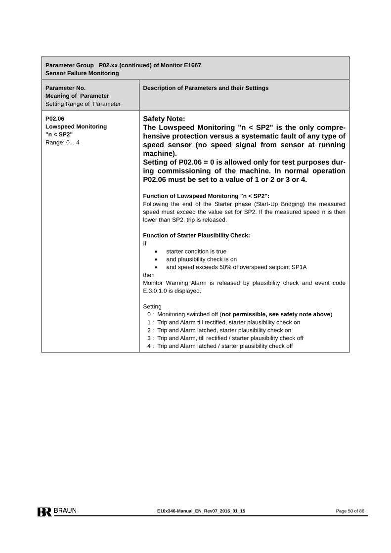
E16x346-Manual_EN_Rev07_2016_01_15 Page 50 of 86
Parameter Group P02.xx (continued) of Monitor E1667
Sensor Failure Monitoring
Parameter No.
Meaning of Parameter
Setting Range of Parameter
Description of Parameters and their Settings
P02.06
Lowspeed Monitoring
"n < SP2"
Range: 0 .. 4
Safety Note:
The Lowspeed Monitoring "n < SP2" is the only compre-
hensive protection versus a systematic fault of any type of
speed sensor (no speed signal from sensor at running
machine).
Setting of P02.06 = 0 is allowed only for test purposes dur-
ing commissioning of the machine. In normal operation
P02.06 must be set to a value of 1 or 2 or 3 or 4.
Function of Lowspeed Monitoring "n < SP2":
Following the end of the Starter phase (Start-Up Bridging) the measured
speed must exceed the value set for SP2. If the measured speed n is then
lower than SP2, trip is released.
Function of Starter Plausibility Check:
If
starter condition is true
and plausibility check is on
and speed exceeds 50% of overspeed setpoint SP1A
then
Monitor Warning Alarm is released by plausibility check and event code
E.3.0.1.0 is displayed.
Setting
0 : Monitoring switched off (not permissible, see safety note above)
1 : Trip and Alarm till rectified, starter plausibility check on
2 : Trip and Alarm latched, starter plausibility check on
3 : Trip and Alarm, till rectified / starter plausibility check off
4 : Trip and Alarm latched / starter plausibility check off

E16x346-Manual_EN_Rev07_2016_01_15 Page 51 of 86
Parameter Group P02.xx (continued) of Monitor E1667
Sensor Failure Monitoring
Parameter No.
Meaning of Parameter
Setting Range of Parameter
Description of Parameters and their Settings
P02.07
Speed Comparison
Evaluation Mode
Range: 0 .. 5
Speed comparison of the 3 sensors enables:
Detection of incorrect installation of the sensor (distance from the
tooth wheel too large or wrong position) even during the start-up bridg-
ing phase.
Detection of a fading function of a sensor during normal operation.
Functionality:
Each Monitor has three measuring channels and receives the signals of all
three sensors.
Setting
0 : only the primary sensor will be evaluated; no redundancy
1 : Trip is released if primary sensor fault is detected
2 : only event message is released if primary sensor fault is detected, but
only speed value of primary sensor is used for further evaluation
3 : not permissible
4 : only event message is released if primary sensor fault is detected, but
the mean value of the three speed values is used for further evaluation
5 : same as setting 4, but a trip released due to deviation is latched
Setting 1 or 2 or 4 or 5 :
During machine operation each Monitor compares its sensor input with
those of its two neighbors. If the measured speed value of its own
(primary) sensor in comparison with its two neighbors produces a dis-
crepancy exceeding the tolerance level set at P02.08, the monitor’s
primary sensor will be reported as faulty.
However, should all three measured speed values deviate from each
other for more than the specified tolerance, the monitor will release
trip.
Note:
Setting P02.07 = 4 or 5 avoids a trip release caused by a sensor fault
during the automatic test procedure and are recommended settings.
Example:
Monitor A is tested for overspeed, at the same time the signal from sensor B
drops out. Monitor B reports an event, but continues to evaluate the signals
from sensors A and C.

E16x346-Manual_EN_Rev07_2016_01_15 Page 52 of 86
Parameter Group P02.xx (continued) of Monitor E1667
Sensor Failure Monitoring
Parameter No.
Meaning of Parameter
Setting Range of Parameter
Description of Parameters and their Settings
P02.08
Permissible Speed Difference
between Sensors [RPM]
Range: 001 .. 999
Value for the permissible difference in RPM between the speed measure-
ment of the primary sensor and that of the other two sensors before a fault is
detected. Note: Primary sensor is the sensor the monitor supplies with power.
P02.09
Number of tests until alarm
Range: 01 .. 99
Number of consecutively failed speed comparison tests which may occur be-
fore an event message is issued.
Note:
At speeds lower than 50% of the nominal speed, the number of tests is au-
tomatically increased to avoid incorrect alarms during acceleration phase of
the machine.
Example for Setting of P02.07 = 4:
P02.08 = 030 (permissible difference between measured values = 30 RPM)
P02.09 = 5 (Number of consecutive events till event message issued)
With the example above an event message will be issued when the speed
value of the primary sensor deviates by 30 RPM from the two other meas-
ured sensors five measurements in succession.
When all three measurements of one monitor between themselves differ by
more than 30 RPM (measurement of sensor A = 6031 RPM, of sensor B =
6000 RPM, of sensor C = 5969 RPM), the monitor will release trip.
P02.10
Monitor Warning Alarm also
at Trip Condition
Range: 0 .. 4
Setting depends on how the alarm is used according the specific application
for detection of SOE (sequence of events).
Setting Alarm at
Overspeed-
Trip
Alarm at
Voter-Trip
Alarm at Trip
due to Trip-
Line-Monitoring
Alarm at
Lowspeed-
Trip
0 No No Yes Yes
1 Yes Yes Yes Yes
2 No No No Yes
3 Yes Yes No Yes
4 No No No No
Note: The Monitor Warning Alarm is always released in case of detected
sensor fault.
P02.11
First Alarm only of Monitor
Warning Alarm and Event Mes-
sages and
Range: 0 .. 2
The Monitor Warning Alarm and the event message can be latched.
Setting
0 : not latched
1 : yes, in this case all occurring events are shown in the display as event
combinations
2 : yes, in this case only the first occurring event is displayed
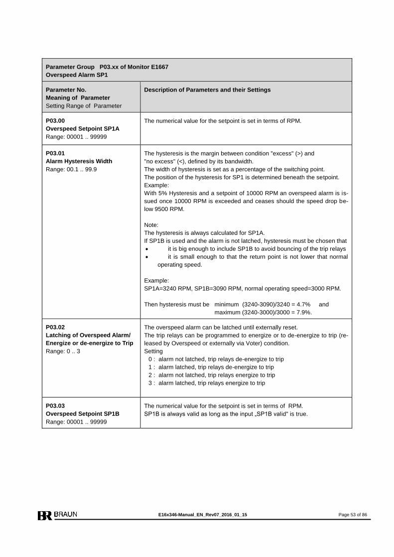
E16x346-Manual_EN_Rev07_2016_01_15 Page 53 of 86
Parameter Group P03.xx of Monitor E1667
Overspeed Alarm SP1
Parameter No.
Meaning of Parameter
Setting Range of Parameter
Description of Parameters and their Settings
P03.00
Overspeed Setpoint SP1A
Range: 00001 .. 99999
The numerical value for the setpoint is set in terms of RPM.
P03.01
Alarm Hysteresis Width
Range: 00.1 .. 99.9
The hysteresis is the margin between condition "excess" (>) and
"no excess" (<), defined by its bandwidth.
The width of hysteresis is set as a percentage of the switching point.
The position of the hysteresis for SP1 is determined beneath the setpoint.
Example:
With 5% Hysteresis and a setpoint of 10000 RPM an overspeed alarm is is-
sued once 10000 RPM is exceeded and ceases should the speed drop be-
low 9500 RPM.
Note:
The hysteresis is always calculated for SP1A.
If SP1B is used and the alarm is not latched, hysteresis must be chosen that
it is big enough to include SP1B to avoid bouncing of the trip relays
it is small enough to that the return point is not lower that normal
operating speed.
Example:
SP1A=3240 RPM, SP1B=3090 RPM, normal operating speed=3000 RPM.
Then hysteresis must be minimum (3240-3090)/3240 = 4.7% and
maximum (3240-3000)/3000 = 7.9%.
P03.02
Latching of Overspeed Alarm/
Energize or de-energize to Trip
Range: 0 .. 3
The overspeed alarm can be latched until externally reset.
The trip relays can be programmed to energize or to de-energize to trip (re-
leased by Overspeed or externally via Voter) condition.
Setting
0 : alarm not latched, trip relays de-energize to trip
1 : alarm latched, trip relays de-energize to trip
2 : alarm not latched, trip relays energize to trip
3 : alarm latched, trip relays energize to trip
P03.03
Overspeed Setpoint SP1B
Range: 00001 .. 99999
The numerical value for the setpoint is set in terms of RPM.
SP1B is always valid as long as the input „SP1B valid" is true.
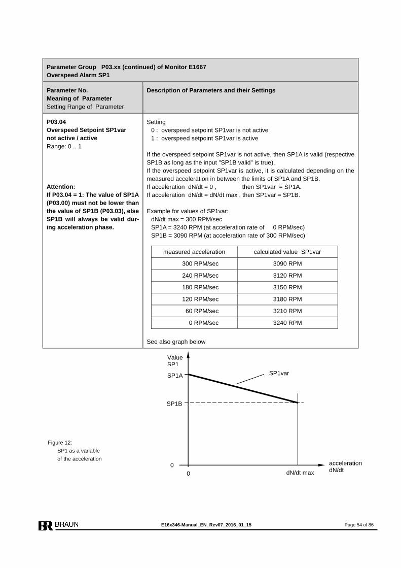
E16x346-Manual_EN_Rev07_2016_01_15 Page 54 of 86
Parameter Group P03.xx (continued) of Monitor E1667
Overspeed Alarm SP1
Parameter No.
Meaning of Parameter
Setting Range of Parameter
Description of Parameters and their Settings
P03.04
Overspeed Setpoint SP1var
not active / active
Range: 0 .. 1
Attention:
If P03.04 = 1: The value of SP1A
(P03.00) must not be lower than
the value of SP1B (P03.03), else
SP1B will always be valid dur-
ing acceleration phase.
Setting
0 : overspeed setpoint SP1var is not active
1 : overspeed setpoint SP1var is active
If the overspeed setpoint SP1var is not active, then SP1A is valid (respective
SP1B as long as the input "SP1B valid" is true).
If the overspeed setpoint SP1var is active, it is calculated depending on the
measured acceleration in between the limits of SP1A and SP1B.
If acceleration dN/dt = 0 , then SP1var = SP1A.
If acceleration dN/dt = dN/dt max , then SP1var = SP1B.
Example for values of SP1var:
dN/dt max = 300 RPM/sec
SP1A = 3240 RPM (at acceleration rate of 0 RPM/sec)
SP1B = 3090 RPM (at acceleration rate of 300 RPM/sec)
measured acceleration calculated value SP1var
300 RPM/sec 3090 RPM
240 RPM/sec 3120 RPM
180 RPM/sec 3150 RPM
120 RPM/sec 3180 RPM
60 RPM/sec 3210 RPM
0 RPM/sec 3240 RPM
See also graph below
Figure 12:
SP1 as a variable
of the acceleration
0
acceleration dN/dt dN/dt max
SP1B
SP1A
0
SP1var
Value SP1
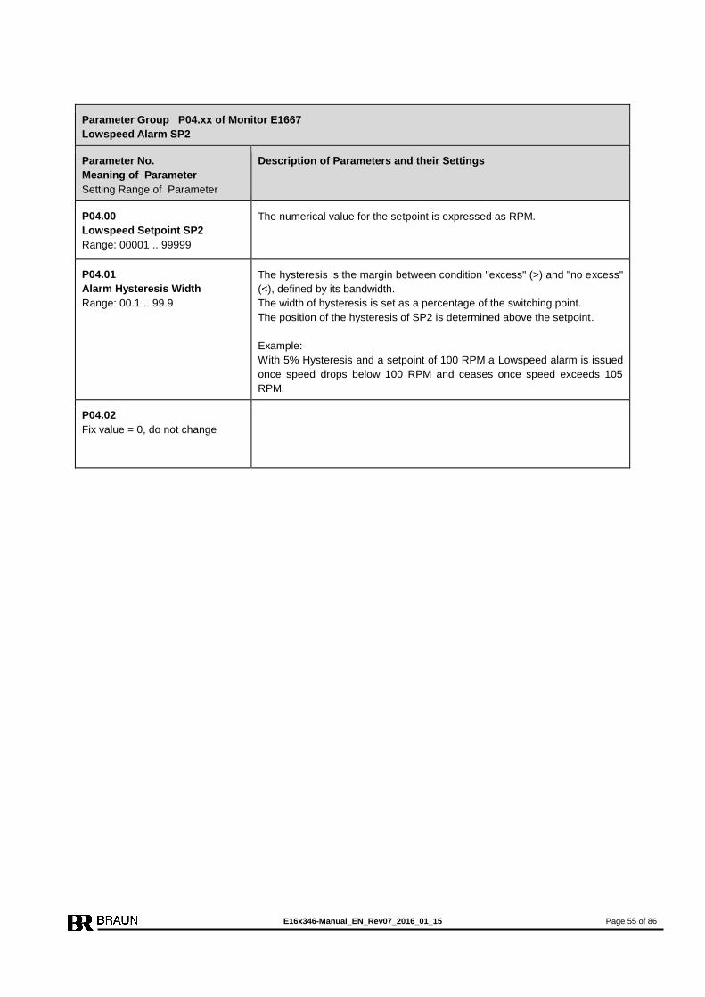
E16x346-Manual_EN_Rev07_2016_01_15 Page 55 of 86
Parameter Group P04.xx of Monitor E1667
Lowspeed Alarm SP2
Parameter No.
Meaning of Parameter
Setting Range of Parameter
Description of Parameters and their Settings
P04.00
Lowspeed Setpoint SP2
Range: 00001 .. 99999
The numerical value for the setpoint is expressed as RPM.
P04.01
Alarm Hysteresis Width
Range: 00.1 .. 99.9
The hysteresis is the margin between condition "excess" (>) and "no excess"
(<), defined by its bandwidth.
The width of hysteresis is set as a percentage of the switching point.
The position of the hysteresis of SP2 is determined above the setpoint.
Example:
With 5% Hysteresis and a setpoint of 100 RPM a Lowspeed alarm is issued
once speed drops below 100 RPM and ceases once speed exceeds 105
RPM.
P04.02
Fix value = 0, do not change
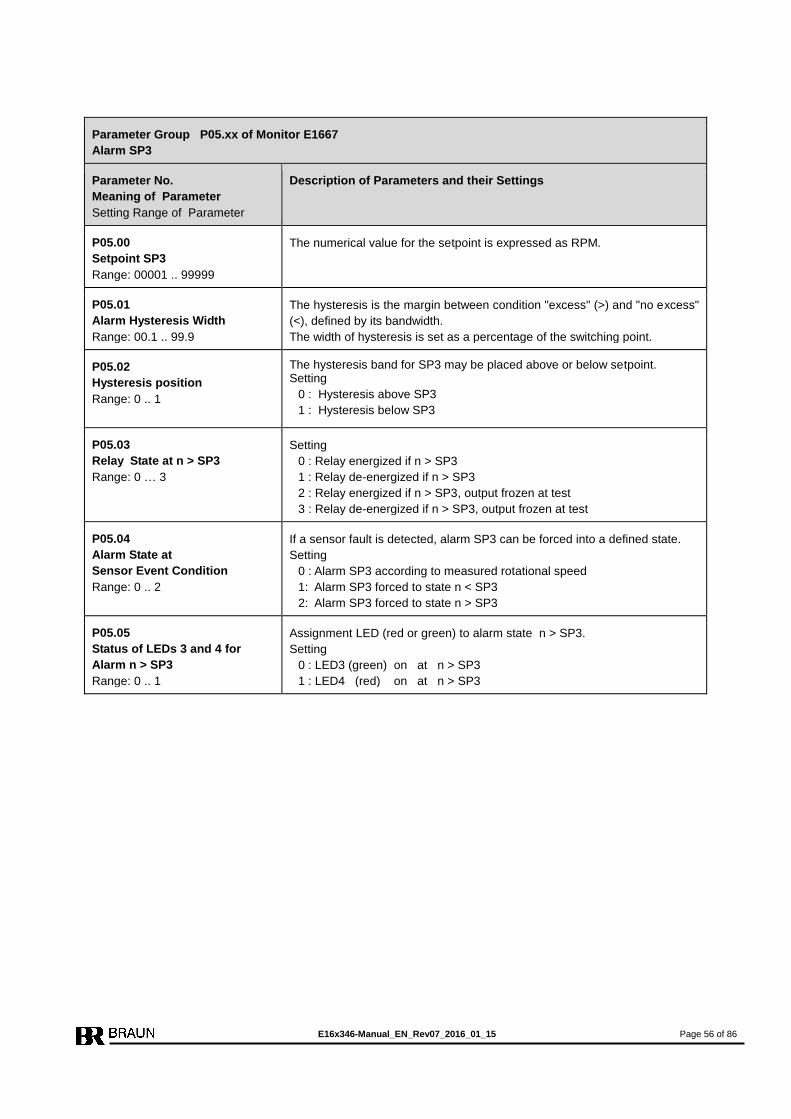
E16x346-Manual_EN_Rev07_2016_01_15 Page 56 of 86
Parameter Group P05.xx of Monitor E1667
Alarm SP3
Parameter No.
Meaning of Parameter
Setting Range of Parameter
Description of Parameters and their Settings
P05.00
Setpoint SP3
Range: 00001 .. 99999
The numerical value for the setpoint is expressed as RPM.
P05.01
Alarm Hysteresis Width
Range: 00.1 .. 99.9
The hysteresis is the margin between condition "excess" (>) and "no excess"
(<), defined by its bandwidth.
The width of hysteresis is set as a percentage of the switching point.
P05.02
Hysteresis position
Range: 0 .. 1
The hysteresis band for SP3 may be placed above or below setpoint. Setting
0 : Hysteresis above SP3
1 : Hysteresis below SP3
P05.03
Relay State at n > SP3
Range: 0 … 3
Setting
0 : Relay energized if n > SP3
1 : Relay de-energized if n > SP3
2 : Relay energized if n > SP3, output frozen at test
3 : Relay de-energized if n > SP3, output frozen at test
P05.04
Alarm State at
Sensor Event Condition
Range: 0 .. 2
If a sensor fault is detected, alarm SP3 can be forced into a defined state.
Setting
0 : Alarm SP3 according to measured rotational speed
1: Alarm SP3 forced to state n < SP3
2: Alarm SP3 forced to state n > SP3
P05.05
Status of LEDs 3 and 4 for
Alarm n > SP3
Range: 0 .. 1
Assignment LED (red or green) to alarm state n > SP3.
Setting
0 : LED3 (green) on at n > SP3
1 : LED4 (red) on at n > SP3
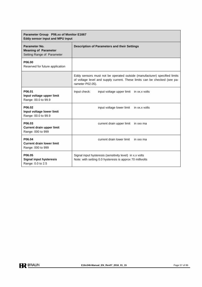
E16x346-Manual_EN_Rev07_2016_01_15 Page 57 of 86
Parameter Group P06.xx of Monitor E1667
Eddy sensor input and MPU input
Parameter No.
Meaning of Parameter
Setting Range of Parameter
Description of Parameters and their Settings
P06.00
Reserved for future application
Eddy sensors must not be operated outside (manufacturer) specified limits
of voltage level and supply current. These limits can be checked (see pa-
rameter P02.05).
P06.01
Input voltage upper limit
Range: 00.0 to 99.9
Input check: input voltage upper limit in xx.x volts
P06.02
Input voltage lower limit
Range: 00.0 to 99.9
input voltage lower limit in xx.x volts
P06.03
Current drain upper limit
Range: 000 to 999
current drain upper limit in xxx ma
P06.04
Current drain lower limit
Range: 000 to 999
current drain lower limit in xxx ma
P06.05
Signal input hysteresis
Range: 0.0 to 2.5
Signal input hysteresis (sensitivity level) in x.x volts
Note: with setting 0.0 hysteresis is approx 70 millivolts

E16x346-Manual_EN_Rev07_2016_01_15 Page 58 of 86
Parameter Group P07.xx of Monitor E1667
Trip-Line-Monitoring, Rotational Direction Output
Parameter No.
Meaning of Parameter
Setting Range of Parameter
Description of Parameters and their Settings
P07.00
Trip-Line-Monitoring
Range: 0 .. 3
If activated the Monitor checks the output of the Trip-Lines.
If two or three Trip-Lines indicate trip condition the monitor moves to trip sta-
tus (Trip Lock Function).
Following the reset signal the monitor releases the trip state for one second.
Within this time the feedback signal must respond correctly, otherwise the
monitor returns to trip status. Setting
0 : Trip-Line-Monitoring not active
1 : Trip-Line-Monitoring active, with response time until trip = 50 ms
2 : not admissible
3 : Trip-Line-Monitoring active, with response time until trip = 3 ms
P07.01
Trip-Line Level at Trip-Status
Range: 0 .. 1
Setting
0 : Low Level at Trip-Status (relays de-energized to Trip)
1 : High-Level at Trip-Status (relays energized to Trip)
P07.02
Signal-Input Level for Rotation-
al Direction Detection
Range: 0 .. 1
Setting
0 : Signal level low is assigned to forward motion
1 : Signal level high is assigned to forward motion
P07.03
Relay State for status forward
motion
Range: 0 .. 1
Setting
0 : Relay de-energized at status forward motion
1 : Relay energized at status forward motion
P07.04
Reserved for future application.
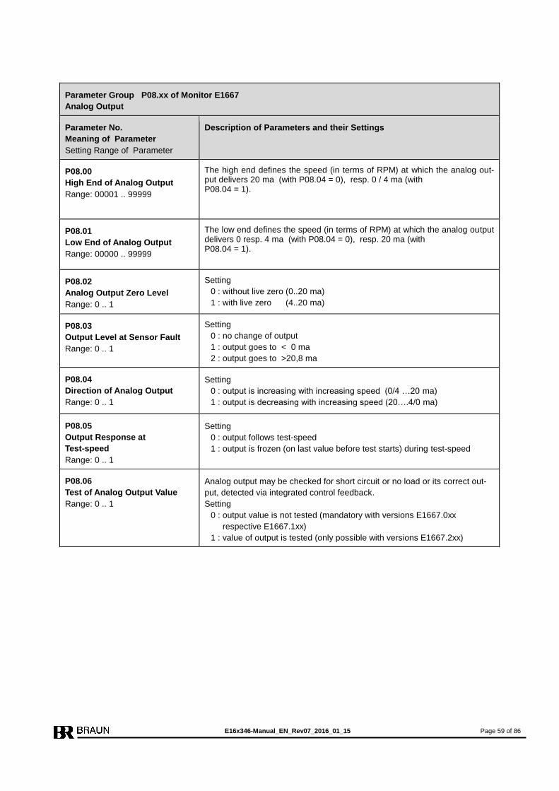
E16x346-Manual_EN_Rev07_2016_01_15 Page 59 of 86
Parameter Group P08.xx of Monitor E1667
Analog Output
Parameter No.
Meaning of Parameter
Setting Range of Parameter
Description of Parameters and their Settings
P08.00
High End of Analog Output
Range: 00001 .. 99999
The high end defines the speed (in terms of RPM) at which the analog out-put delivers 20 ma (with P08.04 = 0), resp. 0 / 4 ma (with P08.04 = 1).
P08.01
Low End of Analog Output
Range: 00000 .. 99999
The low end defines the speed (in terms of RPM) at which the analog output delivers 0 resp. 4 ma (with P08.04 = 0), resp. 20 ma (with P08.04 = 1).
P08.02
Analog Output Zero Level
Range: 0 .. 1
Setting
0 : without live zero (0..20 ma)
1 : with live zero (4..20 ma)
P08.03
Output Level at Sensor Fault
Range: 0 .. 1
Setting
0 : no change of output
1 : output goes to < 0 ma
2 : output goes to >20,8 ma
P08.04
Direction of Analog Output
Range: 0 .. 1
Setting
0 : output is increasing with increasing speed (0/4 …20 ma)
1 : output is decreasing with increasing speed (20….4/0 ma)
P08.05
Output Response at
Test-speed
Range: 0 .. 1
Setting
0 : output follows test-speed
1 : output is frozen (on last value before test starts) during test-speed
P08.06
Test of Analog Output Value
Range: 0 .. 1
Analog output may be checked for short circuit or no load or its correct out-
put, detected via integrated control feedback.
Setting
0 : output value is not tested (mandatory with versions E1667.0xx
respective E1667.1xx)
1 : value of output is tested (only possible with versions E1667.2xx)

E16x346-Manual_EN_Rev07_2016_01_15 Page 60 of 86
Parameter Group P09.xx of Monitor E1667
Reserved for future application
Parameter No.
Meaning of Parameter
Setting Range of Parameter
Description of Parameters and their Settings
P09.00
Reserved for future application

E16x346-Manual_EN_Rev07_2016_01_15 Page 61 of 86
Parameter Group P10.xx of Monitor E1667
Voter 1 and Logic Output LO1
Parameter No.
Meaning of Parameter
Setting Range of Parameter
Description of Parameters and their Settings
P10.00
Operation mode
Range: 0 .. 5
Setting
0 : Voter inactive
1 : Voter always active (over entire speed range)
2 : Voter only active, if n > SPV1
3 : Voter only active, if n < SPV1
4 : Voter inactive, output LO1 low, if n > SPV1
5 : Voter inactive, output LO1 high, if n > SPV1
P10.01
Input Truth Level
Range: 0 .. 1
Setting
0 : high level at inputs is assigned to trip condition
1 : low level at inputs is assigned to trip condition
P10.02
Voting Logic
Range: 0 .. 3
Selectable Voting Logics are:
1oo2 : trip is released if 1of 2 inputs signalizes trip condition
2oo2 : trip is released if 2 of 2 inputs signalize trip condition
2oo3 : trip is released if 2 of 3 inputs signalize trip condition
3oo3 : trip is released if 3 of 3 inputs signalize trip condition
Setting
0 : 1oo2 (only inputs 1 and 2 of voter 1 are monitored)
1 : 2oo2 (only inputs 1 and 2 of voter 1 are monitored)
2 : 2oo3 (all three inputs of voter 1 are monitored)
3 : 3oo3 (all three inputs of voter 1 are monitored)
P10.03
Truth Time until Trip
Range: 0 .. 7
If the trip signal is shorter than the
minimum truth time, the signal is
not valid (anti bouncing filter). If the
signal is longer than the maximum
truth time, the signal is valid and
trip is released
Note:
Signal truth times in between min.
and max. may release trip.
Maximum response time until trip-
lines go to trip status is maximum
truth time + 3 milliseconds.
Setting Truth time (Trip after)
min. max.
0 3 msec 6 msec
1 6 msec 9 msec
2 12 msec 16 msec
3 24 msec 28 msec
4 48 msec 52 msec
5 96 msec 102 msec
6 192 msec 202 msec
7 384 msec 400 msec
8 768 msec 800 msec
9 1570 msec 1600 msec
P10.04
Trip by Voter 1 latched
Range: 0 .. 1
Setting
0 : trip by voter 1 is not latched
1 : trip by voter 1 is latched until reset

E16x346-Manual_EN_Rev07_2016_01_15 Page 62 of 86
P10.05
Delay of Antivalence Alarm
Range: 0 .. 9
To avoid unnecessary Antivalence Alarms due to shifted trip release signals
at the voter inputs a delay may be introduced.
Antivalence alarm will then be released only if the time shift between the
signals exceeds the set delay.
Setting
0 : no delay
1 : delay = 100 milliseconds
2 : delay = 500 milliseconds
3 : delay = 1 second
4 : delay = 2 seconds
5 : delay = 3 seconds
6 : delay = 5 seconds
7 : delay = 15 seconds
8 : delay = 30 seconds
9 : delay = 60 seconds
Note:
The input signals will be monitored for antivalence only, if the voter is active.
P10.06
Setpoint SPV1
Range: 00001 .. 99999 [RPM]
Depending on setting of P10.00, SPV1 controls the activity of voter 1 or con-
trols directly the output LO1.
SPV1 is set in terms of RPM.
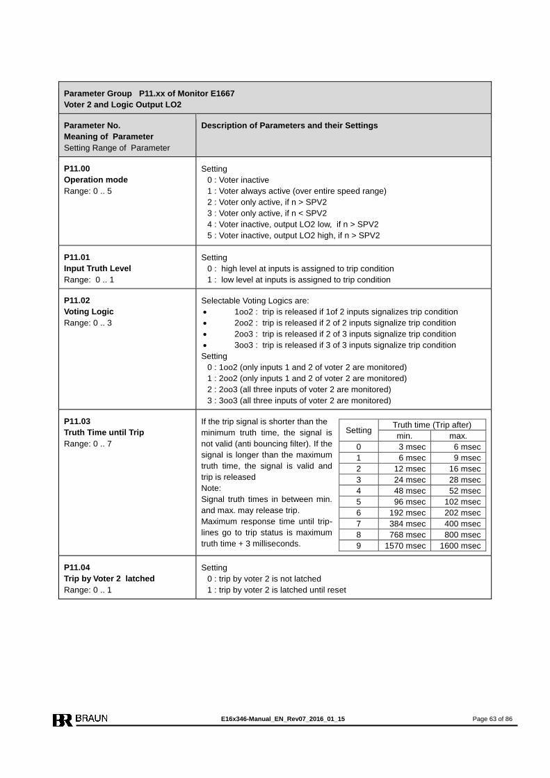
E16x346-Manual_EN_Rev07_2016_01_15 Page 63 of 86
Parameter Group P11.xx of Monitor E1667
Voter 2 and Logic Output LO2
Parameter No.
Meaning of Parameter
Setting Range of Parameter
Description of Parameters and their Settings
P11.00
Operation mode
Range: 0 .. 5
Setting
0 : Voter inactive
1 : Voter always active (over entire speed range)
2 : Voter only active, if n > SPV2
3 : Voter only active, if n < SPV2
4 : Voter inactive, output LO2 low, if n > SPV2
5 : Voter inactive, output LO2 high, if n > SPV2
P11.01
Input Truth Level
Range: 0 .. 1
Setting
0 : high level at inputs is assigned to trip condition
1 : low level at inputs is assigned to trip condition
P11.02
Voting Logic
Range: 0 .. 3
Selectable Voting Logics are:
1oo2 : trip is released if 1of 2 inputs signalizes trip condition
2oo2 : trip is released if 2 of 2 inputs signalize trip condition
2oo3 : trip is released if 2 of 3 inputs signalize trip condition
3oo3 : trip is released if 3 of 3 inputs signalize trip condition
Setting
0 : 1oo2 (only inputs 1 and 2 of voter 2 are monitored)
1 : 2oo2 (only inputs 1 and 2 of voter 2 are monitored)
2 : 2oo3 (all three inputs of voter 2 are monitored)
3 : 3oo3 (all three inputs of voter 2 are monitored)
P11.03
Truth Time until Trip
Range: 0 .. 7
If the trip signal is shorter than the
minimum truth time, the signal is
not valid (anti bouncing filter). If the
signal is longer than the maximum
truth time, the signal is valid and
trip is released
Note:
Signal truth times in between min.
and max. may release trip.
Maximum response time until trip-
lines go to trip status is maximum
truth time + 3 milliseconds.
Setting Truth time (Trip after)
min. max.
0 3 msec 6 msec
1 6 msec 9 msec
2 12 msec 16 msec
3 24 msec 28 msec
4 48 msec 52 msec
5 96 msec 102 msec
6 192 msec 202 msec
7 384 msec 400 msec
8 768 msec 800 msec
9 1570 msec 1600 msec
P11.04
Trip by Voter 2 latched
Range: 0 .. 1
Setting
0 : trip by voter 2 is not latched
1 : trip by voter 2 is latched until reset

E16x346-Manual_EN_Rev07_2016_01_15 Page 64 of 86
P11.05
Delay of Antivalence Alarm
Range: 0 .. 9
To avoid unnecessary Antivalence Alarms due to shifted trip release signals
at the voter inputs a delay may be introduced.
Antivalence alarm will then be released only if the time shift between the
signals exceeds the set delay.
Setting
0 : no delay
1 : delay = 100 milliseconds
2 : delay = 500 milliseconds
3 : delay = 1 second
4 : delay = 2 seconds
5 : delay = 3 seconds
6 : delay = 5 seconds
7 : delay = 15 seconds
8 : delay = 30 seconds
9 : delay = 60 seconds
Note:
The input signals will be monitored for antivalence only, if the voter is active.
P11.06
Setpoint SPV2
Range: 00001 .. 99999 [RPM]
Depending on setting of P11.00, SPV2 controls the activity of voter 2 or con-
trols directly the output LO2.
SPV2 is set in terms of RPM.

E16x346-Manual_EN_Rev07_2016_01_15 Page 65 of 86
Parameter Group P12.xx of Monitor E1667
Voter 3 and Logic Output LO3
Parameter No.
Meaning of Parameter
Setting Range of Parameter
Description of Parameters and their Settings
P12.00
Operation mode
Range: 0 .. 5
Setting
0 : Voter inactive
1 : Voter always active (over entire speed range)
2 : Voter only active, if n > SPV3
3 : Voter only active, if n < SPV3
4 : Voter inactive, output LO3 low, if n > SPV3
5 : Voter inactive, output LO3 high, if n > SPV3
P12.01
Input Truth Level
Range: 0 .. 1
Setting
0 : high level at inputs is assigned to trip condition
1 : low level at inputs is assigned to trip condition
P12.02
Voting Logic
Range: 0 .. 3
Selectable Voting Logics are:
1oo2 : trip is released if 1of 2 inputs signalizes trip condition
2oo2 : trip is released if 2 of 2 inputs signalize trip condition
2oo3 : trip is released if 2 of 3 inputs signalize trip condition
3oo3 : trip is released if 3 of 3 inputs signalize trip condition
Setting
0 : 1oo2 (only inputs 1 and 2 of voter 3 are monitored)
1 : 2oo2 (only inputs 1 and 2 of voter 3 are monitored)
2 : 2oo3 (all three inputs of voter 3 are monitored)
3 : 3oo3 (all three inputs of voter 3 are monitored)
P12.03
Truth Time until Trip
Range: 0 .. 7
If the trip signal is shorter than the
minimum truth time, the signal is
not valid (anti bouncing filter). If the
signal is longer than the maximum
truth time, the signal is valid and
trip is released
Note:
Signal truth times in between min.
and max. may release trip.
Maximum response time until trip-
lines go to trip status is maximum
truth time + 3 milliseconds.
Setting Truth time (Trip after)
min. max.
0 3 msec 6 msec
1 6 msec 9 msec
2 12 msec 16 msec
3 24 msec 28 msec
4 48 msec 52 msec
5 96 msec 102 msec
6 192 msec 202 msec
7 384 msec 400 msec
8 768 msec 800 msec
9 1570 msec 1600 msec
P12.04
Trip by Voter3 latched
Range: 0 .. 1
Setting
0 : trip by voter 3 is not latched
1 : trip by voter 3 is latched until reset
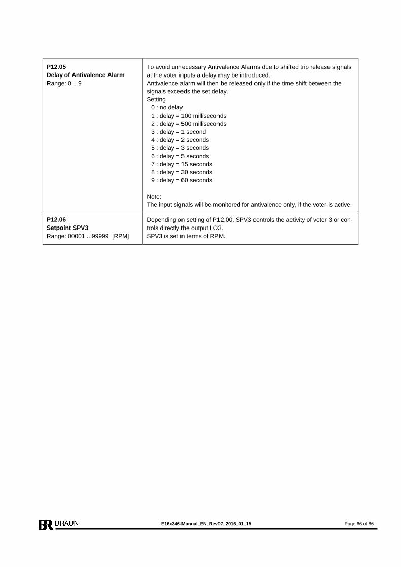
E16x346-Manual_EN_Rev07_2016_01_15 Page 66 of 86
P12.05
Delay of Antivalence Alarm
Range: 0 .. 9
To avoid unnecessary Antivalence Alarms due to shifted trip release signals
at the voter inputs a delay may be introduced.
Antivalence alarm will then be released only if the time shift between the
signals exceeds the set delay.
Setting
0 : no delay
1 : delay = 100 milliseconds
2 : delay = 500 milliseconds
3 : delay = 1 second
4 : delay = 2 seconds
5 : delay = 3 seconds
6 : delay = 5 seconds
7 : delay = 15 seconds
8 : delay = 30 seconds
9 : delay = 60 seconds
Note:
The input signals will be monitored for antivalence only, if the voter is active.
P12.06
Setpoint SPV3
Range: 00001 .. 99999 [RPM]
Depending on setting of P12.00, SPV3 controls the activity of voter 3 or con-
trols directly the output LO3.
SPV3 is set in terms of RPM.

E16x346-Manual_EN_Rev07_2016_01_15 Page 67 of 86
Parameter Group P13.xx of Monitor E1667
Voter 4 and Logic Output LO4
Parameter No.
Meaning of Parameter
Setting Range of Parameter
Description of Parameters and their Settings
P13.00
Operation mode
Range: 0 .. 5
Setting
0 : Voter inactive
1 : Voter always active (over entire speed range)
2 : Voter only active, if n > SPV4
3 : Voter only active, if n < SPV4
4 : Voter inactive, output LO4 low, if n > SPV4
5 : Voter inactive, output LO4 high, if n > SPV4
P13.01
Input Truth Level
Range: 0 .. 1
Setting
0 : high level at inputs is assigned to trip condition
1 : low level at inputs is assigned to trip condition
P13.02
Voting Logic
Range: 0 .. 3
Selectable Voting Logics are:
1oo2 : trip is released if 1of 2 inputs signalizes trip condition
2oo2 : trip is released if 2 of 2 inputs signalize trip condition
2oo3 : trip is released if 2 of 3 inputs signalize trip condition
3oo3 : trip is released if 3 of 3 inputs signalize trip condition
Setting
0 : 1oo2 (only inputs 1 and 2 of voter 4 are monitored)
1 : 2oo2 (only inputs 1 and 2 of voter 4 are monitored)
2 : 2oo3 (all three inputs of voter 4 are monitored)
3 : 3oo3 (all three inputs of voter 4 are monitored)
P13.03
Truth Time until Trip
Range: 0 .. 7
If the trip signal is shorter than the
minimum truth time, the signal is
not valid (anti bouncing filter). If the
signal is longer than the maximum
truth time, the signal is valid and
trip is released
Note:
Signal truth times in between min.
and max. may release trip.
Maximum response time until trip-
lines go to trip status is maximum
truth time + 3 milliseconds.
Setting Truth time (Trip after)
min. max.
0 3 msec 6 msec
1 6 msec 9 msec
2 12 msec 16 msec
3 24 msec 28 msec
4 48 msec 52 msec
5 96 msec 102 msec
6 192 msec 202 msec
7 384 msec 400 msec
8 768 msec 800 msec
9 1570 msec 1600 msec
P13.04
Trip by Voter 4 latched
Range: 0 .. 1
Setting
0 : trip by voter 4 is not latched
1 : trip by voter 4 is latched until reset

E16x346-Manual_EN_Rev07_2016_01_15 Page 68 of 86
P13.05
Delay of Antivalence Alarm
Range: 0 .. 9
To avoid unnecessary Antivalence Alarms due to shifted trip release signals
at the voter inputs a delay may be introduced.
Antivalence alarm will then be released only if the time shift between the
signals exceeds the set delay.
Setting
0 : no delay
1 : delay = 100 milliseconds
2 : delay = 500 milliseconds
3 : delay = 1 second
4 : delay = 2 seconds
5 : delay = 3 seconds
6 : delay = 5 seconds
7 : delay = 15 seconds
8 : delay = 30 seconds
9 : delay = 60 seconds
Note:
The input signals will be monitored for antivalence only, if the voter is active.
P13.06
Setpoint SPV4
Range: 00001 .. 99999 [RPM]
Depending on setting of P13.00, SPV4 controls the activity of voter 4 or con-
trols directly the output LO4.
SPV4 is set in terms of RPM.

E16x346-Manual_EN_Rev07_2016_01_15 Page 69 of 86
Parameter Group P14.xx of Monitor E1667
Voter 5 and Logic Output LO5
Parameter No.
Meaning of Parameter
Setting Range of Parameter
Description of Parameters and their Settings
P14.00
Operation mode
Range: 0 .. 5
Setting
0 : Voter inactive
1 : Voter always active (over entire speed range)
2 : Voter only active, if n > SPV5
3 : Voter only active, if n < SPV5
4 : Voter inactive, output LO5 low, if n > SPV5
5 : Voter inactive, output LO5 high, if n > SPV5
P14.01
Input Truth Level
Range: 0 .. 1
Setting
0 : high level at inputs is assigned to trip condition
1 : low level at inputs is assigned to trip condition
P14.02
Voting Logic
Range: 0 .. 3
Selectable Voting Logics are:
1oo2 : trip is released if 1of 2 inputs signalizes trip condition
2oo2 : trip is released if 2 of 2 inputs signalize trip condition
2oo3 : trip is released if 2 of 3 inputs signalize trip condition
3oo3 : trip is released if 3 of 3 inputs signalize trip condition
Setting
0 : 1oo2 (only inputs 1 and 2 of voter 5 are monitored)
1 : 2oo2 (only inputs 1 and 2 of voter 5 are monitored)
2 : 2oo3 (all three inputs of voter 5 are monitored)
3 : 3oo3 (all three inputs of voter 5 are monitored)
P14.03
Truth Time until Trip
Range: 0 .. 7
If the trip signal is shorter than the
minimum truth time, the signal is
not valid (anti bouncing filter). If the
signal is longer than the maximum
truth time, the signal is valid and
trip is released
Note:
Signal truth times in between min.
and max. may release trip.
Maximum response time until trip-
lines go to trip status is maximum
truth time + 3 milliseconds.
Setting Truth time (Trip after)
min. max.
0 3 msec 6 msec
1 6 msec 9 msec
2 12 msec 16 msec
3 24 msec 28 msec
4 48 msec 52 msec
5 96 msec 102 msec
6 192 msec 202 msec
7 384 msec 400 msec
8 768 msec 800 msec
9 1570 msec 1600 msec
P14.04
Trip by Voter 5 latched
Range: 0 .. 1
Setting
0 : trip by voter 5 is not latched
1 : trip by voter 5 is latched until reset

E16x346-Manual_EN_Rev07_2016_01_15 Page 70 of 86
P14.05
Delay of Antivalence Alarm
Range: 0 .. 9
To avoid unnecessary Antivalence Alarms due to shifted trip release signals
at the voter inputs a delay may be introduced.
Antivalence alarm will then be released only if the time shift between the
signals exceeds the set delay.
Setting
0 : no delay
1 : delay = 100 milliseconds
2 : delay = 500 milliseconds
3 : delay = 1 second
4 : delay = 2 seconds
5 : delay = 3 seconds
6 : delay = 5 seconds
7 : delay = 15 seconds
8 : delay = 30 seconds
9 : delay = 60 seconds
Note:
The input signals will be monitored for antivalence only, if the voter is active.
P14.06
Setpoint SPV5
Range: 00001 .. 99999 [RPM]
Depending on setting of P14.00, SPV5 controls the activity of voter 5 or con-
trols directly the output LO5.
SPV5 is set in terms of RPM.

E16x346-Manual_EN_Rev07_2016_01_15 Page 71 of 86
Parameter Group P15.xx of Monitor E1667
Voter 6 and Logic Output LO6
Parameter No.
Meaning of Parameter
Setting Range of Parameter
Description of Parameters and their Settings
P15.00
Operation mode
Range: 0 .. 5
Setting
0 : Voter inactive
1 : Voter always active (over entire speed range)
2 : Voter only active, if n > SPV6
3 : Voter only active, if n < SPV6
4 : Voter inactive, output LO6 low, if n > SPV6
5 : Voter inactive, output LO6 high, if n > SPV6
P15.01
Input Truth Level
Range: 0 .. 1
Setting
0 : high level at inputs is assigned to trip condition
1 : low level at inputs is assigned to trip condition
P15.02
Voting Logic
Range: 0 .. 3
Selectable Voting Logics are:
1oo2 : trip is released if 1of 2 inputs signalizes trip condition
2oo2 : trip is released if 2 of 2 inputs signalize trip condition
2oo3 : trip is released if 2 of 3 inputs signalize trip condition
3oo3 : trip is released if 3 of 3 inputs signalize trip condition
Setting
0 : 1oo2 (only inputs 1 and 2 of voter 6 are monitored)
1 : 2oo2 (only inputs 1 and 2 of voter 6 are monitored)
2 : 2oo3 (all three inputs of voter 6 are monitored)
3 : 3oo3 (all three inputs of voter 6 are monitored)
P15.03
Truth Time until Trip
Range: 0 .. 7
If the trip signal is shorter than the
minimum truth time, the signal is
not valid (anti bouncing filter). If the
signal is longer than the maximum
truth time, the signal is valid and
trip is released
Note:
Signal truth times in between min.
and max. may release trip.
Maximum response time until trip-
lines go to trip status is maximum
truth time + 3 milliseconds.
Setting Truth time (Trip after)
min. max.
0 3 msec 6 msec
1 6 msec 9 msec
2 12 msec 16 msec
3 24 msec 28 msec
4 48 msec 52 msec
5 96 msec 102 msec
6 192 msec 202 msec
7 384 msec 400 msec
8 768 msec 800 msec
9 1570 msec 1600 msec
P15.04
Trip by Voter 6 latched
Range: 0 .. 1
Setting
0 : trip by voter 6 is not latched
1 : trip by voter 6 is latched until reset

E16x346-Manual_EN_Rev07_2016_01_15 Page 72 of 86
P15.05
Delay of Antivalence Alarm
Range: 0 .. 9
To avoid unnecessary Antivalence Alarms due to shifted trip release signals
at the voter inputs a delay may be introduced.
Antivalence alarm will then be released only if the time shift between the
signals exceeds the set delay.
Setting
0 : no delay
1 : delay = 100 milliseconds
2 : delay = 500 milliseconds
3 : delay = 1 second
4 : delay = 2 seconds
5 : delay = 3 seconds
6 : delay = 5 seconds
7 : delay = 15 seconds
8 : delay = 30 seconds
9 : delay = 60 seconds
Note:
The input signals will be monitored for antivalence only, if the voter is active.
P15.06
Setpoint SPV6
Range: 00001 .. 99999 [RPM]
Depending on setting of P15.00, SPV6 controls the activity of voter 6 or con-
trols directly the output LO6.
SPV6 is set in terms of RPM.
E16x346-Manual_EN_Rev07_2016_01_15 Page 73 of 86
Parameter Group P16.xx of Monitor E1667
Reserved for future application
Parameter No.
Meaning of Parameter
Setting Range of Parameter
Description of Parameters and their Settings
P16.00
Reserved for future application
P16.01
Reserved for future application
P16.02
Reserved for future application
P16.03
Reserved for future application
P16.04
Reserved for future application
P16.05
Reserved for future application
P16.06
Reserved for future application
Parameter Group P17.xx of Monitor E1667
PROFIBUS
Parameter No.
Meaning of Parameter
Setting Range of Parameter
Description of Parameters and their Settings
P17.00
Device No for PROFIBUS
Range: 001 .. 125
All members of the PROFIBUS-Communication must have different device nos.

E16x346-Manual_EN_Rev07_2016_01_15 Page 74 of 86
9. Parameters of Test-Generator E1697
9.1. Summary of parameters and their default values
Param.
No.
Default
Value Parameter Function
P00.xx Code figure, Parameter Lock
P00.00 0000 Code figure
.01 0000 New code figure
.02 0 Parameter Lock : 0: locked / 1: enabled
P01.xx Output Scaling
P01.00 0 Reserved for future applications
.01 10000 Value of output frequency in Hz at nominal Test-Speed
.02 0 Reserved for future applications
.03 10000 Nominal Test-Speed in RPM
P02.xx Monitor-Test Configuration
P02.00 1 Reserved for future applications
.01 0 Reserved for future applications
.02 1440 Test Interval in xxxx minutes
.03 0 De-energize / energize to Trip
.04 11000 Test-Speed 1: 'n > SP1'
.05 09000 Test-Speed 2: 'n < SP1'
P03.xx Trip-Line Test Configuration
P03.00 01440 Test Interval in xxxxx minutes (max 65000)
.01 0 Test Mode: 0 ... 3 (see table)
.02 0 Reserved for future applications
.03 0 Feedback-Signal level at trip : 0: low / 1: high
.04 0 Reserved for future applications
.05 00 duration time for Trip-Line test in xx sec
.06 0 Reserved for future applications
.07 60 Waiting time after reset of alarms in xx sec
.08 0 Waiting time after test of a Trip-Line in xx sec
.09 0 Reserved for future applications
P04.xx Data Interface
P04.00 020 PROFIBUS-Interface Device no.

E16x346-Manual_EN_Rev07_2016_01_15 Page 75 of 86
9.2. Description of Parameters and their Settings of Test-Generator E1697
Parameter Group P00.xx of Test-Generator E1697
Code Figure, Parameter Lock
Parameter No.
Meaning of Parameter
Setting Range of Parameter
Description of Parameters and their Settings
P00.00
Code Figure
Range: 0000 .. 9999
If the parameters are locked (see P00.02), the code figure must be entered
prior to any change of other parameters.
If the code figure is not correct, -E 1- is displayed.
Without code figure and P00.02 : 0 the values of all parameters may be in-
spected, but not changed.
P00.01
New Code Figure
Range: 0000 .. 9999
A new code figure may be set in P00.01. Then it replaces the previous one.
P00.02
Parameter Lock
Range: 0 .. 1
Setting
0 : Parameters are locked, change only possible with code figure
1 : Parameters unlocked, change of parameter values possible
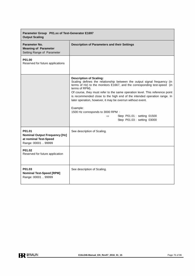
E16x346-Manual_EN_Rev07_2016_01_15 Page 76 of 86
Parameter Group P01.xx of Test-Generator E1697
Output Scaling
Parameter No.
Meaning of Parameter
Setting Range of Parameter
Description of Parameters and their Settings
P01.00 Reserved for future applications
Description of Scaling: Scaling defines the relationship between the output signal frequency (in terms of Hz) to the monitors E1667, and the corresponding test-speed (in terms of RPM).
Of course, they must refer to the same operation level. This reference point
is recommended close to the high end of the intended operation range. In
later operation, however, it may be overrun without event.
Example:
1500 Hz corresponds to 3000 RPM :
Step P01.01 : setting 01500
Step P01.03 : setting 03000
P01.01
Nominal Output Frequency [Hz]
at nominal Test-Speed
Range: 00001 .. 99999
See description of Scaling.
P01.02 Reserved for future application
P01.03
Nominal Test-Speed [RPM]
Range: 00001 .. 99999
See description of Scaling.
E16x346-Manual_EN_Rev07_2016_01_15 Page 77 of 86
Parameter Group P02.xx of Test-Generator E1697
Monitor Test
Parameter No.
Meaning of Parameter
Setting Range of Parameter
Description of Parameters and their Settings
P02.00 Reserved for future applications
P02.01 Reserved for future applications
P02.02
Time Interval in between
Monitor Test Sequences
Range: 0001 .. 9999 [min]
The time interval in between the Monitor Test sequences can be set from
0001 to 9999 minutes. Recommended settings: any time in between 60 and 1440 minutes.
P02.03
De-energize/Energize to Trip
resp. Test of SP1A and SP1B
Range: 0 .. 3
De-Energize/Energize depends on the setting of P03.02 of monitors E1667. Setting
0 : if P03.02 of E1667 is set to 0
1 : not permissible
2 : if P03.02 of E1667 is set to 2 or 3
3 : if P03.02 of E1667 is set to 0 and test of SP1A and SP1B is required Explanation:
If P02.03 = 0 or 2, then Test-Speed 1 and 2:
In the first step of the monitor auto test sequence, the monitor is tested with
test-speed 1. Value for test-speed 1 must be > SP1 of monitor.
In the second step of the monitor auto test sequence, the monitor is tested
with test-speed 2. Value for test-speed 2 must be < SP1 of monitor.
Example:
SP1 of monitor is set to 3300 RPM.
Recommended value for Test-speed 1 : 3305 RPM
Recommended value for Test-speed 2 : 3295 RPM
If P02.03 = 3, then P02.04 must be set to SP1A (P03.00 of E1667) and
P02.05 must be set to SP1B (P03.03 of E1667).
Test will then be performed with Test-Speed SP1A +/- 5RPM and with Test-
Speed SP1B +/- 5RPM.
E16x346-Manual_EN_Rev07_2016_01_15 Page 78 of 86
Parameter Group P02.xx (continued) of Test-Generator E1697
Monitor Test
Parameter No.
Meaning of Parameter
Setting Range of Parameter
Description of Parameters and their Settings
P02.04
Test-Speed 1 [RPM] resp. SP1A
Range: 00001 .. 99999
See explanation of step P03.02
P02.05
Test-Speed 2 [RPM] resp. SP1B
Range: 00001 .. 99999
See explanation of step P03.02

E16x346-Manual_EN_Rev07_2016_01_15 Page 79 of 86
Parameter Group P03.xx of Test-Generator E1697
Trip-Line Test
Parameter No.
Meaning of Parameter
Setting Range of Parameter
Description of Parameters and their Settings
P03.00
Time Interval in between
Trip-Line Test Sequences
Range: 00001 .. 65000 [min]
The time interval in between automatic (see P03.01) Trip-Line Test sequenc-
es can be set from 00001 to 65000 minutes. Recommended settings: as recommended by solenoid valve supplier, but not less than 60 minutes.
P03.01
Trip-Line Test Mode
Range: 0 .. 3
Setting
0 : Trip-Line Test off, feedback signal from 2oo3 magnetic solenoid are not
evaluated)
1 : Trip-Line Test sequence in automatic mode with interval set in P03.00;
feedback signals from 2oo3 magnetic solenoid will be evaluated.
In the feedback does signalize trip status, the output will hold the cor-
responding Trip-Line on trip status and the test is aborted.
2 : Trip-Line Test controlled by external signals, simultaneous test of 2 or 3
lines is inhibited,
feedback signal from 2oo3 magnetic solenoid are not evaluated
3 : one single Trip-Line Test Sequence, externally triggered by signal
Start Auto-Test-Sequence;
feedback signals from 2oo3 magnetic solenoid will be evaluated,
Note: If setting = 2 or = 4, all other parameters of group P03 are not rele-
vant.
P03.02 Reserved for future application
P03.03
Feedback Level from solenoid
at trip state
Range: 0 .. 1
Setting
0 : low level feedback expected at trip state
1 : high level feedback expected at trip state
P03.04 Reserved for future application
P03.05
Duration of Trip-Line Test
Range: 01 .. 99 [sec]
If automatic sequence is activated (P03.01 = 1 or = 3), each Trip-Line is set
(subsequently) to trip condition for the duration set in P03.05. Duration is set
in terms of seconds.
Note: Setting 00 equals 01.
P03.06 Reserved for future application
P03.07
Waiting Time after Reset of
Alarms
Range: 01 .. 99 [sec]
After a reset of an alarm, the Test-Generator waits for this time before it
starts to check the external feedback signals.
Waiting time is set in terms of seconds.
Note: Setting 00 equals 01.
E16x346-Manual_EN_Rev07_2016_01_15 Page 80 of 86
P03.08
Waiting Time after test of a Trip-
Line
Range: 01 .. 99 [sec]
The Test-Generator waits after the test of a Trip-Line for this time before it
permanently checks again the status of the feedback signals from the sole-
noid for No-Trip-state.
Waiting time is set in terms of seconds.
Note: Setting 00 equals 01.
P03.09 Reserved for future application
Parameter Group P04.xx of Test-Generator E1697
PROFIBUS
Parameter No.
Meaning of Parameter
Setting Range of Parameter
Description of Parameters and their Settings
P04.00
Device No for PROFIBUS
Range: 001 .. 125
All members of the PROFIBUS-Communication must have different device nos.

E16x346-Manual_EN_Rev07_2016_01_15 Page 81 of 86
10. Event Codes and Troubleshooting
10.1. Event Codes on display of E1667
The Event Codes are shown in format E.0.x.x.x .
Depending on setting of P02.11 only the first occurred fault or all faults are displayed (combi-
nation of faults is possible).
Display Explanation of Event Code
E.0.0.0.0 Overspeed trip (if P03.02 = 0)
E.0.x.x.1 Sensor failure (current or voltage), refer to P02.05
E.0.x.x.2 Deviation of primary sensor versus neighbor sensors, refer to P02.07
E.0.x.x.3 E.x.x.x.1 + E.x.x.x.2
E.0.x.x.4 Speed < SP2
E.0.x.x.5 E.x.x.x.1 + E.x.x.x.4
E.0.x.x.6 E.x.x.x.2 + E.x.x.x.4
E.0.x.x.7 E.x.x.x.1 + E.x.x.x.2 + E.x.x.x.4
E.0.x.1.x Generator tests with zero speed
E.0.x.2.x Trip by Voter
E.0.x.4.x Internal relay fault
E.0.1.x.x Failure detection during internal self test
E.0.2.x.x Overspeed trip (if P03.02 = 1)
E.0.3.x.x E.x.1.x.x + E.x.2.x.x
E.0.4.0.0 without Trip
Alarm caused by antivalence of Voter Signals or signals for Trip-Line-Monitoring (for troubleshooting refer to next page)
E.0.4.0.0 with Trip
Trip-Line Monitoring has caused trip
E.0.4.2.0 Trip by voter ( with non-coincidence at inputs of voter)
E.0.6.x.x E.x.2.x.x + E.x.4.x.x
E.0.8.0.0 Trip-Line Monitoring has caused trip
E.0.A.0.0 Trip due to Overspeed (and P07.00 = 1 or 3)
E.0.c.0.0 Trip-Line Monitoring has caused trip plus antivalence of signals for Trip-Line-Monitoring (for troubleshooting refer to next page)
E.3.0.1.0 Starter Input is active at speed > 50% of nominal speed, see also parameter P02.06
E.3.0.2.0 External Analog output event ( 'no load' or fault of connected device )
E.3.0.2.1 Internal Analog output event (fault on monitor board)
E.6.0.0.1 Parameter value changed via RS232-Interface
-E1- Wrong code figure in step P00.00
-E4- No test by E1697 for more than 7 days (releases also Monitor Warning Alarm)
E16x346-Manual_EN_Rev07_2016_01_15 Page 82 of 86
10.2. Troubleshooting if display of Monitor reads E.0.4.x.x
Display E.0.4.x.x signalizes a fault (not all signals are identical) from the input signals for the
voters or for Trip-Line-Monitoring (resp. feedbacks from 2oo3-solenoid).
The actual status of the signal inputs is shown in Special Display Mode 2.
Switching between Standard and Special Display Mode 2 by pressing keys and simul-
taneously.
Special Display Mode 2
In Special Display Mode 2 LED1 and LED4 are blinking.
Steps of Special Display Mode 2 : 0._x.x.x
1._x.x.x
2._x.x.x
3._x.x.x
4._x.x.x
Steps of Special Display Mode 2 are selected with key (next step) resp.
key (previous step).
For troubleshooting only steps 3. _x.x.x and 4. _x.x.x are relevant.
The status of signal inputs for Trip-Line-Monitoring are shown in step 3 .
Display of:
3._x.x.1 : Feedback signal from Trip-Line I is true
3._x.x.2 : Feedback signal from Trip-Line II is true
3._x.x.4 : Feedback signal from Trip-Line III is true
resp. all combinations hereof, for example:
3._x.x.7 : all Feedback signal from Trip-Lines are true
The voter signal inputs are shown in step 4._x.x.x
Display of:
4.n.0.0.1 : Voter n, input 1 active n = 1 - 6 (7 reserved)
4.n.0.0.2 : Voter n, input 2 active
4.n.0.0.4 : Voter n, input 3 active
resp. all combinations hereof, for example:
4.3.0.0.5 : Voter 3, inputs 1 und 3 active, input 2 not active.
While key is pressed, the input status latched at event will be shown, else the current in-
put status.
Switch the input status of voter 1 to 6 with key .

E16x346-Manual_EN_Rev07_2016_01_15 Page 83 of 86
10.3. Event codes on display of E1697
Display Event
C0-E1 Trip status notification from Monitor A
C0-E2 Trip status notification from Monitor B
C0-E3 Trip status notification from Monitor A + B
C0-E4 Trip status notification from Monitor C
C0-E5 Trip status notification from Monitor A + C
C0-E6 Trip status notification from Monitor B + C
C0-E7 Trip status notification from Monitor A + B + C
C1-E1 Fault during Test of Monitor A at step 1
C1-E2 Fault during Test of Monitor A at step 2
C1-E3 Fault during Test of Monitor A at step 3
C2-E1 Fault during Test of Monitor B at step 1
C2-E2 Fault during Test of Monitor B at step 2
C2-E3 Fault during Test of Monitor B at step 3
C3-E1 Fault during Test of Monitor C at step 1
C3-E2 Fault during Test of Monitor C at step 2
C3-E3 Fault during Test of Monitor C at step 3
C7-E1 During Test of Monitor A or B or C at test speed 1 a regular trip has occured
C7-E3 During Test of Monitor A or B or C with “forced trip” a regular trip has occured
C9-E1 Fault of Monitor A subsequent to a test step
C9-E2 Fault of Monitor B subsequent to a test step
C9-E4 Fault of Monitor C subsequent to a test step
C9-E7 All Monitors on Trip at start of test
ECh0.1 Alarm notification from Monitor A
ECh0.2 Alarm notification from Monitor B
ECh0.3 Alarm notification from Monitor A + B
ECh0.4 Alarm notification from Monitor C
ECh0.5 Alarm notification from Monitor A + C
ECh0.6 Alarm notification from Monitor B + C
ECh0.7 Alarm notification from Monitor A + B + C
Continued on next page
E16x346-Manual_EN_Rev07_2016_01_15 Page 84 of 86
Event Codes on display of E1697 (continued)
Display Explanation of Event Code (y = not relevant with this code)
E.0.y.y.1 Feedback signal I of 2oo3 valve block is in Trip-Status
E.0.y.y.2 Feedback signal II of 2oo3 valve block is in Trip-Status
E.0.y.y.4 Feedback signal III of 2oo3 valve block is in Trip-Status
E.0.y.y.7 Feedback signals I,II,III of 2oo3 valve block are in Trip-Status
E.1.y.y.0 Incorrect feedback signal I of 2oo3 valve block at test of Trip-Line I (no trip at test)
E.1.y.y.2 Incorrect feedback signal II of 2oo3 valve block at test of Trip-Line I (incorrect wiring)
E.1.y.y.4 Incorrect feedback signal III of 2oo3 valve block at test of Trip-Line I (incorrect wiring)
E.2.y.y.0 Incorrect feedback signal II of 2oo3 valve block at test of Trip-Line II (no trip at test)
E.2.y.y.4 Incorrect feedback signal III of 2oo3 valve block at test of Trip-Line II (incorrect wiring)
E.3.y.y.0 Incorrect feedback signal III of 2oo3 valve block at test of Trip-Line III (no trip at test)
FC-5.1 Test outputs are not syncronous: if alarm returns after reset, one of the test outputs has a
hardware fault and E1697 must be replaced
FC-5.2 Input "Testlock" is active
FC-5.6 Input "Testlock" is active for more than 60 minutes

E16x346-Manual_EN_Rev07_2016_01_15 Page 85 of 86
11. Revision notes
Date Rev.
23.03.2011 01 Editorial modification only : Chapter "Event-Codes" added
24.05.2011 01 Technical and editorial modification valid for E16x346-systems with serial nos exceeding
220849:
E1697 with additional functionality of test SP1A and SP1B.
03.06.2011 01 Editorial modifications only:
Adapter L3D02 for RS232-Interface amended.
Event-Codes added.
09.08.2011 01 Editorial modification only: Parameters of group P06 changed to 'for future application'.
14.10.2011 01 Editorial modification only: E1697: Description of P02.03 updated.
06.12.2011 02 Editorial modification only: new document format
10.01.2012 03 Technical and editorial modifications valid for monitors E1667 exceeding serial 208965 resp.
E16x346-systems with serial nos exceeding 220845:
E1667 - sensor input voltage shown in special display mode 1
- additional setting for P02.10 = 4
Technical and editorial modification valid for E16x346-systems with serial nos exceeding
220845: Additional function: Trip-Circuits V and VI
21.05.2012 04 Technical and editorial modification valid for monitors E1667 exceeding serial 231199 resp.
E16x346-systems with serial nos exceeding 220936:
E1667 with additional setting for P02.06 = 3 or 4
12.10.2012 04 Editorial modification only: SIL3 certificate added in chapter 1.6.3.
12.11.2012 05 Editorial modifications only:
Power supply of E1697 added in wiring diagram
Technical and editorial modifications valid for monitors E1667 exceeding serial 233999 resp.
E16x346-systems with serial nos exceeding 232905:
E1667 - with analog output check and event detection
- with optional Eddy Current Sensor input
- sensor input voltage shown in special display mode 1
- additional setting for P02.10 = 4
- additional setting for P02.07 = 5
- additional settings for P05.03 = 3 or 4
- additional setting for P07.00 = 3
- meaning of parameters P10.05, P11.05, P12.05, P13.05, P14.05, P15.05 changed
to: Delay of Antivalence Alarm
- additional event codes E.3.0.x.0- additional event codes E.0.8.0.0 and E.0.c.0.0
- change of parameter values via RS232 sets monitor to trip status and display to
event code E.6.0.0.1
- Profibus-Interface with additional datatype 8 for voter status
29.11.2012 05 Editorial modifications only: correction of misspellings
05.02.2013 05 Editorial modification only:
Safety note for P02.06 added
Expression "System Fault Alarm" replaced by "System Warning Alarm"
19.06.2014 05 Editorial modification only:
Document changed to Bookmark Format
SIL3 Certificate updated
To be continued on next page
E16x346-Manual_EN_Rev07_2016_01_15 Page 86 of 86
15.09.2015 06 Editorial modification only:
Wording of Event Codes of Trip-Line-Test modified
Technical and editorial modification valid for Monitors E1667 exceeding serial no 1506250030
resp. E16x346-systems with serial no exceeding 1506250059:
- Parameter CRC can be displayed, see chapter 5.1.5, Note: This modification re-
quires Interface Software IS-RS232-E16 version 4.05 or higher
- Tighter timing for “Truth Time until Trip” and additional settings 8 and 9 of voters 1
through 6, see steps P10.03 through P15.03
- If P03.02 is set to 2 or 3 (energize to trip), system will not trip at power up
Technical and editorial modification valid for Test-Generators E1697 exceeding serial no.
1506250033 resp. E16x346-systems with serial no exceeding 1506250059:
- Parameter CRC can be displayed, see chapter 6.1.5, Note: This modification re-
quires Interface Software IS-RS232-E16 version 4.05 or higher
15.01.2016 07 Technical and editorial modification:
valid for E16x346-systems with serial no exceeding 1605150000:
Watchdog Function added, see chapters 2.2.12 and 2.3.12 and step P02.00
Related Documents