Thick Film Hybrid IC Ordering number : EN4585A 61096HA (OT)/52493YO 5-2377 No. 4585-1/3 SANYO Electric Co.,Ltd. Semiconductor Bussiness Headquarters TOKYO OFFICE Tokyo Bldg., 1-10, 1 Chome, Ueno, Taito-ku, TOKYO, 110 JAPAN 2-Channel 70 W min AF Power Amplifier (Split Power Supply) STK4211V Features • The inclusion of a muting ci rcuit on-chip allows all types of impulse noise to be excluded. • Current mir ror circuit ap plicatio n reduces di stortion to 0.008%. • Pin compa tible with t he STK420 1II Series ( THD = 0.4%) and the STK4141X Series (THD = 0.02%) Package Dimensions unit: mm 4086A Specifications Maximum Ratings at Ta = 25°C Note: Use a constant volta ge power supply as the test po wer supply unless oth erwise specified. * Use the transformer power supply shown on the next page when measuring the available time for load shorted and the output noise voltage. Recommended Operating Conditions at Ta = 25°C Parameter Symbol Condition Rating Unit Maximum supply voltage V CC max ±62 V Thermal resistance θ j-c 1.5 ° C/W Junction temperature Tj 150 ° C Operating case temperature Tc 125 ° C Storage temperature Tstg –30 to +125 ° C Available time for load shorted t S * V CC = ±43 V, R L = 8 Ω, f = 50 Hz, P O = 70 W 1 sec Parameter Symbol Condition Rating Unit Recommended supply voltage V CC ±43 V Load resistance R L 8 Ω [STK4211V]

Welcome message from author
This document is posted to help you gain knowledge. Please leave a comment to let me know what you think about it! Share it to your friends and learn new things together.
Transcript
832019 Datasheet 4211
httpslidepdfcomreaderfulldatasheet-4211 13
Thick Film Hybrid IC
Ordering number EN4585A
61096HA (OT)52493YO 5-2377 No 4585-13
SANYO Electric CoLtd Semiconductor Bussiness HeadquartersTOKYO OFFICE Tokyo Bldg 1-10 1 Chome Ueno Taito-ku TOKYO 110 JAPAN
2-Channel 70 W min AF Power Amplifier
(Split Power Supply)
STK4211V
Features
bull The inclusion of a muting circuit on-chip allows all
types of impulse noise to be excluded
bull Current mirror circuit application reduces distortion to
0008
bull Pin compatible with the STK4201II Series (THD = 04)
and the STK4141X Series (THD = 002)
Package Dimensions
unit mm
4086A
Specifications
Maximum Ratings at Ta = 25degC
Note Use a constant voltage power supply as the test power supply unless otherwise specified
Use the transformer power supply shown on the next page when measuring the available time for load shorted and the output noise voltage
Recommended Operating Conditions at Ta = 25degC
Parameter Symbol Condition Rating Unit
Maximum supply voltage VCC max plusmn62 V
Thermal resistance θ j-c 15 degCW
Junction temperature Tj 150 degC
Operating case temperature Tc 125 degC
Storage temperature Tstg ndash30 to +125 degC
Available time for load shorted tS VCC = plusmn43 V RL = 8 Ω f = 50 Hz PO = 70 W 1 sec
Parameter Symbol Condition Rating Unit
Recommended supply voltage VCC plusmn43 V
Load resistance RL 8 Ω
[STK4211V]
832019 Datasheet 4211
httpslidepdfcomreaderfulldatasheet-4211 23
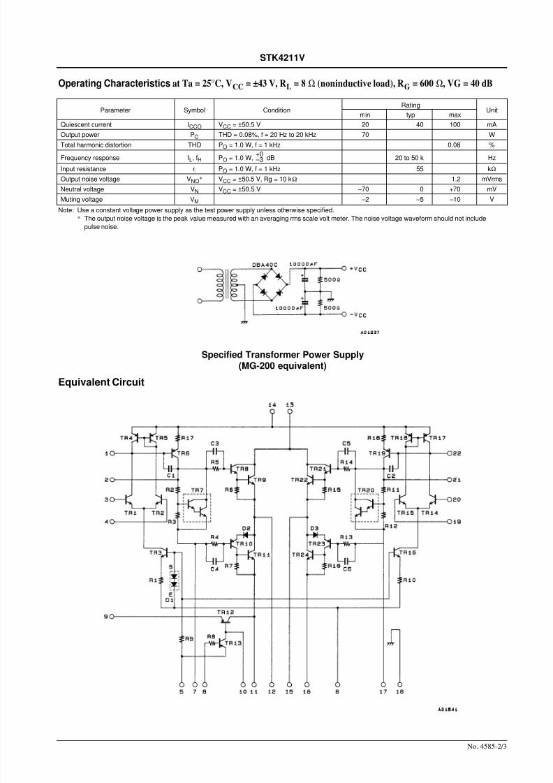
Operating Characteristics at Ta = 25degC VCC = plusmn43 V RL = 8 Ω (noninductive load) RG = 600 Ω VG = 40 dB
Note Use a constant voltage power supply as the test power supply unless otherwise specified
The output noise voltage is the peak value measured with an averaging rms scale volt meter The noise voltage waveform should not include
pulse noise
Specified Transformer Power Supply(MG-200 equivalent)
Equivalent Circuit
No 4585-23
STK4211V
Parameter Symbol ConditionRating
Unitmin typ max
Quiescent current ICCO VCC = plusmn505 V 20 40 100 mA
Output power PO THD = 008 f = 20 Hz to 20 kHz 70 WTotal harmonic distortion THD PO = 10 W f = 1 kHz 008
Frequency response fL fH PO = 10 W dB 20 to 50 k Hz
Input resistance ri PO = 10 W f = 1 kHz 55 kΩ
Output noise voltage VNO VCC = plusmn505 V Rg = 10 kΩ 12 mVrms
Neutral voltage VN VCC = plusmn505 V ndash70 0 +70 mV
Muting voltage VM ndash2 ndash5 ndash10 V
+0 ndash3
832019 Datasheet 4211
httpslidepdfcomreaderfulldatasheet-4211 33
No 4585-33
STK4211V
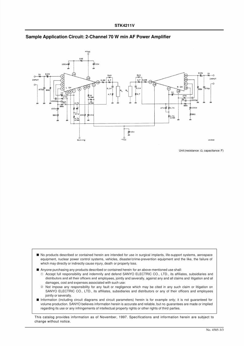
Sample Application Circuit 2-Channel 70 W min AF Power Amplifier
Unit (resistance Ω capacitance F)
This catalog provides information as of November 1997 Specifications and information herein are subject to
change without notice
s No products described or contained herein are intended for use in surgical implants life-support systems aerospace
equipment nuclear power control systems vehicles disastercrime-prevention equipment and the like the failure of
which may directly or indirectly cause injury death or property loss
s Anyone purchasing any products described or contained herein for an above-mentioned use shall
Accept full responsibility and indemnify and defend SANYO ELECTRIC CO LTD its affiliates subsidiaries and
distributors and all their officers and employees jointly and severally against any and all claims and litigation and all
damages cost and expenses associated with such use
Not impose any responsibility for any fault or negligence which may be cited in any such claim or litigation on
SANYO ELECTRIC CO LTD its affiliates subsidiaries and distributors or any of their officers and employees
jointly or severally
s Information (including circuit diagrams and circuit parameters) herein is for example only it is not guaranteed for
volume production SANYO believes information herein is accurate and reliable but no guarantees are made or impliedregarding its use or any infringements of intellectual property rights or other rights of third parties
832019 Datasheet 4211
httpslidepdfcomreaderfulldatasheet-4211 23
Operating Characteristics at Ta = 25degC VCC = plusmn43 V RL = 8 Ω (noninductive load) RG = 600 Ω VG = 40 dB
Note Use a constant voltage power supply as the test power supply unless otherwise specified
The output noise voltage is the peak value measured with an averaging rms scale volt meter The noise voltage waveform should not include
pulse noise
Specified Transformer Power Supply(MG-200 equivalent)
Equivalent Circuit
No 4585-23
STK4211V
Parameter Symbol ConditionRating
Unitmin typ max
Quiescent current ICCO VCC = plusmn505 V 20 40 100 mA
Output power PO THD = 008 f = 20 Hz to 20 kHz 70 WTotal harmonic distortion THD PO = 10 W f = 1 kHz 008
Frequency response fL fH PO = 10 W dB 20 to 50 k Hz
Input resistance ri PO = 10 W f = 1 kHz 55 kΩ
Output noise voltage VNO VCC = plusmn505 V Rg = 10 kΩ 12 mVrms
Neutral voltage VN VCC = plusmn505 V ndash70 0 +70 mV
Muting voltage VM ndash2 ndash5 ndash10 V
+0 ndash3
832019 Datasheet 4211
httpslidepdfcomreaderfulldatasheet-4211 33
No 4585-33
STK4211V
Sample Application Circuit 2-Channel 70 W min AF Power Amplifier
Unit (resistance Ω capacitance F)
This catalog provides information as of November 1997 Specifications and information herein are subject to
change without notice
s No products described or contained herein are intended for use in surgical implants life-support systems aerospace
equipment nuclear power control systems vehicles disastercrime-prevention equipment and the like the failure of
which may directly or indirectly cause injury death or property loss
s Anyone purchasing any products described or contained herein for an above-mentioned use shall
Accept full responsibility and indemnify and defend SANYO ELECTRIC CO LTD its affiliates subsidiaries and
distributors and all their officers and employees jointly and severally against any and all claims and litigation and all
damages cost and expenses associated with such use
Not impose any responsibility for any fault or negligence which may be cited in any such claim or litigation on
SANYO ELECTRIC CO LTD its affiliates subsidiaries and distributors or any of their officers and employees
jointly or severally
s Information (including circuit diagrams and circuit parameters) herein is for example only it is not guaranteed for
volume production SANYO believes information herein is accurate and reliable but no guarantees are made or impliedregarding its use or any infringements of intellectual property rights or other rights of third parties
832019 Datasheet 4211
httpslidepdfcomreaderfulldatasheet-4211 33
No 4585-33
STK4211V
Sample Application Circuit 2-Channel 70 W min AF Power Amplifier
Unit (resistance Ω capacitance F)
This catalog provides information as of November 1997 Specifications and information herein are subject to
change without notice
s No products described or contained herein are intended for use in surgical implants life-support systems aerospace
equipment nuclear power control systems vehicles disastercrime-prevention equipment and the like the failure of
which may directly or indirectly cause injury death or property loss
s Anyone purchasing any products described or contained herein for an above-mentioned use shall
Accept full responsibility and indemnify and defend SANYO ELECTRIC CO LTD its affiliates subsidiaries and
distributors and all their officers and employees jointly and severally against any and all claims and litigation and all
damages cost and expenses associated with such use
Not impose any responsibility for any fault or negligence which may be cited in any such claim or litigation on
SANYO ELECTRIC CO LTD its affiliates subsidiaries and distributors or any of their officers and employees
jointly or severally
s Information (including circuit diagrams and circuit parameters) herein is for example only it is not guaranteed for
volume production SANYO believes information herein is accurate and reliable but no guarantees are made or impliedregarding its use or any infringements of intellectual property rights or other rights of third parties
Related Documents