System Specifications 3 3 3 Interworking 7 7 7 Datapoint Types 2 2 2 Summary: This Chapter specifies the KNX Datapoint Types for Interworking This Chapter describes the general usable and Functional Block specific, standard Datapoint Types that are to be used for transmission of data on the bus. Version v1.4 is an Approved Standard.

Welcome message from author
This document is posted to help you gain knowledge. Please leave a comment to let me know what you think about it! Share it to your friends and learn new things together.
Transcript

System Specifications 333
Interworking 777
Datapoint Types 222
Summary:
This Chapter specifies the KNX Datapoint Types for Interworking
This Chapter describes the general usable and Functional Block specific, standard Datapoint Types that are to be used for transmission of data on the bus.
Version v1.4 is an Approved Standard.

KNX Standard Interworking Datapoint Types
©Copyright 1998 - 2009, KNX Association System Specifications AS v1.4 - page 2 of 148
Document updates Version Date Description
v1.0 AS 2002.01.03 Preparation of the approved standard. v1.1 DP 2006.06.16 The DPTs of the following documents are integrated.
− Chapter 7/1/3 (S12) “Logical Functional Blocks” − Chapter 7/20 (S12) “Lighting” − Chapter 7/50 (S12) “Shutters and Blinds” − Supplement 11 “HVAC Datapoint Types” − Supplement 12 “Channel Codes” − Supplement 14 “DPT_DateTime” − AN004 “Additional HVAC data types” − AN006 “Update of Supplement 14 DPT_DateTime” − AN027 “TFI approved Datapoint Types for general usage” − AN035 “DPT_Version” − AN079 “TFI Accepted DPTs 05.03”
Preparation of the Draft Proposal. v1.2 DV 2006.12.20 Preparation of the Draft for Voting. v1.3 AS 2007.03.14 Editorial correction of DPT_TempFlowWaterDemAbs (DPT_ID = 210.100):
V15 V16 and B8 B16 in detailed specification, acc. resolution of comments to AN096 v01. Inclusion of resolution of comments from Final Voting. Preparation of the Approved Standard.
v1.4 AS 2007.03.20 − HDPT_Length_mm (7.011)H added. − HDPT_Rotation_Angle (8.011)H added. − HDPT_MBus_Address (230.1000)H PDT corrected from PDT_GENERIC_09 to
PDT_GENERIC_08. 2007.10.03 − AN050 “AN to Supplement 12” integrated. 2007.10.05 − AN051 “New channels” integrated. 2007.10.19 − AN087 “New channels 2005.02” integrated. 2007.12.14 Integrated conclusion of WGI meeting of 2007.09.26 about use of DPT_Power
and DPT_Value_Power. 2008.03.13 − AN057 “System B” integrated (HDPT_ErrorClass_System H extension) 2008.03.14 − AN096 “WGI accepted DPTs 06.01” started and completed integration.
− AN098 “Unicode” started and completed integration. 2008.04.28 − AN066 “cEMI adaptations”: extension of DPT_CommMode. 2008.05.19 − PART_Logical, PART_Invert and PART_Input_Connected added (AN050) 2008.06.04 − AN097 “Eberle Status Byte”: integration started and completed. 2008.11.05 − Coding of HDPT_CommModeH replaced by reference to PID_COMM_MODE
in 3/6/3. 2009.02.03 − AN105 to AN110: removed TP0 and PL132 from possible values of
HDPT_MediaH 2009.04.10 − Editorial update for inclusion in the KNX Specifications v2.0. v1.4 AS 2009.04.27 − 7/1/5 “General Purpose I/O”: added DPTs used in that specification.
References [01] Chapter 3/6/3 “External Message Interface” [02] Chapter 3/7/3 “Standard Identifier Tables”
Filename: 03_07_02 Datapoint Types v1.4 AS v20090427a.doc Version: 1.4 Status: Approved Standard Savedate: 2009.04.27 Number of pages: 148

KNX Standard Interworking Datapoint Types
©Copyright 1998 - 2009, KNX Association System Specifications AS v1.4 - page 3 of 148
Contents
1 Introduction ............................................................................................................................ 7 1.1 Classification and identification of Datapoint Types ..................................................... 7 1.2 Subtype ranges for Datapoint Type Identifiers ............................................................... 8 1.3 Datapoint Type specification style ................................................................................. 9
1.3.1 Notations and format ........................................................................................... 9 1.3.2 Property Datatype ............................................................................................... 9 1.3.3 Use .................................................................................................................... 10
1.4 The transmission of DPT encoded data on the bus ....................................................... 10
2 Overview ............................................................................................................................... 11
3 Datapoint Types for common use ....................................................................................... 17 3.1 Datapoint Types B1 ....................................................................................................... 17 3.2 Datapoint Types B2 ....................................................................................................... 19 3.3 Datapoint Types B1U3 ................................................................................................... 20
3.3.1 DPT_Control_Dimming ................................................................................... 20 3.3.2 DPT_Control_Blinds ........................................................................................ 21
3.4 Datapoint Types Character Set” ................................................................................... 22 3.5 Datapoint Types “8-Bit Unsigned Value” .................................................................... 23
3.5.1 Scaled values ..................................................................................................... 23 3.5.2 Non-scaled values ............................................................................................. 24
3.6 Datapoint Types V8 ....................................................................................................... 24 3.6.1 Signed Relative Value ....................................................................................... 24
3.7 Datapoint Type “Status with Mode” ............................................................................. 25 3.8 Datapoint Types “2-Octet Unsigned Value” ................................................................ 25
3.8.1 2-octet unsigned counter value ......................................................................... 25 3.8.2 Time Period ....................................................................................................... 26 3.8.3 Other U16 Datapoint Types ............................................................................... 27
3.9 Datapoint Types “2-Octet Signed Value” ..................................................................... 28 3.9.1 2-octet signed counter value ............................................................................. 28 3.9.2 Delta Time ........................................................................................................ 28 3.9.3 Other V16 Datapoint Types ............................................................................... 29
3.10 Datapoint Types “2-Octet Float Value” ....................................................................... 30 3.11 Datapoint Type “Time” ................................................................................................ 31 3.12 Datapoint Type “Date” ................................................................................................. 32 3.13 Datapoint Types “4-Octet Unsigned Value” ................................................................ 32 3.14 Datapoint Types “4-Octet Signed Value” ..................................................................... 33 3.15 Datapoint Types “4-Octet Float Value” ....................................................................... 33 3.16 Datapoint Type DPT_Access_Data .............................................................................. 36 3.17 Datapoint Types "String" .............................................................................................. 38 3.18 Datapoint Type Scene Number ..................................................................................... 38 3.19 Datapoint Type DPT_SceneControl ............................................................................. 39 3.20 Datapoint Type DPT_DateTime ................................................................................... 39
3.20.1 Notes ................................................................................................................. 40 3.21 Datapoint Types N8 ....................................................................................................... 42 3.22 Datapoint Type B8 ........................................................................................................ 46
3.22.1 Datapoint Type “General Status” ...................................................................... 46 3.22.2 Datapoint Type “Device Control” .................................................................... 47
3.23 Datapoint Types N2 ....................................................................................................... 48

KNX Standard Interworking Datapoint Types
©Copyright 1998 - 2009, KNX Association System Specifications AS v1.4 - page 4 of 148
3.24 Datapoint Type DPT_VarString_8859_1 ..................................................................... 49 3.25 Datapoint Type DPT_SceneInfo ................................................................................... 50 3.26 Datapoint Type Unicode UTF-8 String A[n] ................................................................ 51
3.26.1 DPT_UTF-8 ...................................................................................................... 51 3.27 Datatype B32 .................................................................................................................. 53
3.27.1 Datapoint Type “Combined Info On Off” ........................................................ 53 3.28 Datapoint Type DPT_AlarmInfo .................................................................................. 56 3.29 Datapoint Type DPT_SerNum ..................................................................................... 59 3.30 Datapoint Types “Unsigned Relative Value” ............................................................... 60 3.31 Datapoint Types “Unsigned Counter Value” ............................................................... 61 3.32 Datapoint Types “Time Period..._Z” ............................................................................ 61 3.33 Datapoint Types “Unsigned Flow Rate l/h” ................................................................. 62 3.34 Datapoint Types “Unsigned Counter Value” ............................................................... 63 3.35 Datapoint Types “Unsigned Electric Current μA” ....................................................... 63 3.36 Datapoint Types “Power in kW” .................................................................................. 64 3.37 Datapoint Type “ Atmospheric Pressure with Status/Command” ................................ 64 3.38 Datapoint Types “Signed Relative Value” ................................................................... 66 3.39 Datapoint Type “DeltaTime...Z” .................................................................................. 66 3.40 Datapoint Type DPT_Version ...................................................................................... 68 3.41 Datapoint Type “Volume in Liter” ............................................................................... 70 3.42 Datatype U16U8 ............................................................................................................. 70
3.42.1 Datapoint Type “Scaling speed” ....................................................................... 70 3.42.2 Datapoint Type “Scaling step time” ................................................................. 72
3.43 Datatype V32N8Z8 ......................................................................................................... 73 3.43.1 Datapoint Type “MeteringValue” ..................................................................... 73
4 Datapoint Types for HVAC ................................................................................................. 75 4.1 Simple Datapoint Types with STATUS/COMMAND Z8 field.................................... 75
4.1.1 Introduction ....................................................................................................... 75 4.1.2 Datatype format ................................................................................................ 76 4.1.3 OutOfService mechanism for a parameter ........................................................ 80 4.1.4 OutOfService mechanism for a runtime Datapoint (actual value) .................... 81 4.1.5 Override mechanism ......................................................................................... 82 4.1.6 Alarming mechanism ........................................................................................ 83
4.2 Datapoint Types B1 ....................................................................................................... 84 4.3 Datapoint Types N8 ....................................................................................................... 84 4.4 Data Type “8-Bit Set” ................................................................................................... 87
4.4.1 Datapoint Type “Forcing Signal” ..................................................................... 87 4.4.2 Datapoint Type “Forcing Signal Cool” ............................................................. 88 4.4.3 Datapoint Type “Room Heating Controller Status” ......................................... 89 4.4.4 Datapoint Type “Solar DHW Controller Status” .............................................. 90 4.4.5 Datapoint Type “Fuel Type Set ” ...................................................................... 91 4.4.6 Datapoint Type “Room Cooling Controller Status” ......................................... 92 4.4.7 Datapoint Type “Ventilation Controller Status” ............................................... 92
4.5 Data Type “16-Bit Set” ................................................................................................. 93 4.5.1 Datapoint Type “DHW Controller Status” ....................................................... 93 4.5.2 Datapoint Type “RHCC Status” ....................................................................... 94
4.6 Datapoint Types N2 ....................................................................................................... 97 4.7 Data Type “Boolean with Status/Command” ............................................................... 97
4.7.1 Datapoint Type “Heat/Cool_Z” ........................................................................ 97 4.8 Data Type “8-Bit Enum with Status/Command” .......................................................... 99

KNX Standard Interworking Datapoint Types
©Copyright 1998 - 2009, KNX Association System Specifications AS v1.4 - page 5 of 148
4.8.1 Datapoint Type “HVAC Operating Mode” ...................................................... 99 4.8.2 Datapoint Type “DHW Mode” ....................................................................... 100 4.8.3 Datapoint Type “HVAC Controlling Mode” .................................................. 100 4.8.4 Datapoint Type “Enable Heat/Cool Stage” ..................................................... 101 4.8.5 Datapoint Type “Building Mode” ................................................................... 102 4.8.6 Datapoint Type “Occupancy Mode” ............................................................... 103 4.8.7 Datapoint Type “HVAC Emergency Mode” .................................................. 103
4.9 Data Type “16-Bit Unsigned Value with Status/Command” ..................................... 104 4.9.1 Datapoint Type “HVAC Air Quality” ............................................................ 104 4.9.2 Datapoint Type “ Wind Speed with Status/Command” .................................. 105 4.9.3 Datapoint Type “Sun Intensity with Status/Command” ................................. 105 4.9.4 Datapoint Type “HVAC Air Flow Absolute Value” ...................................... 106
4.10 Data Type “16-Bit Signed Value with Status/Command” ......................................... 107 4.10.1 Datapoint Type “HVAC absolute Temperature” ............................................ 107 4.10.2 Datapoint Type “HVAC relative Temperature” ............................................. 108 4.10.3 Datapoint Type “HVAC Air Flow Relative Value” ....................................... 108
4.11 Data Type “16-Bit Unsigned Value & 8-Bit Enum ” ................................................ 109 4.11.1 Datapoint Type “HVAC Mode & Time delay” .............................................. 109 4.11.2 Datapoint Type “DHW Mode & Time delay” ................................................ 110 4.11.3 Datapoint Type “Occupancy Mode & Time delay” ....................................... 111 4.11.4 Datapoint Type “Building Mode & Time delay” ........................................... 112
4.12 Data Type “8-Bit Unsigned Value & 8-Bit Set” ........................................................ 113 4.12.1 Datapoint Type “Status Burner Controller” .................................................... 113 4.12.2 Datapoint Type “Locking Signal ” ................................................................. 114 4.12.3 Datapoint Type “Boiler Controller Demand Signal” ...................................... 114 4.12.4 Datapoint Type “Actuator Position Demand” ................................................ 115 4.12.5 Datapoint Type “Actuator Position Status” .................................................... 116
4.13 Data Type “16-Bit Signed Value & 8-Bit Set” ........................................................... 117 4.13.1 Datapoint Type “Heat Producer Manager Status” .......................................... 117 4.13.2 Datapoint Type “ Room Temperature Demand” ............................................ 118 4.13.3 Datapoint Type “Cold Water Producer Manager Status” ............................... 119 4.13.4 Datapoint Type “Water Temperature Controller Status” ................................ 120
4.14 Data Type “16-Bit Signed Value & 16-Bit Set” ......................................................... 121 4.14.1 Datapoint Type “Consumer Flow Temperature Demand” ............................. 121
4.15 Data Type “8-Bit Unsigned Value & 8-Bit Enum” .................................................... 122 4.15.1 Datapoint Type “EnergyDemWater” .............................................................. 122
4.16 Data Type “3x 16-Bit Signed Value ” ........................................................................ 123 4.16.1 Datapoint Type “3x set of RoomTemperature Setpoint Shift values ” ........... 123 4.16.2 Datapoint Type “3x set of RoomTemperature Absolute Setpoint values” ..... 124
4.17 Data Type “4x 16-Bit Signed Value ” ........................................................................ 125 4.17.1 Datapoint Type “4x set of RoomTemperature setpoints ” .............................. 125 4.17.2 Datapoint Type “4x set of DHWTemperature setpoints ” .............................. 126 4.17.3 Datapoint Type “4x set of RoomTemperature setpoint shift values ” ............ 127
4.18 Data Type “16-Bit Signed & 8-Bit Unsigned Value & 8-Bit Set” ............................. 128 4.18.1 Datapoint Type “Heat Prod. Manager Demand Signal” ................................. 128 4.18.2 Datapoint Type “Cold Water Prod. Manager Demand Signal” ...................... 129
4.19 Data Type “ V16 U8 B16” ............................................................................................ 130 4.19.1 Datapoint Type “Status Boiler Controller” ..................................................... 130 4.19.2 Datapoint Type “Status Chiller Controller” .................................................... 131
4.20 Data Type “ U16 U8 N8 B8 ” ....................................................................................... 132

KNX Standard Interworking Datapoint Types
©Copyright 1998 - 2009, KNX Association System Specifications AS v1.4 - page 6 of 148
4.20.1 Datapoint Type “Heat Producer Specification” .............................................. 132 4.21 Data Type “16-Bit Unsigned Value & 16-Bit Signed Value” ................................... 133
4.21.1 Datapoint Type “Next Temperature & Time Delay” ...................................... 133 4.22 Data Type “3x 16-Float Value ” ................................................................................. 134
4.22.1 Datapoint Type “3x set of RoomTemperature Setpoint Values ” ................... 134 4.22.2 Datapoint Type “3x set of RoomTemperature Setpoint Shift Values ” .......... 135
4.23 Data Type “ V8 N8 N8 ” .............................................................................................. 136 4.23.1 Datapoint Type “EnergyDemAir” .................................................................. 136
4.24 Data Type V16V16N8N8 ............................................................................................... 137 4.24.1 Datapoint Type “TempSupplyAirSetpSet” ..................................................... 137
5 Datapoint Types for Load Management .......................................................................... 139
6 Datapoint Types for Lighting ............................................................................................ 140 6.1 Datapoint Types N8 ..................................................................................................... 140
7 Datapoint Types for System .............................................................................................. 141 7.1 Datapoint Types N8 ..................................................................................................... 141 7.2 Datapoint Types B8 ..................................................................................................... 142
7.2.1 Datapoint Type “RF Communication Mode Info” ......................................... 142 7.2.2 Datapoint Type “cEMI Server Supported RF Filtering Modes” .................... 143
7.3 Datatype B16 ................................................................................................................ 144 7.3.1 Datapoint Type “Media” ................................................................................. 144
7.4 Datatype U4U4 ............................................................................................................ 145 7.5 Datapoint Type “MBus Address” ............................................................................... 145
8 Parameter Types ................................................................................................................ 146

KNX Standard Interworking Datapoint Types
©Copyright 1998 - 2009, KNX Association System Specifications AS v1.4 - page 7 of 148
1 0BIntroduction
1.1 8BClassification and identification of Datapoint Types
Data Type Dimension
Datapoint Type
Format Encoding Range Unit
Figure 1 - Structure of Datapoint Types
The Datapoint Types are defined as a combination of a data type and a dimension. It has been preferred not to define the data types separately from any dimension. This only leads to more abstract naming and identifications.
Any Datapoint Type thus standardizes one combination of format, encoding, range and unit. The Datapoint Types will be used to describe further KNX Interworking Standards.
The Datapoint Types are identified by a 16 bit main number separated by a dot from a 16-bit subnumber, e.g. "7.002". The coding is as follows:
Field Stands for
main number(left) Format Encoding
subnumber (right) Range Unit
Datapoint Types with the same main number thus have the same format and encoding.
Datapoint Types with the same main number have the same data type. A different subnumber indicates a different dimension (different range and/or different unit).

KNX Standard Interworking Datapoint Types
©Copyright 1998 - 2009, KNX Association System Specifications AS v1.4 - page 8 of 148
1.2 9BSubtype ranges for Datapoint Type Identifiers The assignment of Datapoint Type identifiers by KNX Association is done in a systematic way according the scheme below.
Application Domain Subnumber
MAIN number
0 … 199 200 … 299 300 … 59 999 ≥ 60 000
mainly unstructured structured Common use 0 … 99 DPT is
• standard • mainly unstructured • common use
DPT is • standardised • structured • common use
reserved for future
use
Reserved. These
DPT-IDs shall not be
used.
HVAC 100 … 499 DPT is • standardised • unstructured • HVAC specific use
DPT is • standardised • structured • HVAC LTE
only managed by WGI
Load Management
500 … 599 DPT is • standardised • unstructured • LMM specific usage
DPT is • standardised • structured
Lighting 600 … 999 DPT is
• standardised • unstructured • lighting
DPT is • standardised • structured • lighting
System 1 000…1 199 DPT is • standardised • unstructured • system
DPT is • standardised • structured • system
Reserved 1200… 50 999
reserved for otherapplications (managed by WGI)
Manufacturer specific
≥ 60 000 manufacturer specific extensions a manufacturer specific
extensions a a For interpretation of these Datapoint Types the device type needs to be known.
These ranges are defined for DPTs for given application areas. Entire ranges of 500 entries are assigned in one go.
Subtype range Application area
From To
100 499 HVAC
500 599 Load Management
600 999 Lighting
1 000 1 199 System
1 200 50 999 Reserved for other application domains

KNX Standard Interworking Datapoint Types
©Copyright 1998 - 2009, KNX Association System Specifications AS v1.4 - page 9 of 148
1.3 10BDatapoint Type specification style
1.3.1 85BNotations and format Symbol Field
A Character
A[n] String of n characters
B Boolean / Bit set
C Control
E Exponent
F Floating point value
M Mantissa
N eNumeration
r Reserved bit or field
S Sign
U Unsigned value
V 2's Complement signed value
Z8 Standardised Status/Command B8. Encoding as in XDPT_StatusGen X
Numbers in suffix denote the length of a field in bit. EXAMPLE U16 indicates a 16 bit unsigned integer.
In the following, the format is described MSB first (most significant octet left) and msb first (most significant bit left) inside an octet. Please refer as well to clause X1.4X.
Datapoint Types shorter than 1 octet are transmitted in the data-field of the frame on the lower bit positions. The preceding bits shall be 0.
1.3.2 86BProperty Datatype Property values can be encoded according the DPTs specified in this document. Therefore, this document specifies a mandatory Property Datatype for every DPT. In each clause of this document, this Property Datatype is specified:
- for all DPTs in that clause in general, or - for each DPT in that clause individually.
If the Property Value is an array, then all elements of that array shall be encoded according this specified DPT.
Please refer to X[02]X for the specification of the Property Datatypes.
Interface Object Servers may encode the Property Datatypes on 5 bit or on 6 bit. This influences the Property Datatype that shall be used as specified below.
Property Datatype supported by the device Property Datatype that shall be used
Size Range
5 bit 00h to 1Fh The alternative Property Datatype as specified behind “(Alt.: …)” in the DPT definition.
6 bit 00h to 3Fh The Property Datatype as specified in the DPT definition.

KNX Standard Interworking Datapoint Types
©Copyright 1998 - 2009, KNX Association System Specifications AS v1.4 - page 10 of 148
1.3.3 87BUse Some DPTs can be used without any restriction. Other DPTs can only be used where this is allowed explicitly. This is specified in the DPT definitions. The following applies.
Abbreviation Meaning Explanation
G General This Datapoint Type can be used without any restrictions.
FB Functional Block This Datapoint Type shall not be used in general.
This Datapoint Type shall only be used for implementations of standard Functional Blocks where this DPT is used.
This Datapoint Type is not allowed for any other purpose.
HVAC
HWH
TU
…
Application Domains
This Datapoint Type shall not be used in general.
This Datapoint Type may only be used within the specified application domain.
This Datapoint Type is not allowed for any other purpose.
1.4 11BThe transmission of DPT encoded data on the bus Data encoded according a DPT that is transmitted on the KNX system shall be transmitted with the most significant octet first in the frame and the least significant octet last. An example is shown in XFigure 2X.
Octet 6 Octet 7 Octet 8 Octet 9 Octet 10 APCI r r r Day r r r r Month r Year 7 6 5 4 3 2 1 0 7 6 5 4 3 2 1 0 7 6 5 4 3 2 1 0 7 6 5 4 3 2 1 0 7 6 5 4 3 2 1 0
APCI
AP
CI
APCI
AP
CI
0 0 1 0 0 0 0 0 0 0 0 0 0 1 0 0 1 0 0 0 0 0 1 1 0 0 0 0 0 0 0 1 1 0 18 12 2006
Figure 2 – December 12, 2006 encoded according DPT_Date in an A_GroupValue_Write-frame (example on TP1)
NOTE The transmission order of the bits within an octet depends on the medium and may be “most significant bit” (msb) first or “least significant bit” (lsb) first.

KNX Standard Interworking Datapoint Types
©Copyright 1998 - 2009, KNX Association System Specifications AS v1.4 - page 11 of 148
2 1BOverview DPT_ID Format DPT_Name
H1.001H B1 HDPT_SwitchH
H1.002H B1 HDPT_BoolH
H1.003H B1 HDPT_EnableH
H1.004H B1 HDPT_RampH
H1.005H B1 HDPT_AlarmH
H1.006H B1 HDPT_BinaryValueH
H1.007H B1 HDPT_StepH
H1.008H B1 HDPT_UpDown H
H1.009H B1 HDPT_OpenCloseH
H1.010H B1 HDPT_StartH
H1.011H B1 HDPT_StateH
H1.012H B1 HDPT_InvertH
H1.013H B1 HDPT_DimSendStyle H
H1.014H B1 HDPT_InputSourceH
H1.015H B1 HDPT_ResetH
H1.016H B1 HDPT_AckH
H1.017H B1 HDPT_TriggerH
H1.018H B1 HDPT_OccupancyH
H1.019H B1 HDPT_Window_DoorH
H1.021H B1 HDPT_LogicalFunctionH
H1.022H B1 HDPT_Scene_AB H
H1.023H B1 HDPT_ShutterBlinds_ModeH
H1.100H B1 HDPT_Heat/CoolH
H2.001H B2 HDPT_Switch_ControlH
H2.002H B2 HDPT_Bool_ControlH
H2.003H B2 HDPT_Enable_ControlH
H2.004H B2 HDPT_Ramp_ControlH
H2.005H B2 HDPT_Alarm_ControlH
H2.006H B2 HDPT_BinaryValue_ControlH
H2.007H B2 HDPT_Step_ControlH
H2.008H B2 HDPT_Direction1_ControlH
H2.009H B2 HDPT_Direction2_ControlH
H2.010H B2 HDPT_Start_ControlH
H2.011H B2 HDPT_State_ControlH
H2.012H B2 HDPT_Invert_ControlH
H3.007H B1U3 HDPT_Control_DimmingH
H3.008H B1U3 HDPT_Control_BlindsH
H4.001H A8 HDPT_Char_ASCIIH
H4.002H A8 HDPT_Char_8859_1H
H5.001H U8 HDPT_ScalingH
H5.003H U8 HDPT_AngleH
H5.004H U8 HDPT_Percent_U8H
H5.005H U8 HDPT_DecimalFactorH
H5.010H U8 HDPT_Value_1_UcountH
H6.001H V8 HDPT_Percent_V8 H
H6.010H V8 HDPT_Value_1_CountH
H6.020H B5N3 HDPT_Status_Mode3H
H7.001H U16 HDPT_Value_2_UcountH
H7.002H U16 HDPT_TimePeriodMsecH
H7.003H U16 HDPT_TimePeriod10MSec H
H7.004H U16 HDPT_TimePeriod100MSec H

KNX Standard Interworking Datapoint Types
©Copyright 1998 - 2009, KNX Association System Specifications AS v1.4 - page 12 of 148
DPT_ID Format DPT_Name
H7.005H U16 HDPT_TimePeriodSec H
H7.006H U16 HDPT_TimePeriodMinH
H7.007H U16 HDPT_TimePeriodHrsH
H7.010H U16 HDPT_PropDataType H
H7.011H U16 HDPT_Length_mmH
H7.012H U16 HDPT_UElCurrentmAH
H7.013H U16 HDPT_Brightness H
H8.001H V16 HDPT_Value_2_CountH
H8.002H V16 HDPT_DeltaTimeMsecH
H8.003H V16 HDPT_DeltaTime10MSec H
H8.004H V16 HDPT_DeltaTime100MSecH
H8.005H V16 HDPT_DeltaTimeSecH
H8.006H V16 HDPT_DeltaTimeMinH
H8.007H V16 HDPT_DeltaTimeHrsH
H8.010H V16 HDPT_Percent_V16H
H8.011H V16 HDPT_Rotation_AngleH
H9.001H F16 HDPT_Value_TempH
H9.002H F16 HDPT_Value_TempdH
H9.003H F16 HDPT_Value_TempaH
H9.004H F16 HDPT_Value_LuxH
H9.005H F16 HDPT_Value_WspH
H9.006H F16 HDPT_Value_PresH
H9.007H F16 HDPT_Value_HumidityH
H9.008H F16 HDPT_Value_AirQualityH
H9.010H F16 HDPT_Value_Time1H
H9.011H F16 HDPT_Value_Time2H
H9.020H F16 HDPT_Value_VoltH
H9.021H F16 HDPT_Value_CurrH
H9.022H F16 HDPT_PowerDensityH
H9.023H F16 HDPT_KelvinPerPercentH
H9.024H F16 HDPT_PowerH
9.025 F16 DPT_Value_Volume_Flow H10.001H N3N5r2N6r2N6 HDPT_TimeOfDayH
H11.001H r3N5r4N4r1U7 HDPT_DateH
H12.001H U32 HDPT_Value_4_UcountH
H13.001H V32 HDPT_Value_4_CountH
H13.100H V32 HDPT_LongDeltaTimeSecH
H14.000H F32 HDPT_Value_AccelerationH
H14.001H F32 HDPT_Value_Acceleration_AngularH
H14.002H F32 HDPT_Value_Activation_EnergyH
H14.003H F32 HDPT_Value_ActivityH
H14.004H F32 HDPT_Value_Mol H
H14.005H F32 HDPT_Value_AmplitudeH
H14.006H F32 HDPT_Value_AngleRadH
H14.007H F32 HDPT_Value_AngleDegH
H14.008H F32 HDPT_Value_Angular_MomentumH
H14.009H F32 HDPT_Value_Angular_VelocityH
H14.010H F32 HDPT_Value_AreaH
H14.011H F32 HDPT_Value_CapacitanceH
H14.012H F32 HDPT_Value_Charge_DensitySurfaceH
H14.013H F32 HDPT_Value_Charge_DensityVolumeH
H14.014H F32 HDPT_Value_Compressibility H
H14.015H F32 HDPT_Value_ConductanceH

KNX Standard Interworking Datapoint Types
©Copyright 1998 - 2009, KNX Association System Specifications AS v1.4 - page 13 of 148
DPT_ID Format DPT_Name
H14.016H F32 HDPT_Value_Electrical_ConductivityH
H14.017H F32 HDPT_Value_DensityH
H14.018H F32 HDPT_Value_Electric_ChargeH
H14.019H F32 HDPT_Value_Electric_CurrentH
H14.020H F32 HDPT_Value_Electric_CurrentDensityH
H14.021H F32 HDPT_Value_Electric_DipoleMomentH
H14.022H F32 HDPT_Value_Electric_DisplacementH
H14.023H F32 HDPT_Value_Electric_FieldStrengthH
H14.024H F32 HDPT_Value_Electric_FluxH
H14.025H F32 HDPT_Value_Electric_FluxDensity H
H14.026H F32 HDPT_Value_Electric_PolarizationH
H14.027H F32 HDPT_Value_Electric_Potential H
H14.028H F32 HDPT_Value_Electric_PotentialDifference H
H14.029H F32 HDPT_Value_ElectromagneticMMomentH
H14.030H F32 HDPT_Value_Electromotive_ForceH
H14.031H F32 HDPT_Value_EnergyH
H14.032H F32 HDPT_Value_ForceH
H14.033H F32 HDPT_Value_FrequencyH
H14.034H F32 HDPT_Value_Angular_FrequencyH
H14.035H F32 HDPT_Value_Heat_Capacity H
H14.036H F32 HDPT_Value_Heat_FlowRate H
H14.037H F32 HDPT_Value_Heat_QuantityH
H14.038H F32 HDPT_Value_ImpedanceH
H14.039H F32 HDPT_Value_LengthH
H14.040H F32 HDPT_Value_Light_QuantityH
H14.041H F32 HDPT_Value_LuminanceH
H14.042H F32 HDPT_Value_Luminous_FluxH
H14.043H F32 HDPT_Value_Luminous_IntensityH
H14.044H F32 HDPT_Value_Magnetic_FieldStrengthH
H14.045H F32 HDPT_Value_Magnetic_FluxH
H14.046H F32 HDPT_Value_Magnetic_FluxDensity H
H14.047H F32 HDPT_Value_Magnetic_MomentH
H14.048H F32 HDPT_Value_Magnetic_PolarizationH
H14.049H F32 HDPT_Value_Magnetization H
H14.050H F32 HDPT_Value_MagnetomotiveForceH
H14.051H F32 HDPT_Value_MassH
H14.052H F32 HDPT_Value_MassFluxH
H14.053H F32 HDPT_Value_MomentumH
H14.054H F32 HDPT_Value_Phase_AngleRadH
H14.055H F32 HDPT_Value_Phase_AngleDegH
H14.056H F32 HDPT_Value_PowerH
H14.057H F32 HDPT_Value_Power_Factor H
H14.058H F32 HDPT_Value_PressureH
H14.059H F32 HDPT_Value_ReactanceH
H14.060H F32 HDPT_Value_ResistanceH
H14.061H F32 HDPT_Value_ResistivityH
H14.062H F32 HDPT_Value_SelfInductance H
H14.063H F32 HDPT_Value_SolidAngleH
H14.064H F32 HDPT_Value_Sound_IntensityH
H14.065H F32 HDPT_Value_SpeedH
H14.066H F32 HDPT_Value_Stress H
H14.067H F32 HDPT_Value_Surface_TensionH
H14.068H F32 HDPT_Value_Common_TemperatureH

KNX Standard Interworking Datapoint Types
©Copyright 1998 - 2009, KNX Association System Specifications AS v1.4 - page 14 of 148
DPT_ID Format DPT_Name
H14.069H F32 HDPT_Value_Absolute_TemperatureH
H14.070H F32 HDPT_Value_TemperatureDifference H
H14.071H F32 HDPT_Value_Thermal_Capacity H
H14.072H F32 HDPT_Value_Thermal_Conductivity H
H14.073H F32 HDPT_Value_ThermoelectricPowerH
H14.074H F32 HDPT_Value_TimeH
H14.075H F32 HDPT_Value_TorqueH
H14.076H F32 HDPT_Value_VolumeH
H14.077H F32 HDPT_Value_Volume_FluxH
H14.078H F32 HDPT_Value_WeightH
H14.079H F32 HDPT_Value_WorkH
H15.000H U4U4U4U4U4U4B4N4 HDPT_Access_DataH
H16.000H A14 HDPT_String_ASCIIH
H16.001H A14 HDPT_String_8859_1H
H17.001H r2U6 HDPT_SceneNumberH
H18.001H B1r1U6 HDPT_SceneControlH
H19.001H U8[r4U4][r3U5][U3U5][r2U6][r2U6]B16 HDPT_DateTime H
20.001 N8 DPT_SCLOMode H20.002H N8 HDPT_BuildingModeH
H20.003H N8 HDPT_OccModeH
H20.004H N8 HDPT_PriorityH
H20.005H N8 HDPT_LightApplicationMode H
H20.006H N8 HDPT_ApplicationAreaH
H20.007H N8 HDPT_AlarmClassTypeH
H20.008H N8 HDPT_PSUModeH
H20.011H N8 HDPT_ErrorClass_SystemH
H20.012H N8 HDPT_ErrorClass_HVACH
H20.013H N8 HDPT_Time_DelayH
H20.017H N8 HDPT_SensorSelectH
H20.100H N8 HDPT_FuelTypeH
H20.101H N8 HDPT_BurnerType H
H20.102H N8 HDPT_HVACModeH
H20.103H N8 HDPT_DHWModeH
H20.104H N8 HDPT_LoadPriorityH
H20.105H N8 HDPT_HVACContrModeH
H20.106H N8 HDPT_HVACEmergModeH
H20.107H N8 HDPT_ChangeoverModeH
H20.108H N8 HDPT_ValveModeH
H20.109H N8 HDPT_DamperModeH
H20.110H N8 HDPT_HeaterModeH
H20.111H N8 HDPT_FanModeH
H20.112H N8 HDPT_MasterSlaveModeH
H20.113H N8 HDPT_StatusRoomSetpH
H20.600H N8 HDPT_Behaviour_Lock_Unlock H
H20.601H N8 HDPT_Behaviour_Bus_Power_Up_Down H
H20.1000H N8 HDPT_CommModeH
H20.1001H N8 HDPT_AddInfoTypesH
H20.1002H N8 HDPT_RF_ModeSelectH
H20.1003H N8 HDPT_RF_FilterSelectH
H21.001H B8 HDPT_StatusGenH
H21.002H B8 HDPT_Device_ControlH
H21.100H B8 HDPT_ForceSignH
H21.101H B8 HDPT_ForceSignCoolH

KNX Standard Interworking Datapoint Types
©Copyright 1998 - 2009, KNX Association System Specifications AS v1.4 - page 15 of 148
DPT_ID Format DPT_Name
H21.102H B8 HDPT_StatusRHCH
H21.103H B8 HDPT_StatusSDHWC H
H21.104H B8 HDPT_FuelTypeSetH
H21.105H B8 HDPT_StatusRCCH
H21.106H B8 HDPT_StatusAHU H
H21.1000H B8 HDPT_RF_ModeInfoH
H21.1001H B8 HDPT_RF_FilterInfoH
H22.100H B16 HDPT_StatusDHWCH
H22.101H B16 HDPT_StatusRHCC H
H22.1000H B16 HDPT_MediaH
H23.001H N2 HDPT_OnOff_ActionH
H23.002H N2 HDPT_Alarm_ReactionH
H23.003H N2 HDPT_UpDown_ActionH
H23.102H N2 HDPT_HVAC_PB_ActionH
H24.001H A[n] HDPT_VarString_8859_1H
H25.1000H U4U4 HDPT_DoubleNibbleH
H26.001H r1b1U6 HDPT_SceneInfo H
H27.001H B32 HDPT_CombinedInfoOnOff H
H28.001H A[n] HDPT_UTF-8H
H200.100H B1Z8 HDPT_Heat/Cool_ZH
H200.101H B1Z8 HDPT_BinaryValue_ZH
H201.100H N8Z8 HDPT_HVACMode_ZH
H201.102H N8Z8 HDPT_DHWMode_ZH
H201.104H N8Z8 HDPT_HVACContrMode_ZH
201.105 N8Z8 DPT_EnablH/Cstage_Z DPT_EnablH/CStage 201.107 N8Z8 DPT_BuildingMode_Z H201.108H N8Z8 HDPT_OccMode_ZH
H201.109H N8Z8 HDPT_HVACEmergMode_ZH
H202.001H U8Z8 HDPT_RelValue_ZH
H202.002H U8Z8 HDPT_UCountValue8_ZH
H203.002H U16Z8 HDPT_TimePeriodMsec_ZH
H203.003H U16Z8 HDPT_TimePeriod10Msec_ZH
H203.004H U16Z8 HDPT_TimePeriod100Msec_ZH
H203.005H U16Z8 HDPT_TimePeriodSec_ZH
H203.006H U16Z8 HDPT_TimePeriodMin_ZH
H203.007H U16Z8 HDPT_TimePeriodHrs_ZH
H203.011H U16Z8 HDPT_UFlowRateLiter/h_ZH
H203.012H U16Z8 HDPT_UCountValue16_ZH
H203.013H U16Z8 HDPT_UElCurrentμA_ZH
H203.014H U16Z8 HDPT_PowerKW_ZH
H203.015H U16Z8 HDPT_AtmPressureAbs_ZH
H203.017H U16Z8 HDPT_PercentU16_ZH
203.100 U16Z8 DPT_HVACAirQual_Z 203.101 U16Z8 DPT_WindSpeed_Z DPT_WindSpeed 203.102 U16Z8 DPT_SunIntensity_Z 203.104 U16Z8 DPT_HVACAirFlowAbs_Z H204.001H V8Z8 HDPT_RelSignedValue_ZH
H205.002H V16Z8 HDPT_DeltaTimeMsec_ZH
H205.003H V16Z8 HDPT_DeltaTime10Msec_ZH
H205.004H V16Z8 HDPT_DeltaTime100Msec_Z H
H205.005H V16Z8 HDPT_DeltaTimeSec_ZH
H205.006H V16Z8 HDPT_DeltaTimeMin_ZH
H205.007H V16Z8 HDPT_DeltaTimeHrs_ZH

KNX Standard Interworking Datapoint Types
©Copyright 1998 - 2009, KNX Association System Specifications AS v1.4 - page 16 of 148
DPT_ID Format DPT_Name
205.100 V16Z8 DPT_TempHVACAbs_Z 205.101 V16Z8 DPT_TempHVACRel_Z 205.102 V16Z8 DPT_HVACAirFlowRel_Z 206.100 U16N8 DPT_HVACModeNext 206.102 U16N8 DPT_DHWModeNext 206.104 U16N8 DPT_OccModeNext 206.105 U16N8 DPT_BuildingModeNext 207.100 U8B8 DPT_StatusBUC 207.101 U8B8 DPT_LockSign 207.102 U8B8 DPT_ValueDemBOC 207.104 U8B8 DPT_ActPosDemAbs 207.105 U8B8 DPT_StatusAct 209.100 V16B8 DPT_StatusHPM 209.101 V16B8 DPT_TempRoomDemAbs 209.102 V16B8 DPT_StatusCPM 209.103 V16B8 DPT_StatusWTC H210.100H V16B16 HDPT_TempFlowWaterDemAbsH
211.100 U8N8 DPT_EnergyDemWater 212.100 V16V16V16 DPT_TempRoomSetpSetShift[3] H212.101H V16V16V16 HDPT_TempRoomSetpSet[3]H
213.100 V16V16V16V16 DPT_TempRoomSetpSet[4] 213.101 V16V16V16V16 DPT_TempDHWSetpSet[4] H213.102H V16V16V16V16 HDPT_TempRoomSetpSetShift[4]H
214.100 V16U8B8 DPT_PowerFlowWaterDemHPM 214.101 V16U8B8 DPT_PowerFlowWaterDemCPM 215.100 V16U8B16 DPT_StatusBOC 215.101 V16U8B16 DPT_StatusCC 216.100 U16U8N8B8 DPT_SpecHeatProd H217.001H U5U5U6 HDPT_VersionH
H218.001H V32Z8 HDPT_VolumeLiter_ZH
H219.001H U8N8N8N8B8B8 HDPT_AlarmInfo H
220.100 U16V16 DPT_TempHVACAbsNext H221.001H N16U32 HDPT_SerNum H
222.100 F16F16F16 DPT_TempRoomSetpSetF16[3] 222.101 F16F16F16 DPT_TempRoomSetpSetShiftF16[3] 223.100 V8N8N8 DPT_EnergyDemAir 224.100 V16V16N8N8 DPT_TempSupply AirSetpSet H225.001H U16U8 HDPT_ScalingSpeedH
H225.002H U16U8 DPT_Scaling_Step_Time 229.001 V32N8Z8 DPT_MeteringValue 230.1000 U16U32U8N8 DPT_MBus_Address

KNX Standard Interworking Datapoint Types
©Copyright 1998 - 2009, KNX Association System Specifications AS v1.4 - page 17 of 148
3 2BDatapoint Types for common use
3.1 12BDatapoint Types B1 Format: 1 bit: B1
octet nr 1
field names b
encoding B
Range: b = {0,1}
Unit: None.
Resol.: (not applicable)
PDT: PDT_BINARY_INFORMATION (alt: PDT_UNSIGNED_CHAR)
Datapoint Types
ID: Name: Encoding: b Use: 1.001 DPT_Switch 0 = Off
1 = On G
1.002 DPT_Bool 0 = False 1 = True
G
1.003 DPT_Enable 0 = Disable 1 = Enable
G
1.004 DPT_Ramp 0 = No ramp 1 = Ramp
FB
1.005 DPT_Alarm 0 = No alarm 1 = Alarm
FB
1.006 DPT_BinaryValue 0 = Low 1 = High
FB
1.007 DPT_Step 0 = Decrease 1 = Increase
FB
1.008 DPT_UpDown 0 = Up 1 = Down
G
1.009 DPT_OpenClose 0 = Open 1 = Close
G
1.010 DPT_Start 0 = Stop 1 = Start
G
1.011 DPT_State 0 = Inactive 1 = Active
FB
1.012 DPT_Invert 0 = Not inverted 1 = Inverted
FB
1.013 DPT_DimSendStyle 0 = Start/stop 1 = Cyclically
FB
1.014 DPT_InputSource 0 = Fixed 1 = Calculated
FB
1.015 DPT_Reset 0 = no action (dummy) 1 = reset command (trigger)
G
1.016 DPT_Ack 0 = no action (dummy) 1 = acknowledge command (trigger), e.g. for
alarming
G
1.017 DPT_Trigger 0, 1 = trigger G 1.018 DPT_Occupancy 0 = not occupied
1 = occupied G

KNX Standard Interworking Datapoint Types
©Copyright 1998 - 2009, KNX Association System Specifications AS v1.4 - page 18 of 148
Format: 1 bit: B1
octet nr 1
field names b
encoding B
Range: b = {0,1}
Unit: None.
Resol.: (not applicable)
PDT: PDT_BINARY_INFORMATION (alt: PDT_UNSIGNED_CHAR)
Datapoint Types
ID: Name: Encoding: b Use: 1.019 DPT_Window_Door 0 = closed
1 = open G
1.021 DPT_LogicalFunction 0 = logical function OR 1 = logical function AND
FB
1.022 DPT_Scene_AB F
1F
) 0 = scene A 1 = scene B
FB
1.023 DPT_ShutterBlinds_Mode 0 = only move Up/Down mode (shutter) 1 = move Up/Down + StepStop mode (blind)
FB
1) DPT_Scene_AB allows numbering the scenes with 0 and 1. KNX Association recommends displaying these
scene numbers in ETS™, other software and controllers as 1 and 2, this is, with an offset of 1 compared to the actual transmitted value.

KNX Standard Interworking Datapoint Types
©Copyright 1998 - 2009, KNX Association System Specifications AS v1.4 - page 19 of 148
3.2 13BDatapoint Types B2 Format: 2 bit: B2
octet nr 1
field names c v
encoding B B
Range: c = {0,1} v = {0,1}
Unit: None
Resol.: (not applicable)
PDT: PDT_GENERIC_01
Datapoint Types
ID: Name: Use: Encoding: c v 0 = no control
1 = control According to Type 1.xxx
2.001 DPT_Switch_Control G 2.002 DPT_Bool_Control G c v 2.003 DPT_Enable_Control FB 0 0 No control 2.004 DPT_Ramp_Control FB 0 1 No control 2.005 DPT_Alarm_Control FB 1 0 Control. Function value 0 2.006 DPT_BinaryValue_Control FB 1 1 Control. Function value 1 2.007 DPT_Step_Control FB 2.008 DPT_Direction1_Control FB 2.009 DPT_Direction2_Control FB 2.010 DPT_Start_Control FB 2.011 DPT_State_Control FB 2.012 DPT_Invert_Control FB

KNX Standard Interworking Datapoint Types
©Copyright 1998 - 2009, KNX Association System Specifications AS v1.4 - page 20 of 148
3.3 14BDatapoint Types B1U3
3.3.1 88BDPT_Control_Dimming Format: 4 bit: B1U3
octet nr 1
field names c Step-Code
encoding B UUU
Range: c = {0,1} StepCode = [000b…111b]
Unit: none
Resol.: (not applicable)
PDT: PDT_GENERIC_01
Datapoint Types
ID: Name: Use: 3.007 DPT_Control_Dimming FB
Data fields Description Encoding
c Increase or decrease the brightness. See HX1.007X X0 = Decrease X1 = IncreaseX
StepCode The amount of intervals into which the range of 0 % … 100 % is subdivided, or the break indication.
- 001b…111b: Step Number of intervals = 2^(stepcode-1)
- 000b: Break

KNX Standard Interworking Datapoint Types
©Copyright 1998 - 2009, KNX Association System Specifications AS v1.4 - page 21 of 148
3.3.2 89BDPT_Control_Blinds Format: 4 bit: B1U3
octet nr 1
field names c Step-Code
encoding B UUU
Range: c = {0,1} StepCode = [000b…111b]
Unit: none
Resol.: (not applicable)
PDT: PDT_GENERIC_01
Datapoint Types
ID: Name: Use: 3.008 DPT_Control_Blinds FB
Data fields Description Encoding
c Move up or down. See HX1.008X X0 = Up X1 = DownX
StepCode The amount of intervals into which the range of 0 % … 100 % is subdivided, or the break indication.
- 001b…111b: Step Number of intervals = 2^(stepcode-1)
- 000b: Break
NOTE This DPT can be used both for the relative positioning of the vertical blinds positions as well as for the relative positioning of the angle of the slats.

KNX Standard Interworking Datapoint Types
©Copyright 1998 - 2009, KNX Association System Specifications AS v1.4 - page 22 of 148
3.4 15BDatapoint Types Character Set” Format: 8 bit: A8
octet nr 1
field names Character
encoding A A A A A A A A
Unit: None
Resol.: (not applicable)
Datapoint Types
ID: Name: Range: Encoding: PDT: Use:
4.001 DPT_Char_ASCII [0...127] See below. The most significant bit shall always be 0.
PDT_GENERIC_01 (alt: PDT_UNSIGNED_CHAR)
G
4.002 DPT_Char_8859_1 [0...255] See below. PDT_UNSIGNED_CHAR G
Encoding:
AAAA AAAA LSN = Least Significant Nibble MSN LSN MSN = Most Significant Nibble
MSN 0 1 2 3 4 5 6 7 8 9 A B C D E F
4.001 DPT_Char_ASCII LSN 0 NUL DLE 0 @ P ` p ° À Ð à ð
4.002 DPT_Char_8859_1 1 SOHDC1 ! 1 A Q a q ¡ ± Á Ñ á ñ 2 STX DC2 " 2 B R b r ¢ ² Â Ò â ò
3 ETX DC3 # 3 C S c s £ ³ Ã Ó ã ó 4 EOT DC4 $ 4 D T d t ¤ ´ Ä Ô ä ô 5 ENQNAK % 5 E U e u ¥ µ Å Õ å õ 6 ACK SYN & 6 F V f v ¦ ¶ Æ Ö æ ö 7 BEL ETB ' 7 G W g w § · Ç × ç ÷ 8 BS CAN ( 8 H X h x ¨ ¸ È Ø è ø 9 HT EM ) 9 I Y i y © ¹ É Ù é ù A LF SUB * : J Z j z ª º Ê Ú ê ú B VT ESC + ; K [ k { « » Ë Û ë û C FF FS , < L \ l | ¬ ¼ Ì Ü ì ü D CR GS - = M ] m } - ½ Í Ý í ý E SO RS . > N ^ n ~ ® ¾ Î Þ î þ F SI US / ? O _ o ¯ ¿ Ï ß ï ÿ
Decoding of 00h to 1Fh
The support of the control characters in the range 00h to 1Fh is not mandatory. The receiver shall not react on reception of an unsupported value in this range. If the receiver supports any of the encoded controls (like backspace, clear screen ...) the encoding shall however be as indicated above.

KNX Standard Interworking Datapoint Types
©Copyright 1998 - 2009, KNX Association System Specifications AS v1.4 - page 23 of 148
3.5 16BDatapoint Types “8-Bit Unsigned Value”
3.5.1 90BScaled values Format: 8 bit: U8
octet nr 1
field names Unsigned Value
encoding UUUUUUUU
Encoding: binary encoded msb lsb U U U U U U U U 0 0 0 0 0 0 0 0 = range min. /off 0 0 0 0 0 0 0 1 = value “low” …
… …
1 1 1 1 1 1 1 1 = range max.
Range: U = [0…255]
Datapoint Types
ID: Name: Range: Unit: Resol.: PDT: Use:
5.001 DPT_Scaling [0…100] % ≈ 0,4 % PDT_SCALING (alt.: PDT_UNISIGNED_CHAR)
G
5.003 DPT_Angle [0…360] ° ≈ 1,4° PDT_UNSIGNED_CHAR G
5.004 DPT_Percent_U8 F
2F
) [0…255] % 1 % PDT_UNSIGNED_CHAR FB
5.005 DPT_DecimalFactor ratio PDT_UNSIGNED_CHAR
Examples
Datapoint Type
Encoded Value Resolution
50 % 100 % 255 %
5.001 80h FFh Out of encodable range. ≈ 0,4 %
5.004 32h 64h FFh 1 %
2) This DPT was previously named “DPT_RelPos_Valve”.

KNX Standard Interworking Datapoint Types
©Copyright 1998 - 2009, KNX Association System Specifications AS v1.4 - page 24 of 148
3.5.2 91BNon-scaled values Format: 8 bit: U8
octet nr 1
field names Unsigned Value
encoding UUUUUUUU
Encoding: binary encoded
Range: UsignedValue = [0…255]
PDT: PDT_UNSIGNED_CHAR
Datapoint Types
ID: Name: Range: Unit: Resol.: Use:
5.010 DPT_Value_1_Ucount [0…255] counter pulses 1 counter pulse G
3.6 17BDatapoint Types V8
3.6.1 92BSigned Relative Value Format: 8 bit
octet nr 1
field names RelSigned Value
encoding V V V V V V V V
Encoding: Two's complement notation
Range: -128 … 127
PDT: PDT_CHAR
Datapoint Types
ID: Name: Range: Unit: Resolution Use:
6.001 DPT_Percent_V8 -128 % … 127 % % 1 % G
6.010 DPT_Value_1_Count -128 … 127 counter pulses 1 counter pulse G

KNX Standard Interworking Datapoint Types
©Copyright 1998 - 2009, KNX Association System Specifications AS v1.4 - page 25 of 148
3.7 18BDatapoint Type “Status with Mode” Format: 8 bit: B5N3
octet nr 1
field names
a b c d e f
encoding B B B B B N N N
Range: a, b, c, d, e = {0,1}
f = {001b,010b,100b}
Unit: none
Resol.: (not applicable)
PDT: PDT_GENERIC_01
Datapoint Types
ID: Name: Encoding: Use:
6.020 DPT_Status_Mode3 A,B,C,D,E: 0 = set 1 = clear
FFF 001b = mode 0 is active 010b = mode 1 is active 100b = mode 2 is active
FB
3.8 19BDatapoint Types “2-Octet Unsigned Value”
3.8.1 93B2-octet unsigned counter value Format: 2 octets: U16
octet nr 2 MSB 1 LSB
field names UnsignedValue
encoding UUUUUUUU UUUUUUUU
Encoding: Binary encoded value
Range: UnsignedValue = [0…65535]
PDT PDT_UNSIGNED_INT
Datapoint Types
ID: Name: Range: Unit: Resol.: Use:
7.001 DPT_Value_2_Ucount [0…65 535] pulses 1 pulse G
7.010 DPT_PropDataType Identifier Interface Object Property data type. No Unit.
n.a. F
3F
) n.a. F
4F
) FB
3) n.a. : not applicable 4) n.a. : not applicable

KNX Standard Interworking Datapoint Types
©Copyright 1998 - 2009, KNX Association System Specifications AS v1.4 - page 26 of 148
3.8.2 94BTime Period Format: 2 octets: U16
octet nr 2 MSB 1 LSB
field names TimePeriod
encoding UUUUUUUU UUUUUUUU
Encoding: Binary encoded value
Range: UnsignedValue = [0…65535]
PDT PDT_UNSIGNED_INT
Datapoint Types
ID: Name: Range: Unit: Resol.: Use:
7.002 DPT_TimePeriodMsec 0 ms … 6 5535 ms ms 1 ms G
7.003 DPT_TimePeriod10Msec 0 s … 655,35 s ms 10 ms G F
5F
)
7.004 DPT_TimePeriod100Msec 0 s … 6 553,5 s ms 100 ms G X
5X
)
7.005 DPT_TimePeriodSec 0 s … 65 535 s (≅ 18,2 hours) s 1 s G
7.006 DPT_TimePeriodMin 0 min … 65 535 min (≅ 45,5 days) min 1 min G X
5X
)
7.007 DPT_TimePeriodHrs 0 h … 65 535 h (≅ 7,4 years) h 1 h G
5) Not allowed for runtime communication. This DPT shall only be used for parameters and diagnostic data or if
specified as such in a FB specification!

KNX Standard Interworking Datapoint Types
©Copyright 1998 - 2009, KNX Association System Specifications AS v1.4 - page 27 of 148
3.8.3 95BOther U16 Datapoint Types Format: 2 octets: U16
octet nr. 2MSB 1LSB
field names UnsignedValue
encoding U U U U U UU U U U U U U UUU
Encoding: See below
Range: UnsignedValue = [0 … 65 535]
Unit: See below.
Resol.: see below.
PDT: PDT_UNSIGNED_INT Datapoint Types
ID: Name: Range, encoding Unit: Resol.: Use:
7.011 DPT_Length_mm 0 mm … 65 535 mm mm 1 mm FB SAB
7.012 DPT_UElCurrentmA 0 = no bus power supply functionality available
none not applicable FB
1 … 65 535 = value binary encoded
mA 1 mA
7.013 DPT_Brightness 0 lux … 65 535 lux value binary encoded
lux 1 lux FB F6F)
6) DPT_Brightness shall solely be used for the encoding of the approved E-Mode parameters.
For run-time communication, DPT_Value_Lux (F16) shall be used.

KNX Standard Interworking Datapoint Types
©Copyright 1998 - 2009, KNX Association System Specifications AS v1.4 - page 28 of 148
3.9 20BDatapoint Types “2-Octet Signed Value”
3.9.1 96B2-octet signed counter value Format: 2 octet: V16
octet nr 2 MSB 1 LSB
field names SignedValue
encoding VVVVVVVV VVVVVVVV
Encoding: Two’s complement notation
Range: SignedValue = [-32 768 … 32 768]
PDT PDT_INT
Datapoint Types
ID: Name: Range: Unit: Resol.: Use:
8.001 DPT_Value_2_Count [-32 768 … 32 767] X
a)X
pulses 1 pulse G
8.010 DPT_Percent_V16 -327,68 % ... 327,67 % % 0,01 % G a) Only for XDPT_Value_2_UcountX, the value 7FFFh can be used to denote invalid data. b) For XDPT_Percent_X, the value 7FFFh shall be used to denote invalid data.
3.9.2 97BDelta Time Format: 2 octet: V16
octet nr 2 MSB 1 LSB
field names DeltaTime
encoding VVVVVVVV VVVVVVVV
Encoding: Two’s complement notation
Range: SignedValue = [-32 768 … 32 768]
PDT PDT_INT
Datapoint Types
ID: Name: Range: Unit: Resol.: Use:
8.002 DPT_DeltaTimeMsec -32 768 ms … 32 767 ms ms 1 ms G
8.003 DPT_DeltaTime10Msec -327,68 s … 327,67 s ms 10 ms G X
a)X
8.004 DPT_DeltaTime100Msec -3 276,8 s … 3 276,7 s ms 100 ms G X
a)X
8.005 DPT_DeltaTimeSec -32 768 s … 32 767 s (≅ 9,1 h) s 1 s G
8.006 DPT_DeltaTimeMin -32 768 min … 32 767 min (≅ 22,7 d) min 1 min G X
a)X
8.007 DPT_DeltaTimeHrs -32 768 h … 32 767 h (≅ 3,7 y) h 1 h G
a) Not allowed for run-time communication. This DPT shall only be used for parameters and diagnostic data or if specified as such in a FB specification.

KNX Standard Interworking Datapoint Types
©Copyright 1998 - 2009, KNX Association System Specifications AS v1.4 - page 29 of 148
3.9.3 98BOther V16 Datapoint Types Format: 2 octets: V16
octet nr. 2MSB 1LSB
field names SignedValue
encoding V V V V V V V V V V V V V V V V
Encoding: Two’s complement notation.
Range: SignedValue = [-32 768 … 32 768]
Unit: See below
Resol.: See below
PDT: PDT_INT
Datapoint Types
ID: Name: Range: Unit: Resol.: Use:
8.011 DPT_Rotation_Angle [-32 768°… 32 768°] ° 1° FB SAB

KNX Standard Interworking Datapoint Types
©Copyright 1998 - 2009, KNX Association System Specifications AS v1.4 - page 30 of 148
3.10 21BDatapoint Types “2-Octet Float Value” Format: 2 octets: F16
octet nr 2 MSB 1 LSB
field names FloatValue
encoding M E E E E MMM MMM MM MMMM
Encoding: FloatValue = (0,01*M)*2(E)
E = [0 … 15] M = [-2 048 … 2 047], two’s complement notation
For all Datapoint Types 9.xxx, the encoded value 7FFFh shall always be used to denote invalid data.
Range: [-671 088,64 … 670 760,96]
PDT: PDT_KNX_FLOAT
Datapoint Types
ID: Name: Range: Unit: Resol.: Use:
9.001 DPT_Value_Temp -273 °C … 670 760 °C °C F
7F
) 1 °C G
9.002 DPT_Value_Tempd -670 760 K … 670 760 K K 1 K G
9.003 DPT_Value_Tempa -670 760 K/h … 670 760 K/h K/h 1 K/h G
9.004 DPT_Value_Lux 0 Lux … 670 760 Lux Lux 1 Lux G
9.005 DPT_Value_Wsp 0 m/s … 670 760 m/s m/s 1 m/s G
9.006 DPT_Value_Pres 0 Pa … 670 760 Pa Pa 1 Pa G
9.007 DPT_Value_Humidity 0 % … 670 760 % % 1 % G
9.008 DPT_Value_AirQuality 0 ppm … 670 760 ppm ppm 1 ppm G
9.010 DPT_Value_Time1 -670 760 s … 670 760 s s 1 s G
9.011 DPT_Value_Time2 -670 760 ms … 670 760 ms ms 1 ms G
9.020 DPT_Value_Volt -670 760 mV… 670 760 mV mV 1 mV G
9.021 DPT_Value_Curr -670 760 mA … 670 760 mA mA 1 mA G
9.022 DPT_PowerDensity -670 760 W/m2 … 670 760 W/m2 W/m2 1 W/m2 FB
9.023 DPT_KelvinPerPercent -670 760 K/% … 670 760 K/% K/% 1 K/% FB
9.024 DPT_Power F
8F
-670 760 kW … 670 760 kW kW 1 kW FB
9.025 DPT_Value_Volume_Flow -670 760 l/h … 670 760 l/h l/h 1 l/h FB This DPT is only used in case of universal I/O modules which can provide any sensor value in 2 octet float format.
7) KNX Association strongly recommends full implementation of this Datapoint Type in objects with actuator
functionality (i.e. receiving values from the bus). However, it is allowed for objects sending on or receiving temperature values from the bus to only support this Datapoint Type with a fixed exponent of 3. In this case, an appropriate warning shall be made to the installer in the manufacturer’s product instruction sheet.
8) Concerning the selection of the appropriate DPT for encoding electrical power, NOTE 1 shall be observed.

KNX Standard Interworking Datapoint Types
©Copyright 1998 - 2009, KNX Association System Specifications AS v1.4 - page 31 of 148
NOTE 1 – DPTs for power
Two DPTs are specified for encoding electrical power. The DPT shall be chosen appropriatelly in function of the accuracy and range that shall be covered by the application.
Table 1 – DPTs for power
ID Name Range Resolution
X9.024 X XDPT_Power X -671 088,64 kW to 670 760,96 kW
-671 088 640 W to 670 760 960 W
10 W
X14.056 X XDPT_Value_Power X ± ~10-44,85 to ~1038,53 1 W
3.11 22BDatapoint Type “Time” Format: 3 octets: N3U5r2U6r2U6
octet nr. 3 MSB 2 1 LSB
field names Day Hour 0 0 Minutes 0 0 Seconds
encoding N N N U U UU U r r U U U UUU r r UUUUUU
Encoding: binary encoded
PDT: PDT_TIME
Datapoint Types
ID: Name: Field: Encoding: Range: Unit: Resol.: Use:
10.001 DPT_TimeOfDay Day 1 = Monday …
7 = Sunday 0 = no day
[0…7] none none G
Hour binary encoded [0…23] hours h Minutes binary encoded [0…59] minutes min
Seconds binary encoded [0…59] seconds s

KNX Standard Interworking Datapoint Types
©Copyright 1998 - 2009, KNX Association System Specifications AS v1.4 - page 32 of 148
3.12 23BDatapoint Type “Date” Format: 3 octets: r3U5r4U4r1U7
octet nr. 3 MSB 2 1 LSB
field names 0 0 0 Day 0 0 0 0 Month 0 Year
encoding r r r U U UU U r r r r U UU U r UUUUUUU
Encoding: All values binary encoded.
PDT: PDT_DATE
Datapoint Types
ID: Name: Field: Range: Unit: Resol.: Use:
11.001 DPT_Date Day [1…31] Day of month 1 day G
Month [1…12] Month 1 month
Year [0…99] Year 1 year
Century Encoding
The following interpretation shall be carried out by devices receiving the Datapoint Type X11.001X and carrying out calculations on the basis of the entire 3rd octet:
if Octet3 contains value ≥ 90 : interpret as 20th century
if Octet 3 contains value < 90: interpret as 21st century
This format covers the range 1990 to 2089.
Example:
YYYYYYY = 99d equals 1999
YYYYYYY = 0d equals 2000
YYYYYYY = 4d equals 2004
3.13 24BDatapoint Types “4-Octet Unsigned Value” Format: 4 octets: U32
octet nr 4 MSB 3 2 1 LSB
field names UnsignedValue
encoding U U U U U UU U U U U U U UUU UUUUUUUU UUUUUUUU
Encoding: Binary encoded
Range: UnsignedValue = [0…4 294 967 295]
PDT PDT_UNSIGNED_LONG
Datapoint Types
ID: Name: Unit: Resol.: Usage:
12.001 DPT_Value_4_Ucount counter pulses 1 pulse G

KNX Standard Interworking Datapoint Types
©Copyright 1998 - 2009, KNX Association System Specifications AS v1.4 - page 33 of 148
3.14 25BDatapoint Types “4-Octet Signed Value” Format: 4 octets: V32
octet nr 4 MSB 3 2 1 LSB
field names SignedValue
encoding V V V V V V V V V V V V V V V V V V V V V V V V V V V V V V V V
Encoding: Two’s complement notation
Range: SignedValue = [-2 147 483 648 … 2 147 483 647]
PDT PDT_LONG
Datapoint Types
ID: Name: Range: Unit: Resol.: Use:
13.001 DPT_Value_4_Count counter pulses
1 pulse G
13.100 DPT_LongDeltaTimeSec -2 147 483 648 s … 2 147 483 647 s X
a)X s 1 s G X
b)X
a) This is approximately 68 years. Thanks to this large possible range, no binary overflow will be possible in practice.
b) This DPT shall however only be used for diagnostic data, like operating hours. It shall not be used for run time communication (inputs and outputs) nor for parameters.
3.15 26BDatapoint Types “4-Octet Float Value” Format: 4 octets: F32
octet nr. 4 MSB 3 2 1 LSB
field names S Exponent Fraction
encoding F F F F F F F F F F F F F F F F F F F F F F F F F F F F F F F F
Encoding: The values are encoded in the IEEE floating point format according IEEE 754.
Range: S (Sign) = {0,1} Exponent = [0 … 255] Fraction = [0 … 8 388 607]
PDT: PDT_FLOAT Datapoint Types
ID: Name: Unit: Resol.: Comment: Use:
14.000 DPT_Value_Acceleration m s-2 1 m s-2 acceleration G 14.001 DPT_Value_Acceleration_Angular rad s-2 1 rad s-2 acceleration, angular G
14.002 DPT_Value_Activation_Energy J mol-1 1 J mol-1 activation energy G
14.003 DPT_Value_Activity s-1 1 s-1 activity (radioactive) G
14.004 DPT_Value_Mol mol 1 mol amount of substance G 14.005 DPT_Value_Amplitude - - amplitude
(unit as appropriate) G
14.006 DPT_Value_AngleRad rad 1 rad angle, radiant G 14.007 DPT_Value_AngleDeg ° 1 ° angle, degree G

KNX Standard Interworking Datapoint Types
©Copyright 1998 - 2009, KNX Association System Specifications AS v1.4 - page 34 of 148
Datapoint Types
ID: Name: Unit: Resol.: Comment: Use:
14.008 DPT_Value_Angular_Momentum J s 1 J s angular momentum G 14.009 DPT_Value_Angular_Velocity rad s-1 1 rad s-1 angular velocity G
14.010 DPT_Value_Area m2 1 m2 area G
14.011 DPT_Value_Capacitance F 1 F capacitance G 14.012 DPT_Value_Charge_DensitySurface C m-2 1 C m-2 charge density
(surface) G
14.013 DPT_Value_Charge_DensityVolume C m-3 1 C m-3 charge density (volume)
G
14.014 DPT_Value_Compressibility m2 N-1 1 m2 N-1 compressibility G
14.015 DPT_Value_Conductance S = Ω-1 1 S conductance G
14.016 DPT_Value_Electrical_Conductivity S m-1 1 S m-1 conductivity, electrical
G
14.017 DPT_Value_Density kg m-3 1 kg m-3 density G
14.018 DPT_Value_Electric_Charge C 1 C electric charge G 14.019 DPT_Value_Electric_Current A 1 A electric current G 14.020 DPT_Value_Electric_CurrentDensity A m-2 1 A m-2 electric current
density G
14.021 DPT_Value_Electric_DipoleMoment C m 1 C m electric dipole moment
G
14.022 DPT_Value_Electric_Displacement C m-2 1 C m-2 electric displacement G
14.023 DPT_Value_Electric_FieldStrength V m-1 1 V m-1 electric field strength G
14.024 DPT_Value_Electric_Flux c 1 c electric flux G 14.025 DPT_Value_Electric_FluxDensity C m-2 1 C m-2 electric flux density G
14.026 DPT_Value_Electric_Polarization C m-2 1 C m-2 electric polarization G
14.027 DPT_Value_Electric_Potential V 1 V electric potential G 14.028 DPT_Value_Electric_PotentialDiffere
nce V 1 V electric potential
difference G
14.029 DPT_Value_ElectromagneticMMoment
A m2 1 A m2 electromagnetic moment
G
14.030 DPT_Value_Electromotive_Force V 1 V electromotive force G 14.031 DPT_Value_Energy J 1 J energy G 14.032 DPT_Value_Force N 1 N force G 14.033 DPT_Value_Frequency Hz = s-1 1 Hz frequency G
14.034 DPT_Value_Angular_Frequency rad s-1 1 rad s-1 frequency, angular (pulsatance)
G
14.035 DPT_Value_Heat_Capacity J K-1 1 J K-1 heat capacity G
14.036 DPT_Value_Heat_FlowRate W 1 W heat flow rate G 14.037 DPT_Value_Heat_Quantity J 1 J heat, quantity of G 14.038 DPT_Value_Impedance Ω 1 Ω impedance G
14.039 DPT_Value_Length m 1 m length G 14.040 DPT_Value_Light_Quantity J or lm s 1 J light, quantity of G

KNX Standard Interworking Datapoint Types
©Copyright 1998 - 2009, KNX Association System Specifications AS v1.4 - page 35 of 148
Datapoint Types
ID: Name: Unit: Resol.: Comment: Use:
14.041 DPT_Value_Luminance cd m-2 1 cd m-2 luminance G
14.042 DPT_Value_Luminous_Flux lm 1 lm luminous flux G 14.043 DPT_Value_Luminous_Intensity cd 1 cd luminous intensity G 14.044 DPT_Value_Magnetic_FieldStrength A m-1 1 A m-1 magnetic field
strength G
14.045 DPT_Value_Magnetic_Flux Wb 1 Wb magnetic flux G 14.046 DPT_Value_Magnetic_FluxDensity T 1 T magnetic flux density G 14.047 DPT_Value_Magnetic_Moment A m2 1 A m2 magnetic moment G
14.048 DPT_Value_Magnetic_Polarization T 1 T magnetic polarization G 14.049 DPT_Value_Magnetization A m-1 1 A m-1 magnetization G
14.050 DPT_Value_MagnetomotiveForce A 1 A magneto motive force
G
14.051 DPT_Value_Mass kg 1 kg mass G 14.052 DPT_Value_MassFlux kg s-1 1 kg s-1 mass flux G
14.053 DPT_Value_Momentum N s-1 1 N s-1 momentum G
14.054 DPT_Value_Phase_AngleRad rad 1 rad phase angle, radiant G 14.055 DPT_Value_Phase_AngleDeg ° 1° phase angle,
degrees G
14.056 DPT_Value_Power F
9F
W 1 W power G
14.057 DPT_Value_Power_Factor cos Φ 1 cos Φ power factor G
14.058 DPT_Value_Pressure Pa = N m-2 1 Pa pressure G
14.059 DPT_Value_Reactance Ω 1 Ω reactance G
14.060 DPT_Value_Resistance Ω 1 Ω resistance G
14.061 DPT_Value_Resistivity Ωm 1 Ωm resistivity G
14.062 DPT_Value_SelfInductance H 1 H self inductance G 14.063 DPT_Value_SolidAngle sr 1 sr solid angle G 14.064 DPT_Value_Sound_Intensity W m-2 1 W m-2 sound intensity G
14.065 DPT_Value_Speed m s-1 1 m s-1 speed G
14.066 DPT_Value_Stress Pa = N m-2 1 Pa stress G
14.067 DPT_Value_Surface_Tension N m-1 1 N m-1 surface tension G 14.068 DPT_Value_Common_Temperature °C 1°C temperature,
common G
14.069 DPT_Value_Absolute_Temperature K vK temperature (absolute)
G
14.070 DPT_Value_TemperatureDifference K 1 K temperature difference
G
14.071 DPT_Value_Thermal_Capacity J K-1 1 J K-1 thermal capacity G
9) Concerning the selection of the appropriate DPT for encoding electrical power, NOTE 1 shall be observed.

KNX Standard Interworking Datapoint Types
©Copyright 1998 - 2009, KNX Association System Specifications AS v1.4 - page 36 of 148
Datapoint Types
ID: Name: Unit: Resol.: Comment: Use:
14.072 DPT_Value_Thermal_Conductivity W m-1 K-1 1 W m-1 K-1
thermal conductivity G
14.073 DPT_Value_ThermoelectricPower V K-1 1 V K-1 thermoelectric power G
14.074 DPT_Value_Time s 1 s time F
10F
) G
14.075 DPT_Value_Torque N m 1 N m torque G 14.076 DPT_Value_Volume m3 1 m3 volume G
14.077 DPT_Value_Volume_Flux m3 s-1 1 m3 s-1 volume flux G
14.078 DPT_Value_Weight N 1 N weight G 14.079 DPT_Value_Work J 1 J work G
3.16 27BDatapoint Type DPT_Access_Data Format: 4 octets: U4U4U4U4U4U4B4N4
octet nr. 4 MSB 3 2 1 LSB
field names D6 D5 D4 D3 D2 D1 E P DC Index
encoding U U U U U UUU U U U U U UU U UUUUUUUU b b b b NNNN
Encoding: D6, D5, D4, D3, D2, D1: binary encoded value N: binary encoded value E, P, D, C: See below
Unit: Not applicable.
Resol.: Not applicable.
PDT: PDT_GENERIC_04
Datapoint Types
ID: Name: Use:
15.000 DPT_Access_Data FB
10) For proper usage see note!

KNX Standard Interworking Datapoint Types
©Copyright 1998 - 2009, KNX Association System Specifications AS v1.4 - page 37 of 148
Field Description Encoding Range
D6, D5, D4, D3, D2, D1
digit x (1…6) of access identification code. Only a card or key number should be used. System number, version number, country code, etc are not necessary. Ciphered access information code should be possible in principle. If 24 bits are not necessary, the most significant positions shall be set to zero.
Values binary encoded. [0 … 9]
E Detection error 0 = no error 1 = reading of access
information code was not successful).
{0,1}
P Permission (informs about the access decision made by the controlling device)
0 = not accepted 1 = accepted
{0,1}
D Read direction (e.g. of badge) If not used (e.g. electronic key) set to zero.
0 = left to right 1 = right to left
{0,1}
C Encryption of access information. 0 = no 1 = yes
{0,1}
Index Index of access identification code (future use)
Value binary encoded. [0 … 15]
EXAMPLE 1 Transmission of the access identification code “123456”, without error indication, permission accepted, badge read from left to right, no encryption and index 13.
Octet 6 Octet 7 Octet 8 Octet 9 Octet 10 Octet 11 7 6 5 4 3 2 1 0 7 6 5 4 3 2 1 0 7 6 5 4 3 2 1 0 7 6 5 4 3 2 1 0 7 6 5 4 3 2 1 0 7 6 5 4 3 2 1 0 APCI r r r r r r D6 D5 D4 D3 D2 D1 E P D C Index 0 0 1 0 0 0 0 0 0 0 0 0 0 1 0 0 1 0 0 0 1 1 0 1 0 0 0 1 0 1 0 1 1 0 0 1 0 0 1 1 0 1 1 2 3 4 5 6 13
EXAMPLE 2 Transmission of the access identification code “6789”, without error indication, permission not accepted, badge read from left to right, no encryption and index 14.
Octet 6 Octet 7 Octet 8 Octet 9 Octet 10 Octet 11 7 6 5 4 3 2 1 0 7 6 5 4 3 2 1 0 7 6 5 4 3 2 1 0 7 6 5 4 3 2 1 0 7 6 5 4 3 2 1 0 7 6 5 4 3 2 1 0 APCI r r r r r r D6 D5 D4 D3 D2 D1 E P D C Index 0 0 1 0 0 0 0 0 0 0 0 0 0 0 0 0 0 0 0 1 1 0 0 1 1 1 1 0 0 0 1 0 0 1 0 0 0 0 1 1 1 0 0 0 6 7 8 9 14

KNX Standard Interworking Datapoint Types
©Copyright 1998 - 2009, KNX Association System Specifications AS v1.4 - page 38 of 148
3.17 28BDatapoint Types "String" Format: 14 octets: A14
octet nr. 14 MSB … 1 LSB
field names Character 1 … Character 14
encoding A A A A A A A A A A A A A A A A
Encoding: These Datapoint Types are used to transmit strings of textual characters. The length is fixed to 14 octets. The contents are filled starting from the most significant octet. Each octet shall be encoded as specified for the chosen character set, as defined in clause X0 X. If the string to be transmitted is smaller then 14 octets, unused trailing octets in the character string shall be set to NULL (00h).
Example: ‘KNX is OK’ is encoded as follows : 4B 4E 58 20 69 73 20 4F 4B 00 00 00 00 00
Unit: Not applicable.
Resol.: Not applicable.
PDT: PDT_GENERIC_14
Datapoint Types
ID: Name: Range: Use:
16.000 DPT_String_ASCII See H4.001H ( HDPT_Char_ASCIIH) G
16.001 DPT_String_8859_1 See H4.002H ( HDPT_Char_8859_1H) G
3.18 29BDatapoint Type Scene Number Format: 1 octet: r2U6
octet nr. 1
field names r r SceneNumber
encoding 0 0 U U U U U U
PDT: PDT_GENERIC_01
Datapoint Types
ID: Name: Encoding: Resol: Range: Use:
17.001 DPT_SceneNumber SceneNumber Value binary encoded 1 [0 … 63] G

KNX Standard Interworking Datapoint Types
©Copyright 1998 - 2009, KNX Association System Specifications AS v1.4 - page 39 of 148
3.19 30BDatapoint Type DPT_SceneControl Format: 1 octet: B1r1U6
octet nr. 1
field names C R Scene-Number
encoding B r U U U UUU
Unit: Not applicable.
Resol.: Not applicable.
PDT: PDT_GENERIC_01
Datapoint Types
ID: Name: Encoding: Range: Use:
18.001 DPT_SceneControl C 0 = activate the scene corresponding to the field Scene Number
1 = learn the scene corresponding to the field Scene Number
[0, 1] G
R Reserved (0) {0}
Scene-Number
Scene number [0 … 63]
NOTE 2 DPT_SceneControl allows numbering the scene from 0 to 63. KNX Association recommends displaying these scene numbers in ETS™, other software and controllers numbered from 1 to 64, this is, with an offset of 1 compared to the actual transmitted value.
3.20 31BDatapoint Type DPT_DateTime Format: 8 octets: U8[r4U4][r3U5][U3U5][r2U6][r2U6]B16
octet nr. 8 MSB 7 6 5
field names Year 0 0 0 0 Month 0 0 0 DayOfMonth DayOf-Week HourOfDay
encoding U U U U U U U U r r r r U U U U r r r U U U U U U U U U U U U U
octet nr. 4 3 2 1 LSB
field names 0 0 Minutes 0 0 Seconds F W
D
NW
D
NY
N
D
ND
oW
NT
SU
TI
CLQ
0 0 0 0 0 0 0
encoding r r U U U U U U r r U U U U U U B B B B B B B B B r r r r r r r
PDT: PDT_DATE_TIME
Datapoint Types
ID: Name: Use:
19.001 DPT_DateTime G

KNX Standard Interworking Datapoint Types
©Copyright 1998 - 2009, KNX Association System Specifications AS v1.4 - page 40 of 148
Field Description Encoding Range Unit Resol.:
Year Year Value binary encoded, offset 1900 0 = 1900 255 = 2155
[0…255] year 1 year
Month Month Value binary encoded 1 = January
… 12 = December
[1…12] Month 1 month
DayOfMonth D Value binary encoded 1 = 1st day 31 = 31st day
[1…31] none none
DayOfWeek Day of week Value binary encoded 0 = any day 1 = Monday
… 7 = Sunday
[0…7] none none
HourOfDay Hour of day Value binary encoded. [0…24] h 1 h Minutes Minutes Value binary encoded. [0…59] min 1 min Seconds Seconds Value binary encoded. [0…59] s 1 s F Fault 0 = Normal (No fault)
1 = Fault {0,1} none none
WD Working Day 0 = Bank day (No working day) 1 = Working day
{0,1} none none
NWD No WD 0 = WD field valid 1 = WD field not valid
{0,1} none none
NY No Year 0 = Year field valid 1 = Year field not valid
{0,1} none none
ND No Date 0 = Month and Day of Month fields valid
1 = Month and Day of Month fields not valid
{0,1} none none
NDOW No Day of Week 0 = Day of week field valid 1 = Day of week field not valid
{0,1} none none
NT No Time 0 = Hour of day, Minutes and Seconds fields valid
1 = Hour of day, Minutes and Seconds fields not valid
{0,1} none none
SUTI Standard Summer Time
0 = Time = UT+X 1 = Time = UT+X+1
{0,1} none none
CLQ Quality of Clock 0 = clock without ext. sync signal 1 = clock with ext. sync signal
{0,1} none none
3.20.1 99BNotes Note 3
The year is encoded on 8 bits instead as on 7 bits as in XDPT_DateX. This encoding is taken from the BACnet standard.
Note 4
The encoding of the hour is within the range [0…24] instead of [0…23].

KNX Standard Interworking Datapoint Types
©Copyright 1998 - 2009, KNX Association System Specifications AS v1.4 - page 41 of 148
When the hour is set to "24", the values of octet 3 (Minutes) and 2 (Seconds) have to be set to zero. Messages with invalid values ("Hour = 24", Minutes and Seconds not zero) have to be ignored by the receiver.
Explanation: for normal clock information the range 0 … 23 would certainly be sufficient. But this Datapoint Type will also be used to encode e.g. schedule programs. In daily schedule programs usually "end of day" is encoded as 24:00:00 and not 23:59:59; otherwise there would be a 1 s "break" at midnight.
Example: comfort temperature level from 07:00 ... 24:00.
Without the value 24:00:00 there is a problem to differentiate between a full 24 h period and a 0 h period.
Examples:
- A daily program with 24 h comfort level is encoded as "start comfort: 00:00:00" and "end of comfort: 24:00:00".
- A daily program with 0 h comfort level (⇒ all day economy level) is encoded as "start comfort: 00:00:00" and "end of comfort: 00:00:00".
Note 5
"Fault" is set if one ore more supported fields of the Date&Time information are corrupted. This is not the same as when the NY, ND, NW etc. attributes would be set (in this case the corresponding fields are not supported).
"Fault" is set e.g.
- after power-down, if battery backup of the clock was not sufficient
- after 1st start-up of the device (clock unconfigured)
- radio-clock (DCF 77) had no reception for a very long time
"Fault" is usually cleared automatically by the device (producer) if the local clock is set or clock data is refreshed by other means (e.g. by reception of system clock message, reception of DCF 77 radio message etc.).
The receiver (e.g. a room unit, MMI) will interpret Date&Time with "Fault" as corrupted and will either ignore the message or show --:--:-- or blinking 00:00:00 (as known from Video recorders after power-up).
Note 6
SUTI is only an attribute for information / visualisation. In the hour field, summer-time correction is already considered. Therefore no hour offset shall be added by the receiver if SUTI is set.
SUTI = 0 standard time SUTI = 1 summer daylight saving time
Note 7
NDoW = 1 means that the “Day of Week”-field ddd is invalid and the ddd information shall be ignored. A Clock not supporting Day of Week information shall set NdoW = 1.
NDoW = 0 and ddd = 0 means that the ddd-field is valid and that ddd is a wildcard. This encoding feature is thought for use in for instance scheduling information.
Note 8
Bit 7 of the octet 1 is used for “Quality of Clock” bit (CLQ). The other bits of this octet are reserved for future extensions. Their values shall be 0. If this Datapoint Type is used for transmitting data, transmitters shall set the lower 7 bits to 0. Receivers shall check these bits to be 0.
This bit is called “Quality of Clock” (CLQ).

KNX Standard Interworking Datapoint Types
©Copyright 1998 - 2009, KNX Association System Specifications AS v1.4 - page 42 of 148
Encoding
0: Clock without an external synchronisation signal.
The device sending date&time information has a local clock, which can be inaccurate !
1: Clock with an external synchronisation signal (like DCF77, videotext, etc.).
The device sending date & time information sends signals which are synchronised (time to time) with external date & time information.
The default value is 0.
Also an externally synchronised clock should send CLQ = 0 after start-up (until reception of first synchronisation signal) or after a synchronisation timeout.
The “Quality of Clock” bit (CLQ) is used in datagrams transmitting date&time information during runtime.
In the FB System Clock, CLQ information is used for resolution of system clock master conflicts: a system clock master sending CLQ = 1 displaces a system clock master sending CLQ = 0 (for further information see Chapter 7/1/1 "FB System Clock".
If the Datapoint Type DPT_DateTime is used for parameters like scheduler information, use of this information bit makes no sense, CLQ bit should be set to 0.
3.21 32BDatapoint Types N8 Format: 1 octet: N8
octet nr. 1
field names field1
encoding N N N N N NNN
Encoding: Encoding absolute value N = [0 … 255]
Unit: none
Resol.: none
PDT: PDT_ENUM8 (alt: PDT_UNSIGNED_CHAR) Datapoint Types
ID: Name: Encoding: Range: Use:
20.001 DPT_SCLOMode field1 = SCLOMode 0 = autonomous 1 = slave 2 = master 3 …255 not used; reserved
[0 … 3] FB
20.002 DPT_BuildingMode F
11F
) field1 = BuildingMode 0 = Building in use 1 = Building not used 2 = Building protection
[0 …3] G
11) Same as HDPT_BuildingMode_Z (201.107)H, but without Status/Command field.

KNX Standard Interworking Datapoint Types
©Copyright 1998 - 2009, KNX Association System Specifications AS v1.4 - page 43 of 148
Datapoint Types
ID: Name: Encoding: Range: Use:
20.003 DPT_OccMode F
12F
) field1 = OccMode 0 = occupied 1 = standby 2 = not occupied 3 …255 not used; reserved
[0 … 3] G
20.004 DPT_Priority F
13F
) field1 = Priority 0 is highest priority
0 = High 1 = Medium 2 = Low 3 = ‘void’ 4 … 255 not used; reserved
[0 … 3] FB
20.005 DPT_LightApplicationMode field1 = Application Mode 0 = normal 1 = presence simulation 2 = night round 3 … 16 = reserved 17 … 255 = manufacturer specific
[0 … 3] FB
20.006 DPT_ApplicationArea F
14F
) field1 = ApplicationArea 0 = no fault 1 = system and functions
of common interest 2 … 9 = reserved 10 = HVAC general FBs 11 = HVAC Hot Water
Heating 12 = HVAC Direct
Electrical Heating 13 = HVAC Terminal Units 14 = HVAC VAC 15 … 19 = reserved (HVAC) 20 = Lighting 21 … 29 = reserved (Lighting) 30 = Security 31 … 39 = reserved (Security) 40 = Load Management 41 … 49 = reserved (Load
Management) 50 = Shutters and blinds other values = reserved, shall not
be used
{0, 1, 10, 11, 12, 13, 14}
FB
20.007 DPT_AlarmClassType field1 = AlarmClassType 0 = reserved (not used) 1 = simple alarm 2 = basic alarm 3 = extended alarm 4 … 255 = reserved, shall not
be used
[0 … 3] FB
12) Same as HDPT_OccMode_Z (201.108)H, but without Z8 field. 13) This Datapoint Type is used for parameters, not for runtime interworking. It is used e.g. to define the alarm
priority of a configurable digital alarm input in a device. 14) This coding corresponds to the numbering of parts in Volume 7 of KNX System Specification.

KNX Standard Interworking Datapoint Types
©Copyright 1998 - 2009, KNX Association System Specifications AS v1.4 - page 44 of 148
Datapoint Types
ID: Name: Encoding: Range: Use:
20.008 DPT_PSUMode field1 = PSUMode 0 = disabled (PSU/DPSU
fixed off) 1 = enabled (PSU/DPSU
fixed on) 2 = auto (PSU/DPSU
automatic on/off) 3 … 255 = reserved, shall not
be used
[0 … 2] System
20.011 DPT_ErrorClass_System F
15F
) field1 = ErrorClass_System 0 = no fault 1 = general device fault
(e.g. RAM, EEPROM, UI, watchdog, …)
2 = communication fault 3 = configuration fault 4 = hardware fault 5 = software fault 6 = insufficient non
volatile memory 7 = insufficient volatile
memory 8 = memory allocation
command with size 0 received
9 = CRC-error 10 = watchdog reset
detected 11 = invalid opcode
detected 12 = general protection
fault 13 = maximal table length
exceeded 14 = undefined load
command received 15 = Group Address Table
is not sorted 16 = invalid connection
number (TSAP) 17 = invalid Group Object
number (ASAP) 18 = Group Object Type
exceeds (PID_MAX_APDU_LENGTH – 2)
19 … 255 = reserved, shall not be used
[0 … 5] FB
15) This encoding is already used in FB Technical Alarm.

KNX Standard Interworking Datapoint Types
©Copyright 1998 - 2009, KNX Association System Specifications AS v1.4 - page 45 of 148
Datapoint Types
ID: Name: Encoding: Range: Use:
20.012 DPT_ErrorClass_HVAC F
16F
) field1 = AlarmClass_HVAC 0 = no fault 1 = sensor fault 2 = process fault /
controller fault 3 = actuator fault 4 = other fault 5 … 255 = reserved, shall not
be used
[0 … 4] FB
20.013 DPT_Time_Delay
(from PART_Time_Delay)
field1 = TimeDelay 0 = not active 1 = 1 s 2 = 2 s 3 = 3 s 4 = 5 s 5 = 10 s 6 = 15 s 7 = 20 s 8 = 30 s 9 = 45 s 10 = 1 min 11 = 1,25 min 12 = 1,5 min 13 = 2 min 14 = 2,5 min 15 = 3 min 16 = 5 min 17 = 15 min 18 = 20 min 19 = 30 min 20 = 1 h 21 = 2 h 22 = 3 h 23 = 5 h 24 = 12 h 25 = 24 h 26 … 255 = reserved, shall not
be used
[0 … 25] FB
20.017 DPT_SensorSelect field1 = SensorSelect 0 = inactive 1 = digital input not inverted 2 = digital input inverted 3 = analog input -> 0 % to 100% 4 = temperature sensor input
[0 … 4] G
16) This encoding is already used in FB Technical Alarm.

KNX Standard Interworking Datapoint Types
©Copyright 1998 - 2009, KNX Association System Specifications AS v1.4 - page 46 of 148
3.22 33BDatapoint Type B8
3.22.1 100BDatapoint Type “General Status” Format: 1 octet: Z8
octet nr. 1
field names Attributes
b7b6b5b4b3b2b1b0
encoding b b b b b b b b
Resol.: (not applicable)
PDT: PDT_BITSET8 (alt: PDT_GENERIC_01)
Datapoint Types
ID: Name: Encoding: Range: Use:
21.001 DPT_StatusGen See below See below G
Data fields Description Encoding Unit Range Attributes Bit
- OutOfService b0 corresponding Datapoint value is out of service
0 = false 1 = true
none {0,1}
- Fault b1 corresponding Datapoint Main value is corrupted due to a failure
0 = false 1 = true
none {0,1}
- Overridden b2 corresponding Datapoint Main value is overridden
0 = false 1 = true
none {0,1}
- InAlarm b3 corresponding Datapoint is in alarm 0 = false 1 = true
none {0,1}
- AlarmUnAck b4 alarm status of corresponding Datapoint is not acknowledged
0 = false 1 = true
none {0,1}
- reserved b5, b6, b7 reserved, set 0 NA NA NA
Standard mode: This DPT represents the STATUS information of the LTE Z8 information.
In the LTE model, the Z8 field is always combined with a Datapoint main value (together thus building a compound structure). If in Standard Mode DPT_StatusGen is used, the corresponding Datapoint is always additional information to another Datapoint that represents the main value.
EXAMPLE - Datapoint 1: temperature sensor value with DPT_Value_Temp - Datapoint 2: additional status of Datapoint 1 with DPT_StatusGen
The 2 Datapoints Main value and Status value cannot be transmitted simultaneously. Therefore inconsistencies between the Main value and the Status information may occur. The Status information is mainly used for visualisation.
Restriction: Only the STATUS part of the Z8 information can be transmitted. Execution of the Z8 COMMAND feature is not possible in Standard Mode.
Please refer as well to the description of STATUS/COMMAND Z8 in clause X4.1 X.

KNX Standard Interworking Datapoint Types
©Copyright 1998 - 2009, KNX Association System Specifications AS v1.4 - page 47 of 148
3.22.2 101BDatapoint Type “Device Control” Format: 1 octet: B8
octet nr. 1
field names DeviceControl
b7b6b5b4b3b2b1b0
encoding b b b b b b b b
Encoding: See below
Range:: See below
Unit: none
Resol.: (not applicable)
PDT: PDT_BITSET8 (alt: PDT_GENERIC_01)
Datapoint Types
ID: Name: Encoding, range: Use:
21.002 DPT_Device_Control See below System: PID_DEVICE_CONTROL
Bit Data fields Description Encoding Unit Range b0 - UserStopped The user application is stopped. 0 = false
1 = true
none {0,1}
b1 - OwnIA A datagram with the own Individual Address as Source Address has been received
0 = false
1 = true
none {0,1}
b2 - VerifyMode Verify Mode is on. 0 = false
1 = true
none {0,1}
b3…b7 - Reserved reserved, set 0 NA NA NA

KNX Standard Interworking Datapoint Types
©Copyright 1998 - 2009, KNX Association System Specifications AS v1.4 - page 48 of 148
3.23 34BDatapoint Types N2 Format: 2 bit: N2
octet nr 1
field names s
encoding NN
Unit: None
Resol.: (not applicable)
PDT: PDT_ENUM8 (alt: PDT_UNSIGNED_CHAR)
Datapoint Types
ID: Name: Range: Use: Encoding: 23.001 DPT_OnOffAction [00b…11b] FB s
00b = off 01b = on 10b = off/on 11b = on/off
23.002 DPT_Alarm_Reaction [00b…10b] FB s 00b = no alarm is used 01b = alarm position is UP 10b = alarm position is DOWN (11b = reserved; shall not be used)
23.003 DPT_UpDown_Action [00b…11b] FB s 00b = Up 01b = Down 10b = UpDown 11b = DownUp

KNX Standard Interworking Datapoint Types
©Copyright 1998 - 2009, KNX Association System Specifications AS v1.4 - page 49 of 148
3.24 35BDatapoint Type DPT_VarString_8859_1 Format: variable length: A[n]
N MSB ... 1 LSB
A … 00
Encoding: This Datapoint Type shall be used to transmit strings of textual characters. The length is not fixed, but variable; the string shall be terminated by a single character NULL (00h). No length information shall be transmitted in the APDU a).
Handling non-supported lengths: - Data Link Layer: neglect the frame - Application Layer: cut to the maximum supported length, keeping the
characters at the beginning, i.e. starting with the MSB. - Interface Object Server
The implicit array strucure of a property value of an Interface Object property can be used to store multiple strings. Every array element shall contain exactly one string. These array elements can have a different length. The APDU's used to read/write these strings shall only contain entire strings; exactly one NULL-character shall appear between string elements and at the end of the last string F
17F
). This means that strings that do not fit in the supported array length shall not be cut off. If a property value is read which would lead to an APDU longer than the length supported by the server, the server shall respond with a negative response; i.e. the APDU shall not be limited to the number of elements that does fit it, but instead contain no property value data. The client can then read a smaller number of array elements.
Each character shall be encoded according ISO 8859-1.
Example: ‘KNX is OK’ is encoded as follows : 4Bh 4Eh 58h 20h 69h 73h 20h 4Fh 4Bh 00h
Example: ‘This format allows transmission of very long strings!’ is encoded as follows : 54h 68h 69h 73h 20h 66h 6Fh 72h 6Dh 61h 74h 20h 61h 6Ch 6Ch 6Fh 77h 73h 20h 74h 72h 61h 6Eh 73h 6Dh 69h 73h 73h 69h 6Fh 6Eh 20h 6Fh 66h 20h 76h 65h 72h 79h 20h 6Ch 6Fh 6Eh 67h 20 73h 74h 72h 69h 6Eh 67h 73h 21h 00h
Unit: Not applicable.
PDT:
Datapoint Types
ID: Name: Range Usage:
24.001 DPT_VarString_8859_1 Acc. DPT 4.002 (DPT_Char_8859_1) General a) Length information is implicitly in the frame (by the Data Link Layer)
17) The NULL character is actually part of the DPT_VarString_8859_1 format.

KNX Standard Interworking Datapoint Types
©Copyright 1998 - 2009, KNX Association System Specifications AS v1.4 - page 50 of 148
3.25 36BDatapoint Type DPT_SceneInfo Format: 1 octet: r1B1U6
octet nr. 1
field names R B Scene-Number
encoding 0 b U U U UU U
Encoding: All values binary encoded.
Range: See below.
Unit: Not applicable.
Resol.: Not applicable.
PDT: PDT_GENERIC_01
Datapoint Types
ID: Name: Encoding: Range: Use:
26.001 DPT_SceneInfo r Reserved (0) none G
B info: 0 = scene is active 1 = scene is inactive
[0, 1]
SceneNumber Scene number [0 … 63]
NOTE 9 DPT_SceneInfo allows numbering the scene from 0 to 63. KNX Association recommends displaying these scene numbers in ETS™, other software and controllers numbered from 1 to 64, this is, with an offset of 1 compared to the actual transmitted value.

KNX Standard Interworking Datapoint Types
©Copyright 1998 - 2009, KNX Association System Specifications AS v1.4 - page 51 of 148
3.26 37BDatapoint Type Unicode UTF-8 String A[n]
3.26.1 102BDPT_UTF-8 Format: A[n]
N MSB ... 1 LSB
A … 00
Encoding: This Datapoint Type shall be used to transmit Unicode strings, whereas the UTF-8 encoding scheme shall be used for Unicode Transformation to data contents for transmission.
The data length for one character is variable from 1 octet to 4 octets. Each character shall be encoded according Unicode Transformation Format UTF-8:
Char. number range
(hexadecimal)
UTF-8 octet sequence (binary) Remark
U+0000 – U+007F 0xxxxxxx ASCII equivalent range; octet begins with zero
U+0080 – U+07FF
110xxxxx 10xxxxxx 1st octet begins with 110, the second octet begins with 10.
U+0800 – U+FFFF
1110xxxx 10xxxxxx 10xxxxxx 1st octet begins with 1110, the following octets begin with 10.
U+10000 – U+10FFFF
11110xxx 10xxxxxx 10xxxxxx 10xxxxxx
1st octet begins with 11110, the following octets begin with 10.
For more information about Unicode please refer to Hwww.unicode.orgH. The code charts are listed there under Hhttp://www.unicode.org/charts/H. For more information about UTF-8 please refer to Hwww.ietf.orgH / Hhttp://www.ietf.org/rfc/rfc3629.txtH.
Using UTF-8 the data length for a string (multiple characters) is also not fixed, but variable. The string shall be terminated by the NULL- character (00h). No length information shall be transmitted in the APDU a.
Handling of non-supported lengths:
- Data Link Layer: neglect the frame
- Application Layer: cut to the maximum supported length, keeping the characters at the beginning, i.e. starting with the MSB.
- Interface Object Server
The implicit array structure of a Property Value of an Interface Object Property can be used to store multiple strings. Every array element shall contain exactly one string. These array elements can have a different length. The APDUs used to read/write these strings shall only contain entire strings; exactly one NULL character shall appear between string elements and at the end of the last string. This means that strings that do not fit in the supported array length shall not be cut off. If a Property Value is read that would lead to an APDU longer than the length supported by the server, the server shall respond with a negative response; i.e. the APDU shall not be limited to the number of elements that does fit it, but instead contain no Property Value data. The client can then read a smaller number of array elements.

KNX Standard Interworking Datapoint Types
©Copyright 1998 - 2009, KNX Association System Specifications AS v1.4 - page 52 of 148
Range: U+000000 … U+10FFFF (220+216)
Unit: None a Length information is implicitly in the frame (by the Data Link Layer) b When writing about a Unicode character, it is normal to write "U+" followed by a hexadecimal number indicating the character's code point. For code points in the Basic Multilingual Plane (BMP), four digits are used; for code points outside the BMP, five or six digits are used, as required.
Datapoint Types
ID: Name: Range Usage:
28.001 DPT_UTF-8 U+0000 … U+10FFFF (220+216) General
UTF-8
UTF-8 stands for Unicode Transformation Format-8. It is an octet (8 bit) lossless encoding of Unicode characters.
UTF-8 is standardized as RFC 3629 / STD 63 (2003), which establishes UTF-8 as a standard Internet Protocol element.
UTF-8 uses one to four octets per character, depending on the Unicode symbol. Only one octet is needed to encode the 128 US-ASCII characters (Unicode range U+0000 to U+007F). Two octets are needed for Latin letters with diacritics, combining diacritics and for Greek, Cyrillic, Armenian, Hebrew, Arabic, Syriac and Thanna (Unicode range U+0080-U+07FF). Three octets are needed for the rest of the Basic multilingual plane (which contains virtually all characters in common use). Four octets are needed for characters in other planes of Unicode. Four octets may seem like a lot for one character (code point). However code points outside the Basic Multilingual Plane are generally very rare. Furthermore, UTF-16 (the main alternative to UTF-8) also needs four octets for these code points. Whether UTF-8 or UTF-16 is more efficient depends on the range of code points being used.
In UTF-8, characters from the range U+0000 to U+10FFFF (the UTF-16 accessible range) are encoded using sequences of 1 to 4 octets. The only octet of a "sequence" of one has the higher-order bit set to 0, the remaining 7 bits being used to encode the character number. In a sequence of n octets, n > 1, the initial octet has the n higher-order bits set to 1, followed by a bit set to 0. The remaining bit(s) of that octet contain bits from the number of the character to be encoded. The following octet(s) all have the higher-order bit set to 1 and the following bit set to 0, leaving 6 bit in each to contain bits from the character to be encoded.
The table below summarizes the format of these different octet types. The letter x indicates bits available for encoding bits of the character number.
Char. number range (hexadecimal)
UTF-8 octet sequence (binary)
U+0000 – U+007F 0xxxxxxx
U+0080 – U+07FF 110xxxxx 10xxxxxx
U+0800 – U+FFFF 1110xxxx 10xxxxxx 10xxxxxx
U+10000 – U+10FFFF 11110xxx 10xxxxxx 10xxxxxx 10xxxxxx

KNX Standard Interworking Datapoint Types
©Copyright 1998 - 2009, KNX Association System Specifications AS v1.4 - page 53 of 148
3.27 38BDatatype B32
3.27.1 103BDatapoint Type “Combined Info On Off” Format: 4 octets: B32
octet nr. 4 MSB 3 2 1 LSB
field names
m15
m14
m13
m12
m11
m10
m9
m8
m7
m6
m5
m4
m3
m2
m1
m0
s15
s14
s13
s12
s11
s10
s9 s8 s7 s6 s5 s4 s3 s2 s1 s0
encoding B B B B B B B B B B B B B B B B B B B B B B B B B B B B B B B B
Encoding: Value of all fields binary coded
Range: All fields: {0, 1}
Unit: Not applicable.
Resol.: Not applicable.
PDT: PDT_GENERIC_04
Datapoint Types
ID: Name: Use:
27.001 DPT_CombinedInfoOnOff General a) a) This DPT shall only be used for status outputs.
Datafields Bit # Description Encoding s0 0 Info On Off Output 1 0 = output state is Off
1 = output state is On s1 1 Info On Off Output 2 0 = output state is Off
1 = output state is On s2 2 Info On Off Output 3 0 = output state is Off
1 = output state is On s3 3 Info On Off Output 4 0 = output state is Off
1 = output state is On s4 4 Info On Off Output 5 0 = output state is Off
1 = output state is On s5 5 Info On Off Output 6 0 = output state is Off
1 = output state is On s6 6 Info On Off Output 7 0 = output state is Off
1 = output state is On s7 7 Info On Off Output 8 0 = output state is Off
1 = output state is On s8 8 Info On Off Output 9 0 = output state is Off
1 = output state is On s9 9 Info On Off Output 10 0 = output state is Off
1 = output state is On s10 10 Info On Off Output 11 0 = output state is Off
1 = output state is On s11 11 Info On Off Output 12 0 = output state is Off
1 = output state is On s12 12 Info On Off Output 13 0 = output state is Off
1 = output state is On s13 13 Info On Off Output 14 0 = output state is Off
1 = output state is On s14 14 Info On Off Output 15 0 = output state is Off
1 = output state is On

KNX Standard Interworking Datapoint Types
©Copyright 1998 - 2009, KNX Association System Specifications AS v1.4 - page 54 of 148
Datafields Bit # Description Encoding s15 15 Info On Off Output 16 0 = output state is Off
1 = output state is On m0 16 Mask Bit Info On Off Output 1 0 = output state is not valid
1 = output state is valid m1 17 Mask Bit Info On Off Output 2 0 = output state is not valid
1 = output state is valid m2 18 Mask Bit Info On Off Output 3 0 = output state is not valid
1 = output state is valid m3 19 Mask Bit Info On Off Output 4 0 = output state is not valid
1 = output state is valid m4 20 Mask Bit Info On Off Output 5 0 = output state is not valid
1 = output state is valid m5 21 Mask Bit Info On Off Output 6 0 = output state is not valid
1 = output state is valid m6 22 Mask Bit Info On Off Output 7 0 = output state is not valid
1 = output state is valid m7 23 Mask Bit Info On Off Output 8 0 = output state is not valid
1 = output state is valid m8 24 Mask Bit Info On Off Output 9 0 = output state is not valid
1 = output state is valid m9 25 Mask Bit Info On Off Output 10 0 = output state is not valid
1 = output state is valid m10 26 Mask Bit Info On Off Output 11 0 = output state is not valid
1 = output state is valid m11 27 Mask Bit Info On Off Output 12 0 = output state is not valid
1 = output state is valid m12 28 Mask Bit Info On Off Output 13 0 = output state is not valid
1 = output state is valid m13 29 Mask Bit Info On Off Output 14 0 = output state is not valid
1 = output state is valid m14 30 Mask Bit Info On Off Output 15 0 = output state is not valid
1 = output state is valid m15 31 Mask Bit Info On Off Output 16 0 = output state is not valid
1 = output state is valid If one or more output bits are not used or the output states are not valid then the assigned mask bits of this outputs shall be set to the value = 0.

KNX Standard Interworking Datapoint Types
©Copyright 1998 - 2009, KNX Association System Specifications AS v1.4 - page 55 of 148
Usage requirements
This DPT may only be used for encoding the combined binary output information of a multiple channel binary actuator. It avoids the bus load that is caused by individual single bit state outputs, certainly in case of simultaneous changes (e.g. “all off”).
Switch On Off
Multi ChannelBinary Sensor
DPT_SwitchSwitch On Off
Info On Off
Channel 1
Channel 2
Channel n 3
DPT_SwitchSwitch On Off
Info On Off
DPT_SwitchSwitch On Off
Info On Off
DPT_SwitchSwitch On Off
Info On Off
Channe4
Channel 5
Channel n (<=16)
Multi Channel Binary Actuator
(number of channels<=16)
Combined Info On Off
Visualisation(e.g. DISPLAY)
Info On Off
Info On Off
Info On Off
Info On Off
Info On Off
Info On Off
Combined Info On Off
DPT_SwitchSwitch On Off
Info On Off
DPT_SwitchSwitch On Off
Info On Off
Switch On Off
Switch On Off
Switch On Off
Switch On Off
Switch On Off
Combined Info On Off
Conventional Switch /Push Button
Conventional Switch /Push Button
Conventional Switch /Push Button
Conventional Switch /Push Button
Conventional Switch /Push Button
Conventional Switch /Push Button

KNX Standard Interworking Datapoint Types
©Copyright 1998 - 2009, KNX Association System Specifications AS v1.4 - page 56 of 148
3.28 39BDatapoint Type DPT_AlarmInfo Format: 6 octets: U8N8N8N8B8B8
octet nr. 6 MSB 5 4 3 2 field names LogNumber AlarmPriority Application-
Area ErrorClass Attributes
encoding U U U U U UU U N N N N N NNN NNNNNNNN NNNNNNNN 0 0 B B B B B B
octet nr. 1 LSB field names AlarmStatus-
Attributes
octet nr. 0 0 0 0 0 B B B
Encoding: binary encoded values
Unit: not applicable
Resol.: not applicable
PDT: PDT_ALARM_INFO (alt: PDT_GENERIC_06)
Datapoint Types
ID: Name: Encoding: Range: Use:
219.001 DPT_AlarmInfo LogNumber: U8 Log Number [0 … 255] FB´s Alarm Source, Alarm Sink
AlarmPriority: N8 Alarm Priority See HDPT_PriorityH. 3 priorities 0 = highest priority; for “no priority”, ‘03h is used (=’void’)
[0 … 2]
ApplicationArea: N8 Application Area see Note 4
ErrorClass: N8 Error Class see Note 5
Attributes: B8 attributes: Boolean - B0: Ack_Sup 0 = False, 1 = True {0, 1} - B1: TimeStamp_Sup 0 = False, 1 = True {0, 1} - B2: AlarmText_Sup 0 = False, 1 = True {0, 1} - B3: ErrorCode_Sup 0 = False, 1 = True {0, 1} - B4 … B7: reserved Fixed to 0 - AlarmStatusAttributes: B8 Alarm Status (attributes) - B0: InAlarm 0 = False, 1 = True {0, 1} - B1: AlarmUnAck 0 = False, 1 = True {0, 1} - B2: Locked 0 = False, 1 = True {0, 1} - B3 … B7: reserved Fixed to 0 -
Note 1
Alarm messages contain an ‘Application area’ information to allow filtering of alarm messages in subsystems. Coding of ‘Application Areas’ see XNote 4 X.

KNX Standard Interworking Datapoint Types
©Copyright 1998 - 2009, KNX Association System Specifications AS v1.4 - page 57 of 148
Note 2
Examples of (HVAC) Alarm messages of different companies showed that many alarm informations are company specific and only more neutral „error classes“ can be standardised.
Company specific additional information (if necessary) is possible, e.g. in additional Datapoints. Examples of such additional Datapoints are ‘timestamp’ and ‘AlarmText_Log’ in this specification document.
Note 3
B0 in attributes field (Ack_Sup) indicates whether the alarm is a simple error which can never be acknowledged (0) or an alarm with acknowledge and/or ‘alarm reset’ mechanism (1).
If it is a simple error without acknowledge:
• the alarm source sends ‘acknowledged’ (bit ‘AlarmUnAck’ = 0) as status information in the alarm state attributes.
Note 4
Coding of ‘Application Area’ (Enumeration):
Code a) Application Area
0 no fault
1 System & functions of common interest
2 … 9 reserved
10 HVAC General FB´s
11 HVAC Hot Water Heating
12 HVAC Direct Electrical Heating
13 HVAC Terminal Units
14 HVAC VAC
15 … 19 reserved (HVAC)
20 Lighting
21 ..29 reserved (Lighting)
30 Security
31 … 39 reserved (Security)
50 Shutters & Blinds
… …
… 255 not used a) This coding corresponds to the numbering of parts in Volume 7 of KNX
System Specification.
Faults in functions of common interest (Functional Blocks according to Part 7/1) shall be mapped to the application area ‘System’, e.g. a multiple system clock master conflict is a ‘configuration fault’ (see error class coding in XNote 6 X) within application area ‘system’.
KNX Association Working Group Interworking is responsible for definition of additional ‘application area’ codes.

KNX Standard Interworking Datapoint Types
©Copyright 1998 - 2009, KNX Association System Specifications AS v1.4 - page 58 of 148
Note 5
Responsibility for Definition of ‘Error Class’ Codes within the Application Areas is in the scope of the KNX Association Application Specification Groups. KNX Association Working Group Interworking is responsible for definition of the ‘Error Class’ Codes within the Application Area ‘System’.
XNote 6 X of this document contains the error class coding within application area ‘system’ as a proposal to the HVAC ASG.
XNote 7 X of this document contains an error class coding within ‘HVAC’ as a proposal to the HVAC ASG.
Note 6- Technical Alarm Error Class Coding within Application Area ‘System’
Code Error Class
0 no fault
1 general device fault (e.g. RAM, EEPROM, UI, Watchdog, …)
2 communication fault
3 configuration fault
4 HW fault
5 SW fault
6 not used
… not used
255 not used
Faults in functions of common interest (Functional Blocks according to Vol. 7-1) should be mapped to the application area ‘System’, e.g. a multiple system clock master conflict is a ‘configuration fault’.
KNX Association Working Group Interworking is responsible for definition of additional error class codes within application area ‘system’.
Examples:
• Detection of ‘two devices with same individual address’ causes a configuration fault.
• Detection of a ‘multiple system clock master conflict’ (without automatic resolution) causes a configuration fault.
• Detection of failure of a (formerly present) communication partner causes a communication faul.t
• Timeout detection on the System Clock Signal (heartbeat) causes a communication fault.
Note 7 - Technical Alarm Error Class Coding within ‘HVAC’ Application Area(s)
Code Error Class
0 no fault
1 sensor fault
2 process fault /controller fault
3 actuator fault
4 other faults
5 not used
… not used
255 not used

KNX Standard Interworking Datapoint Types
©Copyright 1998 - 2009, KNX Association System Specifications AS v1.4 - page 59 of 148
The coding above is a proposal and has to be approved by the HVAC Application Specification Group. The ‘HVAC’ ASG is also responsible for definition of additional error class codes within 'HVAC’ application area(s).
3.29 40BDatapoint Type DPT_SerNum Format: 6 octets: N16U32
octet nr. 6 MSB 5
field names ManufacturerCode
encoding N N N N N N NN N N N N N N NN
octet nr. 4 3 2 1 LSB
field names IncrementedNumber
encoding U U U U U U UU U U U U U U UU UUUUUUUU UUUUUUUU
Encoding: ManufacturerCode, IncrementedNumber: binary encoded
Range: ManufacturerCode: [0 … 65 535] IncrementedNumber: [0 … 4 294 967 295]
Unit: none
Resol.: not applicable
PDT: PDT_GENERIC_06
Datapoint Types
ID: Name: Range: Unit: Resol.: Use:
221.001 DPT_SerNum See above. See above. See above. G
IncrementedNumber shall be incremented with each BAU.
The owner of the microcontroller shall ensure the global uniqueness of the leading 4 octets within the specific manufacturer’s code space.

KNX Standard Interworking Datapoint Types
©Copyright 1998 - 2009, KNX Association System Specifications AS v1.4 - page 60 of 148
3.30 41BDatapoint Types “Unsigned Relative Value” LTE: compound structure
Format: 2 octets: U8Z8
octet nr 2 MSB 1 LSB
field names RelValue Status Command
encoding U U U U U UU U Z Z Z Z Z Z Z Z
PDT: PDT_GENERIC_02
Datapoint Types
ID: Name: Use:
202.001 DPT_RelValue_Z G Data fields Description Encoding Unit Range Resol.
RelValue Unsigned relative value U8 % 0 % … 255 % 1 %
Status/Command standard Status/Command HZ8H none none none Standard Mode
Datapoint Type 202.001 shall in Standard Mode be encoded as a percentage value without the Z8 field. The actually used DPT depends on the Datapoint and shall be defined in the Datapoint specification in the Functional Block.
Multiple solutions are possible. Solution B) is preferred because there is no mapping of the % value.
A) HDPT_Scaling H (5.001)
Encoding: 0 %…100 %. Full Datapoint Type value: 0 … 255, i.e. 1 % = value 255/100 !
To be used for valve position control in order to be backwards compatible with EIB valves.
B) HDPT_Percent_U8 H (5.004)
Encoding: 0 %…255 %. Full Datapoint Type value: 0 … 255, i.e. 1 % = value 1.
To be used for % energy demand etc.
C) HDPT_Value_Humidity H (9.0xx) float F16 encoding
To be used for air humidity only.

KNX Standard Interworking Datapoint Types
©Copyright 1998 - 2009, KNX Association System Specifications AS v1.4 - page 61 of 148
3.31 42BDatapoint Types “Unsigned Counter Value” LTE: compound structure
Format: 2 octets: U8Z8
octet nr 2 MSB 1 LSB
field names CounterValue Status Command
encoding U U U U U UU U Z Z Z Z Z Z Z Z
PDT: PDT_GENERIC_02
Datapoint Types
ID: Name: Use:
202.002 DPT_UCountValue8_Z G Data fields Description Encoding Unit Range Resol.
CounterValue Unsigned counter value U8 none 0 … 255 1
Status/Command standard Status/Command HZ8H none none none
Standard Mode
HDPT_Value_1_UcountH (DPT_ID = 5.010), this is, only the field CounterValue without the Z8 field.
3.32 43BDatapoint Types “Time Period..._Z” Format: 3 octets: U16Z8
octet nr 3 MSB 2 LSB 1
field names TimePeriod Status Command
encoding U U U U U U UU U U U U U U UU Z Z Z Z Z Z Z Z
Encoding: TimePeriod: Values shall be binary coded. Status/Command: Z8
PDT: PDT_GENERIC_03
Datapoint Types
ID: Name: Range: Unit: Resol.: Use:
203.002 DPT_TimePeriodMsec_Z 0 ms … 65 535 ms ms 1 ms G
203.003 DPT_TimePeriod10Msec_Z 0 s … 655,35 s ms 10 ms G
203.004 DPT_TimePeriod100Msec_Z 0 s … 6 553,5 s ms 100 ms G
203.005 DPT_TimePeriodSec_Z 0 s … 65 535 s (≅ 18,2 hours) s 1 s G
203.006 DPT_TimePeriodMin_Z 0 min … 65 535 min (≅ 45,5 days) min 1 min G
203.007 DPT_TimePeriodHrs_Z 0 h … 65 535 h (≅ 7,4 years) h 1 h G
Data fields Description
TimePeriod Unsigned time value
Status/Command standard Status/Command

KNX Standard Interworking Datapoint Types
©Copyright 1998 - 2009, KNX Association System Specifications AS v1.4 - page 62 of 148
Standard Mode
HDPT_TimePeriodH... (7.002 ... 7.007), only TimePeriod without Z8 field.
3.33 44BDatapoint Types “Unsigned Flow Rate l/h” LTE: compound structure
Format: 3 octets: U16Z8
octet nr 3 MSB 2 LSB 1
field names FlowRate Status Command
encoding U U U U U UU U U U U U U UUU Z Z Z Z Z Z Z Z
Encoding: FlowRate: U16 (Values shall be binary coded). Status/Command: Z8
PDT: PDT_GENERIC_03
Datapoint Types
ID: Name: Use:
203.011 DPT_UFlowRateLiter/h_Z G Data fields Description Encoding Unit Range Resol.
FlowRate flow rate U16 l/h 0 l/h … 655,35 l/h 0,01 l/h
Status/Command standard Status/Command HZ8H none none none
In case of a detected sensor failure the Status Flag ‘Fault’ shall be set. This is a mandatory feature of this DPT.
In this case in addition the reason of ‘Fault’ may be encoded in the ‘FlowRate’ field (optional feature): see standard Z8 mechanism in X4.1.2 X.
Standard Mode
HDPT_Value_Volume_FluxH ( H14.077H), without Z8 field.

KNX Standard Interworking Datapoint Types
©Copyright 1998 - 2009, KNX Association System Specifications AS v1.4 - page 63 of 148
3.34 45BDatapoint Types “Unsigned Counter Value” LTE: compound structure
Format: 3 octets: U16Z8
octet nr 3 MSB 2 LSB 1
field names CounterValue Status Command
encoding U U U U U UU U U U U U U UUU Z Z Z Z Z Z Z Z
PDT: PDT_GENERIC_03
Datapoint Types
ID: Name: Use:
203.012 DPT_UCountValue16_Z G Data fields Description Encoding Unit Range Resol.:
RelValue Unsigned counter value value binary encoded none 0 … 65 535 1
Status/Command standard Status/Command HZ8H none none none Standard Mode
HDPT_Value_2_Ucount H(7.001), only CounterValue without Z8 field.
3.35 46BDatapoint Types “Unsigned Electric Current μA” LTE: compound structure
Format: 3 octets: U16Z8
octet nr 3 MSB 2 LSB 1
field names ElCurrent Status Command
encoding U U U U U UU U U U U U U UU U Z Z Z Z Z Z Z Z
PDT: PDT_GENERIC_03
Datapoint Types
ID: Name: Use:
203.013 DPT_UElCurrentμA_Z G Data fields Description Encoding Unit Range Resol.
ElCurrent electric current value U16 µA 0 µA … 655,35 μA 0,01 µA
Status/Command standard Status/Command HZ8H none none none In case of a detected sensor failure the Status Flag ‘Fault’ shall be set. This is a mandatory feature of this DPT.
In this case in addition the reason of ‘Fault’ may be encoded in the ‘ElCurrent’ field (optional feature): see standard Z8 mechanism in X4.1.2 X.

KNX Standard Interworking Datapoint Types
©Copyright 1998 - 2009, KNX Association System Specifications AS v1.4 - page 64 of 148
Standard Mode
HDPT_Value_Electric_CurrentH (DPT_ID = 14.019), without Z8 field.
3.36 47BDatapoint Types “Power in kW” LTE: compound structure
Format: 3 octets: U16Z8
octet nr 3 MSB 2 LSB 1
field names Power Status Command
encoding U U U U U UUU U U U U U UUU Z Z Z Z Z Z Z Z
PDT: PDT_GENERIC_03
Datapoint Types
ID: Name: Use:
203.014 DPT_PowerKW_Z G Data fields Description Encoding Unit Range Resol.
Power Electrical power U16 kW 0 kW …65535 kW 1 kW
Status/Command standard Status/Command HZ8H none none none Standard Mode
HDPT_Power H (DPT_ID = H9.024H, format: F16) shall be used.
3.37 48BDatapoint Type “Atmospheric Pressure with Status/Command” LTE: compound structure
Format: 3 octets: U16Z8
octet nr 3 MSB 2 LSB 1
field names AtmPressure Status Command
encoding U U U U U UUU U U U U U UUU Z Z Z Z Z Z Z Z
PDT: PDT_GENERIC_03
Datapoint Types
ID: Name: Use:
203.015 DPT_AtmPressureAbs_Z G

KNX Standard Interworking Datapoint Types
©Copyright 1998 - 2009, KNX Association System Specifications AS v1.4 - page 65 of 148
Data fields Description Encoding Unit Range Resol. AtmosphericPressure Atmospheric Pressure
absolute value mbar U16 mbar 0 mbar to 1200 mbar
(and more) 0,05 mbar *)
Status/Command standard Status/Command
HZ8H none none none
In case of a detected sensor failure the Status Flag ‘Fault’ shall be set. This is a mandatory feature of this DPT.
In this case in addition the reason of ‘Fault’ may be encoded in the ‘AtmosphericPressure’ field (optional feature): see standard Z8 mechanism
Standard Mode
HDPT_Value_PresH ( H9.006H), unit Pa; only pressure value without Z8 field
*) NOTE 1 Pa = 0,01 mbar = 0,000001 bar = 1 Nm-2 100 Pa = 1 hPa = 1 mbar
3.37.1 104BDatapoint Type “DPT_PercentU16_Z” LTE: compound structure
Format: 3 octet: U16Z8
3 MSB PercentValue
2 LSB PercentValue
1 Status
Command
UUUUUUUU UUUUUUUU ZZZZZZZZ
Encoding: See below
Range: See below
Unit: See below
Datapoint Types
ID: Name: Range: Unit: Usage:
203.017 DPT_PercentU16_Z See below See below FOCI Data fields Description Unit / Range
PercentValue U16, 0,01 % resolution 0 % to 655,35 %
Status/Command standard Status/Command Z8 Standard Mode
HDPT_Scaling H ( H5.001H), percent value with ~04 % resolution; without Z8 field.

KNX Standard Interworking Datapoint Types
©Copyright 1998 - 2009, KNX Association System Specifications AS v1.4 - page 66 of 148
3.38 49BDatapoint Types “Signed Relative Value” LTE: compound structure
Format: 2 octets: V8Z8
octet nr 2 MSB 1 LSB
field names RelSigned Value
Status Command
encoding V V V V V V V V Z Z Z Z Z Z Z Z
PDT: PDT_GENERIC_02
Datapoint Types
ID: Name: Use:
204.001 DPT_RelSignedValue_Z G Data fields Description Encoding Unit Range Resol.
RelSignedValue Relative signed value % V8 % -100 % … 100 % 1 %
Status/Command standard Status/Command HZ8H none none none Standard Mode
HDPT_Percent_V8 H ( H6.001H); only RelSignedValue without Z8 field.
3.39 50BDatapoint Type “DeltaTime...Z” LTE: compound structure
Format: 3 octets: V16Z8
octet nr 3 MSB 2 LSB 1
field names DeltaTime Status Command
encoding V V V V V V V V V V V V V V V V Z Z Z Z Z Z Z Z
Encoding: DeltaTime: V16 Status/Command: HZ8H
PDT: PDT_GENERIC_03
Datapoint Types
ID: Name: Range: Unit: Resol.: Use:
205.002 DPT_DeltaTimeMsec_Z -32 768 ms … 32 767 ms ms 1 ms G
205.003 DPT_DeltaTime10Msec_Z -327,68 s … 327,67 s ms 10 ms G
205.004 DPT_DeltaTime100Msec_Z -3 276,8 s … 3 276,7 s ms 100 ms G
205.005 DPT_DeltaTimeSec_Z -32 768 s … 32 767 s (≅ ± 9,1 hours) s 1 s G
205.006 DPT_DeltaTimeMin_Z -32 768 min ... 32 767 min(≅ ± 22,7 damin 1 min G
205.007 DPT_DeltaTimeHrs_Z -32 768 h ... 32 767 h (≅ ± 3,7 years) h 1 h G

KNX Standard Interworking Datapoint Types
©Copyright 1998 - 2009, KNX Association System Specifications AS v1.4 - page 67 of 148
Data fields Description Unit / Range
DeltaTime signed delta time value, two’s complement encoding V16, see above
Status/Command standard Status/Command Z8 Standard Mode
HDPT_DeltaTimeH...(DPT H8.002 ... 8.007H), without Z8 field.

KNX Standard Interworking Datapoint Types
©Copyright 1998 - 2009, KNX Association System Specifications AS v1.4 - page 68 of 148
3.40 51BDatapoint Type DPT_Version Format: 2 octet: U5U5U6
octet nr. 2 MSB 1 LSB
field names Magic Number
Version Number
RevisionNumber
encoding U U U U U UUU U U U U U UU U
Encoding: All values binary encoded.
Unit: none
PDT: PDT_VERSION(alt: PDT_GENERIC_02)
Datapoint Types
ID: Name: Use:
217.001 DPT_Version G
Field Description Encoding Range Resol.:
Magic Number
An increment of the Magic Number means an incompatible change: ⇒ no forward or backwards compatibility. This field of the version information is used for compati-bility checks but it is normally not displayed (invisible). If the Magic Number is incremented the Version Number shall also be “incremented” (i.e. higher number). Recommendation: Start with 0.
U5 0 … 31 1
Version Number
Version Number is “incremented” (i.e. higher number) if a new version has new features. Usage:
- If the Magic Number is incremented, the Version Number shall be incremented as well. This shall denote an incompatible change.
- If the Magic Number is not incremented and the Version Number is incremented, this shall denote a backwards compatible extension.
Recommendation: Start with 1.
U5 0 … 31 1
Revision Number
Revision Number is “incremented” (i.e. higher number) because of minor changes without effects on forward and backward functional compatibility between newer and older version.
Recommendation: Start with 0.
U6 0 … 63 1
DPT_Version is the standardised encoding format of version information e.g. used for software version, hardware version, data-interface version etc. DPT_Version supports encoding of Version.Revision information and of a compatibility identifier called ‘Magic Number’.
In practice the available encoding range of M.V.R 0.0.0 ... 31.31.63 is sufficient.

KNX Standard Interworking Datapoint Types
©Copyright 1998 - 2009, KNX Association System Specifications AS v1.4 - page 69 of 148
EXAMPLES
M.V.R. previous version
M.V.R. new version
Meaning
0.1.0 0.1.1 minor modification without effect on compatibility 0.1.1 0.2.0 backwards compatible change 0.2.0 1.3.0 incompatible change
Encoding of invalid version information If the version information that is transferred using DPT_Version is invalid, void or undefined, this shall be indicated by setting the values of each individual field to its maximum encodable value. Invalid version information shall thus be encoded as M.V.R. = 31.31.63.
Compatibility rules XTable 2X Xbelow X specifies the compatibility rules.
Table 2 – Compatibility rules
M V R Compatibility
= = = compatible version
= = > minor changes without effects on forward and backward functional compatibility between previous and new version
= > any value new version has new features but is still backwards compatible to the previous version (all old features are supported)
> = any value combination is not allowed: in case of change of the magic number also the version number shall be incremented
> > any value no forward or backwards compatibility Legend > This field has been incremented compared to the previous version. = This field did not change compared to the previous version.

KNX Standard Interworking Datapoint Types
©Copyright 1998 - 2009, KNX Association System Specifications AS v1.4 - page 70 of 148
3.41 52BDatapoint Type “Volume in Liter” LTE: compound structure
Format: 5 octets: V32Z8
octet nr 5 MSB 4 3 2 LSB 1
field names VolumeLiter Status Command
encoding V V V V V V V V V V V V V V V V V V V V V V V V V V V V V V V V Z Z Z Z Z Z Z Z
PDT: PDT_GENERIC_05
Datapoint Types
ID: Name: Use:
218.001 DPT_VolumeLiter_Z G Data fields Description Encoding Unit Range Resol.
VolumeLiter volume in liter V32 l -2 147 483 648 l … 2 147 483 647 l
1 l
Status/Command standard Status/Command HZ8H none none none Standard Mode
HDPT_Value_Volume H ( H14.076H), float value without Z8 field.
3.42 53BDatatype U16U8
3.42.1 105BDatapoint Type “Scaling speed” Format: 3 octets: U16U8
octet nr. 3 MSB 2 1 LSB
field names TimePeriod Percent
encoding U U UU U UU U U U U U U UUU UUUUUUUU
Encoding: value of all fields binary encoded.
Range:: See below.
Unit: See below.
Resol.: See below.
PDT: PDT_GENERIC_03
Datapoint Types
ID: Name: Use:
225.001 DPT_ScalingSpeed General a) a)
Not allowed for run-time communication. This DPT shall only be used for parameters and diagnostic data or if specified as such in a FB specification.

KNX Standard Interworking Datapoint Types
©Copyright 1998 - 2009, KNX Association System Specifications AS v1.4 - page 71 of 148
Data Fields Description Range Unit Resol. TimePeriod Unsigned time-value for calculating speed.
(see also DPT_TimePeriod100Msec; DPT_ID = 7.004)
[1…65535] 100 ms 100 ms
Percent Unsigned percent value for calculating speed.
(see also DPT_Scaling; DPT_ID = ID 5.001)
[0,4…100] % 0,4 %
Examples a. Only a single Datapoint of type DPT_ScalingSpeed is used.
The speed for changing the value of a Datapoint of type DPT_Scaling is constant over the whole range of DPT_Scaling. 3 MSB 2 1 LSB Encoded value
00h 28h FFh 25 %/s
b. Two Datapoints DP0 and DP1 of type DPT_ScalingSpeed are used for two different speeds in two subranges:
Rule in the FB: subrange0: 0 % … DP0.percentvalue speed in subrange0: DP0.percentvalue/DP0.timevalue subrange1: DP0.percentvalue … DP1.percentvalue speed in subrange1: (DP1.percentvalue – DP0.percentvalue) / DP1.timevalue
Encoded values DP0
3 MSB 2 1 LSB subrange0: 0 % … 75 % 00h 78h COh speed0: 6,25 %/s
DP1
3 MSB 2 1 LSB subrange1: 75 % … 100 % 00h 14h FFh speed1: 12,5 %/s

KNX Standard Interworking Datapoint Types
©Copyright 1998 - 2009, KNX Association System Specifications AS v1.4 - page 72 of 148
3.42.2 106BDatapoint Type “Scaling step time” Format: 3 octets: U16U8
octet nr. 3 MSB 2 1 LSB
field names TimePeriod Percent
encoding U U U U U UU U U U U U U UUU UUUUUUUU
Encoding: value of all fields binary encoded.
PDT: PDT_GENERIC_03
Datapoint Types
ID: Name: Use:
225.002 DPT_Scaling_Step_Time General a) a)
Not allowed for run-time communication. This DPT shall only be used for parameters and diagnostic data or if specified as such in a FB specification.
Data Fields Description Range Unit Resol. TimePeriod Unsigned time-value (time needed for changing data
point of Type DPT_Scaling by its resolution) (see also DPT_TimePeriodMsec; DPT_ID = 7.002)
[1…65535] ms 1 ms
Percent Range in within time-value is valid (see also DPT_Scaling; DPT_ID = ID 5.001)
[0,4…100] % 0,4 %
Examples
a. Only a single Datapoint of type DPT_Scaling_Step_Time is used.
The speed for changing the value of a Datapoint of type DPT_Scaling is constant over the whole range of DPT_Scaling. 3 MSB 2 1 LSB Encoded value
00h 0Fh FFh 15 ms/step
b. Two Datapoints DP0 and DP1 of type DPT_Scaling_Step_Time are used for two different time values in two subranges:
Rule in the FB: subrange0: 0 % … DP0.percentvalue time per step in subrange0: DP0.timevalue subrange1: DP0.percentvalue … DP1.percentvalue time per step in subrange1: DP1.timevalue
Encoded values DP0
3 MSB 2 1 LSB subrange0: 0 % … 75 % 00h 3Eh COh time0: 62 ms/step
DP1
3 MSB 2 1 LSB subrange1: 75 % … 100 % 00h 1Fh FFh time1: 31 ms/step

KNX Standard Interworking Datapoint Types
©Copyright 1998 - 2009, KNX Association System Specifications AS v1.4 - page 73 of 148
3.43 54BDatatype V32N8Z8
3.43.1 107BDatapoint Type “MeteringValue” Format: 6 octets: V32N8Z8
octet nr. 6 MSB 5 4 3
field names CountVal
encoding V V V V V V V V V V V V V V V V V V V V V V V V V V V V V V V V
octet nr. 2 1 LSB
field names ValInfField Status/Command
encoding N N N N N NN N Z Z Z Z Z Z Z Z
PDT: PDT_GENERIC_06
Datapoint Types
ID: Name: Use:
229.001 DPT_MeteringValue FB Data fields Description Unit / Range
CountVal Counter value 32 bit Signed value
Encoding of void value, fault, overridden etc. using Z8 Field
V32, -2 147 483 648 to 2 147 483 647 unit and resolution according to ValInfField
ValInfField Encoding of unit and resolution of the counter value
N8, 00h to 7Fh subset of M-Bus VIF table, and the subset of VIFE table for MWh, GJ, MW, GJ/h mapped to:
80h, 81h 88h, 89h A8h, A9h B0h, B1h encoding see table below
Status/Command Standard Status/Command. Z8
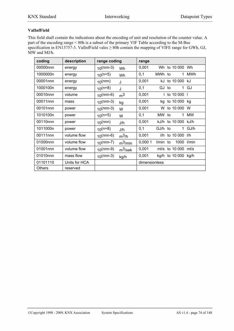
KNX Standard Interworking Datapoint Types
©Copyright 1998 - 2009, KNX Association System Specifications AS v1.4 - page 74 of 148
ValInfField
This field shall contain the indications about the encoding of unit and resolution of the counter value. A part of the encoding range < 80h is a subset of the primary VIF Table according to the M-Bus specification Hin H EN13757-3. ValInfField vales ≥ 80h contain the mapping of VIFE range for GWh, GJ, MW and MJ/h.
coding description range coding range 00000nnn energy 10(nnn-3) Wh 0,001 Wh to 10 000 Wh
1000000n energy 10(n+5) Wh 0,1 MWh to 1 MWh
00001nnn energy 10(nnn) J 0,001 kJ to 10 000 kJ
1000100n energy 10(n+8) J 0,1 GJ to 1 GJ
00010nnn volume 10(nnn-6) m3 0,001 l to 10 000 l
00011nnn mass 10(nnn-3) kg 0,001 kg to 10 000 kg
00101nnn power 10(nnn-3) W 0,001 W to 10 000 W
1010100n power 10(n+5) W 0,1 MW to 1 MW
00110nnn power 10(nnn) J/h 0,001 kJ/h to 10 000 kJ/h
1011000n power 10(n+8) J/h 0,1 GJ/h to 1 GJ/h
00111nnn volume flow 10(nnn-6) m3/h 0,001 l/h to 10 000 l/h
01000nnn volume flow 10(nnn-7) m3/min 0,000 1 l/min to 1000 l/min
01001nnn volume flow 10(nnn-9) m3/sek 0,001 ml/s to 10 000 ml/s
01010nnn mass flow 10(nnn-3) kg/h 0,001 kg/h to 10 000 kg/h
01101110 Units for HCA dimensionless Others reserved

KNX Standard Interworking Datapoint Types
©Copyright 1998 - 2009, KNX Association System Specifications AS v1.4 - page 75 of 148
4 3BDatapoint Types for HVAC
4.1 55BSimple Datapoint Types with STATUS/COMMAND Z8 field
4.1.1 108BIntroduction This clause gives a general introduction to the subject of extended Datapoint Types used in HVAC applications including a standardised Z8 field with STATUS / COMMAND information besides the main data value.
The Datapoint Types containing a Z8 field always have the structure MZ8. This is, one main value (M) is followed by the Z8 field.
Datapoint Types with a Z8 field have the naming format DPT_....._Z.
These Datapoint Types are based on a more object oriented approach. This is the following. - If such a Datapoint is accessed using the A_PropertyValue_Read-service
F
18F
) the response shall contain the Z8 field that is interpreted as a generic STATUS information that contains attributes of the Datapoint;
- If such a Datapoint is distributed using the service A_GroupPropertyValue_InfoReport X
18X
), the Z8 field shall be interpreted as a generic STATUS information that contains attributes of the Datapoint (same as Response);
- If such a Datapoint is accessed using the services A_PropertyValue_Write X
18X
) or A_GroupPropertyValue_Write
X
18X
), the additional field shall be interpreted as a COMMAND that contains methods to be executed on the Datapoint.
STATUS - field
For many HVAC objects a status information must be provided in addition to the main value for Read-access or InfoReport service. EXAMPLES
- sensor fault ⇒ value is invalid - Datapoint is not used by the application (out of service) ⇒ value is invalid - sensor value is overridden - sensor alarm level is exceeded - etc.
This Status information shall be transmitted together with the main value in the same A_PropertyValue_-Response-PDU, A_GroupPropertyValue_Response-PDU or A_GroupPropertyValue_InfoReport-PDU (no different Datapoints or properties) for reasons of data consistency, support of generic Datapoint descriptions and minimised bus load.
The KNX protocol does not offer the possibility to read different Datapoints in the same Application Layer PDU therefore structured DPT are used.
18) The services A_PropertyValue_Read (A_PropertyValue_Read-PDU, A_PropertyValue_Response-PDU) or the
service A_PropertyValue_Write (A_PropertyValue_Write-PDU) using point-to-point connectionless or connection-oriented communication mode or the LTE services A_GroupPropertyValue_Read (A_GroupPropertyValue_Read-PDU, A_GroupPropertyValue_Response-PDU), A_GroupPropertyValue_InfoReport, A_GroupPropertyValue_Write.

KNX Standard Interworking Datapoint Types
©Copyright 1998 - 2009, KNX Association System Specifications AS v1.4 - page 76 of 148
COMMAND field
On the other hand, execution of specific commands using the Application Layer services A_PropertyValue_Write and A_GroupPropertyValue_Write to change the status and behaviour of a Datapoint is often required. EXAMPLES
- set Datapoint out of service - normal write of a parameter - override sensor value - acknowledge alarm - etc.
This Command shall also be transmitted together with the main value in the same A_PropertyValue_Write-PDU or A_GroupPropertyValue_Write-PDU (no different Datapoints or properties) for reasons of data consistency, generic Datapoint descriptions and minimal bus load.
The KNX protocol does not offer specific Application Layer services to execute these different write commands. It is also not possible to write different Datapoints in the same Application Layer PDU.
Therefore additional datatypes are proposed to allow transmission of the Z8 STATUS/COMMAND field in the same PDU.
4.1.2 109BDatatype format XTable 3 X summarizes the general structure of new elementary datatypes with STATUS/COMMAND field in data octet 1.
Table 3 – Interpretation of the Z8-field in function of the Application Layer service
Property Access Application Layer Service PDU data octet n..2 data octet 1 Z8
point-to-point addressing
A_PropertyValue_Response-PDU STATUS
A_PropertyValue_Write-PDU COMMAND
LTE
A_GroupPropertyValue_InfoReport-PDU STATUS
A_GroupPropertyValue_Response-PDU elementary datatype STATUS
A_GroupPropertyValue_Write-PDU COMMAND Constraint
The Z8 datatype format is not applicable to the Shared Variable model or standard Group Objects because the Shared Variable model does not differentiate between InfoReport and Write service. The A_GroupValue_Write service is used for reporting of information (e.g. sensor values) and writing of information (e.g. write a actuator setpoint). Therefore the interpretation of the Z8 field would be ambiguous.

KNX Standard Interworking Datapoint Types
©Copyright 1998 - 2009, KNX Association System Specifications AS v1.4 - page 77 of 148
STATUS field: Z8 contains a 8 bit bitset (also following TC247 ‘Field Level Objects’ status) in case of InfoReport or Read/Response service
Bit # Function Main value
Remark Valid Invalid
Bit 0 OutOfService Typical usage: - optional sensor is not connected (out of service), sensor
data is invalid - configuration parameter is void (function disabled)
0: false X* Datapoint is accessible and the main value is valid 1: true X Datapoint is accessible but out of service, i.e. the main value is
void and may contain any value. The sender shall support the ‘OutOfService’ flag if the main value may be out of service. The receiver shall detect that the main value is invalid due to OutOfService condition
Bit 1 Fault Typical usage: - sensor value is corrupted due to a hardware problem, data
is invalid - a database value is corrupted, e.g. due to loss off backup
power, erased EEPROM etc. 0: false X Datapoint main value is valid ⇒ no failure
1: true X Datapoint main value is corrupted due to failure.
The sender shall support the ‘Fault’ flag if the main value may be corrupted. The receiver shall detect that the main value is corrupted due to fault condition. The main value field contains failure information instead of the data value if ‘Fault’ = true: main value failure information = 0 : general fault (unspecified) = 1 : sensor open circuit (optional detection) = 2 : sensor short circuit (optional detection) all other values are reserved The sender shall set the main value = 0 if the reason for the fault cannot be specified.
Bit 2 Overridden Typical usage: - sensor value is temporarily overridden for service - actuator setpoint is temporarily overridden for service
0: false X* normal operation of the Datapoint, actual value 1: true X* actual Datapoint value is overridden Bit 3 InAlarm Usage: for Datapoints with Alarming capability only 0: false X* Datapoint not in alarm status 1: true X* some alarm condition for this Datapoint occurred Bit 4 AlarmUnAck Usage: for Datapoints with Alarming capability only 0: acknowledged X* alarm is acknowledged by operator 1: unacknowledged X* alarm is not yet acknowledged by operator Bit 5-7 reserved set to 0,0,0
X* validity of Datapoint value depends on other STATUS attributes

KNX Standard Interworking Datapoint Types
©Copyright 1998 - 2009, KNX Association System Specifications AS v1.4 - page 78 of 148
Combination of Status bits
STATUS Bits
Main value Remarks
Out
OfS
ervi
ce
Faul
t
Ove
rrid
den
InA
larm
; A
larm
UnA
ck
false false false X valid Normal case
false false true X valid value is overridden
false true false X failure info
Datapoint failure, main value contains a failure information
false true true X ! valid ! *)
Datapoint failure but e.g. a corrupted (sensor-) value is overridden. ‘Overridden’ has priority over ‘Fault’. The main value is valid.
true false false X invalid - actual (sensor-) value not available - parameter out of service
true true X X ----- illegal combination: if a Datapoint is out of service there is no reason for a ‘Fault’ because also failure detection is out of service
true X true X ----- illegal combination: if a Datapoint is out of service there is no possibility to override it
Remarks
- Setting of the Status flags ‘OutOfService’ and ‘Fault’ is mutually exclusive. If a Datapoint is out of service (i.e. void, function disabled), a fault condition cannot arise and vice versa.
- Currently the flags ‘InAlarm’ and ‘AlarmUnAck’ are not used (i.e. 0, 0) in all Datapoints except simple AlarmInfo Datapoint (⇒ see FB Technical Alarm) because Alarms are generated at device level but not at Datapoint level. But the STATUS enables Alarm generation and acknowledgement at Datapoint level in future applications.
- Depending on the features of a property only a subset of STATUS flags may be supported. The other flags are set to 0 (default) ⇒ Features to be defined in the Datapoint description.
- *) Support of this combination of 'Fault' and 'Overridden' is optional. It is allowed that the override of the Datapoint value automatically clears the 'Fault' attribute, see also clause X4.1.5X ⇒ 'Fault' = false / 'Overridden' = true After execution of the COMMAND 'Release', the 'Overridden' attribute is cleared and the 'Fault' attribute is set again if the failure still persists.

KNX Standard Interworking Datapoint Types
©Copyright 1998 - 2009, KNX Association System Specifications AS v1.4 - page 79 of 148
COMMAND field: Z8 contains a 8 bit enumeration value in case of a write service.
enum value
COMMAND
Main value
Remark Typical support in
Valid
don’
t car
e
LTE
Writ
e C
lient
1)
LTE
Writ
e Se
rver
2)
Prop
erty
W
rite
=0 NormalWrite X
Typical usage: - normal write of a setpoint, parameter,
configuration value - not applicable for sensor values ! → no change of the STATUS flags
X X X
=1 Override X
Typical usage: - temporary override of a sensor value for
service - temporary override of a actuator setpoint
for service → sets STATUS ‘Overridden’ → may clear STATUS 'Fault' (optional, see above)
- X X
=2 Release X
Typical usage: together with ‘Override’. Undo ‘Override’, leads to normal operation of the Datapoint using the actual value → resets STATUS ‘Overridden’
- X X
=3 SetOSV X
Typical usage: disable functionality of a Datapoint - configuration parameter is void (function
disabled) - sensor is disabled SetOSV ⇒ data object is unused, function disabled → sets STATUS ‘OutOfService’
- (X) X
=4 ResetOSV X
Typical usage: together with ‘SetOSV’ The main value field is valid but may be ignored by the receiver (e.g. sensor) → resets STATUS ‘OutOfService’
- (X) X
=5 AlarmAck X
Usage: for Datapoints with Alarming capability only Acknowledgement of Alarm STATUS → resets STATUS ‘AlarmUnAck’
- - X
=6 SetToDefault X Typical usage: parameters
Sets the main value to the default value - X X
=7-255 reserved 1) LTE runtime interworking Write Output, e.g. a HVAC zone controller valve setpoint output 2) LTE runtime interworking Write Input, e.g. a Valve setpoint input 3) Property (parameter in a device, server) accessible by a tool (client) X: usage possible and useful; support to be decided for each Datapoint individually (X): very limited usage in practice.

KNX Standard Interworking Datapoint Types
©Copyright 1998 - 2009, KNX Association System Specifications AS v1.4 - page 80 of 148
Remarks
- The usage of the Commands ‘NormalWrite’ and ‘Override’/ ‘Release’ is usually but not always mutually exclusive. E.g. a parameter may be written but an override of a parameter does not make sense. EXCEPTION EXAMPLE
The valve setpoint is a LTE write input on the valve. A HVAC controller sends the valve setpoint periodically to the valve using the ‘NormalWrite’ Command. A tool could execute an override to the setpoint on the valve. The valve uses from then on the override value and not the value from the HVAC controller.
- Reception of a COMMAND in the Datapoint server may change the STATUS of the Datapoint in the database. The Command itself is not stored in the database.
- COMMAND features except ‘NormalWrite’ are mainly applicable for properties with Write access in client/server mode with point-to-point addressing. The Sender (i.e. Datapoint client) using A_PropertyValue_Write is normally a (Service-) Tool.
- During runtime communication the sender (i.e. a process device) of a LTE A_GroupPropValue_Write-PDU will usually have the COMMAND field fixed to ‘NormalWrite’ (=0) because most other commands have no practical usage for process data communication. A tool will use A_PropertyValue_Write and point-to-point addressing, see above.
- Depending on the features of a property only a small subset of COMMANDS may be supported in the Datapoint server. ⇒ Features to be defined in the Datapoint description.
4.1.3 110BOutOfService mechanism for a parameter A parameter and the functionality behind the parameter can be disabled using the ‘SetOSV’ command.
EXAMPLE
'OutOfService'= false
Command 'SetOSV'Status 'OutOfService' = true;function(parameter) is disabled
Command 'ResetOSV'Store main value;Status 'OutOfService'= falsefunction(parameter) is enabled
Command 'ResetOSV'Store main value
Command 'NormalWrite'Store main value
'OutOfService'= true
Command 'NormalWrite'no action
Command 'Override'no action
Command 'Override'no action
Command 'SetOSV'no action
- The parameter is changed using ‘NormalWrite’ Command.
- The Command ‘ResetOSV’ resets the Status ‘OutOfService’ to false and the main value is written to the parameter.
- ‘Override’ Command and Status ‘Overridden’ are not supported on parameter Datapoints.

KNX Standard Interworking Datapoint Types
©Copyright 1998 - 2009, KNX Association System Specifications AS v1.4 - page 81 of 148
4.1.4 111BOutOfService mechanism for a runtime Datapoint (actual value) A runtime Datapoint (e.g. a sensor value) and the functionality behind the Datapoint may be automatically disabled by the application program for various reasons (e.g. an optional sensor is not connected). This is indicated by the Status ‘OutOfService’.
The Datapoint value may be overridden only if ‘OutOfService’ = false. If ‘OutOfService’ = true, the Override feature is inhibited.
EXAMPLE 1 Commands ‘SetOSV’ and ‘Reset OSV’ are supported, i.e. the actual value can be set out of service by a tool.
'OutOfService'= false
Command 'SetOSV'Status 'OutOfService' = true;function(datapoint) is disabled
Command 'ResetOSV'Status 'OutOfService'= falsefunction(datapoint) is enabledCommand 'ResetOSV'
no action
'OutOfService'= true
Command 'Override'no action
Command 'Override'Store main valueStatus 'Overridden'=true
Command 'SetOSV'no action
Command 'Release'Status 'Overridden'=false
Command 'Release'no action
EXAMPLE 2 The application program changes the ‘OutOfService’ Status automatically depending
on local application conditions. E.g. an optional sensor is not connected to a HVAC controller ⇒ Status ‘OutOfService’ = true (and not ‘Fault’ = true) Property Write Commands ‘SetOSV’ and ‘ResetOSV’ sent via bus are not supported on such Datapoints.
'OutOfService'= false
Application condition X Status 'OutOfService' = true;function(datapoint) is disabled
Application condition YStatus 'OutOfService'= falsefunction(datapoint) is enabledCommand 'ResetOSV'
no action
'OutOfService'= true
Command 'Override'no action
Command 'Override'Store main valueStatus 'Overridden'=true
Command 'SetOSV'no action
Command 'Release'Status 'Overridden'=false
Command 'Release'no action
Command 'ResetOSV'no action
Command 'SetOSV'no action

KNX Standard Interworking Datapoint Types
©Copyright 1998 - 2009, KNX Association System Specifications AS v1.4 - page 82 of 148
4.1.5 112BOverride mechanism ‘Override’ is used for a temporary service operation on device level or system level. Usually sensor values or actuator setpoints may support the override feature.
InfoReportRead/Response
CMD 'Release' / 'Override'
internal value
'Overridden' = false 'Overridden' = true
datapoint value
e.g. from sensoroverride value
NOTE In case of a sensor failure (STATUS 'Fault') it may be useful to override the sensor value temporarily for service reasons. Execution of the COMMAND 'Override' disconnects the data flow from the sensor to the Datapoint value and the override value is used instead. Since the actual sensor value is no more considered, it is allowed for the implementation of the Datapoint to clear the STATUS 'Fault' when 'Overridden' is set. See also clause X4.1.2
EXAMPLE 1 Override of a sensor value, e.g. the LTE InfoReport sensor output (Datapoint server); local override of the output by a tool using Property Write service (individual addressing).
'Overridden'= false
Command 'NormalWrite'no action
'Overridden'= true
Command 'NormalWrite'no action
Command 'Override'Store main value
Command 'Override'Status 'Overridden'=trueStore main value Command 'SetOSV'
no action
Command 'ResetOSV'no action
Command 'Release'Status 'Overridden'=false
Command 'Release'no action
- In the state ‘Overridden’ = true the actual value of the sensor is replaced by the override value, which is distributed in the system using LTE InfoReport service.
- In the state ‘Overridden’ = true the Commands ‘SetOSV / ‘ResetOSV’ have no effect (Override has in this case higher priority).
EXAMPLE 2 Override of a valve setpoint on the valve, i.e. a LTE Write input (Datapoint server) on the valve is overridden from a tool by using LTE Write service or Property Write service.
'Overridden'= false
Command 'NormalWrite'Store main value
'Overridden'= true
Command 'NormalWrite'no action
Command 'Override'Store main value
Command 'Override'Status 'Overridden'=trueStore main value Command 'SetOSV'
no action
Command 'ResetOSV'no action
Command 'Release'Status 'Overridden'=false
Command 'Release'no action

KNX Standard Interworking Datapoint Types
©Copyright 1998 - 2009, KNX Association System Specifications AS v1.4 - page 83 of 148
- In state ‘Overridden’ = true the override value is used and the received value (LTE Write service) with Command ‘NormalWrite’ is ignored.
- After the ‘Release’ Command the actual value of the Datapoint is undefined until the reception of the next ‘NormalWrite’ LTE Write update (the valve will use either a default value or keeps the override value).
Override Timeout: ‘Overridden’ status shall be self clearing based on a timeout, because the override condition shall not remain forever if the operator / installer forgets to ‘Release’ the overridden Datapoint.
The implementation of the timeout is company specific, e.g. - individual timeout per Datapoint - or automatic ‘Release’ of all Datapoints in a device at midnight - or re-trigger a common timeout for all Datapoints after reception of each ‘Override’ Command
⇒ timeout executes a ‘Release’ on all Datapoints.
Power-up condition will normally reset the ‘Overridden’ attribute (manufacturer specific solution).
4.1.6 113BAlarming mechanism - An Alarm at Datapoint level indicates that a serious fault condition occurred or still occurs on the
Datapoint.
EXAMPLES - transient error event (e.g. critical sensor level exceeded) - persistent error state (e.g. sensor fault; corrupted memory value)
- Alarms can be acknowledged by an operator (write service to a property). Datapoints with Alarm feature therefore therefore a corresponding 2 bit state machine in the Status field (InAlarm / AlarmUnAck).
Alarm State Machine
Normal, Acked Normal,UnAcked
Alarm, Acked Alarm,UnAcked
disturbancedisappears
disturbance appears
disturbancedisappears
disturbance appears disturbance
appears
disturbanceappears
InAlarm = false;AlarmUnAck = acknowledged
Command ‘AlarmAck’
Command ‘AlarmAck’
Command ‘AlarmAck’
Command ‘AlarmAck’InAlarm = true;AlarmUnAck = acknowledged
InAlarm = false;AlarmUnAck = unacknowledged
InAlarm = true;AlarmUnAck = unacknowledged
NOTE Currently Alarm messages are provided for the system only on device-level (not on functional or Datapoint level) using the AlarmInfo Datapoint (⇒ see FB Technical Alarm). I.e. individual Datapoints except the device alarm Datapoint AlarmInfo do not support this feature.

KNX Standard Interworking Datapoint Types
©Copyright 1998 - 2009, KNX Association System Specifications AS v1.4 - page 84 of 148
4.2 56BDatapoint Types B1 Format: 1 bit: B1
octet nr 1
field names b
encoding B
Encoding: See below
Range: b = {0,1}
Unit: See below
Resol.: (not applicable)
PDT: PDT_BINARY_INFORMATION (alt: PDT_UNSIGNED_CHAR)
Datapoint Types
ID: Name: Encoding: b Use: 1.100 DPT_Heat/Cool 0 = cooling
1 = heating FB
4.3 57BDatapoint Types N8 Format: 1 octet: N8
octet nr. 1
field names field1
encoding N N N N N NNN
Encoding: Encoding absolute value N = [0 … 255]
Unit: none
Resol.: none
PDT: PDT_ENUM8 (alt: PDT_UNSIGNED_CHAR) Datapoint Types
ID: Name: Encoding: Range: Use:
20.100 DPT_FuelType field1 = FuelType 0 = auto 1 = oil 2 = gas 3 = solid state fuel 4 … 255 = not used, reserved
[0 … 3] HWH
20.101 DPT_BurnerType field1 = BurnerType 0 = reserved 1 = 1 stage 2 = 2 stage 3 = modulating 4 … 255 = reserved
[0 … 3] HWH

KNX Standard Interworking Datapoint Types
©Copyright 1998 - 2009, KNX Association System Specifications AS v1.4 - page 85 of 148
Datapoint Types
ID: Name: Encoding: Range: Use:
20.102 DPT_HVACMode field1 = HVACMode 0 = Auto 1 = Comfort 2 = Standby 3 = Economy 4 = Building Protection 5 … 255 = reserved
[0 … 4] HVAC
NOTE 10 DPT_HVACMode is the same as HDPT_HVACMode_Z (201.100) H, but without Z8 field. In HVAC Room Controllers in KNX Standard Mode, DPT_HVACMode shall be used to set the HVAC Mode.
The HVAC Room controller may have in addition to the DPT_HVACMode individual Datapoints of 1 bit to set the HVAC Mode. (This means that additional HVAC Mode via individual 1 bit DPs is allowed.)
For reporting the currently set HVAC Mode by means of a status/diagnostic Datapoint, the HVAC Room controllers shall use XDPT_StatusRHCCX or possibly XDPT_HVACStatusX (see XAppendix AX).
20.103 DPT_DHWMode F
19F
) field1 = DHWMode 0 = Auto 1 = LegioProtect 2 = Normal 3 = Reduced 4 = Off/FrostProtect 5 … 255 = reserved
[0 … 4] HWH
20.104 DPT_LoadPriority field1 = LoadPriority 0 = None 1 = Shift load priority 2 = Absolute load priority 3 … 255 = reserved
[0 … 2] HVAC
20.105 DPT_HVACContrMode F
20F
) field1 = HVACContrMode 0 = Auto 1 = Heat 2 = Morning Warmup 3 = Cool 4 = Night Purge 5 = Precool 6 = Off 7 = Test 8 = Emergency Heat 9 = Fan only 10 = Free Cool 11 = Ice 12 … 19 = reserved 20 = NoDem 21 … 255 = reserved
{[0 … 11], 20} HVAC
19) Same as HDPT_DHWMode_Z (201.102)H, but without Z8 field. 20) Same as HDPT_HVACContrMode_Z (201.104)H, but without Z8 field.

KNX Standard Interworking Datapoint Types
©Copyright 1998 - 2009, KNX Association System Specifications AS v1.4 - page 86 of 148
Datapoint Types
ID: Name: Encoding: Range: Use:
20.106 DPT_HVACEmergMode F
21F
) field1 = HVACEmergMode 0 = Normal 1 = EmergPressure 2 = EmergDepressure 3 = EmergPurge 4 = EmergShutdown 5 = EmergFire 6 … 255 = reserved
[0 … 5] HVAC
20.107 DPT_ChangeoverMode field1 = ChangeoverMode 0 = Auto 1 = CoolingOnly 2 = HeatingOnly 3 … 255 = reserved
[0 … 2] HVAC
20.108 DPT_ValveMode field1 = ValveMode 0 = reserved 1 = Heat stage A for normal
heating 2 = Heat stage B for heating
with two stages (A + B) 3 = Cool stage A for normal
cooling 4 = Cool stage B for cooling
with two stages (A + B) 5 = Heat/Cool for changeover
applications 6 … 255 = reserved
[1 … 5] HVAC
20.109 DPT_DamperMode field1 = DamperMode 0 = reserved 1 = Fresh air, e.g. for fancoils 2 = Supply Air. e.g. for VAV 3 = Extract Air e.g. for VAV 4 … 255 = reserved
[1 … 3] HVAC
20.110 DPT_HeaterMode field1 = HeaterMode 0 = reserved 1 = Heat Stage A On/Off 2 = Heat Stage A Proportional 3 = Heat Stage B Proportional 4 … 255 = reserved
[1 … 3] HVAC
20.111 DPT_FanMode field1 = FanMode 0 = not running 1 = permanently running 2 = running in intervals 3 … 255 = reserved
[0 … 2] TU
20.112 DPT_MasterSlaveMode field1 = MasterSlaveMode 0 = autonomous 1 = master 2 = slave 3 … 255 = reserved
[0 … 2] TU
21) Same as HDPT_HVACEmergMode_Z (201.109)H, but without Z8 field.

KNX Standard Interworking Datapoint Types
©Copyright 1998 - 2009, KNX Association System Specifications AS v1.4 - page 87 of 148
Datapoint Types
ID: Name: Encoding: Range: Use:
20.113 DPT_StatusRoomSetp field1 = StatusRoomSetp 0 = normal setpoint 1 = alternative setpoint 2 = building protection setpoint 3 … 255 = reserved
[0 … 2] TU
DEH
4.4 58BData Type “8-Bit Set”
4.4.1 114BDatapoint Type “Forcing Signal” LTE: compound structure
Format: 1 octet: B8 octet nr. 1
field names Attributes
encoding B B B B B B B B
Encoding: See below.
Range: See below.
Unit: Not applicable.
Resol.: Not applicable.
PDT: PDT_BITSET8 (alt: PDT_GENERIC_01)
Datapoint Types
ID: Name: Encoding: Range: Use:
21.100 DPT_ForceSign See below See below HWH Data fields Description Range Attributes Bit # Bitset B8,
- ForceRequest 0 indicates if forced power consumption is necessary (validity of the remaining attributes)
true / false
- Protection 1 ‘Protection’ indicates that a critical overheat condition occurs (e.g. too high boiler temp.). The interpretation of the attributes ‘DHWNorm’, ‘DHWLegio’, ‘RoomHComf’ and ‘RoomHMax’ depends on the type of overheat: the addressed heat consumers shall consume energy
true / false
- Oversupply 2 ‘Oversupply’ indicates that an uncritical overheat condition occurs (e.g. boiler temperature is much higher than requested by heat demand). The interpretation of the attributes ‘DHWNorm’, ‘DHWLegio’, ‘RoomHComf’ and ‘RoomHMax’ depends on the type of overheat: the addressed heat consumers may consume energy
true / false

KNX Standard Interworking Datapoint Types
©Copyright 1998 - 2009, KNX Association System Specifications AS v1.4 - page 88 of 148
Data fields Description Range Attributes Bit # Bitset B8,
- Overrun 3 indicates that remaining energy is available (e.g. in the boiler after load shutdown). All heat consumers which were active immediately before the overrun condition occurred continue their energy consumption with their last setpoint. This attribute is completely independent from the attributes ‘Protection’, ‘Oversupply’, ‘DHWNorm’, ‘DHWLegio’, ‘RoomHComf’ and ‘RoomHMax’
true / false
- DHWNorm 4 Load DHW to ‘Normal’ Level in case of overheat: additional info about the type of overheat is contained in the ‘Protection’ and ‘Oversupply’ attributes
true / false
- DHWLegio 5 Load DHW to ‘LegioProtect’ Level in case of overheat (‘Protection’ or ‘Oversupply’)
true / false
- RoomHComf 6 Load Room Heating to ‘Comfort’ Level in case of overheat (‘Protection’ or ‘Oversupply’)
true / false
- RoomHMax 7 Load Room Heating with maximum flow temperature in case of overheat (‘Protection’ or ‘Oversupply’)
true / false
Depending on the usage of this DPT in a given Datapoint, some bit-fields may be unused and set to ‘0’ by the sender and will be ignored by the receiver
Standard Mode
The information of this DPT is not available in Standard Mode.
4.4.2 115BDatapoint Type “Forcing Signal Cool” LTE: compound structure
Format: 1 octet: B8 octet nr. 1
field names Attributes
encoding B B B B B B B B
Encoding: See below.
Range: See below.
Unit: Not applicable.
Resol.: Not applicable.
PDT: PDT_BITSET8 (alt: PDT_GENERIC_01)
Datapoint Types
ID: Name: Encoding: Range: Use:
21.101 DPT_ForceSignCool See below. See below. VAC

KNX Standard Interworking Datapoint Types
©Copyright 1998 - 2009, KNX Association System Specifications AS v1.4 - page 89 of 148
Data fields Description Unit / Range
Attributes Bit # Bitset B8
- ForceRequest 0 indicates if forced power consumption is necessary (validity of the remaining attributes)
true / false
reserved 1 to 7 default 0 Standard Mode
The information of this DPT is not available in Standard Mode.
4.4.3 116BDatapoint Type “Room Heating Controller Status” LTE: structured DPT
Format: 1 octet: B8 octet nr. 1
field names Attributes
encoding B B B B B B B B
Encoding: See below.
Range: See below.
Unit: Not applicable.
Resol.: Not applicable.
PDT: PDT_BITSET8 (alt: PDT_GENERIC_01)
Datapoint Types
ID: Name: Encoding: Range: Use:
21.102 DPT_StatusRHC See below. See below. HWH Data fields Description Unit / Range
Attributes Bit # Bitset B8
- Fault 0 Room Heating Controller as a failure (mainly for monitoring)
true / false
- StatusECO 1 ECO status; temporary energy saving mode; e.g. due to high room temperature or high outside temperature
true / false
- TempFlowLimit 2 Flow temperature limitation active true / false
- TempReturnLimit 3 Return temperature limitation active true / false
- StatusMorningBoost 4 morning boost active true / false
- StatusStartOptim 5 start optimization active true / false
- StatusStopOptim 6 stop optimization active true / false
- SummerMode 7 room heating is disabled due to local summer/winter mode
true / false
Depending on the usage of this DPT in a given Datapoint, some bit-fields may be unused and set to ‘0’ by the sender and will be ignored by the receiver

KNX Standard Interworking Datapoint Types
©Copyright 1998 - 2009, KNX Association System Specifications AS v1.4 - page 90 of 148
Standard Mode
Separate Boolean DPs.
4.4.4 117BDatapoint Type “Solar DHW Controller Status” LTE: structured DPT
Format: 1 octet: B8 octet nr. 1
field names Attributes
encoding 0 0 0 0 0 B B B
Encoding: See below.
Range: See below.
Unit: Not applicable.
Resol.: Not applicable.
PDT: PDT_BITSET8 (alt: PDT_GENERIC_01)
Datapoint Types
ID: Name: Encoding: Range: Use:
21.103 DPT_StatusSDHWC See below. See below. DHW control Data fields Description Unit / Range
Attributes Bit # Bitset B8
- Fault 0 SDHWC has a failure 1 = fault 0 = ok
- SDHWLoadActive 1 SDHW load currently active, solar pump is running true / false
- SolarLoadSufficient 2 enough solar energy available for DHW load to reach the DHW temperature setpoint
true / false
- reserved 3 to 7 default 0 Standard Mode
Separate Boolean DPs.

KNX Standard Interworking Datapoint Types
©Copyright 1998 - 2009, KNX Association System Specifications AS v1.4 - page 91 of 148
4.4.5 118BDatapoint Type “Fuel Type Set” LTE: structured DPT
Format: 1 octet: B8 octet nr. 1
field names Fuel Type Set
encoding 0 0 0 0 0 B B B
Encoding: See below.
Range: See below.
Unit: Not applicable.
Resol.: Not applicable.
PDT: PDT_BITSET8 (alt: PDT_GENERIC_01)
Datapoint Types
ID: Name: Encoding: Range: Use:
21.104 DPT_FuelTypeSet See below. See below. HWH Data fields Description Unit / Range
FuelType Bit # Bitset B8
- Oil 0 oil fuel supported true / false
- Gas 1 gas fuel supported true / false
- SolidState 2 solid state fuel supported true / false
reserved 3 to 7 default 0
Standard Mode
The information of this DPT is not available in Standard Mode.

KNX Standard Interworking Datapoint Types
©Copyright 1998 - 2009, KNX Association System Specifications AS v1.4 - page 92 of 148
4.4.6 119BDatapoint Type “Room Cooling Controller Status” LTE: structured DPT
Format: 1 octet: B8 octet nr. 1
field names Attributes
encoding 0 0 0 0 0 0 0 B
Encoding: See below.
Range: See below.
Unit: Not applicable.
Resol.: Not applicable.
PDT: PDT_BITSET8 (alt: PDT_GENERIC_01)
Datapoint Types
ID: Name: Encoding: Range: Use:
21.105 DPT_StatusRCC See below. See below. VAC Data fields Description Unit / Range
Attributes Bit # Bitset B8
- Fault 0 Room Cooling Controller has a failure (mainly for monitoring) true / false
reserved 1 to 7 for features implemented in the future default 0
Standard Mode
Separate Boolean DPs.
4.4.7 120BDatapoint Type “Ventilation Controller Status” LTE: structured DPT
Format: 1 octet: B8 octet nr. 1
field names Attributes
encoding 0 0 0 0 B B B B
Encoding: See below.
Range: See below.
Unit: Not applicable.
Resol.: Not applicable.
PDT: PDT_BITSET8 (alt: PDT_GENERIC_01)
Datapoint Types
ID: Name: Encoding: Range: Use:
21.106 DPT_StatusAHU See below See below VAC

KNX Standard Interworking Datapoint Types
©Copyright 1998 - 2009, KNX Association System Specifications AS v1.4 - page 93 of 148
Data fields Description Unit / Range
Attributes Bit # Bitset B8
- Fault 0 Ventilation Controller has a failure (mainly for monitoring) true / false
- FanActive 1 Supply and / or exhaust air fans are operating true / false
- Heat 2 Ventilation Controller is in heating mode true / false
- Cool 3 Ventilation Controller is in cooling mode true / false
reserved 4 to 7 for features implemented in the future default 0 Standard Mode
Separate Boolean DPs.
4.5 59BData Type “16-Bit Set”
4.5.1 121BDatapoint Type “DHW Controller Status” LTE: compound structure
Format: 2 octets: B16 octet nr. 2MSB 1LSB
field names Attributes
encoding 0 0 0 0 0 0 0 B B B B B B B B B
Encoding:
Range:
Unit: Not applicable.
Resol.: Not applicable.
PDT: PDT_BITSET16 (alt: PDT_GENERIC_02)
Datapoint Types
ID: Name: Encoding: Range: Use:
22.100 DPT_StatusDHWC See below See below DHW control

KNX Standard Interworking Datapoint Types
©Copyright 1998 - 2009, KNX Association System Specifications AS v1.4 - page 94 of 148
Data fields Description Unit / Range
Attributes Bit # Bitset B16
- Fault 0 DHWC has a failure true / false
- DHWLoadActive 1 DHW load currently active true / false
- LegioProtActive 2 legionella protection procedure active (load & hold)
true / false
- DHWPushActive 3 true during DHW load triggered by a ‘DHWPush’ command
true / false
- OtherEnergySourceActive 4 load by DHWC is disabled due to other active energy source (e.g. electrical)
true / false
- SolarEnergyOnly 5 load by DHWC is disabled due to sufficient solar energy
true / false
- SolarEnergySupport 6 DHW load is partly done by solar energy true / false
- TempOptimShiftActive 7 actual DHW temp setpoint is influenced by TempDHWSetpOptimShift ≠ 0
true / false
reserved 8 to 15 reserved default 0 Standard Mode
Separate Boolean DPs.
4.5.2 122BDatapoint Type “RHCC Status” LTE
Not available.
Standard Mode
Format: 2 octets: B16
octet nr. 2 MSB 1 LSB
field names Attributes
0 b14 b13 b12 b11 b10 b9 b8 b7 b6 b5 b4 b3 b2 b1 b0
encoding r B B B B B B B B B B B B B B B
Range: all fields: {0,1}
Unit: Not applicable.
Resol.: Not applicable.
PDT: PDT_BITSET16 (alt: PDT_GENERIC_02)
Datapoint Types
ID: Name: Use:
22.101 DPT_StatusRHCC HVAC

KNX Standard Interworking Datapoint Types
©Copyright 1998 - 2009, KNX Association System Specifications AS v1.4 - page 95 of 148
Data fields Description Sup Encoding
Bit # Attributes Bitset B16
0 Fault Room Temperature Controller has a failure. This is a status information, mainly for monitoring.
M 0 = false 1 = true
1 StatusEcoH ECO status of the room heating temperature controller; If true, the heating controller is temporary in energy saving mode and there is no heat demand although the controller is in heating mode (HeatCoolMode=heating) e.g. due to high room temperature because of internal or solar heat gains or due to high outside temperature
O 0 = false 1 = true
2 TempFlowLimit Flow temperature limitation is active. E.g. max. flow temperature limitation for floor heating protection
O 0 = false 1 = true
3 TempReturnLimit Return temperature limitation is active e.g. min return temperature is maintained for boiler protection
O 0 = false 1 = true
4 StatusMorningBoostH Heating morning boost is active, plant is operated at maximum heating output
O 0 = false 1 = true
5 StatusStartOptim optimum early start control in the morning is active in order to reach the comfort setpoint according to schedule
O 0 = false 1 = true
6 StatusStopOptim optimum early shutdown control in the evenig is active in order to maintain the comfort setpoint until the end of the comfort schedule period
O 0 = false 1 = true
7 HeatingDisabled room heating is disabled due to local summer/winter mode. E.g. heating is disabled if - the attenuated outside temperature is above a
threshold - current date is in programmed summer-period
O 0 = false 1 = true
8 HeatCoolMode HeatCoolMode of the controller default: heating
M 0 = cooling 1 = heating
9 StatusEcoC ECO status of the room cooling temperature controller; If true, the cooling controller is temporary in energy saving mode and there is no cooling demand although the controller is in cooling mode (HeatCoolMode=cooling) e.g. due to energy savings regulations cooling is not allowed if the room temperature is below a defined limit.
O 0 = false 1 = true
10 StatusPreCool Pre cooling mode in the morning, , plant is operated at maximum cooling output
O 0 = false 1 = true
11 CoolingDisabled Cooling is disabled due to (examples) - calendar regulations: current date is out of cooling
period - the attenuated outside temperature is below a
threshold
O 0 = false 1 = true
12 DewPointStatus DewPointStatus of the controller O 0 = no alarm1 = alarm
13 FrostAlarm Frost alarm status of the controller: in alarm if the room temperature drops below a critical threshold
O 0 = no alarm1 = alarm
14 OverheatAlarm Overheat alarm status of the controller: in alarm if the room temperature exceeds a critical threshold
O 0 = no alarm1 = alarm
15 reserved -- default 0

KNX Standard Interworking Datapoint Types
©Copyright 1998 - 2009, KNX Association System Specifications AS v1.4 - page 96 of 148
Usage requirements
DPT_StatusRHCC shall be used by an HVAC Room controller to report the currently set HVAC Mode by means of a status/diagnostic Datapoint.
NOTE 11 An alternative coding is allowed to report the currently set HVAC Mode. For the description and the usage conditions, please refer to the description of XDPT_HVACStatus X in XAppendix A X.
Encoding
Most of the status fields are optional. The coding of the optional fields is defined so that the default value ‘0’ represents the normal case and ‘1’ represents the exception. Displays will usually only indicate the exception but not the normal case. Therefore depending on the usage of this DPT in a given Datapoint, some bit-fields may be unused and set to ‘0’ by the sender and will be ignored by the receiver.
Remarks
- DPT_StatusRHCC is derived from DPT_StatusRHC (21.102) and the “Eberle Status Octet” and extended by some additional attributes
- DPT_StatusRHC is extended to 16 bit and the information of DPT_StatusRHC is a subset of DPT_StatusRHCC
- Except HVAC mode information, all relevant attributes of the “Eberle Status Octet” are included
- The actual HVAC mode of the controller is encoded as enum value in a separate Datapoint.
- The cooling control sequence of the controller is active if - HeatCoolMode = cooling - CoolingDisabled = false
- The heating control sequence of the controller is active if - HeatCoolMode = heating - HeatingDisabled = false
- The controller is neither heating nor cooling if - HeatCoolMode = don’t care - CoolingDisabled = true - HeatingDisabled = true

KNX Standard Interworking Datapoint Types
©Copyright 1998 - 2009, KNX Association System Specifications AS v1.4 - page 97 of 148
4.6 60BDatapoint Types N2 Format: 2 bit: N2
octet nr 1
field names s
encoding NN
Unit: None
Resol.: (not applicable)
PDT: PDT_ENUM8 (alt: PDT_UNSIGNED_CHAR)
Datapoint Types
ID: Name: Range: Use: Encoding:
23.102 DPT_HVAC_PB_Action [00b…11b] FB s 00b = Comfort/Economy 01b = Comfort/Nothing 10b = Economy/Nothing 11b = Building prot/Auto
4.7 61BData Type “Boolean with Status/Command”
4.7.1 123BDatapoint Type “Heat/Cool_Z” LTE: compound structure
Format: 2 octets: B1Z8
2 Heat/Cool
1 Status
Command
0000000B ZZZZZZZZ
Encoding: See below
Range: See below
Unit: See below
Datapoint Types
ID: Name: Range: Unit: Usage:
200.100 DPT_Heat/Cool_Z See below See below HVAC
Data fields Description Unit / Range Heat/Cool Bit # Bitset B8, - Heat/Cool 0 0= cooling
1= heating Status/Command standard Status/Command Z8
Standard Mode
HDPT_Heat/Cool (01.100)H; without Z8 field

KNX Standard Interworking Datapoint Types
©Copyright 1998 - 2009, KNX Association System Specifications AS v1.4 - page 98 of 148
4.7.2 124BDatapoint Type “DPT_BinaryValue_Z” LTE: compound structure
Format: 2 octets: B1Z8
2 BinaryValue
1 Status
Command
0000000B ZZZZZZZZ
Encoding: See below
Range: See below
Unit: See below
Datapoint Types
ID: Name: Range: Unit: Usage:
200.101 DPT_BinaryValue_Z See below See below FOCI
Data fields Description Unit / Range
BinaryValue Bit # Bitset B8
- Low/High 0 0 = low 1 =high
Status/Command standard Status/Command Z8 Standard Mode
HDPT_BinaryValueH ( H1.006H) without Z8 field/

KNX Standard Interworking Datapoint Types
©Copyright 1998 - 2009, KNX Association System Specifications AS v1.4 - page 99 of 148
4.8 62BData Type “8-Bit Enum with Status/Command”
4.8.1 125BDatapoint Type “HVAC Operating Mode” LTE: compound structure
Format: 2 octets: N8Z8 octet nr. 2 1
field names HVACMode Status/ Command
encoding N N N N N NNN Z Z Z Z Z Z Z Z
Resol.: none
PDT: PDT_GENERIC_02
Datapoint Types
ID: Name: Encoding: Range: Unit: Use:
201.100 DPT_HVACMode_Z See below See below See below HVAC DPT_HVACMode_Z
Data fields Description Unit / Range
HVACMode HVAC operating mode
Depending on the type of Datapoint the value ‘Auto’ is allowed or not ⇒ to be defined per Datapoint
enum. N8
Encoding absolute value N = {0, 255} 0 = Auto 1 = Comfort 2 = Standby 3 = Economy 4 = Bldg.Prot 5-255: reserved
Status/Command standard Status/Command Z8
Standard Mode
HDTP_HVACMode (20.102) H, without Z8 field.

KNX Standard Interworking Datapoint Types
©Copyright 1998 - 2009, KNX Association System Specifications AS v1.4 - page 100 of 148
4.8.2 126BDatapoint Type “DHW Mode” LTE: compound structure
Format: 2 octet N8Z8
2 DHWMode
1 Status/
Command
NNNNNNNN ZZZZZZZZ
Encoding: See below
Range: See below
Unit: See below
Datapoint Types
ID: Name: Range: Unit: Usage:
201.102 DPT_DHWMode_Z See below See below HWH DPT_DHWMode_Z:
Data fields Description Unit / Range DHWMode DHW operating mode
Depending on the type of Datapoint the value ‘Auto’ is allowed or not ⇒ to be defined per Datapoint
enum. N8 Encoding absolute value N = {0, 255} 0 = Auto 1 = LegioProtect 2 = Normal 3 = Reduced 4 = Off/FrostProtect 5 to 255: reserved
Status/Command standard Status/Command Z8
Standard Mode
HDPT_DHWModeH ( H20.103 H) without Z8 field.
4.8.3 127BDatapoint Type “HVAC Controlling Mode” LTE: compound structure
Format: 2 octets: N8Z8 octet nr. 2 1
field names HVACContr-Mode Status-
/Command
encoding N N N N N NNN Z Z Z Z Z Z Z Z
PDT: PDT_GENERIC_02
Datapoint Types
ID: Name: Encoding: Unit: Range: Resol.: Use:
201.104 DPT_HVACContrMode_Z See below. See below. See below. See below. TU

KNX Standard Interworking Datapoint Types
©Copyright 1998 - 2009, KNX Association System Specifications AS v1.4 - page 101 of 148
Data fields Description Unit / Range
HVACContrMode enum.: N8
Encoding absolute value N = {0, 255}
0 = Auto 1 = Heat 2 = Morning Warmup 3 = Cool 4 = Night Purge 5 = Precool 6 = Off 7 = Test 8 = Emergency Heat 9 = Fan only 10 = Free Cool 11 = Ice 12 to 19 = reserved 20 = NoDem 21 to 255 = reserved
Status/Command standard Status/Command Z8 Standard Mode
HDPT_HVACContrModeH ( H20.105H), without Z8 field.
4.8.4 128BDatapoint Type “Enable Heat/Cool Stage” LTE: compound structure
Format: 2 octets: N8Z8 octet nr. 2 1
field names EnableH/C-Stage Status-
/Command
encoding N N N N N NNN Z Z Z Z Z Z Z Z
Unit: none
Resol.: none
PDT: PDT_GENERIC_02
Datapoint Types
ID: Name: Encoding: Range: Use:
201.105 DPT_EnableH/Cstage_Z See below. See below. HVAC

KNX Standard Interworking Datapoint Types
©Copyright 1998 - 2009, KNX Association System Specifications AS v1.4 - page 102 of 148
Data fields Description Unit / Range
EnableH/CStage enum.: N8
Encoding absolute value N = {0, 255}
0 = disabled 1 = enable stage A 2 = enable stage B 3 = enable both stages
Status/Command standard Status/Command Z8 Standard Mode
Not available.
4.8.5 129BDatapoint Type “Building Mode” LTE: compound structure
Format: 2 octets: N8Z8
2 BuildingMode
1 Status/
Command
NNNNNNNN ZZZZZZZZ
Encoding: See below
Range: See below
Unit: See below
Datapoint Types
ID: Name: Range: Unit: Usage:
201.107 DPT_BuildingMode_Z See below See below general
Data fields Description Unit / Range
BuildingMode enum. N8 Encoding absolute value N = {0, 255} 0 = Building in use 1 = Building not used 2 = Building Protection
Status/Command standard Status/Command Z8
Standard Mode
HDPT_BuildingModeH ( H20.002H), without Z8 field.

KNX Standard Interworking Datapoint Types
©Copyright 1998 - 2009, KNX Association System Specifications AS v1.4 - page 103 of 148
4.8.6 130BDatapoint Type “Occupancy Mode” LTE: compound structure
Format: 2 octets: N8Z8
2 OccMode
1 Status/
Command
NNNNNNNN ZZZZZZZZ
Encoding: See below
Range: See below
Unit: See below
Datapoint Types
ID: Name: Range: Unit: Usage:
201.108 DPT_OccMode_Z See below See below HVAC
Data fields Description Unit / Range
OccMode enum. N8 Encoding absolute value N = {0, 255} 0 = Occupied 1 = Standby 2 = Not occupied
Status/Command standard Status/Command Z8
Standard Mode
DPT_OccMode (20.003) without Z8 field.
4.8.7 131BDatapoint Type “HVAC Emergency Mode” LTE: compound structure
Format: 2 octets: N8Z8
2 HVACEmerg
Mode
1 Status/
Command
NNNNNNNN ZZZZZZZZ
Encoding: See below
Range: See below
Unit: See below
Datapoint Types
ID: Name: Range: Unit: Usage:
201.109 DPT_HVACEmergMode_Z See below See below HVAC

KNX Standard Interworking Datapoint Types
©Copyright 1998 - 2009, KNX Association System Specifications AS v1.4 - page 104 of 148
Data fields Description Unit / Range
HVACEmergMode enum. N8 Encoding absolute value N = {0, 255} 0 = Normal 1 = EmergPressure 2 = EmergDepressure 3 = EmergPurge 4 = EmergShutdown 5 = EmergFire 6 to 255: reserved
Status/Command standard Status/Command Z8
Standard Mode
HVACEmergMode (20.106), without Z8 field
4.9 63BData Type “16-Bit Unsigned Value with Status/Command”
4.9.1 132BDatapoint Type “HVAC Air Quality” LTE: compound structure
Format: 3 octets: U16Z8
3 MSB HVACAirQual
2 LSB HVACAirQual
1 Status
Command
UUUUUUUU UUUUUUUU ZZZZZZZZ
Encoding: See below
Range: See below
Unit: See below
Datapoint Types
ID: Name: Range: Unit: Usage:
203.100 DPT_ HVACAirQual_Z See below See below TU, VAC Data fields Description Unit / Range
HVACAirQual U16, 1ppm resolution 0 ppm to 65535 ppm
Status/Command standard Status/Command Z8 In case of a detected sensor failure the Status Flag ‘Fault’ shall be set. This is a mandatory feature of this DPT.
In this case in addition the reason of ‘Fault’ may be encoded in the ‘HVACAirQual’ field (optional feature): see standard Z8 mechanism in X4.1.2X.
Standard Mode
DPT_Value_AirQuality (9.008), only HVACAirQual without Z8 field.

KNX Standard Interworking Datapoint Types
©Copyright 1998 - 2009, KNX Association System Specifications AS v1.4 - page 105 of 148
4.9.2 133BDatapoint Type “Wind Speed with Status/Command” LTE: compound structure
Format: 3 octets: U16Z8
3 MSB WindSpeed
2 LSB WindSpeed
1 Status
Command
UUUUUUUU UUUUUUUU ZZZZZZZZ
Encoding: See below
Range: See below
Unit: See below
Datapoint Types
ID: Name: Range: Unit: Usage:
203.101 DPT_WindSpeed_Z See below See below HVAC
Data fields Description Unit / Range
WindSpeed wind speed absolute value m/s U16, 0,01 m/s resolution 0 km/h … 200 km/h (and more)
Status/Command standard Status/Command Z8
In case of a detected sensor failure the Status Flag ‘Fault’ shall be set. This is a mandatory feature of this DPT.
In this case in addition the reason of ‘Fault’ may be encoded in the ‘WindSpeed’ field (optional feature): see standard Z8 mechanism in X4.1.2 X.
Standard Mode
DPT_Value_Wsp (9.005 ), only WindSpeed without Z8 field.
4.9.3 134BDatapoint Type “Sun Intensity with Status/Command” LTE: compound structure
Format: 3 octets: U16Z8
3 MSB SunIntensity
2 LSB SunIntensity
1 Status
Command
UUUUUUUU UUUUUUUU ZZZZZZZZ
Encoding: See below
Range: See below
Unit: See below
Datapoint Types
ID: Name: Range: Unit: Usage:
203.102 DPT_SunIntensity_Z See below See below HVAC

KNX Standard Interworking Datapoint Types
©Copyright 1998 - 2009, KNX Association System Specifications AS v1.4 - page 106 of 148
Data fields Description Unit / Range
SunIntensity Sun intensity W/m2 U16, 0,05 W/m2 resolution 0 W/m2 … 1400 W/m2 (theoretical max. sun intensity)
Status/Command standard Status/Command Z8
In case of a detected sensor failure the Status Flag ‘Fault’ shall be set. This is a mandatory feature of this DPT.
In this case in addition the reason of ‘Fault’ may be encoded in the ‘SunIntensity’ field (optional feature): see standard Z8 mechanism in X4.1.2 X.
Standard Mode
DPT_PowerDensity (9.022); only SunIntensity without Z8 field.
4.9.4 135BDatapoint Type “HVAC Air Flow Absolute Value” LTE: compound structure
Format: 3 octets: U16Z8
3 MSB HVACAirFlow
2 LSB HVACAirFlow
1 Status
Command
UUUUUUUU UUUUUUUU ZZZZZZZZ
Encoding: See below
Range: See below
Unit: See below
Datapoint Types
ID: Name: Range: Unit: Usage:
203.104 DPT_HVACAirFlowAbs_Z See below See below TU Data fields Description Unit / Range
HVACAirFlow U16, 1m³/h resolution 0 m³/h to 65535 m³/h
Status/Command standard Status/Command Z8
Standard Mode
DPT_Value_AirFlow (9.009) in m3/h, only HVACAirFlow without Z8 field.

KNX Standard Interworking Datapoint Types
©Copyright 1998 - 2009, KNX Association System Specifications AS v1.4 - page 107 of 148
4.10 64BData Type “16-Bit Signed Value with Status/Command”
4.10.1 136BDatapoint Type “HVAC absolute Temperature” LTE: compound structure
Format: 3 octets: V16Z8
3 MSB Temp
2 LSB Temp
1 Status
Command
VVVVVVVV VVVVVVVV ZZZZZZZZ
Encoding: See below
Range: See below
Unit: See below
Datapoint Types
ID: Name: Range: Unit: Usage:
205.100 DPT_TempHVACAbs_Z See below See below HVAC DPT_TempHVACAbs_Z
Data fields Description Unit / Range
Temp temperature absolute value °C V16, 0,02°C resolution –273°C to 655,34 °C
Status/Command standard Status/Command Z8 Exception handling
In case of a detected sensor failure the Status Flag ‘Fault’ shall be set. This is a mandatory feature of this DPT.
In this case in addition the reason of ‘Fault’ may be encoded in the ‘Temp’ field (optional feature): see standard Z8 mechanism in X4.1.2X.
Standard Mode
XDPT_Value_Temp X ( X9.001X), without Z8 field.

KNX Standard Interworking Datapoint Types
©Copyright 1998 - 2009, KNX Association System Specifications AS v1.4 - page 108 of 148
4.10.2 137BDatapoint Type “HVAC relative Temperature” LTE: compound structure
Format: 3 octets: V16Z8
3 MSB Temp
2 LSB Temp
1 Status
Command
VVVVVVVV VVVVVVVV ZZZZZZZZ
Encoding: See below
Range: See below
Unit: See below
Datapoint Types
ID: Name: Range: Unit: Usage:
205.101 DPT_TempHVACRel_Z See below See below HVAC
DPT_TempHVACRel_Z
Data fields Description Unit / Range
Temp temperature relative value / offset K V16, 0,02 K resolution –273 K to 655,34 K
Status/Command standard Status/Command Z8
Standard Mode
XDPT_Value_Tempd X ( X9.002 X), without Z8 field.
4.10.3 138BDatapoint Type “HVAC Air Flow Relative Value” LTE: compound structure
Format: 3 octets: V16Z8
3 MSB HVACAirFlow
2 LSB HVACAirFlow
1 Status
Command
VVVVVVVV VVVVVVVV ZZZZZZZZ
Encoding: See below
Range: See below
Unit: See below
Datapoint Types
ID: Name: Range: Unit: Usage:
205.102 DPT_HVACAirFlowRel_Z See below See below TU

KNX Standard Interworking Datapoint Types
©Copyright 1998 - 2009, KNX Association System Specifications AS v1.4 - page 109 of 148
Data fields Description Unit / Range
HVACAirFlow V16, 1m³/h resolution –32768 m+/h to 32767 m³/h
Status/Command standard Status/Command Z8
Standard Mode
DPT_Value_AirFlow (9.009) in m3/h, only HVACAirFlow without Z8 field
4.11 65BData Type “16-Bit Unsigned Value & 8-Bit Enum”
4.11.1 139BDatapoint Type “HVAC Mode & Time delay” LTE: compound structure
Format: 3 octets: U16N8
3 MSB Delay Time
2 LSB Delay Time
1 HVACMode
UUUUUUUU UUUUUUUU NNNNNNNN
Encoding: See below
Range: See below
Unit: See below
Datapoint Types
ID: Name: Range: Unit: Usage:
206.100 DPT_HVACModeNext See below See below HVAC
DPT_HVACModeNext:
Data fields Description Unit / Range
Time delay time U16, 1 min resolution 1 min to 65 535 min 0 = undefined delay time *)
HVACMode This DPT can be used to encode: - the next active HVACMode after expiration of the delay time - the currently active HVACMode which will be active during the delay time
enum. N8 Encoding absolute value N = {0, 255} 0 = Undefined*) 1 = Comfort 2 = Standby 3 = Economy 4 = Bldg.Prot 5 to 255: reserved

KNX Standard Interworking Datapoint Types
©Copyright 1998 - 2009, KNX Association System Specifications AS v1.4 - page 110 of 148
*) The following combinations are in principle possible:
Time HVACMode = 0 (Undefined) = 0 (Undefined) the content of the Datapoint is void / undefined
= 0 (Undefined) = {1..4} defined and valid HVACMode but the delay time is undefined (unknown)
> 0 = 0 (Undefined) undefined (unknown) HVACMode during a defined delay time ⇒ in practice this combination is normally useless
> 0 = {1..4} defined and valid HVACMode and delay time
Allowed combinations and their usage/interpretation are defined at the level of Datapoint specifications
Standard Mode
The information of this DPT is not available in Standard Mode.
4.11.2 140BDatapoint Type “DHW Mode & Time delay” LTE: compound structure
Format: 3 octets: U16N8
3 MSB Delay Time
2 LSB Delay Time
1 DHWMode
UUUUUUUU UUUUUUUU NNNNNNNN
Encoding: See below
Range: See below
Unit: See below
Datapoint Types
ID: Name: Range: Unit: Usage:
206.102 DPT_DHWModeNext See below See below DHW control DPT_DHWModeNext:
Data fields Description Unit / Range
Time delay time U16, 1 min resolution 1 min … 65535 min 0 = undefined delay time *)
DHWMode This DPT can be used to encode: - the next active DHWMode after expiration of the delay
time - the currently active DHWMode which will be active
during the delay time
enum. N8 Encoding absolute value N = {0, 255} 0 = Undefined*) 1 = LegioProtect 2 = Normal 3 = Reduced 4 = Off/FrostProtect 5-255: reserved

KNX Standard Interworking Datapoint Types
©Copyright 1998 - 2009, KNX Association System Specifications AS v1.4 - page 111 of 148
*) The following combinations are in principle possible:
Time DHWMode = 0 (Undefined) = 0 (Undefined) the content of the Datapoint is void / undefined
= 0 (Undefined) = {1..4} defined and valid DHWMode but the delay time is undefined (unknown)
> 0 = 0 (Undefined) undefined (unknown) DHWMode during a defined delay time ⇒ in practice this combination is normally useless
> 0 = {1..4} defined and valid DHWMode and delay time Allowed combinations and their usage/interpretation are defined at the level of Datapoint specifications
Standard Mode
The information of this DPT is not available in Standard Mode.
4.11.3 141BDatapoint Type “Occupancy Mode & Time delay” LTE: compound structure
Format: 3 octets: U16N8
3 MSB Delay Time
2 LSB Delay Time
1 OccMode
U U U U U UU U U U U U U UUU UUUUUUUU
Encoding: See below
Range: See below
Unit: See below
Datapoint Types
ID: Name: Range: Unit: Usage:
206.104 DPT_OccModeNext See below See below TU
DPT_OccModeNext:
Data fields Description Unit / Range
Time delay time U16, 1 Min resolution 1 min … 65535 min 0 = next mode not available
OccMode enum. N8 Encoding absolute value N = {0, 255} 0 = Occupied 1 = Standby 2 = Not occupied 3-255: reserved
Standard Mode
Not available.

KNX Standard Interworking Datapoint Types
©Copyright 1998 - 2009, KNX Association System Specifications AS v1.4 - page 112 of 148
4.11.4 142BDatapoint Type “Building Mode & Time delay” LTE: compound structure
Format: 3 octets: N8U16
3 MSB Delay Time
2 LSB Delay Time
1 BuildingMode
UUUUUUUU UUUUUUUU NNNNNNNN
Encoding: See below
Range: See below
Unit: See below
Datapoint Types
ID: Name: Range: Unit: Usage:
206.105 DPT_BuildingModeNext See below See below TU DPT_BuildingModeNext:
Data fields Description Unit / Range
Time delay time U16, 1 Min resolution 1 min … 65535 min 0 = next mode not available
BuildingMode enum. N8 Encoding absolute value N = {0, 255} 0 = Building in use 1 = Building not used 2 = Building Protection 3-255: reserved
Standard Mode
Not available.

KNX Standard Interworking Datapoint Types
©Copyright 1998 - 2009, KNX Association System Specifications AS v1.4 - page 113 of 148
4.12 66BData Type “8-Bit Unsigned Value & 8-Bit Set”
4.12.1 143BDatapoint Type “Status Burner Controller” LTE: compound structure
Format: 2 octets: U8B8
2 PrelBurner
1 Attributes
UUUUUUUU 00BBBBBB
Encoding: See below
Range: See below
Unit: See below
Datapoint Types
ID: Name: Range: Unit: Usage:
207.100 DPT_StatusBUC See below See below HWH Data fields Description Unit / Range
PrelBurner Actual relative power % U8, 0..100%, 1% resolution Attributes Bit # Bitset B8 - PrelBurnerValid 0 validity of PrelBurnerField true / false - Fault 1 burner failure true / false - StatusStage1 2 stage 1 or base stage active on / off - StatusStage2 3 stage 2 / modulation active on / off reserved 4-7 default 0
Standard Mode
6 separate Datapoints
- PrelBurner: DPT_RelPos_Valve (5.004)
- Fault: DPT_Bool (1.002)
- StatusStage1, StatusStage2: DPT_Switch (1.001)

KNX Standard Interworking Datapoint Types
©Copyright 1998 - 2009, KNX Association System Specifications AS v1.4 - page 114 of 148
4.12.2 144BDatapoint Type “Locking Signal” LTE: compound structure
Format: 2 octets: U8B8
2 PwrReduction
1 Attributes
UUUUUUUU 000000BB
Encoding: See below
Range: See below
Unit: See below
Datapoint Types
ID: Name: Range: Unit: Usage:
207.101 DPT_LockSign See below See below HVAC
Data fields Description Unit / Range
PwrReduction Requested power reduction – 0 % no reduction – 100 % max. reduction
U8, 0 % … 100 %, 1 % resolution
Attributes Bit # Bitset B8, - LockRequest 0 indicates if power reduction is necessary
(validity of PwrReduction) true / false
- Type 1 indicates whether overload is critical (e.g. too low boiler temp.) or uncritical (e.g. requested boiler temperature can not be provided but boiler temperature is above critical lower limit)
1= critical 0= uncritical
reserved 2-7 default 0
Standard Mode
Not available.
4.12.3 145BDatapoint Type “Boiler Controller Demand Signal” LTE: compound structure
Format: 2 octets: U8B8
2 RelBurnerDem
1 Attributes
UUUUUUUU 000000BB
Encoding: See below
Range: See below
Unit: See below
Datapoint Types
ID: Name: Range: Unit: Usage:
207.102 DPT_ValueDemBOC See below See below Burner control

KNX Standard Interworking Datapoint Types
©Copyright 1998 - 2009, KNX Association System Specifications AS v1.4 - page 115 of 148
Data fields Description Unit / Range
RelBurnerDem Relative demand %: for modulating burner U8, 0 % … 100 %, 1 % resolution
Attributes Bit # Bitset B8, - Stage1Control 0 controls operation of stage 1 or base stage 1= on / 0= off - Stage2Control 1 controls stage 2 for two stage burner 1= on / 0= off reserved 2-7 default 0 Standard Mode
The information of this DPT is not available in Standard Mode.
4.12.4 146BDatapoint Type “Actuator Position Demand” LTE: compound structure
Format: 2 octets: U8B8
2 ActPosDem
1 Attributes
UUUUUUUU 0000BBBB
Encoding: See below
Range: See below
Unit: See below
Datapoint Types
ID: Name: Range: Unit: Usage:
207.104 DPT_ActPosDemAbs See below See below HVAC
Data fields Description Unit / Range
ActPosDe�mAbs Absolute actuator position demand (setpoint, valve linearized)
U8, 0 % … 100 %, 1 % resolution
Attributes Bit # Bitset B8, - DemValid 0 Validity of ActPosDem
‘false’ means also ‘no demand’ true / false
- AbsLoadPriority 1 absolute load priority true / false - ShiftLoadPriority 2 shift load priority true / false - EmergDem 3 emergency demand (heating or cooling) for
room frost protection or de-icing true / false
reserved 4-7 default 0
Remark: depending on the usage of this DPT per Datapoint, some of the attributes (except DemValid) may not be supported and shall then be set to false (=0)
Standard Mode: % value, without attributes
The DPT in standard mode is depending on the Datapoint and is defined in the Datapoint specification. Two solutions are possible. Solution B) is preferred because there is no mapping of the % value.

KNX Standard Interworking Datapoint Types
©Copyright 1998 - 2009, KNX Association System Specifications AS v1.4 - page 116 of 148
A) DPT_Scaling (5.001) Encoding 0 % … 100 % full datatype value 0...255, i.e. 1 % = value 255/100! To be used in heating individual room control systems for backwards compatibility with actuator position demand in the EIB HWH ObIS.
B) DPT_Percent_U8 (5.004) Encoding 0 % …255 % full datatype value 0 … 255, i.e. 1 % = value 1 To be used in ventilation and cooling applications.
4.12.5 147BDatapoint Type “Actuator Position Status” LTE: compound structure
Format: 2 octets: U8B8
2 ActPos
1 Attributes
UUUUUUUU 0000BBBB
Encoding: See below
Range: See below
Unit: See below
Datapoint Types
ID: Name: Range: Unit: Usage:
207.105 DPT_StatusAct See below See below HVAC
Data fields Description Unit / Range
ActPos actual actuator position U8, 0 %… 100 %, 1 % resolution
Attributes Bit # Bitset B8, - Failure 0 actuator has a failure true/false - ManualOverride 1 actuator position is manually overridden true/false - CalibrationMode 2 actuator is currently in calibration mode true/false - ValveKick 3 valve is currently executing a valve kick true/false reserved 4-7 default 0
Standard Mode
5 separate Datapoints
- ActPosition: DPT_Scaling (5.001)
- ActStatus: 4 individual Boolean Datapoints

KNX Standard Interworking Datapoint Types
©Copyright 1998 - 2009, KNX Association System Specifications AS v1.4 - page 117 of 148
4.13 67BData Type “16-Bit Signed Value & 8-Bit Set”
4.13.1 148BDatapoint Type “Heat Producer Manager Status” LTE: compound structure
Format: 3 octets: V16B8
3 MSB TempFlow
ProdSegmH
2 LSB TempFlow
ProdSegmH
1 Attributes
VVVVVVVV VVVVVVVV 000BBBBB
Encoding: See below
Range: See below
Unit: See below
Datapoint Types
ID: Name: Range: Unit: Usage:
209.100 DPT_StatusHPM See below See below HWH
Data fields Description Unit / Range
TempFlowProdSegmH
common flow temperature of ProdSegmH V16, –273°C to 655,34°C 0,02°C resolution
Attributes Bit # Bitset B8 - TempFlowValid 0 validity of TempFlowProdSegmH field true / false - Fault 1 some failure in boiler sequence: HPM itself or
boiler(s) have a failure (mainly used for monitoring)
true / false
- SummerMode 2 boiler sequence switched off due to local summer/winter mode (mainly used for monitoring)
true / false
- OffPerm 3 boiler sequence is permanently off (manual switch or failure)
true / false
- NoHeatAvailable 4 boiler sequence is temporary not producing heat true / false reserved 5-7 default 0
Standard Mode
Separate Datapoints
- TempFlowWaterProdSegmH: DPT_Value_Temp (9.001)
- Fault: DPT_Bool (1.002)
- SummerMode: DPT_Bool (1.002)
- OffPerm: DPT_Bool (1.002)
- NoHeatAvailable: DPT_Bool (1.002)

KNX Standard Interworking Datapoint Types
©Copyright 1998 - 2009, KNX Association System Specifications AS v1.4 - page 118 of 148
4.13.2 149BDatapoint Type “Room Temperature Demand” LTE: compound structure
Format: 3 octets: V16B8
3 MSB TempRoom
Dem
2 LSB TempRoom
Dem
1 Attributes
VVVVVVVV VVVVVVVV 0000BBBB
Encoding: See below
Range: See below
Unit: See below
Datapoint Types
ID: Name: Range: Unit: Usage:
209.101 DPT_TempRoomDemAbs See below See below HWH Data fields Description Unit / Range
TempRoomDem requested room temperature setpoint V16, –273°C to 655,34°C 0,02°C resolution
Attributes Bit # Bitset B8 - DemValid 0 Validity of TempRoomDem
‘false’ means also ‘no demand’ true / false
- AbsLoadPriority 1 absolute load priority true / false - ShiftLoadPriority 2 shift load priority true / false - EmergDem 3 emergency demand (heating or cooling) for
room frost protection or de-icing true / false
reserved 4-7 default 0
Remark: depending on the usage of this DPT per Datapoint, some of the attributes (except DemValid) may not be supported and shall then be set to false (=0)
Standard Mode
TempRoomDem only: DPT_Value_Temp (9.001). No support of load priority functionality.

KNX Standard Interworking Datapoint Types
©Copyright 1998 - 2009, KNX Association System Specifications AS v1.4 - page 119 of 148
4.13.3 150BDatapoint Type “Cold Water Producer Manager Status” LTE: compound structure
Format: 3 octets: V16B8
3 MSB TempFlow
ProdSegmC
2 LSB TempFlow
ProdSegmC
1 Attributes
VVVVVVVV VVVVVVVV 0000BBBB
Encoding: See below
Range: See below
Unit: See below
Datapoint Types
ID: Name: Range: Unit: Usage:
209.102 DPT_StatusCPM See below See below VAC
Data fields Description Unit / Range
TempFlowProdSegmC chilled water flow temperature in the cooling production segment
V16, –273°C to 655,34°C 0,02°C resolution
Attributes Bit # Bitset B8 - TempFlowValid 0 validity of TempFlowProdSegmH field true / false - Fault 1 some failure in the chiller true / false - OffPerm 2 permanently off (manual switch or failure) true / false - NoCoolAvailable 3 temporarily no cooling in the production
segment available true / false
reserved 4-7 default 0
Standard Mode: separate Datapoints
- TempFlowWaterProdSegmC: DPT_Value_Temp (9.001)
- Fault: DPT_Bool (1.002)
- OffPerm: DPT_Bool (1.002)
- NoCoolAvailable: DPT_Bool (1.002)

KNX Standard Interworking Datapoint Types
©Copyright 1998 - 2009, KNX Association System Specifications AS v1.4 - page 120 of 148
4.13.4 151BDatapoint Type “Water Temperature Controller Status” LTE: compound structure
Format: 3 octets: V16B8
3 MSB TempWater
2 LSB TempWater
1 Attributes
VVVVVVVV VVVVVVVV 00000BBB
Encoding: See below
Range: See below
Unit: See below
Datapoint Types
ID: Name: Range: Unit: Usage:
209.103 DPT_StatusWTC See below See below HVAC
Data fields Description Unit / Range
TempWater actual temperature (flow or return) of the water temperature controller
V16, –273°C to 655,34°C 0,02°C resolution
Attributes Bit # Bitset B8 - TempWaterValid 0 validity of TempWater field true / false - Fault 1 some failure in the water temperature controller true / false - CtrlStatus 2 Controller status
on: controller is working (default if not supported) off: controller is stopped; no control of water temperature
on / off
reserved 3-7 default 0
Standard Mode: separate Datapoints
- TempWater: DPT_Value_Temp (9.001)
- Fault: DPT_Bool (1.002)
- CtrlStatus: DPT_Switch (1.001)

KNX Standard Interworking Datapoint Types
©Copyright 1998 - 2009, KNX Association System Specifications AS v1.4 - page 121 of 148
4.14 68BData Type “16-Bit Signed Value & 16-Bit Set”
4.14.1 152BDatapoint Type “Consumer Flow Temperature Demand” LTE: compound structure
Format: 4 octet; V16B16
4 MSB TempFlowDem
3 LSB TempFlowDem
2 MSB Attributes
1 LSB Attributes
VVVVVVVV VVVVVVVV 0000BBBB BBBBBBBB
Encoding: See below
Range: See below
Unit: See below
Datapoint Types
ID: Name: Range: Unit: Usage:
210.100 DPT_TempFlowWaterDemAbs See below See below HVAC
Data fields Description Unit / Range
TempFlowDem flow temperature demand (setpoint) V16, –273°C to 655,34°C 0,02°C resolution
Attributes Bit # Bitset B16 - DemValid 0 Validity of TempFlowDem
‘false’ means also ‘no demand’ true / false
- AbsLoadPriority 1 absolute load priority true / false - ShiftLoadPriority 2 shift load priority true / false - MaxTempLimit 3 TempFlowDem contains max. temperature
limit true / false
- MinTempLimit 4 TempFlowDem contains min. temperature limit true / false - DHWReq 5 Heat demand from DHW ⇒ for DHW
preparation during summer (room heating off) true / false
- RoomCtrlReq 6 demand from Room Heating or Cooling true / false - VentReq 7 demand from Ventilation (Heating or Cooling) true / false - AuxAllSeasonReq
8 demand from auxiliary heat or cool consumer; all season
true / false
- SystemPumpReq 9 request for water circulation in the primary distribution segment (common system pump on)
true / false
- EmergDem 10 emergency demand (heating or cooling) for room frost protection or de-icing
true / false
- DHWLegioReq 11 demand from DHW while legionella function is active (can only be ‘true’ if DHWReq = ‘true’)
true / false
reserved 12-15 default 0
Remark: depending on the usage of this DPT per Datapoint, some of the attributes (except DemValid) may not be supported and shall then be set to false (=0)
Standard Mode
The information of this DPT is not available in Standard Mode.

KNX Standard Interworking Datapoint Types
©Copyright 1998 - 2009, KNX Association System Specifications AS v1.4 - page 122 of 148
4.15 69BData Type “8-Bit Unsigned Value & 8-Bit Enum”
4.15.1 153BDatapoint Type “EnergyDemWater” LTE: compound structure
Format: 2 octets: U8N8
2 EnergyDem
1 HVACContr Mod
UUUUUUUU NNNNNNNN
Encoding: see below
Range: see below
Unit: see below
Datapoint Types
ID: Name: Range: Unit: Usage:
211.100 DPT_EnergyDem Water see below see below HVAC
Data fields Description Unit / Range
EnergyDem Energy demand of terminal unit controller U8, 0 %..100 % 1 % resolution
ContrModeAct Actual controller Mode enum. N8 Encoding absolute value N = {0, 255} 0: Auto 1: Heat 2: Morning Warmup 3: Cool 4: Night Purge 5: Precool 6: Off 7: Test 8: Emergency Heat 9: Fan only 10: Free Cool 11: Ice 12 to 19: reserved 20: NoDem 21-255: reserved
Standard Mode
Splitting in 2 separate Datapoints:
DPT_Percent_U8 (5.004)
DPT_HVACContrMode (20.105)

KNX Standard Interworking Datapoint Types
©Copyright 1998 - 2009, KNX Association System Specifications AS v1.4 - page 123 of 148
4.16 70BData Type “3x 16-Bit Signed Value ”
4.16.1 154BDatapoint Type “3x set of RoomTemperature Setpoint Shift values” LTE: compound structure
Format: 6 octet; V16V16V16
6 MSB TempSetp ShiftComf
5 LSB TempSetp ShiftComf
4 MSB TempSetp ShiftStdby
3 LSB TempSetp ShiftStdby
VVVVVVVV VVVVVVVV VVVVVVVV VVVVVVVV
2 MSB TempSetp ShiftEco
1 LSB TempSetp ShiftEco
VVVVVVVV VVVVVVVV
Encoding: see below
Range: see below
Unit: K
Datapoint Types
ID: Name: Range: Unit: Usage:
212.100 DPT_TempRoomSetpSetShift[3] see below see below HVAC
Data fields Description Unit / Range
TempSetpShiftComf room temperature setpoint shift comfort (delta value)
V16, –655,34 K to 655,34 K 0,02°C resolution
TempSetpShiftStdby room temperature setpoint shift standby (delta value)
V16, –655,34 K to 655,34 K 0,02°C resolution
TempSetpShiftEco room temperature setpoint shift economy (delta value)
V16, –655,34 K to 655,34 K 0,02°C resolution
Standard Mode
DPT_TempRoomSetpSetShiftF16[3] (222.101), float encoding.

KNX Standard Interworking Datapoint Types
©Copyright 1998 - 2009, KNX Association System Specifications AS v1.4 - page 124 of 148
4.16.2 155BDatapoint Type “3x set of RoomTemperature Absolute Setpoint values” LTE: compound structure
Format: 6 octets: V16V16V16
6 MSB TempSetp
Comf
5 LSB TempSetp
Comf
4 MSB TempSetp
Stdby
3 LSB TempSetp
Stdby
VVVVVVVV VVVVVVVV VVVVVVVV VVVVVVVV
2 MSB TempSetp
Eco
1 LSB TempSetp
Eco
VVVVVVVV VVVVVVVV
Unit: °C
Datapoint Types
ID: Name: Usage:
212.101 DPT_TempRoomSetpSet[3] HVAC
Data fields Description Unit / Range TempSetpComf room temperature setpoint comfort V16, –273°C to 655,34 °C
0,02°C resolution TempSetpStdby room temperature setpoint standby V16, –273°C to 655,34 °C
0,02°C resolution TempSetpEco room temperature setpoint economy V16, –273°C to 655,34 °C
0,02°C resolution Standard Mode
HDPT_TempRoomSetpSetF16[3]H ( H222.100 H), float encoding

KNX Standard Interworking Datapoint Types
©Copyright 1998 - 2009, KNX Association System Specifications AS v1.4 - page 125 of 148
4.17 71BData Type “4x 16-Bit Signed Value ”
4.17.1 156BDatapoint Type “4x set of RoomTemperature setpoints ” LTE: compound structure
Format: 8 octet; V16V16V16V16
8 MSB TempSetp
Comf
7 LSB TempSetp
Comf
6 MSB TempSetp
Stdby
5 LSB TempSetp
Stdby
VVVVVVVV VVVVVVVV VVVVVVVV VVVVVVVV
4 MSB TempSetp
Eco
3 LSB TempSetp
Eco
2 MSB TempSetp
BProt
1 LSB TempSetp
BProt
VVVVVVVV VVVVVVVV VVVVVVVV VVVVVVVV
Encoding: see below
Range: see below
Unit: °C
Datapoint Types
ID: Name: Range: Unit: Usage:
213.100 DPT_TempRoomSetpSet[4] see below see below HVAC
Data fields Description Unit / Range
TempSetpComf room temperature setpoint comfort V16, –273°C to 655,34°C 0,02°C resolution
TempSetpStdby room temperature setpoint standby V16, –273°C to 655,34°C 0,02°C resolution
TempSetpEco room temperature setpoint economy V16, –273°C to 655,34°C 0,02°C resolution
TempSetpBProt room temperature setpoint building protection
V16, –273°C to 655,34°C 0,02°C resolution
Standard Mode
The information of this DPT is not available in Standard Mode.

KNX Standard Interworking Datapoint Types
©Copyright 1998 - 2009, KNX Association System Specifications AS v1.4 - page 126 of 148
4.17.2 157BDatapoint Type “4x set of DHWTemperature setpoints ” LTE: compound structure
Format: 8 octet; V16V16V16V16
8 MSB TempSetp
LegioProtect
7 LSB TempSetp
LegioProtect
6 MSB TempSetp
Normal
5 LSB TempSetp
Normal
VVVVVVVV VVVVVVVV VVVVVVVV VVVVVVVV
4 MSB TempSetp Reduced
3 LSB TempSetp Reduced
2 MSB TempSetpOff/FrostProtect
1 LSB TempSetpOff/FrostProtect
VVVVVVVV VVVVVVVV VVVVVVVV VVVVVVVV
Encoding: see below
Range: see below
Unit: °C
Datapoint Types
ID: Name: Range: Unit: Usage:
213.101 DPT_TempDHWSetpSet[4] see below see below HVAC
DHW Data fields Description Unit / Range
TempSetpLegio Protect
DHW temperature setpoint for LegioProtect operating mode
V16, –273°C to 655,34°C 0,02°C resolution
TempSetpNormal DHW temperature setpoint for Normal operating mode V16, –273°C to 655,34°C 0,02°C resolution
TempSetpReduced DHW temperature setpoint for Reduced operating mode
V16, –273°C to 655,34°C 0,02°C resolution
TempSetpOff/ FrostProtect
DHW temperature setpoint for Off/FrostProtect operating mode
V16, –273°C to 655,34°C 0,02°C resolution
Standard Mode
The information of this DPT is not available in Standard Mode.

KNX Standard Interworking Datapoint Types
©Copyright 1998 - 2009, KNX Association System Specifications AS v1.4 - page 127 of 148
4.17.3 158BDatapoint Type “4x set of RoomTemperature setpoint shift values ” LTE: compound structure
Format: 8 octets: V16V16V16V16
8 MSB TempSetp ShiftComf
7 LSB TempSetp ShiftComf
6 MSB TempSetp ShiftStdby
5 LSB TempSetp ShiftStdby
VVVVVVVV VVVVVVVV VVVVVVVV VVVVVVVV
4 MSB TempSetp ShiftEco
3 LSB TempSetp ShiftEco
2 MSB TempSetp ShiftBProt
1 LSB TempSetp ShiftBProt
VVVVVVVV VVVVVVVV VVVVVVVV VVVVVVVV
Unit: K
Datapoint Types
ID: Name: Usage:
213.102 DPT_TempRoomSetpSetShift[4] HVAC Data fields Description Unit / Range TempSetpShiftComf room temperature setpoint shift comfort (delta
value) V16, –655,34 K to 655,34 K 0,02 K resolution
TempSetpShiftStdby room temperature setpoint shift standby (delta value)
V16, –655,34 K to 655,34 K 0,02 K resolution
TempSetpShiftEco room temperature setpoint shift economy (delta value)
V16, –655,34 K to 655,34 K 0,02 K resolution
TempSetpShiftBProt room temperature setpoint shift building protection (delta value)
V16, –655,34 K to 655,34 K 0,02 K resolution
Standard Mode
The information of this DPT is not available in Standard Mode.

KNX Standard Interworking Datapoint Types
©Copyright 1998 - 2009, KNX Association System Specifications AS v1.4 - page 128 of 148
4.18 72BData Type “16-Bit Signed & 8-Bit Unsigned Value & 8-Bit Set”
4.18.1 159BDatapoint Type “Heat Prod. Manager Demand Signal” LTE: compound structure
Format: 4 octet; V16U8B8
4 MSB TempFlowDem
3 LSB TempFlowDem
2 RelDemLimit
1 Attributes
VVVVVVVV VVVVVVVV UUUUUUUU 00BBBBBB
Encoding: See below
Range: See below
Unit: See below
Datapoint Types
ID: Name: Range: Unit: Usage:
214.100 DPT_PowerFlowWaterDemHPM See below See below HWH
Data fields Description Unit / Range
TempFlowDem flow temperature demand / requested boiler temperature
V16, –273°C to 655,34°C 0,02°C resolution
RelDemLimit Relative demand %: max. limitation for modulating burner, used in boiler
U8, 0 % to 100 % 1 % resolution
Attributes Bit # Bitset B8 - TempFlowDemValid 0 Validity of TempFlowDem
‘false’ means also ‘no demand’ true / false
- Stage1Enabled 1 if enabled, stage 1 can be activated by the BoC ⇒ forced or auto
1= Enabled 0= Disabled
- Stage1Forced 2 - if forced: stage 1 is generally on - if auto: stage 1 is activated if necessary according to boiler temperture
1= Forced 0= Auto
- Stage2Enable 3 stage 2 control: see stage 1 1= Enabled 0= Disabled
- Stage2Forced 4 stage 2 control: see stage 1 1= Forced 0= Auto
- BoilerEnable 5 boiler pump is on (water flow) must be enabled before burner is turned on
1= Enabled 0= Disabled
reserved 6-7 default 0
Standard Mode
The information of this DPT is not available in Standard Mode.

KNX Standard Interworking Datapoint Types
©Copyright 1998 - 2009, KNX Association System Specifications AS v1.4 - page 129 of 148
4.18.2 160BDatapoint Type “Cold Water Prod. Manager Demand Signal” LTE: compound structure
Format: 4 octet; V16U8B8
4 MSB TempFlowDem
3 LSB TempFlowDem
2 RelDemLimit
1 Attributes
VVVVVVVV VVVVVVVV UUUUUUUU 00000BBB
Encoding: See below
Range: See below
Unit: See below
Datapoint Types
ID: Name: Range: Unit: Usage:
214.101 DPT_PowerFlowWaterDemCPM See below See below VAC
Data fields Description Unit / Range
TempFlowDem chilled water flow temperature demand V16, –273°C to 655,34°C 0,02°C resolution
RelDemLimit This value sets the relative demand limit in percent, used in chiller sequences controlled by the Cold Water Production Manager CPM (0% = no stages, 100% = all stages)
U8, 0 % … 100 %, 1 % resolution
Attributes Bit # Bitset B8 –TempFlowDemValid 0 validity of chilled water flow temperature
‘false’ means also ‘no demand’ true / false
– RelDemLimitValid 1 validity of relative demand limit true / false – Chiller Enable 2 chilled water pump enabled (must be enabled
before chiller compressor is started, only applicable when chilled water pump available)
true / false
reserved 3-7 default 0 Standard Mode
The information of this DPT is not available in Standard Mode.

KNX Standard Interworking Datapoint Types
©Copyright 1998 - 2009, KNX Association System Specifications AS v1.4 - page 130 of 148
4.19 73BData Type “ V16 U8 B16”
4.19.1 161BDatapoint Type “Status Boiler Controller” LTE: compound structure
Format: 5 octet; V16U8B16
5 MSB TempBoiler
4 LSB TempBoiler
3 PrelBurner
2 MSB Attributes
1 LSB Attributes
VVVVVVVV VVVVVVVV UUUUUUUU 0000BBBB BBBBBBBB
Encoding: See below
Range: See below
Unit: See below
Datapoint Types
ID: Name: Range: Unit: Usage:
215.100 DPT_StatusBOC See below See below HWH Data fields Description Unit / Range
TempBoiler Boiler temperature V16, –273°C to 655,34°C 0,02°C resolution
PrelBurner Actual relative power of the burner U8, 0 % to 100 % 1 % resolution
Attributes Bit # Bitset B16 – TempBoilerValid 0 validity of TempBoiler field true / false – PrelBurnerValid 1 validity of PrelBurner field true / false – Fault 2 boiler failure true /false – SummerMode 3 boiler switched off due to local
summer/winter mode true / false
– OffPerm 4 permanently off (manual switch or failure)
true / false
– NoHeatAvailable 5 boiler is temporary not providing heat
true / false
– StatusBurnerStage1Enable 6 stage 1 or base stage enabled enable (=1) / disable (=0) – StatusBurnerStage2Enable 7 stage 2 / modulation enabled enable / disable – ReqNextStage 8 for boiler with two stage burner:
power limit of stage 1 is reached, HPM is requested to enable stage 2
true / false
– ReqNextBoiler 9 power limit of boiler is reached, HPM is requested to enable next boiler in cascade
true / false
– ReducedAvailability 10 boiler is in principle available but other boilers should be used with preference
true / false
– ChimneySweep 11 ChimneySweep function active true / false reserved 12-15 default 0

KNX Standard Interworking Datapoint Types
©Copyright 1998 - 2009, KNX Association System Specifications AS v1.4 - page 131 of 148
Standard Mode
The information of this Datapoint Type is in Standard Mode available through DPs with different DPTs as follows.
- TempBoiler: DPT_Value_Temp (9.001) - PrelBurner: DPT_RelPos_Valve (5.004) - Fault: DPT_Bool (1.002) - StatusBurnerStage1Enable: DPT_Enable (1.003) - StatusBurnerStage2Enable: DPT_Enable (1.003)
4.19.2 162BDatapoint Type “Status Chiller Controller” LTE: compound structure
Format: 5 octet; V16U8B16
5 MSB TempChiller
4 LSB TempChiller
3 PrelChiller
2 MSB Attributes
1 LSB Attributes
VVVVVVVV VVVVVVVV UUUUUUUU 00000000 BBBBBBBB
Encoding: See below
Range: See below
Unit: See below
Datapoint Types
ID: Name: Range: Unit: Usage:
215.101 DPT_StatusCC See below See below VAC Data fields Description Unit / Range
TempChiller chilled water flow temperature V16, –273 to 655,34°C 0,02°C resolution
PrelChiller Actual relative power of the chiller (stages in percent)
U8, 0 % … 100 %, 1 % resolution
Attributes Bit # Bitset containing status info Bitset B16 – TempChillerValid 0 validity of TempChiller field true / false – PrelChillerValid 1 validity of PrelChiller field true / false – Status 2 chiller running status true /false – Fault 3 chiller failure true / false – OffPerm 4 permanently off (manual switch of failure) true / false – ReqNextStage 5 power limit of current stage is reached, next
stage required true / false
– ReqNextChiller 6 power limit of chiller is reached, next chiller required
true / false
– ReducedAvailability 7 reduce availability, chiller is in principle available, but preferably an other chiller is used
true / false
reserved 8-15 default 0

KNX Standard Interworking Datapoint Types
©Copyright 1998 - 2009, KNX Association System Specifications AS v1.4 - page 132 of 148
Standard Mode
The information of this Datapoint Type is in Standard Mode available through DPs with different DPTs as follows.
- TempChiller: DPT_Value_Temp (9.001) - PrelChiller: DPT_RelPos_Valve (5.004) - Fault: DPT_Bool (1.002) - StatusChiller: DPT_Bool (1.002)
4.20 74BData Type “U16U8N8B8”
4.20.1 163BDatapoint Type “Heat Producer Specification” LTE: compound structure
Format: 5 octet; U16U8N8B8
5 MSB Pnom
4 LSB Pnom
3 BstageLimit
2 BurnerType
1 FuelType
UUUUUUUU UUUUUUUU UUUUUUUU NNNNNNNN 00000BBB
Encoding: See below
Range: See below
Unit: See below
Datapoint Types
ID: Name: Range: Unit: Usage:
216.100 DPT_SpecHeatProd See below See below HWH
Data fields Description Unit / Range
Pnom Nominal power of burner/boiler U16, 0 kW to 65535 kW resolution 1 kW
BstageLimit relative power limit % of stage 1 resp. base stage void (value 100%) for 1stage burner
U8, 0 % to 100 %, 1 % resolution
BurnerType 1 stage, 2 stage, modulating burner enum. N8 Encoding absolute value N = {0, 255} 0: reserved 1: 1 stage 2: 2 stage 3: modulating 4 to 255: reserved
FuelType Bit # Bitset B8 - Oil 0 oil fuel supported true / false - Gas 1 gas fuel supported true / false - SolidState 2 solid state fuel supported true / false reserved 3-7 default 0
Standard Mode
The information of this DPT is not available in Standard Mode.

KNX Standard Interworking Datapoint Types
©Copyright 1998 - 2009, KNX Association System Specifications AS v1.4 - page 133 of 148
4.21 75BData Type “16-Bit Unsigned Value & 16-Bit Signed Value”
4.21.1 164BDatapoint Type “Next Temperature & Time Delay” LTE: compound structure
Format: 4 octet; U16V16
4 MSB Delay Time
3 LSB Delay Time
2 MSB Temp
1 LSB Temp
UUUUUUUU UUUUUUUU VVVVVVVV VVVVVVVV
Encoding: See below
Range: See below
Unit: See below
Datapoint Types
ID: Name: Range: Unit: Usage:
220.100 DPT_TempHVACAbsNext See below See below TU, DEH
Data fields Description Unit / Range
DelayTime Time delay U16, 1Min resolution 1 min to 65535 min 0: next temperature value not
available Temp absolute temperature value V16,
0,02°C resolution -273°C to 655,34°C
Standard Mode
The information of this DPT is not available in Standard Mode.

KNX Standard Interworking Datapoint Types
©Copyright 1998 - 2009, KNX Association System Specifications AS v1.4 - page 134 of 148
4.22 76BData Type “3x 16-Float Value ”
4.22.1 165BDatapoint Type “3x set of RoomTemperature Setpoint Values ” Format: 6 octet; F16F16F16
6 MSB TempSetp
Comf
5 LSB TempSetp
Comf
4 MSB TempSetp
Stdby
3 LSB TempSetp
Stdby
FFFFFFFF FFFFFFFF FFFFFFFF FFFFFFFF
2 MSB TempSetp
Eco
1 LSB TempSetp
Eco
FFFFFFFF FFFFFFFF
Encoding: see below
For all fields “Comfort”, “Standby” and “Economy”, only the value 7FFFh shall be used to denote invalid data.
Range: see below
Unit: °C
Datapoint Types
ID: Name: Range: Unit: Usage:
222.100 DPT_TempRoomSetpSetF16[3] see below see below HVAC
Data fields Description Unit / Range
TempSetpComf room temperature setpoint comfort -273°C to 670 760°C
TempSetpStdby room temperature setpoint standby -273°C to 670 760°C
TempSetpEco room temperature setpoint economy -273°C to 670 760°C
Similar to DPT_TempRoomSetpSet[4] (213.100) but only 3 values with float encoding

KNX Standard Interworking Datapoint Types
©Copyright 1998 - 2009, KNX Association System Specifications AS v1.4 - page 135 of 148
4.22.2 166BDatapoint Type “3x set of RoomTemperature Setpoint Shift Values ” Format: 6 octet; F16F16F16
6 MSB TempSetp ShiftComf
5 LSB TempSetp ShiftComf
4 MSB TempSetp ShiftStdby
3 LSB TempSetp ShiftStdby
FFFFFFFF FFFFFFFF FFFFFFFF FFFFFFFF
2 MSB TempSetp ShiftEco
1 LSB TempSetp ShiftEco
FFFFFFFF FFFFFFFF
Encoding: see below
For all fields “Comfort”, “Standby” and “Economy”, only the value 7FFFh shall be used to denote invalid data.
Range: see below
Unit: K
Datapoint Types
ID: Name: Range: Unit: Usage:
222.101 DPT_TempRoomSetpSetShiftF16[3] see below see below HVAC
Data fields Description Unit / Range
TempSetpShiftComf room temperature setpoint shift comfort (delta value) -670 760 K…670 760 K
TempSetpShiftStdby room temperature setpoint shift standby (delta value) -670 760 K…670 760 K
TempSetpShiftEco room temperature setpoint shift economy (delta value) -670 760 K…670 760 K
Same as DPT_TempRoomSetpSetShift[3] (212.100) but with float encoding

KNX Standard Interworking Datapoint Types
©Copyright 1998 - 2009, KNX Association System Specifications AS v1.4 - page 136 of 148
4.23 77BData Type “ V8 N8 N8 ”
4.23.1 167BDatapoint Type “EnergyDemAir” LTE: compound structure
Format: 3 octets: V8N8N8
3 EnergyDem
2 HVACContr Mod
1 HVACEmerg
Mode
VVVVVVVV NNNNNNNN NNNNNNNN
Encoding: see below
Range: see below
Unit: see below
Datapoint Types
ID: Name: Range: Unit: Usage:
223.100 DPT_EnergyDemAir see below see below HVAC
Data fields Description Unit / Range
EnergyDem Energy demand of terminal unit controller - 100 %: full heating demand 100 %: full cooling demand
V8, -100 % to 100 % 1 % resolution
ContrModeAct Actual controller Mode enum. N8 Encoding absolute value N = {0, 255} 0: Auto 1: Heat 2: Morning Warmup 3: Cool 4: Night Purge 5: Precool 6: Off 7: Test 8: Emergency Heat 9: Fan only 10: Free Cool 11: Ice 12 to 19: reserved 20: NoDem 21 to 255: reserved
HVACEmergMode Acutal HVAC Emergency Mode enum. N8 Encoding absolute value N = {0, 255} 0: Normal 1: EmergPressure 2: EmergDepressure 3: EmergPurge 4: EmergShutdown 5: EmergFire 6 to 255: reserved

KNX Standard Interworking Datapoint Types
©Copyright 1998 - 2009, KNX Association System Specifications AS v1.4 - page 137 of 148
Standard Mode
Splitting in 3 separate Datapoints:
- DPT_Percent_V8 (6.001)
- DPT_HVACContrMode (20.105)
- DPT_HVACEmergMode (20.106)
4.24 78BData Type V16V16N8N8
4.24.1 168BDatapoint Type “TempSupplyAirSetpSet” LTE: compound structure
Format: 6 octet; V16V16N8N8
6 MSB TempSetp
Cooling
5 LSB TempSetp
Cooling
4 MSB TempSetp
Heating
3 LSB TempSetp
Heating
VVVVVVVV VVVVVVVV VVVVVVVV VVVVVVVV
2 HVACContr Mod
1 HVACEmerg
Mode
NNNNNNNN NNNNNNNN
Encoding: see below
Range: see below
Unit: see below
Datapoint Types
ID: Name: Range: Unit: Usage:
224.100 DPT_TempSupply AirSetpSet see below see below HVAC
Data fields Description Unit / Range
TempSetpCooling Supply air temperature cooling setpoint V16, –273°C to 655,34°C 0,02°C resolution
TempSetpHeating Supply air temperature heating setpoint V16, –273°C to 655,34°C 0,02°C resolution

KNX Standard Interworking Datapoint Types
©Copyright 1998 - 2009, KNX Association System Specifications AS v1.4 - page 138 of 148
Data fields Description Unit / Range ContrModeAct Actual controller Mode enum. N8
Encoding absolute value N = {0, 255} 0: Auto 1: Heat 2: Morning Warmup 3: Cool 4: Night Purge 5: Precool 6: Off 7: Test 8: Emergency Heat 9: Fan only 10: Free Cool 11: Ice 12 to 19: reserved 20: NoDem 21 to 255: reserved
HVACEmergMode Acutal HVAC Emergency Mode enum. N8 Encoding absolute value N = {0, 255} 0: Normal 1: EmergPressure 2: EmergDepressure 3: EmergPurge 4: EmergShutdown 5: EmergFire 6 to 255: reserved
Standard Mode
The information of this DPT is not available in Standard Mode.

KNX Standard Interworking Datapoint Types
©Copyright 1998 - 2009, KNX Association System Specifications AS v1.4 - page 139 of 148
5 4BDatapoint Types for Load Management No Datapoint Types for Load Management have been specified so far. This clause is a placeholder.

KNX Standard Interworking Datapoint Types
©Copyright 1998 - 2009, KNX Association System Specifications AS v1.4 - page 140 of 148
6 5BDatapoint Types for Lighting
6.1 79BDatapoint Types N8 Format: 1 octet: N8
octet nr. 1
field names field1
encoding N N N N N NNN
Encoding: Encoding absolute value N = [0 … 255]
Unit: none
Resol.: none
PDT: PDT_ENUM8 (alt: PDT_UNSIGNED_CHAR) Datapoint Types
ID: Name: Encoding: Range: Use:
20.600 DPT_Behaviour_Lock_Unlock
field1 = Behaviour_Lock_Unlock 0 = off 1 = on 2 = no change 3 = value according
additional parameter 4 = memory function value 5 = updated value 6 = value before locking 7 … 255 = reserved
[0 … 6] FB
20.601 DPT_Behaviour_Bus_Power_Up_Down
field1 = Behaviour_Bus_Power_Up_Down
0 = off 1 = on 2 = no change 3 = value according
additional parameter 4 = last (value before bus
power down) 5 … 255 = reserved
[0 … 4] FB

KNX Standard Interworking Datapoint Types
©Copyright 1998 - 2009, KNX Association System Specifications AS v1.4 - page 141 of 148
7 6BDatapoint Types for System
7.1 80BDatapoint Types N8 Format: 1 octet: N8
octet nr. 1
field names field1
encoding N N N N N NNN
Encoding: Encoding absolute value N = [0 … 255]
Unit: none
Resol.: none
PDT: PDT_ENUM8 (alt: PDT_UNSIGNED_CHAR) Datapoint Types
ID: Name: Encoding: Range: Use:
20.1000 DPT_CommMode field1 = CommMode Reference: DPT_CommMode shall be
encoded according the specification of PID_COMM_MODE in X[01]X.
See reference
System
20.1001 DPT_AddInfoTypes field1 = AddInfoType 00h = reserved 01h = PL medium Domain
Address 02h = RF Control Octet and
Serial Number or DoA 03h = Busmonitor Error Flags 04h = Relative timestamp 05h = Time delay 06h = Extended Relative
Timestamp 07h = BiBat information 08h … FEh = reserved, shall not be
used FFh = reserved for future
system extensions (ESC code)
System
20.1002 DPT_RF_ModeSelect field1 = RF_ModeSelect 00h = asynchronous 01h = asynchronous + BiBat
Master 02h = asynchronous + BiBat
Slave 03h … FFh = reserved, shall not be
used
[00h … 02h] System

KNX Standard Interworking Datapoint Types
©Copyright 1998 - 2009, KNX Association System Specifications AS v1.4 - page 142 of 148
Datapoint Types
ID: Name: Encoding: Range: Use:
20.1003 DPT_RF_FilterSelect field1 = RF_FilterSelect 00h = no filtering, all
supported received frames shall be passed to the cEMI client using L_Data.ind
01h = filtering by Domain Address
02h = filtering by KNX Serial Number table
03h = filtering by Domain Address and by Serial number table
04h … FFh = reserved, shall not be used
[00h … 03h] System
7.2 81BDatapoint Types B8
7.2.1 169BDatapoint Type “RF Communication Mode Info” Format: 1 octet: B8
octet nr. 1
field names RFCommInfo
b7b6b5b4b3b2b1b0
encoding b b b b b b b b
Encoding: See below
Range:: See below
Unit: none
Resol.: (not applicable)
PDT: PDT_BITSET8 (alt: PDT_GENERIC_01)
Datapoint Types
ID: Name: Encoding, range: Use:
21.1000 DPT_RF_ModeInfo See below System
Bit Data fields Description Encoding Unit Range
b0 Asynchronous asynchronous mode support (0 = value not allowed) 1 = true
none {0,1}
b1 BiBat Master BiBat Master mode supported 0 = false 1 = true
none {0,1}
b2 BiBat Slave BiBat Slave mode supported 0 = false 1 = true
none {0,1}
b3…b7 reserved reserved, set to 0 not applicable n.a. n.a.

KNX Standard Interworking Datapoint Types
©Copyright 1998 - 2009, KNX Association System Specifications AS v1.4 - page 143 of 148
7.2.2 170BDatapoint Type “cEMI Server Supported RF Filtering Modes” Format: 1 octet: B8
octet nr. 1
field names RFFilterInfo
b7b6b5b4b3b2b1b0
encoding b b b b b b b b
Encoding: See below
Range:: See below
Unit: none
Resol.: (not applicable)
PDT: PDT_BITSET8 (alt: PDT_GENERIC_01)
Datapoint Types
ID: Name: Encoding, range: Use:
21.1001 DPT_RF_FilterInfo See below System
Bit Data fields Description Encoding Unit Range
b0 DoA Filtering by Domain Address supported
0 = false 1 = true
none {0,1}
b1 KNX SN Filtering by KNX Serial Number supported
0 = false 1 = true
none {0,1}
b2 DoA and KNX SN
Filtering by Domain Address and KNX Serial Number supported
0 = false 1 = true
none {0,1}
b3…b7 reserved reserved, set to 0 not applicable n.a. n.a.

KNX Standard Interworking Datapoint Types
©Copyright 1998 - 2009, KNX Association System Specifications AS v1.4 - page 144 of 148
7.3 82BDatatype B16
7.3.1 171BDatapoint Type “Media” Format: 2 octets: B16
octet nr. 2 MSB 1 LSB
field names Media b15b14b13b12b11b10b9B8b7b6b5b4b3b2b1b
0
encoding b b b b b b b b b b b b b b b b
Encoding: See below
Range:: See below
Unit: none
Resol.: not applicable
PDT: PDT_BITSET16 (alt: PDT_GENERIC_02)
Datapoint Types
ID: Name: Bit Name: Meaning Coding: Use:
22.1000 DPT_Media b0 (reserved) reserved 0 System
b1 TP1 TP1 is supported 0 = false 1 = true
b2 PL110 PL110 is supported 0 = false 1 = true
b3 (reserved) reserved 0
b4 RF RF is supported 0 = false 1 = true
b5 … b15 none reserved default 0

KNX Standard Interworking Datapoint Types
©Copyright 1998 - 2009, KNX Association System Specifications AS v1.4 - page 145 of 148
7.4 83BDatatype U4U4 Format: 1 octet: U4U4
octet nr. 1
field names Busy Nak
encoding U U U U U UU U
Encoding: All field values binary encoded.
Range: See below.
Unit: none
Resol.: not applicable
PDT: PDT_GENERIC_01
Datapoint Types
ID: Name: Field: Description Range: Use:
25.1000 DPT_DoubleNibble Busy Number of busy repetitions. [0 … 3] System
Nak Number of inack repetitions. [0 … 3]
7.5 84BDatapoint Type “MBus Address” Format: 8 octets: U16U32U8N8
octet nr. 8 MSB 7 6 5 4
field names MSB ManufactID LSB MSB IdentNumber
encoding U U U U U UU U U U U U U UUU UUUUUUUU UUUUUUUU U U U U U U U U
octet nr. 3 2 1 LSB
field names LSB Version Medium
encoding U U U U U UU U U U U U U UUU NNNNNNNN
Encoding: All values binary encoded.
PDT: PDT_GENERIC_08
Datapoint Types
ID: Name: Use:
230.1000 DPT_MBus_Address Metering Data fields Description Unit / Range
ManufactID Manufacturer identification According to M-Bus manufacturer codes.
IdentNumber Identification number Full range, encoding is manufacturer specific.
Version Device Version Full range, manufacturer specific.
Medium Measured medium Enum according to MBus, See EN 13757-3 and Table 1 “Supported physical media” in Part 10/3 “RF metering protocol”.

KNX Standard Interworking Datapoint Types
©Copyright 1998 - 2009, KNX Association System Specifications AS v1.4 - page 146 of 148
8 7BParameter Types Name Size Coding Range
PART_Switch_Value 1 bit HXDPT_SwitchXH (HX1.001 XH) As in DPT. PART_Boolean 1 bit HXDPT_BoolXH (HX1.002 XH) As in DPT. PART_UpDown_Action 1 bit HXDPT_UpDown XH (HX1.008 XH) As in DPT. PART_Invert 1 bit DPT_Invert (1.012) As in DPT. PART_Logical 1 bit DPT_LogicalFunction (1.021) As in DPT. PART_Scene_Value 1 bit HXDPT_Scene_ABXH (HX1.022 XH) As in DPT. PART_Blind_Mode 1 bit DPT_ShutterBlinds_Mode (1.023) As in DPT. PART_OnOff_Action 2 bit HXDPT_OnOffActionXH (HX23.001XH) As in DPT. PART_Alarm_Reaction 2 bit HXDPT_Alarm_ReactionXH (HX23.002XH) As in DPT. PART_Scene_Number 6 bit HXDPT_SceneNumberXH (HX17.001XH) [0 … 7] PART_Byte_Value 1 octet Value PART_COV_Lux 2 octets HDPT_Value_LuxH (H9.004 H) As in DPT. PART_Cycle_Time 1 octet HXDPT_Time_DelayXH (HX20.013XH) {5, 8, 9, 10, 13, 15} PART_Time_Delay 1 octet HXDPT_Time_DelayXH (HX20.013XH) As in DPT. PART_Prewarning_Delay 1 octet HXDPT_Time_DelayXH (HX20.013XH) {0, 6, 8, 10} PART_Adaptive_Selection 1 octet DPT_Adaptive_Selection (228.1000) Prio: As in DPT.
Size: {001b, 010b, 011b}
PART_Adjustable_Selection 1 octet HXDPT_Value_1_UcountXH (HX5.010 XH) As in DPT. 0 = none
PART_Light_Value 2 octets HXDPT_Brightness XH (HX7.013 XH) As in DPT. PART_Render_Value 2 octets HXDPT_Value_2_UcountXH (HX7.001 XH) As in DPT. PART_Date_Time 8 octets HXDPT_DateTime XH (HX19.001XH) As in DPT. PART_UpDown_Switch_Action 2 bit HDPT_UpDown_ActionH (H23.003H) As in DPT. PART_PB_Action_HVAC 2 bit HDPT_HVAC_PB_ActionH (H23.102H) As in DPT. PART_PB_Action_HVAC_-Extended
3 bit HDPT_HVAC_PB_ActionH_Extended As in DPT.
PART_Dimming_Value 8 bit HDPT_Scaling (5.001)H As in DPT. PART_Input_Connected 4 bit No DPT is defined.
Coding: for bit 0 (lsb) to bit 3 bit n = 0: Input n is not connected bit n = 1: Input n is connected
All 4 bits {0,1}

KNX Standard Interworking Datapoint Types
©Copyright 1998 - 2009, KNX Association System Specifications AS v1.4 - page 147 of 148
Appendix A (normative)
DPT_HVACStatus DPT_HVACStatus is a non-standard DPT that is used by an HVAC Room controller to report the currently set HVAC Mode by means of a status/diagnostic Datapoint.
The use of the possible DPTs to this purpose shall comply with XTable 4X.
Table 4 – Use conditions of DPT_HVACStatus and DPT_StatusRHCC DPT Until April 2010 After April 2010 DPT_HVACStatus (Eberle status octet)
may a) may
HDPT_StatusRHCC H may a) shall a) At least one of DPT_HVACStatus or DPT_StatusRHCC shall be used.
It may use the following non-standardised but common coding, sometimes referred to as ‘the Eberle status octet’ (but only until April 2010, if this DPT is the only status/diagnostic Datapoint included in the respective application for this purpose).
Format: 1 octet: B8 octet nr. 1
field names Attributes b7b6b5b4b3b2b1b0
encoding b b b b b b b b
Resol.: not applicable
PDT: PDT_BITSET8 (alt: PDT_GENERIC_01)
Datapoint Types
ID: Name: Encoding: Range: Use:
-- DPT_HVACStatus See below See below HVAC
Data fields Description Encoding Unit Range Bit Attributes
b0 Comfort Indicates whether comfort mode is active or not
0 = false 1 = true
none {0,1}
b1 Standby Indicates whether standby mode is active or not
0 = false 1 = true
none {0,1}
b2 Night Indicates whether night mode is active or not 0 = false 1 = true
none {0,1}
b3 Frost/Heat protection
Indicates whether frost/heat protection is active or not
0 = false 1 = true
none {0,1}
b4 Dew Point Indicates whether dew point mode is active or not
0 = false 1 = true
none {0,1}
b5 Heat/Cool Indicates whether the controller is heating or cooling
0 = cooling 1 = heating
none {0,1}

KNX Standard Interworking Datapoint Types
©Copyright 1998 - 2009, KNX Association System Specifications AS v1.4 - page 148 of 148
Data fields Description Encoding Unit Range
b6 Controller Status Indicates whether the controller is active or inactive
0 = active 1 = inactive
none {0,1}
b7 Frost alarm Indicates whether the frost alarm is active 0 = inactive 1 = active
none {0,1}
Related Documents