Operator’s Manual

Welcome message from author
This document is posted to help you gain knowledge. Please leave a comment to let me know what you think about it! Share it to your friends and learn new things together.
Transcript
Important Safety Instructions
The exclamation point within an equilateral triangle is intended to alert the user to the presence of important operating and maintenance instructions in the literature accompanying this unit.
This unit has been carefully designed to provide years of safe, reliable performance. As with all electrical equipment, however, there are some basic precautions that you should follow to avoid personal injury or printer damage:
• Before using the printer, carefully read all the installation and operating instructions.
• Observe all warning instruction labels on the printer.
• Install the printer on a flat, firm surface.
• Do not place the printer on or near a heat source.
• To protect your printer from overheating, make sure no openings on the printer areblocked.
• Never insert anything into the ventilation slots and openings of the printer.
• Do not use the printer near water or spill liquid into it.
• Ensure that the AC power source matches the ratings listed for the printer. (Ifunsure, check with your dealer or local utility provider.)
• Do not walk on the AC power cord. If the AC power cord becomes damaged orfrayed, replace it immediately.
• If the printer ever needs repair, consult only qualified, trained service personnel. Nouser-serviceable parts are inside; do not remove the cover.
I-Class
1 Overview
1.1 About the Printer
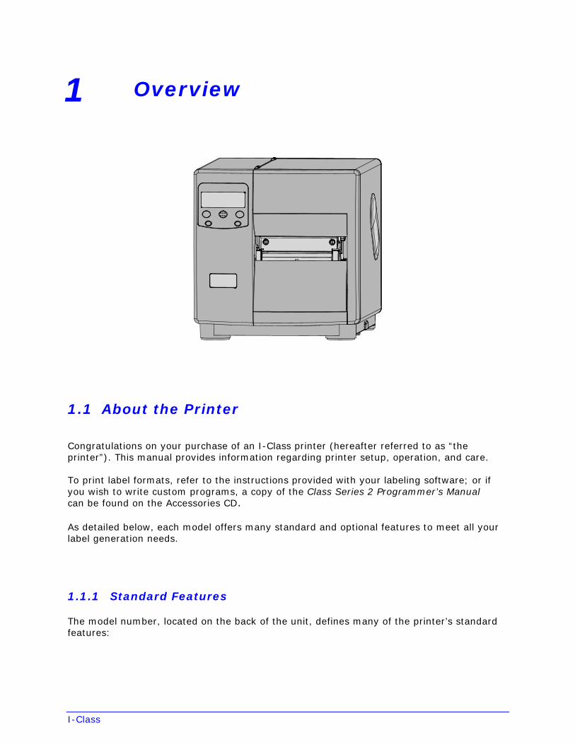
Congratulations on your purchase of an I-Class printer (hereafter referred to as “the printer”). This manual provides information regarding printer setup, operation, and care.
To print label formats, refer to the instructions provided with your labeling software; or if you wish to write custom programs, a copy of the Class Series 2 Programmer’s Manual can be found on the Accessories CD.
As detailed below, each model offers many standard and optional features to meet all your label generation needs.
1.1.1 Standard Features
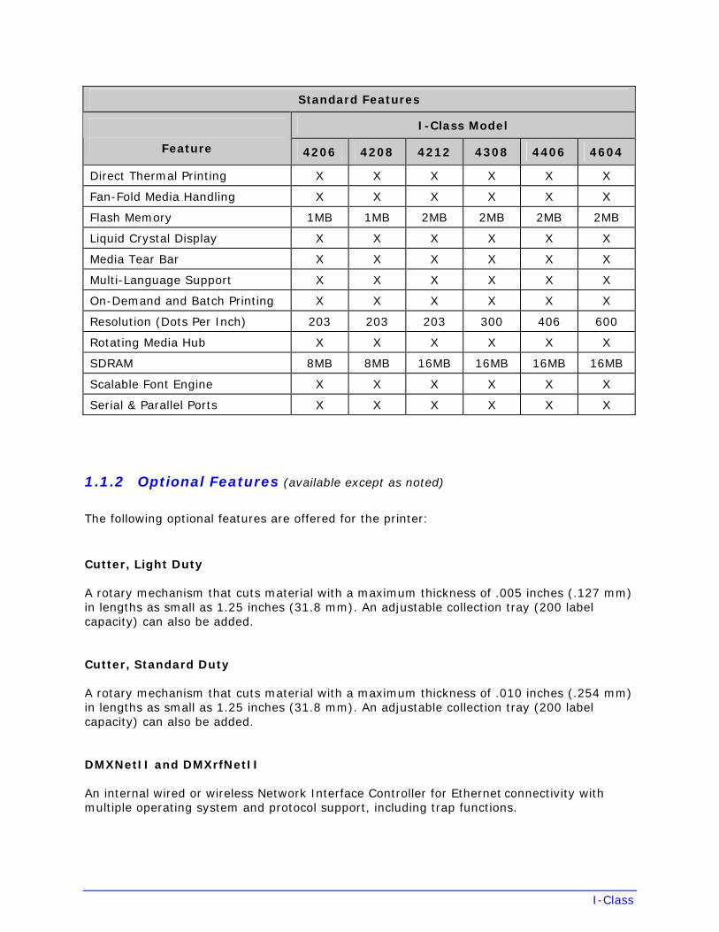
The model number, located on the back of the unit, defines many of the printer’s standard features:
I-Class
Standard Features
I-Class Model
Feature 4206 4208 4212 4308 4406 4604
Direct Thermal Printing X X X X X X
Fan-Fold Media Handling X X X X X X
Flash Memory 1MB 1MB 2MB 2MB 2MB 2MB
Liquid Crystal Display X X X X X X
Media Tear Bar X X X X X X
Multi-Language Support X X X X X X
On-Demand and Batch Printing X X X X X X
Resolution (Dots Per Inch) 203 203 203 300 406 600
Rotating Media Hub X X X X X X
SDRAM 8MB 8MB 16MB 16MB 16MB 16MB
Scalable Font Engine X X X X X X
Serial & Parallel Ports X X X X X X
1.1.2 Optional Features (available except as noted)
The following optional features are offered for the printer:
Cutter, Light Duty
A rotary mechanism that cuts material with a maximum thickness of .005 inches (.127 mm) in lengths as small as 1.25 inches (31.8 mm). An adjustable collection tray (200 label capacity) can also be added.
Cutter, Standard Duty
A rotary mechanism that cuts material with a maximum thickness of .010 inches (.254 mm) in lengths as small as 1.25 inches (31.8 mm). An adjustable collection tray (200 label capacity) can also be added.
DMXNetII and DMXrfNetII
An internal wired or wireless Network Interface Controller for Ethernet connectivity with multiple operating system and protocol support, including trap functions.
I-Class
External Keyboard (specify voltage & country requirement when ordering)
A portable terminal for stand-alone printing.
External Media Rewinder (specify voltage requirement when ordering)
A feature-dependant bidirectional label rewinding device:
• DMXREW1 – rewinds widths up to 4.5 inches (114 mm) into eight-inch (203 mm)outer diameter rolls on one to four inch (25 to 101 mm) diameter cores at up to teninches per second.
• DMXREW2 – rewinds widths up to 9.5 inches (241 mm) into twelve-inch (304 mm)outer diameter rolls on a three-inch (76 mm) diameter core at up to thirty inches persecond.
GPI/O Multi-Expansion Card
A slide-in multi-feature circuit card:
• Flash Memory Expansion – stores up to 8 MB of label formats, fonts, and graphics.
• Real Time Clock – keeps the time and date for labeling functions.
• GPIO Port – controls print functions via an external device (e.g., a label applicator).
• ILPC Fonts (optional) – extends printing capabilities with CG-Times, Kanji Gothic B,Simplified Chinese GB, Korean Hangul scalable fonts.
• MCL Serial Port (optional) – allows use with MCL application programs and firmware.
Internal Rewinder
An internal device capable of rewinding six-inch (152 mm) outer diameter rolls of labels or backing material.
Linear Scanner (unavailable for I-4206; cannot be used with a cutter option)
A CCD device that ensures the readability of bar codes.
Peel and Present Mechanism (requires the Internal Rewinder option)
A device that peels labels from the backing material for immediate application, regulated by previous label removal [minimum label length is 1.5 inches (38 mm)].
Present Sensor
A device that regulates output to the removal of a previously printed label.
I-Class
RFID
An integrated Radio Frequency Identification tag encoding and reading device with data capture capabilities, available for immediate or future use:
• Factory Installed – complete, ready to use.
• Ready – factory installed antenna, requiring installation of additional hardware.
RS-422 Serial Interface (unavailable for I-4206 and I-4208 models)
Single-drop interface hardware for greater printer to host serial communication distances (at up to 38,400 baud).
Thermal Transfer (specify ribbon configuration at time of order)
A device that allows the use of ribbon to produce exceptional image clarity (as compared to most direct thermal media).
Twinax/Coax Interface
A slide-in circuit card that provides connectivity to AS/400 and System/3X Twinax host systems or 3270-type host systems (cabling included).
USB Port
A slide-in circuit card that provides a Universal Serial Bus (Version 1.1) interface for Windows printing environments.
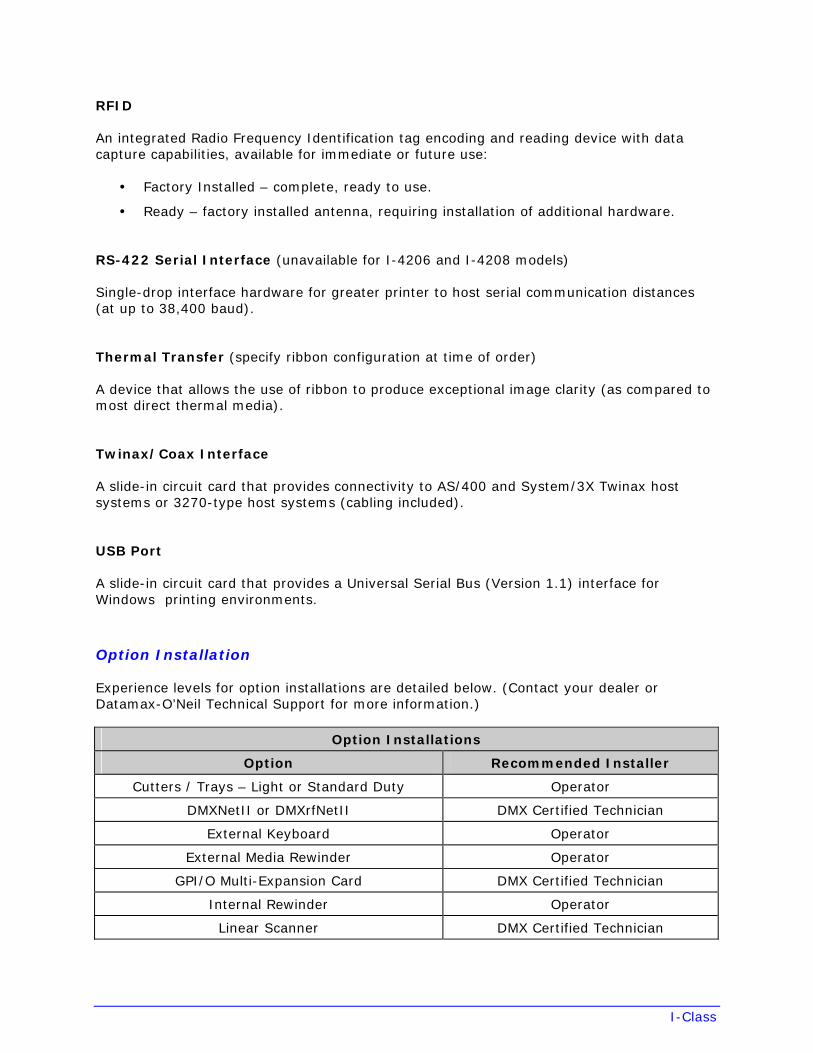
Option Installation
Experience levels for option installations are detailed below. (Contact your dealer or Datamax-O’Neil Technical Support for more information.)
Option Installations
Option Recommended Installer
Cutters / Trays – Light or Standard Duty Operator
DMXNetII or DMXrfNetII DMX Certified Technician
External Keyboard Operator
External Media Rewinder Operator
GPI/O Multi-Expansion Card DMX Certified Technician
Internal Rewinder Operator
Linear Scanner DMX Certified Technician
I-Class
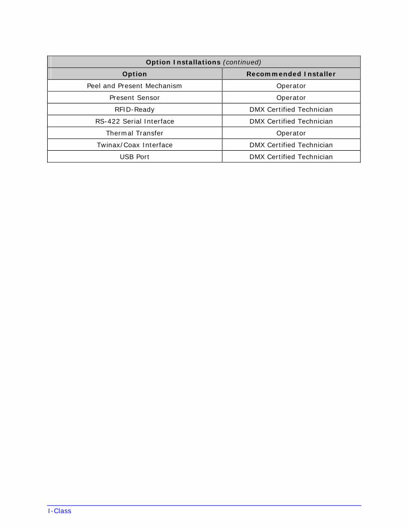
Option Installations (continued)
Option Recommended Installer
Peel and Present Mechanism Operator
Present Sensor Operator
RFID-Ready DMX Certified Technician
RS-422 Serial Interface DMX Certified Technician
Thermal Transfer Operator
Twinax/Coax Interface DMX Certified Technician
USB Port DMX Certified Technician
I-Class
2 Getting Started
2.1 Unpacking the Printer
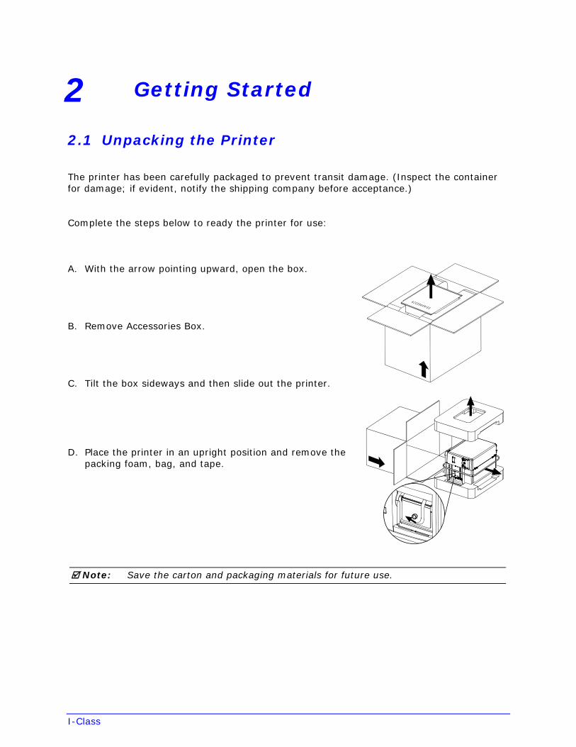
The printer has been carefully packaged to prevent transit damage. (Inspect the container for damage; if evident, notify the shipping company before acceptance.)
Complete the steps below to ready the printer for use:
A. With the arrow pointing upward, open the box.
B. Remove Accessories Box.
C. Tilt the box sideways and then slide out the printer.
D. Place the printer in an upright position and remove the packing foam, bag, and tape.
Note: Save the carton and packaging materials for future use.
I-Class
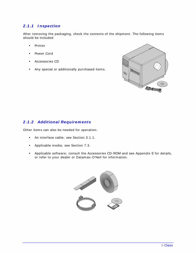
2.1.1 Inspection
After removing the packaging, check the contents of the shipment. The following items should be included:
• Printer
• Power Cord
• Accessories CD
• Any special or additionally purchased items.
2.1.2 Additional Requirements
Other items can also be needed for operation:
• An interface cable; see Section 3.1.1.
• Applicable media; see Section 7.3.
• Applicable software; consult the Accessories CD-ROM and see Appendix E for details,or refer to your dealer or Datamax-O’Neil for information.
I-Class
3 Setting up the Printer
3.1 Installation
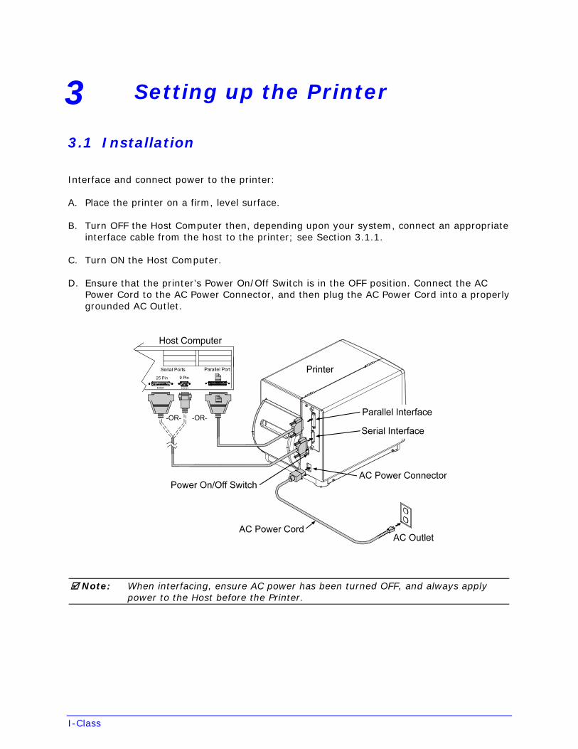
Interface and connect power to the printer:
A. Place the printer on a firm, level surface.
B. Turn OFF the Host Computer then, depending upon your system, connect an appropriate interface cable from the host to the printer; see Section 3.1.1.
C. Turn ON the Host Computer.
D. Ensure that the printer’s Power On/Off Switch is in the OFF position. Connect the AC Power Cord to the AC Power Connector, and then plug the AC Power Cord into a properly grounded AC Outlet.
Note: When interfacing, ensure AC power has been turned OFF, and always apply power to the Host before the Printer.
I-Class
3.1.1 Communications
Following power-up (or after a period of inactivity), interface port selection occurs automatically upon detection of valid data. If the incoming (received) data flow stops and the Host Timeout Value (see Section 4.2.6) is exceeded, partially received formats will be ignored and the port detection process repeated.
Notes: 1) To change an active port immediately, cycle the power OFF and ON.
2) For alternate data processing options, see SYSTEM SETTINGS / INPUTMODE - Section 4.2.5.
DMXNetII Network Interface Card / DMXrfNetII Wireless Network Interface Card
The optional network interface has several menu-selectable modes; see Section 4.2.6 or refer to the manual provided with the option.
Parallel Port
The parallel interface has two menu-selectable modes of operation:
• Unidirectional mode is forward channel communication and requires a Centronics
cable with a 36 pin male connector.
• Bidirectional mode is IEEE 1284 Compliant, using forward and reverse channelcommunications and requires an IEEE 1284 cable with a Centronics 36 pin maleconnector.
Serial Port
The serial interface supports RS-232C, and if equipped optional RS-422 communications. The serial interface has menu-selectable settings that must match the host computer’s settings; see Section 4.2.6. In addition to the port settings, serial cable wiring must have specific pin connections for proper data flow; see Section 7.3.
USB Interface Card
The optional USB Port is plug and play interface, operating transparently and without menu-selectable settings or modes.
WARNING
The USB Port is a device-end only connection. Never connect a keyboard, mouse, modem, etc. to this port; damage can result.
I-Class
3.2 Media Loading
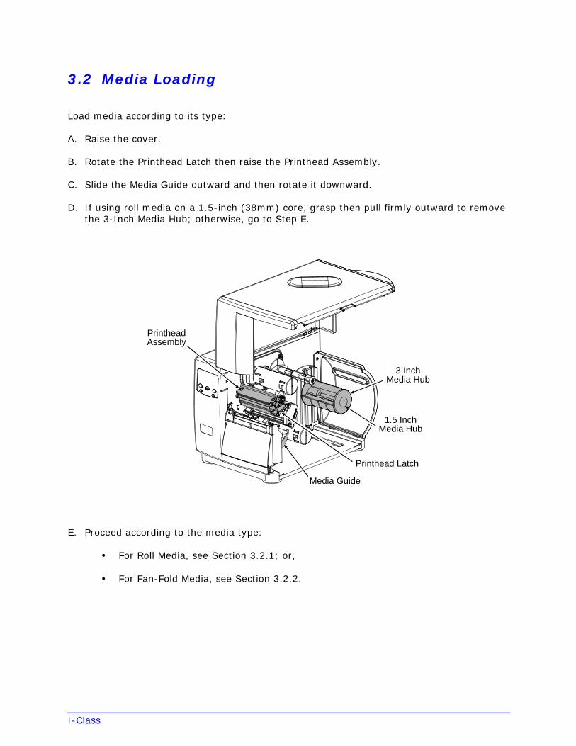
Load media according to its type:
A. Raise the cover.
B. Rotate the Printhead Latch then raise the Printhead Assembly.
C. Slide the Media Guide outward and then rotate it downward.
D. If using roll media on a 1.5-inch (38mm) core, grasp then pull firmly outward to remove the 3-Inch Media Hub; otherwise, go to Step E.
1.5 InchMedia Hub
3 InchMedia Hub
Media Guide
Printhead Latch
PrintheadAssembly
E. Proceed according to the media type:
• For Roll Media, see Section 3.2.1; or,
• For Fan-Fold Media, see Section 3.2.2.
I-Class
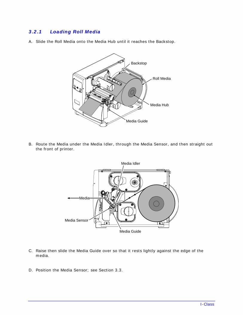
3.2.1 Loading Roll Media
A. Slide the Roll Media onto the Media Hub until it reaches the Backstop.
Roll Media
Media Guide
Backstop
Media Hub
B. Route the Media under the Media Idler, through the Media Sensor, and then straight out the front of printer.
Media Idler
Media Guide
Media Sensor
Media
C. Raise then slide the Media Guide over so that it rests lightly against the edge of the media.
D. Position the Media Sensor; see Section 3.3.
I-Class
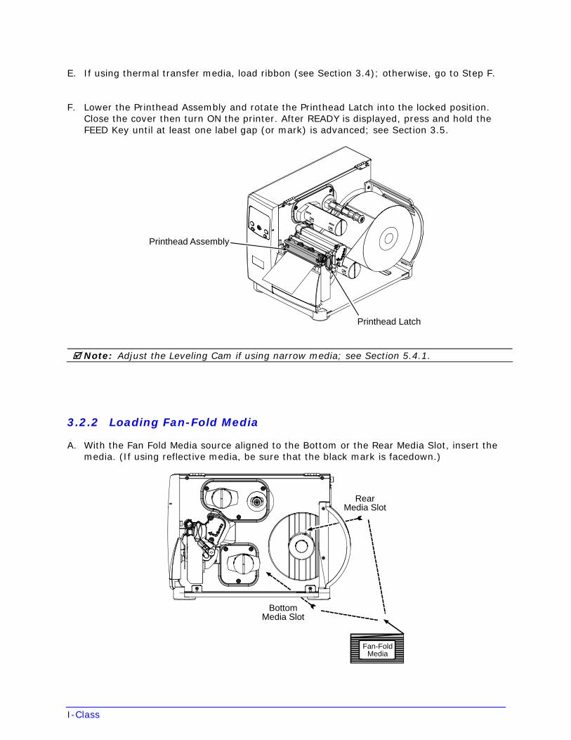
E. If using thermal transfer media, load ribbon (see Section 3.4); otherwise, go to Step F.
F. Lower the Printhead Assembly and rotate the Printhead Latch into the locked position. Close the cover then turn ON the printer. After READY is displayed, press and hold the FEED Key until at least one label gap (or mark) is advanced; see Section 3.5.
Printhead Latch
Printhead Assembly
Note: Adjust the Leveling Cam if using narrow media; see Section 5.4.1.
3.2.2 Loading Fan-Fold Media
A. With the Fan Fold Media source aligned to the Bottom or the Rear Media Slot, insert the media. (If using reflective media, be sure that the black mark is facedown.)
Fan-FoldMedia
BottomMedia Slot
RearMedia Slot
I-Class
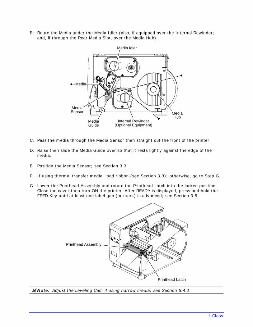
B. Route the Media under the Media Idler (also, if equipped over the Internal Rewinder; and, if through the Rear Media Slot, over the Media Hub).
Media Idler
MediaGuide
MediaSensor
Media
Internal Rewinder(Optional Equipment)
MediaHub
C. Pass the media through the Media Sensor then straight out the front of the printer.
D. Raise then slide the Media Guide over so that it rests lightly against the edge of the media.
E. Position the Media Sensor; see Section 3.3.
F. If using thermal transfer media, load ribbon (see Section 3.3); otherwise, go to Step G.
G. Lower the Printhead Assembly and rotate the Printhead Latch into the locked position. Close the cover then turn ON the printer. After READY is displayed, press and hold the FEED Key until at least one label gap (or mark) is advanced; see Section 3.5.
Printhead Assembly
Printhead Latch
Note: Adjust the Leveling Cam if using narrow media; see Section 5.4.1.
I-Class
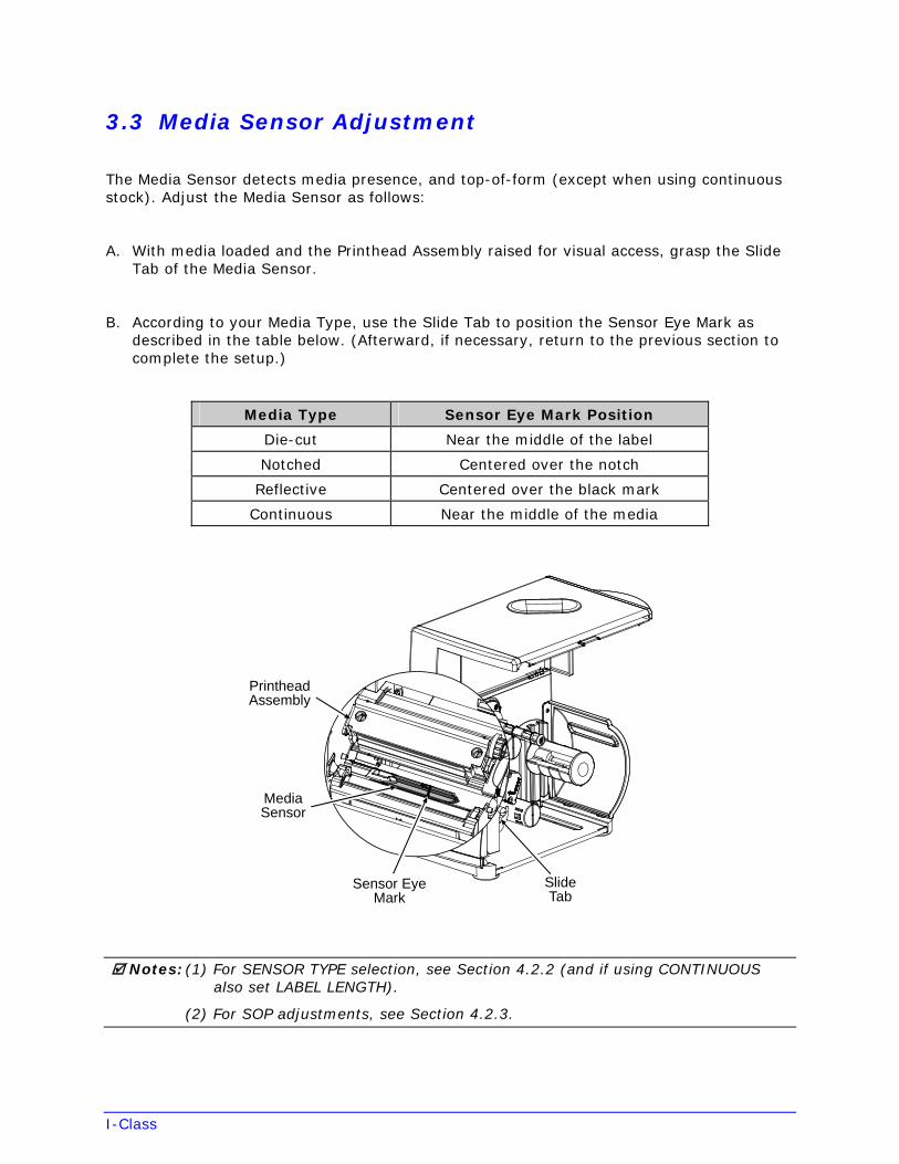
3.3 Media Sensor Adjustment
The Media Sensor detects media presence, and top-of-form (except when using continuous stock). Adjust the Media Sensor as follows:
A. With media loaded and the Printhead Assembly raised for visual access, grasp the Slide Tab of the Media Sensor.
B. According to your Media Type, use the Slide Tab to position the Sensor Eye Mark as described in the table below. (Afterward, if necessary, return to the previous section to complete the setup.)
Media Type Sensor Eye Mark Position
Die-cut Near the middle of the label
Notched Centered over the notch
Reflective Centered over the black mark
Continuous Near the middle of the media
MediaSensor
PrintheadAssembly
Sensor EyeMark
SlideTab
Notes: (1) For SENSOR TYPE selection, see Section 4.2.2 (and if using CONTINUOUS also set LABEL LENGTH).
(2) For SOP adjustments, see Section 4.2.3.
I-Class
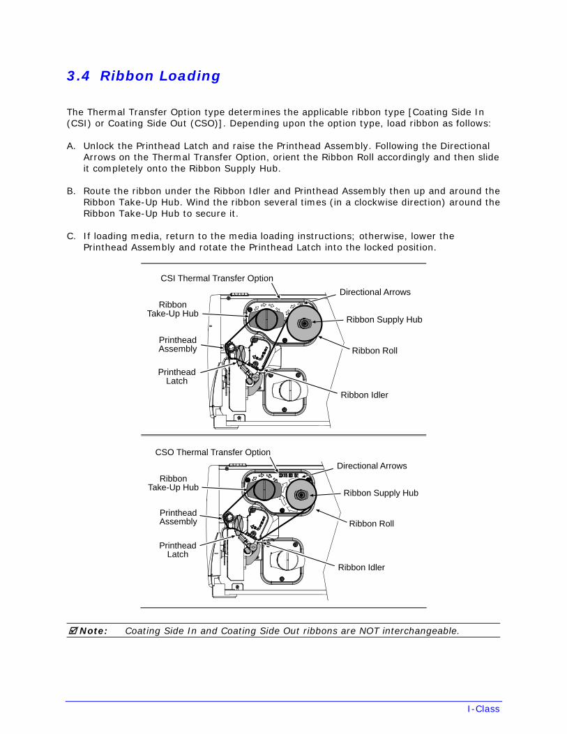
3.4 Ribbon Loading
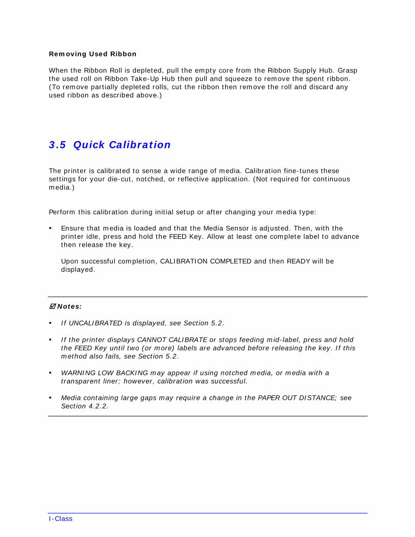
The Thermal Transfer Option type determines the applicable ribbon type [Coating Side In (CSI) or Coating Side Out (CSO)]. Depending upon the option type, load ribbon as follows:
A. Unlock the Printhead Latch and raise the Printhead Assembly. Following the Directional Arrows on the Thermal Transfer Option, orient the Ribbon Roll accordingly and then slide it completely onto the Ribbon Supply Hub.
B. Route the ribbon under the Ribbon Idler and Printhead Assembly then up and around the Ribbon Take-Up Hub. Wind the ribbon several times (in a clockwise direction) around the Ribbon Take-Up Hub to secure it.
C. If loading media, return to the media loading instructions; otherwise, lower the Printhead Assembly and rotate the Printhead Latch into the locked position.
RibbonTake-Up Hub
PrintheadLatch
Ribbon Idler
Ribbon Roll
Ribbon Supply Hub
Directional Arrows
CSI Thermal Transfer Option
PrintheadAssembly
RibbonTake-Up Hub
PrintheadLatch
Ribbon Idler
Ribbon Roll
Ribbon Supply Hub
Directional Arrows
CSO Thermal Transfer Option
PrintheadAssembly
Note: Coating Side In and Coating Side Out ribbons are NOT interchangeable.
I-Class
Removing Used Ribbon
When the Ribbon Roll is depleted, pull the empty core from the Ribbon Supply Hub. Grasp the used roll on Ribbon Take-Up Hub then pull and squeeze to remove the spent ribbon. (To remove partially depleted rolls, cut the ribbon then remove the roll and discard any used ribbon as described above.)
3.5 Quick Calibration
The printer is calibrated to sense a wide range of media. Calibration fine-tunes these settings for your die-cut, notched, or reflective application. (Not required for continuous media.)
Perform this calibration during initial setup or after changing your media type:
• Ensure that media is loaded and that the Media Sensor is adjusted. Then, with theprinter idle, press and hold the FEED Key. Allow at least one complete label to advancethen release the key.
Upon successful completion, CALIBRATION COMPLETED and then READY will bedisplayed.
Notes:
• If UNCALIBRATED is displayed, see Section 5.2.
• If the printer displays CANNOT CALIBRATE or stops feeding mid-label, press and holdthe FEED Key until two (or more) labels are advanced before releasing the key. If thismethod also fails, see Section 5.2.
• WARNING LOW BACKING may appear if using notched media, or media with atransparent liner; however, calibration was successful.
• Media containing large gaps may require a change in the PAPER OUT DISTANCE; seeSection 4.2.2.
I-Class
4 Using the Control Panel
4.1 Operation
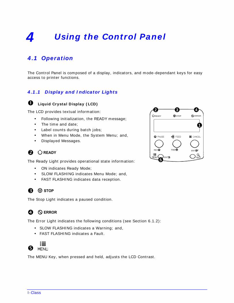
The Control Panel is composed of a display, indicators, and mode-dependant keys for easy access to printer functions.
4.1.1 Display and Indicator Lights
Liquid Crystal Display (LCD)
The LCD provides textual information:
• Following initialization, the READY message;• The time and date;• Label counts during batch jobs;• When in Menu Mode, the System Menu; and,• Displayed Messages.
The Ready Light provides operational state information:
• ON indicates Ready Mode;• SLOW FLASHING indicates Menu Mode; and,• FAST FLASHING indicates data reception.
The Stop Light indicates a paused condition.
The Error Light indicates the following conditions (see Section 6.1.2):
• SLOW FLASHING indicates a Warning; and,• FAST FLASHING indicates a Fault.
The MENU Key, when pressed and held, adjusts the LCD Contrast.
ERRORSTOPREADY
ENTFWDREV
ESC
5
4
1
32
I-Class
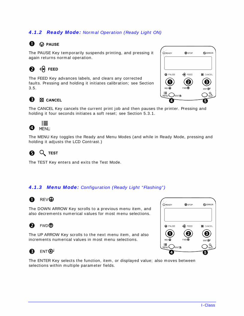
4.1.2 Ready Mode: Normal Operation (Ready Light ON)
The PAUSE Key temporarily suspends printing, and pressing it again returns normal operation.
The FEED Key advances labels, and clears any corrected faults. Pressing and holding it initiates calibration; see Section 3.5.
The CANCEL Key cancels the current print job and then pauses the printer. Pressing and holding it four seconds initiates a soft reset; see Section 5.3.1.
The MENU Key toggles the Ready and Menu Modes (and while in Ready Mode, pressing and holding it adjusts the LCD Contrast.)
The TEST Key enters and exits the Test Mode.
4.1.3 Menu Mode: Configuration (Ready Light “Flashing”)
The DOWN ARROW Key scrolls to a previous menu item, and also decrements numerical values for most menu selections.
The UP ARROW Key scrolls to the next menu item, and also increments numerical values in most menu selections.
The ENTER Key selects the function, item, or displayed value; also moves between selections within multiple parameter fields.
I-Class
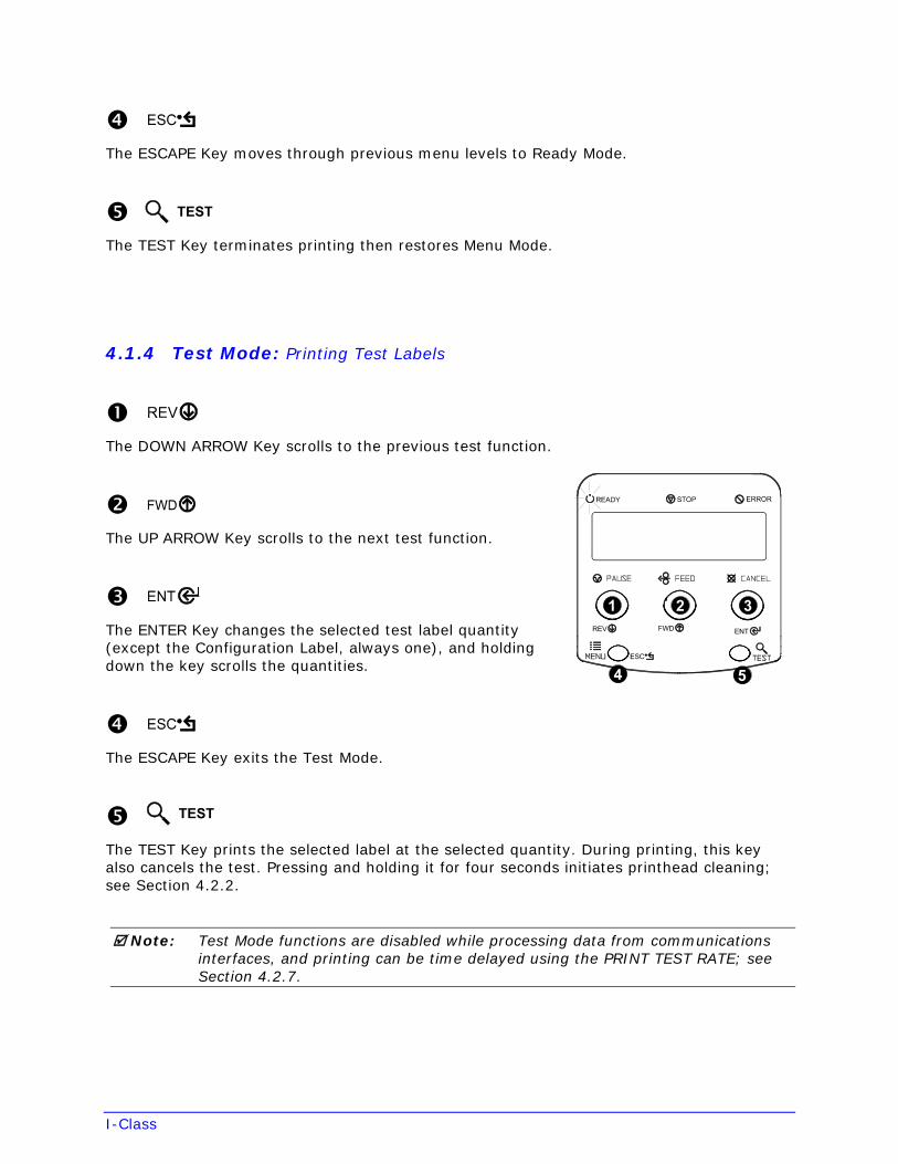
The ESCAPE Key moves through previous menu levels to Ready Mode.
The TEST Key terminates printing then restores Menu Mode.
4.1.4 Test Mode: Printing Test Labels
The DOWN ARROW Key scrolls to the previous test function.
The UP ARROW Key scrolls to the next test function.
The ENTER Key changes the selected test label quantity (except the Configuration Label, always one), and holding down the key scrolls the quantities.
The ESCAPE Key exits the Test Mode.
The TEST Key prints the selected label at the selected quantity. During printing, this key also cancels the test. Pressing and holding it for four seconds initiates printhead cleaning; see Section 4.2.2.
Note: Test Mode functions are disabled while processing data from communications interfaces, and printing can be time delayed using the PRINT TEST RATE; see Section 4.2.7.
I-Class
4.2 The System Menu
The MENU Key accesses seven system branches:
• MEDIA SETTINGS
• PRINT CONTROL
• PRINTER OPTIONS
• SYSTEM SETTINGS
• COMMUNICATIONS
• DIAGNOSTICS
• MCL OPTIONS
Notes: (1) Entering the menu takes the printer offline and halts the processing of new data.
(2) Selected Menu items are indicated with an asterisk (*) next to the displayed setting, while items designated with a section symbol (§) require a reset to
become effective.
(3) Password protection can prevent accidental or unauthorized Menu System changes; see Section 4.2.5.
(4) The commands from your host computer may, in some cases, override themenu settings; see Section 4.2.6 for setting controls.
(5) Depending upon the installed firmware, some of the menu selections represented below may not appear in your printer.
(6) Options or items not detected by the printer may indicate NOT INSTALLED when accessed in the menu.
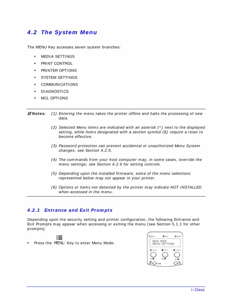
4.2.1 Entrance and Exit Prompts
Depending upon the security setting and printer configuration, the following Entrance and Exit Prompts may appear when accessing or exiting the menu (see Section 5.1.1 for other prompts).
• Press the Key to enter Menu Mode.
ERRORSTOPREADY
ENTFWDREV
ESC
I-Class
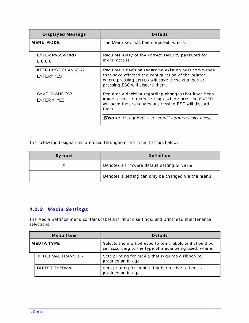
Displayed Message Details
MENU MODE The Menu Key has been pressed, where:
ENTER PASSWORD
0 0 0 0
Requires entry of the correct security password for menu access.
KEEP HOST CHANGES?
ENTER=YES
Requires a decision regarding existing host commands that have affected the configuration of the printer, where pressing ENTER will save these changes or pressing ESC will discard them.
SAVE CHANGES?
ENTER = YES
Requires a decision regarding changes that have been made to the printer’s settings, where pressing ENTER will save these changes or pressing ESC will discard them.
Note: If required, a reset will automatically occur.
The following designations are used throughout the menu listings below:
Symbol Definition
Denotes a firmware default setting or value.
Denotes a setting can only be changed via the menu.
4.2.2 Media Settings
The Media Settings menu contains label and ribbon settings, and printhead maintenance selections.
Menu Item Details
MEDIA TYPE Selects the method used to print labels and should be set according to the type of media being used, where:
THERMAL TRANSFER Sets printing for media that requires a ribbon to produce an image.
DIRECT THERMAL Sets printing for media that is reactive to heat to produce an image.
I-Class
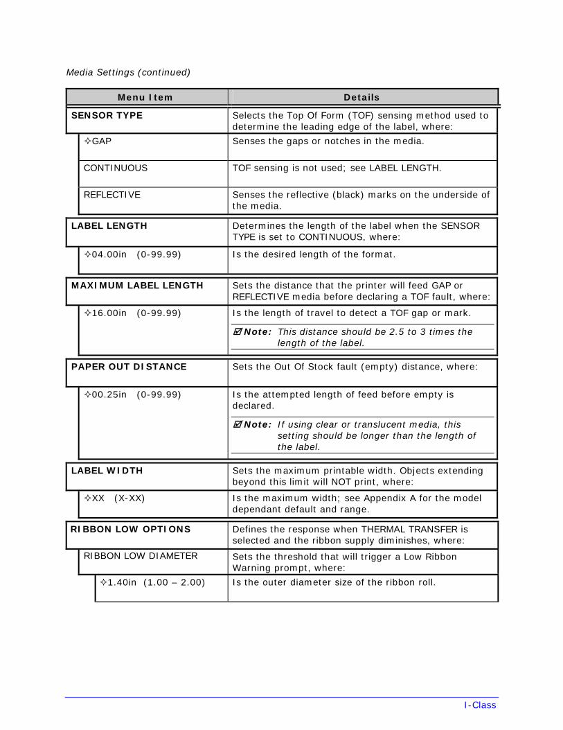
Media Settings (continued)
Menu Item Details
SENSOR TYPE Selects the Top Of Form (TOF) sensing method used to determine the leading edge of the label, where:
GAP Senses the gaps or notches in the media.
CONTINUOUS TOF sensing is not used; see LABEL LENGTH.
REFLECTIVE Senses the reflective (black) marks on the underside of the media.
LABEL LENGTH Determines the length of the label when the SENSOR TYPE is set to CONTINUOUS, where:
04.00in (0-99.99) Is the desired length of the format.
MAXIMUM LABEL LENGTH Sets the distance that the printer will feed GAP or REFLECTIVE media before declaring a TOF fault, where:
16.00in (0-99.99) Is the length of travel to detect a TOF gap or mark.
Note: This distance should be 2.5 to 3 times the length of the label.
PAPER OUT DISTANCE Sets the Out Of Stock fault (empty) distance, where:
00.25in (0-99.99) Is the attempted length of feed before empty is declared.
Note: If using clear or translucent media, this setting should be longer than the length of the label.
LABEL WIDTH Sets the maximum printable width. Objects extending beyond this limit will NOT print, where:
XX (X-XX) Is the maximum width; see Appendix A for the model dependant default and range.
RIBBON LOW OPTIONS Defines the response when THERMAL TRANSFER is selected and the ribbon supply diminishes, where:
RIBBON LOW DIAMETER Sets the threshold that will trigger a Low Ribbon Warning prompt, where:
1.40in (1.00 – 2.00) Is the outer diameter size of the ribbon roll.
I-Class
Media Settings (continued)
Menu Item Details
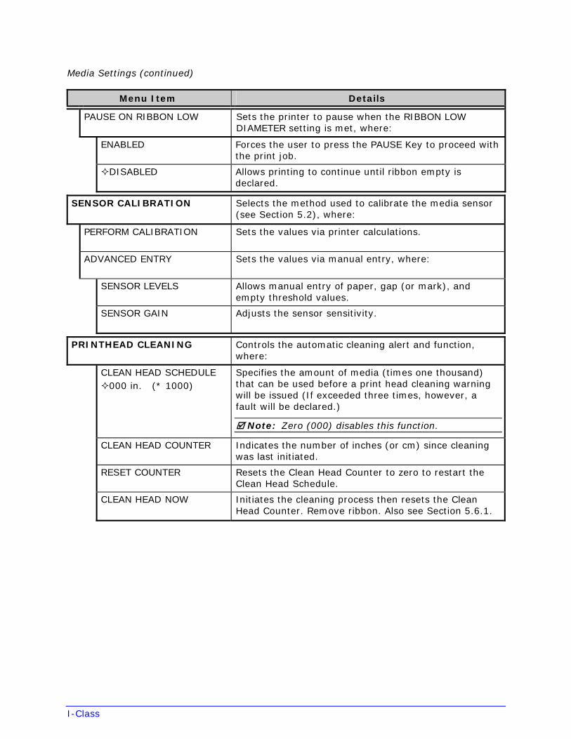
PAUSE ON RIBBON LOW Sets the printer to pause when the RIBBON LOW DIAMETER setting is met, where:
ENABLED Forces the user to press the PAUSE Key to proceed with the print job.
DISABLED Allows printing to continue until ribbon empty is declared.
SENSOR CALIBRATION Selects the method used to calibrate the media sensor (see Section 5.2), where:
PERFORM CALIBRATION Sets the values via printer calculations.
ADVANCED ENTRY Sets the values via manual entry, where:
SENSOR LEVELS Allows manual entry of paper, gap (or mark), and empty threshold values.
SENSOR GAIN Adjusts the sensor sensitivity.
PRINTHEAD CLEANING Controls the automatic cleaning alert and function, where:
CLEAN HEAD SCHEDULE 000 in. (* 1000)
Specifies the amount of media (times one thousand) that can be used before a print head cleaning warning will be issued (If exceeded three times, however, a fault will be declared.)
Note: Zero (000) disables this function.
CLEAN HEAD COUNTER Indicates the number of inches (or cm) since cleaning was last initiated.
RESET COUNTER Resets the Clean Head Counter to zero to restart the Clean Head Schedule.
CLEAN HEAD NOW Initiates the cleaning process then resets the Clean Head Counter. Remove ribbon. Also see Section 5.6.1.
I-Class
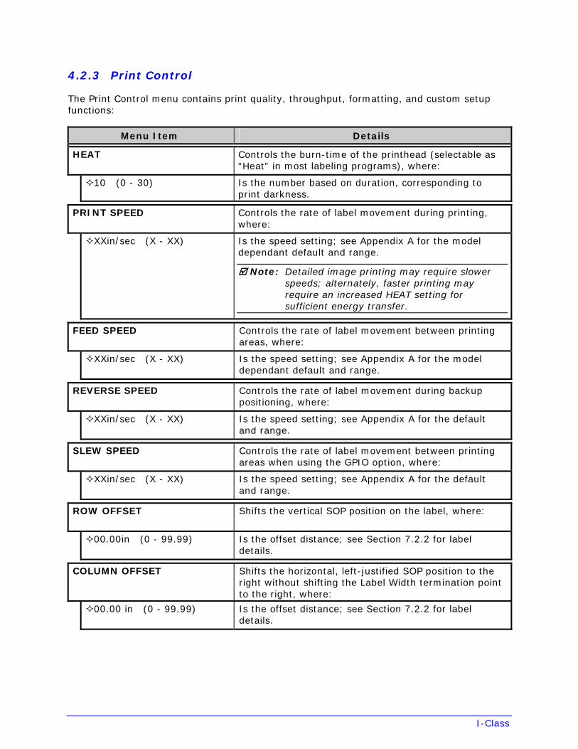
4.2.3 Print Control
The Print Control menu contains print quality, throughput, formatting, and custom setup functions:
Menu Item Details
HEAT Controls the burn-time of the printhead (selectable as “Heat” in most labeling programs), where:
10 (0 - 30) Is the number based on duration, corresponding to print darkness.
PRINT SPEED Controls the rate of label movement during printing, where:
XXin/sec (X - XX) Is the speed setting; see Appendix A for the model dependant default and range.
Note: Detailed image printing may require slower speeds; alternately, faster printing may require an increased HEAT setting for sufficient energy transfer.
FEED SPEED Controls the rate of label movement between printing areas, where:
XXin/sec (X - XX) Is the speed setting; see Appendix A for the model dependant default and range.
REVERSE SPEED Controls the rate of label movement during backup positioning, where:
XXin/sec (X - XX) Is the speed setting; see Appendix A for the default and range.
SLEW SPEED Controls the rate of label movement between printing areas when using the GPIO option, where:
XXin/sec (X - XX) Is the speed setting; see Appendix A for the default and range.
ROW OFFSET Shifts the vertical SOP position on the label, where:
00.00in (0 - 99.99) Is the offset distance; see Section 7.2.2 for label details.
COLUMN OFFSET Shifts the horizontal, left-justified SOP position to the right without shifting the Label Width termination point to the right, where:
00.00 in (0 - 99.99) Is the offset distance; see Section 7.2.2 for label details.
I-Class
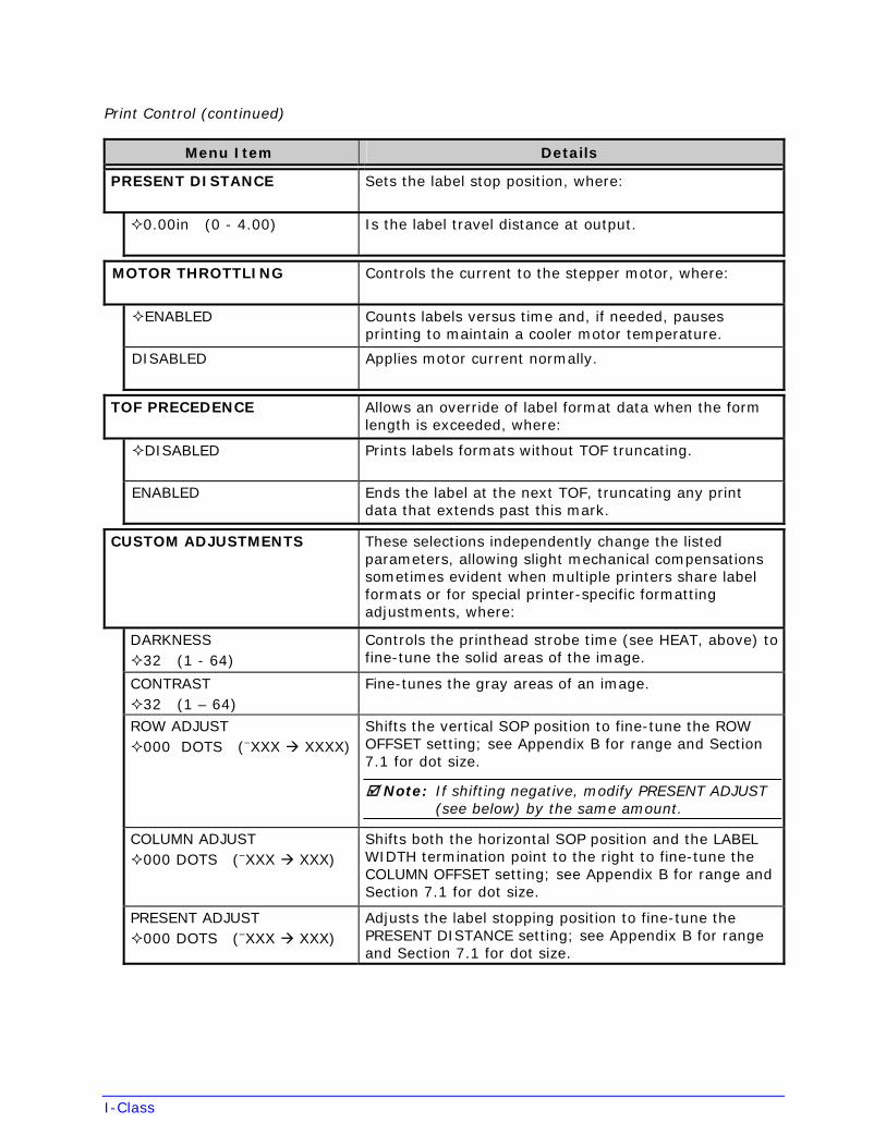
Print Control (continued)
Menu Item Details
PRESENT DISTANCE Sets the label stop position, where:
0.00in (0 - 4.00) Is the label travel distance at output.
MOTOR THROTTLING Controls the current to the stepper motor, where:
ENABLED Counts labels versus time and, if needed, pauses printing to maintain a cooler motor temperature.
DISABLED Applies motor current normally.
TOF PRECEDENCE Allows an override of label format data when the form length is exceeded, where:
DISABLED Prints labels formats without TOF truncating.
ENABLED Ends the label at the next TOF, truncating any print data that extends past this mark.
CUSTOM ADJUSTMENTS These selections independently change the listed parameters, allowing slight mechanical compensations sometimes evident when multiple printers share label formats or for special printer-specific formatting adjustments, where:
DARKNESS 32 (1 - 64)
Controls the printhead strobe time (see HEAT, above) to fine-tune the solid areas of the image.
CONTRAST 32 (1 – 64)
Fine-tunes the gray areas of an image.
ROW ADJUST 000 DOTS (–XXX XXXX)
Shifts the vertical SOP position to fine-tune the ROW OFFSET setting; see Appendix B for range and Section 7.1 for dot size.
Note: If shifting negative, modify PRESENT ADJUST (see below) by the same amount.
COLUMN ADJUST 000 DOTS (–XXX XXX)
Shifts both the horizontal SOP position and the LABEL WIDTH termination point to the right to fine-tune the COLUMN OFFSET setting; see Appendix B for range and Section 7.1 for dot size.
PRESENT ADJUST 000 DOTS (–XXX XXX)
Adjusts the label stopping position to fine-tune the PRESENT DISTANCE setting; see Appendix B for range and Section 7.1 for dot size.
I-Class
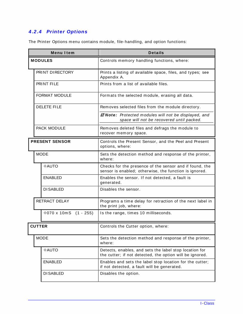
4.2.4 Printer Options
The Printer Options menu contains module, file-handling, and option functions:
Menu Item Details
MODULES Controls memory handling functions, where:
PRINT DIRECTORY Prints a listing of available space, files, and types; see Appendix A.
PRINT FILE Prints from a list of available files.
FORMAT MODULE Formats the selected module, erasing all data.
DELETE FILE Removes selected files from the module directory.
Note: Protected modules will not be displayed, and space will not be recovered until packed.
PACK MODULE Removes deleted files and defrags the module to recover memory space.
PRESENT SENSOR Controls the Present Sensor, and the Peel and Present options, where:
MODE Sets the detection method and response of the printer, where:
AUTO Checks for the presence of the sensor and if found, the sensor is enabled; otherwise, the function is ignored.
ENABLED Enables the sensor. If not detected, a fault is generated.
DISABLED Disables the sensor.
RETRACT DELAY Programs a time delay for retraction of the next label in the print job, where:
070 x 10mS (1 - 255) Is the range, times 10 milliseconds.
CUTTER Controls the Cutter option, where:
MODE Sets the detection method and response of the printer, where:
AUTO Detects, enables, and sets the label stop location for the cutter; if not detected, the option will be ignored.
ENABLED Enables and sets the label stop location for the cutter; if not detected, a fault will be generated.
DISABLED Disables the option.
I-Class
Printer Options (continued)
Menu Item Details
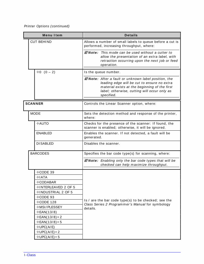
CUT BEHIND Allows a number of small labels to queue before a cut is performed, increasing throughput, where:
Note: This mode can be used without a cutter to allow the presentation of an extra label, with retraction occurring upon the next job or feed operation.
0 (0 – 2) Is the queue number.
Note: After a fault or unknown label position, the leading edge will be cut to ensure no extra material exists at the beginning of the first label; otherwise, cutting will occur only as specified.
SCANNER Controls the Linear Scanner option, where:
MODE Sets the detection method and response of the printer, where:
AUTO Checks for the presence of the scanner: If found, the scanner is enabled; otherwise, it will be ignored.
ENABLED Enables the scanner. If not detected, a fault will be generated.
DISABLED Disables the scanner.
BARCODES Specifies the bar code type(s) for scanning, where:
Note: Enabling only the bar code types that will be checked can help maximize throughput.
CODE 39IATACODABARINTERLEAVED 2 OF 5INDUSTRIAL 2 OF 5CODE 93CODE 128MSI/PLESSEYEAN(13/8)EAN(13/8)+2EAN(13/8)+5UPC(A/E)UPC(A/E)+2UPC(A/E)+5
Is / are the bar code type(s) to be checked; see the Class Series 2 Programmer’s Manual for symbology details.
I-Class
Printer Options (continued)
Menu Item Details
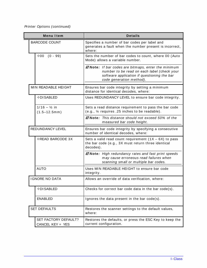
BARCODE COUNT Specifies a number of bar codes per label and generates a fault when the number present is incorrect, where:
00 (0 - 99) Sets the number of bar codes to count, where 00 (Auto Mode) allows a variable number.
Note: If bar codes are bitmaps, enter the minimum number to be read on each label (check your software application if questioning the bar code generation method).
MIN READABLE HEIGHT Ensures bar code integrity by setting a minimum distance for identical decodes, where:
DISABLED Uses REDUNDANCY LEVEL to ensure bar code integrity.
1/16 – ½ in (1.5–12.5mm)
Sets a read distance requirement to pass the bar code (e.g., ¼ requires .25 inches to be readable).
Note: This distance should not exceed 50% of the measured bar code height.
REDUNDANCY LEVEL Ensures bar code integrity by specifying a consecutive number of identical decodes, where:
READ BARCODE 3X Sets a valid read count requirement (1X – 6X) to pass the bar code (e.g., 3X must return three identical decodes).
Note: High redundancy rates and fast print speeds may cause erroneous read failures when scanning small or multiple bar codes.
AUTO Uses MIN READABLE HEIGHT to ensure bar code integrity.
IGNORE NO DATA Allows an override of data verification, where:
DISABLED Checks for correct bar code data in the bar code(s).
ENABLED Ignores the data present in the bar code(s).
SET DEFAULTS Restores the scanner settings to the default values, where:
SET FACTORY DEFAULT? CANCEL KEY = YES
Restores the defaults, or press the ESC Key to keep the current configuration.
I-Class
Printer Options (continued)
Menu Item Details
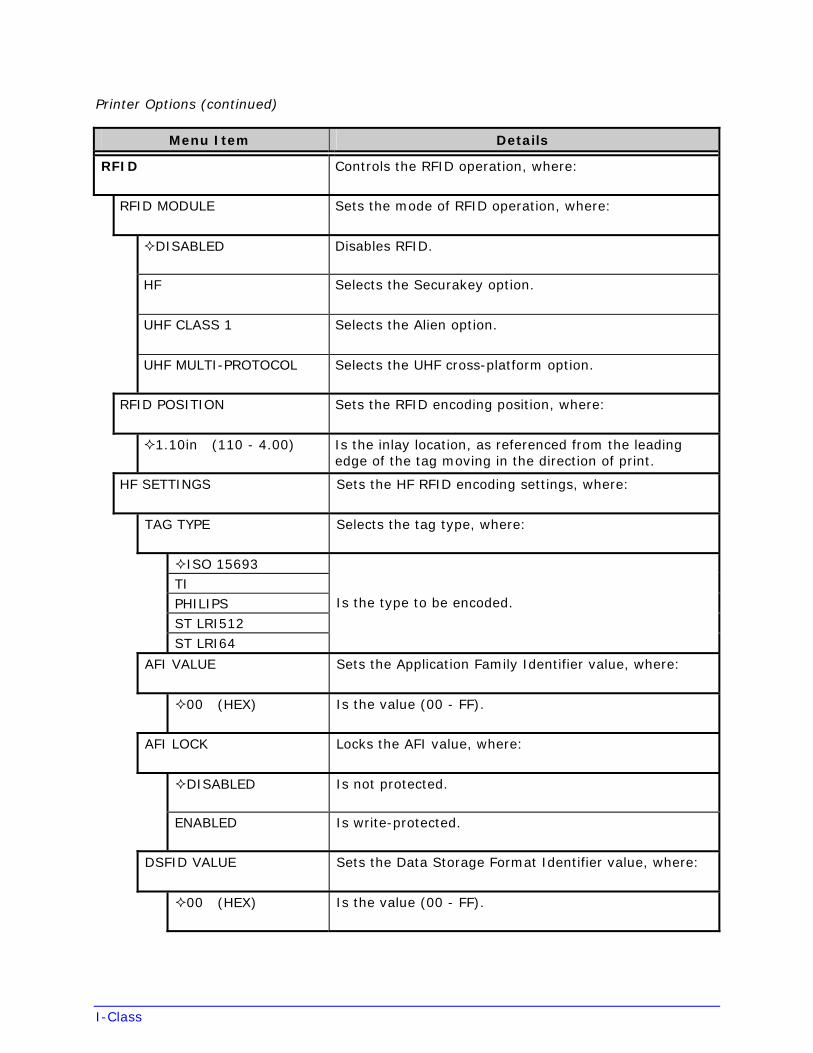
RFID Controls the RFID operation, where:
RFID MODULE Sets the mode of RFID operation, where:
DISABLED Disables RFID.
HF Selects the Securakey option.
UHF CLASS 1 Selects the Alien option.
UHF MULTI-PROTOCOL Selects the UHF cross-platform option.
RFID POSITION Sets the RFID encoding position, where:
1.10in (110 - 4.00) Is the inlay location, as referenced from the leading edge of the tag moving in the direction of print.
HF SETTINGS Sets the HF RFID encoding settings, where:
TAG TYPE Selects the tag type, where:
ISO 15693TI PHILIPS ST LRI512 ST LRI64
Is the type to be encoded.
AFI VALUE Sets the Application Family Identifier value, where:
00 (HEX) Is the value (00 - FF).
AFI LOCK Locks the AFI value, where:
DISABLED Is not protected.
ENABLED Is write-protected.
DSFID VALUE Sets the Data Storage Format Identifier value, where:
00 (HEX) Is the value (00 - FF).
I-Class
Printer Options (continued)
Menu Item Details
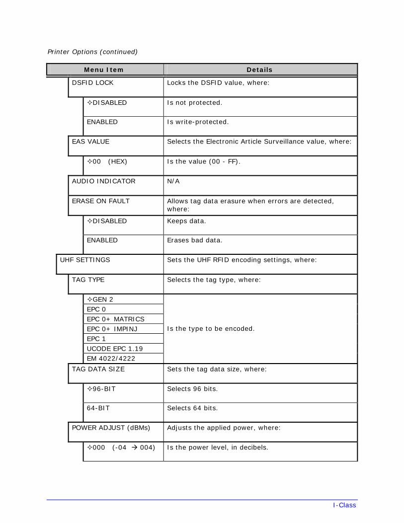
DSFID LOCK Locks the DSFID value, where:
DISABLED Is not protected.
ENABLED Is write-protected.
EAS VALUE Selects the Electronic Article Surveillance value, where:
00 (HEX) Is the value (00 - FF).
AUDIO INDICATOR N/A
ERASE ON FAULT Allows tag data erasure when errors are detected, where:
DISABLED Keeps data.
ENABLED Erases bad data.
UHF SETTINGS Sets the UHF RFID encoding settings, where:
TAG TYPE Selects the tag type, where:
GEN 2EPC 0 EPC 0+ MATRICS EPC 0+ IMPINJ EPC 1 UCODE EPC 1.19 EM 4022/4222
Is the type to be encoded.
TAG DATA SIZE Sets the tag data size, where:
96-BIT Selects 96 bits.
64-BIT Selects 64 bits.
POWER ADJUST (dBMs) Adjusts the applied power, where:
000 (-04 004) Is the power level, in decibels.
I-Class
Printer Options (continued)
Menu Item Details
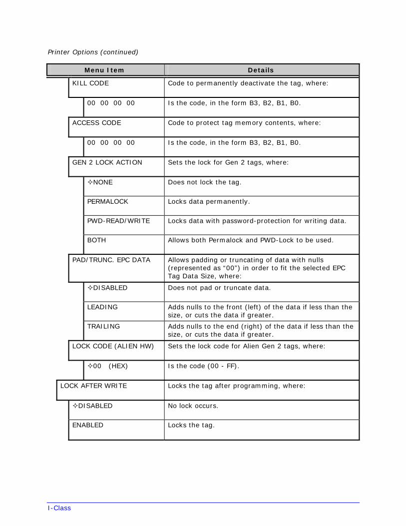
KILL CODE Code to permanently deactivate the tag, where:
00 00 00 00 Is the code, in the form B3, B2, B1, B0.
ACCESS CODE Code to protect tag memory contents, where:
00 00 00 00 Is the code, in the form B3, B2, B1, B0.
GEN 2 LOCK ACTION Sets the lock for Gen 2 tags, where:
NONE Does not lock the tag.
PERMALOCK Locks data permanently.
PWD-READ/WRITE Locks data with password-protection for writing data.
BOTH Allows both Permalock and PWD-Lock to be used.
PAD/TRUNC. EPC DATA Allows padding or truncating of data with nulls (represented as “00”) in order to fit the selected EPC Tag Data Size, where:
DISABLED Does not pad or truncate data.
LEADING Adds nulls to the front (left) of the data if less than the size, or cuts the data if greater.
TRAILING Adds nulls to the end (right) of the data if less than the size, or cuts the data if greater.
LOCK CODE (ALIEN HW) Sets the lock code for Alien Gen 2 tags, where:
00 (HEX) Is the code (00 - FF).
LOCK AFTER WRITE Locks the tag after programming, where:
DISABLED No lock occurs.
ENABLED Locks the tag.
I-Class
Printer Options (continued)
Menu Item Details
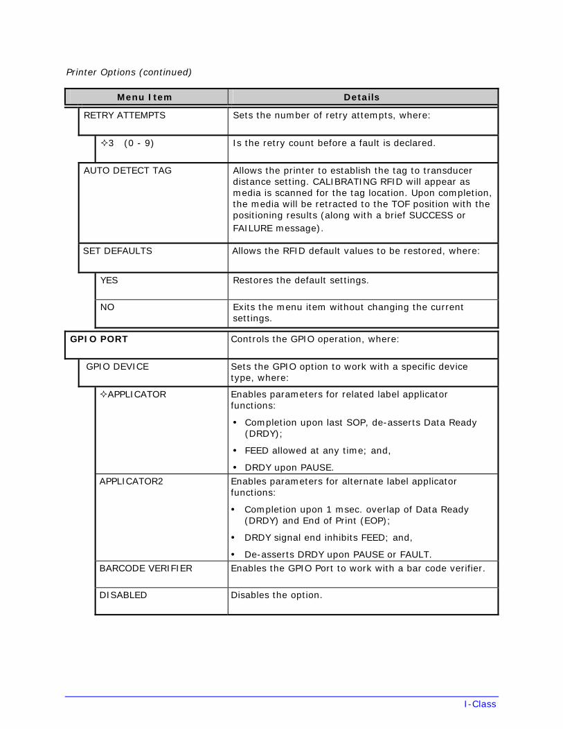
RETRY ATTEMPTS Sets the number of retry attempts, where:
3 (0 - 9) Is the retry count before a fault is declared.
AUTO DETECT TAG Allows the printer to establish the tag to transducer distance setting. CALIBRATING RFID will appear as media is scanned for the tag location. Upon completion, the media will be retracted to the TOF position with the positioning results (along with a brief SUCCESS or FAILURE message).
SET DEFAULTS Allows the RFID default values to be restored, where:
YES Restores the default settings.
NO Exits the menu item without changing the current settings.
GPIO PORT Controls the GPIO operation, where:
GPIO DEVICE Sets the GPIO option to work with a specific device type, where:
APPLICATOR Enables parameters for related label applicator functions:
• Completion upon last SOP, de-asserts Data Ready(DRDY);
• FEED allowed at any time; and,
• DRDY upon PAUSE.APPLICATOR2 Enables parameters for alternate label applicator
functions:
• Completion upon 1 msec. overlap of Data Ready(DRDY) and End of Print (EOP);
• DRDY signal end inhibits FEED; and,
• De-asserts DRDY upon PAUSE or FAULT.BARCODE VERIFIER Enables the GPIO Port to work with a bar code verifier.
DISABLED Disables the option.
I-Class
Printer Options (continued)
Menu Item Details
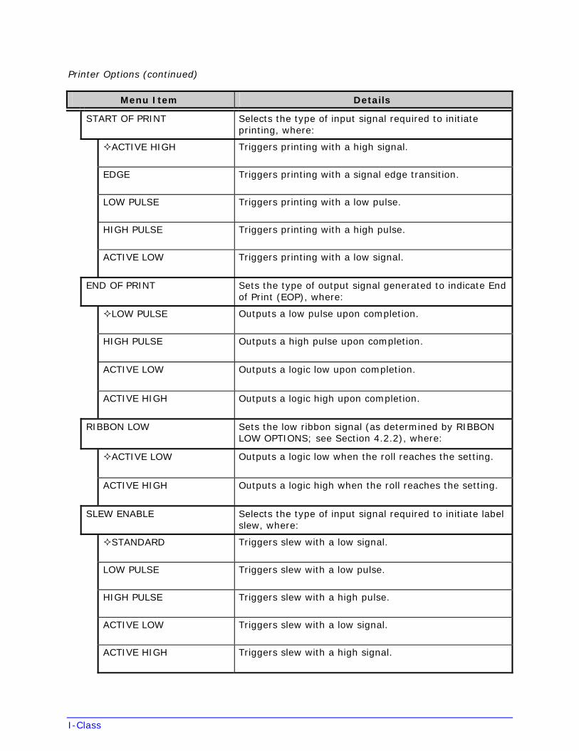
START OF PRINT Selects the type of input signal required to initiate printing, where:
ACTIVE HIGH Triggers printing with a high signal.
EDGE Triggers printing with a signal edge transition.
LOW PULSE Triggers printing with a low pulse.
HIGH PULSE Triggers printing with a high pulse.
ACTIVE LOW Triggers printing with a low signal.
END OF PRINT Sets the type of output signal generated to indicate End of Print (EOP), where:
LOW PULSE Outputs a low pulse upon completion.
HIGH PULSE Outputs a high pulse upon completion.
ACTIVE LOW Outputs a logic low upon completion.
ACTIVE HIGH Outputs a logic high upon completion.
RIBBON LOW Sets the low ribbon signal (as determined by RIBBON LOW OPTIONS; see Section 4.2.2), where:
ACTIVE LOW Outputs a logic low when the roll reaches the setting.
ACTIVE HIGH Outputs a logic high when the roll reaches the setting.
SLEW ENABLE Selects the type of input signal required to initiate label slew, where:
STANDARD Triggers slew with a low signal.
LOW PULSE Triggers slew with a low pulse.
HIGH PULSE Triggers slew with a high pulse.
ACTIVE LOW Triggers slew with a low signal.
ACTIVE HIGH Triggers slew with a high signal.
I-Class
Printer Options (continued)
Menu Item Details
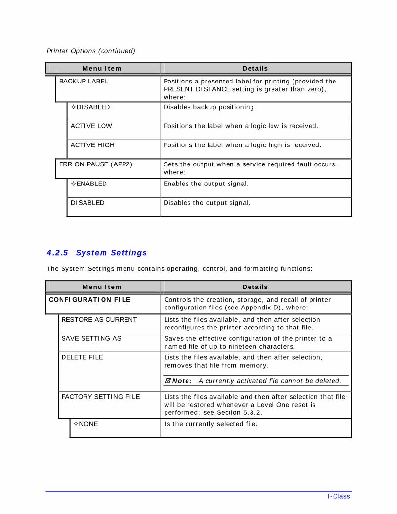
BACKUP LABEL Positions a presented label for printing (provided the PRESENT DISTANCE setting is greater than zero), where:
DISABLED Disables backup positioning.
ACTIVE LOW Positions the label when a logic low is received.
ACTIVE HIGH Positions the label when a logic high is received.
ERR ON PAUSE (APP2) Sets the output when a service required fault occurs, where:
ENABLED Enables the output signal.
DISABLED Disables the output signal.
4.2.5 System Settings
The System Settings menu contains operating, control, and formatting functions:
Menu Item Details
CONFIGURATION FILE Controls the creation, storage, and recall of printer configuration files (see Appendix D), where:
RESTORE AS CURRENT Lists the files available, and then after selection reconfigures the printer according to that file.
SAVE SETTING AS Saves the effective configuration of the printer to a named file of up to nineteen characters.
DELETE FILE Lists the files available, and then after selection, removes that file from memory.
Note: A currently activated file cannot be deleted.
FACTORY SETTING FILE Lists the files available and then after selection that file will be restored whenever a Level One reset is performed; see Section 5.3.2.
NONE Is the currently selected file.
I-Class
System Settings (continued)
Menu Item Details
INTERNAL MODULE D Allocates a number of 1KB memory blocks for internal Memory Module D; where:
1024 K (XXX - XXXX) Is the memory allocation; see Appendix A for the memory ranges, types, and availability.
DEFAULT MODULE Designates the memory module for storage when no other location is specified; where:
D Is the module; see Appendix A for availability.
SCALEABLE FONT CACHE Configures the number of 1KB memory blocks for the scaleable font engine; where:
0312 K (100 - 5120) Is the memory allocation; see Appendix A for availability.
SINGLE BYTE SYMBOLS Selects from the 66 available code pages used for single byte fonts (unless otherwise specified in DPL); where:
PC–850 MULTILINGUAL Is the selected code page; for details see the Class Series 2 Programmer’s Manual.
DOUBLE BYTE SYMBOLS Selects the code page (see the Class Series 2 Programmer’s Manual) used for the ILPC option (unless otherwise specified), where:
UNICODE Selects Unicode (including Korean).
GB Selects Government Bureau Industry Standard, Chinese (PRC).
BIG 5 Selects Taiwan encoded.
JIS Selects Japanese Industry Standard.
SHIFT JIS Selects Shift Japanese Industry Standard.
EUC Selects Extended UNIX Code.
TIME AND DATE Allows the user to set the time and date; where:
SET HOUR 06:30AM 01JAN2000
Enters the information for the time and date fields.
Note: Time and date retention (after power removal) requires the Real Time Clock function; see GPI/O Multi-Expansion CCA, Section 1.1.2.
I-Class
System Settings (continued)
Menu Item Details
MEDIA COUNTERS Provides a recorded count of inches printed and time; where:
ABSOLUTE COUNTER Shows the total number of inches printed and the set date. (Non-resettable)
RESETTABLE COUNTER Shows the number of inches printed and the last reset date.
RESET COUNTER Returns the RESETTABLE COUNTER to zero.
PRINT CONFIGURATION Prints a Configuration Label of current database information where items denoted with the section (§) and bullet ( ) symbol indicate changes not yet saved.
CONFIGURATION LEVEL Displays the hardware and software feature level of the printer, where:
Identifies the unique key number of the printer, in the form
vvvv-wwxx-yyyyyy-zzz
Where:
vvvv – Represents the printer model number.
wwxx – Represents the hardware and software levels, where:
ww – Represents the main logic card type:
PA = CCA 51-2178-XX; or TB = CCA 51-2301-XX
xx – Represents the software feature level:
10 = Standard DPL 11 = 4208 20 = Internal CG Times Font
yyyyyy – Is a manufacturing date code.
PRINTER KEY
zzz – Is a unique time stamp.
APPLICATION VERSION Displays the level, version number, and date of the application firmware.
BOOT LOADER Displays the Boot Loader version level and date.
UPGRADE PRINTER CODE 0 0 0 0 0 0
Upgrades the printer to the corresponding feature level. (Authorization required.)
I-Class
System Settings (continued)
Menu Item Details
UNLOCK FEATURE 0 0 0 0 0 0
Unlocks a corresponding feature with the entry of the correct code.
SET FACTORY DEFAULTS Returns the printer settings to the factory-programmed values or the Factory Setting File values, where:
SET FACTORY DEFAULT? CANCEL KEY = YES
Overwrites the current configuration and restores the default configuration (), or if selected the Factory Setting File. Otherwise, press the ESC Key to keep the current configuration.
Note: A reset will occur and, if no Factory Setting File is used, all settings returned except CUSTOM ADJUSTMENTS and calibrations.
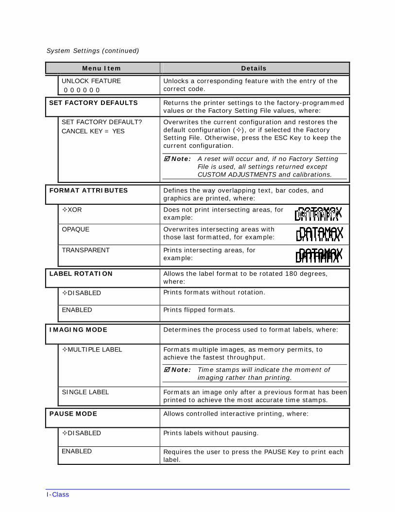
FORMAT ATTRIBUTES Defines the way overlapping text, bar codes, and graphics are printed, where:
XOR Does not print intersecting areas, for example:
OPAQUE Overwrites intersecting areas with those last formatted, for example:
TRANSPARENT Prints intersecting areas, for example:
LABEL ROTATION Allows the label format to be rotated 180 degrees, where:
DISABLED Prints formats without rotation.
ENABLED Prints flipped formats.
IMAGING MODE Determines the process used to format labels, where:
MULTIPLE LABEL Formats multiple images, as memory permits, to achieve the fastest throughput.
Note: Time stamps will indicate the moment of imaging rather than printing.
SINGLE LABEL Formats an image only after a previous format has been printed to achieve the most accurate time stamps.
PAUSE MODE Allows controlled interactive printing, where:
DISABLED Prints labels without pausing.
ENABLED Requires the user to press the PAUSE Key to print each label.
I-Class
System Settings (continued)
Menu Item Details
PEEL MODE Allows the SOP signal to initiate (via GPIO option) the feeding of the labels, where:
DISABLED Feeds regardless of SOP.
ENABLED Feeds only when SOP is received.
SECURITY Allows menu password protection, where:
SELECT SECURITY Enables or disables the security feature, where:
Note: The default password must be changed to activate.
DISABLED Allows entry.
SECURE MENU Sets a password requirement for menu entry.
MENU AND TEST Sets a password requirement for menu and test entries.
MODIFY PASSWORD Modifies the four-digit password required when security is enabled, where:
MODIFY PASSWORD? CANCEL KEY = YES
Enters the password (after confirmation); otherwise, press the ESC Key to keep the current password.
Note: The default password is 0000.
UNITS OF MEASURE Sets the measurement standard for the printer, where:
IMPERIAL Uses inches.
METRIC Uses millimeters and centimeters.
INPUT MODE Defines the type of processing that occurs when data is received, where:
DPL Processes data for standard DPL printing; see the Class Series 2 Programmer’s Manual.
LINE Processes data for template (Line Mode) printing; see the Class Series 2 Programmer’s Manual.
I-Class
System Settings (continued)
Menu Item Details
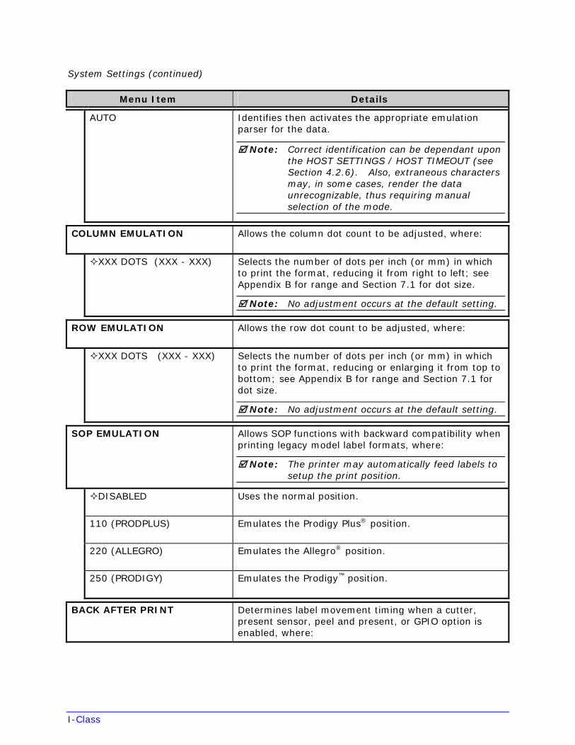
AUTO Identifies then activates the appropriate emulation parser for the data.
Note: Correct identification can be dependant upon the HOST SETTINGS / HOST TIMEOUT (see Section 4.2.6). Also, extraneous characters may, in some cases, render the data unrecognizable, thus requiring manual selection of the mode.
COLUMN EMULATION Allows the column dot count to be adjusted, where:
XXX DOTS (XXX - XXX) Selects the number of dots per inch (or mm) in which to print the format, reducing it from right to left; see Appendix B for range and Section 7.1 for dot size.
Note: No adjustment occurs at the default setting.
ROW EMULATION Allows the row dot count to be adjusted, where:
XXX DOTS (XXX - XXX) Selects the number of dots per inch (or mm) in which to print the format, reducing or enlarging it from top to bottom; see Appendix B for range and Section 7.1 for dot size.
Note: No adjustment occurs at the default setting.
SOP EMULATION Allows SOP functions with backward compatibility when printing legacy model label formats, where:
Note: The printer may automatically feed labels to setup the print position.
DISABLED Uses the normal position.
110 (PRODPLUS) Emulates the Prodigy Plus® position.
220 (ALLEGRO) Emulates the Allegro® position.
250 (PRODIGY) Emulates the Prodigy™ position.
BACK AFTER PRINT Determines label movement timing when a cutter, present sensor, peel and present, or GPIO option is enabled, where:
I-Class
System Settings (continued)
Menu Item Details
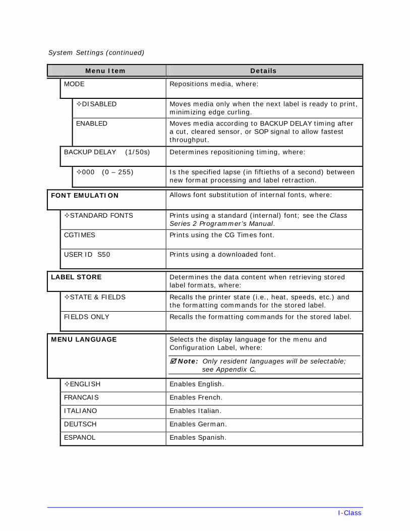
MODE Repositions media, where:
DISABLED Moves media only when the next label is ready to print, minimizing edge curling.
ENABLED Moves media according to BACKUP DELAY timing after a cut, cleared sensor, or SOP signal to allow fastest throughput.
BACKUP DELAY (1/50s) Determines repositioning timing, where:
000 (0 – 255) Is the specified lapse (in fiftieths of a second) between new format processing and label retraction.
FONT EMULATION Allows font substitution of internal fonts, where:
STANDARD FONTS Prints using a standard (internal) font; see the Class Series 2 Programmer’s Manual.
CGTIMES Prints using the CG Times font.
USER ID S50 Prints using a downloaded font.
LABEL STORE Determines the data content when retrieving stored label formats, where:
STATE & FIELDS Recalls the printer state (i.e., heat, speeds, etc.) and the formatting commands for the stored label.
FIELDS ONLY Recalls the formatting commands for the stored label.
MENU LANGUAGE Selects the display language for the menu and Configuration Label, where:
Note: Only resident languages will be selectable; see Appendix C.
ENGLISH Enables English.
FRANCAIS Enables French.
ITALIANO Enables Italian.
DEUTSCH Enables German.
ESPANOL Enables Spanish.
I-Class
System Settings (continued)
Menu Item Details
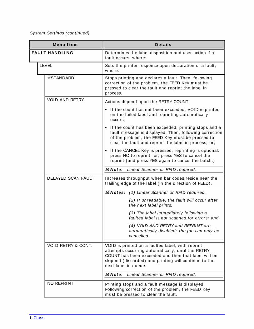
FAULT HANDLING Determines the label disposition and user action if a fault occurs, where:
LEVEL Sets the printer response upon declaration of a fault, where:
STANDARD Stops printing and declares a fault. Then, following correction of the problem, the FEED Key must be pressed to clear the fault and reprint the label in process.
VOID AND RETRY Actions depend upon the RETRY COUNT:
• If the count has not been exceeded, VOID is printedon the failed label and reprinting automaticallyoccurs;
• If the count has been exceeded, printing stops and afault message is displayed. Then, following correctionof the problem, the FEED Key must be pressed toclear the fault and reprint the label in process; or,
• If the CANCEL Key is pressed, reprinting is optional:press NO to reprint; or, press YES to cancel thereprint (and press YES again to cancel the batch.)
Note: Linear Scanner or RFID required.
DELAYED SCAN FAULT Increases throughput when bar codes reside near the trailing edge of the label (in the direction of FEED).
Notes: (1) Linear Scanner or RFID required.
(2) If unreadable, the fault will occur after the next label prints;
(3) The label immediately following a faulted label is not scanned for errors; and,
(4) VOID AND RETRY and REPRINT are automatically disabled; the job can only be cancelled.
VOID RETRY & CONT. VOID is printed on a faulted label, with reprint attempts occurring automatically, until the RETRY COUNT has been exceeded and then that label will be skipped (discarded) and printing will continue to the next label in queue.
Note: Linear Scanner or RFID required.
NO REPRINT Printing stops and a fault message is displayed. Following correction of the problem, the FEED Key must be pressed to clear the fault.
I-Class
System Settings (continued)
Menu Item Details
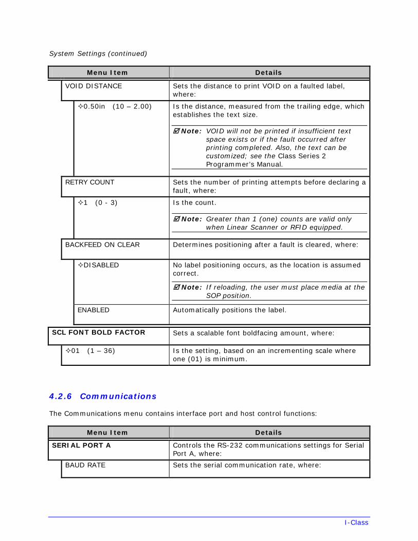
VOID DISTANCE Sets the distance to print VOID on a faulted label, where:
0.50in (10 – 2.00) Is the distance, measured from the trailing edge, which establishes the text size.
Note: VOID will not be printed if insufficient text space exists or if the fault occurred after printing completed. Also, the text can be customized; see the Class Series 2 Programmer’s Manual.
RETRY COUNT Sets the number of printing attempts before declaring a fault, where:
1 (0 - 3) Is the count.
Note: Greater than 1 (one) counts are valid only when Linear Scanner or RFID equipped.
BACKFEED ON CLEAR Determines positioning after a fault is cleared, where:
DISABLED No label positioning occurs, as the location is assumed correct.
Note: If reloading, the user must place media at the SOP position.
ENABLED Automatically positions the label.
SCL FONT BOLD FACTOR Sets a scalable font boldfacing amount, where:
01 (1 – 36) Is the setting, based on an incrementing scale where one (01) is minimum.
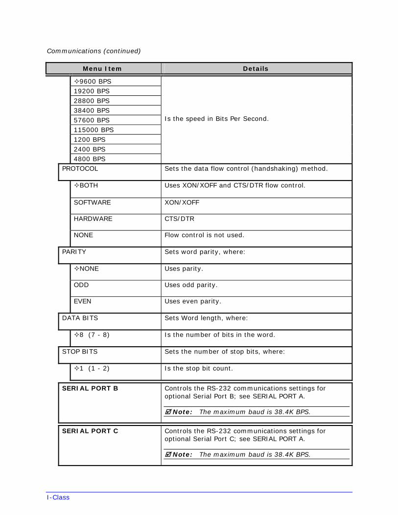
4.2.6 Communications
The Communications menu contains interface port and host control functions:
Menu Item Details
SERIAL PORT A Controls the RS-232 communications settings for Serial Port A, where:
BAUD RATE Sets the serial communication rate, where:
I-Class
Communications (continued)
Menu Item Details
9600 BPS19200 BPS 28800 BPS 38400 BPS 57600 BPS 115000 BPS 1200 BPS 2400 BPS 4800 BPS
Is the speed in Bits Per Second.
PROTOCOL Sets the data flow control (handshaking) method.
BOTH Uses XON/XOFF and CTS/DTR flow control.
SOFTWARE XON/XOFF
HARDWARE CTS/DTR
NONE Flow control is not used.
PARITY Sets word parity, where:
NONE Uses parity.
ODD Uses odd parity.
EVEN Uses even parity.
DATA BITS Sets Word length, where:
8 (7 - 8) Is the number of bits in the word.
STOP BITS Sets the number of stop bits, where:
1 (1 - 2) Is the stop bit count.
SERIAL PORT B Controls the RS-232 communications settings for optional Serial Port B; see SERIAL PORT A.
Note: The maximum baud is 38.4K BPS.
SERIAL PORT C Controls the RS-232 communications settings for optional Serial Port C; see SERIAL PORT A.
Note: The maximum baud is 38.4K BPS.
I-Class
Communications (continued)
Menu Item Details
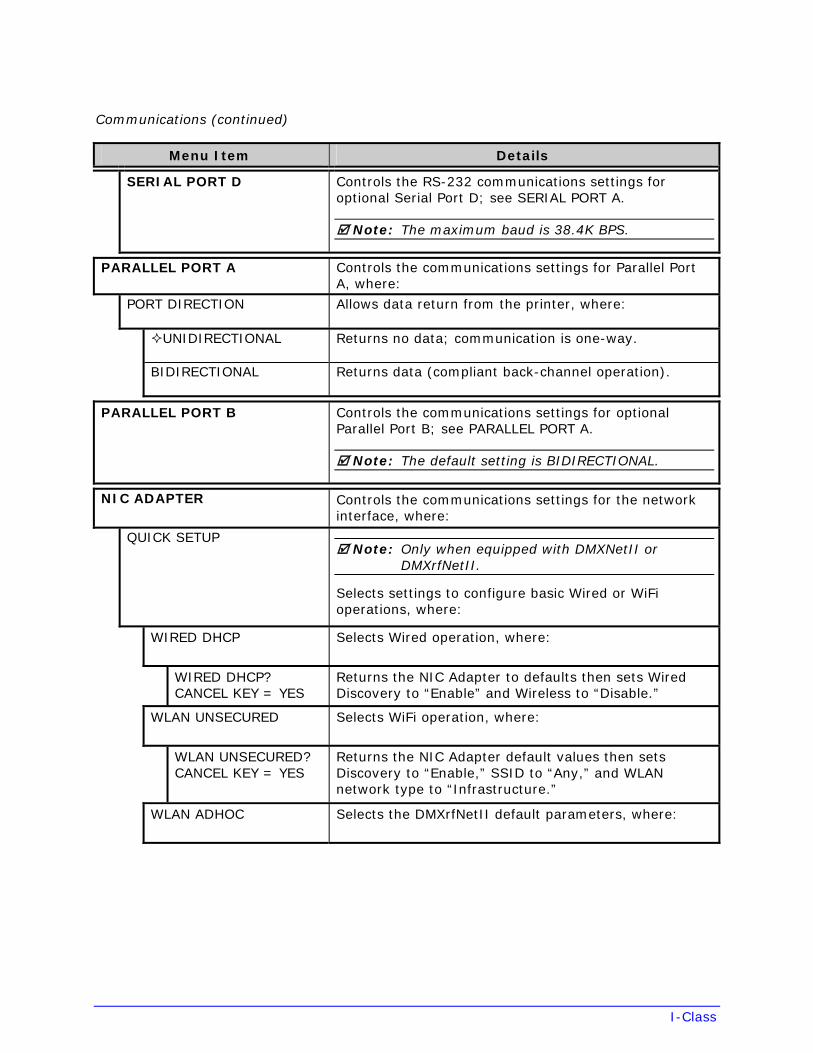
SERIAL PORT D Controls the RS-232 communications settings for optional Serial Port D; see SERIAL PORT A.
Note: The maximum baud is 38.4K BPS.
PARALLEL PORT A Controls the communications settings for Parallel Port A, where:
PORT DIRECTION Allows data return from the printer, where:
UNIDIRECTIONAL Returns no data; communication is one-way.
BIDIRECTIONAL Returns data (compliant back-channel operation).
PARALLEL PORT B Controls the communications settings for optional Parallel Port B; see PARALLEL PORT A.
Note: The default setting is BIDIRECTIONAL.
NIC ADAPTER Controls the communications settings for the network interface, where:
QUICK SETUP Note: Only when equipped with DMXNetII or
DMXrfNetII.
Selects settings to configure basic Wired or WiFi operations, where:
WIRED DHCP Selects Wired operation, where:
WIRED DHCP? CANCEL KEY = YES
Returns the NIC Adapter to defaults then sets Wired Discovery to “Enable” and Wireless to “Disable.”
WLAN UNSECURED Selects WiFi operation, where:
WLAN UNSECURED? CANCEL KEY = YES
Returns the NIC Adapter default values then sets Discovery to “Enable,” SSID to “Any,” and WLAN network type to “Infrastructure.”
WLAN ADHOC Selects the DMXrfNetII default parameters, where:
I-Class
Communications (continued)
Menu Item Details
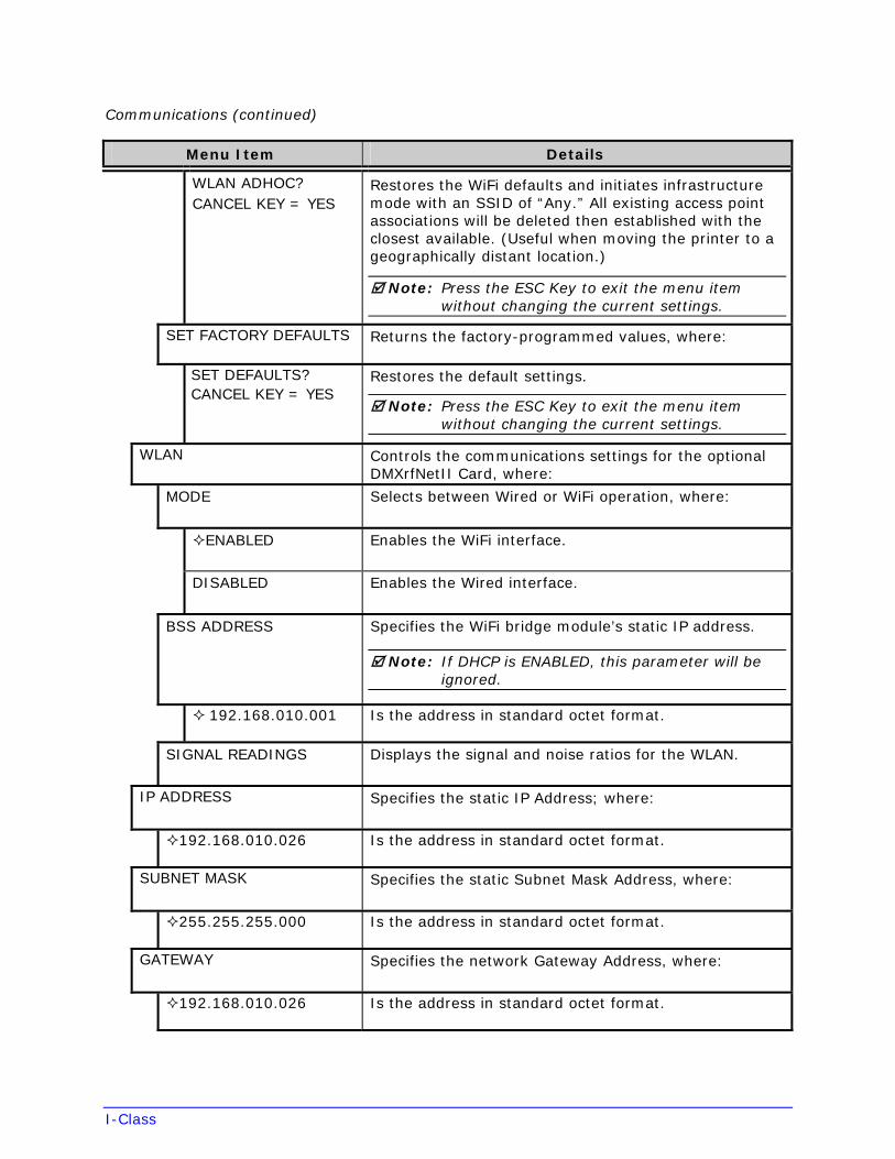
WLAN ADHOC? CANCEL KEY = YES
Restores the WiFi defaults and initiates infrastructure mode with an SSID of “Any.” All existing access point associations will be deleted then established with the closest available. (Useful when moving the printer to a geographically distant location.)
Note: Press the ESC Key to exit the menu item without changing the current settings.
SET FACTORY DEFAULTS Returns the factory-programmed values, where:
SET DEFAULTS? CANCEL KEY = YES
Restores the default settings.
Note: Press the ESC Key to exit the menu item without changing the current settings.
WLAN Controls the communications settings for the optional DMXrfNetII Card, where:
MODE Selects between Wired or WiFi operation, where:
ENABLED Enables the WiFi interface.
DISABLED Enables the Wired interface.
BSS ADDRESS Specifies the WiFi bridge module’s static IP address.
Note: If DHCP is ENABLED, this parameter will be ignored.
192.168.010.001 Is the address in standard octet format.
SIGNAL READINGS Displays the signal and noise ratios for the WLAN.
IP ADDRESS Specifies the static IP Address; where:
192.168.010.026 Is the address in standard octet format.
SUBNET MASK Specifies the static Subnet Mask Address, where:
255.255.255.000 Is the address in standard octet format.
GATEWAY Specifies the network Gateway Address, where:
192.168.010.026 Is the address in standard octet format.
I-Class
Communications (continued)
Menu Item Details
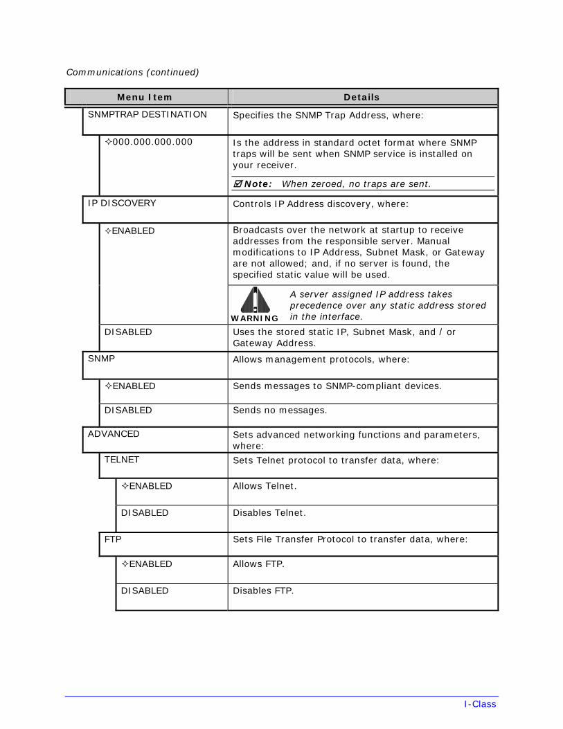
SNMPTRAP DESTINATION Specifies the SNMP Trap Address, where:
000.000.000.000 Is the address in standard octet format where SNMP traps will be sent when SNMP service is installed on your receiver.
Note: When zeroed, no traps are sent.
IP DISCOVERY Controls IP Address discovery, where:
Broadcasts over the network at startup to receive addresses from the responsible server. Manual modifications to IP Address, Subnet Mask, or Gateway are not allowed; and, if no server is found, the specified static value will be used.
ENABLED
WARNING
A server assigned IP address takes precedence over any static address stored in the interface.
DISABLED Uses the stored static IP, Subnet Mask, and / or Gateway Address.
SNMP Allows management protocols, where:
ENABLED Sends messages to SNMP-compliant devices.
DISABLED Sends no messages.
ADVANCED Sets advanced networking functions and parameters, where:
TELNET Sets Telnet protocol to transfer data, where:
ENABLED Allows Telnet.
DISABLED Disables Telnet.
FTP Sets File Transfer Protocol to transfer data, where:
ENABLED Allows FTP.
DISABLED Disables FTP.
I-Class
Communications (continued)
Menu Item Details
MTU Sets the Maximum Transmission Unit packet size, where:
01500(512 - 65515)
Is the packet size, in bytes.
GRATUITOUS ARP Sets the Address Resolution Protocol notification rate, where:
0000 (0 - 2048) Is the time, in minutes.
PORT NUMBER Sets the network communications port, where:
09100 (1 - 65535) Is the Port Number.
DUPLEX CAPABILITY Sets the communication capability for the Wired network, where:
AUTO-NEGOTIATE Automatically selects the best type.
100BASET HALF Selects 100 Mb half duplex (in both directions, one way at a time) operation.
100BASET FULL Selects 100 Mb full duplex (in both directions, simultaneously) operation.
10BASET HALF Selects 10 Mb half duplex (in both directions, one way at a time) operation.
10BASET FULL Selects 10 Mb full duplex (in both directions, simultaneously) operation.
ADVERTISE CAPABILITY Transmits the printer’s communication capability for the Wired network, where:
AUTOMATIC Advertises the DUPLEX CAPABILITY set value.
ALL CAPABILITIES Advertises all possible values for DUPLEX CAPABILITY.
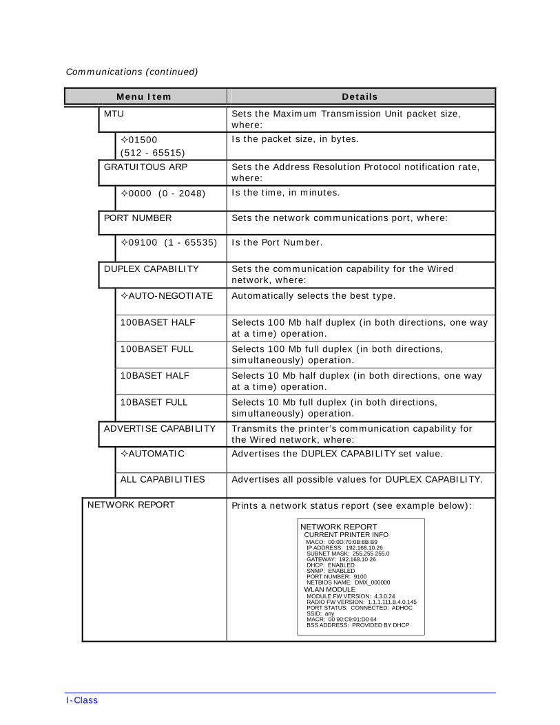
NETWORK REPORT Prints a network status report (see example below):
NETWORK REPORT CURRENT PRINTER INFO MACO: 00:0D:70:0B:8B B9 IP ADDRESS: 192.168.10.26 SUBNET MASK: 255.255 255.0 GATEWAY: 192.168.10 26 DHCP: ENABLED SNMP: ENABLED
PORT NUMBER: 9100NETBIOS NAME: DMX_000000
WLAN MODULE MODULE FW VERSION: 4.3.0.24 RADIO FW VERSION: 1.1.1.111.8.4.0.145 PORT STATUS: CONNECTED: ADHOC SSID: any MACR: 00 90:C9:01:D0 64 BSS ADDRESS: PROVIDED BY DHCP
I-Class
Communications (continued)
Menu Item Details
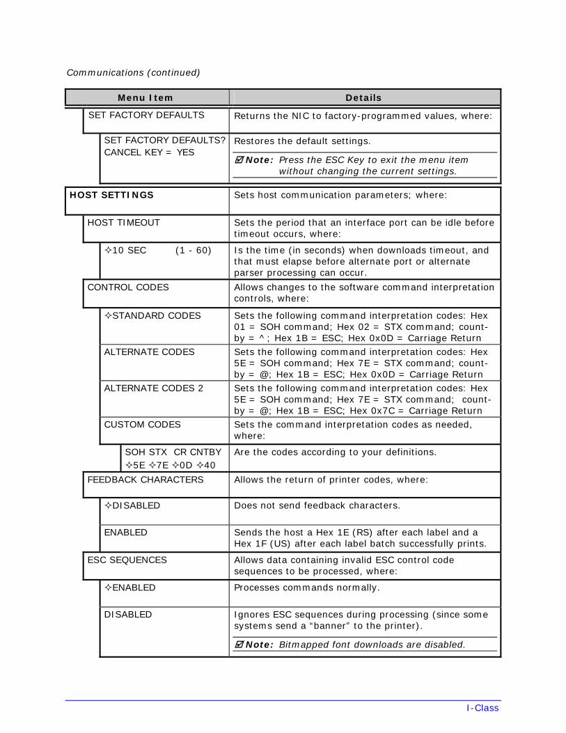
SET FACTORY DEFAULTS Returns the NIC to factory-programmed values, where:
SET FACTORY DEFAULTS? CANCEL KEY = YES
Restores the default settings.
Note: Press the ESC Key to exit the menu item without changing the current settings.
HOST SETTINGS Sets host communication parameters; where:
HOST TIMEOUT Sets the period that an interface port can be idle before timeout occurs, where:
10 SEC (1 - 60) Is the time (in seconds) when downloads timeout, and that must elapse before alternate port or alternate parser processing can occur.
CONTROL CODES Allows changes to the software command interpretation controls, where:
STANDARD CODES Sets the following command interpretation codes: Hex 01 = SOH command; Hex 02 = STX command; count-by = ^; Hex 1B = ESC; Hex 0x0D = Carriage Return
ALTERNATE CODES Sets the following command interpretation codes: Hex 5E = SOH command; Hex 7E = STX command; count-by = @; Hex 1B = ESC; Hex 0x0D = Carriage Return
ALTERNATE CODES 2 Sets the following command interpretation codes: Hex 5E = SOH command; Hex 7E = STX command; count-by = @; Hex 1B = ESC; Hex 0x7C = Carriage Return
CUSTOM CODES Sets the command interpretation codes as needed, where:
SOH STX CR CNTBY 5E 7E 0D 40
Are the codes according to your definitions.
FEEDBACK CHARACTERS Allows the return of printer codes, where:
DISABLED Does not send feedback characters.
ENABLED Sends the host a Hex 1E (RS) after each label and a Hex 1F (US) after each label batch successfully prints.
ESC SEQUENCES Allows data containing invalid ESC control code sequences to be processed, where:
ENABLED Processes commands normally.
DISABLED Ignores ESC sequences during processing (since some systems send a “banner” to the printer).
Note: Bitmapped font downloads are disabled.
I-Class
Communications (continued)
Menu Item Details
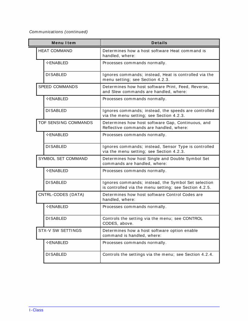
HEAT COMMAND Determines how a host software Heat command is handled, where:
ENABLED Processes commands normally.
DISABLED Ignores commands; instead, Heat is controlled via the menu setting; see Section 4.2.3.
SPEED COMMANDS Determines how host software Print, Feed, Reverse, and Slew commands are handled, where:
ENABLED Processes commands normally.
DISABLED Ignores commands; instead, the speeds are controlled via the menu setting; see Section 4.2.3.
TOF SENSING COMMANDS Determines how host software Gap, Continuous, and Reflective commands are handled, where:
ENABLED Processes commands normally.
DISABLED Ignores commands; instead, Sensor Type is controlled via the menu setting; see Section 4.2.3.
SYMBOL SET COMMAND Determines how host Single and Double Symbol Set commands are handled, where:
ENABLED Processes commands normally.
DISABLED Ignores commands; instead, the Symbol Set selection is controlled via the menu setting; see Section 4.2.5.
CNTRL-CODES (DATA) Determines how host software Control Codes are handled, where:
ENABLED Processes commands normally.
DISABLED Controls the setting via the menu; see CONTROL CODES, above.
STX-V SW SETTINGS Determines how a host software option enable command is handled, where:
ENABLED Processes commands normally.
DISABLED Controls the settings via the menu; see Section 4.2.4.
I-Class
Communications (continued)
Menu Item Details
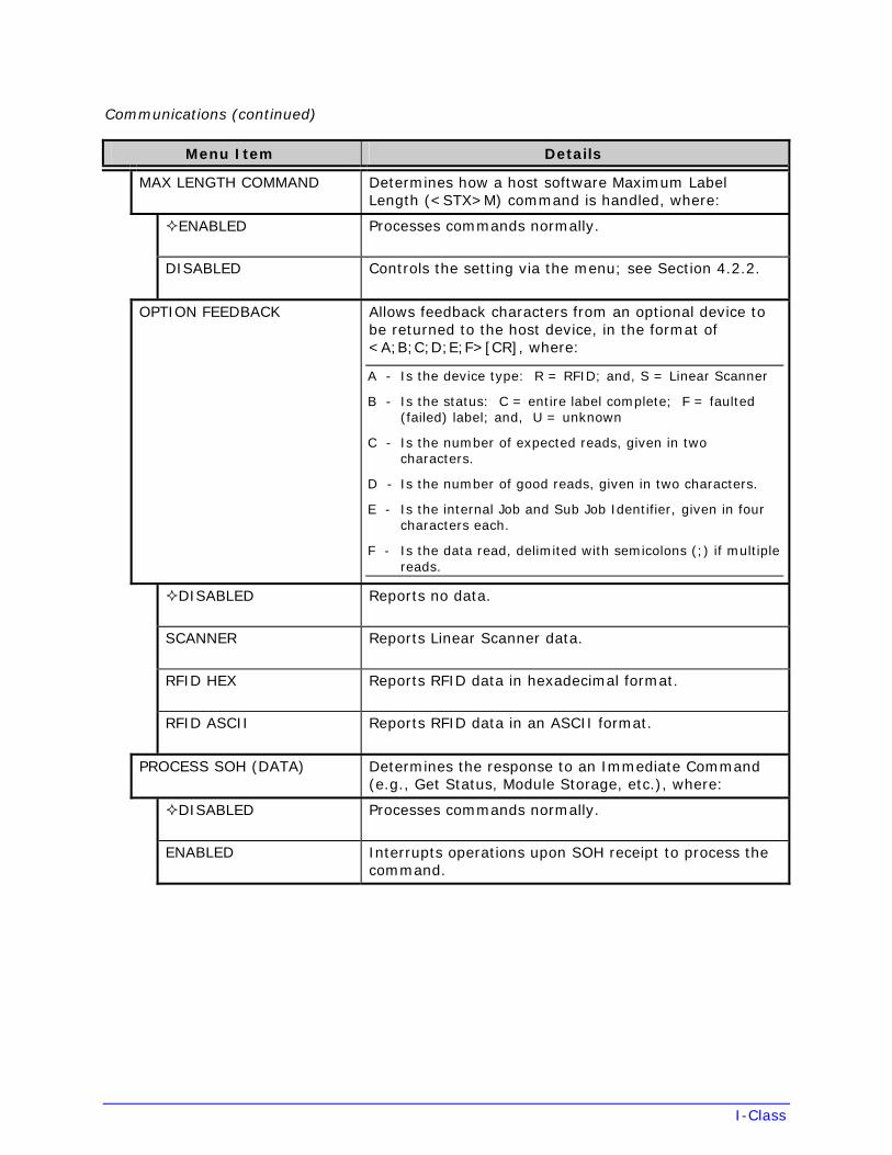
MAX LENGTH COMMAND Determines how a host software Maximum Label Length (<STX>M) command is handled, where:
ENABLED Processes commands normally.
DISABLED Controls the setting via the menu; see Section 4.2.2.
OPTION FEEDBACK Allows feedback characters from an optional device to be returned to the host device, in the format of <A;B;C;D;E;F>[CR], where:
A - Is the device type: R = RFID; and, S = Linear Scanner
B - Is the status: C = entire label complete; F = faulted (failed) label; and, U = unknown
C - Is the number of expected reads, given in two characters.
D - Is the number of good reads, given in two characters.
E - Is the internal Job and Sub Job Identifier, given in four characters each.
F - Is the data read, delimited with semicolons (;) if multiple reads.
DISABLED Reports no data.
SCANNER Reports Linear Scanner data.
RFID HEX Reports RFID data in hexadecimal format.
RFID ASCII Reports RFID data in an ASCII format.
PROCESS SOH (DATA) Determines the response to an Immediate Command (e.g., Get Status, Module Storage, etc.), where:
DISABLED Processes commands normally.
ENABLED Interrupts operations upon SOH receipt to process the command.
I-Class
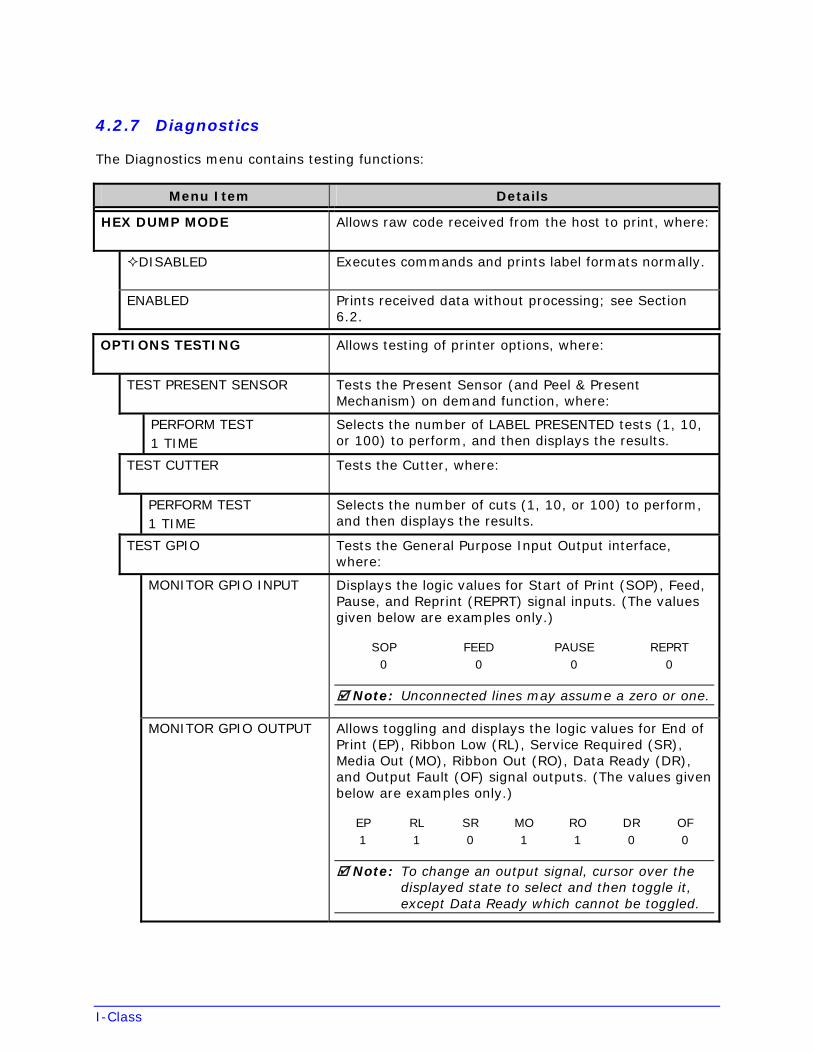
4.2.7 Diagnostics
The Diagnostics menu contains testing functions:
Menu Item Details
HEX DUMP MODE Allows raw code received from the host to print, where:
DISABLED Executes commands and prints label formats normally.
ENABLED Prints received data without processing; see Section 6.2.
OPTIONS TESTING Allows testing of printer options, where:
TEST PRESENT SENSOR Tests the Present Sensor (and Peel & Present Mechanism) on demand function, where:
PERFORM TEST 1 TIME
Selects the number of LABEL PRESENTED tests (1, 10, or 100) to perform, and then displays the results.
TEST CUTTER Tests the Cutter, where:
PERFORM TEST 1 TIME
Selects the number of cuts (1, 10, or 100) to perform, and then displays the results.
TEST GPIO Tests the General Purpose Input Output interface, where:
MONITOR GPIO INPUT Displays the logic values for Start of Print (SOP), Feed, Pause, and Reprint (REPRT) signal inputs. (The values given below are examples only.)
SOP FEED PAUSE REPRT0 0 0 0
Note: Unconnected lines may assume a zero or one.
MONITOR GPIO OUTPUT Allows toggling and displays the logic values for End of Print (EP), Ribbon Low (RL), Service Required (SR), Media Out (MO), Ribbon Out (RO), Data Ready (DR), and Output Fault (OF) signal outputs. (The values given below are examples only.)
EP RL SR MO RO DR OF 1 1 0 1 1 0 0
Note: To change an output signal, cursor over the displayed state to select and then toggle it, except Data Ready which cannot be toggled.
I-Class
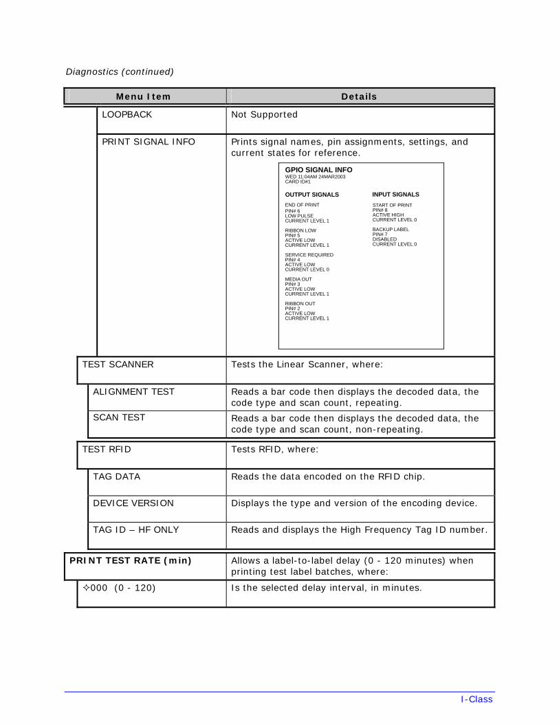
Diagnostics (continued)
Menu Item Details
LOOPBACK Not Supported
PRINT SIGNAL INFO Prints signal names, pin assignments, settings, and current states for reference.
GPIO SIGNAL INFOWED 11:04AM 24MAR2003CARD ID#1
OUTPUT SIGNALS
END OF PRINTPIN# 6LOW PULSECURRENT LEVEL 1
RIBBON LOWPIN# 5ACTIVE LOWCURRENT LEVEL 1
SERVICE REQUIREDPIN# 4ACTIVE LOWCURRENT LEVEL 0
MEDIA OUTPIN# 3ACTIVE LOWCURRENT LEVEL 1
RIBBON OUTPIN# 2ACTIVE LOWCURRENT LEVEL 1
INPUT SIGNALS
START OF PRINTPIN# 8ACTIVE HIGHCURRENT LEVEL 0
BACKUP LABELPIN# 7DISABLEDCURRENT LEVEL 0
TEST SCANNER Tests the Linear Scanner, where:
ALIGNMENT TEST Reads a bar code then displays the decoded data, the code type and scan count, repeating.
SCAN TEST Reads a bar code then displays the decoded data, the code type and scan count, non-repeating.
TEST RFID Tests RFID, where:
TAG DATA Reads the data encoded on the RFID chip.
DEVICE VERSION Displays the type and version of the encoding device.
TAG ID – HF ONLY Reads and displays the High Frequency Tag ID number.
PRINT TEST RATE (min) Allows a label-to-label delay (0 - 120 minutes) when printing test label batches, where:
000 (0 - 120) Is the selected delay interval, in minutes.
I-Class
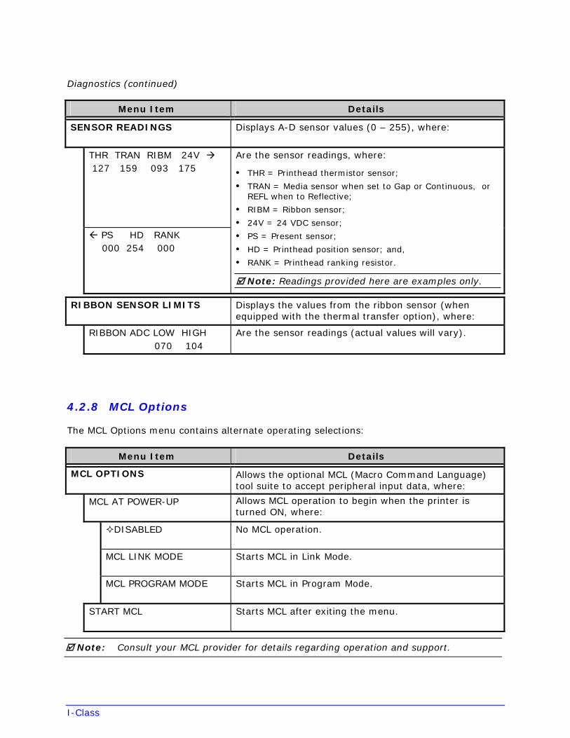
Diagnostics (continued)
Menu Item Details
SENSOR READINGS Displays A-D sensor values (0 – 255), where:
THR TRAN RIBM 24V 127 159 093 175
PS HD RANK 000 254 000
Are the sensor readings, where:
• THR = Printhead thermistor sensor;
• TRAN = Media sensor when set to Gap or Continuous, orREFL when to Reflective;
• RIBM = Ribbon sensor;
• 24V = 24 VDC sensor;
• PS = Present sensor;
• HD = Printhead position sensor; and,
• RANK = Printhead ranking resistor.
Note: Readings provided here are examples only.
RIBBON SENSOR LIMITS Displays the values from the ribbon sensor (when equipped with the thermal transfer option), where:
RIBBON ADC LOW HIGH 070 104
Are the sensor readings (actual values will vary).
4.2.8 MCL Options
The MCL Options menu contains alternate operating selections:
Menu Item Details
MCL OPTIONS Allows the optional MCL (Macro Command Language) tool suite to accept peripheral input data, where:
MCL AT POWER-UP Allows MCL operation to begin when the printer is turned ON, where:
DISABLED No MCL operation.
MCL LINK MODE Starts MCL in Link Mode.
MCL PROGRAM MODE Starts MCL in Program Mode.
START MCL Starts MCL after exiting the menu.
Note: Consult your MCL provider for details regarding operation and support.
I-Class
4.3 The Test Menu
The TEST Key accesses six resident format selections that are printed at selected heat and speed settings (see Section 4.1.4 for printing details).
Notes: (1) With the exception of the Configuration Label, all test labels require full width media to capture the entire format.
(2) During a test, press the Key or the Key to stop printing.
(3) Use PRINT TEST RATE (Section 4.2.7) to delay printing.
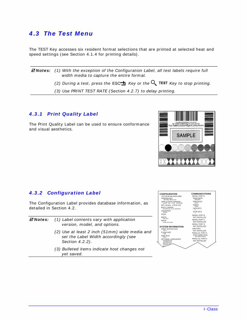
4.3.1 Print Quality Label
The Print Quality Label can be used to ensure conformance and visual aesthetics.
4.3.2 Configuration Label
The Configuration Label provides database information, as detailed in Section 4.2.
Notes: (1) Label contents vary with application version, model, and options.
(2) Use at least 2 inch (51mm) wide media and set the Label Width accordingly (see Section 4.2.2).
(3) Bulleted items indicate host changes not yet saved.
PARALLEL PORT APORT DIRECTION
UNI-DIRECTIONAL
PARALLEL PORT ANOT INSTALLED
COMMUNICATIONSSERIAL PORT ABAUD RATE
9600 BPS
PROTOCOLBOTH
PARITYNONE
DATA BITS8
STOP BITS1
SERIAL PORT BNOT INSTALLED
SERIAL PORT CNOT INSTALLED
SERIAL PORT DNOT INSTALLED
USB PORTNOT INSTALLED
SYSTEM INFORMATIONPRINT BUFFER SIZE
100 in.
FLASH SIZE2 MB
RAM TESTPASS
OPTIONAL LANGUAGESFRANCIAS.DLNITALIANO.DLNDEUTSCH.DLNESPANOL.DL
ONF
CONFIGURATIONTUE 09 09 AM 29JUL2008PRINTER KEY
308-TB10-020312-001
APPLICATION VERSION83-228 -11E 11.05 07/07/2008
MCL Version 1.20.02-126BOOT LOADER
83-2269-11A 11.01 10/02/2007
UNLOCKED*NONE
FPGA*
MACONOT SET
MACR00-90-c9-01-d0-8
I-Class
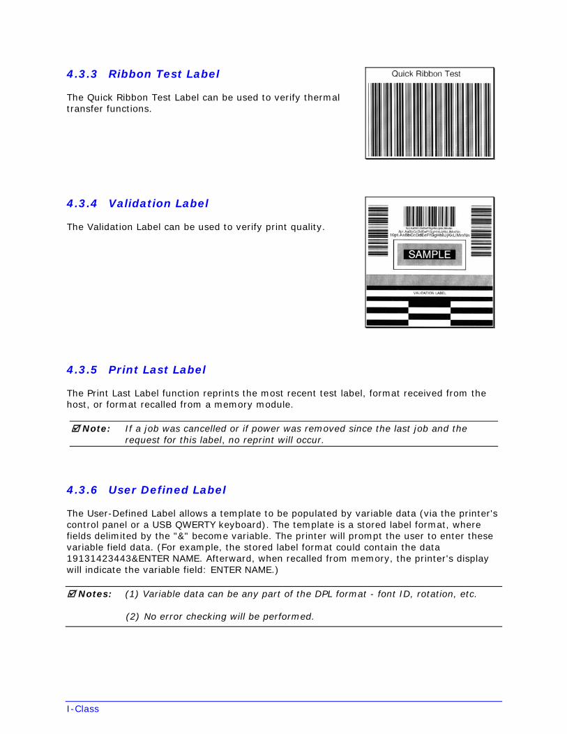
4.3.3 Ribbon Test Label
The Quick Ribbon Test Label can be used to verify thermal transfer functions.
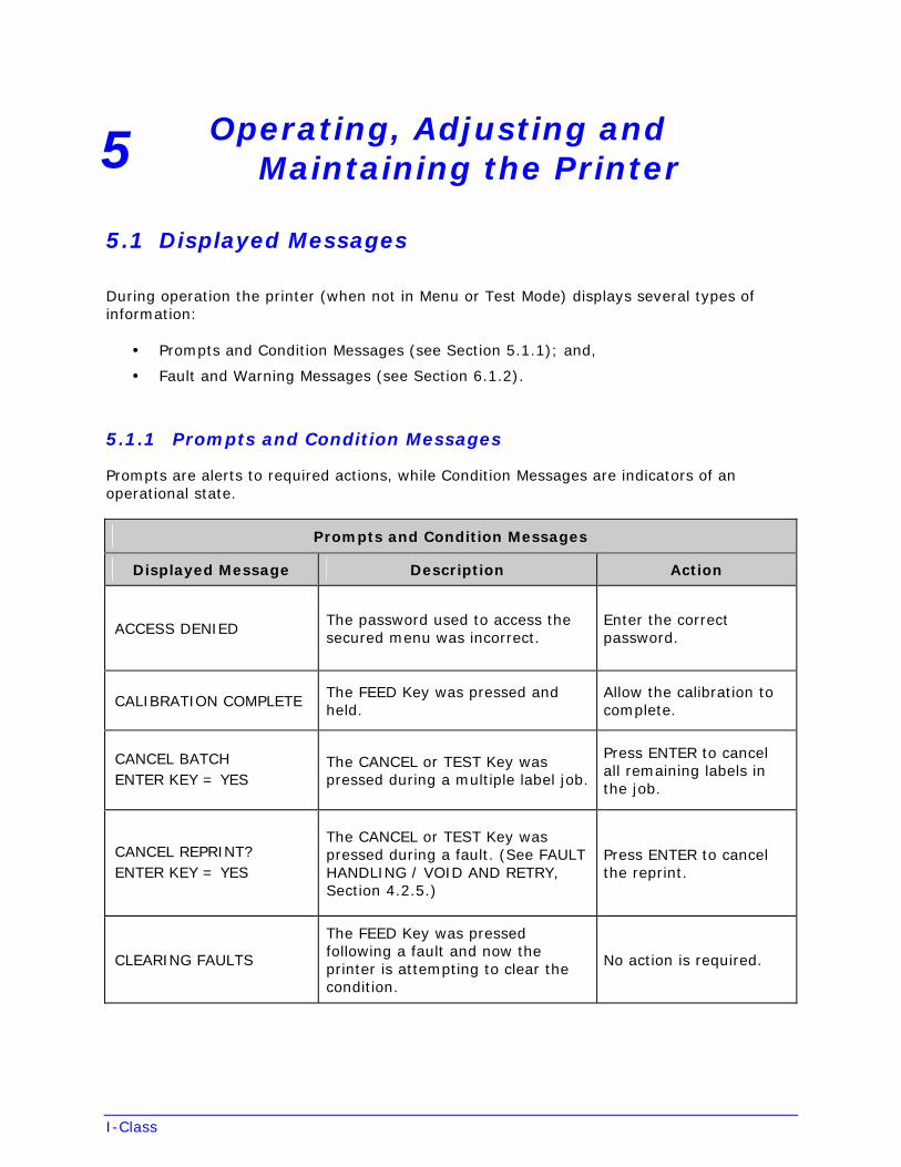
4.3.4 Validation Label
The Validation Label can be used to verify print quality.
4.3.5 Print Last Label
The Print Last Label function reprints the most recent test label, format received from the host, or format recalled from a memory module.
Note: If a job was cancelled or if power was removed since the last job and the request for this label, no reprint will occur.
4.3.6 User Defined Label
The User-Defined Label allows a template to be populated by variable data (via the printer's control panel or a USB QWERTY keyboard). The template is a stored label format, where fields delimited by the "&" become variable. The printer will prompt the user to enter these variable field data. (For example, the stored label format could contain the data 19131423443&ENTER NAME. Afterward, when recalled from memory, the printer's display will indicate the variable field: ENTER NAME.)
Notes: (1) Variable data can be any part of the DPL format - font ID, rotation, etc.
(2) No error checking will be performed.
I-Class
5 Operating, Adjusting and Maintaining the Printer
5.1 Displayed Messages
During operation the printer (when not in Menu or Test Mode) displays several types of information:
• Prompts and Condition Messages (see Section 5.1.1); and,
• Fault and Warning Messages (see Section 6.1.2).
5.1.1 Prompts and Condition Messages
Prompts are alerts to required actions, while Condition Messages are indicators of an operational state.
Prompts and Condition Messages
Displayed Message Description Action
ACCESS DENIED The password used to access the secured menu was incorrect.
Enter the correct password.
CALIBRATION COMPLETE The FEED Key was pressed and held.
Allow the calibration to complete.
CANCEL BATCH ENTER KEY = YES
The CANCEL or TEST Key was pressed during a multiple label job.
Press ENTER to cancel all remaining labels in the job.
CANCEL REPRINT? ENTER KEY = YES
The CANCEL or TEST Key was pressed during a fault. (See FAULT HANDLING / VOID AND RETRY, Section 4.2.5.)
Press ENTER to cancel the reprint.
CLEARING FAULTS
The FEED Key was pressed following a fault and now the printer is attempting to clear the condition.
No action is required.
I-Class
Prompts and Condition Messages (continued)
Displayed Message Description Action
DISPLAY CONTRAST The MENU Key is being pressed and held, and now the LCD contrast is being adjusted.
Release the MENU Key when the desired contrast is achieved.
DMXNET INITIALIZING The network card is initializing, a normal condition following power-up or a reset.
No action is required. Depending upon the settings, it may take a few minutes.
NOT INSTALLED The selected option or feature cannot be found.
Verify that the option or feature is correctly installed. If so, call for service.
PAUSED
The PAUSE Key was pressed (or PAUSE MODE is enabled, see Section 4.2.5) and now the printer is in a paused condition.
Press PAUSE.
PRINTHEAD CLEANING
The TEST Key was pressed and held, or CLEAN HEAD NOW was selected, and now printhead cleaning is in progress.
No action is required.
READY The printer is waiting to receive label formats, downloads, etc.
Send a label format, download, etc.
REMOVE LABELThe Present Sensor (or Peel and Present Mechanism) is enabled and a label awaits removal.
Remove the label.
REMOVE RIBBON PRESS ANY KEY
The TEST Key was pressed and held, or CLEAN HEAD NOW was selected, but ribbon is installed.
Remove ribbon and press any key to proceed.
SUCCESSFUL PRESS ANY KEY
The selected operation was successfully completed.
Press any key to continue.
I-Class
Prompts and Condition Messages (continued)
Displayed Message Description Action
SYSTEM INITIALIZING The power switch has been turned ON or a reset has occurred.
No action is required. Wait briefly while the process completes.
SYSTEM RESET IN PROGRESS
A reset has occurred. No action is required. Wait briefly while the process completes.
UNCALIBRATED The Media Sensor is not calibrated. Perform calibration; see Section 5.2.
WAITING FOR DATA The SOP signal has been received, but the printer awaits label data.
Send data from the host.
WAITING FOR SIGNAL The printer awaits a SOP signal. Send the SOP signal from the applicator to the GPIO port.
XXXX OF XXXX PRINTING
A print job is in process, as indicated by the batch total and remaining label count.
No action is required.
5.2 Calibration
Calibration ensures label detection. Perform calibration when the UNCALIBRATED is displayed. Two different methods, Standard and Advanced Entry, are available to calibrate the printer.
5.2.1 Standard Calibration
Standard Calibration, appropriate for most media types, is a method that allows visual access to the media sensor for positioning. Displayed sensor readings can also be used to indicate the best position over the media – helpful when using small, position-critical TOF notches or marks.
I-Class
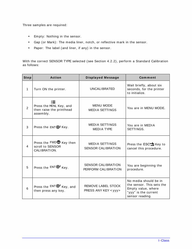
Three samples are required:
• Empty: Nothing in the sensor.
• Gap (or Mark): The media liner, notch, or reflective mark in the sensor.
• Paper: The label (and liner, if any) in the sensor.
With the correct SENSOR TYPE selected (see Section 4.2.2), perform a Standard Calibration as follows:
Step Action Displayed Message Comment
1 Turn ON the printer. UNCALIBRATED Wait briefly, about six seconds, for the printer to initialize.
2 Press the Key, and then raise the printhead assembly.
MENU MODE MEDIA SETTINGS
You are in MENU MODE.
3 Press the Key. MEDIA SETTINGS
MEDIA TYPE You are in MEDIA SETTINGS.
4 Press the Key then scroll to SENSOR CALIBRATION.
MEDIA SETTINGS SENSOR CALIBRATION
Press the Key to cancel this procedure.
5 Press the Key. SENSOR CALIBRATION PERFORM CALIBRATION
You are beginning the procedure.
6 Press the Key, and then press any key.
REMOVE LABEL STOCK PRESS ANY KEY <yyy>
No media should be in the sensor. This sets the Empty value, where “yyy” is the current sensor reading.
I-Class
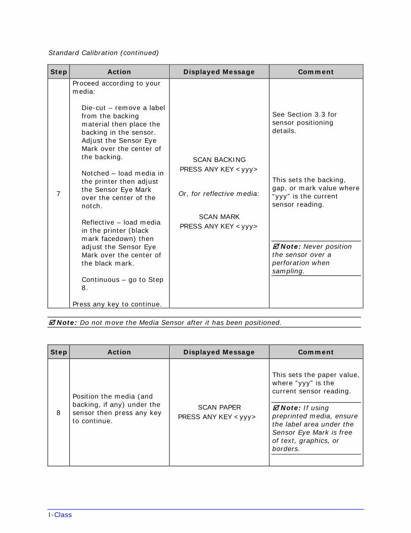
Standard Calibration (continued)
Step Action Displayed Message Comment
7
Proceed according to your media:
Die-cut – remove a label from the backing material then place the backing in the sensor. Adjust the Sensor Eye Mark over the center of the backing.
Notched – load media in the printer then adjust the Sensor Eye Mark over the center of the notch.
Reflective – load media in the printer (black mark facedown) then adjust the Sensor Eye Mark over the center of the black mark.
Continuous – go to Step 8.
Press any key to continue.
SCAN BACKING PRESS ANY KEY <yyy>
Or, for reflective media:
SCAN MARK PRESS ANY KEY <yyy>
See Section 3.3 for sensor positioning details.
This sets the backing, gap, or mark value where “yyy” is the current sensor reading.
Note: Never position the sensor over a perforation when sampling.
Note: Do not move the Media Sensor after it has been positioned.
Step Action Displayed Message Comment
8
Position the media (and backing, if any) under the sensor then press any key to continue.
SCAN PAPER PRESS ANY KEY <yyy>
This sets the paper value, where “yyy” is the current sensor reading.
Note: If using preprinted media, ensure the label area under the Sensor Eye Mark is free of text, graphics, or borders.
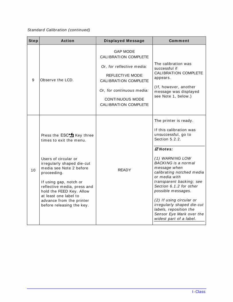
I-Class
Standard Calibration (continued)
Step Action Displayed Message Comment
9 Observe the LCD.
GAP MODE CALIBRATION COMPLETE
Or, for reflective media:
REFLECTIVE MODE CALIBRATION COMPLETE
Or, for continuous media:
CONTINUOUS MODE CALIBRATION COMPLETE
The calibration was successful if CALIBRATION COMPLETE appears.
(If, however, another message was displayed see Note 1, below.)
10
Press the Key three times to exit the menu.
Users of circular or irregularly shaped die-cut media see Note 2 before proceeding.
If using gap, notch or reflective media, press and hold the FEED Key. Allow at least one label to advance from the printer before releasing the key.
READY
The printer is ready.
If this calibration was unsuccessful, go to Section 5.2.2.
Notes:
(1) WARNING LOW BACKING is a normal message when calibrating notched media or media with transparent backing; see Section 6.1.2 for other possible messages.
(2) If using circular or irregularly shaped die-cut labels, reposition the Sensor Eye Mark over the widest part of a label.
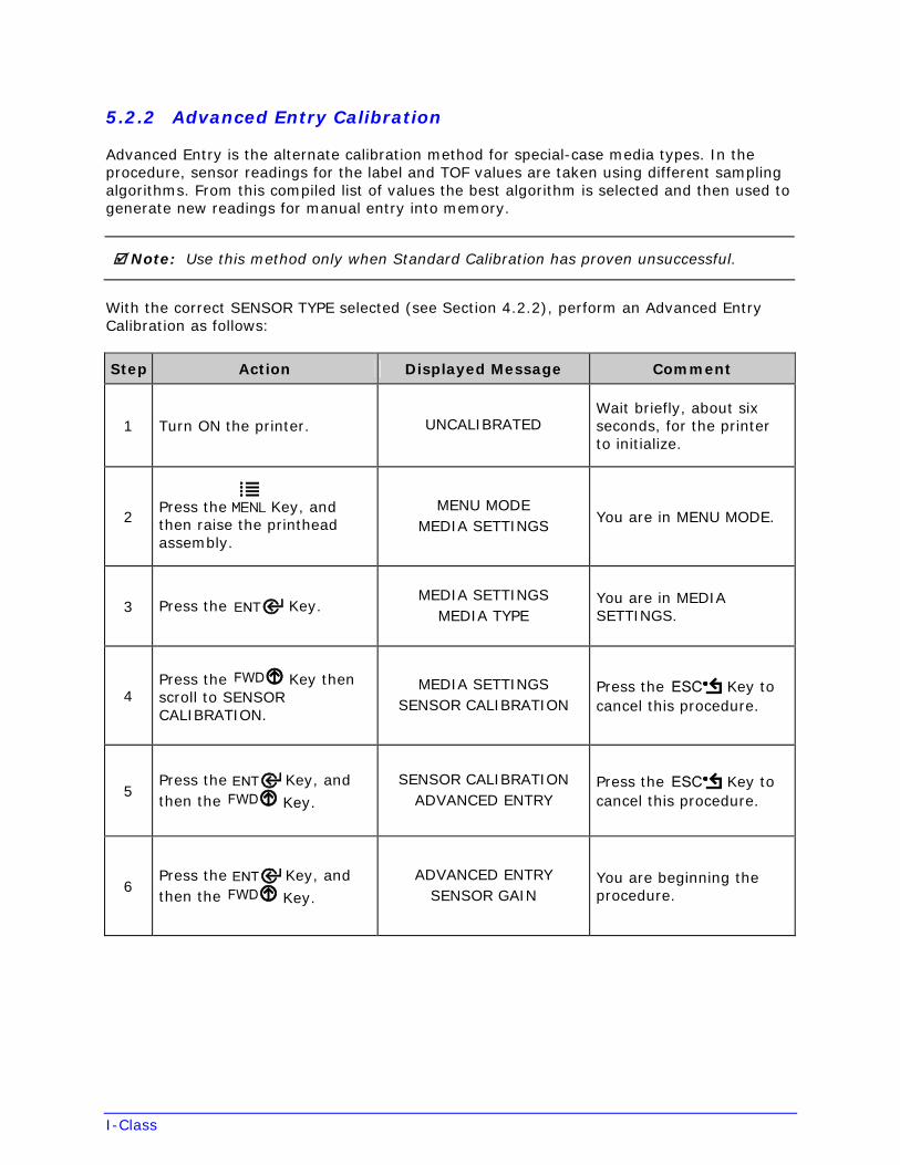
I-Class
5.2.2 Advanced Entry Calibration
Advanced Entry is the alternate calibration method for special-case media types. In the procedure, sensor readings for the label and TOF values are taken using different sampling algorithms. From this compiled list of values the best algorithm is selected and then used to generate new readings for manual entry into memory.
Note: Use this method only when Standard Calibration has proven unsuccessful.
With the correct SENSOR TYPE selected (see Section 4.2.2), perform an Advanced Entry Calibration as follows:
Step Action Displayed Message Comment
1 Turn ON the printer. UNCALIBRATED Wait briefly, about six seconds, for the printer to initialize.
2 Press the Key, and then raise the printhead assembly.
MENU MODE MEDIA SETTINGS
You are in MENU MODE.
3 Press the Key. MEDIA SETTINGS
MEDIA TYPE You are in MEDIA SETTINGS.
4 Press the Key then scroll to SENSOR CALIBRATION.
MEDIA SETTINGS SENSOR CALIBRATION
Press the Key to cancel this procedure.
5 Press the Key, and then the Key.
SENSOR CALIBRATION ADVANCED ENTRY
Press the Key to cancel this procedure.
6 Press the Key, and then the Key.
ADVANCED ENTRY SENSOR GAIN
You are beginning the procedure.
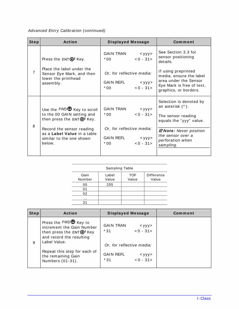
I-Class
Advanced Entry Calibration (continued)
Step Action Displayed Message Comment
7
Press the Key.
Place the label under the Sensor Eye Mark, and then lower the printhead assembly.
GAIN TRAN <yyy> *00 <0 - 31>
Or, for reflective media:
GAIN REFL <yyy> *00 <0 - 31>
See Section 3.3 for sensor positioning details.
If using preprinted media, ensure the label area under the Sensor Eye Mark is free of text, graphics, or borders.
8
Use the Key to scroll to the 00 GAIN setting and then press the Key.
Record the sensor reading as a Label Value in a table similar to the one shown below.
GAIN TRAN <yyy> *00 <0 - 31>
Or, for reflective media:
GAIN REFL <yyy> *00 <0 - 31>
Selection is denoted by an asterisk (*).
The sensor reading equals the “yyy” value.
Note: Never position the sensor over a perforation when sampling.
Sampling Table
Gain Number
Label Value
TOF Value
Difference Value
00 2550102…31
Step Action Displayed Message Comment
9
Press the Key to increment the Gain Number then press the Key and record the resulting Label Value.
Repeat this step for each of the remaining Gain Numbers (01-31).
GAIN TRAN <yyy> *31 <0 - 31>
Or, for reflective media:
GAIN REFL <yyy> *31 <0 - 31>
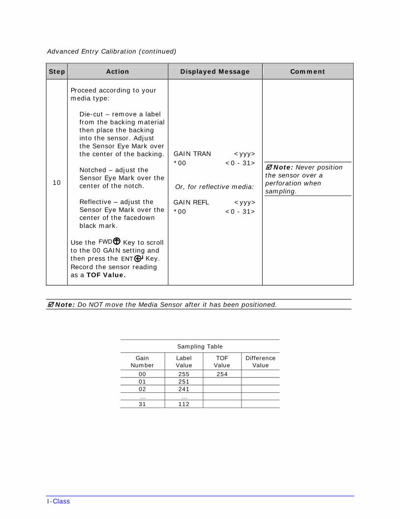
I-Class
Advanced Entry Calibration (continued)
Step Action Displayed Message Comment
10
Proceed according to your media type:
Die-cut – remove a label from the backing material then place the backing into the sensor. Adjust the Sensor Eye Mark over the center of the backing.
Notched – adjust the Sensor Eye Mark over the center of the notch.
Reflective – adjust the Sensor Eye Mark over the center of the facedown black mark.
Use the Key to scroll to the 00 GAIN setting and then press the Key. Record the sensor reading as a TOF Value.
GAIN TRAN <yyy> *00 <0 - 31>
Or, for reflective media:
GAIN REFL <yyy> *00 <0 - 31>
Note: Never position the sensor over a perforation when sampling.
Note: Do NOT move the Media Sensor after it has been positioned.
Sampling Table
Gain Number
Label Value
TOF Value
Difference Value
00 255 25401 25102 241… …31 112
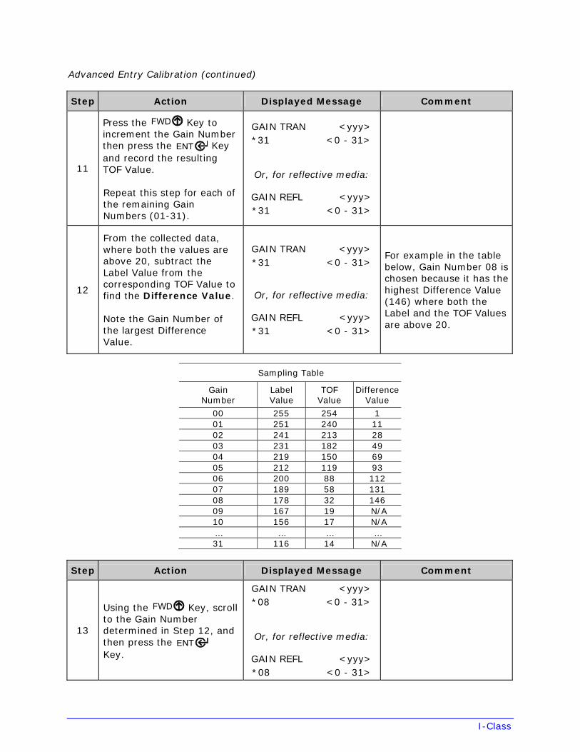
I-Class
Advanced Entry Calibration (continued)
Step Action Displayed Message Comment
11
Press the Key to increment the Gain Number then press the Key and record the resulting TOF Value.
Repeat this step for each of the remaining Gain Numbers (01-31).
GAIN TRAN <yyy> *31 <0 - 31>
Or, for reflective media:
GAIN REFL <yyy> *31 <0 - 31>
12
From the collected data, where both the values are above 20, subtract the Label Value from the corresponding TOF Value to find the Difference Value.
Note the Gain Number of the largest Difference Value.
GAIN TRAN <yyy> *31 <0 - 31>
Or, for reflective media:
GAIN REFL <yyy> *31 <0 - 31>
For example in the table below, Gain Number 08 is chosen because it has the highest Difference Value (146) where both the Label and the TOF Values are above 20.
Sampling Table
Gain Number
Label Value
TOF Value
Difference Value
00 255 254 101 251 240 1102 241 213 2803 231 182 4904 219 150 6905 212 119 9306 200 88 11207 189 58 13108 178 32 14609 167 19 N/A10 156 17 N/A… … … …31 116 14 N/A
Step Action Displayed Message Comment
13
Using the Key, scroll to the Gain Number determined in Step 12, and then press the Key.
GAIN TRAN <yyy> *08 <0 - 31>
Or, for reflective media:
GAIN REFL <yyy> *08 <0 - 31>
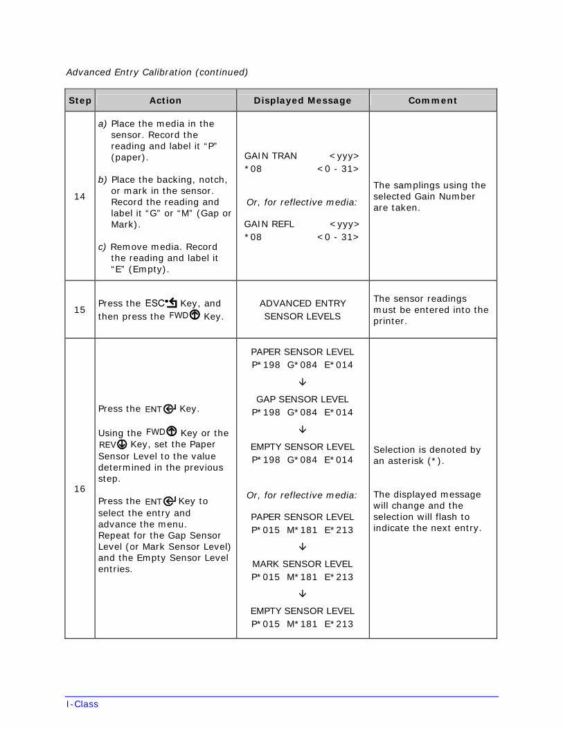
I-Class
Advanced Entry Calibration (continued)
Step Action Displayed Message Comment
14
a) Place the media in thesensor. Record thereading and label it “P”(paper).
b) Place the backing, notch,or mark in the sensor.Record the reading andlabel it “G” or “M” (Gap orMark).
c) Remove media. Recordthe reading and label it“E” (Empty).
GAIN TRAN <yyy> *08 <0 - 31>
Or, for reflective media:
GAIN REFL <yyy> *08 <0 - 31>
The samplings using the selected Gain Number are taken.
15 Press the Key, and then press the Key.
ADVANCED ENTRY SENSOR LEVELS
The sensor readings must be entered into the printer.
16
Press the Key.
Using the Key or the Key, set the Paper
Sensor Level to the value determined in the previous step.
Press the Key to select the entry and advance the menu. Repeat for the Gap Sensor Level (or Mark Sensor Level) and the Empty Sensor Level entries.
PAPER SENSOR LEVEL P*198 G*084 E*014
GAP SENSOR LEVEL P*198 G*084 E*014
EMPTY SENSOR LEVEL P*198 G*084 E*014
Or, for reflective media:
PAPER SENSOR LEVELP*015 M*181 E*213
MARK SENSOR LEVELP*015 M*181 E*213
EMPTY SENSOR LEVELP*015 M*181 E*213
Selection is denoted by an asterisk (*).
The displayed message will change and the selection will flash to indicate the next entry.
I-Class
Advanced Entry Calibration (continued)
Step Action Displayed Message Comment
17
After all entries have been made, press the Key to back out of the menu and then press the Keyto save the settings and return to the Ready Mode.
SAVE CHANGES? ENTER KEY = YES
From READY, press the FEED Key to advance to the next label TOF.
Note: If the Advanced Entry Calibration fails, enter MEDIA SETTINGS / CALIBRATION / ADVANCED ENTRY / SENSOR GAIN and lower the selected Gain Number by one. Select the new Gain Number then save the changes and exit the menu. Retest your media. If unsuccessful, repeat the procedure until a usable gain is obtained.
5.3 Reset Methods
There are three reset methods, each with a different affectivity. Proceed according to the desired result:
5.3.1 Soft Reset
To clear any temporary host settings, press and hold the CANCEL Key for approximately four seconds.
5.3.2 Level One Reset
To return the factory default settings or (if saved) a Factory Setting File, turn OFF the printer. Press and hold the PAUSE and CANCEL Keys while turning ON the printer and until the SYSTEM RESET message flashes.
Note: The same as selecting SET FACTORY DEFAULTS; see Section 4.2.5.
5.3.3 Level Two Reset
To return the firmware default settings and clear all parameters, turn OFF the printer. Press and hold the PAUSE, FEED, and CANCEL Keys while turning ON the printer and until the SYSTEM RESET message flashes.
Note: Calibration is required; see Section 5.2.
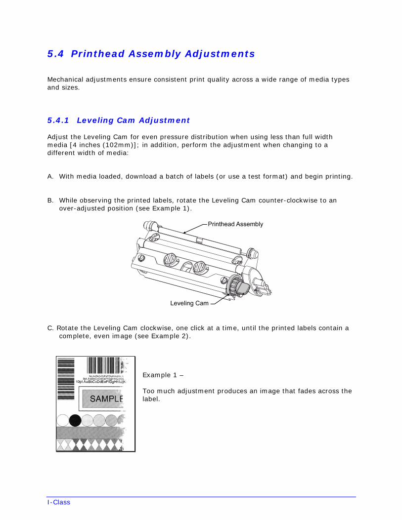
I-Class
5.4 Printhead Assembly Adjustments
Mechanical adjustments ensure consistent print quality across a wide range of media types and sizes.
5.4.1 Leveling Cam Adjustment
Adjust the Leveling Cam for even pressure distribution when using less than full width media [4 inches (102mm)]; in addition, perform the adjustment when changing to a different width of media:
A. With media loaded, download a batch of labels (or use a test format) and begin printing.
B. While observing the printed labels, rotate the Leveling Cam counter-clockwise to an over-adjusted position (see Example 1).
C. Rotate the Leveling Cam clockwise, one click at a time, until the printed labels contain a complete, even image (see Example 2).
Example 1 –
Too much adjustment produces an image that fades across the label.
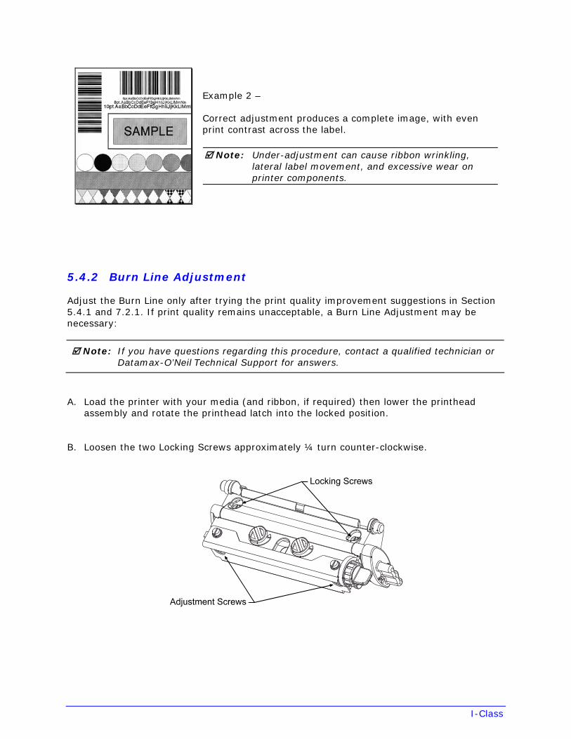
I-Class
Example 2 –
Correct adjustment produces a complete image, with even print contrast across the label.
Note: Under-adjustment can cause ribbon wrinkling, lateral label movement, and excessive wear on printer components.
5.4.2 Burn Line Adjustment
Adjust the Burn Line only after trying the print quality improvement suggestions in Section 5.4.1 and 7.2.1. If print quality remains unacceptable, a Burn Line Adjustment may be necessary:
Note: If you have questions regarding this procedure, contact a qualified technician or Datamax-O’Neil Technical Support for answers.
A. Load the printer with your media (and ribbon, if required) then lower the printhead assembly and rotate the printhead latch into the locked position.
B. Loosen the two Locking Screws approximately ¼ turn counter-clockwise.
I-Class
C. Equally turn each Adjustment Screw counter-clockwise until the burn line is positioned past the platen roller apex. Print a Validation Label; see Section 4.3.4. (The print on the label should have a light, uneven appearance.)
D. Tighten the Locking Screws just enough to remove any play in the printhead assembly, while leaving them loose enough to allow for adjustment.
E. Equally turn each Adjustment Screw clockwise about ¼ turn (or 1/8 turn for finer adjustments as print quality becomes maximized – see note below) then print a Validation Label and examine the print quality for improvement. Repeat this step until the labels are produced with even print contrast and acceptable print quality.
Note: Turning the Adjustment Screws counter-clockwise will NOT move the printhead outward; if the printhead was adjusted too far inward, restart the entire procedure.
F. Tighten the Locking Screws. Print a final test label to verify the adjustment.
5.5 Printhead Replacement
CAUTION
• Use extreme care when handling the printhead and follow standardESD prevention procedures.
• Never use sharp objects on the printhead surface.
• If 24V OUT OF TOLERANCE is displayed (see Section 6.1.2), or if youhave any questions regarding this procedure, contact a qualifiedtechnician or Datamax-O’Neil Technical Support for answers.
Follow the procedure below to replace the printhead:
A. Touch a bare metal area of the printer’s frame to discharge any static electricity present on your body.
B. Turn OFF and unplug the printer. Open the access cover. If ribbon is installed, remove it.
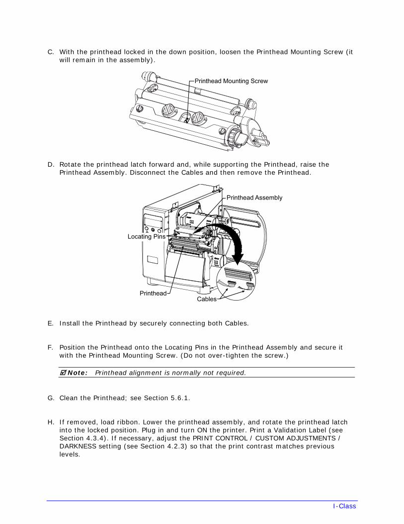
I-Class
C. With the printhead locked in the down position, loosen the Printhead Mounting Screw (it will remain in the assembly).
D. Rotate the printhead latch forward and, while supporting the Printhead, raise the Printhead Assembly. Disconnect the Cables and then remove the Printhead.
E. Install the Printhead by securely connecting both Cables.
F. Position the Printhead onto the Locating Pins in the Printhead Assembly and secure it with the Printhead Mounting Screw. (Do not over-tighten the screw.)
Note: Printhead alignment is normally not required.
G. Clean the Printhead; see Section 5.6.1.
H. If removed, load ribbon. Lower the printhead assembly, and rotate the printhead latch into the locked position. Plug in and turn ON the printer. Print a Validation Label (see Section 4.3.4). If necessary, adjust the PRINT CONTROL / CUSTOM ADJUSTMENTS / DARKNESS setting (see Section 4.2.3) so that the print contrast matches previous levels.
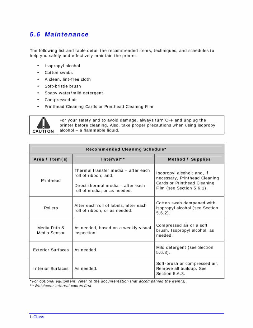
I-Class
5.6 Maintenance
The following list and table detail the recommended items, techniques, and schedules to help you safely and effectively maintain the printer:
• Isopropyl alcohol
• Cotton swabs
• A clean, lint-free cloth
• Soft-bristle brush
• Soapy water/mild detergent
• Compressed air
• Printhead Cleaning Cards or Printhead Cleaning Film
CAUTION
For your safety and to avoid damage, always turn OFF and unplug the printer before cleaning. Also, take proper precautions when using isopropyl alcohol – a flammable liquid.
Recommended Cleaning Schedule*
Area / Item(s) Interval** Method / Supplies
Printhead
Thermal transfer media – after each roll of ribbon; and,
Direct thermal media – after each roll of media, or as needed.
Isopropyl alcohol; and, if necessary, Printhead Cleaning Cards or Printhead Cleaning Film (see Section 5.6.1).
Rollers After each roll of labels, after each roll of ribbon, or as needed.
Cotton swab dampened with isopropyl alcohol (see Section 5.6.2).
Media Path & Media Sensor
As needed, based on a weekly visual inspection.
Compressed air or a soft brush. Isopropyl alcohol, as needed.
Exterior Surfaces As needed. Mild detergent (see Section 5.6.3).
Interior Surfaces As needed. Soft-brush or compressed air. Remove all buildup. See Section 5.6.3.
*For optional equipment, refer to the documentation that accompanied the item(s).**Whichever interval comes first.
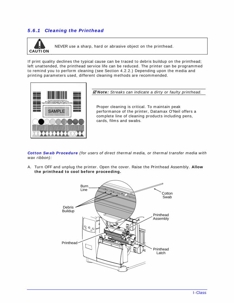
I-Class
5.6.1 Cleaning the Printhead
CAUTION NEVER use a sharp, hard or abrasive object on the printhead.
If print quality declines the typical cause can be traced to debris buildup on the printhead; left unattended, the printhead service life can be reduced. The printer can be programmed to remind you to perform cleaning (see Section 4.2.2.) Depending upon the media and printing parameters used, different cleaning methods are recommended.
Note: Streaks can indicate a dirty or faulty printhead.
Proper cleaning is critical. To maintain peak performance of the printer, Datamax O’Neil offers a complete line of cleaning products including pens, cards, films and swabs.
Cotton Swab Procedure (for users of direct thermal media, or thermal transfer media with wax ribbon):
A. Turn OFF and unplug the printer. Open the cover. Raise the Printhead Assembly. Allow the printhead to cool before proceeding.
CottonSwab
DebrisBuildup
BurnLine
PrintheadLatch
PrintheadAssembly
Printhead
I-Class
B. Move media (and ribbon, if present) away from the printhead, as necessary. Using a cotton swab moistened (not soaked) with isopropyl alcohol, gently wipe away buildup on the Printhead while paying special attention to cleaning the Burn Line. Allow the printhead to dry.
C. Reposition media (and ribbon, if present). Lower and lock the Printhead Assembly.
D. Plug in and turn ON the printer. Close the cover then run a few sample labels and examine them. If streaking is still present, use the Cleaning Card Procedure, below; otherwise, this completes cleaning. If the CLEAN HEAD SCHEDULE has been set, enter the menu and select RESET COUNTER; see Section 4.2.2.
Cleaning Card Procedure (for users of direct thermal media, or thermal transfer media with wax/resin ribbon combinations; also for unsuccessful Cotton Swab cleaning attempts):
A. Open the cover. Unlock the Printhead Latch and raise the Printhead Assembly. Allow the printhead to cool before proceeding.
B. Remove media (and ribbon, if present) then place a Cleaning Card (part number 70-2013-01) under the printhead.
C. Lower and lock the Printhead Assembly. Disengage the Leveling Cam.
D. Close the cover then enter the menu and select CLEAN HEAD NOW; see Section 4.2.2.
E. After the cleaning card has been run through the printer, reinstall media (and ribbon, if needed). Run a few sample labels and examine them. If streaking is still present, use the Cleaning Film Procedure, below; otherwise, this completes cleaning.
Cleaning Film Procedure (for users of thermal transfer media and resin ribbon, when printing with a Heat Value of 22 or higher, or when other methods prove unsuccessful):
A. Open the cover. Unlock the Printhead Latch and raise the Printhead Assembly. Allow the printhead to cool before proceeding.
B. Remove media (and ribbon, if present) then place a sheet of Cleaning Film (part number 70-2087-01) under the printhead.
C. Lower and lock the Printhead Assembly. Disengage the Leveling Cam.
D. Close the cover then enter the menu and select CLEAN HEAD NOW; see Section 4.2.2.
E. After the cleaning film has been run through the printer, turn OFF and unplug the printer. Open the cover then raise the Printhead Assembly and wait briefly for the printhead to cool. Using a cotton swab moistened (not soaked) with isopropyl alcohol, clean the printhead then allow it to dry.
F. Reinstall media (and ribbon, if needed). Plug in and turn ON the printer. Run a few sample labels and examine them. If streaking is still present the printhead may need to be replaced.
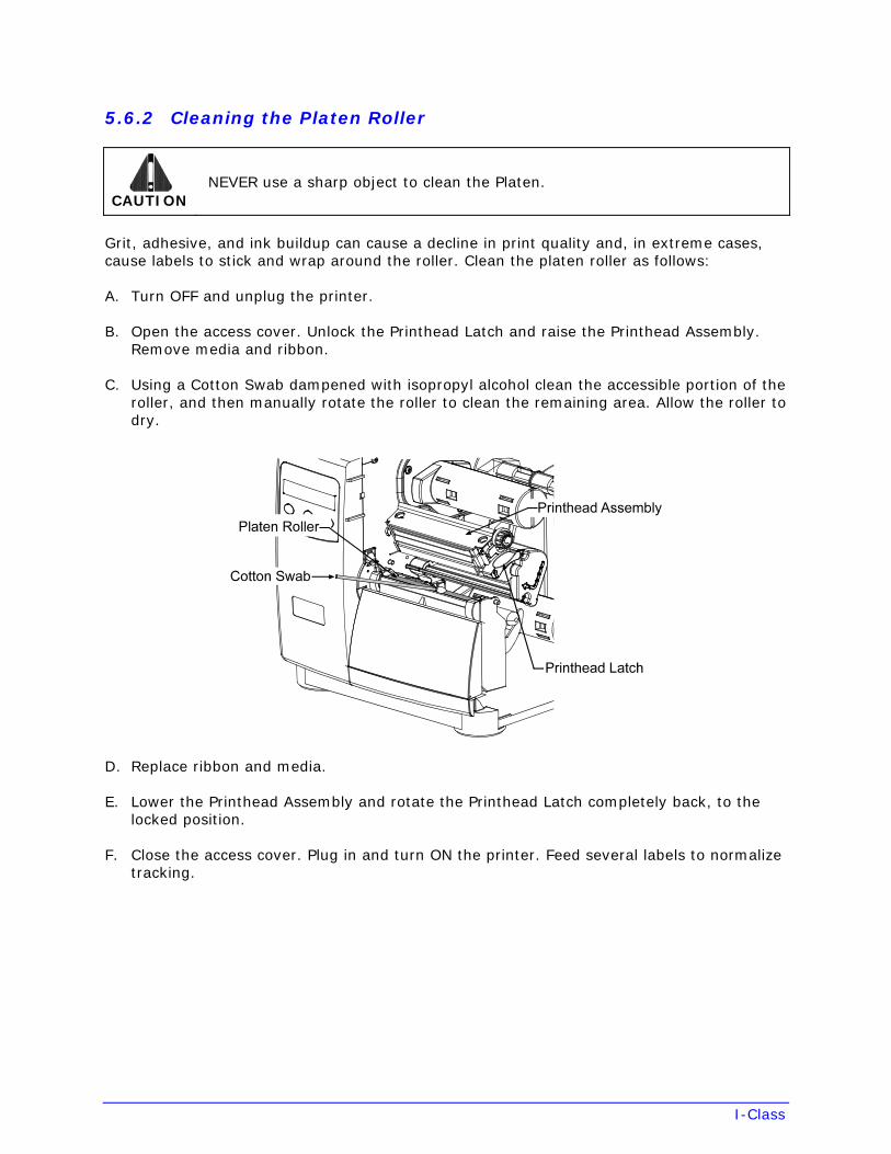
I-Class
5.6.2 Cleaning the Platen Roller
CAUTION NEVER use a sharp object to clean the Platen.
Grit, adhesive, and ink buildup can cause a decline in print quality and, in extreme cases, cause labels to stick and wrap around the roller. Clean the platen roller as follows:
A. Turn OFF and unplug the printer.
B. Open the access cover. Unlock the Printhead Latch and raise the Printhead Assembly. Remove media and ribbon.
C. Using a Cotton Swab dampened with isopropyl alcohol clean the accessible portion of the roller, and then manually rotate the roller to clean the remaining area. Allow the roller to dry.
D. Replace ribbon and media.
E. Lower the Printhead Assembly and rotate the Printhead Latch completely back, to the locked position.
F. Close the access cover. Plug in and turn ON the printer. Feed several labels to normalize tracking.
I-Class
5.6.3 Cleaning Interior and Exterior Surfaces
Interior Surfaces – Turn OFF and unplug the printer. Remove all media. Then, using a soft bristle brush or compressed air, remove all dust particle buildup inside the printer.
Exterior Surfaces – Turn OFF and unplug the printer. Remove all media. Then, using a soft cloth or sponge dampened with general-purpose cleanser (never abrasive cleansers or solvents) wipe the exterior surfaces until clean.
5.7 Application Updates
The update can be performed in Ready Mode or in Download Mode. Before updating, identify the current program version by printing a Configuration Label (see Section 4.2.2). Compare that version string to those available from our web site then download the desired file onto your computer’s hard drive. Proceed according to the currently installed version:
• If 2.091 or greater, see Section 5.7.1 or 5.7.2.
• If 2.08 or less, see Section 5.7.2.
Notes: If updating to version 11.021 or greater, the Boot Loader must be updated before proceeding; see Section 5.8.
Also, those desiring an alternate menu language must also download the EFIGS menu language file. Go to the EFIGS directory and copy 832296.01C (or most current version) to lpt1: /b (where the DOS Copy command requires the /b parameter because this file contains binary code).
WARNING
If an error occurs during downloading, the update will be terminated. If the process did not reach ERASING FLASH or UPDATING SOFTWARE, the previous program will remain intact; otherwise, a successful download must be completed to make the printer operable.
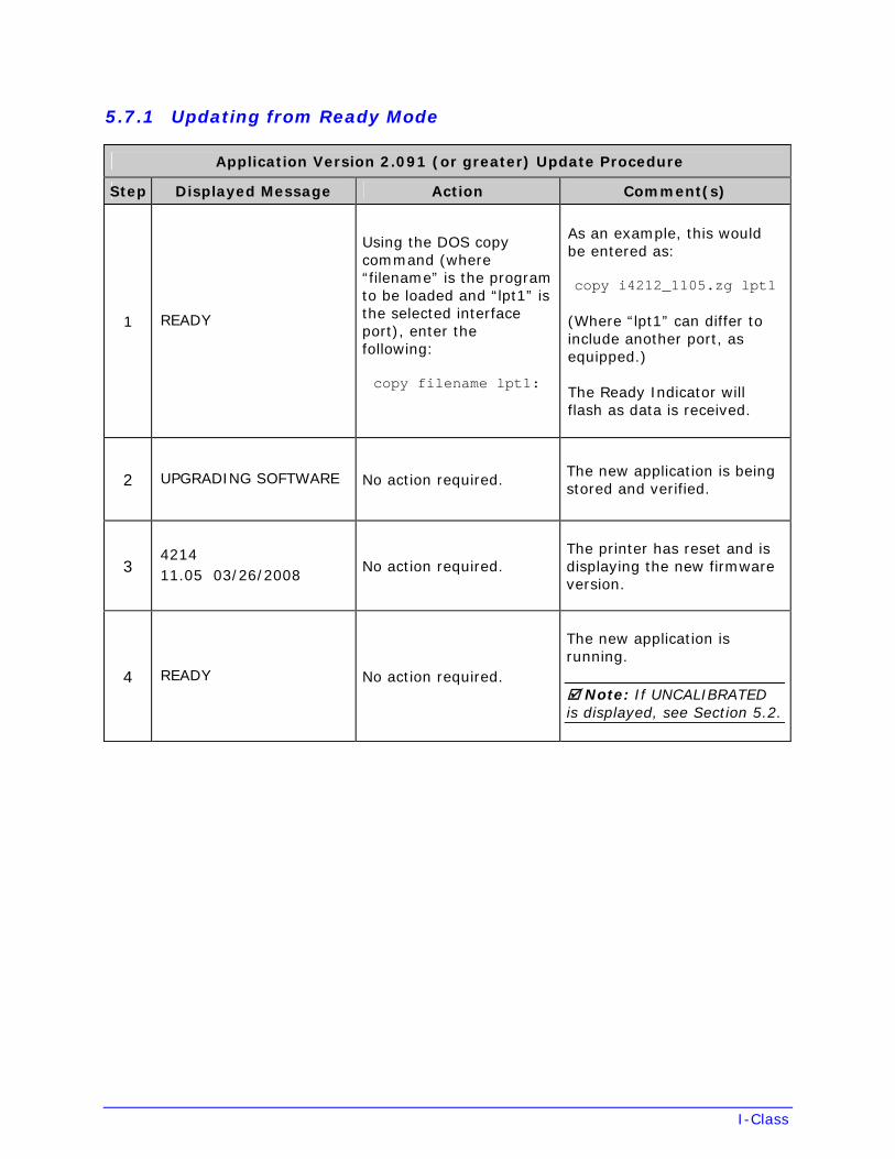
I-Class
5.7.1 Updating from Ready Mode
Application Version 2.091 (or greater) Update Procedure
Step Displayed Message Action Comment(s)
1 READY
Using the DOS copy command (where “filename” is the program to be loaded and “lpt1” is the selected interface port), enter the following:
copy filename lpt1:
As an example, this would be entered as:
copy i4212_1105.zg lpt1
(Where “lpt1” can differ to include another port, as equipped.)
The Ready Indicator will flash as data is received.
2 UPGRADING SOFTWARE No action required. The new application is being stored and verified.
3 4214 11.05 03/26/2008
No action required. The printer has reset and is displaying the new firmware version.
4 READY No action required.
The new application is running.
Note: If UNCALIBRATED is displayed, see Section 5.2.
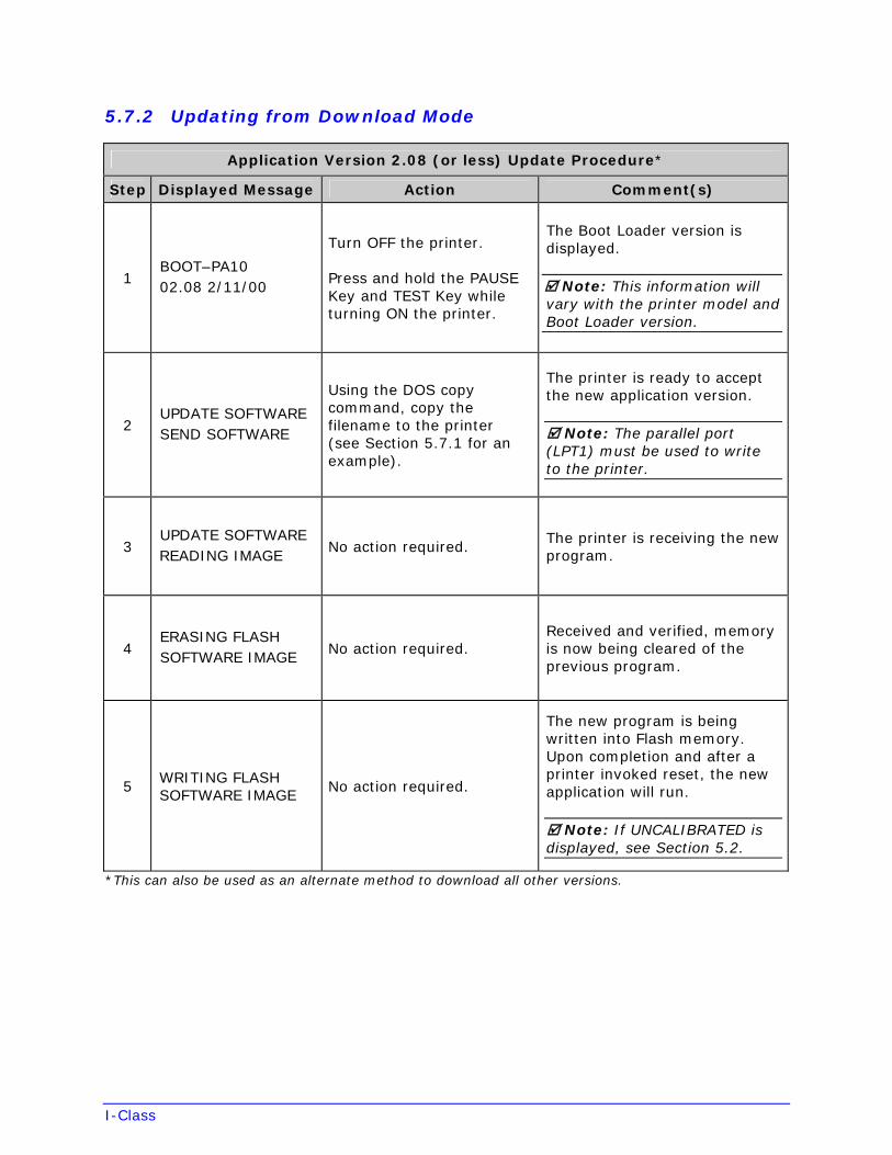
I-Class
5.7.2 Updating from Download Mode
Application Version 2.08 (or less) Update Procedure*
Step Displayed Message Action Comment(s)
1 BOOT–PA10 02.08 2/11/00
Turn OFF the printer.
Press and hold the PAUSE Key and TEST Key while turning ON the printer.
The Boot Loader version is displayed.
Note: This information will vary with the printer model and Boot Loader version.
2 UPDATE SOFTWARE SEND SOFTWARE
Using the DOS copy command, copy the filename to the printer (see Section 5.7.1 for an example).
The printer is ready to accept the new application version.
Note: The parallel port (LPT1) must be used to write to the printer.
3 UPDATE SOFTWARE READING IMAGE
No action required. The printer is receiving the new program.
4 ERASING FLASH SOFTWARE IMAGE
No action required. Received and verified, memory is now being cleared of the previous program.
5 WRITING FLASH SOFTWARE IMAGE
No action required.
The new program is being written into Flash memory. Upon completion and after a printer invoked reset, the new application will run.
Note: If UNCALIBRATED is displayed, see Section 5.2.
*This can also be used as an alternate method to download all other versions.
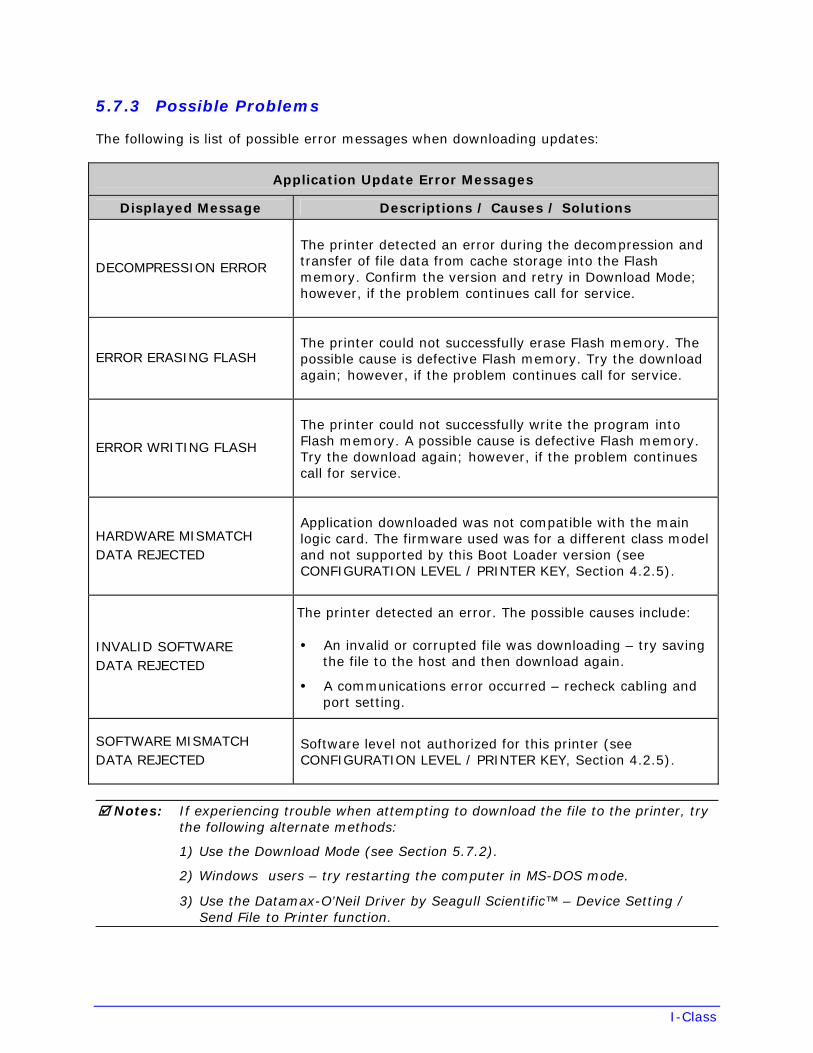
I-Class
5.7.3 Possible Problems
The following is list of possible error messages when downloading updates:
Application Update Error Messages
Displayed Message Descriptions / Causes / Solutions
DECOMPRESSION ERROR
The printer detected an error during the decompression and transfer of file data from cache storage into the Flash memory. Confirm the version and retry in Download Mode; however, if the problem continues call for service.
ERROR ERASING FLASH The printer could not successfully erase Flash memory. The possible cause is defective Flash memory. Try the download again; however, if the problem continues call for service.
ERROR WRITING FLASH
The printer could not successfully write the program into Flash memory. A possible cause is defective Flash memory. Try the download again; however, if the problem continues call for service.
HARDWARE MISMATCH DATA REJECTED
Application downloaded was not compatible with the main logic card. The firmware used was for a different class model and not supported by this Boot Loader version (see CONFIGURATION LEVEL / PRINTER KEY, Section 4.2.5).
INVALID SOFTWAREDATA REJECTED
The printer detected an error. The possible causes include:
• An invalid or corrupted file was downloading – try savingthe file to the host and then download again.
• A communications error occurred – recheck cabling andport setting.
SOFTWARE MISMATCH DATA REJECTED
Software level not authorized for this printer (see CONFIGURATION LEVEL / PRINTER KEY, Section 4.2.5).
Notes: If experiencing trouble when attempting to download the file to the printer, try the following alternate methods:
1) Use the Download Mode (see Section 5.7.2).
2) Windows users – try restarting the computer in MS-DOS mode.
3) Use the Datamax-O’Neil Driver by Seagull Scientific™ – Device Setting /Send File to Printer function.
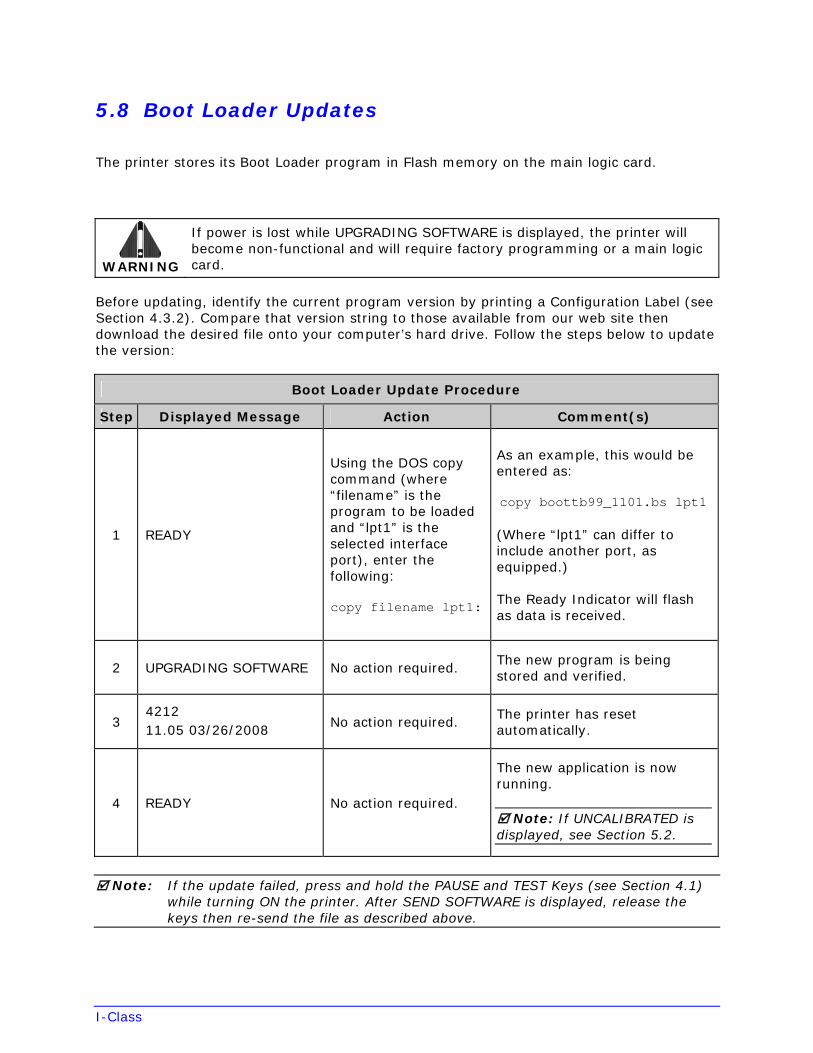
I-Class
5.8 Boot Loader Updates
The printer stores its Boot Loader program in Flash memory on the main logic card.
WARNING
If power is lost while UPGRADING SOFTWARE is displayed, the printer will become non-functional and will require factory programming or a main logic card.
Before updating, identify the current program version by printing a Configuration Label (see Section 4.3.2). Compare that version string to those available from our web site then download the desired file onto your computer’s hard drive. Follow the steps below to update the version:
Boot Loader Update Procedure
Step Displayed Message Action Comment(s)
1 READY
Using the DOS copy command (where “filename” is the program to be loaded and “lpt1” is the selected interface port), enter the following:
copy filename lpt1:
As an example, this would be entered as:
copy boottb99_1101.bs lpt1
(Where “lpt1” can differ to include another port, as equipped.)
The Ready Indicator will flash as data is received.
2 UPGRADING SOFTWARE No action required. The new program is being stored and verified.
3 4212 11.05 03/26/2008
No action required. The printer has reset automatically.
4 READY No action required.
The new application is now running.
Note: If UNCALIBRATED is displayed, see Section 5.2.
Note: If the update failed, press and hold the PAUSE and TEST Keys (see Section 4.1) while turning ON the printer. After SEND SOFTWARE is displayed, release the keys then re-send the file as described above.
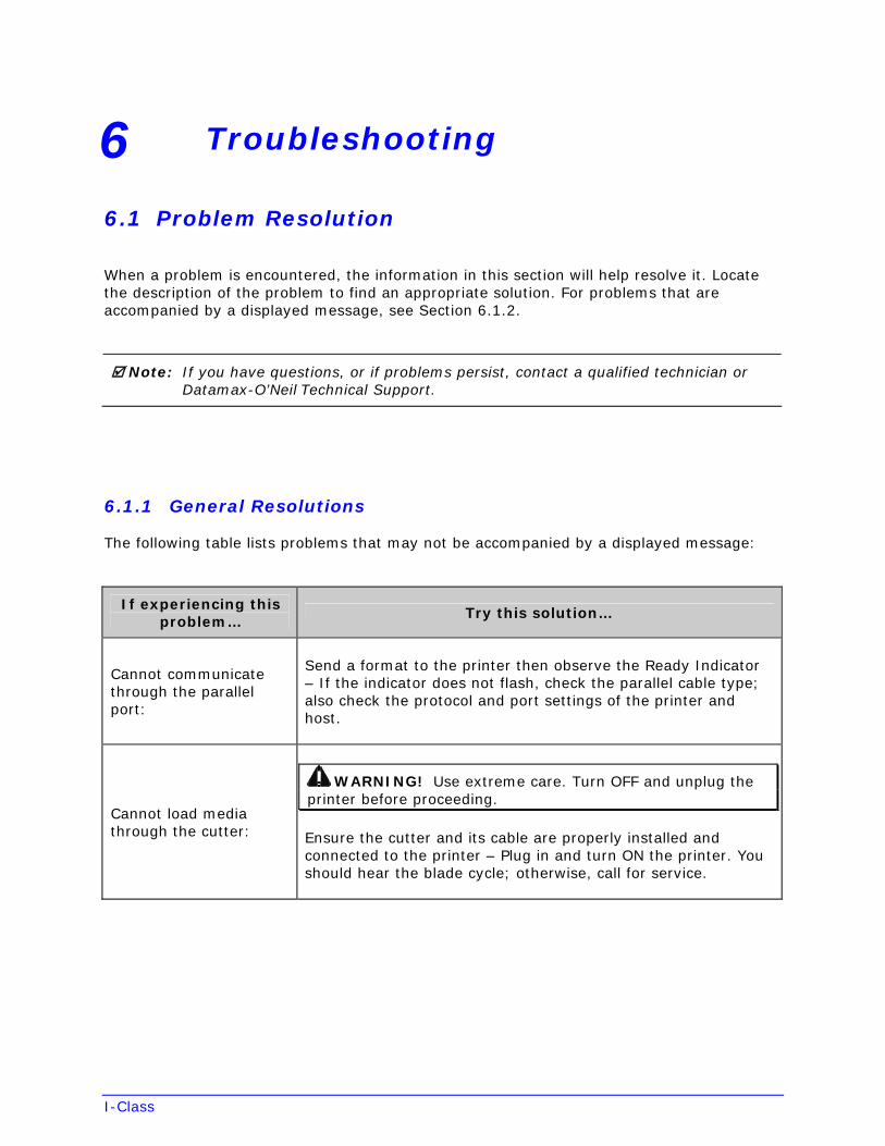
I-Class
6 Troubleshooting
6.1 Problem Resolution
When a problem is encountered, the information in this section will help resolve it. Locate the description of the problem to find an appropriate solution. For problems that are accompanied by a displayed message, see Section 6.1.2.
Note: If you have questions, or if problems persist, contact a qualified technician or Datamax-O’Neil Technical Support.
6.1.1 General Resolutions
The following table lists problems that may not be accompanied by a displayed message:
If experiencing this problem…
Try this solution…
Cannot communicate through the parallel port:
Send a format to the printer then observe the Ready Indicator – If the indicator does not flash, check the parallel cable type;also check the protocol and port settings of the printer and host.
Cannot load media through the cutter:
WARNING! Use extreme care. Turn OFF and unplug the printer before proceeding.
Ensure the cutter and its cable are properly installed and connected to the printer – Plug in and turn ON the printer. You should hear the blade cycle; otherwise, call for service.
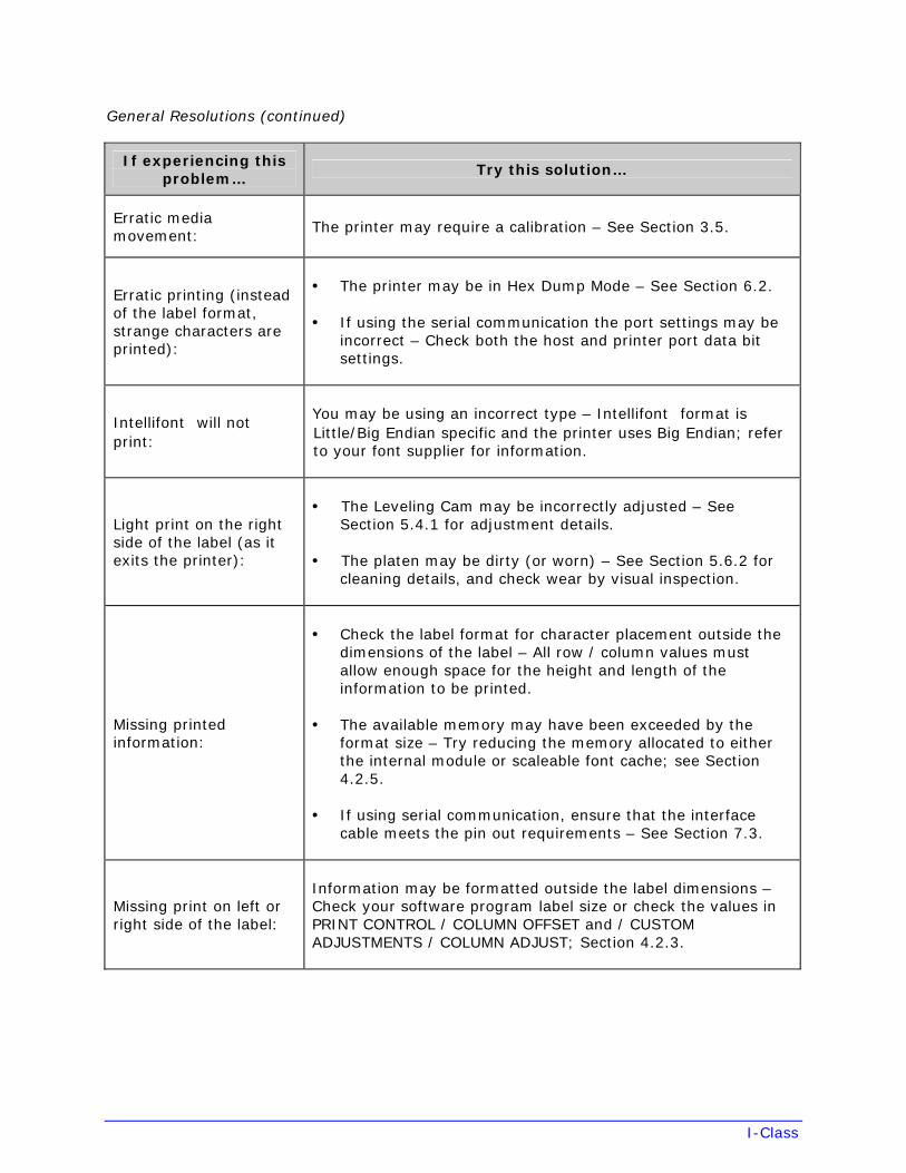
I-Class
General Resolutions (continued)
If experiencing this problem…
Try this solution…
Erratic media movement:
The printer may require a calibration – See Section 3.5.
Erratic printing (instead of the label format, strange characters are printed):
• The printer may be in Hex Dump Mode – See Section 6.2.
• If using the serial communication the port settings may beincorrect – Check both the host and printer port data bitsettings.
Intellifont will not print:
You may be using an incorrect type – Intellifont format is Little/Big Endian specific and the printer uses Big Endian; refer to your font supplier for information.
Light print on the right side of the label (as it exits the printer):
• The Leveling Cam may be incorrectly adjusted – SeeSection 5.4.1 for adjustment details.
• The platen may be dirty (or worn) – See Section 5.6.2 forcleaning details, and check wear by visual inspection.
Missing printed information:
• Check the label format for character placement outside thedimensions of the label – All row / column values mustallow enough space for the height and length of theinformation to be printed.
• The available memory may have been exceeded by theformat size – Try reducing the memory allocated to eitherthe internal module or scaleable font cache; see Section4.2.5.
• If using serial communication, ensure that the interfacecable meets the pin out requirements – See Section 7.3.
Missing print on left or right side of the label:
Information may be formatted outside the label dimensions – Check your software program label size or check the values in PRINT CONTROL / COLUMN OFFSET and / CUSTOM ADJUSTMENTS / COLUMN ADJUST; Section 4.2.3.
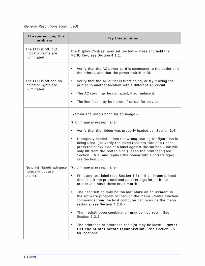
I-Class
General Resolutions (continued)
If experiencing this problem…
Try this solution…
The LCD is off, but indicator lights are illuminated:
The Display Contrast may set too low – Press and hold the MENU Key; see Section 4.1.1.
The LCD is off and no indicator lights are illuminated:
• Verify that the AC power cord is connected to the outlet andthe printer, and that the power switch is ON.
• Verify that the AC outlet is functioning, or try moving theprinter to another location with a different AC circuit.
• The AC cord may be damaged, if so replace it.
• The line fuse may be blown, if so call for service.
No print (labels advance normally but are blank):
Examine the used ribbon for an image –
If an image is present, then:
• Verify that the ribbon was properly loaded per Section 3.4.
• If properly loaded – then the wrong coating configuration isbeing used. (To verify the inked (coated) side of a ribbon,press the sticky side of a label against the surface – ink willonly lift from the coated side.) Clean the printhead (seeSection 5.6.1) and replace the ribbon with a correct type;see Section 3.4.
If no image is present, then:
• Print any test label (see Section 4.3) – If an image printedthen check the protocol and port settings for both theprinter and host; these must match.
• The heat setting may be too low. Make an adjustment inthe software program or through the menu. (Same functioncommands from the host computer can override the menusettings; see Section 4.2.6.)
• The media/ribbon combination may be incorrect – SeeSection 7.2.2.
• The printhead or printhead cable(s) may be loose – PowerOFF the printer before reconnection – see Section 5.5for locations.
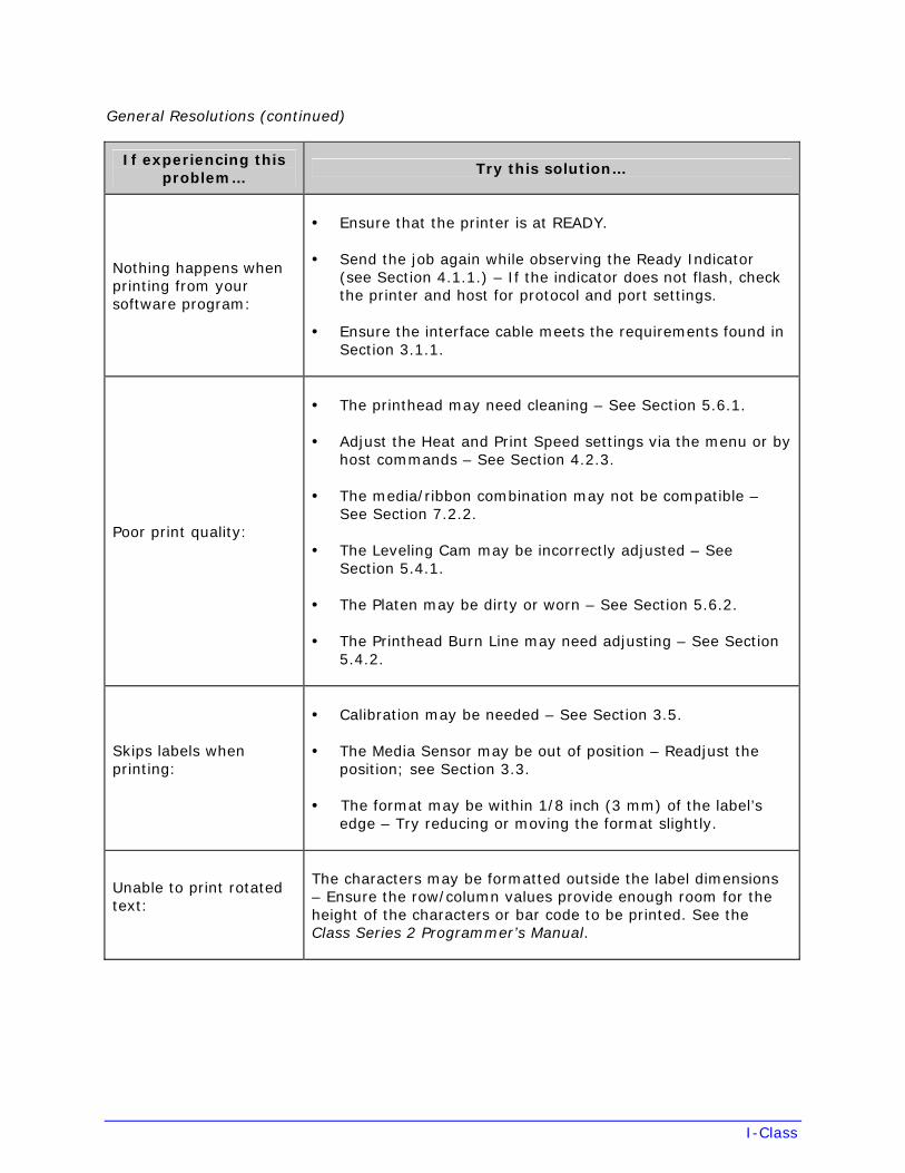
I-Class
General Resolutions (continued)
If experiencing this problem…
Try this solution…
Nothing happens when printing from your software program:
• Ensure that the printer is at READY.
• Send the job again while observing the Ready Indicator(see Section 4.1.1.) – If the indicator does not flash, checkthe printer and host for protocol and port settings.
• Ensure the interface cable meets the requirements found inSection 3.1.1.
Poor print quality:
• The printhead may need cleaning – See Section 5.6.1.
• Adjust the Heat and Print Speed settings via the menu or byhost commands – See Section 4.2.3.
• T he media/ribbon combination may not be compatible –See Section 7.2.2.
• The Leveling Cam may be incorrectly adjusted – SeeSection 5.4.1.
• The Platen may be dirty or worn – See Section 5.6.2.
• The Printhead Burn Line may need adjusting – See Section5.4.2.
Skips labels when printing:
• Calibration may be needed – See Section 3.5.
• The Media Sensor may be out of position – Readjust theposition; see Section 3.3.
• The format may be within 1/8 inch (3 mm) of the label’sedge – Try reducing or moving the format slightly.
Unable to print rotated text:
The characters may be formatted outside the label dimensions – Ensure the row/column values provide enough room for theheight of the characters or bar code to be printed. See the Class Series 2 Programmer’s Manual.
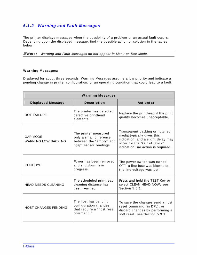
I-Class
6.1.2 Warning and Fault Messages
The printer displays messages when the possibility of a problem or an actual fault occurs. Depending upon the displayed message, find the possible action or solution in the tables below.
Note: Warning and Fault Messages do not appear in Menu or Test Mode.
Warning Messages:
Displayed for about three seconds, Warning Messages assume a low priority and indicate a pending change in printer configuration, or an operating condition that could lead to a fault.
Warning Messages
Displayed Message Description Action(s)
DOT FAILURE The printer has detected defective printhead elements.
Replace the printhead if the print quality becomes unacceptable.
GAP MODE WARNING LOW BACKING
The printer measured only a small difference between the “empty” and “gap” sensor readings.
Transparent backing or notched media typically gives this indication, and a slight delay may occur for the “Out of Stock” indication; no action is required.
GOODBYE Power has been removed and shutdown is in progress.
The power switch was turned OFF; a line fuse was blown; or, the line voltage was lost.
HEAD NEEDS CLEANING The scheduled printhead cleaning distance has been reached.
Press and hold the TEST Key or select CLEAN HEAD NOW; see Section 5.6.1.
HOST CHANGES PENDING
The host has pending configuration changes that require a “host reset command.”
To save the changes send a host reset command (in DPL), or discard changes by performing a soft reset; see Section 5.3.1.
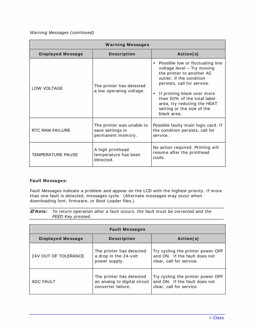
I-Class
Warning Messages (continued)
Warning Messages
Displayed Message Description Action(s)
LOW VOLTAGE The printer has detected a low operating voltage.
• Possible low or fluctuating linevoltage level – Try movingthe printer to another ACoutlet; if the conditionpersists, call for service.
• If printing black over morethan 50% of the total labelarea, try reducing the HEATsetting or the size of theblack area.
RTC RAM FAILURE The printer was unable to save settings in permanent memory.
Possible faulty main logic card. If the condition persists, call for service.
TEMPERATURE PAUSE A high printhead temperature has been detected.
No action required. Printing will resume after the printhead cools.
Fault Messages:
Fault Messages indicate a problem and appear on the LCD with the highest priority. If more than one fault is detected, messages cycle. (Alternate messages may occur when downloading font, firmware, or Boot Loader files.)
Note: To return operation after a fault occurs, the fault must be corrected and the FEED Key pressed.
Fault Messages
Displayed Message Description Action(s)
24V OUT OF TOLERANCE The printer has detected a drop in the 24-volt power supply.
Try cycling the printer power OFF and ON. If the fault does not clear, call for service.
ADC FAULT The printer has detected an analog to digital circuit converter failure.
Try cycling the printer power OFF and ON. If the fault does not clear, call for service.
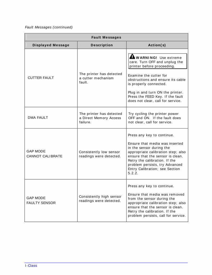
I-Class
Fault Messages (continued)
Fault Messages
Displayed Message Description Action(s)
CUTTER FAULT The printer has detected a cutter mechanism fault.
WARNING! Use extreme care. Turn OFF and unplug the printer before proceeding.
Examine the cutter for obstructions and ensure its cable is properly connected.
Plug in and turn ON the printer. Press the FEED Key. If the fault does not clear, call for service.
DMA FAULT The printer has detected a Direct Memory Access failure.
Try cycling the printer power OFF and ON. If the fault does not clear, call for service.
GAP MODE CANNOT CALIBRATE
Consistently low sensor readings were detected.
Press any key to continue.
Ensure that media was inserted in the sensor during the appropriate calibration step; also ensure that the sensor is clean. Retry the calibration. If the problem persists, try Advanced Entry Calibration; see Section 5.2.2.
GAP MODE FAULTY SENSOR
Consistently high sensor readings were detected.
Press any key to continue.
Ensure that media was removed from the sensor during the appropriate calibration step; also ensure that the sensor is clean. Retry the calibration. If the problem persists, call for service.

I-Class
Fault Messages (continued)
Fault Messages
Displayed Message Description Action(s)
OUT OF STOCK The printer cannot detect media.
Try the following procedures:
• Load media. Ensure that thelabels are passing through theMedia Sensor and, ifnecessary, readjust the MediaSensor over the TOF mark;see Section 3.3. Also, if usingmedia with large gaps, adjustthe PAPER OUT DISTANCE(see Section 4.2.2); or,
• Calibrate the printer; seeSection 5.2.
POSITION FAULT
One of the following has occurred:
• An update was madeto the applicationversion;
• The printer waspowered-off or resetduring a ribbon, out ofstock or TOF fault; or,
• The printer was unableto complete thecalibration.
Try one of the following procedures:
• Press the FEED Key then clearany related fault condition; or,
• Calibrate the printer; seeSection 5.2.
PRESENT SENSOR FAULT The printer cannot detect the Present Sensor.
Ensure that the option is installed properly. Try cycling the power OFF and ON. If the fault does not clear, call for service.
PRINT ENGINE FAULT The printer has detected a problem within the print logic.
Try cycling the power OFF and ON. If the fault does not clear, call for service.
RAM FAULT The system has detected a memory failure.
Try cycling the power OFF and ON. If the fault does not clear, call for service.
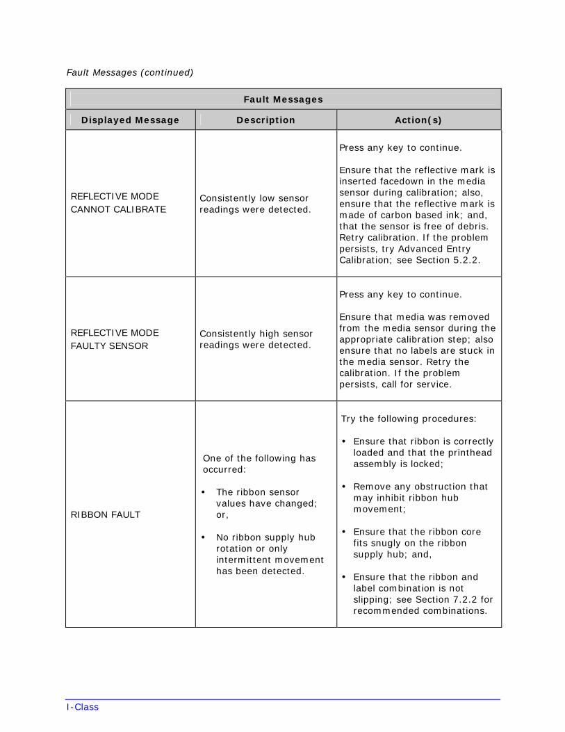
I-Class
Fault Messages (continued)
Fault Messages
Displayed Message Description Action(s)
REFLECTIVE MODE CANNOT CALIBRATE
Consistently low sensor readings were detected.
Press any key to continue.
Ensure that the reflective mark is inserted facedown in the media sensor during calibration; also, ensure that the reflective mark is made of carbon based ink; and, that the sensor is free of debris. Retry calibration. If the problem persists, try Advanced Entry Calibration; see Section 5.2.2.
REFLECTIVE MODE FAULTY SENSOR
Consistently high sensor readings were detected.
Press any key to continue.
Ensure that media was removed from the media sensor during the appropriate calibration step; also ensure that no labels are stuck in the media sensor. Retry the calibration. If the problem persists, call for service.
RIBBON FAULT
One of the following has occurred:
• The ribbon sensorvalues have changed;or,
• No ribbon supply hubrotation or onlyintermittent movementhas been detected.
Try the following procedures:
• Ensure that ribbon is correctlyloaded and that the printheadassembly is locked;
• Remove any obstruction thatmay inhibit ribbon hubmovement;
• Ensure that the ribbon corefits snugly on the ribbonsupply hub; and,
• Ensure that the ribbon andlabel combination is notslipping; see Section 7.2.2 forrecommended combinations.
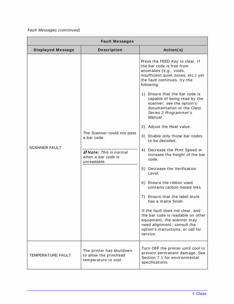
I-Class
Fault Messages (continued)
Fault Messages
Displayed Message Description Action(s)
SCANNER FAULT
The Scanner could not pass a bar code.
Note: This is normal when a bar code is unreadable.
Press the FEED Key to clear. If the bar code is free from anomalies (e.g., voids, insufficient quiet zones, etc.) yet the fault continues, try the following:
1) Ensure that the bar code iscapable of being read by thescanner; see the option’sdocumentation or the ClassSeries 2 Programmer’sManual.
2) Adjust the Heat value.
3) Enable only those bar codesto be decoded.
4) Decrease the Print Speed orincrease the height of the barcode.
5) Decrease the VerificationLevel.
6) Ensure the ribbon usedcontains carbon-based inks.
7) Ensure that the label stockhas a matte finish.
If the fault does not clear, and the bar code is readable on other equipment, the scanner may need alignment; consult the option’s instructions, or call for service.
TEMPERATURE FAULT The printer has shutdown to allow the printhead temperature to cool.
Turn OFF the printer until cool to prevent permanent damage. See Section 7.1 for environmental specifications.
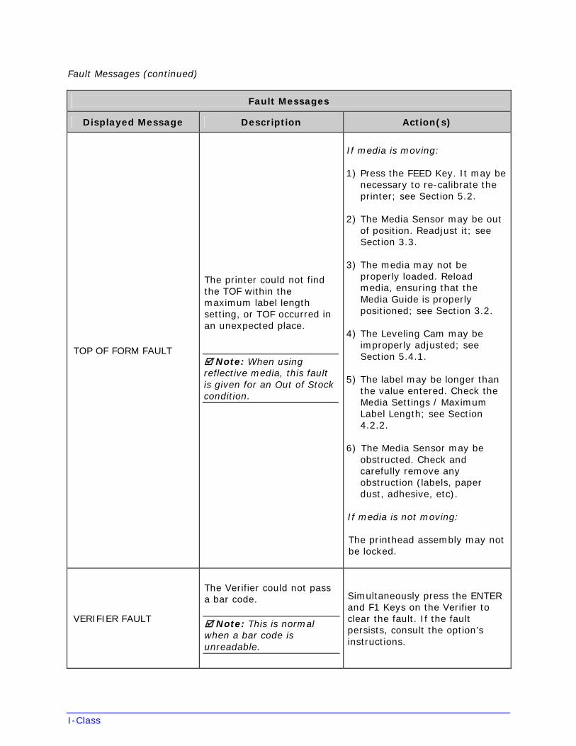
I-Class
Fault Messages (continued)
Fault Messages
Displayed Message Description Action(s)
TOP OF FORM FAULT
The printer could not find the TOF within the maximum label length setting, or TOF occurred in an unexpected place.
Note: When using reflective media, this fault is given for an Out of Stock condition.
If media is moving:
1) Press the FEED Key. It may benecessary to re-calibrate theprinter; see Section 5.2.
2) The Media Sensor may be outof position. Readjust it; seeSection 3.3.
3) The media may not beproperly loaded. Reloadmedia, ensuring that theMedia Guide is properlypositioned; see Section 3.2.
4) The Leveling Cam may beimproperly adjusted; seeSection 5.4.1.
5) The label may be longer thanthe value entered. Check theMedia Settings / MaximumLabel Length; see Section4.2.2.
6) The Media Sensor may beobstructed. Check andcarefully remove anyobstruction (labels, paperdust, adhesive, etc).
If media is not moving:
The printhead assembly may not be locked.
VERIFIER FAULT
The Verifier could not pass a bar code.
Note: This is normal when a bar code is unreadable.
Simultaneously press the ENTER and F1 Keys on the Verifier to clear the fault. If the fault persists, consult the option’s instructions.
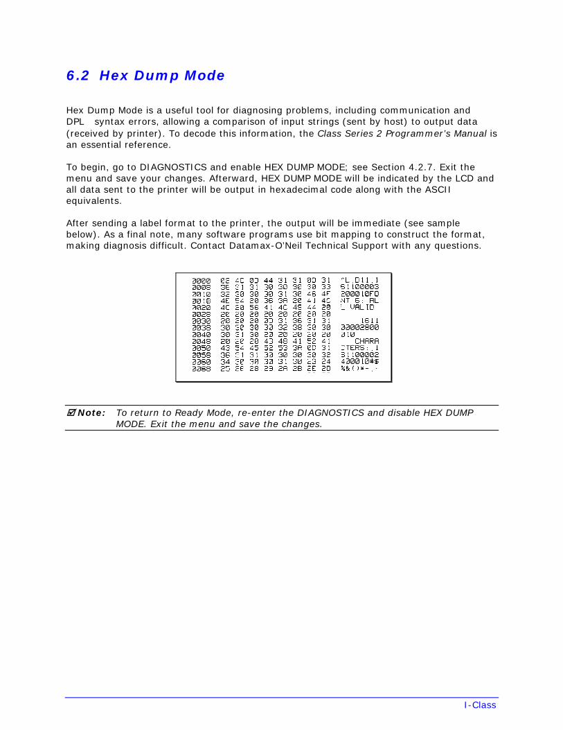
I-Class
6.2 Hex Dump Mode
Hex Dump Mode is a useful tool for diagnosing problems, including communication and DPL syntax errors, allowing a comparison of input strings (sent by host) to output data (received by printer). To decode this information, the Class Series 2 Programmer’s Manual is an essential reference.
To begin, go to DIAGNOSTICS and enable HEX DUMP MODE; see Section 4.2.7. Exit the menu and save your changes. Afterward, HEX DUMP MODE will be indicated by the LCD and all data sent to the printer will be output in hexadecimal code along with the ASCII equivalents.
After sending a label format to the printer, the output will be immediate (see sample below). As a final note, many software programs use bit mapping to construct the format, making diagnosis difficult. Contact Datamax-O’Neil Technical Support with any questions.
Note: To return to Ready Mode, re-enter the DIAGNOSTICS and disable HEX DUMP MODE. Exit the menu and save the changes.
I-Class
7 Specifications
7.1 General
Bar Codes
Code 39, Interleaved 2 of 5, Code 128 (subsets A, B and C), Codabar, LOGMARS, UPC-A, UPC-E, UPC 2 & 5 digit addendums, EAN-8, EAN-13, EAN 2 & 5 digit addendums, UPC Random Weight, Code 93, Plessey, Universal Shipping Container Symbology, Code 128 MOD 43, Postnet, USS/EAN-128 Random Weight, Telepen, USD-8 (Code 11), UPS MaxiCode (modes 2 & 3), PDF417, Data Matrix, QR Code, Aztec, and MicroPDF417. (See the Class Series 2 Programmer’s Manual for details.)
Fonts
9 Bit-Mapped Fonts; CG Triumvirate Scalable Font; and, CG Triumvirate Condensed Bold Scalable Font. (See the Class Series 2 Programmer’s Manual for details.)
Communications
Interfaces: EIA RS-232/DB-25 Serial & IEEE 1284 Compliant Parallel
Serial Data Rates: 1200, 2400, 4800, 9600, 19.2K, and 38.4K baud.
Handshaking: Xon / Xoff & CTS / DTR
Parity: Even, Odd, or None
Stop Bits: 1 or 2
Data Bits: 7 or 8
Electrical
Input Voltage: 90 – 132 or 180 – 264 VAC @ 47–63 Hz, auto-ranging.
Power Consumption: Typical Operating: 90 Watts; Standby: 10 Watts
Grounding: Unit must connect to a properly grounded receptacle.
I-Class
Environmental
Operating Temperature: 32 F – 100 F (0 C to 38 C)
Storage Temperature: 0° F – 140° F (-17° C to 60° C)
Humidity: 10% – 95% non-condensing
Dust: Non-conducting, non-corrosive
Electromagnetic Radiation: Moderate RF fields can be tolerated
Mechanical
Height: 12.70 inches (322.6 mm)
Width: 12.62 inches (320.6 mm)
Depth: 18.60 inches (472.5 mm)
Weight: 45 pounds (20.5 kg)
Printing
Type: Direct Thermal or optional Thermal Transfer
Speed: 2 – 6 IPS (51 – 152 MMPS): I-4206 2 – 8 IPS (51 – 203 MMPS): I-4208 2 – 12 IPS (51 – 305 MMPS): I-4212 2 – 8 IPS (51 – 203 MMPS): I-4308 2 – 6 IPS (51 – 152 MMPS): I-4406 2 – 4 IPS (51 – 102 MMPS): I-4604
Printhead Resolution: 203 DPI (8.0 dots/mm): I-4206, I-4208, I-4212 300 DPI (11.8 dots/mm): I-4308 406 DPI (16.0 dots/mm): I-4406 600 DPI (23.6 dots/mm): I-4604
Nominal Dot Size: .0043” X .0052” (.11 mm X .13 mm): I-4206, I-4208, I-4212 .0027” X .0043” (.07 mm X .11 mm): I-4308 .0013” X .0018” (.05 mm X .07 mm): I-4406 .0008” X .0015” (.03 mm X .06 mm): I-4604
Printhead Protection: Thermistor pauses operation upon over-temperature detection then resumes printing after cool-down.
I-Class
Printing (continued)
Maximum Print Width: 4.10” (104.0 mm): I-4206, I-4208, I-4212 4.16” (105.7 mm): I-4308 4.10” (104.0 mm): I-4406 4.16” (105.7 mm): I-4604
Print Length Range:
with cutter:
with peel & present:
.25”- 99” (6.4 - 2514.6 mm): I-4206, I-4208, I-4212, I-4308
.25”- 84” (6.4 - 2133.6 mm): I-4406
.25”- 55” (6.4 - 1397 mm): I-4604
1.25”- 99” (31.8 - 2514.6 mm): I-4206,I-4208, I-4212, I-4308 1.25” - 84” (31.8 - 2133.6 mm): I-4406 1.25” - 55” (31.8 - 1397 mm): I-4604
1.50” - 99” (38 – 2514.6 mm): I-4206, I-4208, I-4212, I-4308 1.50” - 84” (38 – 2133.6 mm): I-4406 1.50” - 55” (38 – 1397 mm): I-4604
Print Justification: Left
Flash Memory: 1 MB: I-4206, I-4208 2 MB: I-4212, I-4308, I-4406, I-4604
SDRAM Memory: 8 MB: I-4206, I-4208 16 MB: I-4212, I-4308, I-4406, I-4604
Media Types: Roll-Fed, Die-Cut, Continuous, and Fan-Fold. Flat on the printable side with no more than .0007” (.018 mm) protrusions on the opposite side.
Media Roll Capacity: 8” (203 mm) outer diameter, wound out labels only
Media Core: 1.5” or 3.0” (38 mm or 76.2 mm) inner diameter
Ribbon Core: 1.010” .006” (25.6 mm .2 mm) inner diameter. Core not to protrude beyond ribbon edge.
Ribbon Width Range: 1.0” – 4.5” (25.4 mm – 114.3 mm), where Coated Side In and Coated Side Out ribbon is NOT interchangeable and is specified by the Thermal Transfer option type; also, width should slightly exceed that of the media and backing, if any, to protect the printhead.
Ribbon Length: 1968 feet (600 meters) maximum
I-Class
7.2 Approved Media and Ribbon
To achieve optimum print quality and maximum printhead life, DATAMAX-O’NEIL brand media and ribbons must be used. These supplies are specially formulated for use in this printer. The use of non-Datamax-O’Neil supplies may affect the print quality, performance, and life of the printer or its components (see the Warranty Statement).
Media selection is an important determinant in the throughput, quality, and performance of the printed product. General factors to consider are listed below:
Direct Thermal –
• The abrasiveness of the material covering the reactive layer of the media.
• The amount of heat required to start the chemical reaction.
• The ability of the media to control the chemical reaction.
Thermal Transfer –
• The combination of top coatings and ribbons may affect image quality.
• The ribbon back coating can provide printhead protection and, depending upon theformula, help reduce static buildup.
• The ribbon width, when slightly wider than the media, can also guard againstabrasion.
7.2.1 Controlling Print Quality
The printer provides flexible print controls. Of these, the amount of heat applied and the rate of media movement will have the most effect on the printed output. Four settings are available via PRINT CONTROL (see Section 4.2.3):
• HEAT sets the printing energy level, where lower amounts lighten the image andhigher amounts darken it;
• PRINT SPEED adjusts throughput, where slow speeds allow more time for energytransfer and fast speeds may require more HEAT to achieve the desired contrast;
• CONTRAST fine-tunes the gray (shaded) areas of the image; and,
• DARKNESS fine-tunes the black areas of the image.
Note: Depending on HOST SETTINGS, some print quality settings can be overridden by the host; see Section 4.2.6.
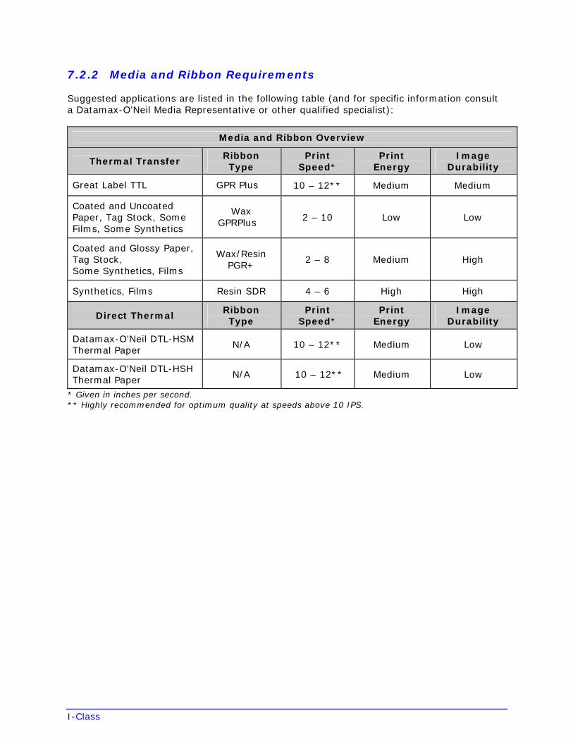
I-Class
7.2.2 Media and Ribbon Requirements
Suggested applications are listed in the following table (and for specific information consult a Datamax-O’Neil Media Representative or other qualified specialist):
Media and Ribbon Overview
Thermal Transfer Ribbon Type
Print Speed*
Print Energy
Image Durability
Great Label TTL GPR Plus 10 – 12** Medium Medium
Coated and Uncoated Paper, Tag Stock, Some Films, Some Synthetics
Wax GPRPlus 2 – 10 Low Low
Coated and Glossy Paper, Tag Stock, Some Synthetics, Films
Wax/Resin PGR+
2 – 8 Medium High
Synthetics, Films Resin SDR 4 – 6 High High
Direct Thermal Ribbon Type
Print Speed*
Print Energy
Image Durability
Datamax-O’Neil DTL-HSM Thermal Paper
N/A 10 – 12** Medium Low
Datamax-O’Neil DTL-HSH Thermal Paper
N/A 10 – 12** Medium Low
* Given in inches per second.** Highly recommended for optimum quality at speeds above 10 IPS.
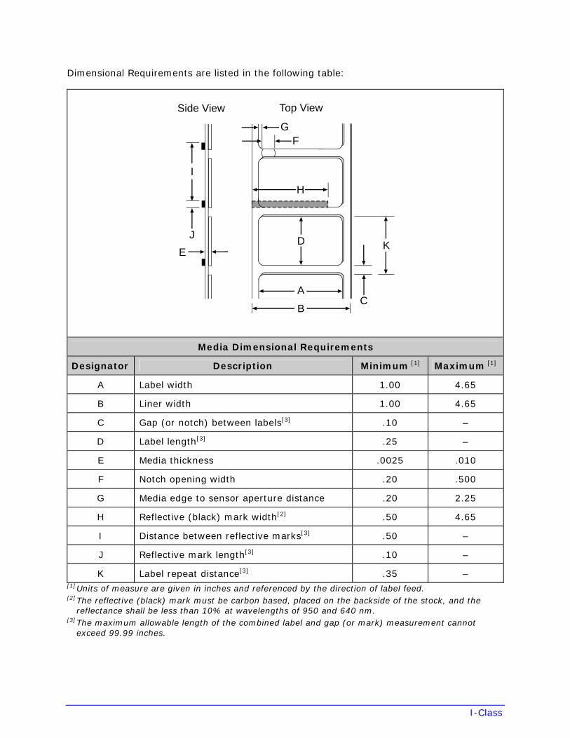
I-Class
Dimensional Requirements are listed in the following table:
E
J
I
C
K
A
B
D
H
FG
Side View Top View
Media Dimensional Requirements
Designator Description Minimum [1] Maximum [1]
A Label width 1.00 4.65
B Liner width 1.00 4.65
C Gap (or notch) between labels[3] .10 –
D Label length[3] .25 –
E Media thickness .0025 .010
F Notch opening width .20 .500
G Media edge to sensor aperture distance .20 2.25
H Reflective (black) mark width[2] .50 4.65
I Distance between reflective marks[3] .50 –
J Reflective mark length[3] .10 –
K Label repeat distance[3] .35 –[1] Units of measure are given in inches and referenced by the direction of label feed. [2] The reflective (black) mark must be carbon based, placed on the backside of the stock, and the
reflectance shall be less than 10% at wavelengths of 950 and 640 nm. [3] The maximum allowable length of the combined label and gap (or mark) measurement cannot
exceed 99.99 inches.
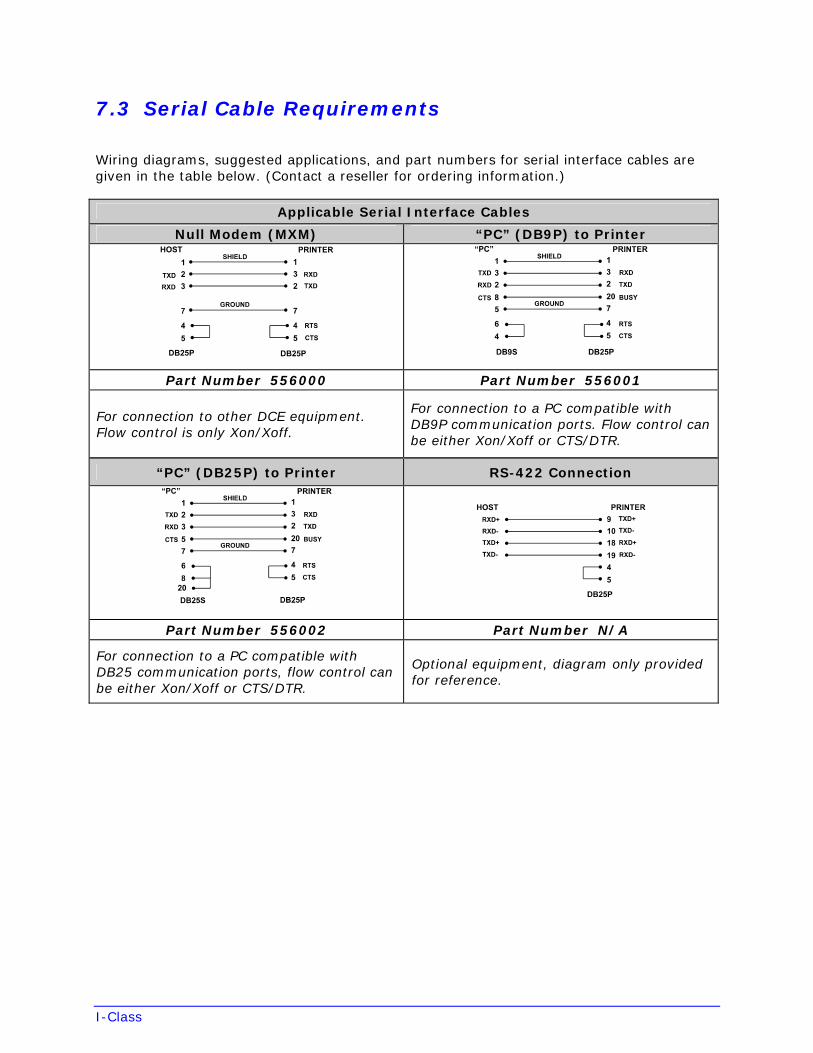
I-Class
7.3 Serial Cable Requirements
Wiring diagrams, suggested applications, and part numbers for serial interface cables are given in the table below. (Contact a reseller for ordering information.)
Applicable Serial Interface Cables
Null Modem (MXM) “PC” (DB9P) to Printer
Part Number 556000 Part Number 556001
For connection to other DCE equipment. Flow control is only Xon/Xoff.
For connection to a PC compatible with DB9P communication ports. Flow control can be either Xon/Xoff or CTS/DTR.
“PC” (DB25P) to Printer RS-422 Connection
Part Number 556002 Part Number N/A
For connection to a PC compatible with DB25 communication ports, flow control can be either Xon/Xoff or CTS/DTR.
Optional equipment, diagram only provided for reference.
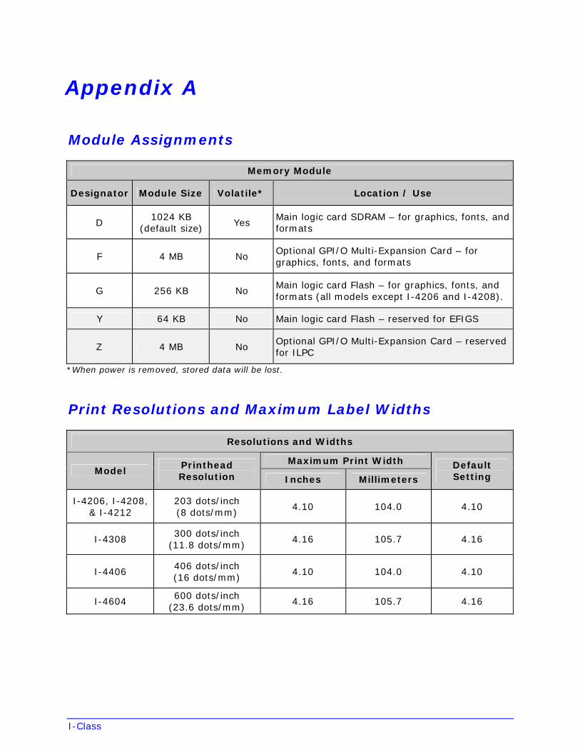
I-Class
Appendix A
Module Assignments
Memory Module
Designator Module Size Volatile* Location / Use
D 1024 KB
(default size) Yes
Main logic card SDRAM – for graphics, fonts, and formats
F 4 MB NoOptional GPI/O Multi-Expansion Card – for graphics, fonts, and formats
G 256 KB NoMain logic card Flash – for graphics, fonts, and formats (all models except I-4206 and I-4208).
Y 64 KB No Main logic card Flash – reserved for EFIGS
Z 4 MB No Optional GPI/O Multi-Expansion Card – reserved for ILPC
*When power is removed, stored data will be lost.
Print Resolutions and Maximum Label Widths
Resolutions and Widths
Maximum Print Width Model
Printhead Resolution Inches Millimeters
Default Setting
I-4206, I-4208, & I-4212
203 dots/inch (8 dots/mm)
4.10 104.0 4.10
I-4308 300 dots/inch
(11.8 dots/mm) 4.16 105.7 4.16
I-4406 406 dots/inch (16 dots/mm)
4.10 104.0 4.10
I-4604 600 dots/inch
(23.6 dots/mm) 4.16 105.7 4.16
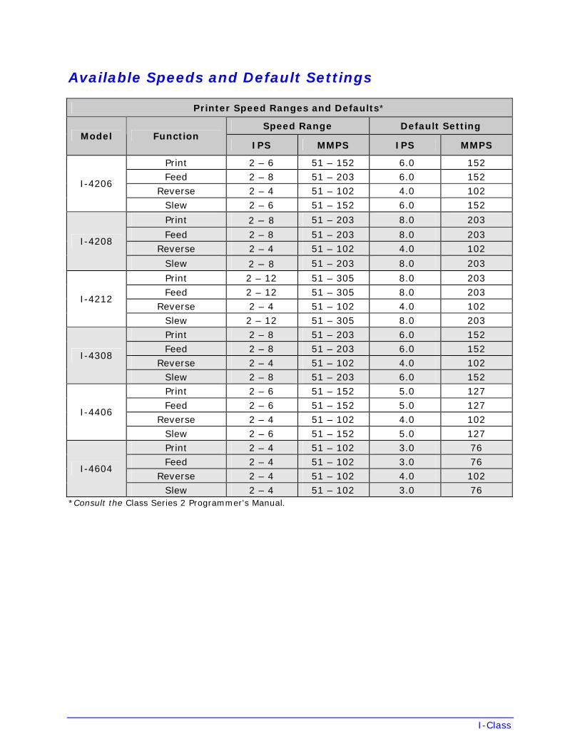
I-Class
Available Speeds and Default Settings
Printer Speed Ranges and Defaults*
Speed Range Default Setting Model Function
IPS MMPS IPS MMPS
Print 2 – 6 51 – 152 6.0 152 Feed 2 – 8 51 – 203 6.0 152
Reverse 2 – 4 51 – 102 4.0 102 I-4206
Slew 2 – 6 51 – 152 6.0 152
Print 2 – 8 51 – 203 8.0 203
Feed 2 – 8 51 – 203 8.0 203 Reverse 2 – 4 51 – 102 4.0 102
I-4208
Slew 2 – 8 51 – 203 8.0 203
Print 2 – 12 51 – 305 8.0 203 Feed 2 – 12 51 – 305 8.0 203
Reverse 2 – 4 51 – 102 4.0 102 I-4212
Slew 2 – 12 51 – 305 8.0 203 Print 2 – 8 51 – 203 6.0 152 Feed 2 – 8 51 – 203 6.0 152
Reverse 2 – 4 51 – 102 4.0 102 I-4308
Slew 2 – 8 51 – 203 6.0 152 Print 2 – 6 51 – 152 5.0 127 Feed 2 – 6 51 – 152 5.0 127
Reverse 2 – 4 51 – 102 4.0 102 I-4406
Slew 2 – 6 51 – 152 5.0 127 Print 2 – 4 51 – 102 3.0 76 Feed 2 – 4 51 – 102 3.0 76
Reverse 2 – 4 51 – 102 4.0 102 I-4604
Slew 2 – 4 51 – 102 3.0 76 *Consult the Class Series 2 Programmer's Manual.
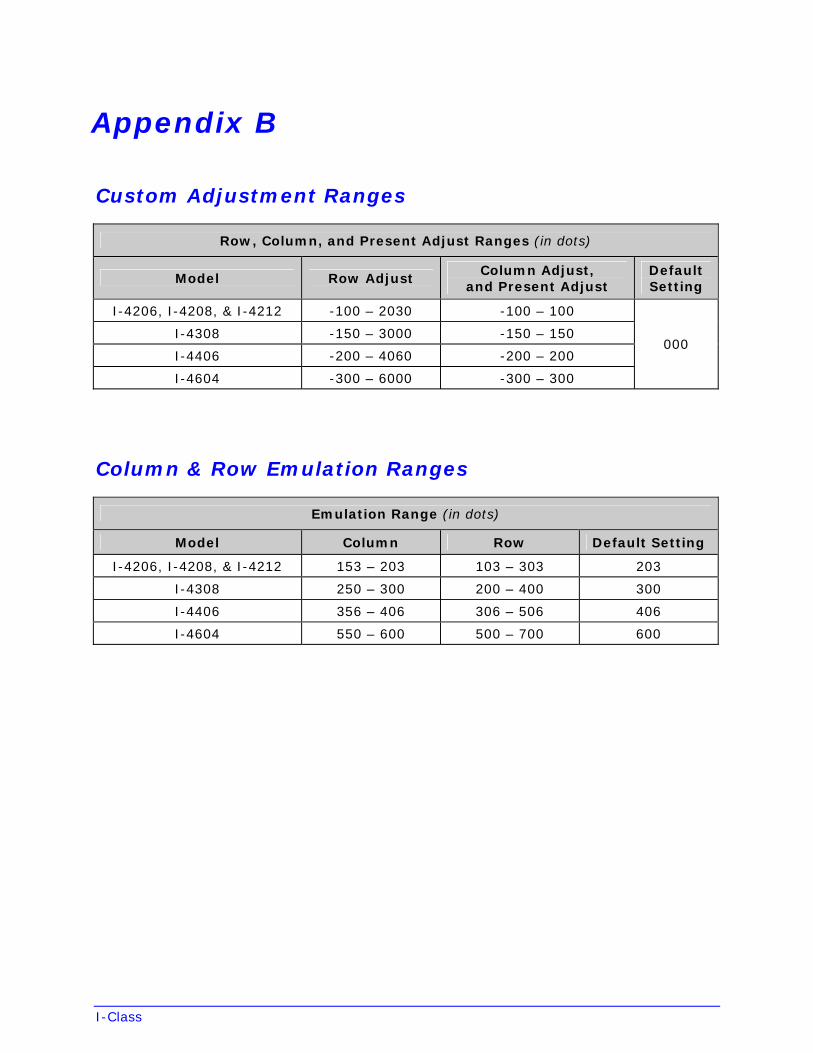
I-Class
Appendix B
Custom Adjustment Ranges
Row, Column, and Present Adjust Ranges (in dots)
Model Row Adjust Column Adjust,
and Present Adjust Default Setting
I-4206, I-4208, & I-4212 -100 – 2030 -100 – 100
I-4308 -150 – 3000 -150 – 150
I-4406 -200 – 4060 -200 – 200
I-4604 -300 – 6000 -300 – 300
000
Column & Row Emulation Ranges
Emulation Range (in dots)
Model Column Row Default Setting
I-4206, I-4208, & I-4212 153 – 203 103 – 303 203
I-4308 250 – 300 200 – 400 300
I-4406 356 – 406 306 – 506 406
I-4604 550 – 600 500 – 700 600

I-Class
Appendix C
Menu Multi-Language Support
The printer allows new menu languages and / or replacement of the Datamax-O’Neil provided translations. A Microsoft Excel Spreadsheet defines the menu dictionary and a new language column is added or an existing column modified. Then, by clicking on the “Generate DPL file(s)” radio button, the generated DPL file(s) is sent to the printer.
Here are the highlights and restrictions of the feature:
• The printer can register up to 10 different display languages, including EFIGS.
• The EFIGS languages and any additional languages are stored on Module Y: a 64KBFlash Module located on the main logic card.
• It is okay to download menu files generated for a lesser firmware revision to newfirmware – any messages that are not defined are displayed in English.
• For the procedures below, the printer will accept the menu downloads from anyavailable port.
• The language creation programs support Windows 95, Windows 98, WindowsNT, and Windows 2000.
Required Software Comment
I-Class Application Version 3.0 or greater[1]
Must reside in the target printer. (See Section 5.7)
Microsoft Excel 97 Must be purchased by user.
Img2dl.exe[1] [2] Program used during the process to create DPL file.
Gemmsgxls.xls[1] [2] Menu Dictionary
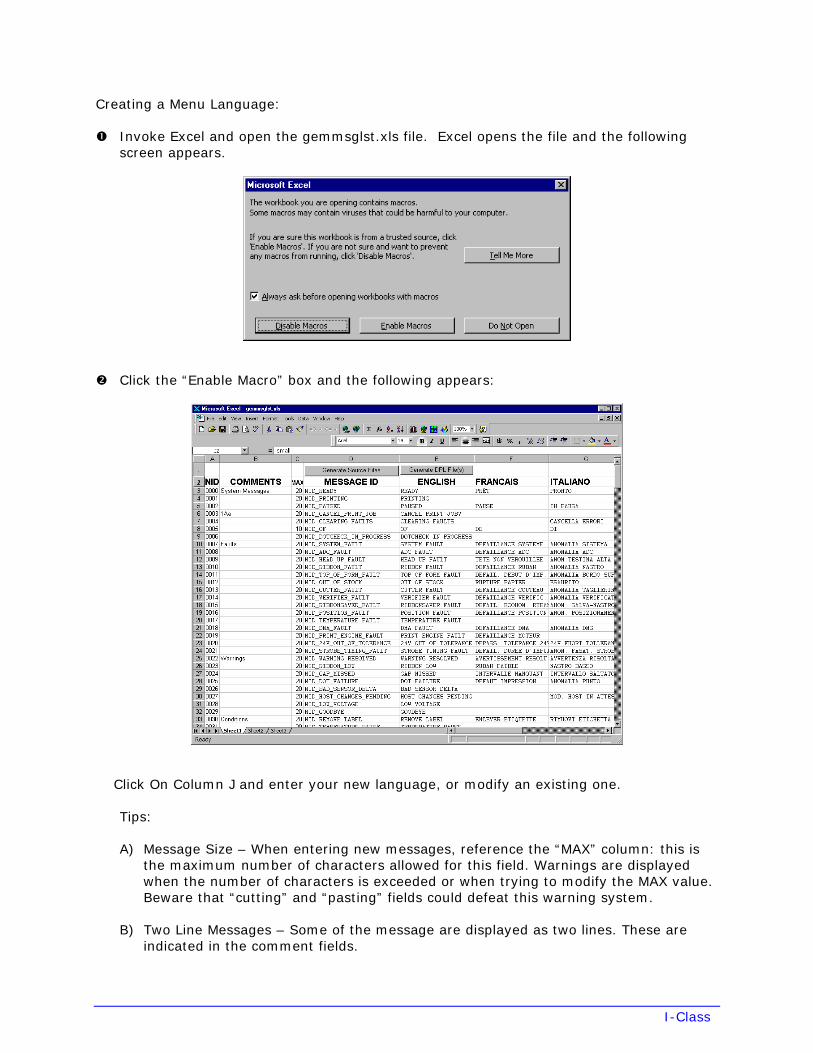
I-Class
Creating a Menu Language:
Invoke Excel and open the gemmsglst.xls file. Excel opens the file and the following screen appears.
Click the “Enable Macro” box and the following appears:
Click On Column J and enter your new language, or modify an existing one.
Tips:
A) Message Size – When entering new messages, reference the “MAX” column: this isthe maximum number of characters allowed for this field. Warnings are displayedwhen the number of characters is exceeded or when trying to modify the MAX value.Beware that “cutting” and “pasting” fields could defeat this warning system.
B) Two Line Messages – Some of the message are displayed as two lines. These areindicated in the comment fields.
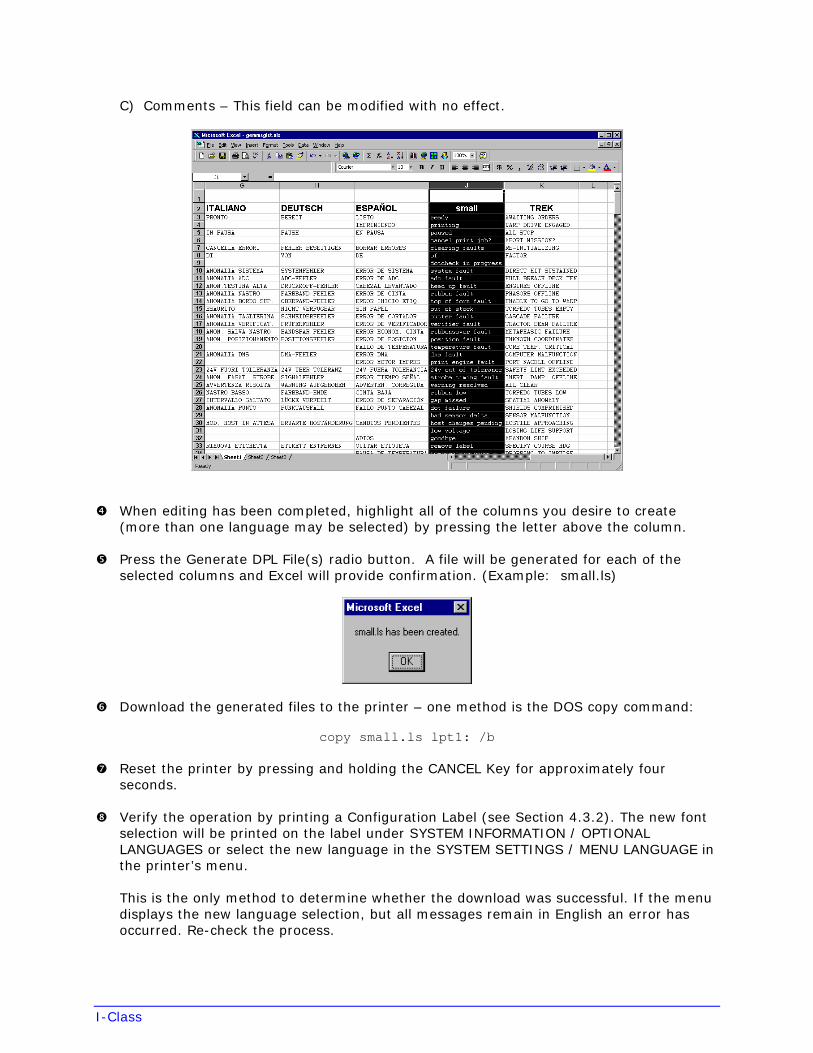
I-Class
C) Comments – This field can be modified with no effect.
When editing has been completed, highlight all of the columns you desire to create (more than one language may be selected) by pressing the letter above the column.
Press the Generate DPL File(s) radio button. A file will be generated for each of the selected columns and Excel will provide confirmation. (Example: small.ls)
Download the generated files to the printer – one method is the DOS copy command:
copy small.ls lpt1: /b
Reset the printer by pressing and holding the CANCEL Key for approximately four seconds.
Verify the operation by printing a Configuration Label (see Section 4.3.2). The new font selection will be printed on the label under SYSTEM INFORMATION / OPTIONAL LANGUAGES or select the new language in the SYSTEM SETTINGS / MENU LANGUAGE in the printer’s menu.
This is the only method to determine whether the download was successful. If the menu displays the new language selection, but all messages remain in English an error has occurred. Re-check the process.
I-Class
Contact Datamax-O’Neil Technical Support if problems continue (be prepared to provide the Gemmsglst.xls and the DPL download file that you have created). Other possible error messages are as follows:
Menu Language Error Message Description
Please select the entire column(s) or the desired language(s), by clicking on the column letter(s)
After pressing the Generate DPL File(s) radio button, the languages to convert were not correctly selected.
Message text may not exceed MAX = xx designated characters for this MID
The entered message exceeds the number of characters specified in column C. You may not modify this number.
Advanced File Handling Information
• EFIGS is standard, loaded into Module Y. Module Y is LOCKED and will only acceptadditional Language Downloads.
• After downloading a language update, Module Y is left UNLOCKED until the printer isreset or power is cycled. In this state, Module Y will accept font, image and labelformat downloads. The module will also honor the Clear Module request. Therefore,following an update it is recommended that a reset be performed to lock the module;otherwise, a software package may “Clear All Modules” thus destroying the newmenu language(s).
• Module Y can be UNLOCKED by sending this DPL string: <STX>KpY0.
• To restore the factory generated EFIGS image, download the file *832296.01A to theprinter. This file is located on the Datamax-O’Neil FTP site. The letter at the end ofthe file name (e.g., A) specifies the revision. The latest revision will be available onthe FTP site.
• Downloading the same language twice will automatically delete the first occurrence,but will not free the memory space. Use the Pack Module feature (see Section 4.2.4)or reload the EFIGS file to free the space.
• Deletion of the selected language will set the printer to English.
• The total number of languages that the printer can now accept is limited to 10, butthis number is dependent upon the size of each language translation. The translationsize will vary with the number of messages that are translated for that particularlanguage. Current complete language files are about 7,000 bytes each but withproduct growth, the total number of languages is expected to drop to seven.
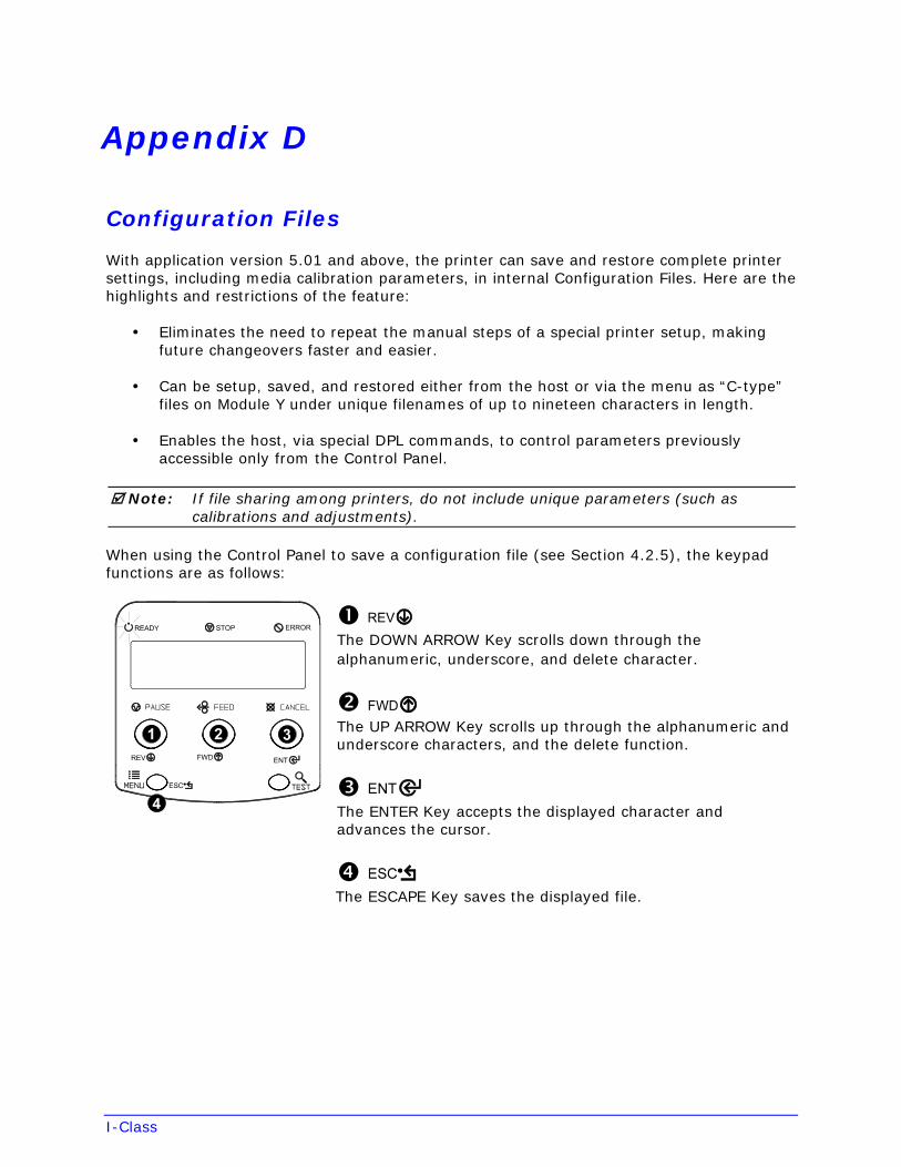
I-Class
Appendix D
Configuration Files
With application version 5.01 and above, the printer can save and restore complete printer settings, including media calibration parameters, in internal Configuration Files. Here are the highlights and restrictions of the feature:
• Eliminates the need to repeat the manual steps of a special printer setup, makingfuture changeovers faster and easier.
• Can be setup, saved, and restored either from the host or via the menu as “C-type”files on Module Y under unique filenames of up to nineteen characters in length.
• Enables the host, via special DPL commands, to control parameters previouslyaccessible only from the Control Panel.
Note: If file sharing among printers, do not include unique parameters (such as calibrations and adjustments).
When using the Control Panel to save a configuration file (see Section 4.2.5), the keypad functions are as follows:
The DOWN ARROW Key scrolls down through the alphanumeric, underscore, and delete character.
The UP ARROW Key scrolls up through the alphanumeric and underscore characters, and the delete function.
The ENTER Key accepts the displayed character and advances the cursor.
The ESCAPE Key saves the displayed file.
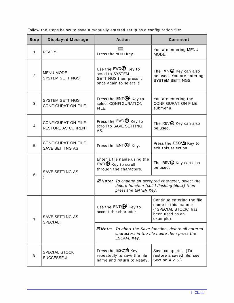
I-Class
Follow the steps below to save a manually entered setup as a configuration file:
Step Displayed Message Action Comment
1 READY Press the Key. You are entering MENU MODE.
2 MENU MODE SYSTEM SETTINGS
Use the Key to scroll to SYSTEM SETTINGS then press it once again to select it.
The Key can also be used. You are entering SYSTEM SETTINGS.
3 SYSTEM SETTINGS CONFIGURATION FILE
Press the Key to select CONFIGURATION FILE.
You are entering the CONFIGURATION FILE submenu.
4 CONFIGURATION FILERESTORE AS CURRENT
Press the Key to scroll to SAVE SETTING AS.
The Key can also be used.
5 CONFIGURATION FILESAVE SETTING AS
Press the Key. Press the Key to exit this selection.
Enter a file name using the Key to scroll
through the characters.
The Key can also be used.
6 SAVE SETTING AS:
Note: To change an accepted character, select the delete function (solid flashing block) then press the ENTER Key.
Use the Key to accept the character.
Continue entering the file name in this manner (“SPECIAL STOCK” has been used as an example). 7
SAVE SETTING ASSPECIAL :
Note: To abort the Save function, delete all entered characters in the file name then press the ESCAPE Key.
8 SPECIAL STOCK SUCCESSFUL
Press the Key repeatedly to save the file name and return to Ready.
Save complete. (To restore a saved file, see Section 4.2.5.)
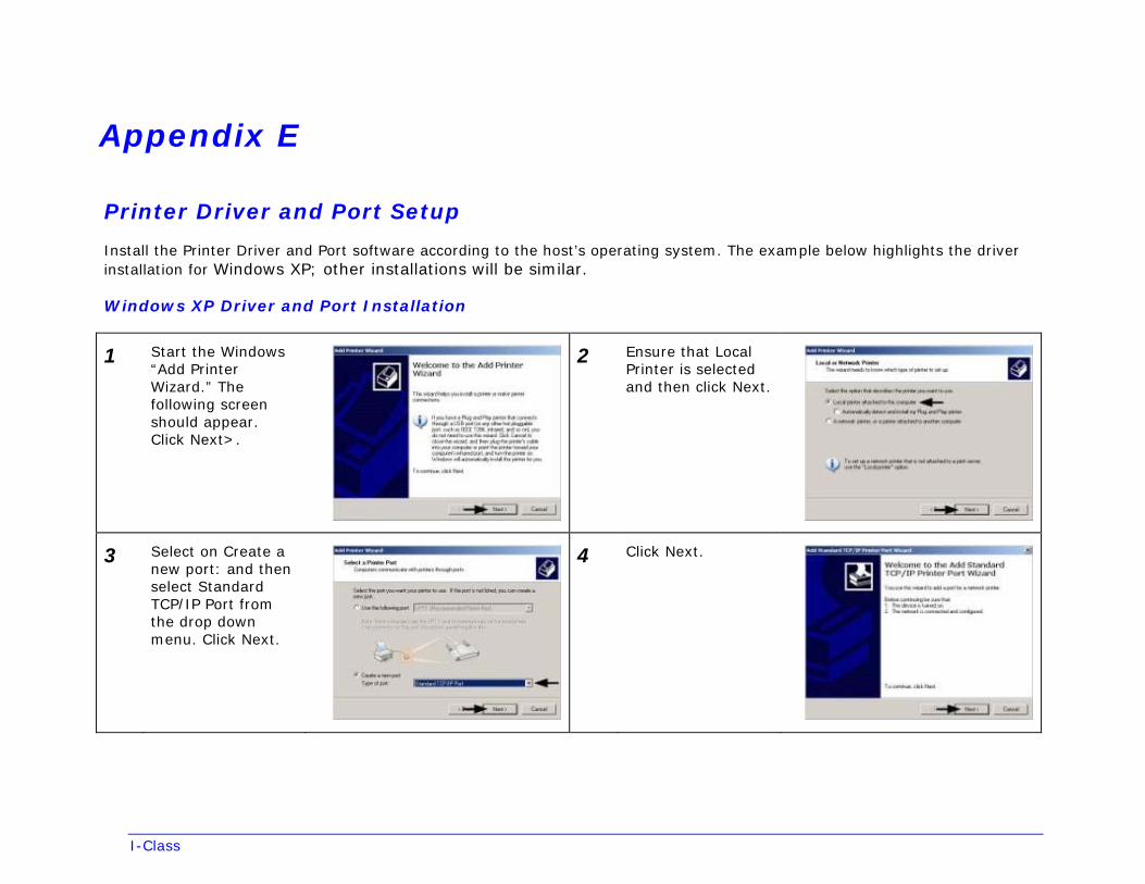
I-Class
Appendix E
Printer Driver and Port Setup
Install the Printer Driver and Port software according to the host’s operating system. The example below highlights the driver installation for Windows XP; other installations will be similar.
Windows XP Driver and Port Installation
1 Start the Windows “Add Printer Wizard.” The following screen should appear. Click Next>.
2 Ensure that Local Printer is selected and then click Next.
3 Select on Create a new port: and then select Standard TCP/IP Port from the drop down menu. Click Next.
4 Click Next.
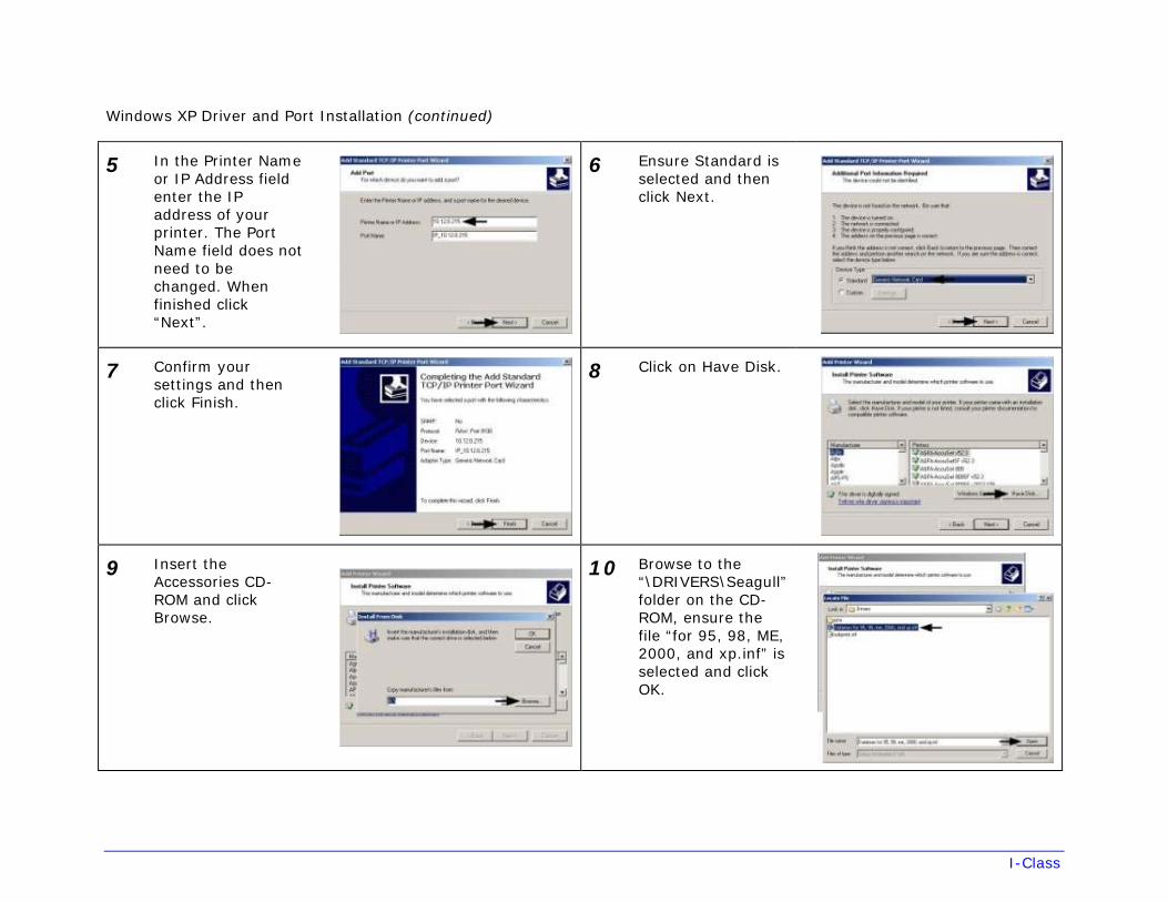
I-Class
Windows XP Driver and Port Installation (continued)
5 In the Printer Name or IP Address field enter the IP address of your printer. The Port Name field does not need to be changed. When finished click “Next”.
6 Ensure Standard is selected and then click Next.
7 Confirm your settings and then click Finish.
8 Click on Have Disk.
9 Insert the Accessories CD-ROM and click Browse.
10 Browse to the“\DRIVERS\Seagull” folder on the CD-ROM, ensure the file “for 95, 98, ME, 2000, and xp.inf” is selected and click OK.
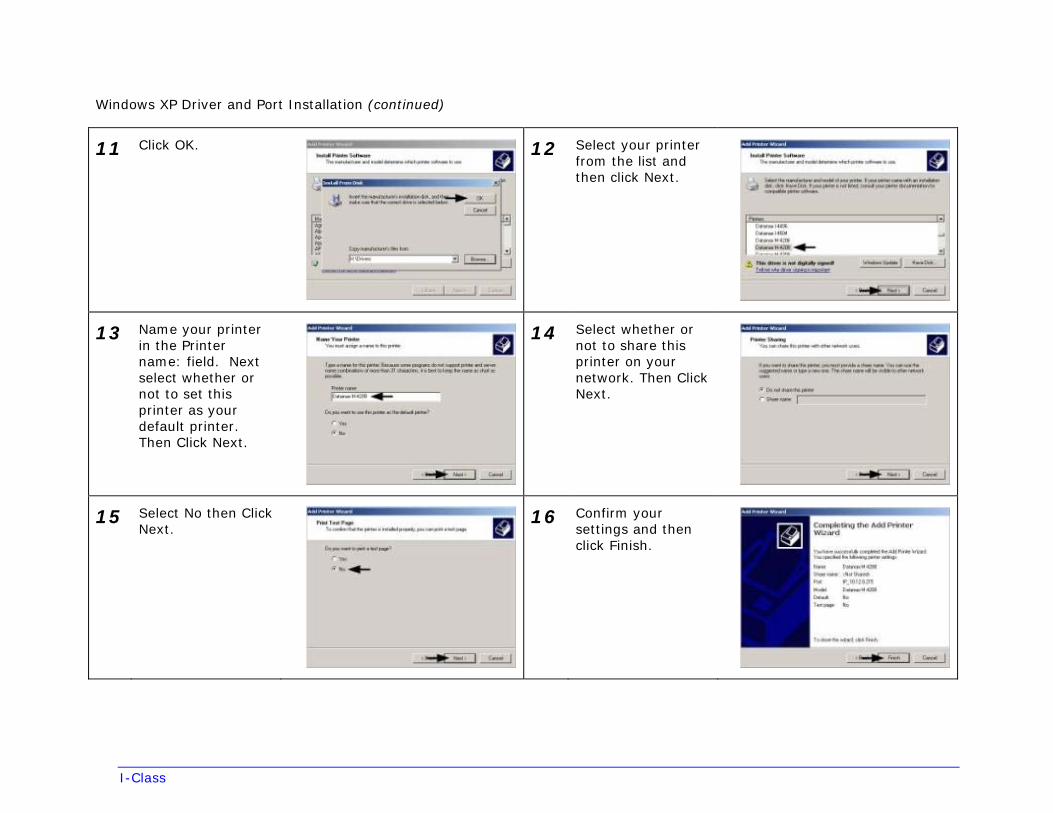
I-Class
Windows XP Driver and Port Installation (continued)
11 Click OK. 12 Select your printerfrom the list and then click Next.
13 Name your printerin the Printer name: field. Next select whether or not to set this printer as your default printer. Then Click Next.
14 Select whether ornot to share this printer on your network. Then Click Next.
15 Select No then ClickNext.
16 Confirm yoursettings and then click Finish.
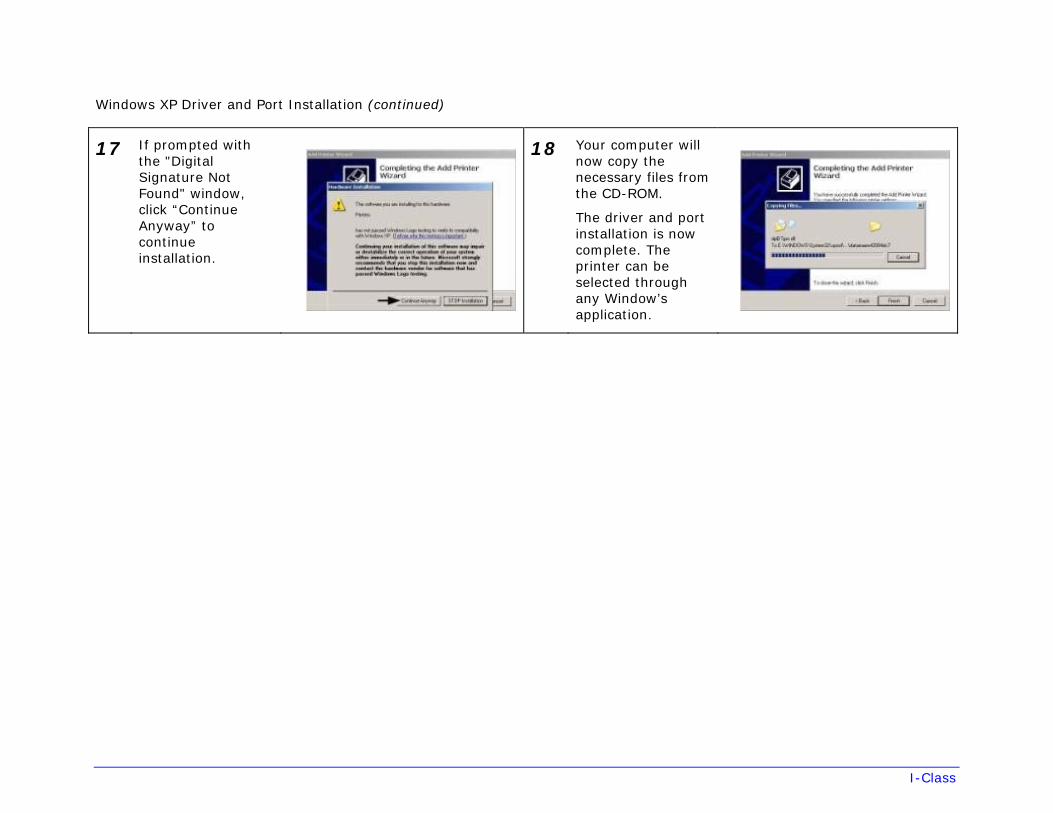
I-Class
Windows XP Driver and Port Installation (continued)
17 If prompted withthe "Digital Signature Not Found" window, click “Continue Anyway” to continue installation.
18 Your computer willnow copy the necessary files from the CD-ROM.
The driver and port installation is now complete. The printer can be selected through any Window’s application.
I-Class
Glossary alphanumeric Consisting of alphabetic, numeric, punctuation and other symbols.
backing material The silicon-coated paper carrier material to which labels with adhesive backing are affixed (also referred to as “liner”).
bar code A representation of alphanumeric information in a pattern of machine-readable marks. The basic categories are divided into one-dimensional (UPC, Code 39, Postnet, etc.) and two-dimensional bar codes (Data Matrix, MaxiCode, PDF417, etc.).
boot loader The resident program that loads the application from Flash memory, decompresses it into the SRAM, and starts operations.
burn line The row of thermal elements in the printhead that create the images on the media.
calibration The process through which sensor readings are entered into the printer for correct sensor function (for example, detection of a given media type) and TOF positioning.
character set The entire complement of alphanumeric symbols contained in a given font.
checksum An alphanumeric error detection method used in many bar code symbologies for informational security.
continuous media An uninterrupted roll or box of label or tag stock media that contains no gap, notch, or mark to separate individual labels or tags.
core diameter The inside diameter measurement of the cardboard core at the center of a ribbon or media roll.
cutter A mechanical device with a rotary or guillotine type blade used to cut labels or tags following printing.
defaults The functional setting values returned following a factory reset of the printer.
diagnostics Programs used to locate and diagnose hardware problems.
die-cut media Media that has been cut into a pattern using a press, where the excess paper is removed leaving individual labels, with gaps between them, attached to a backing material.
direct thermal The printing method that uses a heat sensitive media and only the heat of the thermal printhead to create an image on the label.
direct thermal media Media coated with special chemicals that react and darken with the application of heat.
I-Class
DPI (dots per inch) A measurement of print resolution, rated in the number of thermal elements contained in one inch of the printhead (also referred to as “resolution”).
DPL (Datamax-O’Neil Programming Language) programming commands used specifically for control of and label production in Datamax-O’Neil printers. A complete listing of commands can be found in the Class Series 2 Programmer’s Manual.
EFIGS English, French, Italian, German, Spanish, and other multi-language support as programmed for the menu and configuration label.
fan-fold Media that is folded and stacked.
feed speed The speed at which the media moves under the printhead in non-printed areas and between labels.
Flash memory Non-volatile memory (does not require printer power to maintain data) that can be erased and reprogrammed, used to hold the operating program.
font A set of alphanumeric characters that share a particular typeface.
gap A space between die-cut or notched labels used to sense the top-of-form.
IPS (inches per second) Imperial measurement of printer speeds.
label A paper or synthetic printing material, typically with adhesive backing.
label length The distance from the top of the label to the bottom of the label as it exits the printer.
label repeat The distance from the top of one label to the top of the next label.
label tracking Excessive lateral (side to side) movement of the media as it travels under the printhead.
label width The left to right measurement of the label as it exits the printer.
mark Generalized term for the carbon-based black line on the underside of reflective media used to indicate the top-of-form.
media Generalized term for all types of printing stocks, including: roll fed, continuous, die-cut, reflective, and fanfold.
media hub Device in the printer used to support roll media.
media sensor A photo-sensor device that detects media, and the top-of-form when using die-cut, notched or reflective media.
MMPS (millimeters per second) Metric measurement of printer speeds.
notched stock Media, typically tag stock, with holes or notches in the material that is used to signal the top-of-form. The printer must be set to “gap” to use this media type.
I-Class
on demand An output regulator (i.e., the Present Sensor) that inhibits printing when a label is already present.
preprinted media Label stock that contains borders, text, or graphics, floodcoating, etc.
perforation Small cuts extending through the backing and/or label material to facilitate their separation (also referred to as “perf”).
print speed The speed at which the media moves under the printhead during the printing process.
reflective media Media imprinted with carbon-based black marks on the underside of the material, which is used to signal the top-of-form when the “reflective” sensor is enabled.
registration Repeatable top to bottom alignment of printed labels.
reverse speed The backward rate of media motion into the printer during tear-off, peel and present and cutting operations for positioning the label at the start of print position.
ribbon An extruded polyester tape with several layers of material, one of which is ink-like, used to produce an image on the label (also referred to as “foil”).
ribbon wrinkle An undesirable overlapping of the ribbon during the printing process that leads to voids on the printed label, typically caused by an improper leveling cam adjustment.
roll media A form of media that is wound upon a core.
start of print (SOP) The position on the label where printing begins; also, the signal that initiates GPIO-controlled printing.
tag stock A heavy paper or synthetic printing material, typically featuring a notch or black mark for TOF and no adhesive backing.
thermal transfer The printing method that creates an image by transferring ink from a ribbon onto the media using the heat from the thermal printhead.
TOF (top-of-form) The start of a new label as indicated by a label gap, notch, mark or programming.
void An undesirable blank space in a printed image.
Operator’s Manual
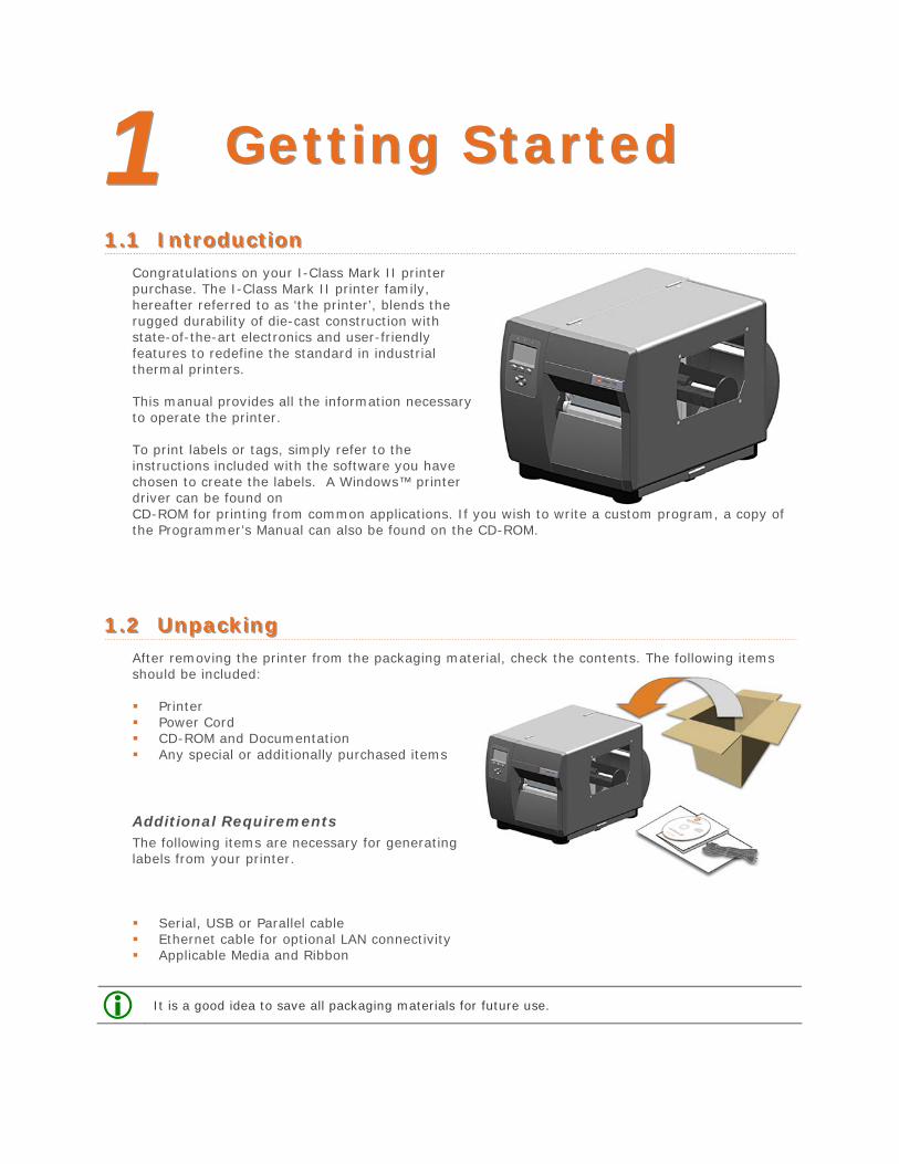
11 GGeettttiinngg SSttaarrtteedd
11..11 IInnttrroodduuccttiioonn Congratulations on your I-Class Mark II printer purchase. The I-Class Mark II printer family, hereafter referred to as ‘the printer’, blends the rugged durability of die-cast construction with state-of-the-art electronics and user-friendly features to redefine the standard in industrial thermal printers.
This manual provides all the information necessary to operate the printer.
To print labels or tags, simply refer to the instructions included with the software you have chosen to create the labels. A Windows™ printer driver can be found on CD-ROM for printing from common applications. If you wish to write a custom program, a copy of the Programmer’s Manual can also be found on the CD-ROM.
11..22 UUnnppaacckkiinngg After removing the printer from the packaging material, check the contents. The following items should be included:
Printer Power Cord CD-ROM and Documentation Any special or additionally purchased items
Additional Requirements The following items are necessary for generating labels from your printer.
Serial, USB or Parallel cable Ethernet cable for optional LAN connectivity Applicable Media and Ribbon
It is a good idea to save all packaging materials for future use.
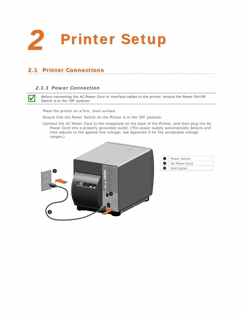
22 PPrriinntteerr SSeettuupp
22..11 PPrriinntteerr CCoonnnneeccttiioonnss
2.1.1 Power Connection
Before connecting the AC Power Cord or interface cables to the printer, ensure the Power On/Off Switch is in the ‘Off’ position.
Place the printer on a firm, level surface.
Ensure that the Power Switch on the Printer is in the ‘Off’ position.
Connect the AC Power Cord to the receptacle on the back of the Printer, and then plug the AC Power Cord into a properly grounded outlet. (The power supply automatically detects and then adjusts to the applied line voltage; see Appendix A for the acceptable voltage ranges.)
Power Switch
AC Power Cord
Wall Outlet
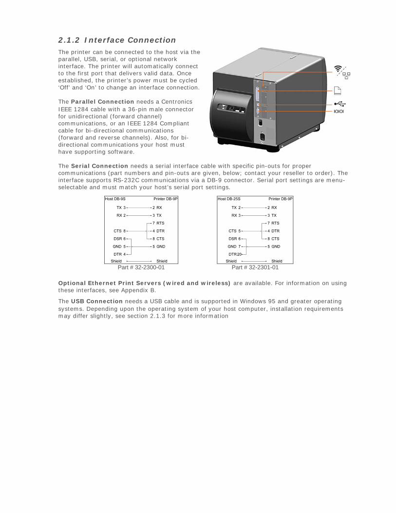
2.1.2 Interface Connection The printer can be connected to the host via the parallel, USB, serial, or optional network interface. The printer will automatically connect to the first port that delivers valid data. Once established, the printer’s power must be cycled ‘Off’ and ‘On’ to change an interface connection.
The Parallel Connection needs a Centronics IEEE 1284 cable with a 36-pin male connector for unidirectional (forward channel) communications, or an IEEE 1284 Compliant cable for bi-directional communications (forward and reverse channels). Also, for bi-directional communications your host must have supporting software.
The Serial Connection needs a serial interface cable with specific pin-outs for proper communications (part numbers and pin-outs are given, below; contact your reseller to order). The interface supports RS-232C communications via a DB-9 connector. Serial port settings are menu-selectable and must match your host’s serial port settings.
Part # 32-2300-01 Part # 32-2301-01
Optional Ethernet Print Servers (wired and wireless) are available. For information on using these interfaces, see Appendix B.
The USB Connection needs a USB cable and is supported in Windows 95 and greater operating systems. Depending upon the operating system of your host computer, installation requirements may differ slightly, see section 2.1.3 for more information
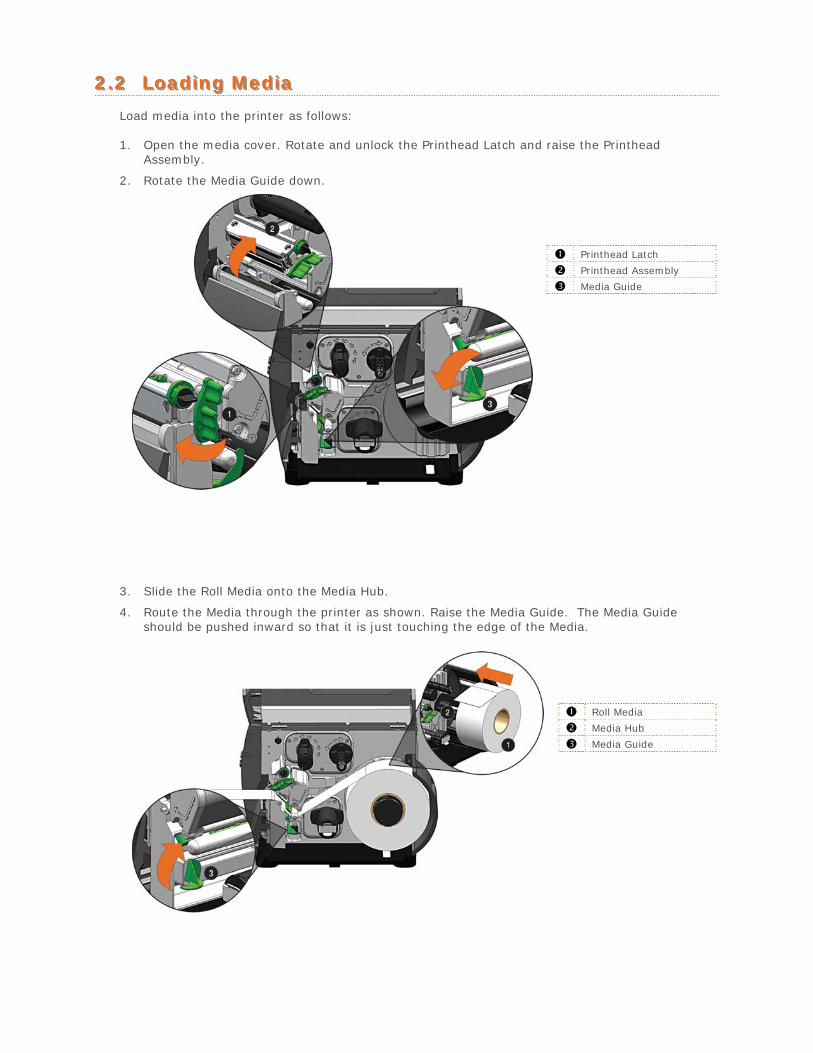
22..22 LLooaaddiinngg MMeeddiiaa
Load media into the printer as follows:
1. Open the media cover. Rotate and unlock the Printhead Latch and raise the PrintheadAssembly.
2. Rotate the Media Guide down.
Printhead Latch
Printhead Assembly
Media Guide
3. Slide the Roll Media onto the Media Hub.
4. Route the Media through the printer as shown. Raise the Media Guide. The Media Guideshould be pushed inward so that it is just touching the edge of the Media.
Roll Media
Media Hub
Media Guide
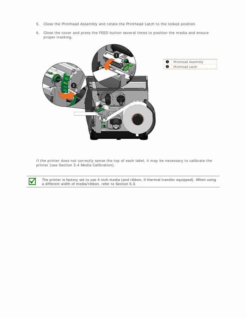
5. Close the Printhead Assembly and rotate the Printhead Latch to the locked position.
6. Close the cover and press the FEED button several times to position the media and ensureproper tracking.
Printhead Assembly
Printhead Latch
If the printer does not correctly sense the top of each label, it may be necessary to calibrate the printer (see Section 3.4 Media Calibration).
The printer is factory set to use 4-inch media (and ribbon, if thermal transfer equipped). When using a different width of media/ribbon, refer to Section 5.3.
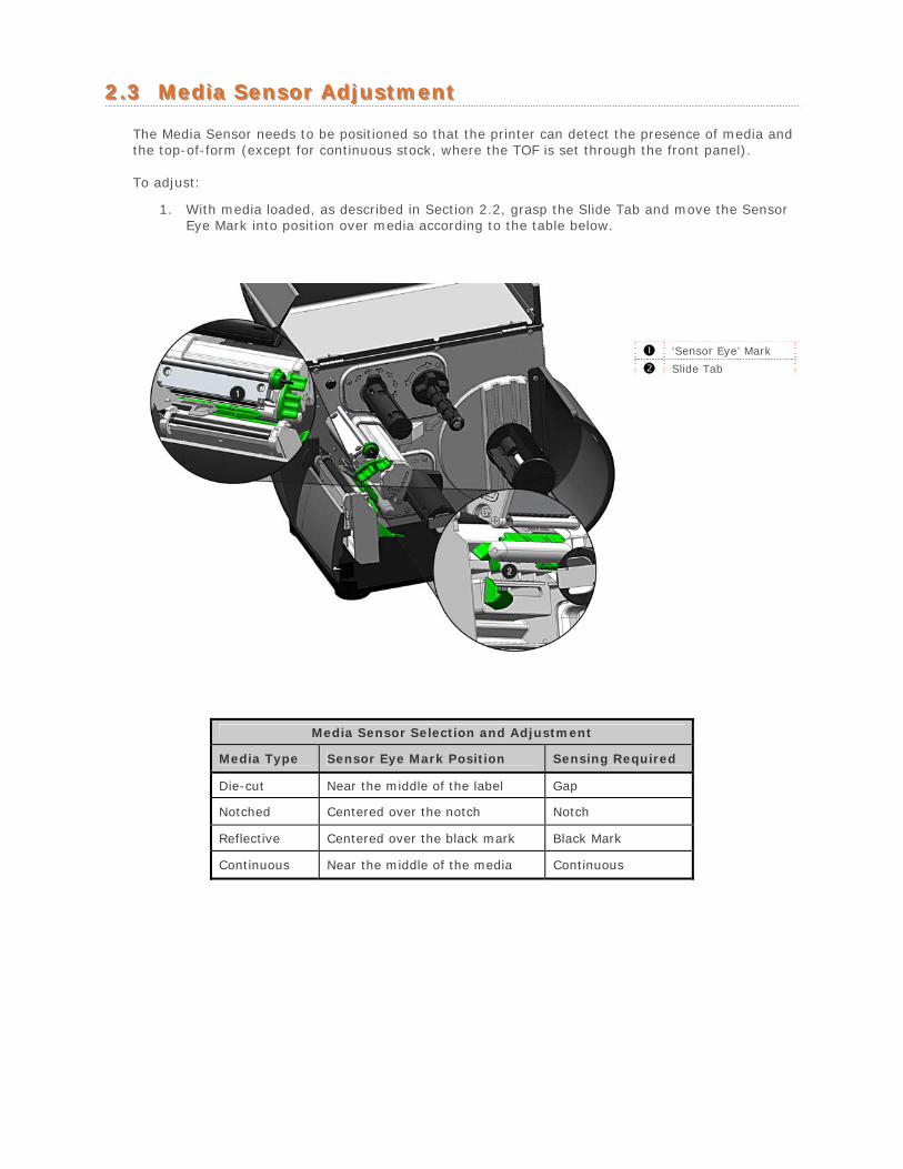
22..33 MMeeddiiaa SSeennssoorr AAddjjuussttmmeenntt
The Media Sensor needs to be positioned so that the printer can detect the presence of media and the top-of-form (except for continuous stock, where the TOF is set through the front panel).
To adjust:
1. With media loaded, as described in Section 2.2, grasp the Slide Tab and move the SensorEye Mark into position over media according to the table below.
‘Sensor Eye’ Mark
Slide Tab
Media Sensor Selection and Adjustment
Media Type Sensor Eye Mark Position Sensing Required
Die-cut Near the middle of the label Gap
Notched Centered over the notch Notch
Reflective Centered over the black mark Black Mark
Continuous Near the middle of the media Continuous
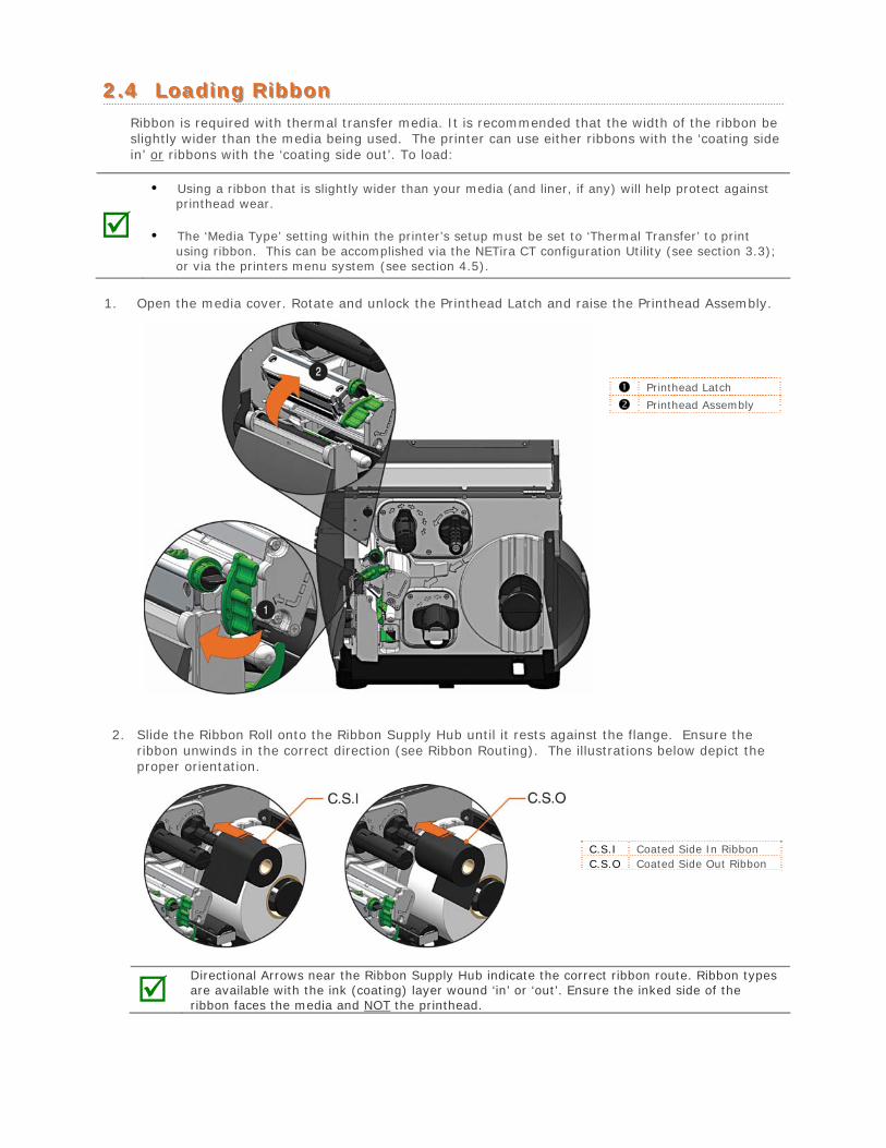
22..44 LLooaaddiinngg RRiibbbboonn Ribbon is required with thermal transfer media. It is recommended that the width of the ribbon be slightly wider than the media being used. The printer can use either ribbons with the ‘coating side in’ or ribbons with the ‘coating side out’. To load:
• Using a ribbon that is slightly wider than your media (and liner, if any) will help protect against
printhead wear.
• The ‘Media Type’ setting within the printer’s setup must be set to ‘Thermal Transfer’ to printusing ribbon. This can be accomplished via the NETira CT configuration Utility (see section 3.3);or via the printers menu system (see section 4.5).
1. Open the media cover. Rotate and unlock the Printhead Latch and raise the Printhead Assembly.
Printhead Latch
Printhead Assembly
2. Slide the Ribbon Roll onto the Ribbon Supply Hub until it rests against the flange. Ensure theribbon unwinds in the correct direction (see Ribbon Routing). The illustrations below depict theproper orientation.
C.S.I Coated Side In Ribbon C.S.O Coated Side Out Ribbon
Directional Arrows near the Ribbon Supply Hub indicate the correct ribbon route. Ribbon types are available with the ink (coating) layer wound ‘in’ or ‘out’. Ensure the inked side of the ribbon faces the media and NOT the printhead.
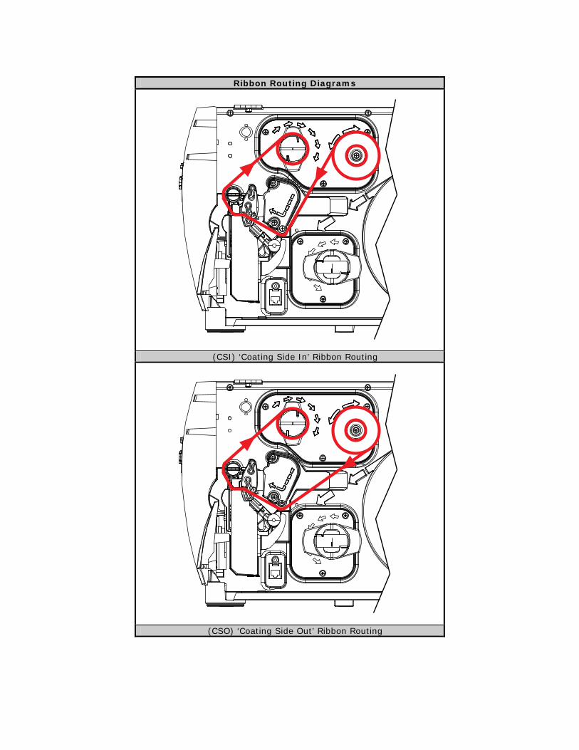
Ribbon Routing Diagrams
(CSI) ‘Coating Side In’ Ribbon Routing
(CSO) ‘Coating Side Out’ Ribbon Routing
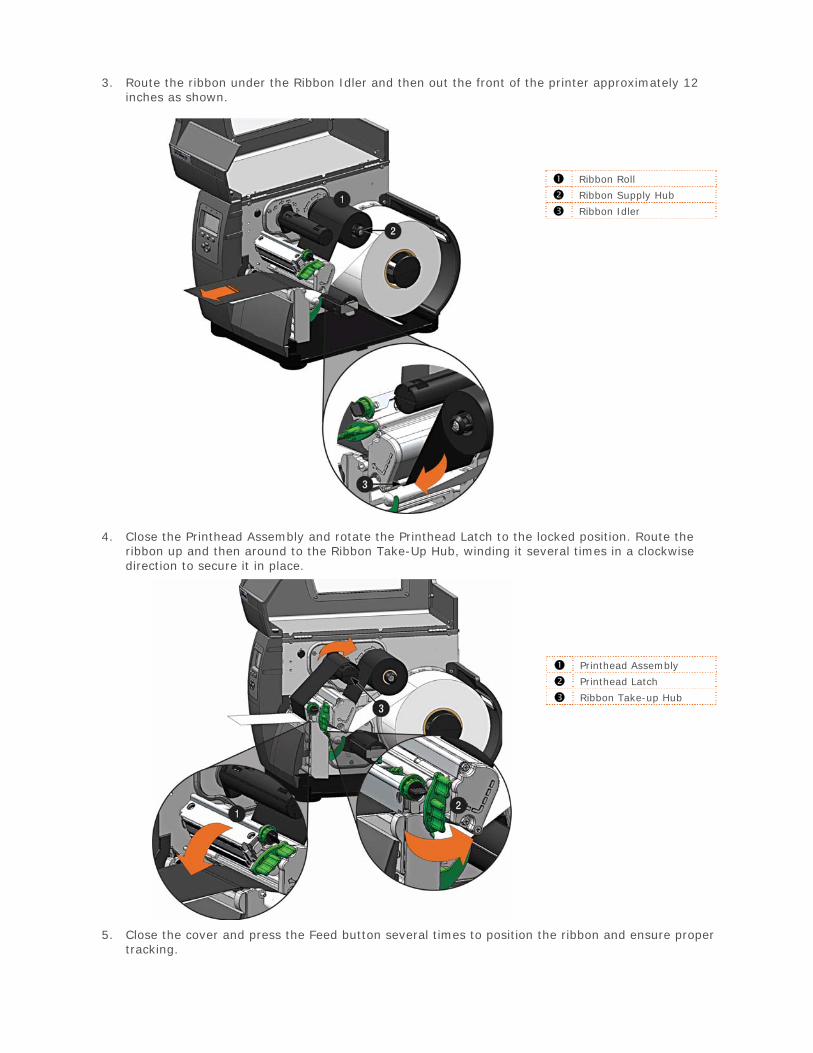
3. Route the ribbon under the Ribbon Idler and then out the front of the printer approximately 12inches as shown.
Ribbon Roll
Ribbon Supply Hub
Ribbon Idler
4. Close the Printhead Assembly and rotate the Printhead Latch to the locked position. Route theribbon up and then around to the Ribbon Take-Up Hub, winding it several times in a clockwisedirection to secure it in place.
Printhead Assembly
Printhead Latch
Ribbon Take-up Hub
5. Close the cover and press the Feed button several times to position the ribbon and ensure propertracking.
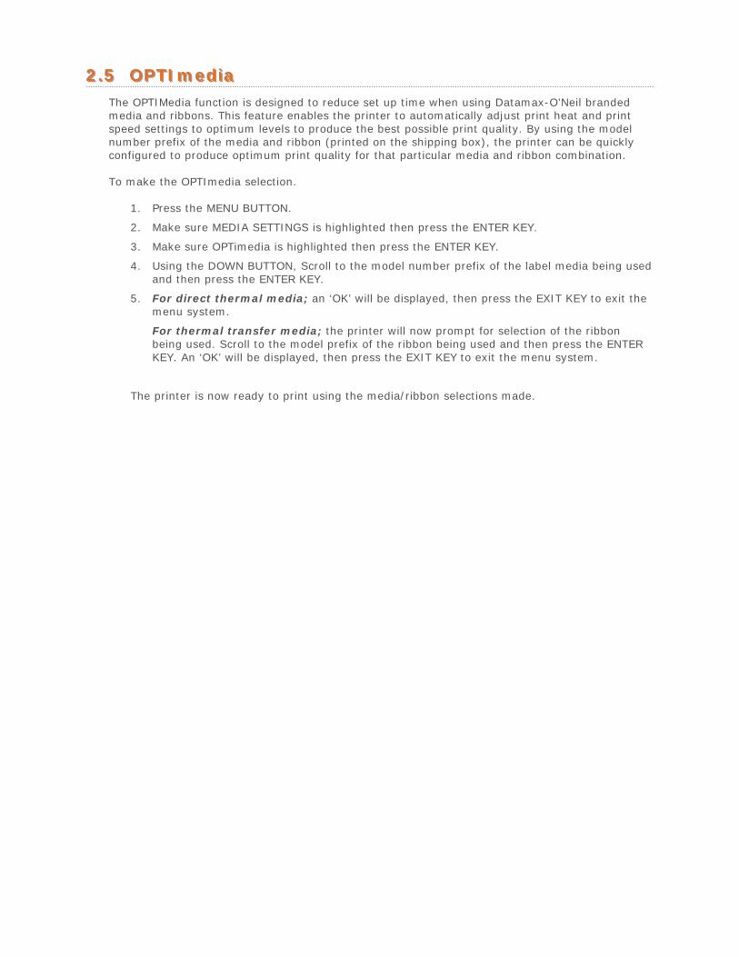
22..55 OOPPTTIImmeeddiiaa The OPTIMedia function is designed to reduce set up time when using Datamax-O’Neil branded media and ribbons. This feature enables the printer to automatically adjust print heat and print speed settings to optimum levels to produce the best possible print quality. By using the model number prefix of the media and ribbon (printed on the shipping box), the printer can be quickly configured to produce optimum print quality for that particular media and ribbon combination.
To make the OPTImedia selection.
1. Press the MENU BUTTON.
2. Make sure MEDIA SETTINGS is highlighted then press the ENTER KEY.
3. Make sure OPTimedia is highlighted then press the ENTER KEY.
4. Using the DOWN BUTTON, Scroll to the model number prefix of the label media being usedand then press the ENTER KEY.
5. For direct thermal media; an ‘OK’ will be displayed, then press the EXIT KEY to exit themenu system.
For thermal transfer media; the printer will now prompt for selection of the ribbonbeing used. Scroll to the model prefix of the ribbon being used and then press the ENTERKEY. An ‘OK’ will be displayed, then press the EXIT KEY to exit the menu system.
The printer is now ready to print using the media/ribbon selections made.
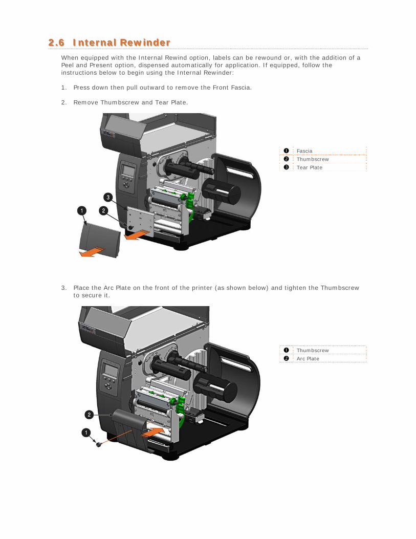
22..66 IInntteerrnnaall RReewwiinnddeerr When equipped with the Internal Rewind option, labels can be rewound or, with the addition of a Peel and Present option, dispensed automatically for application. If equipped, follow the instructions below to begin using the Internal Rewinder:
1. Press down then pull outward to remove the Front Fascia.
2. Remove Thumbscrew and Tear Plate.
Fascia
Thumbscrew
Tear Plate
3. Place the Arc Plate on the front of the printer (as shown below) and tighten the Thumbscrewto secure it.
Thumbscrew
Arc Plate
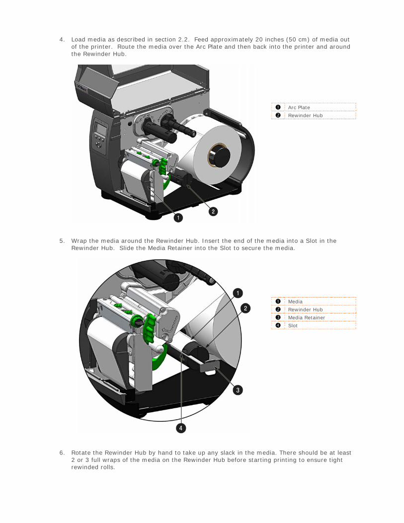
4. Load media as described in section 2.2. Feed approximately 20 inches (50 cm) of media outof the printer. Route the media over the Arc Plate and then back into the printer and aroundthe Rewinder Hub.
Arc Plate
Rewinder Hub
5. Wrap the media around the Rewinder Hub. Insert the end of the media into a Slot in theRewinder Hub. Slide the Media Retainer into the Slot to secure the media.
Media
Rewinder Hub
Media Retainer
Slot
6. Rotate the Rewinder Hub by hand to take up any slack in the media. There should be at least2 or 3 full wraps of the media on the Rewinder Hub before starting printing to ensure tightrewinded rolls.
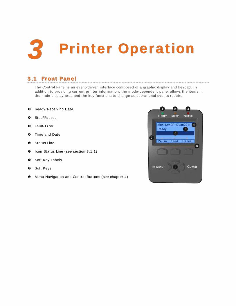
33 PPrriinntteerr OOppeerraattiioonn
33..11 FFrroonntt PPaanneell The Control Panel is an event-driven interface composed of a graphic display and keypad. In addition to providing current printer information, the mode-dependent panel allows the items in the main display area and the key functions to change as operational events require.
Ready/Receiving Data
Stop/Paused
Fault/Error
Time and Date
Status Line
Icon Status Line (see section 3.1.1)
Soft Key Labels
Soft Keys
Menu Navigation and Control Buttons (see chapter 4)
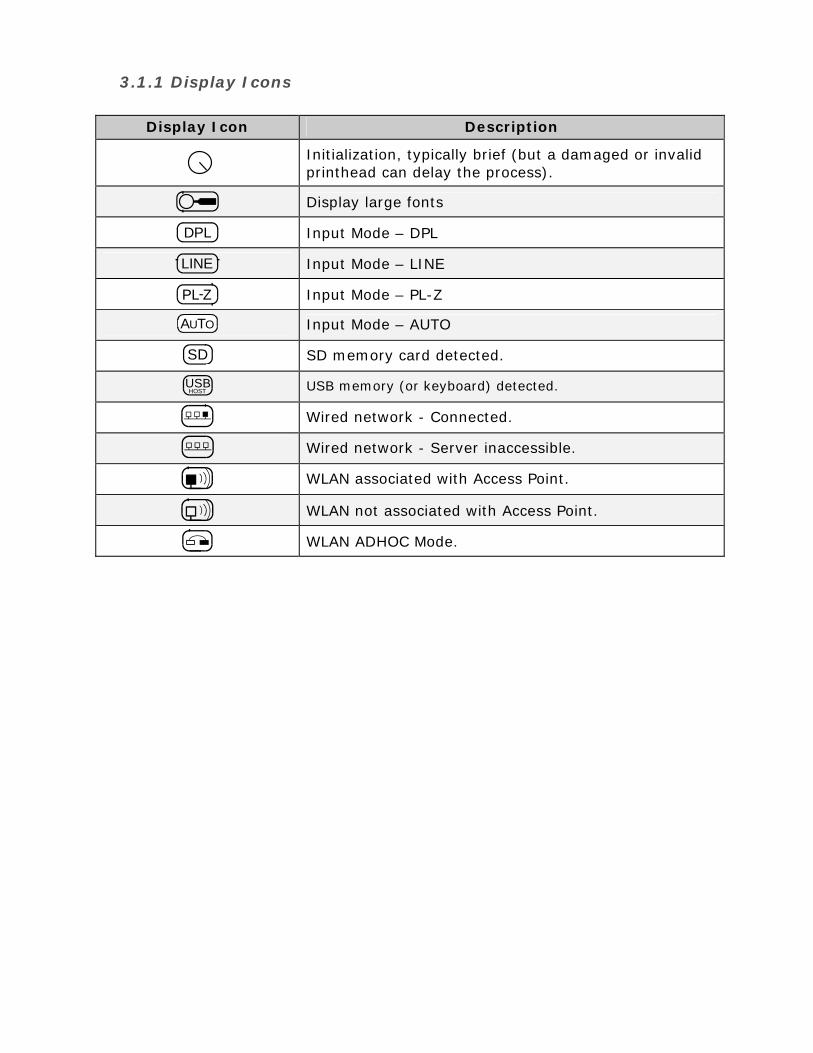
3.1.1 Display Icons
Display Icon Description
Initialization, typically brief (but a damaged or invalid printhead can delay the process).
Display large fonts
DPL Input Mode – DPL
LINE Input Mode – LINE
PL Z Input Mode – PL-Z
AUTO Input Mode – AUTO
SD SD memory card detected.
USBHOST USB memory (or keyboard) detected.
Wired network - Connected.
Wired network - Server inaccessible.
WLAN associated with Access Point.
WLAN not associated with Access Point.
WLAN ADHOC Mode.
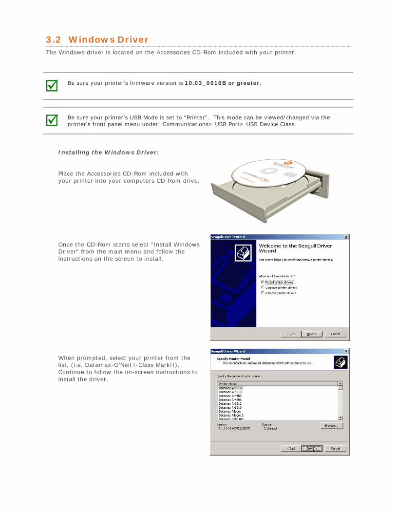
3.2 Windows Driver The Windows driver is located on the Accessories CD-Rom included with your printer.
Be sure your printer’s firmware version is 10.03_0016B or greater.
Be sure your printer’s USB Mode is set to “Printer”. This mode can be viewed/changed via the printer’s front panel menu under: Communications> USB Port> USB Device Class.
Installing the Windows Driver:
Place the Accessories CD-Rom included with your printer into your computers CD-Rom drive.
Once the CD-Rom starts select "Install Windows Driver" from the main menu and follow the instructions on the screen to install.
When prompted, select your printer from the list, (i.e. Datamax-O’Neil I-Class MarkII). Continue to follow the on-screen instructions to install the driver.
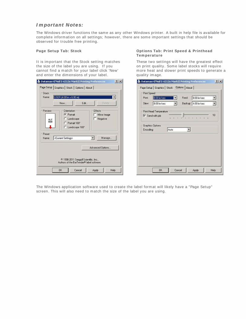
Important Notes:
The Windows driver functions the same as any other Windows printer. A built in help file is available for complete information on all settings; however, there are some important settings that should be observed for trouble free printing.
Page Setup Tab: Stock
It is important that the Stock setting matches the size of the label you are using. If you cannot find a match for your label click 'New' and enter the dimensions of your label.
Options Tab: Print Speed & Printhead Temperature
These two settings will have the greatest effect on print quality. Some label stocks will require more heat and slower print speeds to generate a quality image.
The Windows application software used to create the label format will likely have a "Page Setup" screen. This will also need to match the size of the label you are using.
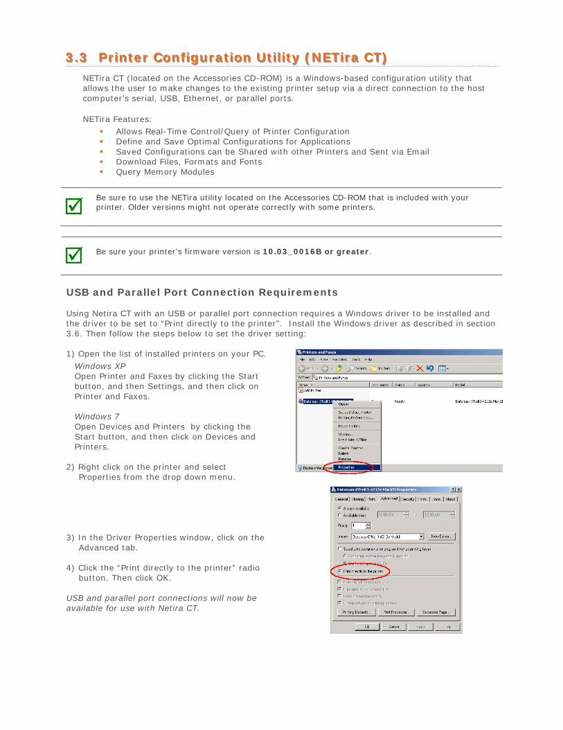
33..33 PPrriinntteerr CCoonnffiigguurraattiioonn UUttiilliittyy ((NNEETTiirraa CCTT)) NETira CT (located on the Accessories CD-ROM) is a Windows-based configuration utility that allows the user to make changes to the existing printer setup via a direct connection to the host computer’s serial, USB, Ethernet, or parallel ports.
NETira Features: Allows Real-Time Control/Query of Printer Configuration Define and Save Optimal Configurations for Applications Saved Configurations can be Shared with other Printers and Sent via Email Download Files, Formats and Fonts Query Memory Modules
Be sure to use the NETira utility located on the Accessories CD-ROM that is included with your printer. Older versions might not operate correctly with some printers.
Be sure your printer’s firmware version is 10.03_0016B or greater.
USB and Parallel Port Connection Requirements
Using Netira CT with an USB or parallel port connection requires a Windows driver to be installed and the driver to be set to “Print directly to the printer”. Install the Windows driver as described in section 3.6. Then follow the steps below to set the driver setting:
1) Open the list of installed printers on your PC.Windows XP Open Printer and Faxes by clicking the Start button, and then Settings, and then click on Printer and Faxes.
Windows 7 Open Devices and Printers by clicking the Start button, and then click on Devices and Printers.
2) Right click on the printer and selectProperties from the drop down menu.
3) In the Driver Properties window, click on theAdvanced tab.
4) Click the “Print directly to the printer” radiobutton. Then click OK.
USB and parallel port connections will now be available for use with Netira CT.
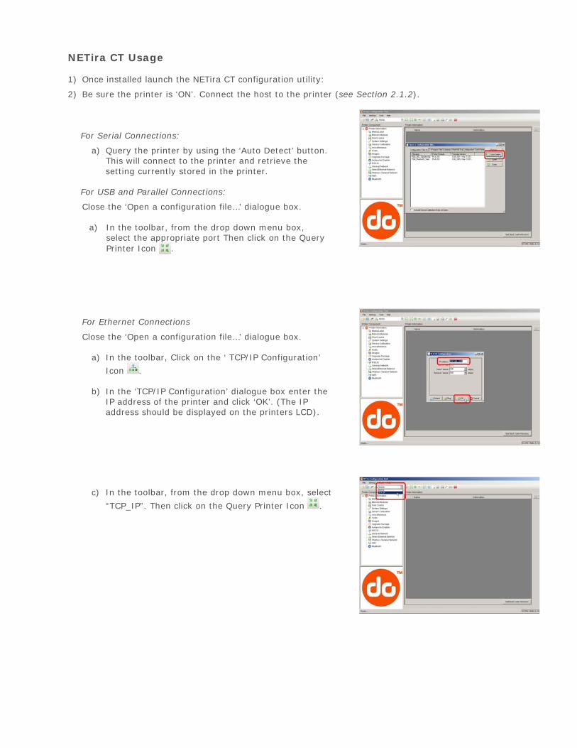
NETira CT Usage
1) Once installed launch the NETira CT configuration utility:
2) Be sure the printer is ‘ON’. Connect the host to the printer (see Section 2.1.2).
For Serial Connections:
a) Query the printer by using the ‘Auto Detect’ button.This will connect to the printer and retrieve thesetting currently stored in the printer.
For USB and Parallel Connections:
Close the ‘Open a configuration file…’ dialogue box.
a) In the toolbar, from the drop down menu box,select the appropriate port Then click on the QueryPrinter Icon .
For Ethernet Connections
Close the ‘Open a configuration file…’ dialogue box.
a) In the toolbar, Click on the ‘ TCP/IP Configuration’
Icon .
b) In the ‘TCP/IP Configuration’ dialogue box enter theIP address of the printer and click ‘OK’. (The IPaddress should be displayed on the printers LCD).
c) In the toolbar, from the drop down menu box, select
“TCP_IP”. Then click on the Query Printer Icon .
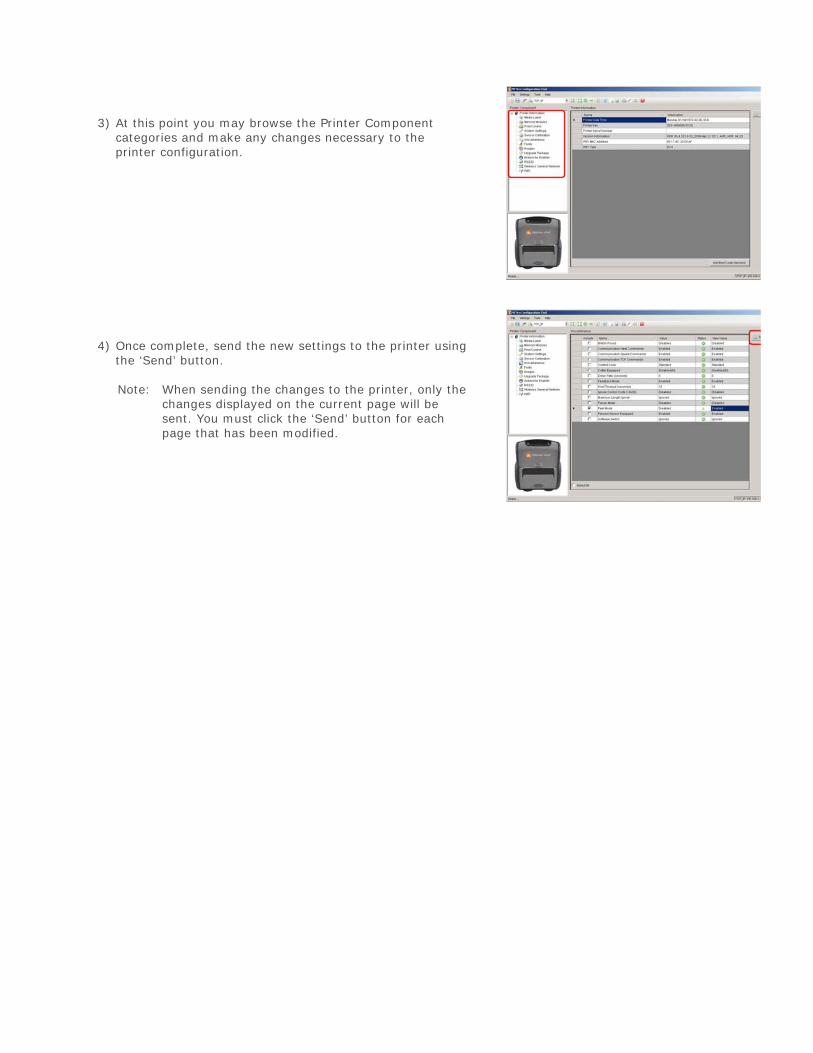
3) At this point you may browse the Printer Componentcategories and make any changes necessary to theprinter configuration.
4) Once complete, send the new settings to the printer usingthe ‘Send’ button.
Note: When sending the changes to the printer, only thechanges displayed on the current page will be sent. You must click the ‘Send’ button for each page that has been modified.
33..44 MMeeddiiaa CCaalliibbrraattiioonn
3.4.1 Quick Calibration Quick Calibration should be performed as part of the media loading routine to fine-tune the sensing parameters.
(1) This calibration is not necessary when using continuous stock.
(2) Media containing large gaps may require a change in the PAPER EMPTY DISTANCE before proceeding.
Calibrate the printer as follows:
1. Ensure that the printer is ON and in an idle state (i.e., not off-line) with media loaded, themedia sensor adjusted, and the sensor type selected.
2. Press and hold the FEED Key until at least one full label has been output then release the keyand wait for the printer to process the data. There are two possible outcomes:
CALIBRATION COMPLETE - will be displayed, and the media will be advanced to the next top of form if calibration was successful; or,
CALIBRATION FAILED will be displayed if calibration was not successful. In this case, check the hints listed below to help resolve the problem:
Calibration Hints:
WARNING LOW BACKING is a normal message when calibrating die-cut media mounted on a highly translucent liner or notched tag stocks.
If the initial attempt fails, press and hold the FEED Key until two successive label TOFs have been output. If, however, CALIBRATION FAILED is displayed again, perform the Standard Calibration routine, see Section 3.4.3.
3.4.2 Empty Calibration Empty Calibration calibrates the printer’s media sensor to detect an ‘Out of Stock’ condition. Calibrate the printer as follows:
1. Ensure that the printer is ON and in an idle state (i.e., not off-line) with media removed.
2. Press and hold the Pause & Feed Keys together. The printer will now be calibrated for the ‘Outof Stock’ condition.
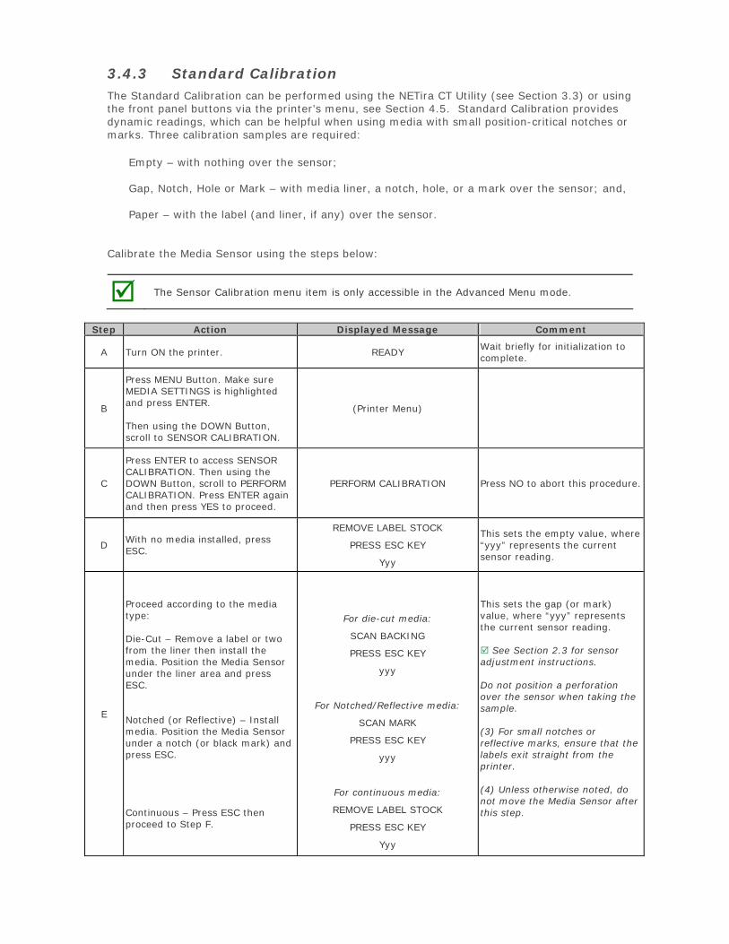
3.4.3 Standard Calibration The Standard Calibration can be performed using the NETira CT Utility (see Section 3.3) or using the front panel buttons via the printer’s menu, see Section 4.5. Standard Calibration provides dynamic readings, which can be helpful when using media with small position-critical notches or marks. Three calibration samples are required:
Empty – with nothing over the sensor;
Gap, Notch, Hole or Mark – with media liner, a notch, hole, or a mark over the sensor; and,
Paper – with the label (and liner, if any) over the sensor.
Calibrate the Media Sensor using the steps below:
The Sensor Calibration menu item is only accessible in the Advanced Menu mode.
Step Action Displayed Message Comment
A Turn ON the printer. READY Wait briefly for initialization to complete.
B
Press MENU Button. Make sure MEDIA SETTINGS is highlighted and press ENTER.
Then using the DOWN Button, scroll to SENSOR CALIBRATION.
(Printer Menu)
C
Press ENTER to access SENSOR CALIBRATION. Then using the DOWN Button, scroll to PERFORM CALIBRATION. Press ENTER again and then press YES to proceed.
PERFORM CALIBRATION Press NO to abort this procedure.
D With no media installed, press ESC.
REMOVE LABEL STOCK
PRESS ESC KEY
Yyy
This sets the empty value, where “yyy” represents the current sensor reading.
E
Proceed according to the media type:
Die-Cut – Remove a label or two from the liner then install the media. Position the Media Sensor under the liner area and press ESC.
Notched (or Reflective) – Install media. Position the Media Sensor under a notch (or black mark) and press ESC.
Continuous – Press ESC then proceed to Step F.
For die-cut media:
SCAN BACKING
PRESS ESC KEY
yyy
For Notched/Reflective media:
SCAN MARK
PRESS ESC KEY
yyy
For continuous media:
REMOVE LABEL STOCK
PRESS ESC KEY
Yyy
This sets the gap (or mark) value, where “yyy” represents the current sensor reading.
See Section 2.3 for sensor adjustment instructions.
Do not position a perforation over the sensor when taking the sample.
(3) For small notches or reflective marks, ensure that the labels exit straight from the printer.
(4) Unless otherwise noted, do not move the Media Sensor after this step.
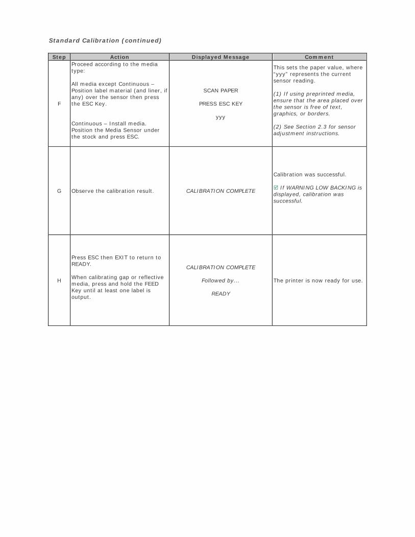
Standard Calibration (continued)
Step Action Displayed Message Comment
F
Proceed according to the media type:
All media except Continuous – Position label material (and liner, if any) over the sensor then press the ESC Key.
Continuous – Install media. Position the Media Sensor under the stock and press ESC.
SCAN PAPER
PRESS ESC KEY
yyy
This sets the paper value, where “yyy” represents the current sensor reading.
(1) If using preprinted media, ensure that the area placed over the sensor is free of text, graphics, or borders.
(2) See Section 2.3 for sensor adjustment instructions.
G Observe the calibration result. CALIBRATION COMPLETE
Calibration was successful.
If WARNING LOW BACKING is displayed, calibration was successful.
H
Press ESC then EXIT to return to READY.
When calibrating gap or reflective media, press and hold the FEED Key until at least one label is output.
CALIBRATION COMPLETE
Followed by...
READY
The printer is now ready for use.
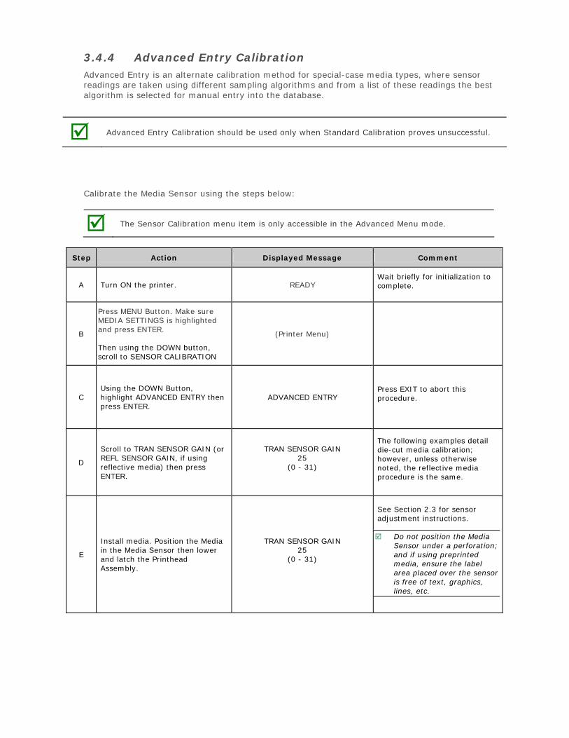
3.4.4 Advanced Entry Calibration Advanced Entry is an alternate calibration method for special-case media types, where sensor readings are taken using different sampling algorithms and from a list of these readings the best algorithm is selected for manual entry into the database.
Advanced Entry Calibration should be used only when Standard Calibration proves unsuccessful.
Calibrate the Media Sensor using the steps below:
The Sensor Calibration menu item is only accessible in the Advanced Menu mode.
Step Action Displayed Message Comment
A Turn ON the printer. READY Wait briefly for initialization to complete.
B
Press MENU Button. Make sure MEDIA SETTINGS is highlighted and press ENTER.
Then using the DOWN button, scroll to SENSOR CALIBRATION
(Printer Menu)
C Using the DOWN Button, highlight ADVANCED ENTRY then press ENTER.
ADVANCED ENTRY Press EXIT to abort this procedure.
D
Scroll to TRAN SENSOR GAIN (or REFL SENSOR GAIN, if using reflective media) then press ENTER.
TRAN SENSOR GAIN 25
(0 - 31)
The following examples detail die-cut media calibration; however, unless otherwise noted, the reflective media procedure is the same.
E
Install media. Position the Media in the Media Sensor then lower and latch the Printhead Assembly.
TRAN SENSOR GAIN 25
(0 - 31)
See Section 2.3 for sensor adjustment instructions.
Do not position the Media Sensor under a perforation; and if using preprinted media, ensure the label area placed over the sensor is free of text, graphics, lines, etc.
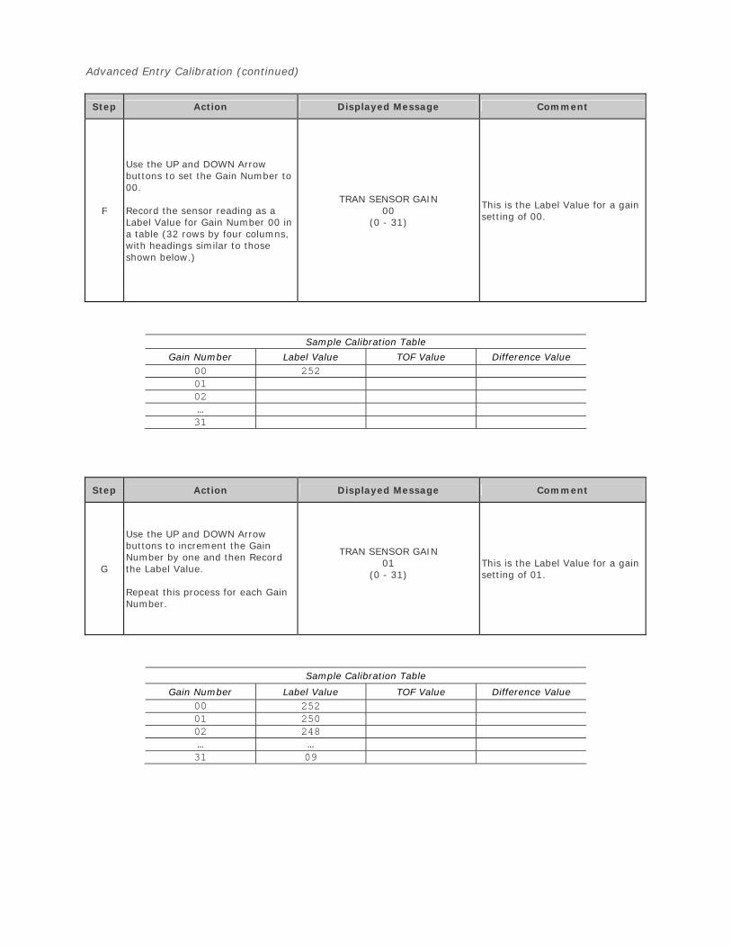
Advanced Entry Calibration (continued)
Step Action Displayed Message Comment
F
Use the UP and DOWN Arrow buttons to set the Gain Number to 00.
Record the sensor reading as a Label Value for Gain Number 00 in a table (32 rows by four columns, with headings similar to those shown below.)
TRAN SENSOR GAIN 00
(0 - 31)
This is the Label Value for a gain setting of 00.
Sample Calibration Table
Gain Number Label Value TOF Value Difference Value 00 2520102…31
Step Action Displayed Message Comment
G
Use the UP and DOWN Arrow buttons to increment the Gain Number by one and then Record the Label Value.
Repeat this process for each Gain Number.
TRAN SENSOR GAIN 01
(0 - 31) This is the Label Value for a gain setting of 01.
Sample Calibration Table
Gain Number Label Value TOF Value Difference Value 00 25201 25002 248… …31 09
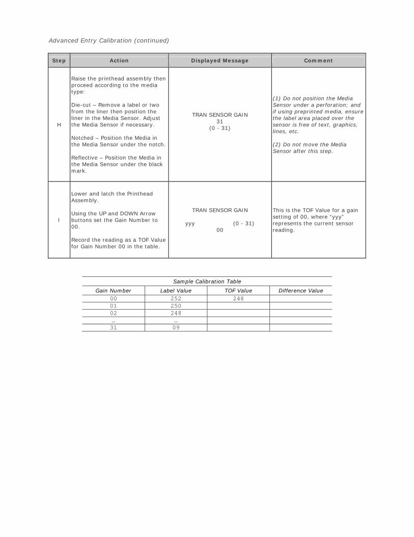
Advanced Entry Calibration (continued)
Step Action Displayed Message Comment
H
Raise the printhead assembly then proceed according to the media type:
Die-cut – Remove a label or two from the liner then position the liner in the Media Sensor. Adjust the Media Sensor if necessary.
Notched – Position the Media in the Media Sensor under the notch.
Reflective – Position the Media in the Media Sensor under the black mark.
TRAN SENSOR GAIN 31
(0 - 31)
(1) Do not position the Media Sensor under a perforation; and if using preprinted media, ensure the label area placed over the sensor is free of text, graphics, lines, etc.
(2) Do not move the Media Sensor after this step.
I
Lower and latch the Printhead Assembly.
Using the UP and DOWN Arrow buttons set the Gain Number to 00.
Record the reading as a TOF Value for Gain Number 00 in the table.
TRAN SENSOR GAIN
yyy (0 - 31) 00
This is the TOF Value for a gain setting of 00, where “yyy” represents the current sensor reading.
Sample Calibration Table
Gain Number Label Value TOF Value Difference Value 00 252 24801 25002 248… …31 09
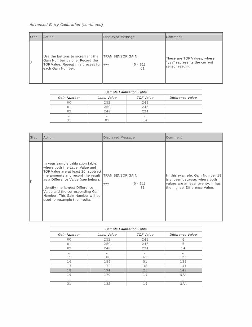
Advanced Entry Calibration (continued)
Step Action Displayed Message Comment
J
Use the buttons to increment the Gain Number by one. Record the TOF Value. Repeat this process for each Gain Number.
TRAN SENSOR GAIN
yyy (0 - 31) 01
These are TOF Values, where “yyy” represents the current sensor reading.
Sample Calibration Table
Gain Number Label Value TOF Value Difference Value 00 252 24801 250 24502 248 234… … …31 09 14
Step Action Displayed Message Comment
K
In your sample calibration table, where both the Label Value and TOF Value are at least 20, subtract the amounts and record the result as a Difference Value (see below).
Identify the largest Difference Value and the corresponding Gain Number. This Gain Number will be used to resample the media.
TRAN SENSOR GAIN
yyy (0 - 31) 31
In this example, Gain Number 18 is chosen because, where both values are at least twenty, it has the highest Difference Value.
Sample Calibration Table
Gain Number Label Value TOF Value Difference Value 00 252 248 401 250 245 502 248 234 14… … … …15 188 63 12516 184 51 13317 179 38 14118 174 25 149 19 170 19 N/A… … … …31 132 14 N/A
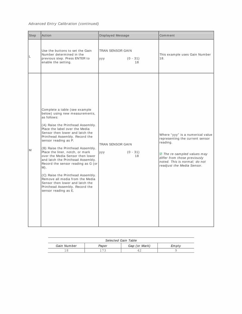
Advanced Entry Calibration (continued)
Step Action Displayed Message Comment
L
Use the buttons to set the Gain Number determined in the previous step. Press ENTER to enable the setting.
TRAN SENSOR GAIN
yyy (0 - 31) 18
This example uses Gain Number 18.
M
Complete a table (see example below) using new measurements, as follows:
(A) Raise the Printhead Assembly. Place the label over the Media Sensor then lower and latch the Printhead Assembly. Record the sensor reading as P.
(B) Raise the Printhead Assembly. Place the liner, notch, or mark over the Media Sensor then lower and latch the Printhead Assembly. Record the sensor reading as G (or M).
(C) Raise the Printhead Assembly. Remove all media from the Media Sensor then lower and latch the Printhead Assembly. Record the sensor reading as E.
TRAN SENSOR GAIN
yyy (0 - 31) 18
Where “yyy” is a numerical value representing the current sensor reading.
The re-sampled values may differ from those previously noted. This is normal; do not readjust the Media Sensor.
Selected Gain Table
Gain Number Paper Gap (or Mark) Empty 18 173 42 9
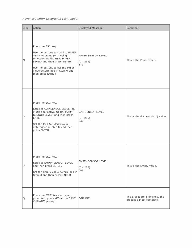
Advanced Entry Calibration (continued)
Step Action Displayed Message Comment
N
Press the ESC Key.
Use the buttons to scroll to PAPER SENSOR LEVEL (or if using reflective media, REFL PAPER LEVEL) and then press ENTER.
Use the buttons to set the Paper value determined in Step M and then press ENTER.
PAPER SENSOR LEVEL
(0 - 255) 173
This is the Paper value.
O
Press the ESC Key.
Scroll to GAP SENSOR LEVEL (or, if using reflective media, MARK SENSOR LEVEL) and then press ENTER.
Set the Gap (or Mark) value determined in Step M and then press ENTER.
GAP SENSOR LEVEL
(0 - 255) 042
This is the Gap (or Mark) value.
P
Press the ESC Key.
Scroll to EMPTY SENSOR LEVEL and then press ENTER.
Set the Empty value determined in Step M and then press ENTER.
EMPTY SENSOR LEVEL
(0 - 255) 009
This is the Empty value.
Q Press the EXIT Key and, when prompted, press YES at the SAVE CHANGES prompt.
OFFLINE The procedure is finished, the process almost complete.
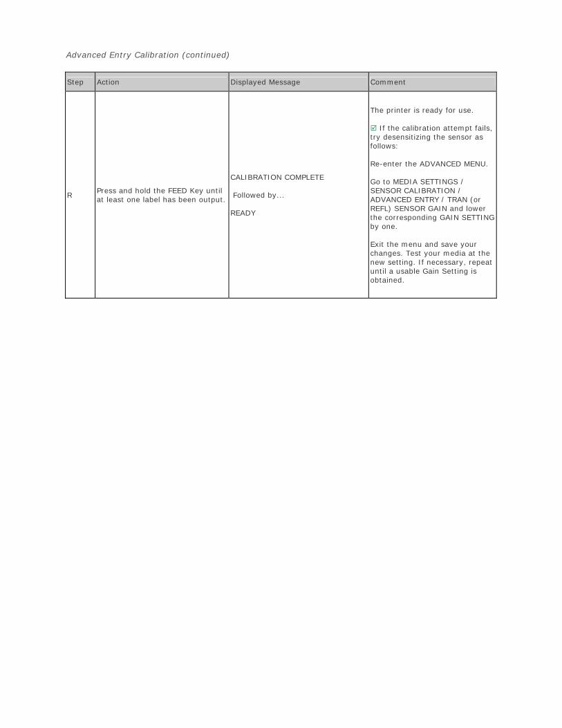
Advanced Entry Calibration (continued)
Step Action Displayed Message Comment
R Press and hold the FEED Key until at least one label has been output.
CALIBRATION COMPLETE
Followed by...
READY
The printer is ready for use.
If the calibration attempt fails, try desensitizing the sensor as follows:
Re-enter the ADVANCED MENU.
Go to MEDIA SETTINGS / SENSOR CALIBRATION / ADVANCED ENTRY / TRAN (or REFL) SENSOR GAIN and lower the corresponding GAIN SETTING by one.
Exit the menu and save your changes. Test your media at the new setting. If necessary, repeat until a usable Gain Setting is obtained.
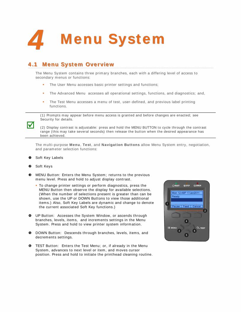
44 MMeennuu SSyysstteemm
44..11 MMeennuu SSyysstteemm OOvveerrvviieeww The Menu System contains three primary branches, each with a differing level of access to secondary menus or functions:
The User Menu accesses basic printer settings and functions;
The Advanced Menu accesses all operational settings, functions, and diagnostics; and,
The Test Menu accesses a menu of test, user-defined, and previous label printingfunctions.
(1) Prompts may appear before menu access is granted and before changes are enacted; see Security for details.
(2) Display contrast is adjustable: press and hold the MENU BUTTON to cycle through the contrast range (this may take several seconds) then release the button when the desired appearance has been achieved.
The multi-purpose Menu, Test, and Navigation Buttons allow Menu System entry, negotiation, and parameter selection functions:
Soft Key Labels
Soft Keys
MENU Button: Enters the Menu System; returns to the previous menu level. Press and hold to adjust display contrast.
To change printer settings or perform diagnostics, press theMENU Button then observe the display for available selections.(When the number of selections present is greater than can beshown, use the UP or DOWN Buttons to view those additionalitems.) Also, Soft Key Labels are dynamic and change to denotethe current associated Soft Key functions.)
UP Button: Accesses the System Window, or ascends through branches, levels, items, and increments settings in the Menu System. Press and hold to view printer system information.
DOWN Button: Descends through branches, levels, items, and decrements settings.
TEST Button: Enters the Test Menu; or, if already in the Menu System, advances to next level or item, and moves cursor position. Press and hold to initiate the printhead cleaning routine.
44..22 TThhee UUsseerr MMeennuu The User Menu contains basic selections in these menus:
Media Settings Print Control Printer Options System Settings
(1) Some setting changes will only become effective (and saved) after selecting YES at the Save Changes prompt.
(2) Labeling software may, in some cases, override the printer menu settings; see Advanced Menu for details.
44..33 TThhee AAddvvaanncceedd MMeennuu The Advanced Menu contains all setting, control, and functional selections in these menus:
Media Settings Print Control Printer Options System Settings Communications Diagnostics
After selecting the Advanced Menu, it will be accessed whenever the MENU BUTTON is pressed. To enable the Advanced Menu, proceed as follows:
1. Press the MENU BUTTON.
2. Using the UP or the DOWN BUTTON, scroll to SYSTEM SETTINGS then press the ENTERKEY.
3. Scroll to MENU MODE then press the ENTER KEY.
4. Scroll to ADVANCED MENU then press the ENTER KEY. (Upon completion, OK will bedisplayed and the printer will exit the menu system.)
(1) Some setting changes will only become effective (and saved) after selecting YES at the Save Changes prompt.
(2) Labeling software may, in some cases, override the printer menu settings; see Advanced Menu / Communications / Host Settings to avoid potential conflicts.
(3) To return to the User Menu, re-select it or restore the factory defaults.
44..44 TThhee TTeesstt MMeennuu The Test Menu contains test and informational label selections:
Print Quality Label Print Configuration Ribbon Test Label Test Label Validation Label Print Last Label User Defined Label
Internally generated, these labels are printed at pre-selected media type, speed, and heat settings. Changes to these print settings can be made via the Menu System or through host commands. When printing, use full width media to capture the entire format; otherwise, adjust the printer and set the Label Width menu setting.
(1) Press the CANCEL KEY to stop printing.
(2) A printing delay can be set; see Print Test Rate (in Diagnostics).
4.4.1 User-Defined Label The User-Defined Label allows a template to be populated by variable data (via the printer’s control panel or a USB QWERTY keyboard). The template is a stored label format, where fields delimited by an ampersand (&) become variable.
The printer will prompt you to enter the variable field data. For example, the stored label format could contain the data 19131423443&ENTER NAME&
Afterward, when recalled from memory, the printer’s display will indicate the variable field: ENTER NAME
(1) Variable data can be any part of the DPL format - font ID, positioning, etc.
(2) No error checking will be performed.
(3) Supports .dlb, .dpl, .prn, and .txt file types.
44..55 MMeennuu DDeettaaiillss
Media Settings The Media Settings menu contains label and ribbon sensing and sizing functions, as well as printhead cleaning selections:
OPTimedia Media Type Media Index Type Label Length Maximum Label Length* Paper Empty Distance* Label Width Ribbon Low Options* Sensor Calibration* Printhead Cleaning*
Items denoted with an asterisk (*) are only accessible through the Advanced Menu.
The menu selections are defined on the following pages:
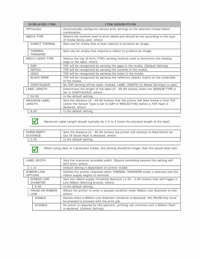
DISPLAYED ITEM ITEM DESCRIPTION
OPTimedia Automatically configures various print settings to the selected media/ribbon combination.
MEDIA TYPE Selects the method used to print labels and should be set according to the type of media being used, where:
DIRECT THERMAL Sets use for media that is heat reactive to produce an image.
THERMAL TRANSFER
Sets use for media that requires a ribbon to produce an image.
MEDIA INDEX TYPE Selects the top-of-form (TOF) sensing method used to determine the leading edge of the label, where:
GAP TOF will be recognized by sensing the gaps in the media. (Default Setting) NOTCH TOF will be recognized by sensing the notches in the media. HOLE TOF will be recognized by sensing the holes in the media. BLACK MARK TOF will be recognized by sensing the reflective (black) marks on the underside
of the media CONTINUOUS No TOF sensing will be used; instead, LABEL LENGTH (in Media Settings) is used.
LABEL LENGTH Determines the length of the label (0 - 99.99 inches) when the SENSOR TYPE is set to CONTINUOUS, where:
04.00 Is the default setting. MAXIMUM LABEL LENGTH
Sets the distance (0 - 99.99 inches) that the printer will feed media to find TOF (when the Sensor Type is set to GAP or REFLECTIVE) before a TOF Fault is declared, where:
8.00 Is the default setting.
Maximum Label Length should typically be 2.5 to 3 times the physical length of the label.
PAPER EMPTY DISTANCE
Sets the distance (0 - 99.99 inches) the printer will attempt to feed before an Out Of Stock Fault is declared, where:
0.25 Is the default setting.
When using clear or translucent media, this setting should be longer than the actual label size.
LABEL WIDTH Sets the maximum printable width. Objects extending beyond this setting will NOT print, where:
x.xx Default setting is dependant on printer model. RIBBON LOW OPTIONS
Defines the printer response when THERMAL TRANSFER mode is selected and the ribbon supply begins to diminish.
RIBBON LOW DIAMETER
Sets the ribbon supply threshold diameter (1.00 - 2.00 inches) that will trigger a Low Ribbon Warning prompt, where:
0.50 Is the default setting. PAUSE ON RIBBON LOW
Allows the printer to enter a paused condition when Ribbon Low Diameter is met, where:
ENABLE Pauses when a Ribbon Low Diameter condition is detected; the PAUSE Key must be pressed to proceed with the print job.
DISABLE No action is required by the operator; printing can continue until a Ribbon Fault is declared. (Default Setting)
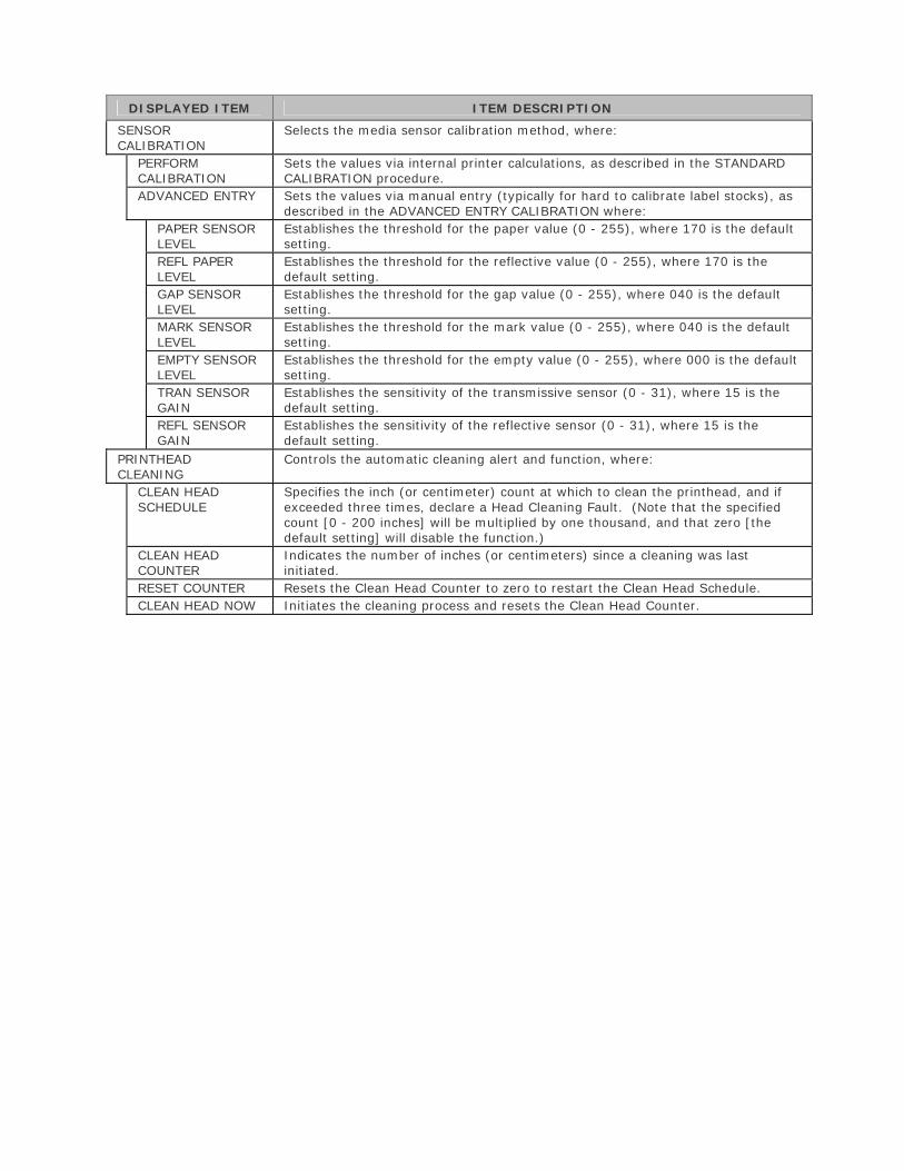
DISPLAYED ITEM ITEM DESCRIPTION
SENSOR CALIBRATION
Selects the media sensor calibration method, where:
PERFORM CALIBRATION
Sets the values via internal printer calculations, as described in the STANDARD CALIBRATION procedure.
ADVANCED ENTRY Sets the values via manual entry (typically for hard to calibrate label stocks), as described in the ADVANCED ENTRY CALIBRATION where:
PAPER SENSOR LEVEL
Establishes the threshold for the paper value (0 - 255), where 170 is the default setting.
REFL PAPER LEVEL
Establishes the threshold for the reflective value (0 - 255), where 170 is the default setting.
GAP SENSOR LEVEL
Establishes the threshold for the gap value (0 - 255), where 040 is the default setting.
MARK SENSOR LEVEL
Establishes the threshold for the mark value (0 - 255), where 040 is the default setting.
EMPTY SENSOR LEVEL
Establishes the threshold for the empty value (0 - 255), where 000 is the default setting.
TRAN SENSOR GAIN
Establishes the sensitivity of the transmissive sensor (0 - 31), where 15 is the default setting.
REFL SENSOR GAIN
Establishes the sensitivity of the reflective sensor (0 - 31), where 15 is the default setting.
PRINTHEAD CLEANING
Controls the automatic cleaning alert and function, where:
CLEAN HEAD SCHEDULE
Specifies the inch (or centimeter) count at which to clean the printhead, and if exceeded three times, declare a Head Cleaning Fault. (Note that the specified count [0 - 200 inches] will be multiplied by one thousand, and that zero [the default setting] will disable the function.)
CLEAN HEAD COUNTER
Indicates the number of inches (or centimeters) since a cleaning was last initiated.
RESET COUNTER Resets the Clean Head Counter to zero to restart the Clean Head Schedule. CLEAN HEAD NOW Initiates the cleaning process and resets the Clean Head Counter.
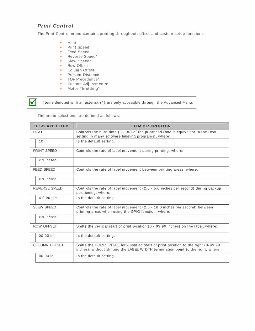
Print Control The Print Control menu contains printing throughput, offset and custom setup functions:
Heat Print Speed Feed Speed Reverse Speed* Slew Speed* Row Offset Column Offset Present Distance TOF Precedence* Custom Adjustments* Motor Throttling*
Items denoted with an asterisk (*) are only accessible through the Advanced Menu.
The menu selections are defined as follows:
DISPLAYED ITEM ITEM DESCRIPTION
HEAT Controls the burn time (0 - 30) of the printhead (and is equivalent to the Heat setting in many software labeling programs), where:
10 Is the default setting.
PRINT SPEED Controls the rate of label movement during printing, where:
x.x in/sec
FEED SPEED Controls the rate of label movement between printing areas, where:
x.x in/sec
REVERSE SPEED Controls the rate of label movement (2.0 - 5.0 inches per second) during backup positioning, where:
4.0 in/sec Is the default setting.
SLEW SPEED Controls the rate of label movement (2.0 - 16.0 inches per second) between printing areas when using the GPIO function, where:
x.x in/sec
ROW OFFSET Shifts the vertical start of print position (0 - 99.99 inches) on the label, where:
00.00 in. Is the default setting.
COLUMN OFFSET Shifts the HORIZONTAL, left-justified start of print position to the right (0-99.99 inches), without shifting the LABEL WIDTH termination point to the right, where:
00.00 in. Is the default setting.
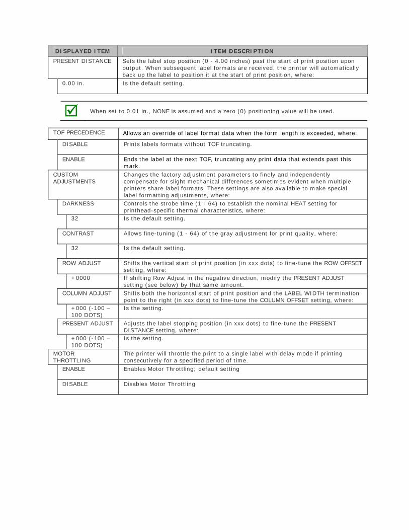
DISPLAYED ITEM ITEM DESCRIPTION
PRESENT DISTANCE Sets the label stop position (0 - 4.00 inches) past the start of print position upon output. When subsequent label formats are received, the printer will automatically back up the label to position it at the start of print position, where:
0.00 in. Is the default setting.
When set to 0.01 in., NONE is assumed and a zero (0) positioning value will be used.
TOF PRECEDENCE Allows an override of label format data when the form length is exceeded, where:
DISABLE Prints labels formats without TOF truncating.
ENABLE Ends the label at the next TOF, truncating any print data that extends past this mark.
CUSTOM ADJUSTMENTS
Changes the factory adjustment parameters to finely and independently compensate for slight mechanical differences sometimes evident when multiple printers share label formats. These settings are also available to make special label formatting adjustments, where:
DARKNESS Controls the strobe time (1 - 64) to establish the nominal HEAT setting for printhead-specific thermal characteristics, where:
32 Is the default setting.
CONTRAST Allows fine-tuning (1 - 64) of the gray adjustment for print quality, where:
32 Is the default setting.
ROW ADJUST Shifts the vertical start of print position (in xxx dots) to fine-tune the ROW OFFSET setting, where:
+0000 If shifting Row Adjust in the negative direction, modify the PRESENT ADJUST setting (see below) by that same amount.
COLUMN ADJUST Shifts both the horizontal start of print position and the LABEL WIDTH termination point to the right (in xxx dots) to fine-tune the COLUMN OFFSET setting, where:
+000 (-100 – 100 DOTS)
Is the setting.
PRESENT ADJUST Adjusts the label stopping position (in xxx dots) to fine-tune the PRESENT DISTANCE setting, where:
+000 (-100 – 100 DOTS)
Is the setting.
MOTOR THROTTLING
The printer will throttle the print to a single label with delay mode if printing consecutively for a specified period of time.
ENABLE Enables Motor Throttling; default setting
DISABLE Disables Motor Throttling
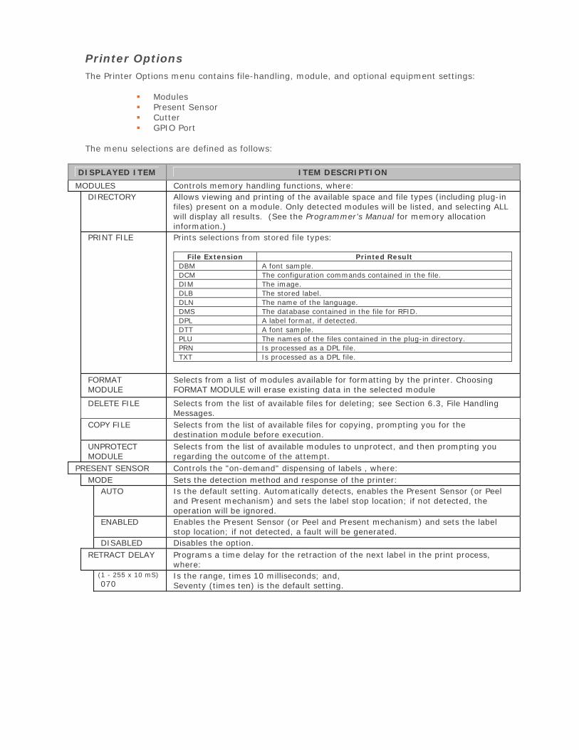
Printer Options The Printer Options menu contains file-handling, module, and optional equipment settings:
Modules Present Sensor Cutter GPIO Port
The menu selections are defined as follows:
DISPLAYED ITEM ITEM DESCRIPTION
MODULES Controls memory handling functions, where: DIRECTORY Allows viewing and printing of the available space and file types (including plug-in
files) present on a module. Only detected modules will be listed, and selecting ALL will display all results. (See the Programmer’s Manual for memory allocation information.)
PRINT FILE Prints selections from stored file types:
File Extension Printed Result DBM A font sample. DCM The configuration commands contained in the file. DIM The image.DLB The stored label.DLN The name of the language. DMS The database contained in the file for RFID. DPL A label format, if detected. DTT A font sample. PLU The names of the files contained in the plug-in directory. PRN Is processed as a DPL file. TXT Is processed as a DPL file.
FORMAT MODULE
Selects from a list of modules available for formatting by the printer. Choosing FORMAT MODULE will erase existing data in the selected module
DELETE FILE Selects from the list of available files for deleting; see Section 6.3, File Handling Messages.
COPY FILE Selects from the list of available files for copying, prompting you for the destination module before execution.
UNPROTECT MODULE
Selects from the list of available modules to unprotect, and then prompting you regarding the outcome of the attempt.
PRESENT SENSOR Controls the "on-demand" dispensing of labels , where: MODE Sets the detection method and response of the printer:
AUTO Is the default setting. Automatically detects, enables the Present Sensor (or Peel and Present mechanism) and sets the label stop location; if not detected, the operation will be ignored.
ENABLED Enables the Present Sensor (or Peel and Present mechanism) and sets the label stop location; if not detected, a fault will be generated.
DISABLED Disables the option.RETRACT DELAY Programs a time delay for the retraction of the next label in the print process,
where: (1 - 255 x 10 mS) 070
Is the range, times 10 milliseconds; and, Seventy (times ten) is the default setting.
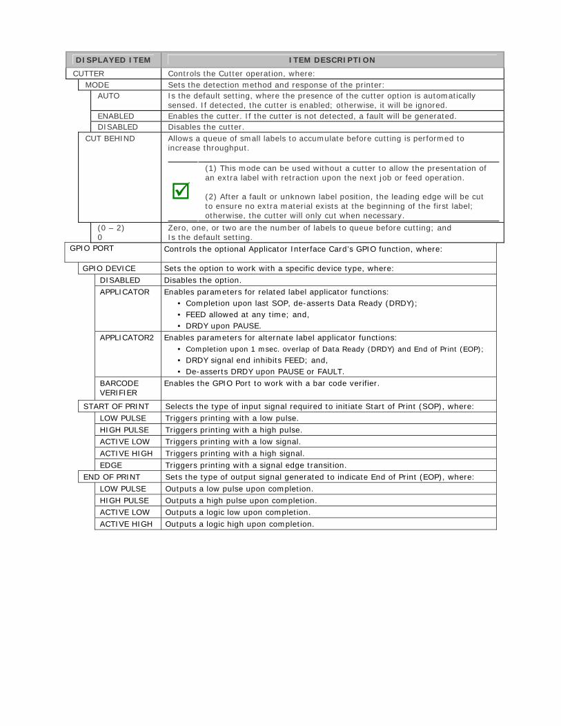
DISPLAYED ITEM ITEM DESCRIPTION
CUTTER Controls the Cutter operation, where: MODE Sets the detection method and response of the printer:
AUTO Is the default setting, where the presence of the cutter option is automatically sensed. If detected, the cutter is enabled; otherwise, it will be ignored.
ENABLED Enables the cutter. If the cutter is not detected, a fault will be generated. DISABLED Disables the cutter.
CUT BEHIND Allows a queue of small labels to accumulate before cutting is performed to increase throughput.
(1) This mode can be used without a cutter to allow the presentation of an extra label with retraction upon the next job or feed operation.
(2) After a fault or unknown label position, the leading edge will be cut to ensure no extra material exists at the beginning of the first label; otherwise, the cutter will only cut when necessary.
(0 – 2) 0
Zero, one, or two are the number of labels to queue before cutting; and Is the default setting.
GPIO PORT Controls the optional Applicator Interface Card’s GPIO function, where:
GPIO DEVICE Sets the option to work with a specific device type, where: DISABLED Disables the option. APPLICATOR Enables parameters for related label applicator functions:
• Completion upon last SOP, de-asserts Data Ready (DRDY);• FEED allowed at any time; and,• DRDY upon PAUSE.
APPLICATOR2 Enables parameters for alternate label applicator functions: • Completion upon 1 msec. overlap of Data Ready (DRDY) and End of Print (EOP);
• DRDY signal end inhibits FEED; and,• De-asserts DRDY upon PAUSE or FAULT.
BARCODE VERIFIER
Enables the GPIO Port to work with a bar code verifier.
START OF PRINT Selects the type of input signal required to initiate Start of Print (SOP), where: LOW PULSE Triggers printing with a low pulse. HIGH PULSE Triggers printing with a high pulse. ACTIVE LOW Triggers printing with a low signal. ACTIVE HIGH Triggers printing with a high signal. EDGE Triggers printing with a signal edge transition.
END OF PRINT Sets the type of output signal generated to indicate End of Print (EOP), where: LOW PULSE Outputs a low pulse upon completion. HIGH PULSE Outputs a high pulse upon completion. ACTIVE LOW Outputs a logic low upon completion. ACTIVE HIGH Outputs a logic high upon completion.
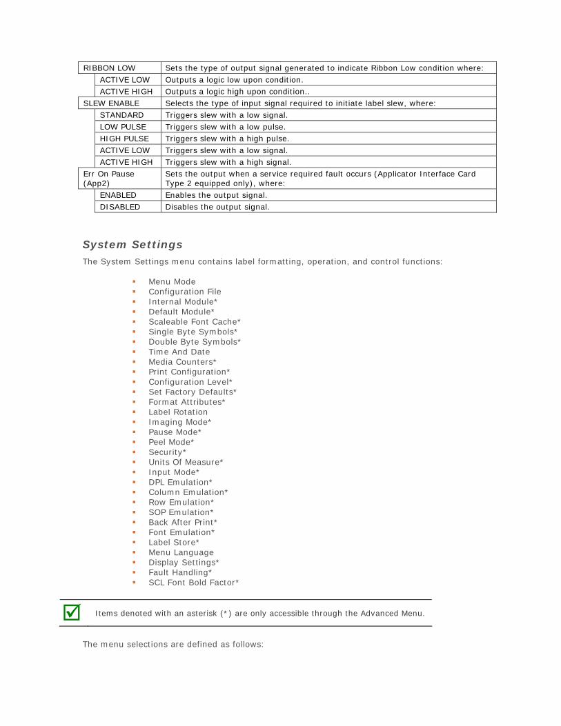
RIBBON LOW Sets the type of output signal generated to indicate Ribbon Low condition where: ACTIVE LOW Outputs a logic low upon condition. ACTIVE HIGH Outputs a logic high upon condition..
SLEW ENABLE Selects the type of input signal required to initiate label slew, where: STANDARD Triggers slew with a low signal. LOW PULSE Triggers slew with a low pulse. HIGH PULSE Triggers slew with a high pulse. ACTIVE LOW Triggers slew with a low signal. ACTIVE HIGH Triggers slew with a high signal.
Err On Pause (App2)
Sets the output when a service required fault occurs (Applicator Interface Card Type 2 equipped only), where:
ENABLED Enables the output signal. DISABLED Disables the output signal.
System Settings The System Settings menu contains label formatting, operation, and control functions:
Menu Mode Configuration File Internal Module* Default Module* Scaleable Font Cache* Single Byte Symbols* Double Byte Symbols* Time And Date Media Counters* Print Configuration* Configuration Level* Set Factory Defaults* Format Attributes* Label Rotation Imaging Mode* Pause Mode* Peel Mode* Security* Units Of Measure* Input Mode* DPL Emulation* Column Emulation* Row Emulation* SOP Emulation* Back After Print* Font Emulation* Label Store* Menu Language Display Settings* Fault Handling* SCL Font Bold Factor*
Items denoted with an asterisk (*) are only accessible through the Advanced Menu.
The menu selections are defined as follows:
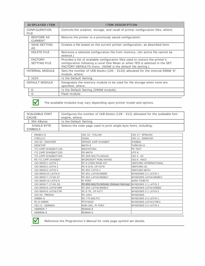
DISPLAYED ITEM ITEM DESCRIPTION
CONFIGURATION FILE
Controls the creation, storage, and recall of printer configuration files, where:
RESTORE AS CURRENT
Returns the printer to a previously saved configuration.
SAVE SETTING AS
Creates a file based on the current printer configuration, as described here.
DELETE FILE Removes a selected configuration file from memory. (An active file cannot be deleted.)
FACTORY SETTING FILE
Provides a list of available configuration files used to restore the printer's configuration following a Level One Reset or when YES is selected in the SET FACTORY DEFAULTS menu. (NONE is the default file setting.)
INTERNAL MODULE Sets the number of 1KB blocks (100 - 5120) allocated for the internal DRAM ‘D’ module, where:
1024 Is the Default Setting. DEFAULT MODULE Designates the memory module to be used for file storage when none are
specified, where: D Is the Default Setting (DRAM module). G Flash module.
The available modules may vary depending upon printer model and options.
SCALEABLE FONT CACHE
Configures the number of 1KB blocks (128 - 512) allocated for the scaleable font engine, where:
384 KBytes Is the Default Setting. SINGLE BYTE
SYMBOLS Selects the code page used to print single byte fonts, including:
ARABIC-8 ISO 15: ITALIAN ISO 17: SPANISH CYRILLIC LEGAL ISO 11: SWEDISH ISO 60: DAN/NOR HP4000 ZAPF DINGBAT SYMBOL DESKTOP MATH-8 TURKISH-8ITC ZAPF DINGBAT/100 MACINTOSH PS TEXT ITC ZAPF DINGBAT/200 PS-MATH UTF-8 ITC ZAPF DINGBAT/300 PC-858 MULTILINGUAL ISO 4: UK PS ITC ZAPF DINGBAT MICROSOFT PUBLISHING ISO 6: ASCII ISO 8859/1 LATIN 1 PC-8 CODE PAGE 437 VENTURA INTERNATIONAL ISO 8859/2 LATIN 2 PC-8 D/N, CP 437N VENTURA US ISO 8859/5 LATIN 5 PC-852 LATIN 2 VENTURA MATH ISO 8859/10 LATIN 6 PC-851 LATIN/GREEK WINDOWS 3.1 LATIN 1 ISO 8859/7 LT/GK E7 PC-862 LATIN/ARABIC WINDOWS LATIN/ARABIC ISO 8859/15 LATIN 9 PI FONT AGFA TIDBITS ISO 8859/7 LT/GK EG PC-850 MULTILINGUAL (Default Setting) WINDOWS 3.1 LATIN 2 ISO 8859/8 LATIN/HBR PC-864 LATIN/ARABIC WINDOWS LATIN/GREEK ISO 8859/8 LATIN/CYR PC-8 TK, CP 437T WINDOWS 3.1 LATIN 5 ISO 69: FRENCH PC-1004 WINDOWS GREEK-8 PC-775 BALTIC WINDOWS 3.0 LATIN 1 PC-8 GREEK PTXT3000 WINDOWS LATIN/CYRIC ISO 21: GERMAN NON-UGL, PI FONT WINDOWS 3.0 LATIN 5 HEBREW-7 ROMAN-8HEBREW-8 ROMAN-9
Reference the Programmer’s Manual for code page symbol set details.
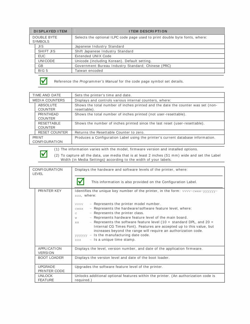
DISPLAYED ITEM ITEM DESCRIPTION
DOUBLE BYTE SYMBOLS
Selects the optional ILPC code page used to print double byte fonts, where:
JIS Japanese Industry Standard SHIFT JIS Shift Japanese Industry Standard EUC Extended UNIX Code UNICODE Unicode (including Korean). Default setting. GB Government Bureau Industry Standard; Chinese (PRC) BIG 5 Taiwan encoded
Reference the Programmer’s Manual for the code page symbol set details.
TIME AND DATE Sets the printer's time and date. MEDIA COUNTERS Displays and controls various internal counters, where:
ABSOLUTE COUNTER
Shows the total number of inches printed and the date the counter was set (non-resettable).
PRINTHEAD COUNTER
Shows the total number of inches printed (not user-resettable).
RESETTABLE COUNTER
Shows the number of inches printed since the last reset (user-resettable).
RESET COUNTER Returns the Resettable Counter to zero. PRINT CONFIGURATION
Produces a Configuration Label using the printer's current database information.
(1) The information varies with the model, firmware version and installed options.
(2) To capture all the data, use media that is at least 2 inches (51 mm) wide and set the Label Width (in Media Settings) according to the width of your labels.
CONFIGURATION LEVEL
Displays the hardware and software levels of the printer, where:
This information is also provided on the Configuration Label.
PRINTER KEY Identifies the unique key number of the printer, in the form: vvvv-cwxx-yyyyyy-zzz, where:
vvvv - Represents the printer model number. cwxx - Represents the hardware/software feature level, where: c - Represents the printer class. w - Represents hardware feature level of the main board. xx - Represents the software feature level (10 = standard DPL, and 20 =
Internal CG Times Font). Features are accepted up to this value, but increases beyond the range will require an authorization code.
yyyyyy - Is the manufacturing date code. zzz - Is a unique time stamp.
APPLICATION VERSION
Displays the level, version number, and date of the application firmware.
BOOT LOADER Displays the version level and date of the boot loader.
UPGRADE PRINTER CODE
Upgrades the software feature level of the printer.
UNLOCK FEATURE
Unlocks additional optional features within the printer. (An authorization code is required.)
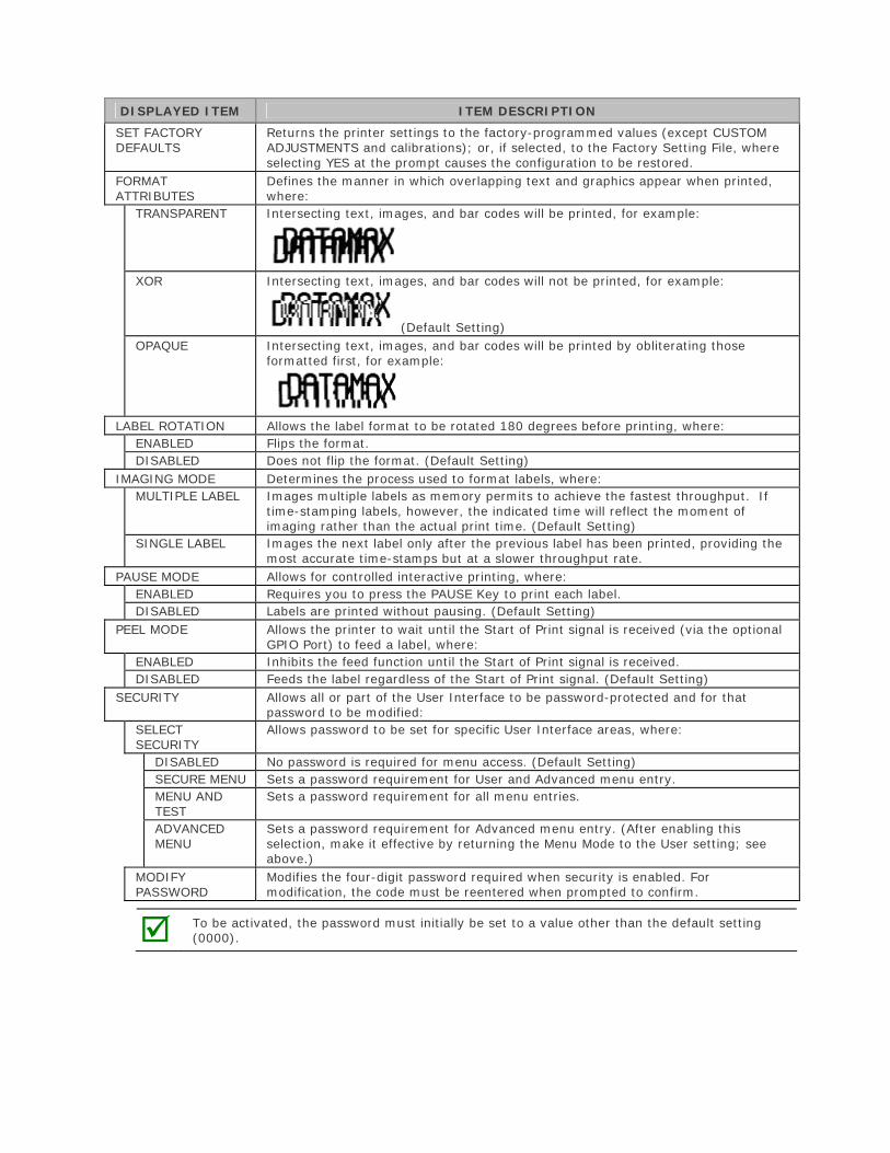
DISPLAYED ITEM ITEM DESCRIPTION
SET FACTORY DEFAULTS
Returns the printer settings to the factory-programmed values (except CUSTOM ADJUSTMENTS and calibrations); or, if selected, to the Factory Setting File, where selecting YES at the prompt causes the configuration to be restored.
FORMAT ATTRIBUTES
Defines the manner in which overlapping text and graphics appear when printed, where:
TRANSPARENT Intersecting text, images, and bar codes will be printed, for example:
XOR Intersecting text, images, and bar codes will not be printed, for example:
(Default Setting) OPAQUE Intersecting text, images, and bar codes will be printed by obliterating those
formatted first, for example:
LABEL ROTATION Allows the label format to be rotated 180 degrees before printing, where: ENABLED Flips the format.DISABLED Does not flip the format. (Default Setting)
IMAGING MODE Determines the process used to format labels, where: MULTIPLE LABEL Images multiple labels as memory permits to achieve the fastest throughput. If
time-stamping labels, however, the indicated time will reflect the moment of imaging rather than the actual print time. (Default Setting)
SINGLE LABEL Images the next label only after the previous label has been printed, providing the most accurate time-stamps but at a slower throughput rate.
PAUSE MODE Allows for controlled interactive printing, where: ENABLED Requires you to press the PAUSE Key to print each label. DISABLED Labels are printed without pausing. (Default Setting)
PEEL MODE Allows the printer to wait until the Start of Print signal is received (via the optional GPIO Port) to feed a label, where:
ENABLED Inhibits the feed function until the Start of Print signal is received. DISABLED Feeds the label regardless of the Start of Print signal. (Default Setting)
SECURITY Allows all or part of the User Interface to be password-protected and for that password to be modified:
SELECT SECURITY
Allows password to be set for specific User Interface areas, where:
DISABLED No password is required for menu access. (Default Setting) SECURE MENU Sets a password requirement for User and Advanced menu entry. MENU AND TEST
Sets a password requirement for all menu entries.
ADVANCED MENU
Sets a password requirement for Advanced menu entry. (After enabling this selection, make it effective by returning the Menu Mode to the User setting; see above.)
MODIFY PASSWORD
Modifies the four-digit password required when security is enabled. For modification, the code must be reentered when prompted to confirm.
To be activated, the password must initially be set to a value other than the default setting (0000).
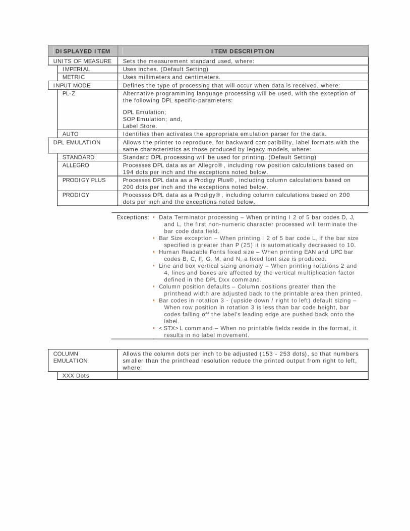
DISPLAYED ITEM ITEM DESCRIPTION
UNITS OF MEASURE Sets the measurement standard used, where: IMPERIAL Uses inches. (Default Setting) METRIC Uses millimeters and centimeters.
INPUT MODE Defines the type of processing that will occur when data is received, where: PL-Z Alternative programming language processing will be used, with the exception of
the following DPL specific-parameters:
DPL Emulation; SOP Emulation; and, Label Store.
AUTO Identifies then activates the appropriate emulation parser for the data. DPL EMULATION Allows the printer to reproduce, for backward compatibility, label formats with the
same characteristics as those produced by legacy models, where: STANDARD Standard DPL processing will be used for printing. (Default Setting) ALLEGRO Processes DPL data as an Allegro®, including row position calculations based on
194 dots per inch and the exceptions noted below. PRODIGY PLUS Processes DPL data as a Prodigy Plus®, including column calculations based on
200 dots per inch and the exceptions noted below. PRODIGY Processes DPL data as a Prodigy®, including column calculations based on 200
dots per inch and the exceptions noted below.
Exceptions: Data Terminator processing – When printing I 2 of 5 bar codes D, J, and L, the first non-numeric character processed will terminate the bar code data field.
Bar Size exception – When printing I 2 of 5 bar code L, if the bar sizespecified is greater than P (25) it is automatically decreased to 10.
Human Readable Fonts fixed size – When printing EAN and UPC barcodes B, C, F, G, M, and N, a fixed font size is produced.
Line and box vertical sizing anomaly – When printing rotations 2 and4, lines and boxes are affected by the vertical multiplication factor defined in the DPL Dxx command.
Column position defaults – Column positions greater than theprinthead width are adjusted back to the printable area then printed.
Bar codes in rotation 3 - (upside down / right to left) default sizing –When row position in rotation 3 is less than bar code height, bar codes falling off the label's leading edge are pushed back onto the label.
<STX>L command – When no printable fields reside in the format, itresults in no label movement.
COLUMN EMULATION
Allows the column dots per inch to be adjusted (153 - 253 dots), so that numbers smaller than the printhead resolution reduce the printed output from right to left, where:
XXX Dots
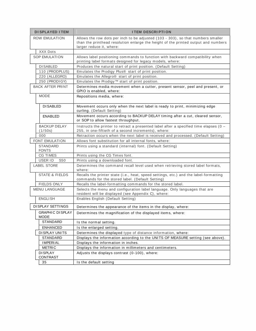
DISPLAYED ITEM ITEM DESCRIPTION
ROW EMULATION Allows the row dots per inch to be adjusted (103 - 303), so that numbers smaller than the printhead resolution enlarge the height of the printed output and numbers larger reduce it, where:
XXX Dots SOP EMULATION Allows label positioning commands to function with backward compatibility when
printing label formats designed for legacy models, where: DISABLED Produces the natural start of print position. (Default Setting) 110 (PRODPLUS) Emulates the Prodigy Plus® start of print position. 220 (ALLEGRO) Emulates the Allegro® start of print position. 250 (PRODIGY) Emulates the Prodigy™ start of print position.
BACK AFTER PRINT Determines media movement when a cutter, present sensor, peel and present, or GPIO is enabled, where:
MODE Repositions media, where:
DISABLED Movement occurs only when the next label is ready to print, minimizing edge curling. (Default Setting)
ENABLED Movement occurs according to BACKUP DELAY timing after a cut, cleared sensor, or SOP to allow fastest throughput.
BACKUP DELAY (1/50s)
Instructs the printer to retract a presented label after a specified time elapses (0 – 255, in one-fiftieth of a second increments), where:
000 Retraction occurs when the next label is received and processed. (Default Setting) FONT EMULATION Allows font substitution for all internal fonts, where:
STANDARD FONTS
Prints using a standard (internal) font. (Default Setting)
CG TIMES Prints using the CG Times font. USER ID S50 Prints using a downloaded font.
LABEL STORE Determines the command recall level used when retrieving stored label formats, where:
STATE & FIELDS Recalls the printer state (i.e., heat, speed settings, etc.) and the label-formatting commands for the stored label. (Default Setting)
FIELDS ONLY Recalls the label-formatting commands for the stored label. MENU LANGUAGE Selects the menu and configuration label language. Only languages that are
resident will be displayed (see Appendix C), where: ENGLISH Enables English (Default Setting)
DISPLAY SETTINGS Determines the appearance of the items in the display, where:
GRAPHIC DISPLAY MODE
Determines the magnification of the displayed items, where:
STANDARD Is the normal setting. ENHANCED Is the enlarged setting.
DISPLAY UNITS Determines the displayed type of distance information, where: STANDARD Displays the information according to the UNITS OF MEASURE setting (see above). IMPERIAL Displays the information in inches. METRIC Displays the information in millimeters and centimeters.
DISPLAY CONTRAST
Adjusts the displays contrast (0-100), where:
35 Is the default setting
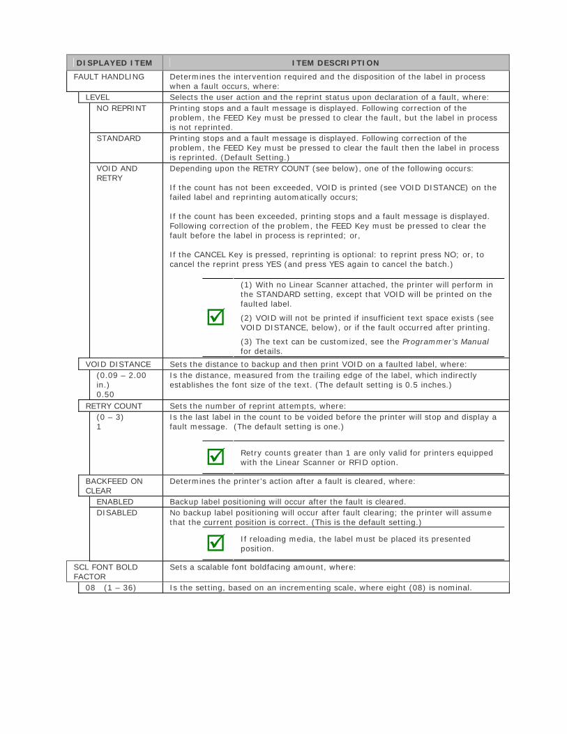
DISPLAYED ITEM ITEM DESCRIPTION
FAULT HANDLING Determines the intervention required and the disposition of the label in process when a fault occurs, where:
LEVEL Selects the user action and the reprint status upon declaration of a fault, where: NO REPRINT Printing stops and a fault message is displayed. Following correction of the
problem, the FEED Key must be pressed to clear the fault, but the label in process is not reprinted.
STANDARD Printing stops and a fault message is displayed. Following correction of the problem, the FEED Key must be pressed to clear the fault then the label in process is reprinted. (Default Setting.)
VOID AND RETRY
Depending upon the RETRY COUNT (see below), one of the following occurs:
If the count has not been exceeded, VOID is printed (see VOID DISTANCE) on the failed label and reprinting automatically occurs;
If the count has been exceeded, printing stops and a fault message is displayed. Following correction of the problem, the FEED Key must be pressed to clear the fault before the label in process is reprinted; or,
If the CANCEL Key is pressed, reprinting is optional: to reprint press NO; or, to cancel the reprint press YES (and press YES again to cancel the batch.)
(1) With no Linear Scanner attached, the printer will perform in the STANDARD setting, except that VOID will be printed on the faulted label.
(2) VOID will not be printed if insufficient text space exists (see VOID DISTANCE, below), or if the fault occurred after printing.
(3) The text can be customized, see the Programmer’s Manual for details.
VOID DISTANCE Sets the distance to backup and then print VOID on a faulted label, where: (0.09 – 2.00 in.) 0.50
Is the distance, measured from the trailing edge of the label, which indirectly establishes the font size of the text. (The default setting is 0.5 inches.)
RETRY COUNT Sets the number of reprint attempts, where: (0 – 3) 1
Is the last label in the count to be voided before the printer will stop and display a fault message. (The default setting is one.)
Retry counts greater than 1 are only valid for printers equipped with the Linear Scanner or RFID option.
BACKFEED ON CLEAR
Determines the printer's action after a fault is cleared, where:
ENABLED Backup label positioning will occur after the fault is cleared. DISABLED No backup label positioning will occur after fault clearing; the printer will assume
that the current position is correct. (This is the default setting.)
If reloading media, the label must be placed its presented position.
SCL FONT BOLD FACTOR
Sets a scalable font boldfacing amount, where:
08 (1 – 36) Is the setting, based on an incrementing scale, where eight (08) is nominal.
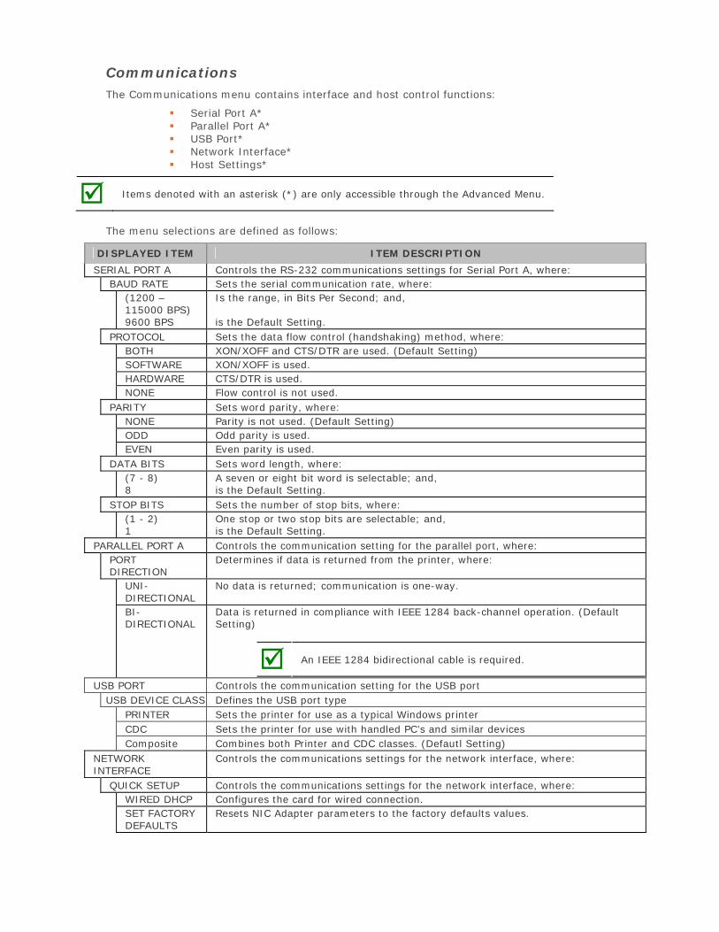
Communications The Communications menu contains interface and host control functions:
Serial Port A* Parallel Port A* USB Port* Network Interface* Host Settings*
Items denoted with an asterisk (*) are only accessible through the Advanced Menu.
The menu selections are defined as follows:
DISPLAYED ITEM ITEM DESCRIPTION
SERIAL PORT A Controls the RS-232 communications settings for Serial Port A, where: BAUD RATE Sets the serial communication rate, where:
(1200 – 115000 BPS) 9600 BPS
Is the range, in Bits Per Second; and,
is the Default Setting. PROTOCOL Sets the data flow control (handshaking) method, where:
BOTH XON/XOFF and CTS/DTR are used. (Default Setting) SOFTWARE XON/XOFF is used. HARDWARE CTS/DTR is used. NONE Flow control is not used.
PARITY Sets word parity, where: NONE Parity is not used. (Default Setting) ODD Odd parity is used. EVEN Even parity is used.
DATA BITS Sets word length, where: (7 - 8) 8
A seven or eight bit word is selectable; and, is the Default Setting.
STOP BITS Sets the number of stop bits, where: (1 - 2) 1
One stop or two stop bits are selectable; and, is the Default Setting.
PARALLEL PORT A Controls the communication setting for the parallel port, where: PORT DIRECTION
Determines if data is returned from the printer, where:
UNI-DIRECTIONAL
No data is returned; communication is one-way.
BI-DIRECTIONAL
Data is returned in compliance with IEEE 1284 back-channel operation. (Default Setting)
An IEEE 1284 bidirectional cable is required.
USB PORT Controls the communication setting for the USB port USB DEVICE CLASS Defines the USB port type
PRINTER Sets the printer for use as a typical Windows printer CDC Sets the printer for use with handled PC’s and similar devices Composite Combines both Printer and CDC classes. (Defautl Setting)
NETWORK INTERFACE
Controls the communications settings for the network interface, where:
QUICK SETUP Controls the communications settings for the network interface, where: WIRED DHCP Configures the card for wired connection. SET FACTORY DEFAULTS
Resets NIC Adapter parameters to the factory defaults values.
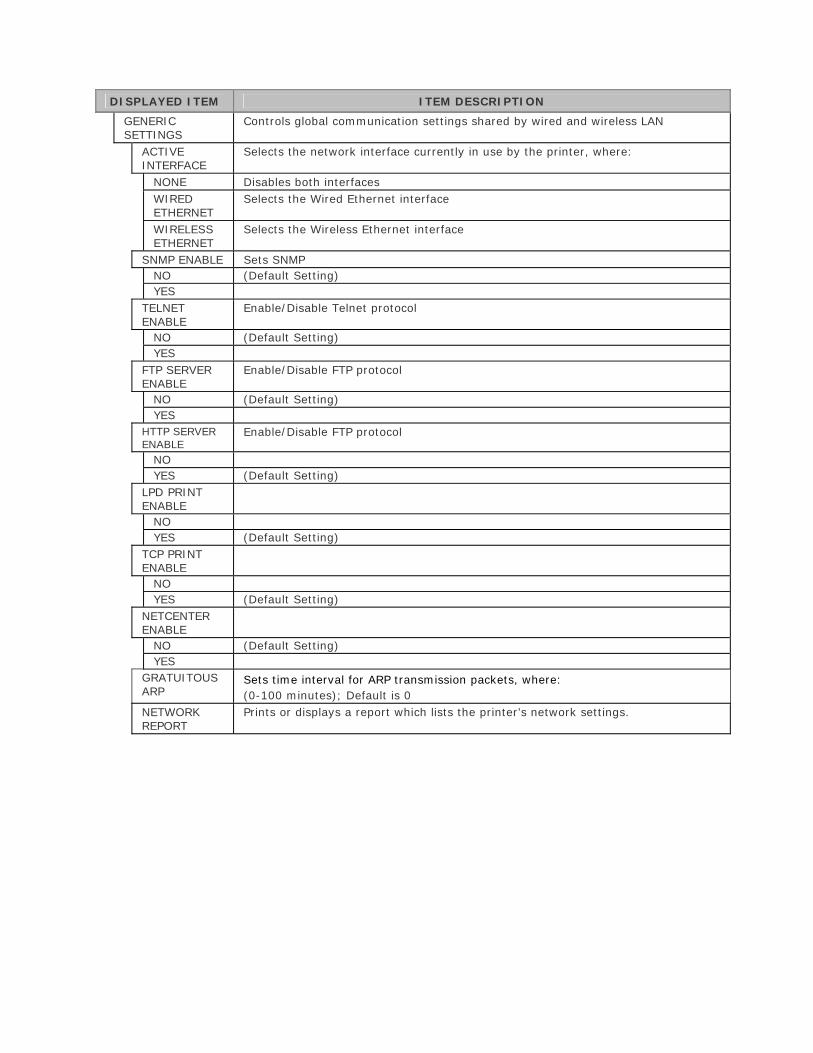
DISPLAYED ITEM ITEM DESCRIPTION
GENERIC SETTINGS
Controls global communication settings shared by wired and wireless LAN
ACTIVE INTERFACE
Selects the network interface currently in use by the printer, where:
NONE Disables both interfacesWIRED ETHERNET
Selects the Wired Ethernet interface
WIRELESS ETHERNET
Selects the Wireless Ethernet interface
SNMP ENABLE Sets SNMP NO (Default Setting)YES
TELNET ENABLE
Enable/Disable Telnet protocol
NO (Default Setting)YES
FTP SERVER ENABLE
Enable/Disable FTP protocol
NO (Default Setting)YES
HTTP SERVER ENABLE
Enable/Disable FTP protocol
NOYES (Default Setting)
LPD PRINT ENABLE
NOYES (Default Setting)
TCP PRINT ENABLE
NOYES (Default Setting)
NETCENTER ENABLE
NO (Default Setting)YES
GRATUITOUS ARP
Sets time interval for ARP transmission packets, where: (0-100 minutes); Default is 0
NETWORK REPORT
Prints or displays a report which lists the printer’s network settings.
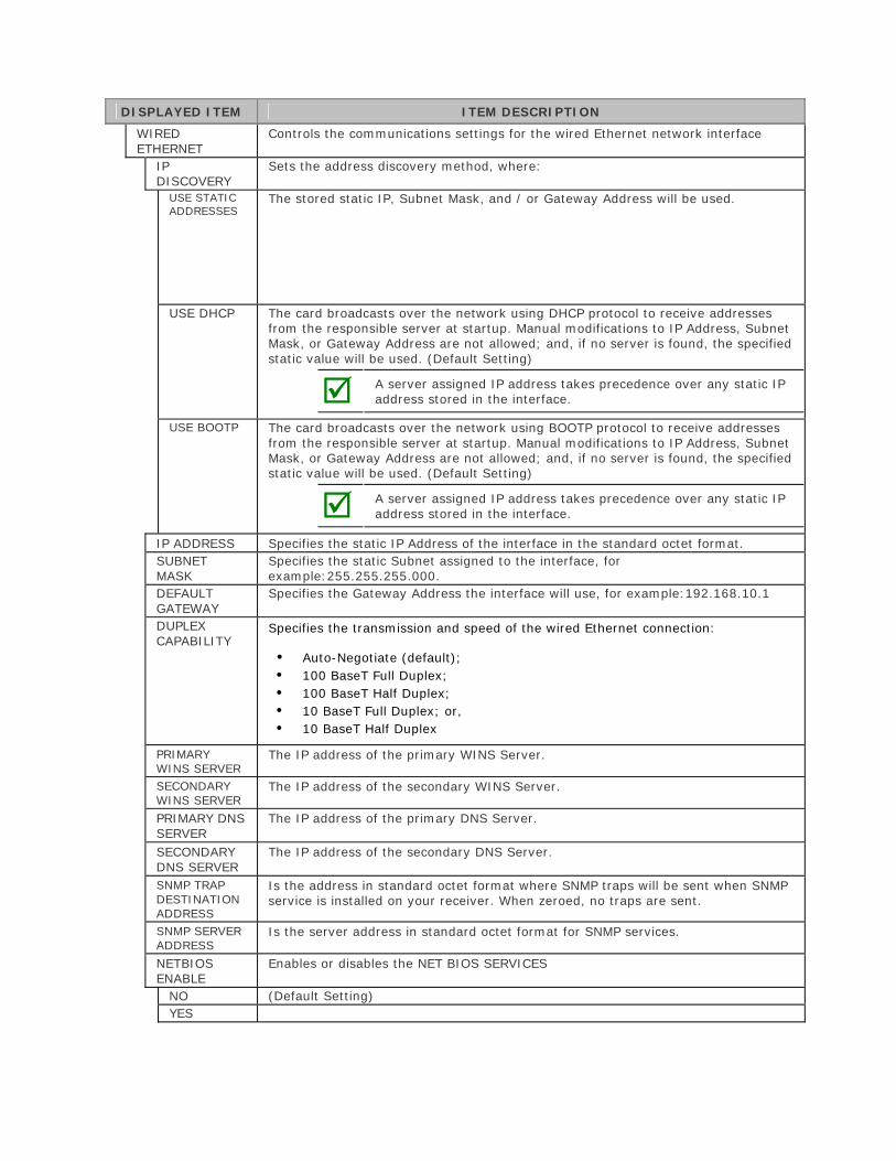
DISPLAYED ITEM ITEM DESCRIPTION
WIRED ETHERNET
Controls the communications settings for the wired Ethernet network interface
IP DISCOVERY
Sets the address discovery method, where:
USE STATIC ADDRESSES
The stored static IP, Subnet Mask, and / or Gateway Address will be used.
USE DHCP The card broadcasts over the network using DHCP protocol to receive addresses from the responsible server at startup. Manual modifications to IP Address, Subnet Mask, or Gateway Address are not allowed; and, if no server is found, the specified static value will be used. (Default Setting)
A server assigned IP address takes precedence over any static IP address stored in the interface.
USE BOOTP The card broadcasts over the network using BOOTP protocol to receive addresses from the responsible server at startup. Manual modifications to IP Address, Subnet Mask, or Gateway Address are not allowed; and, if no server is found, the specified static value will be used. (Default Setting)
A server assigned IP address takes precedence over any static IP address stored in the interface.
IP ADDRESS Specifies the static IP Address of the interface in the standard octet format. SUBNET MASK
Specifies the static Subnet assigned to the interface, for example:255.255.255.000.
DEFAULT GATEWAY
Specifies the Gateway Address the interface will use, for example:192.168.10.1
DUPLEX CAPABILITY
Specifies the transmission and speed of the wired Ethernet connection:
• Auto-Negotiate (default);• 100 BaseT Full Duplex;• 100 BaseT Half Duplex;• 10 BaseT Full Duplex; or,• 10 BaseT Half Duplex
PRIMARY WINS SERVER
The IP address of the primary WINS Server.
SECONDARY WINS SERVER
The IP address of the secondary WINS Server.
PRIMARY DNS SERVER
The IP address of the primary DNS Server.
SECONDARY DNS SERVER
The IP address of the secondary DNS Server.
SNMP TRAP DESTINATION ADDRESS
Is the address in standard octet format where SNMP traps will be sent when SNMP service is installed on your receiver. When zeroed, no traps are sent.
SNMP SERVER ADDRESS
Is the server address in standard octet format for SNMP services.
NETBIOS ENABLE
Enables or disables the NET BIOS SERVICES
NO (Default Setting)YES
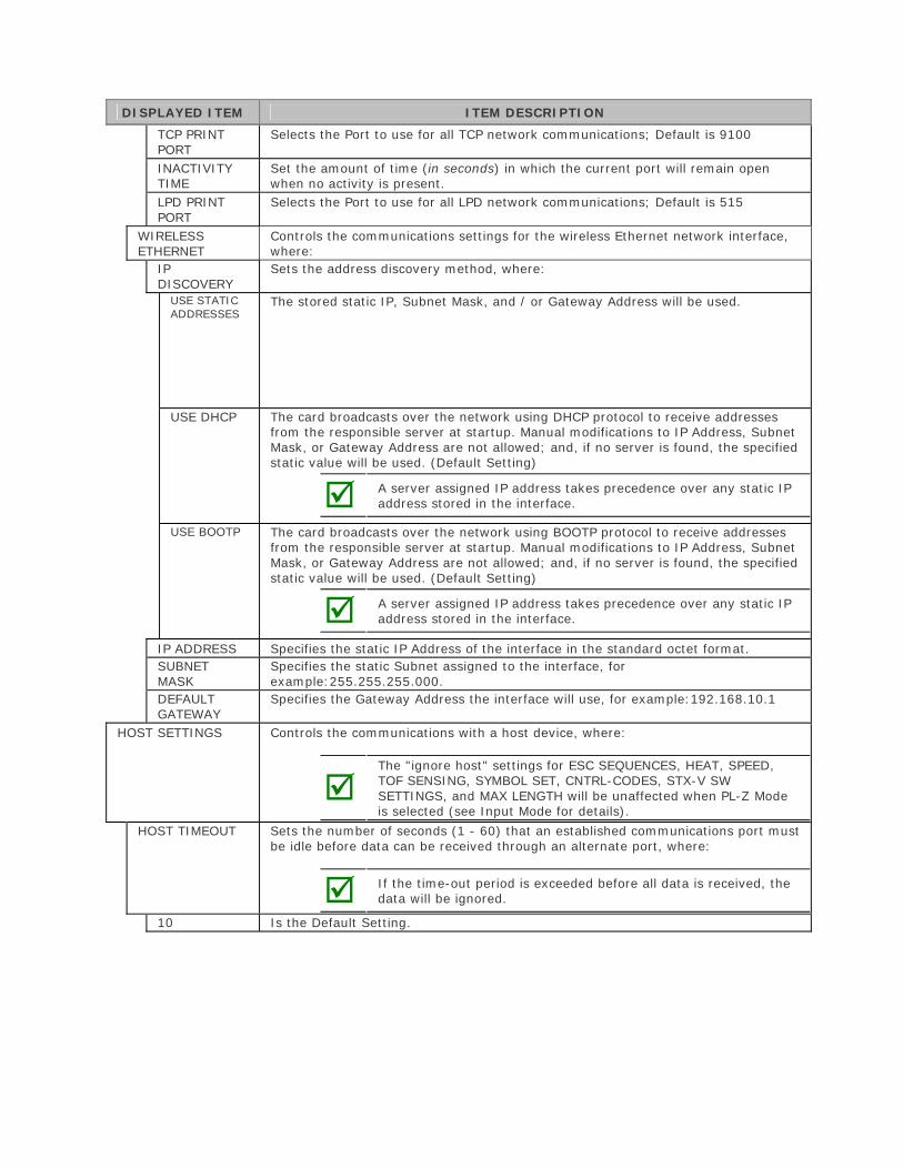
DISPLAYED ITEM ITEM DESCRIPTION
TCP PRINT PORT
Selects the Port to use for all TCP network communications; Default is 9100
INACTIVITY TIME
Set the amount of time (in seconds) in which the current port will remain open when no activity is present.
LPD PRINT PORT
Selects the Port to use for all LPD network communications; Default is 515
WIRELESS ETHERNET
Controls the communications settings for the wireless Ethernet network interface, where:
IP DISCOVERY
Sets the address discovery method, where:
USE STATIC ADDRESSES
The stored static IP, Subnet Mask, and / or Gateway Address will be used.
USE DHCP The card broadcasts over the network using DHCP protocol to receive addresses from the responsible server at startup. Manual modifications to IP Address, Subnet Mask, or Gateway Address are not allowed; and, if no server is found, the specified static value will be used. (Default Setting)
A server assigned IP address takes precedence over any static IP address stored in the interface.
USE BOOTP The card broadcasts over the network using BOOTP protocol to receive addresses from the responsible server at startup. Manual modifications to IP Address, Subnet Mask, or Gateway Address are not allowed; and, if no server is found, the specified static value will be used. (Default Setting)
A server assigned IP address takes precedence over any static IP address stored in the interface.
IP ADDRESS Specifies the static IP Address of the interface in the standard octet format. SUBNET MASK
Specifies the static Subnet assigned to the interface, for example:255.255.255.000.
DEFAULT GATEWAY
Specifies the Gateway Address the interface will use, for example:192.168.10.1
HOST SETTINGS Controls the communications with a host device, where:
The "ignore host" settings for ESC SEQUENCES, HEAT, SPEED, TOF SENSING, SYMBOL SET, CNTRL-CODES, STX-V SW SETTINGS, and MAX LENGTH will be unaffected when PL-Z Mode is selected (see Input Mode for details).
HOST TIMEOUT Sets the number of seconds (1 - 60) that an established communications port must be idle before data can be received through an alternate port, where:
If the time-out period is exceeded before all data is received, the data will be ignored.
10 Is the Default Setting.
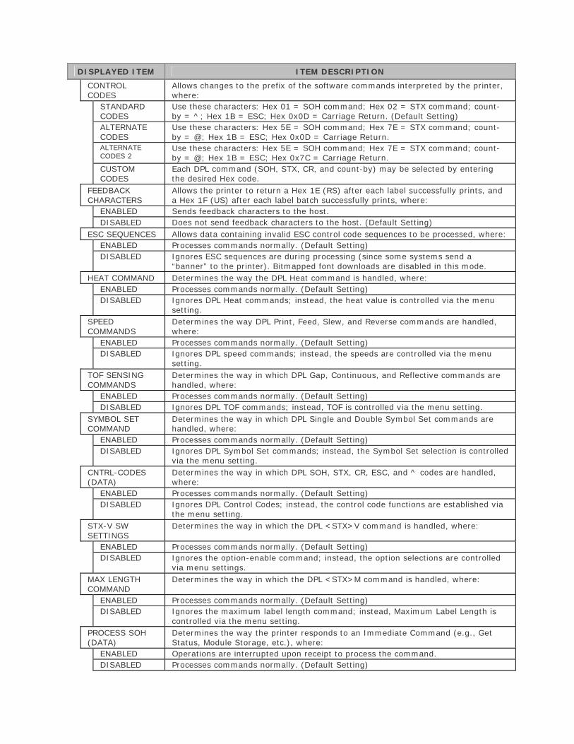
DISPLAYED ITEM ITEM DESCRIPTION
CONTROL CODES
Allows changes to the prefix of the software commands interpreted by the printer, where:
STANDARD CODES
Use these characters: Hex 01 = SOH command; Hex 02 = STX command; count-by = ^; Hex 1B = ESC; Hex 0x0D = Carriage Return. (Default Setting)
ALTERNATE CODES
Use these characters: Hex 5E = SOH command; Hex 7E = STX command; count-by = @; Hex 1B = ESC; Hex 0x0D = Carriage Return.
ALTERNATE CODES 2
Use these characters: Hex 5E = SOH command; Hex 7E = STX command; count-by = @; Hex 1B = ESC; Hex 0x7C = Carriage Return.
CUSTOM CODES
Each DPL command (SOH, STX, CR, and count-by) may be selected by entering the desired Hex code.
FEEDBACK CHARACTERS
Allows the printer to return a Hex 1E (RS) after each label successfully prints, and a Hex 1F (US) after each label batch successfully prints, where:
ENABLED Sends feedback characters to the host. DISABLED Does not send feedback characters to the host. (Default Setting)
ESC SEQUENCES Allows data containing invalid ESC control code sequences to be processed, where: ENABLED Processes commands normally. (Default Setting) DISABLED Ignores ESC sequences are during processing (since some systems send a
“banner” to the printer). Bitmapped font downloads are disabled in this mode. HEAT COMMAND Determines the way the DPL Heat command is handled, where:
ENABLED Processes commands normally. (Default Setting) DISABLED Ignores DPL Heat commands; instead, the heat value is controlled via the menu
setting. SPEED COMMANDS
Determines the way DPL Print, Feed, Slew, and Reverse commands are handled, where:
ENABLED Processes commands normally. (Default Setting) DISABLED Ignores DPL speed commands; instead, the speeds are controlled via the menu
setting. TOF SENSING COMMANDS
Determines the way in which DPL Gap, Continuous, and Reflective commands are handled, where:
ENABLED Processes commands normally. (Default Setting) DISABLED Ignores DPL TOF commands; instead, TOF is controlled via the menu setting.
SYMBOL SET COMMAND
Determines the way in which DPL Single and Double Symbol Set commands are handled, where:
ENABLED Processes commands normally. (Default Setting) DISABLED Ignores DPL Symbol Set commands; instead, the Symbol Set selection is controlled
via the menu setting. CNTRL-CODES (DATA)
Determines the way in which DPL SOH, STX, CR, ESC, and ^ codes are handled, where:
ENABLED Processes commands normally. (Default Setting) DISABLED Ignores DPL Control Codes; instead, the control code functions are established via
the menu setting. STX-V SW SETTINGS
Determines the way in which the DPL <STX>V command is handled, where:
ENABLED Processes commands normally. (Default Setting) DISABLED Ignores the option-enable command; instead, the option selections are controlled
via menu settings. MAX LENGTH COMMAND
Determines the way in which the DPL <STX>M command is handled, where:
ENABLED Processes commands normally. (Default Setting) DISABLED Ignores the maximum label length command; instead, Maximum Label Length is
controlled via the menu setting. PROCESS SOH (DATA)
Determines the way the printer responds to an Immediate Command (e.g., Get Status, Module Storage, etc.), where:
ENABLED Operations are interrupted upon receipt to process the command. DISABLED Processes commands normally. (Default Setting)
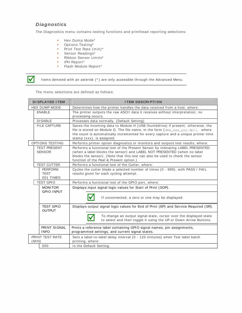
Diagnostics The Diagnostics menu contains testing functions and printhead reporting selections:
Hex Dump Mode* Options Testing* Print Test Rate (min)* Sensor Readings* Ribbon Sensor Limits* iPH Report* Flash Module Report*
Items denoted with an asterisk (*) are only accessible through the Advanced Menu.
The menu selections are defined as follows:
DISPLAYED ITEM ITEM DESCRIPTION
HEX DUMP MODE Determines how the printer handles the data received from a host, where: ENABLE The printer outputs the raw ASCII data it receives without interpretation; no
processing occurs. DISABLE Processes data normally. (Default Setting) FILE CAPTURE Saves the incoming data to Module H (USB thumbdrive) if present; otherwise, the
file is stored on Module G. The file name, in the form [dmx_xxx_yyy.dpl], where the count is automatically incremented for every capture and a unique printer time stamp (xxx), is assigned.
OPTIONS TESTING Performs printer option diagnostics or monitors and outputs test results, where: TEST PRESENT SENSOR
Performs a functional test of the Present Sensor by indicating LABEL PRESENTED (when a label blocks the sensor) and LABEL NOT PRESENTED (when no label blocks the sensor). (Note that this test can also be used to check the sensor function of the Peel & Present option.)
TEST CUTTER Performs a functional test of the Cutter, where: PERFORM TEST 001 TIMES
Cycles the cutter blade a selected number of times (0 - 999), with PASS / FAIL results given for each cycling attempt.
TEST GPIO Performs a functional test of the GPIO port, where: MONITOR GPIO INPUT
Displays input signal logic values for Start of Print (SOP).
If unconnected, a zero or one may be displayed.
TEST GPIO OUTPUT
Displays output signal logic values for End of Print (EP) and Service Required (SR).
To change an output signal state, cursor over the displayed state to select and then toggle it using the UP or Down Arrow Buttons.
PRINT SIGNAL INFO
Prints a reference label containing GPIO signal names, pin assignments, programmed settings, and current signal states.
PRINT TEST RATE (MIN)
Sets a label-to-label delay interval (0 - 120 minutes) when Test label batch printing, where:
000 Is the Default Setting.
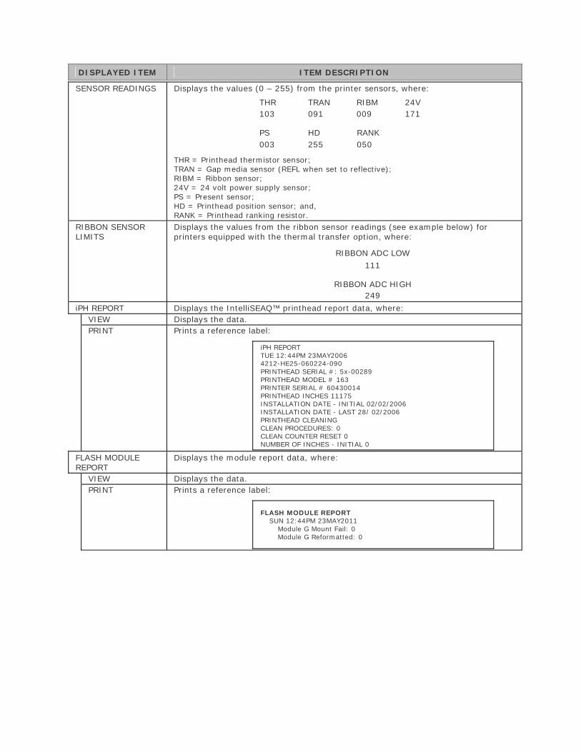
DISPLAYED ITEM ITEM DESCRIPTION
SENSOR READINGS Displays the values (0 – 255) from the printer sensors, where:
THR TRAN RIBM 24V103 091 009 171
PS HD RANK003 255 050
THR = Printhead thermistor sensor; TRAN = Gap media sensor (REFL when set to reflective); RIBM = Ribbon sensor; 24V = 24 volt power supply sensor; PS = Present sensor; HD = Printhead position sensor; and, RANK = Printhead ranking resistor.
RIBBON SENSOR LIMITS
Displays the values from the ribbon sensor readings (see example below) for printers equipped with the thermal transfer option, where:
RIBBON ADC LOW
111
RIBBON ADC HIGH 249
iPH REPORT Displays the IntelliSEAQ™ printhead report data, where: VIEW Displays the data.PRINT Prints a reference label:
iPH REPORT TUE 12:44PM 23MAY2006 4212-HE25-060224-090 PRINTHEAD SERIAL #: 5x-00289 PRINTHEAD MODEL # 163 PRINTER SERIAL # 60430014 PRINTHEAD INCHES 11175 INSTALLATION DATE - INITIAL 02/02/2006 INSTALLATION DATE - LAST 28/ 02/2006 PRINTHEAD CLEANING CLEAN PROCEDURES: 0 CLEAN COUNTER RESET 0 NUMBER OF INCHES - INITIAL 0
FLASH MODULE REPORT
Displays the module report data, where:
VIEW Displays the data.PRINT Prints a reference label:
FLASH MODULE REPORT SUN 12:44PM 23MAY2011
Module G Mount Fail: 0 Module G Reformatted: 0
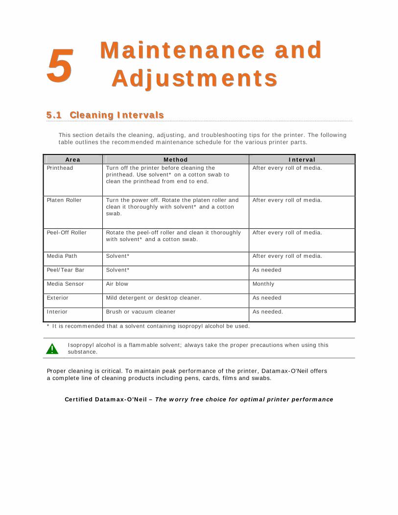
55 MMaaiinntteennaannccee aannddAAddjjuussttmmeennttss
55..11 CClleeaanniinngg IInntteerrvvaallss
This section details the cleaning, adjusting, and troubleshooting tips for the printer. The following table outlines the recommended maintenance schedule for the various printer parts.
Area Method Interval Printhead Turn off the printer before cleaning the
printhead. Use solvent* on a cotton swab to clean the printhead from end to end.
After every roll of media.
Platen Roller Turn the power off. Rotate the platen roller and clean it thoroughly with solvent* and a cotton swab.
After every roll of media.
Peel-Off Roller Rotate the peel-off roller and clean it thoroughly with solvent* and a cotton swab.
After every roll of media.
Media Path Solvent* After every roll of media.
Peel/Tear Bar Solvent* As needed
Media Sensor Air blow Monthly
Exterior Mild detergent or desktop cleaner. As needed
Interior Brush or vacuum cleaner As needed.
* It is recommended that a solvent containing isopropyl alcohol be used.
Isopropyl alcohol is a flammable solvent; always take the proper precautions when using this substance.
Proper cleaning is critical. To maintain peak performance of the printer, Datamax-O’Neil offers a complete line of cleaning products including pens, cards, films and swabs.
Certified Datamax-O’Neil – The worry free choice for optimal printer performance
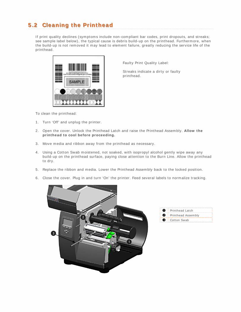
55..22 CClleeaanniinngg tthhee PPrriinntthheeaadd
If print quality declines (symptoms include non-compliant bar codes, print dropouts, and streaks; see sample label below), the typical cause is debris build-up on the printhead. Furthermore, when the build-up is not removed it may lead to element failure, greatly reducing the service life of the printhead.
Faulty Print Quality Label:
Streaks indicate a dirty or faulty printhead.
To clean the printhead:
1. Turn ‘Off’ and unplug the printer.
2. Open the cover. Unlock the Printhead Latch and raise the Printhead Assembly. Allow theprinthead to cool before proceeding.
3. Move media and ribbon away from the printhead as necessary.
4. Using a Cotton Swab moistened, not soaked, with isopropyl alcohol gently wipe away anybuild-up on the printhead surface, paying close attention to the Burn Line. Allow the printheadto dry.
5. Replace the ribbon and media. Lower the Printhead Assembly back to the locked position.
6. Close the cover. Plug in and turn ‘On’ the printer. Feed several labels to normalize tracking.
Printhead Latch
Printhead Assembly
Cotton Swab

Automated Printhead Cleaning
1. Remove media and ribbon.
2. Place a Datamax-O’Neil Cleaning Card, part number 70-2013-01 under the printhead. Lowerand lock the printhead. Ensure that the Media Width Adjustment is not engaged.
3. Press and hold the TEST Key for approximately four seconds.
The printer will begin the cleaning routine.
4. In cases of heavy build-up, or if high heat values are typically used for printing, flip the cardover and repeat Step 3.
5. Reinstall your ribbon and media (if necessary, readjust the Media Width Adjustment, seeSection 5.3). Lower and lock the printhead. Close the cover.
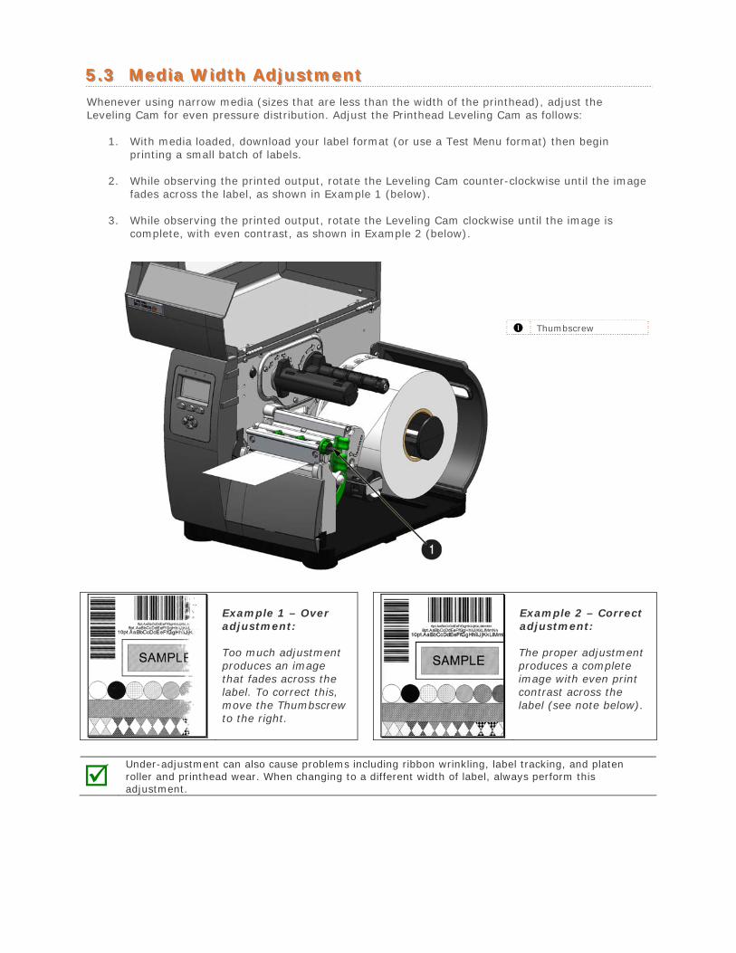
55..33 MMeeddiiaa WWiiddtthh AAddjjuussttmmeenntt Whenever using narrow media (sizes that are less than the width of the printhead), adjust the Leveling Cam for even pressure distribution. Adjust the Printhead Leveling Cam as follows:
1. With media loaded, download your label format (or use a Test Menu format) then beginprinting a small batch of labels.
2. While observing the printed output, rotate the Leveling Cam counter-clockwise until the imagefades across the label, as shown in Example 1 (below).
3. While observing the printed output, rotate the Leveling Cam clockwise until the image iscomplete, with even contrast, as shown in Example 2 (below).
Thumbscrew
Example 1 – Over adjustment:
Too much adjustment produces an image that fades across the label. To correct this, move the Thumbscrew to the right.
Example 2 – Correct adjustment:
The proper adjustment produces a complete image with even print contrast across the label (see note below).
Under-adjustment can also cause problems including ribbon wrinkling, label tracking, and platen roller and printhead wear. When changing to a different width of label, always perform this adjustment.
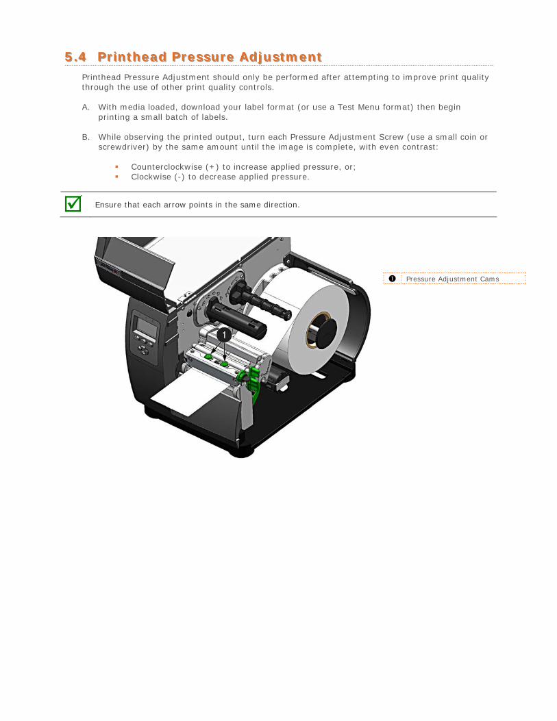
55..44 PPrriinntthheeaadd PPrreessssuurree AAddjjuussttmmeenntt Printhead Pressure Adjustment should only be performed after attempting to improve print quality through the use of other print quality controls.
A. With media loaded, download your label format (or use a Test Menu format) then begin printing a small batch of labels.
B. While observing the printed output, turn each Pressure Adjustment Screw (use a small coin or screwdriver) by the same amount until the image is complete, with even contrast:
Counterclockwise (+) to increase applied pressure, or; Clockwise (-) to decrease applied pressure.
Ensure that each arrow points in the same direction.
Pressure Adjustment Cams

55..55 PPrriinntthheeaadd RReeppllaacceemmeenntt To replace a damaged printhead, follow the procedure below.
Printheads are fragile; use extreme care when handling and never use a sharp object on the surface. If you have questions, contact a qualified technician or Datamax-O’Neil Technical Support before proceeding.
1. Touch a bare metal part of the printer’s frame to discharge any static electricity that may bepresent on your body.
2. Turn ‘Off’ and unplug the printer. Open the cover; if ribbon is installed, remove it.
3. With the printhead locked in the down position, loosen the Printhead Mounting Screw (it willremain in the assembly).
4. Unlatch the Printhead Assembly. While holding the Printhead, raise the assembly. Disconnectthe two cables and then remove the old Printhead.
5. While carefully holding the new Printhead, connect both cables.
6. Position the Printhead onto the Locating Pins in the Printhead Assembly and secure in placewith the Printhead Mounting Screw (do not over-tighten).
7. Clean the Printhead (see Section 5.2).
8. Reload ribbon (if removed), lower the printhead assembly, and rotate the printhead latchback, into the locked position.
Printhead Mounting Screw
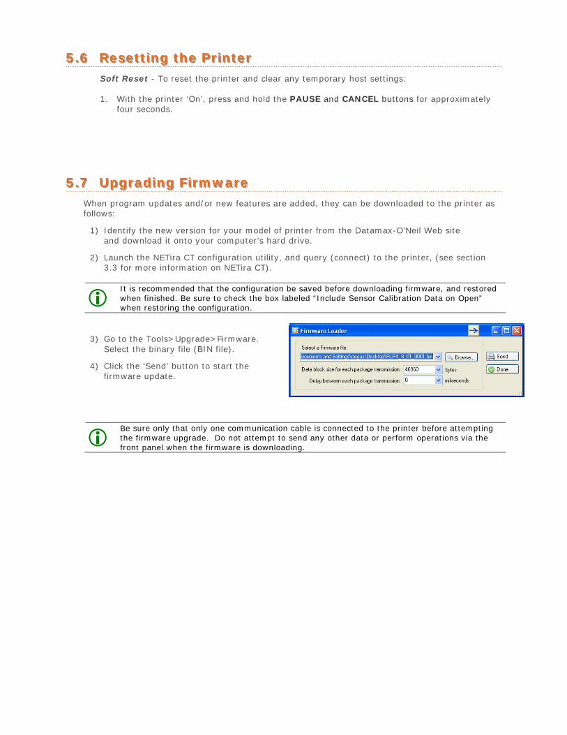
55..66 RReesseettttiinngg tthhee PPrriinntteerr Soft Reset - To reset the printer and clear any temporary host settings:
1. With the printer ‘On’, press and hold the PAUSE and CANCEL buttons for approximatelyfour seconds.
55..77 UUppggrraaddiinngg FFiirrmmwwaarree When program updates and/or new features are added, they can be downloaded to the printer as follows:
1) Identify the new version for your model of printer from the Datamax-O’Neil Web siteand download it onto your computer’s hard drive.
2) Launch the NETira CT configuration utility, and query (connect) to the printer, (see section3.3 for more information on NETira CT).
It is recommended that the configuration be saved before downloading firmware, and restored when finished. Be sure to check the box labeled “Include Sensor Calibration Data on Open” when restoring the configuration.
3) Go to the Tools>Upgrade>Firmware.Select the binary file (BIN file).
4) Click the ‘Send’ button to start thefirmware update.
Be sure only that only one communication cable is connected to the printer before attempting the firmware upgrade. Do not attempt to send any other data or perform operations via the front panel when the firmware is downloading.
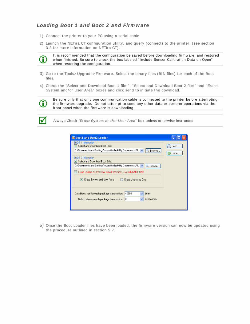
Loading Boot 1 and Boot 2 and Firmware
1) Connect the printer to your PC using a serial cable
2) Launch the NETira CT configuration utility, and query (connect) to the printer, (see section3.3 for more information on NETira CT).
It is recommended that the configuration be saved before downloading firmware, and restored when finished. Be sure to check the box labeled “Include Sensor Calibration Data on Open” when restoring the configuration.
3) Go to the Tools>Upgrade>Firmware. Select the binary files (BIN files) for each of the Bootfiles.
4) Check the “Select and Download Boot 1 file:”, “Select and Download Boot 2 file:” and “EraseSystem and/or User Area” boxes and click send to initiate the download.
Be sure only that only one communication cable is connected to the printer before attempting the firmware upgrade. Do not attempt to send any other data or perform operations via the front panel when the firmware is downloading.
Always Check “Erase System and/or User Area” box unless otherwise instructed.
5) Once the Boot Loader files have been loaded, the firmware version can now be updated usingthe procedure outlined in section 5.7.
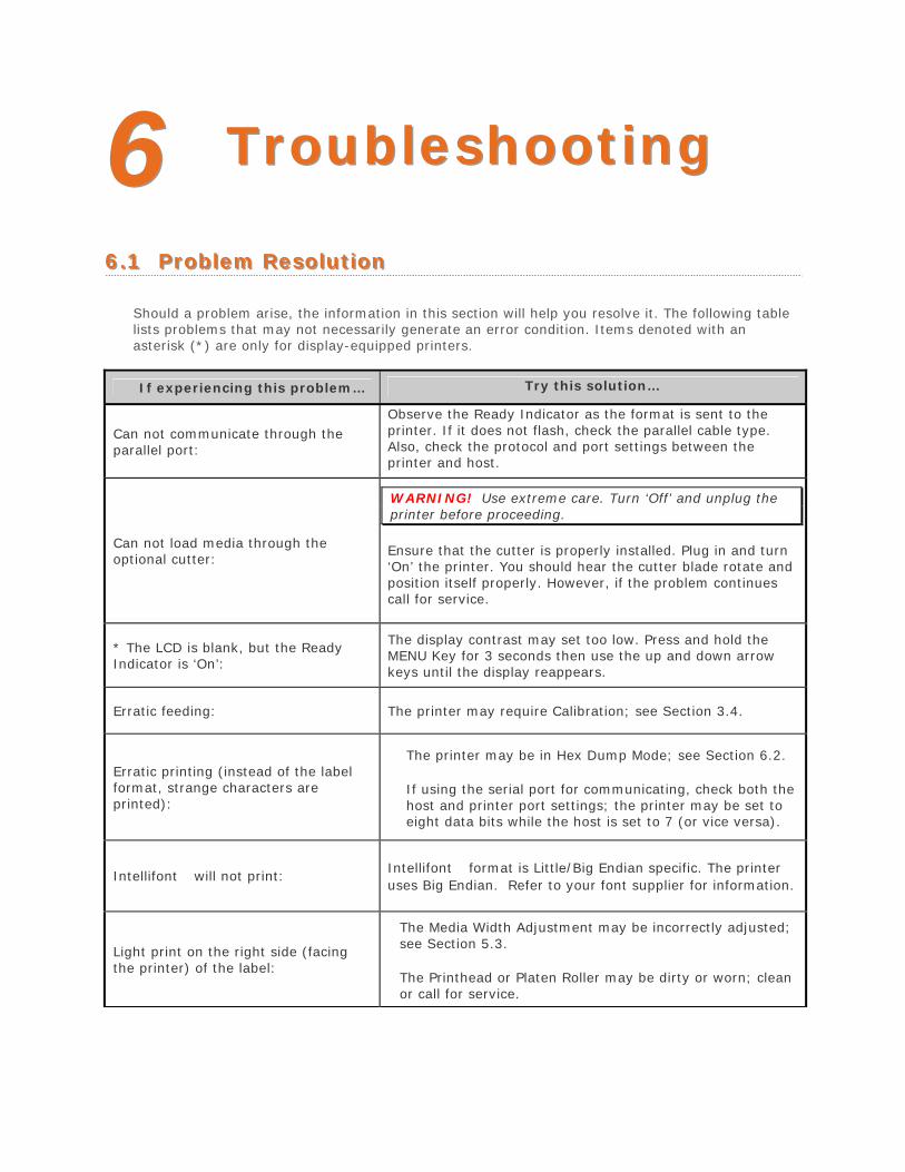
66 TTrroouubblleesshhoooottiinngg
66..11 PPrroobblleemm RReessoolluuttiioonn
Should a problem arise, the information in this section will help you resolve it. The following table lists problems that may not necessarily generate an error condition. Items denoted with an asterisk (*) are only for display-equipped printers.
If experiencing this problem… Try this solution…
Can not communicate through the parallel port:
Observe the Ready Indicator as the format is sent to the printer. If it does not flash, check the parallel cable type. Also, check the protocol and port settings between the printer and host.
Can not load media through the optional cutter:
WARNING! Use extreme care. Turn ‘Off’ and unplug the printer before proceeding.
Ensure that the cutter is properly installed. Plug in and turn ‘On’ the printer. You should hear the cutter blade rotate and position itself properly. However, if the problem continues call for service.
* The LCD is blank, but the ReadyIndicator is ‘On’:
The display contrast may set too low. Press and hold the MENU Key for 3 seconds then use the up and down arrow keys until the display reappears.
Erratic feeding: The printer may require Calibration; see Section 3.4.
Erratic printing (instead of the label format, strange characters are printed):
The printer may be in Hex Dump Mode; see Section 6.2.
If using the serial port for communicating, check both the host and printer port settings; the printer may be set to eight data bits while the host is set to 7 (or vice versa).
Intellifont will not print: Intellifont format is Little/Big Endian specific. The printer uses Big Endian. Refer to your font supplier for information.
Light print on the right side (facing the printer) of the label:
The Media Width Adjustment may be incorrectly adjusted; see Section 5.3.
The Printhead or Platen Roller may be dirty or worn; clean or call for service.
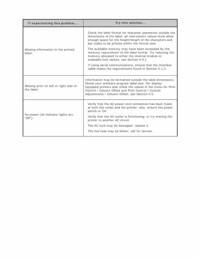
If experiencing this problem… Try this solution…
Missing information in the printed label:
Check the label format for character placement outside the dimensions of the label; all row/column values must allow enough space for the height/length of the characters and bar codes to be printed within the format size.
The available memory may have been exceeded by the memory requirement of the label format. Try reducing the memory allocated to either the internal module or scaleable font caches, see Section 4.5.)
If using serial communications, ensure that the interface cable meets the requirements found in Section 2.1.2.
Missing print on left or right side of the label:
Information may be formatted outside the label dimensions. Check your software program label size. For display-equipped printers also check the values in the menu for Print Control / Column Offset and Print Control / Custom Adjustments / Column Offset; see Section 4.5.
No power (all indicator lights are ‘Off”):
Verify that the AC power cord connection has been made at both the outlet and the printer; also, ensure the power switch is ‘On’.
Verify that the AC outlet is functioning, or try moving the printer to another AC circuit.
The AC cord may be damaged; replace it.
The line fuse may be blown; call for service.
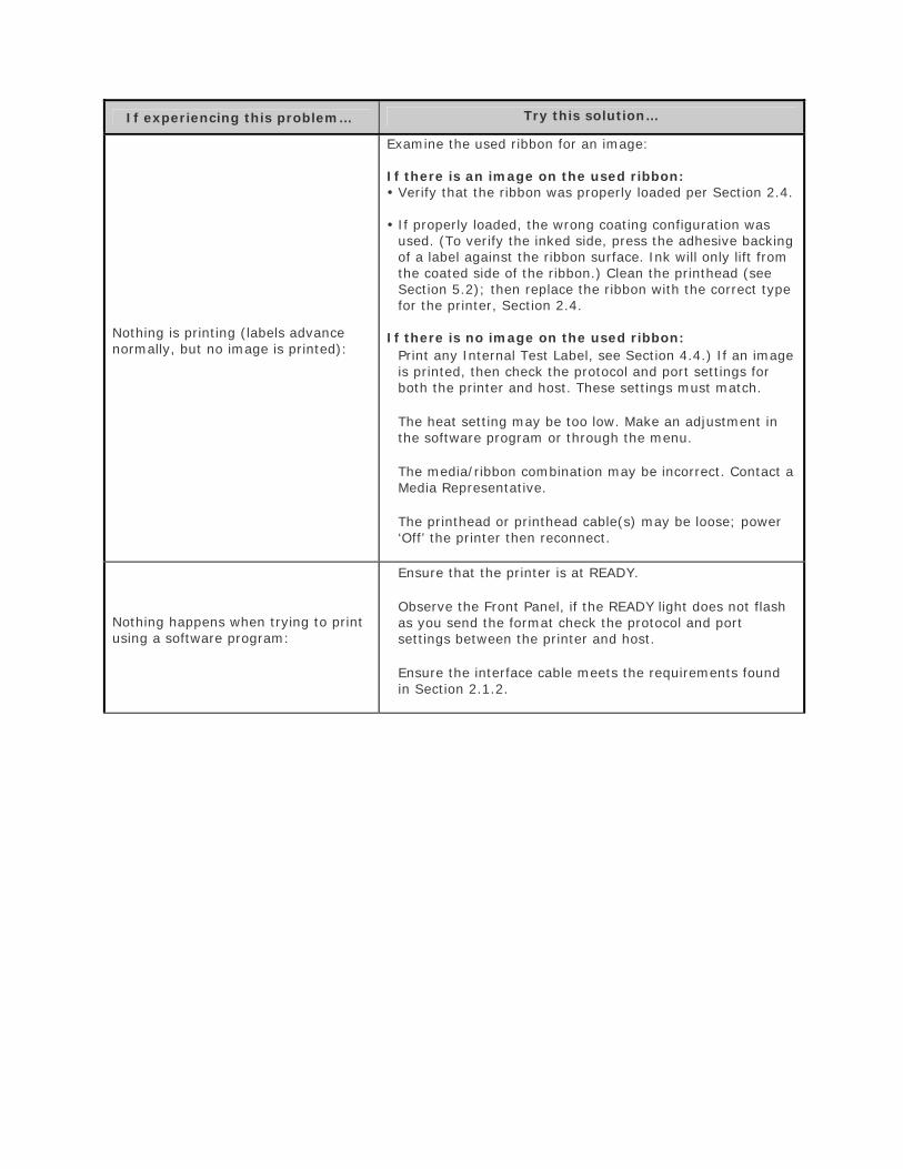
If experiencing this problem… Try this solution…
Nothing is printing (labels advance normally, but no image is printed):
Examine the used ribbon for an image:
If there is an image on the used ribbon: Verify that the ribbon was properly loaded per Section 2.4.
If properly loaded, the wrong coating configuration was used. (To verify the inked side, press the adhesive backing of a label against the ribbon surface. Ink will only lift from the coated side of the ribbon.) Clean the printhead (see Section 5.2); then replace the ribbon with the correct type for the printer, Section 2.4.
If there is no image on the used ribbon: Print any Internal Test Label, see Section 4.4.) If an image is printed, then check the protocol and port settings for both the printer and host. These settings must match.
The heat setting may be too low. Make an adjustment in the software program or through the menu.
The media/ribbon combination may be incorrect. Contact a Media Representative.
The printhead or printhead cable(s) may be loose; power ‘Off’ the printer then reconnect.
Nothing happens when trying to print using a software program:
Ensure that the printer is at READY.
Observe the Front Panel, if the READY light does not flash as you send the format check the protocol and port settings between the printer and host.
Ensure the interface cable meets the requirements found in Section 2.1.2.
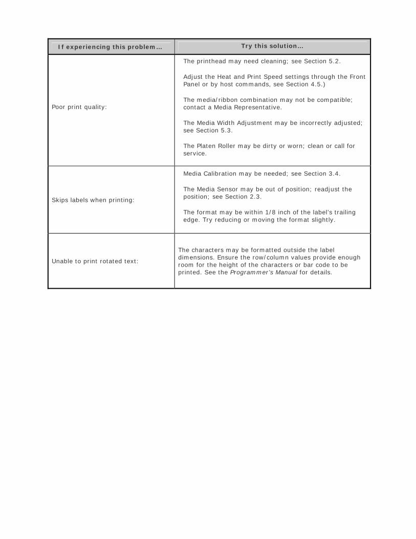
If experiencing this problem… Try this solution…
Poor print quality:
The printhead may need cleaning; see Section 5.2.
Adjust the Heat and Print Speed settings through the Front Panel or by host commands, see Section 4.5.)
The media/ribbon combination may not be compatible; contact a Media Representative.
The Media Width Adjustment may be incorrectly adjusted; see Section 5.3.
The Platen Roller may be dirty or worn; clean or call for service.
Skips labels when printing:
Media Calibration may be needed; see Section 3.4.
The Media Sensor may be out of position; readjust the position; see Section 2.3.
The format may be within 1/8 inch of the label’s trailing edge. Try reducing or moving the format slightly.
Unable to print rotated text:
The characters may be formatted outside the label dimensions. Ensure the row/column values provide enough room for the height of the characters or bar code to be printed. See the Programmer’s Manual for details.
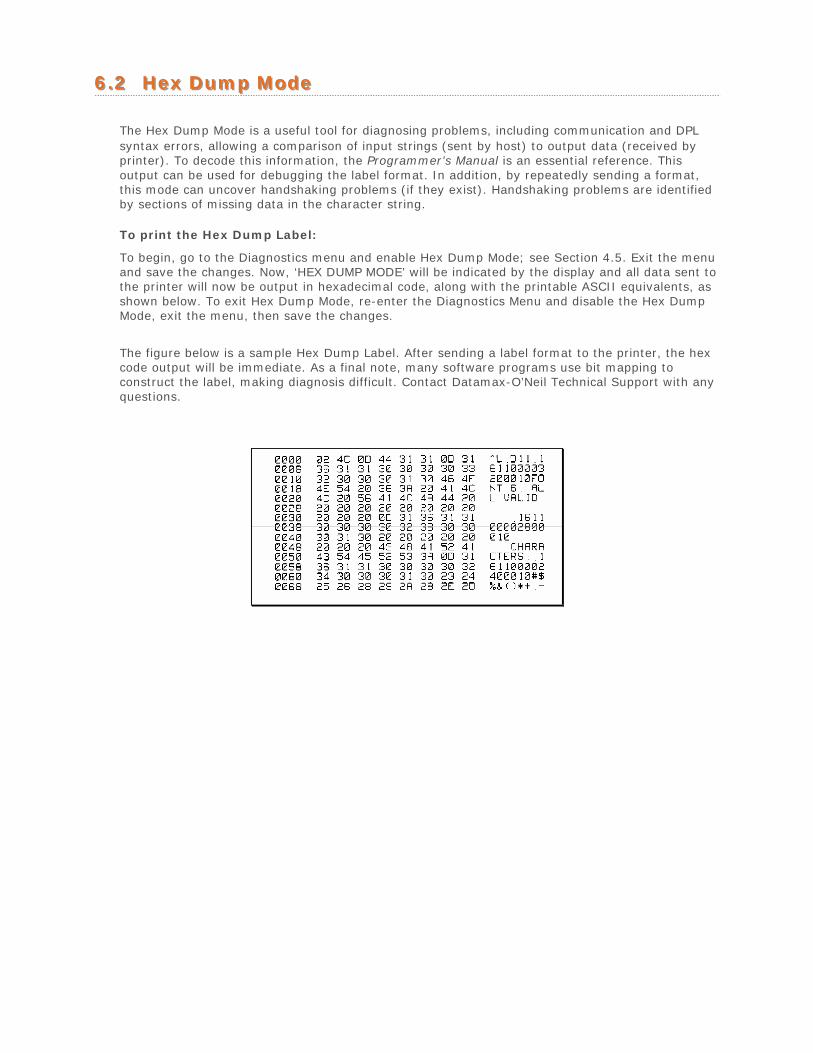
66..22 HHeexx DDuummpp MMooddee
The Hex Dump Mode is a useful tool for diagnosing problems, including communication and DPL syntax errors, allowing a comparison of input strings (sent by host) to output data (received by printer). To decode this information, the Programmer’s Manual is an essential reference. This output can be used for debugging the label format. In addition, by repeatedly sending a format, this mode can uncover handshaking problems (if they exist). Handshaking problems are identified by sections of missing data in the character string.
To print the Hex Dump Label:
To begin, go to the Diagnostics menu and enable Hex Dump Mode; see Section 4.5. Exit the menu and save the changes. Now, ‘HEX DUMP MODE’ will be indicated by the display and all data sent to the printer will now be output in hexadecimal code, along with the printable ASCII equivalents, as shown below. To exit Hex Dump Mode, re-enter the Diagnostics Menu and disable the Hex Dump Mode, exit the menu, then save the changes.
The figure below is a sample Hex Dump Label. After sending a label format to the printer, the hex code output will be immediate. As a final note, many software programs use bit mapping to construct the label, making diagnosis difficult. Contact Datamax-O’Neil Technical Support with any questions.
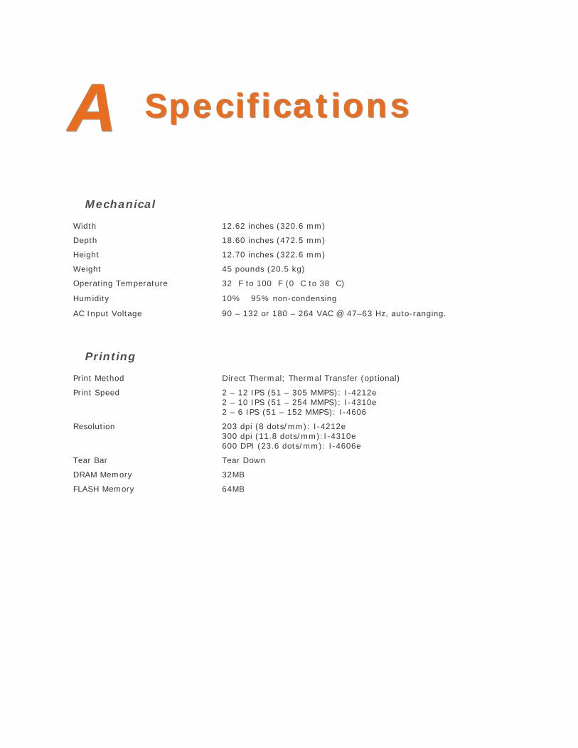
AA SSppeecciiffiiccaattiioonnss
Mechanical
Width 12.62 inches (320.6 mm)
Depth 18.60 inches (472.5 mm)
Height 12.70 inches (322.6 mm)
Weight 45 pounds (20.5 kg)
Operating Temperature 32 F to 100 F (0 C to 38 C)
Humidity 10% 95% non-condensing
AC Input Voltage 90 – 132 or 180 – 264 VAC @ 47–63 Hz, auto-ranging.
Printing
Print Method Direct Thermal; Thermal Transfer (optional)
Print Speed 2 – 12 IPS (51 – 305 MMPS): I-4212e 2 – 10 IPS (51 – 254 MMPS): I-4310e 2 – 6 IPS (51 – 152 MMPS): I-4606
Resolution 203 dpi (8 dots/mm): I-4212e 300 dpi (11.8 dots/mm):I-4310e 600 DPI (23.6 dots/mm): I-4606e
Tear Bar Tear Down
DRAM Memory 32MB
FLASH Memory 64MB
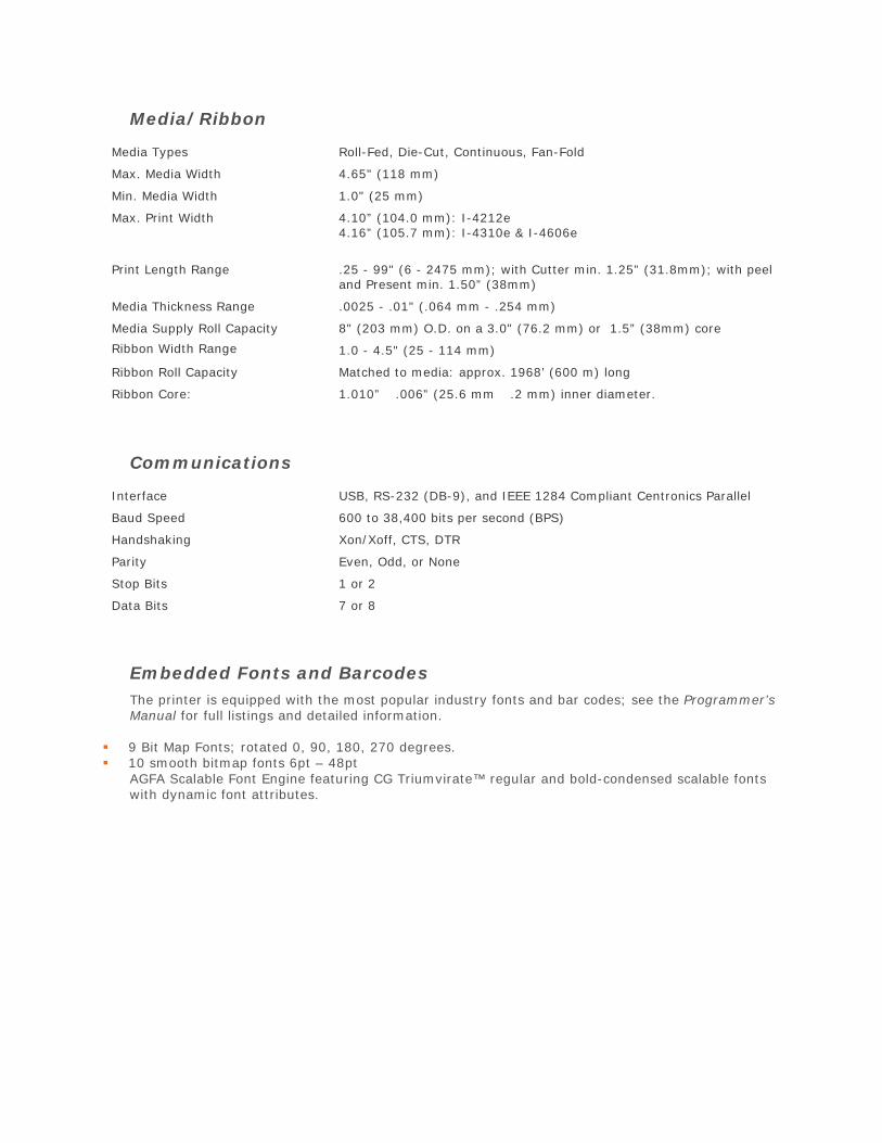
Media/Ribbon
Media Types Roll-Fed, Die-Cut, Continuous, Fan-Fold
Max. Media Width 4.65" (118 mm)
Min. Media Width 1.0" (25 mm)
Max. Print Width 4.10” (104.0 mm): I-4212e 4.16” (105.7 mm): I-4310e & I-4606e
Print Length Range .25 - 99" (6 - 2475 mm); with Cutter min. 1.25” (31.8mm); with peel and Present min. 1.50” (38mm)
Media Thickness Range .0025 - .01" (.064 mm - .254 mm)
Media Supply Roll Capacity 8" (203 mm) O.D. on a 3.0" (76.2 mm) or 1.5” (38mm) core
Ribbon Width Range 1.0 - 4.5" (25 - 114 mm)
Ribbon Roll Capacity Matched to media: approx. 1968’ (600 m) long
Ribbon Core: 1.010” .006” (25.6 mm .2 mm) inner diameter.
Communications
Interface USB, RS-232 (DB-9), and IEEE 1284 Compliant Centronics Parallel
Baud Speed 600 to 38,400 bits per second (BPS)
Handshaking Xon/Xoff, CTS, DTR
Parity Even, Odd, or None
Stop Bits 1 or 2
Data Bits 7 or 8
Embedded Fonts and Barcodes The printer is equipped with the most popular industry fonts and bar codes; see the Programmer’s Manual for full listings and detailed information.
9 Bit Map Fonts; rotated 0, 90, 180, 270 degrees. 10 smooth bitmap fonts 6pt – 48pt
AGFA Scalable Font Engine featuring CG Triumvirate™ regular and bold-condensed scalable fontswith dynamic font attributes.
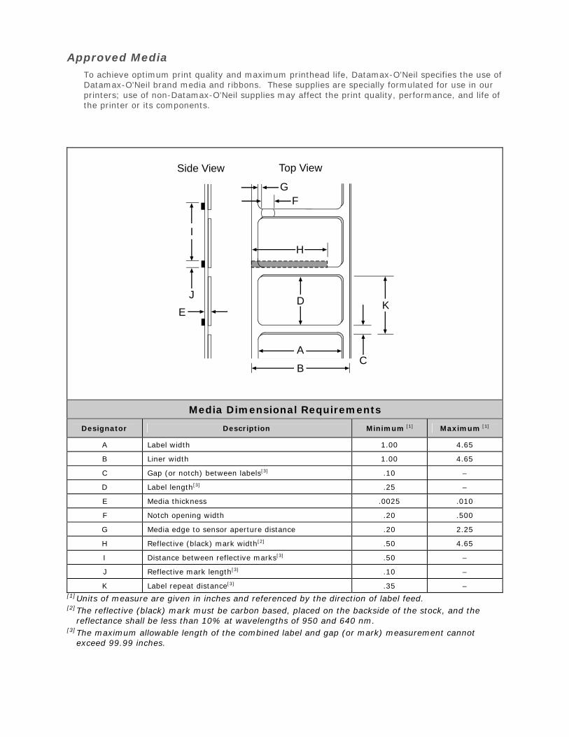
Approved Media To achieve optimum print quality and maximum printhead life, Datamax-O’Neil specifies the use of Datamax-O’Neil brand media and ribbons. These supplies are specially formulated for use in our printers; use of non-Datamax-O’Neil supplies may affect the print quality, performance, and life of the printer or its components.
E
J
I
C
K
A
B
D
H
FG
Side View Top View
Media Dimensional Requirements
Designator Description Minimum [1] Maximum [1]
A Label width 1.00 4.65
B Liner width 1.00 4.65
C Gap (or notch) between labels[3] .10 –
D Label length[3] .25 –
E Media thickness .0025 .010
F Notch opening width .20 .500
G Media edge to sensor aperture distance .20 2.25
H Reflective (black) mark width[2] .50 4.65
I Distance between reflective marks[3] .50 –
J Reflective mark length[3] .10 –
K Label repeat distance[3] .35 –[1] Units of measure are given in inches and referenced by the direction of label feed. [2] The reflective (black) mark must be carbon based, placed on the backside of the stock, and the
reflectance shall be less than 10% at wavelengths of 950 and 640 nm. [3] The maximum allowable length of the combined label and gap (or mark) measurement cannot
exceed 99.99 inches.
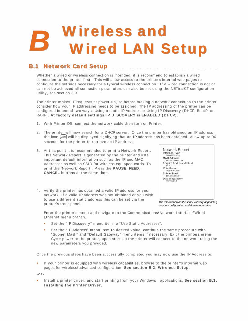
BB WWiirreelleessss aanndd WWiirreedd LLAANN SSeettuupp
BB..11 NNeettwwoorrkk CCaarrdd SSeettuupp Whether a wired or wireless connection is intended, it is recommend to establish a wired connection to the printer first. This will allow access to the printers internal web pages to configure the settings necessary for a typical wireless connection. If a wired connection is not or can not be achieved all connection parameters can also be set using the NETira CT configuration utility, see section 3.3.
The printer makes IP requests at power-up, so before making a network connection to the printer consider how your IP addressing needs to be assigned. The IP addressing of the printer can be configured in one of two ways: Using a static IP Address or Using IP Discovery (DHCP, BootP, or RARP). At factory default settings IP DISCOVERY is ENABLED (DHCP).
1. With Printer Off, connect the network cable then turn on Printer.
2. The printer will now search for a DHCP server. Once the printer has obtained an IP addressthe icon will be displayed signifying that an IP address has been obtained. Allow up to 90 seconds for the printer to retrieve an IP address.
3. At this point it is recommended to print a Network Report.This Network Report is generated by the printer and listsimportant default information such as the IP and MACAddresses as well as SSID for wireless equipped cards. Toprint the ‘Network Report’: Press the PAUSE, FEED,CANCEL buttons at the same time.
4. Verify the printer has obtained a valid IP address for yournetwork. If a valid IP address was not obtained or you wishto use a different static address this can be set via theprinter’s front panel. The information on this label will vary depending
on your configuration and firmware version.
Enter the printer’s menu and navigate to the Communications/Network Interface/WiredEthernet menu branch.
Set the “IP Discovery” menu item to “Use Static Addresses”.
Set the “IP Address” menu item to desired value, continue the same procedure with“Subnet Mask” and “Default Gateway” menu items if necessary. Exit the printers menu.Cycle power to the printer, upon start-up the printer will connect to the network using thenew parameters you provided.
Once the previous steps have been successfully completed you may now use the IP Address to:
If your printer is equipped with wireless capabilities, browse to the printer’s internal webpages for wireless/advanced configuration. See section B.2, Wireless Setup.
-or-
Install a printer driver, and start printing from your Windows applications. See section B.3,Installing the Printer Driver.
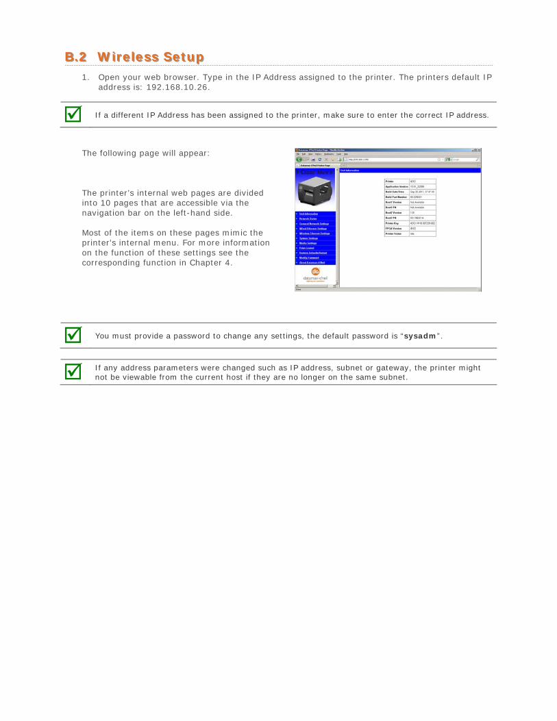
BB..22 WWiirreelleessss SSeettuupp 1. Open your web browser. Type in the IP Address assigned to the printer. The printers default IP
address is: 192.168.10.26.
If a different IP Address has been assigned to the printer, make sure to enter the correct IP address.
The following page will appear:
The printer’s internal web pages are divided into 10 pages that are accessible via the navigation bar on the left-hand side.
Most of the items on these pages mimic the printer's internal menu. For more information on the function of these settings see the corresponding function in Chapter 4.
You must provide a password to change any settings, the default password is “sysadm”.
If any address parameters were changed such as IP address, subnet or gateway, the printer might not be viewable from the current host if they are no longer on the same subnet.
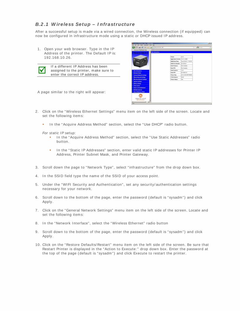
B.2.1 Wireless Setup – Infrastructure After a successful setup is made via a wired connection, the Wireless connection (if equipped) can now be configured in infrastructure mode using a static or DHCP issued IP address.
1. Open your web browser. Type in the IPAddress of the printer. The Default IP is:192.168.10.26.
If a different IP Address has been assigned to the printer, make sure to enter the correct IP address.
A page similar to the right will appear:
2. Click on the “Wireless Ethernet Settings” menu item on the left side of the screen. Locate andset the following items:
In the “Acquire Address Method” section, select the “Use DHCP” radio button.
For static IP setup: In the “Acquire Address Method” section, select the “Use Static Addresses” radio
button.
In the “Static IP Addresses” section, enter valid static IP addresses for Printer IPAddress, Printer Subnet Mask, and Printer Gateway.
3. Scroll down the page to “Network Type”, select “infrastructure” from the drop down box.
4. In the SSID field type the name of the SSID of your access point.
5. Under the “WIFI Security and Authentication”, set any security/authentication settingsnecessary for your network.
6. Scroll down to the bottom of the page, enter the password (default is “sysadm”) and clickApply.
7. Click on the “General Network Settings” menu item on the left side of the screen. Locate andset the following items:
8. In the “Network Interface”, select the “Wireless Ethernet” radio button
9. Scroll down to the bottom of the page, enter the password (default is “sysadm”) and clickApply.
10. Click on the “Restore Defaults/Restart” menu item on the left side of the screen. Be sure thatRestart Printer is displayed in the “Action to Execute:” drop down box. Enter the password atthe top of the page (default is “sysadm”) and click Execute to restart the printer.
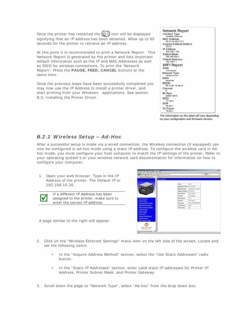
Once the printer has restarted the icon will be displayed signifying that an IP address has been obtained. Allow up to 90 seconds for the printer to retrieve an IP address.
At this point it is recommended to print a Network Report. This Network Report is generated by the printer and lists important default information such as the IP and MAC Addresses as well as SSID for wireless connections. To print the ‘Network Report’: Press the PAUSE, FEED, CANCEL buttons at the same time.
Once the previous steps have been successfully completed you may now use the IP Address to install a printer driver, and start printing from your Windows applications. See section B.3, Installing the Printer Driver.
The information on this label will vary depending on your configuration and firmware version.
B.2.1 Wireless Setup – Ad-Hoc After a successful setup is made via a wired connection, the Wireless connection (if equipped) can now be configured in ad-hoc mode using a static IP address. To configure the wireless card in Ad-hoc mode, you must configure your host computer to match the IP settings of the printer. Refer to your operating system’s or your wireless network card documentation for information on how to configure your computer.
1. Open your web browser. Type in the IPAddress of the printer. The Default IP is:192.168.10.26.
If a different IP Address has been assigned to the printer, make sure to enter the correct IP address.
A page similar to the right will appear:
2. Click on the “Wireless Ethernet Settings” menu item on the left side of the screen. Locate andset the following items:
In the “Acquire Address Method” section, select the “Use Static Addresses” radiobutton.
In the “Static IP Addresses” section, enter valid static IP addresses for Printer IPAddress, Printer Subnet Mask, and Printer Gateway.
3. Scroll down the page to “Network Type”, select “Ad-hoc” from the drop down box.
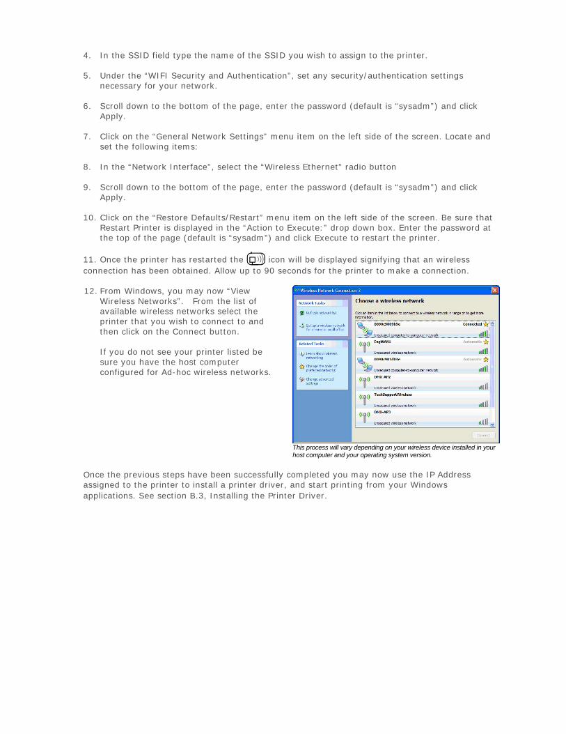
4. In the SSID field type the name of the SSID you wish to assign to the printer.
5. Under the “WIFI Security and Authentication”, set any security/authentication settingsnecessary for your network.
6. Scroll down to the bottom of the page, enter the password (default is “sysadm”) and clickApply.
7. Click on the “General Network Settings” menu item on the left side of the screen. Locate andset the following items:
8. In the “Network Interface”, select the “Wireless Ethernet” radio button
9. Scroll down to the bottom of the page, enter the password (default is “sysadm”) and clickApply.
10. Click on the “Restore Defaults/Restart” menu item on the left side of the screen. Be sure thatRestart Printer is displayed in the “Action to Execute:” drop down box. Enter the password atthe top of the page (default is “sysadm”) and click Execute to restart the printer.
11. Once the printer has restarted the icon will be displayed signifying that an wireless connection has been obtained. Allow up to 90 seconds for the printer to make a connection.
12. From Windows, you may now “ViewWireless Networks”. From the list ofavailable wireless networks select theprinter that you wish to connect to andthen click on the Connect button.
If you do not see your printer listed besure you have the host computerconfigured for Ad-hoc wireless networks.
This process will vary depending on your wireless device installed in your host computer and your operating system version.
Once the previous steps have been successfully completed you may now use the IP Address assigned to the printer to install a printer driver, and start printing from your Windows applications. See section B.3, Installing the Printer Driver.
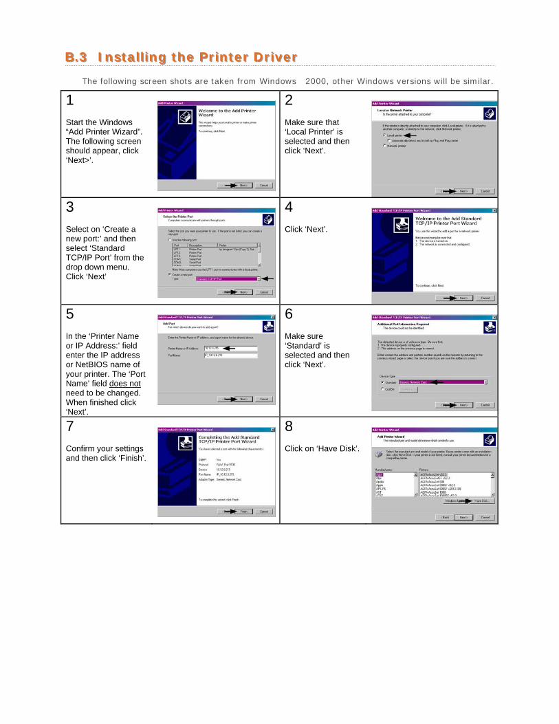
BB..33 IInnssttaalllliinngg tthhee PPrriinntteerr DDrriivveerr
The following screen shots are taken from Windows 2000, other Windows versions will be similar.
1 Start the Windows “Add Printer Wizard”. The following screen should appear, click ‘Next>’.
2 Make sure that ‘Local Printer’ is selected and then click ‘Next’.
3 Select on ‘Create a new port:’ and then select ‘Standard TCP/IP Port’ from the drop down menu. Click ‘Next’
4 Click ‘Next’.
5 In the ‘Printer Name or IP Address:’ field enter the IP address or NetBIOS name of your printer. The ‘Port Name’ field does not need to be changed. When finished click ‘Next’.
6 Make sure ‘Standard’ is selected and then click ‘Next’.
7 Confirm your settings and then click ‘Finish’.
8 Click on ‘Have Disk’.
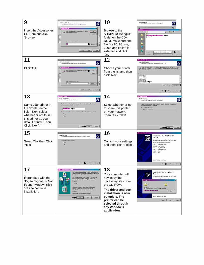
9 Insert the Accessories CD-Rom and click ‘Browse’.
10 Browse to the “\DRIVERS\Seagull” folder on the CD-ROM, make sure the file “for 95, 98, me, 2000, and xp.inf” is selected and click ‘OK’.
11 Click ‘OK’.
12 Choose your printer from the list and then click ‘Next’.
13 Name your printer in the ‘Printer name:’ field. Next select whether or not to set this printer as your default printer. Then Click ‘Next’.
14 Select whether or not to share this printer on your network. Then Click ‘Next’
15 Select ‘No’ then Click ‘Next’.
16 Confirm your settings and then click ‘Finish’.
17 If prompted with the "Digital Signature Not Found" window, click ‘Yes’ to continue installation.
18 Your computer will now copy the necessary files from the CD-ROM.
The driver and port installation is now complete. The printer can be selected through any Window’s application.
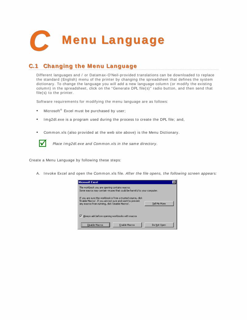
CC MMeennuu LLaanngguuaaggee
CC..11 CChhaannggiinngg tthhee MMeennuu LLaanngguuaaggee Different languages and / or Datamax-O’Neil-provided translations can be downloaded to replace the standard (English) menu of the printer by changing the spreadsheet that defines the system dictionary. To change the language you will add a new language column (or modify the existing column) in the spreadsheet, click on the “Generate DPL file(s)” radio button, and then send that file(s) to the printer.
Software requirements for modifying the menu language are as follows:
• Microsoft® Excel must be purchased by user;
• Img2dl.exe is a program used during the process to create the DPL file; and,
• Common.xls (also provided at the web site above) is the Menu Dictionary.
Place Img2dl.exe and Common.xls in the same directory.
Create a Menu Language by following these steps:
A. Invoke Excel and open the Common.xls file. After the file opens, the following screen appears:
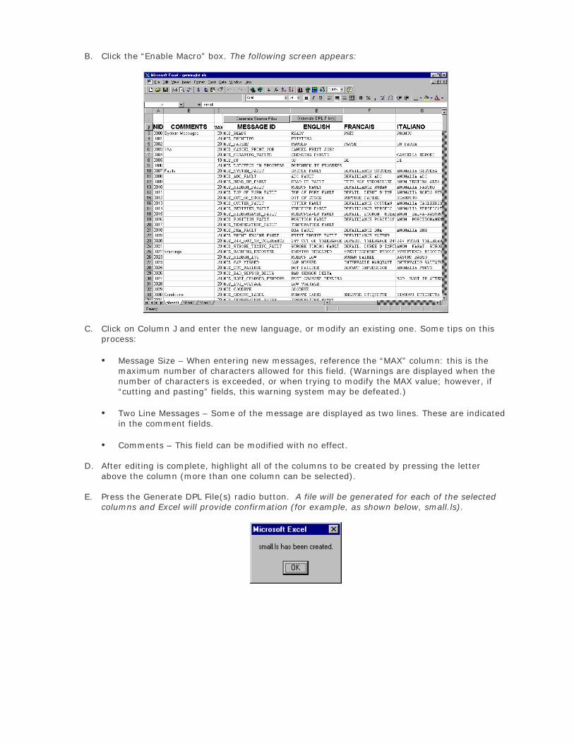
B. Click the “Enable Macro” box. The following screen appears:
C. Click on Column J and enter the new language, or modify an existing one. Some tips on this process:
• Message Size – When entering new messages, reference the “MAX” column: this is themaximum number of characters allowed for this field. (Warnings are displayed when thenumber of characters is exceeded, or when trying to modify the MAX value; however, if“cutting and pasting” fields, this warning system may be defeated.)
• Two Line Messages – Some of the message are displayed as two lines. These are indicatedin the comment fields.
• Comments – This field can be modified with no effect.
D. After editing is complete, highlight all of the columns to be created by pressing the letter above the column (more than one column can be selected).
E. Press the Generate DPL File(s) radio button. A file will be generated for each of the selected columns and Excel will provide confirmation (for example, as shown below, small.ls).
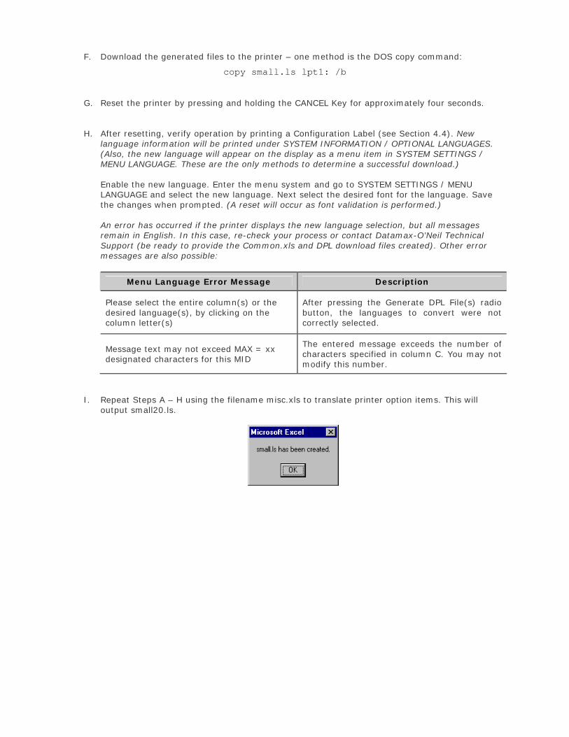
F. Download the generated files to the printer – one method is the DOS copy command:
copy small.ls lpt1: /b
G. Reset the printer by pressing and holding the CANCEL Key for approximately four seconds.
H. After resetting, verify operation by printing a Configuration Label (see Section 4.4). New language information will be printed under SYSTEM INFORMATION / OPTIONAL LANGUAGES. (Also, the new language will appear on the display as a menu item in SYSTEM SETTINGS / MENU LANGUAGE. These are the only methods to determine a successful download.)
Enable the new language. Enter the menu system and go to SYSTEM SETTINGS / MENU LANGUAGE and select the new language. Next select the desired font for the language. Save the changes when prompted. (A reset will occur as font validation is performed.)
An error has occurred if the printer displays the new language selection, but all messages remain in English. In this case, re-check your process or contact Datamax-O’Neil Technical Support (be ready to provide the Common.xls and DPL download files created). Other error messages are also possible:
Menu Language Error Message Description
Please select the entire column(s) or the desired language(s), by clicking on the column letter(s)
After pressing the Generate DPL File(s) radio button, the languages to convert were not correctly selected.
Message text may not exceed MAX = xx designated characters for this MID
The entered message exceeds the number of characters specified in column C. You may not modify this number.
I. Repeat Steps A – H using the filename misc.xls to translate printer option items. This will output small20.ls.
CC..22 AAddvvaanncceedd FFiillee HHaannddlliinngg IInnffoorrmmaattiioonn
• The standard printer leaves the factory with EFIGS loaded into Module Y. At this point, ModuleY is LOCKED and will only accept additional language downloads.
• After downloading a language update, Module Y is left UNLOCKED until the printer is reset orpower is cycled. In this state, Module Y will accept font, image and label format downloads.The module will also honor the Clear Module request. Therefore, following an update it isrecommended that a reset be performed to lock the module; otherwise, a software packagemay “Clear All Modules” thus destroying the new menu language(s).
• Module Y can be UNLOCKED by sending this DPL string: <STX>KpY0
• To restore the factory generated EFIGS image, download the file *832296.01A to the printer.This file is located on the Datamax-O’Neil FTP site. The letter at the end of the file name (e.g.,A) specifies the revision. The latest revision will be available on the FTP site.
• Downloading the same language twice will automatically delete the first occurrence, but willnot free the memory space.
• Deletion of the selected language will reset the printer to English. The total number oflanguages that the printer can now accept is limited to 10, but this number is dependent uponthe size of each language translation. The translation size will vary with the number ofmessages that are translated for that particular language. Current complete language files areabout 7,000 bytes each; but with product growth, the total number of languages is expectedto drop to five.
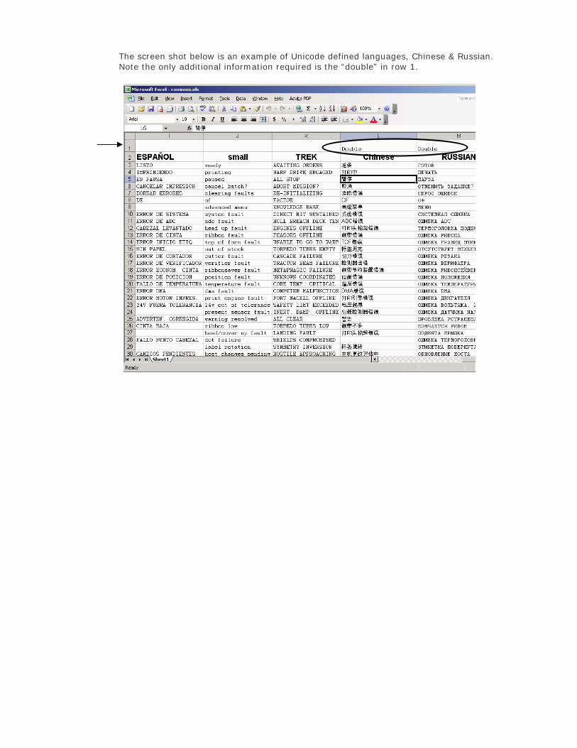
The screen shot below is an example of Unicode defined languages, Chinese & Russian. Note the only additional information required is the “double” in row 1.
Related Documents


![[XLS]ca.ingrammicro.com · Web viewDATALOGIC SCANNING - MOBILE DATAMAX (407) 578-8007 DATAMAX - E CLASS DATAMAX - EX2 DATAMAX - M I H W CLASS DATAMAX - MEDIA DATAMAX - S CLASS DLINK](https://static.cupdf.com/doc/110x72/5b2041797f8b9afb1e8b53e1/xlsca-web-viewdatalogic-scanning-mobile-datamax-407-578-8007-datamax.jpg)