1 Air Cooled Chiller&Heat Pump with Inverter scroll compressors EWA(Y)T~CZ N/P/H - Nominal capacity range 16 - 90 kW - Packaged solution - R-32 refrigerant Performance according to EN14511. Databook CSS 10.29 04/2021 Code:

Welcome message from author
This document is posted to help you gain knowledge. Please leave a comment to let me know what you think about it! Share it to your friends and learn new things together.
Transcript

1
Air Cooled Chiller&Heat Pump with Inverter scroll compressors EWA(Y)T~CZ N/P/H - Nominal capacity range 16 - 90 kW - Packaged solution - R-32 refrigerant
Performance according to EN14511.
Databook CSS 10.29 04/2021
Code:
TECHNICAL SPECIFICATION
2
INDEX
Introduction .............................................................................................................. 3
Refrigerant charge ..................................................................................................... 6
Nomenclature ............................................................................................................ 6
Standard components ................................................................................................. 7
Options .................................................................................................................... 9
Accessories ............................................................................................................... 9
Technical specification .............................................................................................. 13
Electrical specification ............................................................................................... 43
Sound levels ........................................................................................................... 49
Envelopes ............................................................................................................... 50
Installation notes ..................................................................................................... 52

TECHNICAL SPECIFICATION
3
Introduction Low operating cost. The new Daikin BLUEVOLUTION chiller&heat pump series (EWA(Y)T-CZ) is the result of careful design aimed to optimize the energy efficiency and thus the total life cycle cost of the unit, with reduced operating cost thanks to outstanding performances and reliability. The units feature high efficiency scroll compressor arranged in single or tandem configuration on each refrigerant circuit, optimized condensing section with advanced technology condensing fans and plates evaporator with low refrigerant content and reduced pressure drops. Low environmental impact. Latest revision of F-GAS, entered into force in 2015, set up a phase down program for traditional HFC’s refrigerants. In 2018 first significant reduction step has been introduced (37%) and in 2030 the reduction (calculated in equivalent CO2 tons) will need to achieve almost 80%.
The new Daikin BLUEVOLUTION series uses R-32 refrigerant to reduce drastically the carbon footprint of the unit. The selection of R-32 (chemical name difluoromethane) minimises the global warming impact of scroll compressor units thanks to the lower Global Warming Potential in combination with high-energy efficiency. The Global Warming Potential of R-32 is 675, which is only one third of the commonly used refrigerant R-410A. Thanks to the low flammability classification (R-32 refrigerant is classified A2L in ISO817), it can be safely used in many applications including chilled water systems. Being a single component refrigerant, R-32 is also easier to recycle and reuse, that is another environmental plus in its favour. Daikin has a long history of continuous reduction of the environmental impact of cooling, heating and refrigeration, having a unique expertise that comes from manufacturing both refrigerants and equipment. This position is one of the results of company's corporate philosophy to "Be a Company that Leads in Applying Environmentally Friendly Practices". Outstanding reliability. The units have one or two truly independent refrigerant circuits with one or two compressors to assure maximum safety for any maintenance, whether planned or not. Condensation control. Units are equipped with fan speed modulation. Fan silent mode. Units are standardly supplied with fan silent mode. This feature allows the user to set up detailed time bands to reduce fan rotation speed and therefore sound emission in those areas where night quietness is a mandatory requirement. The average sound power reduction is -2dB(A).
Superior control logic. The control logic is designed to provide maximum efficiency, to continue operation in unusual operating conditions and to provide history of unit operation. Easy interface with, Bacnet, Ethernet TCP/IP or Modbus communications. Master/Slave operation is provided as standard allowing to connect up to 4 units working as single system.
Dynamic Condensing Pressure Management. Superior software logic has been developed to get the highest efficiency at whatever operating condition: thanks to the Dynamic Condensing Pressure Management the unit controller adjusts the condensing pressure set-point to minimize the overall power input.

TECHNICAL SPECIFICATION
4
Code requirements – Safety and compliance to laws/directives Units are designed and manufactured in accordance to the following directives and harmonized standards:
Low voltage directive DIRECTIVE 2014/35/EU Electromagnetic compatibility (EMC) DIRECTIVE 2014/30/EU Machinery directive DIRECTIVE 2006/42/EC Pressure equipment Directive DIRECTIVE 2014/68/EU Ecodesing DIRECTIVE 2009/125/EC Safety of machinery EN 60335-2-40 EMC - Part 6-2 EN 61000-6-2 EMC - Part 6-4 EN 61000-6-4 Low voltage directive DIRECTIVE 2014/35/EU Electromagnetic compatibility (EMC) DIRECTIVE 2014/30/EU
Certifications. Units are CE and EAC marked, complying with European directives in force, concerning manufacturing and safety. On request units can be produced complying with laws in force in non-European countries (ASME, etc.), and with other applications.
Compressors Hermetic orbiting scroll type optimized for R-32 operation and complete with motor over-temperature and over-current protection devices. Each compressor is equipped with an oil heater that keeps the oil from being diluted by the refrigerant when the unit is not running. Each compressor is mounted on rubber antivibration mounts and is standardly equipped with compressor jacket for a quite operation. Unit is delivered with complete oil charge. The Variable Frequency Drive (VFD) is integrated in the electrical panel of the unit and it allows continuous modulation of compressor’s rotational speed. On site, unit can be set to operate in boosted mode, please check the technical table values in the _MAX section. Water Side Heat Exchanger The unit is equipped with a direct expansion plate-to-plate type Heat Exchanger optimized for R-32 refrigerant operation. This heat exchanger is made of stainless-steel brazed plates and is covered with 20mm closed cell insulation material. The flow switch is standard and factory mounted while the water filter on the heat exchanger side is shipped with the chiller but needs to be field installed. Air Side Heat Exchanger The Air Side Heat Exchanger is manufactured with internally enhanced seamless copper tubes arranged in a staggered row pattern and mechanically expanded into lanced and rippled aluminum Air Side Heat Exchanger fins with full fin collars. An integral sub-cooler circuit provides sub-cooling to effectively eliminate liquid flashing and increase cooling capacity without increasing the power input. Air Side Heat Exchanger fans Air Side Heat Exchanger fans are propeller type with high efficiency design blades to maximize performances. The blades are made of glass-reinforced resin and a guard protects each fan. Units are standardly equipped with inverter driven fans. Electronic expansion valve The unit is equipped with electronic expansion valves to achieve precise control of R-32 refrigerant mass flow. Electronic expansion valves become mandatory to improve the energy efficiency and to accurately control the temperature in a wide range. Electronic expansion valves have unique features: short opening and closing time, high resolution, positive shut-off function to eliminate use of additional solenoid valve, continuous modulation of mass flow without stress in the refrigerant circuit and corrosion resistant stainless-steel body. If compared to traditional thermostatic valves, electronic expansion valves allow the system to work with low condenser pressure (wintertime) without any refrigerant flow problems and to perfectly control the chilled water temperature.

TECHNICAL SPECIFICATION
5
Refrigerant circuit Each unit has one or two independent refrigerant circuits and each one includes:
• Compressors • Refrigerant • Water side Heat Exchanger • Air Side Heat Exchanger • Electronic expansion valve • Filters • Charging valves • High pressure switch • High pressure transducers • Low pressure transducers • Suction temperature sensor • Discharge temperature sensor
Electrical panel Power and control are in the main panel that is manufactured to ensure protection against weather conditions. The electrical panel is IPX4 and fitted with a main switch interlocked door that shuts off power supply when opening. Safety device / logic for each refrigerant circuit The following devices / logics are available: • high pressure switch; • high pressure transducer; • low pressure transducer; • high compressor discharge temperature; • Compressor case temperatute switch • low pressure ratio; System security The following securities are available: • low ambient temperature lock-out; • freeze protection.
Supervising systems remote communication Controller can communicate to BMS (Building Management System) based on the most common protocols as: • Modbus MSTP TCP-IP Accessory • BACnet MSTP TCP-IP Accessory

TECHNICAL SPECIFICATION
6
Refrigerant charge
Additional information related to F-GAS Regulation (EU) No 517/2014 of the European Parliament and of the Council of 16 April 2014 on fluorinated greenhouse gases and repealing Regulation (EC) No 842/2006
Unit Model Refrigerant type
Refrigerant GWP
N° of circuits
Refrigerant charge
Circuit 1 [kg]
Refrigerant charge
Circuit 2 [kg]
EWAT/EWYT016CZN-A1 R32 675 1 3.0 - EWAT/EWYT021CZN-A1 R32 675 1 5.5 - EWAT/EWYT025CZN-A1 R32 675 1 5.5 - EWAT/EWYT032CZN-A1 R32 675 1 7.0 - EWAT/EWYT040CZN-A1 R32 675 1 8.0 - EWAT/EWYT040CZN-A2 R32 675 2 6.0 6.0 EWAT/EWYT050CZN-A2 R32 675 2 6.0 6.0 EWAT/EWYT064CZN-A2 R32 675 2 7.0 6.0 EWAT/EWYT090CZN-A2 R32 675 2 8.0 8.0
Note: Equipment contains fluorinated greenhouse gases.
Refrigerant Charges of the P and H version are the same as for the N version.
Actual refrigerant charge depends on the final unit construction, details can be found on the unit labels.
Nomenclature
TECHNICAL SPECIFICATION
7
ard componentsmponents Standard Component and Features (supplied on basic units)
Hour run meter (provided as standard) General fault contactor (provided as standard) Main switch interlock door (provided as standard) Master / Slave (provided as standard) The DAIKIN Master/ Slave (M/S) control. Once set which unit has the role of master, the other(s) will operate as slave(s) based on the inputs provided by the master. The chillers must be installed in parallel in the hydronic plant. With Master/Slave control it is possible to balance the working hours of the compressors enhancing reliability and extending the life of the system. In order to operate in Master/Slave mode an additional probe (NTC10K type or available as an accessory EKTSMS) must be installed on the common line of the plant and connected to the master unit. The master / slave feature allows to manage the start and stop of field supplied water pumps. The power supply of the field supplied pumps is seperate from the unit.
20mm evaporator insulation (provided as standard) The heat exchanger is fitted with 20mm closed cell insulation material
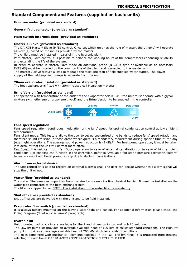
Brine Version (provided as standard) For operation with temperature at the outlet of the evaporator below +4°C the unit must operate with a glycol mixture (with ethylene or propylene glycol) and the Brine Version to be enabled in the controller.
Fans speed regulation Fans speed regulation: continuous modulation of the fans’ speed for optimal condensation control at low ambient temperatures. Fans silent mode: This feature allows the user to set up customized time bands to reduce fans’ speed rotation and therefore sound emission in those areas where quiet is a mandatory requirement during specific time of the day (e.g. night operation). The average sound power reduction is -2 dB(A). For heat pump operation, it must be taken into account that the unit will defrost more often. Fan Boost: the unit can go in fan Boost operation in case of external canalization or in case of high ambient conditions just enabling the function in the controller. Refer to “Available fan static pressure correction factors” tables in case of additional pressure drop due to ducts or canalizations.
Alarm from external device The unit controller is able to receive an external alarm signal. The user can decide whether this alarm signal will stop the unit or not. Water filter (provided as standard) The water filter removes impurities from the ater by means of a fine physical barrier. It must be installed on the water pipe connected to the heat exchanger inlet. The filter is shipped loose. NOTE: The installation of the water filter is mandatory. Shut off valve (provided as standard) Shut off valves are delivered with the unit and to be field installed.
Evaporator flow switch (provided as standard) It is always factory mounted on the leaving water side and cabled. For additional information please check the Piping Diagram (“Hydraulic schemes” paragraph).
Hydronic kit Unit mounted hydronic kits are available for the P and H version in low and high lift solution. The Low lift pump kit provides an average available head of 100 kPa at chiller standard conditions. The High lift pump kit provides an average available head of 200 kPa at chiller standard conditions. The kit is completed with mechanical elements specified in the P&I. The hydronic kit is protected from freezing selecting the additional OP.191-ANTIFREEZE PROTECTION ELECTRIC HEATER.

TECHNICAL SPECIFICATION
8
Inverter for pump (provided as standard for P and H versions) The Inverter kit is standardly associated with the hydronic kit. The inverter for the pump has been designed for operation at an ambient temperature of max 50 ° C; continuous operation at full load at an ambient temperature of 50 ° C will reduce the useful life of the inverter itself.
The inverter pump can be used for the following purposes:
- Adjusting the water flow rate during unit commissioning. - Set a “thermostat off” pump speed. With the inverter kit, it is possible to manage two different water flow
settings: a setting for water flow during the "Thermostat ON" mode (when the chiller is actually providing cooling to the plant), and a set for the “thermostat off” mode (when the plant load is satisfied and the compressors are waiting to start). This feature allows to achieve energy saving on plant operating cost by reducing the speed of the pumps when the chiller has reached the set point.
- Control variable flow on primary loop based on chiller delta-T (available for single chiller installation only)
Having the unit with the inverter kit for the on-board pump it is possible to manage a variable water flow rate for the primary loop. This function is available as standard when the hydronic kit plus inverter are selected. The standard feature is applicable for single unit installation only. In case of multiple chillers installation an additional control is needed. The variable flow control is suitable for primary/secondary plant but can not be used in Variable Primary Flow chilled water system configurations.
In a Primary-Secondary plant configuration a key component is the decoupler. The decoupler is always open (no valve must be installed). The aim of the decoupler is to allows the primary and secondary pumps to operate at different flow rates. This is necessary because the primary pumps and secondary pumps are managed differently and so the primary and secondary flow rate are practically never the same. Specifically, the primary flow rate is managed based on the chiller delta-T (Tout - Tin), the secondary flow rate is regulated to maintain the necessary pressure differential in the secondary loop. The direction of the water flow through the decoupler must be always from supply to return. To ensure this the primary flow rate must be higher than the secondary flow rate. If this condition is not respected the warmer return water will flow backwards through the decoupler and raise the supply water temperature. Due to the higher temperature of the supply water the terminal (users) unit control will open the valves asking for higher water flow rate. The secondary pumps will speed up increasing even more the water flow rate on secondary plant making the situation even worst (secondary flow rate >> primary flow rate). As result there will be no control on the supply water temperature losing effectiveness of the cooling plant. On the other side any excess in the primary flow, vs. secondary flow, flows through the decoupler from the supply to the return mixing with the warmer return water. To reach this target is very important to have minimum pressure drop in the decoupler that needs to be sized to reach a pressure drop that should not exceed 4÷5 kPa for the flow rate of the primary pump. Activating the variable flow control the chiller will modulate the water flow rate based on the chiller delta-T. When the secondary loop will reduce the water flow rate (because the plant load decrease), the water flow rate in the decoupler (always from supply to return) increases. The return water temperature mixes with the supply water from the decoupler reducing the inlet water temperature and so the delta-T on the chiller. As consequence the chiller control reduce the speed of the pump, reducing the primary flow rate. On the opposite, when the flow rate on secondary flow increases also the water temperature at the chiller inlet increase (increasing the delta-T); therefore, the chiller control will increase the water flow rate.
TECHNICAL SPECIFICATION
9
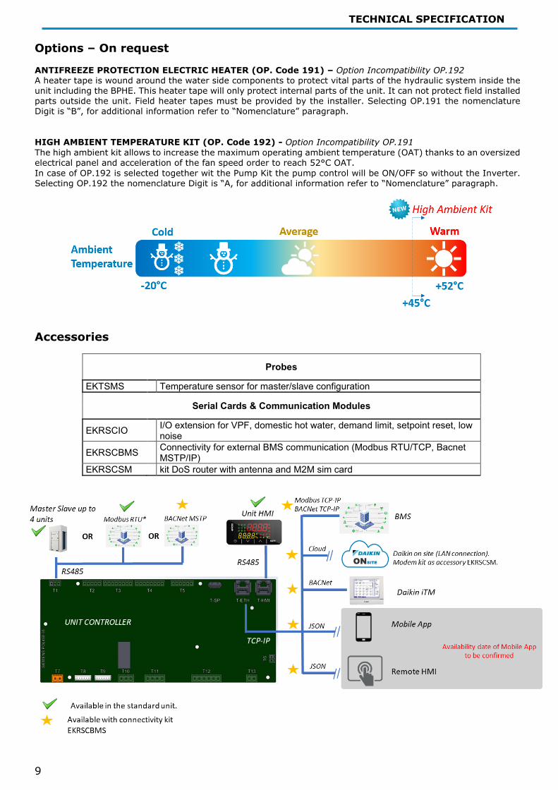
Options Options – On request ANTIFREEZE PROTECTION ELECTRIC HEATER (OP. Code 191) – Option Incompatibility OP.192 A heater tape is wound around the water side components to protect vital parts of the hydraulic system inside the unit including the BPHE. This heater tape will only protect internal parts of the unit. It can not protect field installed parts outside the unit. Field heater tapes must be provided by the installer. Selecting OP.191 the nomenclature Digit is “B”, for additional information refer to “Nomenclature” paragraph. HIGH AMBIENT TEMPERATURE KIT (OP. Code 192) - Option Incompatibility OP.191 The high ambient kit allows to increase the maximum operating ambient temperature (OAT) thanks to an oversized electrical panel and acceleration of the fan speed order to reach 52°C OAT. In case of OP.192 is selected together wit the Pump Kit the pump control will be ON/OFF so without the Inverter. Selecting OP.192 the nomenclature Digit is “A, for additional information refer to “Nomenclature” paragraph.
Accessories Accessories
Probes
EKTSMS Temperature sensor for master/slave configuration
Serial Cards & Communication Modules
EKRSCIO I/O extension for VPF, domestic hot water, demand limit, setpoint reset, low noise
EKRSCBMS Connectivity for external BMS communication (Modbus RTU/TCP, Bacnet MSTP/IP)
EKRSCSM kit DoS router with antenna and M2M sim card

TECHNICAL SPECIFICATION
10
EKTSMS – Temperature sensor for master/slave configuration EKRSCIO is an additional module for the controller extending the numbers of Inputs/Outputs (I/O). The additional I/O module is valid for VPF-Variable Primary Flow, DHW-Domestic hot water management, Demand limit, Setpoint reset, Low noise, Double set point, Defrost out, Cooling heating output.
I/O extension – PINOUT
Temperature sensors Domestic Hot Water sensor NTC10K measuring range 100-670000 Ω X1
Voltage Input Demand Limit/Current Limit Analog input volt 0-10V X2
Voltage Input
Evaporator DP (VPF)/DHW 3WV Feedback Open Analog input volt 0-10V X3
System DP (VPF)/DHW 3WV Feedback Close Analog input volt 0-10V X4
Setpoint Reset Analog input volt 0-10V X5
Digital inputs Low Noise Digital input potential free contact X6
Digital inputs
Thermo On/Off Digital input potential free contact X7
Domestic Hot Water Enable Digital input potential free contact X8
Double Setpoint Powered Digital input 230VAC DI1
Digital outputs Cooling/Heating Digital output relay 230V - 2A DO1
Digital outputs
Defrost Output Digital output relay 230V - 2A DO2
Bypass Valve (VPF) Digital output relay 230V - 2A DO3
Domestic Hot Water 3 Way Valve Digital output relay 230V - 2A DO4
- Digital output relay 230V - 2A DO5
M/S DHW VPF Demand Limit Current Limit M/S Not compatible Not compatible To be confirmed To be confirmed DHW Not compatible Compatible Compatible VPF Compatible Compatible Demand Limit Compatible Current Limit
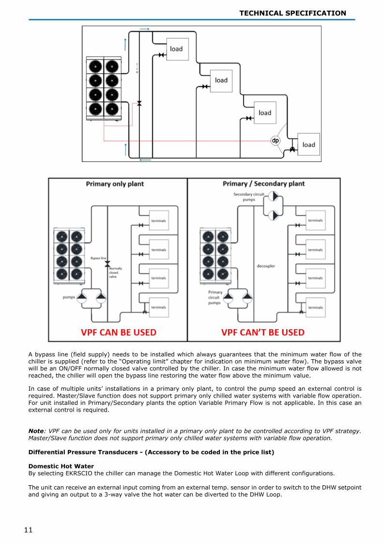
Double set point Possibility to set two different chilled water temperature set points. Ambient outside temperature sensor and setpoint reset (provided as standard) The leaving water temperature set-point can be overwritten through an external 0-10V signal, through the ambient temperature, or through the water side heat exchanger ΔT. Variable Primary Flow By selecting EKRSCIO the chiller can manage the Variable Primary water flow according to the differential pressure measured in a specific point of the plant, selected by the plant designer. The differential pressure transducer is available as an accessory. However, not providing the connection capillaries between the evaporator and the accessory itself. Once installed, the differential pressure transducer must be connected to the unit. As an alternative the unit controller can receive directly the differential pressure value from an external BMS communicating with the standards communication protocols (eg. MODBUS). The Variable Primary Flow (VPF) configuration is an alternative to the more “traditional” Primary/Secondary (P/S) plant configuration. Daikin Applied Europe is not responsible for the plant configuration and cannot confirm the optimal position of the differential pressure transducer.
TECHNICAL SPECIFICATION
11
A bypass line (field supply) needs to be installed which always guarantees that the minimum water flow of the chiller is supplied (refer to the “Operating limit” chapter for indication on minimum water flow). The bypass valve will be an ON/OFF normally closed valve controlled by the chiller. In case the minimum water flow allowed is not reached, the chiller will open the bypass line restoring the water flow above the minimum value.
In case of multiple units’ installations in a primary only plant, to control the pump speed an external control is required. Master/Slave function does not support primary only chilled water systems with variable flow operation. For unit installed in Primary/Secondary plants the option Variable Primary Flow is not applicable. In this case an external control is required. Note: VPF can be used only for units installed in a primary only plant to be controlled according to VPF strategy. Master/Slave function does not support primary only chilled water systems with variable flow operation. Differential Pressure Transducers - (Accessory to be coded in the price list) Domestic Hot Water By selecting EKRSCIO the chiller can manage the Domestic Hot Water Loop with different configurations. The unit can receive an external input coming from an external temp. sensor in order to switch to the DHW setpoint and giving an output to a 3-way valve the hot water can be diverted to the DHW Loop.

TECHNICAL SPECIFICATION
12
Low Noise By selecting EKRSCIO the unit can manage the Low Noise Operation.
EKRSCBMS – Connectivity Card In case the BMS communication is needed, with Modbus or BACnet protocol, the connectivity card is delivered with the unit. Through a dedicated App, available for iOS and Android, it is possible to scan the QRCode and the activation key and generate the controller license file for activating the corresponding communication protocol.
M/S - Master (T1)
M/S - Slave (T1)
Modbsu RTU (T1)
Modbus TCP-IP
Bacnet MSTP (T1)
Bacnet TCP-IP
IO Extension Pack Modem
M/S - Master (T1) Not
compatible Not compatible Compatible Not
compatible Compatible Compatible Compatible
M/S - Slave (T1) Not
compatible Not compatible
Not compatible Compatible Not
compatible Compatible
Modbsu RTU (T1) Compatible Not
compatible Compatible Not compatible Compatible
Modbus TCP-IP Compatible Compatible Compatible To be
confirmed- CF Bacnet MSTP (T1) To be
confirmed Not compatible Compatible
Bacnet TCP-IP Compatible To be
confirmed - CF IO Extension Pack Compatible
Modem EKRSCSM - Daikin on site modem with antenna (Accessory) Connecting the unit to Daikin on Site will be possible through a dedicated modem that can be ordered from Factory as an accessory.

TECHNICAL SPECIFICATION
13
Technical specificationpp EWAT~CZN MODEL EWAT016CZN-
A1 EWAT021CZN-
A1 EWAT025CZN-
A1 EWAT032CZN-
A1 EWAT040CZN-
A1 EWAT040CZN-
A2 COOLING PERFORMANCE
Capacity - Cooling kW 15.9 20.9 25.6 32.4 39.6 41.4
Capacity control - Type Inverter Controlled
Inverter Controlled
Inverter Controlled
Inverter Controlled
Inverter Controlled
Inverter Controlled
Capacity control - Minimum capacity % 18 14 12 19 15 14
Unit power input - Cooling kW 5.5 6.6 8.5 10.3 13.4 13.2 EER 2.9 3.16 3 3.13 2.95 3.12 SEER 5 5 5.06 5.21 5.09 5.41 IPLV 5.83 6.29 6.05 6.25 5.87 6.37 CASING Colour * IW IW IW IW IW IW Material * GPSS GPSS GPSS GPSS GPSS GPSS DIMENSIONS Height mm 1878 1878 1878 1878 1878 1878 Width mm 1152 1152 1152 1752 1752 2306 Length mm 802 802 802 802 802 814 WEIGHT Unit Weight kg 222 245 245 340 339 480 Operating Weight kg 223 247 247 343 342 486 WATER HEAT EXCHANGER
Type * Brazed plate Brazed plate Brazed plate Brazed plate Brazed plate Brazed plate Fluid Water Water Water Water Water Water
Fouling Factor m2°C/W 0 0 0 0 0 0
Water Volume l 1 2 2 2 2 5 Water temperature in °C 12 12 12 12 12 12 Water temperature out °C 7 7 7 7 7 7 Water flow rate l/s 0.8 1 1.2 1.6 1.9 2 Water pressure drop kPa 19.8 11.3 16.3 19.2 27.6 9.91
Insulation material * Black closed-cell flexible elastomeric
foam
Black closed-cell flexible elastomeric
foam
Black closed-cell flexible elastomeric
foam
Black closed-cell flexible elastomeric
foam
Black closed-cell flexible elastomeric
foam
Black closed-cell flexible elastomeric
foam AIR HEAT EXCHANGER
Type * Al Fins&Cu Tubes
Al Fins&Cu Tubes
Al Fins&Cu Tubes
Al Fins&Cu Tubes
Al Fins&Cu Tubes
Al Fins&Cu Tubes
FAN Type * Axial Axial Axial Axial Axial Axial Drive * VFD VFD VFD VFD VFD VFD Nominal air flow l/s 3228 3122 3524 5080 6701 5444 Air Temperature °C 35 35 35 35 35 35 Quantity No. 1 1 1 2 2 2 Speed rpm 800 800 900 700 900 700 Motor input kW 0.4 0.4 0.5 0.5 1.1 0.5 COMPRESSOR Type Scroll Scroll Scroll Scroll Scroll Scroll Oil charge l 2.2 2.2 2.2 3.2 3.2 4.4 Quantity No. 1 1 1 1 1 2 SOUND LEVEL** Sound Power - Cooling dB(A) 76 76 78 79 80 80 Sound Pressure level @1m distance - Cooling dB(A) 59.7 59.7 61.7 62.2 63.2 62.8
REFRIGERANT CIRCUIT Refrigerant type R32 R32 R32 R32 R32 R32 Refrigerant charge kg 3 5.5 5.5 7 8 12 N. of circuits No. 1 1 1 1 1 2 PIPING CONNECTIONS Evaporator water inlet/outlet mm 1''1/4 (female) 1''1/4 (female) 1''1/4 (female) 1''1/4 (female) 1''1/4 (female) 2'' (female)

TECHNICAL SPECIFICATION
14
MODEL EWAT050CZN-
A2 EWAT064CZN-
A2 EWAT090CZN-
A2 COOLING PERFORMANCE Capacity - Cooling kW 50.8 64 88.3
Capacity control - Type Inverter Controlled
Inverter Controlled
Inverter Controlled
Capacity control - Minimum capacity % 12 15 14
Unit power input - Cooling kW 17 21.8 31 EER 2.98 2.93 2.84 SEER 5.33 5.21 5.03 IPLV 5.92 5.88 5.61 CASING Colour * IW IW IW Material * GPSS GPSS GPSS DIMENSIONS Height mm 1878 1878 1878 Width mm 2306 2906 3506 Length mm 814 814 814 WEIGHT Unit Weight kg 480 574 672 Operating Weight kg 486 580 680 WATER HEAT EXCHANGER Type * Brazed plate Brazed plate Brazed plate Fluid Water Water Water
Fouling Factor m2°C/W 0 0 0
Water Volume l 5 5 8 Water temperature in °C 12 12 12 Water temperature out °C 7 7 7 Water flow rate l/s 2.4 3.1 4.2 Water pressure drop kPa 14.3 21.7 20.1
Insulation material * Black closed-cell flexible elastomeric
foam
Black closed-cell flexible elastomeric
foam
Black closed-cell flexible elastomeric
foam AIR HEAT EXCHANGER
Type * Al Fins&Cu Tubes
Al Fins&Cu Tubes
Al Fins&Cu Tubes
FAN Type * Axial Axial Axial Drive * VFD VFD VFD Nominal air flow l/s 7048 8967 13402 Air Temperature °C 35 35 35 Quantity No. 2 3 4 Speed rpm 900 800 900 Motor input kW 1.1 1.2 2.3 COMPRESSOR Type Scroll Scroll Scroll Oil charge l 4.4 5.4 6.4 Quantity No. 2 2 2 SOUND LEVEL** Sound Power - Cooling dB(A) 81 83 85 Sound Pressure level @1m distance - Cooling dB(A) 63.8 65.4 67
REFRIGERANT CIRCUIT Refrigerant type R32 R32 R32 Refrigerant charge kg 12 13 16 N. of circuits No. 2 2 2 PIPING CONNECTIONS Evaporator water inlet/outlet mm 2'' (female) 2'' (female) 2'' (female)
TECHNICAL SPECIFICATION
15
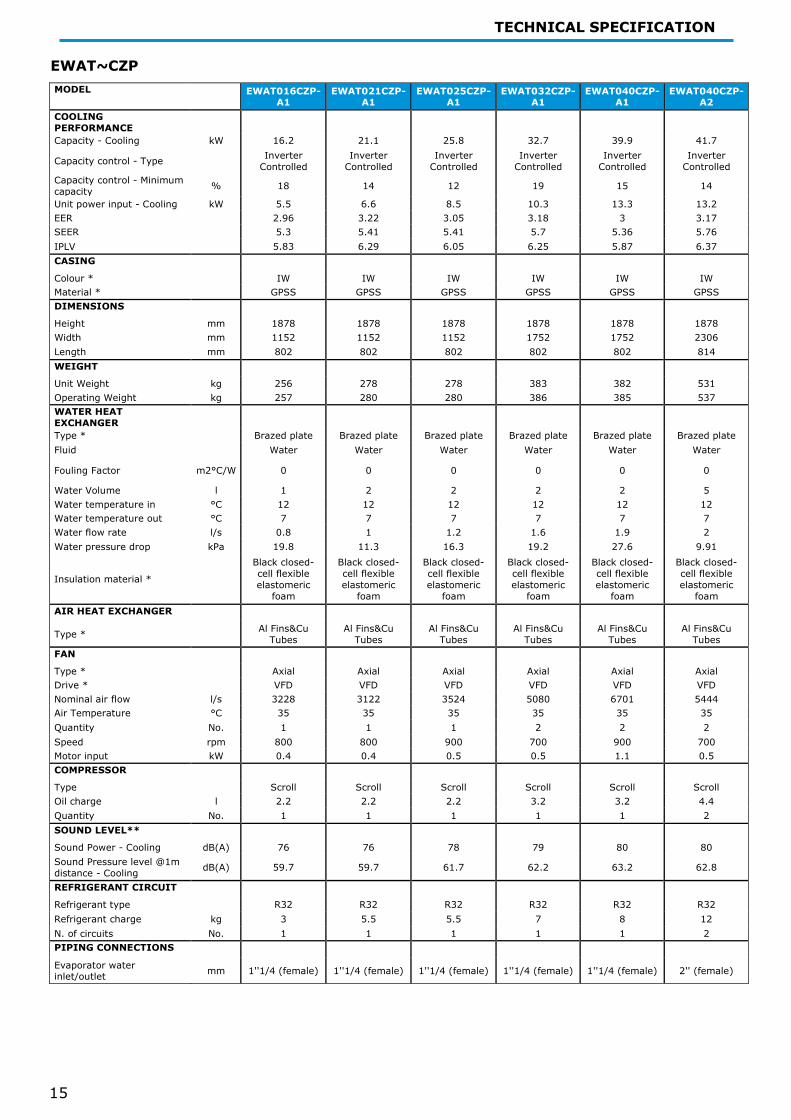
EWAT~CZP MODEL EWAT016CZP-
A1 EWAT021CZP-
A1 EWAT025CZP-
A1 EWAT032CZP-
A1 EWAT040CZP-
A1 EWAT040CZP-
A2 COOLING PERFORMANCE
Capacity - Cooling kW 16.2 21.1 25.8 32.7 39.9 41.7
Capacity control - Type Inverter Controlled
Inverter Controlled
Inverter Controlled
Inverter Controlled
Inverter Controlled
Inverter Controlled
Capacity control - Minimum capacity % 18 14 12 19 15 14
Unit power input - Cooling kW 5.5 6.6 8.5 10.3 13.3 13.2 EER 2.96 3.22 3.05 3.18 3 3.17 SEER 5.3 5.41 5.41 5.7 5.36 5.76 IPLV 5.83 6.29 6.05 6.25 5.87 6.37 CASING Colour * IW IW IW IW IW IW Material * GPSS GPSS GPSS GPSS GPSS GPSS DIMENSIONS Height mm 1878 1878 1878 1878 1878 1878 Width mm 1152 1152 1152 1752 1752 2306 Length mm 802 802 802 802 802 814 WEIGHT Unit Weight kg 256 278 278 383 382 531 Operating Weight kg 257 280 280 386 385 537 WATER HEAT EXCHANGER
Type * Brazed plate Brazed plate Brazed plate Brazed plate Brazed plate Brazed plate Fluid Water Water Water Water Water Water
Fouling Factor m2°C/W 0 0 0 0 0 0
Water Volume l 1 2 2 2 2 5 Water temperature in °C 12 12 12 12 12 12 Water temperature out °C 7 7 7 7 7 7 Water flow rate l/s 0.8 1 1.2 1.6 1.9 2 Water pressure drop kPa 19.8 11.3 16.3 19.2 27.6 9.91
Insulation material * Black closed-cell flexible elastomeric
foam
Black closed-cell flexible elastomeric
foam
Black closed-cell flexible elastomeric
foam
Black closed-cell flexible elastomeric
foam
Black closed-cell flexible elastomeric
foam
Black closed-cell flexible elastomeric
foam AIR HEAT EXCHANGER
Type * Al Fins&Cu Tubes
Al Fins&Cu Tubes
Al Fins&Cu Tubes
Al Fins&Cu Tubes
Al Fins&Cu Tubes
Al Fins&Cu Tubes
FAN Type * Axial Axial Axial Axial Axial Axial Drive * VFD VFD VFD VFD VFD VFD Nominal air flow l/s 3228 3122 3524 5080 6701 5444 Air Temperature °C 35 35 35 35 35 35 Quantity No. 1 1 1 2 2 2 Speed rpm 800 800 900 700 900 700 Motor input kW 0.4 0.4 0.5 0.5 1.1 0.5 COMPRESSOR Type Scroll Scroll Scroll Scroll Scroll Scroll Oil charge l 2.2 2.2 2.2 3.2 3.2 4.4 Quantity No. 1 1 1 1 1 2 SOUND LEVEL** Sound Power - Cooling dB(A) 76 76 78 79 80 80 Sound Pressure level @1m distance - Cooling dB(A) 59.7 59.7 61.7 62.2 63.2 62.8
REFRIGERANT CIRCUIT Refrigerant type R32 R32 R32 R32 R32 R32 Refrigerant charge kg 3 5.5 5.5 7 8 12 N. of circuits No. 1 1 1 1 1 2 PIPING CONNECTIONS Evaporator water inlet/outlet mm 1''1/4 (female) 1''1/4 (female) 1''1/4 (female) 1''1/4 (female) 1''1/4 (female) 2'' (female)

TECHNICAL SPECIFICATION
16
MODEL EWAT050CZP-
A2 EWAT064CZP-
A2 EWAT090CZP-
A2 COOLING PERFORMANCE Capacity - Cooling kW 51.1 64.4 88.8
Capacity control - Type Inverter Controlled
Inverter Controlled
Inverter Controlled
Capacity control - Minimum capacity % 12 15 14
Unit power input - Cooling kW 17 21.9 31.1 EER 3.03 2.95 2.85 SEER 5.48 5.34 5.18 IPLV 5.92 5.88 5.61 CASING Colour * IW IW IW Material * GPSS GPSS GPSS DIMENSIONS Height mm 1878 1878 1878 Width mm 2306 2906 3506 Length mm 814 814 814 WEIGHT Unit Weight kg 531 630 727 Operating Weight kg 537 636 735 WATER HEAT EXCHANGER Type * Brazed plate Brazed plate Brazed plate Fluid Water Water Water
Fouling Factor m2°C/W 0 0 0
Water Volume l 5 5 8 Water temperature in °C 12 12 12 Water temperature out °C 7 7 7 Water flow rate l/s 2.4 3.1 4.2 Water pressure drop kPa 14.3 21.7 20.1
Insulation material * Black closed-cell flexible elastomeric
foam
Black closed-cell flexible elastomeric
foam
Black closed-cell flexible elastomeric
foam AIR HEAT EXCHANGER
Type * Al Fins&Cu Tubes
Al Fins&Cu Tubes
Al Fins&Cu Tubes
FAN Type * Axial Axial Axial Drive * VFD VFD VFD Nominal air flow l/s 7048 8967 13402 Air Temperature °C 35 35 35 Quantity No. 2 3 4 Speed rpm 900 800 900 Motor input kW 1.1 1.2 2.3 COMPRESSOR Type Scroll Scroll Scroll Oil charge l 4.4 5.4 6.4 Quantity No. 2 2 2 SOUND LEVEL** Sound Power - Cooling dB(A) 81 83 85 Sound Pressure level @1m distance - Cooling dB(A) 63.8 65.4 67
REFRIGERANT CIRCUIT Refrigerant type R32 R32 R32 Refrigerant charge kg 12 13 16 N. of circuits No. 2 2 2 PIPING CONNECTIONS Evaporator water inlet/outlet mm 2'' (female) 2'' (female) 2'' (female)

TECHNICAL SPECIFICATION
17
EWAT~CZH MODEL EWAT016CZH-
A1 EWAT021CZH-
A1 EWAT025CZH-
A1 EWAT032CZH-
A1 EWAT040CZH-
A1 EWAT040CZH-
A2 COOLING PERFORMANCE
Capacity - Cooling kW 16.2 21.2 25.9 32.8 40.1 41.8
Capacity control - Type Inverter Controlled
Inverter Controlled
Inverter Controlled
Inverter Controlled
Inverter Controlled
Inverter Controlled
Capacity control - Minimum capacity % 18 14 12 19 15 14
Unit power input - Cooling kW 5.62 6.74 8.7 10.4 13.5 13.3 EER 2.89 3.15 2.98 3.14 2.97 3.15 SEER 5.2 5.32 5.34 5.67 5.34 5.76 IPLV 5.83 6.29 6.05 6.25 5.87 6.37 CASING Colour * IW IW IW IW IW IW Material * GPSS GPSS GPSS GPSS GPSS GPSS DIMENSIONS Height mm 1878 1878 1878 1878 1878 1878 Width mm 1152 1152 1152 1752 1752 2306 Length mm 802 802 802 802 802 814 WEIGHT Unit Weight kg 256 278 278 383 382 531 Operating Weight kg 257 280 280 386 385 537 WATER HEAT EXCHANGER
Type * Brazed plate Brazed plate Brazed plate Brazed plate Brazed plate Brazed plate Fluid Water Water Water Water Water Water
Fouling Factor m2°C/W 0 0 0 0 0 0
Water Volume l 1 2 2 2 2 5 Water temperature in °C 12 12 12 12 12 12 Water temperature out °C 7 7 7 7 7 7 Water flow rate l/s 0.8 1 1.2 1.6 1.9 2 Water pressure drop kPa 19.8 11.3 16.3 19.2 27.6 9.9
Insulation material * Black closed-cell flexible elastomeric
foam
Black closed-cell flexible elastomeric
foam
Black closed-cell flexible elastomeric
foam
Black closed-cell flexible elastomeric
foam
Black closed-cell flexible elastomeric
foam
Black closed-cell flexible elastomeric
foam AIR HEAT EXCHANGER
Type * Al Fins&Cu Tubes
Al Fins&Cu Tubes
Al Fins&Cu Tubes
Al Fins&Cu Tubes
Al Fins&Cu Tubes
Al Fins&Cu Tubes
FAN Type * Axial Axial Axial Axial Axial Axial Drive * VFD VFD VFD VFD VFD VFD Nominal air flow l/s 3228 3122 3524 5080 6701 5444 Air Temperature °C 35 35 35 35 35 35 Quantity No. 1 1 1 2 2 2 Speed rpm 800 800 900 700 900 700 Motor input kW 0.4 0.4 0.5 0.5 1.1 0.5 COMPRESSOR Type Scroll Scroll Scroll Scroll Scroll Scroll Oil charge l 2.2 2.2 2.2 3.2 3.2 4.4 Quantity No. 1 1 1 1 1 2 SOUND LEVEL** Sound Power - Cooling dB(A) 76 76 78 79 80 80 Sound Pressure level @1m distance - Cooling dB(A) 59.7 59.7 61.7 62.2 63.2 62.8
REFRIGERANT CIRCUIT Refrigerant type R32 R32 R32 R32 R32 R32 Refrigerant charge kg 3 5.5 5.5 7 8 12 N. of circuits No. 1 1 1 1 1 2 PIPING CONNECTIONS Evaporator water inlet/outlet mm 1''1/4 (female) 1''1/4 (female) 1''1/4 (female) 1''1/4 (female) 1''1/4 (female) 2'' (female)
TECHNICAL SPECIFICATION
18
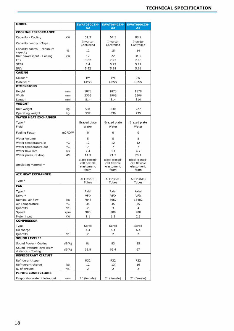
MODEL EWAT050CZH-
A2 EWAT064CZH-
A2 EWAT090CZH-
A2 COOLING PERFORMANCE Capacity - Cooling kW 51.3 64.5 88.9
Capacity control - Type Inverter Controlled
Inverter Controlled
Inverter Controlled
Capacity control - Minimum capacity % 12 15 14
Unit power input - Cooling kW 17 22 31.2 EER 3.02 2.93 2.85 SEER 5.4 5.27 5.12 IPLV 5.92 5.88 5.61 CASING Colour * IW IW IW Material * GPSS GPSS GPSS DIMENSIONS Height mm 1878 1878 1878 Width mm 2306 2906 3506 Length mm 814 814 814 WEIGHT Unit Weight kg 531 630 727 Operating Weight kg 537 636 735 WATER HEAT EXCHANGER Type * Brazed plate Brazed plate Brazed plate Fluid Water Water Water
Fouling Factor m2°C/W 0 0 0
Water Volume l 5 5 8 Water temperature in °C 12 12 12 Water temperature out °C 7 7 7 Water flow rate l/s 2.4 3.1 4.2 Water pressure drop kPa 14.3 21.7 20.1
Insulation material * Black closed-cell flexible elastomeric
foam
Black closed-cell flexible elastomeric
foam
Black closed-cell flexible elastomeric
foam AIR HEAT EXCHANGER
Type * Al Fins&Cu Tubes
Al Fins&Cu Tubes
Al Fins&Cu Tubes
FAN Type * Axial Axial Axial Drive * VFD VFD VFD Nominal air flow l/s 7048 8967 13402 Air Temperature °C 35 35 35 Quantity No. 2 3 4 Speed rpm 900 800 900 Motor input kW 1.1 1.2 2.3 COMPRESSOR Type Scroll Scroll Scroll Oil charge l 4.4 5.4 6.4 Quantity No. 2 2 2 SOUND LEVEL** Sound Power - Cooling dB(A) 81 83 85 Sound Pressure level @1m distance - Cooling dB(A) 63.8 65.4 67
REFRIGERANT CIRCUIT Refrigerant type R32 R32 R32 Refrigerant charge kg 12 13 16 N. of circuits No. 2 2 2 PIPING CONNECTIONS Evaporator water inlet/outlet mm 2'' (female) 2'' (female) 2'' (female)

TECHNICAL SPECIFICATION
19
EWAT~CZN MAX (“MAX” configuration has to be setted on site through the controller) MODEL EWAT016CZN-
A1_MAX EWAT021CZN-
A1_MAX EWAT025CZN-
A1_MAX EWAT032CZN-
A1_MAX EWAT040CZN-
A1_MAX EWAT040CZN-
A2_MAX COOLING PERFORMANCE
Capacity - Cooling kW 18.3 25 29.3 38.6 45.2 49.6
Capacity control - Type Inverter Controlled
Inverter Controlled
Inverter Controlled
Inverter Controlled
Inverter Controlled
Inverter Controlled
Capacity control - Minimum capacity % 18 14 12 19 15 14
Unit power input - Cooling kW 6.8 8.5 10.7 13.5 16.7 17.3 EER 2.69 2.94 2.74 2.87 2.71 2.87 SEER 5 5 5.06 5.21 5.09 5.41 IPLV 5.83 6.29 6.05 6.25 5.87 6.37 CASING Colour * IW IW IW IW IW IW Material * GPSS GPSS GPSS GPSS GPSS GPSS DIMENSIONS Height mm 1878 1878 1878 1878 1878 1878 Width mm 1152 1152 1152 1752 1752 2306 Length mm 802 802 802 802 802 814 WEIGHT Unit Weight kg 222 245 245 340 339 480 Operating Weight kg 223 247 247 343 342 486 WATER HEAT EXCHANGER
Type * Brazed plate Brazed plate Brazed plate Brazed plate Brazed plate Brazed plate Fluid Water Water Water Water Water Water
Fouling Factor m2°C/W 0 0 0 0 0 0
Water Volume l 1 2 2 2 2 5 Water temperature in °C 12 12 12 12 12 12 Water temperature out °C 7 7 7 7 7 7 Water flow rate l/s 0.9 1.2 1.4 1.8 2.2 2.4 Water pressure drop kPa 25.6 15.7 20.7 26.4 35 13.8
Insulation material * Black closed-cell flexible elastomeric
foam
Black closed-cell flexible elastomeric
foam
Black closed-cell flexible elastomeric
foam
Black closed-cell flexible elastomeric
foam
Black closed-cell flexible elastomeric
foam
Black closed-cell flexible elastomeric
foam AIR HEAT EXCHANGER
Type * Al Fins&Cu Tubes
Al Fins&Cu Tubes
Al Fins&Cu Tubes
Al Fins&Cu Tubes
Al Fins&Cu Tubes
Al Fins&Cu Tubes
FAN Type * Axial Axial Axial Axial Axial Axial Drive * VFD VFD VFD VFD VFD VFD Nominal air flow l/s 3228 3122 3524 5080 6701 5444 Air Temperature °C 35 35 35 35 35 35 Quantity No. 1 1 1 2 2 2 Speed rpm 800 800 900 700 900 700 Motor input kW 0.4 0.4 0.5 0.5 1.1 0.5 COMPRESSOR Type Scroll Scroll Scroll Scroll Scroll Scroll Oil charge l 2.2 2.2 2.2 3.2 3.2 4.4 Quantity No. 1 1 1 1 1 2 SOUND LEVEL** Sound Power - Cooling dB(A) 76 76 78 79 80 80 Sound Pressure level @1m distance - Cooling dB(A) 59.7 59.7 61.7 62.2 63.2 62.8
REFRIGERANT CIRCUIT Refrigerant type R32 R32 R32 R32 R32 R32 Refrigerant charge kg 3 5.5 5.5 7 8 12 N. of circuits No. 1 1 1 1 1 2 PIPING CONNECTIONS Evaporator water inlet/outlet mm 1''1/4 (female) 1''1/4 (female) 1''1/4 (female) 1''1/4 (female) 1''1/4 (female) 2'' (female)

TECHNICAL SPECIFICATION
20
MODEL EWAT050CZN-
A2_MAX EWAT064CZN-
A2_MAX EWAT090CZN-
A2_MAX COOLING PERFORMANCE Capacity - Cooling kW 58.2 72.7 98.3
Capacity control - Type Inverter Controlled
Inverter Controlled
Inverter Controlled
Capacity control - Minimum capacity % 12 15 14
Unit power input - Cooling kW 21.3 27.4 38.2 EER 2.73 2.65 2.57 SEER 5.33 5.21 5.03 IPLV 5.92 5.88 5.61 CASING Colour * IW IW IW Material * GPSS GPSS GPSS DIMENSIONS Height mm 1878 1878 1878 Width mm 2306 2906 3506 Length mm 814 814 814 WEIGHT Unit Weight kg 480 574 672 Operating Weight kg 486 580 680 WATER HEAT EXCHANGER Type * Brazed plate Brazed plate Brazed plate Fluid Water Water Water
Fouling Factor m2°C/W 0 0 0
Water Volume l 5 5 8 Water temperature in °C 12 12 12 Water temperature out °C 7 7 7 Water flow rate l/s 2.8 3.5 4.7 Water pressure drop kPa 18.3 27.4 24.4
Insulation material * Black closed-cell flexible elastomeric
foam
Black closed-cell flexible elastomeric
foam
Black closed-cell flexible elastomeric
foam AIR HEAT EXCHANGER
Type * Al Fins&Cu Tubes
Al Fins&Cu Tubes
Al Fins&Cu Tubes
FAN Type * Axial Axial Axial Drive * VFD VFD VFD Nominal air flow l/s 7048 8967 13402 Air Temperature °C 35 35 35 Quantity No. 2 3 4 Speed rpm 900 800 900 Motor input kW 1.1 1.2 2.3 COMPRESSOR Type Scroll Scroll Scroll Oil charge l 4.4 5.4 6.4 Quantity No. 2 2 2 SOUND LEVEL** Sound Power - Cooling dB(A) 81 83 85 Sound Pressure level @1m distance - Cooling dB(A) 63.8 65.4 67
REFRIGERANT CIRCUIT Refrigerant type R32 R32 R32 Refrigerant charge kg 12 13 16 N. of circuits No. 2 2 2 PIPING CONNECTIONS Evaporator water inlet/outlet mm 2'' (female) 2'' (female) 2'' (female)

TECHNICAL SPECIFICATION
21
EWAT~CZP MAX (“MAX” configuration has to be setted on site through the controller) MODEL EWAT016CZP-
A1_MAX EWAT021CZP-
A1_MAX EWAT025CZP-
A1_MAX EWAT032CZP-
A1_MAX EWAT040CZP-
A1_MAX EWAT040CZP-
A2_MAX COOLING PERFORMANCE
Capacity - Cooling kW 18.6 25.3 29.6 38.9 45.6 50
Capacity control - Type Inverter Controlled
Inverter Controlled
Inverter Controlled
Inverter Controlled
Inverter Controlled
Inverter Controlled
Capacity control - Minimum capacity % 18 14 12 19 15 14
Unit power input - Cooling kW 6.8 8.5 10.6 13.4 16.6 17.2 EER 2.75 2.98 2.78 2.91 2.75 2.91 SEER 5.3 5.41 5.41 5.7 5.36 5.76 IPLV 5.83 6.29 6.05 6.25 5.87 6.37 CASING Colour * IW IW IW IW IW IW Material * GPSS GPSS GPSS GPSS GPSS GPSS DIMENSIONS Height mm 1878 1878 1878 1878 1878 1878 Width mm 1152 1152 1152 1752 1752 2306 Length mm 802 802 802 802 802 814 WEIGHT Unit Weight kg 256 278 278 383 382 531 Operating Weight kg 257 280 280 386 385 537 WATER HEAT EXCHANGER
Type * Brazed plate Brazed plate Brazed plate Brazed plate Brazed plate Brazed plate Fluid Water Water Water Water Water Water
Fouling Factor m2°C/W 0 0 0 0 0 0
Water Volume l 1 2 2 2 2 5 Water temperature in °C 12 12 12 12 12 12 Water temperature out °C 7 7 7 7 7 7 Water flow rate l/s 0.88 1.2 1.4 1.84 2.16 2.37 Water pressure drop kPa 25.6 15.7 20.7 26.4 35 13.8
Insulation material * Black closed-cell flexible elastomeric
foam
Black closed-cell flexible elastomeric
foam
Black closed-cell flexible elastomeric
foam
Black closed-cell flexible elastomeric
foam
Black closed-cell flexible elastomeric
foam
Black closed-cell flexible elastomeric
foam AIR HEAT EXCHANGER
Type * Al Fins&Cu Tubes
Al Fins&Cu Tubes
Al Fins&Cu Tubes
Al Fins&Cu Tubes
Al Fins&Cu Tubes
Al Fins&Cu Tubes
FAN Type * Axial Axial Axial Axial Axial Axial Drive * VFD VFD VFD VFD VFD VFD Nominal air flow l/s 3228 3122 3524 5080 6701 5444 Air Temperature °C 35 35 35 35 35 35 Quantity No. 1 1 1 2 2 2 Speed rpm 800 800 900 700 900 700 Motor input kW 0.4 0.4 0.5 0.5 1.1 0.5 COMPRESSOR Type Scroll Scroll Scroll Scroll Scroll Scroll Oil charge l 2.2 2.2 2.2 3.2 3.2 4.4 Quantity No. 1 1 1 1 1 2 SOUND LEVEL** Sound Power - Cooling dB(A) 76 76 78 79 80 80 Sound Pressure level @1m distance - Cooling dB(A) 59.7 59.7 61.7 62.2 63.2 62.8
REFRIGERANT CIRCUIT Refrigerant type R32 R32 R32 R32 R32 R32 Refrigerant charge kg 3 5.5 5.5 7 8 12 N. of circuits No. 1 1 1 1 1 2 PIPING CONNECTIONS Evaporator water inlet/outlet mm 1''1/4 (female) 1''1/4 (female) 1''1/4 (female) 1''1/4 (female) 1''1/4 (female) 2'' (female)

TECHNICAL SPECIFICATION
22
MODEL EWAT050CZP-
A2_MAX EWAT064CZP-
A2_MAX EWAT090CZP-
A2_MAX COOLING PERFORMANCE Capacity - Cooling kW 58.6 73.3 98.8
Capacity control - Type Inverter Controlled
Inverter Controlled
Inverter Controlled
Capacity control - Minimum capacity % 12 15 14
Unit power input - Cooling kW 21.2 27.5 38.4 EER 2.77 2.67 2.58 SEER 5.48 5.34 5.18 IPLV 5.92 5.88 5.61 CASING Colour * IW IW IW Material * GPSS GPSS GPSS DIMENSIONS Height mm 1878 1878 1878 Width mm 2306 2906 3506 Length mm 814 814 814 WEIGHT Unit Weight kg 531 630 727 Operating Weight kg 537 636 735 WATER HEAT EXCHANGER Type * Brazed plate Brazed plate Brazed plate Fluid Water Water Water
Fouling Factor m2°C/W 0 0 0
Water Volume l 5 5 8 Water temperature in °C 12 12 12 Water temperature out °C 7 7 7 Water flow rate l/s 2.8 3.5 4.7 Water pressure drop kPa 18.3 27.4 24.4
Insulation material * Black closed-cell flexible elastomeric
foam
Black closed-cell flexible elastomeric
foam
Black closed-cell flexible elastomeric
foam AIR HEAT EXCHANGER
Type * Al Fins&Cu Tubes
Al Fins&Cu Tubes
Al Fins&Cu Tubes
FAN Type * Axial Axial Axial Drive * VFD VFD VFD Nominal air flow l/s 7048 8967 13402 Air Temperature °C 35 35 35 Quantity No. 2 3 4 Speed rpm 900 800 900 Motor input kW 1.1 1.2 2.3 COMPRESSOR Type Scroll Scroll Scroll Oil charge l 4.4 5.4 6.4 Quantity No. 2 2 2 SOUND LEVEL** Sound Power - Cooling dB(A) 81 83 85 Sound Pressure level @1m distance - Cooling dB(A) 63.8 65.4 67
REFRIGERANT CIRCUIT Refrigerant type R32 R32 R32 Refrigerant charge kg 12 13 16 N. of circuits No. 2 2 2 PIPING CONNECTIONS Evaporator water inlet/outlet mm 2'' (female) 2'' (female) 2'' (female)

TECHNICAL SPECIFICATION
23
EWAT~CZH MAX (“MAX” configuration has to be setted on site through the controller) MODEL EWAT016CZH-
A1_MAX EWAT021CZH-
A1_MAX EWAT025CZH-
A1_MAX EWAT032CZH-
A1_MAX EWAT040CZH-
A1_MAX EWAT040CZH-
A2_MAX COOLING PERFORMANCE
Capacity - Cooling kW 18.7 25.4 29.6 39.1 45.7 50.1
Capacity control - Type Inverter Controlled
Inverter Controlled
Inverter Controlled
Inverter Controlled
Inverter Controlled
Inverter Controlled
Capacity control - Minimum capacity % 18 14 12 19 15 14
Unit power input - Cooling kW 6.9 8.7 10.8 13.5 16.7 17.3 EER 2.69 2.93 2.73 2.89 2.73 2.9 SEER 5.2 5.32 5.34 5.67 5.34 5.76 IPLV 5.83 6.29 6.05 6.25 5.87 6.37 CASING Colour * IW IW IW IW IW IW Material * GPSS GPSS GPSS GPSS GPSS GPSS DIMENSIONS Height mm 1878 1878 1878 1878 1878 1878 Width mm 1152 1152 1152 1752 1752 2306 Length mm 802 802 802 802 802 814 WEIGHT Unit Weight kg 256 278 278 383 382 531 Operating Weight kg 257 280 280 386 385 537 WATER HEAT EXCHANGER
Type * Brazed plate Brazed plate Brazed plate Brazed plate Brazed plate Brazed plate Fluid Water Water Water Water Water Water
Fouling Factor m2°C/W 0 0 0 0 0 0
Water Volume l 1 2 2 2 2 5 Water temperature in °C 12 12 12 12 12 12 Water temperature out °C 7 7 7 7 7 7 Water flow rate l/s 0.9 1.2 1.4 1.8 2.2 2.4 Water pressure drop kPa 25.6 15.7 20.7 26.4 35 13.8
Insulation material * Black closed-cell flexible elastomeric
foam
Black closed-cell flexible elastomeric
foam
Black closed-cell flexible elastomeric
foam
Black closed-cell flexible elastomeric
foam
Black closed-cell flexible elastomeric
foam
Black closed-cell flexible elastomeric
foam AIR HEAT EXCHANGER
Type * Al Fins&Cu Tubes
Al Fins&Cu Tubes
Al Fins&Cu Tubes
Al Fins&Cu Tubes
Al Fins&Cu Tubes
Al Fins&Cu Tubes
FAN Type * Axial Axial Axial Axial Axial Axial Drive * VFD VFD VFD VFD VFD VFD Nominal air flow l/s 3228 3122 3524 5080 6701 5444 Air Temperature °C 35 35 35 35 35 35 Quantity No. 1 1 1 2 2 2 Speed rpm 800 800 900 700 900 700 Motor input kW 0.4 0.4 0.5 0.5 1.1 0.5 COMPRESSOR Type Scroll Scroll Scroll Scroll Scroll Scroll Oil charge l 2.2 2.2 2.2 3.2 3.2 4.4 Quantity No. 1 1 1 1 1 2 SOUND LEVEL** Sound Power - Cooling dB(A) 76 76 78 79 80 80 Sound Pressure level @1m distance - Cooling dB(A) 59.7 59.7 61.7 62.2 63.2 62.8
REFRIGERANT CIRCUIT Refrigerant type R32 R32 R32 R32 R32 R32 Refrigerant charge kg 3 5.5 5.5 7 8 12 N. of circuits No. 1 1 1 1 1 2 PIPING CONNECTIONS Evaporator water inlet/outlet mm 1''1/4 (female) 1''1/4 (female) 1''1/4 (female) 1''1/4 (female) 1''1/4 (female) 2'' (female)

TECHNICAL SPECIFICATION
24
MODEL EWAT050CZH-
A2_MAX EWAT064CZH-
A2_MAX EWAT090CZH-
A2_MAX COOLING PERFORMANCE Capacity - Cooling kW 58.7 73.4 98.9
Capacity control - Type Inverter Controlled
Inverter Controlled
Inverter Controlled
Capacity control - Minimum capacity % 12 15 14
Unit power input - Cooling kW 21.3 27.6 38.5 EER 2.76 2.66 2.57 SEER 5.4 5.27 5.12 IPLV 5.92 5.88 5.61 CASING Colour * IW IW IW Material * GPSS GPSS GPSS DIMENSIONS Height mm 1878 1878 1878 Width mm 2306 2906 3506 Length mm 814 814 814 WEIGHT Unit Weight kg 531 630 727 Operating Weight kg 537 636 735 WATER HEAT EXCHANGER Type * Brazed plate Brazed plate Brazed plate Fluid Water Water Water
Fouling Factor m2°C/W 0 0 0
Water Volume l 5 5 8 Water temperature in °C 12 12 12 Water temperature out °C 7 7 7 Water flow rate l/s 2.8 3.5 4.7 Water pressure drop kPa 18.3 27.4 24.4
Insulation material * Black closed-cell flexible elastomeric
foam
Black closed-cell flexible elastomeric
foam
Black closed-cell flexible elastomeric
foam AIR HEAT EXCHANGER
Type * Al Fins&Cu Tubes
Al Fins&Cu Tubes
Al Fins&Cu Tubes
FAN Type * Axial Axial Axial Drive * VFD VFD VFD Nominal air flow l/s 7048 8967 13402 Air Temperature °C 35 35 35 Quantity No. 2 3 4 Speed rpm 900 800 900 Motor input kW 1.1 1.2 2.3 COMPRESSOR Type Scroll Scroll Scroll Oil charge l 4.4 5.4 6.4 Quantity No. 2 2 2 SOUND LEVEL** Sound Power - Cooling dB(A) 81 83 85 Sound Pressure level @1m distance - Cooling dB(A) 63.8 65.4 67
REFRIGERANT CIRCUIT Refrigerant type R32 R32 R32 Refrigerant charge kg 12 13 16 N. of circuits No. 2 2 2 PIPING CONNECTIONS Evaporator water inlet/outlet mm 2'' (female) 2'' (female) 2'' (female)

TECHNICAL SPECIFICATION
25
EWYT~CZN MODEL EWYT016CZN-
A1 EWYT021CZN-
A1 EWYT025CZN-
A1 EWYT032CZN-
A1 EWYT040CZN-
A1 EWYT040CZN-
A2 COOLING PERFORMANCE
Capacity - Cooling kW 15.9 20.9 25.6 32.4 39.6 41.4
Capacity control - Type Inverter Controlled
Inverter Controlled
Inverter Controlled
Inverter Controlled
Inverter Controlled
Inverter Controlled
Capacity control - Minimum capacity % 18 14 12 19 15 14
Unit power input - Cooling kW 5.5 6.6 8.5 10.3 13.4 13.2 EER 2.9 3.16 3 3.13 2.95 3.12 SEER 5 5 5.06 5.21 5.09 5.41 IPLV 5.83 6.29 6.05 6.25 5.87 6.37 HEATING PERFORMANCE
Capacity - Heating kW 15.9 20.2 24.8 32.4 39.4 40.3 Unit power input - Heating kW 4.7 5.8 7.5 9.4 11.8 11.9 COP 3.41 3.46 3.33 3.45 3.33 3.38 SCOP Low / Medium Temp 3.89 / 0 4 / 2.83 4.07 / 2.89 4.06 / 2.85 4.07 / 2.89 4.02 / 2.93 WATER HEAT EXCHANGER HEATING
Water temperature in °C 40 40 40 40 40 40 Water temperature out °C 45 45 45 45 45 45 Water flow rate l/s 0.8 1 1.2 1.5 1.9 1.9 Water pressure drop kPa 19.6 10.6 15.4 19.1 27.1 9.4 FAN Air Temperature 7 7 7 7 7 7 WATER HEAT EXCHANGER COOLING
Type * Brazed plate Brazed plate Brazed plate Brazed plate Brazed plate Brazed plate Fluid Water Water Water Water Water Water
Fouling Factor m2°C/W 0 0 0 0 0 0
Water Volume l 1 2 2 2 2 5 Water temperature in °C 12 12 12 12 12 12 Water temperature out °C 7 7 7 7 7 7 Water flow rate l/s 0.8 1 1.2 1.6 1.9 2 Water pressure drop kPa 19.8 11.3 16.3 19.2 27.6 9.91
Insulation material * Black closed-cell flexible elastomeric
foam
Black closed-cell flexible elastomeric
foam
Black closed-cell flexible elastomeric
foam
Black closed-cell flexible elastomeric
foam
Black closed-cell flexible elastomeric
foam
Black closed-cell flexible elastomeric
foam AIR HEAT EXCHANGER
Type * Al Fins&Cu Tubes
Al Fins&Cu Tubes
Al Fins&Cu Tubes
Al Fins&Cu Tubes
Al Fins&Cu Tubes
Al Fins&Cu Tubes
FAN Type * Axial Axial Axial Axial Axial Axial Drive * VFD VFD VFD VFD VFD VFD Nominal air flow l/s 3228 3122 3524 5080 6701 5444 Air Temperature °C 35 35 35 35 35 35 Quantity No. 1 1 1 2 2 2 Speed rpm 800 800 900 700 900 700 Motor input kW 0.4 0.4 0.5 0.5 1.1 0.5 CASING Colour * IW IW IW IW IW IW Material * GPSS GPSS GPSS GPSS GPSS GPSS DIMENSIONS Height mm 1878 1878 1878 1878 1878 1878 Width mm 1152 1152 1152 1752 1752 2306 Length mm 802 802 802 802 802 814 WEIGHT Unit Weight kg 227 252 252 350 349 494 Operating Weight kg 228 254 254 353 352 500 COMPRESSOR Type Scroll Scroll Scroll Scroll Scroll Scroll Oil charge l 2.2 2.2 2.2 3.2 3.2 4.4 Quantity No. 1 1 1 1 1 2

TECHNICAL SPECIFICATION
26
SOUND LEVEL**
Sound Power - Cooling dB(A) 76 76 78 79 80 80 Sound Pressure level @1m distance - Cooling dB(A) 59.7 59.7 61.7 62.2 63.2 62.8
REFRIGERANT CIRCUIT Refrigerant type R32 R32 R32 R32 R32 R32 Refrigerant charge kg 3 5.5 5.5 7 8 12 N. of circuits No. 1 1 1 1 1 2 PIPING CONNECTIONS
Evaporator water inlet/outlet mm 1''1/4 (female)
1''1/4 (female)
1''1/4 (female)
1''1/4 (female)
1''1/4 (female) 2'' (female)
MODEL EWYT050CZN-
A2 EWYT064CZN-
A2 EWYT090CZN-
A2 COOLING PERFORMANCE Capacity - Cooling kW 50.8 64 88.3
Capacity control - Type Inverter Controlled
Inverter Controlled
Inverter Controlled
Capacity control - Minimum capacity % 12 15 14
Unit power input - Cooling kW 17 21.8 31 EER 2.98 2.93 2.84 SEER 5.33 5.21 5.03 IPLV 5.92 5.88 5.61 HEATING PERFORMANCE Capacity - Heating kW 49.8 61.9 85.8 Unit power input - Heating kW 15.4 19.1 27.2 COP 3.24 3.23 3.16 SCOP Low / Medium Temp 4 / 2.92 3.98 / 2.9 4 / 2.89 WATER HEAT EXCHANGER HEATING
Water temperature in °C 40 40 40 Water temperature out °C 45 45 45 Water flow rate l/s 2.4 3 4.1 Water pressure drop kPa 13.8 20.4 19.1 FAN Air Temperature 7 7 7 WATER HEAT EXCHANGER COOLING
Type * Brazed plate Brazed plate Brazed plate Fluid Water Water Water
Fouling Factor m2°C/W 0 0 0
Water Volume l 5 5 8 Water temperature in °C 12 12 12 Water temperature out °C 7 7 7 Water flow rate l/s 2.4 3.1 4.2 Water pressure drop kPa 14.3 21.7 20.1
Insulation material * Black closed-cell flexible elastomeric
foam
Black closed-cell flexible elastomeric
foam
Black closed-cell flexible elastomeric
foam AIR HEAT EXCHANGER
Type * Al Fins&Cu Tubes
Al Fins&Cu Tubes
Al Fins&Cu Tubes
FAN Type * Axial Axial Axial Drive * VFD VFD VFD Nominal air flow l/s 7048 8967 13402 Air Temperature °C 35 35 35 Quantity No. 2 3 4 Speed rpm 900 800 900 Motor input kW 1.1 1.2 2.3 CASING Colour * IW IW IW Material * GPSS GPSS GPSS

TECHNICAL SPECIFICATION
27
DIMENSIONS Height mm 1878 1878 1878 Width mm 2306 2906 3506 Length mm 814 814 814 WEIGHT Unit Weight kg 494 588 693 Operating Weight kg 500 594 701 COMPRESSOR Type Scroll Scroll Scroll Oil charge l 4.4 5.4 6.4 Quantity No. 2 2 2 SOUND LEVEL** Sound Power - Cooling dB(A) 81 83 85 Sound Pressure level @1m distance - Cooling dB(A) 63.8 65.4 67
REFRIGERANT CIRCUIT Refrigerant type R32 R32 R32 Refrigerant charge kg 12 13 16 N. of circuits No. 2 2 2 PIPING CONNECTIONS Evaporator water inlet/outlet mm 2'' (female) 2'' (female) 2'' (female)

TECHNICAL SPECIFICATION
28
EWYT~CZP MODEL EWYT016CZP-
A1 EWYT021CZP-
A1 EWYT025CZP-
A1 EWYT032CZP-
A1 EWYT040CZP-
A1 EWYT040CZP-
A2 COOLING PERFORMANCE Capacity - Cooling kW 16.1 21.1 25.9 32.7 39.9 41.7
Capacity control - Type Inverter Controlled
Inverter Controlled
Inverter Controlled
Inverter Controlled
Inverter Controlled
Inverter Controlled
Capacity control - Minimum capacity % 18 14 12 19 15 14
Unit power input - Cooling kW 5.4 6.6 8.5 10.3 13.3 13.2 EER 3 3.2 3.1 3.2 3 3.2 SEER 5.3 5.41 5.41 5.7 5.36 5.76 IPLV 5.83 6.29 6.05 6.25 5.87 6.37 HEATING PERFORMANCE Capacity - Heating kW 15.6 19.9 24.6 32.1 39 40 Unit power input - Heating kW 4.6 5.8 7.4 9.3 11.7 11.8 COP 3.37 3.43 3.31 3.44 3.33 3.38 SCOP Low / Medium Temp 4.03 / 0 4.19 / 2.93 4.19 / 2.97 4.18 / 2.9 4.18 / 2.95 4.19 / 3.02 WATER HEAT EXCHANGER HEATING
Water temperature in °C 40 40 40 40 40 40 Water temperature out °C 45 45 45 45 45 45 Water flow rate l/s 0.8 1 1.2 1.5 1.9 1.9 Water pressure drop kPa 19.6 10.6 15.4 19.1 27.1 9.4 FAN Air Temperature 7 7 7 7 7 7 WATER HEAT EXCHANGER COOLING
Type * Brazed plate Brazed plate Brazed plate Brazed plate Brazed plate Brazed plate Fluid Water Water Water Water Water Water
Fouling Factor m2°C/W 0 0 0 0 0 0
Water Volume l 1 2 2 2 2 5 Water temperature in °C 12 12 12 12 12 12 Water temperature out °C 7 7 7 7 7 7 Water flow rate l/s 0.8 1 1.2 1.6 1.9 2 Water pressure drop kPa 19.8 11.3 16.3 19.2 27.6 9.91
Insulation material * Black closed-cell flexible elastomeric
foam
Black closed-cell flexible elastomeric
foam
Black closed-cell flexible elastomeric
foam
Black closed-cell flexible elastomeric
foam
Black closed-cell flexible elastomeric
foam
Black closed-cell flexible elastomeric
foam AIR HEAT EXCHANGER
Type * Al Fins&Cu Tubes
Al Fins&Cu Tubes
Al Fins&Cu Tubes
Al Fins&Cu Tubes
Al Fins&Cu Tubes
Al Fins&Cu Tubes
FAN Type * Axial Axial Axial Axial Axial Axial Drive * VFD VFD VFD VFD VFD VFD Nominal air flow l/s 3228 3122 3524 5080 6701 5444 Air Temperature °C 35 35 35 35 35 35 Quantity No. 1 1 1 2 2 2 Speed rpm 800 800 900 700 900 700 Motor input kW 0.4 0.4 0.5 0.5 1.1 0.5 CASING Colour * IW IW IW IW IW IW Material * GPSS GPSS GPSS GPSS GPSS GPSS DIMENSIONS Height mm 1878 1878 1878 1878 1878 1878 Width mm 1152 1152 1152 1752 1752 2306 Length mm 802 802 802 802 802 814 WEIGHT Unit Weight kg 261 286 286 393 392 546 Operating Weight kg 262 288 288 396 395 551 COMPRESSOR Type Scroll Scroll Scroll Scroll Scroll Scroll Oil charge l 2.2 2.2 2.2 3.2 3.2 4.4 Quantity No. 1 1 1 1 1 2
TECHNICAL SPECIFICATION
29
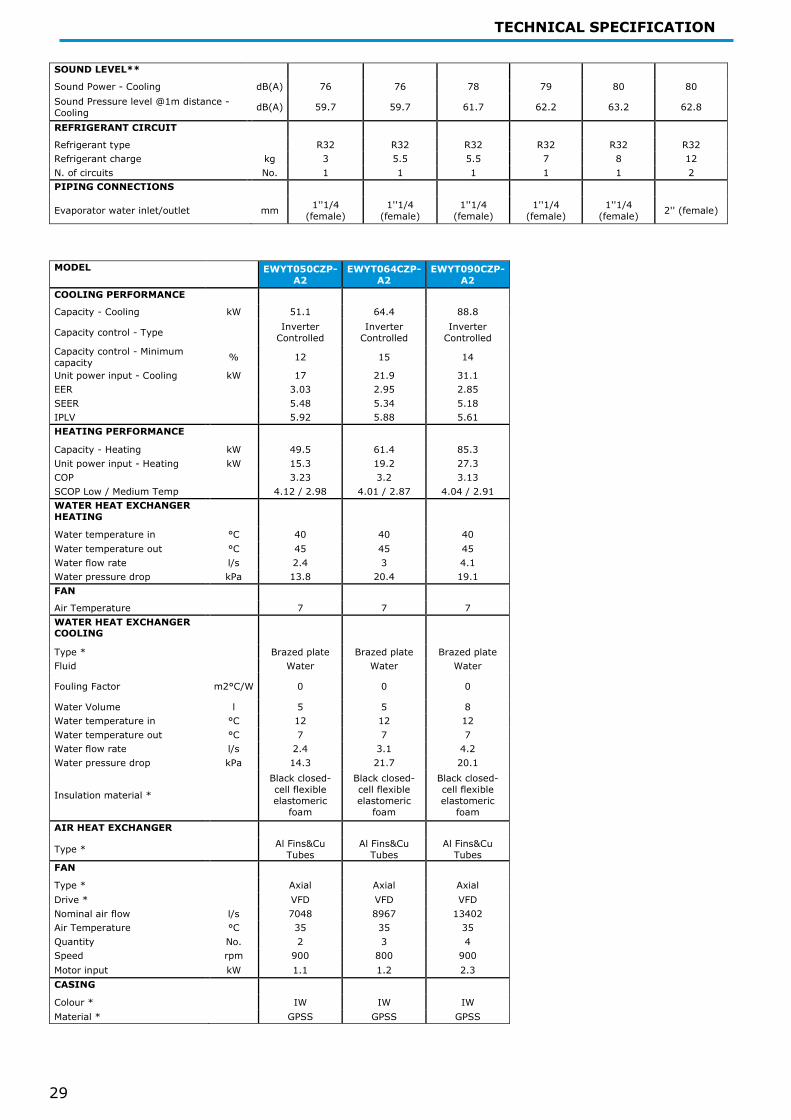
SOUND LEVEL**
Sound Power - Cooling dB(A) 76 76 78 79 80 80 Sound Pressure level @1m distance - Cooling dB(A) 59.7 59.7 61.7 62.2 63.2 62.8
REFRIGERANT CIRCUIT Refrigerant type R32 R32 R32 R32 R32 R32 Refrigerant charge kg 3 5.5 5.5 7 8 12 N. of circuits No. 1 1 1 1 1 2 PIPING CONNECTIONS
Evaporator water inlet/outlet mm 1''1/4 (female)
1''1/4 (female)
1''1/4 (female)
1''1/4 (female)
1''1/4 (female) 2'' (female)
MODEL EWYT050CZP-
A2 EWYT064CZP-
A2 EWYT090CZP-
A2 COOLING PERFORMANCE Capacity - Cooling kW 51.1 64.4 88.8
Capacity control - Type Inverter Controlled
Inverter Controlled
Inverter Controlled
Capacity control - Minimum capacity % 12 15 14
Unit power input - Cooling kW 17 21.9 31.1 EER 3.03 2.95 2.85 SEER 5.48 5.34 5.18 IPLV 5.92 5.88 5.61 HEATING PERFORMANCE Capacity - Heating kW 49.5 61.4 85.3 Unit power input - Heating kW 15.3 19.2 27.3 COP 3.23 3.2 3.13 SCOP Low / Medium Temp 4.12 / 2.98 4.01 / 2.87 4.04 / 2.91 WATER HEAT EXCHANGER HEATING
Water temperature in °C 40 40 40 Water temperature out °C 45 45 45 Water flow rate l/s 2.4 3 4.1 Water pressure drop kPa 13.8 20.4 19.1 FAN Air Temperature 7 7 7 WATER HEAT EXCHANGER COOLING
Type * Brazed plate Brazed plate Brazed plate Fluid Water Water Water
Fouling Factor m2°C/W 0 0 0
Water Volume l 5 5 8 Water temperature in °C 12 12 12 Water temperature out °C 7 7 7 Water flow rate l/s 2.4 3.1 4.2 Water pressure drop kPa 14.3 21.7 20.1
Insulation material * Black closed-cell flexible elastomeric
foam
Black closed-cell flexible elastomeric
foam
Black closed-cell flexible elastomeric
foam AIR HEAT EXCHANGER
Type * Al Fins&Cu Tubes
Al Fins&Cu Tubes
Al Fins&Cu Tubes
FAN Type * Axial Axial Axial Drive * VFD VFD VFD Nominal air flow l/s 7048 8967 13402 Air Temperature °C 35 35 35 Quantity No. 2 3 4 Speed rpm 900 800 900 Motor input kW 1.1 1.2 2.3 CASING Colour * IW IW IW Material * GPSS GPSS GPSS

TECHNICAL SPECIFICATION
30
DIMENSIONS Height mm 1878 1878 1878 Width mm 2306 2906 3506 Length mm 814 814 814 WEIGHT Unit Weight kg 546 644 749 Operating Weight kg 551 650 757 COMPRESSOR Type Scroll Scroll Scroll Oil charge l 4.4 5.4 6.4 Quantity No. 2 2 2 SOUND LEVEL** Sound Power - Cooling dB(A) 81 83 85 Sound Pressure level @1m distance - Cooling dB(A) 63.8 65.4 67
REFRIGERANT CIRCUIT Refrigerant type R32 R32 R32 Refrigerant charge kg 12 13 16 N. of circuits No. 2 2 2 PIPING CONNECTIONS Evaporator water inlet/outlet mm 2'' (female) 2'' (female) 2'' (female)

TECHNICAL SPECIFICATION
31
EWYT~CZH MODEL EWYT016CZH-
A1 EWYT021CZH-
A1 EWYT025CZH-
A1 EWYT032CZH-
A1 EWYT040CZH-
A1 EWYT040CZH-
A2 COOLING PERFORMANCE
Capacity - Cooling kW 16.2 21.2 25.9 32.8 40.1 41.8
Capacity control - Type Inverter Controlled
Inverter Controlled
Inverter Controlled
Inverter Controlled
Inverter Controlled
Inverter Controlled
Capacity control - Minimum capacity % 18 14 12 19 15 14
Unit power input - Cooling kW 5.6 6.7 8.7 10.4 13.5 13.3 EER 2.89 3.15 2.98 3.14 2.97 3.15 SEER 5.2 5.32 5.34 5.67 5.34 5.76 IPLV 5.83 6.29 6.05 6.25 5.87 6.37 HEATING PERFORMANCE
Capacity - Heating kW 15.5 19.8 24.5 32 38.9 39.9 Unit power input - Heating kW 4.8 6 7.6 9.5 11.9 12 COP 3.24 3.31 3.22 3.37 3.28 3.33 SCOP Low / Medium Temp 3.88 / 0 4.06 / 2.84 4.08 / 2.89 4.11 / 2.87 4.13 / 2.91 4.14 / 2.98 WATER HEAT EXCHANGER HEATING
Water temperature in °C 40 40 40 40 40 40 Water temperature out °C 45 45 45 45 45 45 Water flow rate l/s 0.8 1 1.2 1.6 1.9 1.9 Water pressure drop kPa 19.6 10.6 15.4 19.1 27.1 9.4 FAN Air Temperature 7 7 7 7 7 7 WATER HEAT EXCHANGER COOLING
Type * Brazed plate Brazed plate Brazed plate Brazed plate Brazed plate Brazed plate Fluid Water Water Water Water Water Water
Fouling Factor m2°C/W 0 0 0 0 0 0
Water Volume l 1 2 2 2 2 5 Water temperature in °C 12 12 12 12 12 12 Water temperature out °C 7 7 7 7 7 7 Water flow rate l/s 0.8 1 1.2 1.6 1.9 2 Water pressure drop kPa 19.8 11.3 16.3 19.2 27.6 9.9
Insulation material * Black closed-cell flexible elastomeric
foam
Black closed-cell flexible elastomeric
foam
Black closed-cell flexible elastomeric
foam
Black closed-cell flexible elastomeric
foam
Black closed-cell flexible elastomeric
foam
Black closed-cell flexible elastomeric
foam AIR HEAT EXCHANGER
Type * Al Fins&Cu Tubes
Al Fins&Cu Tubes
Al Fins&Cu Tubes
Al Fins&Cu Tubes
Al Fins&Cu Tubes
Al Fins&Cu Tubes
FAN Type * Axial Axial Axial Axial Axial Axial Drive * VFD VFD VFD VFD VFD VFD Nominal air flow l/s 3227 3122 3524 5080 6701 5444 Air Temperature °C 35 35 35 35 35 35 Quantity No. 1 1 1 2 2 2 Speed rpm 800 800 900 700 900 700 Motor input kW 0.4 0.4 0.5 0.5 1.1 0.5 CASING Colour * IW IW IW IW IW IW Material * GPSS GPSS GPSS GPSS GPSS GPSS DIMENSIONS Height mm 1878 1878 1878 1878 1878 1878 Width mm 1152 1152 1152 1752 1752 2306 Length mm 802 802 802 802 802 814 WEIGHT Unit Weight kg 261 286 286 393 392 546 Operating Weight kg 262 288 288 396 395 551 COMPRESSOR Type Scroll Scroll Scroll Scroll Scroll Scroll Oil charge l 2.2 2.2 2.2 3.2 3.2 4.4 Quantity No. 1 1 1 1 1 2

TECHNICAL SPECIFICATION
32
SOUND LEVEL**
Sound Power - Cooling dB(A) 76 76 78 79 80 80 Sound Pressure level @1m distance - Cooling dB(A) 59.7 59.7 61.7 62.2 63.2 62.8
REFRIGERANT CIRCUIT Refrigerant type R32 R32 R32 R32 R32 R32 Refrigerant charge kg 3 5.5 5.5 7 8 12 N. of circuits No. 1 1 1 1 1 2 PIPING CONNECTIONS
Evaporator water inlet/outlet mm 1''1/4 (female)
1''1/4 (female)
1''1/4 (female)
1''1/4 (female)
1''1/4 (female) 2'' (female)
MODEL EWYT050CZH-
A2 EWYT064CZH-
A2 EWYT090CZH-
A2 COOLING PERFORMANCE Capacity - Cooling kW 51.3 64.5 88.9
Capacity control - Type Inverter Controlled
Inverter Controlled
Inverter Controlled
Capacity control - Minimum capacity % 12 15 14
Unit power input - Cooling kW 17 22 31.2 EER 3.02 2.93 2.85 SEER 5.4 5.27 5.12 IPLV 5.92 5.88 5.61 HEATING PERFORMANCE Capacity - Heating kW 49.4 61.3 85.2 Unit power input - Heating kW 15.4 19.3 27.4 COP 3.2 3.17 3.12 SCOP Low / Medium Temp 4.09 / 2.96 3.94 / 2.84 4 / 2.88 WATER HEAT EXCHANGER HEATING
Water temperature in °C 40 40 40 Water temperature out °C 45 45 45 Water flow rate l/s 2.4 3 4.1 Water pressure drop kPa 13.8 20.4 19.1 FAN Air Temperature 7 7 7 WATER HEAT EXCHANGER COOLING
Type * Brazed plate Brazed plate Brazed plate Fluid Water Water Water
Fouling Factor m2°C/W 0 0 0
Water Volume l 5 5 8 Water temperature in °C 12 12 12 Water temperature out °C 7 7 7 Water flow rate l/s 2.4 3.1 4.2 Water pressure drop kPa 14.3 21.7 20.1
Insulation material * Black closed-cell flexible elastomeric
foam
Black closed-cell flexible elastomeric
foam
Black closed-cell flexible elastomeric
foam AIR HEAT EXCHANGER
Type * Al Fins&Cu Tubes
Al Fins&Cu Tubes
Al Fins&Cu Tubes
FAN Type * Axial Axial Axial Drive * VFD VFD VFD Nominal air flow l/s 7048 8967 13402 Air Temperature °C 35 35 35 Quantity No. 2 3 4 Speed rpm 900 800 900 Motor input kW 1.1 1.2 2.3 CASING Colour * IW IW IW Material * GPSS GPSS GPSS

TECHNICAL SPECIFICATION
33
DIMENSIONS Height mm 1878 1878 1878 Width mm 2306 2906 3506 Length mm 814 814 814 WEIGHT Unit Weight kg 546 644 749 Operating Weight kg 551 650 757 COMPRESSOR Type Scroll Scroll Scroll Oil charge l 4.4 5.4 6.4 Quantity No. 2 2 2 SOUND LEVEL** Sound Power - Cooling dB(A) 81 83 85 Sound Pressure level @1m distance - Cooling dB(A) 63.8 65.4 67
REFRIGERANT CIRCUIT Refrigerant type R32 R32 R32 Refrigerant charge kg 12 13 16 N. of circuits No. 2 2 2 PIPING CONNECTIONS Evaporator water inlet/outlet mm 2'' (female) 2'' (female) 2'' (female)

TECHNICAL SPECIFICATION
34
EWYT~CZN MAX (“MAX” configuration has to be setted on site through the controller) MODEL EWYT016CZN-
A1_MAX EWYT021CZN-
A1_MAX EWYT025CZN-
A1_MAX EWYT032CZN-
A1_MAX EWYT040CZN-
A1_MAX EWYT040CZN-
A2_MAX COOLING PERFORMANCE
Capacity - Cooling kW 18.3 25 29.3 38.6 45.2 49.6
Capacity control - Type Inverter Controlled
Inverter Controlled
Inverter Controlled
Inverter Controlled
Inverter Controlled
Inverter Controlled
Capacity control - Minimum capacity % 18 14 12 19 15 14
Unit power input - Cooling kW 6.8 8.5 10.7 13.5 16.7 17.3 EER 2.69 2.94 2.74 2.87 2.71 2.87 SEER 5 5 5.06 5.21 5.09 5.41 IPLV 5.83 6.29 6.05 6.25 5.87 6.37 HEATING PERFORMANCE
Capacity - Heating kW 18.3 24.3 28.7 36.5 44.7 48.7 Unit power input - Heating kW 5.6 7.2 9 11.5 14.2 14.7 COP 3.28 3.38 3.19 3.17 3.15 3.31 SCOP Low / Medium Temp 3.89 / 0 4 / 2.83 4.07 / 2.89 4.06 / 2.85 4.07 / 2.89 4.02 / 2.93 WATER HEAT EXCHANGER HEATING
Water temperature in °C 40 40 40 40 40 40 Water temperature out °C 45 45 45 45 45 45 Water flow rate l/s 0.9 1.2 1.4 1.7 2.1 2.3 Water pressure drop kPa 25.3 14.7 19.8 23.7 34.1 13.25 FAN Air Temperature 7 7 7 7 7 7 WATER HEAT EXCHANGER COOLING
Type * Brazed plate Brazed plate Brazed plate Brazed plate Brazed plate Brazed plate Fluid Water Water Water Water Water Water
Fouling Factor m2°C/W 0 0 0 0 0 0
Water Volume l 1 2 2 2 2 5 Water temperature in °C 12 12 12 12 12 12 Water temperature out °C 7 7 7 7 7 7 Water flow rate l/s 0.9 1.2 1.4 1.8 2.2 2.4 Water pressure drop kPa 25.5 15.6 20.7 26.3 35 13.7
Insulation material * Black closed-cell flexible elastomeric
foam
Black closed-cell flexible elastomeric
foam
Black closed-cell flexible elastomeric
foam
Black closed-cell flexible elastomeric
foam
Black closed-cell flexible elastomeric
foam
Black closed-cell flexible elastomeric
foam AIR HEAT EXCHANGER
Type * Al Fins&Cu Tubes
Al Fins&Cu Tubes
Al Fins&Cu Tubes
Al Fins&Cu Tubes
Al Fins&Cu Tubes
Al Fins&Cu Tubes
FAN Type * Axial Axial Axial Axial Axial Axial Drive * VFD VFD VFD VFD VFD VFD Nominal air flow l/s 3227 3122 3524 5080 6701 5444 Air Temperature °C 35 35 35 35 35 35 Quantity No. 1 1 1 2 2 2 Speed rpm 800 800 900 700 900 700 Motor input kW 0.4 0.4 0.5 0.5 1.1 0.5 CASING Colour * IW IW IW IW IW IW Material * GPSS GPSS GPSS GPSS GPSS GPSS DIMENSIONS Height mm 1878 1878 1878 1878 1878 1878 Width mm 1152 1152 1152 1752 1752 2306 Length mm 802 802 802 802 802 814 WEIGHT Unit Weight kg 227 252 252 350 349 494 Operating Weight kg 228 254 254 353 352 500 COMPRESSOR Type Scroll Scroll Scroll Scroll Scroll Scroll Oil charge l 2.2 2.2 2.2 3.2 3.2 4.4 Quantity
No. 1 1 1 1 1 2

TECHNICAL SPECIFICATION
35
SOUND LEVEL**
Sound Power - Cooling dB(A) 76 76 78 79 80 80 Sound Pressure level @1m distance - Cooling dB(A) 59.7 59.7 61.7 62.2 63.2 62.8
REFRIGERANT CIRCUIT Refrigerant type R32 R32 R32 R32 R32 R32 Refrigerant charge kg 3 5.5 5.5 7 8 12 N. of circuits No. 1 1 1 1 1 2 PIPING CONNECTIONS
Evaporator water inlet/outlet mm 1''1/4 (female)
1''1/4 (female)
1''1/4 (female)
1''1/4 (female)
1''1/4 (female) 2'' (female)
MODEL EWYT050CZN-
A2_MAX EWYT064CZN-
A2_MAX EWYT090CZN-
A2_MAX COOLING PERFORMANCE Capacity - Cooling kW 58.2 72.7 98.3
Capacity control - Type Inverter Controlled
Inverter Controlled
Inverter Controlled
Capacity control - Minimum capacity % 12 15 14
Unit power input - Cooling kW 21.3 27.4 38.2 EER 2.73 2.65 2.57 SEER 5.33 5.21 5.03 IPLV 5.92 5.88 5.61 HEATING PERFORMANCE Capacity - Heating kW 57.3 69.2 94.7 Unit power input - Heating kW 18.6 23.2 32.4 COP 3.09 2.98 2.92 SCOP Low / Medium Temp 4 / 2.92 3.98 / 2.9 4 / 2.89 WATER HEAT EXCHANGER HEATING
Water temperature in °C 40 40 40 Water temperature out °C 45 45 45 Water flow rate l/s 2.74 3.31 4.52 Water pressure drop kPa 17.7 24.9 22.7 FAN Air Temperature 7 7 7 WATER HEAT EXCHANGER COOLING
Type * Brazed plate Brazed plate Brazed plate Fluid Water Water Water
Fouling Factor m2°C/W 0 0 0
Water Volume l 5 5 8 Water temperature in °C 12 12 12 Water temperature out °C 7 7 7 Water flow rate l/s 2.8 3.5 4.7 Water pressure drop kPa 18.3 27.4 24.4
Insulation material * Black closed-cell flexible elastomeric
foam
Black closed-cell flexible elastomeric
foam
Black closed-cell flexible elastomeric
foam AIR HEAT EXCHANGER
Type * Al Fins&Cu Tubes
Al Fins&Cu Tubes
Al Fins&Cu Tubes
FAN Type * Axial Axial Axial Drive * VFD VFD VFD Nominal air flow l/s 7048 8967 13402 Air Temperature °C 35 35 35 Quantity No. 2 3 4 Speed rpm 900 800 900 Motor input kW 1.1 1.2 2.3 CASING Colour * IW IW IW Material * GPSS GPSS GPSS
TECHNICAL SPECIFICATION
36
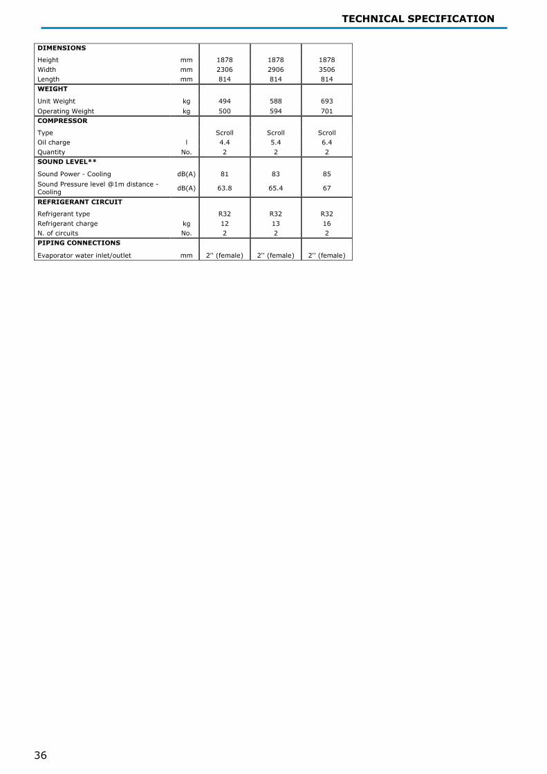
DIMENSIONS Height mm 1878 1878 1878 Width mm 2306 2906 3506 Length mm 814 814 814 WEIGHT Unit Weight kg 494 588 693 Operating Weight kg 500 594 701 COMPRESSOR Type Scroll Scroll Scroll Oil charge l 4.4 5.4 6.4 Quantity No. 2 2 2 SOUND LEVEL** Sound Power - Cooling dB(A) 81 83 85 Sound Pressure level @1m distance - Cooling dB(A) 63.8 65.4 67
REFRIGERANT CIRCUIT Refrigerant type R32 R32 R32 Refrigerant charge kg 12 13 16 N. of circuits No. 2 2 2 PIPING CONNECTIONS Evaporator water inlet/outlet mm 2'' (female) 2'' (female) 2'' (female)
TECHNICAL SPECIFICATION
37
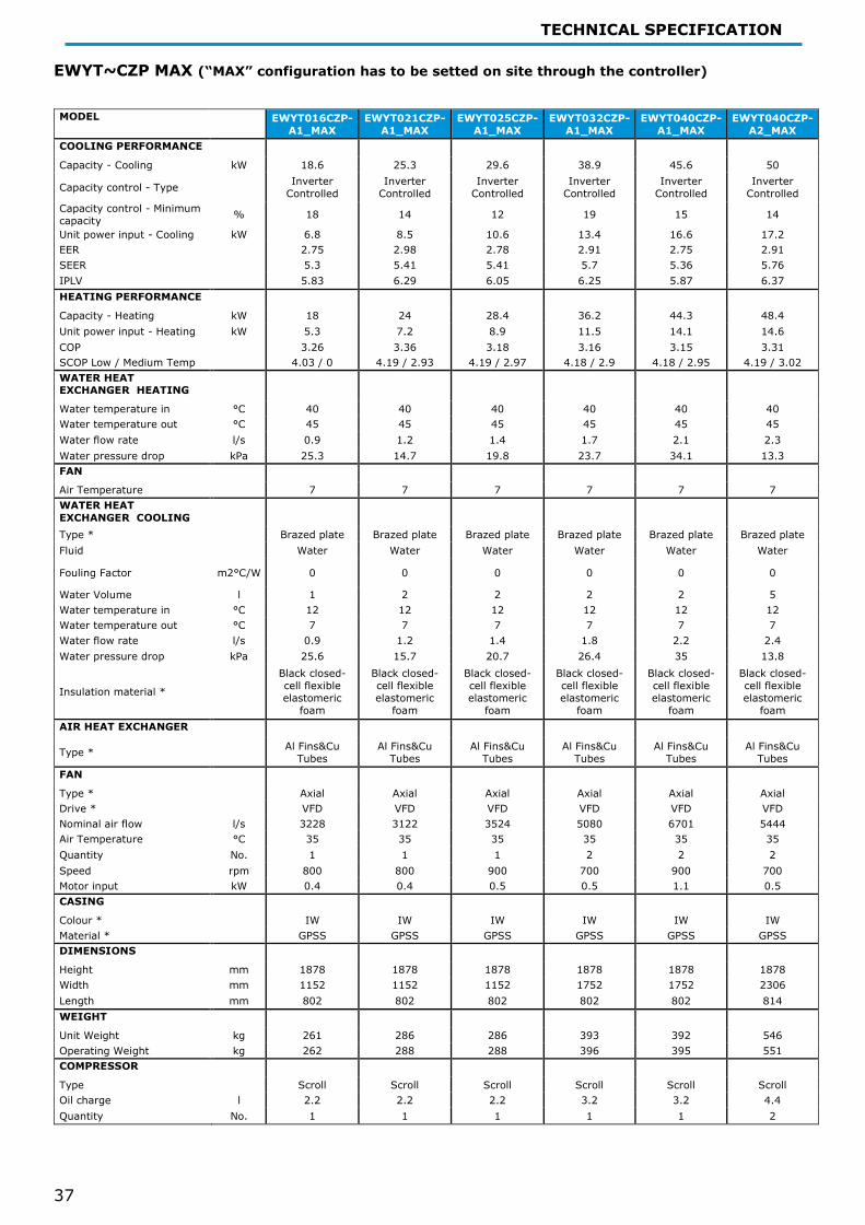
EWYT~CZP MAX (“MAX” configuration has to be setted on site through the controller) MODEL EWYT016CZP-
A1_MAX EWYT021CZP-
A1_MAX EWYT025CZP-
A1_MAX EWYT032CZP-
A1_MAX EWYT040CZP-
A1_MAX EWYT040CZP-
A2_MAX COOLING PERFORMANCE Capacity - Cooling kW 18.6 25.3 29.6 38.9 45.6 50
Capacity control - Type Inverter Controlled
Inverter Controlled
Inverter Controlled
Inverter Controlled
Inverter Controlled
Inverter Controlled
Capacity control - Minimum capacity % 18 14 12 19 15 14
Unit power input - Cooling kW 6.8 8.5 10.6 13.4 16.6 17.2 EER 2.75 2.98 2.78 2.91 2.75 2.91 SEER 5.3 5.41 5.41 5.7 5.36 5.76 IPLV 5.83 6.29 6.05 6.25 5.87 6.37 HEATING PERFORMANCE Capacity - Heating kW 18 24 28.4 36.2 44.3 48.4 Unit power input - Heating kW 5.3 7.2 8.9 11.5 14.1 14.6 COP 3.26 3.36 3.18 3.16 3.15 3.31 SCOP Low / Medium Temp 4.03 / 0 4.19 / 2.93 4.19 / 2.97 4.18 / 2.9 4.18 / 2.95 4.19 / 3.02 WATER HEAT EXCHANGER HEATING
Water temperature in °C 40 40 40 40 40 40 Water temperature out °C 45 45 45 45 45 45 Water flow rate l/s 0.9 1.2 1.4 1.7 2.1 2.3 Water pressure drop kPa 25.3 14.7 19.8 23.7 34.1 13.3 FAN Air Temperature 7 7 7 7 7 7 WATER HEAT EXCHANGER COOLING
Type * Brazed plate Brazed plate Brazed plate Brazed plate Brazed plate Brazed plate Fluid Water Water Water Water Water Water
Fouling Factor m2°C/W 0 0 0 0 0 0
Water Volume l 1 2 2 2 2 5 Water temperature in °C 12 12 12 12 12 12 Water temperature out °C 7 7 7 7 7 7 Water flow rate l/s 0.9 1.2 1.4 1.8 2.2 2.4 Water pressure drop kPa 25.6 15.7 20.7 26.4 35 13.8
Insulation material * Black closed-cell flexible elastomeric
foam
Black closed-cell flexible elastomeric
foam
Black closed-cell flexible elastomeric
foam
Black closed-cell flexible elastomeric
foam
Black closed-cell flexible elastomeric
foam
Black closed-cell flexible elastomeric
foam AIR HEAT EXCHANGER
Type * Al Fins&Cu Tubes
Al Fins&Cu Tubes
Al Fins&Cu Tubes
Al Fins&Cu Tubes
Al Fins&Cu Tubes
Al Fins&Cu Tubes
FAN Type * Axial Axial Axial Axial Axial Axial Drive * VFD VFD VFD VFD VFD VFD Nominal air flow l/s 3228 3122 3524 5080 6701 5444 Air Temperature °C 35 35 35 35 35 35 Quantity No. 1 1 1 2 2 2 Speed rpm 800 800 900 700 900 700 Motor input kW 0.4 0.4 0.5 0.5 1.1 0.5 CASING Colour * IW IW IW IW IW IW Material * GPSS GPSS GPSS GPSS GPSS GPSS DIMENSIONS Height mm 1878 1878 1878 1878 1878 1878 Width mm 1152 1152 1152 1752 1752 2306 Length mm 802 802 802 802 802 814 WEIGHT Unit Weight kg 261 286 286 393 392 546 Operating Weight kg 262 288 288 396 395 551 COMPRESSOR Type Scroll Scroll Scroll Scroll Scroll Scroll Oil charge l 2.2 2.2 2.2 3.2 3.2 4.4 Quantity No. 1 1 1 1 1 2

TECHNICAL SPECIFICATION
38
SOUND LEVEL**
Sound Power - Cooling dB(A) 76 76 78 79 80 80 Sound Pressure level @1m distance - Cooling dB(A) 59.7 59.7 61.7 62.2 63.2 62.8
REFRIGERANT CIRCUIT Refrigerant type R32 R32 R32 R32 R32 R32 Refrigerant charge kg 3 5.5 5.5 7 8 12 N. of circuits No. 1 1 1 1 1 2 PIPING CONNECTIONS
Evaporator water inlet/outlet mm 1''1/4 (female)
1''1/4 (female)
1''1/4 (female)
1''1/4 (female)
1''1/4 (female) 2'' (female)
MODEL EWYT050CZP-
A2_MAX EWYT064CZP-
A2_MAX EWYT090CZP-
A2_MAX COOLING PERFORMANCE Capacity - Cooling kW 58.6 73.3 98.8
Capacity control - Type Inverter Controlled
Inverter Controlled
Inverter Controlled
Capacity control - Minimum capacity % 12 15 14
Unit power input - Cooling kW 21.2 27.5 38.4 EER 2.77 2.67 2.58 SEER 5.48 5.34 5.18 IPLV 5.92 5.88 5.61 HEATING PERFORMANCE Capacity - Heating kW 58.9 68.7 94.1 Unit power input - Heating kW 18.5 23.3 32.5 COP 3.08 2.96 2.9 SCOP Low / Medium Temp 4.12 / 2.98 4.01 / 2.87 4.04 / 2.91 WATER HEAT EXCHANGER HEATING
Water temperature in °C 40 40 40 Water temperature out °C 45 45 45 Water flow rate l/s 2.7 3.3 4.5 Water pressure drop kPa 17.7 24.9 22.7 FAN Air Temperature 7 7 7 WATER HEAT EXCHANGER COOLING
Type * Brazed plate Brazed plate Brazed plate Fluid Water Water Water
Fouling Factor m2°C/W 0 0 0
Water Volume l 5 5 8 Water temperature in °C 12 12 12 Water temperature out °C 7 7 7 Water flow rate l/s 2.8 3.5 4.7 Water pressure drop kPa 18.3 27.4 24.4
Insulation material * Black closed-cell flexible elastomeric
foam
Black closed-cell flexible elastomeric
foam
Black closed-cell flexible elastomeric
foam AIR HEAT EXCHANGER
Type * Al Fins&Cu Tubes
Al Fins&Cu Tubes
Al Fins&Cu Tubes
FAN Type * Axial Axial Axial Drive * VFD VFD VFD Nominal air flow l/s 7048 8967 13402 Air Temperature °C 35 35 35 Quantity No. 2 3 4 Speed rpm 900 800 900 Motor input kW 1.1 1.2 2.3 CASING Colour * IW IW IW Material * GPSS GPSS GPSS
.

TECHNICAL SPECIFICATION
39
DIMENSIONS Height mm 1878 1878 1878 Width mm 2306 2906 3506 Length mm 814 814 814 WEIGHT Unit Weight kg 546 644 749 Operating Weight kg 551 650 757 COMPRESSOR Type Scroll Scroll Scroll Oil charge l 4.4 5.4 6.4 Quantity No. 2 2 2 SOUND LEVEL** Sound Power - Cooling dB(A) 81 83 85 Sound Pressure level @1m distance - Cooling dB(A) 63.8 65.4 67
REFRIGERANT CIRCUIT Refrigerant type R32 R32 R32 Refrigerant charge kg 12 13 16 N. of circuits No. 2 2 2 PIPING CONNECTIONS Evaporator water inlet/outlet mm 2'' (female) 2'' (female) 2'' (female)

TECHNICAL SPECIFICATION
40
EWYT~CZH MAX (“MAX” configuration has to be setted on site through the controller) MODEL EWYT016CZH-
A1_MAX EWYT021CZH-
A1_MAX EWYT025CZH-
A1_MAX EWYT032CZH-
A1_MAX EWYT040CZH-
A1_MAX EWYT040CZH-
A2_MAX COOLING PERFORMANCE
Capacity - Cooling kW 18.7 25.4 29.6 39.1 45.7 50.1
Capacity control - Type Inverter Controlled
Inverter Controlled
Inverter Controlled
Inverter Controlled
Inverter Controlled
Inverter Controlled
Capacity control - Minimum capacity % 18 14 12 19 15 14
Unit power input - Cooling kW 6.9 8.7 10.8 13.5 16.7 17.3 EER 2.69 2.93 2.73 2.89 2.73 2.9 SEER 5.2 5.32 5.34 5.67 5.34 5.76 IPLV 5.83 6.29 6.05 6.25 5.87 6.37 HEATING PERFORMANCE
Capacity - Heating kW 18 23.9 28.3 36.1 44.2 48.3 Unit power input - Heating kW 5.7 7.3 9.1 11.6 14.2 14.7 COP 3.15 3.26 3.1 3.11 3.11 3.28 SCOP Low / Medium Temp 3.88 / 0 4.06 / 2.84 4.08 / 2.89 4.11 / 2.87 4.13 / 2.91 4.14 / 2.98 WATER HEAT EXCHANGER HEATING
Water temperature in °C 40 40 40 40 40 40 Water temperature out °C 45 45 45 45 45 45 Water flow rate l/s 0.9 1.2 1.4 1.8 2.2 2.3 Water pressure drop kPa 25.3 14.7 19.8 23.7 34.1 13.3 FAN Air Temperature 7 7 7 7 7 7 WATER HEAT EXCHANGER COOLING
Type * Brazed plate Brazed plate Brazed plate Brazed plate Brazed plate Brazed plate Fluid Water Water Water Water Water Water
Fouling Factor m2°C/W 0 0 0 0 0 0
Water Volume l 1 2 2 2 2 5 Water temperature in °C 12 12 12 12 12 12 Water temperature out °C 7 7 7 7 7 7 Water flow rate l/s 0.9 1.2 1.4 1.9 2.2 2.4 Water pressure drop kPa 25.6 15.7 20.7 26.4 35 13.8
Insulation material * Black closed-cell flexible elastomeric
foam
Black closed-cell flexible elastomeric
foam
Black closed-cell flexible elastomeric
foam
Black closed-cell flexible elastomeric
foam
Black closed-cell flexible elastomeric
foam
Black closed-cell flexible elastomeric
foam AIR HEAT EXCHANGER
Type * Al Fins&Cu Tubes
Al Fins&Cu Tubes
Al Fins&Cu Tubes
Al Fins&Cu Tubes
Al Fins&Cu Tubes
Al Fins&Cu Tubes
FAN Type * Axial Axial Axial Axial Axial Axial Drive * VFD VFD VFD VFD VFD VFD Nominal air flow l/s 3228 3122 3524 5080 6701 5444 Air Temperature °C 35 35 35 35 35 35 Quantity No. 1 1 1 2 2 2 Speed rpm 800 800 900 700 900 700 Motor input kW 0.4 0.4 0.5 0.5 1.1 0.5 CASING Colour * IW IW IW IW IW IW Material * GPSS GPSS GPSS GPSS GPSS GPSS DIMENSIONS Height mm 1878 1878 1878 1878 1878 1878 Width mm 1152 1152 1152 1752 1752 2306 Length mm 802 802 802 802 802 814 WEIGHT Unit Weight kg 261 286 286 393 392 546 Operating Weight kg 262 288 288 396 395 551 COMPRESSOR Type Scroll Scroll Scroll Scroll Scroll Scroll Oil charge l 2.2 2.2 2.2 3.2 3.2 4.4 Quantity No. 1 1 1 1 1 2

TECHNICAL SPECIFICATION
41
SOUND LEVEL**
Sound Power - Cooling dB(A) 76 76 78 79 80 80 Sound Pressure level @1m distance - Cooling dB(A) 59.7 59.7 61.7 62.2 63.2 62.8
REFRIGERANT CIRCUIT Refrigerant type R32 R32 R32 R32 R32 R32 Refrigerant charge kg 3 5.5 5.5 7 8 12 N. of circuits No. 1 1 1 1 1 2 PIPING CONNECTIONS
Evaporator water inlet/outlet mm 1''1/4 (female)
1''1/4 (female)
1''1/4 (female)
1''1/4 (female)
1''1/4 (female) 2'' (female)
MODEL EWYT050CZH-
A2_MAX EWYT064CZH-
A2_MAX EWYT090CZH-
A2_MAX COOLING PERFORMANCE Capacity - Cooling kW 58.7 73.4 98.9
Capacity control - Type Inverter Controlled
Inverter Controlled
Inverter Controlled
Capacity control - Minimum capacity % 12 15 14
Unit power input - Cooling kW 21.3 27.6 38.5 EER 2.76 2.66 2.57 SEER 5.4 5.27 5.12 IPLV 5.92 5.88 5.61 HEATING PERFORMANCE Capacity - Heating kW 56.7 68.6 94 Unit power input - Heating kW 18.6 23.4 32.6 COP 3.06 2.94 2.88 SCOP Low / Medium Temp 4.09 / 2.96 3.94 / 2.84 4 / 2.88 WATER HEAT EXCHANGER HEATING
Water temperature in °C 40 40 40 Water temperature out °C 45 45 45 Water flow rate l/s 2.7 3.3 4.5 Water pressure drop kPa 17.7 24.9 22.7 FAN Air Temperature 7 7 7 WATER HEAT EXCHANGER COOLING
Type * Brazed plate Brazed plate Brazed plate Fluid Water Water Water
Fouling Factor m2°C/W 0 0 0
Water Volume l 5 5 8 Water temperature in °C 12 12 12 Water temperature out °C 7 7 7 Water flow rate l/s 2.8 3.5 4.7 Water pressure drop kPa 18.3 27.4 24.4
Insulation material * Black closed-cell flexible elastomeric
foam
Black closed-cell flexible elastomeric
foam
Black closed-cell flexible elastomeric
foam AIR HEAT EXCHANGER
Type * Al Fins&Cu Tubes
Al Fins&Cu Tubes
Al Fins&Cu Tubes
FAN Type * Axial Axial Axial Drive * VFD VFD VFD Nominal air flow l/s 7048 8967 13402 Air Temperature °C 35 35 35 Quantity No. 2 3 4 Speed rpm 900 800 900 Motor input kW 1.1 1.2 2.3 CASING Colour * IW IW IW Material * GPSS GPSS GPSS

TECHNICAL SPECIFICATION
42
DIMENSIONS Height mm 1878 1878 1878 Width mm 2306 2906 3506 Length mm 814 814 814 WEIGHT Unit Weight kg 546 644 749 Operating Weight kg 551 650 757 COMPRESSOR Type Scroll Scroll Scroll Oil charge l 4.4 5.4 6.4 Quantity No. 2 2 2 SOUND LEVEL** Sound Power - Cooling dB(A) 81 83 85 Sound Pressure level @1m distance - Cooling dB(A) 63.8 65.4 67
REFRIGERANT CIRCUIT Refrigerant type R32 R32 R32 Refrigerant charge kg 12 13 16 N. of circuits No. 2 2 2 PIPING CONNECTIONS Evaporator water inlet/outlet mm 2'' (female) 2'' (female) 2'' (female)
All the cooling performances (Cooling capacity, unit power input in cooling and EER) are based on the following conditions: 12,0/7,0°C; ambient 35,0°C, unit at full load operation; operating fluid: Water; fouling factor = 0. EN14511:2018 All the heating performances (Heating capacity, unit power input in heating and COP) are based on the following conditions: 40,0/45,0°C; ambient 7,0°C, unit at full load operation; operating fluid: Water; fouling factor = 0. EN14511:2018 The values of SCOP and ηs are calculated in accordance with the Ecodesign regulation No. 813/2013 and the standard EN 14825-2018, these units are classified as “Medium Temperature Heat Pumps” exept for the 16kW size that is classified as “Low Temperature Heat Pumps”. SCOP calculation for Low and Medium Temperature is based on the following conditions: Tbivalent -7 °C, Tdesign -10 °C, Average Climate. SEER is calculated in accordance with the regulation No. 2281/2016 and standard EN14825 for information only, unless the unit is a “cooling-only” type. ** Sound power level is measured in cooling mode at full load (referred to 12/7°C, ambient 35°C) in accordance with ISO 9614 and Eurovent requirements The sound pressure is calculated from the sound power level and are for information only and not considered binding. The minimum capacity indicated is referred to unit operating at standard Eurovent conditions. Dimensions and weights are for indication only and not considered binding. Before designing the installation, consult the official drawings available from the factory at request. All the data are referred to standard unit without options. All data are subject to change without notice

ELECTRICAL SPECIFICATIONS
43
Electrical specificationcc EWAT~CZN / MAX MODEL EWAT016CZN-
A1 EWAT021CZN-
A1 EWAT025CZN-
A1 EWAT032CZN-
A1 EWAT040CZN-
A1 EWAT040CZN-
A2 POWER SUPPLY Phases No. 3 3 3 3 3 3 Frequency Hz 50 50 50 50 50 50 Voltage V 400 400 400 400 400 400 Voltage tolerance Minimum % -10% -10% -10% -10% -10% -10% Voltage tolerance Maximum % 10% 10% 10% 10% 10% 10% UNIT Maximum inrush current A 0 0 0 0 0 0 Nominal running current cooling STD / MAX A 14 / 16 15 / 18 18 / 21 25 / 30 29 / 33 30 / 35
Maximum running current A 17 21 23 34 38 41 Maximum current for wires sizing A 21 25 28 41 46 50
COMPRESSORS Phases No. 3 3 3 3 3 3 Voltage V 400 400 400 400 400 400 Voltage tolerance Minimum % -10% -10% -10% -10% -10% -10% Voltage tolerance Maximum % 10% 10% 10% 10% 10% 10% Maximum running current A 0 0 0 0 0 0 Starting method VFD VFD VFD VFD VFD VFD
MODEL EWAT050CZN-
A2 EWAT064CZN-
A2 EWAT090CZN-
A2 POWER SUPPLY Phases No. 3 3 3 Frequency Hz 50 50 50 Voltage V 400 400 400 Voltage tolerance Minimum % -10% -10% -10% Voltage tolerance Maximum % 10% 10% 10% UNIT Maximum inrush current A 0 0 0 Nominal running current cooling STD / MAX A 34 / 41 46 / 54 62 / 72
Maximum running current A 46 61 83 Maximum current for wires sizing A 56 73 101 COMPRESSORS Phases No. 3 3 3 Voltage V 400 400 400 Voltage tolerance Minimum % -10% -10% -10% Voltage tolerance Maximum % 10% 10% 10% Maximum running current A 0 0 0 Starting method VFD VFD VFD

ELECTRICAL SPECIFICATIONS
44
EWAT~CZP / MAX MODEL EWAT016CZP-
A1 EWAT021CZP-
A1 EWAT025CZP-
A1 EWAT032CZP-
A1 EWAT040CZP-
A1 EWAT040CZP-
A2 POWER SUPPLY Phases No. 3 3 3 3 3 3 Frequency Hz 50 50 50 50 50 50 Voltage V 400 400 400 400 400 400 Voltage tolerance Minimum % -10% -10% -10% -10% -10% -10% Voltage tolerance Maximum % 10% 10% 10% 10% 10% 10% UNIT Maximum inrush current A 0 0 0 0 0 0 Nominal running current cooling STD / MAX A 11 / 13 13 / 16 16 / 19 22 / 27 25 / 30 26 / 32
Maximum running current A 21 25 27 38 42 45 Maximum current for wires sizing A 21 25 28 41 46 50
COMPRESSORS Phases No. 3 3 3 3 3 3 Voltage V 400 400 400 400 400 400 Voltage tolerance Minimum % -10% -10% -10% -10% -10% -10% Voltage tolerance Maximum % 10% 10% 10% 10% 10% 10% Maximum running current A 0 0 0 0 0 0 Starting method VFD VFD VFD VFD VFD VFD
MODEL EWAT050CZP-
A2 EWAT064CZP-
A2 EWAT090CZP-
A2 POWER SUPPLY Phases No. 3 3 3 Frequency Hz 50 50 50 Voltage V 400 400 400 Voltage tolerance Minimum % -10% -10% -10% Voltage tolerance Maximum % 10% 10% 10% UNIT Maximum inrush current A 0 0 0 Nominal running current Cooling STD / MAX A 31 / 38 42 / 51 58 / 68
Maximum running current A 50 66 88 Maximum current for wires sizing A 56 73 101 COMPRESSORS Phases No. 3 3 3 Voltage V 400 400 400 Voltage tolerance Minimum % -10% -10% -10% Voltage tolerance Maximum % 10% 10% 10% Maximum running current A 0 0 0 Starting method VFD VFD VFD

ELECTRICAL SPECIFICATIONS
45
EWAT~CZH / MAX MODEL EWAT016CZH-
A1 EWAT021CZH-
A1 EWAT025CZH-
A1 EWAT032CZH-
A1 EWAT040CZH-
A1 EWAT040CZH-
A2 POWER SUPPLY Phases No. 3 3 3 3 3 3 Frequency Hz 50 50 50 50 50 50 Voltage V 400 400 400 400 400 400 Voltage tolerance Minimum % -10% -10% -10% -10% -10% -10% Voltage tolerance Maximum % 10% 10% 10% 10% 10% 10% UNIT Maximum inrush current A 0 0 0 0 0 0 Nominal running current cooling STD / MAX A 11 / 13 13 / 16 16 / 19 22 / 27 25 / 30 26 / 32
Maximum running current A 21 25 27 39 43 46 Maximum current for wires sizing A 21 25 28 41 46 50
COMPRESSORS Phases No. 3 3 3 3 3 3 Voltage V 400 400 400 400 400 400 Voltage tolerance Minimum % -10% -10% -10% -10% -10% -10% Voltage tolerance Maximum % 10% 10% 10% 10% 10% 10% Maximum running current A 0 0 0 0 0 0 Starting method VFD VFD VFD VFD VFD VFD
MODEL EWAT050CZH-
A2 EWAT064CZH-
A2 EWAT090CZH-
A2 POWER SUPPLY Phases No. 3 3 3 Frequency Hz 50 50 50 Voltage V 400 400 400 Voltage tolerance Minimum % -10% -10% -10% Voltage tolerance Maximum % 10% 10% 10% UNIT Maximum inrush current A 0 0 0 Nominal running current Cooling STD / MAX A 31 / 38 42 / 51 58 / 68
Maximum running current A 51 68 90 Maximum current for wires sizing A 56 73 101 COMPRESSORS Phases No. 3 3 3 Voltage V 400 400 400 Voltage tolerance Minimum % -10% -10% -10% Voltage tolerance Maximum % 10% 10% 10% Maximum running current A 0 0 0 Starting method VFD VFD VFD

ELECTRICAL SPECIFICATIONS
46
EWYT~CZN / MAX MODEL EWAT016CZN-
A1 EWAT021CZN-
A1 EWAT025CZN-
A1 EWAT032CZN-
A1 EWAT040CZN-
A1 EWAT040CZN-
A2 POWER SUPPLY Phases No. 3 3 3 3 3 3 Frequency Hz 50 50 50 50 50 50 Voltage V 400 400 400 400 400 400 Voltage tolerance Minimum % -10% -10% -10% -10% -10% -10% Voltage tolerance Maximum % 10% 10% 10% 10% 10% 10% UNIT Maximum inrush current A 0 0 0 0 0 0 Nominal running current cooling STD / MAX A 13 / 15 15 / 18 18 / 21 24 / 29 28 / 32 29 / 34
Maximum running current A 17 21 23 34 38 41 Maximum current for wires sizing A 21 25 28 41 46 50
COMPRESSORS Phases No. 3 3 3 3 3 3 Voltage V 400 400 400 400 400 400 Voltage tolerance Minimum % -10% -10% -10% -10% -10% -10% Voltage tolerance Maximum % 10% 10% 10% 10% 10% 10% Maximum running current A 0 0 0 0 0 0 Starting method VFD VFD VFD VFD VFD VFD
MODEL EWAT050CZN-
A2 EWAT064CZN-
A2 EWAT090CZN-
A2 POWER SUPPLY Phases No. 3 3 3 Frequency Hz 50 50 50 Voltage V 400 400 400 Voltage tolerance Minimum % -10% -10% -10% Voltage tolerance Maximum % 10% 10% 10% UNIT Maximum inrush current A 0 0 0 Nominal running current cooling STD / MAX A 33 / 40 44 / 52 60 / 70
Maximum running current A 46 61 83 Maximum current for wires sizing A 56 73 101 COMPRESSORS Phases No. 3 3 3 Voltage V 400 400 400 Voltage tolerance Minimum % -10% -10% -10% Voltage tolerance Maximum % 10% 10% 10% Maximum running current A 0 0 0 Starting method VFD VFD VFD
.
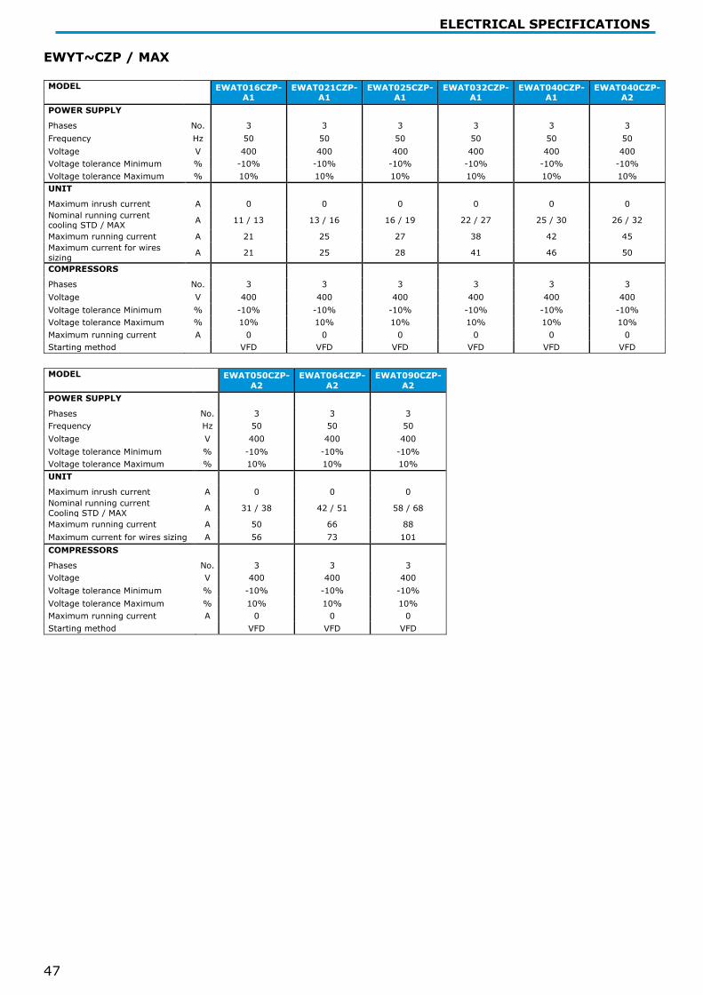
ELECTRICAL SPECIFICATIONS
47
EWYT~CZP / MAX MODEL EWAT016CZP-
A1 EWAT021CZP-
A1 EWAT025CZP-
A1 EWAT032CZP-
A1 EWAT040CZP-
A1 EWAT040CZP-
A2 POWER SUPPLY Phases No. 3 3 3 3 3 3 Frequency Hz 50 50 50 50 50 50 Voltage V 400 400 400 400 400 400 Voltage tolerance Minimum % -10% -10% -10% -10% -10% -10% Voltage tolerance Maximum % 10% 10% 10% 10% 10% 10% UNIT Maximum inrush current A 0 0 0 0 0 0 Nominal running current cooling STD / MAX A 11 / 13 13 / 16 16 / 19 22 / 27 25 / 30 26 / 32
Maximum running current A 21 25 27 38 42 45 Maximum current for wires sizing A 21 25 28 41 46 50
COMPRESSORS Phases No. 3 3 3 3 3 3 Voltage V 400 400 400 400 400 400 Voltage tolerance Minimum % -10% -10% -10% -10% -10% -10% Voltage tolerance Maximum % 10% 10% 10% 10% 10% 10% Maximum running current A 0 0 0 0 0 0 Starting method VFD VFD VFD VFD VFD VFD
MODEL EWAT050CZP-
A2 EWAT064CZP-
A2 EWAT090CZP-
A2 POWER SUPPLY Phases No. 3 3 3 Frequency Hz 50 50 50 Voltage V 400 400 400 Voltage tolerance Minimum % -10% -10% -10% Voltage tolerance Maximum % 10% 10% 10% UNIT Maximum inrush current A 0 0 0 Nominal running current Cooling STD / MAX A 31 / 38 42 / 51 58 / 68
Maximum running current A 50 66 88 Maximum current for wires sizing A 56 73 101 COMPRESSORS Phases No. 3 3 3 Voltage V 400 400 400 Voltage tolerance Minimum % -10% -10% -10% Voltage tolerance Maximum % 10% 10% 10% Maximum running current A 0 0 0 Starting method VFD VFD VFD

ELECTRICAL SPECIFICATIONS
48
EWYT~CZH / MAX MODEL EWAT016CZH-
A1 EWAT021CZH-
A1 EWAT025CZH-
A1 EWAT032CZH-
A1 EWAT040CZH-
A1 EWAT040CZH-
A2 POWER SUPPLY Phases No. 3 3 3 3 3 3 Frequency Hz 50 50 50 50 50 50 Voltage V 400 400 400 400 400 400 Voltage tolerance Minimum % -10% -10% -10% -10% -10% -10% Voltage tolerance Maximum % 10% 10% 10% 10% 10% 10% UNIT Maximum inrush current A 0 0 0 0 0 0 Nominal running current cooling STD / MAX A 11 / 13 13 / 16 16 / 19 22 / 27 25 / 30 26 / 32
Maximum running current A 21 25 27 39 43 46 Maximum current for wires sizing A 21 25 28 41 46 50
COMPRESSORS Phases No. 3 3 3 3 3 3 Voltage V 400 400 400 400 400 400 Voltage tolerance Minimum % -10% -10% -10% -10% -10% -10% Voltage tolerance Maximum % 10% 10% 10% 10% 10% 10% Maximum running current A 0 0 0 0 0 0 Starting method VFD VFD VFD VFD VFD VFD
MODEL EWAT050CZH-
A2 EWAT064CZH-
A2 EWAT090CZH-
A2 POWER SUPPLY Phases No. 3 3 3 Frequency Hz 50 50 50 Voltage V 400 400 400 Voltage tolerance Minimum % -10% -10% -10% Voltage tolerance Maximum % 10% 10% 10% UNIT Maximum inrush current A 0 0 0 Nominal running current Cooling STD / MAX A 31 / 37 42 / 51 58 / 68
Maximum running current A 51 68 90 Maximum current for wires sizing A 56 73 101 COMPRESSORS Phases No. 3 3 3 Voltage V 400 400 400 Voltage tolerance Minimum % -10% -10% -10% Voltage tolerance Maximum % 10% 10% 10% Maximum running current A 0 0 0 Starting method VFD VFD VFD
The data are referred to the standard unit without options All data are subject to change without notice, Please refer to unit nameplate data
Fluid: Water Allowed voltage tolerance ± 10%, Voltage unbalance between phases must be within ± 3%. Maximum starting current: In case of inverter driven units, no inrush current at start up is experienced. Nominal current in cooling mode is referred to the following conditions: evaporator 12/7°C; ambient 35°C; compressors + fans current Maximum running current is based on max compressor absorbed current in its envelope and max fans absorbed current Maximum unit current for wires sizing is based on minimum allowed voltage

SOUND LEVELS
49
Sound levels EWA(Y)T~CZ
Sound pressure level at 1 m from the unit Sound
Power
MODEL 63 Hz 125 Hz 250 Hz 500 Hz 1000 Hz 2000 Hz 4000 Hz 8000 Hz db(A) db (A)
EWYT/EWAT016CZ-A1 68.1 63.0 58.0 54.9 55.5 50.8 49.0 42.3 59.6 76.0
EWYT/EWAT021CZ-A1 71.2 65.5 58.7 55.4 53.7 51.5 49.0 42.9 59.6 76.0
EWYT/EWAT025CZ-A1 74.3 69.9 60.9 56.8 54.5 53.5 51.1 44.8 61.6 78.0
EWYT/EWAT032CZ-A1 68.5 62.6 59.5 58.2 57.9 55.0 49.1 33.8 62.2 79.0
EWYT/EWAT040CZ-A1 68.6 62.7 59.7 58.8 59.5 55.9 49.2 33.8 63.2 80.0
EWYT/EWAT040CZ-A2 74.3 68.5 61.8 58.5 56.9 54.6 52.1 45.9 62.8 80.0
EWYT/EWAT050CZ-A2 77.1 72.0 63.4 59.0 56.3 55.1 53.6 47.8 63.8 81.0
EWYT/EWAT064CZ-A2 75.0 70.8 64.9 61.3 58.9 58.6 52.4 46.2 65.4 83.0
EWYT/EWAT090CZ-A2 75.2 71.3 65.7 62.6 60.6 61.3 52.7 46.2 67.0 85.0
Sound power level (referred to evaporator 12/7°C, ambient 35°C full load operation) are measured in accordance with ISO 9614 and Eurovent 8/1. The certification refers only to the overall sound power level. The sound data in the Octave band spectrum is intended for reference only and not considered binding. The sound pressure is calculated from the sound power level and are for information only and not considered binding.

INSTALLATIONS NOTES
50
Envelopes ENVELOPE COOLING – EWAT-CZ
ENVELOPE COOLING – EWYT-CZ
-25-20-15-10
-505
10152025303540455055
-20 -15 -10 -5 0 5 10 15 20 25 30
OAT
[°C]
ELWT [°C]
Ref.1
Ref.2
-25-20-15-10
-505
10152025303540455055
-20 -15 -10 -5 0 5 10 15 20 25 30
OAT
[°C]
ELWT [°C]
Ref.1
Ref.2

INSTALLATIONS NOTES
51
ENVELOPE HEATING – EWYT-CZ [sizes 21-90]
ENVELOPE HEATING – EWYT-CZ [size16]
*16 kW size has a dedicated envelope, being a “Low Temp. Heat Pump” and not a “Medium Temp.” One
Ref. 1 Unit operations in this area require OP. 192 - HIGH AMBIENT TEMPERATURE KIT. Ref. 2 Unit operations in this area require the enabling of the Brine version in the controller and the
use of the proper amount of glycol. Ref. 3 Certain unit sizes might work in part load in this area.
15
20
25
30
35
40
45
50
55
60
65
-25 -20 -15 -10 -5 0 5 10 15 20 25 30 35 40
CLW
T [°
C]
OAT [°C]
Ref.3
15
20
25
30
35
40
45
50
55
60
65
-25 -20 -15 -10 -5 0 5 10 15 20 25 30 35 40
CLW
T [°
C]
OAT [°C]
Ref.3

INSTALLATIONS NOTES
52
Installation notes Water heat exchanger - minimum/maximum water Δt The minimum and maximum allowed Δt at full load conditioins are respectively 4°C and 8°C. Contact factory in case lower or higher Δt are required. Minimum and maximum evaporator flows are to be respected withing the Δt range above.
Water flow The following tables indicate the minimum and maximum water flow allowed for each model. For application with Variable Primary Flow refer to the following value for the dimensioning of the bypass line. The minimum flow indicated correspond to the minimum flow allowed at minimum load for the unit. It is not intended as minimum flow allowed for unit full load operation. For minimum flow allowed (maximum deltaT) in full load operation refer to Selection Software. Note: the performances are certified at standard conditions and with the unit operating with the nominal water flow (corresponding to OAT 35°C; water in/out 12/7°C).
N – Naked Version P – H Pump Versions
MODEL Min Flow [l/s]
Max flow [l/s] MODEL Min flow
[l/s] Max flow
[l/s]
EWAT/EWYT016CZN-A1 0.44 2.34 EWAT/EWYT016CZP(H)-A1 0.44 1.70
EWAT/EWYT021CZN-A1 0.84 2.66 EWAT/EWYT021CZP(H)-A1 0.84 1.90
EWAT/EWYT025CZN-A1 0.84 2.66 EWAT/EWYT025CZP(H)-A1 0.84 1.90
EWAT/EWYT032CZN-A1 1.01 2.66 EWAT/EWYT032CZP(H)-A1 1.01 2.66
EWAT/EWYT040CZN-A1 1.01 2.66 EWAT/EWYT040CZP(H)-A1 1.01 2.66
EWAT/EWYT040CZN-A2 1.41 6.00 EWAT/EWYT040CZP(H)-A2 1.41 3.89
EWAT/EWYT050CZN-A2 1.41 6.00 EWAT/EWYT050CZP(H)-A2 1.41 3.89
EWAT/EWYT064CZN-A2 1.41 6.00 EWAT/EWYT064CZP(H)-A2 1.41 5.50
EWAT/EWYT090CZN-A2 2.43 6.66 EWAT/EWYT090CZP(H)-A2 2.43 6.00
Minimum glycol percentage for low air ambient temperature to prevent freezing of the hydraulic circuit
AMBIENT T [°C] -3 -8 -15 -20 AMBIENT T [°C] -3 -8 -15 -20 ETHYLENE GLYCOL 10% 20% 30% 40% PROPYLENE GLYCOL 10% 20% 30% 40%
The presence of glycol in the water system will affect unit performances. Refer to the selection software for details. All machine protection systems, such as antifreeze and low-pressure protection will need to be set in accordance to the type and percentage of the glycol and plant requirements.
Air heat exchanger - Altitude correction factors
ELEVATION ABOVE SEA LEVEL [m] 0 300 600 900 1200 1500 1800
BAROMETRIC PRESSURE [mbar] 1013 997 942 908 875 843 812
COOLING CAPACITY CORRECTION FACTOR 1 0,993 0,986 0,979 0,973 0,967 0,96
POWER INPUT CORRECTION FACTOR 1 1,005 1,009 1,015 1,021 1,026 1,031
Maximum operating altitude is 1800 m above sea level. Available fan static pressure correction factors
COOLING EXTERNAL STATIC PRESSURE [Pa] 0 50 100
COOLING CAPACITY CORRECTION FACTOR 1 0.99 0.98 UNIT PI CORRECTION FACTOR 1 1.03 1.07
REDUCTION OF MAX OPERATING AMBIENT TEMPERATURE [°C] 0 -1.5 -2.5

INSTALLATIONS NOTES
53
HEATING
EXTERNAL STATIC PRESSURE [Pa] 0 50 100 HEATING CAPACITY CORRECTION FACTOR 1 0.99 0.97
UNIT PI CORRECTION FACTOR 1 1.008 1.011
INCREASE OF MIN OPERATING AMBIENT TEMPERATURE [°C] 0 +0.5 +1.0
COOLING Boosted Fan EXTERNAL STATIC PRESSURE [Pa] 0 50 100
COOLING CAPACITY CORRECTION FACTOR 1 1 1 UNIT PI CORRECTION FACTOR 1 1.04 1.09
REDUCTION OF MAX OPERATING AMBIENT TEMPERATURE [°C] 0 0 0
HEATING Boosted Fan
EXTERNAL STATIC PRESSURE [Pa] 0 50 100 HEATING CAPACITY CORRECTION FACTOR 1 1 1
UNIT PI CORRECTION FACTOR 1 1.05 1.10 INCREASE OF MIN OPERATING AMBIENT TEMPERATURE [°C] 0 0 0
Applications with more than 100 Pa of external static pressure are not recommended. Heating correction factors are intented not considering the de frost. In case of canalization is not possible to redcude Sound powe level with Fan Silent Mode. Maximum cable dimension Maximum cable dimension that can be physically connected to the main switch of the unit.
Model
Max cable size [mm^2] Model [A] Max cable size
[mm^2] Model [A]
STD Configuration HIGH AMBIENT TEMPERATURE KIT OP.192
EWAT/EWYT016CZN(P)(H)-A1 16 63 16 63 EWAT/EWYT021CZN(P)(H)-A1 16 63 16 63 EWAT/EWYT025CZN(P)(H)-A1 16 63 16 63 EWAT/EWYT032CZN(P)(H)-A1 16 63 50 100 EWAT/EWYT040CZN(P)(H)-A1 16 63 50 100 EWAT/EWYT040CZN(P)(H)-A2 50 80 50 80 EWAT/EWYT050CZN(P)(H)-A2 50 80 50 80 EWAT/EWYT064CZN(P)(H)-A2 50 100 70 125 EWAT/EWYT090CZN(P)(H)-A2 70 125 70 125

INSTALLATIONS NOTES
54
Plant water content The chilled water distribution circuits should have a minimum water content to avoid excessive compressors start and stop. During the span of one hour there will be no more than 10 starts of the compressor. The plant side should therefore ensure that the overall water content allows a more constant functioning of the unit and consequently greater environmental comfort. The calculation of the water content should also consider the plant’s design parameters. As a general indication the water content should not be less than the values in the following table:
Heat-Pump Suggested L/kW
Min water content [L] Cooling-Only Suggested
L/kW Min water
content [L]
EWYT016CZN/P/H-A1 5.7 90 EWAT016CZN/P/H-A1 3.7 58
EWYT021CZN/P/H-A1 5.0 100 EWAT021CZN/P/H-A1 2.8 58
EWYT025CZN/P/H-A1 4.4 110 EWAT025CZN/P/H-A1 2.3 58
EWYT032CZN/P/H-A1 4.9 160 EWAT032CZN/P/H-A1 2.8 90
EWYT040CZN/P/H-A1 4.6 180 EWAT040CZN/P/H-A1 2.3 90
EWYT040CZN/P/H-A2 3.0 120 EWAT040CZN/P/H-A2 1.5 60
EWYT050CZN/P/H-A2 2.6 130 EWAT050CZN/P/H-A2 1.2 60
EWYT064CZN/P/H-A2 2.7 170 EWAT064CZN/P/H-A2 1.1 73
EWYT090CZN/P/H-A2 2.7 230 EWAT090CZN/P/H-A2 1.0 90
Note: The indication is intended as a general guideline and not intended to substitute the evaluation made by qualified technical personnel or by HVAC engineers. For more detailed analysis is better to consider the use of other more detailed approach.
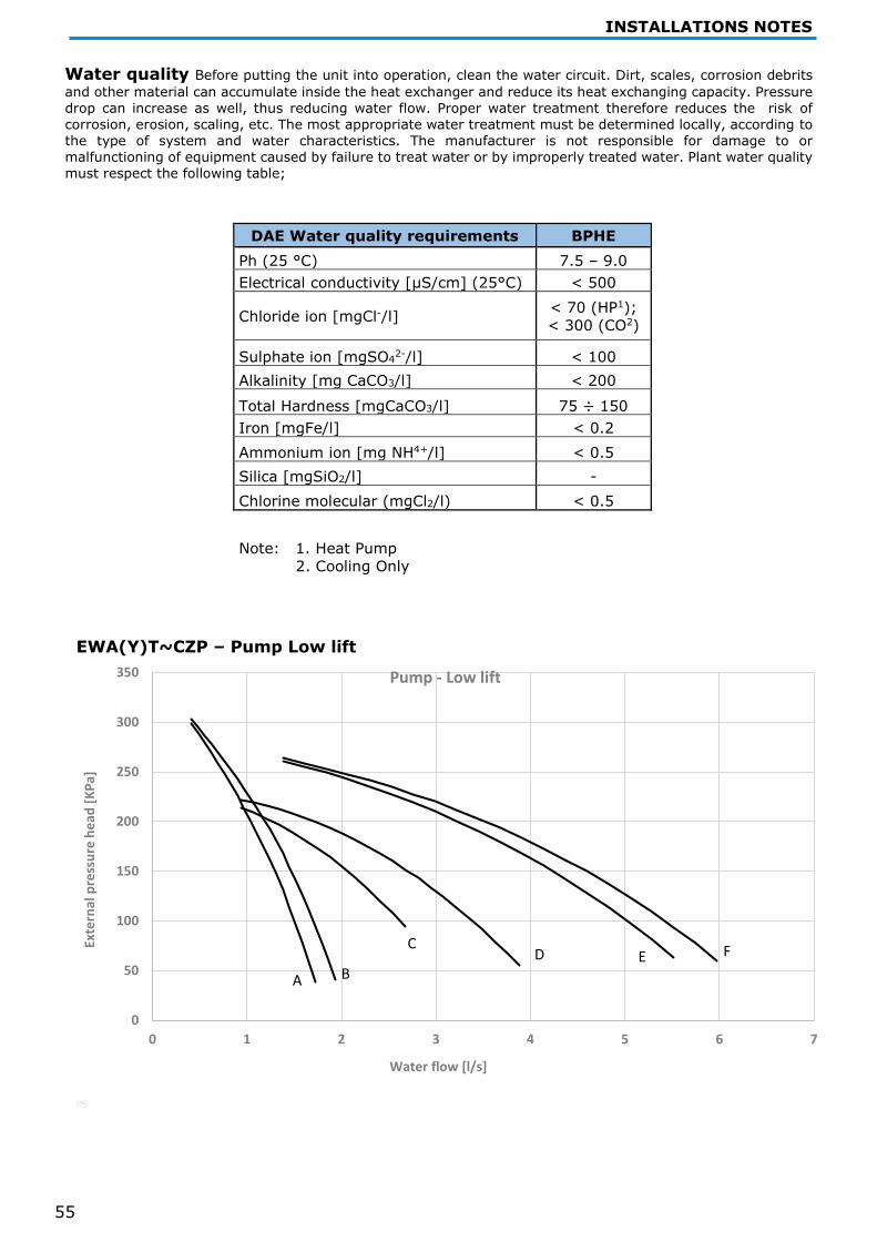
INSTALLATIONS NOTES
55
Water quality Before putting the unit into operation, clean the water circuit. Dirt, scales, corrosion debrits and other material can accumulate inside the heat exchanger and reduce its heat exchanging capacity. Pressure drop can increase as well, thus reducing water flow. Proper water treatment therefore reduces the risk of corrosion, erosion, scaling, etc. The most appropriate water treatment must be determined locally, according to the type of system and water characteristics. The manufacturer is not responsible for damage to or malfunctioning of equipment caused by failure to treat water or by improperly treated water. Plant water quality must respect the following table;
DAE Water quality requirements BPHE Ph (25 °C) 7.5 – 9.0 Electrical conductivity [μS/cm] (25°C) < 500
Chloride ion [mgCl-/l] < 70 (HP1); < 300 (CO2)
Sulphate ion [mgSO42-/l] < 100 Alkalinity [mg CaCO3/l] < 200
Total Hardness [mgCaCO3/l] 75 ÷ 150 Iron [mgFe/l] < 0.2 Ammonium ion [mg NH4+/l] < 0.5 Silica [mgSiO2/l] - Chlorine molecular (mgCl2/l) < 0.5
Note: 1. Heat Pump 2. Cooling Only
EWA(Y)T~CZP – Pump Low lift
0
50
100
150
200
250
300
350
0 1 2 3 4 5 6 7
Exte
rnal
pre
ssur
e he
ad [K
Pa]
Water flow [l/s]
Pump - Low lift
CD E F
A B

INSTALLATIONS NOTES
56
EWA(Y)T~CZH – Pump High lift
External pressure head refers to unit equipped with hydronic kit, defined as difference between pump external static pressure and evaporator and water filter pressure drops.
For water flow limits of the unit refer to water flow section.
Pump - Low lift Pump - High lift
Model Pump’s curve Model Pump’s
curve
EWAT/EWYT016CZP-A1 A EWAT/EWYT016CZH-A1 A
EWAT/EWYT021CZP-A1 B EWAT/EWYT021CZH-A1 B
EWAT/EWYT025CZP-A1 B EWAT/EWYT025CZH-A1 B
EWAT/EWYT032CZP-A1 C EWAT/EWYT032CZH-A1 C
EWAT/EWYT040CZP-A1 C EWAT/EWYT040CZH-A1 C
EWAT/EWYT040CZP-A2 D EWAT/EWYT040CZH-A2 D
EWAT/EWYT050CZP-A2 D EWAT/EWYT050CZH-A2 D
EWAT/EWYT064CZP-A2 E EWAT/EWYT064CZH-A2 E
EWAT/EWYT090CZP-A2 F EWAT/EWYT090CZH-A2 F
0
100
200
300
400
500
600
0 1 2 3 4 5 6 7
Exte
rnal
pre
ssur
e he
ad [K
Pa]
Water flow [l/s]
Pump - High lift
A
B
C
D
E
F

INSTALLATIONS NOTES
57
Pump data
Model Power [kW]
Current [A] Model Power
[kW] Current
[A] EWA(Y)T016CZP-A1 1,1 2,4 EWA(Y)T016CZH-A1 1,5 3,2
EWA(Y)T021CZP-A1 1,1 2,4 EWA(Y)T021CZH-A1 1,5 3,2
EWA(Y)T025CZP-A1 1,1 2,4 EWA(Y)T025CZH-A1 1,5 3,2
EWA(Y)T032CZP-A1 1,1 2,4 EWA(Y)T032CZH-A1 2,2 4,56
EWA(Y)T040CZP-A1 1,1 2,4 EWA(Y)T040CZH-A1 2,2 4,56
EWA(Y)T040CZP-A2 1,1 2,4 EWA(Y)T040CZH-A2 2,2 4,56
EWA(Y)T050CZP-A2 1,1 2,4 EWA(Y)T050CZH-A2 2,2 4,56
EWA(Y)T064CZP-A2 2,2 4,56 EWA(Y)T064CZH-A2 3 6,35
EWA(Y)T090CZP-A2 2,2 4,56 EWA(Y)T090CZH-A2 3 6,35
Water filter pressure drops
0
10
20
30
40
50
60
70
80
90
0 1 2 3 4 5 6 7
Exte
rnal
pre
ssur
e he
ad [k
Pa]
Water flow [l/s]
Water filter pressure drops
MONO CIRCUIT DUAL CIRCUIT
1'' 1/42''

INSTALLATIONS NOTES
58
Space requirements
It is fundamental to respect minimum distances on all units to ensure optimum ventilation to the condenser coils. When deciding where to position the unit and to ensure a proper air flow, the following factors must be taken into consideration: − avoid any warm air recirculation; − avoid insufficient air supply to the air-cooled condenser. Both these conditions can cause an increase of condensing pressure, which leads to a reduction in energy efficiency and refrigerating capacity. Any side of the unit must be accessible for post-installation maintenance operations and vertical air discharge must not be obstructed. Figure below shows the minimum space required.
DUAL 90 kW unit Where:
• A : Electrical panel side • B/D : Side view of battery • C : Front view of battery • Suction side
If the unit is installed in a free field, the distances indicated are: A/B/C/D≥500 mm
In the presence of obstacles or walls, the following minimum distances are recommended:
ℎ2 > 0 → 𝐴𝐴 ≥ 𝐴𝐴 +
ℎ22
ℎ1 > 0 → 𝐶𝐶 ≥ 𝐶𝐶 +ℎ12

INSTALLATIONS NOTES
59
If two units are installed in a free field side by side along their longer sides, A and C, the minimum recommended distance between them is 1000 mm; if two units are installed side by side along their shorter sides, sides B and D, the minimum distance between them should be 500 mm. Should the unit be installed without observing the recommended minimum distances from walls and/or vertical obstacles, there could be a combination of warm air recirculation and/or insufficient supply to the air-cooled condenser which could cause a reduction of capacity and efficiency. In any case, the microprocessor will allow the unit to adapt itself to new operating conditions and deliver the maximum available capacity under any given circumstances, even if the lateral distance is lower than recommended, unless the operating conditions should affect personnel safety or unit reliability.
Units installed side by side along their shorter sides, B or D Case 1 Case 2
Units installed side by side along their longer sides (Case 1 and Case 2) The minimum distances, reported above, ensure functionality of the unit in most applications.

INSTALLATIONS NOTES
60
Water filter The installation of the filter is mandatory.The water filter has to be installed as close as possible to the chiller. If the chiller is installed in a different part of the hydraulic system, the installer must ensure the cleaning of the water pipes between water filter and evaporator. The pressure drop value showed in CSS (Chiller Selection Software) are referred to chiller evaporator only.
Hydraulic schemes
- Hydraulic scheme
Water pressure Check whether the water pressure is above 1 bar. If it is lower, add water. The maximum operating pressure is 3 bar for P and H versions. For N version please take care that the components installed in the field piping can withstand the water pressure “maximum 3 bar + static pressure of the external pump” and not exceeding 10 bar.

INSTALLATIONS NOTES
61
TECHNICAL SPECIFICATIONS
General
The unit will be designed and manufactured in accordance with the following European directives and harmonized standards: • Low voltage directive -DIRECTIVE 2014/35/EU • Electromagnetic compatibility (EMC) DIRECTIVE 2014/30/EU • Machinery directive - DIRECTIVE 2006/42/EC • Pressure equipment Directive - DIRECTIVE 2014/68/EU • Ecodesing - DIRECTIVE 2009/125/EC • Safety of machinery EN 60335-2-40 • EMC - Part 6-2 EN 61000-6-2 • EMC - Part 6-4 EN 61000-6-4 The unit will be tested at full load in the factory (at the nominal working conditions and water temperatures). The unit will be delivered to the job site completely assembled and charged with refrigerant and oil. The installation of the unit must comply with the manufacturer’s instructions for rigging and handling equipment.
The unit will be able to start up and operate (as standard) at full load with: - Outside air temperature from............... °C to............... °C - Evaporator leaving fluid temperature between............... °C and............... °C Refrigerant HFC R-32
Performance Chiller shall supply the following performances: • Number of chiller(s):............... unit(s) • Cooling capacity for single chiller:............... kW • Power input for single chiller in cooling mode:............... kW • Heat exchanger entering water temperature in cooling mode:............... °C • Heat exchanger leaving water temperature in cooling mode:............... °C • Heat exchanger water flow:............... l/s • Nominal outside working ambient temperature in cooling mode:............... °C • Minimum full load efficiency (EER): …………….. (kW/kW) • Minimum part load efficiency (SEER): …………….. (kW/kW)
Operating voltage range should be 400V ±10%, 3ph, 50Hz (or 380V ±10%, 3ph, 60Hz), voltage unbalance maximum 3%, without neutral conductor and shall only have one power connection point.
Unit description Chiller shall include one or two independent refrigerant circuits, hermetic orbiting scroll type optimized for R-32 operation, electronic expansion device (EEXV), direct expansion, PHE evaporator, air-cooled condenser section made with copper-aluminum technology, R-32 refrigerant, lubrication system, motor starting components, control system and all components necessary for a safe and stable unit operation. The chiller will be factory assembled on a robust base frame made of galvanized steel, protected by an epoxy paint.
Sound level and vibrations Sound power level shall not exceed ………dB(A). The sound power levels must be rated in accordance to ISO 9614 (other types of rating cannot be used). Vibration on the base frame should not exceed 2 mm/s.
Dimensions Unit dimensions shall not exceed following indications: - Unit length............... mm - Unit width............... mm - Unit height............... mm
Compressors Hermetic orbiting scroll type optimized for R-32 operation and complete with motor over-temperature and over-current protection devices. Each compressor equipped with oil heater that keeps the oil from being diluted by the refrigerant when the chiller is not running. Each compressor is mounted on rubber antivibration mounts for a quite operation. Unit is delivered with complete oil charge.
Evaporator The units shall be equipped with a direct expansion plate to plate type evaporator • The evaporator will be made of stainless steel brazed plates and shall be linked with an electrical heater
controlled by a thermostat and shall be insulated with flexible, closed cell polyurethane insulation material • The evaporator will be manufactured in accordance to PED approval • Flow switch on evaporator is factory mounted as standard • Water flter on evaporator is shipped loose as standard

INSTALLATIONS NOTES
62
TECHNICAL SPECIFICATIONS TECHNICAL SPECIFICATIONS
Air Side Heat Exchanger The Air Side Heat Exchanger is manufactured with internally enhanced seamless copper tubes arranged in a staggered row pattern and mechanically expanded into lanced and rippled aluminum Air Side Heat Exchanger fins with full fin collars. An integral sub-cooler circuit provides sub-cooling to effectively eliminate liquid flashing and increase cooling capacity without increasing the power input. Air Side Heat Exchanger fans Air Side Heat Exchanger fans are propeller type with high efficiency design blades to maximize performances. The blades are made of glass-reinforced resin and a guard protects each fan. Units are standardly equipped with inverter driven fans. Refrigerant circuit The unit shall have one or two independent refrigerant. • The circuit shall include as standard: electronic expansion device driven by unit’s microprocessor control. The units will be provided with an automatic control for condensing pressure which ensures the working at low external temperatures down to - …………… °C, to maintain condensing pressure. • The unit automatically unloads when abnormal high condensing pressure is detected. This to prevent the shutdown of the refrigerant circuit (shutdown of the unit) due to a high-pressure fault. The compressor shall be connected to unit’s metal base frame by rubber anti vibration supports to prevent the transmission of vibrations to all metal unit structure, in order to limit the unit noise emissions.
Master/Slave The unit shell be able to operate in Master / Slave mode in order to be connected with another similar unit (up to 4). The master unit shall manage the slave units connected in parallel on the hydraulic plant with the aim of optimize the running hours of each compressor and to balance running hours and the load between the units.
Electrical control panel Power and control shall be located in the main panel that will be manufactured to ensure protection against all weather conditions. • The electrical panel shall be IP54 and (when opening the doors) internally protected against possible accidental contact with live parts • The main panel shall be fitted with a main switch interlocked door that shuts off power supply when opening • The power section will include compressors and fans starter devices Controller The controller will be installed as standard and it will be used to modify unit set-points and check control parameters. • A sophisticated software with predictive logic, will select the most energy efficient combination of compressors, EEXV and condenser fans to keep stable operating conditions to maximize unit energy efficiency and reliability • The controller will be able to protect critical components based on external signals received from the unit itself Controller features Controller shall be guarantee following minimum functions:
• Management of the compressors, • Chiller enabled to work in partial failure condition • Full routine operation at condition of: - high ambient temperature value - high thermal load - high evaporator entering water temperature (start-up) • Leaving water evaporator temperature regulation • Display of Status Safety Devices • Number of starts and compressor working hours • Optimized management of unit load • Fan management according to condensing pressure • Start at high evaporator water temperature • Master / Slave (provided as standard) • Variable primary Flow (available as accessory)

Related Documents