ibm.com/redbooks Data Warehousing with the Informix Dynamic Server Chuck Ballard Veronica Gomes Gregory Hilz Manjula Panthagani Claus Samuelsen Develop a data infrastructure to power business intelligence solutions Simplify your data warehouse design and deployment Manage with the SQW Administration Console

Welcome message from author
This document is posted to help you gain knowledge. Please leave a comment to let me know what you think about it! Share it to your friends and learn new things together.
Transcript
ibm.com/redbooks
Data Warehousingwith the InformixDynamic Server
Chuck BallardVeronica Gomes
Gregory HilzManjula Panthagani
Claus Samuelsen
Develop a data infrastructure to power business intelligence solutions
Simplify your data warehouse design and deployment
Manage with the SQW Administration Console
Front cover

Data Warehousing with the Informix Dynamic Server
December 2009
International Technical Support Organization
SG24-7788-00
© Copyright International Business Machines Corporation 2009. All rights reserved.Note to U.S. Government Users Restricted Rights -- Use, duplication or disclosure restricted by GSA ADPSchedule Contract with IBM Corp.
First Edition (December 2009)
This edition applies to Version 11.5 of IBM Informix Dynamic Server and, more specifically, the Informix Warehouse Feature.
Note: Before using this information and the product it supports, read the information in “Notices” on page xi.
Contents
Notices . . . . . . . . . . . . . . . . . . . . . . . . . . . . . . . . . . . . . . . . . . . . . . . . . . . . . . . xiTrademarks . . . . . . . . . . . . . . . . . . . . . . . . . . . . . . . . . . . . . . . . . . . . . . . . . . . xii
Preface . . . . . . . . . . . . . . . . . . . . . . . . . . . . . . . . . . . . . . . . . . . . . . . . . . . . . . xiiiThe team who wrote this book . . . . . . . . . . . . . . . . . . . . . . . . . . . . . . . . . . . . . xiv
Other contributors . . . . . . . . . . . . . . . . . . . . . . . . . . . . . . . . . . . . . . . . . . . . xvBecome a published author . . . . . . . . . . . . . . . . . . . . . . . . . . . . . . . . . . . . . . . xviComments welcome. . . . . . . . . . . . . . . . . . . . . . . . . . . . . . . . . . . . . . . . . . . . . xvi
Chapter 1. Introduction . . . . . . . . . . . . . . . . . . . . . . . . . . . . . . . . . . . . . . . . . . 11.1 Contents abstract . . . . . . . . . . . . . . . . . . . . . . . . . . . . . . . . . . . . . . . . . . . . 31.2 Data warehousing . . . . . . . . . . . . . . . . . . . . . . . . . . . . . . . . . . . . . . . . . . . . 6
1.2.1 The enterprise data warehouse . . . . . . . . . . . . . . . . . . . . . . . . . . . . . 71.2.2 Business Intelligence . . . . . . . . . . . . . . . . . . . . . . . . . . . . . . . . . . . . . 9
1.3 The database server . . . . . . . . . . . . . . . . . . . . . . . . . . . . . . . . . . . . . . . . . 101.3.1 Technology for business . . . . . . . . . . . . . . . . . . . . . . . . . . . . . . . . . . 111.3.2 Storage optimization . . . . . . . . . . . . . . . . . . . . . . . . . . . . . . . . . . . . . 121.3.3 Serving the enterprise . . . . . . . . . . . . . . . . . . . . . . . . . . . . . . . . . . . . 13
1.4 The Informix Warehouse . . . . . . . . . . . . . . . . . . . . . . . . . . . . . . . . . . . . . . 141.4.1 Informix Warehouse architecture . . . . . . . . . . . . . . . . . . . . . . . . . . . 16
Chapter 2. Planning the environment . . . . . . . . . . . . . . . . . . . . . . . . . . . . . 212.1 Data warehousing and business intelligence . . . . . . . . . . . . . . . . . . . . . . 222.2 The data warehouse . . . . . . . . . . . . . . . . . . . . . . . . . . . . . . . . . . . . . . . . . 24
2.2.1 Data warehousing infrastructure . . . . . . . . . . . . . . . . . . . . . . . . . . . . 262.2.2 Characteristics of a data warehouse. . . . . . . . . . . . . . . . . . . . . . . . . 272.2.3 Data modeling: logical and physical . . . . . . . . . . . . . . . . . . . . . . . . . 30
2.3 Data warehouse life cycle . . . . . . . . . . . . . . . . . . . . . . . . . . . . . . . . . . . . . 332.3.1 The Informix Warehouse life cycle . . . . . . . . . . . . . . . . . . . . . . . . . . 342.3.2 Data management life cycle . . . . . . . . . . . . . . . . . . . . . . . . . . . . . . . 362.3.3 Data architect and modeling life cycle. . . . . . . . . . . . . . . . . . . . . . . . 372.3.4 Data integration life cycle . . . . . . . . . . . . . . . . . . . . . . . . . . . . . . . . . 39
2.4 Data warehouse architecture . . . . . . . . . . . . . . . . . . . . . . . . . . . . . . . . . . 452.4.1 Types of data warehouse repositories . . . . . . . . . . . . . . . . . . . . . . . 462.4.2 Implementation options . . . . . . . . . . . . . . . . . . . . . . . . . . . . . . . . . . . 482.4.3 Determining which architecture is for you . . . . . . . . . . . . . . . . . . . . . 50
2.5 Considerations in building a DW environment . . . . . . . . . . . . . . . . . . . . . 502.5.1 Implementation approaches . . . . . . . . . . . . . . . . . . . . . . . . . . . . . . . 502.5.2 Data integration of heterogeneous systems . . . . . . . . . . . . . . . . . . . 52
© Copyright IBM Corp. 2009. All rights reserved. iii

2.5.3 Large data volumes and complex queries . . . . . . . . . . . . . . . . . . . . 552.5.4 Project scope, budget, and time constraints . . . . . . . . . . . . . . . . . . . 562.5.5 Maintenance . . . . . . . . . . . . . . . . . . . . . . . . . . . . . . . . . . . . . . . . . . . 57
2.6 The business intelligence tools . . . . . . . . . . . . . . . . . . . . . . . . . . . . . . . . . 582.7 The Informix Warehouse platform . . . . . . . . . . . . . . . . . . . . . . . . . . . . . . . 61
2.7.1 Informix Warehouse components . . . . . . . . . . . . . . . . . . . . . . . . . . . 622.7.2 Planning an n-tier installation . . . . . . . . . . . . . . . . . . . . . . . . . . . . . . 64
Chapter 3. Informix Warehouse Client . . . . . . . . . . . . . . . . . . . . . . . . . . . . 693.1 Introduction to Design Studio Workbench . . . . . . . . . . . . . . . . . . . . . . . . . 70
3.1.1 The Eclipse platform . . . . . . . . . . . . . . . . . . . . . . . . . . . . . . . . . . . . . 703.1.2 Workspace . . . . . . . . . . . . . . . . . . . . . . . . . . . . . . . . . . . . . . . . . . . . 723.1.3 Projects and the local file system . . . . . . . . . . . . . . . . . . . . . . . . . . . 723.1.4 Welcome page . . . . . . . . . . . . . . . . . . . . . . . . . . . . . . . . . . . . . . . . . 73
3.2 Design Studio Workbench. . . . . . . . . . . . . . . . . . . . . . . . . . . . . . . . . . . . . 743.2.1 Perspectives . . . . . . . . . . . . . . . . . . . . . . . . . . . . . . . . . . . . . . . . . . . 753.2.2 Editors . . . . . . . . . . . . . . . . . . . . . . . . . . . . . . . . . . . . . . . . . . . . . . . . 773.2.3 Views. . . . . . . . . . . . . . . . . . . . . . . . . . . . . . . . . . . . . . . . . . . . . . . . . 783.2.4 Common tasks . . . . . . . . . . . . . . . . . . . . . . . . . . . . . . . . . . . . . . . . . 863.2.5 Team component . . . . . . . . . . . . . . . . . . . . . . . . . . . . . . . . . . . . . . . 92
Chapter 4. Developing the physical model . . . . . . . . . . . . . . . . . . . . . . . . . 954.1 Physical data model . . . . . . . . . . . . . . . . . . . . . . . . . . . . . . . . . . . . . . . . . 96
4.1.1 Physical model structure . . . . . . . . . . . . . . . . . . . . . . . . . . . . . . . . . . 974.1.2 Industry templates. . . . . . . . . . . . . . . . . . . . . . . . . . . . . . . . . . . . . . . 98
4.2 Creating the physical data model . . . . . . . . . . . . . . . . . . . . . . . . . . . . . . . 984.2.1 Importing from an empty template . . . . . . . . . . . . . . . . . . . . . . . . . . 994.2.2 Reverse engineering from an existing database. . . . . . . . . . . . . . . 1004.2.3 Using the Data Source Explorer . . . . . . . . . . . . . . . . . . . . . . . . . . . 102
4.3 Working with diagrams . . . . . . . . . . . . . . . . . . . . . . . . . . . . . . . . . . . . . . 1024.3.1 Creating a diagram . . . . . . . . . . . . . . . . . . . . . . . . . . . . . . . . . . . . . 1024.3.2 Using the diagram editor . . . . . . . . . . . . . . . . . . . . . . . . . . . . . . . . . 103
4.4 Editing physical data models. . . . . . . . . . . . . . . . . . . . . . . . . . . . . . . . . . 1054.4.1 Using the Data Project Explorer . . . . . . . . . . . . . . . . . . . . . . . . . . . 106
4.5 Deploying the data model . . . . . . . . . . . . . . . . . . . . . . . . . . . . . . . . . . . . 1064.5.1 Using Design Studio to deploy the data model . . . . . . . . . . . . . . . . 1064.5.2 Using the Administration Console to deploy a physical model . . . . 108
4.6 Maintaining the physical data models . . . . . . . . . . . . . . . . . . . . . . . . . . . 1094.6.1 Comparing objects within the physical data model . . . . . . . . . . . . . 1094.6.2 Visualizing differences between objects . . . . . . . . . . . . . . . . . . . . . 1094.6.3 Synchronization of differences . . . . . . . . . . . . . . . . . . . . . . . . . . . . 1104.6.4 Impact analysis . . . . . . . . . . . . . . . . . . . . . . . . . . . . . . . . . . . . . . . . 111
Chapter 5. Data movement and transformation . . . . . . . . . . . . . . . . . . . . 115
iv Data Warehousing with the Informix Dynamic Server
5.1 SQL Warehousing Tool . . . . . . . . . . . . . . . . . . . . . . . . . . . . . . . . . . . . . . 1175.1.1 SQW overview . . . . . . . . . . . . . . . . . . . . . . . . . . . . . . . . . . . . . . . . 1175.1.2 SQW architecture . . . . . . . . . . . . . . . . . . . . . . . . . . . . . . . . . . . . . . 1185.1.3 SQW warehouse application life cycle . . . . . . . . . . . . . . . . . . . . . . 1205.1.4 Source, target, and execution databases . . . . . . . . . . . . . . . . . . . . 1235.1.5 Setting up a data warehouse project. . . . . . . . . . . . . . . . . . . . . . . . 125
5.2 Data flows . . . . . . . . . . . . . . . . . . . . . . . . . . . . . . . . . . . . . . . . . . . . . . . . 1275.2.1 Defining a data flow. . . . . . . . . . . . . . . . . . . . . . . . . . . . . . . . . . . . . 1275.2.2 Data flow editor . . . . . . . . . . . . . . . . . . . . . . . . . . . . . . . . . . . . . . . . 1295.2.3 Data flow operators . . . . . . . . . . . . . . . . . . . . . . . . . . . . . . . . . . . . . 1315.2.4 Subflows . . . . . . . . . . . . . . . . . . . . . . . . . . . . . . . . . . . . . . . . . . . . . 1595.2.5 Validation and code generation. . . . . . . . . . . . . . . . . . . . . . . . . . . . 1615.2.6 Testing and debugging a data flow . . . . . . . . . . . . . . . . . . . . . . . . . 1655.2.7 Maintaining aggregation tables . . . . . . . . . . . . . . . . . . . . . . . . . . . . 1685.2.8 Removing data periodically . . . . . . . . . . . . . . . . . . . . . . . . . . . . . . . 172
5.3 Control flows . . . . . . . . . . . . . . . . . . . . . . . . . . . . . . . . . . . . . . . . . . . . . . 1775.3.1 Defining a control flow. . . . . . . . . . . . . . . . . . . . . . . . . . . . . . . . . . . 1785.3.2 Control flow editor . . . . . . . . . . . . . . . . . . . . . . . . . . . . . . . . . . . . . . 1805.3.3 Control flow operators . . . . . . . . . . . . . . . . . . . . . . . . . . . . . . . . . . . 1815.3.4 Validation and code generation. . . . . . . . . . . . . . . . . . . . . . . . . . . . 1955.3.5 Testing and debugging a control flow . . . . . . . . . . . . . . . . . . . . . . . 197
5.4 Variables in data flows and control flows . . . . . . . . . . . . . . . . . . . . . . . . 1985.5 Preparing for deployment . . . . . . . . . . . . . . . . . . . . . . . . . . . . . . . . . . . . 203
5.5.1 Defining data warehouse applications . . . . . . . . . . . . . . . . . . . . . . 2045.5.2 Defining Application Profiles . . . . . . . . . . . . . . . . . . . . . . . . . . . . . . 204
5.6 Integrating with InfoSphere DataStage . . . . . . . . . . . . . . . . . . . . . . . . . . 2075.6.1 Overview of IBM InfoSphere DataStage . . . . . . . . . . . . . . . . . . . . . 2085.6.2 Key differences between SQW and DataStage . . . . . . . . . . . . . . . 2105.6.3 Integrating DataStage and SQW. . . . . . . . . . . . . . . . . . . . . . . . . . . 213
5.7 Using Informix load utilities . . . . . . . . . . . . . . . . . . . . . . . . . . . . . . . . . . . 2145.7.1 The High-Performance Loader . . . . . . . . . . . . . . . . . . . . . . . . . . . . 2145.7.2 Using onunload and onload . . . . . . . . . . . . . . . . . . . . . . . . . . . . . . 2155.7.3 Informix dbload . . . . . . . . . . . . . . . . . . . . . . . . . . . . . . . . . . . . . . . . 216
Chapter 6. Deploying and managing Informix Warehouse solutions. . . 2176.1 Informix Warehouse Administration Console . . . . . . . . . . . . . . . . . . . . . 219
6.1.1 Functionality provided by the Admin Console . . . . . . . . . . . . . . . . . 2206.1.2 Architecture . . . . . . . . . . . . . . . . . . . . . . . . . . . . . . . . . . . . . . . . . . . 2216.1.3 Deploying in a runtime environment . . . . . . . . . . . . . . . . . . . . . . . . 2226.1.4 Administering security . . . . . . . . . . . . . . . . . . . . . . . . . . . . . . . . . . . 2256.1.5 General administration tasks. . . . . . . . . . . . . . . . . . . . . . . . . . . . . . 2286.1.6 Locating and using diagnostics . . . . . . . . . . . . . . . . . . . . . . . . . . . . 237
6.2 Informix SQL Warehousing . . . . . . . . . . . . . . . . . . . . . . . . . . . . . . . . . . . 238
Contents v
6.2.1 An overview of the SQW components . . . . . . . . . . . . . . . . . . . . . . 2396.2.2 Runtime architecture of SQL Warehousing. . . . . . . . . . . . . . . . . . . 242
6.3 Deploying the physical data model . . . . . . . . . . . . . . . . . . . . . . . . . . . . . 2516.3.1 Deployment using the Design Studio . . . . . . . . . . . . . . . . . . . . . . . 2516.3.2 Deployment using the Admin Console . . . . . . . . . . . . . . . . . . . . . . 2526.3.3 Deployment using native IDS functionality . . . . . . . . . . . . . . . . . . . 253
6.4 Deploying warehouse applications . . . . . . . . . . . . . . . . . . . . . . . . . . . . . 2536.4.1 Managing applications . . . . . . . . . . . . . . . . . . . . . . . . . . . . . . . . . . 2596.4.2 Manage Control Flows . . . . . . . . . . . . . . . . . . . . . . . . . . . . . . . . . . 263
Chapter 7. Optimizing your Informix Warehouse environment . . . . . . . . 2777.1 Informix Dynamic Server . . . . . . . . . . . . . . . . . . . . . . . . . . . . . . . . . . . . . 2787.2 IDS architecture. . . . . . . . . . . . . . . . . . . . . . . . . . . . . . . . . . . . . . . . . . . . 2797.3 Data loading capabilities . . . . . . . . . . . . . . . . . . . . . . . . . . . . . . . . . . . . . 280
7.3.1 SQL load and unload commands . . . . . . . . . . . . . . . . . . . . . . . . . . 2807.3.2 The dbexport and dbimport utilities . . . . . . . . . . . . . . . . . . . . . . . . . 2807.3.3 The dbload utility . . . . . . . . . . . . . . . . . . . . . . . . . . . . . . . . . . . . . . . 2817.3.4 The onunload and onload utilities . . . . . . . . . . . . . . . . . . . . . . . . . . 2837.3.5 The High-Performance Loader . . . . . . . . . . . . . . . . . . . . . . . . . . . . 283
7.4 Temporary spaces. . . . . . . . . . . . . . . . . . . . . . . . . . . . . . . . . . . . . . . . . . 2897.4.1 Creating temporary dbspaces . . . . . . . . . . . . . . . . . . . . . . . . . . . . . 2927.4.2 DBSPACETEMP configuration parameter . . . . . . . . . . . . . . . . . . . 2937.4.3 DBSPACETEMP environment variable. . . . . . . . . . . . . . . . . . . . . . 2937.4.4 Estimating temporary space for dbspaces and hash joins . . . . . . . 294
7.5 Partitioning . . . . . . . . . . . . . . . . . . . . . . . . . . . . . . . . . . . . . . . . . . . . . . . 2957.5.1 Planning a fragmentation strategy . . . . . . . . . . . . . . . . . . . . . . . . . 2957.5.2 Setting fragmentation goals . . . . . . . . . . . . . . . . . . . . . . . . . . . . . . 2967.5.3 Improving performance for individual queries . . . . . . . . . . . . . . . . . 2977.5.4 Reducing contention between queries and transactions. . . . . . . . . 2977.5.5 Increasing data availability . . . . . . . . . . . . . . . . . . . . . . . . . . . . . . . 2987.5.6 Examining your data and queries . . . . . . . . . . . . . . . . . . . . . . . . . . 2997.5.7 Physical fragmentation factors to consider . . . . . . . . . . . . . . . . . . . 2997.5.8 Designing a distribution scheme . . . . . . . . . . . . . . . . . . . . . . . . . . . 3007.5.9 Designing an expression-based distribution scheme . . . . . . . . . . . 3027.5.10 Multiple partitions in a single dbspace . . . . . . . . . . . . . . . . . . . . . 3037.5.11 Suggestions for improving fragmentation . . . . . . . . . . . . . . . . . . . 3047.5.12 Fragmenting indexes. . . . . . . . . . . . . . . . . . . . . . . . . . . . . . . . . . . 3067.5.13 Restrictions on indexes for fragmented tables . . . . . . . . . . . . . . . 3107.5.14 Using distribution schemes to eliminate fragments. . . . . . . . . . . . 3107.5.15 Fragmentation expressions for fragment elimination . . . . . . . . . . 3117.5.16 Page size and table space considerations . . . . . . . . . . . . . . . . . . 313
7.6 The merge statement . . . . . . . . . . . . . . . . . . . . . . . . . . . . . . . . . . . . . . . 3147.6.1 Statement actions . . . . . . . . . . . . . . . . . . . . . . . . . . . . . . . . . . . . . . 314
vi Data Warehousing with the Informix Dynamic Server
7.6.2 Restrictions on source and target tables. . . . . . . . . . . . . . . . . . . . . 3157.6.3 Restrictions on the source table . . . . . . . . . . . . . . . . . . . . . . . . . . . 3157.6.4 Restrictions on the target table . . . . . . . . . . . . . . . . . . . . . . . . . . . . 3167.6.5 Handling duplicate rows . . . . . . . . . . . . . . . . . . . . . . . . . . . . . . . . . 317
7.7 Memory management . . . . . . . . . . . . . . . . . . . . . . . . . . . . . . . . . . . . . . . 3187.7.1 Virtual memory segment . . . . . . . . . . . . . . . . . . . . . . . . . . . . . . . 3187.7.2 Light scan . . . . . . . . . . . . . . . . . . . . . . . . . . . . . . . . . . . . . . . . . . . . 3197.7.3 Buffer pools . . . . . . . . . . . . . . . . . . . . . . . . . . . . . . . . . . . . . . . . . . . 3197.7.4 Database shared memory. . . . . . . . . . . . . . . . . . . . . . . . . . . . . . . . 3207.7.5 Managing shared memory . . . . . . . . . . . . . . . . . . . . . . . . . . . . . . . 3217.7.6 Database server shared memory configuration parameters . . . . . . 3237.7.7 Setting SQL statement cache parameters . . . . . . . . . . . . . . . . . . . 3257.7.8 Changing forced residency . . . . . . . . . . . . . . . . . . . . . . . . . . . . . . . 3267.7.9 Adding segments to the virtual portion of shared memory . . . . . . . 3267.7.10 Configurable page size and buffer pools. . . . . . . . . . . . . . . . . . . . 326
7.8 PDQ. . . . . . . . . . . . . . . . . . . . . . . . . . . . . . . . . . . . . . . . . . . . . . . . . . . . . 3297.8.1 PDQ configuration parameters . . . . . . . . . . . . . . . . . . . . . . . . . . . . 3297.8.2 Structure of a DSS query . . . . . . . . . . . . . . . . . . . . . . . . . . . . . . . . 3317.8.3 Database operations that use PDQ . . . . . . . . . . . . . . . . . . . . . . . . 3327.8.4 SQL operations that do not use PDQ . . . . . . . . . . . . . . . . . . . . . . . 334
7.9 Indexing strategies . . . . . . . . . . . . . . . . . . . . . . . . . . . . . . . . . . . . . . . . . 3417.9.1 Managing indexes . . . . . . . . . . . . . . . . . . . . . . . . . . . . . . . . . . . . . . 3417.9.2 Choosing columns for indexes . . . . . . . . . . . . . . . . . . . . . . . . . . . . 3437.9.3 Creating and dropping an index in an online environment . . . . . . . 3467.9.4 Creating or dropping indexes online . . . . . . . . . . . . . . . . . . . . . . . . 3477.9.5 Improving performance for index builds . . . . . . . . . . . . . . . . . . . . . 3487.9.6 Index self-join access method. . . . . . . . . . . . . . . . . . . . . . . . . . . . . 3497.9.7 Creating attached indexes in an online environment . . . . . . . . . . . 349
7.10 Join strategies . . . . . . . . . . . . . . . . . . . . . . . . . . . . . . . . . . . . . . . . . . . . 3527.10.1 IDS cost-based optimizer . . . . . . . . . . . . . . . . . . . . . . . . . . . . . . . 3527.10.2 Nested-loop join . . . . . . . . . . . . . . . . . . . . . . . . . . . . . . . . . . . . . . 3537.10.3 Hash joins . . . . . . . . . . . . . . . . . . . . . . . . . . . . . . . . . . . . . . . . . . . 3547.10.4 Join order . . . . . . . . . . . . . . . . . . . . . . . . . . . . . . . . . . . . . . . . . . . 3567.10.5 Other memory allocations . . . . . . . . . . . . . . . . . . . . . . . . . . . . . . . 3617.10.6 Using OPTCOMPIND . . . . . . . . . . . . . . . . . . . . . . . . . . . . . . . . . . 363
7.11 Compression . . . . . . . . . . . . . . . . . . . . . . . . . . . . . . . . . . . . . . . . . . . . . 3657.11.1 Purpose of data compression . . . . . . . . . . . . . . . . . . . . . . . . . . . . 3677.11.2 Finding compression candidates. . . . . . . . . . . . . . . . . . . . . . . . . . 3687.11.3 Enabling compression. . . . . . . . . . . . . . . . . . . . . . . . . . . . . . . . . . 3707.11.4 Creating the dictionary . . . . . . . . . . . . . . . . . . . . . . . . . . . . . . . . . 3707.11.5 Compress, Repack and Shrink . . . . . . . . . . . . . . . . . . . . . . . . . . . 3717.11.6 Monitoring compression . . . . . . . . . . . . . . . . . . . . . . . . . . . . . . . . 371
7.12 High availability and DSS . . . . . . . . . . . . . . . . . . . . . . . . . . . . . . . . . . . 372
Contents vii
7.12.1 High-Availability Data Replication . . . . . . . . . . . . . . . . . . . . . . . . . 3737.12.2 Remote Standalone Secondary . . . . . . . . . . . . . . . . . . . . . . . . . . 3747.12.3 Shared Disk Secondary . . . . . . . . . . . . . . . . . . . . . . . . . . . . . . . . 3757.12.4 Continuous log restore . . . . . . . . . . . . . . . . . . . . . . . . . . . . . . . . . 3777.12.5 Enterprise Replication . . . . . . . . . . . . . . . . . . . . . . . . . . . . . . . . . . 378
7.13 Raw tables. . . . . . . . . . . . . . . . . . . . . . . . . . . . . . . . . . . . . . . . . . . . . . . 3797.13.1 RAW versus TEMP . . . . . . . . . . . . . . . . . . . . . . . . . . . . . . . . . . . . 3807.13.2 Advantages of non-logging tables. . . . . . . . . . . . . . . . . . . . . . . . . 3817.13.3 Loading a large, existing standard table using RAW . . . . . . . . . . 3817.13.4 Loading a new, large table using RAW . . . . . . . . . . . . . . . . . . . . . 3827.13.5 Fast recovery of table types . . . . . . . . . . . . . . . . . . . . . . . . . . . . . 3837.13.6 Backup and restore of RAW tables . . . . . . . . . . . . . . . . . . . . . . . . 383
7.14 Update statistics . . . . . . . . . . . . . . . . . . . . . . . . . . . . . . . . . . . . . . . . . . 3847.14.1 Create index distribution implementation . . . . . . . . . . . . . . . . . . . 3857.14.2 Updating statistics when not generated automatically . . . . . . . . . 3867.14.3 Updating the number of rows . . . . . . . . . . . . . . . . . . . . . . . . . . . . 3877.14.4 Dropping data distributions . . . . . . . . . . . . . . . . . . . . . . . . . . . . . . 3887.14.5 Creating data distributions . . . . . . . . . . . . . . . . . . . . . . . . . . . . . . 3887.14.6 Updating statistics on very large databases . . . . . . . . . . . . . . . . . 3917.14.7 Improving the performance of UPDATE STATISTICS . . . . . . . . . 3927.14.8 Notes on improved sampling size . . . . . . . . . . . . . . . . . . . . . . . . . 3927.14.9 Update statistics tracking . . . . . . . . . . . . . . . . . . . . . . . . . . . . . . . 3937.14.10 Temp table statistics . . . . . . . . . . . . . . . . . . . . . . . . . . . . . . . . . . 394
7.15 Optimistic concurrency . . . . . . . . . . . . . . . . . . . . . . . . . . . . . . . . . . . . . 394
Chapter 8. Moving forward with Informix Warehousing . . . . . . . . . . . . . 4018.1 Building around the Informix Warehouse foundation . . . . . . . . . . . . . . . 4038.2 Text analytics . . . . . . . . . . . . . . . . . . . . . . . . . . . . . . . . . . . . . . . . . . . . . 406
8.2.1 Unstructured data stored in IDS . . . . . . . . . . . . . . . . . . . . . . . . . . . 4078.2.2 The Basic Text Search DataBlade module . . . . . . . . . . . . . . . . . . . 4088.2.3 IBM OmniFind Enterprise Search . . . . . . . . . . . . . . . . . . . . . . . . . . 412
8.3 Location-based data . . . . . . . . . . . . . . . . . . . . . . . . . . . . . . . . . . . . . . . . 4148.3.1 Using Map rendering capabilities in BI tools . . . . . . . . . . . . . . . . . . 4148.3.2 Using Informix Spatial DataBlade module. . . . . . . . . . . . . . . . . . . . 4168.3.3 Using the Informix Geodetic DataBlade module . . . . . . . . . . . . . . . 4298.3.4 The Web Feature Service . . . . . . . . . . . . . . . . . . . . . . . . . . . . . . . . 429
8.4 Integrating with BI tools . . . . . . . . . . . . . . . . . . . . . . . . . . . . . . . . . . . . . . 4308.4.1 Cognos Express 9. . . . . . . . . . . . . . . . . . . . . . . . . . . . . . . . . . . . . . 4308.4.2 Cognos 8 Business Intelligence . . . . . . . . . . . . . . . . . . . . . . . . . . . 4318.4.3 SPSS, an IBM Company. . . . . . . . . . . . . . . . . . . . . . . . . . . . . . . . . 432
8.5 Real-time data warehousing . . . . . . . . . . . . . . . . . . . . . . . . . . . . . . . . . . 433
Glossary . . . . . . . . . . . . . . . . . . . . . . . . . . . . . . . . . . . . . . . . . . . . . . . . . . . . 435
viii Data Warehousing with the Informix Dynamic Server
Abbreviations and acronyms . . . . . . . . . . . . . . . . . . . . . . . . . . . . . . . . . . . 439
Related publications . . . . . . . . . . . . . . . . . . . . . . . . . . . . . . . . . . . . . . . . . . 443IBM Redbooks . . . . . . . . . . . . . . . . . . . . . . . . . . . . . . . . . . . . . . . . . . . . . . . . 443Other publications . . . . . . . . . . . . . . . . . . . . . . . . . . . . . . . . . . . . . . . . . . . . . 443Online resources . . . . . . . . . . . . . . . . . . . . . . . . . . . . . . . . . . . . . . . . . . . . . . 444Education support . . . . . . . . . . . . . . . . . . . . . . . . . . . . . . . . . . . . . . . . . . . . . 445How to get Redbooks . . . . . . . . . . . . . . . . . . . . . . . . . . . . . . . . . . . . . . . . . . . 446Help from IBM . . . . . . . . . . . . . . . . . . . . . . . . . . . . . . . . . . . . . . . . . . . . . . . . 446
Index . . . . . . . . . . . . . . . . . . . . . . . . . . . . . . . . . . . . . . . . . . . . . . . . . . . . . . . 447
Contents ix

x Data Warehousing with the Informix Dynamic Server

Notices
This information was developed for products and services offered in the U.S.A.
IBM may not offer the products, services, or features discussed in this document in other countries. Consult your local IBM representative for information on the products and services currently available in your area. Any reference to an IBM product, program, or service is not intended to state or imply that only that IBM product, program, or service may be used. Any functionally equivalent product, program, or service that does not infringe any IBM intellectual property right may be used instead. However, it is the user's responsibility to evaluate and verify the operation of any non-IBM product, program, or service.
IBM may have patents or pending patent applications covering subject matter described in this document. The furnishing of this document does not give you any license to these patents. You can send license inquiries, in writing, to: IBM Director of Licensing, IBM Corporation, North Castle Drive, Armonk, NY 10504-1785 U.S.A.
The following paragraph does not apply to the United Kingdom or any other country where such provisions are inconsistent with local law: INTERNATIONAL BUSINESS MACHINES CORPORATION PROVIDES THIS PUBLICATION "AS IS" WITHOUT WARRANTY OF ANY KIND, EITHER EXPRESS OR IMPLIED, INCLUDING, BUT NOT LIMITED TO, THE IMPLIED WARRANTIES OF NON-INFRINGEMENT, MERCHANTABILITY OR FITNESS FOR A PARTICULAR PURPOSE. Some states do not allow disclaimer of express or implied warranties in certain transactions, therefore, this statement may not apply to you.
This information could include technical inaccuracies or typographical errors. Changes are periodically made to the information herein; these changes will be incorporated in new editions of the publication. IBM may make improvements and/or changes in the product(s) and/or the program(s) described in this publication at any time without notice.
Any references in this information to non-IBM Web sites are provided for convenience only and do not in any manner serve as an endorsement of those Web sites. The materials at those Web sites are not part of the materials for this IBM product and use of those Web sites is at your own risk.
IBM may use or distribute any of the information you supply in any way it believes appropriate without incurring any obligation to you.
Information concerning non-IBM products was obtained from the suppliers of those products, their published announcements or other publicly available sources. IBM has not tested those products and cannot confirm the accuracy of performance, compatibility or any other claims related to non-IBM products. Questions on the capabilities of non-IBM products should be addressed to the suppliers of those products.
This information contains examples of data and reports used in daily business operations. To illustrate them as completely as possible, the examples include the names of individuals, companies, brands, and products. All of these names are fictitious and any similarity to the names and addresses used by an actual business enterprise is entirely coincidental.
COPYRIGHT LICENSE:
This information contains sample application programs in source language, which illustrate programming techniques on various operating platforms. You may copy, modify, and distribute these sample programs in any form without payment to IBM, for the purposes of developing, using, marketing or distributing application programs conforming to the application programming interface for the operating platform for which the sample programs are written. These examples have not been thoroughly tested under all conditions. IBM, therefore, cannot guarantee or imply reliability, serviceability, or function of these programs.
© Copyright IBM Corp. 2009. All rights reserved. xi
Trademarks
IBM, the IBM logo, and ibm.com are trademarks or registered trademarks of International Business Machines Corporation in the United States, other countries, or both. These and other IBM trademarked terms are marked on their first occurrence in this information with the appropriate symbol (® or ™), indicating US registered or common law trademarks owned by IBM at the time this information was published. Such trademarks may also be registered or common law trademarks in other countries. A current list of IBM trademarks is available on the Web at http://www.ibm.com/legal/copytrade.shtml
The following terms are trademarks of the International Business Machines Corporation in the United States, other countries, or both:
AIX®Ascential®ClearCase®Cognos®DataBlade®DataStage®DB2 Universal Database™DB2®developerWorks®
Distributed Relational Database Architecture™
DRDA®GPFS™IBM®IMS™Informix®InfoSphere™MetaStage®
OmniFind®Optim™Passport Advantage®Rational®Redbooks®Redbooks (logo) ®WebSphere®z/OS®
The following terms are trademarks of other companies:
Adobe, the Adobe logo, and the PostScript logo are either registered trademarks or trademarks of Adobe Systems Incorporated in the United States, and/or other countries.
Adobe Flex, Adobe, and Portable Document Format (PDF) are either registered trademarks or trademarks of Adobe Systems Incorporated in the United States, other countries, or both.
Cognos, and the Cognos logo are trademarks or registered trademarks of Cognos Incorporated, an IBM Company, in the United States and/or other countries.
Oracle, JD Edwards, PeopleSoft, Siebel, and TopLink are registered trademarks of Oracle Corporation and/or its affiliates.
ACS, Interchange, Red Hat, and the Shadowman logo are trademarks or registered trademarks of Red Hat, Inc. in the U.S. and other countries.
SAP, and SAP logos are trademarks or registered trademarks of SAP AG in Germany and in several other countries.
Java, and all Java-based trademarks are trademarks of Sun Microsystems, Inc. in the United States, other countries, or both.
Microsoft, Windows, and the Windows logo are trademarks of Microsoft Corporation in the United States, other countries, or both.
Intel, Intel logo, Intel Inside logo, and Intel Centrino logo are trademarks or registered trademarks of Intel Corporation or its subsidiaries in the United States and other countries.
UNIX is a registered trademark of The Open Group in the United States and other countries.
Linux is a trademark of Linus Torvalds in the United States, other countries, or both.
Other company, product, or service names may be trademarks or service marks of others.
xii Data Warehousing with the Informix Dynamic Server
Preface
This IBM® Redbooks® publication discusses and demonstrates the capabilities available with the IBM Informix® Dynamic Server (IDS) to develop and support a robust data warehousing infrastructure. Those capabilities are delivered in conjunction with the Informix Warehouse Feature.
IDS has the key characteristics necessary for a robust data warehousing environment; and with the Informix Warehouse Feature, the design and deployment of an Informix warehouse has become easier and more cost effective with new Eclipse-based GUI tools. For example, there is a state-of-the-art extract, load, and transform (ELT) tool for applying updates to the data warehouse. The tool enables updates to be applied in a more continuous, rather than batch-oriented process. Continuous updating becomes a key requirement with the movement toward a real-time data warehousing environment.
Using IDS for a data warehouse is an ideal solution for Informix clients who want to build end-to-end analytics, reporting, and business intelligence solutions. The data warehouse can be sourced from IDS and many other data sources. Clients can more effectively use front-end analysis and reporting tools, such as IBM Cognos®, and develop mashups and other dashboards. Informix clients can simplify operational complexity and reduce costs by using a single database server for both their operational and data warehousing environments.
The Informix Warehouse Feature includes the SQL Warehouse (SQW) tool that has been integrated with IDS Version 11. SQW includes the following components for designing, developing, and administering a data warehousing environment:
� Design Studio� SQL Warehousing Tool� Warehouse Administration Console
The Informix Warehouse Feature and its components are described in this book. Its capabilities enable you to get all the required data for business intelligence purposes into the data warehouse and organized for easy access and analysis.
To complete your solution for business intelligence, you must be able to access and use the data contained in your data warehousing environment. To satisfy those requirements, IBM offers the Cognos product suite. That suite includes a comprehensive set of tools for functionality such as reporting, drill-down and drill-up analyses, and dashboard and scorecarding. You can explore and analyze
© Copyright IBM Corp. 2009. All rights reserved. xiii

large volumes of data covering all dimensions of the business, whether stored in online analytical processing (OLAP) or dimensionally aware relational sources. The Cognos product, along with SQW and IDS, provides a single source for Informix clients seeking data warehousing and business intelligence solutions.
The team who wrote this book
This book was produced by a team of specialists from around the world working at the International Technical Support Organization, San Jose Center.
Chuck Ballard is a Project Manager at the International Technical Support Organization, in San Jose, California. He has over 35 years of experience, holding positions in the areas of Product Engineering, Sales, Marketing, Technical Support, and Management. His expertise is in the areas of database technology, data management, data warehousing, business intelligence, and process re-engineering. He has written extensively on these subjects, taught classes, and presented at conferences and seminars worldwide. Chuck
has both a Bachelor’s degree and a Master’s degree in Industrial Engineering from Purdue University.
Veronica Gomes is an IT Specialist on the IBM Informix Competitive Technologies and Enablement team, working for the Informix Development organization, and is based in Miami, Florida. She has over 10 years of experience in database technologies and applications, working in areas such as Software Development, IT Consulting, Technical Sales and Technical Support. Veronica is a Computer Science Engineer, and holds a Master’s degree in Information Systems Management.
Gregory Hilz is a Senior IT Specialist in the IBM Data Management Lab Services Software Group. He has over 33 years of experience in the IT industry and 25 years working with the Informix product line as an Application Developer, Database Administrator and Consultant. Greg started as a Consultant with Informix in 1996, working with customers and business partners on application development and design, IDS performance tuning, migrations, and replication.
xiv Data Warehousing with the Informix Dynamic Server

Manjula Panthagani is a Software Engineer and Technical Support Professional, with Informix Dynamic Server as her specialty. She works for the IBM Software Group in Information Management, and is located in Lenexa, Kansas, United States.
Claus Samuelsen is a Senior IT Specialist, for both Informix and DB2® products, and is in Software Sales for the IBM Sales and Distribution Organization. Claus is in the Information Management department, and is located in Lyngby, Denmark. He came to IBM with the Informix Software acquisition in 2001, and has expertise in database and data warehousing. Claus has experience working in data warehousing in both retail and production industries.
Other contributors
We thank other people who have either contributed directly to the content of this book or to its development and publication.
From IBM Locations Worldwide:
� Cindy Fung: Program Management Marketing Manager, IDS Product Management, San Jose, CA
� Kathryn A Grainger: nformation Development Team Lead, InfoSphere™ Warehouse, IBM Software Group, Silicon Valley Lab, San Jose, CA
� Fred Ho: Program Director, Informix Competitive Technologies, San Jose, CA
� Christine M Hong: Manager, IDS and IMIT Project Management, IBM Software Group, Information Management, Silicon Valley Lab, San Jose, CA
� Pat Moffatt: Program Manager, Education Planning and Development, Markham, ON Canada
� Kumar Muthukumar: Development Manager, Warehouse Tools Design and Runtime, IBM Software Group, Lenexa, KS
� Rajesh Nair: Product Manager, Informix Dynamic Server, IBM Software Group, Information Management, Lenexa, KS
� Hai-Nhu Tran: Information Developer and Team Lead for Informix Information Development, IBM Software Group, Silicon Valley Lab, San Jose, CA
Preface xv
From the International Technical Support Organization:
Mary Comianos: Publications ManagementEmma Jacobs: GraphicsAnn Lund: Residency AdministrationDiane Sherman: Editor
Become a published author
Join us for a two- to six-week residency program! Help write a book dealing with specific products or solutions, while getting hands-on experience with leading-edge technologies. You will have the opportunity to team with IBM technical professionals, Business Partners, and Clients.
Your efforts will help increase product acceptance and customer satisfaction. As a bonus, you will develop a network of contacts in IBM development labs, and increase your productivity and marketability.
Find out more about the residency program, browse the residency index, and apply online at:
ibm.com/redbooks/residencies.html
Comments welcome
Your comments are important to us!
We want our books to be as helpful as possible. Send us your comments about this book or other IBM Redbooks publications in one of the following ways:
� Use the online Contact us review Redbooks form found at:
ibm.com/redbooks
� Send your comments in an e-mail to:
� Mail your comments to:
IBM Corporation, International Technical Support OrganizationDept. HYTD Mail Station P0992455 South RoadPoughkeepsie, NY 12601-5400
xvi Data Warehousing with the Informix Dynamic Server
Chapter 1. Introduction
We are well into the information age and most everyone now knows the value of information. Clearly, information is power, and we as a society are reaping the benefits of all the information technology that is currently available. The advent of the Internet, the growth in the movement to online commerce, social networking, the advancements in technology, and the increased online user community has solidified this direction. The speed of change, improvement, and growth is ever increasing. This movement has touched the lives of nearly everyone, and has enabled significant advances in nearly every business environment. As such, it has required many changes in business strategies and directions. Businesses have embraced that change, and are feverishly working to position themselves to be successful. It is not simply a choice, it is a requirement to be successful, and also to remain viable as a competitive business entity.
This movement has drastically increased the business requirement for speed and flexibility. Decisions must be made faster to keep up with, or to stay ahead of, the competition. The initiative that supports access to, and use of, this information is referred to as business intelligence (BI). It requires more information, and information that is more current, to be effective and enable you to gain and maintain a business advantage. This is what is driving the movement towards a real-time BI environment. From a business perspective, it also requires designing and developing your business processes to be event-driven. These are the steps that can enable those processes to more easily be automated and support a more continuous-flow processing business model, which, in turn, can move you closer to a real-time business environment.
1
© Copyright IBM Corp. 2009. All rights reserved. 1

However, such an environment requires more than simply fast access to data. It requires that you have current data and more of it available to access, so you can transform it into information and knowledge for business decision making. The base building block to achieve this is a robust data warehousing infrastructure. Although this approach seems simple enough to do, there are always issues and challenges, such as the business and economic environment, and fast changing technology.
We find ourselves today in a time when the stock market is very volatile, and there is a general slowing in business. We are constantly reminded of the threat of recession, many businesses are struggling to return to profitability, and customer loyalty seems a thing of the past. To combat these conditions, companies need capabilities that can enable them to proactively manage and direct their business. One such critical capability required for this enablement is for their information to become closer to real-time, and available when it is demanded. Having information that is more current enables a significant business advantage, and also in these times it is fast becoming a requirement for business survival.
Having current information can enable a business to employ proactive decision-making steps to achieve business goals and measurements, rather than the more common approach of reacting in order to minimize the effect of problems when goals and measurements will not be achieved. Being proactive is the lock, and a robust data warehousing environment is the key to opening that lock.
The data warehousing capabilities available with the IBM Informix Dynamic Server (IDS) can provide you with an integrated and simplified software platform. It is now easier to use your existing Informix infrastructure to also power business intelligence solutions, with tools that simplify warehouse design and deployment. For example, you can use a single data management platform, IDS, for both transaction processing and business analytics. Or, you can build a separate data warehousing environment, depending on workload requirements. IDS and these tools help you to more easily transform your transaction data for use in enabling more informed business decisions.
2 Data Warehousing with the Informix Dynamic Server
1.1 Contents abstract
In this section, we give a brief description of the topics presented in this book. We provide overview information for readers who only want to know about the offering and its components, and we provide more detailed information for readers who have the task of assessing or implementing the Informix Warehouse. Depending on your specific interest, level of detail, and job focus, certain chapters might be more relevant.
The chapters in this book are:
� Chapter 1 provides an overview of data warehousing and the Informix Warehouse. The chapter also includes the following topics:
– A description of the objectives and scope of the book, and the value to be gained from reading this book
– A brief overview of data warehousing, its usefulness and value
– A look at the topic of business intelligence, and how it is supported by, and integrated with, the data warehousing environment
– A high level summary of the IDS database server and the technology and key features that make it a great choice for both transaction processing and for data warehousing
– A brief description of the Informix Warehouse offering, architecture, and components for developing your data warehousing solution
� Chapter 2, “Planning the environment” on page 21 discusses the key technical challenges, considerations, technologies and implementation approaches related to planning and deploying a data warehousing (DW) or business intelligence (BI) solution. Here, we position the IBM Informix Warehouse and other complementary technologies that can be used together when planning and implementing a data warehousing solution. The chapter also includes the following topics:
– An overview of data warehousing and business intelligence to position them and determine the requirements for their infrastructure
– A description of data warehousing architecture and the data warehouse life cycle
– Considerations and implementation approaches
– A discussion of the tools, platforms, and topologies available to help as you plan for your implementation
� Chapter 3, “Informix Warehouse Client” on page 69 discusses the client, which is delivered by using the Informix Warehouse Design Studio. The Informix Warehouse Client offers an integrated platform to design, test, debug
Chapter 1. Introduction 3
and deploy physical data models of the source and target systems involved in your Informix data warehousing project. It also includes the extract, load, and transform (ELT) processes for data movement and transformation required to integrate the data from the heterogeneous source databases and files into the target IDS repositories that will be your Informix data warehouse. The chapter also includes the following topics:
– An overview of the Informix Warehouse Design Studio
– A discussion of the functions and components of Design Studio and the Eclipse platform upon which they are built
– A description of the components of Design Studio, and, in particular, the Design Studio Workbench that is used for the design and delivery of the data warehousing solution
� Chapter 4, “Developing the physical model” on page 95 discusses the physical model, which is enabled by using the Informix Warehouse Design Studio. Physical data models can be created from the base components, but you can also create a model from a template, from an existing database (reverse engineering), from DDL scripts, from the Data Source Explorer within the Design Studio, or by importing a logical data model from, for example, InfoSphere Data Architect. The chapter also includes the following topics:
– A discussion of the physical data model, including the structure and industry templates that are available for a fast start
– Approaches for creating your data model
– Editing and deploying the data model, and the tools provided to help
– A discussion of the requirements for maintaining your data model with the Informix Administration Console
� Chapter 5, “Data movement and transformation” on page 115 discusses how the data movement processes are now also requiring the support of a more continuous, and faster, flow of data into the data warehouse. In these processes, the data is extracted, loaded directly into the data warehouse server, transformed there, and then loaded into the data warehouse tables. This process is referred to as extract, load, and transform (ELT). The SQL Warehousing Tool (SQW), which is a component of Design Studio, is used to create these processes and the resulting ELT jobs. The chapter also includes the following topics:
– An overview discussion of the SQL Warehousing Tool, its architecture and life cycle, along with the initial design criteria for the data warehouse
– Detailed discussions and descriptions of the data flows and control flows, including their development and use
4 Data Warehousing with the Informix Dynamic Server
– A discussion of how to prepare for and execute the deployment phase of the data warehouse development
– A description of deployment methodologies and tools and how they can be integrated to enable both the development and the ongoing maintenance of the data warehouse
� Chapter 6, “Deploying and managing Informix Warehouse solutions” on page 217 is a key milestone, and the start of the implementation and maintenance phases. The SQW data flows and control flow, to maintain the production data, can be deployed and managed through the Informix Warehouse Administration Console (Admin Console). Other tasks could be performed with SQL scripts, but the preferred method is to use the Admin Console. The chapter also includes the following topics:
– The Informix Warehouse Admin Console architecture and functionality
– Deployment of the solution in a runtime environment, along with a discussion of the administration and security requirements
– A discussion of the Informix SQL Warehousing (SQW) architecture, components, and capabilities
– More details about the deployment of the physical data model and the tools used in that process, such as the Design Studio, Admin Console, and native IDS functionality
� Chapter 7, “Optimizing your Informix Warehouse environment” on page 277 focuses on the modification of the physical components and configuration parameter settings of the Informix Dynamic Server environment that can help optimize your Informix warehouse environment. The subject of IDS engine performance tuning and optimization is vast and ever evolving. Therefore, we specifically focus on the topic as it relates to deployment in the Data Studio and Data Warehouse environments. Even at that, the chapter contains a significant amount of information. The chapter also includes these topics:
– An overview of IDS architecture and capabilities, which provides a base for the information
– A discussion of data loading and partitioning capabilities, particularly as they pertain to maintaining high performance and availability (because it is the data repository for the data warehouse)
– A discussion of manipulating and organizing the data as it is loaded into the data warehousing repository
– In addition to data storage requirements, a discussion of the use of memory and how it affects performance
– A discussion of the numerous other capabilities of IDS that help maintain a high level of query performance, and resource management
Chapter 1. Introduction 5
� Chapter 8, “Moving forward with Informix Warehousing” on page 401 is included to change the focus from planning and implementation to the use and expansion of the environment. For example, you need to consider how to incorporate new technologies as they become available to continue and develop a more advanced and sophisticated data warehousing environment.
As examples, after you have a robust BI solution using traditional structured data, you might want to integrate unstructured data analytics (such as text search and spatial-related queries) as part of the solution. Or, the data warehouse administrators may be asked to enable updates to be made to the data warehouse in real-time, or at least at much shorter intervals of time. The chapter also includes the following topics:
– A discussion of using text analytics and unstructured data
– A discussion of using location-based data being used in spatial and geodetic applications
– An overview of BI tools. Getting data into the data warehouse is a primary objective, but getting the data out so it can be used in business decision making requires other tools.
With this brief description of the contents of the book, you should now be better equipped to determine your topic and reading priorities.
1.2 Data warehousing
A data warehousing workload is inherently different from an online transaction processing (OLTP) workload, both in terms of the customer applications and in its affect on the underlying database management system (DBMS).
OLTP workloads typically consist of short transactions accessing random records, and typically only a few records per transaction. The database schema for an OLTP application is typically designed to minimize redundancy, by using entity-relationship (E-R) data modeling techniques, because changes to the underlying tables generate index updates that are expensive to maintain. In a well designed OLTP system, the schema is normalized to reduce redundancy.
Data warehousing and decision support systems (DSS) typically involve accessing a large number of records and involve joins of those records across dimension tables and the fact table (or tables), followed by aggregation (Group By) and ordering (Order By). To maximize performance for these types of queries, the schema is typically designed using dimensional modeling, and the data is often de-normalized to allow some redundancy.
6 Data Warehousing with the Informix Dynamic Server

IDS inherently possesses a number of features that make it very suitable for a DSS environment. For example, IDS multithreading, Dynamic Scalable Architecture (DSA) and rich fragmentation (also known as partitioning) schemes, along with the ability to do fragment elimination, allow for efficient parallel query processing. IDS also has a very efficient hash join algorithm, which is essential when joining smaller dimension tables to large fact tables. Finally, its ability to do efficient add/drop fragments allows for easy roll-on/roll-off of table and index fragments, critical to most DSS environments where time-cyclic data management is deployed.
Customers with OLTP applications are accustomed to the reliability, high availability, and high performance characteristics of IDS. Fortunately, customers running DSS workloads can expect exactly the same characteristics. In fact, a significant number of IDS customers have already deployed IDS as their data warehouse platform, many of which house data volumes that are in the terabyte range. So clearly, IDS as a database is a viable platform for the DSS environment; and the new data warehousing offering from IDS builds on that platform to enable a complete systems solution.
A complete data warehousing solution is much more than just query performance at the database level. A significant ongoing effort is expended to collect data from various data sources, merge it, cleanse it, and finally load it into the data warehouse. There are also the tasks of building the reports, BI portals, dashboards, and scorecards that are expected in today’s on-demand and fast changing business environment. Until now, clients using IDS for data warehousing have had to rely on custom code, scripts, and application programs to maintain this environment. But now the Informix Warehouse Feature offering from IDS can significantly minimize those customized and manual activities; performing data warehousing on IDS can be a viable, easy, and efficient solution.
1.2.1 The enterprise data warehouse
An enterprise data warehouse (EDW) services the entire enterprise. When we talk about the EDW, we are typically talking about an enterprise data warehousing environment, because the environment can consist of the EDW, operational data store (ODS), and physical and virtual data marts. Including the ODS in the data warehousing environment enables access to more current data more quickly, particularly if it happens that the data warehouse is updated by one or more batch processes rather than continuously.
An example of an EDW is represented by the diagram in Figure 1-1 on page 8. Although it is depicted as a single data store, it can actually be comprised of multiple data stores. Those data stores could be what we call data marts or simply decision support databases.
Chapter 1. Introduction 7
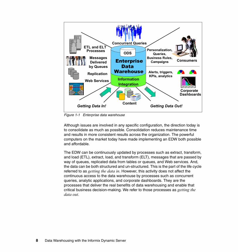
Figure 1-1 Enterprise data warehouse
Although issues are involved in any specific configuration, the direction today is to consolidate as much as possible. Consolidation reduces maintenance time and results in more consistent results across the organization. The powerful computers on the market today have made implementing an EDW both possible and affordable.
The EDW can be continuously updated by processes such as extract, transform, and load (ETL), extract, load, and transform (ELT), messages that are passed by way of queues, replicated data from tables or queues, and Web services. And, the data can be both structured and un-structured. This is the part of the life cycle referred to as getting the data in. However, this activity does not affect the continuous access to the data warehouse by processes such as concurrent queries, analytic applications, and corporate dashboards. They are the processes that deliver the real benefits of data warehousing and enable that critical business decision-making. We refer to those processes as getting the data out.
Getting Data In! Getting Data Out!
ProcessesETL and ELT
Messages Delivered
by Queues
Replication
Web Services
Data Mining, Rules,
Campaigns
Alerts, Triggers,
CorporateDashboards
Concurrent Queries
Consumers
WarehouseInformationIntegration
ODS
Enterprise
Content
Data
Personalization, Queries,
Business Rules, Campaigns
Alerts, triggers, KPIs, analytics
8 Data Warehousing with the Informix Dynamic Server
1.2.2 Business Intelligence
One characterization of business intelligence (BI) is that it is insight gained from analyzing quantitative business data to make a better informed decision. The typical BI user performs a decision support role and uses business data to provide insight into, as an example, company strategy and direction. In addition to traditional BI, business performance management (BPM) is an initiative that expands the scope of BI to include the integration of processes, methodologies, metrics and technologies for the enterprise to better measure, monitor and manage business performance.
By contributing to an integrated, enterprise-wide data and reporting approach, and by providing highlights into the business direction, BI is able to provide the necessary information at the right time to management. Technologies such as Web services (to minimize the time and cost of application development), federation and information integration (for heterogeneous data accessibility and data integration), grid computing (to supply the resources needed, and enable the support of large volumes of data), and interactive portals and dashboards can enable the use of a broader range and variety of more current data, presented on demand and in a format that is much easier to interpret and understand by a larger number of users.
The primary focus of BI is to develop a cross-process reporting strategy through data analysis and decision-support capabilities. One step in this direction is to develop common dashboard tools and a common dashboard infrastructure. Through dashboards, analysts can reduce the time spent collecting data and increase the time spent analyzing it.
As BPM becomes more integrated with BI, an important point is that BI expands beyond business decision making to also provide closed-loop feedback, enabling improvements in the business processes.
The BI environment is changing in other ways also. For example, companies no longer have the long strategic time-frames in which to plan, design, and manage processes. Business managers are looking for answers to their questions much more quickly than in the past. Strategic time-frames have continued to become smaller. For example, yearly revenue goals and measurements have, for most enterprises, become quarterly goals and measurements. Investors and share-holders are more demanding and more critical of missed performance goals, even with these shorter measurement periods. And, they are expressing their opinion by giving, or withholding, their investment money.
These demands are coming at a time when the volume of data is growing, business mergers and acquisitions is increasing, the use of strategic outsourcing is growing, and a requirement for faster turnaround on information requests is
Chapter 1. Introduction 9
increasing. This has put an enormous burden on the information technology (IT) organizations. And, most of this change is centered around BI, because that is the environment responsible for providing information for decision-making.
Business intelligence is the process by which you can obtain accurate and consistent business data from your data warehousing environment, analyze this data from various business contexts, identify trends, variations, and anomalies, execute simulations, and obtain detailed insight (intelligence) about your business. Having this intelligence enables faster and easier identification and resolution of business problems.
Having right-time business intelligence offers the opportunity for proactive management of the business. For example, you can identify and be alerted to potential problems that could hinder meeting your business goals and measurements. And you have the required information for decision-making, and for taking appropriate actions to avoid them. This can result in improved business performance management and improved business process management.
1.3 The database server
The performance, scalability, resilience, and ease-of-use combined with low administration requirements of IDS makes it an ideal database server of choice to support the growing volumes of data in business organizations. And with the emphasis on analytics to provide dynamic business decision-making, these capabilities have become requirements for businesses to be successful in the marketplace.
Several features and capabilities of IDS that help support the specific needs of a demanding data warehousing environment are:
� Multithreading Dynamic Scalable Architecture (DSA): Is one of the technologies that enables IDS to deliver the scalability, performance, and efficient use of hardware and operating system resources needed to support the ever growing query and analytics workloads in data warehousing and business intelligence environments.
� Decision support systems (DSS) configuration: Optimizes IDS memory usage and enables efficient hash joins to support of the growing volume of queries.
� Parallel database query (PDQ): Enables parallel operations for best throughput and use of your resources when working with a large and dynamic query workload.
� Time-cyclic data management: Yields increased performance and data manageability with the large volumes of data common in the data warehousing environment.
10 Data Warehousing with the Informix Dynamic Server
� Configurable page sizes: In disk and memory, customizes your compute environment to gain performance advantages.
� Ability to handle large chunks: Allows an IDS instance to better support large volumes of data.
� Quick sequential scans: Is essential for table scans, particularly as your volume of queries increases.
Several capabilities that are delivered with IDS database server and that are needed to support high data volumes and growing workloads common in data warehousing include:
� Requires less administration and is easier to run and manage. � Can autonomically take corrective actions and perform self tuning. � Enables automated systems monitoring and maintenance. � Provides a non-blocking checkpoint. � Has a continuous availability feature for cluster solutions. � Has multiple high availability options to minimize downtime.� Can be administered by command line utilities, SQL, or the OpenAdmin Tool.
With such capabilities, as examples, you can:
� Perform implementation and maintenance with minimal resources.� Easily embed IDS in application systems.� Create your own administration free zone.
1.3.1 Technology for business
IDS is designed to help businesses better leverage their existing information assets as they move into an on-demand business environment. In this type of environment, mission-critical database management applications typically require a combination of online transaction processing (OLTP) and batch and decision support systems (DSS), including online analytical processing (OLAP). And IDS offers capabilities to minimize downtime and to enable a fast and full recovery if an outage occurs.
Meeting these requirements calls for a data server that is flexible and can accommodate change and growth: in applications, data volume, and numbers of users. Also, it must be able to scale in performance as well as in functionality. This new suite of business availability functionality provides greater flexibility and performance in backing up and restoring an instance, automated statistical and performance metric gathering, improvements in administration, and reductions in the cost to operate the data server.
The technology used by IDS enables efficient use of existing hardware and software, including single and multiprocessor architectures. And it helps you
Chapter 1. Introduction 11
keep up with technological growth, including the requirement for such things as more complex application support, which often calls for the use of nontraditional or rich data types that cannot be stored in simple character or numeric form.
Built on the IBM Informix Dynamic Scalable Architecture (DSA), IDS provides one of the most effective solutions available. As examples, it includes:
� A next-generation parallel data server architecture that delivers mainframe-caliber scalability
� Manageability and performance
� Minimal operating system overhead
� Automatic distribution of workload
� The capability to extend the server to handle new types of data
IDS delivers proven technology that efficiently integrates new and complex data directly into the database. It handles time-series, spatial, geodetic, Extensible Markup Language (XML), video, image, and other user-defined data along with traditional data to meet today’s most rigorous data and business demands. It also helps businesses lower their total cost of ownership (TCO) by leveraging its well-regarded general ease of use and administration, and its support of existing standards for development tools and systems infrastructure. IDS is a development-neutral environment and supports a comprehensive array of application development tools for rapid deployment of applications under Linux®, Microsoft® Windows®, and UNIX® operating environments.
Starting with IDS 11, the legendary availability and reliability of IDS includes a full active-active cluster solution for high availability and low cost scalability. You can use Informix to manage workload distribution across multiple read-only or full-transaction nodes, and dynamically add different types of nodes into your cluster environment to scale out or increase availability in the most demanding environments. Warehouse workloads have the flexibility to work on the same database with operational data, running real-time on a separate node in the cluster. Data can also be replicated in real-time using Enterprise Replication, or copied to a separate data warehouse server. With Informix, you have the flexibility to design the system to meet your needs and to make the most of your existing infrastructure.
1.3.2 Storage optimization
Storage optimization is responsible for compressing and consolidating the data within IDS. Tests have shown that space requirements in memory or disk can be reduced by an average of 50%. This, in turn, can significantly reduce processing time.
12 Data Warehousing with the Informix Dynamic Server
The components of storage optimization are:
� Compression
The amount of data stored within databases continues to grow rapidly. Although the cost of storage continues to go down, it is not keeping pace with the amount of data generated. This puts pressure on IT budgets to find ways to reduce costs. When you consider that most databases employ redundant storage and backup copies of data, you can easily see that even small database systems that use only a terabyte of storage can easily require 3 - 6 times that amount of total storage.
IBM Informix Dynamic Server (IDS) has data compression technology to minimize the impact of these huge volumes of data. IDS provides full online support for turning on storage optimization and compressing existing table data while applications continue to use the table. This means that no system downtime is required to use the IDS storage optimization technology. Customers have been able to achieve up to 80% savings in storage, depending on their data characteristics. A reduction in data volumes also means less time to complete backup and restore operations. Many customers have experienced up to a 20% performance improvement in their applications because of less I/O and improved buffer pool utilization.
� Repack
This component, consolidates the free space created within each partition.
� Shrink
This component removes the unused portion of the partition and returns it for reuse by IDS. These spaces are much easier for IDS to reuse than smaller, isolated free spaces.
Compression and consolidation is key to improving query performance and minimizing the physical disk space required
1.3.3 Serving the enterprise
IBM Informix Dynamic Server 11 (IDS 11) continues a long-standing tradition, within IBM and Informix, of delivering first-in-class data servers. It combines the robustness, high performance, availability, and scalability needed in modern business today.
Complex, mission-critical database management applications typically require a combination of online transaction processing (OLTP) and batch and decision-support operations, including online analytical processing (OLAP). Meeting these needs is contingent upon a data server that can scale in performance as well as in functionality. It must dynamically adjust as
Chapter 1. Introduction 13
requirements change from accommodating larger amounts of data, to changes in query operations, to increasing numbers of concurrent users. The technology must be designed to efficiently use all the capabilities of the existing hardware and software configuration, including single and multiprocessor architectures.
Finally, the data server must satisfy users’ demands for more complex application support, which often uses nontraditional or rich data types that cannot be stored in simple character or numeric form. IDS is built on the IBM Informix Dynamic Scalable Architecture (DSA). It provides one of the most effective solutions available: a next-generation parallel data server architecture that delivers mainframe-caliber scalability, manageability, and performance; minimal operating system overhead; automatic distribution of workload; and the capability to extend the server to handle new types of data. With version 11, IDS increases its lead over the data server landscape with even faster performance, a new suite of business availability functionality, greater flexibility and performance in backing up and restoring an instance, automated statistical and performance metric gathering, improvements in administration, reducing the cost to operate the data server, and more.
IDS delivers proven technology that efficiently integrates new and complex data directly into the database. It handles time-series, spatial, geodetic, Extensible Markup Language (XML), video, image, and other user-defined data with traditional data to meet today’s most rigorous data and business demands. IDS helps businesses to lower their total cost of ownership (TCO) by leveraging its well-regarded general ease of use and administration, and its support of existing standards for development tools and systems infrastructure. IDS is a development-neutral environment and supports a comprehensive array of application development tools for rapid deployment of applications under Linux, Microsoft Windows, and UNIX operating environments.
The maturity and success of IDS is built on many years of widespread use in critical business operations, which attests to its stability, performance, and usability. IDS 11 moves this already highly successful enterprise relational data server to a new level.
1.4 The Informix Warehouse
The primary focus of this book is on implementing data warehousing in an Informix environment. To enable that implementation, we have developed the IBM Informix Warehouse as the means of providing an integrated data warehouse infrastructure. The Informix Warehouse consists of the IBM Informix Dynamic Server (IDS) V11.50xC4 and the Informix Warehouse Feature 11.50. The Informix Warehouse Feature includes an integrated set of tooling to help
14 Data Warehousing with the Informix Dynamic Server
build, deploy, operate, and maintain a robust data warehousing infrastructure that can deliver managed information assets to business decision makers.
Informix Warehouse simplifies the design and deployment of a data warehouse, allowing you to more easily enable these business applications, supplying a state of the art extract, load, and transform (ELT) tool, all in an easy to use Eclipse-based GUI environment. This platform provides the foundation for you to cost effectively deploy and build next-generation analytic solutions using the IBM Informix Dynamic Server. So, why an ELT tool?
The difference between extract, transform, and load (ETL) and ELT is primarily in where the data transformations are performed and in how the data gets loaded into the data warehousing database. Traditional ETL products have been developed to perform data transformations completely separately from the target data warehousing database, and then the data gets loaded into the data warehousing database, most typically in a batch-loading scenario.
The growing movement towards solutions that can provide more, and more current, data in the data warehouse has resulted with the need for a process to transform and load the it into the data warehouse in more of a continuous manner. That is commonly referred to as a movement towards real-time data management. This spawned a variation of the ETL process, known as ELT. Here, most or all of the data transformation is performed in the data warehousing environment rather than on a separate server prior to the load.
The basic idea is to take advantage of the inherent parallelism and power of the new processors of the database engine itself and perform the bulk of the transformation after the data is actually loaded into the database. This approach enables the movement towards more continuous loading of the data, and thus faster availability of more data in the data warehouse.
Now, two methodologies for transforming and loading data into the data warehouse are available:
� ETL (extract, transform, and load)
Here the source data is loaded into a database server that is external to the data warehousing environment. After loading, the required transformations are made to enable the resulting data to be loaded into the data warehousing environment - ready for use.
� ELT (extract, load, and transform)
Here, most or all of the source data is extracted and loaded into the data warehousing environment. Then, the required transformations are made and loaded into the target data warehousing databases.
Chapter 1. Introduction 15
Using an ELT tool means that before performing any transformations on the source data, that data will be implicitly loaded as needed (commonly in the form of temporary databases that are reused across the data flow), inside an IDS execution database, which can be the same as the data warehouse database, or another IDS database.
Using Informix for a data warehouse database is an ideal solution for Informix users who want to build end-to-end business intelligence and reporting solutions using data from various sources, including IDS. You can effectively use front-end analysis and reporting tools, such as IBM Cognos, or develop mashups and other dashboards. Using a single database server for both operational and warehouse data can simplify operational complexity and reduce costs.
IBM Informix Warehouse V11.50 is available in two offerings.
� Informix Warehouse Enterprise Edition, which includes IDS Enterprise Edition, the IBM IDS Storage Optimization feature for Enterprise Edition, and the Informix Warehouse Feature for Enterprise Edition for integrated warehouse tooling.
The IDS Storage Optimization feature enables you to reduce your storage costs by selecting which tables and fragments to compress. It also helps you with disk space management by providing functions to repack rows for storage optimization and to truncate empty extents at the end of a table to release unused space. This process can help reduce the number of disk I/Os and improve efficiency of memory buffer pools usage, resulting in faster query processing and response time.
� Informix Warehouse Workgroup Edition, which includes IDS Workgroup Edition and the Informix Warehouse Feature.
1.4.1 Informix Warehouse architecture
The Informix Warehouse Feature is available separately if you already have either the IDS Enterprise or Workgroup Edition licenses for warehouse processing and want to add the Informix Warehouse Feature for integrated warehouse tooling. Figure 1-2 on page 17 illustrates the Informix Warehouse architecture.
The Informix Warehouse (IW) capabilities includes:
� Informix Warehouse Client with Design Studio for data modeling, schema design, data transformation design, and data flow design.
� Informix Warehouse Server with Administration Console to schedule and manage data flows.
� SQL Warehouse runtime to perform data transformation
16 Data Warehousing with the Informix Dynamic Server
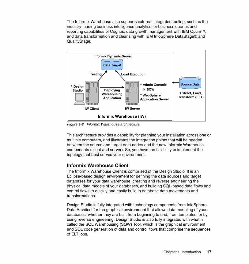
The Informix Warehouse also supports external integrated tooling, such as the industry-leading business intelligence analytics for business queries and reporting capabilities of Cognos, data growth management with IBM Optim™, and data transformation and cleansing with IBM InfoSphere DataStage® and QualityStage.
Figure 1-2 Informix Warehouse architecture
This architecture provides a capability for planning your installation across one or multiple computers, and illustrates the integration points that will be needed between the source and target data nodes and the new Informix Warehouse components (client and server). So, you have the flexibility to implement the topology that best serves your environment.
Informix Warehouse ClientThe Informix Warehouse Client is comprised of the Design Studio. It is an Eclipse-based design environment for defining the data sources and target databases for your data warehouse, creating and reverse engineering the physical data models of your databases, and building SQL-based data flows and control flows to quickly and easily build in database data movements and transformations.
Design Studio is fully integrated with technology components from InfoSphere Data Architect for the graphical environment that allows data modeling of your databases, whether they are built from beginning to end, from templates, or by using reverse engineering. Design Studio is also fully integrated with what is called the SQL Warehousing (SQW) Tool, which is the graphical environment and SQL code generation of data and control flows that comprise the sequences of ELT jobs.
IW Client IW Server
Informix Dynamic Server
Data Target
Informix Warehouse (IW)
• Admin ConsoleSQW
• WebSphereApplication Server
• Design Studio
Load Execution
Deploying Warehousing Application
Testing
Source Data
Extract, Load, Transform (ELT)
Chapter 1. Introduction 17
Informix Warehouse ServerThe Informix Warehouse Server houses components that comprise the Informix Warehouse. It should not be confused with the Informix DBMS server that houses the actual data warehouse. As such, the Informix Warehouse Server houses the following as components:
� WebSphere® Application Server� Informix Warehouse Administration Console (Admin Console)� SQL Warehousing (SQW) tool
The WebSphere Application Server is included specifically to support the Admin Console and SQW run-time services that are in charge of scheduling, executing, and monitoring the SQL-based ELT jobs (control flows) that have been defined and packaged using Design Studio.
The Informix Warehouse Administration Console (Admin Console) is a Web-based application for administering database and system resources associated with your data warehouse, and also for deploying, scheduling, and monitoring the control flows previously created in Design Studio (through processes called the SQL Warehousing (SQW) services). To support these SQW run-time services, the Admin Console includes the WebSphere Application Server. However, you can run the Administration Console on any other Java™ application server.
The Administration Console enables you to:
� Manage common resources, such as database connections and machine resources
� Schedule the execution of control flows (sequences of ELT data flows)
� Monitor the execution status
The detailed features of the Informix Warehouse offering are provided in subsequent chapters of this book. More information can also be found in an article located at the following Informix Web site:
http://www.ibm.com/informix/warehouse
Completing your data warehouse solutionIn this brief introduction, and in the remaining chapters of this book, we describe how you can use the Informix Warehouse to build a data warehousing infrastructure, enabling you to get your data into the data warehouse in a form suitable for query processing and business intelligence (BI) activities. The remaining task then is to get the data out of the data warehouse for your BI purposes. To satisfy that requirement, and to complete the solution for a comprehensive data warehousing and BI environment, IBM offers the Cognos product suite. That suite includes a comprehensive set of tools for reporting,
18 Data Warehousing with the Informix Dynamic Server

drill-down/drill-up analyses, and dashboard and scorecard capabilities. The Cognos industry-leading BI capabilities allow it to do both multidimensional online analytical processing (MOLAP) and relational OLAP (ROLAP) to adapt to the size of the data sets involved. Although other BI tools in the industry can also readily access IDS databases, the Cognos product, with SQW and IDS, provide a single source for Informix customers seeking a data warehousing solution.
Chapter 1. Introduction 19

20 Data Warehousing with the Informix Dynamic Server

Chapter 2. Planning the environment
In this chapter, we discuss the key technical challenges, considerations, technologies, and implementation approaches related to planning and deploying a data warehousing (DW) or business intelligence (BI) solution. In this context, we position the IBM Informix Warehouse and other complementary technologies that can be used together when planning and implementing these types of solutions.
With the Informix Warehouse, Informix users can leverage their existing data, Informix environment and skills, and build a robust data warehousing infrastructure around IDS. Informix Warehouse provides the tools and capabilities to easily perform the tasks related to creating and maintaining physical models and enabling data transformation and movement of data from source operational systems into a data warehousing environment built on IDS.
2
© Copyright IBM Corp. 2009. All rights reserved. 21
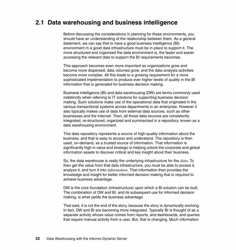
2.1 Data warehousing and business intelligence
Before discussing the considerations in planning for these environments, you should have an understanding of the relationship between them. As a general statement, we can say that to have a good business intelligence (BI) environment m a good data infrastructure must be in place to support it. The more structured and organized the data environment is, the faster and easier accessing the relevant data to support the BI requirements becomes.
This approach becomes even more important as organizations grow and become more dispersed, data volumes grow, and the data analysis activities become more complex. All this leads to a growing requirement for a more sophisticated implementation to produce ever higher levels of quality in the BI information that is generated for business decision making.
Business intelligence (BI) and data warehousing (DW) are terms commonly used indistinctly when referring to IT solutions for supporting business decision making. Such solutions make use of the operational data that originated in the various transactional systems across departments in an enterprise. However it also typically makes use of data from external data sources, such as other businesses and the Internet. Then, all those data sources are consistently integrated, re-structured, organized and summarized in a repository, known as a data warehousing environment.
This data repository represents a source of high-quality information about the business. and that is easy to access and understand. The repository is then used, on-demand, as a trusted source of information. That information is significantly high in value and strategic in helping unlock the corporate and global information assets to discover critical and key insight about their business.
So, the data warehouse is really the underlying infrastructure for the data. To then get the value from that data infrastructure, you must be able to access it, analyze it, and turn it into information. That information then provides the knowledge and insight for better informed decision making that is required to achieve business advantage.
DW is the core foundation (infrastructure) upon which a BI solution can be built. The combination of DW and BI, and its subsequent use for informed decision making, is what yields the business advantage.
That said, it is not the end of the story, because the story is dynamically evolving. In fact, DW and BI are becoming more integrated. Typically BI is thought of as a separate activity whose value comes from reports, and dashboards, and queries that require manual activity from a user. But, that is changing. Much information
22 Data Warehousing with the Informix Dynamic Server
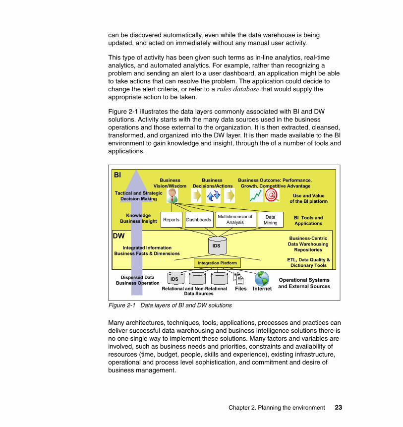
can be discovered automatically, even while the data warehouse is being updated, and acted on immediately without any manual user activity.
This type of activity has been given such terms as in-line analytics, real-time analytics, and automated analytics. For example, rather than recognizing a problem and sending an alert to a user dashboard, an application might be able to take actions that can resolve the problem. The application could decide to change the alert criteria, or refer to a rules database that would supply the appropriate action to be taken.
Figure 2-1 illustrates the data layers commonly associated with BI and DW solutions. Activity starts with the many data sources used in the business operations and those external to the organization. It is then extracted, cleansed, transformed, and organized into the DW layer. It is then made available to the BI environment to gain knowledge and insight, through the of a number of tools and applications.
Figure 2-1 Data layers of BI and DW solutions
Many architectures, techniques, tools, applications, processes and practices can deliver successful data warehousing and business intelligence solutions there is no one single way to implement these solutions. Many factors and variables are involved, such as business needs and priorities, constraints and availability of resources (time, budget, people, skills and experience), existing infrastructure, operational and process level sophistication, and commitment and desire of business management.
Dispersed DataBusiness Operation
Integrated InformationBusiness Facts & Dimensions
KnowledgeBusiness Insight
BusinessVision/Wisdom
Business Decisions/Actions
Business Outcome: Performance, Growth, Competitive Advantage
FilesRelational and Non-Relational
Operational Systems and External Sources
ETL, Data Quality & Dictionary Tools
Business-CentricData Warehousing
Repositories
Internet
Tactical and StrategicDecision Making
BI
Use and Value of the BI platform
BI Tools and Applications
Reports Dashboards Multidimensional Analysis
Data Mining
IDS
IDS
Data Sources
Integration Platform
DW
Chapter 2. Planning the environment 23
The focus of this book is on the technology for creating a data warehousing environment with Informix. As examples, in the subsequent chapters we discuss and describe the components of the Informix Warehouse, and best practices when IDS is the platform. Also included is integration of Informix Warehouse with BI tools such as IBM Cognos BI, that will allow the business users to visualize and analyze the data using reports and dashboards, as examples. We also discuss the incorporation of unstructured data and text, to provide complementary content management, text analytics and location-based knowledge.
2.2 The data warehouse
A data warehouse, in concept, is an area where data is collected and stored for the purpose of being analyzed. The defining characteristic of a data warehouse is its purpose. Most of the data collected comes from the operational systems developed to support the on-going day-to-day business operations of an enterprise. This type of data is typically referred to as operational data. Those systems used to collect the operational data are transaction-oriented. That is, they were built to process the business transactions that occur in the enterprise. Typically, being online systems, they then provide online transaction processing (OLTP).
To analyze huge volumes of data efficiently requires that the data be organized much differently than the OLTP data. Thus, the data used for OLTP and data warehousing are two separate and distinct sets of data used for their separate and distinct purposes. The data in a data warehouse is typically referred to as informational data. The systems used to perform the analytical processing of the informational data are also typically online, so are referred to as online analytical processing systems (OLAP).
The business rationale for data warehousing is well known. It is to provide a clean, stable, consistent, usable, and understandable source of business data that is organized for analysis. That is, the operational data from the business processes must be transformed to a format and structure that can yield useful business information. To satisfy that need requires an architecture-based solution.
Figure 2-2 on page 25 shows an architecture-based solution for a data warehousing environment. The data warehouse architecture can be expanded to multiple layers to enable multiple business views to be built on the consistent information base provided by the data warehouse. This particular example shows the flow of data from the operational systems to the data warehouse, and then to potential data marts that might be required.
24 Data Warehousing with the Informix Dynamic Server
Figure 2-2 Example data warehousing architecture
There are variants in the architectures used in business, and most are typically designed with multiple layers. This approach enables the separation of the operational and the informational data, and provides the mechanisms to clean, transform, and enhance the data as it moves across the layers from the operational to the informational environment. Having this informational environment as a source of clean, high-quality data is invaluable for the enterprise decision-makers. Therefore, we refer to it as an enterprise data warehouse (EDW).
Integrating the corporate operational data within a data warehouse environment results in multiple benefits, such as:
� Improving access to the organization data� Being a common accurate source for business analytics� Housing historic and non-volatile data for trending� Providing data for business performance management� Consolidating disparate sources� Creating a path for standardization, consistency and data quality
High-quality is a key factor for measuring the success of a data warehouse implementation. Quality includes the following characteristics:
� Accuracy: The data is truthful, and has correct semantics, forms and values, and conforms to actual business facts, terms, metrics, context and standards.
� Consistency: The data is integrated and mapped with the correct terms, formats and values, delivering the correct mapping of terms, formats and values from the various sources to the warehouse business standards.
� Completeness: Includes all data that is relevant for the business and provides the information required for decision support.
Operational Systems
Data Warehouse
Data Mart
Metadata
Data Mart Data Mart
Chapter 2. Planning the environment 25
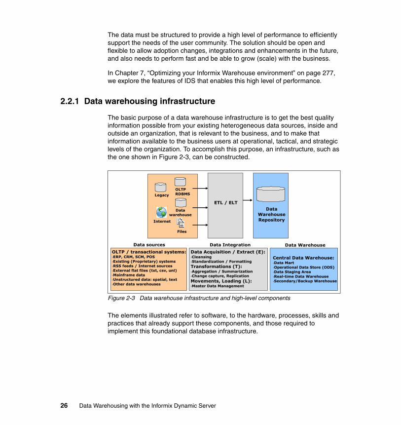
The data must be structured to provide a high level of performance to efficiently support the needs of the user community. The solution should be open and flexible to allow adoption changes, integrations and enhancements in the future, and also needs to perform fast and be able to grow (scale) with the business.
In Chapter 7, “Optimizing your Informix Warehouse environment” on page 277, we explore the features of IDS that enables this high level of performance.
2.2.1 Data warehousing infrastructure
The basic purpose of a data warehouse infrastructure is to get the best quality information possible from your existing heterogeneous data sources, inside and outside an organization, that is relevant to the business, and to make that information available to the business users at operational, tactical, and strategic levels of the organization. To accomplish this purpose, an infrastructure, such as the one shown in Figure 2-3, can be constructed.
Figure 2-3 Data warehouse infrastructure and high-level components
The elements illustrated refer to software, to the hardware, processes, skills and practices that already support these components, and those required to implement this foundational database infrastructure.
OLTPRDBMSLegacy
Datawarehouse
Data sources Data Integration Data Warehouse
OLTP / transactional systems:?ERP, CRM, SCM, POS?Existing (Proprietary) systems?RSS feeds / Internet sources?External flat files (txt, csv, unl)?Mainframe data?Unstructured data: spatial, text?Other data warehouses
Data Acquisition / Extract (E):?Cleansing?Standardization / FormattingTransformations (T):?Aggregation / Summarization?Change capture, ReplicationMovements, Loading (L):?Master Data Management
Central Data Warehouse:?Data Mart?Operational Data Store (ODS)?Data Staging Area?Real-time Data Warehouse?Secondary/Backup Warehouse
Files
Internet
ETL / ELTData
Warehouse Repository
26 Data Warehousing with the Informix Dynamic Server
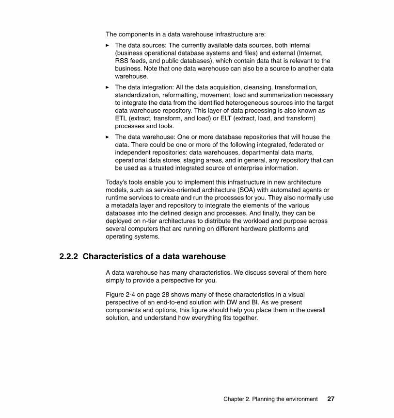
The components in a data warehouse infrastructure are:
� The data sources: The currently available data sources, both internal (business operational database systems and files) and external (Internet, RSS feeds, and public databases), which contain data that is relevant to the business. Note that one data warehouse can also be a source to another data warehouse.
� The data integration: All the data acquisition, cleansing, transformation, standardization, reformatting, movement, load and summarization necessary to integrate the data from the identified heterogeneous sources into the target data warehouse repository. This layer of data processing is also known as ETL (extract, transform, and load) or ELT (extract, load, and transform) processes and tools.
� The data warehouse: One or more database repositories that will house the data. There could be one or more of the following integrated, federated or independent repositories: data warehouses, departmental data marts, operational data stores, staging areas, and in general, any repository that can be used as a trusted integrated source of enterprise information.
Today’s tools enable you to implement this infrastructure in new architecture models, such as service-oriented architecture (SOA) with automated agents or runtime services to create and run the processes for you. They also normally use a metadata layer and repository to integrate the elements of the various databases into the defined design and processes. And finally, they can be deployed on n-tier architectures to distribute the workload and purpose across several computers that are running on different hardware platforms and operating systems.
2.2.2 Characteristics of a data warehouse
A data warehouse has many characteristics. We discuss several of them here simply to provide a perspective for you.
Figure 2-4 on page 28 shows many of these characteristics in a visual perspective of an end-to-end solution with DW and BI. As we present components and options, this figure should help you place them in the overall solution, and understand how everything fits together.
Chapter 2. Planning the environment 27
Figure 2-4 Overview DW and BI solution structure
Separation of DSS and OLTP dataA good practice is to keep the DSS and OLTP data areas separate, including the following levels of separation:
� Hardware level: Have each database and IDS instance on different servers or machines if possible.
� Instance level: Have two IDS servers running on the same machine, one tuned for OLTP and one tuned for DSS, high availability.
� Database level: Have two databases (OLTP and DSS) within the same IDS instance, tuned for a mixed workload.
� User or schema level: Although less desirable, an alternative is to keep tables of the different systems (OLTP and DSS) stored in the same database, but with different table user or schema names to differentiate the systems.
Many reasons exist for keeping these systems running on independent environments; the following list contains several of the reasons:
� The BI tools perform complex ad hoc queries that retrieve and process large amounts of data. Separation of workloads is required to prevent these queries from impacting the performance of the transactions running in the operational systems.
� The DSS environment typically integrates data from one or more heterogeneous systems. A process to perform acquisition, cleansing, integration, transformation and loading of that data into an integrated
ERP
SCM
CRM
POS
e-Commerce
Operational / TransactionalSystems and External Sources
(Sources)
Online Transaction Processing (OLTP) Online Analytical Processing (OLAP)
Data Warehousing Platform(Targets)
Data marts
Data martsODS
Data Staging Area
Data Warehouse
Data Warehouse
Business Intelligence Tools
ETL
or
ELT
28 Data Warehousing with the Informix Dynamic Server
database is more effective than resolving the integration issues of distributed systems on complex queries at runtime.
� The performance and administration requirements of the DSS and OLTP systems are quite different in OLAP/DSS. Therefore, users, volume of data and requirements for backup, availability, performance tuning, workload types, tools, data modeling and security are also different and require different skills, skill levels, experience, and expertise.
For example, when you configure two IDS servers running on the same machine, be sure to avoid unnecessary competition for resources and to make them as independent as possible. Considerations include dividing the CPU virtual processors (CPU VPs), buffers and shared memory settings, network cards and IP addresses, message files, and other resources.
Data integrationAn important aspect of building a data warehouse is the design and implementation of the data integration and reconciliation to resolve any differences in formatting and semantics, and any inconsistencies found across the organization’s data. This aspect is particularly important when the data is coming from a number of heterogeneous sources of data.
The applications that gather data from those data sources, format it, organize it, consolidate it, transform it, ensure it is consistent, and store it in the data warehouse, are called extract, transform, and load (ETL) applications. The techniques and technology for ETL continue to improve to meet the changing nature of the data environment.
Part of that change includes the growing movement towards solutions that can provide more data and data that is more current. That is commonly referred to as a movement towards real-time data management. Providing additional support for data integration in that type of environment has spawned another variation of the ETL process. That variation is ELT, or extract, load, and transform. With ELT, more of the data transformation is performed on the target system after the data has been loaded, rather than on a separate server prior to the load.
The Informix Warehouse Feature client (Design Studio) provides a development environment for ELT. It allows clients to graphically design, test, debug, and prepare for the deployment of SQL-based ELT jobs. These jobs can then be scheduled for one-time or ongoing period execution. For this requirement, there are also products within the IBM InfoSphere Information Server, such as DataStage and QualityStage.
Chapter 2. Planning the environment 29
Other types of tools that can be part of the Integration stage in a data warehousing project are:
� Master Data Management (MDM)� Dictionary and metadata � Data Quality � Change Data Capture (CDC)
2.2.3 Data modeling: logical and physical
Data modeling provides the base, and is the organizing structure, for the data warehousing environment. It affects every phase of data usage.
Generally speaking, a model is an abstraction and reflection of the real world, giving us the ability to visualize what we cannot yet realize. It is the same with data modeling. The primary aim of a data model is to make sure that all data objects required by the business are accurately and fully represented.
The result is a logical and physical data model for an enterprise data warehouse that is designed with data structures in the terms and metrics normally used to understand the business.
Various data modeling techniques can be used, depending on the characteristics of the database and data warehouse engine technology to use at the database level, and at the OLAP BI tools level. Examples are relational or dimensional database, relational OLAP (ROLAP), and multidimensional OLAP (MOLAP).
For additional information about data modeling there are a number of books written by Dr. Ralph Kimball. He is well known in the industry, is a leading proponent of the technology, and is generally acknowledged to be the originator of many of the core concepts in this subject area. Dr. Kimball has written extensively on these and related subjects, and provides education and consulting offerings to help clients as they design, develop, and implement their data warehousing environments. We have listed several of his works in “Other publications” on page 443. We consider these to be required reading for anyone interested in the subject of data warehousing and data modeling.
Attention: Be aware that differences exist in the level of support for these types of modeling across the various platforms.
30 Data Warehousing with the Informix Dynamic Server
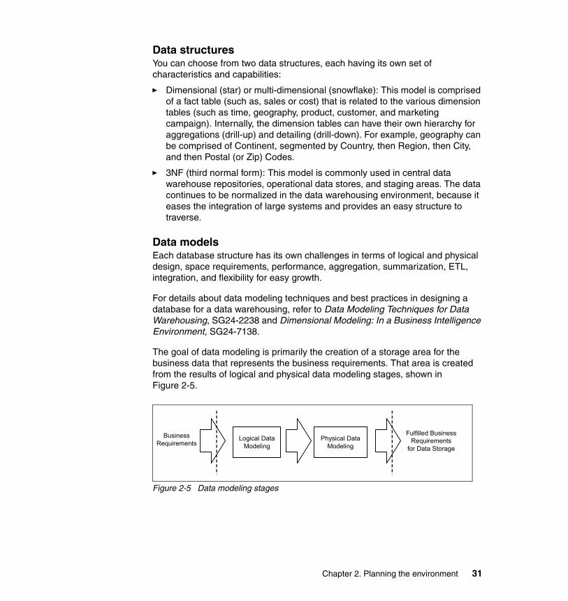
Data structuresYou can choose from two data structures, each having its own set of characteristics and capabilities:
� Dimensional (star) or multi-dimensional (snowflake): This model is comprised of a fact table (such as, sales or cost) that is related to the various dimension tables (such as time, geography, product, customer, and marketing campaign). Internally, the dimension tables can have their own hierarchy for aggregations (drill-up) and detailing (drill-down). For example, geography can be comprised of Continent, segmented by Country, then Region, then City, and then Postal (or Zip) Codes.
� 3NF (third normal form): This model is commonly used in central data warehouse repositories, operational data stores, and staging areas. The data continues to be normalized in the data warehousing environment, because it eases the integration of large systems and provides an easy structure to traverse.
Data modelsEach database structure has its own challenges in terms of logical and physical design, space requirements, performance, aggregation, summarization, ETL, integration, and flexibility for easy growth.
For details about data modeling techniques and best practices in designing a database for a data warehousing, refer to Data Modeling Techniques for Data Warehousing, SG24-2238 and Dimensional Modeling: In a Business Intelligence Environment, SG24-7138.
The goal of data modeling is primarily the creation of a storage area for the business data that represents the business requirements. That area is created from the results of logical and physical data modeling stages, shown in Figure 2-5.
Figure 2-5 Data modeling stages
Logical DataModeling
Physical DataModeling
BusinessRequirements
Fulfilled BusinessRequirements
for Data Storage
Chapter 2. Planning the environment 31
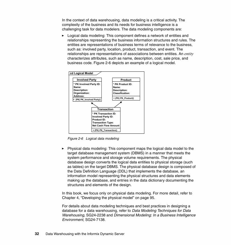
In the context of data warehousing, data modeling is a critical activity. The complexity of the business and its needs for business intelligence is a challenging task for data modelers. The data modeling components are:
� Logical data modeling: This component defines a network of entities and relationships representing the business information structures and rules. The entities are representations of business terms of relevance to the business, such as: involved party, location, product, transaction, and event. The relationships are representations of associations between entities. An entity characterizes attributes, such as name, description, cost, sale price, and business code. Figure 2-6 depicts an example of a logical model.
Figure 2-6 Logical data modeling
� Physical data modeling: This component maps the logical data model to the target database management system (DBMS) in a manner that meets the system performance and storage volume requirements. The physical database design converts the logical data entities to physical storage (such as tables) on the target DBMS. The physical database design is composed of the Data Definition Language (DDL) that implements the database, an information model representing the physical structures and data elements making up the database, and entries in the data dictionary documenting the structures and elements of the design.
In this book, we focus only on physical data modeling. For more detail, refer to Chapter 4, “Developing the physical model” on page 95.
For details about data modeling techniques and best practices in designing a database for a data warehousing, refer to Data Modeling Techniques for Data Warehousing, SG24-2238 and Dimensional Modeling: In a Business Intelligence Environment, SG24-7138.
Involved Party
+ (PK) PK_Involved Party()
Involved Party* PK Involved Party ID:Name:Description:Organization:Address:
Involved Party
+ (PK) PK_Product()
Product* PK Product ID:Name:Description:Classification:
cd Logical Model
Involved Party
+ (PK) PK_Transaction()
Transaction* PK Transaction ID:Involved Party ID:Product ID:Transaction Type:Net Cash Flow Amount
32 Data Warehousing with the Informix Dynamic Server
The Informix clientThe Informix Warehouse Feature client component (Design Studio) provides a development and deployment environment for physical data modeling of relational databases in Informix that will serve as data warehouses. Design Studio is an Eclipse-based framework that includes an InfoSphere Data Architect plug-in which gives the functionality to create, edit, evaluate change impact, and create an SQL script to deploy the physical data model or changes to it, for your target database systems in Informix.
You might want to complement Informix Warehouse Design Studio functionality for physical modeling, with logical modeling design tools. You can design, graphically visualize, and communicate and validate with business users, the business model that has a clear mapping with your physical database design. The data model hides the details about the database and its objects, and focuses on the high-level conceptual and logical data elements and their relationships, as well as business processes that will be implemented, that are of interest for the users. Examples of such tools are IBM InfoSphere Data Architect, CA ERwin, Microsoft Visio, and Embarcadero tools.
2.3 Data warehouse life cycle
When planning for a BI or DW solution, be sure to understand that a data warehouse is not a product, it is a solution. As such, it is based on a number of products and conforms to a particular life cycle. That life cycle includes tasks and activities for maintenance, support, optimization and enhancement after deployment. We have illustrated the life cycle in Figure 2-7 on page 34, along with examples of the types of tasks and activities performed.
The tasks that comprise the DW Lifecycle, then, must include creation and population of the data warehouse, and the ongoing maintenance to keep it current. So, the transformation processes (ETL and ELT) continue operating after deployment to ensure that all the data continues to get refreshed. To support all the requirements, it may be refreshed on a batch, or periodic, basis or incrementally updated on an ongoing and continuous basis.
Chapter 2. Planning the environment 33
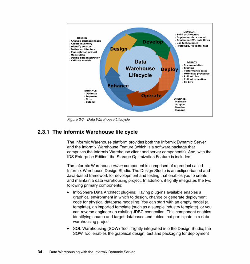
Figure 2-7 Data Warehouse Lifecycle
2.3.1 The Informix Warehouse life cycle
The Informix Warehouse platform provides both the Informix Dynamic Server and the Informix Warehouse Feature (which is a software package that comprises the Informix Warehouse client and server components). And, with the IDS Enterprise Edition, the Storage Optimization Feature is included.
The Informix Warehouse client component is comprised of a product called Informix Warehouse Design Studio. The Design Studio is an eclipse-based and Java-based framework for development and testing that enables you to create and maintain a data warehousing project. In addition, it tightly integrates the two following primary components:
� InfoSphere Data Architect plug-ins: Having plug-ins available enables a graphical environment in which to design, change or generate deployment code for physical database modeling. You can start with an empty model (a template), an imported template (such as a sample industry template), or you can reverse engineer an existing JDBC connection. This component enables identifying source and target databases and tables that participate in a data warehousing project.
� SQL Warehousing (SQW) Tool: Tightly integrated into the Design Studio, the SQW Tool enables the graphical design, test and packaging for deployment
Design
Develop
Deploy
Operate
EnhanceENHANCE? Optimize? Improve? Grow? Extend
DESIGN? Analyze business needs? Assess inventory? Identify sources ? Define architecture? Plan solution project? Model data? Define data integration? Validate models
DEVELOP? Build architecture? Implement data model? Implement ETL data flows? Use technologies? Prototype, validate, test
OPERATE? Maintain? Support? Monitor? Manage
DEPLOY? Documentation? Training? Performance tests? Formalize processes? Rollout plan? Rollout execution? Go Live
DataDataWarehouseWarehouseLifecycleLifecycle
34 Data Warehousing with the Informix Dynamic Server
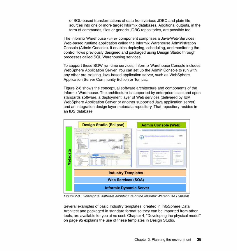
of SQL-based transformations of data from various JDBC and plain file sources into one or more target Informix databases. Additional outputs, in the form of commands, files or generic JDBC repositories, are possible too.
The Informix Warehouse server component comprises a Java-Web-Services Web-based runtime application called the Informix Warehouse Administration Console (Admin Console). It enables deploying, scheduling, and monitoring the control flows previously designed and packaged using Design Studio through processes called SQL Warehousing services.
To support these SQW run-time services, Informix Warehouse Console includes WebSphere Application Server. You can set up the Admin Console to run with any other pre-existing Java-based application server, such as WebSphere Application Server Community Edition or Tomcat.
Figure 2-8 shows the conceptual software architecture and components of the Informix Warehouse. The architecture is supported by enterprise-scale and open standards software, a deployment layer of Web services (delivered by IBM WebSphere Application Server or another supported Java application server) and an integration design layer metadata repository. That repository resides in an IDS database.
Figure 2-8 Conceptual software architecture of the Informix Warehouse Platform
Several examples of basic Industry templates, created in InfoSphere Data Architect and packaged in standard format so they can be imported from other tools, are available for you at no cost. Chapter 4, “Developing the physical model” on page 95 explains the use of these templates in Design Studio.
Design Studio (Eclipse) Admin Console (Web)
Met
adat
a
Informix Dynamic Server
Web Services (SOA)
Industry Templates
Chapter 2. Planning the environment 35
Refer to 2.7, “The Informix Warehouse platform” on page 61, which discusses the software components inside the architecture of an Informix Warehouse and proposes the tiers where the software components can be deployed.
Based on this conceptual software architecture, in the following sections we discuss the capabilities of Informix Warehouse and complementary software that align with the life cycle of data management and warehousing infrastructures:
� 2.3.2, “Data management life cycle” on page 36� 2.3.3, “Data architect and modeling life cycle” on page 37� 2.3.4, “Data integration life cycle” on page 39
2.3.2 Data management life cycle
The life cycle is comprised of a combination of Informix Warehouse Design Studio, no-cost Informix OpenAdmin Tool (OAT), either no-cost or Optim Data Studio and other products within the Optim family. Together they provide a platform that ranges from simple to sophisticated for enabling the data management tasks, which is based on policies that are shared and enabled with the downstream tasks. These tools provide the following capabilities:
� Improve individual, team and organizational database productivity.� Support tasks across heterogeneous environments.� Increase automation.� Optimize performance.� Improve resource utilization.� Facilitate collaboration.
These capabilities are key enablers for accelerating business growth, reducing infrastructure costs, and enabling data governance in any IT environment, including data warehousing.
For more information, consult the following Web locations:
� Informix OpenAdmin Tool for IDS
http://www.openadmintool.org/
� IBM (Optim) Data Studio
http://www.ibm.com/software/data/optim/data-studio/
36 Data Warehousing with the Informix Dynamic Server
2.3.3 Data architect and modeling life cycle
Design Studio includes a library of Eclipse plug-ins from InfoSphere Data Architect. These plug-ins enable you to:
� Create or change physical data models for your target data warehouse.
� Import data models from templates (for instance, industry models).
� Discover heterogeneous data sources by using reverse engineering.
� Explore and visualize the Entity-Relationship diagram of data sources.
� Relate disparate data sources within the same DW application.
� Compare the physical database structure of two data sources or targets.
� Generate Gap or Delta DDL script based on the comparison of two models.
� Discover similarities between data sources.
� Analyze models and data sources for conformance to enterprise standards.
� Validate the models for accuracy.
� Generate an impact analysis of changes in dependent data structures.
� Deploy generated DDL script for new data models, changes or deltas (to synchronize) databases.
� Save diagrams in different formats, such as graphic, XML, DDL script.
� Document physical data models.
� Keep history of changes made to data models and manage previous versions.
Figure 2-9 on page 38 illustrates the physical data model life cycle that the IDA plug-ins in Design Studio support for the source and target databases identified in your warehouse application.
Chapter 2. Planning the environment 37
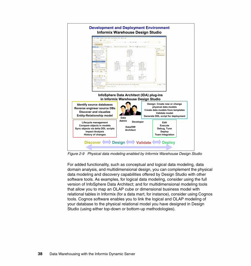
Figure 2-9 Physical data modeling enabled by Informix Warehouse Design Studio
For added functionality, such as conceptual and logical data modeling, data domain analysis, and multidimensional design, you can complement the physical data modeling and discovery capabilities offered by Design Studio with other software tools. As examples, for logical data modeling, consider using the full version of InfoSphere Data Architect; and for multidimensional modeling tools that allow you to map an OLAP cube or dimensional business model with relational tables in Informix (for a data mart, for instance), consider using Cognos tools. Cognos software enables you to link the logical and OLAP modeling of your database to the physical relational model you have designed in Design Studio (using either top-down or bottom-up methodologies).
Lifecycle managementCompare objects in models
Sync objects via delta DDL scriptsImpact Analysis
History of changes
EditExecute
Debug, TuneDeploy
Team Integration
Identify source databasesReverse engineer source DBs
Discover and visualizeEntity-Relationship model
Design: Create new or changephysical data models
Create data models from templatesValidate model
Generate DDL script for deployment
InfoSphere Data Architect (IDA) plugInfoSphere Data Architect (IDA) plug--insinsin Informix Warehouse Design Studioin Informix Warehouse Design Studio
Data/DW Architect
Data Admin Developer
Discover Design Validate Deploy
Development and Deployment EnvironmentInformix Warehouse Design StudioInformix Warehouse Design Studio
38 Data Warehousing with the Informix Dynamic Server
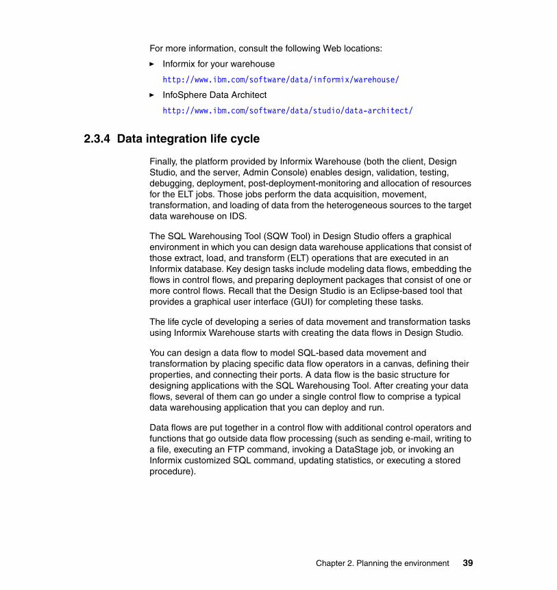
For more information, consult the following Web locations:
� Informix for your warehouse
http://www.ibm.com/software/data/informix/warehouse/
� InfoSphere Data Architect
http://www.ibm.com/software/data/studio/data-architect/
2.3.4 Data integration life cycle
Finally, the platform provided by Informix Warehouse (both the client, Design Studio, and the server, Admin Console) enables design, validation, testing, debugging, deployment, post-deployment-monitoring and allocation of resources for the ELT jobs. Those jobs perform the data acquisition, movement, transformation, and loading of data from the heterogeneous sources to the target data warehouse on IDS.
The SQL Warehousing Tool (SQW Tool) in Design Studio offers a graphical environment in which you can design data warehouse applications that consist of those extract, load, and transform (ELT) operations that are executed in an Informix database. Key design tasks include modeling data flows, embedding the flows in control flows, and preparing deployment packages that consist of one or more control flows. Recall that the Design Studio is an Eclipse-based tool that provides a graphical user interface (GUI) for completing these tasks.
The life cycle of developing a series of data movement and transformation tasks using Informix Warehouse starts with creating the data flows in Design Studio.
You can design a data flow to model SQL-based data movement and transformation by placing specific data flow operators in a canvas, defining their properties, and connecting their ports. A data flow is the basic structure for designing applications with the SQL Warehousing Tool. After creating your data flows, several of them can go under a single control flow to comprise a typical data warehousing application that you can deploy and run.
Data flows are put together in a control flow with additional control operators and functions that go outside data flow processing (such as sending e-mail, writing to a file, executing an FTP command, invoking a DataStage job, or invoking an Informix customized SQL command, updating statistics, or executing a stored procedure).
Chapter 2. Planning the environment 39
Data movement and transformation processes are designed and developed using Design Studio. The life cycle of those processes include these activities:
� Design and validate data flows.� Test-debug-run data flows.� Design and validate control flows.� Test-debug-run control flows.� Prepare the control flow application for deployment.
Key features of data flows are:
� Defines data transformation steps.
� Includes a library of operators for common extraction and transformation steps.
� Enables a library to be extended by 3rd-party operators.
� Has general SQL operators that are also available to directly express transformations in SQL.
� Supports variables and parameterization of flows.
� Can define reusable sub-flows (macros) for often used transformation patterns.
� Possibility to test and debug the flow on a database before it is deployed.
Key features of control flows are:
� Allows coordination of execution of several data flows and other activities.
� Supports execution conditions of on success, on failure, and always (unconditional).
� Support for:
– Data flows– DataStage jobs– Secure server script commands– E-mail activities– Iterators– IDS scripts and operators
� Generation of deployable data warehousing applications to later deploy control flows and their associated resources to production server through the Admin Console.
40 Data Warehousing with the Informix Dynamic Server
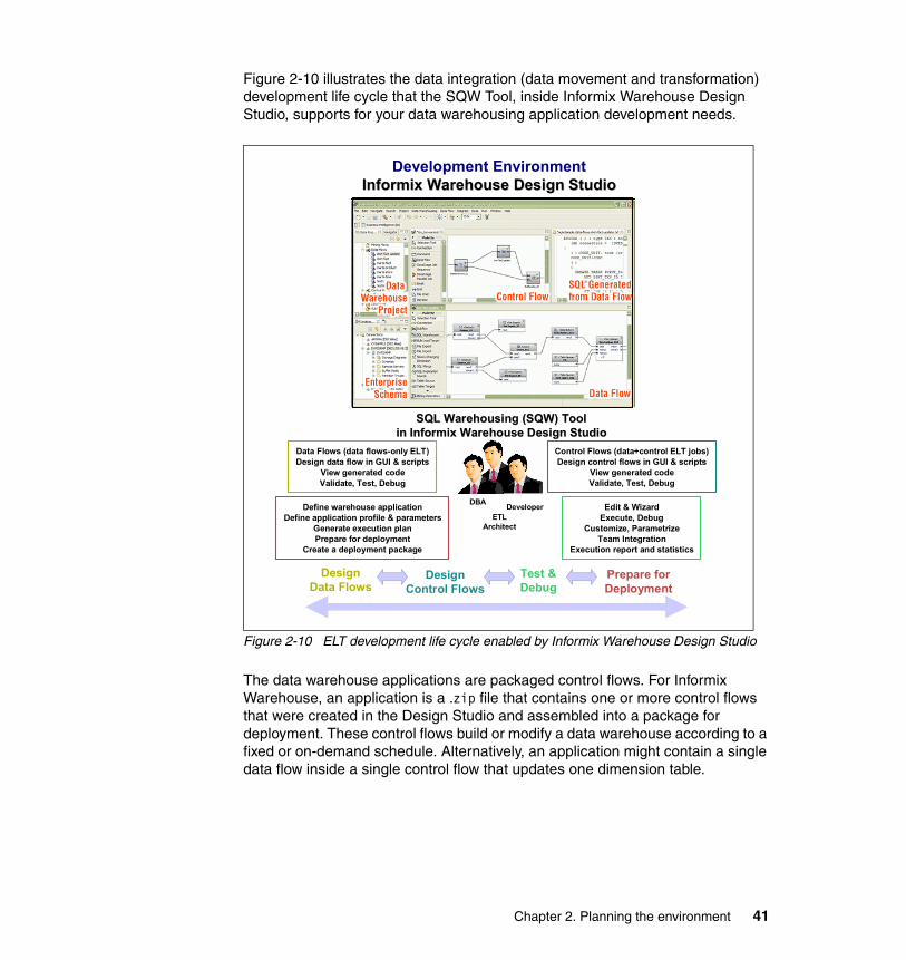
Figure 2-10 illustrates the data integration (data movement and transformation) development life cycle that the SQW Tool, inside Informix Warehouse Design Studio, supports for your data warehousing application development needs.
Figure 2-10 ELT development life cycle enabled by Informix Warehouse Design Studio
The data warehouse applications are packaged control flows. For Informix Warehouse, an application is a .zip file that contains one or more control flows that were created in the Design Studio and assembled into a package for deployment. These control flows build or modify a data warehouse according to a fixed or on-demand schedule. Alternatively, an application might contain a single data flow inside a single control flow that updates one dimension table.
Define warehouse applicationDefine application profile & parameters
Generate execution planPrepare for deployment
Create a deployment package
Edit & WizardExecute, Debug
Customize, ParametrizeTeam Integration
Execution report and statistics
Data Flows (data flows-only ELT)Design data flow in GUI & scripts
View generated codeValidate, Test, Debug
Control Flows (data+control ELT jobs)Design control flows in GUI & scripts
View generated codeValidate, Test, Debug
Design Data Flows
Design Control Flows
Prepare for Deployment
Test & Debug
ETL Architect
DBA Developer
SQL Warehousing (SQW) ToolSQL Warehousing (SQW) Toolin Informix Warehouse Design Studioin Informix Warehouse Design Studio
Development EnvironmentInformix Warehouse Design StudioInformix Warehouse Design Studio
Chapter 2. Planning the environment 41
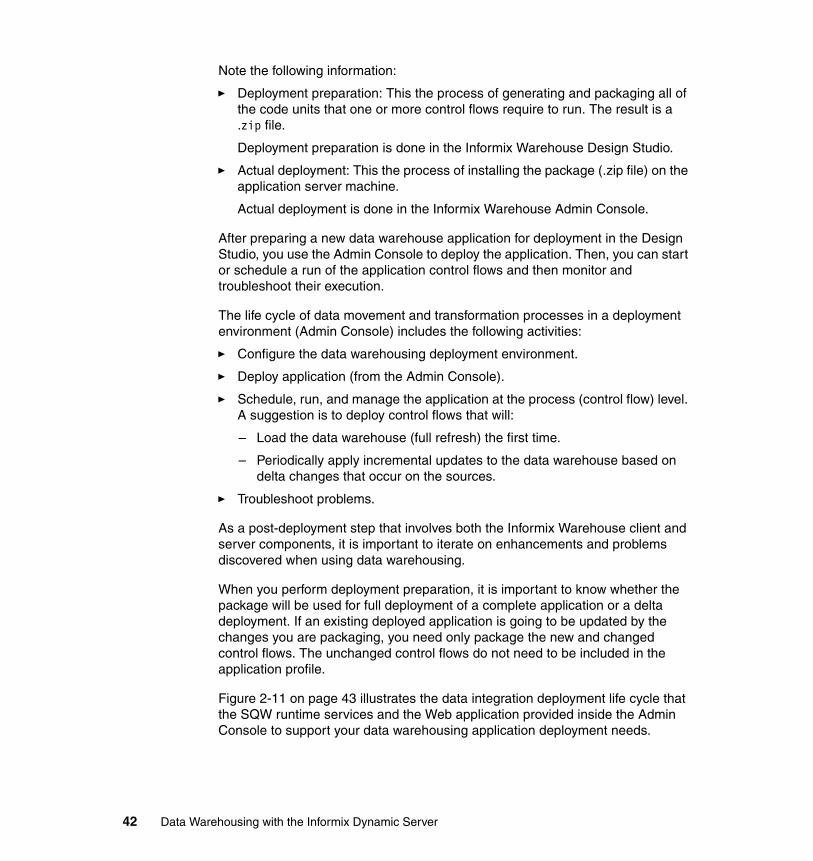
Note the following information:
� Deployment preparation: This the process of generating and packaging all of the code units that one or more control flows require to run. The result is a .zip file.
Deployment preparation is done in the Informix Warehouse Design Studio.
� Actual deployment: This the process of installing the package (.zip file) on the application server machine.
Actual deployment is done in the Informix Warehouse Admin Console.
After preparing a new data warehouse application for deployment in the Design Studio, you use the Admin Console to deploy the application. Then, you can start or schedule a run of the application control flows and then monitor and troubleshoot their execution.
The life cycle of data movement and transformation processes in a deployment environment (Admin Console) includes the following activities:
� Configure the data warehousing deployment environment.
� Deploy application (from the Admin Console).
� Schedule, run, and manage the application at the process (control flow) level. A suggestion is to deploy control flows that will:
– Load the data warehouse (full refresh) the first time.
– Periodically apply incremental updates to the data warehouse based on delta changes that occur on the sources.
� Troubleshoot problems.
As a post-deployment step that involves both the Informix Warehouse client and server components, it is important to iterate on enhancements and problems discovered when using data warehousing.
When you perform deployment preparation, it is important to know whether the package will be used for full deployment of a complete application or a delta deployment. If an existing deployed application is going to be updated by the changes you are packaging, you need only package the new and changed control flows. The unchanged control flows do not need to be included in the application profile.
Figure 2-11 on page 43 illustrates the data integration deployment life cycle that the SQW runtime services and the Web application provided inside the Admin Console to support your data warehousing application deployment needs.
42 Data Warehousing with the Informix Dynamic Server
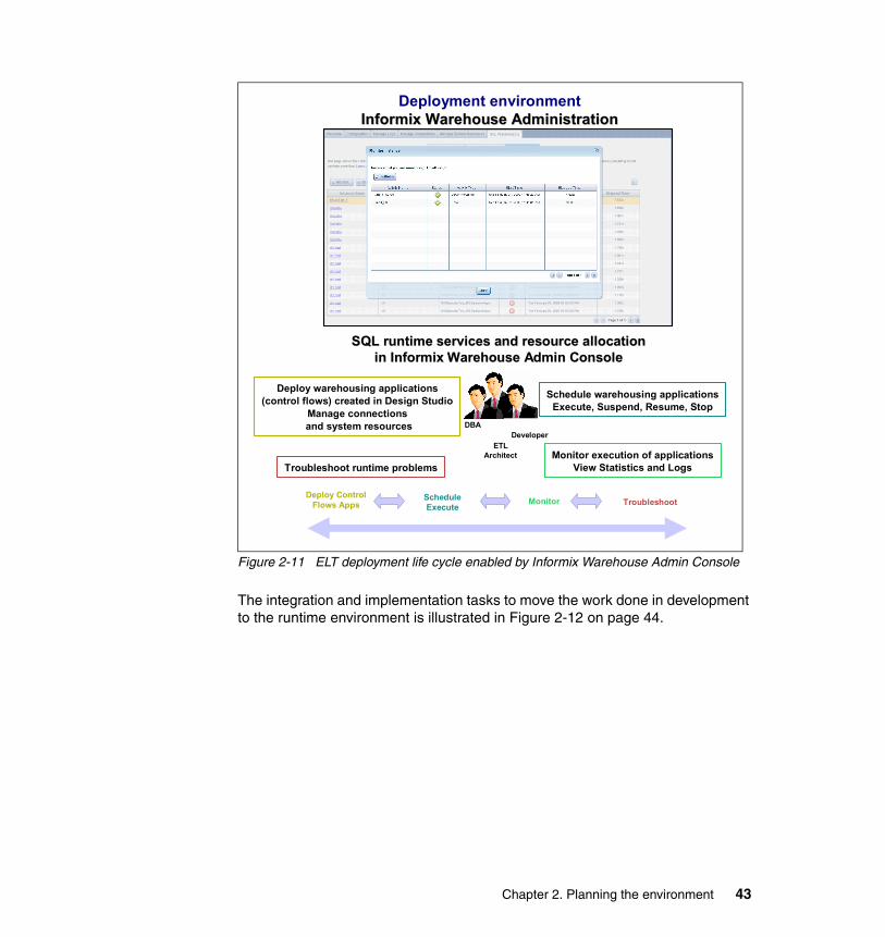
Figure 2-11 ELT deployment life cycle enabled by Informix Warehouse Admin Console
The integration and implementation tasks to move the work done in development to the runtime environment is illustrated in Figure 2-12 on page 44.
Troubleshoot runtime problemsMonitor execution of applications
View Statistics and Logs
Deploy warehousing applications(control flows) created in Design Studio
Manage connectionsand system resources
Schedule warehousing applicationsExecute, Suspend, Resume, Stop
Deploy Control Flows Apps
ScheduleExecute TroubleshootMonitor
ETL Architect
DBADeveloper
SQL runtime services and resource allocationSQL runtime services and resource allocationin Informix Warehouse Admin Consolein Informix Warehouse Admin Console
Deployment environmentInformix Warehouse Administration Informix Warehouse Administration
ConsoleConsole
Chapter 2. Planning the environment 43
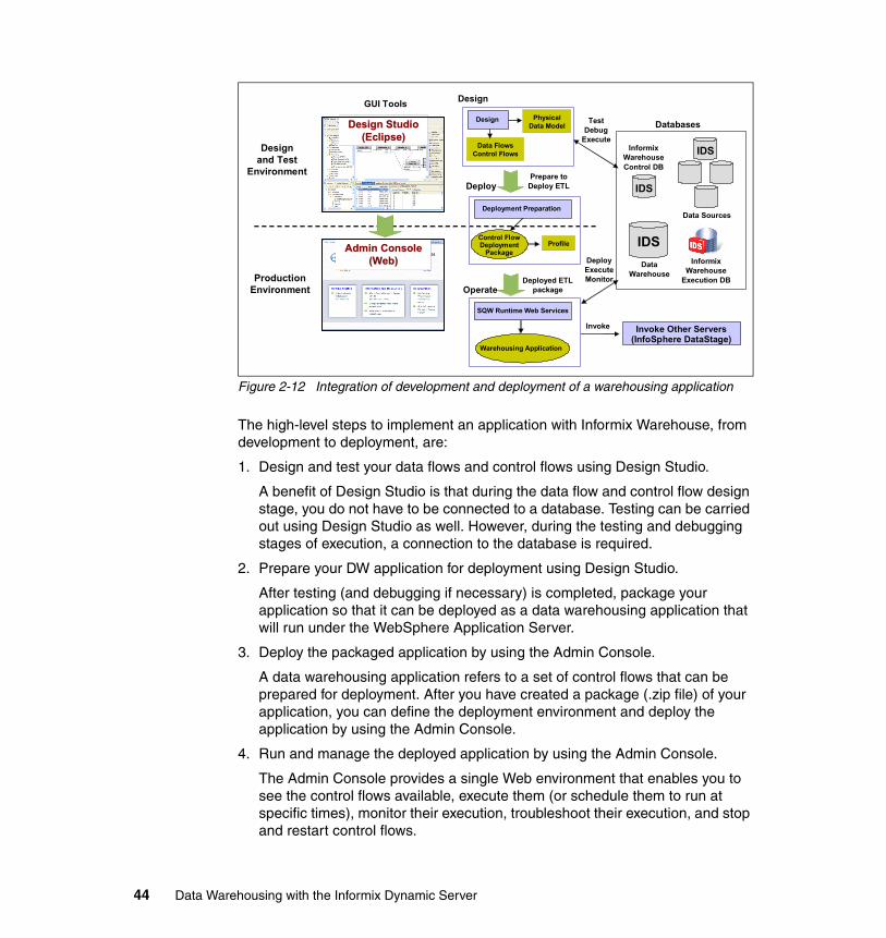
Figure 2-12 Integration of development and deployment of a warehousing application
The high-level steps to implement an application with Informix Warehouse, from development to deployment, are:
1. Design and test your data flows and control flows using Design Studio.
A benefit of Design Studio is that during the data flow and control flow design stage, you do not have to be connected to a database. Testing can be carried out using Design Studio as well. However, during the testing and debugging stages of execution, a connection to the database is required.
2. Prepare your DW application for deployment using Design Studio.
After testing (and debugging if necessary) is completed, package your application so that it can be deployed as a data warehousing application that will run under the WebSphere Application Server.
3. Deploy the packaged application by using the Admin Console.
A data warehousing application refers to a set of control flows that can be prepared for deployment. After you have created a package (.zip file) of your application, you can define the deployment environment and deploy the application by using the Admin Console.
4. Run and manage the deployed application by using the Admin Console.
The Admin Console provides a single Web environment that enables you to see the control flows available, execute them (or schedule them to run at specific times), monitor their execution, troubleshoot their execution, and stop and restart control flows.
Databases
Design
Operate
Data FlowsControl Flows
Design Studio Design Studio (Eclipse)(Eclipse)
Admin ConsoleAdmin Console(Web)(Web)
Data Sources
Informix WarehouseControl DB
Data Warehouse
PhysicalData Model
Deploy
TestDebug
Execute
DeployExecuteMonitor
Invoke
Prepare to Deploy ETL
Deployed ETL package
GUI Tools
Designand Test
Environment
ProductionEnvironment
Informix Warehouse
Execution DB
Design
Profile
Deployment Preparation
Control Flow Deployment
Package
SQW Runtime Web Services
Warehousing Application
Invoke Other Servers (InfoSphere DataStage)
IDS
IDS
IDS
44 Data Warehousing with the Informix Dynamic Server
The two databases that are necessary in an Informix Warehouse development and deployment environment, in addition to the JDBC source and target databases, are:
� SQL execution database: Although this database is typically the same as the target Informix Warehouse repository, it can be a separate database. It is the database where implicit temporary tables and other temporary objects are stored, by default. These are tables that are needed for ELT executions in Design Studio and Admin Console. A connection to this database exists at ELT runtime. A good practice is to save a connection and keep the execution database the same as either the primary source database, or the target database. IDS 11.10 or later is required to run the generated SQL code.
� Control database: This is typically a separate database with a default name of sqwctrl. It is used only by the Admin Console, and must be created (empty) by the time you install the Admin Console. It is the database where the status of all deployment and execution of the applications (control flow) is stored. It must be a logged database.
Every data flow requires an SQL execution database, which can be:
� The source database� The target database� An independent database
A more efficient approach is if the database is the same as either the primary source or target database, to eliminate data being moved twice.
For more information, consult the Informix Warehouse documentation pages at the Informix Dynamic Server Information Center. Search for Informix Warehouse, at the following location:
http://publib.boulder.ibm.com/infocenter/idshelp/v115/index.jsp
2.4 Data warehouse architecture
When planning and implementing a data warehouse, a key decision to be made is, obviously, where to store the data. As part of that decision, you must determine what type (or types) of data warehouse repository (or repositories) are required. You must also determine the implementation topology and approach that will best satisfy your requirements.
The data warehouse architecture you select will determine the location (or locations) of the data warehouse repository (or repositories), and where the control resides. As examples, the data can reside in a central location that is managed centrally, or in distributed local, and remote locations that are either
Chapter 2. Planning the environment 45
managed centrally or independently. A related decision will be whether to have one large database, or a number of smaller ones that are perhaps related to specific organizational entities.
2.4.1 Types of data warehouse repositories
Several options are available when you determine the types of repositories you will have. Which you choose depends on your particular requirements.
Enterprise data warehouse This topic can be complex, but we simplify it here. For our purposes, we refer to an enterprise data warehouse (EDW) simply as an integrated repository of all the data in the enterprise. The key word is integrated. Because that is the case, we do not infer that all the data is in a single repository. Similarly we do not infer that all the data is, or must be, physically centralized.
Various opinions exist about the data structure and organization in an EDW. Typically, we think of an EDW as having an entity attribute relationship (E-R) data model. This relationship will then dictate the use of normalized data. But, depending on your requirements, you might choose to use a combination of E-R models and normalized (atomic level), and dimensional models and denormalized (summarized or aggregated) data.
Again, we return to the key word, integrated, as a primary requirement.
Data martsAgain, options differ regarding the definition of a data mart, whether they should even be used. Much is written about this topic, and you should be familiar with it. Key to your decision of whether to include data marts in your architecture is to be familiar with the advantages and disadvantages of using them. The question is: Will data marts satisfy your requirements for data warehousing?
Typically, a data mart is built on a dimensional model rather than an E-R data model. The reason is that they are easier to develop and use, and can provide performance advantages in many situations. They are focused on providing an optimized data infrastructure for OLAP analysis and queries for a particular business environment.
Basically, the two types of data marts are:
� Dependent: These data marts contain data that has been directly extracted from the data warehouse. Therefore, the data is integrated, and is consistent with the data in the data warehouse.
46 Data Warehousing with the Informix Dynamic Server
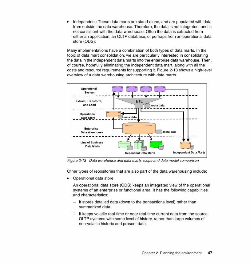
� Independent: These data marts are stand-alone, and are populated with data from outside the data warehouse. Therefore, the data is not integrated, and is not consistent with the data warehouse. Often the data is extracted from either an application, an OLTP database, or perhaps from an operational data store (ODS).
Many implementations have a combination of both types of data marts. In the topic of data mart consolidation, we are particularly interested in consolidating the data in the independent data marts into the enterprise data warehouse. Then, of course, hopefully eliminating the independent data mart, along with all the costs and resource requirements for supporting it. Figure 2-13 shows a high-level overview of a data warehousing architecture with data marts.
Figure 2-13 Data warehouse and data marts scope and data model comparison
Other types of repositories that are also part of the data warehousing include:
� Operational data store
An operational data store (ODS) keeps an integrated view of the operational systems of an enterprise or functional area. It has the following capabilities and characteristics:
– It stores detailed data (down to the transactions level) rather than summarized data.
– It keeps volatile real-time or near real-time current data from the source OLTP systems with some level of history, rather than large volumes of non-volatile historic and present data.
meta data
meta data
meta data
Independent Data MartsDependent Data Marts
Line of BusinessData Marts
Enterprise Data Warehouse
OperationalData Store
Extract, Transform,and Load
OperationalSystem
ETL
Chapter 2. Planning the environment 47
– It uses the same, or very similar, normalized database structures and OLTP models used in the source transactional systems, rather than featuring a new data model based on business terms and OLAP.
– It has a dual role in a data warehousing infrastructure. It can be used as an interim data warehouse repository for the operational environment and also can be used as an integrated and consistent operational source to feed data to the data warehousing environment.
� Data staging area
Data staging areas are repositories used to store temporary or intermediate results in the data acquisition, cleansing, transformation, movement, and load (ETL) processes. And, the Informix Warehouse SQL execution database could also be considered a staging area for the ELT-based jobs.
2.4.2 Implementation options
In this section, we describe the types of data warehousing implementations. Each can satisfy the basic requirements of data warehousing, and thus provide flexibility to handle the requirements in the various types of enterprises.
The types of data warehousing implementations, also shown in Figure 2-14 on page 49, are:
� Centralized: This type is characterized as having all the data in a central environment, under central management. However, centralization does not necessarily imply that all the data is in one location or in one common systems environment. That is, it is centralized, but logically centralized rather than physically centralized. When it is logically centralized, by design, it then may be referred to as a hub and spoke implementation. The key point is that the environment is managed as a single integrated entity.
� Hub and spoke: This type typically represents one type of distributed implementation. It implies a central data warehouse, which is the hub, and distributed implementations of data marts, which are the spokes. Here again, the key is the environment is managed as a single integrated entity.
� Distributed: In this type, the data warehouse itself is distributed, whether it is with or without data marts. That can imply two different implementations, for example:
– The data warehouse can reside in multiple hardware and software environments. The key is that the multiple instances conform to the same data model, and are managed as a single entity.
– The data warehouse can reside in multiple hardware and software environments, but as separate and independent entities. In this case, they
48 Data Warehousing with the Informix Dynamic Server
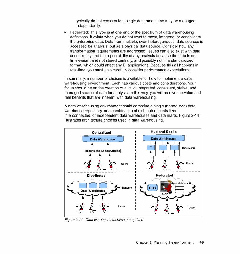
typically do not conform to a single data model and may be managed independently.
� Federated: This type is at one end of the spectrum of data warehousing definitions. It exists when you do not want to move, integrate, or consolidate the enterprise data. Data from multiple, even heterogeneous, data sources is accessed for analysis, but as a physical data source. Consider how any transformation requirements are addressed. Issues can also exist with data concurrency and the repeatability of any analysis because the data is not time-variant and not stored centrally, and possibly not in a standardized format, which could affect any BI applications. Because this all happens in real-time, you must also carefully consider performance expectations.
In summary, a number of choices is available for how to implement a data warehousing environment. Each has various costs and considerations. Your focus should be on the creation of a valid, integrated, consistent, stable, and managed source of data for analysis. In this way, you will receive the value and real benefits that are inherent with data warehousing.
A data warehousing environment could comprise a single (normalized) data warehouse repository, or a combination of distributed, centralized, interconnected, or independent data warehouses and data marts. Figure 2-14 illustrates architecture choices used in data warehousing.
Figure 2-14 Data warehouse architecture options
Reports and Ad hoc Queries
Users
Data Marts
Hub and SpokeCentralized
Distributed
Users
Network
Federated
Spreadsheets
Users
ODS
Data WarehouseData Warehouse
Data Warehouse
Users
OLTP
Chapter 2. Planning the environment 49

Two of the very common choices are the hub and spoke architecture and the Distributed architecture with linked dimensional marts, which are commonly seen as the resulting product from building a warehouse using the top-down and bottom-up methodologies, respectively.
2.4.3 Determining which architecture is for you
What would be the best architecture for you? It depends on your needs, current environment, constraints and available resources.
For instance, when there are time restrictions and need to deliver results soon for a few business areas, then either the bus architecture, the independent data marts or the single centralized data warehouse are chosen as first alternatives. On the other hand, if high quality, true integration and corporate-wide business impact are critical, then the architectures like hub and spoke architecture, bus and centralized warehouse are the best choices. Independent data marts and federated architectures do not provide the consistency, integration and quality as the other options.
Business-wide centralized data warehouse architecture can be seen as the most elegant choice if the business and data sources are relatively centralized, and such an IT environment can be found even in mid-market organizations. Otherwise, the bus (interconnected) data marts and the hub and spoke data warehouse are more practical choices for businesses with a wide geographic distribution.
2.5 Considerations in building a DW environment
This section discusses considerations that are associated with building and maintaining a BI and DW environment. We provide an overview of several implementation approaches to help as you decide which might work best for you.
2.5.1 Implementation approaches
The two basic approaches that can be used as you prepare your implementation process are top-down and bottom-up. These approaches to implementation are described in this section. However, for more information about delivering data warehouse repositories, refer to Data Mart Consolidation: Getting Control of Your Enterprise Information, SG24-6653.
50 Data Warehousing with the Informix Dynamic Server
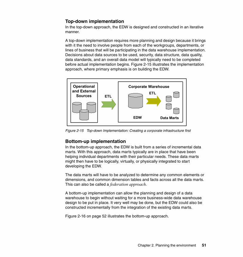
Top-down implementationIn the top-down approach, the EDW is designed and constructed in an iterative manner.
A top-down implementation requires more planning and design because it brings with it the need to involve people from each of the workgroups, departments, or lines of business that will be participating in the data warehouse implementation. Decisions about data sources to be used, security, data structure, data quality, data standards, and an overall data model will typically need to be completed before actual implementation begins. Figure 2-15 illustrates the implementation approach, where primary emphasis is on building the EDW.
Figure 2-15 Top-down Implementation: Creating a corporate infrastructure first
Bottom-up implementationIn the bottom-up approach, the EDW is built from a series of incremental data marts. With this approach, data marts typically are in place that have been helping individual departments with their particular needs. These data marts might then have to be logically, virtually, or physically integrated to start developing the EDW.
The data marts will have to be analyzed to determine any common elements or dimensions, and common dimension tables and facts across all the data marts. This can also be called a federation approach.
A bottom-up implementation can allow the planning and design of a data warehouse to begin without waiting for a more business-wide data warehouse design to be put in place. It very well may be done, but the EDW could also be constructed incrementally from the integration of the existing data marts.
Figure 2-16 on page 52 illustrates the bottom-up approach.
Operationaland External
Sources
Corporate Warehouse
EDW Data Marts
ETLETL
Chapter 2. Planning the environment 51
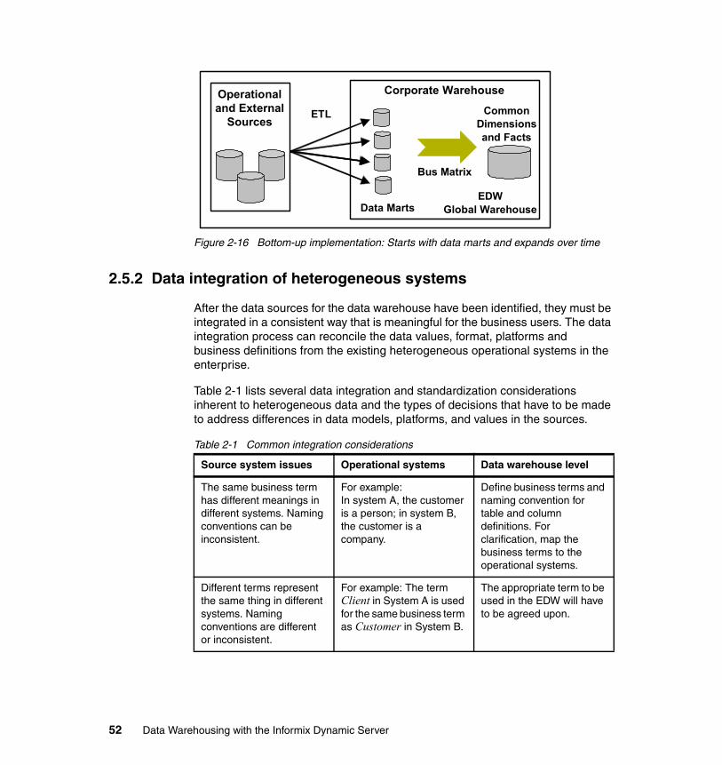
Figure 2-16 Bottom-up implementation: Starts with data marts and expands over time
2.5.2 Data integration of heterogeneous systems
After the data sources for the data warehouse have been identified, they must be integrated in a consistent way that is meaningful for the business users. The data integration process can reconcile the data values, format, platforms and business definitions from the existing heterogeneous operational systems in the enterprise.
Table 2-1 lists several data integration and standardization considerations inherent to heterogeneous data and the types of decisions that have to be made to address differences in data models, platforms, and values in the sources.
Table 2-1 Common integration considerations
Operationaland External
Sources
Corporate Warehouse
Data MartsEDW
Global Warehouse
ETL
Bus Matrix
Common Dimensions and Facts
Source system issues Operational systems Data warehouse level
The same business term has different meanings in different systems. Naming conventions can be inconsistent.
For example: In system A, the customer is a person; in system B, the customer is a company.
Define business terms and naming convention for table and column definitions. For clarification, map the business terms to the operational systems.
Different terms represent the same thing in different systems. Naming conventions are different or inconsistent.
For example: The term Client in System A is used for the same business term as Customer in System B.
The appropriate term to be used in the EDW will have to be agreed upon.
52 Data Warehousing with the Informix Dynamic Server
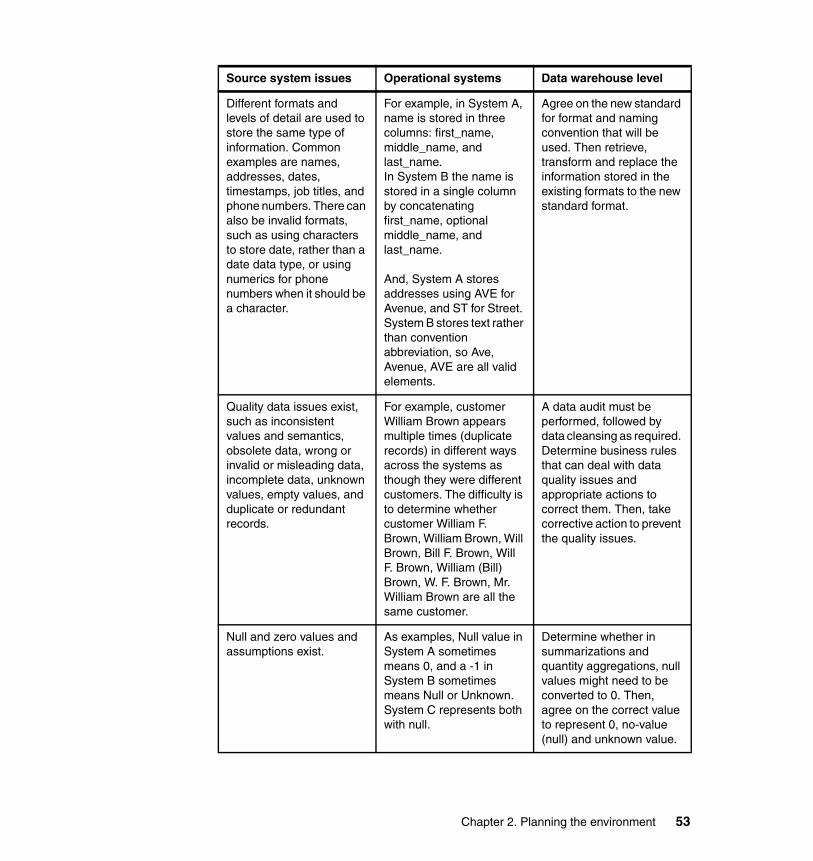
Different formats and levels of detail are used to store the same type of information. Common examples are names, addresses, dates, timestamps, job titles, and phone numbers. There can also be invalid formats, such as using characters to store date, rather than a date data type, or using numerics for phone numbers when it should be a character.
For example, in System A, name is stored in three columns: first_name, middle_name, and last_name.In System B the name is stored in a single column by concatenating first_name, optional middle_name, and last_name.
And, System A stores addresses using AVE for Avenue, and ST for Street. System B stores text rather than convention abbreviation, so Ave, Avenue, AVE are all valid elements.
Agree on the new standard for format and naming convention that will be used. Then retrieve, transform and replace the information stored in the existing formats to the new standard format.
Quality data issues exist, such as inconsistent values and semantics, obsolete data, wrong or invalid or misleading data, incomplete data, unknown values, empty values, and duplicate or redundant records.
For example, customer William Brown appears multiple times (duplicate records) in different ways across the systems as though they were different customers. The difficulty is to determine whether customer William F. Brown, William Brown, Will Brown, Bill F. Brown, Will F. Brown, William (Bill) Brown, W. F. Brown, Mr. William Brown are all the same customer.
A data audit must be performed, followed by data cleansing as required. Determine business rules that can deal with data quality issues and appropriate actions to correct them. Then, take corrective action to prevent the quality issues.
Null and zero values and assumptions exist.
As examples, Null value in System A sometimes means 0, and a -1 in System B sometimes means Null or Unknown. System C represents both with null.
Determine whether in summarizations and quantity aggregations, null values might need to be converted to 0. Then, agree on the correct value to represent 0, no-value (null) and unknown value.
Source system issues Operational systems Data warehouse level
Chapter 2. Planning the environment 53
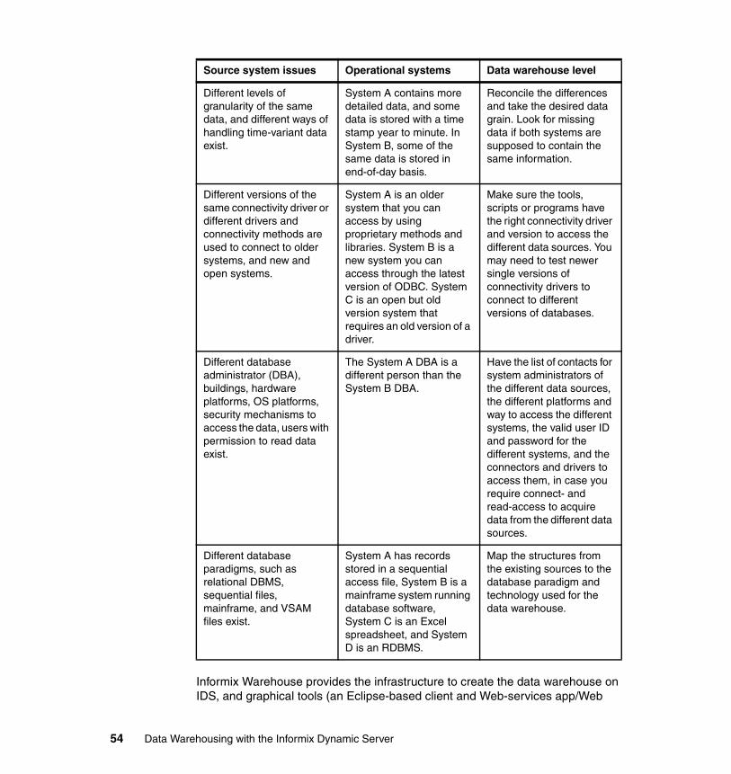
Informix Warehouse provides the infrastructure to create the data warehouse on IDS, and graphical tools (an Eclipse-based client and Web-services app/Web
Different levels of granularity of the same data, and different ways of handling time-variant data exist.
System A contains more detailed data, and some data is stored with a time stamp year to minute. In System B, some of the same data is stored in end-of-day basis.
Reconcile the differences and take the desired data grain. Look for missing data if both systems are supposed to contain the same information.
Different versions of the same connectivity driver or different drivers and connectivity methods are used to connect to older systems, and new and open systems.
System A is an older system that you can access by using proprietary methods and libraries. System B is a new system you can access through the latest version of ODBC. System C is an open but old version system that requires an old version of a driver.
Make sure the tools, scripts or programs have the right connectivity driver and version to access the different data sources. You may need to test newer single versions of connectivity drivers to connect to different versions of databases.
Different database administrator (DBA), buildings, hardware platforms, OS platforms, security mechanisms to access the data, users with permission to read data exist.
The System A DBA is a different person than the System B DBA.
Have the list of contacts for system administrators of the different data sources, the different platforms and way to access the different systems, the valid user ID and password for the different systems, and the connectors and drivers to access them, in case you require connect- and read-access to acquire data from the different data sources.
Different database paradigms, such as relational DBMS, sequential files, mainframe, and VSAM files exist.
System A has records stored in a sequential access file, System B is a mainframe system running database software, System C is an Excel spreadsheet, and System D is an RDBMS.
Map the structures from the existing sources to the database paradigm and technology used for the data warehouse.
Source system issues Operational systems Data warehouse level
54 Data Warehousing with the Informix Dynamic Server
server) to ease the physical design of the data model, and also design, test, deploy and monitor the data movements and transformations required during the integration and standardization activities.
When sophisticated data quality and integration capabilities are required, IBM Information Server’s DataStage and QualityStage can be used. Jobs created on the Web-services platform of these two products can be invoked from control flows created in Informix Warehouse.
For more information about InfoSphere Information Server, which includes DataStage and QualityStage, refer to:
� IBM InfoSphere DataStage
http://www.ibm.com/software/data/infosphere/datastage/
� IBM InfoSphere QualityStage
http://www.ibm.com/software/data/infosphere/qualitystage/
2.5.3 Large data volumes and complex queries
Typical challenges in data warehousing projects are how to deal with large volumes of data with high rates of growth, the associated storage requirements, the time to perform administrative tasks, and managing query performance.
When dealing with these issues, consider the following information:
� Demands on storage and network bandwidth
– Determine whether deep compression is needed (Storage Optimization Feature is delivered with the Informix Warehouse Enterprise Edition).
– Have a plan for growth from both a software and hardware perspective.
– Understand how to satisfy the demands for temporary space required for ELT activities.
– Secure adequate network bandwidth.
� Performance of data integration activities
– Keep information that affects the indexes current.– Update statistics regularly to aid the Optimizer.– Consider using the Auto Update Statistics (AUS) capability.– Optimize ELT processes - to satisfy time and space requirements.– Keep aggregates up to date.– Plan a time window to keep objects in the database up to date.– Tune IDS engine for ELT activities as needed, in addition to BI queries.– Use efficient operators inside Informix Warehouse.– Integrate with High-Performance Loader (HPL) as needed.
Chapter 2. Planning the environment 55
� Query performance:
– Plan for requirements in CPU, memory, disk and the network to handle the volume of data and complex query processing.
– Tune performance of tables
• Apply or change Fragmentation schema.• Change location in dbspace.• Perform compression, repack, and shrink.• Create indexes as needed.• Drop indexes that are not being used.
– Tune temporary space required for ad-hoc queries.
– Tune prepared and pre-defined queries in dashboards and reports.
– Keep indexes and Update Statistics current.
– Check for appropriate placement of tables and indexes in dbspaces.
� Maintenance tasks
– Secure time windows where maintenance tasks will run (backups, recovery, table maintenance, index rebuild, fragmentation, compression).
– Use automated capabilities, such as Auto Update Statistics (AUS).
2.5.4 Project scope, budget, and time constraints
Develop a project plan that follows best practices for these types of IT projects and where all the stages, people involved, scope, risks, change controls and management, deliverables, requirements and resources are well-defined. Consider the following information:
� Make sure you follow the best practices and methodologies for IT Project Management and specifically the ones that apply to DW and BI projects.
� Determine the right scope of the project based on the assessment on the needs of the business users and the resource constraints.
� Define the appropriate implementation approach (top-down, or bottom-up).
� Select the skilled team to manage and deploy the project.
� Make sure the business users and analysts are involved.
� Look for ways to make the project affordable without sacrificing quality.
DW and BI projects normally have high visibility across the entire organization, because they involve the business users, who will be the ultimate users of the BI solution. Such projects imply a long-term investment and they may produce changes in the corporate or department standards such as those for terms, metrics, semantics, and formats.
56 Data Warehousing with the Informix Dynamic Server
Being highly visible projects in the organizations means that either being a success or a failure, it will be a visible success story or a visible failure story. This is one challenge to take into consideration when planning these types of solutions. Another challenge is that, having to involve the business users from the early stages of the project may represent difficulties to find them available for interviews, as they are normally very busy and do not have time for responding to many questions they consider silly or obvious. Ask the important questions to these users, and find the answer to the less-strategic and less-important questions somewhere else inside the organization.
Involving business users and business analysts in the project at all times is important. This can help guarantee that the system is business-centric in terms of the model, queries and interfaces with the users and that it responds to the critical business questions that the users require from a BI system.
2.5.5 Maintenance
How do operational transactions and activities get propagated from the sources to the data warehouse? What happens if the data warehouse is offline for some period of time? How often (daily, twice a day, weekly) do you want to keep the data warehouse updated? And, how can you keep the data warehouse up and available, updated and useful over several years? This all implies providing the maintenance infrastructure for its active life cycle, including periodic backups, performance tuning, growth analysis and capacity planning for the future, and keeping the system updated in terms of the data stored there.
Maintaining the data warehouse represents a challenge, particularly as users want access to more, and more current, data. Therefore, the following considerations must be addressed:
� How will you keep track of the changes that occur in a record on the source system, in the data warehouse? For example, if a customer changes an address, both the old and new values must be kept in the data warehouse, along with an associated time value.
� How will you keep the tables and the aggregate (summary tables) up to date?
� How often to you want the data warehouse to be updated?
� If you establish and test the window time for the updates based on the actual ETL workload and completion, is the time window enough for the volume of updates that will normally occur in the system?
Chapter 2. Planning the environment 57
� How will refresh the aggregate and summary tables? Will they be kept current as their base tables in the data warehouse get updated (immediate refresh) or will they be periodically refreshed (scheduled at certain times)?
� If a real-time (or near real-time) data warehouse is needed, which mechanism will be used to either push or pull the data that changed in the source? How will you determine that a change occurred since the last update? How will you apply those changes to the data warehouse without deleting any previous history of the records affected by the change?
2.6 The business intelligence tools
The users of a data warehousing system are most typically the business users. In this case, they are the managers, executives, or owners of an enterprise or business function (department) who must ask many questions about the business, easily visualize the performance indicators, analyze the data from the troubled areas, and determine a resolution. As you can see, the users must analyze the data from multiple perspectives.
The interfaces between those users and the data are the BI tools and applications. They enable the users to easily, and many times graphically, visualize the status of the business. The real value of the interfaces is that the users have the ability to unlock or discover strategic information and acquire new knowledge and insight about the business behavior and performance. This is all enabled by the integrated, historic and accurate data available in the data warehouse.
The users query the data in the data warehouse in terms of facts and metrics. That is, in a way that makes sense from a business perspective. These queries can be very complex, but dynamically built and executed against the database (not pre-optimized) and involve processing (in the database) and retrieving (through the network) large volumes of data.
All this is why the users of a DW and BI solution may not be involved in the selection of tools on the back-end infrastructure, but need to be involved in the selection of the BI tools that will be used for the analysis of data, the discovery of information, and the creation of new knowledge. Table 2-2 on page 59 lists benefits gained by the sample types of actions executed by users.
58 Data Warehousing with the Informix Dynamic Server
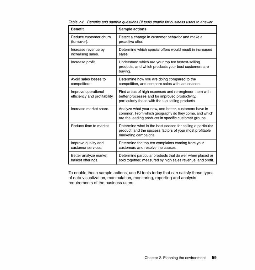
Table 2-2 Benefits and sample questions BI tools enable for business users to answer
To enable these sample actions, use BI tools today that can satisfy these types of data visualization, manipulation, monitoring, reporting and analysis requirements of the business users.
Benefit Sample actions
Reduce customer churn (turnover).
Detect a change in customer behavior and make a proactive offer.
Increase revenue by increasing sales.
Determine which special offers would result in increased sales.
Increase profit. Understand which are your top ten fastest-selling products, and which products your best customers are buying.
Avoid sales losses to competitors.
Determine how you are doing compared to the competition, and compare sales with last season.
Improve operational efficiency and profitability.
Find areas of high expenses and re-engineer them with better processes and for improved productivity, particularly those with the top selling products.
Increase market share. Analyze what your new, and better, customers have in common. From which geography do they come, and which are the leading products in specific customer groups.
Reduce time to market. Determine what is the best season for selling a particular product, and the success factors of your most profitable marketing campaigns.
Improve quality and customer services.
Determine the top ten complaints coming from your customers and resolve the causes.
Better analyze market basket offerings.
Determine particular products that do well when placed or sold together, measured by high sales revenue, and profit.
Chapter 2. Planning the environment 59
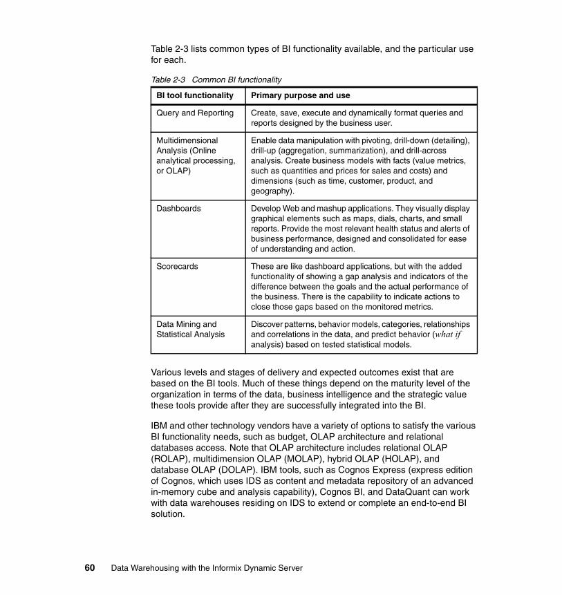
Table 2-3 lists common types of BI functionality available, and the particular use for each.
Table 2-3 Common BI functionality
Various levels and stages of delivery and expected outcomes exist that are based on the BI tools. Much of these things depend on the maturity level of the organization in terms of the data, business intelligence and the strategic value these tools provide after they are successfully integrated into the BI.
IBM and other technology vendors have a variety of options to satisfy the various BI functionality needs, such as budget, OLAP architecture and relational databases access. Note that OLAP architecture includes relational OLAP (ROLAP), multidimension OLAP (MOLAP), hybrid OLAP (HOLAP), and database OLAP (DOLAP). IBM tools, such as Cognos Express (express edition of Cognos, which uses IDS as content and metadata repository of an advanced in-memory cube and analysis capability), Cognos BI, and DataQuant can work with data warehouses residing on IDS to extend or complete an end-to-end BI solution.
BI tool functionality Primary purpose and use
Query and Reporting Create, save, execute and dynamically format queries and reports designed by the business user.
Multidimensional Analysis (Online analytical processing, or OLAP)
Enable data manipulation with pivoting, drill-down (detailing), drill-up (aggregation, summarization), and drill-across analysis. Create business models with facts (value metrics, such as quantities and prices for sales and costs) and dimensions (such as time, customer, product, and geography).
Dashboards Develop Web and mashup applications. They visually display graphical elements such as maps, dials, charts, and small reports. Provide the most relevant health status and alerts of business performance, designed and consolidated for ease of understanding and action.
Scorecards These are like dashboard applications, but with the added functionality of showing a gap analysis and indicators of the difference between the goals and the actual performance of the business. There is the capability to indicate actions to close those gaps based on the monitored metrics.
Data Mining and Statistical Analysis
Discover patterns, behavior models, categories, relationships and correlations in the data, and predict behavior (what if analysis) based on tested statistical models.
60 Data Warehousing with the Informix Dynamic Server
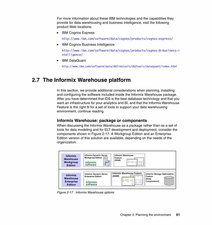
For more information about these IBM technologies and the capabilities they provide for data warehousing and business intelligence, visit the following product Web locations:
� IBM Cognos Express
http://www.ibm.com/software/data/cognos/products/cognos-express/
� IBM Cognos Business Intelligence
http://www.ibm.com/software/data/cognos/products/cognos-8-business-intelligence/
� IBM DataQuant
http://www.ibm.com/software/data/db2imstools/db2tools/dataquant/index.html
2.7 The Informix Warehouse platform
In this section, we provide additional considerations when planning, installing and configuring the software included inside the Informix Warehouse package. After you have determined that IDS is the best database technology and that you want an infrastructure for your analytics and BI, and that the Informix Warehouse Feature is the right fit for a set of tools to support your data warehousing environment, continue reading.
Informix Warehouse: package or componentsWhen discussing the Informix Warehouse as a package rather than as a set of tools for data modeling and for ELT development and deployment, consider the components shown in Figure 2-17. A Workgroup Edition and an Enterprise Edition version of this solution are available, depending on the needs of the organization.
Figure 2-17 Informix Warehouse options
Informix Dynamic Server Workgroup Edition
Informix Warehouse Feature(SQW)
Informix Dynamic Server Enterprise Edition
Informix Warehouse Feature(SQW)
Informix Storage OptimizationFeature(Deep Compression)
Informix WarehouseWorkgroup
Edition
Informix WarehouseEnterprise
Edition
Chapter 2. Planning the environment 61
If IDS 11.50 is already a part of your environment, then only the additional features have to be incorporated, based on the needs and based on the availability of those features on your IDS edition.
The Informix Warehouse Feature requires IDS 11.50.xC3 or later for both IDS Workgroup Edition and Enterprise Edition; the Informix Storage Optimization Feature is available in IDS 11.50.xC4 or later and, at the time this book was written, is only for the Enterprise Edition of IDS.
Informix Warehouse documentationFor documentation about the Informix Warehouse Feature (installing Informix Warehouse, and data warehousing and analytics) go to the Informix Dynamic Server 11.50 Information Center:
http://publib.boulder.ibm.com/infocenter/idshelp/v115/index.jsp
2.7.1 Informix Warehouse components
After the BI environment has been assessed, and any gaps identified, a project plan can be created based on the needs and the available resources. Then, you have to decide what data model, what scope or type of data warehouse repository, and what implementation approach will be used to build the infrastructure.
Depending on these decisions, determine how to use the Informix Warehouse Feature for designing and deploying the SQL-based ELT data movements and transformations needed in the environment.
The work flow for developing a SQL warehousing application primarily involves architects and administrators. The architects use the Design Studio to design data flows and control flows and prepare the application for deployment. The administrators deploy and manage the application in the Admin Console.
Informix Warehouse Client componentThis component includes the Design Studio tool, which in turn includes the SQL Warehousing (SQW) Tool that is used for the SQL-based ELT functions. This component also has additional Java-based plug-ins, such as part of InfoSphere Data Architect software (in the form of an Eclipse plug-in), used for the physical data modeling functionality.
Informix Warehouse Design StudioDesign Studio, which includes both InfoSphere Data Architect plug-ins, and the SQL Warehousing (SQW) Tool, provides a common graphical design environment for creating physical data models from templates or reverse
62 Data Warehousing with the Informix Dynamic Server
engineering; creating, testing, and debugging SQL data flows and control flows, and packaging them into data warehousing applications. Design Studio is built on the Eclipse Workbench, which is a development environment that you can customize by adding commercial or cost-free Eclipse and Java plug-ins, which are available from:
http://www.eclipse.org/
SQL Warehousing ToolSQL Warehousing (SQW) Tool is a graphical tool that generates SQL for warehouse maintenance and administration. It automatically generates the optimized SQL code based on visual operator flows that you model in Design Studio.
The library of SQL operators covers the in-database data operations that are typically needed to move data between database tables and to populate analytical structures. And you have the option of extending this library by invoking your own SQL-based operations and code. SQL Warehousing Tool complements and works with ETL products from IBM (such as DataStage and QualityStage, part of the Information Server line) and other vendors.
Informix Warehouse Server componentThis component comprises the Informix Warehouse Admin Console (which includes a Web application to provide an interface for deployment) and also WebSphere Application Server. In addition, the SQL Warehousing (SQW) runtime Web-services execute the SQL-based transformations in the code generated by the SQW Tool.
Informix Warehouse Admin ConsoleThe Admin Console is a Web application from which you can deploy and manage applications, control flows, database resources, and system resources. As examples, you can perform the following types of tasks in the Admin Console:
� Common configuration
Create and manage database and system resources, including driver definitions, log files, and notifications.
� SQL warehousing
Run and monitor data warehousing applications and view deployment histories and execution statistics.
� Application and services deployment
WebSphere Application Server is a Java-based Web application server that is required by the Admin Console. WebSphere Application Server provides a rich application deployment environment with a complete set of application
Chapter 2. Planning the environment 63
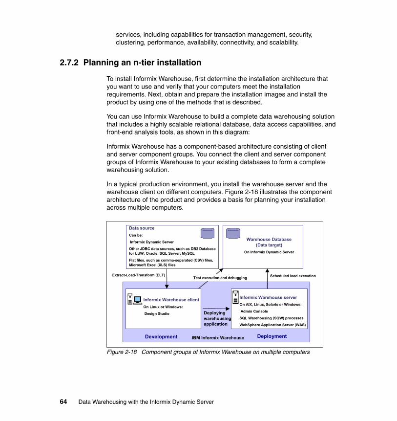
services, including capabilities for transaction management, security, clustering, performance, availability, connectivity, and scalability.
2.7.2 Planning an n-tier installation
To install Informix Warehouse, first determine the installation architecture that you want to use and verify that your computers meet the installation requirements. Next, obtain and prepare the installation images and install the product by using one of the methods that is described.
You can use Informix Warehouse to build a complete data warehousing solution that includes a highly scalable relational database, data access capabilities, and front-end analysis tools, as shown in this diagram:
Informix Warehouse has a component-based architecture consisting of client and server component groups. You connect the client and server component groups of Informix Warehouse to your existing databases to form a complete warehousing solution.
In a typical production environment, you install the warehouse server and the warehouse client on different computers. Figure 2-18 illustrates the component architecture of the product and provides a basis for planning your installation across multiple computers.
Figure 2-18 Component groups of Informix Warehouse on multiple computers
Data sourceCan be:
Informix Dynamic Server
Other JDBC data sources, such as DB2 Database for LUW; Oracle; SQL Server; MySQL
Flat files, such as comma-separated (CSV) files, Microsoft Excel (XLS) files
Warehouse Database (Data target)
On Informix Dynamic Server
Test execution and debuggingExtract-Load-Transform (ELT) Scheduled load execution
IBM Informix Warehouse
Deploying warehousing application
Informix Warehouse clientOn Linux or Windows:
Design Studio
Informix Warehouse serverOn AIX, Linux, Solaris or Windows:
Admin Console
SQL Warehousing (SQW) processes
WebSphere Application Server (WAS)
Development Deployment
64 Data Warehousing with the Informix Dynamic Server
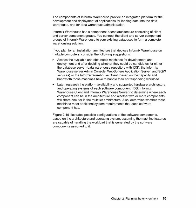
The components of Informix Warehouse provide an integrated platform for the development and deployment of applications for loading data into the data warehouse, and for data warehouse administration.
Informix Warehouse has a component-based architecture consisting of client and server component groups. You connect the client and server component groups of Informix Warehouse to your existing databases to form a complete warehousing solution.
If you plan for an installation architecture that deploys Informix Warehouse on multiple computers, consider the following suggestions:
� Assess the available and obtainable machines for development and deployment and after deciding whether they could be candidates for either the database server (data warehouse repository with IDS), the Informix Warehouse server Admin Console, WebSphere Application Server, and SQW services) or the Informix Warehouse Client, based on the capacity and bandwidth those machines have to handle their corresponding workload.
� Later, research the platform availability and supported hardware architecture and operating systems of each software component (IDS, Informix Warehouse Client and Informix Warehouse Server) to determine where each component can be in the architecture and whether two or more components will share one tier in the multitier architecture. Also, determine whether these machines meet additional system requirements that each software component has.
Figure 2-19 illustrates possible configurations of the software components, based on the architecture and operating system, assuming the machine features are capable of handling the workload that is generated by the software components assigned to it.
Chapter 2. Planning the environment 65
Figure 2-19 Tier architecture for Informix Warehouse components
For information about the Informix Warehouse supported platforms and system requirements, go to the following Web location:
http://www.ibm.com/support/docview.wss?uid=swg21255099
At the time this book was written, the platforms supported by Informix Warehouse were:
� Client components
– Windows XP on 32-bit– Windows Vista on 32-bit– RHEL4 and SLES9 on 32-bit only
� Server components
– Windows 2003 Server on 32-bit and 64-bit– AIX® 5.3 64-bit kernel– Linux 2.6 on 64-bit: RHEL 4, 5 and SLES 9, 10– Solaris 9, 10 64-bit– HP-UX 11iv2 64-bit
For platform availability of IDS, go to the following Web location:
http://www.ibm.com/software/data/informix/pubs/roadmaps.html
Application Server Application Server Application Server
Client
Data Warehousing Server
Data Warehousing Server
Client Client
Data Warehousing Server
One-Tier Two-Tier Three-Tier
66 Data Warehousing with the Informix Dynamic Server
For Informix support for Linux distributions, go to following Web location:
http://www.ibm.com/software/data/informix/linux/
For IDS system requirements, go to the Informix Dynamic Server (IDS) site:
http://www.ibm.com/software/data/informix/ids/requirements.html
After all the installation and configuration of the components is complete, you can start using Informix Warehouse. To design, deploy, and manage a new SQL warehousing application use the following tools:
1. Use the Design Studio to:
a. Set up the SQL warehousing environment, including a data warehousing project, and access to one or more physical data models.
b. Design data flows that represent the movement of data from the source, through a series of transform operations, and into the target system.
c. Design control flows that define processing rules for the execution of a set of related data flows. Control flows can also trigger external commands and scripts, perform file transfers, send e-mails, and invoke InfoSphere DataStage jobs.
d. Test and debug data flows and control flows.
e. Create a data warehousing application that contains one or more control flows and prepare the application for deployment.
2. Use the Informix Warehouse Admin Console to:
a. Deploy the application to the system where WebSphere Application Server is running.
b. Schedule, monitor, and manage the data warehousing processes and activities that comprise the application.
After building the first iteration of an application and executing it successfully, you can manage changes in the source and target data and update or redeploy the application accordingly.
Chapter 2. Planning the environment 67

68 Data Warehousing with the Informix Dynamic Server
Chapter 3. Informix Warehouse Client
In this chapter, we introduce the Informix Warehouse Client component, which is delivered by the Informix Warehouse Design Studio Workbench. Hereafter we will refer to it as the Workbench or Design Studio. It offers an integrated platform to design, test, debug and deploy physical data models of the source and target systems involved in your Informix data warehousing project. It also includes the extract, load, and transform (ELT) processes for data movement and transformation required to integrate the data from the heterogeneous source databases and files into the target IDS repositories that will be your Informix data warehouse. The entire set of objects and processes for physical data models and ELT data and control flows are integrated into a project that can later be deployed and monitored as an instance of a warehousing application.
In this chapter, we also introduce features and capabilities of the Workbench, including such topics as:
� Using the Workbench� Taking advantage of the Eclipse Platform� Exploring data� Designing physical database models� Designing and deploying SQL Warehousing data and control flows
Design Studio is based on the Eclipse platform, which is a powerful development environment; we provide background information about Eclipse and then delve into the Design Studio user interface and common tasks.
3
© Copyright IBM Corp. 2009. All rights reserved. 69
3.1 Introduction to Design Studio Workbench
In this section, we provide information to familiarize you with the Informix Design Studio Workbench, which is also referred to as simply Design Studio. The Design Studio is the main interface, but before you can begin using it, you should understand several basic concepts.
Design Studio, which is based on the Eclipse platform, includes the following tools and features:
� Integrated physical data modeling, based on InfoSphere Data Architect
A physical data model provides the metadata for database objects when you are designing data flows and control flows.
� SQL Warehousing Tool for data flow and control flow design
This is a graphical tool that generates SQL for warehouse maintenance and administration. The SQL Warehousing Tool automatically generates SQL that is based on visual operator flows that you model in Design Studio. The library of SQL operators covers the in-database data operations that are typically needed to move data between database tables and to populate analytical structures. The SQL Warehousing Tool complements and works with ETL products from IBM and other vendors.
� Integration points with InfoSphere DataStage ETL systems
With InfoSphere DataStage, specific integration points exist that allow the integration of a DataStage job into SQW flows. Then, SQW functions are executed by IDS, and DataStage jobs are executed by the DataStage server. Conversely, SQW data flows can be integrated into DataStage jobs and, again, the SQW functions will be executed by IDS, and DataStage functions will be executed by the DataStage server.
3.1.1 The Eclipse platform
The Design Studio is based upon the Eclipse open source platform. Eclipse is an open source community of companies who focus on providing a universal framework for tools integration. The Eclipse consortium was founded in late 2001, and has now grown to over 80 members, including many industry leading software vendors. The Eclipse platform provides a powerful framework and the common GUI and infrastructure required to integrate tools. The platform is extended by installing plug-ins that are developed by tools providers to provide specific features.
The basic architecture of Eclipse offers many services that tools developers would have to write if they did not use the Eclipse platform. Eclipse has a rich
70 Data Warehousing with the Informix Dynamic Server
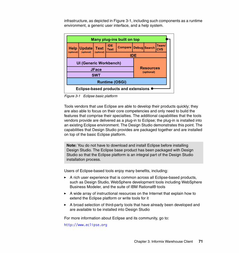
infrastructure, as depicted in Figure 3-1, including such components as a runtime environment, a generic user interface, and a help system.
Figure 3-1 Eclipse basic platform
Tools vendors that use Eclipse are able to develop their products quickly; they are also able to focus on their core competencies and only need to build the features that comprise their specialties. The additional capabilities that the tools vendors provide are delivered as a plug-in to Eclipse; the plug-in is installed into an existing Eclipse environment. The Design Studio demonstrates this point. The capabilities that Design Studio provides are packaged together and are installed on top of the basic Eclipse platform.
Users of Eclipse-based tools enjoy many benefits, including:
� A rich user experience that is common across all Eclipse-based products, such as Design Studio, WebSphere development tools including WebSphere Business Modeler, and the suite of IBM Rational® tools
� A wide array of instructional resources on the Internet that explain how to extend the Eclipse platform or write tools for it
� A broad selection of third-party tools that have already been developed and are available to be installed into Design Studio
For more information about Eclipse and its community, go to:
http://www.eclipse.org
Note: You do not have to download and install Eclipse before installing Design Studio. The Eclipse base product has been packaged with Design Studio so that the Eclipse platform is an integral part of the Design Studio installation process.
Runtime (OSGi)
SWTJFace
UI (Generic Workbench)Resources
Eclipse-based products and extensions
(optional)
Team/CVSSearchDebugCompareIDE
Text
IDE
Help Update Text(optional) (optional) (optional)
Many plug-ins built on top
Chapter 3. Informix Warehouse Client 71
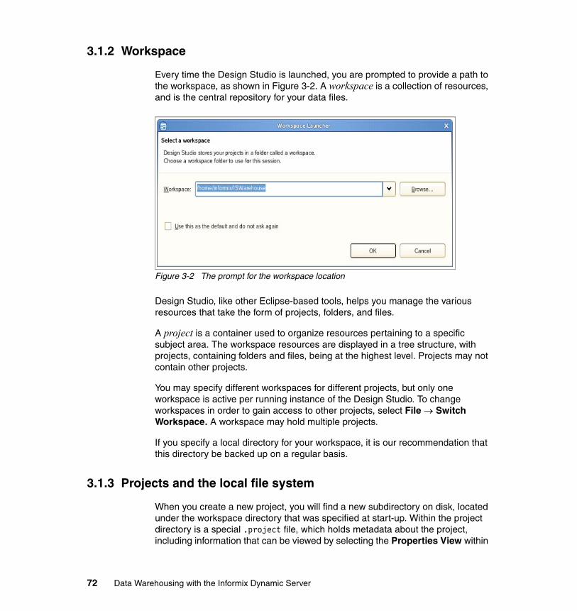
3.1.2 Workspace
Every time the Design Studio is launched, you are prompted to provide a path to the workspace, as shown in Figure 3-2. A workspace is a collection of resources, and is the central repository for your data files.
Figure 3-2 The prompt for the workspace location
Design Studio, like other Eclipse-based tools, helps you manage the various resources that take the form of projects, folders, and files.
A project is a container used to organize resources pertaining to a specific subject area. The workspace resources are displayed in a tree structure, with projects, containing folders and files, being at the highest level. Projects may not contain other projects.
You may specify different workspaces for different projects, but only one workspace is active per running instance of the Design Studio. To change workspaces in order to gain access to other projects, select File → Switch Workspace. A workspace may hold multiple projects.
If you specify a local directory for your workspace, it is our recommendation that this directory be backed up on a regular basis.
3.1.3 Projects and the local file system
When you create a new project, you will find a new subdirectory on disk, located under the workspace directory that was specified at start-up. Within the project directory is a special .project file, which holds metadata about the project, including information that can be viewed by selecting the Properties View within
72 Data Warehousing with the Informix Dynamic Server
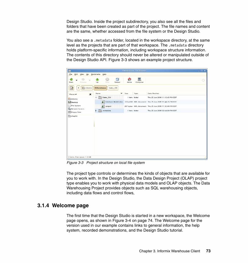
Design Studio. Inside the project subdirectory, you also see all the files and folders that have been created as part of the project. The file names and content are the same, whether accessed from the file system or the Design Studio.
You also see a .metadata folder, located in the workspace directory, at the same level as the projects that are part of that workspace. The .metadata directory holds platform-specific information, including workspace structure information. The contents of this directory should never be altered or manipulated outside of the Design Studio API. Figure 3-3 shows an example project structure.
Figure 3-3 Project structure on local file system
The project type controls or determines the kinds of objects that are available for you to work with. In the Design Studio, the Data Design Project (OLAP) project type enables you to work with physical data models and OLAP objects. The Data Warehousing Project provides objects such as SQL warehousing objects, including data flows and control flows,
3.1.4 Welcome page
The first time that the Design Studio is started in a new workspace, the Welcome page opens, as shown in Figure 3-4 on page 74. The Welcome page for the version used in our example contains links to general information, the help system, recorded demonstrations, and the Design Studio tutorial.
Chapter 3. Informix Warehouse Client 73
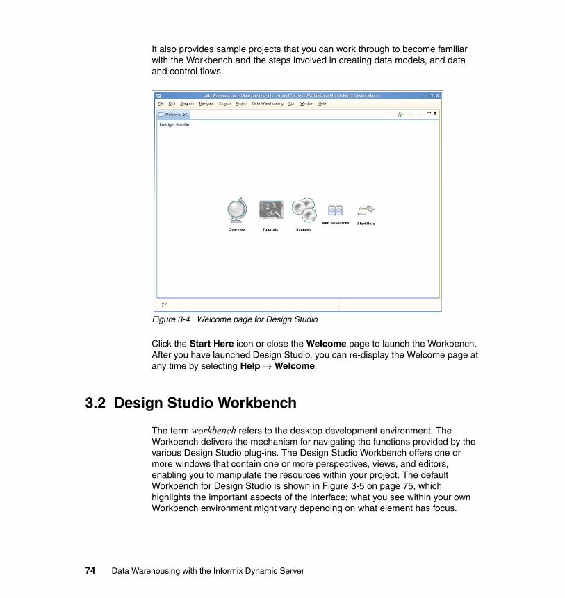
It also provides sample projects that you can work through to become familiar with the Workbench and the steps involved in creating data models, and data and control flows.
Figure 3-4 Welcome page for Design Studio
Click the Start Here icon or close the Welcome page to launch the Workbench. After you have launched Design Studio, you can re-display the Welcome page at any time by selecting Help → Welcome.
3.2 Design Studio Workbench
The term workbench refers to the desktop development environment. The Workbench delivers the mechanism for navigating the functions provided by the various Design Studio plug-ins. The Design Studio Workbench offers one or more windows that contain one or more perspectives, views, and editors, enabling you to manipulate the resources within your project. The default Workbench for Design Studio is shown in Figure 3-5 on page 75, which highlights the important aspects of the interface; what you see within your own Workbench environment might vary depending on what element has focus.
74 Data Warehousing with the Informix Dynamic Server
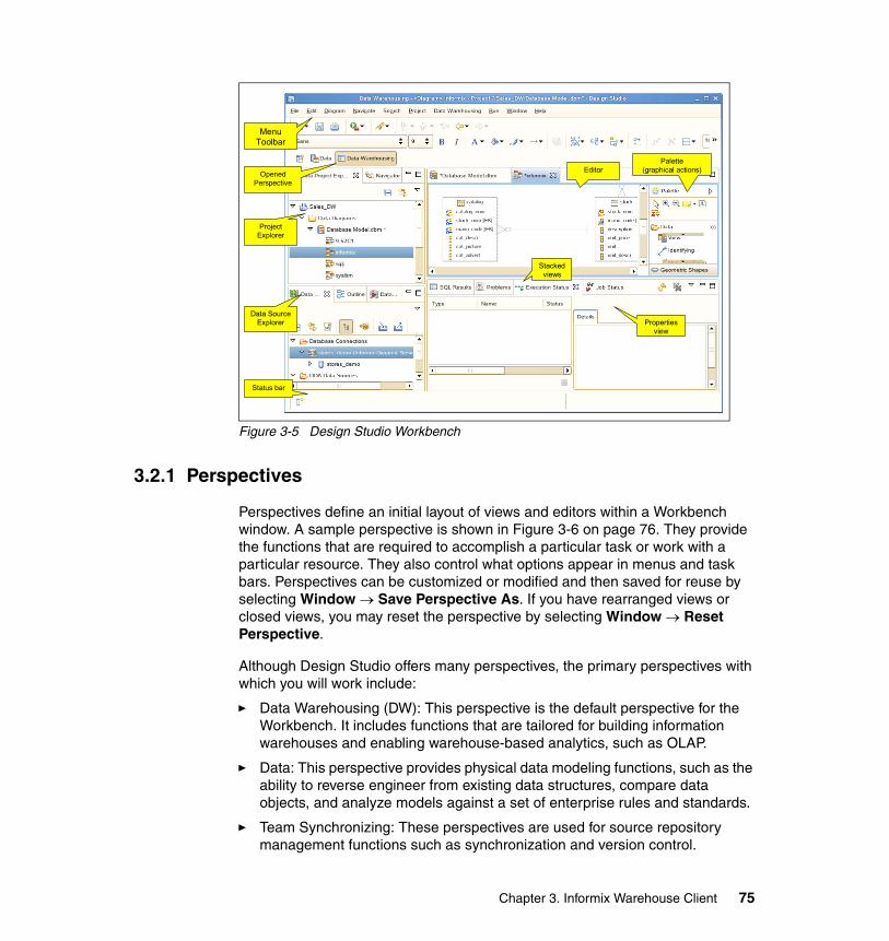
Figure 3-5 Design Studio Workbench
3.2.1 Perspectives
Perspectives define an initial layout of views and editors within a Workbench window. A sample perspective is shown in Figure 3-6 on page 76. They provide the functions that are required to accomplish a particular task or work with a particular resource. They also control what options appear in menus and task bars. Perspectives can be customized or modified and then saved for reuse by selecting Window → Save Perspective As. If you have rearranged views or closed views, you may reset the perspective by selecting Window → Reset Perspective.
Although Design Studio offers many perspectives, the primary perspectives with which you will work include:
� Data Warehousing (DW): This perspective is the default perspective for the Workbench. It includes functions that are tailored for building information warehouses and enabling warehouse-based analytics, such as OLAP.
� Data: This perspective provides physical data modeling functions, such as the ability to reverse engineer from existing data structures, compare data objects, and analyze models against a set of enterprise rules and standards.
� Team Synchronizing: These perspectives are used for source repository management functions such as synchronization and version control.
Menu Toolbar
Opened Perspective
Project Explorer
Data Source Explorer
Editor
Status bar
Palette (graphical actions)
Properties view
Stacked views
Chapter 3. Informix Warehouse Client 75
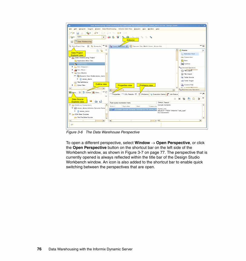
Figure 3-6 The Data Warehouse Perspective
To open a different perspective, select Window → Open Perspective, or click the Open Perspective button on the shortcut bar on the left side of the Workbench window, as shown in Figure 3-7 on page 77. The perspective that is currently opened is always reflected within the title bar of the Design Studio Workbench window. An icon is also added to the shortcut bar to enable quick switching between the perspectives that are open.
Data Project Explorer view
Data Source Explorer view
Outline view
Editor(s)
Properties view Problems view
76 Data Warehousing with the Informix Dynamic Server
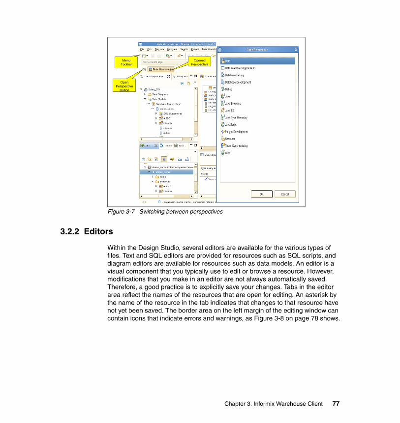
Figure 3-7 Switching between perspectives
3.2.2 Editors
Within the Design Studio, several editors are available for the various types of files. Text and SQL editors are provided for resources such as SQL scripts, and diagram editors are available for resources such as data models. An editor is a visual component that you typically use to edit or browse a resource. However, modifications that you make in an editor are not always automatically saved. Therefore, a good practice is to explicitly save your changes. Tabs in the editor area reflect the names of the resources that are open for editing. An asterisk by the name of the resource in the tab indicates that changes to that resource have not yet been saved. The border area on the left margin of the editing window can contain icons that indicate errors and warnings, as Figure 3-8 on page 78 shows.
Menu Toolbar
Open Perspective
Button
Opened Perspective
Chapter 3. Informix Warehouse Client 77
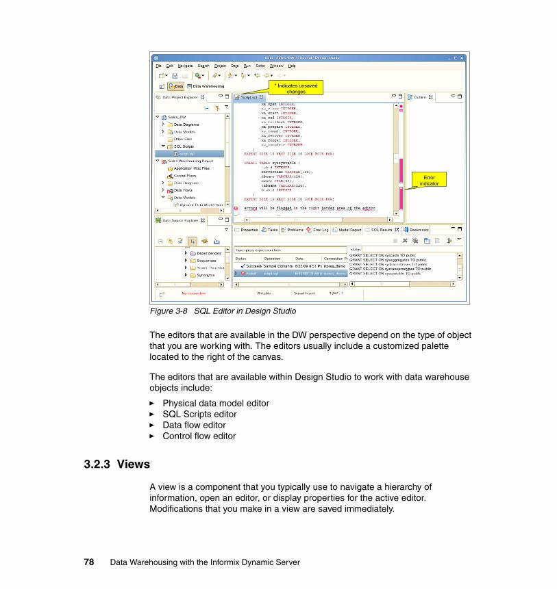
Figure 3-8 SQL Editor in Design Studio
The editors that are available in the DW perspective depend on the type of object that you are working with. The editors usually include a customized palette located to the right of the canvas.
The editors that are available within Design Studio to work with data warehouse objects include:
� Physical data model editor� SQL Scripts editor� Data flow editor� Control flow editor
3.2.3 Views
A view is a component that you typically use to navigate a hierarchy of information, open an editor, or display properties for the active editor. Modifications that you make in a view are saved immediately.
Error indicator
* Indicates unsaved changes
78 Data Warehousing with the Informix Dynamic Server
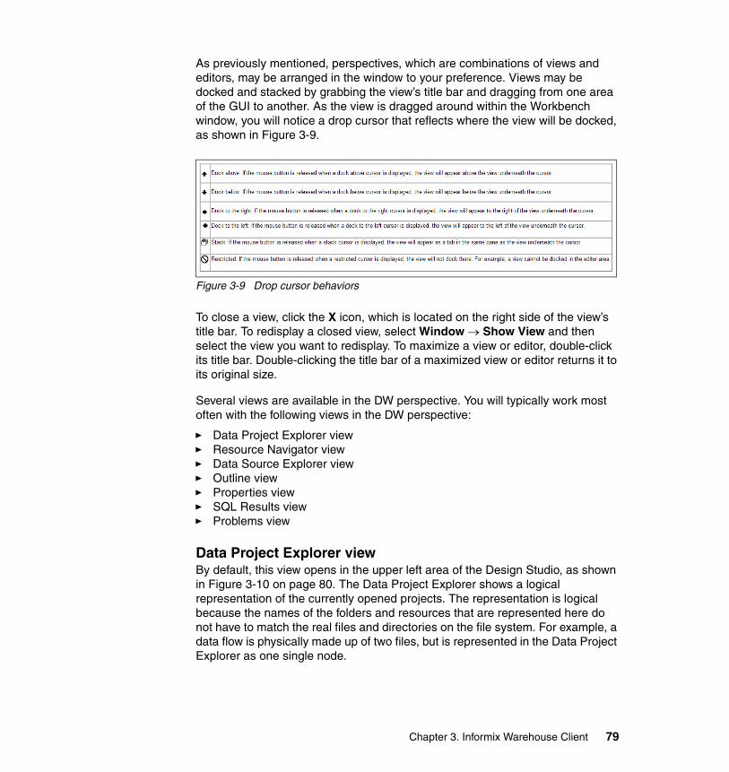
As previously mentioned, perspectives, which are combinations of views and editors, may be arranged in the window to your preference. Views may be docked and stacked by grabbing the view’s title bar and dragging from one area of the GUI to another. As the view is dragged around within the Workbench window, you will notice a drop cursor that reflects where the view will be docked, as shown in Figure 3-9.
Figure 3-9 Drop cursor behaviors
To close a view, click the X icon, which is located on the right side of the view’s title bar. To redisplay a closed view, select Window → Show View and then select the view you want to redisplay. To maximize a view or editor, double-click its title bar. Double-clicking the title bar of a maximized view or editor returns it to its original size.
Several views are available in the DW perspective. You will typically work most often with the following views in the DW perspective:
� Data Project Explorer view� Resource Navigator view� Data Source Explorer view� Outline view� Properties view� SQL Results view� Problems view
Data Project Explorer viewBy default, this view opens in the upper left area of the Design Studio, as shown in Figure 3-10 on page 80. The Data Project Explorer shows a logical representation of the currently opened projects. The representation is logical because the names of the folders and resources that are represented here do not have to match the real files and directories on the file system. For example, a data flow is physically made up of two files, but is represented in the Data Project Explorer as one single node.
Chapter 3. Informix Warehouse Client 79
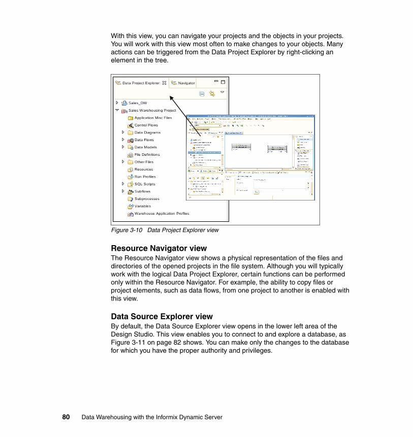
With this view, you can navigate your projects and the objects in your projects. You will work with this view most often to make changes to your objects. Many actions can be triggered from the Data Project Explorer by right-clicking an element in the tree.
Figure 3-10 Data Project Explorer view
Resource Navigator viewThe Resource Navigator view shows a physical representation of the files and directories of the opened projects in the file system. Although you will typically work with the logical Data Project Explorer, certain functions can be performed only within the Resource Navigator. For example, the ability to copy files or project elements, such as data flows, from one project to another is enabled with this view.
Data Source Explorer viewBy default, the Data Source Explorer view opens in the lower left area of the Design Studio. This view enables you to connect to and explore a database, as Figure 3-11 on page 82 shows. You can make only the changes to the database for which you have the proper authority and privileges.
80 Data Warehousing with the Informix Dynamic Server
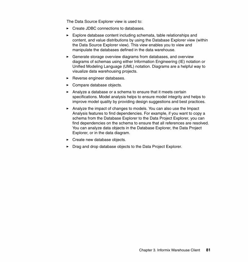
The Data Source Explorer view is used to:
� Create JDBC connections to databases.
� Explore database content including schemata, table relationships and content, and value distributions by using the Database Explorer view (within the Data Source Explorer view). This view enables you to view and manipulate the databases defined in the data warehouse.
� Generate storage overview diagrams from databases, and overview diagrams of schemas using either Information Engineering (IE) notation or Unified Modeling Language (UML) notation. Diagrams are a helpful way to visualize data warehousing projects.
� Reverse engineer databases.
� Compare database objects.
� Analyze a database or a schema to ensure that it meets certain specifications. Model analysis helps to ensure model integrity and helps to improve model quality by providing design suggestions and best practices.
� Analyze the impact of changes to models. You can also use the Impact Analysis features to find dependencies. For example, if you want to copy a schema from the Database Explorer to the Data Project Explorer, you can find dependencies on the schema to ensure that all references are resolved. You can analyze data objects in the Database Explorer, the Data Project Explorer, or in the data diagram.
� Create new database objects.
� Drag and drop database objects to the Data Project Explorer.
Chapter 3. Informix Warehouse Client 81
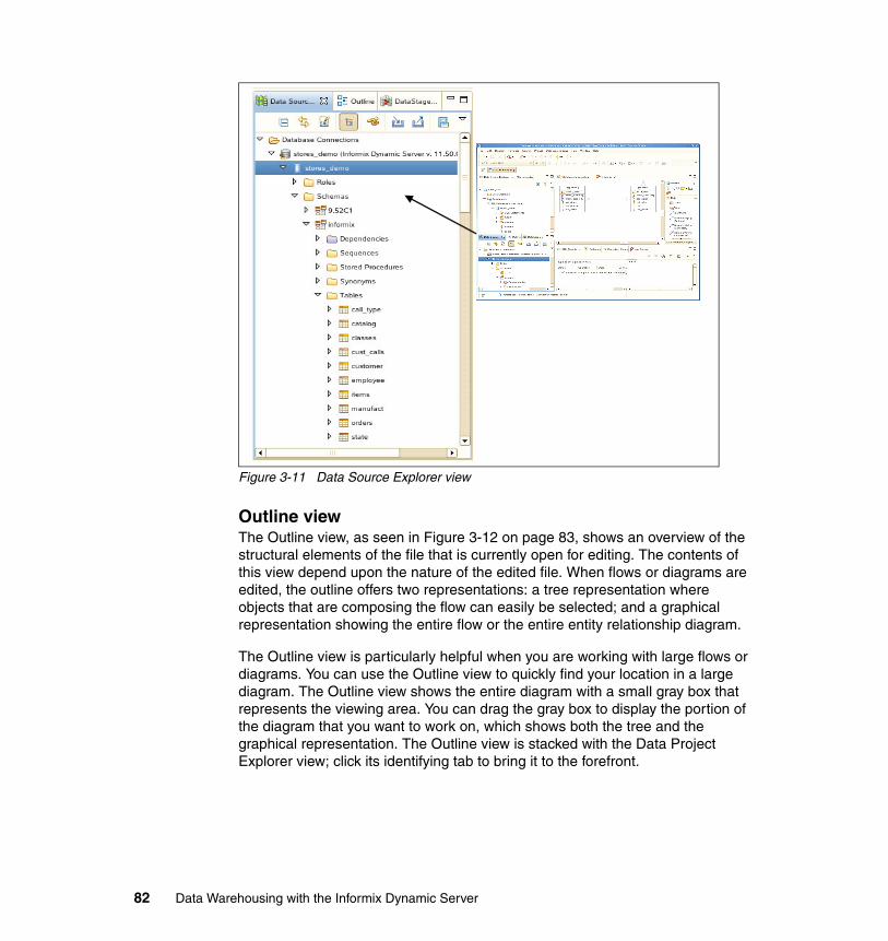
Figure 3-11 Data Source Explorer view
Outline viewThe Outline view, as seen in Figure 3-12 on page 83, shows an overview of the structural elements of the file that is currently open for editing. The contents of this view depend upon the nature of the edited file. When flows or diagrams are edited, the outline offers two representations: a tree representation where objects that are composing the flow can easily be selected; and a graphical representation showing the entire flow or the entire entity relationship diagram.
The Outline view is particularly helpful when you are working with large flows or diagrams. You can use the Outline view to quickly find your location in a large diagram. The Outline view shows the entire diagram with a small gray box that represents the viewing area. You can drag the gray box to display the portion of the diagram that you want to work on, which shows both the tree and the graphical representation. The Outline view is stacked with the Data Project Explorer view; click its identifying tab to bring it to the forefront.
82 Data Warehousing with the Informix Dynamic Server
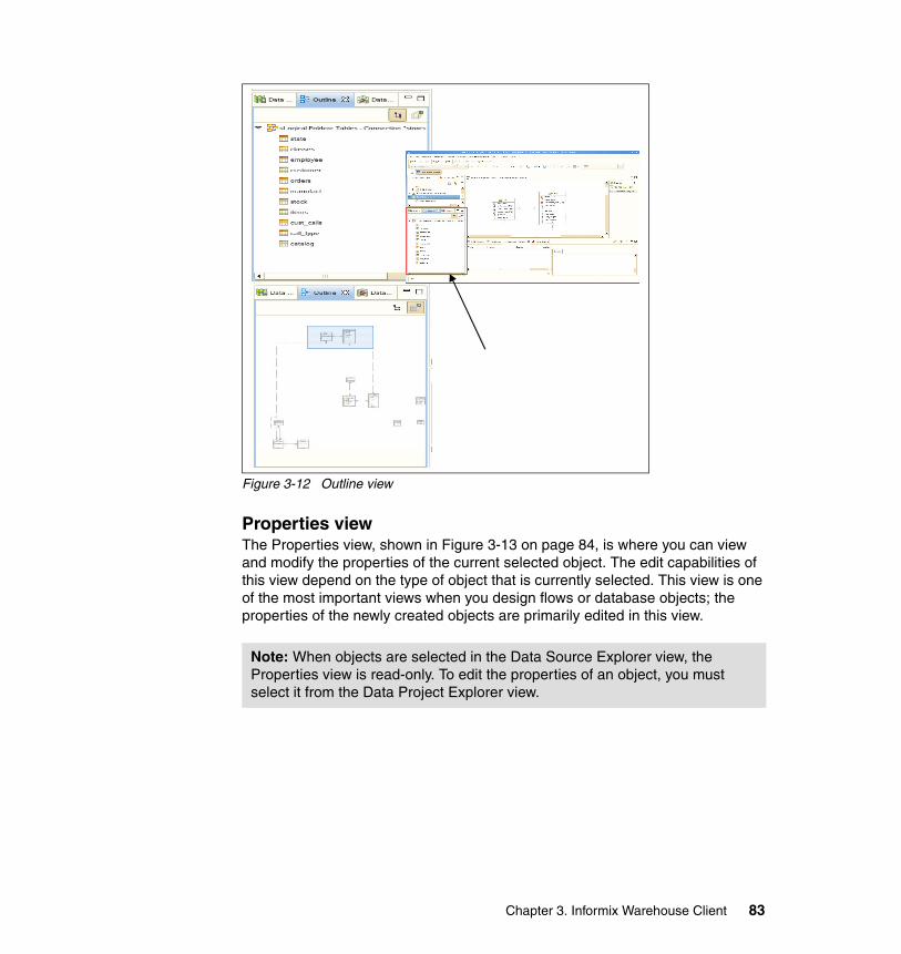
Figure 3-12 Outline view
Properties viewThe Properties view, shown in Figure 3-13 on page 84, is where you can view and modify the properties of the current selected object. The edit capabilities of this view depend on the type of object that is currently selected. This view is one of the most important views when you design flows or database objects; the properties of the newly created objects are primarily edited in this view.
Note: When objects are selected in the Data Source Explorer view, the Properties view is read-only. To edit the properties of an object, you must select it from the Data Project Explorer view.
Chapter 3. Informix Warehouse Client 83
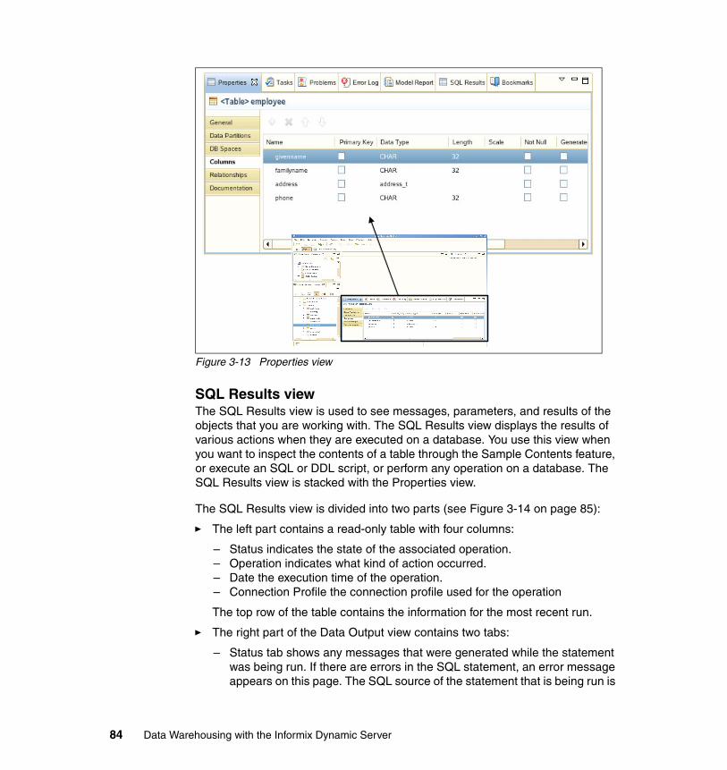
Figure 3-13 Properties view
SQL Results view The SQL Results view is used to see messages, parameters, and results of the objects that you are working with. The SQL Results view displays the results of various actions when they are executed on a database. You use this view when you want to inspect the contents of a table through the Sample Contents feature, or execute an SQL or DDL script, or perform any operation on a database. The SQL Results view is stacked with the Properties view.
The SQL Results view is divided into two parts (see Figure 3-14 on page 85):
� The left part contains a read-only table with four columns:
– Status indicates the state of the associated operation.– Operation indicates what kind of action occurred.– Date the execution time of the operation. – Connection Profile the connection profile used for the operation
The top row of the table contains the information for the most recent run.
� The right part of the Data Output view contains two tabs:
– Status tab shows any messages that were generated while the statement was being run. If there are errors in the SQL statement, an error message appears on this page. The SQL source of the statement that is being run is
84 Data Warehousing with the Informix Dynamic Server
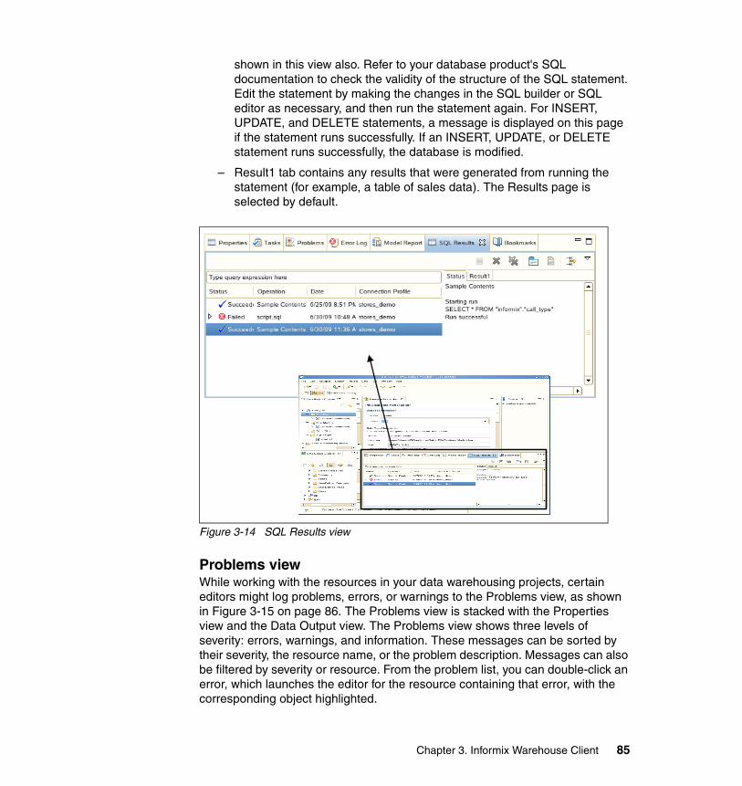
shown in this view also. Refer to your database product's SQL documentation to check the validity of the structure of the SQL statement. Edit the statement by making the changes in the SQL builder or SQL editor as necessary, and then run the statement again. For INSERT, UPDATE, and DELETE statements, a message is displayed on this page if the statement runs successfully. If an INSERT, UPDATE, or DELETE statement runs successfully, the database is modified.
– Result1 tab contains any results that were generated from running the statement (for example, a table of sales data). The Results page is selected by default.
Figure 3-14 SQL Results view
Problems viewWhile working with the resources in your data warehousing projects, certain editors might log problems, errors, or warnings to the Problems view, as shown in Figure 3-15 on page 86. The Problems view is stacked with the Properties view and the Data Output view. The Problems view shows three levels of severity: errors, warnings, and information. These messages can be sorted by their severity, the resource name, or the problem description. Messages can also be filtered by severity or resource. From the problem list, you can double-click an error, which launches the editor for the resource containing that error, with the corresponding object highlighted.
Chapter 3. Informix Warehouse Client 85
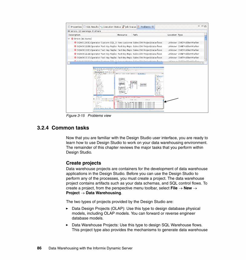
Figure 3-15 Problems view
3.2.4 Common tasks
Now that you are familiar with the Design Studio user interface, you are ready to learn how to use Design Studio to work on your data warehousing environment. The remainder of this chapter reviews the major tasks that you perform within Design Studio.
Create projectsData warehouse projects are containers for the development of data warehouse applications in the Design Studio. Before you can use the Design Studio to perform any of the processes, you must create a project. The data warehouse project contains artifacts such as your data schemas, and SQL control flows. To create a project, from the perspective menu toolbar, select File → New → Project → Data Warehousing.
The two types of projects provided by the Design Studio are:
� Data Design Projects (OLAP): Use this type to design database physical models, including OLAP models. You can forward or reverse engineer database models.
� Data Warehouse Projects: Use this type to design SQL Warehouse flows. This project type also provides the mechanisms to generate data warehouse
86 Data Warehousing with the Informix Dynamic Server
application packages to deploy on the IDS server. Data warehouse projects can also contain your physical data models.
Data warehouse projects may depend on metadata (for example, a physical data model) that is stored in data design projects. You can link a data warehouse project to a data design project by right-clicking the data warehouse project and selecting Project References from the context menu.
Then, you may select from the list of available data design projects. When a warehouse project refers to a data design project, you have access to the metadata in that project when you are designing data flows. Linked resources are indicated within the Project Explorer.
You can import data flows and other objects into a data warehouse project by selecting File → Import → File system. Be sure to identify the correct folder name for the object that you want to import. For example, if you are importing a data flow, specify the data-flows folder as the target directory in your project. If you do not select the correct folder, the results of the import operation are unpredictable.
Add database connectionsEvery time Design Studio is launched, the Data Source Explorer displays all the connections you created. It also displays any previously defined database connections that are not IDS database connections. Before you can browse or explore a new database, you must define a database connection to the data source.
Note: If you delete a linked physical data model (.dbm file) from a data warehouse project, you are deleting the original model file, not just the link to that model. Rather, you should remove the project reference to that data model.
Important: Do not rename or copy and paste a data warehouse project. These actions have unpredictable results and are likely to cause problems with the objects inside the project, such as subflows and application profiles.
Note: The database connections that you define in the Data Source Explorer view are used during the design or development phase of your data warehouse project; they define a connection from your Design Studio client to the database server. When you are ready to deploy your project, you must define a run-time database connection through the Admin Console.
Chapter 3. Informix Warehouse Client 87
The database connections are represented in the Data Source Explorer View by a node. The connections are initially disconnected (no plus sign [+] is indicated on their left side). You can connect to a database by right-clicking on its connection node and selecting Reconnect. You are then prompted for a user ID and password. After the connection has been made, you can expand the tree to explore its schema, tables, and other objects.
To add another remote database or non IDS database to your Data Source Explorer view, click the New Connection Profile icon. A dialog box opens; it is for collecting the connection information such as database vendor and version, database name, port number, JDBC driver, and user ID and password. You may also specify filters for the database connection if appropriate. After this information is correctly supplied, the database is added to the Connections list. For more details about configuring database connections, go to:
http://publib.boulder.ibm.com/infocenter/idshelp/v115/index.jsp?topic=/com.ibm.dwe.navigate.doc/welcome_db2warehouse.html
Browse databases and explore dataAfter you are successfully connected to a database in the Data Source Explorer, there are many ways to explore your data from within Design Studio. You can explore schema, table relationships, or table content:
� Exploring database schemas
To expand a database so you can explore it, double-click its icon, or click the plus sign [+] to the left of the database name. You can view items such as storage diagrams, schemas and tables, view relationships between tables, and columns. Use the Properties View after selecting a table to display this information.
� Viewing sample content
Inspect the content of single tables by expanding the explorer tree and viewing the schemata and tables. Right-click on a table and select Data → Sample Contents. The Data Output view displays a sampling of the data. The number of rows selected for the sample is controlled by the Output preference setting, which is found under the Data category, as described in “Customize the environment” on page 89.
� Edit, load, and extract data
In addition to being able to sample data contents, other actions are available from the Data context menu.
88 Data Warehousing with the Informix Dynamic Server
To get to the Data context menu, expand a database tree within the Database Explorer view, right-click on a table, select Data, and then select one of the following actions from the context menu:
– Edit: With the proper database authority, you may edit the contents of the table in an editor.
– Load: Load the table with data from a flat file.
– Extract: Write the contents of the table to a flat file with the Extract option.
Work with databases offlineDatabase connection information can be saved locally to allow database objects to be viewed from Design Studio without having an active connection to the database. Not all features are available without an active connection; capabilities that can be performed include viewing database objects and their properties, and creating and viewing overview diagrams.
To work with a database connection offline, use the following steps:
1. While connected, refresh your database connection.
2. Right-click the active database connection and select Save Offline. The connection information will be saved to your local Design Studio client.
3. Right-click the same active database connection, and select Disconnect.
4. Right-click the same connection again, and select Work Offline. The locally saved database information will be retrieved.
5. To return to the active connection, right-click and select Disconnect, then right-click the connection and select Connect.
6. If you want to work while disconnected again, refresh your local connection by repeating these steps, to ensure that you have captured any changes that were made to the database since you were last connected.
Customize the environmentYou can modify many aspects about the behavior and appearance of your Design Studio Workbench. For example, you can change the fonts and colors that are used, control the placement of tabs, and configure the behavior of plug-ins that you may have installed into your Eclipse environment.
To customize your Design Studio environment, select Window → Preferences. The Preferences dialog opens, enabling you to set preferences for all tools that are installed in your Design Studio framework. See Figure 3-16 on page 90.
Chapter 3. Informix Warehouse Client 89
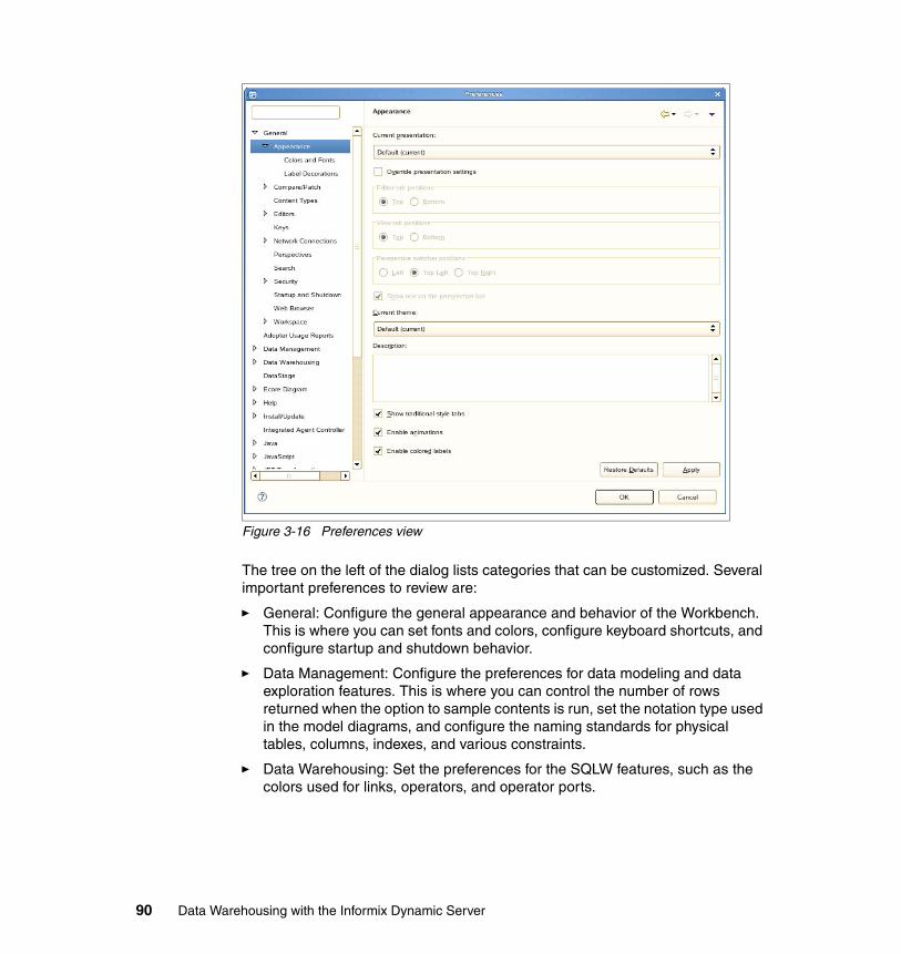
Figure 3-16 Preferences view
The tree on the left of the dialog lists categories that can be customized. Several important preferences to review are:
� General: Configure the general appearance and behavior of the Workbench. This is where you can set fonts and colors, configure keyboard shortcuts, and configure startup and shutdown behavior.
� Data Management: Configure the preferences for data modeling and data exploration features. This is where you can control the number of rows returned when the option to sample contents is run, set the notation type used in the model diagrams, and configure the naming standards for physical tables, columns, indexes, and various constraints.
� Data Warehousing: Set the preferences for the SQLW features, such as the colors used for links, operators, and operator ports.
90 Data Warehousing with the Informix Dynamic Server
� Modeling: Define the appearance of the data model objects including constraints, comments, and notes. This is also where validation rules for constraints are enabled and disabled.
� Team: Configure CVS or any other control version system solution you may be using.
Model data structuresAs part of the process of developing your solution, you will be designing and modifying physical database models, and defining schemas and storage specifications. To get started, use the following steps:
1. Open the data design project you want to work in.
2. Launch the New Data Model Wizard by right-clicking on the Data Models folder, and selecting New → Physical Data Model.
3. Choose the destination project folder, provide a name for your data model, and continue to follow the prompts from the wizard.
Models can be created from start to finish, or reverse engineered from existing DDL or databases. Other tasks that are performed include comparing data objects and models with each other or with other objects, analyzing designs to confirm that standards are complied with, and then deploying the model. For more details about physical data modeling, refer to Chapter 4, “Developing the physical model” on page 95
Design data flows and control flowsData flows and control flows are housed within the Data Warehouse project type. Data flows model data transformation steps that move data from a relational table or file, perform some processing, and insert the results into some type of relational or file target. From the data flow models, SQL-based code is generated to accomplish the tasks defined in the flow.
A control flow determines the processing sequence of data flows along with other types of common data processing tasks such as executing OS scripts, IDS scripts, FTP, and e-mail. It allows the construction of success and failure paths and iterative loops.
Chapter 3. Informix Warehouse Client 91
3.2.5 Team component
If you have many developers working on your data warehousing projects within Design Studio, you might want to set up a version control system. A version control system keeps track of changes to files, and allows developers who might be physically separated to collaborate on design projects.
The Design Studio offers integrated support for two version control solutions: Concurrent Versions System (CVS) and IBM ClearCase®. The integration points allow you to perform version control tasks directly from your database project explorer. In this section, we provide a brief overview of the CVS and ClearCase options.
Concurrent Versions SystemThe Eclipse framework supports the Concurrent Versions System (CVS) standard. CVS manages a set of related files, such as Design Studio project files, in a repository that is running on a CVS server. To obtain a copy of the files you want to work on, you must check-out the files from the CVS server. After you are done with your work, you update your changes back to the server by committing your files through a check-in process. The CVS server also manages conflicts, in the case that two different developers have made changes to the same set of project files. CVS provides a history of the work done by team members, and provides the mechanisms to coordinate and integrate work done by team members. If you have a CVS server set up within your network environment, you can enable the Teaming perspective and views.
A CVS repository is a persistent data store that coordinates multiple user access to projects and their contents. Projects in a repository can be of two forms: immutable (a project version) or modifiable (a project in a branch). Communication between the repository and Workbench clients is possible over local or wide area networks. The Workbench includes a built-in client for the CVS. With this client you can access CVS repositories.
IBM Rational ClearcaseThe Eclipse framework supports Rational ClearCase. ClearCase is a software configuration management tool that manages files and directories using object repositories called versioned object bases (VOBs). A VOB is the permanent data repository in which you store files, directories, and metadata. Anything that can be represented as a file or directory can be managed in a ClearCase VOB. ClearCase repository displays its contents as files in a file system, which can be operated on in the same way as you would files in the native file system. The atomic object put under version control in ClearCase is referred to as an element. Elements are file system objects: files and directories. Every element records versions of the file or directory it represents. So, when a user checks in a file, a
92 Data Warehousing with the Informix Dynamic Server

new version is created for that element. These element versions are organized into branches. A branch is an object that specifies a linear sequence of element versions. They are used for many purposes, such as doing parallel development and maintaining variants of the system.
To obtain a copy of the files you want to work on, use the check-out process to get the files from the VOB server. After you are done with your work, you update your changes back to the server by committing your files through a check-in process. The VOB server also manages conflicts, in the case that two different developers have made changes to the same set of project files. ClearCase provides a history of the work done by team members, and provides the mechanisms to coordinate and integrate work done by team members. If you have ClearCase set up within your environment, you can enable the Teaming perspective and views.
Chapter 3. Informix Warehouse Client 93

94 Data Warehousing with the Informix Dynamic Server

Chapter 4. Developing the physical model
In this chapter, we describe how to create physical models by using the Design Studio (a component of the Informix Warehouse Client). Physical data models can be created in several ways. You can of course create a new data model from the base components, but you can also create a model from a template, from an existing database (reverse engineering), from DDL scripts, from the Data Source Explorer within the Design Studio, or by importing a logical data model from, for example, InfoSphere Data Architect.
The data modeling process is basically a two-step process: First, create a logical model and then transfer it to a physical model. In a highly structured modeling environment, business process models and conceptual models can be developed prior to creating the actual logical and physical data models.
The logical data model is characterized by defining the normalization, setting naming standards, and defining entities, attributes, and relations. The logical data model is platform-independent.
The physical data model is characterized by defining the tables, columns with data types and indexes. The physical data model is typically platform-dependent and is the direct source for creating DDL scripts.
4
© Copyright IBM Corp. 2009. All rights reserved. 95
4.1 Physical data model
Physical data models define the internal schema of the data sources within the data warehouse environment. Data models outline data tables, the columns within those tables, and the relationships between tables. The Design Studio includes the components necessary to enable you to create a physical model and then generate the appropriate SQL for your implementation target. Physical models are constrained to the concept of the target. For example, Informix Warehouse physical models are constrained to the relational model. You can only model objects that are supported by the target database. For example, the ability to model columns of data type SERIAL only applies to IDS targets.
The physical models that you create in Design Studio can be used to create new schemas or to update schemas that already exist in the target database.
Using the Design Studio, within your physical data models, you can define data elements for the target database, such as:
� Databases (one per data model)� Tables� Views� Primary keys and foreign keys� Indexes� Stored procedures and functions� Synonyms� Sequences� Users and roles
The physical data models that you create and work within Design Studio are implemented as an entity relationship (E-R) diagram. The models are visually represented using either Information Engineering (IE) notation or Unified Modeling Language (UML) notation. Before you begin the modeling work, you should configure Design Studio to use the notation that you prefer.
To set the preferred capability, open the Preferences dialog from the Window menu and then select Data Management → Diagram, as depicted in Figure 4-1 on page 97.
96 Data Warehousing with the Informix Dynamic Server
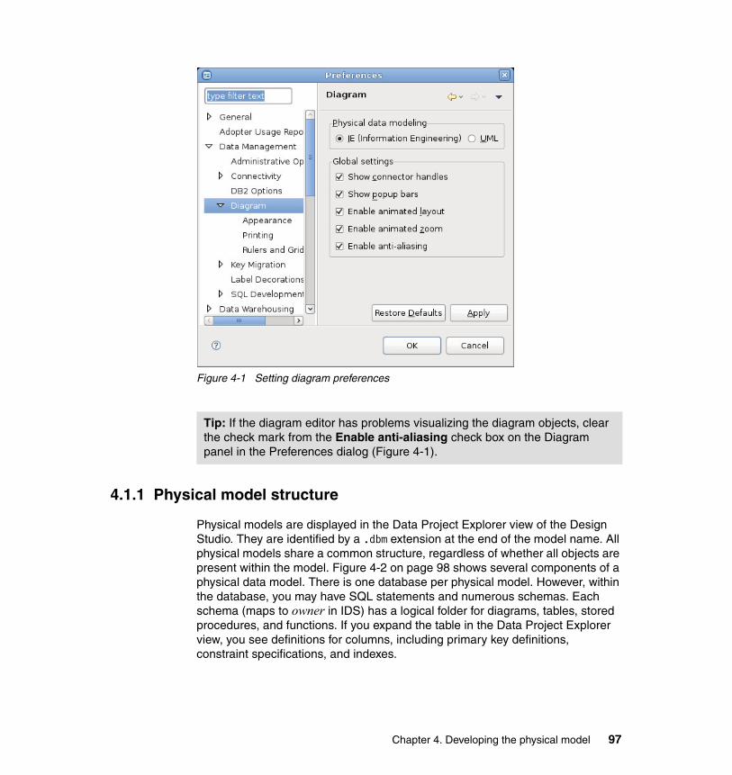
Figure 4-1 Setting diagram preferences
4.1.1 Physical model structure
Physical models are displayed in the Data Project Explorer view of the Design Studio. They are identified by a .dbm extension at the end of the model name. All physical models share a common structure, regardless of whether all objects are present within the model. Figure 4-2 on page 98 shows several components of a physical data model. There is one database per physical model. However, within the database, you may have SQL statements and numerous schemas. Each schema (maps to owner in IDS) has a logical folder for diagrams, tables, stored procedures, and functions. If you expand the table in the Data Project Explorer view, you see definitions for columns, including primary key definitions, constraint specifications, and indexes.
Tip: If the diagram editor has problems visualizing the diagram objects, clear the check mark from the Enable anti-aliasing check box on the Diagram panel in the Preferences dialog (Figure 4-1).
Chapter 4. Developing the physical model 97
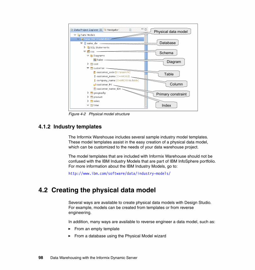
Figure 4-2 Physical model structure
4.1.2 Industry templates
The Informix Warehouse includes several sample industry model templates. These model templates assist in the easy creation of a physical data model, which can be customized to the needs of your data warehouse project.
The model templates that are included with Informix Warehouse should not be confused with the IBM Industry Models that are part of IBM InfoSphere portfolio. For more information about the IBM Industry Models, go to:
http://www.ibm.com/software/data/industry-models/
4.2 Creating the physical data model
Several ways are available to create physical data models with Design Studio. For example, models can be created from templates or from reverse engineering.
In addition, many ways are available to reverse engineer a data model, such as:
� From an empty template
� From a database using the Physical Model wizard
Physical data model
Database
Schema
Diagram
Table
Column
Primary constraint
Index
98 Data Warehousing with the Informix Dynamic Server
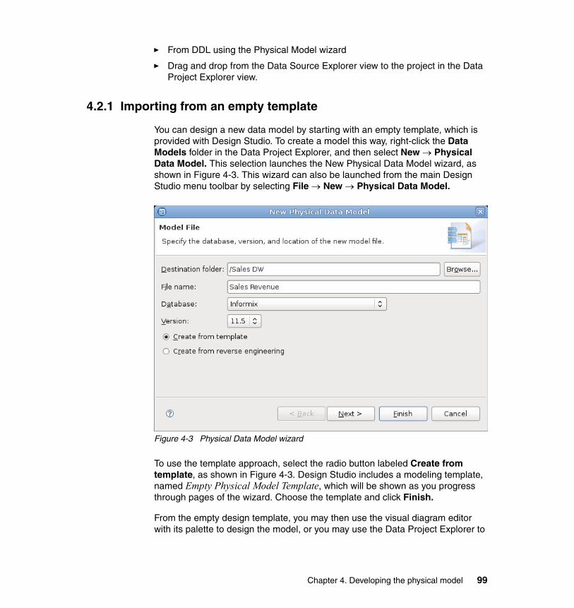
� From DDL using the Physical Model wizard
� Drag and drop from the Data Source Explorer view to the project in the Data Project Explorer view.
4.2.1 Importing from an empty template
You can design a new data model by starting with an empty template, which is provided with Design Studio. To create a model this way, right-click the Data Models folder in the Data Project Explorer, and then select New → Physical Data Model. This selection launches the New Physical Data Model wizard, as shown in Figure 4-3. This wizard can also be launched from the main Design Studio menu toolbar by selecting File → New → Physical Data Model.
Figure 4-3 Physical Data Model wizard
To use the template approach, select the radio button labeled Create from template, as shown in Figure 4-3. Design Studio includes a modeling template, named Empty Physical Model Template, which will be shown as you progress through pages of the wizard. Choose the template and click Finish.
From the empty design template, you may then use the visual diagram editor with its palette to design the model, or you may use the Data Project Explorer to
Chapter 4. Developing the physical model 99
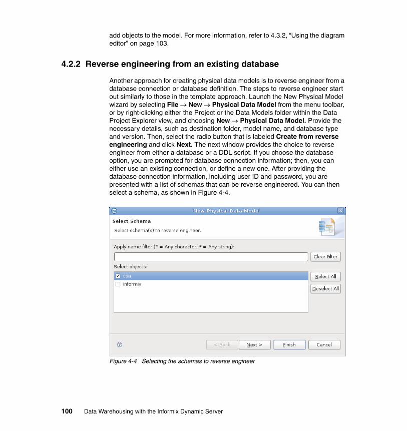
add objects to the model. For more information, refer to 4.3.2, “Using the diagram editor” on page 103.
4.2.2 Reverse engineering from an existing database
Another approach for creating physical data models is to reverse engineer from a database connection or database definition. The steps to reverse engineer start out similarly to those in the template approach. Launch the New Physical Model wizard by selecting File → New → Physical Data Model from the menu toolbar, or by right-clicking either the Project or the Data Models folder within the Data Project Explorer view, and choosing New → Physical Data Model. Provide the necessary details, such as destination folder, model name, and database type and version. Then, select the radio button that is labeled Create from reverse engineering and click Next. The next window provides the choice to reverse engineer from either a database or a DDL script. If you choose the database option, you are prompted for database connection information; then, you can either use an existing connection, or define a new one. After providing the database connection information, including user ID and password, you are presented with a list of schemas that can be reverse engineered. You can then select a schema, as shown in Figure 4-4.
Figure 4-4 Selecting the schemas to reverse engineer
100 Data Warehousing with the Informix Dynamic Server
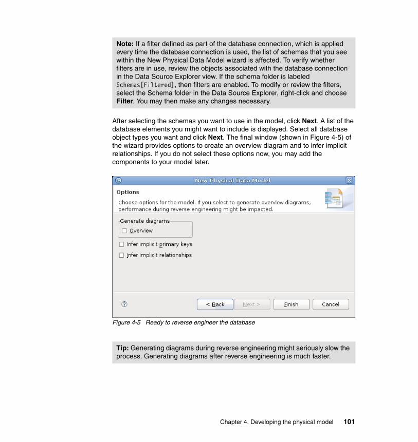
After selecting the schemas you want to use in the model, click Next. A list of the database elements you might want to include is displayed. Select all database object types you want and click Next. The final window (shown in Figure 4-5) of the wizard provides options to create an overview diagram and to infer implicit relationships. If you do not select these options now, you may add the components to your model later.
Figure 4-5 Ready to reverse engineer the database
Note: If a filter defined as part of the database connection, which is applied every time the database connection is used, the list of schemas that you see within the New Physical Data Model wizard is affected. To verify whether filters are in use, review the objects associated with the database connection in the Data Source Explorer view. If the schema folder is labeled Schemas[Filtered], then filters are enabled. To modify or review the filters, select the Schema folder in the Data Source Explorer, right-click and choose Filter. You may then make any changes necessary.
Tip: Generating diagrams during reverse engineering might seriously slow the process. Generating diagrams after reverse engineering is much faster.
Chapter 4. Developing the physical model 101
4.2.3 Using the Data Source Explorer
Perhaps the easiest method to create a new physical model from an existing database is to drag and drop the objects from the Data Source Explorer to the Data Project Explorer. To use this method, verify that there is an active connection to the source database within the Data Source Explorer view. Expand the database connection and select the objects to be reverse engineered. The level of granularity available ranges from database to table. After you have selected the objects, drag them up to the Data Project Explorer, and drop them onto an existing project, as shown in 4.2, “Creating the physical data model” on page 98. The resulting physical model name is the name of the database connection. A number is added to the end of the model name for uniqueness, if necessary.
4.3 Working with diagrams
The Design Studio uses E-R diagrams to provide a visual representation of the physical data models within your projects. E-R diagrams are a useful mechanism for understanding the data elements within your projects and communicating that information to others. Within Design Studio, you may have multiple diagrams per schema within the projects. A helpful approach is to organize the data models into multiple subject areas, especially when working with a large, complex data model.
In addition to the value that the diagrams bring to the projects by simplifying and improving the understanding of complex data environments, the diagrams can also be used to edit and modify the physical data model.
4.3.1 Creating a diagram
The Design Studio offers several ways to add the E-R diagrams to the projects.
If you have chosen to reverse engineer the data model, you may opt to have the wizard create an overview diagram for you. The wizard provides prompts that enable you to specify the elements that you want to include in the diagram.
You may still use diagrams in the data projects, even if you do not create the data models with the reverse engineering approach. New diagrams may be created from any Diagrams folder in the Project Explorer. Simply right-click the Diagrams folder and select New Overview Diagram. You are prompted to select the elements from the current schema you want to include in the diagram.
102 Data Warehousing with the Informix Dynamic Server
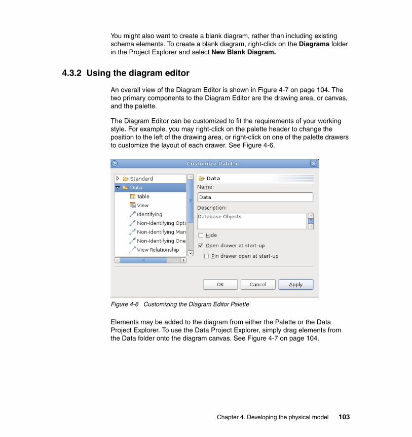
You might also want to create a blank diagram, rather than including existing schema elements. To create a blank diagram, right-click on the Diagrams folder in the Project Explorer and select New Blank Diagram.
4.3.2 Using the diagram editor
An overall view of the Diagram Editor is shown in Figure 4-7 on page 104. The two primary components to the Diagram Editor are the drawing area, or canvas, and the palette.
The Diagram Editor can be customized to fit the requirements of your working style. For example, you may right-click on the palette header to change the position to the left of the drawing area, or right-click on one of the palette drawers to customize the layout of each drawer. See Figure 4-6.
Figure 4-6 Customizing the Diagram Editor Palette
Elements may be added to the diagram from either the Palette or the Data Project Explorer. To use the Data Project Explorer, simply drag elements from the Data folder onto the diagram canvas. See Figure 4-7 on page 104.
Chapter 4. Developing the physical model 103
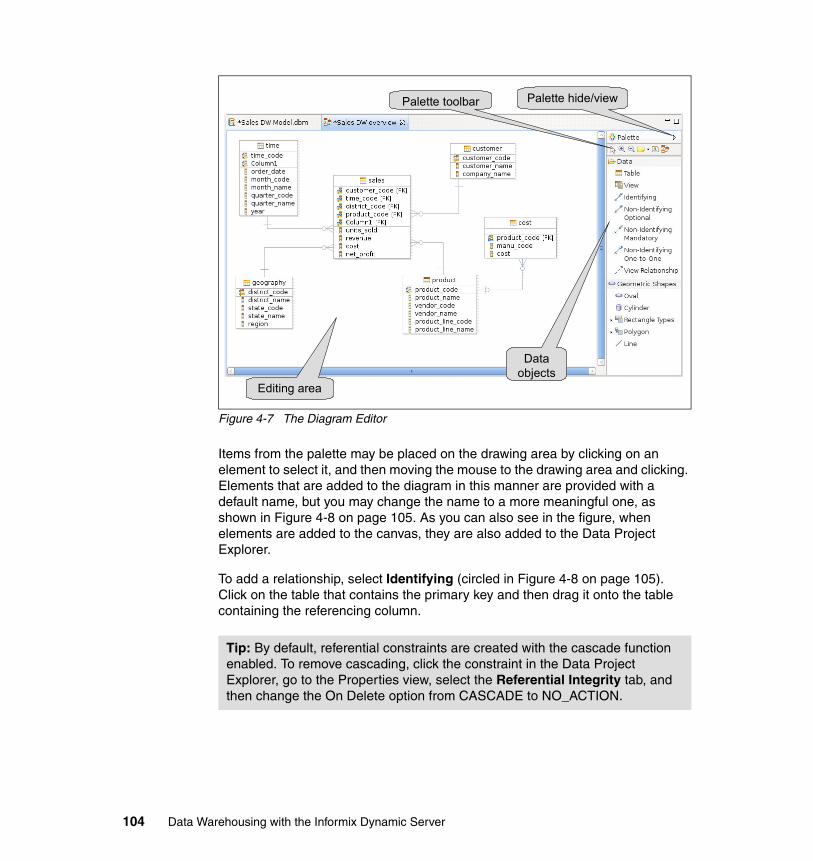
Figure 4-7 The Diagram Editor
Items from the palette may be placed on the drawing area by clicking on an element to select it, and then moving the mouse to the drawing area and clicking. Elements that are added to the diagram in this manner are provided with a default name, but you may change the name to a more meaningful one, as shown in Figure 4-8 on page 105. As you can also see in the figure, when elements are added to the canvas, they are also added to the Data Project Explorer.
To add a relationship, select Identifying (circled in Figure 4-8 on page 105). Click on the table that contains the primary key and then drag it onto the table containing the referencing column.
Tip: By default, referential constraints are created with the cascade function enabled. To remove cascading, click the constraint in the Data Project Explorer, go to the Properties view, select the Referential Integrity tab, and then change the On Delete option from CASCADE to NO_ACTION.
Palette hide/viewPalette toolbar
Data objects
Editing area
104 Data Warehousing with the Informix Dynamic Server
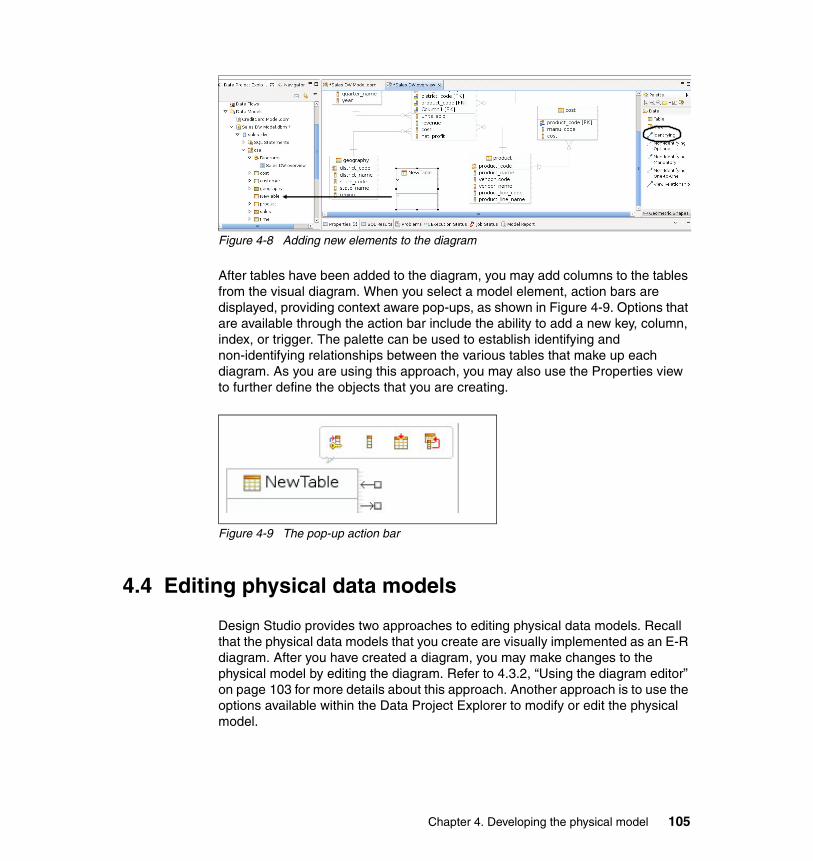
Figure 4-8 Adding new elements to the diagram
After tables have been added to the diagram, you may add columns to the tables from the visual diagram. When you select a model element, action bars are displayed, providing context aware pop-ups, as shown in Figure 4-9. Options that are available through the action bar include the ability to add a new key, column, index, or trigger. The palette can be used to establish identifying and non-identifying relationships between the various tables that make up each diagram. As you are using this approach, you may also use the Properties view to further define the objects that you are creating.
Figure 4-9 The pop-up action bar
4.4 Editing physical data models
Design Studio provides two approaches to editing physical data models. Recall that the physical data models that you create are visually implemented as an E-R diagram. After you have created a diagram, you may make changes to the physical model by editing the diagram. Refer to 4.3.2, “Using the diagram editor” on page 103 for more details about this approach. Another approach is to use the options available within the Data Project Explorer to modify or edit the physical model.
Chapter 4. Developing the physical model 105
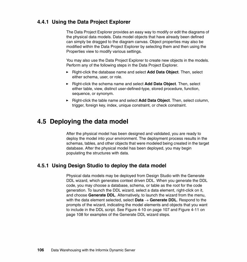
4.4.1 Using the Data Project Explorer
The Data Project Explorer provides an easy way to modify or edit the diagrams of the physical data models. Data model objects that have already been defined can simply be dragged to the diagram canvas. Object properties may also be modified within the Data Project Explorer by selecting them and then using the Properties view to modify various settings.
You may also use the Data Project Explorer to create new objects in the models. Perform any of the following steps in the Data Project Explorer.
� Right-click the database name and select Add Data Object. Then, select either schema, user, or role.
� Right-click the schema name and select Add Data Object. Then, select either table, view, distinct user-defined-type, stored procedure, function, sequence, or synonym.
� Right-click the table name and select Add Data Object. Then, select column, trigger, foreign key, index, unique constraint, or check constraint.
4.5 Deploying the data model
After the physical model has been designed and validated, you are ready to deploy the model into your environment. The deployment process results in the schemas, tables, and other objects that were modeled being created in the target database. After the physical model has been deployed, you may begin populating the structures with data.
4.5.1 Using Design Studio to deploy the data model
Physical data models may be deployed from Design Studio with the Generate DDL wizard, which generates context driven DDL. When you generate the DDL code, you may choose a database, schema, or table as the root for the code generation. To launch the DDL wizard, select a data element, right-click on it, and choose Generate DDL. Alternatively, to launch the wizard from the menu, with the data element selected, select Data → Generate DDL. Respond to the prompts of the wizard, indicating the model elements and objects that you want to include in the DDL script. See Figure 4-10 on page 107 and Figure 4-11 on page 108 for examples of the Generate DDL wizard steps.
106 Data Warehousing with the Informix Dynamic Server
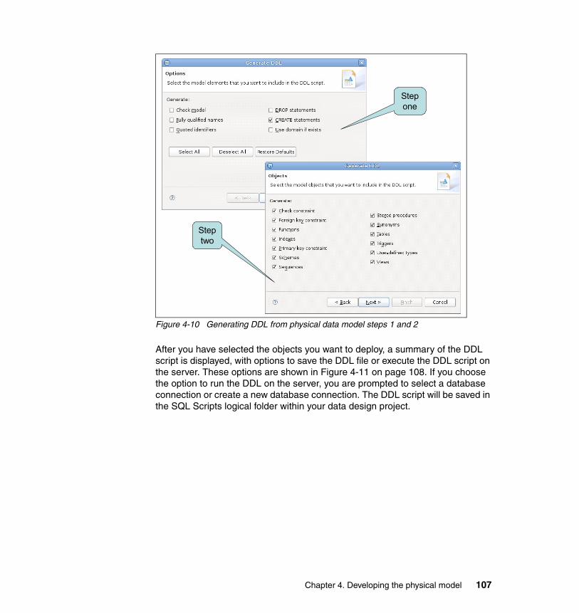
Figure 4-10 Generating DDL from physical data model steps 1 and 2
After you have selected the objects you want to deploy, a summary of the DDL script is displayed, with options to save the DDL file or execute the DDL script on the server. These options are shown in Figure 4-11 on page 108. If you choose the option to run the DDL on the server, you are prompted to select a database connection or create a new database connection. The DDL script will be saved in the SQL Scripts logical folder within your data design project.
Step one
Step two
Chapter 4. Developing the physical model 107
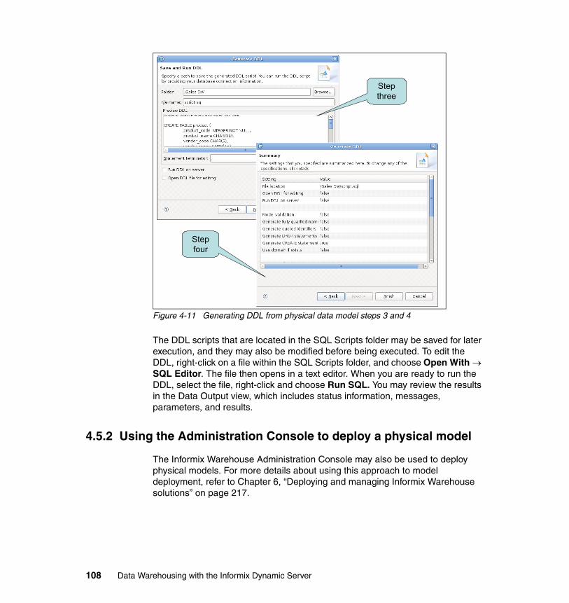
Figure 4-11 Generating DDL from physical data model steps 3 and 4
The DDL scripts that are located in the SQL Scripts folder may be saved for later execution, and they may also be modified before being executed. To edit the DDL, right-click on a file within the SQL Scripts folder, and choose Open With → SQL Editor. The file then opens in a text editor. When you are ready to run the DDL, select the file, right-click and choose Run SQL. You may review the results in the Data Output view, which includes status information, messages, parameters, and results.
4.5.2 Using the Administration Console to deploy a physical model
The Informix Warehouse Administration Console may also be used to deploy physical models. For more details about using this approach to model deployment, refer to Chapter 6, “Deploying and managing Informix Warehouse solutions” on page 217.
Step three
Step four
108 Data Warehousing with the Informix Dynamic Server
4.6 Maintaining the physical data models
Business demands and requests for reporting and analysis change over time, so the data models also have to be adapted to meet these new business requests. Design Studio can compare physical data models or compare a physical data model with an existing database. When differences are found, Design Studio can then be used to synchronize the models and analyze the impact of the changes.
4.6.1 Comparing objects within the physical data model
Design Studio provides object-based comparison and synchronization capabilities as a mechanism to assist and simplify the task of maintaining model accuracy. From the Data Project Explorer or the Data Source Explorer, you may select a database object, right-click and select Compare With → Another Data Object. You are then prompted to select the object to use for comparison. Another way to achieve the same comparison is to highlight two data objects, right-click and select Compare With → Each Other. Within the Data Project Explorer, a third comparison option is available if the source of the model was created by reverse engineering. If that is the case, then select an object, right-click and select Compare → Original Source. This option is only available from the Data Project Explorer, and not the Data Source Explorer.
These options, under the Compare With command, are helpful if you have to compare physical objects with each other, for example, to compare objects from a test database to objects in a production database. Or, perhaps you want to compare the baseline database objects from the Data Source Explorer with changed objects from your Project before deploying changes.
4.6.2 Visualizing differences between objects
The results of the object comparison are displayed in two views that are connected. The upper view is called Structural Compare. The Structural Compare shows the differences in a tree format. The first column is a tree, and each entry in the tree represents a part of the model where a difference was found. The second column in the Structural Compare output shows the first object as input to the Compare command. The third column shows the second object to which it was being compared. A copy of the differences may be saved by clicking the Export button in the upper right portion of the Structural Compare view. The file that results from this option is an XML file.
Chapter 4. Developing the physical model 109
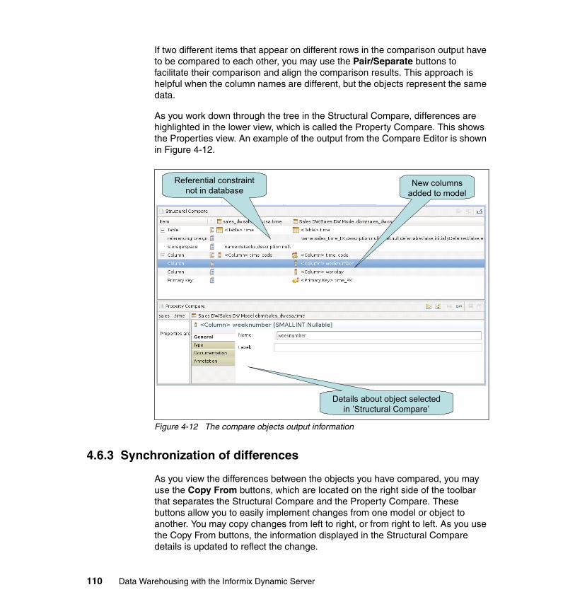
If two different items that appear on different rows in the comparison output have to be compared to each other, you may use the Pair/Separate buttons to facilitate their comparison and align the comparison results. This approach is helpful when the column names are different, but the objects represent the same data.
As you work down through the tree in the Structural Compare, differences are highlighted in the lower view, which is called the Property Compare. This shows the Properties view. An example of the output from the Compare Editor is shown in Figure 4-12.
Figure 4-12 The compare objects output information
4.6.3 Synchronization of differences
As you view the differences between the objects you have compared, you may use the Copy From buttons, which are located on the right side of the toolbar that separates the Structural Compare and the Property Compare. These buttons allow you to easily implement changes from one model or object to another. You may copy changes from left to right, or from right to left. As you use the Copy From buttons, the information displayed in the Structural Compare details is updated to reflect the change.
Referential constraint not in database
New columns added to model
Details about object selected in ’Structural Compare’
110 Data Warehousing with the Informix Dynamic Server
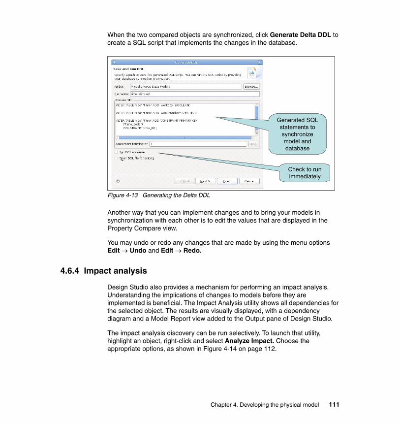
When the two compared objects are synchronized, click Generate Delta DDL to create a SQL script that implements the changes in the database.
Figure 4-13 Generating the Delta DDL
Another way that you can implement changes and to bring your models in synchronization with each other is to edit the values that are displayed in the Property Compare view.
You may undo or redo any changes that are made by using the menu options Edit → Undo and Edit → Redo.
4.6.4 Impact analysis
Design Studio also provides a mechanism for performing an impact analysis. Understanding the implications of changes to models before they are implemented is beneficial. The Impact Analysis utility shows all dependencies for the selected object. The results are visually displayed, with a dependency diagram and a Model Report view added to the Output pane of Design Studio.
The impact analysis discovery can be run selectively. To launch that utility, highlight an object, right-click and select Analyze Impact. Choose the appropriate options, as shown in Figure 4-14 on page 112.
Generated SQL statements to synchronize model and database
Check to run immediately
Chapter 4. Developing the physical model 111
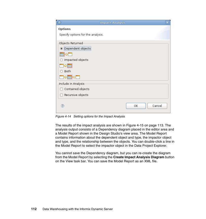
Figure 4-14 Setting options for the Impact Analysis
The results of the impact analysis are shown in Figure 4-15 on page 113. The analysis output consists of a Dependency diagram placed in the editor area and a Model Report shown in the Design Studio’s view area. The Model Report contains information about the dependent object and type, the impactor object and type, and the relationship between the objects. You can double-click a line in the Model Report to select the impactor object in the Data Project Explorer.
You cannot save the Dependency diagram, but you can re-create the diagram from the Model Report by selecting the Create Impact Analysis Diagram button on the View task bar. You can save the Model Report as an XML file.
112 Data Warehousing with the Informix Dynamic Server
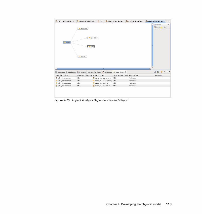
Figure 4-15 Impact Analysis Dependencies and Report
Chapter 4. Developing the physical model 113

114 Data Warehousing with the Informix Dynamic Server
Chapter 5. Data movement and transformation
Data movement is a major discipline within data warehousing projects. As an example, data is moved from production systems to the data warehouse. Then, inside the data warehouse, data is moved from high-granularity tables to summary tables. In addition, data might then be moved from the data warehouse to data marts. During or after the movement, data can undergo transformation in order to achieve high consistency across the data warehouse.
Data movement is a major discipline within data warehousing projects. For example, data must be moved from production systems to the data warehouse. But more than moved, it must be transformed to a format that is easily understood and accessed for query and analysis purposes. For example, data may be moved from high-granularity tables to summary tables. In addition, data might then be moved, or replicated, from the data warehouse to smaller data marts.
Traditionally, loading data into the data warehouse has been done with what are called extract, transform, and load (ETL) jobs. These jobs are described as data flows and subflows, which are built from other data sources, targets, and operators. Here, the data is extracted from those sources and loaded onto a server, separate from the data warehousing server. Appropriate transformations are then made, such as summarizing high-granularity data to summary tables, and then the results are loaded either directly into the data warehouse server
5
© Copyright IBM Corp. 2009. All rights reserved. 115

tables or first into staging tables. This has traditionally been done with scheduled (such as hourly, daily, or weekly) batch jobs.
But the data movement processes are now also requiring the support of a more continuous, and faster, flow of data into the data warehouse. In this process, the data is extracted, loaded directly into the data warehouse server, transformed there, and then loaded into the data warehouse tables. This process is referred to as extract, load, and transform (ELT). The SQL Warehousing Tool (SQW), which is a component of Design Studio, is used to create these ELT jobs.
In this chapter. we describe SQW and provide examples of its use.
116 Data Warehousing with the Informix Dynamic Server
5.1 SQL Warehousing Tool
In this section, we provide an overview and architecture discussion of the SQL Warehousing Tool (SQW). Understanding, at a high level, the overall purpose and intent of the SQW in the context of building the business intelligence (BI) platform is important. Here, we describe the overall function of SQW, the SQW application life cycle, the definitions of source, target and execution databases, and we show how to get started with a data warehouse project.
SQW is a graphical SQL-generation utility that is used for data warehouse maintenance and administration and one that can replace hand-coded SQL. It automatically generates IDS-specific SQL that is based on visual flows, which are modeled in Design Studio. SQW complements, rather than replaces, ETL tools by improving data warehouse administrator productivity. After data and control flows are created, execution plan graphs (EPGs) are generated and then deployed as an IBM WebSphere Application Server application. Using the Admin Console, this deployed application can then be managed. That is to say, it can be scheduled to be executed and monitored. The execution is controlled by the Data Integration Service (DIS).
5.1.1 SQW overview
One important basic function in building the BI platform is having the ability to manage and move data within the data warehouse while transforming it for various purposes. The Informix Warehouse provides this functionality for IDS data warehouses with SQW. SQW refers to the functions within the Design Studio for developing data movement and transformation flows and functions within the Informix Warehouse Runtime environment for the deployment, execution, and management of these flows.
Using SQW functions within the Design Studio, and a graphical flow editor, you develop logical flow models that represent the actions that have to apply to the data as it moves from sources to targets. These flows are called data flows. The majority of data flows will have sources and targets that represent relational tables within the data warehouse, but these sources and targets can also be flat files and remote IDS and non-IDS relational data stores.
The operators in a data flow represent a higher level abstraction model of the actions that have to be applied to the data. From this model, IDS SQL-based code is generated and organized into an execution plan called a data flow execution plan graph (EPG). This generated code is primarily IDS SQL and, at execution, is executed by the IDS database engine.
Chapter 5. Data movement and transformation 117
Typically you develop a number of data flows for a particular warehouse application which might have some types of dependencies in the order of execution such that certain flows will have to execute before other flows by using some type of processing rules. Design Studio provides a graphical editor in which you can define the order of execution of these related data flows. These flows are called control flows.
In addition to sequencing data flows, a control flow can execute other data processing functions such as operating system scripts, IDS SQL scripts, batch executables, File Transfer Protocol (FTP), the sending of e-mail notifications, and others. A control flow contains data flow and non-data flow activities such as command execution and file wait, as examples. A control flow also generates a control flow EPG where the SQW runtime engine (DIS) reads and executes the appropriate nodes based on the execution result of the predecessor activity.
SQW also provides a runtime server component that supports the deployment, execution and management of data movement and transformation flows for a runtime environment such as a test or QA system, or a production system. The user interface for the runtime environment is through a Web browser, using the Informix Warehouse Administration Console, which provides access to the functions required to manage the Informix Warehouse runtime environment, including the functions necessary to deploy, execute, and manage the SQW data movement and transformation flows.
Informix Warehouse SQW can also be used as a complementary product to an ETL tool and various IDS load tools. If the ETL tool is IBM InfoSphere DataStage (DataStage), specific integration points exist that allow the integration of a DataStage job into SQW flows. Then SQW functions will be executed by IDS and DataStage jobs will be executed by the DataStage server. Conversely, SQW data flows can be integrated into DataStage jobs and, again, the SQW functions will be executed by IDS and DataStage functions will be executed by the DataStage server.
5.1.2 SQW architecture
Informix Warehouse SQW has architectural components in both the Informix Warehouse development environment and the Informix Warehouse runtime environment.
The development components for SQW are part of the Informix Warehouse integrated development environment, the Design Studio. Chapter 3, “Informix Warehouse Client” on page 69 has an overview of the Design Studio.
As depicted in Figure 5-1 on page 119, the elements of the Design Studio for SQW consist of a data flow editor and a control flow editor. These are graphical
118 Data Warehousing with the Informix Dynamic Server
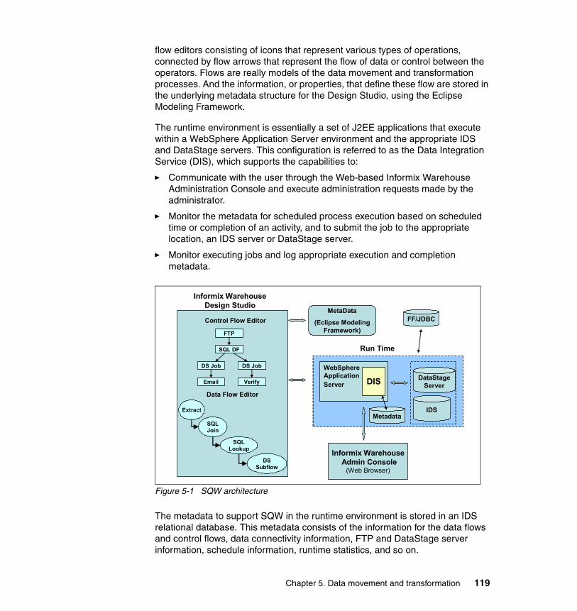
flow editors consisting of icons that represent various types of operations, connected by flow arrows that represent the flow of data or control between the operators. Flows are really models of the data movement and transformation processes. And the information, or properties, that define these flow are stored in the underlying metadata structure for the Design Studio, using the Eclipse Modeling Framework.
The runtime environment is essentially a set of J2EE applications that execute within a WebSphere Application Server environment and the appropriate IDS and DataStage servers. This configuration is referred to as the Data Integration Service (DIS), which supports the capabilities to:
� Communicate with the user through the Web-based Informix Warehouse Administration Console and execute administration requests made by the administrator.
� Monitor the metadata for scheduled process execution based on scheduled time or completion of an activity, and to submit the job to the appropriate location, an IDS server or DataStage server.
� Monitor executing jobs and log appropriate execution and completion metadata.
Figure 5-1 SQW architecture
The metadata to support SQW in the runtime environment is stored in an IDS relational database. This metadata consists of the information for the data flows and control flows, data connectivity information, FTP and DataStage server information, schedule information, runtime statistics, and so on.
Informix WarehouseDesign Studio
Control Flow Editor
Data Flow Editor
SQL Lookup
DS Subflow
FTP
SQL DF
DS Job DS Job
Email Verify
WebSphereApplicationServer DIS
Run Time
Informix WarehouseAdmin Console
(Web Browser)
DataStageServer
IDS
MetaData
(Eclipse Modeling Framework)
FF/JDBC
MetadataExtract
SQL Join
Chapter 5. Data movement and transformation 119
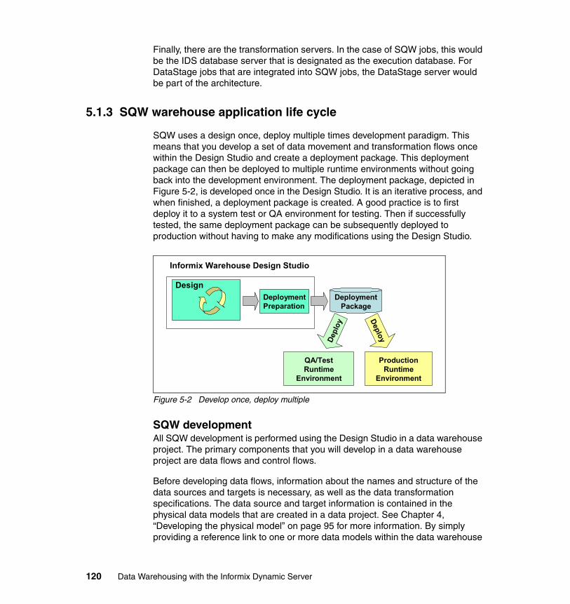
Finally, there are the transformation servers. In the case of SQW jobs, this would be the IDS database server that is designated as the execution database. For DataStage jobs that are integrated into SQW jobs, the DataStage server would be part of the architecture.
5.1.3 SQW warehouse application life cycle
SQW uses a design once, deploy multiple times development paradigm. This means that you develop a set of data movement and transformation flows once within the Design Studio and create a deployment package. This deployment package can then be deployed to multiple runtime environments without going back into the development environment. The deployment package, depicted in Figure 5-2, is developed once in the Design Studio. It is an iterative process, and when finished, a deployment package is created. A good practice is to first deploy it to a system test or QA environment for testing. Then if successfully tested, the same deployment package can be subsequently deployed to production without having to make any modifications using the Design Studio.
Figure 5-2 Develop once, deploy multiple
SQW developmentAll SQW development is performed using the Design Studio in a data warehouse project. The primary components that you will develop in a data warehouse project are data flows and control flows.
Before developing data flows, information about the names and structure of the data sources and targets is necessary, as well as the data transformation specifications. The data source and target information is contained in the physical data models that are created in a data project. See Chapter 4, “Developing the physical model” on page 95 for more information. By simply providing a reference link to one or more data models within the data warehouse
DeploymentPreparation
Design
Informix Warehouse Design Studio
DeploymentPackage
QA/TestRuntime
Environment
Depl
oy
Deploy
ProductionRuntime
Environment
120 Data Warehousing with the Informix Dynamic Server
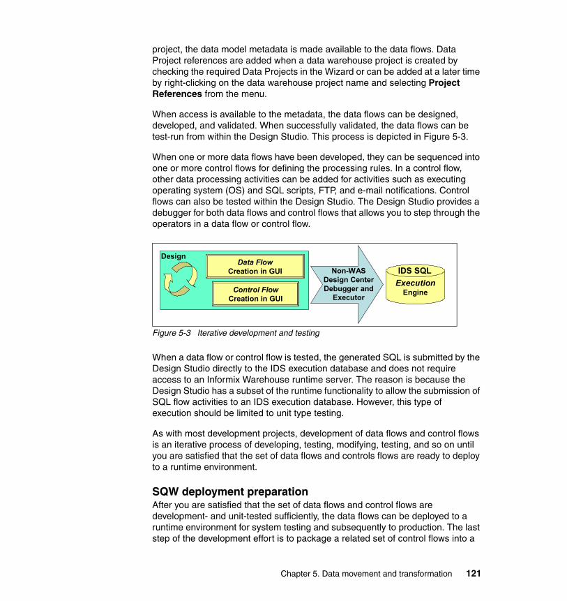
project, the data model metadata is made available to the data flows. Data Project references are added when a data warehouse project is created by checking the required Data Projects in the Wizard or can be added at a later time by right-clicking on the data warehouse project name and selecting Project References from the menu.
When access is available to the metadata, the data flows can be designed, developed, and validated. When successfully validated, the data flows can be test-run from within the Design Studio. This process is depicted in Figure 5-3.
When one or more data flows have been developed, they can be sequenced into one or more control flows for defining the processing rules. In a control flow, other data processing activities can be added for activities such as executing operating system (OS) and SQL scripts, FTP, and e-mail notifications. Control flows can also be tested within the Design Studio. The Design Studio provides a debugger for both data flows and control flows that allows you to step through the operators in a data flow or control flow.
Figure 5-3 Iterative development and testing
When a data flow or control flow is tested, the generated SQL is submitted by the Design Studio directly to the IDS execution database and does not require access to an Informix Warehouse runtime server. The reason is because the Design Studio has a subset of the runtime functionality to allow the submission of SQL flow activities to an IDS execution database. However, this type of execution should be limited to unit type testing.
As with most development projects, development of data flows and control flows is an iterative process of developing, testing, modifying, testing, and so on until you are satisfied that the set of data flows and controls flows are ready to deploy to a runtime environment.
SQW deployment preparationAfter you are satisfied that the set of data flows and control flows are development- and unit-tested sufficiently, the data flows can be deployed to a runtime environment for system testing and subsequently to production. The last step of the development effort is to package a related set of control flows into a
Data FlowCreation in GUI
Control FlowCreation in GUI
Design
ExecutionEngine
Non-WAS Design Center Debugger and
Executor
IDS SQL
Chapter 5. Data movement and transformation 121
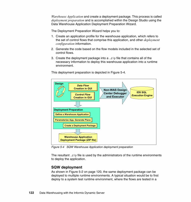
Warehouse Application and create a deployment package. This process is called deployment preparation and is accomplished within the Design Studio using the Data Warehouse Application Deployment Preparation Wizard.
The Deployment Preparation Wizard helps you to:
1. Create an application profile for the warehouse application, which refers to the set of control flows that comprise this application, and other deployment configuration information.
2. Generate the code based on the flow models included in the selected set of control flows.
3. Create the deployment package into a .zip file that contains all of the necessary information to deploy this warehouse application into a runtime environment.
This deployment preparation is depicted in Figure 5-4.
Figure 5-4 SQW Warehouse Application deployment preparation
The resultant .zip file is used by the administrators of the runtime environments to deploy the application.
SQW deploymentAs shown in Figure 5-2 on page 120, the same deployment package can be deployed to multiple runtime environments. A typical situation would be to first deploy to a system test runtime environment, where the flows are tested in a
Data FlowCreation in GUI
Control FlowCreation in GUI
Design
IDS SQL Execution Engine
Warehouse Application Deployment Package (ZIP file)
Non-WAS Design Center Debugger
and Executor
Deployment Preparation
Create a Deployment Package
Parameterize App, Generate Plans
Define a Warehouse Application
122 Data Warehousing with the Informix Dynamic Server
simulated production environment before being deployed to a production runtime environment.
Deployment to a particular runtime environment is done by the administrator of the runtime environment using the Web-based Informix Warehouse Administration Console. The administrator must have access to the deployment .zip file either on the Informix Warehouse Application Server or on the local system.
The deployment process consists of using the Informix Warehouse Administration Console to:
1. Configure the runtime environment and create the appropriate database connectivity definition.
2. Install the warehouse application into the runtime environment, using the deployment .zip file.
3. Develop process schedules for the execution of the warehouse application processes.
In the remainder of this chapter, we focus on the development and deployment preparation functions within the Design Studio.
5.1.4 Source, target, and execution databases
Before going further, an important definition to understand is for the term execution database and the relationship to source and target databases. The execution database is the database that does the transformation work when the SQL code in a data warehouse application runs. This database must be an IDS database.
The execution database name is a primary property of a data flow and all SQL code for that data flow will be run at the execution database. Different data flows can have different execution databases; the data flow SQL code will be submitted to the execution database defined in the data flow properties. An example is if you have to move data from a warehouse database to a distributed data mart. Part of the processing can happen at the data warehouse database and part of it might happen at the distributed data mart database.
The notion of a remote or local database source or target is relative to the execution database where the SQL code is submitted. If the source or target database is the same database as the execution database, then they are local databases. Only IDS databases can be local databases. When the target or source database is different from the execution database, they are remote databases. A remote database is accessed by the Java Database Connectivity (JDBC) interface standard and may be a relational database that is not IDS.
Chapter 5. Data movement and transformation 123
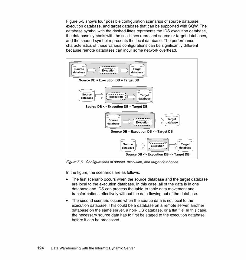
Figure 5-5 shows four possible configuration scenarios of source database, execution database, and target database that can be supported with SQW. The database symbol with the dashed-lines represents the IDS execution database, the database symbols with the solid lines represent source or target databases, and the shaded symbol represents the local database. The performance characteristics of these various configurations can be significantly different because remote databases can incur some network overhead.
Figure 5-5 Configurations of source, execution, and target databases
In the figure, the scenarios are as follows:
� The first scenario occurs when the source database and the target database are local to the execution database. In this case, all of the data is in one database and IDS can process the table-to-table data movement and transformations effectively without the data flowing out of the database.
� The second scenario occurs when the source data is not local to the execution database. This could be a database on a remote server, another database on the same server, a non-IDS database, or a flat file. In this case, the necessary source data has to first be staged to the execution database before it can be processed.
Execution Targetdatabase
Sourcedatabase
Source DB = Execution DB = Target DB
Source DB = Execution DB <> Target DB
Source DB <> Execution DB = Target DB
Source DB <> Execution DB <> Target DB
Execution Targetdatabase
Sourcedatabase
ExecutionSource
databaseTarget
database
Sourcedatabase
TargetdatabaseExecution
124 Data Warehousing with the Informix Dynamic Server
� The third scenario occurs when the target is not local to the execution database. This could be a database on a remote system, another database on the same server, or a non-IDS database. In this case, the data has to flow out of the execution database to the external target using remote inserts.
� The fourth scenario occurs when both the source data and then eventual target are not local to the IDS database. The source data has to be staged to the execution database for processing and then sent to the remote target for updating.
Although all of these scenarios are supported by SQW, the most effective performance will be gained by co-locating the target and execution database as shown in the first two scenarios.
5.1.5 Setting up a data warehouse project
The development of data flows and control flows take place within the Design Studio and are organized into data warehouse projects, which are containers for the metadata artifacts that represent the flows. In addition to data flows and control flows, there are also folders in the data warehouse project for other artifacts that support the development effort such as subflows, SQL scripts, application profiles, and resource profiles. Figure 5-6 shows a data warehouse project folder structure. The data warehouse project folder is accessed from the Data Project Explorer tab of the Design Studio.
Chapter 5. Data movement and transformation 125
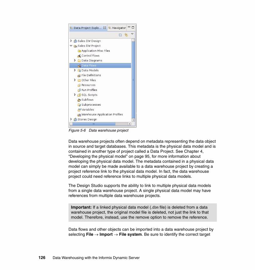
Figure 5-6 Data warehouse project
Data warehouse projects often depend on metadata representing the data object in source and target databases. This metadata is the physical data model and is contained in another type of project called a Data Project. See Chapter 4, “Developing the physical model” on page 95, for more information about developing the physical data model. The metadata contained in a physical data model can simply be made available to a data warehouse project by creating a project reference link to the physical data model. In fact, the data warehouse project could need reference links to multiple physical data models.
The Design Studio supports the ability to link to multiple physical data models from a single data warehouse project. A single physical data model may have references from multiple data warehouse projects.
Data flows and other objects can be imported into a data warehouse project by selecting File → Import → File system. Be sure to identify the correct target
Important: If a linked physical data model (.dbm file) is deleted from a data warehouse project, the original model file is deleted, not just the link to that model. Therefore, instead, use the remove option to remove the reference.
126 Data Warehousing with the Informix Dynamic Server
folder type for the object being imported. For example, make sure to import data flows into the data flows folder in the data warehouse project.
5.2 Data flows
In this section, we discuss in more detail the process of developing SQW data flows using the Design Studio. We discuss the data flow operators, flow validation, code generation, testing and debugging. For further information about this topic, refer to the IBM Informix Dynamic Server v11.50 Information Center:
http://publib.boulder.ibm.com/infocenter/idshelp/v115/index.jsp
5.2.1 Defining a data flow
Data flows model the SQL-based data movement and transformation activities that execute in the IDS database. A data flow consists of activities that extract data from flat files or relational tables, transform the data and load it into a relational table in a data warehouse, data mart, or staging area. Data can also be exported to flat files.
The Design Studio provides a graphical editor with an intuitive way to visualize and design data flows. Graphical operators model the various steps of a data flow activity. By arranging these source, transform, and target operators in a canvas work area, connecting them, and then defining their properties, models can be created that meet business requirements. After creating data flows, you generate the SQL code that creates the specific SQL operations, which are performed by the execution database when you run a data warehouse application.
Figure 5-7 shows a simple data flow that selects data from IDS items, orders, and customer tables, joins the tables and selects required columns, replaces natural keys with dimensional keys and finally inserts the rows into the sales fact table. A data flow consists of operators, ports and connectors.
Note: The actual development of data flows and control flows do not require a live connection to a database. But, a live connection to a relational database is required to test a data flow or control flow. You may also want a live connection in the Data Source Explorer to view or manipulate physical objects in the database or to sample data contents.
Chapter 5. Data movement and transformation 127
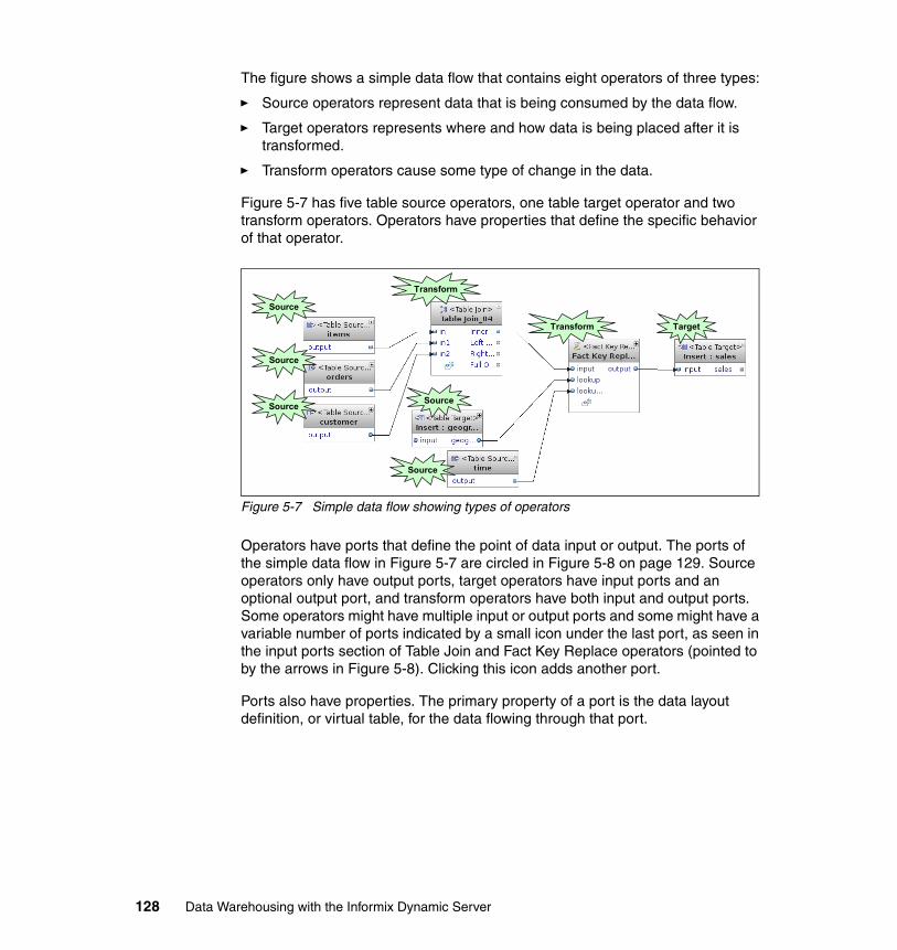
The figure shows a simple data flow that contains eight operators of three types:
� Source operators represent data that is being consumed by the data flow.
� Target operators represents where and how data is being placed after it is transformed.
� Transform operators cause some type of change in the data.
Figure 5-7 has five table source operators, one table target operator and two transform operators. Operators have properties that define the specific behavior of that operator.
Figure 5-7 Simple data flow showing types of operators
Operators have ports that define the point of data input or output. The ports of the simple data flow in Figure 5-7 are circled in Figure 5-8 on page 129. Source operators only have output ports, target operators have input ports and an optional output port, and transform operators have both input and output ports. Some operators might have multiple input or output ports and some might have a variable number of ports indicated by a small icon under the last port, as seen in the input ports section of Table Join and Fact Key Replace operators (pointed to by the arrows in Figure 5-8). Clicking this icon adds another port.
Ports also have properties. The primary property of a port is the data layout definition, or virtual table, for the data flowing through that port.
Source
Source
Source
Target
Transform
Transform
Source
Source
128 Data Warehousing with the Informix Dynamic Server
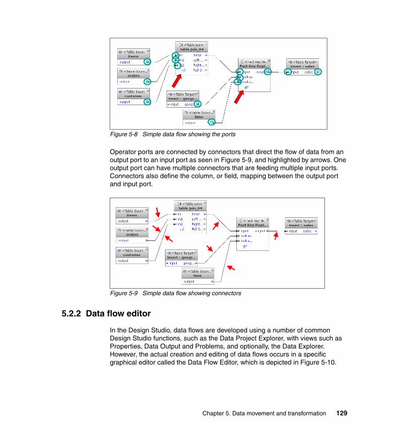
Figure 5-8 Simple data flow showing the ports
Operator ports are connected by connectors that direct the flow of data from an output port to an input port as seen in Figure 5-9, and highlighted by arrows. One output port can have multiple connectors that are feeding multiple input ports. Connectors also define the column, or field, mapping between the output port and input port.
Figure 5-9 Simple data flow showing connectors
5.2.2 Data flow editor
In the Design Studio, data flows are developed using a number of common Design Studio functions, such as the Data Project Explorer, with views such as Properties, Data Output and Problems, and optionally, the Data Explorer. However, the actual creation and editing of data flows occurs in a specific graphical editor called the Data Flow Editor, which is depicted in Figure 5-10.
IO
I
I
I I O
O
OO
O
O
I
I
Chapter 5. Data movement and transformation 129
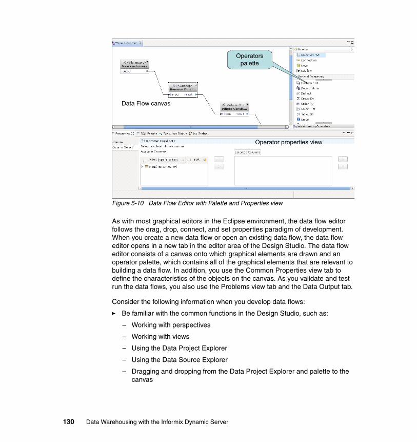
Figure 5-10 Data Flow Editor with Palette and Properties view
As with most graphical editors in the Eclipse environment, the data flow editor follows the drag, drop, connect, and set properties paradigm of development. When you create a new data flow or open an existing data flow, the data flow editor opens in a new tab in the editor area of the Design Studio. The data flow editor consists of a canvas onto which graphical elements are drawn and an operator palette, which contains all of the graphical elements that are relevant to building a data flow. In addition, you use the Common Properties view tab to define the characteristics of the objects on the canvas. As you validate and test run the data flows, you also use the Problems view tab and the Data Output tab.
Consider the following information when you develop data flows:
� Be familiar with the common functions in the Design Studio, such as:
– Working with perspectives
– Working with views
– Using the Data Project Explorer
– Using the Data Source Explorer
– Dragging and dropping from the Data Project Explorer and palette to the canvas
Data Flow canvas
Operators palette
Operator properties view
130 Data Warehousing with the Informix Dynamic Server
� Orient the data flow from left to right. This orientation enables a more organized diagram because the output ports are on the right side of an operator and the input ports are on the left side.
� Work with only a few operators at a time.
� Define the properties of the operators.
� Divide larger data flows into smaller subflows. A subflow can be reused in other data flows.
� Operator input and output ports have properties that might have to be manually defined or modified. The properties of these ports are the schemas (column definitions) of the data that flows between the operators. These schemas might have to be managed as the flow progresses.
� A data flow itself has properties with the execution database. Where this data flow executes, is the most important.
5.2.3 Data flow operators
Data flow operators represent the source, transform, and target steps in a data flow. Operators, which are graphical objects that you can select from a palette and drop in the canvas work area, form the nodes in a data flow diagram. Each type of operator has a specific set of input and output data ports, one or more lists of data columns, and a number of properties that define exactly how each operator moves or transforms data.
The three categories of data flow operators are:
� Source operators that cause data to be brought into the data flow from a persistent source, typically a relational table.
� Target operators that causes data processed in the data flow to be persistent, typically in a relational table.
� Transform operators perform some type of action on the data as it moves from source to target.
Operators can be expanded or collapsed to show more or less detail, as seen in Figure 5-11. The two operators have been expanded and you can now see the data layout properties for each port and how the individual columns of the virtual tables map between the output port and the input port.
Chapter 5. Data movement and transformation 131
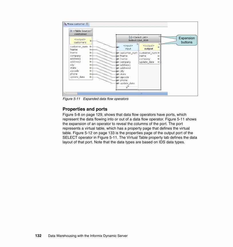
Figure 5-11 Expanded data flow operators
Properties and portsFigure 5-8 on page 129, shows that data flow operators have ports, which represent the data flowing into or out of a data flow operator. Figure 5-11 shows the expansion of an operator to reveal the columns of the port. The port represents a virtual table, which has a property page that defines the virtual table. Figure 5-12 on page 133 is the properties page of the output port of the SELECT operator in Figure 5-11. The Virtual Table property tab defines the data layout of that port. Note that the data types are based on IDS data types.
Expansion buttons
Expansion buttons
132 Data Warehousing with the Informix Dynamic Server
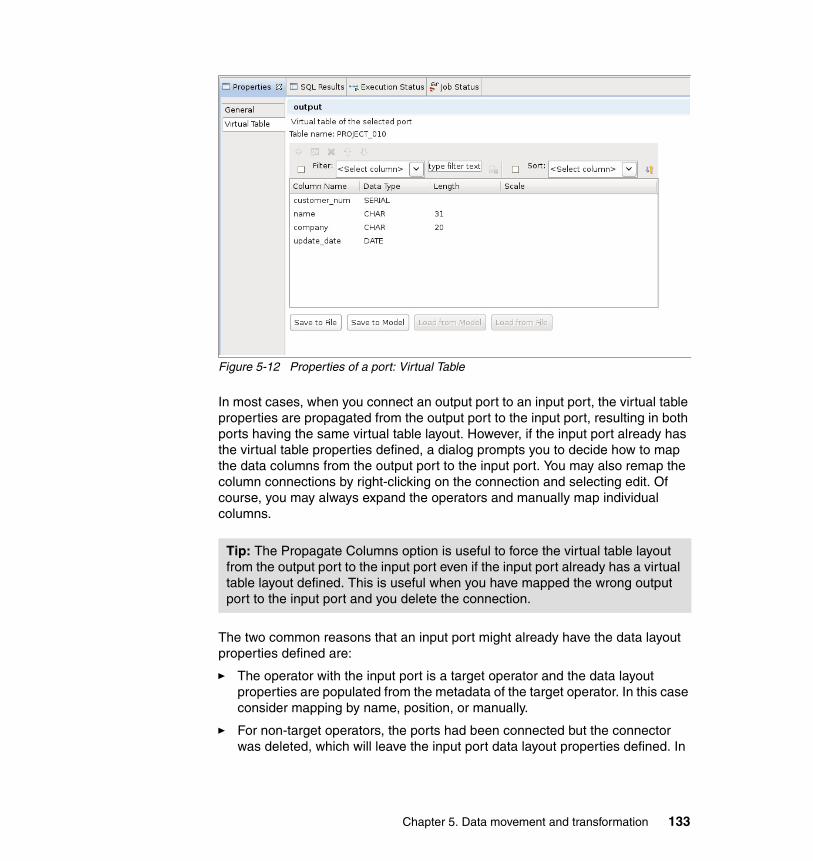
Figure 5-12 Properties of a port: Virtual Table
In most cases, when you connect an output port to an input port, the virtual table properties are propagated from the output port to the input port, resulting in both ports having the same virtual table layout. However, if the input port already has the virtual table properties defined, a dialog prompts you to decide how to map the data columns from the output port to the input port. You may also remap the column connections by right-clicking on the connection and selecting edit. Of course, you may always expand the operators and manually map individual columns.
The two common reasons that an input port might already have the data layout properties defined are:
� The operator with the input port is a target operator and the data layout properties are populated from the metadata of the target operator. In this case consider mapping by name, position, or manually.
� For non-target operators, the ports had been connected but the connector was deleted, which will leave the input port data layout properties defined. In
Tip: The Propagate Columns option is useful to force the virtual table layout from the output port to the input port even if the input port already has a virtual table layout defined. This is useful when you have mapped the wrong output port to the input port and you delete the connection.
Chapter 5. Data movement and transformation 133
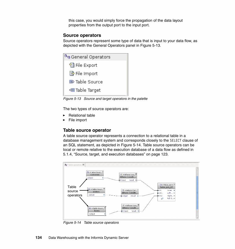
this case, you would simply force the propagation of the data layout properties from the output port to the input port.
Source operatorsSource operators represent some type of data that is input to your data flow, as depicted with the General Operators panel in Figure 5-13.
Figure 5-13 Source and target operators in the palette
The two types of source operators are:
� Relational table� File import
Table source operatorA table source operator represents a connection to a relational table in a database management system and corresponds closely to the SELECT clause of an SQL statement, as depicted in Figure 5-14. Table source operators can be local or remote relative to the execution database of a data flow as defined in 5.1.4, “Source, target, and execution databases” on page 123.
Figure 5-14 Table source operators
Table source operators
134 Data Warehousing with the Informix Dynamic Server
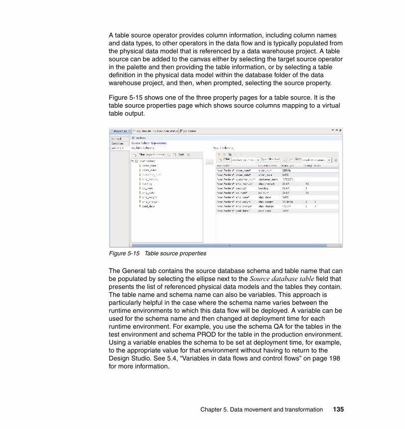
A table source operator provides column information, including column names and data types, to other operators in the data flow and is typically populated from the physical data model that is referenced by a data warehouse project. A table source can be added to the canvas either by selecting the target source operator in the palette and then providing the table information, or by selecting a table definition in the physical data model within the database folder of the data warehouse project, and then, when prompted, selecting the source property.
Figure 5-15 shows one of the three property pages for a table source. It is the table source properties page which shows source columns mapping to a virtual table output.
Figure 5-15 Table source properties
The General tab contains the source database schema and table name that can be populated by selecting the ellipse next to the Source database table field that presents the list of referenced physical data models and the tables they contain. The table name and schema name can also be variables. This approach is particularly helpful in the case where the schema name varies between the runtime environments to which this data flow will be deployed. A variable can be used for the schema name and then changed at deployment time for each runtime environment. For example, you use the schema QA for the tables in the test environment and schema PROD for the table in the production environment. Using a variable enables the schema to be set at deployment time, for example, to the appropriate value for that environment without having to return to the Design Studio. See 5.4, “Variables in data flows and control flows” on page 198 for more information.
Chapter 5. Data movement and transformation 135
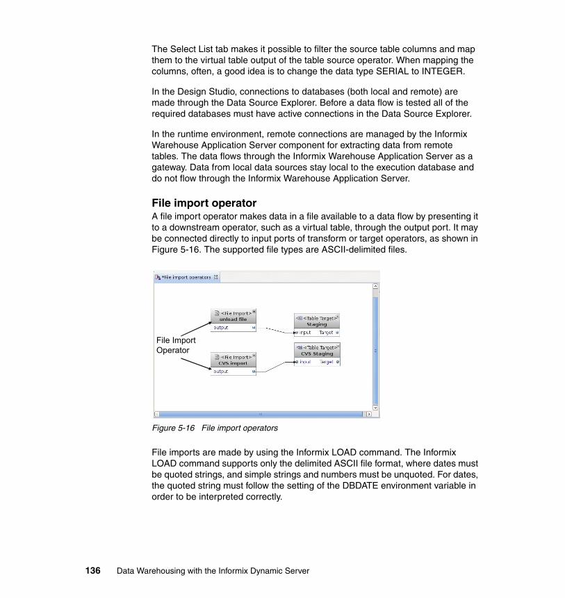
The Select List tab makes it possible to filter the source table columns and map them to the virtual table output of the table source operator. When mapping the columns, often, a good idea is to change the data type SERIAL to INTEGER.
In the Design Studio, connections to databases (both local and remote) are made through the Data Source Explorer. Before a data flow is tested all of the required databases must have active connections in the Data Source Explorer.
In the runtime environment, remote connections are managed by the Informix Warehouse Application Server component for extracting data from remote tables. The data flows through the Informix Warehouse Application Server as a gateway. Data from local data sources stay local to the execution database and do not flow through the Informix Warehouse Application Server.
File import operatorA file import operator makes data in a file available to a data flow by presenting it to a downstream operator, such as a virtual table, through the output port. It may be connected directly to input ports of transform or target operators, as shown in Figure 5-16. The supported file types are ASCII-delimited files.
Figure 5-16 File import operators
File imports are made by using the Informix LOAD command. The Informix LOAD command supports only the delimited ASCII file format, where dates must be quoted strings, and simple strings and numbers must be unquoted. For dates, the quoted string must follow the setting of the DBDATE environment variable in order to be interpreted correctly.
File Import Operator
136 Data Warehousing with the Informix Dynamic Server
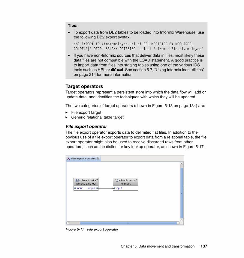
Target operatorsTarget operators represent a persistent store into which the data flow will add or update data, and identifies the techniques with which they will be updated.
The two categories of target operators (shown in Figure 5-13 on page 134) are:
� File export target� Generic relational table target
File export operatorThe file export operator exports data to delimited flat files. In addition to the obvious use of a file export operator to export data from a relational table, the file export operator might also be used to receive discarded rows from other operators, such as the distinct or key lookup operator, as shown in Figure 5-17.
Figure 5-17 File export operator
Tips:
� To export data from DB2 tables to be loaded into Informix Warehouse, use the following DB2 export syntax:
db2 EXPORT TO /tmp/employee.unl of DEL MODIFIED BY NOCHARDEL COLDEL'|' DECPLUSBLANK DATESISO "select * from db2inst1.employee"
� If you have non-Informix sources that deliver data in files, most likely these data files are not compatible with the LOAD statement. A good practice is to import data from files into staging tables using one of the various IDS tools such as HPL or dbload. See section 5.7, “Using Informix load utilities” on page 214 for more information.
Chapter 5. Data movement and transformation 137
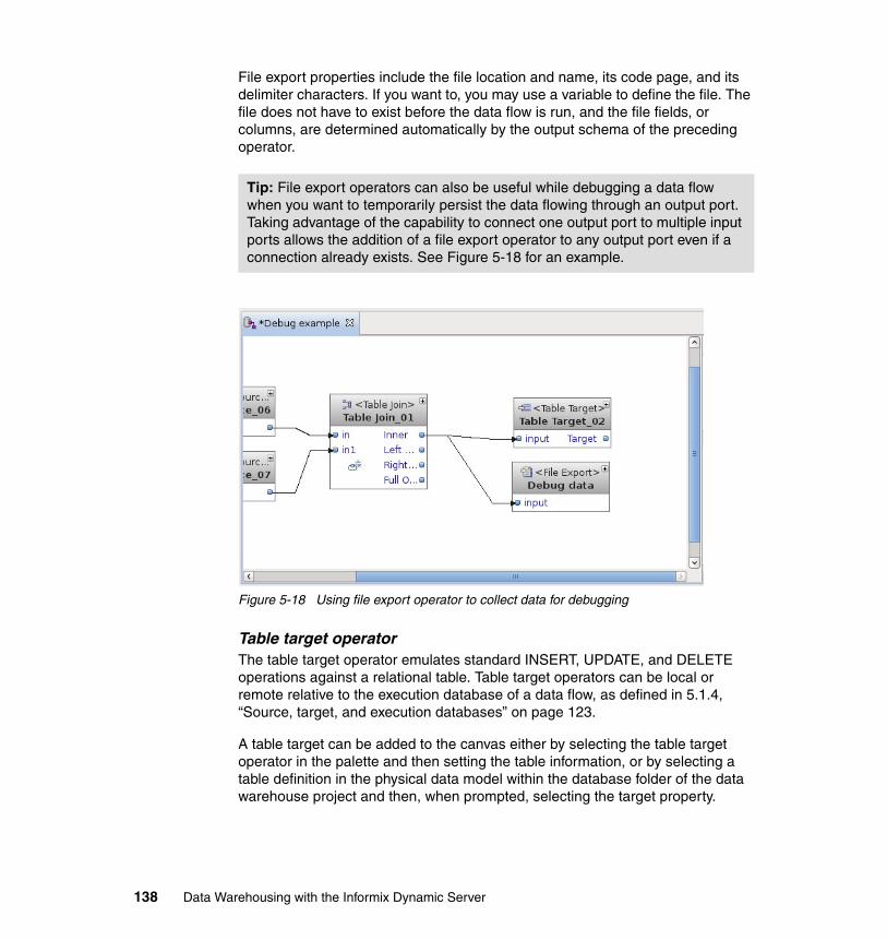
File export properties include the file location and name, its code page, and its delimiter characters. If you want to, you may use a variable to define the file. The file does not have to exist before the data flow is run, and the file fields, or columns, are determined automatically by the output schema of the preceding operator.
Figure 5-18 Using file export operator to collect data for debugging
Table target operatorThe table target operator emulates standard INSERT, UPDATE, and DELETE operations against a relational table. Table target operators can be local or remote relative to the execution database of a data flow, as defined in 5.1.4, “Source, target, and execution databases” on page 123.
A table target can be added to the canvas either by selecting the table target operator in the palette and then setting the table information, or by selecting a table definition in the physical data model within the database folder of the data warehouse project and then, when prompted, selecting the target property.
Tip: File export operators can also be useful while debugging a data flow when you want to temporarily persist the data flowing through an output port. Taking advantage of the capability to connect one output port to multiple input ports allows the addition of a file export operator to any output port even if a connection already exists. See Figure 5-18 for an example.
138 Data Warehousing with the Informix Dynamic Server
In the Design Studio, connections to databases (both local and remote) are made through the Data Source Explorer. Before a data flow is tested, all required databases must have active connections in the Data Source Explorer.
In the runtime environment, remote connections are managed by the Informix Warehouse Application Server component for sending data to remote tables; the data flows through the Informix Warehouse Application Server as a gateway. Data from local data sources stay local to the execution database and does not flow through the Informix Warehouse Application Server.
Target table operators provide three ways to update the data in a target table:
� INSERT: Adds rows from the input data set to the target table without any changes to existing rows.
� UPDATE: Matches rows from the input data set with those in the target table. If the match is found, the row is updated; if no match exists, no action is taken.
� DELETE: Checks the target table for rows that meet a specified condition and deletes those rows.
The target table operator also has an output port named ‘Target’ as shown in Figure 5-18 on page 138. Optionally, you can connect the output port to a transform operator or another target operator in the data flow. The output port contains data that is modified by the operations in the target table.
Transform operatorsTransform operators represent some type of transformation action taken against the data flowing into the operator. As shown in Figure 5-19 on page 140, two categories of data flow transform operators are available in the data flow editor palette:
� General Operators represent typical SQL-based types of data movement and transformation functions.
� Warehousing Operators represent typical functions to manipulate and analyze the data flowing through a data flow.
Chapter 5. Data movement and transformation 139
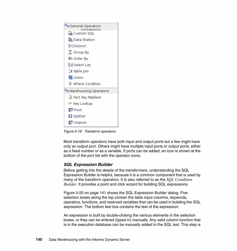
Figure 5-19 Transform operators
Most transform operators have both input and output ports but a few might have only an output port. Others might have multiple input ports or output ports, either as a fixed number or as a variable. If ports can be added, an icon is shown at the bottom of the port list with the operator icons.
SQL Expression BuilderBefore getting into the details of the transformers, understanding the SQL Expression Builder is helpful, because it is a common component that is used by many of the transform operators. It is also referred to as the SQL Condition Builder. It provides a point and click wizard for building SQL expressions.
Figure 5-20 on page 141 shows the SQL Expression Builder dialog. Five selection boxes along the top contain the table input columns, keywords, operators, functions, and reserved variables that can be used in building the SQL expression. The bottom text box contains the text of the expression.
An expression is built by double-clicking the various elements in the selection boxes, or they can be entered (typed in) manually. Any valid column function that is in the execution database can be manually added to the SQL text. This step is
140 Data Warehousing with the Informix Dynamic Server
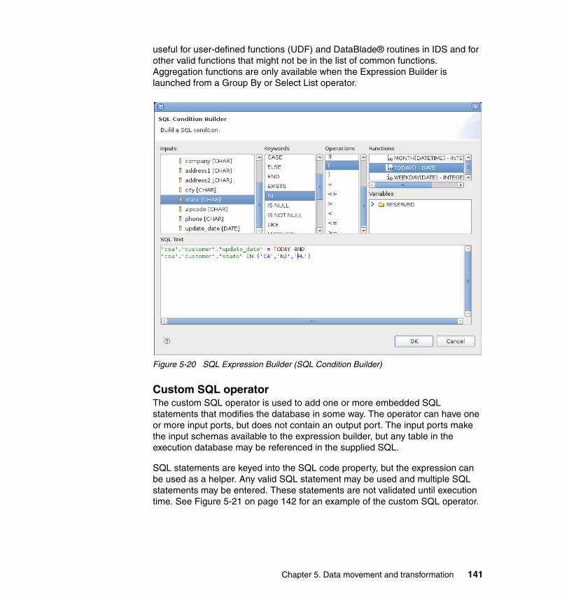
useful for user-defined functions (UDF) and DataBlade® routines in IDS and for other valid functions that might not be in the list of common functions. Aggregation functions are only available when the Expression Builder is launched from a Group By or Select List operator.
Figure 5-20 SQL Expression Builder (SQL Condition Builder)
Custom SQL operatorThe custom SQL operator is used to add one or more embedded SQL statements that modifies the database in some way. The operator can have one or more input ports, but does not contain an output port. The input ports make the input schemas available to the expression builder, but any table in the execution database may be referenced in the supplied SQL.
SQL statements are keyed into the SQL code property, but the expression can be used as a helper. Any valid SQL statement may be used and multiple SQL statements may be entered. These statements are not validated until execution time. See Figure 5-21 on page 142 for an example of the custom SQL operator.
Chapter 5. Data movement and transformation 141
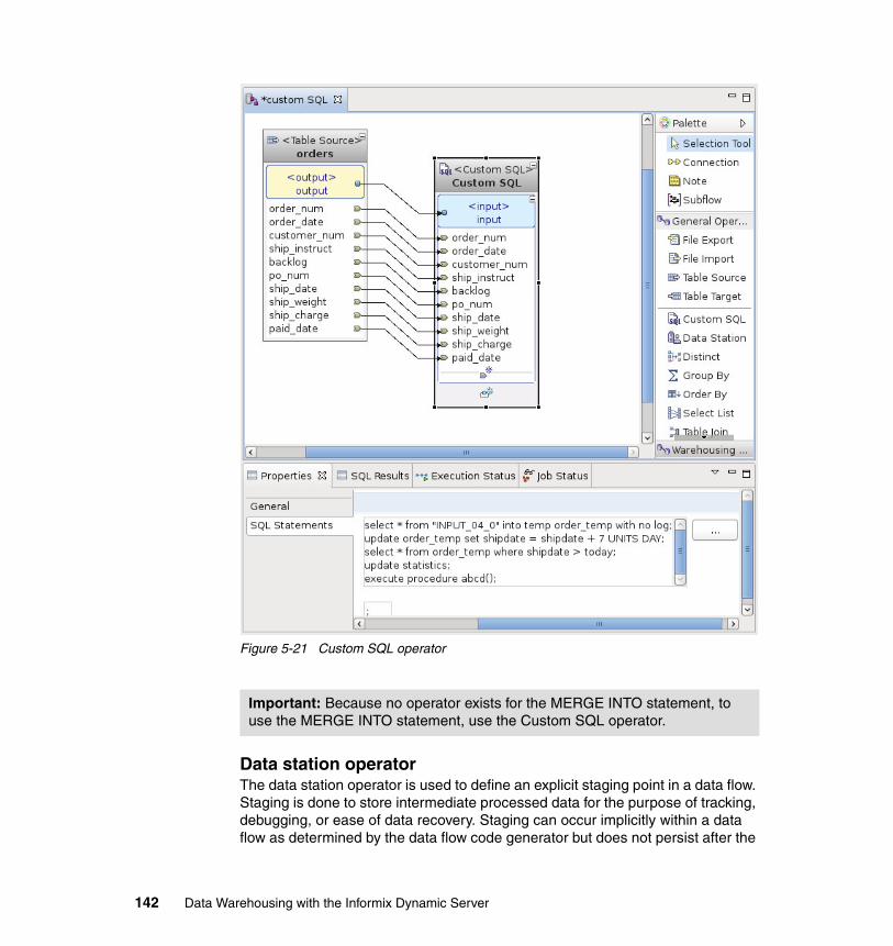
Figure 5-21 Custom SQL operator
Data station operatorThe data station operator is used to define an explicit staging point in a data flow. Staging is done to store intermediate processed data for the purpose of tracking, debugging, or ease of data recovery. Staging can occur implicitly within a data flow as determined by the data flow code generator but does not persist after the
Important: Because no operator exists for the MERGE INTO statement, to use the MERGE INTO statement, use the Custom SQL operator.
142 Data Warehousing with the Informix Dynamic Server
data flow execution. However, you might want to have data put into a persistent store at various points during processing, perhaps as logical recovery points. The data station operator enables you to define when to put the data into a persistent store.
A number of reasons exist to persist intermediate data. For example, during development, you might want to view the data after a certain operation to ensure that the processing was done correctly. So, you can add a data station in the middle of a data flow for debugging purposes. You also might have to keep track of the data at certain points in the processing for audit purposes or perhaps to provide a recovery point. A data station can be added at the appropriate points in the data flow.
The four storage types for data stations are:
� A persistent table stores data in a permanent relational table existing in the data model. You can optionally specify to delete all data from the table after the data flow has executed.
� A temporary table stores the data in a temporary table object (regular table) during the data flow, but the data does not persist after the execution of the data flow.
� A view is useful to influence code generation to not implicitly persist data.
� A flat file persists the data to a flat file, which can be useful in scenarios where you want to use a bulk loader to load data from a flat file. One flat file data station operator can be used instead of a file export target and a file import source.
The exact properties of the data station depends on the storage type, but basically provides the name of the object. A persistent table must already exist in the physical data mode. The names of temporary tables and views must be
Note: You should not confuse the Informix temporary tables that are created by the Informix database during run time with those created by the data station operator of type temporary table. In the Design Studio, the code generator makes use of Informix temporary tables during run time, as much as Informix permits. This is done to achieve better runtime performance of the data flow. Further, the temporary table (the default name is TEMP1) that is created by the data station operator, of type temporary table, does not necessarily mean that it is an Informix temporary table. The temporary table could be a persistent table. But the table is still a temporary object, which means that this staging object (either a global temporary table, or a persistent table), will be dropped at the end of the data flow execution. In other words, the temporary table concept in data station is really from a data flow perspective, and not from a database object perspective.
Chapter 5. Data movement and transformation 143
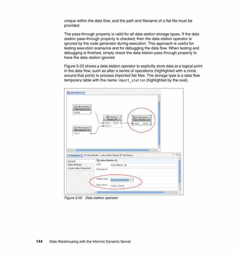
unique within the data flow, and the path and filename of a flat file must be provided.
The pass-through property is valid for all data station storage types. If the data station pass-through property is checked, then the data station operator is ignored by the code generator during execution. This approach is useful for testing execution scenarios and for debugging the data flow. When testing and debugging is finished, simply check the data station pass through property to have the data station ignored.
Figure 5-22 shows a data station operator to explicitly store data at a logical point in the data flow, such as after a series of operations (highlighted with a circle around that point) to process imported flat files. The storage type is a data flow temporary table with the name import_station (highlighted by the oval).
Figure 5-22 Data station operator
144 Data Warehousing with the Informix Dynamic Server
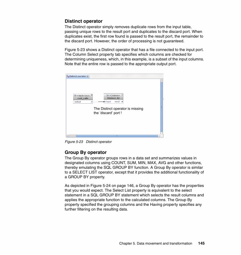
Distinct operatorThe Distinct operator simply removes duplicate rows from the input table, passing unique rows to the result port and duplicates to the discard port. When duplicates exist, the first row found is passed to the result port, the remainder to the discard port. However, the order of processing is not guaranteed.
Figure 5-23 shows a Distinct operator that has a file connected to the input port. The Column Select property tab specifies which columns are checked for determining uniqueness, which, in this example, is a subset of the input columns. Note that the entire row is passed to the appropriate output port.
Figure 5-23 Distinct operator
Group By operatorThe Group By operator groups rows in a data set and summarizes values in designated columns using COUNT, SUM, MIN, MAX, AVG and other functions, thereby emulating the SQL GROUP BY function. A Group By operator is similar to a SELECT LIST operator, except that it provides the additional functionality of a GROUP BY property.
As depicted in Figure 5-24 on page 146, a Group By operator has the properties that you would expect. The Select List property is equivalent to the select statement in a SQL GROUP BY statement which selects the result columns and applies the appropriate function to the calculated columns. The Group By property specified the grouping columns and the Having property specifies any further filtering on the resulting data.
The Distinct operator is missing the ’discard’ port !
Chapter 5. Data movement and transformation 145
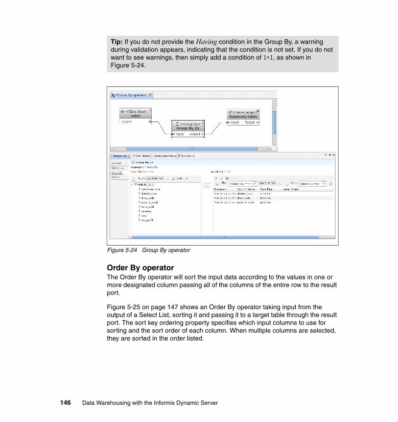
Figure 5-24 Group By operator
Order By operatorThe Order By operator will sort the input data according to the values in one or more designated column passing all of the columns of the entire row to the result port.
Figure 5-25 on page 147 shows an Order By operator taking input from the output of a Select List, sorting it and passing it to a target table through the result port. The sort key ordering property specifies which input columns to use for sorting and the sort order of each column. When multiple columns are selected, they are sorted in the order listed.
Tip: If you do not provide the Having condition in the Group By, a warning during validation appears, indicating that the condition is not set. If you do not want to see warnings, then simply add a condition of 1=1, as shown in Figure 5-24.
146 Data Warehousing with the Informix Dynamic Server
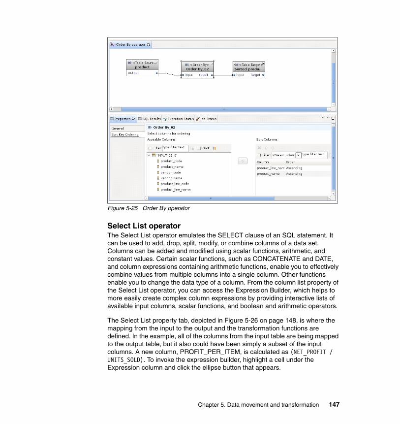
Figure 5-25 Order By operator
Select List operatorThe Select List operator emulates the SELECT clause of an SQL statement. It can be used to add, drop, split, modify, or combine columns of a data set. Columns can be added and modified using scalar functions, arithmetic, and constant values. Certain scalar functions, such as CONCATENATE and DATE, and column expressions containing arithmetic functions, enable you to effectively combine values from multiple columns into a single column. Other functions enable you to change the data type of a column. From the column list property of the Select List operator, you can access the Expression Builder, which helps to more easily create complex column expressions by providing interactive lists of available input columns, scalar functions, and boolean and arithmetic operators.
The Select List property tab, depicted in Figure 5-26 on page 148, is where the mapping from the input to the output and the transformation functions are defined. In the example, all of the columns from the input table are being mapped to the output table, but it also could have been simply a subset of the input columns. A new column, PROFIT_PER_ITEM, is calculated as (NET_PROFIT / UNITS_SOLD). To invoke the expression builder, highlight a cell under the Expression column and click the ellipse button that appears.
Chapter 5. Data movement and transformation 147
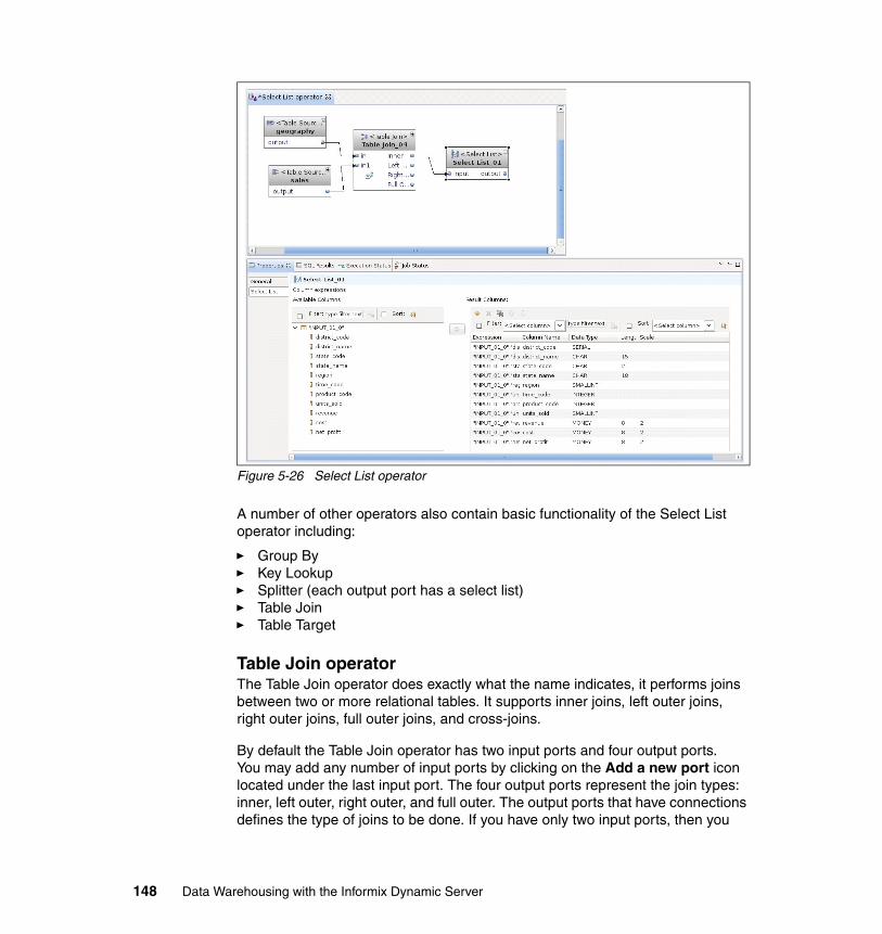
Figure 5-26 Select List operator
A number of other operators also contain basic functionality of the Select List operator including:
� Group By � Key Lookup � Splitter (each output port has a select list) � Table Join � Table Target
Table Join operatorThe Table Join operator does exactly what the name indicates, it performs joins between two or more relational tables. It supports inner joins, left outer joins, right outer joins, full outer joins, and cross-joins.
By default the Table Join operator has two input ports and four output ports. You may add any number of input ports by clicking on the Add a new port icon located under the last input port. The four output ports represent the join types: inner, left outer, right outer, and full outer. The output ports that have connections defines the type of joins to be done. If you have only two input ports, then you
148 Data Warehousing with the Informix Dynamic Server
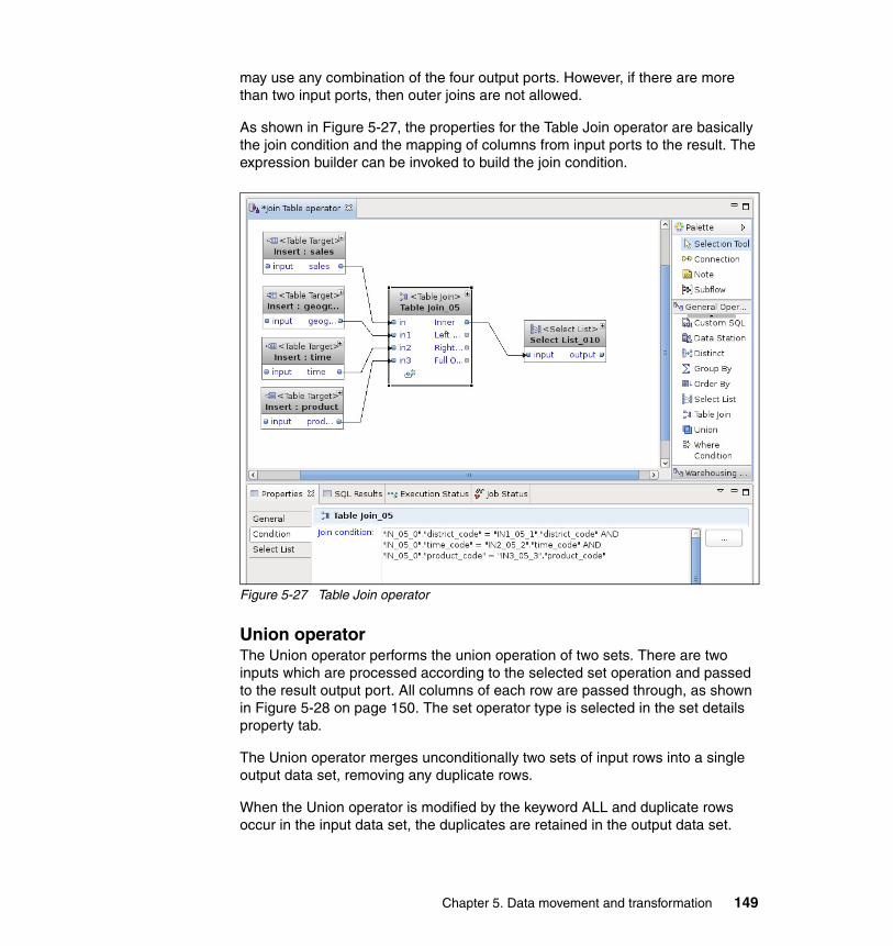
may use any combination of the four output ports. However, if there are more than two input ports, then outer joins are not allowed.
As shown in Figure 5-27, the properties for the Table Join operator are basically the join condition and the mapping of columns from input ports to the result. The expression builder can be invoked to build the join condition.
Figure 5-27 Table Join operator
Union operatorThe Union operator performs the union operation of two sets. There are two inputs which are processed according to the selected set operation and passed to the result output port. All columns of each row are passed through, as shown in Figure 5-28 on page 150. The set operator type is selected in the set details property tab.
The Union operator merges unconditionally two sets of input rows into a single output data set, removing any duplicate rows.
When the Union operator is modified by the keyword ALL and duplicate rows occur in the input data set, the duplicates are retained in the output data set.
Chapter 5. Data movement and transformation 149
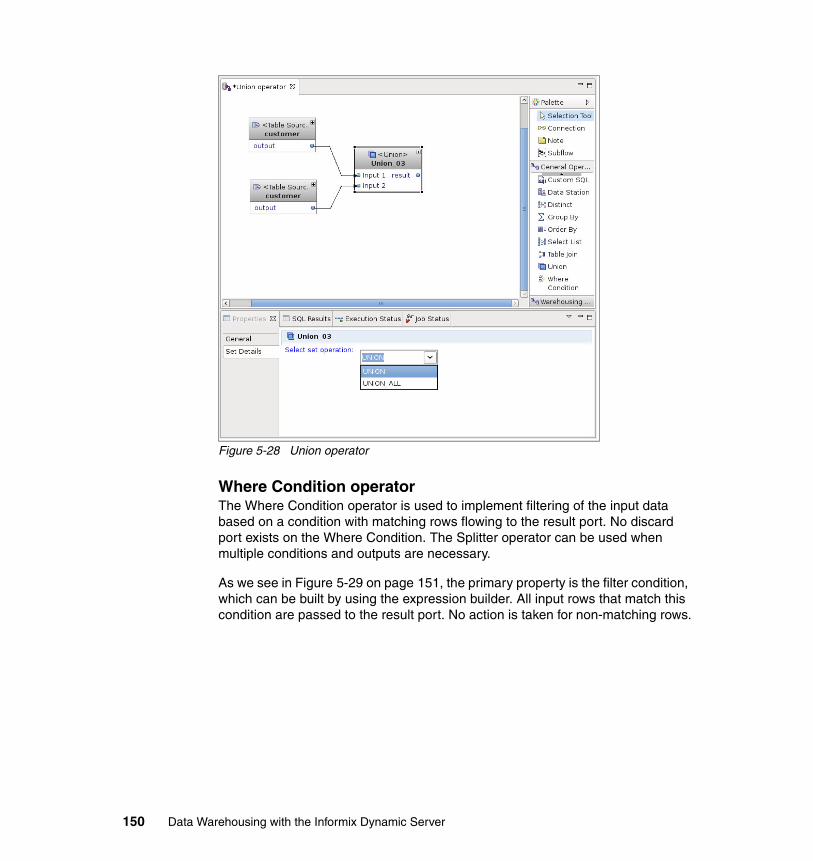
Figure 5-28 Union operator
Where Condition operatorThe Where Condition operator is used to implement filtering of the input data based on a condition with matching rows flowing to the result port. No discard port exists on the Where Condition. The Splitter operator can be used when multiple conditions and outputs are necessary.
As we see in Figure 5-29 on page 151, the primary property is the filter condition, which can be built by using the expression builder. All input rows that match this condition are passed to the result port. No action is taken for non-matching rows.
150 Data Warehousing with the Informix Dynamic Server
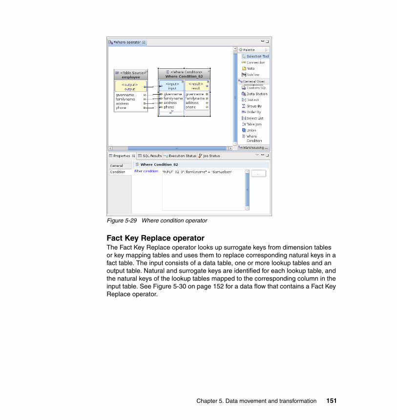
Figure 5-29 Where condition operator
Fact Key Replace operatorThe Fact Key Replace operator looks up surrogate keys from dimension tables or key mapping tables and uses them to replace corresponding natural keys in a fact table. The input consists of a data table, one or more lookup tables and an output table. Natural and surrogate keys are identified for each lookup table, and the natural keys of the lookup tables mapped to the corresponding column in the input table. See Figure 5-30 on page 152 for a data flow that contains a Fact Key Replace operator.
Chapter 5. Data movement and transformation 151
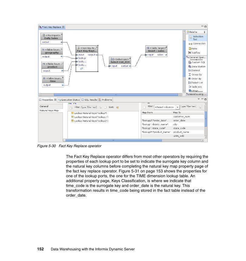
Figure 5-30 Fact Key Replace operator
The Fact Key Replace operator differs from most other operators by requiring the properties of each lookup port to be set to indicate the surrogate key column and the natural key columns before completing the natural key map property page of the fact key replace operator. Figure 5-31 on page 153 shows the properties for one of the lookup ports, the one for the TIME dimension lookup table. An additional property page, Keys Classification, is where we indicate that time_code is the surrogate key and order_date is the natural key. This transformation results in time_code being stored in the fact table instead of the order_date.
152 Data Warehousing with the Informix Dynamic Server
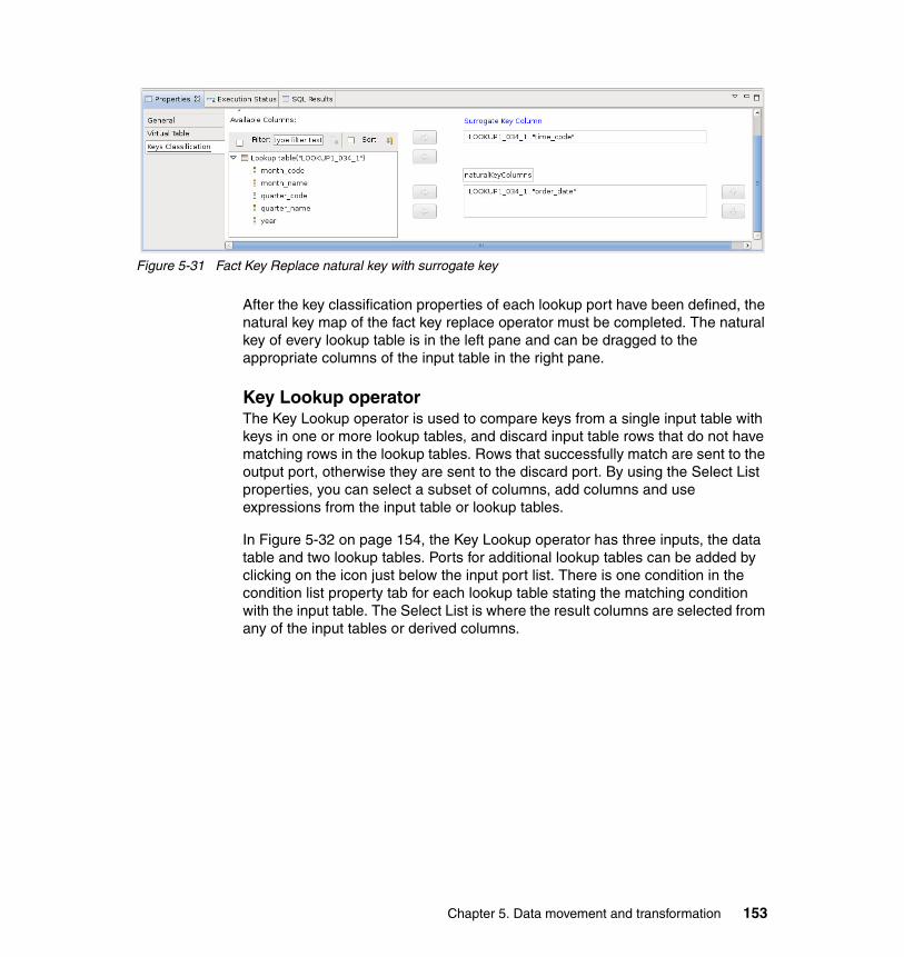
Figure 5-31 Fact Key Replace natural key with surrogate key
After the key classification properties of each lookup port have been defined, the natural key map of the fact key replace operator must be completed. The natural key of every lookup table is in the left pane and can be dragged to the appropriate columns of the input table in the right pane.
Key Lookup operatorThe Key Lookup operator is used to compare keys from a single input table with keys in one or more lookup tables, and discard input table rows that do not have matching rows in the lookup tables. Rows that successfully match are sent to the output port, otherwise they are sent to the discard port. By using the Select List properties, you can select a subset of columns, add columns and use expressions from the input table or lookup tables.
In Figure 5-32 on page 154, the Key Lookup operator has three inputs, the data table and two lookup tables. Ports for additional lookup tables can be added by clicking on the icon just below the input port list. There is one condition in the condition list property tab for each lookup table stating the matching condition with the input table. The Select List is where the result columns are selected from any of the input tables or derived columns.
Chapter 5. Data movement and transformation 153
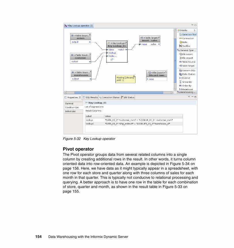
Figure 5-32 Key Lookup operator
Pivot operatorThe Pivot operator groups data from several related columns into a single column by creating additional rows in the result. In other words, it turns column oriented data into row-oriented data. An example is depicted in Figure 5-34 on page 156. Here, we have data as it might typically appear in a spreadsheet, with one row for each store and quarter along with three columns of sales for each month in that quarter. This is typically not conducive to relational processing and querying. A better approach is to have one row in the table for each combination of store, quarter and month, as shown in the result table in Figure 5-33 on page 155.
154 Data Warehousing with the Informix Dynamic Server
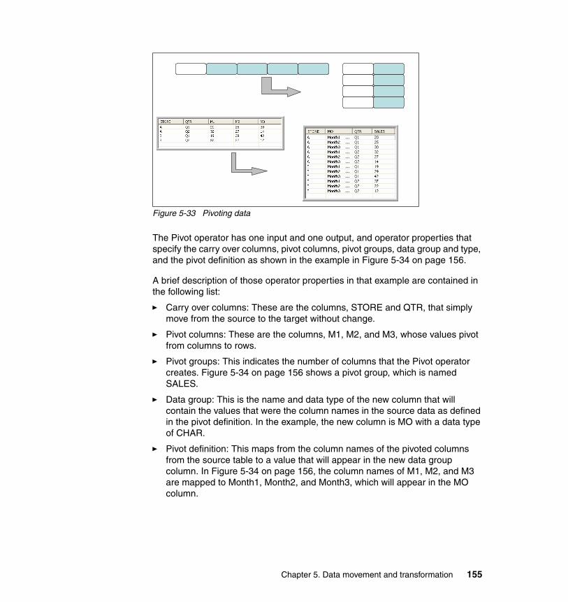
Figure 5-33 Pivoting data
The Pivot operator has one input and one output, and operator properties that specify the carry over columns, pivot columns, pivot groups, data group and type, and the pivot definition as shown in the example in Figure 5-34 on page 156.
A brief description of those operator properties in that example are contained in the following list:
� Carry over columns: These are the columns, STORE and QTR, that simply move from the source to the target without change.
� Pivot columns: These are the columns, M1, M2, and M3, whose values pivot from columns to rows.
� Pivot groups: This indicates the number of columns that the Pivot operator creates. Figure 5-34 on page 156 shows a pivot group, which is named SALES.
� Data group: This is the name and data type of the new column that will contain the values that were the column names in the source data as defined in the pivot definition. In the example, the new column is MO with a data type of CHAR.
� Pivot definition: This maps from the column names of the pivoted columns from the source table to a value that will appear in the new data group column. In Figure 5-34 on page 156, the column names of M1, M2, and M3 are mapped to Month1, Month2, and Month3, which will appear in the MO column.
Chapter 5. Data movement and transformation 155
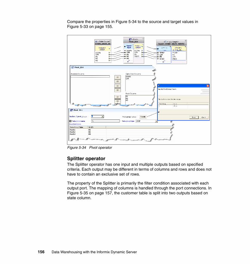
Compare the properties in Figure 5-34 to the source and target values in Figure 5-33 on page 155.
Figure 5-34 Pivot operator
Splitter operatorThe Splitter operator has one input and multiple outputs based on specified criteria. Each output may be different in terms of columns and rows and does not have to contain an exclusive set of rows.
The property of the Splitter is primarily the filter condition associated with each output port. The mapping of columns is handled through the port connections. In Figure 5-35 on page 157, the customer table is split into two outputs based on state column.
156 Data Warehousing with the Informix Dynamic Server
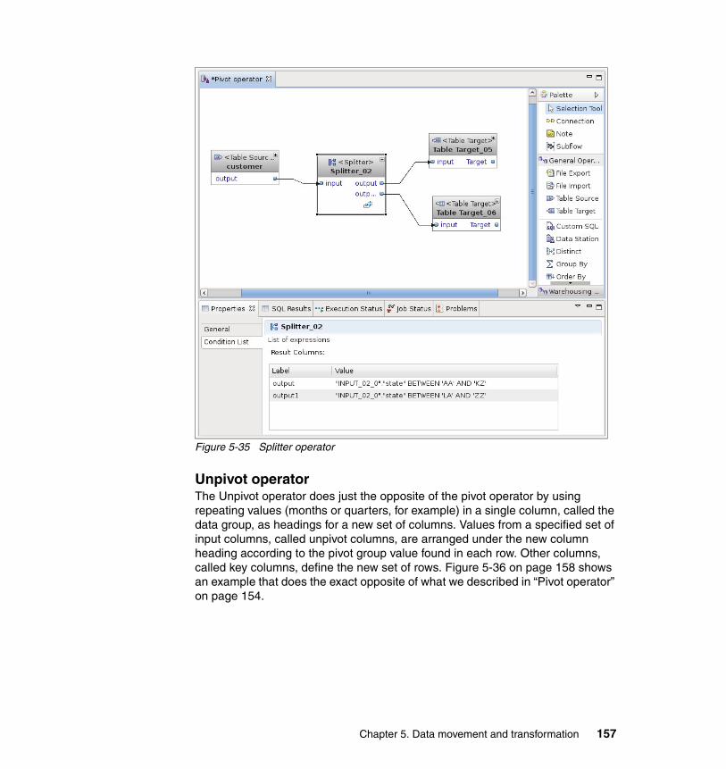
Figure 5-35 Splitter operator
Unpivot operatorThe Unpivot operator does just the opposite of the pivot operator by using repeating values (months or quarters, for example) in a single column, called the data group, as headings for a new set of columns. Values from a specified set of input columns, called unpivot columns, are arranged under the new column heading according to the pivot group value found in each row. Other columns, called key columns, define the new set of rows. Figure 5-36 on page 158 shows an example that does the exact opposite of what we described in “Pivot operator” on page 154.
Chapter 5. Data movement and transformation 157
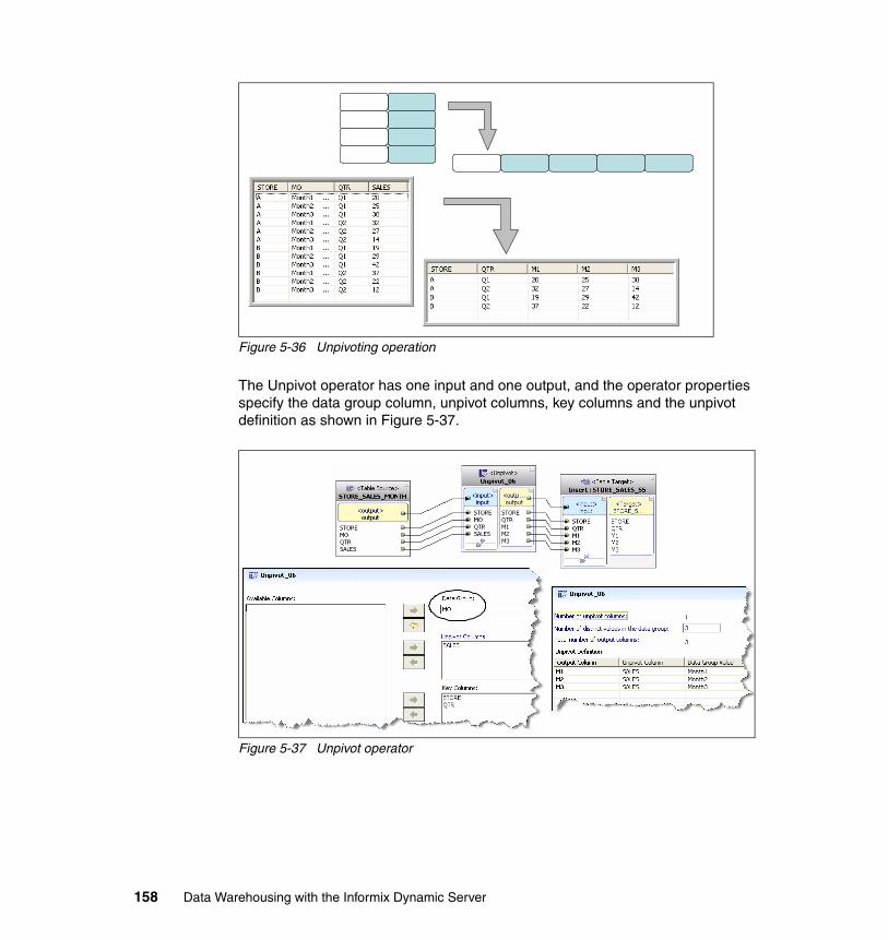
Figure 5-36 Unpivoting operation
The Unpivot operator has one input and one output, and the operator properties specify the data group column, unpivot columns, key columns and the unpivot definition as shown in Figure 5-37.
Figure 5-37 Unpivot operator
158 Data Warehousing with the Informix Dynamic Server
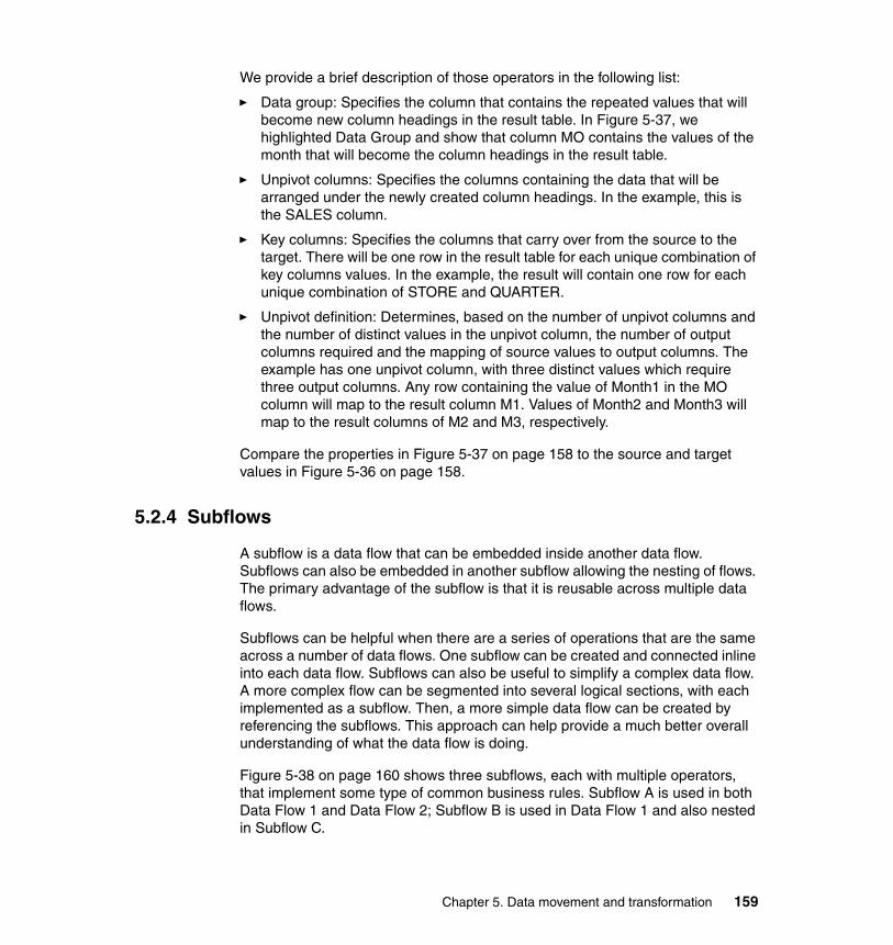
We provide a brief description of those operators in the following list:
� Data group: Specifies the column that contains the repeated values that will become new column headings in the result table. In Figure 5-37, we highlighted Data Group and show that column MO contains the values of the month that will become the column headings in the result table.
� Unpivot columns: Specifies the columns containing the data that will be arranged under the newly created column headings. In the example, this is the SALES column.
� Key columns: Specifies the columns that carry over from the source to the target. There will be one row in the result table for each unique combination of key columns values. In the example, the result will contain one row for each unique combination of STORE and QUARTER.
� Unpivot definition: Determines, based on the number of unpivot columns and the number of distinct values in the unpivot column, the number of output columns required and the mapping of source values to output columns. The example has one unpivot column, with three distinct values which require three output columns. Any row containing the value of Month1 in the MO column will map to the result column M1. Values of Month2 and Month3 will map to the result columns of M2 and M3, respectively.
Compare the properties in Figure 5-37 on page 158 to the source and target values in Figure 5-36 on page 158.
5.2.4 Subflows
A subflow is a data flow that can be embedded inside another data flow. Subflows can also be embedded in another subflow allowing the nesting of flows. The primary advantage of the subflow is that it is reusable across multiple data flows.
Subflows can be helpful when there are a series of operations that are the same across a number of data flows. One subflow can be created and connected inline into each data flow. Subflows can also be useful to simplify a complex data flow. A more complex flow can be segmented into several logical sections, with each implemented as a subflow. Then, a more simple data flow can be created by referencing the subflows. This approach can help provide a much better overall understanding of what the data flow is doing.
Figure 5-38 on page 160 shows three subflows, each with multiple operators, that implement some type of common business rules. Subflow A is used in both Data Flow 1 and Data Flow 2; Subflow B is used in Data Flow 1 and also nested in Subflow C.
Chapter 5. Data movement and transformation 159
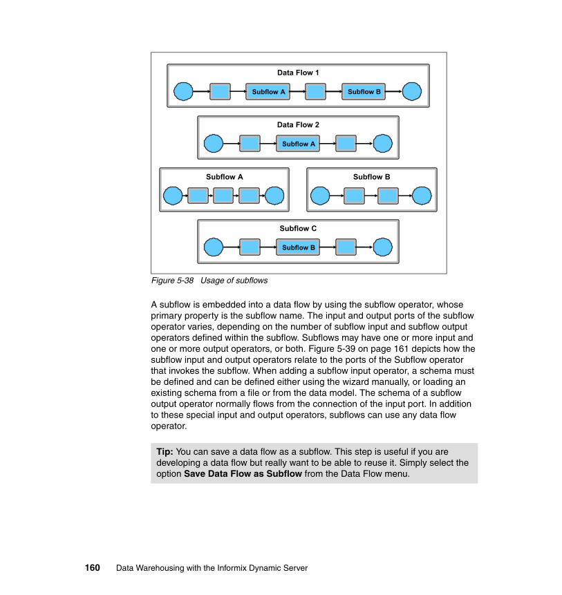
Figure 5-38 Usage of subflows
A subflow is embedded into a data flow by using the subflow operator, whose primary property is the subflow name. The input and output ports of the subflow operator varies, depending on the number of subflow input and subflow output operators defined within the subflow. Subflows may have one or more input and one or more output operators, or both. Figure 5-39 on page 161 depicts how the subflow input and output operators relate to the ports of the Subflow operator that invokes the subflow. When adding a subflow input operator, a schema must be defined and can be defined either using the wizard manually, or loading an existing schema from a file or from the data model. The schema of a subflow output operator normally flows from the connection of the input port. In addition to these special input and output operators, subflows can use any data flow operator.
Tip: You can save a data flow as a subflow. This step is useful if you are developing a data flow but really want to be able to reuse it. Simply select the option Save Data Flow as Subflow from the Data Flow menu.
Subflow A Subflow B
Data Flow 1
Subflow A
Data Flow 2
Subflow A Subflow B
Subflow B
Subflow C
160 Data Warehousing with the Informix Dynamic Server
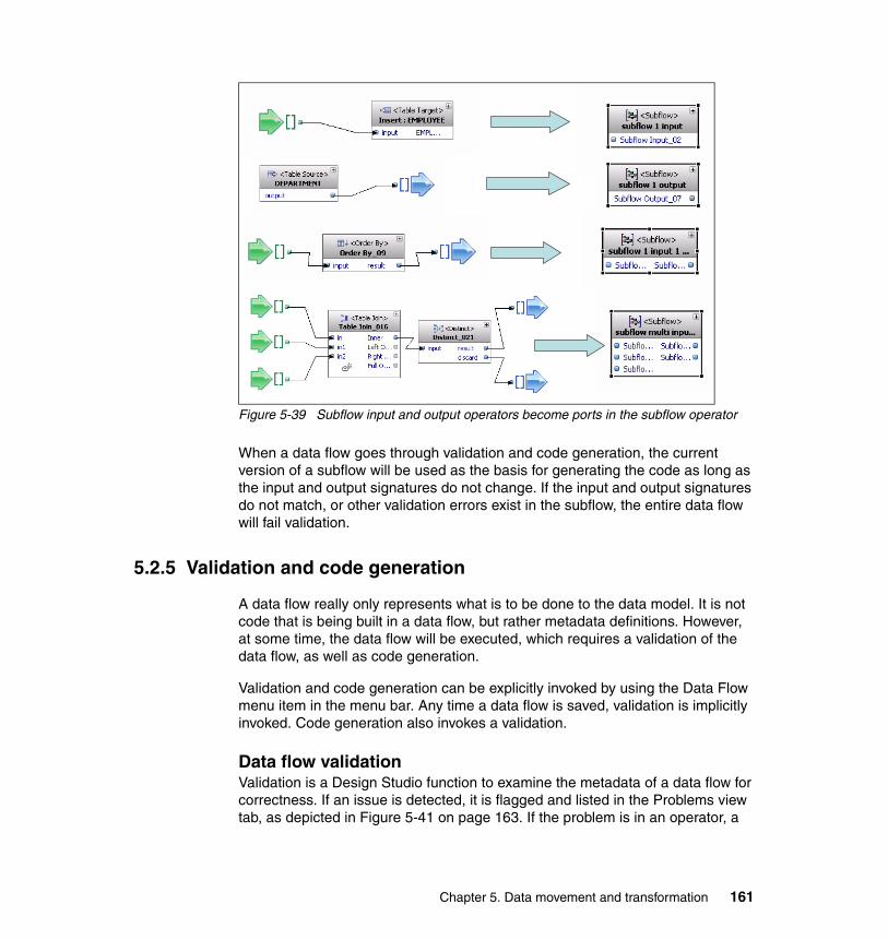
Figure 5-39 Subflow input and output operators become ports in the subflow operator
When a data flow goes through validation and code generation, the current version of a subflow will be used as the basis for generating the code as long as the input and output signatures do not change. If the input and output signatures do not match, or other validation errors exist in the subflow, the entire data flow will fail validation.
5.2.5 Validation and code generation
A data flow really only represents what is to be done to the data model. It is not code that is being built in a data flow, but rather metadata definitions. However, at some time, the data flow will be executed, which requires a validation of the data flow, as well as code generation.
Validation and code generation can be explicitly invoked by using the Data Flow menu item in the menu bar. Any time a data flow is saved, validation is implicitly invoked. Code generation also invokes a validation.
Data flow validationValidation is a Design Studio function to examine the metadata of a data flow for correctness. If an issue is detected, it is flagged and listed in the Problems view tab, as depicted in Figure 5-41 on page 163. If the problem is in an operator, a
Chapter 5. Data movement and transformation 161
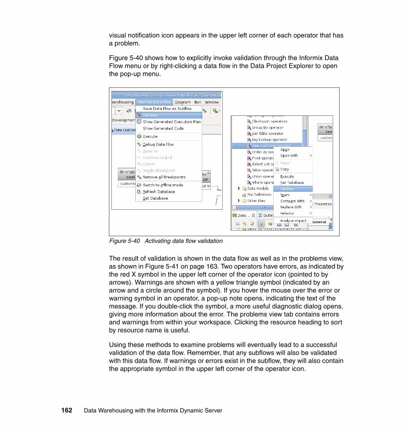
visual notification icon appears in the upper left corner of each operator that has a problem.
Figure 5-40 shows how to explicitly invoke validation through the Informix Data Flow menu or by right-clicking a data flow in the Data Project Explorer to open the pop-up menu.
Figure 5-40 Activating data flow validation
The result of validation is shown in the data flow as well as in the problems view, as shown in Figure 5-41 on page 163. Two operators have errors, as indicated by the red X symbol in the upper left corner of the operator icon (pointed to by arrows). Warnings are shown with a yellow triangle symbol (indicated by an arrow and a circle around the symbol). If you hover the mouse over the error or warning symbol in an operator, a pop-up note opens, indicating the text of the message. If you double-click the symbol, a more useful diagnostic dialog opens, giving more information about the error. The problems view tab contains errors and warnings from within your workspace. Clicking the resource heading to sort by resource name is useful.
Using these methods to examine problems will eventually lead to a successful validation of the data flow. Remember, that any subflows will also be validated with this data flow. If warnings or errors exist in the subflow, they will also contain the appropriate symbol in the upper left corner of the operator icon.
162 Data Warehousing with the Informix Dynamic Server
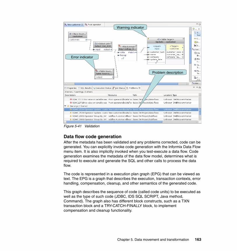
Figure 5-41 Validation
Data flow code generationAfter the metadata has been validated and any problems corrected, code can be generated. You can explicitly invoke code generation with the Informix Data Flow menu item. It is also implicitly invoked when you test-execute a data flow. Code generation examines the metadata of the data flow model, determines what is required to execute and generate the SQL and other calls to process the data flow.
The code is represented in a execution plan graph (EPG) that can be viewed as text. The EPG is a graph that describes the execution, transaction contexts, error handling, compensation, cleanup, and other semantics of the generated code.
This graph describes the sequence of code (called code units) to be executed as well as the type of such code (JDBC, IDS SQL SCRIPT, Java method, Command). The graph also has different block constructs, such as a TXN transaction block and a TRY-CATCH-FINALLY block, to implement compensation and cleanup functionality.
Warning indicator
Problem description
Error indicator
Chapter 5. Data movement and transformation 163
The three types of execution plan graphs are:
� Deployment EPG
Contains code that is run once (and only once) when the data warehouse application is deployed to the SQL warehousing application-server-based runtime. This EPG is used to prepare the application environment for execution. For example, to register stored procedures.
� Runtime EPG
Contains execution time code that is executed every time a process is executed.
� Undeployment EPG
Contains code that is run when the data warehouse application is uninstalled from the SQL warehousing runtime. It is the opposite of the deployment EPG. Hence, they are run only once.
When you explicitly generate code, the generated code will appear in a text window within the Design Studio that you can browse. Depending on the data flow, this code might not be intuitively obvious, but you can see what will be executed. Figure 5-42 on page 165 shows a data flow, with a snippet of the generated code in text and graphics. The graphical viewer is used to step through and debug a data flow as described in 5.2.6, “Testing and debugging a data flow” on page 165.
164 Data Warehousing with the Informix Dynamic Server
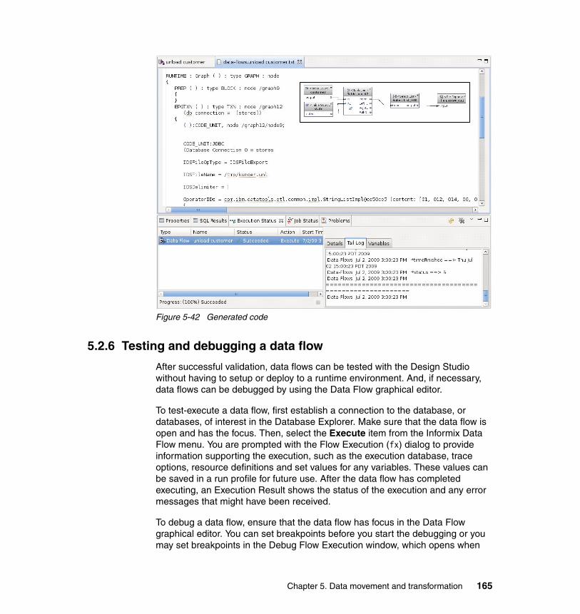
Figure 5-42 Generated code
5.2.6 Testing and debugging a data flow
After successful validation, data flows can be tested with the Design Studio without having to setup or deploy to a runtime environment. And, if necessary, data flows can be debugged by using the Data Flow graphical editor.
To test-execute a data flow, first establish a connection to the database, or databases, of interest in the Database Explorer. Make sure that the data flow is open and has the focus. Then, select the Execute item from the Informix Data Flow menu. You are prompted with the Flow Execution (fx) dialog to provide information supporting the execution, such as the execution database, trace options, resource definitions and set values for any variables. These values can be saved in a run profile for future use. After the data flow has completed executing, an Execution Result shows the status of the execution and any error messages that might have been received.
To debug a data flow, ensure that the data flow has focus in the Data Flow graphical editor. You can set breakpoints before you start the debugging or you may set breakpoints in the Debug Flow Execution window, which opens when
Chapter 5. Data movement and transformation 165
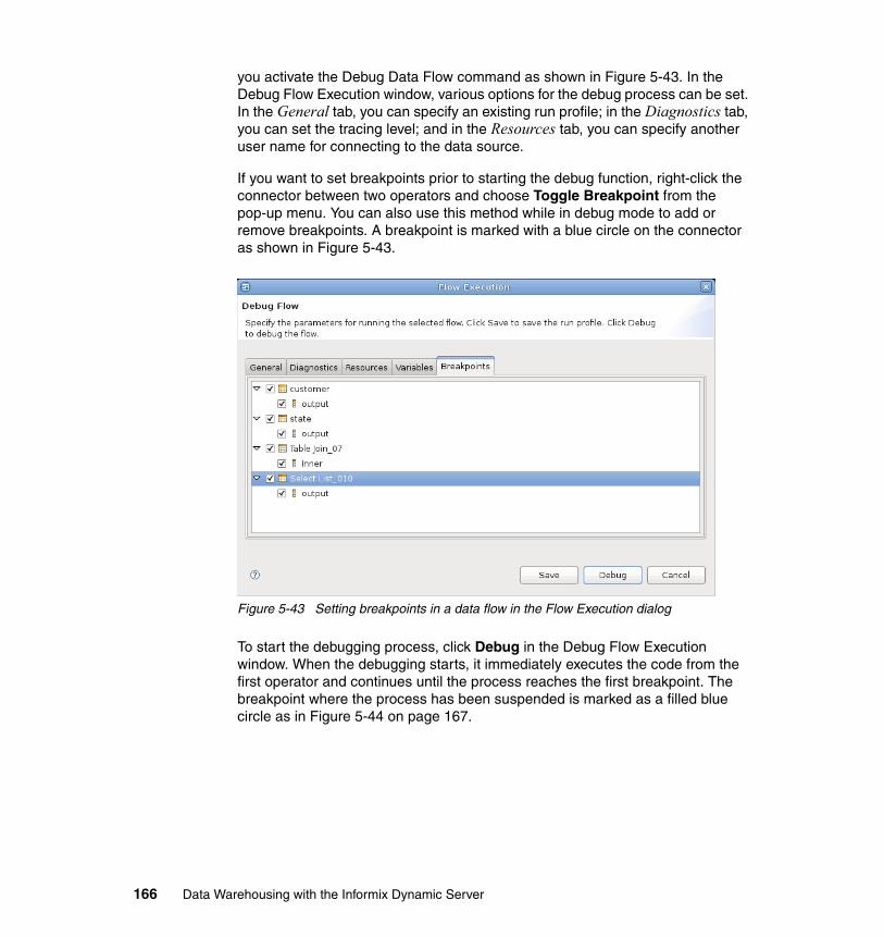
you activate the Debug Data Flow command as shown in Figure 5-43. In the Debug Flow Execution window, various options for the debug process can be set. In the General tab, you can specify an existing run profile; in the Diagnostics tab, you can set the tracing level; and in the Resources tab, you can specify another user name for connecting to the data source.
If you want to set breakpoints prior to starting the debug function, right-click the connector between two operators and choose Toggle Breakpoint from the pop-up menu. You can also use this method while in debug mode to add or remove breakpoints. A breakpoint is marked with a blue circle on the connector as shown in Figure 5-43.
Figure 5-43 Setting breakpoints in a data flow in the Flow Execution dialog
To start the debugging process, click Debug in the Debug Flow Execution window. When the debugging starts, it immediately executes the code from the first operator and continues until the process reaches the first breakpoint. The breakpoint where the process has been suspended is marked as a filled blue circle as in Figure 5-44 on page 167.
166 Data Warehousing with the Informix Dynamic Server
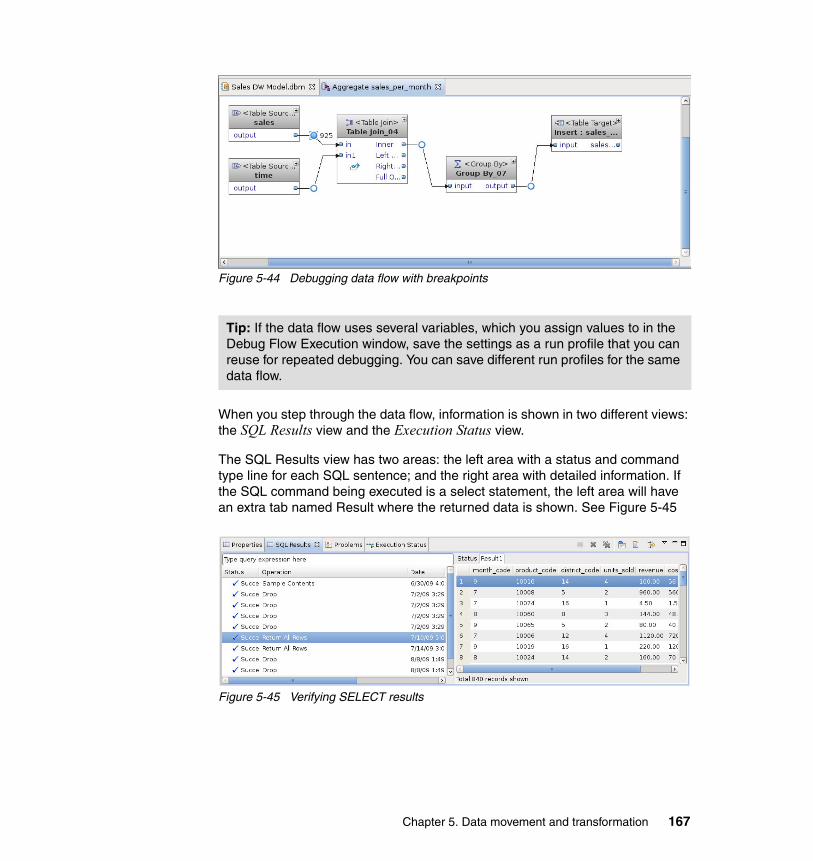
Figure 5-44 Debugging data flow with breakpoints
When you step through the data flow, information is shown in two different views: the SQL Results view and the Execution Status view.
The SQL Results view has two areas: the left area with a status and command type line for each SQL sentence; and the right area with detailed information. If the SQL command being executed is a select statement, the left area will have an extra tab named Result where the returned data is shown. See Figure 5-45
Figure 5-45 Verifying SELECT results
Tip: If the data flow uses several variables, which you assign values to in the Debug Flow Execution window, save the settings as a run profile that you can reuse for repeated debugging. You can save different run profiles for the same data flow.
Chapter 5. Data movement and transformation 167
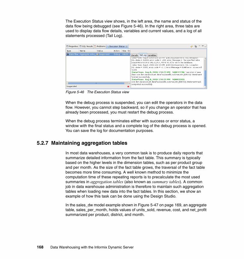
The Execution Status view shows, in the left area, the name and status of the data flow being debugged (see Figure 5-46). In the right area, three tabs are used to display data flow details, variables and current values, and a log of all statements processed (Tail Log).
Figure 5-46 The Execution Status view
When the debug process is suspended, you can edit the operators in the data flow. However, you cannot step backward, so if you change an operator that has already been processed, you must restart the debug process.
When the debug process terminates either with success or error status, a window with the final status and a complete log of the debug process is opened. You can save the log for documentation purposes.
5.2.7 Maintaining aggregation tables
In most data warehouses, a very common task is to produce daily reports that summarize detailed information from the fact table. This summary is typically based on the higher levels in the dimension tables, such as per product group and per month. As the size of the fact table grows, the traversal of the fact table becomes more time consuming. A well known method to minimize the computation time of these repeating reports is to precalculate the most used summaries in aggregation tables (also known as summary tables). A common job in data warehouse administration is therefore to maintain such aggregation tables when loading new data into the fact tables. In this section, we show an example of how this task can be done using the Design Studio.
In the sales_dw model example shown in Figure 5-47 on page 169, an aggregate table, sales_per_month, holds values of units_sold, revenue, cost, and net_profit summarized per product, district, and month.
168 Data Warehousing with the Informix Dynamic Server
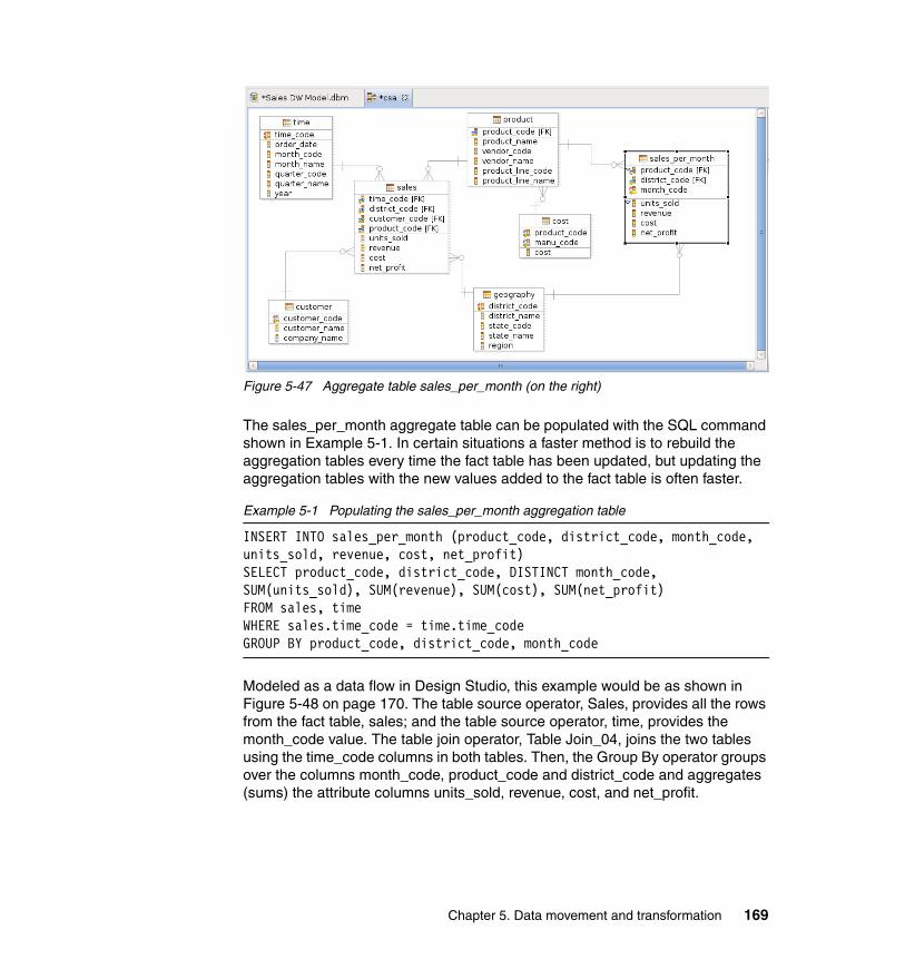
Figure 5-47 Aggregate table sales_per_month (on the right)
The sales_per_month aggregate table can be populated with the SQL command shown in Example 5-1. In certain situations a faster method is to rebuild the aggregation tables every time the fact table has been updated, but updating the aggregation tables with the new values added to the fact table is often faster.
Example 5-1 Populating the sales_per_month aggregation table
INSERT INTO sales_per_month (product_code, district_code, month_code, units_sold, revenue, cost, net_profit)SELECT product_code, district_code, DISTINCT month_code,SUM(units_sold), SUM(revenue), SUM(cost), SUM(net_profit)FROM sales, timeWHERE sales.time_code = time.time_codeGROUP BY product_code, district_code, month_code
Modeled as a data flow in Design Studio, this example would be as shown in Figure 5-48 on page 170. The table source operator, Sales, provides all the rows from the fact table, sales; and the table source operator, time, provides the month_code value. The table join operator, Table Join_04, joins the two tables using the time_code columns in both tables. Then, the Group By operator groups over the columns month_code, product_code and district_code and aggregates (sums) the attribute columns units_sold, revenue, cost, and net_profit.
Chapter 5. Data movement and transformation 169
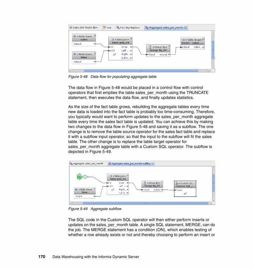
Figure 5-48 Data flow for populating aggregate table
The data flow in Figure 5-48 would be placed in a control flow with control operators that first empties the table sales_per_month using the TRUNCATE statement, then executes the data flow, and finally updates statistics.
As the size of the fact table grows, rebuilding the aggregate tables every time new data is loaded into the fact table is probably too time-consuming. Therefore, you typically would want to perform updates to the sales_per_month aggregate table every time the sales fact table is updated. You can achieve this by making two changes to the data flow in Figure 5-48 and saving it as a subflow. The one change is to remove the table source operator for the sales fact table and replace it with a subflow input operator, so that the input to the subflow will fit the sales table. The other change is to replace the table target operator for sales_per_month aggregate table with a Custom SQL operator. The subflow is depicted in Figure 5-49.
Figure 5-49 Aggregate subflow
The SQL code in the Custom SQL operator will then either perform inserts or updates on the sales_per_month table. A single SQL statement, MERGE, can do the job. The MERGE statement has a condition (ON), which enables testing of whether a row already exists or not and thereby choosing to perform an insert or
170 Data Warehousing with the Informix Dynamic Server
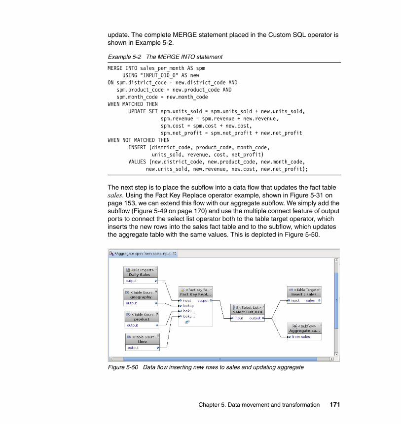
update. The complete MERGE statement placed in the Custom SQL operator is shown in Example 5-2.
Example 5-2 The MERGE INTO statement
MERGE INTO sales_per_month AS spm USING "INPUT_010_0" AS newON spm.district_code = new.district_code AND
spm.product_code = new.product_code ANDspm.month_code = new.month_code
WHEN MATCHED THEN UPDATE SET spm.units_sold = spm.units_sold + new.units_sold,
spm.revenue = spm.revenue + new.revenue,spm.cost = spm.cost + new.cost,spm.net_profit = spm.net_profit + new.net_profit
WHEN NOT MATCHED THEN INSERT (district_code, product_code, month_code,
units_sold, revenue, cost, net_profit) VALUES (new.district_code, new.product_code, new.month_code,
new.units_sold, new.revenue, new.cost, new.net_profit);
The next step is to place the subflow into a data flow that updates the fact table sales. Using the Fact Key Replace operator example, shown in Figure 5-31 on page 153, we can extend this flow with our aggregate subflow. We simply add the subflow (Figure 5-49 on page 170) and use the multiple connect feature of output ports to connect the select list operator both to the table target operator, which inserts the new rows into the sales fact table and to the subflow, which updates the aggregate table with the same values. This is depicted in Figure 5-50.
Figure 5-50 Data flow inserting new rows to sales and updating aggregate
Chapter 5. Data movement and transformation 171
5.2.8 Removing data periodically
To avoid an ever-growing data warehouse, you should have a procedure that removes some of the data when it reaches a certain age. However, the job of removing such data can be very time consuming. In Example 5-3, we show how a partitioning strategy can both improve overall performance and change the time-consuming recurring data deletion into a job that is done in seconds.
In the example, we look at a fact table that holds one year of data. Every month, we remove the data that has become older than one year. For this example, we use the same sales_dw data warehouse as used in other examples, shown in Figure 5-47 on page 169.
From an SQL perspective, deleting rows that are more than a year old is fairly simple. The code in Example 5-3 uses a subquery that finds all the time_code values representing a date that, compared with the last day of the previous month, is more than a year old. It then deletes the rows in the sales fact table having these time_code values.
The problem with an SQL statement like this is that when the fact table contains millions of rows and several indexes, the run time can get extremely long.
Example 5-3 Deleting rows that are one year old at end of last month.
DELETE FROM salesWHERE sales.time_code IN
(SELECT time_code FROM timeWHERE last_day(today - 1 units month)::date - order_date > 365)
By using IDS table partitioning facilities, we can make the delete operation happen in seconds instead of perhaps hours. The table partitioning syntax and usage is described in 7.5, “Partitioning” on page 295. With table partitioning, we actually gain two goals. One is an overall performance improvement, because IDS uses parallel database query (PDQ) for many queries. Another is that table partitioning improves manageability.
172 Data Warehousing with the Informix Dynamic Server
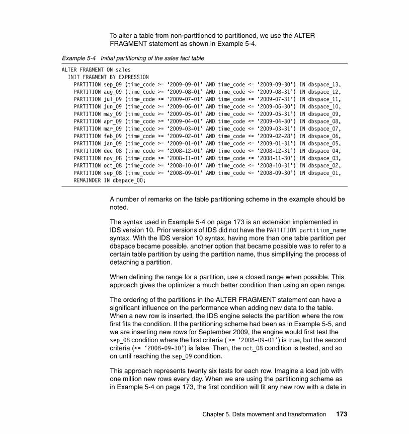
To alter a table from non-partitioned to partitioned, we use the ALTER FRAGMENT statement as shown in Example 5-4.
Example 5-4 Initial partitioning of the sales fact table
ALTER FRAGMENT ON salesINIT FRAGMENT BY EXPRESSIONPARTITION sep_09 (time_code >= ‘2009-09-01’ AND time_code <= ‘2009-09-30’) IN dbspace_13,PARTITION aug_09 (time_code >= ‘2009-08-01’ AND time_code <= ‘2009-08-31’) IN dbspace_12,PARTITION jul_09 (time_code >= ‘2009-07-01’ AND time_code <= ‘2009-07-31’) IN dbspace_11,PARTITION jun_09 (time_code >= ‘2009-06-01’ AND time_code <= ‘2009-06-30’) IN dbspace_10,PARTITION may_09 (time_code >= ‘2009-05-01’ AND time_code <= ‘2009-05-31’) IN dbspace_09,PARTITION apr_09 (time_code >= ‘2009-04-01’ AND time_code <= ‘2009-04-30’) IN dbspace_08,PARTITION mar_09 (time_code >= ‘2009-03-01’ AND time_code <= ‘2009-03-31’) IN dbspace_07,PARTITION feb_09 (time_code >= ‘2009-02-01’ AND time_code <= ‘2009-02-28’) IN dbspace_06,PARTITION jan_09 (time_code >= ‘2009-01-01’ AND time_code <= ‘2009-01-31’) IN dbspace_05,PARTITION dec_08 (time_code >= ‘2008-12-01’ AND time_code <= ‘2008-12-31’) IN dbspace_04,PARTITION nov_08 (time_code >= ‘2008-11-01’ AND time_code <= ‘2008-11-30’) IN dbspace_03,PARTITION oct_08 (time_code >= ‘2008-10-01’ AND time_code <= ‘2008-10-31’) IN dbspace_02,PARTITION sep_08 (time_code >= ‘2008-09-01’ AND time_code <= ‘2008-09-30’) IN dbspace_01,REMAINDER IN dbspace_00;
A number of remarks on the table partitioning scheme in the example should be noted.
The syntax used in Example 5-4 on page 173 is an extension implemented in IDS version 10. Prior versions of IDS did not have the PARTITION partition_name syntax. With the IDS version 10 syntax, having more than one table partition per dbspace became possible. another option that became possible was to refer to a certain table partition by using the partition name, thus simplifying the process of detaching a partition.
When defining the range for a partition, use a closed range when possible. This approach gives the optimizer a much better condition than using an open range.
The ordering of the partitions in the ALTER FRAGMENT statement can have a significant influence on the performance when adding new data to the table. When a new row is inserted, the IDS engine selects the partition where the row first fits the condition. If the partitioning scheme had been as in Example 5-5, and we are inserting new rows for September 2009, the engine would first test the sep_08 condition where the first criteria ( >= ‘2008-09-01’) is true, but the second criteria (<= ‘2008-09-30’) is false. Then, the oct_08 condition is tested, and so on until reaching the sep_09 condition.
This approach represents twenty six tests for each row. Imagine a load job with one million new rows every day. When we are using the partitioning scheme as in Example 5-4 on page 173, the first condition will fit any new row with a date in
Chapter 5. Data movement and transformation 173
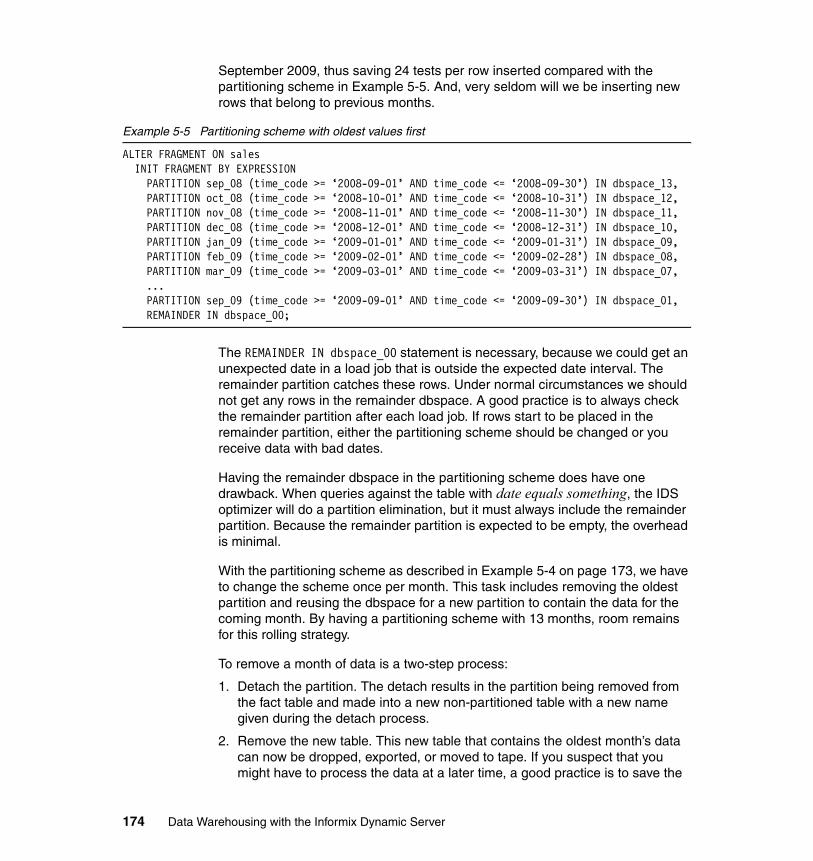
September 2009, thus saving 24 tests per row inserted compared with the partitioning scheme in Example 5-5. And, very seldom will we be inserting new rows that belong to previous months.
Example 5-5 Partitioning scheme with oldest values first
ALTER FRAGMENT ON salesINIT FRAGMENT BY EXPRESSIONPARTITION sep_08 (time_code >= ‘2008-09-01’ AND time_code <= ‘2008-09-30’) IN dbspace_13,PARTITION oct_08 (time_code >= ‘2008-10-01’ AND time_code <= ‘2008-10-31’) IN dbspace_12,PARTITION nov_08 (time_code >= ‘2008-11-01’ AND time_code <= ‘2008-11-30’) IN dbspace_11,PARTITION dec_08 (time_code >= ‘2008-12-01’ AND time_code <= ‘2008-12-31’) IN dbspace_10,PARTITION jan_09 (time_code >= ‘2009-01-01’ AND time_code <= ‘2009-01-31’) IN dbspace_09,PARTITION feb_09 (time_code >= ‘2009-02-01’ AND time_code <= ‘2009-02-28’) IN dbspace_08,PARTITION mar_09 (time_code >= ‘2009-03-01’ AND time_code <= ‘2009-03-31’) IN dbspace_07,...PARTITION sep_09 (time_code >= ‘2009-09-01’ AND time_code <= ‘2009-09-30’) IN dbspace_01,REMAINDER IN dbspace_00;
The REMAINDER IN dbspace_00 statement is necessary, because we could get an unexpected date in a load job that is outside the expected date interval. The remainder partition catches these rows. Under normal circumstances we should not get any rows in the remainder dbspace. A good practice is to always check the remainder partition after each load job. If rows start to be placed in the remainder partition, either the partitioning scheme should be changed or you receive data with bad dates.
Having the remainder dbspace in the partitioning scheme does have one drawback. When queries against the table with date equals something, the IDS optimizer will do a partition elimination, but it must always include the remainder partition. Because the remainder partition is expected to be empty, the overhead is minimal.
With the partitioning scheme as described in Example 5-4 on page 173, we have to change the scheme once per month. This task includes removing the oldest partition and reusing the dbspace for a new partition to contain the data for the coming month. By having a partitioning scheme with 13 months, room remains for this rolling strategy.
To remove a month of data is a two-step process:
1. Detach the partition. The detach results in the partition being removed from the fact table and made into a new non-partitioned table with a new name given during the detach process.
2. Remove the new table. This new table that contains the oldest month’s data can now be dropped, exported, or moved to tape. If you suspect that you might have to process the data at a later time, a good practice is to save the
174 Data Warehousing with the Informix Dynamic Server
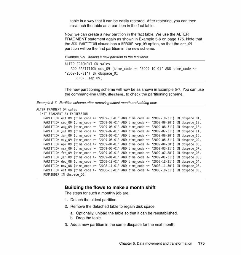
table in a way that it can be easily restored. After restoring, you can then re-attach the table as a partition in the fact table.
Now, we can create a new partition in the fact table. We use the ALTER FRAGMENT statement again as shown in Example 5-6 on page 175. Note that the ADD PARTITION clause has a BEFORE sep_09 option, so that the oct_09 partition will be the first partition in the new scheme.
Example 5-6 Adding a new partition to the fact table
ALTER FRAGMENT ON salesADD PARTITION oct_09 (time_code >= ‘2009-10-01’ AND time_code <=
‘2009-10-31’) IN dbspace_01BEFORE sep_09;
The new partitioning scheme will now be as shown in Example 5-7. You can use the command-line utility, dbschema, to check the partitioning scheme.
Example 5-7 Partition scheme after removing oldest month and adding new.
ALTER FRAGMENT ON salesINIT FRAGMENT BY EXPRESSIONPARTITION oct_09 (time_code >= ‘2009-10-01’ AND time_code <= ‘2009-10-31’) IN dbspace_01,PARTITION sep_09 (time_code >= ‘2009-09-01’ AND time_code <= ‘2009-09-30’) IN dbspace_13,PARTITION aug_09 (time_code >= ‘2009-08-01’ AND time_code <= ‘2009-08-31’) IN dbspace_12,PARTITION jul_09 (time_code >= ‘2009-07-01’ AND time_code <= ‘2009-07-31’) IN dbspace_11,PARTITION jun_09 (time_code >= ‘2009-06-01’ AND time_code <= ‘2009-06-30’) IN dbspace_10,PARTITION may_09 (time_code >= ‘2009-05-01’ AND time_code <= ‘2009-05-31’) IN dbspace_09,PARTITION apr_09 (time_code >= ‘2009-04-01’ AND time_code <= ‘2009-04-30’) IN dbspace_08,PARTITION mar_09 (time_code >= ‘2009-03-01’ AND time_code <= ‘2009-03-31’) IN dbspace_07,PARTITION feb_09 (time_code >= ‘2009-02-01’ AND time_code <= ‘2009-02-28’) IN dbspace_06,PARTITION jan_09 (time_code >= ‘2009-01-01’ AND time_code <= ‘2009-01-31’) IN dbspace_05,PARTITION dec_08 (time_code >= ‘2008-12-01’ AND time_code <= ‘2008-12-31’) IN dbspace_04,PARTITION nov_08 (time_code >= ‘2008-11-01’ AND time_code <= ‘2008-11-30’) IN dbspace_03,PARTITION oct_08 (time_code >= ‘2008-10-01’ AND time_code <= ‘2008-10-31’) IN dbspace_02,REMAINDER IN dbspace_00;
Building the flows to make a month shiftThe steps for such a monthly job are:
1. Detach the oldest partition.
2. Remove the detached table to regain disk space:
a. Optionally, unload the table so that it can be reestablished.b. Drop the table.
3. Add a new partition in the same dbspace for the next month.
Chapter 5. Data movement and transformation 175
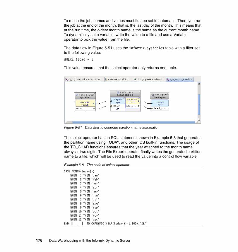
To reuse the job, names and values must first be set to automatic. Then, you run the job at the end of the month, that is, the last day of the month. This means that at the run time, the oldest month name is the same as the current month name. To dynamically set a variable, write the value to a file and use a Variable operator to pick the value from the file.
The data flow in Figure 5-51 uses the informix.systables table with a filter set to the following value:
WHERE tabid = 1
This value ensures that the select operator only returns one tuple.
Figure 5-51 Data flow to generate partition name automatic
The select operator has an SQL statement shown in Example 5-8 that generates the partition name using TODAY, and other IDS built-in functions. The usage of the TO_CHAR functions ensures that the year attached to the month name always is two digits. The File Export operator finally writes the generated partition name to a file, which will be used to read the value into a control flow variable.
Example 5-8 The code of select operator
CASE MONTH(today()) WHEN 1 THEN 'jan' WHEN 2 THEN 'feb' WHEN 3 THEN 'mar' WHEN 4 THEN 'apr' WHEN 5 THEN 'may' WHEN 6 THEN 'jun' WHEN 7 THEN 'jul' WHEN 8 THEN 'aug' WHEN 9 THEN 'sep' WHEN 10 THEN 'oct' WHEN 11 THEN 'nov' WHEN 12 THEN 'dec'END || '_' || TO_CHAR(MOD(YEAR(today())-1,100),'&&')
176 Data Warehousing with the Informix Dynamic Server
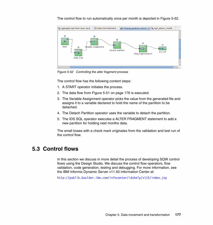
The control flow to run automatically once per month is depicted in Figure 5-52.
Figure 5-52 Controlling the alter fragment process
The control flow has the following content steps:
1. A START operator initiates the process.
2. The data flow from Figure 5-51 on page 176 is executed.
3. The Variable Assignment operator picks the value from the generated file and assigns it to a variable declared to hold the name of the partition to be detached.
4. The Detach Partition operator uses the variable to detach the partition.
5. The IDS SQL operator executes a ALTER FRAGMENT statement to add a new partition for holding next months data.
The small boxes with a check mark originates from the validation and test run of the control flow.
5.3 Control flows
In this section we discuss in more detail the process of developing SQW control flows using the Design Studio. We discuss the control flow operators, flow validation, code generation, testing and debugging. For more information, see the IBM Informix Dynamic Server v11.50 Information Center at:
http://publib.boulder.ibm.com/infocenter/idshelp/v115/index.jsp
Chapter 5. Data movement and transformation 177
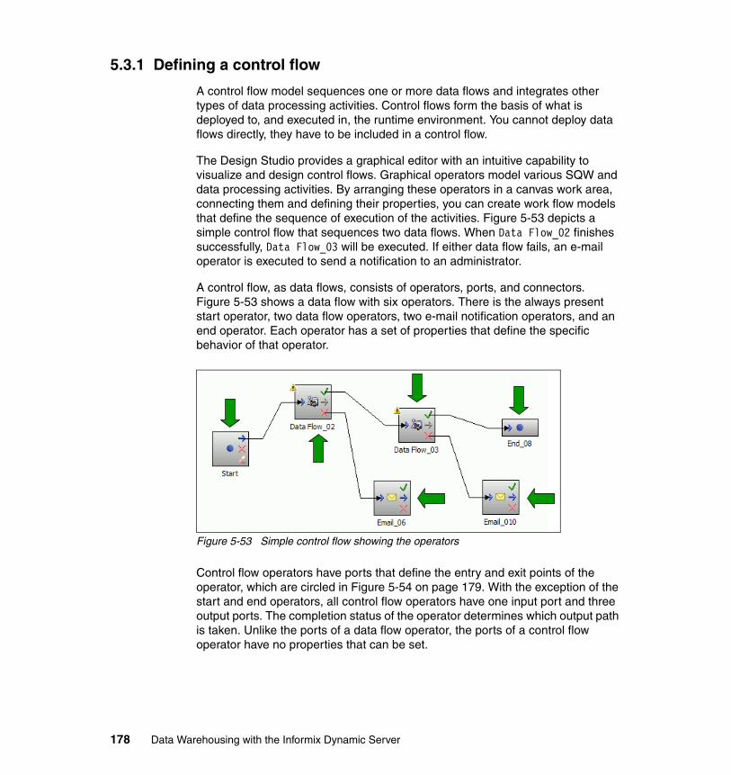
5.3.1 Defining a control flow
A control flow model sequences one or more data flows and integrates other types of data processing activities. Control flows form the basis of what is deployed to, and executed in, the runtime environment. You cannot deploy data flows directly, they have to be included in a control flow.
The Design Studio provides a graphical editor with an intuitive capability to visualize and design control flows. Graphical operators model various SQW and data processing activities. By arranging these operators in a canvas work area, connecting them and defining their properties, you can create work flow models that define the sequence of execution of the activities. Figure 5-53 depicts a simple control flow that sequences two data flows. When Data Flow_02 finishes successfully, Data Flow_03 will be executed. If either data flow fails, an e-mail operator is executed to send a notification to an administrator.
A control flow, as data flows, consists of operators, ports, and connectors. Figure 5-53 shows a data flow with six operators. There is the always present start operator, two data flow operators, two e-mail notification operators, and an end operator. Each operator has a set of properties that define the specific behavior of that operator.
Figure 5-53 Simple control flow showing the operators
Control flow operators have ports that define the entry and exit points of the operator, which are circled in Figure 5-54 on page 179. With the exception of the start and end operators, all control flow operators have one input port and three output ports. The completion status of the operator determines which output path is taken. Unlike the ports of a data flow operator, the ports of a control flow operator have no properties that can be set.
178 Data Warehousing with the Informix Dynamic Server
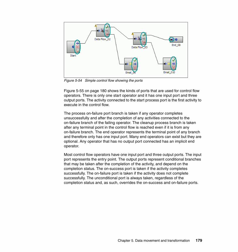
Figure 5-54 Simple control flow showing the ports
Figure 5-55 on page 180 shows the kinds of ports that are used for control flow operators. There is only one start operator and it has one input port and three output ports. The activity connected to the start process port is the first activity to execute in the control flow.
The process on-failure port branch is taken if any operator completes unsuccessfully and after the completion of any activities connected to the on-failure branch of the failing operator. The cleanup process branch is taken after any terminal point in the control flow is reached even if it is from any on-failure branch. The end operator represents the terminal point of any branch and therefore only has one input port. Many end operators can exist but they are optional. Any operator that has no output port connected has an implicit end operator.
Most control flow operators have one input port and three output ports. The input port represents the entry point. The output ports represent conditional branches that may be taken after the completion of the activity, and depend on the completion status. The on-success port is taken if the activity completes successfully. The on-failure port is taken if the activity does not complete successfully. The unconditional port is always taken, regardless of the completion status and, as such, overrides the on-success and on-failure ports.
Chapter 5. Data movement and transformation 179
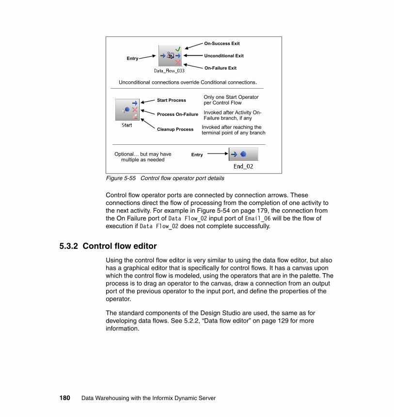
Figure 5-55 Control flow operator port details
Control flow operator ports are connected by connection arrows. These connections direct the flow of processing from the completion of one activity to the next activity. For example in Figure 5-54 on page 179, the connection from the On Failure port of Data Flow_02 input port of Email_06 will be the flow of execution if Data Flow_02 does not complete successfully.
5.3.2 Control flow editor
Using the control flow editor is very similar to using the data flow editor, but also has a graphical editor that is specifically for control flows. It has a canvas upon which the control flow is modeled, using the operators that are in the palette. The process is to drag an operator to the canvas, draw a connection from an output port of the previous operator to the input port, and define the properties of the operator.
The standard components of the Design Studio are used, the same as for developing data flows. See 5.2.2, “Data flow editor” on page 129 for more information.
Entry
On-Success Exit
Unconditional Exit
On-Failure Exit
Unconditional connections override Conditional connections.
Start Process
Process On-Failure
Cleanup Process
Only one Start Operator per Control Flow
Invoked after Activity On-Failure branch, if any
Invoked after reaching the terminal point of any branch
EntryOptional… but may have multiple as needed
180 Data Warehousing with the Informix Dynamic Server
Consider the following information as you develop control flows:
� Be familiar with the common functions in the Design Studio:
– Working with perspectives
– Working with views
– Using the Data Project Explorer
– Using the Database Explorer
– Dragging from the Data Project Explorer and palette to the canvas
� Be familiar with developing data flows.
� Orient the data flow from left to right. This orientation enables a more organized diagram because the output ports are on the right side of an operator and the input ports are on the left side.
� Work with only a few operators at a time.
� Operators have properties that must be defined.
� Operators have on-success and on-failure ports for connection purposes.
� Control flows use the same validation features as data flows.
� Think of simple data processing logic rules for success and failure conditional paths.
� Validate, generate code, and test each data flow before testing in a control flow.
5.3.3 Control flow operators
Control flow operators represent a type of data processing activity to be executed in the sequence of the control flow. Operators are graphical objects that are dragged from the palette and dropped onto the editor canvas and form the nodes of the control flow sequence. An example of the palette is depicted in Figure 5-56 on page 183.
Each operator represents a specific type of activity and has properties to define that activity:
� SQW flow operator
– Data Flow Operator
� Command operators
– Command– Secure Command– Secure FTP
Chapter 5. Data movement and transformation 181
� Control operators
– Start– Continue– Break– Fail– End– File Wait– File Write– Iterator– Parallel Container– Subprocess– Variable Assignment– Variable Comparison
� Informix operators
– Attach partition– Detach partition– IDS Custom SQL– IDS SQL Script– Update Statistics
� Notification operator
– E-mail Notification
� DataStage operators
– DataStage Parallel Job– DataStage Job Sequence
DataStage operators are discussed in 5.6, “Integrating with InfoSphere DataStage” on page 207.
182 Data Warehousing with the Informix Dynamic Server
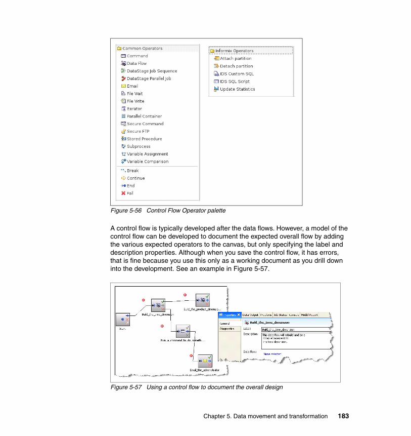
Figure 5-56 Control Flow Operator palette
A control flow is typically developed after the data flows. However, a model of the control flow can be developed to document the expected overall flow by adding the various expected operators to the canvas, but only specifying the label and description properties. Although when you save the control flow, it has errors, that is fine because you use this only as a working document as you drill down into the development. See an example in Figure 5-57.
Figure 5-57 Using a control flow to document the overall design
Chapter 5. Data movement and transformation 183
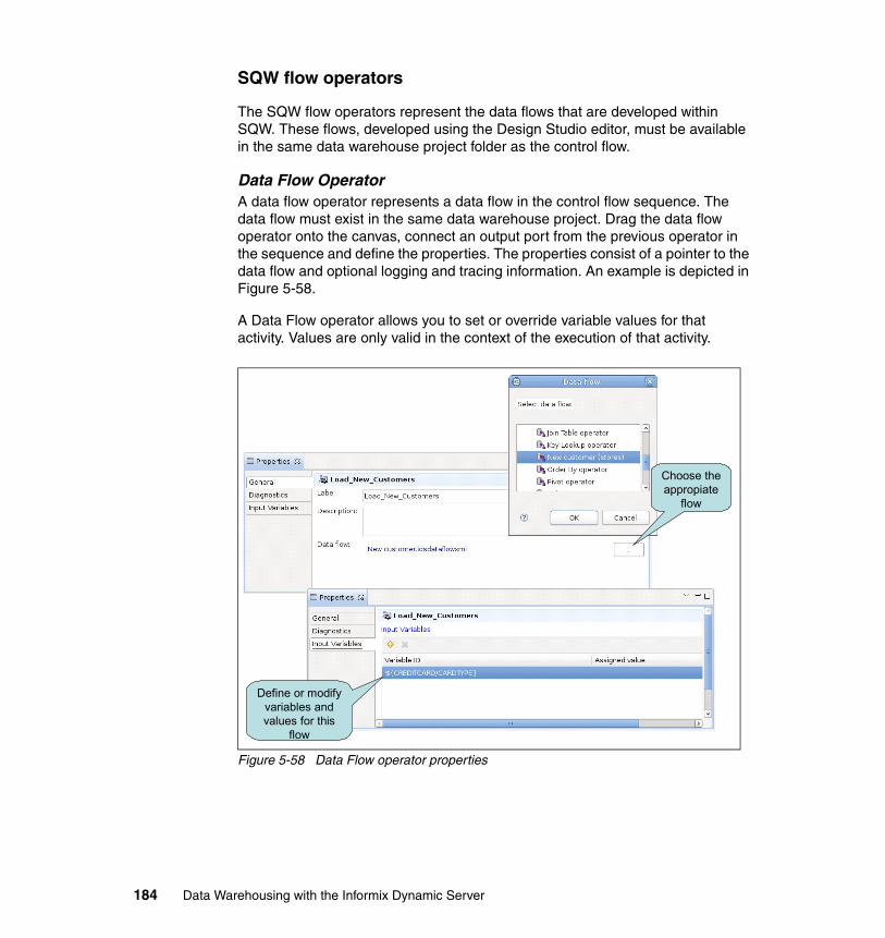
SQW flow operators
The SQW flow operators represent the data flows that are developed within SQW. These flows, developed using the Design Studio editor, must be available in the same data warehouse project folder as the control flow.
Data Flow OperatorA data flow operator represents a data flow in the control flow sequence. The data flow must exist in the same data warehouse project. Drag the data flow operator onto the canvas, connect an output port from the previous operator in the sequence and define the properties. The properties consist of a pointer to the data flow and optional logging and tracing information. An example is depicted in Figure 5-58.
A Data Flow operator allows you to set or override variable values for that activity. Values are only valid in the context of the execution of that activity.
Figure 5-58 Data Flow operator properties
Choose the appropiate
flow
Define or modify variables and values for this
flow
184 Data Warehousing with the Informix Dynamic Server
Command operatorsThe command operators are used to execute batch code that can be invoked through a type of command-line interface. Executing commands that prompt for user input is not a good practice. Commands can be operating system scripts, IDS scripts, executable programs or the FTP command, and all are supported by the same command operator. The type of command is a property of the command operator.
CommandWith the Command operator, you can run executables such as shell scripts or the FTP command. Choose the type of command-line operation to be used, and the appropriate properties are displayed.
The command that is invoked with the Command operator must terminate with an exit value. This exit value is checked to determine whether the command completed successfully. A return code of 0 indicates a successful completion.
Wildcard-based file transfers are not supported with FTP. For example, /tmp/unload/*.unl is not supported as a file path.
Non-SQL files, such as .bat and .sh files, are not included in the deployment package and therefore must be moved to the deployed system manually.
The following are general rules to be used when spaces are part of the location or parameter values. Refer to the SQL Warehousing Tool Users Guide, SC19-1257-01, for details related to your particular situation. When specifying parameters, spaces serve as delimiters.
Note the following information about operating systems:
� Linux and UNIX
Locations should be specified in the same manner, whether or not the location contains spaces. Do not enclose locations in double quotation marks. Arguments that contain spaces should be in double quotation marks. If a double quotation mark is to be passed as a parameter value, then it must be proceeded by an escape character, which is the forward slash character (/).
Note: When you define a Data Flow operator, click the ellipsis button to choose the appropriate flow. Operators in the chosen data flow can make use of variables. The Input Variables table allows you to set or override variables that are used by operators defined in the data flow. These variables are only valid in the context of the execution of this data flow.
Chapter 5. Data movement and transformation 185
� Windows
Spaces in the location or in parameters must be enclosed in double quotation marks. (Arguments for shell scripts that contain spaces must be included in triple double-quotation marks.) If a double quotation mark is to be passed as a parameter value, then it must be proceeded by an escape character, which is the backward slash character (\).
Secure CommandInvoke a command on a remote system using the Secure Shell (SSH) protocol.
The Secure Command operator provides the same functionality as the Command operator, but uses a secure connection between the Design Studio client and a remote server to run a script or a command on the remote computer.
The secure command operator uses the SSH protocol to create a secure connection between the client and the remote server. You can run the following types of commands by using the Secure Command operator:
� IDS SQL scripts� Shell scripts (including batch files)� IDS administration commands� Other executables
You can secure the execution of the command in one of the following ways:
� Use a user ID and password to execute the command on the remote computer.
� Set up a public key authentication between the client and the remote computer by using the SSH protocol.
� Set up host authentication on the client computer.
Important: Do not use the command operator to call a command that invokes an interactive executable. For example, any GUI program falls into this category, as well as any command-line utility that prompts a user response or opens an interactive shell. No other operators in the control flow will run until a user responds to the command. Depending on the behavior of the interactive executable, it might not be possible for users to respond to the executable within the context of the control flow. Consequently, the control flow waits indefinitely or is cancelled. To terminate the control flow when testing, the easiest approach would be to terminate Design Studio. To do so in a production environment, the application server must be restarted.
186 Data Warehousing with the Informix Dynamic Server
Secure FTPCopy one or more files from or to a remote host securely, using the SSH File Transfer Protocol (SFTP).
The Secure FTP operator transfers one or more files to and from a remote computer by using SFTP.
The Secure FTP operator uses the SSH protocol to create a secure connection between the client and the remote server. The operator supports the following SFTP operations:
� Put� Get
You can use expressions with wildcard characters to transfer multiples files at one time. This is different than the FTP in the Command operator.
You can provide authentication for the file transfer in one of the following ways:
� Use a user ID and password.
� Set up a public key authentication between the client and the remote computer by using the SSH protocol.
� Set up host authentication on the client.
Control operatorsIn this section, we look at the control operators.
StartEvery control flow must have one and only one Start operator. When you create a control flow, a Start operator is placed on the canvas automatically. Because of this, you cannot select a Start operator from the palette. As with other operators, you may select it so that you can view and define its properties.
The Start port on the Start operator (see Figure 5-55 on page 180) is connected to the first operator in a control flow.
The On Failure output port starts the process-level error branch of the control flow. If there is an error in any operator in the control flow, the operators connected to the activity-level On Failure port (the On Failure port for the operator that failed) is run. Then, the process-level error branch (the On Failure port for the Start operator) is run. This gives you the ability to specify unique steps to be taken when various operators fail or have a generalized error process.
Chapter 5. Data movement and transformation 187
The Cleanup output port starts the sequence of operators that are run after completing either the main processing branch or the error branch.
ContinueThis operator proceeds unconditionally with the next iteration in a processing loop performed by an iterator operator.
The Continue operator is basically the opposite of the Break operator. In this case, it allows an iteration to continue when it would have normally terminated. Assume that there is a File Wait operator coded within an iteration, and that the file wait expects the file to exist. If the file does not exist, then the iteration would terminate, but because a continuation operator is invoked when the file is not found, the iteration continues.
BreakThis operator breaks out of a processing loop that is performed by an iterator operator.
The Break operator provides a way to prematurely terminate an iteration. For example, a stored procedure is executed some number of times, based on the iteration properties. The stored procedure returns an output variable that is then checked by the Variable Compare operator. If the result of the comparison is false, then the iteration is terminated regardless of whether the defined iteration criteria was met.
FailThis operator explicitly causes the control flow to fail and proceed to the next On Failure path, if any.
EndThis operator ends a series of activities or a control flow.
File WaitThis operator checks for the existence or non-existence of a file.
The File Wait operator can pause the control flow execution for a period of time while the system checks for the existence or non-existence of a specified file. You can specify the amount of time to allocate to this operator.
In addition to the obvious use of waiting for a file to arrive to be processed, the File Wait operator is very useful for coordinating activities between executing processes or organizations by using small files as flags or semaphores. Another organization or another process could place a file in a certain directory to reflect a certain status. A control flow can check the existence of this file to determine what to do.
188 Data Warehousing with the Informix Dynamic Server
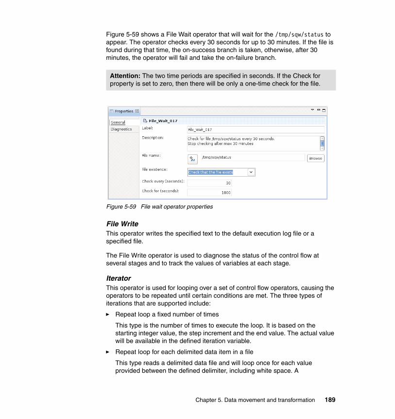
Figure 5-59 shows a File Wait operator that will wait for the /tmp/sqw/status to appear. The operator checks every 30 seconds for up to 30 minutes. If the file is found during that time, the on-success branch is taken, otherwise, after 30 minutes, the operator will fail and take the on-failure branch.
Figure 5-59 File wait operator properties
File WriteThis operator writes the specified text to the default execution log file or a specified file.
The File Write operator is used to diagnose the status of the control flow at several stages and to track the values of variables at each stage.
IteratorThis operator is used for looping over a set of control flow operators, causing the operators to be repeated until certain conditions are met. The three types of iterations that are supported include:
� Repeat loop a fixed number of times
This type is the number of times to execute the loop. It is based on the starting integer value, the step increment and the end value. The actual value will be available in the defined iteration variable.
� Repeat loop for each delimited data item in a file
This type reads a delimited data file and will loop once for each value provided between the defined delimiter, including white space. A
Attention: The two time periods are specified in seconds. If the Check for property is set to zero, then there will be only a one-time check for the file.
Chapter 5. Data movement and transformation 189

comma-delimited file with the values 1, 6, 18, and 22 will loop four times and in order, passing the current value through the defined iteration variable.
� Repeat loop for each file in a directory
This loop technique reads the names of all the files in a directory and loops once for each, making the filename available in the defined iteration variable.
When adding an iterator operator onto the canvas, you actually get two operators on the canvas, the iterator operator itself and an end iterator operator as shown in Figure 5-60 on page 191. Within the loop is one data flow operator. Of course, you can have as many operators within the loop as necessary. The properties of the iterator operator control the looping. The iterator reads file names from a comma-delimited file, and loops once for each file name executing the data flow each time. The file name value is also available through the iteration variable. The data flow uses this file name to load the proper file.
The iterator uses the iteration variable for holding the actual value of the specific iterator type. This variable can be used in any variable field in the underlying set of operators, even referenced in an underlying data flow. See 5.4, “Variables in data flows and control flows” on page 198 for more information about using variables in data flows and control flows.
Important: To pass validation, you must select a variable. To successfully run your control flow, the new variable must be defined in one of the operators in the iteration loop.
190 Data Warehousing with the Informix Dynamic Server
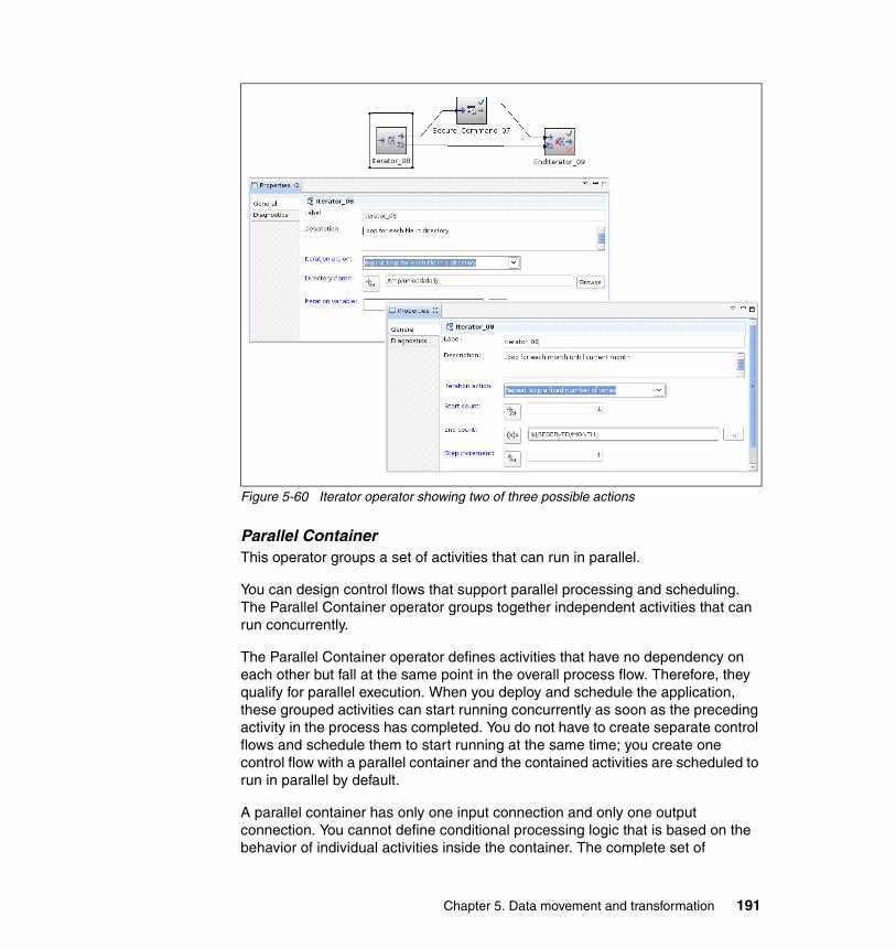
Figure 5-60 Iterator operator showing two of three possible actions
Parallel ContainerThis operator groups a set of activities that can run in parallel.
You can design control flows that support parallel processing and scheduling. The Parallel Container operator groups together independent activities that can run concurrently.
The Parallel Container operator defines activities that have no dependency on each other but fall at the same point in the overall process flow. Therefore, they qualify for parallel execution. When you deploy and schedule the application, these grouped activities can start running concurrently as soon as the preceding activity in the process has completed. You do not have to create separate control flows and schedule them to start running at the same time; you create one control flow with a parallel container and the contained activities are scheduled to run in parallel by default.
A parallel container has only one input connection and only one output connection. You cannot define conditional processing logic that is based on the behavior of individual activities inside the container. The complete set of
Chapter 5. Data movement and transformation 191
activities represents a unit of work that has one result. For example, if the first parallel data flow succeeds and the second fails, the parallel container must take the on-failure path to the next activity in the control flow.
SubprocessThis operator runs a subprocess.
Variable AssignmentThis operator assigns a variable or a fixed value to another variable.
Variable ComparisonThis operator compares a variable with a value and applies conditional processing logic based on the result.
The Variable Comparison operator allows for branching logic in a control flow. A specified variable is compared to either a constant value or to another variable. The result is either a true or false condition. (Also, an error condition can result from a type mismatch.)
The variable comparison operation can be numeric (for example, =, <, >, and so on), a string (equals, substring, and so on), or boolean. It can also test for null.
Informix operatorsThe Informix Control Flow operators are Informix-specific operators for handling fragmentation and SQL scripts.
Attach PartitionThis operator attaches a partition from another table.
Detach PartitionThis operator detaches a partition from an existing partitioned table to a separate table.
Note: Most control flow operators, including subprocesses, can be defined as activities in a parallel container. The following operators cannot be placed in a parallel container:
� Another Parallel Container� Iterator� Break� Continue� File� End� Variable Comparison
192 Data Warehousing with the Informix Dynamic Server
IDS Custom SQLThis operator is used to execute SQL commands as part of the control flow.
You can write any number of statements; both DDL and DML. The statements are executed against the database defined on the properties general tab.
IDS SQL ScriptIDS SQL Script operators run SQL script files on the IDS engine. The IDS SQL Script operator works only with files that are on the database server. When you run a flow that contains the IDS SQL Script operator, a stored procedure called INFORMIX.DS_EXECSQLSCRIPT_FILE is created and executed on the IDS server, if one does not exist already.
When using IDS SQL Script operator be aware of the following points:
� In the SQL script location field, type a file path for a directory that resides on the IDS server, or click Browse to locate and specify another directory path or use the default directory.
� To make the flow portable, consider using a variable for the path name combined with the actual script name.
Specify the particular IDS database instance where you want to run the SQL script. To view all the available data connections that the IDS SQL Script can run against, click the menu in the Informix Database connection property.
Update StatisticsThis operator performs an UPDATE STATISTICS operation to gather statistical information about database tables and data distribution information and records the information in system catalog tables.
The UPDATE STATISTICS code can either be generated by choosing various properties options or it can be manually coded.
Note: The SQL script file that is specified in this property must be located on the same machine as the IDS server.
Tip: Output files are placed in the current working directory of the Design Studio or the Application Server. Specify absolute paths in your script if you want output files to be created in a particular directory.
Chapter 5. Data movement and transformation 193
When selecting the Customized option on the properties tab that is labeled Update Statistics Statement, you can manually edit the statement. You may add a number of statements, for example:
UPDATE STATISTICS LOW DROP DISTRIBUTION;UPDATE STATISTICS HIGH FOR TABLE customer(customer_code);UPDATE STATISTICS HIGH FOR TABLE product(product_code);UPDATE STATISTICS HIGH FOR TABLE geography(district_code);UPDATE STATISTICS HIGH FOR TABLE sales(customer_code,product_code,district_code);
Each UPDATE STATISTICS statement must be terminated with a semicolon.
Notification operatorsNotification operators are used as an alert for some type of important event that has taken place in the control flow. This is typically used for notifying an administrator that some error has occurred, but could be an event such as the successful completion of the control flow. The control flow uses an e-mail operator to accomplish notification.
E-mail NotificationThe e-mail operator will simply send an e-mail to a specified e-mail address with the provided message. Figure 5-61 on page 196 shows a control flow with several e-mail operators attached to the on-failure ports of data flow operators, which will send an e-mail when a data flow encounters an error. There are properties for the sender e-mail address, the recipient e-mail address, the subject text and the message text. The SMTP server is not specified in the operator but is defined in the runtime environment as a system resource. E-mail will not be sent when executing a control flow test within the Design Studio.
DataStage operatorsDataStage operators are:
� DataStage Parallel Job� DataStage Job Sequence
Tip: If you choose Update statistics on: Tables on the properties General tab, you must supply a table name on the Table tab. Likewise, if you choose Update statistics on: Routines, you must supply a routine name. Otherwise, the control flow validation can fail, even if you select the Customized option on the Update Statistics Statement tab. To avoid having to use a table name or a routine name, choose the Update statistics on: Both tables and routines option.
194 Data Warehousing with the Informix Dynamic Server
5.3.4 Validation and code generation
A control flow is simply a model that represents the sequence of the activities you want to perform. You are not building code in a control flow, but rather defining metadata. However, at some time you will want to execute the control flow, which does require something that can be executed. So, you have to validate the data flow and generate code.
Validation and code generation can be explicitly invoked through the Control Flow menu item in the menu bar. Any time a control flow is saved, validation is implicitly invoked. Be aware that invoking code generation also causes an implicit validation to occur.
ValidationValidation is the process that the Design Studio uses to examine the metadata of a control flow to see if it is correct. If it detects a problem, it flags the problem and lists it in the Problems view tab. If the problem is in an operator, a visual notification icon appears in the upper left corner of each operator that has a problem. In addition to the validation of the control flow metadata, validation also individually validates all data flows and subflows in a hierarchical manner. If you have a large control flow containing many data flows, expect the validation to take a bit longer.
Figure 5-61 on page 196 shows how to explicitly invoke a control flow validation from the Control Flow menu for a control flow with a Secure FTP operator with an error as indicated by the symbols in the upper left corner of the operator icon (in our example in the figure, it is the upper left corner of the Validate menu item). The diagnostic dialog shows that the Secure FTP operator is missing a file name in its properties.
Chapter 5. Data movement and transformation 195
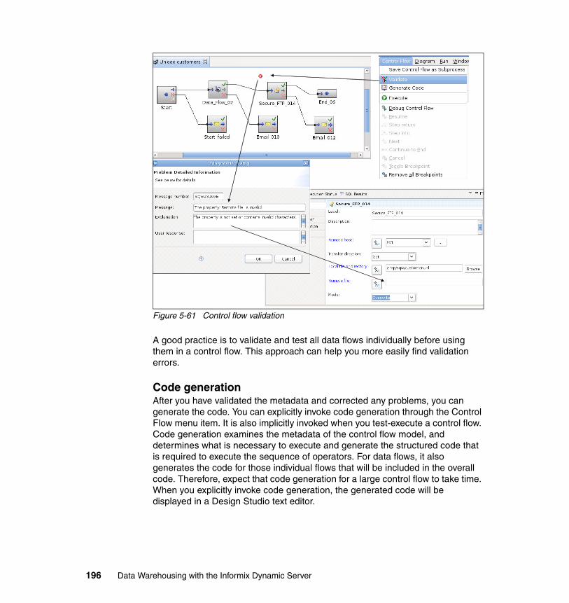
Figure 5-61 Control flow validation
A good practice is to validate and test all data flows individually before using them in a control flow. This approach can help you more easily find validation errors.
Code generationAfter you have validated the metadata and corrected any problems, you can generate the code. You can explicitly invoke code generation through the Control Flow menu item. It is also implicitly invoked when you test-execute a control flow. Code generation examines the metadata of the control flow model, and determines what is necessary to execute and generate the structured code that is required to execute the sequence of operators. For data flows, it also generates the code for those individual flows that will be included in the overall code. Therefore, expect that code generation for a large control flow to take time. When you explicitly invoke code generation, the generated code will be displayed in a Design Studio text editor.
196 Data Warehousing with the Informix Dynamic Server

As with the data flow, the code is represented in an execution plan graph (EPG). However, no special EPG viewer is necessary for a control flow because the control flow itself is a type of graphical EPG.
5.3.5 Testing and debugging a control flow
After a successful validation, control flows can be tested from within the Design Studio without having to set up or deploy to a runtime environment. And, if necessary, control flows can be debugged using the control flow debugger.
To test-execute a control flow, first establish a connection to the database, or databases, of interest in the Database Explorer. Make sure that the control flow is open and has the focus. Then, select Execute from the Data Flow menu. You are prompted with the Flow Execution dialog, which is where you provide information supporting the execution, such as the trace options, resource definitions, and set values for any variables. You can save these values in a run profile for future use. Be aware that a test execution also implicitly invokes both validation and code generation, so the process might take longer than you expect for the execution to start. After the control flow has completed executing, you are presented with the Execution Result showing the status of the execution and any error messages that might have been received.
To debug a control, select Debug Control Flow from the Control Flow menu and complete the Flow Execution dialog. Be aware that a test execution also implicitly invokes both validation and code generation so the process might take longer than you expect for the debug session to start. The debug session takes place directly in the control flow editor instead of a separate EPG viewer, but operates just like the data flow operator. Figure 5-62 on page 198 shows a control flow debug session.
Attention: The control flow debugger executes data flows as a black box, and does not step into the data flow EPG. The assumption is that, by now, you will have already debugged the data flows individually.
Chapter 5. Data movement and transformation 197
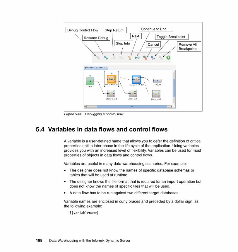
Figure 5-62 Debugging a control flow
5.4 Variables in data flows and control flows
A variable is a user-defined name that allows you to defer the definition of critical properties until a later phase in the life cycle of the application. Using variables provides you with an increased level of flexibility. Variables can be used for most properties of objects in data flows and control flows.
Variables are useful in many data warehousing scenarios. For example:
� The designer does not know the names of specific database schemas or tables that will be used at runtime.
� The designer knows the file format that is required for an import operation but does not know the names of specific files that will be used.
� A data flow has to be run against two different target databases.
Variable names are enclosed in curly braces and preceded by a dollar sign, as the following example:
${variablename}
Debug Control Flow
Resume Debug
Step Return
Step Into
Next
Continue to End
Cancel
Toggle Breakpoint
Remove All Breakpoints
198 Data Warehousing with the Informix Dynamic Server
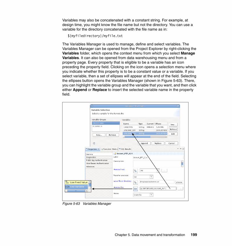
Variables may also be concatenated with a constant string. For example, at design time, you might know the file name but not the directory. You can use a variable for the directory concatenated with the file name as in:
${myfiledirectory}/myfile.txt
The Variables Manager is used to manage, define and select variables. The Variables Manager can be opened from the Project Explorer by right-clicking the Variables folder, which opens the context menu from which you select Manage Variables. It can also be opened from data warehousing menu and from a property page. Every property that is eligible to be a variable has an icon preceding the property field. Clicking on the icon opens a selection menu where you indicate whether this property is to be a constant value or a variable. If you select variable, then a set of ellipses will appear at the end of the field. Selecting the ellipses button opens the Variables Manager (shown in Figure 5-63). There, you can highlight the variable group and the variable that you want, and then click either Append or Replace to insert the selected variable name in the property field.
Figure 5-63 Variables Manager
Chapter 5. Data movement and transformation 199
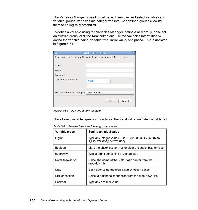
The Variables Manger is used to define, edit, remove, and select variables and variable groups. Variables are categorized into user-defined groups allowing them to be logically organized.
To define a variable using the Variables Manager, define a new group, or select an existing group, click the New button and use the Variables Information to define the variable name, variable type, initial value, and phase. This is depicted in Figure 5-64.
Figure 5-64 Defining a new variable
The allowed variable types and how to set the initial value are listed in Table 5-1.
Table 5-1 Variable types and setting initial values
Variable types Setting an initial value
BigInt Type any integer value (–9,223,372,036,854,775,807 to 9,223,372,036,854,775,807).
Boolean Mark the check box for true or clear the check box for false.
ByteArray Type a string containing any character.
DataStageServer Select the name of the DataStage server from the drop-down list.
Date Set a date using the drop-down selection boxes.
DBConnection Select a database connection from the drop-down list.
Decimal Type any decimal value.
200 Data Warehousing with the Informix Dynamic Server
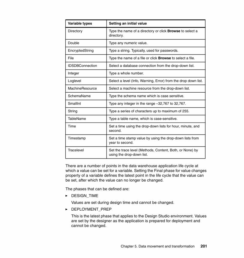
There are a number of points in the data warehouse application life cycle at which a value can be set for a variable. Setting the Final phase for value changes property of a variable defines the latest point in the life cycle that the value can be set, after which the value can no longer be changed.
The phases that can be defined are:
� DESIGN_TIME
Values are set during design time and cannot be changed.
� DEPLOYMENT_PREP
This is the latest phase that applies to the Design Studio environment. Values are set by the designer as the application is prepared for deployment and cannot be changed.
Directory Type the name of a directory or click Browse to select a directory.
Double Type any numeric value.
EncryptedString Type a string. Typically, used for passwords.
File Type the name of a file or click Browse to select a file.
IDSDBConnection Select a database connection from the drop-down list.
Integer Type a whole number.
Loglevel Select a level (Info, Warning, Error) from the drop down list.
MachineResource Select a machine resource from the drop-down list.
SchemaName Type the schema name which is case sensitive.
SmallInt Type any integer in the range –32,767 to 32,767.
String Type a series of characters up to maximum of 255.
TableName Type a table name, which is case-sensitive.
Time Set a time using the drop-down lists for hour, minute, and second.
Timestamp Set a time stamp value by using the drop-down lists from year to second.
Tracelevel Set the trace level (Methods, Content, Both, or None) by using the drop-down list.
Variable types Setting an initial value
Chapter 5. Data movement and transformation 201
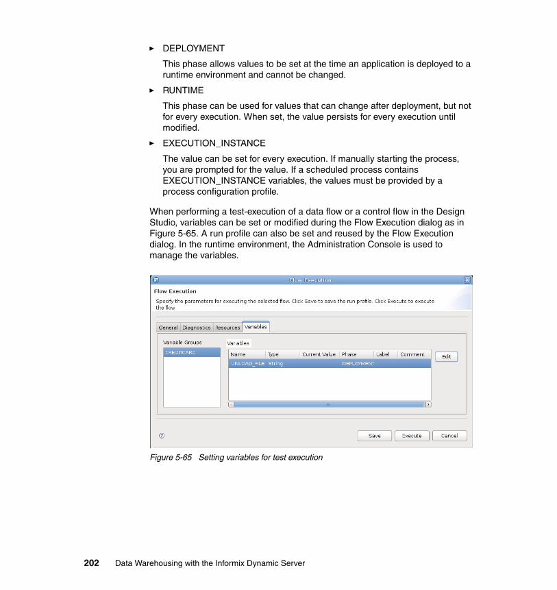
� DEPLOYMENT
This phase allows values to be set at the time an application is deployed to a runtime environment and cannot be changed.
� RUNTIME
This phase can be used for values that can change after deployment, but not for every execution. When set, the value persists for every execution until modified.
� EXECUTION_INSTANCE
The value can be set for every execution. If manually starting the process, you are prompted for the value. If a scheduled process contains EXECUTION_INSTANCE variables, the values must be provided by a process configuration profile.
When performing a test-execution of a data flow or a control flow in the Design Studio, variables can be set or modified during the Flow Execution dialog as in Figure 5-65. A run profile can also be set and reused by the Flow Execution dialog. In the runtime environment, the Administration Console is used to manage the variables.
Figure 5-65 Setting variables for test execution
202 Data Warehousing with the Informix Dynamic Server
5.5 Preparing for deployment
The SQW warehouse application, as with any application, follows the usual develop, test, and production cycle. So far in this chapter, we have focused on the development of data flows and control flows and have tested them in an isolated development environment. In this section, we look at the final step that the designer performs in the Design Studio, which is to prepare an application for deployment to a runtime environment.
The ultimate goal is to execute these warehousing applications in a production system. Before going to production, be sure that the applications work well with other applications and production-like data, and within the system infrastructure. This may be called system testing, quality assurance, or user acceptance testing. We want to be sure that, when the application is installed in the production system, problems will have already been corrected.
Moving the warehousing application from a developer’s environment to some type of runtime environment, whether test or production, is called deployment. SQW deployment is performed in two steps:
1. The developer uses the Design Studio to prepare and package the application for deployment resulting in a deployment file.
2. This deployment file is then deployed, or installed, into a system testing environment.
If problems occur, the data flow or control flow must be modified in the development environment, the Design Studio, and then redeployed to the test runtime environment. After it is successfully tested, the same deployment package can be installed into the production environment.
This section describes how to prepare a set of data flows and control flows for deployment, resulting in a deployment package. The actual installation, or deployment, into a runtime environment is discussed in Chapter 6, “Deploying and managing Informix Warehouse solutions” on page 217.
The process of preparing an application for deployment uses wizards to define a warehouse application, define application profiles, generate code and create a .zip file containing the actual deployment package.
Chapter 5. Data movement and transformation 203
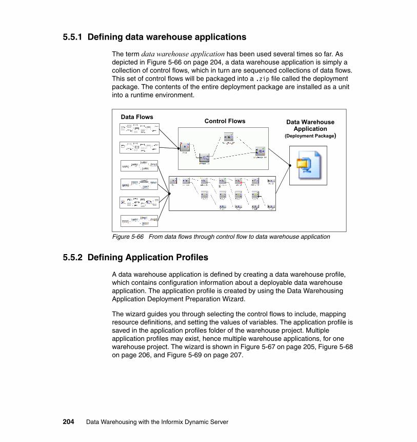
5.5.1 Defining data warehouse applications
The term data warehouse application has been used several times so far. As depicted in Figure 5-66 on page 204, a data warehouse application is simply a collection of control flows, which in turn are sequenced collections of data flows. This set of control flows will be packaged into a .zip file called the deployment package. The contents of the entire deployment package are installed as a unit into a runtime environment.
Figure 5-66 From data flows through control flow to data warehouse application
5.5.2 Defining Application Profiles
A data warehouse application is defined by creating a data warehouse profile, which contains configuration information about a deployable data warehouse application. The application profile is created by using the Data Warehousing Application Deployment Preparation Wizard.
The wizard guides you through selecting the control flows to include, mapping resource definitions, and setting the values of variables. The application profile is saved in the application profiles folder of the warehouse project. Multiple application profiles may exist, hence multiple warehouse applications, for one warehouse project. The wizard is shown in Figure 5-67 on page 205, Figure 5-68 on page 206, and Figure 5-69 on page 207.
Data Flows Control Flows Data WarehouseApplication
(Deployment Package)
204 Data Warehousing with the Informix Dynamic Server
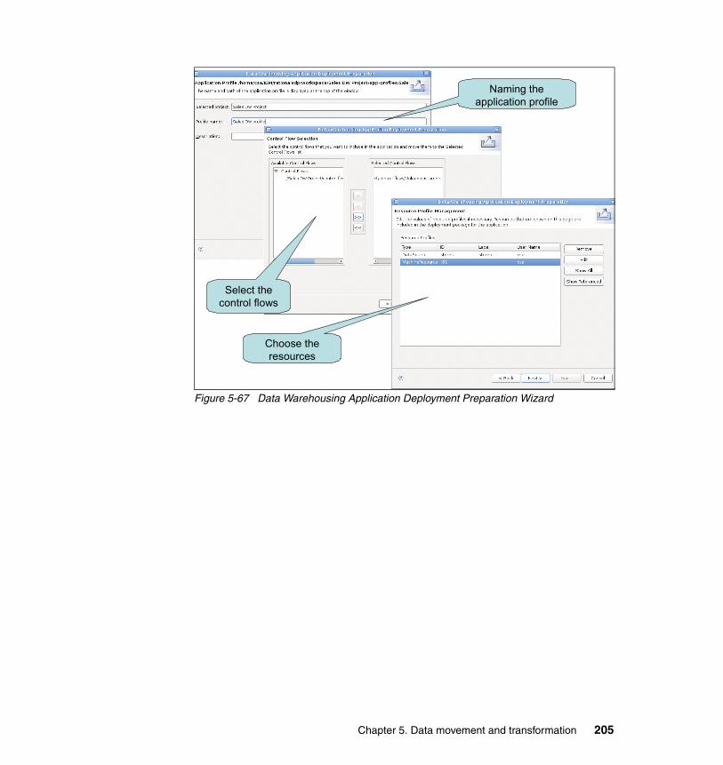
Figure 5-67 Data Warehousing Application Deployment Preparation Wizard
Naming the application profile
Select the control flows
Choose the resources
Chapter 5. Data movement and transformation 205
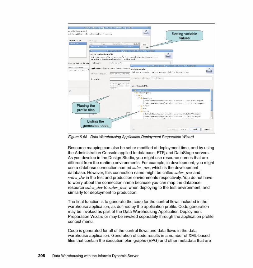
Figure 5-68 Data Warehousing Application Deployment Preparation Wizard
Resource mapping can also be set or modified at deployment time, and by using the Administration Console applied to database, FTP, and DataStage servers. As you develop in the Design Studio, you might use resource names that are different from the runtime environments. For example, in development, you might use a database connection named sales_dev, which is the development database. However, this connection name might be called sales_test and sales_dw in the test and production environments respectively. You do not have to worry about the connection name because you can map the database resource sales_dev to sales_test, when deploying to the test environment, and similarly for deployment to production.
The final function is to generate the code for the control flows included in the warehouse application, as defined by the application profile. Code generation may be invoked as part of the Data Warehousing Application Deployment Preparation Wizard or may be invoked separately through the application profile context menu.
Code is generated for all of the control flows and data flows in the data warehouse application. Generation of code results in a number of XML-based files that contain the execution plan graphs (EPG) and other metadata that are
Setting variable values
Placing the profile files
Listing the generated code
206 Data Warehousing with the Informix Dynamic Server
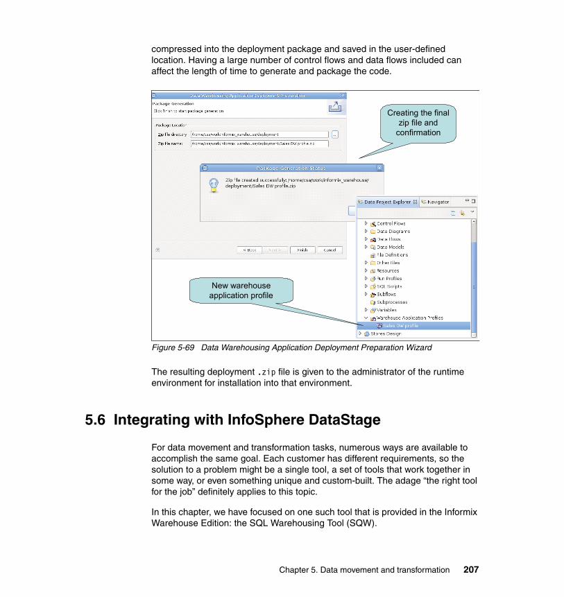
compressed into the deployment package and saved in the user-defined location. Having a large number of control flows and data flows included can affect the length of time to generate and package the code.
Figure 5-69 Data Warehousing Application Deployment Preparation Wizard
The resulting deployment .zip file is given to the administrator of the runtime environment for installation into that environment.
5.6 Integrating with InfoSphere DataStage
For data movement and transformation tasks, numerous ways are available to accomplish the same goal. Each customer has different requirements, so the solution to a problem might be a single tool, a set of tools that work together in some way, or even something unique and custom-built. The adage “the right tool for the job” definitely applies to this topic.
In this chapter, we have focused on one such tool that is provided in the Informix Warehouse Edition: the SQL Warehousing Tool (SQW).
New warehouse application profile
Creating the final zip file and
confirmation
Chapter 5. Data movement and transformation 207

In this section, we look at the IBM enterprise ETL tool, IBM InfoSphere DataStage to understand:
� When, where, and why to use each type of tool� How SQW and enterprise ETL tools complement each other� How and why to integrate DataStage functionality into SQW
SQW is a strategic design and deployment component within Informix Warehouse that leverages the SQL processing of IDS to perform data movement and transformation. In contrast, IBM InfoSphere DataStage uses its own high-performance parallel and scalable engine that can operate independently of the database vendor. It can also produce limited database specific SQL for processing that is completed within the database.
DataStage is optimized for integrating information from a myriad of sources inside and outside of the enterprise while processing high volumes of data resulting in population of the detail layer of the data warehouse. And DataStage has a rich library of prebuilt transformations to make the task faster and easier. SQW is optimized exclusively for Informix Warehouse, using a set of SQL operations to create and maintain data structures, based primarily on the data in the detail layer. These structures are typically used for analytic applications found in business intelligence (BI), and comprise part of the business intelligence framework as discussed in Chapter 1, “Introduction” on page 1.
DataStage and SQW have some functionality that is different, and some functionality that may overlap. Therefore, clients can find that either one, both, or a combination of the two might best satisfy their requirements. The two products can complement each other in an enterprise data warehousing environment based on the IBM Informix Dynamic Server.
5.6.1 Overview of IBM InfoSphere DataStage
IBM InfoSphere DataStage is the strategic enterprise ETL component for IBM InfoSphere Information Server. Embracing the concepts of service-oriented architecture (SOA), InfoSphere Information Server delivers multiple discrete services that hide the complexities of distributed configurations.
In this way, services can focus on functionality, and the individual InfoSphere components can be used to satisfy intricate tasks without custom programming. This design supports the configuration of integration jobs that match a wide variety of client environments and tiered architectures. For example, InfoSphere DataStage supports the collection, transformation, and distribution of large volumes of data, with data structures ranging from simple to highly complex.
The system manages data arriving in real-time as well as data received on a periodic or scheduled basis. Companies can solve large-scale business
208 Data Warehousing with the Informix Dynamic Server
problems through high-performance processing of massive data volumes. By leveraging the parallel processing capabilities of multiprocessor hardware platforms, DataStage can scale to satisfy the demands of ever-growing data volumes, stringent real-time requirements, and ever shrinking batch windows.
InfoSphere DataStage has the functionality, flexibility, and scalability required to perform the following demanding data integration tasks:
� Integrate data from the widest range of enterprise and external data sources.
� Incorporate data validation rules.
� Process and transform large volumes of data using scalable parallel processing.
� Handle very complex transformations.
� Manage multiple integration processes.
� Provide direct connectivity to enterprise application as sources or targets.
� Leverage metadata for analysis and maintenance.
� Operate in batch, real-time, or as a Web service.
In its simplest form, DataStage performs data movement and transformation from source systems to target systems in batch and in real-time. The data source can include indexed files, sequential files, relational database, archives, external data sources, enterprise application, and message queues. The transformations may also include:
� String and numeric formatting and data type conversions from source to target systems
� Business derivations and calculations performed by applying business rules and algorithms to the data. Examples range from straightforward currency conversions to more complex profit calculations.
� Reference data checks and enforcement to validate customer or product identifiers. This technique is used in building a normalized data warehouse.
� Conversion of reference data from disparate sources to a common reference set, creating consistency across these systems. This technique is used to create a master data set (or conformed dimensions) for data involving products, customers, suppliers, and employees.
� Aggregations for reporting and analytics
Creation of analytical or reporting databases, such as data marts or multidimensional cubes, is a process that involves denormalizing data into structures such as star or snowflake schemas to improve performance and ease of use for business users.
Chapter 5. Data movement and transformation 209
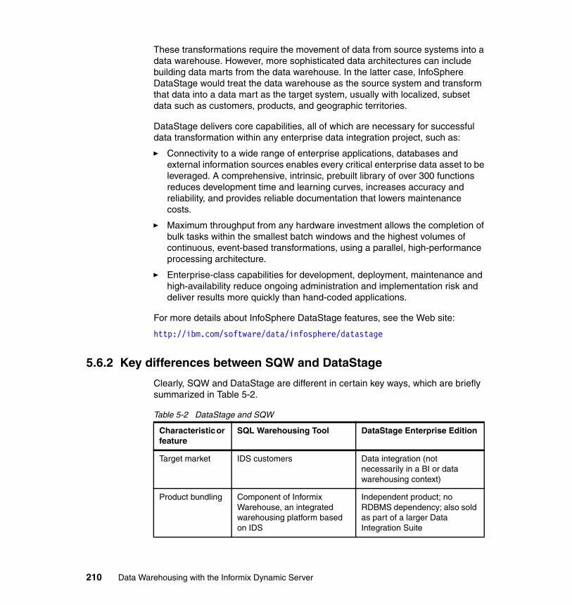
These transformations require the movement of data from source systems into a data warehouse. However, more sophisticated data architectures can include building data marts from the data warehouse. In the latter case, InfoSphere DataStage would treat the data warehouse as the source system and transform that data into a data mart as the target system, usually with localized, subset data such as customers, products, and geographic territories.
DataStage delivers core capabilities, all of which are necessary for successful data transformation within any enterprise data integration project, such as:
� Connectivity to a wide range of enterprise applications, databases and external information sources enables every critical enterprise data asset to be leveraged. A comprehensive, intrinsic, prebuilt library of over 300 functions reduces development time and learning curves, increases accuracy and reliability, and provides reliable documentation that lowers maintenance costs.
� Maximum throughput from any hardware investment allows the completion of bulk tasks within the smallest batch windows and the highest volumes of continuous, event-based transformations, using a parallel, high-performance processing architecture.
� Enterprise-class capabilities for development, deployment, maintenance and high-availability reduce ongoing administration and implementation risk and deliver results more quickly than hand-coded applications.
For more details about InfoSphere DataStage features, see the Web site:
http://ibm.com/software/data/infosphere/datastage
5.6.2 Key differences between SQW and DataStage
Clearly, SQW and DataStage are different in certain key ways, which are briefly summarized in Table 5-2.
Table 5-2 DataStage and SQW
Characteristic or feature
SQL Warehousing Tool DataStage Enterprise Edition
Target market IDS customers Data integration (not necessarily in a BI or data warehousing context)
Product bundling Component of Informix Warehouse, an integrated warehousing platform based on IDS
Independent product; no RDBMS dependency; also sold as part of a larger Data Integration Suite
210 Data Warehousing with the Informix Dynamic Server
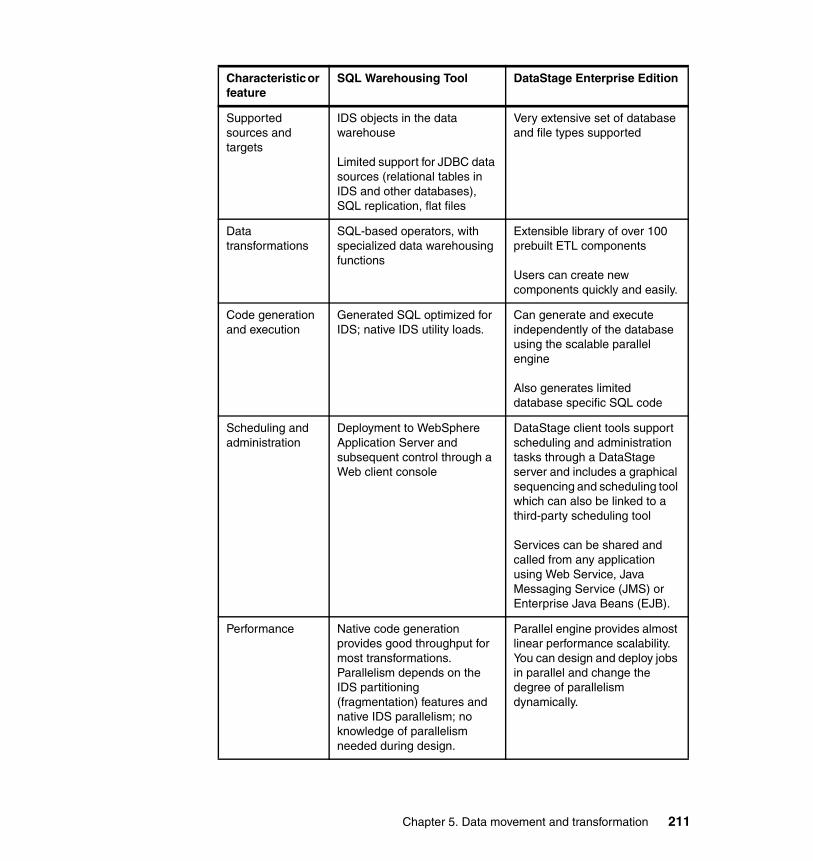
Supported sources and targets
IDS objects in the data warehouse
Limited support for JDBC data sources (relational tables in IDS and other databases), SQL replication, flat files
Very extensive set of database and file types supported
Data transformations
SQL-based operators, with specialized data warehousing functions
Extensible library of over 100 prebuilt ETL components
Users can create new components quickly and easily.
Code generation and execution
Generated SQL optimized for IDS; native IDS utility loads.
Can generate and execute independently of the database using the scalable parallel engine
Also generates limited database specific SQL code
Scheduling and administration
Deployment to WebSphere Application Server and subsequent control through a Web client console
DataStage client tools support scheduling and administration tasks through a DataStage server and includes a graphical sequencing and scheduling tool which can also be linked to a third-party scheduling tool
Services can be shared and called from any application using Web Service, Java Messaging Service (JMS) or Enterprise Java Beans (EJB).
Performance Native code generation provides good throughput for most transformations. Parallelism depends on the IDS partitioning (fragmentation) features and native IDS parallelism; no knowledge of parallelism needed during design.
Parallel engine provides almost linear performance scalability. You can design and deploy jobs in parallel and change the degree of parallelism dynamically.
Characteristic or feature
SQL Warehousing Tool DataStage Enterprise Edition
Chapter 5. Data movement and transformation 211
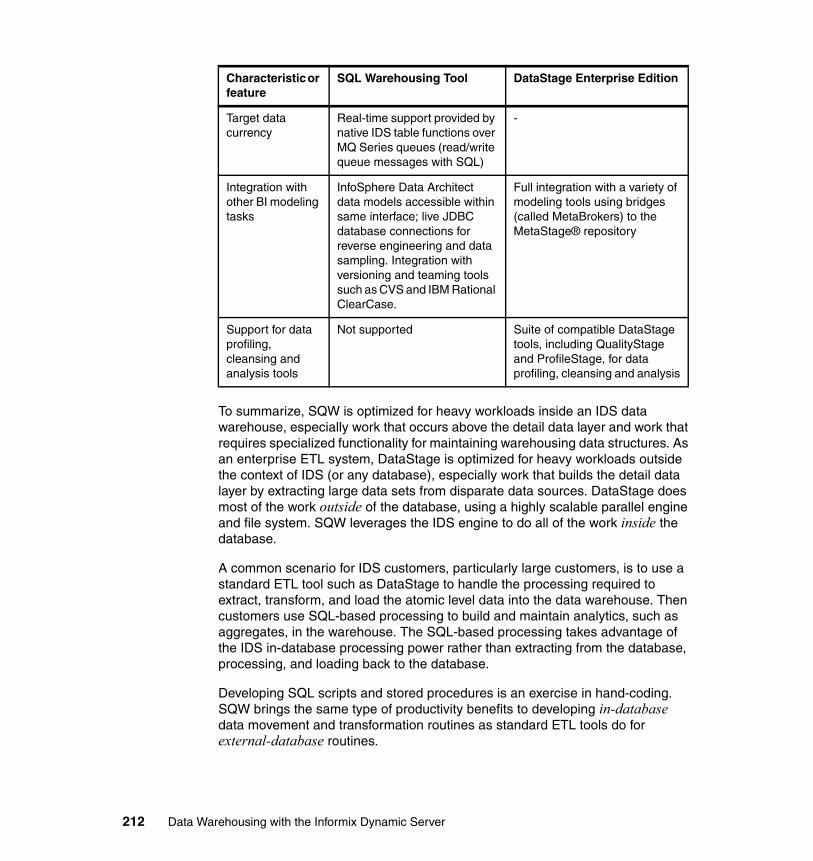
To summarize, SQW is optimized for heavy workloads inside an IDS data warehouse, especially work that occurs above the detail data layer and work that requires specialized functionality for maintaining warehousing data structures. As an enterprise ETL system, DataStage is optimized for heavy workloads outside the context of IDS (or any database), especially work that builds the detail data layer by extracting large data sets from disparate data sources. DataStage does most of the work outside of the database, using a highly scalable parallel engine and file system. SQW leverages the IDS engine to do all of the work inside the database.
A common scenario for IDS customers, particularly large customers, is to use a standard ETL tool such as DataStage to handle the processing required to extract, transform, and load the atomic level data into the data warehouse. Then customers use SQL-based processing to build and maintain analytics, such as aggregates, in the warehouse. The SQL-based processing takes advantage of the IDS in-database processing power rather than extracting from the database, processing, and loading back to the database.
Developing SQL scripts and stored procedures is an exercise in hand-coding. SQW brings the same type of productivity benefits to developing in-database data movement and transformation routines as standard ETL tools do for external-database routines.
Target data currency
Real-time support provided by native IDS table functions over MQ Series queues (read/write queue messages with SQL)
-
Integration with other BI modeling tasks
InfoSphere Data Architect data models accessible within same interface; live JDBC database connections for reverse engineering and data sampling. Integration with versioning and teaming tools such as CVS and IBM Rational ClearCase.
Full integration with a variety of modeling tools using bridges (called MetaBrokers) to the MetaStage® repository
Support for data profiling, cleansing and analysis tools
Not supported Suite of compatible DataStage tools, including QualityStage and ProfileStage, for data profiling, cleansing and analysis
Characteristic or feature
SQL Warehousing Tool DataStage Enterprise Edition
212 Data Warehousing with the Informix Dynamic Server
If any of your data warehouse processing relies heavily on hand-coded SQL scripts, procedures or applications, SQW would be a good fit and could replace the custom code with data flows or have a combination of SQW data flows and custom code integrated into control flows. Also, smaller IDS shops that cannot yet justify the cost of a full-scale ETL product, could use SQW for their data movement and transformation flows.
5.6.3 Integrating DataStage and SQW
For situations where using DataStage and SQW together is desired, SQW has built-in integration points. Although DataStage and SQW are sold separately and have their own development interface, the resulting jobs of both tools can be integrated and managed together from either DataStage or Informix Warehouse runtime components.
Integrating DataStage jobs into SQWIntegrating DataStage jobs into SQW allows you to use the capabilities of the Informix Warehouse runtime environment to manage and schedule the execution of both DataStage jobs and SQW flows. DataStage jobs are submitted by the Informix Warehouse runtime code to a DataStage server for execution; the SQW flows are submitted to the IDS execution database for processing.
The two ways to integrate DataStage jobs into SQW are:
� Embed a DataStage parallel job into a data flow as a subflow. This way is accomplished by first exporting a DataStage job in XML format and then importing it into the Design Studio. This subflow can then be used as an operator in one or more SQW data flows and connected directly to SQL operators, thereby becoming part of the data flow.
� Embed DataStage jobs into control flows, thereby sequencing DataStage jobs along with data flows and other operators supported by SQW control flows. SQW control flows have operators for DataStage parallel jobs and DataStage job sequences which are put onto the canvas, then properties that point to the DataStage server and the particular job are defined.
To support the integration of DataStage jobs, SQW provides a DataStage Server view and a Job Status view. These views provide information about the DataStage servers that are available and the particular jobs they are running.
Integrating SQW flows into DataStageIntegrating SQW flows into DataStage jobs allows you to use the capabilities of DataStage to manage and schedule the execution of both DataStage jobs and SQW flows. In this case, control flows and the Informix Warehouse runtime environment are not used. Instead, data flows are transformed into SQL scripts
Chapter 5. Data movement and transformation 213
that are embedded as DataStage command stages in a DataStage job. The resulting job can then be used in DataStage job sequences.
5.7 Using Informix load utilities
In section 5.1.4, “Source, target, and execution databases” on page 123, we discussed various scenarios of production databases, execution databases, and data warehouse databases. Because the transformations and data loading made with SQW is based on SQL capabilities within the execution database, a good practice is for these transformations and loads into the final fact tables, aggregate tables, and dimensions take place in the data warehouse database. Likewise if you extract data from the data warehouse to data marts using SQW, a good practice is for the execution database to be located in the data warehouse.
However, in various situations, other data movement utilities can solve the task faster. The IDS engine comes standard with a number of data movement utilities. These are dbexport and dbimport, onunload and onload, dbload, and High-Performance Loader (HPL). Several of these utilities are discussed in this section. For more detail about each utility, refer to Chapter 7, “Optimizing your Informix Warehouse environment” on page 277.
5.7.1 The High-Performance Loader
Most likely, a number of source databases exist from where data will be extracted, as depicted in Figure 5-70 on page 215. If the source databases are IDS-based, the most effective extraction tool is the High-Performance Loader (HPL). HPL can use files, tapes, and named pipes as output targets. When the data arrives at the data warehouse system, HPL is probably also be the most efficient tool for loading the data into staging tables. If the data sources are non-IDS based, you can use either unload tools (that come with the specific RDBMS) or specialized extraction systems (such as IBM InfoSphere DataStage). Again, when the data arrives at the data warehouse system, consider HPL for loading the data into staging tables. HPL has transformation capabilities that may satisfy your requirements. One of the features is the character set conversion. For example, if your data originates from a mainframe, HPL can read EBCDIC sources and load data as ASCII. For a detailed description of HPL, see section 7.3, “Data loading capabilities” on page 280.
214 Data Warehousing with the Informix Dynamic Server
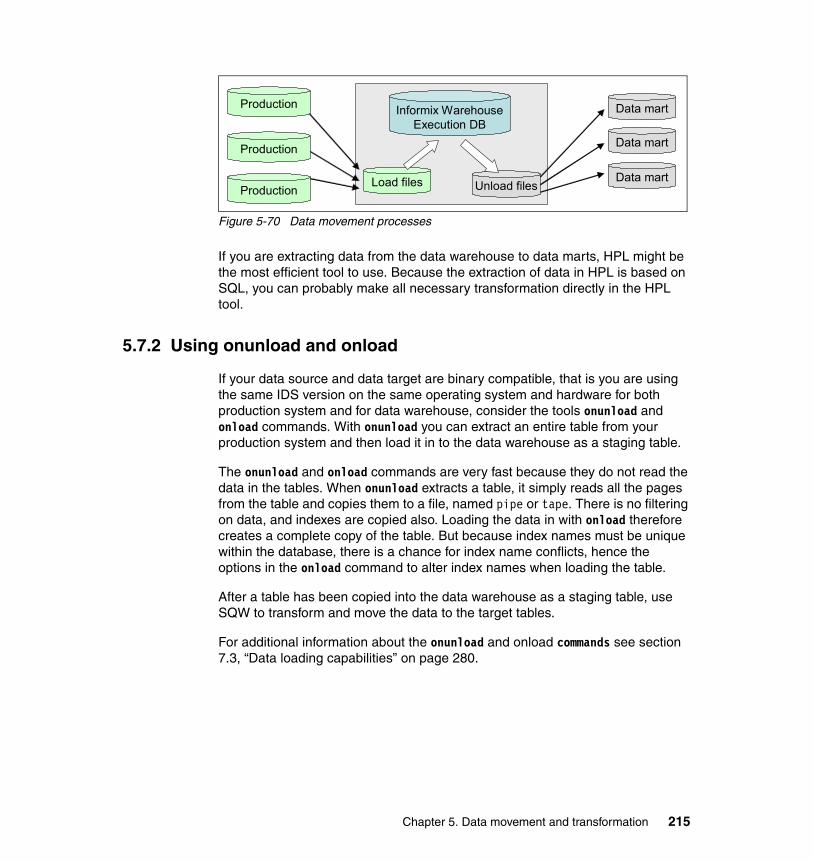
Figure 5-70 Data movement processes
If you are extracting data from the data warehouse to data marts, HPL might be the most efficient tool to use. Because the extraction of data in HPL is based on SQL, you can probably make all necessary transformation directly in the HPL tool.
5.7.2 Using onunload and onload
If your data source and data target are binary compatible, that is you are using the same IDS version on the same operating system and hardware for both production system and for data warehouse, consider the tools onunload and onload commands. With onunload you can extract an entire table from your production system and then load it in to the data warehouse as a staging table.
The onunload and onload commands are very fast because they do not read the data in the tables. When onunload extracts a table, it simply reads all the pages from the table and copies them to a file, named pipe or tape. There is no filtering on data, and indexes are copied also. Loading the data in with onload therefore creates a complete copy of the table. But because index names must be unique within the database, there is a chance for index name conflicts, hence the options in the onload command to alter index names when loading the table.
After a table has been copied into the data warehouse as a staging table, use SQW to transform and move the data to the target tables.
For additional information about the onunload and onload commands see section 7.3, “Data loading capabilities” on page 280.
Data mart
Data mart
Data martLoad files Unload files
Production
Production
Production
Informix Warehouse Execution DB
Chapter 5. Data movement and transformation 215

5.7.3 Informix dbload
The dbload command has its strength in reading ASCII files. It can read both standard Informix delimited files and also fixed record length files. It can even take substrings.
Informix dbload uses a command file for controlling the load job, and has many features for fx error handling and commit frequency. Because dbload uses a command file, you can set up dbload to read from several files as well as writing to several tables.
For additional information about the dbload command, refer to 7.3, “Data loading capabilities” on page 280.
216 Data Warehousing with the Informix Dynamic Server
Chapter 6. Deploying and managing Informix Warehouse solutions
To provide the data required for analysis, an Informix Warehouse solution typically contains several components, which have been discussed in the previous chapters of this book. The starting point in a data warehouse implementation is the development of a physical data model to hold the required data. After a data model is in place, the data can be readily accessed and used for analysis. SQL Warehousing (SQW) data flows and control flows must be in place to ensure that the data being used for analysis is current and is being accessed in the most efficient way.
After a solution has been developed, Informix Warehouse provides the ability to deploy and manage that solution in a production environment. The range of tasks required for each component of the solution vary from ensuring that the production databases are enabled for OLAP through to the actual running of the routines to maintain the data. The component within Informix Warehouse that is provided to deploy and manage these tasks is the Informix Warehouse Administration Console (Admin Console).
6
© Copyright IBM Corp. 2009. All rights reserved. 217

The Admin Console component is installed within WebSphere Application Server, which is the infrastructure used for the runtime environment. The SQW data flows and control flows, to maintain the production data, have to be deployed and managed through the Admin Console. For other tasks, such as the deploying of the physical model, it is a good practice to use the Admin Console. However, other methods, such as directly deploying SQL scripts, are also available.
In this chapter, we discuss how to use the Admin Console to deploy and manage solutions. Topics included are:
� Informix Warehouse Administration Console (Admin Console)
� Deployment of development code into a test or production environment
� Managing the SQL Warehousing solution with the Admin Console
� Location and use of diagnostic information
218 Data Warehousing with the Informix Dynamic Server
6.1 Informix Warehouse Administration Console
Informix Warehouse Administration Console (Admin Console), is a Web-based application for administering database and system resources related to your warehouse. The Admin Console provides the capability to deploy, schedule, and monitor the control flows created in Design Studio through processes called the SQL Warehousing (SQW) services. To be able to support these SQW run-time services, WebSphere Application Server is packaged with the Admin Console, but you can also run the Admin Console on any other Java-based application server.
You can log in to the Admin Console by using the following address:
http://host_name:9080/ibm/warehouse
After you log in to the Admin Console the Welcome page is displayed, as shown in Figure 6-1 on page 220. On that Welcome page you can see the components of an Informix Warehouse solution that can be accessed and managed.
Note: If port number 9080 is already taken, you can find the default port number in the portdef.props file in the following location:
AppServer\profiles\AppSrv01\properties\portdef.props
The default port number is specified by the WC_defaulthost property.
Chapter 6. Deploying and managing Informix Warehouse solutions 219
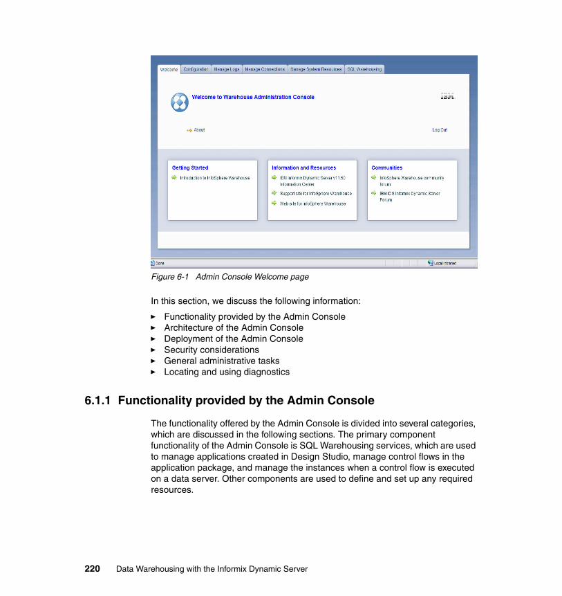
Figure 6-1 Admin Console Welcome page
In this section, we discuss the following information:
� Functionality provided by the Admin Console� Architecture of the Admin Console� Deployment of the Admin Console� Security considerations� General administrative tasks� Locating and using diagnostics
6.1.1 Functionality provided by the Admin Console
The functionality offered by the Admin Console is divided into several categories, which are discussed in the following sections. The primary component functionality of the Admin Console is SQL Warehousing services, which are used to manage applications created in Design Studio, manage control flows in the application package, and manage the instances when a control flow is executed on a data server. Other components are used to define and set up any required resources.
220 Data Warehousing with the Informix Dynamic Server
The following components of the Admin Console are described in this chapter:
� Configuration: Configures notification and logging services. You can specify the location and settings for the system log file and specify your SMTP host name information to enable e-mail notifications to be sent from the server.
� Log management: Enables you to look at the log files that are updated when warehousing applications run. The log files contain error messages and other output that can help you diagnose problems or verify that applications are running as expected.
� Connection management: Defines the database connections that are available to your application, and to which you can connect.
� Resource management: Creates the system resources that your application requires. As examples, a system resource defines a computer that is used in an FTP operation or an IBM DataStage server that runs parallel jobs.
� SQL Warehousing: Controls the deployment, running, scheduling and monitoring of data warehouse applications that were created in the Design Studio. The Admin Console provides for the viewing of statistics and logs associated with processes and for the troubleshooting of any runtime issues.
6.1.2 Architecture
The Admin Console is a platform for running production SQW routines in a runtime environment. To support this functionality, the architecture of the Admin Console interfaces with the individual components, as well as the WebSphere Application Server environment.
Admin Console interfaces with componentsThe Admin Console is a J2EE application that is installed locally to a WebSphere Application Server as part of the installation process. The console provides a Common Web interface which is based on Adobe® Flex RIA (rich Internet application) technology. This common Web interface is combined with a common administration infrastructure, which provides services between the Web client and the underlying administration interfaces for the SQL Warehousing (SQW). These interfaces, which are illustrated in Figure 6-2 on page 222, include:
� Presentation layer: Provides all the UI views necessary to display application logic of the Admin Console components. In this architecture, Web pages are implemented using Flex RIA technology.
� Bean/Controller: This layer controls all the Admin Console application logic necessary for the presentation layer. It interacts with the services in the Server Infrastructure and provides information needed for the presentation layer.
Chapter 6. Deploying and managing Informix Warehouse solutions 221
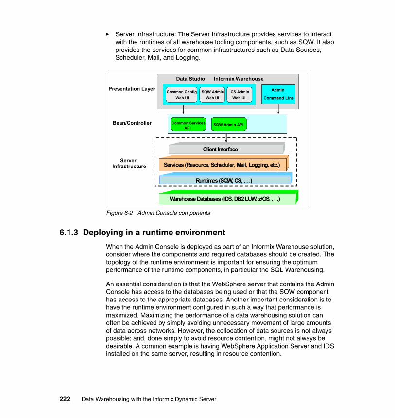
� Server Infrastructure: The Server Infrastructure provides services to interact with the runtimes of all warehouse tooling components, such as SQW. It also provides the services for common infrastructures such as Data Sources, Scheduler, Mail, and Logging.
Figure 6-2 Admin Console components
6.1.3 Deploying in a runtime environment
When the Admin Console is deployed as part of an Informix Warehouse solution, consider where the components and required databases should be created. The topology of the runtime environment is important for ensuring the optimum performance of the runtime components, in particular the SQL Warehousing.
An essential consideration is that the WebSphere server that contains the Admin Console has access to the databases being used or that the SQW component has access to the appropriate databases. Another important consideration is to have the runtime environment configured in such a way that performance is maximized. Maximizing the performance of a data warehousing solution can often be achieved by simply avoiding unnecessary movement of large amounts of data across networks. However, the collocation of data sources is not always possible; and, done simply to avoid resource contention, might not always be desirable. A common example is having WebSphere Application Server and IDS installed on the same server, resulting in resource contention.
Presentation Layer
Server Infrastructure
Bean/Controller
Data Studio
JDBC/JCC/SQLJServices (Resource, Scheduler, Mail, Logging, etc.)
Client Interface
Warehouse Databases (IDS, DB2 LUW, z/OS, . . .)
Informix Warehouse
Runtimes (SQW, CS, . . .)
Common ConfigWeb UI
SQW AdminWeb UI
CS AdminWeb UI
Admin
Command Line
SQW Admin APICommon ServicesAPI
222 Data Warehousing with the Informix Dynamic Server
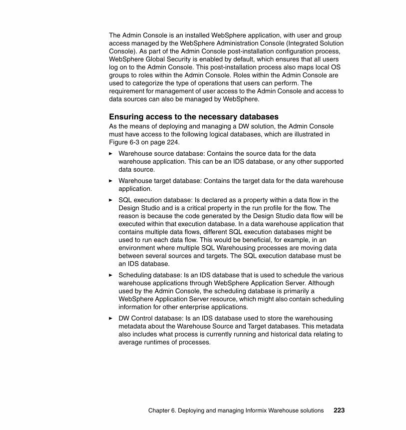
The Admin Console is an installed WebSphere application, with user and group access managed by the WebSphere Administration Console (Integrated Solution Console). As part of the Admin Console post-installation configuration process, WebSphere Global Security is enabled by default, which ensures that all users log on to the Admin Console. This post-installation process also maps local OS groups to roles within the Admin Console. Roles within the Admin Console are used to categorize the type of operations that users can perform. The requirement for management of user access to the Admin Console and access to data sources can also be managed by WebSphere.
Ensuring access to the necessary databasesAs the means of deploying and managing a DW solution, the Admin Console must have access to the following logical databases, which are illustrated in Figure 6-3 on page 224.
� Warehouse source database: Contains the source data for the data warehouse application. This can be an IDS database, or any other supported data source.
� Warehouse target database: Contains the target data for the data warehouse application.
� SQL execution database: Is declared as a property within a data flow in the Design Studio and is a critical property in the run profile for the flow. The reason is because the code generated by the Design Studio data flow will be executed within that execution database. In a data warehouse application that contains multiple data flows, different SQL execution databases might be used to run each data flow. This would be beneficial, for example, in an environment where multiple SQL Warehousing processes are moving data between several sources and targets. The SQL execution database must be an IDS database.
� Scheduling database: Is an IDS database that is used to schedule the various warehouse applications through WebSphere Application Server. Although used by the Admin Console, the scheduling database is primarily a WebSphere Application Server resource, which might also contain scheduling information for other enterprise applications.
� DW Control database: Is an IDS database used to store the warehousing metadata about the Warehouse Source and Target databases. This metadata also includes what process is currently running and historical data relating to average runtimes of processes.
Chapter 6. Deploying and managing Informix Warehouse solutions 223
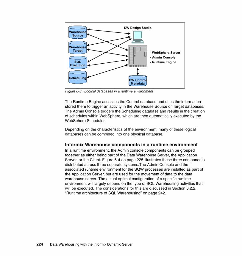
Figure 6-3 Logical databases in a runtime environment
The Runtime Engine accesses the Control database and uses the information stored there to trigger an activity in the Warehouse Source or Target databases. The Admin Console triggers the Scheduling database and results in the creation of schedules within WebSphere, which are then automatically executed by the WebSphere Scheduler.
Depending on the characteristics of the environment, many of these logical databases can be combined into one physical database.
Informix Warehouse components in a runtime environmentIn a runtime environment, the Admin console components can be grouped together as either being part of the Data Warehouse Server, the Application Server, or the Client. Figure 6-4 on page 225 illustrates these three components distributed across three separate systems.The Admin Console and the associated runtime environment for the SQW processes are installed as part of the Application Server, but are used for the movement of data to the data warehouse server. The actual optimal configuration of a specific runtime environment will largely depend on the type of SQL Warehousing activities that will be executed. The considerations for this are discussed in Section 6.2.2, “Runtime architecture of SQL Warehousing” on page 242.
SQL Execution
Scheduling
Warehouse Target
DW Design StudioWarehouse
Source
- WebSphere Server - Admin Console- Runtime Engine
DW Control Metadata
224 Data Warehousing with the Informix Dynamic Server
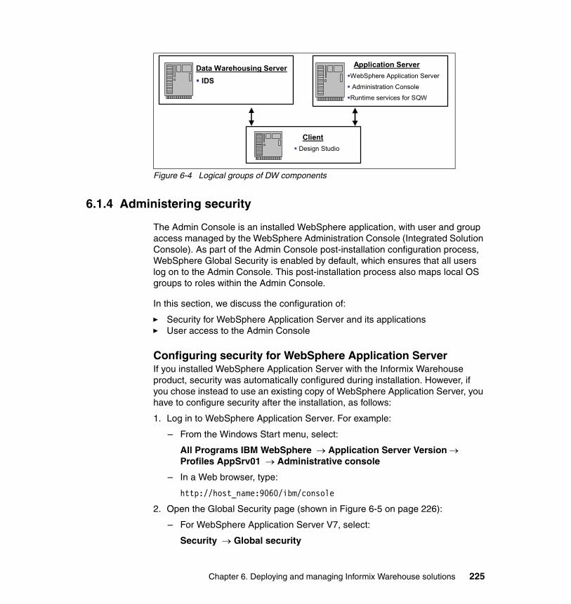
Figure 6-4 Logical groups of DW components
6.1.4 Administering security
The Admin Console is an installed WebSphere application, with user and group access managed by the WebSphere Administration Console (Integrated Solution Console). As part of the Admin Console post-installation configuration process, WebSphere Global Security is enabled by default, which ensures that all users log on to the Admin Console. This post-installation process also maps local OS groups to roles within the Admin Console.
In this section, we discuss the configuration of:
� Security for WebSphere Application Server and its applications� User access to the Admin Console
Configuring security for WebSphere Application ServerIf you installed WebSphere Application Server with the Informix Warehouse product, security was automatically configured during installation. However, if you chose instead to use an existing copy of WebSphere Application Server, you have to configure security after the installation, as follows:
1. Log in to WebSphere Application Server. For example:
– From the Windows Start menu, select:
All Programs IBM WebSphere → Application Server Version → Profiles AppSrv01 → Administrative console
– In a Web browser, type:
http://host_name:9060/ibm/console
2. Open the Global Security page (shown in Figure 6-5 on page 226):
– For WebSphere Application Server V7, select:
Security → Global security
Data Warehousing ServerIDS
ClientDesign Studio
Application ServerWebSphere Application Server
Administration Console
Runtime services for SQW
Chapter 6. Deploying and managing Informix Warehouse solutions 225
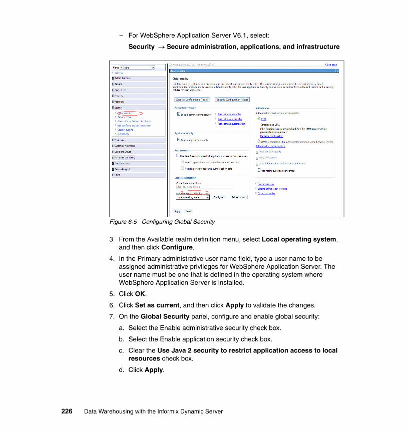
– For WebSphere Application Server V6.1, select:
Security → Secure administration, applications, and infrastructure
Figure 6-5 Configuring Global Security
3. From the Available realm definition menu, select Local operating system, and then click Configure.
4. In the Primary administrative user name field, type a user name to be assigned administrative privileges for WebSphere Application Server. The user name must be one that is defined in the operating system where WebSphere Application Server is installed.
5. Click OK.
6. Click Set as current, and then click Apply to validate the changes.
7. On the Global Security panel, configure and enable global security:
a. Select the Enable administrative security check box.
b. Select the Enable application security check box.
c. Clear the Use Java 2 security to restrict application access to local resources check box.
d. Click Apply.
226 Data Warehousing with the Informix Dynamic Server
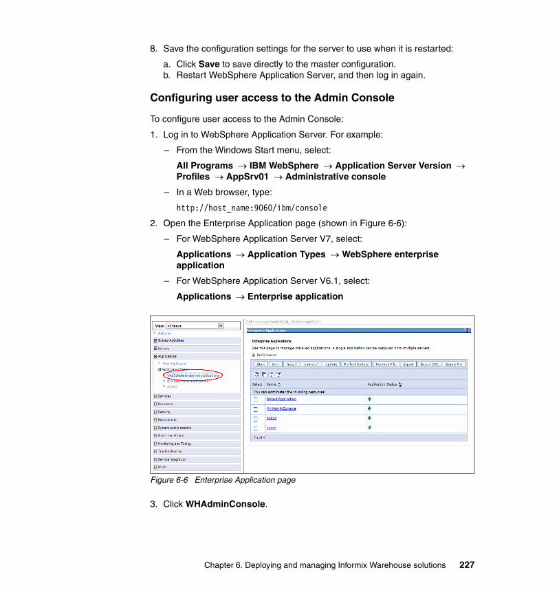
8. Save the configuration settings for the server to use when it is restarted:
a. Click Save to save directly to the master configuration.b. Restart WebSphere Application Server, and then log in again.
Configuring user access to the Admin Console
To configure user access to the Admin Console:
1. Log in to WebSphere Application Server. For example:
– From the Windows Start menu, select:
All Programs → IBM WebSphere → Application Server Version → Profiles → AppSrv01 → Administrative console
– In a Web browser, type:
http://host_name:9060/ibm/console
2. Open the Enterprise Application page (shown in Figure 6-6):
– For WebSphere Application Server V7, select:
Applications → Application Types → WebSphere enterprise application
– For WebSphere Application Server V6.1, select:
Applications → Enterprise application
Figure 6-6 Enterprise Application page
3. Click WHAdminConsole.
Chapter 6. Deploying and managing Informix Warehouse solutions 227
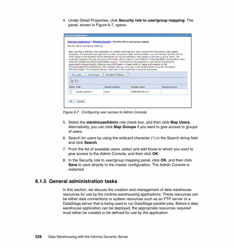
4. Under Detail Properties, click Security role to user/group mapping. The panel, shown in Figure 6-7, opens.
Figure 6-7 Configuring user access to Admin Console
5. Select the warehouseAdmin role check box, and then click Map Users. Alternatively, you can click Map Groups if you want to give access to groups of users.
6. Search for users by using the wildcard character (*) in the Search string field and click Search.
7. From the list of available users, select and add those to whom you want to give access to the Admin Console, and then click OK.
8. In the Security role to user/group mapping panel, click OK, and then click Save to save directly to the master configuration. The Admin Console is restarted.
6.1.5 General administration tasks
In this section, we discuss the creation and management of data warehouse resources for use by the runtime warehousing applications. These resources can be either data connections or system resources such as an FTP server or a DataStage server that is being used to run DataStage parallel jobs. Before a data warehouse application can be deployed, the appropriate resources required must either be created or be defined for use by the application.
228 Data Warehousing with the Informix Dynamic Server
Although the data flows and control flows contain initial references to resources, the actual resources to be used during execution might not be known at design time. During the deployment, an administrator must map these initial references to the actual references. This resource management task is not part of deployment, so you must define the resources first, then select them during the deployment process.
Warehouse resources require creation only if an application contains control flows that access those resources. If the control flows do not have FTP commands or access DataStage jobs, then defining system resources is not necessary. If SQL scripts are to be deployed to perform tasks such as LOAD and EXPORT, the database has to be managed by SQW and the user ID and password (stored in a specific encrypted format) must be provided in the data source definition. If the database is local and no user ID and password is specified, then implicit connect will be used.
Use the pages in the Admin Console to perform these administrative tasks:
� Configure the Notification Service and System Logging Service.� Manage logs.� Manage connections.� Manage system resources.
ConfigurationUse the Configuration page to configure the e-mail Notification Service and the System Logging Service, as described in this section.
Notification ServiceTo enable e-mail notifications to be sent from your server, you must specify your SMTP host name information in the Configure the Notification Service dialog window, shown in Figure 6-8 on page 230. From the Configuration tab, open the window by selecting the Notification service from the list of services, and then clicking the Configure button.
Chapter 6. Deploying and managing Informix Warehouse solutions 229
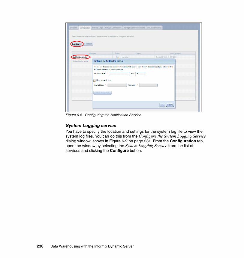
Figure 6-8 Configuring the Notification Service
System Logging serviceYou have to specify the location and settings for the system log file to view the system log files. You can do this from the Configure the System Logging Service dialog window, shown in Figure 6-9 on page 231. From the Configuration tab, open the window by selecting the System Logging Service from the list of services and clicking the Configure button.
Notification service
Configure
230 Data Warehousing with the Informix Dynamic Server
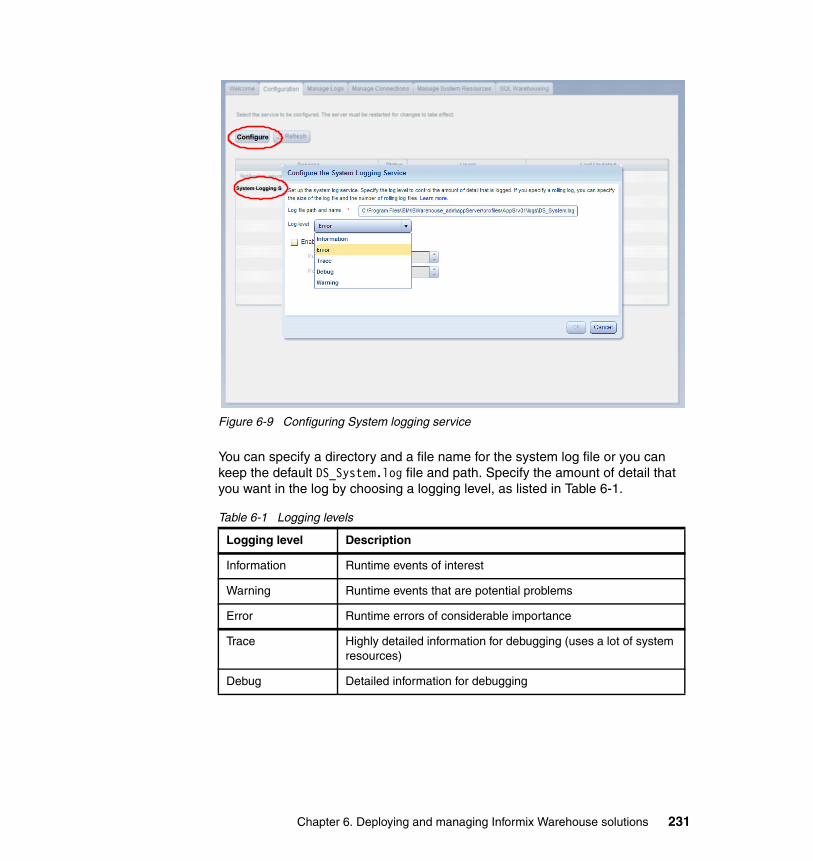
Figure 6-9 Configuring System logging service
You can specify a directory and a file name for the system log file or you can keep the default DS_System.log file and path. Specify the amount of detail that you want in the log by choosing a logging level, as listed in Table 6-1.
Table 6-1 Logging levels
Logging level Description
Information Runtime events of interest
Warning Runtime events that are potential problems
Error Runtime errors of considerable importance
Trace Highly detailed information for debugging (uses a lot of system resources)
Debug Detailed information for debugging
System Logging S
Configure
Chapter 6. Deploying and managing Informix Warehouse solutions 231
If you want the system logger to write to a rotating set of system log files rather than to write to a single file, enable the rolling file. You can also specify the size of the log and the number of files to use.
Manage LogsYou can view the system log files in the Admin Console from the Manage Logs page. You can specify the number of rows that you want to view from the file; the default view is the last 200 rows. A sample Log File Contents is shown in Figure 6-10 on page 233.
You can order the entries in the system log file by selecting either Order by recent or Order by oldest.
Tip: The logging level that you select includes all higher-severity messages. For example, if you specify Information as your logging level, the system will write Information, Warning, and Error messages to the system log. If you specify Error, the system logging service will log only error messages.
Note: Log files that do not yet exist are not listed on the Manage Logs page. For example, if you specify a rolling log of three files, the system creates the first file and lists that first file on the Manage Logs page. When that file reaches the length limit, the system creates the second file and lists the first file and the second file on the Manage Logs page, and so on.
Also, if you change the location of a log file and then restart the computer, the system lists only the active version of the file that is in the new location. To see the version of the file that is in the old location, you must open it from the directory in which it is stored.
232 Data Warehousing with the Informix Dynamic Server
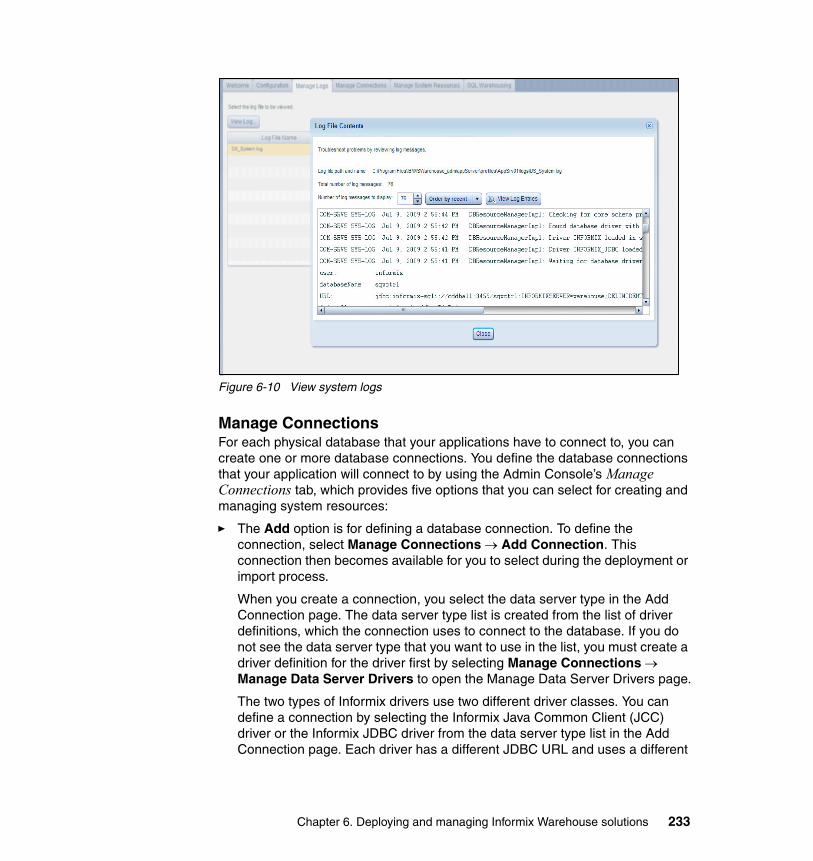
Figure 6-10 View system logs
Manage ConnectionsFor each physical database that your applications have to connect to, you can create one or more database connections. You define the database connections that your application will connect to by using the Admin Console’s Manage Connections tab, which provides five options that you can select for creating and managing system resources:
� The Add option is for defining a database connection. To define the connection, select Manage Connections → Add Connection. This connection then becomes available for you to select during the deployment or import process.
When you create a connection, you select the data server type in the Add Connection page. The data server type list is created from the list of driver definitions, which the connection uses to connect to the database. If you do not see the data server type that you want to use in the list, you must create a driver definition for the driver first by selecting Manage Connections → Manage Data Server Drivers to open the Manage Data Server Drivers page.
The two types of Informix drivers use two different driver classes. You can define a connection by selecting the Informix Java Common Client (JCC) driver or the Informix JDBC driver from the data server type list in the Add Connection page. Each driver has a different JDBC URL and uses a different
Chapter 6. Deploying and managing Informix Warehouse solutions 233
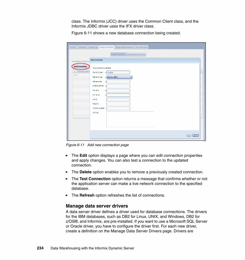
class. The Informix (JCC) driver uses the Common Client class, and the Informix JDBC driver uses the IFX driver class.
Figure 6-11 shows a new database connection being created.
Figure 6-11 Add new connection page
� The Edit option displays a page where you can edit connection properties and apply changes. You can also test a connection to the updated connection.
� The Delete option enables you to remove a previously created connection.
� The Test Connection option returns a message that confirms whether or not the application server can make a live network connection to the specified database.
� The Refresh option refreshes the list of connections.
Manage data server driversA data server driver defines a driver used for database connections. The drivers for the IBM databases, such as DB2 for Linux, UNIX, and Windows, DB2 for z/OS®, and Informix, are pre-installed. If you want to use a Microsoft SQL Server or Oracle driver, you have to configure the driver first. For each new driver, create a definition on the Manage Data Server Drivers page. Drivers are
Add Connection
234 Data Warehousing with the Informix Dynamic Server
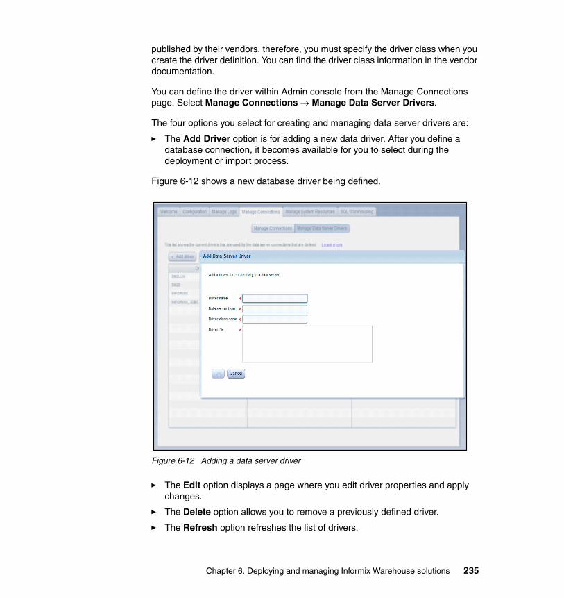
published by their vendors, therefore, you must specify the driver class when you create the driver definition. You can find the driver class information in the vendor documentation.
You can define the driver within Admin console from the Manage Connections page. Select Manage Connections → Manage Data Server Drivers.
The four options you select for creating and managing data server drivers are:
� The Add Driver option is for adding a new data driver. After you define a database connection, it becomes available for you to select during the deployment or import process.
Figure 6-12 shows a new database driver being defined.
Figure 6-12 Adding a data server driver
� The Edit option displays a page where you edit driver properties and apply changes.
� The Delete option allows you to remove a previously defined driver.
� The Refresh option refreshes the list of drivers.
Chapter 6. Deploying and managing Informix Warehouse solutions 235
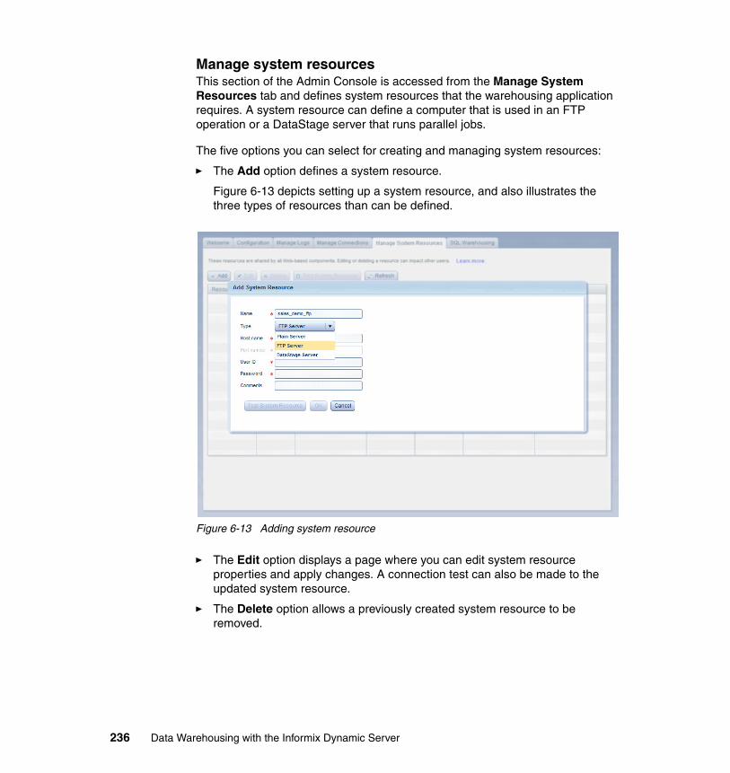
Manage system resourcesThis section of the Admin Console is accessed from the Manage System Resources tab and defines system resources that the warehousing application requires. A system resource can define a computer that is used in an FTP operation or a DataStage server that runs parallel jobs.
The five options you can select for creating and managing system resources:
� The Add option defines a system resource.
Figure 6-13 depicts setting up a system resource, and also illustrates the three types of resources than can be defined.
Figure 6-13 Adding system resource
� The Edit option displays a page where you can edit system resource properties and apply changes. A connection test can also be made to the updated system resource.
� The Delete option allows a previously created system resource to be removed.
236 Data Warehousing with the Informix Dynamic Server
� The Test Connection option returns a message that confirms whether or not the application server can make a live network connection to the FTP server or DataStage server. This test is performed by a Telnet connection being attempted to the specified system resource.
� The Refresh option refreshes the list of defined system resources.
6.1.6 Locating and using diagnostics
Because the Admin Console is an application within WebSphere Application Server, the WebSphere Application Server tools can be used to provide diagnostic information. The primary source for WebSphere Application Server diagnostic information is the Integrated Solution Console, which in a default installation can be found at the secure site:
https://localhost:9043/ibm/console
Or at the non-secure site:
http://localhost:9060/ibm/console
This console provides logging and tracing for WebSphere Application Server, runtime messages, and the ability to trace data sources that have been defined within WebSphere Application Server, as follows:
� Runtime messages
The runtime messages are accessed from the Integrated Solution Console by navigating to Troubleshooting → Runtime Messages. These messages are grouped as either Errors, Warnings, or Messages.
� Logging and tracing
For each instance of the WebSphere Application Server, the logging and tracing can be viewed by initially navigating to Troubleshooting → Logs and Tracing and then selecting the server for which diagnostics are to be viewed.
The five options for logging and tracing are:
– Diagnostic trace
This option allows the viewing and modifying of the properties for the diagnostic trace service. By default, the diagnostic tracing is enabled and has a maximum file size of 20MB.
– JVM logs
This option allows viewing and modifying of the settings for the Java virtual machine (JVM) System.out and System.err logs for the server. The JVM logs are created by redirecting the System.out and System.err streams of the JVM to independent log files.
Chapter 6. Deploying and managing Informix Warehouse solutions 237
The System.out log is used to monitor the health of the running application server. The System.err log contains exception stack-trace information that is useful when performing problem analysis. There is one set of JVM logs for each application server and all of its applications.
– Process logs
The process logs are created by redirecting the standard out and standard error streams of a process to independent log files. These logs can contain information relating to problems in native code or diagnostic information written by the JVM. By default the logs are named native_stdout.log and native_stderr.log, and can be viewed from within the console.
– IBM Service logs
The IBM Service log contains both the WebSphere Application Server messages that are written to the System.out stream and some special messages that contain extended service information that can be important when analyzing problems. There is one service log for all WebSphere Application Server Java virtual machines (JVMs) on a node, including all application servers, and a node agent (if present) for each. A separate activity log is created for a deployment manager in its own logs directory. The IBM Service log is maintained in a binary format and is primarily used by support personnel
– Change log detail levels
This option is used to configure and manage log level settings. Log levels enable you to control which events are processed by Java logging. The following setting is the default:
*=info
It means that all traceable code running in the application server, including WebSphere Application Server system code and customer code, is processed and that all informational messages are captured.
6.2 Informix SQL Warehousing
Now that the database objects have been created within a data warehouse, there is a need to design, develop and deploy a means of maintaining the data within these objects. If a table is created and initially populated with data, then the contents of this table have to be maintained to ensure that we are using the correct data. For example, if one of the dimensional tables has a product that moves within its hierarchy, then this change has to be reflected in the dimensional table. If this change is not reflected, then incorrect business decisions might be made based on an old version of the data.
238 Data Warehousing with the Informix Dynamic Server
There are a number of ways to maintain the contents of database tables, such as Operating System scripts, SQL scripts, or an ETL tool such as Ascential® DataStage. The Design Studio provides the functionality to develop, validate, and test warehousing applications that primarily work with data after it is within a database. The Admin Console is then used to take these applications that have been created and deploy them into a production environment. After the application is deployed, the Admin Console can be used to run and monitor data warehouse applications that contain specific executable processes. The Admin Console can also be used to set up scheduling of these processes, view execution statistics and analyze log files.
Before continuing, we want to define what we mean by an application and a process:
� An application represents one or more processes that the Design Studio users have assembled into a package for deployment. These processes might consist of a set of control flows that build or modify a data warehouse according to a fixed or on-demand schedule. Alternatively, an application might contain a single data flow inside a single control flow that updates one dimension table.
� An individual process in the runtime environment is equivalent to a control flow in the design-time environment. When a schedule or process is started, all of the activities within a particular control flow, including its data flows, are executed.
In this section, we concentrate on the SQL Warehousing (SQW) functionality in the Admin Console, and the runtime deployment of warehousing applications. We also discuss:
� What the SQL Warehousing components are� What the runtime architecture considerations are for SQL Warehousing� How to manage database and system resources� How to deploy and manage warehouse applications� How to manage warehouse processes� How to find warehousing diagnostics� How to use warehousing diagnostics
Full details about the development of an SQL Warehousing application can be found in Chapter 5, “Data movement and transformation” on page 115.
6.2.1 An overview of the SQW components
The creation of an SQL Warehousing application and the subsequent deployment of this application are part of the same overall process, which has the aim of populating and maintaining the production database or databases.
Chapter 6. Deploying and managing Informix Warehouse solutions 239
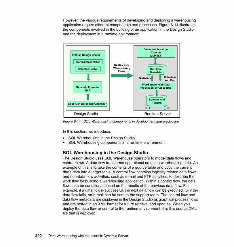
However, the various requirements of developing and deploying a warehousing application require different components and processes. Figure 6-14 illustrates the components involved in the building of an application in the Design Studio and the deployment in a runtime environment.
Figure 6-14 SQL Warehousing components in development and production
In this section, we introduce:
� SQL Warehousing in the Design Studio� SQL Warehousing components in a runtime environment
SQL Warehousing in the Design StudioThe Design Studio uses SQL Warehouse operators to model data flows and control flows. A data flow transforms operational data into warehousing data. An example of this is to take the contents of a source table and copy the current day’s data into a target table. A control flow contains logically related data flows and non-data flow activities, such as e-mail and FTP activities, to describe the work flow for building a warehousing application. Within a control flow, the data flows can be conditional based on the results of the previous data flow. For example, if a data flow is successful, the next data flow can be executed. Or if the data flow fails, an e-mail can be sent to the support team. The control flow and data flow metadata are displayed in the Design Studio as graphical process flows and are stored in an XML format for future retrieval and updates. When you deploy the data flow or control to the runtime environment, it is this source XML file that is deployed.
Design StudioDesign Studio Runtime ServerRuntime Server
Code Generator and Optimizer
Run time Metadata
Deploy SQL Warehousing
Flows
Eclipse Design Center
Control flow editor
Metadata Flows in EMF
Schedule and Run
DW Administration Console
(JSP/JSF)
Statistics
Sources and Targets
Data flow editor
WebSphere with Data Integration Services (DIS)
240 Data Warehousing with the Informix Dynamic Server
After the control flows have been validated and verified with the corresponding activities/data flows, they can be packaged into SQL Warehouse applications. The packaging of the application generates the runtime code for the control flows and data flows which is stored as an execution plan graph (EPG). An execution plan graph describes the execution of a data flow and control flow as a sequence of nodes. Different types of nodes in an EPG depict the various execution points in a flow. As examples, the start of execution, end of execution, and start of database transaction. After it is packaged, the application can be deployed by the Admin Console into the runtime environment.
More details about the building of an SQL Warehousing application can be found in Chapter 5, “Data movement and transformation” on page 115.
SQL Warehousing components in a runtime environmentThe starting point for the runtime deployment of an application is the packaged SQL Warehousing application that has been created within Design Studio. The runtime environment to which the application is deployed consists of the following individual components, shown in Figure 6-14 on page 240, (with an overall topology shown in Figure 6-15 on page 242):
� Admin Console
Use the console to deploy and manage the SQL Warehousing applications.
� Runtime metadata database
This component is an IDS database that is used to store the metadata about the running of processes and the storing of runtime statistics. The default name of the metadata database is sqwctrl.
� WebSphere or Data Integration Service (DIS)
Either or both of these components handle all interaction with the SQL Warehouse metadata, and source and target tables. They are part of the Admin Console and used as the runtime environment for SQL Warehousing. DIS can access the data sources through a WebSphere application interface, using JDBC drivers.
� Sources and Targets
These databases are referenced by data flow activities, and can be local or remote to the Admin Console. The source and target databases for SQL script activities can also be local or remote to the Admin Console and the connection to these target databases are managed by DIS. In Figure 6-15 on page 242 the source, target, and runtime databases are all remote to the WebSphere Application Server processor.
Chapter 6. Deploying and managing Informix Warehouse solutions 241
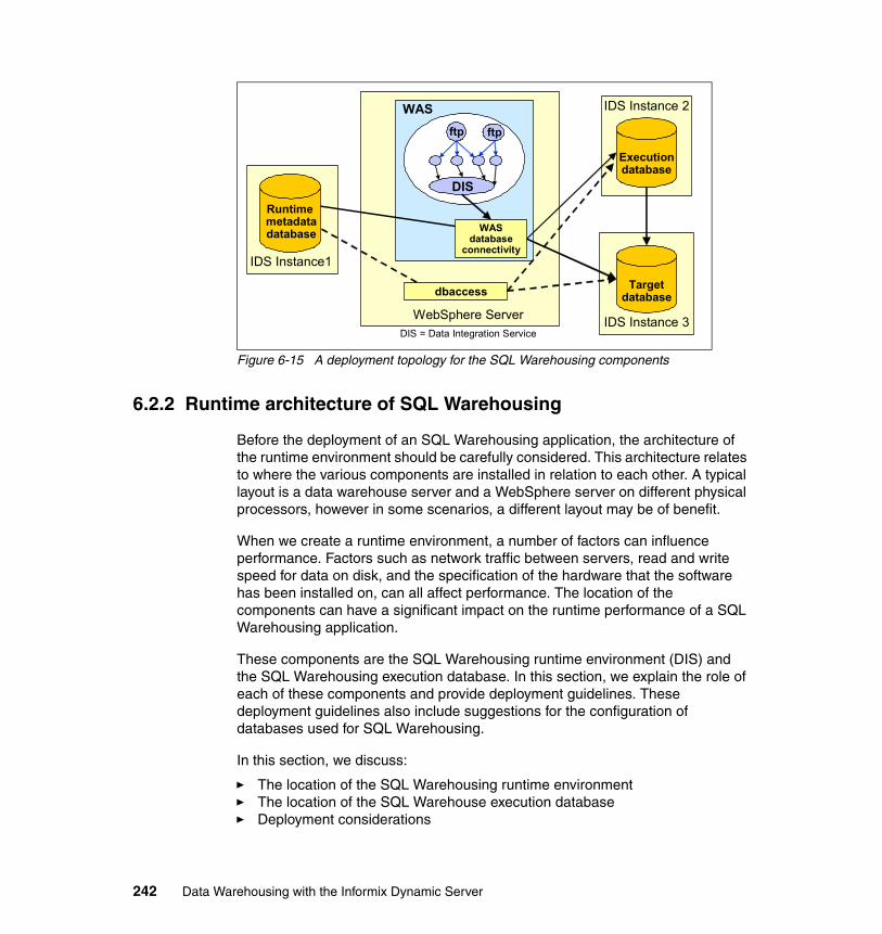
Figure 6-15 A deployment topology for the SQL Warehousing components
6.2.2 Runtime architecture of SQL Warehousing
Before the deployment of an SQL Warehousing application, the architecture of the runtime environment should be carefully considered. This architecture relates to where the various components are installed in relation to each other. A typical layout is a data warehouse server and a WebSphere server on different physical processors, however in some scenarios, a different layout may be of benefit.
When we create a runtime environment, a number of factors can influence performance. Factors such as network traffic between servers, read and write speed for data on disk, and the specification of the hardware that the software has been installed on, can all affect performance. The location of the components can have a significant impact on the runtime performance of a SQL Warehousing application.
These components are the SQL Warehousing runtime environment (DIS) and the SQL Warehousing execution database. In this section, we explain the role of each of these components and provide deployment guidelines. These deployment guidelines also include suggestions for the configuration of databases used for SQL Warehousing.
In this section, we discuss:
� The location of the SQL Warehousing runtime environment� The location of the SQL Warehouse execution database� Deployment considerations
WASftp
DIS = Data Integration Service
ftp
DIS
WebSphere Server
Targetdatabase
IDS Instance 3
Executiondatabase
IDS Instance 2
Runtime metadatadatabase
IDS Instance1
dbaccess
WAS database
connectivity
242 Data Warehousing with the Informix Dynamic Server
Location of the SQL Warehousing runtime environmentWhen the administration application is installed in the WebSphere Application Server, one of the components provides the runtime environment for the SQL Warehousing activities. This component is known as the SQL Warehousing runtime environment, or the Data Integration Service (DIS). This component runs the Design Studio operators that perform the following operations:
� Execute a select statement against a source database.� Insert data into a target database� Execute an SQL or OS script.� Perform the FTP operation from and to a remote system.� Wait for a file before commencing the next process.
The location of the SQL Warehousing runtime environment, in relation to the location of the commands, is important because the SQW runtime environment carries out activities from the system where the SQL Warehousing runtime environment is installed. In this section, we describe two examples of how a command is run, based on how the runtime environment is configured:
� Deploying an FTP operator � Deploying an SQL script
Deploying an FTP operatorAn FTP operator is commonly used to move data from one system to another, at which point the flat file can be used as an input for a LOAD command. For more details about defining an FTP operator, refer to “Manage system resources” on page 236. When using the SQL Warehousing FTP operator in a runtime environment, the execution process depends on where WebSphere Application Server or DIS has been installed. Figure 6-16 on page 244 shows two scenarios in which the process of an FTP command depends on where the WebSphere server is installed in relation to the FTP files.
Note: The execution database is specified while developing an application in the Design Studio and can be mapped to a runtime database when the SQW application is deployed.
Chapter 6. Deploying and managing Informix Warehouse solutions 243
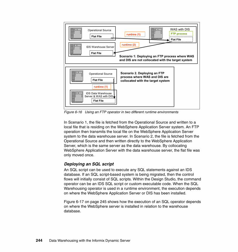
Figure 6-16 Using an FTP operator in two different runtime environments
In Scenario 1, the file is fetched from the Operational Source and written to a local file that is residing on the WebSphere Application Server system. An FTP operation then transmits the local file on the WebSphere Application Server system to the data warehouse server. In Scenario 2, the file is fetched from the Operational Source and then written directly to the WebSphere Application Server, which is the same server as the data warehouse. By collocating WebSphere Application Server with the data warehouse server, the flat file was only moved once.
Deploying an SQL scriptAn SQL script can be used to execute any SQL statements against an IDS database. If an SQL script-based system is being migrated, then the control flows will initially consist of SQL scripts. Within the Design Studio, the command operator can be an IDS SQL script or custom executable code. When the SQL Warehousing operator is used in a runtime environment, the execution depends on where the WebSphere Application Server or DIS has been installed.
Figure 6-17 on page 245 shows how the execution of an SQL operator depends on where the WebSphere server is installed in relation to the warehouse database.
WAS with DISFTP process
Operational Source
Flat File
IDS Warehouse Server
Flat File
Flat File
runtime (1)
runtime (2)
Operational Source
Flat File
IDS Data Warehouse Server & WAS with DIS
Flat File
runtime (1)
Scenario 1: Deploying an FTP process where WAS and DIS are not collocated with the target system
Scenario 2. Deploying an FTP process where WAS and DIS are collocated with the target system
244 Data Warehousing with the Informix Dynamic Server
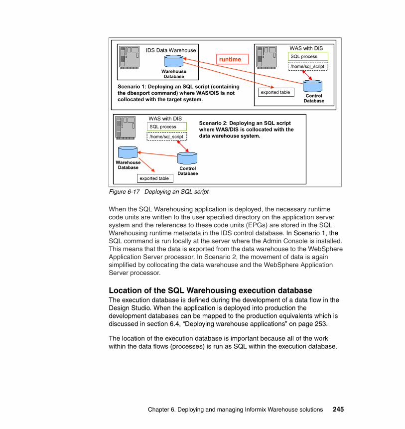
Figure 6-17 Deploying an SQL script
When the SQL Warehousing application is deployed, the necessary runtime code units are written to the user specified directory on the application server system and the references to these code units (EPGs) are stored in the SQL Warehousing runtime metadata in the IDS control database. In Scenario 1, the SQL command is run locally at the server where the Admin Console is installed. This means that the data is exported from the data warehouse to the WebSphere Application Server processor. In Scenario 2, the movement of data is again simplified by collocating the data warehouse and the WebSphere Application Server processor.
Location of the SQL Warehousing execution database The execution database is defined during the development of a data flow in the Design Studio. When the application is deployed into production the development databases can be mapped to the production equivalents which is discussed in section 6.4, “Deploying warehouse applications” on page 253.
The location of the execution database is important because all of the work within the data flows (processes) is run as SQL within the execution database.
Scenario 1: Deploying an SQL script (containing the dbexport command) where WAS/DIS is not collocated with the target system.
Scenario 2: Deploying an SQL script where WAS/DIS is collocated with the data warehouse system.
WAS with DISSQL process
/home/sql_scriptruntime
Control Database
IDS Data Warehouse
Warehouse Database
exported table
WAS with DISSQL process
/home/sql_script
Control Database
exported table
Warehouse Database
Chapter 6. Deploying and managing Informix Warehouse solutions 245
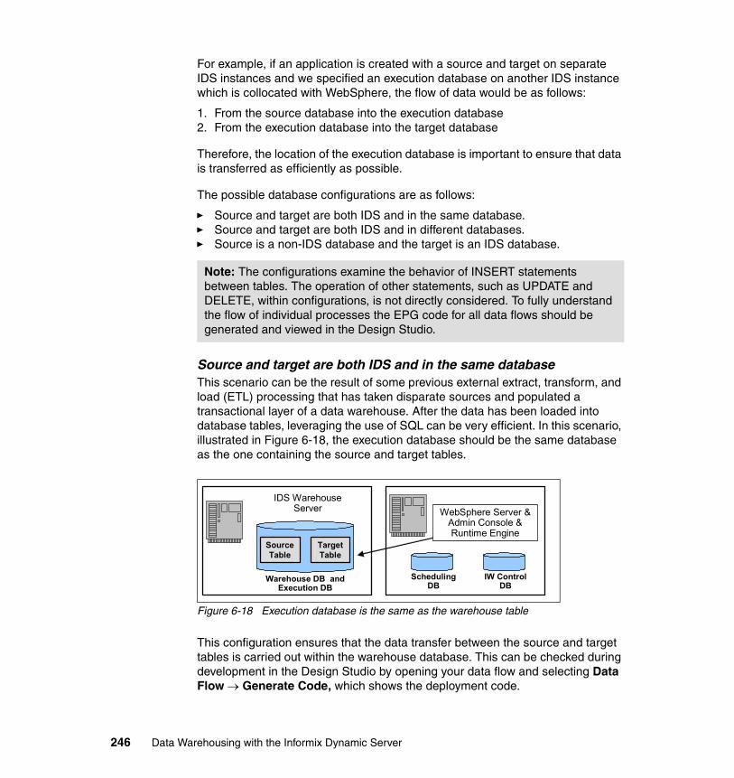
For example, if an application is created with a source and target on separate IDS instances and we specified an execution database on another IDS instance which is collocated with WebSphere, the flow of data would be as follows:
1. From the source database into the execution database2. From the execution database into the target database
Therefore, the location of the execution database is important to ensure that data is transferred as efficiently as possible.
The possible database configurations are as follows:
� Source and target are both IDS and in the same database.� Source and target are both IDS and in different databases.� Source is a non-IDS database and the target is an IDS database.
Source and target are both IDS and in the same databaseThis scenario can be the result of some previous external extract, transform, and load (ETL) processing that has taken disparate sources and populated a transactional layer of a data warehouse. After the data has been loaded into database tables, leveraging the use of SQL can be very efficient. In this scenario, illustrated in Figure 6-18, the execution database should be the same database as the one containing the source and target tables.
Figure 6-18 Execution database is the same as the warehouse table
This configuration ensures that the data transfer between the source and target tables is carried out within the warehouse database. This can be checked during development in the Design Studio by opening your data flow and selecting Data Flow → Generate Code, which shows the deployment code.
Note: The configurations examine the behavior of INSERT statements between tables. The operation of other statements, such as UPDATE and DELETE, within configurations, is not directly considered. To fully understand the flow of individual processes the EPG code for all data flows should be generated and viewed in the Design Studio.
IW Control DB
Scheduling DB
Warehouse DB and Execution DB
IDS Warehouse Server
Source Table
Target Table
WebSphere Server & Admin Console & Runtime Engine
246 Data Warehousing with the Informix Dynamic Server
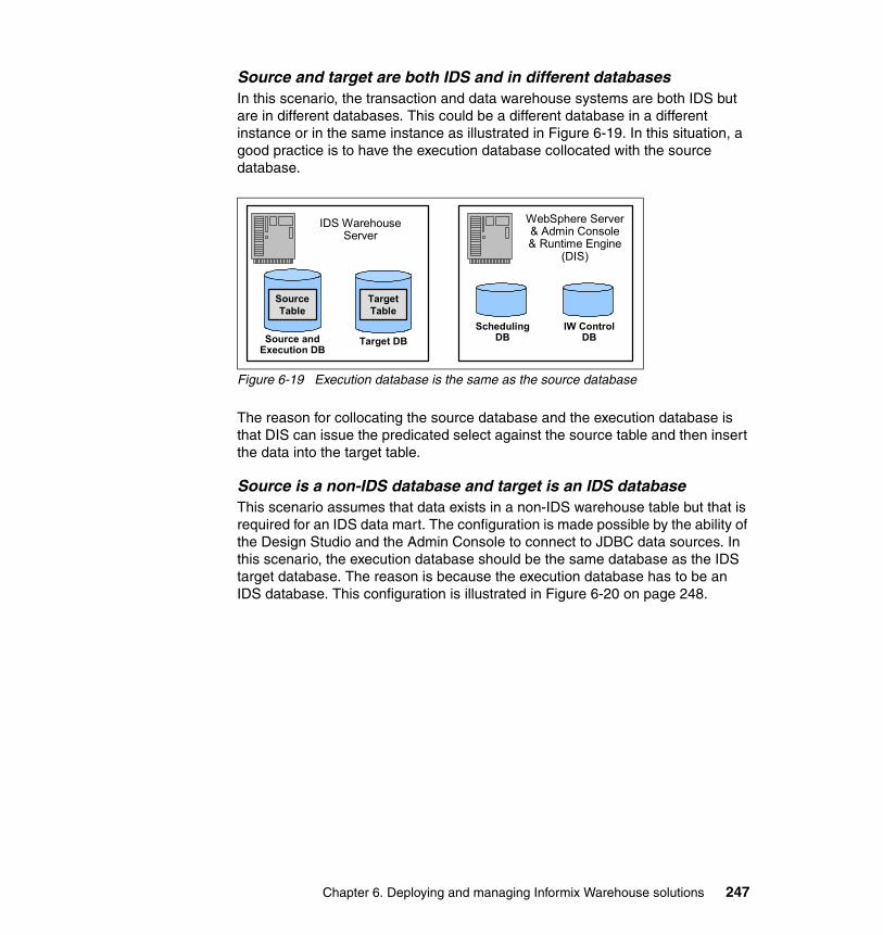
Source and target are both IDS and in different databasesIn this scenario, the transaction and data warehouse systems are both IDS but are in different databases. This could be a different database in a different instance or in the same instance as illustrated in Figure 6-19. In this situation, a good practice is to have the execution database collocated with the source database.
Figure 6-19 Execution database is the same as the source database
The reason for collocating the source database and the execution database is that DIS can issue the predicated select against the source table and then insert the data into the target table.
Source is a non-IDS database and target is an IDS databaseThis scenario assumes that data exists in a non-IDS warehouse table but that is required for an IDS data mart. The configuration is made possible by the ability of the Design Studio and the Admin Console to connect to JDBC data sources. In this scenario, the execution database should be the same database as the IDS target database. The reason is because the execution database has to be an IDS database. This configuration is illustrated in Figure 6-20 on page 248.
IW Control DB
Scheduling DB
WebSphere Server & Admin Console & Runtime Engine
(DIS)
Source and Execution DB
IDS Warehouse Server
Target Table
Source Table
Target DB
Chapter 6. Deploying and managing Informix Warehouse solutions 247
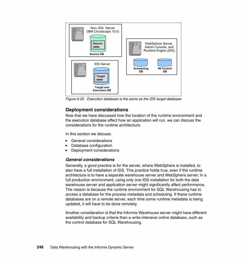
Figure 6-20 Execution database is the same as the IDS target database
Deployment considerationsNow that we have discussed how the location of the runtime environment and the execution database affect how an application will run, we can discuss the considerations for the runtime architecture.
In this section we discuss:
� General considerations� Database configuration� Deployment considerations
General considerationsGenerally, a good practice is for the server, where WebSphere is installed, to also have a full installation of IDS. This practice holds true, even if the runtime architecture is to have a separate warehouse server and WebSphere server. In a full production environment, using only one IDS installation for both the data warehouse server and application server might significantly affect performance. The reason is because the runtime environment for SQL Warehousing has to access a database for the process metadata and scheduling. If these runtime databases are on a remote server, each time some runtime metadata is being updated, it will have to be done remotely.
Another consideration is that the Informix Warehouse server might have different availability and backup criteria than a write-intensive online database, such as the control database for SQL Warehousing.
IW Control DB
Scheduling DB
WebSphere Server, Admin Console, and
Runtime Engine (DIS)
Target and Execution DB
IDS Server
Target table
Source DB
Non–IDS Server (IBM Cloudscape 10.0)
Source table
248 Data Warehousing with the Informix Dynamic Server
Database configurationWhen a warehousing application is deployed to a runtime environment, the configuration of the databases being used has to be considered. As with all aspects of the deployment, the EPG code in the Design Studio should be examined to understand how each database is being used. The Database configuration for Warehouse Environment is discussed in detail in Chapter 7, “Optimizing your Informix Warehouse environment” on page 277.
Deployment considerationsIf a runtime environment has applications that fit certain profiles, then considering the collocation of the WebSphere server and the Informix Warehouse server can be worthwhile. In this section, we discuss two common application profiles, based on the scenarios discussed in “Location of the SQL Warehousing runtime environment” on page 243 and “Location of the SQL Warehousing execution database” on page 245.
The two profiles are:
� Applications with multiple command operators
If the deployed warehouse applications execute a large volume of commands such as FTP, SQL scripts, or OS scripts, then a worthwhile consideration is to collocate the WebSphere Application Server and IDS Data Warehouse server. Figure 6-16 on page 244 and Figure 6-17 on page 245 illustrated how collocating the two servers can ensure that data is moved as efficiently as possible. The key consideration is that the commands are executed by the runtime component, which is on the WebSphere server. This is only a consideration rather than a recommendation, because a good practice, generally, is for a runtime WebSphere Application Server environment and a runtime IDS Data Warehouse to be on separate servers, to mitigate any resource contention. If however the quantity of the commands being deployed is large, or if large volumes of data are being moved, collocating the two servers might be beneficial.
� Applications with multiple data flows
If the deployed warehouse applications primarily contain SQL data flows, the runtime performance can be affected by the location of the execution database and the location of the WebSphere Application Server server, as follows:
– If the source and target databases are the same, then as long as the execution database is also in that database, having WebSphere Application Server collocated is not necessary. Only the commands will be flowing between WebSphere Application Server and IDS; data will not be moving between the two environments.
Chapter 6. Deploying and managing Informix Warehouse solutions 249
– If the source and target databases are in different databases, the WebSphere Application Server server will be used to move the data between the two databases. If the source and target tables are in the same database, the execution database should be defined as being the same database. If the source and target databases are separate and the process is doing a predicated SELECT, such as a SELECT from table where value = x, the execution database should be collocated with the source database.
The collocation of WebSphere Application Server with the IDS data warehouse server could also be considered if large volumes of data are flowing through DIS. If the source and target databases are on physically separate servers, then the performance would be optimized by having WebSphere Application Server on the target machine to perform any inserts locally.
This is only a consideration rather than a recommendation because good practice generally is that a runtime WebSphere Application Server environment and a runtime IDS data warehouse should be on separate servers to mitigate any resource contention. If the quantity of data being moved is sufficiently large, then collocating the two servers might be beneficial.
The best way to decide what runtime topology can best suit the data flows is to view the generated code for a data flow within the Design Studio. If the EPG code is only making one database connection, then collocating the IDS and WebSphere is probably not required. If the generated EPG code contains multiple database connections and use of Java runtime unit classes, such as com.ibm.datatools.etl.dataflow.baselib.runtimeunits.JDBCInsert, then data will flow through the WebSphere server.
Although collocation might not always be desirable or possible, an important point to understand is that the connections to the multiple databases are made by the SQL Warehousing runtime environment. Therefore, as the connections are made by the runtime environment, the insert classes are being executed on the WebSphere server.
250 Data Warehousing with the Informix Dynamic Server
6.3 Deploying the physical data model
When moving from a development DW environment to a production environment the first part of a deployment is the database structure that has been created from the physical model. There are a number of available methods to deploy the database structure whether they are part of the Admin Console or through some other method.
In this section, we discuss deployment by using:
� Design Studio� Admin Console� Native IDS functionality
6.3.1 Deployment using the Design Studio
The Design Studio has the capability to deploy the physical data model directly to a target database or to save the model to a file. The physical data model can be generated by navigating to Projects → Databases → <Model Name> → <Database> and then right-clicking on a database.
If the Design Studio has a connection to the production database and the users have the correct authority, the physical model can be directly deployed to the production database.
The option to generate a file should however be considered for a variety of reasons:
� Does the data model require being entered into a source control system?
� If deployment is to be done as part of deploying the warehousing applications, does it have to be included as a DDL file?
� Will the production tablespaces have the same naming and paths as development?
� Can the performance of the physical data model be enhanced by modifying the DDL to include additional indexing?
The generation or deployment of a data model is shown in Figure 6-21 on page 252. In this example, the PRODUCT table has been defined with initial extent size 16 and next extent size 16 with page lock mode. The option to open the file for editing has been selected, so the values can be changed in the generated model.
Chapter 6. Deploying and managing Informix Warehouse solutions 251
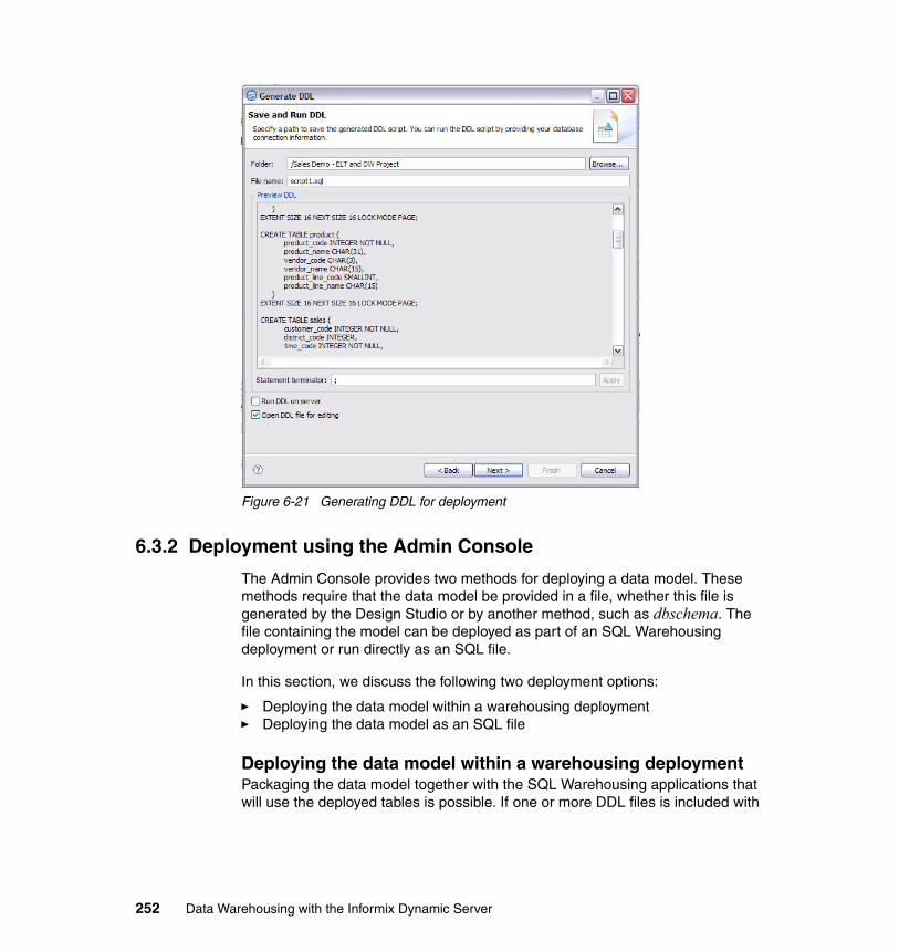
Figure 6-21 Generating DDL for deployment
6.3.2 Deployment using the Admin Console
The Admin Console provides two methods for deploying a data model. These methods require that the data model be provided in a file, whether this file is generated by the Design Studio or by another method, such as dbschema. The file containing the model can be deployed as part of an SQL Warehousing deployment or run directly as an SQL file.
In this section, we discuss the following two deployment options:
� Deploying the data model within a warehousing deployment� Deploying the data model as an SQL file
Deploying the data model within a warehousing deploymentPackaging the data model together with the SQL Warehousing applications that will use the deployed tables is possible. If one or more DDL files is included with
252 Data Warehousing with the Informix Dynamic Server
the deployment package in the Design Studio, the files will be executed by the Admin Console as part of the application deployment, as follows:
1. Within the Project in the Design Studio, the DDL can be generated from the development database into a file, or a file can be imported containing the DDL into the project.
2. When a new data warehouse application is created, the packaging of the deployment code allows the specification of one or more DDL files to be included with the application. When the deployment .zip file is created, the DDL files that have been specified are contained within the /etl/misc/ folder.
3. When a data warehouse application is deployed within the Admin Console, an option, in step 1 on page 256: General (refer to “Deployment process” on page 256), is named Execute Deployment Code Units. This option executes any files in the /etl/misc/ folder and is set to Yes by default.
The deployment of a data warehousing application is discussed in more detail in section 6.4, “Deploying warehouse applications” on page 253.
6.3.3 Deployment using native IDS functionality
Because the generated file is a standard IDS file, it can be deployed using DBACCESS, and executed from the dbaccess command. If the default statement terminator is used, then the command would be:
dbaccess - ddlscript.sql
6.4 Deploying warehouse applications
Now that the required data and system resources have been created, the warehouse applications developed in the Design Studio can be deployed to the runtime environment. The preparation of the warehouse application takes place in the Design Studio, but the actual deployment takes place in the Admin Console. The deployment of new applications makes the applications processes available for scheduling, execution, and administration. The resources that are referenced in the control flows and data flows must be ready to accommodate the new application. The process for creating these resources has been discussed in “Manage system resources” on page 236. Each application to be deployed contains one or more control flows, which in turn contain data flows or
Tip: The statement terminator for the DDL file should be defined as a semi-colon (;) character.
Chapter 6. Deploying and managing Informix Warehouse solutions 253
other activities such as SQL scripts, executables, FTP commands, or OS scripts. When the application is deployed, each control flow becomes a runtime process.
In this section, we discuss:
� Contents of the warehouse deployment file� Deployment process� Structures created by the deployment� Management of the applications after deployment
Contents of the warehouse deployment fileBefore the deployment of the warehouse application is discussed, you should understand the contents of the deployment package. The deployment package is a .zip file that is generated by the Design Studio for deployment. This .zip file contains data flows and control flows that were created during the design phase. These data flows are compiled and validated based on an application profile; the appropriate deployment package containing the code is generated as a result. An application profile is a combination of control flows, database definitions, variables, and script files.
For example, you can package as many control flows into a data warehouse application as desired. Also, multiple applications can contain the same flows. Flows contained within the same application share the same application home/log/work directory after the data warehouse archive has been deployed in Admin Console. They can also be enabled/disabled together, but are otherwise independent of each other.
254 Data Warehousing with the Informix Dynamic Server
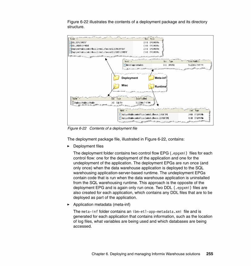
Figure 6-22 illustrates the contents of a deployment package and its directory structure.
Figure 6-22 Contents of a deployment file
The deployment package file, illustrated in Figure 6-22, contains:
� Deployment files
The deployment folder contains two control flow EPG (.epgxmi) files for each control flow: one for the deployment of the application and one for the undeployment of the application. The deployment EPGs are run once (and only once) when the data warehouse application is deployed to the SQL warehousing application-server-based runtime. The undeployment EPGs contain code that is run when the data warehouse application is uninstalled from the SQL warehousing runtime. This approach is the opposite of the deployment EPG and is again only run once. Two DDL (.epgxmi) files are also created for each application, which contains any DDL files that are to be deployed as part of the application.
� Application metadata (meta-inf)
The meta-inf folder contains an ibm-etl-app-metadata.xmi file and is generated for each application that contains information, such as the location of log files, what variables are being used and which databases are being accessed.
Meta-inf
RuntimeMisc
Deployment
Chapter 6. Deploying and managing Informix Warehouse solutions 255
� Applicable miscellaneous files (misc)
The misc folder contains deployment files, which are database setup files that are bundled with the data warehouse application. Their purpose is to prepare the database for use before the control flows are executed. Commands in these files have to be run only once rather than each time a process is run. Examples of the types of commands in these files are DDL statements to create tables or a database configuration update.
� The runtime execution plan graphs (EPGs)
The runtime folder contains one runtime EPG (.epgxmi) file for each operator in the control flow, whether it is a data flow, an e-mail, or a DB2 command. This file is the XML representation of the graphical element within the Design studio and is run each time the process is invoked.
Deployment processThe deployment process extracts code units from the .zip file that is generated by the Design Studio and creates a deployment file structure. The process also populates control tables in the SQL Data Warehousing control database.
The four steps to deploying the application are:
1. General: The first task is to locate and select the deployment .zip file. This file can either be local to the client system or local to the application server. After it is selected, the .zip file is read and elements of the application metadata are presented, and can be changed if required. These elements include the application name, the application home directory, and the application log and temp directories. Be careful when you decide where to place the application files, because they are used at runtime to execute the operators within them.
2. Data Sources: In this step of the process, you map the data sources to be used for the target system where the installed application is going to run. This step requires the data resources to already be defined. The resource names do not have to be the same if the mapping is done to the correct JNDI name on the application server. If the database name was TEST in development, this process allows you to map this database to the appropriate JNDI name in the runtime environment.
3. System Resources: In this step, you map the system resources that are used in the development environment to the system resources where the installed application will run. If an FTP server has been defined in the Design Studio, then the mapping would be to a production FTP server. The system resource being mapped to must have already been defined, and the system resource information is displayed only if the control flow contains DataStage elements or any commands with a type of FTP.
256 Data Warehousing with the Informix Dynamic Server
4. Variables: A variable is a user-defined name that represents data that can be changed in a data or control flow. The flexibility of variables allows the definition of certain properties to be deferred until a later time. Variables can be defined within the Design Studio to require a value at varying phases of the deployment cycle.
These phases are:
– Design: The variable is populated during the design phase and does not require input during the production deployment.
– Preparation: The variable is populated during the preparation of the deployment package and does not require input during the production deployment.
– Deployment: The variable must be populated during the deployment of the application. An example of this is when a data flow is deployed to a test system and later to a production system where the production system is very similar to the test system except for the table schema names. A designer might then choose to use deployment phase variables for the table schema names so that the tested SQW application can be deployed safely into the production system.
– Runtime: The variable can be populated during deployment, but this is not required. Instead, the variable can be populated by updating the process after the application is deployed. A runtime-level variable can be used where multiple control flows exist, and which all use the same variable. Setting this variable at a general application level might not be desired.
– Execution: The variable can be populated during deployment but this is not required. Instead the variable has to be populated when the individual process instance is run. The setting of a variable at the execution instance means that a new value can be, but does not necessarily have to be, specified each time the process runs. The setting of an execution variable requires a process profile to be defined. An example of the use of an execution instance is if a user needed to have the same data flow run against different databases. The designer can use an execution phase variable for the database so that each process instance can choose against which database the data flow should run. This approach removes having to design or deploy identical data flows with different database names.
Deployment file structureAfter the application is installed, the relevant application, process, activity, and variable parameters are written to the SQL warehouse control tables. Also, the deployment and execution code units, which will be used at process execution time, are written to the application home directory.
Chapter 6. Deploying and managing Informix Warehouse solutions 257
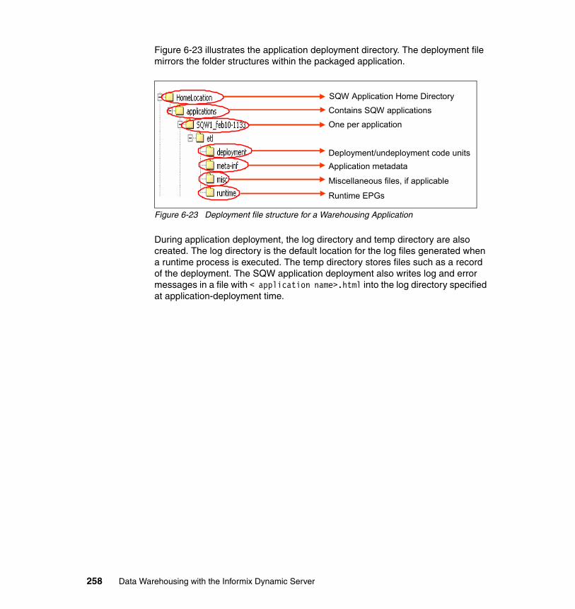
Figure 6-23 illustrates the application deployment directory. The deployment file mirrors the folder structures within the packaged application.
Figure 6-23 Deployment file structure for a Warehousing Application
During application deployment, the log directory and temp directory are also created. The log directory is the default location for the log files generated when a runtime process is executed. The temp directory stores files such as a record of the deployment. The SQW application deployment also writes log and error messages in a file with < application name>.html into the log directory specified at application-deployment time.
SQW Application Home Directory
Contains SQW applications
One per application
Deployment/undeployment code unitsApplication metadata
Miscellaneous files, if applicable
Runtime EPGs
258 Data Warehousing with the Informix Dynamic Server
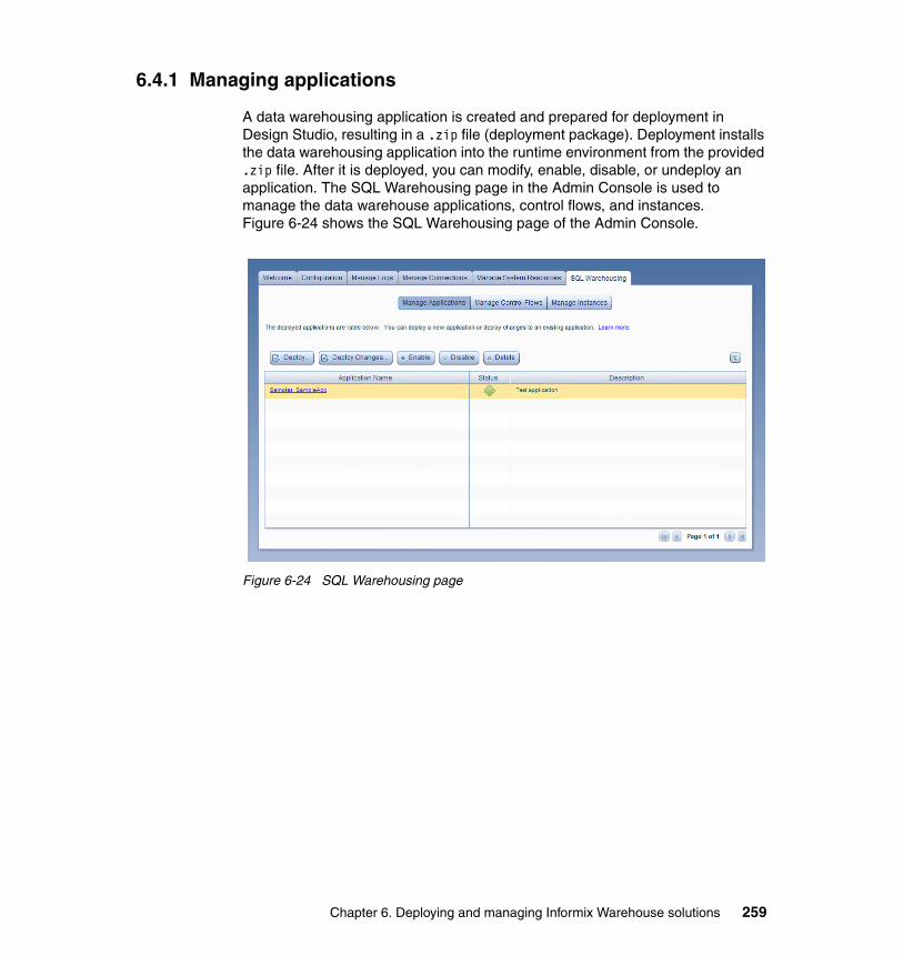
6.4.1 Managing applications
A data warehousing application is created and prepared for deployment in Design Studio, resulting in a .zip file (deployment package). Deployment installs the data warehousing application into the runtime environment from the provided .zip file. After it is deployed, you can modify, enable, disable, or undeploy an application. The SQL Warehousing page in the Admin Console is used to manage the data warehouse applications, control flows, and instances. Figure 6-24 shows the SQL Warehousing page of the Admin Console.
Figure 6-24 SQL Warehousing page
Chapter 6. Deploying and managing Informix Warehouse solutions 259
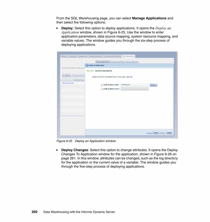
From the SQL Warehousing page, you can select Manage Applications and then select the following options:
� Deploy: Select this option to deploy applications. It opens the Deploy an Application window, shown in Figure 6-25. Use the window to enter application parameters, data source mapping, system resource mapping, and variable values. The window guides you through the six-step process of deploying applications.
Figure 6-25 Deploy an Application window
� Deploy Changes: Select this option to change attributes. It opens the Deploy Changes To Application window for the application, shown in Figure 6-26 on page 261. In this window, attributes can be changed, such as the log directory for the application or the current value of a variable. The window guides you through the five-step process of deploying applications.
260 Data Warehousing with the Informix Dynamic Server
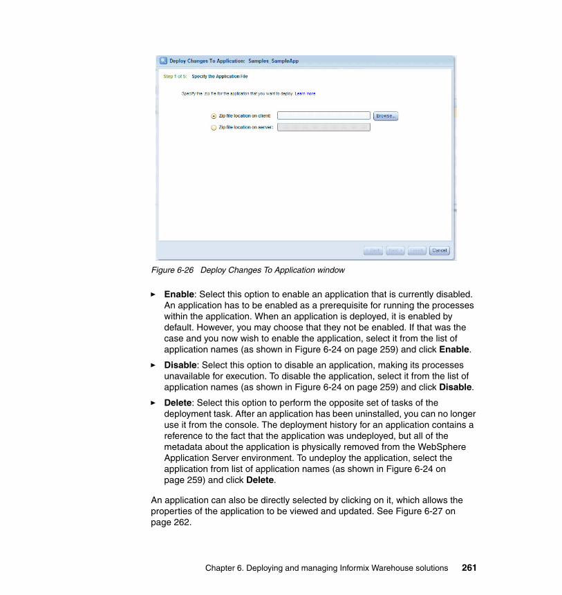
Figure 6-26 Deploy Changes To Application window
� Enable: Select this option to enable an application that is currently disabled. An application has to be enabled as a prerequisite for running the processes within the application. When an application is deployed, it is enabled by default. However, you may choose that they not be enabled. If that was the case and you now wish to enable the application, select it from the list of application names (as shown in Figure 6-24 on page 259) and click Enable.
� Disable: Select this option to disable an application, making its processes unavailable for execution. To disable the application, select it from the list of application names (as shown in Figure 6-24 on page 259) and click Disable.
� Delete: Select this option to perform the opposite set of tasks of the deployment task. After an application has been uninstalled, you can no longer use it from the console. The deployment history for an application contains a reference to the fact that the application was undeployed, but all of the metadata about the application is physically removed from the WebSphere Application Server environment. To undeploy the application, select the application from list of application names (as shown in Figure 6-24 on page 259) and click Delete.
An application can also be directly selected by clicking on it, which allows the properties of the application to be viewed and updated. See Figure 6-27 on page 262.
Chapter 6. Deploying and managing Informix Warehouse solutions 261
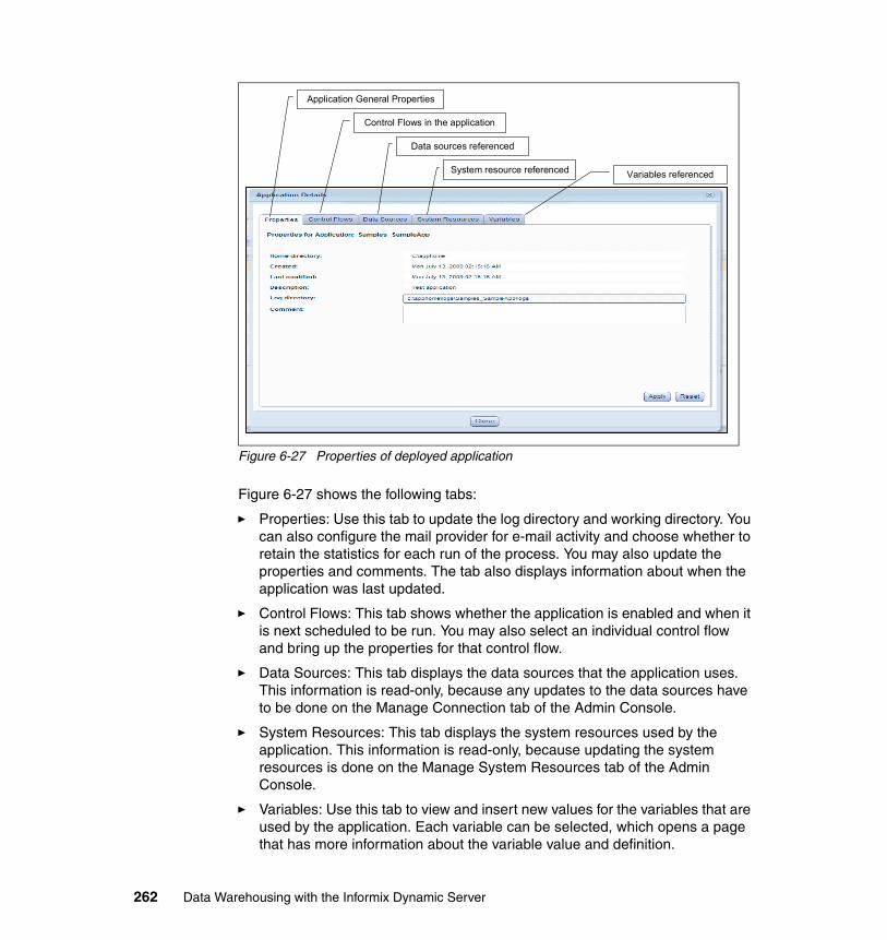
Figure 6-27 Properties of deployed application
Figure 6-27 shows the following tabs:
� Properties: Use this tab to update the log directory and working directory. You can also configure the mail provider for e-mail activity and choose whether to retain the statistics for each run of the process. You may also update the properties and comments. The tab also displays information about when the application was last updated.
� Control Flows: This tab shows whether the application is enabled and when it is next scheduled to be run. You may also select an individual control flow and bring up the properties for that control flow.
� Data Sources: This tab displays the data sources that the application uses. This information is read-only, because any updates to the data sources have to be done on the Manage Connection tab of the Admin Console.
� System Resources: This tab displays the system resources used by the application. This information is read-only, because updating the system resources is done on the Manage System Resources tab of the Admin Console.
� Variables: Use this tab to view and insert new values for the variables that are used by the application. Each variable can be selected, which opens a page that has more information about the variable value and definition.
Application General Properties
Control Flows in the application
Data sources referenced
System resource referenced Variables referenced
262 Data Warehousing with the Informix Dynamic Server
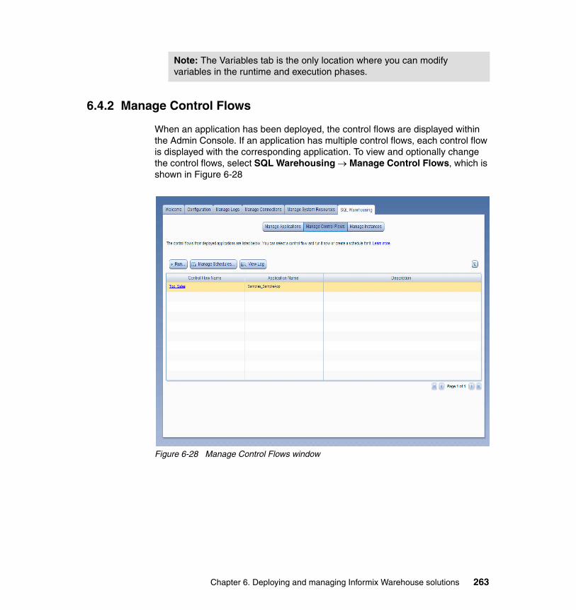
6.4.2 Manage Control Flows
When an application has been deployed, the control flows are displayed within the Admin Console. If an application has multiple control flows, each control flow is displayed with the corresponding application. To view and optionally change the control flows, select SQL Warehousing → Manage Control Flows, which is shown in Figure 6-28
Figure 6-28 Manage Control Flows window
Note: The Variables tab is the only location where you can modify variables in the runtime and execution phases.
Chapter 6. Deploying and managing Informix Warehouse solutions 263
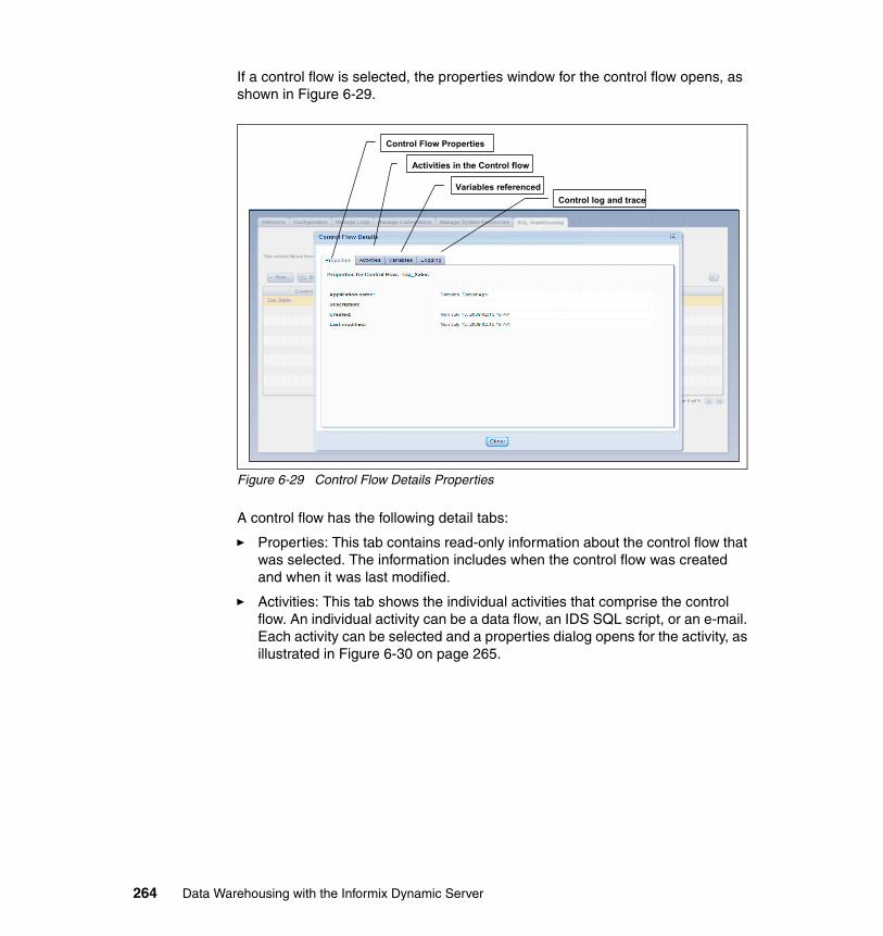
If a control flow is selected, the properties window for the control flow opens, as shown in Figure 6-29.
Figure 6-29 Control Flow Details Properties
A control flow has the following detail tabs:
� Properties: This tab contains read-only information about the control flow that was selected. The information includes when the control flow was created and when it was last modified.
� Activities: This tab shows the individual activities that comprise the control flow. An individual activity can be a data flow, an IDS SQL script, or an e-mail. Each activity can be selected and a properties dialog opens for the activity, as illustrated in Figure 6-30 on page 265.
Control Flow Properties
Activities in the Control flow
Variables referencedControl log and trace
264 Data Warehousing with the Informix Dynamic Server
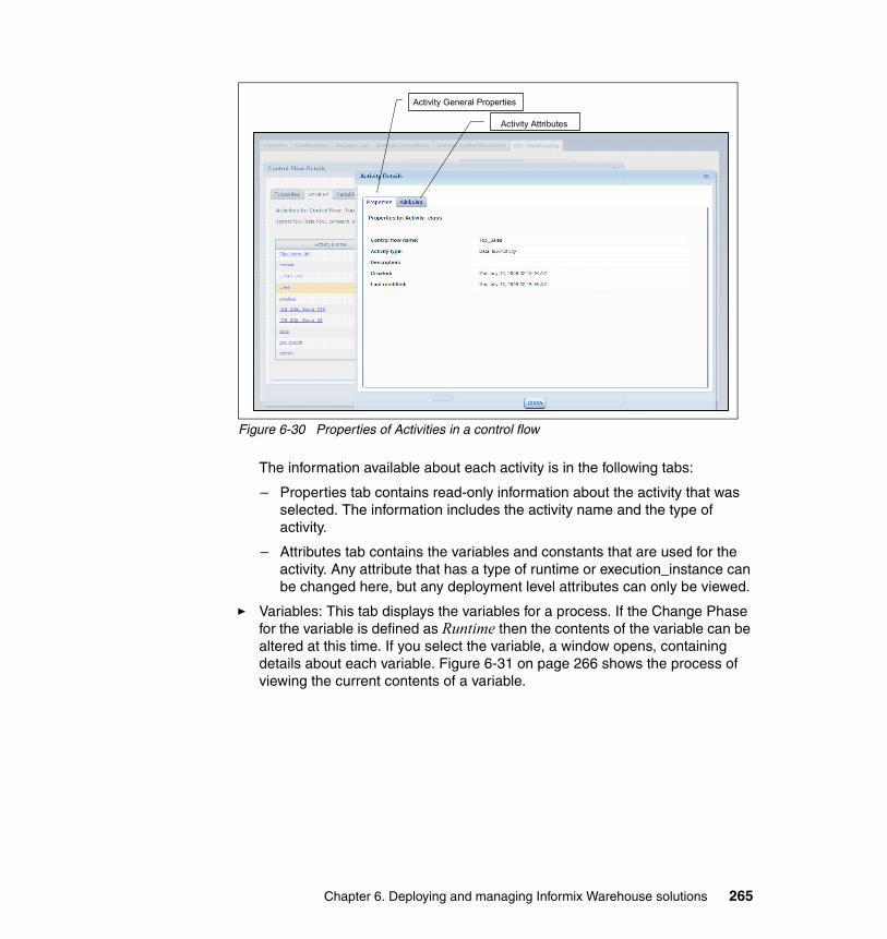
Figure 6-30 Properties of Activities in a control flow
The information available about each activity is in the following tabs:
– Properties tab contains read-only information about the activity that was selected. The information includes the activity name and the type of activity.
– Attributes tab contains the variables and constants that are used for the activity. Any attribute that has a type of runtime or execution_instance can be changed here, but any deployment level attributes can only be viewed.
� Variables: This tab displays the variables for a process. If the Change Phase for the variable is defined as Runtime then the contents of the variable can be altered at this time. If you select the variable, a window opens, containing details about each variable. Figure 6-31 on page 266 shows the process of viewing the current contents of a variable.
Activity General Properties
Activity Attributes
Chapter 6. Deploying and managing Informix Warehouse solutions 265
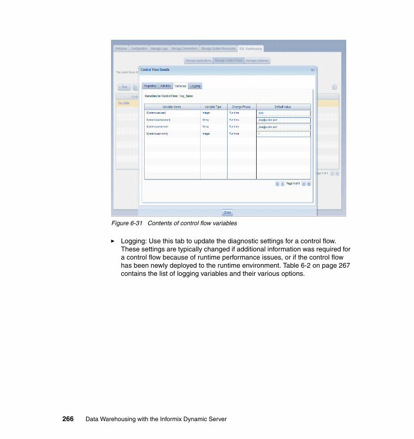
Figure 6-31 Contents of control flow variables
� Logging: Use this tab to update the diagnostic settings for a control flow. These settings are typically changed if additional information was required for a control flow because of runtime performance issues, or if the control flow has been newly deployed to the runtime environment. Table 6-2 on page 267 contains the list of logging variables and their various options.
266 Data Warehousing with the Informix Dynamic Server
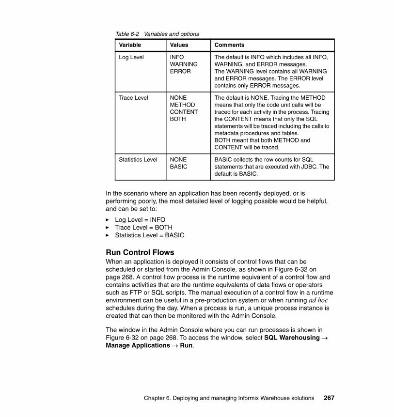
Table 6-2 Variables and options
In the scenario where an application has been recently deployed, or is performing poorly, the most detailed level of logging possible would be helpful, and can be set to:
� Log Level = INFO� Trace Level = BOTH� Statistics Level = BASIC
Run Control FlowsWhen an application is deployed it consists of control flows that can be scheduled or started from the Admin Console, as shown in Figure 6-32 on page 268. A control flow process is the runtime equivalent of a control flow and contains activities that are the runtime equivalents of data flows or operators such as FTP or SQL scripts. The manual execution of a control flow in a runtime environment can be useful in a pre-production system or when running ad hoc schedules during the day. When a process is run, a unique process instance is created that can then be monitored with the Admin Console.
The window in the Admin Console where you can run processes is shown in Figure 6-32 on page 268. To access the window, select SQL Warehousing → Manage Applications → Run.
Variable Values Comments
Log Level INFOWARNINGERROR
The default is INFO which includes all INFO, WARNING, and ERROR messages.The WARNING level contains all WARNING and ERROR messages. The ERROR level contains only ERROR messages.
Trace Level NONE METHOD CONTENT BOTH
The default is NONE. Tracing the METHOD means that only the code unit calls will be traced for each activity in the process. Tracing the CONTENT means that only the SQL statements will be traced including the calls to metadata procedures and tables.BOTH meant that both METHOD and CONTENT will be traced.
Statistics Level NONEBASIC
BASIC collects the row counts for SQL statements that are executed with JDBC. The default is BASIC.
Chapter 6. Deploying and managing Informix Warehouse solutions 267
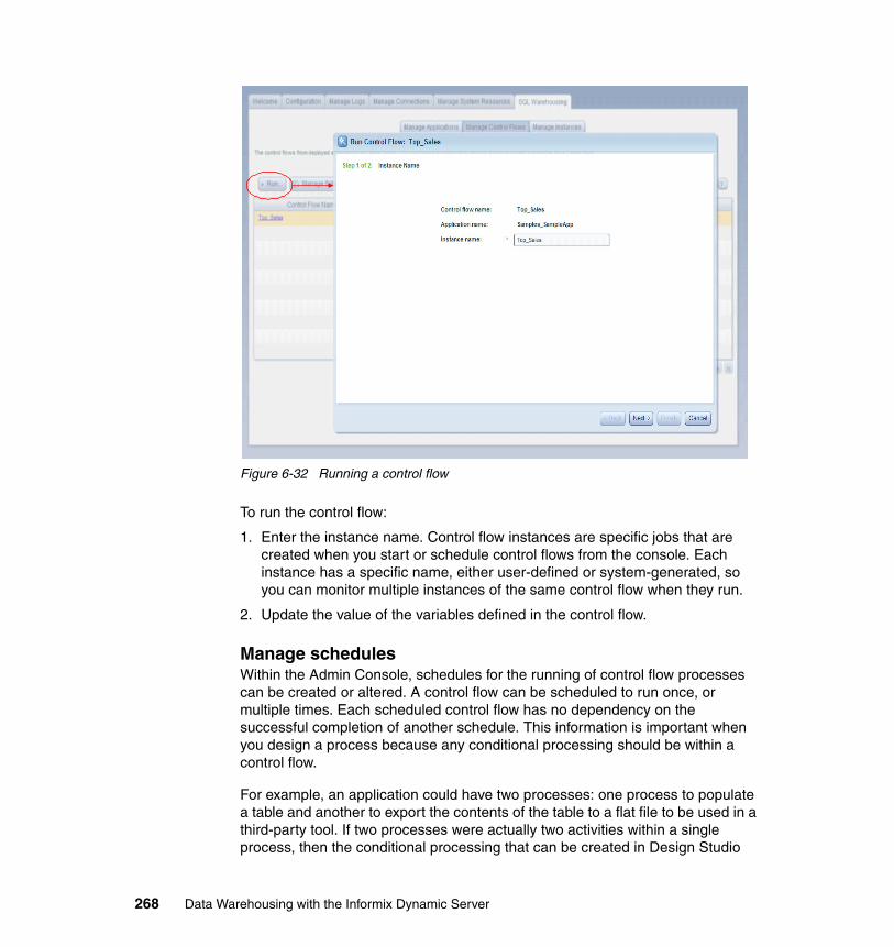
Figure 6-32 Running a control flow
To run the control flow:
1. Enter the instance name. Control flow instances are specific jobs that are created when you start or schedule control flows from the console. Each instance has a specific name, either user-defined or system-generated, so you can monitor multiple instances of the same control flow when they run.
2. Update the value of the variables defined in the control flow.
Manage schedulesWithin the Admin Console, schedules for the running of control flow processes can be created or altered. A control flow can be scheduled to run once, or multiple times. Each scheduled control flow has no dependency on the successful completion of another schedule. This information is important when you design a process because any conditional processing should be within a control flow.
For example, an application could have two processes: one process to populate a table and another to export the contents of the table to a flat file to be used in a third-party tool. If two processes were actually two activities within a single process, then the conditional processing that can be created in Design Studio
268 Data Warehousing with the Informix Dynamic Server
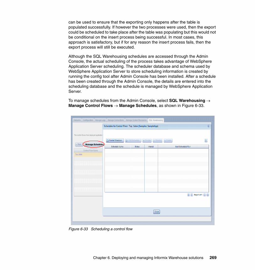
can be used to ensure that the exporting only happens after the table is populated successfully. If however the two processes were used, then the export could be scheduled to take place after the table was populating but this would not be conditional on the insert process being successful. In most cases, this approach is satisfactory, but if for any reason the insert process fails, then the export process will still be executed.
Although the SQL Warehousing schedules are accessed through the Admin Console, the actual scheduling of the process takes advantage of WebSphere Application Server scheduling. The scheduler database and schema used by WebSphere Application Server to store scheduling information is created by running the config tool after Admin Console has been installed. After a schedule has been created through the Admin Console, the details are entered into the scheduling database and the schedule is managed by WebSphere Application Server.
To manage schedules from the Admin Console, select SQL Warehousing → Manage Control Flows → Manage Schedules, as shown in Figure 6-33.
Figure 6-33 Scheduling a control flow
Manage Schedules
Chapter 6. Deploying and managing Informix Warehouse solutions 269

This page of the Admin Console is where you create and manage schedules by selecting the following options:
� Create Schedule: Use this option to create a new schedule for a control flow process. When a scheduled control flow is run, the instance ID is the process name concatenated with the runtime. For example, a schedule named NewSchedule is run at 13:09 on 5 July 2006, it would have an instance ID of NewSchedule2-0607151309.
A schedule can be run repeatedly or only once. If the schedule is to be run more than once then it can be configured in three ways:
– Daily: A daily schedule executes every day at the same time that was specified for the first run of the schedule. If the original run was scheduled on 2009/07/13 at 14:16:00 then the subsequent run will be scheduled to start at 2009/07/14 at 14:16:00.
The schedule can be created to run indefinitely or for a specific number of days.
– Weekly: A weekly schedule will execute on the day or days specified at the same time that was specified for the first run of the schedule. If the first run of a schedule is on a Monday, the schedule will be set to next execute on the following Monday. The schedule can be set to run on more than one day, so if the original run was on a Monday then the schedule can be set to run on Monday through Friday. The use of a weekly schedule is useful where processes need to execute during the week but not on the weekends.
The schedule can also be created to run indefinitely or for a certain number of weeks.
– Fixed Interval: A fixed interval schedule is run initially at a specified date and time and thereafter at a specified repeat-interval for the schedule. That is, after how many hours and minutes should the schedule be run again. The repeat interval is from when the job started, so if the control flow process started at 07:00:00 and finished at 07:10:00 and the repeat interval is two hours, then the control flow process would run at about 09:00:00. The process might not run at exactly at 09:00:00, because by default the WebSphere Application Server scheduler has a poll interval of 30 seconds to check for scheduled jobs to run.
The schedule can be created to run indefinitely or for a certain number of intervals.
� Edit Schedule: Use this option to update an existing schedule. For example, the schedule for a process can be changed from a daily schedule to a weekly schedule. A schedule also has to be updated when the process profile is
270 Data Warehousing with the Informix Dynamic Server

changed. So, if the value for a variable has to change or a different profile has to be used, then this change is performed here.
Changing a schedule is much like creating one in that a new date and time can be specified for the process to initially run and then the new type of schedule will commence. For example, if an existing daily schedule was set to next execute at 09:00:00 on the July 13 and the schedule was changed to a fixed interval, then by default the first run of the new schedule will be at 09:00:00 on July 13. The starting time and date of the updated schedule can be changed but they have to be greater than or equal to the current date and time.
� Enable: Use this option to start a schedule that has been previously suspended.
� Disable: Use this option to stop a current schedule, which prevents any scheduled processes that have not yet started.
� Delete: Use this option to remove a schedule. If there are a large number of schedules, the deleting of completed schedules is a useful means of housekeeping.
Manage InstancesEach instance of a runtime process can be monitored through the Admin Console whether the instance was invoked through a schedule or an ad hoc run. The Manage Instances window, shown in Figure 6-34 on page 272, contains information about the execution of the process and the ability to manage failed instances. Each instance that is run adds one row to this window so the included filter allows the amount of data shown on-screen to be restricted. This option is used to monitor the progress of a control flow instance. To access the window from the Admin Console, select SQL Warehousing → Manage Instances.
Chapter 6. Deploying and managing Informix Warehouse solutions 271
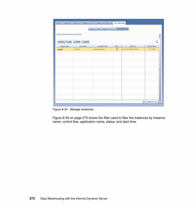
Figure 6-34 Manage Instances
Figure 6-35 on page 273 shows the filter used to filter the instances by instance name, control flow, application name, status, and start time.
272 Data Warehousing with the Informix Dynamic Server
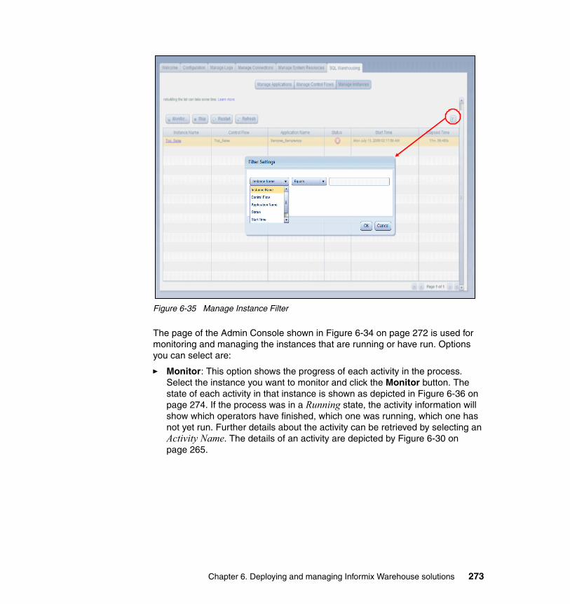
Figure 6-35 Manage Instance Filter
The page of the Admin Console shown in Figure 6-34 on page 272 is used for monitoring and managing the instances that are running or have run. Options you can select are:
� Monitor: This option shows the progress of each activity in the process. Select the instance you want to monitor and click the Monitor button. The state of each activity in that instance is shown as depicted in Figure 6-36 on page 274. If the process was in a Running state, the activity information will show which operators have finished, which one was running, which one has not yet run. Further details about the activity can be retrieved by selecting an Activity Name. The details of an activity are depicted by Figure 6-30 on page 265.
Chapter 6. Deploying and managing Informix Warehouse solutions 273
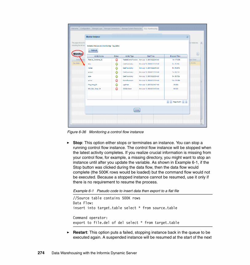
Figure 6-36 Monitoring a control flow instance
� Stop: This option either stops or terminates an instance. You can stop a running control flow instance. The control flow instance will be stopped when the latest activity completes. If you realize crucial information is missing from your control flow, for example, a missing directory, you might want to stop an instance until after you update the variable. As shown in Example 6-1, if the Stop button was clicked during the data flow, then the data flow would complete (the 500K rows would be loaded) but the command flow would not be executed. Because a stopped instance cannot be resumed, use it only if there is no requirement to resume the process.
Example 6-1 Pseudo code to insert data then export to a flat file
//Source table contains 500K rowsData Flow:insert into target.table select * from source.table
Command operator:export to file.del of del select * from target.table
� Restart: This option puts a failed, stopping instance back in the queue to be executed again. A suspended instance will be resumed at the start of the next
Monitor
274 Data Warehousing with the Informix Dynamic Server

activity, but a failed instance can be restarted with the failed activity or with the next activity. The exception to this is a failed activity in an iteration that always restarts with the start iterator of the outermost iteration. In Example 6-1 on page 274, if the data flow was successful but the command operator failed, then the resumption of the instance results in the command operator being executed (but the data flow would not be executed again because it had already run successfully).
Chapter 6. Deploying and managing Informix Warehouse solutions 275

276 Data Warehousing with the Informix Dynamic Server
Chapter 7. Optimizing your Informix Warehouse environment
In this chapter, we discuss the modification of the physical components and configuration parameter settings of the Informix Dynamic Server environment that can help optimize your Informix warehouse environment.
The subject of IDS engine performance tuning and optimization is vast and ever evolving, thus we are specifically focusing the material in this publication to the subject as it relates to deployment in the Data Studio and Data Warehouse environments.
7
© Copyright IBM Corp. 2009. All rights reserved. 277
7.1 Informix Dynamic Server
Complex, mission-critical database management applications typically require a combination of online transaction processing (OLTP) and batch and decision-support operations, including online analytical processing (OLAP). Meeting these requirements is contingent upon a data server that can scale in performance and in functionality. It must dynamically adjust as requirements change from accommodating larger amounts of data, to changes in query operations, to increasing numbers of concurrent users. The technology must be designed to efficiently use all the capabilities of the existing hardware and software configuration, including single and multiprocessor architectures. Finally, the data server must satisfy user demands for more complex application support, and which often uses nontraditional or rich data types that cannot be stored in simple character or numeric form.
IDS is built on the IBM Informix Dynamic Scalable Architecture (DSA). It provides one of the most effective solutions available: a next-generation parallel data server architecture that delivers mainframe-caliber scalability, manageability, and performance; minimal operating system overhead; automatic distribution of workload; and the capability to extend the server to handle new types of data. With Version 11, IDS increased its lead over the data server landscape with even faster performance, a new suite of business availability functionality, greater flexibility and performance in backing up and restoring an instance, automated statistical and performance metric gathering, improvements in administration, reducing the cost to operate the data server, and more.
IDS delivers proven technology that efficiently integrates new and complex data directly into the database. It handles time-series, spatial, geodetic, Extensible Markup Language (XML), video, image, and other user-defined data, along with traditional data, to meet the most rigorous data and business demands. IDS helps businesses to lower their total cost of ownership (TCO) by leveraging its well-regarded general ease-of-use and administration, and its support of existing standards for development tools and systems infrastructure. IDS is a development-neutral environment and supports a comprehensive array of application development tools for rapid deployment of applications under Linux, Microsoft Windows, and UNIX operating environments.
The maturity and success of IDS is built on many years of widespread use in critical business operations, which attests to its stability, performance, and usability. IDS 11 has moved this already highly successful enterprise relational data server to an even higher level.
278 Data Warehousing with the Informix Dynamic Server
7.2 IDS architecture
High systems performance is essential for maintaining maximum throughput. IDS maintains industry-leading performance levels through multiprocessor features, shared memory management, efficient data access, and cost-based query optimization. It is available on many hardware platforms and, because the underlying platform is transparent to applications, the data server can migrate easily to more powerful computing environments as requirements change. This transparency enables developers to take advantage of high-end symmetric multiprocessing (SMP) systems with little or no modification of application code.
Data server architecture is a significant differentiator and contributor to the server’s performance, scalability, and ability to support new data types and processing requirements. Many data servers available today use an older technological design that, for an individual user, requires each database operation (for example, read, sort, write, and communication) to invoke a separate operating system process. This architecture worked well when database sizes and user counts were relatively small. Today, these types of servers spawn many hundreds and even thousands of individual processes that the operating system must create, queue, schedule, manage, control, and then terminate when no longer required. Given that, generally speaking, any individual system processor can only work on one thing at a time and the operating system works through each of the processes before returning to the top of the queue, this data server architecture creates an environment where individual database operations must wait for one or more passes through the queue to complete their task. Scalability with this type of architecture has nothing to do with the software; it is entirely dependent on the speed of the processor, how fast it can work through the queue before it starts over again.
The IDS data server architecture is based on advanced technology that efficiently uses virtually all of today’s hardware and software resources. Called the Dynamic Scalable Architecture (DSA), it fully exploits the processing power available in SMP environments by performing similar types of database activities (such as I/O, complex queries, index builds, log recovery, inserts, and backups and restores) in parallelized groups rather than as discrete operations. The DSA design architecture includes built-in multithreading and parallel processing capabilities, dynamic and self-tuning shared memory components, and intelligent logical data storage capabilities, supporting the most efficient use of all available system resources.
Chapter 7. Optimizing your Informix Warehouse environment 279
7.3 Data loading capabilities
IDS provides several data movement utilities that can be used to unload and load data. Some only work within IDS environments, others produce or use plain ASCII files and can load files created by a non-IDS unload process. When using ASCII files, the default IDS delimiter is the vertical bar ( | ), often called the pipe character. A good practice is to use this character because it significantly reduces the chance for conflict with text inside the load/unload file.
7.3.1 SQL load and unload commands
The slowest and least robust load and unload commands, in terms of functionality, is an SQL statement. It is used to identify attributes and conditions for extracting data, converting data to ASCII and (usually) populating a named flat file. Conversely, the contents of an ASCII file, whether created from an IDS instance or a competitive server, can be read and inserted into an IDS database based on an attribute list contained in the SQL statement.
Unlike the unload process, which can configured to select from multiple tables if desired, the load process can only insert into a single table. When loading, a one-to-one match of table attributes to data file elements is not required; in the load statement file elements can be mapped to specific table attributes. Obviously, any table attribute not mapped should not have the constraint of not null or the insert process can fail.
These operations do not require an exclusive lock on the tables involved, although one should be created if a static image of the source table is required during an unload or to minimize the risk of a long transaction condition when loading a large amount of data into a logged database or table.
7.3.2 The dbexport and dbimport utilities
Here, we discuss a very commonly used set of utilities developed particularly for moving an entire IDS database to an instance on a non-compatible operating system. The dbexport utility automatically creates a set of ASCII unload files, one for each table, and the complete schema definition for the database. With the addition of the -ss flag, table fragmentation rules and extent sizing in the DDL definition file will be included.
When exporting, an exclusive lock is required on the database to ensure logical consistency between tables with referential integrity constraints. With the appropriate flags, the unload files can be either created on disk or output to tape.
280 Data Warehousing with the Informix Dynamic Server
When output to tape, the database DDL file is still created on disk so it can be edited if necessary.
The database DDL file is created in the same directory as the data unload files if unloading to disk. The file naming convention of database_name.sql should not be changed because dbexport utility matches the file name to the database name specified when the utility is invoked. The DDL file looks very similar to that created by the dbschema utility although it also includes load-file information and load-triggering control characters. This file can be edited to change fragmentation rules or extent sizing if necessary. Attribute names can be changed and data types, provided the new types do not conflict with the type, can be unloaded. New constraints, indexes, stored procedures, or user-defined routines (UDRs) can be added in the appropriate places in the DDL file.
When the dbimport utility is invoked, the target database is created. Then, using the DDL file, each table is created, loaded with data, followed by index, constraint or stored procedures/UDR creation. By default, the database is created in a non-logged mode to prevent a long transaction from occurring during data loads. This can be overridden although the administrator should remember that the database creation, all table loads and index, constraint and stored procedure and UDR creation, occurs within a single transaction. After the database is created and loaded, it can be converted to the desired logging mode with the appropriate ontape or ondblog command. With the -d dbspace flag, the dbimport utility creates the database in the dbspace listed rather than in the root dbspace (rootdbs). When importing, the -c flag can be used to continue the load process although non-fatal errors occur.
Because these utilities translate to and from ASCII, they are relatively slow from a performance perspective. It is nice however to have a partially editable and completely transportable database capture.
7.3.3 The dbload utility
The dbload utility uses ASCII data files and a control file to load specific pre-existing tables within a database. Because the loads can be occurring within a logged database, the control file parameters give this utility more flexibility.
These parameters include:
-l The full path file name in which errors are logged
-e number The number of data load errors which can occur before the utility aborts processing. The load errors are logged if the -l parameter is used.
Chapter 7. Optimizing your Informix Warehouse environment 281
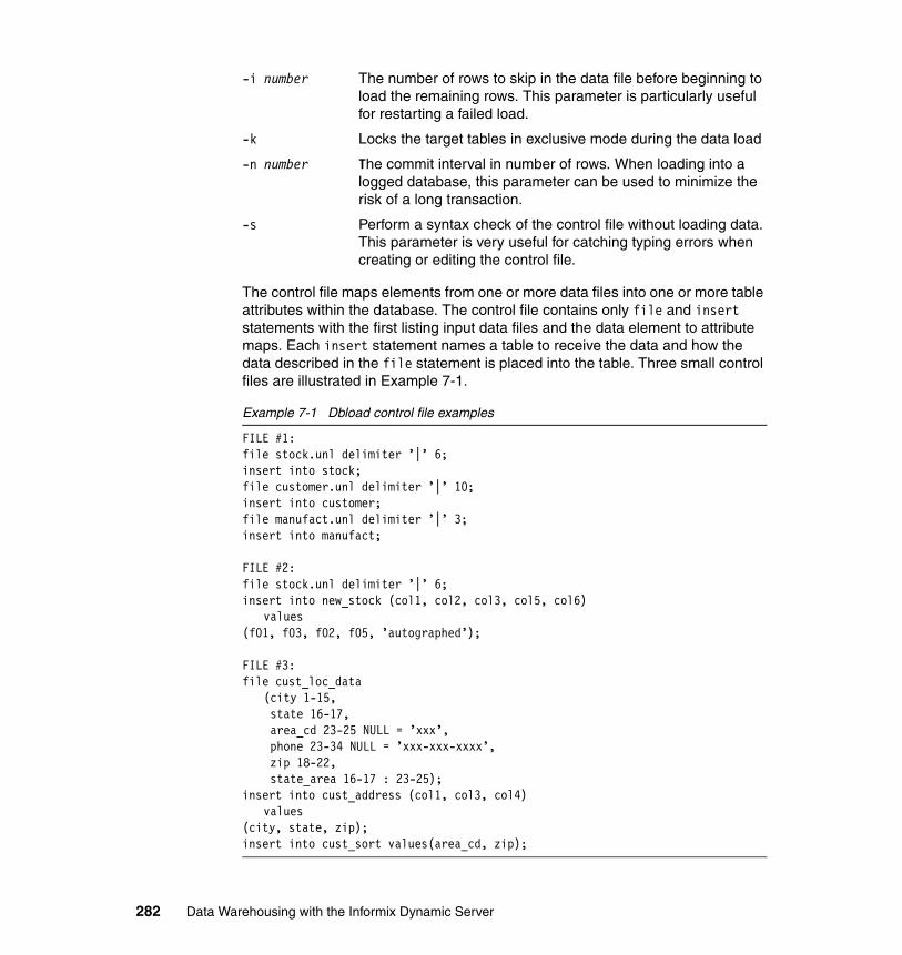
-i number The number of rows to skip in the data file before beginning to load the remaining rows. This parameter is particularly useful for restarting a failed load.
-k Locks the target tables in exclusive mode during the data load
-n number The commit interval in number of rows. When loading into a logged database, this parameter can be used to minimize the risk of a long transaction.
-s Perform a syntax check of the control file without loading data. This parameter is very useful for catching typing errors when creating or editing the control file.
The control file maps elements from one or more data files into one or more table attributes within the database. The control file contains only file and insert statements with the first listing input data files and the data element to attribute maps. Each insert statement names a table to receive the data and how the data described in the file statement is placed into the table. Three small control files are illustrated in Example 7-1.
Example 7-1 Dbload control file examples
FILE #1:file stock.unl delimiter ’|’ 6; insert into stock; file customer.unl delimiter ’|’ 10; insert into customer; file manufact.unl delimiter ’|’ 3; insert into manufact;
FILE #2:file stock.unl delimiter ’|’ 6; insert into new_stock (col1, col2, col3, col5, col6)
values (f01, f03, f02, f05, ’autographed’);
FILE #3:file cust_loc_data
(city 1-15, state 16-17, area_cd 23-25 NULL = ’xxx’, phone 23-34 NULL = ’xxx-xxx-xxxx’, zip 18-22, state_area 16-17 : 23-25);
insert into cust_address (col1, col3, col4) values
(city, state, zip); insert into cust_sort values(area_cd, zip);
282 Data Warehousing with the Informix Dynamic Server
In the first and second control file examples, the load files use a vertical bar character ( | ), also called a pipe, as the separator between data elements. In the first control file, there is a one-to-one match between data elements and the specified target table attributes, so a direct insert is requested. In the second control file, the data file contains six elements but only five table attributes are loaded. Of the five attributes to load, the last receives a constant. Finally in the last control file, the data files do not use a delimiter symbol so the data elements are mapped to a control file variable through their position within the text string. For example, the first 15 characters are mapped into the city variable. In addition, this control file specifies two tables are to be loaded from one row of input data.
The dbload utility supports almost all of the extensible data types. However, nesting of types is not supported.
7.3.4 The onunload and onload utilities
The onunload and onload utilities function similarly to dbexport and dbimport utilities with a major caveat. Whereas the dbexport and dbimport utilities worked with ASCII files, the onunload and onload utilities use data in the native IDS binary format. As a result, data extraction and reloading is significantly faster.
Because the onunload and onload utilities use data in binary form, they can only be used when moving between physical servers using the same operating system and the exact same version of IDS. Another difference is that a DDL file is not created, the table and attribute definitions as they exist in the source database are used as defaults when recreating the tables. Certain definitions can be overridden with flags when the onload utility is invoked, including changing the dbspace in which a table is created, an index’s fragmentation rule, and renaming an index or constraint.
7.3.5 The High-Performance Loader
The High-Performance Loader (HPL) is a database server utility that allows efficient and fast loading and unloading of large quantities of data. The HPL supports exchanging data with tapes, data files and programs, and converts data from these sources into a format compatible with an IDS database. Likewise, extracted data can be published to tape, disk, or other targets, and converted into several data formats including ASCII, IDS binary, or EBCDIC. The HPL also supports data manipulation and filtering during load and unload operations.
Chapter 7. Optimizing your Informix Warehouse environment 283
The HPL is actually a collection of four components:
� onpload utility
The onpload utility has the following features:
– Converts, filters, and moves data between a database and a storage device.
– Uses information from the onpload database to run the load and unload jobs and to convert the data.
– Records information during a load about data records that do not meet the load criteria.
The onpload utility can load or unload data from files that are larger than 2 GB and can generate .log, .rej, and .flt files that are larger than 2 GB.
� ipload utility
The ipload utility is a UNIX-based GUI that has the following features:
– Creates and manages the onpload database.
– Creates and stores information for onpload.
– Enables you to create, edit, and group the components of the load and unload jobs.
– Stores information about the load components in the database.
� onpladm utility
The onpladm utility is a command-line utility for both UNIX and Windows with the same functionality as ipload utility.
� onpload database
The onpload database has the following features:
– Contains information that the onpload utility requires to perform data loads and unloads.
– Can reside on any database server on your network.
– Can be used by any onpload utility on the same network. In contrast, the target database must be located on the same server as the onpload utility.
Tip: The onpload utility must be located on the same network as the onpload database and on the same server as the target database. You can start onpload by using ipload or from the command line.
Note: The ipload utility is only available on UNIX and Linux systems.
284 Data Warehousing with the Informix Dynamic Server
The HPL loader is the fastest of the data migration utilities because its operations can be parallelized to simultaneously read or write to or from multiple devices. However, setting up and using the HPL requires more work, and often at a table-by-table level. A separate configuration file in $INFORMIXDIR/etc folder for the HPL is where parameters such as the number of converter threads, AIO buffers and buffer size, and so on are set.
The HPL connects to an IDS instance through its network-based instance name or alias and allocates threads for each device defined for the project. As a result, it is important that the network-based connection protocol be tuned to support the additional overhead of HPL operations. Unload projects do not lock the source tables in exclusive mode. However, load projects can execute in one of two modes:
� Express
Target table indexes, triggers, and constraints are disabled and data is loaded using light appends; no records are written to the logical logs. The table is locked in exclusive mode and when the project is completed a level 0 backup is required to facilitate instance recovery.
� Deluxe
Target table indexes, triggers, and constraints are active and the table is accessible by other users. The inserts are logged but execute as a single transaction so a commit point has to be set in the project definition to prevent a long transaction from occurring.
As mentioned earlier, HPL operations are defined and executed as projects. Each project contains definitions for devices to read from or write to, the input and output data formats, any filters for excluding data, the actual SQL operations to execute and maps for describing attribute to data element correspondence.
Project definitions can be created and maintained graphically through ipload, Server Studio JE (SSJE) or the Informix Server Administrator (ISA) utilities, as illustrated in Figure 7-1 on page 286, Figure 7-2 on page 287, and Figure 7-3 on page 288, or from the command line with the onpladm interface.
Chapter 7. Optimizing your Informix Warehouse environment 285
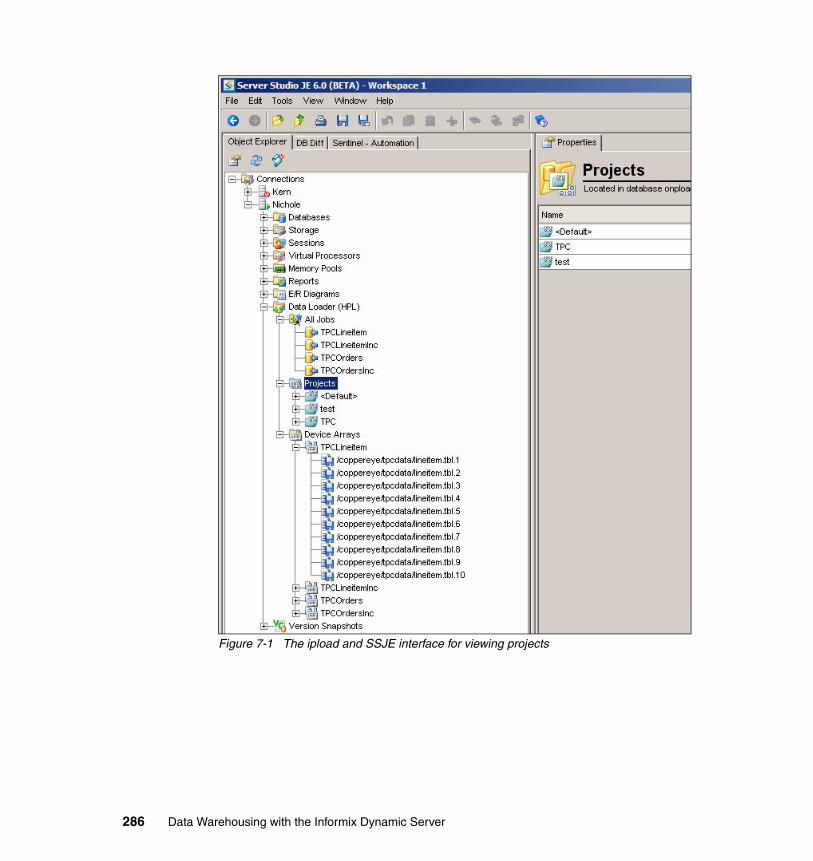
Figure 7-1 The ipload and SSJE interface for viewing projects
286 Data Warehousing with the Informix Dynamic Server
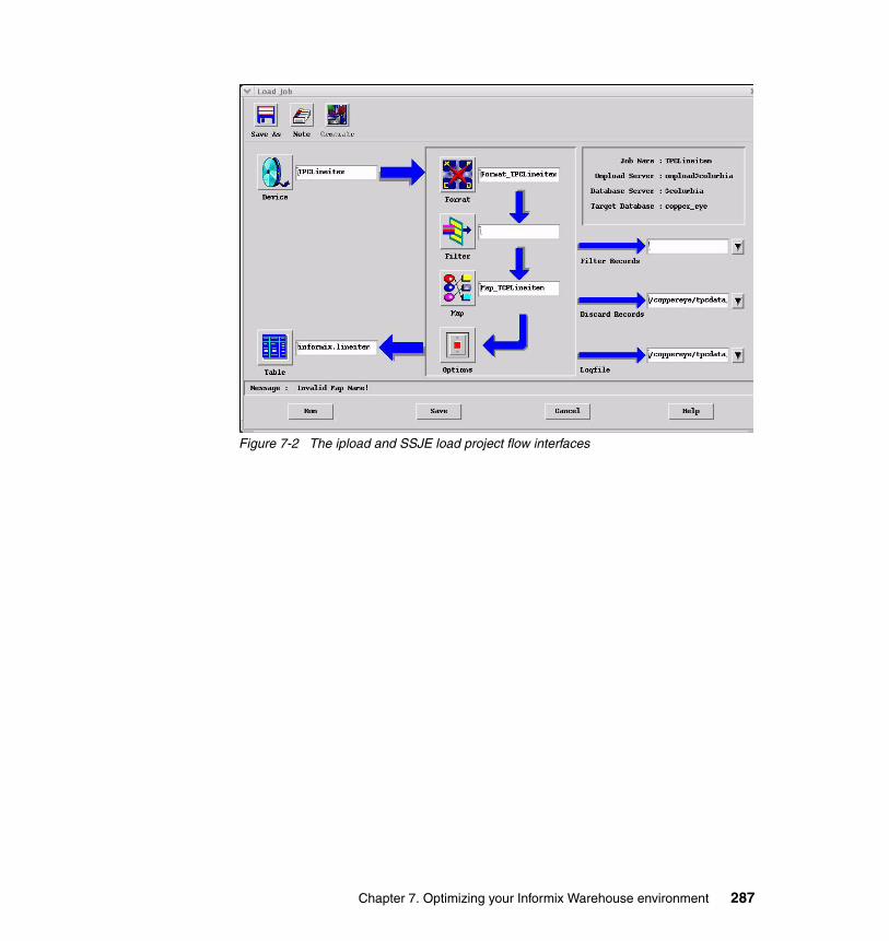
Figure 7-2 The ipload and SSJE load project flow interfaces
Chapter 7. Optimizing your Informix Warehouse environment 287
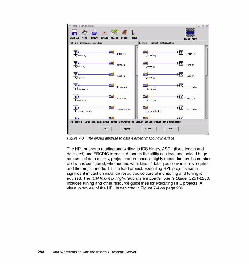
Figure 7-3 The ipload attribute to data element mapping interface
The HPL supports reading and writing to IDS binary, ASCII (fixed length and delimited) and EBCDIC formats. Although the utility can load and unload huge amounts of data quickly, project performance is highly dependent on the number of devices configured, whether and what kind of data type conversion is required, and the project mode, if it is a load project. Executing HPL projects has a significant impact on instance resources so careful monitoring and tuning is advised. The IBM Informix High-Performance Loader User’s Guide, G251-2286, includes tuning and other resource guidelines for executing HPL projects. A visual overview of the HPL is depicted in Figure 7-4 on page 289.
288 Data Warehousing with the Informix Dynamic Server
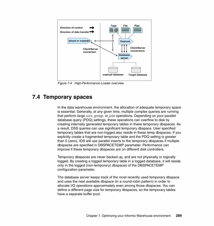
Figure 7-4 High-Performance Loader overview
7.4 Temporary spaces
In the data warehouse environment, the allocation of adequate temporary space is essential. Generally, at any given time, multiple complex queries are running that perform large sort, group, or join operations. Depending on your parallel database query (PDQ) settings, these operations can overflow to disk by creating internally generated temporary tables in these temporary dbspaces. As a result, DSS queries can use significant temporary dbspace. User specified temporary tables that are non-logged also reside in these temp dbspaces. If you explicitly create a fragmented temporary table and the PDQ setting is greater than 0 (zero), IDS will use parallel inserts to the temporary dbspaces if multiple dbspaces are specified in DBSPACETEMP parameter. Performance can improve if these temporary dbspaces are on different disk controllers.
Temporary dbspaces are never backed up, and are not physically or logically logged. By creating a logged temporary table in a logged database, it will reside only in the logged (non-temporary) dbspaces of the DBSPACETEMP configuration parameter.
The database server keeps track of the most recently used temporary dbspace and uses the next available dbspace (in a round-robin pattern) in order to allocate I/O operations approximately even among those dbspaces. You can define a different page size for temporary dbspaces, so the temporary tables have a separate buffer pool.
Direction of control
Direction of data transfer
Ipload or onpladm
Tape File Pipe
Onpload
Database server
onpload database Target database
Client/Server connections
Client/Server connection
Chapter 7. Optimizing your Informix Warehouse environment 289

All DML operations on temporary tables create logs. Not only do these logs take log space, but if you have enabled your system for high availability, they are transported to other systems, simply to be ignored.
To avoid this overhead, you can use the CREATE TEMP TABLE..WITH NO LOG option. IDS 11 provides a method to disable logging on temporary tables by default, even when you do not use the WITH NO LOG modifier.
Logging can be disabled by either of the following two ways:
� Statically, but putting the following parameter in the ONCONFIG file:
TEMPTAB_NOLOG 1
� Dynamically, with, as examples, one of the following commands:
onmode -Wf "TEMPTAB_NOLOG =1"onmode -Wm "TEMPTAB_NOLOG =1"
Note however that -Wm changes the value and enables the behavior on the system immediately. The -Wf flag does the same thing as -Wm flag, and then writes the new value to the IDS configuration file.
Depending how the temporary space is created, the database server uses the following default locations for temporary table and sort files when you do not set DBSPACETEMP:
� The dbspace of the current database, when you create an explicit temporary table with the TEMP TABLE clause of the CREATE TABLE statement and do not specify a dbspace for the table either in the IN dbspace clause or in the FRAGMENT BY clause
This action can severely affect I/O to that dbspace. If the root dbspace is mirrored, you encounter a slight double-write performance penalty for I/O to the temporary tables and sort files.
Attention: Be aware that you cannot roll back any changes to the table if you do not have logging specified for it.
Attention: If you do not specify a value for the DBSPACETEMP configuration parameter or the DBSPACETEMP environment variable, the database server uses this operating-system file for implicit temporary tables. If this file system has insufficient space to hold a sort file, the query that is performing the sort operation returns an error. Meanwhile, the operating system might be severely affected until you remove the sort file.
290 Data Warehousing with the Informix Dynamic Server
� The root dbspace, when you create an explicit temporary table with the INTO TEMP option of the SELECT statement
This action can severely affect I/O to the root dbspace. If the root dbspace is mirrored, you encounter a slight double-write performance penalty for I/O to the temporary tables and sort files.
� The operating-system directory or file that you specify in one of the following variables:
– In UNIX, the operating-system directory or directories that the PSORT_DBTEMP environment variable specifies, if it is set. If PSORT_DBTEMP is not set, the database server writes sort files to the operating-system file space in the /tmp directory.
– In Windows, the directory specified in TEMP or TMP in the User Environment Variables window by selecting Control Panel → System. The database server uses the operating-system directory or files to direct any overflow that results from the following database operations:
• SELECT statement with GROUP BY clause • SELECT statement with ORDER BY clause• Hash-join operation• Nested-loop join operation • Index builds
You can improve performance with the use of temporary dbspaces that you create exclusively to store temporary tables and sort files. A good practice is to use the DBSPACETEMP configuration parameter and the DBSPACETEMP environment variable to assign these tables and files to temporary dbspaces.
When you specify dbspaces in either the DBSPACETEMP configuration parameter or the DBSPACETEMP environment variable, you gain the following performance advantages:
� Reduced I/O impact on the root dbspace, production dbspaces, or operating-system files.
� Use of parallel sorts into the temporary files (to process query clauses such as ORDER BY or GROUP BY, or to sort index keys when you execute CREATE INDEX) when you specify more than one dbspace for temporary tables and PDQ priority is set to greater than 0.
� Improved speed with which the database server creates temporary tables when you assign two or more temporary dbspaces on separate disks.
� Use of parallel inserts into the temporary table when PDQ priority is set to greater than 0 (zero) and the temporary table is created by the CREATE TEMP TABLE statement that has one of the combinations of configuration choices depicted in Table 7-1 on page 292. The database server then
Chapter 7. Optimizing your Informix Warehouse environment 291
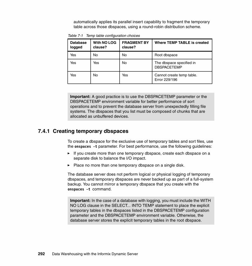
automatically applies its parallel insert capability to fragment the temporary table across those dbspaces, using a round-robin distribution scheme.
Table 7-1 Temp table configuration choices
7.4.1 Creating temporary dbspaces
To create a dbspace for the exclusive use of temporary tables and sort files, use the onspaces -t parameter. For best performance, use the following guidelines:
� If you create more than one temporary dbspace, create each dbspace on a separate disk to balance the I/O impact.
� Place no more than one temporary dbspace on a single disk.
The database server does not perform logical or physical logging of temporary dbspaces, and temporary dbspaces are never backed up as part of a full-system backup. You cannot mirror a temporary dbspace that you create with the onspaces -t command.
Database logged
With NO LOG clause?
FRAGMENT BY clause?
Where TEMP TABLE is created
Yes No No Root dbspace
Yes Yes No The dbspace specified in DBSPACETEMP
Yes No Yes Cannot create temp table. Error 229/196
Important: A good practice is to use the DBSPACETEMP parameter or the DBSPACETEMP environment variable for better performance of sort operations and to prevent the database server from unexpectedly filling file systems. The dbspaces that you list must be composed of chunks that are allocated as unbuffered devices.
Important: In the case of a database with logging, you must include the WITH NO LOG clause in the SELECT... INTO TEMP statement to place the explicit temporary tables in the dbspaces listed in the DBSPACETEMP configuration parameter and the DBSPACETEMP environment variable. Otherwise, the database server stores the explicit temporary tables in the root dbspace.
292 Data Warehousing with the Informix Dynamic Server
7.4.2 DBSPACETEMP configuration parameter
The DBSPACETEMP configuration parameter specifies a list of dbspaces in which the database server places temporary tables and sort files by default. Some or all of the dbspaces that you list in this configuration parameter can be temporary dbspaces, which are reserved exclusively to store temporary tables and sort files.
If you specify more than one dbspace in this list, the database server uses its parallel insert capability to fragment temporary tables across all the listed dbspaces, using a round-robin distribution scheme. For more information, refer to 7.5.8, “Designing a distribution scheme” on page 300.
The DBSPACETEMP configuration parameter enables the database administrator to restrict which dbspaces the database server uses for temporary storage. For detailed information about the settings of DBSPACETEMP, refer to IBM Informix Dynamic Server Administrator’s Reference, G229-6360.
7.4.3 DBSPACETEMP environment variable
To override the DBSPACETEMP parameter, you can use the DBSPACETEMP environment variable for both temporary tables and sort files. This environment variable specifies a comma- or colon-separated list of dbspaces in which to place temporary tables for the current session.
Use DBSPACETEMP rather than the PSORT_DBTEMP environment variable to specify sort files for the following reasons:
� DBSPACETEMP typically yields better performance. When dbspaces reside on character-special devices (also known as raw disk devices), the database server uses unbuffered disk access. I/O is faster to unbuffered devices than to regular (buffered) operating-system files because the database server manages the I/O operation directly.
Important: The DBSPACETEMP configuration parameter is not set in the onconfig.std file. For best performance with temporary tables and sort files, a good practice is to use DBSPACETEMP to specify two or more dbspaces on separate disks.
Important: A good practice is to use the DBSPACETEMP parameter or the DBSPACETEMP environment variable for better performance of sort operations and to prevent the database server from unexpectedly filling file systems.
Chapter 7. Optimizing your Informix Warehouse environment 293
� PSORT_DBTEMP specifies one or more operating-system directories in which to place sort files. These operating-system files can unexpectedly fill on your computer because the database server does not manage them.
7.4.4 Estimating temporary space for dbspaces and hash joins
Define more DBSPACETEMP to allow parallelism. Also consider how much additional space is necessary. For example, hash joins can use a significant amount of memory and can potentially overflow to temporary space on disk. You can use the following formula to estimate the amount of memory that is required for the hash table in a hash join:
hash_table_size = (32 bytes + row_size) * num_rows_table
You can increase the amount of temporary space for dbspaces and for hash joins. The following guidelines can help you estimate the amount of temporary space to allocate:
� For OLTP applications, allocate temporary dbspaces that equal at least 10% of the table.
� For DSS applications, allocate temporary dbspaces that equal at least 50% of the table.
A hash join, which works by building a table (the hash table) from the rows in one of the tables in a join, and then probing it with rows from the other table, can use a substantial amount of memory and can potentially overflow to temporary space on disk. The hash table size is governed by the size of the table that is used to build the hash table (which is often the smaller of the two tables in the join), after applying any filters, which can reduce the number of rows and possibly reduce the number of columns.
Hash-join partitions are organized into pages, with each page having a header. The header and tuples are larger in databases on 64-bit platforms than in builds on 32-bit platforms. The size of each page is the base page size (2 KB or 4 KB depending on system) unless a single row requires more space. If you have more space, you can add bytes to the length of your rows.
You may use the following formula to estimate the amount of memory that is required for the hash table in a hash join:
hash_table_size = (32 bytes + row_size_smalltab) * num_rows_smalltab
In the example, row_size_smalltab and num_rows_smalltab refer to the row size and the number of rows, respectively, in the smaller of the two tables participating in the hash join.
294 Data Warehousing with the Informix Dynamic Server
For example, suppose you have a page head that is 80 bytes in length and a row header that is 48 bytes in length. Because each row must be aligned to 8 bytes, you might have to add up to 7 bytes to the row length, as shown in these formulas:
per_row_size = 48 bytes + rowsize + mod(rowsize, 8) page_size = base_page_size (2 K or 4 K) rows_per_page = round_down_to_integer((page_size - 80 bytes) / per_row_size)
If the value of rows_per_page is less than one, increase the page_size value to the smallest multiple of the base_page_size, as shown in this formula:
size = (numrows_smalltab / rows_per_page) * page_size
You can use the DS_NONPDQ_QUERY_MEM configuration parameter to configure the sort-memory for all queries except PDQ queries.
7.5 Partitioning
The design of the dbspace layout is one of the major factors that determine the database server performance. Load balancing across all available spindles can sound dated in today’s world of SANs, but is still paramount to database performance in the decision support system (DSS) environment. Indeed, one of the most frequent causes of poor performance in relational database systems is contention for data that resides on a single I/O physical or even logical device. IDS supports table fragmentation (also partitioning), which allows you to store data from a single table on multiple disk devices. Proper fragmentation of high-use tables can significantly reduce I/O contention.
In this section, we discuss creating and managing dbspaces to get maximum benefit from the database server.
7.5.1 Planning a fragmentation strategy
A fragmentation strategy consists of two parts:
� A distribution scheme that specifies how to group rows into fragments
You specify the distribution scheme in the FRAGMENT BY clause of the CREATE TABLE, CREATE INDEX, or ALTER FRAGMENT statements.
� The set of dbspaces in which you locate the fragments
You specify the set of dbspaces or the IN clause (storage option) of the SQL statements in the previous bullet item.
Chapter 7. Optimizing your Informix Warehouse environment 295
To formulate a fragmentation strategy:
1. Decide on your primary fragmentation goal, which should depend, to a large extent, on the types of applications that access the table.
2. Make the following decisions based on your primary fragmentation goal:
– Whether to fragment the table data, the table index, or both– What the ideal distribution of rows or index keys is for the table
3. Choose either an expression-based or round-robin distribution scheme:
– If you choose an expression-based distribution scheme, you must then design suitable fragment expressions.
– If you choose a round-robin distribution scheme, the database server determines which rows to put into a specific fragment.
4. To complete the fragmentation strategy, you must decide on the number and location of the fragments:
– The number of fragments depends on your primary fragmentation goal.
– Where you locate fragments depends on the number of disks available in your configuration.
When you plan a fragmentation strategy, consider the following space and page issues:
� Although a 4 TB chunk can be on a 2 KB page, only 32 GB can be used in a dbspace because of a rowid format limitation.
� For a fragmented table, all fragments must use the same page size.
� For a fragmented index, all fragments must use the same page size.
� A table can be in one dbspace and the index for that table can be in another dbspace. These dbspaces do not require the same page size.
There are many considerations when fragmenting. For example, you must understand the workload and then consider how to fragment both the table and the indexes based on that workload.
7.5.2 Setting fragmentation goals
Analyze your data warehouse application and workload to determine the balance to strike among the following fragmentation goals:
� Improve performance of individual queries
To improve the performance of individual queries, fragment tables appropriately and set resource-related parameters to specify system resource use (memory, CPU virtual processors, and so forth).
296 Data Warehousing with the Informix Dynamic Server
� Reduce contention
You can often use fragmentation to reduce contention when simultaneous queries against a table perform index scans to return a few rows.
� Improve data availability
Careful fragmentation of dbspaces can improve data availability if devices fail. Table fragments on the failed device can be restored quickly, and other fragments are still accessible.
� Improve data loading performance
When you use the High-Performance Loader (HPL) to load a table that is fragmented across multiple disks, it allocates threads to light append the data into the fragments in parallel.
7.5.3 Improving performance for individual queries
If the primary goal of fragmentation is improved performance for individual queries, try to distribute all the rows of the table evenly over the different disks. Overall query-completion time is reduced when the database server does not have to wait for data retrieval from a table fragment that has more rows than other fragments.
If queries access data by performing sequential scans against significant portions of tables, fragment the table rows only, do not fragment the index. If an index is fragmented and a query has to cross a fragment boundary to access the data, the performance of the query can be worse than if you do not fragment.
If queries access data by performing an index read, you can improve performance by using the same distribution scheme for the index and the table.
If you use round-robin fragmentation, do not fragment your index. Consider placing that index in a separate dbspace from other table fragments.
7.5.4 Reducing contention between queries and transactions
Fragmentation can reduce contention for data in tables used by multiple queries. It can also often reduce contention when many simultaneous queries against a table perform index scans to return a few rows. For tables subjected to this type of load, fragment both the index keys and data rows with a distribution scheme that allows each query to eliminate unnecessary fragments from its scan. Use an expression-based distribution scheme.
To fragment a table for reduced contention, start by investigating which queries access which parts of the table. Next, fragment your data so that some of the
Chapter 7. Optimizing your Informix Warehouse environment 297
queries are routed to one fragment while others access a different fragment. The database server performs this routing when it evaluates the fragmentation rule for the table. Finally, store the fragments on separate disks.
Your success in reducing contention depends on how much you know about the distribution of data in the table and the scheduling of queries against the table. For example, if the distribution of queries against the table is set up so that all rows are accessed at roughly the same rate, try to distribute rows evenly across the fragments. However, if certain values are accessed at a higher rate than others, you can compensate for this difference by distributing the rows over the fragments to balance the access rate.
7.5.5 Increasing data availability
When you distribute table and index fragments across disks or devices, you improve the availability of data during disk or device failures. The database server continues to allow access to fragments stored on disks or devices that remain operational. This availability has important implications for the following types of applications:
� Applications that do not require access to unavailable fragments
A query that does not require the database server to access data in an unavailable fragment can still successfully retrieve data from fragments that are available. For example, if the distribution expression uses a single column, the database server can determine if a row is contained in a fragment without accessing the fragment. If the query accesses only rows that are contained in available fragments, a query can succeed even when some of the data in the table is unavailable.
� Applications that accept the unavailability of data
Certain applications are designed in such a way that they can accept the unavailability of data in a fragment and require the ability to retrieve the data that is available. To specify which fragments can be skipped, these applications can execute the SET DATASKIP statement before they execute a query.
If your fragmentation goal is increased availability of data, fragment both table rows and index keys so that if a disk drive fails, some of the data is still available. If applications must always be able to access a subset of your data, keep those rows together in the same mirrored dbspace.
298 Data Warehousing with the Informix Dynamic Server
7.5.6 Examining your data and queries
To determine a fragmentation strategy, you must know how the data in a table is used. Take the following steps to gather information about a table that you might fragment:
1. Identify the queries that are critical to performance.
2. Use the SET EXPLAIN statement to determine how the data is being accessed. To determine how the data is accessed, you can sometimes simply review the SELECT statements along with the table schema.
3. Determine what portion of the data each query examines. For example, if certain rows in the table are read most of the time, you can isolate them in a small fragment to reduce I/O contention for other fragments.
4. Determine which statements create temporary files. Decision-support queries, which is what we are mainly concerned with in this effort, typically create and access large temporary files. So, placement of temporary dbspaces can be critical to performance.
5. If particular tables are always joined together in a decision-support query, spread fragments for these tables across different disks.
6. Examine the columns in the table to determine which fragmentation scheme would keep each scan thread equally busy for the decision-support queries. To see how the column values are distributed, create a distribution on the column with the UPDATE STATISTICS statement and examine the distribution with dbschema, such as:
dbschema -d database -hd table
7.5.7 Physical fragmentation factors to consider
When you fragment a table, the physical placement issues that pertain to tables apply to individual table fragments. Because each fragment resides in its own dbspace on a disk, you must address these issues separately for the fragments on each disk.
Fragmented and nonfragmented tables differ in the following ways:
� For fragmented tables, each fragment is placed in a separate, designated dbspace or multiple partitions of the table are created within a single dbspace. For nonfragmented tables, the table can be placed in the default dbspace of the current database.
Regardless of whether the table is fragmented, a good practice is to create a single chunk on each disk for each dbspace.
Chapter 7. Optimizing your Informix Warehouse environment 299
� Extent sizes for a fragmented table are usually smaller than the extent sizes for an equivalent nonfragmented table because fragments do not grow in increments as large as the entire table.
� In a fragmented table, the row pointer is not a unique unchanging pointer to the row on a disk. The database server uses the combination of fragment ID and row pointer internally, inside an index, to point to the row. These two fields are unique but can change over the life of the row. An application cannot access the fragment ID; therefore, a good practice is to use primary keys to access a specific row in a fragmented table.
� An attached index or an index on a nonfragmented table uses 4 bytes for the row pointer. A detached index uses 8 bytes of disk space per key value for the fragment ID and row pointer combination.
Specifically, decision-support queries generated for use within the data warehouse typically create and access large temporary files; placement of temporary dbspaces is a critical factor for performance.
7.5.8 Designing a distribution scheme
After you decide whether to fragment table rows, index keys, or both, and you decide how the rows or keys should be distributed over fragments, you decide on a scheme to implement this distribution. The database server supports the following distribution schemes:
� Round-robin
This type of fragmentation places rows one after another in fragments, rotating through the series of fragments to distribute the rows evenly.
For smart large objects, you can specify multiple sbspaces in the PUT clause of the CREATE TABLE or ALTER TABLE statement to distribute smart large objects in a round-robin distribution scheme so that the number of smart large objects in each space is approximately equal.
For INSERT statements, the database server uses a hash function on a random number to determine the fragment in which to place the row. For INSERT cursors, the database server places the first row in a random fragment, the second in the next fragment sequentially, and so on. If one of the fragments is full, it is skipped.
� Expression-based
This type of fragmentation puts rows that contain specified values in the same fragment. You specify a fragmentation expression that defines criteria for assigning a set of rows to each fragment, either as a range rule or some arbitrary rule. You can specify a remainder fragment that holds all rows that
300 Data Warehousing with the Informix Dynamic Server
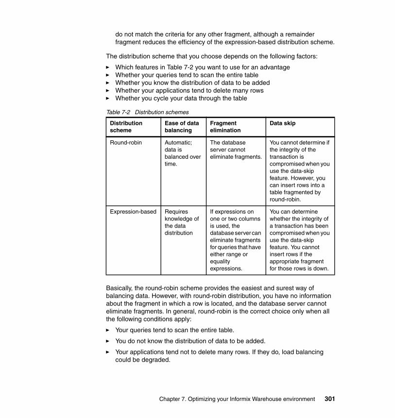
do not match the criteria for any other fragment, although a remainder fragment reduces the efficiency of the expression-based distribution scheme.
The distribution scheme that you choose depends on the following factors:
� Which features in Table 7-2 you want to use for an advantage� Whether your queries tend to scan the entire table � Whether you know the distribution of data to be added� Whether your applications tend to delete many rows � Whether you cycle your data through the table
Table 7-2 Distribution schemes
Basically, the round-robin scheme provides the easiest and surest way of balancing data. However, with round-robin distribution, you have no information about the fragment in which a row is located, and the database server cannot eliminate fragments. In general, round-robin is the correct choice only when all the following conditions apply:
� Your queries tend to scan the entire table.
� You do not know the distribution of data to be added.
� Your applications tend not to delete many rows. If they do, load balancing could be degraded.
Distribution scheme
Ease of data balancing
Fragment elimination
Data skip
Round-robin Automatic; data is balanced over time.
The database server cannot eliminate fragments.
You cannot determine if the integrity of the transaction is compromised when you use the data-skip feature. However, you can insert rows into a table fragmented by round-robin.
Expression-based Requires knowledge of the data distribution
If expressions on one or two columns is used, the database server can eliminate fragments for queries that have either range or equality expressions.
You can determine whether the integrity of a transaction has been compromised when you use the data-skip feature. You cannot insert rows if the appropriate fragment for those rows is down.
Chapter 7. Optimizing your Informix Warehouse environment 301

An expression-based scheme might be the best choice to fragment the data if any of the following conditions apply:
� Your application calls for numerous decision-support queries that scan specific portions of the table.
� You know the data distribution.
� You plan to cycle data through a database.I
If you plan to add and delete large amounts of data periodically, based on the value of a column such as date, you can use that column in the distribution scheme. You can then use the alter fragment attach and alter fragment detach statements to cycle the data through the table.
The ALTER FRAGMENT ATTACH and DETACH statements provide the following advantages over bulk loads and deletions:
� The rest of the table fragments are available for other users to access. Only the fragment that you attach or detach is not available to other users.
� With the performance enhancements, the execution of an ALTER FRAGMENT ATTACH or DETACH statement is much faster than a bulk load or mass deletion.
7.5.9 Designing an expression-based distribution scheme
The first step in designing an expression-based distribution scheme is to determine the distribution of data in the table, particularly the distribution of values for the column on which you base the fragmentation expression. To obtain this information, run the UPDATE STATISTICS statement for the table and then use the dbschema utility to examine the distribution.
After you know the data distribution, you can design a fragmentation rule that distributes data across fragments as required to meet your fragmentation goal.
If your primary goal is to improve performance, your fragment expression should generate an even distribution of rows across fragments. If your primary fragmentation goal is improved concurrency, analyze the queries that access the table. If certain rows are accessed at a higher rate than others, you can compensate by opting for an uneven distribution of data over the fragments that you create.
Try not to use columns that are subject to frequent updates in the distribution expression. Such updates can cause rows to move from one fragment to another. That is, they can be deleted from one and added to another and this activity increases processor and I/O overhead.
302 Data Warehousing with the Informix Dynamic Server
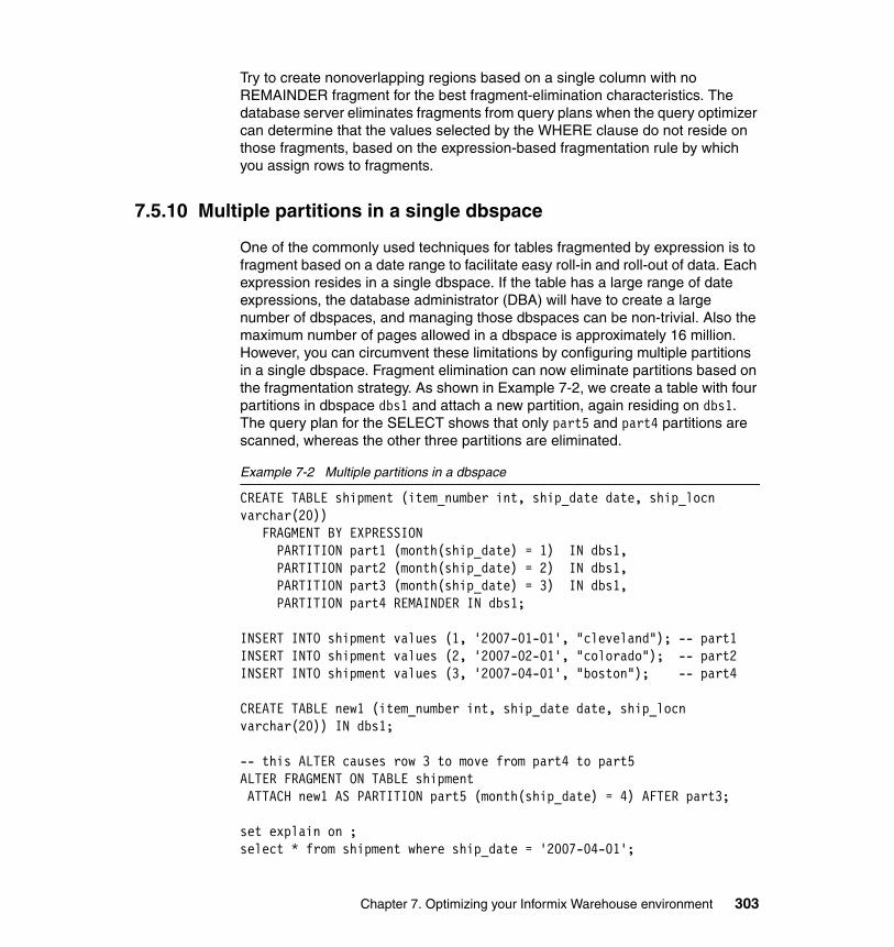
Try to create nonoverlapping regions based on a single column with no REMAINDER fragment for the best fragment-elimination characteristics. The database server eliminates fragments from query plans when the query optimizer can determine that the values selected by the WHERE clause do not reside on those fragments, based on the expression-based fragmentation rule by which you assign rows to fragments.
7.5.10 Multiple partitions in a single dbspace
One of the commonly used techniques for tables fragmented by expression is to fragment based on a date range to facilitate easy roll-in and roll-out of data. Each expression resides in a single dbspace. If the table has a large range of date expressions, the database administrator (DBA) will have to create a large number of dbspaces, and managing those dbspaces can be non-trivial. Also the maximum number of pages allowed in a dbspace is approximately 16 million. However, you can circumvent these limitations by configuring multiple partitions in a single dbspace. Fragment elimination can now eliminate partitions based on the fragmentation strategy. As shown in Example 7-2, we create a table with four partitions in dbspace dbs1 and attach a new partition, again residing on dbs1. The query plan for the SELECT shows that only part5 and part4 partitions are scanned, whereas the other three partitions are eliminated.
Example 7-2 Multiple partitions in a dbspace
CREATE TABLE shipment (item_number int, ship_date date, ship_locn varchar(20)) FRAGMENT BY EXPRESSION PARTITION part1 (month(ship_date) = 1) IN dbs1, PARTITION part2 (month(ship_date) = 2) IN dbs1, PARTITION part3 (month(ship_date) = 3) IN dbs1, PARTITION part4 REMAINDER IN dbs1;
INSERT INTO shipment values (1, '2007-01-01', "cleveland"); -- part1INSERT INTO shipment values (2, '2007-02-01', "colorado"); -- part2INSERT INTO shipment values (3, '2007-04-01', "boston"); -- part4
CREATE TABLE new1 (item_number int, ship_date date, ship_locn varchar(20)) IN dbs1;
-- this ALTER causes row 3 to move from part4 to part5ALTER FRAGMENT ON TABLE shipment ATTACH new1 AS PARTITION part5 (month(ship_date) = 4) AFTER part3;
set explain on ;select * from shipment where ship_date = '2007-04-01';
Chapter 7. Optimizing your Informix Warehouse environment 303
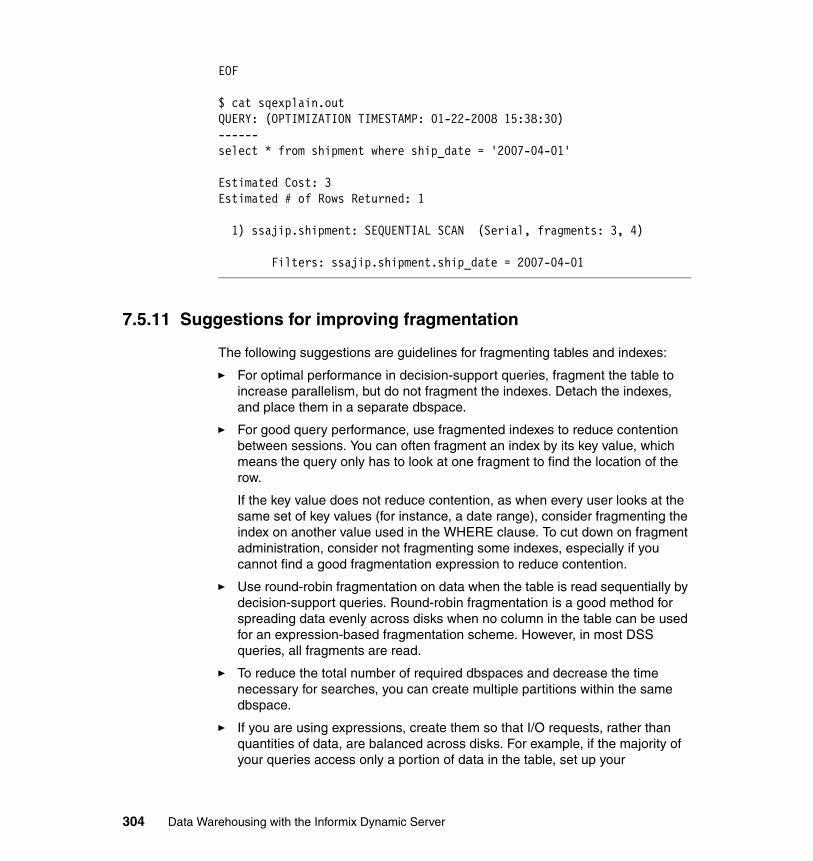
EOF
$ cat sqexplain.outQUERY: (OPTIMIZATION TIMESTAMP: 01-22-2008 15:38:30)------select * from shipment where ship_date = '2007-04-01'
Estimated Cost: 3Estimated # of Rows Returned: 1
1) ssajip.shipment: SEQUENTIAL SCAN (Serial, fragments: 3, 4)
Filters: ssajip.shipment.ship_date = 2007-04-01
7.5.11 Suggestions for improving fragmentation
The following suggestions are guidelines for fragmenting tables and indexes:
� For optimal performance in decision-support queries, fragment the table to increase parallelism, but do not fragment the indexes. Detach the indexes, and place them in a separate dbspace.
� For good query performance, use fragmented indexes to reduce contention between sessions. You can often fragment an index by its key value, which means the query only has to look at one fragment to find the location of the row.
If the key value does not reduce contention, as when every user looks at the same set of key values (for instance, a date range), consider fragmenting the index on another value used in the WHERE clause. To cut down on fragment administration, consider not fragmenting some indexes, especially if you cannot find a good fragmentation expression to reduce contention.
� Use round-robin fragmentation on data when the table is read sequentially by decision-support queries. Round-robin fragmentation is a good method for spreading data evenly across disks when no column in the table can be used for an expression-based fragmentation scheme. However, in most DSS queries, all fragments are read.
� To reduce the total number of required dbspaces and decrease the time necessary for searches, you can create multiple partitions within the same dbspace.
� If you are using expressions, create them so that I/O requests, rather than quantities of data, are balanced across disks. For example, if the majority of your queries access only a portion of data in the table, set up your
304 Data Warehousing with the Informix Dynamic Server
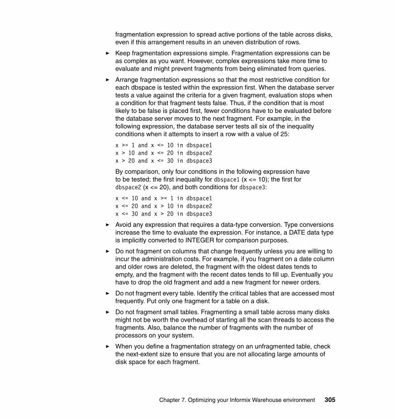
fragmentation expression to spread active portions of the table across disks, even if this arrangement results in an uneven distribution of rows.
� Keep fragmentation expressions simple. Fragmentation expressions can be as complex as you want. However, complex expressions take more time to evaluate and might prevent fragments from being eliminated from queries.
� Arrange fragmentation expressions so that the most restrictive condition for each dbspace is tested within the expression first. When the database server tests a value against the criteria for a given fragment, evaluation stops when a condition for that fragment tests false. Thus, if the condition that is most likely to be false is placed first, fewer conditions have to be evaluated before the database server moves to the next fragment. For example, in the following expression, the database server tests all six of the inequality conditions when it attempts to insert a row with a value of 25:
x >= 1 and x <= 10 in dbspace1x > 10 and x <= 20 in dbspace2x > 20 and x <= 30 in dbspace3
By comparison, only four conditions in the following expression have to be tested: the first inequality for dbspace1 (x <= 10); the first fordbspace2 (x <= 20), and both conditions for dbspace3:
x <= 10 and x >= 1 in dbspace1x <= 20 and x > 10 in dbspace2x <= 30 and x > 20 in dbspace3
� Avoid any expression that requires a data-type conversion. Type conversions increase the time to evaluate the expression. For instance, a DATE data type is implicitly converted to INTEGER for comparison purposes.
� Do not fragment on columns that change frequently unless you are willing to incur the administration costs. For example, if you fragment on a date column and older rows are deleted, the fragment with the oldest dates tends to empty, and the fragment with the recent dates tends to fill up. Eventually you have to drop the old fragment and add a new fragment for newer orders.
� Do not fragment every table. Identify the critical tables that are accessed most frequently. Put only one fragment for a table on a disk.
� Do not fragment small tables. Fragmenting a small table across many disks might not be worth the overhead of starting all the scan threads to access the fragments. Also, balance the number of fragments with the number of processors on your system.
� When you define a fragmentation strategy on an unfragmented table, check the next-extent size to ensure that you are not allocating large amounts of disk space for each fragment.
Chapter 7. Optimizing your Informix Warehouse environment 305
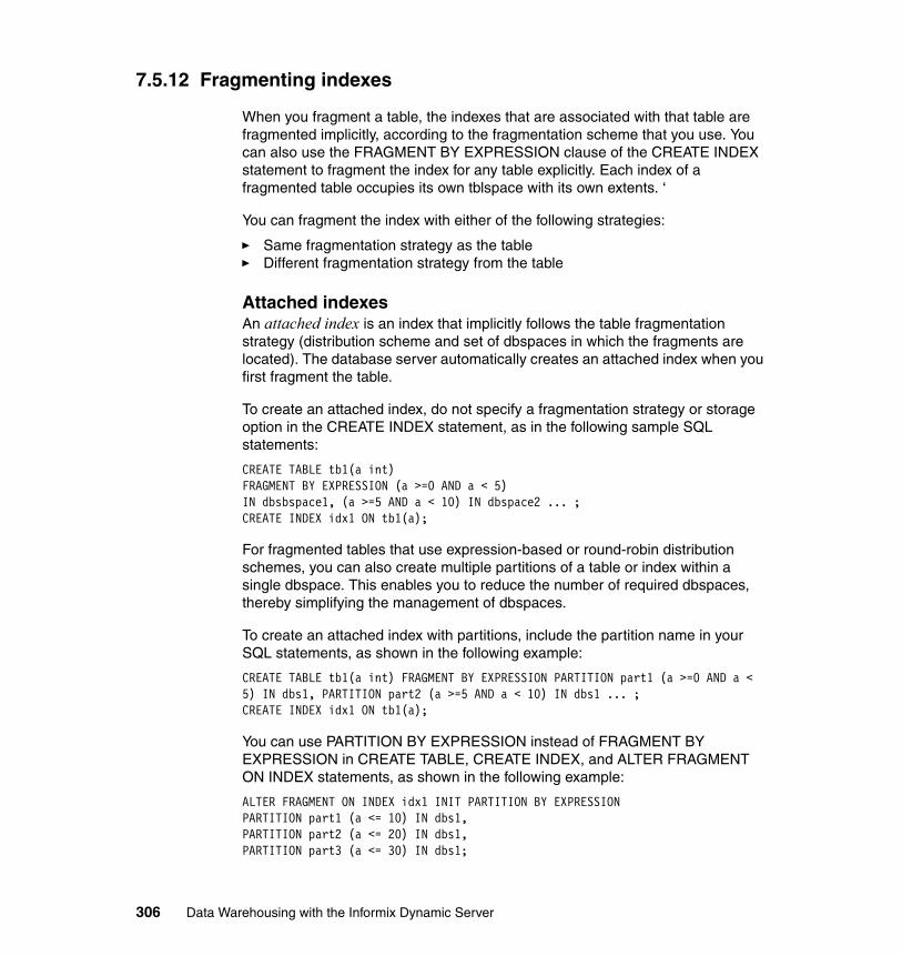
7.5.12 Fragmenting indexes
When you fragment a table, the indexes that are associated with that table are fragmented implicitly, according to the fragmentation scheme that you use. You can also use the FRAGMENT BY EXPRESSION clause of the CREATE INDEX statement to fragment the index for any table explicitly. Each index of a fragmented table occupies its own tblspace with its own extents. ‘
You can fragment the index with either of the following strategies:
� Same fragmentation strategy as the table � Different fragmentation strategy from the table
Attached indexesAn attached index is an index that implicitly follows the table fragmentation strategy (distribution scheme and set of dbspaces in which the fragments are located). The database server automatically creates an attached index when you first fragment the table.
To create an attached index, do not specify a fragmentation strategy or storage option in the CREATE INDEX statement, as in the following sample SQL statements:
CREATE TABLE tb1(a int) FRAGMENT BY EXPRESSION (a >=0 AND a < 5)IN dbsbspace1, (a >=5 AND a < 10) IN dbspace2 ... ; CREATE INDEX idx1 ON tb1(a);
For fragmented tables that use expression-based or round-robin distribution schemes, you can also create multiple partitions of a table or index within a single dbspace. This enables you to reduce the number of required dbspaces, thereby simplifying the management of dbspaces.
To create an attached index with partitions, include the partition name in your SQL statements, as shown in the following example:
CREATE TABLE tb1(a int) FRAGMENT BY EXPRESSION PARTITION part1 (a >=0 AND a < 5) IN dbs1, PARTITION part2 (a >=5 AND a < 10) IN dbs1 ... ; CREATE INDEX idx1 ON tb1(a);
You can use PARTITION BY EXPRESSION instead of FRAGMENT BY EXPRESSION in CREATE TABLE, CREATE INDEX, and ALTER FRAGMENT ON INDEX statements, as shown in the following example:
ALTER FRAGMENT ON INDEX idx1 INIT PARTITION BY EXPRESSIONPARTITION part1 (a <= 10) IN dbs1,PARTITION part2 (a <= 20) IN dbs1, PARTITION part3 (a <= 30) IN dbs1;
306 Data Warehousing with the Informix Dynamic Server
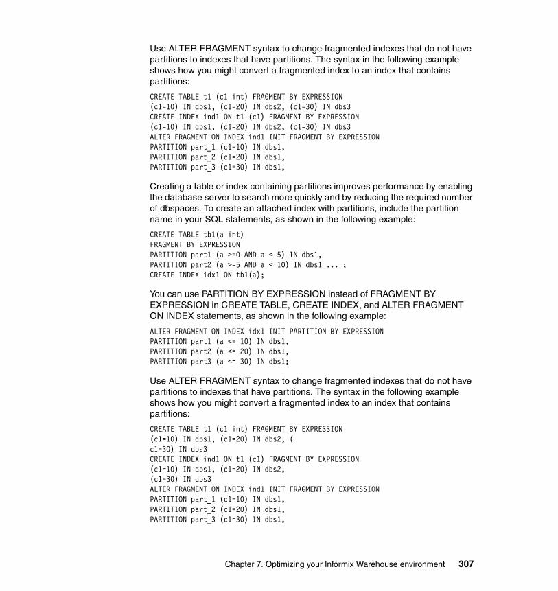
Use ALTER FRAGMENT syntax to change fragmented indexes that do not have partitions to indexes that have partitions. The syntax in the following example shows how you might convert a fragmented index to an index that contains partitions:
CREATE TABLE t1 (c1 int) FRAGMENT BY EXPRESSION(c1=10) IN dbs1, (c1=20) IN dbs2, (c1=30) IN dbs3 CREATE INDEX ind1 ON t1 (c1) FRAGMENT BY EXPRESSION(c1=10) IN dbs1, (c1=20) IN dbs2, (c1=30) IN dbs3 ALTER FRAGMENT ON INDEX ind1 INIT FRAGMENT BY EXPRESSION PARTITION part_1 (c1=10) IN dbs1, PARTITION part_2 (c1=20) IN dbs1, PARTITION part_3 (c1=30) IN dbs1,
Creating a table or index containing partitions improves performance by enabling the database server to search more quickly and by reducing the required number of dbspaces. To create an attached index with partitions, include the partition name in your SQL statements, as shown in the following example:
CREATE TABLE tb1(a int) FRAGMENT BY EXPRESSION PARTITION part1 (a >=0 AND a < 5) IN dbs1, PARTITION part2 (a >=5 AND a < 10) IN dbs1 ... ; CREATE INDEX idx1 ON tb1(a);
You can use PARTITION BY EXPRESSION instead of FRAGMENT BY EXPRESSION in CREATE TABLE, CREATE INDEX, and ALTER FRAGMENT ON INDEX statements, as shown in the following example:
ALTER FRAGMENT ON INDEX idx1 INIT PARTITION BY EXPRESSIONPARTITION part1 (a <= 10) IN dbs1,PARTITION part2 (a <= 20) IN dbs1,PARTITION part3 (a <= 30) IN dbs1;
Use ALTER FRAGMENT syntax to change fragmented indexes that do not have partitions to indexes that have partitions. The syntax in the following example shows how you might convert a fragmented index to an index that contains partitions:
CREATE TABLE t1 (c1 int) FRAGMENT BY EXPRESSION(c1=10) IN dbs1, (c1=20) IN dbs2, (c1=30) IN dbs3 CREATE INDEX ind1 ON t1 (c1) FRAGMENT BY EXPRESSION(c1=10) IN dbs1, (c1=20) IN dbs2,(c1=30) IN dbs3 ALTER FRAGMENT ON INDEX ind1 INIT FRAGMENT BY EXPRESSION PARTITION part_1 (c1=10) IN dbs1, PARTITION part_2 (c1=20) IN dbs1, PARTITION part_3 (c1=30) IN dbs1,
Chapter 7. Optimizing your Informix Warehouse environment 307
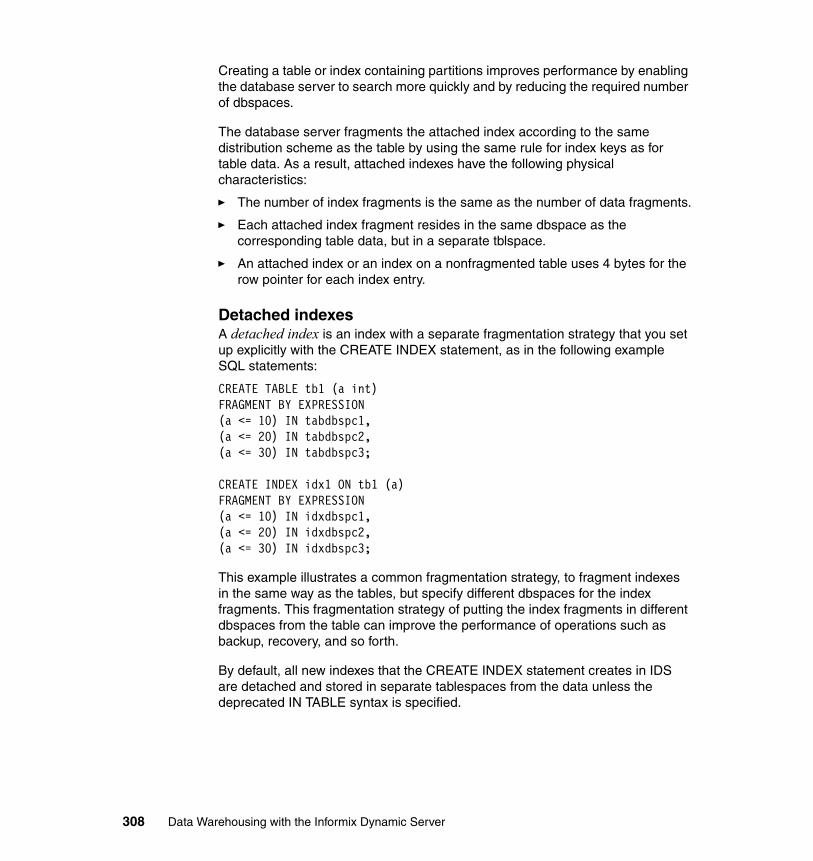
Creating a table or index containing partitions improves performance by enabling the database server to search more quickly and by reducing the required number of dbspaces.
The database server fragments the attached index according to the same distribution scheme as the table by using the same rule for index keys as for table data. As a result, attached indexes have the following physical characteristics:
� The number of index fragments is the same as the number of data fragments.
� Each attached index fragment resides in the same dbspace as the corresponding table data, but in a separate tblspace.
� An attached index or an index on a nonfragmented table uses 4 bytes for the row pointer for each index entry.
Detached indexes A detached index is an index with a separate fragmentation strategy that you set up explicitly with the CREATE INDEX statement, as in the following example SQL statements:
CREATE TABLE tb1 (a int) FRAGMENT BY EXPRESSION (a <= 10) IN tabdbspc1, (a <= 20) IN tabdbspc2, (a <= 30) IN tabdbspc3;
CREATE INDEX idx1 ON tb1 (a) FRAGMENT BY EXPRESSION (a <= 10) IN idxdbspc1, (a <= 20) IN idxdbspc2, (a <= 30) IN idxdbspc3;
This example illustrates a common fragmentation strategy, to fragment indexes in the same way as the tables, but specify different dbspaces for the index fragments. This fragmentation strategy of putting the index fragments in different dbspaces from the table can improve the performance of operations such as backup, recovery, and so forth.
By default, all new indexes that the CREATE INDEX statement creates in IDS are detached and stored in separate tablespaces from the data unless the deprecated IN TABLE syntax is specified.
308 Data Warehousing with the Informix Dynamic Server
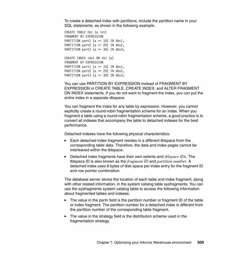
To create a detached index with partitions, include the partition name in your SQL statements, as shown in the following example:
CREATE TABLE tb1 (a int)FRAGMENT BY EXPRESSION PARTITION part1 (a <= 10) IN dbs1,PARTITION part2 (a <= 20) IN dbs2,PARTITION part3 (a <= 30) IN dbs3;
CREATE INDEX idx1 ON tb1 (a) FRAGMENT BY EXPRESSION PARTITION part1 (a <= 10) IN dbs1, PARTITION part2 (a <= 20) IN dbs2,PARTITION part3 (a <= 30) IN dbs3;
You can use PARTITION BY EXPRESSION instead of FRAGMENT BY EXPRESSION in CREATE TABLE, CREATE INDEX, and ALTER FRAGMENT ON INDEX statements. If you do not want to fragment the index, you can put the entire index in a separate dbspace.
You can fragment the index for any table by expression. However, you cannot explicitly create a round-robin fragmentation scheme for an index. When you fragment a table using a round-robin fragmentation scheme, a good practice is to convert all indexes that accompany the table to detached indexes for the best performance.
Detached indexes have the following physical characteristics:
� Each detached index fragment resides in a different tblspace from the corresponding table data. Therefore, the data and index pages cannot be interleaved within the tblspace.
� Detached index fragments have their own extents and tblspace IDs. The tblspace ID is also known as the fragment ID and partition number. A detached index uses 8 bytes of disk space per index entry for the fragment ID and row pointer combination.
The database server stores the location of each table and index fragment, along with other related information, in the system catalog table sysfragments. You can use the sysfragments system catalog table to access the following information about fragmented tables and indexes:
� The value in the partn field is the partition number or fragment ID of the table or index fragment. The partition number for a detached index is different from the partition number of the corresponding table fragment.
� The value in the strategy field is the distribution scheme used in the fragmentation strategy.
Chapter 7. Optimizing your Informix Warehouse environment 309
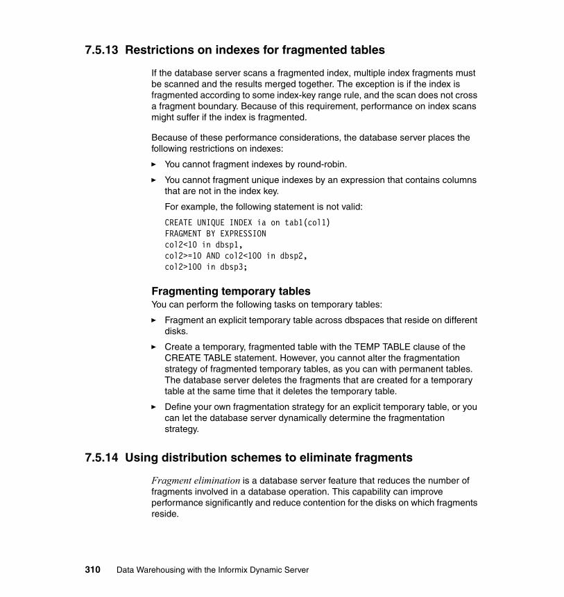
7.5.13 Restrictions on indexes for fragmented tables
If the database server scans a fragmented index, multiple index fragments must be scanned and the results merged together. The exception is if the index is fragmented according to some index-key range rule, and the scan does not cross a fragment boundary. Because of this requirement, performance on index scans might suffer if the index is fragmented.
Because of these performance considerations, the database server places the following restrictions on indexes:
� You cannot fragment indexes by round-robin.
� You cannot fragment unique indexes by an expression that contains columns that are not in the index key.
For example, the following statement is not valid:
CREATE UNIQUE INDEX ia on tab1(col1) FRAGMENT BY EXPRESSION col2<10 in dbsp1,col2>=10 AND col2<100 in dbsp2, col2>100 in dbsp3;
Fragmenting temporary tablesYou can perform the following tasks on temporary tables:
� Fragment an explicit temporary table across dbspaces that reside on different disks.
� Create a temporary, fragmented table with the TEMP TABLE clause of the CREATE TABLE statement. However, you cannot alter the fragmentation strategy of fragmented temporary tables, as you can with permanent tables. The database server deletes the fragments that are created for a temporary table at the same time that it deletes the temporary table.
� Define your own fragmentation strategy for an explicit temporary table, or you can let the database server dynamically determine the fragmentation strategy.
7.5.14 Using distribution schemes to eliminate fragments
Fragment elimination is a database server feature that reduces the number of fragments involved in a database operation. This capability can improve performance significantly and reduce contention for the disks on which fragments reside.
310 Data Warehousing with the Informix Dynamic Server
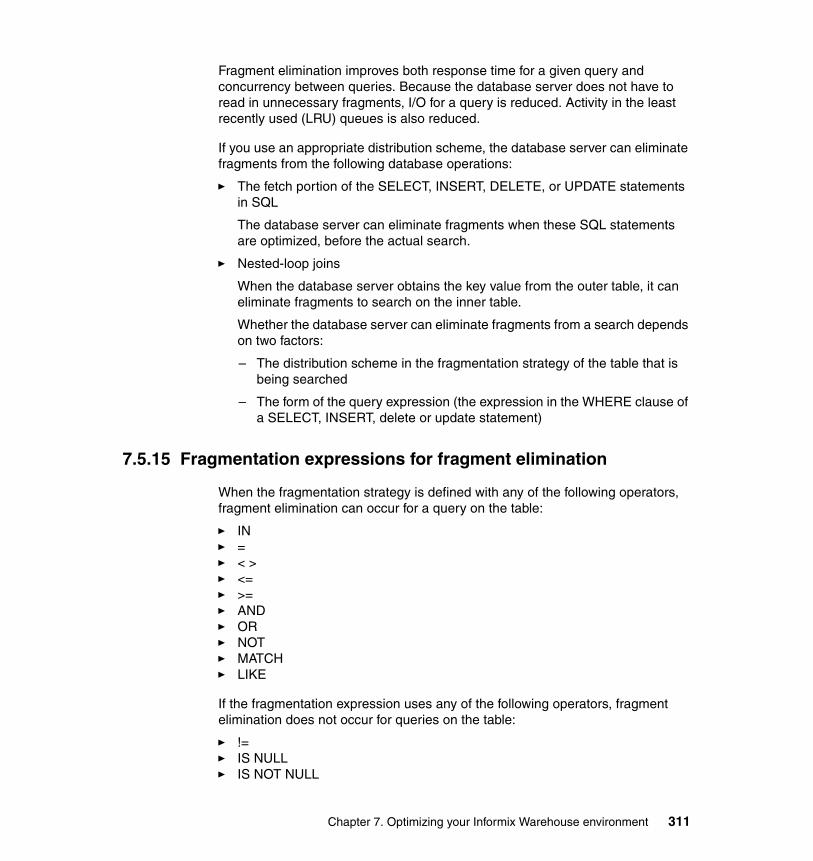
Fragment elimination improves both response time for a given query and concurrency between queries. Because the database server does not have to read in unnecessary fragments, I/O for a query is reduced. Activity in the least recently used (LRU) queues is also reduced.
If you use an appropriate distribution scheme, the database server can eliminate fragments from the following database operations:
� The fetch portion of the SELECT, INSERT, DELETE, or UPDATE statements in SQL
The database server can eliminate fragments when these SQL statements are optimized, before the actual search.
� Nested-loop joins
When the database server obtains the key value from the outer table, it can eliminate fragments to search on the inner table.
Whether the database server can eliminate fragments from a search depends on two factors:
– The distribution scheme in the fragmentation strategy of the table that is being searched
– The form of the query expression (the expression in the WHERE clause of a SELECT, INSERT, delete or update statement)
7.5.15 Fragmentation expressions for fragment elimination
When the fragmentation strategy is defined with any of the following operators, fragment elimination can occur for a query on the table:
� IN � = � < > � <= � >= � AND� OR� NOT � MATCH � LIKE
If the fragmentation expression uses any of the following operators, fragment elimination does not occur for queries on the table:
� != � IS NULL� IS NOT NULL
Chapter 7. Optimizing your Informix Warehouse environment 311

Effectiveness of fragment eliminationThe database server cannot eliminate fragments when you fragment a table with a round-robin distribution scheme. Furthermore, not all expression-based distribution schemes give you the same fragment-elimination behavior.
The Table 7-3 summarizes the fragment-elimination behavior for different combinations of expression-based distribution schemes and query expressions. Partitions in fragmented tables do not effect the fragment-elimination behavior.
Table 7-3 Partitions in fragmented tables
Table 7-3 indicates that the distribution schemes enable fragment elimination, but the effectiveness of fragment elimination is determined by the WHERE clause of the query in question.
For example, consider a table that is fragmented with the following expression:
FRAGMENT BY EXPRESSION100 < column_a AND column_b < 0 IN dbsp1,100 >= column_a AND column_b < 0 IN dbsp2, column_b >= 0 IN dbsp3
The database server cannot eliminate any fragments from the search if the WHERE clause has the following expression:
column_a = 5 OR column_b = -50
On the other hand, the database server can eliminate the fragment in dbspace dbsp3 if the WHERE clause has the following expression:
column_b = -50
Furthermore, the database server can eliminate the two fragments in dbspaces dbsp2 and dbsp3 if the WHERE clause has the following expression:
column_a = 5 AND column_b = -50
Partitions in fragmented tables do not effect fragment-elimination behavior.
Type of Query (WHERE clause) Expression
Nonoverlapping Fragments on a Single Column
Overlapping or Non-contiguous Fragments on a Single Column
Nonoverlapping Fragments on Multiple Columns
Range expression Fragments can be eliminated.
Fragments cannot be eliminated.
Fragments cannot be eliminated.
Equality expression
Fragments can be eliminated.
Fragments can be eliminated.
Fragments can be eliminated.
312 Data Warehousing with the Informix Dynamic Server
7.5.16 Page size and table space considerations
In this section, we look at the considerations for page size and for tablespaces.
Page sizeThe default system page size is platform-dependent (4 KB on Windows and 2 KB on most UNIX platforms) but you might want to create multiple dbspaces with differing page sizes that are multiples of the system page size. Each page size can have its own BUFFERPOOL setting in the onconfig file. The maximum allowable page size is 16 KB.
Several advantages of larger page sizes are:
� Reduced depth of b-tree indexes, even for smaller index keys
� Decreased checkpoint time
� Grouping of long rows on the same page which otherwise would span multiple pages for the default page size
Tblspace Tblspace extentsEach dbspace contains a tblspace called the tblspace tblspace that describes all tblspaces in the dbspace. When creating a dbspace, the default first and next extent sizes for tblspace tblspace are 250 and 50 pages whereas for non-root dbspaces, the defaults are 50 and 50. If your database has a large number of tables, these defaults can cause fragmented extents, some of which may reside in non-primary chunks, and this can impact performance.
At the time of disk initialization (oninit -iy), you can use the TBLTBLFIRST and TBLTBLNEXT configuration parameters to specify the first and next extent sizes for the tblspace tblspace belonging to the root dbspace. For non-root dbspaces, you can use the onspaces utility to specify the initial and next extent sizes for the tblspace tblspace, when creating this dbspace. The first and next extent sizes cannot be changed after the creation of the dbspace. You cannot specify these extent sizes for temporary dbspaces, sbspaces, blobspaces, or external spaces.
The number of pages in the tblspace tblspace will be equal to the total number of table and detached index fragments including any system objects that reside in the dbspace. As shown in Example 7-3 on page 314, dbs4 is created with a initial and next extent size of 2 MB and 1 MB for tblspace tblspace. The oncheck -pe output confirms the first extent size is 1000 pages (for 2 KB page size).
Chapter 7. Optimizing your Informix Warehouse environment 313
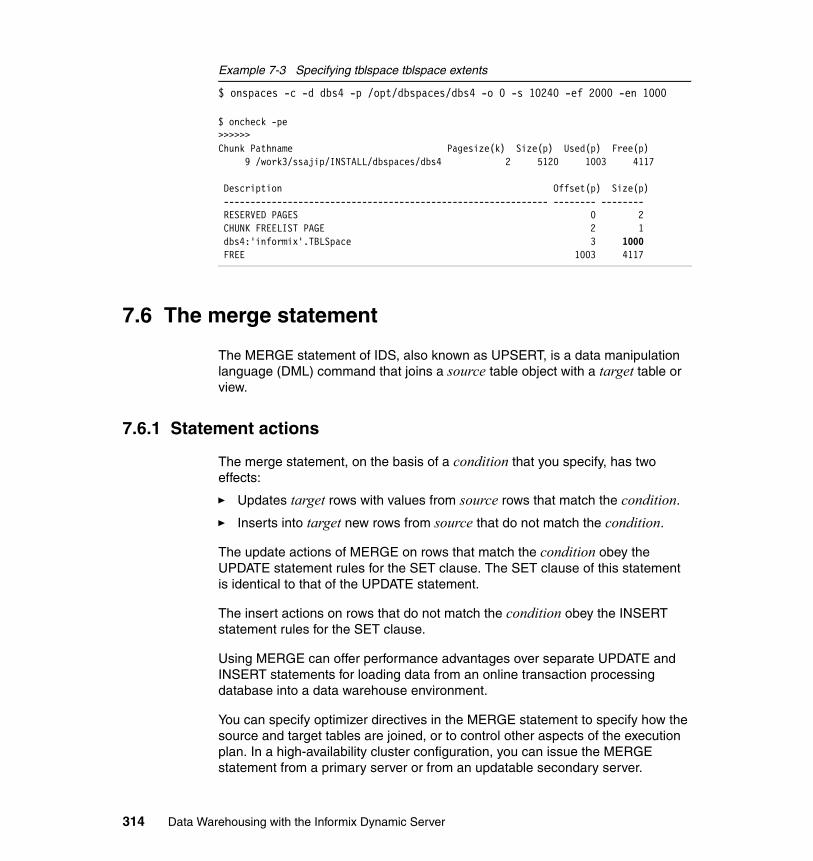
Example 7-3 Specifying tblspace tblspace extents
$ onspaces -c -d dbs4 -p /opt/dbspaces/dbs4 -o 0 -s 10240 -ef 2000 -en 1000
$ oncheck -pe >>>>>>Chunk Pathname Pagesize(k) Size(p) Used(p) Free(p) 9 /work3/ssajip/INSTALL/dbspaces/dbs4 2 5120 1003 4117
Description Offset(p) Size(p) ------------------------------------------------------------- -------- -------- RESERVED PAGES 0 2 CHUNK FREELIST PAGE 2 1 dbs4:'informix'.TBLSpace 3 1000 FREE 1003 4117
7.6 The merge statement
The MERGE statement of IDS, also known as UPSERT, is a data manipulation language (DML) command that joins a source table object with a target table or view.
7.6.1 Statement actions
The merge statement, on the basis of a condition that you specify, has two effects:
� Updates target rows with values from source rows that match the condition.
� Inserts into target new rows from source that do not match the condition.
The update actions of MERGE on rows that match the condition obey the UPDATE statement rules for the SET clause. The SET clause of this statement is identical to that of the UPDATE statement.
The insert actions on rows that do not match the condition obey the INSERT statement rules for the SET clause.
Using MERGE can offer performance advantages over separate UPDATE and INSERT statements for loading data from an online transaction processing database into a data warehouse environment.
You can specify optimizer directives in the MERGE statement to specify how the source and target tables are joined, or to control other aspects of the execution plan. In a high-availability cluster configuration, you can issue the MERGE statement from a primary server or from an updatable secondary server.
314 Data Warehousing with the Informix Dynamic Server

The following example uses the transaction table new_sale to merge rows into the fact table sale, updating sale_count if there are already records in the sale table. If not, the rows are inserted into the sale table.
MERGE INTO sale USING new_sale AS n ON sale.cust_id = n.cust_id WHEN MATCHED THEN UPDATE SET sale.salecount = sale.salecount + n.salecount WHEN NOT MATCHED THEN INSERT (cust_id, salecount) VALUES (n.cust_id,n.salecount);
If an error occurs while MERGE is executing, the entire statement is rolled back. In a transaction that includes the MERGE statement and one or more savepoints, you can include error-handling logic that supports the ROLLBACK TO SAVEPOINT statement. After a rollback to a savepoint, the effects of the MERGE operation persist if MERGE precedes the specified savepoint, but they are rolled back if MERGE follows the savepoint within the transaction.
Any constraints on the target table are enforced in MERGE operations. If the constraint-checking mode for the target table is set to IMMEDIATE, then unique and referential constraints of the target object are checked after all the UPDATE and INSERT operations are complete. The NOT NULL and check constraints are checked during the UPDATE and INSERT operations. If the checking mode is set to DEFERRED, the constraints are not checked until after the transaction is committed.
7.6.2 Restrictions on source and target tables
Which table objects can be the source or target of the MERGE statement depends on attributes of the table object. It also depends on what access privileges and security credentials are held by the user who issues the MERGE statement.
7.6.3 Restrictions on the source table
The source object can be in the same database as the target object or in a different database. The source object can exist in a database that is not managed by the local Dynamic Server instance. Unlike the target object, the source can be a collection-derived table that is defined by the result of a query.
The user issuing the MERGE statement must hold the Connect access privilege (or a higher privilege) on the database of the source object, and must hold the Select privilege (or a higher privilege) on the source object. The user can be granted these access privileges individually, or can hold them as a member of
Chapter 7. Optimizing your Informix Warehouse environment 315
the PUBLIC group, or through the current or default role of the user, if the role or PUBLIC holds those privileges.
If the source object or any of its columns is protected by a label-based security policy, the user who issues the MERGE statement must have a security label (or must hold a security policy exemption) that provides sufficient credentials to read the source object. If the credentials of the user are insufficient to read protected columns, according to the standard label-based access control (LBAC) rules, then the MERGE operation can process only a subset of the source object data. If this subset is an empty set, then MERGE cannot insert any source object data. into the target table.
The source object cannot be a view on which a SELECT trigger is defined. Before such a view can be a source for MERGE, you must first disable or drop the INSTEAD OF trigger.
If the target table is a hierarchic table, the source table cannot also be a hierarchic table.
7.6.4 Restrictions on the target table
The target table object must be in a database of the same IDS instance to which the current session is connected. The MERGE statement cannot update a remote table.
If the target table is a correction-derived table, you must understand how to update elements of that table type or the elements of a collection variable.
The following restrictions apply to the target table of the MERGE statement. If the target table has any of the following attributes, the MERGE operation returns an error.
� The target cannot be:
– A hierarchic table if the source is a hierarchic table
– A Virtual Table Interface (VTI) table
– In a database of a remote IDS instance
– A system catalog table
– A view on which an INSTEAD OF trigger is defined
– A read-only view
– A pseudo-table (a memory-resident object in a system database, such as the sysmaster or sysadmin databases)
316 Data Warehousing with the Informix Dynamic Server
– A data source of any subquery of the same MERGE statement, including:
• Subqueries in the ON clause
• Subqueries in the SET clause
• Subqueries in the VALUES clause
• Subqueries in any clause of a SELECT statement within the MERGE statement
� The MERGE statement of IDS supports the following objects as target tables. The target can be:
– Protected by an LBAC security policy.
– A table on which a violations table or a diagnostics tables is defined.
– A table on which an update trigger or an Insert trigger is defined.
If both an update and an insert trigger are defined on the target table, MERGE acts as a triggering even for both triggers. Just as for any DML statement, the database server treats all the triggers that are activated by the same MERGE statement as a single trigger, and the resulting trigger action is the merged-action list. All rules that govern a trigger action apply to the merged list as one list, and no distinction is made between the two original triggers.
If the target table has violations defined, then a violation table and a diagnostic table will hold the nonconforming rows that fail to satisfy constraints and unique indexes during insert or update operations on target table by the MERGE statement.
The MERGE statement cannot be issued directly as a triggered action. A trigger routine that is called in a triggered action, however, can issue the MERGE statement.
7.6.5 Handling duplicate rows
While MERGE is executing, the same row in the target table cannot be updated more than once. Inserted rows are not updated by the MERGE statement. For example, as shown in Table 7-4 on page 318, if the sale table contains the two records, then the new_sale table contains the three records shown in the table.
Chapter 7. Optimizing your Informix Warehouse environment 317
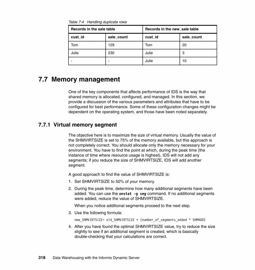
Table 7-4 Handling duplicate rows
7.7 Memory management
One of the key components that affects performance of IDS is the way that shared memory is allocated, configured, and managed. In this section, we provide a discussion of the various parameters and attributes that have to be configured for best performance. Some of these configuration changes might be dependent on the operating system, and those have been noted separately.
7.7.1 Virtual memory segment
The objective here is to maximize the size of virtual memory. Usually the value of the SHMVIRTSIZE is set to 75% of the memory available, but this approach is not completely correct. You should allocate only the memory necessary for your environment. You have to find the point at which, during the peak time (the instance of time where resource usage is highest), IDS will not add any segments; if you reduce the size of SHMVIRTSIZE, IDS will add another segment.
A good approach to find the value of SHMVIRTSIZE is:
1. Set SHMVIRTSIZE to 50% of your memory.
2. During the peak time, determine how many additional segments have been added. You can use the onstat -g seg command. If no additional segments were added, reduce the value of SHMVIRTSIZE.
When you notice additional segments proceed to the next step.
3. Use the following formula:
new_SHMVIRTSIZE= old_SHMVIRTSIZE + (number_of_segments_added * SHMADD)
4. After you have found the optimal SHMVIRTSIZE value, try to reduce the size slightly to see if an additional segment is created, which is basically double-checking that your calculations are correct.
Records in the sale table Records in the new_sale table
cust_id sale_count cust_id sale_count
Tom 129 Tom 20
Julie 230 Julie 3
- - Julie 10
318 Data Warehousing with the Informix Dynamic Server

7.7.2 Light scan
The light scan is a mechanism that bypasses the traditional reading process. Pages are read from disk and put in the buffer cache in the resident shared memory segment. The light scan reads the page from disk and puts it in the light_scan_buffers, which reside in the virtual segment of the shared memory. It then reads the data in parallel, providing a significant increase in performance when compared with scanning large tables.
The number of light scan buffers is defined by the following equation:
light_scan_buffers = roundup((RA_PAGES + RA_THRESHOLD)/ (MAXAIOSIZE/PAGESIZE))
As you can see, the RA_PAGES and RA_THRESHOLD can affect the number of light scan buffers, and they cannot be changed dynamically. What you can consider is to create dbspaces dedicated to the DSS activity, giving them a larger page size. When increasing the PAGESIZE value, IDS increases the number of light scan buffers, as shown in the previous formula. The page size must be a multiple of the operating system page size, but not greater than 16 KB. Give attention to the size of your row. Each page can contain a maximum 255 rows, so if the row size is small and the page size is large you risk losing disk space. To know the maximum row size use the following command:
oncheck -pt databasename:tablename
Then, check the line: Maximum row size.
To create a dbspace with a customized page size in KB, you can use the following command:
onspaces -c -d DBspace [-t] [-k pagesize] -p path -o offset -s size [-m path offset]
7.7.3 Buffer pools
The buffer pool in the resident portion of shared memory contains buffers that store dbspace pages read from disk. The pool of buffers comprise the largest allocation of the resident portion of shared memory. The number of buffer pools depends on the default page size. The maximum number of buffer pools on a system with a default page size of 2 KB is eight, and with default page size of 4 KB, the maximums number is four. You use a BUFFERPOOL configuration
Note: MAXAIOSIZE is an Informix internal parameter that is platform-dependent. In general, it is in the area of about eight pages.
Chapter 7. Optimizing your Informix Warehouse environment 319
parameter to specify information about buffer pool, including the number of buffers in a buffer pool.
The BUFFERPOOL configuration parameter specifies the values for BUFFERS, LRUs, LRU_MAX_DIRTY, LRU_MIN_DIRTY for both the default page size buffer pool and for any non-default pages size buffer pools. However, if you create a dbspace with a non-default page size, the dbspace must have a corresponding buffer pool. For example, if you create a dbspace with a page size of 8 KB, you must create a buffer pool with a page size of 8 KB. The BUFFERPOOL onconfig parameter can be useful to reduce the number of buffer and force IDS to use the light scan. For a DSS environment, you can set the buffers to a low number, for example, to the 5000 shown in the following command:
BUFFERPOOL size=8K,buffers=5000,lrus=8,lru_min_dirty=50,lru_max_dirty=60
When you create a dbspace with a non-default page size, and if no buffer pool of this page size exists, a new buffer pool is created using the default buffer pool configuration. If there is no BUFFERPOOL default value in $ONCONFIG, the value from the onconfig.std file is used. Example 7-4 shows the value set of the BUFFERPOOL configuration parameter in the onconfig file.
Example 7-4 Bufferpool
BUFFERPOOL size=16K,buffers=1000,lrus=4,lru_min_dirty=50.000000,lru_max_dirty=60.000000BUFFERPOOL size=2K,buffers=2000,lrus=8,lru_min_dirty=50.000000,lru_max_dirty=60.000000
7.7.4 Database shared memory
Shared memory is an operating system feature that allows the database server threads and processes to share data by sharing access to pools of memory. Several main advantages are:
� Memory: Reduces overall memory usage by letting the virtual processes and utilities access shared data instead of keeping their own private copies.
Note: The deprecated configuration parameters are:
BUFFERS, LRUS, LRU_MIN_DIRTY, LRU_MAX_DIRTY
Instead of these configuration parameters, use BUFFERPOOL.
320 Data Warehousing with the Informix Dynamic Server
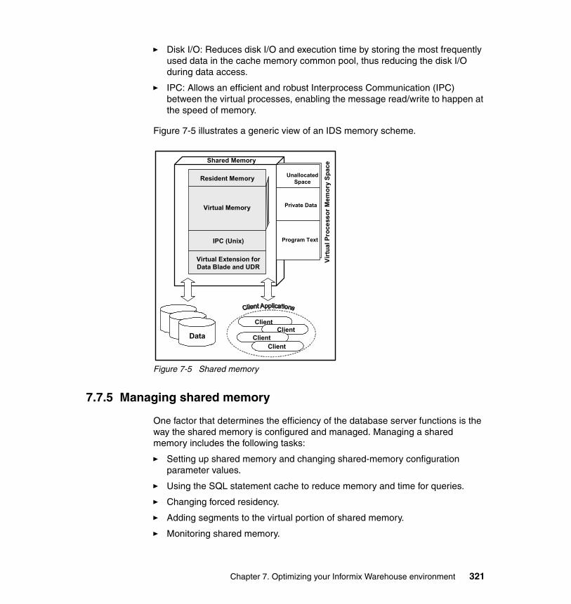
� Disk I/O: Reduces disk I/O and execution time by storing the most frequently used data in the cache memory common pool, thus reducing the disk I/O during data access.
� IPC: Allows an efficient and robust Interprocess Communication (IPC) between the virtual processes, enabling the message read/write to happen at the speed of memory.
Figure 7-5 illustrates a generic view of an IDS memory scheme.
Figure 7-5 Shared memory
7.7.5 Managing shared memory
One factor that determines the efficiency of the database server functions is the way the shared memory is configured and managed. Managing a shared memory includes the following tasks:
� Setting up shared memory and changing shared-memory configuration parameter values.
� Using the SQL statement cache to reduce memory and time for queries.
� Changing forced residency.
� Adding segments to the virtual portion of shared memory.
� Monitoring shared memory.
Client
DataClient
ClientClient
Resident Memory
Virtual Memory
IPC (Unix)
Virtual Extension for Data Blade and UDR
Shared Memory
Virt
ual P
roce
ssor
Mem
ory
Spac
e
Unallocated Space
Private Data
Program Text
Chapter 7. Optimizing your Informix Warehouse environment 321
In this section, we discuss shared memory management issues in more detail.
Setting the shared memory configuration parametersSetting up shared memory for a system involves setting it at the operating system level and the database level.
Operating system shared memorySetting up the shared memory configuration parameters differs from one operating system to another. The various UNIX operating systems manage the same shared memory configuration through its unique proprietary mechanism. However, irrespective of the operating system, you might have to tune the following functional parameters:
� Maximum operating system shared-memory segment size� Minimum shared memory segment size, expressed in bytes� Maximum number of shared memory identifiers� Lower-boundary address for shared memory� Maximum number of attached shared memory segments per process� Maximum amount of system wide shared memory� Maximum number of semaphore identifiers (UNIX)� Maximum number of semaphores (UNIX)� Maximum number of semaphores per identifier (UNIX)
Example 7-5 shows a Solaris operating system shared memory configuration parameter from the /etc/system path on an IDS V10 test database server.
Example 7-5 Solaris 5.8 /etc/system entry
* Set shared memoryset shmsys:shminfo_shmmax=2048000000set shmsys:shminfo_shmmin=128set shmsys:shminfo_shmmni=500set shmsys:shminfo_shmseg=64
* Set Semaphoresset semsys:seminfo_semmni=4096set semsys:seminfo_semmns=4096set semsys:seminfo_semmnu=4096set semsys:seminfo_semume=64set semsys:seminfo_semmap=256
Refer to the specific operating system manual for further information about a particular operating environment of interest.
322 Data Warehousing with the Informix Dynamic Server
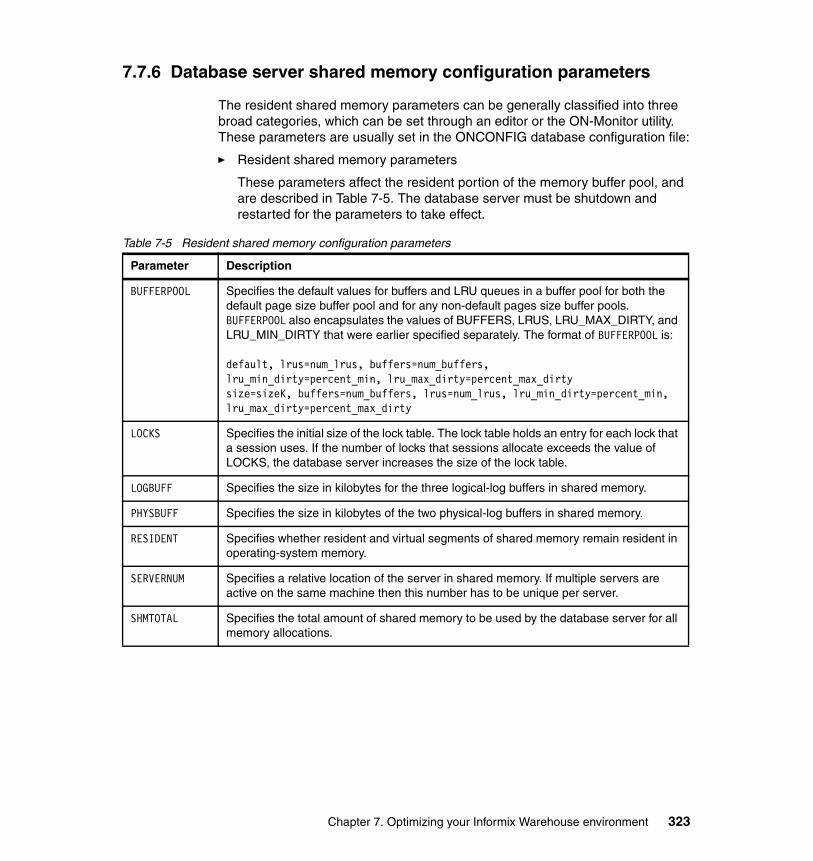
7.7.6 Database server shared memory configuration parameters
The resident shared memory parameters can be generally classified into three broad categories, which can be set through an editor or the ON-Monitor utility. These parameters are usually set in the ONCONFIG database configuration file:
� Resident shared memory parameters
These parameters affect the resident portion of the memory buffer pool, and are described in Table 7-5. The database server must be shutdown and restarted for the parameters to take effect.
Table 7-5 Resident shared memory configuration parameters
Parameter Description
BUFFERPOOL Specifies the default values for buffers and LRU queues in a buffer pool for both the default page size buffer pool and for any non-default pages size buffer pools. BUFFERPOOL also encapsulates the values of BUFFERS, LRUS, LRU_MAX_DIRTY, and LRU_MIN_DIRTY that were earlier specified separately. The format of BUFFERPOOL is:
default, lrus=num_lrus, buffers=num_buffers,lru_min_dirty=percent_min, lru_max_dirty=percent_max_dirtysize=sizeK, buffers=num_buffers, lrus=num_lrus, lru_min_dirty=percent_min, lru_max_dirty=percent_max_dirty
LOCKS Specifies the initial size of the lock table. The lock table holds an entry for each lock that a session uses. If the number of locks that sessions allocate exceeds the value of LOCKS, the database server increases the size of the lock table.
LOGBUFF Specifies the size in kilobytes for the three logical-log buffers in shared memory.
PHYSBUFF Specifies the size in kilobytes of the two physical-log buffers in shared memory.
RESIDENT Specifies whether resident and virtual segments of shared memory remain resident in operating-system memory.
SERVERNUM Specifies a relative location of the server in shared memory. If multiple servers are active on the same machine then this number has to be unique per server.
SHMTOTAL Specifies the total amount of shared memory to be used by the database server for all memory allocations.
Chapter 7. Optimizing your Informix Warehouse environment 323
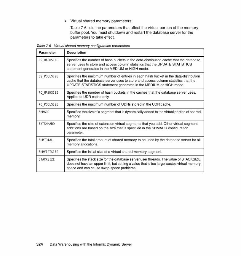
� Virtual shared memory parameters:
Table 7-6 lists the parameters that affect the virtual portion of the memory buffer pool. You must shutdown and restart the database server for the parameters to take effect.
Table 7-6 Virtual shared memory configuration parameters
Parameter Description
DS_HASHSIZE Specifies the number of hash buckets in the data-distribution cache that the database server uses to store and access column statistics that the UPDATE STATISTICS statement generates in the MEDIUM or HIGH mode.
DS_POOLSIZE Specifies the maximum number of entries in each hash bucket in the data-distribution cache that the database server uses to store and access column statistics that the UPDATE STATISTICS statement generates in the MEDIUM or HIGH mode.
PC_HASHSIZE Specifies the number of hash buckets in the caches that the database server uses. Applies to UDR cache only.
PC_POOLSIZE Specifies the maximum number of UDRs stored in the UDR cache.
SHMADD Specifies the size of a segment that is dynamically added to the virtual portion of shared memory.
EXTSHMADD Specifies the size of extension virtual segments that you add. Other virtual segment additions are based on the size that is specified in the SHMADD configuration parameter.
SHMTOTAL Specifies the total amount of shared memory to be used by the database server for all memory allocations.
SHMVIRTSIZE Specifies the initial size of a virtual shared-memory segment.
STACKSIZE Specifies the stack size for the database server user threads. The value of STACKSIZE does not have an upper limit, but setting a value that is too large wastes virtual memory space and can cause swap-space problems.
324 Data Warehousing with the Informix Dynamic Server
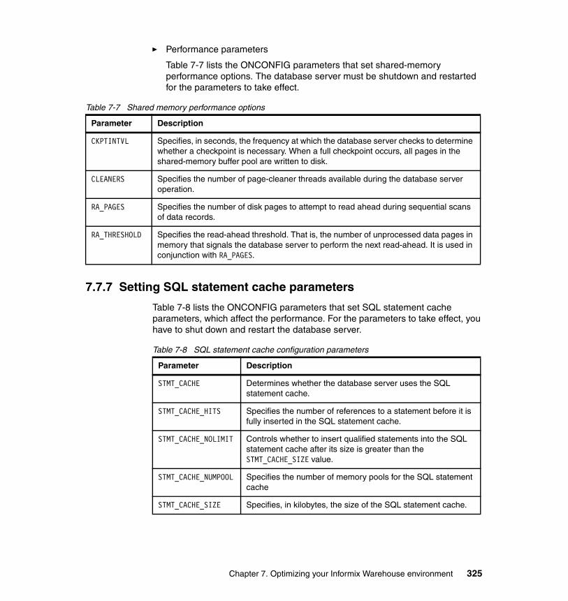
� Performance parameters
Table 7-7 lists the ONCONFIG parameters that set shared-memory performance options. The database server must be shutdown and restarted for the parameters to take effect.
Table 7-7 Shared memory performance options
7.7.7 Setting SQL statement cache parameters
Table 7-8 lists the ONCONFIG parameters that set SQL statement cache parameters, which affect the performance. For the parameters to take effect, you have to shut down and restart the database server.
Table 7-8 SQL statement cache configuration parameters
Parameter Description
CKPTINTVL Specifies, in seconds, the frequency at which the database server checks to determine whether a checkpoint is necessary. When a full checkpoint occurs, all pages in the shared-memory buffer pool are written to disk.
CLEANERS Specifies the number of page-cleaner threads available during the database server operation.
RA_PAGES Specifies the number of disk pages to attempt to read ahead during sequential scans of data records.
RA_THRESHOLD Specifies the read-ahead threshold. That is, the number of unprocessed data pages in memory that signals the database server to perform the next read-ahead. It is used in conjunction with RA_PAGES.
Parameter Description
STMT_CACHE Determines whether the database server uses the SQL statement cache.
STMT_CACHE_HITS Specifies the number of references to a statement before it is fully inserted in the SQL statement cache.
STMT_CACHE_NOLIMIT Controls whether to insert qualified statements into the SQL statement cache after its size is greater than the STMT_CACHE_SIZE value.
STMT_CACHE_NUMPOOL Specifies the number of memory pools for the SQL statement cache
STMT_CACHE_SIZE Specifies, in kilobytes, the size of the SQL statement cache.
Chapter 7. Optimizing your Informix Warehouse environment 325
7.7.8 Changing forced residency
To change the usage status of the resident portion of the shared memory we can either use the onmode utility or change the RESIDENT parameter of the ONCONFIG file. The residency status can be changed either temporarily or permanently.
Temporarily change the residency: Online modeUse the onmode utility to change the residency status. You must have DBA authority to perform this action. You can perform this action while the server is in the online mode:
� To turn on residency, execute the command: onmode -r� To turn off residency, execute the command: onmode -n
The changes are temporary until the time that either an onmode command is issued to revert the setting, or until the server is restarted, at which time the status is set to the value as specified in the RESIDENT parameter in the ONCONFIG file. The ONCONFIG value of RESIDENT is not changed through this method.
Change the residency: Offline modeYou can change the RESIDENT parameter value in the ONCONFIG file to change the status of the residency. The status becomes effective when the server is started.
7.7.9 Adding segments to the virtual portion of shared memory
Adding segments is usually not necessary because the server automatically allocates additional shared memory on a needed basis, except in very rare cases when the operating system enforces certain internal restrictions for the number of segments a process can allocate. In such cases you can use the -a option of the onmode utility to allocate additional shared memory segments.
7.7.10 Configurable page size and buffer pools
In this section, we discuss the following topics related to the configurable page size feature:
� Why a configurable page size?� Advantages of using the configurable page size feature� How to specify page size
326 Data Warehousing with the Informix Dynamic Server
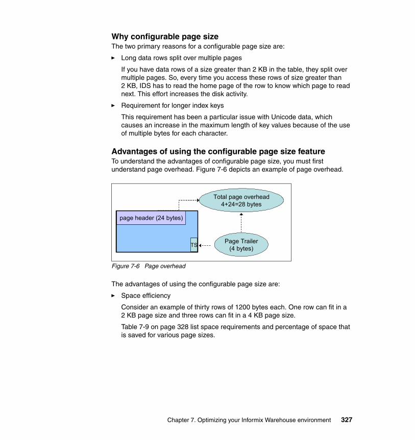
Why configurable page sizeThe two primary reasons for a configurable page size are:
� Long data rows split over multiple pages
If you have data rows of a size greater than 2 KB in the table, they split over multiple pages. So, every time you access these rows of size greater than 2 KB, IDS has to read the home page of the row to know which page to read next. This effort increases the disk activity.
� Requirement for longer index keys
This requirement has been a particular issue with Unicode data, which causes an increase in the maximum length of key values because of the use of multiple bytes for each character.
Advantages of using the configurable page size featureTo understand the advantages of configurable page size, you must first understand page overhead. Figure 7-6 depicts an example of page overhead.
Figure 7-6 Page overhead
The advantages of using the configurable page size are:
� Space efficiency
Consider an example of thirty rows of 1200 bytes each. One row can fit in a 2 KB page size and three rows can fit in a 4 KB page size.
Table 7-9 on page 328 list space requirements and percentage of space that is saved for various page sizes.
Total page overhead4+24=28 bytes
page header (24 bytes)
TSPage Trailer
(4 bytes)
Chapter 7. Optimizing your Informix Warehouse environment 327
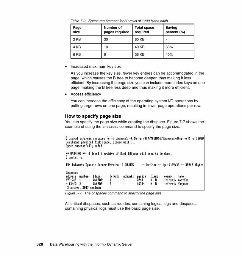
Table 7-9 Space requirement for 30 rows of 1200 bytes each
� Increased maximum key size
As you increase the key size, fewer key entries can be accommodated in the page, which causes the B tree to become deeper, thus making it less efficient. By increasing the page size you can include more index keys on one page, making the B tree less deep and thus making it more efficient.
� Access efficiency
You can increase the efficiency of the operating system I/O operations by putting large rows on one page, resulting in fewer page operations per row.
How to specify page sizeYou can specify the page size while creating the dbspace. Figure 7-7 shows the example of using the onspaces command to specify the page size.
Figure 7-7 The onspaces command to specify the page size
All critical dbspaces, such as rootdbs, containing logical logs and dbspaces containing physical logs must use the basic page size.
Page size
Number of pages required
Total space required
Savingpercent (%)
2 KB 30 60 KB -
4 KB 10 40 KB 33%
6 KB 6 36 KB 40%
328 Data Warehousing with the Informix Dynamic Server
7.8 PDQ
Another key factor in processing queries related to the data warehouse is parallel database query (PDQ), to read the pages in parallel. To do this, PDQ must be specifically activated and system resources must be configured and dedicated to its use. PDQ allows the database server to distribute the work for one aspect of a query among several processors. Table fragmentation enables you to store the parts of a table on different disks. PDQ delivers maximum performance benefits when the data that you query is in fragmented tables. PDQ can, depending on its configuration, be quite resource-intensive and must be used with caution.
7.8.1 PDQ configuration parameters
Primarily, six variables enable you to control PDQ:
� PDQPRIORITY sets a reasonable or recommended priority value.
� MAX_PDQPRIORITY limits the PDQ resources that the database server can allocate to any one DSS query. MAX_PDQPRIORITY is a factor that is used to scale the value of PDQ priority set by users.
� DS_TOTAL_MEMORY specifies the amount of memory available for PDQ queries.
� DS_MAX_SCANS limits the number of Parallel Database Query (PDQ) scan threads that the database server can execute concurrently.
� DS_MAX_QUERIES specifies the maximum number of queries that can run concurrently.
� DS_NONPDQ_QUERY_MEM increases the amount of memory that is a available for a query that is not a Parallel Database Query (PDQ).
In the following list, you can see the formulas used in PDQ. A good understanding of these formulas can help to find the best setting for the PDQ parameters for your environment:
� Memory quantum
Memory is granted in units called a quantum. A quantum unit is the minimum increment of memory allocated to a query. The memory quantum is calculated with the following formula:
memory quantum = DS_TOTAL_MEMORY / DS_MAX_QUERIES
Chapter 7. Optimizing your Informix Warehouse environment 329
� Minimum amount of decision-support memory
When you assign a value to the configuration parameter DS_MAX_QUERIES, the database server sets the minimum amount of decision-support memory according to the following formula:
min_ds_total_memory = DS_MAX_QUERIES * 128 kilobytes
When you do not assign a value to DS_MAX_QUERIES, the database server uses the following formula instead, and is based on the value of VPCLASS CPU or NUMCPUVPS:
min_ds_total_memory = NUMCPUVPS * 2 * 128 kilobytes
� Resources allocated
When a query requests a percentage of PDQ resources, the database server allocates the MAX_PDQPRIORITY percentage of the amount requested, as the following formula shows:
Resources allocated = (PDQPRIORITY / 100) * (MAX_PDQPRIORITY / 100)
� Memory for query
The amount of memory that is granted to a single parallel database query depends on many system factors, but in general, the amount of memory granted to a single parallel database query is proportional to the following formula:
memory_grant_basis = (DS_TOTAL_MEMORY/DS_MAX_QUERIES) * (PDQPRIORITY / 100) * (MAX_PDQPRIORITY / 100)
� Maximum number of scan threads per query
You can limit the number of concurrent scans using the DS_MAX_SCANS. In fact, the resources that users can assign to a query are calculated by the following formula:
scan_threads = min (nfrags, (DS_MAX_SCANS * (pdqpriority / 100) * (MAX_PDQPRIORITY / 100) )
Where:
– nfrags is the number of fragments in the table with the largest number of fragments.
– pdqpriority is the PDQ priority value set by either the PDQPRIORITY environment variable or the SET PDQPRIORITY statement.
� Amount of shared memory for PDQ
Use the following formula as a starting point for estimating the amount of shared memory to allocate to decision-support queries:
DS_TOTAL_MEMORY = p_mem - os_mem - rsdnt_mem - (128 kilobytes * users) - other_mem
330 Data Warehousing with the Informix Dynamic Server
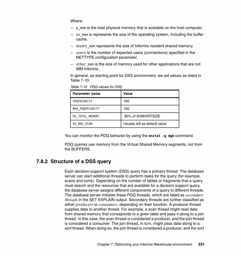
Where:
– p_mem is the total physical memory that is available on the host computer.
– os_mem is represents the size of the operating system, including the buffer cache.
– resdnt_mem represents the size of Informix resident shared memory.
– users is the number of expected users (connections) specified in the NETTYPE configuration parameter.
– other_mem is the size of memory used for other applications that are not IBM Informix.
In general, as starting point for DSS environment, we set values as listed in Table 7-10.
Table 7-10 PDQ values for DSS
You can monitor the PDQ behavior by using the onstat –g mgm command.
PDQ queries use memory from the Virtual Shared Memory segments, not from the BUFFERS.
7.8.2 Structure of a DSS query
Each decision-support system (DSS) query has a primary thread. The database server can start additional threads to perform tasks for the query (for example, scans and sorts). Depending on the number of tables or fragments that a query must search and the resources that are available for a decision support query, the database server assigns different components of a query to different threads. The database server initiates these PDQ threads, which are listed as secondary threads in the SET EXPLAIN output. Secondary threads are further classified as either producers or consumers, depending on their function. A producer thread supplies data to another thread. For example, a scan thread might read data from shared memory that corresponds to a given table and pass it along to a join thread. In this case, the scan thread is considered a producer, and the join thread is considered a consumer. The join thread, in turn, might pass data along to a sort thread. When doing so, the join thread is considered a producer, and the sort
Parameter name Value
PDQPRIORITY 100
MAX_PDQPRIORITY 100
DS_TOTAL_MEMORY 90% of SHMVIRTSIZE
DS_MAX_SCAN Usually left as default value
Chapter 7. Optimizing your Informix Warehouse environment 331
thread is considered a consumer. Several producers can supply data to a single consumer. When this situation occurs, the database server sets up an internal mechanism, called an exchange, that synchronizes the transfer of data from those producers to the consumer. For instance, if a fragmented table is to be sorted, the optimizer typically calls for a separate scan thread for each fragment. Because of different I/O characteristics, the scan threads can be expected to complete at different times. An exchange is used to funnel the data produced by the various scan threads into one or more sort threads with a minimum of buffering. Depending on the complexity of the query, the optimizer might call for a multilayered hierarchy of producers, exchanges, and consumers. Generally speaking, consumer threads work in parallel with producer threads so that the amount of intermediate buffering that the exchanges perform remains negligible.
The database server creates these threads and exchanges automatically and transparently. They terminate automatically as they complete processing for a given query. The database server creates new threads and exchanges as necessary for subsequent queries.
7.8.3 Database operations that use PDQ
In this section, we describe the types of SQL operations that the database server processes in parallel and the situations that limit the degree of parallelism that the database server can use. In the following discussions, a query is defined as any SELECT statement.
Parallel delete The database server takes the following two steps to process DELETE, INSERT, and UPDATE statements:
1. Fetches the qualifying rows.
2. Applies the action of deleting, inserting, or updating.
The database server performs the first step of a DELETE statement in parallel, with one exception; the database server does not process the first part of a DELETE statement in parallel if the targeted table has a referential constraint that can cascade to a child table.
Parallel inserts The database server performs the following types of inserts in parallel:
SELECT...INTO TEMP inserts using explicit temporary tables.INSERT INTO...SELECT inserts using implicit temporary tables.
332 Data Warehousing with the Informix Dynamic Server
Explicit inserts with SELECT...INTO TEMP The database server can insert rows in parallel into explicit temporary tables that you specify in SQL statements of the form SELECT....INTO TEMP. For example, the database server can perform the inserts in parallel into the temporary table, temp_table, as shown in the following example:
SELECT * FROM table1 INTO TEMP temp_table
Performing parallel inserts into a temporary tableTo perform the inserts, follow these steps:
1. Set PDQ priority to greater than zero (> 0). This requirement must be met for any query that you want the database server to perform in parallel.
2. Set DBSPACETEMP to a list of two or more dbspaces. This step is required because of the way that the database server performs the insert. To perform the insert in parallel, the database server first creates a fragmented temporary table. So that the database server knows where to store the fragments of the temporary table, you must specify a list of two or more dbspaces in the DBSPACETEMP configuration parameter or the DBSPACETEMP environment variable. In addition, you must set DBSPACETEMP to indicate storage space for the fragments before you execute the SELECT...INTO statement.
The database server performs the parallel insert by writing in parallel to each of the fragments in a round-robin fashion. Performance improves as you increase the number of fragments.
Implicit inserts with INSERT INTO...SELECT The database server can also insert rows in parallel into implicit tables that it creates when it processes SQL statements of the form INSERT INTO...SELECT statement. For example, the database server processes the following INSERT statement in parallel:
INSERT INTO target_table SELECT * FROM source_table
The target table can be either a permanent table or a temporary table.
The database server processes this type of INSERT statement in parallel only when the target tables meet the following criteria:
� The value of PDQ priority is greater than 0.
� The target table is fragmented into two or more dbspaces.
� The target table has no enabled referential constraints or triggers.
� The target table is not a remote table.
Chapter 7. Optimizing your Informix Warehouse environment 333
� The target table does not contain filtering constraints in a database with logging.
� The target table does not contain columns of TEXT or BYTE data type.
The database server does not process parallel inserts that reference an SPL routine. For example, the database server would never process the following statement in parallel:
INSERT INTO table1 EXECUTE PROCEDURE ins_proc
Parallel index buildsIndex builds can take advantage of PDQ and can be parallelized. The database server performs both scans and sorts in parallel for index builds. The following operations initiate index builds:
� Create an index.� Add a unique, primary key.� Add a referential constraint. � Enable a referential constraint.
When PDQ is in effect, the scans for index builds are controlled by the PDQ configuration parameters listed at the beginning of this section.
If your system is configured with multiple processors, the database server uses two sort threads to sort the index keys. The database server uses two sort threads during index builds without the user setting the PSORT_NPROCS environment variable.
7.8.4 SQL operations that do not use PDQ
The database server does not process the following types of queries in parallel:
� Queries started with an isolation level of Cursor Stability.
� Subsequent changes to the isolation level do not affect the parallelism of queries already prepared. This situation results from the inherent nature of parallel scans, which scan several rows simultaneously.
� Queries that use a cursor declared as FOR UPDATE.
� An UPDATE statement that has an update trigger that updates in the For Each Row section of the trigger definition.
� Data Definition Language (DDL) statements.
334 Data Warehousing with the Informix Dynamic Server
Update statistics The SQL UPDATE STATISTICS statement, which is not processed in parallel, is affected by PDQ because it must allocate the memory used for sorting. Thus the behavior of the UPDATE STATISTICS statement is affected by the memory management associated with PDQ.
Although the UPDATE STATISTICS statement is not processed in parallel, the database server must allocate the memory that this statement uses for sorting.
A common method to achieve a measure of parallel processing, while executing UPDATE STATISTICS statements, is to run several statements concurrently rather than consecutively. Be sure to monitor the system load that is generated from this method and be aware of a point of diminishing returns from running too many statements concurrently.
SPL routines and triggers Statements that involve SPL routines are not executed in parallel. However, statements within procedures are executed in parallel. When the database server executes an SPL routine, it does not use PDQ to process unrelated SQL statements contained in the procedure. However, each SQL statement can be executed independently in parallel, using intraquery parallelism when possible. As a consequence, you should limit the use of procedure calls from within Data Manipulation Language (DML) statements if you want to exploit the parallel processing abilities of the database server.
The database server uses intraquery parallelism to process the statements in the body of an SQL trigger in the same way that it processes statements in SPL routines.
Correlated and uncorrelated subqueries The database server does not use PDQ to process correlated subqueries. Only one thread at a time can execute a correlated subquery. While one thread executes a correlated subquery, other threads that request to execute the subquery are blocked until the first one completes.
For uncorrelated subqueries, only the first thread that makes the request will actually execute the subquery. Other threads simply use the results of the subquery and can do so in parallel.
As a consequence, a best practice is to, when possible, use joins rather than subqueries to build queries so that the queries can take advantage of PDQ.
Chapter 7. Optimizing your Informix Warehouse environment 335
OUTER index joins The database server reduces the PDQ priority of queries that contain OUTER index joins to LOW (if the priority is set to a higher value) for the duration of the query. If a subquery or a view contains OUTER index joins, the database server lowers the PDQ priority of only that subquery or view, not of the parent query or any other subquery.
Remote tables Although the database server can process the data that is stored in a remote table in parallel, the data is communicated serially because the database server allocates a single thread to submit and receive the data from the remote table.
The database server lowers the PDQ priority, of queries that require access to a remote database, to LOW. In that case, all local scans are parallel, but all local joins and remote access are nonparallel.
Allocating resources for parallel database queries When the database server uses PDQ to perform a query in parallel, it puts a heavy load on the operating system. In particular, PDQ exploits the following resources:
� Memory � CPU VPs (CPU virtual processors)� Disk I/O (to fragmented tables and temporary table space) � Scan threads
When you configure the database server, consider how the use of PDQ affects users of decision-support applications, as well as all other applications. You can control how the database server uses resources in the following ways:
� Limit the priority of parallel database queries.� Adjust the amount of memory. � Limit the number of scan threads.� Limit the number of concurrent queries.
Limiting the priority of DSS queries The default value for the PDQ priority of individual applications is 0 (zero), which means that PDQ processing is not used. The database server uses this value unless one of the following actions overrides it:
� The user sets the PDQPRIORITY environment variable.� The application uses the SET PDQPRIORITY statement.
The PDQPRIORITY environment variable and the MAX_PDQPRIORITY configuration parameter work together to control the amount of resources to
336 Data Warehousing with the Informix Dynamic Server
allocate for parallel processing. Setting these configuration parameters correctly is critical for the effective operation of PDQ.
The MAX_PDQPRIORITY configuration parameter allows the database server administrator to limit the parallel processing resources that DSS queries consume. Thus, the PDQPRIORITY environment variable sets a reasonable or recommended priority value, and MAX_PDQPRIORITY limits the resources that an application can claim.
The MAX_PDQPRIORITY configuration parameter specifies the maximum percentage of the requested resources that a query can obtain. For instance, if PDQPRIORITY is 80 and MAX_PDQPRIORITY is 50, each active query receives an amount of memory equal to 40% of DS_TOTAL_MEMORY, rounded down to the nearest quantum. In this example, MAX_PDQPRIORITY effectively limits the number of concurrent decision-support queries to two. Subsequent queries must wait for earlier queries to finish before they acquire the resources that they have to run.
An application or user can implement the DEFAULT tag of the SET PDQPRIORITY statement to use the value for PDQ priority if the value has been set by the PDQPRIORITY environment variable. DEFAULT is the symbolic equivalent of a -1 value for PDQ priority.
You can use the onmode command-line utility to change the values of the following configuration parameters temporarily:
� Use onmode -M to change the value of DS_TOTAL_MEMORY. � Use onmode -Q to change the value of DS_MAX_QUERIES.� Use onmode -D to change the value of MAX_PDQPRIORITY. � Use onmode -S to change the value of DS_MAX_SCANS.
These changes remain in effect only while the database server remains running. When the database server starts, it uses the values listed in the ONCONFIG file.
If you must change the values of the decision-support parameters on a regular basis (for example, to set MAX_PDQPRIORITY to 100 each night for processing reports), you can use a scheduled operating-system job to set the values. For information about creating scheduled jobs, see your operating-system manuals.
To obtain the best performance from the database server, choose values for the PDQPRIORITY environment variable and MAX_PDQPRIORITY parameter, observe the resulting behavior, and then adjust the values for these parameters. No well-defined rules exist for choosing these environment variable and parameter values. The following sections discuss strategies for setting PDQPRIORITY and MAX_PDQPRIORITY for specific needs.
Chapter 7. Optimizing your Informix Warehouse environment 337
Limiting the value of PDQ priority The MAX_PDQPRIORITY configuration parameter limits the PDQ priority that the database server grants when users either set the PDQPRIORITY environment variable or issue the SET PDQPRIORITY statement before they issue a query. When an application or a user attempts to set a PDQ priority, the priority that is granted is multiplied by the value that MAX_PDQPRIORITY specifies.
The value of MAX_PDQPRIORITY can be set lower if you want to allocate more resources to OLTP processing. Set the value higher when you want to allocate more resources to decision-support processing. The possible range of values is 0 - 100. This range represents the percent of resources that you can allocate to decision-support processing.
Maximizing non-DSS throughput At times, you might want to allocate resources to maximize the throughput for individual OLTP applications rather than for decision-support queries. In this case, set MAX_ PDQPRIORITY to 0, which limits the value of PDQ priority to OFF. A PDQ priority value of OFF does not prevent decision-support queries from running. Instead, it causes the queries to run without parallelization. In this configuration, response times for decision-support queries might be slower than expected.
Conserving resources If applications make little use of queries that require parallel sorts and parallel joins, consider using the LOW setting for PDQ priority.
If the database server is operating in a multiuser environment, you might set MAX_PDQPRIORITY to 1 to increase interquery performance at the cost of some intraquery parallelism. A trade-off exists between these two types of parallelism because they compete for the same resources. As a compromise, you might set MAX_PDQPRIORITY to an intermediate value (perhaps 20 or 30) and set PDQPRIORITY to LOW. The environment variable sets the default behavior to LOW, but the MAX_PDQPRIORITY configuration parameter allows individual applications to request more resources with the SET PDQPRIORITY statement.
Allowing maximum use of parallelism Set PDQPRIORITY and MAX_PDQPRIORITY to 100 if you want the database server to assign as many resources as possible to parallel processing. This setting is appropriate for times when parallel processing does not interfere with non-DSS processing. You can use different numeric settings for PDQPRIORITY to experiment with the effects of parallelism on a single application.
338 Data Warehousing with the Informix Dynamic Server
Limits on parallelism associated with PDQ priorityThe database server reduces the PDQ priority of queries that contain outer joins to LOW (if set to a higher value) for the duration of the query. If a subquery or a view contains outer joins, the database server lowers the PDQ priority only of that subquery or view, not of the parent query or of any other subquery.
The database server lowers the PDQ priority of queries that require access to a remote database (same or different database server instance) to LOW if you set it to a higher value. In that case, all local scans are parallel, but all local joins and remote accesses are nonparallel.
Adjusting the amount of memoryUse the following formula as a starting point for estimating the amount of shared memory to allocate to decision-support queries:
DS_TOTAL_MEMORY = p_mem - os_mem - rsdnt_mem - (128 kilobytes * users) - other_mem
Where:
� p_mem represents the total physical memory that is available on the host computer.
� os_mem represents the size of the operating system, including the buffer cache.
� resdnt_mem represents the size of Informix resident shared memory.
� users is the number of expected users (connections) specified in the NETTYPE configuration parameter.
� other_mem is the size of memory used for other applications that are not IBM Informix applications.
The value for DS_TOTAL_MEMORY that is derived from this formula serves only as a starting point. To arrive at a value that makes sense for your configuration, you must monitor paging and swapping. (Use the tools provided with your operating system to monitor paging and swapping.) When paging increases, decrease the value of DS_TOTAL_MEMORY so that processing the OLTP workload can proceed.
The amount of memory that is granted to a single parallel database query depends on many system factors, but in general the amount of memory granted to a single parallel database query is proportional to the following formula:
memory_grant_basis = (DS_TOTAL_MEMORY/DS_MAX_QUERIES) * (PDQPRIORITY / 100) * (MAX_PDQPRIORITY / 100)
Chapter 7. Optimizing your Informix Warehouse environment 339

However, if the currently executing queries on all databases of the server instance require more memory than this estimate of the average allocation, another query might overflow to disk or might wait until concurrent queries completed execution and released sufficient memory resources for running the query. The following alternative formula estimates the PDQ memory available for a single query directly:
memory_for_single_query = DS_TOTAL_MEMORY * (PDQPRIOIRTY / 100) * (MAX_PDQPRIORITY / 100)
Limiting the number of concurrent scans The database server apportions a number of scans to a query according to its PDQ priority (among other factors). To limit the resources that users can assign to a query, use DS_MAX_SCANS and MAX_PDQPRIORITY according to the following formula:
scan_threads = min (nfrags, (DS_MAX_SCANS * (pdqpriority / 100) * (MAX_PDQPRIORITY / 100) )
Where:
� nfrags is the number of fragments in table with the largest number of fragments.
� pdqpriority is the PDQ priority value set by either the PDQPRIORITY environment variable or the SET PDQPRIORITY statement.
For example, suppose a large table contains 100 fragments. With no limit on the number of concurrent scans allowed, the database server would concurrently execute 100 scan threads to read this table. In addition, as many users as want to could initiate this query.
As the database server administrator, you set DS_MAX_SCANS to a value lower than the number of fragments in this table to prevent the database server from being flooded with scan threads by multiple decision-support queries. You can set DS_MAX_SCANS to 20 to ensure that the database server concurrently executes a maximum of 20 scan threads for parallel scans. Furthermore, if multiple users initiate parallel database queries, each query receives only a percentage of the 20 scan threads, according to the PDQ priority assigned to the query and the value for MAX_PDQPRIORITY that the database server administrator sets.
Limiting the maximum number of queries The DS_MAX_QUERIES configuration parameter limits the number of concurrent decision-support queries that can run. To estimate the number of decision-support queries that the database server can run concurrently, count each query that runs with PDQ priority set to 1 (one) or greater as one full query.
340 Data Warehousing with the Informix Dynamic Server

The database server allocates less memory to queries that run with a lower priority, so you can assign lower-priority queries a PDQ priority value that is in the range of 1 - 30, depending on the resource impact of the query. The total number of queries with PDQ priority values greater than 0 (zero) cannot exceed DS_MAX_QUERIES.
7.9 Indexing strategies
In this section, we review performance considerations associated with indexes, including space considerations, choosing indexes to create, and managing indexes.
From an overall design standpoint, we have to perform a division of tables and indexes in such a way to maximize the ability of IDS to execute parallel operations. Indexes and index-based constraints should be separated into a number of other spaces so that as index finds are executing, parallel table reads can occur. As much as possible, these dbspaces should be placed on different logical unit numbers (LUNs) using different drives to minimize device contention.
7.9.1 Managing indexes
An index is necessary on any column or combination of columns that must be unique. However, the presence of an index can also allow the query optimizer to speed up a query. The optimizer can use an index in the following ways:
� To replace repeated sequential scans of a table with nonsequential access
� To avoid reading row data when processing expressions that name only indexed columns
� To avoid a sort (including building a temporary table) when executing the GROUP BY and ORDER BY clauses.
As a result, an index on the appropriate column can save thousands, tens of thousands, or in extreme cases, even millions of disk operations during a query. However, indexes involve costs, which is also a consideration.
Space costs of indexes One cost of an index is disk space. The presence of an index can add many pages to a dbspace, and having as many index pages as row pages in an indexed table is easy. Also, in an environment where multiple languages are used, indexes that are created for each language require additional disk space.
Chapter 7. Optimizing your Informix Warehouse environment 341
When you consider space costs, also consider whether increasing the page size of a standard or temporary dbspace is beneficial in your environment. If you want a longer key length than is available for the default page size, you can increase the page size. If you increase the page size, the size must be an integral multiple of the default page size, not greater than 16 KB.
You might not want to increase the page size if your application contains small sized rows. Increasing the page size for an application that randomly accesses small rows might decrease performance. In addition, a page lock on a larger page will lock more rows, reducing concurrency in some situations.
Time costs of indexesAnother cost of an index is time when the table is modified. The following descriptions assume that approximately two pages must be read to locate an index entry. That is the case when the index consists of a root page, one level of branch pages, and a set of leaf pages. The root page is assumed to be in a buffer already. The index for a very large table has at least two intermediate levels, so about three pages are read when the database server references such an index.
Presumably, one index is used to locate a row being altered. The pages for that index might be found in page buffers in shared memory for the database server. However, the pages for any other indexes that require altering must be read from disk.
Under these assumptions, index maintenance adds time to different kinds of modifications, such as those examples described in the following list:
� When you delete a row from a table, the database server must delete its entries from all indexes.
The database server must look up the entry for the deleted row (typically two or three pages in) and rewrite the leaf page. The write operation to update the index is performed in memory, and the leaf page is flushed when the least recently used (LRU) buffer that contains the modified page is cleaned. This operation requires two or three page accesses to read the index pages if necessary and one deferred page access to write the modified page.
� When you insert a row, the database server must insert its entries in all indexes.
The database server must find a place in which to enter the inserted row within each index and rewrite (typically one deferred page out), for a total of three or four immediate page accesses per index.
342 Data Warehousing with the Informix Dynamic Server
� When you update a row, the database server must look up its entries in each index that applies to an altered column (typically two or three pages in).
The database server must rewrite the leaf page to eliminate the old entry (one deferred page out) and then locate the new column value in the same index (two or three more pages in) and the row entered (one more deferred page out).
Insertions and deletions change the number of entries on a leaf page. Although virtually every pagents operation requires some additional work to deal with a leaf page that has either filled or been emptied, if pagents is greater than 100, this additional work occurs less than 1% of the time. You can often disregard it when you estimate the I/O impact.
In short, when a row is inserted or deleted at random, allow three to four added page I/O operations per index. When a row is updated, allow six to eight page I/O operations for each index that applies to an altered column. If a transaction is rolled back, all this work must be undone. For this reason, rolling back a transaction can take some time. Because the alteration of the row itself requires only two page I/O operations, index maintenance is clearly the most time-consuming part of data modification.
Removing unclaimed index spaceA background thread, the B-Tree scanner, identifies an index with the most unclaimed index space. Unclaimed index space degrades performance and causes extra work for the server. When an index is chosen for scanning, the entire leaf of the index is scanned for deleted (dirty) items that were committed, but not yet removed from the index. The B-Tree scanner removes these items when necessary. The B-Tree scanner allows multiple threads.
Use the BTSCANNER configuration parameter to specify the number of B-Tree scanner threads to start and the priority of the B-Tree scanner threads when the database server starts. Also, you can invoke the B-Tree scanner from the command line.
7.9.2 Choosing columns for indexes
Indexes are required on columns that must be unique and are not specified as primary keys. In addition, add an index on columns that:
� Are used in joins and that are not specified as foreign keys� Are frequently used in filter expressions � Are frequently used for ordering or grouping� Do not involve duplicate keys � Are amenable to clustered indexing
Chapter 7. Optimizing your Informix Warehouse environment 343
Filtered columns in large tablesIf a column is often used to filter the rows of a large table, consider placing an index on it. The optimizer can use the index to select the desired columns and avoid a sequential scan of the entire table. One example is a table that contains a large mailing list. If you find that a postal-code column is often used to filter a subset of rows, consider putting an index on that column.
This strategy yields a net savings of time only when the selectivity of the column is high; that is, when only a small fraction of rows holds any one indexed value. Nonsequential access through an index takes several more disk I/O operations than sequential access does, so if a filter expression on the column passes more than a fourth of the rows, the database server might as well read the table sequentially.
As a rule, indexing a filter column saves time in the following cases:
� The column is used in filter expressions in many queries or in slow queries.� The column contains at least 100 unique values.� Most column values appear in fewer than 10% of the rows.
Columns used for Order-By and Group-ByWhen a large quantity of rows must be ordered or grouped, the database server must put the rows in order. One way that the database server performs this task is to select all the rows into a temporary table and sort the table. But, if the ordering columns are indexed, the optimizer sometimes reads the rows in sorted order through the index, thus avoiding a final sort.
Because the keys in an index are in sorted sequence, the index really represents the result of sorting the table. By placing an index on the ordering column or columns, you can replace many sorts during queries with a single sort when the index is created.
Avoiding columns with duplicate keysWhen duplicate keys are permitted in an index, entries that match a given key value are grouped in lists. The database server uses these lists to locate rows that match a requested key value. When the selectivity of the index column is high, these lists are generally short. But, when only a few unique values occur, the lists become long and can cross multiple leaf pages.
Placing an index on a column that has low selectivity (that is, a small number of distinct values relative to the number of rows) can reduce performance. In such cases, the database server must not only search the entire set of rows that match the key value, but it must also lock all the affected data and index pages. This process can impede the performance of other update requests as well.
344 Data Warehousing with the Informix Dynamic Server

To correct this problem, replace the index on the low-selectivity column with a composite index that has a higher selectivity. Use the low-selectivity column as the leading column and a high-selectivity column as your second column in the index. The composite index limits the number of rows that the database server must search to locate and apply an update.
You can use any second column to disperse the key values as long as its value does not change, or changes at the same time as the real key. The shorter the second column the better, because its values are copied into the index and expand its size.
Clustering Clustering is a method for arranging the rows of a table so that their physical order on disk closely corresponds to the sequence of entries in the index. (Do not confuse the clustered index with an optical cluster, which is a method for storing logically related TEXT or BYTE data together on an optical volume.) When you know that a table is ordered by a certain index, you can avoid sorting. You can also be sure that when the table is searched on that column, it is read effectively in sequential order, instead of nonsequentially.
In the stores_demo database, the orders table has an index, zip_ix, on the postal-code column. The following statement causes the database server to put the rows of the customer table in descending order by postal code:
ALTER INDEX zip_ix TO CLUSTER
To cluster a table on a nonindexed column, you must create an index. The following statement reorders the orders table by order date:
CREATE CLUSTERED INDEX o_date_ix ON orders (order_date ASC)
To reorder a table, the database server must copy the table. In the preceding example, the database server reads all the rows in the table and constructs an index. Then, it reads the index entries in sequence. For each entry, it reads the matching row of the table and copies it to a new table. The rows of the new table are in the desired sequence. This new table replaces the old table.
Clustering is not preserved when you alter a table. When you insert new rows, they are stored physically at the end of the table, regardless of their contents. When you update rows and change the value of the clustering column, the rows are written back into their original location in the table.
Clustering can be restored after the order of rows is disturbed by ongoing updates. The following statement reorders the table to restore data rows to the index sequence:
ALTER INDEX o_date_ix TO CLUSTER
Chapter 7. Optimizing your Informix Warehouse environment 345
Reclustering is usually quicker than the original clustering because reading out the rows of a nearly clustered table is similar in I/O impact to a sequential scan.
Clustering and reclustering can take a lot of space and time. To reduce the amount of clustering, build the table in the desired order initially
Configuration parameters that affect the degree of clusteringThe clust field in the sysindexes or the sysindices table represents the degree of clustering of the index. The value of this field is affected by:
� The value in the buffers field of the BUFFERPOOL configuration parameter
� DS_MAX_QUERIES, which specifies the maximum number of PDQ queries that can run concurrently
Each of these configuration parameters affects the amount of buffer space available for a single user session. Additional buffers can result in better clustering (a smaller clust value in the sysindexes or sysindices tables).
You can create more buffers by:
� Increasing the buffers in BUFFERPOOL � Decreasing DS_MAX_QUERIES� Both increasing the buffers in BUFFERPOOL and decreasing
DS_MAX_QUERIES
7.9.3 Creating and dropping an index in an online environment
You can use the CREATE INDEX ONLINE and DROP INDEX ONLINE statements to create and drop an index in an online environment, when the database and its associated tables are continuously available.
The CREATE INDEX ONLINE statement enables you to create an index without having an exclusive lock placed over the table during the duration of the index build. You can use the CREATE INDEX ONLINE statement even when reads or updates are occurring on the table. This means index creation can begin immediately.
When you create an index online, the database server logs the operation with a flag, so data recovery and restore operations can recreate the index.
When you create an index online, you may use the ONLIDX_MAXMEM configuration parameter to limit the amount of memory that is allocated to the preimage log pool and to the updator log pool in shared memory. You might want to do this step if you plan to complete other operations on a table column while executing the CREATE INDEX ONLINE statement on the column.
346 Data Warehousing with the Informix Dynamic Server
The DROP INDEX ONLINE statement enables you to drop indexes even when Dirty Read is the transaction isolation level.
The advantages of creating indexes using the CREATE INDEX ONLINE statement are:
� If a new index is necessary to improve the performance of queries on a table, you can immediately create the index without a lock placed over the table.
� The database server can create an index while a table is being updated.
� The table is available for the duration of the index build. The query optimizer can establish better query plans because the optimizer can update statistics in unlocked tables.The advantages of dropping indexes using the DROP INDEX ONLINE statement are:
– You can drop an inefficient index without disturbing ongoing queries that are using that index.
– When the index is flagged, the query optimizer will not use the index for new SELECT operations on tables.
If you initiate a DROP INDEX ONLINE statement for a table that is being updated, the operation does not occur until after the table update is completed. After you issue the DROP INDEX ONLINE statement, no one can reference the index, but concurrent operations can use the index until the operations terminate. The database server waits to drop the index until all users have finished accessing the index.
An example of creating an index in an online environment is:
CREATE INDEX idx_1 ON table1(col1) ONLINE
An example of dropping an index in an online environment is:
DROP INDEX idx_1 ONLINE
7.9.4 Creating or dropping indexes online
The following list contains circumstances under which you cannot create or drop indexes online. That is, you cannot use the CREATE INDEX ONLINE statement to create the following items:
� Index at the same time that a table is being altered� A clustered index� A Virtual-Index Interface (VII) R-Tree index� A functional index� An index online statement that is inside a transaction
Chapter 7. Optimizing your Informix Warehouse environment 347

You cannot use the DROP INDEX ONLINE statement to drop the following items:
� A Virtual-Index Interface (VII) R-Tree index� A clustered index� An index online statement that is inside a transaction
7.9.5 Improving performance for index builds
When possible, the database server uses parallel processing to improve the response time of index builds. The number of parallel processes is based on the number of fragments in the index and the value of the PSORT_NPROCS environment variable. The database server builds the index with parallel processing even when the value of PDQ priority is 0 (zero).
You can often improve the performance of an index build by taking the following steps:
1. Set PDQ priority to a value greater than 0 to obtain more memory than the default 128 KB. When you set PDQ priority to greater than 0 (zero), the index build can take advantage of the additional memory for parallel processing. To set PDQ priority, use either the PDQPRIORITY environment variable or the SET PDQPRIORITY statement in SQL.
2. Do not set the PSORT_NPROCS environment variable.
3. A good practice is not to set the PSORT_NPROCS environment variable. If you have a computer with multiple processors, the database server uses two threads per sort when it sorts index keys and PSORT_NPROCS is not set. The number of sorts depends on the number of fragments in the index, the number of keys, the key size, and the values of the PDQ memory configuration parameters.
4. Allocate enough memory and temporary space to build the entire index with the following activities:
a. Estimate the amount of virtual shared memory that the database server might require for sorting.
b. Specify more memory with the DS_TOTAL_MEMORY and DS_MAX_QUERIES configuration parameters.
c. If not enough memory is available, estimate the amount of temporary space necessary for an entire index build.
d. Use the onspaces -t utility to create large temporary dbspaces and specify them in the DBSPACETEMP configuration parameter or the DBSPACETEMP environment variable.
348 Data Warehousing with the Informix Dynamic Server
7.9.6 Index self-join access method
Traditionally, an index scan allows you to scan a single range (based on the start/stop key) of an index. The index self-join access method lets you scan many mini-ranges instead of a large single range, based on filters on the non-leading keys of an index.
The index self-join is a new type of index scan where the table is logically joined to itself, such that for each unique combination of the leading key columns of an index, additional filters on non-leading key columns of the index are used to perform a more efficient mini-index scan. Results from multiple mini-index scans are then combined to generate the result set of the query.
This is the example query:
SELECT * FROM tabWHERE c1 >= 1 and c1 <= 3 and c2 >= 10 and c2 <= 11 and c3 >= 100 and c3 <= 102
Indexes can also be partitioned using an expression-based partitioning scheme. A table’s index partitioning scheme does not have to be the same as that used for the associated table. Partitioned indexes can be placed on a different physical disk than the data, resulting in optimum parallel processing performance. Partitioning tables and indexes improves the performance of data-loading and index-building operations.
7.9.7 Creating attached indexes in an online environment
You can create and drop an index without having an exclusive lock placed on the table during the duration of the index build. This approach also makes the table available during index build. CREATE INDEX ONLINE and DROP INDEX ONLINE statements can be used to create and drop online indexes. You can use the CREATE INDEX ONLINE even when the reads and updates of the table are occurring. The advantages of creating indexes with CREATE INDEX ONLINE statement are:
� If you have to build a new index to improve the performance of the query, you can immediately create it without placing a lock on the table.
� The query optimizer can establish better query plans, because it can update statistics on unlocked tables.
� The database server can build an index while the table is being updated.
� The table is available for the duration of the index build.
Chapter 7. Optimizing your Informix Warehouse environment 349
The advantages of dropping indexes with DROP INDEX ONLINE statement are:
� You can drop the inefficient index without disturbing ongoing queries that are using them.
� When the index is flagged, the query optimizer does not use the index for new SELECT operations on tables.
The ONLIDX_MAXMEM configuration parameter can be used to limit the amount of memory that is allocated to a single pre-image pool and a single updator log pool. The pre-image and updator log pools are shared memory pools that are created when a CREATE INDEX ONLINE statement is executed. The pools are freed after the execution of the statement is complete. You can set ONLIDX_MAXMEM in ONCONFIG file before starting the database server or you can set it dynamically using the onmode -wm and onmode -wf commands.
An example command to create an index online is:
CREATE INDEX cust_idx on customer(zipcode) ONLINE
An example command to drop an index online is:
DROP INDEX cust_idx ONLINE
R-Tree and functional indexesIDS extensibility features include a new type of indexing, the R-Tree index. This multidimensional index can be used in many situations (for example, spatial-type queries). IDS also supports B-Tree indexing of any type, as long as you can define a sorting order.
In addition, IDS can index the result of a user-defined routine. This type of index is called a functional index. An important note is that you cannot create a functional index on the result of a built-in function. For example, you cannot create a functional index on the result of the UPPER function. You can workaround this limitation easily by creating an SPL routine that serves as a wrapper. The definition of this function would be:
CREATE FUNCTION myUpper(in VARCHAR(300))WITH (NOT VARIANT)RETURN(UPPER(in))END FUNCTION;
The creation of an index on the result of the MyUpper function could speedup the processing of SQL statements such as:
SELECT * FROM customerWHERE MyUpper(lastname) = "HILZ";
350 Data Warehousing with the Informix Dynamic Server
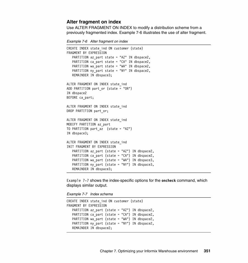
Alter fragment on indexUse ALTER FRAGMENT ON INDEX to modify a distribution scheme from a previously fragmented index. Example 7-6 illustrates the use of alter fragment.
Example 7-6 Alter fragment on index
CREATE INDEX state_ind ON customer (state)FRAGMENT BY EXPRESSION PARTITION az_part state = "AZ" IN dbspace2, PARTITION ca_part state = "CA" IN dbspace2, PARTITION wa_part state = "WA" IN dbspace2, PARTITION ny_part state = "NY" IN dbspace2, REMAINDER IN dbspace3;
ALTER FRAGMENT ON INDEX state_indADD PARTITION part_or (state = "OR")IN dbspace2BEFORE ca_part;
ALTER FRAGMENT ON INDEX state_indDROP PARTITION part_or;
ALTER FRAGMENT ON INDEX state_indMODIFY PARTITION az_partTO PARTITION part_az (state = "AZ")IN dbspace3;
ALTER FRAGMENT ON INDEX state_indINIT FRAGMENT BY EXPRESSION PARTITION az_part (state = "AZ") IN dbspace2, PARTITION ca_part (state = "CA") IN dbspace2, PARTITION wa_part (state = "WA") IN dbspace3, PARTITION ny_part (state = "NY") IN dbspace3, REMAINDER IN dbspace3;
Example 7-7 shows the index-specific options for the oncheck command, which displays similar output.
Example 7-7 Index schema
CREATE INDEX state_ind ON customer (state)FRAGMENT BY EXPRESSION PARTITION az_part (state = "AZ") IN dbspace2, PARTITION ca_part (state = "CA") IN dbspace2, PARTITION wa_part (state = "WA") IN dbspace2, PARTITION ny_part (state = "NY") IN dbspace2, REMAINDER IN dbspace2;
Chapter 7. Optimizing your Informix Warehouse environment 351
7.10 Join strategies
The IDS optimizer must evaluate the various ways in which a query might be performed. If the query includes a join, the optimizer must determine the join plan (hash or nested loop) and the order in which tables are evaluated or joined. The following section explains the components of a query plan and the join strategies employed.
7.10.1 IDS cost-based optimizer
IDS uses a cost-based optimizer to determine the fastest way to retrieve data from database tables and indexes based on detailed statistical information about the data within the database generated by the UPDATE STATISTICS SQL command. This statistical information includes more than just the number of rows in the table; the maximum and minimum values for selected columns, value granularity and skew, index depth, and more are captured and recorded in overhead structures for the optimizer. The optimizer uses this information to pick the access plan that provides the quickest access to the data while trying to minimize the impact on system resources. The optimizer’s plan is built using estimates of I/O and processor costs in its calculations.
Access plan information is available for review through several management interfaces so that developers and engine administrators can evaluate the effectiveness of their application and database design. The SQL operations under review do not have to actually execute in order to get the plan information. By either setting an environment variable, executing a separate SQL command, or embedding an instruction in the target SQL operation, the operation stops after the operation is prepared and the access plan information is output for review. With this functionality, application logic and database design can be tested for efficiency without having to constantly rebuild data back to a known good state.
In rare cases, the optimizer might not choose the best plan for accessing data. This can happen when, for example, the query is extremely complex or insufficient statistical information is available about the table data. In these situations, after careful review and consideration, an administrator or developer can influence the plan by including optimizer directives (also known as optimizer hints) in the SQL statement. You can set optimizer directives to use or exclude specific indexes, specify the join order of tables, or specify the join type to be used when the operation is executed. You can also set an optimizer directive to optimize a query to retrieve only the N rows of the possible result set.
The latest versions of IDS have additional optimizer statistical functionality. In addition to the automatic gathering of statistics as indexes are created,
352 Data Warehousing with the Informix Dynamic Server
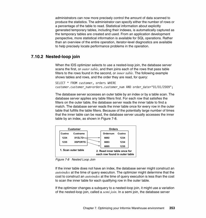
administrators can now more precisely control the amount of data scanned to produce the statistics. The administrator can specify either the number of rows or a percentage of the table to read. Statistical information about explicitly generated temporary tables, including their indexes, is automatically captured as the temporary tables are created and used. From an application development perspective, more statistical information is available for SQL operations. Rather than an overview of the entire operation, iterator-level diagnostics are available to help precisely locate performance problems in the operation.
7.10.2 Nested-loop join
When the IDS optimizer selects to use a nested-loop join, the database server scans the first, or outer table, and then joins each of the rows that pass table filters to the rows found in the second, or inner table. The following example shows tables and rows, and the order they are read, for query:
SELECT * FROM customer, orders WHERE customer.customer_num=orders.customer_num AND order_date>"01/01/2009";
The database server accesses an outer table by an index or by a table scan. The database server applies any table filters first. For each row that satisfies the filters on the outer table, the database server reads the inner table to find a match. The database server reads the inner table once for every row in the outer table that fulfills the table filters. Because of the potentially large number of times that the inner table can be read, the database server usually accesses the inner table by an index, as shown in Figure 7-8.
Figure 7-8 Nested Loop Join
If the inner table does not have an index, the database server might construct an autoindex at the time of query execution. The optimizer might determine that the cost to construct an autoindex at the time of query execution is less than the cost to scan the inner table for each qualifying row in the outer table.
If the optimizer changes a subquery to a nested-loop join, it might use a variation of the nested-loop join, called a semi join. In a semi join, the database server
CustomerCustno Custname
1234 XYZLTD
1235 XSPORTS
OrdersOrdernum Custno
6692 1234
6693 1234
6695 1235 1. Scan outer table 2. Read inner table once for
each row found in outer table
Chapter 7. Optimizing your Informix Warehouse environment 353
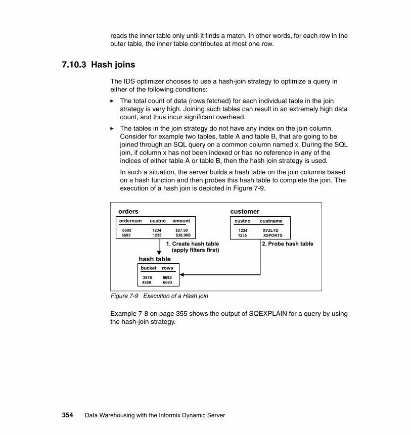
reads the inner table only until it finds a match. In other words, for each row in the outer table, the inner table contributes at most one row.
7.10.3 Hash joins
The IDS optimizer chooses to use a hash-join strategy to optimize a query in either of the following conditions:
� The total count of data (rows fetched) for each individual table in the join strategy is very high. Joining such tables can result in an extremely high data count, and thus incur significant overhead.
� The tables in the join strategy do not have any index on the join column. Consider for example two tables, table A and table B, that are going to be joined through an SQL query on a common column named x. During the SQL join, if column x has not been indexed or has no reference in any of the indices of either table A or table B, then the hash join strategy is used.
In such a situation, the server builds a hash table on the join columns based on a hash function and then probes this hash table to complete the join. The execution of a hash join is depicted in Figure 7-9.
Figure 7-9 Execution of a Hash join
Example 7-8 on page 355 shows the output of SQEXPLAIN for a query by using the hash-join strategy.
ordernum custno amount
6692 1234 $27.506693 1235 $38.90S
custno custname
1234 XYZLTD1235 XSPORTS
bucket rows
3978 66924588 6693
orders customer
hash table
1. Create hash table (apply filters first)
2. Probe hash table
354 Data Warehousing with the Informix Dynamic Server
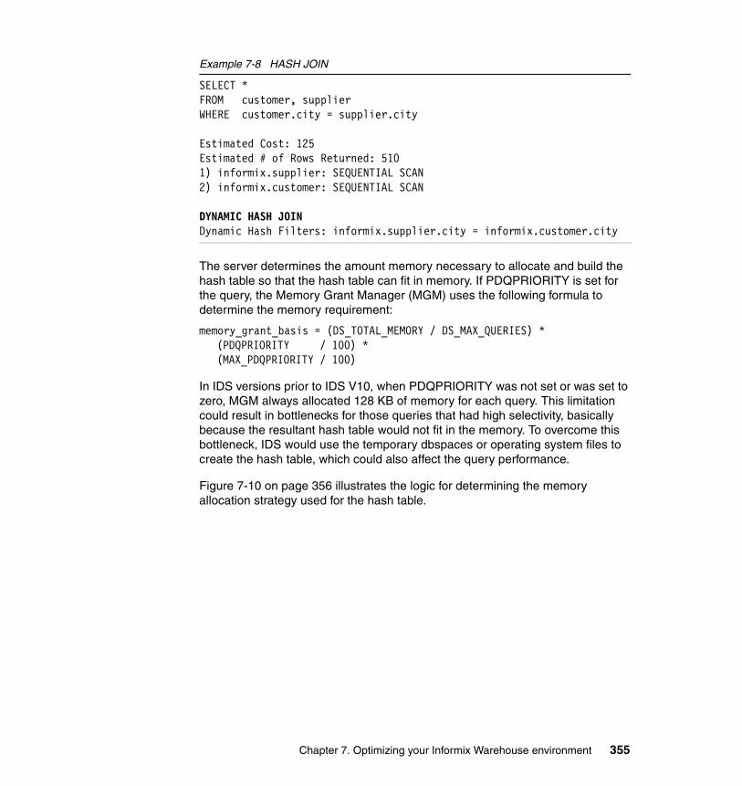
Example 7-8 HASH JOIN
SELECT * FROM customer, supplier WHERE customer.city = supplier.city
Estimated Cost: 125 Estimated # of Rows Returned: 510 1) informix.supplier: SEQUENTIAL SCAN 2) informix.customer: SEQUENTIAL SCAN
DYNAMIC HASH JOIN Dynamic Hash Filters: informix.supplier.city = informix.customer.city
The server determines the amount memory necessary to allocate and build the hash table so that the hash table can fit in memory. If PDQPRIORITY is set for the query, the Memory Grant Manager (MGM) uses the following formula to determine the memory requirement:
memory_grant_basis = (DS_TOTAL_MEMORY / DS_MAX_QUERIES) *(PDQPRIORITY / 100) *(MAX_PDQPRIORITY / 100)
In IDS versions prior to IDS V10, when PDQPRIORITY was not set or was set to zero, MGM always allocated 128 KB of memory for each query. This limitation could result in bottlenecks for those queries that had high selectivity, basically because the resultant hash table would not fit in the memory. To overcome this bottleneck, IDS would use the temporary dbspaces or operating system files to create the hash table, which could also affect the query performance.
Figure 7-10 on page 356 illustrates the logic for determining the memory allocation strategy used for the hash table.
Chapter 7. Optimizing your Informix Warehouse environment 355
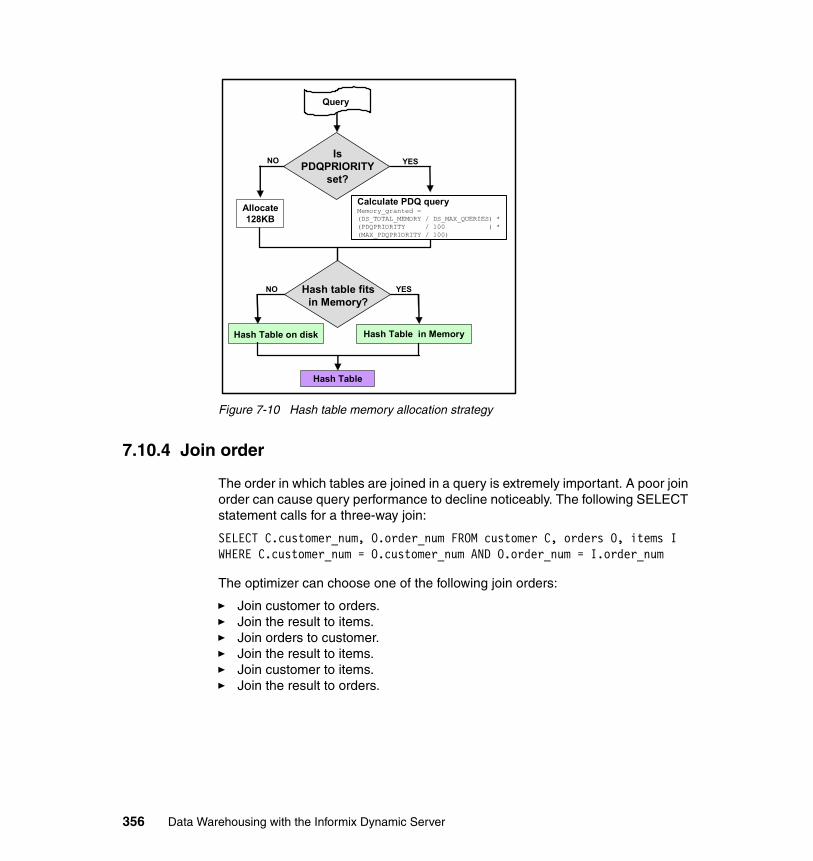
Figure 7-10 Hash table memory allocation strategy
7.10.4 Join order
The order in which tables are joined in a query is extremely important. A poor join order can cause query performance to decline noticeably. The following SELECT statement calls for a three-way join:
SELECT C.customer_num, O.order_num FROM customer C, orders O, items I WHERE C.customer_num = O.customer_num AND O.order_num = I.order_num
The optimizer can choose one of the following join orders:
� Join customer to orders. � Join the result to items.� Join orders to customer. � Join the result to items.� Join customer to items.� Join the result to orders.
NO YES
Hash Table on disk Hash Table in Memory
Hash Table
YESNO
Is PDQPRIORITY
set?
Query
Hash table fits in Memory?
Calculate PDQ queryMemory_granted = (DS_TOTAL_MEMORY / DS_MAX_QUERIES) * (PDQPRIORITY / 100 ) * (MAX_PDQPRIORITY / 100)
Allocate 128KB
356 Data Warehousing with the Informix Dynamic Server
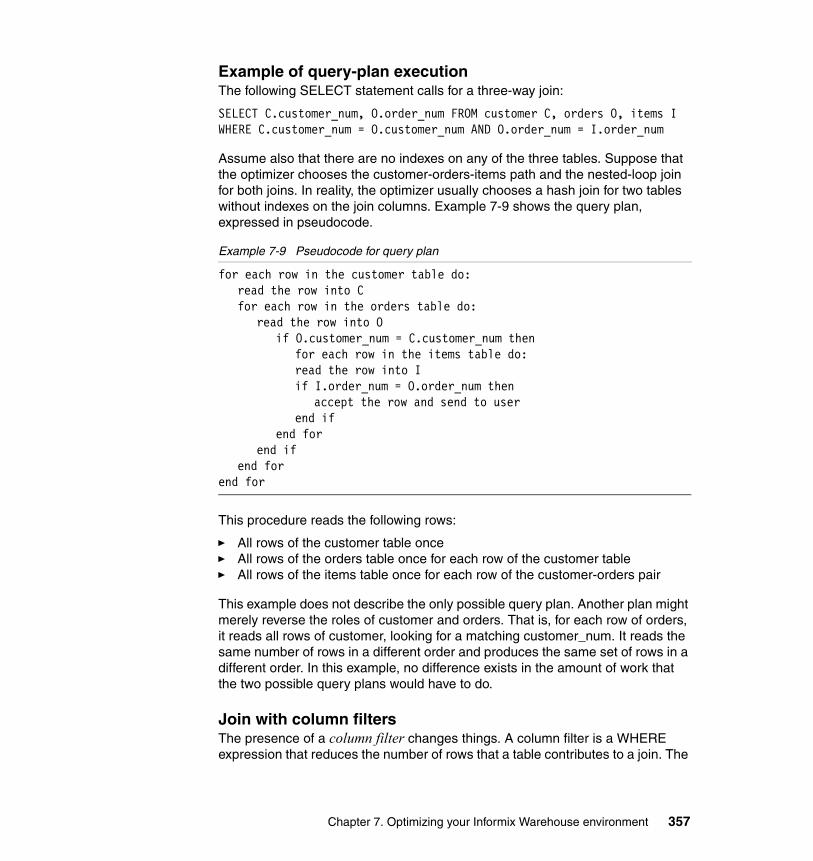
Example of query-plan executionThe following SELECT statement calls for a three-way join:
SELECT C.customer_num, O.order_num FROM customer C, orders O, items I WHERE C.customer_num = O.customer_num AND O.order_num = I.order_num
Assume also that there are no indexes on any of the three tables. Suppose that the optimizer chooses the customer-orders-items path and the nested-loop join for both joins. In reality, the optimizer usually chooses a hash join for two tables without indexes on the join columns. Example 7-9 shows the query plan, expressed in pseudocode.
Example 7-9 Pseudocode for query plan
for each row in the customer table do: read the row into C for each row in the orders table do:
read the row into O if O.customer_num = C.customer_num then
for each row in the items table do: read the row into I if I.order_num = O.order_num then
accept the row and send to userend if
end forend if
end forend for
This procedure reads the following rows:
� All rows of the customer table once� All rows of the orders table once for each row of the customer table� All rows of the items table once for each row of the customer-orders pair
This example does not describe the only possible query plan. Another plan might merely reverse the roles of customer and orders. That is, for each row of orders, it reads all rows of customer, looking for a matching customer_num. It reads the same number of rows in a different order and produces the same set of rows in a different order. In this example, no difference exists in the amount of work that the two possible query plans would have to do.
Join with column filters The presence of a column filter changes things. A column filter is a WHERE expression that reduces the number of rows that a table contributes to a join. The
Chapter 7. Optimizing your Informix Warehouse environment 357
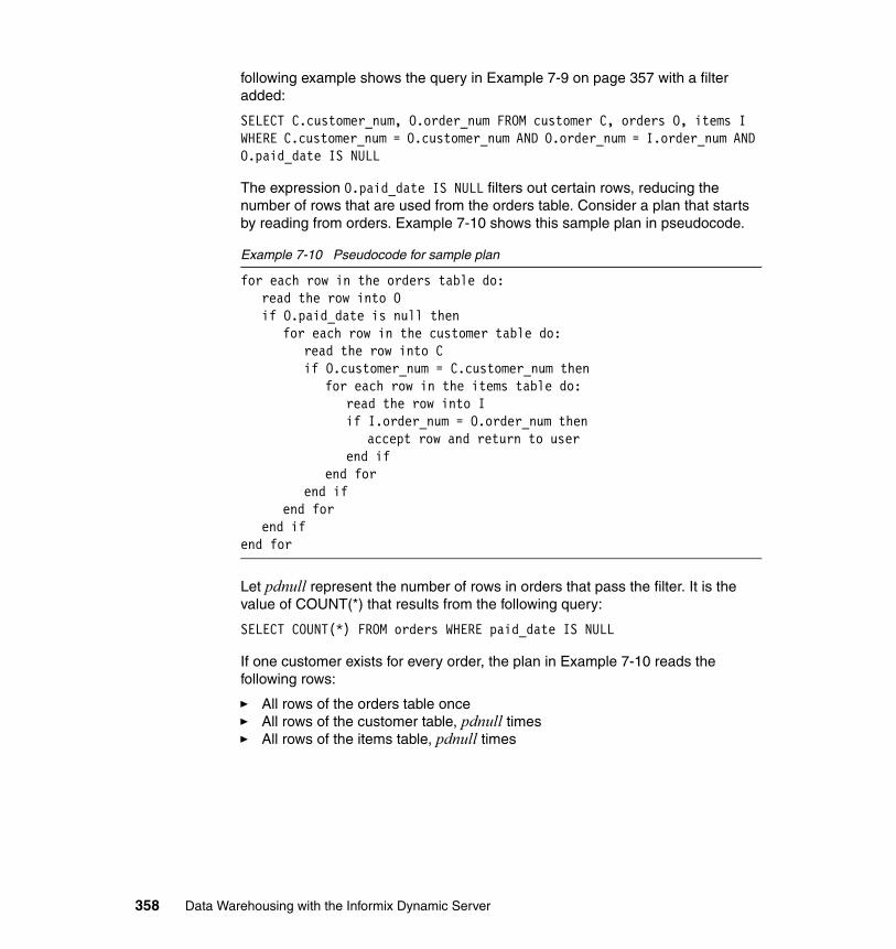
following example shows the query in Example 7-9 on page 357 with a filter added:
SELECT C.customer_num, O.order_num FROM customer C, orders O, items I WHERE C.customer_num = O.customer_num AND O.order_num = I.order_num AND O.paid_date IS NULL
The expression O.paid_date IS NULL filters out certain rows, reducing the number of rows that are used from the orders table. Consider a plan that starts by reading from orders. Example 7-10 shows this sample plan in pseudocode.
Example 7-10 Pseudocode for sample plan
for each row in the orders table do:read the row into O if O.paid_date is null then
for each row in the customer table do:read the row into C if O.customer_num = C.customer_num then
for each row in the items table do: read the row into I if I.order_num = O.order_num then
accept row and return to user end if
end forend if
end for end if
end for
Let pdnull represent the number of rows in orders that pass the filter. It is the value of COUNT(*) that results from the following query:
SELECT COUNT(*) FROM orders WHERE paid_date IS NULL
If one customer exists for every order, the plan in Example 7-10 reads the following rows:
� All rows of the orders table once� All rows of the customer table, pdnull times� All rows of the items table, pdnull times
358 Data Warehousing with the Informix Dynamic Server
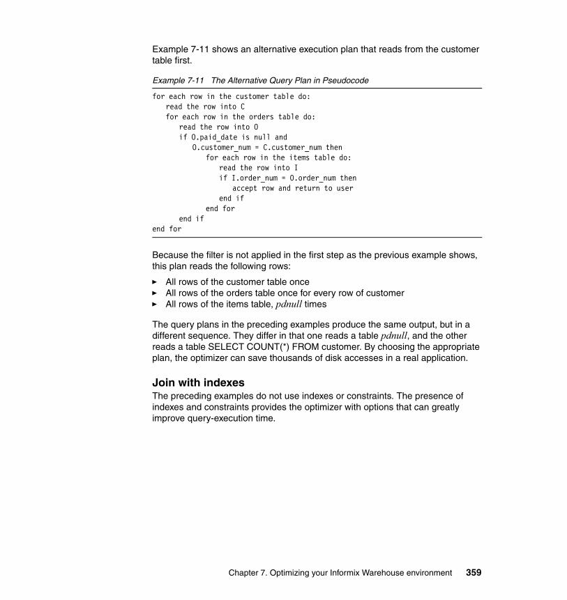
Example 7-11 shows an alternative execution plan that reads from the customer table first.
Example 7-11 The Alternative Query Plan in Pseudocode
for each row in the customer table do: read the row into C for each row in the orders table do:
read the row into O if O.paid_date is null and
O.customer_num = C.customer_num then for each row in the items table do:
read the row into I if I.order_num = O.order_num then
accept row and return to userend if
end for end if
end for
Because the filter is not applied in the first step as the previous example shows, this plan reads the following rows:
� All rows of the customer table once� All rows of the orders table once for every row of customer � All rows of the items table, pdnull times
The query plans in the preceding examples produce the same output, but in a different sequence. They differ in that one reads a table pdnull, and the other reads a table SELECT COUNT(*) FROM customer. By choosing the appropriate plan, the optimizer can save thousands of disk accesses in a real application.
Join with indexes The preceding examples do not use indexes or constraints. The presence of indexes and constraints provides the optimizer with options that can greatly improve query-execution time.
Chapter 7. Optimizing your Informix Warehouse environment 359
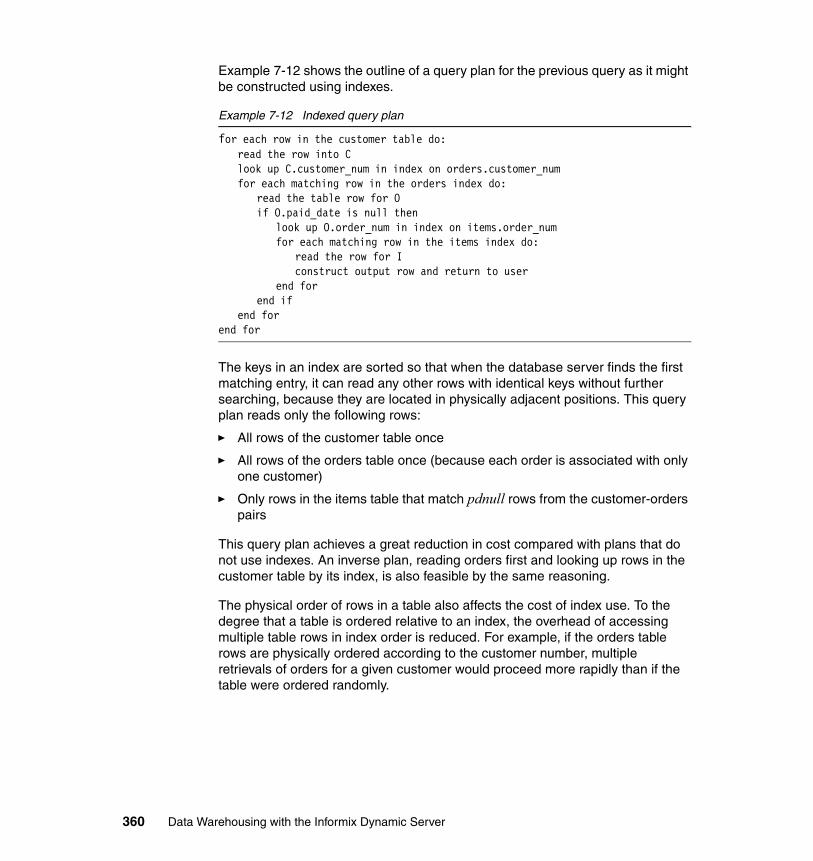
Example 7-12 shows the outline of a query plan for the previous query as it might be constructed using indexes.
Example 7-12 Indexed query plan
for each row in the customer table do: read the row into C look up C.customer_num in index on orders.customer_num for each matching row in the orders index do:
read the table row for Oif O.paid_date is null then
look up O.order_num in index on items.order_numfor each matching row in the items index do:
read the row for I construct output row and return to user
end forend if
end forend for
The keys in an index are sorted so that when the database server finds the first matching entry, it can read any other rows with identical keys without further searching, because they are located in physically adjacent positions. This query plan reads only the following rows:
� All rows of the customer table once
� All rows of the orders table once (because each order is associated with only one customer)
� Only rows in the items table that match pdnull rows from the customer-orders pairs
This query plan achieves a great reduction in cost compared with plans that do not use indexes. An inverse plan, reading orders first and looking up rows in the customer table by its index, is also feasible by the same reasoning.
The physical order of rows in a table also affects the cost of index use. To the degree that a table is ordered relative to an index, the overhead of accessing multiple table rows in index order is reduced. For example, if the orders table rows are physically ordered according to the customer number, multiple retrievals of orders for a given customer would proceed more rapidly than if the table were ordered randomly.
360 Data Warehousing with the Informix Dynamic Server
7.10.5 Other memory allocations
In this section, we discuss other types of memory allocations.
ORDER BY and GROUP BYTo evaluate ORDER BY and GROUP BY operations, IDS first determines the amount of memory available for each query. As with the hash join, MGM uses the same formula to determine the memory size. If the PDQPRIORITY is not set, the query is allocated the standard 128 KB.
DSS non-PDQ memoryBecause the server always allocates a maximum of 128 KB of memory per query, irrespective of the size of the hash table to be built, it uses disk to build the hash table. This is also true for those conditions in which queries with large intermediate results require sorting or have to store large temporary results from the sort. The use of the disk to store the hash table can dramatically slow down both hash join and sorting.
To avoid these potential bottlenecks IDS V10 has a configuration variable called DS_NONPDQ_QUERY_MEM. This variable uses a minimum value of 128 KB and maximum of 25% of DS_TOTAL_MEMORY as the allocation of memory. This allows administrators the capability to have a way of increasing the size of this memory allocation, avoiding the use of disk to store hash table results, thus enabling improved performance.
You can set the DS_NONPDQ_QUERY_MEM variable in following ways:
� As a configuration parameter in the ONCONFIG file. For example:
DS_NONPDQ_QUERY_MEM 512 # KB is the unit.
� Using the onmode command with the -wm or -wf options. Examples are:
– onmode -wm: Changes the DS_NONPDQ_QUERY_MEM value in the memory. The value set by –wm option is lost when the IDS server is shut down and restarted. For example:
onmode –wm DS_NONPDQ_QUERY_MEM=512
– onmode -wf: Changes the DS_NONPDQ_QUERY_MEM value in the memory, along with the value in the ONCONFIG file. The value set by the –wf option is not lost when the IDS server is shutdown and restarted. For example:
onmode –wf DS_NONPDQ_QUERY_MEM=512
� In the onmonitor utility: The Non PDQ Query Memory option can be used to set the value for the DS_NONPDQ_QUERY_MEM variable. To navigate to this menu, use the onmonitor → Parameters → PDQ options.
Chapter 7. Optimizing your Informix Warehouse environment 361
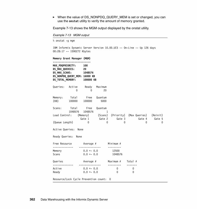
� When the value of DS_NONPDQ_QUERY_MEM is set or changed, you can use the onstat utility to verify the amount of memory granted.
Example 7-13 shows the MGM output displayed by the onstat utility.
Example 7-13 MGM output
% onstat -g mgm
IBM Informix Dynamic Server Version 10.00.UC5 -- On-Line -- Up 126 days 00:28:17 -- 1590272 Kbytes
Memory Grant Manager (MGM)--------------------------MAX_PDQPRIORITY: 100DS_MAX_QUERIES: 20DS_MAX_SCANS: 1048576DS_NONPDQ_QUERY_MEM: 16000 KBDS_TOTAL_MEMORY: 100000 KB
Queries: Active Ready Maximum 0 0 20
Memory: Total Free Quantum(KB) 100000 100000 5000
Scans: Total Free Quantum 1048576 1048576 1Load Control: (Memory) (Scans) (Priority) (Max Queries) (Reinit) Gate 1 Gate 2 Gate 3 Gate 4 Gate 5(Queue Length) 0 0 0 0 0
Active Queries: None
Ready Queries: None
Free Resource Average # Minimum #-------------- --------------- ---------Memory 0.0 +- 0.0 12500Scans 0.0 +- 0.0 1048576
Queries Average # Maximum # Total #-------------- --------------- --------- -------Active 0.0 +- 0.0 0 0Ready 0.0 +- 0.0 0 0
Resource/Lock Cycle Prevention count: 0
362 Data Warehousing with the Informix Dynamic Server
7.10.6 Using OPTCOMPIND
The OPTCOMPIND environment variable and the OPTCOMPIND configuration parameter indicate the preferred join plan, thus assisting the optimizer in selecting the appropriate join method for parallel database queries.
To influence the optimizer in its choice of a join plan, you can set the OPTCOMPIND configuration parameter. The value that you assign to this configuration parameter is referenced only when applications do not set the OPTCOMPIND environment variable.
You can set OPTCOMPIND to 0 (zero) if you want the database server to select a join plan exactly as it did in versions of the database server prior to V6.0. This option ensures compatibility with previous versions of the database server.
An application with an isolation mode of Repeatable Read can lock all records in a table when it performs a hash join. For this reason, a good practice is to set OPTCOMPIND to 1 (one).
If you want the optimizer to make the determination for you based on cost, regardless of the isolation level of applications, set OPTCOMPIND to 2.
Dynamic OPTCOMPINDThe OPTCOMPIND configuration parameter helps the optimizer choose an appropriate access method for the application. When the optimizer examines join plans, OPTCOMPIND indicates the preferred method for performing the join operation for an ordered pair of tables. Until now, the value of OPTCOMPIND can be set in the ONCONFIG file at the server level and in the environment. With this feature in IDS V10 you can change the value of OPTCOMPIND within a session and control the type of execution plan generated depending on the type of query being executed. The OPTCOMPIND environment variable/onconfig parameter can be set to values 0, 1, 2, which have the following meanings:
� 0: A nested-loop join is preferred, where possible, over a sort-merge join or a hash join.
� 1: When the transaction isolation mode is not Repeatable Read, the optimizer behaves as in setting 2; otherwise, the optimizer behaves as in setting 0.
� 2: Nested-loop joins are not necessarily preferred. The optimizer bases its decision purely on costs, regardless of transaction isolation mode.
If you set the value of OPTCOMPIND by using the new command, then that value takes precedence over both the environment setting (if specified) and the ONCONFIG setting. The value of OPTCOMPIND does not change even if the application switches to another database.
Chapter 7. Optimizing your Informix Warehouse environment 363
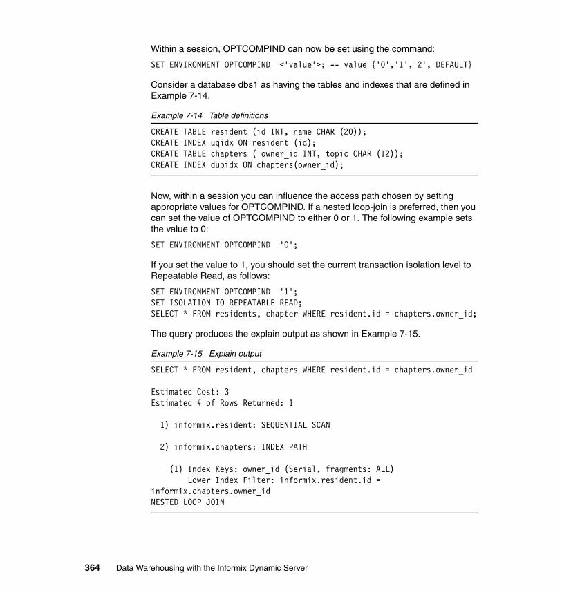
Within a session, OPTCOMPIND can now be set using the command:
SET ENVIRONMENT OPTCOMPIND <'value'>; -- value {'0','1','2', DEFAULT}
Consider a database dbs1 as having the tables and indexes that are defined in Example 7-14.
Example 7-14 Table definitions
CREATE TABLE resident (id INT, name CHAR (20));CREATE INDEX uqidx ON resident (id);CREATE TABLE chapters ( owner_id INT, topic CHAR (12));CREATE INDEX dupidx ON chapters(owner_id);
Now, within a session you can influence the access path chosen by setting appropriate values for OPTCOMPIND. If a nested loop-join is preferred, then you can set the value of OPTCOMPIND to either 0 or 1. The following example sets the value to 0:
SET ENVIRONMENT OPTCOMPIND '0';
If you set the value to 1, you should set the current transaction isolation level to Repeatable Read, as follows:
SET ENVIRONMENT OPTCOMPIND '1';SET ISOLATION TO REPEATABLE READ;SELECT * FROM residents, chapter WHERE resident.id = chapters.owner_id;
The query produces the explain output as shown in Example 7-15.
Example 7-15 Explain output
SELECT * FROM resident, chapters WHERE resident.id = chapters.owner_id
Estimated Cost: 3Estimated # of Rows Returned: 1
1) informix.resident: SEQUENTIAL SCAN
2) informix.chapters: INDEX PATH
(1) Index Keys: owner_id (Serial, fragments: ALL) Lower Index Filter: informix.resident.id = informix.chapters.owner_idNESTED LOOP JOIN
364 Data Warehousing with the Informix Dynamic Server
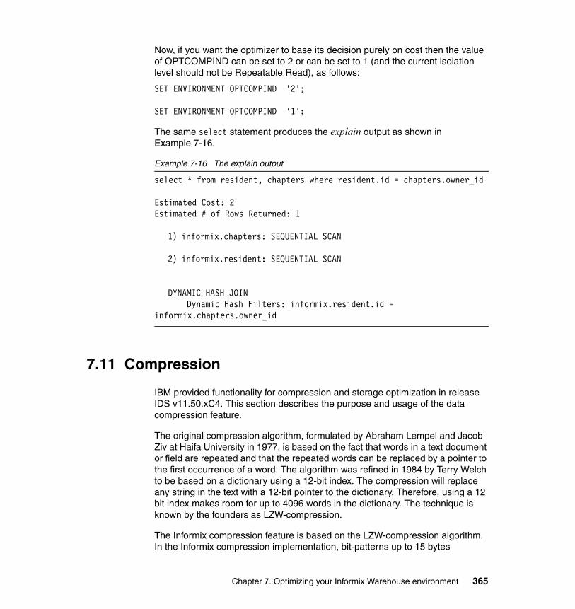
Now, if you want the optimizer to base its decision purely on cost then the value of OPTCOMPIND can be set to 2 or can be set to 1 (and the current isolation level should not be Repeatable Read), as follows:
SET ENVIRONMENT OPTCOMPIND '2';
SET ENVIRONMENT OPTCOMPIND '1';
The same select statement produces the explain output as shown in Example 7-16.
Example 7-16 The explain output
select * from resident, chapters where resident.id = chapters.owner_id
Estimated Cost: 2Estimated # of Rows Returned: 1
1) informix.chapters: SEQUENTIAL SCAN
2) informix.resident: SEQUENTIAL SCAN
DYNAMIC HASH JOIN Dynamic Hash Filters: informix.resident.id =
informix.chapters.owner_id
7.11 Compression
IBM provided functionality for compression and storage optimization in release IDS v11.50.xC4. This section describes the purpose and usage of the data compression feature.
The original compression algorithm, formulated by Abraham Lempel and Jacob Ziv at Haifa University in 1977, is based on the fact that words in a text document or field are repeated and that the repeated words can be replaced by a pointer to the first occurrence of a word. The algorithm was refined in 1984 by Terry Welch to be based on a dictionary using a 12-bit index. The compression will replace any string in the text with a 12-bit pointer to the dictionary. Therefore, using a 12 bit index makes room for up to 4096 words in the dictionary. The technique is known by the founders as LZW-compression.
The Informix compression feature is based on the LZW-compression algorithm. In the Informix compression implementation, bit-patterns up to 15 bytes
Chapter 7. Optimizing your Informix Warehouse environment 365
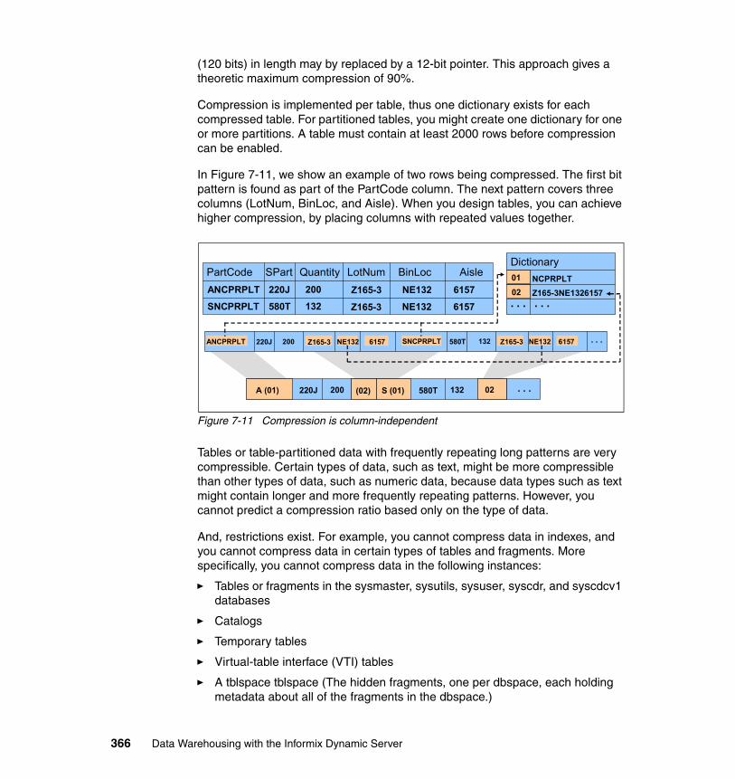
(120 bits) in length may by replaced by a 12-bit pointer. This approach gives a theoretic maximum compression of 90%.
Compression is implemented per table, thus one dictionary exists for each compressed table. For partitioned tables, you might create one dictionary for one or more partitions. A table must contain at least 2000 rows before compression can be enabled.
In Figure 7-11, we show an example of two rows being compressed. The first bit pattern is found as part of the PartCode column. The next pattern covers three columns (LotNum, BinLoc, and Aisle). When you design tables, you can achieve higher compression, by placing columns with repeated values together.
Figure 7-11 Compression is column-independent
Tables or table-partitioned data with frequently repeating long patterns are very compressible. Certain types of data, such as text, might be more compressible than other types of data, such as numeric data, because data types such as text might contain longer and more frequently repeating patterns. However, you cannot predict a compression ratio based only on the type of data.
And, restrictions exist. For example, you cannot compress data in indexes, and you cannot compress data in certain types of tables and fragments. More specifically, you cannot compress data in the following instances:
� Tables or fragments in the sysmaster, sysutils, sysuser, syscdr, and syscdcv1 databases
� Catalogs
� Temporary tables
� Virtual-table interface (VTI) tables
� A tblspace tblspace (The hidden fragments, one per dbspace, each holding metadata about all of the fragments in the dbspace.)
Dictionary
. . . . . .Z165-3NE1326157NCPRPLT
PartCode SPart Quantity LotNum BinLoc AisleANCPRPLT
SNCPRPLT
220J
580T
200
132Z165-3
Z165-3
NE132
NE132
6157
6157
220J 200 580T 132 . . .
220J 200 580T 132 . . .
01
02
A (01) (02) S (01) 02
ANCPRPLT Z165-3 NE132 6157 SNCPRPLT Z165-3 NE132 6157
366 Data Warehousing with the Informix Dynamic Server
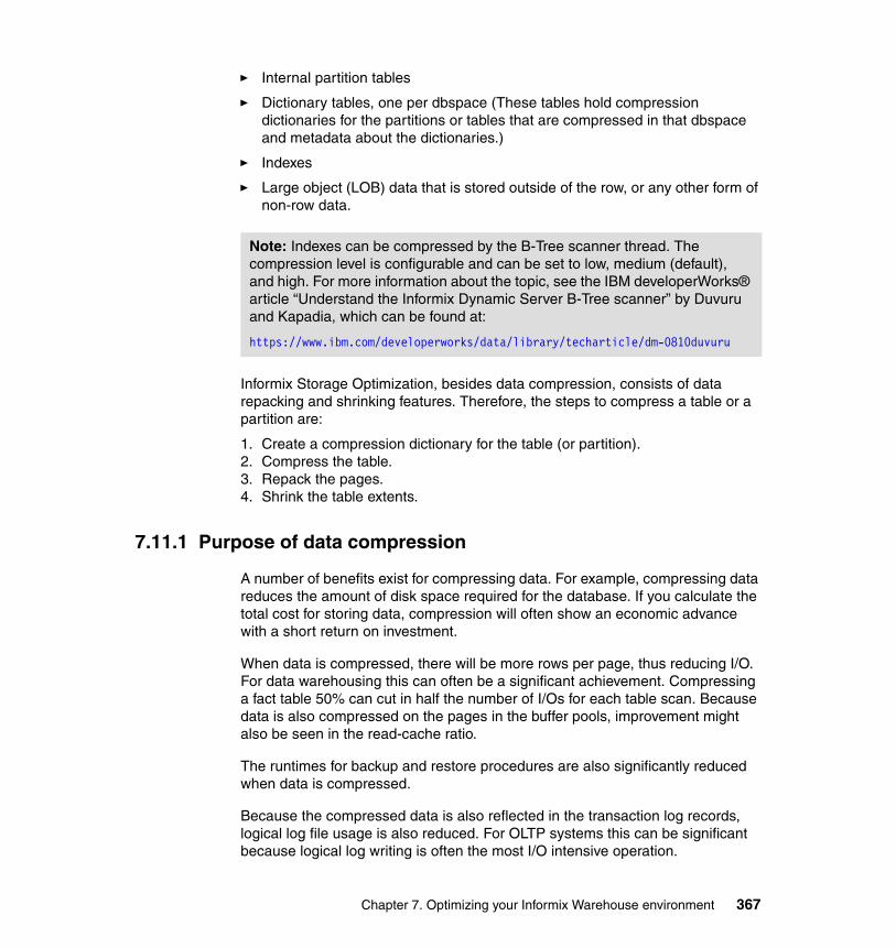
� Internal partition tables
� Dictionary tables, one per dbspace (These tables hold compression dictionaries for the partitions or tables that are compressed in that dbspace and metadata about the dictionaries.)
� Indexes
� Large object (LOB) data that is stored outside of the row, or any other form of non-row data.
Informix Storage Optimization, besides data compression, consists of data repacking and shrinking features. Therefore, the steps to compress a table or a partition are:
1. Create a compression dictionary for the table (or partition).2. Compress the table.3. Repack the pages.4. Shrink the table extents.
7.11.1 Purpose of data compression
A number of benefits exist for compressing data. For example, compressing data reduces the amount of disk space required for the database. If you calculate the total cost for storing data, compression will often show an economic advance with a short return on investment.
When data is compressed, there will be more rows per page, thus reducing I/O. For data warehousing this can often be a significant achievement. Compressing a fact table 50% can cut in half the number of I/Os for each table scan. Because data is also compressed on the pages in the buffer pools, improvement might also be seen in the read-cache ratio.
The runtimes for backup and restore procedures are also significantly reduced when data is compressed.
Because the compressed data is also reflected in the transaction log records, logical log file usage is also reduced. For OLTP systems this can be significant because logical log writing is often the most I/O intensive operation.
Note: Indexes can be compressed by the B-Tree scanner thread. The compression level is configurable and can be set to low, medium (default), and high. For more information about the topic, see the IBM developerWorks® article “Understand the Informix Dynamic Server B-Tree scanner” by Duvuru and Kapadia, which can be found at:
https://www.ibm.com/developerworks/data/library/techarticle/dm-0810duvuru
Chapter 7. Optimizing your Informix Warehouse environment 367
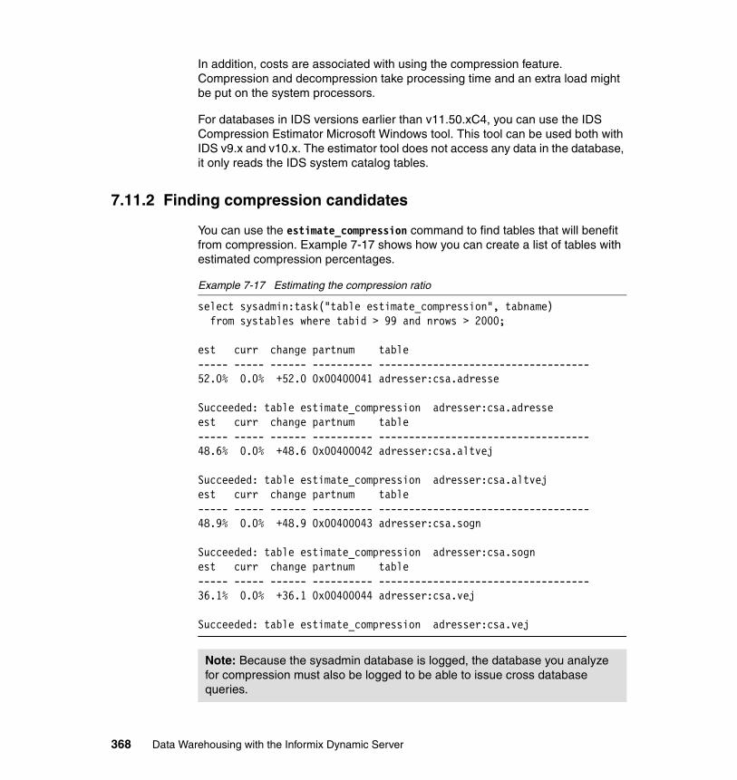
In addition, costs are associated with using the compression feature. Compression and decompression take processing time and an extra load might be put on the system processors.
For databases in IDS versions earlier than v11.50.xC4, you can use the IDS Compression Estimator Microsoft Windows tool. This tool can be used both with IDS v9.x and v10.x. The estimator tool does not access any data in the database, it only reads the IDS system catalog tables.
7.11.2 Finding compression candidates
You can use the estimate_compression command to find tables that will benefit from compression. Example 7-17 shows how you can create a list of tables with estimated compression percentages.
Example 7-17 Estimating the compression ratio
select sysadmin:task("table estimate_compression", tabname) from systables where tabid > 99 and nrows > 2000;
est curr change partnum table----- ----- ------ ---------- -----------------------------------52.0% 0.0% +52.0 0x00400041 adresser:csa.adresse
Succeeded: table estimate_compression adresser:csa.adresseest curr change partnum table----- ----- ------ ---------- -----------------------------------48.6% 0.0% +48.6 0x00400042 adresser:csa.altvej
Succeeded: table estimate_compression adresser:csa.altvejest curr change partnum table----- ----- ------ ---------- -----------------------------------48.9% 0.0% +48.9 0x00400043 adresser:csa.sogn
Succeeded: table estimate_compression adresser:csa.sognest curr change partnum table----- ----- ------ ---------- -----------------------------------36.1% 0.0% +36.1 0x00400044 adresser:csa.vej
Succeeded: table estimate_compression adresser:csa.vej
Note: Because the sysadmin database is logged, the database you analyze for compression must also be logged to be able to issue cross database queries.
368 Data Warehousing with the Informix Dynamic Server
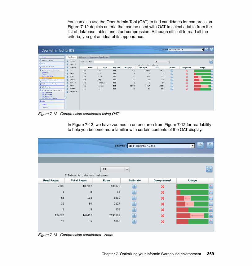
You can also use the OpenAdmin Tool (OAT) to find candidates for compression. Figure 7-12 depicts criteria that can be used with OAT to select a table from the list of database tables and start compression. Although difficult to read all the criteria, you get an idea of its appearance.
Figure 7-12 Compression candidates using OAT
In Figure 7-13, we have zoomed in on one area from Figure 7-12 for readability to help you become more familiar with certain contents of the OAT display.
Figure 7-13 Compression candidates - zoom
Chapter 7. Optimizing your Informix Warehouse environment 369

7.11.3 Enabling compression
The command to enable compression, shown in Example 7-18, should only be run once per IDS instance.
Example 7-18 Enable compression
database sysadmin;execute function task(“enable compression”);
7.11.4 Creating the dictionary
You can create a compression dictionary, based on existing rows, for IDS to use when compressing data in tables or table fragments. After you create the dictionary, IDS uses the dictionary to compress newly inserted or updated rows.
Example 7-19 shows how to use the task command, when connected to the sysadmin database.
Example 7-19 Create compression dictionary for one table
database sysadmin;execute function task(“table create_dictionary”, “mytable”, ”mydatabase”,”myschema”)
You can also use the task routine in a select statement, as shown in Example 7-20. It shows how to create compression dictionaries for all tables with more than 2000 rows.
Example 7-20 Create dictionary for all tables having more than 2000 rows
database mydb;select sysadmin:task("table create_dictionary", tabname)
from systables where tabid > 99 and nrows > 2000;
The rows already in a table when the dictionary is created, remain uncompressed until the task command (table compress) is issued.
370 Data Warehousing with the Informix Dynamic Server
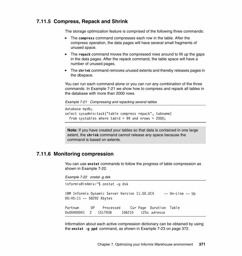
7.11.5 Compress, Repack and Shrink
The storage optimization feature is comprised of the following three commands:
� The compress command compresses each row in the table. After the compress operation, the data pages will have several small fragments of unused space.
� The repack command moves the compressed rows around to fill up the gaps in the data pages. After the repack command, the table space will have a number of unused pages.
� The shrink command removes unused extents and thereby releases pages in the dbspace.
You can run each command alone or you can run any combination of the three commands. In Example 7-21 we show how to compress and repack all tables in the database with more than 2000 rows.
Example 7-21 Compressing and repacking several tables
database mydb;select sysadmin:task("table compress repack", tabname)
from systables where tabid > 99 and nrows > 2000;
7.11.6 Monitoring compression
You can use onstat commands to follow the progress of table compression as shown in Example 7-22.
Example 7-22 onstat -g dsk
informix@in4mix:~$ onstat -g dsk
IBM Informix Dynamic Server Version 11.50.UC4 -- On-Line -- Up 00:45:11 -- 58292 Kbytes
Partnum OP Processed Cur Page Duration Table0x00400041 2 1517938 106210 125s adresse
Information about each active compression dictionary can be obtained by using the onstat -g ppd command, as shown in Example 7-23 on page 372.
Note: If you have created your tables so that data is contained in one large extent, the shrink command cannot release any space because the command is based on extents.
Chapter 7. Optimizing your Informix Warehouse environment 371
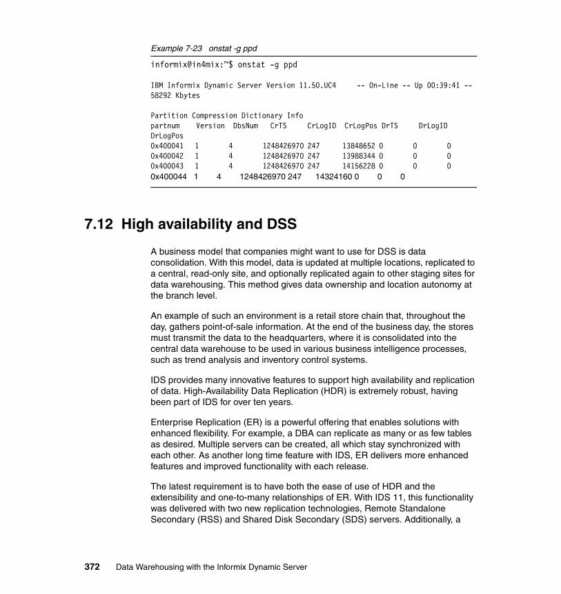
Example 7-23 onstat -g ppd
informix@in4mix:~$ onstat -g ppd
IBM Informix Dynamic Server Version 11.50.UC4 -- On-Line -- Up 00:39:41 -- 58292 Kbytes
Partition Compression Dictionary Infopartnum Version DbsNum CrTS CrLogID CrLogPos DrTS DrLogID DrLogPos0x400041 1 4 1248426970 247 13848652 0 0 0 0x400042 1 4 1248426970 247 13988344 0 0 0 0x400043 1 4 1248426970 247 14156228 0 0 0 0x400044 1 4 1248426970 247 14324160 0 0 0
7.12 High availability and DSS
A business model that companies might want to use for DSS is data consolidation. With this model, data is updated at multiple locations, replicated to a central, read-only site, and optionally replicated again to other staging sites for data warehousing. This method gives data ownership and location autonomy at the branch level.
An example of such an environment is a retail store chain that, throughout the day, gathers point-of-sale information. At the end of the business day, the stores must transmit the data to the headquarters, where it is consolidated into the central data warehouse to be used in various business intelligence processes, such as trend analysis and inventory control systems.
IDS provides many innovative features to support high availability and replication of data. High-Availability Data Replication (HDR) is extremely robust, having been part of IDS for over ten years.
Enterprise Replication (ER) is a powerful offering that enables solutions with enhanced flexibility. For example, a DBA can replicate as many or as few tables as desired. Multiple servers can be created, all which stay synchronized with each other. As another long time feature with IDS, ER delivers more enhanced features and improved functionality with each release.
The latest requirement is to have both the ease of use of HDR and the extensibility and one-to-many relationships of ER. With IDS 11, this functionality was delivered with two new replication technologies, Remote Standalone Secondary (RSS) and Shared Disk Secondary (SDS) servers. Additionally, a
372 Data Warehousing with the Informix Dynamic Server
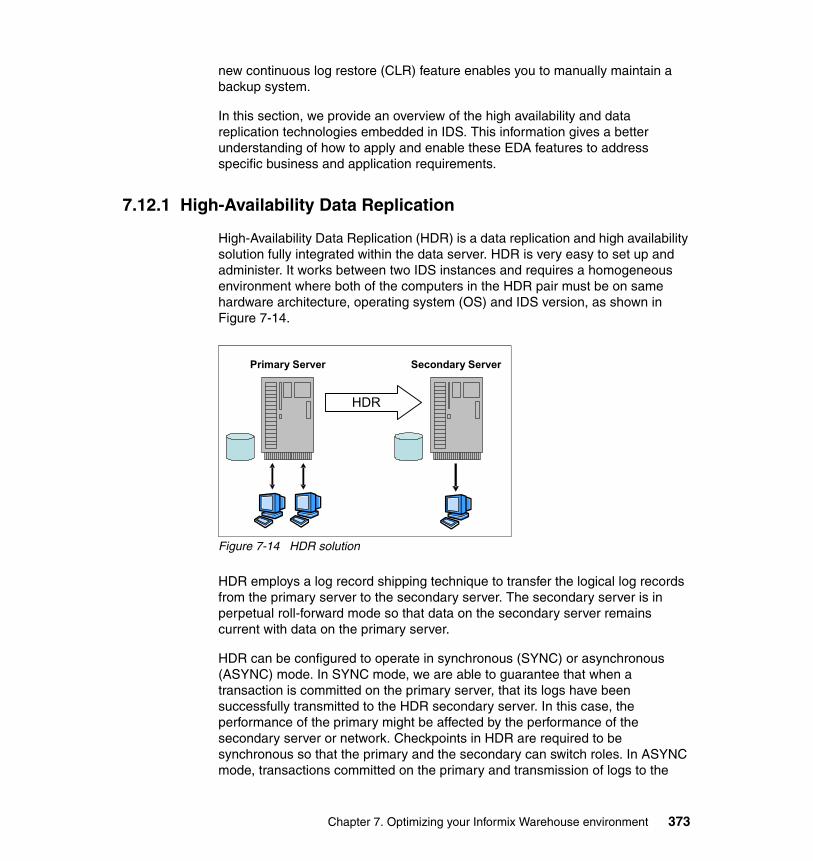
new continuous log restore (CLR) feature enables you to manually maintain a backup system.
In this section, we provide an overview of the high availability and data replication technologies embedded in IDS. This information gives a better understanding of how to apply and enable these EDA features to address specific business and application requirements.
7.12.1 High-Availability Data Replication
High-Availability Data Replication (HDR) is a data replication and high availability solution fully integrated within the data server. HDR is very easy to set up and administer. It works between two IDS instances and requires a homogeneous environment where both of the computers in the HDR pair must be on same hardware architecture, operating system (OS) and IDS version, as shown in Figure 7-14.
Figure 7-14 HDR solution
HDR employs a log record shipping technique to transfer the logical log records from the primary server to the secondary server. The secondary server is in perpetual roll-forward mode so that data on the secondary server remains current with data on the primary server.
HDR can be configured to operate in synchronous (SYNC) or asynchronous (ASYNC) mode. In SYNC mode, we are able to guarantee that when a transaction is committed on the primary server, that its logs have been successfully transmitted to the HDR secondary server. In this case, the performance of the primary might be affected by the performance of the secondary server or network. Checkpoints in HDR are required to be synchronous so that the primary and the secondary can switch roles. In ASYNC mode, transactions committed on the primary and transmission of logs to the
Primary Server Secondary Server
HDR
Chapter 7. Optimizing your Informix Warehouse environment 373
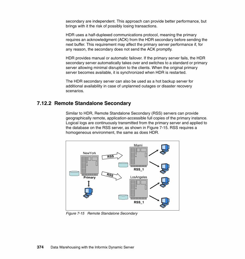
secondary are independent. This approach can provide better performance, but brings with it the risk of possibly losing transactions.
HDR uses a half-duplexed communications protocol, meaning the primary requires an acknowledgment (ACK) from the HDR secondary before sending the next buffer. This requirement may affect the primary server performance if, for any reason, the secondary does not send the ACK promptly.
HDR provides manual or automatic failover. If the primary server fails, the HDR secondary server automatically takes over and switches to a standard or primary server allowing minimal disruption to the clients. When the original primary server becomes available, it is synchronized when HDR is restarted.
The HDR secondary server can also be used as a hot backup server for additional availability in case of unplanned outages or disaster recovery scenarios.
7.12.2 Remote Standalone Secondary
Similar to HDR, Remote Standalone Secondary (RSS) servers can provide geographically remote, application-accessible full copies of the primary instance. Logical logs are continuously transmitted from the primary server and applied to the database on the RSS server, as shown in Figure 7-15. RSS requires a homogeneous environment, the same as does HDR.
Figure 7-15 Remote Standalone Secondary
NewYork
LosAngeles
Miami
RSS_1
RSS_1
Primary
RSS
RSS
374 Data Warehousing with the Informix Dynamic Server
RSS is different from HDR. As examples, RSS only uses asynchronous transmissions of logs and checkpoints, RSS servers cannot be promoted directly to a Primary, and one or more RSS servers can be created.
Instead of using the half-duplexed communications protocol of HDR, RSS servers use a fully duplexed protocol provided by the server multiplexer (SMX) communications interface that supports encrypted multiplexed network connections between servers in high availability environments. SMX provides a reliable, secure, high-performance communication mechanism between database server instances.
Using full duplexed communication results in RSS servers having very little impact on the primary server performance.
Multiple RSS servers in geographically diverse locations can be used to provide faster query response than if all the users had to access the primary server. The application traffic that only reads the data can be sent to local RSS servers. For example, RSS servers can feed data to Web applications that do not require up-to-the-minute data. If the applications have to update the data, they connect to the primary, otherwise they read the data from the local RSS server. This configuration reduces network traffic and the time required by the application to access the data.
Remote application servers can access local database servers to minimize latency and improve performance. RSS can also be used as multiple remote backup servers for additional availability in the event of unplanned outages or any catastrophe at the location of the primary or other HA secondary servers.
7.12.3 Shared Disk Secondary
Unlike HDR and RSS, Shared Disk Secondary (SDS) servers access the same physical disk as the primary server. They provide increased availability and scalability without having to maintain multiple copies of the database, which results in lowering data storage costs. This is depicted in Figure 7-16 on page 376.
Chapter 7. Optimizing your Informix Warehouse environment 375
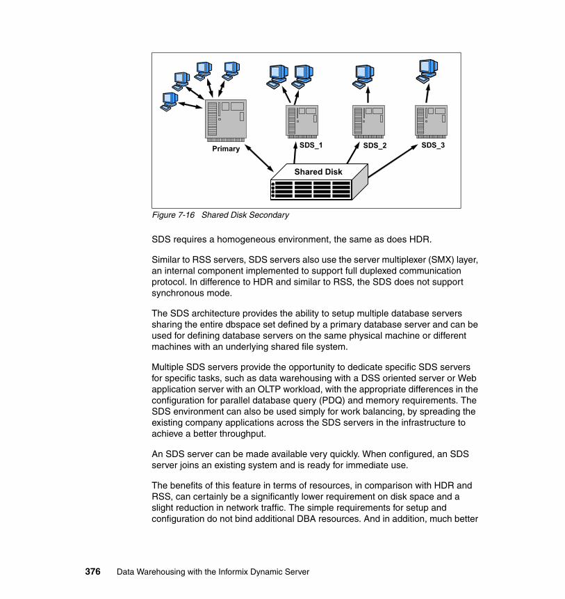
Figure 7-16 Shared Disk Secondary
SDS requires a homogeneous environment, the same as does HDR.
Similar to RSS servers, SDS servers also use the server multiplexer (SMX) layer, an internal component implemented to support full duplexed communication protocol. In difference to HDR and similar to RSS, the SDS does not support synchronous mode.
The SDS architecture provides the ability to setup multiple database servers sharing the entire dbspace set defined by a primary database server and can be used for defining database servers on the same physical machine or different machines with an underlying shared file system.
Multiple SDS servers provide the opportunity to dedicate specific SDS servers for specific tasks, such as data warehousing with a DSS oriented server or Web application server with an OLTP workload, with the appropriate differences in the configuration for parallel database query (PDQ) and memory requirements. The SDS environment can also be used simply for work balancing, by spreading the existing company applications across the SDS servers in the infrastructure to achieve a better throughput.
An SDS server can be made available very quickly. When configured, an SDS server joins an existing system and is ready for immediate use.
The benefits of this feature in terms of resources, in comparison with HDR and RSS, can certainly be a significantly lower requirement on disk space and a slight reduction in network traffic. The simple requirements for setup and configuration do not bind additional DBA resources. And in addition, much better
Primary SDS_1 SDS_2 SDS_3
Shared Disk
376 Data Warehousing with the Informix Dynamic Server
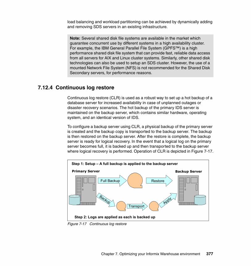
load balancing and workload partitioning can be achieved by dynamically adding and removing SDS servers in an existing infrastructure.
7.12.4 Continuous log restore
Continuous log restore (CLR) is used as a robust way to set up a hot backup of a database server for increased availability in case of unplanned outages or disaster recovery scenarios. The hot backup of the primary IDS server is maintained on the backup server, which contains similar hardware, operating system, and an identical version of IDS.
To configure a backup server using CLR, a physical backup of the primary server is created and the backup copy is transported to the backup server. The backup is then restored on the backup server. After the restore is complete, the backup server is ready for logical recovery. In the event that a logical log on the primary server becomes full, it is backed up and then transported to the backup server where logical recovery is performed. Operation of CLR is depicted in Figure 7-17.
Figure 7-17 Continuous log restore
Note: Several shared disk file systems are available in the market which guarantee concurrent use by different systems in a high availability cluster. For example, the IBM General Parallel File System (GPFS™) is a high performance shared disk file system that can provide fast, reliable data access from all servers for AIX and Linux cluster systems. Similarly, other shared disk technologies can also be used to setup an SDS cluster. However, the use of a mounted Network File System (NFS) is not recommended for the Shared Disk Secondary servers, for performance reasons.
Backup Server
Full Backup Restore
Transport
Step 1: Setup – A full backup is applied to the backup server
Step 2: Logs are applied as each is backed up
Primary Server
Backup Apply
Chapter 7. Optimizing your Informix Warehouse environment 377
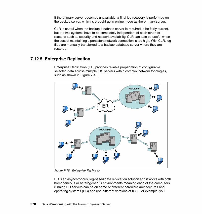
If the primary server becomes unavailable, a final log recovery is performed on the backup server, which is brought up in online mode as the primary server.
CLR is useful when the backup database server is required to be fairly current, but the two systems have to be completely independent of each other for reasons such as security and network availability. CLR can also be useful when the cost of maintaining a persistent network connection is too high. With CLR, log files are manually transferred to a backup database server where they are restored.
7.12.5 Enterprise Replication
Enterprise Replication (ER) provides reliable propagation of configurable selected data across multiple IDS servers within complex network topologies, such as shown in Figure 7-18.
Figure 7-18 Enterprise Replication
ER is an asynchronous, log-based data replication solution and it works with both homogeneous or heterogeneous environments meaning each of the computers running ER servers can be on same or different hardware architectures and operating systems (OS) and use different versions of IDS. For example, you
HA Cluster
HA Cluster
ER
378 Data Warehousing with the Informix Dynamic Server
could replicate the data from IDS 11 (32-bit) on Linux to IDS 10 on Solaris (64 bit).
ER can be configured to replicate data immediately, at certain intervals or point in time, and it can be used to replicate individual tables or subsets of tables rather than the entire database or instance. In addition, each ER replication definition can target different specific instances, rather than all instances in the ER system.
The flexible architecture of ER allows organizations to customize their replication environment, based on business requirements and models such as primary-target replication, where the flow of information is in one direction, usually for the purpose of data dissemination or consolidation, and update-anywhere replication, where changes made on any location are replicated to all other participating database servers, often used for workload distribution.
ER provides mechanisms to easily set up and deploy replication for systems with large numbers of tables and servers, and it also provides support for online schema evolution that allows modifications in replication definitions or replicated tables for an active ER system without interrupting the data replication.
ER offers an effective mechanism for replication within network topologies with fully connected database servers and not directly connected database servers in a hierarchical tree of servers. Depending on the volume of data, the distance between the servers and the network facilities that are available, ER can be configured to use a hierarchical tree or forest of trees topology, in a way that the network traffic and database server processing could be highly reduced. For example, if replication for a large number of servers across continents is required, then a fully connected topology may not be feasible for all the servers because of insufficient network bandwidth for the data volume, so in this case a ER system could benefit from an hierarchical topology.
ER is not an instance-wide replication, so the disk space requirement for each of the IDS instances will depend on that database server usage and other business needs. All the features of ER can result in a wide spectrum of benefits, including reliable and fast replication of data across a distributed or global organization, improved data availability, capacity relief and increased performance.
7.13 Raw tables
Databases for decision-support applications are often created by periodically loading tables that have been unloaded from active OLTP databases. As
Chapter 7. Optimizing your Informix Warehouse environment 379
previously discussed, you can use one or more of the following methods to load large tables quickly:
� High-Performance Loader (HPL)
You can use HPL in express mode to load tables quickly.
� Nonlogging tables:
The database server provides support to do the following tasks:
– Create nonlogging or logging tables in a logging database. – Alter a table from nonlogging to logging and vice versa.
The two table types are STANDARD (logging tables) and RAW (nonlogging tables). You may use any loading utility, such as dbimport or HPL, to load RAW tables.
7.13.1 RAW versus TEMP
RAW tables are nonlogging permanent tables that are similar to tables in a nonlogging database. RAW tables use light appends, which add rows quickly to the end of each table fragments. Updates, inserts, and deletions in a RAW table are supported, but not logged. RAW tables do not support primary constraints, unique constraints, and rollback. However, these tables can be indexed and updated.
You can restore a RAW table from the last physical backup if it has not been updated since that backup. Fast recovery rolls back incomplete transactions on STANDARD tables but not on RAW tables. A RAW table has the same attributes whether stored in a logging or nonlogging database.
RAW tables are intended for the initial loading and validation of data. To load RAW tables, you can use any loading utility, including dbexport or the High-Performance Loader (HPL) in express mode. If an error or failure occurs while loading a RAW table, the resulting data is whatever was on the disk at the time of the failure.
TEMP tables are temporary, logged tables that are dropped when the user session closes, the database server shuts down, or on reboot after a failure. Temp tables support indexes, constraints, and rollback. You cannot recover, back up, or restore TEMP tables. TEMP tables support bulk operations such as light appends, which add rows quickly to the end of each table fragment
Table 7-11 on page 381 lists the properties of the types of tables available with IDS.
380 Data Warehousing with the Informix Dynamic Server
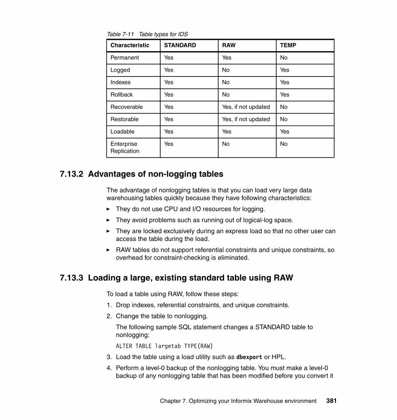
Table 7-11 Table types for IDS
7.13.2 Advantages of non-logging tables
The advantage of nonlogging tables is that you can load very large data warehousing tables quickly because they have following characteristics:
� They do not use CPU and I/O resources for logging.
� They avoid problems such as running out of logical-log space.
� They are locked exclusively during an express load so that no other user can access the table during the load.
� RAW tables do not support referential constraints and unique constraints, so overhead for constraint-checking is eliminated.
7.13.3 Loading a large, existing standard table using RAW
To load a table using RAW, follow these steps:
1. Drop indexes, referential constraints, and unique constraints.
2. Change the table to nonlogging.
The following sample SQL statement changes a STANDARD table to nonlogging:
ALTER TABLE largetab TYPE(RAW)
3. Load the table using a load utility such as dbexport or HPL.
4. Perform a level-0 backup of the nonlogging table. You must make a level-0 backup of any nonlogging table that has been modified before you convert it
Characteristic STANDARD RAW TEMP
Permanent Yes Yes No
Logged Yes No Yes
Indexes Yes No Yes
Rollback Yes No Yes
Recoverable Yes Yes, if not updated No
Restorable Yes Yes, if not updated No
Loadable Yes Yes Yes
Enterprise Replication
Yes No No
Chapter 7. Optimizing your Informix Warehouse environment 381
to STANDARD type. The level-0 backup provides a starting point from which to restore the data.
5. Change the nonlogging table to a logging table before you use it in a transaction. The following sample SQL statement changes a RAW table to a STANDARD table:
ALTER TABLE largetab TYPE(STANDARD)
6. Re-create indexes, referential constraints, and unique constraints.
7.13.4 Loading a new, large table using RAW
The following steps are for loading a new, large table using RAW:
1. Create a nonlogging table in a logged database. The following sample SQL statements creates a nonlogging table:
CREATE DATABASE history WITH LOG; CONNECT TO DATABASE history; CREATE RAW TABLE history (... );
2. Load the table using a load utility such as dbexport, dbload, or the HPL.
3. Perform a level-0 backup of the nonlogging table. You must make a level-0 backup of any nonlogging table that has been modified before you convert it to STANDARD type. The level-0 backup provides a starting point from which to restore the data.
4. Change the nonlogging table to a logging table before you use it in a transaction. The following sample SQL statement changes a raw table to a standard table:
ALTER TABLE largetab TYPE(STANDARD);
5. Create indexes on columns most often used in query filters.
6. Create any referential constraints and unique constraints, if necessary.
Attention: A best practice is not to use nonlogging tables within a transaction where multiple users can modify the data. If you have to use a nonlogging table within a transaction, either set Repeatable Read isolation level or lock the table in exclusive mode to prevent concurrency problems.
Attention: A best practice is not to use nonlogging tables within a transaction where multiple users can modify the data. If you have to use a nonlogging table within a transaction, either set Repeatable Read isolation level or lock the table in exclusive mode to prevent concurrency problems.
382 Data Warehousing with the Informix Dynamic Server
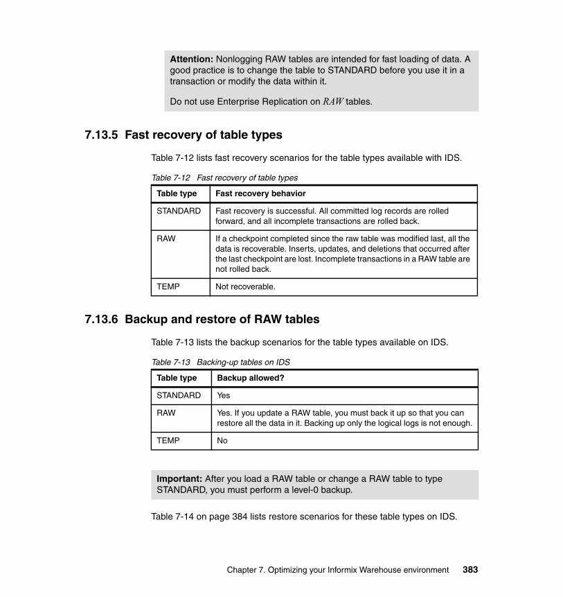
7.13.5 Fast recovery of table types
Table 7-12 lists fast recovery scenarios for the table types available with IDS.
Table 7-12 Fast recovery of table types
7.13.6 Backup and restore of RAW tables
Table 7-13 lists the backup scenarios for the table types available on IDS.
Table 7-13 Backing-up tables on IDS
Table 7-14 on page 384 lists restore scenarios for these table types on IDS.
Attention: Nonlogging RAW tables are intended for fast loading of data. A good practice is to change the table to STANDARD before you use it in a transaction or modify the data within it.
Do not use Enterprise Replication on RAW tables.
Table type Fast recovery behavior
STANDARD Fast recovery is successful. All committed log records are rolled forward, and all incomplete transactions are rolled back.
RAW If a checkpoint completed since the raw table was modified last, all the data is recoverable. Inserts, updates, and deletions that occurred after the last checkpoint are lost. Incomplete transactions in a RAW table are not rolled back.
TEMP Not recoverable.
Table type Backup allowed?
STANDARD Yes
RAW Yes. If you update a RAW table, you must back it up so that you can restore all the data in it. Backing up only the logical logs is not enough.
TEMP No
Important: After you load a RAW table or change a RAW table to type STANDARD, you must perform a level-0 backup.
Chapter 7. Optimizing your Informix Warehouse environment 383
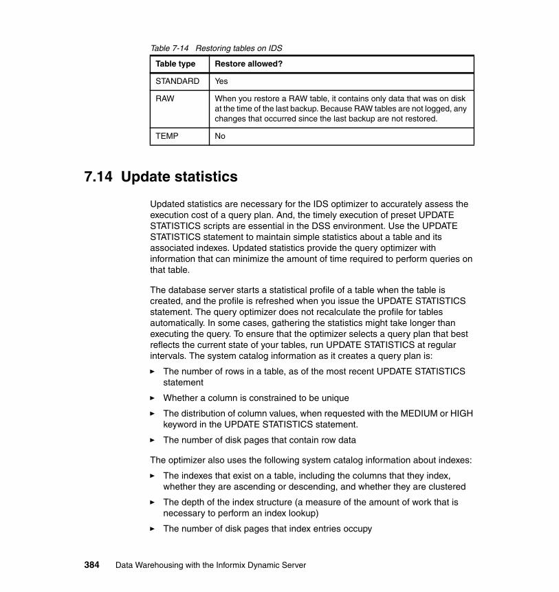
Table 7-14 Restoring tables on IDS
7.14 Update statistics
Updated statistics are necessary for the IDS optimizer to accurately assess the execution cost of a query plan. And, the timely execution of preset UPDATE STATISTICS scripts are essential in the DSS environment. Use the UPDATE STATISTICS statement to maintain simple statistics about a table and its associated indexes. Updated statistics provide the query optimizer with information that can minimize the amount of time required to perform queries on that table.
The database server starts a statistical profile of a table when the table is created, and the profile is refreshed when you issue the UPDATE STATISTICS statement. The query optimizer does not recalculate the profile for tables automatically. In some cases, gathering the statistics might take longer than executing the query. To ensure that the optimizer selects a query plan that best reflects the current state of your tables, run UPDATE STATISTICS at regular intervals. The system catalog information as it creates a query plan is:
� The number of rows in a table, as of the most recent UPDATE STATISTICS statement
� Whether a column is constrained to be unique
� The distribution of column values, when requested with the MEDIUM or HIGH keyword in the UPDATE STATISTICS statement.
� The number of disk pages that contain row data
The optimizer also uses the following system catalog information about indexes:
� The indexes that exist on a table, including the columns that they index, whether they are ascending or descending, and whether they are clustered
� The depth of the index structure (a measure of the amount of work that is necessary to perform an index lookup)
� The number of disk pages that index entries occupy
Table type Restore allowed?
STANDARD Yes
RAW When you restore a RAW table, it contains only data that was on disk at the time of the last backup. Because RAW tables are not logged, any changes that occurred since the last backup are not restored.
TEMP No
384 Data Warehousing with the Informix Dynamic Server
� The number of unique entries in an index, which can be used to estimate the number of rows that an equality filter returns
� Second-largest and second-smallest key values in an indexed column
Only the second-largest and second-smallest key values are noted, because the extreme values might have a special meaning that is not related to the remainder of the data in the column. The database server assumes that key values are distributed evenly between the second largest and second smallest. Only the initial 4 bytes of these keys are stored. If you create a distribution for a column associated with an index, the optimizer uses that distribution when it estimates the number of rows that match a query.
7.14.1 Create index distribution implementation
Starting with IDS version 11, CREATE INDEX automatically creates distributions and statistics for the leading column of the index, as follows:
UPDATE STATISTICS HIGH/MEDIUM;UPDATE STATISTICS LOW;
When you upgrade to a new version of the database server, you might have to drop distributions to remove the old distribution structure in the sysdistrib system catalog table. UPDATE STATISTICS distributions are created automatically when an index is created either implicitly or explicitly. Sample size is the data seen during the static phase of the online index build; catch-up data is ignored.
The UPDATE STATISTICS feature has the following characteristics:
� It leverages the sorted data produced by create index.
� Each sort stream creates mini-distribution bins.
� It ships the mini-bin by using a queue to a mini-bin collector thread.
� The mini-bin collector thread sorts mini-bins.
� It merges the mini-bins into a final distribution bin.
� The feature is enabled by default and there are no documented ONCONFIG parameters to switch this feature off.
The UPDATE STATISTICS feature is disabled when:
� The lead of the index is a user-defined type (UDT), built-in or non-built-in, because this forces a top-down index build.
� The index is of type Functional.
� The index is a Virtual Index Interface (VII).
� Fewer than two rows are in the table.
Chapter 7. Optimizing your Informix Warehouse environment 385
If the feature is disabled when the UPDATE STATISTICS is executed, certain system catalogs are updated:
� CREATE INDEX of type B-Tree, Functional, or VII index force
� UPDATE STATISTICS LOW equivalent information to be updated in the following system catalogs:
– Systables– Sysfragments– Sysindexes– Syscolumns
The following SQL statements create auto-distributions and statistics:
CREATE INDEX idx_1 ON foo (col1); ALTER FRAGMENT FOR TABLE foo INIT …. ALTER FRAGMENT FOR INDEX idx_1 INIT …ALTER TABLE ADD UNIQUE CONSTRAINT …
7.14.2 Updating statistics when not generated automatically
The UPDATE STATISTICS statement updates the statistics in the system catalogs that the optimizer uses to determine the lowest-cost query plan.
The following statistics are generated automatically by the CREATE INDEX statement, with or without the ONLINE keyword:
� Index-level statistics, equivalent to the statistics gathered in the UPDATE STATISTICS operation in LOW mode, for all types of indexes, including B-Tree, Virtual Index Interface, and functional indexes.
� Column-distribution statistics, equivalent to the distribution generated in the UPDATE STATISTICS operation in HIGH mode, for a non-opaque leading indexed column of an ordinary B-Tree index.
To ensure that the optimizer selects a query plan that best reflects the current state of your tables, run UPDATE STATISTICS at regular intervals when the statistics are not generated automatically.
Table 7-15 on page 387 summarizes when to run various UPDATE STATISTICS statements if the statistics are not generated automatically. If you have to run UPDATE STATISTICS statements and you have many tables, you can write a script to generate these UPDATE STATISTICS statements. The Informix Server
Important: You do not have to run UPDATE STATISTICS operations when the statistics are generated automatically.
386 Data Warehousing with the Informix Dynamic Server
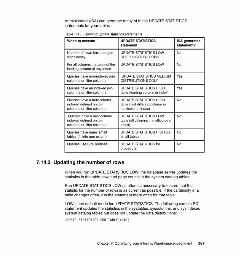
Administrator (ISA) can generate many of these UPDATE STATISTICS statements for your tables.
Table 7-15 Running update statistics statements
7.14.3 Updating the number of rows
When you run UPDATE STATISTICS LOW, the database server updates the statistics in the table, row, and page counts in the system catalog tables.
Run UPDATE STATISTICS LOW as often as necessary to ensure that the statistic for the number of rows is as current as possible. If the cardinality of a table changes often, run the statement more often for that table.
LOW is the default mode for UPDATE STATISTICS. The following sample SQL statement updates the statistics in the systables, syscolumns, and sysindexes system catalog tables but does not update the data distributions:
UPDATE STATISTICS FOR TABLE tab1;
When to execute UPDATE STATISTICS statement
ISA generates statement?
Number of rows has changed significantly
UPDATE STATISTICS LOW DROP DISTRIBUTIONS
No
For all columns that are not the leading column of any index
UPDATE STATISTICS LOW No
Queries have non-indexed join columns or filter columns
UPDATE STATISTICS MEDIUM DISTRIBUTIONS ONLY
Yes
Queries have an indexed join columns or filter columns
UPDATE STATISTICS HIGH table (leading column in index)
Yes
Queries have a multicolumn indexed defined on join columns or filter columns
UPDATE STATISTICS HIGH table (first differing column in multicolumn index)
No
Queries have a multicolumn indexed defined on join columns or filter columns
UPDATE STATISTICS LOW table (all columns in multicolumn index)
No
Queries have many small tables (fit into one extent)
UPDATE STATISTICS HIGH on small tables
No
Queries use SPL routines UPDATE STATISTICS for procedure
No
Chapter 7. Optimizing your Informix Warehouse environment 387
7.14.4 Dropping data distributions
When you upgrade to a new version of the database server, you might have to drop distributions to remove the old distribution structure in the sysdistrib system catalog table:
UPDATE STATISTICS DROP DISTRIBUTIONS;
Drop distributions in LOW mode without gathering statisticsYou can remove distribution information from the sysdistrib table and update the systables.version column in the system catalog for those tables whose distributions were dropped, without gathering any LOW mode table and index statistics. You do this by using the DROP DISTRIBUTIONS ONLY option in the UPDATE STATISTICS statement. Using the DROP DISTRIBUTIONS ONLY option can result in faster performance because Dynamic Server does not gather the table and index statistics that the LOW mode option generates when the ONLY keyword does not follow the DROP DISTRIBUTIONS keywords.
7.14.5 Creating data distributions
The database server creates data distributions, which provide information to the optimizer, any time the command UPDATE STATISTICS MEDIUM or UPDATE STATISTICS HIGH is executed. You do not have to run UPDATE STATISTICS operations when the statistics are generated automatically.
You can control the sample size for the scan through the keyword HIGH or MEDIUM. The difference between UPDATE STATISTICS HIGH and UPDATE STATISTICS MEDIUM is the number of rows sampled. UPDATE STATISTICS HIGH samples the entire table; UPDATE STATISTICS MEDIUM samples only a subset of rows, based on the confidence and resolution used by the UPDATE STATISTICS statement.
You can use the LOW keyword with the UPDATE STATISTICS statement only for fully qualified index keys.
If a distribution has been generated for a column, the optimizer uses that information to estimate the number of rows that match a query against a column. Data distributions in sysdistrib supersede values in the colmin and colmax column of the syscolumns system catalog table when the optimizer estimates the number of rows returned.
Important: The database server creates data distributions by sampling a column’s data, sorting the data, building distributions bins, and inserting the results into the sysdistrib system catalog table.
388 Data Warehousing with the Informix Dynamic Server

When you use data-distribution statistics for the first time, try to update statistics in MEDIUM mode for all your tables and then update statistics in HIGH mode for all columns that head indexes. This strategy produces statistical query estimates for the columns that you specify. These estimates, on average, have a margin of error less than the percent value of the total number of rows in the table, where percent is the value that you specify in the RESOLUTION clause in the MEDIUM mode. The default percent value for MEDIUM mode is 2.5%. For columns with HIGH mode distributions, the default resolution is 0.5%. With the DISTRIBUTIONS ONLY option, you can execute UPDATE STATISTICS MEDIUM at the table level or for the entire system because the overhead of the extra columns is not large.
The database server uses the storage locations that the DBSPACETEMP environment variable specifies only when you use the HIGH option of UPDATE STATISTICS. You can prevent UPDATE STATISTICS operations from using indexes when sorting rows by setting the third parameter of the DBUPSPACE environment variable to a value of 1 (one).
For each table that your query accesses, build data distributions according to the following guidelines. Also see the guidelines and examples that follow.
To generate statistics on a table, follow these steps:
1. Identify the set of all columns that appear in any single-column or multi-column index on the table.
2. Identify the subset that includes all columns that are not the leading column of any index.
3. Run UPDATE STATISTICS LOW on each column in that subset.
To build data distributions for each table that your query accesses, follow these steps:
1. Run a single UPDATE STATISTICS MEDIUM for all columns in a table that do not head an index. Use the default parameters unless the table is very large, in which case use a resolution of 1.0 and confidence of 0.99.
2. Run the following UPDATE STATISTICS statement to create distributions for non-index join columns and non-index filter columns:
UPDATE STATISTICS MEDIUM DISTRIBUTIONS ONLY;
3. Run UPDATE STATISTICS HIGH for all columns that head an index. For the fastest execution time of the UPDATE STATISTICS statement, you must execute one UPDATE STATISTICS HIGH statement for each column, as shown in the examples in “UPDATE STATISTICS HIGH for all columns” on page 390.
4. If you have indexes that begin with the same subset of columns, run UPDATE STATISTICS HIGH for the first column in each index that differs, as shown in
Chapter 7. Optimizing your Informix Warehouse environment 389

“UPDATE STATISTICS HIGH for the first column in each index that differs” on page 391
5. For each single-column or multi-column index on the table:
a. Identify the set of all columns that appear in the index.
b. Identify the subset that includes all columns that are not the leading column of any index.
c. Run UPDATE STATISTICS LOW on each column in that subset. (LOW is the default.)
6. For the tables on which indexes were created in step 3 on page 389, run an UPDATE STATISTICS statement to update the sysindexes and syscolumns system catalog tables, as shown in the following example:
UPDATE STATISTICS FOR TABLE t1(a,b,e,f);
7. For small tables, run UPDATE STATISTICS HIGH, for example:
UPDATE STATISTICS HIGH FOR TABLE t2;
Because the statement constructs the statistics only once for each index, these steps ensure that UPDATE STATISTICS executes rapidly.
UPDATE STATISTICS HIGH for all columnsIn this section, we show UPDATE STATISTICS HIGH statements for all columns that head an index.
Suppose you have a table t1 with columns a, b, c, d, e, and f with the following indexes:
CREATE INDEX ix_1 ON t1 (a, b, c, d) ... CREATE INDEX ix_3 ON t1 (f) ...
Run the following UPDATE STATISTICS statements for the columns that head an index:
UPDATE STATISTICS HIGH FOR TABLE t1(a); UPDATE STATISTICS HIGH FOR TABLE t1(f);
These UPDATE STATISTICS HIGH statements replace the distributions created with the UPDATE STATISTICS MEDIUM statements with high distributions for index columns.
390 Data Warehousing with the Informix Dynamic Server
UPDATE STATISTICS HIGH for the first column in each index that differsHere we show UPDATE STATISTICS HIGH statements for the first column in each index that differs. For example, suppose you have the following indexes on table t1:
CREATE INDEX ix_1 ON t1 (a, b, c, d) ...CREATE INDEX ix_2 ON t1 (a, b, e, f) ... CREATE INDEX ix_3 ON t1 (f) ...
Step 3 on page 389 executes UPDATE STATISTICS HIGH on column a and column f. Then run UPDATE STATISTICS HIGH on columns c and e.
UPDATE STATISTICS HIGH FOR TABLE t1(c);UPDATE STATISTICS HIGH FOR TABLE t1(e);
In addition, you can run UPDATE STATISTICS HIGH on column b, although this is usually not necessary.
7.14.6 Updating statistics on very large databases
To enable statements to automatically run in parallel, you must run UPDATE STATISTICS LOW with the PDQ priority set to a value in the range of 1 - 10. If the PDQ priority is set to 1, then 10% of the index fragments are analyzed at one time for the current table. If the PDQ priority is set to 5, then 50% of the index fragments are analyzed at one time for the current table.If the PDQ priority is set to 10, all fragments are analyzed at one time for the current table. If the PDQ priority is set to a value that is higher than 10, IDS operates as though the PDQ priority is set to 10, analyzing all fragments at one time for the current table.
If you run UPDATE STATISTICS MEDIUM or HIGH, you can set the PDQ priority to a value that is higher than 10. Because the UPDATE STATISTICS MEDIUM and HIGH statements perform a large amount of sorting operations, increasing the PDQ priority to a value that is higher than 10 provides additional memory than can improve the speed of the sorting operations.
Note: In the DSS environment, if you have an extremely large database and indexes are fragmented, UPDATE STATISTICS LOW can automatically run statements in parallel.
Chapter 7. Optimizing your Informix Warehouse environment 391
7.14.7 Improving the performance of UPDATE STATISTICS
When you execute the UPDATE STATISTICS statement, the database server uses memory and disk to sort and construct data distributions. You can affect the amount of memory and disk available for UPDATE STATISTICS with the following methods:
� PDQ priority
Although the UPDATE STATISTICS statement is not processed in parallel, you can obtain more memory for sorting when you set PDQ priority greater than 0 (zero). The default value for PDQ priority is 0. To set PDQ priority, use either the PDQPRIORITY environment variable or the SQL statement SET PDQPRIORITY. The format is:
� DBUPSPACE environment variable
You can use the DBUPSPACE environment variable to constrain the amount of system disk space that the UPDATE STATISTICS statement can use to construct multiple column distributions simultaneously. The format is:
7.14.8 Notes on improved sampling size
The UPDATE STATISTICS MEDIUM syntax is enhanced to support a user-configured sampling size.
Here is a list of the enhancements to UPDATE STATISTICS MEDIUM:
� UPDATE STATISTICS MEDIUM SAMPLING SIZE <number>
A number that is less than or equal to 1 (<= 1.0) is interpreted as a percent of the number of rows in the table to be sampled.
A number that is greater than 1 (> 1.0) is interpreted as the number of rows to be sampled.
� The SAMPLING SIZE configuration is stored in a new sysdistrib column called smplsize.
� The user sampling size might be above the preset sampling size of at resolution of 2.5 and confidence of 80.
� The actual number of rows sampled for UPDATE STATISTICS MEDIUM gets recorded in sysdistrib.rowssmpld.
� SAMPLING is a new keyword and table name SAMPLING cannot be used in the UPDATE STATISTICS statement.
When you use data distribution statistics for the first time, update statistics in MEDIUM mode for all your tables and then update statistics in HIGH mode for all columns that head indexes. This strategy produces statistical query estimates for
392 Data Warehousing with the Informix Dynamic Server
the columns that you specify. These estimates, on average, have a margin of error less than percent of the total number of rows in the table, where percent is the value that you specify in the RESOLUTION clause in the MEDIUM mode. The default percent value for MEDIUM mode is 2.5%. For columns with HIGH mode distributions, the default resolution is 0.5%.
In Example 7-24, the SAMPLING SIZE 0.7 examines 70% of rows in the table.
Example 7-24 SAMPLING SIZE examining percentage of rows
create table test (col1 integer)Insert 100 rowsUPDATE STATISTICS MEDIUM FOR TABLE test (col1) SAMPLING SIZE 0.7;
Example 7-25 with the SAMPLING SIZE 40.0 examines 40 rows in the table.
Example 7-25 SAMPLING SIZE examining the number of rows
create table test (col1 integer)Insert 100 rowsUPDATE STATISTICS MEDIUM FOR TABLE test (col1) SAMPLING SIZE 40.0;
7.14.9 Update statistics tracking
The following list indicates where the update information is stored:
� The time that UPDATE STATISTICS LOW was run is recorded in: systables.ustlowts
� The time that UPDATE STATSTICS MEDIUM or HIGH was executed is stored in the date field: sysdistrib.constr_time
� User-specified sample size is stored in: sysdistrib.smplsize.
� The number of rows sampled during the distribution build is stored in: sysdistrib.rowssmpld
DBExport and DBSchema have been enhanced to dump out sampling size syntax and value for displaying distributions. All of these functions allow a DBA to create SQL queries that can obtain these results and monitor the instance with greater detail. This capability allows a DBA to know exactly when update statistics last executed, and this information can be helpful in solving performance-related issues.
Chapter 7. Optimizing your Informix Warehouse environment 393

7.14.10 Temp table statistics
Users are no longer required to run UPDATE STATISTICS LOW on temp tables. The number of rows and the number of pages are updated every time we access the temp table data dictionary entry.
Adding indexes to temp tables automatically creates distributions and statistics for the temp table. We retain temp table statistics and distribution information every time that we reset the temp table dictionary information after the Data Definition Language (DDL).
7.15 Optimistic concurrency
The objective of optimistic concurrency control is to minimize the time over which a given resource would be unavailable for use by another transaction.
Pessimistic Pessimistic concurrency control relies on the locking of data for the duration of the transaction. The locks themselves are managed by the database server to control access to data. Pessimistic concurrency enables ordered updates when data access is in contention. However, the developer must exercise caution to prevent deadlocks. Also, some queries (such as queries that use the DISTINCT keyword, and queries that require joins) do not support exclusive locking.
OptimisticOptimistic concurrency control relies on validation at the time of storing data in the database server by means of an overqualified update statement. If the data represented by an entity has not changed in the database server since the time the data was stored, the update is permitted to complete successfully. If, however, the data was modified by a parallel transaction in between the time the entity was loaded and stored, then the updates are not applied in the database server and the transaction is rolled back. Optimistic concurrency is most useful in environments of light contention. An overqualified update statement might be:
UPDATE QUALIFIEDADDRESS SET ACTIVE = ?, STREET = ?, CITY = ?, STATE = ?, QUALIFIEDACCOUNT_PK = ? WHERE PK = ? AND ACTIVE = ? AND QUALIFIEDACCOUNT_PK = ?
394 Data Warehousing with the Informix Dynamic Server
Optimistic predicate clauseWhen optimistic access intent is setup, specify the attributes that you want to be included in the optimistic predicate. The attribute is included in the WHERE clause of the UPDATE SQL statement, in which the ID is the primary key column:
UPDATE SET X = ? WHERE ID = ? AND X = ?
Concurrency controlA concurrency control scheme is considered optimistic when locks are acquired and released over a very short time at the end of a transaction. Being the objective of optimistic concurrency is to minimize the unavailability for use by other transactions. This is especially important with long-running transactions, such as would occur in a data warehousing environment, where a pessimistic scheme would lock resources for unacceptably long periods of time.
IDS supports record locking of an accessed data source to prevent data corruption. Concurrency control is the management of contention for data resources. We can control concurrency within IDS by the setting of the isolation level at the session level.
SET ISOLATION LEVEL COMMITTED READ
In the Committed Read isolation level, exclusive row-level locks that are held by other sessions can cause SQL operations to fail with a lock error when attempting to read data in the locked rows. You can use the LAST COMMITTED keyword option to the SET ISOLATION COMMITTED READ statement to reduce the risk of such locking conflicts. In contexts where an application attempts to read a row on which another session holds an exclusive lock, these keywords instruct the database server to return the most recently committed version of the row, rather than wait for the lock to be released. The LAST COMMITTED keywords are only effective with concurrent read operations. They cannot prevent locking conflicts or errors that occur when concurrent sessions attempt to write to the same row.
Applications that PREPARE a statement before running EXECUTE can sometimes fail with the following error:
-710 error - Table <table-name> has been dropped, altered, or renamed.
This happens when the table or tables to which the statement refers in the PREPARE statement, are renamed or altered, possibly changing the structure of the table or even an UPDATE STATISTICS statement on the table. By setting the configuration parameter AUTO_REPREPARE to 1, IDS automatically re-optimizes SPL routines and re-prepares prepared objects after the schema of a table referenced by the SPL routine or by the prepared object has been changed.
Chapter 7. Optimizing your Informix Warehouse environment 395
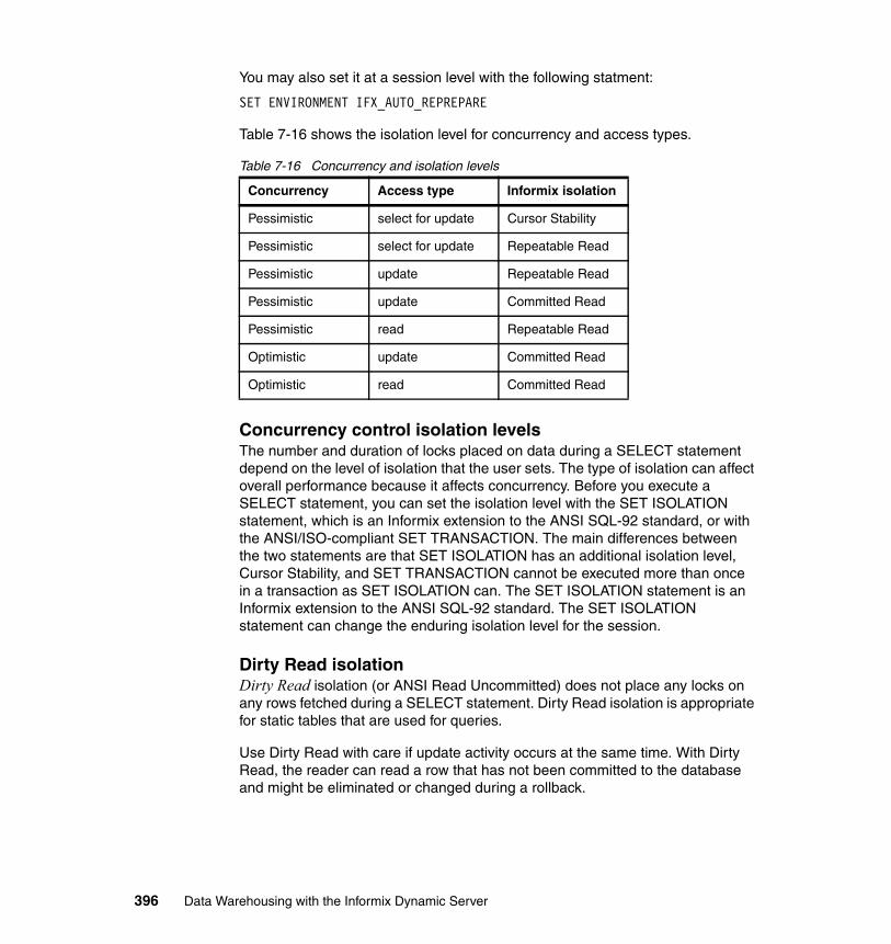
You may also set it at a session level with the following statment:
SET ENVIRONMENT IFX_AUTO_REPREPARE
Table 7-16 shows the isolation level for concurrency and access types.
Table 7-16 Concurrency and isolation levels
Concurrency control isolation levelsThe number and duration of locks placed on data during a SELECT statement depend on the level of isolation that the user sets. The type of isolation can affect overall performance because it affects concurrency. Before you execute a SELECT statement, you can set the isolation level with the SET ISOLATION statement, which is an Informix extension to the ANSI SQL-92 standard, or with the ANSI/ISO-compliant SET TRANSACTION. The main differences between the two statements are that SET ISOLATION has an additional isolation level, Cursor Stability, and SET TRANSACTION cannot be executed more than once in a transaction as SET ISOLATION can. The SET ISOLATION statement is an Informix extension to the ANSI SQL-92 standard. The SET ISOLATION statement can change the enduring isolation level for the session.
Dirty Read isolation Dirty Read isolation (or ANSI Read Uncommitted) does not place any locks on any rows fetched during a SELECT statement. Dirty Read isolation is appropriate for static tables that are used for queries.
Use Dirty Read with care if update activity occurs at the same time. With Dirty Read, the reader can read a row that has not been committed to the database and might be eliminated or changed during a rollback.
Concurrency Access type Informix isolation
Pessimistic select for update Cursor Stability
Pessimistic select for update Repeatable Read
Pessimistic update Repeatable Read
Pessimistic update Committed Read
Pessimistic read Repeatable Read
Optimistic update Committed Read
Optimistic read Committed Read
396 Data Warehousing with the Informix Dynamic Server

For example, consider the following scenario:
User 1 starts a transaction. User 1 inserts row A. User 2 reads row A. User 1 rolls back row A.
User 2 reads row A, which user 1 rolls back seconds later. In effect, user 2 reads a row that was never committed to the database. Uncommitted data that is rolled back can be a problem in applications.
Because the database server does not check or place any locks for queries, Dirty Read isolation offers the best performance of all isolation levels. However, because of potential problems with uncommitted data that is rolled back, use Dirty Read isolation with care. Because problems with uncommitted data that is rolled back are an issue only with transactions, databases that do not have transaction (and hence do not allow transactions) use Dirty Read as a default isolation level. In fact, Dirty Read is the only isolation level allowed for databases that do not have transaction logging.
Committed read isolationA reader with the Committed Read isolation (or ANSI Read Committed) level checks for locks before returning a row. By checking for locks, the reader cannot return any uncommitted rows.
The database server does not actually place any locks for rows read during Committed Read. It simply checks for any existing rows in the internal lock table.
Committed Read is the default isolation level for databases with logging if the log mode is not ANSI-compliant. For databases created with a logging mode that is not ANSI-compliant, Committed Read is an appropriate isolation level for most activities. For ANSI-compliant databases, Repeatable Read is the default isolation level.
Reducing the risk of committed read isolation level conflicts In the Committed Read isolation level, locks held by other sessions can cause SQL operations to fail if the current session cannot acquire a lock or if the database server detects a deadlock. A deadlock occurs when two users hold locks, and each user wants to acquire a lock that the other user owns. The LAST COMMITTED keyword option to the SET ISOLATION COMMITTED READ statement of SQL reduces the risk of locking conflicts. This syntax instructs the server to return the most recently committed version of the rows, even if another concurrent session holds an exclusive lock. You can use the LAST COMMITTED keyword option for B-Tree and functional indexes, tables that support transaction logging, and tables that do not have page-level locking or exclusive locks.
Chapter 7. Optimizing your Informix Warehouse environment 397

For databases created with transaction logging, you can set the USELASTCOMMITTED configuration parameter to specify whether the database server uses the last committed version of the data, rather than wait for the lock to be released, when sessions using the Dirty Read or Committed Read isolation level (or the ANSI/ISO level of Read Uncommitted or Read Committed) attempt to read a row on which a concurrent session holds a shared lock. The last committed version of the data is the version of the data that existed before any updates occurred.
If no value, or a value of NONE, is set for the USELASTCOMMITTED configuration parameter or for the USELASTCOMMITTED session environment variable, sessions in a COMMITTED READ or READ COMMITTED isolation level wait for any exclusive locks to be released, unless the SET ISOLATION COMMITTED READ LAST COMMITTED statement of SQL instructs the database server to read the most recently committed version of the data.
Setting the USELASTCOMMITTED configuration parameter to operate with the Committed Read isolation level can affect performance only if concurrent conflicting updates occur. When concurrent conflicting updates occur, the performance of queries depends on the dynamics of the transactions. For example, a reader using the last committed version of the data, might have to undo the updates made to a row by another concurrent transaction. This situation involves reading one or more log records, thereby increasing the I/O traffic, which can affect performance.
Cursor stability isolation A reader with Cursor Stability isolation acquires a shared lock on the row that is currently fetched. This action assures that no other user can update the row until the user fetches a new row. In the pseudocode example for a cursor, in Example 7-26, at fetch a row, the database server releases the lock on the previous row and places a lock on the row being fetched. At close the cursor, the server releases the lock on the last row.
Example 7-26 Locks placed for cursor stability set
set isolation to cursor stability declare cursor for SELECT * FROM customer open the cursorwhile there are more rowsfetch a row do work end whileclose the cursor
If you do not use a cursor to fetch data, Cursor Stability isolation behaves in the same way as Committed Read. No locks are actually placed.
398 Data Warehousing with the Informix Dynamic Server
Repeatable read isolation Repeatable Read isolation (ANSI Serializable and ANSI Repeatable Read) is the strictest isolation level. With Repeatable Read, the database server locks all rows examined (not just fetched) for the duration of the transaction.
The pseudocode in Example 7-27 shows when the database server places and releases locks for a repeatable read. At fetch a row, the server places a lock on the row being fetched and on every row it examines in order to retrieve this row. At close the cursor, the server releases the lock on the last row.
Example 7-27 Locks placed for repeatable read
set isolation to repeatable read begin work declare cursor for SELECT * FROM customeropen the cursor while there are more rows
fetch a rowdo work
end while close the cursorcommit work
Repeatable Read is useful during any processing in which multiple rows are examined, but none must change during the transaction. For example, suppose an application must check the account balance of three accounts that belong to one person. The application gets the balance of the first account and then the second. But, at the same time, another application begins a transaction that debits the third account and credits the first account. By the time that the original application obtains the account balance of the third account, it has been debited. However, the original application did not record the debit of the first account.
When you use Committed Read or Cursor Stability, the previous scenario can occur. However, it cannot occur with Repeatable Read. The original application holds a read lock on each account that it examines until the end of the transaction, so the attempt by the second application to change the first account fails (or waits, depending upon SET LOCK MODE).
Because even examined rows are locked, if the database server reads the table sequentially a large number of rows unrelated to the query result can be locked. For this reason, use Repeatable Read isolation for tables when the database server can use an index to access a table. If an index exists and the optimizer chooses a sequential scan instead, you can use directives to force use of the index. However, forcing a change in the query path might negatively affect query performance.
Chapter 7. Optimizing your Informix Warehouse environment 399

400 Data Warehousing with the Informix Dynamic Server
Chapter 8. Moving forward with Informix Warehousing
In this book, we have focused on planning and implementing for development and deployment purposes, and using the integrated software tools within the Informix Warehouse to create the foundation for a data warehouse or business intelligence solution based on the Informix Dynamic Server.
After a foundation for business intelligence using IDS (or even a separate data warehouse repository dedicated to the DSS workload, or a mixed OLTP and DSS workload database) is created using the Informix Warehouse software tools, the last phase of the project is to integrate the warehouse repository with additional software tools, technologies and information.
One purpose of integrating complementary technologies into the data warehousing foundation is to better enable you to move to a complete BI solution. That is, to provide the BI tools for business users to access, visualize and analyze their data from a business performance management perspective. In addition, involving the business users is important when deciding on the set of BI tools to use. This is because those tools must fit the organizational maturity level for using BI, the business user needs and skills, and the proposed integration with the planned or existing data warehouse platform.
In addition, you should consider how to incorporate new technologies that become available and are related to expanding or enhancing the existing
8
© Copyright IBM Corp. 2009. All rights reserved. 401

solution. This consideration translates into project iterations to create a more advanced or sophisticated data warehousing experience for the business users and administrators of the solution beyond traditional data reporting or analysis.
For example, after you have a robust BI solution using traditional structured data, you may want to be able to integrate unstructured data analytics (such as text search and spatial-related queries) as part of the BI solution. Or, the data warehouse administrators might be asked to enable updates to be made to the data warehouse in real-time, or at least at much shorter intervals of time.
402 Data Warehousing with the Informix Dynamic Server
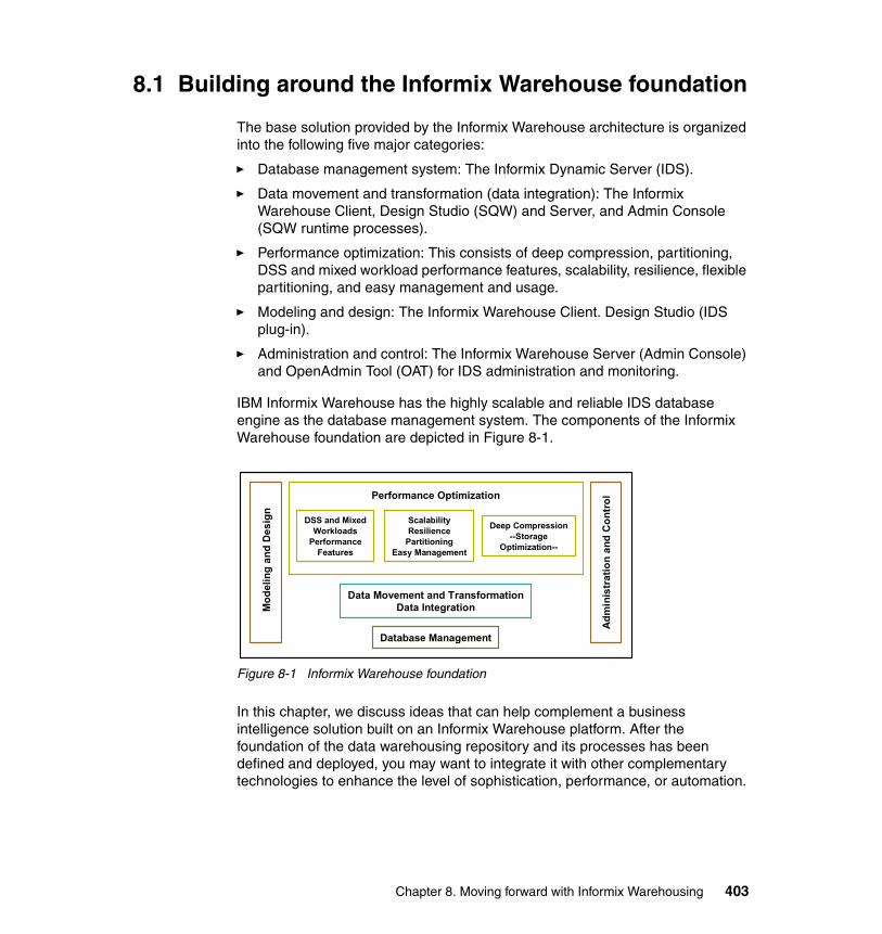
8.1 Building around the Informix Warehouse foundation
The base solution provided by the Informix Warehouse architecture is organized into the following five major categories:
� Database management system: The Informix Dynamic Server (IDS).
� Data movement and transformation (data integration): The Informix Warehouse Client, Design Studio (SQW) and Server, and Admin Console (SQW runtime processes).
� Performance optimization: This consists of deep compression, partitioning, DSS and mixed workload performance features, scalability, resilience, flexible partitioning, and easy management and usage.
� Modeling and design: The Informix Warehouse Client. Design Studio (IDS plug-in).
� Administration and control: The Informix Warehouse Server (Admin Console) and OpenAdmin Tool (OAT) for IDS administration and monitoring.
IBM Informix Warehouse has the highly scalable and reliable IDS database engine as the database management system. The components of the Informix Warehouse foundation are depicted in Figure 8-1.
Figure 8-1 Informix Warehouse foundation
In this chapter, we discuss ideas that can help complement a business intelligence solution built on an Informix Warehouse platform. After the foundation of the data warehousing repository and its processes has been defined and deployed, you may want to integrate it with other complementary technologies to enhance the level of sophistication, performance, or automation.
Database Management
Data Movement and TransformationData Integration
Performance Optimization
Mod
elin
g an
d D
esig
n
Adm
inis
trat
ion
and
Con
trol
DSS and MixedWorkloads
PerformanceFeatures
ScalabilityResilience
PartitioningEasy Management
Deep Compression--Storage
Optimization--
Chapter 8. Moving forward with Informix Warehousing 403
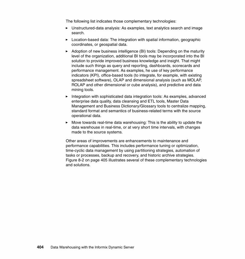
The following list indicates those complementary technologies:
� Unstructured-data analysis: As examples, text analytics search and image search.
� Location-based data: The integration with spatial information, geographic coordinates, or geospatial data.
� Adoption of new business intelligence (BI) tools: Depending on the maturity level of the organization, additional BI tools may be incorporated into the BI solution to provide improved business knowledge and insight. That might include such things as query and reporting, dashboards, scorecards and performance management. As examples, he use of key performance indicators (KPI), office-based tools (to integrate, for example, with existing spreadsheet software), OLAP and dimensional analysis (such as MOLAP, ROLAP and other dimensional or cube analysis), and predictive and data mining tools.
� Integration with sophisticated data integration tools: As examples, advanced enterprise data quality, data cleansing and ETL tools, Master Data Management and Business Dictionary/Glossary tools to centralize mapping, standard format and semantics of business-related terms with the source operational data.
� Move towards real-time data warehousing: This is the ability to update the data warehouse in real-time, or at very short time intervals, with changes made to the source systems.
Other areas of improvements are enhancements to maintenance and performance capabilities. This includes performance tuning or optimization, time-cyclic data management by using partitioning strategies, automation of tasks or processes, backup and recovery, and historic archive strategies. Figure 8-2 on page 405 illustrates several of these complementary technologies and solutions.
404 Data Warehousing with the Informix Dynamic Server
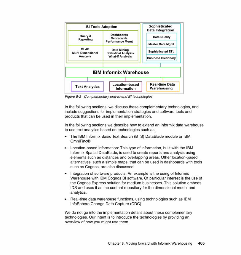
Figure 8-2 Complementary end-to-end BI technologies
In the following sections, we discuss these complementary technologies, and include suggestions for implementation strategies and software tools and products that can be used in their implementation.
In the following sections we describe how to extend an Informix data warehouse to use text analytics based on technologies such as:
� The IBM Informix Basic Text Search (BTS) DataBlade module or IBM OmniFind®
� Location-based information: This type of information, built with the IBM Informix Spatial DataBlade, is used to create reports and analysis using elements such as distances and overlapping areas. Other location-based alternatives, such a simple maps, that can be used in dashboards with tools such as Cognos, are also discussed.
� Integration of software products: An example is the using of Informix Warehouse with IBM Cognos BI software. Of particular interest is the use of the Cognos Express solution for medium businesses. This solution embeds IDS and uses it as the content repository for the dimensional model and analytics.
� Real-time data warehouse functions, using technologies such as IBM InfoSphere Change Data Capture (CDC)
We do not go into the implementation details about these complementary technologies. Our intent is to introduce the technologies by providing an overview of how you might use them.
BI Tools Adoption Sophisticated Data Integration
IBM Informix Warehouse
Text Analytics Location-based Information
Real-time Data Warehousing
Query & Reporting
Dashboards Scorecards
Performance Mgmt
OLAP Multi-Dimensional
Analysis
Data Mining Statistical Analysis
What-If Analysis
Data Quality
Business Dictionary
Sophisticated ETL
Master Data Mgmt
Chapter 8. Moving forward with Informix Warehousing 405

8.2 Text analytics
To date, data warehousing has primarily been focused on structured data. However, perhaps 80% of all available information is in unstructured format. Several examples include: insurance accident reports, e-mails, repair claims, call center records or notes, product information, customer information, and medical journals.
Text analytics enables you to extract business value from unstructured text data such as e-mails, customer relationship management (CRM) records, office documents, Web pages (blogs, wikis, articles), printouts, XML documents, and output produced by Web services, and any other text-based data.
Certain technologies that allow you to take the unstructured data stored, for example, in the form of large objects (BLOBs or CLOBs) in IDS and perform flexible queries to search for words, phrases, and patterns, and comparisons. Sophisticated stages of these types of projects might include, for example, the creation of a content management system integrated within the business intelligence environment.
Currently, three very good alternatives for performing text analytics with IDS are:
� Informix Basic Text Search (BTS) DataBlade module, included within IDS at no cost.
� Informix Excalibur Text (ETX) DataBlade module, an add-on DataBlade that can be acquired separately from IDS.
� IBM OmniFind technologies such as OmniFind Enterprise Search, which provides an enterprise-wide search capability.
Other solutions, not discussed here, include other content management systems that can source IDS databases containing unstructured data, in addition to other sources of information such as office documents, PDF, HTML, XML, direct connection to e-mail, and text messaging systems.
In this section, we provide a brief overview of several of these alternatives and how they function with IDS.
406 Data Warehousing with the Informix Dynamic Server
8.2.1 Unstructured data stored in IDS
Unstructured data that is stored in IDS in the form of smart large objects can be read or written in their entirety or in part. They can be stored in two built-in opaque data types, BLOB or CLOB, which store, respectively, binary data or character data:
� BLOB: This type is for binary data that a program can generate, such as graphics, drawings and picture images, videos and music clips, maps, spatial objects, and highly-formatted documents, such as such as .pdf and .doc format types, that are generated by office applications. A BLOB column can store up to 4 TB of binary data.
� CLOB: This type is for blocks of a large ASCII text or document, or large readable and printable text, such as formatted files of the type of HTML, XML, RTF, TXT, CSV, and PS documents. A CLOB column can store up to 4 terabytes of text data.
Smart large objects are stored in smart blobspaces, or sbspaces, which serve as an efficient storage for this type of data. You can specify whether to have logging in smart large objects and sbspaces independently from the logging characteristics of the database. You can also use a temporary sbspace to store temporary smart large objects without any logging.
IDS provides functions to import (load) and export (unload) smart large objects so the binary or character objects or files can be copied to and from the file system or database. IDS provides the smart-large-object API in the DataBlade API, and the Informix ESQL/C programming interface.
Uploading binary and text data to IDS tablesYou can use the IDS FILETOBLOB function to create a BLOB value for data in an IDS table from a binary file that is stored in a specified operating system file path. For CLOBs, the FILETOCLOB function creates a CLOB value for a data value that is stored in a large text file.
These functions determine the operating system file to use from the following parameters:
� Path name: Identifies the directory path and name of the source file.
� File destination: Identifies the computer client or server on which this file resides:
– Use client to identify the client computer as the location of the source file.
– Use server to identify the server computer as the location of the source file. You must use the full path name.
Chapter 8. Moving forward with Informix Warehousing 407
The following example is of a table containing a serial column cand_id and a BLOB column cand_pic to store the picture of a candidate. We are using an INSERT statement, along with FileToBlob function, to upload a photo stored in the directory c:\tmp\photo.bmp on the database server (not the client):
INSERT INTO rdb@rserv:election (cand_id, cand_pic) VALUES (0, FILETOBLOB('C:\tmp\photo.bmp', 'server'));
To unload data, you can use UNLOAD or any other export utility in IDS to download several records, including their binary BLOB columns, or, to get a specific BLOB or CLOB as a file in the file system, you can use the function LOTOFILE. This function copies a smart large object to an operating system file. The first parameter specifies the BLOB or CLOB column to copy. The function determines what file to create from parameters similar to FileToBlob and FileToClob functions. For example:
select LoToFile(cand_pic, 'C:\tmp\photo_cand_100.bmp', 'server') from rdb@rserv:election where cand_id=100;
Informix Warehouse tools support simple large objects (BYTE, TEXT) and smart large objects (BLOB, CLOB) in data movement operators, such as Table Source, Table Target, File Export and File Import. When manual or individual upload or download is required for specific records, the functions above can be used, and they can be invoked using an Informix Custom SQL operator inside an Informix Warehouse control flow.
8.2.2 The Basic Text Search DataBlade module
The Basic Text Search (BTS) DataBlade is included with IDS at no extra cost and extends IDS capabilities to search for words and phrases in all string based table columns. This simple to use module allows you to search words and phrases in an unstructured document repository stored in a column of a table using simple SQL queries. The column can be a BLOB, CHAR, CLOB, LVARCHAR, NCHAR, NVARCHAR, or VARCHAR data type. Search strategies include single and multiple character wildcard searches, fuzzy and proximity searches, and AND, OR, and NOT Boolean operations. This feature is documented in the IBM Informix Database Extensions User's Guide, SC23-9427.
The Basic Text Search DataBlade module uses the open source CLucene text search package. CLucene is a high-performance, scalable, cross platform, full-featured, open-source indexing and searching API written in C++. This text search package and its associated functions, known as the text search engine, is specifically designed to perform fast retrieval and automatic indexing of text data. The text search engine runs in one of the IDS server-controlled virtual processes.
408 Data Warehousing with the Informix Dynamic Server
The Basic Text Search DataBlade module has two principal components, the bts_contains() search predicate function and the Basic Text Search DataBlade management functions.
The bts_contains() search predicateWhen you execute searches with Basic Text Search you use a predicate called bts_contains() that instructs the database server to call the text search engine to perform the search.
For example, to search for the string century in the column brands in the table products you use the following statement:
SELECT id FROM products WHERE bts_contains(brands, 'century');
The search predicate takes a variety of arguments to make the search more detailed than one using a LIKE condition. Search strategies include single and multiple character wildcard searches, fuzzy and proximity searches, AND, OR, and NOT Boolean operations, range options, and term-boosting.
You can search for unstructured text or, if you use XML index parameters, you can search columns within XML documents by tags, attributes, or XML paths.
The Basic Text Search DataBlade module includes several functions that you can use to perform various tasks, such as compacting the BTS index and obtaining the release number of the module.
Database server requirements and restrictionsIf you want to use the Basic Text Search DataBlade module, you must have IBM Informix Dynamic Server, Version 11.10 or later.
With Basic Text Search, be aware of the following aspects:
� It can be used with most multi-byte character sets and supports GLS (including UTF-8). The exception is ideographic languages such as Chinese, Korean, and Japanese.
� It does not support:
– Distributed queries– Parallel database queries (PDQs)
� It supports searches on primary and all types of secondary servers in high-availability clusters.
Chapter 8. Moving forward with Informix Warehousing 409
Supported data types for Basic Text SearchTo use Basic Text Search, you must store the text data in a column of data type BLOB, CHAR, CLOB, LVARCHAR, NCHAR, NVARCHAR, |or VARCHAR. The index can be stored in either an sbspace or an extspace. Data in a column of data type TEXT is not supported by BTS.
If your documents are over 32 KB, store them in columns of type BLOB or CLOB.
The size of a document to be indexed is limited by the amount of available virtual memory on your machine. For example, if you have 1 GB of available virtual memory, you can only index documents that are smaller than 1 GB.
Preparing the Basic Text Search DataBlade moduleBefore you can use the Basic Text Search DataBlade module, you must prepare the server environment and create the BTS index.
PrerequisitesPrerequisites include:
� Review the database server requirements and restrictions.
� Verify that the searchable text is one of the supported data types for Basic Text Search.
� Review index restrictions for Basic Text Search.
ProcedureTo prepare the Basic Text Search DataBlade module, complete these tasks:
1. Define the BTS extension virtual process class.2. Create a default sbspace.3. Create an sbspace for the BTS index.4. Create a space for temporary data. (This step is optional.) 5. Create the BTS index.
Defining the BTS extension virtual processor classYou must define a BTS extension virtual processor (EVP) class to use a BTS index. The Basic Text Search functions run in the BTS EVP without yielding, which means that only one index operation executes at one time. Basic Text Search supports only one BTS EVP.
Note: Although you can store searchable text in a column of the BLOB data type, Basic Text Search does not support indexing binary data. BLOB data type columns must contain text.
410 Data Warehousing with the Informix Dynamic Server
To define the BTS virtual processor, add the following line to the ONCONFIG file:
VPCLASS bts,noyield,num=1
Restart the database server for the BTS processor class to take effect.
Creating a default sbspaceYou must create a default sbspace and set the SBSPACENAME configuration parameter in the ONCONFIG file before you register the BTS DataBlade module into any database, or the registration fails. During registration, the Basic Text Search (BTS) DataBlade module sets up internal directories in the default sbspace.
The BTS DataBlade module also stores BTS indexes in the default sbspace, unless you explicitly specify another sbspace, when you create the index. Be sure the default sbspace is large enough to hold all of these objects.
The default sbspace must have the following characteristics:
� Logging must be enabled. Include the -Df "LOGGING=ON" option when you create the sbspace with the onspaces utility.
� Buffering must be enabled. Buffering is enabled by default, when you create an sbspace with the onspaces utility.
To create the default sbspace:
1. Set the SBSPACENAME configuration parameter in the ONCONFIG file to the name of your default sbspace. The following example sets the name of the default sbspace to sbsp1:
SBSPACENAME sbsp1
2. Restart the database server.
3. Create the sbspace by using the onspaces utility. Include the following option:
-Df "LOGGING=ON"
The following example creates an sbspace called sbsp1 in the file named /data/ifmx/sbspace:
onspaces -c -S sbsp1 -g 2 -p /data/ifmx/sbspace -o 0 -s 100000 -Df "LOGGING=ON"
Adding text analytics inside a BI applicationYou can integrate the use of the bts_contains() search predicate with common SQL based queries generated inside the BI tool or application that you are using. Most BI tools allow you to create, customize using parameters/variables and save your own queries that can go together with other query results.
Chapter 8. Moving forward with Informix Warehousing 411
8.2.3 IBM OmniFind Enterprise Search
The RDBMS will provide for storing unstructured data and, increasingly, also semi-structured XML data. In IDS, data types such as VARCHAR and CLOB allow you to store plain ASCII text, such as .html, .xml, .rtf, and .txt formats, and BLOBs provide for storage of complex (proprietary) types of data, such as .pdf, .doc, and .ppt formats. SQL in IDS provides not only storage for these data types, but also enables the queries with sophisticated mechanisms for defining and executing searches on these types of data.
These Informix capabilities come from advanced extensible technology with its DataBlade functionality to allow users to develop their own searching mechanisms, by using Basic Text Search or Excalibur Text Search.
Although the Informix BTS DataBlade module supports most character-based data types, it does not provide for searching in BLOB columns. In the specific case of searching inside BLOBs, Informix databases support the Excalibur Text DataBlade, which is essentially a text indexing and search engine that plugs into the Informix database and supports BLOB and CLOB data types.
When there is a need to integrate the text analytics capabilities at the enterprise level, not restricted to an Informix database or warehouse, in one single search engine, a solution such as OmniFind can help. You can use OmniFind with the DataListener to push both structured and unstructured data that is stored in an RDBMS such as Informix (and also other databases and content repositories across the IT environment) to OmniFind.
Enterprise search technologies provide users with the ability to find relevant information anywhere within an organization using the simple word matching capabilities of Internet search. Examples of this include the use of semantic searching (searching for fast car might match records containing Porsche) and parametric searching (find all references occurring from 1990 to 1991).
When searching across the enterprise, the Informix database becomes another source and needs to be accessible from the OmniFind environment. An enterprise search system with a Web interface provides extensive capabilities for searching in a large number of structured and unstructured data sources with a single query. Fast query response times and a consolidated, ranked result set that is based on extensive text analysis, enables you to locate documents of interest and extract meaning from document content. By entering a query in a Web browser, you can search local and remote databases, collaboration systems, e-mail systems, news groups, content management systems, file systems, and internal and external Web sites at the same time.
OmniFind provides a Web interface for collecting, analyzing, indexing and searching text data, and an administration and monitoring console. In addition,
412 Data Warehousing with the Informix Dynamic Server
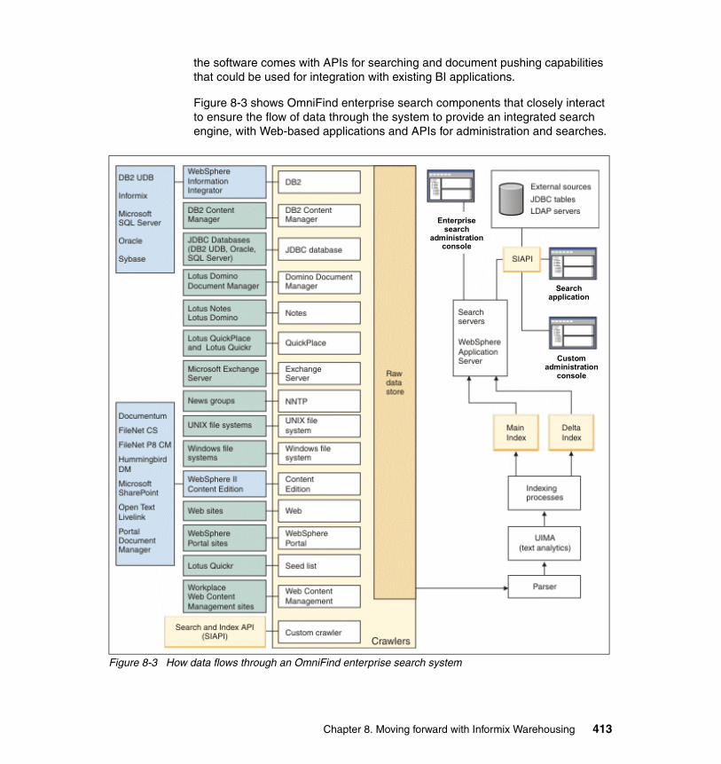
the software comes with APIs for searching and document pushing capabilities that could be used for integration with existing BI applications.
Figure 8-3 shows OmniFind enterprise search components that closely interact to ensure the flow of data through the system to provide an integrated search engine, with Web-based applications and APIs for administration and searches.
Figure 8-3 How data flows through an OmniFind enterprise search system
Enterprise search
administration console
Search application
Custom administration
console
Chapter 8. Moving forward with Informix Warehousing 413
For more information about OmniFind, consult the product page:
http://www.ibm.com/software/data/enterprise-search/
8.3 Location-based data
In data warehouse repositories, we normally see one or several tables that contain geographic or location data. In case of STAR schemas, we normally see Geography or Location as a common dimension table to which the fact table records are related. We have to store geographic information regarding customers, stores, offices, people, suppliers, vendors, and other entities. Depending on the level of information that we store in dimension-type of tables in our warehouse, we are capable of doing more or less analysis around the spatial, geospatial or geographic location of those entities.
Here are several examples of possible enhancements to BI solutions when the location-based information is incorporated into the data warehouse:
� Using BI tools capabilities for rendering maps in dashboards and reports� Using Informix Spatial DataBlade for spatial information in the database� Using Informix Geodetic DataBlade for geospatial information in the database� Using Web Feature Services for presentation layer of spatial data
A good introduction to the Informix Spatial DataBlade can be found in Customizing Informix Dynamic Server for Your Environment, SG24-7522. Refer to the information about publishing location data with a Web Feature Service.
In the following sections, we briefly explore these options for enhancing your BI applications with location-based data.
8.3.1 Using Map rendering capabilities in BI tools
You can also have dashboards displaying colored key performance indicators (KPIs), such as total sales, growth, revenue, and number of plant alarms, automatically placed or pin-pointed by the BI tool on the location of the entity being measured, on the map of the world, the country, the state, the city or the building. This can be easily done in tools such as Cognos 8 BI by setting up and using its Map Manager, which provides an extensive set of pre-existing maps for the incorporation of visual location-based information about dashboards and reports.
Some BI tools have their own map capabilities and provide you with ways to enter geographic-based information; other tools use map plug-ins or map import conversions from Google, Yahoo, ESRI, MapInfo, or other vendors. Some tools
414 Data Warehousing with the Informix Dynamic Server

provide both options. For instance, Cognos BI allows you to use the Google Maps API in reports using JavaScript. Also, if you do not want to use the Maps directory provided by Cognos, you can use custom maps, because it provides the ability to import and convert from other map formats, such as ESRI-generated maps, into the Cognos proprietary map format (CMF) in Map Manager.
In Cognos Express 9.0, Report Studio provides a set of maps that you can use to represent tabular data in a spatial context. For example, on a map of the world, countries can be colored to represent the level of revenue.
To set up this capability, review the documentation of the BI tool of your choice for dashboards, scorecards, and reports. Normally, most of the set up is done at the BI tool side. For instance, in the specific case of Cognos, after deciding which map to use in a given dashboard or report, you should map data values of locations (such as cities or countries) found in the query using the map (for instance, a world map) with the location and position points on the map itself. Colors associated to those points that will be rendered on top of the map can be associated to thresholds on data values found for measures, such as revenue or costs.
Most BI tools enable you to drill down, up and through another dashboard and report using these points layers on maps, which provide value for business users, because they can use the map to visualize the general health of the business performance of, for example, stores by city. Then, simply click on those points that are colored in red, given an outstanding value, to see a more detailed report or dashboard showing why the performance of that location or city is not the desired one. Another alternative is to give the business user some information in advance. For instance, as the mouse hovers over the red-colored points on the map, the actual values for the measure (sales or cost) that result in that specific location being a bad performer.
Figure 8-4 on page 416 shows an sample dashboard rendering a map object for which we have associated point-layer information to relate points on the map with data values coming from data warehouse queries.
Chapter 8. Moving forward with Informix Warehousing 415
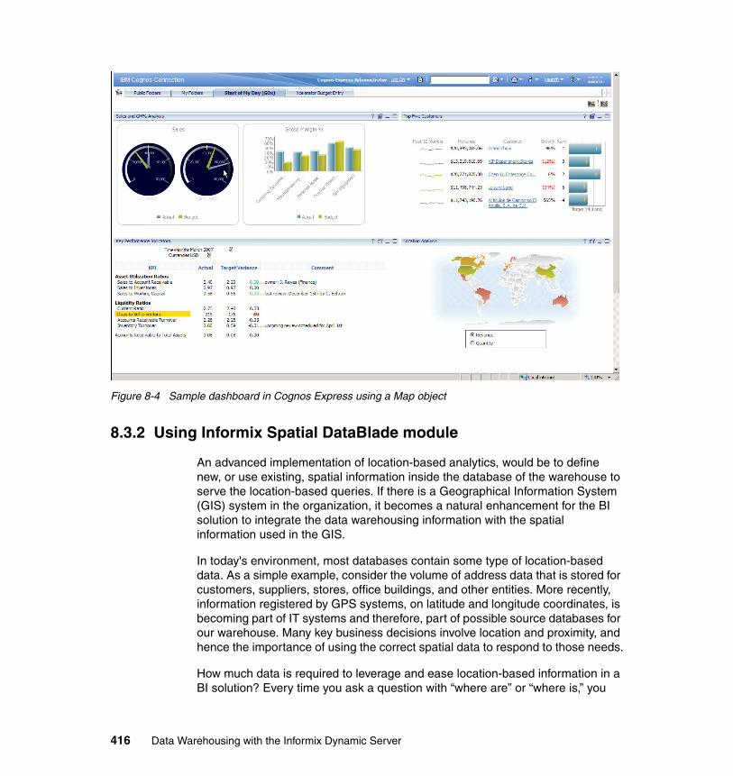
Figure 8-4 Sample dashboard in Cognos Express using a Map object
8.3.2 Using Informix Spatial DataBlade module
An advanced implementation of location-based analytics, would be to define new, or use existing, spatial information inside the database of the warehouse to serve the location-based queries. If there is a Geographical Information System (GIS) system in the organization, it becomes a natural enhancement for the BI solution to integrate the data warehousing information with the spatial information used in the GIS.
In today's environment, most databases contain some type of location-based data. As a simple example, consider the volume of address data that is stored for customers, suppliers, stores, office buildings, and other entities. More recently, information registered by GPS systems, on latitude and longitude coordinates, is becoming part of IT systems and therefore, part of possible source databases for our warehouse. Many key business decisions involve location and proximity, and hence the importance of using the correct spatial data to respond to those needs.
How much data is required to leverage and ease location-based information in a BI solution? Every time you ask a question with “where are” or “where is,” you
416 Data Warehousing with the Informix Dynamic Server

are asking about location. All well-known information, such as street, city, district, and country, are a type of location-based data. In many aspects, these data types work well, but they certainly also have their limitations.
When talking about spatial data, you are talking about location-based data, but in a very concise manner. With spatial data you work with data that are defined as coordinates in a well defined geographic coordinate system. Each location can be expressed as a point. A point is a multi-value data type, which at least contains an x-value and a y-value that makes sense in the coordinate system. Roads, water pipes and power supply lines can be described as lines of points, and objects that describe an area like a building or a lake can be described as a polygon.
The IBM Informix Spatial DataBlade module, which is available to download separately at no cost for Informix customers of any IDS 11.50 edition, extends the IDS engine with high-performance and easy-to-use capabilities for location-based data in the form of SQL-based spatial data types (UDTs), user-defined routines (UDRs) and user-defined functions (UDFs), and efficient access methods through an R-Tree index. The Spatial DataBlade enables organizations to transform both traditional and location-based data into important information to help gain a competitive advantage by providing an infrastructure for spatial data access and analytics. It is the technology that helps customers handle spatial using a plain earth model representation. You can use standard SQL queries or a client-side Geographic Information Systems (GIS) software (such as that from ESRI and MapInfo) to retrieve information around a spatial awareness.
IDS implements a set of types and functions defined by the current GIS industry specifications of the Open Geospatial Consortium (OGC). It concisely defines geometry types, hierarchies and spatial functions. For instance, the Spatial DataBlade module introduces new multi-value data types to the IDS engine. Several of these data types are st_point, st_line and st_polygon, and several of the functions are st_distance(), st_intersects() and st_area().
Loading spatial data inside an Informix databaseIf the organization has existing IBM or third-party location-based software, such as ESRI ArcSDE or Safe Software FME, one can easily load existing geographic data into Informix by using the exchange file or ubiquitous Shape file that is exported from the GIS software.
However, challenges can still exist. One of these challenges is dealing with spatial information or geographic files coming from different sources and GIS systems that handle the spatial data differently; some of them might not be compliant with the Open GIS Simple Features specification. Different resolution of the spatial data on the different source systems because of different spatial
Chapter 8. Moving forward with Informix Warehousing 417
reference systems (SRS) used to load the data might lead to duplicate-vertex, invalid geometries, errors and inaccurate data values.
The good news for the sake of the data warehousing quality, with regard to spatial data, is that the Informix Spatial DataBlade validates every geometry value on input to the database. Although this validation imposes a slight overhead on first data-warehouse load or delta bulk loads by using insert and update transactions, guaranteeing the integrity of the spatial data inside the database is worthwhile. With Informix as a spatial database, every geometry value in the warehouse will always be processed without problems.
You can use Informix Warehouse to invoke Informix loaders or custom SQL statements to load spatial data from an existing GIS spatial database such as Informix or DB2, into Informix. One option is to invoke an Informix Custom SQL statement to use a LOAD command to import spatial data from previously generated file formats such as:
� IBM Informix load/unload format� OGC well-known text representation (WKT)� OGC well-known binary representation (WKB)� ESRI shapefile format
Except for the IBM Informix load format, all of these formats require the use of input and output conversion functions to insert spatial data into, and retrieve data from, a database. The IBM Informix Spatial DataBlade module has functions to convert data into its stored data types for each of these formats.
You may also use a specialized Spatial ETL software, such as Safe Software FME and MapInfo Easy Loader. The desired characteristics for such Spatial ETL tools are:
� RDBMS level integrity checks for legal, valid, and compliant geometry
� Geo-processing to enable transformations of data into the desired structure of the target Informix database
� Multiple input system support, to enable extracting data from several different (heterogeneous) GIS database sources and files
� Multiple output system support, if more than one target system is needed
� Support for Informix database as either source or as both the source and target system
The following sections provide a brief overview of how to use the Informix Spatial DataBlade module.
418 Data Warehousing with the Informix Dynamic Server
Installation and registrationInformix customers using IDS 11.50 can obtain the IBM Informix Spatial DataBlade module at no cost from the Passport Advantage® Web site, which also contains a trial version available from the download page at:
http://www14.software.ibm.com/webapp/download/search.jsp?rs=ifxsdb
Assuming that you are using a Linux64-bit system for the deployment, run the installation the following program for 64-bit Linux on Intel® or AMD systems:
spatial.8.21.FC3.LINUX86_64.bin
The installation program requires a JRE v1.5 or higher. The program installs the Spatial DataBlade as a subdirectory under the $INFORMIXDIR/extend directory.
Before registering the spatial DataBlade in a database, you must ensure that IDS has been configured with a default smart blobspace and a system smart blobspace. This step implies making adjustments to IDS server configuration parameters in the ONCONFIG file: SBSPACENAME, SYSSBSPACENAME STACKSIZE (64 #KB). After reconfiguring IDS, the instance must be restarted.
Register the Spatial DataBlade, which will indicate that it depends on registration of the Informix R-Tree DataBlade module.
After registration, two new tables are created inside your database:
� The spatial_references table contains rows describing various spatial systems. If your data is based on latitude and longitude coordinates, you can use one of the predefined references, fx WGS 84. If your spatial data has its own coordinate system definition, you must create a new row in the spatial_references table that describes your coordinate system.
� The geometry_columns table is only needed if you intend to use ESRI ArcSDE software. If you intend to use ESRI ArcGis software together with your data warehouse you should also add a column named se_row_id to each table containing spatial data type columns. The se_row_id column values must be unique in each table.
Geocoding the dataGeocoding is the process of converting textual addresses into the spatial data type st_point, which contains the coordinates for the location. For example, if you have addresses with house numbers, you can add a column to the address.
Example 8-1 on page 420 illustrates the table ATM without any spatial data (just data values to detail the address of the ATM machine).
Chapter 8. Moving forward with Informix Warehousing 419
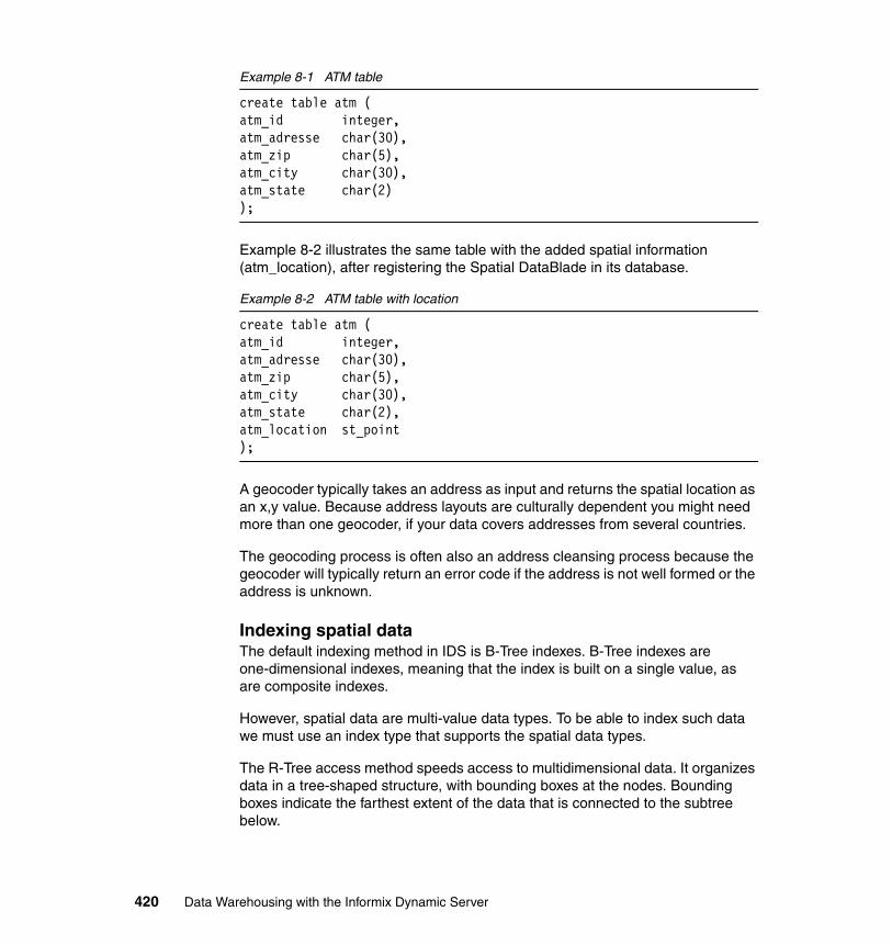
Example 8-1 ATM table
create table atm (atm_id integer,atm_adresse char(30),atm_zip char(5),atm_city char(30),atm_state char(2));
Example 8-2 illustrates the same table with the added spatial information (atm_location), after registering the Spatial DataBlade in its database.
Example 8-2 ATM table with location
create table atm (atm_id integer,atm_adresse char(30),atm_zip char(5),atm_city char(30),atm_state char(2),atm_location st_point);
A geocoder typically takes an address as input and returns the spatial location as an x,y value. Because address layouts are culturally dependent you might need more than one geocoder, if your data covers addresses from several countries.
The geocoding process is often also an address cleansing process because the geocoder will typically return an error code if the address is not well formed or the address is unknown.
Indexing spatial dataThe default indexing method in IDS is B-Tree indexes. B-Tree indexes are one-dimensional indexes, meaning that the index is built on a single value, as are composite indexes.
However, spatial data are multi-value data types. To be able to index such data we must use an index type that supports the spatial data types.
The R-Tree access method speeds access to multidimensional data. It organizes data in a tree-shaped structure, with bounding boxes at the nodes. Bounding boxes indicate the farthest extent of the data that is connected to the subtree below.
420 Data Warehousing with the Informix Dynamic Server
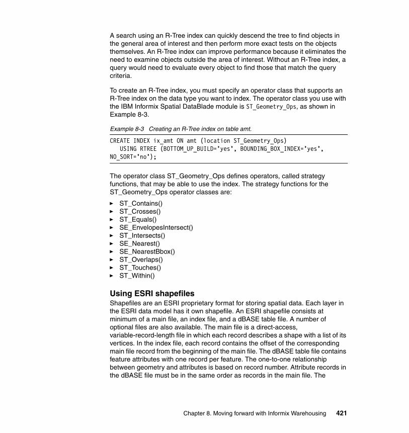
A search using an R-Tree index can quickly descend the tree to find objects in the general area of interest and then perform more exact tests on the objects themselves. An R-Tree index can improve performance because it eliminates the need to examine objects outside the area of interest. Without an R-Tree index, a query would need to evaluate every object to find those that match the query criteria.
To create an R-Tree index, you must specify an operator class that supports an R-Tree index on the data type you want to index. The operator class you use with the IBM Informix Spatial DataBlade module is ST_Geometry_Ops, as shown in Example 8-3.
Example 8-3 Creating an R-Tree index on table amt.
CREATE INDEX ix_amt ON amt (location ST_Geometry_Ops)USING RTREE (BOTTOM_UP_BUILD=’yes’, BOUNDING_BOX_INDEX=’yes’,
NO_SORT=’no’);
The operator class ST_Geometry_Ops defines operators, called strategy functions, that may be able to use the index. The strategy functions for the ST_Geometry_Ops operator classes are:
� ST_Contains()� ST_Crosses()� ST_Equals()� SE_EnvelopesIntersect()� ST_Intersects()� SE_Nearest()� SE_NearestBbox()� ST_Overlaps()� ST_Touches()� ST_Within()
Using ESRI shapefilesShapefiles are an ESRI proprietary format for storing spatial data. Each layer in the ESRI data model has it own shapefile. An ESRI shapefile consists at minimum of a main file, an index file, and a dBASE table file. A number of optional files are also available. The main file is a direct-access, variable-record-length file in which each record describes a shape with a list of its vertices. In the index file, each record contains the offset of the corresponding main file record from the beginning of the main file. The dBASE table file contains feature attributes with one record per feature. The one-to-one relationship between geometry and attributes is based on record number. Attribute records in the dBASE file must be in the same order as records in the main file. The
Chapter 8. Moving forward with Informix Warehousing 421
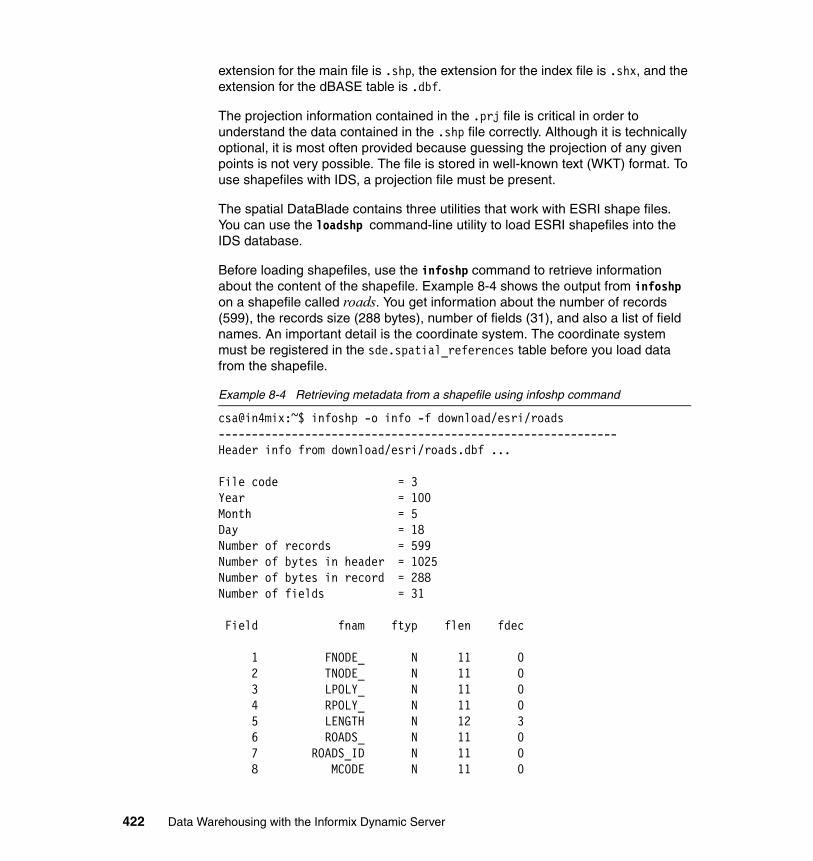
extension for the main file is .shp, the extension for the index file is .shx, and the extension for the dBASE table is .dbf.
The projection information contained in the .prj file is critical in order to understand the data contained in the .shp file correctly. Although it is technically optional, it is most often provided because guessing the projection of any given points is not very possible. The file is stored in well-known text (WKT) format. To use shapefiles with IDS, a projection file must be present.
The spatial DataBlade contains three utilities that work with ESRI shape files. You can use the loadshp command-line utility to load ESRI shapefiles into the IDS database.
Before loading shapefiles, use the infoshp command to retrieve information about the content of the shapefile. Example 8-4 shows the output from infoshp on a shapefile called roads. You get information about the number of records (599), the records size (288 bytes), number of fields (31), and also a list of field names. An important detail is the coordinate system. The coordinate system must be registered in the sde.spatial_references table before you load data from the shapefile.
Example 8-4 Retrieving metadata from a shapefile using infoshp command
csa@in4mix:~$ infoshp -o info -f download/esri/roads------------------------------------------------------------Header info from download/esri/roads.dbf ...
File code = 3Year = 100Month = 5Day = 18Number of records = 599Number of bytes in header = 1025Number of bytes in record = 288Number of fields = 31
Field fnam ftyp flen fdec
1 FNODE_ N 11 0 2 TNODE_ N 11 0 3 LPOLY_ N 11 0 4 RPOLY_ N 11 0 5 LENGTH N 12 3 6 ROADS_ N 11 0 7 ROADS_ID N 11 0 8 MCODE N 11 0
422 Data Warehousing with the Informix Dynamic Server
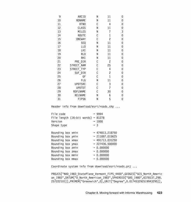
9 ARCID N 11 0 10 RDNAME N 11 0 11 RTNO C 4 0 12 CLASS N 11 0 13 MILES N 7 3 14 ROUTE C 1 0 15 ONEWAY C 2 0 16 SEQ N 11 0 17 LLO N 11 0 18 LHI N 11 0 19 RLO N 11 0 20 RHI N 11 0 21 PRE_DIR C 2 0 22 STREET_NAM C 25 0 23 STREET_TYP C 4 0 24 SUF_DIR C 2 0 25 GF C 1 0 26 FLG N 11 0 27 UPDTSRC C 3 0 28 UPDTDT C 7 0 29 RDFLNAME C 30 0 30 RELNAME N 6 0 31 FIPS6 N 5 0
Header info from download/esri/roads.shp ...
File code = 9994File length (16-bit words) = 81278Version = 1000Shape type = 3
Bounding box xmin = 474813.218750Bounding box ymin = 211897.015625Bounding box xmax = 491713.031250Bounding box ymax = 227436.500000Bounding box zmin = 0.000000Bounding box zmax = 0.000000Bounding box mmin = 0.000000Bounding box mmax = 0.000000
Coordinate system info from download/esri/roads.prj ...
PROJCS["NAD_1983_StatePlane_Vermont_FIPS_4400",GEOGCS["GCS_North_American_1983",DATUM["D_North_American_1983",SPHEROID["GRS_1980",6378137,298.257222101]],PRIMEM["Greenwich",0],UNIT["Degree",0.017453292519943295]],
Chapter 8. Moving forward with Informix Warehousing 423
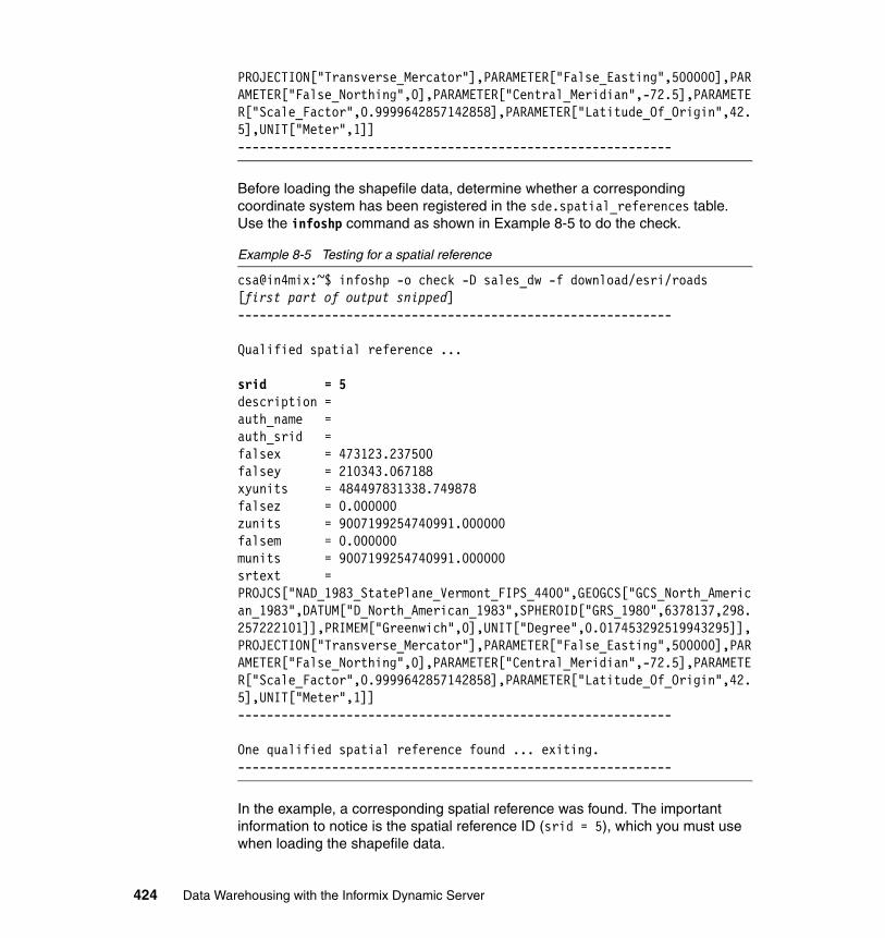
PROJECTION["Transverse_Mercator"],PARAMETER["False_Easting",500000],PARAMETER["False_Northing",0],PARAMETER["Central_Meridian",-72.5],PARAMETER["Scale_Factor",0.9999642857142858],PARAMETER["Latitude_Of_Origin",42.5],UNIT["Meter",1]]------------------------------------------------------------
Before loading the shapefile data, determine whether a corresponding coordinate system has been registered in the sde.spatial_references table. Use the infoshp command as shown in Example 8-5 to do the check.
Example 8-5 Testing for a spatial reference
csa@in4mix:~$ infoshp -o check -D sales_dw -f download/esri/roads[first part of output snipped]------------------------------------------------------------
Qualified spatial reference ...
srid = 5description = auth_name = auth_srid = falsex = 473123.237500falsey = 210343.067188xyunits = 484497831338.749878falsez = 0.000000zunits = 9007199254740991.000000falsem = 0.000000munits = 9007199254740991.000000srtext = PROJCS["NAD_1983_StatePlane_Vermont_FIPS_4400",GEOGCS["GCS_North_American_1983",DATUM["D_North_American_1983",SPHEROID["GRS_1980",6378137,298.257222101]],PRIMEM["Greenwich",0],UNIT["Degree",0.017453292519943295]],PROJECTION["Transverse_Mercator"],PARAMETER["False_Easting",500000],PARAMETER["False_Northing",0],PARAMETER["Central_Meridian",-72.5],PARAMETER["Scale_Factor",0.9999642857142858],PARAMETER["Latitude_Of_Origin",42.5],UNIT["Meter",1]]------------------------------------------------------------
One qualified spatial reference found ... exiting.------------------------------------------------------------
In the example, a corresponding spatial reference was found. The important information to notice is the spatial reference ID (srid = 5), which you must use when loading the shapefile data.
424 Data Warehousing with the Informix Dynamic Server
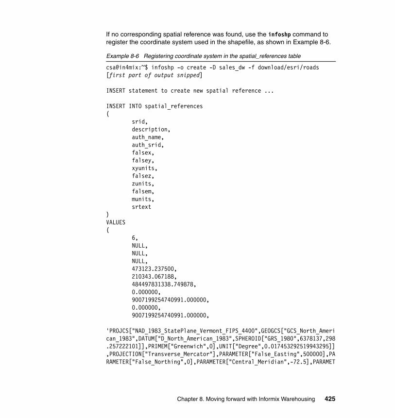
If no corresponding spatial reference was found, use the infoshp command to register the coordinate system used in the shapefile, as shown in Example 8-6.
Example 8-6 Registering coordinate system in the spatial_references table
csa@in4mix:~$ infoshp -o create -D sales_dw -f download/esri/roads[first part of output snipped]
INSERT statement to create new spatial reference ...
INSERT INTO spatial_references( srid, description, auth_name, auth_srid, falsex, falsey, xyunits, falsez, zunits, falsem, munits, srtext)VALUES( 6, NULL, NULL, NULL, 473123.237500, 210343.067188, 484497831338.749878, 0.000000, 9007199254740991.000000, 0.000000, 9007199254740991.000000, 'PROJCS["NAD_1983_StatePlane_Vermont_FIPS_4400",GEOGCS["GCS_North_American_1983",DATUM["D_North_American_1983",SPHEROID["GRS_1980",6378137,298.257222101]],PRIMEM["Greenwich",0],UNIT["Degree",0.017453292519943295]],PROJECTION["Transverse_Mercator"],PARAMETER["False_Easting",500000],PARAMETER["False_Northing",0],PARAMETER["Central_Meridian",-72.5],PARAMET
Chapter 8. Moving forward with Informix Warehousing 425
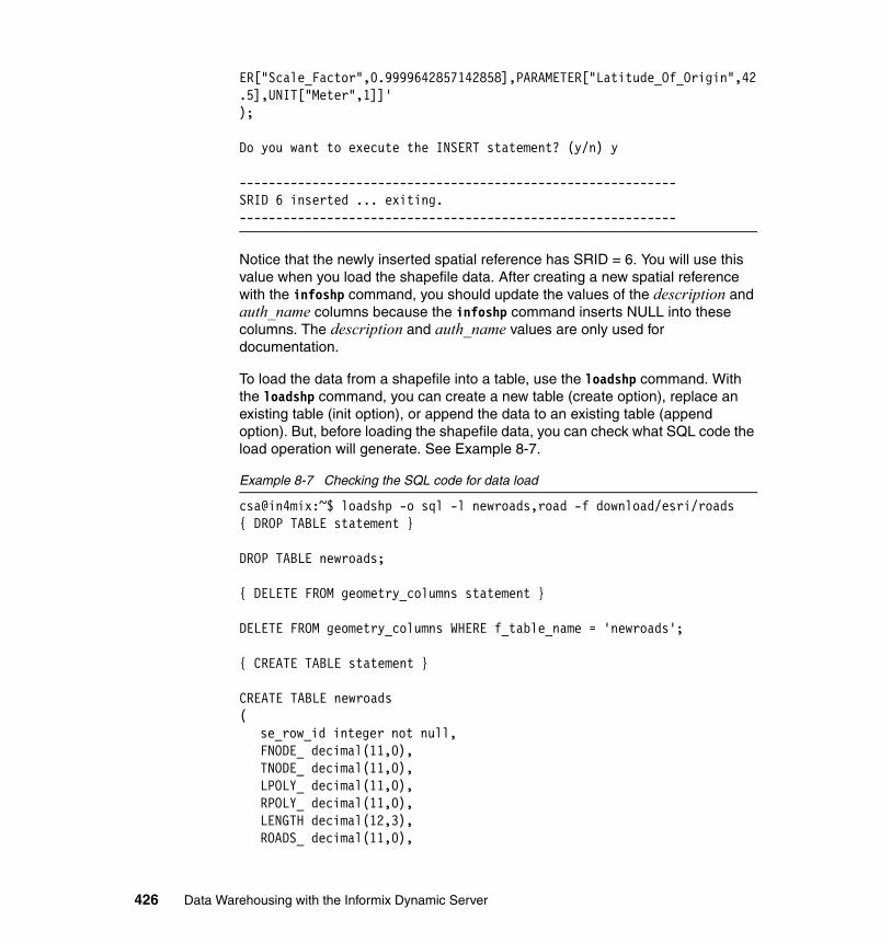
ER["Scale_Factor",0.9999642857142858],PARAMETER["Latitude_Of_Origin",42.5],UNIT["Meter",1]]');
Do you want to execute the INSERT statement? (y/n) y
------------------------------------------------------------SRID 6 inserted ... exiting.------------------------------------------------------------
Notice that the newly inserted spatial reference has SRID = 6. You will use this value when you load the shapefile data. After creating a new spatial reference with the infoshp command, you should update the values of the description and auth_name columns because the infoshp command inserts NULL into these columns. The description and auth_name values are only used for documentation.
To load the data from a shapefile into a table, use the loadshp command. With the loadshp command, you can create a new table (create option), replace an existing table (init option), or append the data to an existing table (append option). But, before loading the shapefile data, you can check what SQL code the load operation will generate. See Example 8-7.
Example 8-7 Checking the SQL code for data load
csa@in4mix:~$ loadshp -o sql -l newroads,road -f download/esri/roads{ DROP TABLE statement }
DROP TABLE newroads;
{ DELETE FROM geometry_columns statement }
DELETE FROM geometry_columns WHERE f_table_name = 'newroads';
{ CREATE TABLE statement }
CREATE TABLE newroads(
se_row_id integer not null,FNODE_ decimal(11,0),TNODE_ decimal(11,0),LPOLY_ decimal(11,0),RPOLY_ decimal(11,0),LENGTH decimal(12,3),ROADS_ decimal(11,0),
426 Data Warehousing with the Informix Dynamic Server
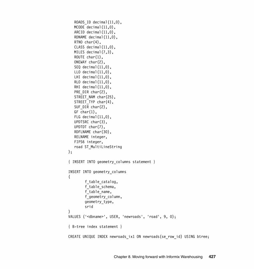
ROADS_ID decimal(11,0),MCODE decimal(11,0),ARCID decimal(11,0),RDNAME decimal(11,0),RTNO char(4),CLASS decimal(11,0),MILES decimal(7,3),ROUTE char(1),ONEWAY char(2),SEQ decimal(11,0),LLO decimal(11,0),LHI decimal(11,0),RLO decimal(11,0),RHI decimal(11,0),PRE_DIR char(2),STREET_NAM char(25),STREET_TYP char(4),SUF_DIR char(2),GF char(1),FLG decimal(11,0),UPDTSRC char(3),UPDTDT char(7),RDFLNAME char(30),RELNAME integer,FIPS6 integer,road ST_MultiLineString
);
{ INSERT INTO geometry_columns statement }
INSERT INTO geometry_columns( f_table_catalog, f_table_schema, f_table_name, f_geometry_column, geometry_type, srid)VALUES ('<dbname>', USER, 'newroads', 'road', 9, 0);
{ B-tree index statement }
CREATE UNIQUE INDEX newroads_ix1 ON newroads(se_row_id) USING btree;
Chapter 8. Moving forward with Informix Warehousing 427
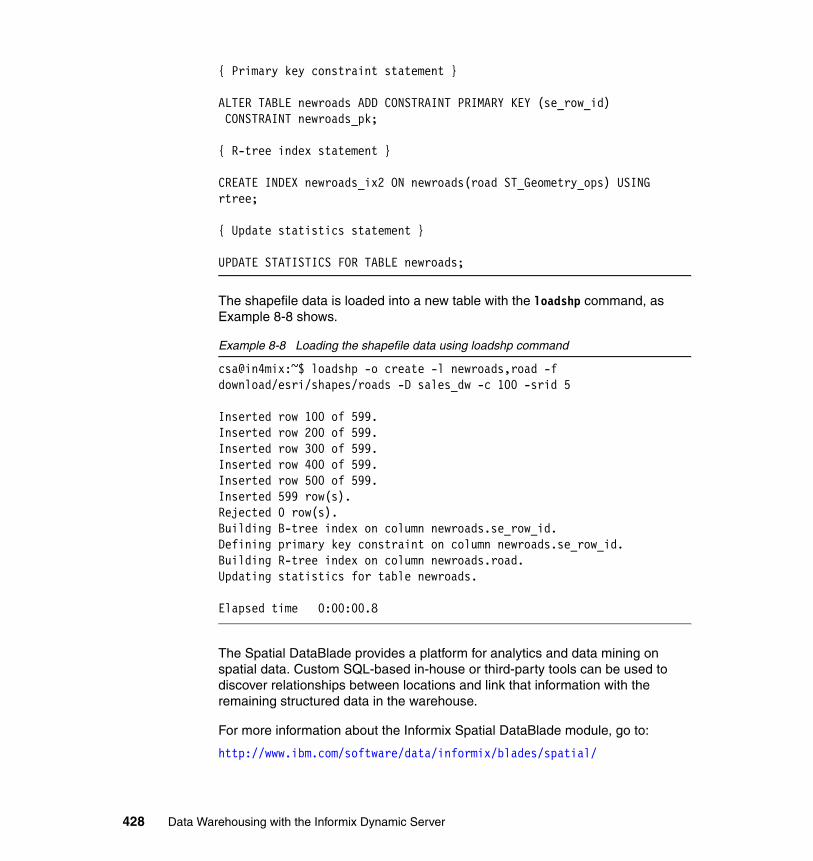
{ Primary key constraint statement }
ALTER TABLE newroads ADD CONSTRAINT PRIMARY KEY (se_row_id) CONSTRAINT newroads_pk;
{ R-tree index statement }
CREATE INDEX newroads_ix2 ON newroads(road ST_Geometry_ops) USING rtree;
{ Update statistics statement }
UPDATE STATISTICS FOR TABLE newroads;
The shapefile data is loaded into a new table with the loadshp command, as Example 8-8 shows.
Example 8-8 Loading the shapefile data using loadshp command
csa@in4mix:~$ loadshp -o create -l newroads,road -f download/esri/shapes/roads -D sales_dw -c 100 -srid 5
Inserted row 100 of 599.Inserted row 200 of 599.Inserted row 300 of 599.Inserted row 400 of 599.Inserted row 500 of 599.Inserted 599 row(s).Rejected 0 row(s).Building B-tree index on column newroads.se_row_id.Defining primary key constraint on column newroads.se_row_id.Building R-tree index on column newroads.road.Updating statistics for table newroads.
Elapsed time 0:00:00.8
The Spatial DataBlade provides a platform for analytics and data mining on spatial data. Custom SQL-based in-house or third-party tools can be used to discover relationships between locations and link that information with the remaining structured data in the warehouse.
For more information about the Informix Spatial DataBlade module, go to:
http://www.ibm.com/software/data/informix/blades/spatial/
428 Data Warehousing with the Informix Dynamic Server
8.3.3 Using the Informix Geodetic DataBlade module
The Geodetic DataBlade module is currently offered as an add-on DataBlade that can be acquired if the system needs to use a round Earth model rather than a flat plane Earth model. It is useful for spatial-based analytics requiring querying long distances. The Geodetic DataBlade provides additional value for customers who must work with very accurate representations of latitude and longitude that provide for the curvature of the earth calculations.
This module enables you to manage geospatial information referenced by latitude-longitude coordinates, supporting global space- and time-based queries without limitations inherent in map projections.
Similar to the Spatial DataBlade, the Geodetic DataBlade manages spatial data using Geographic Information Systems (GIS) technologies, but it is best used for global data sets and applications.
It also uses the R-Tree index on integrated space, time and numeric dimensions for fast performance and efficient access, and provides an SQL API for incorporating queries into existing applications to do spatial-analytics.
For more information about the Geodetic DataBlade, consult:
http://www.ibm.com/software/data/informix/blades/geodetic/
8.3.4 The Web Feature Service
For integration of spatial-based information with Web Services architectures, the Web Feature Service (WFS) implements an Open Geospatial Consortium Web Feature Service (OGC WFS) in IDS to act as a presentation layer for both the Spatial and Geodetic DataBlade modules.
The purpose of the WFS is to enable Web-services calls and applications. The OGC WFS interface allows requests for geographical features across the Web, using platform-independent calls. The XML-based Geography Markup Language (GML) is used as the encoding for transporting the geographic features.
For more information about the WFS DataBlade, refer to the article Using Web Feature Service (WFS) with IBM Informix Dynamic Server at IBM developerWorks:
http://www.ibm.com/developerworks/data/library/techarticle/dm-0810kleoppel/index.html
Chapter 8. Moving forward with Informix Warehousing 429
8.4 Integrating with BI tools
To complete the picture of comprehensive BI and analytic functionality for IDS customers, the IBM Cognos product suite includes a comprehensive suite of tools for reporting, drill-down and drill-up analyses, and dashboard and scorecard capabilities. Its industry-leading BI capabilities allow it to do both multidimensional online analytical processing (MOLAP) and relational OLAP (ROLAP) that adapts to the size of the data sets involved.
For advanced stages of BI adoption, where predictive and statistical models to do data mining on the warehouse information is required, SPSS offers predictive analytic capabilities that help users predict future events and respond proactively upon that insight for a better business result.
The Cognos and SPSS products, along with SQW and IDS, provide a single source for Informix customers seeking an end-to-end data warehousing solution.
Informix databases can be used as data source of most BI tools through the native Informix client driver, or through ODBC or JDBC drivers. Consult the BI tool documentation for requirements on the Informix client and server sides.
We now briefly explore several IBM BI tools that can use IDS to enable business intelligence at different levels of needs:
� IBM Cognos Express 9� IBM Cognos 8 BI� IBM SPSS
8.4.1 Cognos Express 9
IBM Cognos Express delivers essential reporting, real-time analysis and manipulation of multidimensional data (OLAP) with write-back, dashboard, scorecard, and planning capabilities specifically built and priced to meet the requirements of midsize companies. The product has certain limitations on the number of users and the size of the deployment host that do not exist in the Enterprise-size solution Cognos BI.
IBM Cognos Express is a simple, yet complete, solution that integrates all of the essential business intelligence and planning features. This offering features a deep integration between Cognos and Informix products, because IDS 11.50 is the default contents repository and sample packages for Cognos Express, in addition to the fact that IDS can be used as data source for the BI tool.
430 Data Warehousing with the Informix Dynamic Server
In Cognos Express, everything is included in a pre-configured, self-contained solution that makes it simple and easy to install, own, operate, and grow. And, the solution connects with IDS using direct Informix Connect and ODBC driver.
A single centralized Web interface is provided to enable you to control all administrative aspects of installation, deployment, and management, using only a few mouse clicks. This product uses a self-service model that allows business users to work independently to analyze information and create and modify reports, without having to rely on IT for help. This BI offering includes the following components:
� Express Reporter (query and reporting):
– Self-service reporting and ad hoc query– Broad report coverage: operational, transactional, dashboards, ad hoc
� Express Advisor (analysis and visualization)
– Freeform analysis and visualization– Real-time analysis with in-memory multidimensional capability
� Express Xcelerator (planning and analysis)
– Excel-based planning and business analysis
– Extends the familiar Excel front-end with a powerful in-memory analytics engine for multi-dimensional analysis and planning
The integration points between Cognos Express 9 and IDS as source warehouse repository, and also as content repository, can be found at Cognos Express 9.0 Software Environments:
http://www.ibm.com/support/docview.wss?uid=swg27016645
For more information about Cognos Express, refer to:
http://www.ibm.com/software/data/cognos/products/cognos-express/
The product documentation for Cognos Express 9.0 can be found at:
http://publib.boulder.ibm.com/infocenter/cx/v9r0m0/index.jsp
8.4.2 Cognos 8 Business Intelligence
Although Cognos Express 9 is an easy-to-use, pre-configured, BI tools solution for mid-size organizations, with specific BI capabilities, Cognos 8 Business Intelligence (BI) delivers the complete range of BI capabilities (reporting, analysis, dashboarding, and scorecards) on a single, service-oriented architecture (SOA). You can author, share, and use reports that draw on data across all enterprise sources for better business decisions.
Chapter 8. Moving forward with Informix Warehousing 431
The integration points between Cognos 8 BI with IDS as data source warehouse repository, and the supported IDS versions by the Cognos BI tools can on the Cognos 8 BI 8.4 Software Environments page:
http://www.ibm.com/support/docview.wss?uid=swg27014110
For more information about Cognos 8 Business Intelligence, go to:
http://www.ibm.com/software/data/cognos/products/cognos-8-business-intelligence/capabilities.html
8.4.3 SPSS, an IBM Company
SPSS has been acquired by IBM. SPSS has a software product suite for developing predictive analytics solutions. Those solutions help users gain predictive knowledge and act upon the insight to drive smarter business outcomes. The SPSS products offer capabilities such as:
� Data collection: To capture information about such things as people's attitudes and opinions.
� Modeling (formerly Clementine): Enables predictive analytics. You will be able to discover hidden relationships in data and anticipate the outcomes of future interactions.
� Statistics: This is a wide range of data and statistical manipulation programs. With SPSS Statistics family, including PASW Statistics (formerly SPSS Statistics), you can be confident in your results and decisions.
� Deployment: Enables you to act based on business users’ insights by embedding analytic results into business processes.
You can connect SPSS to IDS (the warehouse) using ODBC driver.
For more information about the IBM acquisition of SPSS, go to:
http://www.ibm.com/software/data/info/spss/
For more information about SPSS, go to:
http://www.spss.com
432 Data Warehousing with the Informix Dynamic Server
8.5 Real-time data warehousing
InfoSphere Change Data Capture (CDC) Version 6.3 captures and delivers (pushes) changed data across diverse data stores in real-time. IDS can be used as either source (only if IDS 11.50.xC3 or greater is used) or target systems.
The functionality that CDC provides enable solutions such as: Real-time and dynamic data warehousing, real-time analytics, business intelligence and reporting, and eBusiness. InfoSphere CDC also provides functions for data translation, filtering, replication, and high availability.
Fore more information about integration of Informix databases and CDC, go to:
http://www.ibm.com/developerworks/data/library/techarticle/dm-0902govindarajan/
For more information about InfoSphere CDC, refer to:
http://www.ibm.com/software/data/infosphere/change-data-capture/
Chapter 8. Moving forward with Informix Warehousing 433

434 Data Warehousing with the Informix Dynamic Server
Glossary
ACL. access control list. The list of principals that have explicit permission (to publish, to subscribe to, and to request persistent delivery of a publication message) against a topic in the topic tree. The ACLs define the implementation of topic-based security.
aggregate. Pre-calculated and pre-stored summaries, kept in the data warehouse to improve query performance.
aggregation. An attribute-level transformation that reduces the level of detail of available data, for example, having a Total Quantity by Category of Items rather than the individual quantity of each item in the category.
API. application programming interface. An interface provided by a software product that enables programs to request services.
asynchronous messaging. A method of communication between programs in which a program places a message on a message queue, and then proceeds with its own processing without waiting for a reply to its message.
attribute. A field in a dimension table.
BLOB. binary large object, a block of bytes of data (for example, the body of a message) that has no discernible meaning, but is treated as one solid entity that cannot be interpreted.
commit. An operation that applies all the changes made during the current unit of recovery or unit of work. After the operation is complete, a new unit of recovery or unit of work begins.
composite key. A key in a fact table that is the concatenation of the foreign keys in the dimension tables.
© Copyright IBM Corp. 2009. All rights reserved.
configuration. The collection of brokers, their execution groups, the message flows and sets that are assigned to them, and the topics and associated access control specifications.
Continuous Data Replication. Refer to Enterprise Replication.
DDL. Data Definition Language. An SQL statement that creates or modifies the structure of a table or database, for example, CREATE TABLE, DROP TABLE, ALTER TABLE, or CREATE DATABASE.
DML. Data Manipulation Language. An INSERT, UPDATE, DELETE, or SELECT SQL statement.
data append. A data loading technique where new data is added to the database, leaving the existing data unaltered.
data cleansing. A process of data manipulation and transformation to eliminate variations and inconsistencies in data content. This is typically to improve the quality, consistency, and usability of the data.
data federation. The process of enabling data from multiple heterogeneous data sources to appear as though it is contained in a single relational database. Can also be referred to as distributed access.
data mart. An implementation of a data warehouse, typically with a smaller and more tightly restricted scope, such as for a department or workgroup. It can be independent, or derived from another data warehouse environment.
data mining. A mode of data analysis that has a focus on the discovery of new information, such as unknown facts, data relationships, or data patterns.
435
data partition. A segment of a database that can be accessed and operated on independently, even though it is part of a larger data structure.
data refresh. A data loading technique where all the data in a database is completely replaced with a new set of data.
data warehouse. A specialized data environment developed, structured, and used specifically for decision support and informational applications. It is subject oriented rather than application oriented. Data is integrated, non-volatile, and time variant.
database partition. Part of a database that consists of its own data, indexes, configuration files, and transaction logs.
DataBlade. Program modules that provide extended capabilities for Informix databases and are tightly integrated with the DBMS.
DB Connect. Enables connection to several relational database systems and the transfer of data from these database systems into the SAP Business Information Warehouse.
debugger. A facility on the Message Flows view in the Control Center that enables message flows to be visually debugged.
deploy. Make operational the configuration and topology of the broker domain.
dimension. Data that further qualifies or describes a measure, or both, such as amounts or durations.
distributed application In message queuing, a set of application programs that can each be connected to a different queue manager, but that collectively constitute a single application.
drill-down. Iterative analysis, exploring facts at more detailed levels of the dimension hierarchies.
Dynamic SQL. SQL that is interpreted during execution of the statement.
embedded database. A database that works exclusively with a single application or appliance.
engine. A program that performs a core or essential function for other programs. A database engine performs database functions on behalf of the database user programs.
enrichment. The creation of derived data. An attribute-level transformation performed by some type of algorithm to create one or more new (derived) attributes.
Enterprise Replication. An asynchronous, log-based tool for replicating data between IBM Informix Dynamic Server database servers.
extenders. Program modules that provide extended capabilities for DB2 and are tightly integrated with DB2.
facts. A collection of measures, and the information to interpret those measures in a given context.
federation. A method of providing a unified interface to diverse data.
gateway. A means to access a heterogeneous data source. It can use native access or ODBC technology.
grain. The fundamental lowest level of data represented in a dimensional fact table.
instance. A particular realization of a computer process. Relative to the database, the realization of a complete database environment.
JDBC. Java Database Connectivity. An application programming interface that has the same characteristics as ODBC, but is specifically designed for use by Java database applications.
Java developer kit. A Software package used to write, compile, debug, and run Java applets and applications.
436 Data Warehousing with the Informix Dynamic Server
Java Message Service (JMS). An application programming interface that provides Java language functions for handling messages.
Java runtime environment. A subset of the Java Development Kit that enables you to run Java applets and applications.
materialized query table. A table where the results of a query are stored for later reuse.
measure. A data item that measures the performance or behavior of business processes.
message domain. The value that determines how the message is interpreted (parsed).
message flow. A directed graph that represents the set of activities performed on a message or event as it passes through a broker. A message flow consists of a set of message processing nodes and message processing connectors.
message parser. A program that interprets the bit stream of an incoming message and creates an internal representation of the message in a tree structure. A parser is also responsible for generating a bit stream for an outgoing message from the internal representation.
metadata. Typically called data (or information) about data. It describes or defines data elements.
MOLAP. multidimensional OLAP. Also called MD-OLAP. It is OLAP that uses a multidimensional database as the underlying data structure.
multidimensional analysis. Analysis of data along several dimensions, for example, analyzing revenue by product, store, and date.
multitasking. Operating system capability that allows multiple tasks to run concurrently, taking turns using the resources of the computer.
multithreading. Operating system capability that enables multiple concurrent users to use the same program. This saves the overhead of initiating the program multiple times.
nickname. An identifier that is used to reference the object located at the data source that you want to access.
node group. Group of one or more database partitions.
node. An instance of a database or database partition.
ODS. (1) operational data store: A relational table for holding clean data to load into InfoCubes, and can support some query activity. (2) Online Dynamic Server: An older name for IDS.
OLAP. online analytical processing. This is a form of data analysis that uses a multidimensional view of aggregate data, enabling fast access to the data.
Open Database Connectivity (ODBC). A standard application programming interface for accessing data in both relational and non-relational database management systems. Using this API, database applications can access data stored in database management systems on a variety of computers even if each database management system uses a different data storage format and programming interface. ODBC is based on the call level interface (CLI) specification of the X/Open SQL Access Group.
optimization. The capability to enable a process to execute and perform in such a way as to maximize performance, minimize resource utilization, and minimize the process execution response time delivered to the user.
partition. Part of a database that consists of its own data, indexes, configuration files, and transaction logs.
pass through. The act of passing the SQL for an operation directly to the data source without being changed by the federation server.
PHP. Hypertext Preprocessor. A general purpose scripting language.
Glossary 437
pivoting. Analysis operation where a user takes a different viewpoint of the results, for example, by changing the way the dimensions are arranged.
primary key. Field in a table that is uniquely different for each record in the table.
process. An instance of a program running in a computer.
program. A specific set of ordered operations for a computer to perform.
pushdown. The act of optimizing a data operation by pushing the SQL down to the lowest point in the federated architecture where that operation can be executed. More simply, a pushdown operation is one that is executed at a remote server.
RSAM. Relational Sequential Access Method is the disk access method and storage manager for the Informix DBMS.
ROLAP. relational OLAP. Multidimensional analysis using a multidimensional view of relational data. A relational database is used as the underlying data structure.
Roll-up. Iterative analysis, exploring facts at a higher level of summarization.
server. A computer program that provides services to other computer programs (and their users) in the same or other computers. However, the computer that a server program runs in is also frequently referred to as a server.
shared nothing. A data management architecture where nothing is shared between processes. Each process has its own processor, memory, and disk space.
static SQL. SQL that has been compiled prior to execution. Typically provides best performance.
subject area. A logical grouping of data by categories, such as customers or items.
synchronous messaging. A method of communication between programs in which a program places a message on a message queue and then waits for a reply before resuming its own processing.
task. The basic unit of programming that an operating system controls. Also see Multitasking.
thread. The placeholder information associated with a single use of a program that can handle multiple concurrent users. Also see Multithreading.
unit of work. A recoverable sequence of operations performed by an application between two points of consistency.
user mapping. An association made between the federated server user ID and password and the data source (to be accessed) user ID and password.
virtual database. A federation of multiple heterogeneous relational databases.
Warehouse catalog. A subsystem that stores and manages all the system metadata.
xtree. A query-tree tool that enables you to monitor the query plan execution of individual queries in a graphical environment.
438 Data Warehousing with the Informix Dynamic Server
acronyms
ACS access control system
ADK Archive Development Kit (SAP)
API application programming interface
AQR automatic query rewrite
AR access register
ARM automatic restart manager
ART access register translation
ASCII American Standard Code for Information Interchange
AST application summary table
AUS Auto Update Statistics
BLOB Binary large object
BW Business Information Warehouse (SAP BW)
CCMS Computing Center Management System
CDR Continuous Data Replication
CFG configuration
CLI call level interface
CLOB character large object
CLP command-line processor
CLR Continuous Log Restore
CORBA Common Object Request Broker Architecture
CPU central processing unit
CS Cursor Stability
DaaS Data as a Service
DAS DB2 Administration Server
DB database
DB2 II DB2 Information Integrator
DB2 UDB DB2 Universal Database™
Abbreviations and
© Copyright IBM Corp. 2009. All rights reserved.
DBA database administrator
DBM database manager
DBMS database management system
DCE distributed computing environment
DCM Dynamic Coserver Management
DCOM distributed component object model
DDL data definition language
DES Data Encryption Standard
DIMID Dimension Identifier
DLL dynamic link library
DML data manipulation language
DMS database managed space
DPF data partitioning facility
DRDA® Distributed Relational Database Architecture™
DSA Dynamic Scalable Architecture
DSN data source name
DSS decision support system
EAI enterprise application integration
EBCDIC Extended Binary Coded Decimal Interchange Code
EDA enterprise data architecture
EDU engine dispatchable unit
EGL Enterprise Generation Language
EGM Enterprise Gateway Manager
EJB Enterprise Java Beans
ER enterprise replication
439
ERP enterprise resource planning
ESE Enterprise Server Edition
ETL extract, transform, and load
FP fix pack
FTP File Transfer Protocol
Gb gigabit
GB gigabyte
GLS Global Language Support
GUI graphical user interface
HADR high availability disaster recovery
HDR high availability data replication
HPL High-Performance Loader
I/O input/output
IBM International Business Machines Corporation
ID identifier
IDE integrated development environment
IDS Informix Dynamic Server
II Information Integrator
IMS™ Information Management System
ISA Informix Server Administrator
ISAM indexed sequential access method
ISM Informix Storage Manager
ISV independent software vendor
IT Information technology
ITR Internal throughput rate
ITSO International Technical Support Organization
IX index
J2EE Java 2 Platform, Enterprise Edition
JAR Java archive
JDBC Java Database Connectivity
JDK Java developer kit
JE Java Edition
JMS Java Message Service
JRE Java runtime environment
JVM Java virtual machine
KB kilobyte (1024 bytes)
LBAC label-based access control
LDAP Lightweight Directory Access Protocol
LPAR logical partition
LRU least recently used
LUN logical unit number
LV logical volume
Mb megabit
MB megabyte
MDC multidimensional clustering
MPP massively parallel processing
MQI message queuing interface
MQT materialized query table
MRM message repository manager
MTK IBM Migration Toolkit
NPI non-partitioning index
OAT OpenAdmin Tool
ODBC Open Database Connectivity
ODS operational data store
OEM original equipment manufacturer
OLAP online analytical processing
OLE object linking and embedding
OLTP online transaction processing
ORDBMS object relational database management system
OS operating system
PAM Pluggable Authentication Module
PDS partitioned data set
PHP Hypertext Preprocessor
440 Data Warehousing with the Informix Dynamic Server
PIB parallel index build
PSA persistent staging area
RBA relative byte address
RBAC role-based access control
RBW red brick warehouse
RDBMS relational database management system
RHEL Red Hat Enterprise Linux
RID record identifier
RR repeatable read
RS Read Stability
RSAM Relational Sequential Access Method
RSS remote stand-alone secondary
RTO recovery time objective
SA systems administrator
SCB session control block
SDK software development kit
SDS shared disk secondary
SID surrogate identifier
SLES SUSE Linux Enterprise Server
SMI System Monitoring Interface
SMIT System Management Interface Tool
SMP symmetric multiprocessing
SMS system-managed space
SSJE Server Studio Java Edition
SOA service-oriented architecture
SOAP Simple Object Access Protocol
SPL Stored Procedure Language
SQL structured query
TCB thread control block
TMU table management utility
TS table space
UDB Universal Database
UDF user-defined function
UDR user-defined routine
URL Uniform Resource Locator
VG volume group (RAID disk terminology).
VLDB very large database
VP virtual processor
VSAM virtual sequential access method
VII Virtual Index Interface
VTI Virtual Table Interface
WFS Web Feature Service
WSDL Web Services Description Language
WWW World Wide Web
XBSA X/Open Backup Services Application
XML Extensible Markup Language
XPS Informix Extended Parallel Server
Abbreviations and acronyms 441

442 Data Warehousing with the Informix Dynamic Server
Related publications
The publications listed in this section are considered particularly suitable for a more detailed discussion of the topics covered in this book.
IBM Redbooks
For information about ordering these publications, see “How to get Redbooks” on page 446. Note that some of the documents referenced here may be available in softcopy only.
� Data Mart Consolidation: Getting Control of Your Enterprise Information, SG24-6653
� Data Modeling Techniques for Data Warehousing, SG24-2238
� Dimensional Modeling: In a Business Intelligence Environment, SG24-7138
Other publicationsThese publications are also relevant as further information sources:
� IBM Informix Database Design and Implementation Guide, G251-2271
� Ralph Kimball. The Data Warehouse Toolkit: Practical Techniques for Building Dimensional Data Warehouses. John Wiley & Sons, 1996.
� Ralph Kimball, Laura Reeves, Margy Ross, and Warren Thornthwaite. The Data Warehouse Lifecycle Toolkit: Expert Methods for Designing, Developing, and Deploying Data Warehouses. John Wiley & Sons, 1998.
� Ralph Kimball, and Margy Ross. The Data Warehouse Toolkit: The Complete Guide to Dimensional Modeling (Second Edition). John Wiley & Sons, 2002.
� Claudia Imhoff, Nicholas Galemmo, and Jonathan G. Geiger. Mastering Data Warehouse Design: Relational and Dimensional Techniques, John Wiley & Sons, 2003.
� Toby J. Teorey. Database Modeling & Design, Third Edition, The Morgan Kaufmann Series in Data Management Systems, Academic Press, 1999.
� W. H. Inmon, Building the Data Warehouse. John Wiley & Sons, 2005.
© Copyright IBM Corp. 2009. All rights reserved. 443
� W. H. Inmon, Claudia Imhoff, and Ryan Sousa, Corporate Information Factory (Second Edition). John Wiley & Sons, 2000.
� Melissa A. Cook. Building Enterprise Information Architectures, Prentice-Hall, Inc., 1996.
� Lou Agosta, The Essential Guide to Data Warehousing, Prentice-Hall, Inc., 1999.
Online resources
These Web sites are also relevant as further information sources:
� OpenAdmin Tool for IDS
http://www.openadmintool.org/
� IBM Data Studio
http://www.ibm.com/software/data/optim/data-studio
� Using Informix for your Warehouse
http://www.ibm.com/software/data/informix/warehouse/
� InfoSphere Data Architect
http://www.ibm.com/software/data/studio/data-architect/
� IBM InfoSphere DataStage
http://www.ibm.com/software/data/infosphere/datastage/
� IBM InfoSphere QualityStage
http://www.ibm.com/software/data/infosphere/qualitystage/
� IBM Cognos Express
http://www.ibm.com/software/data/cognos/products/cognos-express/
� IBM Cognos Business Intelligence
http://www.ibm.com/software/data/cognos/products/cognos-8-business-intelligence/
� IBM DataQuant
http://www.ibm.com/software/data/db2imstools/db2tools/dataquant/index.html
444 Data Warehousing with the Informix Dynamic Server

Education support
Available from IBM training, the newest offerings support your training needs, enhance your skills and boost your success with IBM software.
IBM offers a range of training options from traditional classroom to instructor-led online courses to meet your demanding schedule.
Instructor-Led Online (ILO) training is an innovative learning format where students get the benefit of being in a classroom with the convenience and cost savings of online training.
Go green with IBM Onsite training. Choose from the same quality training delivered in classrooms, or customize a course or a selection of courses to best suit your business needs
Enjoy further savings when you purchase training at a discount with an IBM Education Pack (online account), which is a flexible and convenient way to pay, track, and manage your education expenses online.
Check your local Information Management Training and Education Web site or with your training representative for the most recent training schedule. Also refer to Table 1.
Table 1 Education offerings
Descriptions of courses for IT professionals and managers are available at:
http://www.ibm.com/services/learning/ites.wss/tp/en?pageType=tp_search
Course title Classroom: Course Code
Instructor Led Online:Course Code
Informix Warehouse: SQL Warehousing Tool and Administration Console
IXA51 3XA51
Changing Business with Data Insight DW03 3W03
Architecting the Data Warehouse DW11 -
Informix Dynamic Server Database Administration: Managing and Optimizing Data
IX22 3X22
Informix Dynamic Server 11 New Features IX30 3X30
Informix Dynamic Server System Administration IX81 3X81
Informix Dynamic Server Replication IX42 3X42
Related publications 445
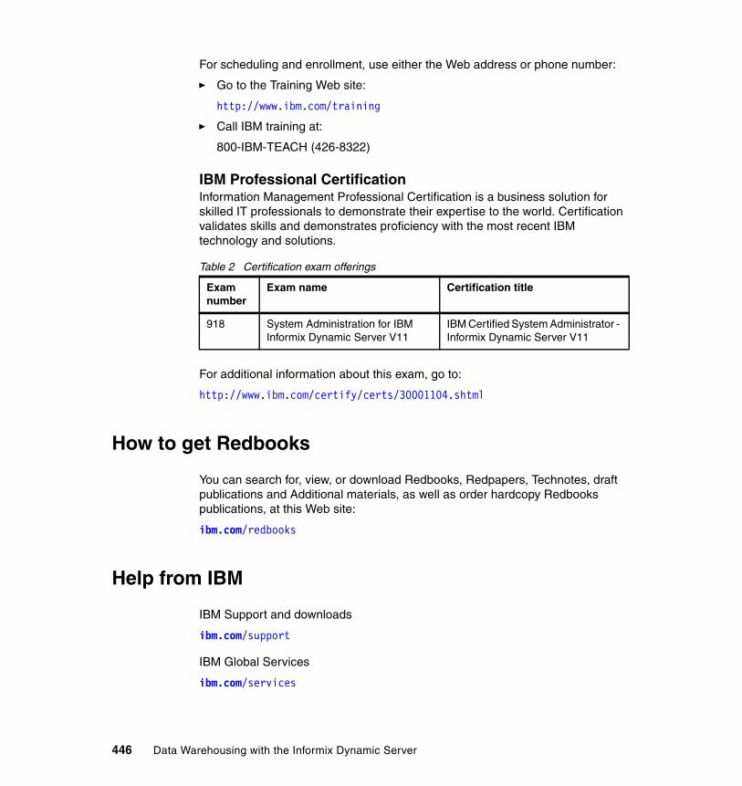
For scheduling and enrollment, use either the Web address or phone number:
� Go to the Training Web site:
http://www.ibm.com/training
� Call IBM training at:
800-IBM-TEACH (426-8322)
IBM Professional CertificationInformation Management Professional Certification is a business solution for skilled IT professionals to demonstrate their expertise to the world. Certification validates skills and demonstrates proficiency with the most recent IBM technology and solutions.
Table 2 Certification exam offerings
For additional information about this exam, go to:
http://www.ibm.com/certify/certs/30001104.shtml
How to get Redbooks
You can search for, view, or download Redbooks, Redpapers, Technotes, draft publications and Additional materials, as well as order hardcopy Redbooks publications, at this Web site:
ibm.com/redbooks
Help from IBM
IBM Support and downloads
ibm.com/support
IBM Global Services
ibm.com/services
Exam number
Exam name Certification title
918 System Administration for IBM Informix Dynamic Server V11
IBM Certified System Administrator - Informix Dynamic Server V11
446 Data Warehousing with the Informix Dynamic Server
Index
Aaccess methods 417ACTIVE in update statement 394Admin Console 18, 35, 39–40, 42–45, 62–63, 65, 67, 87, 217–219, 221–225, 227–229, 232–233, 236–237, 239, 241, 245, 247, 251–254, 259, 262–263, 267–271, 273, 403
data flows 16deploy 217deploy physical model 108description of 35resource mapping 206
administrationaggregation tables 168and control 403architecture 221commands 186DataStage 210deploying warehouse applications 253differences of SQW, DataStage 211DSS and OLTP 29execute requests 119fragmentation, costs 305fragmentation, improving 304free zone 11low requirements 10of data warehouse 65OmniFind 412OpenAdmin Tool (OAT) 403security 226server capabilities 11SQL Warehousing runtime environment 243SQL Warehousing Tool 70SQW 63tasks 228technology for business 11
AIX 66, 377alter fragment 351analytic applications 8API 73, 407–408, 415, 429application development xiv, 9, 12, 14, 41, 278, 353architecture 3, 12, 14, 24–25, 27, 35, 46–47, 49, 70, 117, 119, 221, 239, 278–279, 373, 379
© Copyright IBM Corp. 2009. All rights reserved.
component-based 65data warehouse 45high-performance processing 210hub and spoke 50Informix Warehouse 16, 35, 66, 403InfoSphere DataStage 208n-tier installation 64OLAP 60parallel data server 278runtime 248runtime of SQL Warehousing 242SDS 376SOA 431SQW 118
array 12, 14, 71, 278asynchronous 373, 375, 378availability
and backup 248business 11cluster 11, 314, 377, 409data 297DataStage 210DSS 372DSS and OLTP 28enterprise 13HDR 372–373high-availability environment 375increasing data 298logs 290network 378of data 379OLTP 7platform 65–66real-time data warehousing 433resources 23Shared Disk Secondary 375WebSphere Application Server 64
Bbackup 13, 374, 377–378
and recovery 404deployment 248detached index 308
447
level-0 285, 381RAW versus TEMP 380remote 375temporary dbspaces 292
backup and restore 13, 367, 383CLR 377RAW tables 383
backup database 378backup server 377backups 56–57, 279BI xiii–xiv, 1–3, 9–10, 16–18, 21–23, 58, 60, 208, 372, 401, 403, 406, 430–431, 433binary large object
See BLOBBLOB 406–408, 410, 412, 435blobspaces 407Boolean 200, 408–409BPM 9–10B-tree 367, 386, 428
and R-tree 350index statement 427keyword option 397removing index space 343scanner 343
buffer cache 319, 331, 339buffer pool 16, 289, 319–320, 323–326BUFFERS 320, 323, 331business analytics 2, 25business model 33, 38business performance 9–10business performance management
See BPMbusiness processes 1, 9, 24, 33, 432, 460
CC in ESQL/C 407C in SELECT statement 356C subflow 159cache 319, 321, 324–325, 331, 339, 367cardinality 387character large object
See CLOBcheck constraints 315checkpoints 373, 375chunk 296, 299CLOB 407–408, 410, 412, 439closed-loop 9CLR 373, 377–378, 439
cluster environment 12clustered index 345, 347collection of data 432commit 216, 282, 285, 399Committed Read isolation 395–399concurrency 49, 342, 382, 394–395
between queries 311control isolation 395–396improved 302
concurrent queries 8configuration 5, 8, 14, 63, 67, 119, 122, 124, 202, 204, 208, 223–225, 227–228, 242, 246–248, 256, 277–278, 285, 289–293, 295–296, 313–314, 318–325, 329–331, 333–334, 336–340, 343, 346, 348, 350, 361, 363, 375–376, 392, 395, 398, 411, 419
parameters 320, 322–323, 337, 346, 348consistency 25consolidation 13, 47, 372, 379container 72, 191–192Continuous Log Restore
See CLRcost-based optimizer 352CPU VPs 29, 336CREATE INDEX statement 306, 308, 386CRM 406Cursor Stability 334, 396, 398–399
Ddashboards 8–9data
informational 24operational 24
Data Definition LanguageSee DDL
data distribution 193, 301–302, 392data integration 9data Load activity 280data mart 38, 123, 127, 210, 247
consolidation 47definition of 46
data movement 4, 39, 41, 69, 117–118, 120, 124, 127, 139, 207–209, 212–214, 280, 408data replication 373, 378–379data types 12, 14, 95, 132, 135, 278–279, 281, 283, 366, 407, 410, 412, 417–418, 420data warehouse
definition of 24
448 Data Warehousing with the Informix Dynamic Server
data warehousing xiii–xv, 2–4, 6–8, 10, 18, 21–25, 30–32, 34, 36, 39–42, 44, 46, 48–49, 55, 58, 61, 63–64, 67, 69, 81, 85, 115, 198–199, 208, 210–211, 222, 253, 259, 367, 372, 376, 381, 395, 401–403, 406, 416, 418, 430, 433
implementations 48Centralized 48Distributed 48Hub and Spoke 48
with data marts 47database xiv
instance 193objects 70, 81, 83, 89, 109, 238operations 279, 291, 311
database server xiii, 3, 10, 16, 65, 87, 120, 193, 283–284, 289–293, 295–298, 300–301, 303, 305–310, 312, 317, 320–325, 329–338, 340, 342–349, 353, 360, 363, 375–380, 384–385, 387–389, 392, 394–395, 397–399, 408–411DataBlade 141, 407, 409, 412DataStage 17, 29, 39–40, 55, 63, 67, 70, 118–119, 182, 194, 200, 206–210, 212–214, 221, 228–229, 236, 239, 256DBMS 6, 54dbspace 56, 173–175, 281, 283, 289–293, 295–299, 303–306, 308–309, 312–313, 319–320, 328, 341, 366–367, 371, 376DDL 4, 32, 37, 84, 91, 95, 99–100, 106–108, 111, 193, 251–252, 255, 280–281, 283, 334, 394, 435deadlock 394, 397Decision Support Systemdecision support system
See DSSdecision-making 9default buffer pool 320degree of parallelism 211, 332DELETE 85, 138–139, 172, 246, 311, 332, 426dependent data marts 46deployment xiii, 2, 5, 12, 14–15, 29, 33–35, 39–45, 61–63, 65, 67, 106, 108, 117–118, 120, 122–123, 135, 164, 185, 201–202, 204–208, 210–211, 218, 220–221, 229, 233, 235, 238–239, 241–242, 246, 248–249, 251–259, 261, 265, 277–278, 401, 419, 430–432
preparation 122, 203Design Studio xiii, 3–4, 16–17, 29, 33–39, 41–42, 44–45, 62–63, 67, 69–74, 76, 78–80, 86, 88–89, 95–96, 102, 105–106, 109, 112, 120, 125, 130, 135, 143, 161, 164–165, 168–169, 177–178, 184, 186,
195, 197, 203, 206, 213, 219–220, 223, 239–241, 243–247, 249–254, 256, 259, 268, 403
code display 196connections to databases 136deployment preparation 203DEPLOYMENT_PREP 201E-R diagrams 102launch New Physical Data Model wizard 99link multiple models from project 126SQL Warehousing components 240test execution 202
disaster 374, 377disk 280, 283, 318–319, 325, 327, 361Distributed Relational Database Architecture (DR-DA) 439DML 193, 290, 314, 317, 335DOLAP 60DRAUTO 374DROP 194, 346–347, 350–351, 388, 426DROP DISTRIBUTIONS 387DROP INDEX 349DROP TABLE 426DSA 7, 10, 12, 14, 278–279, 439DSS 6, 10, 28, 289, 319, 331, 373, 376, 401Dynamic Scalable Architecture
See DSA
EEclipse 17, 37, 54, 62, 70–71
environment 15, 89, 130Modeling Framework 119platform 69–71tools 39, 72
EDA 373editors in Design Studio 77EDW 8, 25, 46ELT 8, 116embedding 39, 352, 432enterprise data warehouse
See EDWEnterprise Edition 16, 34, 55, 61, 210Enterprise Java Beans 211Enterprise Replication
See EREntity-Relationship
See E-RE-R 6, 37, 46, 96, 102, 105ER 12, 372, 378–379, 381, 383
Index 449

ESRI shapefile 421ETL 8, 27, 31, 33, 48, 57, 63, 70, 118, 208, 211–213, 239, 246, 404, 418ETL tools 208, 212, 418Excalibur 406, 412exclusive set 156execution database 123execution plan graph (EPG) 163, 197export utility 408expression-based 296–297, 300–304, 306, 312, 349extensible 283, 350, 372, 412extent 251, 280–281, 296, 300, 305, 313, 371, 387, 420extent size 251, 313extract, load, and transform
See ELTextract, transform, and load
See ETL
Ffailover 374fast recovery 383faster query response 375federated 27, 50federation 9, 51file formats 418forced residency 326forest of trees topology 379fragmentation 7, 56, 192, 211, 280–281, 283, 295–300, 302–306, 308–309, 311, 329fragments 330
GGeodetic 414, 429getting the data in 8getting the data out 8graphs
Deployment EPG 164Runtime EPG 164See also execution plan graph (EPG)Undeployment EPG 164
GROUP BY 145, 169, 291, 341, 361GUI 39, 70, 186, 284
HHA 11–12, 372–373, 375
hash joins 10, 294HDR 372–376, 440HDR pair 373heterogeneous data 9, 26, 37, 52hierarchical 195, 379high availability
See HAHigh Availability Data Replication 440
See HDRHigh-Performance Loader
See HPLHOLAP 60host name 221, 229hot backup 377HPL 55, 214, 283HP-UX 66HTML 406–407
IIBM WebSphere Application Server 35IDS
Enterprise Edition 16instances 11, 28, 246, 316, 373, 379Workgroup Edition 62
impact analysis 111implement an application 44independent data marts 47index
constraints 359distribution 385fragments 7, 298, 308–310, 313, 391rebuild 56scans 297, 310, 349
indexes 55, 90, 95–97, 172, 215, 281, 285, 296, 304, 306–308, 310, 313, 317, 341–343, 347, 349–350, 352, 357, 359–360, 364, 366–367, 380–382, 384, 386, 389–392, 394, 397, 411, 420information integration 9information technology (IT) 10informational data 24Informix
SQW 207Informix JDBC 233Informix JDBC driver 234Informix Warehouse Administration Console
See Admin ConsoleInformix Warehouse Application Server 123, 139Informix Warehouse Feature 16
450 Data Warehousing with the Informix Dynamic Server
Informix Warehouse platformdefinition of 34IDS 34Informix Warehouse Feature 34Storage Optimization Feature 34
INSERT 85, 138–139, 169, 171, 246, 300, 303, 311, 314, 332–333, 408, 425–427instance 11, 14, 28, 37–38, 50, 69, 72, 193, 237, 246–247, 257, 267–268, 270–274, 278, 280, 285, 288, 304–305, 315–316, 318, 332, 337, 339–340, 370, 374, 379, 393, 415, 417, 419integration 30, 39, 70, 210, 212, 241, 243, 404–405
Data Integration Service (DIS) 119ipload utility 284isolation levels 396–397
JJ2EE 119, 221Java 18, 34–35, 62–63, 123, 163, 211, 219, 226, 233, 237–238, 250
Enterprise Java Beans 211JDBC 34, 45, 81, 88, 123, 163, 211–212, 233, 241, 247, 267, 430JDBC driver 234join operation 291, 363joins 6, 10, 127, 148, 169, 294, 311, 314, 335–336, 338, 343, 353, 357, 363, 376, 394
hash 354inner 148outer 336
Llabel-based access control
See LBAClatency 375LBAC 316–317, 440leaf page 342light scan 319light scan buffers 319Linux 12, 14, 66–67, 185, 234, 278, 284, 377, 379, 419LIST 145load 7–8, 27, 29, 39, 42, 48, 127, 143, 173, 190, 212, 214–216, 246, 280–285, 287–288, 297, 301–302, 335–336, 368, 377, 380–383, 407, 417–418, 422, 426Locks 282log buffers 323
log files 232logging and tracing 237logical data modeling 32logical logs 285, 328, 367, 383
Mmemory 10, 12, 16, 29, 56, 60, 279, 294–296, 316, 318–326, 329–331, 335–336, 339, 341–342, 346, 348, 350, 355, 361–362, 376, 391, 410, 431
allocation 356, 361management 322, 335pools 350usage 320
Memory Grant Manager (MGM) 355, 362MERGE INTO statement 142, 171merge join 363MERGE statement 170, 314–315, 317metadata 27, 30, 35, 60, 70, 72, 87, 119, 121, 125, 133, 161, 163, 195–196, 206, 209, 223, 240–241, 245, 248, 255–256, 261, 366–367, 422Microsoft SQL Server 234model 1, 33–34, 37, 39, 46–48, 51, 55, 57, 62–63, 70, 78, 81, 87, 90, 95–96, 101–102, 105–110, 121, 126–127, 135, 143, 160–161, 163, 178, 183, 195, 217, 240, 251–252, 372, 405, 417, 421, 431
abstraction 117analysis 81control flow 196data structure 91design new 99example 168flat plane 429physical 4, 99–100, 138, 251Physical Model wizard 98report 111–112round Earth 429template 99
MOLAP 60, 404, 430monitoring 11, 18, 35, 39, 59, 221, 273, 403, 412
compression 371shared memory 321
multiple devices 285multiple instances 48, 268
Nnamed pipes 214naming conventions 52near real-time 47, 58
Index 451
nested loop join 364network facilities 379
OOAT 11, 36, 369, 403object types 101ODBC 54, 430–432, 437, 440ODS 7offline mode 326OLAP 11, 13, 19, 24, 29–30, 38, 46, 48, 60, 73, 75, 86, 217, 278, 404, 430OLTP 6, 11, 13, 24, 28–29, 47–48, 278, 294, 338–339, 367, 376, 379, 401oncheck 313–314, 319, 351ONCONFIG 320, 325, 363, 385onconfig 293, 313, 320, 363ONCONFIG file 290, 323, 326, 337, 350, 361, 363, 411, 419onconfig file 320on-demand 7, 22, 41, 239online analytical processing
See OLAPonline mode 326online transaction processing
See OLTPonmode 290, 326, 337, 350, 361onmode utility 326onpload database 284onpload utility 284onspaces 292, 313–314, 319, 348, 411onstat 318, 331, 362, 371–372ontape 281OpenAdmin Tool
See OAToperational data 24operational data store
See ODSoptimistic concurrency 395optimization 5, 12, 16, 33, 277, 279, 365, 371, 403–404optimizer 173, 303, 314, 332, 341, 344, 347, 349–350, 352–354, 356, 359, 363, 365, 384, 386, 388, 399
directives 352query plans 347statistics 347, 352, 384
optimizer directives 352Oracle driver 234
ORDER BY 291, 341, 361
Ppackages 39, 87, 430page 11, 73–74, 84, 132, 135, 138, 152, 199, 219–220, 225, 227, 232–236, 251, 259, 262, 270, 273, 289, 294, 296, 313, 319–320, 323, 325–328, 342–343, 367, 387, 397, 414, 419
light scan 319page size 294, 296, 313, 319–320, 326–328, 342parallel database query
See PDQparallel insert 292–293, 333parallel query 7parallelism 211, 294, 304, 332, 334–335, 338partitioning 7, 172–174, 211, 295, 349, 377, 403–404pass-through property 144passwords 201PDQ 10, 172, 289, 291, 295, 329–338, 340, 346, 348, 361, 376, 391performance xiv, 5–6, 9–11, 13–14, 25–26, 28–29, 31, 36, 46, 49, 55–58, 60, 64, 124–125, 143, 172–173, 208–211, 214, 222, 242, 248–249, 251, 266, 277–279, 281, 283, 288–293, 295–297, 299–300, 302, 304, 307–310, 313–314, 318–319, 325, 329, 333, 337–338, 341, 343–344, 347–349, 353, 355, 361, 373–375, 377, 379–380, 388, 392–393, 396–399, 401, 403–404, 408, 414–415, 417, 421, 429performance tuning 29, 404perspectives
definition of 75primary 75
physical data model 32physical logs 328physical model 97primary 9, 34, 45–46, 51, 60, 96–97, 104, 120, 123, 128, 150, 159–160, 220, 226, 237, 296–297, 300, 302, 313–314, 327, 331, 334, 343, 373–380, 395, 409, 428privileges 80, 226, 315process management 10processes 4, 8–9, 18, 23, 26–27, 33, 35, 48, 55, 59, 67, 69, 86, 188, 209, 215, 219, 221, 223–224, 239, 241, 245–246, 253, 261, 267–268, 270–271, 279, 320–321, 332–333, 335, 348, 372, 403–404, 408, 432
452 Data Warehousing with the Informix Dynamic Server
projectdefinition of 72file holds metadata 72type 73
Qquery
fragments 7, 16, 297–299, 303query optimizer 347, 384query plan 303, 352, 357, 360, 384, 386queues 8, 209, 212, 311, 323
Rraw disk devices 293READ COMMITTED 398read-ahead 325real time 6, 12, 15, 23, 29, 47, 49, 58, 208, 212, 402, 404–405, 430–431, 433recovery 11, 56, 142–143, 279, 285, 308, 346, 374, 377–378, 380, 383, 404recovery time objective (RTO) 441Redbooks Web site 446
Contact us xvireferential integrity 104, 280Remote Standalone Secondary
See RSSRepeatable Read 363–365, 382, 396–397, 399replication xiv, 12, 211, 372–373, 378–379, 381, 383, 433replication environment 379replication topologies 379restore 13, 345–346, 367, 377, 380, 382–384ROLAP 19, 30, 60, 404, 430roles 96, 223, 225, 357, 373roll back 290, 315, 380, 396roll forward 373round-robin 289, 292–293, 296–297, 300–301, 304, 306, 309–310, 312, 333RSS 372, 374–376, 441R-tree 350, 417, 420–421, 428–429
Ssavepoints 315sbspaces 407scalability 10, 12–13, 64, 209, 211, 278–279, 375, 403schema 6, 16, 28, 56, 81, 88, 96–97, 100–103, 106,
135, 138, 160, 201, 257, 269, 280, 299, 351, 379, 395SDS 372, 375–377search 228, 405–406, 408–412secondary 314, 331, 372–375, 377, 409security 29, 51, 54, 64, 225–226, 315–317, 378security label 316security policy 316SELECT 132, 134, 145, 147, 167, 169, 172, 250, 291–292, 299, 303, 311, 316–317, 332–333, 347, 349–350, 353, 355–356, 358–359, 364, 396, 398–399, 409self tuning 11sequences 96server xiii, 2, 5, 13, 16, 18, 29, 35, 44–45, 55, 62–63, 65–67, 177, 193, 208, 211, 213, 218–219, 221–222, 224–227, 233, 235, 237–238, 243–244, 277–278, 285, 293, 315, 323, 362, 367, 371–372, 375–376, 386, 388, 401, 403, 409, 414
connection 233service-oriented architecture
See SOASET 171, 298–299, 314–315, 317, 330–331, 336–338, 340, 348, 364–365, 392, 394–399SET ISOLATION 364, 396shapefile 421Shared Disk Secondary
See SDSshared memory 319–326, 330–331, 339, 346, 348sharing 65, 320, 376smart large objects 407SMP 279snapshot 318SOA 27, 208, 431SPL routines 334–335, 350, 387, 395SQEXPLAIN 354SQL xiii, 11, 16–17, 29, 33–35, 39, 45, 48, 62–63, 67, 69–70, 73, 78, 84, 86, 96–97, 107–108, 111, 117, 121, 123, 125, 127, 134, 139–142, 145, 147, 163–164, 167, 169–170, 172, 176–177, 182, 185–186, 192–193, 208, 211–215, 217–224, 229, 234, 238–246, 248–250, 252, 255–257, 259–260, 263, 269, 271, 280, 285, 295, 306–309, 311, 321, 325, 332–335, 348, 350, 352, 354, 381–382, 386–387, 392–393, 395–398, 408, 411, 417–418, 426, 428–429
code 127SQL Condition Builder 140SQL editors 77
Index 453
SQL Expression Builder 140SQL Warehousing Tool
See SQWSQW xiii, 5, 17–19, 34–35, 39, 41–42, 62–63, 65, 70, 116–122, 124, 127, 177–178, 181, 184–185, 203, 207–208, 210, 212–215, 217–219, 221–222, 224, 229, 239, 243, 257–258, 403, 430staging tables 137, 214statistical information 193, 352statistics 39, 55, 63, 119, 170, 194, 221, 239, 241, 262, 324, 335, 349, 353, 384–393, 428stored procedures 97, 164, 212, 281stores_demo database 345structured data 6, 8, 402, 406, 428subqueries 335summary tables 57–58, 115, 168symmetric multiprocessor
See SMPsynchronous 373, 376synonyms 96syntax 137, 172, 282, 307–308, 392–393, 397system catalog 193, 309, 316, 368, 384–385, 387–388, 390
Ttable space 313, 336, 371tables 6, 8, 16, 28, 31, 34, 38, 45, 51, 56–58, 63, 70, 88, 90, 95–97, 105–106, 115, 127, 131, 135–137, 139, 143, 148, 151, 153, 168–169, 193–194, 198, 211, 214–216, 238, 241, 246, 250, 252, 256–257, 280–283, 285, 289–297, 299, 303–306, 308–310, 312–314, 317, 319, 329, 331–333, 336, 341, 344, 346–347, 349–350, 352–354, 356–357, 363–364, 366–372, 379–384, 386–388, 390, 392, 394–397, 399, 407, 414, 419TCO 12, 14, 278templates 4, 17, 34–35, 37, 62, 95, 98–99temporary tables 143, 289–293, 310, 332, 353
explicit 292implicit 290
test environment 135, 206text analytics 406text search 6, 402, 408–410, 412thread 299, 331, 335, 343, 367, 385topology
forest of trees 379total cost of ownership
See TCO
transaction 2–3, 6, 11, 13, 24, 64, 163, 241, 247, 278, 280–282, 285, 301, 314, 343, 347, 363–364, 367, 373, 382, 394–399transaction logging 397transaction processing 24triggers 224, 285, 317, 333, 335troubleshoot 42, 44, 221TRUNCATE 170tuning xiv, 5, 11, 29, 56–57, 277, 279, 288, 404
UUDF 141, 350, 417UDR 281, 324, 417UDT 385UNIX 12, 14, 185, 234, 278, 284, 291, 313, 322unstructured data 6, 24, 402, 406, 412UPDATE 85, 138–139, 171, 193, 246, 299, 302, 311, 314, 324, 332, 334, 352, 384–395, 428Update Statistics 56, 182, 193–194, 324, 335, 384–393UPDATE STATISTICS statement 194, 335, 384, 387–389, 392UPSERT 314user-defined functions
See UDFuser-defined routines
See UDR
VVARCHAR data type 408video 12, 14, 278views 24, 74, 78, 83, 96, 109, 129–130, 143, 167, 181, 213, 221views and perspectives 75, 79VII 347–348, 385–386violation table 317Virtual Index Interface
See VIIvirtual machine 237virtual processors
See VPVirtual Table Interface
See VTIVOB 92VP 29, 296, 336, 410VTI 316, 366
454 Data Warehousing with the Informix Dynamic Server
WWeb Feature Services 414Web services 8–9, 35, 209, 429WebSphere 18, 35, 44, 63, 67, 71, 211, 218–219, 221–222, 224–227, 237–238, 241–244, 246, 248–250WebSphere Administration Console 223, 225WebSphere Application Server 18, 35, 63, 119, 221, 225–227, 237–238, 244Windows 12, 14, 66, 186, 225, 227, 234, 278, 284, 291, 313, 368workbench 74workspace
definition of 72
XXML 12, 14, 37, 109, 112, 206, 213, 240, 256, 278, 406–407, 409, 412, 429
Zz/OS 234
Index 455

456 Data Warehousing with the Informix Dynamic Server
(1.0” spine)0.875”<
->1.498”
460 <->
788 pages
Data Warehousing w
ith the Inform
ix Dynamic Server


®
SG24-7788-00 ISBN 0738433845
INTERNATIONAL TECHNICALSUPPORTORGANIZATION
BUILDING TECHNICALINFORMATION BASED ONPRACTICAL EXPERIENCE
IBM Redbooks are developed by the IBM International Technical Support Organization. Experts from IBM, Customers and Partners from around the world create timely technical information based on realistic scenarios. Specific recommendations are provided to help you implement IT solutions more effectively in your environment.
For more information:ibm.com/redbooks
®
Data Warehousingwith the InformixDynamic Server
Develop a data infrastructure to power business intelligence solutions
Simplify your data warehouse design and deployment
Manage with the SQW Administration Console
The IBM Informix Dynamic Server (IDS) has the tools to build a powerful data warehouse infrastructure platform to lower costs and increase profits by doing more with your existing operational data and infrastructure. The Informix Warehouse Feature simplifies the process for design and deployment of a high performance data warehouse. With a state-of-the-art extract, load, and transform (ELT) tool and an Eclipse-based GUI environment that is easy to use, this comprehensive platform provides the foundation you need to cost effectively build and deploy the data warehousing infrastructure, using the IBM Informix Dynamic Server, and needed to enable the development and use of next-generation analytic solutions .
This IBM Redbooks publication describes the technical information and demonstrates the functions and capabilities of the Informix Dynamic Server Warehouse Feature. It can help you understand how to develop a data warehousing architecture and infrastructure to meet your particular requirements, with the Informix Dynamic Server. It can also enable you to transform and manage your operational data, and use it to populate your data warehouse. With that new data warehousing environment, you can support the data analysis and decision-making that are required as you monitor and manage your business processes, and help you meet your business performance management goals, objectives, and measurements.
Back cover
Related Documents


