Data Sheet D-TS-V1018_5 Temperature Measurement Products Spring Loaded Sensor Assembly - V10186 Welded Sensor Assembly - V10187 Sensor Assembly Without Thermowell - V10188 Sensor Only - V10189 Spring Loaded Sensor Assembly -V10186 Welded Sensor Assembly - V10187 Sensor Assembly w/o Thermowell - V10188 Sensor Only - V10189 Design - Can be built from standardized components - Standard lengths for fewer spare parts on stock - Immersion lengths can be selected individually - Sensor can be replaced during operation - No welding seams coming into contact with media Technical Features - Approvals according to FM and ATEX for intrinsically safe installation of the transmitter - Thermowell materials and designs adapted to operating conditions - Installation of a transmitter in the connection head eliminates the need for multi-wire circuit - Interference-immune standard output signal 4 to 20 mA Applications - Chemical process engineering - Petroleum/natural gas supply and processing - Power generation and heat distribution FM Approved Sensor Assemblies - Sensors approved for Intrinsic Safe Class 1, Div 1 - Sensors approved for Non-incendive Class 1, Div 2

Welcome message from author
This document is posted to help you gain knowledge. Please leave a comment to let me know what you think about it! Share it to your friends and learn new things together.
Transcript

Data SheetD-TS-V1018_5
Temperature Measurement Products Spring Loaded Sensor Assembly - V10186
Welded Sensor Assembly - V10187Sensor Assembly Without Thermowell - V10188
Sensor Only - V10189
Spring Loaded Sensor Assembly -V10186Welded Sensor Assembly - V10187
Sensor Assembly w/o Thermowell - V10188 Sensor Only - V10189
Design- Can be built from standardized
components- Standard lengths for fewer spare parts
on stock- Immersion lengths can be selected
individually- Sensor can be replaced during operation- No welding seams coming into contact
with media
Technical Features- Approvals according to FM and ATEX
for intrinsically safe installation of thetransmitter
- Thermowell materials and designsadapted to operating conditions
- Installation of a transmitter in theconnection head eliminates the need formulti-wire circuit
- Interference-immune standard outputsignal 4 to 20 mA
Applications- Chemical process engineering- Petroleum/natural gas supply and
processing- Power generation and heat distribution
FM Approved Sensor Assemblies- Sensors approved for Intrinsic Safe
Class 1, Div 1- Sensors approved for Non-incendive
Class 1, Div 2
2
Temperature Measurement ProductsSensyTemp Sensor Assemblies D-TS-V1018_5
Sensor Design
All of the sensors assemblies are FM certified forInstrinic Safe Class 1, Div 1; and Non-incendive Class 1,Div 2 applications, as well as, general purpose.
The thermocouple thermometers are used primarily formeasuring temperatures in process systems which havecorrosive media in the operating range up to 1832 °F(800 °C). RTD thermometers have an operating rangeup to 752 °F (400 °C).
They are composed of a thermowell made from barstock material, with an extension and a connection headwith a spring loaded or welded exchangeable sensor.
The design of the thermowell matches the mechanicalrequirements in both measurement and mechanicalterms, thus enabling it to withstand high levels of stresscaused by pressure (up to 10,000 psi), flow and vibration.
This sensor design is ideal for mating the sensors tovirtually any enclosure and assembly. The sensor:
- can be removed while the system is running withoutdismantling the entire sensor,
- can be calibrated in a standard test facility,- can be stocked as a universal standard
component in order to assure availability of thesystem during replacement.
Welded Sensor AssemblyV10187
Spring Loaded Sensor AssemblyV10186
Figure 1
Figure 2
3
Temperature Measurement ProductsSensyTemp Sensor Assemblies D-TS-V1018_5
Response times
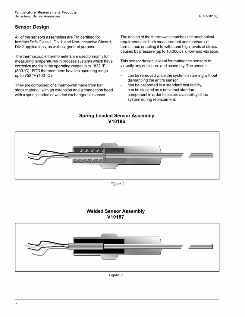
Apart from the thermowell mass at the measuring point,the factors governing the heat transfers, which are thechief determinants for the response time, are the heatcapacity, pressure, density, moisture and flow velocity ofthe medium. The following table features approximatevalues, referring to water or air.
Resistance Temperature Detectors (RTD)
Nominal resistance/Standard/ToleranceResistance elements with platinum measurementwindings are used. In accordance with DIN EN 60 751the nominal resistance is defined as follows:• 100 ohms at 0 °C• Temperature coefficient 3.85 x 10 -3 (K -1) - Averaged
between 0 °C and 100 °C.For your quick reference some typical permissible valuesare shown in the table below for Class A and B.For practical reasons we recommend a maximum long-term operating temperature of max. 400 °C for Class Atolerance.
Greater flow velocities and heat capacitiesconsiderably reduce the time intervals. The values T0.5and T0.9 give information on the time period after which50 % or 90 % of a sudden temperature change isdisplayed.
Operational temperatureThe temperature range is from -392 to +1110ºF
(-200 to +600°C)
Sheath materialThe standard material used for all resistancethermometer measuring insets is 316 Ti.
Number of lead wires/measuring circuits/sheathdiametersSensors can be supplied with:• 1 or 2 measurement RTD’s and
in 2, 3 and 4-wire circuits.However, in some particular cases the combinations arerestricted.
TABLE 2
Temperature 0ºC/32ºF 100ºC/212ºF 200ºC/392ºF 300ºC/572ºF 400ºC/852ºF 500ºC/932ºF 600ºC/1112ºFΩ 100 138.51 175.86 212.05 247.09 280.98 313.71
Class B 0.3ºC/2.1ºF 0.8ºC/2.6ºF 1.3ºC/3.1ºF 1.8ºC/3.6ºF 2.3ºC/4.1ºF 2.8ºC/4.6ºF 3.3ºC/5.1ºFClass A 0.15ºC/1.95ºF 0.35ºC/2.15ºF 0.55ºC/2.35ºF 0.75ºC/2.55ºF 0.95ºC/2.75ºF 1.15ºC/2.95ºF N/A
Resistance of platinum RTD according to IEC 60 751
Allowed Deviation for platinum RTD according to IEC 60 751
TABLE 1
Thermowell In water 1.3 ft/s
In air 10 ft/s Sensor
Type
U-length T 0.5 T 0.9 T 0.5 T 0.9 Tapered 2.5 inch 20 sec 63 sec 300 sec 900 sec Resistance Thermometer
RTD Tapered 5 inch 14 sec 44 sec 235 sec 706 sec Tapered 2.5 inch 16 sec 50 sec 235 sec 705 sec Thermocouple Tapered 5 inch 10 sec 40 sec 150 sec 500 sec
4
Temperature Measurement ProductsSensyTemp Sensor Assemblies D-TS-V1018_5
Thermocouples
Standard/ToleranceFor thermocouples conforming to DIN EN 60 584 variousdifferent classes are defined for the permissible deviationfrom the e.m.f. reference table. The measured thermo-electric emf. corresponds to the temperature differencebetween hot junction and reference junction. Thereference table conforming to DIN EN 60 584 relates to areference temperature at 0 °C. Because of the fact that,as the temperature rises, the effects of oxidation canhave significant adverse effects on the characteristicsand service life of a measuring inset, the specifiedoperating temperatures (dependent on thermocoupletype, tolerance class and sheath diameter) should neverbe exceeded.
Accessories, componentsMany of the components of the models listed in thecatalog can be ordered as separate components ormodules. In this respect, please consult your nearestrepresentative.
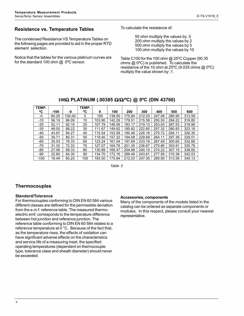
Resistance vs. Temperature Tables
The condensed Resistance VS Temperature Tables onthe following pages are provided to aid in the proper RTDelement selection.
Notice that the tables for the various platinum curves arefor the standard 100 ohm @ 0ºC sensor.
To calculate the resistance of:
50 ohm multiply the values by .5200 ohm multiply the values by 2500 ohm multiply the values by 5100 ohm multiply the values by 10
Table C100 for the 100 ohm @ 25ºC Copper (90.35ohms @ 0ºC) is published. To calculate theresistance of the 10 ohm at 25ºC (9.035 ohms @ 0ºC)multiply the value shown by .1.
TEMP. ºC
-100
-0
TEMP. ºC
0
100
200
300
400
500
600
-0 60.25 100.00 0 100 138.50 175.84 212.03 247.06 280.90 313.59 -10 56.19 96.09 10 103.90 142.29 179.51 215.58 250.50 284.22 316.80 -20 52.11 92.16 20 107.79 146.06 183.17 219.13 253.93 287.53 319.99 -30 48.00 88.22 30 111.67 149.82 185.82 222.65 257.32 290.83 323.18 -40 43.67 84.27 40 115.54 153.58 190.46 226.18 270.72 294.11 326.35 -50 39.71 80.31 50 119.40 157.32 194.08 229.69 264.11 297.39 329.51 -60 35.53 76.33 60 123.24 161.04 197.69 233.19 267.49 300.65 332.66 -70 31.32 72.33 70 127.07 164.76 201.30 236.67 270.86 303.91 335.79 -80 27.08 68.33 80 130.89 168.47 204.88 240.15 274.22 307.15 338.92 -90 22.80 64.30 90 134.70 172.16 288.46 243.61 277.56 310.38 342.03 -100 18.49 60.25 100 183.50 175.84 212.03 247.05 280.90 313.59 345.13
100ΩΩΩΩΩ PLATINUM (.00385 Ω/Ω/Ω/Ω/Ω/Ω/Ω/Ω/Ω/Ω/ºC) @ 0ºC (DIN 43760)
Table 3
5
Temperature Measurement ProductsSensyTemp Sensor Assemblies D-TS-V1018_5
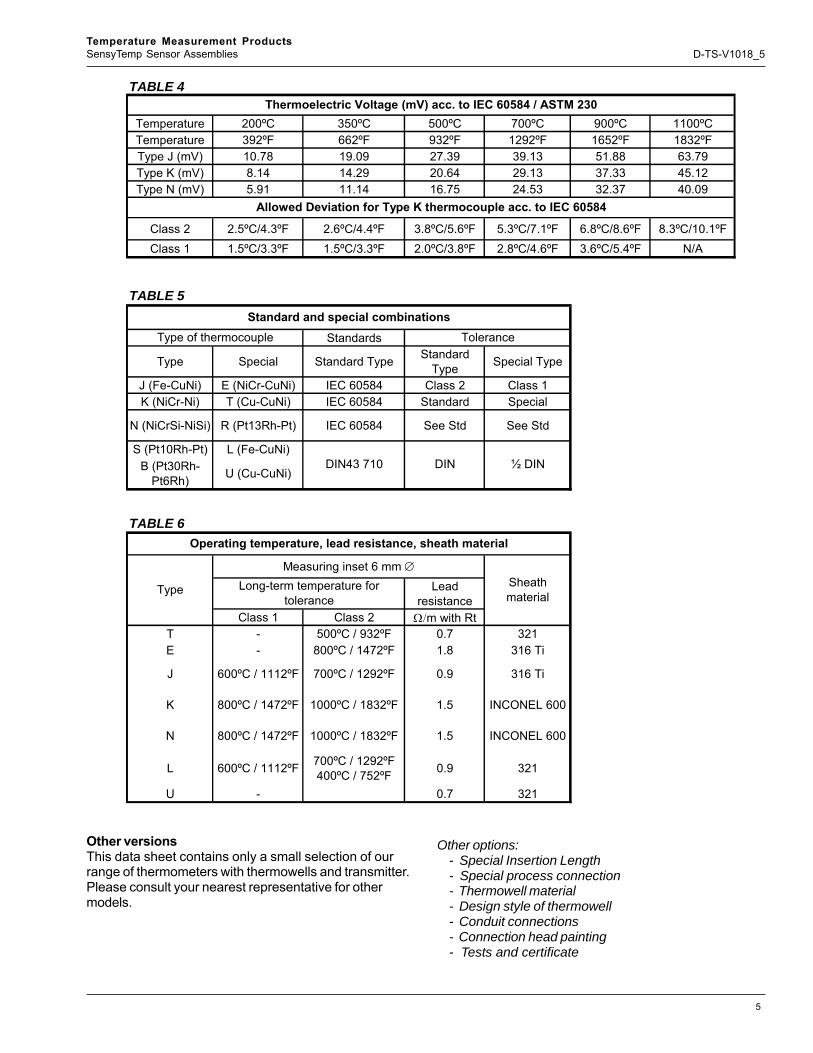
Other versionsThis data sheet contains only a small selection of ourrange of thermometers with thermowells and transmitter.Please consult your nearest representative for othermodels.
Other options:- Special Insertion Length- Special process connection- Thermowell material- Design style of thermowell- Conduit connections- Connection head painting- Tests and certificate
TABLE 4
Temperature 200ºC 350ºC 500ºC 700ºC 900ºC 1100ºCTemperature 392ºF 662ºF 932ºF 1292ºF 1652ºF 1832ºFType J (mV) 10.78 19.09 27.39 39.13 51.88 63.79Type K (mV) 8.14 14.29 20.64 29.13 37.33 45.12Type N (mV) 5.91 11.14 16.75 24.53 32.37 40.09
Class 2 2.5ºC/4.3ºF 2.6ºC/4.4ºF 3.8ºC/5.6ºF 5.3ºC/7.1ºF 6.8ºC/8.6ºF 8.3ºC/10.1ºFClass 1 1.5ºC/3.3ºF 1.5ºC/3.3ºF 2.0ºC/3.8ºF 2.8ºC/4.6ºF 3.6ºC/5.4ºF N/A
TABLE 5
Standards
Type Special Standard Type Standard Type Special Type
J (Fe-CuNi) E (NiCr-CuNi) IEC 60584 Class 2 Class 1K (NiCr-Ni) T (Cu-CuNi) IEC 60584 Standard Special
N (NiCrSi-NiSi) R (Pt13Rh-Pt) IEC 60584 See Std See Std
S (Pt10Rh-Pt) L (Fe-CuNi)B (Pt30Rh-
Pt6Rh) U (Cu-CuNi)
TABLE 6
Lead resistance
Class 1 Class 2 Ω/m with RtT - 500ºC / 932ºF 0.7 321E - 800ºC / 1472ºF 1.8 316 Ti
J 600ºC / 1112ºF 700ºC / 1292ºF 0.9 316 Ti
K 800ºC / 1472ºF 1000ºC / 1832ºF 1.5 INCONEL 600
N 800ºC / 1472ºF 1000ºC / 1832ºF 1.5 INCONEL 600
L 600ºC / 1112ºF 700ºC / 1292ºF 400ºC / 752ºF 0.9 321
U - 0.7 321
Thermoelectric Voltage (mV) acc. to IEC 60584 / ASTM 230
Allowed Deviation for Type K thermocouple acc. to IEC 60584
Standard and special combinationsType of thermocouple Tolerance
DIN43 710 DIN ½ DIN
Operating temperature, lead resistance, sheath material
Type
Measuring inset 6 mm ∅Sheath material
Long-term temperature for tolerance
6
Temperature Measurement ProductsSensyTemp Sensor Assemblies D-TS-V1018_5
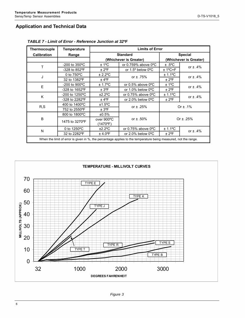
Application and Technical Data
Figure 3
TABLE 7 - Limit of Error - Reference Junction at 32ºF
Thermocouple TemperatureCalibration Range
-200 to 350ºC ± 1ºC or 0.759% above 0ºC ± .5ºC-328 to 852ºF ± 2ºF or 1.5º below 0ºC ± 1ºC=F
0 to 750ºC ± 2.2ºC ± 1.1ºC32 to 1382ºF ± 4ºF ± 2ºF-200 to 900ºC ± 1.7ºC or 0.5% above 0ºC ± 1ºC-328 to 1652ºF ± 3ºF or 1.0% below 0ºC ± 2ºF-200 to 1250ºC ±2.2ºC or 0.75% above 0ºC ± 1.1ºC-328 to 2282ºF ± 4ºF or 2.0% below 0ºC ± 2ºF400 to 1400ºC ±1.5ºC752 to 2550ºF ± 3ºF800 to 1800ºC ±0.5%
1475 to 3270ºF over 900ºC (1470ºF)
0 to 1250ºC ±2.2ºC or 0.75% above 0ºC ± 1.1ºC32 to 2282ºF ± 4.0ºF or 2.0% below 0ºC ± 2ºF
Limits of ErrorStandard
(Whichever is Greater)Special
(Whichever is Greater)
T or ± .4%
J or ± .75% or ± .4%
E or ± .4%
K or ± .4%
N or ± .4%
When the limit of error is given in %, the percentage applies to the temperature being measured, not the range.
R,S or ± .25% Or ± .1%
B or ± .50% Or ± .25%
TEMPERATURE - MILLIVOLT CURVES
0
10
20
30
40
50
60
70
32 1000 2000 3000DEGREES FAHRENHEIT
MIL
LIVO
LTS
(APP
RO
X.)
TYPE E
TYPE J
TYPE K
TYPE RTYPE S
TYPE B
TYPE T

7
Temperature Measurement ProductsSensyTemp Sensor Assemblies D-TS-V1018_5
Thermocouple Lead-Wire Configurations
Single, Grounded
Figure 4
Thermocouple Junction Configurations
Single, Ungrounded
Type J Type E+ Purple
- Red
+ Yellow
- Red
Type T+ Blue
- Red
+ ++
--
Dual, Grounded, Unisolated
-
++
--
Dual, Ungrounded, Unisolated
++
--
Dual, Ungrounded, Isolated
•
•
+ White
- Red
•
Type K
•
• •
+
••
• •

8
Temperature Measurement ProductsSensyTemp Sensor Assemblies D-TS-V1018_5
Thermowells
In most temperature measurement applications withinprocess industry the sensitive element can not beplaced directly into contact with the medium whosetemperature is to be measured.
In such cases a thermowell must be used. The design ofthe well depends on the existing pressure, temperature,consistency and velocity of the medium.
ABB’s thermowells are made from bar stock materialand are available in 3 basic designs. For optimal re-sponse times different tip designs are available.
The design and selection of the thermowell matches themechanical requirements in both measurement andmechanical terms, thus enabling it to withstand highlevels of stress caused by pressure, flow and vibration.
CaptionsA = Well Bore depthB = Thermowell stem diameterL = Thermowell lengthP = Process ConnectionT = Lag Extension lengthU = Immersion length
Threaded
Flanged Socket Welded
Figure 5
Figure 6 Figure 7
9
Temperature Measurement ProductsSensyTemp Sensor Assemblies D-TS-V1018_5
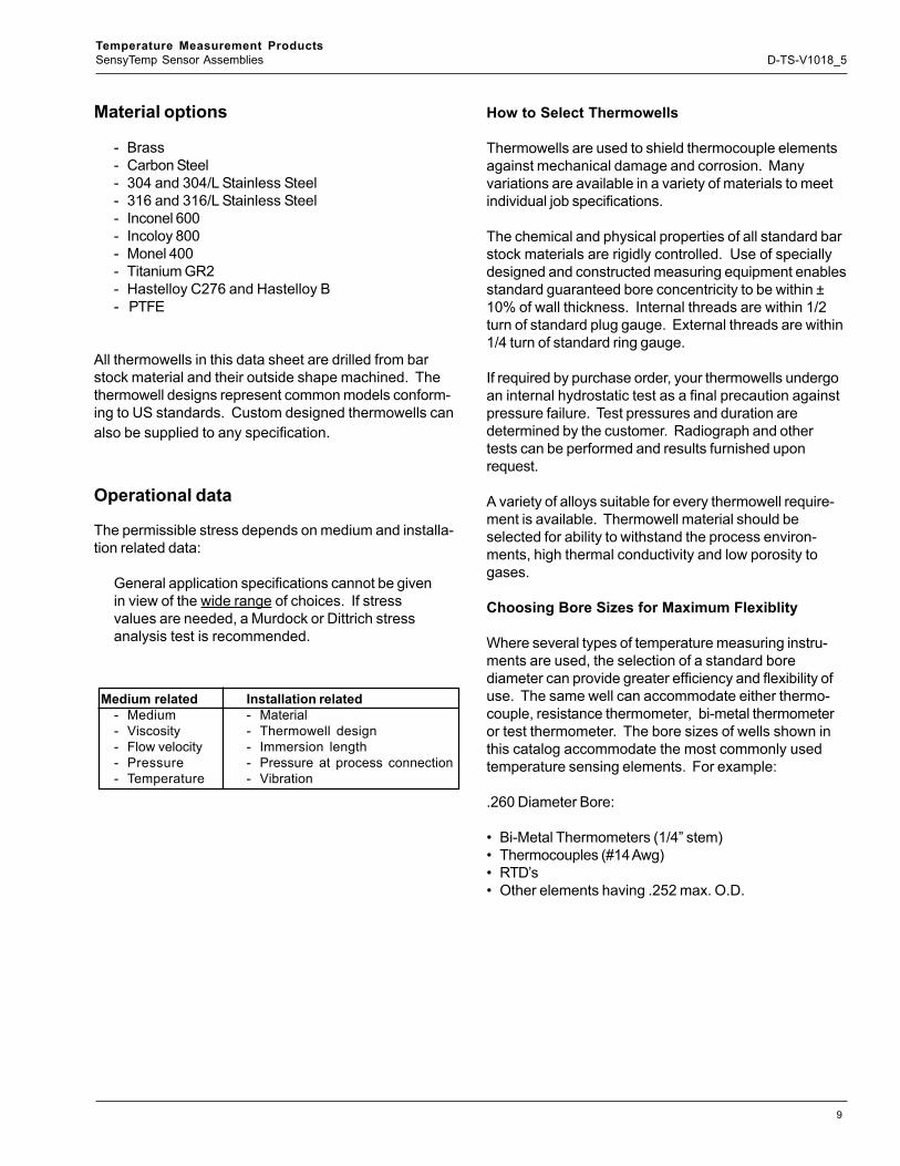
Material options
- Brass- Carbon Steel- 304 and 304/L Stainless Steel- 316 and 316/L Stainless Steel- Inconel 600- Incoloy 800- Monel 400- Titanium GR2- Hastelloy C276 and Hastelloy B- PTFE
All thermowells in this data sheet are drilled from barstock material and their outside shape machined. Thethermowell designs represent common models conform-ing to US standards. Custom designed thermowells canalso be supplied to any specification.
Operational data
The permissible stress depends on medium and installa-tion related data:
General application specifications cannot be givenin view of the wide range of choices. If stressvalues are needed, a Murdock or Dittrich stressanalysis test is recommended.
Medium related Installation related- Medium - Material- Viscosity - Thermowell design- Flow velocity - Immersion length- Pressure - Pressure at process connection- Temperature - Vibration
How to Select Thermowells
Thermowells are used to shield thermocouple elementsagainst mechanical damage and corrosion. Manyvariations are available in a variety of materials to meetindividual job specifications.
The chemical and physical properties of all standard barstock materials are rigidly controlled. Use of speciallydesigned and constructed measuring equipment enablesstandard guaranteed bore concentricity to be within ±10% of wall thickness. Internal threads are within 1/2turn of standard plug gauge. External threads are within1/4 turn of standard ring gauge.
If required by purchase order, your thermowells undergoan internal hydrostatic test as a final precaution againstpressure failure. Test pressures and duration aredetermined by the customer. Radiograph and othertests can be performed and results furnished uponrequest.
A variety of alloys suitable for every thermowell require-ment is available. Thermowell material should beselected for ability to withstand the process environ-ments, high thermal conductivity and low porosity togases.
Choosing Bore Sizes for Maximum Flexiblity
Where several types of temperature measuring instru-ments are used, the selection of a standard borediameter can provide greater efficiency and flexibility ofuse. The same well can accommodate either thermo-couple, resistance thermometer, bi-metal thermometeror test thermometer. The bore sizes of wells shown inthis catalog accommodate the most commonly usedtemperature sensing elements. For example:
.260 Diameter Bore:
• Bi-Metal Thermometers (1/4” stem)• Thermocouples (#14 Awg)• RTD’s• Other elements having .252 max. O.D.
10
Temperature Measurement ProductsSensyTemp Sensor Assemblies D-TS-V1018_5
When to Use Tapered or Straight Thermowells
Tapered thermowells provide greater strength withoutsacrificing sensitivity. Because of its higherstrength-to-weight ratio, the tapered thermowell providesgreater resistance to high frequency vibrations thanstraight thermowells. This permits reliable operation athigh fluid velocities. Thus, for higher fluid velocities, thetapered well should be chosen; for lower fluid velocities,the straight well.
Choosing the Material
A most important factor in selecting thermowell materialis to determine the corrosive conditions to which the wellwill be exposed. The high mirror polish given to all wellsenhances its corrosion resistance capability.
Occasionally, the material consideration is one ofstrength rather than corrosion. For example, a stainlesssteel well may be required for high pressure waterservice, where a brass well might have been satisfactoryfrom a corrosion viewpoint.
Choosing the Proper Connection
In this catalog you will find standardized wells ofthreaded, flanged (ASA and Van Stone), and socket weldtypes with standard bore sizes. A provision for customerspecifying design parameters or “weld-in” thermowells isalso provided.
Threaded wells are made in readily weldable material.Standard flanged wells (other than Van Stone) haveflanges welded front and back with “V” or “J” groovedesign. Full penetration double welded flanges are alsoavailable.
Socket weld of wells are especially simple to install.They fit ASA standard socket weld couplings or flangesto produce a clean, tight installation.
11
Temperature Measurement ProductsSensyTemp Sensor Assemblies D-TS-V1018_5
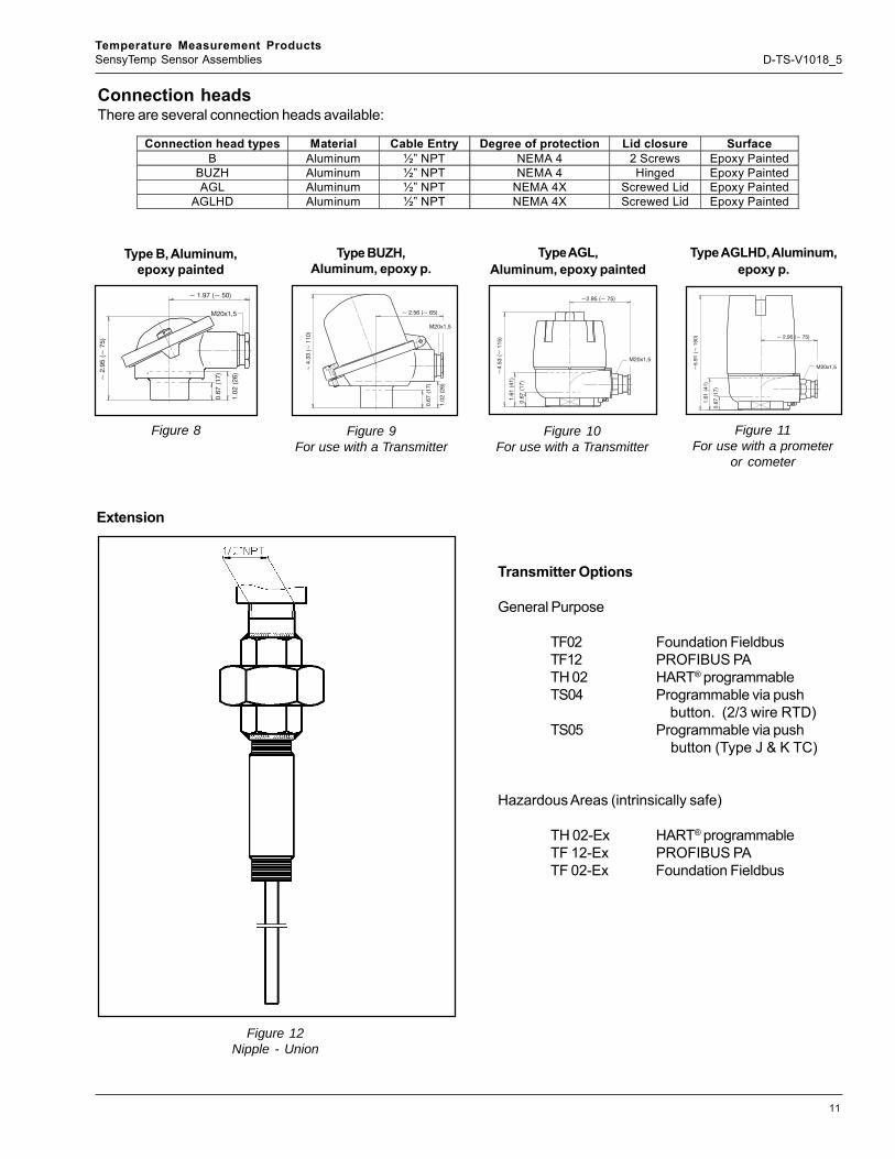
Connection headsThere are several connection heads available:
Connection head types Material Cable Entry Degree of protection Lid closure Surface B Aluminum ½” NPT NEMA 4 2 Screws Epoxy Painted
BUZH Aluminum ½” NPT NEMA 4 Hinged Epoxy Painted AGL Aluminum ½” NPT NEMA 4X Screwed Lid Epoxy Painted
AGLHD Aluminum ½” NPT NEMA 4X Screwed Lid Epoxy Painted
Type B, Aluminum,epoxy painted
Type BUZH,Aluminum, epoxy p.
Type AGL,Aluminum, epoxy painted
Type AGLHD, Aluminum,epoxy p.
Figure 9For use with a Transmitter
Figure 10For use with a Transmitter
Figure 11For use with a prometer
or cometer
Transmitter Options
General Purpose
TF02 Foundation FieldbusTF12 PROFIBUS PATH 02 HART® programmableTS04 Programmable via push
button. (2/3 wire RTD)TS05 Programmable via push
button (Type J & K TC)
Hazardous Areas (intrinsically safe)
TH 02-Ex HART® programmableTF 12-Ex PROFIBUS PATF 02-Ex Foundation Fieldbus
Figure 12Nipple - Union
Extension
~ 1.97 (~ 50)
~2
.95
(~7
5)
0.6
7(1
7)
1.0
2(2
6)
M20x1,5 ~ 2.56 (~ 65)~
4.3
3(~
11
0)
0.6
7(1
7)
1.0
2(2
6)
M20x1,5
~2.95 (~ 75)
~4
.53
(~1
15
)
0.6
7(1
7)
1.6
1(4
1)
M20x1,5
~ 2.95 (~ 75)
~5
.91
(~1
50
)
0.6
7(1
7)
1.6
1(4
1)
M20x1,5
Figure 8
12
Temperature Measurement ProductsSensyTemp Sensor Assemblies D-TS-V1018_5
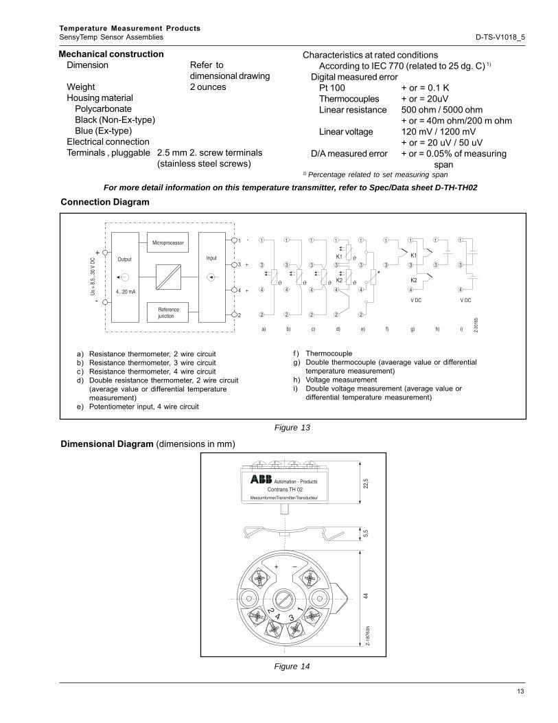
TH02/TH02-ex – Head-mounted temperaturetransmitter, HART programmable via push-button, Pt 100 (RTD), thermocouples, electri-cal isolation
Technical DataOutput
Output signal(temperature-linear) 4 to 20 mA
Current consumption <3.6 mAMax. output current 23.6 mAResidual ripple <0.3%
Parameterizable current error signalUnderranging 3.6 mAOverrranging 22 mADefault value 3.6 to 23.6 mA
Damping t63 = 0 to 30Input
ResistanceResistance
thermometer Pt 100(IEC751,JIS,SAMA)n - Pt 100/Ni 100 toPt 1000/ Ni 1000: Cu(n=0.1, 0.2, 0.5, 1, 2, 3, to
10)Min. measuring span
15K/50 KResistance 0 to 500 ohm/0 to 5000 ohm
Min.measuring span5 ohm/50 ohm
Maximum line resistance (Rw) per core2,3,4 wire 7.5 ohm, 10 ohm,
50 ohmMeasuring current 300 uASensor short-circuit <5 ohm (for RTD)Sensor break (temperature/resistance
measurement 2,3,4 wire)Measuring range 0 to 500 ohm >530 ohmMeasuring range 0 to 5000 ohm >5.3 K ohm
Sensor wire break monitoring in accordancewith NAMUR NE 89Sensor wire break detection3 wire resistance measurement >35 ohm4 wire resistance measurement >3.7 K ohm
ThermocouplesVoltages -125 mV to +125 mV
-125 mV to +1200 mVMinimum measuring span 2 mV/50 mVSensor wire break monitoring in accordancewith NAMUR NE 89
Pulsed with 1 uA outside of the measuring intervalMonitoring disconnectibleThermocouple measurement > 5 k ohmVoltage measurement > 5 k ohmInternal reference junctionPt 100, via software switchable (no jumper necessary)
Power Supply (poling protected)Supply voltageNon-Ex-application Us = 8.5 to 30 V DCFor Ex-Application, max. Ui = 8.5 to 29.4 V DC2 wire method: power supply wires =
signal wiresInfluence of supply voltage <0.05 % / 10Maximum residual ripple < or = 1% Us
(<500 Hz)Power demand of indicators(only with AGL head)
(Power demand of transmitter and indicator have to be added)
Prometer and Cometer Usd = 2.9 V DCMaximum load (Usmax – Usmin)R(k ohm) = 23.6
General characteristicsOutput signal refreshment rate
Pt 100 0.4 s (Input signalchange < 0.25 K/s)
Thermocouples 0.2 s (Input signalchange < 0.25 K/s)
Vibration resistanceVibration in operation 2g acc. to DIN IEC 68T. 2-6Resistance to shockacc. to DIN IEC 68T.2-27Electrical isolation (I/O) 1.5 kV AC (60 s)Long-term stability < or = 0.1 % p.a.
Environment conditionsAmbient temperature range -40 to 85 dg. CTransport and storage temperature
-40 to 100 dg.CRelative humidity <100 %
(100% humidity withisolated terminals only)
Condensation Permitted
13
Temperature Measurement ProductsSensyTemp Sensor Assemblies D-TS-V1018_5
Mechanical constructionDimension Refer to
dimensional drawingWeight 2 ouncesHousing material
PolycarbonateBlack (Non-Ex-type)Blue (Ex-type)
Electrical connectionTerminals , pluggable 2.5 mm 2. screw terminals
(stainless steel screws)
For more detail information on this temperature transmitter, refer to Spec/Data sheet D-TH-TH02
Characteristics at rated conditionsAccording to IEC 770 (related to 25 dg. C) 1)
Digital measured errorPt 100 + or = 0.1 KThermocouples + or = 20uVLinear resistance 500 ohm / 5000 ohm
+ or = 40m ohm/200 m ohmLinear voltage 120 mV / 1200 mV
+ or = 20 uV / 50 uVD/A measured error + or = 0.05% of measuring
span1) Percentage related to set measuring span
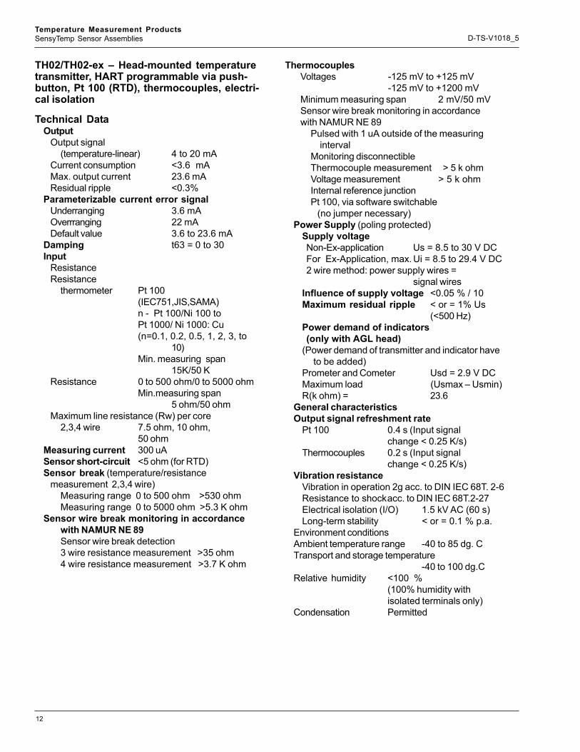
Connection Diagram
Dimensional Diagram (dimensions in mm)
1
3
4
2
ϑ4...20 mA
+
-
1
3
4
2
+
+
-
a) b) c) d) e) f) g) h) i)
V DC
Z-20
165
Us
= 8,
5...3
0V
DC
ϑ
1
3
4
2
ϑ
1
3
4
2
1
3
4
2
1
3
1
3
1
3
4
V DC
K1
K2
1
3
4
ϑ
ϑ
K1
K2
1
3
4
2
Output
Microprocessor
Input
Referencejunction
12
34
+
445,
5Z
-187
63h
Contrans TH 02
Messumformer/Transmitter/Transducteur
22,5Automation - Products
a) Resistance thermometer, 2 wire circuitb) Resistance thermometer, 3 wire circuitc) Resistance thermometer, 4 wire circuitd) Double resistance thermometer, 2 wire circuit
(average value or differential temperaturemeasurement)
e) Potentiometer input, 4 wire circuit
f ) Thermocoupleg) Double thermocouple (avaerage value or differential
temperature measurement)h) Voltage measurementi) Double voltage measurement (average value or
differential temperature measurement)
Figure 13
Figure 14
14
Temperature Measurement ProductsSensyTemp Sensor Assemblies D-TS-V1018_5
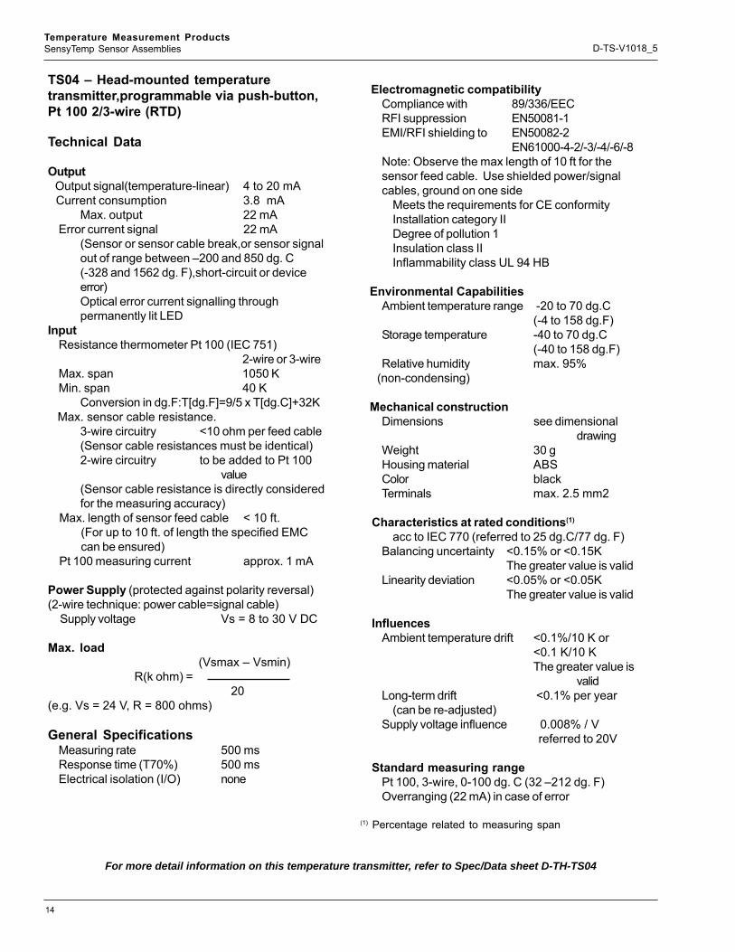
TS04 – Head-mounted temperaturetransmitter,programmable via push-button,Pt 100 2/3-wire (RTD)
Technical Data
Output Output signal(temperature-linear) 4 to 20 mA Current consumption 3.8 mA
Max. output 22 mAError current signal 22 mA
(Sensor or sensor cable break,or sensor signalout of range between –200 and 850 dg. C(-328 and 1562 dg. F),short-circuit or deviceerror)Optical error current signalling throughpermanently lit LED
InputResistance thermometer Pt 100 (IEC 751)
2-wire or 3-wireMax. span 1050 KMin. span 40 K
Conversion in dg.F:T[dg.F]=9/5 x T[dg.C]+32K Max. sensor cable resistance.
3-wire circuitry <10 ohm per feed cable(Sensor cable resistances must be identical)2-wire circuitry to be added to Pt 100
value(Sensor cable resistance is directly consideredfor the measuring accuracy)
Max. length of sensor feed cable < 10 ft.(For up to 10 ft. of length the specified EMCcan be ensured)
Pt 100 measuring current approx. 1 mA
Power Supply (protected against polarity reversal)(2-wire technique: power cable=signal cable)
Supply voltage Vs = 8 to 30 V DC
Max. load (Vsmax – Vsmin)
R(k ohm) = 20
(e.g. Vs = 24 V, R = 800 ohms)
General SpecificationsMeasuring rate 500 msResponse time (T70%) 500 msElectrical isolation (I/O) none
Electromagnetic compatibilityCompliance with 89/336/EECRFI suppression EN50081-1EMI/RFI shielding to EN50082-2
EN61000-4-2/-3/-4/-6/-8Note: Observe the max length of 10 ft for thesensor feed cable. Use shielded power/signalcables, ground on one side
Meets the requirements for CE conformityInstallation category IIDegree of pollution 1Insulation class IIInflammability class UL 94 HB
Environmental CapabilitiesAmbient temperature range -20 to 70 dg.C
(-4 to 158 dg.F)Storage temperature -40 to 70 dg.C
(-40 to 158 dg.F)Relative humidity max. 95%
(non-condensing)
Mechanical constructionDimensions see dimensional
drawingWeight 30 gHousing material ABSColor blackTerminals max. 2.5 mm2
Characteristics at rated conditions(1)
acc to IEC 770 (referred to 25 dg.C/77 dg. F)Balancing uncertainty <0.15% or <0.15K
The greater value is validLinearity deviation <0.05% or <0.05K
The greater value is valid
InfluencesAmbient temperature drift <0.1%/10 K or
<0.1 K/10 KThe greater value is
validLong-term drift <0.1% per year
(can be re-adjusted)Supply voltage influence 0.008% / V
referred to 20V
Standard measuring rangePt 100, 3-wire, 0-100 dg. C (32 –212 dg. F)Overranging (22 mA) in case of error
(1) Percentage related to measuring span
For more detail information on this temperature transmitter, refer to Spec/Data sheet D-TH-TS04

15
Temperature Measurement ProductsSensyTemp Sensor Assemblies D-TS-V1018_5
Dimensional drawing (dimensions in mm)
Connecting Diagram
Ø 4
3.0
mm
21.0 mm
33.0 mm
5.5 mm
5.5 mm
4.5 mm
Center bore
(Standard dimensions)
Pt 100
8...30 V DC
-
+
4...20 mA
Pt 100
5
3
1
4
2
5
3
4
*
white
red
red
Load resistance
white
red
red V
Figure 15
Figure 16

16
Temperature Measurement ProductsSensyTemp Sensor Assemblies D-TS-V1018_5
Electromagnetic compatibilityMeets the requirements for CE conformityInstallation category IIDegree of pollution 1 Insulation class IIInflammability class UL 94 HB
Environmental CapabilitiesAmbient temperature range -20 to 70 dg.C
(-4 TO 158 dg.F)Storage temperature -40 to 70 dg.C
(-40 to 158 dg.F)Relative humidity max. 95%
(non-condensing)
Mechanical constructionDimensions see dimensional drawingWeight 30 gHousing material ABSColor blackTerminals max. 2.5 mm2
Characteristics at rated conditions(1)
acc to IEC 770 (referred to 25 dg.C/77 dg. F)Balancing uncertainty <0.15% or <0.15K
The greater value is validLinearity deviation <0.05% or <0.05K
The greater value is valid
InfluencesAmbient temperature drift <0.1%/10 K or
<0.1 K/10 KThe greater value is valid
Influence of reference junction <0.05%/10 K bzw. <0.05 K/ 10K
The greater value is validLong-term drift <0.1% per year
Supply voltage influence 0.008% / V referred to 20V
Standard measuring rangeV11507-1100 Type K: 0 to 1000 dg. C
(32 to 212 dg. F)V11507-1300 Type J: 0 to 1000 dg. C
(32 to 212 dg. F)Overranging (22 mA) in case of error
(1) Percentage related to measuring span
Compliance with 89/336/EECRFI suppression EN50081-1EMI/RFI shielding to EN50082-2
EN61000-4-2/-3/-4/-6/-8 Note: Observe the max length of 10 ft for the
sensor feed cable.Use shielded power/signal cables,
ground on one side
For more detail information on this temperature transmitter, refer to Spec/Data sheet D-TH-TS05
TS05 – Head-mounted temperaturetransmitter,programmable via push-button,thermocouples
Technical DataOutput
Output signal(temperature-linear)4 to 20 mA
Current consumption 3.8 mAMax. output 22 mA
Error current signal 22 mA(Sensor or sensor cable break,or sensor signalout the max measuring range of the respectivethermocouple; error current optically indicated viapermanently lit LED)
InputThermocouple
Transmitter type max. measuring rangeV11507-1100 Type K: -200 to 1370 dg.C
(-328 to 2498 dg.F)Type J: -200 to 1200 dg.C
(-328 to 2192 dg.F)Type T: -200 to 400 dg.C
(-328 to 2192 dg.F)V11507-1300 Type J: -200 to 1200 dg.C
(-328 to 2192 dg.F)Type F: -200 to 1200 dg.C
(-328 to 2192 dg.F)Type E: -200 to 1000 dg.C
(-328 to 1832 dg.F)Min. measuring range
4 mV or min. temperature range, depending onthermocouple type, e.g. Type K 4 mVcorresponds to 100 K
Conversion in dg.F: T[dg.F] = 9/5 x T[dg.C] + 32 K
Power Supply (protected against polarity reversal)(2-wire technique: power cable=signal cable)Supply voltage Vs = 8 to 30 V DC
Max. load (Vsmax – Vsmin)
R(k ohm) =2021
(e.g. Vs = 24 V, R = 800 ohms)
General SpecificationsMeasuring rates 500 msResponse time (T70%) 500 msElectrical isolation (I/O) 50 V DC
(Test: 200 V DC 1 min.)

17
Temperature Measurement ProductsSensyTemp Sensor Assemblies D-TS-V1018_5
Dimensional drawing (dimensions in mm)
Connecting Diagram
8...30 V DC
-
+
4...20 mA
5
3
1
4
2
+
-
Senso
r
Load resistance
V
Push button (programming switch)
LED for programmingmode and indication oferror current signal
Ø 4
3.0
mm
21.0 mm
33.0 mm
5.5 mm
5.5 mm
4.5 mm
Center bore
(Standard dimensions)
Transmitter Part No. V11507-1100 V11507-1300 Selectable thermocouple types K J T J F E Thermocouple + Terminals - No. of LED flashes
4 3 *
5 3 **
4 3
***
5 3 *
5 3 **
5 3
*** Table 1: Assignment between LED and thermoupcle type
Figure 17
Figure 18
18
Temperature Measurement ProductsSensyTemp Sensor Assemblies D-TS-V1018_5
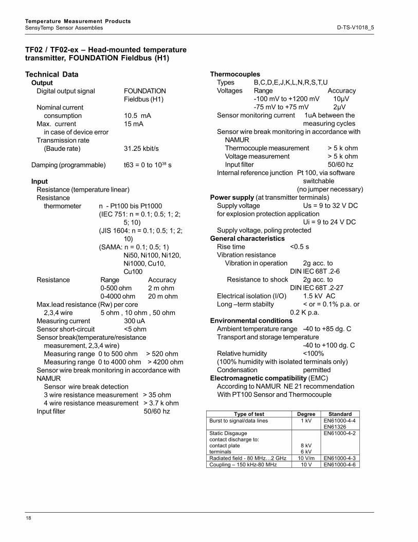
TF02 / TF02-ex – Head-mounted temperaturetransmitter, FOUNDATION Fieldbus (H1)
Technical DataOutput
Digital output signal FOUNDATIONFieldbus (H1)
Nominal currentconsumption 10.5 mA
Max. current 15 mAin case of device error
Transmission rate(Baude rate) 31.25 kbit/s
Damping (programmable) t63 = 0 to 1038 s
InputResistance (temperature linear)Resistance
thermometer n - Pt100 bis Pt1000(IEC 751: n = 0.1; 0.5; 1; 2;
5; 10)(JIS 1604: n = 0.1; 0.5; 1; 2;
10)(SAMA: n = 0.1; 0.5; 1)
Ni50, Ni100, Ni120,Ni1000, Cu10,Cu100
Resistance Range Accuracy0-500 ohm 2 m ohm0-4000 ohm 20 m ohm
Max.lead resistance (Rw) per core2,3,4 wire 5 ohm , 10 ohm , 50 ohm
Measuring current 300 uASensor short-circuit <5 ohmSensor break(temperature/resistance
measurement, 2,3,4 wire)Measuring range 0 to 500 ohm > 520 ohmMeasuring range 0 to 4000 ohm > 4200 ohm
Sensor wire break monitoring in accordance withNAMUR
Sensor wire break detection3 wire resistance measurement > 35 ohm4 wire resistance measurement > 3.7 k ohm
Input filter 50/60 hz Type of test Degree Standard Burst to signal/data lines 1 kV EN61000-4-4
EN61326 Static Disgauge contact discharge to: contact plate terminals
8 kV 6 kV
EN61000-4-2
Radiated field - 80 MHz…2 GHz 10 V/m EN61000-4-3 Coupling – 150 kHz-80 MHz 10 V EN61000-4-6
ThermocouplesTypes B,C,D,E,J,K,L,N,R,S,T,UVoltages Range Accuracy
-100 mV to +1200 mV 10μV-75 mV to +75 mV 2μV
Sensor monitoring current 1uA between themeasuring cycles
Sensor wire break monitoring in accordance withNAMURThermocouple measurement > 5 k ohmVoltage measurement > 5 k ohmInput filter 50/60 hz
Internal reference junction Pt 100, via softwareswitchable
(no jumper necessary)Power supply (at transmitter terminals)
Supply voltage Us = 9 to 32 V DCfor explosion protection application
Ui = 9 to 24 V DCSupply voltage, poling protected
General characteristicsRise time <0.5 sVibration resistance
Vibration in operation 2g acc. toDIN IEC 68T .2-6
Resistance to shock 2g acc. toDIN IEC 68T .2-27
Electrical isolation (I/O) 1.5 kV ACLong –term stabilty < or = 0.1% p.a. or
0.2 K p.a.Environmental conditions
Ambient temperature range -40 to +85 dg. CTransport and storage temperature
-40 to +100 dg. CRelative humidity <100%(100% humidity with isolated terminals only)Condensation permitted
Electromagnetic compatibility (EMC)According to NAMUR NE 21 recommendationWith PT100 Sensor and Thermocouple

19
Temperature Measurement ProductsSensyTemp Sensor Assemblies D-TS-V1018_5
Mechanical constructionDimensions refer to dimensional drawingWeight 2 ouncesHousing material polycarbonateColor black / blue (Ex version)Terminals, pluggablescrew terminals 2.5 mm2
(stainless steel screws)Influences
Influence of ambient temperaturePt100 + or = 0.25 K/ 10 KResistance measurement
0 to 500 ohm + or = 10 m ohm / 10 K0 to 4000 ohm + or = 100 m ohm / 10 K
Thermocouple e.g.Type K + or = 0.25 K / 10 KVoltage measurement
-100 mV to +1200 mV + or = 150 uV / 10 K-75 mV to +75 mV + or = 10 uV / 10 K
Characteristics at rated conditionsacc. to IEC 770 (related to 25 dg. C)
For more detail information on this temperature transmitter, refer to Spec/Data sheet D-TH-TF02
Input Element Standard Sensor
Measuring Range
IEC 584-1 Thermocouple Type B Thermocouple Type E Thermocouple Type J Thermocouple Type K Thermocouple Type R Thermocouple Type S Thermocouple Type T Thermocouple Type N
0 to +1820ºC -270 to +1000ºC -210 to +1200ºC -270 to +1372ºC -50 to +1768ºC -50 to +1768ºC -270 to +400ºC -270 to +1300ºC
( +32 to +3308ºF) (-454 to +1832ºF) (-346 to +2192ºF) (-454 to +2502ºF) ( -58 to +3215ºF) ( -58 to +3215ºF) (-454 to +752ºF) (-454 to +2372ºF)
W3, ASTME 998
Thermocouple Type C Thermocouple Type D
0 to +2315ºC 0 to +2315ºC
( +32 to +4200ºF) ( +32 to +4200ºF)
DIN 43710 Thermocouple Type L Thermocouple Type U
-200 to +900ºC -200 to +600ºC
(-328 to +1652ºF) (-328 to +1112ºF)
IEC 751; JIS; SAMA1
2,3 and 4-wire Resistance thermometer Pt100 Resistance thermometer Pt1000
-200 to +850ºC -200 to +850ºC
(-328 to +1562ºF) (-328 to +1562ºF)
DIN 437602 2,3 and 4-wire (a = 0.00618)
Resistance thermometer Pt100 Resistance thermometer Pt1000
-60 to +250ºC -60 to +250ºC
( -76 to +482ºF) ( -76 to +482ºF)
Resistance 2,3 and 4-wire
Ω 0 to 500Ω / 0 to 4000Ω
Voltage MV -100mV to +1200mV -75mV to +75mV
Note: 1 IEC 751 a = 0.00385; JIS a = 0.003916; SAMA a = 0.0039022 Edison Curve No. 7 for Ni120
Measuring error incl. characteristic deviationPt 100 + or = 0.1 K
Resistance measurement0 to 500 ohm + or = 40 m ohm0 to 4000 ohm + or = 320 m ohm
Thermocouple e.g. Type K + or = 0.25 KVoltage measurement
-100 mV to +1200 mV + or = 50 uV-75 mV to +75 mV + or = 10 uVAdditional influence of the Pt100
DIN IEC 751 KI. B internal reference junctionParameterization / structure
Type of input(2 independent channels),measuring range, Input filter, damping, alarmfunction, limit values, saving
All data proof against mains failure.Standard parameter (factory settings)
Channel 1 Pt 100, 4 wire circuit, 0 to 100 dg. C Damping 0 s, unit dg. C
Channel 2disabled
Table 8

20
Temperature Measurement ProductsSensyTemp Sensor Assemblies D-TS-V1018_5
Block Diagram
TF02/TF02-ExHead Mounted Temperature Transmitters, FOUNDATION Fieldbus (H1)Connection Diagram
Dimensional Diagram (dimensions in min)
Value_1 (T1)
Value_2 (T2)
Transducer BlockTB
Sensor 1; (T1)
Sensor 2; (T2)
AI Block 1AI 1
AI Block 2AI 2
Reference junctionPt100
Resource Block
out value sensor 1+ Status
by requestonly read
out value sensor 2+ Status
by requestread/write
1
3
4
2
1
3
4
2
1
3
4
2
1
3
4
2
1
3
4
2
1
3
4
2
1
3
4
2
1
3
4
2
ϑ ϑ ϑ
ϑ
ϑϑ
a) b) c) d) e) f) g) h) i) j)
FoundationFieldbus (H1)
+
-
1
3
4
2
1
3
1
3
Input
Referencejunction
Micro-processorOutput
Ch1Ch1
Ch2
Ch1
Ch2
Ch1
Ch2
Ch1
Ch2
1
34
2 ∅44
,4
23,8Automation - Products
TF 02
Messumformer/Transmitter/Transducteur
5,5
Snap-on fixing for DIN rail mounting(35mm)(optionally)
a) Resistance thermometer, 2 wire circuitb) Resistance thermometer, 3 wire circuitc) Resistance thermometer, 4 wire circuitd) Double resistance thermometer, 2 wire circuite) Potentiometer input, 4 wire circuit
- Resistance measurement analogous zu toResistance thermometer circuits a) to d)
f ) Thermocoupleg) Double thermocoupleh) Combination thermocuple resistance thermometer
(Combination Ch1/pin 1-3: RTD and Ch2/pin 2-4:TC also possible)
i) Voltage measurementj) Double voltage measurementt
- Voltage measurement and ResistanceMeasurement analogous to circuit h) also possible
Figure 19
Figure 20
Figure 21
21
Temperature Measurement ProductsSensyTemp Sensor Assemblies D-TS-V1018_5
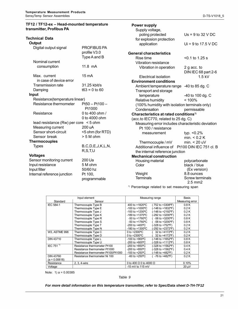
TF12 / TF12-ex – Head-mounted temperaturetransmitter, Profibus PA
Technical DataOutput
Digital output signal PROFIBUS PAprofile V3.0Type A and B
Nominal currentconsumption 11.8 mA
Max. current 15 mAin case of device error
Transmission rate 31.25 kbit/sDamping t63 = 0 to 60
InputResistance(temperature linear)Resistance thermometer Pt50 – Pt100 –
Pt1000Resistance 0 to 400 ohm /
0 to 4000 ohmlead resistance (Rw) per core < 5 ohmMeasuring current 200 uASensor short-circuit <5 ohm (for RTD)Sensor break > 5 M ohm
ThermocouplesTypes B,C,D,E,J,K,L,N,
R,S,T,UVoltagesSensor monitoring current 200 UaInput resistance 5 M ohmInput filter 50/60 hzInternal reference junction Pt 100,
programmable
Power supplySupply voltage,
poling protected Us = 9 to 32 V DCfor explosion protection
application Ui = 9 to 17.5 V DC
General characteristicsRise time <0.1 to 1.25 sVibration resistance
Vibration in operation 2 g acc. toDIN IEC 68 part 2-6
Electrical isolation 1.5 kVEnvironment conditions
Ambient temperature range -40 to 85 dg. CTransport and storage
temperature -40 to 100 dg. CRelative humidity < 100%(100% humidity with isolation terminals only)Condensation permissable
Characteristics at rated conditions1)
(acc.to IEC770, related to 25 dg. C)Measuring error includes characteristic deviation
Pt 100 / resistance measurement typ. <0.2%
min. < 0.2 KThermocouple / mV min. < 20 uV
Additional influence of Pt100 DIN IEC 751 cl. Bthe internal reference junction
Mechanical constructionHousing material polycarbonateColor black / blue
(Ex version)Weight 8.8 ouncesTerminals Screw terminals
2.5 mm21) Percentage related to set measuring span
Input element Standard Sensor
Measuring range Basis Measuring error
IEC 584-1 Thermocouple Type B Thermocouple Type E Thermocouple Type J Thermocouple Type K Thermocouple Type R Thermocouple Type S Thermocouple Type T Thermocouple Type N
400 to +1820ºC -100 to +1000ºC -100 to +1200ºC -189 to +1370ºC -50 to +1760ºC -50 to +1760ºC -200 to +400ºC -180 to +1300ºC
( 752 to +3308ºF) (-148 to +1832ºF) (-148 to +2192ºF) (-292 to +3200ºF) ( -58 to +3200ºF) ( -58 to +3200ºF) (-328 to +752ºF) (-292 to +2372ºF)
0.8 K 0.2 K 0.2 K 0.2 K 0.8 K 0.8 K 0.2 K 0.2 K
W3, ASTME 998 Thermocouple Type C Thermocouple Type D
0 to +2300ºC 0 to +2300ºC
( 32 to +4172ºF) ( 32 to +4172ºF)
0.2 K 0.2 K
DIN 43710 Thermocouple Type L Thermocouple Type U
-100 to +900ºC -200 to +600ºC
(-148 to +1652ºF) (-328 to +1112ºF)
0.8 K 0.8 K
IEC 751 1) Resistance thermometer Pt100 Resistance thermometer Pt1000 Resistance thermometer Pt100/Pt1000
-200 to +850ºC -200 to +850ºC -100 to +250ºC
(-328 to +1562ºF) (-328 to +1562ºF) (-148 to +482ºF)
0.4 K 0.4 K 0.2 K
DIN 43760 (a = 0.00618)
Resistance thermometer Ni 100 -60 to +250ºC ( -76 to +482ºF) 0.2 K
Resistance 2, 3, 4-wire 0 to 400 Ω 0 to 4000 Ω 0.10% Voltage -15 mV to 115 mV 20 µV
Note: 1) a = 0.00385
For more detail information on this temperature transmitter, refer to Spec/Data sheet D-TH-TF12
Table 9
22
Temperature Measurement ProductsSensyTemp Sensor Assemblies D-TS-V1018_5
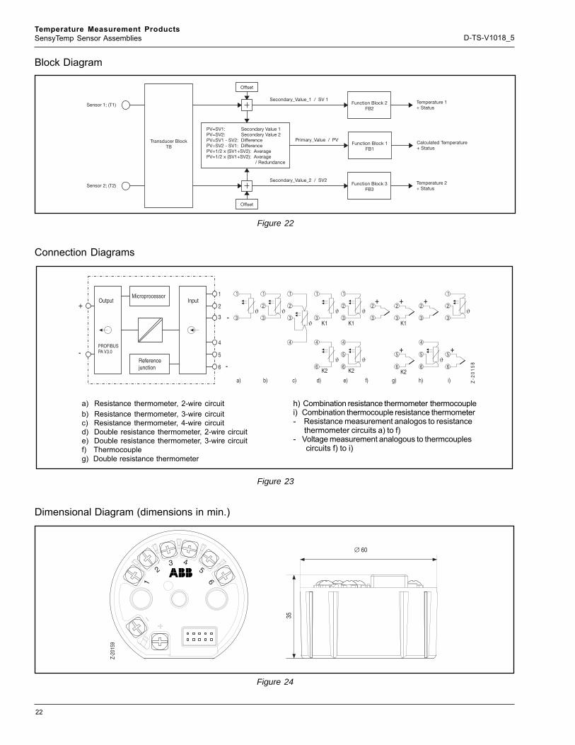
Block Diagram
Connection Diagrams
Dimensional Diagram (dimensions in min.)
a) Resistance thermometer, 2-wire circuitb) Resistance thermometer, 3-wire circuitc) Resistance thermometer, 4-wire circuitd) Double resistance thermometer, 2-wire circuite) Double resistance thermometer, 3-wire circuitf) Thermocoupleg) Double resistance thermometer
h) Combination resistance thermometer thermocouplei) Combination thermocouple resistance thermometer- Resistance measurement analogos to resistance thermometer circuits a) to f)- Voltage measurement analogous to thermcouples circuits f) to i)
PV=SV1: Secondary Value 1PV=SV2: 2PV=SV1 - SV2: DifferencePV=SV2 - SV1: DifferencePV=1/2 x (SV1+SV2): AveragePV=1/2 x (SV1+SV2): Average
/ Redundance
Secondary ValuePrimary_Value / PV
Secondary_Value_1 / SV 1
Secondary_Value_2 / SV2
Transducer BlockTB
Sensor 1; (T1)
Sensor 2; (T2)
Function Block 2FB2
Function Block 1FB1
Function Block 3FB3
Offset
Offset
Temperature 1+ Status
Temperature 2+ Status
Calculated Temperature+ Status
PROFIBUSPA V3.0
+
-
3
4
6
-
+ + +
+ +
ϑ
ϑ
ϑ
ϑϑ
K1
K2a) b) c) d) e) f) g) h) i)
1
3
1
3
2
1
3
4
2ϑ
ϑ
K1
K2
1
3
4
6
5
2ϑ
ϑ
K1
K2
1
3
4
6
3
2
3
6
5
2
3
4
6
5
2
1
3
6
5
2
Z-2
01
58
2
1
5
-
OutputMicroprocessor
Referencejunction
Input
∅ 60
35
Z-20
159
23 4
5
61
Figure 22
Figure 23
Figure 24

23
Temperature Measurement ProductsSensyTemp Sensor Assemblies D-TS-V1018_4
Captions:A = Well Bore DepthB = Thermowell stem diameterE = Extension length (nominal)H = Extension tube diameterL = Thermowell lengthOAL = Over all lengthsP = Process ConnectionT = Lag Extension lengthU = Immersion length
Sensor Design
Figure 25

24
Temperature Measurement ProductsSensyTemp Sensor Assemblies D-TS-V1018_5
Standard Products=Code
Spring Loaded Sensor Assembly with Thermowell V10186
1 : ReservedReserved -
2 : Thermowell MaterialAISI 304 / 304L SST (1.4301 / 1.4306) HAISI 316 / 316L SST (1.4401 / 1.4404) LHastelloy C-276 (2.4819) UInconel 600 (2.4816) PCarbon Ste el DTitanium TChrome Molybdenum F22 GMonel ROther X
3 : Process Connecti onFlange, 1 in. 150 lbs. AISI 316 SST (1.4401) F1Flange, 1.5 in. 150 lbs. AISI 316 SST (1.4401) F2Flange, 2 in. 150 lbs. AISI 316 SST (1.4401) F5Flange, 3 in. 150 lbs. AISI 316 SST (1.4401) F7Flange, 1 in. 300 lbs. AISI 316 SST (1.4401) F8Flange, 1.5 in. 300 lbs. AISI 316 SST (1.4401) F3Flange, 2 in. 300 lbs. AISI 316 SST (1.4401) F4Flange, 1 in. 600 lbs. AISI 316 SST (1.4401) FBFlange, 1.5 in. 600 lbs. AISI 316 SST (1.4401) FCFlange, 2 in. 600 lbs. AISI 316 SST (1.4401) FDFlange 1 in., 900 / 1500 lbs., AI SI 3 16 SST (1.4401) FGFlange, 1.5 in. 900 / 1500 lbs. AI SI 316 SST (1.4401) FHFlange, 2 in. 900 / 1500 lbs. AISI 316 SST (1.4401) FJThreaded, 1/2 in. T1Threaded, 3/4 in. T2Threaded, 1 in. T3Socket Weld, 3/4 in. W2Socket Weld, 1 in. W3Other XX
4 : Tip D esignTapered TReduced Tip RStraight S

25
Temperature Measurement ProductsSensyTemp Sensor Assemblies D-TS-V1018_5
V10186 Code
5 : Thermowell DimensionsU Length 2.0 in. (51 mm) (Not e: 13) 020U Length 2.5 in. (64 mm) (Not e: 13) 025U Length 3.0 in. (76 mm) (Not e: 13) 030U Length 3.5 in. (89 mm) (Not e: 13) 035U Length 4.0 in. (102 mm) (Not e: 13) 040U Length 4.5 in. (114 mm) (Not e: 13) 045U Length 5.0 in. (127 mm) (Not e: 13) 050U Length 5.5 in. (140 mm) (Not e: 13) 055U Length 6.0 in. (152 mm) (Not e: 13) 060U Length 6.5 in. (165 mm) (Not e: 13) 065U Length 7.0 in. (178 mm) (Not e: 13) 070U Length 7.5 in. (191 mm) (Not e: 13) 075U Length 8.0 in. (203 mm) (Not e: 13) 080U Length 8.5 in. (216 mm) (Not e: 13) 085U Length 9.0 in. (229 mm) (Not e: 13) 090U Length 9.5 in. (241 mm) (Not e: 13) 095U Length 10.0 in. (254 mm) (Not e: 13) 100U Length 10.5 in. (267 mm) (Not e: 13) 105U Length 11.0 in. (279 mm) (Not e: 13) 110U Length 11.5 in. (292 mm) (Not e: 13) 115U Length 12.0 in. (305 mm) (Not e: 13) 120U Length 12.5 in. (318 mm) (Not e: 13) 125U Length 13.0 in. (330 mm) (Not e: 13) 130U Length 13.5 in. (343 mm) (Not e: 13) 135U Length 14.0 in. (356 mm) (Not e: 13) 140U Length 14.5 in. (368 mm) (Not e: 13) 145U Length 15.0 in. (381 mm) (Not e: 13) 150U Length 15.5 in. (394 mm) (Not e: 13) 155U Length 16.0 in. (406 mm) (Not e: 13) 160U Length 16.5 in. (419 mm) (Not e: 13) 165U Length 17.0 in. (432 mm) (Not e: 13) 170U Length 17.5 in. (445 mm) (Not e: 13) 175U Length 18.0 in. (457 mm) (Not e: 13) 180U Length 18.5 in. (470 mm) (Not e: 13) 185U Length 19.0 in. (483 mm) (Not e: 13) 190U Length 19.5 in. (495 mm) (Not e: 13) 195U Length 20.0 in. (508 mm) (Not e: 13) 200U Length 20.5 in. (520 mm) (Not e: 13) 205U Length 21.0 in. (533 mm) (Not e: 13) 210U Length 21.5 in. (546 mm) (Not e: 13) 215U Length 22.0 in. (559 mm) (Not e: 13) 220U Length 22.5 in. (572 mm) (Not e: 13) 225U Length 23.0 in. (584 mm) (Not e: 13) 230U Length 23.5 in. (597 mm) (Not e: 13) 235U Length 24.0 in. (610 mm) (Not e: 13) 240U Length 24.5 in. (622 mm) (Not e: 13) 245U Length 25.0 in. (635 mm) (Not e: 13) 250

26
Temperature Measurement ProductsSensyTemp Sensor Assemblies D-TS-V1018_4
V10186 Code
5 : Thermowell Dimensions (cont.)U Length 25.5 in. (648 mm) (Not e: 13) 255U Length 26.0 in. (660 mm) (Not e: 13) 260U Length 26.5 in. (673 mm) (Not e: 13) 265U Length 27.0 in. (686 mm) (Not e: 13) 270U Length 27.5 in. (699 mm) (Not e: 13) 275U Length 28.0 in. (711 mm) (Not e: 13) 280U Length 28.5 in. (724 mm) (Not e: 13) 285U Length 29.0 in. (737 mm) (Not e: 13) 290U Length 29.5 in. (749 mm) (Not e: 13) 295U Length 30.0 in. (762 mm) (Not e: 13) 300U Length 30.5 in. (775 mm) (Not e: 13) 305U Length 31.0 in. (787 mm) (Not e: 13) 310U Length 31.5 in. (800 mm) (Not e: 13) 315U Length 32.0 in. (813 mm) (Not e: 13) 320U Length 32.5 in. (826 mm) (Not e: 13) 325U Length 33.0 in. (838 mm) (Not e: 13) 330U Length 33.5 in. (851 mm) (Not e: 13) 335U Length 34.0 in. (864 mm) (Not e: 13) 340U Length 34.5 in. (876 mm) (Not e: 13) 345U Length 35.0 in. (889 mm) (Not e: 13) 350U Length 35.5 in. (902 mm) (Not e: 13) 355U Length 36.0 in. (914 mm) (Not e: 13) 360U Length 36.5 in. (927 mm) (Not e: 13) 365U Length 37.0 in. (940 mm) (Not e: 13) 370U Length 37.5 in. (953 mm) (Not e: 13) 375U Length 38.0 in. (965 mm) (Not e: 13) 380U Length 38.5 in. (978 mm) (Not e: 13) 385U Length 39.0 in. (991 mm) (Not e: 13) 390U Length 39.5 in. (1003 mm) (Not e: 13) 395U Length 40.0 in. (1016 mm) (Not e: 13) 400Other (Not e: 17) XXX
6 : Thermowell Lag Length TNo Lag 03.00 in. (76 mm ) 36.00 in. (152 mm ) 6Other X
7 : Extension Tube / Length E / MaterialUnion-Nipple 3 in. AISI 316 SST (1.4401) SUnion-Nipple 6 in. AISI 316 SST (1.4401) UWithout N
27
Temperature Measurement ProductsSensyTemp Sensor Assemblies D-TS-V1018_5
V10186 Code
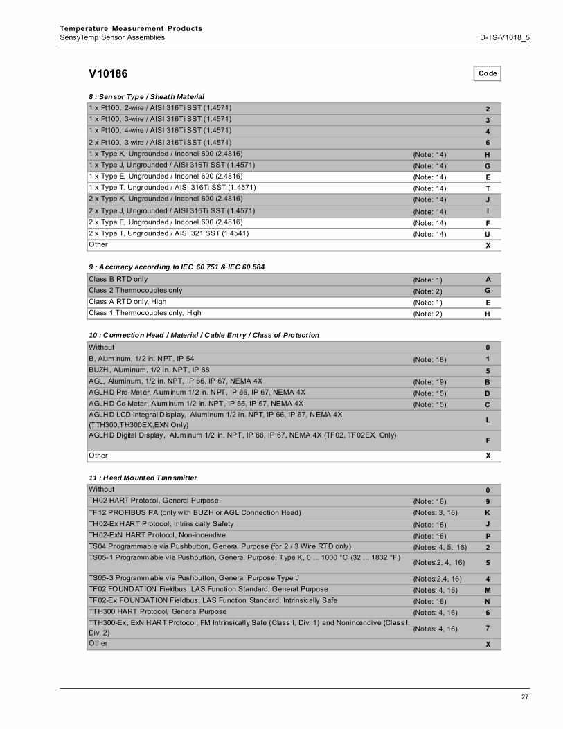
8 : Sensor Type / Sheath Material1 x Pt100, 2-wire / AISI 316Ti SST (1.4571) 21 x Pt100, 3-wire / AISI 316Ti SST (1.4571) 31 x Pt100, 4-wire / AISI 316Ti SST (1.4571) 42 x Pt100, 3-wire / AISI 316Ti SST (1.4571) 61 x Type K, Ungrounded / Inconel 600 (2.4816) (Not e: 14) H1 x Type J, U ngrounded / AISI 316Ti SST (1.4571) (Not e: 14) G1 x Type E, Ungrounded / Inconel 600 (2.4816) (Not e: 14) E1 x Type T, Ungrounded / AISI 316Ti SST (1. 4571) (Not e: 14) T2 x Type K, Ungrounded / Inconel 600 (2.4816) (Not e: 14) J2 x Type J, U ngrounded / AISI 316Ti SST (1.4571) (Not e: 14) I2 x Type E, Ungrounded / Inconel 600 (2.4816) (Not e: 14) F2 x Type T, Ungrounded / AISI 321 SST (1.4541) (Not e: 14) UOther X
9 : A ccuracy according to IEC 60 751 & IEC 60 584Class B RTD only (Not e: 1) AClass 2 Thermocouples only (Not e: 2) GClass A RTD only, High (Not e: 1) EClass 1 Thermocouples only, High (Not e: 2) H
10 : C onnection Head / Material / Cable Entry / Class of ProtectionWithout 0B, Alum inum, 1/ 2 in. NPT, IP 54 (Not e: 18) 1BUZH , Aluminum, 1/2 in. NPT, IP 68 5AGL, Aluminum, 1/2 in. NPT, IP 66, IP 67, NEMA 4X (Not e: 19) BAGLH D Pro-Met er, Alum inum 1/ 2 in. N PT, IP 66, IP 67, NEMA 4X (Not e: 15) DAGLH D Co-Meter, Alum inum 1/2 in. NPT, IP 66, IP 67, NEMA 4X (Not e: 15) CAGLH D LCD Integral D isplay, Aluminum 1/2 in. NPT, IP 66, IP 67, NEMA 4X (TTH300,TH300EX,EXN Only)
L
AGLH D Digital Display, Alum inum 1/2 in. NPT, IP 66, IP 67, NEMA 4X (TF02, TF02EX, Only)F
Other X
11 : H ead Mounted TransmitterWithout 0TH02 HART Protocol, General Purpose (Not e: 16) 9TF12 PROFIBUS PA (only w ith BUZH or AGL Connection Head) (Not es: 3, 16) KTH02-Ex H ART Protocol, Intrinsically Safety (Not e: 16) JTH02-ExN HART Protocol, Non-incendive (Not e: 16) PTS04 Programmable via Pushbutton, General Purpose (for 2 / 3 Wire RTD only) (Not es: 4, 5, 16) 2TS05-1 Programm able via Pushbutton, General Purpose, Type K, 0 ... 1000 °C (32 ... 1832 °F)
(Not es:2, 4, 16) 5
TS05-3 Programm able via Pushbutton, General Purpose Type J (Not es:2,4, 16) 4TF02 FOUNDATION Fieldbus, LAS Function Standard, General Purpose (Not es: 4, 16) MTF02-Ex FOUNDATION Fieldbus, LAS Function Standard, Intrinsically Safe (Not e: 16) NTTH300 HART Protocol, General Purpose (Not es: 4, 16) 6TTH300-Ex, ExN H ART Protocol, FM Intr insically Safe (Class I, Div. 1) and Nonincendive (Class I, Div. 2) (Not es: 4, 16) 7
Other X

28
Temperature Measurement ProductsSensyTemp Sensor Assemblies D-TS-V1018_5
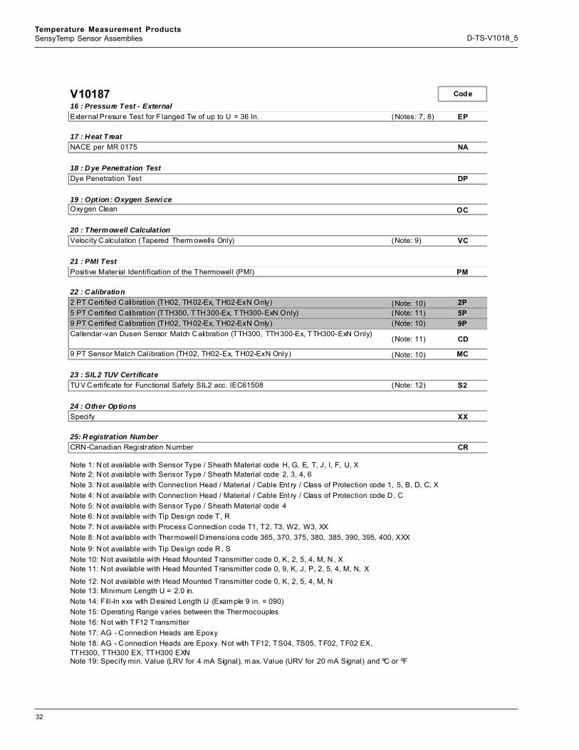
V10186 - ADDITIONAL ORDERING CODE12 : Sensor TypeGround Thermocouple 3313 : Thermowell OptionTantalum Sheath (Straight Tip Only) (Not e: 6) KK4 … 12 R MS H igh Polish Stem Finish 4F14 : Name PlateTag No. on Stainless Steel Label SL15 : Pressure Test - InternalInternal Pressure Test of t he Therm owell IP16 : Pressure Test - ExternalExternal Presure Test for Flanged Tw of up to U = 36 In. (Not es: 7, 8) EP17 : Heat TreatNACE per MR 0175 NA18 : Dye Penetration TestDye Penetration Test DP19 : Option: Oxygen Servi ceOxygen Clean OCP-TS-V10186_12_SP 1/24/0820 : Thermowell CalculationVelocity Calculation (Tapered Therm owells Only) (Not e: 9) VC21 : PMI TestPositive Material Identification of the Thermowell (PMI) PM22 : Calibration2 PT Certified C alibration (TH02, TH02-Ex, TH02-ExN Only) (Not e: 10) 2P5 PT Certified C alibration (TTH300, TTH300-Ex, TTH300-ExN Only) (Not e: 11) 5P9 PT Certified C alibration (TH02, TH02-Ex, TH02-ExN Only) (Not e: 10) 9PCallendar-van Dusen Sensor Match C alibration (TTH300, TTH300-Ex, TTH300-ExN Only) (Not e: 11) CD9 PT Sensor Match Calibration (TH02, TH02-Ex, TH02-ExN Only) (Not e: 10) M C23 : SIL2 TUV CertificateTU V C ertificate for Functional Safety SIL2 acc. IEC61508 (Not e: 12) S224 : Other OptionsSpecify XX25: R egistration NumberCRN-Canadian Registration N umber CR
Note 5: N ot available with Sensor Type / Sheath Material code 4Note 6: N ot available with Tip Design code T, RNote 7: N ot available with Process C onnection code T1, T2, T3, W2, W3, XXNote 8: N ot available with Thermowell D imensions code 365, 370, 375, 380, 385, 390, 395, 400, XXXNote 9: N ot available with Tip Design code R , SNote 10: N ot available with Head Mounted Transmitter code 0, K, 2, 5, 4, M, N , XNote 11: N ot available with Head Mounted Transmitter code 0, 9, K, J, P, 2, 5, 4, M, N, XNote 12: N ot available with Head Mounted Transmitter code 0, K, 2, 5, 4, M, NNote 13: Minimum Length U = 2.0 in.Note 14: Operating Range varies between the ThermocouplesNote 15: AG - C onnection Heads are Epoxy. Not with TF12, TS04, TS05, TF02, TF02 EX, TTH300, TTH300 EX,TTH300EXNNote 16: Specify min. Value (LRV for 4 mA Signal), m ax. Value (URV for 20 mA Signal) and ºC or ºFNote 17: F ill-In xxx with Desired Length U (Exam ple 9 in. = 090)Note 18: N ot with TF12 TransmitterNote 19: AG - C onnection Heads are Epoxy
Note 4: N ot available with Connection Head / Material / Cable Ent ry / Class of Protection code D , C
Note 1: N ot available with Sensor Type / Sheath Material code H, G, E, T, J, I, F, U, XNote 2: N ot available with Sensor Type / Sheath Material code 2, 3, 4, 6Note 3: N ot available with Connection Head / Material / Cable Ent ry / Class of Protection code 1, 5, B, D, C, X

29
Temperature Measurement ProductsSensyTemp Sensor Assemblies D-TS-V1018_5
Welded Sensor Assembly with Thermowell V10187
1 : Dash Characteristic 07Dash -
2 : Thermowell MaterialAISI 304 / 304L SST (1.4301 / 1.4306) HAISI 316 / 316L SST (1.4401 / 1.4404) LHastelloy C-276 (2.4819) UInconel 600 (2.4816) PCarbon Ste el DTitanium T TChrome Molybdenum F22 GMonel ROther X
3 : Process Connecti onFlange 1 in., 150 lbs., AISI 316 SST (1.4401) F1Flange 1.5 in., 150 lbs., AISI 316 SST (1.4401) F2Flange 2 in., 150 lbs., AISI 316 SST (1.4401) F5Flange 3 in., 150 lbs., AISI 316 SST (1.4401) F7Flange 1 in., 300 lbs., AISI 316 SST (1.4401) F8Flange 1.5 in., 300 lbs., AISI 316 SST (1.4401) F3Flange 2 in., 300 lbs., AISI 316 SST (1.4401) F4Flange 1 in., 600 lbs., AISI 316 SST (1.4401) FBFlange 1.5 in., 600 lbs., AISI 316 SST (1.4401) FCFlange 2 in., 600 lbs., AISI 316 SST (1.4401) FDFlange 1 in., 900 / 1500 lbs., AI SI 3 16 SST (1.4401) FGFlange 1.5 in., 900 / 1500 lbs. , AISI 316 SST (1.4401) FHFlange 2 in., 900 / 1500 lbs., AI SI 3 16 SST (1.4401) FJThreaded, 1/2 in. T1Threaded, 3/4 in. T2Threaded, 1 in. T3Socket Weld, 3/4 in. W2Socket Weld, 1 in. W3Other XX
4 : Tip D esignTapered TReduced Tip RStraight S

30
Temperature Measurement ProductsSensyTemp Sensor Assemblies D-TS-V1018_5
V10187 Code
5 : Thermowell DimensionsU Length 2.0 in. (51 mm) (Note: 13) 020U Length 2.5 in. (64 mm ) (Note: 13) 025U Length 3.0 in. (76 mm ) (Note: 13) 030U Length 3.5 in. (89 mm ) (Note: 13) 035U Length 4.0 in. (102 mm) (Note: 13) 040U Length 4.5 in. (114 mm) (Note: 13) 045U Length 5.0 in. (127 mm) (Note: 13) 050U Length 5.5 in. (140 mm) (Note: 13) 055U Length 6.0 in. (152 mm) (Note: 13) 060U Length 6.5 in. (165 mm) (Note: 13) 065U Length 7.0 in.) (178 mm) (Note: 13) 070U Length 7.5 in. (191 mm) (Note: 13) 075U Length 8.0 in. (203 mm) (Note: 13) 080U Length 8.5 in.) (216 mm) (Note: 13) 085U Length 9.0 in. (229 mm) (Note: 13) 090U Length 9.5 in. (241 mm) (Note: 13) 095U Length 10.0 in. (254 mm) (Note: 13) 100U Length 10.5 in. (267 mm) (Note: 13) 105U Length 11.0 in. (279 mm) (Note: 13) 110U Length 11.5 in. (292 mm) (Note: 13) 115U Length 12.0 in. (305 mm) (Note: 13) 120U Length 12.5 in. (318 mm) (Note: 13) 125U Length 13.0 in. (330 mm) (Note: 13) 130U Length 13.5 in. (343 mm) (Note: 13) 135U Length 14.0 in. (356 mm) (Note: 13) 140U Length 14.5 in. (368 mm) (Note: 13) 145U Length 15.0 in. (381 mm) (Note: 13) 150U Length 15.5 in. (394 mm) (Note: 13) 155U Length 16.0 in. (406 mm) (Note: 13) 160U Length 16.5 in. (419 mm) (Note: 13) 165U Length 17.0 in. (432 mm) (Note: 13) 170U Length 17.5 in. (445 mm) (Note: 13) 175U Length 18.0 in. (457 mm) (Note: 13) 180U Length 18.5 in. (470 mm) (Note: 13) 185U Length 19.0 in. (483 mm) (Note: 13) 190U Length 19.5 in. (495 mm) (Note: 13) 195U Length 20.0 in. (508 mm) (Note: 13) 200U Length 20.5 in. (520 mm) (Note: 13) 205U Length 21.0 in. (533 mm) (Note: 13) 210U Length 21.5 in. (546 mm) (Note: 13) 215U Length 22.0 in. (559 mm) (Note: 13) 220U Length 22.5 in. (573 mm) (Note: 13) 225U Length 23.0 in. (584 mm) (Note: 13) 230U Length 23.5 in. (597 mm) (Note: 13) 235U Length 24.0 in. (610 mm) (Note: 13) 240U Length 24.5 in. (622 mm) (Note: 13) 245U Length 25.0 in. (635 mm) (Note: 13) 250U Length 25.5 in. (640 mm) (Note: 13) 255

31
Temperature Measurement ProductsSensyTemp Sensor Assemblies D-TS-V1018_5
V10187 Code8 : Sensor Type / Sheath Material (Cont)1 x Type T, Ungrounded / AISI 316Ti SST (1. 4571) (Note: 15) T2 x Type K, Ungrounded / Inconel 600 (2.4816) (Note: 15) J2 x Type J, Ungrounded / AISI 316Ti SST (1.4571) (Note: 15) I2 x Type E, Ungrounded / Inconel 600 (2.4816) (Note: 15) F2 x Type T, Ungrounded / AISI 321 SST (1.4541) (Note: 15) UOther X
9 : A ccuracy according to IEC 60751 & IEC 60584Class B RTD only (Note: 1) AClass 2 Thermocouples only (Note: 2) GClass A RTD only, High (Note: 1) EClass 1 Thermocouples only, High (Note: 2) H
10 : C onnection Head / Material / C able Entry / Class of ProtectionWithout 0B, Alum inum, 1/ 2 in. N PT, IP 54 (Note: 16) 1BUZH , Aluminum, 1/2 in. NPT, IP 68 5AGL, Aluminum, 1/2 in. NPT, IP 66, IP 67, NEMA 4X (Note: 17) BAGLH D Pro-Met er, Alum inum 1/ 2 in. NPT, IP 66, IP 67, NEMA 4X (Note: 18) DAGLH D Co-Meter, Alum inum 1/2 in. NPT, IP 66, IP 67, NEMA 4X (Note: 18) CAGLH D LCD Integral D isplay, Aluminum 1/2 in. NPT, IP 66, IP 67, N EMA 4X (TTH300, TTH300 EX, Only) L
AGLH D Digital Display, Alum inum 1/2 in. NPT, IP 66, IP 67, NEMA 4X (TF02,TF02EX Only FOther X
11 : H ead Mounted TransmitterWithout 0TH02 HART Protocol, General Purpose (Note: 19) 9TF12 PROFIBUS PA (only w ith BUZH or AGL Connection Head) (Notes: 3, 19) KTH02-Ex H ART Protocol, Intrinsically Safety (Note: 19) JTH02-ExN HART Protocol, Non- incendive (Note: 19) PTS04 Programmable via Pushbutton, General Purpose (for 2 / 3 wire RTD only) (Notes: 4, 5, 1 2TS05-1 Programm able via Pushbutton, General Purpose Type K, 0 ... 1000 °C (32 ... 1832 °F)
(Notes: 4, 19) 5
TS05-3 Programm able via Pushbutton, General Purpose, Type J (Notes: 4, 19) 4TF02 FOUND ATION Fieldbus, LAS function standard, General Purpose (Notes: 4, 19) MTTH300 HART Protocol, General Purpose 6TTH300-Ex, ExN HAR T Protocol, FM Intr insically Safe (Class I, Div. 1) and Nonincendive (C lass I, Div. 2) 7
TF02-Ex FOUNDATION F ieldbus, LAS function standard, Int rinsically Safe (Note: 19) NOther X
ADDITIONAL ORDERING CODE12 : Sensor TypeGround Thermocouple 33
13 : Thermowell OptionTantalum Sheath (Straight Tip Only) (Note: 6) KK4 … 12 RMS H igh Polish Stem Finish 4F
14 : N ame PlateTag N o. on Stainless Steel Label SL
15 : Pressure Test - InternalInternal Pressure Test of t he Therm owell IP
32
Temperature Measurement ProductsSensyTemp Sensor Assemblies D-TS-V1018_5
V10187 Code16 : Pressure Test - ExternalExternal Presure Test for F langed Tw of up to U = 36 In. (Notes: 7, 8) EP
17 : Heat TreatNACE per MR 0175 NA
18 : Dye Penetration TestDye Penetration Test DP
19 : Option: Oxygen Servi ceOxygen Clean OC
20 : Thermowell CalculationVelocity C alculation (Tapered Therm owells Only) (Note: 9) VC
21 : PMI TestPositive Mater ial Identification of the Thermowell (PMI) PM
22 : Calibration2 PT Certified Calibration (TH02, TH02-Ex, TH02-ExN Only) (Note: 10) 2P5 PT Certified Calibration (TTH300, TTH300-Ex, TTH300-ExN Only) (Note: 11) 5P9 PT Certified Calibration (TH02, TH02-Ex, TH02-ExN Only) (Note: 10) 9PCallendar-van Dusen Sensor Match Calibration (TTH300, TTH300-Ex, TTH300-ExN Only)
(Note: 11) CD
9 PT Sensor Match Calibration (TH02, TH02-Ex, TH02-ExN Only) (Note: 10) MC
23 : SIL2 TUV CertificateTUV C ertificate for Functional Safety SIL2 acc. IEC61508 (Note: 12) S2
24 : Other OptionsSpecify XX
25: R egistration NumberCRN-Canadian Registration Number CR
Note 1: Not available with Sensor Type / Sheath Material code H, G, E, T, J, I, F, U, XNote 2: Not available with Sensor Type / Sheath Material code 2, 3, 4, 6Note 3: Not available with Connection Head / Material / Cable Ent ry / Class of Protection code 1, 5, B, D, C, XNote 4: Not available with Connection Head / Material / Cable Ent ry / Class of Protection code D , CNote 5: Not available with Sensor Type / Sheath Material code 4Note 6: Not available with Tip Design code T, RNote 7: Not available with Process Connection code T1, T2, T3, W2, W3, XX
Note 9: Not available with Tip Design code R , SNote 10: Not available with Head Mounted Transmitter code 0, K, 2, 5, 4, M, N , X
Note 12: Not available with Head Mounted Transmitter code 0, K, 2, 5, 4, M, NNote 13: Minimum Length U = 2.0 in.Note 14: Fill-In xxx with Desired Length U (Exam ple 9 in. = 090)Note 15: Operating Range varies between the ThermocouplesNote 16: Not with TF12 TransmitterNote 17: AG - Connection Heads are EpoxyNote 18: AG - Connection Heads are Epoxy. Not with TF12, TS04, TS05, TF02, TF02 EX, TTH300, TTH300 EX, TTH300 EXN
Note 11: Not available with Head Mounted Transmitter code 0, 9, K, J, P, 2, 5, 4, M, N, X
Note 19: Specify min. Value (LRV for 4 mA Signal), m ax. Value (URV for 20 mA Signal) and ºC or ºF
Note 8: Not available with Thermowell D imensions code 365, 370, 375, 380, 385, 390, 395, 400, XXX
33
Temperature Measurement ProductsSensyTemp Sensor Assemblies D-TS-V1018_5
Standard Products=Code
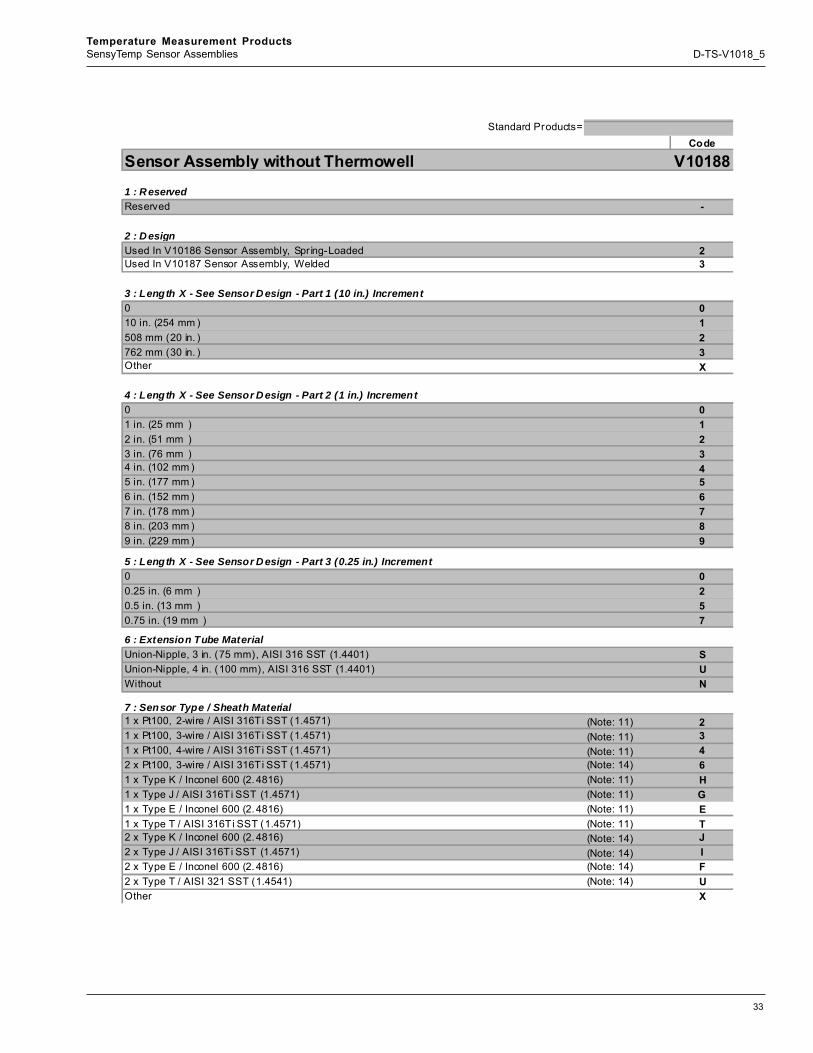
Sensor Assembly without Thermowell V10188
1 : R eservedReserved -
2 : D esignUsed In V10186 Sensor Assembly, Spr ing-Loaded 2Used In V10187 Sensor Assembly, Welded 3
3 : Length X - See Sensor D esign - Part 1 (10 in.) Increment0 010 in. (254 mm ) 1508 mm (20 in. ) 2762 mm (30 in. ) 3Other X
4 : Length X - See Sensor D esign - Part 2 (1 in.) Increment0 01 in. (25 mm ) 12 in. (51 mm ) 23 in. (76 mm ) 34 in. (102 mm ) 45 in. (177 mm ) 56 in. (152 mm ) 67 in. (178 mm ) 78 in. (203 mm ) 89 in. (229 mm ) 9
5 : Length X - See Sensor D esign - Part 3 (0.25 in.) Increment0 00.25 in. (6 mm ) 20.5 in. (13 mm ) 50.75 in. (19 mm ) 7
6 : Extension Tube MaterialUnion-Nipple, 3 in. (75 mm), AISI 316 SST (1.4401) SUnion-Nipple, 4 in. (100 mm), AISI 316 SST (1.4401) UWithout N
7 : Sensor Type / Sheath Material1 x Pt100, 2-wire / AISI 316Ti SST (1.4571) (Note: 11) 21 x Pt100, 3-wire / AISI 316Ti SST (1.4571) (Note: 11) 31 x Pt100, 4-wire / AISI 316Ti SST (1.4571) (Note: 11) 42 x Pt100, 3-wire / AISI 316Ti SST (1.4571) (Note: 14) 61 x Type K / Inconel 600 (2. 4816) (Note: 11) H1 x Type J / AISI 316Ti SST (1.4571) (Note: 11) G1 x Type E / Inconel 600 (2. 4816) (Note: 11) E1 x Type T / AISI 316Ti SST (1.4571) (Note: 11) T2 x Type K / Inconel 600 (2. 4816) (Note: 14) J2 x Type J / AISI 316Ti SST (1.4571) (Note: 14) I2 x Type E / Inconel 600 (2. 4816) (Note: 14) F2 x Type T / AISI 321 SST (1.4541) (Note: 14) UOther X

34
Temperature Measurement ProductsSensyTemp Sensor Assemblies D-TS-V1018_5
V10188 Code
8 : A ccuracy according to IEC 60751 & IEC 60582Class B RTD only (Note: 1) AClass 2 Thermocouples only (Note: 2) GClass A RTD only (Note: 1) EClass 1 Thermocouples only (Note: 2) H
9 : C onnection Head / Material / C able Entry / Class of ProtectionWithout 0B (Basic), Aluminum, 1/2 in. NPT, IP 54 (Not with TF 12 Xmt.) (Note: 15) 1BUZH , Aluminum, 1/2 in. NPT, IP 68 5AGL Heavy Duty Aluminum, 1/2 in. NPT, IP 66, IP 67 / NEMA 4X (Note: 12) BAGLH D Pro-Meter, Connection Head Alum inum, 1/ 2 in. N PT, IP 66, IP 67, NEMA 4X (Note: 13) DAGLH D Co-Meter, Alum inum, I P 66, IP 67, NEMA 4X (Note: 13) CAGLH D LCD Integral D isplay, Aluminum 1/2 in. NPT, IP 66, IP 67, N EMA 4X (THX300, TTh300EX,EXN Only) L
AGLH D Digital Display, Alum inum 1/2 in. NPT, IP 66, IP 67, NEMA 4X (TF02, TF02EX Only) FOther X
10 : H ead Mounted TransmitterWithout 0TH02 HART Protocol, General Purpose (Note: 10) 9TF12 PROFIBUS PA (only w ith BUZH or AGL Connection Head) (Notes: 3, 10) KTH02-Ex H ART Protocol, Intrinsically Safe (Note: 10) JTH02-ExN HART Protocol, Nonincendive (Note: 10) PTS04 Programmable via Pushbutton, General Purpose (for 2 / 3 wire RTD only) (Notes: 4, 5, 10) 2TS05-1, Program mable via Pushbutton, General Purpose Type K, 0 ... 1000 °C (32 ... 1832 °F)
(Notes: 4, 5, 10) 5
TS05-3, Program mable via Pushbutton, General Purpose, Type J (Notes: 4, 6, 10) 4TF02 FOUND ATION Fieldbus, LAS function standard, General Purpose (Notes: 4, 10) MTTH300 HART Protocol, General Purpose 6TTH300-Ex, ExN HAR T Protocol, FM Intr insically Safe (Class I, Div. 1) and Nonincendive (Class I, Div. 2) 7
TF02-Ex FOUNDATION Fieldbus, LAS function standard, FM Intrinsically Safe (Notes: 4, 10) NOther X
ADDITIONAL ORDERING CODE11 : Sensor TypeGround Thermocouple 33
12 : N ame PlateTag N o. on Stainless Steel Label SL
13 : C alibration2 PT Certified C alibration (TH02, TH02-Ex, TH02-ExN Only) (Note: 7) 2P5 PT Certified C alibration (TTH300, TTH 300-Ex, TTH300-ExN Only) (Note: 8) 5P9 PT Certified C alibration (TH02, TH02-Ex, TH02-ExN Only) (Note: 7) 9PCallendar-van Dusen Sensor Match Calibration (TTH300, TTH300-Ex, TTH300-ExN Only)
(Note: 8) CD
9 PT Sensor Match Calibration (TH02, TH02-Ex, TH02-ExN Only) (Note: 7) M C
14 : SIL2 TUV CertificateTUV Certificate for Functional Safety SIL2 acc. IEC61508 (Note: 9) S2
15 : Other OptionsSpecify XX
35
Temperature Measurement ProductsSensyTemp Sensor Assemblies D-TS-V1018_5
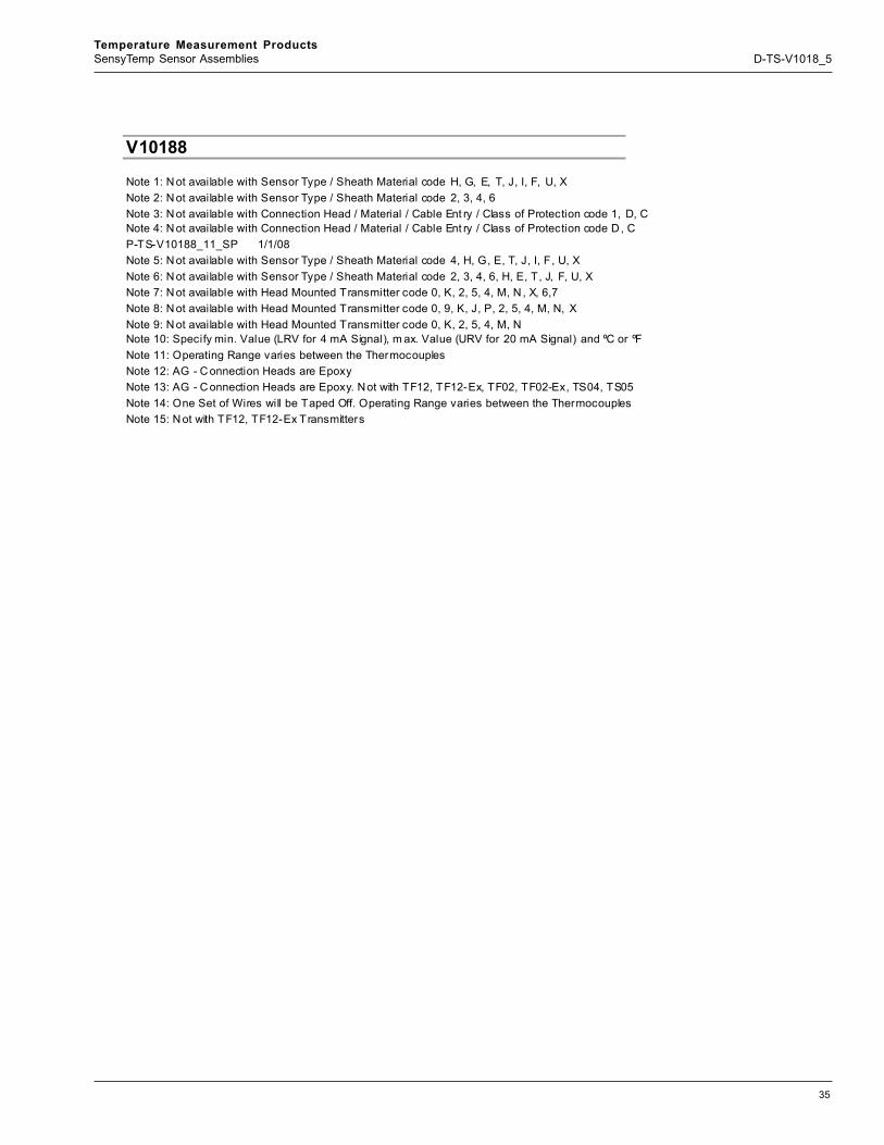
V10188
P-TS-V10188_11_SP 1/1/08
Note 14: One Set of Wires will be Taped Off. Operating Range varies between the ThermocouplesNote 15: N ot with TF12, TF12-Ex Transmitters
Note 10: Specify min. Value (LRV for 4 mA Signal), m ax. Value (URV for 20 mA Signal) and ºC or ºFNote 11: Operating Range varies between the ThermocouplesNote 12: AG - C onnection Heads are EpoxyNote 13: AG - C onnection Heads are Epoxy. Not with TF12, TF12-Ex, TF02, TF02-Ex, TS04, TS05
Note 6: N ot available with Sensor Type / Sheath Material code 2, 3, 4, 6, H, E, T, J, F, U, XNote 7: N ot available with Head Mounted Transmitter code 0, K, 2, 5, 4, M, N , X, 6,7Note 8: N ot available with Head Mounted Transmitter code 0, 9, K, J, P, 2, 5, 4, M, N, XNote 9: N ot available with Head Mounted Transmitter code 0, K, 2, 5, 4, M, N
Note 2: N ot available with Sensor Type / Sheath Material code 2, 3, 4, 6Note 3: N ot available with Connection Head / Material / Cable Ent ry / Class of Protection code 1, D, CNote 4: N ot available with Connection Head / Material / Cable Ent ry / Class of Protection code D , C
Note 5: N ot available with Sensor Type / Sheath Material code 4, H, G, E, T, J, I, F, U, X
Note 1: N ot available with Sensor Type / Sheath Material code H, G, E, T, J, I, F, U, X
36
Temperature Measurement ProductsSensyTemp Sensor Assemblies D-TS-V1018_5
Standard Products=Code
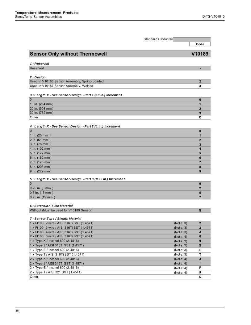
Sensor Only without Thermowell V10189
1 : ReservedReserved -
2 : DesignUsed In V10186 Sensor Assembly, Spr ing-Loaded 2Used In V10187 Sensor Assembly, Welded 3
3 : Length X - See Sensor Design - Part 1 (10 in.) Increment0 010 in. (254 mm ) 120 in. (508 mm ) 230 in. (762 mm ) 3Other X
4 : Length X - See Sensor Design - Part 2 (1 in.) Increment0 01 in. (25 mm ) 12 in. (51 mm ) 23 in. (76 mm ) 34 in. (102 mm ) 45 in. (177 mm ) 56 in. (152 mm ) 67 in. (178 mm ) 78 in. (203 mm ) 89 in. (229 mm ) 9
5 : Length X - See Sensor Design - Part 3 (0.25 in.) Increment0 00.25 in. (6 mm ) 20.5 in. (13 mm ) 50.75 in. (19 mm ) 7
6 : Extension Tube MaterialWithout (Must be used for V10189 Sensor) N
7 : Sensor Type / Sheath Material1 x Pt100, 2-wire / AISI 316Ti SST (1.4571) (Not e: 3) 21 x Pt100, 3-wire / AISI 316Ti SST (1.4571) (Not e: 3) 31 x Pt100, 4-wire / AISI 316Ti SST (1.4571) (Not e: 3) 42 x Pt100, 3-wire / AISI 316Ti SST (1.4571) (Not e: 4) 61 x Type K / Inconel 600 (2. 4816) (Not e: 3) H1 x Type J / AISI 316Ti SST (1.4571) (Not e: 3) G1 x Type E / Inconel 600 (2. 4816) (Not e: 3) E1 x Type T / AISI 316Ti SST (1.4571) (Not e: 3) T2 x Type K / Inconel 600 (2. 4816) (Not e: 4) J2 x Type J / AISI 316Ti SST (1.4571) (Not e: 4) I2 x Type E / Inconel 600 (2. 4816) (Not e: 4) F2 x Type T / AISI 321 SST (1.4541) (Not e: 4) UOther X
37
Temperature Measurement ProductsSensyTemp Sensor Assemblies D-TS-V1018_5
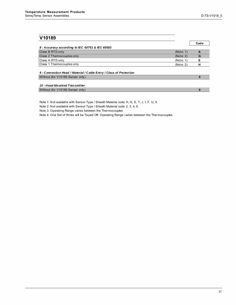
V10189Code
8 : Accuracy according to IEC 60751 & IEC 60583Class B RTD only (Not e: 1) AClass 2 Thermocouples only (Not e: 2) GClass A RTD only (Not e: 1) EClass 1 Thermocouples only (Not e: 2) H
9 : Connection Head / Material / Cable Entry / Class of ProtectionWithout (for V10189 Sensor only) 0
10 : Head Mounted TransmitterWithout (for V10189 Sensor only) 0
Note 1: Not available with Sensor Type / Sheath Material code H, G, E, T, J, I, F, U, XNote 2: Not available with Sensor Type / Sheath Material code 2, 3, 4, 6Note 3: Operating Range varies between the ThermocouplesNote 4: One Set of Wires will be Ta ped Off. Operating Range varies between the Thermocouples
38
Temperature Measurement ProductsSensyTemp Sensor Assemblies D-TS-V1018_5
The Company’s policy is one of continuous productimprovement and the right is reserved to modify the
information contained herein without notice.
Printed in USA (7.28.08)
© ABB 2006, 2008
D-T
S-V1
018_
5ABB has Sales & Customer Supportexpertise in over 100 countries worldwide
www.abb.com/instrumentation
ABB Inc.125 East County Line RoadWarminsterPA 18974USATel: +1 215 674 6001Fax: +1 215 674 7183
ABB LtdSalterbeck Trading EstateWorkington, CumbriaCA14 5DSUKTel: +44 (0)1946 830 611Fax: +44 (0)1946 832 661
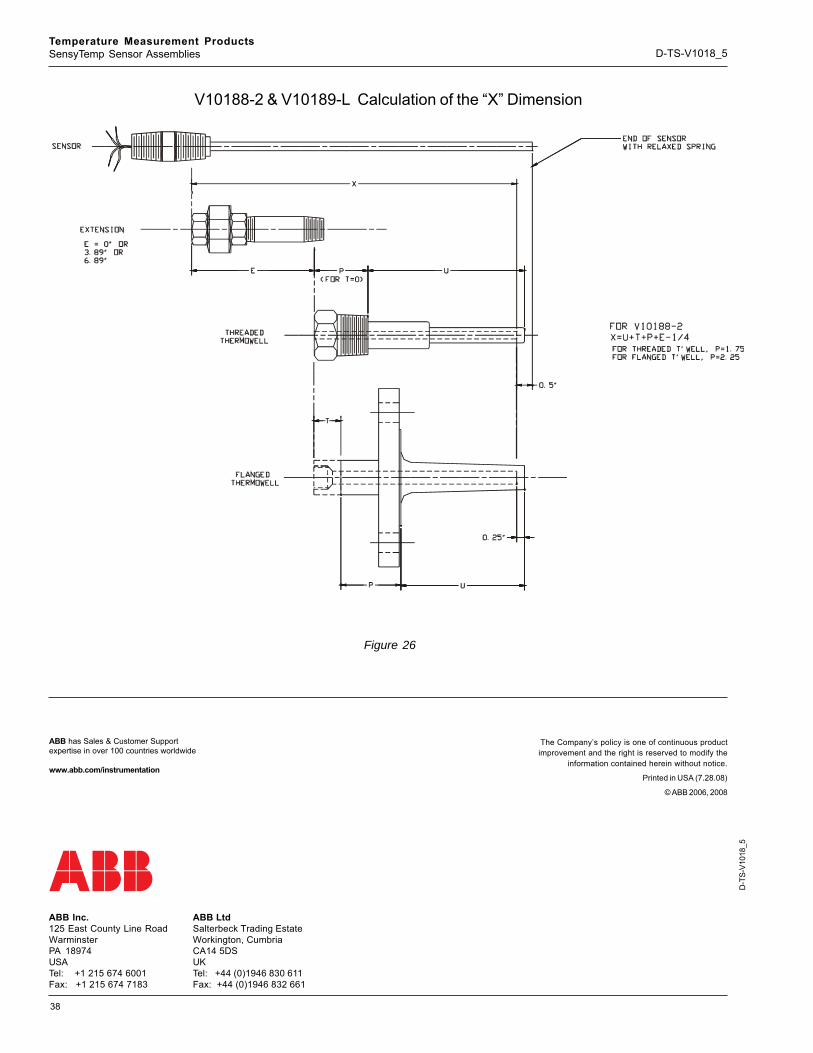
Figure 26
V10188-2 & V10189-L Calculation of the “X” Dimension
Related Documents