Data sheet SONOMETER TM 1100 Ultrasonic compact energy meter Description/Application MID examination certificate no. : DE-10-MI004-PTB003 The SONOMETER™1100 is an ultrasonic static compact energy meter especially designed for heating, cooling or combined heating/cooling application in local and district energy systems. The SONOMETER™1100 as a compact energy meter consists of the following components: - Ultrasonic flow sensor; - Calculator with integral hardware and software for measuring flow rate, temperature and energy consumption; - Pair of temperature sensors. Features - 1st. approval in Europe for ultrasonic energy meter with dynamic range of q i /q p 1 : 250 in class 2 (q p 1.5 / 2.5 / 6 / 10 / 15 / 25 / 40 / 60 m³/h) - Complete dynamic range: ≥ 1 : 1500 - Lithium battery, 230 V AC or 24 V AC mains unit - Battery lifetime 11 years (16 years optional) - Unique free- beam principle - Improved service-friendly energy meter design - Housings with thread and flange (PN 16 / 25) - Can be configured for heating, cooling or combined heating/cooling application - Temperature range: 5 - 130 / 150 °C - Overload temperature up to 150 °C (q p = 0.6 - 2.5 m 3 /h) - Swirl-free flow around reflector - Lower pressure loss - Robust stainless steel reflector - Insensitive to dirt - Available in nominal sizes q p 0.6 / 1.0 / 1.5 / 2.5 / 3.5 / 6 / 10 / 15 / 25 / 40 / 60 m³/h - Measuring accuracy meets the requirements of EN 1434 ( MID) class 2 and 3 - No calming sections necessary in the inlet and/or outlet (standard installation) Special Features - Power save mode - NOWA test capability - Remote reading via M-Bus, L-Bus, RS 232, RS 485, Radio or optical interface - Integrated Radio (868 or 434 Hz), Real Data or Open Metering Standard (OMS) - Individual remote reading (Automatic Meter Reading) with add on modules Plug&Play - 2 communication ports (e.g. M-Bus + M-Bus) - Improved radio performance - Individual tariff functions - History memory for 24 months - Extensive diagnostic displays - IZAR@SET parameterization software on Windows basis guarantees optimum adaptation to the user’s specific needs 1 DEN-SMT/PL VD.SH.J1.02 © Danfoss 12/2010

Welcome message from author
This document is posted to help you gain knowledge. Please leave a comment to let me know what you think about it! Share it to your friends and learn new things together.
Transcript
Data sheet
SONOMETERTM1100Ultrasonic compact energy meter
Description/Application
MID examination certificate no. : DE-10-MI004-PTB003
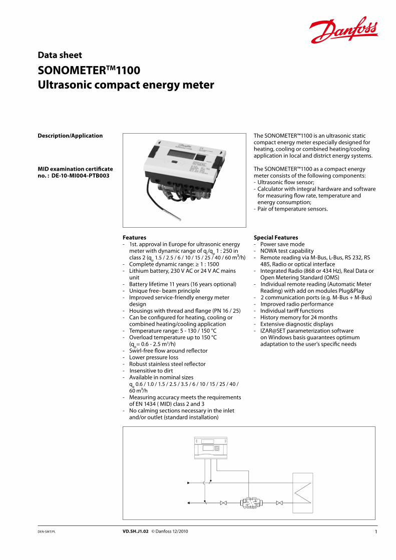
The SONOMETER™1100 is an ultrasonic static compact energy meter especially designed for heating, cooling or combined heating/cooling application in local and district energy systems.
The SONOMETER™1100 as a compact energy meter consists of the following components:- Ultrasonic flow sensor;- Calculator with integral hardware and software
for measuring flow rate, temperature and energy consumption;
- Pair of temperature sensors.
Features- 1st. approval in Europe for ultrasonic energy
meter with dynamic range of qi/q
p 1 : 250 in
class 2 (qp 1.5 / 2.5 / 6 / 10 / 15 / 25 / 40 / 60 m³/h)
- Complete dynamic range: ≥ 1 : 1500- Lithium battery, 230 V AC or 24 V AC mains
unit- Battery lifetime 11 years (16 years optional)- Unique free- beam principle- Improved service-friendly energy meter
design- Housings with thread and flange (PN 16 / 25)- Can be configured for heating, cooling or
combined heating/cooling application- Temperature range: 5 - 130 / 150 °C- Overload temperature up to 150 °C
(qp= 0.6 - 2.5 m3/h)
- Swirl-free flow around reflector- Lower pressure loss- Robust stainless steel reflector- Insensitive to dirt- Available in nominal sizes
qp 0.6 / 1.0 / 1.5 / 2.5 / 3.5 / 6 / 10 / 15 / 25 / 40 /
60 m³/h- Measuring accuracy meets the requirements
of EN 1434 ( MID) class 2 and 3- No calming sections necessary in the inlet
and/or outlet (standard installation)
Special Features- Power save mode- NOWA test capability- Remote reading via M-Bus, L-Bus, RS 232, RS
485, Radio or optical interface- Integrated Radio (868 or 434 Hz), Real Data or
Open Metering Standard (OMS)- Individual remote reading (Automatic Meter
Reading) with add on modules Plug&Play- 2 communication ports (e.g. M-Bus + M-Bus)- Improved radio performance- Individual tariff functions- History memory for 24 months- Extensive diagnostic displays- IZAR@SET parameterization software
on Windows basis guarantees optimum adaptation to the user’s specific needs
1DEN-SMT/PL VD.SH.J1.02 © Danfoss 12/2010
Data Sheet SONOMETERTM1100 – Ultrasonic energy meter
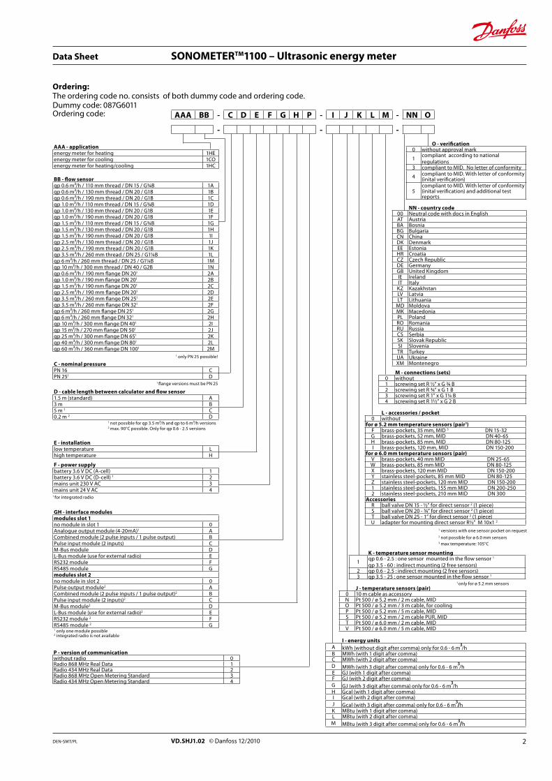
Ordering code: AAA BB - C D E F G H P - I J K L M - NN O
AAA - applicationenergy meter for heating 1HEenergy meter for cooling 1COenergy meter for heating/cooling 1HC
O - verification0 without approval mark
1compliant according to national regulations
3 compliant to MID. No letter of conformity
4 compliant to MID. With letter of conformity (inital verification)
5compliant to MID. With letter of conformity (inital verification) and additional test reports
F - power supplybattery 3.6 V DC (A-cell) 1battery 3.6 V DC (D-cell) 1 2mains unit 230 V AC 3mains unit 24 V AC 4
1 for integrated radio
GH - interface modulesmodules slot 1no module in slot 1 0Analogue output module (4-20mA)1 ACombined module (2 pulse inputs / 1 pulse output) BPulse input module (2 inputs) CM-Bus module DL-Bus module (use for external radio) ERS232 module FRS485 module Gmodules slot 2no module in slot 2 0Pulse output module2 ACombined module (2 pulse inputs / 1 pulse output)2 BPulse input module (2 inputs)2 CM-Bus module2 DL-Bus module (use for external radio)2 ERS232 module 2 FRS485 module 2 G1 only one module possible2 integrated radio is not available
I - energy unitsA kWh (without digit after comma) only for 0.6 - 6 m³/hB MWh (with 1 digit after comma)C MWh (with 2 digit after comma)D MWh (with 3 digit after comma) only for 0.6 - 6 m³/hE GJ (with 1 digit after comma) F GJ (with 2 digit after comma)G GJ (with 3 digit after comma) only for 0.6 - 6 m³/hH Gcal (with 1 digit after comma)I Gcal (with 2 digit after comma)J Gcal (with 3 digit after comma) only for 0.6 - 6 m³/hK MBtu (with 1 digit after comma) L MBtu (with 2 digit after comma) M MBtu (with 3 digit after comma) only for 0.6 - 6 m³/h
J - temperature sensors (pair)0 10 m cable as accessoryN Pt 500 / ø 5.2 mm / 2 m cable, MIDO Pt 500 / ø 5.2 mm / 3 m cable, for coolingP Pt 500 / ø 5.2 mm / 5 m cable, MIDS Pt 500 / ø 5.2 mm / 2 m cable PUR, MIDT Pt 500 / ø 6.0 mm / 2 m cable, MIDV Pt 500 / ø 6.0 mm / 5 m cable, MID
L - accessories / pocket0 without
for ø 5.2 mm temperature sensors (pair1)F brass-pockets, 35 mm, MID 3 DN 15-32G brass-pockets, 52 mm, MID DN 40-65H brass-pockets, 85 mm, MID DN 80-125I brass-pockets, 120 mm, MID DN 150-200
for ø 6.0 mm temperature sensors (pair)V brass-pockets, 40 mm MID DN 25-65W brass-pockets, 85 mm MID DN 80-125X brass-pockets, 120 mm MID DN 150-200Y stainless steel-pockets, 85 mm MID DN 80-125Z stainless steel-pockets, 120 mm MID DN 150-2001 stainless steel-pockets, 155 mm MID DN 200-2502 stainless steel-pockets, 210 mm MID DN 300
AccessoriesR ball valve DN 15 - ½” for direct sensor 2 (1 piece)S ball valve DN 20 - ¾” for direct sensor 2 (1 piece)T ball valve DN 25 - 1” for direct sensor 2 (1 piece)U adapter for mounting direct sensor R½” M 10x1 2
M - connections (sets)0 without1 screwing set R ½” x G ¾ B2 screwing set R ¾” x G 1 B3 screwing set R 1” x G 11/4 B4 screwing set R 1½” x G 2 B
K - temperature sensor mounting
1qp 0.6 - 2.5 : one sensor mounted in the flow sensor 1
qp 3.5 - 60 : indirect mounting (2 free sensors)2 qp 0.6 - 2.5 : indirect mounting (2 free sensors)3 qp 3.5 - 25 : one sensor mounted in the flow sensor 1
BB - flow sensorqp 0.6 m³/h / 110 mm thread / DN 15 / G¾B 1Aqp 0.6 m³/h / 130 mm thread / DN 20 / G1B 1Bqp 0.6 m³/h / 190 mm thread / DN 20 / G1B 1Cqp 1.0 m³/h / 110 mm thread / DN 15 / G¾B 1Dqp 1.0 m³/h / 130 mm thread / DN 20 / G1B 1Eqp 1.0 m³/h / 190 mm thread / DN 20 / G1B 1Fqp 1.5 m³/h / 110 mm thread / DN 15 / G¾B 1Gqp 1.5 m³/h / 130 mm thread / DN 20 / G1B 1Hqp 1.5 m³/h / 190 mm thread / DN 20 / G1B 1Iqp 2.5 m³/h / 130 mm thread / DN 20 / G1B 1Jqp 2.5 m³/h / 190 mm thread / DN 20 / G1B 1Kqp 3.5 m³/h / 260 mm thread / DN 25 / G11/4B 1Lqp 6 m³/h / 260 mm thread / DN 25 / G11/4B 1Mqp 10 m³/h / 300 mm thread / DN 40 / G2B 1Nqp 0.6 m³/h / 190 mm flange DN 201 2Aqp 1.0 m³/h / 190 mm flange DN 201 2Bqp 1.5 m³/h / 190 mm flange DN 201 2Cqp 2.5 m³/h / 190 mm flange DN 201 2Dqp 3.5 m³/h / 260 mm flange DN 251 2Eqp 3.5 m³/h / 260 mm flange DN 321 2Fqp 6 m³/h / 260 mm flange DN 251 2Gqp 6 m³/h / 260 mm flange DN 321 2Hqp 10 m³/h / 300 mm flange DN 401 2Iqp 15 m³/h / 270 mm flange DN 501 2Jqp 25 m³/h / 300 mm flange DN 651 2Kqp 40 m³/h / 300 mm flange DN 801 2Lqp 60 m³/h / 360 mm flange DN 1001 2M
C - nominal pressurePN 16 CPN 251 D
D - cable length between calculator and flow sensor1.5 m (standard) A3 m B5 m 1 C0.2 m 2 D
E - installationlow temperature Lhigh temperature H
NN - country code00 Neutral code with docs in EnglishAT AustriaBA BosniaBG BulgariaCN ChinaDK DenmarkEE EstoniaHR CroatiaCZ Czech RepublicDE GermanyGB United KingdomIE IrelandIT ItalyKZ KazakhstanLV LatviaLT Lithuania
MD MoldovaMK MacedoniaPL PolandRO RomaniaRU RussiaCS SerbiaSK Slovak RepublicSI SloveniaTR TurkeyUA UkraineXM Montenegro
1 only PN 25 possible!
1 not possible for qp 3.5 m³/h and qp to 6 m³/h versions2 max. 90°C possible. Only for qp 0.6 - 2.5 versions
1 flange versions must be PN 25
1 versions with one sensor pocket on request2 not possible for ø 6.0 mm sensors3 max temperature: 105°C
1 only for ø 5.2 mm sensors
- - -
Ordering:The ordering code no. consists of both dummy code and ordering code.Dummy code: 087G6011
P - version of communicationwithout radio 0Radio 868 MHz Real Data 1Radio 434 MHz Real Data 2Radio 868 MHz Open Metering Standard 3Radio 434 MHz Open Metering Standard 4
2VD.SHJ1.02 © Danfoss 12/2010DEN-SMT/PL
Data Sheet SONOMETERTM1100 – Ultrasonic energy meter
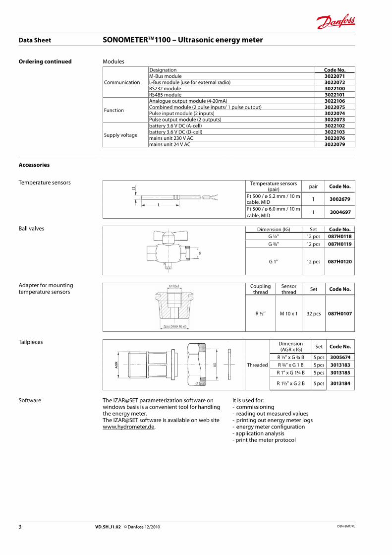
Ordering continued Modules
Communication
Designation Code No.M-Bus module 3022071L-Bus module (use for external radio) 3022072RS232 module 3022100RS485 module 3022101
Function
Analogue output module (4-20mA) 3022106Combined module (2 pulse inputs/ 1 pulse output) 3022075Pulse input module (2 inputs) 3022074Pulse output module (2 outputs) 3022073
Supply voltage
battery 3.6 V DC (A-cell) 3022102battery 3.6 V DC (D-cell) 3022103mains unit 230 V AC 3022076mains unit 24 V AC 3022079
Accessories
Temperature sensors Temperature sensors (pair) pair Code No.
Pt 500 / ø 5.2 mm / 10 m cable, MID 1 3002679
Pt 500 / ø 6.0 mm / 10 m cable, MID
1 3004697
Ball valves Dimension (IG) Set Code No.G ½’’ 12 pcs 087H0118
G ¾’’ 12 pcs 087H0119
G 1’’ 12 pcs 087H0120
Adapter for mounting temperature sensors
Coupling thread
Sensor thread Set Code No.
R ½’’ M 10 x 1 32 pcs 087H0107
Tailpieces
Threaded
Dimension (AGR x IG) Set Code No.
R ½” x G ¾ B 5 pcs 3005674
R ¾” x G 1 B 5 pcs 3013183
R 1” x G 11/4 B 5 pcs 3013185
R 1½” x G 2 B 5 pcs 3013184
Software The IZAR@SET parameterization software on windows basis is a convenient tool for handling the energy meter.The IZAR@SET software is available on web site www.hydrometer.de.
It is used for:- commissioning- reading out measured values- printing out energy meter logs- energy meter configuration- application analysis- print the meter protocol
3 DEN-SMT/PLVD.SH.J1.02 © Danfoss 12/2010
Data Sheet SONOMETERTM1100 – Ultrasonic energy meter
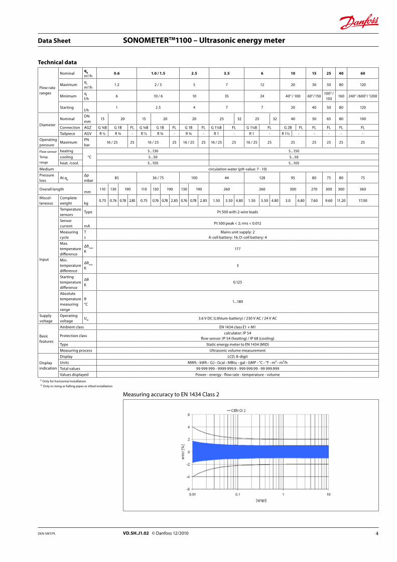
Technical data
Flow rateranges
Nominalqp m3/h
0.6 1.0 / 1.5 2.5 3.5 6 10 15 25 40 60
Maximumq
s
m3/h1.2 2 / 3 5 7 12 20 30 50 80 120
Minimum q
i
l/h6 10 / 6 10 35 24 401) / 100 601) / 150
1001) / 150
160 2401) /6002)/ 1200
Starting l/h
1 2.5 4 7 7 20 40 50 80 120
Diameter
NominalDN mm
15 20 15 20 20 25 32 25 32 40 50 65 80 100
Connection AGZ G ¾B G 1B FL G ¾B G 1B FL G 1B FL G 11/4B FL G 11/4B FL G 2B FL FL FL FL FL
Tailpiece AGV R ½ R ¾ - R ½ R ¾ - R ¾ - R 1 - R 1 - R 1½ - - - - -
Operating pressure
MaximumPN bar
16 / 25 25 16 / 25 25 16 / 25 25 16 / 25 25 16 / 25 25 25 25 25 25 25
Flow sensor
Temp.
range
heating
°C
5...130 5...150
cooling 5...50 5...50
heat. /cool. 5...105 5...105
Medium circulation water (pH-value: 7 - 10)
Pressure loss
At qp
Δp mbar
85 36 / 75 100 44 128 95 80 75 80 75
Overall length mm
110 130 190 110 130 190 130 190 260 260 300 270 300 300 360
Miscel-laneous
Complete weight
kg
0.75 0.76 0.78 2.85 0.75 0.76 0.78 2.85 0.76 0.78 2.85 1.50 3.50 4.80 1.50 3.50 4.80 3.0 6.80 7.60 9.60 11.20 17.00
Input
Temperature sensors
Type Pt 500 with 2-wire leads
Sensor current
mA
Pt 500 peak < 2; rms < 0.012
Measuring cycle
T s
Mains unit supply: 2 A-cell battery: 16; D-cell battery: 4
Max. temperature difference
Δθmax
K
177
Min. temperature difference
Δθmin
K
3
Starting temperature difference
Δθ K
0.125
Absolute temperature measuring range
θ °C
1...180
Supply voltage
Operating voltage
UN
3.6 V DC (Lithium-battery) / 230 V AC / 24 V AC
Basicfeatures
Ambient class EN 1434 class E1 + M1
Protection classcalculator: IP 54
flow sensor: IP 54 (heating) / IP 68 (cooling)
Type Static energy meter to EN 1434 (MID)
Measuring process Ultrasonic volume measurement
Displayindication
Display LCD, 8-digit
Units MWh - kWh - GJ - Gcal - MBtu - gal - GMP - °C - °F - m³ - m³/h
Total values 99 999 999 - 9999 999.9 - 999 999.99 - 99 999.999
Values displayed Power - energy - flow rate - temperature - volume1) Only for horizontal installation
2) Only in rising or falling pipes or tilted installation
Measuring accuracy to EN 1434 Class 2
4DEN-SMT/PL VD.SH.J1.02 © Danfoss 12/2010
Data Sheet SONOMETERTM1100 – Ultrasonic energy meter
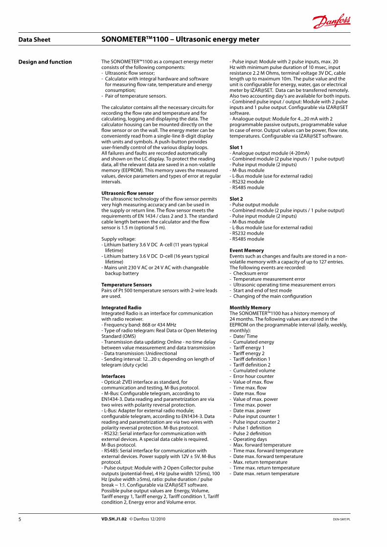
Design and function The SONOMETER™1100 as a compact energy meter consists of the following components:- Ultrasonic flow sensor;- Calculator with integral hardware and software
for measuring flow rate, temperature and energy consumption;
- Pair of temperature sensors.
The calculator contains all the necessary circuits for recording the flow rate and temperature and for calculating, logging and displaying the data. The calculator housing can be mounted directly on the flow sensor or on the wall. The energy meter can be conveniently read from a single-line 8-digit display with units and symbols. A push-button provides user-friendly control of the various display loops. All failures and faults are recorded automatically and shown on the LC display. To protect the reading data, all the relevant data are saved in a non-volatile memory (EEPROM). This memory saves the measured values, device parameters and types of error at regular intervals.
Ultrasonic flow sensorThe ultrasonic technology of the flow sensor permits very high measuring accuracy and can be used in the supply or return line. The flow sensor meets the requirements of EN 1434 / class 2 and 3. The standard cable length between the calculator and the flow sensor is 1.5 m (optional 5 m).
Supply voltage:- Lithium battery 3.6 V DC A-cell (11 years typical
lifetime)- Lithium battery 3.6 V DC D-cell (16 years typical
lifetime)- Mains unit 230 V AC or 24 V AC with changeable
backup battery
Temperature SensorsPairs of Pt 500 temperature sensors with 2-wire leads are used.
Integrated RadioIntegrated Radio is an interface for communication with radio receiver.- Frequency band: 868 or 434 MHz- Type of radio telegram: Real Data or Open Metering Standard (OMS)- Transmission data updating: Online - no time delay between value measurement and data transmission- Data transmission: Unidirectional- Sending interval: 12...20 s; depending on length of telegram (duty cycle)
Interfaces- Optical: ZVEI interface as standard, for communication and testing, M-Bus protocol.- M-Bus: Configurable telegram, according to EN1434-3. Data reading and parametrization are via two wires with polarity reversal protection.- L-Bus: Adapter for external radio module; configurable telegram, according to EN1434-3. Data reading and parametrization are via two wires with polarity reversal protection. M-Bus protocol.- RS232: Serial interface for communication with external devices. A special data cable is required. M-Bus protocol.- RS485: Serial interface for communication with external devices. Power supply with 12V ± 5V. M-Bus protocol.- Pulse output: Module with 2 Open Collector pulse outputs (potential-free), 4 Hz (pulse width 125ms), 100 Hz (pulse width ≥5ms), ratio: pulse duration / pulse break ~ 1:1. Configurable via IZAR@SET software. Possible pulse output values are Energy, Volume, Tariff energy 1, Tariff energy 2, Tariff condition 1, Tariff condition 2, Energy error and Volume error.
- Pulse input: Module with 2 pulse inputs, max. 20 Hz with minimum pulse duration of 10 msec, input resistance 2.2 M Ohms, terminal voltage 3V DC, cable length up to maximum 10m. The pulse value and the unit is configurable for energy, water, gas or electrical meter by IZAR@SET. Data can be transferred remotely. Also two accounting day’s are available for both inputs.- Combined pulse input / output: Module with 2 pulse inputs and 1 pulse output. Configurable via IZAR@SET software.- Analogue output: Module for 4...20 mA with 2 programmable passive outputs, programmable value in case of error. Output values can be power, flow rate, temperatures. Configurable via IZAR@SET software.
Slot 1 - Analogue output module (4-20mA)- Combined module (2 pulse inputs / 1 pulse output)- Pulse input module (2 inputs)- M-Bus module- L-Bus module (use for external radio) - RS232 module - RS485 module
Slot 2 - Pulse output module- Combined module (2 pulse inputs / 1 pulse output)- Pulse input module (2 inputs)- M-Bus module- L-Bus module (use for external radio)- RS232 module- RS485 module Event MemoryEvents such as changes and faults are stored in a non-volatile memory with a capacity of up to 127 entries. The following events are recorded:- Checksum error- Temperature measurement error- Ultrasonic operating time measurement errors- Start and end of test mode- Changing of the main configuration
Monthly MemoryThe SONOMETER™1100 has a history memory of 24 months. The following values are stored in the EEPROM on the programmable interval (daily, weekly, monthly):- Date/ Time- Cumulated energy- Tariff energy 1- Tariff energy 2- Tariff definition 1- Tariff definition 2- Cumulated volume- Error hour counter- Value of max. flow- Time max. flow- Date max. flow- Value of max. power- Time max. power- Date max. power- Pulse input counter 1- Pulse input counter 2- Pulse 1 definition- Pulse 2 definition- Operating days- Max. forward temperature- Time max. forward temperature- Date max. forward temperature- Max. return temperature- Time max. return temperature- Date max. return temperature
5 DEN-SMT/PLVD.SH.J1.02 © Danfoss 12/2010
Data Sheet SONOMETERTM1100 – Ultrasonic energy meter
Design and function, continued
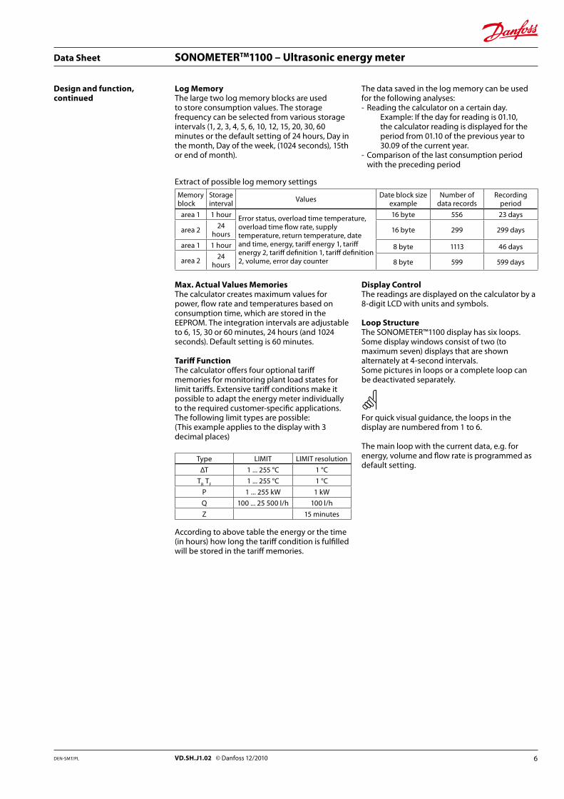
Log MemoryThe large two log memory blocks are used to store consumption values. The storage frequency can be selected from various storage intervals (1, 2, 3, 4, 5, 6, 10, 12, 15, 20, 30, 60 minutes or the default setting of 24 hours, Day in the month, Day of the week, (1024 seconds), 15th or end of month).
The data saved in the log memory can be used for the following analyses:- Reading the calculator on a certain day. Example: If the day for reading is 01.10,
the calculator reading is displayed for the period from 01.10 of the previous year to 30.09 of the current year.
- Comparison of the last consumption period with the preceding period
Extract of possible log memory settings
Memory block
Storage interval Values Date block size
exampleNumber of
data recordsRecording
period
area 1 1 hour Error status, overload time temperature, overload time flow rate, supply temperature, return temperature, date and time, energy, tariff energy 1, tariff energy 2, tariff definition 1, tariff definition 2, volume, error day counter
16 byte 556 23 days
area 2 24 hours 16 byte 299 299 days
area 1 1 hour 8 byte 1113 46 days
area 2 24 hours 8 byte 599 599 days
Max. Actual Values MemoriesThe calculator creates maximum values for power, flow rate and temperatures based on consumption time, which are stored in the EEPROM. The integration intervals are adjustable to 6, 15, 30 or 60 minutes, 24 hours (and 1024 seconds). Default setting is 60 minutes.
Tariff FunctionThe calculator offers four optional tariff memories for monitoring plant load states for limit tariffs. Extensive tariff conditions make it possible to adapt the energy meter individually to the required customer-specific applications.The following limit types are possible:(This example applies to the display with 3 decimal places)
Type LIMIT LIMIT resolution
ΔT 1 ... 255 °C 1 °C
TR
TF
1 ... 255 °C 1 °C
P 1 ... 255 kW 1 kW
Q 100 ... 25 500 l/h 100 l/h
Z 15 minutes
According to above table the energy or the time (in hours) how long the tariff condition is fulfilled will be stored in the tariff memories.
Display ControlThe readings are displayed on the calculator by a 8-digit LCD with units and symbols.
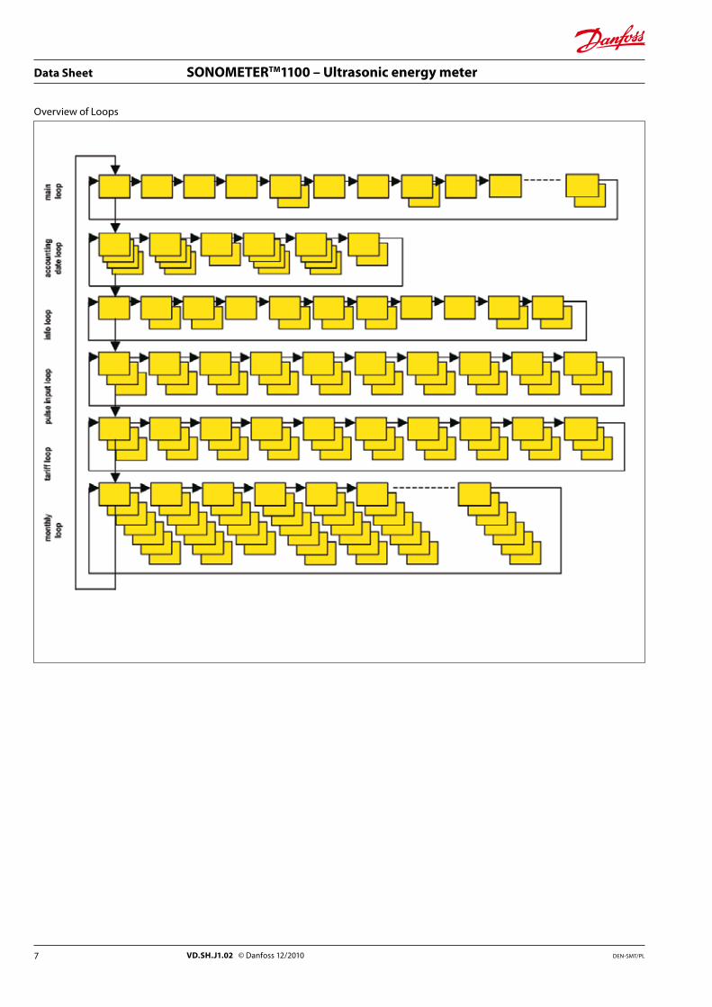
Loop StructureThe SONOMETER™1100 display has six loops. Some display windows consist of two (to maximum seven) displays that are shown alternately at 4-second intervals.Some pictures in loops or a complete loop can be deactivated separately.
For quick visual guidance, the loops in the display are numbered from 1 to 6.
The main loop with the current data, e.g. for energy, volume and flow rate is programmed as default setting.
6DEN-SMT/PL VD.SH.J1.02 © Danfoss 12/2010
Data Sheet SONOMETERTM1100 – Ultrasonic energy meter
Overview of Loops
7 DEN-SMT/PLVD.SH.J1.02 © Danfoss 12/2010
Data Sheet SONOMETERTM1100 – Ultrasonic energy meter
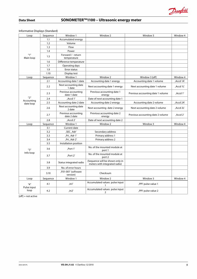
Informative Displays (Standard)
Loop Sequence Window 1 Window 2 Window 3 Window 4
“1”Main loop
1.1 Accumulated energy
1.2 Volume
1.3 Flow
1.4 Power
1.5 Forward / - return temperature
1.6 Difference temperature
1.7 Operating days
1.9 Error status
1.10 Display test
Loop Sequence Window 1 Window 2 Window 3 [off] Window 4
“2”Accountingdate loop
2.1 Accounting date 1 date Accounting date 1 energy Accounting date 1 volume ,Accd 1A'
2.2 Next accounting date 1 date Next accounting date 1 energy Next accounting date 1 volume ,Accd 1L'
2.3 Previous accounting date 1 date
Previous accounting date 1 energy Previous accounting date 1 volume ,Accd 1'
2.4 ,Accd 1' Date of next accounting date 1
2.5 Accounting date 2 date Accounting date 2 energy Accounting date 2 volume ,Accd 2A'
2.6 Next accounting date 2 date Next accounting date 2 energy Next accounting date 2 volume ,Accd 2L'
2.7 Previous accounting date 2 date
Previous accounting date 2 energy Previous accounting date 2 volume ,Accd 2'
2.8 ,Accd 2' Date of next accounting date 2
Loop Sequence Window 1 Window 2 Window 3 Window 4
“3“Info loop
3.1 Current date
3.2 ,SEC_Adr' Secondary address
3.3 ,Pri_Adr 1' Primary address 1
3.4 ,Pri_Adr 2' Primary address 2
3.5 Installation position
3.6 ,Port 1' No. of the mounted module at port 1
3.7 ,Port 2' No. of the mounted module at port 2
3.8 Status integrated radio (Sequence will be shown only in meters with integrated radio)
3.9 No. of error hours
3.10 ,F01-001' (software version) Checksum
Loop Sequence Window 1 Window 2 Window 3 Window 4
“4”Pulse input
loop
4.1 ,In1' Accumulated values pulse input 1 ,PPI' pulse value 1
4.2 ,In2' Accumulated values pulse input 2 ,PPI' pulse value 2
[off] = not active
8DEN-SMT/PL VD.SH.J1.02 © Danfoss 12/2010
Data Sheet SONOMETERTM1100 – Ultrasonic energy meter
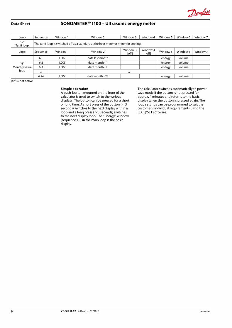
Loop Sequence Window 1 Window 2 Window 3 Window 4 Window 5 Window 6 Window 7
“5”Tariff loop The tariff loop is switched off as a standard at the heat meter or meter for cooling.
Loop Sequence Window 1 Window 2 Window 3[off]
Window 4[off] Window 5 Window 6 Window 7
“6”Monthly value
loop
6.1 ,LOG’ date last month energy volume
6.2 ,LOG’ date month - 1 energy volume
6.3 ,LOG’ date month - 2 energy volume
... ...
6.24 ,LOG’ date month - 23 energy volume
[off] = not active
Simple operationA push-button mounted on the front of the calculator is used to switch to the various displays. The button can be pressed for a short or long time. A short press of the button ( < 3 seconds) switches to the next display within a loop and a long press ( > 3 seconds) switches to the next display loop. The “Energy” window (sequence 1.1) in the main loop is the basic display.
The calculator switches automatically to power save mode if the button is not pressed for approx. 4 minutes and returns to the basic display when the button is pressed again. The loop settings can be programmed to suit the customer’s individual requirements using the IZAR@SET software.
9 DEN-SMT/PLVD.SH.J1.02 © Danfoss 12/2010
Data Sheet SONOMETERTM1100 – Ultrasonic energy meter
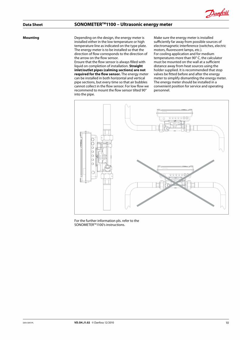
Mounting Depending on the design, the energy meter is installed either in the low temperature or high temperature line as indicated on the type plate. The energy meter is to be installed so that the direction of flow corresponds to the direction of the arrow on the flow sensor.Ensure that the flow sensor is always filled with liquid on completion of installation. Straight inlet/outlet pipes (calming sections) are not required for the flow sensor. The energy meter can be installed in both horizontal and vertical pipe sections, but every time so that air bubbles cannot collect in the flow sensor. For low flow we recommend to mount the flow sensor tilted 90° into the pipe.
Make sure the energy meter is installed sufficiently far away from possible sources of electromagnetic interference (switches, electric motors, fluorescent lamps, etc.).For cooling application and for medium temperatures more than 90° C, the calculator must be mounted on the wall at a sufficient distance away from heat sources using the holder supplied. It is recommended that stop valves be fitted before and after the energy meter to simplify dismantling the energy meter. The energy meter should be installed in a convenient position for service and operating personnel.
For the further information pls. refer to the SONOMETER™1100’s instructions.
10DEN-SMT/PL VD.SH.J1.02 © Danfoss 12/2010
Data Sheet SONOMETERTM1100 – Ultrasonic energy meter
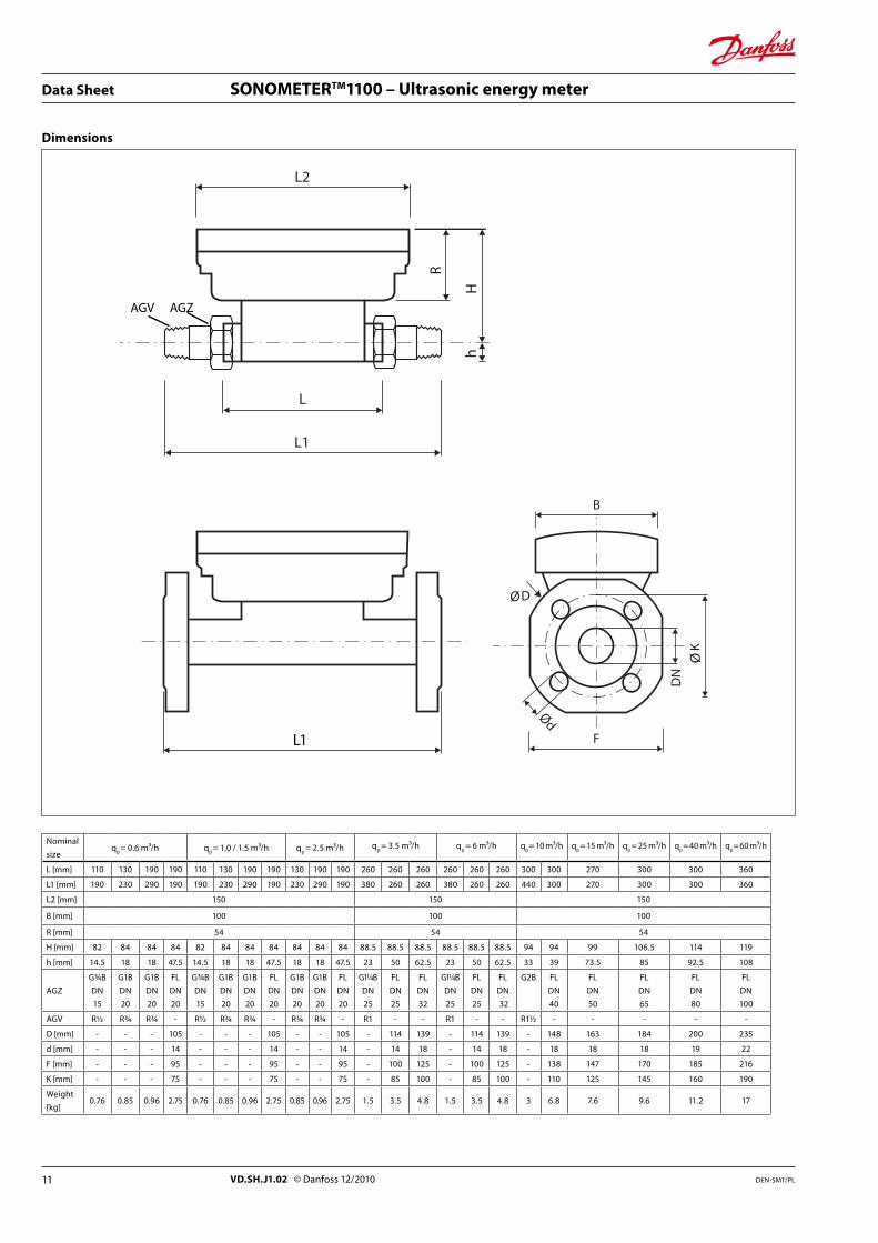
Dimensions
Nominal
sizeq
p = 0.6 m³/h q
p = 1.0 / 1.5 m³/h q
p = 2.5 m³/h q
p = 3.5 m³/h q
p = 6 m³/h q
p = 10 m³/h q
p = 15 m³/h q
p = 25 m³/h q
p = 40 m³/h q
p = 60 m³/h
L [mm] 110 130 190 190 110 130 190 190 130 190 190 260 260 260 260 260 260 300 300 270 300 300 360
L1 [mm] 190 230 290 190 190 230 290 190 230 290 190 380 260 260 380 260 260 440 300 270 300 300 360
L2 [mm] 150 150 150
B [mm] 100 100 100
R [mm] 54 54 54
H [mm] 82 84 84 84 82 84 84 84 84 84 84 88.5 88.5 88.5 88.5 88.5 88.5 94 94 99 106.5 114 119
h [mm] 14.5 18 18 47.5 14.5 18 18 47.5 18 18 47.5 23 50 62.5 23 50 62.5 33 39 73.5 85 92.5 108
AGZ
G¾B
DN
15
G1B
DN
20
G1B
DN
20
FL
DN
20
G¾B
DN
15
G1B
DN
20
G1B
DN
20
FL
DN
20
G1B
DN
20
G1B
DN
20
FL
DN
20
G11/4B
DN
25
FL
DN
25
FL
DN
32
G11/4B
DN
25
FL
DN
25
FL
DN
32
G2B FL
DN
40
FL
DN
50
FL
DN
65
FL
DN
80
FL
DN
100
AGV R½ R¾ R¾ - R½ R¾ R¾ - R¾ R¾ - R1 - - R1 - - R1½ - - - - -
D [mm] - - - 105 - - - 105 - - 105 - 114 139 - 114 139 - 148 163 184 200 235
d [mm] - - - 14 - - - 14 - - 14 - 14 18 - 14 18 - 18 18 18 19 22
F [mm] - - - 95 - - - 95 - - 95 - 100 125 - 100 125 - 138 147 170 185 216
K [mm] - - - 75 - - - 75 - - 75 - 85 100 - 85 100 - 110 125 145 160 190
Weight
[kg]0.76 0.85 0.96 2.75 0.76 0.85 0.96 2.75 0.85 0.96 2.75 1.5 3.5 4.8 1.5 3.5 4.8 3 6.8 7.6 9.6 11.2 17
RL1
L
hH
L2
L1 F
K
Ød
DN
B
DØ
Ø
L1
AGV AGZ
11 DEN-SMT/PLVD.SH.J1.02 © Danfoss 12/2010
Data Sheet SONOMETERTM1100 – Ultrasonic energy meter
Dimensions, continued
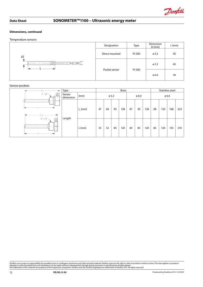
Temperature sensors
Designation Type DimensionD (mm) L (mm)
Direct mounted Pt 500 ø 5.2 45
Pocket sensor Pt 500
ø 5.2 45
ø 6.0 50
Sensor pockets
Type Brass Stainless steel
Sensor dimension (mm) ø 5.2 ø 6.0 ø 6.0
Length
L1 (mm) 47 60 93 128 47 92 128 98 133 168 223
L (mm) 35 52 85 120 40 85 120 85 120 155 210
12 Produced by Danfoss A/S © 12/2010VD.SH.J1.02
Related Documents