1 DEN-SMT/SI NovoCon® S Digital/Hybrid - High Accuracy Actuator VD.HU.P1.02 © Danfoss 06/2015 Description NovoCon® S Digital/Hybrid is a high accuracy multi-function actuator, specifically designed for use in combination with Pressure Independent Balancing Control Valve type AB-QM in sizes from DN 10-32. The high position accuracy of the actuator, together with the pressure independent and linear characteristic of AB-QM valve, allow NovoCon® S Digital/Hybrid to be used as flow indicator. Setup of actuator and valve parameters is made via fieldbus. Control is made via analog inputs or field bus for NovoCon® S Hybrid. NovoCon® S Digital is controlled via field bus. Ordering Type Code No. NovoCon® S Hybrid 003Z8500 NovoCon® S Digital 003Z8501 The actuator with AB-QM is used to control water supply to fan coil units, chilled beams, induction units, small re-heaters, re-coolers, AHU’s and other terminal units for zone control in which hot/cold water is the controlled medium. Due to its accuracy, remote functionality and flow indication features can significantly add to an accelerated commissioning process, easy maintenance, improved indoor comfort, energy saving and fair allocation of heat/cool energy. Main features: • BACnet: B-ASC (BACnet Application Specific Controller) • Remote commissioning/Reset/Flush features • Flow indication • High position accuracy • LED bar displaying status • No tools required for mounting • Maintenance-free during lifetime • Self-positioning process • Low-noise operation • Plug-in halogen free cables • Auto MAC addressing • Auto baud rate detection • Intrinsic alarm reporting • Valve blockage alarm • Broken wire detection on analog control and ground signal • Mis-wiring protection on any wire up to 30 V Accessories Type Length Connections Code No. Cable NovoCon® Digital 1.5 m bus / power 003Z8600 Cable NovoCon® Digital 5 m bus / power 003Z8601 Cable NovoCon® Digital 10 m bus / power 003Z8602 Cable NovoCon® Digital, daisy chain 1.5 m actuator / actuator 003Z8603 Cable NovoCon® Digital, daisy chain 5 m actuator / actuator 003Z8604 Cable NovoCon® Digital, daisy chain 10 m actuator / actuator 003Z8605 Cable NovoCon® Analog 1.5 m 0-10 V / power / voltage booster 003Z8606 Cable NovoCon® Analog 5 m 0-10 V / power / voltage booster 003Z8607 Cable NovoCon® Analog 10 m 0-10 V / power / voltage booster 003Z8608 Note! Cables are not included with actuator and must be ordered separately. Approvals EMC Directive 2004/108/EC, EN 60730-2-14:1997, EN 60730-2-14/A1:2001, EN60730-1:2011 RoHS Directive 2011/65/EU Data sheet

Welcome message from author
This document is posted to help you gain knowledge. Please leave a comment to let me know what you think about it! Share it to your friends and learn new things together.
Transcript
1DEN-SMT/SI
NovoCon® S Digital/Hybrid - High Accuracy Actuator
VD.HU.P1.02 © Danfoss 06/2015
Description
NovoCon® S Digital/Hybrid is a high accuracy multi-function actuator, specifically designed for use in combination with Pressure Independent Balancing Control Valve type AB-QM in sizes from DN 10-32.
The high position accuracy of the actuator, together with the pressure independent and linear characteristic of AB-QM valve, allow NovoCon® S Digital/Hybrid to be used as flow indicator.
Setup of actuator and valve parameters is made via fieldbus. Control is made via analog inputs or field bus for NovoCon® S Hybrid. NovoCon® S Digital is controlled via field bus.
Ordering Type Code No.
NovoCon® S Hybrid 003Z8500
NovoCon® S Digital 003Z8501
The actuator with AB-QM is used to control water supply to fan coil units, chilled beams, induction units, small re-heaters, re-coolers, AHU’s and other terminal units for zone control in which hot/cold water is the controlled medium. Due to its accuracy, remote functionality and flow indication features can significantly add to an accelerated commissioning process, easy maintenance, improved indoor comfort, energy saving and fair allocation of heat/cool energy.
Main features:• BACnet: B-ASC (BACnet Application Specific
Controller)• Remote commissioning/Reset/Flush features• Flow indication• High position accuracy• LED bar displaying status• No tools required for mounting• Maintenance-free during lifetime• Self-positioning process• Low-noise operation• Plug-in halogen free cables• Auto MAC addressing• Auto baud rate detection• Intrinsic alarm reporting• Valve blockage alarm• Broken wire detection on analog control and
ground signal• Mis-wiring protection on any wire up to 30 V
AccessoriesType Length Connections Code No.
Cable NovoCon® Digital 1.5 m bus / power 003Z8600
Cable NovoCon® Digital 5 m bus / power 003Z8601
Cable NovoCon® Digital 10 m bus / power 003Z8602
Cable NovoCon® Digital, daisy chain 1.5 m actuator / actuator 003Z8603
Cable NovoCon® Digital, daisy chain 5 m actuator / actuator 003Z8604
Cable NovoCon® Digital, daisy chain 10 m actuator / actuator 003Z8605
Cable NovoCon® Analog 1.5 m 0-10 V / power / voltage booster 003Z8606
Cable NovoCon® Analog 5 m 0-10 V / power / voltage booster 003Z8607
Cable NovoCon® Analog 10 m 0-10 V / power / voltage booster 003Z8608
Note! Cables are not included with actuator and must be ordered separately.
Approvals EMC Directive 2004/108/EC, EN 60730-2-14:1997, EN 60730-2-14/A1:2001, EN60730-1:2011RoHS Directive 2011/65/EU
Data sheet
2 VD.HU.P1.02 © Danfoss 06/2015 DEN-SMT/SI
Technical data Power supply range 24 V AC/DC, ± 25%, 50 / 60 Hz
Power consumption Running: 3.25 VA / Standby: 0.8 W
Protection class III safety extra-low voltage
Electrical connection Halogen free cable
Control options LOG / MDF (alpha setting controlled)
Control signal NovoCon® S Hybrid 0-10 VDC, 0-5 VDC, 2-10 VDC, 5-10 VDC, 2-6 VDC,6-10 VDC, 0-20 mA, 4-20 mA, BACnet MS/TP
Control signal NovoCon® S Digital BACnet MS/TP
Actuator speed selections (open to close) 3 sec/mm, 6 sec/mm, 12 sec/mm, 24 sec/mm, Constant Time
Stroke 6 mm
Force 90 N
Position accuracy ± 0.05 mm
Ambient temp. range −10° C to 55° C
Max. medium temp. 120° C
Storage temp. range –40 to 70 °C
Grade of enclosure IP 54 (IP 40 upside down)
Weight 0.4 kg
BACnet dataType Length
BACnet device profile BACnet Application Specific Controller (B-ASC)
BACnet protocol BACnet Master Slave / Token Passing (MS/TP)
BACnet baud rates supported Auto baud rate detection / 9600 bps / 19200 bps / 38400 bps / 56700 bps/ 76800 bps / 115200 bps
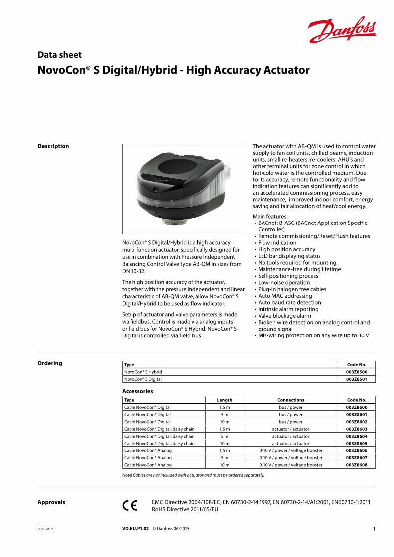
94
112
80
Dimensions
Data sheet NovoCon® S Digital/Hybrid - High Accuracy Actuator
3VD.HU.P1.02 © Danfoss 06/2015DEN-SMT/SI
Presetting
Design
Mounting Orientation
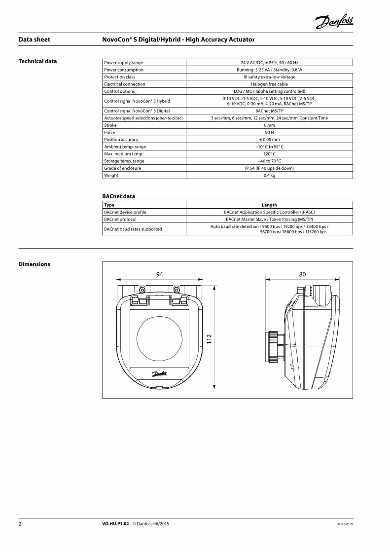
Preset of flow is made electronically with the NovoCon® S Digital/Hybrid actuator. Preset on the AB-QM valve is not used under normal operation.
Normal operationLeave valve at default factory preset (100 %).
High flow operationIn order to achieve a more efficient flush and enable presetting of valve of more than 100% it is recommended to manually preset AB-QM valve to maximum flow. This is done by turning the preset scale counter-clockwise until it stops. See drawing.NovoCon® S Digital/Hybrid in high flow operation enables presetting of AB-QM DN 10-20 up to 120% and DN 25-32 up to 110%.
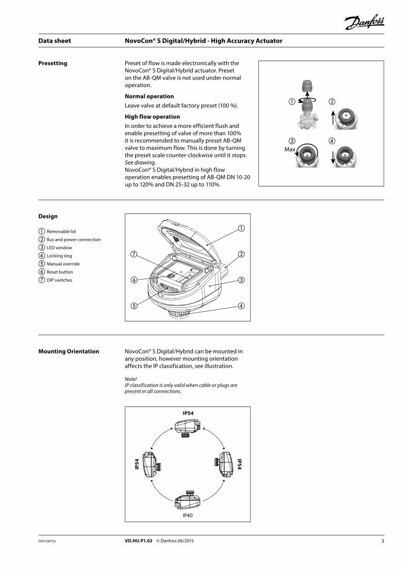
NovoCon® S Digital/Hybrid can be mounted in any position, however mounting orientation affects the IP classification, see illustration.
Note!IP classification is only valid when cable or plugs are present in all connections.
①
③
②
④
⑦
⑤
⑥
IP40
IP54
IP54IP54
① Removable lid
② Bus and power connection
③ LED window
④ Locking ring
⑤ Manual override
⑥ Reset button
⑦ DIP switches
Max
① ②
③ ④
Data sheet NovoCon® S Digital/Hybrid - High Accuracy Actuator
4 VD.HU.P1.02 © Danfoss 06/2015 DEN-SMT/SI
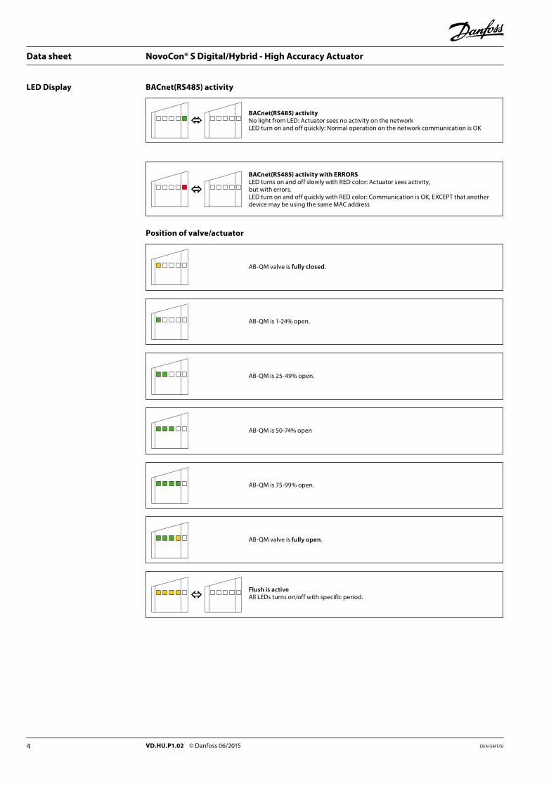
LED Display BACnet(RS485) activity
BACnet(RS485) activityNo light from LED: Actuator sees no activity on the networkLED turn on and off quickly: Normal operation on the network communication is OK
Position of valve/actuator
AB-QM valve is fully closed.
AB-QM is 1-24% open.
AB-QM is 25-49% open.
AB-QM is 50-74% open
AB-QM is 75-99% open.
AB-QM valve is fully open.
Flush is activeAll LEDs turns on/off with specific period.
BACnet(RS485) activity with ERRORSLED turns on and off slowly with RED color: Actuator sees activity,but with errors.LED turn on and off quickly with RED color: Communication is OK, EXCEPT that another device may be using the same MAC address
Data sheet NovoCon® S Digital/Hybrid - High Accuracy Actuator
5VD.HU.P1.02 © Danfoss 06/2015DEN-SMT/SI
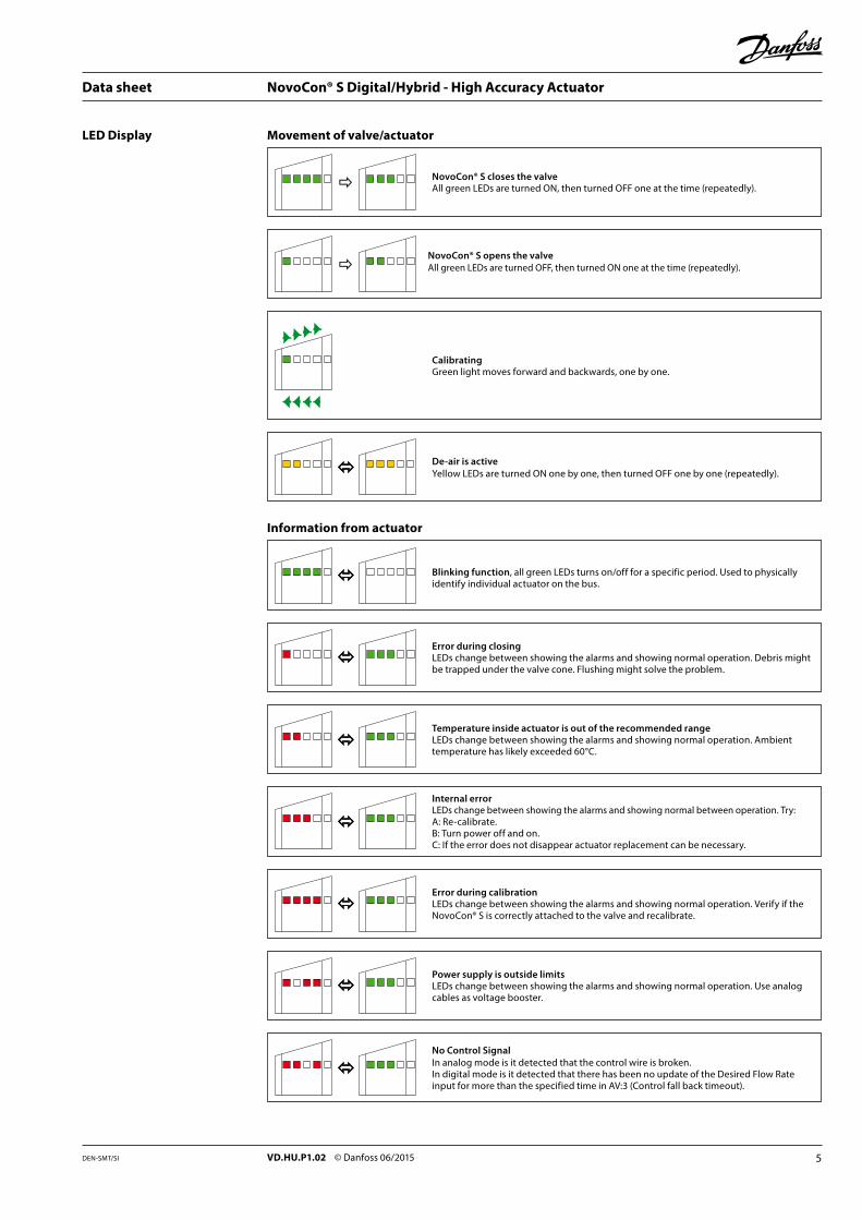
LED Display
NovoCon® S closes the valveAll green LEDs are turned ON, then turned OFF one at the time (repeatedly).
NovoCon® S opens the valveAll green LEDs are turned OFF, then turned ON one at the time (repeatedly).
CalibratingGreen light moves forward and backwards, one by one.
De-air is activeYellow LEDs are turned ON one by one, then turned OFF one by one (repeatedly).
Movement of valve/actuator
Blinking function, all green LEDs turns on/off for a specific period. Used to physically identify individual actuator on the bus.
Error during closingLEDs change between showing the alarms and showing normal operation. Debris might be trapped under the valve cone. Flushing might solve the problem.
Temperature inside actuator is out of the recommended rangeLEDs change between showing the alarms and showing normal operation. Ambient temperature has likely exceeded 60°C.
Internal errorLEDs change between showing the alarms and showing normal between operation. Try:A: Re-calibrate.B: Turn power off and on.C: If the error does not disappear actuator replacement can be necessary.
Information from actuator
Power supply is outside limitsLEDs change between showing the alarms and showing normal operation. Use analog cables as voltage booster.
No Control SignalIn analog mode is it detected that the control wire is broken.In digital mode is it detected that there has been no update of the Desired Flow Rate input for more than the specified time in AV:3 (Control fall back timeout).
Error during calibrationLEDs change between showing the alarms and showing normal operation. Verify if the NovoCon® S is correctly attached to the valve and recalibrate.
Data sheet NovoCon® S Digital/Hybrid - High Accuracy Actuator
6 VD.HU.P1.02 © Danfoss 06/2015 DEN-SMT/SI
LED Display
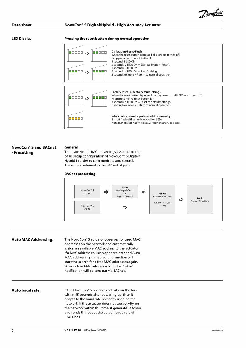
NovoCon® S and BACnet- Presetting
GeneralThere are simple BACnet settings essential to the basic setup configuration of NovoCon® S Digital/Hybrid in order to communicate and control. These are contained in the BACnet objects.
Calibration/Reset/FlushWhen the reset button is pressed all LEDs are turned off. Keep pressing the reset button for 1 second: 1 LED ON 2 seconds: 2 LEDs ON = Start calibration (Reset). 3 seconds: 3 LEDs ON 4 seconds: 4 LEDs ON = Start flushing. 5 seconds or more = Return to normal operation.
Factory reset - reset to default settings When the reset button is pressed during power up all LED’s are turned off.Keep pressing the reset button for 4 seconds: 4 LEDs ON = Reset to default settings. 6 seconds or more = Return to normal operation.
Pressing the reset button during normal operation
When factory reset is performed it is shown by:1 short flash with all yellow position LED’s.Note that all settings will be reverted to factory settings.
BACnet presetting
NovoCon® SHybrid
BV:0Analog (default)
orDigital Control
NovoCon® SDigital
MSV:3Select Valve Type
(default AB-QM DN 15)
AV:0Design Flow Rate
Auto MAC Addressing:
Auto baud rate:
The NovoCon® S actuator observes for used MAC addresses on the network and automatically assign an available MAC address to the actuator. If a MAC address collision appears later and Auto MAC addressing is enabled this function will start the search for a free MAC addresses again. When a free MAC address is found an “I-Am” notification will be sent out via BACnet.
If the NovoCon® S observes activity on the bus within 45 seconds after powering up, then it adapts to the baud rate presently used on the network. If the actuator does not see activity on the network within this time, it generates a token and sends this out at the default baud rate of 38400bps.
Data sheet NovoCon® S Digital/Hybrid - High Accuracy Actuator
7VD.HU.P1.02 © Danfoss 06/2015DEN-SMT/SI
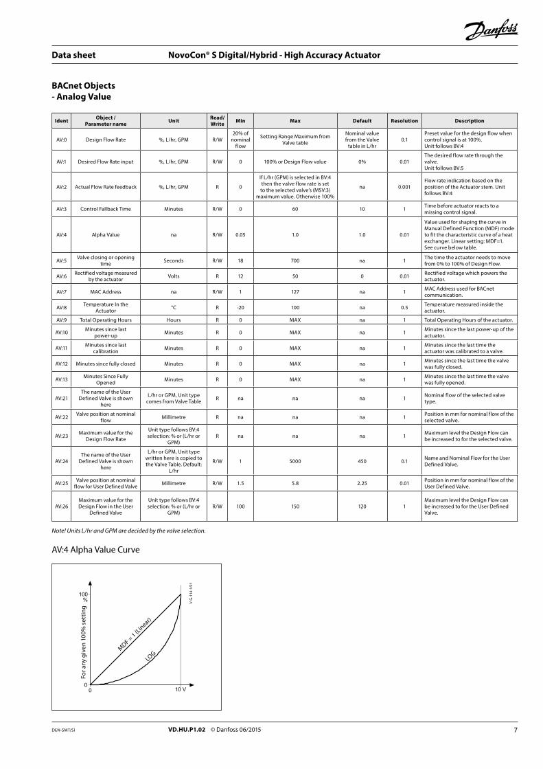
BACnet Objects- Analog Value
Ident Object /Parameter name Unit Read/
Write Min Max Default Resolution Description
AV:0 Design Flow Rate %, L/hr, GPM R/W20% of
nominalflow
Setting Range Maximum from Valve table
Nominal value from the Valve
table in L/hr0.1
Preset value for the design flow when control signal is at 100%.Unit follows BV:4
AV:1 Desired Flow Rate input %, L/hr, GPM R/W 0 100% or Design Flow value 0% 0.01The desired flow rate through the valve.Unit follows BV:5
AV:2 Actual Flow Rate feedback %, L/hr, GPM R 0
If L/hr (GPM) is selected in BV:4 then the valve flow rate is set to the selected valve’s (MSV:3)
maximum value. Otherwise 100%
na 0.001Flow rate indication based on the position of the Actuator stem. Unit follows BV:4
AV:3 Control Fallback Time Minutes R/W 0 60 10 1 Time before actuator reacts to a missing control signal.
AV:4 Alpha Value na R/W 0.05 1.0 1.0 0.01
Value used for shaping the curve in Manual Defined Function (MDF) mode to fit the characteristic curve of a heat exchanger. Linear setting: MDF=1.See curve below table.
AV:5 Valve closing or opening time Seconds R/W 18 700 na 1 The time the actuator needs to move
from 0% to 100% of Design Flow.
AV:6 Rectified voltage measured by the actuator Volts R 12 50 0 0.01 Rectified voltage which powers the
actuator.
AV:7 MAC Address na R/W 1 127 na 1 MAC Address used for BACnet communication.
AV:8 Temperature In the Actuator °C R -20 100 na 0.5 Temperature measured inside the
actuator.
AV:9 Total Operating Hours Hours R 0 MAX na 1 Total Operating Hours of the actuator.
AV:10 Minutes since last power-up Minutes R 0 MAX na 1 Minutes since the last power-up of the
actuator.
AV:11 Minutes since last calibration Minutes R 0 MAX na 1 Minutes since the last time the
actuator was calibrated to a valve.
AV:12 Minutes since fully closed Minutes R 0 MAX na 1 Minutes since the last time the valve was fully closed.
AV:13 Minutes Since Fully Opened Minutes R 0 MAX na 1 Minutes since the last time the valve
was fully opened.
AV:21The name of the User
Defined Valve is shown here
L/hr or GPM, Unit type comes from Valve Table R na na na 1 Nominal flow of the selected valve
type.
AV:22 Valve position at nominal flow Millimetre R na na na 1 Position in mm for nominal flow of the
selected valve.
AV:23 Maximum value for the Design Flow Rate
Unit type follows BV:4 selection: % or (L/hr or
GPM)R na na na 1 Maximum level the Design Flow can
be increased to for the selected valve.
AV:24The name of the User
Defined Valve is shown here
L/hr or GPM, Unit type written here is copied to the Valve Table. Default:
L/hr
R/W 1 5000 450 0.1 Name and Nominal Flow for the User Defined Valve.
AV:25 Valve position at nominal flow for User Defined Valve Millimetre R/W 1.5 5.8 2.25 0.01 Position in mm for nominal flow of the
User Defined Valve.
AV:26Maximum value for the Design Flow in the User
Defined Valve
Unit type follows BV:4 selection: % or (L/hr or
GPM)R/W 100 150 120 1
Maximum level the Design Flow can be increased to for the User Defined Valve.
Note! Units L/hr and GPM are decided by the valve selection.
AV:4 Alpha Value Curve
For a
ny g
iven
100
% s
ettin
g
MDF = 1 (Linear)
LOG
Data sheet NovoCon® S Digital/Hybrid - High Accuracy Actuator
8 VD.HU.P1.02 © Danfoss 06/2015 DEN-SMT/SI
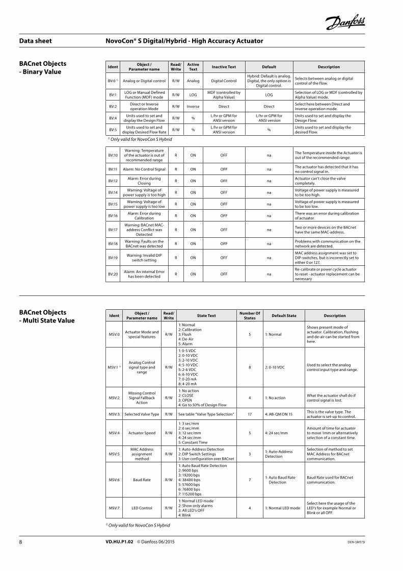
Ident Object /Parameter name
Read/Write State Text Number Of
States Default State Description
MSV:0 Actuator Mode and special features R/W
1: Normal2: Calibration3: Flush4: De-Air5: Alarm
5 1: Normal
Shows present mode of actuator. Calibration, flushing and de-air can be started from here.
MSV:1 1)Analog Control signal type and
rangeR/W
1: 0-5 VDC2: 0-10 VDC3: 2-10 VDC4: 5-10 VDC5: 2-6 VDC6: 6-10 VDC7: 0-20 mA8: 4-20 mA
8 2: 0-10 VDC Used to select the analog control input type and range.
MSV:2Missing Control Signal Fallback
ActionR/W
1: No action2: CLOSE3: OPEN4: Go to 50% of Design Flow
4 1: No action What the actuator shall do if control signal is lost.
MSV:3 Selected Valve Type R/W See table “Valve Type Selection” 17 4: AB-QM DN 15 This is the valve type. The actuator is set-up to control.
MSV:4 Actuator Speed R/W
1: 3 sec/mm2: 6 sec/mm3: 12 sec/mm4: 24 sec/mm5: Constant Time
5 4: 24 sec/mmAmount of time for actuator to move 1mm or alternatively selection of a constant time.
MSV:5MAC Address assignment
methodR/W
1: Auto-Address Detection2: DIP Switch Settings3: User configuration over BACnet
3 1: Auto-Address Detection
Selection of method to set MAC Address for BACnet communication.
MSV:6 Baud Rate R/W
1: Auto Baud Rate Detection2: 9600 bps3: 19200 bps4: 38400 bps5: 57600 bps6: 76800 bps7: 115200 bps
7 1: Auto Baud Rate Detection
Baud Rate used for BACnet communication.
MSV:7 LED Control R/W
1: Normal LED mode2: Show only alarms3: All LED’s OFF4: Blink
4 1: Normal LED modeSelect here the usage of the LED’s for example Normal or Blink or all OFF.
1) Only valid for NovoCon S Hybrid
BACnet Objects- Multi State Value
Ident Object /Parameter name
Read/Write
Active Text Inactive Text Default Description
BV:0 1) Analog or Digital control R/W Analog Digital ControlHybrid: Default is analog. Digital, the only option is
Digital control.
Selects between analog or digital control of the flow.
BV:1 LOG or Manual Defined Function (MDF) mode R/W LOG MDF (controlled by
Alpha Value) LOG Selection of LOG or MDF (controlled by Alpha Value) mode.
BV:2 Direct or Inverse operation Mode R/W Inverse Direct Direct Select here between Direct and
Inverse operation mode.
BV:4 Units used to set and display the Design Flow R/W % L/hr or GPM for
ANSI versionL/hr or GPM for
ANSI versionUnits used to set and display the Design Flow.
BV:5 Units used to set and display Desired Flow Rate R/W % L/hr or GPM for
ANSI version % Units used to set and display the desired Flow.
1) Only valid for NovoCon S Hybrid
BV:10Warning: Temperature of the actuator is out of
recommended rangeR ON OFF na The Temperature inside the Actuator is
out of the recommended range.
BV:11 Alarm: No Control Signal R ON OFF na The actuator has detected that it has no control signal in.
BV:12 Alarm: Error during Closing R ON OFF na Actuator can't close the valve
completely.
BV:14 Warning: Voltage of power supply is too high R ON OFF na Voltage of power supply is measured
to be too high.
BV:15 Warning: Voltage of power supply is too low R ON OFF na Voltage of power supply is measured
to be too low.
BV:16 Alarm: Error during Calibration R ON OFF na There was an error during calibration
of actuator.
BV:17Warning: BACnet MAC-
address Conflict was Detected
R ON OFF na Two or more devices on the BACnet have the same MAC-address.
BV:18 Warning: Faults on the BACnet was detected R ON OFF na Problems with communication on the
network are detected.
BV:19 Warning: Invalid DIP switch setting R ON OFF na
MAC address assignment was set to DIP-switches, but is incorrectly set to either 0 or 127.
BV:20 Alarm: An internal Error has been detected R ON OFF na
Re-calibrate or power cycle actuator to reset - actuator replacement can be necessary
BACnet Objects- Binary Value
Data sheet NovoCon® S Digital/Hybrid - High Accuracy Actuator
9VD.HU.P1.02 © Danfoss 06/2015DEN-SMT/SI
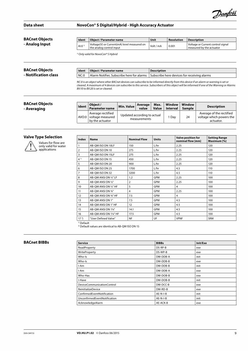
BACnet BIBBs Service BIBBs Init/Exe
ReadProperty DS-RP-B exe
WriteProperty DS-WP-B exe
Who-Is DM-DDB-A init
Who-Is DM-DDB-B exe
I-Am DM-DDB-B init
I-Am DM-DDB-A exe
Who-Has DM-DOB-B exe
I-Have DM-DOB-B init
DeviceCommunicationControl DM-DCC-B exe
ReinitializeDevice DM-RD-B exe
ConfirmedEventNotification AE-N-I-B init
UnconfirmedEventNotification AE-N-I-B init
AcknowledgeAlarm AE-ACK-B exe
Index Name Nominal Flow Units Valve position for nominal flow [mm]
Setting Range Maximum [%]
1 AB-QM ISO DN 10LF 150 L/hr 2.25 120
2 AB-QM ISO DN 10 275 L/hr 2.25 120
3 AB-QM ISO DN 15LF 275 L/hr 2.25 120
4 1) AB-QM ISO DN 15 450 L/hr 2.25 120
5 AB-QM ISO DN 20 900 L/hr 2.25 120
6 AB-QM ISO DN 25 1700 L/hr 4.5 110
7 AB-QM ISO DN 32 3200 L/hr 4.5 110
8 AB-QM ANSI DN ½" LF 1.2 GPM 2.25 100
9 AB-QM ANSI DN ½" 2 GPM 2.25 100
10 AB-QM ANSI DN ½" HF 5 GPM 4 100
11 AB-QM ANSI DN ¾" 4 GPM 2.25 100
12 AB-QM ANSI DN ¾" HF 7.5 GPM 4 100
13 AB-QM ANSI DN 1" 7.5 GPM 4.5 100
14 AB-QM ANSI DN 1" HF 12 GPM 4.5 100
15 AB-QM ANSI DN 1¼" 14.1 GPM 4.5 100
16 AB-QM ANSI DN 1¼" HF 17.5 GPM 4.5 100
17 2) "User Defined Valve" NF UF VPNF SRM1) Default2) Default values are identical to AB-QM ISO DN 15
Valve Type Selection
BACnet Objects- Analog Input
Ident Object / Parameter name Unit Resolution Description
AI:0 1) Voltage(V) or Current(mA) level measured on the analog control input Volt / mA 0.001 Voltage or Current control signal
measured by the actuator
1) Only valid for NovoCon® S Hybrid
BACnet Objects- Notification class
Ident Object / Parameter name Description
NC:0 Alarm Notifier, Subscribe here for alarms Subscribe here devices for receiving alarms
NC:0 is an object where other BACnet devices can subscribe to be informed directly from this device if an alarm or warning is set or cleared. A maximum of 4 devices can subscribe to this service. Subscribers of this object will be informed if one of the Warning or Alarms BV:10 to BV:20 is set or cleared.
BACnet Objects- Averaging Ident Object /
Parameter name Min. Value Average value
Max. Value
Window Interval
Window Sample Description
AVO:0Average rectified voltage measured by the actuator
Updated according to actualmeasurements 1 Day 24
Average of the rectified voltage which powers the
actuator.
Values for flow are only valid for water applications
Data sheet NovoCon® S Digital/Hybrid - High Accuracy Actuator
10 VD.HU.P1.02 © Danfoss 06/2015 DEN-SMT/SI
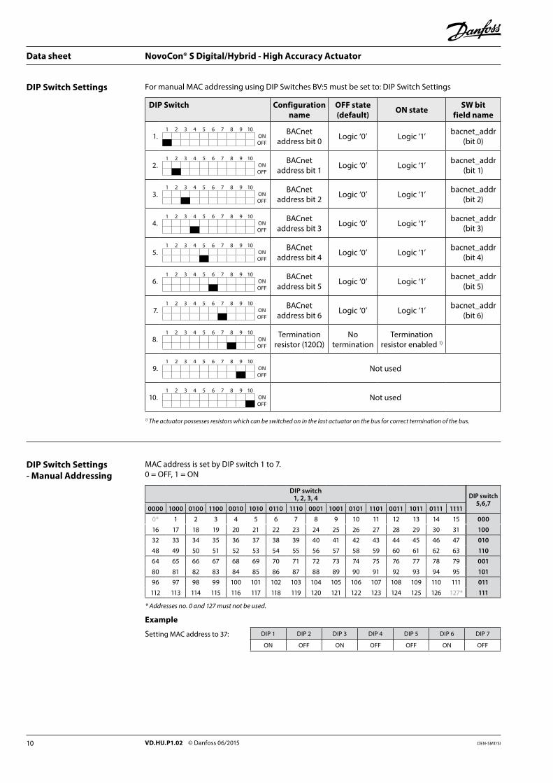
DIP Switch Settings- Manual Addressing
MAC address is set by DIP switch 1 to 7.0 = OFF, 1 = ON
DIP switch1, 2, 3, 4 DIP switch
5,6,70000 1000 0100 1100 0010 1010 0110 1110 0001 1001 0101 1101 0011 1011 0111 1111
0* 1 2 3 4 5 6 7 8 9 10 11 12 13 14 15 000
16 17 18 19 20 21 22 23 24 25 26 27 28 29 30 31 100
32 33 34 35 36 37 38 39 40 41 42 43 44 45 46 47 010
48 49 50 51 52 53 54 55 56 57 58 59 60 61 62 63 110
64 65 66 67 68 69 70 71 72 73 74 75 76 77 78 79 001
80 81 82 83 84 85 86 87 88 89 90 91 92 93 94 95 101
96 97 98 99 100 101 102 103 104 105 106 107 108 109 110 111 011
112 113 114 115 116 117 118 119 120 121 122 123 124 125 126 127* 111
* Addresses no. 0 and 127 must not be used.
Example
Setting MAC address to 37: DIP 1 DIP 2 DIP 3 DIP 4 DIP 5 DIP 6 DIP 7
ON OFF ON OFF OFF ON OFF
DIP Switch Settings For manual MAC addressing using DIP Switches BV:5 must be set to: DIP Switch Settings
DIP Switch Configuration name
OFF state (default) ON state SW bit
field name
1.1 2 3 4 5 6 7 8 9 10
ONOFF
BACnetaddress bit 0 Logic ‘0’ Logic ‘1’ bacnet_addr
(bit 0)
2.1 2 3 4 5 6 7 8 9 10
ONOFF
BACnet address bit 1 Logic ‘0’ Logic ‘1’ bacnet_addr
(bit 1)
3.1 2 3 4 5 6 7 8 9 10
ONOFF
BACnet address bit 2 Logic ‘0’ Logic ‘1’ bacnet_addr
(bit 2)
4.1 2 3 4 5 6 7 8 9 10
ONOFF
BACnet address bit 3 Logic ‘0’ Logic ‘1’ bacnet_addr
(bit 3)
5.1 2 3 4 5 6 7 8 9 10
ONOFF
BACnet address bit 4 Logic ‘0’ Logic ‘1’ bacnet_addr
(bit 4)
6.1 2 3 4 5 6 7 8 9 10
ONOFF
BACnet address bit 5 Logic ‘0’ Logic ‘1’ bacnet_addr
(bit 5)
7.1 2 3 4 5 6 7 8 9 10
ONOFF
BACnet address bit 6 Logic ‘0’ Logic ‘1’ bacnet_addr
(bit 6)
8.1 2 3 4 5 6 7 8 9 10
ONOFF
Termination resistor (120Ω)
Notermination
Termination resistor enabled 1)
9.1 2 3 4 5 6 7 8 9 10
ONOFF
Not used
10.1 2 3 4 5 6 7 8 9 10
ONOFF
Not used
1) The actuator possesses resistors which can be switched on in the last actuator on the bus for correct termination of the bus.
Data sheet NovoCon® S Digital/Hybrid - High Accuracy Actuator
11VD.HU.P1.02 © Danfoss 06/2015DEN-SMT/SI
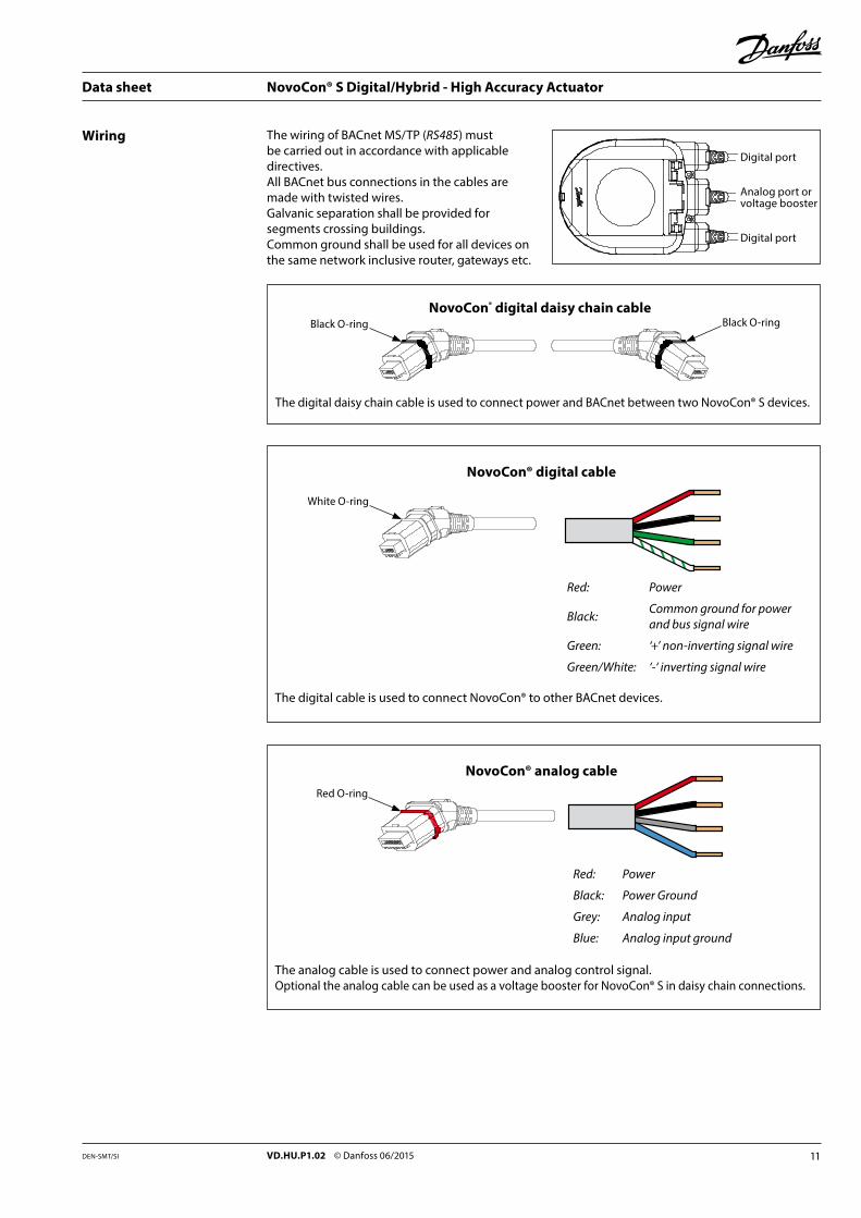
Wiring The wiring of BACnet MS/TP (RS485) must be carried out in accordance with applicable directives.All BACnet bus connections in the cables are made with twisted wires.Galvanic separation shall be provided for segments crossing buildings.Common ground shall be used for all devices on the same network inclusive router, gateways etc.
Digital port
Analog port or voltage booster
Digital port
NovoCon® analog cable
The analog cable is used to connect power and analog control signal.Optional the analog cable can be used as a voltage booster for NovoCon® S in daisy chain connections.
Red: Power
Black: Power Ground
Grey: Analog input
Blue: Analog input ground
NovoCon® digital cable
The digital cable is used to connect NovoCon® to other BACnet devices.
Red: Power
Black: Common ground for power and bus signal wire
Green: ‘+’ non-inverting signal wire
Green/White: ‘-‘ inverting signal wire
NovoCon® digital daisy chain cable
The digital daisy chain cable is used to connect power and BACnet between two NovoCon® S devices.
Black O-ring
White O-ring
Red O-ring
Black O-ring
Data sheet NovoCon® S Digital/Hybrid - High Accuracy Actuator
12 VD.HU.P1.02 © Danfoss 06/2015 DEN-SMT/SI
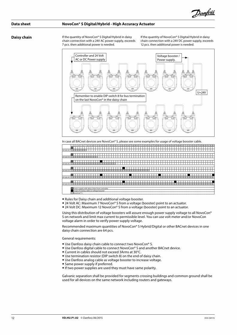
Daisy chain
Remember to enable DIP switch 8 for bus termination on the last NovoCon® in the daisy chain
Voltage booster / Power supply.
Controller and 24 Volt AC or DC Power supply
U=24V
1 2 3 4 5 6 7 8 9 10 11 12 13 14 15 16 17 18 19 20 21 22 23 24 25 26 27 28 29 30 31 32 33 34 35 36 37 38 39 40 41 42 43 44 45 46 47 48 49 50 51 52 53 54 55 56 57 58 59 60 61 62 63 64
24 Volt AC
24 Volt DC
24 Volt AC
24 Volt DC
24 Volt AC
24 Volt DC
Power supply with daisy chain from controllerUsage of analog cable as voltage boosterNovoCon® S
In case all BACnet devices are NovoCon® S, please see some examples for usage of voltage booster cable.
Rules for Daisy chain and additional voltage booster. 24 Volt AC: Maximum 7 NovoCon® S from a voltage (booster) point to an actuator. 24 Volt DC: Maximum 12 NovoCon® S from a voltage (booster) point to an actuator.
Using this distribution of voltage boosters will assure enough power supply voltage to all NovoCon® S on network and limit max current to permissible level. You can use volt meter and/or NovoCon voltage alarm in order to verify power supply voltage.
Recommended maximum quantities of NovoCon® S Hybrid/Digital or other BACnet devices in one daisy chain connection are 64 pcs.
General requirements:
Use Danfoss daisy chain cable to connect two NovoCon® S. Use Danfoss digital cable to connect NovoCon® S and another BACnet device. Current in cables should not exceed 3Arms at 30°C. Use termination resistor (DIP switch 8) on the end of daisy chain. Use Danfoss analog cable as voltage booster to increase voltage. Same power supply if preferred. If two power supplies are used they must have same polarity.
Galvanic separation shall be provided for segments crossing buildings and common ground shall be used for all devices on the same network including routers and gateways.
If the quantity of NovoCon® S Digital/Hybrid in daisy chain connection with a 24V AC power supply, exceeds 7 pcs. then additional power is needed.
If the quantity of NovoCon® S Digital/Hybrid in daisy chain connection with a 24V DC power supply, exceeds 12 pcs. then additional power is needed.
Data sheet NovoCon® S Digital/Hybrid - High Accuracy Actuator
13VD.HU.P1.02 © Danfoss 06/2015DEN-SMT/SI
NovoCon™ S Digital/Hybrid actuatorNovoCon™ S is a gear actuator for pressure independent balancing and control valve type AB-QM DN10-32. Supply Voltage: 24V AC/DC ±25% 50-60Hz Control signal - hybrid version: BACnet, 0-10V/2-10V sequential (0-5V/5-10V), 0-20mA/4-20mA Control signal - digital version: BACnetActuator has the following remote features:– AB-QM design flow pre-setting– Flushing the valve and terminal unit– Error during closing intrinsic alarm reporting– LOG/LIN/α-setting characteristics setting– Speed selection 3/6/12/24 s/mm– Opening/closing time selection from 18s to 700s– Auto MAC addressing– Auto Baud rate detection– Flow indication based on measured stroke in l/h Spindle position accuracy: ±0.05mm Cables: Halogen free plug-in available in 1.5m, 5m and 10m length. IP Class: 54 Closing force: 90N Stroke: 7mm BACnet Testing Laboratories (BTL) listed BACnet MS/TP fieldbus device
Tender text
Data sheet NovoCon® S Digital/Hybrid - High Accuracy Actuator

14 VD.HU.P1.02 © Danfoss 06/2015 DEN-SMT/SI
Data sheet NovoCon® S Digital/Hybrid - High Accuracy Actuator

15VD.HU.P1.02 © Danfoss 06/2015DEN-SMT/SI
Data sheet NovoCon® S Digital/Hybrid - High Accuracy Actuator
16 VD.HU.P1.02 Produced by Danfoss A/S © 06/2015
Data sheet NovoCon® S Digital/Hybrid - High Accuracy Actuator
Related Documents