VALSTEAM ADCA We reserve the right to change the design and material of this product without notice. IS PV10.00 E 06.07 DATA SHEET FOR ADCATROL CONTROL VALVES VALVE SIZING The valve sizing is based on the calculation of the Kv coefficient. The Kv represents the quantity of water, expressed in cubic meters (m 3 ) at 15 ºC, that flows through the valve with a pressure drop of 1 bar, in one hour period. The formulas, below indicated, allow the Kv calculation in accordance with the type of fluid and its operating condition. After the Kv calculation, the corresponding Kvs is available from the valve data sheet. If real operating data have been used for the calculation, as a rule, the calculated Kv should be around 70% to 80% of the selected valve Kvs in order to ensure the proper regulation of maximum flow rate at the given operating conditions, preventing that sometimes some precautionary additions will result in undesirable valve oversizing. At the same time, it is necessary to check whether the minimum flow rate can be even regulated or not, considering the chosen valve rangeability. For critical applications (critical flow velocities, for example), noise prediction, etc, please fill the data sheet available in the next pages and submit it to our technical department for proper selection using our software. Kv Flow coefficient m 3 /h P1 Upstream absolute pressure bar P2 Downstream absolute pressure bar Dp Pressure drop (P1 – P2) bar Q1 Flow rate m 3 /h Q2 Flow rate kg/h Q3 Flow rate N.m 3 /h (0 ºC – 1013 mbar) d1 Specific weight of liquid kg/m 3 d2 Specific weight of gas kg/m 3 T Absolute temperature (T=273 + t ºC) ºK t Fluid temperature ºC RECOMMENDED FLOW VELOCITIES AT THE INLET OF VALVES LIQUIDS GASES SATURATED STEAM SUPERHEATED STEAM 2,5 m/s 20 m/s 25 m/s 50 m/s CALCULATION OF Kv VALUE PRESSURE DROP MEDIUM LIQUIDS SATURATED STEAM GASES a) 2 1 2 P P 2 1 P Dp 1000 1 1 Dp d Q Kv 2 4 , 22 2 P Dp Q Kv 2 2 514 3 P Dp T d Q Kv b) 2 1 2 P P 2 1 P Dp 1 2 , 11 2 P Q Kv T d P Q Kv 2 1 257 3 Remarks: For superheated steam and other fluids please consult. a) Subcritical pressure drop: downstream absolute pressure more than 50% of the absolute upstream pressure in the valve. b) Supercritical pressure drop: downstream absolute pressure is equal or less than 50% of the upstream absolute pressure in the valve.

Welcome message from author
This document is posted to help you gain knowledge. Please leave a comment to let me know what you think about it! Share it to your friends and learn new things together.
Transcript

VALSTEAM ADCA We reserve the right to change the design and material of this product without notice.
IS PV10.00 E 06.07
DATA SHEET FOR ADCATROL CONTROL VALVES
VALVE SIZING The valve sizing is based on the calculation of the Kv coefficient. The Kv represents the quantity of water, expressed in cubic meters (m3) at 15 ºC, that flows through the valve with a pressure drop of 1 bar, in one hour period. The formulas, below indicated, allow the Kv calculation in accordance with the type of fluid and its operating condition. After the Kv calculation, the corresponding Kvs is available from the valve data sheet. If real operating data have been used for the calculation, as a rule, the calculated Kv should be around 70% to 80% of the selected valve Kvs in order to ensure the proper regulation of maximum flow rate at the given operating conditions, preventing that sometimes some precautionary additions will result in undesirable valve oversizing. At the same time, it is necessary to check whether the minimum flow rate can be even regulated or not, considering the chosen valve rangeability. For critical applications (critical flow velocities, for example), noise prediction, etc, please fill the data sheet available in the next pages and submit it to our technical department for proper selection using our software.
Kv Flow coefficient m3/h
P1 Upstream absolute pressure bar
P2 Downstream absolute pressure bar
Dp Pressure drop (P1 – P2) bar
Q1 Flow rate m3/h
Q2 Flow rate kg/h
Q3 Flow rate N.m3/h (0 ºC – 1013 mbar)
d1 Specific weight of liquid kg/m3
d2 Specific weight of gas kg/m3
T Absolute temperature (T=273 + t ºC) ºK
t Fluid temperature ºC
RECOMMENDED FLOW VELOCITIES AT THE INLET OF VALVES
LIQUIDS GASES SATURATED STEAM SUPERHEATED STEAM
2,5 m/s 20 m/s 25 m/s 50 m/s
CALCULATION OF Kv VALUE
PRESSURE DROP
MEDIUM
LIQUIDS SATURATED STEAM GASES
a)
2
12
PP
2
1PDp
1000
11
Dp
dQKv
24,22
2
PDp
QKv
2
2
514
3
PDp
TdQKv
b)
2
12
PP
2
1PDp
12,11
2
P
QKv
Td
P
QKv
2
1257
3
Remarks: For superheated steam and other fluids please consult. a) Subcritical pressure drop: downstream absolute pressure more than 50% of the absolute upstream pressure in the valve. b) Supercritical pressure drop: downstream absolute pressure is equal or less than 50% of the upstream absolute pressure in the valve.

VALSTEAM ADCA We reserve the right to change the design and material of this product without notice.
IS PV10.00 E 06.07
0
Kv
Kv H
SUPERCRITICAL PRESSURE DROP When pressure ratio is supercritical, the flow reaches acoustic velocity at the narrowest section, causing a higher level of noise, cavitation or flashing. In these cases, the single or double perforated trim design is recommended. INHERENT FLOW CHARACTERISTICS PT – On-off: the flow rate changes from 0 to 100% - fully open or fully closed control. PL – Linear: the flow capacity or Kv increases linearly with valve travel. The flow is directly proportional to the valve travel. Recommended when there are no relevant variations in differential pressure or flow rates EQP – Equal-percentage: for equal increments of valve plug travel, the change in flow rate related to travel may be expressed as a constant percentage of the flow rate at the time of the change. At constant differential pressure, a valve travel increase of 10% usually corresponds to a flow rate increase equal to 50% of the valve flow preceding the variation. The change in flow rate observed, related to travel, will be relatively small when the valve plug is near its seat and relatively high when the valve plug is nearly wide open. Recommended when there are wide variations in flow rate or differential pressure.
CONTROL VALVE SEAT LEAKAGE CLASSIFICATIONS
BO – Leak test on the closure with air, in accordance with DIN 3230
NOMINAL SIZE (DN)
LEAKAGE RATE 1
LEAKAGE RATE 2
LEAKAGE RATE 3 TEST PERIOD
(minutes) Over Up to Bubbles per minute a) cm3 per minute
40 0 2 25 0,25
40 100 0 6 63 1
100 150 0 9 94 1
150 200 0 12 125 2
200 250 0 15 157 2
250 300 0 18 188 2

VALSTEAM ADCA We reserve the right to change the design and material of this product without notice.
IS PV10.00 E 06.07
Kvs VALUES FOR ADCATROL V25 AND V40 – STANDARD PARABOLIC PLUGS
SEAT Ø
(mm)
VALVE STROKE
(mm)
SIZES
DN 15 DN 20 DN 25 DN 32 DN 40 DN 50 DN 65 DN 80 DN 100 DN 125 DN 150 DN 200
4 *
20
0,1
4 * 0,25
4 * 0,5
8 * 1
8 * 1,7 1,7
12 2,1 2,5 3
12 2,7 3,7 4 4,3
15 3,8 4,7 5,8 6,1 6,8
20 5,1 6,3 7,8 9,3 10,2
25 9,4 11,7 14,6 17,5 18,7
32 15,4 19,2 24 28 30,5
40 22,2 27,7 34,6 40,8 44,7
50 40,1 49 61 68 74,1
65
30 / 40
63,4 79,2 91 109,3 119
80 89,7 112,1 139,8 166 182
100 136,7 170,8 212,5 243
125 40 / 50
230,6 288,2 359,4
150 316,1 396
200 50 / 80 590
* Microflow only available with contoured linear characteristic.
Kvs VALUES FOR ADCATROL V25 AND V40 – PERFORATED PLUG PL (LINEAR)
SEAT Ø
(mm)
VALVE STROKE
(mm)
SIZES
DN 15 DN 20 DN 25 DN 32 DN 40 DN 50 DN 65 DN 80 DN 100 DN 125 DN 150 DN 200
15
25
2,55 2,65 2,65 2,65 2,65
20 4,6 4,8 4,8 4,8 4,8
25 7,1 7,5 7,5 7,5 7,5
32
30
11,8 11,8 11,8 11,8 11,8
40 18 18 18 19 19
50 28 30 30 30 30
65 40 48 50 50 50 50
80 50
74 75 75 76 76
100 115 121 121 121
125 60 180 189 189
150 80
260 270
200 402

VALSTEAM ADCA We reserve the right to change the design and material of this product without notice.
IS PV10.00 E 06.07
Kvs VALUES FOR ADCATROL V25 AND V40 – PERFORATED PLUG EQP (EQUAL PERCENTAGE)
SEAT Ø
(mm)
VALVE STROKE
(mm)
SIZES
DN 15 DN 20 DN 25 DN 32 DN 40 DN 50 DN 65 DN 80 DN 100 DN 125 DN 150 DN 200
15
25
20 2,65 2,65 2,65 2,65
25 4,8 4,8 4,8 4,8
32
30
7,5 7,5 7,5 7,5
40 11,8 11,8 11,8 11,8
50 18 18 19 19
65 40 30 30 30 30
80 50
50 50 50 50
100 75 75 76 76
125 60 121 121 121
150 80
189 189
200 270

VALSTEAM ADCA We reserve the right to change the design and material of this product without notice.
IS PV10.00 E 06.07
ADCATROL – DETAILS FOR SELECTION AND SIZING
CUSTOMER: ........................................................................................................ OUR REFª ......................................
VALVE TYPE: ............................................ REG NR.: DATE: ........ / ........ / ........ PAGE: ...... / ......
1 SERVICE :
2 PIPELINE SIZE / RATING : DN .......... PN........... CLASS ..........
3 FLUID :................................. LIQUID STEAM GAS
4 VISCOSITY : cP TEMP.: ºC SPECIF. WEIGHT : Kg/Nm3
MIN. STAND. MAX. UNIT
5 FLOW RATE :
6 UPSTREAM PRESSURE ABS.(Gauge + Atmospheric press.) :
7 DOWNSTREAM PRESSURE ABS.(Gauge + Atmospheric press.) :
8 PRESSURE DROP (bar) :
9 AMBIENT TEMPERATURE º C :
10 VALVE TYPE: 2 way Straightway Angle valve under over (the seat)
3 way Mixing AB A Diverging AB A
ACTION ON FAILURE: AB B AB B
11 TAG:
12 SIZE / RATING: DN .......... PN........... CLASS ..........
13 TYPE OF CONNECTION: Welded end ……………..
14 BODY MATERIAL:
15 PLUG MATERIAL: Stainless steel Soft Stellite ..........................
16 SOFT SEAT SEAL MATERIAL: PTFE / GR PTFE ..........................
17 PLUG CHARACTERISTICS: Equal % Linear On / Off
18 SEAL: Metal Soft CLASSE .......................................
19 SEAT MATERIAL: Stainless steel Stellite ..........................
20 REDUCE BORE: Yes No Size ...............
21 BONNET: Standard Finned Extended ..........................
22 STUFFING BOX PACKING: Virgin PTFE PTFE / GR Pure Graphite Bellows Other
23 ACTUATOR REF.: .................................... Pneumatic Electric Manual ..........................
24 PNEUMATIC SIGNAL: 0,2 - 1 bar 0,4 - 1,2 bar 0,4 - 2 bar 0 - 2,5 bar ..........................
25 ACTION ON AIR FAILURE: Closed Opened Yes No
26 ELECTRIC SIGNAL: 4-20 mA 0-10 V ............. INITIAL COMPRESSION .............. mm
27 ACTION ON CURRENT FAILURE: Closed Opened Stop
28 ELECTRIC SUPPLY: 230 V 24 V ..................
29 LIMIT SWITCHES: Open valve limit switch Close valve limit switch
30 POSITIONER REF: ................................... Pneumatic Electro - pneumatic Electric
32 CONTROL SIGNAL: Pneumatic Electric
33 CONTROL VALVE: Opened at: ......... psi/bar ......... mA .........V Closed at: .......... psi/bar ......... mA .........V
34 AIR FILTER REGULATOR: Yes No AIR SUPPLY: ........ psi / bar
35 SOLENOID VALVE: Yes No ….. VAC ……. VDC
REMARKS:
Number _____
Kgs/dm3
Fluid Direction:
PO
SIT
ION
ER
Flanged EN ANSI Threaded
OP
ER
AT
ING
CO
ND
ITIO
NS
VA
LV
E B
OD
Y
STATE AT THE INPUT :
HANDWEEL:
AC
TU
AT
OR

VALSTEAM ADCA We reserve the right to change the design and material of this product without notice.
IS PV10.00 E 06.07
B
A AB
B
ABA
ADCATROL CONTROL VALVES
General Information
TWO WAY VALVES Application: On/off, control of flow, pressure and temperature. Fig.1 THREE WAY MIXING VALVES Application: Mixing of two streams By-pass at heat exchangers Fig.2 THREE WAY DIVERTING VALVES Application: Diverting of two streams By-pass at heat exchangers * Diverting into two different systems (* The mixing design is recommended, see Fig.6) Fig.3

VALSTEAM ADCA We reserve the right to change the design and material of this product without notice.
IS PV10.00 E 06.07
A BB
A
A
B
A B
AB
A B
TYPICAL REGULATION LOOPS
Two-way valve arrangement Fluid: saturated steam Fig.4
Three – way mixing valve arrangement (mixing regulation) Fluids: water, diathermic oil, … Fig.5
Three – way mixing valve arrangement (diverting regulation) Fluids: water, diathermic oil, … Fig.6
Three – way diverting valve arrangement Fluids: water, diathermic oil, … Fig.7
Two-way valve arrangement Fluids: water, diathermic oil, … Fig.8
VALSTEAM ADCA We reserve the right to change the design and material of this product without notice.
IS PV10.00 E 06.07
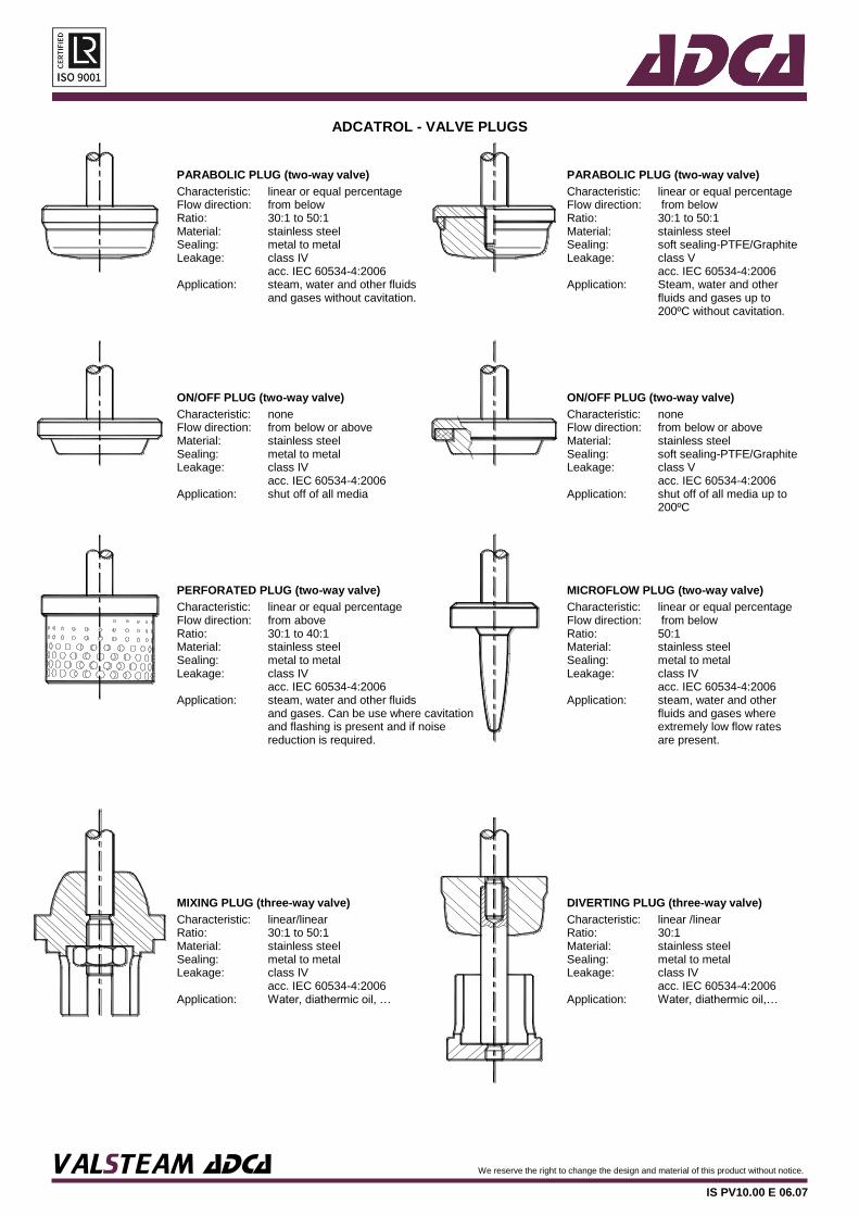
ADCATROL - VALVE PLUGS
PARABOLIC PLUG (two-way valve) PARABOLIC PLUG (two-way valve)
Characteristic: Flow direction: Ratio: Material: Sealing: Leakage: Application:
linear or equal percentage from below 30:1 to 50:1 stainless steel metal to metal class IV acc. IEC 60534-4:2006 steam, water and other fluids and gases without cavitation.
Characteristic: Flow direction: Ratio: Material: Sealing: Leakage: Application:
linear or equal percentage from below 30:1 to 50:1 stainless steel soft sealing-PTFE/Graphite class V acc. IEC 60534-4:2006 Steam, water and other fluids and gases up to 200ºC without cavitation.
ON/OFF PLUG (two-way valve) ON/OFF PLUG (two-way valve)
Characteristic: Flow direction: Material: Sealing: Leakage: Application:
none from below or above stainless steel metal to metal class IV acc. IEC 60534-4:2006 shut off of all media
Characteristic: Flow direction: Material: Sealing: Leakage: Application:
none from below or above stainless steel soft sealing-PTFE/Graphite class V acc. IEC 60534-4:2006 shut off of all media up to 200ºC
PERFORATED PLUG (two-way valve) MICROFLOW PLUG (two-way valve)
Characteristic: Flow direction: Ratio: Material: Sealing: Leakage: Application:
linear or equal percentage from above 30:1 to 40:1 stainless steel metal to metal class IV acc. IEC 60534-4:2006 steam, water and other fluids and gases. Can be use where cavitation and flashing is present and if noise reduction is required.
Characteristic: Flow direction: Ratio: Material: Sealing: Leakage: Application:
linear or equal percentage from below 50:1 stainless steel metal to metal class IV acc. IEC 60534-4:2006 steam, water and other fluids and gases where extremely low flow rates are present.
MIXING PLUG (three-way valve) DIVERTING PLUG (three-way valve)
Characteristic: Ratio: Material: Sealing: Leakage: Application:
linear/linear 30:1 to 50:1 stainless steel metal to metal class IV acc. IEC 60534-4:2006 Water, diathermic oil, …
Characteristic: Ratio: Material: Sealing: Leakage: Application:
linear /linear 30:1 stainless steel metal to metal class IV acc. IEC 60534-4:2006 Water, diathermic oil,…

VALSTEAM ADCA We reserve the right to change the design and material of this product without notice.
IS PV10.00 E 06.07
ADCATROL SPINDLE PACKING
“V” RINGS WITH SPRING GRAPHITE
Type: Max. pressure: Max. temperature: Material: Application:
V1.1 40bar 200ºC PTFE/Graphite Steam, water and other fluids
Type Max. pressure: Max. temperature: Material: Application:
G1 40bar 400ºC Graphite Steam, water and other fluids
“V” RINGS WITH SPRING “V” RINGS W/SPRING &COOLING FINS
Type: Max. pressure : Max. temperature: Material: Application:
V2.1 40bar 180ºC PTFE Steam, water and other fluids
Type: Max. pressure : Max. temperature: Material: Application:
V1.1 and VV1.1 40bar 250ºC PTFE/Graphite Steam, water and other fluids
BELLOWS “V” RINGS WITH SPRINGS
Max. pressure : Max. temperature: Material: Application:
25bar 400ºC Stainless steel Water, diathermic oil,…
Type: Max. pressure : Max.temperature: Material: Application:
VV1.1 40bar 200ºC PTFE/Graphite Steam, water and other fluids

VALSTEAM ADCA We reserve the right to change the design and material of this product without notice.
IS PV10.00 E 06.07
PHYSICAL PROPERTIES OF SATURATED STEAM
Pm (bar)
Pa (bar)
T (°C)
V (m3/kg)
he (kcal/kg)
he (kJ/kg)
r (kcal/kg)
r (kJ/kg)
hg (kcal/kg)
hg (kJ/kg)
0,00 1,013 100,0 1,673 100,1 419,1 539,4 2258,4 639,5 2677,5
0,05 1,063 101,4 1,601 101,5 425,0 538,4 2254,2 639,9 2679,1
0,10 1,113 102,6 1,533 102,8 430,4 537,7 2251,2 640,5 2681,6
0,15 1,163 105,1 1,471 104,1 435,8 536,9 2247,9 641,0 2683,7
0,20 1,213 106,2 1,414 105,3 440,9 536,2 2245,0 641,5 2685,8
0,30 1,313 107,4 1,312 107,6 450,5 534,7 2238,7 642,3 2689,2
0,40 1,413 109,5 1,225 109,8 459,7 533,3 2232,8 643,1 2692,5
0,50 1,513 111,6 1,149 111,9 468,5 531,9 2227,0 643,8 2695,5
0,60 1,613 113,5 1,038 113,8 476,5 530,6 2221,5 644,4 2698,0
0,70 1,713 115,4 1,024 115,7 484,4 529,5 2216,9 645,2 2701,3
0,80 1,813 117,1 0,971 117,5 491,9 528,3 2211,9 645,8 2703,8
0,90 1,913 118,8 0,923 119,2 499,1 527,1 2206,9 646,3 2705,9
1,00 2,013 120,4 0,881 120,8 505,8 526,0 2202,3 646,8 2708,0
1,10 2,113 121,9 0,841 122,4 512,5 525,1 2198,5 647,5 2711,0
1,20 2,213 123,4 0,806 124,0 519,2 524,1 2194,3 648,1 2713,5
1,30 2,313 124,9 0,773 125,4 525,0 523,1 2190,1 648,5 2715,1
1,40 2,413 126,3 0,743 126,8 530,9 522,2 2186,3 649,0 2717,2
1,50 2,513 127,6 0,714 128,1 536,3 521,1 2181,7 649,2 2718,1
1,60 2,613 128,9 0,689 129,5 542,2 520,4 2178,8 649,9 2721,0
1,70 2,713 130,1 0,665 130,7 547,2 519,5 2175,0 650,2 2722,3
1,80 2,813 131,4 0,643 132,0 552,7 518,6 2171,3 650,6 2723,9
1,90 2,913 132,5 0,622 133,2 557,7 517,8 2167,9 651,0 2725,6
2,00 3,013 133,7 0,603 134,4 562,7 517,0 2164,6 651,4 2727,3
2,20 3,213 135,9 0,568 136,6 571,9 515,5 2158,3 652,1 2730,2
2,40 3,413 138,0 0,536 138,8 581,1 514,0 2152,0 652,8 2733,1
2,60 3,613 140,0 0,509 140,8 589,5 512,6 2146,2 653,4 2735,7
2,80 3,813 141,9 0,483 142,8 597,9 511,2 2140,3 654,0 2738,2
3,00 4,013 143,7 0,461 144,7 605,8 509,9 2134,8 654,6 2740,7
3,20 4,213 145,4 0,440 146,4 612,9 508,6 2129,4 655,0 2742,4
3,40 4,413 147,2 0,422 148,2 620,5 507,4 2124,4 655,6 2744,9
3,60 4,613 148,8 0,405 149,9 627,6 506,1 2118,9 656,0 2746,5
3,80 4,813 150,4 0,389 151,5 634,3 505,0 2114,3 656,5 2748,6
4,00 5,013 152,0 0,374 153,1 641,0 503,8 2109,3 656,9 2750,3
4,20 5,213 153,4 0,361 154,6 647,3 502,7 2104,7 657,3 2752,0
4,40 5,413 154,8 0,348 156,1 653,6 501,6 2100,1 657,7 2753,7
4,60 5,613 156,2 0,336 157,6 659,8 500,6 2095,9 658,2 2755,8
4,80 5,813 157,6 0,325 159,0 665,7 499,5 2091,3 658,5 2757,0
5,00 6,013 158,9 0,315 160,3 671,1 498,5 2087,1 658,8 2758,3
5,50 6,513 162,1 0,292 163,6 685,0 496,1 2077,1 659,7 2762,0
6,00 7,013 165,0 0,272 166,7 697,9 493,8 2067,4 660,5 2765,4
6,50 7,513 167,8 0,255 169,6 710,1 491,6 2058,2 661,2 2768,3
7,00 8,013 170,5 0,240 172,4 721,8 489,4 2049,0 661,8 2770,8
7,50 8,513 173,0 0,227 175,1 733,1 487,4 2040,6 662,5 2773,8
8,00 9,013 175,4 0,215 177,6 743,6 485,4 2032,3 663,0 2775,8
8,50 9,513 177,7 0,204 180,0 753,6 483,5 2024,3 663,5 2777,9
9,00 10,013 180,0 0,194 182,3 763,3 481,6 2016,4 663,9 2779,6
9,50 10,513 182,1 0,185 184,6 772,9 479,8 2008,8 664,4 2781,7
10,00 11,013 184,1 0,177 186,8 782,1 478,0 2001,3 664,8 2783,4
11,00 12,013 188,0 0,163 190,9 799,3 474,6 1987,1 665,5 2786,3
12,00 13,013 191,7 0,151 194,8 815,6 471,4 1973,7 666,2 2789,2
13,00 14,013 195,1 0,141 198,5 831,1 468,3 1960,7 666,8 2791,8
14,00 15,013 198,3 0,132 202,0 845,7 465,3 1948,1 667,3 2793,9
15,00 16,013 201,4 0,124 205,3 859,6 462,5 1936,4 667,8 2795,9
16,00 17,013 204,4 0,117 208,5 872,9 459,7 1924,7 668,2 2797,6
17,00 18,013 207,2 0,110 211,5 885,5 457,0 1913,4 668,5 2798,9
18,00 19,013 209,9 0,105 214,4 897,8 454,4 1902,5 668,8 2800,1
19,00 20,013 212,5 0,100 217,2 909,4 451,8 1891,6 669,0 2801,0
20,00 21,013 215,0 0,095 220,0 921,1 449,4 1881,5 669,4 2802,6
21,00 22,013 217,3 0,090 222,6 932,0 447,0 1871,5 669,6 2803,5
22,00 23,013 219,6 0,087 225,1 942,4 444,6 1861,5 669,7 2803,9
23,00 24,013 221,8 0,083 227,6 952,9 442,2 1851,4 669,8 2804,3
24,00 25,013 224,0 0,080 230,0 963,0 440,0 1842,2 670,0 2805,2
25,00 26,013 226,1 0,077 232,3 972,6 437,7 1832,6 670,0 2805,2
Pm – gauge pressure; Pa – absolute pressure; T – temperature; V – specific volume; he – specific enthalpy of liquid; r – specific enthalpy of vaporization; Hg – specific enthalpy of saturated steam.

VALSTEAM ADCA We reserve the right to change the design and material of this product without notice.
IS PV10.00 E 06.07
MASS FLOWRATES OF SATURATED STEAM FOR DIFFERENT VELOCITIES IN PIPES DIN2448 – STANDARD
Pm bar
v m/s
FLOWRATE (kg/h)
DN 15
DN 20
DN 25
DN 32
DN 40
DN 50
DN 65
DN 80
DN 100
DN 125
DN 150
DN 200
DN 250
DN 300
0.4
15 10 17 28 48 64 103 171 236 397 600 878 1476 2346 3319
25 17 29 47 80 107 171 285 393 662 1000 1464 2459 3911 5532
40 28 46 75 128 171 274 456 628 1058 1601 2342 3935 6257 8851
0.6
15 12 20 33 56 76 121 202 278 468 708 1036 1741 2769 3917
25 20 34 55 94 126 202 336 463 781 1181 1727 2902 4615 6528
40 33 54 89 151 202 324 538 741 1249 1889 2764 4644 7384 10445
0.8
15 13 22 35 60 81 130 216 297 501 757 1108 1862 2960 4187
25 22 36 59 101 135 216 360 495 835 1262 1846 3103 4934 6979
40 35 58 95 161 216 346 575 792 1335 2019 2954 4964 7894 11166
1
15 14 24 39 67 89 143 238 327 552 835 1221 2052 3263 4615
25 24 40 65 111 149 238 396 546 920 1391 2035 3420 5438 7692
40 38 64 104 178 238 381 634 873 1472 2226 3256 5471 8700 12307
1.5
15 18 29 48 82 110 176 293 404 681 1030 1507 2532 4026 5694
25 30 49 80 137 184 294 489 673 1135 1716 2511 4219 6710 9491
40 47 79 129 219 294 470 783 1078/ 1816 2746 4018 6751 10735 15185
2
15 21 35 57 97 131 209 347 478 806 1219 1784 2998 4767 6743
25 35 58 95 162 218 348 579 797 1344 2032 2973 4996 7945 11238
40 56 93 152 259 348 557 927 1276 2150 3252 4757 7994 12711 17980
2.5
15 24 40 66 112 151 241 401 553 931 1409 2061 3463 5506 7789
25 41 67 110 187 251 402 669 921 1552 2348 3435 5771 9177 12982
40 65 108 176 300 402 643 1070 1474 2484 3756 5495 9234 14684 20770
3
15 28 46 75 127 171 273 454 626 1055 1595 2333 3921 6235 8820
25 46 76 125 212 285 455 757 1043 1758 2658 3889 6535 10392 14699
40 73 122 199 339 455 728 1212 1669 2813 4253 6223 10456 16627 23519
4
15 34 56 92 157 211 337 560 771 1300 1966 2876 4833 7685 10871
25 57 94 154 261 351 561 934 1286 2167 3277 4794 8055 12809 18119
40 90 150 246 418 561 898 1494 2057 3467 5243 7670 12888 20495 28990
5
15 40 67 109 186 250 400 665 916 1544 2334 3415 5738 9125 12907
25 67 111 182 310 417 666 1109 1527 2573 3890 5692 9564 15208 21512
40 107 178 292 496 667 1066 1774 2443 4116 6224 9107 15302 24333 34420
6
15 47 77 127 216 289 463 770 1061 1788 2703 3955 6646 10568 14948
25 78 129 211 359 482 772 1284 1768 2979 4505 6592 11076 17613 24913
40 124 206 338 575 772 1235 2054 2829 4767 7208 10546 17722 28180 39861
7
15 53 88 144 244 328 525 873 1202 2026 3064 4482 7532 11977 16941
25 88 146 239 407 547 875 1455 2004 3377 5106 7470 12553 19961 28235
40 141 234 383 652 875 1399 2328 3206 5402 8170 11953 20084 31937 45176
8
15 59 98 160 273 366 586 975 1342 2261 3420 5003 8407 13369 18911
25 98 163 267 455 610 976 1624 2237 3769 5700 8339 14012 22282 31518
40 157 261 427 727 977 1562 2599 3579 6031 9120 13342 22420 35651 50429
9
15 65 109 178 302 406 649 1080 1487 2506 3790 5545 9318 14816 20958
25 109 181 296 504 676 1082 1800 2479 4177 6317 9242 15529 24694 34930
40 174 289 474 806 1082 1731 2880 3966 6683 10107 14787 24847 39510 55888
10
15 72 119 195 331 445 711 1184 1630 2747 4154 6078 10212 16239 22971
25 119 198 324 552 741 1186 1973 2717 4578/ 6923 10129 17021 27066 38285
40 191 317 519 884 1186 1897 3157 4347 7325 11077 16207 27233 43305 61255
12
15 84 139 228 388 521 834 1388 1911 3220 4869 7124 11971 19036 26926
25 140 232 380 647 869 1390 2313 3185 5367 8115 11873 19951 31726 44877
40 224 372 608 1036 1390 2224 3700 5095 8587 12985 18998 31922 50761 71803
14
15 96 160 261 444 596 954 1587 2186 3683 5570 8150 13694 21776 30802
25 160 266 435 740 994 1590 2645 3643 6139 9284 13583 22823 36293 51336
40 256 425 696 1185 1591 2544 4233 5829 9823 14854 21732 36517 58068 82138
16
15 108 180 294 501 673 1076 1791 2466 4156 6284 9194 15450 24567 34751
25 181 300 491 835 1122 1794 2985 4110 6926 10474 15324 25749 40945 57918
40 289 480 785 1337 1794 2870 4775 6576 11082 16758 24518 41199 65513 92668
18
15 121 201 328 559 750 1199 1995 3326
2748 4631 7003 10245 17215 27375 38722
25 201 334 547 931 1250 1999 3326 4580 7718 11671 17075 28692 45625 64537
40 322 535 875 1489 2000 3198 5321 7328 12348 18673 27320 45907 73000 103259
20
15 134 222 363 617 829 1326 2205 3037 5118 7740 11324 19027 30256 42798
25 223 369 604 1029 1381 2209 3676 5062 8530 12899 18873 31712 50427 71330
40 356 591 967 1646 2210 3535 5881 8099 13648 20639 30196 50740 80684 114128
VALSTEAM ADCA We reserve the right to change the design and material of this product without notice.
IS PV10.00 E 06.07
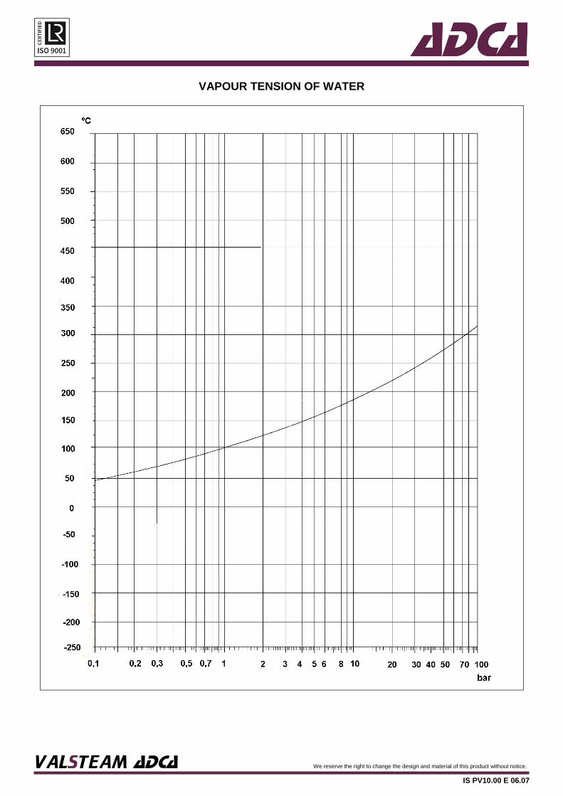
VAPOUR TENSION OF WATER

VALSTEAM ADCA We reserve the right to change the design and material of this product without notice.
IS PV10.00 E 06.07
CONVERSION FACTORS
FLOW RATE IN VOLUME
UNIT m3/s L/s cfm gpm
Cubic metre per second m3/s 1 1×10³ 2118,88 15850
Litre per second L/s 1×10⁻³ 1 2,1189 15,85
Cubic foot per minute cfm 0,4719×10⁻³ 0,4719 1 7,48
Gallon per minute gpm 0,6309×10⁻⁴ 0,06309 0,1337 1
MASS
UNIT kg lb ton
Kilogramme kg 1 2,2046 1×10⁻³
Pound lb 0,4536 1 0,454×10-3
Ton short (US) ton 907,1847 2000 1
AREA
UNIT m2 cm2 in2 ft2
Square metre m2 1 1×10⁴ 1550 10,764
Square centimetre cm2 1×10⁻⁴ 1 0,155 10,764×10-4
Square inch in2 6,452×10-4 6,452 1 6,944×10-3
Square foot ft2 9,290×10-2 928,03 144 1
LENGTH
UNIT m cm mm in ft
Metre m 1 1×10² 1×10³ 39,370 3,281
Centimetre cm 1×10⁻² 1 10 0,390 0,033
Milimetre mm 1×10⁻³ 1×10⁻¹ 1 0,039 3,28×10⁻³
Inch in 2,54×10⁻² 2,540 25,4 1 0,083
Foot ft 0,305 30,480 304,8 12 1
VOLUME
UNIT m3 L in3 ft3 gal
Cubic metre m3 1 1×10³ 61,024×103 35,315 219,969
Cubic dcm or liter dm3 (L) 1×10⁻³ 1 61,024 0,353 0,220
Cubic inch in3 0,0164×10⁻³ 0,016 1 5,787×10-4 3,605×10-3
Cubic foot ft3 0,028 28,317 1728 1 6,229
Gallon (UK) gal 4,546×10-3 4,546 277,419 0,161 1
WORK, ENERGY, HEAT AND ENTHALPY
UNIT J kgfm kcal Wh Btu
Joule J 1 0,1020 0,2388×10⁻³ 0,2778×10⁻³ 0,9478×10⁻³
Kilogramme metre kgfm 9,807 1 2,342×10-3 2,724×10-3 9,295×10-3
Kilocalorie kcal 4186,8 426,92 1 3,968 3,968
Watt hour Wh 3600 367,08 0,861 1 3,413
British thermal unit Btu 1055,06 107,58 0,252 0,293 1

VALSTEAM ADCA We reserve the right to change the design and material of this product without notice.
IS PV10.00 E 06.07
POWER
UNIT W kcal/h kgm/s BTU/h ft lb/s BHP CV
Watt W 1 0,8605 0,102 3,413 0,7375 1,341×10-3 1,360×10-3
Kilocalorie/hour kcal/h 1,1628 1 0,1186 3,9683 0,8576 1,559×10-3 1,581×10-3
Kilogramme metre/sec kgm/s 9,807 8,434 1 33,47 7,233 1,315×10-2 1,333×10-2
British thermal unit/hour BTU/h 0,293 0,252 0,02988 1 0,2161 0,393×10-3 0,398×10-3
Foot pound/second ft lb/s 1,356 1,166 0,1383 4,627 1 1,818×10-3 1,844×10-3
Brake horsepower BHP 745,7 641,3 76,04 2547 550 1 1,0139
Horsepower (metric) CV 735,5 632,53 75 2512,2 542,4 0,986 1
VELOCITY
UNIT m/s ft/s km/h
Metre per second m/s 1 3,2808 3,6
Foot per second ft/s 0,3048 1 1,0973
Kilometre per hour km/h 0,2778 0,9113 1
PRESSURE
UNIT Pa bar at mm Hg kgf/m2 psi lbf/ft2
Pascal Pa 1 1x10⁻⁵ 1,0197x10⁻⁵ 0,0075 0,10197 0,145x10-3 0,02088
Bar bar 1x10⁵ 1 1,0197 750,07 10197 14,5050 2088
Atmosphere (Kgf/cm2) atm 98070 0,9807 1 735,56 10000 14,223 2048,16
Millimetre of mercury mm Hg 133,32 1,3332x10⁻³ 1,3595x10⁻³ 1 13,595 0,0193 1,392
Kilogramme per sq. mtr. kgf/m2 9,807 9,807x10-5 1x10⁻⁴ 0,0735 1 0,0014 0,205
Pounds per sq. Inch psi 6894,14 0,06894 0,0703 51,719 703,07 1 144
Pounds per sq. foot lbf/ft2 47,876 4,7876x10⁻⁴ 4,8824x10⁻⁴ 0,7183 4,8824 0,00694 1
WATER HARDNESS
UNIT ºFr ºdH GPG ppm
French degree ºFr 1 0,56 0,583 10,0
German degree ºdH 1,79 1 1,040 17,9
Grain/US gallon GPG 1,71 0,958 1 17,1
Parts per million ppm 0,10 0,056 0,0583 1
TEMPERATURE
oC oF 0C oF oC oF 0C oF
-35 -31 40 104 115 239 190 374
-30 -22 45 113 120 248 195 383
-25 -13 50 122 125 257 200 392
-20 -4 55 131 130 266 205 401
-15 5 60 140 135 275 210 410
-10 14 65 149 140 284 215 419
-5 23 70 158 145 293 220 428
0 32 75 167 150 302 225 437
5 41 80 176 155 311 230 446
10 50 85 185 160 320 235 455
15 59 90 194 165 329 240 464
20 68 95 203 170 338 245 473
25 77 100 212 175 347 250 482
30 86 105 221 180 356 255 491
35 95 110 230 185 365 260 500
Conversion equations
T(ºF) = (1,8 × T(ºC)) + 32
T(ºC) = 0,55 × (T(ºF) - 32)
T(K) = T(ºC) + 273,15

VALSTEAM ADCA We reserve the right to change the design and material of this product without notice.
IS PV10.00 E 06.07
MASS PER UNIT VOLUME OF DRY AIR (IN kg/m3)
FOR TEMPERATURES FROM 0 ºC TO 300 ºC AND PRESSURES FROM 0 TO 25 bar
T (ºC) GAUGE PRESSURE (bar)
0 0,5 1 1,5 2 2,5 3 3,5 4 4,5 5
0 1,293 1,931 2,569 3,207 3,845 4,483 5,121 5,759 6,397 7,036 7,674
10 1,247 1,863 2,478 3,094 3,709 4,325 4,941 5,556 6,172 6,787 7,403
20 1,205 1,799 2,394 2,988 3,583 4,177 4,772 5,367 5,961 6,556 7,150
30 1,165 1,740 2,315 2,890 3,465 4,040 4,615 5,189 5,764 6,339 6,914
40 1,128 1,684 2,241 2,798 3,354 3,911 4,467 5,024 5,580 6,137 6,693
50 1,093 1,632 2,172 2,711 3,250 3,790 4,329 4,868 5,408 5,947 6,486
60 1,060 1,583 2,106 2,630 3,153 3,676 4,199 4,722 5,245 5,768 6,292
70 1,029 1,537 2,045 2,553 3,061 3,569 4,077 4,585 5,092 5,600 6,108
80 1,000 1,494 1,987 2,481 2,974 3,468 3,961 4,455 4,948 5,442 5,935
90 0,973 1,453 1,932 2,412 2,892 3,372 3,852 4,332 4,812 5,292 5,772
100 0,947 1,414 1,881 2,348 2,815 3,282 3,749 4,216 4,683 5,150 5,617
110 0,922 1,377 1,832 2,286 2,741 3,196 3,651 4,106 4,561 5,016 5,471
120 0,898 1,342 1,785 2,228 2,672 3,115 3,558 4,002 4,445 4,888 5,331
130 0,876 1,308 1,741 2,173 2,605 3,038 3,470 3,902 4,335 4,767 5,199
140 0,855 1,277 1,699 2,120 2,542 2,964 3,386 3,808 4,230 4,651 5,073
150 0,835 1,247 1,658 2,070 2,482 2,894 3,306 3,718 4,130 4,542 4,953
160 0,815 1,218 1,620 2,023 2,425 2,827 3,230 3,632 4,034 4,437 4,839
170 0,797 1,190 1,584 1,977 2,370 2,763 3,157 3,550 3,943 4,337 4,730
180 0,779 1,164 1,549 1,933 2,318 2,702 3,087 3,472 3,856 4,241 4,626
190 0,763 1,139 1,515 1,891 2,268 2,644 3,020 3,397 3,773 4,149 4,526
200 0,746 1,115 1,483 1,852 2,220 2,588 2,957 3,325 3,693 4,062 4,430
220 0,716 1,070 1,423 1,776 2,130 2,483 2,837 3,190 3,543 3,897 4,250
240 0,688 1,028 1,368 1,707 2,047 2,386 2,726 3,066 3,405 3,745 4,085
260 0,662 0,989 1,316 1,643 1,970 2,297 2,624 2,951 3,278 3,605 3,931
280 0,639 0,954 1,269 1,584 1,899 2,214 2,529 2,844 3,159 3,474 3,789
300 0,616 0,920 1,224 1,528 1,833 2,137 2,441 2,745 3,049 3,353 3,657
T (ºC) GAUGE PRESSURE (bar)
6 7 8 9 10 12 14 16 18 20 25
0 8,950 10,226 11,502 12,778 14,054 16,606 19,159 21,711 24,263 26,815 33,196
10 8,634 9,865 11,096 12,327 13,558 16,020 18,482 20,944 23,406 25,868 32,024
20 8,339 9,528 10,717 11,906 13,095 15,473 17,852 20,230 22,608 24,986 30,931
30 8,064 9,214 10,364 11,514 12,663 14,963 17,263 19,562 21,862 24,162 29,911
40 7,807 8,920 10,033 11,146 12,259 14,485 16,711 18,938 21,164 23,390 28,956
50 7,565 8,644 9,722 10,801 11,880 14,037 16,194 18,352 20,509 22,666 28,060
60 7,338 8,384 9,430 10,470 11,523 13,616 5,708 17,800 19,893 21,986 27,217
70 7,124 8,140 9,156 10,171 11,187 13,219 15,250 17,280 19,314 21,345 26,424
80 6,922 7,909 8,896 9,883 10,870 12,845 14,819 16,793 18,767 20,741 25,676
90 6,732 7,692 8,651 9,611 10,571 12,491 14,411 16,330 18,250 20,170 24,969
100 6,551 7,485 8,420 9,354 10,288 12,156 14,024 15,893 17,761 19,629 24,300
110 6,380 7,290 8,200 9,110 10,019 11,839 13,658 15,478 17,297 19,117 23,666
120 6,218 7,105 7,991 8,878 9,764 11,538 13,311 15,084 16,857 18,631 23,064
130 6,064 6,928 7,793 8,658 9,522 11,252 12,981 14,710 16,439 18,168 22,492
140 5,917 6,761 7,604 8,448 9,292 10,979 12,667 14,354 16,041 17,729 21,947
150 5,777 6,601 7,425 8,248 9,072 10,720 12,367 14,015 15,662 17,310 21,429
160 5,644 6,449 7,253 8,058 8,863 10,472 12,082 13,691 15,301 16,910 20,934
170 5,516 6,303 7,090 7,876 8,663 10,236 11,809 13,382 14,955 16,529 20,461
180 5,395 6,164 6,933 7,702 8,472 10,010 11,548 13,087 14,625 16,164 20,010
190 5,278 6,031 6,783 7,536 8,289 9,794 11,299 12,804 14,310 15,815 19,578
200 5,167 5,903 6,640 7,377 8,114 9,587 11,060 12,534 14,007 15,481 19,164
220 4,957 5,664 6,371 7,078 7,784 9,198 10,612 12,025 13,439 14,853 18,387
240 4,764 5,443 6,123 6,802 7,481 8,840 10,198 11,557 12,915 14,274 17,670
260 4,585 5,443 5,893 6,547 7,200 8,508 9,816 11,123 12,431 13,738 17,007
280 4,419 5,050 5,680 6,310 6,940 8,200 9,461 10,721 11,981 13,242 16,392
300 4,265 4,873 5,482 6,090 6,698 7,914 9,131 10,347 11,563 12,780 15,820

VALSTEAM ADCA We reserve the right to change the design and material of this product without notice.
IS PV10.00 E 06.07
PHYSICAL PROPERTIES OF GASES AND VAPOURS – SI UNITS
Referred to 0ºC (32F) and 1013,25 mbar (14,7 psia)
ρ - mass per unit volume
V - specific volume
Tf - melting temperature
Cp - specific heat at constant pressure
Te - boiling temperature
λ - thermal conductivity
ρe - mass per unit volume of the liquid at Te
Gas or Vapour Formula ρ (kg/m3) Tf (oC) Te (
oC) ρe (kg/m3) V (m3/kg) Cp
(kcal/kg.h.ºC) λ
(kcal/m.h.ºC)
Acetone C3H6O 2,591 -94,8 56,2 749 0,386 0,296 0,0083
Acetylene C2H2 1,162 -83,3 -83,6 613 0,861 0,386 0,0158
Ammonia NH3 0,76 -77,9 -33,4 680 1,316 0,491 0,0187
Argon Ar 1,782 189,2 -185,7 1820 0,561 0,125 0,014
Benzole C6H6 3,485 - - - 0,287 0,227 0,0076
Biogas (40% CH4) - 1,467 - - - - - -
Biogas (56% CH4) - 1,267 - - - - - -
Biogas (70% CH4) - 1,092 - - - - - -
Butane C4H10 2,593 -138,4 -0,5 602 0,386 0,382 0,0119
Carbon dioxide CO2 1,964 -56,6 -78,2 1219 0,509 0,195 0,0122
Carbon disulphide CS2 3,397
0,294 0,139 0,0058
Carbon monoxide CO 1,25 -205 -191,6 801 0,8 0,248 0,0191
Chlorine Cl2 3,164 -101 -34,6 1512 0,316 0,116 0,0073
Diethyl ether C4H10O 3,307
0,302 0,345 0,0108
Dry air - 1,293 -213 -192,3 875 0,773 0,24 0,0209
Ethane C2H6 1,342 -183,3 -88,6 546 0,745 0,394 0,0155
Ethyl alcohol C2H6O 2,055 -114,2 78,3 747 0,487 0,364 0,0119
Ethylene C2H4 1,251 -169,5 -103,7 568 0,799 0,349 0,0144
Helium He 0,179 -272,2 -268,9 125 5,599 1,25 0,1233
Hydrochloric acid HCl 1,627 -111,2 -84,8 1135 0,615 0,19 0,0072
Hydrogen H2 0,09 -259,1 -252,9 71 11,118 3,45 0,1508
Hydrogen sulphide H2S 1,52 -85,6 -60,4 957 0,658 0,237 0,0108
Methane CH4 0,716 -182,5 -161,5 415 1,397 0,517 0,0263
Methyl alcohol CH4O 1,429 -97,6 64,7 737 0,7 0,32 0,012
Natural gas - 0,6 - - - - - -
Nitrogen N2 1,25 -209,9 -195,8 810 0,8 0,247 0,0205
Oxygen O2 1,428 -218,4 -183 1131 0,7 0,218 0,0208
Propane C3H8 1,968 -187,7 -42,1 585 0,508 0,37 0,013
Propylene C3H6 1,877 -185 -47,8 686 0,533 0,34 -
Sulfur dioxide SO2 2,858 - - - 0,35 0,14 0,0072

VALSTEAM ADCA We reserve the right to change the design and material of this product without notice.
IS PV10.00 E 06.07
PHYSICAL PROPERTIES OF WATER – SI UNITS
tref – reference temperature for
Ca – actual specific heat at tref
Ms – mass per unit volume at 20ºC (68ºF) λ – rthermal conductivity at tref
Temp.
(ºC) Ms
(kg/m3) V
(m3/kgx1000) Ca
(kcal/kg.ºC) λ
(kcal/m.h.ºC) Temp.
(ºC) Ms
(kg/m3) V
(m3/kgx1000) Ca
(kcal/kg.ºC) λ
(kcal/m.h.ºC)
0 999,87 1,00013 − − 70 977,81 1,02269 1,0002 0,57
4 999,99 1,00001 − − 71 977,23 1,0233 − −
6 999,97 1,00003 − − 72 976,66 1,0239 − −
8 999,89 1,00011 − − 73 976,07 1,02452 − −
10 999,75 1,00025 1 0,493 74 975,48 1,02514 − −
12 999,55 1,00045 − − 75 974,89 1,02576 1,0013 0,574
14 999,3 1,0007 − − 76 974,29 1,02639 − −
16 999 1,001 − − 77 973,68 1,02703 − −
18 998,65 1,00135 − − 78 973,07 1,02768 − −
20 998,2 1,0018 1 0,51 79 972,45 1,02833 − −
22 997,83 1,00217 − − 80 971,83 1,02899 1,0025 0,577
24 997,37 1,00264 − − 81 971,21 1,02964 − −
26 996,87 1,00314 − − 82 970,57 1,03032 − −
28 996,33 1,00368 − − 83 969,94 1,03099 − −
30 995,76 1,00426 1 0,526 84 969,3 1,03167 − −
32 995,12 1,0049 − − 85 968,65 1,03236 1,0037 0,58
34 994,49 1,00554 − − 86 968 1,03306 − −
36 993,74 1,0063 − − 87 967,34 1,03376 − −
38 993,02 1,00703 − − 88 966,68 1,03447 − −
40 992,24 1,00782 1 0,539 89 966,01 1,03519 − −
41 991,86 1,00821 − − 90 965,34 1,0359 1,0049 0,582
42 991,47 1,0086 − − 91 964,67 1,03662 − −
43 991,07 1,00901 − − 92 963,99 1,03736 − −
44 990,66 1,00943 − − 93 963,3 1,0381 − −
45 990,25 1,00985 − − 94 962,61 1,03884 − −
46 989,82 1,01028 − − 95 961,92 1,03959 1,006 0,584
47 989,4 1,01071 − − 96 961,22 1,04034 − −
48 988,96 1,01116 − − 97 960,51 1,04111 − −
49 988,52 1,01161 − − 98 959,81 1,04187 − −
50 988,07 1,01207 1 0,551 99 959,09 1,04266 − −
51 987,62 1,01254 − − 100 958,38 1,04343 1,0061 0,586
52 987,15 1,01302 − − 105 − − 1,0071 0,588
53 986,69 1,01349 − − 110 − − 1,0084 0,589
54 986,21 1,01398 − − 115 − − 1,0098 0,59
55 985,73 1,01448 1 0,556 120 − − 1,0114 0,591
56 985,25 1,01497 − − 125 − − 1,0132 0,591
57 984,75 1,01549 − − 130 − − 1,0152 0,592
58 984,25 1,016 − − 135 − − 1,0175 0,592
59 983,75 1,01652 − − 140 − − 1,02 0,592
60 983,24 1,01705 1 0,561 145 − − 1,0228 0,591
61 982,72 1,01758 − − 150 − − 1,0258 0,591
62 982,2 1,01812 − − 160 − − 1,0328 0,589
63 981,67 1,01867 − − 170 − − 1,0411 0,586
64 981,13 1,01923 − − 180 − − 1,0507 0,582
65 980,59 1,01979 1 0,566 190 − − 1,0619 0,578
66 980,05 1,02036 − − 200 − − 1,0746 0,572
67 979,5 1,02093 − − 210 − − 1,089 0,565
68 978,94 1,02151 − − 220 − − 1,1052 0,558
69 978,38 1,0221 − − 230 − − 1,1234 0,55

VALSTEAM ADCA We reserve the right to change the design and material of this product without notice.
IS PV10.00 E 06.07
PHYSICAL PROPERTIES OF LIQUIDS – SI UNITS
Tref – reference temperature for Ca – actual specific heat at tref
Ms – mass per unit volume at 20ºC (68ºF) λ – thermal conductivity at tref
Liquid Tref (ºC)
Ms (kg/m3)
Ca (kcal/kg.ºC)
λ (kcal/m.h.ºC)
Liquid Tref (ºC) Ms
(kg/m3) Ca
(kcal/kg.ºC) λ
(kcal/m.h.ºC)
Acetic acid 25 1049 0,51 0,166 Methane - 90 162 - -
Acetone 20 790 0,515 0,139 Methanol 20 791 0,33 -
Ammonia sol. (25%)
20 771 - 0,425 Methyl alcohol (95%vol.)
20 792 0,596 0,174
Apple juice 20 1356 0,446 - Milk, cow, heavy cream
20 994 0,94 0,434
Argon -186 1430 - - Naphta 15 665 0,92 -
Automobile oils
15 880-940 - 0,125 Nitric acid 20 1520 0,411 0,456
Beer 10 1010 - - Nitrogen -201 808 - -
Benzene 20 870 0,43 0,138 Oil, coconut 20 924 - -
Benzole 20 879 0,43 0,132 Oil, corn 20 922 - -
80 - 0,44 0,13 Oil, castor 25 956,1 0,43 0,155
Butane 25 599 0,55 - Oil, cotton seed 15 926 - -
Butter 20 911 0,557-0,688 - Oil, olive 10 918 0,47 0,146
Carbon tetrachloride
25 1584 0,207 0,089 Oil, palm 20 915 - -
Carbon disulphide
20 1266 0,241 0,138 Oil, soya 20 927 0,47 -
Chloride 25 1560 - - Oil, sunflower 20 920 - -
Chloroform 20 1489 0,251 0,11 Oil, peanut 20 914 - -
Citric acid 25 1660 - - Oil, whale 15 925 - -
Crude oil 20 900 - 0,113 Oxygen (liquid) -186 1155 - -
Diesel 20 800 - - Petrol 30 680 - 710 0,45 0,112
Ethane (liquid)
-89 570 - - Phenol 25 1072 0,34 0,163
Ethyl acetate 20 901 - - Propanol 25 804 - -
Ethyl alcohol (95%vol.)
0 789 0,547 0,166 Propyl alcohol 25 800 0,57 0,138
40 - 0,648 0,144 Sea water 25 1025 0,94 -
Fuel oil 20 840 - 920 0,471 0,103 Sodium carbonate 20 2530 0,86 0,516
Gasoline 20 803 0,53 0,129 Sodium Hydroxide (caustic soda)
15 1250 0,77 0,37
Glycerine 10 1260 0,576 0,25 Sulphuric acid 12 1853 0,33 0,28
Glycerol 25 1126 - - Sulphurous acid (96%)
20 1840 0,351 0,43
Helium -271 147 - -
Water
8 999,88 1 0,485
Honey 20 1420 0,54-0,6 0,00648 41 991,66 1 0,538
Hydrazine 25 795 - - 72 976,36 1 0,58
Hydrochloric acid (25%)
20 1150 0,75 0,404 100 958,38 1,006 0,586
Kerosene 16 820,1 0,48 0,125 200 0 - 200 1,037 0,572
Lubricating oil
81 920 - 0,105
0 - - 0,133
100 - - 0,128
200 - - 0,122
VALSTEAM ADCA We reserve the right to change the design and material of this product without notice.
IS PV10.00 E 06.07
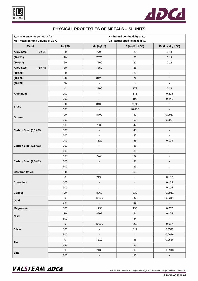
PHYSICAL PROPERTIES OF METALS – SI UNITS
Tref - reference temperature for λ - thermal conductivity at tref Ms - mass per unit volume at 20 ºC Ca - actual specific heat at tref
Metal Tref (ºC) Ms (kg/m3) λ (kcal/m.h.ºC) Ca (kcal/kg.h.ºC)
Alloy Steel (5%Cr) 20 7790 28 0,11
(20%Cr) 20 7670 20 0,11
(10%Cr) 20 7760 27 0,11
Alloy Steel (5%Ni) 30 7850 25 -
(10%Ni) 30 - 22 -
(40%Ni) 30 8120 9 -
(20%Ni) 30 - 14 -
Aluminum
0 2700 173 0,21
100 - 176 0,224
300 - 198 0,241
Brass 20 8400 79-96 -
100 - 90-110 -
Bronze 20 8700 50 0,0913
100 - 62 0,0937
Carbon Steel (0,1%C)
100 7830 47 -
300 - 43 -
600 - 32 -
Carbon Steel (0,5%C)
100 7820 45 0,113
300 - 38 -
600 - 31 -
Carbon Steel (1,5%C)
100 7740 32 -
300 - 31 -
600 - 29 -
Cast Iron (4%C) 20 - 50 -
Chromium
0 7190 - 0,102
100 - - 0,113
300 - - 0,125
Copper 20 8960 332 0,0911
Gold 0 19320 268 0,0311
200 - 266 -
Magnesium 100 1738 135 0,257
Nikel 10 8902 54 0,105
500 - 44 -
Silver
0 10500 360 0,057
100 - 312 0,0572
900 - - 0,0676
Tin 0 7310 56 0,0536
200 - 52 -
Zinc 0 7133 95 0,0918
200 - 90 -

VALSTEAM ADCA We reserve the right to change the design and material of this product without notice.
IS PV10.00 E 06.07
FLASH STEAM FROM BOILING CONDENSATE
Atm
osphe r i c p
r essu r e
Related Documents