1 VD.A6.E1.02 © Danfoss 11/2011 SMT/SI Data sheet Automatic balancing valves ASV Description / Application ASV balancing valves are used for dynamic hydronic balance in heating and cooling systems. Dynamic balancing means: permanent balancing from 0 to 100 % load by controlling the pressure in systems with variable f low. At partial loads, when the f low is decreased by the control valve, pressure limitation is still performed and consequently performing dynamic balancing. By using ASV you avoid using complex and time consuming commissioning methods. Dynamic balancing of the system in all loads helps you to save energy and improves climate comfort and control. F low limitation By using combination of pressure controller ASV and settable terminal’s unit valve, f low limitation is established. F low limitation for each terminal unit prevents underf lows on distant units and overf lows on others thus allows efficient pumping. Lower noise emission Differential pressure limitation provides the pressure over the control valve not to increase at partial loads thus noise emission will be lower. (This is the reason why DIN 18380 requires control of differential pressure by partial load.) No balancing method needed F low limitation is achieved by adjusting each hydronic loop separately without inf luencing others, which consequently results in one time adjusting process. No special balancing method is needed so commisioning cost can be saved. Control valve authority Controlling differential pressure over the control valve means that authority is high – which allows an accurate and stable control as well as energy saving. Zone balancing By installing the ASV sets you can divide the piping system in pressure independent zones. This allows a gradual connection of zones to the main in new constructions or at renovation without using an additional balancing method. There is no need to perform a new commissioning every time the system is changed because the hydronic balance is done automatically. ASV-P valves have fixed setting (10 kPa). ASV-PV valves are settable in different ranges: • 5-25 kPa setting is mostly used for radiator application, • 20-40 kPa setting is used for radiator, fan coil, chilled beam and f lat station applications, • 35-75 kPa setting is used for flat station and fan coil, chilled beam application, • 60-100 kPa setting is used for large terminal unit application (air handling units, fan coils, etc.). Using ASV valves it is possible to optimize pump head while independent pressure zones allow to keep authority of terminal unit’s valve high. ASV-P ASV-PV ASV-PV ASV-PV ASV-BD ASV-I ASV-M DN 15-40 DN 15-40 DN 50 DN 65-100 DN 15-50 DN 15-50 DN 15-50

Welcome message from author
This document is posted to help you gain knowledge. Please leave a comment to let me know what you think about it! Share it to your friends and learn new things together.
Transcript
1VD.A6.E1.02 © Danfoss 11/2011SMT/SI
Data sheet
Automatic balancing valvesASV
Description / Application ASV balancing valves are used for dynamic hydronic balance in heating and cooling systems. Dynamic balancing means: permanent balancing from 0 to 100 % load by controlling the pressure in systems with variable f low. At partial loads, when the f low is decreased by the control valve, pressure limitation is still performed and consequently performing dynamic balancing.By using ASV you avoid using complex and time consuming commissioning methods. Dynamic balancing of the system in all loads helps you to save energy and improves climate comfort and control.
F low limitationBy using combination of pressure controller ASV and settable terminal’s unit valve, f low limitation is established.
F low limitation for each terminal unit prevents underf lows on distant units and overf lows on others thus allows efficient pumping.
Lower noise emissionDifferential pressure limitation provides the pressure over the control valve not to increase at partial loads thus noise emission will be lower. (This is the reason why DIN 18380 requires control of differential pressure by partial load.)
No balancing method neededF low limitation is achieved by adjusting each hydronic loop separately without inf luencing others, which consequently results in one time adjusting process. No special balancing method is needed so commisioning cost can be saved.
Control valve authorityControlling differential pressure over the control valve means that authority is high – which allows an accurate and stable control as well as energy saving.
Zone balancingBy installing the ASV sets you can divide the piping system in pressure independent zones. This allows a gradual connection of zones to the main in new constructions or at renovation without using an additional balancing method. There is no need to perform a new commissioning every time the system is changed because the hydronic balance is done automatically.
ASV-P valves have fixed setting (10 kPa).
ASV-PV valves are settable in different ranges:• 5-25kPasettingismostlyusedforradiator
application,• 20-40kPasettingisusedforradiator,fancoil,
chilled beam and f lat station applications,• 35-75kPasettingisusedforflatstationand
fan coil, chilled beam application,• 60-100kPasettingisusedforlargeterminal
unit application (air handling units, fan coils, etc.).
Using ASV valves it is possible to optimize pump head while independent pressure zones allow to keep authority of terminal unit’s valve high.
ASV-P ASV-PV ASV-PV ASV-PV ASV-BD ASV-I ASV-M DN 15-40 DN 15-40 DN 50 DN 65-100 DN 15-50 DN 15-50 DN 15-50

2 VD.A6.E1.02 © Danfoss 11/2011 SMT/SI
Data sheet Automatic balancing valves ASV
Description / Application(continuous)
ASV balancing valves are designed to guarantee high quality of the automatic balancing by:- a pressure released cone,- an adapted membrane for every valve
dimension which provide constant quality performance for all sizes,
- spring with linear characteristic that makes setting required Δp easy.
A 90° angle between all service features (shut-off, draining, setting, measuring) allows an easy access under any installing condition.
All the above-mentioned features and functions are realized in small build-in dimensions so it is easy to install ASV even in very limited space.
ASV valves are performing pressure control not only at design conditions (100 % load) but also at all partial loads (thus fulfilling the requirements of DIN 18380 norms). By controlling pressure at a partial load one can prevent noise problems on thermostatic radiator valves which often occur in unbalanced systems.
ASVvalves(DN15-40)arepackagedinstyropore(EPS) which can be used for insulation at
temperatures up to 80 °C. An insulation cap is available as an accessory for insulation at higher temperatures (up to 120 °C).
ASV valves in dimensions DN 15-40 are supplied withaninternalorexternalthreadwhileDN50issupplied with external thread only. If an external thread is chosen, a threaded or weld nipple can be supplied as an accessory. Dimensions DN65-100aresuppliedasflangedvalves.
ASV balancing valves have integrated service functions such as shut-off and draining.
ASV-PV can be equipped with nipple for f low measuring. In that case measuringnipples need to be ordered separately and mounted on the valve as follows:• ontopofdraincock(DN15-50),• ontheflangeconnectionbeforethevalveis
filledwithwater(DN65-100).
ASV-PV valves are to be mounted in return pipe, in combination with partner valves mounted in f low pipe. As a partner valve ASV-M/I/BD are recommendedfordimensionsDN15toDN50and MSV-F2 for dimensions DN65 to DN 100.
There are two basic configurations when using ASV partner valves (ASV-BD, ASV-I, ASV-M, MSV-F2):
- partner valve outside the control loop (Fig. 1). Recommended configuration: it results in best
performance since whole controlled pressure range is available to the riser. Flow limitation is done on each terminal unit in the riser (for example, RA-N with presetting on radiator, etc).
DN15toDN50:ASV-MorASV-BD DN65toDN100:MSV-F2,byconnecting
impulse tube to down-flow measuring nipple.
Fig. 2 Setting of ASV-PV = ∆priser + ∆piFig. 1 Setting of ASV-PV = Δpriser
- partner valve inside control loop (Fig. 2). Offers flow limitation on the riser however
part of the controlled pressure range is used by pressure drop on partner valve (∆pi). It is recommended when flow limitation on each terminal units is not possible.
DN15toDN50:ASV-IorASV-BD. DN65toDN100:MSV-F2,byconnecting
impulse tube to up-flow measuring nipple.
ASV-BD can be used outside or inside control loop by choice of which measuring nipple is open. To be used outside control loop, blue measuring nipple needs to be open. In this position, flow verification can be done (default position). To be used inside control loop, red measuring nipple needs to be open. In this position, flow verification & flow verification can be done.

3VD.A6.E1.02 © Danfoss 11/2011SMT/SI
Data sheet Automatic balancing valves ASV
Fig. 3 ASV in riser / typical heating application (general example)
Description / Application(continuous)
ASV valves are to be used in radiator heating systems to control the differential pressure in risers. To limit the f low for every radiator, the thermostatic radiator valve with pre-setting facilities (feature) is used together with a constant pressure provided by the ASV, thus providing balanced heat distribution.
Alternatively the f low in the riser can be limited by using setting function of the ASV-I.Controlling differential pressure over the riser means also that the valve authority over the thermostatic radiator valves is high – which allows an accurate and stable temperature control and saves energy.
ASV valves are to be used in f loor heating systems. To limit the f low for every loop valves with an integrated f low limiting or presetting function should be used together with a constant pressure provided by an ASV-PV valve. Alternatively the f low for the whole manifold can be limited by using the setting function of the ASV-I or ASV-BD.
ASV-PV valves can control the differential pressure in several ranges if different pressure is needed. Due to its small dimensions the ASV automatic balancing valves are easy to install in a wall mounted box for f loor heating manifolds.
Fig. 4 ASV in manifold for f loor heating system
4 VD.A6.E1.02 © Danfoss 11/2011 SMT/SI
Data sheet Automatic balancing valves ASV
Description / Application (continuous)
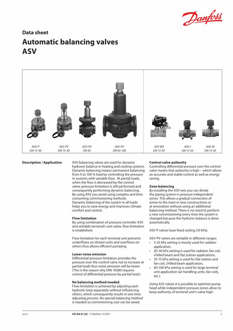
Fig. 6 F lat station
In f lat stations, pressure conditions change when sanitary water heating is taking place in comaparison to the situation when only heating is needed. By using ASV-PV valves the differential pressure is controlled also in those conditions.
Constant differential pressure in combination with pre-set control valves i.e. ASV-I or ASV-BD limits the f low.
ASV automatic balancing valves can be used also in other applications. For example ASV can be used to prevent noise problems at the thermostatic radiator valves in small systems by controlling the differential pressure. ASV can be used in every application you need a small differential pressure controller, for example like small f loor manifolds or f lat stations. In buildings equipped with f lat stations ASV valves can be used to provide secure automatic balance by the means of differential pressure control in risers/zones.
Fig. 5 ASV with fan coil
The ASV valves are to be used in systems with fan coils, induction devices and air-heaters to secure an automatic hydronic balance by the means of differential pressure control in branches or at every coil. Constant differential pressure in combination with pre-set control valves i.e. ASV-I or ASV-BD limits the f low.

5VD.A6.E1.02 © Danfoss 11/2011SMT/SI
Thread F lange
Q min ≤ Q ≤ Q 10 kPa
Data sheet Automatic balancing valves ASV
Sizing
We recommend to size the diameter of ASV-P/PVvalvesbyusingFig7.Maximumflowrates are based on 10 kPa differential pressure over the valve which allows effcient pumping and saves energy.
After ASV-P/PV valves have been sized the same dimension of partner valve ASV-BD / ASV-I / ASV-M / MSV-F2 valve should be selected.
Example:
Given:Pipeflow200l/h,pipesDN15
Solution: Horizontal line intersects the column for the valveDN15whichcanthereforebeselectedasrequired size. For detailed sizing see examples on pages 12 and 13. For different ∆pv (differential pressure over the valve) see diagrams in Appendix A.
Connection between valves size and pipe sizeKv values per particular dimension were designed tocoverflowrangeaccordingtoVDI2073withwater velocity of up 0.8 m/s, at differential pressure of 10 kPa over the valve. As long as the water velocity in the pipe is between 0.3 and 0.8 m/s dimension of the valve should be equal to pipe dimension.
This rule is derived out of the fact that Kv values per particular dimension were designed to cover flowrangeaccordingtoVDI2073atdifferentialpressure of 10 kPa over the valve.
Fig. 7 Column diagram for sizing ASV valves at ∆pv = 10 kPa. For different ∆pv values use diagram A and B in Appendix.
6 VD.A6.E1.02 © Danfoss 11/2011 SMT/SI
Data sheet Automatic balancing valves ASV
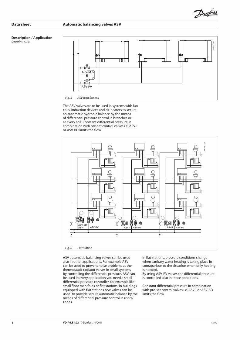
Ordering ASV-Pbalancingvalve,inclusiveinthebox:1.5mimpulsetube(G1/16A)anddraincock(G3/4 A) Constant differential pressure 10 kPa
Type DN kVS(m3/h)Internal thread
(ISO7/1) Code No. Type External thread(ISO 228/1) Code No.
15 1.6 Rp ½ 003L7621 G¾A 003L7626
20 2.5 Rp¾ 003L7622 G1A 003L7627
25 4.0 Rp 1 003L7623 G1¼A 003L7628
32 6.3 Rp1¼ 003L7624 G1½A 003L7629
40 10 Rp 1½ 003L7625 G1¾A 003L7630
ASV-Pbalancingvalve,inclusiveinthebox:1.5mimpulsetube(G1/16A)anddraincock(G3/4 A)
Type DN kVS Connection
∆p setting rangeCode No.
(m3/h) (kPa)
15 1.6
Internal thread ISO7/1
Rp 1/2
5-25
003L7601
20 2.5 Rp 3/4 003L7602
25 4.0 Rp 1 003L7603
32 6.3 Rp 11/4 003L7604
40 10.0 Rp 11/2 003L7605
15 1.6 Rp 1/2
20-40
003L7611
20 2.5 Rp 3/4 003L7612
25 4.0 Rp 1 003L7613
32 6.3 Rp 11/4 003L7614
40 10.0 Rp 11/2 003L7615
32 6.3 Rp 11/435-75
003L7616
40 10.0 Rp 11/2 003L7617
15 1.6
External thread ISO 228/1
G3/4 A
5-25
003L7606
20 2.5 G1A 003L7607
25 4.0 G11/4 A 003L7608
32 6.3 G11/2 A 003L7609
40 10.0 G13/4 A 003L7610
ASV-P balancing valve, inclusive in the box: 2.5mimpulsetube(G1/16A)draincock(G3/4 A) and adapter 003L8151
Type DN kVS Connection
∆p setting rangeCode No.
(m3/h) (kPa)
50 20External thread
ISO 228/1G21/2
5-25 003Z0611
20-40 003Z0621
35-75 003Z0631
60-100 003Z0641
ASV-P balancing valve, inclusive in the box: 2.5mimpulsetube(G1/16 A), adapter ASV large 003Z0691 and 003L8151
Type DN kVS Connection
∆p setting rangeCode No.
(m3/h) (kPa)
65 30
F lange EN 1092-2
20-40
003Z0623
80 48 003Z0624
100 76.0 003Z0625
65 30
35-75
003Z0633
80 48 003Z0634
100 76.0 003Z0635
65 30
60-100
003Z0643
80 48 003Z0644
100 76.0 003Z0645

7VD.A6.E1.02 © Danfoss 11/2011SMT/SI
Data sheet Automatic balancing valves ASV
ASV-BD shut-off valve, multifunctional partner valve (shut-off, rotating measuring station)
Type DNkVS Internal thread
Code No.(m3/h) (ISO7/1)
15 3.0 Rp ½ 003Z4041
20 6.0 Rp¾ 003Z4042
25 9.5 Rp 1 003Z4043
32 18 Rp1¼ 003Z4044
40 26 Rp 1½ 003Z4045
50 40 Rp 2 003Z4046
ASV-M shut-off valve, without measuring nipples
Type DNkVS
(m3/h)Internal thread
(ISO7/1)Code No. Type External thread
(ISO 228/1)Code No.
15 1.6 Rp ½ 003L7691 G¾A 003L7696
20 2.5 Rp¾ 003L7692 G1A 003L7697
25 4.0 Rp 1 003L7693 G1¼A 003L7698
32 6.3 Rp1¼ 003L7694 G1½A 003L7699
40 10 Rp 1½ 003L7695 G1¾A 003L7700
50 16 G2¼A 003L7702
ASV-I adjustment valve, inclusive two measuring nipples
Type DNkVS
(m3/h)Internal thread
(ISO7/1)Code No. Type External thread
(ISO 228/1)Code No.
15 1.6 Rp ½ 003L7641 G¾A 003L7646
20 2.5 Rp¾ 003L7642 G1A 003L7647
25 4.0 Rp 1 003L7643 G1¼A 003L7648
32 6.3 Rp1¼ 003L7644 G1½A 003L7649
40 10 Rp 1½ 003L7645 G1¾A 003L7650
50 16 G2¼A 003L7652
Accessories and spare parts Description Comments/connection Code No.
Shut-off knob for ASV-I (black)
DN15 003L8155
DN 20 003L8156
DN25 003L8157
DN32/DN40/DN50 003L8158
Shut-off knob for ASV-M (black)
DN15 003L8146
DN 20 003L8147
DN25 003L8148
DN32/DN40/DN50 003L8149
Differential pressure measuring connector For drain cock 003L8143
Drain cock ForASV-PV(DN15-50) 003L8141
Two measuring nipples and one locking plateFor ASV-I and ASV-M, rectus type
003L8145
3 mm measuring nipples, 2 pcs For ASV-BD 4) 003Z4662
Operating handle For ASV-BD 4) 003Z4652
Impulse tube, with O-rings
1.5m 003L8152
2.5m 003Z0690
5m 003L8153
Adapter large ASV 1) G¼-R¼;G 1/16 003Z0691
Nipple for connecting impulse tube 2) G1/16-R¼ 003L8151
Nipple for connecting impulse tube on other valves (US standard)
G1/16-4/16-20 UNF-2B 003L8176
O-ring for impulse tube 3) 2.90×1.78 003L8175
Plug for impulse tube connection ASV-I/M 3) G1/16 A 003L81741) Recommended for use with MSV-F2, connected to measuring hole, it allows connection of impulse tube from ASV while retaining
measurement functionality.2) Recommended for use with MSV-F2, connected to measuring hole. Can also be used for connecting impulse tube directly on the pipe.3) Set of 10 pieces.4) for whole range of ASV-BD accessories please refer to Leno™ MSV-BD datasheet.
Ordering (continuous)
8 VD.A6.E1.02 © Danfoss 11/2011 SMT/SI
Data sheet Automatic balancing valves ASV
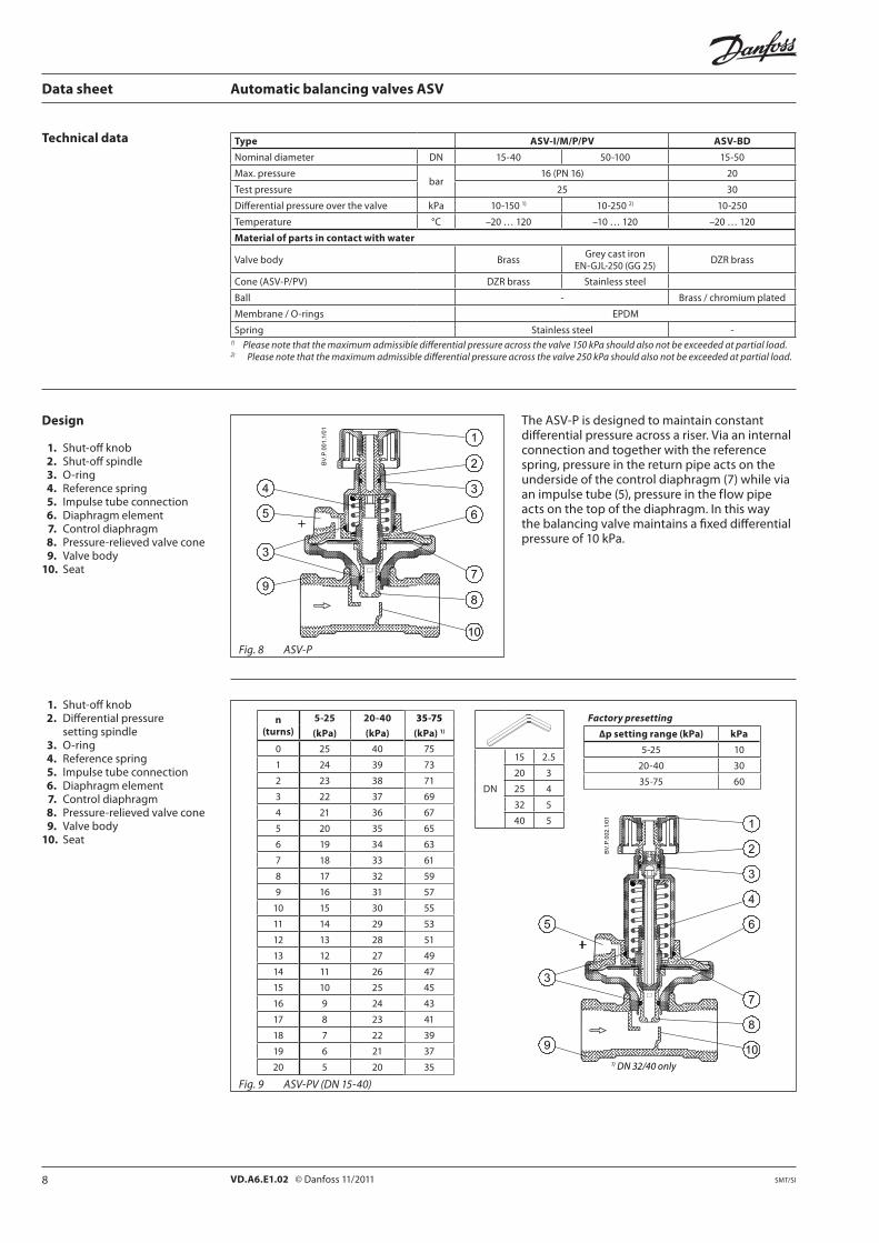
Technical data Type ASV-I/M/P/PV ASV-BD
Nominal diameter DN 15-40 50-100 15-50
Max. pressurebar
16(PN16) 20
Test pressure 25 30
Differential pressure over the valve kPa 10-1501) 10-2502) 10-250
Temperature °C –20 … 120 –10 … 120 –20 … 120
Material of parts in contact with water
Valve body BrassGreycastiron
EN-GJL-250(GG25)DZR brass
Cone (ASV-P/PV) DZR brass Stainless steel
Ball - Brass / chromium plated
Membrane / O-rings EPDM
Spring Stainless steel -1) Please note that the maximum admissible differential pressure across the valve 150 kPa should also not be exceeded at partial load.2) Please note that the maximum admissible differential pressure across the valve 250 kPa should also not be exceeded at partial load.
The ASV-P is designed to maintain constant differential pressure across a riser. Via an internal connection and together with the reference spring, pressure in the return pipe acts on the undersideofthecontroldiaphragm(7)whileviaanimpulsetube(5),pressureintheflowpipeacts on the top of the diaphragm. In this way the balancing valve maintains a fixed differential pressure of 10 kPa.
Fig. 8 ASV-P
Design
1. Shut-off knob 2. Shut-off spindle 3. O-ring 4. Reference spring 5. Impulse tube connection 6. Diaphragm element 7. Control diaphragm 8. Pressure-relieved valve cone 9. Valve body10. Seat
1. Shut-off knob 2. Differential pressure setting spindle 3. O-ring 4. Reference spring 5. Impulse tube connection 6. Diaphragm element 7. Control diaphragm 8. Pressure-relieved valve cone 9. Valve body 10. Seat
n (turns)
5-25 20-40 35-75
(kPa) (kPa) (kPa) 1)
0 25 40 75
1 24 39 73
2 23 38 71
3 22 37 69
4 21 36 67
5 20 35 65
6 19 34 63
7 18 33 61
8 17 32 59
9 16 31 57
10 15 30 55
11 14 29 53
12 13 28 51
13 12 27 49
14 11 26 47
15 10 25 45
16 9 24 43
17 8 23 41
18 7 22 39
19 6 21 37
20 5 20 35
Factory presetting
∆p setting range (kPa) kPa
5-25 10
20-40 30
35-75 60DN
15 2.5
20 3
25 4
32 5
40 5
Fig. 9 ASV-PV (DN 15-40)
1) DN 32/40 only
9VD.A6.E1.02 © Danfoss 11/2011SMT/SI
Data sheet Automatic balancing valves ASV
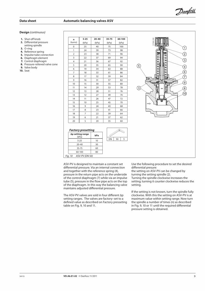
Design (continuous)
1. Shut-off knob 2. Differential pressure setting spindle 3. O-ring 4. Reference spring 5. Impulse tube connection 6. Diaphragm element 7. Control diaphragm 8. Pressure-relieved valve cone 9. Valve body 10. Seat
n(turns)
5-25 20-40 35-75 60-100
(kPa) (kPa) (kPa) (kPa)
0 25 40 75 100
1 24 39 73 98
2 23 38 71 96
3 22 37 69 94
4 21 36 67 92
5 20 35 65 90
6 19 34 63 88
7 18 33 61 86
8 17 32 59 84
9 16 31 57 82
10 15 30 55 80
11 14 29 53 78
12 13 28 51 76
13 12 27 49 74
14 11 26 47 72
15 10 25 45 70
16 9 24 43 68
17 8 23 41 66
18 7 22 39 64
19 6 21 37 62
20 5 20 35 60
Fig. 10 ASV-PV (DN 50)
ASV-PV is designed to maintain a constant set differential pressure. Via an internal connection andtogetherwiththereferencespring(4),pressure in the return pipe acts on the underside ofthecontroldiaphragm(7)whileviaanimpulsetube(5),pressureintheflowpipeactsonthetopof the diaphragm. In this way the balancing valve maintains adjusted differential pressure.
The ASV-PV valves are sold in four different ∆p setting ranges. The valves are factory–set to a defined value as described on Factory presseting table on Fig. 9, 10 and 11.
Use the following procedure to set the desired differential presure: the setting on ASV-PV can be changed by turning the setting spindle (2). Turning the spindle clockwise increases the setting;turningitcounterclockwisereducesthesetting.
If the setting is not known, turn the spindle fully clockwise. With this the setting on ASV-PV is at maximum value within setting range. Now turn the spindle a number of times (n) as described in Fig. 9, 10 or 11 until the required differential pressure setting is obtained.
Factory presetting∆p setting range
(kPa)kPa
5-25 10
20-40 30
35-75 60
60-100 80
DN 50 5
10 VD.A6.E1.02 © Danfoss 11/2011 SMT/SI
Data sheet Automatic balancing valves ASV
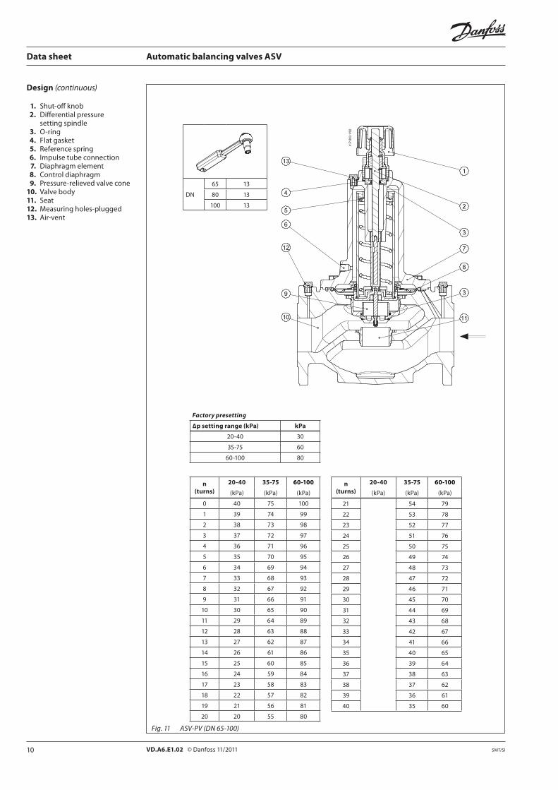
Design (continuous)
1. Shut-off knob 2. Differential pressure setting spindle 3. O-ring 4. F lat gasket 5. Reference spring 6. Impulse tube connection 7. Diaphragm element 8. Control diaphragm 9. Pressure-relieved valve cone 10. Valve body 11. Seat12. Measuring holes-plugged 13. Air-vent
n (turns)
20-40 35-75 60-100
(kPa) (kPa) (kPa)
0 40 75 100
1 39 74 99
2 38 73 98
3 37 72 97
4 36 71 96
5 35 70 95
6 34 69 94
7 33 68 93
8 32 67 92
9 31 66 91
10 30 65 90
11 29 64 89
12 28 63 88
13 27 62 87
14 26 61 86
15 25 60 85
16 24 59 84
17 23 58 83
18 22 57 82
19 21 56 81
20 20 55 80
Fig. 11 ASV-PV (DN 65-100)
n (turns)
20-40 35-75 60-100
(kPa) (kPa) (kPa)
21 54 79
22 53 78
23 52 77
24 51 76
25 50 75
26 49 74
27 48 73
28 47 72
29 46 71
30 45 70
31 44 69
32 43 68
33 42 67
34 41 66
35 40 65
36 39 64
37 38 63
38 37 62
39 36 61
40 35 60
DN
65 13
80 13
100 13
Factory presetting
∆p setting range (kPa) kPa
20-40 30
35-75 60
60-100 80

11VD.A6.E1.02 © Danfoss 11/2011SMT/SI
Data sheet Automatic balancing valves ASV
Design (continuous) 1. Valve body 2. Ball 3. Ball seat 4. Supporting screw 5. Throttle bush 6. Closing bush 7. Valve top 8. Spindle head 9. Spindle 10. Rotation lock 11. Drain cock 12. Handle 13. Rotating measuring station 14. Measuring nipple 15. Impulse tube connection
Partner valves ASV-BD/I/M are to be used together with the automatic balancing valves ASV-PV/P to control differential pressure in the risers.
ASV-BD is a combined presetting and shut off valve with a range of unique features:
• highkvvaluesforsmallpressurelosses• partnervalvepositioninsideoroutside
control loop (see page 2 for details), chooseable even after the valve is already installed and under pressure.
• Numericpresettingscale,visiblefrommultiple angles
• Easylockingofpresetting• Rotatingmeasuringstationwithbuilt-in
measuring nipples for 3 mm needles• Built-indraincockwithseparateflow/return
draining• Removablehandwheelforeasymounting.•Open-closedcolourindicator.
Impulse tube connectionThe impulse line must be connected to impulse tubeconnectionpiece(15).Inworkingposition,one of measuring nipples needs to be open while other closed. There are two possible configurations, with partner valve inside or outside control loop. It can be chosen by impulse tube connection side:- Partner valve outside controlled loop: opened outlet measuring nipple (blue marking). ASV-BD needs to be set to max setting (fully open. F low verification is possible.- Partner valve inside controlled loop: opened inlet measuring nipple (red marking). F low
limitation with flow verification is possible.Note: Default position is opened inlet measuring nipple (blue marking).
F low limitationUse the following procedure:1. When valve is open the lock is released.
Allen key can also be used.2. The handle pops up and the required f low
setting may be set. 4. Lockthesettingbypressingthehandleuntil
click.5. Ifneeded,flowcanbemeasuredusing PFM4000orotherbrandofmeasuring
instrument.
F low verification (in case ASV-BD is used outside controlled loop)Use the following procedure:1. ASV-BD setting is at maximum value.2. FlowcanbemeasuredusingPFM4000or
other brand of measuring instrument.3. If pressure drop across the valve is too low for
reliable f low measurement, ASV-BD needs to be set to lower setting to achieve high enough pressure drop across the valve.
4. Afterflowmeasurement,returnthesettingto maximum value and lock it by pressing the handle until click.
DrainingUse the following procedure to drain:1. Close opened measuring nipple.2. Remove the impulse tube.3. Remove the adapter. Make sure that drain
cock is fixed with spanner when adapter is removed.
4. Bluenippleopenstheoutletwhileredmeasuring nipple opens the inlet. Make sure not to use more than max. 3 turns. Drain tap and nipples can rotate to any position.
Note: when draining, always keep same or higher static pressure on upper part of ASV-P/PV membrane. Therefore, always drain from return pipe first and remove impulse tube only after return pipe is empty. If draining is done from flow pipe first, membrane can be damaged.
Fig. 11a ASV-BD DN 15-50

12 VD.A6.E1.02 © Danfoss 11/2011 SMT/SI
Port A Port B
DN
15 2.5
20 3
25 4
32/40/50 5
Port A Port B
Data sheet Automatic balancing valves ASV
ASV-M is designed to shut-off the pipe f low. ASV-M has a connection for an impulse tube to ASV-P/ASV-PV. It can be equipped with nipples for f low measuring (which are sold separately as accessories).
Fig. 13 ASV-M
1. Shut-off knob 2. Shut-off spindle 3. O-rings 4. Valve cone 5. Seat 6. Valve body
Design (continuous) 1. Shut-off knob 2. Shut-off spindle 3. Setting spindle 4. Scale disc 5. O-rings 6. Valve cone 7. Seat 8. Valve body
Fig. 12 ASV-I
ASV-I incorporates a double cone able to give maximum stroke limitation, thus achieving f low limitation. It also incorporates shut off function. ASV-I is equipped with the nipples for the f low measurement and a connection for the ASV-P/ASV-PV impulse tube.
Use the following procedure to limit the f low: turn the valve knob fully counter clockwise to open the valve. The mark on the knob will now be opposite »0« on the scale. Turn the valve knob clockwise to the required setting (e.g. for setting 2.2 the knob must be rotated two full turns and then forward to »2« on the scale. Hold the knob to keep the setting (e.g. 2.2) and using a hexagon
socket key turn the spindle fully counter clockwise (until a stop can be felt). Turn the valve knob fully counter clockwise so that the mark on the knob is opposite »0« on the scale.
The valve is now open as many turns from the closed position (2.2) as indicated by the conversion from required f low. To annul the setting, turn the hexagon socket key fully clockwise (until a stop can be felt).
Remember, at the same time the knob must be held on its »0« setting.
To read presetting valve has to be closed.

13VD.A6.E1.02 © Danfoss 11/2011SMT/SI
Data sheet Automatic balancing valves ASV
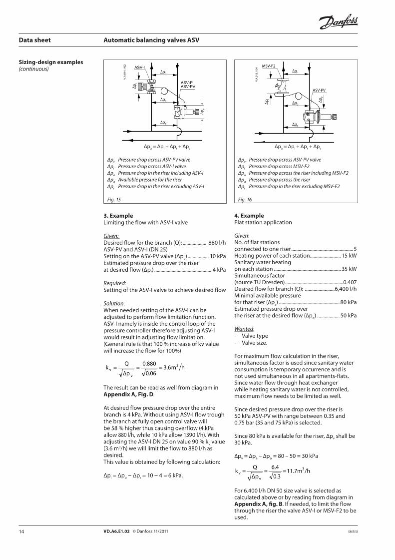
Δpa = Δpm + Δpr + Δpv
Δpv Pressure drop across ASV-P/PVΔpm Pressure drop across ASV-M valveΔpr Necessary pressure for the riserΔpa Available pressure for the riser
Sizing-design examples
1. Example
Given:Radiator system with thermostatic radiator valves with pre-setting function.Desired f low for the riser (Q): .......................1,500l/hMinimal available pressure for that riser (Δpa) ................................................. 70kPaEstimated pressure drop over the riser at the desired f low (Δpr) .................................... 20 kPa
Wanted:- Valve type- Valve sizeSince radiator valves has pre-setting function ASV-M is selected.Since desired pressure drop over the riser is 20 kPa ASV-PV is selected.ASV-PV should control 20 kPa pressure over the riserthatmeansthat50kPaoutof70willbedisposed over two valves.
Δpv + Δpm = Δpa−Δpr=70−20=50kPa
WepresumethatdimensionDN25istherightdimension for this example (please mind that both valves should be of the same dimension). AsASV-MDN25istobefullyopenpressuredropis calculated by following equation:
14 kPa0.14bar4.0
1.5
Kv
Q∆p
22
m ==⎟⎠⎞
⎜⎝⎛=⎟
⎠⎞
⎜⎝⎛=
or by reading from diagram in Appendix A, fig. E as follows: Drawhorizontallinefrom1.5m3/h(~1,500l/h)troughthelinethatdepictsdimensionDN25.From the intersection draw vertical line to read thatpressuredropis14kPa.Pressure drop over ASV-PV valve is therefore:
Δpv= (Δpa-Δpr)−Δpm=50kPa−14kPa=36kPa
as can be read from diagram in Appendix A, Fig. A.
Fig. 14
2. ExampleCorrecting the f low with the differential pressure setting.
Given: Measured f low for the riser Q1 .....................1,500l/hASV-PV valve’s setting Δpr ................................ 20 kPa
Wanted:New valves’ setting to increase the f low for 10%, Q2=1650l/h.
Setting on the ASV-PV valve:When needed setting of the control pressure can beadjustedtoparticularvalue(ASV-PVfrom5to25kPaor20to40kPa). With increasing/decreasing the setting it is possible to adjust f low trough the riser, terminal or similar. (100 % increase of control pressure will increasetheflowfor41%)
24kPa1500
165020.0
Q
Qpp
22
1
212 =⎟
⎠⎞
⎜⎝⎛×=⎟⎟
⎠
⎞⎜⎜⎝
⎛×=
Ifweincreasethesettingto24kPaflowwillbeincreasedto10%to1,650l/h.
14 VD.A6.E1.02 © Danfoss 11/2011 SMT/SI
Data sheet Automatic balancing valves ASV
Sizing-design examples (continuous)
3. ExampleLimitingtheflowwithASV-Ivalve
Given: Desired f low for the branch (Q): ................... 880 l/hASV-PVandASV-I(DN25)Setting on the ASV-PV valve (Δpo) ................. 10 kPaEstimated pressure drop over the riser at desired f low (Δpr) ..............................................4kPa
Required:Setting of the ASV-I valve to achieve desired f low
Solution:When needed setting of the ASV-I can be adjusted to perform f low limitation function. ASV-I namely is inside the control loop of the pressure controller therefore adjusting ASV-I would result in adjusting f low limitation. (Generalruleisthat100%increaseofkvvaluewill increase the f low for 100%)
hm3.60.06
0.880
Δp
Qk 3
vv ===
The result can be read as well from diagram in Appendix A, Fig. D.
At desired f low pressure drop over the entire branchis4kPa.WithoutusingASV-Iflowtroughthe branch at fully open control valve will be58%higherthuscausingoverflow(4kPaallow 880 l/h, while 10 kPa allow 1390 l/h). With adjustingtheASV-IDN25onvalue90%kv value (3.6m3/h) we will limit the f low to 880 l/h as desired. This value is obtained by following calculation:
Δpi = Δpo − Δpr=10−4=6kPa.
Δpa = Δpi + Δpr + Δpv
Δpv Pressure drop across ASV-PV valveΔpi Pressure drop across ASV-I valveΔpo Pressure drop in the riser including ASV-IΔpa Available pressure for the riserΔpr Pressure drop in the riser excluding ASV-I
Fig. 15
Δpa = Δpi + Δpr + Δpv
Δpv Pressure drop across ASV-PV valveΔpi Pressure drop across MSV-F2Δpo Pressure drop across the riser including MSV-F2Δpa Pressure drop across the riserΔpr Pressure drop in the riser excluding MSV-F2
Fig. 16
4. ExampleF lat station application
Given:No. of f lat stations connected to one riser ..................................................5Heating power of each station......................... 15kWSanitary water heating on each station ......................................................35kWSimultaneous factor (source TU Dresden) ...............................................0.407Desired f low for branch (Q): ........................6,400l/hMinimal available pressure for that riser (∆pa) ................................................. 80 kPaEstimated pressure drop over the riser at the desired f low (∆po) ..................50kPa
Wanted:- Valve type- Valve size.
For maximum f low calculation in the riser, simultaneous factor is used since sanitary water consumption is temporary occurrence and is not used simultaneous in all apartments-f lats. Since water f low through heat exchanger while heating sanitary water is not controlled, maximum f low needs to be limited as well.
Since desired pressure drop over the riser is 50kPaASV-PVwithrangebetween0.35and0.75bar(35and75kPa)isselected.
Since 80 kPa is available for the riser, ∆pv shall be 30 kPa.
∆pv = ∆pa – ∆po=80–50=30kPa
/h11.7m0.3
6.4
Δp
Qk 3
vv ===
For6.400l/hDN50sizevalveisselectedascalculated above or by reading from diagram in Appendix A, fig. B. If needed, to limit the f low through the riser the valve ASV-I or MSV-F2 to be used.
15VD.A6.E1.02 © Danfoss 11/2011SMT/SI
Data sheet Automatic balancing valves ASV
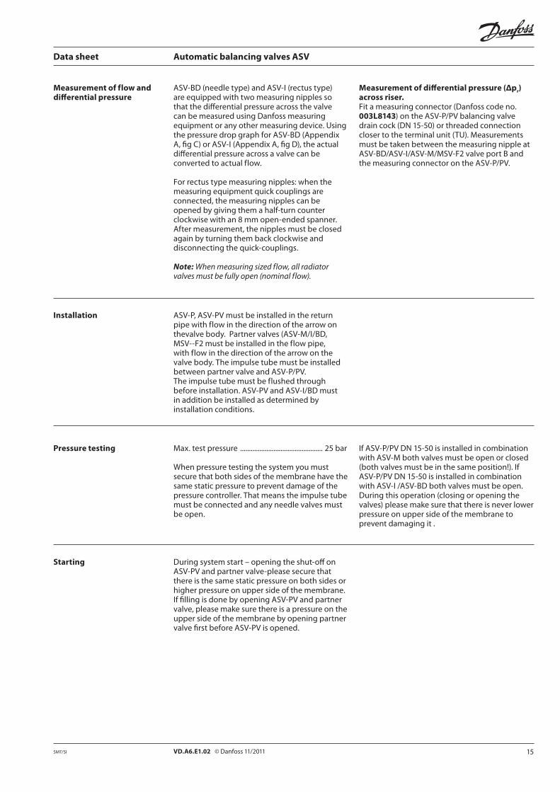
Measurement of f low and differential pressure
ASV-BD (needle type) and ASV-I (rectus type) are equipped with two measuring nipples so that the differential pressure across the valve can be measured using Danfoss measuring equipment or any other measuring device. Using the pressure drop graph for ASV-BD (Appendix A, fig C) or ASV-I (Appendix A, fig D), the actual differential pressure across a valve can be converted to actual f low.
For rectus type measuring nipples: when the measuring equipment quick couplings are connected, the measuring nipples can be opened by giving them a half-turn counter clockwise with an 8 mm open-ended spanner. After measurement, the nipples must be closed again by turning them back clockwise and disconnecting the quick-couplings.
Note: When measuring sized f low, all radiator valves must be fully open (nominal f low).
Measurement of differential pressure (Δpr) across riser.Fit a measuring connector (Danfoss code no. 003L8143) on the ASV-P/PV balancing valve draincock(DN15-50)orthreadedconnectioncloser to the terminal unit (TU). Measurements must be taken between the measuring nipple at ASV-BD/ASV-I/ASV-M/MSV-F2 valve port B and the measuring connector on the ASV-P/PV.
Installation ASV-P, ASV-PV must be installed in the return pipe with f low in the direction of the arrow on thevalve body. Partner valves (ASV-M/I/BD, MSV--F2 must be installed in the f low pipe, with f low in the direction of the arrow on the valve body. The impulse tube must be installed between partner valve and ASV-P/PV.The impulse tube must be f lushed through before installation. ASV-PV and ASV-I/BD must in addition be installed as determined by installation conditions.
Pressure testing Max. test pressure ...............................................25bar
When pressure testing the system you must secure that both sides of the membrane have the same static pressure to prevent damage of the pressure controller. That means the impulse tube must be connected and any needle valves must be open.
During system start – opening the shut-off on ASV-PV and partner valve-please secure that there is the same static pressure on both sides or higher pressure on upper side of the membrane. If filling is done by opening ASV-PV and partner valve, please make sure there is a pressure on the upper side of the membrane by opening partner valve first before ASV-PV is opened.
Starting
IfASV-P/PVDN15-50isinstalledincombinationwith ASV-M both valves must be open or closed (both valves must be in the same position!). If ASV-P/PVDN15-50isinstalledincombinationwith ASV-I /ASV-BD both valves must be open. During this operation (closing or opening the valves) please make sure that there is never lower pressure on upper side of the membrane to prevent damaging it .

16 VD.A6.E1.02 © Danfoss 11/2011 SMT/SI
Data sheet Automatic balancing valves ASV
Dimensions
ASV-PV
DNL1 L2 L3 H1 H2 D1 D2 S a b c
mm ISO7/1 ISO 228/1
15 65 120 139 102 15 28 61 27 Rp ½ G¾A
G¾A
20 75 136 159 128 18 35 76 32 Rp¾ G1A
25 85 155 169 163 23 45 98 41 Rp 1 G1¼A
32 95 172 179204
29 55 122 50 Rp1¼ G1½A2451)
40 100 206 184209
31 55 122 55 Rp 1½ G1¾A2501)
1) 35-75 kPa setting range
ASV-P
DNL1 L2 L3 H1 H2 D1 D2 S a b c
mm ISO7/1 ISO 228/1
15 65 120 139 82 15 28 61 27 Rp ½ G¾A
G¾A
20 75 136 159 103 18 35 76 32 Rp¾ G1A
25 85 155 169 132 23 45 98 41 Rp 1 G1¼A
32 95 172 179 165 29 55 122 50 Rp1¼ G1½A
40 100 206 184 170 31 55 122 55 Rp 1½ G1¾A
Fig. 17

17VD.A6.E1.02 © Danfoss 11/2011SMT/SI
Data sheet Automatic balancing valves ASV
ASV-PV
DNL1 H1 H2 D1 D2 D3
mm
65 290 385 93 68 205 145
80 310 390 100 68 218 160
100 347 446 112 68 248 180
Dimensions(continuous)
ASV-PV
DN∆p setting range L1 L2 L3 H1 H2 D1 D2 b c
kPa mm ISO 228/1
50
5-25
130 244 234
232
61 55 133 G21/2 G3/4 A20-40
35-75273
60-10
Fig. 18
18 VD.A6.E1.02 © Danfoss 11/2011 SMT/SI
Data sheet Automatic balancing valves ASV
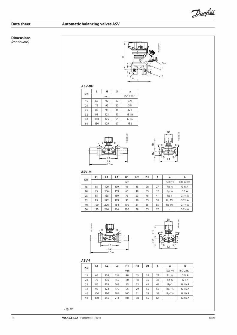
Dimensions(continuous)
ASV-I
DNL1 L2 L3 H1 H2 D1 S a b
mm ISO7/1 ISO 228/1
15 65 120 139 48 15 28 27 Rp ½ G¾A
20 75 136 159 60 18 35 32 Rp¾ G1A
25 85 155 169 75 23 45 41 Rp 1 G1¼A
32 95 172 179 95 29 55 50 Rp1¼ G1½A
40 100 206 184 100 31 55 55 Rp 1½ G1¾A
50 130 246 214 106 38 55 67 - G2¼A
ASV-M
DNL1 L2 L3 H1 H2 D1 S a b
mm ISO7/1 ISO 228/1
15 65 120 139 48 15 28 27 Rp ½ G¾A
20 75 136 159 60 18 35 32 Rp¾ G1A
25 85 155 169 75 23 45 41 Rp 1 G1¼A
32 95 172 179 95 29 55 50 Rp1¼ G1½A
40 100 206 184 100 31 55 55 Rp 1½ G1¾A
50 130 246 214 106 38 55 67 - G2¼A
Fig. 19
ASV-BD
DNL H S a
mm ISO 228/1
15 65 92 27 G½
20 75 95 32 G¾
25 85 98 41 G1
32 95 121 50 G1¼
40 100 125 55 G1½
50 130 129 67 G2
L
G1/4
S
aa
H
19VD.A6.E1.02 © Danfoss 11/2011SMT/SI
Data sheet Automatic balancing valves ASV
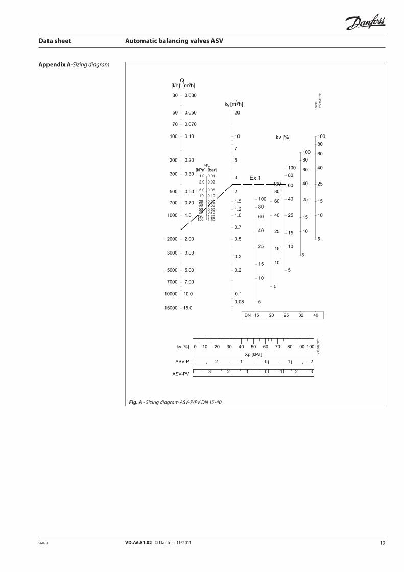
Appendix A-Sizing diagram
Fig. A - Sizing diagram ASV-P/PV DN 15-40

20 VD.A6.E1.02 © Danfoss 11/2011 SMT/SI
Data sheet Automatic balancing valves ASV
Fig. B - Sizing diagram ASV-PV DN 50-100
Appendix A-Sizing diagram

21VD.A6.E1.02 © Danfoss 11/2011SMT/SI
10
20
3050
100
200
300400
6001000
2000
30004000
60008000
10000
20000300004000050000
Data sheet Automatic balancing valves ASV
Fig.C - Sizing diagram ASV-BD DN 15-50
Appendix A-Sizing diagram

22 VD.A6.E1.02 © Danfoss 11/2011 SMT/SI
Data sheet Automatic balancing valves ASV
Fig. E -Pressure drop over ASV-M valves, DN 15-50
Fig. D-Sizing diagram ASV-I, DN 15-50
Appendix A

23VD.A6.E1.02 © Danfoss 11/2011SMT/SI
Data sheet
Insulation, fittings
Description
EPP insulation cap for ASVConnection Code No.
DN15 003L8170
DN 20 003L8171
DN25 003L8172
DN 32 003L8173
DN40 003L8139
InsulationThe EPS styropor packaging in which the valve is supplied can be used as insulation in systems where the temperature does not exceed 80 °C under continuous operation.
ASV-BD valve is supplied together with EPP insulation cap. ASV-BD insulation cap offers click on feature for fact and easy mounting on the valve. Insulation cap in EPP is offered for use at higher temperatures, up to 120 °C.
Both materials (EPS and EPP) are approved in accordancewithfireclassstandardB2,DIN4102.
Ordering EPP insulation cap for ASV-BDConnection Code No.
DN15 003Z4781
DN 20 003Z4782
DN25 003Z4783
DN 32 003Z4784
DN40 003Z4785
DN50 003Z4786
FittingsFor valves with external thread Danfoss offers threaded or welded tailpieces as accessory.
MaterialsNut ................................................................................brassTailpiece welding .....................................................steel Tailpiece threaded ..................................................brass
FittingsType Comments to pipe to valve Code No.
Tailpiece threaded (1 pcs.)
R 1/2 DN15 003Z0232
R 3/4 DN 20 003Z0233
R 1 DN25 003Z0234
R 1 1/4 DN 32 003Z0235
R 11/2 DN40 003Z0273
R 2DN50(21/4”) 003Z0274 2)
DN50(21/2”) 003Z0278 1)
Tailpiece welding (1 pcs.)
DN15 DN15 003Z0226
DN 20 DN 20 003Z0227
DN25 DN25 003Z0228
DN 32 DN 32 003Z0229
DN40 DN40 003Z0271
DN50DN50(21/4”) 003Z0272 2)
DN50(21/2”) 003Z0276 1)
Note: ASV-PV DN 50 (2 1/2”) and ASV-I/M DN 50 (2 1/4”) have different size connection.1) To use with ASV-PV DN 50 valves2) To use with ASV-I and ASV-M DN 50 valves.

24 VD.A6.E1.02 Produced by Danfoss A/S © 11/2011
A
BC
A
BC
D
Data sheet Automatic balancing valves ASV
1. The pressure differential controller valve should be available in the range from DN 10-100. 2. The pressure differential control based on integrated membrane element. 3. Therangeofsettabledifferentialpressureshouldbe5-25kPaor20-40kPaindimension
DN15-40and20-40kPa,35-75kPaor60-100kPaindimensionDN50-100. 4. Thesettingofpressuredifferenceshouldbewithhexagonkey(DN15-40)orsocketneedtobe
hidden. 5. Thepressuredifferencesettingshouldbelinear(1turn1kPaor1turn2kPadependingon
dimension). 6. Thepressuredifferencerangeshouldbeinterchangeablewithspringchangeindimension
DN15-40withoutdrainthesystem. 7. Shutoffservicefunctionshouldbepossiblewithhandknob. 8. DrainfunctionisneededinrangeDN15-50. 9. Temperaturerangeshouldbe−20…+120°CatDN15-40and−10…+120°CatDN50-100.10. Nominalpressureshouldbe16barwithtestpressure25bar.11. ThepressuredifferentialcontrolvalvepackageinDN15-40rangeneedstocontainimpulsetube
(min.1,5m)andEPSvalveinsulationuptomin.80°C.
Nominal diameter: _ ________Connection: ________ Adjustment range from - to ________ kPaProduced by: Danfoss Type: ASV-PVOrderingno.:003L_____
ASV-PV tender text
Dimensions - insulation
DNA B C D
mm
15 61 110 111 37
20 76 120 136 45
25 100 135 155 55
32 118 148 160 70
40 118 148 180 70
DNA B C
mm
15 79 85 122
20 84 85 122
25 99 85 122
32 132 85 185
40 138 130 185
50 138 126 185
ASV-I/M/P/PV
ASV-BD

Unit 5, 83 Bassett Street Mona Vale \ PO Box 707 Mona Vale NSW 1660T 1800 636 091 \ F 02 9997 7852
E [email protected] \ W www.devexsystems.com.auDevex Systems Pty Ltd \ ACN 122 894 562
BROCCLN101.2
Devex Systems specialises in heating, cooling and insulation solutions for new and existing buildings in residential, commercial and industrial environments.
For more information on any of our product lines, please contact us at:1800 636 091 or [email protected]
www.devexsystems.com.au
Related Documents