1 VD.LE.K5.02 © Danfoss 11/2014 DEN-SMT/SI Actuator for modulating control AME 435 Data sheet Actuator Type Power supply Code No. (V) AME 435 24 AC/DC 082H0161 Accessories-Stem heater Type DN Code No. Stem heater 15-80 065Z0315 Description AMV 435 actuator is used with two and three-way valves type VRB, VRG, VF and VL up to DN 80 diameter and for AHQM DN 40-100. The actuator has some special features: • it automatically adapts its stroke to the valve end positions which reduces commissioning time (self stroking) • valve flow adjustment feature; flow can be variably-adjusted from linear to logarithmic or opposite. Ordering Accessories-Adapter Valves DN max. Δp Code No. (bar) For old valves VRB, VRG, VF, VL 15 9 065Z0313 20 4 25 2 32 1 40 0,8 50 0,5 • energy saving, cost reducing and energy efficiency improving anti-oscillation function • the advanced design incorporates load related ‘switch-off’ to ensure that actuators and valves are not exposed to overload Combinations with other valves could be seen under Accessories. Main data: • Nominal voltage (AC or DC): - 24 V, 50 Hz/60 Hz • Control input signal: - 0(4)-20 mA - 0(2)-10 V • Force: 400 N • Stroke: 20 mm • Speed (selectable): - 7,5 s/mm - 15 s/mm • Max. medium temperature: 130 °C • Self stroking • LED signalling • External RESET button • Output signal • Manual operation

Welcome message from author
This document is posted to help you gain knowledge. Please leave a comment to let me know what you think about it! Share it to your friends and learn new things together.
Transcript
1VD.LE.K5.02 © Danfoss 11/2014DEN-SMT/SI
Actuator for modulating controlAME 435
Data sheet
Actuator
TypePower supply
Code No.(V)
AME 435 24 AC/DC 082H0161
Accessories-Stem heater
Type DN Code No.
Stem heater 15-80 065Z0315
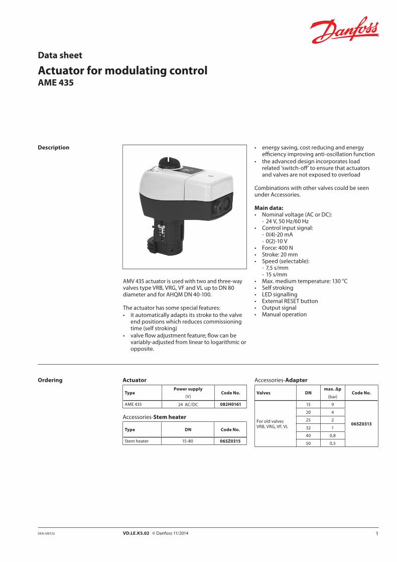
Description
AMV 435 actuator is used with two and three-way valves type VRB, VRG, VF and VL up to DN 80 diameter and for AHQM DN 40-100.
The actuator has some special features:• it automatically adapts its stroke to the valve
end positions which reduces commissioning time (self stroking)
• valve flow adjustment feature; flow can be variably-adjusted from linear to logarithmic or opposite.
Ordering Accessories-Adapter
Valves DNmax. Δp
Code No.(bar)
For old valves VRB, VRG, VF, VL
15 9
065Z0313
20 4
25 2
32 1
40 0,8
50 0,5
• energy saving, cost reducing and energy efficiency improving anti-oscillation function
• the advanced design incorporates load related ‘switch-off’ to ensure that actuators and valves are not exposed to overload
Combinations with other valves could be seen under Accessories.
Main data:• Nominal voltage (AC or DC):
- 24 V, 50 Hz/60 Hz • Control input signal:
- 0(4)-20 mA - 0(2)-10 V
• Force: 400 N• Stroke: 20 mm• Speed (selectable):
- 7,5 s/mm - 15 s/mm
• Max. medium temperature: 130 °C• Self stroking• LED signalling• External RESET button• Output signal• Manual operation
2 VD.LE.K5.02 © Danfoss 11/2014 DEN-SMT/SI
①
②③
④
⑤
Data sheet Actuator for modulating control AME 435
Power supply V 24 AC/DC; ±10%
Power consumption VA 4,5
Frequency Hz 50/60
Control input YV 0-10 (2-10); Ri = 95 kΩ
mA 0-20 (4-20); Ri = 500 Ω
Output signal X V 0-10 (2-10); RL = 650 Ω (maximal load)
Closing force N 400
Max. stroke mm 20
Speed s/mm 7,5 or 15
Max. medium temperature
°C
130
Ambient temperature 0 … 55
Storage and transport temperature –40 … 70
Protection class II
Grade of enclosure IP 54
Weight kg 0,45
- marking in accordance with standards Low Voltage Directive (LVD) 2006/95/EC: EN 60730-1, EN 60730-2-14 EMC Directive 2004/108/EC: EN 61000-6-2, EN 61000-6-3
Technical data
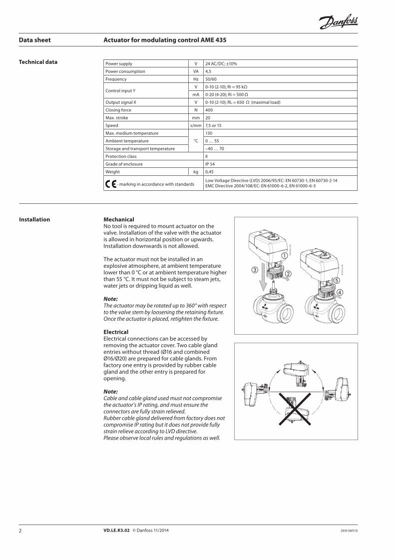
Installation MechanicalNo tool is required to mount actuator on the valve. Installation of the valve with the actuator is allowed in horizontal position or upwards. Installation downwards is not allowed.
The actuator must not be installed in an explosive atmosphere, at ambient temperature lower than 0 °C or at ambient temperature higher than 55 °C. It must not be subject to steam jets, water jets or dripping liquid as well.
Note: The actuator may be rotated up to 360° with respect to the valve stem by loosening the retaining fixture. Once the actuator is placed, retighten the fixture.
ElectricalElectrical connections can be accessed by removing the actuator cover. Two cable gland entries without thread (Ø16 and combined Ø16/Ø20) are prepared for cable glands. From factory one entry is provided by rubber cable gland and the other entry is prepared for opening.
Note: Cable and cable gland used must not compromise the actuator’s IP rating, and must ensure the connectors are fully strain relieved.Rubber cable gland delivered from factory does not compromise IP rating but it does not provide fully strain relieve according to LVD directive.Please observe local rules and regulations as well.
3VD.LE.K5.02 © Danfoss 11/2014DEN-SMT/SI
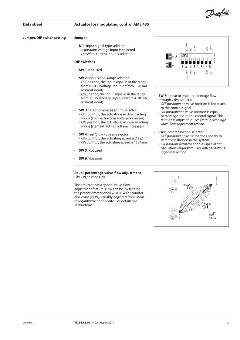
Jumper
• U/I - Input signal type selector- U position; voltage input is selected- I position; current input is selected
DIP switches
• SW 1: Not used
• SW 2: Input signal range selector- OFF position; the input signal is in the range
from 0-10 V (voltage input) or from 0-20 mA (current input)
- ON position; the input signal is in the range from 2-10 V (voltage input) or from 4-20 mA (current input)
• SW 3: Direct or inverse acting selector - OFF position; the actuator is in direct acting
mode (stem extracts as voltage increases)- ON position; the actuator is in inverse acting
mode (stem retracts as voltage increases)
• SW 4: Fast/Slow - Speed selector- OFF position; the actuating speed is 7,5 s/mm- ON position; the actuating speed is 15 s/mm
• SW 5: Not used
• SW 6: Not used
2 …
10
V
INV
SLO
W
LOG
SMA
RT
0 …
10
V
DIR
FAST LIN
AC
T
Data sheet Actuator for modulating control AME 435
Jumper/DIP switch setting
• SW 7: Linear or equal-percentage flow through valve selector - OFF position; the valve position is linear acc.
to the control signal- ON position; the valve position is equal-
percentage acc. to the control signal. This relation is adjustable - see Equal-percentage valve-flow adjustment section
• SW 8: Smart function selector - OFF position; the actuator does not try to
detect oscillations in the system- ON position; actuator enables special anti
oscillations algorithm – see Anti oscillations algorithm section
Equal-percentage valve-flow adjustment(SW 7 in position ON) The actuator has a special valve-flow adjustment feature. Flow can be, by turning the potentiometer clock wise (CW) or counter clockwise (CCW), variably adjusted from linear to logarithmic or opposite. For details see Instructions.

4 VD.LE.K5.02 © Danfoss 11/2014 DEN-SMT/SI
Fig. 2
Valve position X signal (V)
Fig. 1
Point A
linear area
static
charaste
ristic
dynamic charasteristic
Data sheet Actuator for modulating control AME 435
Anti oscillations algorithm(SW 8 in position ON)
The actuator has special anti oscillations algorithm. In case control signal Y on certain point oscillates (Fig. 1) - looking from time perspective, algorithm starts to lower the amplification of the ouput to the valve. Instead of having static characteristics actuator changes to dynamic characteristics (Fig. 2) - certain output stroke area changes to new slope (decrease amplification).
After control signal does not oscillate anymore output to the valve slowly returns back to static characteristics.
Jumper/DIP switch setting(continued)
iMCV 2nd generation
Harmonic oscillations are high frequency oscillations with low amplitude that vary around its own equilibrium value and not around set-point temperature. They can appear in up to 70 % of control time, even though the system is properly commissioned. Harmonic oscillations have negative influence on control stability, and lifetime of the valve and actuator.
Smoothening function Smoothening function implemented in New 2nd generation of anti-oscillation function reduces harmonic oscillations; consequently room temperature is closer to the set-point (desired) temperature. Smoother operation of the MCV increases lifetime of the valve and actuator and saves energy and reduces costs in general.
5VD.LE.K5.02 © Danfoss 11/2014DEN-SMT/SI
RESET/STAND-BY
Data sheet Actuator for modulating control AME 435
Complete the mechanical and electrical installation, set jumper and DIP-switches, then perform the necessary checks and tests:
• Apply power Note that the actuator will now perform
automatic self stroking function
• Apply the appropriate control signal and check:- if the valve stem direction is correct for the
application and- the actuator drives the valve over the entire
stroke length
The unit is now fully commissioned.
Commissioning Automatic self stroking featureThe actuator automatically adapts its stroke to the valve end positions:
- when power is applied for the first time or- afterwards by pressing the STAND-BY/RESET
button for 5 seconds
Testing entire valve stroke lengthThe actuator can be driven to the fully-open or closed positions (depending on valve type) by connecting SN to terminals 1 or 3.
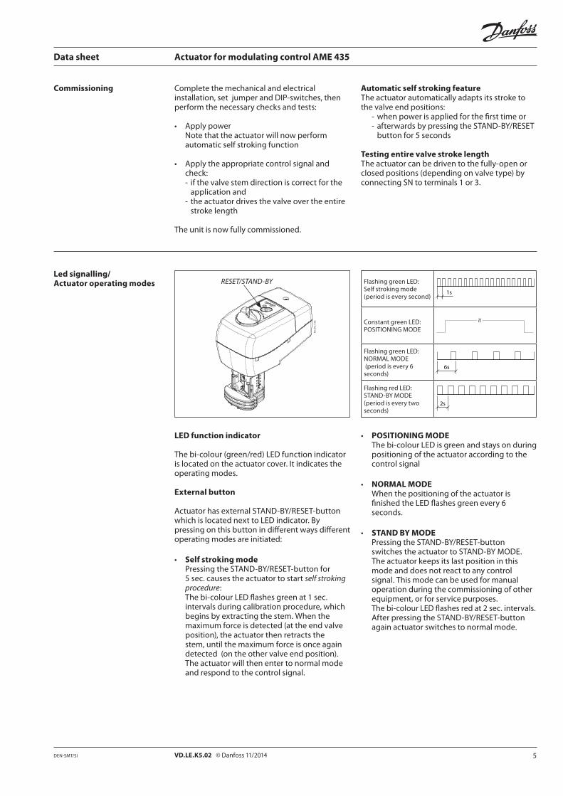
Led signalling/Actuator operating modes
LED function indicator
The bi-colour (green/red) LED function indicator is located on the actuator cover. It indicates the operating modes.
External button
Actuator has external STAND-BY/RESET-button which is located next to LED indicator. By pressing on this button in different ways different operating modes are initiated:
• Self stroking mode Pressing the STAND-BY/RESET-button for
5 sec. causes the actuator to start self stroking procedure:
The bi-colour LED flashes green at 1 sec. intervals during calibration procedure, which begins by extracting the stem. When the maximum force is detected (at the end valve position), the actuator then retracts the stem, until the maximum force is once again detected (on the other valve end position). The actuator will then enter to normal mode and respond to the control signal.
Flashing green LED: Self stroking mode (period is every second)
Constant green LED: POSITIONING MODE
≈
Flashing green LED: NORMAL MODE (period is every 6 seconds)
Flashing red LED: STAND-BY MODE (period is every two seconds)
• POSITIONING MODE The bi-colour LED is green and stays on during
positioning of the actuator according to the control signal
• NORMAL MODE When the positioning of the actuator is
finished the LED flashes green every 6 seconds.
• STAND BY MODE Pressing the STAND-BY/RESET-button
switches the actuator to STAND-BY MODE. The actuator keeps its last position in this mode and does not react to any control signal. This mode can be used for manual operation during the commissioning of other equipment, or for service purposes.
The bi-colour LED flashes red at 2 sec. intervals. After pressing the STAND-BY/RESET-button
again actuator switches to normal mode.
6 VD.LE.K5.02 © Danfoss 11/2014 DEN-SMT/SI
power supply
down up
Data sheet Actuator for modulating control AME 435
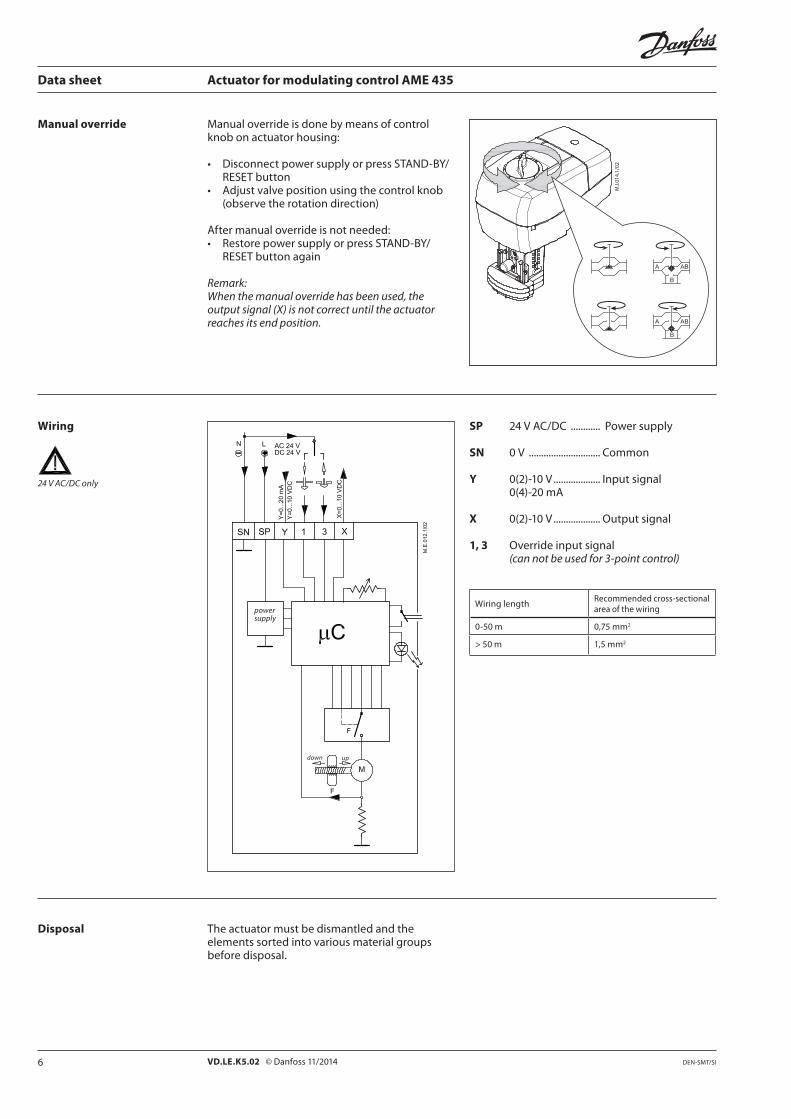
Manual override Manual override is done by means of control knob on actuator housing:
• Disconnect power supply or press STAND-BY/RESET button
• Adjust valve position using the control knob (observe the rotation direction)
After manual override is not needed:• Restore power supply or press STAND-BY/
RESET button again
Remark:When the manual override has been used, the output signal (X) is not correct until the actuator reaches its end position.
Wiring
24 V AC/DC only
SP 24 V AC/DC ............ Power supply
SN 0 V ............................. Common
Y 0(2)-10 V ................... Input signal 0(4)-20 mA
X 0(2)-10 V ................... Output signal 1, 3 Override input signal (can not be used for 3-point control)
Wiring lengthRecommended cross-sectional area of the wiring
0-50 m 0,75 mm2
> 50 m 1,5 mm2
The actuator must be dismantled and the elements sorted into various material groups before disposal.
Disposal
7VD.LE.K5.02 © Danfoss 11/2014DEN-SMT/SI
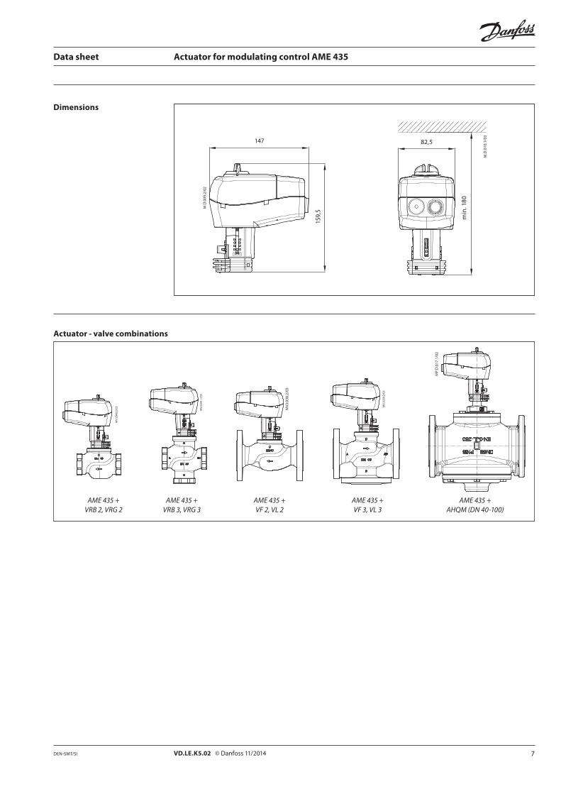
147
159,
5
82,5
min
. 180
Actuator - valve combinations
AME 435 + AME 435 + AME 435 + AME 435 + AME 435 + VRB 2, VRG 2 VRB 3, VRG 3 VF 2, VL 2 VF 3, VL 3 AHQM (DN 40-100)
Data sheet Actuator for modulating control AME 435
Dimensions

8 VD.LE.K5.02 Produced by Danfoss A/S © 11/2014
Data sheet Actuator for modulating control AME 435
Related Documents