MVR College of Engineering And Technology @ CSE Dept UNIT 2 CNS JAWAHARLAL NEHRU TECHNOLOGICAL UNIVERSITY KAKINADA CRYPTOGRAPHY AND NETWORK SECURITY . UNIT-II: Secret Key Cryptography: 1. Data Encryption Standard(DES), Strength of DES, 2. Block Cipher Design Principles and Modes of Operations, 3. Triple DES, 4. International Data Encryption algorithm, 5. Blowfish, 6. CAST-128, 7. AES 1. Data Encryption Standard(DES), Strength of DES The most widely used encryption scheme is based on the Data Encryption Standard (DES) adopted in 1977 by the National Bureau of Standards, now the National Institute of Standards and Technology (NIST), as Federal Information Processing Standard 46 (FIPS PUB 46). The algorithm itself is referred to as the Data Encryption Algorithm (DEA).7 For DES, data are encrypted in 64-bit blocks using a 56-bit key. The algorithm transforms 64-bit input in a series of steps into a 64-bit output. The same steps, with the same key, are used to reverse the encryption. DES Encryption The overall scheme for DES encryption is illustrated in Figure 3.5. As with any encryption scheme, there are two inputs to the encryption function: the plaintext to be encrypted and the key. In this case, the plaintext must be 64 bits in length and the key is 56 bits in length. Looking at the left-hand side of the figure, we can see that the processing of the plaintext proceeds in three phases. First, the 64-bit plaintext passes through an initial permutation (IP) that rearranges the bits to produce the permuted input. This is followed by a phase consisting of sixteen rounds of the same function, which involves both permutation and substitution functions. The output of the last (sixteenth) round consists of 64 bits that are a function of the input plaintext and the key. The left and right halves of the output are swapped to produce the preoutput. Finally, the preoutput is passed through a permutation [IP - 1 ]that is the inverse of the initial permutation function, to produce the 64-bit cipher text. With the exception of the initial and final permutations

Welcome message from author
This document is posted to help you gain knowledge. Please leave a comment to let me know what you think about it! Share it to your friends and learn new things together.
Transcript

MVR College of Engineering And Technology @ CSE Dept UNIT 2 CNS
JAWAHARLAL NEHRU TECHNOLOGICAL UNIVERSITY KAKINADA
CRYPTOGRAPHY AND NETWORK SECURITY
.
UNIT-II: Secret Key Cryptography:
1. Data Encryption Standard(DES), Strength of DES,
2. Block Cipher Design Principles and Modes of Operations,
3. Triple DES,
4. International Data Encryption algorithm,
5. Blowfish,
6. CAST-128,
7. AES
1. Data Encryption Standard(DES), Strength of DES
The most widely used encryption scheme is based on the Data Encryption Standard (DES) adopted in 1977 by the National Bureau of Standards, now the National Institute of Standards and Technology (NIST), as Federal Information Processing Standard 46 (FIPS PUB 46). The algorithm itself is referred to as the Data Encryption Algorithm (DEA).7 For DES, data are encrypted in 64-bit blocks using a 56-bit key. The algorithm transforms 64-bit input in a series of steps into a 64-bit output. The same steps, with the same key, are used to reverse the encryption.
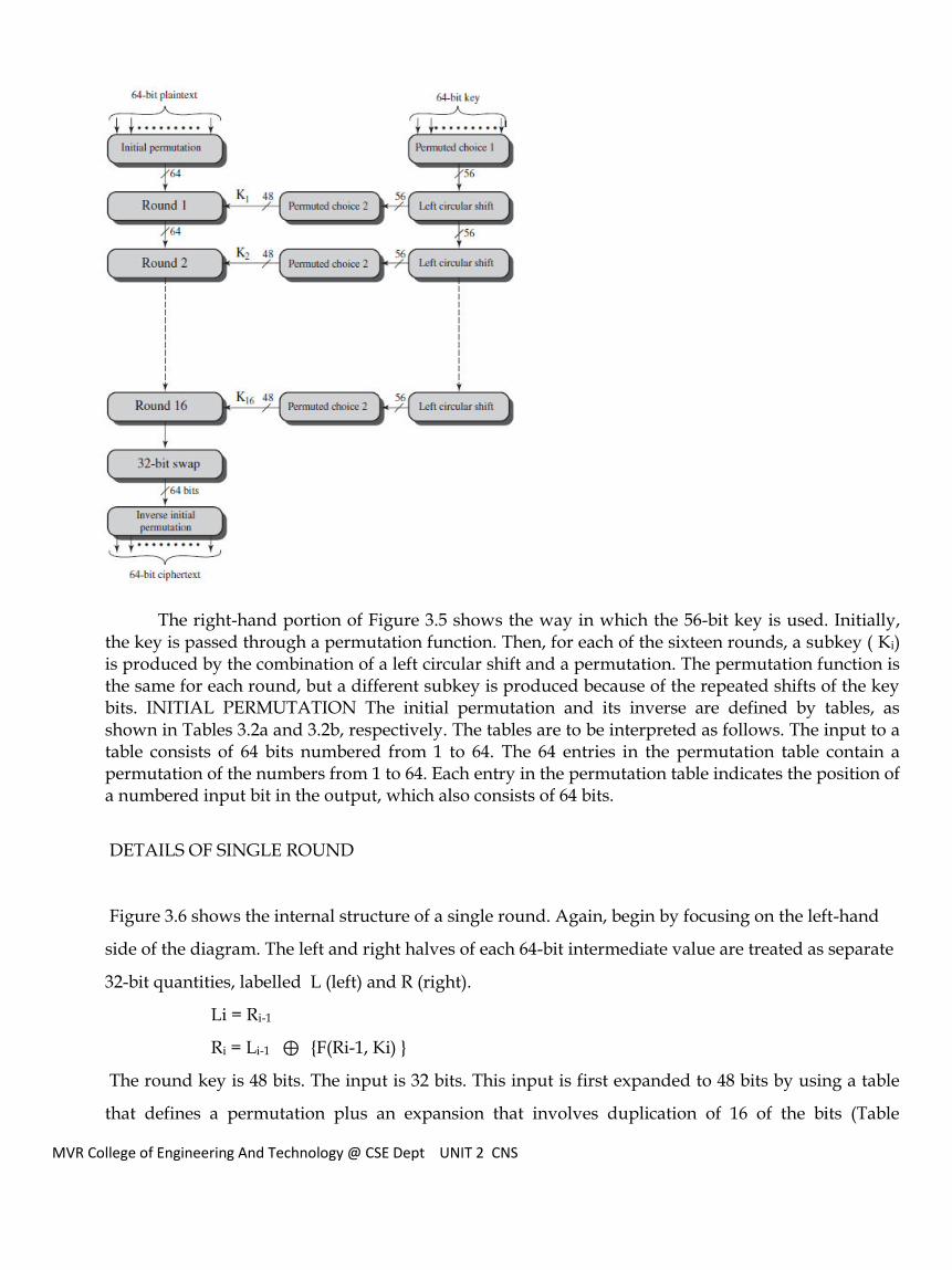
DES Encryption The overall scheme for DES encryption is illustrated in Figure 3.5. As with any encryption scheme, there are two inputs to the encryption function: the plaintext to be encrypted and the key. In this case, the plaintext must be 64 bits in length and the key is 56 bits in length.
Looking at the left-hand side of the figure, we can see that the processing of the plaintext proceeds in three phases. First, the 64-bit plaintext passes through an initial permutation (IP) that rearranges the bits to produce the permuted input. This is followed by a phase consisting of sixteen rounds of the same function, which involves both permutation and substitution functions. The output of the last (sixteenth) round consists of 64 bits that are a function of the input plaintext and the key. The left and right halves of the output are swapped to produce the preoutput. Finally, the preoutput is passed through a permutation [IP-
1]that is the inverse of the initial permutation function, to produce the 64-bit cipher text. With the exception of the initial and final permutations
MVR College of Engineering And Technology @ CSE Dept UNIT 2 CNS
The right-hand portion of Figure 3.5 shows the way in which the 56-bit key is used. Initially,
the key is passed through a permutation function. Then, for each of the sixteen rounds, a subkey ( Ki) is produced by the combination of a left circular shift and a permutation. The permutation function is the same for each round, but a different subkey is produced because of the repeated shifts of the key bits. INITIAL PERMUTATION The initial permutation and its inverse are defined by tables, as shown in Tables 3.2a and 3.2b, respectively. The tables are to be interpreted as follows. The input to a table consists of 64 bits numbered from 1 to 64. The 64 entries in the permutation table contain a permutation of the numbers from 1 to 64. Each entry in the permutation table indicates the position of a numbered input bit in the output, which also consists of 64 bits.
DETAILS OF SINGLE ROUND
Figure 3.6 shows the internal structure of a single round. Again, begin by focusing on the left-hand
side of the diagram. The left and right halves of each 64-bit intermediate value are treated as separate
32-bit quantities, labelled L (left) and R (right).
Li = Ri-1
Ri = Li-1 ⊕ {F(Ri-1, Ki) }
The round key is 48 bits. The input is 32 bits. This input is first expanded to 48 bits by using a table
that defines a permutation plus an expansion that involves duplication of 16 of the bits (Table

MVR College of Engineering And Technology @ CSE Dept UNIT 2 CNS
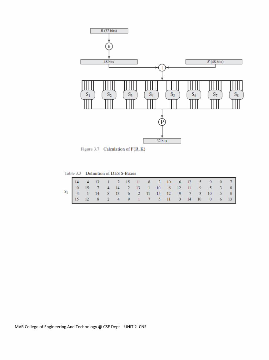
3.2c).The resulting 48 bits are XORed with Ki . This 48-bit result passes through a substitution
function that produces a 32-bit output, which is permuted as defined by Table 3.2d. The role of the S-
boxes in the function F is illustrated in Figure 3.7
The substitution consists of a set of eight S-boxes, each of which accepts 6 bits as input and produces
4 bits as output. These transformations are defined in Table 3.3, which is interpreted as follows: The
first and last bits of the input to box form a 2-bit binary number to select one of four substitutions
defined by the four rows in the table for . The middle four bits select one of the sixteen columns.The
decimal value in the cell selected by the row and column is then converted to its 4-bit representation
to pro- duce the output. For example, in S1, for input 011001, the row is 01 (row 1) and the column is
1100 (column 12).The value in row 1,column 12 is 9,so the output is 1001
MVR College of Engineering And Technology @ CSE Dept UNIT 2 CNS

MVR College of Engineering And Technology @ CSE Dept UNIT 2 CNS

MVR College of Engineering And Technology @ CSE Dept UNIT 2 CNS
THE STRENGTH OF DES
The Use of 56-Bit Keys
With a key length of 56 bits, there are 256 possible keys, which is approximately 7.2 X 10¹⁶ keys. Thus, on the
face of it, a brute-force attack appears impractical.Assuming that, on average, half the key space has to be
searched, a single machine performing one DES encryption per microsecond would take more than a
thousand years to break the cipher.
DES finally and definitively proved insecure in July 1998, when the Electronic Frontier Foundation (EFF)
announced that it had broken a DES encryption using a special-purpose “DES cracker” machine that was
built for less than $250,000. The attack took less than three days.The EFF has published a detailed

MVR College of Engineering And Technology @ CSE Dept UNIT 2 CNS
description of the machine, enabling others to build their own cracker [EFF98].And, of course, hardware
prices will continue to drop as speeds increase, making DES virtually worthless.
there are a number of alternatives to DES, the most important of which are AES and triple DES.
2. Block Cipher Design Principles
A block cipher is an encryption/decryption scheme in which a block of plaintext is treated as a whole and
used to produce a ciphertext block of equal length.
◆ Many block ciphers have a Feistel structure.Such a structure consists of a number of identical rounds of
processing. In each round, a substitution is performed on one half of the data being processed,followed by a
permu- tation that interchanges the two halves. The original key is expanded so that a different key is used
for each round.
◆ The Data Encryption Standard (DES) has been the most widely used encryption algorithm until
recently.It exhibits the classic Feistel structure. DES uses a 64-bit block and a 56-bit key.
◆ Two important methods of cryptanalysis are differential cryptanalysis and linear cryptanalysis.DES has
been shown to be highly resistant to these two types of attack.
A stream cipher is one that encrypts a digital data stream one bit or one byte at a time. A block cipher is one
in which a block of plaintext is treated as a whole and used to produce a cipher text block of equal length.
Typically, a block size of 64 or 128 bits is used.
A block cipher operates on a plaintext block of n bits to produce a ciphertext block of n bits. There are
possible different plaintext blocks and, for the encryption to be reversible (i.e., for decryption to be
possible), each must produce a unique ciphertext block. Such a transformation is called reversible, or
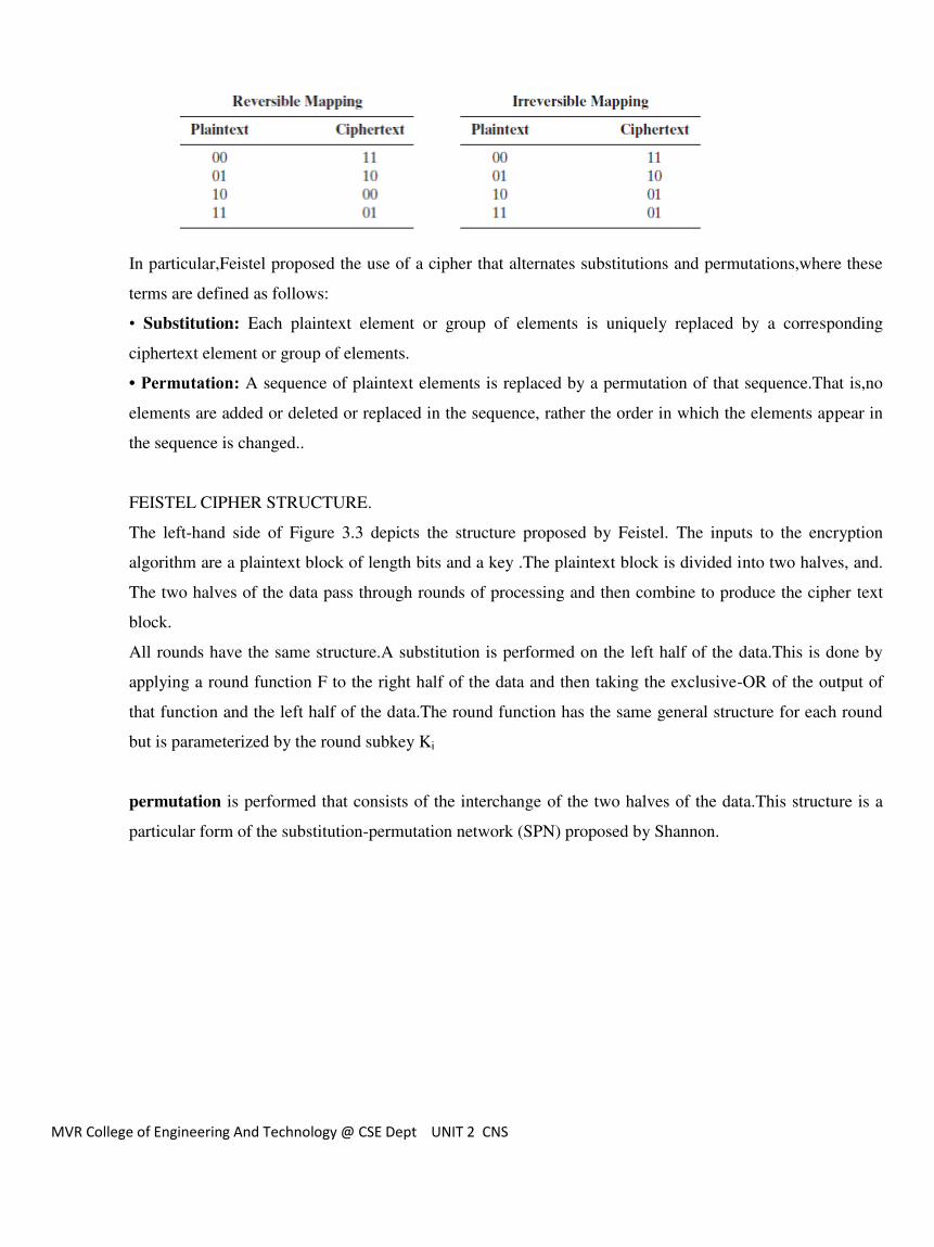
nonsingular.The following examples illustrate nonsingular and singular transformations for n=2
MVR College of Engineering And Technology @ CSE Dept UNIT 2 CNS
In particular,Feistel proposed the use of a cipher that alternates substitutions and permutations,where these
terms are defined as follows:
• Substitution: Each plaintext element or group of elements is uniquely replaced by a corresponding
ciphertext element or group of elements.
• Permutation: A sequence of plaintext elements is replaced by a permutation of that sequence.That is,no
elements are added or deleted or replaced in the sequence, rather the order in which the elements appear in
the sequence is changed..
FEISTEL CIPHER STRUCTURE.
The left-hand side of Figure 3.3 depicts the structure proposed by Feistel. The inputs to the encryption
algorithm are a plaintext block of length bits and a key .The plaintext block is divided into two halves, and.
The two halves of the data pass through rounds of processing and then combine to produce the cipher text
block.
All rounds have the same structure.A substitution is performed on the left half of the data.This is done by
applying a round function F to the right half of the data and then taking the exclusive-OR of the output of
that function and the left half of the data.The round function has the same general structure for each round
but is parameterized by the round subkey Ki
permutation is performed that consists of the interchange of the two halves of the data.This structure is a
particular form of the substitution-permutation network (SPN) proposed by Shannon.

MVR College of Engineering And Technology @ CSE Dept UNIT 2 CNS
Design of Function F
The heart of a Feistel block cipher is the function F. As we have seen, in DES, this function relies on the use
of S-boxes.This is also the case for many other symmetric block ciphers. However, we can make some
general comments about the criteria for designing F. After that, we look specifically at S-box design.
MVR College of Engineering And Technology @ CSE Dept UNIT 2 CNS
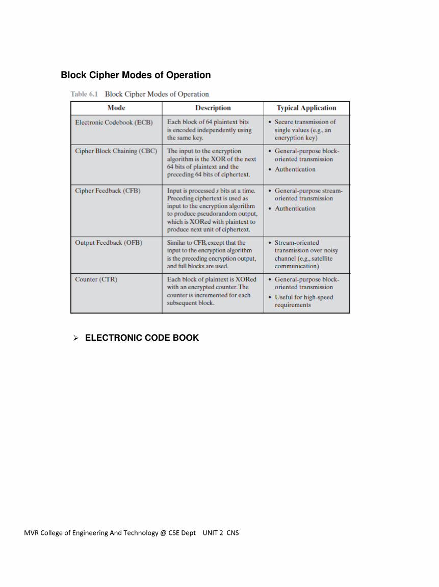
Block Cipher Modes of Operation
ELECTRONIC CODE BOOK

MVR College of Engineering And Technology @ CSE Dept UNIT 2 CNS
The simplest mode is the electronic codebook(ECB) mode,in which plaintext is handled one block at a time
and each block of plaintext is encrypted using the same key (Figure 6.3).The term codebook is used
because,for a given key,there is a unique ciphertext for every -bit block of plaintext.
CIPHER BLOCK CHAINING MODE
To overcome the security deficiencies of ECB, we would like a technique in which the same plaintext block,
if repeated, produces different cipher text blocks.A simple way to satisfy this requirement is the cipher block
chaining(CBC) mode (Figure 6.4). In this scheme, the input to the encryption algorithm is the XOR of the
current plain- text block and the preceding cipher text block; the same key is used for each block .In effect,
we have chained together the processing of the sequence of plaintext blocks.
For decryption, each cipher block is passed through the decryption algorithm. The result is XOR ed with the
preceding cipher text block to produce the plaintext block. To see that this works, we can write
Cj = E(K, [Cj-1 , Pj])

MVR College of Engineering And Technology @ CSE Dept UNIT 2 CNS
CIPHER FEEDBACK MODE
Figure 6.5 depicts the CFB scheme. In the figure, it is assumed that the unit of transmission is bits;
a common value is .As with CBC, the units of plaintext are chained together , so that the ciphertext
of any plaintext unit is a function of all the preceding plaintext. In this case, rather than blocks of
bits, the plaintext is divided into segments of bits.
First , consider encryption. The input to the encryption function is a -bit shift register that is
initially set to some initialization vector (IV).The leftmost (most significant) bits of the output of
the encryption function are XORed with the first segment of plaintext to produce the first unit of
ciphertext , which is then transmitted. In addition, the contents of the shift register are shifted left
by bits, and are placed in the rightmost (least significant) bits of the shift register. This process
continues until all plaintext units have been encrypted.

MVR College of Engineering And Technology @ CSE Dept UNIT 2 CNS
For decryption, the same scheme is used, except that the received ciphertext unit is XORed with
the output of the encryption function to produce the plaintext unit. Note that it is the encryption
function that is used, not the decryption function.

MVR College of Engineering And Technology @ CSE Dept UNIT 2 CNS
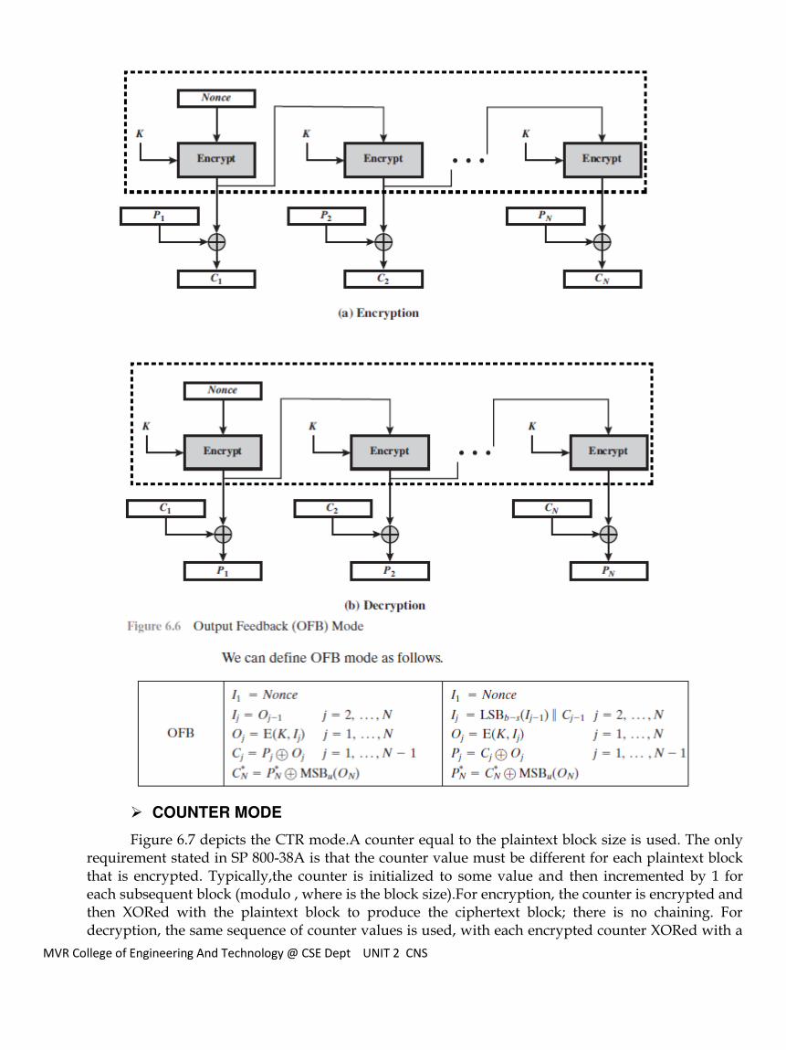
OUTPUT FEEDBACK MODE
The output feedback (OFB) mode is similar in structure to that of CFB.As can be seen in Figure
6.6,it is the output of the encryption function that is fed back to the shift register in OFB, whereas
in CFB, the ciphertext unit is fed back to the shift register.The other difference is that the OFB
mode operates on full blocks of plaintext and ciphertext, not on an -bit subset. Encryption can be
expressed as
MVR College of Engineering And Technology @ CSE Dept UNIT 2 CNS
COUNTER MODE
Figure 6.7 depicts the CTR mode.A counter equal to the plaintext block size is used. The only requirement stated in SP 800-38A is that the counter value must be different for each plaintext block that is encrypted. Typically,the counter is initialized to some value and then incremented by 1 for each subsequent block (modulo , where is the block size).For encryption, the counter is encrypted and then XORed with the plaintext block to produce the ciphertext block; there is no chaining. For decryption, the same sequence of counter values is used, with each encrypted counter XORed with a

MVR College of Engineering And Technology @ CSE Dept UNIT 2 CNS
ciphertext block to recover the corresponding plaintext block. Thus, the initial counter value must be made available for decryption. Given a sequence of counters we can define CTR mode as follows.
3. Triple DES
In cryptography, Triple DES (3DES) is the common name for the Triple Data Encryption Algorithm (TDEA or Triple
DEA)symmetric-key block cipher, which applies the Data Encryption Standard (DES) cipher algorithm three times to
each data block.
The original DES cipher's key size of 56 bits was generally sufficient when that algorithm was designed, but the
availability of increasing computational power made brute-force attacks feasible. Triple DES provides a relatively simple
method of increasing the key size of DES to protect against such attacks, without the need to design a completely new
block cipher algorithm.

MVR College of Engineering And Technology @ CSE Dept UNIT 2 CNS
Algorithm
Triple DES uses a "key bundle" that comprises three DES keys, K1, K2 and K3, each of 56 bits
(excluding parity bits). The encryption algorithm is:
Cipher text = EK3(DK2(EK1(plaintext)))
I.e., DES encrypt with K1, DES decrypt with K2, then DES encrypt with K3.
Decryption is the reverse:
Plaintext = DK1(EK2(DK3(ciphertext)))
I.e., decrypt with K3, encrypt with K2, then decrypt with K1.
Each triple encryption encrypts one block of 64 bits of data.
In each case the middle operation is the reverse of the first and last. This improves the strength of the algorithm
when using keying option 2, and provides backward compatibilitywith DES with keying option 3.
Keying options
The standards define three keying options:
Keying option 1: All three keys are independent.
Keying option 2: K1 and K2 are independent, and K3 = K1.
Keying option 3: All three keys are identical, i.e. K1 = K2 = K3.
Keying option 1 is the strongest, with 3 × 56 = 168 independent key bits.
Keying option 2 provides less security, with 2 × 56 = 112 key bits. This option is stronger than simply DES encrypting twice,
e.g. with K1 and K2, because it protects against meet-in-the-middle attacks.
Keying option 3 is equivalent to DES, with only 56 key bits. This option provides backward compatibility with DES, because
the first and second DES operations cancel out. It is no longer recommended by the National Institute of Standards and
Technology (NIST),and is not supported by ISO/IEC 18033-3
The electronic payment industry uses Triple DES and continues to develop and promulgate standards based upon it
4. International Data Encryption algorithm
IDEA operates on 64-bit blocks using a 128-bit key, and consists of a series of eight identical transformations (a round, see
the illustration) and an output transformation (the half-round). The processes for encryption and decryption are similar. IDEA
derives much of its security by interleaving operations from different groups — modular addition and multiplication, and
bitwise eXclusive OR (XOR) — which are algebraically "incompatible" in some sense. In more detail, these operators, which
all deal with 16-bit quantities, are:

MVR College of Engineering And Technology @ CSE Dept UNIT 2 CNS
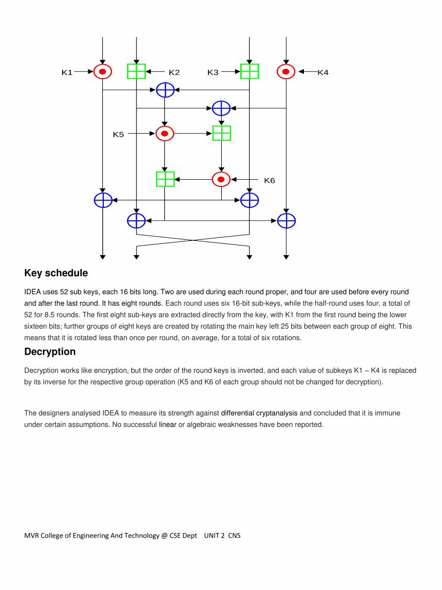
Bitwise eXclusive OR (denoted with a blue circled plus ⊕).
Addition modulo 216 (denoted with a green boxed plus ⊞).
Multiplication modulo 216+1, where the all-zero word (0x0000) in inputs is interpreted as 216 and 216 in output is
interpreted as the all-zero word (0x0000) (denoted by a red circled dot ⊙).
After the eight rounds comes a final “half round”, the output transformation illustrated below (the swap of the middle two values cancels out the swap at the end of the last round, so that there is no net swap):
Structure[
The overall structure of IDEA follows the Lai-Massey scheme. XOR is used for both subtraction and addition. IDEA uses a
key-dependent half-round function. To work with 16 bit words (meaning four inputs instead of two for the 64 bit block size),
IDEA uses the Lai-Massey scheme twice in parallel, with the two parallel round functions being interwoven with each other.
To ensure sufficient diffusion, two of the sub-blocks are swapped after each round
MVR College of Engineering And Technology @ CSE Dept UNIT 2 CNS
Key schedule
IDEA uses 52 sub keys, each 16 bits long. Two are used during each round proper, and four are used before every round
and after the last round. It has eight rounds. Each round uses six 16-bit sub-keys, while the half-round uses four, a total of
52 for 8.5 rounds. The first eight sub-keys are extracted directly from the key, with K1 from the first round being the lower
sixteen bits; further groups of eight keys are created by rotating the main key left 25 bits between each group of eight. This
means that it is rotated less than once per round, on average, for a total of six rotations.
Decryption
Decryption works like encryption, but the order of the round keys is inverted, and each value of subkeys K1 – K4 is replaced
by its inverse for the respective group operation (K5 and K6 of each group should not be changed for decryption).
The designers analysed IDEA to measure its strength against differential cryptanalysis and concluded that it is immune
under certain assumptions. No successful linear or algebraic weaknesses have been reported.
MVR College of Engineering And Technology @ CSE Dept UNIT 2 CNS
5. Blowfish
Blowfish is a symmetric-key block cipher, designed in 1993 by Bruce Schneier and included in a large number
of cipher suites and encryption products. Blowfish provides a good encryption rate in software and no
effective cryptanalysis of it has been found to date. However, the Advanced Encryption Standard (AES) now
receives more attention. It takes a variable-length key, from 32 bits to 448 bits, making it ideal for both
domestic and exportable use.
P is an array of eighteen 32-bit integers.
S is a two-dimensional array of 32-bit integer of dimension 4x256.
Both arrays are initialized with constants, which happen to be the hexadecimal digits of π (a pretty
decent random number source).
The key is divided up into 32-bit blocks and XORed with the initial elements of the P and S arrays. The
results are written back into the array.
A message of all zeros is encrypted; the results of the encryption are written back to the P and S
arrays. The P and S arrays are now ready for use.
MVR College of Engineering And Technology @ CSE Dept UNIT 2 CNS
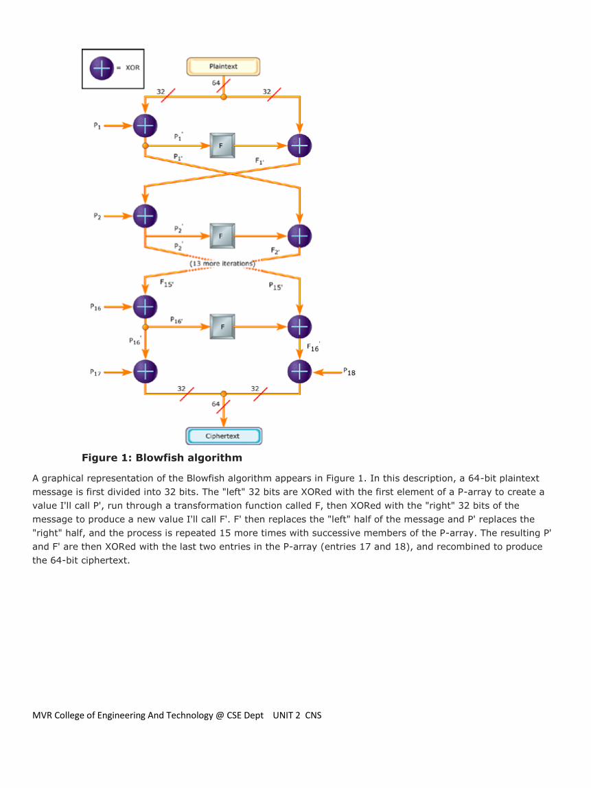
Figure 1: Blowfish algorithm
A graphical representation of the Blowfish algorithm appears in Figure 1. In this description, a 64-bit plaintext
message is first divided into 32 bits. The "left" 32 bits are XORed with the first element of a P-array to create a
value I'll call P', run through a transformation function called F, then XORed with the "right" 32 bits of the
message to produce a new value I'll call F'. F' then replaces the "left" half of the message and P' replaces the
"right" half, and the process is repeated 15 more times with successive members of the P-array. The resulting P'
and F' are then XORed with the last two entries in the P-array (entries 17 and 18), and recombined to produce
the 64-bit ciphertext.
MVR College of Engineering And Technology @ CSE Dept UNIT 2 CNS
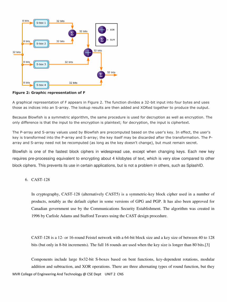
Figure 2: Graphic representation of F
A graphical representation of F appears in Figure 2. The function divides a 32-bit input into four bytes and uses
those as indices into an S-array. The lookup results are then added and XORed together to produce the output.
Because Blowfish is a symmetric algorithm, the same procedure is used for decryption as well as encryption. The
only difference is that the input to the encryption is plaintext; for decryption, the input is ciphertext.
The P-array and S-array values used by Blowfish are precomputed based on the user's key. In effect, the user's
key is transformed into the P-array and S-array; the key itself may be discarded after the transformation. The P-
array and S-array need not be recomputed (as long as the key doesn't change), but must remain secret.
Blowfish is one of the fastest block ciphers in widespread use, except when changing keys. Each new key
requires pre-processing equivalent to encrypting about 4 kilobytes of text, which is very slow compared to other
block ciphers. This prevents its use in certain applications, but is not a problem in others, such as SplashID.
6. CAST-128
In cryptography, CAST-128 (alternatively CAST5) is a symmetric-key block cipher used in a number of
products, notably as the default cipher in some versions of GPG and PGP. It has also been approved for
Canadian government use by the Communications Security Establishment. The algorithm was created in
1996 by Carlisle Adams and Stafford Tavares using the CAST design procedure.
CAST-128 is a 12- or 16-round Feistel network with a 64-bit block size and a key size of between 40 to 128
bits (but only in 8-bit increments). The full 16 rounds are used when the key size is longer than 80 bits.[3]
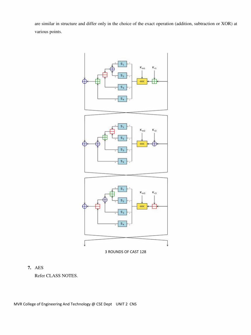
Components include large 8×32-bit S-boxes based on bent functions, key-dependent rotations, modular
addition and subtraction, and XOR operations. There are three alternating types of round function, but they
MVR College of Engineering And Technology @ CSE Dept UNIT 2 CNS
are similar in structure and differ only in the choice of the exact operation (addition, subtraction or XOR) at
various points.
3 ROUNDS OF CAST 128
7. AES
Refer CLASS NOTES.
Related Documents