Data conversion devices Data Conversion Devices are very important components of a Machine Control Unit 2.8.1 shows a typical control system with data conversion devices. Converters are used, which are abbreviated as DACs. In subsequent sections we will be discussing about various types of ADC and DAC devices, their principle of working and circuitry. Figure 2.8.1 A control system with ADC and DAC devices Page 51 Lecture 4.3 digital form and vis-à-vis. Analog to Digital Converter is abbreviated as ADC. Figure (MCU). MCUs are controlled by various computers or microcontrollers which are accepting signals only in Digital Form i.e. in the form of 0s and 1s, while the signals received from signal conditioning module or sensors are generally in analogue form (continuous). Therefore a system is essentially required to convert analog signals into Based on the signals received from sensors, MCU generates actuating signals in the Digital form. Most of the actuators e.g. DC servo motors only accept analogue signals. Therefore the digital signals must be converted into Analog form so that the required actuator can be operated accordingly. For this purpose Digital to Analog

Welcome message from author
This document is posted to help you gain knowledge. Please leave a comment to let me know what you think about it! Share it to your friends and learn new things together.
Transcript
Data conversion devices
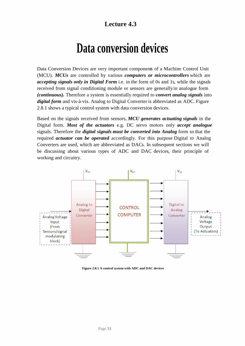
Data Conversion Devices are very important components of a Machine Control Unit
2.8.1 shows a typical control system with data conversion devices.
Converters are used, which are abbreviated as DACs. In subsequent sections we will be discussing about various types of ADC and DAC devices, their principle of working and circuitry.
Figure 2.8.1 A control system with ADC and DAC devices
Page 51
Lecture 4.3
digital form and vis-à-vis. Analog to Digital Converter is abbreviated as ADC. Figure
(MCU). MCUs are controlled by various computers or microcontrollers which are accepting signals only in Digital Form i.e. in the form of 0s and 1s, while the signals received from signal conditioning module or sensors are generally in analogue form (continuous). Therefore a system is essentially required to convert analog signals into
Based on the signals received from sensors, MCU generates actuating signals in the Digital form. Most of the actuators e.g. DC servo motors only accept analogue signals. Therefore the digital signals must be converted into Analog form so that the required actuator can be operated accordingly. For this purpose Digital to Analog
Basic components used in ADCs and DACs
1. Comparators In general ADCs and DACs comprise of Comparators. Comparator is a combination
signal i.e. in form of 0s and 1s indicating which voltage is higher. If V+ and V- be input voltages at two terminals of comparator then output of comparator will be as
V+ > V- Output 1
V+ < V- Output 0
2. Encoders Though the output obtained from comparators are in the form of 0s and 1s, but can’t be called as binary output. A sequence of 0s and 1s will be converted into binary form by using a circuit called Encoder. A simple encoder converts 2n input lines into ‘n’ output lines. These ‘n’ output lines follow binary algebra.
3. Analog to Digital Converter (ADC)
As discussed in previous section ADCs are used to convert analog signals into Digital Signals. There are various techniques of converting Analog Signals into Digital signals which are enlisted as follows. However we will be discussing only Direct Conversion ADC, detail study of other techniques is out of the scope of the present course.
1. Direct Conversion ADC or Flash ADC 2. Successive Approximation ADC 3. A ramp-compare ADC 4. Wilkinson ADC 5. Integrating ADC 6. Delta-encoded ADC or counter-ramp 7. Pipeline ADC (also called subranging quantizer) 8. Sigma-delta ADC (also known as a delta-sigma ADC) 9. Time-interleaved ADC
Page 52
of diodes and Operational Amplifiers. A comparator is a device which compares the voltage input or current input at its two terminals and gives output in form of digital
3.1 Direct Conversion ADC or Flash ADC
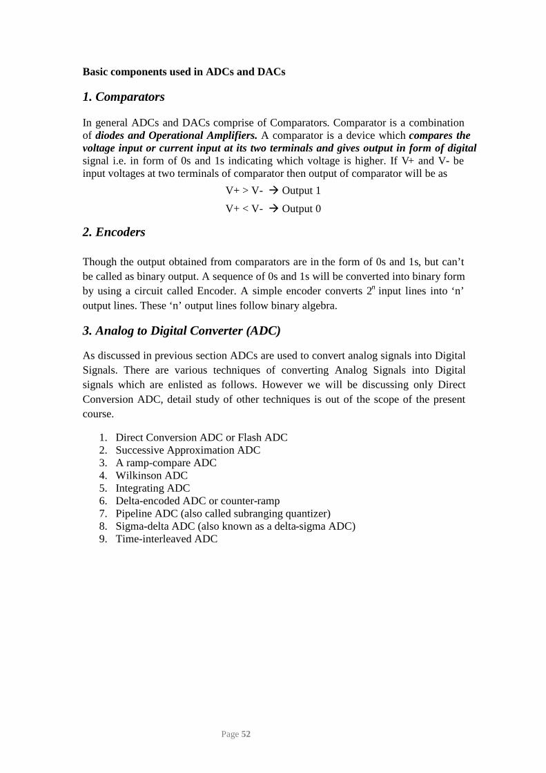
Figure 2.8.2 Circuit of Flash ADC
Figure 2.8.2 shows the circuit of Direct conversion or Flash ADC. To convert a digital signal of N-bits, Flash ADC requires 2N-1 comparators and 2N resistors. The circuit provides the reference voltage to all the comparators. Each comparator gives an output of 1 when its analog voltage is higher than reference voltage or otherwise the output is 0. In the above circuit, reference voltages to comparators are provided by means of resistor ladder logic.
The circuit described in figure 2.8.2 acts as 3 Bit ADC device. Let us assume this ADC works between the range of 0-10 Volts. The circuit requires 7 comparators and 8 resisters. Now the voltages across each resistor are divided in such a way that a ladder of 1 volt is built with the help of 1K-Ohm resistances. Therefore the reference voltages across all the comparators are 1-7 volts.
Now let us assume that an input voltage signal of 2.5 V is to be converted into its related digital form. As 2.5V is greater than 1V and 2V, first two comparators will give output as 1, 1. But 2.5V is less than 3,4,5,6,7 V values therefore all other comparators will give 0s. Thus we will have output from comparators as 0000011 (from top). This will be fed to the encoder logic circuit. This circuit will first change the output in single high line format and then converts it into 3 output lines format by using binary algebra. Then this digital output from ADC may be used for manipulation or actuation by the microcontrollers or computers.
Page 53
4. Digital to Analog Converters
As discussed in previous section DACs are used to convert digital signals into Analog Signals. There are various techniques of converting Digital Signals into Analog signals which are as follows however we will be discussing only few important techniques in detail:
1. Pulse-width modulator 2. Oversampling DACs or interpolating DACs 3. The binary-weighted DAC 4. Switched resistor DAC 5. Switched current source DAC 6. Switched capacitor DAC 7. The R-2R ladder 8. The Successive-Approximation or Cyclic DAC, 9. The thermometer-coded DAC
4.1 Binary Weighted DAC
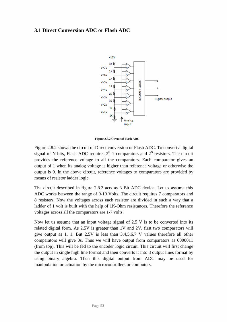
Figure 2.8.3 Circuit of binary weighted DAC
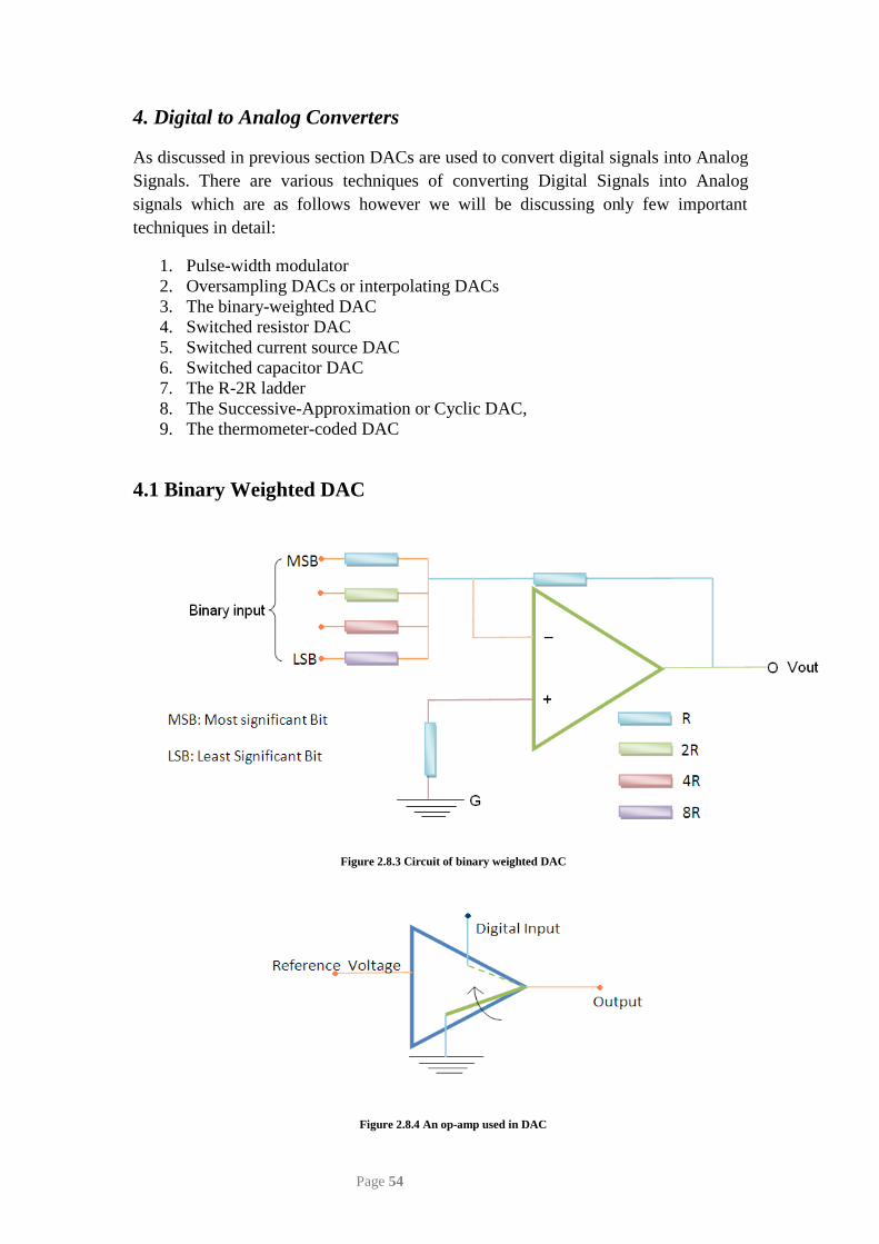
Figure 2.8.4 An op-amp used in DAC
Page 54
As name indicates, in binary weighted DAC, output voltage can be calculated by expression which works on binary weights. Its circuit can be realized in Figure 2.8.3. From the figure it can be noted that most significant bit of digital input is connected to minimum resistance and vice versa. Digital bits can be connected to resistance through a switch which connects resistance-end to the ground. The digital input is zero when former bit is connected to reference voltage and if it is 1. This can be understood from Figure 2.8.4. DAC output voltage can be calculated from property of operational amplifiers. If V1 be input voltage at MSB (most significant bit), V2 be input voltage at next bit and so on then for four bit DAC we can write,
𝑉1𝑅
+ 𝑉22𝑅
+ 𝑉34𝑅
+ 𝑉48𝑅
= 𝑉𝑜𝑢𝑡𝑅
(2.8.1)
Note: Here V1,V2 V3,V4 will be Vref if digital input is 1 or otherwise it will be zero.
Hence output voltage can be found as:
𝑉𝑂𝑈𝑇 𝛼 (23 ∗ 𝑉1 + 22 ∗ 𝑉2 + 21 ∗ 𝑉3 + 20 ∗ 𝑉4) (2.8.2)
However Binary weighted DAC doesn’t work for multiple or higher bit systems as the value of resistance doubles in each case.
Thus simple and low bit digital signals from a transducer can be converted into a related continuous value of voltages (analogue) by using binary weighted DAC. These will further be used for manipulation or actuation.
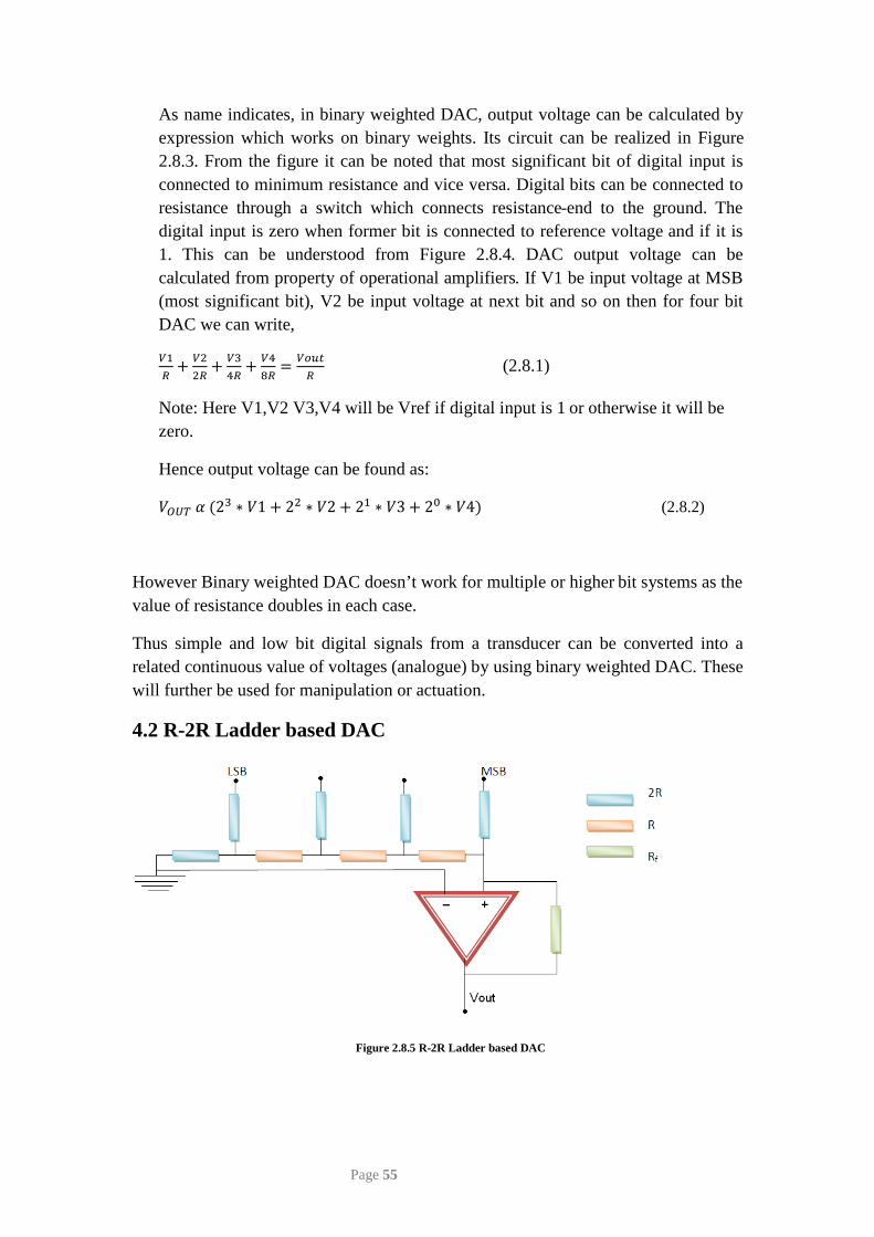
4.2 R-2R Ladder based DAC
Figure 2.8.5 R-2R Ladder based DAC
Page 55
In R-2R ladder logic, shortcoming of Binary Logic has been removed by making the value of maximum resistance double however the rest of the circuit remains same. Figure 2.8.5 shows the circuit of R-2R Ladder based DAC. If we apply voltage division rule in above case, then we can calculate that output voltage as,
𝑉𝑜𝑢𝑡 = 𝑉𝑟𝑒𝑓∗ 𝑅𝑓𝑅
∗ 𝑉𝐴𝐿 (2.8.3)
Where VAL can be calculated from the digital signal input as,
𝑉𝐴𝐿 = 𝐷024
+ 𝐷123
+ 𝐷222
+ 𝐷323
(2.8.4)
In this way output voltage is obtained by converting the digital signals received from microprocessor/ microcontroller. These voltages will further be used to actuate the desired actuator viz. DC/AC motors.
In this module we have studied the principle of operation of various sensors which are commonly used in mechatronics and manufacturing automation. Also the signal conditioning operations and the devices which are used to generate the proper signals for desired automation application have been studied. In the next module we will study the construction and working of microprocessor and the devices which are being used in controlling the various operations of automation using the microprocessors.
Quiz
1. Differentiate between Binary weighted DAC and R-2R ladder based DAC. 2. Explain the importance of data conversion devices in mechatronics with suitable example.
Page 56
Related Documents