Operate at capacity HEADQUARTERS 300 TradeCenter, Ste 4610 Woburn, MA 01801 USA Manufacturing and Support 1050 NE Hostmark Street, Ste 101 Poulsbo, WA 98370 USA Data Collection Workbook ©2019, Azima, Inc.

Welcome message from author
This document is posted to help you gain knowledge. Please leave a comment to let me know what you think about it! Share it to your friends and learn new things together.
Transcript

Operate at capacity HEADQUARTERS
300 TradeCenter, Ste 4610 Woburn, MA 01801 USA
Manufacturing and Support 1050 NE Hostmark Street, Ste 101
Poulsbo, WA 98370 USA
Data Collection Workbook
©2019, Azima, Inc.

Distributed System Installation

Page 3 of 42
Sybase SQL Anywhere 7.0
Sybase SQL Anywhere 12.0

Page 4 of 42
Local Installation of Database

Page 5 of 42
Understanding the Machine
Page 6 of 42
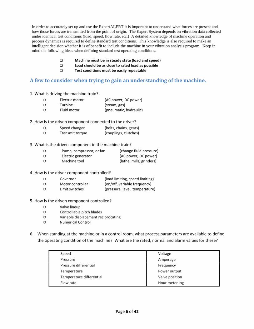
In order to accurately set up and use the ExpertALERT it is important to understand what forces are present and
how those forces are transmitted from the point of origin. The Expert System depends on vibration data collected
under identical test conditions (load, speed, flow rate, etc.) A detailed knowledge of machine operation and
process dynamics is required to define standard test conditions. This knowledge is also required to make an
intelligent decision whether it is of benefit to include the machine in your vibration analysis program. Keep in
mind the following ideas when defining standard test operating conditions.
Machine must be in steady state (load and speed) Load should be as close to rated load as possible Test conditions must be easily repeatable
A few to consider when trying to gain an understanding of the machine.
1. What is driving the machine train?
Electric motor (AC power, DC power) Turbine (steam, gas) Fluid motor (pneumatic, hydraulic)
2. How is the driven component connected to the driver?
Speed changer (belts, chains, gears) Transmit torque (couplings, clutches)
3. What is the driven component in the machine train?
Pump, compressor, or fan (change fluid pressure) Electric generator (AC power, DC power) Machine tool (lathe, mills, grinders)
4. How is the driver component controlled?
Governor (load limiting, speed limiting) Motor controller (on/off, variable frequency) Limit switches (pressure, level, temperature)
5. How is the driven component controlled?
Valve lineup Controllable pitch blades Variable displacement reciprocating Numerical Control
6. When standing at the machine or in a control room, what process parameters are available to define
the operating condition of the machine? What are the rated, normal and alarm values for these?
Speed Voltage
Pressure Amperage
Pressure differential Frequency
Temperature Power output
Temperature differential Valve position
Flow rate Hour meter log

Page 7 of 42
Preparing the Machine

Page 8 of 42
Here are some guidelines for preparing a machine.
1. Survey the machine
Locate all bearings. Determine whether they are rolling contact or journal bearings. Locate all couplings. Determine whether they are flexible or rigid couplings. Locate rotating components. (rotors, gears, impellers,…) Determine whether rotating components are simply supported or overhung. Determine component codes to be used by Expert System. Determine measurement locations required by Expert System. Determine best location to adhere sensor mounting pads. Motor fan housings,
motor cooling fins, pump volutes, sheet metal cowlings, hollow (resonant) areas and the like are not acceptable locations.
2. Install accelerometer mounting pads and barcodes (optional) on the machine.
Prepare the surface with a file. A surface free from paint, rust, and oil is required. Adhere pads on machine. Must have metal to metal contact with the notch
properly aligned. Attach pads in the exact same place on similar machine types (MIDs) Determine the orientation. (RAT, ART, ...), See Section on Blocking Determine the bearing number. (1, 2, 3, ...), See Section on Blocking Adhere a machine id label at a convenient place near each pad. Use strobe-tach or hand held tachometer to record shaft speeds if unknown. If belt driven, measure pulley diameters and centerline distance between shafts.
3. Record machine information in the Vibration Test Analysis Guide (VTAG).
Name of machine including unit number. Nameplate data on all components. Don't be afraid to sand paint off label plates. Location, orientation, and barcode # for each sensor mounting pad. Sketch of machine in silhouette form showing test locations. Schematic sketch of machine showing only rotating components. Photograph machine showing whole or significant parts of the machine and pad
orientation / location. Count the number of visually exposed rotating elements. (blades, teeth, vanes,...)
4. Collect the following from the literature. (Keep this info in a folder for each MID)
Gear ratio and teeth count for all gearboxes (if available) Equipment specification sheet from front of tech manual. Outline (installation) drawing of the unit. Section or assembly drawings that show internal configuration Technical manual cover and/or get manual # and title. General description paragraphs explaining principles of operation.

Page 9 of 42
Following are some questions you may consider when defining standard test
operating conditions for a machine:
o What is the purpose of the machine?
o How is the driver controlled?
o How is the driven component controlled?
o What is the rated load for the machine?
o What % of the rated load is the machine normally operated?
o For turbines, at what speed is the governor set?
o What is the repair history for the machine?
o What are the consequences/costs if the machine were to fail?
o Are there any special conditions that must be met before the machine can be run long enough for a
vibration test? For example, bleeding down an accumulator, over-riding a limit switch, bypassing
the governor to increase speed, head tank feed and bleed, ...
o Are there any known resonant frequencies (criticals) associated with the machine.
o What process parameters are available and what are the limits? You may want to record some of
these parameters as process points for trending purposes.
Speed Pressure
Pressure differential Temperature
Temperature differential Flow rate
Valve position Voltage
Amperage Frequency
Power output Shaft position indicator
Hour meter log
Page 10 of 42
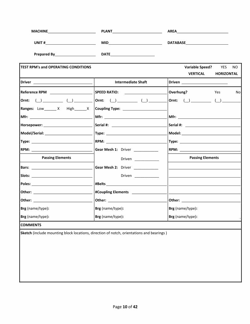
MACHINE PLANT AREA
UNIT # MID DATABASE
Prepared By DATE
TEST RPM's and OPERATING CONDITIONS Variable Speed? YES NO
VERTICAL HORIZONTAL
Driver Intermediate Shaft Driven
Reference RPM SPEED RATIO: Overhung? Yes No
Ornt: (__) (__) Ornt: (__) (__) Ornt: (__) (__)
Ranges: Low ______ X High ______ X Coupling Type:
Mfr: Mfr: Mfr:
Horsepower: Serial #: Serial #:
Model/Serial: Type: Model:
Type: RPM: Type:
RPM: Gear Mesh 1: Driver ____________ RPM:
Passing Elements Driven ____________ Passing Elements
Bars: Gear Mesh 2: Driver ____________
Slots: Driven ____________
Poles: #Belts
Other: #Coupling Elements
Other: Other: Other:
Brg (name/type): Brg (name/type): Brg (name/type):
Brg (name/type): Brg (name/type): Brg (name/type):
COMMENTS
Sketch (include mounting block locations, direction of notch, orientations and bearings )

Page 11 of 42
Quick Guide to Completing the VTAG
MACHINE: Machine Name
PLANT: Plant Name
AREA: Area Name
UNIT #: Which of the identical units is this?
MID: MID group to which this machine belongs.
DATABASE: In which database is this MID stored?
NOTE: May be worthwhile to note if replicating this machine.
Prepared By: Your Name
DATE: Today's Date
TEST RPM's and OPERATING CONDITIONS:
At what speed is this machine running when measurements are to be collected, and are there
any other conditions to check (for example load)?
Variable Speed: Is this a variable speed or DC motor?
VERTICAL/ Is this machine mounted vertically or horizontally?
HORIZONTAL
Driver: Name the driver component (electric motor, turbine, fluid motor, etc.)
Driven: Name the driven component (pump, compressor, fan, generator, etc.)
Reference RPM: Rotational rate of the reference shaft.
Speed Ratio: Calculated as Driver : Driven, e.g., Driver : Driven = 1 : 2 = 1800 : 3600
Or Driver : Driven = 2 : 1 = 1800 : 900
Overhung: Is the driven component overhung?
Ornt: Transducer Orientation - combinations of RTA or VHA
Enter the position number in the brackets.
Ranges: How many orders of the reference shaft rate for low and high frequency ranges - 10X and 100X
Coupling Type: Coupling Type - flexible, close coupled, fluid (note vane count)...
Mfr: Component Manufacturer
Horsepower: The rated horsepower (or KW) as indicated on the nameplate.
Serial #: Component Serial Number/your Part Number/Equipment Number
Model: Model of this component
Type: Component type
RPM: Rotational rate of this component
Passing Elements: For example number of Fan Blades, Pump Impellers, Motor Bars, Pistons...
Gear Mesh: Number of teeth on the driver element and on the driven element
# Belts: Number of belts. Also record sheave diameters.
#Coupling Elements: Number of coupling elements
Brg: The bearing name (not necessary for ExpertALERT) and type - ball bearing, thrust, journal.
Other: Enter other rotating component information
COMMENTS: Enter any information not covered by the above fields
Sketch: Sketch the machine, clearly identifying mounting block locations, transducer orientations,
bearing positions

Page 12 of 42
Bearing Location Numbering
Motor Pump
Motor
34
1 2 3 4
1 2
Motor
1 2
PumpGear
3 4
5 6 7 8
Motor
1 2 3 4(4)
5
6
Pump
Gear
Pump
Sensor Location Numbering
Page 13 of 42
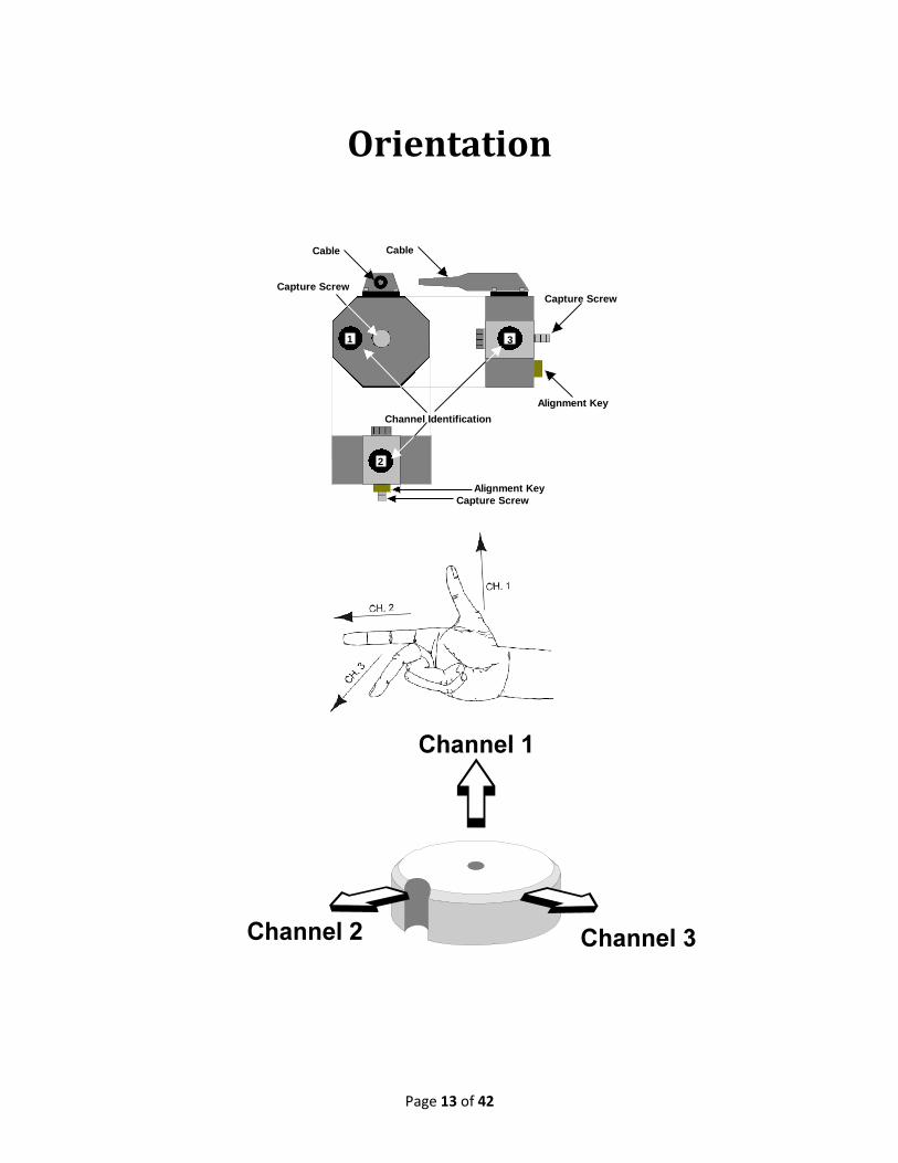
Orientation
2
1 3
Channel Identification
Alignment Key
Capture Screw
Capture Screw
Alignment Key
Capture Screw
Cable Cable
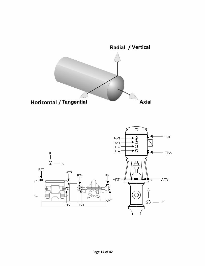
Page 14 of 42
Horizontal /
/ Vertical

Page 15 of 42
Vibration Transmission Path
When the accelerometer is connected to the attachment pad for data collection, you are measuring the vibration of the attachment pad as a result of the vibration of the machine.
When a component in the machine is deteriorating, its vibration will change in response to the wear it is undergoing. The rest of the machine also will change its vibration characteristics in response to this component. You, in turn, are monitoring the change in vibration of the attachment pad, which is in response to the change in vibration of the machine, which is in response to the change in vibration of the problem component.
It is imperative that this path be as short as possible, so that the changes in the attachment pad’s vibration mimic as closely as possible the changes in vibration of the component itself.
Important! Mount the attachment pad as close as possible to the component that it is intended to monitor, and make sure that the transmission path is as solid as possible. Do not, for example, mount the attachment pad on a coupling or fan guard, or a sheet metal cover.
Accelerometer Location
Correct
NoNo
No

Page 16 of 42
Blocking Exercise
1. Which accelerometer channel is in line with the block’s threaded hole and pin? ___________
2. Which accelerometer channel measures vibration in the direction of the triaxial cluster’s screw
and block’s threaded hole? ____________
3. Label the pickup number and orientation for each of the mounting blocks on the following machines.
a.
____________
____________
____________
Continued on next page.

Page 17 of 42
b.
____________
c.
____________
____________

Page 18 of 42
General Considerations for Blocking
• Be aware of safety
• Consider all machines of MID when determining test locations
• Location should be easily accessible
• Take notice to possible causes of interference
• Follow 40 HP, 1 Meter rule
• If in doubt, better to have more data
• Goal is for repeatability
Repeatability
The success of vibration analysis depends on the repeatability of the collected data. There are a number of ways that repeatability can be maximized
NOTE
If the pad is rotated 180 degrees around the radial axis, the data on all channels will not be affected if phase data is not desired.
• The alignment notch on the attachment pad ensures that the transducer is always connected to the pad in the same orientation. However, if it is necessary to replace a missing or damaged pad, it is critical that the pad be replaced in the same orientation and position. Obviously, if the pad is replaced with the notch in a different direction, data that had previously been stored as Axial data, may now be stored as Radial data and so on. If the pad is not replaced in the same position, the vibration signature will be different (even if only slightly) and this may cause erroneous results from the diagnostics.
• The contact surface between the pad and transducer should always be wiped clean prior to data collection.
• The same torque is applied with the ball driver each time the transducer is attached.

Page 19 of 42
Forcing Frequency = number of elements x speed of shaft
Forcing FrequenciesForcing FrequenciesForcing Frequencies
Motor
GearCprsr

Page 20 of 42
Calculating Gear Ratios and Gear Mesh Frequencies
•
•
•
•
• Always confirm with logic check
• If value across ratio increases, the gear ratio is
increaser (output runs faster than input)
• If value across ratio decreases, the gear ratio is
decreaser (output runs slower than input)
•
• Any shaft can be the reference shaft
• Reference shaft is denoted as 1.00xShaft
• 1.00xM, motor shaft reference is most common

Page 21 of 42
Nu
mb
er of Te
ethN
um
be
r of Te
eth
Input Shaft 1.00x Ref Shaft
Output Shaft ___ x Ref Shaft
Page 22 of 42
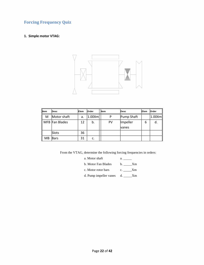
Forcing Frequency Quiz
1. Simple motor VTAG:
From the VTAG, determine the following forcing frequencies in orders:
a. Motor shaft a. _____
b. Motor Fan Blades b. _____Xm
c. Motor rotor bars c. _____Xm
d. Pump impeller vanes d. _____Xm
Item Desc Elem Order Item Desc Elem Order
M Motor shaft a. 1.00Xm P Pump Shaft 1.00Xm
MFB Fan Blades 12 b. PV Impeller
vanes
6 d.
Slots 36
MB Bars 31 c.

Page 23 of 42
2. Geared pump VTAG:
Item Driver Components Elem Order Item Driven Components Elem Order
M Motor shaft a. a. P Pump Shaft 1 d.
MB Bars 40 b. G2 Driven gear 79 c.
G1 Pinion 32 c. PV Sliding vanes 6 e.
a. What is the gear ratio for the gear box on this Blackmer pump? ___________ to _________
b. Is the gearbox a speed INCREASER or DECREASER?
c. If this Reliance 40 HP motor is running at 30 HZ, what is the pump shaft speed?
d. From the VTAG, if the motor is the reference shaft (1.00x) determine the forcing frequencies in
orders for the following:
a. Motor shaft (M) _____xM
b. Motor bars (MB) _____xM
c. Gear mesh (GM) _____xM
d. Pump shaft (P) _____xM
e. Pump vanes (PV) _____xM
BONUS: What minimum frequency range would you need to identify the second order of (or 2
times) the motor bar frequency?
a. 0 – 2500 Hz
b. 0 – 32 Hz
c. 0 – 5000 Hz
d. 0 – 640 Hz

Page 24 of 42
NOTES:

Page 25 of 42
Collecting Data
The TRIO® family of analyzers is unique in that it takes a
modular approach to data collection.
The TRIO system is made up of three components:
• TRIO Controller (Various Models) • Data Processor-1 (DP-1, DP-2, DP-2H) • Triaxial accelerometer with 6’ coiled cable
Page 26 of 42
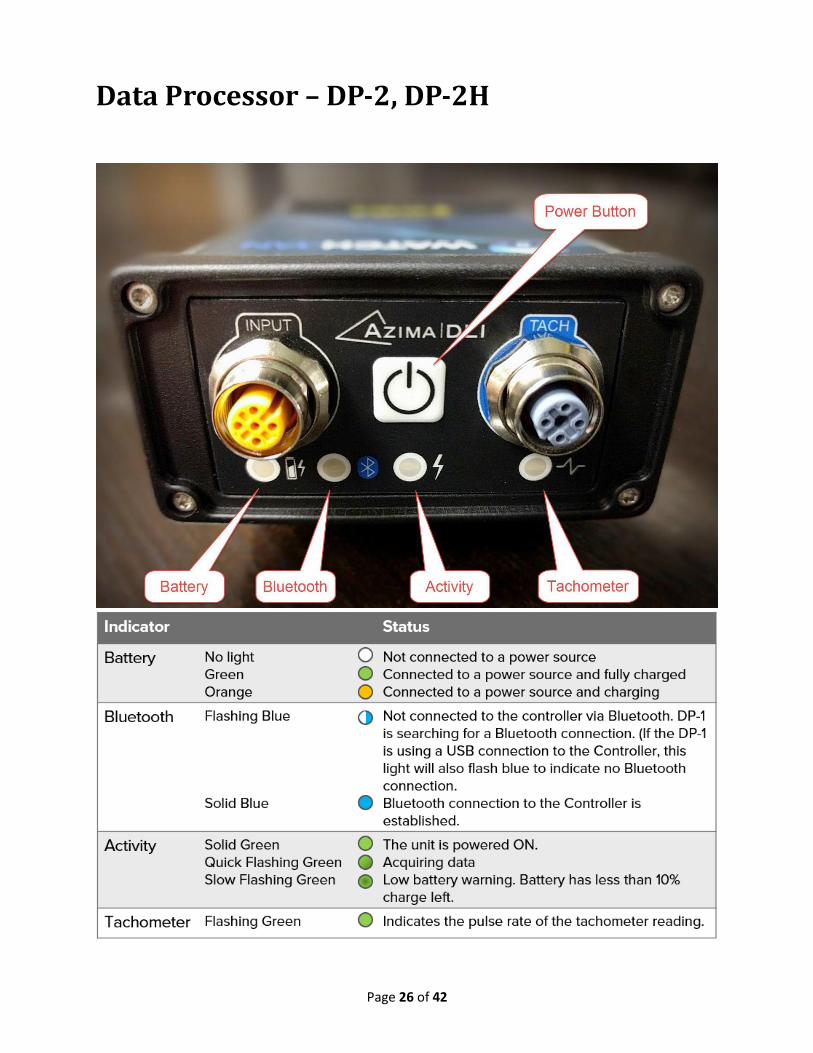
Data Processor – DP-2, DP-2H
Page 27 of 42
Charging the DP The DP can be powered by connecting it directly to a wall outlet or power strip or it can be powered directly from the Controller or a laptop.
It takes about two hours to fully change the DP from a wall outlet. It takes about four hours if charged from the Controller or a laptop.
1. Plug the appropriate end of the provided power supply to the DC power port on
the lower right side of the Controller. You will have to flip open the latch of the
lower compartment to access the port.
2. Plug the three-prong end of the power supply to a wall outlet or power strip.
3. Wait while the batteries charge. The two battery LEDs on the front of the unit
(designated with an L for the left battery and an R for the right one) will glow
orange/yellow while charging. They are fully charged when both lights go out.
Important! If the DP and Controller have a Bluetooth connection established when a USB cable connects them, it the Controller will retain that Bluetooth connection. It will NOT switch to USB communication.
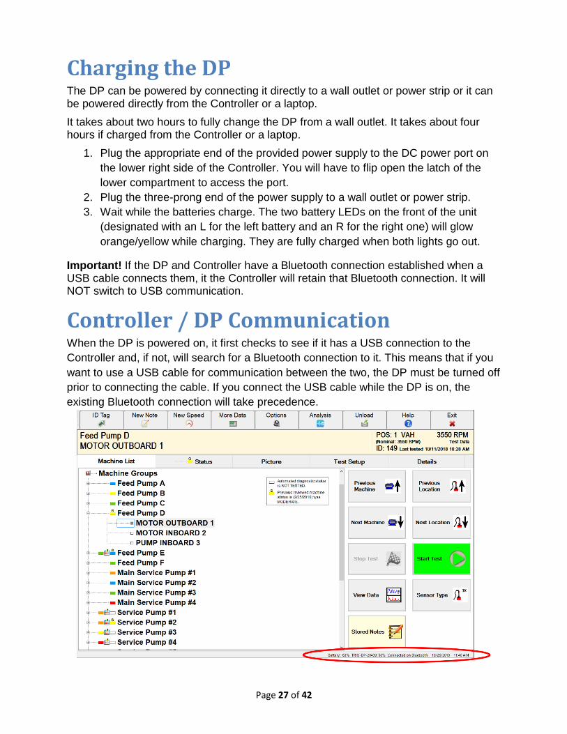
Controller / DP Communication When the DP is powered on, it first checks to see if it has a USB connection to the
Controller and, if not, will search for a Bluetooth connection to it. This means that if you
want to use a USB cable for communication between the two, the DP must be turned off
prior to connecting the cable. If you connect the USB cable while the DP is on, the
existing Bluetooth connection will take precedence.

Page 28 of 42
Data and Survey Transfer Methods There are several methods for transferring data and survey information between a TRIO and external ExpertALERT or StandardALERT software.
This transfer is needed in order to get the collected data from the database on the Controller to the "master" ALERT database for analysis. Likewise, new surveys and other database modifications made in ALERT must be transferred to the Controller before they are seen in Data Collector Mode.
Method Description When to Use It
Replication
This is the easiest method to use once it is set up.
The person using the TRIO Controller connects it to the Internet and double-clicks an icon on the unit's desktop to synchronize the two databases. Data is transferred to the external ALERT software and updated survey information and other database modifications are applied to the TRIO. (Replication is a two-way process.)
Replication has specific requirements that MUST be met in order for it to function successfully.
These requirements include having Internet access and having your IT department configure your firewall to enable you to access an external FTP server.
The geographic area from which you need to send data and IT policies may prohibit the use of replication.
Data Collector Survey File Exchange
This method enables you to transfer data from a data collector to external ALERT software and also to transfer surveys from the ALERT software to the data collector.
The Data Collector Survey File Exchange does not synchronize the databases as with replication. Rather, it provides a way to get data to the person performing analysis and, likewise, get surveys created in ALERT to the data collector.
Data is unloaded from Data Collector Mode into a Data Collector Survey Data File (*.DF), which is then loaded into ALERT.
Surveys are written to a Data Collector Survey File (*SF) from ALERT and loaded onto the TRIO. The *.SF file is used to create a new database containing the machines in the survey.
Note: Voice notes and photographs will not transfer using this method. They will only transfer via replication.
This method is only relevant when using your TRIO with external ExpertALERT or StandardALERT software.
This option is intended for situations in which data collection is being performed in a remote location where Internet access is limited.
A Data Collector Survey File (*SF) can be loaded onto the TRIO where it will create a database containing the machines on the survey. This survey file can be sent via email, on a removable USB (thumb) drive, over a network, or be downloaded from the WATCHMAN Reliability Portal.
Likewise, the data collected with the TRIO can be unloaded into a Data Collector Data File (*.DF) and sent to the person doing analysis via the same file transfer methods.
Page 29 of 42
Survey File Exchange
Use the following procedure to incorporate the Survey File Exchange method to load
and unload data from your TRIO.
Transferring Data from ExpertALERT to TRIO
The following sets of steps explain how to load the data collector from ExpertALERT.
To write database changes to a data collector survey file (*SF) The following steps create a survey file (*SF) containing the database structure for a particular survey.
1. In ExpertALERT, expand the tree structure and select the survey containing the database change(s).
2. Choose Data Collector>Write Data Collector Survey File. (If this option is not enabled, be sure you have selected a survey from the tree structure.)
3. Browse to the location in which you want to save the data collector survey file (*.SF), enter a name for it in the File name box, and then click Save. Put some thought into naming the survey file as it will be the name of the new database that is created from the file.
4. When the data collector survey file (*.SF) has been created, a confirmation message appears. Click OK to dismiss it.
To load a data collector survey file (*.SF) onto a TRIO The following steps create a new database containing only the machines included in the survey from which the survey file was written.
1. Launch the TRIO software, but do not log in.
2. On the login screen, do the following:
a. In the User name box, enter your user name.
b. In the Password box, enter your password.
c. From the Data Source drop-down list, select Browse and then navigate to the (*.SF) file containing the survey information written from ExpertALERT.
3. Select the data collector survey file, then click Open.
4. Wait while a new database is created. The database name is the same as the survey file, so the next time you log in, you can select it from the Data Source drop-down list.
5. When a confirmation message appears, click OK.

Page 30 of 42
Transferring Data from a TRIO to ExpertALERT
The following sets of steps explain how to off-load the data from the analyzer and then
how to read (import) the data into ExpertALERT for analysis.
To transfer data from a TRIO to a portable data file (*.DF) The following steps create the data file (*.DF) that will be read by ExpertALERT (or StandardALERT). This file contains the data collected for machines on a particular survey.
1. Ensure you are in Data Collector Mode.
2. Click the Unload button in the top toolbar.
3. If you have more than one survey on the TRIO, a dialog box opens so you can select the one whose data you want to transfer, then click OK. If you only have one survey, it is automatically selected for you and you will not see the selection dialog box.
4. Specify the location to which you want to save the data file, then click Save. You can accept the default path or specify a different location. For example, if you are planning to move the file via a removable USB (thumb) drive, insert the drive to the USB port of the data collector and then browse to it. By default, the file is given the same name as the survey, followed by the database name, and the current date/time (for example, MonthlyVibeCollection_Plant23_081111433.DF).
Important! Be sure you remember where you save the data file as you will need to know this location when you read the file in ExpertALERT (or StandardALERT).
5. On the confirmation message, click OK.
To read a data file (*.DF) in ALERT
These steps explain how to get data that was unloaded from a TRIO into ExpertALERT (or StandardALERT) for analysis.
1. Ensure you know the location of the data file (*.DF) that was unloaded from your TRIO. For example, if the data file was emailed to you, be sure to note were you downloaded it on your computer.
2. In ExpertALERT, choose Data Collector>Read Data Collector Data File.
3. Browse to the location in which the data file (*.DF) is saved, select it, and then click Open.
4. When the data has been added to the database, a confirmation message appears. Click OK to dismiss it.
Database modifications made in ExpertALERT must be transferred to the TRIO. For example, a new location may have been added to a machine. These database changes are written to a data collector survey file (*.SF) in ExpertALERT and then loaded onto the TRIO.

Page 31 of 42
Data Collection Mode
User Preferences & Options
• Data Collector Options. These are settings that are NOT tied to a particular login, but to the unit itself. Data collector options are set by clicking the Options button while in Data Collector Mode. These options include specifying the format used to display the results of tests, the style of the Start button, and whether you want the diagnostic system to run each time data is collected. To learn more about the unit-level options you can set, see the Specifying Data Collection Options topic.
You can use any of the following methods in Data Collector Mode to specify the location and start collecting data.
• Select a Location from the Tree Structure.
• Enter an ID Tag to Identify the Measurement Location.
• Click a Location on a Photograph.
You can also enter process point measurements (temperature, pressure, etc.) via the
data collector.
Page 32 of 42
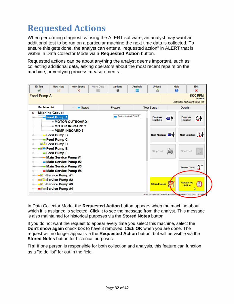
Requested Actions When performing diagnostics using the ALERT software, an analyst may want an additional test to be run on a particular machine the next time data is collected. To ensure this gets done, the analyst can enter a "requested action" in ALERT that is visible in Data Collector Mode via a Requested Action button.
Requested actions can be about anything the analyst deems important, such as collecting additional data, asking operators about the most recent repairs on the machine, or verifying process measurements.
In Data Collector Mode, the Requested Action button appears when the machine about which it is assigned is selected. Click it to see the message from the analyst. This message is also maintained for historical purposes via the Stored Notes button.
If you do not want the request to appear every time you select this machine, select the Don't show again check box to have it removed. Click OK when you are done. The request will no longer appear via the Requested Action button, but will be visible via the Stored Notes button for historical purposes.
Tip! If one person is responsible for both collection and analysis, this feature can function
as a "to do list" for out in the field.
Page 33 of 42
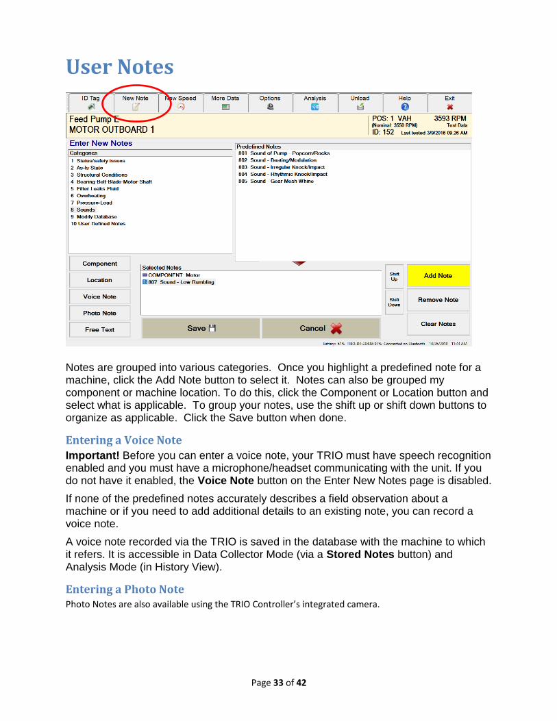
User Notes
Notes are grouped into various categories. Once you highlight a predefined note for a machine, click the Add Note button to select it. Notes can also be grouped my component or machine location. To do this, click the Component or Location button and select what is applicable. To group your notes, use the shift up or shift down buttons to organize as applicable. Click the Save button when done.
Entering a Voice Note
Important! Before you can enter a voice note, your TRIO must have speech recognition enabled and you must have a microphone/headset communicating with the unit. If you do not have it enabled, the Voice Note button on the Enter New Notes page is disabled.
If none of the predefined notes accurately describes a field observation about a machine or if you need to add additional details to an existing note, you can record a voice note.
A voice note recorded via the TRIO is saved in the database with the machine to which it refers. It is accessible in Data Collector Mode (via a Stored Notes button) and Analysis Mode (in History View).
Entering a Photo Note Photo Notes are also available using the TRIO Controller’s integrated camera.

Page 34 of 42
Setting Machine Speed
When collecting data in the field, you can update the machine speed with a different value - either one measured with a tachometer or manually entered by you. If you update the speed value, the new speed appears on the data collector screen, but will be labeled either "Measured" or "Entered" depending on how the value was captured by the TRIO. This new value will be saved with the current test data; it does NOT replace the nominal speed in the database. Important! Updating the test speed does not change the nominal speed in the database. The updated speed is saved with the current data set so that it can be used for diagnostics on that test only. The updated speed will be labeled as "Entered" or "Measured" on the data collector interface (depending on how it was captured by the TRIO).
To enter a new speed for the current test 1. Ensure you are in Data Collector Mode.
2. On the Machine List tab, expand the tree structure and select the machine whose speed you want to replace for the current test.
3. Click the New RPM button in the top toolbar.
4. Define the speed units you are entering by selecting either the RPM (revolutions per minute) or RPS (revolutions per second) option button.
5. Do one of the following, depending on how you plan to capture the speed value:
− If you plan to manually enter a value, use the number pad to enter the speed in the box and then click Save.
− If you plan to measure it with a tachometer:
a. Connect the handheld laser laser tachometer to the TACH input on the DP-1 and then set it up to capture speed from the machine. (The handheld laser tachometer is an accessory you can purchase for your TRIO.)
b. If the collected speed needs to be divided (for example, if your tach has multiple notches) select the Divide Tach check box, then enter the value you want the speed divided by in the box that appears.
c. Click the Measure button and wait while the tachometer determines the speed and, if needed, divides the value per your specifications.
d. The measured speed will appear on the screen and may adjust slightly as the tachometer continues to measure it. When you are satisfied with the value (for example, it holds steady for a bit), click the Save button.
Note: The raw speed value appears in the box above the number pad. If you specified that the value be divided, the calculated speed will appear in the Resultant box.

Page 35 of 42
Analysis Mode (CX-Series)
User Preferences & Options
User Preferences.
These are global settings that apply to a particular login. If more than one person shares
a data collector, each can customize his or her own preferences. User preferences are
set in Analysis Mode by choosing File>Users And Preferences. User preferences
include the parameters used to determine whether a machine is considered "tested"
and the order in which machines appear in the tree structure. To learn more about the
preferences you can set, switch to Analysis Mode, choose Help>Contents to open the
Analysis Mode online help, and then search the help index for "user preferences" to
locate the "Specifying User Preferences" topic.
Hours to Consider Machine/Location Tested
Besides user options, there are data collector options that apply to the TRIO as a whole. One of those settings lets you specify how many hours a machine or measurement location will be considered tested. When you collect data from a location, its icon will change to one with a turquoise check mark. When all of the locations for a machine have been tested, the icon for the machine will change to one with a turquoise check mark as well.
• This lets the person collecting the data know that it has recently had data collected.
• The number of hours you specify here determines when that check mark is removed.
• This setting is different from both the Tested/Not tested setting in your user
preferences and the Routing Collection Period/Test Time Span settings established
in the database.

Page 36 of 42
Using more than one DP NOTE: Your TRIO Controller and DP are pre-configured to communicate with each other at the factory. The below information is necessary only if using multiple controllers or DPs or if re-configuration is necessary. Only one DP can be paired with a controller at a time.
DP Configuration Tool
Use the DP Configuration Tool to specify time-related settings and to identify the TRIO DP with which you want the Controller to communicate.
Selecting a New Device When the DP Configuration Tool opens, the name of the device currently selected to communicate with the Controller appears. The device name will be Trio-DP-xxxxx where the last five digits are the DPs serial number.
If you want to use a different DP-1 with the Controller, click the Select Device button to see all Bluetooth devices that are currently "seen" by the Controller. For a device to appear in the list, it must be "paired" with the Controller via its Windows Bluetooth settings.
Select the DP you plan to use, click OK, and then click Save Changes and Exit.

Page 37 of 42
Pairing a DP with the Controller via Window Bluetooth Settings Any DP that will communicate with the Controller via Bluetooth must be "paired" with the Controller via its Windows Bluetooth settings. This is in addition to it being specified via the DP Configuration Tool (as explained above) and having Bluetooth selected as one of the Controller's enabled wireless communication methods (done via the Menu button).
Generally, you will NOT need to do this if you are using the DP-1 that came with the Controller. The pairing should be set up for you. However, the following steps are helpful if you ever need to troubleshoot the connection.
You WILL need to perform the following steps if you purchase an additional DP-1 after your Controller has already been shipped to you.
1. Power on the DP and ensure it is in close proximity to the Controller.
2. From the controller, locate the Bluetooth icon in the system stray and select Show Bluetooth Devices.
3. Click Add a device to see a list of Bluetooth devices "detected" by the Controller.
4. Locate the DP you plan to add (Trio-DP-xxxx) and select it.
5. Enter Pairing code 1234, then click OK.
The DP is now paired with the Controller and will appear in the list of paired devices via
the DP Configuration Tool.
Page 38 of 42
Collecting Data
Tools of the Trade
• Balldriver(s)
• Mounting pads
• Adhesive
• Flat File
• VTAG
• 5/32 Tap and Drill Bit
• Wiping Rag
• Ear Plugs
Test Operating Conditions
• Vitally important for the Expert System to correctly identify a machine fault
• Listed on the VTAG and in EA database
• Especially important for variable speed equipment (always verify the speed)
• Ensure machinery is properly warmed up and steady-state condition
Steps for collecting data
1. Synchronize to WATCHMAN Data Center
2. Check proper test operating conditions and blocking
3. Connect the accelerometer to the machine
• Attachment pad with Ball Driver
• Quick-connect Pad
4. Start collection using machine tree or machine photo
5. Collect all points for the machine
6. Enter process readings and notes
7. Synchronize to WATCHMAN Data Center
Page 39 of 42
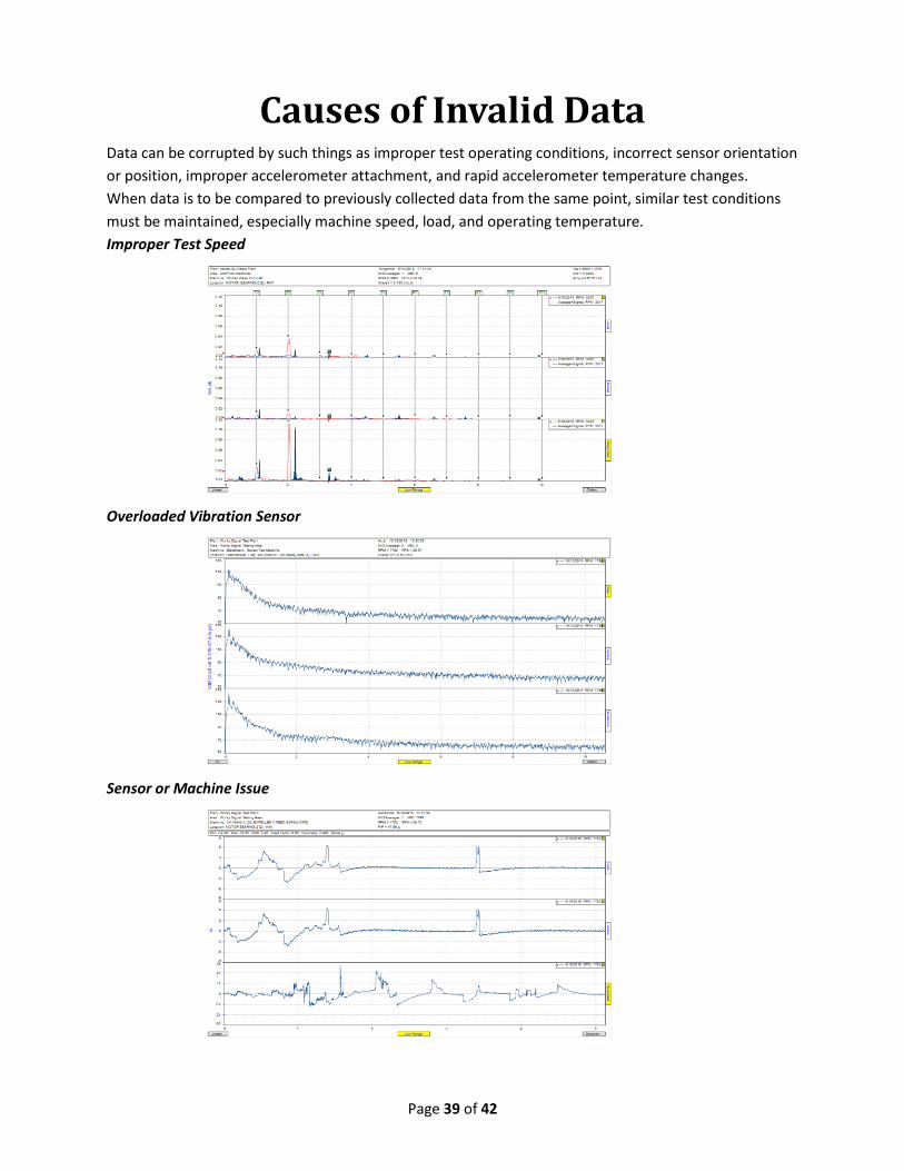
Causes of Invalid Data Data can be corrupted by such things as improper test operating conditions, incorrect sensor orientation
or position, improper accelerometer attachment, and rapid accelerometer temperature changes.
When data is to be compared to previously collected data from the same point, similar test conditions
must be maintained, especially machine speed, load, and operating temperature.
Improper Test Speed
Overloaded Vibration Sensor
Sensor or Machine Issue

Page 40 of 42
Notes:

Page 41 of 42
Notes:

Related Documents