UNIVERSITY OF NAIROBI SCHOOL OF COMPUTING AND INFORMATICS DATA CAPTURE MODEL FOR UTILITY PROVIDERS USING HAND HELD DEVICES VIA MOBILE NETWORK: CASE FOR NAIROBI WATER COMPANY BY P56/P/8887/2006: KIPLAGAT DAVID October 200&X Submitted in partial fulfillment of the requirements of the degree of Masters of Science in Computer Science i University of NAIROBI Library oiililll

Welcome message from author
This document is posted to help you gain knowledge. Please leave a comment to let me know what you think about it! Share it to your friends and learn new things together.
Transcript

UNIVERSITY OF NAIROBI
SCHOOL OF COMPUTING AND INFORMATICS
DATA CAPTURE MODEL FOR UTILITY PROVIDERS USING
HAND HELD DEVICES VIA MOBILE NETWORK: CASE FOR
NAIROBI WATER COMPANY
BY
P56/P/8887/2006: KIPLAGAT DAVID
October 200&X
Submitted in partial fulfillment of the requirements of the degree of Masters of Science in
Computer Science
i
University of NAIROBI Library
oiililll

DECLARATION
This Project, as presented on this report is my original work and to the best of my
knowledge has not been presented for any other university award.
Signed
David ICiplagat, P56/P/8887/2006
This Project has been submitted as part of fulfillment of the requirements for the
award of Masters of Science in Computer Science of the School of Computing
and Informatics of the University of Nairobi, with my approval as the University
Supervisor.
Signed:
Mr. Dan Orwa.
School of Computing & Informatics......... U niyersity of NAIROBI
p. 0 . Box 30197 NAIROBI
1 1

ACKNOWLEDGMENTS
I wish to express my sincere appreciation to Dan Orwa, my supervisor, for his
invaluable counsel and guidance towards the successful completion of this research
project, and indeed for his immense assistance all through this MSc. course. Special
thanks also to all my MSc lecturers for sharing their knowledge with me during this last
year. Thanks also to my colleagues for their valuable input.
I wish to also express my sincere acknowledgement to Nairobi Water Company (NWSC)
staff for conducting the usability test and filling the questionnaire. Special thanks goes to
Grace Ndungu the HR manager (NWSC) for granting me the authority to carry out
research, the Billing Manager Josiah Gitu (NWSC) who assisted me to get the
participants to carry out the test, the training and change management coordinator
(NWSC) Peter Kamau Mwangi for seeing into it that my request to conduct research was
granted and above all Lenah Ngungu the Billing Officer (Central Region-NWSC) who
was in charge of the participants that tested the system and filled the questionnaire.
I owe my deepest appreciation and gratitude to Mr. M. Mukiiri, Mr. P. Kariuki and Mrs.
}. Mwangi for assisting me in the configuration and installation of the development
environment. I would also like to extend a special thank you to Mr. Peter Cech a kannel
expert for assisting me in getting configuration file working after trying for more than
one month.
In addition, I owe thanks to the rest of my family: my son, Denley, my wife Angeline
and the rest of my extended family and friends. You have all provided me with love and
inspiration. Thank you.
iii

IV

DEDICATION
Special dedication goes to my son Denley Kipkoech Lagat and my lovely wife
Angeline Kiplagat.

PERMISSION TO LEND AND/OR COPY
I agree that University of Nairobi Library may lend or copy this ResearchProject upon request.
October 2008.
vi
ABSTRACT
Utility providers faces a major task of collecting data from there remote installations. In
order to be more efficient there is a growing need to reengineer there operations to make
them more efficient, effective and customer focused while reducing the cost of operation
both in terms of personnel involved, time and the actual operational costs. With the
current emergence of 3G networks in wireless network there is need for this companies
to look closely at mobile computing as the most cost effective solution to fix there
problems.
This research project mainly targeted the utility providers and the focus
was to come up with a cost effective, secure, usable, adaptable, portable and
above all extensible mobile data collection model and implement it as a
prototype system that can be combined with other e-enabling technologies to
create a holistic system for utility providers to reengineer there current business
processes to make them more efficient and effective thereby improving on
customer perception.
Using the WAP model has the preferred technology, this research as
added to the voices of WAP proponents who have been suppressed by the
opponents by proposing a solution to solve the current major problem of WAP,
lack of end to end security which its opponents have used has a weapon to
discredit the WAP technology. This has been done by using the kannel Gateway
which can be configured within the web server of the organization hence no
need of an external provider.
Also this research as shown that there is actually no need to acquire other
devices to enhance on meter reading. The mobile phones can be used to achieve a
lot. If the recommended further work can be pursuit it can be seen that the
capabilities of mobile phones are enormous and can actually transform the way
companies conduct there business.
vii
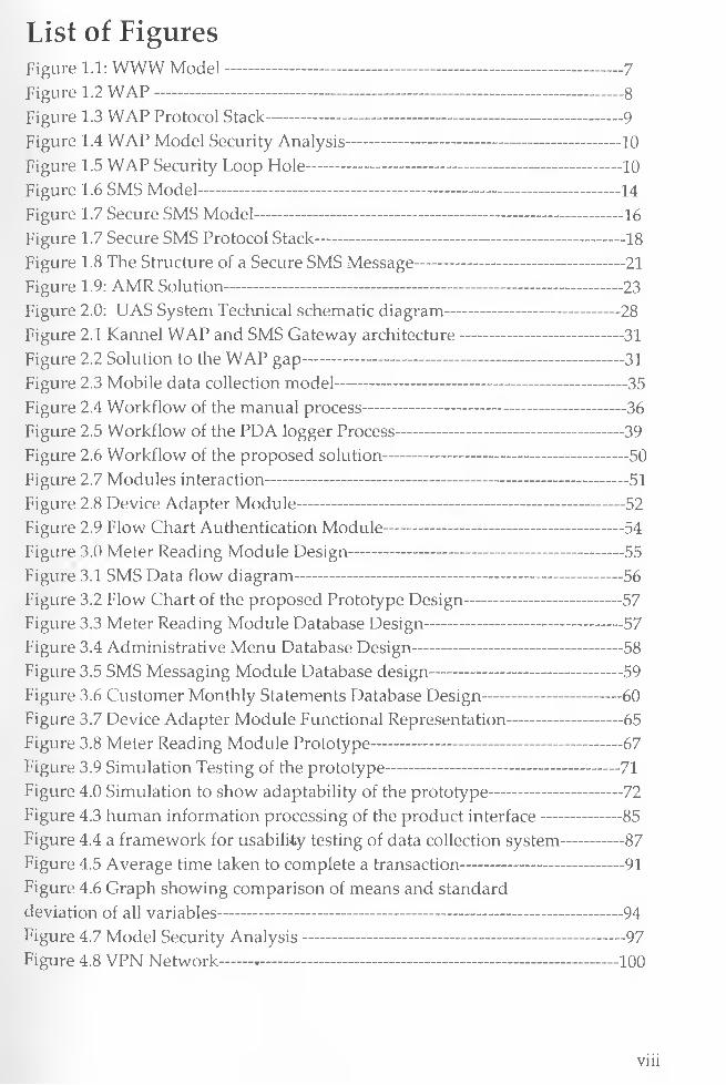
List of FiguresFigure 1.1: WWW M odel--------------------------------------------------------------------------7Figure 1.2 W A P ---------------------------------------------------------------------------------------8Figure 1.3 WAP Protocol Stack------------------------------------------------------------------9Figure 1.4 WAP Model Security Analysis--------------------------------------------------- 10Figure 1.5 WAP Security Loop Hole-----------------------------------------------------------10Figure 1.6 SMS Model------------------------------------------------------------------------------ 14Figure 1.7 Secure SMS Model------------------------------------------------- 16Figure 1.7 Secure SMS Protocol Stack--------------------------------------------------------- 18Figure 1.8 The Structure of a Secure SMS Message---------------------------------------21Figure 1.9: AMR Solution--------------------------------------------------------------------------23Figure 2.0: UAS System Technical schematic diagram-------------------------------- 28Figure 2.1 Kannel WAP and SMS Gateway architecture------------------------------ 31Figure 2.2 Solution to the WAP gap------------------------------------------------------------31Figure 2.3 Mobile data collection model------------------------------------------------------ 35Figure 2.4 Workflow of the manual process-------------------------------------------------36Figure 2.5 Workflow of the PDA logger Process------------------------------------------ 39Figure 2.6 Workflow of the proposed solution--------------------------------------------- 50Figure 2.7 Modules interaction------------------------------------------------------------------- 51Figure 2.8 Device Adapter Module-------------------------------------------------------------52Figure 2.9 Flow Chart Authentication Module-------------------------------------------- 54Figure 3.0 Meter Reading Module Design--------------------------------------------------- 55Figure 3.1 SMS Data flow diagram-------------------------------------------------------------56Figure 3.2 Flow Chart of the proposed Prototype Design----------------------------- 57Figure 3.3 Meter Reading Module Database Design--------------- 57Figure 3.4 Administrative Menu Database Design---------------------------------------58Figure 3.5 SMS Messaging Module Database design----------------------------- 59Figure 3.6 Customer Monthly Statements Database Design--------------------------60Figure 3.7 Device Adapter Module Functional Representation--------------------- 65Figure 3.8 Meter Reading Module Prototype-----------------------------------------------67Figure 3.9 Simulation Testing of the prototype------------------------------------------- 71Figure 4.0 Simulation to show adaptability of the prototype-------------------------72Figure 4.3 human information processing of the product interface---------------85Figure 4.4 a framework for usability testing of data collection system------------87Figure 4.5 Average time taken to complete a transaction------------------------------ 91Figure 4.6 Graph showing comparison of means and standarddeviation of all variables-------------------------------------------------------------------------- 94Figure 4.7 Model Security Analysis---------------------------------------------------------- 97Figure 4.8 VPN Network------------------------------------------------------------------------- 100
viii
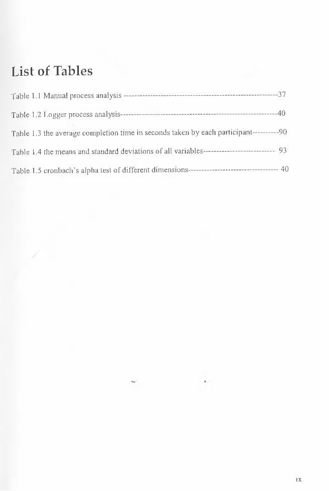
List of Tables
Table 1.1 Manual process analysis---------------------------------------------------------------37
Table 1.2 Logger process analysis----------------------------------------------------------------40
Table 1.3 the average completion time in seconds taken by each participant--------- 90
Table 1.4 the means and standard deviations of all variables----------------------------- 93
Table 1.5 cronbach’s alpha test of different dimensions------------------------------------ 40
/
IX

TerminologyAMR Automatic Meter Reading System3 C Third Generations wireless networkAPI Application Program InterfaceBSC Base Station ControllerBTS Base Transceiver StationCDMA Code Division Multiple AccessDCS Data Collection SystemsGMSC Gateway Mobile Services ControllerGPRS General Packet Radio ServiceGSM Global System for Mobile CommunicationGUI Graphical User InterfaceHLR Home Location RegisterHTML HyperText Markup LanguageHTTP HyperText Transfer ProtocolIP Internet ProtocolIT/IS Information Technology/ Information SystemJ2ME Java 2 Platform, Micro EditionKPLC Kenya Power and Lighting CompanyMIDlet Mobile Information Device ApplicationMSC Mobile Services Switching CentreMSISDN Mobile Station International PSTN/ISDN NumberMSRN Mobile Station Roaming NumberNWC Nairobi Water CompanyPAP Push Access ProtocolPC Personal ComputerPI Push InitiatorUP Utility ProviderSMS Short Message ServiceSMS-C Short Message Service CentreSNMP Simple Network Management ProtocolSMPP Short Message Peer to Peer ProtocolTCP/IP Transport Control Protocol/ Internet ProtocolWAE Wireless Application EnvironmentWAP Wireless Application ProtocolWDP Wireless Datagram ProtocolWGP WAP Gateway ProxyWML Wireless Markup LanguageWSP Wireless Session ProtocolWTP Wireless Transaction ProtocolWTLS Wireless Transport Layer SecurityWWW World Wide WebXHTML extensible HyperText Markup LanguageXML extensible Markup LanguageRADIUS Remote -Authentication Dial-In User Service; an AAA server
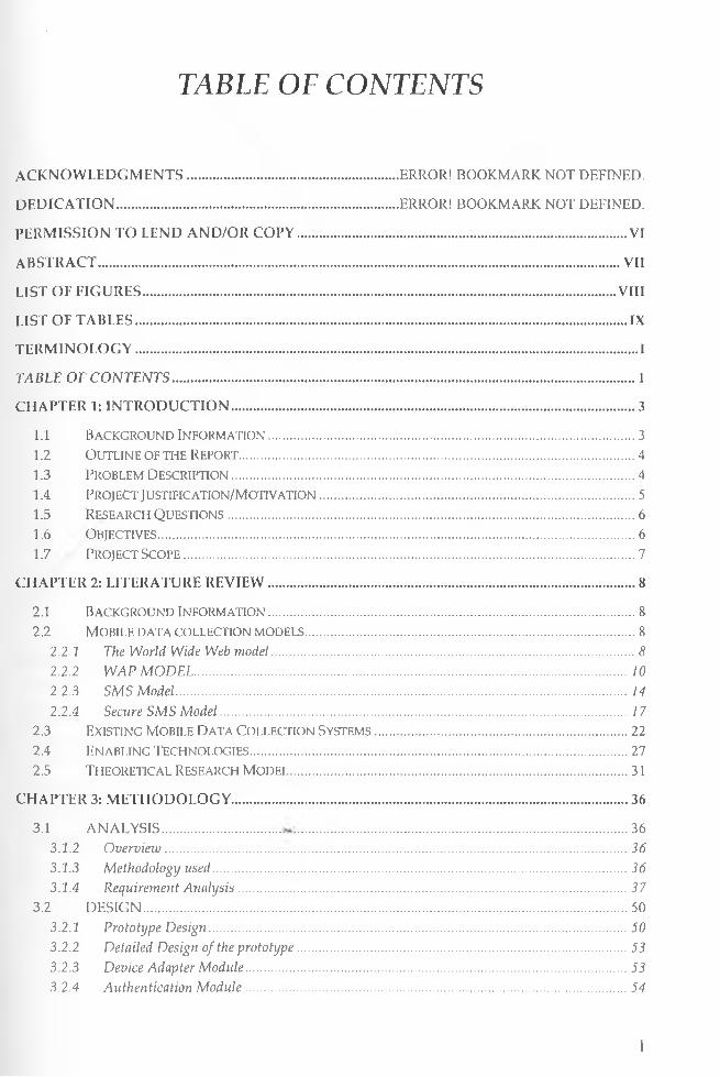
TABLE OF CONTENTS
ACKNOWLEDGMENTS......................................................... ERROR! BOOKMARK NOT DEFINED.
DEDICATION..................................................................................ERROR! BOOKMARK NOT DEFINED.
PERMISSION TO LEND AND/OR COPY................................................................................................ VI
ABSTRACT........................................................................................................................................................ VII
LIST OF FIGURES..........................................................................................................................................VIII
LIST OF TABLES............................................................................................................................................... IX
TERMINOLOGY.................................................................................................................................................. I
TABLE O F C O N TEN TS ....................................................................................................................................... 1
CHAPTER 1: INTRODUCTION......................................................................................................................3
1.1 Background Information........................................................................................................... 3l .2 Outline of the Report.................................................................................................................... 41.3 Problem Description.......................................................................................................................4l .4 Project J ustific ation/Motiv ation............................................................................................. 51.5 Research Questions........................................................................................................................ 61.6 Objectives........................................................................................................................................... 61.7 Project Scope.......................................................................................... :....................................... 7
CHAPTER 2: LITERATURE REVIEW........................................................................................................... 8
2.1 Background Information........................................................................................................... 82.2 Mobile data collection models.................................................................................................8
2.2.1 The World Wide Web model.......................................................................................................... 82.2.2 WAP M O DEL ............................................................................................................................... 102.2.3 SMS Model.................................................................................................................................... 142.2.4 Secure SM S M odel....................................................................................................................... 1 7
2.3 Existing Mobile Data Collection Systems.......................................................................... 222.4 Enabling Technologies...............................................................................................................272.5 Theoretical Research Model...................................................................................................3 1
CHAPTER 3: METHODOLOGY....................................................................................................................36
3.1 ANALYSIS................................ .............................................................................................. 363.1.2 Overvieiu....................................................................................................................................... 363.1.3 Methodology used......................................................................................................................... 363.1.4 Requirement Analysis..................................................................................................................37
3.2 DESIGN....................................................................................................................................503.2.1 Prototype Design.......................................................................................................................... 503.2.2 Detailed Design of the prototype.................................................................................................533.2.3 Device Adapter Module................................................................................................................533.2.4 Authentication M odule................................................................................................................54
1
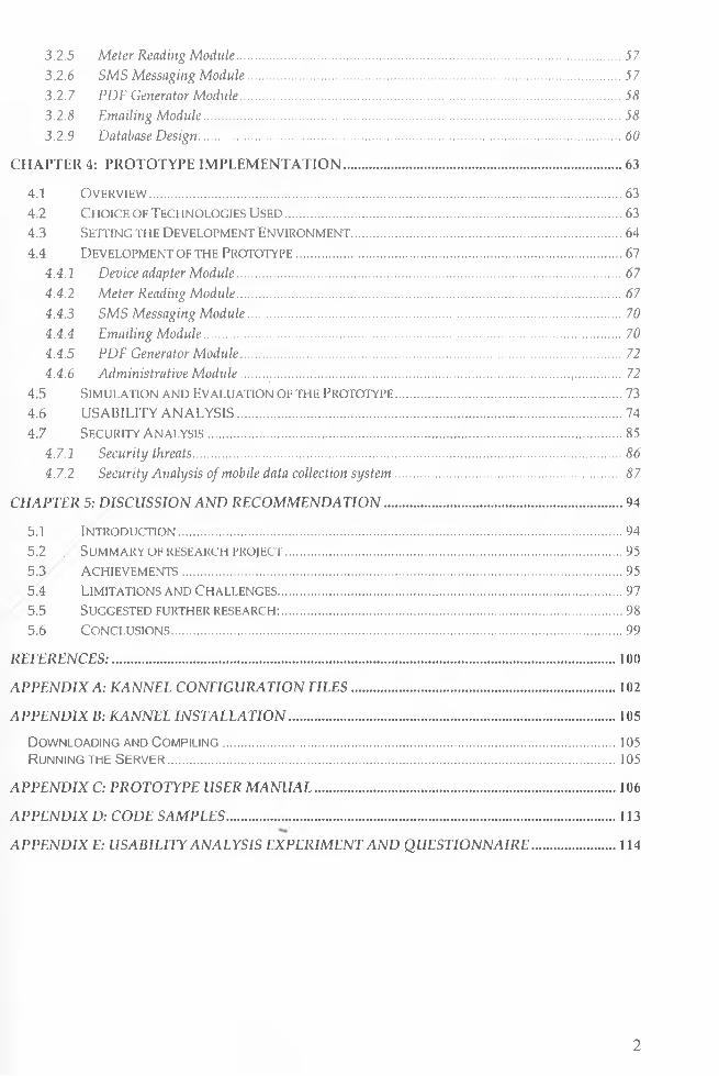
3.2.5 Meter Reading Module.................................................................................................................573.2.6 SM S Messaging M odule..............................................................................................................573.2.7 PDF Generator M odule................................................................................................................583.2.8 Emailing Module.......................................................................................................................... 583.2.9 Database D esign:.......................................................................................................................... 60
CHAPTER 4: PROTOTYPE IMPLEMENTATION..................................................................................63
4.1 Overview.......................................................................................................................................... 634.2 Choice of Technologies Used...................................................................................................634.3 Setting the Development Environment............................................................................... 644.4 Development of the Prototype................................... 67
4.4.1 Device adapter Module.................................................................................................................. 674.4.2 Meter Reading Module.................................................................................................................674.4.3 SM S Messaging M odule..............................................................................................................704.4.4 Emailing Module...........................................................................................................................704.4.5 PDF Generator Module...................................... 724.4.6 Administrative M odule................................................................................................................ 72
4.5 Simulation and Evaluation of the Prototype...................................................................734.6 USABILITY ANALYSIS..................................................................................... 744.7 Security Analysis......................................................................................................................... 85
4.7.1 Security threats..............................................................................................................................864.7.2 Security Analysis of mobile data collection system ...................................................................87
CH APTER 5: D ISCU SSIO N A N D R EC O M M EN D A TIO N ...................................................................... 94
5.1 Introduction...................................................................................................................................945.2 . Summary of research project...................................................................................................955.3 Achievements.................................................................................................................................955.4 Limitations and Challenges..................................................................................................... 975.5 Suggested further research: ....................................................................................................985.6 Conclusions............................. 99
R E FE R E N C E S :................................................................................................................................................... 100
A P P EN D IX A : KANNEL CO N FIG U RATIO N F IL E S ..............................................................................102
A P P EN D IX B: KAN N EL IN ST A LL A T IO N ................................................................................................105
Downloading and Compiling................................................................................................................... 105Running the Server....................................................................................................................................105
A P P EN D IX C: PRO TO TYPE USER M A N U A L ........................................................................................ 106
A P P EN D IX D: CO D E SA M PLES .................................................................................................................. 113
A P P EN D IX E: U SA BILITY A N A LYSIS EX PER IM EN T AN D Q U ESTIO N N A IR E ......................... 114
2
Chapter 1: Introduction
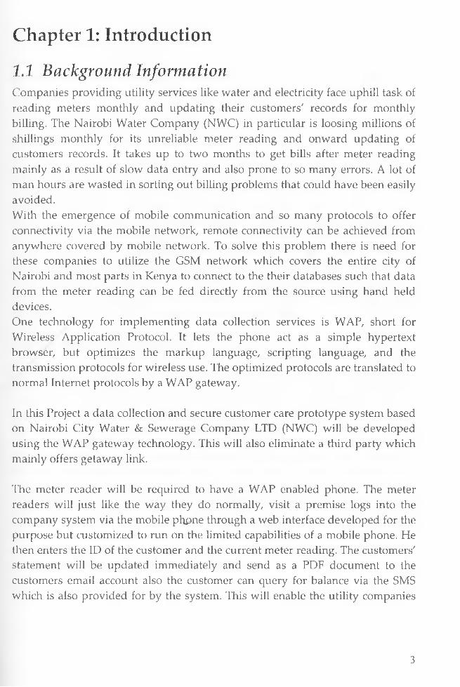
1.1 Background InformationCompanies providing utility services like water and electricity face uphill task of reading meters monthly and updating their customers' records for monthly billing. The Nairobi Water Company (NWC) in particular is loosing millions of shillings monthly for its unreliable meter reading and onward updating of customers records. It takes up to two months to get bills after meter reading mainly as a result of slow data entry and also prone to so many errors. A lot of man hours are wasted in sorting out billing problems that could have been easily avoided.With the emergence of mobile communication and so many protocols to offer connectivity via the mobile network, remote connectivity can be achieved from anywhere covered by mobile network. To solve this problem there is need for these companies to utilize the GSM network which covers the entire city of Nairobi and most parts in Kenya to connect to the their databases such that data from the meter reading can be fed directly from the source using hand held devices.One technology for implementing data collection services is WAP, short for Wireless Application Protocol. It lets the phone act as a simple hypertext browser, but optimizes the markup language, scripting language, and the transmission protocols for wireless use. The optimized protocols are translated to normal Internet protocols by a WAP gateway.
In this Project a data collection and secure customer care prototype system based on Nairobi City Water & Sewerage Company LTD (NWC) will be developed using the WAP gateway technology. This will also eliminate a third party which mainly offers getaway link.
The meter reader will be required to have a WAP enabled phone. The meter readers will just like the way they do normally, visit a premise logs into the company system via the mobile phpne through a web interface developed for the purpose but customized to run on the limited capabilities of a mobile phone. He then enters the ID of the customer and the current meter reading. The customers' statement will be updated immediately and send as a PDF document to the customers email account also the customer can query for balance via the SMS which is also provided for by the system. This will enable the utility companies
3
to fully utilize the services of the meter readers and be prompt thereby increasing the revenue and efficiency.Apart from development of the prototype this project will try to highlight the capability of mobile phone as a capable information device. We shall also investigate how secure is the technology we are adopting.
1.2 Outline of the ReportThis research project contains five main chapters. First there is a chapter one about introduction. Then there is chapter two, here literature review is presented and various models are analyzed critically then a theoretical research model is developed. Chapter three deals with Analysis and design, here we take a look at the requirement analysis of mobile application. After analysis of requirements we move to the design of the product. Chapter four looks at the implementation of the prototype. The actual coding will be attached as an appendix, so only the implementation framework is discussed. Next we look at the most important component of the research which is the security analysis and usability analysis of mobile solutions in respect to the proposed model. In chapter five we look at the general discussion, the recommendation and conclusion.
1.3 Problem DescriptionUtility providers face a major task in collecting monthly data from their investments which can be countrywide or within a city or a town. This monthly data is the source of their core income. Therefore any inefficiency results in serious financial problems which can lead to poor services and eventual collapse. For example the city council of Nairobi failed in water meter reading leading to outsourcing to an independent Nairobi City Water & Sewerage Company LTD (NWC) which by the look of things is headed for failure if they don't reengineer the way they read their meters and update their systems promptly and accurately as well as linking it to customer care for prompt customer information. There is need to utilize technology in the most cost effective way while minimizing the workforcejnvolved in order to increase the return on investment. Faced with these facts and given that mobile networks now covers most parts of the country, mobile technology can be used to enhance service efficiency while minimizing the cost of operation.
4
1.4 Project Justification/MotivationThe inefficiency shown by the utility providers in carrying out their core business is perplexing to say the least. The Nairobi water company for example has completely failed to read their meters monthly and have resorted to inaccurate approximation of customers bills. Each time a customer request for their bills they are given an estimated bill which can be under or over depending on unknown probabilities. When they finally read after 3 to 4 months and updated in the system 1 month later the customer is served with a bill he or she has no idea where it came from or had totally not budgeted for. With this scenario the ever skyrocketing unpaid bills is largely caused by the providers' inefficiency and inaccuracy rather than the customer themselves.
Talking to management of these providers of why they are not efficient in this current age of technology, they will gladly inform you that the budget needed to computerize these operations especially meter reading remotely and networking their remote offices and branches to their information centre runs into billions of shillings hence they will never afford it. There only hope is that a donor will one day come to their rescue or they will just continue with there survival techniques.
What the management is not aware of is that the simple gadget they have in the name of a mobile device they are so much accustomed to using for communication is the key to streamlining there services. It will actually be cost effective to implement this service which will utilize the existing GSM network of the mobile operators. It will also eliminate the data entry clerks, save on stationery, reduce inquiry and customer service staff and above all ensure that there systems are updated immediately the meter reading is read at the source. The system will also have an SMS gateway such that customers can inquire their balance via their mobile phones. It will also have emailing capability such that immediately the meter is read the system generates dynamically a PDF statement and emails it to the customer.
The beauty of the proposed model is that instead of management thinking where it will get millions of shillings to digitize its operations it will actually save them millions of shillings. Hence the motivating factor is how the mobile devices can actually be used to give these providers a lifeline at a minimum cost where the return is high while meeting the following core factors;
• Cost effective - (time, Monetary and Efficiency)
• Adaptability - device independent.
5

• Secure
• Portability
• Extensibility
1.5 Research Questions• What are the types of models that can be used to implement mobile data
collection system for utility providers?
• Which model or models are the most cost effective, usable and secure for
implementing mobile metering services for utility providers?
• Is it possible to implement a mobile data collection system using the
model(s) chosen that is adaptable to the device or browser being used?
• Is the model developed usable by the intended users?
1.6 ObjectivesThe general objective of this research project is to develop a cost effective secure
mobile data collection and customer information model for utility providers and
implement it as a system prototype to show how utility providers can utilize the
system using WAP enabled mobile phones to enable updating of the central
system from the remote location of the meter and link this to customer care
service automatically. We also look at security, vulnerability and user analysis of
the model.
Specific Objectives• To carry out analysis of existing data collection models.
• To identify ways in which data capture, analysis and customer care
workflow can be reorganized and made more efficient.
• To analyze security and vulnerability of the prototype and what
enhancements can be done to make it more secure.
• To identify cost effectiveAvays in which hand-held devices can be used for
data collection.
• To develop a working prototype of the system based on the proposed
model
• To carry out usability analysis of the prototype.
6
1.7 Project ScopeAn important part of this research project will be to develop a data collection
model and implement has a prototype system. Functionality is the main focus of
the prototype system. The prototype will have all the functionality required to
successfully perform a laboratory usability test. Since the security of the solution
is transparent for the users, this will be partly implemented to save on time and
resources required e.g. the RADIUS server. A preliminary security and usability
analysis will be conducted. Suggestions on what security measures should be
implemented in the system will be made based on the results from this analysis.
The suggestions will focus mainly on measures for securing the wireless link,
authenticating the devices and protecting the data. Detailed security analysis is
beyond the scope of this project, because it would require specific security
measures to be implemented. Usability analysis will be done using participants
from real intended users. This involves letting participants test the prototype
then answer the usability questionnaire based on the test in order to analyze the
usability of the proposed model.
7
CHAPTER 2: LITERATURE REVIEW
2.1 Background InformationUtility providers are companies or organization or government departments that provide metered services to the public. Currently we have two main utility providers the water services which are mainly controlled by the local government with each local council being entitled to manage water services within there area of jurisdiction. The second provider is Electricity providers which is mainly controlled and managed by the Kenya power and lighting company (KPLC) with government having majority shares. Both these providers face the same problem of trying to automate there meter readings and none has so far made any headway. Although KPLC are in the process of installing digital meters the remote meter can directly communicate with the base station for eventual updating of the systems. However this is still a pipe dream and requires huge investment to install. For the Water services, there problems are still so basic that they actually need something if they are to even start thinking of changing current meters to digital.
2.2 Mobile data collection models
2.2.1 The World Wide Web model
The WWW model, or simply the web, used on the Internet gives a client the possibility to receive contents in a well-specified data format from web servers. The communication is handled through standard networking protocols such as HTTP and TCP/IP. To reach the content on the server the client uses addresses in a standard naming model called Uniform Resource Locator (URL) as shown in Figure 1.1 The client uses a Web Browser to view the content provided and among the formats supported are a language to describe the appearance of the content called HyperText Mark-tip Language (HTML) and a script language to enhance the content functionality called JavaScript or vbScript. It is a stable model that has been used to develop the WAP model [7],
8

The Internet \J,InternetP iu toco l
Slack HTMLJavaScript
— Internet - Protocols
HTMLHTTP
TL5/SSLTCP/IP
CGIScripts
OtC-
W ubBrowser
Fig 1.1: WWW Model (source WAP forum)
Advantages of WWW Model• It's a stable accepted standard model within the field of computing• High number of experts to develop application for this model are
, available• Supports exchange of high volume of information unlike the WAP model.« Highly secure using SSL (Secure HTTP)• Can utilize any existing public and private network
Shortcomings for WWW Model for mobile applications• It is designed for large bandwidth, low delay• Its stateless, client/server, request/response communication• Its based on connection oriented, one connection per request• High overheads TCP 3-way handshake, DNS lookup overheads• Has big protocol headers, uncompressed content transfer• primitive caching (often disabled, dynamic objects)• security problems (using SSL/TLS with proxies)• designed for computers with "high" performance, color high-resolution
display, mouse, hard disk• typically, web pages optimized for design, not for communication; ignore
end-system characteristics
9
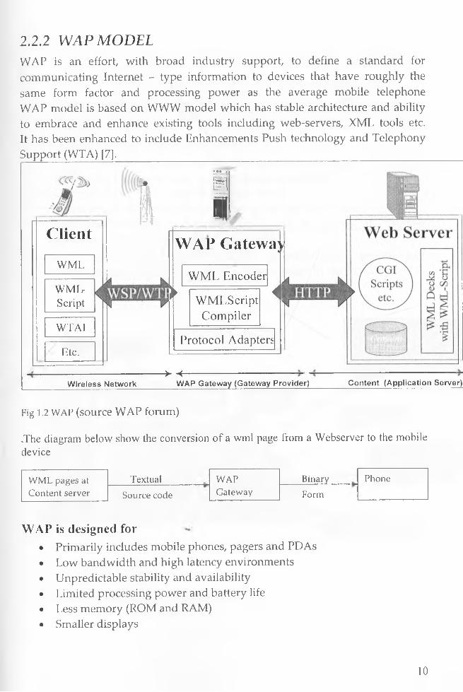
2.2.2 WAP MODELWAP is an effort, with broad industry support, to define a standard for communicating Internet - type information to devices that have roughly the same form factor and processing power as the average mobile telephone WAP model is based on WWW model which has stable architecture and ability to embrace and enhance existing tools including web-servers, XML tools etc. It has been enhanced to include Enhancements Push technology and Telephony Support (WTA) [?].____________________________________________________________
Client
WML
WMLScript
ffL M1 H i,-L l
m
WAP Gatewa>
WTAl
Etc.
W M L Encode r
► W M LScriptCompiler
<
| Protocol Adapters
-> -f-Wireless Network WAP Gateway (Gateway Provider) Content (Application Server)
Fig 1.2 WAP (source WAP forum)
,The diagram below show the conversion of a wml page from a Webserver to the mobile device
WML pages at Textual WAP Binary PhoneContent server Source code Gateway Form
WAP is designed for• Primarily includes mobile phones, pagers and PDAs• Low bandwidth and high latency environments• Unpredictable stability and availability• Limited processing power and battery life• Less memory (ROM and RAM)• Smaller displays
10
WAP Objectives• Create global wireless protocol specifications that work across differing
wireless technologies• Facilitate network-operator and third party service provisioning• Define a layered, scalable and extensible architecture• Bring Internet/Intranet information and advanced data services to wireless
terminals• Optimize for efficient use of device resources• Provide support for secure applications and communication• Embrace and extend existing standards where possible• Optimize for efficient use of device resources• Optimize for narrowband bearers with potentially high latency• Enable personalization and customization of the device, the content
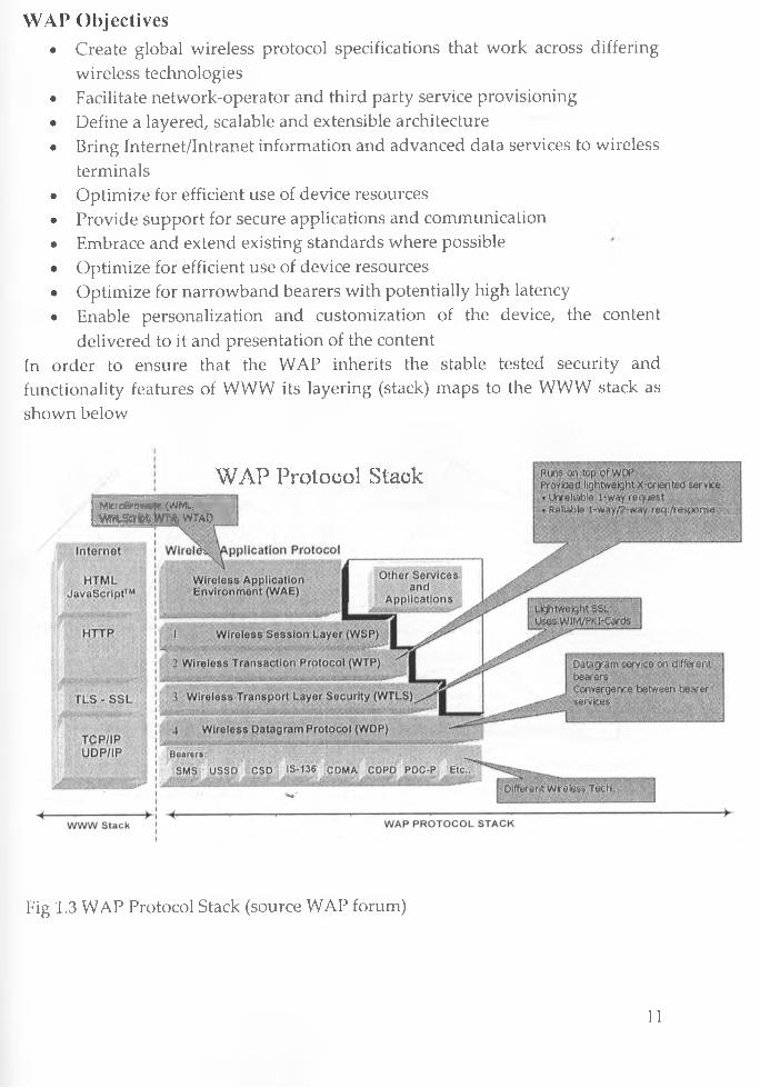
delivered to it and presentation of the contentIn order to ensure that the WAP inherits the stable tested security and functionality features of WWW its layering (stack) maps to the WWW stack as shown below
WAP Protocol StackMlcroBrows*r (WML,
a m m m m mm
Fig 1.3 WAP Protocol Stack (source WAP forum)
11
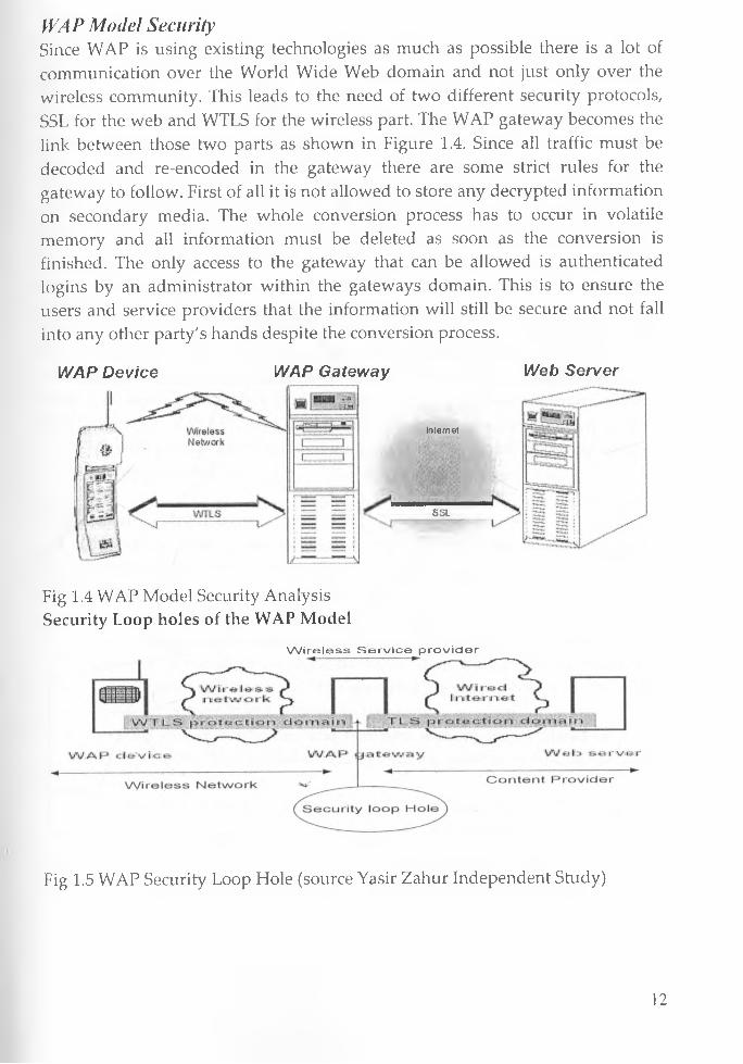
WAP Mode! SecuritySince WAP is using existing technologies as much as possible there is a lot of communication over the World Wide Web domain and not just only over the wireless community. This leads to the need of two different security protocols, SSL for the web and WTLS for the wireless part. The WAP gateway becomes the link between those two parts as shown in Figure 1.4. Since all traffic must be decoded and re-encoded in the gateway there are some strict rules for the gateway to follow. First of all it is not allowed to store any decrypted information on secondary media. The whole conversion process has to occur in volatile memory and all information must be deleted as soon as the conversion is finished. The only access to the gateway that can be allowed is authenticated logins by an administrator within the gateways domain. This is to ensure the users and service providers that the information will still be secure and not fall into any other party's hands despite the conversion process.
WAP Device WAP Gateway
Internet
SSI
Web Server
Fig 1.4 WAP Model Security Analysis Security Loop holes of the WAP Model
W ire less Service provider
Fig 1.5 WAP Security Loop Hole (source Yasir Zahur Independent Study)
12

Considering that wireless networks are generally more vulnerable than wired networks, a number of wireless security standards have been developed to ensure the security of information transmitted over the wireless Internet. For instance, Wireless Application Protocol (WAP) solutions use the wireless transport layer security (WTLS) in place of Secure Socket Layer (SSL) or Transport Layer Security (TLS) to ensure secure transmissions between WAP client devices and the WAP gateway. However, communication between the WAP gateway and the backend application or Web server is over a wired network and thus uses standard TCP/IP based Internet security protocol such as TLS or SSL. This scenario therefore creates a need for inter-protocol translation to be handled within the WAP gateway. This results in what is known as the "WAP gap" (Security loop Hole), which is a subtle security issue within WAP-based solutions. The WAP gap occurs due to the inter-protocol translation or conversion process, which causes encrypted data to be decrypted, albeit momentarily, and then re-encrypted before transmission from the WAP gateway to either the WAP client device or the backend application or Web server. The WAP gap represent the fact that every encrypted message transmitted using WTLS, between a WAP client device and the wired Internet through a WAP gateway, will at some brief instance exist as readable plaintext whose security could be compromised [18].
WAP model advantagesThe list below is some of the functionalities that reduce the workload and the power consumption for the client. It will give the user more operating time as well as a cheaper device, since it does not need as much computing power.
• All information, including the HTTP headers, is binary encoded by the WAP gateway. The amount of data to deliver between the client and the gateway is therefore significantly reduced in contrast to the plain text used by the HTTP protocol. The encoding also saves power on the client device since the content is easier to parse.
• Sessions can be suspended and resumed without the overhead of initialestablishment. This is useful, besides saving power, to free up network resources. -w
• The number of packages needed by the transaction protocol is reduced, since there is only one route between the gateway and the client. Therefore the need to manage unordered packages does not exist.
• The gateway handles all the DNS services to resolve domain names used in the URLs. This means that no extra packages for name translation have
13

to be sent over the wireless domain. However, this is not a unique advantage of WAP since it can be achieved with a HTTP proxy as well.
• From version 1.2 of the WAP protocol push functionality will be available. This means that a content provider can push information to the user whenever it is appropriate, e.g. to inform the user of changes or events.
• The improvements made to the protocol stack lead to significant savings in bandwidth. Here is a query from a HTTP 1.0 compatible browser compared to a query from a WAP browser. With a typical handset session with three requests and three responses less than half the number of packages is needed by the WAP protocol stack, which leads to the fact that while the HTTP 1.0 stack have 65% overhead the WAP stack only needs 14% overhead [18],
WAP Model disadvantages• It is very difficult to configure WAP phones for new WAP services, with
20 or so different parameters needing to be entered to gain access to a WAP service.
• There are few mobile phones that support WAP and widespread WAP support in handsets is unlikely for a long time. The problem is also compounded by change in technology frequently. Since the solution targets on mostly the meter readers it wont be a big hindrance to the proposed model
• There are many WAP Gateway vendors out there competing against each other with largely the same standardized product. This has led to consolidation
• The WAP gap security loop hole. Lack of end to end security due to change of protocol between the WAP gateway and the WWW model
2.2.3 SMS ModelThe initial idea for SMS usage was intended for the subscribers to send non- sensitive messages across the open GSM network. Mutual authentication, text encryption, end-to-end security, non-repudiation were omitted during the design of GSM architecture [20],Security Deficiencies of GSM ArchitectureMuch as GSM system strives to make a provision for security services it still has limitations in its security. Tasneem et al (1998), point out the lack of data integrity in the GSM. On top of this the following cryptographic issues with regard to the authentication and encryption algorithms have been identified.
14
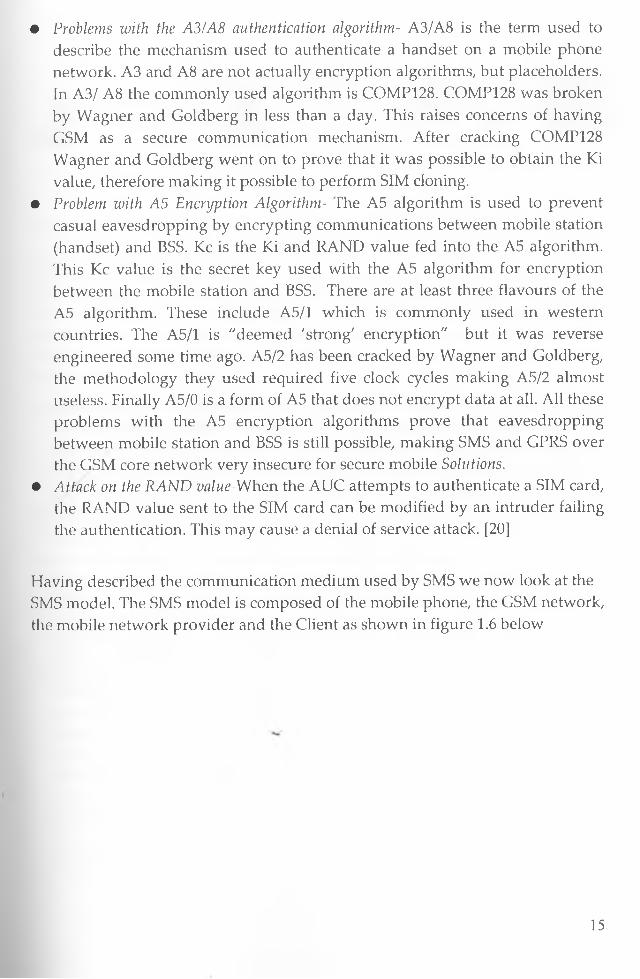
• Problems with the A3/A8 authentication algorithm- A3/A8 is the term used to describe the mechanism used to authenticate a handset on a mobile phone network. A3 and A8 are not actually encryption algorithms, but placeholders. In A3/ A8 the commonly used algorithm is COMP128. COMP128 was broken by Wagner and Goldberg in less than a day. This raises concerns of having GSM as a secure communication mechanism. After cracking COMP128 Wagner and Goldberg went on to prove that it was possible to obtain the Ki value, therefore making it possible to perform SIM cloning.
• Problem with A5 Encryption Algorithm- The A5 algorithm is used to prevent casual eavesdropping by encrypting communications between mobile station (handset) and BSS. Kc is the Ki and RAND value fed into the A5 algorithm. This Kc value is the secret key used with the A5 algorithm for encryption between the mobile station and BSS. There are at least three flavours of the A5 algorithm. These include A5/1 which is commonly used in western countries. The A5/1 is "deemed 'strong' encryption" but it was reverse engineered some time ago. A5/2 has been cracked by Wagner and Goldberg, the methodology they used required five clock cycles making A5/2 almost useless. Finally A5/0 is a form of A5 that does not encrypt data at all. All these problems with the A5 encryption algorithms prove that eavesdropping between mobile station and BSS is still possible, making SMS and GPRS over the GSM core network very insecure for secure mobile Solutions.
• Attack on the RAND value-W/hen the AUC attempts to authenticate a SIM card, the RAND value sent to the SIM card can be modified by an intruder failing the authentication. This may cause a denial of service attack. [20]
Having described the communication medium used by SMS we now look at the SMS model. The SMS model is composed of the mobile phone, the GSM network, the mobile network provider and the Client as shown in figure 1.6 below
15

Security Problems with SMSThe initial idea for SMS usage was intended for the subscribers to send nonsensitive messages across the open GSM network. Mutual authentication, text encryption, end-to-end security, non-repudiation were omitted during the design of GSM architecture. Below is some of the security problems associated with the SMS model.
• Forging Originator's Address -SMS spoofing is an attack that involves a third party sending out SMS messages that appear to be from a legit sender. It is possible to alter the originator's address field in the SMS header to another alpha-numerical string. It hides the original sender's address and the sender can send out hoax messages and performs masquerading attacks. This is common among messages originating from web interfaces using the WWW model.
• SMS Encryption-The default data format for SMS messages is in plaintext. The only encryption involved during transmission is the encryption between the base transceiver station and the mobile station. End-to-end encryption is currently not available. The encryption algorithm used is A5 which is proven to be vulnerable. Therefore a more secure algorithm is needed.
• Denial of Service Attack-There is security vulnerability at the SMS Centre (SMSC). When an SMS message is received at the SMSC, the message gets queued up at the storage buffer. The attacker can exploit this vulnerability by flooding the buffer queue with multiple meaningless messages to a target mobile number. This type of flooding can causes the SMSC to reject incoming messages for the victim because the storage space is limited in the buffer queue [19]
advantages
• Enables wireless data access for corporate users.
16
• Notification mechanisms for newer services such as those utilizing wireless application protocol (WAP)
• Protection of important network resources (such as voice channels), due to SMS' sparing use of the control and traffic channels
• Delivery of messages to multiple subscribers at a time• Ability to receive diverse information• Integration with other data and Internet-based applications• Reliable, low-cost communication mechanism for concise information• Guaranteed message delivery• Delivery of notifications and alertsDisadvantages
• Insecure mode of data trasmission
o A5 encryption algorithm is not entirely secure. Research has shown that this method has flaws and it is vulnerable to attacks.
o If the message content is not encrypted then any personnel who have access to the service provider s SMS data can view the sensitive details.
o The verification depends only on the sender's number, such that if the SIM card is lost or the SIM card is duplicated, the attacker can use the victim s account to perform transaction.
o The SMS message that gets sent to the application server is only encrypted between the mobile station and the base transceiver station. The message is in plaintext within the mobile operator s network.
o By allowing customers to send their authentication PIN, the service provider can read the PIN because it is sent in plaintext.
• Lack of interactivity to real time data sources• Length limit of 160 characters• Expensive mode of data transfer compaired to the WAP model and WWW
model• Unable to control input format
2.2.4 Secure SMS Model wThe confidentiality of the message content transferred from the mobile phone to the application server must be preserved. Any unauthorized individual who managed to obtain the message must not be able to read the secured contents within the SMS message. Only the parties with the correct security details can acquire the message content. If the transmitting message was altered, the receiver should be able to notice the message content is changed.
17
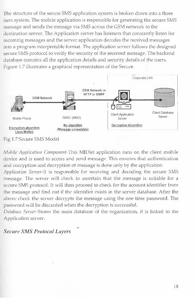
The structure of the secure SMS application system is broken down into a three tiers system. The mobile application is responsible for generating the secure SMS message and sends the message via SMS across the GSM network to the destination server. The Application server has listeners that constantly listen for incoming messages and the server application decodes the received messages into a program interpretable format. The application server follows the designed secure SMS protocol to verify the security of the received message. The backend database contains all the application details and security details of the users. Figure 1.7 illustrates a graphical representation of the Secure.
GSM Network or HTTP or SMPP
Mobile Phone
Encryption algorithm (Java Midletl
SMSC (MNO)
No algorithm (Message unreadable!
Corporate LAN
Client Application Server
Decryption Algorithm
Fig 1.7 Secure SMS Model
Mobile' Application Component-This MIDlet application runs on the client mobile device and is used to access and send message. This ensures that authentication and encryption and decryption of message is done only by the application Application Server-lt is responsible for receiving and decoding the secure SMS message. The server will check to ascertain that the message is suitable for a secure SMS protocol. It will then proceed to check for the account identifier from the message and find out if the identifier exists in the server database. After the above check the server decrypts the message using the one time password. The password will be discarded when the decryption is successful.Database Server-Stores the main database of the organization, it is linked to the Application server.
V'Secure SMS Protocol Layers
18
SMS Message encrypted
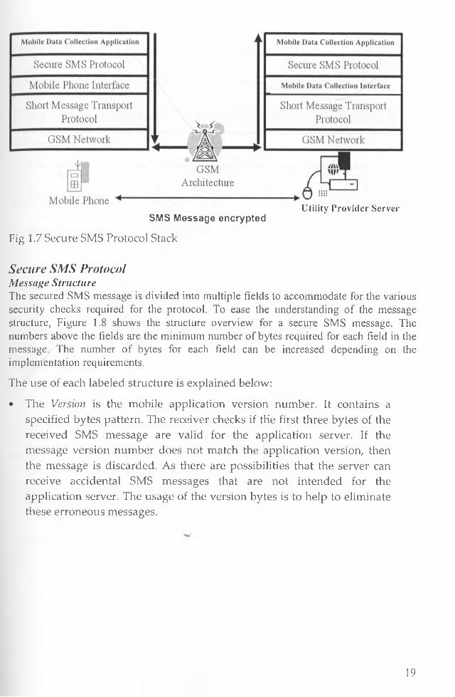
Fig 1.7 Secure SMS Protocol Stack
Utility Provider Server
Secure SMS Protocol Message StructureThe secured SMS message is divided into multiple Fields to accommodate for the various security checks required for the protocol. To ease the understanding of the message structure, Figure 1.8 shows the structure overview for a secure SMS message. The numbers above the fields are the minimum number of bytes required for each field in the message. The number of bytes for each field can be increased depending on the i mplementation requirements.
The use of each labeled structure is explained below:
• The Version is the mobile application version number. It contains a specified bytes pattern. The receiver checks if the first three bytes of the received SMS message are valid for the application server. If the message version number does not match the application version, then the message is discarded. As there are possibilities that the server can receive accidental SMS messages that are not intended for the application server. The usage of the version bytes is to help to eliminate these erroneous messages.
19

C 3 CD CD < C 8 5 >
Vers ion A ccID Seq Secure M essage
_ , —- < 6 6 ; - CD 2 0 .J
Encrypted Text Length Encrypted Banking Details D igest Length D igest
C a ^ - CDPIN Type of Transaction
------------- ------------7Transaction Payload Encryption Payload
T ransac tion type
T yp e 1 (B a lan ce)
T yp e 2 (Transfer M oney )
T yp e 3 (P u rchase Airtim e)
/ CDlo Transaction Payload R equired, Filled with Random Byte
CD CD CDDestination A ccID A m ount Filled R andom Bytes
CD CD CDMobile N um ber A m ount Filled R andom Bytes
Figure 1.8 The Structure of a Secure SMS Message
• The AccID contains the customer account identifier of the user.• The Seq is the user's current sequence number of the one-time password.• The Encrypted Text Length contains the number of next bytes that are the
ciphered message.• The Digest Length contains the number of next bytes that contains the
message digest.• The Digest contains the calculated digest value of the message. The use
of the digest is for the server to check for message integrity. For the secure SMS protocol, a single digest of the following fields is calculated: Version, AccID, Seq, PIN, Type of Transaction and Transaction Payload.
The content of the following fields is encrypted using the generated session key.• The PIN contains the user predefined password. This is used by the
receiver application to authenticate the user.• The secure SMS message can be used for different types of transactions.
The Type of Transaction is used by the application server to identify the type of transaction it should perform.
The Transaction Payload is the extra data that is used for a transaction, but it is not used for any security purpose. The content of the Transaction Payload depends on the type of transaction requested. The structure of the payload depends on the type of transaction offered by the Client [20],
20

Advantages of secure SMS modelApart from inheriting all the advantages of SMS model the secure SMS model has thefollowing security advantages.• Confidentiality-This is achieved by encrypting the message using a symmetric
secret one-time password. The one-time password is only shared between the user and the application server. The strength of the confidentiality depends on the security strength of the passwords generation algorithm used and the strength of the ciphering algorithm used. It is assumed that only the authorized user will know his/her list of passwords and the passwords are never shared with other people.
• Integrity-The message digest is the hashed value of the message content calculated server application and the mobile phone application. If the content is altered during transmission, the hashing algorithm will generate a different digest value at the receiver side. If the digests mismatch, the receiver will know that the integrity of the message has been compromised. The strength of the integrity checks depends on the strength of the algorithm used to generate the digest value and it also depends on the strength of the encryption algorithm used to hide the confidential data.
• Authentication-For the receiver to authenticate the user, the user must provide his/her authentication detail(s) to the receiver. This authentication process is performed by validating the message PIN with the receiver stored PIN. The PIN is previously selected by the user when the user registers for a mobile application account. The strength of the authentication depends on the password selection strategies used.
• Non-Repudiation-On\y the account holder and the application server are supposed to have the one-time password. The application server does not generate the same one-time password more than once. Therefore every onetime password is unique in the server's database. Each pair of one-time password and sequence number is only allowed to be used for a single user. Therefore the user cannot deny not sending the message because only that specific user has that unique pair of password and sequence number to encrypt the message. If the application server can use the same sequence- password pair to decrypt the message, then it indicates that user must have sent the message.
• Availability-The availability of this protocol depends on the availability of the cellular network. The time it takes for a message to be delivered depends on the density of network operator base towers. The number of transactions that the server can handle at once depends on the hardware capability. If the server's hardware can handle multiple incoming messages then the server can perform multiprocessing to accommodate for more requests. The protocol
21

has no restriction on the type of hardware needed. Therefore it is up to the developers to decide the hardware specifications. Apart from the security issues being addressed the format of the input is also controlled because the user interface is controlled by the MIDlet application developed.
Shortcomings of this ModelFor this model to work in a large organization it requires an SMS gateway which is mostly provided by a third party companies licensed by CCK unless the company acquires their own SMS Gateway. It is also affected by the shortcomings of the SMS which can only allow upto 160 characters hence not viable for a fully fledged system. Unlike the WAP model which utilizes the traditional web interface systems, the client mobile devices have to be installed with the mobile application component hence costly to maintain and support. Also the model has the following thread offs• Cost - charges per SMS not per the size of transfer• Language specific - J2ME• Security vs. Performance trade-off• Security vs. Functionality trade-off• Hardware Platform (Compatibility)-MIDP 2.0 Compliant. Not all mobile
devices support this platform• Limitation of SMS Length (160 characters)• Problems associated with Client server technology for example need to
update handsets every time modification is done.• Need to learn new platform of development. That's does not utilise the
existing stable programming paradigm of WWW model.• Not easy to extend and increase functionality.• Does not support high level of interactivity.• Flaving the application loaded onto the SIM card makes the mobile
application SIM card dependent. If the SIM card is lost, the security of the mobile application is vulnerable.
• Unlike the WWW model and WAP model it is based on SMS processing hence concurrency processing and scalability might be hard to achieve.
2.3 Existing Mobile Data Collection SystemsThe solutions provided are numerous and varied but we will highlight just a few
of them related to the models we have described above:
Automatic meter reading (AMR) Systems - Using wireless radio
transmitters, AMR remotely reads customer meters and then transfers the data
22
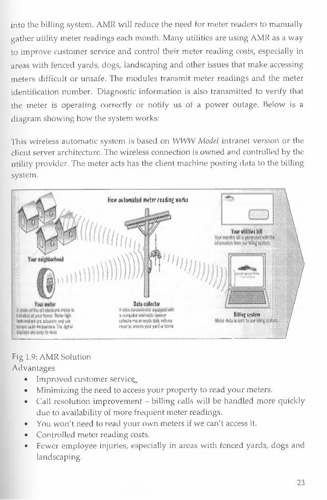
into the billing system. AMR will reduce the need for meter readers to manually
gather utility meter readings each month. Many utilities are using AMR as a way
to improve customer service and control their meter reading costs, especially in
areas with fenced yards, dogs, landscaping and other issues that make accessing
meters difficult or unsafe. The modules transmit meter readings and the meter
identification number. Diagnostic information is also transmitted to verify that
the meter is operating correctly or notify us of a power outage. Below is a
diagram showing how the system works:
This wireless automatic system is based on WWW Model intranet version or the client server architecture. The wireless connection is owned and controlled by the utility provider. The meter acts has the client machine posting data to the billing system.
(«*t ind'fi n Ww*ti w 4 m i*m N w f l t 1m d g u i
He* m !o«i meter rtidhg works
« lwflplta laws«««t* nsK«r «WmA io m m jw ini tr tem
BiSini w lm
Fig 1.9: AMR Solution Advantages
• Improved customer servic^.• Minimizing the need to access your property to read your meters.• Call resolution improvement - billing calls will be handled more quickly
due to availability of more frequent meter readings.• You won't need to read your own meters if we can't access it.• Controlled meter reading costs.• Fewer employee injuries, especially in areas with fenced yards, dogs and
landscaping.
23
• A reduction in operational costs that will save you money.Why it's not a preferred Solution to this projectThe goal of this project is to minimize implementation cost as much as possible. This option is not viable for the NWC since:-
• They have to replace all there water meters which are already in use.• They will have to install or give a third party AMR and the cost associated
with this solution is prohibitive. Average of $2000 dollars per digital meter• Need to hire new skilled expatriates or train existing staff to manage the
solution• Need to change there existing solution since AMR is not an open source
solution rather than a package provided by specific companies.• It takes a very long period to implement usually more than 5 years in
developed countries.• Maintenance of electronic meters more frequent than current existing
meters.• Industrial relationship issues.• Since the system is not open, it's not easy to build additional modules on
top.
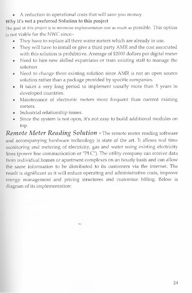
R e m o t e M e t e r R e a d i n g S o l u t i o n - The remote meter reading software and accompanying hardware technology is state of the art. It allows real time monitoring and metering of electricity, gas and water using existing electricity lines (power line communication or "PLC"). The utility company can receive data from individual homes or apartment complexes on an hourly basis and can allow the same information to be distributed to its customers via the internet. The result is significant as it will reduce operating and administrative costs, improve energy management and pricing structures and customize billing. Below is diagram of its implementation:
24

U A S S y s t e m T e c h n i c a l S c h e m a t i c
D ig it a l E l e c t r i c i t y » M e t e r
|• C E B u s P L C M o d u l e : i
( S l a v e ) :
C E B u s P L C M o d u l e ( M a s t e r )
G a t e S e r v e r ♦
P h o n e M o d e m o r A D S L (M ult ip le x c o m m u n i c a t i o n
w i t h m a x . 1 0 0 0 h o u s e t )
* i * ‘-Es
Fig 2.0: UAS System Technical schematic diagram
C u s t o m e r
This wired automatic system is based on WWW Model. The meter acts has the client machine posting data to the billing system [12],Advantages
• Use already existing lines of communication• High reliability• Various applications• Easy monitoring and management• Customer accessible management program through internet
Why it's not a preferred Solution to this project• They have to replace all there water meters which are already in use with
digital meters and connect to electricity line.• Assumes each homestead have a telephone or electricity line for
communication• Expensive to install and maintain• Need to hire new skilled expatriates or train existing staff to manage this
solution• Need to change there existing solution since this solution is not an open
source solution rather thama package provided by specific companies.• It takes a very long period to implement usually more than 5 years in
developed countries.• Does not utilize the emerging technology of mobile communication.• Maintenance of electronic meters more frequent than current existing
meters.
25

C e l e s t a M e t e r r e a d i n g s o l u t i o n - With this wireless meter reading solution meter readers will use their rugged PDA terminals to receive their metering schedules, record the metering data on site and send the readings wirelessly over GPRS to SAP back-office system. Process integration is based on Celesta's proprietary mBusiness software platform, which enables intelligent applications on portable terminals with Microsoft Pocket PC or Symbian operating systems and push/pull communications with back-office systems such as SAP R/3.This solution is based on secure WWW Model where application is accessed via GPRS connectivity using special mobile terminals which can be installed with Microsoft pocket PC hence system accessible via internet browser for pocket PC. Advantages
• High reliability• Easy monitoring and management• Customer accessible management program through internet• Uses wireless technology
Disadvantages• The system is very costly to implement since it's closed and installed and
maintained by the supplier.• Leads to over reliance on the supplier• .Expensive to install and maintain• Need to hire new skilled expatriates or train existing staff to manage this
solution• Need to change there existing solution since this solution is not an open
source solution rather than a package provided by specific companies.• Forces companies to purchase SAP solutions which is very expensive.• No local support.• Does not support variety of mobile devices
Customer SMS -T h is is a two way Short Message service (SMS).Where the Customer reads the reading and sends a text message via a third party SMS Gateway to companies system for updating of his record.
This model is based on the SMS model. But instead of using the meter reader, the
company accepts SMS from customers and bills them.
Advantages• Cheaper to implement.• Consumes less bandwidth.• Time efficient
26

• No need of Meter ReadersWhy it's not a preferred Solution to this project
• This solution is very insecure because SMS are meant to send very basic none critical information via the network.
• Data can easily be accessed by unauthorized personnel• Need to send data in a given format hence prone to errors• Reliance on a third party who enhance introduces a point of inefficiency.• Expensive to maintain monthly third party charges.• Need to verify entries before batching them to the central system• It depends mostly on the honesty of the customer
2AEnabling TechnologiesHere we describe various mobile network technologies, where some are currently in existence on global mobile networks, while the other technologies are gradually becoming adopted by mobile operators. A technical description is outlined for some of the communication services for these network technologies.
Mobile Network Technologies• GSM - Global System for Mobile Communication is a second generation
standard for mobile Communication, developed by the European Telecommunications Standards Institute (ETSI) and now currently owned by the Third Generation Partnership Project (3GPP). Operating in the 900 MHz and the 1800 MHz frequency band, GSM is the most widespread mobile standard currently in use across Europe and the Asia-Pacific region [24],
• GPRS- General Packet Radio Service is packet switched wireless protocol providing non voice value added services that allows information to be sent and received across a mobile telephone network. It is described as a 2.5G technology which supplements Circuit Switched technology such as GSM. Data transmissions speeds of 9.6 kbps to a theoretical maximum speed of up to 171.2 kbps are achievable with GPRS using all eight timeslots at the same time. In addition to higher data rates, GPRS provides users with all time connectivity while only charged for the data viewed or received with a minimal online charge [24].
• EDGE- Enhanced Data for Global Evolution is a higher bandwidth version of GPRS permitting transmission speeds of up to 384 Kbps. It is compatible with the GSM protocol, but it requires higher quality radio signals to reach the increased speed[24]..
27

• 3G -3rd Generation is the generic term for the next big step in mobile technology development. The formal standard for 3G is the IMT-2000 (International Mobile Telecommunications 2000). There are three optional modes as part of the 3G standard. W-CDMA (Wireless Code Division Multiple Access) is for Europe and for the Asian GSM countries, CDMA (Code Division Multiple Access) is for North America, and then TDD/CDMA (Time Division Duplex/CDMA) for China [24]..
• CDMA - Code Division Multiple Access is a proprietary standard for mobile communication, where GSM is an open standard. CDMA was pioneered by Qualcomm and enhanced by Ericsson. Both standards are in competition for dominance in the cellular world. CDMA is a spread spectrum technology, which means that it spreads the information contained in a particular signal of interest over a much greater bandwidth than the original signal. A CDMA call starts with a standard rate of 9.6 kbps, which is then spread to a transmitted rate of about 1.23 Mbps [24]..
Communication Services• SMS -Short Messaging Service was created as a part of the GSM Phase 1
standard to send and receive short text messages, of 70-160 alphanumeric characters in length, to and from mobile phones MS is a smart service, as it can store messages when to the target mobile device is switched off and forwards the messages when the unit is again in use. SMS applications are voicemail/fax notifications, delivery of replacement ring-tones, operator logos and group graphics, unified messaging, personal communication (text messaging), and information services. Basically, any information that fits into a short text message can be delivered by SMS [24]..
• WAP- Wireless Application Protocol is a technology which provides a mechanism for displaying internet information on a mobile phone or any wireless device. This is done by translating internet information in to a format which can be displayed within the constraints of a mobile device. To obtain Internet access on a mobile device, the device should be WAP- enabled and the web site information should be described in WML (Wireless Markup Language) format. WML is the mobile equivalent to HTML for web pages.
• E-mail- Short for electronic mail and often abbreviated to e-mail, email or simply mail, is a store and forward method of composing, sending, storing, and receiving messages over electronic communication systems. The term "e-mail" (as a noun or verb) applies both to the Internet e-mail system based on the Simple Mail Transfer Protocol (SMTP) and to X.400 systems, and to intranet systems allowing users within one organization
28
to e-mail each other. Intranets may use the Internet protocols or X.400 protocols for internal e-mail service supporting workgroup collaboration [16].
Implementation Programming Languages• XML- XML (Extensible Markup Language) is a formal recommendation
from the World Wide Web Consortium (W3C) for describing and displaying the content. It is a structured set of rules for how one might define any kind of data to be shared on the Web. It is similar to the language of today's Web pages, the Hypertext Markup Language (LITML). Both XML and HTML contain markup symbols to describe the contents of a page or file. HTML, however, describes the content of a Web page (mainly text and graphic images) only in terms of how it is to be displayed and interacted with. XML describes the content in terms of what data is being described [24]..
• VoiceXML -VoiceXML is an application of the XML which, when combined with voice recognition technology, enables interactive access to the Web through the telephone or a voice-driven browser
• WML and WMLScript- Content and services in WAP are presented to the phone using the Wireless Markup Language (WML) and the WMLScript programming language. WML is a simple markup language defined with XML and is used to mark the contents of the file as actual text, title, hyperlinks, etc. A WML page is a deck of cards. One card at a time is displayed by the phone. WMLScript is a simple programming language based on ECMAScript and JavaScript, which are usually but not always implemented in WWW browsers. A WAP browser is required to implement WMLScript. WMLScript is used to make WAP pages more dynamic [24]..
• Java and J2ME- Java is a programming language expressly designed for use in the distributed environment of the Internet. Java can be used to create complete applications that may run on a single computer or be distributed among servers and clients in a network. It can also be used to build a small application module or applet for use as part of a Web page. Applets make it possible for a Web page user to interact with the page. The Java 2 Platform, Micro Edition, Wireless Toolkit 2.0 supports the development of Java applications that run on devices complaint with the MIDP 2.0.
29
WAP GateivayThere are several gateways in the market that can be used to implement the WAP model. Examples are:
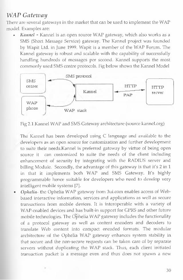
• Kannel - Kannel is an open source WAP gateway, which also works as a SMS (Short Message Service) gateway. The Kannel project was founded by Wapit Ltd. in June 1999. Wapit is a member of the WAP Forum. The Kannel gateway is robust and scalable with the capability of successfully handling hundreds of messages per second. Kannel supports the most commonly used SMS centre protocols. Fig below shows the Kannel Model
SMScenter
W A Pphone
f
HTTPserver
V.J
WAP stack
Fig 2.1 Kannel WAP and SMS Gateway architecture (source kannel.org)
The Kannel has been developed using C language and available to the developers as an open source for customization and further development to suite their needs.Kannel is preferred gateway by virtue of being open source it can customized to suite the needs of the client including enhancement of security by integrating with the RADIUS server and billing Module. Secondly, the advantage of this gateway is that it's 2 in 1 in that it implements both WAP and SMS Gateway. It's highly programmable hence suitable for developers who need to develop very intelligent mobile systems [7].
• Ophelia- the Ophelia WAP gateway from 3ui.com enables access of Web- based interactive information, services and applications as well as secure transactions from mobile devices. It is interoperable with a variety of WAP-enabled devices and has built-in support for GPRS and other future mobile technologies. The Ophelia WAP gateway includes the functionality of a protocol gateway as well as content encoders and decoders to translate Web content into compact encoded formats. The modular architecture of the Ophelia WAP gateway enhances system stability in that secure and the non-secure requests can be taken care of by separate servers without duplicating the WAP stack. Thus, each client initiated transaction packet is a message even and thus does not spawn a new
30

thread. It also has a thread manager which keeps the system from going into an unstable state should there be an overflow of incoming requests [5],
2 .5 Theoretical Research ModelIn designing the the model to be used as a framework for the development of the mobile data collection and customer information system, we need to first breakdown the functionality components of the system. The model should have the following functionality components:• Meter Reading Component - This component should be mobile, secure,
adaptive and have authenticated direct connection to the corporate data source. Update to the system should be online and access should be retricted to authorised users and mobile devices only. The module should be integratable to existing systems hence portability is a necessity.
• Customer Information Component - this component is mainly informative hence users or customers don't connect directly to the data source but gets information from the corporate information system based on the information in the system. Here it should support two types of information, the detailed customer billing statement which can only be available via a desktop computers and short informative messages which can be done via SMS. It follows then that billing statement can be done through emailing by sending a PDF billing statement to the customer Email. Short messages can be done via GSM or GPRS.
The model developed should in general meet the following minimum requirements.
• Cost - the model should be cheaper to implement and maintain• Usability - the model should be usable• Processing time should be very short i.e. 10 minutes from the time of
posting meter reading to the time the customer receives the monthly statement.
• Adaptability - because of change of technology in mobile world there is need for a solution that can adapt to any device in the market (device independent) i.e. application can run in normal browsers, various types of WAP browsers, Voice browsers etc. it should support current and future technology.
• Security - Need for a model that is secure. That is the model should satisfy the five requirements of a secure system confidentiality, authentication, availabilty, integrity, non-repudiation
• Portability - the model should be portable to any platform and system
31
• Extensibility - The model should be highly extensible• Scalability- the model should be scalable
Lastly the model should be able to address most of the utility providers challenges which are within the scope of this research project. The challenges we identified through interview and observation and has been highligted in the analysis section of this report.Meter rending component can be implemented using WWW model, Secure SMS model and the WAP model. The WWW model cannot be used because of the limitation of mobile devices highlighted in the analysis section. The secure SMS model is not prefered due to the limitation in length, language dependent and lack of interactivity with the data source. This leaves WAP model as the most viable solution albeit with its limitation mainly in terms of security and adaptability. In order to use the WAP model we need a solution for the WAP gap and adaptability shortcomings. The section below discusses the solution to the shortcomings oft the WAP model
WAP model shortcomings solutionThere are a number of possible workarounds to reduce the risk posed by the WAP gap issue and minimize the possibility of it being maliciously exploited. These include:
• Ensuring the WAP gateways at the wireless network operator's premises are installed within a heavily secured data centre area with very restricted access. The best practice is to install the WAP Gateway at the application server or the web server. Avoid outsourcing the WAP gateway for critical application.
• Designing the message translation process handled within the gateway such that all encryption, decryption and encoding take place within memory without the use of any temp files or explicit writes to disk.
• Ensuring that no details of the translation are ever logged to disk.• Hosting the WAP gateway within the same secured wired network (i.e.
wireless application owner's own network) as the application server and taking full responsibility for its administration. This ensures that all the inter-protocol translation process is done within the wireless application owner's secured network.
• Use of RADIUS server between the WAP gateway and the Wireless provider.
• Another method for securing WAP solutions is by implementing WTLS tunneling. WTLS tunneling is a new technology that eliminates the WAP gap by providing a WTLS "tunnel" within the WAP gateway such that secure messages can be passed from the wireless device through the WAP
32

gateway and then to the server without being decrypted. In a WTLS tunneling system, the encrypted data from a wireless client-device is sent to the server, just as in a regular WTLS session; however rather than switching from WTLS to SSL encryption, the server sends a new 128-bit WTLS key encrypted with the user's public key. This new 128-bit WTLS key is then used to encrypt data for the rest of the transaction. WTLS tunneling ensures end-to-end WTLS encryption for communications, as data is not decrypted until it reaches its final destination [6], This solution as been used in the current WAP 2.0 complaint devices.
Proposed solution to WAP Security loop holeFor this project the following viable solutions are recommended for the WAP gap- Host the gateway within the secure intranet of the corporates server room.- Use of RADIUS server to enhance authentication of the WAP gateway server
Content Provider (LAN)Wireless Network
WTLS
NetworkOperatorControl WAP GatewayRem ote
Client Host Control
Figure 2.2 Solution to the WAP gapProposed solution to WAP Adaptability shortcomingsThe reasons why WAP m-commerce is still not popular is the requirement that developers have to develop two similar pages one for the web using HTML standard and one for WAP browsers using WML standard. Another problem is that WML tags vary from device to device hence a page that can be displayed in Nokia might not be displayed in Samsung phone. This creates an irritation effect because of need to test the application in a variety of mobile devices to be confident of variety support. For adaptability there is need to have a device detection component and display content based on the browser in use. This eliminates the need to test the application in a variety of devices and the need to
33
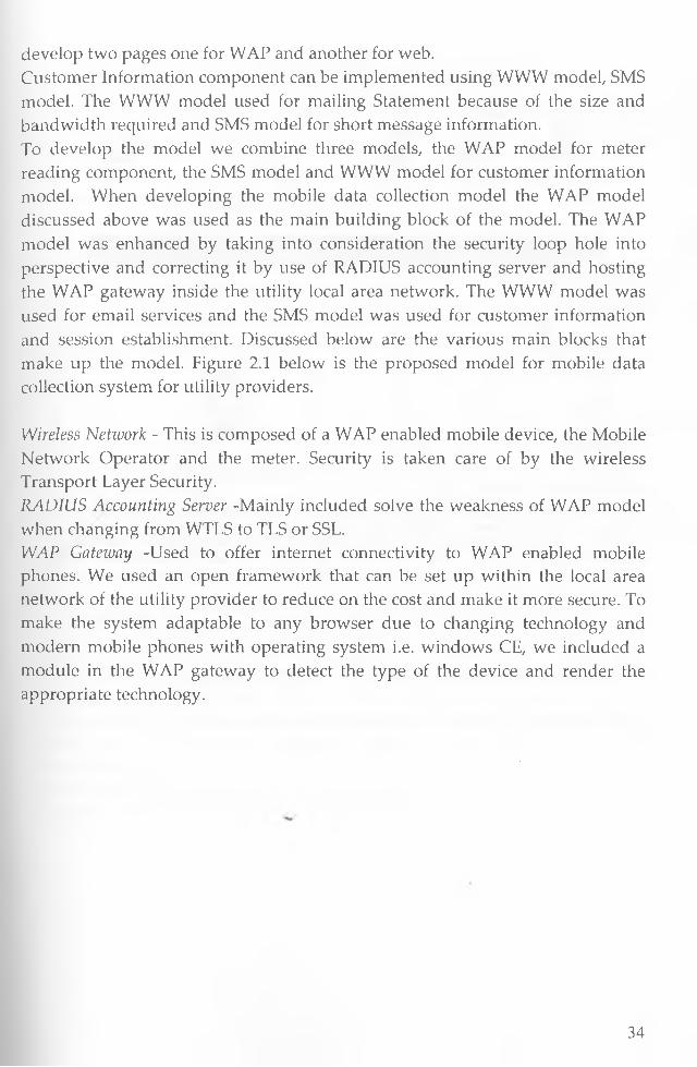
develop two pages one for WAP and another for web.Customer Information component can be implemented using WWW m odel SMS model. The WWW model used for mailing Statement because of the size and bandwidth required and SMS model for short message information.To develop the model we combine three models, the WAP model for meter reading component, the SMS model and WWW model for customer information model. When developing the mobile data collection model the WAP model discussed above was used as the main building block of the model. The WAP model was enhanced by taking into consideration the security loop hole into perspective and correcting it by use of RADIUS accounting server and hosting the WAP gateway inside the utility local area network. The WWW model was used for email services and the SMS model was used for customer information and session establishment. Discussed below are the various main blocks that make up the model. Figure 2.1 below is the proposed model for mobile data collection system for utility providers.
Wireless Network - This is composed of a WAP enabled mobile device, the Mobile Network Operator and the meter. Security is taken care of by the wireless Transport Layer Security.RADIUS Accounting Server -Mainly included solve the weakness of WAP model when changing from WTLS to TLS or SSL.WAP Gateway -Used to offer internet connectivity to WAP enabled mobile phones. We used an open framework that can be set up within the local area network of the utility provider to reduce on the cost and make it more secure. To make the system adaptable to any browser due to changing technology and modern mobile phones with operating system i.e. windows CE, we included a module in the WAP gateway to detect the type of the device and render the appropriate technology.
34
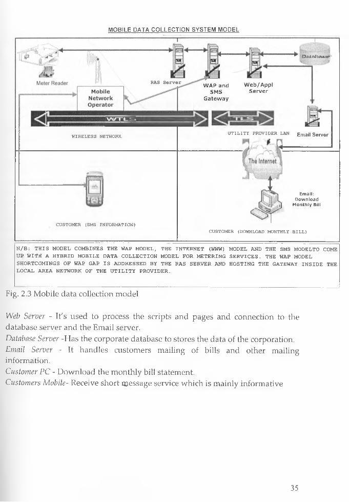
MOBILE DATA COLLECTION SYSTEM MODEL
O j i l a b n s c r
E B I E
WIRELESS NETWORK
0~ ' r— ~
CUSTOMER (SMS INFORMATION)
WAP and Web/ApplSMS Server
Gateway
UTILITY PROVIDER LAN Emaj| Server
Email: Download
% > # J Monthly Bill
CUSTOMER (DOWNLOAD MONTHLY BILL)
N/B: THIS MODEL COMBINES THE WAP MODEL, THE INTERNET (WWW) MODEL AND THE SMS MODELTO COME UP WITH A HYBRID MOBILE DATA COLLECTION MODEL FOR METERING SERVICES. THE WAP MODEL SHORTCOMINGS OF WAP GAP IS ADDRESSED BY THE RAS SERVER AND HOSTING THE GATEWAY INSIDE THE LOCAL AREA NETWORK OF THE UTILITY PROVIDER.
Fig. 2.3 Mobile data collection model
Web Server - It's used to process the scripts and pages and connection to the database server and the Email server.Database Server -Has the corporate database to stores the data of the corporation. Email Server - It handles customers mailing of bills and other mailing information.Customer PC - Download the monthly bill statement.Customers Mobile- Receive short message service which is mainly informative
35
CHAPTER 3: METHODOLOGY
3.1 ANALYSIS
3.1.2 OverviewThe previous chapter reviewed the various models that can be used to develop this prototype, there weakness and enhancement that can be done to make them more secure and usable. We also developed the the the mobile data collection model based on the integration of three models discussed in the literture review. Taking the challenges faced by the Utility providers into context, the cost, usability, security, adaptability, portability and extensibility into account. The research project will begin by looking at the current operations of the NWC in terms of metering services and using mobile technology and combination of other technologies propose a reengineered cost effective process. Based on the limitation of mobile phones, we will come up with a both functional and non functional requirements for the system. We will then use the model developed in Figure 2.6 that addresses the weakness of the other models highlighted earlier and carry out usability analysis of the prototype.
3.1.3 Methodology usedLiterature survey was done to identify the other related mobile metering solutions there weakness and strengths. The models that can be used were also researched and analyzed to find there appropriateness.
In order to identify challenges facing utility providers and how current workfow can be reengineered, a fact finding was done at the NCW through interview and observation. The type of questions were structured in such a manner that the workflow and current challenges facing utility providers are captured. The Nairobi Water company was chosen as a reprentative sample of all the other utility providers in kenya. Its also important to note that this is a prototype and further survey and analysis is recommended for the system to encompass all the varying factors that have to be considered before system implementation.
Other importantant information was obtained through observation, journals, books and more importantly the internet. Since WAP is a fairly new technology the internet and journals were the main contributary of information in the development and analysis of the prototype.
36
Based on the mobile data collection model developed in chapter two figure 2.6 a prototype of the model was designed. In the design of the prototype data flow and flow charting was used to design the prototype.
The prototype was implemented using PHP language with combination of open source technology and MySQL database. In the development we used the modular approach where each module making the model was developed and tested independently. After all modules were developed, the prototype was integrated then tested as a unit to ascertain the workability of the proposed model.
In testing we followed the modular and unit testing approach. Each module was tested independently then integration was done and overall testing was the done as a unit.
Security analysis and usability analysis were done since there are the components determining the viability of the proposed solution. Usability analysis were done by the NWC by performing the experiment described in Appendix E and answering the Survey questions contained in the questionnaire attached in appendix E.
3.1.4 Requirement AnalysisThis section describes the requirements for the prototype. Proposes a model for the prototype and also the hardware and software used to develop the solution are described. Finally a description on how the various components of the model work are highligted.
Review of Current Metering ProcessesIn Kenya currently there are two main processes of meter reading, the manual
process and the Logger (PDA) process. These two methods are used by both the
KPLC and NWC. Below is the analysis of the two processes which will assist in
the design of the mobile data collection prototype.
Manual processIn this system meter readers are sent to the house of the customer with printouts of the customer account details. The meter reader accesses the meter and records the current meter reading against the customers account; the forms are the
37
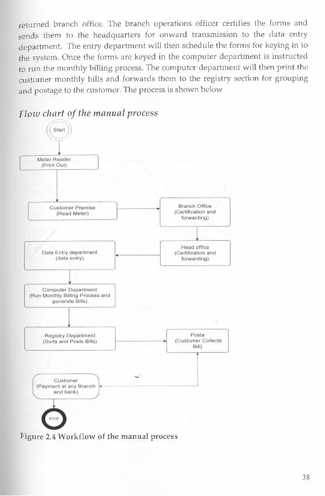
returned branch office. The branch operations officer certifies the forms and sends them to the headquarters for onward transmission to the data entry department. The entry department will then schedule the forms for keying in to the system. Once the forms are keyed in the computer department is instructed to run the monthly billing process. The computer department will then print the customer monthly bills and forwards them to the registry section for grouping and postage to the customer. The process is shown below
Flow chart of the manual process
Figure 2.4 W orkflow of the manual process
38
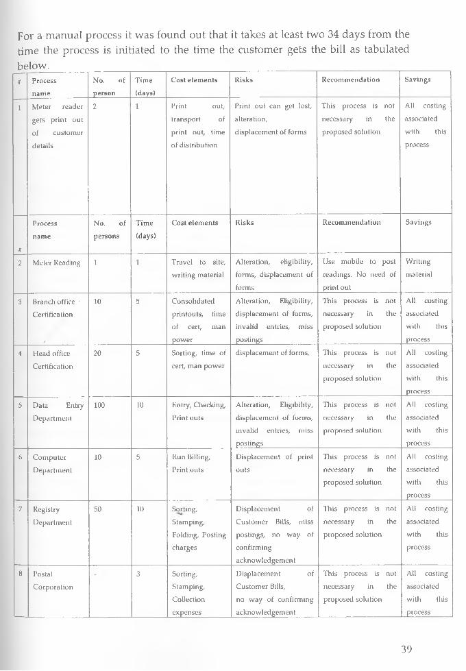
For a manual process it was found out that it takes at least two 34 days from the time the process is initiated to the time the customer gets the bill as tabulated below. ____________________________________________________t P ro c e s s
n a m e
N o . o f
p e r s o n
T im e
(d a y s)
C o s t e le m e n ts R is k s R e c o m m e n d a t io n S a v in g s
1 M e te r re a d e r
g e ts p r in t o u t
o f c u s to m e r
d e ta ils
2 1 P r in t o u t,
tra n s p o r t o f
p r in t o u t, tim e
o f d is tr ib u tio n
P rin t o u t c a n g e t lo st,
a lte ra tio n ,
d is p la c e m e n t o f fo rm s
T h is p ro c e s s is n o t
n e c e s s a ry in th e
p ro p o s e d s o lu t io n
A ll c o s tin g
a s s o c ia te d
w ith th is
p ro c e s s
f
P ro c e s s
n a m e
N o . o f
p e r s o n s
T im e
(d a y s)
C o s t e le m e n ts R is k s R e c o m m e n d a t io n S a v in g s
2 M e te r R e a d in g i 1 T r a v e l to s ite ,
w r it in g m a te r ia l
A lte ra tio n , e lig ib ility ,
fo rm s , d is p la c e m e n t o f
fo r m s
U s e m o b ile to p o s t
re a d in g s . N o n e e d o f
p r in t o u t
W rit in g
m a te r ia l
3 B r a n c h o ff ic e -
C e r tif ic a tio n
f
10 5 C o n s o lid a te d
p r in to u ts , tim e
o f c e rt , m a n
p o w e r
A lte ra tio n , E lig ib ility ,
d is p la c e m e n t o f fo rm s,
in v a lid e n tr ie s , m iss
p o s t in g s
T h is p ro c e s s is n o t
n e c e s s a ry in th e
p ro p o s e d s o lu t io n
A ll c o s tin g
a s s o c ia te d
w ith th is
p ro c e s s
4 H e a d o ff ic e
C e r t i f ic a t io n
2 0 5 S o r tin g , tim e o f
c e r t , m a n p o w e r
d is p la c e m e n t o f fo rm s, T h is p ro c e s s is n o t
n e c e s s a ry in th e
p ro p o s e d s o lu tio n
A ll c o s tin g
a s s o c ia te d
w ith th is
p ro ce s s
5 D a ta E n try
D e p a r tm e n t
100 10 E n tr y , C h e c k in g ,
P r in t o u ts
A lte ra tio n , E lig ib ility ,
d is p la c e m e n t o f fo rm s,
in v a lid e n tr ie s , m iss
p o s t in g s
T h is p ro c e s s is n o t
n e c e s s a ry in th e
p ro p o s e d s o lu t io n
A ll c o s tin g
a s s o c ia te d
w ith th is
p ro c e s s
6 C o m p u te r
D e p a r tm e n t
10 5 R u n B illin g ,
P r in t o u ts
D is p la c e m e n t o f p rin t
o u ts
T h is p ro c e s s is n o t
n e c e s s a ry in th e
p ro p o s e d s o lu t io n
A ll c o s tin g
a s s o c ia te d
w ith th is
p ro c e s s
7 R e g is try
D e p a r tm e n t
5 0 10 S o r tin g ,
S ta m p in g ,
F o ld in g , P o s tin g
c h a r g e s
D is p la c e m e n t o f
C u s to m e r B ills , m iss
p o s t in g s , n o w a y o f
c o n f ir m in g
a c k n o w le d g e m e n t
T h is p ro c e s s is n o t
n e c e s s a ry in th e
p ro p o s e d s o lu t io n
A ll c o s tin g
a s s o c ia te d
w ith th is
p ro c e s s
8 P o s ta l
C o r p o r a t io n
3 S o r tin g ,
S ta m p in g ,
C o lle c tio n
e x p e n s e s
D is p la c e m e n t o f
C u s to m e r B ills ,
n o w a y o f c o n f ir m in g
a c k n o w le d g e m e n t
T h is p ro c e s s is n o t
n e c e s s a r y in th e
p ro p o s e d s o lu t io n
A ll c o s tin g
a s s o c ia te d
w ith th is
p ro c e s s
39
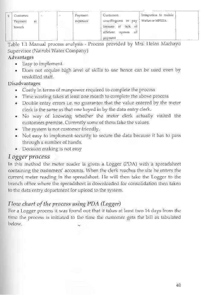
9 C u s to m e r - - P a y m e n t C u s to m e rs In te g r a tio n to m o b ile
P a y m e n t a t e x p e n s e s u n w illin g n e s s to p ay W a lle t o r M P E S A .
b r a n c h b e c a u s e o f la c k o f
e f f ic ie n t s y s te m
p a y m e n t
o f
Table 1.1 Manual process analysis - Process provided by Mrs. Helen Machayo Supervisor (Nairobi Water Company)Advantages
• Easy to implement.• Does not require high level of skills to use hence can be used even by
unskilled staff.Disadvantages
• Costly in terms of manpower required to complete the process• Time wasting takes at least one month to complete the above process• Double entry errors i.e. no guarantee that the value entered by the meter
clerk is the same as that one keyed in by the data entry clerk.• No way of knowing whether the meter clerk actually visited the
customers premise. Currently some of them fake the values.• The system is not customer friendly.• Not easy to implement security to secure the data because it has to pass
through a number of hands.• Decision making is not easy
Logger processIn this method the meter reader is given a Logger (PDA) with a spreadsheet containing the customers' accounts. When the clerk reaches the site he enters the current meter reading in the spreadsheet. He will then take the Logger to the branch office where the spreadsheet is downloaded for consolidation then taken to the data entry department for upload to the system.
Flow chart of the process using PDA (Logger)For a Logger process it was found out that it takes at least two 14 days from the time the process is initiated to the time the customer gets the bill as tabulated below.
40

II
3 LOI r R e
l
R e c e i v e t h e L o g g e r ( P D A ) M e t e r R e a d e r
C u s t o m e r P r e m i s e ( R e a d t h e M e t e r )
IB r a n c h O f f i c e
D o w n l o a d f o r c o n s o l id a t a t i o n
IC o m p u t e r D e p a r t m e n t
U p l o a d d a t a f r o m B r a n c h o f f i c e a n d R u n B i l l in g
II
R e g i s t r y D e p a r t m e n t S o r t a n d R o s t B i l l s
C u s t o m e rP a y m e n t o f b il l a t a n y B r a n c h
Figure 2.5 Workflow of the PDA logger Process.
» P r o c e s s
n a m e
N o . o f
p e r s o n
T im e
(d a y s )
C o s t e le m e n ts R is k s R e c o m m e n d a t io n S a v in g s
1 M e te r r e a d e r
L o g g e r
a s s ig n m e n ts
2 1 L o g g e r , P rin t
o u t, t r a n s p o r t
o f p r in t o u t
a n d lo g g e r ,
t im e of
d is tr ib u tio n
L o g g e r c a n g e t lo s t
H a s n o w a te r t ig h t
a u th e n tic a tio n
m e c h a n is m
N o n e e d o f a lo g g e r
o r P r in t o u ts
A ll c o s tin g
a s s o c ia te d
w ith th is
p ro c e s s
2 M e te r R e a d in g 1 1 T r a v e l to s ite , A lte r a tio n U s e m o b ile to p o s t
r e a d in g s
lo g g e r
3 B r a n c h o ffice
D o w n lo a d fo r
c o n s o lid a t io n
5 1 tim e o f
d o w n lo a d ,
m a n p o w e r
A lte r a tio n ,
E lig ib ility ,
d is p la c e m e n t o f
lo g g e r s , in v a lid
e n tr ie s , m is s
p o s tin g s
T h is p r o c e s s is n o t
n e c e s s a r y in th e
p r o p o s e d so lu tio n
A ll c o s tin g
a s s o c ia te d
w ith th is
p r o c e s s
41

4
5
C o m p u te r
d e p a r tm e n t
U p lo a d in g
A n d b illin g
2 0 2 tim e o f
d o w n lo a d ,
m a n p o w e r
A lte ra tio n ,
E lig ib ility ,
d is p la c e m e n t o f
lo g g e r s , in v a lid
e n tr ie s , m iss
p o s tin g s ,
D is p la c e m e n t o f
p rin t o u ts
T h is p ro c e s s is n o t
n e c e s s a r y in th e
p r o p o s e d s o lu tio n
A ll co s tin g
a s s o c ia te d
w ith th is
p ro c e s s
R e g is tr y
D e p a r tm e n t
5 0 1 0 S o rtin g ,
S ta m p in g ,
F o ld in g ,
P o s tin g
c h a r g e s
D is p la c e m e n t o f
C u s to m e r B ills , m is s
p o s tin g s , n o w a y o f
co n firm in g
a c k n o w le d g e m e n t
T h is p ro c e s s is n o t
n e c e s s a r y in th e
p r o p o s e d so lu tio n
A ll co s tin g
a s s o c ia te d
w ith th is
p ro c e s s
6 P o s ta l
C o r p o r a t io n
3 S o rtin g ,
S ta m p in g ,
C o lle c tio n
e x p e n s e s
D is p la c e m e n t o f
C u s to m e r Bills,
n o w a y o f
co n firm in g
a c k n o w le d g e m e n t
T h is p r o c e s s is n o t
n e c e s s a r y in th e
p r o p o s e d s o lu tio n
A ll co s tin g
a s s o c ia te d
w ith th is
p ro c e s s
7 C u s to m e r
P a y m e n t a t
b r a n c h
P a y m e n t
e x p e n s e s
C u s to m e r s
u n w illin g n e s s to p a y
b e c a u s e o f la ck o f
e ffic ie n t s y s te m o f
p a y m e n t
I n te g r a tio n to
m o b ile W a lle t o r
M P E S A .
Table 1.2 Logger process analysis - Process provided by Mrs. Helen Machayo Supervisor (Nairobi Water Company)
Although the process as been reduced to seven processes it still takes an average of 18 days for the customer to get the monthly bill and the man power required is still unnecessarily high. It has also several security loop holes like alteration of data and identification of where the alteration occurs remains a challenge. Advantages
• Reduces double entry associated with the manual system• Reduces the time taken to complete the process• Does not depend on any connectivity hence quite reliable
Disadvantages• Extra work of uploading the data into the system.
• Not extensible
• Bulky to carry the device around
• Not easy to implement security features required
• Data in the spreadsheet has to be formatted in a strict manner.
• Does not significantly reduce the time required to serve the customer.
42
• Need to verify entries before batching them to the central system
• Not adaptable to other hand held devices.
• The device is very expensive to maintain and purchase. It goes for average
of Kenya Shillings 130,000.00 and annual maintenance of 25,000.00.
Data capture challenges facing utility providers.Utility providers face quite a number of challenges in reengineering there metering services to make them more efficient and cost effective has we found out from our interview with the supervisor of the NWC. A look at the operations of the NWC, we found out that they face the following challenges
• Reducing the cost operations related to meter reading and customer information
• Timely meter reading and sending of bills to the customers• Increasing accuracy in meter reading and subsequent updates in the
system• Ensuring that the meter readers actually visits the site and gets the correct
values• By passing of metering by crooked customers especially in disadvantaged
estates• Availability, reliability and convenient way of payment of bills by
customers• Getting a metering solution that is cost effective, adaptive, secure,
portable, extensible and usable in the market• Enhancing security of the customer data and the metering equipment.• Problem encountered when visiting customer premise i.e. closed gates,
Dogs etc• Invalid readings leading to approximation of the meter reading and a
customer paying twice in a circle. A good example records available for a customer of KPLC is that the meter reader in June 2008 enters a reading of 13100 instead of the actual 12925 and in the next month of July 2008 the meter reader realising the meter reading is still at 12976 decides to reset both the meter reading previous and current to 12976. The customer although he had paid upto 13100 has to start again to pay extra 124 units he had paid for.
Although the proposed solution will not solve all the challenges highlighted
above but will go a long way in addressing quite a number of them. Further
enhancement of the system to include geographic position services and branding
43

of meters with an encrypted barcode which will be transferred to the mobile
phone as a picture and processed using the imaging processing module will go
along way to solve the above challenges.
Requirements for a M-solutionUnlike desktop computers mobile devices have various limitations that have to be taken care of when designing applications meant to run on this devices. Its important that that this limitation are are addressed. Below are the challenges that need to be addressed when designing M-solutions.
lim itation of mobile devicesThe first challenge is to bridge the limitation of mobile devices in order to be usable; mobile phones have to be small in size and light in weight. This puts rather severe limits on their design, which results on several challenges:
• The battery has a fairly low capacity, resulting in more limitations due to having to keep power consumption down for every part.
• They have small screen and keyboard, resulting in very limited input and output possibilities and making user interfaces awkward.
• Slow processor and little memory, resulting in little computation being possible on the phone itself. Some of these limitations apply only to phones and other mobile devices do better. For example, the screen size of a Palm device is large enough that simple text processing is doable. For every device meant to be mobile, however, the limitations will apply to some extent. It is not really possible to comfortably carry around a full size keyboard, mouse, and screen.
• The wireless mobile network also has severe limitations, compared to a wired local area network. The total amount of bandwidth that all mobile users in a geographical area can share is limited. With cables it is always possible to expand the bandwidth by installing more cables, but the total spectrum of radio waves available for mobile networking is limited both by physics and by the way it has been allocated to various purposes by governments.
• Radio waves are also inherently error prone, since they are affected by many sources of disturbances: other devices and the Sun cause interferences by sending their own signals, and buildings, mountains and other parts of the landscape distort and in some cases prevent the radio signals from reaching their destination. Even if nothing else is a problem, the distance to the nearest base station for the mobile network may be too large.
44
• This results in a network with limited bandwidth and a high error rate. Normal networking protocols, such as TCP/IP, have been designed for an environment with low error rates, which makes them partly unsuitable for a mobile network.
• Additionally, the various protocols used in the Internet (and that's about the only interesting global network for mobile users as well) on top of TCP/IP are textual, meaning that the messages they send are plain text. This makes them easier to specify and understand, and much easier to implement them and debug the implementations, but when bandwidth is very limited, they do waste it.
UsabilityThe second challenge is to make the applications easy to use and at the same time allow consistent, always available access to relevant data, even when network coverage is not available. For mobile phones users can register more than one provider such that incase the primary one is down they can switch to the secondary one.Network securityThe third challenge is the network security. The data sent and received should never be exposed en route between the user and the corporate firewall even when using different networks and technologies. Only a VPN solution provides a truly network independent solution as different wireless network technologies have their own distinctive security features and characteristics and vary from insecure to almost secure. For extremely confidential information the security of wireless networks is not enough without network independent solutions like VPN. Also the security should be enforceable from a central, administrative console to ensure compliance.
Unreliable networksThe fourth challenge to overcome is the network reliability. The lack of highspeed and robust wireless networks necessitates a mobile application solution that minimizes network reliance, optimizes data transport, and mitigates the disruption from dropped connections. For the design of the applications this means that the most critical information exchanges should be designed to be carried out in the narrowest band network used for the application and that only the most critical information is transferred. Disruptions and errors can be handled by applying techniques to ensure the integrity of the data transferred.ScalabilityThe fifth challenge is scalability. The proliferation of wireless devices and mobile aPplications creates an immense administrative burden on corporations. To
45
attain their full return on investment, even large-scale solutions must be completely and easily manageable by just few centrally-located administrators. For these management and also security reasons it is reasonable and recommendable to separate corporate mobile users to a separate sub network with their own firewall and servers. To cut down the amount of wasted time it is also important that the users could update their user profile, device profile, or mobile application suite on the road without having to return to the office. All the necessary updates and data synchronization should be able to be done on- the-air as requested as the device is connected to the network. Security updates would have to be forced so that the users could not avoid them. This way also a stolen or lost device could be locked up as it enters a network.
Enterprise integrationThe sixth challenge is to integrate the mobile applications to existing enterprise systems. Mobile applications must be able to access all relevant corporate data and still fit seamlessly into existing corporate infrastructures. Enterprise legacy systems and databases are adaptable to new forms by using middleware solutions: the information on old databases can be converted to XML format, which is then easier to refine and reform to other forms. Middleware can also be used to recognize the user's (mobile) device and its capabilities and then reform the data into a form the device can understand. The same thing can also be done vice versa when the user sends information back to database from the device. This is called adaptive infrastructure.
ExtensibilityThe seventh challenge in wireless applications is the extensibility. Solutions or applications should be adaptable to changing needs: they should be able to evolve as business needs to evolve. Extensibility is best achieved by applying open standards. Currently open source technology is fast becoming as a standard in mobile computing and mobile applications.Information system securityThe last challenge in mobile applications is to ensure that the systems are secure and only authorized users access the system. With the rapid growth in e- commerce and m-commerce, the security of sensitive information being transmitted over an open network like the Internet and mobile internet, has continued to be a serious cause for concern.The goal of a good, reasonably secure information system is to always ensure that the following five basic tenets of information security are all well accounted for in the infrastructure, procedures, policies and people associated with its deployment:
46

• Authentication - the process of validating the true identity of a user requesting access.
• Authorization - the method of establishing the rights and privileges of a user during its interaction with the system.
• Confidentiality - the means of ensuring that all sensitive data being transmitted can only be read by authorized parties.
• Integrity - the process of preventing alteration of data in transit by unauthorized third parties.
• Non-repudiation - the means of proving the occurrence of a transaction and making it impossible for parties involved to deny carrying out the transaction.
Various standards and protocols have been put in place to ensure support for the above security requirements within the wired Internet infrastructure. These include SSL (Secure socket Layer), TLS (Transport Layer Security), S-HTTP (Secure HyperText Transport Protocol), Public-Key Cryptography, use of Digital Certificates and Digital Signatures etc.However, these technologies by the nature of their design can only be implemented over the wired Internet since it provides the required high bandwidth, low latency and stable connections with client machines having a comparatively higher processing power. Due to the absence of these features in the wireless networks, these security standards could not be applied directly onto the wireless Internet without modification. The Wireless Application Protocol (WAP) was designed as a lightweight protocol to enable communication between resource-constrained wireless devices and the wired Internet.
User RequirementsTo conceptualize a mobile application, additional informational added values have to be targeted, using mobile added values. In other words, it is far from sufficiency to just porting an existing Internet application on a mobile device. Mobile applications have to be specifically made-to-measure on the one hand side to the needs and expectations of the mobile user, and on the other hand side to the specific restrictions of mobile communication techniques and mobile devices.In order to derive a set of requirements to mobile data collection system we pursue two steps: Firstly we identify general characteristics of the mobile use which are relevant. Secondly we closely watch the user and his context when wanting to use mobile data collection system.

Characteristics of the mobile useThe use of mobile applications underlies several specific restrictions. We consider five characteristics of the mobile use to be particularly relevant as they greatly influence the design of mobile data collection system and the suitability of certain technical solutions.
• A mobile application is used via a mobile device. For these devices (currently either a mobile phone or a PDA), special limitations are valid. For the mobile data collection system context, above all, these are the limited input and display capabilities.
• The connection is provided by a mobile network operator (MNO). This is especially important if applications need to access certain parts of the infrastructure which are under control of the MNO (e.g. the SIM card). In the case of negotiations, these have to be pursued with all MNO on the designated market.
• The use of mobile data transmission is expensive. In the case of circuit- switched data transmission (e.g. GSM) this extends to the connection time, in the case of packet-switched data transmission (e.g. GPRS) this extends to the transferred data volume.
• Sensitive data is transmitted. This implicates the use of adequate security measures.
• A disruption of the usage is possible at any time. This is principally already true for electronic data collection system as well (the connection may e.g. be disrupted by a breakdown of the transmission or of the operating system of the client computer) and provides a special necessity to avoid incomplete transactions. For mobile data collection system, it is extremely more probable as a mobile usage causes a continuous change of conditions, e.g. through geographical influences or cell-handover. Thus, it is also important for the usability of a service.
It is important that the named restrictions have to be considered as early as possible, which means in the phase of conceptualization.
Resulting requirementsWith regard to the characteristics we identified and the use cases we introduced we develop 15 requirements to mobile data collection system which are explained in the following.The requirements can be discerned into four categories: technical, usability, design and security. We did so in order to later locate the problem areas of applications.
48

Technical requirements:• The usage must be possible with both kinds of available mobile devices.
This requirement is resulting from the characteristic that usage will be made with a mobile device. It should be possible for the user to use his preferred device, in order to benefit from its advantages.
• The application should adapt to the conditions of the mobile device automatically. This is resulting from the same characteristic. The application should automatically detect the kind of device it is executed on and adapt automatically to its features.
• The usage must be possible for customers of any MNO. This requirement results from the characteristic that usage will be performed through the network of one the respective MNO. The usage must be possible for everybody; the customers of one operator must not be locked out.
• The amount of the transmitted data should be as small as possible. This requirement results from the second characteristic that mobile data transmission is expensive. Additionally to the aspects of cost, the aspect of waiting time (impacting negatively on convenience) for the transmission is also important.
Usability requirements:• This requirement results from the fact that mobile data transmission is
expensive (this especially for circuit-switched connections) as well as from the fact that a disruption is possible at any time. It should be possible to use the application without a permanent connection to the server.
• A simplified method of data input. This requirement is of special interest when a necessity is given to enter request through voice instead of typing or ensure it accepts valid keys only.
• //One-Click,/-Request of important data. It is important to allow quick access to information. This information should be available with just a few "clicks", in the ideal case with only one.
Design requirements:• The possibility to personalize the application. This requirement can be
deduced from different use cases. If the user gets a lot of data displayed, there should be a possibility to use a personalized structure to view the data.
• The possibility to scale the application. This concerns the easy switch of use cases for the user, e.g. if he gets an unexpected account number and
49
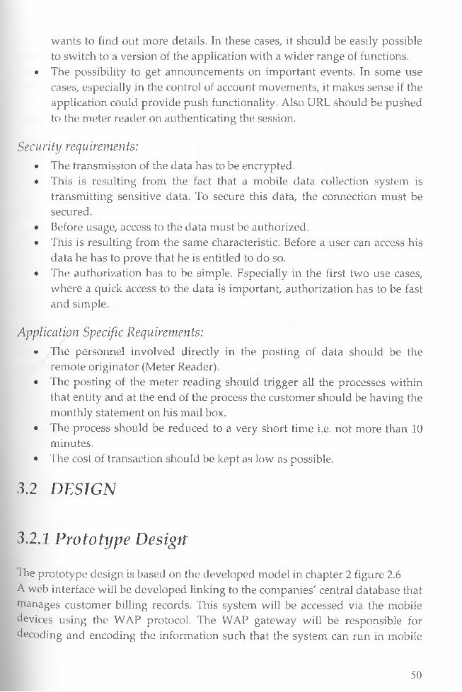
wants to find out more details. In these cases, it should be easily possible to switch to a version of the application with a wider range of functions.
• The possibility to get announcements on important events. In some use cases, especially in the control of account movements, it makes sense if the application could provide push functionality. Also URL should be pushed to the meter reader on authenticating the session.
Security requirements:• The transmission of the data has to be encrypted.• This is resulting from the fact that a mobile data collection system is
transmitting sensitive data. To secure this data, the connection must be secured.
• Before usage, access to the data must be authorized.• This is resulting from the same characteristic. Before a user can access his
data he has to prove that he is entitled to do so.• The authorization has to be simple. Especially in the first two use cases,
where a quick access to the data is important, authorization has to be fast and simple.
Application Specific Requirements:• The personnel involved directly in the posting of data should be the
remote originator (Meter Reader).• The posting of the meter reading should trigger all the processes within
that entity and at the end of the process the customer should be having the monthly statement on his mail box.
• The process should be reduced to a very short time i.e. not more than 10 minutes.
• The cost of transaction should be kept as low as possible.
3.2 DESIGN
3.2.1 Prototype Design
The prototype design is based on the developed model in chapter 2 figure 2.6 A web interface will be developed linking to the companies' central database that manages customer billing records. This system will be accessed via the mobile devices using the WAP protocol. The WAP gateway will be responsible for decoding and encoding the information such that the system can run in mobile
50

devices which are known to have various limitation discussed earlier. The WAP gateway will also be enhanced to work as a SMS gateway such that the customer can use to query the system for various functions for example checking current balance and ordering Monthly statement.
The major milestone of this project is to cut down on operational cost while
enhancing efficiency, a module for generating a PDF statement and emailed to
the customers will be developed. The generation of the customer's statement will
be triggered by an update of the customer records via the mobile devices. This
will eliminate the monthly printing and postage of customer bills and
statements. Security will be enhanced at the WAP and SMS gateway such that
the WAP gateway will be developed in such a way that a part from checking the
conventional way of logging in, only authorized mobile phones can access the
system for those updating the meter reading.
Floiv chart of the proposed solutionThe above two methods of meter reading which are currently in use simultaneously requires reengineering to reduce on time of the entire process to one day, improve on security of information and reduce on the number of personnel involved in an entity customer transaction to one. In this prototype we try as much as possible to reduce human interaction with data and let only a single user be responsible with the entire customer transaction from meter reading to sending of customer bill. The following diagram figure 2.6 shows the flow chart of the proposed reengineered process.
51

Figure 2.6 Workflow of the proposed solution.The process is reduced into two steps with no paper one involved and only the meter reader and the customer involved. There are no players in the middle rather than software services that interact seamlessly to reduce the time from the average 14 days to an average of 10 minutes to receive the bill. Efficiency can further be achieved on the side of payment pay integrating with the mobile wallet such that customer can make payment through credit cards via mobile phone or integrate it to the popular Safaricom MPESA.
52
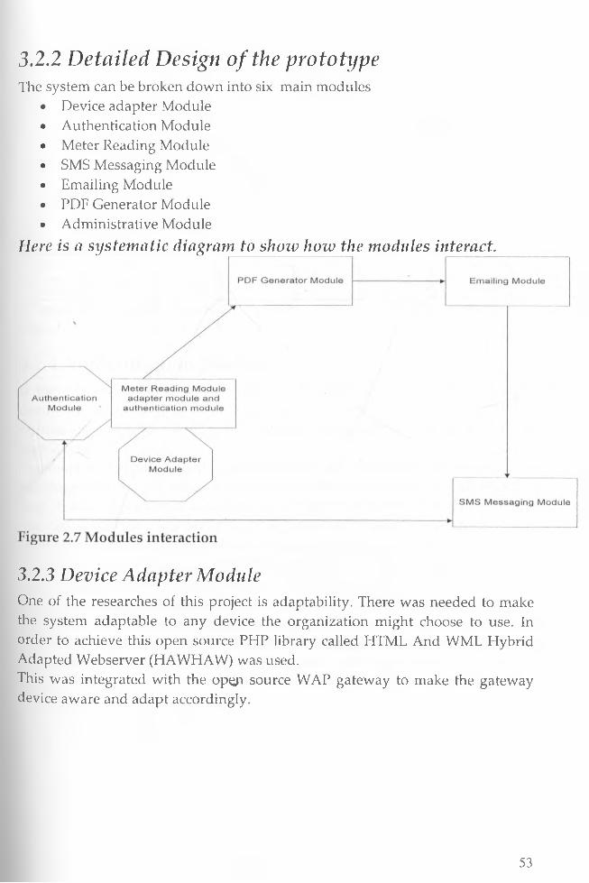
3.2.2 Detailed Design of the prototypeThe system can be broken down into six main modules
• Device adapter Module• Authentication Module• Meter Reading Module• SMS Messaging Module• Emailing Module• PDF Generator Module• Administrative Module
Here is a systematic diagram to show how the modules interact.
3.2.3 Device Adapter ModuleOne of the researches of this project is adaptability. There was needed to make the system adaptable to any device the organization might choose to use. In order to achieve this open source PHP library called HTML And WML Hybrid Adapted Webserver (HAWHAW) was used.This was integrated with the opep source WAP gateway to make the gateway device aware and adapt accordingly.
53
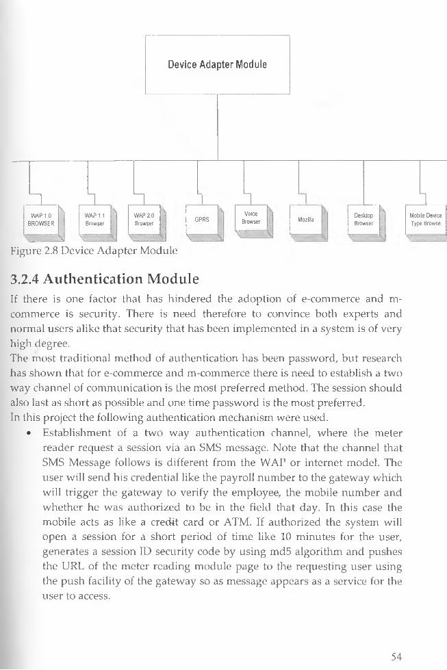
Device A dap te r M odule
WAP 10 BROWSER
1 n I 1\w ap 1.1 :Browser
\WAP 2.0 I Browser
\'
GPRS\ k
VoiceBrowser 1
\ kk k z z u i kssim k s u s iiFigure 2.8 Device Adapter Module
Mozilla
nDesktopBrowser
sMobile Device Type Browse
3.2.4 Authentication ModuleIf there is one factor that has hindered the adoption of e-commerce and m- commerce is security. There is need therefore to convince both experts and normal users alike that security that has been implemented in a system is of very high degree.The most traditional method of authentication has been password, but research has shown that for e-commerce and m-commerce there is need to establish a two way channel of communication is the most preferred method. The session should also last as short as possible and one time password is the most preferred.In this project the following authentication mechanism were used.
• Establishment of a two way authentication channel, where the meter reader request a session via an SMS message. Note that the channel that SMS Message follows is different from the WAP or internet model. The user will send his credential like the payroll number to the gateway which will trigger the gateway to verify the employee, the mobile number and whether he was authorized to be in the field that day. In this case the mobile acts as like a credit card or ATM. If authorized the system will open a session for a short period of time like 10 minutes for the user, generates a session ID security code by using md5 algorithm and pushes the URL of the meter reading module page to the requesting user using the push facility of the gateway so as message appears as a service for the user to access.
54

• Due to the limitation of mobile phones the need to minimize clicks is very important. The page will require the user to enter is PIN, the account number and meter reading then click on the submit button. The system will check the security code, the status of the secession and if valid checks the PIN and mobile identification code from the headers and if successful post the data to the central database and closes the session. In real implementation, on the WAP server the configuration file is designed in such way that request are rerouted to the RADIUS server for authenticating the user. RADIUS server is a proven technology for authenticating remote users. RADIUS is also used to seal the WAP gap discussed earlier.
• If the user does not transact within the time given, the session closes and notified via SMS or GPRS message of the same
Below is schematic flow chart diagram showing authentication routes for the prototype
55

Figure 2.9 Flow Chart Authentication Module
56

3.2.5 Meter Reading Module
Considering the limitations of the target client devices, the User Interface of meter reading was designed such that the need for substantial amount of data entry was kept to a barest minimum. The UI design minimizes the need for users to enter long streams of text and also the module is voice enabled such that incase the company subscribes to voice data; the meter reader will just have to enter values through talking instead of typing. The values are also validated to avoid entering wrong data.Security is also of concern. This was done by ensuring that the Meter reader first has to request for a session ID via SMS by sending is payroll number. This will ensure that the system validates the mobile number details and the employee details before pushing a URL via GPRS for login and submission of current meter reading.The session will remain open for a short time preferably 10 minutes before it's closed.
The flow chart is shown in diagram Figure 2.6 above. The diagram below shows the user interface of the meter reading module
Figure 3.0 Meter Reading Module Design
3.2.6 SMS Messaging ModuleThis module uses the SMS Gateway which comes with the WAP gateway to process SMS. SMS are mainly processed via the configuration file and they are database driven. Below is the flow of SMS Processing
57
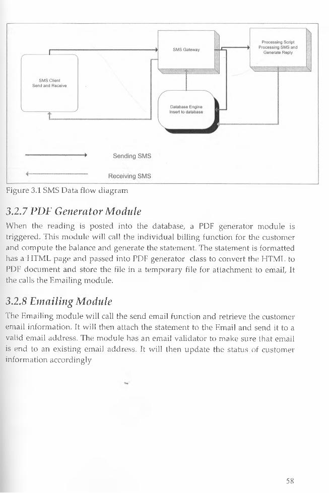
Figure 3.1 SMS Data flow diagram
3.2.7 PDF Generator ModuleWhen the reading is posted into the database, a PDF generator module is triggered. This module will call the individual billing function for the customer and compute the balance and generate the statement. The statement is formatted has a'HTML page and passed into PDF generator class to convert the HTML to PDF document and store the file in a temporary file for attachment to email, It the calls the Emailing module.
3.2.8 Emailing ModuleThe Emailing module will call the send email function and retrieve the customer email information. It will then attach the statement to the Email and send it to a valid email address. The module has an email validator to make sure that email is end to an existing email address. It will then update the status of customer information accordingly
58
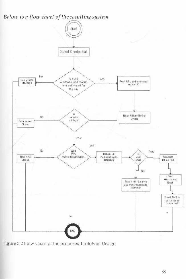
Beloiv is a flow chart of the resulting system
Figure 3.2 Flow Chart of the proposed Prototype Design
59

3.2.9 Database Design:In the design of the database most of the tables are simulations of the existing billing system which is expected that the proposed prototype will be integrated. Hence tables like employees, customers, Transactions and meter reading are simulations and will inherit the billing database structure currently in use. For completeness of the prototype the tables are created as simulations and no effort is made to normalize them but concentration is made on the functionality of the prototype.
Figure 3.3 Meter Reading Module Database Design
f~ meteireadirigs » j—jx
r'df j ernployeeid
i] i customeiid | i processed_date P " : insertdate | i previous | ] current □ rateH security_code [ j sessionid | processed | j audittirne f j audit id
employees |"’r | —tx
; names i payrollno i designation ] address i department ; rnobileno j email j status audittirne auditid
f~ authentication|»|—|x
ridnsns□ rnobileno | status f j pinno [~1 audittirne f- : auditid
| sessions
Figure 3.4 Administrative Menu Database Design
60
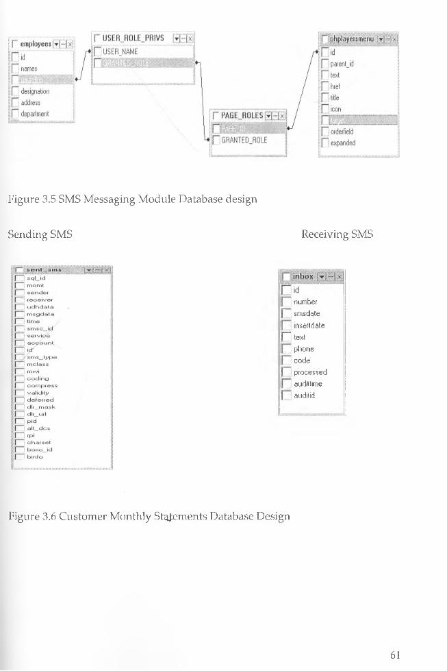
Figure 3.5 SMS Messaging Module Database design
Sending SMS Receiving SMS
i number £ j smsdate
insertdater text
I phone I code
| processed audittime
j auditid
Figure 3.6 Customer Monthly Statements Database Design
61
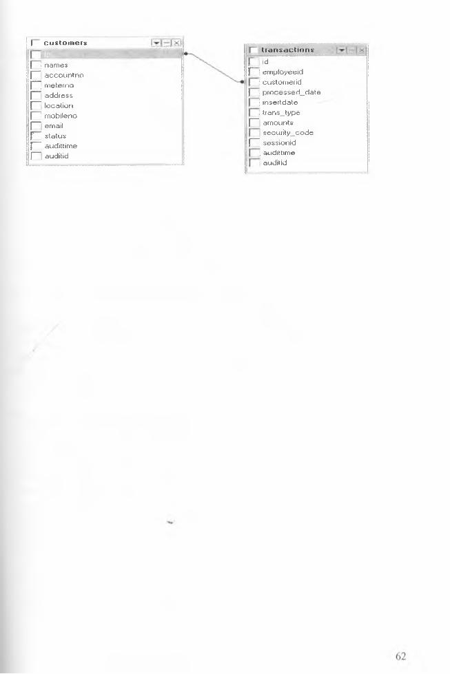
□_LLLL.I_LL.I_
| c u s to m e r s
names accountno meterno address location mobileno email status audittime auditid
.F " t r a n s a c t io n s
. ~~ ld |3 J employecid
! custornerid ) ; processed_date
| insertdate I trans_type r amountssecurity_code n sessionid
j audittime j auditid
CHAPTER 4: PROTOTYPE IMPLEMENTATION
4.1 OverviewIn this chapter we present the implementation of our prototype. We start by describing the choice of technologies used then the system development specifications and the development environment then discuss the design, prototype Implementation and testing. In the implementation of the prototype the following are discussed
• Coding -Explanation of coding is done sample code functions are attached as an appendix
• Testing - Modular and unit testing is done to prove the workability of the proposed solution
• Installation - installation is attached as an appendix• Documentation -user documentation is also attached as an appendix
4.2 Choice of Technologies Used
Program at ing LanguagePHP programming language was preferred in the development of the prototype because of experience we have in developing application using PHP, its robustness and portability to various platforms. It is also easier to call and manipulate the gateway in PHP.
Mobile Development FrameworkThe development of WAP enabled application pages is usually in WML and WML Scripting. This could have necessitated learning new technology and syntax for WML coding. To encapsulate this, we used the HAWHAW development framework such that coding of WAP pages is done through the HAWHAW methodology and syntax which is purely PHP standard hence benefit from our wealth of knowledge in PHP programming. HAWHAW is an open source framework for development of web and WAP pages using PHP language which are device and browser independent hence ensuring application adaptability to any device and browser.
The current situation out there is that many WAP applications are highly incompatible and not able to inter work with different mobile devices. This is mainly caused by strong differing browser implementations and network
63
configurations. Starting to program WML means to painfully learn about all those pitfalls one by one and day by day.
Using this framework the application was developed to be voice aware application such that using voice browsers sound can be used instead of tying and keying in data.
GatewayThe Kannel WAP and SMS Gateway were chosen first and foremost is that it's 2 in 1, have both the WAP and SMS Gateway. Secondly it's a free open source hence has no cost implication meeting our target to develop a cost effective solution. Thirdly, given that what is downloaded is actually the source code for compilation, it can be customize to suite specific needs of the customer. Another advantage is that its development in C language makes it very efficient and fast and suited for large organization processing thousands of records per minute. Given that configuration file is developed outside the kannel it's highly dynamic and portable to any system within the Linux environment. Lastly other boxes can be developed and ported into it for example I integrated with the sqlbox to directly insert SMS to database and pull and send SMS from database without any processing script.
PlatformThe Linux environment was chosen because of its support to open source products and resilience to viruses so it further boosts the security of the system. It was also dictated by the gateway chosen which can only run in Unix environment.
DatabaseMySql Database was chosen because it free and easily available. The open source nature of MySql makes it adaptable to many platforms. However it's important that any relational database can be used. On real application implementation the relational database currently in use within the organization will be used with no modification of the source code since connection is provide using ADO connection which is database independent.
4.3 Setting the Development EnvironmentA development environment is made up of tools, underlying APIs and the operating platform necessary for developing the applications. Developing mobile data collection system using Open source Technology required the following:
64
• Linux Operating System (Red Hat Enterprise 5.0)• Apache 2.2.8• PHP 5.2• Perl 5.8• MySql 5.1.5• Kannel 1.4.1 SMS and WAP Gateway source code• HTML And WML Hybrid Adapter Web server• GSM Modem (USB Edge GPRS Modem)• Mobile Device Simulators
Configuration of the Kennel SMS and WAP GatewayThe kannel SMS and WAP gateway is an open source gateway written in C. its Installation and configuration is a bit complex. After Compiling and installation of the Kannel a configuration file is developed based on the kannel syntax.
Coding Configuration FileA configuration file consists of groups of configuration variables. Groups are separated by empty lines, and each variable is defined on its own line. Each group in Kannel configuration is distinguished with a group variable. Comments are lines that begin with a number sign (#) and are ignored (they don't, for example, separate groups of variables).A variable definition line has the name of the variable, and equals sign (=) and the value of the variable. The name of the variable can contain any characters except white space and equals. The value of the variable is a string, with or without quotation marks () around it. Quotation marks are needed if the variable needs to begin or end with white space or contain special characters. Normal C escape character syntax works inside quotation marks.
Perhaps an example will make things easier to comprehend:1 # A do-nothing service.2 group = sms-service3 keyword = nop *.•4 text = "You asked nothing and I did it!"56 ft Default service.7 group = sms-service8 keyword = default9 text = "No services defined"
65

The above snippet defines the keyword nop for an SMS service and a default action for situation when the keyword in the SMS message does not match any defined service.Lines 1 and 6 are comment lines. Line 5 separates the two groups. The remaining lines define variables. The group type is defined by the group variable value.
Kannel BoxesFor Kannel to work the configuration file should define the following boxes- bearerbox - Required in all cases
- sqlbox (Optional if not database driven)- smsbox - required for SMS facility- wapbox - required for WAP services
Refer to appendix B: for the configuration file we developed for the application
Running KannelTo start the gateway, you need to start each box you need. You always need the bearer box, and depending on whether you want WAP and SMS gateways you need to start the WAP and SMS boxes. If you want, you can run several of them.
Starting the gatewayAfter you have compiled Kannel and developed the configuration file for your taste, you can either run Kannel from command line or develop start up daemons scripts to use it as a daemon
To start the bearerbox, give the following command: bearerbox -v [log level value(0-4)] [config-file]
The -v 1 sets the logging level to INFO. This way, you won't see a large amount of debugging output (the default is DEBUG), [config-file] is the name of the configuration file you are using with Kannel. •After the bearer box, you can start the WAP box:
wapbox -v [log level valuq(0-4)] [config-file]
or the SQL box:sqlbox -v [log level value(0-4)] [config-file]
or the SMS box:smsbox -v [log level value(0-4)] [config-file]
66
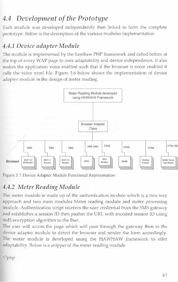
4.4 Development of the PrototypeEach module was developed independently then linked to form the complete prototype. Below is the description of the various modules implementation
4.4.1 Device adapter ModuleThe module is implemented by the hawhaw PHP framework and called before at the top of every WAP page to over adaptability and device independence. It also makes the application voice enabled such that if the browser is voice enabled it calls the voice vxml file. Figure 3.6 below shows the implementation of device adapter module in the design of meter reading.
Figure 3.7 Device Adapter Module Functional Represenation
4.4.2 Meter Reading ModuleThe meter module is made up of the authentication module which is a two way approach and two main modules Meter reading module and meter processing module. Authentication script receives the user credential from the SMS gateway and establishes a session ID then pushes the URL with encoded session ID using md5 encryption algorithm to the Ctser.The user will access the page which will pass through the gateway then to the device adapter module to detect the browser and render the form accordingly. The meter module is developed using the HAWHAW framework to offer adaptability. Below is a snippet of the meter reading module
<?php
67
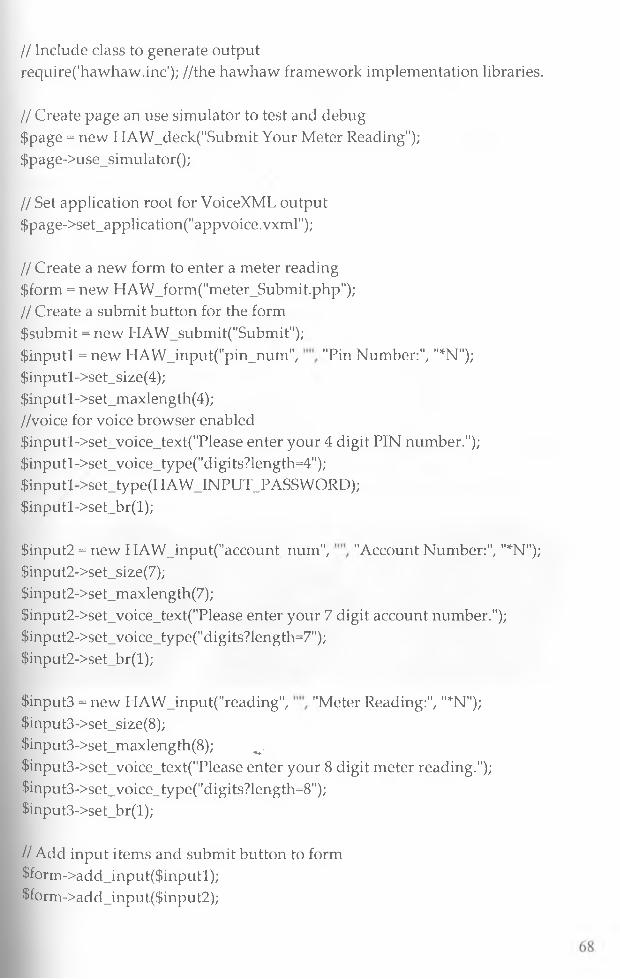
// Include class to generate outputrequire('hawhaw.inc'); //the hawhaw framework implementation libraries.
// Create page an use simulator to test and debug $page = new HAW_deck("Submit Your Meter Reading"); $page->use_simulator();
// Set application root for VoiceXML output $page->set_application("appvoice.vxml");
// Create a new form to enter a meter reading $form = new HAW_form("meter_Submit.php");// Create a submit button for the form $submit = new HAW_submit("Submit");$inputl = new H A W _in p u t("p in _n u m ","P in Number:", "*N"); $inputl->set_size(4);$inputl->set_maxlength(4);//voice for voice browser enabled$inputl->set_voice_text("Please enter your 4 digit PIN number.");$inputl->set_voice_type("digits?length=4");$inputl->set_type(HAWJNPUT_PASSWORD);$inputl->set_br(l);
$input2 = new H A W _input("account_num ","A ccount Number:", "*N"); $input2->set_size(7);$input2->set_maxlength(7);$input2->set_voice_text("Please enter your 7 digit account number."); $input2->set_voice_type("digits?length=7");$input2->set_br(l);
$input3 = new H A W _inp u t("read in g","M eter Reading:", "*N"); $input3->set_size(8);$input3->set_maxlength(8); w$input3->setjvoice_text("Please enter your 8 digit meter reading."); $input3->set_voice_type("digits?length=8");$input3->set_br(l);
// Add input items and submit button to form $form->add_input($inputl);$form->add_input($input2);

$form->add_input($input3);$form->add_submit($submit);
// Add form to page $page->add_form($form);// Render the page $page->create_page ();
?>appvoice.vxml -This is used to welcome the meter reader incase he has a voice enabled browser. See appendix section appvoice.vxml implementation.
On submitting the data it's processed by meter reading processing function. Refer to appendix section for meter reading processing module implementation.
The module is developed in PHP using the HAWHAW framework to ensure adaptability and avoid using a different standard for internet applications and different standard for Wireless application.To enhance security a two ways approach is used and session ID remains open for a short period of time and also session is only open for a user if he has been authorized to be in the field for that day. The figure below is the expected outputNokia 3110c.
69

Figure 3.8 Meter Reading Module Prototype
4.4.3 SMS Messaging ModuleSMS Messaging module was achieved through the configuration file. A file called sqlbox.conf was developed to handle SMS for inserting and retrieving from the database.The SMS module is controlled by the sqlbox which is part of the boxes that are started when starting the kannel. It used to send and receive SMS. Refer to the appendix section for the configuration file for both smsbox and sqlbox which are configured and passed as parameter when starting the kannel as explained in the running the kannel section.
4.4.4 Emailing ModuleWe developed an emailing module in PHP that identifies the Emailing server and using SMTP protocol sends the attachment generated to the email of the customer retrieved from the database. The module will then delete the temporary file attachment from the file system of the server and saves a flag against the customer monthly statement to indicate that the statement has been posted to the customer. The module also checks the validity of the customer email to make sure that it actually exists to avoid sending statement to invalid email accounts. Below is a brief preview of the implementation function for the email module
70
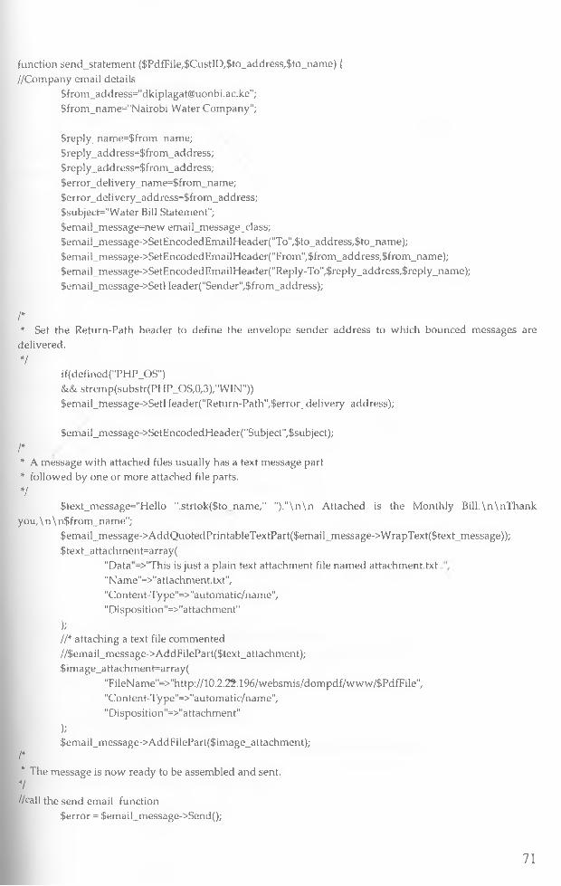
f u n c tio n s e n d _ s ta te m e n t ($ P d f F ile ,$ C u s tI D ,$ to _ a d d r e s s /$ to _ n a m e ) {
/ /C o m p a n y e m a il d e ta ils
$ f r o m _ a d d r e s s = " d k ip la g a t@ u o n b i .a c .k e ";
$ fr o m _ n a m e = " N a iro b i W a te r C o m p a n y " ;
$ r e p ly _ n a m e = $ f r o m _ n a m e ;
$ r e p l y _ a d d r e s s = $ f r o m _ a d d r e s s ;
{ r e p l y _ a d d r e s s = $ f r o m _ a d d r e s s ;
$ e r r o r _ d e liv e r y _ n a m e = $ f r o m _ n a m e ;
$ e r r o r _ d e liv e r y _ a d d r e s s = $ f r o m _ a d d r e s s ;
$ s u b je c t= " W a te r Bill S ta te m e n t" ;
{e m a i l_ m e s s a g e = n e w e m a il_ m e s s a g e _ c la s s ;
$ e m a i l_ m e s s a g e -> S e tE n c o d e d E m a ilH e a d e r (" T o " ,$ to _ a d d r e s s ;$ to _ n a m e ) ;
$ e m a i l_ m e s s a g e -> S e tE n c o d e d E m a ilH e a d e r (" F r o m " /$ f r o m _ a d d r e s s /$ f r o m _ n a m e ) ;
{e m a i l_ m e s s a g e -> S e tE n c o d e d E m a ilH e a d e r ( " R e p ly -T o " ,{ r e p ly _ a d d r e s s ,{ r e p l y _ n a m e ) ;
$ e m a i l_ m e s s a g e -> S e tH e a d e r (" S e n d e r " /$ f r o m _ a d d r e s s ) ;
I** S et th e R e tu r n -P a th h e a d e r to d e fin e th e e n v e lo p e s e n d e r a d d r e s s to w h ic h b o u n c e d m e s s a g e s a re
d e liv e re d .
7if (d e f in e d ("P H P _ O S ")
& & s t r c m p (s u b s tr (P H P _ O S ,0 ,3 ) ," W I N " ) )
$ e m a il_ tn e s s a g e -> S e tH e a d e r ( " R e tu m -P a th " ,$ e r r o r _ d e l iv e r y _ a d d r e s s ) ;
{e m a i l_ m e s s a g e -> S e tE n c o d e d H e a d e r ( “S u b ject" , {s u b je c t ) ;
I** A m e s s a g e w ith a t ta c h e d files u s u a lly h a s a te x t m e s s a g e p a r t
* fo llo w e d b y o n e o r m o r e a t ta c h e d file p a rts .
V$ te x t_ m e s s a g e = " H e llo " .s tr to k fS to n a m e ," " ) ."\ n \ n A tta c h e d is th e M o n th ly B ill.\ n \ n T h a n k
y o u , \ n \ n $ f r o m _ n a m e " ;
$ e m a i l _ m e s s a g e -> A d d Q u o te d P r in ta b le T e x tP a r t($ e m a i l_ m e s s a g e -> W r a p T e x t ($ te x t_ m e s s a g e ) ) ;
$ te x t_ a t ta c h m e n t= a r r a y (
" D a ta ’ -> " T h is is ju s t a p la in te x t a t ta c h m e n t file n a m e d a t ta c h m e n t .tx t
"N a m e "= > "a t ta c h rn e n t .tx t" ,
" C o n te n t-T y p e " = > " a u to m a tic /n a m e " ,
"D isp o s itio n " = > " a tta c h m e n t"
);II* a t ta c h in g a te x t file c o m m e n te d
/ /$ e m a i l_ m e s s a g e -> A d d F i le P a r t ($ te x t_ a t ta c h m e n t ) ;
$ im a g e _ a t ta c h m e n t= a r r a y (
"F i le N a m e " = > "h tt p :/ /1 0 .2 .2 ? .1 9 6 /w e b s m i s /d o m p d f /w w w /$ P d f F i le ",
"C o n te n t-T y p e " = > " a u to m a tic /n a m e " ,
"D is p o s itio n " = > " a tta c h m e n t"
);$ e m a il_ m e s s a g e -> A d d F ile P a r t ($ im a g e _ a t ta c h m e n t ) ;
I** T h e m e s s a g e is n o w r e a d y to b e a s s e m b le d a n d s e n t.
7//ca ll th e s e n d e m a il fu n c tio n
{ e r r o r = $ e m a il_ m e s s a g e -> S e n d () ;
71
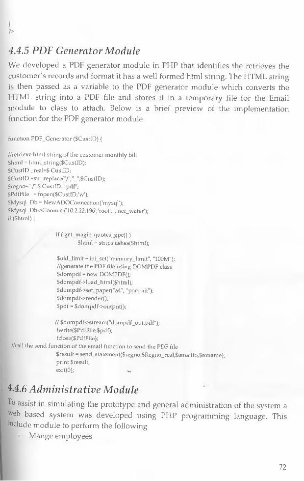
?>
4.4.5 PDF Generator ModuleWe developed a PDF generator module in PHP that identifies the retrieves the customer's records and format it has a well formed html string. The HTML string is then passed as a variable to the PDF generator module which converts the HTML string into a PDF file and stores it in a temporary file for the Email module to class to attach. Below is a brief preview of the implementation function for the PDF generator module
fu n c tio n P D F _ G e n e r a to r ($ C u s tID ) {
/ / r e t r ie v e h tm l s tr in g o f th e c u s to m e r m o n th ly bill
$ h tm l = h tm l_ s tr in g ($ C u s tI D );
S C u stID _ re a l= $ C u s tID ;
S C u stID = s tr _ r e p la c e (" /" ," _ " ,$ C u s tI D ) ;
$ re g n o = " ./" .$ C u s tI D ." .p d f" ;
S P d fF ile = f o p e n ($ C u s tlD /w ') ;
$ M y sq l_ D b = N e w A D O C o n n e c tio n ( 'm y s q r ) ;
$ M y s q l_ D b -> C o n n e c t( '1 0 .2 .2 2 .1 9 6 ', 'r o o t '/ "/ 'n c c _ w a te r ') ;
i f ($ h tm l)|
if ( g e t_ m a g i c _ q u o t e s _ g p c ( ) )
$ h tm l = s tr ip s la s h e s (S h tm l) ;
S o l d J i m i t = in i_ s e t (" m e m o r y _ lim it" , "1 0 0 M " );
/ /g e n e r a te th e P D F file u s in g D O M P D F c la ss
S d o m p d f = n e w D O M P D F ();
$ d o m p d f -> lo a d _ h tm l($ h tm l) ;
$ d o m p d f -> s e t_ p a p e r (" a 4 " / " p o r tra i t" ) ;
$ d o m p d f -> r e n d e r () ;
S p d f = $ d o m p d f -> o u tp u t( ) ;
/ / $ d o m p d f -> s tr e a m (" d o m p d f _ o u t .p d f " ) ;
fw r ite ($ P d f F ile ,$ p d f ) ;
fc lo se (S P d fF ile ) ;
//ca ll th e s e n d f u n c tio n o f th e e m a il fu n c tio n to s e n d th e P D F file
S re s u lt = s e n d _ s ta te m e n t($ r e g n o ,S R e g n o _ r e a l ,$ e m a ilto ,$ to n a m e ) ; p rin t S re su lt ;
exit(O); w
4.4.6 Administrative ModuleTo assist in simulating the prototype and general administration of the system a ^eb based system was developed using PHP programming language. This delude module to perform the following
Mange employees
72

- Manage Customers Manage authentication
- Manage Sessions- Monitor the system
Manage mobile devices- Access to the database records
4.5 Simulation and Evaluation of the PrototypeThree different simulators were used to simulate the system. The gateway and the web server were installed in one red hat Linux machine. The machine was configured as both as a gateway, Webserver and a database server. Another a computer was used as a simulator to run the three simulators (Nokia 7210 SDK, OpenWave and HAWHAW simulator). A real nokia 3110c phone was used to initiate the session and also acts as a customer phone for receiving notification. The same computer was used to access the customers' statement via email. Below are the diagrams showing the meter reading interfaces for the simulators.
Simulation of the prototype using Nokia 7210 SDK
• • •• • •• * *
Pin Number •*234567Account Number:
Meter Reading: 'Submit
n u AM
Figure 3.9 Simulation Testing
73
4.6 USABILITY ANALYSIS
OverviewThe usability of a system can be defined as the capability in human functional terms to be used easily and effectively by the specified range of users, given specified training and user support, to fulfill the specified range of tasks, with the specified range of environmental scenarios [25].
Usability analysis is a process of assessing the usability of products by some form of assessment, typically through observation of how representative users perform standard tasks using the product [25].
The high demand and fast growth of mobile applications have attracted extensive research interests. Because developing mobile applications with an easy-to-use interface is critical for successful adoption and use of applications, one of the important research issues is regarding how to conduct an appropriate usability test using mobile devices in a wireless environment. Usability testing is an evaluation method used to measure how well users can use a specific software system. It provides a third-party assessment of the ease with which end users view content or execute an application on a mobile device. An effective usability test has to be able to elicit feedback from users about whether they use an application without (or almost without) difficulty and how they like using the application, as well as evaluate levels of task performance achieved by users
There are various guidelines for usability testing of desktop applications. However, those established concepts, methodologies, and approaches commonly used in traditional human-computer interaction research are not always applicable to mobile applications [26] due to mobility and the distinct features of mobile devices and wireless networks. Ideally, usability testing of mobile applications should be carefully designed to cover all or most possible situations of a mobile environment [25] .In reality, however, this poses many challenges. For example, it is difficult to foresee the exact situations of the application use - users may be standing, walking, t>r sitting in a dark or bright environment while using an application. As a result, a usability test may have to concentrate only on certain aspects of a mobile application and sacrifice others. Furthermore, traditional research methodologies used in usability testing, including controlled laboratory experiments and field studies, have various limitations in a mobile environment, such as ignoring the mobile context or lack of sufficient procedural
74

control. Therefore, it is essential to develop guidelines for usability testing of mobile applications.
Because achieving a high level of user satisfaction is critical to the success of mobile applications, usability testing is a mandatory process to ensure that a mobile application is practical, effective, and easy to use, especially from a user's perspective.
Methodology usedTo have a good measure of usability of the mobile product, the research was conducted by the intended users (Nairobi Water Company). A questionnaire was prepared based on the usability framework defined in figure 4.4 below. To allow the users respond to the questionnaire the procedure for using the product was given and users tested the system. The test was also used to compute the average completion time of a transaction by logging in the start and end time of the transaction when the system is being used.
A framework for usability testing of mobile data collection systemThis research presents a new framework for usability testing based on a typical human information processing. It defines the usability as the degree to which the users are satisfied with the product with respect to both the performance and the image/impression. Usability is classified into four dimensions for testing: perception, learning/memorization, control/action and evaluative feeling [25], The figure 4.3 below presents operational criteria for testing usability.
Evaluative Feeling
Figure 4.3 A human information processing of the product interface (adaptedfrom [26, 27])
As illustrated in Figure 4.3, the performance dimensions, which stand for the specific criteria that should be used to evaluate the usability, were classified into
75
four categories: perception, learning/memorization, control/action and evaluative feeling. The classification was based on a typical human information processing [26].
• Perception: this category consists of the usability dimensions applicable to examine how well users perceive and interpret the interface of a product [27]. For the mobile data collection system, form size, visibility of the form is examples of perception of the product interface.
• Control/Action: this category represents the dimensions that explain the users' control activity and its results [27]. Speed of form entry, Simplicity, comprehensibility, Reliability, data capture, Efficiency, Responsiveness, rectification of errors is examples of the control/action on the system.
• Learning/Memorization: this category explains how fast the users get used to the product and how well they remember it [27]. Guidance capability, predictability, Memorability, consistency, informativeness and responsiveness are the typical factors of this category.
• Evaluative Feeling: this category is supposed to explain the attitude or judgmental feeling about a product [27], Comfort, logic, attractiveness, satisfaction, acceptance, usefulness and convenience are the typical factors of this category.
Based on the four dimensions of usability, the criteria for usability testing are defined for mobile data collection system. The framework of usability testing of the mobile data collection system is constructed in Figure 4.4.
76

' Figure 4.4 a framework for usability testing of data collection system
As illustrated in Figure 4.4 the usability of data collection system can be tested according to four dimensions: perception, learning/memorization, control/action and evaluative feeling. For each dimension, the operational criteria for testing are illustrated.
Usability testing of mobile data collection systemUsing the framework in figure 4.4 above, usability analysis was done based on the framework. The research questions were identified and constructed based on figure 4.4 above. For the research to be effective we approached one of the utilities companies the NWC to iise there human resources which they accepted. Attached in Appendix E is the procedure for testing and usability questionnaire the users were given.
77
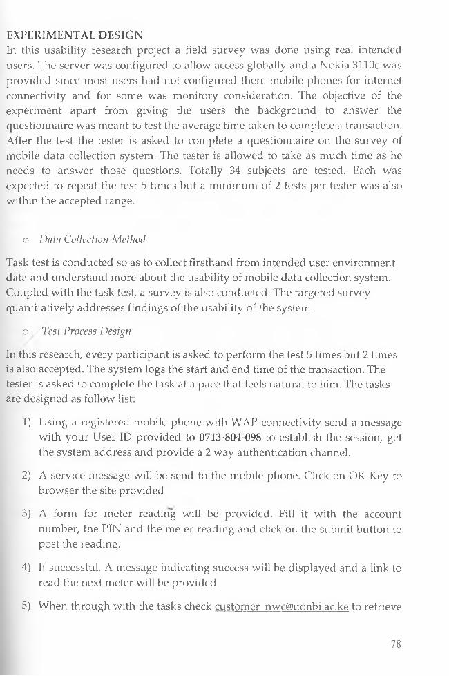
EXPERIMENTAL DESIGNIn this usability research project a field survey was done using real intended users. The server was configured to allow access globally and a Nokia 3110c was provided since most users had not configured there mobile phones for internet connectivity and for some was monitory consideration. The objective of the experiment apart from giving the users the background to answer the questionnaire was meant to test the average time taken to complete a transaction. After the test the tester is asked to complete a questionnaire on the survey of mobile data collection system. The tester is allowed to take as much time as he needs to answer those questions. Totally 34 subjects are tested. Each was expected to repeat the test 5 times but a minimum of 2 tests per tester was also within the accepted range.
o Data Collection Method
Task test is conducted so as to collect firsthand from intended user environment data and understand more about the usability of mobile data collection system. Coupled with the task test, a survey is also conducted. The targeted survey quantitatively addresses findings of the usability of the system.
o Test Process Design
In this research, every participant is asked to perform the test 5 times but 2 times is also accepted. The system logs the start and end time of the transaction. The tester is asked to complete the task at a pace that feels natural to him. The tasks are designed as follow list:
1) Using a registered mobile phone with WAP connectivity send a message with your User ID provided to 0713-804-098 to establish the session, get the system address and provide a 2 way authentication channel.
2) A service message will be send to the mobile phone. Click on OK Key to browser the site provided
3) A form for meter reading will be provided. Fill it with the account number, the PIN and the meter reading and click on the submit button to post the reading.
4) If successful. A message indicating success will be displayed and a link to read the next meter will be provided
5) When through with the tasks check customer [email protected] to retrieve
78
and download the bill statement.
The actual procedure is provided in appendix E.
o Questionnaire Design
The questionnaire is titled "Survey on the usability of data collection system". A total of 22 questions were surveyed, including 2 questions concerned on perception, 8 questions concerned on control/action, 6 questions concerned on learning/memorization, and 6 questions concerned on evaluative feeling. Besides, some questions about subjects' background are designed, which could help to describe the sample characteristics. The survey used a 5-point Likert scale where. l=strongly disagree, 2=Disagree, 3=neither agree nor disagree, 4=Agree, 5=strongly agree. The questionnaire is attached as appendix E.
o Targeted Respondents
In this study, the targeted sampling was focused on obtaining a high quality sample of real meter readers and their supervisors. Most interviewees are 31-40 years old and all respondents had used mobile phone for a period of two to eleven years. This sampling is considered a well-defined population selection with relatively high quality and stringency. To further minimize sampling errors, each individual solicited for a response was requested to provide accurate and well thought out responses.
RESULTS
o Test Findings and Analysis
1) Transaction Completion Time
The raw logs is for determining the completion time of each transaction is attached in appendix E. the table 1.3 below shows the average completion time of each participant.
79
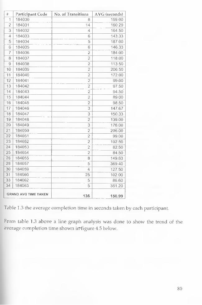
# Participant Code No. of Transitions AVG (seconds)1 184030 8 159.002 184031 14 160.293 184032 4 164.50
• 4 184033 6 143.335 184034 5 187.006 184035 6 146.337 184036 2 184.008 184037 2 118.009 184038 2 113.50
10 184039 2 206.5011 184040 2 172.0012 184041 2 99.0013 184042 2 97.5014 184043 2 94.5015 184044 2 89.0016 184045 2 98.5017 184046 3 147.6718 184047 3 150.3319 184048 2 139.0020 184049 3 176.0021 184050 2 206.0022 184051 2 99.0023 184052 2 102.5024 184053 2 82.5025 184054 2 84.5026 184055 8 149.6328 184057 5 369.4030 184059 4 127.5031 184060 25 102.0033 184062 5 86.6034 184063 5 351.20
GRAND AVG TIME TAKEN 136 150 .99
Table 1.3 the average completion time in seconds taken by each participant.
From table 1.3 above a line graph analysis was done to show the trend of the average completion time shown irrfigure 4.5 below.
80

Average time taken to complete a transaction
01DCoo0ai£
aiQID
V = 17) + 137 .3 r = C.1
/ ■
//
i\
; ji / iI / ii j
± 4 » « /V. L AT ~
b Jr J / ' I i 7I* 1
— "!
" P I i ^ — '—
K ^ A 16 * K* K* kV K* >> K* K* ^ r£ ^ r£ ^ cjS ^
Parti ci pants
Figure 4.5 Average time taken to complete a transaction
It can be seen from the graph the average completion time of each transaction is 151 seconds. That is from the time of authentication initiation to posting of email to the customers email account. Most participants took around 150 seconds to complete the transaction which translates to three minutes to complete the transaction. Compared to the manual process taking an average of one month and logger process which takes 15 days, the mobile data collection and customer information system will actually achieve great results within the shortest time possible. It's important to note that the completion time can be affected by the speed of the user, the type of phone being used and the reliability of the mobile network. However in all cases the time taken will not be more than 10 minutes the time we had indicated in this research to achieve. This can be shown very well from the research where the experiment was performed for a period of three weeks and the highest completion time recorded was about 360 seconds translating to 6 minutes hence our hypothesis is true.
In conducting the usability test, testers faced various challenges which included lack of WAP enabled phones provided by the utility providers or interviewer due to budget constraint. We were forced to provide one mobile phone which was controlled by the billing officer. She will always call the meter readers at there convenience to perform the test which took unnecessary long time to finish the research.
Secondly, Most of the participants had not browsed using a mobile phone before and some had difficulty typing in numbers since the prototype had not been
81
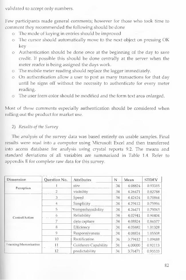
validated to accept only numbers.
Few participants made general comments; however for those who took time to comment they recommended the following should be done
o The mode of keying in entries should be improvedo The cursor should automatically move to the next object on pressing OK
keyo Authentication should be done once at the beginning of the day to save
credit. If possible this should be done centrally at the server when the meter reader is being assigned the days work.
o The mobile meter reading should replace the logger immediately.o On authentication allow a user to post as many transactions for that day
until he signs off without the necessity to authenticate for every meter reading.
o The user form color should be modified and the form text area enlarged.
Most of these comments especially authentication should be considered when rolling out the product for market use.
2) Results of the Survey
The analysis of the survey data was based entirely on usable samples. Final results were read into a computer using Microsoft Excel and then transferred into access database for analysis using crystal reports 9.2. The means and standard deviations of all variables are summarized in Table 1.4. Refer to appendix E for complete raw data for this survey.
Dimension Question No. Attributes N Mean STDEV
P e r c e p t io n1 size 34 4.08824 0.933152 visibility 34 4.26471 0.82788
C o n tro l/ A c tio n
3 Speed 34 4.42424 0.708444 Simplicity 34 4.29412 0.759965 Tomprehensibility 34 4.26471 0.790436 Reliability 34 4.02941 0.904047 data capture 34 4.08824 0.865778 Efficiency 34 4.05882 1.013289 Responsiveness 34 4.08824 1.0550810 Rectification 34 3.79412 1.09488
L e a m in g / M e m o r iz a t io n 11 Guidance Capability 34 4.00000 0.9211312 predictability 34 3.76471 0.95533
82
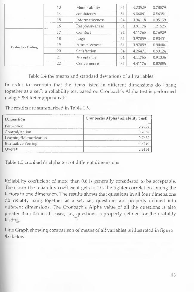
1 3 Memorability 3 4 4 . 2 3 5 2 9 0 . 7 8 0 7 9
1 4 consistency 3 4 4 .0 6 0 6 1 0 . 8 6 3 8 4
1 5 Informativeness 3 4 3 . 9 4 1 1 8 0 .9 5 1 5 9
1 6 Responsiveness 3 4 3 . 9 1 1 7 6 1 .2 1 5 2 5
1 7 Comfort 3 4 4 .1 1 7 6 5 0 .7 6 9 2 9
1 8 Logic 3 4 3 .9 7 0 5 9 0 .8 3 4 3 1
E valu ative Feelin g1 9 Attractiveness 3 4 3 . 9 7 0 5 9 0 .9 0 4 0 4
2 0 Satisfaction 3 4 4 .2 6 4 7 1 0 .9 3 1 2 4
2 1 Acceptance 3 4 4 .1 1 7 6 5 0 . 9 1 3 3 6
2 2 Convenience 3 4 4 . 4 1 1 7 6 0 .8 2 0 8 5
Table 1.4 the means and standard deviations of all variables
In order to ascertain that the items listed in different dimensions do "hang together as a set", a reliability test based on Cronbach's Alpha test is performed using SPSS Refer appendix E.
The results are summarized in Table 1.5.
Dimension Cronbachs Alpha (reliability Test)
Perception 0.8558Control/Action 0.7082Learning/Memorization 0.7682Evaluative Feeling 0.8290Overall 0.8434
Table 1.5 cronbach's alpha test of different dimensions
Reliability coefficient of more than 0.6 is generally considered to be acceptable. The closer the reliability coefficient gets to 1.0, the tighter correlation among the factors in one dimension. The results shows that questions in all four dimensions do reliably hang together as a set, i.e., questions are properly defined into different dimensions. The Cronbach's Alpha value of all the questions is also greater than 0.6 in all cases, i.e., questions is properly defined for the usability testing.
Line Graph showing comparison of means of all variables is illustrated in figure 4.6 below
83

Comparison of mean and stabdard deviation of all variables
Us&btttty Attributes
Mean Values Standard Deviation Values
Figure 4.6 Graph showing comparison of means and standard deviation of all variables
Figure 4.6 shows that respondent's present positive response on most criteria of the mobile data collection system. Furthermore, respondents show similar response on most criteria of the system, which can also validate the classification of the four dimensions and the definitions of the 22 criteria for usability testing. The results also show that most respondents prefer the mobile data collection system hence resistance will be minimal, this can be attributed to the fact that the meter readers are assured of their jobs. Most respondents seem not to be comfortable with the authentication method and data entry procedures this is expected because there is always a thread of between security and usability otherwise its important to improve the data entry method including voice recognition which has been incorporated into the system. Otherwise all the
84
respondents were very excited about the possibility of such a system and are looking forward to its implementation.
4.7 Security AnalysisOverviewWith the rapid growth in e-commerce and m-commerce, the security of sensitive information such as a corporate data being transmitted over an open network like the Internet, has continued to be a serious cause for concern. This is even more so for m-commerce transactions, which are done over the mobile Internet. The goal of a good, reasonably secure information system is to always ensure that the following five basic tenets of information security are all well accounted for in the infrastructure, procedures, policies and people associated with its deployment:
• Authentication - the process of validating the true identity of a user requesting access.
• Authorization - the method of establishing the rights and privileges of a user during its interaction with the system.
• Confidentiality - the means of ensuring that all sensitive data being transmitted can only be read by authorized parties.
• Integrity - the process of preventing alteration of data in transit by unauthorized third parties.
• Non-repudiation - the means of proving the occurrence of a transaction and making it impossible for parties involved to deny carrying out the transaction.
Wireless security is in many occasions comparable with the security of its wired
equivalent. But still the mobility and increasing amount of wireless devices and
networks bring new threats and make many of the old ones even bigger.
Wireless security has lots in common with security in fixed networks as the basic
rules for the both are the same - same basic tools can be used in both but many of
them are more crucial to implement in the wireless world to maintain the same
level of security. Wireless communications have some specific characteristics
over the fixed communications that have to be considered in the sense of
security.
Those are:

• Transmission through air: anyone can listen (privacy)• Radio waves do not stop to corporate walls or to other artificial borders
(privacy)• Spectrum of the radio channels is limited (availability)• Without network coverage no services available (availability)
Keeping data private is a big issue for any wireless network. In the days of voice-
only communications, the greatest worry was that an eavesdropper could listen
to a private conversation, but mobile commerce makes security even more
critical - if people are going to entrust their bank account to technology, it has to
be secure.
Security is an important enabler for the development, adoption and the usage of
the mobile and wireless technologies and services. Business, as well as consumer,
applications will not be able to realize their fullest potential unless a sufficient
level of trust is established in the underlying security of mobile networks.
4.7.1 Security threatsThe same basic security threats are confronted in fixed and wireless networks, but the wireless and mobility brings a new aspect for all of them. Due to the high and ever increasing number of wireless and mobile devices the affects can be exponential to those of the fixed ones.The basic types and threats are:
- Attacks
- Intellectual property theft
- Identity theft
- Brand theft
- Destruction of data'and/or equipment
-Privacy violations
- Surveillance
- Databases collecting private information -traffic analysis
- Massive electronic surveillance -Publicity attacks
86
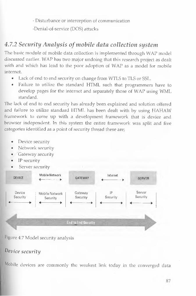
- Disturbance or interception of communication
-Denial-of-service (DOS) attacks
4.7.2 Security Analysis of mobile data collection systemThe basic module of mobile data collection is implemented through WAP model discussed earlier. WAP has two major undoing that this research project as dealt with and which has lead to the poor adoption of WAP as a model for mobile internet.
• Lack of end to end security on change from WTLS to TLS or SSL.• Failure to utilize the standard HTML such that programmers have to
develop pages for the internet and separately those of WAP using WML standard.
The lack of end to end security has already been explained and solution offered and failure to utilize standard HTML has been dealt with by using HAHAW framework to come up with a development framework that is device and browser independent. In this system the entire framework was split and five categories identified as a point of security thread these are;
• Device security• Network security• Gateway security• IP security• Server security
D E V IC EM o b ile N e tw o rkA ___ fc. G A T E W A Y
Internet-4 h. S E R V E R%------------------------- r
DeviceSecurity
4________________ w
Mobile Network Security
A k.
GatewaySecurity
4 k.
i p
Security-4 k.
ServerSecurity
W ^ w * V 4-------------------------p 4 -------------------------►
rEnd to End Security
Figure 4.7 Model security analysis
Device securityMobile devices are commonly the weakest link today in the converged data

world. The diversity of standards available and their relative immaturity makes it very difficult to impose sufficient security standards on mobile device access. The importance of the device security comes into spotlight in corporate adoption of the devices as they are becoming business tools to be used with corporate IT- infrastructure: even a robust and expensive security infrastructure may be easily penetrated through a mobile device security hole.From devices point-of-view there are features to point out that are generally causing security problems. These are:
• As they are wireless and mobile, they can be taken almost anywhere, not just in locked corporate premises -Typically they are small and light making them easy to lose or steal
• As the amounts of the devices is rising they are becoming a more attractive target for attackers
• Hardware features set the limitations for certain security software to be used on the device itself (CPU, memory, battery life, etc.)
• Since Request of session ID and URL is done through SMS. SMS is very insecure and someone can pretend and send SMS claiming that you are the originator. Since SMS is stored on the SMSC and mobile phone the message can also be altered
SolutionIn this model the security of the device has been secured by using two way authentications to make sure that the device being used is from the authorized person. The meter reader sends a message with his credential which theoretically is known by the meter reader only. The system checks the credential send and the mobile number of the user. Assuming someone send the right credential and manages to forge the mobile number user, the system will push the URL and session ID for access to the system. The user will be required to enter the PIN which is generated whenever a meter reader is to go to the field through the corporate intranet system. So the imitator will face the second handle of guessing the PIN. Assuming going against all odds he guesses the PIN right then on posting the details of which the meier reading should be above the previous, the WAP gateway will pass the WAP header file to RADIUS server for authentication and if the registered user MSISDN is not the same as the claiming user MSISDN the security system will be informed and the account locked. So the hacker cannot use other device other than the registered user device. Authorization can further be enhanced by Wireless Identity Module (WIM). WAP devices can use a Wireless Identity Module (WIM) which contains the
88

necessary private and public keys to perform digital signatures and certificate verification respectively. It is a tamper-proof device, which means that it is very difficult for an attacker to obtain the keys which are stored in this device. The WIM can be compared to the SIM of the GSM or smart card authentication mechanism.
Network securityWireless communications use air interface to carry the electromagnetic waves that carry the information. The air interface has the security concern that anyone in the range of the communication can intercept the data being transferred through it. And it is a lot easier than intercepting communications in fixed network as the waves in the air go all over but in the fixed line they do not leak out of the cables; in the fixed world the eavesdropper has to know where the lines are going to tap to them.Other security problem with the air interface has been the fact that the radio waves will not stop to certain borders like organization's physical premises. This is serious problem with WLAN implementations as in the cities many offices are building their own WLAN networks near to each other as one might think the possible concerns in a office building where in every floor resides a different company with its own and different WLAN. This is basically equivalent to leaving an open network connection for everybody to peruse without the need to physically plug in a cable. To a certain degree, this issue is addressed by a standard security function called Wired Equivalent Privacy (WEP). In many cases this technology alone is not sufficient, so additional security options are being developed for WLANs to enhance the protection provided by WEP.For data security reasons almost all wireless networks have to have some degree of network security with their own security (encrypting) algorithms or mechanisms. The degree of the security within the network without outside encrypting depends on the network. For example, GSM communication is encoded with a 128k algorithm to ensure secure wireless transport. Each of the users is assigned a temporary code that enables them to receive only the digital signal sent to them. In an eavesdropping scenario the time required to crack the code is usually longer than the life of the temporary key. The security offering capability of the upcoming UMTS system is going to be higher due to the higher data rates and more complex modulation schemes. Alternative network technologies are to a larger extent subject to security issues.SolutionIn wireless network security is provided by the WTLS layer of the WAP protocol
89
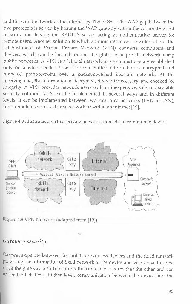
and the wired network or the internet by TLS or SSL. The WAP gap between the two protocols is solved by hosting the WAP gateway within the corporate wired network and having the RADIUS server acting as authentication server for remote users. Another solution is which administrators can consider later is the establishment of Virtual Private Network (VPN) connects computers and devices, which can be located around the globe, to a private network using public networks. A VPN is a 'virtual network' since connections are established only on a when-needed basis. The transmitted information is encrypted and tunneled point-to-point over a packet-switched insecure network. At the receiving end, the information is decrypted, filtered if necessary, and checked for integrity. A VPN provides network users with an inexpensive, safe and scalable security solution. VPN can be implemented in several ways and in different levels. It can be implemented between two local area networks (LAN-to-LAN), from remote user to local area network or within an intranet [19].
Figure 4.8 illustrates a virtual private network connection from mobile device
Gateway securityGateways operate between the mobile or wireless devices and the fixed network Providing the information of fixed network to the device and vice versa. In some cases the gateway also transforms the content to a form that the other end can understand it. On a higher level, communication between the device and the
90
gateway is also subject to being protected by data security protocols. The transforming of the information from another encrypted form to another is then done at the gateway. In the former version of WAP (1.1) this was done by first decrypting the content and then encrypting it again with the other algorithm. This left a little theoretical time space open for hackers to get the content in plaintext. In the newer release of WAP (2.0) this should have been addressed.
Considering that wireless networks are generally more vulnerable than wired networks, a number of wireless security standards have been developed to ensure the security of information transmitted over the wireless Internet. For instance, Wireless Application Protocol (WAP) solutions use the wireless transport layer security (WTLS) in place of Secure Socket Layer (SSL) or Transport Layer Security (TLS) to ensure secure transmissions between WAP client devices and the WAP gateway. However, communication between the WAP gateway and the backend application or Web server is over a wired network and thus uses standard TCP/IP based Internet security protocol such as TLS or SSL. This scenario therefore creates a need for inter-protocol translation to be handled within the WAP gateway. This results in what is known as the "WAP gap" (Security loop Hole), which is a subtle security issue within WAP-based solutions. The WAP gap occurs due to the inter-protocol translation or conversion process, which causes encrypted data to be decrypted, albeit momentarily, and then re-encrypted before transmission from the WAP gateway to either the WAP client device or the backend application or Web server. The WAP gap represent the fact that every encrypted message transmitted using WTLS, between a WAP client device and the wired Internet through a WAP gateway, will at some brief instance exist as readable plaintext whose security could be compromised.There are a number of possible workarounds to reduce the risk posed by the WAP gap issue and minimize the possibility of it being maliciously exploited. These include:
• Ensuring the WAP gateways at the wireless network operator's premises are installed within a heavily secured data centre area with very restricted access. The best practice is tQ install the WAP Gateway at the application server or the web server. Avoid outsourcing the WAP gateway for critical application.
• Designing the message translation process handled within the gateway such that all encryption, decryption and encoding take place within memory without the use of any temp files or explicit writes to disk.
• Ensuring that no details of the translation are ever logged to disk.
91
• Hosting the WAP gateway within the same secured wired network (i.e. wireless application owner's own network) as the application server and taking full responsibility for its administration. This ensures that all the inter-protocol translation process is done within the wireless application owner's secured network.
• Use of RADIUS server between the WAP gateway and the Wireless provider.
Server securityServer security is not directly related to the mobile security but servers are in an important position for the services and applications and very important components of an end-to-end mobile data security infrastructure. Servers might store valuable and confidential information that is not meant to be open for public. Only the individuals with permission have to be let in to access that information. Also the availability of services should be guaranteed. With increasing numbers of mobile devices hackers will be attracted to try to exploit the possibilities of doing so called denial-of-service attack, laming down a server with too many requests from millions of devices that they possibly could gain the access. Also the servers are in a key position to spread malicious code to other devices or to prevent it.Solution:AuthenticationAuthentication is about the continuity of relationships, knowing who to trust and who not to trust, making sense of a complex world. People authenticate themselves many times a day, even without recognizing it, but it is still one important part of our daily lives; recognizing the faces, voices or other recognizable features of our trusted partners, colleagues, relatives or even goods or services.In this project we implemented a two way approach to authentication as explained earlier. Also only the rheter reading interface is available over the WAP. The administrative module is done within a web based interface within the corporate network
firewall
92
Firewalls have generally been used to separate corporate intranets from the Internet by providing access control. A properly configured firewall prevents unauthorized access to or from private networks, especially Intranets. All messages (i.e. all IP traffic) entering or leaving the Intranet pass through the firewall, which examines each message and blocks messages that do not meet the specified security criteria. A Firewall is one of the fundamental components of a secure network.Firewalls can be hardware or software based. Hardware based solutions are often designed for large scale IP traffic such as large corporation intranets. Software based firewalls are designed for smaller IP traffic, such as even single computers. In the age of powerful viruses and worms and always-on connectivity it is also recommendable to have a software based firewall on a single computer to prevent unauthorized access and usage
The Human Factor and Security ManagementComputer security is difficult, to the vendors of software and hardware products, but also to the users of those products. Even if the hardware, the software and network were secure, the complete system could still be jeopardized by one user that does not care enough about security.Security of computers and systems always interacts with users, and as commonly the user is a human, it is the security of the interaction between human and the computer or system. One does not need to look far to find an easy example of this. One such example would be a user that shares out confidential information like PIN with other people. Even though the system was secure, the user made the information insecure by carelessly handling it.To reduce this incidence we recommend having a PIN generator that generates a unique PIN every time the user needs to go to the field
One important part of security management is the creation of company security guidelines. They are then the rules by which every employee must abide. The guidelines must also follow the rules according to which those guilty of breaking them are being punished. As important as the guidelines they are to inform and educate employees to obey them. When these steps have been taken it is the corporate responsibility to keep the infrastructure up to date.
93
Chapter 5: Discussion and Recom m endation
5.1 IntroductionIn order to provide suitable support in the context of less reliable networks suffering e.g. from lower throughput and higher latencies, the design of such system has to be reconsidered. Moreover, low-capable end devices pose additional requirements on sensible strategies for the development of such M- Solutions. Slow processors, a limited amount of memory, small displays, and low battery capacities have to be taken into account. Lastly, the cellular design of modern mobile networks shall be exploited. Besides their intrinsic scalability, cellular structures can simplify the integration of location-dependency considerably.
The Wireless Application Protocol as mobile counterpart of the ubiquitous and supposedly omnipotent World Wide Web is one the few middleware standards explicitly tailored for use in wireless environments on top of small end devices. The general idea behind WAP obviously is to continue the impressive success of the Web in the realm of mobile networks. However, the acceptance of WAP is still limited—not without reason.
This include the lack of end to end security between wireless to wired which in this research project we proposed the use of RADIUS server and using the kannel gateway which can be configured within the Webserver of the corporate network
Secondly, need for content providers to develop two completely independent and diverse versions of their Web pages. Although the limitations imposed by mobile stations and WML browsers require a separate representation anyway, it is currently not possible to generate both versions out of a common base document due to considerable markup language diversities and to a minor degree lack of tool support. By implementing the device independent module within the Webserver and using the HAWHAW framework to develop application it eliminated this need to develop two completely independent applications for both wireless and internet.
94
5.2 Summary of research projectIn this research project we began studying the various models of implementing mobile data collection system. We also identified the various challenges affecting the Utility providers and the current workflow. This was done by fact finding mission at NWC. Then taking into consideration the limitation of mobile devices, the challenges facing utility providers and the core objective of the research a hybrid model was developed.The requirements as per the general limitation of mobile devices and the security required were analyzed and documented. Based on the requirements the design of the prototype was developed. Implementation was then done. Usability testing was done to ascertain the workability of the prototype within the real environment. Through testing and analysis of test results for structural correctness of the system was avoided since the objective was to develop a prototype and that is expected to be done by implementers in real environment. Based on the consideration to be done in real life both security and usability analysis was done.
5.3 AchievementsAt the start of this research the following were the objectives if this research
• To carry out analysis of existing data collection models- Literature review
was done on the existing mobile data collection models, there architecture,
known shortcomings and advantages were investigated. From the
analysis a model was developed by combining WAP, WWW,SMS
addressing there shortcomings within the model to come up with a data
collection model for mobile data collection.
• To identify data capture challenges facing utility providers - challenges
facing utility providers were identified and shown how the proposed
model will assist the companies to overcome them. Although not all
challenges were exhaustively solved, the recommendation for further
work if pursuit will be able to offer a comprehensive integrated secure
mobile solution for utility companies to reengineer there metering services
in terms of customer care and meter reading.
• To identify ways in which data capture, analysis and customer care
workflow can be reorganized and made more efficient - current two main
methods workflow of data collection was and areas that need business
95

process reengineering highlighted together with the savings associated
with the flow. Then using the proposed solution, we proposed a new
efficient workflow that will reduce human interaction and increase
software module interaction such that only one person is involved in the
entire process just to post the meter reading. This also achieved record
security such that the originator actually takes the responsibility of the
record entered through comprehensive audit trail.
• To identify cost effective ways in which hand-held devices can be used for
data collection - after identifying the different models the WAP model
was chosen after proposing the solution to their current limitation of WAP
gap and adaptability. To be cost effective the model was then expanded to
include other web services to enhance to customer information. These
include the SMS solution, Emailing and PDF generator each performing a
unique function in the model.
• To analyze security and vulnerability of the prototype and what
enhancements can be done to make it more secure - Security analysis was
done on the proposed model. The weakness identified and solution
offered. This included the RADIUS implementation, hosting WAP
gateway within the corporate network and implementing a two way
channel of authentication, opening session ID when only necessary for a
short period of time and PIN generation on the need be basis.
• To develop a working prototype of the system based on the proposed
model, - The prototype was implemented using purely open source
products. All the main modules were implemented and tested to make
sure they are working within the expected time limit.
• To evaluate the usability of the system in view of the limitation of the
mobile devices- The usability of prototype was tested to test workability
both in terms of proposed structure and time taken to complete a
transaction. Features to make the system more usable were implemented
including reducing number of clicks to one, pushing URL instead of
typing and validating data entry to ensure that fields for numbers accept
only numbers and length etc. Adaptability was included using the device
independent framework and coding based on one standard for all the
96
devices. We were able to perform usability test and survey research with
real intended users courtesy of NWC.
5.4 Limitations and ChallengesLimitations
In the process of developing this research project, quite a number of challenges and limitation came up along the way. Some of these changes were;
• The number of servers required. From the model at least three servers
were required. That is for Gateway, Webserver, and RADIUS and
database server. All this were combined to one physical server which
might affect the behavior of the system in real environment in terms of
speed.
• Lack of different models of mobile phones to give to the participants to
test the system.
• Real environment testing had a costing implication for airtime and data
transmission hence limitation of test to very few test runs.
ChallengesConfiguration of the Kannel WAP and SMS gateway proved a taunting task
because of poor documentation and support.
Development of the configuration file for the USB Samba Edge modem proved a
monumental task because it was a new device in the market and I had to get the
technical manual from the supplier after struggling with it for more than one
month.
Another challenge was testing the voice component of the meter reading module
because of lack of voice browsers and most simulators available require payment
to host the site testing. w
Another challenge was given that WAP technology is a fairly new research area
material available are not adequate and sometimes contradictory depending on
the biasness of the author.
97

I^astl y , integration of all the technologies used in this research proved a daunting
faSk. But we managed in the long last to develop all the modules anticipated and
testeed there workability. Also lack of funds to get every device required was
anotidier handicap.
5,5 Suggested further research:j obi l e technology and in particular m-commerce is still a new field of immense resea»*~ch currently. So far all indication is that with the introduction of gigabit jietwc^rk the 3G the m-commerce will by pass the e-commerce which is yet to gain ^ s tro n g foot hold. The sheer number of mobile users alone makes it a very intere f sting area to role out customer targeted specific services. In the area of meter " in g services the challenges facing utility providers are many and this reseai— _ch although it tried to sort out quite a number of them there were some specifi i c that were not within the scope of this project due to time constraint and need f c t o have others contribute to this interesting field. Two particular challenges facing ~ utility providers require further research and work this are
• Ensuring that the meter readers actually visits the site and gets the correct
values
• Visiting of customer premises which they might not allow or have some
dogs that can cause harm to staff reading the meters.
' Efficient and convenient customer payment systems
The fir—i rst one of ensuring meter readers actually visit the site and get correct values, although in this research the fact that customer will immediately via SMS orCPfcM RS message get a confirmation message of the current meter reading which lie can j—i immediately confirm with the meter reader and take appropriate action 11 a% assist, it is not a water tight method because the owner might be ifomtenserested to confirm or at the work place when the meter is being read. The W ni.rj—ngthod is to implement a two way approach. That is integration to WVajs-aphical Positioning system via GPRS and integration to a spatial database, ^ ■ h d ih a t the locality coordinates of each meter is stored in the spatial databaseandvvhthecooivWn
dx/hen the meter reader is posting the readings the mobile phone also postsordinates where the meter reader is standing currently such that if it is not
n the locality of the meter reading the posting are rejected on that basis.
J f ^ b d l y the utility providers can barcode there meters with permanent code ^ M *d “hat the system can be integrated with an imaging processing module. In ^ ^ p s a s e before the meter reader authenticates to post the reading, using the
98

Lastly, integration of all the technologies used in this research proved a daunting
task. But we managed in the long last to develop all the modules anticipated and
tested there workability. Also lack of funds to get every device required was
another handicap.
5.5 Suggested further research:Mobile technology and in particular m-commerce is still a new field of immense research currently. So far all indication is that with the introduction of gigabit network the 3G the m-commerce will by pass the e-commerce which is yet to gain strong foot hold. The sheer number of mobile users alone makes it a very interesting area to role out customer targeted specific services. In the area of metering services the challenges facing utility providers are many and this research although it tried to sort out quite a number of them there were some specific that were not within the scope of this project due to time constraint and need to have others contribute to this interesting field. Two particular challenges facing utility providers require further research and work this are
• Ensuring that the meter readers actually visits the site and gets the correct
values
• Visiting of customer premises which they might not allow or have some
dogs that can cause harm to staff reading the meters.
• Efficient and convenient customer payment systems
The first one of ensuring meter readers actually visit the site and get correct values, although in this research the fact that customer will immediately via SMS or GPRS message get a confirmation message of the current meter reading which he can immediately confirm with the meter reader and take appropriate action will assist, it is not a water tight method because the owner might be disinterested to confirm or at the work place when the meter is being read. The best method is to implement a two way approach. That is integration to Geographical Positioning system via GPRS and integration to a spatial database. Such that the locality coordinates of each meter is stored in the spatial database and when the meter reader is posting the readings the mobile phone also posts the coordinates where the meter reader is standing currently such that if it is not within the locality of the meter reading the posting are rejected on that basis.
Secondly the utility providers can barcode there meters with permanent code such that the system can be integrated with an imaging processing module. In this case before the meter reader authenticates to post the reading, using the
98
camera takes the picture of the barcode which is sent to imaging module to decrypt and compare with the stored security code of the meter. This will also enhance on the security of the system.
Thirdly, further work should be done to investigate how to use mobile technology to avoid meter readers entering the compound of the customer while taking into consideration the cost of the solution to be proposed. Currently the viable option is imaging and Bluetooth technology which can be integrated to mobile devices which are Bluetooth enabled.
Lastly to complete a holistic solution m-payment system can be incorporated. In this case the system can be linked to MPESA solution or m-wallet for those with credit cards and debit cards such that when the customer receives a message of an email bill the customer using either the m-wallet or MPESA the can make the payment and the same system gateway will process the payment and post to the account number of the customer generate a receipt and attach it to email as a proof of payment for the customer to generate and file.
5.6 ConclusionsUtility providers will achieve a lot if they are to implement mobile solutions and e-technology to reengineer their metering services as shown by this research project. Wireless technologies bring many new possibilities for Utility providers to achieve flexibility and competitiveness or even make possible things that were earlier impossible to do. The main obstacle in utilization of wireless technologies will be the imagination, or more importantly, the lack of it. But as the new technologies may sound a little heaven on Earth, they can become a nightmare if certain things like security and the management of those technologies are not considered, planned and implemented well. Security measures have to be planned analyzed and executed with care to avoid loopholes which if it occurs might affect the role out of mobile applications. For sure, these new technologies will reshape the ways of doing work, business or services, maybe not all, but many of them. Mobile solution?; will reduce the cost of doing business and reduce the number of processes required to complete a transactions thereby enhancing efficiency and effectiveness thereby increasing the return on investment and customer perception which is core to any business.
99
References:1. Technical specifications and presentations by Scott Goldman
http://www.wapforum.org
2. "Nokia WAP Server 1.1 Security Pack", Nokia Mobile Phones
www.nokia.com/corporate/wap
3. "Ericsson Mobile Internet Enabling Proxy 1.0", Ericsson Radio Systems
AB, www.ericsson.com
4. Product data sheet, Jinny WAP Gateway, www.jinny.ie
5. "WAP Gateway 3.0", Exomi Oy, www.exomi.com
6. "WAP 2.0 Technical White Paper", WAP Forum,www.wapforum.org,
January 2002
7. Open Source Kannel Project, http://www.kannel.org.
8. Linux Virtual Server Project, http://www.linuxvirtualserver.org.
9. Php Classes Forum, http://www.phpclasses.org.
10. Damon Hougland, Khurram Zafar.2001. essential WAP FOR WEB
PROFESSIONALS. Upper Saddle River (NJ): Prentice Hall; 234 p.
11. Stallings, W. Network Security Essentials Applications and Standards,
international second ed. Prentice Hall, 2003.
12. AU-System Radio AB. 1999. WAP White Paper. Available:
http://www.wapguide.com/ 28 February 2000.
13. Capone, J. (2002b): “Addressing the Mobile application development and deployment challenge with Java 2 Enterprise Edition. ” Accessed online at http://www.aligo.com on 16-Aug-2002.
14. Al-Saleh, A. (2001). "Wireless Strategy: Guidelines for getting started. ” Wireless Business & Technology Magazine. Accessed online at http://www.sys- con.com/2001/wireless on 18-August-2002.
15. HAWITAW Framework, project http://www.hawhaw.org.
16. Wikipedia, http://en.wikipedia.org/wiki/Email
17. Wei Meng, Soo Mee, Karli Watson, Ted Wugofski. 2000. Beginning WAP,
WML & WMLScript. Birmigham (UK): Wrox Press; 650p
18. Niels Christian Juul and Niels Jorgensen
"Security Limitations in the WAP Architecture" Position Paper
100
19. Steve Lord, X-Force Security Assessment Services, and Internet: Trouble at
the Telco When GSM goes bad. In Network Security, 2003(1):10 - 12, 2003
20. Margrave, D. GSM Security and Encryption. Available from:
http://www.hackcanada.com/blackcrawl/cell/gsm/gsm-secur/gsm-
secur.html (1999); accessed 27 October 2006.
21. Wagner, D. GSM Cloning. Smartcard Developer Association and ISAAC
security research group. Available from:
http://www.isaac.cs.berkeley.edu/isaac/gsm.html (1998); accessed 28
October 2006.
22. Burak Bayoglu: Performance evaluation of WTLS handshake protocol
using RAS and elliptic curve cryptosystems, 2004.
23. Biryukov, A. Shamir, A. Wagner, D. Real Time Cryptanalysis of A5/1 on a
PC. In Fast Software Encryption Workshop, 2000
24. Amit Vyas, Peter O'Grady, "A Review of Mobile Commerce
Technologies",Department of Industrial Engineering, University of Iowa,
May 2001
25. IT. S.H., Y. M. FI., K. J., and H. S.W., "Usability of consumer electronic
products," International Journal of Industrial Ergonomics, vol. 28, pp. 143-151,
2001.
26. C. D. Wickens, S. E. Gordon, and Y. Liu, An introduction to human factors
engineering. New York: Longman, 1998.
27. S. H. Flan, M. FI. Yun, J. Kwahk, and S. W. Flong, "Usability of consumer
electronic products," International Journal of Industrial Ergonomics, vol. 28,
pp. 143-151, 2001.
101

APPENDIX A: KANNEL CONFIGURATION FIEESSm skannel.conf configuration file for bearerbox and wapbox
g r o u p = c o r e
a d m in -p o r t = 1 3 0 0 0
a d m in -p a s s w o r d = s m s
a d m in -d e n y -ip = " * .* .* .* "
a d m in -a l lo w -ip = "1 2 7 .0 .0 .1 "
w a p b o x -p o r t = 1 3 0 0 2
w d p -in te r fa c e -n a m e =
lo g -f ile = "/ v ar/ lo g / k an n el/ b earerb o x .lo g "
b o x -d e n y -ip =
b o x -a l lo w - ip = "1 2 7 .0 .0 .1 "
# s m s b o x -p o rt = 1 3 0 0 3
s m s b o x -p o r t = 13001
# s m s b o x -p o rt-s s l = y e s
K u n ifie d -p re fix = "+ 2 5 4 ,0 0 2 5 4 ;+ ,0 0 "
s to r e - f i le = / var/ sp ool/ kan n el/ sm s-store
d lr -s to r a g e = m y s q l
g r o u p = p p g
p p g -u r l = / cg i-b in / w ap -p u sh .cg i
p p g -p o r t = 10 0 8 0
tr u s te d -p i = fa lse
p p g -a l lo w -ip = "* .* .* .* "
g r o u p = w a p -p u s h -u s e r
w a p -p u s h -u s e r - fo o
p p g -u s e fn a m e = fo o
p p g -p a s s w o rd = b a r
g r o u p = w a p b o x
b e a r e r b o x -h o s t = lo c a lh o s t
lo g -f ile = "/ var/ log / k an n el/ w ap box .log"
t im e r -fr e q = 10
# m a p -u rl = "h ttp ://localhost/* http :/ / localhost:80/ "
g r o u p = s m s b o x
# re p ly -re q u e s tfa ile d = "N o e x is te u n s e r v ic io a s o c ia d o "
b e a r e r b o x -h o s t = lo c a lh o s t
b e a r e r b o x -p o r t = 1 3 0 0 3
s e n d s m s -p o r t = 1 3 0 1 3
lo g -f ile = "/ var/ log / k ann el/ sm sbox.log "
a c c e s s - lo g = "/ v ar/ lo g / k an n el/ k an n el.access"
lo g - le v e l = 0
g lo b a l-s e n d e r = + 2 5 4 7 1 3 0 8 4 0 9 8 *» '
f fh ttp -re q u e s t-re try = 3
K h ttp -q u e u e -d e la y = 15
# s e n d s m s -c h a rs = "0 1 2 3 4 5 6 7 8 9 +-"
g r o u p = s m s c
s m s c = a t
m o d e m ty p e = a u to
H C h o o s e a p p r o p r ia te o n e . I e n d e d u p w ith s e t t in g a s y m lin k to th e d e v ic e , so 1 # d o n o t n e e d to c h a n g e th e c o n f ig file
( e v e r y tim e th e m o d e m a p p e a rs u n d e r# d if fe re n t d e v ic e n a m e ,
d e v ic e = /dev/ttyA CM O
102

((d ev ice = / dev / m u xl
((d ev ice = / d ev / G SM SM S
((sp eed = 1 1 5 2 0 0
s p e e d = 4 6 0 8 0 0
m y -n u m b e r = "+ 2 5 4 7 1 3 8 0 4 0 9 8 "
s m s c -id = "E S 7 5 "
((a llo w e d -p re fix = "0 ;+ "
K u n ifie d -p re fix = "+ 2 5 4 ,0 0 2 5 4 ;+ ,0 0 "
<( S M S m o d e m S ie m e n s E S 7 5
g r o u p = m o d e m s
id = "E S 7 5 "
n a m e = "S ie m e n s E S 7 5 "
d e te c t-s tr in g = "S IE M E N S "
# d e te c t-s tr in g 2 = "M C 7 5 "
in it -s t r in g = A T i+ C S M S = l ;E l;+ C N M I= 2 ,l ,2 ,2 ,l
(fk e e p a liv e -c m d = "A T + C B C ;+ C S Q "
(te n a b le -h w h s = "A T \ \ Q 3"
n l in e b e lo w re q u ire d , o th e r w is e s e n d in g fa ils
n e e d -s le e p = tru e
((m e s s a g e -s to ra g e = "M E "
(t S M S s e r v ic e
g r o u p = s m s -s e rv ic e
((k ey w o rd = d e fa u lt
k e y w o r d =
k e y w o r d -r e g e x = .1
c a tc h -a l l = tru e
((a llo w e d -p re f ix = "0 ;+ "
tt C h o o s e a m e th o d o f p a s s in g th e S M S fu r th e r
# g e t-u r j = "h ttp ;/ / 1 2 7 .0 .0 .1 / sm s-te s tin g / in d e x .p h p ?p h o n e = % p & le x l= % a "
(texec = < P a th T o S c r ip ts> / re c o rd _ a rg s .sh "% p " "% m " "% M " “% C " "% u " "% b "
g e t-u r l = "h ttp :/ / lo ca lh o st/ sm s/ in d ex .p h p ?t= % t& q = % q & a= % a "
It d o n o t s e n d a n y th in g b a c k
((m a x -m e s s a g e s = 0
c o n c a te n a t io n = tru e
» S M S S E R V IC E 'D e fa u lt '
tl th e r e s h o u ld b e d e fa u lt a lw a y s
g r o u p = s m s -s e rv ic e
k e y w o r d = x x x x x x s e
((ca tch -a ll = tru e
((exec = / u sr/ lo ca l/ b in / k an n el_ in co m in g % t % q % a
((g et-u rl = " h ttp :/ / lo ca lh o st/ sm s/ in d ex l.p h p ?t= % t& q = % q & a = % a "
t e x t - 'H e l lo "
m a x -m e s s a g e s - 0
c o n c a te n a t io n = tru e
U S M S se n d in g
g r o u p = s e n d s m s -u s e r
u s e r n a m e = s m s
p a s s w o rd = s m s
u s e r -a l lo w - ip = "1 2 7 .0 .0 .1 "
d e fa u lt -s m s c = "E S 7 5 "
c o n c a te n a t io n = tru e
# D L R w ith M y S Q L s u p p o r t c o n f ig u r a tio n
P

# E x a m p le d e fin in g a M y S Q L d a ta b a s e c o n n e c tio n re s o u rc e a n d
0 th e re q u ire d ta b le a n d fie ld v a lu e s .
tt
g r o u p = m y s q l-c o n n e c tio n
id = m y d lr
h o s t = lo c a lh o s t
u s e r n a m e = ro o t
p a s s w o r d =
d a ta b a s e = n c c _ w a te r
II m a x c o u n t o f c o n n e c tio n s th a t w ill b e o p e n e d fo r d b p o o l
# d e fa u lt is 1
m a x -c o n n e c t io n s = 1
g r o u p = d lr -d b
id = m y d lr
ta b le “ d e liv e r y _ r e p o r ts
fie ld -s m s c = s m s c
f ie ld -t im e s ta m p = ts
f ie ld -d e s t in a t io n = d e s tin a tio n
f ie ld -s o u r c e = s o u r c e
f ie ld -s e r v ic e = s e r v ic e
f ie ld -u r l = u rl
f ie ld -m a s k = m a sk
f ie ld -s ta tu s = s ta tu s
f ie ld -b o x c -id = b o x c
sqlboxl.conf configuration file for sqlbox service
g r o u p = s q lb o x
id = s q lb o x -d b
s m s b o x - id = s m s b o x
b e a r e r b o x -h o s t = lo c a lh o s t
b e a r e r b o x -p o r t = 1 3 0 0 1
s m s b o x -p o r t = 1 3 0 0 3
s m s b o x -p o r t-s s l = fa ls e
s q l- lo g -ta b le = s e n t_ s m s
s q l- in s e r t - ta b le = s e n d _ s m s
lo g -f ile = "/ v ar/ lo g / k an n el/ k an n el-sq lb o x .lo g "
lo g - le v e l = 0
g r o u p = m y s q l-c o n n e c tio n
id = s q lb o x -d b
h o s t = lo c a lh o s t
u s e r n a m e = ro o t
p a s s w o r d =
d a ta b a s e = n c c _ w a te r
m a x -c o n n e c t io n s = 10
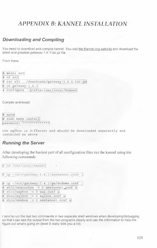
APPENDIX B: KANNEL INSTALLATION
Downloading and Compiling
You need to download and compile kannel. You visit the Kannel.org website and download the latest and greatest gateway-1.X. Y.tar.gz file.
From there:
# mkdir# cd src
srcj
# tar xfz ../downloads/gateway-1.4.1.tar.gz# cd gateway-1.4 . l|# configure --prefix=/usr/local/kannel
Compile and install.
j# make![# sudo make install}[password: **************}
the sqlbox is different and should be downloaded separately and installed as above
Running the Server
After developing the hardest part of all configuration files run the kannel using the following commands(#cd /usr/local/kannel]
(# cp ~/src/gateway-T. 4.1/smskannel . corif .]
;# cp -/ a re / g a te w a y -1 . 4 . 1/gw/modems co n f .| j# sbin/bearerbox -v 0 smskannel ponf &]It til> i n/wapbox -v 0 wap . conf &j j# sbin/sqlbox _-v 0 sqibox.conf &j I# sbin/smsbox -v 0 smskannel. conf &j
I tend to run the last two comm ands in two separate shell w indows when developing/debugging so that I can see the output from the two programs clearly and use the information to help me figure out what’s going on (level 0 really tells you a lot).
105
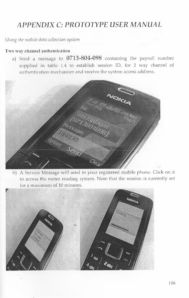
APPENDIX C: PROTOTYPE USER MANUAL
Using the mobile data collection system
Two way channel authentication
a) Send a message to 0713-804-098 containing the payroll number supplied in table 1.4 to establish session ID, for 2 way channel of authentication mechanism and receive the system access address.
b) A Service Message will send to your registered mobile phone. Click on it to access the meter reading system. Note that the session is currently set for a maximum of 10 minutes.
106
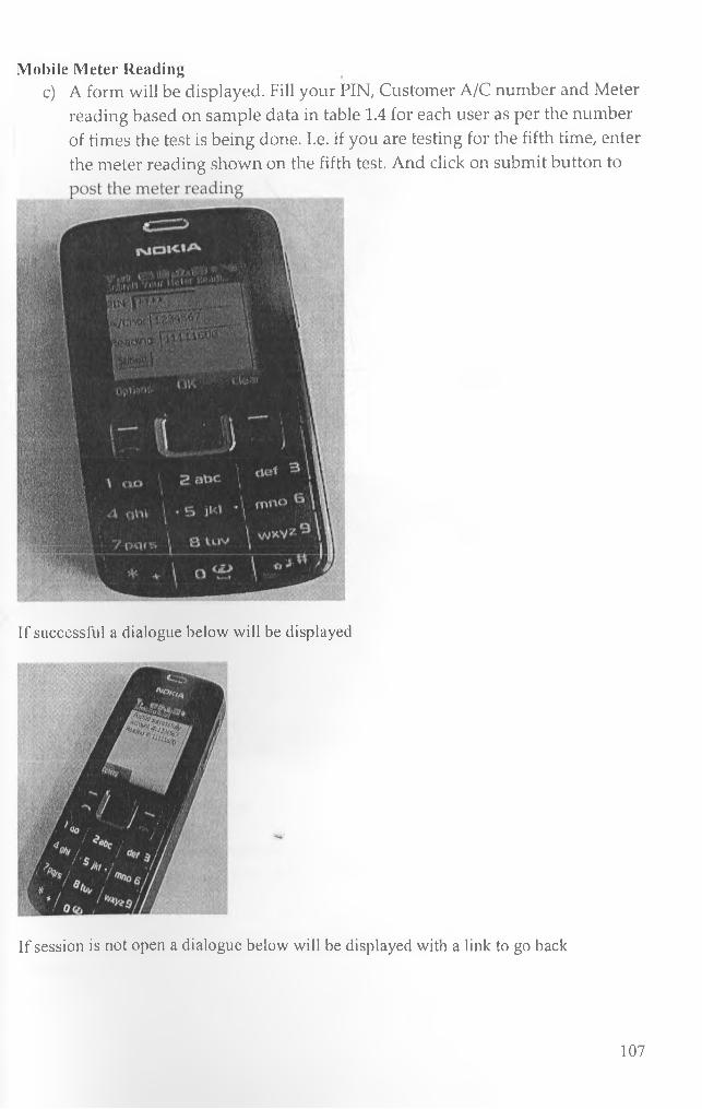
Mobile Meter Readingc) A form will be displayed. Fill your PIN, Customer A/C number and Meter
reading based on sample data in table 1.4 for each user as per the number of times the test is being done. I.e. if you are testing for the fifth time, enter the meter reading shown on the fifth test. And click on submit button to
If successful a dialogue below will be displayed
If session is not open a dialogue below will be displayed with a link to go back
107

Customer Information Service
d) On receiving confirmation dialogue check the email of the customer supplied to confirm that he has received the bill as per the message received.
Confirmation SMS Message to customer while meter reader still at the customer premise.
108

'^ 0 3 3 75/1Balance Ksh 500. Current Meter Reading 11111700. Bill send to your email
Options Clear
Customer Monthly Bill statement download from his/her Email account
N A I R O S I W A T E R C O W P A S Y
i C K V I K C T H E P E O P L E O F N A I R O B I
I V S T A T E M E N T T H E \ I O . M H O f JLT1_V 2 M « I - 2 0 0 B 1 2 0 7 jp m
A c c o u d i N u m b e i : N a.iar& : P A U L . K A X I U K I
123.-«SbT
Traui*. D o s c r i p i i o a D E B I T C R E D I T
Hi a re
3 0 O S - 0 7 - 0 * X 2 : 33 :0 1 W A T E P . B I2_2_ P A Y M S M T (K S H S> 7 ,0 0 0 OC>
2 0 0 8 - 0 7 - W i 7 :2 * :0 .9 W A T E R w v o ! C E { K & n ;s > 4-OP OO
200B-07-C k5- S 7 :3 + :0 3 W A T E R B E . L EtTV O I CELTICS H * jl 1 1 1 M
2 GOB - 0 7 - C -& S7:-4 3 :4 3 W A T E R B32.3_ m v o i c E f u c f i h m ;i 2 l t J M )
2G O S -07-O * & 7:-|«»:4d W A T E R BIZ. I , rN 'V O SCECIA SH ’S ) U 3 « 0
2 0 * 0 6 -0 7 -0 * X 6:OX 7-4 W A T E R B I L L rhf v o sc; E4; k ,s Mia ji * 7 1 . 0 0
2CC.B-07-O4* 2 0 .1 2 :3 3 W A T E »L BIL.3.. E2-TVOSC E ( K % MA> 2 3 0 O©
2 0 0 6 - 0 7 - LO O S : C & . 3 » I V A T E P . B JZ .L txrvoBCEOLsai) 2 3 0 0 G©
2GOE-G7-LO X 3: 3 2 :3 b W A T E BL B I L L E K V O IC E {K S M S ) - 1 .3 3 0 0 0
2 GO 8 - 0 7 - l O * 3 :3 X : 1 2 W A T E R b i z _l D * V O 5 C r B - i H L S Si*8 > 4 bOO «:*o
2 0 0 B - 0 7 - 3 2 X 3 :-47:2*4 W A T E IL BJ2L1. EE* V O I C X ( K S « S jl - 2 . 3 0 0 OO
T u e - J u - L I W B T o t a l 5 .« 2 5 .« * 0 5 .4 0 0 .0 0
B a Iisjuc e 6 1 5 0 6
38n-uil B y : n(a >a«z Ar*s
A p p r o v e d B y ; -N \A .E B -0 3 S .2 U ’ A T E B . C O M P A N Y
N C C A C C O U N T
E r r o n m i d O i a i u i a t i E x p e d i t ' d . A l l Q m # F i* i . E i a < i i J c Lx r L ' u a c r : i g u « d .
System Administration moduleo aid in the system administration, we developed a web interface for the administrator to be able to add users manage meter readers mobile phones, customers and employees.
109
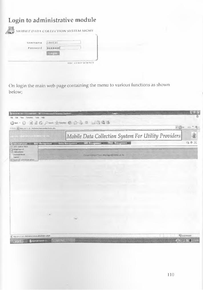
Login to administrative module
M O B I L E I X A L A C O L L E C T I O N S Y S T E M M C M T
Username [164030 Password ••••••«
Login
M S C . C O M I * S O I \ C I
On login the main web page containing the menu to various functions as shown below;
Pie Eck View Fevontes Tooto help
Qtak ■ Q H -^pSWfdl 0 - ** SB I, 4i
■ U U & H B H iH H B Hft
Address ktp://10.2.22.1%/metef/menubuitdef/index.php v ; g j 6 ° l i f i f M
Mobile Data Collection System For Utility Providers t
Iiaqoiiiuni SMS Management EMAIL Management ta *.ulil menu item employees
’ ) cusiorneu \J- iiansaciions
useisG k.imifel inlinlni»»i«iiion
—Conucl Klplagat David ilki|»la<j.iia imnM.,\c. be
& http://10-2.22. l%/meter/fftenutiu<der/r4ex.php#
110
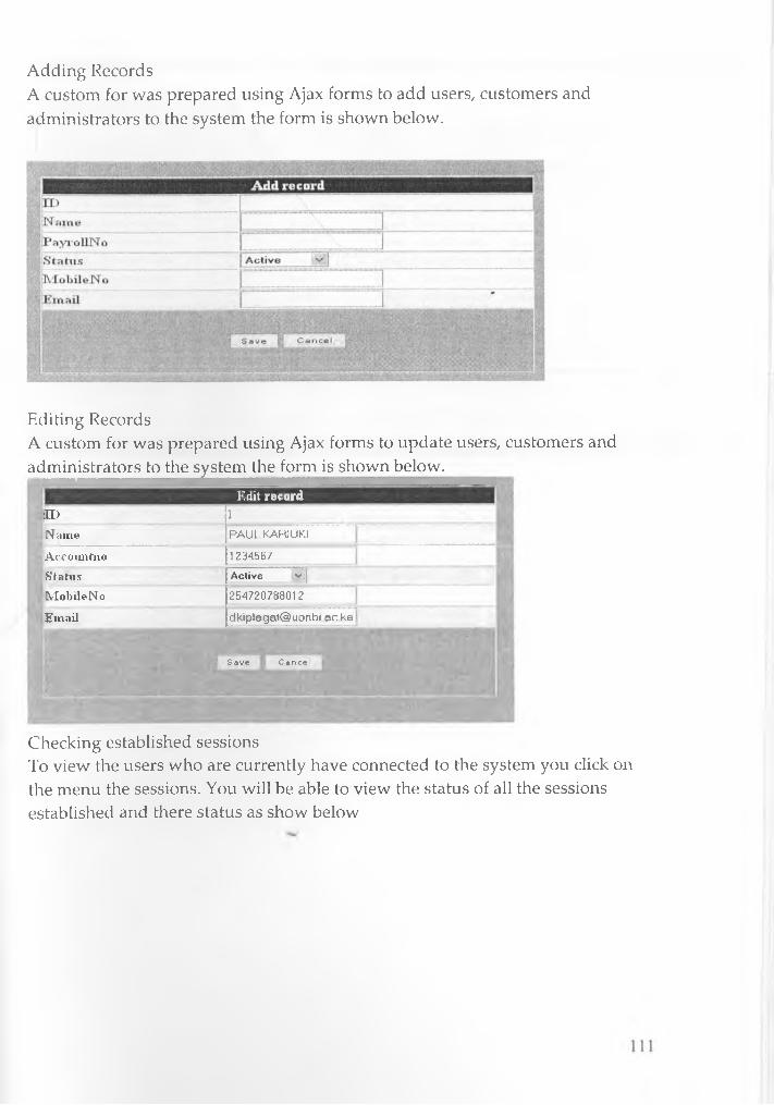
Adding RecordsA custom for was prepared using Ajax forms to add users, customers and administrators to the system the form is shown below.
Editing RecordsA custom for was prepared using Ajax forms to update users, customers and administrators to the system the form is shown below.
Edit recordn > 1
Name P A UL KARIUKI
Accoimtiio 12345b /
S’ tjrtus Active v||
MobileNo 254720788012
Email dkip lagat@ uonbi ac ke
< Save Cancel
Checking established sessionsTo view the users who are currently have connected to the system you click on the menu the sessions. You will be able to view the status of all the sessions established and there status as show below
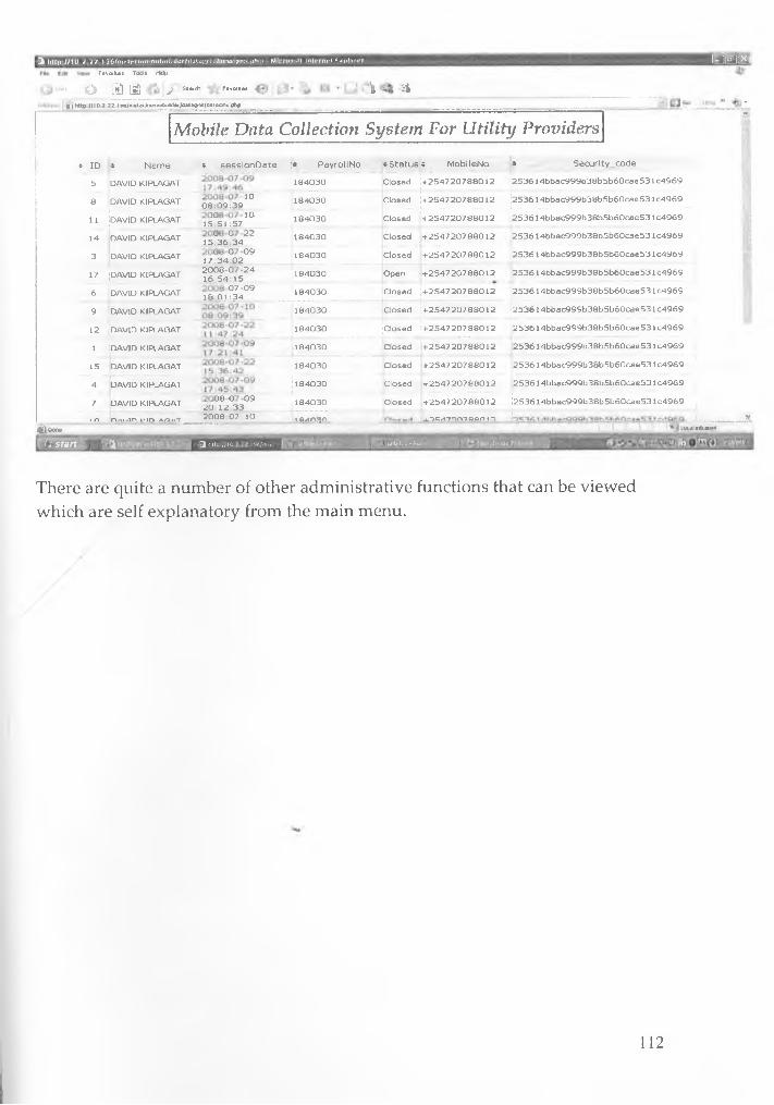
-3 http://1U.7'??r196/fne|pr/mcnuhui|der/ddiaiy«d/3eMioris ph|* - Mi EHiao(t Internet txplon
Favorites Tools Help
- ‘ O L f i ® i > Severs Favorees | S6 | hup //iu i ii »'J.o/i..ecer/me<.uUJrde«/ddtd>«j/seisoo» pT-P v *
‘"‘“T' :"•“T f iK it * rmiiwiS’i'i'i :■■■■■■■■»"»■■■■■ '■•■ ■■■■ ■i;i-, " » -»Mobile Data Collection System For Utility Providers; ID 4 N a m e ? s e s s lo n D a te i P a y ro lIN o * S ta tu s ^ M o b lle N o c S e c u r lty „ c o d e
5 DAVID KIPLAGAT 1 8 4 0 3 0 C losed + 2 5 4 7 2 0 7 8 8 0 1 2 2 5 3 6 1 4 b b a c 9 9 9 b 3 8 b 5 b 6 0 c a e 5 3 1c 4 9 6 9
8 DAVID KIPLAGAT 0 8 + 3 9 K39 ^ ^ 1 8 4 0 3 0 C losed + 2 5 4 7 2 0 7 8 8 0 1 2 2 5 3 6 1 4 b b a c 9 9 9 b 3 8 b 5 b 6 0 c e e 5 3 1 C 4 9 6 9
11 DAVID KIPLAGAT i s ^ S L i / ' 0 1 8 4 0 3 0 C losed + 2 5 4 7 2 0 7 8 8 0 1 2 2 5 3 6 1 4 b b a c 9 9 9 b 3 8 b 5 b 6 0 c a e 5 3 1C 4969
14 D AVID KIPLAGAT 1 5 °3 6 °3 4 2 2 1 8 4 0 3 0 C losed + 2 5 4 7 2 0 7 8 8 0 1 2 2 5 3 6 1 4 b b a c 9 9 9 b 3 8 b 5 b 6 0 c a e 5 3 1C 4969
3 DAVID KIPLAGAT i7 ° 3 4 ° 0 2 ° 9 1 8 4 0 3 0 C losed + 2 5 4 7 2 0 7 8 8 0 1 2 2 5 3 6 1 4 b b a c 9 9 9 b 3 8 b 5 b 6 0 c a e 5 3 1 C 4 9 6 9
17 DAVID KIPLAGAT ^ ^ ° | ^ 0 j j 2 4 1 8 4 0 3 0 O pen + 2 5 4 7 2 0 7 8 8 0 1 2 2 5 3 6 1 4 b b a c 9 9 9 b 3 8 b 5 b 6 0 c a e 5 3 1C 4969
6 DAVID KIPLAGAT i S T D l ^ 0 9 1 8 4 0 3 0 C losed + 2 5 4 7 2 0 7 8 8 0 1 2 2 5 3 6 1 4 b b a c 9 9 9 b 3 8 b 5 b 6 0 c a e 5 3 1 C 4969
9 DAVID KIPLAGAT 1 8 4 0 3 0 C losed + 2 5 4 7 2 0 7 8 8 0 1 2 2 5 3 6 1 4 b b a c 9 9 9 b 3 8 b 5 b 6 0 c a e 5 3 1 c 4 9 6 9
12 DAVID KIPLAGAT 1 8 4 0 3 0 C losed + 2 5 4 7 2 0 7 8 8 0 1 2 2 5 3 6 1 4 b b a c 9 9 9 b 3 8 b 5 b 6 0 c a e 5 3 1c 4 9 6 9
1 b A V ID KIPLAGAT 1 8 4 0 3 0 C losed + 2 5 4 7 2 0 7 8 8 0 1 2 2 5 3 6 1 4 b b a c 9 9 9 b 3 8 b 5 b 6 0 c a e 5 3 1c 4 9 6 9
15 DAVID KIPLAGAT 1 8 4 0 3 0 C losed + 2 5 4 7 2 0 7 8 8 0 1 2 2 5 3 6 1 4 b b a c 9 9 9 b 3 8 b 5 b 6 0 c a e 5 3 lc 4 9 6 9
4 DAVID KIPLAGAT 1 8 4 0 3 0 C losed + 2 5 4 7 2 0 7 8 8 0 1 2 2 5 3 6 1 4 b b a c 9 9 9 b 3 8 b 5 b 6 0 c a e 5 3 1c 4 9 6 9.....................................7 DAVID KIPLAGAT 2 0 ° ? 2 ° 3 3 ° 9 1 8 4 0 3 0 C losed + 2 5 4 7 2 0 7 8 8 0 1 2 2 5 3 6 1 4 b b a c 9 9 9 b 3 8 b 5 b 6 0 c a e 5 3 1c 4 9 6 9
1 n n .u / in L-ICH A A »T 2 0 0 8 - 0 7 - lO i q /» n ^ n .......................... ^ s / m m o o n n ........ .... r :
S i Pen* local mil and
r j j s ta r t I f | ^ N U j / i o r-o/m . ; 1 : hj W&tti it * f'ie : iiM-t
There are quite a number of other administrative functions that can be viewed which are self explanatory from the main menu.
112

APPENDIX D: CODE SAMPLES
Refer to the attached CD-ROM for complete Code for mobile data collection system.
113
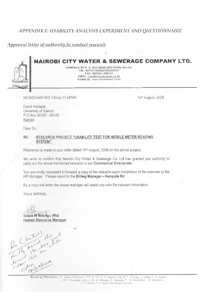
APPENDIX E: USABIEITY ANALYSIS EXPERIMENT AND QUESTIONNAIRE
Approval letter of authority to conduct research
N A IR O B I C IT Y W A TER & SEW ERAGE C O M P A N Y LTD.KAMPALA RD P. O. Box 30656 GPO 00100, Nairobi
TEL: 557131/2/3/552150/553737 FAX: 552126 / 552133
EMAIL: info(a)nairobiwater.co.ke W EBSITE www.iiairobiwater.co.kc
NCWSC/HR/TRG. 13/Vol. 1/13/PMK 19th August, 2008
David Kiplagat University of Nairobi P.0 Box 30197-00100 Nairobi
Dear Sir,
RE: RESEARCH PROJECT “ USABILITY TEST FOR MOBILE METER READINGSYSTEM”
Reference is made to your letter dated 14lh August, 2008 on the above subject./
We write to confirm that Nairobi City Water & Sewerage Co. Ltd has granted you authority to carry out the above mentioned research in our Commercial Directorate.
You are kindly requested to forward a copy of the research upon completion of the exercise to the HR Manager. Please report to the Billing Manager - Kampala Rd
By a copy this letter the above manager will assist you with the relevant information.
Yours faithfully,
Grace W Ndurigu (Ms) Human Resource Manager
C. K Omoio. F K. \fugo (M anaging D iiv lior).
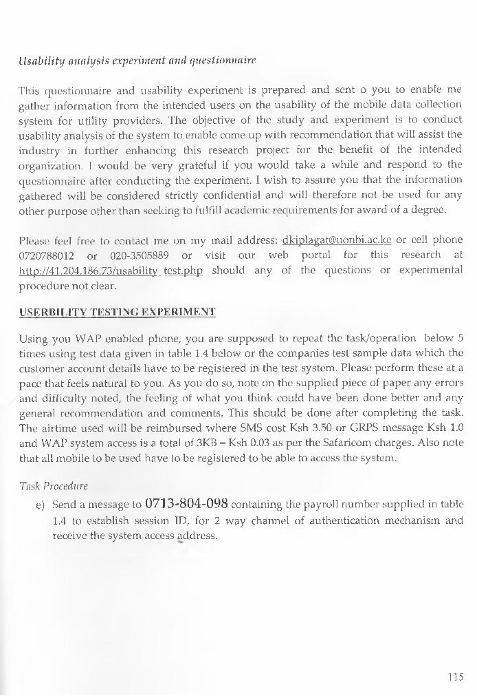
Usability analysis experiment and questionnaire
This questionnaire and usability experiment is prepared and sent o you to enable me gather information from the intended users on the usability of the mobile data collection system for utility providers. The objective of the study and experiment is to conduct usability analysis of the system to enable come up with recommendation that will assist the industry in further enhancing this research project for the benefit of the intended organization. I would be very grateful if you would take a while and respond to the questionnaire after conducting the experiment. I wish to assure you that the information gathered will be considered strictly confidential and will therefore not be used for any other purpose other than seeking to fulfill academic requirements for award of a degree.
Please feel free to contact me on my mail address: [email protected] or cell phone 0720788012 or 020-3505889 or visit our web portal for this research at http://41.204.186.73/usability test.php should any of the questions or experimental procedure not clear.
USKRBIUTY TESTING EXPERIMENT
Using you WAP enabled phone, you are supposed to repeat the task/operation below 5 times using test data given in table 1.4 below or the companies test sample data which the customer account details have to be registered in the test system. Please perform these at a pace that feels natural to you. As you do so, note on the supplied piece of paper any errors and difficulty noted, the feeling of what you think could have been done better and any general recommendation and comments. This should be done after completing the task. The airtime used will be reimbursed where SMS cost Ksh 3.50 or GRPS message Ksh 1.0 and WAP system access is a total of 3KB = Ksh 0.03 as per the Safaricom charges. Also note that all mobile to be used have to be registered to be able to access the system.
Task Procedure
e) Send a message to 0713-804-098 containing the payroll number supplied in table 1.4 to establish session ID, for 2 way channel of authentication mechanism and receive the system access address.
115

f) A Service Message will send to your registered mobile phone. Click on it to access the meter reading system. Note that the session is currently set for a maximum of 10 minutes.
g) A form will be displayed. Fill your PIN, Customer A/C number and Meter reading based on sample data in table 1.4 for each user as per the number of times the test is being done. I.e. if you are testing for the fifth time, enter the meter reading shown on the fifth test. And click on submit button to post the meter reading
116
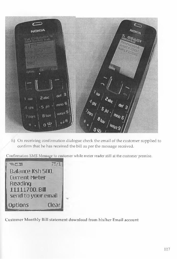
h) On receiving confirmation dialogue check the email of the customer supplied to confirm that he has received the bill as per the message received.
Confirmation SMS Message to customer while meter reader still at the customer premise.P^feiELH 75/1
Balance Ksh 500.Current Meter Reading 11111700. Bill send to your email
Options Clear
Customer M onthly Bill statement download from his/her Email account
117

N A I R O B I W A T E R C O \ £ P A N Y
S E R V I N ’ G T H I P E O P L E O f N A I K O B I
^ i O M a L V
A cic o u d i N u s a » b e r : 1 2 M 5 « T
T r* B %El a m
I Q R T H E X liQ 2 *X -L L Q t JLTJ-.VN * i o .r . : PA E T L. K A J I I U K I
D e i c r i p n o s .
L LlO &V - jr . . ; . / 23- J v i l -200B L2.0T jpcro
D E B I T
2C O S -C 7-0 ‘?' 5 2 :5 :2 :0 1 W A T E R . B I L L P A Y Jr « E N T (K :S H S }
T b 0 & -0 7 -C 5 1 7 :.2 * :C * W A T E R B E L L L t f \<• O 2XirE<:K.S w :s ') •♦■*9 OB
2 0 0 8 - 0 7 - C S & 7 ;3 A :0 2 TV A T E R B I L L E W V* O 2 C E C IiS H .3 f 3 1 3 .0 0
TO O B-07-C > W A T E R B E L L E H V O !C E {K 8 M S |i 2 8 8 0 0
2CK>S-07-Ot? S 7 :4 * :-4 4 W A T E R B I L L EJsfVOS CE(ICSi H S ,| 3 1 3 OO
2 0 0 B - 0 7 -C * 5 S :0 8 :3-f W A T E R . B I L L C K V O ! C E ( K S M S ) 9 7 & OO
2 0 0 9 - 0 7 - 0 '* TO: 1.2 :3 5 W A T E R B I L L D f V O K E C K .fi W>$ ) 2 3 0 0 02O O S -07 -1© OB:C£P:39 W A T E R B E L L Q>TV01CTECELS£LS) 2 .3 0 0 OO
2 0 0 B - 0 7 - SO 5 3 :1 2 :3 1 W A T E R B E L L ej-t v o s CExjK: a h s > - 1 . 1 3 0 0 0
2 0 0 9 **07 -10 l 3 : 3 S:3 T W A T E R B I L L I t * V O !C E {I« .S LTVj AtSOOOO
2 0 0 S -0 7 - .2 2 i 3.*iT:2-P W A T E R BU L L E N V O S C E iK S H S ) - 2 3 0 0 OO
T u « - J u ( - 2 « 0 8 T 04*1 3 .# £ 5 .0 0
B a la a ic , l>25 4.0
‘j * u i l B j : j k / j u n j ^ H v x u <&•/.-at?..V*i
A p p r o v e d B> :K A L B -O B l W A T E R . C O M P A N Y
N C C A C C O U N T
E r r o r i a n d Qwai&'siaiatx E x p c c i « d . A ll Q u e riw i E i&mU (b e U n d e r s ig n e d
C R E D I T
5 .0 0 0 OC»
5.*i-iO.O*3-
USERB1LITY TEST DATATable 1.4: Usability Test Run Data
______ Userbility Experiment______er Test Email: customer [email protected]>er Test Mobile No: 0720788012 Customer Meter ReadingP ayroll
No P IN
M o b ile
M o d e l
T e s t M o b ile
N o .
C u s to m e r
A /C T e s t l T e s t2 T e s t3 T e s t4 te s t5 R e m a rk s
1 8 4 0 3 0 2 0 1 2 N 3 1 1 0 c 0 7 2 0 7 8 8 0 1 2 1 2 3 4 5 6 7 1 1 1 1 2 0 0 0 1 1 1 1 2 0 5 0 1 1 1 1 2 1 0 0 1 1 1 1 2 1 5 0 1 1 1 1 2 2 0 0
1 8 4 0 3 1 2 0 1 3 1 2 3 4 5 6 8 1 1 1 1 3 0 0 0 1 1 1 1 3 0 5 0 1 1 1 1 3 1 0 0 1 1 1 1 3 1 5 0 1 1 1 1 3 2 0 0
1 8 4 0 3 2 2 0 1 4 1 2 3 4 5 6 9 1 1 1 1 4 0 0 0 1 1 1 1 4 0 5 0 1 1 1 1 4 1 0 0 1 1 1 1 4 1 5 0 1 1 1 1 4 2 0 0
1 8 4 0 3 3 2 0 1 5 1 2 3 4 5 7 0 1 1 1 1 5 0 0 0 1 1 1 1 5 0 5 0 1 1 1 1 5 1 0 0 1 1 1 1 5 1 5 0 1 1 1 1 5 2 0 0
1 8 4 0 3 4 2 0 1 6 1 2 3 4 5 7 1 1 1 1 1 6 0 0 0 1 1 1 1 6 0 5 0 1 1 1 1 6 1 0 0 1 1 1 1 6 1 5 0 1 1 1 1 6 2 0 0
t 1 8 4 0 3 5 2 0 1 7 1 2 3 4 5 7 2 1 1 1 1 7 0 0 0 1 1 1 1 7 0 5 0 1 1 1 1 7 1 0 0 1 1 1 1 7 1 5 0 1 1 1 1 7 2 0 0
1 1 8 4 0 3 6 2 0 1 8 1 2 3 4 5 7 3 1 1 1 1 8 0 0 0 1 1 1 1 8 0 5 0 1 1 1 1 8 1 0 0 1 1 1 1 8 1 5 0 1 1 1 1 8 2 0 0
[ 1 8 4 0 3 7 2 0 1 9 1 2 3 4 5 7 4 1 1 1 1 9 0 0 0 1 1 1 1 9 0 5 0 1 1 1 1 9 1 0 0 1 1 1 1 9 1 5 0 1 1 1 1 9 2 0 0
U 8 4 0 3 8 2 0 2 0 1 2 3 4 5 7 5 1 1 1 2 0 0 0 0 1 1 1 2 0 0 5 0 1 1 1 2 0 1 0 0 1 1 1 2 0 1 5 0 1 1 1 2 0 2 0 0
f l 8 4 0 3 9 2 0 2 1 1 2 3 4 5 7 6 1 1 1 2 1 0 0 0 1 1 1 2 1 0 5 0 1 1 1 2 1 1 0 0 1 1 1 2 1 1 5 0 1 1 1 2 1 2 0 0
[1 8 4 0 4 0 2 0 2 2 1 2 3 4 5 7 7 1 1 1 2 2 0 0 0 1 1 1 2 2 0 5 0 1 1 1 2 2 1 0 0 1 1 1 2 2 1 5 0 1 1 1 2 2 2 0 0
U 84041 2 0 2 3 1 2 3 4 5 7 8 1 1 1 2 3 0 0 0 1 1 1 2 3 0 5 0 1 1 1 2 3 1 0 0 1 1 1 2 3 1 5 0 1 1 1 2 3 2 0 0
1184042 2 0 2 4 1 2 3 4 5 7 9 1 1 1 2 4 0 0 0 1 1 1 2 4 0 5 0 1 1 1 2 4 1 0 0 1 1 1 2 4 1 5 0 1 1 1 2 4 2 0 0
1184043 2 0 2 5 1 2 3 4 5 8 0 1 1 1 2 5 0 0 0 1 1 1 2 5 0 5 0 1 1 1 2 5 1 0 0 1 1 1 2 5 1 5 0 1 1 1 2 5 2 0 0
1184044 2 0 2 6 1 2 3 4 5 8 1 1 1 1 2 6 0 0 0 1 1 1 2 6 0 5 0 1 1 1 2 6 1 0 0 1 1 1 2 6 1 5 0 1 1 1 2 6 2 0 0
P 4 0 4 5 2 0 2 7 1 2 3 4 5 8 2 1 1 1 2 7 0 0 0 1 1 1 2 7 0 5 0 1 1 1 2 7 1 0 0 1 1 1 2 7 1 5 0 1 1 1 2 7 2 0 0
1184046 2 0 2 8 1 2 3 4 5 8 3 1 1 1 2 8 0 0 0 1 1 1 2 8 0 5 0 1 1 1 2 8 1 0 0 1 1 1 2 8 1 5 0 1 1 1 2 8 2 0 0
6 8 4 0 4 7 2 0 2 9 1 2 3 4 5 8 4 1 1 1 2 9 0 0 0 1 1 1 2 9 0 5 0 1 1 1 2 9 1 0 0 1 1 1 2 9 1 5 0 1 1 1 2 9 2 0 0
[8 4 0 4 8 2 0 3 0 1 2 3 4 5 8 5 1 1 1 3 0 0 0 0 1 1 1 3 0 0 5 0 1 1 1 3 0 1 0 0 1 1 1 3 0 1 5 0 1 1 1 3 0 2 0 0
[8 4 0 4 9 2 0 3 1 1 2 3 4 5 8 6 1 1 1 3 1 0 0 0 1 1 1 3 1 0 5 0 1 1 1 3 1 1 0 0 1 1 1 3 1 1 5 0 1 1 1 3 1 2 0 0
[840 5 0 2 0 3 2 1 2 3 4 5 8 7 1 1 1 3 2 0 0 0 1 1 1 3 2 0 5 0 1 1 1 3 2 1 0 0 1 1 1 3 2 1 5 0 1 1 1 3 2 2 0 0
[84051 2 0 3 3 1 2 3 4 5 8 8 1 1 1 3 3 0 0 0 1 1 1 3 3 0 5 0 1 1 1 3 3 1 0 0 1 1 1 3 3 1 5 0 1 1 1 3 3 2 0 0
118
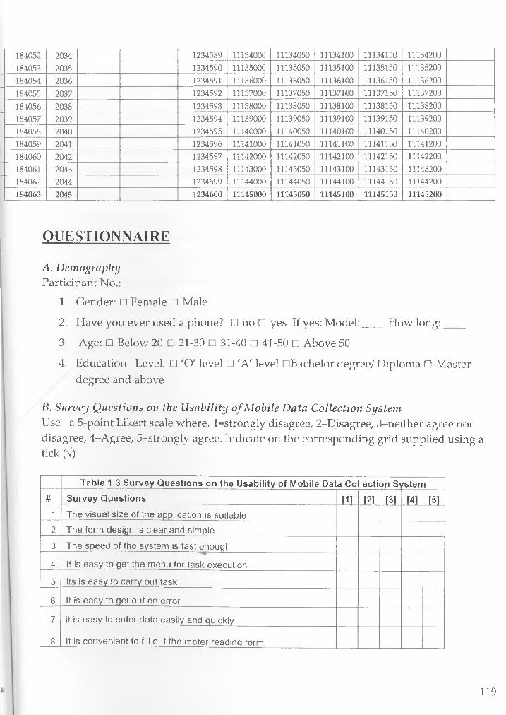
1 8 4 0 5 2 2 0 3 4 1 2 3 4 5 8 9 1 1 1 3 4 0 0 0 1 1 1 3 4 0 5 0 1 1 1 3 4 1 0 0 1 1 1 3 4 1 5 0 1 1 1 3 4 2 0 0
1 8 4 0 5 3 2 0 3 5 1 2 3 4 5 9 0 1 1 1 3 5 0 0 0 1 1 1 3 5 0 5 0 1 1 1 3 5 1 0 0 1 1 1 3 5 1 5 0 1 1 1 3 5 2 0 0
1 8 4 0 5 4 2 0 3 6 1 2 3 4 5 9 1 1 1 1 3 6 0 0 0 1 1 1 3 6 0 5 0 1 1 1 3 6 1 0 0 1 1 1 3 6 1 5 0 1 1 1 3 6 2 0 0
1 8 4 0 5 5 2 0 3 7 1 2 3 4 5 9 2 1 1 1 3 7 0 0 0 1 1 1 3 7 0 5 0 1 1 1 3 7 1 0 0 1 1 1 3 7 1 5 0 1 1 1 3 7 2 0 0
1 8 4 0 5 6 2 0 3 8 1 2 3 4 5 9 3 1 1 1 3 8 0 0 0 1 1 1 3 8 0 5 0 1 1 1 3 8 1 0 0 1 1 1 3 8 1 5 0 1 1 1 3 8 2 0 0
1 8 4 0 5 7 2 0 3 9 1 2 3 4 5 9 4 1 1 1 3 9 0 0 0 1 1 1 3 9 0 5 0 1 1 1 3 9 1 0 0 1 1 1 3 9 1 5 0 1 1 1 3 9 2 0 0
1 8 4 0 5 8 2 0 4 0 1 2 3 4 5 9 5 1 1 1 4 0 0 0 0 1 1 1 4 0 0 5 0 1 1 1 4 0 1 0 0 1 1 1 4 0 1 5 0 1 1 1 4 0 2 0 0
1 8 4 0 5 9 2 0 4 1 1 2 3 4 5 9 6 1 1 1 4 1 0 0 0 1 1 1 4 1 0 5 0 1 1 1 4 1 1 0 0 1 1 1 4 1 1 5 0 1 1 1 4 1 2 0 0
1 8 4 0 6 0 2 0 4 2 1 2 3 4 5 9 7 1 1 1 4 2 0 0 0 1 1 1 4 2 0 5 0 1 1 1 4 2 1 0 0 1 1 1 4 2 1 5 0 1 1 1 4 2 2 0 0
1 8 4 0 6 1 2 0 4 3 1 2 3 4 5 9 8 1 1 1 4 3 0 0 0 1 1 1 4 3 0 5 0 1 1 1 4 3 1 0 0 1 1 1 4 3 1 5 0 1 1 1 4 3 2 0 0
1 8 4 0 6 2 2 0 4 4 1 2 3 4 5 9 9 1 1 1 4 4 0 0 0 1 1 1 4 4 0 5 0 1 1 1 4 4 1 0 0 1 1 1 4 4 1 5 0 1 1 1 4 4 2 0 0
1 8 4 0 6 3 2 0 4 5 1 2 3 4 6 0 0 1 1 1 4 5 0 0 0 1 1 1 4 5 0 5 0 1 1 1 4 5 1 0 0 1 1 1 4 5 1 5 0 1 1 1 4 5 2 0 0
QUESTIONNAIRE
A. DemographyParticipant N o.:_________
1. Gender: □ Female □ Male
2. Have you ever used a phone? □ no □ yes If yes: Model:____ How long:____
3. Age: □ Below 20 □ 21-30 □ 31-40 □ 41-50 □ Above 50
4. Education Level: □ 'O' level □ 'A' level DBachelor degree/ Diploma □ Master degree and above
B. Survey Questions on the Usability of Mobile Data Collection SystemUse a 5-point Likert scale where. l=strongly disagree, 2=Disagree, 3=neither agree nor disagree, 4=Agree, 5=strongly agree. Indicate on the corresponding grid supplied using a tick (V)
Table 1.3 Survey Questions on the U sability o f Mobile Data Collection S\/stem# Survey Q uestions [1] [21 [3] 14] [5]
1 The visual size o f the application is suitable
2 The form design is clear and simple
3 The speed of the system is fast enough
4 It is easy to get the menu for task execution
5 Its is easy to carry out task
6 It is easy to get out on error
7 it is easy to enter data easily and quickly
8 It is convenient to fill out the meter reading form
119

9 It is fast to pet a response on submitting the meter reading
10 It is easy to rectify the errors committed
11 It provides flexible user guidance
12 It is easy to know what to do next with this application
13 It is easy to recall how to do things within this application
14 It is easy to move from one part of a task to another
15 It is easy to see at a glance what the options are at each stage
16 Audio feedback is required
17 It is comfortable to use the application
18 The ordering of menu options is logical
19 The application very attractive presentation
20 I am happy with the application service
21 I will often prefer the mobile data collection system
22It is a convenient and efficient way of mobile data collection for utility companies
Total
General Comments
Transaction Logs
Transaction Logs
# User Start Date End Date Reading Security code Time(sec)1 184030 9/1/2008 16:45:41 9/1/2008 16:47:42 11112000 253614bbac999b38b5b60cae531c4969 121
1 184030 9/1/2008 16:40:12 9/1/2008 16:42:13 11112000 253614bbac999b38b5b60cae531c4969 121
1 184030 9/1/2008 16:35:46 9/1/2008 16:37:47 11112000 253614bbac999b38b5b60cae531C4969 1211 184030 9/1/2008 16:12:07 9/1/2008 16:14:08 11112000 253614bbac999b38b5b60cae531c4969 1211 184030 9/1/2008 16:45:41 9/1/2008 16:48:58 11112050 253614bbac999b38b5b60cae531C4969 197
1 184030 9/1/2008 16:40:12 9/1/2008 16:43:29 11112050 253614bbac999b38b5b60cae531c4969 197
120
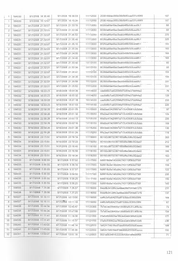
1 184030 9 /1 /2 0 08 16:35:46 9 /1 /2008 16:39:03 11112050 2 53 6 1 4b b a c99 9 b 38 b 5 b6 0 ca e5 3 1c4 9 6 9 197
1 184030 9 /1 /2008 16:12:07 9 /1 /2 0 08 16:15:24 11112050 2 5 3 6 1 4 bb a c9 99b38b5b60cae531C 4969 197
2 184031 9 /1 7 /2 00 8 2 1 :32 :07 9 /1 7 /2 00 8 21 :33 :15 11113050 8038da89 e 49 a c5 ea b b 48 9 c fc6 ce a9 fc1 68
2 184031 9 /1 7 /2 00 8 21:32:01 9 /1 7 /2 00 8 2 1 :33 :09 11113050 8038da89 e 49 a c5 ea b b 48 9 c fc6 ce a9 fc1 68
2 184031 9 /1 7 /2 00 8 2 1 :32 :07 9 /1 7 /2 00 8 2 1 :35 :52 11113200 8038da89 e 49 a c5 ea b b 48 9 c fc6 ce a9 fc1 225
2 184031 9 /1 7 /2 00 8 21:32:01 9 /1 7 /2 00 8 21:35:46 11113200 8038da89 e 49 a c5 ea b b 48 9 c fc6 ce a9 fc1 225
2 184031 9 /1 7 /2 00 8 2 1 :32 :07 9 /1 7 /2 00 8 21 :35 :10 11113000 8038da89 e 49 a c5 ea b b 48 9 c fc6 ce a9 fc1 183
2 184031 9 /1 7 /2 00 8 21:32:01 9 /1 7 /2 00 8 21 :35 :04 11113000 8038da89 e 49 a c5 ea b b 48 9 c fc6 ce a9 fc1 183
2 184031 9 /1 7 /2 0 0 8 2 1 :32 :07 9 /1 7 /2 00 8 2 1 :34 :55 11113050 8038 d a8 9 e 49 a c5 ea b b 48 9 c fc6 ce a9 fc1 168
2 184031 9 /1 7 /2 00 8 21:32:01 9 /1 7 /2 0 0 8 21 :34 :49 11113050 8038 d a8 9 e 49 a c5 ea b b 48 9 c fc6 ce a9 fc1 168
2 184031 9 /1 7 /2 00 8 2 1 :32 :07 9 /1 7 /2 00 8 2 1 :33 :40 11113100 8038 d a8 9 e 49 a c5 ea b b 48 9 c fc6 ce a9 fc1 93
2 184031 9 /1 7 /2 00 8 21:32:01 9 /1 7 /2 00 8 2 1 :33 :34 11113100 8038 d a8 9 e 49 a c5 ea b b 48 9 c fc6 ce a9 fc1 93
2 184031 9 /1 7 /2 00 8 2 1 :32 :07 9 /1 7 /2 00 8 21:34:41 11113100 8038 d a8 9 e 49 a c5 ea b b 48 9 c fc6 ce a9 fc1 154
2 184031 9 /17 /2008 21:32:01 9 /17 /2 00 8 2 1 :34 :35 11113100 8038 d a8 9 e 49 a c5 ea b b 48 9 c fc6 ce a9 fc1 154
2 184031 9 /17 /2008 21 :32 :07 9 /1 7 /2 00 8 2 1 :35 :58 11113200 8038 d a8 9 e 49 a c5 ea b b 48 9 c fc6 ce a9 fc1 231
2 184031 9 /1 7 /2 00 8 21:32:01 9 /1 7 /2 00 8 21 :35 :52 11113200 8038 d a8 9 e 49 a c5 ea b b 48 9 c fc6 ce a9 fc1 231
3 184032 9 /1 6 /2 00 8 18 :03 :23 9 /16 /2 00 8 18:04:39 11114000 C ee8d6b 7 ce 52 5 5 4 fd7 0 3 54 e 3 7b b f4 4 a2 76
3 184032 9 /1 6 /2 00 8 18 :03 :23 9 /1 6 /2 00 8 18:05:32 11114050 C ee8d6b 7 ce 52 5 5 4 fd7 0 3 54 e 3 7b b f4 4 a2 129
3 184032 9 /16 /2008 18 :03 :23 9 /1 6 /2 00 8 18:07:16 11114100 C ee8d6b 7 ce 52 5 5 4 fd7 0 3 54 e 3 7b b f4 4 a2 233
3 184032 9 /16 /2008 18 :03 :23 9 /1 6 /2 0 0 8 18:07:03 11114150 C ee8d6b 7 ce 52 5 5 4 fd7 0 3 54 e 3 7b b f4 4 a2 220
4 184033 9 /16 /2008 2 2 :59 :28 9 /16 /2 00 8 2 3 :01 :05 11115000 6 5d 2 e a 0 3 4 2 5 8 8 7 a 7 17 c4 3 5 0 8 1 c fc5 d b b 97
4 184033 9 /1 6 /2 00 8 2 2 :59 :28 9 /16 /2 00 8 2 3 :01 :32 11115050 6 5d 2 e a 0 3 4 2 5 8 8 7 a 7 17c435081 cfc5dbb 124
4 184033 9 /1 6 /2 00 8 2 2 :59 :28 9 /1 6 /2 00 8 2 3 :03 :13 11115100 65d2ea0 3 4 25 8 8 7a 7 1 7c4 3 5 08 1 c fc5 d b b 225
4 184033 9 /1 6 /2 00 8 22 :59 :28 9 /1 6 /2 00 8 23 :02 :16 11115150 6 5d 2 e a 0 3 4 2 5 8 8 7 a 7 17c435081 c fc5dbb 168
4 184033 9 /1 6 /2 00 8 22 :59 :28 9 /1 6 /2 00 8 23 :01 :38 11115200 65d2ea03425887a717C 435081 c fc5dbb 130
4 184033 9 /16 /2008 22 :59 :28 9 /1 6 /2 00 8 23 :01 :24 11115250 6 5 d 2 e a 0 3 4 2 5 8 8 7 a 7 17 c4 3 5 0 8 1 c fc5dbb 116
5 184034 9 /16 /2008 23:15:51 9 /1 6 /2 00 8 23 :19 :14 11116000 9 51 92C 98732387 1 6 5b f8 e 3 96 c0 f2 d ad 2 203
5 184034 9 /16 /2008 23:15:51 9 /1 6 /2 00 8 23 :19 :23 11116050 9 51 9 2c9 8 7 3 2 3 8 7 1 6 5 b f8 e 3 9 6 c0 f2 d a d 2 212
5 184034 9 /16 /2008 23:15:51 9 /1 6 /2 00 8 23 :18 :40 11116100 9 51 92C 9873 2 3 87 1 6 5b f8 e 3 96 c0 f2 d ad 2 169
5 184034 9 /16 /2008 23:15:51 9 /16 /2 00 8 2 3 :18 :59 11116150 9 51 92C 98732387 1 6 5b f8 e 3 96 c0 f2 d ad 2 188
5 184034 9 /1 6 /2 00 8 23:15:51 9 /1 6 /2 00 8 23 :18 :34 11116200 9 51 92C 9873 2 3 87 1 6 5b f8 e 3 96 c0 f2 d ad 2 163
6 184035 9 /1 7 /2 00 8 5 :55 :55 9 /1 7 /2 00 8 5 :57 :02 11117000 8 d8 8 1 8 c8 e 1 4 0 c6 4 c7 4 3 1 13 f5 6 3 c f7 5 0 f 67
6 184035 9 /1 7 /2 00 8 5 :55 :55 9 /1 7 /2 00 8 5 :58 :34 11117000 8 d 8 8 18 c8 e 1 4 0 c 6 4 c 7 4 3 113 f5 6 3c f75 0 f 159
6 184035 9 /1 7 /2 00 8 5 :55 :55 9 /1 7 /2 00 8 5 :57 :57 11117050 8 d8 8 1 8 c8 e 1 4 0 c6 4 c7 4 3 1 13 f5 6 3c f75 0 f 122
6 184035 9 /1 7 /2 00 8 5 :55 :55 9 /1 7 /2 00 8 5 :59 :50 11117100 8 d 8 8 18 c8 e 1 4 0 c 6 4 c 7 4 3 113 f5 6 3c f75 0 f 235
6 184035 9 /1 7 /2 00 8 5 :55 :55 9 /1 7 /2 00 8 5 :58 :25 11117150 8 d8 8 1 8 c8 e 1 4 0 c6 4 c7 4 3 1 13 f5 6 3c f75 0 f 150
6 184035 9 /1 7 /2 00 8 5 :5 5 :5 5 9 /1 7 /2 00 8 5 :58 :20 11117200 8 d 8 8 18 c8 e 1 4 0 c 6 4 c 7 4 3 113 f5 6 3 c f7 5 0 f 145
7 184036 9 /1 7 /2 00 8 7 :25 :06 9 /1 7 /2 0 0 8 7 :28 :57 11118000 8 4 d d fb 3 4 1 2 6 fc3 a 48 e e3 8 d 70 4 4 e8 7 2 76 231
7 184036 9 /1 7 /2 0 0 8 7 :25 :06 9 /1 7 /2 0 0 8 7 :27 :23 11118050 8 4 d d fb 3 4 12 6 fc3 a4 8 e e3 8 d7 0 4 4e 8 7 27 6 137
8 184037 9 /1 7 /2 00 8 10:10:11 9 /1 7 /2 00 8 10:13:00 11119000 e a6 b 2 e fb dd 4 2 5 5 a 9 f1 b 3 b b c6 3 9 9 b 5 8 f4 169
8 184037 9 /1 7 /2 00 8 10:10:11 9 /1 7 /2 00 8 10:11:18 11119050 e a6 b 2 e fb dd 4 25 5 a 9 f1b 3 b bc6 3 9 9b 5 8 f4 67
9 184038 9 /1 7 /2 00 8 10:44:34 9 /1 7 /2 00 8 10:45:47 11120000 7 b7 a 5 3e 2 3 94 0 0 a 1 3 b d 6 b e 6 c9 1 c4 f6 c4 e 73
9 184038 9 /17 /2 00 8 10:44:34 9 /1 7 /2 00 8 10:47:08 11120050 7 b7 a 5 3e 2 3 94 0 0 a 1 3 b d 6 b e 6 c9 1 c4 f6 c4 e 154
10 184039 9 /17 /2 00 8 11:11:41 9 /17 /2008 11:14:38 11121000 0 5a 5 c f0 6 9 82 b a 7 8 9 2 e d 2 a 6 d 3 8 fe 8 3 2 d 6 177
10 184039 9 /1 7 /2 00 8 11:11:41 9 /17 /2008 11:15:37 11121050 0 5a 5 c f0 6 9 82 b a 7 8 9 2 e d 2 a 6 d 3 8 fe 8 3 2 d 6 236
11 184040 9 /1 7 /2 00 8 11:43:00 9 /1 7 /2 00 8 11:46:14 11122000 3 a8 2 4 15 4 b 1 6 e d 7 d a b 8 9 9 b f0 0 0 b 8 0 e e e e 194
11 184040 9 /1 7 /2 00 8 11:43:00 9 /1 7 /2 00 8 11:45:30 11122050 3 a 8 2 4 15 4 b 1 6 e d 7 d a b 8 9 9b f0 0 0 b8 0 e ee e 150
12 184041 9 /17 /2 00 8 13:00:07 9 /1 7 /2 00 8 13:01:18 11123000 5531 a583 4 81 6 2 22 2 8 0 f20 d 1 e f9e 95 f6 9 71
121

12 184041 9 /1 7 /2 00 8 13:00:07 9 /1 7 /2 00 8 13 :02 :14 11123050 5531 a 5 8 3 4 8 16 22 2 2 80 f20 d 1 e f9e95 f69 127
13 184042 9 /1 7 /2 00 8 13:03:10 9 /1 7 /2 00 8 13:04:22 11124000 07811 dc6c422 33 4 ce 36 a 0 9 ff5 cd6 fe7 1 72
13 184042 9 /1 7 /2 0 0 8 13:03:10 9 /1 7 /2 00 8 13:05:13 11124050 07811dc6 c4 2 23 3 4 ce3 6 a 09 ff5cd 6 fe 7 1 123
14 184043 9 /1 7 /2 0 0 8 13:06:04 9 /1 7 /2 0 0 8 13:07:08 11125000 312351 b ff0 7 9 8 9 7 6 9 0 9 7 66 0 a5 6 3 95 0 6 5 64
14 184043 9 /1 7 /2 0 0 8 13:06:04 9 /1 7 /2 0 0 8 13:08:09 11125050 312351 b ff0 7 9 8 9 7 6 9 0 9 7 66 0 a5 6 3 95 0 6 5 125
15 184044 9 /1 8 /2 00 8 8 :0 4 :0 2 9 /1 8 /2 0 0 8 8 :05 :05 11126000 C 92a103 2 4 37 4 fa c6 81 7 1 9d 6 3 97 9 d0 0 fe 63
15 184044 9 /1 8 /2 0 0 8 8 :0 4 :0 2 9 /1 8 /2 0 0 8 8 :05 :57 11126050 c 9 2 a 1 0 3 2 4 3 7 4 fa c6 8 1 7 1 9d6 3 9 79 d 0 0 fe 115
16 184045 9 /1 8 /2 0 0 8 8 :06 :47 9 /1 8 /2 00 8 8 :07 :59 11127000 9 f6 2 b 8 6 2 5 f9 14 a0 0 2 49 6 3 35 0 3 7e 9 a d9 7 72
16 184045 9 /1 8 /2 00 8 8 :06 :47 9 /1 8 /2 0 0 8 8 :0 8 :5 2 11127050 9 f6 2 b8 6 2 5 f91 4 a 00 2 49 6 3 35 0 3 7e 9 a d9 7 125
17 184046 9 /1 8 /2 0 0 8 8 :0 9 :3 5 9 /1 8 /2 0 0 8 8 :10 :34 11128000 d 86 0 e dd 1 d d8 3 b 36 f0 2 ce 52 b d e6 2 6 c65 3 59
17 184046 9 /1 8 /2 00 8 8 :0 9 :3 5 9 /1 8 /2 00 8 8 :1 2 :0 7 11128050 d 86 0 e dd 1 d d8 3 b 36 f0 2 ce 52 b d e6 2 6 c65 3 152
17 184046 9 /1 8 /2 00 8 8 :0 9 :3 5 9 /1 8 /2 00 8 8 :13 :27 11128100 d 86 0edd 1 d d8 3 b 36 f02 ce 52 b d e6 2 6 c65 3 232
18 184047 9 /1 8 /2 00 8 8 :1 4 :3 2 9 /1 8 /2 00 8 8 :1 5 :3 2 11129000 0 9 3 b 6 0 fd 0 5 5 7 8 0 4 c8 b a 0 cb f1 4 5 3 d a 2 2 f 60
18 184047 9 /1 8 /2 00 8 8 :1 4 :3 2 9 /1 8 /2 00 8 8 :17 :32 11129050 0 9 3 b 6 0 fd 0 5 5 7 8 0 4 c8 b a 0 cb f1 4 5 3 d a 2 2 f 180
18 1 84047 9 /1 8 /2 00 8 8 14:32 9 /1 8 /2 0 0 8 8 :18 :03 11129100 0 93 b 6 0 fd 0 5 5 7 8 0 4 c8 b a 0 cb f1 4 5 3 d a 2 2 f 211
19 184048 9 /1 8 /2 00 8 8 :25:41 9 /1 8 /2 00 8 8 :27 :27 11130000 2 d5 7 9 dc2 9 3 60 d 8 bb fb b 4 aa 5 4 1d e 5 a fa9 106
19 184048 9 /1 8 /2 00 8 8 :25:41 9 /1 8 /2 00 8 8 :28 :33 11130050 2 d5 7 9 dc2 9 3 60 d 8 bb fb b 4 aa 5 4 1d e 5 a fa9 172
20 184049 9 /1 8 /2 00 8 8 :29 :15 9 /1 8 /2 0 0 8 8 :3 1 :2 2 11131000 8 8e f51 f0 b f9 1 1 e 4 5 2 e 8 d b b 1 d 8 0 7 a 8 1 a b 127
20 184049 9 /1 8 /2 00 8 8 :29 :15 9 /1 8 /2 0 0 8 8 :32 :15 11131050 8 8 e f5 1 f0 b f9 11 e452e8dbb1 d807a81 ab 180
20 184049 9 /1 8 /2 00 8 8 :29 :15 9 /1 8 /2 0 0 8 8 :32 :56 11131100 88ef51 f0 b f9 11 e452e8dbb1 d807a81 ab 221
21 184050 9 /1 8 /2 00 8 8 :33 :44 9 /1 8 /2 0 0 8 8 :35 :00 11132000 5 3 5 2 6 9 6 a 9 ca 3 3 9 7 b e b 7 9 f1 16f3a33991 76
21 184050 9 /1 8 /2 00 8 8 :33 :44 9 /1 8 /2 0 0 8 8 :39 :20 11132050 5 35 2 6 96 a 9 ca3 3 9 7b e b 79 f1 1 6 f3 a3 3 9 91 336
22 184051 9 /1 8 /2 00 8 8 :44 :28 9 /1 8 /2 0 0 8 8 :45 :43 11133000 a 5a 6 1 71 7 d dd c3 5 01 c fd f7 a 4 e2 2 d 7d b a a 75
22 184051 9 /1 8 /2 00 8 8 :44 :28 9 /1 8 /2 0 0 8 8:46:31 11133050 a 5 a 6 1 71 7 dd d c3 50 1 c fd f7 a 4 e2 2 d7 d b aa 123
23 184052 9 /1 8 /2 0 0 8 8 :47 :36 9 /1 8 /2 0 0 8 8 :4 8 :4 5 11134000 d 19 8b d 7 36 a 9 7 e 7 ce c fd f8 f4 f2 0 2 7 e f8 0 69
23 184052 9 /1 8 /2 00 8 8 :47 :36 9 /1 8 /2 0 0 8 8 :4 9 :5 2 11134050 d 19 8b d 7 36 a 9 7 e 7 ce c fd f8 f4 f2 0 2 7 e f8 0 136
24 184053 9 /1 8 /2 00 8 8 :50 :36 9 /1 8 /2 0 0 8 8 :51 :34 11135000 2 b 0 f6 5 8 cb ffd 2 8 4 9 8 4 fb 1 1 d 9 0 2 5 4 0 8 1 f 58
24 1 84053 9 /1 8 /2 00 8 8 :50 :36 9 /1 8 /2 0 0 8 8 :5 2 :2 3 11135050 2 b 0 f6 5 8 c b ffd 2 8 4 9 8 4 fb 1 1 d90254081 f 107
25 184054 9 /1 8 /2 00 8 9 :11 :17 9 /1 8 /2 0 0 8 9 :12 :09 11136000 f4 8 c 0 4 ffa b 4 9 ff0 e 5 d 1 17 6 2 4 4 fd fb 6 5c 52
25 184054 9 /1 8 /2 00 8 9 :1 1 :1 7 9 /1 8 /2 0 0 8 9 :13 :14 11136050 f4 8 c 0 4 ffa b 4 9 ff0 e 5 d 1 17 6 2 4 4 fd fb 6 5c 117
26 184055 9 /1 8 /2 00 8 9 :1 5 :0 3 9 /1 8 /2 00 8 9 :18 :24 11137000 2 3 d 2 e 1 5 7 8 5 4 4 b 1 7 2 cca 3 3 2 ff7 4 b d d f5 f 201
26 184055 9 /1 8 /2 00 8 9 :1 5 :0 3 9 /1 8 /2 00 8 9 :17 :06 11137050 2 3 d 2 e 1 5 7 8 5 4 4 b 1 7 2 cca 3 3 2 ff7 4 b d d f5 f 123
26 184055 9 /1 8 /2 00 8 9 :1 5 :0 3 9 /1 8 /2 00 8 9 :19 :08 11137100 2 3 d 2 e 1 5 7 8 5 4 4 b 1 7 2 cca 3 3 2 ff7 4 b d d f5 f 245
26 184055 9 /1 8 /2 00 8 9 :1 5 :0 3 9 /1 8 /2 0 0 8 9 :18 :10 11137150 2 3 d 2 e 1 5 7 8 5 4 4 b 1 7 2 cca 3 3 2 ff7 4 b d d f5 f 187
26 184055 9 /1 8 /2 00 8 9 :15 :03 9 /1 8 /2 00 8 9 :17 :37 11137200 2 3 d 2 e 1 5 7 8 5 4 4 b 1 7 2 cca 3 3 2 ff7 4 b d d f5 f 154
26 184055 9 /1 8 /2 00 8 9 :1 5 :0 3 9 /1 8 /2 00 8 9 :16 :55 11137500 2 3 d 2 e 1 5 7 8 5 4 4 b 1 7 2 cca 3 3 2 ff7 4 b d d f5 f 112
26 184055 9 /1 8 /2 00 8 9 :1 5 :0 3 9 /1 8 /2 00 8 9 :1 6 :4 0 11137300 2 3 d 2 e 1 5 7 8 5 4 4 b 1 7 2 cca 3 3 2 ff7 4 b d d f5 f 97
26 184055 9 /1 8 /2 00 8 9 :15 :03 9 /1 8 /2 0 0 8 9:16:21 11137250 2 3 d 2 e 1 5 7 8 5 4 4 b 1 7 2 cca 3 3 2 ff7 4 b d d f5 f 78
28 184057 9 /1 7 /2 0 0 8 12:38:09 9 /1 7 /2 00 8 12 :41 :04 11139000 a 48 5 6 40 5 3 b3 c7 b 54 8 0 02 4 6 34 8 c7 fa 4a 0 175
28 184057 9 /1 7 /2 0 0 8 12:38:09 9 /1 7 /2 0 0 8 12:43:06 11139050 a 48 5 6 40 5 3 b3 c7 b 54 8 0 02 4 6 34 8 c7 fa 4a 0 297
28 184057 9 /1 7 /2 00 8 12:38:09 9 /1 7 /2 00 8 12 :44 :45 11139100 a 48 5 6 40 5 3 b3 c7 b 54 8 0 02 4 6 34 8 c7 fa 4a 0 396
28 184057 9 /1 7 /2 0 0 8 12:38:09 9 /1 7 /2 0 0 8 12:45:49 11139150 a 48 5 6 40 5 3 b3 c7 b 54 8 0 02 4 6 34 8 c7 fa 4a 0 460
28 184057 9 /1 7 /2 0 0 8 12:38:09 9 /1 7 /2 0 0 8 12:46:48 11139200 a 48 5 6 40 5 3 b3 c7 b 54 8 0 02 4 6 34 8 c7 fa 4a 0 519
30 184059 8 /2 9 /2 0 0 8 15 :35 :32 8 /2 9 /2 0 0 8 15:37:18 11141000 8 9 8 8 5 ff2 c8 3 a 10 30 5 e e0 8 b d5 0 7 c10 4 9 c 106
30 184059 8 /2 9 /2 0 0 8 15:31:12 8 /2 9 /2 00 8 15:32:58 11141000 8 98 8 5 ff2 c8 3 a 1 0 3 0 5 e e 0 8 b d 5 0 7 c1 0 4 9 c 106
30 184059 8 /2 9 /2 0 0 8 15:35:32 8 /2 9 /2 00 8 15:38:01 11141050 8 98 8 5 ff2 c8 3 a 1 0 3 0 5 e e 0 8 b d 5 0 7 c1 0 4 9 c 149
30 184059 8 /2 9 /2 00 8 15 :31 :12 8 /2 9 /2 0 0 8 15:33:41 11141050 8 98 8 5 ff2 c8 3 a 1 0 3 0 5 e e 0 8 b d 5 0 7 c1 0 4 9 c 149
31 184060 8 /2 9 /2 0 0 8 12:00:36 8 /2 9 /2 00 8 12:03:14 11142000 71 e09b16e21 f7 b 6 91 9 b b fc43 f6 a 5 b2 f0 158
122
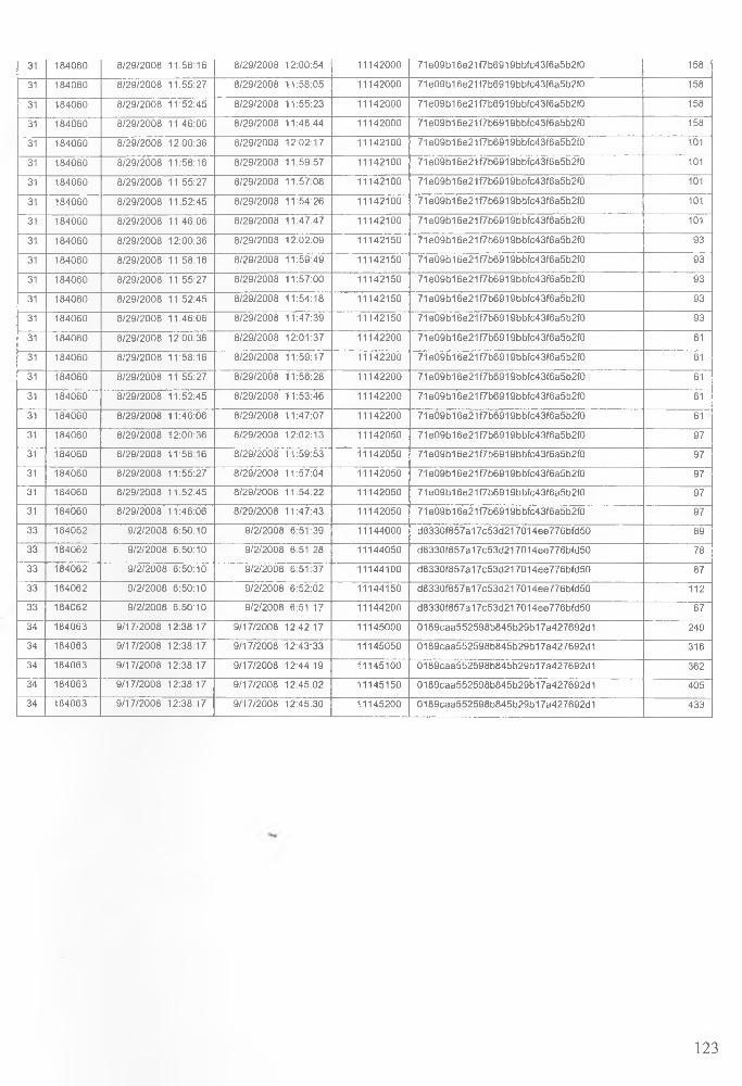
31 184060 8 /2 9 /2 00 8 11:58:16 8 /2 9 /2 00 8 12 :00 :54 11142000 71 e09b16e21 f7 b 6 91 9 b b fc43 f6 a 5 b2 f0 158
31 184060 8 /2 9 /2 0 0 8 11:55:27 8 /29 /2008 11 :58 :05 11142000 71 e09b16e21 f7 b 6 91 9 b b fc43 f6 a 5 b2 f0 158
31 184060 8 /2 9 /2 0 0 8 11 :52 :45 8 /2 9 /2 00 8 11 :55 :23 11142000 71 e09b16e21 f7 b 6 91 9 b b fc43 f6 a 5 b2 f0 158
31 184060 8 /2 9 /2 00 8 11:46:06 8 /2 9 /2 00 8 11 :48 :44 11142000 71 e09b16e21 f7 b 6 9 1 9 b b fc43 f6 a 5 b2 f0 158
31 184060 8 /2 9 /2 0 0 8 12 :00 :36 8 /2 9 /2 00 8 12:02:17 11142100 71 e 0 9 b 1 6 e 2 1 f7 b 6 9 19bb fc43 f6 a 5 b2 f0 101
31 184060 8 /2 9 /2 0 0 8 11:58:16 8 /29 /2008 11:59:57 11142100 71 e09b16e21 f7 b 6 9 19bb fc43 f6 a 5 b2 f0 101
31 184060 8 /2 9 /2 00 8 11:55:27 8 /2 9 /2 00 8 11:57:08 11142100 71 e09b16e21 f7 b 6 9 19bb fc43 f6 a 5 b2 f0 101
31 184060 8 /2 9 /2 00 8 11:52:45 8 /2 9 /2 00 8 11 :54 :26 11142100 71 e 0 9 b 1 6 e 2 1 f7 b 6 9 19bb fc43 f6 a 5 b2 f0 101
31 184060 8 /2 9 /2 00 8 11:46 06 8 /2 9 /2 00 8 11:47:47 11142100 7 1e 0 9 b1 6 e 21 f7 b 6 91 9 b b fc43 f6a 5 b2 f0 101
31 184060 8 /2 9 /2 00 8 12:00:36 8 /2 9 /2 00 8 12:02:09 11142150 71 e09b16e21 f7 b 6 91 9 b b fc43 f6 a 5 b2 f0 93
31 184060 8 /2 9 /2 0 0 8 11 :58 :16 8 /2 9 /2 00 8 11:59:49 11142150 71 e09b16e21 f7 b 6 9 19bb fc43 f6 a 5 b2 f0 93
31 184060 8 /2 9 /2 0 0 8 11 :55 :27 8 /2 9 /2 00 8 11 :57 :00 11142150 7 1e 0 9 b1 6 e 21 f7 b 6 91 9 b b fc43 f6a 5 b2 f0 93
31 184060 8 /2 9 /2 0 0 8 11 :52 :45 8 /2 9 /2 00 8 11:54:18 11142150 71 e 09 b 1 6e 2 1 f7 b6 9 1 9b b fc4 3 f6 a 5b 2 f0 93
31 184060 8 /2 9 /2 0 0 8 11 :46 :06 8 /2 9 /2 00 8 11:47:39 11142150 7 1e 0 9 b1 6 e 2 1 f7 b 6 9 1 9 b b fc4 3 f6 a 5 b 2 f0 93
31 184060 8 /2 9 /2 0 0 8 12 :00 :36 8 /2 9 /2 00 8 12:01:37 11142200 7 1e 0 9 b1 6 e 21 f7 b 6 91 9 b b fc43 f6a 5 b2 f0 61
31 184060 8 /2 9 /2 0 0 8 11 :58 :16 8 /2 9 /2 00 8 11 :59 :17 11142200 71 e09b16e21 f7 b 6 9 1 9 b b fc43 f6 a 5 b2 f0 61
31 184060 8 /2 9 /2 0 0 8 11 :55 :27 8 /2 9 /2 00 8 11:56:28 11142200 7 1e 0 9 b1 6 e 21 f7 b 6 91 9 b b fc43 f6a 5 b2 f0 61
31 184060 8 /2 9 /2 00 8 11 :52 :45 8 /29 /2008 11:53:46 11142200 71 e09b16e21 f7 b 6 9 1 9 b b fc43 f6 a 5 b2 f0 61
31 184060 8 /2 9 /2 00 8 11:46:06 8 /29 /2008 11 :47 :07 11142200 71 e09b16e21 f7 b 6 91 9 b b fc43 f6 a 5 b2 f0 61
31 184060 8 /2 9 /2 00 8 12 :00 :36 8 /2 9 /2 00 8 12 :02 :13 11142050 71 e09b16e21 f7 b 6 9 1 9 b b fc43 f6 a 5 b2 f0 97
31 184060 8 /2 9 /2 00 8 11:58:16 8 /2 9 /2 00 8 1 1 :59 :53 11142050 71 e 09 b16e2117b6919bb fc43 f6a5b2 f0 97
31 184060 8 /2 9 /2 00 8 11:55:27 8 /2 9 /2 00 8 11 :57 :04 11142050 71 e09b16e21 f7 b 6 91 9 b b fc43 f6 a 5 b2 f0 97
31 184060 8 /2 9 /2 0 0 8 11 :52 :45 8 /2 9 /2 00 8 11 :54 :22 11142050 71 e09b16e21 f7 b 6 9 1 9 b b fc43 f6 a 5 b2 f0 97
31 184060 8 /2 9 /2 0 0 8 11 :46 :06 8 /2 9 /2 00 8 11 :47 :43 11142050 71 e 0 9 b 1 6 e 2 1 f7 b 6 9 19bb fc43 f6 a 5 b2 f0 97
33 184062 9 /2 /2 0 08 6 :50 :10 9 /2 /2 0 08 6 :51 :39 11144000 d 83 3 0 f8 5 7a 1 7c5 3 d 21 7 0 14 e e 77 6 b fd 50 89
33 184062 9 /2 /2 0 0 8 6 :50 :10 9 /2 /2 0 08 6 :51 :28 11144050 d 8 3 3 0 f8 5 7 a 1 7 c5 3 d 2 1 7 01 4 ee 7 7 6b fd5 0 78
33 184062 9 /2 /2 0 0 8 6 :50 :10 9 /2 /2 0 08 6 :51 :37 11144100 d 8 3 3 0 f8 5 7 a 1 7 c5 3 d 2 1 7 01 4 ee 7 7 6b fd5 0 87
33 184062 9 /2 /2 0 0 8 6 :50 :10 9 /2 /2 0 08 6 :5 2 :0 2 11144150 d 8 3 3 0 f8 5 7 a 1 7 c5 3 d 2 1 7 01 4ee77 6b fd5 0 112
33 184062 9 /2 /2 0 0 8 6 :50 :10 9 /2 /2 0 0 8 6 :51 :17 11144200 d 83 3 0 f8 5 7a 17 c5 3 d 2 1 7 01 4ee77 6b fd5 0 67
34 184063 9 /1 7 /2 0 0 8 12 :38 :17 9 /17 /2 00 8 12 :42 :17 11145000 0 1 8 9ca a 5 5 2 5 9 8 b 8 4 5 b 2 9 b 1 7 a 4 2 7 6 9 2 d 1 240
34 184063 9 /1 7 /2 00 8 12:38:17 9 /1 7 /2 00 8 12 :43 :33 11145050 0 1 8 9 ca a 5 52 5 9 8b 8 4 5b 2 9 b1 7 a 42 7 69 2 d 1 316
34 184063 9 /1 7 /2 0 0 8 12 :38 :17 9 /1 7 /2 00 8 12:44:19 11145100 0 1 8 9 ca a 5 52 5 9 8b 8 4 5b 2 9 b1 7 a 42 7 69 2 d 1 362
34 184063 9 /1 7 /2 0 0 8 12:38:17 9 /1 7 /2 00 8 12 :45 :02 11145150 0 1 8 9 ca a 5 52 5 9 8b 8 4 5b 2 9 b1 7 a 42 7 69 2 d 1 405
34 184063 9 /1 7 /2 0 0 8 12 :38 :17 9 /1 7 /2 00 8 12:45:30 11145200 0 1 8 9 ca a 5 52 5 9 8b 8 4 5b 2 9 b1 7 a 42 7 69 2 d 1 433
123

124

Survey Q uestionnaire Raw ResultsP A R T IC IP A N T S
Question DescriptionD im e n s io n
U s a b i l i t y _ A t t r ib u te s 1 2 3 4 5 6 7 S 5 10 11 12 13 14 15 16 17 16 19 20 ?1 22 23 24 25 26 27 26 ?P 30 31 32 33
The visual size of the application is suitable Percept
ionSize 5 3 5 4 5 5 4 4 5 3 3 4 ' 4 5 3 5 4 5 4 4 5 5 3 4 3 5 5 5 4 4 1 3 4
The form design is clear and simple visibility 5 3 5 4 5 4 4 4 5 3 4 5 5 5 4 5 4 5 4 4 4 5 4 4 4 4 5 5 4 4 1 5 4
The speed of the system is fast enough
Control/ Action '
Speed 5 5 5 4 5 5 4 5 3 4 5 5 5 5 4 4 4 4 4 5 5 4 5 4 5 4 5 5 4 2 5 4It is easy to get the menu for task execution Simplicity 5 5 5 5 5 3 4 5 5 3 4 5 5 4 4 4 4 5 5 4 3 5 5 5 4 3 5 5 4 4 3 3 4
Its is easy to carry out taskcomprehensibility 4 5 5 4 5 3 5 4 4 4 4 4 5 5 4 4 5 5 5 5 4 4 4 5 4 5 5 4 3 3 2 3 5
It is easy to get out on error Reliability 4 3 4 5 5 3 5 3 5 4 4 4 3 5 5 4 4 5 4 4 5 5 5 5 5 5 3 3 3 3 2 3 3it is easy to enter data easily and guickly data capture 3 2 4 3 5 4 4 3 4 4 3 5 5 5 4 5 5 5 4 3 5 5 4 4 3 5 5 5 4 3 3 4 5It is convenient to fill out the meter reading form Efficiency 3 3 4 3 5 5 5 3 5 5 3 5 3 5 4 5 4 5 4 4 5 5 4 4 5 4 5 5 2 4 1 4 4It is fast to get a response on submitting the meter reading
Responsiveness 5 2 5 5 5 5 ' 5 5 3 5 4 5 3 5 3 3 5 3 4 4 3 5 3 4 3 5 4 4 c 4 1 5 5
It is easy to rectify the errors committed Rectification 3 4 5 1 5 5 5 4 3 3 1 4 3 5 3 5 4 3 4 4 4 5 3 4 5 5 5 4 3 3 5 3 3
It provides flexible user guidance
L eam ing /M eniorization
GuidanceCapability 3 4 5 3 5 4 4 4 4 3 1 4 4 5 4 5 4 5 4 5 4 5 4 4 5 5 5 4 3 4 2 4 3
It is easy to know what to do next with this application predictability 3 4 4 3 5 4 4 4 5 3 1 3 3 4 4 5 4 3 4 5 4 4 4 4 5 5 5 4 2 3 2 4 3It is easy to recall how to do things within this application Memorability 4 4 5 5 5 4 4 5 5 3 2 4 4 5 4 5 5 4 4 4 4 5 5 5 5 5 5 4 3 3 3 4 4It Is easy to move from one part of a task to another consistency 2 5 4 3 5 4 5 4 5 3 3 5 4 5 3 5 4 4 4 5 4 5 4 5 5 3 5 4 3 4 3 3It is easy to see at a glance what the options are at each stage
Informativeness 5 4 4 4 5 5 5 5 5 3 4 4 5 4 3 5 4 4 4 4 4 4 5 4 5 2 4 3 1 4 3 3 3
Audio feedback is reguiredReponsiveness 1 3 4 3 5 5 5 4 5 4 3 3 3 5 3 4 4 5 3 4 4 4 4 5 5 5 1 5 5 5 1 5 3
It is comfortable to use the application
Evaluative
F eeling
Comfort 3 5 5 5 5 4 4 4 4 3 3 4 4 4 4 5 5 5 4 5 4 4 4 5 5 3 5 4 4 4 2 4 3
The ordering of menu options is logical Logic 3 5 5 3 5 3 4 4 . 4 3 3 3 4 4 4 5 5 3 5 5 4 5 5 5 4 4 4 4 3 4 2 4 4The application very attractive presentation
Attractive nes s 3 3 3 4 5 4 5 5 4 4 4 4 5 5 4 4 4 5 5 5 5 4 5 4 3 3 4 4 4 3 1 4 3
1 am happy with the application service Satisfaction 3 5 5 4 5 5 4 4 5 3 5 5 4 5 5 5 4 5 5 4 4 5 5 4 3 5 5 4 5 4 1 3 31 will often prefer the mobile data collection system Acceptance 5 3 4 4 5 5 3 4 5 3 4 5 4 5 5 5 4 4 5 5 4 4 4 4 4 2 5 4 4 4 1 5 4It is a convenient and efficient way of mobile data Convenience 5 4 5 5 5 5 5 3 4 4 5 5 4 5 5 5 4 4 5 5 4 4 4 4 5 4 5 4 5 5 1 5 4
125
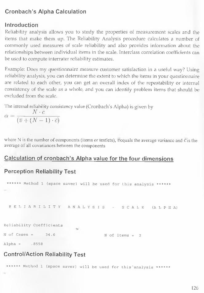
Cronbach’s Alpha Calculation
IntroductionReliability analysis allows you to study the properties of measurement scales and the items that make them up. The Reliability Analysis procedure calculates a number of commonly used measures of scale reliability and also provides information about the relationships between individual items in the scale. Interclass correlation coefficients can be used to compute interrater reliability estimates.
Example: Does my questionnaire measure customer satisfaction in a useful way? Using reliability analysis, you can determine the extent to which the items in your questionnaire are related to each other, you can get an overall index of the repeatability or internal consistency of the scale as a whole, and you can identify problem items that should be excluded from the scale.
The internal reliability consistency value (Cronbach's Alpha) is given byN ■ C
( v + ( N - 1) • c )
where N is the number of components (items or testlets), L’equals the average variance and Cis the average of all covariances between the components
Calculation of cronbach’s Alpha value for the four dimensions
Perception Reliability Test
* * * * * * Method 1 ( s p a c e s a v e r ) w i l l be used f o r t h i s a n a l y s i s * * * * * *
R E L I A B I L I T Y A N A L Y S I S - S C A L E ( A L P H A )
R e l i a b i l i t y C o e f f i c i e n t s
N o f Cases = 3 4 . 0 N o f I t em s = 2
Alpha = . 8 5 5 8
Control/Action Reliability Test
* * * * * * Method 1 ( s p a c e s a v e r ) w i l l be used f o r t h i s ' a n a l y s i s * * * * * *
126

R E L I A B I L I T Y A N A L Y S I S S C A L E ( A L P H A )
R e l i a b i l i t y C o e f f i c i e n t s
N o f Cases = 3 3 . 0 N o f I tems = 8
Alpha = . 7 0 8 2
Learning/Memorization Reliability Test
* * * * * * Method 1 ( s p a c e s a v e r ) w i l l be used f o r t h i s a n a l y s i s * * * * * *
R E L I A B I L I T Y A N A L Y S I S - S C A L E ( A L P H A )
R e l i a b i l i t y C o e f f i c i e n t s
N o f Cases = 3 3 . 0 N o f I t em s = 6
Alpha = . 7 6 8 4
Evaluative Feeling Reliability Test
* * * * * * Method 1 ( s p a c e s a v e r ) w i l l be used f o r t h i s a n a l y s i s * * * * * *
R E L I A B I L I T Y A N A L Y S I S - S C A L E ( A L P H A )
R e l i a b i l i t y C o e f f i c i e n t s
N o f Cases = 3 4 . 0 N o f I t em s = 6
Alpha = . 8 2 9 0
Overall Reliability Test
Method 1 ( s p a c e s a v e r ) w i l l be used f o r t h i s a n a l y s i s * * * * * *
197

r e l i a b i l i t y a n a l y s i s S C A L E ( A L P H A )
R e l i a b i l i t y C o e f f i c i e n t s
N o f Cases = 3 2 . 0
Alpha = . 8 4 3 4
N o f I t em s = 22
128
Related Documents