Modul – 3 Sistem Transmisi TE-09-1313 2 sks Versi-2 Disusun oleh M Aries Purnomo 1 TE-09-1313-021011-03- Transmisi-2

Welcome message from author
This document is posted to help you gain knowledge. Please leave a comment to let me know what you think about it! Share it to your friends and learn new things together.
Transcript

Modul – 3Sistem Transmisi
TE-09-13132 sksVersi-2
Disusun oleh
M Aries Purnomo
1TE-09-1313-021011-03-Transmisi-2
TRANSMISI
• The transfer of information from one point to one or more other points by means of signals
( Rec ITU-R V.662-3-2000 )
2TE-09-1313-021011-03-Transmisi-2

SINYALA physical phenomenon one or more of whose characteristics may vary to represent information.
NOTE – The physical phenomenon may be for instance an electromagnetic wave or acoustic wave and the characteristic may be an electric field, a voltage or a sound pressure.
( Rec ITU-R V.662-3-2000 )
3TE-09-1313-021011-03-Transmisi-2

TE-09-1313-021011-03-Transmisi-2 4
• TELEVISIBentuk telekomunikasi untuk transmisi gambar
diam atau gambar bergerak
TE-09-1313-021011-03-Transmisi-2 5
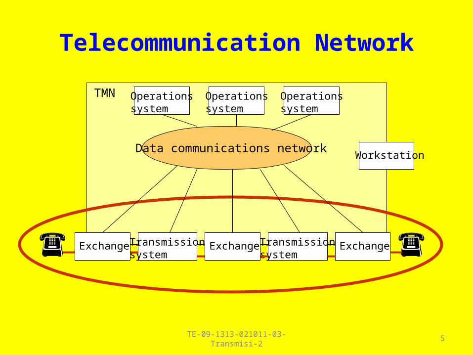
Telecommunication Network
ExchangeTransmissionsystem
Transmissionsystem
Operationssystem
Operationssystem
Operationssystem
ExchangeExchange
WorkstationData communications network
TMN
TE-09-1313-021011-03-Transmisi-2 6
KONSEP SISTEM TRANSMISI
Loss & Gain
TE-09-1313-021011-03-Transmisi-2 7
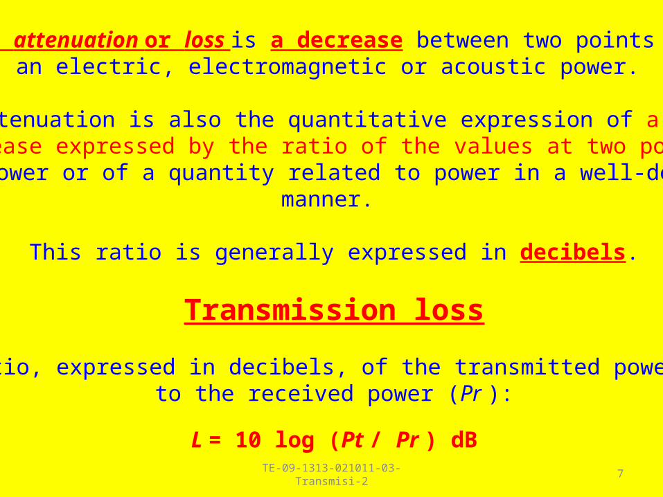
The attenuation or loss is a decrease between two points of an electric, electromagnetic or acoustic power.
The attenuation is also the quantitative expression of a power decrease expressed by the ratio of the values at two points of a power or of a quantity related to power in a well-defined
manner.
This ratio is generally expressed in decibels.
Transmission loss
The ratio, expressed in decibels, of the transmitted power (Pt ) to the received power (Pr ):
L = 10 log (Pt / Pr ) dB
TE-09-1313-021011-03-Transmisi-2 8
The gain is the increase between two points of an electric, electromagnetic or acoustic power.
The gain is also the quantitative expression of a power increase expressed by the ratio of the values at two points of a power or
of a quantity related to power in a well-defined manner.
This ratio is generally expressed in decibels.
Antenna gainAmplifier gain

TE-09-1313-021011-03-Transmisi-2 9
Antenna gain
the power required at the input of a loss free reference antenna (P0) to the power supplied to the input of the given antenna (Pa ) to produce, in a given direction, the same field strength or the same power flux-density at the same distance in a given direction (when not specified otherwise in the direction of Maximum radiation).
G = 10 log (P0 / Pa ) dB
TE-09-1313-021011-03-Transmisi-2 10
In transmission engineering, most often it would be rather impractical to characterize the magnitude of signals directly by a numerical value in volts or watts.
Instead, a logarithmic measure is used, expressed in "dB", to characterize the signal magnitude in relation to some chosen reference value.
Designations commonly used are "power level difference", "voltage level difference", etc., all expressed in "dB". A level difference from a standard situation is described simply as "level".
TE-09-1313-021011-03-Transmisi-2 11
The use of the decibel and of relative levels
in speechband telecommunications RECOMMENDATION ITU-T- G-100.1
USE OF THE DECIBEL AND THE NEPER IN TELECOMMUNICATIONS
RECOMMENDATION ITU-R V.574-4
TE-09-1313-021011-03-Transmisi-2 12
Definition of the decibel
The bel (symbol B) expresses the ratio of two powers by the decimal logarithm of this ratio. This unit is not often used, having been replaced by the decibel (symbol dB) which is one-tenth of a bel.
The decibel also may be used to express the ratio of two field quantities, such as voltage, current, sound pressure, electric field, charge velocity or density, the square of which in linear systems is proportional to power. To obtain the same numerical value as a power ratio, the logarithm of the field quantity ratio is multiplied by the factor 20,assuming that the impedances are equal.
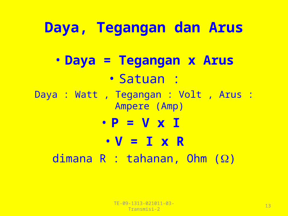
Daya, Tegangan dan Arus
• Daya = Tegangan x Arus
• Satuan :Daya : Watt , Tegangan : Volt , Arus : Ampere (Amp)
• P = V x I
• V = I x Rdimana R : tahanan, Ohm ()
13TE-09-1313-021011-03-Transmisi-2
TE-09-1313-021011-03-Transmisi-2 14
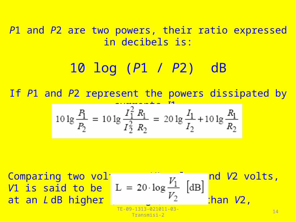
P1 and P2 are two powers, their ratio expressed in decibels is:
10 log (P1 / P2) dB
If P1 and P2 represent the powers dissipated by currents I1 and I2 in resistances R1 and R2:
Comparing two voltages, V1 volts and V2 volts, V1 is said to be at an L dB higher (voltage) level than V2,
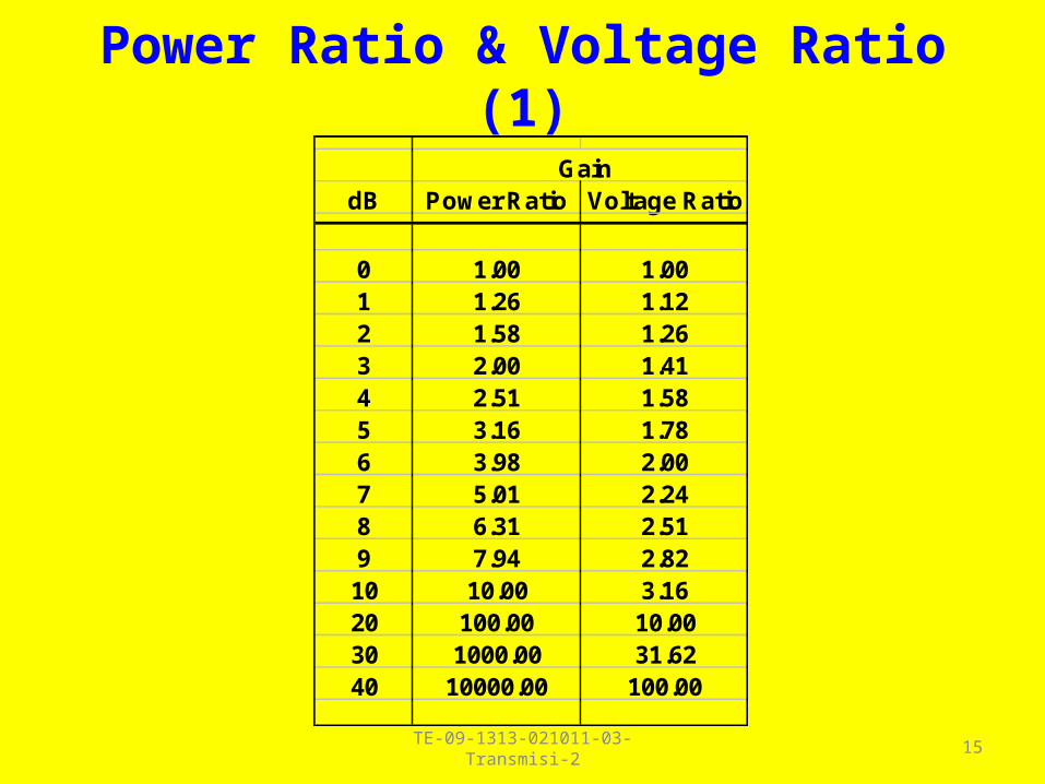
Power Ratio & Voltage Ratio (1)
GaindB Power Ratio Voltage Ratio
0 1.00 1.001 1.26 1.122 1.58 1.263 2.00 1.414 2.51 1.585 3.16 1.786 3.98 2.007 5.01 2.248 6.31 2.519 7.94 2.8210 10.00 3.1620 100.00 10.0030 1000.00 31.6240 10000.00 100.00
15TE-09-1313-021011-03-Transmisi-2
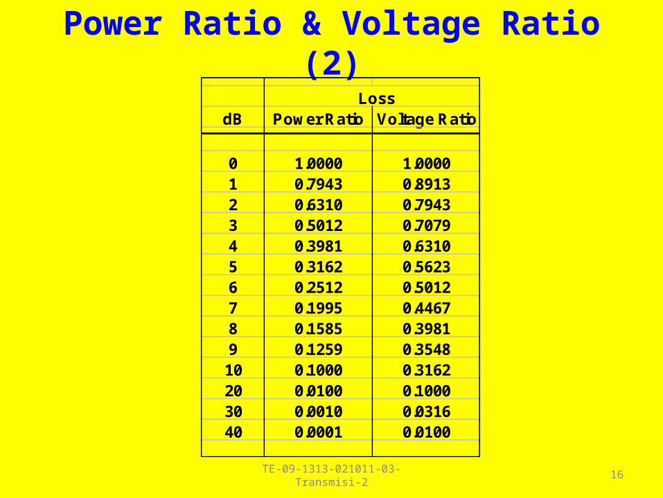
Power Ratio & Voltage Ratio (2)
LossdB Power Ratio Voltage Ratio
0 1.0000 1.00001 0.7943 0.89132 0.6310 0.79433 0.5012 0.70794 0.3981 0.63105 0.3162 0.56236 0.2512 0.50127 0.1995 0.44678 0.1585 0.39819 0.1259 0.354810 0.1000 0.316220 0.0100 0.100030 0.0010 0.031640 0.0001 0.0100
16TE-09-1313-021011-03-Transmisi-2
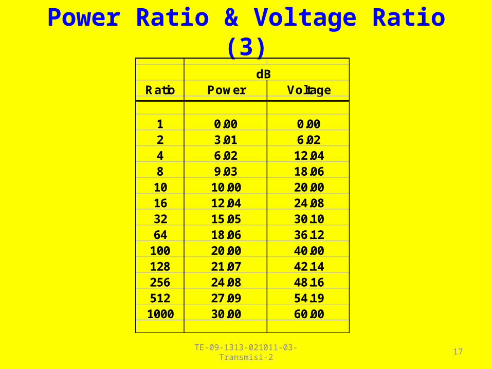
Power Ratio & Voltage Ratio (3)
dBRatio Power Voltage
1 0.00 0.002 3.01 6.024 6.02 12.048 9.03 18.0610 10.00 20.0016 12.04 24.0832 15.05 30.1064 18.06 36.12
100 20.00 40.00128 21.07 42.14256 24.08 48.16512 27.09 54.191000 30.00 60.00
17TE-09-1313-021011-03-Transmisi-2

TE-09-1313-021011-03-Transmisi-2 18
TE-09-1313-021011-03-Transmisi-2 19
Absolute power level :
The absolute power level is the ratio, generally expressed in decibels, between the power of a signal at a point in a transmission channel and a specified reference power.
It should be specified in every case whether the power is real or apparent.

TE-09-1313-021011-03-Transmisi-2 20
It is necessary for the reference power to be indicated by a symbol:
– when the reference power is one watt, the absolute power level is expressed in “decibels relative to one watt” and the symbol “dBW” is used;
– when the reference power is one milliwatt, the absolute power level is expressed in “decibels relative to one milliwatt” and the symbol “dBm” is used.
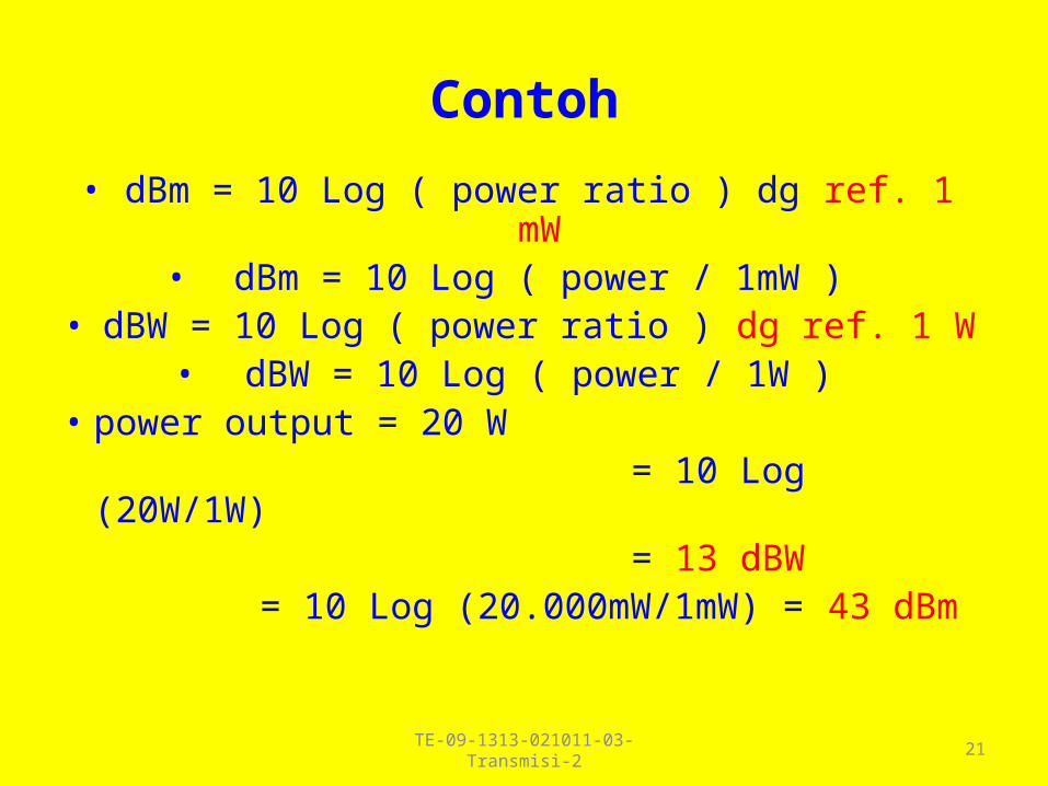
Contoh
• dBm = 10 Log ( power ratio ) dg ref. 1 mW• dBm = 10 Log ( power / 1mW )
• dBW = 10 Log ( power ratio ) dg ref. 1 W• dBW = 10 Log ( power / 1W )
• power output = 20 W = 10 Log (20W/1W) = 13 dBW = 10 Log (20.000mW/1mW) = 43 dBm
21TE-09-1313-021011-03-Transmisi-2
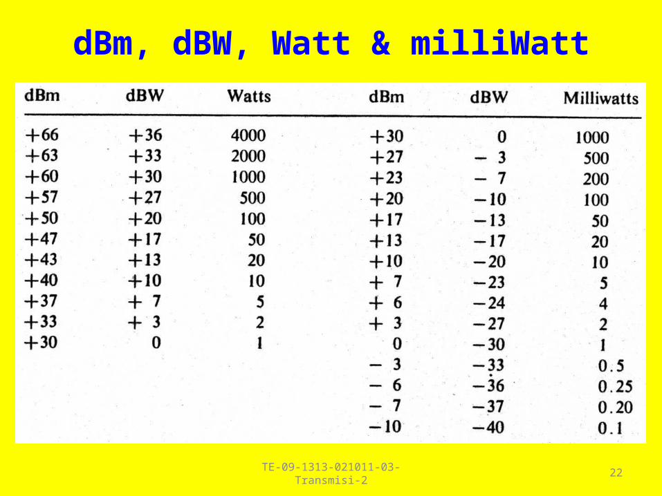
dBm, dBW, Watt & milliWatt
22TE-09-1313-021011-03-Transmisi-2

Voltage & Current Ratio
• dB(Voltage) = 20 Log ( ratio voltage )
• dB(Current) = 20 Log ( ratio current )
23TE-09-1313-021011-03-Transmisi-2
TE-09-1313-021011-03-Transmisi-2 24
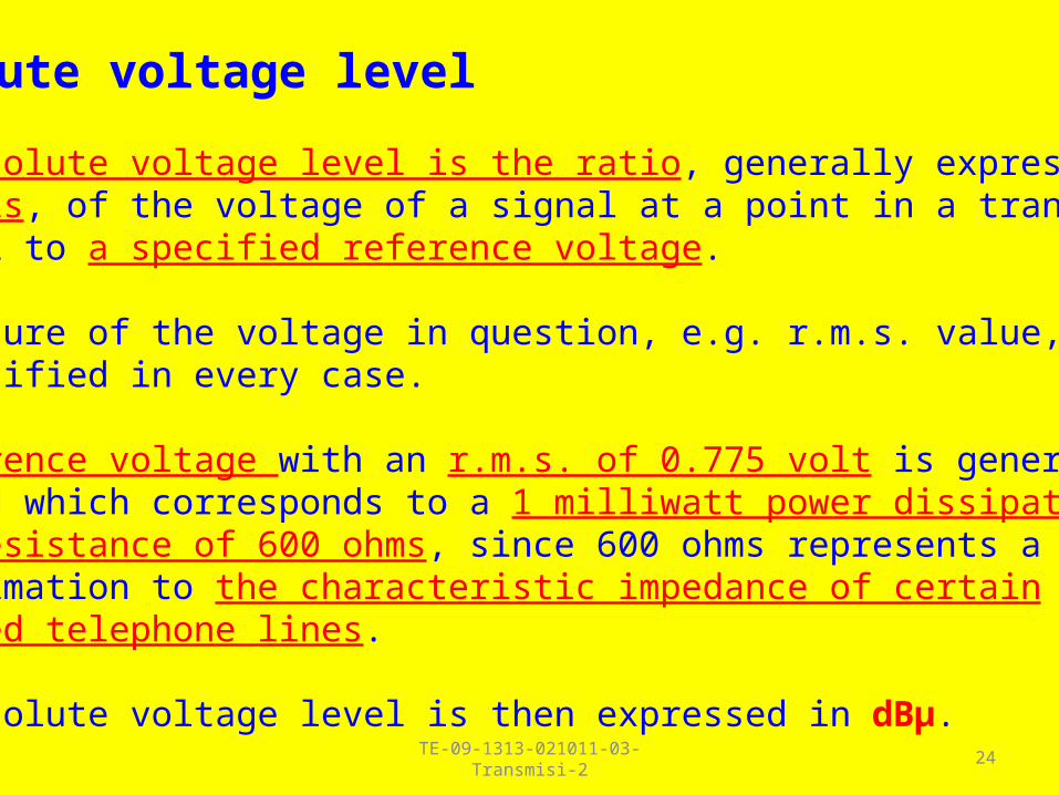
Absolute voltage level
The absolute voltage level is the ratio, generally expressed in decibels, of the voltage of a signal at a point in a transmission channel to a specified reference voltage.
The nature of the voltage in question, e.g. r.m.s. value, should be specified in every case.
A reference voltage with an r.m.s. of 0.775 volt is generally adopted which corresponds to a 1 milliwatt power dissipatedin a resistance of 600 ohms, since 600 ohms represents a roughapproximation to the characteristic impedance of certainbalanced telephone lines.
The absolute voltage level is then expressed in dBμ.

TE-09-1313-021011-03-Transmisi-2 25
If the impedance at the terminals of which the voltage U1 is measured, is in fact 600 ohms, the absolute voltage level
thus defined, corresponds to the absolute power level with respect to 1 milliwatt, and so the number N exactly represents
the level in decibels with respect to 1 milliwatt (dBm).
Lu = 20 log (U1 / U2 ) dBμLp = 10 log (P1 / P2 ) dBm
If the impedance at the terminals of which the voltage U1 is measured, is R ohms, N equals the number of dBm increased
by the quantity 10 log (R/600).
Lu = Lp + 10 log (R / 600)

dBmV
• Digunakan pada transmisi video
• Tegangan ( Voltage ) referensi = 1 mVolt pada beban 75 Ohm
• dBmV = 20 Log ( tegangan/1 mVolt )
26TE-09-1313-021011-03-Transmisi-2

dBmV
27TE-09-1313-021011-03-Transmisi-2
TE-09-1313-021011-03-Transmisi-2 28
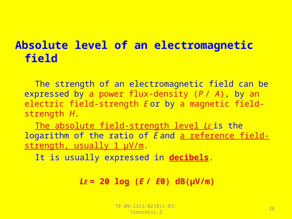
Absolute level of an electromagnetic field
The strength of an electromagnetic field can be expressed by a power flux-density (P / A), by an electric field-strength E or by a magnetic field-strength H.
The absolute field-strength level LE is the logarithm of the ratio of E and a reference field-strength, usually 1 μV/m.
It is usually expressed in decibels.
LE = 20 log (E / E0) dB(μV/m)
TE-09-1313-021011-03-Transmisi-2 29
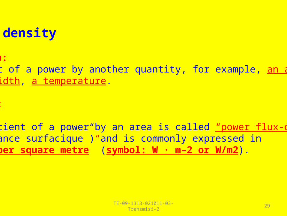
Power density
Definition: Quotient of a power by another quantity, for example, an area, a bandwidth, a temperature.
NOTE 1 :
The quotient of a power by an area is called “power flux-density” (“puissance surfacique”) and is commonly expressed in “watts per square metre” (symbol: W · m–2 or W/m2).
TE-09-1313-021011-03-Transmisi-2 30
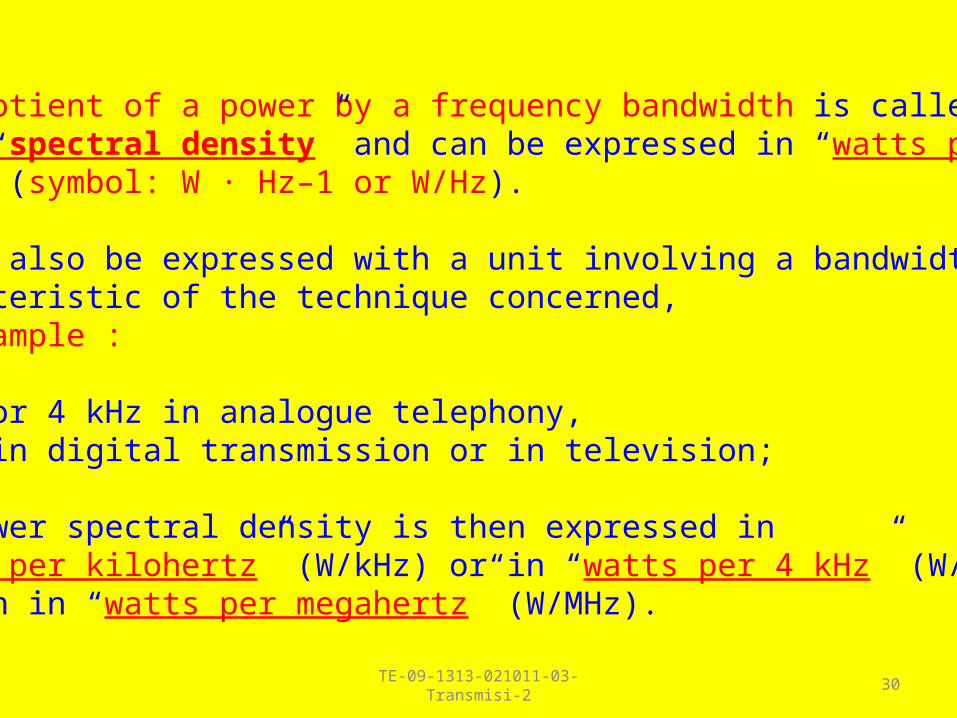
The quotient of a power by a frequency bandwidth is called “power spectral density” and can be expressed in “watts perhertz” (symbol: W · Hz–1 or W/Hz).
It can also be expressed with a unit involving a bandwidth characteristic of the technique concerned, for example :
1 kHz or 4 kHz in analogue telephony, 1 MHz in digital transmission or in television;
the power spectral density is then expressed in “watts per kilohertz” (W/kHz) or in “watts per 4 kHz” (W/4 kHz) or even in “watts per megahertz” (W/MHz).

TE-09-1313-021011-03-Transmisi-2 31
The quotient of a power by a temperature, used particularly in the case of noise powers, has no specific name.
It is usually expressed as “watts per kelvin” (symbol: W · K–1 or W/K).
NOTE 2 :
In some cases a combination of several types of power densities can be used, for example a “spectral power flux-density” which is expressed as “watts per square metre and per hertz” (symbol: W · m−2 · Hz–1 or W/(m2 · Hz)).
TE-09-1313-021011-03-Transmisi-2 32
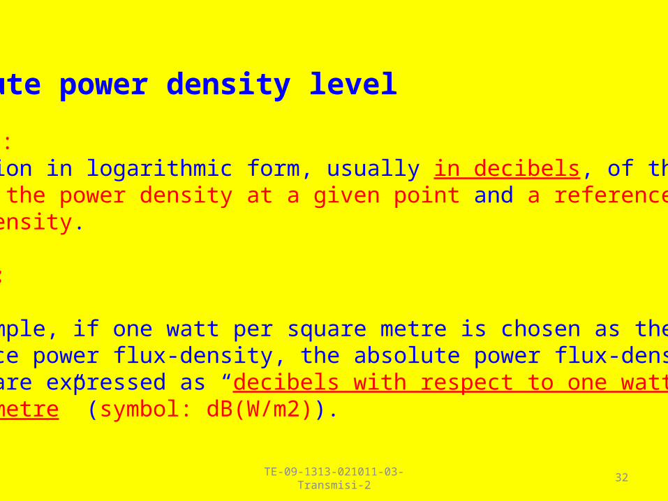
Absolute power density level
Definition : Expression in logarithmic form, usually in decibels, of the ratio between the power density at a given point and a reference power density.
NOTE 1 :
For example, if one watt per square metre is chosen as the reference power flux-density, the absolute power flux-density levels are expressed as “decibels with respect to one watt per square metre” (symbol: dB(W/m2)).

TE-09-1313-021011-03-Transmisi-2 33
Similarly, if one watt per hertz is chosen as the spectral reference power density, the absolute spectral power densitylevels are expressed as “decibels with respect to one watt per hertz” (symbol: dB(W/Hz)).
If one watt per kelvin is chosen as the reference for power density per unit temperature, the absolute power density levelsper temperature unit are expressed as “decibels with respect to one watt per kelvin” (symbol: dB(W/K)).
This notation can easily be extended to combined densities.
For example, the absolute spectral density levels of the fluxdensity are expressed as “decibels with respect to one watt per square metre and per hertz” for which the symbol is: dB(W/(m2 · Hz). Some examples are: dB(W/(m2 · MHz) and dB(W/(m2 · 4 kHz).
TE-09-1313-021011-03-Transmisi-2 34
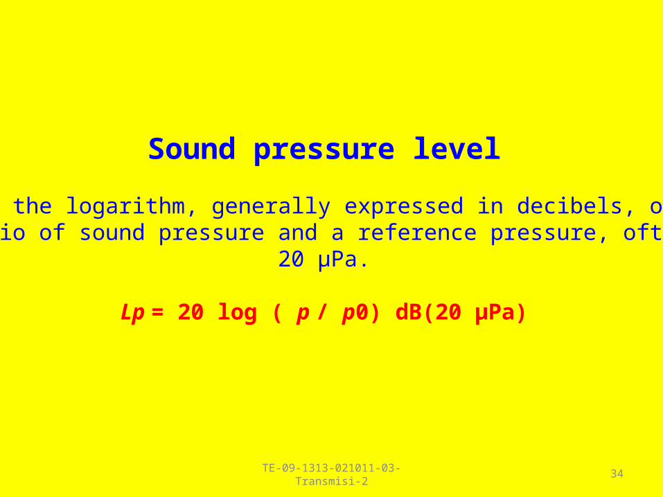
Sound pressure level
This is the logarithm, generally expressed in decibels, of the ratio of sound pressure and a reference pressure, often
20 μPa.
Lp = 20 log ( p / p0) dB(20 μPa)
TE-09-1313-021011-03-Transmisi-2 35
Contoh – contoh perhitunganKonsep transmisi
( Loss & Gain )
TE-09-1313-021011-03-Transmisi-2 36
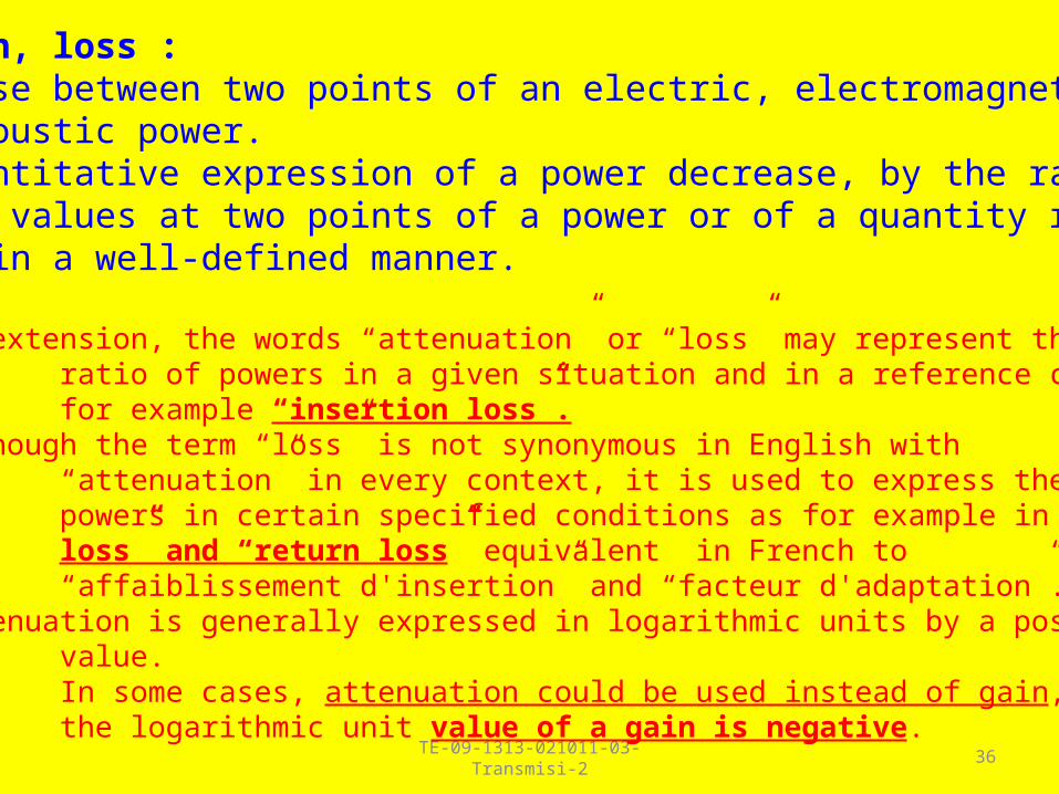
attenuation, loss :1.A decrease between two points of an electric, electromagnetic or acoustic power.2. The quantitative expression of a power decrease, by the ratio of the values at two points of a power or of a quantity related to power in a well-defined manner.
NOTE 1 : By extension, the words “attenuation” or “loss” may represent the ratio of powers in a given situation and in a reference condition; for example “insertion loss”.NOTE 2 : Although the term “loss” is not synonymous in English with “attenuation” in every context, it is used to express the ratio of two powers in certain specified conditions as for example in “insertion loss” and “return loss” equivalent in French to “affaiblissement d'insertion” and “facteur d'adaptation”.NOTE 3 : Attenuation is generally expressed in logarithmic units by a positive value. In some cases, attenuation could be used instead of gain, when the logarithmic unit value of a gain is negative.
TE-09-1313-021011-03-Transmisi-2 37
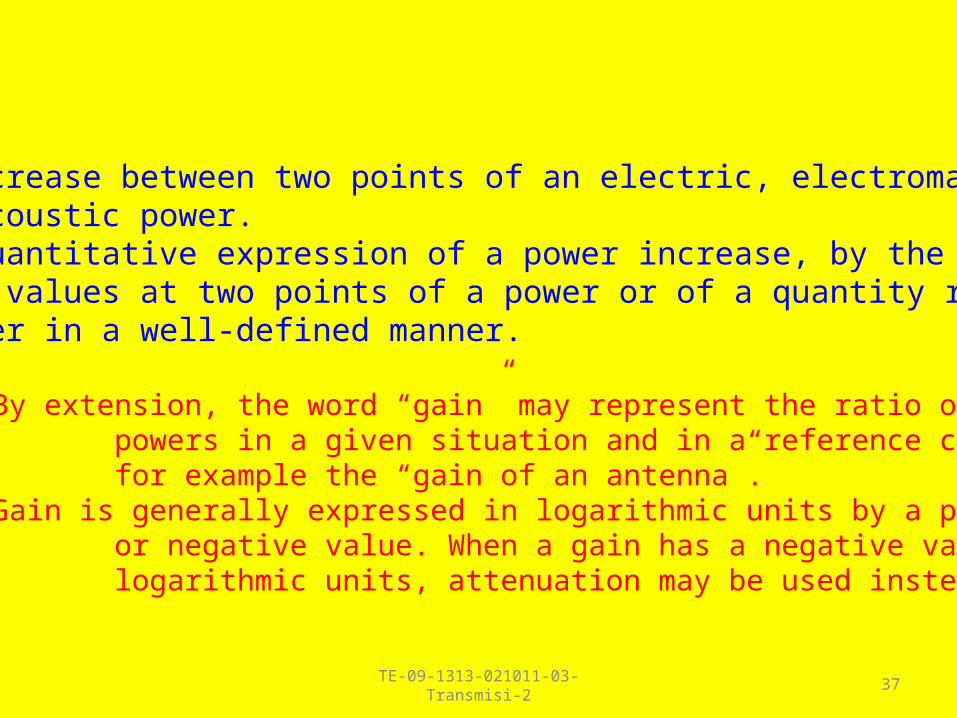
Gain :
1. An increase between two points of an electric, electromagnetic, or acoustic power.2. The quantitative expression of a power increase, by the ratio of the values at two points of a power or of a quantity related to power in a well-defined manner.
NOTE 1 : By extension, the word “gain” may represent the ratio of powers in a given situation and in a reference condition; for example the “gain of an antenna”.NOTE 2 : Gain is generally expressed in logarithmic units by a positive or negative value. When a gain has a negative value in logarithmic units, attenuation may be used instead of gain.

LOSS
• Loss (dB ) = 10 Log(power ratio) = = 10 Log(output/input) = = 10 Log ( 1 / 1.000 ) = = 10x(-3) = -30 dB
Kabel 1000 Watt 1 Watt
Input Output
38TE-09-1313-021011-03-Transmisi-2
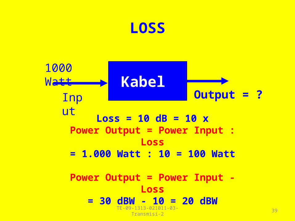
LOSS
Kabel 1000 Watt
Input Output = ?
Loss = 10 dB = 10 xPower Output = Power Input : Loss
= 1.000 Watt : 10 = 100 Watt
Power Output = Power Input - Loss= 30 dBW - 10 = 20 dBW
39TE-09-1313-021011-03-Transmisi-2

GAIN (PENGUATAN)
• Gain (dB ) = 10 Log(power ratio) = = 10 Log(output/input) = = 10 Log ( 2 / 1 ) = 10 x 0,3013 = 3,013 dB = 3 dB
Amplifier1 Watt 2 Watt
Input Output
40TE-09-1313-021011-03-Transmisi-2

GAIN (PENGUATAN)
Amplifier1 Watt
Input Output =?
Gain = 6 dB = 4 x
Power Output = Power Input x GainPower Input = 1 Watt = 30 dBm
Power Output = 1 Watt x 4 = 4 WattPower Output = Power Input + Gain
= 30 + 6 = 36 dBm41TE-09-1313-021011-03-Transmisi-2
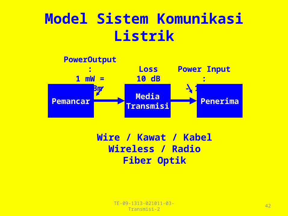
Model Sistem Komunikasi Listrik
MediaTransmisi
PenerimaPemancar
Wire / Kawat / KabelWireless / Radio
Fiber Optik
Loss10 dB
PowerOutput :1 mW =0 dBm
Power Input :- 10 dBm
42TE-09-1313-021011-03-Transmisi-2

Model Sistem Pemancar
AntenaPemancar
Wire / Kawat /Kabel /Kabel Koaxial
Power Output1 kW = 30 dBW
Loss = 3 dB
Power Input27 dBW Gain = 10 dB
EffectiveRadiated
Power(ERP) :37 dBW
43TE-09-1313-021011-03-Transmisi-2
TE-09-1313-021011-03-Transmisi-2 44
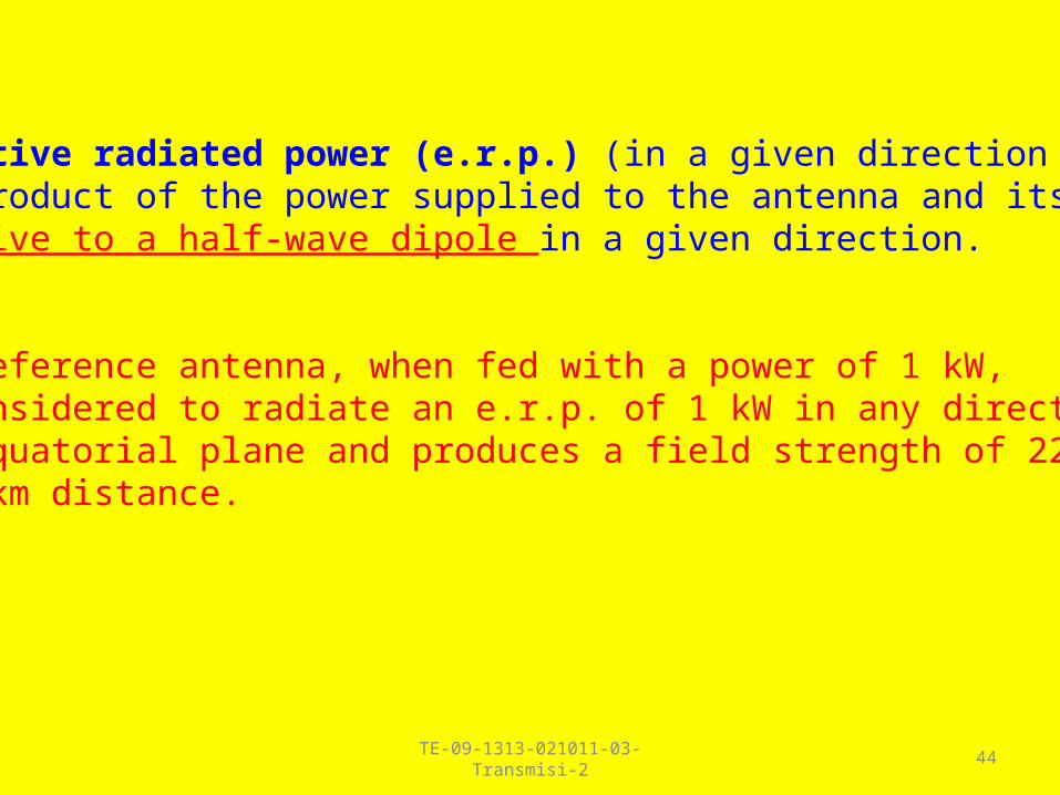
effective radiated power (e.r.p.) (in a given direction )The product of the power supplied to the antenna and its gain relative to a half-wave dipole in a given direction.
Note : The reference antenna, when fed with a power of 1 kW, is considered to radiate an e.r.p. of 1 kW in any direction in the equatorial plane and produces a field strength of 222 mV/m at 1 km distance.
TE-09-1313-021011-03-Transmisi-2 45
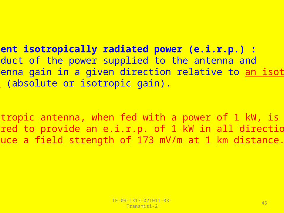
equivalent isotropically radiated power (e.i.r.p.) :The product of the power supplied to the antenna and the antenna gain in a given direction relative to an isotropic antenna (absolute or isotropic gain).
Note : The isotropic antenna, when fed with a power of 1 kW, is considered to provide an e.i.r.p. of 1 kW in all directions and to produce a field strength of 173 mV/m at 1 km distance.
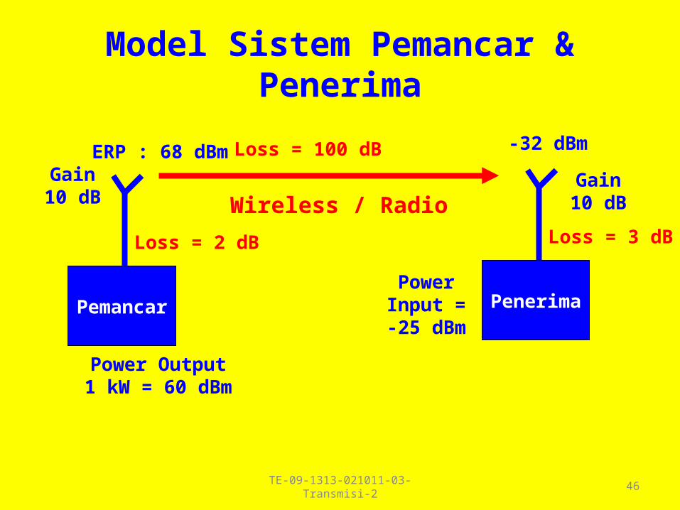
Model Sistem Pemancar & Penerima
PenerimaPemancar
Wireless / Radio
Loss = 100 dB
Gain10 dB
Gain10 dB
Loss = 2 dB Loss = 3 dB
Power Output1 kW = 60 dBm
PowerInput =
-25 dBm
ERP : 68 dBm -32 dBm
46TE-09-1313-021011-03-Transmisi-2

Series Network
N1 N2 N3 TS
10dBm
G3 dB
L5 dB
G3 dB
13dBm
8dBm
11dBm
47TE-09-1313-021011-03-Transmisi-2
Related Documents


![It-041246_teknik Penyambungan_p1 [Dasar-dasar Telekomunikasi]](https://static.cupdf.com/doc/110x72/563db8bd550346aa9a967c59/it-041246teknik-penyambunganp1-dasar-dasar-telekomunikasi.jpg)