Nonlinear dispersion in wave-current interactions Darryl D. Holm and Ruiao Hu Department of Mathematics Imperial College London SW7 2AZ, UK [email protected] and [email protected] In honour of Tony Bloch’s 65th birthday. Happy birthday, Tony! Abstract Via a sequence of approximations of the Lagrangian in Hamilton’s principle for dispersive nonlinear gravity waves we derive a hierarchy of Hamiltonian models for describing wave-current interaction (WCI) in nonlinear dispersive wave dynamics on free surfaces. A subclass of these WCI Hamiltonians admits emer- gent singular solutions for certain initial conditions. These singular solutions are identified with a singular momentum map for left action of the diffeomorphisms on a semidirect-product Lie algebra. This semidirect- product Lie algebra comprises vector fields representing horizontal current velocity acting on scalar functions representing wave elevation. We use computational simulations to demonstrate the dynamical interactions of the emergent wavefront trains which are admitted by this special subclass of Hamiltonians for a variety of initial conditions. In particular, we investigate: (1) A variety of localised initial current configurations in still water whose subsequent propagation generates surface-elevation dynamics on an initially flat surface; and (2) The release of initially confined configurations of surface elevation in still water that generate dynamically interacting fronts of localised currents and wave trains. The results of these simulations show intricate wave-current interaction patterns whose structures are similar to those seen, for example, in Synthetic Aperture Radar (SAR) images taken from the space shuttle. 1 Introduction The sea-surface disturbances whose trains of curved wavefronts trace the propagation of internal gravity waves on the ocean thermocline hundreds of meters below the surface may be observed in many areas of strong tidal flow. For example, the passage of the Atlantic Ocean tides through the Gibraltar Strait produces trains of curved sea-surface wavefronts expanding into the Mediterranean Sea. Likewise, the passage of the Pacific Ocean tides through the Luzon Strait between Taiwan and the Philippines produces trains of curved sea-surface wavefronts expanding into the South China Sea. These coherent trains of expanding curved wavefront disturbances are easily observable because they are strongly nonlinear. Their sea-surface signatures in the South China Sea may even be seen from the Space Shuttle [1, 33, 39], as prominent crests of wave trains move in great arcs hundreds of kilometres in length and traverse sea basins thousands of kilometres across. Figures 1 and 2 show SAR images of the signatures of internal waves on sea surface. 1 arXiv:2108.05213v1 [physics.flu-dyn] 11 Aug 2021

Welcome message from author
This document is posted to help you gain knowledge. Please leave a comment to let me know what you think about it! Share it to your friends and learn new things together.
Transcript

Nonlinear dispersion in wave-current interactions
Darryl D. Holm and Ruiao Hu
Department of Mathematics
Imperial College London SW7 2AZ, UK
[email protected] and [email protected]
In honour of Tony Bloch’s 65th birthday. Happy birthday, Tony!
Abstract
Via a sequence of approximations of the Lagrangian in Hamilton’s principle for dispersive nonlinear
gravity waves we derive a hierarchy of Hamiltonian models for describing wave-current interaction (WCI) in
nonlinear dispersive wave dynamics on free surfaces. A subclass of these WCI Hamiltonians admits emer-
gent singular solutions for certain initial conditions. These singular solutions are identified with a singular
momentum map for left action of the diffeomorphisms on a semidirect-product Lie algebra. This semidirect-
product Lie algebra comprises vector fields representing horizontal current velocity acting on scalar functions
representing wave elevation. We use computational simulations to demonstrate the dynamical interactions
of the emergent wavefront trains which are admitted by this special subclass of Hamiltonians for a variety
of initial conditions.
In particular, we investigate:
(1) A variety of localised initial current configurations in still water whose subsequent propagation generates
surface-elevation dynamics on an initially flat surface; and
(2) The release of initially confined configurations of surface elevation in still water that generate dynamically
interacting fronts of localised currents and wave trains.
The results of these simulations show intricate wave-current interaction patterns whose structures are similar
to those seen, for example, in Synthetic Aperture Radar (SAR) images taken from the space shuttle.
1 Introduction
The sea-surface disturbances whose trains of curved wavefronts trace the propagation of internal gravity waves
on the ocean thermocline hundreds of meters below the surface may be observed in many areas of strong tidal
flow. For example, the passage of the Atlantic Ocean tides through the Gibraltar Strait produces trains of curved
sea-surface wavefronts expanding into the Mediterranean Sea. Likewise, the passage of the Pacific Ocean tides
through the Luzon Strait between Taiwan and the Philippines produces trains of curved sea-surface wavefronts
expanding into the South China Sea. These coherent trains of expanding curved wavefront disturbances are
easily observable because they are strongly nonlinear. Their sea-surface signatures in the South China Sea may
even be seen from the Space Shuttle [1, 33, 39], as prominent crests of wave trains move in great arcs hundreds
of kilometres in length and traverse sea basins thousands of kilometres across. Figures 1 and 2 show SAR images
of the signatures of internal waves on sea surface.
1
arX
iv:2
108.
0521
3v1
[ph
ysic
s.fl
u-dy
n] 1
1 A
ug 2
021

Figure 1: Synthetic Aperture Radar (SAR) Image of internal-wave signatures near Gibraltar Strait Taken
from https://earth.esa.int/web/guest/missions/esa-operational-eo-missions/ers/instruments/
sar/applications/tropical/-/asset_publisher/tZ7pAG6SCnM8/content/oceanic-internal-waves
Figure 2: Synthetic Aperture Radar (SAR) Image of internal-wave signatures on the South China Sea. Taken
from https://earth.esa.int/web/guest/missions/esa-operational-eo-missions/ers/instruments/
sar/applications/tropical/-/asset_publisher/tZ7pAG6SCnM8/content/oceanic-internal-waves
2

Multi-layer modelling of internal waves. The emission of surface effects near the Gibralter Strait observed
in the SAR images seen in figure 1 are short term effects. In contrast, the surface effects seen in SAR images
near Dong Sha Atoll in the South China Sea in figure 2 are long term effects involving internal wave propagation
over hundreds of kilometers. The short term behaviour of internal waves has been modelled with some success
using the well known multi-layer Green-Naghdi (MGN) equations [30]. However, longer term modelling of these
waves has been problematic, because MGN and its rigid-lid version, the Choi-Camassa (CC) equation [9, 10],
were both shown in [32] to be ill-posed in the presence of either bathymetry or shear. For example, even the
shear induced by a single travelling wave causes the linear growth-rate of a perturbation of MGN or CC solutions
to increase without bound as a function of wave number.
Until recently, the ill-posedness of MGN or CC solutions had prevented convergence under grid refinement
of the numerical simulations of these waves over long times, because the cascade of energy to smaller scales
would eventually build up at the highest resolved wave number. Regularisation was possible by keeping higher-
order terms in an asymptotic expansion, as in for example [2]. However, such methods tended to destroy the
Hamiltonian property of the system and also degrade its travelling wave properties. Moreover, if one is to
consider the problem of wave generation and propagation at sea, one must consider the effects of bathymetry
and shear, both of which may induce instability. Thus, the MGN equations had to be modified to make them
well-posed. A recent review of the various approaches to regularising the MGN is given in [15]. The analysis in
[15] focuses on the Camassa-Holm regime of asymptotic expansion for nonlinear shallow water waves defined in
[11]. The present paper also focuses on this asymptotic expansion.
The multi-layer square-root-D (ML√D) system of nonlinear wave equations introduced in [14] satisfies three
fundamental properties that would be desired in a viable regularisation of MGN. Namely,
1. ML√D is linearly well-posed and Hamiltonian;
2. ML√D preserves the MGN linear dispersion relation for fluid at rest;
3. ML√D travelling wave solutions agrees with the MGN and KdV sech2 travelling wave form in the absence
of imposed background shear.
Thus, the ML√D Hamiltonian system remains well-posed in the presence of shear and its solutions agree with
those of the MGN system in the absence of shear [14]. With these properties in mind, we shall choose the
ML√D Hamiltonian system as the basis for the present work.
Aims of the present paper. The overall aim of the present paper is to model the internal-wave surface
signatures seen by SAR images such as those in figures 1 and 2. For this purpose, the investigations of the
present paper will focus on the theoretical and computational simulation properties of the solutions of the
single-layer case of ML√D, known as 1L
√D. The 1L
√D model possesses three well-known variants. These
are the two-component Camassa-Holm equation (CH2) and the modified CH2 equation (ModCH2) with H1
and Hdiv kinetic energy norms. We will derive these variants and then focus computational simulations on the
ModCH2 equation with the H1 kinetic energy norm, which relates to previous work in [17, 18, 26, 27, 28].
We are inspired by the Synthetic Aperture Radar (SAR) images of the internal-wave signatures of wave-
fronts on the sea surface shown in figure 1 and figure 2. As mentioned earlier, these wavefronts are known to
be driven by internal waves propagating on the interfaces of the stratified layers lying beneath the sea surface
[1, 33, 39]. However, the SAR data only contains the wavefront signatures of the internal waves on the sea
surface, as seen from a distance overhead by the Space Shuttle, for example. This means the below-surface
processes of their formation cannot be directly observed. To describe the interactions among these wavefront
signatures on the surface, we seek a minimal description of their dynamics which involves only observable quan-
tities. This minimal model is based on the single-layer version of ML√D which accounts for both kinetic and
potential energy. Specifically, we seek to model the formation and dynamics of trains of wavefronts arising from
an initial impulse of momentum, or from an initial gradient of surface elevation. We also seek to derive the
dynamics of their collisions, including their nonlinear reconnections. In fact, the model we seek would treat the
data only as the motion of curves in two dimensions which make optimal use of their kinetic and potential energy
over a certain horizontal interaction range. In particular, the minimal model would not attempt to describe the
interactions among internal-waves beneath the surface which are believed to produce these wavefronts.
To formulate such a minimal model of wavefront dynamics, we will derive a sequence of approximate
equations in the so-called Camassa-Holm regime of nonlinear wave dynamics [15]. Starting from the single-
layer case (1L√D) we will derive the 2D version of the two-component Camassa-Holm equation (CH2). The
3

1D version of CH2 is well-known for its completely integrable Hamiltonian properties. However, here we will be
working in 2D. From CH2, we will obtain the modified two-component Camassa-Holm equation (ModCH2). In
1D, ModCH2 possesses emergent weak solutions supported on points moving along the real line [28, 26]. In the
2D doubly periodic planar case treated here, ModCH2 possesses emergent weak solutions supported on smooth
curves embedded in 2D. However, the simulations here do not always capture the singular solutions, indicating
that the formation of the singular solution may occur quite slowly. The moving curves in the simulations are
meant to model the dynamics of the sea-surface signature wavefronts driven by internal waves interacting below,
as seen in the SAR image data.
Computational simulations of ModCH2 in 2D will be used here to display the various types of interactions
among these emergent wave profiles in 2D. These simulations show wave trains with both singular and non-
singular profiles emerging from smooth initial conditions. This emergence is followed by reconnections among the
wavefronts during their nonlinear interactions. Some of the intricate patterns seen during these 2D simulations
turn out to be strikingly similar to those seen in the SAR images shown in figures 1 and 2.
Plan of the paper. The plan of the paper is as follows.
Section 1 has provided the problem statement and the main goal of the paper. Namely, we aim to
formulate a minimal model of the dynamical wavefront behaviour seen in SAR images such as those shown
in figures 1 and 2. We have listed the desired aspects of such a model. These desiderata have already been
accomplished in deriving the ML√D model, which provides a multi-layer well-posed description of internal
waves in [14]. Thus, this section has set the context for what follows in the remainder of the paper’s investigation
of single-layer wavefront interaction dynamics.
Section 2 begins by showing that a certain approximation of the 1L√D system easily yields the Hamil-
tonian two-component Camassa-Holm equation (CH2) in 2D. In one spatial dimension (1D), the CH2 equation
is known to be completely integrable by the isospectral method [8, 16]. Its 2D behaviour will be discussed
here, briefly but not extensively, because our main goal is the study of a further approximation. The further
approximation yields the modified CH2 system (ModCH2). As discovered in [28], the solution ansatz for the
dominant behaviour of ModCH2 is given by the singular momentum map discussed in Theorem 2.13 equation
(2.46) in any number of spatial dimensions. Its 1D singular solutions were shown to emerge and dominate the
ModCH2 dynamics arising from all smooth, confined, initial conditions discussed in [26]. As we shall see, the
2D ModCH2 solutions simulated here will not always capture the sharp peaks of the singular solutions.
Section 3 presents selected computational simulations for several classes of solution behaviour which
include wavefront collisions and nonlinear reconnections that are quite reminiscent of the wavefront interaction
data shown in the SAR images in figure 1 and figure 2. Our simulations are meant to illuminate the variety of
interaction behaviours of the singular momentum map solutions of ModCH2 in 2D. These simulations and our
observations of their solution behaviour comprise the primary contribution of the present paper. Additional
simulations and videos of their dynamics are provided in the supplementary materials.
2 Euler-Poincare equations for nonlinearly dispersive gravity waves
Euler-Poincare formulation of the 1L√D equation in 2D
The Euler-Poincare formulation of the 2D 1L√D equation follows from Hamilton’s principle δS = 0 with
S =´ T
0`(u, D)dt for the following Lagrangian,1
`1L√D(u, D) =
1
2
ˆD|u|2 +
d2
3
(∂
∂t
√D
)2
− g(D − b(x)
)2dxdy . (2.1)
Here, we denote fluid velocity as u, constant mean layer thickness as d, bathymetry as b(x) with x = (x, y),
and the total depth as D, the last of which satisfies the following advection equation,
∂D
∂t= −div(Du) . (2.2)
1In the 1L√D Lagrangian, the term representing kinetic energy of vertical motion is proportional to the Fisher-Rao metric,
which appears in probability theory. See e.g., [3] for a fundamental discussion of the Fisher-Rao metric and other generalised
information metrics in probability theory. The Fisher-Rao metric is also important in information geometry [37]. An equivalent
form of the Lagrangian `1L√D in terms of spatial gradients is given in (2.4).
4

In standard form for fluid dynamics, the motion equation for 1L√D is expressed as
∂u
∂t+ u · ∇u = −g∇
(D − b(x)
)− d2
6∇
(1√D
∂2√D
∂t2
). (2.3)
Remark 2.1 (An alternative form of the 1L√D Lagrangian and energy conservation).
Upon substituting the continuity equation (2.2) into the 1L√D Lagrangian in (2.1), one finds an equivalent
Lagrangian, written as the difference of the kinetic and gravitational potential energies,
`1L√D(u, D) =
1
2
ˆu ·Qop(D)u− g
(D − b(x)
)2dx dy . (2.4)
Here, the symmetric, positive-definite operator Qop(D) is defined by its action on the velocity vector, as
Qop(D)u =(D − d2
12
(D(∇D−1div)D
))u . (2.5)
After an integration by parts, the conserved sum of the kinetic and potential energies may be expressed as
E1L√D(u, D) =
1
2
ˆD
[|u|2 +
d2
12D2(divDu)2
]+ g(D − b(x)
)2dx dy . (2.6)
The conserved total energy in (2.6) can be regarded as a metric on the space of smooth functions of vector fields
and densities over R2, (u, D) ∈ X(R2)×Den(R2). Hence, one can write the total energy for the 1L√D in (2.6)
as a squared norm which defines the following metric on X(R2)×Den(R2),
E1L√D(u, D) =:
1
2‖(u, D)‖2 =:
1
2G((u, D) , (u, D)
). (2.7)
The Lie-Poisson Hamiltonian structure of the 1L√D model in equations (2.2) and (2.3) with energy (2.6) is
discussed along with two other models to follow in remark 2.10.
Remark 2.2 (Kelvin circulation theorem for the 1L√D motion equation (2.3)).
Substituting the Lie-derivative relation,
Lu(u · dx) =(u · ∇u+∇|u|
2
2
)· dx , (2.8)
into the motion equation for 1L√D in (2.3) implies the following Kelvin theorem for preservation of circulation,
d
dt
˛c(u)
u · dx =
˛c(u)
(∂t + Lu
)(u · dx) = 0 , (2.9)
for any material loop c(u) moving with the fluid flow.
The 1L√D model admits potential flows. The motion equation for 1L
√D in (2.3) and the vector calculus
relation in (2.8) imply that if curlu = 0 initially, then it will remain so. In this case, the corresponding velocity
potential φ(x, t) for curl-free flows given by u = ∇φ satisfies a Bernoulli equation given by,
∂tφ+1
2|∇φ|2 = − g
(D − b(x)
)− d2
6
(1√D
∂2√D
∂t2
), (2.10)
and the continuity equation in (2.2) becomes
∂D
∂t= −div(D∇φ) , (2.11)
for potential flows u = ∇φ.
Proposition 2.3. The Euler-Poincare equation for the Lagrangian functional `1L√D(u, D) in (2.1) yields the
1L√D motion equation (2.3) in 2D.
5

Proof. The Euler-Poincare equation for a Lagrangian functional `(u, D) is given by [4, 25]
∂tδ`
δu+ (u · ∇)
δ`
δu+δ`
δu(divu) +
δ`
δuj∇uj = D∇ δ`
δD. (2.12)
The corresponding variational derivatives of the Lagrangian functional `1L√D(u, D) in (2.1) are given by
δ`1L√D
δu= Du and
δ`1L√D
δD=
1
2|u|2 − g
(D − b(x)
)− d2
6
(1√D
∂2√D
∂t2
), (2.13)
in which the variations with respect to u and D are taken independently. Substitution of the variational
derivatives in (2.13) and the continuity equation (2.2) into the Euler-Poincare equation (2.12) yields the motion
equation for 1L√D in (2.3).
Deriving the 2-component Camassa-Holm equation (CH2) in 2D
The CH2 equation can be immediately derived as a certain approximation of the 1L√D equation. To
show this derivation directly, we first introduce an alternative form for the 1L√D Lagrangian. The alternative
form is derived by inserting the advection equation (2.2) into formula (2.1) for the 1L√D Lagrangian to find
the equivalent expression,
`1L√D(u, D) =
1
2
ˆD
(|u|2 +
d2
12D2(divDu)
2
)− g(D − b(x)
)2dx dy . (2.14)
We now set D = d in the kinetic energy terms only, to find
`CH2(u, D) =1
2
ˆd
(|u|2 +
d2
12(divu)
2
)− g(D − b(x)
)2dxdy . (2.15)
Proposition 2.4. The Euler-Poincare equation for the Lagrangian functional `CH2(u, D) in (2.15) yields the
CH2 equation with bathymetry b(x) in 2D, as follows.
∂tm′ + (u · ∇)m′ +m′(divu) +m′j∇uj = −gD∇
(D − b(x)
). (2.16)
Proof. The corresponding variational derivatives of the Lagrangian functional `CH2(u, D) in (2.15) are given
by
m′ :=δ`CH2
δu= d(u− d2
12∇divu
)=: Qop(d)u and
δ`CH2
δD= − g
(D − b(x)
). (2.17)
The Euler-Poincare equation (2.12) for the variational derivatives in (2.17) yields the CH2 equation in (2.16).
Remark 2.5. Setting g = 0 and d = 2 in the CH2 equation (2.16) recovers the two-dimensional version of the
Camassa-Holm equation derived in [31]. For a comprehensive survey of the role of the Camassa-Holm equation
in the wider context of nonlinear shallow water equations, see [29].
Remark 2.6 (Solving for velocity u from momentum m′ with the grad-div operator in (2.17)).
In equation (2.17) we see that curl(m′/d) = curlu and div(m′/d) = (1 − d2
12∆)divu. To take a time
step in equation (2.16)we need to determine u from (m′/d). One could formally write GQop(d) ∗ (m′/d) = u in
which one implicitly defines the Green function GQop(d) for the operator Qop(d) in equation (2.17). However, it
is also useful to verify that the solution for the velocity u from the CH2 momentum (m′/d) can be implemented
directly, without solving for the Green function explicitly.
The velocity u can be obtained from momentum m′ via their linear operator relation for velocity u in
equation (2.17). For this, one begins with the Hodge decomposition for the velocity. Namely,
u = curlA+∇φ . (2.18)
Here, the vector potential A is divergence-free divA = 0, has zero mean´DAd
2x = 0, and satisfies Neumann
boundary conditions, ∂nA|∂D = 0. The scalar potential φ vanishes at the boundary. With these conditions, the
vector and scalar potentials each satisfy Poisson equations,
divu = ∆φ , and curlu = −∆A . (2.19)
6
Taking the curl and divergence of the defining relation in (2.17) for the momentum m′ in terms of the
velocity u then yields the inversion formulas for the velocity potentials,
div(m′/d) = (1− α2∆)divu = (1− α2∆)∆φ , and curl(m′/d) = curlu = −∆A . (2.20)
Inverting the relations in (2.20) for the vector and scalar velocity potentials A and φ then yields the velocity via
the Hodge decomposition in (2.18).
Remark 2.7 (Kelvin theorem and conservation laws for the CH2 motion equation (2.16)).
A geometric way of writing the Euler-Poincare equation for any Lagrangian functional `(u, D) in n
dimensions arises by regarding the fluid velocity as a vector field, denoted u, the depth as an n-form, denoted
D, and its dual momentum density as a 1-form density, denoted m := δ`/δu. In coordinates, this is [4, 25]
u := u · ∇ ∈ X(Rn) , D = D dnx ∈ Den(Rn) andδ`
δu:=
δ`
δu· dx⊗ dnx ∈ X∗(Rn) . (2.21)
For the Euler-Poincare variational principle, one also assumes a natural L2 pairing, 〈 · , · 〉, so that
0 = δS =
ˆ ⟨δ`
δu, δu
⟩+
⟨δ`
δD, δD
⟩dt = 0 . (2.22)
In this framework, the Euler-Poincare equation (2.12) for a Lagrangian functional `(u,D) and the auxiliary
equation for the advection of density D are given by [4, 25](∂t + Lu
) δ`δu
= Ddδ`
δDand
(∂t + Lu
)D = 0 . (2.23)
where D is a density and δ`/δD is a scalar function, according to our L2 pairing in (2.22).
The Kelvin circulation theorem in this framework is then proved, as follows,
d
dt
˛c(u)
1
D
δ`
δu=
˛c(u)
(∂t + Lu
)( 1
D
δ`
δu
)=
˛c(u)
dδ`
δD= 0 . (2.24)
In particular, according to (2.16) and (2.17), the Kelvin circulation theorem for CH2 with Lagrangian `CH2 in
(2.15) is given by
d
dt
˛c(u)
1
D
δ`CH2
δu=
d
dt
˛c(u)
d
D
(u− d2
12∇divu
)· dx = 0 . (2.25)
For CH2 in 2D, applying the Stokes theorem to the Kelvin theorem (2.25) implies conservation along flow
trajectories of a potential vorticity. Namely,
∂tσ + u · ∇σ = 0 , where σ := z · curl
(d
D
(u− d2
12∇divu
)). (2.26)
This means, in particular, that if σ vanishes initially, it will continue to do so.
Moreover, equation (2.26) and the continuity equation in (2.2) imply preservation of the integral quantities
(enstrophies) given by
CΦ :=
ˆΦ(σ)Ddxdy , (2.27)
for any differentiable function Φ.
For CH2 in 3D, applying the Stokes theorem to the Kelvin circulation conservation law for the CH2 model
in Kel-CH2 implies the advection of a potential-vorticity vector field, σ, given in components by
∂tσ + u · ∇σ − σ · ∇u = 0 , where σ := D−1curlv , with v = D−1m′ =d
D
(u− d2
12∇divu
). (2.28)
In 3D, the CH2 equation (2.26) and the continuity equation in (2.2) imply preservation of the integral quantity
(helicity) given by
Λ :=
ˆBt
v · curlv d3x =
ˆBt
v · dx ∧ d(v · dx) . (2.29)
The helicity integral in (2.29) is taken over any volume (blob) Bt = φtB0 of fluid moving with the flow, φt, with
outward normal boundary condition curlv · n = 0 on the surface ∂B.
7

Deriving the Modified 2-component Camassa-Holm equation (ModCH2) in 2D and 3D
To derive the ModCH2 model equations, we modify the potential energy terms in the Lagrangian (2.15) for the
CH2 model, as follows
`ModCH2(u, D) =1
2
ˆd
(|u|2 +
d2
12(divu)
2
)− g
[(D − b(x)
)GQop(d) ∗
(D − b(x)
)]dnx ,
(2.30)
where convolution with the Green function GQop(d) acts as a smoothing operator in the potential energy term
in the ModCH2 Lagrangian. The (divu)2 term in (2.30) effectively replaces the vertical kinetic energy by the
divergence of the horizontal velocity.
Proposition 2.8. The Euler-Poincare equation for the Lagrangian functional `ModCH2(u, D) in (2.30) yields
the following modified CH2 equation,
∂tm+ (u · ∇)m+m(divu) +mj∇uj = −gD∇GQop(d) ∗(D − b(x)
)=: −gD∇
(D − b(x)
). (2.31)
Proof. The corresponding variational derivatives of the Lagrangian functional `ModCH2(u, D) in equation (2.30)
are given by
m :=δ`ModCH2
δu= d(u− α2∇divu
)and
δ`ModCH2
δD= −g
(D − b(x)
). (2.32)
The Euler-Poincare equation (2.12) for the variational derivatives in (2.32) yields the ModCH2 equation in
(2.31).
In summary, the velocity u in the ModCH2 equation (2.31) is obtained from momentum m at each time
step by inverting the grad-div Helmholtz operator in (2.32) as explained in remark 2.6. This procedure is valid
in both 2D and 3D.
Remark 2.9 (Kelvin theorem, conservation laws and an additional property for ModCH2).
In combination with the continuity equation for the total depth as D in (2.2), the Kelvin theorem and conser-
vation laws for ModCH2 may be obtained as analogues of those for CH2 in both 2D and 3D in remark 2.7.
However, ModCH2 was introduced in [26] to provide an additional structural feature which goes beyond the CH2
equation. Namely, ModCh2 is both a geodesic equation and an Euler-Poincare equation. In the next section, we
will discuss the implications of these dual properties.
In addition to possessing the same Kelvin theorem and all of the corresponding conservation laws for
CH2 discussed in remark 2.7 which accompany its derivation as an Euler-Poincare equation, the Lie-Poisson
Hamiltonian formulation of the ModCH2 equation places it into a class of equations which admit singular
momentum map solutions in any number of dimensions. This is the subject of the next section.
2.1 Singular momentum map solutions for Modified CH2 (ModCH2)
The purpose of this section is to explain how the dual properties of ModCH2 in being both a geodesic equation
and an Euler-Poincare equation endow it with singular momentum map solutions in any number of dimensions.
That is, ModCH2 admits singular solutions that are represented as a sum over Dirac deltas supported on
curves in the plane, or surfaces in three dimensions, which are advected by the flow of the currents which they
themselves induce throughout the rest of the domain.
Specifically, the singular solutions are given in Theorem 2.13 by
(m, D
)=
N∑i=1
ˆ (Pi(s, t), wi(s)
)δ(x−Qi(s, t)) dks , (2.33)
where s is a coordinate on a submanifold S of Rn, exactly as in the case of EPDiff. For R2, the case dimS = 1
yields fluid variables supported on filaments moving under the action of the diffeomorphisms, while for R3
dimS = 2 yields fluid variables supported on moving surfaces. The geometric setting of the peakon solutions of
the Camassa-Holm equation and its extension to pulson solutions of EPDiff was established in [25]. Following
the reasoning in [23, 28], one may interpret Qi in (2.33) as a smooth embedding in Emb(S,Rn) and Pi = Pi ·dQi
(no sum) as the canonical 1-form on the cotangent bundle T ∗Emb(S,Rn) for the i-th smooth embedding.
8

In a sense, the singular ModCH2 wave-currents are analogues for nonlinear wave dynamics of point
vortices in 2D and vortex lines in 3D for Euler fluid dynamics. However, unlike vortices and vortex lines in 3D
for Euler fluids, the singular ModCH2 wave-currents can emerge spontaneously from smooth, spatially confined
initial conditions, while the point vortices and vortex lines do not emerge spontaneously in Euler fluid dynamics.
Remark 2.10 (Shared Lie-Poisson Hamiltonian structure). As we have seen, all of the models 1L√D, CH2
and ModCH2 yield semiditect-product Euler-Poincare equations in the class EP(DiffsF) in equation (2.12).
Here, F comprises the smooth scalar functions of the densities D = D dnx ∈ Den(Rn) and s denotes the
semidirect-product action [4, 25].
In n dimensions, the corresponding Lie-Poisson Hamiltonian equations can be obtained from the Legendre
transformation,
h(m,D) := 〈m,u〉 − `(u,D) . (2.34)
The variational derivatives of the Hamiltonian are given by
δh(m,D) =⟨δm, u
⟩+⟨m− δ`
δu, δu⟩
+⟨− δ`
δD, δD
⟩. (2.35)
Under the Legendre transformation (2.34), the semidirect-product Lie-Poisson Hamiltonian equations corre-
sponding to the Euler-Poincare equations in (2.12) can be written in three-dimensional matrix component form,
as [4, 25]
∂
∂t
[mi
D
]= −
[∂jmi +mi∂j D∂i
∂jD 0
][ δhδmj
= uj
δhδD = − δ`
δD
]. (2.36)
In (2.36), one sums over repeated spatial component indices, i, j = 1, 2, 3, for each of the Lagrangians `1L√D,
`CH2, and `ModCH2, and all three motion equations share the continuity equation for the total depth, D,
∂D
∂t= −div(Du) . (2.37)
When the Lie-Poisson matrix form (2.36) is extended to n dimensions, the 1L√D equations describe
geodesic motion with respect to the following metric Hamiltonian
h1L√D(u, D) =
1
2
ˆm ·GQop(D) ∗m+ g
(D − b(x)
)2dnx , (2.38)
in which GQop(D) is the Green function for the symmetric operator Qop(D) in equation (2.5). That is,
GQop(D) ∗m = u (2.39)
is the velocity vector for the 1L√D model.
Likewise, the ModCH2 equations describe geodesic motion with respect to the metric Hamiltonian obtained
by replacing GQop(D) by GQop(d) in equation (2.38). The ModCH model also has the special feature that its
Hamiltonian
hModCH2(m, D) =1
2
ˆm ·GQop(d) ∗m + g
(D − b(x)
)GQop(d) ∗
(D − b(x)
)dnx , (2.40)
lies in the following class of general metrics (Green functions),
H(m, D) =1
2
¨m(x, t) · G1(x− x′) m(x′, t) dnx dnx′ +
1
2
¨D(x, t)G2(x− x′)D(x′, t) dnx dnx′ . (2.41)
Importantly for the remainder of the present work, the class of Hamiltonians in (2.41) admits emergent singular
solutions supported on advected embedded spaces.
In preparation for displaying the computational simulations of the singular solution behaviour for ModCH2,
we write the equations in dimension-free form.
Remark 2.11 (Dimension-free form of ModCH2 Lagrangian, `ModCH2). The Lagrangian for ModCH2 in (2.30)
may be cast into dimension-free form by introducing natural units for horizontal length, [L], horizontal velocity,
[U ], and time, [T ] = [L]/[U ], as well as spatially mean vertical depth, denoted d = 〈D〉, and spatially mean
9

vertical wave elevation, [ζ] = 〈D − b(x)〉 = d − 〈b〉. In terms of these units, one may define the following two
dimension-free parameters: aspect ratio, σ = [d]/[L] and elevation Froude number squared, Fr2 = [U ]2/([g][ζ]).
In addition, the dimension-free form of the symmetric operator Qop(σ) is redefined with α2 := σ2/12 as
Qop(α)u :=(
1− α2(∇div
))u . (2.42)
Consequently, the dimension-free form of the Lagrangian for ModCH2 is given by
`ModCH2(u, D) =1
2
ˆ (|u|2 + α2 (divu)
2)
− Fr−2[(D − b(x)
)GQop(α) ∗
(D − b(x)
)]dnx ,
(2.43)
The constants σ2 � 1 and Fr−2 = O(1) here are, respectively, the squares of the aspect ratio and the Froude
number, which have been obtained in making the expression dimension-free. The final dimension-free number
to be defined in the simulations will be the ratio of widths obtained by dividing the width of the initial condition
by the filter width, or interaction range, α = d/√
12 in Qop(α), as defined in (3.2).
Proposition 2.12. The Euler-Poincare equation for the dimension-free Lagrangian functional `ModCH2(u, D)
in (2.43) yields the dimension-free form of the ModCH2 equation, as follows.
∂tm+ (u · ∇)m+m(divu) +mj∇uj = −Fr−2D∇GQop(α) ∗(D − b(x)
)=: −Fr−2D∇
(D − b(x)
). (2.44)
Proof. The corresponding variational derivatives of the Lagrangian functional `ModCH2(u, D) in equation (2.43)
are given by
m :=δ`ModCH2
δu=(u− α2∇divu
)and
δ`ModCH2
δD= −Fr−2
(D − b(x)
). (2.45)
The Euler-Poincare equation (2.12) for the variational derivatives in (2.45) yields the ModCH2 equation in
(2.44).
Singular ModCH2 solutions. In ideal fluid dynamics, various conservation laws are expressed on advected
embedded spaces such as loops and surfaces, as we have seen for example, in the case of CH2 in 2D in the
previous discussion. As explained in [28], ModCH2 dynamics is dominated by the emergence of weak solutions
supported on advected embedded spaces. These emergent weak solutions for ModCH2 on embedded spaces
in any dimension define the momentum map for the left action of the diffeomorphisms on functions taking
values on the semidirect-product Lie algebra X(Rn)sV (Rn). (This is the Lie algebra of vector fields acting on
functions which take values on vector spaces V over Rn, [19, 23, 28].2
The singular momentum map we shall discuss here arises as part of a dual pair.3 The rigid body provides
a familiar example of a dual pair. In the rigid body, the two legs of the dual pair correspond to the cotangent
lift momentum maps for right and left actions, respectively. The dual pair for Euler fluids implies (from right-
invariance) that the momentum map JR is conserved. For Euler fluids, the conservation of the right momentum
map JR is equivalent to Kelvin’s circulation theorem. For Euler fluids, the left momentum map JL maps
Hamilton’s canonical equations on T ∗(SDiff) to their reduced Lie-Poisson form and at the same time implies
that the solutions on T ∗(SDiff) can be defined on embedded subspaces of the domain of flow which are pushed
forward by the left action of SDiff [23]. These results for ideal incompressible Euler fluids were generalised
to semidirect-product left action of Diff on embedded subspaces of the domain of flow for ideal compressible
fluids in [28]. For the fundamental proofs that these maps satisfy the technical conditions required for verifying
them as dual pairs, see [19].
In summary, for the semidirect-product case of EP(DiffsF), the weights wi for i = 1, . . . , N in (2.33)
are considered as maps wi : S → R∗. That is, the weights wi are distributions on S, so that wi ∈ Den(S), where
Den := F∗. In particular, considering the triple
(Qi,Pi, wi) ∈ T ∗Emb(S,Rn) × Den(S) ,
leads to the following solution momentum map introduced in [28].
2In contrast, point vortices in Euler flow define a symplectic momentum map [34] which also generalises to higher-order deriva-
tives, [22, 13, 12].3See [38] for the definitive discussion of dual pairs.
10

Theorem 2.13 (Singular solution momentum map [28]).
The singular solutions of the semidirect-product Lie-Poisson equations in (2.36) for ` = `ModCH2 in (2.30) are
given by
(m, D
)=
N∑i=1
ˆ (Pi(s, t), wi(s)
)δ(x−Qi(s, t)) dks . (2.46)
The expressions for (m, D) ∈ X∗(Rn) s Den(Rn) in (2.46) identify a momentum map
J :N
×i=1
(T ∗Emb(S,Rn) × Den(S)
)→ X∗(Rn) s Den(Rn) . (2.47)
After substituting the formulas in (2.46) for the singular solutions into the Hamiltonian H(m, D) in equation
(2.41), the dynamical equations for the variables (Qi,Pi, wi) are given by the integral expressions
∂tQi(s, t) =∑j
ˆPj(s
′, t)G1(Qi(s, t)−Qj(s′, t)) dks′ ,
∂tPi(s, t) = −∑j
ˆPi(s, t) ·Pj(s
′, t)∇QiG1(Qi(s, t)−Qj(s′, t)) dks′
−∑j
ˆwi(s)wj(s
′)∇QiG2(Qi(s, t)−Qj(s
′, t)) dks′ ,
(2.48)
with ∂twi(s) = 0, for all values of i.
The considerations discussed in [28, 19] derive the above singular momentum map as the left-invariant
leg of a defined dual pair. However, these considerations will not be reviewed here. Instead, the next section
will start a series of illustrations by numerical simulations of the dynamical behaviour of the solutions of the
ModCH2 equations (2.31) in 2D with periodic boundary conditions.
3 Solution behaviour – simulations
3.1 Background – Euler-Poincare and Lie-Poisson derivations
This section reports computational simulations of the interaction dynamics of wave fronts. Before embarking on
our report of these computational simulations, let us place them into the context of the previous literature, which
is based on approximating the Lagrangian in Hamilton’s principle for fluid dynamics. Such approximations have
been designed before to preserve the transport and topological properties of variational principles [4, 20, 21, 17,
18, 25, 26, 27].
Specifically, this section reports simulations in which the Lagrangian functional `ModCH2(u, D) in equa-
tion (2.43) has been augmented to complete the H1 norm in the kinetic energy of the dimension-free form of
the Lagrangian. Namely, we modify the Lagrangian `ModCH2 in (2.43) to include the full H1 norm by writing,
`H1ModCH2(u, D) =1
2
ˆ (|u|2 + α2 |∇u|2
)− Fr−2
[(D − b(x)
)GQH1
op (α) ∗(D − b(x)
)]dnx .
(3.1)
The corresponding dimension-free form of the symmetric operator QH1op (σ) for the H1ModCH2 equation is
defined as, cf. Qop(α)u in equation (3.2),
QH1op(α)u :=
(1− α2
(div∇
))u . (3.2)
Proposition 3.1. The Euler-Poincare equation for the dimension-free Lagrangian functional `H1ModCH2(u, D)
in (3.1) yields the dimension-free form of the H1ModCH2 equation, as follows.
∂tm+ (u · ∇)m+ m(divu) + mj∇uj = −Fr−2D∇GQH1op (α) ∗
(D − b(x)
)=: −Fr−2D∇
(D − b(x)
),
(3.3)
where ( · ) := GQH1op (α) ∗ ( · ) and mj := δ`H1ModCH2/δu
j = QH1op(α)uj.
11

Proof. The corresponding variational derivatives of the Lagrangian functional `H1ModCH2(u, D) in equation
(3.1) in n dimensions are given by
m :=δ`H1ModCH2
δu=(u− α2
(div∇
)u)
andδ`H1ModCH2
δD= −Fr−2
(D − b(x)
). (3.4)
The Euler-Poincare equation (2.12) for the variational derivatives in (2.45) yields the H1ModCH2 equation in
(3.3). After a Legendre transformation, the semidirect-product Lie-Poisson Hamiltonian equations in (2.36)
also yield the H1ModCH2 equation in (3.3), as well as the continuity equation for the depth, D.
Remark 3.2. The Hamiltonian for the H1ModCH2 equation in (3.3) is given by
hH1ModCH2(m, D) =1
2
ˆm ·GQH1
op (d) ∗ m + g(D − b(x)
)GQH1
op (d) ∗(D − b(x)
)dnx , (3.5)
This Hamiltonian also lies in the class the class of Hamiltonians in (2.41). Consequently, the H1ModCH2
equation will admit emergent singular solutions supported on advected embedded spaces which dominate their
asymptotic behaviour.
Remark 3.3 (Interaction dynamics of singular wave fronts with both kinetic and potential energy).
When gravitational potential energy is neglected, then Fr−2 → 0 in equations (3.3) and (3.4). The dimension-
free form of the ModCH2 equation (3.3) in n-dimensions then reduces to the nD Camassa-Holm equation,
which was introduced in [25] and studied numerically in 2D and 3D in [27]. For divergence-free flows, the nD
Camassa-Holm equation is also known as the Euler-α model in a class of other α-fluid models [24], and it was
the source of the Lagrangian-Averaged Navier-Stokes α model (LANS-α model) of divergence-free turbulence in
[6, 7, 17, 18]. In the remainder of the present paper, we will present computational simulations of equation
(3.3) in 2D which include the effects of potential energy as well as the vorticity in the interaction of singular
wave fronts. Consequently, the results we will obtain may be compared with computational simulations of the
Camassa-Holm equation in 2D and 3D of [27], in order to see the differences made in the solution behaviour
due to the presence of gravitational potential energy. The 1D version of these comparisons have already been
made for solutions of both the ModCH2 and H1ModCH2 equations in [26]. In 1D the same run accomplishes
the comparisons of the Camassa-Holm solutions with those of both ModCH2 and H1ModCH2, because in 1D the
operators div∇ and ∇div are the same. The work here presents solutions of H1ModCH2 in 2D for comparisons
with corresponding solutions of the Camassa-Holm equation in [27]. The comparisons of ModCH2 in 2D and
3D with corresponding solutions of the Camassa-Holm equation in [27] will be deferred to a later paper. In the
later paper, we will also present comparisons of Camassa-Holm solutions in 2D and 3D with the corresponding
solutions of EPDiff(Hdiv), as introduced in [31].
3.2 Simulations of emergent H1ModCH2 solutions
In the rest of this section, we consider computational simulations of the H1ModCH2 equation (3.3) dynamics in
2D. We will present five initial conditions in the paper and ten initial conditions in the supplementary materials.
For each initial condition, we consider the dynamical exchange between kinetic and potential energy. This will
be illustrated by starting with only kinetic energy with zero initial elevation in sections 3.2.1, 3.2.2 and 3.2.3,
or with only potential energy in 3.2.5 and 3.2.6. Each of five these initial conditions is simulated for two values
of the interaction range, α, relative to the characteristic width of the initial condition, w0, which all of the
simulations have in common. The two values of α selected in these simulations are given by α = w0 and
8α = w0. For each of these five initial conditions and the two chosen values of α, two figures with six panels
are presented corresponding to the evolution of |u|2 and (D − b(x)), displayed as 6 snapshots. The quantity
(D− b(x)) := GQH1op (α) ∗ (D− b(x)) is the elevation, smoothed by convolution with the Green function GQH1
op (α)
defined in (3.3). For convenience, in this section we will refer to the smoothed difference (D − b(x)) as the
elevation.
The first panel (top left panel) in each figure corresponds to the initial condition. The subsequent panels,
reading across the first row and then across the second row, are snapshots at the subsequent times. The domain
is [0, 2π] × [0, 2π] with doubly periodic boundary conditions. Coordinates are x horizontally and y vertically.
We use the colour map shown in figure 3 for the L2 norm of the velocity, |u|2, where the minimal values and
maximal values appear grey and white respectively. This is the same approach used in [27] where the black
colour at 12.5% intensity exists to show the outlines of spatially confined velocity segments. While the colour
12

map 3 is apt at showing small scale features for positive definite fields, it is not suitable to plot figures that take
on negative values. Thus, the elevation figures will use the standard colour map turbo. In each figure, the colour
map is determined for each panel separately, so that the features of each snapshots are visible. The scales of
the 2D plots are included in each figure alongside the colour bar such that the variation of the intensity across
each panel is clear. Four 1D slices of the domain are included in each snapshot in the directions shown in figure
4. Specifically, the solid black line is the profile along the horizontal y = π, the dashed red line is along the
vertical x = π, the solid green line is along the upward diagonal y = x − π, and the dashed blue line is along
the downward diagonal y = π−x. Similarly to the 2D snapshots, the scales of the 1D plots are also determined
per panel for maximal clarity.
Figure 3: Custom colour map for the upcoming |u|2 plots.
Figure 4: Locations of the 1D profiles of |u| and D in the 2D numerical simulations.
The simulations apply a Fourier spectral method with 2048 Fourier nodes in both the x and y directions.
De-aliasing is accomplished by truncating the highest 13 wave numbers. The time stepping method is the 5th
order Runge Kutta Fehlberg (RKF45) method with adaptive time stepping corresponding to the well known
formula for step control,
hi = γhi−1
(ε|hi−1|||ui − ui||
)1/p
. (3.6)
In (3.6) we denote, as follows. At step i, we have the fourth order solution ui and fifth order solution ui as well
as the previous time step hi−1. The value p = 4 is the order of the solution ui and the order of ui is p + 1. If
the L2 norm of ui − ui is less than the tolerance ε, the step size for the next time step is derived from (3.6). If
the ||ui− ui|| > ε, the current step is repeated with the step size derived from (3.6). The relative tolerance and
safety factor used in this work are ε = 10−5 and γ = 0.9 respectively.
13

3.2.1 Plate
In figures 5-8, we consider the combined dynamics of the velocity magnitude |u| and elevation (D− b(x)) in the
interplay of kinetic and potential energy for different values of α, starting from the same initial conditions in a
doubly periodic square domain with a flat bottom topography, so b(x) = const. The Plate initial condition is
inspired by the two SAR images in figure 1. The first of these two SAR images shows the surface signature of
an internal wave propagating midway through the Gibralter Strait. The second SAR image shows the train of
wavefront surface signatures which develops after the internal wave has propagated into the open Mediterranean
Sea. Initially, the momentum m shown in the first panel of the Plate figure is distributed along a line segment
whose corresponding velocity falls off exponentially as e−|x|/w0 at either end of the segment and also in the
transverse direction. Thus, the transverse slice of the fluid velocity profile shown in the rectangular strip below
the panel as a black curve has a contact discontinuity, i.e., a jump in its derivative. The name “Plate” also
refers to the corresponding case for the 2D CH dynamics simulated in [27]. The advected depth variable D is
initially at rest and the elevation is flat, so D(x, 0) = const.
Figure 5 shows snapshots of the velocity profile of the initially rightward moving line segment. The
support of the velocity solution develops a curvature and “balloons” outward as it moves rightward. It also
stretches because the endpoints of its profile are fixed by the imposed exponential fall-off of velocity there.
The shapes of the velocity profiles in the transverse direction of travel are shown by the 1D plots beneath the
2D snapshots. The bottom panels of 5 show the smoothing of the initial contact curves. Figure 6 shows the
snapshot of elevation (D(x, t)− b(x)) accompanying the evolution of velocity in figure 5. Note that the moving
peak in elevation is accompanied by a trailing depression. This happens because of conservation of total mass.
Namely, mass conservation implies that the moving surface elevation of an initially flat elevation profile must
be accompanied by a corresponding moving depression of the elevation. The peak of the elevation follows the
motion of the velocity profile. However, the profiles of velocity and elevation do not develop the same shape,
because of the trailing depression below the mean elevation. The region of depression formed behind the peak
extends from the initial position of the velocity profile to the tail of the current velocity profile.
Wavefront emergence When α < w0, in figure 7, the unstable initial velocity profile produces a train of
peakon segments emerging as the initial profile breaks up. Each of the emergent wavefronts is curved because
it velocity vanishes at the initial endpoints. The number of wavefronts depends on the size of α. In figures 7-8,
the first emitted velocity wavefronts have the highest velocity and subsequent wavefronts have lower velocity.
Consequently, they will not overtake each other and a wave train will be formed. The material peaks travelling
along with the velocity profiles also have the feature that the first peak is the highest and all subsequent peaks
are lower. The depression region is now bounded by the location of initial velocity profile and the arc defined
by the slowest emitted wavefront. The process of velocity wavefront emergence takes time to complete. This is
shown in the last panel in figure 7, where the initial condition has evolved into 6 fully formed segments ahead
of ramps. As time progresses further, the ramps will develop into a train of wavefront segments.
Figure 8 shows the elevation associated to the velocity in figure 7. Panel 1 of figure 8 shows the initially
flat elevation. Panel 2 shows the early development of a wavetrain of positive elevation. As expected, the leading
wave is the tallest. In panels 2, 3 and 4 one sees the rightward propagation of mass as the wave train moves away
from the initial rightward impulse. In the subsequent panels one sees the continued development of a leftward-
moving depression of the surface due to the emission of the rightward moving wave train of positive elevation.
The grey rectangular strips below the panels show details of the wave-forms along the colour-coded directions
in figure 4. Note, however, that the elevation of the surface between the successive wavefronts in the wave
train is less that the initial level of the fluid at rest. Indeed, the depression is developing a counterflow in the
opposite direction which might eventually cause a large scale oscillation in the wake of the plate. Comparing
the properties of the fastest wavefronts for different values of α, we see that both the material and velocity
wavefronts are higher for smaller values of α. This is due to conservation of mass and energy, in which α
controls the width of the wave profile.
14

Figure 5: Evolution of |u|2 with the “plate” initial condition with α = w0
Figure 6: Evolution of D − b with the “plate” initial condition with α = w0.
15

Figure 7: Evolution of |u|2 with the “plate” initial condition with α = w0/8
Figure 8: Evolution of D − b with the “plate” initial condition with α = w0/8.
16

3.2.2 Skew
Skew flows in figures 11 and 12 are initiated with two peakon segments of the same width and with constant
elevation. The peakon segment located at the back has 1.5 times the amplitude of the peakon segment moving
horizontally. Thus, the waves emerging from the back peakon will overtake the waves emerging from the peakon
moving to the right by moving along the negative diagonal. Panel 2 of figure 11 shows the result of collisions
of the first emitted curved velocity segments. Here, both overtaking and head-on collisions have occurred along
different axes and the resulting non-linear transfer of momentum has resulted in the merging, or reconnection,
of the wave segments. The collision has also produced a hotspot of momentum and elevation located at the
intersection point. This hotspot expands rapidly outward to form the red region of the rightmost wavefront
in panel 3. The appearance of hotspots during the reconnection of wavefronts is also seen in the dynamics
of doubly periodic solutions of the Kadomtsev–Petviashvili equation [5] and also observed, for example, in a
famous photograph of crossing swells in the Atlantic Ocean [36].
The notion of Lagrangian memory wisps introduced in [27] is particularly visible in panel 3 of the elevation
evolution in figure 12, where two wisps can be found connecting the boundaries of the expanding hotspot to
edge points of elevation segments. By examining intermediate snapshots, we see that the initial memory wisp
connects from the hotspot to the edge of the elevation segment after the collision travelling downwards. Via
hotspot expansion and the emission of additional wavefronts from the inital conditions, the wisp splits into two
and connects to different elevation segments. In panel 4 to 6, we see the same interaction of subsequently emitted
wavefronts with multiple collisions and reconnections. In each of the collisions, memory wisps are produced as
seen between resultant wavefronts which suggests the hotspots are part of the mechanism creating the wisps.
We note that the persistent memory wisps in panel 6 between the most and second most rightward elevation
segments are the same memory wisps seen in panel 3. This suggests that the memory wisps are not produced
by the numerical method, instead they are products of the wavefront collisions which preserve the reversibility
of the evolution.
17

Figure 9: Evolution of |u|2 with the “skew” initial condition with α = w0.
Figure 10: Evolution of D − b with the “skew” initial condition with α = w0.
18

Figure 11: Evolution of |u|2 with the “skew” initial condition with α = w0/8.
Figure 12: Evolution of D − b with the “skew” initial condition with α = w0/8.
19
3.2.3 Wedge
The “wedge” initial condition is a modification of the skew collision in which the initial upper peakon segment
travels downward along the negative diagonal and the initial lower peakon segment travels upward along the
positive diagonal. The magnitudes of the velocities are the same and there is a reflection symmetry along the
horizontal axis in the middle of the domain, along y = π. When the emergent wavefronts meet along y = π,
their vertical momentum components collide in opposite directions (head-on). The “wedge” initial condition
can be seen on the left of the lower panels of figure 13, emerging from the line y = π. In panel 3 of figure 13, the
collision of the velocity segments forms a hotspot along the mid-line, which expands outward away during the
reconnection process near the center of panel 4. As these hotspots expand further in the next panels, they leave
behind memory wisps in the velocity which are visible in panel 6. These memory wisps are not seen, though, in
the snapshots of elevation in figure 14, as they are obscured near the boundaries between the depression regions
and the elevation of the material wave segments.
For w0 = 8α in figures 15 and 16, multiple “wedge” collisions occur from the wave train emerging from
the initial conditions. They also interact among wavefronts from the same wave train due to the elastic collision
property. This interaction produces fast, small-scale oscillations which resemble the emergent wavefronts, broken
into even shorter “shards” seen in panel 3 to 6 of figure 15 and in 16. These broken shards of wave segments
arise when the numerical method can no longer resolve the smallest scale behaviour. Lowering the values of α
narrows both the velocity and elevation wave segments. It also has the effect of highlighting the presence of
memory wisps, as more collisions occur with higher transfer of momentum and thus greater separation of the
wavefronts, as seen in the panel 6 of figure 16.
Other aspects of head-on collisions will be discussed next in section 3.2.4 for the “parallel” initial condi-
tions.
20

Figure 13: Evolution of |u|2 with the “wedge” initial condition with α = w0.
Figure 14: Evolution of D − b with the “wedge” initial condition with α = w0.
21

Figure 15: Evolution of |u|2 with the “wedge” initial condition with 8α = w0.
Figure 16: Evolution of D − b with the “wedge” initial condition with 8α = w0/.
22

3.2.4 Parallel
The initial condition for the “parallel” collision comprises two peakon segments of equal and opposite magnitudes
moving toward each other along vertically offset parallel horizontal lines, as shown in figure 17. This situation
differs from the overtaking (rear-end) collisions seen in the “skew” initial conditions, as the collisions are head-
on; so they involve wavefronts with positive and negative velocity components. In 1D, when the wavefronts are
peakons, no vertical offset can occur and an antisymmetric initial condition on the real line produces a collision
in which the two weak solutions bounce off each other elastically in opposite directions. In the 2D case, the
offset initial condition introduces angular momentum into the system. Consequently, the offset head-on collision
can access angular degrees of freedom and thus it will show more complex behaviour than the head-on collision
in 1D.
Consider the case where α = w0 in figure 17. The initial velocity segments balloon outwards and the
shape is smoothed as occurs in the “plate” condition. When the wavefronts collide in panel 3, the magnitude of
velocity along the collision front vanishes and the velocity profile becomes very steep as seen also in 1D peakon
collisions. In panel 4, we see that the wavefront segments which did not undergo head-on collisions contain
hotspots. The hotspots indicate where reconnections have occurred. These hotspots expand in panels 5 and 6
into a velocity profile which balloons outwards with an angle away from the vertical axes. The results of the
head-on collisions are the dark segments connecting the upper and lower velocity wavefronts. The scattering
angle seen clearly in the third panel of figure 18 is due to the conservation of angular momentum during the
offset head-on collision.
Figure 18 shows snapshots of the elevation during the offset head-on collision. As the elevation segments
are advected with the velocity profile, we see an elevation head-on collision in panel 3. In contrast with the
velocity profile where the velocity is tends to zero along the collision front, the elevations are rising in the
collision to create a elevation segment of large amplitude. This reinforced elevation then decreases in height in
panel 4 to 6 as the elevation wavefront emerges from the head-on collisions. This is clearest from the black 1D
profile in the grey rectangular strip below panel 6.
When α < w0, the evolution becomes even more complex because entire trains of wavefronts are involved,
as seen in figures 19 and 20. In these figures, one see the reconnections of velocity and elevation segments which
had undergone head-on collisions with those segments that had not collided. The complexity builds, as the
head-on collisions and reconnections recur again and again, as additional wavefronts continue to be emitted
from the initial conditions.
23

Figure 17: Evolution of |u|2 with the “parallel” initial condition with α = w0.
Figure 18: Evolution of D − b with the “parallel” initial condition with α = w0.
24

Figure 19: Evolution of |u|2 with the “parallel” initial condition with 8α = w0.
Figure 20: Evolution of D − b with the “parallel” initial condition with 8α = w0.
25

3.2.5 Dam Break
A Dam Break, or Lock Release, flow is produced when at time t = 0 a volume of fluid at rest behind a dam,
or lock, is suddenly released. Gravity then drives the flow, as potential energy is converted in kinetic energy.
Here, we treat the case of a radially symmetric Gaussian distribution of initial depth
D = 2e−((x−π)2+(y−π)2)/w0 + b(x),
with constant, non zero bathymetry, b(x) = const > 0. This corresponds to the case where the radially
symmetric Gaussian distribution of initial surface elevation is released into a fluid at rest with a flat surface
over a constant bathymetry. Consider the elevation profile D − b in figure 21. The first panel shows the initial
condition for the elevation, while the second panel show the plateauing of the elevation peak in lowering of its
initial Gaussian profile which, in turn, becomes wider as mass is pushed outward radially by gravity. When
the critical width α of the expansion is reached, then a wavefront is emitted radially outwards on the left and
right hand sides of the domain, as seen in panel 3 and 4. We note that the elevation becomes negative behind
the formation of the material wavefront and it becomes more negative in subsequent panels after panel 3. The
leading edge of the wavefront subsides exponentially as it evolves, as does the shape of the leading edge of the
velocity wavefront in figure 22. In the velocity profile, we see that the emerging wavefront takes the peakon
form in the third panel. As the system evolves, the leading edge of the velocity wavefront is similar in shape to
the material wave profiles in panels three, four and five.
For smaller values of α, a train of velocity and material wavefronts rapidly develops, as seen in figures 24
- 23 where w0 = 8α. Similarly to the “plate” initial condition, the first wavefront has the highest velocity and
elevation, while subsequent wavefronts have lower velocity and elevation. The elevation ahead of the front of
the first wavefront remains flat, but as the expansion continues the level of the fluid surface drops behind the
expanding wave train. If one looks closely, one sees that the level of the surface between the wavefronts in the
wave train is lower that the initial level at rest. Perhaps this would eventually produce a counter flow.
Now we consider a variation of the Dam break initial condition that does produce persistent velocity
peakon wavefronts. The initial conditions for the figures 25 - 28 are
D = 2e−((x−π)2+(y−π)2)/w0 + b(x),
with b(x) = 0 and u = 0. This corresponds to the case where the initial surface elevation is released into the
constant bathymetry. Comparing the velocity profile for the same value of α in figure 26 and 22, we see that the
evolution are very similar for the first three panels as the development of peakon wavefronts. However, we see in
the bottom three panels of figure 26 that the peakons persist and travel outwards radially in a wave train with
decreasing amplitude. The elevation profile in figure 25 also start with the plateauing and lowering of the initial
Gaussian elevation in panel two. In panel three, one sees the start of the formation of a material wavefront.
Instead of the wavefront being formed and emitted like the velocity wavefront, the material wavefront travels
outwards, loses amplitude and vanishes when it reaches the edge of the elevation distribution. The width of the
elevation distribution is widened in this process, as seen in the bottom three panels.
Similarly, for smaller values of α, a train of velocity and material wavefronts appears from the initial
condition, as seen in figures 27 - 28 where w0 = 8α. The process of formation and annihilation of material
peakons persists and the shape of the wavefront reassemble the peakon shape for more subsequent waves in the
wave train. Since the elevation is not negative in this flow, no counter flow would be produced.
From these two variations of the Dam Break problem we see that from a smooth, spatial confined initial
conditions, the time varies for persistent, peakon-shaped wavefronts to develop. However, the issue of the time
of formation of peakon wave profiles is beyond the scope addressed in the present paper.
26
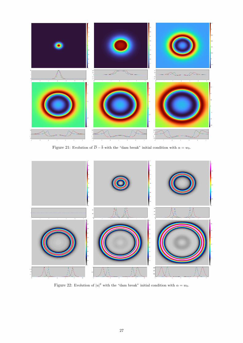
Figure 21: Evolution of D − b with the “dam break” initial condition with α = w0.
Figure 22: Evolution of |u|2 with the “dam break” initial condition with α = w0.
27

Figure 23: Evolution of D − b with the “dam break” initial condition with 8α = w0.
Figure 24: Evolution of |u|2 with the “dam break” initial condition with 8α = w0.
28

Figure 25: Evolution of D − b with the “dam break” initial condition with α = w0 and zero bathymetry.
Figure 26: Evolution of |u|2 with the “dam break” initial condition with α = w0 and zero bathymetry.
29

Figure 27: Evolution of D − b with the “dam break” initial condition with 8α = w0.
Figure 28: Evolution of |u|2 with the “dam break” initial condition with 8α = w0.
30
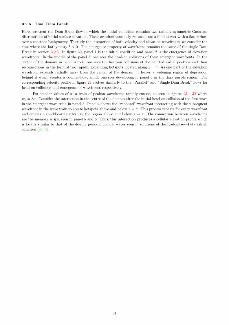
3.2.6 Dual Dam Break
Here, we treat the Dam Break flow in which the initial condition contains two radially symmetric Gaussian
distributions of initial surface elevation. These are simultaneously released into a fluid at rest with a flat surface
over a constant bathymetry. To study the interaction of both velocity and elevation wavefronts, we consider the
case where the bathymetry b > 0. The emergence property of wavefronts remains the same of the single Dam
Break in section 3.2.5. In figure 30, panel 1 is the initial condition and panel 2 is the emergence of elevation
wavefronts. In the middle of the panel 3, one sees the head-on collisions of these emergent wavefronts. In the
center of the domain in panel 4 to 6, one sees the head-on collisions of the emitted radial peakons and their
reconnections in the form of two rapidly expanding hotspots located along x = π. As one part of the elevation
wavefront expands radially away from the center of the domain, it leaves a widening region of depression
behind it which creates a counter-flow, which one sees developing in panel 6 as the dark purple region. The
corresponding velocity profile in figure 29 evolves similarly to the “Parallel” and “Single Dam Break” flows for
head-on collisions and emergence of wavefronts respectively.
For smaller values of α, a train of peakon wavefronts rapidly ensues, as seen in figures 31 - 32 where
w0 = 8α. Consider the interaction in the centre of the domain after the initial head-on collision of the first wave
in the emergent wave train in panel 3. Panel 4 shows the “rebound” wavefront interacting with the subsequent
wavefront in the wave train to create hotspots above and below x = π. This process repeats for every wavefront
and creates a checkboard pattern in the region above and below x = π. The connection between wavefronts
are the memory wisps, seen in panel 5 and 6. Thus, this interaction produces a cellular elevation profile which
is locally similar to that of the doubly periodic cnoidal waves seen in solutions of the Kadomtsev–Petviashvili
equation [36, 5].
31
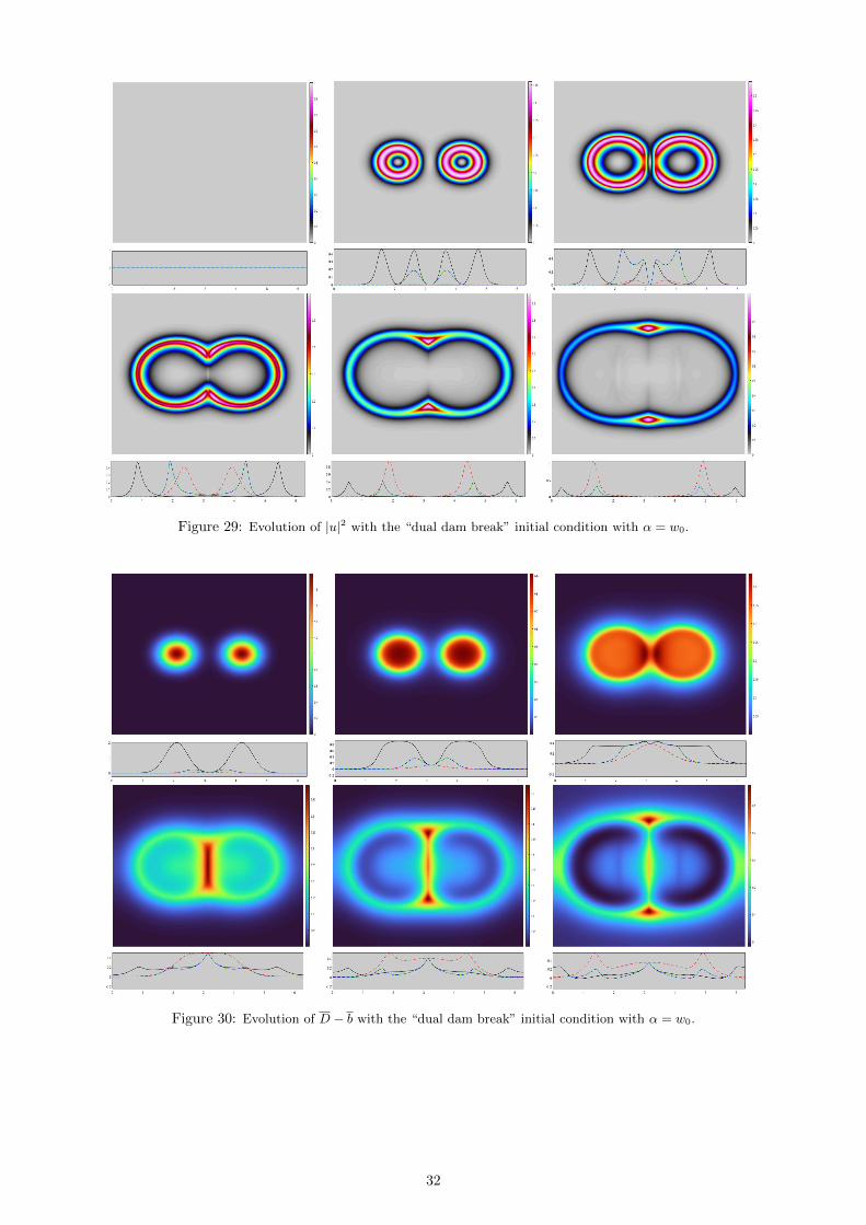
Figure 29: Evolution of |u|2 with the “dual dam break” initial condition with α = w0.
Figure 30: Evolution of D − b with the “dual dam break” initial condition with α = w0.
32

Figure 31: Evolution of |u|2 with the “dual dam break” initial condition with 8α = w0.
Figure 32: Evolution of D − b with the “dual dam break” initial condition with 8α = w0.
33
4 Conclusions and outlook
Inspired by the SAR images of sea-surface wavefronts regarded as the signatures of the dynamics of internal
waves propagating below the surface, we proposed in the introduction to derive a single-layer minimal model of
the surface velocity and elevation whose solution behaviour would mimic the dynamics of the curved wavefronts
seen in the SAR images, figure 1 and 2. The computationally simulated solutions of the H1ModCH2 minimal
model illustrated the emergence of trains of wavefronts which evolved into complex patterns as they propagated
away from localised disturbances of equilibrium and interacted nonlinearly with each other through collisions,
stretching and reconnection.
To mimic the wave-current interaction that drives the curved wavefronts seen in SAR images, we inves-
tigated a variety of computational simulation scenarios which addressed two questions. First, we asked how
would an initial condition evolve if there were a current possessing kinetic energy, but the surface were flat and,
thus, had no gravitational potential energy? This question was answered in sections 3.2.1, 3.2.2 and 3.2.3 to
which we refer for details. Second, we considered the converse question for initial conditions in which a station-
ary elevation was released into still water, as discussed in sections 3.2.5 and 3.2.6. In addition, we have also
mimicked the reconnection properties of the internal waves signatures in the cases where wavefront collisions
occur.
We had hoped that the singular momentum map solutions discussed in section 2.1 would emerge from
our simulations of wavefront trains arising from localised disturbances. This would have reduced the problem of
wave-current interaction among sea-surface wavefronts to the much simpler problem of mutual advection among
curves in the plane. This would have been the case, of course, if we had started with the singular momentum
map in equation (2.46) as the solution ansatz which would follow the dynamics in (2.48). However, we hoped to
see wavetrains of singular solutions on embedded curve segments emerge from generic smooth confined initial
conditions. In fact, we did see that effect in some of the simulations. We saw that wavetrains of peakon curves
did form in some cases of our suite of simulated energy exchange dynamics, more specifically, the dam break
problem with zero bathymetry in section 3.2.5. However, in some other cases such as the “plate” in section
3.2.1, the wavetrains of peakon curves did not form completely. That is, the singular solutions supported on
embedded curves did not always form completely during the time intervals of our simulations. Moreover, in the
“dam break” initial condition in section 3.2.5, the leading peaks in the elevation began to form, and then slowly
ebbed away and disappeared as other peaks emerged behind them and then disappeared later, as well.
So, the question of emergence of the singular momentum map solutions in (2.46) for ModCH2 from a
smooth confined initial condition dynamics remains open. In particular, the question is, under what conditions
will a solution of the 2D ModCH2 equations starting from a smooth confined initial condition indeed produce
a train of singular peakon curve segments, if ever?
Acknowledgements
This paper was written in honour of Tony Bloch’s 65th birthday. Happy birthday, Tony! Best wishes for many
more fruitful happy years of collaboration with your friends in the geometric mechanics community. We would
also like to thank our other friends and colleagues who have generously offered their attention, thoughts and
encouragement in the course of this work during the time of COVID-19. DH is grateful for partial support from
ERC Synergy Grant 856408 - STUOD (Stochastic Transport in Upper Ocean Dynamics). RH is supported by
an EPSRC scholarship [grant number EP/R513052/1].
References
[1] Bai, X., Li, X., Lamb, K.G. and Hu, J., 2017. Internal solitary wave reflection near Dongsha atoll, the South
China Sea. Journal of Geophysical Research: Oceans, 122(10), pp.7978-7991. https://doi.org/10.1002/
2017JC012880
[2] Barros, R. and Choi, W., 2009. Inhibiting shear instability induced by large amplitude internal solitary
waves in two-layer flows with a free surface. Stud. Appl. Math. 122, 325–346. https://doi.org/10.1111/j.
1467-9590.2009.00436.x
34
[3] Burbea, J. and Rao, C.R., 1982. Entropy differential metric, distance and divergence measures in probability
spaces: A unified approach. Journal of Multivariate Analysis, 12(4), pp.575-596. https://doi.org/10.1016/
0047-259X(82)90065-3
[4] Cendra, H., Holm, D.D., Marsden, J.E. and Ratiu, T.S., 1998. Lagrangian reduction, the Euler-Poincare
equations, and semidirect products. Translations of the American Mathematical Society-Series 2, 186, pp.1-26.
https://arxiv.org/abs/chao-dyn/9906004
[5] Chakravarty, S. and Kodama, Y., 2009. Soliton solutions of the KP equation and application to shallow
water waves. Studies in Applied Mathematics, 123(1), pp.83-151. https://doi.org/10.1111/j.1467-9590.
2009.00448.x
[6] Chen, S., Foias, C., Holm, D.D., Olson, E., Titi, E.S. and Wynne, S., 1998. Camassa-Holm equations
as a closure model for turbulent channel and pipe flow. Physical Review Letters, 81(24), p.5338. https:
//doi.org/10.1103/PhysRevLett.81.5338
[7] Chen, S., Foias, C., Holm, D.D., Olson, E., Titi, E.S. and Wynne, S., 1999. A connection between the
Camassa-Holm equations and turbulent flows in channels and pipes. Physics of Fluids, 11(8), pp.2343-2353.
https://doi.org/10.1063/1.870096
[8] Chen, M., and Zhang, Y., 2006. A two-component generalization of the Camassa-Holm equation and its
solutions. Letters in Mathematical Physics, 75(1), 1-15. https://doi.org/10.1007/s11005-005-0041-7
[9] Choi, W. and Camassa, R., 1996. Weakly nonlinear internal waves in a two-fluid system. J. Fluid Mech.
313, 83–103. https://doi.org/10.1017/S0022112096002133
[10] Choi, W. and Camassa, R., 1999. Fully nonlinear internal waves in a two-fluid system. J. Fluid Mech. 396,
1–36. https://doi.org/10.1017/S0022112099005820
[11] Constantin, A. and Lannes, D., 2009. The hydrodynamical relevance of the Camassa-Holm and Degasperis-
Procesi equations. Arch. Ration. Mech. Anal., 192(1):165-186, hal-00726128. https://doi.org/10.1007/
s00205-008-0128-2
[12] Cotter, C.J., Eldering, J., Holm, D.D., Jacobs, H.O. and Meier, D.M., 2016. Weak Dual Pairs and Jetlet
Methods for Ideal Incompressible Fluid Models in n ≥ 2 Dimensions. Journal of Nonlinear Science, 26(6),
pp.1723-1765. https://doi.org/10.1007/s00332-016-9317-6
[13] Cotter, C.J., Holm, D.D., Jacobs, H.O. and Meier, D.M., 2014. A jetlet hierarchy for ideal fluid dynamics.
J. Phys. A: Math. Theor. 47 352001. https://doi.org/10.1088/1751-8113/47/35/352001
[14] Cotter, C.J., Holm, D.D., Percival, J.R., 2010. The square root depth wave equations, Proc Roy Soc A
Math Phys, 466: 3621-3633. http://dx.doi.org/10.1098/rspa.2010.0124
[15] Duchene, V., 2021. Many Models for Water Waves (Doctoral dissertation, Universite de Rennes 1). https:
//tel.archives-ouvertes.fr/tel-03282212
[16] Falqui, G., 2005. On a Camassa-Holm type equation with two dependent variables. Journal of Physics A:
Mathematical and General, 39(2), 327. https://doi.org/10.1088/0305-4470/39/2/004
[17] Foias, C., Holm, D.D. and Titi, E.S., 2001. The Navier-Stokes-alpha model of fluid turbulence. Physica D:
Nonlinear Phenomena, 152, pp.505-519. https://doi.org/10.1016/S0167-2789(01)00191-9
[18] Foias, C., Holm, D.D. and Titi, E.S., 2002. The three dimensional viscous Camassa-Holm equations, and
their relation to the Navier-Stokes equations and turbulence theory. Journal of Dynamics and Differential
Equations, 14(1), pp.1-35. https://doi.org/10.1023/A:1012984210582
[19] Gay-Balmaz, F. and Vizman, C., 2012. Dual pairs in fluid dynamics. Annals of Global Analysis and
Geometry, 41(1), pp.1-24. https://doi.org/10.1007/s10455-011-9267-z.
[20] Holm, D.D., 2001. Variational Principles, Geometry and Topology of Lagrangian-Averaged Fluid Dynamics.
In: Ricca R.L. (eds) An Introduction to the Geometry and Topology of Fluid Flows. NATO Science Series
(Series II: Mathematics, Physics and Chemistry), vol 47. Springer, Dordrecht. https://doi.org/10.1007/
978-94-010-0446-6_14
[21] Holm, D.D., 2015. Variational principles for stochastic fluid dynamics. Proc. R. Soc. A. 471: 20140963
http://doi.org/10.1098/rspa.2014.0963
[22] Holm, D.D. and Jacobs, H.O., 2017. Multipole vortex blobs (MVB): Symplectic geometry and dynamics.
Journal of nonlinear science, 27(3), pp.973-1006. https://doi.org/10.1007/s00332-017-9367-4
[23] Holm, D.D. and Marsden, J.E., 2005. Momentum maps and measure-valued solutions (peakons, filaments,
35
and sheets) for the EPDiff equation. In The breadth of symplectic and Poisson geometry (pp. 203-235).
Birkhauser Boston. https://doi.org/10.1007/0-8176-4419-9_8
[24] Holm, D.D., Marsden, J.E. and Ratiu, T.S., 1998. Euler-Poincare models of ideal fluids with nonlinear
dispersion. Physical Review Letters, 80(19), p.4173. https://doi.org/10.1103/PhysRevLett.80.4173
[25] Holm, D.D., Marsden, J.E. and Ratiu, T.S. 1998 The Euler–Poincare equations and semidirect products
with applications to continuum theories. Adv. Math. 137, 1–81. https://doi.org/10.1006/aima.1998.1721
[26] Holm, D.D., O’Naraigh, L. and Tronci, C., 2009. Singular solutions of a modified two-component Camassa-
Holm equation. Physical Review E, 79(1), p.016601. https://doi.org/10.1103/PhysRevE.79.016601
[27] Holm, D.D. and Staley, M.F.., 2013. Interaction dynamics of singular wave fronts https://arxiv.org/
abs/1301.1460
[28] Holm, D.D. and Tronci, C., 2009. Geodesic flows on semidirect-product Lie groups: geometry of singu-
lar measure-valued solutions. Proceedings of the Royal Society A: Mathematical, Physical and Engineering
Sciences, 465(2102), pp.457-476. https://doi.org/10.1098/rspa.2008.0263
[29] D. Ionescu-Kruse, Mathematical Methods in Water Wave Problems, Habilitation Thesis (2021), Romanian
Academy, 281 p.
[30] Jo, T.-C. and Choi, W., 2002. Dynamics of strongly nonlinear internal solitary waves in shallow water.
Stud. Appl. Math. 109, 205–227. https://doi.org/10.1111/1467-9590.00222
[31] Kruse, H.P., Scheurle, J. and Du, W., 2001. A two-dimensional version of the Camassa-Holm equation. In
Symmetry and Perturbation Theory: SPT 2001 (pp. 120-127). https://doi.org/10.1142/9789812794543_
0017
[32] Liska, R. and Wendroff, B., 1997. Analysis and computation with stratified fluid models. J. Comput. Phys.
137, 212–244. https://doi.org/10.1006/jcph.1997.5806
[33] Liu, A.K., Chang, Y.S., Hsu, M.K. and Liang, N.K., 1998. Evolution of nonlinear internal waves in the
East and South China Seas. J. Geophys. Res. 103, 7995–8008. https://doi.org/10.1029/97JC01918
[34] Marsden, J. and Weinstein, A., 1983. Coadjoint orbits, vortices, and Clebsch variables for incompressible
fluids. Physica D: Nonlinear Phenomena, 7(1-3), pp.305-323. https://doi.org/10.1016/0167-2789(83)
90134-3
[35] Percival, J.R., Cotter, C.J. and Holm, D.D., 2008. A Euler–Poincare framework for the multilayer
Green–Naghdi equations. J. Phys. A: Math. Theoret. 41, 344018. https://doi.org/10.1088/1751-8113/
41/34/344018
[36] Soomere T. (2012) Solitons Interactions. In: Meyers R. (eds) Mathematics of Complexity and Dynamical
Systems. Springer, New York, NY. https://doi.org/10.1007/978-1-4614-1806-1_101
[37] Verdoolaege, G., 2019. Information geometry. MDPI.
[38] Weinstein, A., 1983. The local structure of Poisson manifolds, J. Differential Geom. 18, 523-557. https:
//doi.org/10.4310/jdg/1214437787
[39] Zhao, Z., Liu, B. and Li, X., 2014. Internal solitary waves in the China seas observed using satellite
remote-sensing techniques: A review and perspectives. International Journal of Remote Sensing, 35(11-12),
pp.3926-3946. https://doi.org/10.1080/01431161.2014.916442
36
Related Documents