C. T.-C. Nguyen, TEXMEMS, 5/6/03 DARPA DARPA MTO MTO MEMS: Generalizing the Benefits of Miniaturization Clark T.-C. Nguyen Program Manager, MPG/CSAC/MX/HERMIT Microsystems Technology Office (MTO) Defense Advanced Research Projects Agency TEXMEMS’03 May 6, 2003

Welcome message from author
This document is posted to help you gain knowledge. Please leave a comment to let me know what you think about it! Share it to your friends and learn new things together.
Transcript
C. T.-C. Nguyen, TEXMEMS, 5/6/03
DARPADARPA
MTOMTO
MEMS: Generalizing the Benefits of Miniaturization
Clark T.-C. NguyenProgram Manager, MPG/CSAC/MX/HERMIT
Microsystems Technology Office (MTO)Defense Advanced Research Projects Agency
TEXMEMS’03May 6, 2003
C. T.-C. Nguyen, TEXMEMS, 5/6/03
DARPADARPA
MTOMTOOutline
• Introduction:MEMS technologyintegration with transistors: an early driver for MEMS
• Benefits of MEMSsize reductionspeed, energy conservation, complexity, economy
• Present MEMS Programs in MTONano Mechanical Array Signal Processors (NMASP)Chip-Scale Atomic Clock (CSAC)Micro Power Generation (MPG)
• What’s Next?• Conclusions
C. T.-C. Nguyen, TEXMEMS, 5/6/03
DARPADARPA
MTOMTO
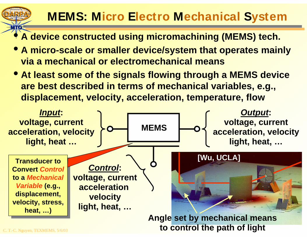
Angle set by mechanical meansto control the path of light
MEMS: Micro Electro Mechanical System
• A device constructed using micromachining (MEMS) tech.• A micro-scale or smaller device/system that operates mainly
via a mechanical or electromechanical means• At least some of the signals flowing through a MEMS device
are best described in terms of mechanical variables, e.g., displacement, velocity, acceleration, temperature, flow
MEMS
Input:voltage, current
acceleration, velocitylight, heat …
Output:voltage, current
acceleration, velocitylight, heat, …
Control:voltage, current
acceleration velocity
light, heat, …
Transducer to Convert Controlto a Mechanical Variable (e.g., displacement,
velocity, stress, heat, …)
Transducer to Convert Controlto a Mechanical Variable (e.g., displacement,
velocity, stress, heat, …)
[Wu, UCLA]
C. T.-C. Nguyen, TEXMEMS, 5/6/03
DARPADARPA
MTOMTOOther Common Attributes of MEMS
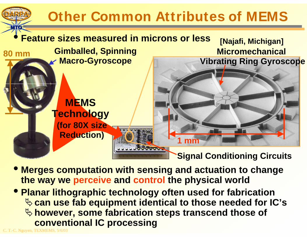
• Feature sizes measured in microns or less
• Merges computation with sensing and actuation to change the way we perceive and control the physical world
• Planar lithographic technology often used for fabricationcan use fab equipment identical to those needed for IC’showever, some fabrication steps transcend those of conventional IC processing
MEMSTechnology
Gimballed, SpinningMacro-Gyroscope
MicromechanicalVibrating Ring Gyroscope
Signal Conditioning Circuits
80 mm
1 mm
(for 80X sizeReduction)
[Najafi, Michigan]
C. T.-C. Nguyen, TEXMEMS, 5/6/03
DARPADARPA
MTOMTO
Silicon Substrate
Glass Substrate
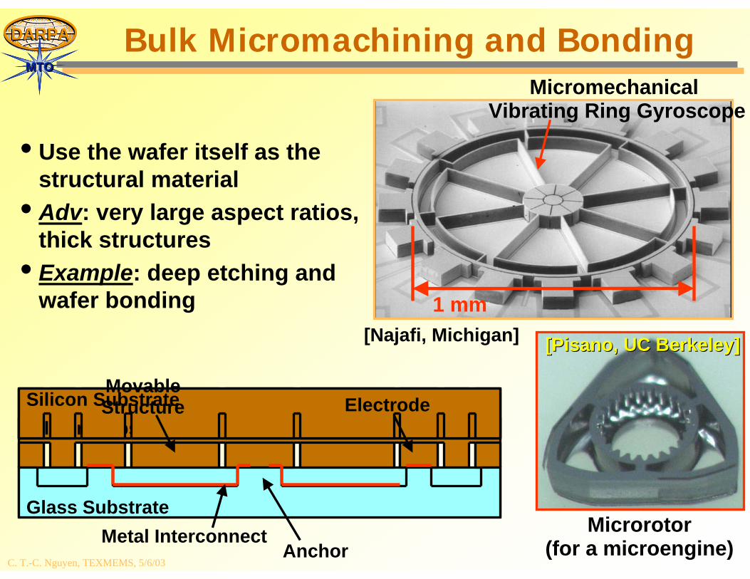
Bulk Micromachining and Bonding
• Use the wafer itself as the structural material
• Adv: very large aspect ratios, thick structures
• Example: deep etching and wafer bonding
Silicon SubstrateSilicon Substrate
Glass Substrate
Silicon Substrate
Metal InterconnectAnchor
MovableStructure Electrode
MicromechanicalVibrating Ring Gyroscope
1 mm
Microrotor(for a microengine)
[Najafi, Michigan] [[PisanoPisano, UC Berkeley], UC Berkeley]
C. T.-C. Nguyen, TEXMEMS, 5/6/03
DARPADARPA
MTOMTO
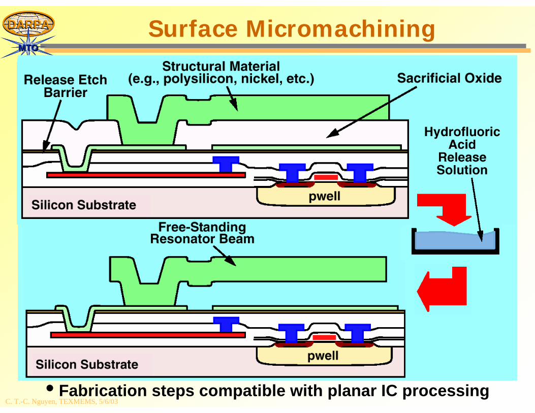
• Fabrication steps compatible with planar IC processing
Surface Micromachining
C. T.-C. Nguyen, TEXMEMS, 5/6/03
DARPADARPA
MTOMTO
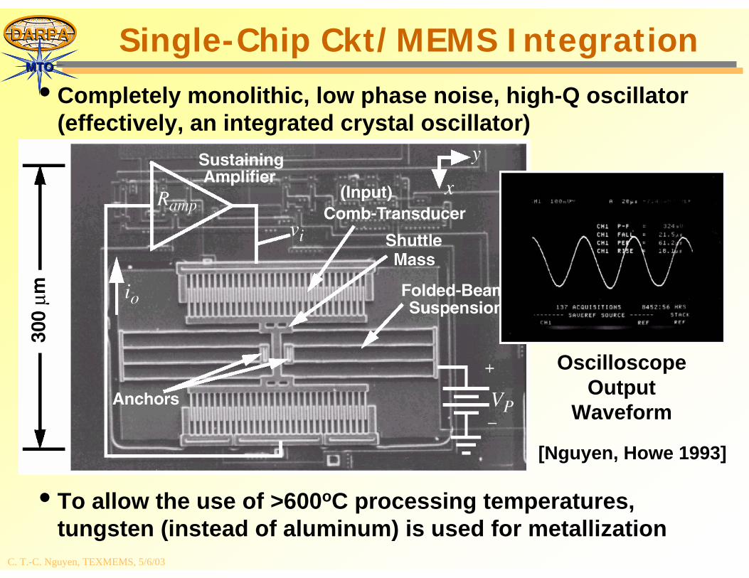
• Completely monolithic, low phase noise, high-Q oscillator (effectively, an integrated crystal oscillator)
• To allow the use of >600oC processing temperatures, tungsten (instead of aluminum) is used for metallization
OscilloscopeOutput
Waveform
Single-Chip Ckt/MEMS Integration
[Nguyen, Howe 1993][Nguyen, Howe 1993]
C. T.-C. Nguyen, TEXMEMS, 5/6/03
DARPADARPA
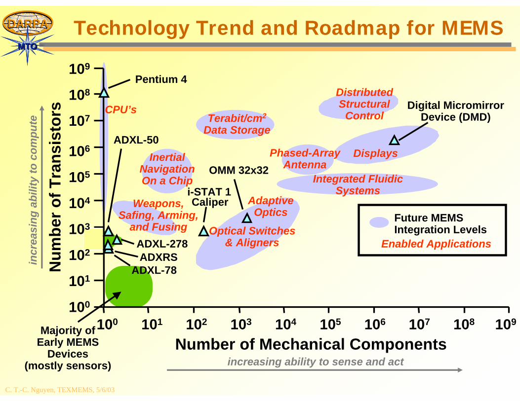
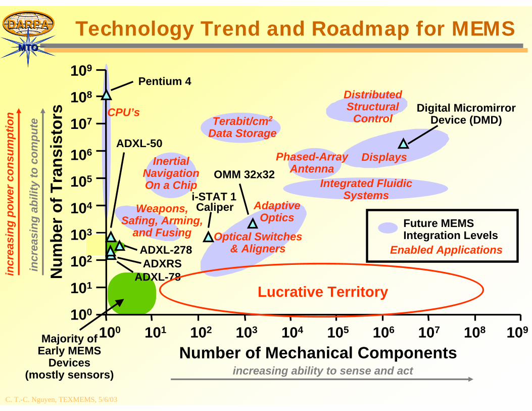
MTOMTOTechnology Trend and Roadmap for MEMS
incr
easi
ng a
bilit
y to
com
pute
increasing ability to sense and act
Num
ber o
f Tra
nsis
tors
Number of Mechanical Components
100
101
102
103
104
105
106
107
108
109
100 101 102 103 104 105 106 107 108 109
AdaptiveOptics
Integrated FluidicSystems
DistributedStructural
ControlTerabit/cm2
Data Storage
Optical Switches& Aligners
InertialNavigationOn a Chip
Displays
Weapons,Safing, Arming,
and Fusing
Majority ofEarly MEMS
Devices(mostly sensors)
ADXL-50
Digital MicromirrorDevice (DMD)
ADXL-278
Future MEMSIntegration Levels
Enabled Applications
OMM 32x32
ADXL-78
CPU’s
Pentium 4
ADXRS
i-STAT 1Caliper
Phased-ArrayAntenna
C. T.-C. Nguyen, TEXMEMS, 5/6/03
DARPADARPA
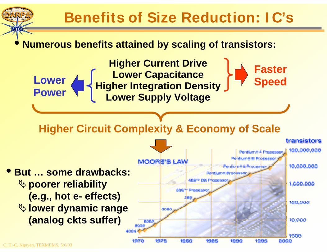
MTOMTOBenefits of Size Reduction: IC’s
• Numerous benefits attained by scaling of transistors:
FasterSpeed
Higher Current DriveLower Capacitance
Higher Integration DensityLower Supply Voltage
LowerPower
Higher Circuit Complexity & Economy of Scale
• But … some drawbacks:poorer reliability (e.g., hot e- effects)lower dynamic range (analog ckts suffer)
C. T.-C. Nguyen, TEXMEMS, 5/6/03
DARPADARPA
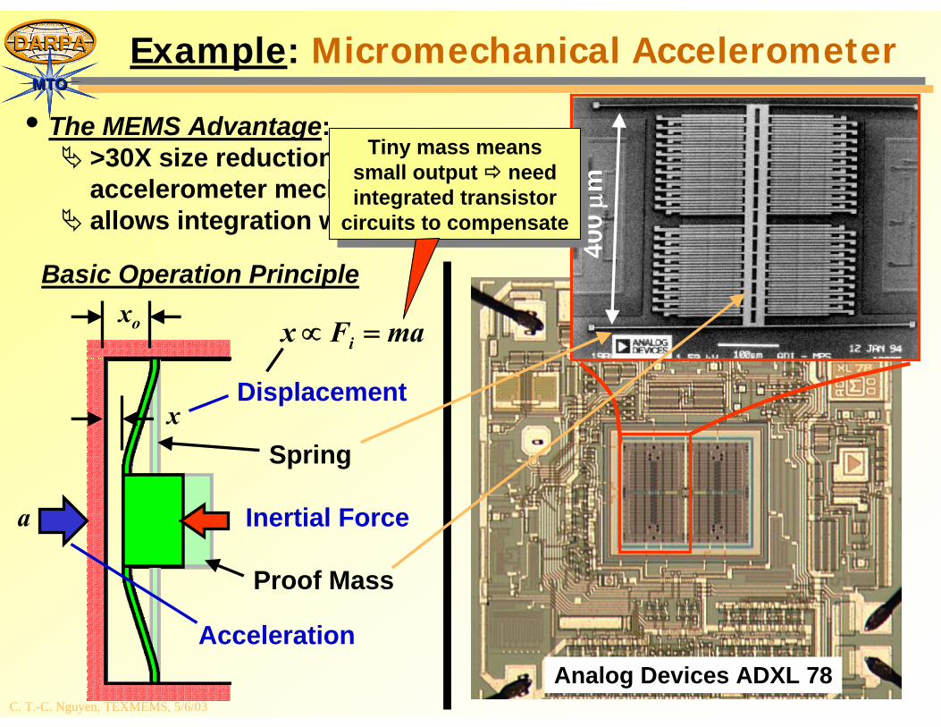
MTOMTOExample: Micromechanical Accelerometer
• The MEMS Advantage:>30X size reduction for accelerometer mechanical elementallows integration with IC’s
xo
x
a
Acceleration
Inertial Force
Spring
Proof Mass
Basic Operation Principle
400
μm
Analog Devices ADXL 78
Displacement
maFx i =∝
Tiny mass means small output need integrated transistor
circuits to compensate
Tiny mass means small output need integrated transistor
circuits to compensate
C. T.-C. Nguyen, TEXMEMS, 5/6/03
DARPADARPA
MTOMTO
DisplaysPhased-ArrayAntenna
Technology Trend and Roadmap for MEMSin
crea
sing
abi
lity
to c
ompu
te
increasing ability to sense and act
Num
ber o
f Tra
nsis
tors
Number of Mechanical Components
100
101
102
103
104
105
106
107
108
109
100 101 102 103 104 105 106 107 108 109
AdaptiveOptics
Integrated FluidicSystems
DistributedStructural
ControlTerabit/cm2
Data Storage
Optical Switches& Aligners
InertialNavigationOn a Chip
Weapons,Safing, Arming,
and Fusing
Majority ofEarly MEMS
Devices(mostly sensors)
ADXL-50
Digital MicromirrorDevice (DMD)
ADXL-278
Future MEMSIntegration Levels
Enabled Applications
OMM 32x32
ADXL-78
CPU’s
Pentium 4
i-STAT 1
ADXRS
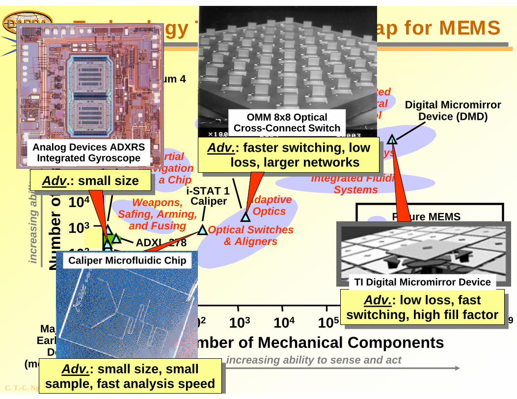
Analog Devices ADXRSIntegrated Gyroscope
Adv.: small sizeAdv.: small size
OMM 8x8 OpticalCross-Connect Switch
Adv.: faster switching, low loss, larger networks
Adv.: faster switching, low loss, larger networks
Adv.: low loss, fast switching, high fill factor
Adv.: low loss, fast switching, high fill factor
TI Digital Micromirror Device
Caliper Microfluidic Chip
Adv.: small size, small sample, fast analysis speed
Adv.: small size, small sample, fast analysis speed
Caliper
C. T.-C. Nguyen, TEXMEMS, 5/6/03
DARPADARPA
MTOMTOTechnology Trend and Roadmap for MEMS
incr
easi
ng a
bilit
y to
com
pute
increasing ability to sense and act
Num
ber o
f Tra
nsis
tors
Number of Mechanical Components
100
101
102
103
104
105
106
107
108
109
100 101 102 103 104 105 106 107 108 109
AdaptiveOptics
Integrated FluidicSystems
DistributedStructural
ControlTerabit/cm2
Data Storage
Optical Switches& Aligners
InertialNavigationOn a Chip
Weapons,Safing, Arming,
and Fusing
Majority ofEarly MEMS
Devices(mostly sensors)
ADXL-50
Digital MicromirrorDevice (DMD)
ADXL-278
Future MEMSIntegration Levels
Enabled Applications
OMM 32x32
ADXL-78
CPU’s
Pentium 4
incr
easi
ng p
ower
con
sum
ptio
n
ADXRS
i-STAT 1Caliper
Lucrative Territory
DisplaysPhased-ArrayAntenna
C. T.-C. Nguyen, TEXMEMS, 5/6/03
DARPADARPA
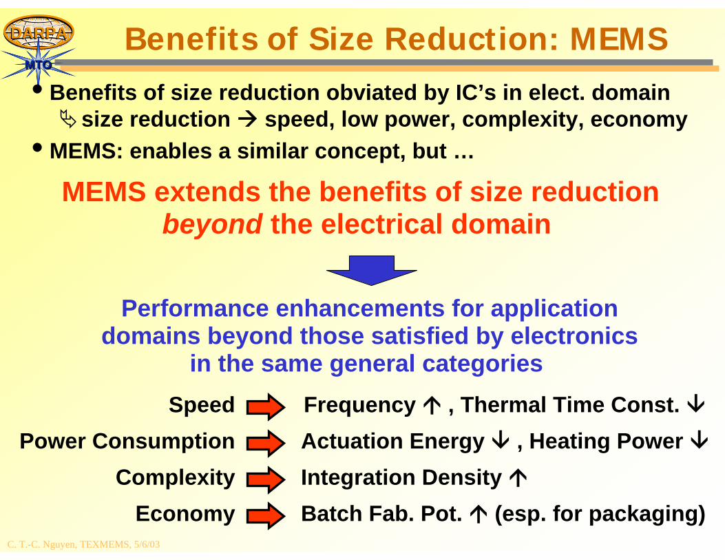
MTOMTOBenefits of Size Reduction: MEMS
• Benefits of size reduction obviated by IC’s in elect. domainsize reduction speed, low power, complexity, economy
• MEMS: enables a similar concept, but …
MEMS extends the benefits of size reductionbeyond the electrical domain
Performance enhancements for applicationdomains beyond those satisfied by electronics
in the same general categories Speed
Power ConsumptionComplexity
Economy
Frequency , Thermal Time Const. Actuation Energy , Heating Power Integration Density Batch Fab. Pot. (esp. for packaging)
C. T.-C. Nguyen, TEXMEMS, 5/6/03
DARPADARPA
MTOMTO
Nano Mechanical Array Signal Processors (NMASP)
C. T.-C. Nguyen, TEXMEMS, 5/6/03
DARPADARPA
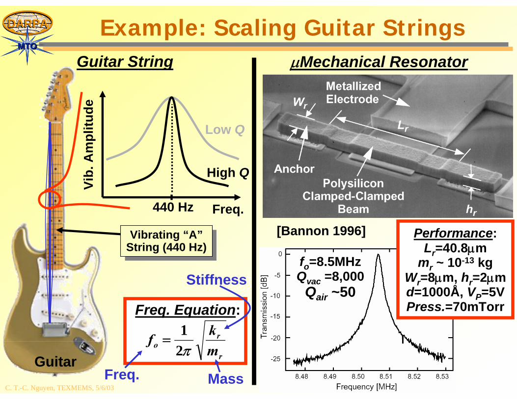
MTOMTOExample: Scaling Guitar Strings
Guitar String
Guitar
Vibrating “A”String (440 Hz)Vibrating “A”
String (440 Hz)
High Q
440 Hz Freq.
Vib.
Am
plitu
de
Low Q
r
ro m
kfπ21
=
Freq. Equation:
Freq.
Stiffness
Mass
fo=8.5MHzQvac =8,000
Qair ~50
μMechanical Resonator
Performance:Lr=40.8μm
mr ~ 10-13 kgWr=8μm, hr=2μmd=1000Å, VP=5VPress.=70mTorr
[Bannon 1996]
C. T.-C. Nguyen, TEXMEMS, 5/6/03
DARPADARPA
MTOMTO
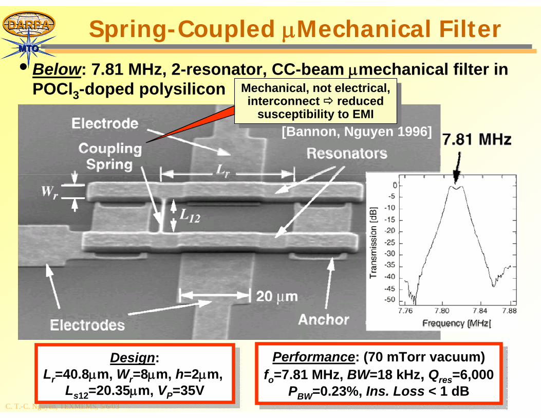
• Below: 7.81 MHz, 2-resonator, CC-beam μmechanical filter in POCl3-doped polysilicon
Spring-Coupled μMechanical Filter
Design:Lr=40.8μm, Wr=8μm, h=2μm,
Ls12=20.35μm, VP=35V
Design:Lr=40.8μm, Wr=8μm, h=2μm,
Ls12=20.35μm, VP=35V
Performance: (70 mTorr vacuum)fo=7.81 MHz, BW=18 kHz, Qres=6,000
PBW=0.23%, Ins. Loss < 1 dB
Performance: (70 mTorr vacuum)fo=7.81 MHz, BW=18 kHz, Qres=6,000
PBW=0.23%, Ins. Loss < 1 dB
Mechanical, not electrical, interconnect reduced
susceptibility to EMI
Mechanical, not electrical, interconnect reduced
susceptibility to EMI[Bannon, Nguyen 1996]

C. T.-C. Nguyen, TEXMEMS, 5/6/03
DARPADARPA
MTOMTOTechnology Trend and Roadmap for MEMS
incr
easi
ng a
bilit
y to
com
pute
increasing ability to sense and act
Num
ber o
f Tra
nsis
tors
Number of Mechanical Components
100
101
102
103
104
105
106
107
108
109
100 101 102 103 104 105 106 107 108 109
AdaptiveOptics
Integrated FluidicSystems
DistributedStructural
ControlTerabit/cm2
Data Storage
Optical Switches& Aligners
InertialNavigationOn a Chip
Weapons,Safing, Arming,
and Fusing
Majority ofEarly MEMS
Devices(mostly sensors)
ADXL-50
Digital MicromirrorDevice (DMD)
ADXL-278
Future MEMSIntegration Levels
Enabled Applications
OMM 32x32
ADXL-78
CPU’s
Pentium 4
incr
easi
ng p
ower
con
sum
ptio
n
ADXRS
i-STAT 1Caliper
Lucrative Territory
DisplaysPhased-ArrayAntenna
C. T.-C. Nguyen, TEXMEMS, 5/6/03
DARPADARPA
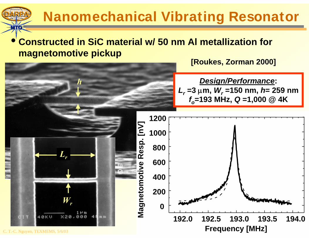
MTOMTONanomechanical Vibrating Resonator
• Constructed in SiC material w/ 50 nm Al metallization for magnetomotive pickup
192.0 192.5 193.0 193.5 194.00
200
400
600
800
1000
1200
Mag
neto
mot
ive
Res
p. [n
V]
Frequency [MHz]
Design/Performance:Lr =3 μm, Wr =150 nm, h= 259 nm
fo=193 MHz, Q =1,000 @ 4K
Lr
Wr
[Roukes, Zorman 2000]
h
C. T.-C. Nguyen, TEXMEMS, 5/6/03
DARPADARPA
MTOMTO
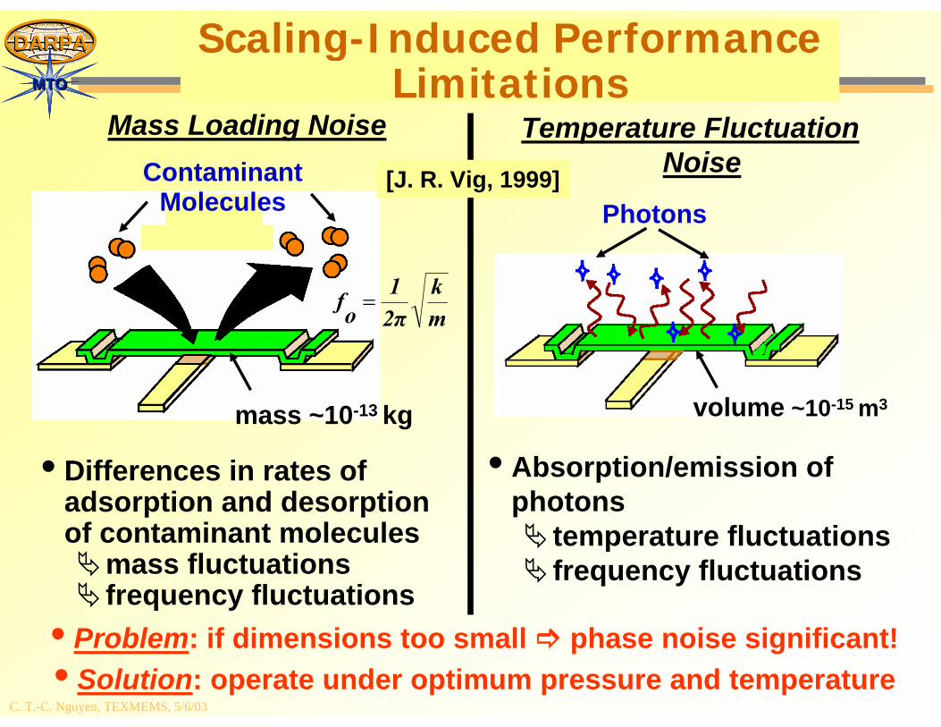
Scaling-Induced Performance Limitations
Mass Loading Noise
• Differences in rates of adsorption and desorptionof contaminant molecules
mass fluctuationsfrequency fluctuations
Temperature Fluctuation Noise
• Absorption/emission of photons
temperature fluctuationsfrequency fluctuations
ContaminantMolecules
mass ~10-13 kg
mk
2π1
of =
Photons
volume ~10-15 m3
• Problem: if dimensions too small phase noise significant!• Solution: operate under optimum pressure and temperature
[J. R. Vig, 1999]
C. T.-C. Nguyen, TEXMEMS, 5/6/03
DARPADARPA
MTOMTO
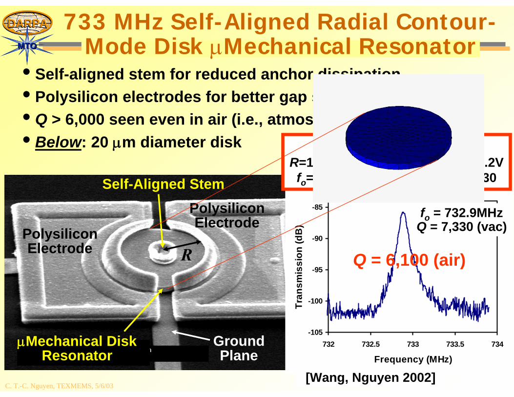
733 MHz Self-Aligned Radial Contour-Mode Disk μMechanical Resonator
• Self-aligned stem for reduced anchor dissipation• Polysilicon electrodes for better gap stability• Q > 6,000 seen even in air (i.e., atmospheric pressure)!• Below: 20 μm diameter disk
PolysiliconElectrode
PolysiliconElectrode
R
Self-Aligned Stem
GroundPlane
fo=433MHzQ=4,066
μMechanical DiskResonator
-105
-100
-95
-90
-85
732 732.5 733 733.5 734
Frequency (MHz)
Tran
smis
sion
(dB
)
[Wang, Nguyen 2002]
fo = 732.9MHzQ = 7,330 (vac)
Design/Performance:R=10μm, t=2.1μm, d=800Å, VP=6.2Vfo=732.9MHz (2nd mode), Q=7,330
Q = 6,100 (air)
C. T.-C. Nguyen, TEXMEMS, 5/6/03
DARPADARPA
MTOMTO
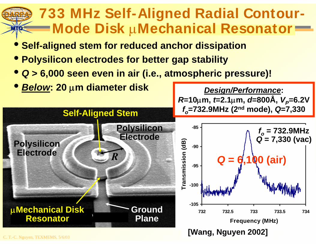
733 MHz Self-Aligned Radial Contour-Mode Disk μMechanical Resonator
• Self-aligned stem for reduced anchor dissipation• Polysilicon electrodes for better gap stability• Q > 6,000 seen even in air (i.e., atmospheric pressure)!• Below: 20 μm diameter disk
PolysiliconElectrode
PolysiliconElectrode
R
Self-Aligned Stem
GroundPlane
fo=433MHzQ=4,066
μMechanical DiskResonator
-105
-100
-95
-90
-85
732 732.5 733 733.5 734
Frequency (MHz)
Tran
smis
sion
(dB
)
[Wang, Nguyen 2002]
fo = 732.9MHzQ = 7,330 (vac)
Design/Performance:R=10μm, t=2.1μm, d=800Å, VP=6.2Vfo=732.9MHz (2nd mode), Q=7,330
Q = 6,100 (air)
C. T.-C. Nguyen, TEXMEMS, 5/6/03
DARPADARPA
MTOMTO
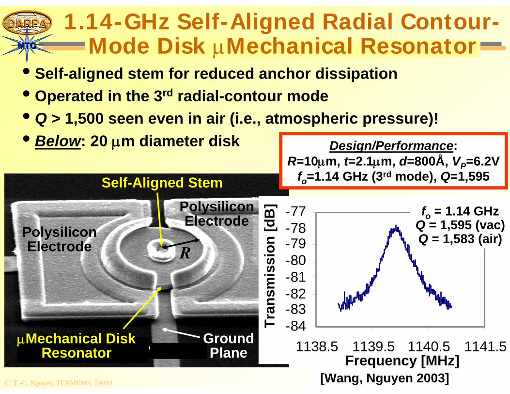
1.14-GHz Self-Aligned Radial Contour-Mode Disk μMechanical Resonator
• Self-aligned stem for reduced anchor dissipation• Operated in the 3rd radial-contour mode• Q > 1,500 seen even in air (i.e., atmospheric pressure)!• Below: 20 μm diameter disk
PolysiliconElectrode
PolysiliconElectrode
R
Self-Aligned Stem
GroundPlane
μMechanical DiskResonator
[Wang, Nguyen 2003]
Design/Performance:R=10μm, t=2.1μm, d=800Å, VP=6.2V
fo=1.14 GHz (3rd mode), Q=1,595
-84-83-82-81-80-79-78-77
1138.5 1139.5 1140.5 1141.5
fo = 1.14 GHzQ = 1,595 (vac)Q = 1,583 (air)
Tran
smis
sion
[dB
]
Frequency [MHz]
C. T.-C. Nguyen, TEXMEMS, 5/6/03
DARPADARPA
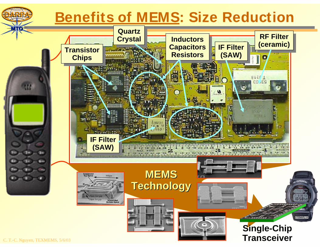
MTOMTOBenefits of MEMS: Size Reduction
TransistorChips
TransistorChips
QuartzCrystalQuartzCrystal
IF Filter(SAW)
IF Filter(SAW)
InductorsCapacitorsResistors
InductorsCapacitorsResistors IF Filter
(SAW)IF Filter(SAW)
RF Filter(ceramic)RF Filter(ceramic)
MEMSMEMSTechnologyTechnology
Single-ChipTransceiver
C. T.-C. Nguyen, TEXMEMS, 5/6/03
DARPADARPA
MTOMTO
Chip-Scale Atomic Clocks (CSAC)
C. T.-C. Nguyen, TEXMEMS, 5/6/03
DARPADARPA
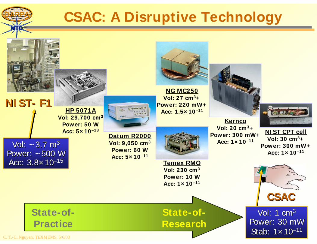
MTOMTOCSAC: A Disruptive Technology
State-of-Practice
State-of-Research
HP 5071AVol: 29,700 cm3
Power: 50 WAcc: 5×10–13
Datum R2000Vol: 9,050 cm3
Power: 60 WAcc: 5×10–11
Temex RMOVol: 230 cm3
Power: 10 WAcc: 1×10–11
NG MC250Vol: 27 cm3+
Power: 220 mW+Acc: 1.5×10⁻¹¹
KerncoVol: 20 cm3+
Power: 300 mW+Acc: 1×10–11
NIST CPT cellVol: 30 cm3+
Power: 300 mW+Acc: 1×10–11
NISTNIST-- F1F1
VolVol: ~3.7 m: ~3.7 m33
Power: ~500 WPower: ~500 WAcc: Acc: 3.83.8××1010––1515
CSACCSACVolVol: 1 cm: 1 cm33
Power: 30 Power: 30 mWmWStab: Stab: 11××1010––1111
C. T.-C. Nguyen, TEXMEMS, 5/6/03
DARPADARPA
MTOMTOChip-Scale Atomic Clock Summary
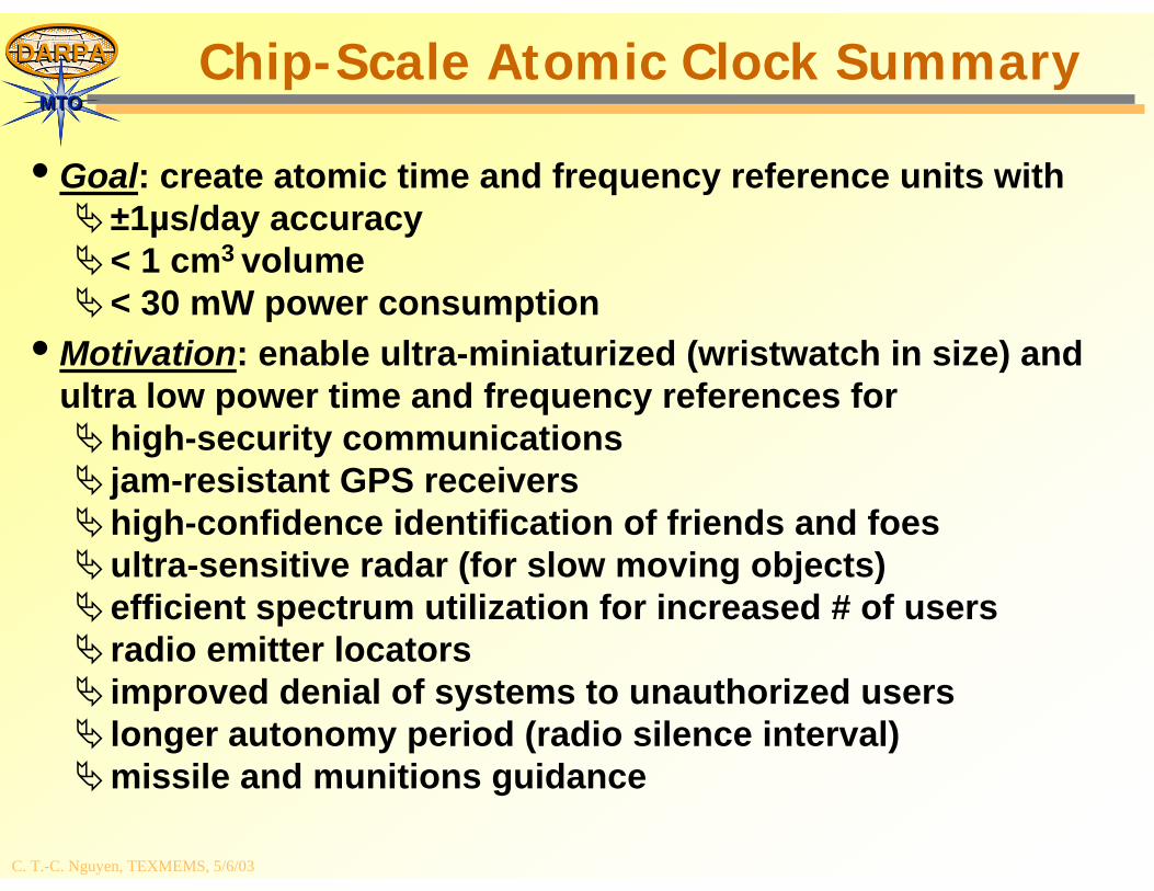
• Goal: create atomic time and frequency reference units with±1µs/day accuracy< 1 cm3 volume< 30 mW power consumption
• Motivation: enable ultra-miniaturized (wristwatch in size) and ultra low power time and frequency references for
high-security communicationsjam-resistant GPS receivershigh-confidence identification of friends and foesultra-sensitive radar (for slow moving objects)efficient spectrum utilization for increased # of usersradio emitter locatorsimproved denial of systems to unauthorized userslonger autonomy period (radio silence interval)missile and munitions guidance
C. T.-C. Nguyen, TEXMEMS, 5/6/03
DARPADARPA
MTOMTOGlobal Positioning Satellite Receiver
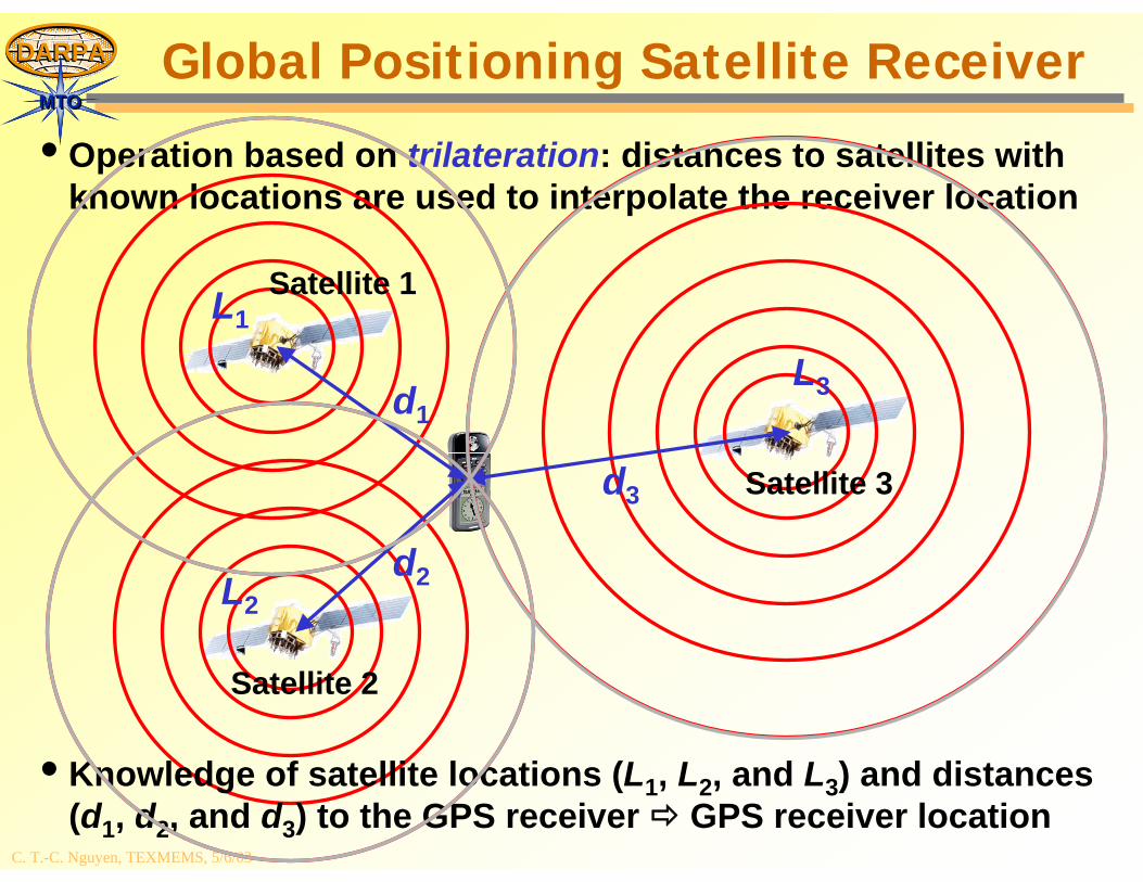
• Operation based on trilateration: distances to satellites with known locations are used to interpolate the receiver location
d1
d2
L1
L3
Satellite 1
Satellite 3
• Knowledge of satellite locations (L1, L2, and L3) and distances (d1, d2, and d3) to the GPS receiver GPS receiver location
L2
Satellite 2
d3
C. T.-C. Nguyen, TEXMEMS, 5/6/03
DARPADARPA
MTOMTOGlobal Positioning Satellite Receiver
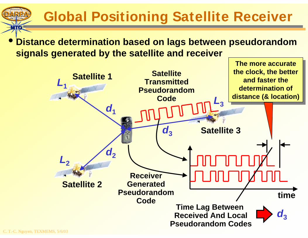
• Distance determination based on lags between pseudorandom signals generated by the satellite and receiver
L1
L2
L3
Satellite 1
Satellite 2
Satellite 3
time
ReceiverGenerated
PseudorandomCode
SatelliteTransmitted
PseudorandomCode
Time Lag Between Received And Local
Pseudorandom Codesd3
The more accurate the clock, the better
and faster the determination of
distance (& location)
The more accurate the clock, the better
and faster the determination of
distance (& location)
d1
d2
d3
C. T.-C. Nguyen, TEXMEMS, 5/6/03
DARPADARPA
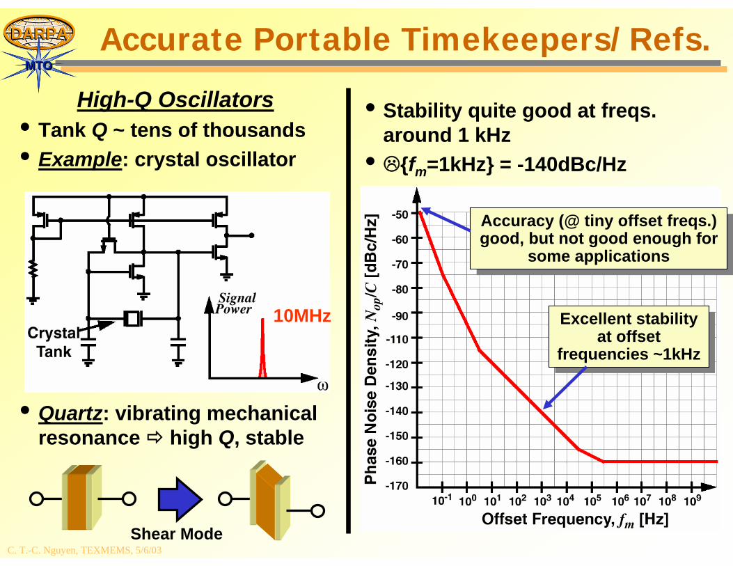
MTOMTOAccurate Portable Timekeepers/Refs.
• Stability quite good at freqs. around 1 kHz
• {fm=1kHz} = -140dBc/Hz
High-Q Oscillators• Tank Q ~ tens of thousands• Example: crystal oscillator
• Quartz: vibrating mechanical resonance high Q, stable
10MHz Excellent stability at offset
frequencies ~1kHz
Excellent stability at offset
frequencies ~1kHz
Accuracy (@ tiny offset freqs.) good, but not good enough for
some applications
Accuracy (@ tiny offset freqs.) good, but not good enough for
some applications
Shear Mode
C. T.-C. Nguyen, TEXMEMS, 5/6/03
DARPADARPA
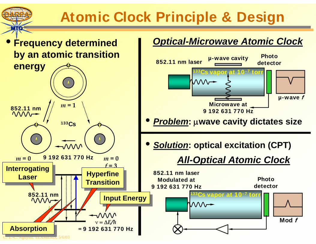
MTOMTOAtomic Clock Principle & Design
• Problem: μwave cavity dictates size133Cs
m = 0f = 4
m = 0f = 3
m = 1
852.11 nm
852.11 nm
ν = ΔE/ħ= 9 192 631 770 Hz
9 192 631 770 Hz
133Cs vapor at 10–7 torr
852.11 nm laserPhoto
detectorµ-wave cavity
Microwave at9 192 631 770 Hz
OpticalOptical--Microwave Atomic ClockMicrowave Atomic Clock
µ-wave f
852.11 nm laserModulated at
9 192 631 770 HzPhoto
detector133Cs vapor at 10–7 torr
Mod f
AllAll--Optical Atomic ClockOptical Atomic Clock• Solution: optical excitation (CPT)
• Frequency determined by an atomic transition energy
InterrogatingLaser
InterrogatingLaser
AbsorptionAbsorption
HyperfineTransitionHyperfineTransition
Input EnergyInput Energy
C. T.-C. Nguyen, TEXMEMS, 5/6/03
DARPADARPA
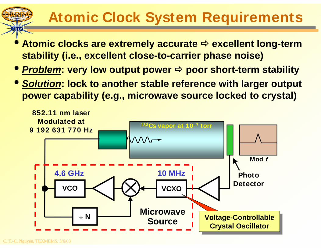
MTOMTOAtomic Clock System Requirements
• Atomic clocks are extremely accurate excellent long-term stability (i.e., excellent close-to-carrier phase noise)
• Problem: very low output power poor short-term stability• Solution: lock to another stable reference with larger output
power capability (e.g., microwave source locked to crystal) 852.11 nm laser
Modulated at9 192 631 770 Hz
PhotoDetector
133Cs vapor at 10–7 torr
Mod f
VCXOVCO
÷ N MicrowaveSource Voltage-Controllable
Crystal OscillatorVoltage-Controllable
Crystal Oscillator
10 MHz4.6 GHz
C. T.-C. Nguyen, TEXMEMS, 5/6/03
DARPADARPA
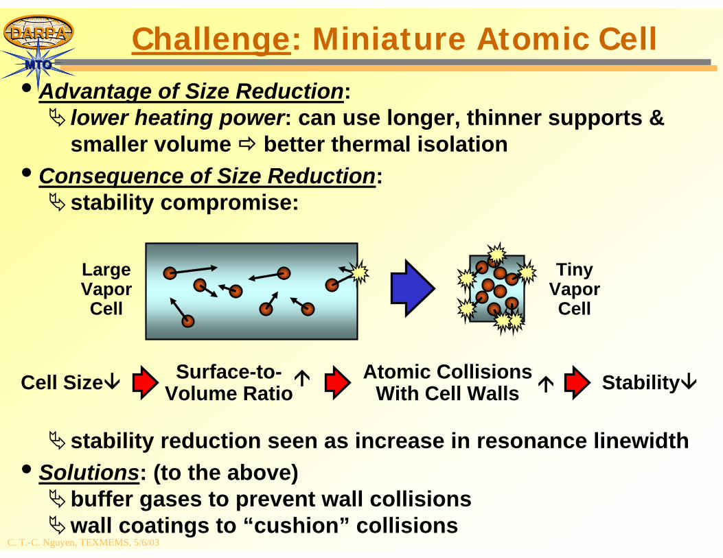
MTOMTOChallenge: Miniature Atomic Cell
• Advantage of Size Reduction:lower heating power: can use longer, thinner supports & smaller volume better thermal isolation
• Consequence of Size Reduction:stability compromise:
stability reduction seen as increase in resonance linewidth• Solutions: (to the above)
buffer gases to prevent wall collisionswall coatings to “cushion” collisions
Cell Size Surface-to-Volume Ratio
Atomic CollisionsWith Cell Walls Stability
LargeVaporCell
TinyVaporCell
C. T.-C. Nguyen, TEXMEMS, 5/6/03
DARPADARPA
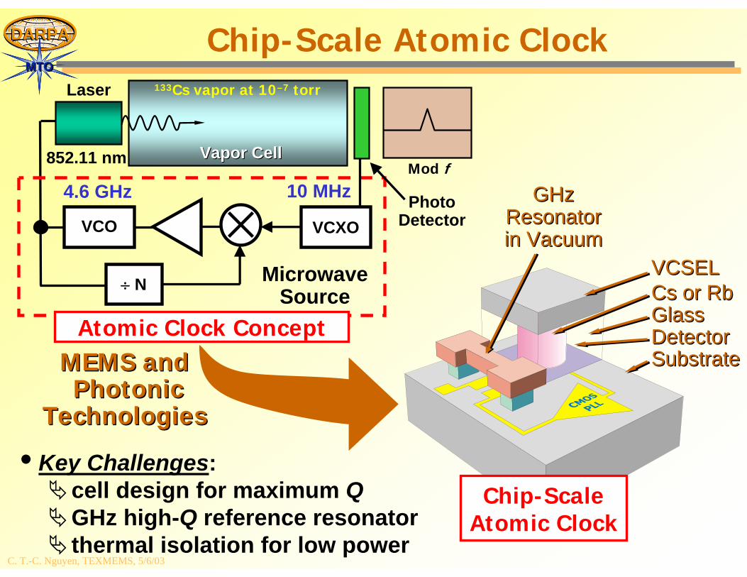
MTOMTOChip-Scale Atomic Clock
• Key Challenges:cell design for maximum QGHz high-Q reference resonatorthermal isolation for low power
Cs or Cs or RbRbGlassGlassDetectorDetector
VCSELVCSEL
SubstrateSubstrate
GHzGHzResonatorResonatorin Vacuumin Vacuum
MEMS andMEMS andPhotonic Photonic
TechnologiesTechnologies
Chip-ScaleAtomic Clock
133Cs vapor at 10–7 torr
VCXOVCO
÷ N MicrowaveSource
10 MHz4.6 GHz
Laser
Vapor CellVapor Cell
PhotoDetector
Atomic Clock Concept
Mod f852.11 nm
C. T.-C. Nguyen, TEXMEMS, 5/6/03
DARPADARPA
MTOMTO
Micro Power Generation (MPG)
C. T.-C. Nguyen, TEXMEMS, 5/6/03
DARPADARPA
MTOMTOMPG Program in a Nutshell
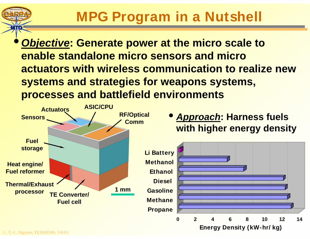
• Objective: Generate power at the micro scale to enable standalone micro sensors and micro actuators with wireless communication to realize new systems and strategies for weapons systems, processes and battlefield environments
Sensors
Fuelstorage
Actuators ASIC/CPURF/Optical
Comm
Heat engine/Fuel reformer
Thermal/Exhaustprocessor 1 mm
TE Converter/Fuel cell
• Approach: Harness fuels with higher energy density
0 2 4 6 8 10 12 14Energy Density (kW-hr/kg)
PropaneMethaneGasoline
DieselEthanol
MethanolLi Battery
C. T.-C. Nguyen, TEXMEMS, 5/6/03
DARPADARPA
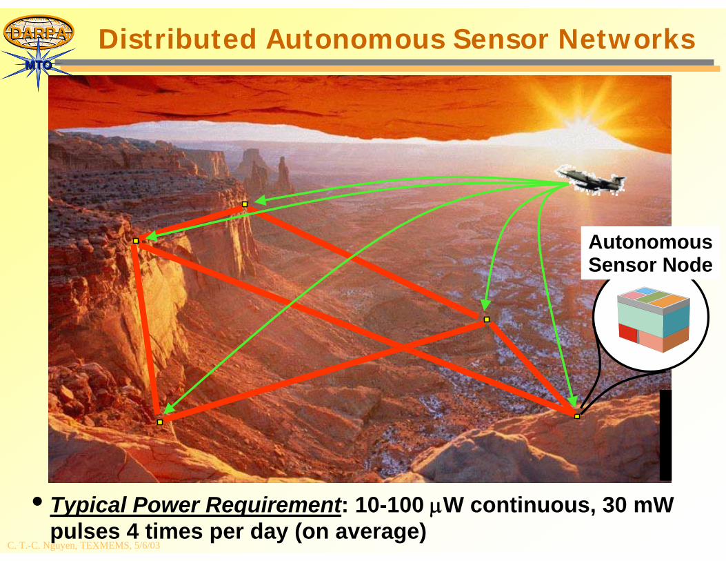
MTOMTODistributed Autonomous Sensor Networks
AutonomousSensor Node
• Typical Power Requirement: 10-100 μW continuous, 30 mWpulses 4 times per day (on average)
C. T.-C. Nguyen, TEXMEMS, 5/6/03
DARPADARPA
MTOMTOApproach: Fuel Cell
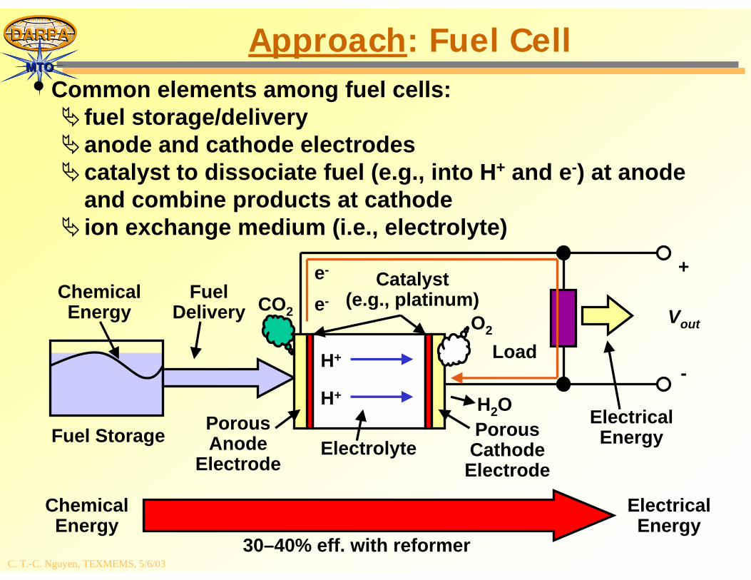
• Common elements among fuel cells:fuel storage/deliveryanode and cathode electrodescatalyst to dissociate fuel (e.g., into H+ and e-) at anode and combine products at cathodeion exchange medium (i.e., electrolyte)
Fuel Storage
Vout
ChemicalEnergy
FuelDelivery
ChemicalEnergy
ElectricalEnergyElectrolyte
PorousAnode
Electrode
PorousCathode
Electrode
Catalyst(e.g., platinum)
Load
+
-H+
e-
H+
e-
CO2O2
H2O
ElectricalEnergy
30–40% eff. with reformer
C. T.-C. Nguyen, TEXMEMS, 5/6/03
DARPADARPA
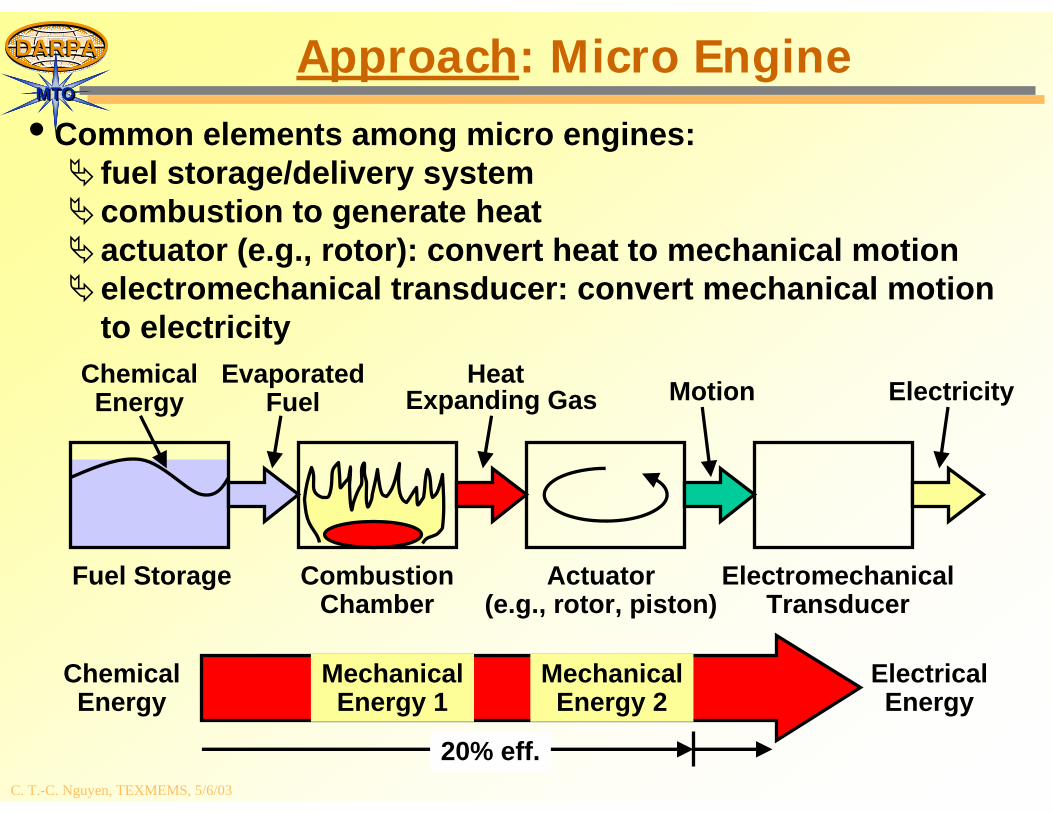
MTOMTOApproach: Micro Engine
• Common elements among micro engines:fuel storage/delivery systemcombustion to generate heatactuator (e.g., rotor): convert heat to mechanical motionelectromechanical transducer: convert mechanical motion to electricity
Fuel Storage CombustionChamber
Heat
Actuator(e.g., rotor, piston)
ElectromechanicalTransducer
ElectricityChemicalEnergy
EvaporatedFuel MotionExpanding Gas
ChemicalEnergy
ElectricalEnergy
MechanicalEnergy 1
MechanicalEnergy 2
20% eff.
C. T.-C. Nguyen, TEXMEMS, 5/6/03
DARPADARPA
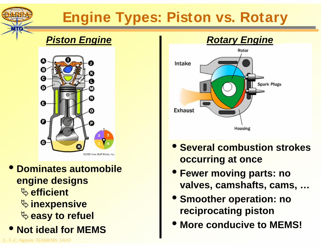
MTOMTOEngine Types: Piston vs. Rotary
• Dominates automobile engine designs
efficientinexpensiveeasy to refuel
• Not ideal for MEMS
• Several combustion strokes occurring at once
• Fewer moving parts: no valves, camshafts, cams, …
• Smoother operation: no reciprocating piston
• More conducive to MEMS!
Piston Engine Rotary Engine
C. T.-C. Nguyen, TEXMEMS, 5/6/03
DARPADARPA
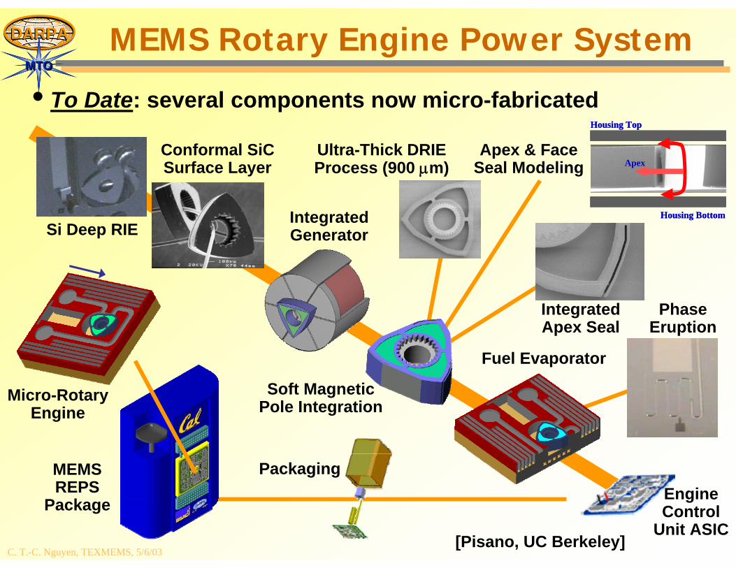
MTOMTOMEMS Rotary Engine Power System
Apex
Housing Top
Housing Bottom
Apex
Housing Top
Housing Bottom
Conformal SiCSurface Layer
Si Deep RIE
MEMSREPS
Package
Packaging
Soft MagneticPole Integration
IntegratedGenerator
Fuel Evaporator
Micro-RotaryEngine
Ultra-Thick DRIEProcess (900 μm)
Apex & FaceSeal Modeling
IntegratedApex Seal
PhaseEruption
EngineControl
Unit ASIC
• To Date: several components now micro-fabricated
[Pisano, UC Berkeley]

C. T.-C. Nguyen, TEXMEMS, 5/6/03
DARPADARPA
MTOMTO
What’s Next?(numerous possbilities)
C. T.-C. Nguyen, TEXMEMS, 5/6/03
DARPADARPA
MTOMTO
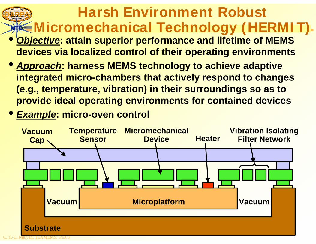
MicromechanicalDevice
Microplatform
Substrate
Vibration IsolatingFilter NetworkHeater
TemperatureSensor
VacuumCap
VacuumVacuum
• Objective: attain superior performance and lifetime of MEMS devices via localized control of their operating environments
• Approach: harness MEMS technology to achieve adaptive integrated micro-chambers that actively respond to changes (e.g., temperature, vibration) in their surroundings so as to provide ideal operating environments for contained devices
• Example: micro-oven control
Harsh Environment Robust Micromechanical Technology (HERMIT)
C. T.-C. Nguyen, TEXMEMS, 5/6/03
DARPADARPA
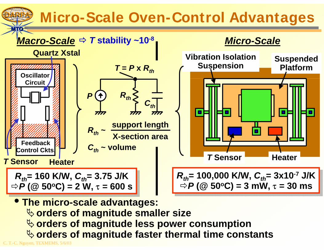
MTOMTOMicro-Scale Oven-Control Advantages
• The micro-scale advantages:orders of magnitude smaller sizeorders of magnitude less power consumptionorders of magnitude faster thermal time constants
SuspendedPlatform
Vibration IsolationSuspension
T Sensor Heater
OscillatorCircuit
FeedbackControl Ckts.
HeaterT Sensor
Quartz Xstal
Rth= 160 K/W, Cth= 3.75 J/KP (@ 50oC) = 2 W, τ = 600 s
Rth= 160 K/W, Cth= 3.75 J/KP (@ 50oC) = 2 W, τ = 600 s
Rth= 100,000 K/W, Cth= 3x10⁻⁷ J/KP (@ 50oC) = 3 mW, τ = 30 ms
Rth= 100,000 K/W, Cth= 3x10⁻⁷ J/KP (@ 50oC) = 3 mW, τ = 30 ms
P RthCth
T = P x Rth
Cth ~ volume
Rth ~ support lengthX-section area
Macro-Scale Micro-ScaleT stability ~10-8
C. T.-C. Nguyen, TEXMEMS, 5/6/03
DARPADARPA
MTOMTO
Conclusions
C. T.-C. Nguyen, TEXMEMS, 5/6/03
DARPADARPA
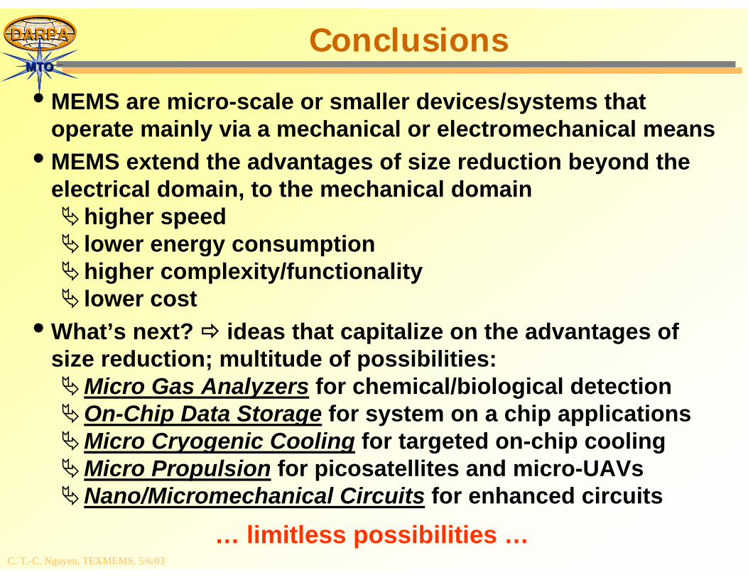
MTOMTOConclusions
• MEMS are micro-scale or smaller devices/systems that operate mainly via a mechanical or electromechanical means
• MEMS extend the advantages of size reduction beyond the electrical domain, to the mechanical domain
higher speedlower energy consumptionhigher complexity/functionalitylower cost
• What’s next? ideas that capitalize on the advantages of size reduction; multitude of possibilities:
Micro Gas Analyzers for chemical/biological detectionOn-Chip Data Storage for system on a chip applicationsMicro Cryogenic Cooling for targeted on-chip coolingMicro Propulsion for picosatellites and micro-UAVsNano/Micromechanical Circuits for enhanced circuits
… limitless possibilities …
Related Documents