ARTICLE IN PRESS Engineering Structures ( ) – Contents lists available at ScienceDirect Engineering Structures journal homepage: www.elsevier.com/locate/engstruct Damping mechanisms and damping ratios in vibrating unreinforced stone masonry Abdelsamie Elmenshawi a,* , Mohamed Sorour a , Aftab Mufti b , Leslie G. Jaeger c , Nigel Shrive a a Department of Civil Engineering, University of Calgary, Canada b Department of Civil Engineering, University of Manitoba, Canada c Department of Civil Engineering, Dalhousie University, Canada article info Article history: Received 7 October 2009 Received in revised form 5 March 2010 Accepted 25 June 2010 Available online xxxx Keywords: Stone masonry Free vibration Viscous damping Coulomb friction abstract In seeking to understand the dynamic behaviour of historic stone structures, eight representative walls were constructed and tested under in-plane free vibration conditions. Each wall consisted of two wythes, one sandstone, one limestone, joined by a rubble core of small stones and mortar. The walls were 2.0 m wide by 2.75 m high by 0.54 m thick. The free vibration tests were conducted in the wall’s in-plane direction at three levels of damage: the first was the undamaged state of the walls, the second after in- plane damage, and the third was after both in- and out-of-plane testing. As such, dynamic characteristics such as effective damping mechanisms and ratios and the natural period of vibration could be evaluated. It was found that although viscous damping was dominant, Coulomb friction damping had significant influence on wall vibration. The viscous damping ratio was 0.03 for the undamaged walls and increased with damage. © 2010 Elsevier Ltd. All rights reserved. 1. Introduction The advent of modern seismic codes around the world has in- spired the investigation of the dynamic properties and seismic vulnerability of heritage structures. The static and dynamic be- haviours of these structures are not easily understood. This is because heritage structures were built based on the builders’ ex- perience at that time, or what is known as ‘‘rule of thumb’’. Many significant historical structures were constructed from unrein- forced stone masonry. Although there have been many attempts to evaluate the seismic behaviour of unreinforced stone masonry, e.g. [1–6], there is no information on the nature of inherent damp- ing mechanisms. However, the viscous damping ratio of unre- inforced stone masonry buildings has been evaluated by some researchers [1,3]. Since progressive cracking occurs in masonry structures, their damping ratios would be different from those used for reinforced and steel structures. Also, the reduction in elas- tic modulus due to cracking would increase the damping level as compared to the uncracked behaviour. Mazzon et al. [3] con- ducted shake table tests for unreinforced stone masonry models (scale 2:3) to evaluate the dynamic behaviour of their strengthen- ing scheme. They suggested a damping ratio between 1.5% and 4% for the unstrengthened model, but the trend of damping could not * Corresponding author. Tel.: +1 403 220 3553; fax: +1 403 282 7026. E-mail address: [email protected] (A. Elmenshawi). be identified for peak ground accelerations more than 0.25g . Maz- zon et al. [3] observed an increase in the damping ratio of their strengthened model, and suggested that the damping ratio lies between 2% and 9%, but with no specific trend between the damp- ing ratio and the acceleration. In contrast, Benedetti et al. [1] esti- mated the initial damping ratio of the fundamental mode of their undamaged stone masonry model to be about 10%, similar to the damping ratios of structures of other materials. It is worth noting that these damping ratios were assumed to be viscous with no at- tempt to verify the actual damping mechanism. Damping mechanisms and ratios have been widely discussed in textbooks on the dynamics of structures, e.g. [7–9]. In these texts, there is agreement that damping is a complex issue, particularly for multi-degrees of freedom (MDOF) structures. There are different types of damping mechanism including viscous damping, Coulomb friction damping, hysteretic damping, and radiation damping. The damping ratio ζ (which is a percentage of the critical damping—the damping for which the structure returns to static equilibrium as quickly as possible without oscillation after a disturbance) is used in dynamic analysis to reflect the inherent capacity of a structure to dissipate imposed dynamic forces. In this context, the damping ratio is a measure of the energy dissipation in a dynamic system. For simplicity and better mathematical formulation, the damping ratio is modeled as though the damping is viscous. However, Coulomb friction damping is another candidate for calculating the damping ratio [10]. Many experimental methods can be used to measure the damping ratio for a system including the decay of free 0141-0296/$ – see front matter © 2010 Elsevier Ltd. All rights reserved. doi:10.1016/j.engstruct.2010.06.016 Please cite this article in press as: Elmenshawi A, et al. Damping mechanisms and damping ratios in vibrating unreinforced stone masonry. Engineering Structures (2010), doi:10.1016/j.engstruct.2010.06.016

Welcome message from author
This document is posted to help you gain knowledge. Please leave a comment to let me know what you think about it! Share it to your friends and learn new things together.
Transcript

ARTICLE IN PRESSEngineering Structures ( ) –
Contents lists available at ScienceDirect
Engineering Structures
journal homepage: www.elsevier.com/locate/engstruct
Damping mechanisms and damping ratios in vibrating unreinforcedstone masonry
Abdelsamie Elmenshawi a,∗, Mohamed Sorour a, Aftab Mufti b, Leslie G. Jaeger c, Nigel Shrive aa Department of Civil Engineering, University of Calgary, Canadab Department of Civil Engineering, University of Manitoba, Canadac Department of Civil Engineering, Dalhousie University, Canada
a r t i c l e i n f o
Article history:Received 7 October 2009Received in revised form5 March 2010Accepted 25 June 2010Available online xxxx
Keywords:Stone masonryFree vibrationViscous dampingCoulomb friction
a b s t r a c t
In seeking to understand the dynamic behaviour of historic stone structures, eight representative wallswere constructed and tested under in-plane free vibration conditions. Each wall consisted of two wythes,one sandstone, one limestone, joined by a rubble core of small stones and mortar. The walls were 2.0 mwide by 2.75 m high by 0.54 m thick. The free vibration tests were conducted in the wall’s in-planedirection at three levels of damage: the first was the undamaged state of the walls, the second after in-plane damage, and the third was after both in- and out-of-plane testing. As such, dynamic characteristicssuch as effective damping mechanisms and ratios and the natural period of vibration could be evaluated.It was found that although viscous damping was dominant, Coulomb friction damping had significantinfluence on wall vibration. The viscous damping ratio was 0.03 for the undamaged walls and increasedwith damage.
© 2010 Elsevier Ltd. All rights reserved.
1. Introduction
The advent of modern seismic codes around the world has in-spired the investigation of the dynamic properties and seismicvulnerability of heritage structures. The static and dynamic be-haviours of these structures are not easily understood. This isbecause heritage structures were built based on the builders’ ex-perience at that time, or what is known as ‘‘rule of thumb’’. Manysignificant historical structures were constructed from unrein-forced stone masonry. Although there have been many attemptsto evaluate the seismic behaviour of unreinforced stone masonry,e.g. [1–6], there is no information on the nature of inherent damp-ing mechanisms. However, the viscous damping ratio of unre-inforced stone masonry buildings has been evaluated by someresearchers [1,3]. Since progressive cracking occurs in masonrystructures, their damping ratios would be different from thoseused for reinforced and steel structures. Also, the reduction in elas-tic modulus due to cracking would increase the damping levelas compared to the uncracked behaviour. Mazzon et al. [3] con-ducted shake table tests for unreinforced stone masonry models(scale 2:3) to evaluate the dynamic behaviour of their strengthen-ing scheme. They suggested a damping ratio between 1.5% and 4%for the unstrengthened model, but the trend of damping could not
∗ Corresponding author. Tel.: +1 403 220 3553; fax: +1 403 282 7026.E-mail address: [email protected] (A. Elmenshawi).
be identified for peak ground accelerations more than 0.25g . Maz-zon et al. [3] observed an increase in the damping ratio of theirstrengthened model, and suggested that the damping ratio liesbetween 2% and 9%, but with no specific trend between the damp-ing ratio and the acceleration. In contrast, Benedetti et al. [1] esti-mated the initial damping ratio of the fundamental mode of theirundamaged stone masonry model to be about 10%, similar to thedamping ratios of structures of other materials. It is worth notingthat these damping ratios were assumed to be viscous with no at-tempt to verify the actual damping mechanism.Dampingmechanisms and ratios have beenwidely discussed in
textbooks on the dynamics of structures, e.g. [7–9]. In these texts,there is agreement that damping is a complex issue, particularly formulti-degrees of freedom (MDOF) structures. There are differenttypes of dampingmechanism including viscous damping, Coulombfriction damping, hysteretic damping, and radiation damping. Thedamping ratio ζ (which is a percentage of the critical damping—thedamping for which the structure returns to static equilibrium asquickly as possible without oscillation after a disturbance) is usedin dynamic analysis to reflect the inherent capacity of a structureto dissipate imposed dynamic forces. In this context, the dampingratio is a measure of the energy dissipation in a dynamic system.For simplicity and better mathematical formulation, the dampingratio is modeled as though the damping is viscous. However,Coulomb friction damping is another candidate for calculating thedamping ratio [10]. Many experimental methods can be used tomeasure the damping ratio for a system including the decay of free
0141-0296/$ – see front matter© 2010 Elsevier Ltd. All rights reserved.doi:10.1016/j.engstruct.2010.06.016
Please cite this article in press as: Elmenshawi A, et al. Dampingmechanisms and damping ratios in vibrating unreinforced stonemasonry. Engineering Structures (2010),doi:10.1016/j.engstruct.2010.06.016
ARTICLE IN PRESS2 A. Elmenshawi et al. / Engineering Structures ( ) –
vibrations and the forced vibration response. The latter approachcomprises the resonant response, the width of the response curveand the half-power method, and the energy loss per cycle [9].The free vibration technique is of a particular interest here
as it was chosen for the experimental work under consideration.The free vibration test can be conducted by imposing an initialnonzero displacement to a structure that can be laterally displacedby a tensioned cable. The cable is then released suddenly to causefree vibration in the structure. The damping ratio can be esti-mated by measuring the decay in the displacement amplitudeswith time. The free vibration test can also be performed by impos-ing an initial nonzero velocity or a combination of initial nonzerodisplacement and nonzero velocity [11]. The current experimen-tal work was conducted by applying a nonzero displacement cor-responding to a very small lateral load to examine the dampingmechanisms and ratios for stone walls representative of the con-struction on Parliament Hill, Ottawa, Canada. The free vibrationtests were a part of extensive dynamic tests conducted on theserepresentative walls to evaluate the seismic vulnerability and pos-sible rehabilitation techniques to apply to the Parliament build-ings. The test specimens were constructed of two wythes ofstonework, one of sandstone and the other of limestone, joinedby a rubble stone masonry core. Three damping mechanisms wereinvestigated—viscous damping, Coulomb friction, and hystereticdamping. The viscous and Coulomb friction damping mechanismscould be evaluated from the free vibration test and are presentedhere, as the hysteretic damping was evaluated from quasi-staticin-plane tests and has been presented elsewhere [12]. Althoughviscous damping is the most common in dynamic analysis, theCoulomb friction mechanism was investigated as the capacity ofthe stone walls depends to some degree on the friction betweenthe stone units and surrounding mortar.
2. Experimental program
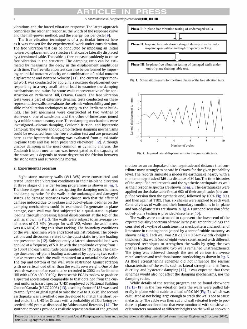
Eight stone masonry walls (W1–W8) were constructed andtested under free vibration conditions in their in-plane directionat three stages of a wider testing programme as shown in Fig. 1.The three stages aimed at investigating the damping mechanismsand damping ratios for the walls in the undamaged and damagedstates. The damage scenarios were chosen such that the effect ofdamage induced due to in-plane and out-of-plane loadings on thedamping mechanisms could be examined. To generate in-planedamage, each wall was first subjected to a quasi-static in-planeloading through increasing lateral displacement at the top of thewall as shown in Fig. 2. The walls were subject to an average ax-ial stress of 0.3 MPa (except for wall W2, where the axial stresswas 0.6 MPa) during this slow racking. The boundary conditionsof the wall specimen were ends fixed against rotation. The obser-vations and discussion related to the quasi-static in-plane loadingare presented in [12]. Subsequently, a lateral sinusoidal load wasapplied at a frequency of 5.0 Hz with the amplitude varying from 1to 10 kN and each amplitude being applied for 10 cycles. The dam-age due to out-of-plane loadingwas caused by applying two earth-quake records with the walls mounted on a uniaxial shake table.The top and bottom of the wall were restrained against rotationwith no vertical load other than the wall’s own weight. One of therecords was that of an earthquake recorded in 2002 on ParliamentHill with a PGA of 0.00192g . Because this PGA is too low to producea spectral acceleration comparable to that obtained from the cur-rent uniform hazard spectra (UHS) employed by National BuildingCode of Canada (NBCC 2005) [13], a scaling factor of 183 was usedto amplify the original signal to raise the PGA to 0.353g . The secondearthquake was a synthetic one developed to match the short pe-riod end of the UHS for Ottawawith a probability of 2% of being ex-ceeded in 50 years as discussed by Atkinson and Beresnev [14]. Thesynthetic records provide a realistic representation of the ground
Fig. 1. Schematic diagrams for the three phases of the free vibration tests.
Fig. 2. Imposed lateral displacements for the quasi-static tests.
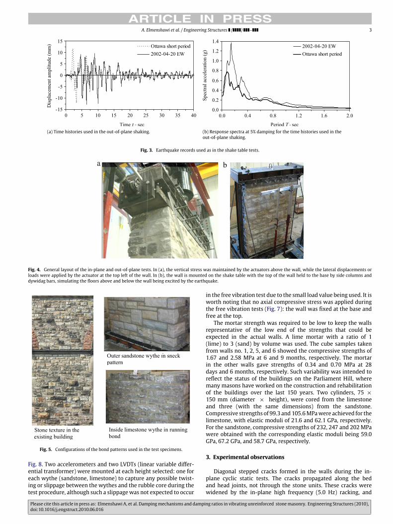
motion for an earthquake of the magnitude and distance that con-tribute most strongly to hazard in Ottawa for the given probabilitylevel. The records simulate a moderate earthquake nearby with amomentmagnitude ofM6 at a distance of 30 km. The timehistoriesof the amplified real records and the synthetic earthquake as wellas their response spectra are shown in Fig. 3. The earthquakeswereapplied on the shake table first at 60% of their amplitudes (the am-plified version then the synthetic one), followed by 100%, Fig. 3(a),and then again at 110%. Thus, six shakes were applied to each wall.General views of walls and their boundary conditions in in-planeand out-of-plane tests are shown in Fig. 4. Further discussion of theout-of-plane testing is provided elsewhere [15].The walls were constructed to represent the lower end of the
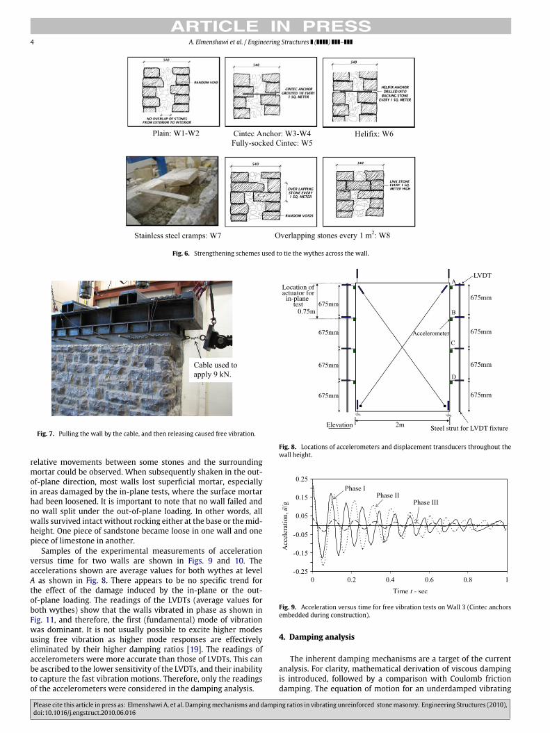
expected quality spectrumof those in the parliament buildings andconsisted of awythe of sandstone in a sneck pattern and another oflimestone in running bond, joined by a core of rubble masonry, asshown in Fig. 5. Eachwallwas 2.0×2.57×0.54m (width×height×thickness). Six walls (out of eight) were constructed with differentproposed techniques to strengthen the walls by tying the twowythes together internally: two walls remained unstrengthened.The tying was achieved through the use of various transversemetal anchors and traditional stone interlocking as shown in Fig. 6.As these strengthening schemes did not influence the seismiccharacteristics of the walls, such as lateral strength and stiffness,ductility, and hysteretic damping [12], it was expected that theseschemes would also not affect the damping mechanisms, nor thedamping ratios.While details of the testing program can be found elsewhere
[12,15–18], in the free vibration tests the walls were pulled lat-erally in plane with a cable to a load of 9.0 kN (Fig. 7), which wascalculated as not being large enough to crack thewalls nor to causeinelasticity. The cable was then cut and wall vibrated freely to pro-duce in-plane accelerations thatweremonitoredwith sensitive ac-celerometers mounted at different heights on the wall as shown in
Please cite this article in press as: Elmenshawi A, et al. Dampingmechanisms and damping ratios in vibrating unreinforced stonemasonry. Engineering Structures (2010),doi:10.1016/j.engstruct.2010.06.016
ARTICLE IN PRESSA. Elmenshawi et al. / Engineering Structures ( ) – 3
(a) Time histories used in the out-of-plane shaking. (b) Response spectra at 5% damping for the time histories used in theout-of-plane shaking.
Fig. 3. Earthquake records used as in the shake table tests.
Fig. 4. General layout of the in-plane and out-of-plane tests. In (a), the vertical stress was maintained by the actuators above the wall, while the lateral displacements orloads were applied by the actuator at the top left of the wall. In (b), the wall is mounted on the shake table with the top of the wall held to the base by side columns anddywidag bars, simulating the floors above and below the wall being excited by the earthquake.
Fig. 5. Configurations of the bond patterns used in the test specimens.
Fig. 8. Two accelerometers and two LVDTs (linear variable differ-ential transformer) were mounted at each height selected: one foreach wythe (sandstone, limestone) to capture any possible twist-ing or slippage between the wythes and the rubble core during thetest procedure, although such a slippagewas not expected to occur
in the free vibration test due to the small load value being used. It isworth noting that no axial compressive stress was applied duringthe free vibration tests (Fig. 7): the wall was fixed at the base andfree at the top.The mortar strength was required to be low to keep the walls
representative of the low end of the strengths that could beexpected in the actual walls. A lime mortar with a ratio of 1(lime) to 3 (sand) by volume was used. The cube samples takenfrom walls no. 1, 2, 5, and 6 showed the compressive strengths of1.67 and 2.58 MPa at 6 and 9 months, respectively. The mortarin the other walls gave strengths of 0.34 and 0.70 MPa at 28days and 6 months, respectively. Such variability was intended toreflect the status of the buildings on the Parliament Hill, wheremany masons have worked on the construction and rehabilitationof the buildings over the last 150 years. Two cylinders, 75 ×150 mm (diameter × height), were cored from the limestoneand three (with the same dimensions) from the sandstone.Compressive strengths of 99.3 and105.6MPawere achieved for thelimestone, with elastic moduli of 21.6 and 62.1 GPa, respectively.For the sandstone, compressive strengths of 232, 247 and 202MPawere obtained with the corresponding elastic moduli being 59.0GPa, 67.2 GPa, and 58.7 GPa, respectively.
3. Experimental observations
Diagonal stepped cracks formed in the walls during the in-plane cyclic static tests. The cracks propagated along the bedand head joints, not through the stone units. These cracks werewidened by the in-plane high frequency (5.0 Hz) racking, and
Please cite this article in press as: Elmenshawi A, et al. Dampingmechanisms and damping ratios in vibrating unreinforced stonemasonry. Engineering Structures (2010),doi:10.1016/j.engstruct.2010.06.016
ARTICLE IN PRESS4 A. Elmenshawi et al. / Engineering Structures ( ) –
Fig. 6. Strengthening schemes used to tie the wythes across the wall.
Fig. 7. Pulling the wall by the cable, and then releasing caused free vibration.
relative movements between some stones and the surroundingmortar could be observed. When subsequently shaken in the out-of-plane direction, most walls lost superficial mortar, especiallyin areas damaged by the in-plane tests, where the surface mortarhad been loosened. It is important to note that no wall failed andno wall split under the out-of-plane loading. In other words, allwalls survived intact without rocking either at the base or themid-height. One piece of sandstone became loose in one wall and onepiece of limestone in another.Samples of the experimental measurements of acceleration
versus time for two walls are shown in Figs. 9 and 10. Theaccelerations shown are average values for both wythes at levelA as shown in Fig. 8. There appears to be no specific trend forthe effect of the damage induced by the in-plane or the out-of-plane loading. The readings of the LVDTs (average values forboth wythes) show that the walls vibrated in phase as shown inFig. 11, and therefore, the first (fundamental) mode of vibrationwas dominant. It is not usually possible to excite higher modesusing free vibration as higher mode responses are effectivelyeliminated by their higher damping ratios [19]. The readings ofaccelerometers were more accurate than those of LVDTs. This canbe ascribed to the lower sensitivity of the LVDTs, and their inabilityto capture the fast vibration motions. Therefore, only the readingsof the accelerometers were considered in the damping analysis.
Location ofactuator for
in-plane test
0.75m675mm
675mm
675mm
675mm
Elevation 2m Steel strut for LVDT fixture
675mm
675mm
675mm
675mm
LVDT
Accelerometer
Fig. 8. Locations of accelerometers and displacement transducers throughout thewall height.
Fig. 9. Acceleration versus time for free vibration tests on Wall 3 (Cintec anchorsembedded during construction).
4. Damping analysis
The inherent damping mechanisms are a target of the currentanalysis. For clarity, mathematical derivation of viscous dampingis introduced, followed by a comparison with Coulomb frictiondamping. The equation of motion for an underdamped vibrating
Please cite this article in press as: Elmenshawi A, et al. Dampingmechanisms and damping ratios in vibrating unreinforced stonemasonry. Engineering Structures (2010),doi:10.1016/j.engstruct.2010.06.016
ARTICLE IN PRESSA. Elmenshawi et al. / Engineering Structures ( ) – 5
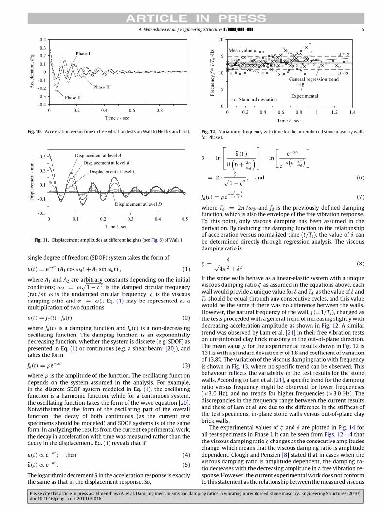
Fig. 10. Acceleration versus time in free vibration tests onWall 6 (Helifix anchors).
Fig. 11. Displacement amplitudes at different heights (see Fig. 8) of Wall 1.
single degree of freedom (SDOF) system takes the form of
u(t) = e−αt (A1 cosωdt + A2 sinωdt) , (1)
where A1 and A2 are arbitrary constants depending on the initialconditions; ωd = ω
√1− ζ 2 is the damped circular frequency
(rad/s); ω is the undamped circular frequency; ζ is the viscousdamping ratio and α = ωζ . Eq. (1) may be represented as amultiplication of two functions
u(t) = fd(t) · fo(t), (2)
where fd(t) is a damping function and fo(t) is a non-decreasingoscillating function. The damping function is an exponentiallydecreasing function, whether the system is discrete (e.g. SDOF) aspresented in Eq. (1) or continuous (e.g. a shear beam; [20]), andtakes the form
fd(t) = ρe−αt (3)
where ρ is the amplitude of the function. The oscillating functiondepends on the system assumed in the analysis. For example,in the discrete SDOF system modeled in Eq. (1), the oscillatingfunction is a harmonic function, while for a continuous system,the oscillating function takes the form of the wave equation [20].Notwithstanding the form of the oscillating part of the overallfunction, the decay of both continuous (as the current testspecimens should be modeled) and SDOF systems is of the sameform. In analyzing the results from the current experimental work,the decay in acceleration with time was measured rather than thedecay in the displacement. Eq. (1) reveals that if
u(t) ∝ e−αt; then (4)
u(t) ∝ e−αt . (5)
The logarithmic decrement δ in the acceleration response is exactlythe same as that in the displacement response. So,
Fig. 12. Variation of frequencywith time for the unreinforced stonemasonrywallsfor Phase I.
δ = ln
u (ti)
u(ti + 2π
ωd
) = ln[ e−αti
e−α(ti+
2πωd
)]
= 2πζ√1− ζ 2
, and (6)
fd(t) = ρe−δ(tTd
)(7)
where Td = 2π/ωd, and fd is the previously defined dampingfunction, which is also the envelope of the free vibration response.To this point, only viscous damping has been assumed in thederivation. By deducing the damping function in the relationshipof acceleration versus normalized time (t/Td), the value of δ canbe determined directly through regression analysis. The viscousdamping ratio is
ζ =δ
√4π2 + δ2
. (8)
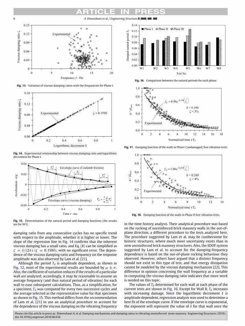
If the stone walls behave as a linear-elastic system with a uniqueviscous damping ratio ζ as assumed in the equations above, eachwallwould provide a unique value for δ and Td, as the value of δ andTd should be equal through any consecutive cycles, and this valuewould be the same if there was no difference between the walls.However, the natural frequency of the wall, f (=1/Td), changed asthe tests proceededwith a general trend of increasing slightly withdecreasing acceleration amplitude as shown in Fig. 12. A similartrend was observed by Lam et al. [21] in their free vibration testson unreinforced clay brick masonry in the out-of-plane direction.The mean value µ for the experimental results shown in Fig. 12 is13Hzwith a standard deviationσ of 1.8 and coefficient of variationof 13.8%. The variation of the viscous damping ratiowith frequencyis shown in Fig. 13, where no specific trend can be observed. Thisbehaviour reflects the variability in the test results for the stonewalls. According to Lam et al. [21], a specific trend for the dampingratio versus frequency might be observed for lower frequencies(<3.0 Hz), and no trends for higher frequencies (>3.0 Hz). Thediscrepancies in the frequency range between the current resultsand those of Lam et al. are due to the difference in the stiffness ofthe test specimens, in-plane stone walls versus out-of-plane claybrick walls.The experimental values of ζ and δ are plotted in Fig. 14 for
all test specimens in Phase I. It can be seen from Figs. 12–14 thatthe viscous damping ratio ζ changes as the consecutive amplitudeschange, which means that the viscous damping ratio is amplitudedependent. Clough and Penzien [8] stated that in cases when theviscous damping ratio is amplitude dependent, the damping ra-tio decreases with the decreasing amplitude in a free vibration re-sponse. However, the current experimentalwork does not conformto this statement as the relationship between themeasured viscous
Please cite this article in press as: Elmenshawi A, et al. Dampingmechanisms and damping ratios in vibrating unreinforced stonemasonry. Engineering Structures (2010),doi:10.1016/j.engstruct.2010.06.016
ARTICLE IN PRESS6 A. Elmenshawi et al. / Engineering Structures ( ) –
Fig. 13. Variation of viscous damping ratios with the frequencies for Phase I.
Fig. 14. Experimental relationship between viscous damping ratio and logarithmicdecrement for Phase I.
Fig. 15. Determination of the natural period and damping functions (the resultsare for W3).
damping ratio from any consecutive cycles has no specific trendwith respect to the amplitude, whether it is higher or lower. Theslope of the regression line in Fig. 14 confirms that the inherentviscous damping has a small ratio, and Eq. (8) can be simplified asζ = δ/(2π) (ζ = 0.159δ), with no significant error. The depen-dence of the viscous damping ratio and frequency on the responseamplitude was also observed by Lam et al. [21].Although the period Td is amplitude dependent, as shown in
Fig. 12, most of the experimental results are bounded by µ ± σ .Also, the coefficient of variation reduces if the results of a particularwall are analyzed; accordingly, it may be reasonable to assume anaverage frequency (and thus natural period of vibration) for eachwall to ease subsequent calculations. Thus, as a simplification, fora specimen, Td was computed for every two successive cycles andthe average selected as the representative value for that specimenas shown in Fig. 15. This method differs from the recommendationof Lam et al. [21] to use an analytical procedure to account forthe dependence of the viscous damping on the vibrating frequency
Fig. 16. Comparison between the natural periods for each phase.
Fig. 17. Damping function of the walls in Phase I (undamaged) free vibration tests.
Fig. 18. Damping function of the walls in Phase II free vibration tests.
in the time history analysis. Their analytical procedure was basedon the rocking of unreinforced brick masonry walls in the out-of-plane direction, a different procedure to the tests analyzed here.The procedure suggested by Lam et al. may be cumbersome forhistoric structures, where much more uncertainty exists than innew unreinforced brickmasonry structures. Also, the SDOF systemsuggested by Lam et al. to account for the damping-frequencydependence is based on the out-of-plane rocking behaviour theyobserved. However, others have argued that a distinct frequencyshould not exist in this type of test, and that energy dissipationcannot be modeled by the viscous damping mechanism [22]. Thisdifference in opinion concerning the wall frequency as a variablein computing the viscous damping ratio indicates that more workis needed on this topic.The values of Td determined for each wall at each phase of the
current tests are shown in Fig. 16. Except for Wall 8, Td increaseswith increasing damage. Since the logarithmic decrement δ isamplitude dependent, regression analysis was used to determine abest fit of the envelope curve. If the envelope curve is exponential,the exponent will represent the value of δ for that wall once the
Please cite this article in press as: Elmenshawi A, et al. Dampingmechanisms and damping ratios in vibrating unreinforced stonemasonry. Engineering Structures (2010),doi:10.1016/j.engstruct.2010.06.016
ARTICLE IN PRESSA. Elmenshawi et al. / Engineering Structures ( ) – 7
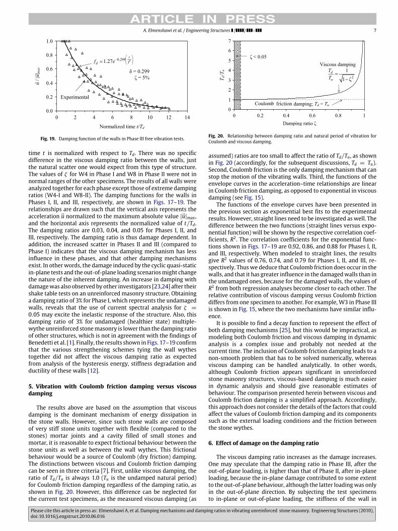
Fig. 19. Damping function of the walls in Phase III free vibration tests.
time t is normalized with respect to Td. There was no specificdifference in the viscous damping ratio between the walls, justthe natural scatter one would expect from this type of structure.The values of ζ for W4 in Phase I and W8 in Phase II were not innormal ranges of the other specimens. The results of all walls wereanalyzed together for each phase except those of extreme dampingratios (W4-I and W8-II). The damping functions for the walls inPhases I, II, and III, respectively, are shown in Figs. 17–19. Therelationships are drawn such that the vertical axis represents theacceleration u normalized to the maximum absolute value |u|max,and the horizontal axis represents the normalized value of t/Td.The damping ratios are 0.03, 0.04, and 0.05 for Phases I, II, andIII, respectively. The damping ratio is thus damage dependent. Inaddition, the increased scatter in Phases II and III (compared toPhase I) indicates that the viscous damping mechanism has lessinfluence in these phases, and that other damping mechanismsexist. In otherwords, the damage induced by the cyclic quasi-staticin-plane tests and the out-of-plane loading scenariosmight changethe nature of the inherent damping. An increase in damping withdamagewas also observed by other investigators [23,24] after theirshake table tests on an unreinforced masonry structure. Obtaininga damping ratio of 3% for Phase I, which represents the undamagedwalls, reveals that the use of current spectral analysis for ζ =0.05 may excite the inelastic response of the structure. Also, thisdamping ratio of 3% for undamaged (healthier state) multiple-wythe unreinforced stonemasonry is lower than the damping ratioof other structures, which is not in agreement with the findings ofBenedetti et al. [1]. Finally, the results shown in Figs. 17–19 confirmthat the various strengthening schemes tying the wall wythestogether did not affect the viscous damping ratio as expectedfrom analysis of the hysteresis energy, stiffness degradation andductility of these walls [12].
5. Vibration with Coulomb friction damping versus viscousdamping
The results above are based on the assumption that viscousdamping is the dominant mechanism of energy dissipation inthe stone walls. However, since such stone walls are composedof very stiff stone units together with flexible (compared to thestones) mortar joints and a cavity filled of small stones andmortar, it is reasonable to expect frictional behaviour between thestone units as well as between the wall wythes. This frictionalbehaviour would be a source of Coulomb (dry friction) damping.The distinctions between viscous and Coulomb friction dampingcan be seen in three criteria [7]. First, unlike viscous damping, theratio of Td/Tn is always 1.0 (Tn is the undamped natural period)for Coulomb friction damping regardless of the damping ratio, asshown in Fig. 20. However, this difference can be neglected forthe current test specimens, as the measured viscous damping (as
Fig. 20. Relationship between damping ratio and natural period of vibration forCoulomb and viscous damping.
assumed) ratios are too small to affect the ratio of Td/Tn, as shownin Fig. 20 (accordingly, for the subsequent discussions, Td = Tn).Second, Coulomb friction is the only damping mechanism that canstop the motion of the vibrating walls. Third, the functions of theenvelope curves in the acceleration–time relationships are linearin Coulomb friction damping, as opposed to exponential in viscousdamping (see Fig. 15).The functions of the envelope curves have been presented in
the previous section as exponential best fits to the experimentalresults. However, straight lines need to be investigated aswell. Thedifference between the two functions (straight lines versus expo-nential function) will be shown by the respective correlation coef-ficients, R2. The correlation coefficients for the exponential func-tions shown in Figs. 17–19 are 0.92, 0.86, and 0.88 for Phases I, II,and III, respectively. When modeled to straight lines, the resultsgive R2 values of 0.76, 0.74, and 0.79 for Phases I, II, and III, re-spectively. Thuswe deduce that Coulomb friction does occur in thewalls, and that it has greater influence in the damagedwalls than inthe undamaged ones, because for the damaged walls, the values ofR2 from both regression analyses become closer to each other. Therelative contribution of viscous damping versus Coulomb frictiondiffers from one specimen to another. For example, W3 in Phase IIIis shown in Fig. 15, where the two mechanisms have similar influ-ence.It is possible to find a decay function to represent the effect of
both damping mechanisms [25], but this would be impractical, asmodeling both Coulomb friction and viscous damping in dynamicanalysis is a complex issue and probably not needed at thecurrent time. The inclusion of Coulomb friction damping leads to anon-smooth problem that has to be solved numerically, whereasviscous damping can be handled analytically. In other words,although Coulomb friction appears significant in unreinforcedstone masonry structures, viscous-based damping is much easierin dynamic analysis and should give reasonable estimates ofbehaviour. The comparison presented herein between viscous andCoulomb friction damping is a simplified approach. Accordingly,this approach does not consider the details of the factors that couldaffect the values of Coulomb friction damping and its componentssuch as the external loading conditions and the friction betweenthe stone wythes.
6. Effect of damage on the damping ratio
The viscous damping ratio increases as the damage increases.One may speculate that the damping ratio in Phase III, after theout-of-plane loading, is higher than that of Phase II, after in-planeloading, because the in-plane damage contributed to some extentto the out-of-plane behaviour, although the latter loadingwas onlyin the out-of-plane direction. By subjecting the test specimensto in-plane or out-of-plane loading, the stiffness of the wall in
Please cite this article in press as: Elmenshawi A, et al. Dampingmechanisms and damping ratios in vibrating unreinforced stonemasonry. Engineering Structures (2010),doi:10.1016/j.engstruct.2010.06.016

ARTICLE IN PRESS8 A. Elmenshawi et al. / Engineering Structures ( ) –
Fig. 21. Spectral acceleration at damping ratios other than 5%.
Fig. 22. Modeling of viscous damping in MDOF systems.
the corresponding direction is degraded; as a result, the naturalperiod of the wall is lengthened. This behaviour is manifested inthe data shown in Fig. 16, where the natural period of vibrationgenerally increases with damage. The damping ratio increased by33% and 67% due to the damage in the in-plane and the out-of-plane loadings, respectively, with respect to the undamaged state.Again, the increased ratio after out-of-plane testing is higher dueto the effect of the preceding in-plane damage. In a real structure,the behaviour in a seismic event ismainly nonlinear and changes inthe stiffness will cause additional hysteretic damping. Thus, it maybe appropriate to define the viscous damping ratio based on theinitial elastic stage and to assume that the damping ratio remainsunchanged [8]. In general, the effect of damage on the viscousdamping ratio is not sufficiently clear. However, the use of thecurrent 5%-damped spectral analysis proposed by seismic codeswill involve a damaged state for a historic structure, not the elasticstate as assumed by codes. The effect of the viscous damping ratioon the seismic shear forces has been summarized elsewhere [26].Of the models presented, that of Newmark and Hall [10] for theconstant acceleration region (where the natural period of historicstructures is expected) is selected herein and drawn in Fig. 21.For undamaged historic structures, the use of 5%-based spectralanalysis instead of the 3%-damping ratio appears to underestimatethe seismic shear on the building by about 16% for the same naturalperiod. Also, the use of a 5% damping ratio decreases the seismicshear forces by 7% compared to those of a 4%-damping ratio forthe same natural period. This is only an approximation, as thenatural periodwill also change due to the effect of damage, like thedamping ratio. The variation of the natural period with the viscousdamping ratio has not been modeled in the literature.Change in the viscous damping ratio with stiffness has been
widelymodeled in the dynamic analysis of MDOF systems. Variousmodels have been used as shown in Fig. 22, including mass pro-portional damping, stiffness proportional damping, and Rayleighdamping (a combination of both mass and stiffness proportionaldamping). The concept of mass proportional damping aligns with
observations from the current tests, in that the damping ratio in-creases as the natural period of vibration increases. In contrast,stiffness proportional damping does not match the experimentalresults. Rayleigh damping aligns with the experimental findingsafter a certain period. Modeling of damping through the system’smass and stiffness is used to account for the effect of highermodes,as these modes have higher natural periods of vibration than thefundamental mode. However, as only the fundamental mode canbe excited by the free vibration test, the increase in the naturalperiod in these tests is due to stiffness degradation, not to highermode effects. Therefore, for unreinforced stone masonry struc-tures, the analysis here suggests that when the fundamental modeof vibration is dominant, mass proportional damping is a suitablemodel to represent the effect of damage on the damping ratio.Hence, for the fundamental mode of vibration, the following re-lationship applies:
ζD
ζo=TDTo=
√kokD
(9)
where the subscript D refers to the damaged state, the subscripto is for the undamaged (elastic) state, and k is the lateral stiffnessof the wall. The ratio kD/ko is the stiffness degradation for the testspecimens and can be calculated for a given drift ratio ∆/h (∆ isthe lateral relative displacement; and h is the wall height) as [12]
kDko= 0.28
(∆
h
)−0.37. (10)
Consequently, both the viscous damping ratio and the natural pe-riod for a given drift ratio (to represent any damaged state) can beapproximated as
ζD
ζo=TDTo= 1.89
(∆
h
)0.185. (11)
Relating the viscous damping ratio and the natural period of vi-bration to the lateral drift can ease the problem of anticipat-ing the dynamic properties of a historic structure where somedamage already exists. Once the lateral drift has been estimated,Eq. (11) allows the levels of the viscous damping ratio and naturalperiod of vibration also to be estimated. The current experimentalresults are in contrast to those of Mazzon et al. [3], who observedthat damping ratios increased as their stone structuremodelswerestrengthened. Lam et al. [21] used Rayleigh damping tomodel theirout-of-plane results; however, the coefficients a0 and a1 as shownin Fig. 22 were 1.0 and 0.002, respectively, which supports the as-sumption of ignoring the stiffness proportional damping, and re-lying only on mass proportional damping as being adequate forunreinforced masonry structures.
7. Hysteretic damping
The free vibration tests analyzed were conducted at a loadinglevel such that the corresponding hysteretic behaviour andconsequently the hysteretic damping could be neglected inthe calculations. However, hysteretic damping would affectthe damping mechanisms of the second and third phaseswhen the walls were damaged, and in actual structures, ashysteretic damping may have a significant effect at higher loads.Hysteretic damping is the energy loss per loading cycle and is awidely accepted measure of damping in systems with nonlinearbehaviour. Although nonlinear damping mechanisms exist in suchsystems, it is assumed that their effect is relatively small so that anequivalent viscous system can be assumed to dissipate the sameenergy per cycle as the nonlinear mechanism [27]. Accordingly, fora cycle i, the damping ratio obtained is called the equivalent viscousdamping ratio ζeq:
Please cite this article in press as: Elmenshawi A, et al. Dampingmechanisms and damping ratios in vibrating unreinforced stonemasonry. Engineering Structures (2010),doi:10.1016/j.engstruct.2010.06.016
ARTICLE IN PRESSA. Elmenshawi et al. / Engineering Structures ( ) – 9
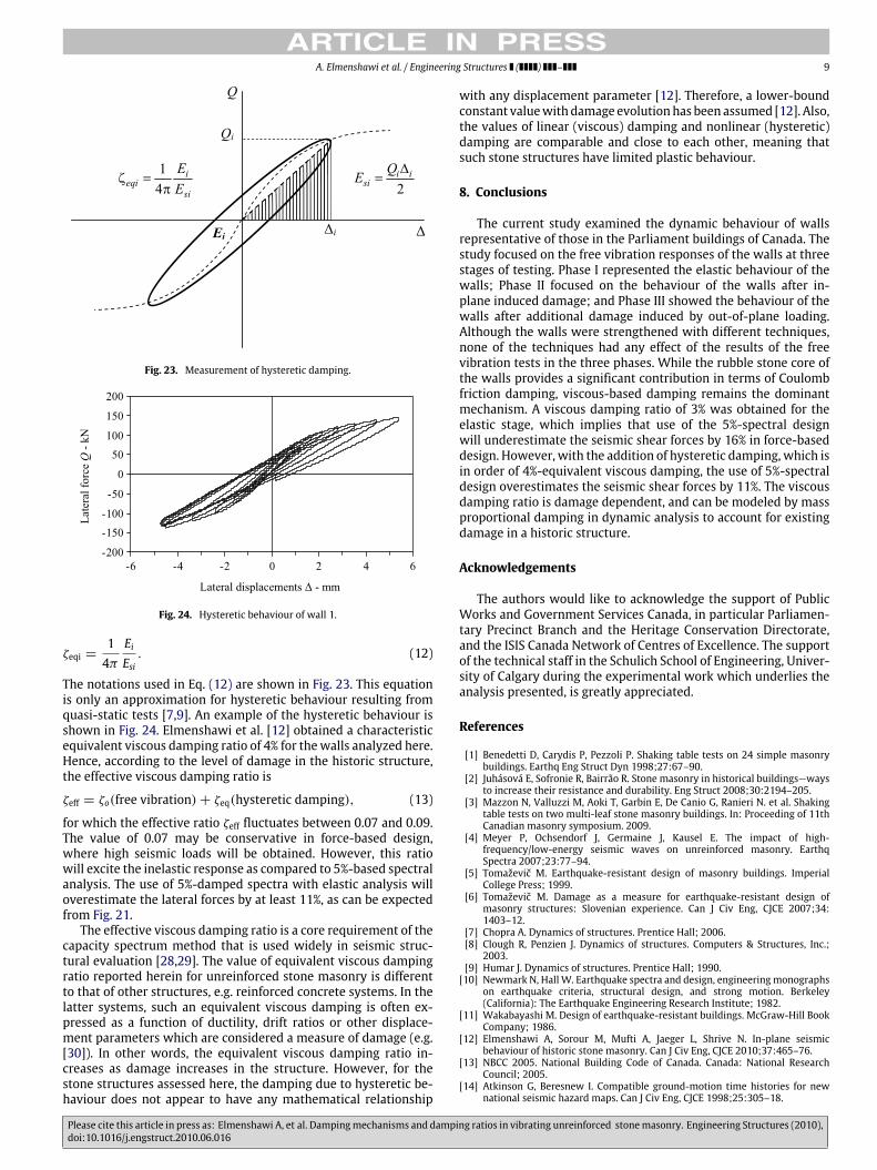
Fig. 23. Measurement of hysteretic damping.
Fig. 24. Hysteretic behaviour of wall 1.
ζeqi =14πEiEsi. (12)
The notations used in Eq. (12) are shown in Fig. 23. This equationis only an approximation for hysteretic behaviour resulting fromquasi-static tests [7,9]. An example of the hysteretic behaviour isshown in Fig. 24. Elmenshawi et al. [12] obtained a characteristicequivalent viscous damping ratio of 4% for thewalls analyzed here.Hence, according to the level of damage in the historic structure,the effective viscous damping ratio is
ζeff = ζo(free vibration)+ ζeq(hysteretic damping), (13)
for which the effective ratio ζeff fluctuates between 0.07 and 0.09.The value of 0.07 may be conservative in force-based design,where high seismic loads will be obtained. However, this ratiowill excite the inelastic response as compared to 5%-based spectralanalysis. The use of 5%-damped spectra with elastic analysis willoverestimate the lateral forces by at least 11%, as can be expectedfrom Fig. 21.The effective viscous damping ratio is a core requirement of the
capacity spectrum method that is used widely in seismic struc-tural evaluation [28,29]. The value of equivalent viscous dampingratio reported herein for unreinforced stone masonry is differentto that of other structures, e.g. reinforced concrete systems. In thelatter systems, such an equivalent viscous damping is often ex-pressed as a function of ductility, drift ratios or other displace-ment parameters which are considered a measure of damage (e.g.[30]). In other words, the equivalent viscous damping ratio in-creases as damage increases in the structure. However, for thestone structures assessed here, the damping due to hysteretic be-haviour does not appear to have any mathematical relationship
with any displacement parameter [12]. Therefore, a lower-boundconstant valuewithdamage evolutionhas been assumed [12]. Also,the values of linear (viscous) damping and nonlinear (hysteretic)damping are comparable and close to each other, meaning thatsuch stone structures have limited plastic behaviour.
8. Conclusions
The current study examined the dynamic behaviour of wallsrepresentative of those in the Parliament buildings of Canada. Thestudy focused on the free vibration responses of the walls at threestages of testing. Phase I represented the elastic behaviour of thewalls; Phase II focused on the behaviour of the walls after in-plane induced damage; and Phase III showed the behaviour of thewalls after additional damage induced by out-of-plane loading.Although the walls were strengthened with different techniques,none of the techniques had any effect of the results of the freevibration tests in the three phases. While the rubble stone core ofthe walls provides a significant contribution in terms of Coulombfriction damping, viscous-based damping remains the dominantmechanism. A viscous damping ratio of 3% was obtained for theelastic stage, which implies that use of the 5%-spectral designwill underestimate the seismic shear forces by 16% in force-baseddesign. However, with the addition of hysteretic damping, which isin order of 4%-equivalent viscous damping, the use of 5%-spectraldesign overestimates the seismic shear forces by 11%. The viscousdamping ratio is damage dependent, and can be modeled by massproportional damping in dynamic analysis to account for existingdamage in a historic structure.
Acknowledgements
The authors would like to acknowledge the support of PublicWorks and Government Services Canada, in particular Parliamen-tary Precinct Branch and the Heritage Conservation Directorate,and the ISIS Canada Network of Centres of Excellence. The supportof the technical staff in the Schulich School of Engineering, Univer-sity of Calgary during the experimental work which underlies theanalysis presented, is greatly appreciated.
References
[1] Benedetti D, Carydis P, Pezzoli P. Shaking table tests on 24 simple masonrybuildings. Earthq Eng Struct Dyn 1998;27:67–90.
[2] Juhásová E, Sofronie R, Bairrão R. Stone masonry in historical buildings—waysto increase their resistance and durability. Eng Struct 2008;30:2194–205.
[3] Mazzon N, Valluzzi M, Aoki T, Garbin E, De Canio G, Ranieri N. et al. Shakingtable tests on two multi-leaf stone masonry buildings. In: Proceeding of 11thCanadian masonry symposium. 2009.
[4] Meyer P, Ochsendorf J, Germaine J, Kausel E. The impact of high-frequency/low-energy seismic waves on unreinforced masonry. EarthqSpectra 2007;23:77–94.
[5] Tomaževič M. Earthquake-resistant design of masonry buildings. ImperialCollege Press; 1999.
[6] Tomaževič M. Damage as a measure for earthquake-resistant design ofmasonry structures: Slovenian experience. Can J Civ Eng, CJCE 2007;34:1403–12.
[7] Chopra A. Dynamics of structures. Prentice Hall; 2006.[8] Clough R, Penzien J. Dynamics of structures. Computers & Structures, Inc.;2003.
[9] Humar J. Dynamics of structures. Prentice Hall; 1990.[10] Newmark N, Hall W. Earthquake spectra and design, engineering monographs
on earthquake criteria, structural design, and strong motion. Berkeley(California): The Earthquake Engineering Research Institute; 1982.
[11] Wakabayashi M. Design of earthquake-resistant buildings. McGraw-Hill BookCompany; 1986.
[12] Elmenshawi A, Sorour M, Mufti A, Jaeger L, Shrive N. In-plane seismicbehaviour of historic stone masonry. Can J Civ Eng, CJCE 2010;37:465–76.
[13] NBCC 2005. National Building Code of Canada. Canada: National ResearchCouncil; 2005.
[14] Atkinson G, Beresnew I. Compatible ground-motion time histories for newnational seismic hazard maps. Can J Civ Eng, CJCE 1998;25:305–18.
Please cite this article in press as: Elmenshawi A, et al. Dampingmechanisms and damping ratios in vibrating unreinforced stonemasonry. Engineering Structures (2010),doi:10.1016/j.engstruct.2010.06.016
ARTICLE IN PRESS10 A. Elmenshawi et al. / Engineering Structures ( ) –
[15] Elmenshawi A, Sorour M, Parsekian G, Duchesne D, Paquette J, Mufti A. etal. Out-of-plane dynamic behaviour of unreinforced stone masonry. In: 8thinternational masonry conference. 2010, pp. 1643–1652.
[16] Sorour M, Parsekian G, Duchesne D, Paquette J, Mufti A, Jaeger L. et al.Evaluation of young’s modulus for stone masonry walls under compression.In: Proceedings, 11th Canadian masonry symposium. 2009. p. 121–30.
[17] Sorour M, Parsekian G, Duchesne D, Paquette J, Mufti A, Jaeger L. et al. Staticand dynamic testing of historic stone masonry walls. In: Prohitech confer-ence, protection of historical buildings by reversible mixed technologies.2009.
[18] Sorour M, Parsekian G, Duchesne D, Paquette J, Mufti A, Jaeger L. et al.Experimental investigation of the mechanical properties of historic stonemasonry walls. In: Proceeding of 8th international seminar on structuralmasonry. 2008. p. 449–57.
[19] Beards C. Structural vibration—analysis and damping. Arnold; 1996.[20] Iwan W. Drift spectrum: measure of demand for earthquake ground motions.
J Struct Eng, ASCE 1997;123:397–404.[21] Lam N, Griffith M, Wilson J, Doherty K. Time-history analysis of URM walls in
out-of-plane flexure. Eng Struct 2003;25:743–54.[22] Makris N, Konstantinidis D. The rocking spectrum and the limitations of
practical design methodologies. Earthq Eng Struct Dyn 2003;32:265–89.
[23] Abrams D, Costley A. Dynamic response measurements for URM buildingsystems. In: Proceedings of the US–Italy workshop on guidelines for seismicevaluation and rehabilitation of unreinforced masonry buildings. 1994.
[24] Bothara J, Dhakal R, Mander J. Seismic performance of an unreinforcedmasonry building: an experimental investigation. Earthq Eng Struct Dyn 2010;39:45–68.
[25] Wu Z, Liu H, Liu L, Yuan D. Identification of nonlinear viscous damping andCoulomb friction from free response data. J SoundVibration 2007;304:407–14.
[26] Lin Y, Miranda E, Chang K. Evaluation of damping reduction factors forestimating elastic response of structureswith high damping. Earthq Eng StructDyn 2005;34:1427–43.
[27] Bandstra J. Comparison of equivalent viscous damping and nonlinear dampingin discrete and continuous vibrating systems. J Vib Acoust Stress Reliab Des1983;105:382–92.
[28] ATC 40. Seismic evaluation and retrofit of concrete buildings. Report No. SSC96-01. Redwood (California): Applied Technology Council; 1996.
[29] FEMA 273. NEHRP guidelines for the seismic rehabilitation of buildings.Washington (DC): Building Seismic Safety Council; 1997.
[30] Elmenshawi A, Brown T. Hysteretic energy and damping capacity of flexuralelements constructed with different concrete strengths. Eng Struct 2010;32:297–305.
Please cite this article in press as: Elmenshawi A, et al. Dampingmechanisms and damping ratios in vibrating unreinforced stonemasonry. Engineering Structures (2010),doi:10.1016/j.engstruct.2010.06.016
Related Documents


![Wave turbulence in vibrating plates: The effect of damping · Wave turbulence for elastic vibrating plates has been investigated theoretically in 2006 [10], rapidly followed by two](https://static.cupdf.com/doc/110x72/5f2249bb2013846f724aca02/wave-turbulence-in-vibrating-plates-the-effect-of-wave-turbulence-for-elastic-vibrating.jpg)


