Damping coefficients for soil–structure systems and evaluation of FEMA 440 subjected to pulse-like near-fault earthquakes Faramarz Khoshnoudian a , Ehsan Ahmadi a,n , Ali Imani Azad a a Department of Civil Engineering, Amirkabir University of Technology (Tehran Polytechnic), Tehran, Iran article info Article history: Received 24 July 2013 Received in revised form 15 January 2014 Accepted 12 February 2014 Keywords: Inertial soil–structure interaction Damping coefficients Soft soils Pulse-like near-fault ground motions abstract In this study, attempts are made to investigate the effects of inertial soil–structure interaction (SSI) on damping coefficients subjected to pulse-like near-fault ground motions. To this end, a suit of 91 pulse- like near-fault ground motions is adopted. The soil and superstructure are idealized employing cone model and single-degree-of-freedom (SDOF) oscillator, respectively. The results demonstrate that soil flexibility reduces and amplifies the damping coefficients for structural viscous damping levels higher and lower than 5%, respectively. The coefficients reach one for both acceleration and displacement responses in cases of dominant SSI effects. The effect of structure dimensions on damping confidents are found insignificant. Moreover, damping coefficients of displacement responses are higher than those of acceleration responses for both fixed-base and flexible-base systems. Evaluation of damping correction factor introduced by FEMA 440 shows its inefficiency to predict acceleration response of soil–structure systems under pulse-like near-fault ground motions. Soil flexibility makes the damping correction factor of moderate earthquakes more pronounced and a distinctive peak value is reported for cases with dominant SSI effects. & 2014 Elsevier Ltd. All rights reserved. 1. Introduction Damping coefficients are used in order to adjust 5%-damped response spectra to higher or lower structural viscous damping levels. Although design response spectra of 5% damping ratio are extensively used in seismic codes for design of structures, other damping levels higher or lower than the critical value (i.e. 5%) may be required for structures equipped with seismic isolation or passive energy dissipation devices. Additionally, need for various damping levels can be found for structures whose viscous damp- ing ratios are not intrinsically of the same quantity as 5%. For example, FEMA 356 recommends viscous damping levels of 2 and 10% for structures without exterior cladding and with wood diaphragms, respectively [1]. Moreover, damping coefficients are used in equivalent linearization procedures adopted in FEMA 440 [2]. Such procedures require damping coefficients to adjust an initial response spectrum to an appropriate level of damping including nonlinear behavior of the structure. Damping coefficients are also known as damping adjustment factors, damping reduction factors, spectral scaling factors, or damping modification factors. However, definitions and terminol- ogies are the same for all the cases. Damping coefficients are conventionally expressed as functions of structural viscous damp- ing ratio and vibration period in order to modify elastic responses of structures with specified periods and viscous damping levels [3–8]. In this regard, some equations were proposed to determine damping coefficients. Nemark and Hall (1973) suggested a formula which is adopted in ATC-40 and FEMA 356 [1,3,9]. Bommer et al. (2000) expression is employed in EC8 [6,10]. Ramirez et al. (2002) equation is used in NEHRP [7,11,12]. Recently, some studies have been devoted to the effects of seismological parameters on the trend of damping coefficients. In 2004, Lin and Chang selected site classes of A–D based on NEHRP classification and investigated the effects of site condition on the mean of damping coefficients [13]. It was noted that displacement damping coefficients for site class C are a little larger than those corresponding to site class AB and D. Nevertheless, displacement damping coefficients for site class AB and D are approximately identical. Moreover, acceleration damp- ing coefficient is more dependent on site condition than displace- ment damping coefficient. Lin et al. (2005) evaluated five various equations for damping coefficient adopting 216 ground motions recorded on firm sites [14]. Bommer and Mendis (2005) revealed that the effect of site condition does not reflect a definite trend [15]. Lin (2006) performed statistical study on damping coeffi- cients using Chi-Chi earthquakes [16]. It was found that damping coefficients are significantly sensitive to earthquake magnitude and site-to-source distance and reduce with increasing these two Contents lists available at ScienceDirect journal homepage: www.elsevier.com/locate/soildyn Soil Dynamics and Earthquake Engineering http://dx.doi.org/10.1016/j.soildyn.2014.02.009 0267-7261 & 2014 Elsevier Ltd. All rights reserved. n Corresponding author. E-mail address: [email protected] (E. Ahmadi). Soil Dynamics and Earthquake Engineering 61-62 (2014) 124–134

Welcome message from author
This document is posted to help you gain knowledge. Please leave a comment to let me know what you think about it! Share it to your friends and learn new things together.
Transcript
Damping coefficients for soil–structure systems and evaluationof FEMA 440 subjected to pulse-like near-fault earthquakes
Faramarz Khoshnoudian a, Ehsan Ahmadi a,n, Ali Imani Azad a
a Department of Civil Engineering, Amirkabir University of Technology (Tehran Polytechnic), Tehran, Iran
a r t i c l e i n f o
Article history:Received 24 July 2013Received in revised form15 January 2014Accepted 12 February 2014
Keywords:Inertial soil–structure interactionDamping coefficientsSoft soilsPulse-like near-fault ground motions
a b s t r a c t
In this study, attempts are made to investigate the effects of inertial soil–structure interaction (SSI) ondamping coefficients subjected to pulse-like near-fault ground motions. To this end, a suit of 91 pulse-like near-fault ground motions is adopted. The soil and superstructure are idealized employing conemodel and single-degree-of-freedom (SDOF) oscillator, respectively. The results demonstrate that soilflexibility reduces and amplifies the damping coefficients for structural viscous damping levels higherand lower than 5%, respectively. The coefficients reach one for both acceleration and displacementresponses in cases of dominant SSI effects. The effect of structure dimensions on damping confidents arefound insignificant. Moreover, damping coefficients of displacement responses are higher than those ofacceleration responses for both fixed-base and flexible-base systems. Evaluation of damping correctionfactor introduced by FEMA 440 shows its inefficiency to predict acceleration response of soil–structuresystems under pulse-like near-fault ground motions. Soil flexibility makes the damping correctionfactor of moderate earthquakes more pronounced and a distinctive peak value is reported for cases withdominant SSI effects.
& 2014 Elsevier Ltd. All rights reserved.
1. Introduction
Damping coefficients are used in order to adjust 5%-dampedresponse spectra to higher or lower structural viscous dampinglevels. Although design response spectra of 5% damping ratio areextensively used in seismic codes for design of structures, otherdamping levels higher or lower than the critical value (i.e. 5%)may be required for structures equipped with seismic isolation orpassive energy dissipation devices. Additionally, need for variousdamping levels can be found for structures whose viscous damp-ing ratios are not intrinsically of the same quantity as 5%. Forexample, FEMA 356 recommends viscous damping levels of 2 and10% for structures without exterior cladding and with wooddiaphragms, respectively [1]. Moreover, damping coefficients areused in equivalent linearization procedures adopted in FEMA 440[2]. Such procedures require damping coefficients to adjust aninitial response spectrum to an appropriate level of dampingincluding nonlinear behavior of the structure.
Damping coefficients are also known as damping adjustmentfactors, damping reduction factors, spectral scaling factors, ordamping modification factors. However, definitions and terminol-ogies are the same for all the cases. Damping coefficients are
conventionally expressed as functions of structural viscous damp-ing ratio and vibration period in order to modify elastic responsesof structures with specified periods and viscous damping levels[3–8]. In this regard, some equations were proposed to determinedamping coefficients. Nemark and Hall (1973) suggested a formulawhich is adopted in ATC-40 and FEMA 356 [1,3,9]. Bommer et al.(2000) expression is employed in EC8 [6,10]. Ramirez et al. (2002)equation is used in NEHRP [7,11,12]. Recently, some studies havebeen devoted to the effects of seismological parameters on thetrend of damping coefficients. In 2004, Lin and Chang selected siteclasses of A–D based on NEHRP classification and investigated theeffects of site condition on the mean of damping coefficients [13].It was noted that displacement damping coefficients for site classC are a little larger than those corresponding to site class AB and D.Nevertheless, displacement damping coefficients for site class ABand D are approximately identical. Moreover, acceleration damp-ing coefficient is more dependent on site condition than displace-ment damping coefficient. Lin et al. (2005) evaluated five variousequations for damping coefficient adopting 216 ground motionsrecorded on firm sites [14]. Bommer and Mendis (2005) revealedthat the effect of site condition does not reflect a definite trend[15]. Lin (2006) performed statistical study on damping coeffi-cients using Chi-Chi earthquakes [16]. It was found that dampingcoefficients are significantly sensitive to earthquake magnitudeand site-to-source distance and reduce with increasing these two
Contents lists available at ScienceDirect
journal homepage: www.elsevier.com/locate/soildyn
Soil Dynamics and Earthquake Engineering
http://dx.doi.org/10.1016/j.soildyn.2014.02.0090267-7261 & 2014 Elsevier Ltd. All rights reserved.
n Corresponding author.E-mail address: [email protected] (E. Ahmadi).
Soil Dynamics and Earthquake Engineering 61-62 (2014) 124–134
factors. Cameron and Green (2007) calibrated damping coeffi-cients based on site classification, earthquake magnitude, andtectonic setting parameters [17]. In 2008, Strafford et al. obtainedexpressions as functions of duration and number of cycles tocompute damping coefficients for different damping ratio levels[18]. Cardone et al. (2009) evaluated the accuracy of sevendifferent equations for damping coefficients using three differentextensive earthquake database motions [19]. Hatzigeorgiou (2010)suggested formulas for damping coefficients of acceleration,velocity, and displacement spectra for different site classes andearthquakes [20]. Hubbard and Mavroeidis (2011) investigateddamping coefficients subjected to pulse-like ground motions [21].Hatzigeorgiou and Papagiannopoulos (2011) made a discussion onthe study of Hubbard and Mavroeidis (2011) and showed thatsome aspects of their conclusions need future clarification [22].The influences of seismological parameters (e.g. earthquake mag-nitude, closest distance, and site condition) on the median damp-ing coefficients of acceleration, velocity, and displacement spectrawere further estimated by Hao et al. (2011) [23]. Recently,Papagiannopoulos et al. (2013) accomplished the recovery ofspectral absolute acceleration as well as spectral relative velocityfrom their pseudo-spectral counterparts through using correctionfactors [24]. All the aforementioned studies have been conductedon fixed-base structures and SSI effect as a key factor has beendisregarded.
Although the influences of seismological parameters on damp-ing coefficients have been thoroughly investigated, SSI effectswhich can significantly change the elastic response of SDOFoscillator have been ignored [25–27]. SDOF oscillator consideringSSI effects is more flexible than the commonly assumed fixed-baseoscillator. Consequently, the soil–structure system has a longernatural period than the fixed-base counterpart. Also, it usuallyhas a higher damping ratio, due to radiation as well as materialdamping in the soil, which can drastically influence the responseof the oscillator [28]. In 1970s, efforts were made to estimate SSIeffects on elastic response of structures [25–27]. Inelastic responseof structures considering SSI effects also was addressed by manyresearchers [29–33]. The results from studies on both elasticand inelastic structures confirm the significant effects of SSI onstructural responses. In FEMA 440 document, the 5%-dampedfixed-base acceleration spectrum is modified for foundationdamping, (i.e. radiation damping ratio of the soil), in order toinclude inertial SSI effects [2].
Therefore, the objective of this research is to evaluate theeffects of SSI on median damping coefficients for both accelerationand displacement response spectra that are more favorablein force-based and displacement-based design techniques. Thebeneath soil is simulated based on the cone model concept. Thesoil-SDOF oscillator model is analyzed subjected to 91 near-faultrecords identified as pulse-like by Baker (2007) [34]. The mediandamping coefficient spectra are constructed for soil-SDOF oscilla-tor models as well as fixed-base counterparts. The effects of maininteracting parameters including non-dimensional frequency andaspect ratio of the superstructure on median damping coefficientsare fully discussed. Finally, damping correction factors proposedby FEMA 440 are compared with those obtained from time historyanalyzes.
2. Soil-SDOF oscillator model and pulse-like near-fault groundmotion database
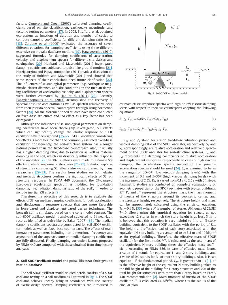
The soil-SDOF oscillator model studied herein consists of a SDOFoscillator resting on a soil medium as illustrated in Fig. 1. The SDOFoscillator behaves linearly being in accordance with the conceptof elastic design spectra. Damping coefficients are introduced to
estimate elastic response spectra with high or low viscous dampinglevels with respect to their 5% counterparts adopting the followingequations:
Baðξo; T fixÞ ¼ Sað5%; T fixÞ=Saðξo; T fixÞ ð1Þ
Bdðξo; T fixÞ ¼ Sdð5%; T fixÞ=Sdðξo; T fixÞ ð2Þ
Tfix and ξo stand for elastic fixed-base vibration period andviscous damping ratio of the SDOF oscillator, respectively. Sa andSd, correspondingly, are relative acceleration and relative displace-ment of the SDOF oscillator for soil–structure systems. Ba andBd represents the damping coefficients of relative accelerationand displacement responses, respectively. In cases of high viscousdamping, the acceleration spectra instead of the pseudo-acceleration spectra should be used [24]. ξo is assumed to be inthe ranges of 0.5–5% (low viscous damping levels) with theincrement of 0.5 and 5–30% (high viscous damping levels) withthe increment of 2.5%. Tfix is varied from 0.1 s to 2.5 s with 0.1 steps.Parametric studies are conducted on complete compatibility ofgeometric properties of the SDOF oscillator with typical buildings.Mn, In, and hn represent the structure mass, the mass momentof inertia of the structure around its geometric center, andthe structure height, respectively. The structure height and masscan be approximately calculated using the empirical equation,Tfix¼0.1 N, [35] where N is number of stories. Although ASCE/SEI7–10 allows using this empirical equation for structures notexceeding 12 stories in which the story height is at least 3 m, itis believed that this equation is very helpful to find an N-storybuilding equivalent to the SDOF oscillator with the period of Tfix.The height and effective load of each story associated with theequivalent N-story building are assumed to be 3.3 m and 10 kN/m2
as for typical buildings. Therefore, the effective mass of SDOFoscillator for the first mode, Mn, is calculated as the total mass ofthe equivalent N-story building times the effective mass coeffi-cient. According to FEMA 356, in case of effective mass factor,a value of 1 stands for equivalent 1- and 2-story buildings, anda value of 0.9 stands for 3- or more story buildings. Also, it is setequal to 1 if the fundamental period, Tfix, is greater than 1 s [1]. hn
is the effective height of the equivalent N-story building taken asthe full height of the building for 1-story structure and 70% of thetotal height for structures with more than 1-story based on FEMA440 recommendation [2]. Mass moment of inertia of the SDOFoscillator, In, is calculated as, Mnr2/4, where r is the radius of thecircular plan.
Fig. 1. Soil-SDOF oscillator model.
F. Khoshnoudian et al. / Soil Dynamics and Earthquake Engineering 61-62 (2014) 124–134 125
Note that only the inertial part of the SSI is considered in thispaper. Based on the assumption that the rigid foundation lies onthe surface of the soil with no embedment and is also subjected tovertically incident plane shear waves with particle motion in thehorizontal direction, the kinematic part of the SSI can be ignored.The radius, mass, and mass moment of inertia of the foundationare represented by r, mf and If, respectively. It should be noted thatthe radius of the foundation and of the plan are identical.Expressing If can be considered the same as In, i.e. mfr
2/4.The foundation-to-structure mass ratio, mf/Mn, is supposed to be0.5 and 0.2 for periods of 0.1 s and 2.5 s, respectively on the basisof conventional building structures. For other periods, a linearinterpolation is used to determine this ratio. This ratio reduceswith the increase of story numbers. A lumped-mass parametermodel is adopted to represent the soil and the interactionmechanisms. The soil beneath the foundation is considered as ahomogenous half-space medium and is substituted with a simpli-fied 3-DOF system based on the cone model concept. Cone modelwas proposed by Meek and Wolf (1993) for evaluating thedynamic stiffness of the soil [36]. The horizontal, s (sway), andthe rocking, φ, DOFs are introduced as the representatives of thetranslational and rotational motions of the foundation, respec-tively. In order to consider the frequency-dependent rotationalsprings and dashpot coefficients, the additional internal rotationaldegree of freedom, θ, is assigned to a polar mass moment ofinertia, mθ¼(9π2/128)ρr5(1�υ)(Va/Vs)2, and connected to the foun-dation node using a rotational dashpot. ρ stands for the massdensity of the soil which depends on the shear-wave velocity, Vs,and is taken as 2.35 t/m3 for shear-wave velocity higher than750 m/s and 1.95 t/m3 for shear-wave velocity lower than 750 m/s.For the motions in the case of nearly incompressible and incom-pressible soil (0.33oυo0.50), two features are included: (a) theaxial-wave velocity, Va, is limited to two times the shear-wavevelocity, 2Vs, (b) a trapped mass moment of inertia, ΔMφ¼0.3πVa(υ-0.33)ρr5, of the soil beneath the foundation, which movesas a rigid body in the same phase with the foundation for therocking degree of freedom, is assigned to the foundation node.ΔMφ is added to If for the soil with Poisson's ratio, υ, greater than0.3 [37]. Moreover, to address approximately the effect of soilnonlinearity, the degraded soil shear-wave velocity, consistentwith strain level in the soil, is used in the model [38].
The coefficients of springs and dashpots for the sway androcking motions are evaluated using the following equations:
ks ¼ 8ρV2s r=ð2�υÞ; Cs ¼ πρV sr2 ð3Þ
kφ ¼ 8ρV2s r
3=ð3ð1�υÞÞ; Cφ ¼ πρVar4=4 ð4ÞIn this research, frictional elements are intended to employ for
analyzing soil–structure problems and the soil material dampingratio is considered 5% [39]. To capture realistic frequency-independent hysteretic material damping, it would be desirableto substitute the augmenting dashpot and pulley-mass of viscousmodel with suitable causal nonlinear elements [40]. The seismicbehavior of soil–structure system depends basically on the size,dynamic properties of the superstructure and the soil attributes.In case of inertial SSI, it is well known that all aforementionedfactors can be taken into account using non-dimensional fre-quency and aspect ratio parameters [27,41]. In order to incorporatethe soil flexibility condition into the systems under consideration,a non-dimensional frequency, a0, is expressed as an index for thestructure-to-soil stiffness ratio, ωfixhn/Vs, where ωfix, i.e. 2π/Tfix, isthe circular frequency of the fixed-base SDOF oscillator. In thisstudy, this parameter is assumed to be 0, 1, 2, and 3 to simulate thevarious SSI conditions. The aspect ratio of the SDOF oscillator isdefined as ratio of the structure height-to-foundation radius, i.e.,hn/r. In this paper, values of 1, 2, 3, and 4 are assigned to this
parameter. The 4-DOF model used herein has the capability to beanalyzed in the time domain using β-Newmark method.
In order to investigate the effects of SSI on the dampingcoefficients of SDOF oscillators and compare the results with thecurrent solution proposed in FEMA 440, an extensive assembly ofrecords is required. The time histories of these records have beenprepared from the Next Generation Attenuation (NGA) library(http://peer.berkeley.edu/nga). Baker (2007) used wavelet trans-formation to decompose the original record, extract the pulseperiod and identify the record as pulse-like or non-pulse-like.Based on Baker's approach [34], ground motions are classified aspulses if they meet the three following criteria: (1) The residualground motion is significantly less intense than the originalground motion (as measured by the ratio of peak ground velocityvalues and ratio of energy values); (2) The pulse arrives at thebeginning of the time history (as measured by the point in time atwhich 10% of the pulse energy has been observed); (3) The originalground motion has a peak ground velocity of greater than 30 cm/s.These three criteria have been quantified by a pulse indicator, ascore between 0 and 1. Pulses with scores larger than 0.85, areidentified as pulse-like motions. This type of ground motion covera wide range of near-fault ground motions and can have detri-mental effects on structural responses. Table 1 illustrates allproperties of the records used in this study. The dataset studiedherein includes 23 earthquakes with moment magnitude (Mw)ranged from 5 to 7.6. It should be noted that the pulse periods (Tp)employed herein are those extracted from wavelet analysis notthose which correspond to the peak spectral velocity.
3. Effects of interacting parameters on damping coefficients ofsoil-SDOF oscillator systems
A total number of approximately 600,000 damping coefficientsis calculated for either acceleration or displacement responses.However, the great part of plots is skipped to be represented dueto limitation on the paper size. As it was noted by Bommer andMendis (2005), the distribution of damping coefficients for variousground motions is very close to lognormal distribution andmedian (geometric mean) is a better central tendency in orderto estimate damping coefficients [15]. Therefore, in the following,median damping coefficients are investigated for various soil–structure systems.
Figs. 2 and 3 illustrate damping coefficients versus fixed-baseperiod (Tfix) and normalized fixed-base period (Tfix/Tp), respec-tively. As it can be seen, the plots with respect to normalized fixed-base periods reflect distinct peak values which cannot be capturedby the plots versus fixed-base periods. As it was confirmed byHubbard and Mavroeidis (2011) [21], normalized fixed-base periodcan better capture the damping coefficients of near-fault groundmotions. Therefore, thereafter, damping coefficients are illustratedwith respect to normalized fixed-base period. Figs. 3 and 4represent the effects of non-dimensional frequency on the damp-ing coefficients of both acceleration and displacement spectra.A maximum value of damping coefficient is identified for highervalues of critical damping, i.e. 5%, that corresponds to normalizedfixed-base periods of 0.75 and 0.85 for acceleration and displace-ment responses, respectively. This point is in accordance withHubbard and Mavroeidis (2011) study at which normalized periodof 0.83 corresponding to the peak value of displacement dampingcoefficient was realized [21]. In the case of fixed-base structure,for damping levels lower than critical damping, not consideredby Hubbard and Mavroeidis (2011), a slight minimum in dampingcoefficient seems to occur at the mentioned normalized fixed-baseperiods. As shown in Figs. 3 and 4, soil flexibility gives rise to lowerand higher damping coefficients for damping levels higher and
F. Khoshnoudian et al. / Soil Dynamics and Earthquake Engineering 61-62 (2014) 124–134126
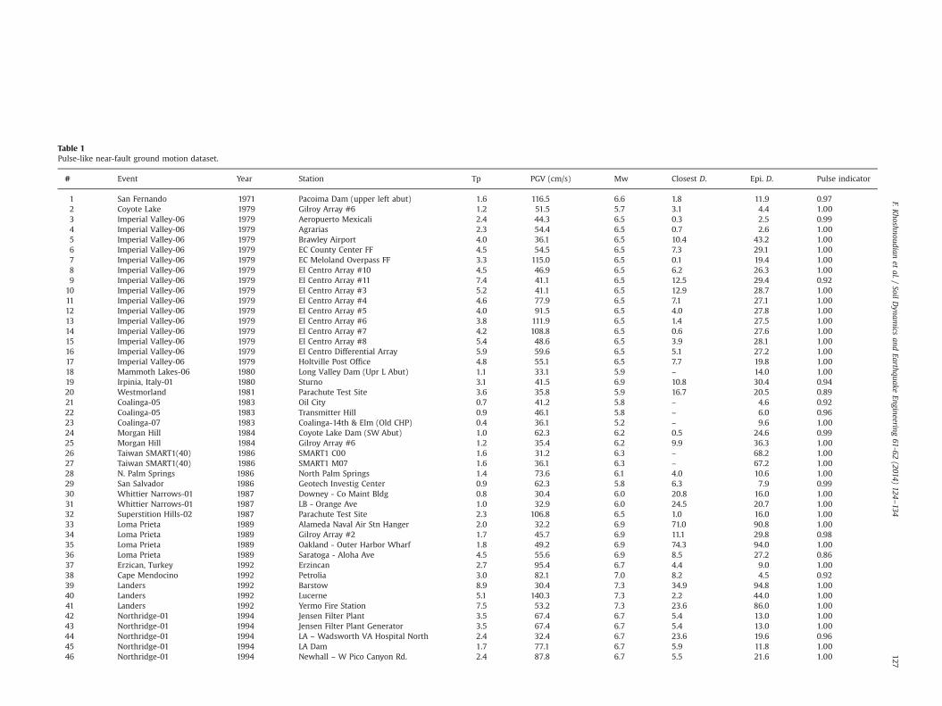
Table 1Pulse-like near-fault ground motion dataset.
# Event Year Station Tp PGV (cm/s) Mw Closest D. Epi. D. Pulse indicator
1 San Fernando 1971 Pacoima Dam (upper left abut) 1.6 116.5 6.6 1.8 11.9 0.972 Coyote Lake 1979 Gilroy Array #6 1.2 51.5 5.7 3.1 4.4 1.003 Imperial Valley-06 1979 Aeropuerto Mexicali 2.4 44.3 6.5 0.3 2.5 0.994 Imperial Valley-06 1979 Agrarias 2.3 54.4 6.5 0.7 2.6 1.005 Imperial Valley-06 1979 Brawley Airport 4.0 36.1 6.5 10.4 43.2 1.006 Imperial Valley-06 1979 EC County Center FF 4.5 54.5 6.5 7.3 29.1 1.007 Imperial Valley-06 1979 EC Meloland Overpass FF 3.3 115.0 6.5 0.1 19.4 1.008 Imperial Valley-06 1979 El Centro Array #10 4.5 46.9 6.5 6.2 26.3 1.009 Imperial Valley-06 1979 El Centro Array #11 7.4 41.1 6.5 12.5 29.4 0.92
10 Imperial Valley-06 1979 El Centro Array #3 5.2 41.1 6.5 12.9 28.7 1.0011 Imperial Valley-06 1979 El Centro Array #4 4.6 77.9 6.5 7.1 27.1 1.0012 Imperial Valley-06 1979 El Centro Array #5 4.0 91.5 6.5 4.0 27.8 1.0013 Imperial Valley-06 1979 El Centro Array #6 3.8 111.9 6.5 1.4 27.5 1.0014 Imperial Valley-06 1979 El Centro Array #7 4.2 108.8 6.5 0.6 27.6 1.0015 Imperial Valley-06 1979 El Centro Array #8 5.4 48.6 6.5 3.9 28.1 1.0016 Imperial Valley-06 1979 El Centro Differential Array 5.9 59.6 6.5 5.1 27.2 1.0017 Imperial Valley-06 1979 Holtville Post Office 4.8 55.1 6.5 7.7 19.8 1.0018 Mammoth Lakes-06 1980 Long Valley Dam (Upr L Abut) 1.1 33.1 5.9 – 14.0 1.0019 Irpinia, Italy-01 1980 Sturno 3.1 41.5 6.9 10.8 30.4 0.9420 Westmorland 1981 Parachute Test Site 3.6 35.8 5.9 16.7 20.5 0.8921 Coalinga-05 1983 Oil City 0.7 41.2 5.8 – 4.6 0.9222 Coalinga-05 1983 Transmitter Hill 0.9 46.1 5.8 – 6.0 0.9623 Coalinga-07 1983 Coalinga-14th & Elm (Old CHP) 0.4 36.1 5.2 – 9.6 1.0024 Morgan Hill 1984 Coyote Lake Dam (SW Abut) 1.0 62.3 6.2 0.5 24.6 0.9925 Morgan Hill 1984 Gilroy Array #6 1.2 35.4 6.2 9.9 36.3 1.0026 Taiwan SMART1(40) 1986 SMART1 C00 1.6 31.2 6.3 – 68.2 1.0027 Taiwan SMART1(40) 1986 SMART1 M07 1.6 36.1 6.3 – 67.2 1.0028 N. Palm Springs 1986 North Palm Springs 1.4 73.6 6.1 4.0 10.6 1.0029 San Salvador 1986 Geotech Investig Center 0.9 62.3 5.8 6.3 7.9 0.9930 Whittier Narrows-01 1987 Downey - Co Maint Bldg 0.8 30.4 6.0 20.8 16.0 1.0031 Whittier Narrows-01 1987 LB - Orange Ave 1.0 32.9 6.0 24.5 20.7 1.0032 Superstition Hills-02 1987 Parachute Test Site 2.3 106.8 6.5 1.0 16.0 1.0033 Loma Prieta 1989 Alameda Naval Air Stn Hanger 2.0 32.2 6.9 71.0 90.8 1.0034 Loma Prieta 1989 Gilroy Array #2 1.7 45.7 6.9 11.1 29.8 0.9835 Loma Prieta 1989 Oakland - Outer Harbor Wharf 1.8 49.2 6.9 74.3 94.0 1.0036 Loma Prieta 1989 Saratoga - Aloha Ave 4.5 55.6 6.9 8.5 27.2 0.8637 Erzican, Turkey 1992 Erzincan 2.7 95.4 6.7 4.4 9.0 1.0038 Cape Mendocino 1992 Petrolia 3.0 82.1 7.0 8.2 4.5 0.9239 Landers 1992 Barstow 8.9 30.4 7.3 34.9 94.8 1.0040 Landers 1992 Lucerne 5.1 140.3 7.3 2.2 44.0 1.0041 Landers 1992 Yermo Fire Station 7.5 53.2 7.3 23.6 86.0 1.0042 Northridge-01 1994 Jensen Filter Plant 3.5 67.4 6.7 5.4 13.0 1.0043 Northridge-01 1994 Jensen Filter Plant Generator 3.5 67.4 6.7 5.4 13.0 1.0044 Northridge-01 1994 LA – Wadsworth VA Hospital North 2.4 32.4 6.7 23.6 19.6 0.9645 Northridge-01 1994 LA Dam 1.7 77.1 6.7 5.9 11.8 1.0046 Northridge-01 1994 Newhall – W Pico Canyon Rd. 2.4 87.8 6.7 5.5 21.6 1.00
F.Khoshnoudian
etal./
SoilDynam
icsand
EarthquakeEngineering
61-62(2014)
124–134
127
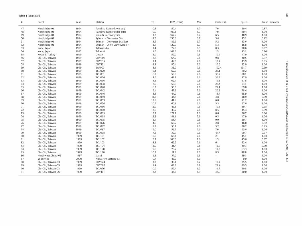
Table 1 (continued )
# Event Year Station Tp PGV (cm/s) Mw Closest D. Epi. D. Pulse indicator
47 Northridge-01 1994 Pacoima Dam (down str) 0.5 50.4 6.7 7.0 20.4 0.8748 Northridge-01 1994 Pacoima Dam (upper left) 0.9 107.1 6.7 7.0 20.4 1.0049 Northridge-01 1994 Rinaldi Receiving Sta 1.2 167.2 6.7 6.5 10.9 1.0050 Northridge-01 1994 Sylmar – Converter Sta 3.5 130.3 6.7 5.4 13.1 0.9251 Northridge-01 1994 Sylmar – Converter Sta East 3.5 116.6 6.7 5.2 13.6 1.0052 Northridge-01 1994 Sylmar – Olive View Med FF 3.1 122.7 6.7 5.3 16.8 1.0053 Kobe, Japan 1995 Takarazuka 1.4 72.6 6.9 0.3 38.6 0.8754 Kobe, Japan 1995 Takatori 1.6 169.6 6.9 1.5 13.1 0.9655 Kocaeli, Turkey 1999 Gebze 5.9 52.0 7.5 10.9 47.0 1.0056 Chi-Chi, Taiwan 1999 CHY006 2.6 64.7 7.6 9.8 40.5 0.9757 Chi-Chi, Taiwan 1999 CHY035 1.4 42.0 7.6 12.7 43.9 0.9558 Chi-Chi, Taiwan 1999 CHY101 4.8 85.4 7.6 10.0 32.0 1.0059 Chi-Chi, Taiwan 1999 TAP003 3.4 33.0 7.6 102.4 151.7 0.9960 Chi-Chi, Taiwan 1999 TCU029 6.4 62.3 7.6 28.1 79.2 1.0061 Chi-Chi, Taiwan 1999 TCU031 6.2 59.9 7.6 30.2 80.1 1.0062 Chi-Chi, Taiwan 1999 TCU034 8.6 42.8 7.6 35.7 87.9 1.0063 Chi-Chi, Taiwan 1999 TCU036 5.4 62.4 7.6 19.8 67.8 1.0064 Chi-Chi, Taiwan 1999 TCU038 7.0 50.9 7.6 25.4 73.1 1.0065 Chi-Chi, Taiwan 1999 TCU040 6.3 53.0 7.6 22.1 69.0 1.0066 Chi-Chi, Taiwan 1999 TCU042 9.1 47.3 7.6 26.3 78.4 1.0067 Chi-Chi, Taiwan 1999 TCU046 8.6 44.0 7.6 16.7 68.9 1.0068 Chi-Chi, Taiwan 1999 TCU049 11.8 44.8 7.6 3.8 38.9 0.9969 Chi-Chi, Taiwan 1999 TCU053 12.9 41.9 7.6 6.0 41.2 1.0070 Chi-Chi, Taiwan 1999 TCU054 10.5 60.9 7.6 5.3 37.6 1.0071 Chi-Chi, Taiwan 1999 TCU056 12.9 43.5 7.6 10.5 39.7 0.9572 Chi-Chi, Taiwan 1999 TCU060 12.0 33.7 7.6 8.5 45.4 0.9973 Chi-Chi, Taiwan 1999 TCU065 5.7 127.7 7.6 0.6 26.7 0.9674 Chi-Chi, Taiwan 1999 TCU068 12.2 191.1 7.6 0.3 47.9 1.0075 Chi-Chi, Taiwan 1999 TCU075 5.1 88.4 7.6 0.9 20.7 1.0076 Chi-Chi, Taiwan 1999 TCU076 4.0 63.7 7.6 2.8 16.0 0.9277 Chi-Chi, Taiwan 1999 TCU082 9.2 56.1 7.6 5.2 36.2 0.9578 Chi-Chi, Taiwan 1999 TCU087 9.0 53.7 7.6 7.0 55.6 1.0079 Chi-Chi, Taiwan 1999 TCU098 7.5 32.7 7.6 47.7 99.7 0.9780 Chi-Chi, Taiwan 1999 TCU101 10.0 68.4 7.6 2.1 45.1 1.0081 Chi-Chi, Taiwan 1999 TCU102 9.7 106.6 7.6 1.5 45.6 0.9782 Chi-Chi, Taiwan 1999 TCU103 8.3 62.2 7.6 6.1 52.4 1.0083 Chi-Chi, Taiwan 1999 TCU104 12.0 31.4 7.6 12.9 49.3 0.9984 Chi-Chi, Taiwan 1999 TCU128 9.0 78.7 7.6 13.2 63.3 1.0085 Chi-Chi, Taiwan 1999 TCU136 10.3 51.8 7.6 8.3 48.8 1.0086 Northwest China-03 1997 Jiashi 1.3 37.0 6.1 – 19.1 1.0087 Yountville 2000 Napa Fire Station #3 0.7 43.0 5.0 – 9.9 1.0088 Chi-Chi, Taiwan-03 1999 CHY024 3.2 33.1 6.2 19.7 25.5 1.0089 Chi-Chi, Taiwan-03 1999 CHY080 1.4 69.9 6.2 22.4 29.5 1.0090 Chi-Chi, Taiwan-03 1999 TCU076 0.9 59.4 6.2 14.7 20.8 1.0091 Chi-Chi, Taiwan-06 1999 CHY101 2.8 36.3 6.3 36.0 50.0 1.00
F.Khoshnoudian
etal./
SoilDynam
icsand
EarthquakeEngineering
61-62(2014)
124–134
128
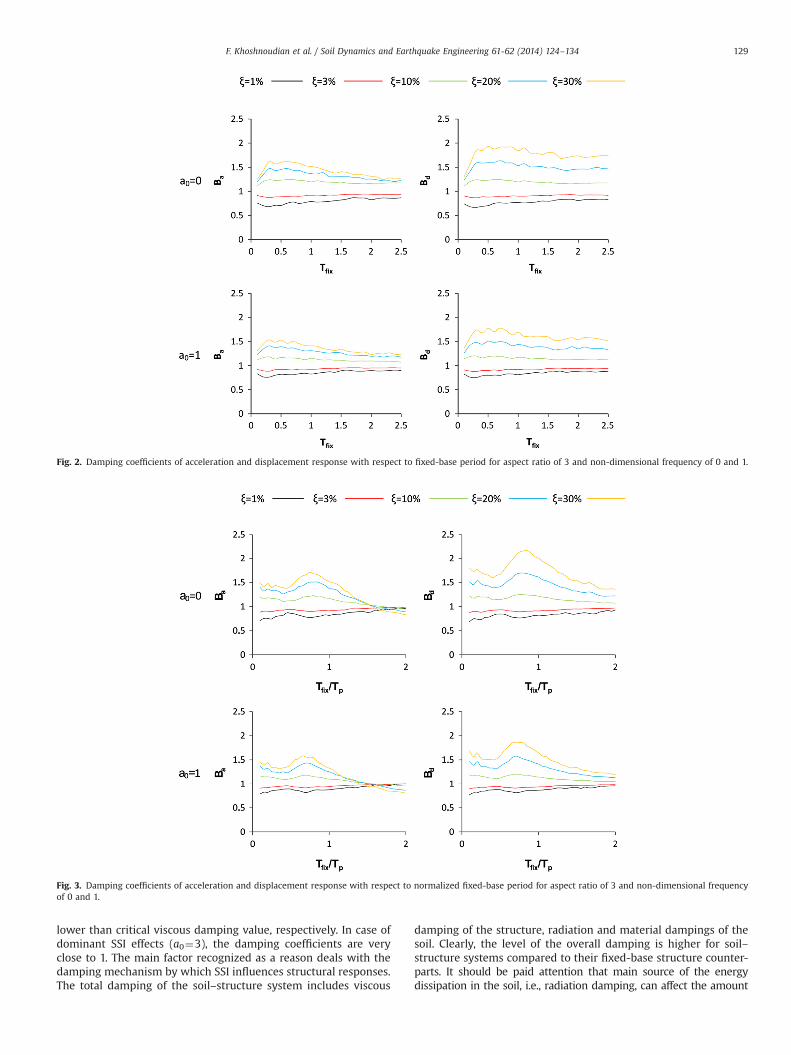
lower than critical viscous damping value, respectively. In case ofdominant SSI effects (a0¼3), the damping coefficients are veryclose to 1. The main factor recognized as a reason deals with thedamping mechanism by which SSI influences structural responses.The total damping of the soil–structure system includes viscous
damping of the structure, radiation and material dampings of thesoil. Clearly, the level of the overall damping is higher for soil–structure systems compared to their fixed-base structure counter-parts. It should be paid attention that main source of the energydissipation in the soil, i.e., radiation damping, can affect the amount
Fig. 2. Damping coefficients of acceleration and displacement response with respect to fixed-base period for aspect ratio of 3 and non-dimensional frequency of 0 and 1.
Fig. 3. Damping coefficients of acceleration and displacement response with respect to normalized fixed-base period for aspect ratio of 3 and non-dimensional frequencyof 0 and 1.
F. Khoshnoudian et al. / Soil Dynamics and Earthquake Engineering 61-62 (2014) 124–134 129
of energy dissipated by the viscous damping of the structure. As thebase becomes flexible, the contribution of structural viscous dampingto the responses of the structure reduces and effects of viscousdamping level variation on structural demands become negligible[26,41–43].
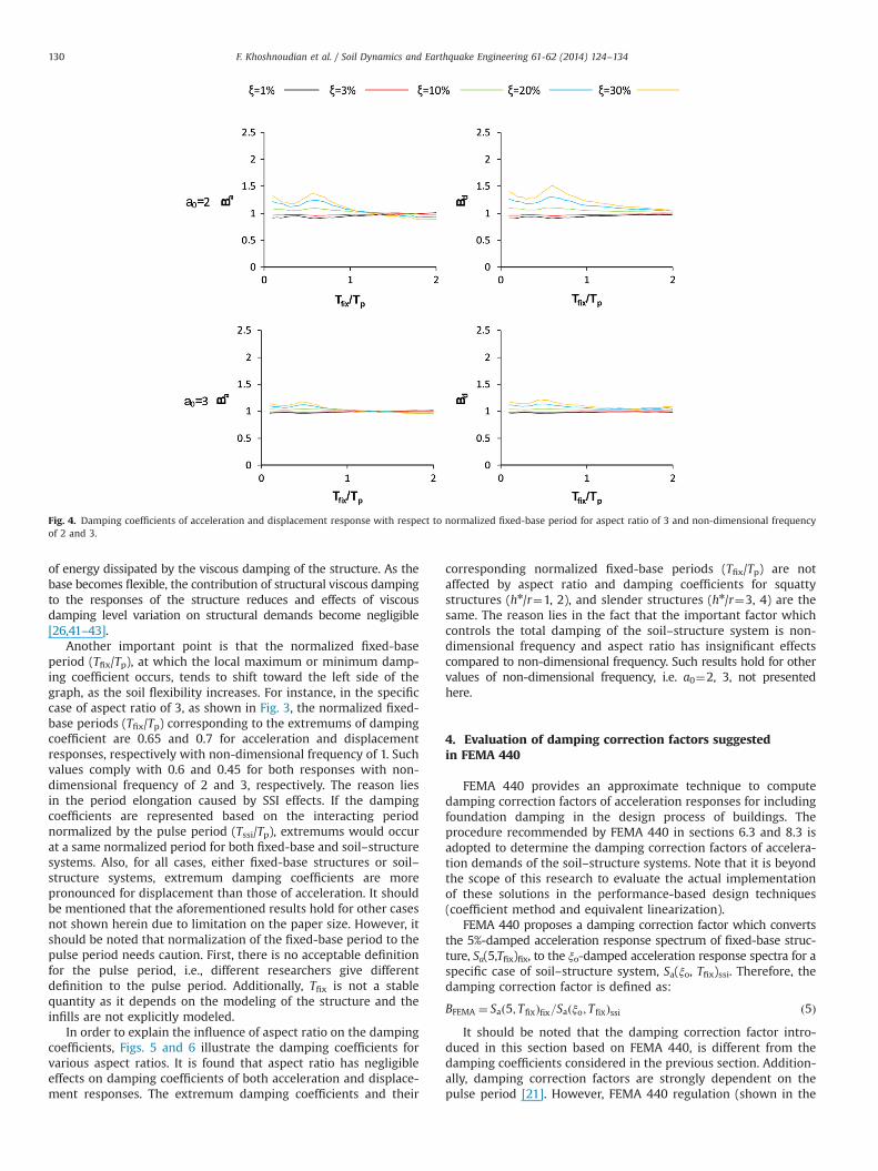
Another important point is that the normalized fixed-baseperiod (Tfix/Tp), at which the local maximum or minimum damp-ing coefficient occurs, tends to shift toward the left side of thegraph, as the soil flexibility increases. For instance, in the specificcase of aspect ratio of 3, as shown in Fig. 3, the normalized fixed-base periods (Tfix/Tp) corresponding to the extremums of dampingcoefficient are 0.65 and 0.7 for acceleration and displacementresponses, respectively with non-dimensional frequency of 1. Suchvalues comply with 0.6 and 0.45 for both responses with non-dimensional frequency of 2 and 3, respectively. The reason liesin the period elongation caused by SSI effects. If the dampingcoefficients are represented based on the interacting periodnormalized by the pulse period (Tssi/Tp), extremums would occurat a same normalized period for both fixed-base and soil–structuresystems. Also, for all cases, either fixed-base structures or soil–structure systems, extremum damping coefficients are morepronounced for displacement than those of acceleration. It shouldbe mentioned that the aforementioned results hold for other casesnot shown herein due to limitation on the paper size. However, itshould be noted that normalization of the fixed-base period to thepulse period needs caution. First, there is no acceptable definitionfor the pulse period, i.e., different researchers give differentdefinition to the pulse period. Additionally, Tfix is not a stablequantity as it depends on the modeling of the structure and theinfills are not explicitly modeled.
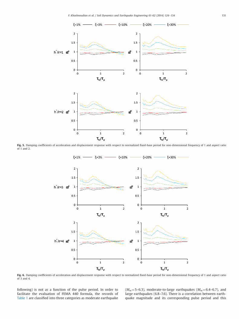
In order to explain the influence of aspect ratio on the dampingcoefficients, Figs. 5 and 6 illustrate the damping coefficients forvarious aspect ratios. It is found that aspect ratio has negligibleeffects on damping coefficients of both acceleration and displace-ment responses. The extremum damping coefficients and their
corresponding normalized fixed-base periods (Tfix/Tp) are notaffected by aspect ratio and damping coefficients for squattystructures (hn/r¼1, 2), and slender structures (hn/r¼3, 4) are thesame. The reason lies in the fact that the important factor whichcontrols the total damping of the soil–structure system is non-dimensional frequency and aspect ratio has insignificant effectscompared to non-dimensional frequency. Such results hold for othervalues of non-dimensional frequency, i.e. a0¼2, 3, not presentedhere.
4. Evaluation of damping correction factors suggestedin FEMA 440
FEMA 440 provides an approximate technique to computedamping correction factors of acceleration responses for includingfoundation damping in the design process of buildings. Theprocedure recommended by FEMA 440 in sections 6.3 and 8.3 isadopted to determine the damping correction factors of accelera-tion demands of the soil–structure systems. Note that it is beyondthe scope of this research to evaluate the actual implementationof these solutions in the performance-based design techniques(coefficient method and equivalent linearization).
FEMA 440 proposes a damping correction factor which convertsthe 5%-damped acceleration response spectrum of fixed-base struc-ture, Sa(5,Tfix)fix, to the ξo-damped acceleration response spectra for aspecific case of soil–structure system, Sa(ξo, Tfix)ssi. Therefore, thedamping correction factor is defined as:
BFEMA ¼ Sað5; T fixÞfix=Saðξo; T fixÞssi ð5ÞIt should be noted that the damping correction factor intro-
duced in this section based on FEMA 440, is different from thedamping coefficients considered in the previous section. Addition-ally, damping correction factors are strongly dependent on thepulse period [21]. However, FEMA 440 regulation (shown in the
Fig. 4. Damping coefficients of acceleration and displacement response with respect to normalized fixed-base period for aspect ratio of 3 and non-dimensional frequencyof 2 and 3.
F. Khoshnoudian et al. / Soil Dynamics and Earthquake Engineering 61-62 (2014) 124–134130
following) is not as a function of the pulse period. In order tofacilitate the evaluation of FEMA 440 formula, the records ofTable 1 are classified into three categories as moderate earthquake
(Mw¼5–6.3), moderate-to-large earthquakes (Mw¼6.4–6.7), andlarge earthquakes (6.8–7.6). There is a correlation between earth-quake magnitude and its corresponding pulse period and this
Fig. 5. Damping coefficients of acceleration and displacement response with respect to normalized fixed-base period for non-dimensional frequency of 1 and aspect ratioof 1 and 2.
Fig. 6. Damping coefficients of acceleration and displacement response with respect to normalized fixed-base period for non-dimensional frequency of 1 and aspect ratioof 3 and 4.
F. Khoshnoudian et al. / Soil Dynamics and Earthquake Engineering 61-62 (2014) 124–134 131
classification can somehow consider the effects of the pulse periodon damping correction factors [32,44,45]. On one hand, dampingcoefficients of FEMA 440 are not functions of the pulse period.On the other hand, damping coefficients strongly depend on thepulse period and earthquake magnitude as shown by Hubbard andMavroeidis (2011) [21]. Therefore, in order to make the compar-ison, the authors categorize the 91earthquakes used based on theirearthquake magnitudes which can somehow consider the effectsof the pulse period because of the correlation between magnitudeand pulse period. However, another option, i.e. considering theentire database as one group and using median of all 91 recordswill completely ignore the important effects of the pulse period ondamping correction factors.
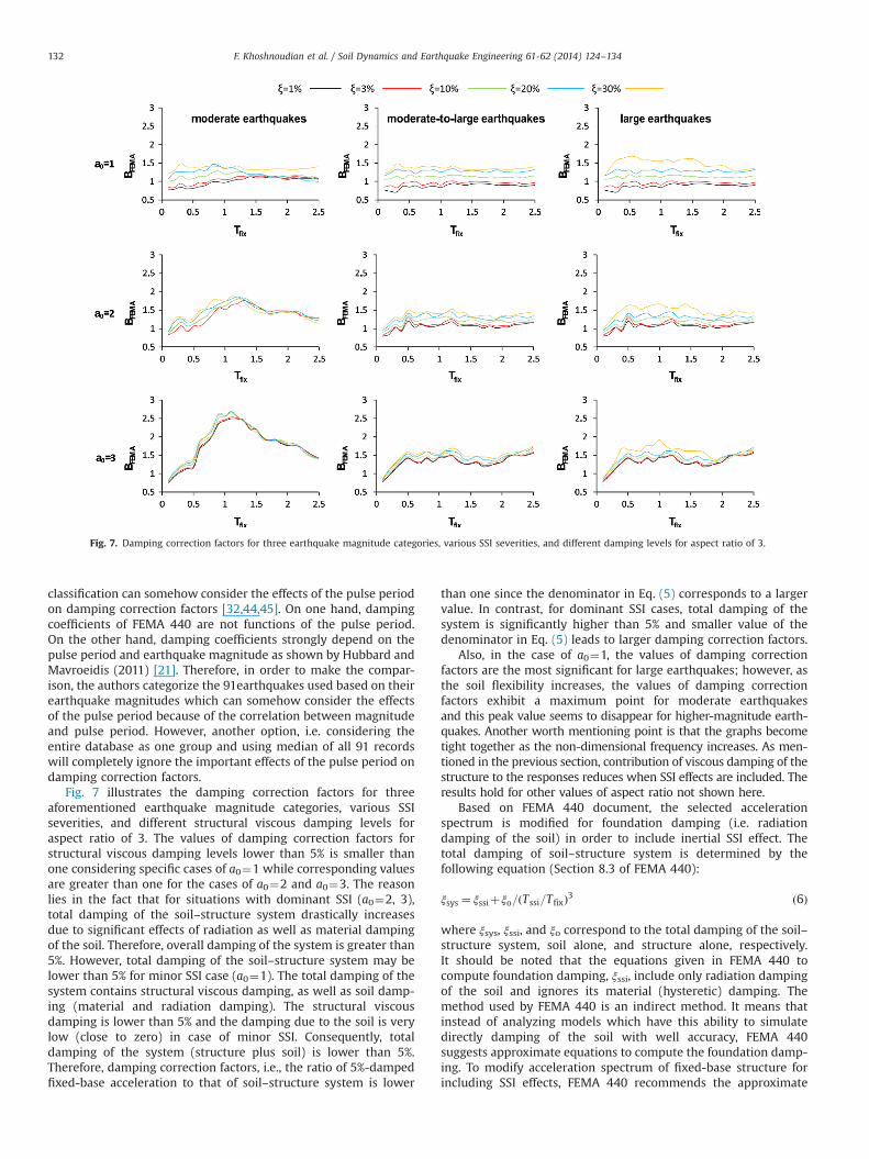
Fig. 7 illustrates the damping correction factors for threeaforementioned earthquake magnitude categories, various SSIseverities, and different structural viscous damping levels foraspect ratio of 3. The values of damping correction factors forstructural viscous damping levels lower than 5% is smaller thanone considering specific cases of a0¼1 while corresponding valuesare greater than one for the cases of a0¼2 and a0¼3. The reasonlies in the fact that for situations with dominant SSI (a0¼2, 3),total damping of the soil–structure system drastically increasesdue to significant effects of radiation as well as material dampingof the soil. Therefore, overall damping of the system is greater than5%. However, total damping of the soil–structure system may belower than 5% for minor SSI case (a0¼1). The total damping of thesystem contains structural viscous damping, as well as soil damp-ing (material and radiation damping). The structural viscousdamping is lower than 5% and the damping due to the soil is verylow (close to zero) in case of minor SSI. Consequently, totaldamping of the system (structure plus soil) is lower than 5%.Therefore, damping correction factors, i.e., the ratio of 5%-dampedfixed-base acceleration to that of soil–structure system is lower
than one since the denominator in Eq. (5) corresponds to a largervalue. In contrast, for dominant SSI cases, total damping of thesystem is significantly higher than 5% and smaller value of thedenominator in Eq. (5) leads to larger damping correction factors.
Also, in the case of a0¼1, the values of damping correctionfactors are the most significant for large earthquakes; however, asthe soil flexibility increases, the values of damping correctionfactors exhibit a maximum point for moderate earthquakesand this peak value seems to disappear for higher-magnitude earth-quakes. Another worth mentioning point is that the graphs becometight together as the non-dimensional frequency increases. As men-tioned in the previous section, contribution of viscous damping of thestructure to the responses reduces when SSI effects are included. Theresults hold for other values of aspect ratio not shown here.
Based on FEMA 440 document, the selected accelerationspectrum is modified for foundation damping (i.e. radiationdamping of the soil) in order to include inertial SSI effect. Thetotal damping of soil–structure system is determined by thefollowing equation (Section 8.3 of FEMA 440):
ξsys ¼ ξssiþξo=ðTssi=T fixÞ3 ð6Þ
where ξsys, ξssi, and ξo correspond to the total damping of the soil–structure system, soil alone, and structure alone, respectively.It should be noted that the equations given in FEMA 440 tocompute foundation damping, ξssi, include only radiation dampingof the soil and ignores its material (hysteretic) damping. Themethod used by FEMA 440 is an indirect method. It means thatinstead of analyzing models which have this ability to simulatedirectly damping of the soil with well accuracy, FEMA 440suggests approximate equations to compute the foundation damp-ing. To modify acceleration spectrum of fixed-base structure forincluding SSI effects, FEMA 440 recommends the approximate
Fig. 7. Damping correction factors for three earthquake magnitude categories, various SSI severities, and different damping levels for aspect ratio of 3.
F. Khoshnoudian et al. / Soil Dynamics and Earthquake Engineering 61-62 (2014) 124–134132
following expression (Section 6.3 of FEMA 440):
BapFEMA ¼ 4=ð5:6� ln ξsysÞ ð7Þ
Note that in the case of fixed-base structure, BapFEMA, becomes
equal to 4/(5.6� ln ξo). When the structure is fixed at its base, theterm ξssi in Eq. (6) is equal to zero (there is no interaction) and Tssi/Tfix becomes equal to 1. Therefore, the term ξsys in Eq. (7) becomesequal to ξo. In order to evaluate FEMA 440, the damping correctionfactors calculated from time history analyzes as an exact solutionusing Eq. (5) (Bex
FEMA) are compared to those obtained from Eq. (7)as an approximate approach (Bap
FEMA). In this regard, the relativeerror is introduced as:
RE¼ BapFEMA=B
exFEMA ð8Þ
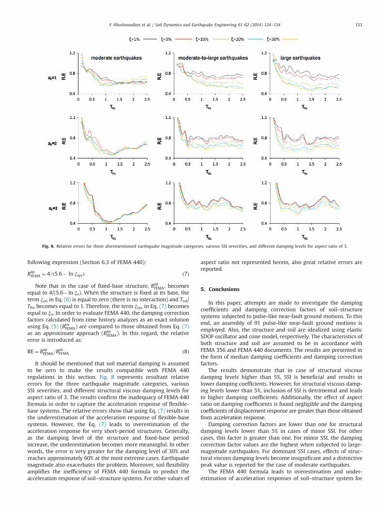
It should be mentioned that soil material damping is assumedto be zero to make the results compatible with FEMA 440regulations in this section. Fig. 8 represents resultant relativeerrors for the three earthquake magnitude categories, variousSSI severities, and different structural viscous damping levels foraspect ratio of 3. The results confirm the inadequacy of FEMA 440formula in order to capture the acceleration response of flexible-base systems. The relative errors show that using Eq. (7) results inthe underestimation of the acceleration response of flexible-basesystems. However, the Eq. (7) leads to overestimation of theacceleration response for very short-period structures. Generally,as the damping level of the structure and fixed-base periodincrease, the underestimation becomes more meaningful. In otherwords, the error is very greater for the damping level of 30% andreaches approximately 60% at the most extreme cases. Earthquakemagnitude also exacerbates the problem. Moreover, soil flexibilityamplifies the inefficiency of FEMA 440 formula to predict theacceleration response of soil–structure systems. For other values of
aspect ratio not represented herein, also great relative errors arereported.
5. Conclusions
In this paper, attempts are made to investigate the dampingcoefficients and damping correction factors of soil–structuresystems subjected to pulse-like near-fault ground motions. To thisend, an assembly of 91 pulse-like near-fault ground motions isemployed. Also, the structure and soil are idealized using elasticSDOF oscillator and cone model, respectively. The characteristics ofboth structure and soil are assumed to be in accordance withFEMA 356 and FEMA 440 documents. The results are presented inthe form of median damping coefficients and damping correctionfactors.
The results demonstrate that in case of structural viscousdamping levels higher than 5%, SSI is beneficial and results inlower damping coefficients. However, for structural viscous damp-ing levels lower than 5%, inclusion of SSI is detrimental and leadsto higher damping coefficients. Additionally, the effect of aspectratio on damping coefficients is found negligible and the dampingcoefficients of displacement response are greater than those obtainedfrom acceleration response.
Damping correction factors are lower than one for structuraldamping levels lower than 5% in cases of minor SSI. For othercases, this factor is greater than one. For minor SSI, the dampingcorrection factor values are the highest when subjected to large-magnitude earthquakes. For dominant SSI cases, effects of struc-tural viscous damping levels become insignificant and a distinctivepeak value is reported for the case of moderate earthquakes.
The FEMA 440 formula leads to overestimation and under-estimation of acceleration responses of soil–structure system for
Fig. 8. Relative errors for three aforementioned earthquake magnitude categories, various SSI severities, and different damping levels for aspect ratio of 3.
F. Khoshnoudian et al. / Soil Dynamics and Earthquake Engineering 61-62 (2014) 124–134 133
short- and long-period structures, respectively. Increasing viscousdamping levels of the structure and inclusion of SSI exacerbate theproblem. Moreover, as the earthquake magnitude becomes larger,the formula leads to greater error. Generally, the relative errorsconfirm the inadequacy of FEMA 440 in order to predict theacceleration response of soil–structure systems under pulse-likenear-fault ground motions.
References
[1] FEMA-356. NEHRP pre-standard and commentary for the seismic rehabilita-tion of buildings. Washington, DC: Federal Emergency Management Agency;2000.
[2] FEMA-440. Improvement of nonlinear static seismic analysis procedures,applied technology council (ATC-55 project), Washington, DC: Federal Emer-gency Management Agency; 2005.
[3] Newmark NM, Hall WJ. Seismic design criteria for nuclear reactor facilities.Building practices for disaster mitigation report No. 46. National Bureau ofStandards, U.S. Department of Commerce; 1973.
[4] Wu JP, Hanson RD. Inelastic response spectra with high-damping. J Struct Div(ASCE) 1989;115(6):1412–31.
[5] Tolis SV, Faccioli E. Displacement design spectra. J Earthq Eng 1999;3:107–25.[6] Bommer JJ, Elnashai AS, Weir AG. Compatible acceleration and displacement
spectra for seismic design codes. In: Proceedings of the 12th world conferenceon earthquake engineering, Auckland; 2000.
[7] Ramirez OM, Constantinou MC, Whittaker AS, Kircher CA, Chrysostomou CZ.Elastic sand inelastic seismic response of buildings with damping systems.Earthq Spectra 2002;18(3):531–47.
[8] Lin YY, Chang KC. Study on damping reduction factor for buildings underearthquake ground motions. J Struct Eng 2003;129(2):206–14, http://dx.doi.org/10.1061/(ASCE)0733-9445(2003)129:2(206).
[9] ATC-40. Seismic evaluation and retrofit of concrete buildings. (Redwood City)CA: Applied Technology Council; 1996.
[10] Eurocode 8. Design of structures for earthquake resistance, part 1: generalrules, seismic actions and rules for buildings. EN 2004-1-1, CEN, Brussels;2004.
[11] NEHRP-2000. Recommended provisions for seismic regulations for newbuildings and other structures. Washington, DC: Federal Emergency Manage-ment Agency; 2000.
[12] NEHRP-2003. Recommended provisions for seismic regulations for newbuildings and other structures. Washington, DC: Federal Emergency Manage-ment Agency; 2003.
[13] Lin YY, Chang KC. Effects of site classes on damping reduction factors. J StructEng 2004;130(11):1667–75, http://dx.doi.org/10.1061/(ASCE)0733-9445(2004)130:11(1667).
[14] Lin YY, Miranda E, Chang KC. Evaluation of damping reduction factors forestimating elastic response of structures with high damping. Earthq Eng StructDyn 2005;34(11):1427–43, http://dx.doi.org/10.1002/eqe.499.
[15] Bommer JJ, Mendis R. Scaling of spectral displacement ordinates with damp-ing ratios. Earthq Eng Struct Dyn 2005;34(2):145–65, http://dx.doi.org/10.1002/eqe.414.
[16] Lin YY. Statistical study on damping modification factors adopted in Taiwan'sseismic isolation design code by using the 21 September 1999 Chi–Chiearthquake, Taiwan. Eng Struct 2006;29:689–93.
[17] Cameron WI, Green RA. Damping correction factors for horizontal ground-motion response spectra. Bull Seismol Soc Am 2007;97(3):934–60, http://dx.doi.org/10.1785/0120060034.
[18] Stafford PJ, Mendis R, Bommer JJ. Dependence of damping correction factors forresponse spectra on duration and numbers of cycles. J Struct Eng 2008;134(8):1364–1373, http://dx.doi.org/10.1061/(ASCE)0733-9445(2008)134:8(1364).
[19] Cardone D, Dolce M, Rivelli M. Evaluation of reduction factors for high-damping design response spectra. Bull Earthq Eng 2009;7(1):273–91, http://dx.doi.org/10.1007/s10518-008-9097-y.
[20] Hatzigeorgiou GD. Damping modification factors for SDOF systems subjectedto near-fault, far-fault and artificial earthquakes. Earthq Eng Struct Dyn2010;39(11):1239–58, http://dx.doi.org/10.1002/eqe.991.
[21] Hubbard DT, Mavroeidis GP. Damping coefficients for near-fault groundmotion response spectra. Soil Dyn Earthq Eng 2011;31:401–17, http://dx.doi.org/10.1016/j.soildyn.2010.09.009.
[22] Hatzigeorgiou GD, Papagiannopoulos GA. Discussion on Damping coefficientsfor near-fault ground motion response spectra. Soil Dyn Earthq Eng2011;31:723–4, http://dx.doi.org/10.1016/j.soildyn.2010.12.010.
[23] Hao A, Zhou D, Li Y, Zhang H. Effects of moment magnitude, site conditionsand closest distance on damping modification factors. Soil Dyn Earthq Eng2011. http://dx.doi.org/10.1016/j.soildyn.2011.05.002.
[24] Papagiannopoulos GA, Hatzigeorgiou GD, Beskos DE. Recovery of spectralabsolute acceleration and spectral relative velocity from their pseudo-spectralcounterparts. Earthq Struct 2013;4(5):489–508.
[25] Chopra AK, Gutierrez JA. Earthquake response analysis of multistory buildingincluding foundation interaction. Earthq Eng Struct Dyn 1974;3:65–77.
[26] Novak M. Effect of soil on structural response to wind and earthquake. EarthqEng Struct Dyn 1974;3:79–96.
[27] Veletsos AS. Dynamic of structure-foundation systems. In: Hal WJ, editor.Structural and geotechnical mechanics. Englewood Cliffs (NJ): Prentice-Hall;1977. p. 333–61.
[28] Wolf JP. Dynamic soil–structure interaction. Englewood Cliffs (NJ): Prentice-Hall; 1985.
[29] Bielak J. Dynamic response of non-linear building-foundation systems. EarthqEng Struct Dyn 1978;7:17–30.
[30] Muller FP, Keintzel E. Ductility requirements for flexibly supported antiseismicstructures, Proceedings of the 7th European conference on earthquakeengineering, 1982.
[31] Rodriguez ME, Montes R. Seismic response and damage analysis of buildingssupported on flexible soils. Earthq Eng Struct Dyn 2000;29:647–65.
[32] Aviles J, Perez-Rocha LE. Soil–structure interaction in yielding systems. EarthqEng Struct Dyn 2003;32:1749–71.
[33] Ghannad MA, Ahmadnia A. The effect of soil–structure interaction on theinelastic structural demands. Eur Earthq Eng 2006;20(1):23–35.
[34] Baker Jack W. Quantitative classification of near-fault ground motions usingwavelet analysis. Bull Seismol Soc Am 2007;97(5):1486–501.
[35] ASCE/SEI 7-10. Minimum design loads for buildings and other structures.Published by American Society of Civil Engineeris; 2010.
[36] Meek W, Wolf JP. Why cone models can represent the elastic half-space.Earthq Eng Struct Dyn 1993;22:759–71.
[37] Wolf JP, Deeks AJ. Foundation vibration analysis: a strength-of-materialsapproach; 2004.
[38] SL Kramer. Geotechnical earthquake engineering. Englewood Cliffs, NJ: Prentice-Hall; 1996.
[39] MeekW,Wolf JP. Material damping for lumped-parameter models of foundation.Earthq Eng Struct Dyn 1994;23:349–62.
[40] Wolf JP. Foundation vibration analysis using simplified physical models.Englewood Cliffs: Prentice Hall; 1994.
[41] Ghannad MA, Fukuwa N, Nishizaka R. A study on the frequency and dampingof soil–structure systems using a simplified model. Struct Eng (AIJ) 1998;44B:85–93.
[42] Veletsos AS, Nair VD. Seismic interaction of structures on hysteretic founda-tion. J Struct Div 1975;101:109–29.
[43] Veletsos AS,Meek JW. Dynamic behavior of building-foundation systemsreport No. 20. Department of Civil Engineering, Rice University, Houston,Texas; 1973.
[44] Bray J, Rodriguez-Marek A. Characterization of forward-directivity groundmotions in the near-fault region. Soil Dyn Earthq Eng 2004;24:815–28.
[45] Jahankhah Ghahari SF, Ghannad MA. Study on elastic response of structures tonear-fault ground motions through record decomposition. Soil Dyn EarthqEng 2010;30:536–46.
F. Khoshnoudian et al. / Soil Dynamics and Earthquake Engineering 61-62 (2014) 124–134134
Related Documents


![P. S. Valsange , M. L. Kulkarni - IOSR Journals in machine [9]. Bearing stiffness & damping coefficients calculated numerically to determine threshold rotor mass under various operating](https://static.cupdf.com/doc/110x72/5aa2c4b77f8b9a46238d7bae/p-s-valsange-m-l-kulkarni-iosr-in-machine-9-bearing-stiffness-damping.jpg)