253 Damage Assessment of Concrete Column using Combination of Nondestructive Methods Dalibor Sekulic, Irina Stipanovic Oslakovic and Emilija Barisic 3 Civil Engineering Institute of Croatia, Department for Concrete and Masonry Structures J. Rakuse 1, 10000 Zagreb, Croatia, Europe, (+385) 6125-134, [email protected] Abstract During construction of viaduct “Stara Susica” on the highway Zagreb – Rijeka in Croatia due to unpredicted mistakes in the execution works sudden fall of prestressed prefabricated beam girder (30 meters long and around 100 tons weight) had happened. During the fall the girder hit the column in its second third of height and caused significant damage of reinforced concrete column. Preliminary visual inspection implied only local damage of surface concrete of the column cross-section, without the indication of deeper structural damage. The combination of nondestructive techniques (ultrasonic pulse velocity and impact echo method) was used for the assessment of column structural damage, which had shown significantly greater structural damage of concrete, with deeper cracks detected within the concrete column than firstly visible from the surface. The combination of nondestructive methods gave a better image of structural damage, considering the size and depth of damage, which was the base for the design project of the column repair (choice of repair methods, technology and materials). In this case study nondestructive evaluation improved both the efficiency and accuracy of column inspection and justified its application in the structural damage assessment. INTRODUCTION Paper describes condition assessment with the application of NDT methods during nondestructive damage investigation on the 18 m high reinforced concrete column on highway Zagreb - Rijeka in Croatia (Figure 1). Column was damaged by sudden fall of prestressed prefabricated beam girder of about 30 meters long and 100 tons weight, caused by carelessness during construction works. During the fall the girder hit the column which caused significant damage of column at the upper third of height. Figure 1: (a) Failure on viaduct Stara Susica on Zagreb – Rijeka highway (b) Damaged column.

Welcome message from author
This document is posted to help you gain knowledge. Please leave a comment to let me know what you think about it! Share it to your friends and learn new things together.
Transcript
253
Damage Assessment of Concrete Column using Combination ofNondestructive Methods
Dalibor Sekulic, Irina Stipanovic Oslakovic and Emilija Barisic3
Civil Engineering Institute of Croatia, Department for Concrete and Masonry Structures
J. Rakuse 1, 10000 Zagreb, Croatia, Europe, (+385) 6125-134, [email protected]
AbstractDuring construction of viaduct “Stara Susica” on the highway Zagreb – Rijeka in Croatia due to unpredicted mistakes in
the execution works sudden fall of prestressed prefabricated beam girder (30 meters long and around 100 tons weight) had
happened. During the fall the girder hit the column in its second third of height and caused signifi cant damage of reinforced
concrete column. Preliminary visual inspection implied only local damage of surface concrete of the column cross-section,
without the indication of deeper structural damage. The combination of nondestructive techniques (ultrasonic pulse velocity
and impact echo method) was used for the assessment of column structural damage, which had shown signifi cantly greater
structural damage of concrete, with deeper cracks detected within the concrete column than fi rstly visible from the surface.
The combination of nondestructive methods gave a better image of structural damage, considering the size and depth of
damage, which was the base for the design project of the column repair (choice of repair methods, technology and materials).
In this case study nondestructive evaluation improved both the effi ciency and accuracy of column inspection and justifi ed its
application in the structural damage assessment.
INTRODUCTIONPaper describes condition assessment with the application of NDT methods during nondestructive damage investigation
on the 18 m high reinforced concrete column on highway Zagreb - Rijeka in Croatia (Figure 1). Column was damaged by
sudden fall of prestressed prefabricated beam girder of about 30 meters long and 100 tons weight, caused by carelessness
during construction works. During the fall the girder hit the column which caused signifi cant damage of column at the upper
third of height.
Figure 1: (a) Failure on viaduct Stara Susica on Zagreb – Rijeka highway (b) Damaged column.
254
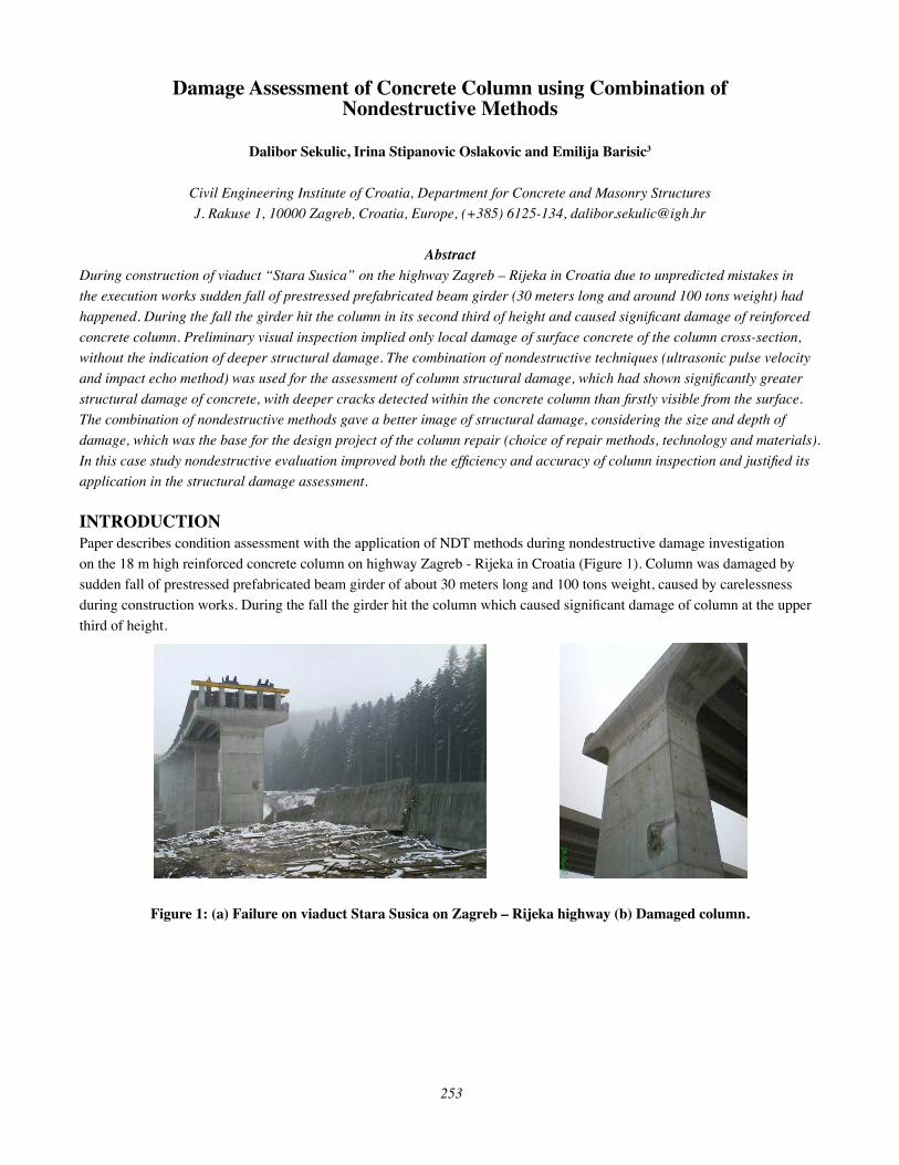
VISUAL INSPECTION AND PLANNED FURTHER INVESTIGATIONS
First insight into damaged column state was obtained by visual inspection. Visual inspection gave local damage on surface
concrete, of the about 10 cm depth and of (120 x 80) cm2 area. Two cracks of 0,1 mm width, and of about 1 m length, were
visible above damage. Also, sliding traces along the column were detectable and visible up to 3 m beneath the place of
impact.
(a) (b) Figure 2: Visible column damages (a) on photograph (b) indicated on measuring mesh.
It was concluded that visual inspection isnʼt suffi cient for complete damaged area detection and it was decided to investigate
wider area around visible damages by nondestructive methods. For this purpose, a measuring mesh covering area of about
(240 x 200 cm) with line separation of 30 cm is drawn. Figure 2(b) shows a mesh compared with visually indicated damages. It
was planned to employ two nondestructive test methods, an impact echo method and time of ultrasonic pulse propagation method.
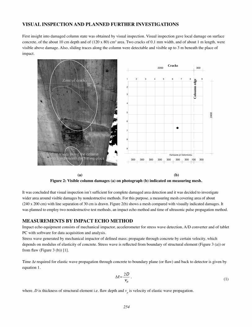
MEASUREMENTS BY IMPACT ECHO METHODImpact echo equipment consists of mechanical impactor, accelerometer for stress wave detection, A/D converter and of tablet
PC with software for data acquisition and analysis.
Stress wave generated by mechanical impactor of defi ned mass; propagate through concrete by certain velocity, which
depends on modulus of elasticity of concrete. Stress wave is refl ected from boundary of structural element (Figure 3 (a)) or
from fl aw (Figure 3 (b)) [1].
Time Δt required for elastic wave propagation through concrete to boundary plane (or fl aw) and back to detector is given by
equation 1.
(1)
where, D is thickness of structural element i.e. fl aw depth and vp is velocity of elastic wave propagation.
2200 300
2400
1 2 3 4 5 6 7 8 9
2
3
4
5
6
7
8
9
300 300 300 300 300 300 300 100 300
Kampada pri betoniranju
Cracks
Col
oum
n ed
ge
pv
Dt
2= ,
255
Figure 3: (a) P-wave refl ection from element boundary (b) P-wave refl ection from fl aw.
To simplify data analysis, data acquisition and analysis software converts signal consisted of N measurement data recorded in
time domain into frequency domain by Fast Fourier transformation (FFT) algorithm described with relation 2.
(2)
After FFT application, measured data shows peaks on certain frequencies (Figure 4 (b)), which simplifi es data interpretation.
(a) (b) Figure 4: (a) Measured data in time domain, (b) Measured data in frequency domain after FFT.
As, frequency and time is connected by:
(3)
it follows equation for depth of fl aw (or structural element thickness) calculation from FFT data.
(4)
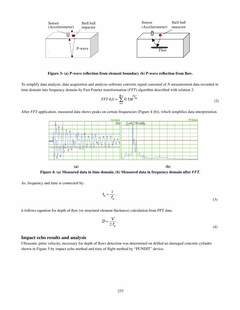
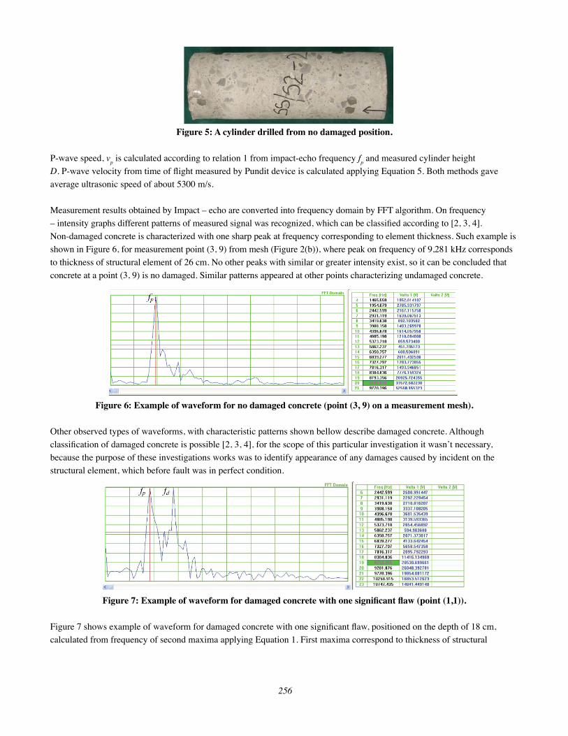
Impact echo results and analysisUltrasonic pulse velocity, necessary for depth of fl aws detection was determined on drilled no damaged concrete cylinder
shown in Figure 5 by impact echo method and time of fl ight method by “PUNDIT” device.
P-wave
Stell ball impactor
Sensor (Accelerometer)
Stell ball impactor
Sensor (Accelerometer)
Flaw
FFT I(f) ==
1
0
N
t
Nift
etI )(
p
pf
t1
= ,
pf
VD
2= .
256
Figure 5: A cylinder drilled from no damaged position.
P-wave speed, vp is calculated according to relation 1 from impact-echo frequency f
p and measured cylinder height
D. P-wave velocity from time of fl ight measured by Pundit device is calculated applying Equation 5. Both methods gave
average ultrasonic speed of about 5300 m/s.
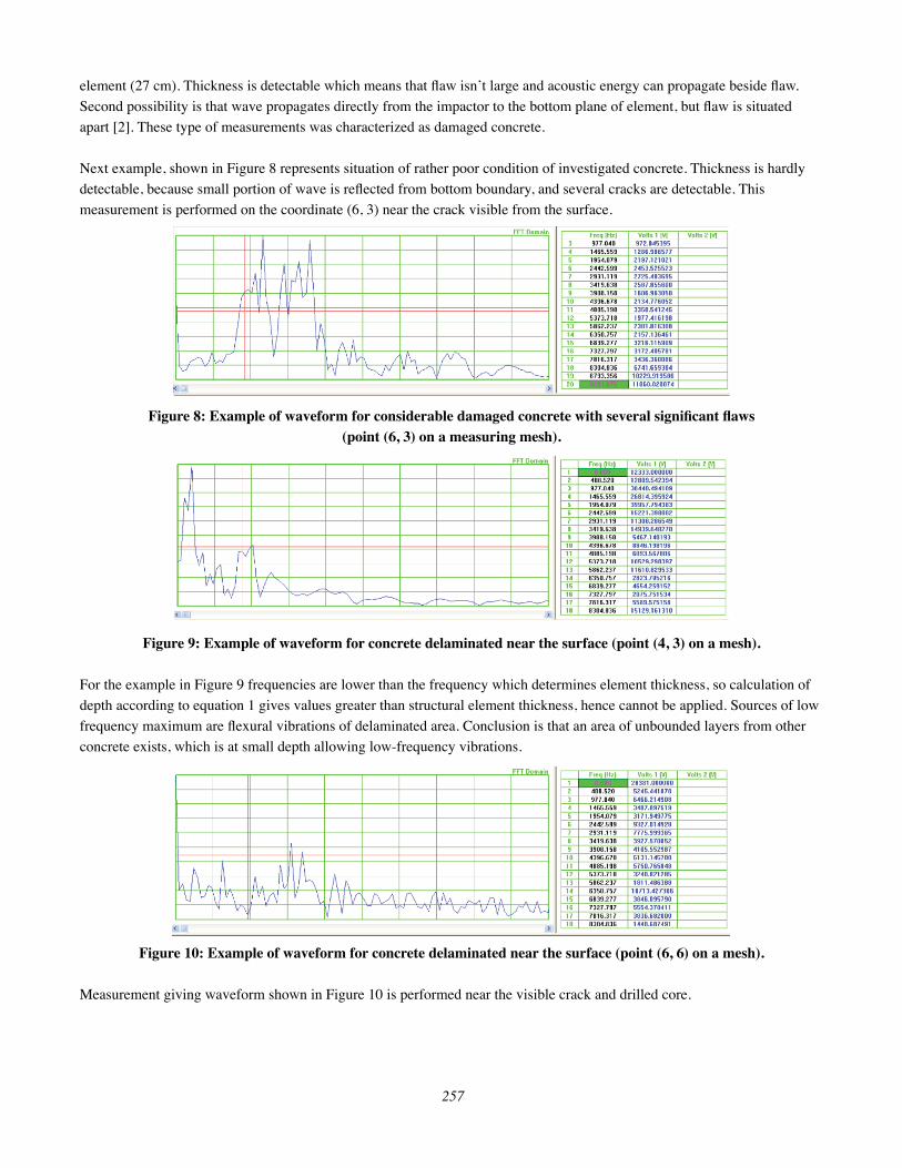
Measurement results obtained by Impact – echo are converted into frequency domain by FFT algorithm. On frequency
– intensity graphs different patterns of measured signal was recognized, which can be classifi ed according to [2, 3, 4].
Non-damaged concrete is characterized with one sharp peak at frequency corresponding to element thickness. Such example is
shown in Figure 6, for measurement point (3, 9) from mesh (Figure 2(b)), where peak on frequency of 9,281 kHz corresponds
to thickness of structural element of 26 cm. No other peaks with similar or greater intensity exist, so it can be concluded that
concrete at a point (3, 9) is no damaged. Similar patterns appeared at other points characterizing undamaged concrete.
Figure 6: Example of waveform for no damaged concrete (point (3, 9) on a measurement mesh).
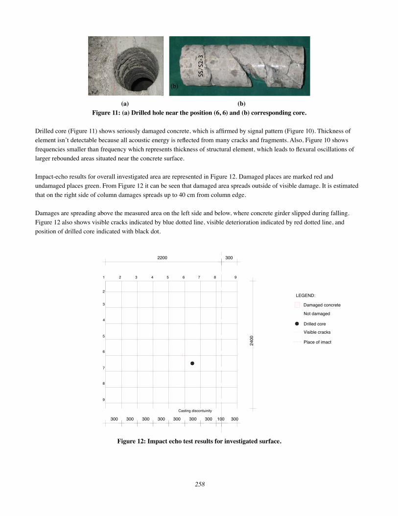
Other observed types of waveforms, with characteristic patterns shown bellow describe damaged concrete. Although
classifi cation of damaged concrete is possible [2, 3, 4], for the scope of this particular investigation it wasnʼt necessary,
because the purpose of these investigations works was to identify appearance of any damages caused by incident on the
structural element, which before fault was in perfect condition.
Figure 7: Example of waveform for damaged concrete with one signifi cant fl aw (point (1,1)).
Figure 7 shows example of waveform for damaged concrete with one signifi cant fl aw, positioned on the depth of 18 cm,
calculated from frequency of second maxima applying Equation 1. First maxima correspond to thickness of structural
257
element (27 cm). Thickness is detectable which means that fl aw isnʼt large and acoustic energy can propagate beside fl aw.
Second possibility is that wave propagates directly from the impactor to the bottom plane of element, but fl aw is situated
apart [2]. These type of measurements was characterized as damaged concrete.
Next example, shown in Figure 8 represents situation of rather poor condition of investigated concrete. Thickness is hardly
detectable, because small portion of wave is refl ected from bottom boundary, and several cracks are detectable. This
measurement is performed on the coordinate (6, 3) near the crack visible from the surface.
Figure 8: Example of waveform for considerable damaged concrete with several signifi cant fl aws (point (6, 3) on a measuring mesh).
Figure 9: Example of waveform for concrete delaminated near the surface (point (4, 3) on a mesh).
For the example in Figure 9 frequencies are lower than the frequency which determines element thickness, so calculation of
depth according to equation 1 gives values greater than structural element thickness, hence cannot be applied. Sources of low
frequency maximum are fl exural vibrations of delaminated area. Conclusion is that an area of unbounded layers from other
concrete exists, which is at small depth allowing low-frequency vibrations.
Figure 10: Example of waveform for concrete delaminated near the surface (point (6, 6) on a mesh).
Measurement giving waveform shown in Figure 10 is performed near the visible crack and drilled core.
258
(a) (b) Figure 11: (a) Drilled hole near the position (6, 6) and (b) corresponding core.
Drilled core (Figure 11) shows seriously damaged concrete, which is affi rmed by signal pattern (Figure 10). Thickness of
element isnʼt detectable because all acoustic energy is refl ected from many cracks and fragments. Also, Figure 10 shows
frequencies smaller than frequency which represents thickness of structural element, which leads to fl exural oscillations of
larger rebounded areas situated near the concrete surface.
Impact-echo results for overall investigated area are represented in Figure 12. Damaged places are marked red and
undamaged places green. From Figure 12 it can be seen that damaged area spreads outside of visible damage. It is estimated
that on the right side of column damages spreads up to 40 cm from column edge.
Damages are spreading above the measured area on the left side and below, where concrete girder slipped during falling.
Figure 12 also shows visible cracks indicated by blue dotted line, visible deterioration indicated by red dotted line, and
position of drilled core indicated with black dot.
Figure 12: Impact echo test results for investigated surface.
2200 30024
00
1 2 3 4 5 6 7 8 9
2
3
4
5
6
7
8
9
300 300 300 300 300 300 300 100 300
Casting discontuinity
Damaged concrete
Not damaged
LEGEND:
Drilled core
Visible cracks
Place of imact
259
ULTRASONIC PULSE TRANSIT TIME METHODUltrasonic pulse transit time method is based on the measurement of time, required for ultrasonic pulse propagation through
investigated concrete element, from which pulse propagation velocity can be calculated according to:
(5)
Where, t is time required for pulse propagation and D is distance between transducers.
Velocity vp is correlated with dynamic modulus of elasticity of concrete and with degree of concrete deterioration [5].
Two test confi gurations are used, non-direct confi guration which uses transmitter and receiver situated on same plane
(Figure 13 (a)), and semi-direct confi guration where transmitter and receiver are placed on two planes at the angle of
90° (Figure 13 (b)) [6]. These test confi gurations are suitable for crack depth determination. Ultrasonic pulse arising at the
crack cannot bridge over, so it propagates on path which requires minimal time to arrive to the detector. Result is time of
fl ight increasing, which makes possible determination of the crack depth. Ultrasonic wave propagation paths, which require
minimal time, are indicated with red lines (Figure 13).
Figure 13: Crack depth measurement principle (a)non-direct method, (b) semi-direct method.
In the case of seriously damaged concrete, with many cracks, result is large decrease of ultrasonic pulse propagation time.
Ultrasonic pulse method results and analysisUltrasonic pulse time of fl ight method is chosen to confi rm results obtained from impact – echo method and to detect depth of
visible cracks. On the column surface indirect method is used. Some measurements are made by positioning transmitter and
receiver to bridge visible crack, for which crack depths were calculated and are shown in Figure 14.
t
Dvp = ,
Receiver Transmitter Transmiter
Receiver (a) (b)
260
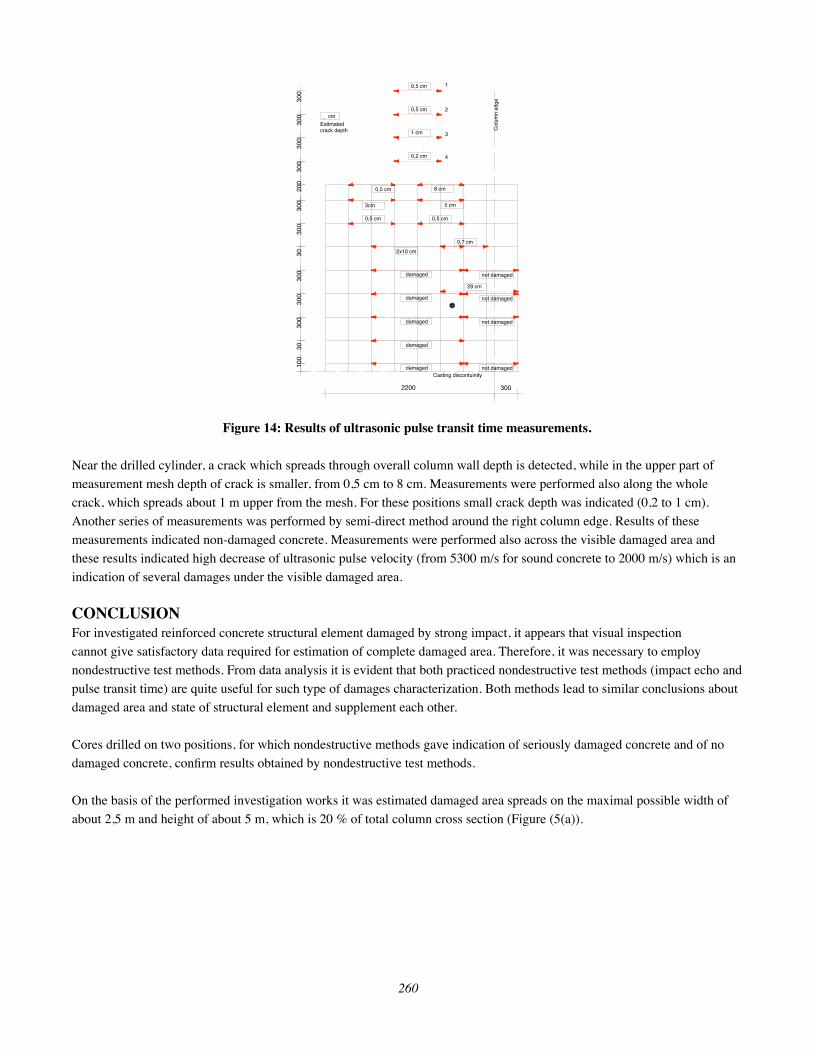
Figure 14: Results of ultrasonic pulse transit time measurements.
Near the drilled cylinder, a crack which spreads through overall column wall depth is detected, while in the upper part of
measurement mesh depth of crack is smaller, from 0,5 cm to 8 cm. Measurements were performed also along the whole
crack, which spreads about 1 m upper from the mesh. For these positions small crack depth was indicated (0,2 to 1 cm).
Another series of measurements was performed by semi-direct method around the right column edge. Results of these
measurements indicated non-damaged concrete. Measurements were performed also across the visible damaged area and
these results indicated high decrease of ultrasonic pulse velocity (from 5300 m/s for sound concrete to 2000 m/s) which is an
indication of several damages under the visible damaged area.
CONCLUSIONFor investigated reinforced concrete structural element damaged by strong impact, it appears that visual inspection
cannot give satisfactory data required for estimation of complete damaged area. Therefore, it was necessary to employ
nondestructive test methods. From data analysis it is evident that both practiced nondestructive test methods (impact echo and
pulse transit time) are quite useful for such type of damages characterization. Both methods lead to similar conclusions about
damaged area and state of structural element and supplement each other.
Cores drilled on two positions, for which nondestructive methods gave indication of seriously damaged concrete and of no
damaged concrete, confi rm results obtained by nondestructive test methods.
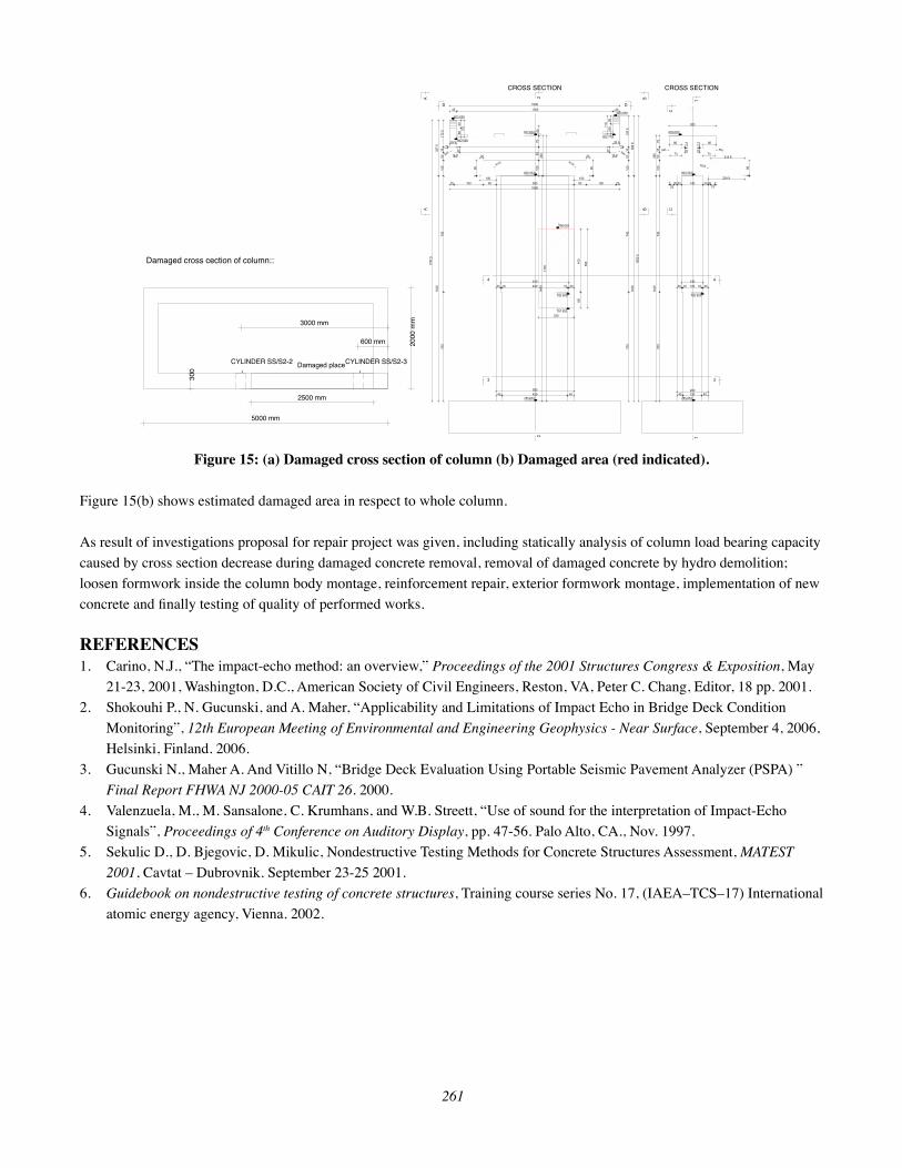
On the basis of the performed investigation works it was estimated damaged area spreads on the maximal possible width of
about 2,5 m and height of about 5 m, which is 20 % of total column cross section (Figure (5(a)).
3002200
0,2 cm
0,5 cm
0,5 cm
1 cm
1
2
3
4
0,5 cm
3cm
0,5 cm
8 cm
5 cm
0,5 cm
0,7 cm
not damaged
2x10 cm
damaged
300
300
300
Casting discontuinity
300
200
300
300
3030
030
030
030
100
Col
umn
edge
28 cm
damaged
damaged
damaged
damaged
not damaged
not damaged
not damaged
_ cm
Esttmated crack depth
261
Figure 15: (a) Damaged cross section of column (b) Damaged area (red indicated).
Figure 15(b) shows estimated damaged area in respect to whole column.
As result of investigations proposal for repair project was given, including statically analysis of column load bearing capacity
caused by cross section decrease during damaged concrete removal, removal of damaged concrete by hydro demolition;
loosen formwork inside the column body montage, reinforcement repair, exterior formwork montage, implementation of new
concrete and fi nally testing of quality of performed works.
REFERENCES1. Carino, N.J., “The impact-echo method: an overview,” Proceedings of the 2001 Structures Congress & Exposition, May
21-23, 2001, Washington, D.C., American Society of Civil Engineers, Reston, VA, Peter C. Chang, Editor, 18 pp. 2001.
2. Shokouhi P., N. Gucunski, and A. Maher, “Applicability and Limitations of Impact Echo in Bridge Deck Condition
Monitoring”, 12th European Meeting of Environmental and Engineering Geophysics - Near Surface, September 4, 2006,
Helsinki, Finland. 2006.
3. Gucunski N., Maher A. And Vitillo N, “Bridge Deck Evaluation Using Portable Seismic Pavement Analyzer (PSPA) ”
Final Report FHWA NJ 2000-05 CAIT 26. 2000.
4. Valenzuela, M., M. Sansalone, C. Krumhans, and W.B. Streett, “Use of sound for the interpretation of Impact-Echo
Signals”, Proceedings of 4th Conference on Auditory Display, pp. 47-56. Palo Alto, CA., Nov. 1997.
5. Sekulic D., D. Bjegovic, D. Mikulic, Nondestructive Testing Methods for Concrete Structures Assessment, MATEST
2001, Cavtat – Dubrovnik. September 23-25 2001.
6. Guidebook on nondestructive testing of concrete structures, Training course series No. 17, (IAEA–TCS–17) International
atomic energy agency, Vienna. 2002.
5000 mm20
00 m
m
300
Damaged place
Damaged cross cection of column::
2500 mm
3000 mm
600 mm
CYLINDER SS/S2-2 CYLINDER SS/S2-3
CROSS SECTION CROSS SECTION
Related Documents