© 1997 Radionics 32206D 9/97 D9210B Access Control Interface Module Operation and Installation Manual

Welcome message from author
This document is posted to help you gain knowledge. Please leave a comment to let me know what you think about it! Share it to your friends and learn new things together.
Transcript

© 1997 Radionics 32206D 9/97
D9210B Access Control Interface ModuleOperation and Installation Manual

32206D 9/97 D9210B Operation & Installation Manual © 1997 RadionicsPage 2
Notices
About This Manual
This manual assumes that you have basic security system installation skills suchas measuring voltages, stripping wire, making proper wire connections, andchecking phone lines. It also assumes you are familiar with the properinstallation of Radionics Control/Communicator panels and the relatedprogramming tasks.
The material and instructions in this manual have been carefully checked foraccuracy and are presumed to be reliable. However, Radionics, Inc. assumes noresponsibility for inaccuracies and reserves the right to modify and revise thismanual without notice.
It is our goal at Radionics to always supply accurate and reliable documentation.If a discrepancy is found in this documentation, please mail a photocopy of thecorrected material to:
Radionics, Inc.c/o Technical Writing Department130 Perinton ParkwayFairport, NY 14450
FCC Notice
This equipment generates, uses and can radiate radio frequency energy. If notinstalled in accordance with the manufacturer’s instructions, it may causeinterference to radio communications. It has been tested and found to complywith the specifications in Subpart J of Part 15 of FCC Rules for Class BComputing Devices.
If this equipment causes interference to radio or television reception –– whichcan be determined by turning the equipment on and off –– the installer isencouraged to correct the interference by one or more of the following measures:1) Reorient the antenna of the radio/television, 2) Connect the AC transformer toa different outlet so the control panel and radio/television are on different branchcircuits, 3) Relocate the control panel with respect to the radio/television.
If necessary, the installer should consult an experienced radio/televisiontechnician for additional suggestions, or send for the “Interference Handbook”prepared by the Federal Communications Commission. This booklet is availablefrom the U.S. Government Printing Office, Washington DC 20402, stock no. 004-000-00450-7.
Regulatory Listings
UL 294 UL 1076 UL 609 FCC 15BUL 365 UL 1610 UL 864 CSFM

© 1997 Radionics D9210B Operation & Installation Manual 32206D 9/97Page 3
Table of Contents
Notices................................................................................................................................................................ 2About This Manual .......................................................................................................................................... 2FCC Notice...................................................................................................................................................... 2Regulatory Listings .......................................................................................................................................... 2
Table of Contents .............................................................................................................................................. 3
Tables and Figures ............................................................................................................................................ 4
Introduction........................................................................................................................................................ 5The D9210B Access Control Interface............................................................................................................ 5Materials Included ........................................................................................................................................... 6Ordered Separately ......................................................................................................................................... 6Listings and Approval Information ................................................................................................................... 6
Installation.......................................................................................................................................................... 7Before You Begin ............................................................................................................................................ 7Step 1: Mounting the Enclosure and Installing the D9210B ............................................................................ 7Step 2: Pulling and Marking the Wires ............................................................................................................ 8Step 3: Mounting ........................................................................................................................................... 10Step 4: Door Contact (Onboard) Point, Terminals 9 and 10 ......................................................................... 10Step 5: Door Lock, Terminals 2, 3 and 4....................................................................................................... 11Step 6: Request to Enter (RTE), Terminals 11 and 12 ................................................................................. 12Step 7: Request to Exit (REX), Terminals 13 and 12.................................................................................... 12Step 8: Enclosure Tamper Switch, Terminals 8 and 9 .................................................................................. 12Step 9: Connecting the Card Reader, Terminals 12, 14, 15, 16, 17, and 18 ................................................ 13Step 10: Setting the Dipswitch and Tagging the Unit .................................................................................... 14Step 11 Connecting Power and SDI, Terminals 1, 3, 5, 6, and 7.................................................................. 15Step 12: Programming and Activating the D9210B....................................................................................... 16Step 13: Testing the D9210B ........................................................................................................................ 16
Troubleshooting .............................................................................................................................................. 17
Detailed System Description .......................................................................................................................... 18Operational Primer ........................................................................................................................................ 18Basic Features .............................................................................................................................................. 21Displays and Reports .................................................................................................................................... 21
Door Release Application ............................................................................................................................... 22
D9210B Terminal Quick Reference and Electrical Specifications .............................................................. 23

32206D 9/97 D9210B Operation & Installation Manual © 1997 RadionicsPage 4
Tables and Figures
TABLE 1. D9210B DIAGNOSTIC AND STATUS LEDS ......................................................................................5TABLE 2. TYPICAL WIRE PLANNING CHART FOR THE D9210B....................................................................8TABLE 3. UL LISTED COMPATIBLE READERS FOR THE D9210B ...............................................................13TABLE 4. D9210B DIPSWITCH SETTINGS .....................................................................................................14TABLE 5. LED TROUBLESHOOTING GUIDE ..................................................................................................17TABLE 6. TERMINAL QUICK REFERENCE GUIDE AND ELECTRICAL SPECIFICATIONS..........................23
FIGURE 1. D9210B ACCESS CONTROL INTERFACE MODULE .....................................................................5FIGURE 2. WIRING DIAGRAM FOR TYPICAL D9210B INSTALLATION..........................................................9FIGURE 3. RELAY INSTALLATION ..................................................................................................................11FIGURE 4. D9210B DIP SWITCH (FACTORY SETTINGS)..............................................................................14FIGURE 5. POWER SUPPLY AND SDI CONNECTIONS.................................................................................15FIGURE 6. D9210B DOOR RELEASE APPLICATION CONNECTIONS..........................................................22
© 1997 Radionics D9210B Operation & Installation Manual 32206D 9/97Page 5
Introduction
The D9210B Access Control Interface
1PWR +
7SDIB
6SDIA
5COM
8T +
10ZN +
9ZNC OM
2LCK N/C
3LCKCO M
4LCKN/O
13REX
12COM
11RTE
16DATA 1
17BUZZER
18LED
15DATA 0
14+5.20V
D0READER
OPERMON
D1READER
123456
ON
D9210B
TerminalBlocks
Diagnostic andStatus LEDs
PROM
DIP Switch
Relay
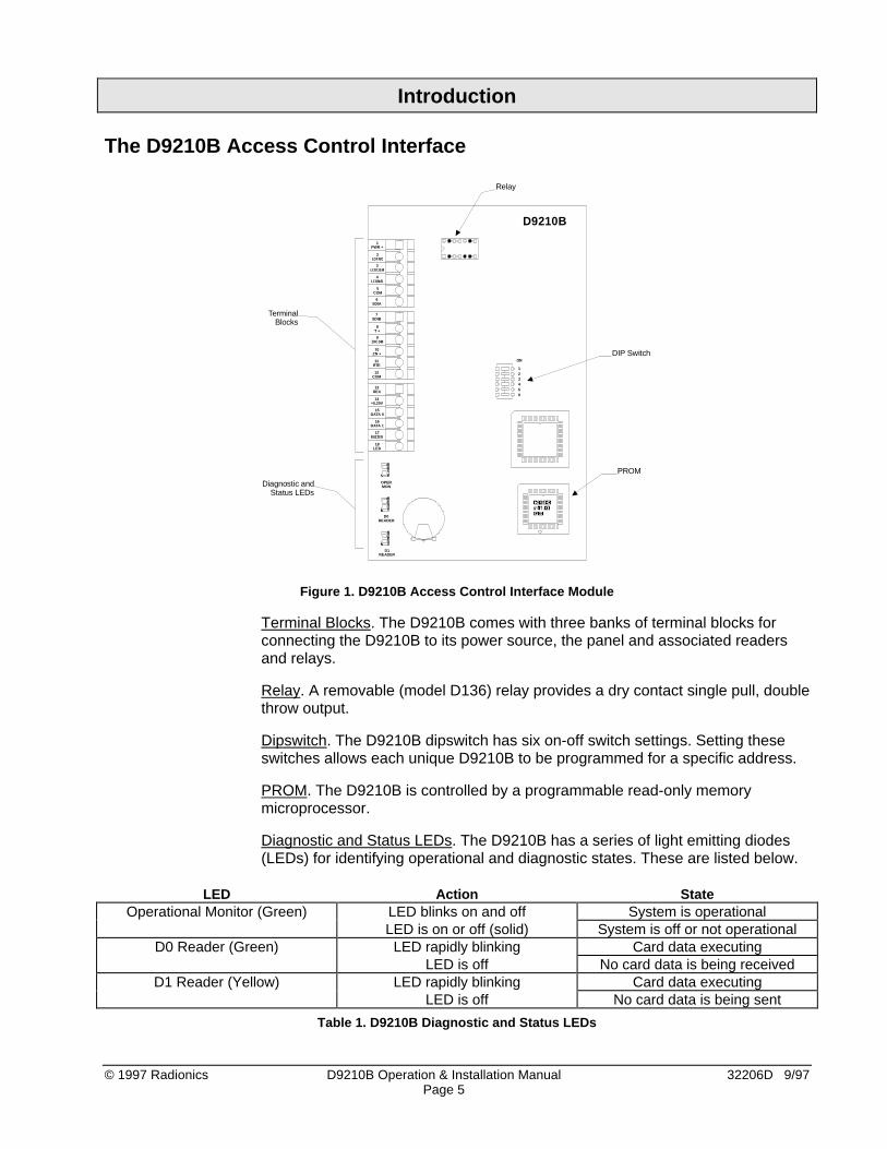
Figure 1. D9210B Access Control Interface Module
Terminal Blocks. The D9210B comes with three banks of terminal blocks forconnecting the D9210B to its power source, the panel and associated readersand relays.
Relay. A removable (model D136) relay provides a dry contact single pull, doublethrow output.
Dipswitch. The D9210B dipswitch has six on-off switch settings. Setting theseswitches allows each unique D9210B to be programmed for a specific address.
PROM. The D9210B is controlled by a programmable read-only memorymicroprocessor.
Diagnostic and Status LEDs. The D9210B has a series of light emitting diodes(LEDs) for identifying operational and diagnostic states. These are listed below.
LED Action StateOperational Monitor (Green) LED blinks on and off System is operational
LED is on or off (solid) System is off or not operationalD0 Reader (Green) LED rapidly blinking Card data executing
LED is off No card data is being receivedD1 Reader (Yellow) LED rapidly blinking Card data executing
LED is off No card data is being sent
Table 1. D9210B Diagnostic and Status LEDs

32206D 9/97 D9210B Operation & Installation Manual © 1997 RadionicsPage 6
Materials Included
Radionics ships the D9210B Access Control Interface module pre-assembledfrom the factory with a power supply, in its own can, or as a unit less can. Youwill receive the following parts with your package depending upon what model isordered, (see Ordered separately).
• D136 removable relay mounted on the board.
• Battery Leads (for the D9210BLC).
• 1K Ω 1/2 watt end of line resistor.
• Literature Pack containing: D9210B Operation and Installation Manual,D9210 Program Entry Guide, ACCESS Program Record Sheet, and PowerSupply Installation Instructions.
• Hardware pack containing: three #6x3/8 self-tapping sheet metal screws tosecure the module on the mounting skirt or the enclosure. Two strain reliefcable ties.
Ordered Separately
The D9210B Door Controller can be used with the Radionics D7412 (supports 2doors) or D9412 (supports 8 doors) Control/Communicator security panels andassociated control keypads and access control readers. Following are theavailable options.
• D9210BLC: The D9210BLC (up to 4) can be installed in the same enclosureas the control panel using the mounting screws and fasteners. Two additionalmodules can be mounted using the D136 brackets. Radionics recommendsthat you use a separate power supply for the D9210Bs to isolate them fromother SDI devices.
• D9210BC: The D9210BC is a complete unit mounted on a mounting skirt,(D9201M) with a switchable 12/24 VDC (500-1500 mA) power supply, and (1)D9210B. It can be installed with another D9210BLC in a single D8103, D8109or D8108A enclosure.
• D9210B: The D9210B is mounted in a 5(W)x8(L)x3(H) enclosure and can bemounted as a standalone unit in the field.
• Compatible Readers: Readers are not shipped with the unit (see Table 3).
Listings and Approval Information
Underwriters Laboratories (UL). The D9210B, when used with the D7412 orD9412 panels, is listed by UL for use as part of an Access Control System;Local, Police-Connect, Central Station, or Proprietary Burglar Alarm System; anda Commercial Fire Alarm System. In addition to the manual, refer to theD7412/D9412 installation documentation regarding Burglar Alarm Grades andFire Alarm services supported. The D9210B is a Signaling Device Subassemblyalso suitable as a Burglar Alarm Unit Accessory Subassembly and AccessControl Unit Subassembly.
Other Listings and Approvals. FCC 15B, CSFM (highrise)

© 1997 Radionics D9210B Operation & Installation Manual 32206D 9/97Page 7
Installation
Before You Begin
Thank you for choosing our product. We have made an effort to identify the keysteps for installing the D9210B successfully. To ensure that your installationgoes smoothly, follow the installation steps in the order presented.
System Planning. Before proceeding, draw your system layout on a sheet ofgraph paper. Also, review the architect and engineering drawings (if available).This will help you set addresses, mark the units, and route/tag wires. Thedrawing should include the Control Panel, the D9210B, the trip switches forRTE/REX, doors, readers, control centers assigned to the same area as theD9210Bs, and the wiring run.
Have the following documents handy as you read through this manual:
• D9210B Program Entry Guide (32207)
• ACCESS Program Record Sheet (32208)
• Control/Communicator Program Entry Guide and Program Record Sheet
• Security System Owner’s Manual (71-06633-000)
• Power Supply Installation Instructions
You should be familiar also with the operation of the D5200 programmer or theRemote Account Manager (R.A.M.) remote programmer.
Step 1: Mounting the Enclosure and Installing the D9210B
Enclosure Placement. There is a 500’ maximum distance allowed between theD9210B and Weigand card readers. Using 22 AWG wire, the D9210B may beremoted up to 2,500 feet away from the control panel; using 18 AWG wire, theD9210B may be remoted up to 5,000 feet. Consider placing the enclosure wherea technician can gain easy access for troubleshooting the unit and where wiringcan be routed easily.
Preparing Knockouts. The D9210B requires six primary wire runs to be routed tothe enclosure (see Table 2). To identify the proper knockouts required,determine from which direction the panel, reader, door contact, door strike andthe request to exit/enter wires will be coming. Run the necessary wiringthroughout the premises and pull the wires into the enclosure. Avoid splicing andgrouping wires together. Knock out the tabs for the wiring prior to mounting theenclosure.
Mounting the Enclosure. When mounting the enclosure, place it against the walland use a “level tool” to ensure the unit is level. Align the enclosure mountingholes with the vertical wood beams, usually 16” apart, to ensure a solid mount.With a pen or pencil, make marks where the top mounting holes expose thesurface.
Set the enclosure down and insert the mounting screws where the marks existfor the top left and right mounting holes. Leave a 1/4” gap between the wall andscrew head so the enclosure can be hung on the screws.
IMPORTANT! If vertical wood beams are not available, be sure to use the properscrew anchors and hardware to mount the unit.

32206D 9/97 D9210B Operation & Installation Manual © 1997 RadionicsPage 8
If any of the knockouts require that wire be run behind the wall, mark the holesand punch/drill them out prior to permanently installing the enclosure. After theholes have been knocked out and the enclosure is level, use all five mountingholes (three on the top and two on the bottom) to install the enclosure.
Step 2: Pulling and Marking the Wires
Running wire. Use Table 2 to estimate the wire bundle size for your knockoutsand where to mount the D9210B. Tag your wire runs to prevent confusion duringinstallation and troubleshooting. Figure 2 shows the wiring for a typical D9210Binstallation.
PurposeSuggestedWire Tag
ApproximateDiameter
RecommendedWire Type
RecommendedColor Code
Power/SDI data Tag A 1/4 “ 4/22 AWG quad(2500 feet)
4/18 AWG quad(5000 feet)
SDI: A (Green)B (Yellow)
Pwr: + (Red)- (Black)
RTE power/input* Tag B 1/4” 4/22 AWG quad Green/Black
REX power/input* Tag C 1/4” 4/22 AWG quad Yellow/Black
Strike power* Tag D 3/8” 2/16-18 AWG zip Red
Door contact* Tag E 1/8” 2/22 AWG
(500 feet)
White
Reader* Tag F 3/8” 6/22 AWGconductor(500 feet)
12 VDC: Red
5 VDC: Orange
COM: Black
D1: White
D0: Green
LED: Brown
Buzzer: Yellow
Buzzer* Tag G 1/8” 2/22 AWG twist +(Red), - (Blk)
Emergency Exit* Tag I 1/8” 2/18 AWG twist Blue
Power SupplyTransformer
Tag J 1/4” 2/18 AWG zip Brown
* Be sure to multiply the wires by the number of D9210Bs in the enclosure.
Table 2. Typical Wire Planning Chart for the D9210B

© 1997 Radionics D9210B Operation & Installation Manual 32206D 9/97Page 9
Figure 2. Wiring Diagram for Typical D9210B Installation

32206D 9/97 D9210B Operation & Installation Manual © 1997 RadionicsPage 10
Step 3: Mounting
Do not install or replace a D9210B while it is connected to live power circuits. TheD9210B should be powered down until it is ready to be tested.
D9210BLC
1. Mount the D8103, D8109 or D8108A enclosure on a flat service.2. Install another D9210LC to the mounting skirt (optional) prior to step 3.3. Hang the mounting skirt in the enclosure by aligning the rectangular tabs of
the enclosure with the rectangular knockouts on the mounting skirt.4. Insert the #6x3/8” screw on the bottom tab of the mounting skirt and tighten
1/4 turn to seat it. This completes the mounting of the skirt in the enclosure.D9210B1. Remove the cover of the D9210B by loosening the two cover screws.2. Remove the required knockouts prior to replacing the cover.3. Mark the holes provided for mounting the bottom half of the unit to a wall or
ceiling.4. Screw the provided screws in to the marked service and allow a 1/4” gap
between the surface and bottom of the screw.5. Hang the unit and secure the screws. Replace the cover and cover screws.D9210BLC1. The unit can be installed in a D8103, D8109 or D8108A enclosure by
matching the three plastic mounting anchors to the three hole foot printsprovided around the sides of the enclosure (4).
2. The unit can be added to a D9210BC by matching the three plastic mountanchors to the available three hole foot prints below the factory installedD9210B.
3. To secure the unit, use the three #8-3/4” screws provided.
Step 4: Door Contact (Onboard) Point, Terminals 9 and 10
Description. The D9210B monitors the sensor loop between the input terminal10 and the common terminal 9 for normal, shorted, or open conditions. This loopis provided for a door contact. The maximum distance the Door Contact may beremoted from the D9210B is 500 feet. The door contact can be programmed asa perimeter, interior, or 24 hour burglar alarm point.
See the D9210B Program Entry Guide (32207) for assigning a point to the doorcontroller and the panel Program Entry Guide for the point types.
Point Sensor Loop. Install a 1k Ω resistor at the door contact, not at theterminal of the input. This will provide supervision against grounds on the loop.You can connect only one contact, that being the door, to this input.

© 1997 Radionics D9210B Operation & Installation Manual 32206D 9/97Page 11
Point Tolerances. The following voltages determine the condition of the on-board point. Use the point common as your (-) reference when measuring thepoint (+). Set your meter for 10 to 24 VDC range.
Voltage Description0 - 1.2VDC Loop shorted
1.8VDC Coming from a shorted condition, theD9210B restores the Door Point at 1.8VDC
2.65VDC Normal loop voltage4.0 - 5.0VDC Loop open
3.5VDC Coming from an open condition, theD9210B restores the Door Point at 3.5VDC
Step 5: Door Lock, Terminals 2, 3 and 4
Description. A removable relay (model D136) provides a dry contact single pulldouble throw output. Some strikes require a closed circuit to unlock the doorwhile others require an open circuit to unlock the door. The relay will support 12VDC @ 2A or 24 VDC @ 2.5 A or 12/24VAC @ 40 A.
Common Input (3) = For 12/24VDC strikes, provide the input powerhere from the power supply.
Lock N/C (2) = For door strikes that require an interruption ofpower to open, connect the positive side of thedoor strike to this terminal.
Lock N/O (4) = For door strikes that require power to open,connect the positive side of the door strike to thisterminal.
Relay Installation. The D136 Relay is installed into the relay socket of theD9210B. Follow these steps for installing the relay:
1. Locate the relay socket on the D9210B board (shown in Figure 3).2. Place the relay into the socket. The plug-in relay has two legs on the bottom
and three legs on the top. When inserting the relay, ensure that it is orientedas shown in Figure 3.
Figure 3. Relay Installation
1PWR +
7SDIB
6SDIA
5COM
8T +
10ZN +
9ZNCOM
2LCKN/C
3LCKCOM
4LCKN/O
11 ON
D9210B
MANUFACTURERNAME
MANUFACTURERNAME
D9210B
TOP
LEFT
32206D 9/97 D9210B Operation & Installation Manual © 1997 RadionicsPage 12
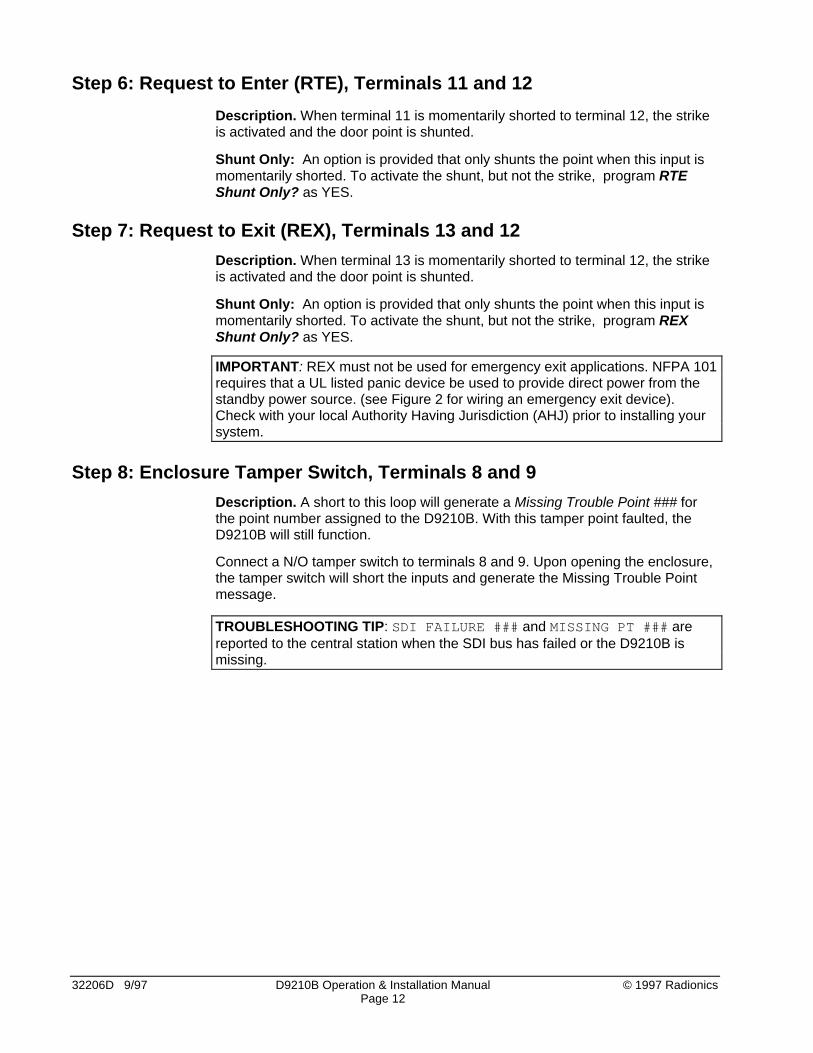
Step 6: Request to Enter (RTE), Terminals 11 and 12
Description. When terminal 11 is momentarily shorted to terminal 12, the strikeis activated and the door point is shunted.
Shunt Only: An option is provided that only shunts the point when this input ismomentarily shorted. To activate the shunt, but not the strike, program RTEShunt Only? as YES.
Step 7: Request to Exit (REX), Terminals 13 and 12
Description. When terminal 13 is momentarily shorted to terminal 12, the strikeis activated and the door point is shunted.
Shunt Only: An option is provided that only shunts the point when this input ismomentarily shorted. To activate the shunt, but not the strike, program REXShunt Only? as YES.
IMPORTANT: REX must not be used for emergency exit applications. NFPA 101requires that a UL listed panic device be used to provide direct power from thestandby power source. (see Figure 2 for wiring an emergency exit device).Check with your local Authority Having Jurisdiction (AHJ) prior to installing yoursystem.
Step 8: Enclosure Tamper Switch, Terminals 8 and 9
Description. A short to this loop will generate a Missing Trouble Point ### forthe point number assigned to the D9210B. With this tamper point faulted, theD9210B will still function.
Connect a N/O tamper switch to terminals 8 and 9. Upon opening the enclosure,the tamper switch will short the inputs and generate the Missing Trouble Pointmessage.
TROUBLESHOOTING TIP: SDI FAILURE ### and MISSING PT ### arereported to the central station when the SDI bus has failed or the D9210B ismissing.
© 1997 Radionics D9210B Operation & Installation Manual 32206D 9/97Page 13
Step 9: Connecting the Card Reader, Terminals 12, 14, 15, 16, 17, and 18
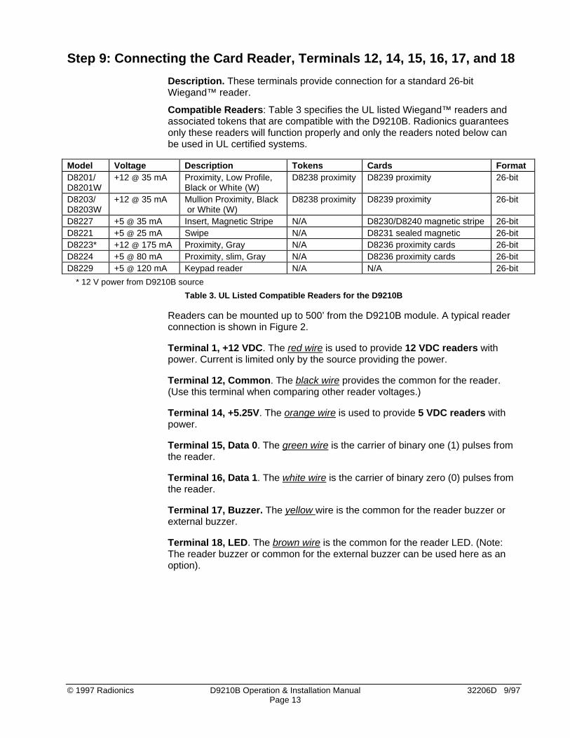
Description. These terminals provide connection for a standard 26-bitWiegand™ reader.
Compatible Readers: Table 3 specifies the UL listed Wiegand™ readers andassociated tokens that are compatible with the D9210B. Radionics guaranteesonly these readers will function properly and only the readers noted below canbe used in UL certified systems.
Model Voltage Description Tokens Cards FormatD8201/D8201W
+12 @ 35 mA Proximity, Low Profile,Black or White (W)
D8238 proximity D8239 proximity 26-bit
D8203/D8203W
+12 @ 35 mA Mullion Proximity, Black or White (W)
D8238 proximity D8239 proximity 26-bit
D8227 +5 @ 35 mA Insert, Magnetic Stripe N/A D8230/D8240 magnetic stripe 26-bitD8221 +5 @ 25 mA Swipe N/A D8231 sealed magnetic 26-bitD8223* +12 @ 175 mA Proximity, Gray N/A D8236 proximity cards 26-bitD8224 +5 @ 80 mA Proximity, slim, Gray N/A D8236 proximity cards 26-bitD8229 +5 @ 120 mA Keypad reader N/A N/A 26-bit
* 12 V power from D9210B source
Table 3. UL Listed Compatible Readers for the D9210B
Readers can be mounted up to 500’ from the D9210B module. A typical readerconnection is shown in Figure 2.
Terminal 1, +12 VDC. The red wire is used to provide 12 VDC readers withpower. Current is limited only by the source providing the power.
Terminal 12, Common. The black wire provides the common for the reader.(Use this terminal when comparing other reader voltages.)
Terminal 14, +5.25V. The orange wire is used to provide 5 VDC readers withpower.
Terminal 15, Data 0. The green wire is the carrier of binary one (1) pulses fromthe reader.
Terminal 16, Data 1. The white wire is the carrier of binary zero (0) pulses fromthe reader.
Terminal 17, Buzzer. The yellow wire is the common for the reader buzzer orexternal buzzer.
Terminal 18, LED. The brown wire is the common for the reader LED. (Note:The reader buzzer or common for the external buzzer can be used here as anoption).

32206D 9/97 D9210B Operation & Installation Manual © 1997 RadionicsPage 14
Step 10: Setting the Dipswitch and Tagging the Unit
The D9412 panel supports up to eight door controllers using all eight addresssettings. The D7412 supports up to two door controllers using the first twoaddress settings. Each D9210B uses one of eight addresses. Addresses cannot be duplicated. Because the D9210B is always supervised, two D9210Bmodules having the same address will not function and SDI failures will occur.
Fill out the Program Record Sheet. Be sure the program record sheet for thisdoor controller contains the area assignment, address assignment and controlcenter assignment.
TECH TIP: Whenever possible, be consistent when numbering doors, controlcenters, and areas. This will help when programming a system with more thanone door. (Example: Assign Door 1 to Area 1 and Control Center 1.)
The D9210B dipswitch with factory defaultsettings (all ON) is shown in Figure 4. Table 4shows the serial device reporting addresssettings for each door controller. Table 4 alsoshows dipswitch settings for Test and Failmodes.
Door Controller AddressFailMode
1 2 3 4 5* 6*
Serial DeviceControl CenterDisplay
Central StationModem IIIa2
D9210 #1 SDI #33 ON ON ON --- --- ---D9210 #2 SDI #34 OFF ON ON --- --- ---D9210 #3 SDI #35 ON OFF ON --- --- ---D9210 #4 SDI #36 OFF OFF ON --- --- ---D9210 #5 SDI #37 ON ON OFF --- --- ---D9210 #6 SDI #38 OFF ON OFF --- --- ---D9210 #7 SDI #39 ON OFF OFF --- --- ---D9210 #8 SDI #40 OFF OFF OFF --- --- ---
SDI Fail ModeSDI Fail – Door Unlocked --- --- --- ON --- ---SDI Fail – Door Locked --- --- --- OFF --- ---
* Switches 5 and 6 must stay in the “ON” position.
Table 4. D9210B Dipswitch Settings
Figure 4. D9210B DIP Switch(Factory Settings)
© 1997 Radionics D9210B Operation & Installation Manual 32206D 9/97Page 15
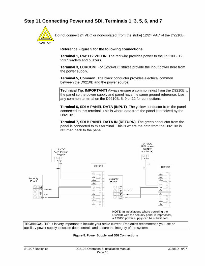
Step 11 Connecting Power and SDI, Terminals 1, 3, 5, 6, and 7
Do not connect 24 VDC or non-isolated [from the strike] 12/24 VAC of the D9210B.
Reference Figure 5 for the following connections.
Terminal 1, Pwr +12 VDC IN. The red wire provides power to the D9210B, 12VDC readers and buzzers.
Terminal 3, LCKCOM. For 12/24VDC strikes provide the input power here fromthe power supply.
Terminal 5, Common. The black conductor provides electrical commonbetween the D9210B and the power source.
Technical Tip: IMPORTANT! Always ensure a common exist from the D9210B tothe panel so the power supply and panel have the same ground reference. Useany common terminal on the D9210B, 5, 9 or 12 for connections.
Terminal 6, SDI A PANEL DATA (INPUT). The yellow conductor from the panelconnected to this terminal. This is where data from the panel is received by theD9210B.
Terminal 7, SDI B PANEL DATA IN (RETURN). The green conductor from thepanel is connected to this terminal. This is where the data from the D9210B isreturned back to the panel.
1PWR +
7SDIB
6SDIA
5COM
8T +
10ZN +
9ZNCOM
2LCKN/C
3LCKCOM
4LCKN/O
D9210B
1PWR +
7SDIB
6SDIA
5COM
8T +
10ZN +
9ZNCOM
2LCKN/C
3LCKCOM
4LCKN/O
D9210B
NOTE: In installations where powering theD9210B with the security panel is impractical,a 12VDC power supply can be substituted.
TECHNICAL TIP: It is very important to include your strike current. Radionics recommends you use anauxiliary power supply to isolate door controls and ensure the integrity of the system.
Figure 5. Power Supply and SDI Connections

32206D 9/97 D9210B Operation & Installation Manual © 1997 RadionicsPage 16
Step 12: Programming and Activating the D9210B
Description. The D9210B needs to be assigned with an area before it willcommunicate properly with the panel. In addition, the dipswitch settings and thepower need to be connected.
The dipswitch settings in Table 4 determine the address of the D9210B. At thetop of the ACCESS program record sheet, the address number (noted next tothe dipswitch setting in Figure 4) will determine which parameters for the doorcontroller are sent.
To activate the D9210B, follow the instructions in the D9210B Program EntryGuide (32207). Use the ACCESS Program Record Sheet (32208) to match thedoor to the proper address and to ensure that the door is assigned to the properarea.
Step 13: Testing the D9210B
Description. The D9210B comes shipped with a default program that will let yourun a quick test upon installing the unit. Go through the following items to verifythe D9210B is functioning properly. If you have problems, see the troubleshooting section.
D9210B: Verify that the Operational Monitor LED is pulsing approximately onceevery second. This indicates the microprocessor is running. Go to the [UNLOCKDOOR] function. A number from 1 to 8 should appear for the door controller. Ifan “F” appears, the unit has failed or is not responding correctly to the panel’spolls.
Zone: Using the Control Center, verify the point is normal when the door isclosed, the point goes off normal when the door is opened and a shunt is notapplied, and that the point stays normal upon opening the door on a valid accessgranted.
Strike: Read a valid token to activate the strike. If tokens have not been added,use the [DOOR CONTROL], [DOOR UNLOCK] mode to cycle the strike. Inaddition, you will cycle the strike when you test the RTE/REX inputs (if shunt onlyis not programmed “yes”).
RTE/REX: Fault these inputs to activate the strike. The default for the strike timeis 10 seconds. Test each separately.
Buzzer: The buzzer should have sounded on each strike activation. Also holdthe door open past the normal shunt time and ensure the “Extend Buzz”functions.
Reader: Depending on the reader, the reader LED will be red upon powering upthe D9210B. During the above tests, it will turn green anytime the strike isactivated.
To verify the reader, check and see that the D1 and D0 LED’s blink rapidly whilea card is passed through the reader or a token is held up to the proximity reader.
For other LED functionality, see Table 5, “LED Troubleshooting” .
© 1997 Radionics D9210B Operation & Installation Manual 32206D 9/97Page 17
Troubleshooting
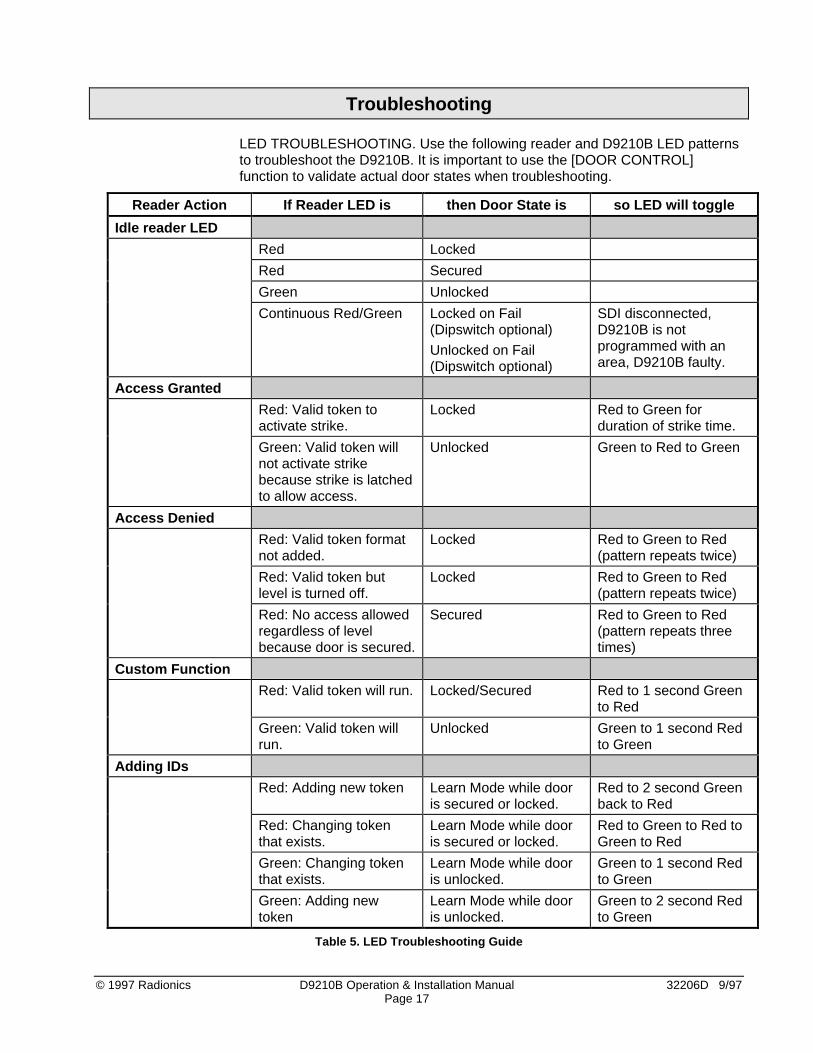
LED TROUBLESHOOTING. Use the following reader and D9210B LED patternsto troubleshoot the D9210B. It is important to use the [DOOR CONTROL]function to validate actual door states when troubleshooting.
Reader Action If Reader LED is then Door State is so LED will toggle
Idle reader LED
Red Locked
Red Secured
Green Unlocked
Continuous Red/Green Locked on Fail(Dipswitch optional)
Unlocked on Fail(Dipswitch optional)
SDI disconnected,D9210B is notprogrammed with anarea, D9210B faulty.
Access Granted
Red: Valid token toactivate strike.
Locked Red to Green forduration of strike time.
Green: Valid token willnot activate strikebecause strike is latchedto allow access.
Unlocked Green to Red to Green
Access Denied
Red: Valid token formatnot added.
Locked Red to Green to Red(pattern repeats twice)
Red: Valid token butlevel is turned off.
Locked Red to Green to Red(pattern repeats twice)
Red: No access allowedregardless of levelbecause door is secured.
Secured Red to Green to Red(pattern repeats threetimes)
Custom Function
Red: Valid token will run. Locked/Secured Red to 1 second Greento Red
Green: Valid token willrun.
Unlocked Green to 1 second Redto Green
Adding IDs
Red: Adding new token Learn Mode while dooris secured or locked.
Red to 2 second Greenback to Red
Red: Changing tokenthat exists.
Learn Mode while dooris secured or locked.
Red to Green to Red toGreen to Red
Green: Changing tokenthat exists.
Learn Mode while dooris unlocked.
Green to 1 second Redto Green
Green: Adding newtoken
Learn Mode while dooris unlocked.
Green to 2 second Redto Green
Table 5. LED Troubleshooting Guide
32206D 9/97 D9210B Operation & Installation Manual © 1997 RadionicsPage 18
Detailed System Description
Operational Primer
The D9210B is a fully supervised, addressable SDI bus device that allowsaccess control integration for the D9412 (8 doors) and D7412 (2 doors) panels.Each D9210B can store up to 986 user tokens (300 tokens for D7412), each witha different access level for each door. Authority for access is controlled by thelevel of the user, the time of day, the state of the door and the armed state of thearea that the D9210B is assigned to. Each of the authority restrictions can becontrolled through automatic and manual functions.
Users can be added to the system either by local programming using the D5200,remote programming using the Remote Account Manager (R.A.M.), or by addingtokens using the Add User function through the control center(s).
The D9210B is not programmed using a local or remote programmer. TheD9210B must be connected to the SDI bus to function properly and receiveoperational programming parameters and user data.
Outputs.
Dry contact SPDT relay for 12/24 volt strikes. The D136 removable relayprovides a Normally Closed (NC), Common (Input voltage) and Normally Open(NO) output. When the relay is energized, the outputs switch to an oppositestate.
Buzzer Output. The buzzer output activates when the door sequence begins or ifthe door is left open for an extended period of time. It provides common to thenegative side of the buzzer.
+5 VDC reader output. The +5 volt DC output is for ID readers that require alower voltage than the +12 VDC readers. It provides a maximum of 150 mA.
Inputs.
SDI input and output. SDI A (yellow) receives data from the SDI A of the panel.SDI B (green) returns data to the SDI B of the panel.
12 VDC input. This input is used to power the D9210B and provides aconnection for the 12 VDC reader and 12 VDC buzzer.
Supervised zone input for the door contact. The zone input on the D9210B isused for the door contact that is physically mounted on the door to which thestrike is connected.
The input can be configured for shorts/opens on faults but is normal only whenthe 1000k ohm resistor is in the circuit.
Unsupervised tamper input. The unsupervised tamper input is normal whenopen. Upon a short, the point number assigned to the supervised zone isreported as a MISSING PT### report.
© 1997 Radionics D9210B Operation & Installation Manual 32206D 9/97Page 19
Unsupervised Request to Enter (RTE) and Request to Exit (REX) inputs. TheRTE input and REX input are normally open inputs sharing the same commonterminal. When momentarily shorted (500 ms) by a dry contact input will initiatethe door sequence. Typical applications include a N/O momentary push buttonor a N/O momentary relay activation from a Door motion detector device.
The REX input generates the Door Request to Exit and is used to exit the areaassigned to the D9210B without having to use an ID. The RTE generates theDoor Request to Enter and is used to enter the area assigned to the D9210B.
Programming REX Shunt Only and RTE Shunt Only allows you to initiate onlythe shunt and buzz when the RTE or REX inputs are shorted. This eliminates theneed for a strike and would be used in applications where a push bar is used toopen the door.
It is advisable to assign a point number to the device used to activate the RTEand REX inputs (such as an infrared with addressable ZONEX). This ensuresthat the device is supervised.
Unsupervised reader. The Weigand Reader input is a five wire input thatsupplies +5 VDC (use the +12 VDC terminal for 12volt readers), negative,ground activation for the reader LED, (D1) and (D0) inputs for the card data.
Two LEDs are provided to indicate that data is reaching the inputs from thereader when an ID is read. The IDs do not have to be valid to illuminate theseLEDs, but the IDs do need to have a format that the reader can decipher.
Normal Door Sequence. The Normal Door Sequence of the D9210B is initiatedby a valid access granted (User ID) or door request (RTE/REX). This initiates thestrike, shunt and buzz time to activate the strike, shunt the point and create anevent reporting the door sequence has begun.
When the door is held open past the normal door sequence time, an extendeddoor sequence time is initiated. This extended time extends the shunt and re-activates the buzzer. If programmed, [ CLOSE DOOR # ] will display at thecontrol center assigned to the door.
The normal door sequence will not activate if the interlock point is in an offnormal (open or short) condition.
The INTERLOCK POINT can be assigned to multiple door controllers. This isuseful for applications that require doors to not activate when a point is faulteduntil the interlock point is normal.
Door States. There are four door states for the D9210B. These door states canbe controlled through the control center, the Remote Account Manager (R.A.M.),scheduled events (Skeds) and automatic programmable functions in the D9210Bparameters.
Locked Door. This state is considered a normal door state.
Unlock Door. This state allows the door to be opened for free access.
Secure Door. This state will not allow access unless a Fire Unlock occurs.
32206D 9/97 D9210B Operation & Installation Manual © 1997 RadionicsPage 20
Fire Unlock. This state allows free access no matter what the previous door stateor armed state is. This is a programmable option that can be used to allow freeaccess into the building upon a fire alarm.
Automatic Functions and Door State. The D9210B has two automaticfunctions that control door state based on the armed state of the area:
Auto Door. With this function as Yes, the door will be unlocked when the area isdisarmed.
Disarm on Open. With this function as Yes, a user with valid access rights willactivate the strike and disarm the system after the door is opened. With thisfunction as no, the area will disarm upon the strike activation.
Access Levels
Armed State rights Users can be prevented from access depending upon thearmed state of the area that the D9210B is assigned to. M-indicates the user hasaccess no matter what the armed state, P- indicates the user has access as longas the Area is perimeter armed or disarmed and D-indicates the user only hasaccess when the area is completely disarmed.
Disarm Access Level. Users are allowed to disarm the area with an access id.Care should be taken to ensure that the user first has the authority to activate thestrike based on the Armed State. P-indicates the user will disarm the area fromMaster to Perimeter Instant. D- indicates the user will disarm the area fromMaster or Perimeter to the disarmed state.
Skeds
Unlock Door . Provides an automatic free access at a specific time period.Requires a Lock Door Sked to return the door to normal. Can be overridden bymanual control at the control center.
Secure Door. Provides an automatic prevention of access at a specific timeperiod. Requires a Lock Door Sked to return to normal. Can be overridden bymanual control at the control center.
Lock Door. Provides an automatic lock door state at a specific time to return thedoor to normal requiring valid cards/tokens to allow access.
Message Suppression. Provides an automatic message off/on function at aspecific time for Door and Access Granted or No Entry messages.
Access Ctl Level On/Off. Provides an automatic on/off for each of the 14 levelsdealing with the access control. Once a level is turned off, all doors are affected.
Modular Design. The D9210B can be replaced by simply disconnecting theexisting unit and connecting a new one with the same dipswitch setting. Thepanel will download stored data to the new unit when it is powered up andconnected to the SDI bus.
Diagnostics. Patterns of LED activation will indicate door state and ID validity.Other indications include SDI failure. (see Table 5, LED Trouble ShootingGuide).

© 1997 Radionics D9210B Operation & Installation Manual 32206D 9/97Page 21
Basic Features• Highly reliable and simple to use• Provides direct interface to 26 bit Weigand card readers.• Interfaces with the D9412 (up to eight) or D7412 (up to two)
Control/Communicator panels• Onboard buzzer output• Card data LEDs indicators for low card data when valid format is read• Operational LED which indicates the CPU is functioning and unit is powered• Removable onboard relay for switching 12/24 VDC/VAC power• Option to unlock or lock door upon SDI bus failure• Supervised Onboard point• Request to Exit and Request to Enter inputs that can have a shunt only option• Easily programmable entry/exit door strike and shunt control• Four door states: Locked, Unlocked, Secured, Fire Unlock.• Disarm states using a token• Pre-warn for holding door open too long• Disarm system before or after a door opens• Automatic Unlock door on disarm, Locked Door when armed• Optional Deactivate strike when the door opened• Interlock point assignment to prevent access until interlock point is normal.• 1000 Cards/Tokens• Fourteen programmable levels of access authority• Users can be added or deleted remotely, locally and with Command Center
Displays and Reports• Access Granted with user ID and User Name• No Entry with user ID and door User Name• Request to Enter with door point text• Request to Exit with door point text• Door Unlocked with door point text• Door Locked with door point text• Alarm Point ### with door point text• Trouble Point ### with door point text• Missing Point ### with door point text• Please Close Door with door point text

32206D 9/97 D9210B Operation & Installation Manual © 1997 RadionicsPage 22
Door Release Application
The D9210B can be used for door release functions. When used in thisconfiguration, the strike relay contacts must be supervised. This can beaccomplished with the use of an end-of-line relay commonly used for smokedetectors. Connecting the D9210B for this application is shown in Figure 6.
Program Point Index in the POINTS handler as Supervisory with PointResponse as “A” (Supervisory on Open and Trouble on Short.
The power supply, end-of-line relay, and the D9210B must be in the sameenclosure or adjacent enclosures connected via conduit not longer than 20 feet.
NOTE: When using the D9210BC, you must use the D8004 TransformerEnclosure for the power supply transformer.
1PWR +
7SDIB
6SDIA
5COM
8T +
10ZN +
9ZNCOM
2LCKN/C
3LCKCOM
4LCKN/O
12COM
11RTE
D9210B
(-)
DOOR ADOOR A
(+)
-+
+-
LOO
P
ON
06 5 4 3 2 1
DATA
+-
-
Figure 6. D9210B Door Release Application Connections

™ The Radionics logo is a registered trademark of Radionics, Inc.© 1997 Radionics, Inc., Salinas, CA, USA. All rights reserved.
D9210B Terminal Quick Referenceand Electrical Specifications
Terminal Description Electrical Specifications
1 PWR + 12 VDC power input • 8.5 - 13.8V [depending on reader draw: 110mA (board) + 150 mA (reader max) = 260 mA]
2 LCK N/C Continuity with LCK COM when relay is off. • 12/24 V @ 2.0 A max (30 VDC max)
3 LCK COM Input to feed LCK N/C (T2) and Lock N/O (T3)
4 LCK N/O Continuity with LCK COM when relay is on. • 12/24 V @ 2.0 A max (30 VDC max)
5 COMMON Common Input (power for lock and device)
6 SDI A Data from the panel to the D9210B • high impedance bi-directional differential bus
7 SDI B Data back to the panel from the D9210B RS-485 @ 9600 baud
8 T + Positive input for Tamper, normally open • open collector input 1K pull up• V in < 1.8 V on > 3.2 V off
9 ZNCOM Common input for on-board point • 1K Ω termination resistor between T9 andT10 required
10 ZN + Positive Input for on-board point
11 RTE Input from Request to Enter (RTE) momentaryshort device
• open collector input 1K pull up• V in < 1.8 V on > 3.2 V off
12 COM Common input for REX/RTE devices
13 REX Input from Request to Exit (REX) momentaryshort device
• open collector input 1K pull up• V in < 1.8 V on > 3.2 V off
14 +5.2 V Power out to 5.2 VDC card reader. • V out 5 V ± .25 V for 20 - 140 mA load• 150 mA maximum continuous
15 DATA 0 Data 0 input from card reader (activates D0LED)
• high impedance differential inputs with 10 Kpull up to +5.2 V
16 DATA 1 Data 1 input from card reader (activates D1LED)
17 BUZZER Buzzer common upon strike activation. • sink up to 35 mA from 5 - 14 VDC source• output impedance is 100 Ω
18 LED LED common upon card read response andstrike activation.
• sink up to 35 mA from 5 - 14 VDC source• output impedance is 180 Ω
Table 6. Terminal Quick Reference Guide and Electrical Specifications
Radionics, Inc.PO Box 80012
Salinas, California 93901-0012
Related Documents