Welcome message from author
This document is posted to help you gain knowledge. Please leave a comment to let me know what you think about it! Share it to your friends and learn new things together.
Transcript

D6-58322 MAY 2011 iii
REVISIONS
707 AIRPLANE CHARACTERISTICS FOR AIRPORT PLANNING
DEC 1968
PAGE
JUNE 2010
PAGE
MAY 2011
PAGE
1-139
113
114
140-142
2


2 D6-58322
1.0 SCOPE AND INTRODUCTION 1.1 SCOPE This document provides, in a standardized format, airplane characteristics data for general airport planning. Since operational practices vary among airlines, specific data should be coordinated with the using airlines prior to facility design. Boeing Commercial Airplanes should be contacted for any additional information required. Content of the document reflects the results of the coordinated efforts by representatives from the following organizations:
Aerospace Industries Association
Airports Council International – North America
Air Transport Association of America
Air Transport Association of America
International Air Transport Association
1.2 INTRODUCTION
This document conforms to NAS 3601. It provides characteristics of the Boeing Model 707 family of airplanes for airport operators, airlines, and engineering consultant organizations. Airplane changes and available options may alter model characteristics; the data presented herein reflect typical airplanes in each model category. For additional information contact: Boeing Commercial Airplanes P.O. Box 3707 Seattle, WA 98124-2207 U.S.A. Attention: Manager, Airport Technology Mail Code: 20-93


D6-58322 JUNE 2010 113
7.0 PAVEMENT DATA
7.1 General Information
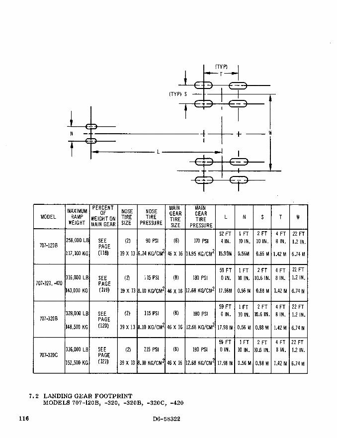
7.2 Landing Gear Footprint
7.3 Maximum Pavement Loads
7.4 Landing Gear Loading on Pavement
7.5 Flexible Pavement Requirements – SEFL 165A
7.6 Flexible Pavement Requirements - LCN Conversion
7.7 Rigid Pavement Requirements - Portland Cement Association Design Method
7.8 Rigid Pavement Requirements - LCN Conversion
7.9 Flexible and Rigid Pavement Requirements - FAA Design Method
7.10 ACN/PCN Reporting System - Flexible and Rigid Pavements

D6-58322 114 JUNE 2010
7.0 PAVEMENT DATA
7.1 General Information
A brief description of the pavement charts that follow will help in their use for airport planning. Each
airplane configuration is depicted with a minimum range of four loads imposed on the main landing
gear to aid in interpolation between the discrete values shown. All curves for any single chart
represent data based on rated loads and tire pressures considered normal and acceptable by current
aircraft tire manufacturer's standards. Tire pressures, where specifically designated on tables and
charts, are at values obtained under loaded conditions as certificated for commercial use.
Page 116 presents basic data on the landing gear footprint configuration, maximum design taxi loads,
and tire sizes and pressures.
Maximum pavement loads for certain critical conditions at the tire-to-ground interface are shown on
page 117.
Pavement requirements for commercial airplanes are customarily derived from the static analysis of
loads imposed on the main landing gear struts. The chart on page 118 is provided in order to
determine these loads throughout the stability limits of the airplane at rest on the pavement. These
main landing gear loads are used as the point of entry to the pavement design charts, interpolating
load values where necessary.
The flexible pavement design curves (Section 7.5) are based on procedures set forth in Instruction
Report No. S-77-1, "Procedures for Development of CBR Design Curves," dated June 1977, and as
modified according to the methods described in ICAO Aerodrome Design Manual, Part 3, Pavements,
2nd Edition, 1983, Section 1.1 (The ACN-PCN Method), and utilizing the alpha factors approved by
ICAO in October 2007. Instruction Report No. S-77-1 was prepared by the U.S. Army Corps of
Engineers Waterways Experiment Station, Soils and Pavements Laboratory, Vicksburg, Mississippi.
The line showing 10,000 coverages is used to calculate Aircraft Classification Number (ACN).
Rigid pavement design curves (page 130) have been prepared with the use of the Westergaard
equation in general accordance with the procedures outlined in the Design of Concrete Airport
Pavement (1955 edition) by Robert G. Packard, published by the American Concrete Pavement
Association, 3800 North Wilke Road, Arlington Heights, Illinois 60004-1268. These curves are
modified to the format described in the Portland Cement Association publication XP6705-2,
Computer Program for Airport Pavement Design (Program PDILB), 1968, by Robert G. Packard.


D6-58322 140 JUNE 2010
7.10 ACN/PCN Reporting System - Flexible and Rigid Pavements
To determine the ACN of an aircraft on flexible or rigid pavement, both the aircraft gross weight and
the subgrade strength category must be known. In the chart in 7.10.1, for an aircraft with gross
weight of 260,000 lb on a (Code B), the flexible pavement ACN is 32. Referring to 7.10.2, the same
aircraft on a medium strength subgrade rigid pavement has an ACN of 33.5.
The following table provides ACN data in tabular format similar to the one used by ICAO in the
“Aerodrome Design Manual Part 3, Pavements.” If the ACN for an intermediate weight between
maximum taxi weight and minimum weight of the aircraft is required, Figures 7.10.1 through 7.10.2
should be consulted.
ACN FOR RIGID PAVEMENT SUBGRADES – MN/m3
ACN FOR FLEXIBLE PAVEMENT SUBGRADES – CBR
AIRCRAFT TYPE
MAXIMUM TAXI
WEIGHT
MINIMUM WEIGHT (1)
LB (KG)
LOAD ON
ONE MAIN GEAR LEG (%)
TIRE
PRESSURE
PSI (MPa)
HIGH
150
MEDIUM
80
LOW
40
ULTRALOW
20
HIGH
15
MEDIUM
10
LOW
6
ULTRALOW
3
707-320C 336,000(152,400)
155,100(70,400)
28.50 180 (1.24) 41
16
46
16
55
18
71
24
41
15
48
17
57
20
66
23
(1) Minimum weight used solely as a baseline for ACN curve generation.

D6-58322 JUNE 2010 141
7.10.1 AIRCRAFT CLASSIFICATION NUMBER - FLEXIBLE PAVEMENT
MODEL 707-320C

D6-58322 142 JUNE 2010
7.10.2 AIRCRAFT CLASSIFICATION NUMBER - RIGID PAVEMENT
MODEL 707-320C
Related Documents