This project has received funding from the European Union’s Horizon 2020 research and innovation programme under grant agreement No 731993. Grant Agreement Number: 731993 Project acronym: AUTOPILOT Project full title: AUTOmated driving Progressed by Internet Of Things D.4.3 Final Technical Evaluation Due delivery date: 20/12/2019 Actual delivery date: 23/12/2019 Organization name of lead participant for this deliverable: IDIADA Dissemination level PU Public X PP Restricted to other programme participants (including the Commission Services) RE Restricted to a group specified by the consortium (including the Commission Services) CO Confidential , only for members of the consortium (including the Commission Services)

Welcome message from author
This document is posted to help you gain knowledge. Please leave a comment to let me know what you think about it! Share it to your friends and learn new things together.
Transcript

This project has received funding from the European Union’s Horizon 2020 research and innovation programme under grant agreement No 731993.
Grant Agreement Number: 731993
Project acronym: AUTOPILOT
Project full title: AUTOmated driving Progressed by Internet Of Things
D.4.3
Final Technical Evaluation
Due delivery date: 20/12/2019
Actual delivery date: 23/12/2019
Organization name of lead participant for this deliverable: IDIADA
Dissemination level
PU Public X
PP Restricted to other programme participants (including the Commission Services)
RE Restricted to a group specified by the consortium (including the Commission Services)
CO Confidential , only for members of the consortium (including the Commission Services)

2
Document Control Sheet
Deliverable number: 4.3
Deliverable responsible: IDIADA
Work package: WP4
Editor: IDIADA
Author(s) – in alphabetical order
Name Organisation E-mail
Alexander Velizhev IBM-RE [email protected]
Anton Dekusar IBM-IE [email protected]
Bart Netten TNO [email protected]
Harry Wedemeijer TNO [email protected]
Carlotta Firmani THALES [email protected]
Vincenzo Di Massa THALES [email protected]
Filippo Visintainer CRF [email protected]
Marco Andreetto CRF [email protected]
Georgios Karagiannis HUAWEI [email protected]
Liuxin Walle HUAWEI [email protected]
Lorenzo Viola HUAWEI [email protected]
Gurkan Solmaz NEC [email protected]
Haibo Chen UNL [email protected]
Kaushali Dave UNL [email protected]
Jianbing Gao UNL [email protected]
Junyan Chen UNL [email protected]
Jordi Pont IDIADA [email protected]
Daniel Gomez IDIADA [email protected]
Jos den Ouden TUE [email protected]
Joris Ijsselmuiden TUE [email protected]
Juan Villar CTAG [email protected]
Moisés Rial CTAG [email protected]
Louis Touko Tcheumadjeu DLR [email protected]
Robert Kaul DLR [email protected]
Martin David GEMALTO [email protected]
Thomas Reschka CETECOM [email protected]
Ralf Tiemann CETECOM [email protected]
Maria Guadalupe Gabian PSA [email protected]
Mahdi Ben Alaya SENSINOV [email protected]

3
Document Revision History
Version Date Modifications Introduced
Modification Reason Modified by
V0.1 26/04/2019 Structure of the document IDI
V0.2 08/05/2019 Safety update IDI
V0.3 08/05/2019 Comments on Data communication and Data Management
TNO
V0.4 09/05/2019 Status on Positioning, Localisation and Navigation
IDI
V0.5 28/11/2019 Final draft (Inputs from all topics and use cases)
IDI
V1.0 12/12/2019 Peer Review TELECOMITALIA
V1.0 17/12/2019 Peer Review VEDECOM
V1.1 16/12/2019 Final version DLR, TNO, IDI
Abstract
This document presents the technical results of evaluating the IoT technologies applied to the autonomous vehicles in the different Pilot Sites. The definition of the methodology was started in D4.1 and refined in D4.2 including the technical research questions, hypotheses, key performance indicators (KPI) and measurements to evaluate the Use Cases and Services implemented at the Pilot Sites. D4.3 aims to evaluate the added value of IoT to accelerate, enhance or enable Automated Driving functions. Evaluations are based on the data collected in Pilot Sites, for each Use Case and Service. The piloting of Use Cases and services are specific for each implementation, nevertheless the technical evaluations target the common added values of IoT to each use case and service. It is evaluated whether if IoT is accelerating the development and deployment of automated driving functions, IoT is enhancing the functionality or performance of automated driving functions or IoT is enabling new automated driving functions.
General topics like data management, data communication, navigation, environmental detections, safety, interoperability, replicability, sustainability, security and privacy are assessed from pilot site implementations in a global project view.
Legal Disclaimer
The information in this document is provided “as is”, and no guarantee or warranty is given that the information is fit for any particular purpose. The above referenced consortium members shall have no liability to third parties for damages of any kind including without limitation direct, special, indirect, or consequential damages that may result from the use of these materials subject to any liability which is mandatory due to applicable law. © 2017 by AUTOPILOT Consortium.

4
Abbreviations and Acronyms
Acronym Definition
CAD Connected and Automated Driving
CEMA Crowdedness Estimation Multimodal Actors
CNN Convolutional Neural Networks
CO2 Carbon Dioxide
COTS Commercial off-the-shelf
CSV Comma-Separated Values
EC European Commission
FMS Fleet Management System
GA Grant Agreement
GMT Greenwich Mean Time
GPS Global Positioning System
HD-Maps High Definition Maps
HY Hypotheses
JSON JavaScript Object Notation
KPI Key Performance Indicator
LIDAR Light Detection and Ranging
MAC Mandatory Access Control
MAV Micro Air Vehicle
MCA Micro Channel Architecture
MITM Man In The Middle
PII Private Information
PMS Parking Management System
PO Project officer
RADAR Radio Detection And Ranging
RQ Research Question
RTK Real Time Kinematic
SQL Structured Query Language
UA User Acceptance
UAC User Account Control
UTC Universal Time Coordinated
WP Work Package
XML eXtensible Markup Language

5
Table of Contents
EXECUTIVE SUMMARY .................................................................................................... 13
1 INTRODUCTION ....................................................................................................... 17
1.1 Purpose of the document .................................................................................................................. 17
1.2 Intended audience ............................................................................................................................ 17
1.3 Terminology ...................................................................................................................................... 18
1.4 Structure of the report ...................................................................................................................... 18
2 TECHNICAL EVALUATION METHODOLOGY ................................................................ 19
2.1 What is the added value of IoT for Automated Driving? .................................................................... 19
2.2 Topics of the evaluation .................................................................................................................... 19
2.3 Technical Research Questions and Hypotheses ................................................................................. 21
2.4 Technical indicators, measurements and metrics .............................................................................. 21
2.5 Test scenario, use cases and services definition ................................................................................ 21
3 USE CASES AND SERVICES ........................................................................................ 23
3.1 Automated Valet Parking .................................................................................................................. 23 3.1.1 Test scenarios ...................................................................................................................................... 23 3.1.2 Research Questions and Hypotheses .................................................................................................. 24 3.1.3 Technical indicators, measurements and metrics ............................................................................... 25 3.1.4 Evaluation............................................................................................................................................ 26
3.1.4.1 AVP Test site and location .......................................................................................................... 27 3.1.4.2 AVP AD prototype test vehicles .................................................................................................. 28 3.1.4.3 Evaluation of KPI-1: Technical complexity of the AVP Implementation ..................................... 29 3.1.4.4 Evaluation of KPI-2 / KPI-6: Evaluation of the detection performance of free parking spots and obstacles on the road .................................................................................................................................. 30 3.1.4.5 Evaluation of KPI-6: Evaluation of the route selected based on the obstacles on the road ...... 34 3.1.4.6 Evaluation of KPI-1 / KPI-7: Evaluation of parking process on the vehicle side ......................... 35 3.1.4.7 Evaluation of the KPI-5: Evaluation of the Reliable information of the driver about the parking process 42
3.1.5 Platforms interoperability supported by AVP Brainport ..................................................................... 44 3.1.6 Data logging and management ........................................................................................................... 45 3.1.7 Conclusion ........................................................................................................................................... 46
3.2 Urban Driving .................................................................................................................................... 47 3.2.1 Research Questions and Hypotheses .................................................................................................. 48 3.2.2 Technical indicators, measurements and metrics ............................................................................... 49 3.2.3 Evaluation............................................................................................................................................ 49
3.2.3.1 Brainport .................................................................................................................................... 49 3.2.3.2 Livorno ........................................................................................................................................ 51 3.2.3.3 Tampere ..................................................................................................................................... 51 3.2.3.4 Versailles .................................................................................................................................... 54

6
3.2.3.5 Vigo ............................................................................................................................................. 55 3.2.4 Results and conclusions ...................................................................................................................... 56
3.3 Highway Pilot .................................................................................................................................... 56 3.3.1 Research Questions and Hypotheses .................................................................................................. 57 3.3.2 Technical indicators, measurements and metrics ............................................................................... 58 3.3.3 Evaluation............................................................................................................................................ 59
3.3.3.1 Highway Pilot – Brainport ........................................................................................................... 59 3.3.3.2 Highway Pilot – Livorno .............................................................................................................. 62
3.4 Platooning ......................................................................................................................................... 65 3.4.1 Research Questions and Hypotheses .................................................................................................. 68 3.4.2 Technical indicators, measurements and metrics ............................................................................... 69 3.4.3 Evaluation............................................................................................................................................ 70 3.4.4 Conclusion ........................................................................................................................................... 75
3.5 Ride Sharing ...................................................................................................................................... 77 3.5.1 Technical Research Questions and Hypotheses .................................................................................. 77 3.5.2 Technical indicators, measurements and metrics ............................................................................... 77 3.5.3 Evaluation............................................................................................................................................ 77
3.5.3.1 Environmental setup .................................................................................................................. 78 3.5.3.2 Results ........................................................................................................................................ 79
3.6 Car Rebalancing ................................................................................................................................. 82 3.6.1 Research Questions and Hypotheses .................................................................................................. 83 3.6.2 Technical indicators, measurements and metrics ............................................................................... 83 3.6.3 Analysis ............................................................................................................................................... 83
3.6.3.1 Evaluation 1: Can IoT be used to dynamically relocate AD vehicles, based on crowdedness and demand and decrease their journey time? .................................................................................................. 84 3.6.3.2 Evaluation 2: Is the tracking and communications of VRUs fast enough so that their locations can be sent and used by IoT enhanced AD to decrease the detection time for these VRUs? ....................... 87
3.6.3.2.1 Experiment set 1: VRU detection using GeoFencing or video camera .................................. 87 3.6.3.2.2 Experiment set 2: Journey time ............................................................................................ 88
4 TOPICS..................................................................................................................... 91
4.1 Safety ................................................................................................................................................ 91 4.1.1 Safety Audit results ............................................................................................................................. 91
4.1.1.1 Users – safety relation ................................................................................................................ 92 4.1.1.2 New software / hardware of the vehicle – safety relation ......................................................... 95 4.1.1.3 AD functions affected by IoT – safety relation ........................................................................... 95 4.1.1.4 Fall-back to original state – safety relation .............................................................................. 101 4.1.1.5 Data priority rules – safety relation .......................................................................................... 101 4.1.1.6 Data delay, missing or corrupted – safety relation .................................................................. 102
4.1.2 Safety Interventions results .............................................................................................................. 103 4.1.3 Conclusions ....................................................................................................................................... 105
4.2 Security ........................................................................................................................................... 105 4.2.1 The research question ....................................................................................................................... 105 4.2.2 Assessment methodology ................................................................................................................. 106 4.2.3 Security evaluation results ................................................................................................................ 106
4.2.3.1 Security events logging ............................................................................................................. 106 4.2.3.2 Logged information .................................................................................................................. 107
4.2.4 Security requirement coverage ......................................................................................................... 107 4.2.5 Conclusion and recommendations for production ........................................................................... 107
7
4.3 Privacy ............................................................................................................................................ 107 4.3.1 Assessment methodology ................................................................................................................. 108 4.3.2 Assessment of use case data flows ................................................................................................... 108 4.3.3 Assessment of user tracking ............................................................................................................. 109 4.3.4 Assessment of information in the ecosystem and possible privacy leaks ........................................ 109 4.3.5 Privacy evaluation results ................................................................................................................. 110
4.3.5.1 Evaluation of privacy threats .................................................................................................... 110 4.3.5.2 Authentication, authorization and access to data and services ............................................... 110
4.3.6 IoT Platform federation ..................................................................................................................... 111 4.3.7 Privacy requirement coverage .......................................................................................................... 111 4.3.8 Conclusions ....................................................................................................................................... 111 4.3.9 Recommendations for production .................................................................................................... 112
4.4 Replicability, sustainability & interoperability ................................................................................. 113 4.4.1 Research Questions and Hypotheses ................................................................................................ 113 4.4.2 Assessment methodology ................................................................................................................. 115 4.4.3 Technical indicators, measurements and metrics ............................................................................. 116 4.4.4 Evaluation.......................................................................................................................................... 117
4.5 Data management ........................................................................................................................... 124 4.5.1 In-vehicle IoT-platform data management ....................................................................................... 125
4.5.1.1 Technical Research Questions and Hypotheses ....................................................................... 125 4.5.1.2 Technical indicators, measurements and metrics .................................................................... 126 4.5.1.3 Evaluation ................................................................................................................................. 126 4.5.1.4 Conclusion ................................................................................................................................ 128
4.5.2 Cloud based IoT-platform data management ................................................................................... 129 4.5.2.1 Technical Research Questions and Hypotheses ....................................................................... 129 4.5.2.2 Technical indicators, measurements and metrics .................................................................... 130 4.5.2.3 Evaluation ................................................................................................................................. 130 4.5.2.4 Conclusion ................................................................................................................................ 134
4.6 Data communication ....................................................................................................................... 134 4.6.1 Technical Research Questions and Hypotheses ................................................................................ 134 4.6.2 Technical indicators, measurements and metrics ............................................................................. 135 4.6.3 Evaluation.......................................................................................................................................... 136 4.6.4 Conclusions ....................................................................................................................................... 138
4.7 Position, localisation and navigation ............................................................................................... 139 4.7.1 Technical Research Questions and Hypotheses ................................................................................ 139 4.7.2 Technical indicators, measurements and metrics ............................................................................. 140 4.7.3 Evaluation.......................................................................................................................................... 140
4.7.3.1 Navigation improvement thanks to Travel time reduction ...................................................... 140 4.7.3.2 Navigation improvement due to speed profile smoothness .................................................... 142
4.7.4 Conclusions ....................................................................................................................................... 144
4.8 Environmental detections ............................................................................................................... 144 4.8.1 Technical Research Questions and Hypotheses ................................................................................ 145 4.8.2 Technical indicators, measurements and metrics ............................................................................. 145
4.8.2.1 Analysis of metrics .................................................................................................................... 148 4.8.3 Evaluation per Pilot Site and Use Case .............................................................................................. 148
4.8.3.1 Brainport Urban Driving evaluation ......................................................................................... 149 4.8.3.2 Brainport Highway Pilot ........................................................................................................... 154 4.8.3.3 Livorno Highway Pilot ............................................................................................................... 158 4.8.3.4 Tampere AVP ............................................................................................................................ 160 4.8.3.5 Versailles Urban Driving ........................................................................................................... 162
4.8.4 Conclusions ....................................................................................................................................... 165

8
5 CONCLUSIONS ....................................................................................................... 167
6 REFERENCES .......................................................................................................... 171
7 ANNEXES ............................................................................................................... 173
7.1 Log data specifications .................................................................................................................... 173 7.1.1 Vehicle Log Data ................................................................................................................................ 174 7.1.2 Communication Log Data .................................................................................................................. 174 7.1.3 Application Log Data ......................................................................................................................... 175
7.2 Standards implementation list for replicability, sustainability & interoperability ........................... 175 7.2.1 List of Standards ................................................................................................................................ 176 7.2.2 Summary of standards and technologies implemented in use cases and pilot sites ........................ 182
7.2.2.1 IoT Platform .............................................................................................................................. 183 7.2.2.2 Vehicle IoT Platform ................................................................................................................. 183 7.2.2.3 Communication Network ......................................................................................................... 185 7.2.2.4 IoT Ecosystem ........................................................................................................................... 186
7.2.3 Aggregated results on standards ...................................................................................................... 186
7.3 Replicability, sustainability, interoperability questionnaire ............................................................ 189
7.4 Replicability assessment tables ....................................................................................................... 189 7.4.1 Automated Valet Parking .................................................................................................................. 189 7.4.2 Platooning ......................................................................................................................................... 192 7.4.3 Highway Pilot .................................................................................................................................... 193 7.4.4 Urban Driving .................................................................................................................................... 193
7.5 Pilot Plan ......................................................................................................................................... 202
7.6 AUTOPILOT security evaluation questionnaire ................................................................................ 202 7.6.1 Definition of a common list of events to be logged .......................................................................... 202 7.6.2 Definition of a common list of log-parameters ................................................................................. 204
7.7 AUTOPILOT privacy assessment questionnaire................................................................................ 205 7.7.1 Privacy assessment of components .................................................................................................. 207
7.8 Communication Performance Analyses ........................................................................................... 208
7.9 Safety Intervention form ................................................................................................................. 211
7.10 Navigation analysis for Brainport Platooning .................................................................................. 212
7.11 Navigation analysis for Brainport Highway Pilot ............................................................................. 212

9
List of Figures Figure 1 AUTOPILOT AD modes, services and applications .................................................................................. 17 Figure 2 Brainport roadside camera ..................................................................................................................... 30 Figure 3 Roadside camera detections................................................................................................................... 31 Figure 4 Field of view captured by cameras under test ....................................................................................... 31 Figure 5 Static object detection ........................................................................................................................... 32 Figure 6 Parking spot occupancy .......................................................................................................................... 33 Figure 7 MAV parking spot occupancy detection (Left: occupied, middle: free, right: MAV in flight) ................. 33 Figure 8 MAV path flow on the DLR test area in Brunswick ................................................................................. 34 Figure 9 Road network in Brainport PS ................................................................................................................. 35 Figure 10 Route A: shorter and optimal route with obstacle ............................................................................... 35 Figure 11 Route B: longer and optimal free obstacle route ................................................................................. 35 Figure 12 Parking service app screenshot ............................................................................................................ 35 Figure 13 Drop-off scenario route (left), and pickup scenario route (right) ......................................................... 36 Figure 14 Trajectories in the pickup scenario ....................................................................................................... 37 Figure 15 Travel speed in the pickup scenario ..................................................................................................... 37 Figure 16 Trajectories for the baseline manoeuvres ............................................................................................ 38 Figure 17 Trajectories for AD manoeuvres ........................................................................................................... 38 Figure 18 Speed for the track in AD mode and baseline ...................................................................................... 38 Figure 19 Parking precision................................................................................................................................... 39 Figure 20 Parking locations ................................................................................................................................... 39 Figure 21 VRU detection precision ....................................................................................................................... 39 Figure 22 Interaction between the AVP devices and the IoT platforms ............................................................... 40 Figure 23 Transmission time from vehicle to PMS ............................................................................................... 40 Figure 24 Delay between RSU/Vehicle and broker/IoT ........................................................................................ 42 Figure 25 Vigo AVP App ........................................................................................................................................ 43 Figure 26 Brainport AVP app ................................................................................................................................ 44 Figure 27 Tampere AVP app ................................................................................................................................. 44 Figure 28 IoT platforms used in Brainport AVP .................................................................................................... 45 Figure 29 AVP Brainport IoT information flow ..................................................................................................... 45 Figure 30 Brainport VRU detection with IoT ......................................................................................................... 50 Figure 31 Brainport VRU detection without IoT ................................................................................................... 50 Figure 32 Brainport GLOSA with IoT ..................................................................................................................... 50 Figure 33 Livorno VRU detection with IoT ............................................................................................................ 51 Figure 34 Livorno GLOSA with IoT ........................................................................................................................ 51 Figure 35 Tampere GLOSA .................................................................................................................................... 52 Figure 36 Tampere state ....................................................................................................................................... 52 Figure 37 Tampere VRU detection with IoT ......................................................................................................... 52 Figure 38 Tampere RSU danger area .................................................................................................................... 52 Figure 39 Tampere GLOSA without IoT ................................................................................................................ 53 Figure 40 Tampere state ....................................................................................................................................... 53 Figure 41 Tampere VRU detection without IoT .................................................................................................... 53 Figure 42 Tampere state ....................................................................................................................................... 53 Figure 43 Versailles VRU detection with IoT ......................................................................................................... 54 Figure 44 Versailles VRU detection without IoT ................................................................................................... 54 Figure 45 Vigo GLOSA and VRU detection ............................................................................................................ 55 Figure 46 Vigo VRU detection detail ..................................................................................................................... 55 Figure 47 Top view of the test site and hazard placement................................................................................... 60 Figure 48 Example of data from Brainport test session ....................................................................................... 61 Figure 49 Data of the discarded experiments. ..................................................................................................... 61 Figure 51 Example of a puddle test. The positions of interest are zoomed ......................................................... 63 Figure 51 Adaptation manoeuvre for the paddle test of Figure 51 ...................................................................... 64 Figure 53 Example of a roadwork test. The positions of interest are zoomed; arrows highlight the vehicle
movement direction .................................................................................................................................... 64 Figure 53 Adaptation manoeuvre for the roadwork test of Figure 53 ................................................................. 65

10
Figure 54 Platooning test run in Brainport ........................................................................................................... 72 Figure 55 Platooning test run in Versailles ........................................................................................................... 73 Figure 56 Simulation area ..................................................................................................................................... 78 Figure 57 Comparison of customers by status ..................................................................................................... 80 Figure 58 Customer dynamics by status ............................................................................................................... 81 Figure 59 Car rebalancing overview ..................................................................................................................... 82 Figure 60 Rerouting of vehicle on other route based on crowd detection .......................................................... 84 Figure 61 Visualisation of the two routes with the actual drive traces ................................................................ 85 Figure 62 Visualization of the location of VRUs .................................................................................................... 85 Figure 63 (a) Vehicle velocity vs. time; (b) histogram of normalised journey time vs. velocity for Evaluation 1
experiments ................................................................................................................................................. 86 Figure 64 Histogram of normalised Journey times collected during all runs (11 runs with IoT, 11 runs without
IoT), for Evaluation 1 experiments ............................................................................................................... 86 Figure 65 (a) Displacement vs. travel time, (b) Velocity/speed vs. travel time and c) Acceleration vs. travel time
..................................................................................................................................................................... 88 Figure 66 (a) Vehicle velocity vs. time; (b) histogram of normalised journey time vs. velocity for Evaluation 2 -
Experiment set 2 .......................................................................................................................................... 89 Figure 67 Histograms of normalised Journey times collected during all runs, for Evaluation 2 - Experiment set 2
..................................................................................................................................................................... 89 Figure 68 Brainport user risks ............................................................................................................................... 93 Figure 69 Livorno User Risks ................................................................................................................................. 94 Figure 70 Tampere user risks ................................................................................................................................ 94 Figure 71 Versailles user risks ............................................................................................................................... 94 Figure 72 Vigo user risks ....................................................................................................................................... 95 Figure 73 Versailles safety intervention analysis ................................................................................................ 104 Figure 74 - Example of information flow of Ride sharing use case ..................................................................... 109 Figure 75 Replicability, Sustainability and Interoperability methodology .......................................................... 115 Figure 76 Distribution of the number of connected IoT devices per singles test run ........................................ 131 Figure 77 Unique IoT message types per singles test run .................................................................................. 131 Figure 78 Number of connected IoT devices per run ......................................................................................... 132 Figure 79 Unique IoT message types per run ..................................................................................................... 132 Figure 80 Distribution of connected IoT devices ................................................................................................ 133 Figure 81 Distribution of unique IoT message types per run ............................................................................. 133 Figure 82 Ad-hoc communication range ............................................................................................................ 137 Figure 83 Alternative communication paths in the Brainport Urban Driving use case ...................................... 138 Figure 84 Brainport platooning route ................................................................................................................. 141 Figure 85 Meeting times since checkpoint A from Brainport Platooning ........................................................... 142 Figure 86 Meeting distance since checkpoint A ................................................................................................. 142 Figure 87 Hazards location in Highway Pilot Brainport ...................................................................................... 143 Figure 88 Speed vs. Meters Analysis (Baseline-T7) ............................................................................................. 144 Figure 89 Speed vs. Meters Analysis (IoT enabled-T9) ....................................................................................... 144 Figure 90 Brainport Urban Driving / Rebalancing use case architecture ............................................................ 150 Figure 91 VRU smartphone interface ................................................................................................................. 151 Figure 92 Typical output of in-vehicle camera detections compared with Smartphone GeoFencing (IoT)
detections .................................................................................................................................................. 151 Figure 93 Position accuracy of the VRU smartphone GPS with respect to camera detections .......................... 152 Figure 94 Overall evaluation of distance threshold ............................................................................................ 153 Figure 95 Brainport Highway Pilot architecture ................................................................................................. 155 Figure 96 Hazard detection rate for Variation 1 across detection and driving adaptation vehicles .................. 157 Figure 97 Hazard detection rate for Variation 2 across detection and driving adaptation vehicles .................. 157 Figure 98 Vehicle speed profile and puddle detection 2 .................................................................................... 159 Figure 99 Vehicle speed profile and roadworks detection 1 .............................................................................. 159 Figure 100 Vehicle speed profile and roadworks detection 2 ............................................................................ 160 Figure 101 Vehicle parking in Parking Spot 1 ..................................................................................................... 161 Figure 102 Vehicle parking in Parking Spot 2 ..................................................................................................... 162 Figure 103 Vehicle parking in Parking Spot 3 ..................................................................................................... 162 Figure 104 Versailles Urban Driving – baseline test (IoT off) .............................................................................. 163

11
Figure 105 Versailles Urban Driving – baseline test (IoT on) .............................................................................. 163 Figure 106 Versailles Urban Driving – baseline test (IoT off) .............................................................................. 164 Figure 107 Versailles Urban Driving – IoT enabled test (IoT on) ........................................................................ 164 Figure 108 V2V communication delays at the access layer for ITS-G5 (top) and UWB (bottom) in Brainport .. 208 Figure 109 V2I end-to-end communication delay for ITS-G5 and 4G/LTE communication ................................ 209 Figure 110 End-to-end communication delays for V2I and I2V messages ......................................................... 210 List of Tables Table 1 General overview of AVP implementations ............................................................................................. 23 Table 2 Automated Valet Parking process ............................................................................................................ 24 Table 3 Performance Indicators for AVP evaluation ............................................................................................. 25 Table 4 AVP Test sites ........................................................................................................................................... 27 Table 5 Prototype test vehicles for each Pilot Site ............................................................................................... 28 Table 6 AVP implementation ................................................................................................................................ 29 Table 7 Parking spot detection rate...................................................................................................................... 32 Table 8 Obstacle detection rate ........................................................................................................................... 32 Table 9 Detection rate .......................................................................................................................................... 34 Table 10 Conclusions for IoT improvements in detections .................................................................................. 35 Table 11 Tampere parking duration and travel distance comparison .................................................................. 36 Table 12 Vigo parking duration and travel distance comparison ......................................................................... 36 Table 13 Statistics for the transmission time for TNO vehicle .............................................................................. 41 Table 14 Statistics for the transmission time for DLR vehicle .............................................................................. 41 Table 15 Statistics for transmission time .............................................................................................................. 41 Table 16 AVP data logging and management ....................................................................................................... 45 Table 17 AVP evaluation conclusions ................................................................................................................... 46 Table 18 Brainport average maximum jerk .......................................................................................................... 50 Table 19 Livorno average maximum jerk .............................................................................................................. 51 Table 20 Tampere average maximum jerk ........................................................................................................... 54 Table 21 Versailles average maximum jerk .......................................................................................................... 55 Table 22 Vigo average maximum jerk .................................................................................................................. 55 Table 23 Urban Driving conclusions ..................................................................................................................... 56 Table 24 Final KPIs from Brainport tests............................................................................................................... 62 Table 25 Effect of detection rate on validation latency. ...................................................................................... 62 Table 26 Final KPIs from Livorno tests .................................................................................................................. 65 Table 27 Platform formation and platooning actions ........................................................................................... 67 Table 28 Performance Indicators for Platoon Formation ..................................................................................... 70 Table 29 Performance measures for Platoon Formation ..................................................................................... 73 Table 30 Area locations and probabilities of vehicle locations ............................................................................ 79 Table 31 Trip origin and destination probabilities ................................................................................................ 79 Table 32 Comparison of customers by status ....................................................................................................... 80 Table 33 Ride sharing measurements .................................................................................................................. 81 Table 34 Ride sharing verification hypotheses ..................................................................................................... 81 Table 35 List of user interactions .......................................................................................................................... 92 Table 36 List of user risks ...................................................................................................................................... 92 Table 37 Users involved in each Pilot Site ............................................................................................................ 93 Table 38 Software and hardware modifications to vehicle .................................................................................. 95 Table 39 Confusion matrix analysis ...................................................................................................................... 96 Table 40 Tampere confusion matrix ..................................................................................................................... 96 Table 41 Versailles confusion matrix .................................................................................................................... 97 Table 42 Vigo confusion matrix ............................................................................................................................ 97 Table 43 Livorno confusion matrix ....................................................................................................................... 98 Table 44 Brainport confusion matrix .................................................................................................................. 100 Table 45 Methods to fall back to original state .................................................................................................. 101 Table 46 Pilot Sites data priority ......................................................................................................................... 101 Table 47 Vehicle reaction when data is delayed, missing or corrupted ............................................................. 102

12
Table 48 Versailles safety intervention example ................................................................................................ 103 Table 49 Replicability, Sustainability and Interoperability technical indicators ................................................ 116 Table 50 Use cases by pilot sites ........................................................................................................................ 117 Table 51 IoT platforms by pilot sites ................................................................................................................... 117 Table 52 Assessment of the technical evaluation criteria - implementation by pilot sites (by July 2019) ......... 118 Table 53 Interoperability assessment by pilot sites ........................................................................................... 119 Table 54 Criteria weights .................................................................................................................................... 122 Table 55 Replicability level comparison ............................................................................................................. 122 Table 56 Platooning results for Brainport .......................................................................................................... 130 Table 57 Evaluation results for AVP Brainport ................................................................................................... 132 Table 58 Highway Pilot evaluation results .......................................................................................................... 133 Table 59 Urban Driving evaluation results ......................................................................................................... 134 Table 60 Data communication measurements ................................................................................................... 136 Table 61 V2X communication delays .................................................................................................................. 136 Table 62 Position and Navigation measurements ............................................................................................. 140 Table 63 Navigation improvements from Brainport platooning ........................................................................ 142 Table 64 Conclusions for positioning, localisation and navigation topic ............................................................ 144 Table 65 Environmental vehicle measurements ................................................................................................ 146 Table 66 Available environment sensor measurements (relative and/or absolute) ......................................... 148 Table 67 Environmental Detections research questions with respect to use cases ........................................... 149 Table 68 Environmental Detections technical measures & metrics with respect to use cases .......................... 149 Table 69 Brainport Highway pilot – evaluation of false detections with respect to position accuracy with
Detection vehicle ....................................................................................................................................... 156 Table 70 Brainport Highway pilot – evaluation of false detections with respect to position accuracy with driving
adaptation vehicle ..................................................................................................................................... 156 Table 71 Overview of standards and technologies implemented in the different use cases and pilot sites ..... 176 Table 72 AVP replicability assessment................................................................................................................ 189 Table 73 Platooning replicability assessment ..................................................................................................... 192 Table 74 Highway Pilot replicability assessment ................................................................................................ 193 Table 75 Urban Driving replicability assessment ................................................................................................ 193 Table 76 AUTOPILOT security events ................................................................................................................. 203 Table 77 AUTOPILOT common list of log-parameters ........................................................................................ 204 Table 78 Ride sharing service component .......................................................................................................... 207 Table 79 Privacy interfaces ................................................................................................................................. 207 Table 80 Information exchanged on interfaces .................................................................................................. 207 Table 81 Data persisted by the component ....................................................................................................... 207 Table 82 Services used by each use case implementation ................................................................................. 208 Table 83 Safety intervention form ...................................................................................................................... 211

13
Executive Summary
The aim of the AUTOPILOT project is to bring together knowledge and technology from the automotive and the Internet-of-Things (IoT) value chains in order to develop IoT-architectures and platforms that will advance autonomous driving (AD) in a connected environment. More specifically, AUTOPILOT aims to evaluate how IoT can improve AD functionalities and services. AUTOPILOT will develop new automated driving services by connecting automated driving equipped vehicles over IoT. The IoT services being developed are expected to accelerate, enhance or enable autonomous driving functions. The resulting system, consisting of several Internet of Things Platforms and its connected devices, needs to be evaluated from a technical point of view. This document presents the final technical evaluation results on several technical topics – functionality, performance, safety, security and privacy, replicability, sustainability and interoperability – that are related to AUTOPILOT’s use of IoT technologies for advancing AD. AUTOPILOT Deliverable D4.1 [1] – presented the overall “Methodology for Evaluation” as a common approach to technical evaluation and the assessment of the impact on business, quality of life and user acceptance. Deliverable D4.2 [2] refines the technical evaluation methodology starting from the D4.1 common approach, and hypotheses, indicators, measurements, pilot scenarios, the data provisioning and quality, the data requirements and the data that has been agreed to be provided by the pilot sites in cooperation with WP2 and WP3. This deliverable, D4.3, presents the results of the evaluation of IoT improvements that have been realised in the implementations of Use Case and services in the Pilot Site. Given the diversity of implementations, an effort has been made to refine KPIs and measurements that can be carried out in multiple the Pilot Sites in order to achieve an evaluation that allows for a fair comparison of the added value of IoT. This has required an effort in the coordination with the different pilot sites and, in some cases, it was necessary to adapt some measurements and evaluations with respect to D4.2 in order to achieve this goal. One important issue faced in this deliverable was that the Pilots were not large scale and the expectations of the storyboards were only partially realized. There were also a low number of test runs and volumes of data to draw reliable conclusions on impacts. The quality of log data varied among all the PS on compliance, consistency, and volume and this constrained the technical evaluation. The best results are collected to support the feasibility of improvements and added value of IoT. The most significant technical improvements due to IoT are:
Enabling the environmental detection of obstacles in advance and informing Automated Vehicles (AV) earlier resulting in an improvement on safety.
Enhancing or smoother navigation.
Enabling traffic control information improving speed and route advising. The major improvements and added value to use case: For Automated Valet Parking (AVP) use case:
1. IoT accelerates AVP by saving the user parking time
2. IoT enables detection and avoidance of obstacles to support AV parking and route planning.
3. IoT reduces the safety risk by avoiding obstacles and skewed parked cars.

14
For Platooning use case: 1. IoT enables platoon formation over larger distances.
2. IoT potentially enables smoother passing of controlled intersections. For Highway Pilot use case:
1. IoT enables to advise AV to avoid and mitigate road surface hazards and smoother driving. For Urban Driving use case:
1. IoT enhances Vulnerable Road User (VRU) detection and result in smoother driving, i.e slowing down earlier and more docile.
For Ride Sharing use case:
1. IoT enhances the routing function resulting in a minor reduction in travel time. 2. IoT accelerates the deployment of the service that can join other separate services using AV
like AVP and platooning. For Car Rebalancing use case:
1. IoT enhances VRUs detection and speed reduction to reduce to safety risk. 2. IoT enhances the route selection resulting in minor reduction in travel time due to crowd
estimation service. 3. IoT enhances the VRU detection time.
The major improvements and added value to technical topics that generically apply to automated driving functions and all use cases: For the safety topic:
1. An important observation to make is that IoT data is not directly used for automated vehicle control in any pilot. IoT data is indirectly used to avoid or stop for safety hazards, and in all implementations additional safety measures have been implemented to override controls if needed.
2. Only one safety intervention is reported that did not related to IoT data sources. 3. Due to low number of test runs, we can only give an indication that “IoT is enhancing safety”
by avoiding or stopping in front of safety events received via IoT.
For the security and privacy topic: 1. Most of the solutions used logging provided by default IoT platform implementations
without any addition. They did not modify the logging to be more suitable for AUTOPILOT, only used what they had. This default logging is usually fine for IoT use cases including security during operation (e.g. logging access to the platform) and comes from industry good best practice. For AUTOPILOT it would be recommended to add more information such as data read, or data modified during the logged event to provide information in case of incident resolution (when they need to investigate what was the reason of an accident).
2. Most of the solutions registered vehicles with permanent identifiers. It means that the logs would contain full information about vehicle trajectory and as such may be used for user tracking without any extra work. Most advanced solutions used identifiers that changed over time, so even if someone reads the logs, he would not be able to track the vehicle for more than a few minutes.
For the interoperability, replicability, sustainability topic:
1. Standardization is a key requirement to achieve high levels of replicability, sustainability, and interoperability. Implementation of IoT platforms and devices that support such industry

15
standards allowed demonstrating interoperability between the pilot site during Test fest activities and inspiring results prove IoT applicability in the automotive domain.
2. When if small modifications are realized it will be feasible that use cases can support replicability and interoperability between specific sites. For instance, Ride Sharing from Versailles would be easily replicable to Brainport and AVP from Tampere and Vigo would also be replicable to Brainport.
For the data management topic: 1. The evaluation results show that In-vehicle IoT-platforms are used for communication with
the cloud based IoT-platform in order to make each use case operational, and enhance automated driving for example to connect to cloud services and for extending the range of detections.
2. Few examples, such as AVP, enable the exchange of vehicle sensor data, meta data and cloud sources via IoT platforms in a manner that is independent of the pilot site, vehicle or sensor. Most use cases use a variety in implemented standards, technologies and IoT message types for provide vehicle sensor data to IoT services and vice versa to use IoT data in vehicles. The in-vehicle IoT platforms do not implement a data management capability to search and discover new IoT services that provide the required information.
3. The intense evaluation of cloud data management shows a very active usage of Cloud IoT-platforms by all developed autonomous driving applications. In most of the cases there is no possibility to implement a specific feature of the autonomous driving application without communication with IoT services. Therefore, our tests confirm the high importance of the Cloud IoT-infrastructure for autonomous driving.
For the data communication topic:
1. Measurements show significantly larger end-to-end delays for communication via IoT platforms that for V2X communication. Average delays of 250 msec versus 25 msec are measured. More importantly is that the variations in delays when using IoT are much larger and can exceed 1 sec.
2. The effective communication range for V2V measured is in the order of 150 – 200 m, while there is no limit observed for 4G/LTE communication to IoT platforms.
3. There is a trade-off to be made for communication for automated driving between low latency and range (or the detection horizon) for safety critical information and information for non-critical services.
4. IoT may also be used to increase reliability when using different data sources, in parallel to V2X communication, or federated IoT platforms.
For the positioning, localization and navigation topic:
1. The PS implementations were not focused on improving position and localization of the AV. Therefore, there were no improvements in these two topics.
2. Thanks to IoT we got a smoother speed profile in Brainport Highway Pilot and a reduction of route travel times in Platooning Brainport. This implies an improvement on navigation.
For the environmental detections' topic:
1. IoT technology itself does not increase the relative or absolute position accuracy on itself. 2. Adding IoT information to an already existing sensor and fusing that information, can
improve the detection range greatly. 3. IoT data is mainly used to increase the prediction horizon.
During the whole evaluation process, we also learned lessons that could help in future similar projects. These are the main conclusions obtained:

16
1. Recommendation to adapt from quantitative into qualitative evaluations to cope with smaller scales.
2. Put more emphasis and importance on the discussions about the go / don’t go decisions. a. Verification and validation done before the evaluation phase starts b. Log data validated before the evaluation phase starts.
17
1 Introduction
1.1 Purpose of the document
D4.3 - Final Technical Evaluation- aims to present the final results of the technical evaluation of the IoT technologies applied to the autonomous vehicles at the different Pilot Sites. The technical evaluation methodology was initially defined in D4.1 [1] and was refined in D4.2 [2] .
The purpose of technical evaluation is to evaluate the potential improvements of IoT to accelerate, enhance or enable automated driving functions and services.
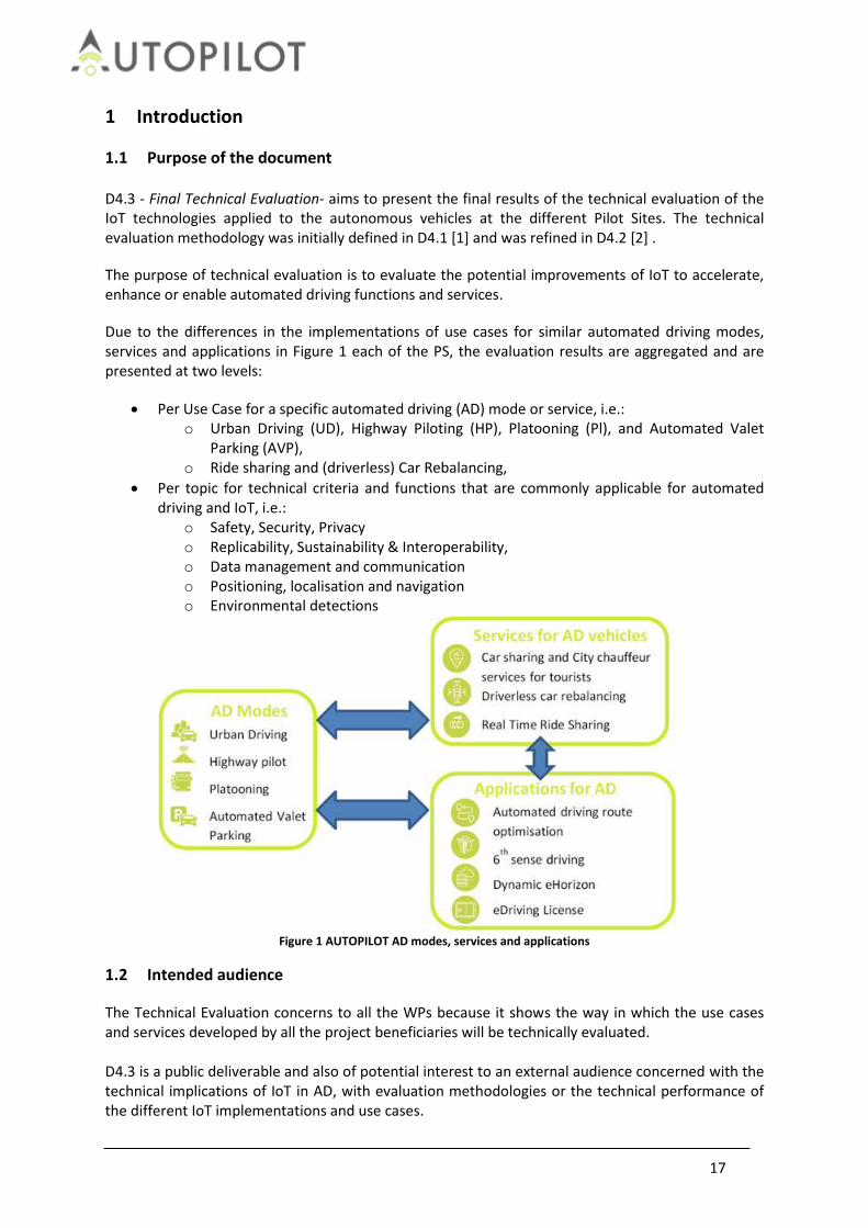
Due to the differences in the implementations of use cases for similar automated driving modes, services and applications in Figure 1 each of the PS, the evaluation results are aggregated and are presented at two levels:
Per Use Case for a specific automated driving (AD) mode or service, i.e.: o Urban Driving (UD), Highway Piloting (HP), Platooning (Pl), and Automated Valet
Parking (AVP), o Ride sharing and (driverless) Car Rebalancing,
Per topic for technical criteria and functions that are commonly applicable for automated driving and IoT, i.e.:
o Safety, Security, Privacy o Replicability, Sustainability & Interoperability, o Data management and communication o Positioning, localisation and navigation o Environmental detections
Figure 1 AUTOPILOT AD modes, services and applications
1.2 Intended audience
The Technical Evaluation concerns to all the WPs because it shows the way in which the use cases and services developed by all the project beneficiaries will be technically evaluated. D4.3 is a public deliverable and also of potential interest to an external audience concerned with the technical implications of IoT in AD, with evaluation methodologies or the technical performance of the different IoT implementations and use cases.

18
1.3 Terminology
User Users are understood here in a wide definition as “anyone who uses the AUTOPILOT services”. This definition is congruent with the approach taken in the unpublished position paper by the CARTRE thematic interest group.
Other road users Road users that are indirectly affected using the technology (i.e. in the single use cases), e.g. cyclist, pedestrian, drivers of conventional vehicles.
Position Absolute position of an object in WGS’84 or GPS coordinates in latitude,
longitude, and optionally with an altitude. Location Relative position of an object on the road defined by lane number, lateral road
or lane offset, and optionally with a map matched position with a longitudinal offset to a road reference point, or road identifier
Measure Parameter or property intended to be measured in a unit. Measurement Operation to determine the value or quantity of a measure at a given time.
1.4 Structure of the report
Chapter 1 introduces the purpose of the document, the intended audience, the terminology used in the document and the structure of the report. Chapter 2 details the methodology used for technical evaluation in AUTOPILOT. It is divided in four parts devoted to the definition of what are: 1) the topics that will be used to evaluate the use cases and services, 2) research questions and hypotheses derived from the topics, 3) indicators and measurements used to answer the research questions, and 4) test scenarios to be reproduced at the Pilot Sites in order to obtain the data needed to compute the indicators. Chapter 3 contains the evaluation results for each Use Case and Service of the AUTOPILOT project. The research questions, together with the hypotheses, are answered with the help of technical data compiled during the test runs. After presenting the results the improvement of IoT indicating if it is accelerating, enhancing or enabling the AD function is presented in the conclusions. Chapter 4 contains the evaluation results for each technical topic defined in the AUTOPILOT project. The results are presented in a general view of the project in terms of data management and communication, navigation, environmental detections, safety, interoperability, replicability and sustainability and security and privacy. Chapter 5 presents the conclusions of the Technical Evaluation of the Use Cases and Services from all the PS. Chapter 6 contains the references mentioned in the deliverable. Chapter 7 contains the annexes with complementary information of the evaluation and the implementation of the use cases and services.

19
2 Technical Evaluation methodology
2.1 What is the added value of IoT for Automated Driving?
The objectives of the AUTOPILOT project are to define and implement IoT architecture for Automated Driving (AD), and to realize IoT-based AD use cases. The main research question to answer in the evaluation of the PS is “What is the added value of IoT for Automated Driving in the piloted Use Cases?” The main hypotheses to test, qualify and quantify the added value are:
IoT is accelerating the development and deployment of automated driving functions.
IoT is enhancing the functionality or performance of automated driving functions.
IoT is enabling new automated driving functions.
Potentially IoT devices can provide information on other vehicles, emergency and heavy good vehicles, stationary and illegally parked vehicles, etc. IoT devices may also provide information on vulnerable road users such as pedestrians, bicyclists and motorbikes, or wheel chairs. A vehicle’s host sensors and ITS-G5 communication can also provide similar information within the range of the sensors or communication. ‘Similar’ is interpreted as information of similar type, contents and quality. IoT can accelerate for example with a cheaper solution, by increasing the penetration rate of probed devices, or extending the ‘range of view’ for similar information.
If the quality or contents of IoT data is better than existing data from the vehicle sensors, then the AD functionality can be enhanced, and performance can be improved. IoT data may provide more information directly from other road users or obstacles for example, or may provide more accurate navigation information.
Whether IoT or IoT data is accelerating or enhancing AD may not always be clear to distinguish a priori. It depends on the existing equipment and infrastructure of use case implementations, which differs between pilot sites for example. Fortunately, similar test scenarios can be defined for both types of hypotheses; with a baseline scenario for the existing situation without IoT data, and comparative evaluations of test scenarios with IoT data.
The third type of hypotheses requires different test scenarios as the pilot system can only be tested with IoT data source to enable new automated driving functions and services. Hence the added value of IoT can be assessed on feasibility for example. A baseline scenario without IoT would not be meaningful or executable, and a comparative evaluation against a ‘without IoT’ baseline is not possible.
2.2 Topics of the evaluation
All Automated Driving functions and services use technologies that can potentially be improved by using IoT provided data. These common technologies are called topics in the evaluation methodology. This section introduces the main topics that will be used for the Technical Evaluation, which have been chosen to cover the technologies used in the developed use cases and services. A differentiation is done between and the topics to be assessed (safety, interoperability and security) and the topics to be evaluated (data management, data communication, position and navigation, environmental detections, replicability, sustainability and privacy). Safety has a very high importance in the project and is considered in many of the development and deployment phases. Obviously, the use of IoT data may affect the Safety of automated driving and, therefore, any incidents should be reported, investigated and assessed. The safety audits done in the verification phase have also been taken into account.

20
The Privacy will be assessed from multiple points of view to ensure that a correct approach has been followed. Relevant issues to this respect are that the user tracking possibilities are limited to a minimum, the project is compliant to GDPR regulation and an appropriated level of privacy is perceived by the end users, in order to ensure that the project is well accepted. The Security will be assessed concerning the most common security threats related to IoT. The three topics of Replicability, Sustainability and Interoperability will be assessed together. The Replicability is the feasibility to deploy one use case or service developed in a given Pilot Site in another Pilot Site. To that aim, the higher the standardization level in the development of the use case or service, the more feasible should it be to replicate it. For this reason, replicability is strongly related to standardization. Therefore, taking as input the level of standardization of Pilot Sites and the related developments, the goal of the replicability assessment is to assess the feasibility of replicating use cases and services between Pilot Sites. The Sustainability is the process of using resources, technological innovation and investments in a balanced manner to the benefit of humankind and the environment. Sustainable Development has been defined by the “Brundtland Report” of the World Commission on Environment and Development stating “to meet the needs of the present without compromising the ability of future generations to meet their own needs” [3]. The Interoperability topic will assess the different IoT technologies and IoT architectures between the Pilot Sites. The Data Management refers to the capability of IoT devices, such as the automated vehicles being tested, to manage the data needed for the automated driving functions and services. Data management on an in-vehicle IoT platform includes the processes to discovery relevant IoT data sources, to subscribe and process relevant IoT data including the assessment of the quality or the data and fusion with on-board sensor data, and to manage alternative communication channels to search and retrieve required data. Data management on a cloud-based IoT platform includes device and subscription management, the up and down loading of data from IoT devices, data brokering, discovery services, data aggregation services, (semantic) data transformations to data formats requested by automated vehicles, and the interaction with other IoT cloud services and (federated) platforms. The Data Communication functionality is provided through alterative communication modes and media. Technical evaluation will focus on the performance comparison of alternative communication channels for Ad-hoc V2X communication and Vehicle – IoT Platform communication. The objective is evaluating the realized communication performances in each of these situations and proposing feasible performance levels. The Position and Navigation compares the information related to routes received by IoT cloud services with the existing vehicle sensors and maps data. The objective is to evaluate the improvement of the internal state, motion planning and routing within automated vehicle functions and services. The Environmental detections refer to the capability of IoT Platforms to acquire information from the environment, such as obstacles and road hazards, other road users, traffic information and environmental conditions. From a technical perspective environmental data may enhance or enable environmental detections for example for VRU or pothole detection, traffic control and status. Potential improvements in detection performance can be measured for example by the type of environmental objects, detection accuracy, rate, and delay, and the geographic position, location and coverage of detections.
21
2.3 Technical Research Questions and Hypotheses
The formulation of research questions is an elaborate and iterative process; taking both a top-down approach (start with impact areas) and bottom-up (start with use-cases). More precisely, on AUTOPILOT project, the research questions are focused on how IoT could offer potential improvements to automated driving functions or driving modes, and how could enable services involving connected and automated vehicles. Consequently, the possible ways in which IoT can improve AD, namely by Accelerating, Enhancing or Enabling new services or automated driving functions are defined. This distinction helps to focus on the future benefits of deploying automation, and steers away from the specific implementation and testing of functions. When accelerating, the IoT is improving the AD deployment or the business case; when enhancing, IoT is improving AD functionality or performance and when enabling, the IoT is adding new AD functionalities. From research questions hypotheses can be formulated. The definition of a hypothesis is: “A specific statement linking a cause to an effect and based on a mechanism linking the two. It is applied to one or more functions and can be tested with statistical means by analysing specific performance indicators in specific scenarios. A hypothesis is expected to predict the direction of the expected change.”1 A large number of research questions and hypotheses have been generated during the first year of the project in Deliverable D4.1 [1]. A limited set of research questions and hypotheses from able to cover the entire project technical scope has been selected.
2.4 Technical indicators, measurements and metrics
The indicators are quantitative or qualitative indicators, derived from one or several measures, agreed on beforehand, expressed as a percentage, index, ate or other value, which are monitored at regular or irregular intervals and can be compared to one or more criteria. During the process of developing hypotheses, it is important to choose appropriate indicators that will allow answering the hypotheses, being also obtainable within the budget and other limitations of the project. Performance indicators are based on measures.
On basis of the previous steps, it can be determined what needs to be measured and how, e.g. collect background data, logging data from sensors and application software, and questionnaires. In FESTA, all the data sources mentioned are considered sensors. Subsequently all data can be acquired, stored, and processed in a generalised way.
A spreadsheet with the minimum data requirements and data quality to be accomplished by the Pilot Sites (Annex 7.1) has been defined.
2.5 Test scenario, use cases and services definition
A Pilot Plan has been defined in [4] in order to group in one spreadsheet all the activities to be done and to be evaluated on each Pilot Site. The part related to the Technical Evaluation is on the fifth tab, where the scenario is described with the following information:
1. Outline of the scenario. This part describes the test environment, setup, starting positions of vehicles, IoT devices and data sources/cloud services to be used, including a map of events.
2. Description of the scenario. This includes the procedure/steps: precondition, actions or
1 http://wiki.fot-net.eu/index.php?title=Hypothesis

22
events (1, 2, 3, etc.) and their order or timing or spacing. It will also define the relevant situations (traffic or weather status, automated driving functions and modes and services).
3. Baseline. Definition of the baseline which will be used to compare with the test results. It also contains a list of devices or services added to the baseline.
4. Hypotheses to be tested. The hypotheses of the spreadsheet which will be evaluated in this scenario.
5. Results. In the first column, the expected results from the test to be reported. In the second column the observed results from users reproducing the scenario will be listed.
6. List of log files generated. List of log files generated in the experiment. 7. Safety interventions. Report of the safety interventions occurred during the scenario.

23
3 Use cases and services
3.1 Automated Valet Parking
Automated Valet Parking (AVP) is an automated driving function that can be integrated with different end-user services and scenarios. AVP is realized in AUTOPILOT in the pilot sites Brainport, Vigo and Tampere.
Table 1 General overview of AVP implementations
Pilot site
Supported features AVP Brainport
(The Netherlands) AVP Tampere
(Finland) AVP Vigo
(Spain)
AVP demo type Outdoor Outdoor Indoor
Drop-off scenario is demonstrated
Pickup scenario is demonstrated
Obstacle detection
Parking spot occupancy detection
x
AVP Smartphone APP (To inform the driver)
Routing service: Free obstacle route
Involved autonomous driving prototype vehicles
TNO AD vehicle (The Netherlands)
X X
DLR AD vehicle (Germany) X X
NEVS AD vehicle (Sweden) X X
VTT AD vehicle (Finland) x X
CTAG AD vehicle (Spain) x X
3.1.1 Test scenarios
Two major scenarios are addressed by AVP; the “drop-off” and the “pick-up” scenarios. Drop-off Scenario: In the drop-off scenario a driver drives his vehicle to a specific drop-off area and stops the vehicle. After the driver has left the vehicle, he sends his car via a smart-phone application to the parking area. The vehicle finds its route and parks itself automatically. Pickup-scenario: In the pick-up scenario a driver waits at a pick-up area and calls his car back via a smart-phone application. The vehicle leaves the parking spot and drives to the pick-up area automatically. After the car has stopped at the pick-up area the driver gets in the vehicle and leaves the pick-up area.
a) Basic sub scenario: In the basic versions of the drop-off and pick-up scenarios there are no obstacles blocking the vehicle’s route, and the vehicle selects the shortest and fastest route.
b) Route sub scenario

24
In the “route sub scenario”, there are obstacles blocking the shortest route. The roadside cameras detect the obstacles and send the data via the IoT platform to the vehicle. The vehicle calculates the optimal (fastest) route to the free parking spot bypassing the blocked route. These two major scenarios have two variants for detecting empty parking spots: For testing the AVP hypotheses the “traditional parking” process is defined as a baseline. Traditional parking means that the entire parking process is done autonomously without the support of any IoT devices or IoT ecosystem. The traditional parking process starts from a predefined drop-off into a parking space, and vice versa to the pick-up location, without the use of the smart-phone application, roadside units, cameras, Micro Air Vehicle (MAV) or IoT platforms.
Table 2 Automated Valet Parking process
Step 1: Arriving at the drop-off position
Step 2: AUTOPILOT-AVP App requesting a parking spot
Step 3: Fixed cameras updating parking spot occupancy status
Step 4: Drone searches and confirms a free parking spot
Step 5: App displays the route to the parking lot
Step 6: Automated parking at the parking spot
3.1.2 Research Questions and Hypotheses
The main research questions are related on how the IoT based services can improve the efficiency of the parking process. Based on the main topics and the functions involved in the use case, we can derive the following research questions: RQ: Is the detection of free parking spots faster compared to traditional parking? HY: The parking slots are detected faster thanks to the use of the infrastructure of the parking and the IoT compared to the traditional parking. RQ: Is the fastest route selected (based on potential obstacles on the route) compared to traditional parking? HY: The IoT calculates the best route for the vehicle in order to reduce the distance and time to travel, which means that the route calculated should be the best option and, therefore, fastest than the traditional parking. RQ: Is the parking process faster compared to traditional parking? HY: The parking manoeuvres are done autonomously with all the environmental information thanks

25
to the IoT, so, it should take less manoeuvres and time to park the vehicle into the parking spot. RQ: Is the driver reliably informed about the parking and pick-up process of the vehicle? HY: The IoT is correctly sending a notification to the smartphone of the user informing the status of the parking process. Based on the log files generated during the tests (see chapter below) quantitative statements can be made about the improvement of efficiency in the context of AVP enhanced by IoT.
3.1.3 Technical indicators, measurements and metrics
The hypotheses have been tested using the key performance indicators (KPI’s) described in the Table 3. The tests have been performed with a differential approach to determine if the function itself has advantages over manual driving and if the IoT improves the function.
Table 3 Performance Indicators for AVP evaluation
No. KPI Measurement Description KPI Relevant for
Description
KPI-1 Parking duration seconds Drop-off scenario: Time from drop-off point until vehicle is parked (parking spot). Pickup scenario: Time from parking spot until the vehicle reached the pickup point.
Brainport Vigo Tampere
Parking duration have been derived from car trajectory (as the GPS coordinates of the vehicle and the vehicle AVP status are continuously logged) during the drop-off and pickup scenario. Data logging of “PositionEstimate” and “VehicleAVPStatus” message is appropriate for this KPI.
KPI-2 Detection performance of free parking spots (Parking spot occupancy)
RSU Camera 1) Detection
performance of free parking spots:
Brainport Vigo Tampere
The KPI has also been measured by the visual observation.
KPI-5 Reliable information of the driver about the parking process
duration Delay between the message transmission from the message generation in the vehicle to the message reception at the AVP mobile APP interface
Brainport Vigo
Reliable information of the driver: the driver needs to be informed 1) if his vehicle is successful parked and about the current status of his vehicle 2) if the parking process is disturbed, broken due for example to an accident, obstacle or malfunction in the vehicle
KPI-6 Detection performance of object/obstacle on the road
manually, correctness of the object detection through the AV-vehicle or RSU camera RSU Camera Detection performance of obstacle detection I the danger area.
Brainport
checking as well different types of object like pedestrian, bike, motorbike …
KPI-7 Parking Evaluate if the cars are parking 100% of the times properly and never cause damages during the test scenario
Brainport Vigo Tampere
KPI-8 Technical complexity of the implementation
Evaluate the technical complexity of the implementation, also analysing the different cases (outdoor /
Brainport Vigo Tampere
It could be a good point to highlight that IoT enables the AVP and that we only need a camera and few things

26
indoor)
During the technical evaluation tests log files of the following components will be generated:
Vehicle state log files.
Roadside unit log files.
Camera log files.
Micro Air Vehicle (Drone) log files.
Communication log files.
IoT log files.
3.1.4 Evaluation
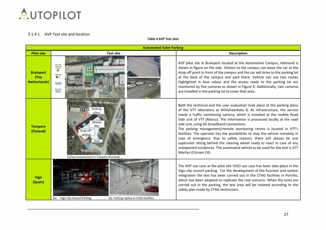
27
3.1.4.1 AVP Test site and location Table 4 AVP Test sites
Automated Valet Parking
Pilot site Test site Description
Brainport (The
Netherlands)
AVP pilot site in Brainport located at the Automotive Campus, Helmond is shown in figure on the side. Visitors to the campus can leave the car at the drop-off point in front of the campus and the car will drive to the parking lot at the back of the campus and park there. Vehicle can use two routes highlighted in blue colour and the access roads to the parking lot are monitored by five cameras as shown in Figure X. Additionally, two cameras are installed in the parking lot to cover that area.
Tampere (Finland)
(a)Test environment in Tampere (Finland)
Both the technical and the user evaluation took place at the parking place of the VTT laboratory at Niittyhaankatu 8. As infrastructure, the service needs a traffic monitoring camera, which is installed at the mobile Road Side unit of VTT (Marsu). The information is processed locally at the road side unit, using 4G broadband connections. The parking management/remote monitoring centre is located in VTT’s facilities. The operator has the possibilities to stop the vehicle remotely in case of emergency. Due to safety reasons, there will always be one supervisor sitting behind the steering wheel ready to react in case of any unexpected incidences. The automated vehicle to be used for the test is VTT Marilyn (Citroen C4).
Vigo (Spain)
(a) Vigo City Council Parking (b) Parking replica in CTAG facilities
The AVP use case at the pilot site VIGO use case has been take place in the Vigo city council parking. For the development of the function and system integration the test has been carried out in the CTAG facilities in Porriño, which has been adapted to replicate the real scenario. When the tests are carried out in the parking, the test area will be isolated according to the safety plan made by CTAG technicians.

28
3.1.4.2 AVP AD prototype test vehicles
Table 5 Prototype test vehicles for each Pilot Site
Automated Valet Parking
Pilot site AD Vehicles Description
Brainport (The
Netherlands)
(a) (b ) (c)
(d) (e)
(a) TNO / TASS AD car Toyota Prius (Hybrid) (b) DLR’s AD car eGolf VW (Electrical) (c) NEVS AD Car (Electrical) (d) Brainport AVP piloting teams at the automotive Campus
(Dec. 2018) (e) NEVS on board vehicle view
Tampere (Finland)
(a) (b)
(a) Citroen C4 - Marilyn 2.0 (b) User tests in Tampere in October 2018
Vigo (Spain)
(a) (b)
(a) PSA C4 - Picasso (b) Parking replica in CTAG facilities

29
3.1.4.3 Evaluation of KPI-1: Technical complexity of the AVP Implementation Table 6 AVP implementation
Level Category
Pilot site Brainport
(The Netherlands) Tampere (Finland)
Vigo (Spain)
Level 1: IoT
Application
System architecture
Parking Service (PMS)
Routing Service
Level 2: IoT Platform
OneM2M IoT platform
x
IBM Watson IoT platform
X
Level 4:
Mobile IoT device
AD vehicle and sensors
Mobile Aerial Vehicle MAV
(Drone) X x
Smartphone APP
(Parking UI)
Level 4: Stationary IoT device
RSU-Camera
Roadside unit infrastructure (Parking spot)
Outdoor
Outdoor
Indoor
Level 5: IoT data model
AVP Data model (DMAG)
Support the AVP data model specified by the AUTOPILOT DMAG group
Support partly the AVP data model specified by the AUTOPILOT DMAG group
Support the AVP data model specified by the AUTOPILOT DMAG group
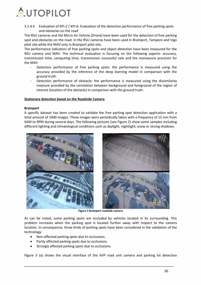
30
3.1.4.4 Evaluation of KPI-2 / KPI-6: Evaluation of the detection performance of free parking spots and obstacles on the road
The RSU cameras and the Micro Air Vehicle (Drone) have been used for the detection of free parking spot and obstacles on the road. In the RSU cameras have been used in Brainport, Tampere and Vigo pilot site while the MAV only in Brainport pilot site. The performance indicators of free parking spots and object detection have been measured for the RSU camera and MAV. The technical evaluation is focusing on the following aspects: accuracy, transmission time, computing time, transmission successful rate and the manoeuvre precision for the MAV
- Detection performance of free parking spots: the performance is measured using the accuracy provided by the inference of the deep learning model in comparison with the ground truth.
- Detection performance of obstacle: the performance is measured using the dissimilarity measure provided by the correlation between background and foreground of the region of interest (location of the obstacle) in comparison with the ground truth.
Stationary detection based on the Roadside Camera Brainport A specific dataset has been created to validate the free parking spot detection application with a total amount of 1000 images. These images were periodically taken with a frequency of 15 min from 6AM to 9PM during several days. The following pictures (see Figure 2) show some samples including different lighting and climatological conditions such as daylight, nightlight, snow or strong shadows.
Figure 2 Brainport roadside camera
As can be noted, some parking spots are occluded by vehicles located in its surrounding. This problem increases when the parking spot is located further away with respect to the camera location. In consequence, three kinds of parking spots have been considered in the validation of the technology:
Non-affected parking spots due to occlusions.
Partly affected parking spots due to occlusions.
Strongly affected parking spots due to occlusions. Figure 3 (a) shows the visual interface of the AVP road unit camera and parking lot detection

31
visualization. Basically, the goal is to solve a classification problem. Once all parking spots has been annotated with respect to the image, the application analyses the status of each parking spot by using a specific deep learning model which has been trained to differentiate between image areas containing available and occupied parking spots (see Figure 3(b)).
(a)
(b)
Figure 3 Roadside camera detections
According to the experiment of obstacle detection, the evaluation has been performed using four static cameras installed in a real environment. Due to the limitation of colour and texture variability of objects which can be used in real tests, the static objects have been virtually generated in order to evaluate the technology. Due to the nature of the algorithm, the obstacle detection module can detect any category of static object. However, the obstacle categorization has been delimited to: ‘BOX’, ‘PEDESTRIAN’, ‘VEHICLE’, ‘TRUCK’ and ‘OTHERS’, where the latter groups together the rest of categories. The minimum size of the obstacle is defined by the specifications of the optical lens and the height of the camera. In our tests, the minimum size of the object is around 50x50x50 cm.
Figure 4 Field of view captured by cameras under test

32
The next images show an example from static object detection. Left image (see Figure 5 a) corresponds to the environment without road obstacles and, right image (see Figure 5 b) shows the same environment with a road obstacle. Particularly, a box has been abandoned in the road. After some time, the static object is detected.
(a)
(b)
Figure 5 Static object detection
Detection rate Number of parking spots considered in tests: 57000 samples. Number of virtual objects considered in tests: 30 samples.
Table 7 Parking spot detection rate
Parking spot detection
Non-Affected Partly Affected Strongly Affected
Average
True Positive 36868 (64.7%) 34747 (60.9%) 30643 (53.7%) 34086 (59.8%)
True Negative 18992 (33.3%) 18833 (33.0%) 17237 (30.2%) 18354 (32.2%)
False Positive 1025 (0.18%) 3388 (0.59%) 6531 (11.4%) 3648 (0.64%)
False Negative 115 (0.02%) 32 (0.006%) 2589 (0.45%) 912 (0.16%)
Parking spot detection
Non-Affected Partly Affected
Strongly Affected
Average
Precision 97.3% 91.1% 82.4% 90.3%
Recall 99.7% 99.9% 92.2% 97.4%
Table 8 Obstacle detection rate
Obstacle detection
True Positive 25 (83.0%) Precision 83.0%
True Negative 0 (0%) Recall 100%
False Positive 5 (17.0%)
False Negative 0 (0%)
Transmission time The RSU camera publishes the parking spot occupancy as well as the obstacle detection IoT message to the PMS via IoT platforms (e.g. In the case of Brainport the message goes through two IoT platforms: oneM2M and Watson IoT platform). The transmission time of the detection message from the sender (RSU-camera) to the receiver (PMS) has been measured.

33
Figure 6 Parking spot occupancy
Tampere In the Tampere test site, the YOLOv3 tool is used for detection and classification of obstacles. If an obstacle, identified using the YOLOv3 tool, is within a predefined area, the area is marked as occupied. The same algorithm is used to determine whether a parking place is occupied or whether there is a person or obstacle on the path of the vehicle (in the “danger zone”). The success rate of YOLOv3 depends on the weather (sunshine), on the lighting level and on the contrast between the object and the environment. The information whether the parking space is occupied or not is used at the beginning of the drop-off phase to assist in the selection of the parking space. This information was always correct. During the drop-off phase, the vehicle passes over the danger zone (detections: 29/29) and in the parking place area (detections 28/29). During the pick-up phase, the vehicle passes over the danger zone (detections 29/29). False positives occur for parking occupancy occurs when the vehicle is on the line of sight between the camera and the parking place. Mobile detection based on the MAV Brainport During four piloting sessions, the MAV received commands to check the occupancy status of two different parking spots which were once occupied and three times unoccupied. In all these runs, the MAV detected the occupancy status of the parking spot correctly. Figure 7 shows a visualization of the object detection by the MAV, Additionally to these piloting it was taken a dataset including 775 image samples of parking spots. We annotated these images and used them for the evaluation of your parking spot occupancy detector. For the parking spot detection we are using a commonly available CNN.
Figure 7 MAV parking spot occupancy detection (Left: occupied, middle: free, right: MAV in flight)
Detection rate The reported values above are for 775 samples taken during the piloting. We have considered the case where the MAV was looking at the parking spot of interest. Our CNN was no fine-tuned on the dataset. To increase the accuracy of our detection one might do so or take multiple image samples

34
and average the outcomes.
Table 9 Detection rate
Parking spot detection BRAINPORT (The Netherlands, NL)
True positive 0.7122
True Negative 0.2116
False positive 0.0025
False Negative 0.0735
The detection works in real-time with about 12.5 fps. For the benchmark, we used an Intel(R) Xeon(R) W-2133 CPU @ 3.60GHz Transmission time The transmission time of the detection message from the sender (MAV) to the receiver (PMS) has been measured. Manoeuvre precision It has been evaluated that the MAV flied correctly and never caused damage during the test scenario. The MAV trajectories have been analysed during the parking spot occupancy detection process.
Figure 8 MAV path flow on the DLR test area in Brunswick
3.1.4.5 Evaluation of KPI-6: Evaluation of the route selected based on the obstacles on the road The routing service as integral part of the AVP parking service (IoT application) uses the IoT obstacle information provided for example by the RSU cameras to calculate the best route (free obstacle and faster route) for the vehicle to free parking spot or to the pickup location in order to reduce the distance and time to travel, which means that the route calculated should be the best option and, therefore, fastest.
Brainport When the user makes a drop off or pick up request through the AVP app, the parking service assigns a spot (in the case of drop off) and sends a free obstacle and a faster route to the vehicle (encapsulated into the AVP vehicle command). There is no rerouting function, if an obstacle is found the vehicle will stop until it is not on its way, and then resume the manoeuvre. Two examples of the route calculation for the Brainport pilot site from the drop-off location to the parking spot without obstacle (Route A) and with obstacle (Route B) when RSU camera detects

35
obstacle prior to navigation are depicted in the illustration below.
Figure 9 Road network in Brainport PS
Figure 10 Route A: shorter and optimal route with obstacle
Figure 11 Route B: longer and optimal free obstacle route
Vigo When the user makes a drop off or pick up request through the app, the parking service assigns a spot (in the case of drop off) and sends a predefined route to the vehicle. There is no rerouting function, if an obstacle is found the vehicle will stop until it is not on its way, and then finishes the manoeuvre.
Figure 12 Parking service app screenshot
Tampere The routing is based on pre-recorded paths. Dependent on the presence of objects on the project path, a path is selected. Conclusion The IoT obstacle information provided by the RSU camera as IoT added value to the AVP allows the extension of the routing services and parking management services and therefore has a positive effect on the AVP like described in the Table 10:
Table 10 Conclusions for IoT improvements in detections
RSU Camera / MAV IoT detection Information
Effect on the Automated Valet Parking
Extension of Routing and PMS services capability
- Dynamic routing to parking location; - Optimizing complete parking operation - Benefit of the IoT platform as standardised
middleware to publish and subscribe the data
3.1.4.6 Evaluation of KPI-1 / KPI-7: Evaluation of parking process on the vehicle side The parking manoeuvres are done autonomously with all the environmental information thanks to

36
the IoT, so, it should take less manoeuvres and time to park the vehicle into the parking spot Parking duration (including legacy traffic)
– Drop-off scenario: Time from drop-off point until vehicle is parked (parking spot). – Pickup scenario: Time from parking spot until the vehicle reached the pickup point.
The time for the parking manoeuvre (between the drop-off point and the parking place) and for the pickup manoeuvre is much larger in automated mode (with IoT) than in the manual mode (without IoT). The main reason is that the speed of the vehicle in automated mode during the parking manoeuvre is limited to 2 m/s. Because for the same test scenario several test runs have been executed, in Table 11 are shown the aggregated values of the parking duration and travel distance.
Table 11 Tampere parking duration and travel distance comparison
TAMPERE (Finland)
Without obstacle
Without IoT With IoT
Drop-off parking duration (in Seconds) 23.2 (st. dev 1.7 ) 51.5 (st. dev. 2.1 )
Drop-off travel distance (in meter) 66.4 (st. dev 2.2 ) 65.9 (st. dev 0.6 )
Pickup parking duration (in Seconds) 18.6 (st.dev 1.7 ) 33.2 (st. dev 2.8)
Pickup travel distance [in meter] 63.6 (st.dev 1.6) 63.2 (st.dev 2.8)
Table 12 Vigo parking duration and travel distance comparison
VIGO (Spain)
Without obstacle
Without IoT With IoT
Drop-off parking duration (in Seconds) 10.6 8.9
Drop-off travel distance (in meter) 29.2
Pickup parking duration (in Seconds) 7.5 8.6
Pickup travel distance [in meter] 25.7
Manoeuvre precision - Evaluate if the car is driven to the route correctly and never cause damages during the test
scenario. The vehicle trajectories have been analysed during the parking and collect process. To measure the manoeuvre precision, both lateral motion which refers to precision of parking position and orientation and path deviations, and longitudinal motion which refers to precision of parking position and speed deviations are included.
Drop-off scenario - route (A to B) Pickup-scenario – route (B to C)
Figure 13 Drop-off scenario route (left), and pickup scenario route (right)

37
Figure 13 shows the trajectories of pickup scenario. Thus, the vehicle can follow the received route from IoT platform. The manoeuvre precision of the vehicle performs well. Figure 14 shows some trajectories of the vehicle during the execution of pickup scenario. Figure 15 shows some travel speed plots in the pickup scenario.
Figure 14 Trajectories in the pickup scenario
Figure 15 Travel speed in the pickup scenario
Tampere Figure 16 shows the trajectories for the baseline manoeuvres (left: all 12 test runs, middle: parking manoeuvre for 1 test run, right: pick-up manoeuvre for 1 test run). Figure 17 shows the trajectories

38
for AD manoeuvres.
Figure 16 Trajectories for the baseline manoeuvres
Figure 17 Trajectories for AD manoeuvres
Figure 18 shows the speed for the track in automated mode (left) and baseline (right, manual mode).
Figure 18 Speed for the track in AD mode and baseline
Statistics for the speed: the average speed during the drop-off manoeuvre is 1.28 m/s for automated mode (2.87 m/s in manual mode). For the pick-up manoeuvre the average speed is 1.9 m/s for automated mode (3.45 m/s for manual mode). Parking precision It has been check whether the vehicle is precisely fit for a parking spot. Evaluate if the cars are parking 100% of the times properly and never cause damages during the test scenario. The red vehicle does not park correctly in the parking lot.
0
1
2
3
0 20 40 60
Speed
drop-off speed pick-up speed

39
Figure 19 Parking precision
The precision of the parking is measured from the position measured by GNSS where the vehicle stops during parking (see Figure 20). This precision is:
- For longitude (the direction in which the vehicle is moving): standard deviation 0.067 m, difference between extremes 0.3 m.
- For latitude (transversal to the vehicle): standard deviation 0.085 m, difference between extremes 0.3 m.
Figure 20 Parking locations
Parking conflict The AD vehicle receives the command from the PMS to park to the designated parking spot and during this time not AD-vehicle occupied the parking spot, the RSU camera detect the parking spot is occupied and published the information to the PMS via the IoT platform that assigned a new parking spot and the new route to the AD-vehicle. Environmental (VRU) detection precision It has been checked whether the vehicle can precisely detect road users and object (static and moving objects). Object classification: PEDESTRIAN, VEHICLE, BYCICLE and TRUCK. For more details see the section about the evaluation of environmental detection.
Figure 21 VRU detection precision
-0.15
-0.1
-0.05
0
0.05
0.1
0.15
0.2
-0.2 -0.15 -0.1 -0.05 0 0.05 0.1 0.15
Parking locations

40
Transmission time Transmission time is defined as the time difference between message sender and message receiver. The transmission time can not only measure the transmission efficiency, but also reflect the transmission precision, as exceptional long transmission time suggests a missing message. Brainport In Brainport, the transmission time is recorded from vehicle sending information to parking management system receiving information. Figure 22 shows the interaction between the AVP devices and the IoT platforms as deployed at the Brainport pilot site. Figure 23 is an example of transmitting vehicle statues. Some statistical evaluation results of the transmission time for TNO and DLR vehicle are summarized in the Table 13 and Table 14. As every communication, such as vehicle to IoT platform, IoT platform to parking management system, parking management system to smart phone, could lead to message missing, the efficiency of transmission time and the reliability of transmission are acceptable and depends on the communication channel used between the system components or devices (e.g. cellular or intranet).
Figure 22 Interaction between the AVP devices and the IoT platforms
Transmission time for TNO vehicle
Orange: IoT event message Grey: IoT command message
Figure 23 Transmission time from vehicle to PMS
Event TNO vehicle (3101)
Event DLR PMS (3185)
IBM Watson IoT (3199)
oneM2M IoT (112233)

41
Table 13 Statistics for the transmission time for TNO vehicle
Statistics for the transmission time (Delay)
Start component TNO Vehicle oneM2M IBM Watson
TNO Vehicle TNO Vehicle
Destination component oneM2M IBM Watson
PMS IBM Watson
PMS
Minimum 39 139 18 200 219
Percentile 25% 54 177 19 234 256
Average 60 190 31 251 282
Std. deviation 10 25 68 26 71
Median 60 190 22 252 275
Percentile 75% 66 202 24 265 289
Maximum 106 275 850 338 1031
Count 268 268 268 268 268
Transmission time for DLR vehicle
Orange: IoT event message Grey: IoT command message
Table 14 Statistics for the transmission time for DLR vehicle
Statistics for the transmission time (Delay) in milliseconds
Start component DLR Vehicle IBM Watson DLR Vehicle
Destination component IBM Watson PMS PMS
Minimum 25 20 48
Percentile 25% 40 22 64
Average 54 29 84
Std. deviation 27 36 46
Median 46 25 71
Percentile 75% 58 27 78
Maximum 222 418 448
Count 148 148 148
Tampere
Table 15 Statistics for transmission time
Average [ms]
Standard deviation
[ms]
Median [ms]
95% percentile
[ms]
99% percentile
[ms] From the vehicle to the PMS
168.3 75 168 196 211
From the RSU to the MQTT broker and the PMS
26.0 58 24 38 51
From the RSU to the IoT system
572.3 292 565 1019 1066
Event DLR vehicle (3183)
Event DLR PMS (3185)
IBM Watson IoT (3199)

42
Figure 24 Delay between RSU/Vehicle and broker/IoT
The delay between the vehicle and the MQTT broker and between the VRU and the MQTT broker has a Gaussian distribution. The distribution of the delay for the IoT system is spread almost equally between 150ms and 1100ms, due to the polling functionality at the IoT system.
3.1.4.7 Evaluation of the KPI-5: Evaluation of the Reliable information of the driver about the parking process
The AVP smartphone app has been implemented for the three pilot sites to support the user by the AVP process (i.e. vehicle parking (drop-off scenario) and vehicle collection (pickup scenario). The following hypothesis that the IoT is correctly sending a notification to the smartphone of the user informing the status (vehicle position and AVP status) of the parking process has been analyses. The performance indicator like transmission time have been taken into account Vigo Opening the Vigo AVP app (see Figure 25) shows a map of the area in which we are. The icons of the car parks that have the AVP service will appear. By selecting one, you can make a reservation. After making the reservation, the user must take the car to the drop off point. Once there the app reminds you a series of steps to follow (close doors, change to neutral) before leaving the vehicle. Once abandoned, the user confirms the request and the drop-off manoeuvre are carried out. When you want to recover your vehicle simply make a request for pick up from the app and the car will go to the pick-up point.
(a) (b) (c)
Drop-off App instructions
(a) (b) (c)
Drop-off manoeuvre information

43
(a) (b) (c)
Pick Up App instructions
(a) (b)
Pick Up manoeuvre information Figure 25 Vigo AVP App
Brainport The Brainport AVP App (see Figure 26) starts with four buttons representing different functions: request a parking spot, reservation, collecting the car and user centre. To continue the requesting, one must login with his own account. Once the account is logged in, the vehicle being parking is selected. In the following example, a NEVES PRIUS Cvehicle05 is selected. Then the user can send the parking request after he chooses the estimated parking time. The user can also select a parking spot with charging station if necessary. A list of available parking spots is returned from the PMS. With these results, the user can choose a parking spot as he wants. After the parking spot is confirmed, the route from drop-off position to the parking spot is generated. The parking process starts. In this process, the vehicle current position and the vehicle statues can be viewed in the App, and the position and statues information are subscribed from the IoT platform. The similar process happens when the user collects the vehicle.
App initialization and instructions
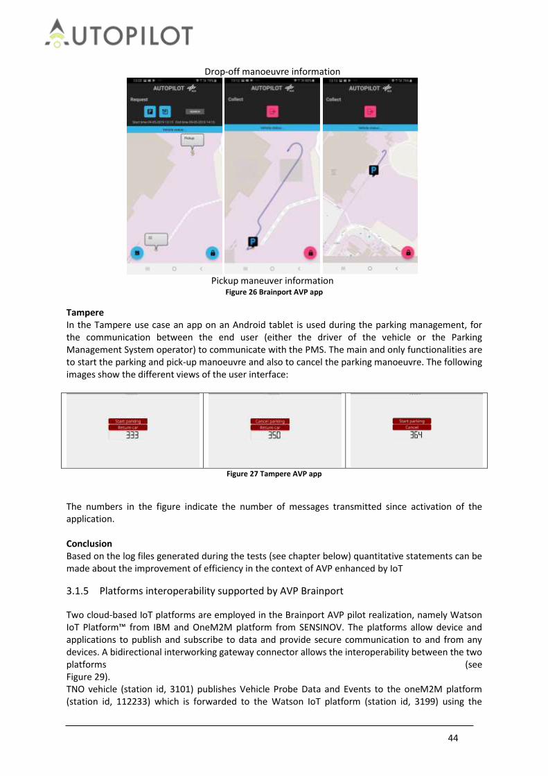
44
Drop-off manoeuvre information
Pickup maneuver information
Figure 26 Brainport AVP app
Tampere In the Tampere use case an app on an Android tablet is used during the parking management, for the communication between the end user (either the driver of the vehicle or the Parking Management System operator) to communicate with the PMS. The main and only functionalities are to start the parking and pick-up manoeuvre and also to cancel the parking manoeuvre. The following images show the different views of the user interface:
Figure 27 Tampere AVP app
The numbers in the figure indicate the number of messages transmitted since activation of the application. Conclusion Based on the log files generated during the tests (see chapter below) quantitative statements can be made about the improvement of efficiency in the context of AVP enhanced by IoT
3.1.5 Platforms interoperability supported by AVP Brainport
Two cloud-based IoT platforms are employed in the Brainport AVP pilot realization, namely Watson IoT Platform™ from IBM and OneM2M platform from SENSINOV. The platforms allow device and applications to publish and subscribe to data and provide secure communication to and from any devices. A bidirectional interworking gateway connector allows the interoperability between the two platforms (see Figure 29). TNO vehicle (station id, 3101) publishes Vehicle Probe Data and Events to the oneM2M platform (station id, 112233) which is forwarded to the Watson IoT platform (station id, 3199) using the

45
downstream connector whereas command data from PMS (station id, 3185) published to the Watson platform are forwarded or mapped to the oneM2M platform using the upstream connector.
Orange: IoT event message Grey: IoT command message
Figure 29 AVP Brainport IoT information flow
3.1.6 Data logging and management
During the technical evaluation tests log files of the following components have been generated in CVS file format and uploaded into the CTS server. These data have been used for the technical evaluation of the AVP use case in the three pilot sites.
Table 16 AVP data logging and management
Automated Valet Parking
Data Management / log files BRAINPORT
(The Netherlands) TAMPERE (Finland)
VIGO (Spain)
Vehicle state log data
Vehicle
Positioning system
Vehicle dynamics
Driver vehicle Interaction
Environmental sensors relatives
Vehicle IoT communication log data
Vehicle IoT event message (PositionEstimate)
Vehicle IoT event message (VehicleAVPStatus)
Event TNO vehicle (3101)
Event DLR PMS (3185)
IBM Watson IoT (3199)
oneM2M IoT (112233)
Figure 28 IoT platforms used in Brainport AVP

46
Vehicle IoT Command message
RSU IoT communication log data
RSU Camera IoT event message (Parking spot occupancy)
RSU Camera IoT event message (Obstacle occupancy)
MAV IoT communication log data
MAV IoT event message (Parking spot occupancy)
MAV IoT command message
Platform IoT communication log data
IBM IoT log message
oneM2M IoT log message
3.1.7 Conclusion
For AVP IoT is used for accessing sources outside the vehicle which help to determine the overall parking situation. The driving function is adapted to import this external data, and to utilize this information for routing and planning. External services (AVP smartphone app) may allow to the vehicle to a specific parking location or retrieve the vehicle. The research questions and hypotheses and their corresponding KPIs are summarized in the Table 17. When the parking manoeuvre is mentioned, it includes both the drop-off and the pick-up of the vehicle, although these can be tested separately. All tests (whenever possible) have been performed with and without IoT to check if it allows the improvement of the autonomous function.
Table 17 AVP evaluation conclusions
No. Topic Research Questions Hypotheses KPI
1
Time saving
Can the system decrease the time a user needs to park their car?
Since the user does not need to be present during the parking manoeuvre, less time will be required.
KPI-1
2 Can the system reduce the total parking manoeuvre time?
The total time of the parking manoeuvre is less with the AVP system than driving manually.
KPI-1
3
Safety
Does the AVP system improve user security?
Since the user does not need to be present during the parking manoeuvre, it is impossible for him to suffer any damage during it.
KPI-2
4 Does the AVP system improve pedestrians’ security?
Since the autonomous parking area will be isolated, there will be no users in it reducing the risk of
KPI-2

47
accident.
5 Does the AVP system improve VRU security?
The IoT will allow the detection of VRU before it enters the range of the car's sensors, allowing the system to react earlier.
KPI-2
6 Energy
efficiency
Is the energy consumption reduced when using the system?
The reduction of time and optimization of routes will cause a reduction in consumption.
7
Manoeuvre precision
Can the AVP system carry out the parking manoeuvre with the same or higher precision than that obtained manually?
The system is accurate enough not to compromise the integrity of the vehicle.
KPI-7
8 Manoeuvre information
Does the user have real time information during the manoeuvre even though he is not present?
The app informs the user in real time of the state of the vehicle during the manoeuvre.
KPI-5
3.2 Urban Driving
Urban driving main objective is to implement automated driving in urban environments taking into account the information provided by external sources that could be accessed via IoT platforms. In this way it is possible to extend the electronic horizon or situational awareness of the vehicle. The relevant external environmental information considered in the project is:
Traffic light states at intersections.
Detections from infrastructure cameras (e.g. pedestrians, bicycle, obstacles…).
Information from vulnerable road users (VRU).
Information from other vehicles captured by their own sensors and shared as IoT elements.
Information about events in the road (e.g. traffic jumps, road works, accidents…) provided by traffic management centres through the IoT infrastructure.
In the project framework this function is going to be tested the following pilot sites: Tampere, Versailles, Livorno, Brainport and Vigo. The baseline scenario is where the automated vehicle uses its own sensors, and V2X communication with the road side units, to detect the environment and receive traffic light controller information. Urban Driving consists of the following pilot scenarios:
VRU interactions. Receiving the information through an IoT platform, the vehicle can be informed that a camera or other sensor has detected pedestrians crossing a zebra crossing, allowing the car to adapt its speed before its own sensors detect the pedestrian. Brainport includes the VRU use case as part of the rebalancing service. In this case, the VRU receives a notification in its app from the approaching vehicle. Each PS implements VRU related use cases with the particularity of the travelling direction of the VRU and the expected reaction in the autonomous vehicle. In Livorno, AD vehicles and connected bicycles are driving on a smart urban road. A connected bicycle with an accelerometer IoT sensor falls down. The event triggers a DENM sent over the ITS G5 network and to the oneM2M platform. The AD cars receive the information of the hazard (fallen bicyclist) by DSRC or by cloud. The AD vehicles approaching the accident area automatically reduce their speed and stop. Versailles implements two particular use cases with two different VRU. In the first use case, a

48
pedestrian walks on the road in front of the vehicle and moves to the side as soon as he/she realises. In the second use case, a bicycle crosses the street in front of the vehicle; coming from the right (90°) and turning left to go where. In both situations the vehicle has to adapt its behaviour (initial speed of the vehicle: max 20km/h). In Vigo the AD vehicle is approaching an area with pedestrians. The vehicle, through its urban in-vehicle app, is constantly requesting to the Urban Server Service if there are any VRU in its area. The vehicle adapts its behaviour by reducing the speed in the surroundings of the VRU in case there is no clear sight. If pedestrians continue in the path of the vehicle as it approaches them, the vehicle will stop. Once the road is clear, the vehicle will continue its journey.
Interaction with traffic lights and traffic signs. When approaching the vehicle in autonomous driving mode at a controlled intersection, the tests will check whether the IoT improves safety and reduces travel times. Livorno, Tampere and Vigo perform the same approach; the traffic light in the intersection is sending the phase information with its corresponding countdown in seconds to the autonomous connected vehicle. The vehicle adapts its speed in order to cross the intersection with an optimized speed. In the case of Livorno, the vehicle performs also and speed adaptation considering the vehicles in front. Brainport and Versailles implements TLA with platooning function. The lead vehicle is connected but not autonomous, it means that the speed adaption in the intersections is performed by the driver based on the information provided by the traffic lights.
Approach to a road hazard: By receiving the information through an IoT platform, the vehicle can be informed of hazards on the road such as road works, accidents or adverse weather conditions, allowing the car to adapt its speed before its own sensors detect the hazard.
Interaction with legacy cars and environmental data. The same as before with the other cars on the road and the environmental data. It is needed to log the interaction with them to ensure the correct behaviour. The V2V messages and the vehicle data and sensors are the main indicators.
Urban Driving will also be tested in conjunction with the ride sharing service on the Versailles and car rebalancing Brainport.
3.2.1 Research Questions and Hypotheses
When evaluating the Urban Driving hypotheses, a comparative approach will be used between the system with and without IoT, in order to check whether it brings significant improvements to the user's safety and reduces travel times. RQ: What is the accuracy of anticipating (detecting and avoiding collisions with) VRUs, legacy vehicles and road hazards when IoT data management and communication are used? VRU detection systems, whether by camera or mobile phone, are especially useful at low visibility points, where vehicles cannot locate pedestrians or cyclists by their own means. In order to analyse the effect on the safety and comfort of the vehicle's passengers, acceleration profiles are analysed, but low test speeds make it difficult to obtain clear results. HY: The use of data generated by the IoT devices, e.g. carried by VRUs, vehicles or road side systems, or cloud services improves the accuracy of detecting VRUs, legacy vehicles and road hazards in vehicles. HY: The use of data generated by the IoT devices, e.g. carried by VRUs, vehicles or road side systems, or cloud services improves the anticipation by automated and connected vehicles, e.g. earlier and

49
smoother speed adaptation. RQ: Is the end user quality of experience (better traveling times, waiting times, and journey times) improved when IoT data management and communication are used? Obtaining traffic light data by IoT should improve travel times, fuel consumption and comfort, as the vehicle can adapt speed earlier than would be possible by observing the traffic light. The lack of pilot sites with a traffic light detection system other than IoT makes it difficult to draw conclusions, as there is no appropriate baseline. HY: The end user quality of experience (better traveling times, waiting times and journey times) is improved when IoT data is used.
3.2.2 Technical indicators, measurements and metrics
The following are indicators with respect to the case of using an automated driving car with and without IoT.
Speed profile variation comparison. It will allow concluding if the IoT reduces travel times.
Acceleration profile comparison. It will allow concluding if IoT smooths the accelerations and decelerations of the journey.
Number of hard braking events comparison. It is expected that IoT will reduce the number of hard braking events by increasing the distance at which information is received from the environment.
Time of detection of pedestrian by the vehicle. The information received from the cameras will allow the car to adapt its speed before it detects the pedestrian with its own sensors.
3.2.3 Evaluation
For the evaluation of the function of urban driving the acceleration profiles have been analysed with the intention of measuring the jerk, which gives us a measure of the comfort of the trip. Since in some pilot sites the baseline is manual driving, the results are better than in the technical tests. Also, the big differences between pilot sites do not allow the comparison between them. The low speeds make the results very low, but the profiles of the IoT tests are more regular than those of the baseline, whether they are manual or autonomous driving. The detection of VRU is done through their smartphones. The jerk results are smoother in IoT tests than in baseline, indicating that IoT makes autonomous driving more regular thus more reliable.
3.2.3.1 Brainport The Brainport GLOSA system is integrated into the Platooning use case. The lead vehicle receives information from the traffic lights and adapts its speed accordingly. The detection of VRU is done through their smartphones. The Brainport GLOSA system is integrated into the Platooning use case. The lead vehicle receives information from the traffic lights and adapts its speed accordingly. Baseline is Automated Vehicle with own sensors and V2X as Baseline for VRU detection test and V2X communication, automated longitudinal and lateral control and platooning functionality for GLOSA. The jerk results are smoother in IoT tests than in baseline, but without major differences. The graphs below (see Figure 30 to Figure 32) show the speed and acceleration of the VRU use case with and without IoT.

50
Figure 30 Brainport VRU detection with IoT
Figure 31 Brainport VRU detection without IoT
Figure 32 Brainport GLOSA with IoT
Table 18 Brainport average maximum jerk
IoT activation Average Max Jerk (m/s3)
GLOSA IoT ON -0.029
IoT OFF -0.0448
VRU detection IoT ON -0.008
IoT OFF -0.011

51
3.2.3.2 Livorno Livorno pilot site uses both GLOSA and VRU detection systems. The traffic light in the intersection is
sending the phase information with its corresponding countdown in seconds to the autonomous
connected vehicle. The vehicle adapts its speed in order to cross the intersection with an optimized
speed. In the case of Livorno, the vehicle performs also and speed adaptation considering the
vehicles in front. In the VRU detection use case, AD vehicles and connected bicycles are driving on a
smart urban road. A connected bicycle with an accelerometer IoT sensor falls down. The event
triggers a DENM sent over the ITS G5 network and to the oneM2M platform. The AD cars receive the
information of the hazard (fallen bicyclist) by DSRC or by cloud. The AD vehicles approaching the
accident area automatically reduce their speed and stop.
Figure 33 Livorno VRU detection with IoT
Figure 34 Livorno GLOSA with IoT
Table 19 Livorno average maximum jerk
IoT activation Average Max Jerk (m/s3)
GLOSA IoT ON -0.0056
VRU detection IoT ON -0.0118
3.2.3.3 Tampere Tampere has a GLOSA system and a VRU camera detection system. To perform the analysis have been compared the jerk of the test with IoT with the baseline, which is manual driving. Although we can observe that the jerk values in manual driving are lower than in autonomous driving, the difference between manual and autonomous driving probably has more influence on the smoothness of driving than the effect of the IoT. In the following graphs we can observe the velocities and accelerations of the cases of GLOSA and VRU detection, depending on the state of the traffic light and the detection of a VRU by the camera. Both graphs belong to the autonomous driving test with IoT. Although in the graphs the acceleration is referred to as "acclateral", it is the longitudinal acceleration; this is due to an error in the signal headers in the logs.

52
Figure 35 Tampere GLOSA
Figure 36 Tampere state
Figure 37 Tampere VRU detection with IoT
Figure 38 Tampere RSU danger area

53
Figure 39 Tampere GLOSA without IoT
Figure 40 Tampere state
Figure 41 Tampere VRU detection without IoT
Figure 42 Tampere state

54
Table 20 Tampere average maximum jerk
IoT Activation Average Max Jerk (m/s3)
GLOSA IoT ON -0.02699
IoT OFF -0.00973
VRU detection IoT ON -0.03018
IoT OFF -0.01378
3.2.3.4 Versailles Versailles implements GLOSA with platooning function. The lead vehicle is connected but not autonomous, it means that the speed adaption in the intersections is performed by the driver based on the information provided by the traffic lights. VRU detection is performed using the mobile phones of pedestrians and cyclists. If a pedestrian walks on the road in front of the vehicle the vehicle reduces its speed until the pedestrian leaves the road. In the cyclist use case, a bicycle crosses the street in front of the vehicle coming from the right (90°) and turning left to go where the vehicle comes from. The vehicle stops to avoid an impact. The baseline is the same situations without IoT, using only vehicle sensors.
Figure 43 Versailles VRU detection with IoT
Figure 44 Versailles VRU detection without IoT

55
Table 21 Versailles average maximum jerk
IoT activation Average Max Jerk (m/s3)
GLOSA IoT ON -0.00173
VRU detection
IoT ON -0.00287
IoT OFF -0.00374
3.2.3.5 Vigo The logs of GLOSA and VRU detection have been recorded simultaneously in the pilot site Vigo. The scenario consisted of an intersection controlled by a traffic light, and a crossing zone controlled by a camera. The baseline tests were performed under the same conditions but with manual conduction. In the first graph we can observe the acceleration and speed of the test and in the second a detail of the vehicle stop due to the detection of a VRU, in which the maximum jerk is selected to evaluate the smoothness of driving. The results show that the values of jerk the manual conduction are in this case greater than those of autonomous conduction with IoT. As in the other pilot sites whose baseline is manual driving, it is difficult to draw conclusions in this regard due to the large difference between manual and autonomous driving.
Figure 45 Vigo GLOSA and VRU detection
Figure 46 Vigo VRU detection detail
Table 22 Vigo average maximum jerk
IoT Activation Average Max Jerk (m/s3)
GLOSA IoT ON -0.00055
IoT OFF -0.6057
VRU detection IoT ON -0.00076
IoT OFF -0.8656

56
3.2.4 Results and conclusions
For the evaluation of the function of urban driving the acceleration profiles have been analysed with the intention of measuring the jerk, which gives us a measure of the comfort of the trip. Since in some pilot sites the baseline is manual driving, the results are better than in the technical tests. Also, the big differences between pilot sites do not allow the comparison between them. The low speeds make the results very low, but the profiles of the IoT tests are more regular than those of the baseline, whether they are manual or autonomous driving. Based on the final results of the evaluation, the following conclusions can be drawn: - The lesser variability of jerk measurements in systems with IoT implemented can allow accelerating the implementation of autonomous driving, since by creating more predictable situations it facilitates the creation of systems that respond to such situations. -VRU detection systems can enhance safety and comfort in autonomous driving as they allow the detection of pedestrians through systems external to the vehicle, allowing them to be located at points of "low visibility" for vehicle sensors using devices such as cameras or mobile phones. -GLOSA systems using IoT enable autonomous driving in environments regulated by traffic lights, allowing a smoother and more efficient driving than alternative systems such as detection by camera, as it allows knowing not only the current state of the traffic light but also the next and the remaining time for the change of state.
Table 23 Urban Driving conclusions
Pilot site Function IoT Jerk (m/s3)
Brainport
Traffic light adaptation ON -0.029
OFF -0.0448
VRU detection ON -0.008
OFF -0.011
Livorno
Traffic light adaptation ON -0.0056
OFF
VRU detection ON -0.0118
OFF
Tampere Traffic light adaptation ON -0.0269
OFF -0.0097
VRU detection ON 0.0301
OFF -0.0137
Versailles Traffic light adaptation ON -0.00173
OFF
VRU detection ON -0.002870
OFF -0.003740
Vigo Traffic light adaptation ON -0.00055
OFF -0.6057
VRU detection ON -0.00076
OFF -0.8656
3.3 Highway Pilot
Highway Pilot is an Automated Driving System which provides automated functionalities to highway driving, performing both longitudinal and lateral vehicle motion control in a specific operational design domain (i.e., only on Highways).

57
The monitoring of the driving environment is a key component for this system and is usually performed by on-board sensors characterized by a limited range and field of view. The AUTOPILOT IoT architecture is aimed at enhancing detection capabilities and automated responses of vehicles with respect to potential road hazards en route. Several events and situations can be identified as potential road hazards but the testing activities performed in Livorno and Brainport pilot sites will focus on road defects (potholes), weather related road changes (puddles), and road works. Anomalies can be merged from different devices, sensors and algorithms, and from different sources such as private and service vehicles, other road users and personal devices, fixed road side sensors back office systems for planning road maintenance and constructions, or traffic information services. The AUTOPILOT goal is to extract specific, reliable, and location-based alerts that can support the environment perception of automated vehicles in controlling speed and headway distance, anticipate and smooth lane change manoeuvres or deactivate the automated functions.
3.3.1 Research Questions and Hypotheses
IoT is expected to positively contribute to both the detection phase and automated responses. IoT can for example improve the number of detected events, accuracy of their localisation, and timeliness of detections, while also the effectiveness of the safety response and related comfort can improve. In such a context it is possible to identify two main research questions which will be hereinafter analysed, together with the underlying hypotheses and the technical indicators which can be used to test them. RQ: Can IoT improve situation awareness? In both Brainport and Livorno pilot sites, data collection, aggregation and event triggering through the IoT can feed the Autonomous Driving functions for the Highway Pilot, enabling a more effective data fusion for situation awareness. While Livorno focusses on the detection and aggregation from mobile probes, fixed sensors and road maintenance plans (road works), Brainport showcases how IoT enables the data sharing among different parties. For situation awareness, the process is considered from the occurrence or emergence of the hazard, the detection, and the collection of detections until validation of the hazard and the triggering of a validated hazard warning towards drivers and automated vehicles. The performance of detection and situation awareness is a trade-off between latency, reliability and accuracy of hazard warnings. On the one hand, the earlier a warning is published, the higher is the positive impact on traffic safety and efficiency. On the other hand, insufficient data collection and validation of hazard warnings increases the false alarm rate and negatively impact the trust and compliance of users to the warnings. To report extreme cases: discontinuous set of generic anomalies with low reliability in the next kilometres will simply cause the deactivation of the highway pilot on the whole highway. If this alerting has also some latency in being produced, it will maybe target just half of the interested AD vehicles (the other half having transited before); on the other hand, prompt, reliable punctual notifications can support longitudinal and lateral control by giving detection redundancy and anticipating the danger. Situation awareness improvements can be tested by the following hypotheses: HY: IoT improves the detection performance of road hazards when anomaly detections are received and integrated from multiple and heterogeneous IoT data sources compared to using any single data source. HY: Latency in validated hazard warnings can be reduced when using multiple and heterogeneous sources compared to using any single source of data.

58
RQ: Can IoT improve automated driving response and driver response? The highway functionalities are demonstrated by CRF and VALEO vehicles in Brainport and Livorno, respectively. The common, measurable functionalities in terms of vehicle response are: longitudinal speed profiling, timing headway from the vehicles in front, command to start lateral shift/lane change. In addition, for Brainport, activation/deactivation of AD can be measured (time it takes for the driver to take again the control of the car). In both vehicles, in addition, the CAN data are used for comparing the vehicle kinematics. HY: validated hazard warnings and driving recommendations can target relevant vehicles based on location. HY: Proposed hazard warnings and driving recommendations eventually result in a better handling of the hazardous situation by the vehicles and drivers.
3.3.2 Technical indicators, measurements and metrics
The hypotheses on anomaly detection and validation performance can be tested using detection performance indicators for detection rate, accuracy and latency. In both pilots, the anomaly detections are collected and validated by a human operator before publishing warnings and alerts to drivers and automated vehicles. Hence the false alarm rate of published warnings is not a relevant criterion to evaluate the added value of IoT.
Detection rate is measured by the number and type of anomalies that are detected by single sources and after fusion and validation by the operator.
Detection accuracy is measured by the location accuracy of anomalies and hazards by the single sources and after fusion and validation by the operator. Location accuracy is measured as the distance or offset between anomaly detections and the true hazard location. If the ground truth is unknown, the validated hazard location can be used as the metric.
Detection reliability is measured by the rate of correct classifications of anomalies; i.e. the confusion matrix of true/false positive/negative detections. In this case, IoT enabled data fusion/aggregation could be compared with single in-vehicle sensors performance. In case the latter information is not available from the AUTOPILOT testing, one could refer to literature information about sensing performance.
Validation latency is measured as the duration between first occurrence or detection of an anomaly and the triggering of the validated hazard warning to drivers and automated vehicles. This duration includes the collection of one or more anomaly detections, validation by the operator and triggering of the hazard warning. This duration includes implicitly the detection delay by any anomaly detection system generating the IoT anomaly detections. This indicator may be rather difficult to assess through real data only, given the limited numbers of vehicles and anomaly cases. However, at least some indications could be extracted by merging single detections on field (e.g. potholes) with traffic flow data. These should be confronted with single sensor performance.
The hypotheses on automated driving response and driver response can be tested using following performance indicators:
The latency between the triggering of the validated hazard warnings and initial response of the driver or automated vehicle functions. This indicator measures the IoT “service chain” after validation, from the IoT platform to the AD vehicle data fusion, and it could avail of timing checkpoints: data communication (section 3.2), IoT data management and the

59
evaluation of the relevance of IoT data for data fusion, actuation and application logic (section 3.1). For immediate local warnings response can be defined from the AD vehicle kinematic response (speed, etc.) or more in general the AD activation/deactivation, or presentation of driver warnings. However, this is not valid for warnings that are stored in the car and taken as input later on.
Smoothness in longitudinal and lateral manoeuvres of automated responses. The speed profile could be measured, time-and position-reference, with and without the IoT warning (section 3.3).
Occurrence of emergency responses such as hard braking or steering. Kinematics data of the vehicle during the trials could be measured (with and without the IoT warning) to check if there are peak events (sharp braking, deactivation of AD, etc.). Actually, it is quite difficult to obtain an indicative and robust measurement with such a small amount of expected AD vehicles statistics on the specific site, so it is suggested to try and compare the data with ordinary traffic data, if available from the road operator.
3.3.3 Evaluation
3.3.3.1 Highway Pilot – Brainport KPI precise definition
The goal of the experimental analysis is the evaluation of the in-vehicle hazard detection system and
of the potential improvements from V2I communication.
The KPIs are based on the following definitions, here formally introduced to avoid ambiguities:
• Anomaly: detected position of a potential hazard. This detection is executed by the vehicle;
• Correct anomaly: anomaly corresponding to a real hazard in the road, i.e., the distance
between the detected anomaly and the closest real hazard (from ground truth) is smaller or
equal to 10 meters;
• False anomaly: anomaly non-corresponding to a real hazard in the road i.e., the distance
between the detected anomaly and the closest real hazard (from ground truth) is larger than
10 meters;
• Hazard warning: the infrastructure message defining the position of a potential hazard in the
road. It is computed by elaborating several anomalies detected by the vehicle.
• True hazard: real position of the hazard (from ground truth);
• Hazard crossing: event in which the vehicle passes close (within 10 meters) to a true hazard.
Notice that the correspondence between the real hazards and the anomalies does not agree with
the specifications, stating that one detection is correct if located within 60 meters before and 30
meters after the true hazard. The choice is necessary since in the test site two real hazards where
placed closer than 90 meters, hence indistinguishable accordingly to the specifications.
The KPIs are defined as following:
• Vehicle detection accuracy: mean error distance between the anomalies and the true hazard
positions. This KPI measures the accuracy of the vehicle sensing independently from the
infrastructure;
• Infrastructure detection accuracy: mean error distance between the estimates of the hazard
positions in the hazard warnings (computed by elaborating several anomalies detected by
the vehicle) and the true hazard positions. This KPI measures the accuracy of the
infrastructure estimates;

60
• Detection rate: percentage of detected hazards, i.e., probability of detecting a hazard with
the vehicle sensing system during hazard crossing;
• Reliability: percentage of anomalies corresponding to a true hazard, i.e., probability that one
detection is not a false alarm.
• Validation latency: minimum amount of time needed by the infrastructure to detect a true
hazard with a confidence (probability) of p.
The validation latency vl depends on the mean flow of cars f in the highway and on the detection
rate dr. Its computation is explained in the following.
By definition, a false negative takes place with probability
1 − 𝑑𝑟, i.e., if a car crosses a hazard, such hazard is missed with probability1 − 𝑑𝑟. Hence, being detections
from different cars independent events, if n cars cross the hazard, the hazard is not detected with
probability
(1 − 𝑑𝑟)𝑛. We ask that the probability of detecting the hazard equals the confidence p, then
𝑝 = 1 − (1 − 𝑑𝑟)𝑛 .
By solving with respect to n, we compute the number of cars that have to cross the hazard to detect
it with probability equal to the confidence p, then, given a mean flow of cars f, 𝑛 = 𝑓 𝑣𝑙 , hence we
get the validation latency as
𝑣𝑙 =log(1 − 𝑝)
𝑓 log(1 − 𝑑𝑟) .
Example: vl = 1min at 99% means that after 1 minute the infrastructure has detected a true hazard with a probability of 99%, or (equivalently) that if we want to be sure (99%) to detect the hazard, we have to wait at least 1min. Data elaboration
The VW Tiguan vehicle was driven for 25 laps in the test site, where 4 hazards where placed as
shown in Figure 47. The available date includes experiments 278, 279, 280, and 284.
In this evaluation, we consider the output of “report anomaly” from the VW Tiguan which contains
the unfiltered data from the VW Tiguan.
In Figure 47 we evaluate the hazard detection that is output from the Valeo Cloud (labelled as
“Publish Road Hazard”). This explains the different results between evaluations in this section with
respect to the results in section 4.8.3.2.
Figure 47 Top view of the test site and hazard placement.

61
An example of experimental data is shown in Figure 48. The vehicle measured positions (in the first
half lap for improved visualization) are reported with blue crosses linked with a solid line, the
anomalies detected by the vehicle are represented as green circles, the hazard positions estimated
by the infrastructure are reported as red dots, while the true hazard positions are highlighted with
magenta squares.
Notice that during the inversion manoeuvres between the laps, several wrong detections where
generated due to the test site conditions. These wrong detections are removed from the dataset.
Figure 48 Example of data from Brainport test session
(The wrong detections due to manoeuvre inversions are highlighted.)
As final remark, the experiment 284 was discarded because of the limited quality of the data. Figure
49 shows the data from experiment 284: notice the presence of several meaningless detections
along all the travelled path. To formally discard the test, we notice that the validation latency is
more than three scaled median absolute deviations away from the median of the dataset, hence it is
statistically considered as an outlier. The poor quality of this test is reasonably due the adversal
experimental conditions: only the camera was used to anomaly detection in this test; moreover the
vehicle was driven under heavy rain on a very dirty road.
Figure 49 Data of the discarded experiments.
The final KPIs are reported in Table 24. The validation latency is computed with a confidence level p = 99%, vehicle flow f from A4 (Milan to Venice) in 2018, f = 139000 vehicle per day. The values are obtained by averaging the KPIs separately computed on the four hazards placed on the test site. Formally, this simplification would be correct if all the hazards had the same probability of taking place conditioned to the fact that a hazard occurs. If the probabilities of encountering different

62
hazards were known, (which is not our case) and significantly different, a weighted mean (where the weights are the occurrence probabilities) clearly would yield a more generalizable value of the KPIs. From Table 24 we notice that:
• the infrastructure improves the accuracy in locating hazards by 9% with respect to the vehicle system;
• The detection rate is very large (77%), hence vehicle has a large probability of detecting a hazard;
• As disadvantage, the vehicle generates a huge number of false alarms (reliability at 36%); • The validation latency is extremely low (less than 2 seconds). •
Table 24 Final KPIs from Brainport tests.
KPI Value Unit
Vehicle detection accuracy 5.12 M
Infrastructure detection accuracy 4.68 M
Detection rate 0.77 -
Reliability 0.36 -
Validation latency 1.94 S
Conclusions The experimental results show that the vehicle is clearly capable of detecting the hazards and confirm the (intuitive) performance improvement coming from the infrastructure. However, the system is extremely sensitive, and generates many false alarms. A much smaller detection rate may be implemented to increase reliability and hence reduce the false alarms (e.g., setting larger acceleration thresholds for pothole detection). Notice from Table 25 that, even if we had a much smaller detection rate (i.e., the sensing system is less sensitive), we would still have good validation latencies.
Table 25 Effect of detection rate on validation latency.
Detection rate [-] Validation latency [min]
5% 0.93
1% 4.75
3.3.3.2 Highway Pilot – Livorno Preliminary comments During the experimental tests, due to some technical problems, e-Horizon did not work properly. Therefore, the data analysis will focus on short range communication (i.e., on the only available data). In particular, we evaluate the goodness of the V2X communication and automatic speed adaptation for longitudinal dynamics. KPI definition The KPIs measure range and repeatability of the V2I communication, and comfort of the speed adaptation. They are defined as follows.
• Communication range: mean RSU distance at which the vehicle receives the hazard warning message for the first time, i.e., the communication range of the RSU in a real scenario;
• Communication range variability: standard deviation of the RSU distance at which the vehicle receives the hazard warning message for the first time, i.e., the variability communication range of the RSU in a real scenario;
• Acceptance range variability: standard deviation of the RSU distance at which the vehicle accepts the hazard warning message for the first time, i.e., the variability of the distance at

63
which the vehicle decides to accept the message; • Maximum deceleration: maximum deceleration (in absolute value) to execute the speed
adaptation manoeuvre. Notice that the acceptance range is not a KPI, since it clearly depends on the (unknown) distance between RSU and hazard. It is remarked that, according to the specifications, the speed adaptation manoeuvre is comfortable for the driver if the maximum deceleration is smaller than 2 m/s2. Data elaboration The vehicle performs speed adaptation autonomously close to the hazards. 20 experiments were executed in two highways, one for the puddle hazard (simulated by dipping a sensor in the water) and one for the roadwork hazard (actually present on the highway). Figure 51 shows an example of puddle test. Notice that the vehicle receives the hazard warning message (green circle) as soon as it gets close to the RSU (red square). However, the vehicle accepts the message after a long track (black cross), as the hazard is initially irrelevant because puddle and RSU are not located in the same part of the roadway of the vehicle when the message is received the first time. Figure 51 shows the automatic speed adaptation executed by the vehicle. Notice that the vehicle reduces its speed from 80km/h to 65 km/h in approximately 12 seconds, with a maximum deceleration of 1m/s2.
Figure 50 Example of a puddle test. The positions of interest are zoomed

64
Figure 51 Adaptation manoeuvre for the paddle test of Figure 51
Figure 53 shows an example of roadwork test. Notice that the vehicle accepts the message (black cross) as soon as the message is received (green circle) since it is approaching the hazard. Figure 53 shows the automatic speed adaptation executed by the vehicle. Notice that the vehicle reduces its speed from 85km/h to 55 km/h in approximately 20 seconds. Despite the settling time is smaller than the experiment of Figure 51, the reduction in speed is much larger, hence the maximum acceleration hits 1.8m/s2.
Figure 52 Example of a roadwork test. The positions of interest are zoomed; arrows highlight the vehicle movement direction

65
Figure 53 Adaptation manoeuvre for the roadwork test of Figure 53
The overall KPIs are reported in Table 26. Notice that the RSU ranges are larger than 1 kilometre, with a variability of 14% and 11%, depending on the test. Moreover the vehicle manoeuvres are comfortable since the mean maximum acceleration remains under the safe threshold of 2 m/s2.
Table 26 Final KPIs from Livorno tests
KPI Puddle value RW value Unit
Communication range 1222 1160 M
Communication range variability 174 104 M
Acceptance range variability 34 43 M
Maximum deceleration 1.32 1.51 m/s2
Conclusions In this test session in Livorno test site, only short range communication was evaluated due to some technical problems with the e-Horizon. The RSUs have been capable of promptly notifying the vehicle on the presence of two types of hazards (puddle and roadwork), allowing the vehicle to automatically executing comfortable speed adaptations.
3.4 Platooning
Platooning is an automated driving function that can be integrated with several end-user services and scenarios. In AUTOPILOT, platooning is implemented in two different scenarios; i.e. as a function in the ride sharing service in Brainport, and as a function for automated fleet rebalancing in Versailles. Consequently the pilot scenarios and situations in which platooning are executed will be different. For example in Brainport, platooning brings passengers from their pick-up point to their destination, while in Versailles platooning returns empty vehicles back to a pick-up point. In Versailles the automated vehicles travel at moderate speeds in an urban environment, while in

66
Brainport the vehicles also travel on the motorway. This section addresses two automated sub functions: platoon formation and platooning. Platoon formation is the process of searching other vehicles and match making to organize a platoon, to navigate the vehicles to a rendezvous point in time, and to organize the vehicles to form and join a platoon. Platooning is the automated driving function to control a string of vehicles as a platoon through traffic, including traffic light controlled intersections. Both platoon formation and platooning can be considered as processes with a state machine with an entry event (1), main activities (2) and an exit event (3) to the next state or process in the pilot scenario. Platoon Formation
1. The implementation at Brainport has a process to form the platoon of automated vehicles. a. A user (operator or driver) initiates the platoon formation with a request to form a
to a cloud service (Platooning Service) via the IoT platform. Users of other vehicles make a similar request.
b. The initial request triggers a platoon formation process in the cloud service. The internal process of the cloud service is not in scope of the research questions or evaluations.
c. The outcome of the cloud service is a first PlatoonFormation IoT message to every vehicle in the platoon with instructions on the rendezvous point where the platoon should be formed, its position or relative location in the platoon, and instructions how to get to the location in the right order.
2. The platoon formation activity starts in the vehicle upon reception of a PlatoonFormation IoT message with instructions from 1c.
a. A route is constructed as a trajectory of set points to the rendezvous point. b. The vehicle drives to the rendezvous point following the speed advices from the
PlatoonFormation messages. c. Frequently and upon any deviation or obstruction, the vehicle sends a PlatoonStatus
IoT message to inform the cloud service and other platooning partners of the deviation.
i. The deviation message may trigger an updating process in 1b, and consequently in 1c and 2a.
ii. The platoon formation process may not succeed to form a platoon and can also be aborted, manually or automatically.
3. The platoon formation ends when the platoon is formed, or the process is aborted. Successful platoon formation is an event that is detected by the platoon formation function in the vehicle. The cloud service or other platooning vehicles are informed with an IoT status update message. The criteria for successful platoon formation and the detection may differ per implementation:
a. The operator or driver in the vehicle decides that the platoon is formed and initiates the platooning phase.
b. Alternatively the vehicles in the platoon detect the successful platoon formation state and proceed to platooning.
In Versailles the formation of the platoon of vehicles is a manual process, not supported by a cloud services and IoT, and not evaluated here. Platooning
4. The entry event is that the platoon is successfully formed, and automated platooning is

67
initiated. In both the Brainport and Versailles implementations, the lead vehicles are manually driven, and the other vehicles follow the leader automatically through traffic.
5. Platooning activities can be differentiated in following simultaneous processes: a. The lead vehicle requests and receives speed advices and platooning information
from the cloud services to navigate the intended route and anticipate the states of traffic lights. The cloud service in Versailles is the Traffic Light Assist (TLA) and in Brainport the PlatoonService (PS). Both services receive traffic light status and timing information from the traffic light controllers via the IoT platform, and convert this information into platoon formation information and speed advices. The two implementations use different sets of IoT messages. The driver in the lead vehicle has the responsibility to adapt driving to the situation and information.
b. The following vehicles in the platoon automatically follow the lead vehicle. Automated driving mode for platooning or car following has two functions:
i. Longitudinal control in which a gap is maintained with minimal fluctuations. ii. Lateral control in which the leader is followed in his lane and path with
minimal lateral deviations. The automated car following function uses V2V ITS-G5 communication.
6. Platooning is ended by the driver in the lead vehicle, either because the destination is reached, or by intervention.
Platooning in Brainport is tested in a series of 5 test weeks from August 2018 till June 2019 in which 95 test runs are executed for technical tests. The additional user test runs are not included in this technical evaluation. Technical tests are organised in 20 different test scenarios, including variations with IoT data sources for traffic management information or traffic light information to improve formation plans, different starting locations, and baseline scenarios without the use of IoT services and data sources. Platooning in Versailles is tested in two weeks in July 2019 in which 11 technical test runs are executed in two scenarios for manual (baseline) and automated fleet rebalancing. Traffic Light assistance is provided for two intersections on the city tour with more controlled intersections. The applications log events and actions as defined in Annex 7.1.3. Event Models are defined for example for the state machines for platooning and platoon formation by the cloud service and in the vehicles. Event models are also defined for manual/automated modes of lateral and longitudinal control, and driver interventions. Models are also defined for the traffic light status and traffic light assistance. Table 27 lists the events and actions that will be used in the presented evaluation results later.
Table 27 Platform formation and platooning actions
Pilot Site Event Model Actions
Bra
inp
ort
Platoon State 1. None 2. Standalone (e.g. during platoon formation) 3. VehicleEngaging/Assembling (vehicles are joining to form a
platoon) 4. Platooning 5. VehicleDisengaging (vehicle(s) are leaving the platoon)
Vehicle Mode 1. None 2. Standalone (e.g. during platoon formation) 3. Engaging (vehicle is joining the platoon) 4. Platooning 5. Disengaging (vehicle is leaving the platoon) 6. Searching (vehicle is waiting for first PlatoonFormation

68
message) 7. Forming (vehicle is lining up in the platoon before
engaging) 8. Connecting (vehicle is connecting to a PlatoonService) 9. Formation Done (formation is successful)
Brake Overrule 1. No overrule (automated braking control) 2. Overrule (intervention by driver)
Ver
saill
es
Traffic Light Assist 1. Platoon discovery 2. Launching supervisor unit 3. Making decision 4. Subscribing to element 5. Unsubscribing from element 6. Closing supervisor unit 7. Platoon is near to a Traffic Light 8. Platoon cross an intersection
Traffic Light 0. Off 1. Green 2. Red
3.4.1 Research Questions and Hypotheses
The main research question “How IoT can improve platooning?” can be refined in the following sub questions and hypotheses. The baseline scenario is that vehicles are already equipped with V2X communication, and the following vehicles in the platoon have automated functions for longitudinal and lateral control and platooning. The connection to the IoT platforms is added to test potential improvements of platoon formation and anticipating traffic lights during platooning. RQ: Can IoT improve match making for platoon formation? This is the first step in which platooning is potentially enabled with a platoon formation service in which vehicles are matched and guided to form a platoon. This is also an important capability for integrating platooning in mobility service concepts such as ride sharing and rebalancing. HY: Provide discovery services, ride sharing or ride sharing services to search and match passengers and vehicles to form platoons with compatible travel plans, origins and destinations, and platooning capabilities. HY: Extend the scope for searching drivers and vehicles beyond the local V2X ad-hoc communication network and communication range. In baseline situations, the vehicles can only communicate using V2X to find potential other vehicles. However, the test vehicles do not have the functionality to organize a platoon, so this baseline cannot be tested. Hypotheses can only test the feasibility of platoon formation to generate and update a suitable rendezvous point, navigate to that point, arrive in the intended order and join the platoon. Hence the IoT can enable a platoon formation service. RQ: Can IoT improve platoon formation? This is the second step in the platoon formation process in which the matched vehicles are guided from their current location to a rendezvous point to form a platoon with other vehicles.

69
HY: A host vehicle is informed of any delays or problems in the activities of other platoon members that affect the platoon formation of the host vehicle. In the baseline situations, the vehicle would have to navigate autonomously to the rendezvous point. However, the test vehicles do not have the functionality for navigation, so this baseline cannot be tested. In the test scenarios, IoT information is provided by the platooning service for re-routing and updating the rendezvous point or expected time of arrival of the host vehicle or other platoon members. The routing efficiency of in-vehicle or cloud services is not subject of evaluation. HY: A host vehicle is informed of any delays or problems in the activities of other platoon members that affect the platoon formation of the host vehicle. HY: A host vehicle receives updated instructions how to adapt its platoon formation activities in coordination with the other platoon members. RQ: Can IoT improve platooning? This is step 4 in the platooning process in which platooning is potentially enhanced with IoT cloud services that provide relevant environmental and situational information, based on which the vehicles can improve the performance of platooning. Relevant information could be information for the planned route on traffic state and congestion, controlled intersections, road hazards, incidents and accidents, map or location information. The platooning use cases in Brainport and Versailles only use traffic light information as IoT data sources; hence the relevance is evaluated for the use and anticipation on controlled intersections. Other relevant IoT information is evaluated in other use cases. HY: Vehicles can subscribe to IoT information that may also be available from V2X communication to improving the communication performance. HY: Vehicles can subscribe to IoT information that is relevant for improving platooning. In the baseline situation, the vehicles use V2V communication for platooning. Potentially the vehicles could also receive I2V information, in particular Signal Phase and Timing (SPaT) information directly from traffic lights. This information can also be provided via an IoT platform, with the added value that the information could be received earlier and allow the platoon to better anticipate traffic light states. Another potential improvement is that an IoT cloud services processes the SPaT information into speed advices that allow the complete platoon to pass on green.
3.4.2 Technical indicators, measurements and metrics
The usage of IoT information from platooning cloud services and traffic light information is tested on the indicator of the number of received IoT messages. The platoon formation in Brainport is a new service for which no baseline can be measured, other than the formation of a platoon within ITS-G5 communication range. The indicators measure the feasibility of platoon formation and are derived from test run statistics and logged actions from Table 27 rather than log parameters.

70
Table 28 Performance Indicators for Platoon Formation
Performance Indicator Measurement
Percentage of successful matches and platoon formations.
A successful match is made when the platoon state and vehicle mode change to 'forming' A platoon formation is successful if the platoon state changes from forming to formation done and/or platooning
Duration of successful matching
Duration that the platoon state "connecting" to the IoT platform by the last vehicle, "searching" and match making for a platoon, till transition to "forming" a platoon by the last vehicle in the platoon
Distance between test vehicles for successful match making
Distance between initial vehicle positions while connecting to the platoon service and searching
Causes for failed matching or platoon formations
Failure are reported by the test drivers in the test context reports, and can also be detected from unintended interventions
Delay between the detection of an issue in the execution of the platoon formation in one test vehicle and the reception of updates of the platoon formation instructions
Issues typically result in vehicles disengaging and are recovered when a message is received to change to forming again.
In the initial evaluation plan [2] another indicator was defined for the delay between arrival of the first and last vehicle at the rendezvous point. This indicator cannot be established as the platoon service frequently updates the rendezvous point. The platooning phases in Versailles and Brainport are evaluated the improvements in anticipating and passing the traffic light as a platoon. The indicators for improvements are derived parameters from the logging:
Decelerations or jerk of the vehicles while approaching the intersections.
Distance to the stop line to start adapting speed to pass on green or stop at red.
3.4.3 Evaluation
The usage of IoT information from platooning cloud services and traffic light information is tested on the indicator of the number of received IoT messages and is included in the evaluation of the data management of the vehicles in section 4.5.2.2. The vehicles and platoon service exchange PlatoonState and PlatoonFormation with a frequency of 1 Hz throughout all pilots for both the platoon formation and platooning processes. The same applies to the Versailles pilots that exchange IoT messages for traffic light information, traffic light advice and platoon advices between could services and the vehicles. Figure 54 shows the log data of a single test run as an example for evaluation. The top shows logged data during the run and the vehicle trajectories are plotted on the map. The two vehicles start at different locations from the East and more than 1 km apart: the lead vehicle (3101, purple trajectory) start from the city of Helmond, the second vehicle (3103, yellow trajectory) start from the Automotive Campus. The vehicle modes during the platoon formation and platooning are shown on the time line in green; a solid line for 3101 and dashed line for 3103: 1. Around 14:45 both vehicles connect to the platoon service, wait while the service is searching
for a match and generate the first PlatoonFormation message, upon which the vehicles start

71
'forming' a few seconds later. 2. In the 'forming' state, the vehicles drive to the rendezvous point and the formation is done
around 14:48:30, just before crossing the intersection Brandevoortse Dreef. 3. Vehicles accelerate after the intersection to join or engage into a platoon, and start platooning
at 14:50. Note that the lead vehicle remains in state formation done (by design), rather than platooning.
4. The platooning can be continued uninterrupted till the traffic lights at the end of the motorway in Eindhoven.
The vehicle speeds is plotted in blue and the absolute distance between the vehicles in red: 5. Vehicle 3101 has to stop on the N270 at the intersection at the campus, while the second vehicle
enters the N270. 6. The 3101 has to accelerate and overtake 3103 to take the lead in the platoon and realize the
planned order for the platoon formation in 2. 7. Both vehicles have to slow down to pass the controlled intersection
Figure 55 gives an example of a platooning test run in Versailles between the stations Hotel de Ville
and Trianon. The first vehicle (station 258226303, green circle on map) is driven manually while 2
other vehicles follow automatically. The map shows the full test run. The data plot and map cut-out
show the event around the connected intersection. The TLA cloud service gives a speed advice (black
line) to the driver in the lead vehicle. In all test runs the platoon had to stop and wait for green for 1
to 2 minutes.
1. Once the signal turns green around 15:38, the lead vehicle receives a speed advice for the time
slot that the complete platoon can pass on green. Around 15:39:20 the lead vehicle has to stop
for the next intersection.
2. The actions for platooning are shown in green. The most relevant actions are when the third
vehicle has crossed the intersection (15:39:40) and the platoon leader unsubscribes to receive
information for the intersection. This is immediately followed by the subscription to the next
intersection. Note that the actions like 'making decision' and 'near traffic light' are logged
frequently and are not plotted for readability.
The trajectories of the two following vehicles is not shown in the data plot, because the log data was
not time synchronised and do not represent realistic car-following behaviour. Also the TLA is not
connected to the traffic light controllers of the other intersections and the advices are not intended
to be followed by the lead vehicle (see [5] section 4.3 for explanation).

72
Figure 54 Platooning test run in Brainport

73
Figure 55 Platooning test run in Versailles
Table 29 summarizes the performance measures for the indicators of
Table 28 for 95 evaluated test runs for platoon formation in Brainport.
Table 29 Performance measures for Platoon Formation
Performance Indicator Measurement Percentage of successful matches and platoon formations.
89% = 85 test runs in which platoons could be formed successfully. In 78 test rune (82%) runs platoon formation could be followed by platooning. In 7 test run the platoon

74
formation succeeds very late and could no longer be continued to platooning.
Duration of successful matching. Typically 10 – 15 sec for the period of connecting and searching till transition to forming and vehicles start driving. Formation requests are issued manually by the driver. Test execution and coordination resulted in delays of up to a minute between the drivers requesting formations. To objectively measure the IoT process rather than driver activities, the duration is started when the last driver requests formation.
Distance between test vehicles for successful match making.
Distance in test scenarios is about 1 km, and larger than ITS-G5 communication range. Larger distances are not tested, but there is no physical limit for the cellular communication and match making in the platoon formation service.
Causes for failed matching or platoon formations.
Platoon formation failed in 8 test runs due to unfortunate combinations of red traffic lights. In 7 (incomplete) test runs, the formation could only be completed after the intended part of the route, and too late to switch to platooning (driver overrule). In 2 test runs no request was made due to software issues.
Delay between the detection of an issue in the execution of the platoon formation in one test vehicle and the reception of updates of the platoon formation instructions
Typical 'issues' are the driver overrule actions for traffic lights and cut-ins. Delay is the sum of: 1. Transitions in platoon status in vehicle 1 due to driver
overrule action and generating an update message. 2. Communication of the 'PositionEstimate' or
'PlatoonStatus' message from vehicle 1 to the Platoon Formation service = Average delays of 100-1000 msec with outliers up to 2 sec
3. Response of the Platoon Formation service 4. Communication of 'PlatoonFormation' message from the
service to vehicle 2 = average delay of about 100msec with outliers up to 1 sec
The total delay is typically in the order of 10 – 15 sec
HY: Provide discovery services, ride sharing or ride sharing services to search and match passengers and vehicles to form platoons with compatible travel plans, origins and destinations, and platooning capabilities. Even though the matching service is deliberately kept simple in the pilots, the concept and feasibility of searching and matching services has been successfully demonstrated in 85 (89%) test runs, as shown in Figure 54. Integration of the car-sharing, automated value parking and platooning has also been demonstrated with passengers from the public during the ITS Europe congress in June 2019. HY: Extend the scope for searching drivers and vehicles beyond the local V2X ad-hoc communication network and communication range. Various starting locations of the two test vehicles have been tested, both are from locations in the city of Helmond and on the Automotive Campus, as shown in Figure 54. The initial distance of the vehicles exceed 1 km in all test runs the vehicles are initially outside the ITS-G5 communication range. Hence cellular communication via the IoT platoon service does extend the scope of searching

75
and matching beyond ITS-G5 communication range. HY: A host vehicle is informed of any delays or problems in the activities of other platoon members that affect the platoon formation of the host vehicle. HY: A host vehicle receives updated instructions how to adapt its platoon formation activities in coordination with the other platoon members. Vehicles inform the platoon service with a PlatoonStatus update message every sec to inform the service of any delay due to traffic congestion or traffic light stops. If the platoon service detects that the vehicles can no longer reach the rendezvous point in the intended order and more or less at the same time, a new rendezvous point is chosen on the intended route, and an updated PlatoonFormation message is sent to the vehicles. Hence all vehicles are informed of any significant delay or problem in any other vehicle participating in the formation. HY: Vehicles can subscribe to IoT traffic light information that may also be available from V2X communication. In both Versailles and Brainport the cloud services receive traffic light information via the IoT platform from traffic light controllers, and provide this, or derived information also via the IoT platform to the platooning vehicles. The feasibility to receive traffic light information or derived information on-time in the vehicles has been successfully demonstrated. Both the Traffic Light Assist (TLA) service and the PlatoonService (PS) provide an added service by integrating the traffic light information into speed advices with the objective to enable the complete platoon to pass the intersection instead of enabling an individual vehicle to pass. The vehicles do not have to receive and process SPaT traffic light information into an optimized speed advice like in a GLOSA I2V service. HY: Vehicles can subscribe to IoT information that is relevant for improving platooning. A potential advantage of an IoT service is that signal phase and timing information is received and processed over longer distances to the intersection, potentially enabling optimization of speed advices and platoon intersection control over a string of intersections. However, neither pilot successfully realized an optimized speed advice enable the platoon to pass on-green without stopping. In Versailles the platoon had to stop 1-2 min in all 11 test runs. This occurs also in the last 3 runs before the leader receives a speed advice to cross the intersection. Brainport has another challenge. The PS provides a speed advice on the approaches to the intersections. However, all intersections have adaptive traffic light controllers that are known to be 'unpredictable' and change phase timing frequently. With every change, the speed advices must be recalculated, making smooth platooning a real challenge and considerably reducing the success rate of passing on green. Consequently, the IoT platooning and platoon formation services could not realize improvements in travel time, or smoothness of platooning on the approach to intersections. The latter is evaluated as part of the urban driving use case in section 3.2.3.
3.4.4 Conclusion
The platooning pilots in Brainport and Versailles have successfully demonstrated the feasibility of using IoT for platooning and platoon formation in a motorway and in an urban environment.

76
RQ: Can IoT improve match making for platoon formation? Yes. The IoT platform in Brainport enables to connect vehicles to a Platoon Service in the cloud. The vehicles can request to match and form a platoon from their current location to a destination. The service can match vehicles from an area in and around the city of Helmond. IoT enables the match making service that cannot be realised using ITS-G5 V2X communication due to its limited communication range. The match making takes 10-15 sec once all vehicles needed for a match have made a request, and the first vehicle can start the platoon formation. RQ: Can IoT improve platoon formation? Yes. The Platoon Service in Brainport provides support for platoon formation to the matched vehicles, with a route to a rendezvous point where a platoon should be formed, and a speed advice to coordinate the timing of matched vehicles to this point. IoT enables the platoon formation over distances larger than can be provided with ITS-G5 V2X communication. The PlatoonService adapts the rendezvous point and advices upon delays of any of the matched vehicles, for example due to congestion or traffic lights. The IoT platform allows the vehicles to keep being informed on the progress of the formation process of other vehicles. Adapting the platoon formation takes 10-15 sec. Matching and platoon formation has been demonstrated successfully in 85 (89%) test runs. RQ: Can IoT improve platooning? Traffic light information as IoT data sources is used to improve platooning in Brainport and Versailles. The Platoon Service in Brainport and the Traffic Light Assist service in Versailles receive traffic light information via the IoT platform from traffic light controllers, and calculate speed advices to the platoon via IoT as well. The Platoon Service provides a speed advice on the approach to intersections. The potential improvements over an ITS-G5 based GLOSA service is that speed advices are provided over larger distances and a series of intersections, and attempt to let a platoon of vehicle pass the intersections on green, rather than advising a single vehicle in the platoon. The Traffic Light Assist service in Versailles provides a speed advice when vehicles can pass an intersection as a complete platoon. The potential improvement is to avoid a platoon from breaking up because of red lights. Both pilots have demonstrated the feasibility to improve platooning with IoT and cloud services. For different technical reasons the actual improvements on speed optimization and traffic efficiency could not be demonstrated, but that was not the objective of AUTOPILOT.

77
3.5 Ride Sharing
3.5.1 Technical Research Questions and Hypotheses
To assess a ride sharing use case we will investigate a top level research question and verify a set of corresponding hypotheses provided below. The top-level research question is: RQ: Is the end user quality of experience (traveling times, waiting times and journey times) improved when IoT infrastructure is used in the ride sharing application? It is expected that by leveraging the IoT infrastructure the ride sharing application will be able to provide more accurate pick-up and drop-off time as well as more reliable and robust routing information either to the driver or to the AD functionalities, and, in overall, will improve user quality of experience. Having mentioned that, we believe that usage of IoT infrastructure will prove following hypotheses: HY: Pick-up and drop-off delays are reduced when IoT infrastructure is used. HY: Journey times are reduced when IoT infrastructure is used. HY: The number of the un-predicted events is reduced, and the overall travel time is decreased to due to better routing.
3.5.2 Technical indicators, measurements and metrics
The following are the indicators with respect to the case of using a personal car without ride sharing should be used for the evaluation purposes:
Cumulative travel times
Cumulative travel distance
Average waiting time for customers (outside the specified time window)
Distribution of waiting times
Probability of constraint violation (pick-up and drop-off outside the specified time windows) Specified above indicators are solely available for collection from the data available in the ride sharing use case implementation and barely derivable from the other sources in the project, like IoT-platforms. We suggest computing specified indicators in the ride sharing applications itself or in a separate application that may be considered as a part of the use case. In this case no additional measurements and metrics are required to expose to the external consumers for the technical evaluation.
3.5.3 Evaluation
As it is designed this case is focused on “mobility-as-a-service” (MAAS) meaning that the most important outcome of the uses case is to provide more flexibility and robustness to end users while they are travelling. Here we are talking about end users as a population of a town or city. Thus, we want to test and evaluate the ride sharing use case on a large scale, where we provide a service to a large number of users and use a large fleet of vehicle. To run such a test in real life, it would require a lot of cars and actuals users. If we wanted to run a few various scenarios of the same use case it would take times more time and resources. It sounds impractical and expensive but still for a ride sharing application that provides MAAS it is essential to be tested in a large city or area. Otherwise you can’t be sure how many cars are necessary to cover certain load of requests.

78
To get insights on how well a ride sharing application can cope with a number of ride requests on a large scale we need to use a simulated environment that reflects real traffic conditions in a city. We don’t have traffic data for a large are but at least in Brainport we have traffic cameras on the A270 highway between cities of Eindhoven and Helmond. These cameras cover a stretch of highway of 8km long. These cameras are managed by TASS and real time traffic information is available through Sensinov oneM2M platform installed at the Brainport pilot site. We may consume available IoT-based information to provide more robust service. We embedded this real time traffic information in to the simulated environment and ran a few experiments on how well the service may handle requests and how IoT based information may affect the quality service. Our experiments are divided in two configurations:
IoT-disabled, where we don’t consider traffic information from the cameras.
IoT-enabled, where we consider traffic information from cameras and vehicles may serve as agents
3.5.3.1 Environmental setup Our environment setup consists of:
A custom traffic simulator that simulates vehicle position on roads considering road types, and speed limits. It can be configured to simulate real time traffic on selected roads.
Area of the simulation: Eindhoven and Helmond as shown on the next figure. o A grey box on the figure is the area where we ran the simulations. Coordinates of
the area are in the table below o A purple stretch on the highway is a place where we have traffic cameras and traffic
information o Markers on the map demonstrate vehicle positions and the number of passengers in
the vehicles. If there’s no number on the marker, the vehicle is on its way to pick up a passenger.
Figure 56 Simulation area
Initial setup includes 100 vehicles randomly located in the specified areas. Each vehicle can carry of 4 passengers. Areas:
o Eindhoven o Larger Eindhoven that includes Eindhoven and suburbs around Eindhoven o Helmond

79
o Neunen o Geldrop o And the area itself
Next table describes probabilities of vehicle locations
Table 30 Area locations and probabilities of vehicle locations
Area North East South West Probability of vehicle location
Eindhoven 51.4584, 5.5157 51.4154, 5.4453 0.30
Larger Eindhoven 51.4927, 5.5323 51.4106, 5.4310 0.20
Helmond 51.5016, 5.7155 51.4511, 5.6008 0.20
Neunen 51.4814, 5.5756 51.4566, 5.5302 0.10
Geldrop 51.4366, 5.5831 51.4068, 5.5342 0.10
Whole area (grey box)
51.5021, 5.7249 51.4018, 5.3950 0.10
Each run is one hour long and consists of batches; each batch is 10 seconds, so 360 batches in total in one run. Long simulations give more data and provide more robust output in overall and easier comparison between runs.
Each batch contains a random number of ride requests, at least one request and at most 4 requests. All the batches and requests are predefined for the reproducibility purposes, so two runs are very close to each other if the environment is the same.
Each ride request is a request for a ride from one location to another for a single passenger. All the requests are served by the ride sharing application on the “first come – first served” basis. Locations are distributed according to next table. So, when a trip is being generated an origin area is sampled from the list of areas with probabilities specified in the “Origin probability” column. Then a random location (latitude/longitude) that is close enough to the roads in this area is sampled. Then a destination area is sampled and the destination location is sampled. As an example: if the origin area is “Larger Eindhoven” then a probability that the destination area is “Helmond” is 0.05.
Table 31 Trip origin and destination probabilities
Destination probabilities
Origin Origin probability
Eindhoven Larger Eindhoven
Helmond Neunen Geldrop Whole area
Eindhoven 0.30 0.30 0.30 0.05 0.15 0.15 0.05
Larger Eindhoven
0.20 0.30 0.30 0.05 0.15 0.15 0.05
Helmond 0.10 0.10 0.10 0.60 0.05 0.05 0.10
Neunen 0.10 0.30 0.30 0.05 0.20 0.05 0.10
Geldrop 0.10 0.30 0.30 0.05 0.05 0.20 0.10
Whole area
0.10 0.30 0.20 0.20 0.10 0.10 0.10
As one may notice the area is large, but traffic information is only available on the highway. Even in this case there’s a visible difference between IoT-enabled and IoT-disabled cases.
3.5.3.2 Results We have run two simulations:
IoT-enabled where we consider traffic information
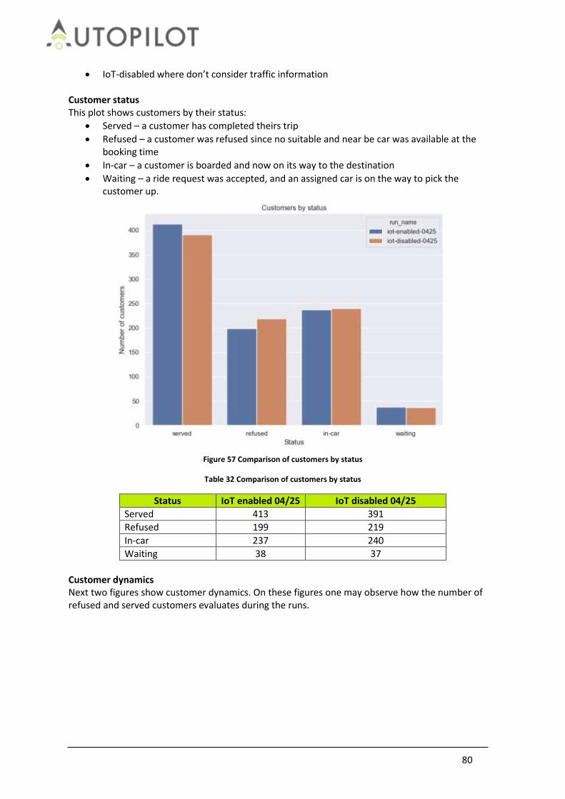
80
IoT-disabled where don’t consider traffic information Customer status This plot shows customers by their status:
Served – a customer has completed theirs trip
Refused – a customer was refused since no suitable and near be car was available at the booking time
In-car – a customer is boarded and now on its way to the destination
Waiting – a ride request was accepted, and an assigned car is on the way to pick the customer up.
Figure 57 Comparison of customers by status
Table 32 Comparison of customers by status
Status IoT enabled 04/25 IoT disabled 04/25
Served 413 391
Refused 199 219
In-car 237 240
Waiting 38 37
Customer dynamics Next two figures show customer dynamics. On these figures one may observe how the number of refused and served customers evaluates during the runs.

81
Figure 58 Customer dynamics by status
Measurements
Table 33 Ride sharing measurements
Hypotheses
Table 34 Ride sharing verification hypotheses
Hypothesis Verification conclusion
Pick-up and drop-off delays are reduced when IoT infrastructure is used
True
Journey times are reduced when IoT infrastructure is used
True
The number of the un-predicted events is reduced, and the overall travel time is decreased to due to better routing
True
Conclusion As we can see there is an observable difference between the runs. In this case the different is small but in the runs; we had traffic information only on a short stretch of the highway. Even with such small amount of real time data we can show the difference between scenarios. If one had access to full real time traffic data, the difference would be much greater. So, in case of fleet management applications the vehicle should play a role of environmental agents and publish events that can be available to the rest vehicles.
Measurement IoT enabled 04/25 IoT disabled 04/25
Cumulative travel times, average per ride 17:05 17:21
Cumulative travel distance, average per vehicle, kilometres
37.7 37.5
Average waiting time for customers, seconds 174 167
Average waiting time for customers (outside the time window of 7 minutes), minutes
10.5 11
Probability of constraint violation (pick-up outside of the time windows of 7 minutes)
0.018 0.024

82
3.6 Car Rebalancing
A Car Rebalancing service receives requests to manage the demand of vehicles at specific locations, relocate vehicles if necessary, and handle any events during the relocation. Car Rebalancing is a service that is piloted in scenarios with other use cases. In Versailles, Car Rebalancing service is used in the Platooning use case. In Brainport Car Rebalancing is used as part of the Urban Driving use case. The use case specific events, such as delays due to traffic lights and avoiding collisions with Vulnerable Road Users (VRUs), are covered in the respective sections and technical evaluations. When evaluating the Car Rebalancing service, a comparative approach is used between the system with and without IoT, in order to check whether it brings significant improvements to the calculation of routes and detections of events. The scenario in Figure 59 is used to evaluate the service.
Figure 59 Car rebalancing overview
Precondition
A vehicle has been parked at pre-defined parking spots. Rebalancing service has already checked that there is a need for 1 vehicle to move from parking A to parking B & initiated that vehicle to start moving. Actions or events
1. Vehicle receives crowd information from the lecture schedule and/or CEMA to check optimal time and route to drive (possibly manual set).
2. Vehicle drives to the other parking spot. 3. VRUs are crossing the street in front of the vehicle.

83
Relevant situations
Vehicle detects VRUs on the route towards other parking spot
VRUs receive a warning of the approaching AD vehicle on their smartphones Baseline:
1. While driving detecting VRU equipped with an ITS-G5 unit, compared to VRU equipped with a smartphone having an app. Both communicating GPS locations to the vehicle.
2. Without driving: vehicle needs to receive a trigger from the rebalancing service (IoT cloud) to start driving. Baseline: only possible manually.
Results:
Vehicle detects VRU also out of line of sight of in-vehicle sensors (using both ITS-G5 as well as 4G of smartphones) and brakes earlier.
Vehicle detects crowdedness through high level of Wi-Fi sniffing activity and decides on different routing.
3.6.1 Research Questions and Hypotheses
From this scenario, we can derive the next research questions and hypotheses: RQ1: Can IoT be used to dynamically relocate AD vehicles, based on crowdedness and demand and
decrease their journey time?
RQ2: Is the tracking and communications of VRUs fast enough so that their locations can be sent and
used by IoT enhanced AD to decrease the detection time for these VRUs?
HY: IoT will extend the detection of VRUs over longer distance (from blocked view). HY: IoT will warn VRUs of an approaching AD vehicle through their smartphones. HY: IoT will enable the relocating an AD vehicle more efficiently, by checking blocked routes (crowdedness).
3.6.2 Technical indicators, measurements and metrics
The indicators to test these hypotheses are the functionality and performance of positioning, localization and environment detections:
Absolute location of AD vehicles on the TU/e campus
Relative location of VRU
Correlation between relative and absolution positions of objects
Delay in detection of targets and objects in the automated functions of test vehicles from different sources; i.e. on-board sensors, V2X communication and received IoT information
Accuracy and reliability of object classification from these different sources
Vehicle dynamics sensors: longitudinal & lateral accelerations
Travel time end-to-end (driving from A to B location according to test routes)
Reaction time of VRU on the approaching AD vehicle
3.6.3 Analysis
This section describes the evaluation and analysis of the Brainport Rebalancing/Urban Driving use case. Two types of experiments are performed. The first evaluation answers RQ1 associated to this

84
use case, focusing on whether IoT can be used to dynamically relocate the AD vehicle based on crowdedness and demand and decrease their journey time. The second evaluation answers RQ2 associated to this use case, focusing on whether the locations of VRUs can be used by IoT enhanced AD to decrease the detection time for these VRUs and incorporating part of the environmental detection analysis, which is more extensively evaluated in section 0.
3.6.3.1 Evaluation 1: Can IoT be used to dynamically relocate AD vehicles, based on crowdedness and demand and decrease their journey time?
In this evaluation one set of experiments is performed. The goal of this set of experiments is to answer RQ1, focusing on whether IoT can be used to dynamically relocate the AD vehicle based on crowdedness and demand and decrease their journey time The applied method in this set of experiments is:
Use crowd estimation to change the route that an AD vehicle takes, see Figure 60; The AD vehicle takes route coloured blue, instead of route coloured red at the moment that crowd is detected on the route coloured red. Note that the GeoFencing service is not activated in this set of experiments
Measure journey travel time and travelled distance over multiple runs
Figure 60 Rerouting of vehicle on other route based on crowd detection

85
Figure 61 Visualisation of the two routes with the actual drive traces
Figure 62 Visualization of the location of VRUs
Figure 60, Figure 61 and Figure 62 show the layout of the area considered for the tests. Figure 62 overlays the density plot of the location of the vehicles, the users whose location is communicated via the equipped smartphones and the Crowd sensors. The Motion Planning uses the crowd estimation in defining the route drive. Once the route is decided the vehicle detects the VRUs using internal sensor and the smartphone application or VRU sensors. The local information is used by the vehicle to decide if to slow down or if it needs to stop completely. Every time the vehicle stops completely it requires some time in order to re-start, also to allow the VRU to cross the road. All this time is used in the decision phase of the motion planning. Especially if the same vehicle or fleet needs to run the same road over time the information can be incorporated in the design of the motion planning in order to optimize the service time. The data collected shows also that the other route has some speed variation due to the road geometry that makes the car slowing down or accelerates due to down slop; this information is collected and can be used for the motion planning functioning. In Figure 63 the comparison of two runs (random two runs shown here, as indicative for all runs), where the green represents a run where IoT was activated (route is changed based on crowd estimation) and red where IoT was not activated (route was taken with a crowd blocking the vehicle) Figure 63 shows two graphs. The upper placed graph shows the vehicle velocity vs. time, while the lower placed graph shows the histogram of normalised journey time vs. velocity. Since the datasets did not have exact same start and end-points, the travel distance and time could therefore not be compared directly. The travel time therefore has been normalized over speed, with a density function, to get a clear overview and a comparative analysis. Additionally, some data points in both datasets should be ignored or treated differently, during further analysis (e.g. changes in speed from driving up and down a slope); Figure 64 shows the histograms of normalised Journey times over travel distance collected during all runs (22), versus bins of velocity;

86
Figure 63 (a) Vehicle velocity vs. time; (b) histogram of normalised journey time vs. velocity for Evaluation 1 experiments
Figure 64 Histogram of normalised Journey times collected during all runs (11 runs with IoT, 11 runs without IoT), for
Evaluation 1 experiments
Conclusions
The conclusions that can be derived from this set of experiments (see Figure 63 and Figure 64) is that when IoT is applied, i.e., using the crowd estimation service (and without using the geofencing service):
IoT, i.e., crowd estimation information, can be used to inform and to dynamically reroute the AD vehicle. When the reroute path is selected correctly to avoid crowds, it can decrease the journey time
Journey time is longer at constant high speed (2.5-3.0 m/s), providing a shorter total travel

87
time and in general smoother ride (less braking or standstill)
journey time is shorter when vehicle is driving slowly up to standstill (0.0-0.5 m/s), even if corrected for the single VRU on the green route
3.6.3.2 Evaluation 2: Is the tracking and communications of VRUs fast enough so that their locations can be sent and used by IoT enhanced AD to decrease the detection time for these VRUs?
The goal of this evaluation is to answer RQ2 associated to this use case, focusing on whether the locations of VRUs can be used by IoT enhanced AD to decrease the detection time for these VRUs. The applied method in this evaluation is: Drive on a pre-set route with the AD vehicle, on which the vehicle will reduce speed or brake based on:
For the non-IoT scenario use only the in-vehicle camera to detect VRUs and when detection is made, the vehicle will stop till standstill.
For the IoT enabled scenario, use the GeoFencing service (where communication to a Smart phone carried by a VRUs is used to filter the smartphone’s position within a predefined area around the vehicle) to detect VRUs and reduce the speed of the vehicle to half of the set speed. In vehicle camera detection is also still active as a redundant safety measure (with similar brake till standstill for safety).
Two experiment sets are performed in this evaluation. The first set focussed on the comparison of VRU detections using GeoFencing (with IoT) vs. only using the in-vehicle camera (without IoT). The second set focuses on the travel time using GeoFencing vs. travel time only using the in-vehicle camera. In both these evaluations, the route has been the same for all runs (so, no rerouting enabled).
3.6.3.2.1 Experiment set 1: VRU detection using GeoFencing or video camera
In this set of experiments, the method of experimentation explained in the previous section is
applied. The observed performance metrics are:
In the first set of experiments the following performance metrics were observed versus travel time:
Displacement: the total travelled distance of the vehicle in [m]
Velocity/speed: vehicle speed in [m/s]
Acceleration: vehicle acceleration in [m/s2] The VRU detections are accomplished using Smart phone detections and visual detections over
time. In particular for the provided graphs/figures in this section:
Dots in shades of red: represent visual detections, for the runs without IoT
different shades of red correspond to different object IDs
Dots in shades of green: visual detections for the runs with IoT
different shades of green correspond to different object IDs
Green crosses: mobile phone detections (y-value = phone ID)
Figure 65 shows on the upper placed graph the a) Displacement versus travel time, in the centre placed graph the b) Velocity/speed vs. travel time and in the lower part placed graph c) Acceleration versus travel time.
Conclusions
The conclusions that can be derived from this set of experiments (see Figure 65) is that when IoT is applied, i.e., using the combination of GeoFencing service and the camera detection)

88
For the IoT enabled (i.e., Geofencing service is enabled) the detection, tracking and VRU position communication is fast enough, since the AD vehicle is able to use the collected information from the GeoFencing service and decelerate (slow down), before the VRU detection information coming from video camera is applied:
o The Geofencing service advises the AD vehicle to decelerate to half speed (in this situation 5km/h) when the VRU is detected
o Video camera advises the AD vehicle to decelerate (brake) till the vehicle stops (0km/h);
In some cases, although the VRU detection with GeoFencing is accomplished later, it causes the vehicle to keep a lower speed, since it still detects the pedestrian within a range of the Geofence; more experiments are needed in order to optimally configure the de-acceleration value and duration that is advised by the Geofencing service to the AD vehicle.
Figure 65 (a) Displacement vs. travel time, (b) Velocity/speed vs. travel time and c) Acceleration vs. travel time
3.6.3.2.2 Experiment set 2: Journey time
In this set of experiments the overall journey time of the AD vehicle is measured, when the AD
vehicle either uses or not uses IoT.
Again, 11 runs with IoT and 11 runs without IoT are compared, similar to Evaluation1.
Figure 66 shows the comparison of two runs (random two runs shown here, as indicative for all runs), where the green represents again a run where IoT was activated (use of GeoFencing service and camera to detect VRUs) and red where IoT was not activated (but where the camera was used to detect a VRU). Similarly to Evaluation 1 experiments, Figure 66 shows two graphs. The upper placed graph shows the vehicle velocity vs. time, while the lower placed graph shows the histogram of normalised journey time vs. velocity. Note that the normalised journey times represent times normalized over the travel distance (including mobile phone and visual detections). Figure 67 shows the Histograms of normalised Journey times collected during all runs, versus bins of velocity;

89
Figure 66 (a) Vehicle velocity vs. time; (b) histogram of normalised journey time vs. velocity for Evaluation 2 - Experiment set 2
Figure 67 Histograms of normalised Journey times collected during all runs, for Evaluation 2 - Experiment set 2
Conclusions
The conclusions that can be derived from this set of experiments (see Figure 67) is that when IoT is applied, i.e., using the combination of GeoFencing service and the camera detection)
Journey time is shorter at constant high speed (2.5-3.0 m/s) (see green bar in Figure 67). This can be explained by the fact that when Geofencing service is applied, the travel time is increased due to the speed reduction (de-acceleration) of half speed when detected correctly. An optimum value for this de-acceleration needs to be found by future

90
experimentation
Journey time is shorter when AD vehicle is driving slowly up to standstill (0.0-0.5 m/s); this means that the vehicle is actually less standing still, when using the GeoFencing function.
Recommendations
Further research should be done on what the size of the GeoFencing area should be. In this evaluation, the size has been chosen based on the comparative study with the camera detection (typically 50m in front of vehicle). The size has an influence on both the experience of safety for passengers (vehicle decelerates perhaps too early, which could be strange to the passenger, since he/she does not know why the vehicle does this (no VRU in sight of the passenger yet).
The travel time could be corrected if the vehicle considers a higher speed after passing the VRU. In this evaluation, the maximum speed was limited in both cases to 10 km/h, which causes the travel time to inherently increase in case of the GeoFencing enabled system (only speed reduction, not considering speed increase after).

91
4 Topics
This section presents the evaluation results of the essential technologies or topics described in section 2.2. The topics are evaluated from the data collected during technical test runs for the use cases.
4.1 Safety
The safety of automated driving vehicles, passengers and road users has a very high importance in the project and is considered in many of the development and deployment phases. The use of IoT data may affect the safety of automated driving. Safety audits were done in the verification phase in Task 2.5 and some recommendations were provided in order to ensure a minimum level of safety in the Pilot Sites. These are reported in AUTOPILOT deliverable IR2.6 [6]. These safety audits and recommendations are evaluated. In this chapter it will be assessed that the actions are applied to the use cases to increase the level of safety. The procedures implemented are related to the users involved in the Pilot Site, to new software or hardware of the vehicle, to the possibility to fall back to an original state and to the IoT data that can affect the AD functions. A numerical evaluation of safety which could be then compared with a baseline is beyond the scope of AUTOPILOT. Instead, all unintended safety interventions and incidents are reported, investigated and assessed. Any human intervention, e.g. by a test or co-driver, to disengage an automated driving mode, function or (safety-relevant) service in real-traffic conditions is considered as an incident that should be reported. Factors that might have caused the incident to report include weather conditions, inattentive road users, unwanted vehicle manoeuvres, and hardware or software failures.
4.1.1 Safety Audit results
The safety assessment will be done taking as the main input the safety audit done and the recommendations given in the verification phase (task 2.5, Internal Report 2.6 [6]). This safety audit consists of a list of inquiries on how IoT data can affect the Autonomous Driving functions. It also considers the number and type of users involved and how they interact with the use case. Using this information an analysis was done in order to detect possible risks and recommendations were provided. Each one of these recommendations was applied by the Pilot Site leaders, meaning an improvement of the safety of the use case. The questions that will be assessed in the audit are:
Are there persons involved in the test cases? What is the role of these persons (VRU, naïve users, expert drivers or operators)?
How many IoT objects are involved in the Use Case / Service? Among them how many vehicles?
To which IoT objects is the vehicle connected during a Use Case?
What data does the IoT provide to the vehicle?
What does the vehicle do with IoT data? Has the software/hardware of the vehicle been modified? If so, which measures have been taken against software/hardware malfunctions?
Can the AD functions be affected by IoT? If so, which functions and how?
Is IoT able to modify or control vehicle motion, i.e. longitudinal or lateral control?
Is there any possibility to fall-back to the vehicle's original state and override IoT functionality?
Which source of data has priority and how is data from IoT weighed relative to data from
92
vehicle sensors in control decisions?
What happens if IoT data is missing, delayed or corrupted? Is there any possibility/tool to test this in the current implementation of the Use Case / Service?
Has the safety of the intended function been tested, e.g. on known safe, unknown safe, known unsafe and unknown unsafe situations?
4.1.1.1 Users – safety relation There are different types of users that interact with the system in the different Pilot Sites. Some of them have direct interaction with the system with professional knowledge as engineers or experts. Others are naïve users acting as vulnerable road users or evaluating the system from an external point of view. All the users that are involved in the test cases are listed in Table 35.
Table 35 List of user interactions
User Knowledge Interaction with the system
Operator Professional Interacts with systems that deal with IoT and vehicle data
Driver Professional Interacts directly with the vehicle
Safety driver Professional Interacts with the vehicle just in case of a safety intervention
AVP expert Professional Interacts with AVP commands in Brainport use case
Student Non professional Interacts with Urban Driving - Brainport as VRU
Roadworker Non professional Interacts with Highway Pilot – Livorno as VRU
Pedestrian Professional / Non professional
Interacts with several use cases as VRU. In some case they are professional engineers and in other cases are naïve users.
Bicyclist Professional / Non professional
Interacts with several use cases as VRU. In some case they are professional engineers and in other cases are naïve users.
Vehicle passenger Non professional Interacts with several use cases as naïve test users for user acceptance or quality of life.
Tourist Non professional Interacts with Urban Driving – Versailles as customer of the service.
Depending on the grade of interaction with the system and the level of knowledge, a level of risk is assigned to each one of these users. A low level of risk will be assigned with a value of 1, a medium level with 2 and a high level with 3 for each category. The sum of the risks of both categories will give a global risk value of the user category. The results are presented in Table 36:
Table 36 List of user risks
User Knowledge (Risk) Interaction with the system (Risk)
Total Risk value
Operator Low (1) Low (1) 2
Driver Low (1) Low (1) 2
Safety driver Low (1) Zero (0) 1
AVP expert Low (1) Low (1) 2
Student Medium (2) Medium (2) 4
Roadworker Medium (2) Medium (2) 4
Pedestrian Medium (2) Medium (2) 4
Pedestrian (exp.) Low (1) Low (1) 2

93
Bicyclist Medium (2) Medium (2) 4
Bicyclist (exp.) Low (1) Low (1) 2
Vehicle passenger Medium (2) Zero (0) 2
Tourist High (3) Medium (2) 5
The list of users involved in each Pilot Site is summarized below:
Table 37 Users involved in each Pilot Site
Brainport Livorno Vigo Tampere Versailles
Users involved
Operators Drivers Safety drivers AVP Expert Students (VRU)
Operators Drivers Safety drivers Road workers Pedestrians Bicyclists
Operators Drivers Naïve users
Operators Drivers Naïve users Pedestrian (exp.) Bicyclist (exp.)
Driver-Operators Tourist Pedestrian (exp.) Bicyclists (exp.)
In order to mitigate these user risks, the Pilot Site responsible informed about the system and gave to the users a minimal technical knowledge about the use case. In the plots below, we observe the level risk reduction thanks to the training provided by the Pilot Site experts.
Figure 68 Brainport user risks
0
1
2
3
4
5
6
Operator Driver Safetydriver
AVP Expert Student
Brainport User Risk
Risk before
Risk after

94
Figure 69 Livorno User Risks
Figure 70 Tampere user risks
Figure 71 Versailles user risks
0
1
2
3
4
5
6
Livorno User Risk
Risk before
Risk after
0
1
2
3
4
5
6
Operator Driver Vehiclepassenger
Pedestrian(exp.)
Bicyclist(exp.)
Tampere User Risk (No mitigation needed)
Risk
0
1
2
3
4
5
6
Driver-Operator Tourist Pedestrian Bicyclists
Versailles User Risk
Risk
Risk

95
Figure 72 Vigo user risks
4.1.1.2 New software / hardware of the vehicle – safety relation We assume that the safety of the AD vehicles has been validated before the new implementations done in the AUTOPILOT project. Therefore, we expect to have the same level of safety after the IoT modifications. Below we can find the modifications done in the vehicles for each Pilot Site:
Table 38 Software and hardware modifications to vehicle
Pilot Site Hardware modification Software modification
Tampere Actuators added to key elements of the vehicle.
Speed and acceleration limited set. The vehicle does not start without PMC verification.
Versailles Actuators added to key elements of the vehicle.
Livorno Vehicle does not apply the IoT recommendation without the TMC approval.
Brainport Added the MOVE BOX to the vehicle for Platooning use case.
Vigo New software is continuing monitoring itself to check the integrity of the data.
The only use case where new hardware has been added to the vehicle is Platooning from Brainport. They have added a MOVE BOX, which had been used for other projects but with other functionalities, and it has been updated according the new IoT features. In Tampere and Versailles actuators have been added to key elements of the vehicle (pedals and steering wheel) and functional safety has been guaranteed after the modification. If the data used by the new software or hardware of the vehicle is validated by an external entity like a Parking Management System (AVP Vigo, Brainport and Tampere) or a Traffic Control System (Highway Pilot Livorno, Platooning Brainport) there is no need for extra recommendations.
4.1.1.3 AD functions affected by IoT – safety relation
0
1
2
3
4
5
6
Operator Driver Naïve user
Vigo User Risk
Risk
Risk

96
The AD functions of the vehicle are not only fed by the vehicle sensors but also can be affected by the IoT data. Since there is an extra source of information feeding the AD functions a safety analysis must be done to ensure the functionality in critical situations. The analysis done in this chapter focuses on the critical situations that may happen during the execution of a use case. More precisely, it focuses on the system interventions or non-interventions in the critical and non-critical situations. This approach is called Confusion Matrix Analysis and it has the structure seen below:
Table 39 Confusion matrix analysis
Pilot Site name (Use Case name)
True Positive System intervention in a critical situation
False Positive System intervention in no critical situation
False Negative No system intervention in a critical situation
True Negative No system intervention in no critical situation
In the Tampere Pilot Site, two use cases are deployed: Urban Driving and Automated Valet Parking. The Urban Driving use case is deployed in an open traffic urban area where the most critical situation is the VRU detection. IoT gives the capability to the vehicle to detect in advance the VRU when crossing the street and to act according to the information received. The Automated Valet Parking use case is deployed in a controlled external area where the vehicle is dropped at the Drop off point and it drives autonomously to the parking slot. During the route, the vehicle may find an obstacle or a VRU and has to avoid it. This will be the most critical situation in the use case.
Table 40 Tampere confusion matrix
Tampere (UD and AVP)
True Positive False Positive System intervention in a critical situation System intervention in no critical situation
UD and AVP: The vehicle will stop in case of VRU detection.
UD: It may result in unintended braking but since the velocity is already low, it will not result in rear-end collision. AVP: There is a double check provided by the Parking Management Operator; therefore this will ensure that IoT does not provide any wrong indication to the vehicle.
False Negative True Negative No system intervention in a critical situation No system intervention in no critical situation
UD: May result in a collision if the driver is not attentive. However, safety driver is still responsible for road safety. AVP: There is a double check provided by the Parking Management Operator; therefore this will ensure that IoT does not provide any wrong indication to the vehicle.
UD and AVP: The vehicle will continue its path.
In the Versailles Pilot Site two use cases are deployed together with a service: Urban Driving + Ride sharing and Platooning + Car Rebalancing. The Urban Driving + Ride sharing is done in an open urban

97
environment where VRUs can walk through and no other vehicles are allowed. For this reason, the most critical situation would be the detection of users during the urban route. The Platooning + Car Rebalancing use case is also deployed in an open traffic urban area where the platoon is used to relocate vehicles from one parking area to another. The platoon is crossing several intersections adapting its speed and in some cases modifying the time remaining of traffic lights. The time gap between vehicles is adapted according the speed so, the most critical situation, are emergency breaks expected or unexpected.
Table 41 Versailles confusion matrix
Versailles (UD and PT)
True Positive False Positive System intervention in a critical situation System intervention in no critical situation
UD: The vehicle will adapt its speed in case of VRU or bicycle detection. PT: In an emergency braking situation the time gap between vehicles will be adjusted based on the current distance between the vehicles and the brake performance.
UD: The vehicle will slow down but since the velocity is already low it will not result in any danger situation. PT: The entire platoon may slow down or brake adjusting the time gap but since the speed is low there will not conduct to any danger situation.
False Negative True Negative No system intervention in a critical situation No system intervention in no critical situation
UD: May result in a collision if the driver is not attentive. There is no safety driver; the passengers of the vehicle are tourists. PT: May result in a collision if the driver is not attentive. There is only a safety driver in the first vehicle, but not in the rest of the platoon.
UD and PT: The vehicle will continue its path.
In the Vigo Pilot Site two use cases are deployed: Urban driving and Automated Valet Parking. The Urban Driving use case is implemented on the Gran Via in Vigo. The scenario includes traffic light information sent by IoT, VRU detection using cameras and hazard warnings sent by the Traffic Control Centre. In this use case the prototype will be able to adapt the speed according to the status and remaining time to change the status of traffic lights and will react in advance to potential warnings received by IoT like VRUs. The Automated Valet Parking is deployed in an indoor environment with no GPS signal available. The vehicle should park autonomously from the drop off point to the parking slot. During the route the vehicle may find a VRU in the path that it has to avoid.
Table 42 Vigo confusion matrix
VIGO (UD and AVP)

98
True Positive False Positive System intervention in a critical situation System intervention in no critical situation
UD: In case of VRU or hazard detection, the vehicle will decelerate some meters in advance and stop if necessary. AVP: In case of VRU detection in the path, the vehicle should stop in advance and wait for continuing the route.
UD: It may result in unintended deceleration but since the velocity is already low, it will not result in rear end collision. AVP: It may result in unintended deceleration but it will not conduct to any danger situation due to the low velocity.
False Negative True Negative
No system intervention in a critical situation No system intervention in no critical situation UD: May result in a collision if the driver is not attentive. The safety driver is still responsible for the road safety and he should take the control to avoid any danger. AVP: May result in a collision if the driver is not attentive. The safety driver is still responsible for the road safety and he should take the control to avoid the obstacle in the path.
UD and AVP: The vehicle will continue its path.
The Livorno Pilot Site has implemented two use cases: Urban Driving and Highway Pilot. The Highway Pilot use case is located in the Florence - Livorno Highway (open traffic). There are two main points during the route: the first one, the puddle zone with three different locations for the sensors which detect the level of water on the road. The second one is a roadwork area in one lane of the highway. When a hazard is detected, a DENM message is sent to the vehicle and a message is displayed in the HMI. The DENM is then validated by the Traffic Control Centre and after that the speed of the AD vehicle is adapted according the current warning. The most critical situations will be the detection of both hazards: puddles and road works warnings. The Urban Driving use case is located in the area of the Port of Livorno (open traffic with restricted access). There are three events that are communicated to the vehicles: a pedestrian traffic light violation (detected by a stereo camera located in the traffic light), a fallen cyclist in the intersection (triggered by an IMU installed in the bicycle which communicates straight forward to the vehicle) and the pavement information (potholes triggered by acceleration sensors of the vehicle and of the HMI tablet installed in it). The VRU detections are considered the most critical situations of the system.
Table 43 Livorno confusion matrix
LIVORNO (HP and UD)
True Positive False Positive System intervention in a critical situation System intervention in no critical situation
HP: In case of puddle detection, the vehicle will slow down to an acceptable speed until the danger zone has passed.
HP: There is a double check provided by the Traffic Management Operator; therefore this will ensure that IoT does not provide any

99
wrong indication to the vehicle.
In case of roadwork detection, the vehicle will slow down or stop if necessary and advice to the driver to change the lane. UD: In case of VRU or bicycle detection, the vehicle will decelerate some meters in advance and stop if necessary.
UD: It may result in unintended deceleration but since the velocity is already low, it will not result in rear end collision.
False Negative True Negative
No system intervention in a critical situation No system intervention in no critical situation HP: There is a double check provided by the Traffic Management Operator; therefore this will ensure that IoT does not provide any wrong indication to the vehicle. UD: May result in a collision if the driver is not attentive. The safety driver is still responsible for the road safety and he should take the control to avoid any danger.
HP and UD: The vehicle will continue its path.
The Brainport Pilot Site has implemented four use cases: Urban Driving + Car Rebalancing, Platooning, Highway Pilot and Automated Valet Parking. The Urban Driving + Car rebalancing are used in order to maintain a balanced number of cars available in each one of the two parking spots in the campus of the Technical University of Eindhoven. Whenever an unbalanced number of cars are detected, one of the cars parked in the parking spot with the most cars shall drive autonomously to the other parking spot. Therefore, the car to be moved receives the command from the IoT-cloud. During its way to the other parking spot, the vehicle perceives the environment by using its own sensors. Furthermore, it receives information from the cloud about the two possible routes between the parking spots, VRU density, and pedestrians’ location information. Based on this information, the vehicle reduces its speed if approaching a pedestrian in a radius of 25 m. If the vehicle sensors detect a pedestrian at a distance shorter than 10 meters, the vehicle will stop. The detection of these VRUs is considered the most critical situation of the use case. The platooning use case is done in the A270 highway from Helmond to Eindhoven (open traffic) and it is divided in three phases: formation, platooning and disengaging. The formation phase can be done in three different ways: 1) The leading car picks up the following car from a starting point in the campus; 2) The driver of the following car drives to the road in order to start following the leading car or 3) The leading and the following car are coordinated through IoT cloud in order to form the platoon at a convenient point on the motorway. During the platooning phase, the leading vehicle is driven manually with ADAS and the following vehicle/s drive in automated mode with proprietary C-ACC and lateral control (lane assist) functions activated and speed advice received trough IoT. An emergency braking during the platooning phase would be the most critical situation of the use case. The Highway Pilot use case is done on the Automotive Campus in Helmond (controlled environment) with two vehicles involved. The first vehicle detects and reports all the road hazards that it can find in the route. The Valeo Cloud evaluates the reported information and upon a certain confidence level, publishes this information on the IoT platform, hence making this information accessible for the second vehicle. The second vehicle reacts automatically to the published road hazards when it is approaching them. The detection of the hazard and reaction of the system would be the most critical situation of the use case.

100
In the Automated Valet Parking use case the vehicle will drive automatically from the drop off point to the parking spot and from the parking spot to the pickup point. The request of the vehicle is done with a smartphone and the parking App. The vehicle receives a route from the Parking Management System that is free of obstacles. If the sensors detect an obstacle on the route of the vehicle, they will send the information via the IoT platform to the PMS. The vehicle will ask for a new route if this occurs. The most critical situation of this use case is the hazard detection.
Table 44 Brainport confusion matrix
BRAINPORT (UD, PT, HP and AVP)
True Positive False Positive System intervention in a critical situation System intervention in no critical situation
UD: In case of VRU detection the vehicle will slow down or stop if necessary. PT: In an emergency braking situation the time gap between vehicles will be adjusted based on the current distance between the vehicles and the brake performance. HP: In case of pothole detection, the vehicle will decelerate some meters in advance until it has passed the hazard. AVP: In case of obstacle detection in the path, the vehicle should stop in advance and reroute to get the final destination.
UD: It may result in unintended deceleration but since the velocity is already low, it will not result in rear end collision. PT: There is a double check provided by the Traffic Management Operator; therefore this will ensure that IoT does not provide any wrong indication to the vehicle. Due to it’s a high speed use case and time gap information is received by V2V the safety driver should be aware in the intersections just in case he has to take control of the vehicle. HP: It may result in unintended deceleration but since the velocity is already low, it will not result in rear end collision. AVP: It may result in unintended deceleration and also in unnecessary rerouting but it will not conduct to any danger situation due to the low velocity and the fact that the new route will be also free of obstacles ensured by the Parking Management System.
False Negative True Negative No system intervention in a critical situation No system intervention in no critical situation
UD: May result in a collision if the driver is not attentive. The safety driver is still responsible for the road safety and he should take the control to avoid any danger. PT: There is a double check provided by the Traffic Management Operator; therefore this will ensure that IoT does not provide any wrong indication to the vehicle. Due to it’s a high speed use case and time gap information is received by V2V the safety driver should be aware in the intersections just in case he has to take control of the vehicle. HP: May result in a low risk situation since the obstacles are not dangerous enough to
UD, PT, HP and AVP: The vehicle will continue its path.

101
conduct to a dangerous situation if the driver is not attentive. The safety driver is still responsible for the road safety and he should take the control to avoid any danger. AVP: May result in a collision if the driver is not attentive. The safety driver is still responsible for the road safety and he should take the control to avoid the obstacle in the path.
4.1.1.4 Fall-back to original state – safety relation In order to ensure the autonomous driving safety, there always must be at least one method in the AD vehicle to fall-back to its original state, skipping the modifications applied in AUTOPILOT project.
Table 45 Methods to fall back to original state
Brake/ Acceleration pedal
Steering wheel
Emergency Red Button
Computer command
Tampere YES NO YES N/A
Versailles YES YES YES N/A
Livorno YES YES YES YES
Brainport YES YES YES N/A
Vigo YES YES YES N/A
4.1.1.5 Data priority rules – safety relation There are two main data sources to collect information from the environment to take actions in advance from dangerous events: the vehicle sensors and the IoT data. The IoT data is used to complement the vehicle sensors data to increase the confidence level and the availability range. There could be a chance that both sources send contradictory information, and, in that case, the vehicle should give priority to the source, which are usually the vehicle sensors, or to the data with the highest-level warning.
Table 46 Pilot Sites data priority
Pilot Site Vehicle sensors priority IoT Data priority Highest level of warning
Tampere X
Versailles X
Livorno X
Brainport X
Vigo X
The IoT data should not have priority over the vehicle sensors, as it is used as complementary data to increase the level of confidence of vehicle sensors data. So, vehicle sensors should always have priority over the rest of the sensors. However, in some cases like Livorno where IoT is used in highways to locate hazards in advance, giving priority to the most critical source of data, even if there is a risk of running into false positives, it’s the best option.

102
4.1.1.6 Data delay, missing or corrupted – safety relation IoT data may not be as reliable as a data source as on-board sensors. This audit assesses the measures taken upon three types of detected issues in the provisioning of IoT data; when IoT data is delayed or not provided at all in time, or when data is corrupted.
Table 47 Vehicle reaction when data is delayed, missing or corrupted
Pilot Site Data delay Data missing Data corrupted
Tampere (AVP) Test is not starting Test is not starting Test is not starting
Tampere (UD) Safety driver should take control but no warning is received
Safety driver should take control but no warning is received
Safety driver should take control but no warning is received
Versailles (UD) Vehicle will continue driving (no critical data)
Vehicle will continue driving (no critical data)
Vehicle will continue driving (no critical data)
Versailles (PT) Platoon is dissolved as soon as V2V communication is interrupted
Platoon is dissolved as soon as V2V communication is interrupted
Platoon is dissolved as soon as V2V communication is interrupted
Livorno (UD) Timestamp check with GPS Integrity check Integrity check
Livorno (HP) Timestamp check with GPS Integrity check Integrity check
Brainport (UD) The vehicle stops safely The vehicle stops safely
The vehicle stops safely
Brainport (AVP) The vehicle stops safely The vehicle stops safely
The vehicle stops safely
Brainport (HP) Safety driver will take the control of the vehicle
Safety driver will take the control of the vehicle
Safety driver will take the control of the vehicle
Brainport (PT) The lead vehicle has still control of the platoon
The lead vehicle has still control of the platoon
The vehicle has still control of the platoon
Vigo (UD) Vehicle will continue driving using vehicle sensors
Vehicle will continue driving using vehicle sensors
Vehicle will continue driving using vehicle sensors
Vigo (AVP) Vehicle will continue driving using vehicle sensors
Vehicle will continue driving using vehicle sensors
Vehicle will continue driving using vehicle sensors
Tampere:
In the AVP use case, the test will not start if data is delayed, missing or corrupted. In the Urban Driving use case, the safety driver will have to take control, but the system does not warn him.
Versailles:
In the Platooning use case, the platoon will be dissolved if data is corrupted or missing.
In the Urban Driving use case, if IoT data is missing, vehicles can continue driving using their on board sensors. IoT data is not safety critical.
Livorno:
For delays, there is a timestamp checking and data is skipped if timestamps are different to the GPS. For misses and corruptions there is an integrity check and they are discarded if they are not consistent.

103
Brainport:
In Platooning if the IoT data is missing, the lead vehicle driver still has full control of the platoon.
In the AVP, if there is no IoT data, the vehicle stops safely. Vigo:
If IoT data is missing, vehicle can continue driving using its own on-board sensors. IoT data is not safety critical.
4.1.2 Safety Interventions results
Pilots are obliged to report all safety related incidents, for example for unintended interventions, during automated driving on the public roads. This will complement the safety audit done previously. In order to report this information, a safety intervention form has been defined to be filled by each Pilot Site after the test iterations. The structure of the form is defined in the Annex Safety Intervention form7.9. Only one safety intervention has been reported among all the Pilot Sites. Below you can find the safety intervention logged for Platooning use case in Versailles. The intervention was done by the test driver due to an inattentive road user and an unwanted vehicle manoeuvre. The vehicle lost the GPS signal and the inertial unit was not strong enough to keep the vehicle on the right path, so the safety driver took over the control for safety reasons. Note that, this report is unrelated to IoT, but an inattentive road user.
Table 48 Versailles safety intervention example
Parameter Name Versailles Platooning 389
Intervention_Type Test driver
Intervention_Cause Inattentive road user Unwanted vehicle manoeuvre
Intervention_Description Safety driver took over the control of the vehicle.
Severity_Perception Moderate
AD_Vehicle_Situation Loss of GPS RTK, inertial unit not strong enough to keep vehicle on the right path.
IoT_Situation Nothing to mention
Traffic_Situation Nothing to mention
This safety intervention can also be observed in the plot below inside the red circle area.

104
Figure 73 Versailles safety intervention analysis
In test run 389, the lead vehicle with StationID 258226303 and the second vehicle with StationID 258226306 had to avoid an inattentive road user, and the test driver had to take over control of the vehicle. The map shows the trajectories of all three vehicles. The larger circles show the vehicle positions at 14:43:00, when the lead vehicle (green) already passed the inattentive road user, and the second vehicle (yellow) has come to a stop, before making the lateral evasive action. The last vehicle (purple) could follow its intended course. Clearly this safety incident is unrelated to IoT data from the Traffic Light Assist cloud service.

105
4.1.3 Conclusions
It general, it can be concluded that IoT data is not safety critical in the implementations of AUTOPILOT project. IoT information is used as complementary data to the vehicle sensors data or other data sources and it helps increasing the confidence level of the data. However, IoT data is still able to affect negatively to the vehicle, so an evaluation of certain factors needs to be done to ensure that there aren’t negative effects. The factors analysed were:
User risks. Depending on the type of user interacting with the use case, there is a higher or lower risk. The main reason for higher risks was the lack of knowledge of the use case, so with trainings to inform the users, the risks were mitigated.
Software and hardware modifications. It is assumed that the vehicle is safe before implementing the new software or hardware needed for the use case. The MOVE BOX from platooning Brainport and the actuators added in the pedals of the vehicles from Tampere and Versailles are the only modifications done to the vehicles. Therefore, a safety validation of the vehicle was done by the Pilot Sites after the new hardware / software implementation and the safety level of the vehicle was the same as before.
IoT and AD functions. For each use case, the most critical situation has been identified. Then, an analysis has been made according the reaction of the system when facing a critical or no critical situation. The most dangerous situations are when the system is not reacting in front of a critical situation, but the vehicles always have a safety driver that can override easily the vehicle decisions.
Fallback to original state. At least, the vehicle must have one way to fallback to original state (before IoT implementations). This is achieved for all vehicles from all the Pilot Sites.
Data priority. The vehicle data always has priority over the IoT data except for Livorno Pilot Site which the highest level of warning has priority. In front of data conflict, the vehicle sensors are much more reliable than IoT data, so it is totally acceptable to give priority to vehicle data over IoT data. However, the Italian use cases despite the possibility to run out into false positives, gives priority to the highest level of warning which is also acceptable but not the best option.
IoT data corrupted or delayed. In the use cases where IoT data is needed for the correct functionality of the use case, the test is stopped and where IoT data is not safety critical the use case continues with the information of vehicle sensors data.
Regarding of the safety interventions logged, it can be concluded that none of the safety incidents occurred during the test runs were not IoT related.
4.2 Security
The security will be assessed concerning the most common security threats related to IoT. This section describes the information related to security that should be provided by all pilot sites for the evaluation of security aspects in the project.
4.2.1 The research question
The main research question of the security aspects of the AUTOPILOT project is: RQ: How far is AUTOPILOT security from readiness to hit the real streets? Security must be assessed from multiple points of view to ensure that a security by design approach was correctly applied, the attack surface is minimized and the identified risks are mitigated.

106
In cases where, for budget or timing constraints, development teams have not been able to implement security measures to mitigate all the identified risks we will research whether the development team has a rationale for not mitigating some risks.
4.2.2 Assessment methodology
The main objective of this assessment is focused on the security of all the devices (or at least device models) used in the implementation and also all the layers of the AUTOPILOT ecosystem. A questionnaire has been set up in order to achieve this objective (Annex 7.6). The questionnaire covers the main aspects of the topic and has to be answered by each Pilot Site. The aspects that are covered by the security questionnaire are:
Physical security. Measure the protection of personnel, hardware, software, networks and data from physical actions and events.
Wired network security. Measure the network parameters as: segregation, firewalls and routers rules
Wireless network security. Measure what protections are in place to protect wireless communications.
Device security. Measure if there is an inventory of installed devices. Measure if an update plan is possible with the current implementation. Measure if devices are baked up and can be recovered in case of disaster.
Logs availability. Measure the availability of log files and if/how they are kept safe.
Application security. Measure how updates are propagated to servers and devices. Measure if the application code is securely executed (minimum privileges principle).
Protocols security. Measure if protocols are resistant to MITM attacks, eavesdropping, and injection.
User / device authentication and authorization. Measure how strong the passwords are and how UAC/MAC is able to correctly identify and authorize users.
Perception of security. Measure how the users are impeded by security features.
4.2.3 Security evaluation results
Security evaluation did not target assessment mitigation of each particular threat. This would be far beyond the scope and possibilities of the project when taken into account that each pilot implementation used a slightly different architecture and components. This approach was proven right when answers were collected and revealed that from security point of view the implementations differed a lot. Main focus of the security evaluation was to review the deployed infrastructure and support for security monitoring and logging of the solution. The infrastructure may provide a baseline for security and mitigate most of the threats common to all IoT projects.
4.2.3.1 Security events logging Questionnaires revealed the fact that there are huge differences among the pilot sites in terms of logged security events and that there is a big difference between the IoT platform and services part and client devices such as vehicles and roadside units. From a service point of view the pilots may be split into two groups. Certain pilot sites used state of the art infrastructure that provided a good level of security event logging of most of the requested events. It must be noted that the provided logging covered only the default IoT or cloud service events and not any AUTOPILOT specific ones. Still the level was a good baseline for production deployment.

107
The other pilot sites' focus on functional implementation and security, including event logging, was neglected except of a few default events provided by used infrastructure. Logging implemented in vehicles should cover data communication, tampering, device updates and other events that are not fully related to the IoT platform, but should support integration and provide reliability of data submitted. The evaluation results show that the logging in the device side is minimal, relying on underlying on the infrastructure at best. It is obvious that the implementation focused on functional requirements.
4.2.3.2 Logged information Questionnaire showed that there was a certain level of logged information in all devices and platforms covering standard information stored by the infrastructure such as event type, time and process id, but additional information needed by AUTOPILOT, such as data sets read or modified during the event, was not logged.
4.2.4 Security requirement coverage
Technical specification provided in D1.4 [7] is very open in terms of security requirements and mostly relies on building bricks used (such as oneM2M platform); there are no AUTOPILOT specific requirements added on top of the bricks. AUTOPILOT specific security and requirements were defined in D1.10 [8]. The document provided a list of concrete requirements for implementation. The security requirements are covered partially and only by a few pilot implementations. Infrastructure provides a basic coverage; there were gaps in security monitoring and logging parts. Nonetheless it is expected that even though most of the treats were not addressed at design level the infrastructure and practice deployed may mitigate most of the security risks.
4.2.5 Conclusion and recommendations for production
It is not possible to provide a common answer to the research question for all the pilot sites. The production readiness differs among pilot implementations. It is clear that few of them are at proof of concept level and at this time it does not make sense to consider going into production, but rather to use results to design a new implementation based on existing bricks and targeting a different level of security and privacy. For this reason the readiness is evaluated for the most advanced implementations only. Functionally the advanced implementations are very close to production quality and following points should not be difficult to resolve. Data protection in IoT platforms was evaluated to detail. The evaluation did not show any encryption or anonymization, so at least basic data encryption should be deployed. The implementations mostly log few important security events that may be important for operational security of the solution. This includes both platform and systems in vehicles and other hardware used.
4.3 Privacy
The Privacy will be assessed from multiple points of view to ensure that a correct approach has been
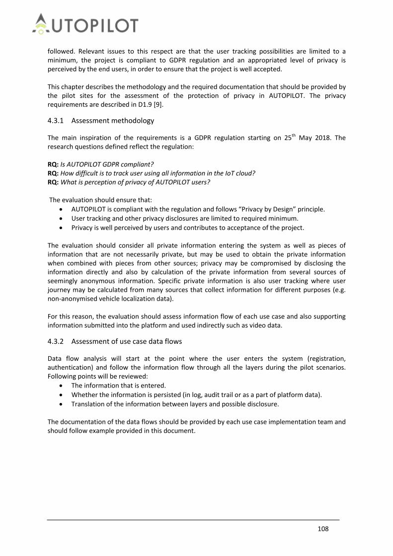
108
followed. Relevant issues to this respect are that the user tracking possibilities are limited to a minimum, the project is compliant to GDPR regulation and an appropriated level of privacy is perceived by the end users, in order to ensure that the project is well accepted. This chapter describes the methodology and the required documentation that should be provided by the pilot sites for the assessment of the protection of privacy in AUTOPILOT. The privacy requirements are described in D1.9 [9].
4.3.1 Assessment methodology
The main inspiration of the requirements is a GDPR regulation starting on 25th May 2018. The research questions defined reflect the regulation: RQ: Is AUTOPILOT GDPR compliant? RQ: How difficult is to track user using all information in the IoT cloud? RQ: What is perception of privacy of AUTOPILOT users? The evaluation should ensure that:
AUTOPILOT is compliant with the regulation and follows “Privacy by Design” principle.
User tracking and other privacy disclosures are limited to required minimum.
Privacy is well perceived by users and contributes to acceptance of the project. The evaluation should consider all private information entering the system as well as pieces of information that are not necessarily private, but may be used to obtain the private information when combined with pieces from other sources; privacy may be compromised by disclosing the information directly and also by calculation of the private information from several sources of seemingly anonymous information. Specific private information is also user tracking where user journey may be calculated from many sources that collect information for different purposes (e.g. non-anonymised vehicle localization data). For this reason, the evaluation should assess information flow of each use case and also supporting information submitted into the platform and used indirectly such as video data.
4.3.2 Assessment of use case data flows
Data flow analysis will start at the point where the user enters the system (registration, authentication) and follow the information flow through all the layers during the pilot scenarios. Following points will be reviewed:
The information that is entered.
Whether the information is persisted (in log, audit trail or as a part of platform data).
Translation of the information between layers and possible disclosure. The documentation of the data flows should be provided by each use case implementation team and should follow example provided in this document.
109
Car sharing service
Authentication service
Watson IoT platform
User
Real identity
Pseudonymous identity
Translation into pseudonym
Store: Audit log with translation key
Translation into common credentials
Store: Audit log with transaction details
Common service credentials
Figure 74 - Example of information flow of Ride sharing use case
4.3.3 Assessment of user tracking
In order to analyse user tracking additional flow will be analysed:
Information about user position via information from other devices. Typical example is information about users entering a vehicle at a specific position and tracking of the vehicle.
Collateral information of the use case available in the platform that may be used for tracking. Example may be information about users on pedestrian crossing with possible unique identification or information collected by roadside units.
4.3.4 Assessment of information in the ecosystem and possible privacy leaks
The information submitted into the system may be exploited on several layers: it may be disclosed by the services via data provided to service providers or disclosed directly as data persisted in the IoT. In order to cover both privacy threats the analysis must cover both data submitted and persisted by the platform and data made available by services accessible from the outside. Each data source of the platform should be analysed for potentially sensitive data and data flows should be provided describing how the data enters the platform, whether data is persisted and describe information that is derived from the data. The data may impact privacy on two levels: when the data enters the pilot site platform or local services and when the data is shared with interoperable platforms. The evaluation should ensure the privacy by design principle is followed for all information entering the platform: that only required information is collected, anonymised as soon as it enters the platform and it is not shared with other

110
platforms if not necessary. In order to simplify the assessment task the data analysis should be limited to information impacting privacy: position data (of vehicles and other traffic actors), unique identifiers (such as pseudonymous credentials, MAC addresses) and video data.
4.3.5 Privacy evaluation results
4.3.5.1 Evaluation of privacy threats Privacy evaluation questions were focused on data flows, exchanges of information between layers of the system and authorization to access the data. The evaluation showed that even though there are big differences among pilot sites implementations the state of implementation is clearly at pilot or proof of concept level. The privacy was not the main focus of the implementation, main goal was to show functionality of the solution and all participants considered the privacy was something that should be added to the solution later. From this point of view it is difficult to say that privacy by design principle was followed from the design phase to the implementation. Direct threat is exposure of PII (personally identifying information) was not perceived in any of the pilot implementations. Common approach is the solution in general does not contain any PII as such. Few of the pilot sites include end users as actors in the IoT platform and services, but in all the cases they are identified by anonymous pseudonyms. Secondary privacy threat is possibility to track user’s position or to reconstruct history of his movement based on information leaked through any of the platform services or from information persisted. Typical weak spot is authentication of vehicles. The implementations differ in this case. Few of them use periodically changing PKI credentials that partially protect the vehicle against tracking, other implementations use either permanent PKI credentials or permanent access tokens generated during device initialization. This means that the services that use GPS positioning process and possibly persist detailed position of the vehicle each time the vehicle submits any information to the platform (road hazard detection service) and in some cases (such as ride sharing) a real time information about trajectory. This is not a privacy threat on its own, but may be exploited for user tracking once the attacker obtains a key to resolve the vehicle identifier into owner’s identity or identify user getting in and out of the vehicle. The tracking data (vehicle identifiers and GPS coordinates) are collected by the IoT platforms, processed by the application service and in most of the cases persisted only in log files of the platform and application service. The service itself in most of the cases does not persist raw information processed and exposes only calculated application information. From this point of view the platforms are vulnerable mostly to insider type attacks. Additional IoT specific privacy threats are when vehicles, road side units or drones stream live information into the platform and it may possibly include video footages with live people. In this case the data are processed by the platform and deleted, but this does not protect against insider attacks or platform misuse. This was a specific case occurring in road hazard service when the car submits position and also photo or video footage of the hazard. It is necessary to note privacy risk associated with this service is very low as exploitation of this use case is very difficult.
4.3.5.2 Authentication, authorization and access to data and services Authorization was evaluated for all communication channels between IoT platform and application services. The lower layers of the solution rely on IoT specifications which cover authentication and authorization requirements in a standard way.

111
There is a difference between authentication of server side components (services) and clients connecting to the platform on behalf of end-users or vehicles (when acting as consumers of application services). The services in pilots use permanent access tokens generated for each client which means there is no distinction of roles per client. Each client would have access to all data related to the service and if there are roles defined the translation must be done at calling client side. This is considered a state of the art approach for cloud services and even though permanent client access token is not the strongest means of authentication in combination with TLS with client authentication or VPN it can be considered enough for the purpose. Pilots don’t implement any additional authorization measures on top of this communication so it may be considered a technological debt that should be finished if the services should go live. Authentication of vehicles (as service consumers) and end-users relies in case of a several services on anonymous PKI credentials which may be considered state of the art. It must be noted that several service implementation don’t take any authentication or authorization into account and the services are open for any clients.
4.3.6 IoT Platform federation
One of the goals of the AUTOPILOT project was to provide possibility of IoT platform federation to share information at platform level. The federation was tested in one of the pilots, but in a very limited way. The main goal was to provide a technical proof of concept, there was no plan to provide policies or blueprints how to realize the federation in production. Pilot implementation provided federation at device level: selected devices were connected to the primary platform and shared with the secondary platform via dedicated gateway. This federation model allows sharing of any devices including drones and vehicles, which means sharing of potential tracking and collateral information. However, the pilot implementation did not share any of this information and future plans considered that information shared by each particular device would be reviewed by device type and limited only to necessary information without any sensitive data. The limited way the federation was implemented does not provide enough information to leverage on the privacy evaluation and provide any guidelines for production; this will be a logical step after additional research of this topic.
4.3.7 Privacy requirement coverage
AUTOPILOT specific privacy requirements were defined in D1.10 [8] and main goal of the privacy related part was to provide a basic guideline how to implement privacy by design and how to address GDPR. The document provided a list of concrete requirements for implementation. It was perceived that the privacy requirements were in some cases not taken into account during design phase of pilot implementation and privacy by design was not deployed. The documentation of data flows, private information and potential privacy threats was scarce. All of this was in line with questionnaire answers that main focus of the pilots is the core functionality when security and privacy was secondary. It is necessary to point out that the implementations did not include any PII and in some cases user tracking was also mitigated.
4.3.8 Conclusions
There are no answers to research questions that would be common to all implementations. In the same way at the security implementations the privacy features differ among pilots. The answers

112
provided here target the most advanced implementations. RQ: Is AUTOPILOT GDPR compliant? The pilots do not include any PII and as such are very close to reaching GDPR in terms of data minimizations. This was due to limited time of the pilot and the fact the PII is not needed for functional demonstration. Production version would be obliged to include the data for accounting and incident resolution, from this point of view the topic would need to be addressed from scratch. Weak point is tracking information, it was collected by all implementations; the most advanced ones used technique that prevented long term tracking which is considered state of the art. As pointed out there was no reliable data analysis provided by the pilot sites and answers of questionnaire may lead to conclusion it was not done for several sites. This means the operating organization would not be able to provide convincing data usage analysis for end-users. RQ: How difficult is to track user using all information in the IoT cloud? The most advanced implementation provided anonymization technique that mitigates tracking threat. The attack path that would provide full tracking would be executable only by insider attack with significant capabilities. On the other hand this does not provide privacy by design and the solution may be vulnerable by misuse by the operating organization. RQ: What is perception of privacy of AUTOPILOT users? This research question is related to user acceptance rather than to technical evaluation of AUTOPILOT privacy and as such will be answered in D4.8 User acceptance assessment.
4.3.9 Recommendations for production
It is clear that few of pilot implementations are at proof of concept level and at this time it does not make sense to consider going to production, but rather to use results to design a new implementation based on existing bricks but targeting a different level of security and privacy. But regardless on implementation level the main recommendation would be to perform a new privacy assessment with more detailed analysis. The focus should be on commercially exploited use cases with external partners for which detailed data flows should be done. The analysis should include also future extensions to identify all data that may be used for data mining or bulk data shared later with partners on top of the commercial services. The analysis should focus on following points:
The implementation team should evaluate all of the data entering the platform for necessity and provide privacy also by performing part of the calculations on the data before they enter the platform and anonymised the inputs, this includes video footages.
Strategy of data sharing with partners, definition of conditions of use for partners and end-users will be necessary before the solution may be assessed for GDPR compliancy. More than one models for end-user information sharing may be proposed, because there are several different types of users and data sharing may be done for exchange of end-user benefits.
Functionally are the advanced implementations very close to production quality, following points should not be difficult to close. In general they are in line with state of the art good practice that is applicable for deployment of every application handling private information.
Anonymization should be implemented for data that are not active anymore, but may be

113
used for analysis and data mining.
The authorization deployed at the level of services may not be sufficient for commercial deployment, because at this level it would be important to have a full data sharing transparency and the operating company would need to convince end-users and regulation authorities the data are shared exactly as provided in contract and collateral leaks are mitigated.
Access to data in the platforms is missing fine grained audit log that would be needed for resolution of incidents especially in case of information leaks.
Data protection should be defined for the platform including encryption and anonymization of persisted data, this is considered current state of the art.
4.4 Replicability, sustainability & interoperability
Replicability, sustainability and interoperability will be assessed together. The Replicability is the feasibility to deploy one use case or service developed in a given Pilot Site in another Pilot Site. The higher the standardization level in the development of a use case or service is, the more feasible it should be to replicate it elsewhere. For this reason, the replicability is strongly related to the standardization. Therefore, taking as input the level of standardization of the Pilot Sites and its developments, the objective of the replicability assessment is to assess the feasibility of replicating use cases and services between Pilot Sites. The Sustainability is the process of using resources, technological innovation and investments in a balanced manner to the benefit of humankind and the environment. Sustainable Development has been defined by the “Brundlandt Report” [3] of the World Commission on Environment and Development as the ability “… to meet the needs of the present without compromising the ability of future generations to meet their own needs”. In the AUTOPILOT project, this concept will be transferred to a technical point of view. The Interoperability topic will assess the different IoT technologies and IoT architectures between the Pilot Sites of the project.
4.4.1 Research Questions and Hypotheses
Replicability is the feasibility to deploy one use case or service developed for a given Pilot Site in another Pilot Site: to reproduce / replicate the same functionality in a different physical environment. For this reason, three evaluations are important to conduct: comparable use case functions, comparable technical implementation & use of same standards. Sustainability is an elaborated concept which covers many different disciplines and thematic issues. However, in this technical evaluation document only the evaluation of sustainability from a technical point of view will be analysed. In this context, sustainability focusses on the acceptance by industry by using widely accepted standards, so that the product/service can be implemented quickly and be used for longer periods of time. Interoperability mainly addresses the communication between separate components: the ability to exchange and make use of information between multiple computer systems or software. This requires standardization on the communication level. For all three topics, the higher the standardisation level in the development of the use case or service, the more feasible it is to be replicated and to be sustainable or interoperable with other IoT platforms. Therefore, taking as input the level of standardization of the Pilot Sites and its developments, the objective of the replicability, sustainability & interoperability assessment is to assess the feasibility of changing use cases and services between Pilot Sites. In WP5, Task 5.5 (D5.7 [10]), there is a list with all the standards involved by AUTOPILOT area of

114
interest (IoT Platform and architecture, Vehicle IoT Integration and platform, Communication network, IoT Eco-system) grouped also by keywords / knowledge areas (Communication and connectivity, Integration and interoperability, Application, Infrastructure, IoT Architecture, Devices and sensor technology, Security and Privacy and Conformance and testing). The replicability assessment will include a study of these standards and a check of which of them are applied to the Pilot Sites and if they are the same among all the AUTOPILOT Pilot Sites. Since the FESTA methodology is more focused on the performance evaluation of a developed system, this methodology will not be applied for the replicability assessment, which will be given or not. Research questions and hypotheses The AUTOPILOT IoT architecture is designed as a federation of IoT platforms, allowing it to be open and flexible. Developers may plug their own (proprietary) IoT platforms or devices in the architecture and exchange data with existing IoT platforms and devices. As each IoT platform provides a different set of services (features) and may expose a different interface and use a different data exchange protocol, an effort is needed to achieve interoperability while allowing for openness and flexibility. In this architecture, data providers or consumers, such as applications, may use any of the available IoT platforms according to their requirements. Therefore the following research questions have been derived with an accompanying hypothesis: RQ: Can we achieve the same level of functionality without introducing interoperability features/services between various IoT technologies and platforms? HY: Due to various technologies being used on the pilot sites we believe that without an additional interoperability layer it is hardly possible to achieve smooth interoperability between devices/services. RQ: What is the value of the interoperability between IoT technologies and IoT architectures? (It helps to unify different formats and data streams). HY: Data and protocol standardization improve interoperability between the devices/services deployed on the pilot sites. RQ: How many (percentage or another relative measure) AD- and IoT-related services are using data coming from different IoT-platforms? HY: Even a simple case would probably involve usage of several devices, platforms, and technologies that may be incompatible out of box requiring additional setup. RQ: How many (percentage or another relative measure) data messages used by the vehicles are coming from different IoT-platforms? HY: Even a simple case would probably involve usage of several devices, platforms, and technologies that may be incompatible out of box requiring additional setup. RQ: How can it be guaranteed that the different Use Cases from the project can adhere to a single standard during testing which allows implementing them in different future applications? HY: This is in particular an important issue when the final product should be taken over by the industry. RQ: Can the system be designed in a way that the automotive industry accepts the product and integrate these newly developed services into their product catalogue? HY: This is important because it will benefit not only the industries but also the end customers’ acceptance towards the range of products. The evolution from research activities into an industry product will benefit the whole transformation process.

115
4.4.2 Assessment methodology
For the purpose of technical evaluation, the following methodology is proposed:
Figure 75 Replicability, Sustainability and Interoperability methodology
First we need to evaluate and compare the functionality of each of the use cases (i.e. function: vehicle needs to be able to detect VRUs) for each of the Pilot Sites, since replicability is to reproduce the same functionality in another environment. Then, the analysis on technical implementation (i.e. VRU detection with communication using ITS-G5 vs. 4G communication) is required, since different technical implementations might already be a bottleneck in implementing interchangeability & replicability between Pilot Sites. Since standards apply to technical implementations, this is the next logical step to be evaluated. Therefore a questionnaire list has been extracted from D5.7 [10] and converted into the checklist to be filled in by the Pilot Sites, in order to evaluate which of these pre-defined standards are being used (see Annex 7.2). Standards evaluation This list is extensive and covers standards on the following areas (in line with D5.7):
IoT Platform and architecture replicability, interoperability
Vehicle IoT integration and platform replicability, interoperability
Communication network interoperability
IoT eco-system sustainability, interoperability The same list can be used to evaluate interoperability, replicability and sustainability, when clustering the same standards to the following keywords:
Communication and Connectivity
Integration and interoperability
Application
Infrastructure
Replicability, sustainablity & interoperability on all Use Cases and Services on all Pilot Sites
Use case evaluation:
•Which functions are identical in the same use case?
•Which technical implementations are identical in the same use case?
Define levels of standardisation according to T5.5 criteria:
- Autopilot area of interest (section 3.2, D5.7)
Evaluate all the use cases acording theses areas of interests and check if the Pilot Site is following the standard.
Four areas: IoT Platform and architecture, Vehicle IoT Integration and platform, Communication network, IoT Eco-system
How many areas of standardisation are followed by each Pilot Site?
116
IoT Architecture
Devices and sensor technology
Security and Privacy
Conformance, Testing Implementation of methodology for replicability, sustainability & interoperability Based on the overview of standards, the following 3 possible methods can be used to technically evaluate the different use cases over the pilot sites:
1. (Step 1) Use the same IoT platform, e.g., oneM2M on the different pilot sites and (Step 2) taking an IoT equipped vehicle/device from one Pilot Site and deploying it on another Pilot Site and (Step 3) is executing the same use case.
2. (Step 1) Use different combinations of “3rd party IoT platform/oneM2M” in different pilot
sites, but where one of these platforms is used as an interoperability platform, and (Step 2) taking an IoT equipped vehicle/device from one Pilot Site and deploying it on another Pilot Site and (Step 3) is executing the same use case.
3. (Step 1) Use different combinations of “3rd party IoT platform/oneM2M” in different pilot
sites, but where the oneM2M platform is used as an interoperability platform, and (Step 2) using oneM2M MCA interface and defined data models for the oneM2M MCA interface and (Step 3) is executing the same use case.
A first evaluation between pilot sites on this topic has been initiated with Brainport, Versailles & Vigo Pilot Sites. In the next phase of the project, this needs to be further evaluated using the above-mentioned approach and the technical indicators described in the following section.
4.4.3 Technical indicators, measurements and metrics
In order to ensure the quality of developed services we have to develop indicators which show if it complies with agreed criteria. Below the list of criteria identified for technical evaluation.
Table 49 Replicability, Sustainability and Interoperability technical indicators
No. Technical Evaluation Criteria Applies to: Checklist
Is the standard used compatible?
1 Standard used by communication system is compatible? Replicability / interoperability
10%
2 Has an international standard (like ISO) been applied? Replicability / interoperability
10%
3 Are communication standards being used by the system?
Replicability / interoperability
10%
4 Have standards for scalability being covered. Does the system scale, when used in a large scale scenario?
Replicability / interoperability / sustainability
10%
5 Have standards for interoperability being used by the system?
Replicability / interoperability
10%
6 Can the standard be easily adapted to industry products?
Sustainability 10%
7 Is reusability of system components ensured? Replicability / 15%

117
sustainability
8 Is the system build in a modular and standardized fashion, so that it integrated into existing components with minimum overhead?
Interoperability / sustainability
15%
9 Is the implementation of the technical solutions (live cycle) cost effective?
Sustainability 5%
10 Can the system components be maintained in a standardized way?
Sustainability 5%
Total: 100%
4.4.4 Evaluation
Evaluation of this topic is mainly based on the documents collected from the pilot sites and the documents already produced in other tasks of the project. Getting low level data that can be also used in the evaluation is hard and especially if there are no specific test cases are implemented by the pilot sites. By specific here we mean tests that are focused on interoperability and collection of corresponding data. So, since we have been limited in a way, we may collect required data we have hosted a comprehensive survey to collect necessary technical details from the pilot sites. Cross pilot site matrix The starting point in the evaluation is a cross pilot site matrix of the cases use case.
Table 50 Use cases by pilot sites
Pilot site/Use case
Automated Valet Parking
Highway Pilot
Platooning Urban Driving
Ride sharing
Tampere Yes Yes
Versailles Yes Yes Yes
Livorno Yes Yes
Brainport Yes Yes Yes Yes Yes
Vigo Yes Yes
In terms of replicability one may expect that in an ideal environment a vehicle taken from one pilot site and can perform the same use case at another pilot site without significant efforts on configuration changes and tuning, e.g. a vehicle from Vigo can run AVP use case at Brainport. Surely, there are different levels of interoperability, like interoperability between platforms, use cases and pilot sites. IoT platforms by cases According to the pilot sites there are 6 different IoT-platform are used in the use cases. The largest number of IoT-platforms can be observed at Brainport. Some use cases require more than one IoT platform, e.g. AVP and ride sharing.
Table 51 IoT platforms by pilot sites
Pilot site/IoT Platform
openMtc (oneM2M)
Sensinov (oneM2M)
Watson IoT (MQTT based)
ICON oneM2M
by TIM
FIWARE IoT Broker
(NGSI)
Huawei OceanConn
ect
Tampere Yes
Versailles Yes
Livorno Yes
Brainport Yes Yes Yes Yes
Vigo Yes

118
The problem with the numerous IoT platforms is that even if they support the same set of standards, like oneM2M, they may come from different vendors and require different configuration and settings; moreover messages are sent and received by applications connected to an IoT platform can be in different formats at different pilot sites. Here we face with two problems:
Interoperability between platforms,
Interoperability between applications; The former one can be addressed relatively easy; an additional interoperability layer can be introduced to enable communications between platforms. This layer would play a role of adapter or bridge between platforms and pass messages in the required directions. The latter problem resides on a higher level of the architecture stack and should be addressed by enforcing industrial standards at the application level. Assessment of the technical evaluation criteria In D4.2 [2] a table with questions was compiled in order to evaluate the implementation of standards useful for the three topics of replicability, sustainability and interoperability. Table 52 below shows the outcome of the questionnaire that has been sent to all pilot sites and use case owners on the implementation of standards. The complete questionnaire with answers from Annex 7.3 is available on AUTOPILOT SharePoint.
Table 52 Assessment of the technical evaluation criteria - implementation by pilot sites (by July 2019)
No. Technical Evaluation Criteria
Applies to: Implementation level
Comments
Is the standard used compatible?
1 Standard used by the communication systems is compatible?
Replicability / interoperability
>50% Most pilot sites have implemented compatible communication system standards
2 Has an international standard (like ISO) been applied?
Replicability / interoperability
90 – 100%
All pilot sites have implemented international (like ISO) standards
3 Are communication standards being used by the system?
Replicability / interoperability
90 – 100%
All pilot sites have implemented communication standards
4 Have standards for scalability being covered. Does the system scale, when used in a large scale scenario?
Replicability / interoperability / sustainability
< 50% Scalability has not been implemented completely
5 Have standards for interoperability being used by the system?
Replicability / interoperability
< 50% Standards for interoperability has not been implemented completely

119
6 Can the standard be easily adapted to industry products?
Sustainability > 50% The standards use by most of the pilot sites are easily adapted
7 Is reusability of system components ensured?
Replicability / sustainability
90 – 100% All pilot sites have implemented components that can be reused
8 Is the system build in a modular and standardized fashion, so that it integrated into existing components with minimum overhead?
Interoperability / sustainability
90 – 100% All pilot sites have built their systems modular and in a standardized fashion
9 Is the implementation of the technical solutions (live cycle) cost effective?
Sustainability > 50%
Most pilot site have implemented a cost-effective solution
10 Can the system components be maintained in a standardized way?
Sustainability > 50%
Most pilot sites have implemented a system that can be maintained in a standardized way
Almost all have implemented standards on communication. On interoperability and scalability, not all pilot sites have implemented tooling yet. Interoperability survey As an addition to the criteria assessment pilot sites were also asked to assess their interoperability level and applied techniques. As it is described in Section 5 of the AUTOPILOT D2.3 [11] interoperability between use cases and pilot sites is achieved by applying the following three principles:
oneM2M Interoperability Platform and Interworking Gateways (or Interworking Proxy Entities): proprietary IoT platforms are interconnected through interworking gateways and the oneM2M interoperability platform.
Standardised IoT Data Models: IoT data requiring to be exchanged across the IoT platforms are standardised.
Standardised Ontologies: To achieve semantic interoperability, IoT data fields values (e.g. hazard types, vulnerable road user types, detected object types, etc.) are semantically standardised in ontologies.
So, the pilot sites were asked if the above described method for interoperability, replicability and sustainability is supported by your pilot and/or use case.
Table 53 Interoperability assessment by pilot sites
Pilot site/Use case
Automated Valet Parking
Highway Pilot
Platooning Urban Driving
Ride sharing
Tampere Partially Partially
Versailles No No No data
Livorno Yes Yes
Brainport Yes No No data Partially Partially
Vigo No data No data

120
Not all the pilot sites and use case managed to provide the answers but the overall picture is somewhat clear. There are 3 negative and 4 partially “yes” answers and the most common problems that the pilot sites stated are:
IT landscape is different comparing to other pilot sites. This includes deployed IoT sensors, services, and services across pilot sites. The problem can be addressed by enforcing high level standards that would focus on actual application design and communications with environment.
Different data models across pilot sites: SENSORIS, NGSI, custom. Usually this is the case when an implementation uses its own custom data model. The clean way would be to review the data models that have been implemented at different pilot sites, get rid of the unnecessary (e.g. in Brainport, several features built-in for the solution flexibility and performance did not end up being actively used), and make them converge to a single standard model.
So, the above-mentioned problems are clearly related to cross site interoperability which is obviously harder to achieve. There are 3 positive answers that usually state:
OneM2M as a single standard that is adopted and widely used by the pilot sites and use cases.
Interoperability gateways are already in place or can be introduced. This is the most effective way to make IoT platform-to-IoT platform communications interoperable. This would result in minimal or zero impact on different implementations of the use case.
Apparently, the positive side is that there is interoperability already in place at pilot site level. Standards survey We assessed standards used in the use case implementation. Annex 7.2 lists the standards and technologies implemented in the different use cases and pilot sites. The method of providing this overview and applied is based on the method described in Section 2.8 of AUTOPILOT D1.8 [12]. Moreover, we also included information coming from Section 2.8 of AUTOPILOT D1.8 related to the standards used for the AUTOPILOT communication infrastructure, with some minor changes (shown in red). In particular, the numbers in the table in section 7.2.1 in that section in bold indicate the number of technologies reported per use case, and the bracket abbreviations gives Pilot Site country information. The standards and technologies are divided in 4 areas:
IoT Platform
Vehicle IoT and Integration Platform,
Communication Network,
IoT ecosystem Key takeaways based on the standard assessment:
IoT Platform: From the point of implemented common standards and/or applied IoT platforms, it can be argued that when assuming that small modifications are realized it will be feasible that:
1. Urban Driving use case can support the replicability and interoperability

121
requirements between 4 to 5 pilot sites 2. AVP, Highway pilot, Platooning and ride sharing use cases can support the
replicability and interoperability requirements between 2 pilot sites;
Vehicle IoT Platform: From the point of implemented common standards and/or specifications in the vehicle IoT Platform, it can be argued that when assuming that small modifications are realized it will be feasible that:
1. Urban Driving use case can support the replicability and interoperability requirements between at least three pilot sites (NL, FR, IT) or (NL, FR, ES);
2. AVP, use case can support the replicability and interoperability requirements between at least two pilot sites: (NL, FI) or (NL, ES);
3. Highway pilot use cases can support the replicability and interoperability requirements between the two pilot sites (IT, NL)
4. Platooning use case can support the replicability and interoperability requirements between the two pilot sites (NL, FR)
Communication Network: From the point of implemented common standards and/or specifications in the Communication Network, it can be argued that when assuming that small modifications are realized it will be feasible that:
1. Urban Driving use case can support the interoperability requirements between at least three pilot sites (NL, FR, IT) or (NL, FR, ES);
2. AVP, use case can support the interoperability requirements between at least two pilot sites: (NL, FI) or (NL, ES);
3. Highway pilot use cases can support the interoperability requirements between the two pilot sites (IT, NL)
4. Platooning and Ride sharing use cases can support the interoperability requirements between the two pilot sites (NL, FR)
IoT Ecosystem: From the point of implemented common standards and/or specifications in the IoT Ecosystem, it can be argued that when assuming that small modifications are realized it will be feasible that:
1. Urban Driving use case can support the sustainability and interoperability requirements between at least three pilot sites (NL, FR, IT) or (NL, FR, ES);
2. AVP, use case can support the sustainability and interoperability requirements between at least two pilot sites: (NL, FI) or (NL, ES);
3. Platooning and Ride sharing use cases can support the sustainability and interoperability requirements between the two pilot sites (NL, FR)
Replicability comparison For replicability assessment we grouped all the implementations of the use cases across pilot sites into pairs: for each pair we take a use case implemented at the source pilot site and analysed what would potentially happen if one brings a car from the source pilot site to the target pilot site and try to run the use case. E.g. what if we take a vehicle from Vigo and run an AVP test at Brainport and verify the outcome of such a test. Each pair was assessed based on 5 categories:
Data model describes which standards and formats have been applied in the implementations. Data models represent how domain knowledge is structured into objects of different types and their relationships between them. Even if data models are different, while they correspond to the same domain, actual data can be represented in various ways understandable by project applications. Hence, difference here usually does not affect critically on replicability.
IoT applications (software). In this category we put all possible (and known) software developed at the pilot sites. Usually, this category contains cloud services, custom services built in the project and everything else related to the pilot site implementations that is not related to IoT platforms and hardware.

122
IoT platform. This is a simplest category, here we assess if IoT platforms are compatible or interoperability between them can be achieved by introducing gateways.
Stationary IoT devices includes comparison of the hardware is used by the pilot site and how it can be different from each other. If some types of devices are missing at one pilot site but are required at another one to run the same use case, you may expect a low score in this category.
Mobile IoT devices includes all possible devices are used at the pilot sites including vehicles itself. The same approach as for stationary devices is applied for mobile devices.
For each category we assigned one of three levels of replicability:
High: no to limited adaptations needed to achieve replicability in this category
Medium: limited to extensive adaptations needed
Low: extensive or even incompatible adaptations needed. This also includes situations when implementations of assessable categories are completely different.
In next table we provide weights of the introduced categories and reasons for such weights. Once we assigned levels to the categories, we can compute an overall score of each possible pair.
Table 54 Criteria weights
Weight factors
Reasoning for weights
Data model 10% If models represent the same domain knowledge it is relatively easy to transform data object between standards and formats.
IoT application (Software)
25% Adaptation of software developed to support a particular use case may take time and can very costly.
IoT Platform 10% Commonly used platforms either provide an additional connector or they can be developed and low cost.
Stationary IoT devices
30% This requires installation of devices on roads, their configuration and support as a result this may the most expensive task (both hardware costs and time consuming)
Mobile IoT devices 25% Vehicle, drones, smartphones, smart watches etc. hardware and software adaptations can be costly
Next table contains all possible results of the replicability assessment across all the use cases and pilot sites. We added a detailed description of this assessment to the Annex 7.4 Replicability assessment tables. Overall scores are computed as weighted average, where weights are taken from the previous table. We rate “high” as 3, “medium” as 2 and “low” as 1. So, if we take the first row from the table, then we get: Overall score = (3 * 0.10 + 3 * 0.25 + 3 * 0.1 + 2 * 0.30 + 2 * 0.25) / 3 = 0.73
Table 55 Replicability level comparison
Source Pilot Site
Use Case
Recipient Pilot Site
Data Model (10%)
IoT Apps
(Software) (25%)
IoT Platfor
m (10%)
Stationary IoT
devices (RSU, etc)
(30%)
Mobile IoT
devices (incl.
vehicles)(25%)
Overall score,
%
Brainport AVP Vigo High Med High Med Med 73

123
AVP Tampere Med Med Med High Med 77
HP Livorno Low Low Med Low Low 37
PLA Versailles Low High High Med Med 75
RS Versailles Low Low Low Med Med 52
UD Livorno Low Med Med High Med 73
UD Versailles Low Med Med High Med 73
UD Vigo Low Med Med High Med 73
UD Tampere Low Med Med High Med 73
UD Daejeon Low Med Med Low High 53
Livorno HP Brainport Low Low Med Low Low 37
UD Brainport Low Low High Low Med 48
UD Versailles Low Low High Low High 57
UD Vigo Low Med Med High Med 73
UD Tampere Low Low Med High Low 57
UD Daejeon Low Low Med Low High 53
Versailles PLA Brainport Low Low High Med Med 58
RS Brainport Low High Med High High 90
UD Brainport Low Med High High Med 77
UD Livorno Low Med High High Med 77
UD Vigo Low Med High High Med 77
UD Tampere Low Med Med High Med 73
UD Daejeon Low Med Low High Med 70
Vigo AVP Brainport High High High Med Med 82
AVP Tampere Med Low Med Med Low 50
UD Brainport Low Low High Low Med 48
UD Livorno Low Low Med High Med 65
UD Versailles Low Low Med Low Med 45
UD Tampere Low Low Med High Med 65
UD Daejeon Low Low Med Low Med 45
Tampere AVP Brainport Low High Med High High 90
AVP Vigo Low Med Low Med Med 60
UD Brainport Low Low Med Low Med 45
UD Livorno Low Med Med High Med 73
UD Versailles Low Low Med Low Med 45
UD Vigo Low Med Low Low Med 50
UD Daejeon Low Med Med Low Med 53
In general, replicability between pilot sites can be achieved but at cost of modifications which sometimes may be quite severe and may include additional hardware installation and software changes. Conclusion Interoperability between platforms can be achieved in some cases out of box when a common set of standards are used and when data structures follow the same industrial model. What is more likely is that interoperability can be achieved by introducing an additional layer on top of IoT platforms and applications that seamlessly transforms incoming data into various standards consumable by connected systems. This has been proven in the project in Brainport where this interoperability layer is used to connect IoT platforms from different vendors. Application level interoperability is harder to achieve as usually applications tend to use custom data

124
models and API that are easily transferrable between them and especially between pilot sites. So here there is a room for improvements. From the replicability evaluation, we see that replicability is for a large part applicable between Brainport & Versailles, based evaluation of data models, IoT platform implementations, IoT platform software and hardware implementations. From a use case point of view, AVP proves already to be very replicable, mainly caused by the fact that the use case itself is already quite a mature application and therefore a mature data model could be implemented in different pilot sites properly. Other use cases are still a bit less mature, being reflected in the replicability evaluation: more effort is needed to work on common data models, and therefore is case one-use case (i.e. moving Ride Sharing (RS) in Brainport to Versailles) is being replicated to another pilot site, the implementation of the data model from the first onto the second, requires quite some effort (depending on the application, this means effort on vehicle, IoT platform, any other mobile IoT devices (such as smartphone). Main drives for replicability are data models, IoT apps (Software) and stationary IoT devices, which seem to be difficult to align and standardize between pilot sites and therefore causing lower replicability values with respect to IoT platforms and mobile IoT devices. It should be noted that the IoT platforms in this project were aligned early in the project, so it should not be surprising that this scores quite high replicability values. Sustainability of the AUTOPILOT IoT-based automated driving uses cases (automated valet parking, platooning, highway pilot, ride sharing, and urban driving) developed and tested at the six pilot sites has been evaluated from technical point of view. In this context, sustainability focuses on industry acceptance by leveraging widely accepted standards, so that the product/service can be implemented quickly and be used for longer periods of time. Some evaluation criteria related to the technical aspects of the sustainability (e.g. reusability of software components, compatibility with standards, adaptation to industry standards, cost effectiveness of implementation, integration of system component into existing software and hardware modules) have been defined and evaluated for each use case at different pilot sites. The results of the evaluation show that the IoT/AD standards are used by most of the pilot sites (e.g. communication Interfaces, IoT platform standards, IoT eco systems standards, client server architecture standards) are fully compliant with the existing standards in the automotive industry. Furthermore, the applications developed and tested at the pilot sites have been built in a modular way and can be easy reused or integrated with low cost and effort into industry products, depending on business attractiveness of each solution. In addition to the mentioned evaluation criteria we also considered such criteria like time savings and comfort of the users, thus increasing the quality of life of the users and that is also one of the reasons to consider these solutions as sustainable.
4.5 Data management
IoT Data Management refers to the capability of IoT devices, such as the automated vehicles being tested, to manage the data needed for the automated driving functions and services. The main research question is how IoT data management can add value to automated driving. The main hypothesis is that IoT data management enables to complement the on-board sensor data with data from IoT data sources to increase the data quality and to accelerate or enhance the functionality and performance, or enable new automated driving functions and services. Technical evaluation of this hypothesis on IoT Data Management is divided into two sections that

125
should be evaluated in conjunction:
In-vehicle IoT-platform data management
Cloud based IoT-platform data management
4.5.1 In-vehicle IoT-platform data management
Data management on an in-vehicle IoT platform includes several data management tasks:
Processes to discovery and subscribe to relevant IoT data sources via an IoT platform.
Processing of published IoT data, including the assessment of the relevance and quality of received data itself and for fusion with on-board sensor data.
Management of alternative communication channels to search and retrieve required data.
4.5.1.1 Technical Research Questions and Hypotheses This section refines the main research question and hypothesis for specific IoT data management tasks on the in-vehicle IoT Platform. The evaluation will focus on the feasibility of an in-vehicle IoT platform to manage the quality and reliability of received data via alternative communication paths. RQ: What is the delay required to discover, subscribe and receive published data? HY: When a new vehicle or other relevant data source becomes relevant to an automated vehicle, some delay is introduced to discovery the new data source and provide first data, in comparison to peer-to-peer communication. The relevance of received data has not been deliberately assessed and logged by in-vehicle IoT platforms. Indirectly the relevance of (IoT) data is evaluated for navigation and environmental detections in the next sections. Since all data flows are deliberately designed on relevance in the pilots, all received data is assumed to be 'relevant' for data management. RQ: Can metadata be provided, independently of the make or type of the service, vehicle, device or sensor? HY: Meta data enables a vehicle to discovery, request, select and receive IoT data based on criteria for the required relevance and quality for automated driving. RQ: Can vehicle sensor data be provided through an IoT platform in a vehicle-independent manner? HY: Sensor data originating from different types of vehicles or road users and in different formats (such as C-ITS, DATEX2 or Sensoris) can be transformed and received in the standard format of preference of the host vehicle. RQ: Can communication reliability be increased through IoT? HY: Data can be sent and received via alternative communication media, channels and routes to and from IoT Platforms, thereby improving the reliability of communication in comparison to using a single peer-to-peer communication route. RQ: Can the quality of cooperative or situational awareness be improved with data received from an IoT platform? HY: The integration in IoT platforms of several communication channels 3G/4G, ITS-G5, LTEv2x increases the reliability by offering redundant information and enabling the optimisation of communication channels according to required quality of communication services such as cost, availability, congestion, latencies, or coverage. HY: IoT data is able to complement the AD sensor data and provides more accurate results. Moreover, the redundancy of the rest of the data increases the confidence of it. The data redundancy also means an increase of the quality of the data.

126
4.5.1.2 Technical indicators, measurements and metrics The following set of indicators is used to test the above mentioned hypotheses. The benchmark or baseline providing the metric for data management on in-vehicle IoT platforms is typically the existing predefined data flows via direct peer-to-peer or V2X communication. The delay in discovery, subscription and publication is measured from the delay in different data flows:
Delay between an initial discovery request from the vehicle to the response from the IoT platform (list of services) received by the vehicle.
Delay between an initial subscription requests from the vehicle to first reception of a published IoT message at the vehicle.
When similar information is also exchanged via peer-to-peer or V2X communication, then the delay from the above two steps can be compared to the delay between the generation time and reception time of the same information or messages. In this case, the delay in direct communication is the metric for the delay in communication via the IoT platform.
The metadata of IoT messages can be evaluated at design time. The indicator for vehicle-independence of the metadata is the level of standardisation and the replicability of the meta data, and the number of pilot sites or use case implementations using the same meta data. During the pilots, the indicator is the number of different types of vehicles using the same, or similar, IoT data streams. The indicator to measure the use of sensor data in a vehicle-independent manner is the number of vehicle-originating data flows and message types that are exchanged via IoT platforms by vehicles from other types. A condition for this indicator is that the standardised IoT messages are exchanged, as defined for example in the common IoT data model ( [11] section 7). The indicator for testing the communication reliability and optimisation of communication facilities is indicator for communication reliability in section 4.6.2. To differentiate between communication channels and media, the communication profile should be logged with the sending and reception of messages on the communication units and IoT platforms. The communication reliability for direct peer-to-peer or V2X communication is the metric for reliability improvements by IoT data management on in-vehicle IoT platforms. An indicator for the quality of cooperative or situational awareness is the relevance of received information for the automated driving function or service. This information however is not logged. The quality can also be evaluated from the improvements in environmental detections, evaluated in section 0.
4.5.1.3 Evaluation This section summarized the evaluation results for the above mentioned indicators from section 4.5.1.2 used to test the hypotheses from section 4.5.1.1. Delay The delay measurements are obtained from data communication evaluations in section 4.6.3 for the mentioned data flows. Taking the platooning use case in Brainport as an example for the delay in discovery, subscription and publication of IoT services and data, then:
Delay between the initial platoon formation request to subscribe to a platooning service and the response from the service is measured as the time in the platoon formation mode 'searching' (section 3.4.3 and Annex 0) and is in the order of one or a few seconds.

127
The difference in communication delay for similar information via V2X communication and via an IoT platform can be evaluated for CAM and IoT position messages in Table 61. End-to-end delays for V2X communication is in the order of 25 msec and via the IoT platform is about 250 msec. IoT communication is an order of magnitude larger, and the variability of the delays is also much larger.
Situations in which a new service becomes available and IoT enabled vehicles have to initiate a discovery and search for this new service have not been piloted. Metadata A list of implemented standards and technologies for the vehicle IoT platforms at the different pilot sites is given in section 7.2.2.2. As an example the implementation of ETSI CAM messages is used in 4 of 5 pilot sites, whereas e.g. ETSI SPaT messages are used only in 2 pilot sites. From the overview in section 7.2.2.2 it becomes clear that a variety of approaches were used per pilot site and use case. Section 7.2.3 aggregates the results from section 7.2.2.2 and indicates how many protocols are commonly used at several pilot sites. Annex 7.4 gives a detailed assessment of the IoT data models used and the commonalities and differences, as well as the estimated effort to replicate services from one pilot site to other pilot sites. To aggregate the assessments:
AVP use cases in Brainport and Vigo use the same data models, while Tampere is using a proprietary model.
For the other use cases, i.e. Platooning, Highway Pilot and Urban Driving, all pilot sites use different IoT data models, and partial or complete adaptations would be needed to replicate the services and use the automated vehicles at other pilot sites.
From the large variety of approaches and standards used in the pilots it can be concluded that although meta data is enforced by the oneM2M standard and provided via IoT platforms, meta data has not been provided in a manner independent of the implemented service, vehicle, device or sensor. Sensor data In section 4.5.2.2 the number of sent and received cloud based IoT messages is given. Those IoT messages are partly based on vehicle sensor data. The obvious example is that vehicles sent IoT Vehicle messages with their momentary location and vehicle state information. As an example at the pilot site Livorno the ETSI DENM messages are sent via IoT. Another example is Highway Pilot use case in Brainport, where the recognition of hazards is performed by a recognition vehicle and forwarded to the cloud IoT platform. In conclusion, vehicle sensor data is provided through an IoT platform in a vehicle-independent manner. However, different standards and vehicle-dependent message formats are implemented. Communication reliability The purpose is to test whether the V2X communication reliability could be improved by communication via IoT platforms. Vehicle IoT platforms have not been developed to actively and deliberately manage the reliability to select alternative communication channels such as V2X and IoT simultaneously for the same or similar information. Few use cases have used alternative communication channels to receive similar information. The urban driving use case in Brainport uses ITS-G5, 4G/LTE and federated IoT Platforms to provide similar data on vulnerable road users to the automated vehicle. The different data sources could increase overall reliability in case any single data feed may fail. As evaluated in section 4.8.3.1, the data fusion handles the differences in message types and data quality, and there is no data management functionality for this on the in-vehicle IoT data platform.

128
From the communication performance of IoT and V2X communication reported in section 4.6.3 and Annex 0, it can be assessed that:
Within the effective V2X communication range (i.e. the range in which V2X communication reliability is sufficient) IoT communication delays is much larger and IoT does not provide an improvement to V2X communication.
Cellular communication to an IoT platform does not impose a range limit and obviously enables communication beyond the effective V2X communication range, and thus improves overall communication reliability, despite larger communication delays.
Quality of cooperative or situational awareness In-vehicle IoT platforms have not actively managed alternative data sources via IoT and V2X communication channels in order to manage the quality of the received data needed to improve cooperative or situational awareness. For environmental detections in section 0, alternative communication channels have been designed to enhance the awareness of obstacles in the vicinity of the host vehicles, i.e. on relative position accuracy, object classification accuracy and detection range. Relevant conclusions from section 0 are that IoT data by itself may not be of sufficient quality for environmental detections, but can be used for example to extend the detection range or awareness horizon of in-vehicle sensors. These conclusions indirectly support the hypothesis that an in-vehicle IoT platform could (or should) manage the data sources and redundancy to increase accuracy and confidence in cooperative and situational awareness.
4.5.1.4 Conclusion The evaluation results show that In-vehicle IoT-platforms are used for communication with the cloud based IoT-platform in order to make each use case operational, however the implemented standards and technologies for the vehicle IoT platforms at the different pilot sites are different as shown in section 4.4 and Annex 7.2.2.2. RQ: What is the delay required to discover, subscribe and receive published data? A typical example is the searching, subscribing and receiving data for the platooning service in Brainport. The process to a first response from the service takes in the order of one or a few seconds. Obviously the first published data may take much longer when a service is waiting for pending information such as other vehicle requests. RQ: Can meta data be provided, independently of the make or type of the service, vehicle, device or sensor? Meta data is enforced by the oneM2M standard and provided via IoT platforms. However, due to the variety of approaches and standards used in the pilots, meta data has not been provided in a manner independent of the implemented service, vehicle, device or sensor. RQ: Can vehicle sensor data be provided through an IoT platform in a vehicle-independent manner? Vehicle sensor data can be provided through an IoT platform in a vehicle-independent manner. However, different standards and vehicle-dependent message formats are implemented. RQ: Can communication reliability be increased through IoT? Cellular communication to an IoT platform does not impose a range limit and obviously enables communication beyond the effective V2X communication range, and thus improves overall

129
communication reliability, despite larger communication delays RQ: Can the quality of cooperative or situational awareness be improved with data received from an IoT platform? The quality of cooperative or situational awareness can be improved with IoT data, for example to extend the range of detection. The in-vehicle IoT platforms that are piloted, however, do not deliberately manage the data sources and communication channels to improve awareness.
4.5.2 Cloud based IoT-platform data management
Data management on a cloud-based IoT platform includes several data management tasks:
Device and subscription management
Up and down loading of data from IoT devices
Discovery services for data brokering, data aggregation services, and (semantic) data transformations to data formats requested by automated vehicles
Interaction with other IoT cloud services and (federated) platforms. AUTOPILOT deploys standard and commercial cloud-based IoT platforms that are also applied for other application domains and markets. The goal of this section is to provide the methodology to evaluate the added value of the IoT infrastructure deployed and managed in the project to the IoT-enabled vehicles and corresponding cloud services. Standard IoT platform functionality and performance are not evaluated per se.
4.5.2.1 Technical Research Questions and Hypotheses This section refines the main research question and hypothesis on how cloud IoT data management adds value to the IoT of automated and connected vehicles. Nowadays, most in-vehicle systems are not connected to Internet and the more so don’t use any cloud services. In recent years, almost all automotive manufacturers are trying to add new features that depend on the vehicle’s connectivity. The main research question should be refined to answer what exactly this connectivity and cloud data management gives to the IoT-enabled vehicles. RQ: Can we achieve the same level of functionality without using cloud data management? HY: The use cases are being developed in the project are barely possible to be implemented without cloud-based data management RQ: Do the IoT-enabled vehicles make use of the cloud data collected by other IoT-enabled sensors, devices or vehicles and managed by a cloud IoT-platform? HY: The IoT-enabled vehicles are connected to the cloud services and cloud data management leverages their driving features.
How many down- and up- streams from/to the cloud IoT-platform are implemented comparing to the number of communication streams with the road-side infrastructure and vehicle-to-vehicle communications (local infrastructure)?
Is collected cloud data available to all the connected vehicles and should be used by several vehicles? Cloud data should be propagated to all the vehicles or only to some of them, or to just one vehicle? Ideally, cloud stored data should be consumed by as many vehicles as possible?
Do cloud services process collected data from the vehicles/devices and give insights into the data (vehicles might be interested in aggregated values computed from raw data or mined

130
data)? RQ: How does the data available on the cloud based IoT infrastructure enable AD- and IoT-related features? HY: The cloud-based data management improves the quality of the driving features of the connected vehicles.
How many driving features are affected by the down-streamed data from the cloud-based IoT platforms? Bear in mind that latency connecting to a cloud could be much larger comparing to latency communicating short range with road-side infrastructure.
How many driving features are using cloud data for production of derivative products (e.g. ride sharing)?
4.5.2.2 Technical indicators, measurements and metrics Based on the proposed research questions and hypotheses we suggest to measure a set of indicators that shed a light on the cloud IoT data management usage and enhancements for the autonomous driving features:
Actual number of components connected to the IoT infrastructure. A comparison of the number of the cloud connected components with the total number of the components defines the value of the cloud infrastructure. There is no unanimous consensus for this relation in scientific literature, but in general the higher the value the more relevant the cloud infrastructure is to the services provided.
Actual data flows between the components. The flows and data types define the relevance of cloud services and hence cloud data management.
The indicators computation and assessment should be based on the collection of the following data:
Messages passing through the cloud IoT infrastructure. This measurement allows assessing the load to the cloud infrastructure and can provide a rough estimate of the quantity of information run by cloud data management.
Origin of a message. The number of producers and consumers give us an estimation of the number of the cross service or cross use case communications.
Destination of a message. Should be used in combination with the origin of the message.
Payload type. The type of the message enables to quantify the volume of data flows from origin to destination.
Data discovery requests. Used data discovery requests and filtering criteria in terms of meta data.
4.5.2.3 Evaluation The table below represents results of evaluation for the Platooning use case at Brainport (only first 10 tests are shown).
Table 56 Platooning results for Brainport
Test ID Number of devices connected to IoT
platform
Number of unique IoT message types
Number of sent messages
Number of received messages
1 2 6 9224 4310
2 4 5 5587 4078
3 3 3 4225 4255
4 2 2 3253 3253
5 4 4 11027 2160

131
6 4 5 4535 3816
7 4 5 4879 4576
8 3 3 3445 3743
9 2 2 2869 5989
10 3 3 2908 3567
The table above confirms an extensive use of the IoT platform by the operational vehicles. The following bar plot indicates a distribution of the number of connected IoT devices per single test runs. In most of the cases 3 or 4 devices are used.
Figure 76 Distribution of the number of connected IoT devices per singles test run
The chart below shows how many unique IoT message types are sent during a single test run. In average we observe 3 or 5 unique message types.
Figure 77 Unique IoT message types per singles test run
The table below shows results of evaluation for the Automated Valet Parking use case at Brainport. In comparison to the Platooning use case we observe less amount of unique message type.
24%
39%
37%
Distribution of connected IoT devices per run
2
3
4
11%
44%
3%
35%
6%
Distribution of unique IoT message types per run
23456

132
Table 57 Evaluation results for AVP Brainport
Test ID Number of devices connected to IoT
platform
Number of unique IoT message types
Number of sent messages
Number of received messages
1 1 2 74 76
2 2 3 1066 1066
3 2 3 703 699
4 2 3 119 119
5 2 3 774 775
6 2 3 345 345
7 1 1 167 165
8 2 3 742 742
9 2 3 371 372
10 2 3 759 759
The following bar plot indicates a distribution of the number of connected IoT devices per single Automated Valet Parking test runs. Only one or two IoT devices are used.
Figure 78 Number of connected IoT devices per run
The chart below shows how many unique IoT message types are sent during a single Automated Valet Parking test run. In 80% of the runs 3 unique message types are sent to the IoT platform.
Figure 79 Unique IoT message types per run
20%
80%
Distribution of connected IoT devices per run
0
1
2
10% 10%
80%
Distribution of unique IoT message types per run
1
2
3

133
The next table presents results of evaluation for the Highway Pilot use case at Brainport.
Table 58 Highway Pilot evaluation results
Test ID Number of devices connected to IoT
platform
Number of unique IoT message types
Number of sent messages
Number of received messages
1 1 2 58 633
2 1 2 43 23
4 1 1 36 461
6 1 2 46 191
7 1 1 100 50
10 1 2 67 675
The next bar plot indicates a distribution of the connected IoT device per single Highway Pilot test runs. In 40% of the cases IoT devices are not used. This reflects testing modes of this uses case (on the ride back all IoT devices are switched off).
Figure 80 Distribution of connected IoT devices
The next chart shows how many unique IoT message types we send during a single Automated Valet Parking test run. In 60% of the runs one or two unique IoT message types are used.
Figure 81 Distribution of unique IoT message types per run
40%
60%
Distribution of connected IoT devices per run
0
1
40%
20%
40%
Distribution of unique IoT message types per run
0
1
2

134
For the Urban Driving use case at Brainport only one test run is available. The table below shows number of messages processed for this use case.
Table 59 Urban Driving evaluation results
Test ID
Number of devices connected to IoT
platform
Number of unique IoT
message types
Number of messages
Number of sent
messages
Number of received messages
1 2 3 45277 1151 1514
The example of Brainport shows active usage of the IoT platform for all test cases. Evaluation results show that multiple IoT device types are used for communication in order to make each use case operational.
4.5.2.4 Conclusion Exhaustive evaluation of cloud based IoT-platform data management shows an active usage of cloud infrastructure. Many applications strongly rely on communication with external cloud services so we conclude the same level of functionality could not be archived without using cloud data management. The IoT-enabled vehicles intensively use of the cloud data collected by other IoT-enabled sensors, devices or vehicles in order to reach target application goals. The data available on the cloud based IoT infrastructure helps to enable AD- and IoT-related features.
4.6 Data communication
The Data Communication functionality is provided through alterative communication modes, channels and media. Technical evaluation compares the communication performance of alternative communication channels for ad-hoc communication, peer-to-peer or device-to-device communication, and communication with data brokers via IoT Platforms in the cloud. Alternative communication media are used such as UWB, LTE, ITS-G5 as well as fixed Ethernet. The objective is to evaluate the communication performance realised in the pilots for each of the communication media as reference and input for the evaluation of data management and use cases.
4.6.1 Technical Research Questions and Hypotheses
The main research question is “How is data communication improved by IoT?“. A baseline for data communication for automated driving is the existing infrastructure for V2X communication, typically using ITS-G5 or UWB short range ad-hoc communication between automated vehicles and road side units. Another baseline is the peer-to-peer communication with service providers via LTE/4G cellular networks. Data communication via IoT platforms and cloud services requires and in-vehicle IoT platform and cellular communication using LTE/4G between automated vehicles and the communication network infrastructure, and IP network communication between IoT platforms and cloud services. The main research question can be refined to the following two questions:
RQ: What are the communication performance differences between different communication
technologies?
This question firstly evaluates and compares the performance of alternative communication networks as used in the pilots. In situations where similar information is exchanged via alternative communication channels, the difference in performance can be compared directly. The hypotheses on communication performance differences are:

135
HY: The end-to-end latency is high when V2V or I2V data is exchanged via an IoT platform, in comparison to V2X ad-hoc communication. HY: The communication range limitation from ad-hoc V2X communication networks is alleviated by communication via IoT platforms.
RQ: Can communication reliability be increased by offering redundant communication channels
provided by IoT?
HY: The hypothesis is that the combination of existing communication networks and IoT potentially provides alternative communication flows thereby increasing the reliability of communication to support automated driving functions in comparison to the baseline of V2X ad-hoc communication.
4.6.2 Technical indicators, measurements and metrics
The indicators and metrics to measure and evaluate communication performance are a subset of those defined in Deliverable D1.7 section 5 [13]. V2X communication and communication via IoT platforms is evaluated on the following performance criteria (see also section 5 and Table 20 of D1.7 [13]):
End-to-end communication latency; from the generation of a message by the sender, till the reception of the message by receivers.
Reliability of communication by the packet loss rate or packet delivery ratio of set and received messages.
Communication range is measured from statistics on and distributions of distances between senders and receivers.
Note that communication performance indicators for bandwidth and node density may not be evaluated if the node density is too low to experience bandwidth issues during the pilots. Also note that D1.7 [13] (Table 20) specifies communication performance requirements only on a qualitative level per use case and device interaction. The objective here is to measure the realised communication performances in these situations and propose feasible performance levels.
Communication performance is measured for all relevant communication media, speed ranges of devices, and environmental situations experienced during the pilots. The measures are summarised in Table 60 and more detailed specifications are provided for logging in Annex 7.1.2.
Communication performance is measured at the facilities or application layers in stations and servers. The communication between IoT platforms in the cloud and in vehicles, and between federated IoT platforms are subject of evaluation. The communication between various IoT devices (other than the devices directly participating in the pilots) and IoT platforms is not directly evaluated.
The communication to other IoT devices, such as road side sensors, drones in ‘the cloud’, and smartphones of anonymous bystanders will not be evaluated. This communication is indirectly evaluated as it is included in the end-to-end delay from detection time at these IoT devices till the reception of the detections and derived information in the automated vehicles.
On the same note, the communication within a vehicle, and between communication layers within a station, are not evaluated directly either. The net effects of communication performance within and between in-vehicle systems will be evaluated in terms of delays in application decisions and actions, and the overall automated driving performance such as positioning improvements.

136
Table 60 Data communication measurements
Name Type Range Unit Description
log_stationid long from 0 to 4294967295 (= 2³²-1)
[N/A] Identifier of the host station that logs the sent or received message
log_action enum ['SENT', 'RECEIVED']
[N/A] Action in communication data flow
log_communi-cationprofile
enum ['ITS_G5', 'CELLULAR', 'UWB', 'LTE_V2X']
[N/A] Communication medium or channel over which the message is sent or received
log_timestamp
long From 0 to 4398046511103 (=2
42-1)
[msec] Timestamp of sending or receiving the message. Elapsed time since midnight January 1
st 1970 UTC.
log_messagetype enum [N/A] Type of standardised message, used for automated processing in case multiple message types are combined in a single log file. The enum fields refer to the <standardisation organisation>.<message type>.
log_messageuuid uuid
[N/A] Universal Unique Identifier of the message. This is an alternative for the identification of messages from the message contents. If used, then the uuid should also be included in the payload of the message and communicated between senders and receivers.
payload Payload of the logged message as specified in Annex 7.1.2.
4.6.3 Evaluation
To calculate the communication performance indicators, all parameters from Table 60 must be logged by both the sender and receiver in a data flow. Unfortunately several devices, services and IoT platforms in the pilots did not log all mandatory parameters, or are not time synchronised, and cannot be included in the communication performance results. Fortunately instances for the relevant types of data flows can be evaluated to test the hypotheses and to answer the research questions in a generic sense. A baseline for short range ad-hoc communication using UWB and ITS-G5 and 4G/LTE communication can be set from the communication performance measurements in Brainport from the Annex 0, and summarised in Table 61. The end-to-end delays at eh application layer are measured for the same TNO communication units.
Table 61 V2X communication delays
Communication delay
UWB ITS-G5 ITS-G5 4G/LTE IoT
Access layer 4 - 5 msec 1 – 2 msec
End-to-end delay at application
layer 25 msec 150 msec 250 msec

137
HY: The end-to-end latency is high when V2V or I2V data is exchanged via an IoT platform, in comparison to V2X ad-hoc communication. The TNO communication units have also been tested for communication via the IoT platform in Brainport for V2V communication and V2I communication to platooning (Annex 0) and parking management services (Figure 23). The end-to-end delay for V2V communication is shown in Table 61. This clearly shows that V2X ad-hoc communication is significantly smaller than cellular communication via an IoT platform. The absolute values of IoT communication delays vary significantly over time, device, service, and network nodes in the data flow. Indicative are the differences in delays measured for the same TNO communication units used for platooning (Annex 0), which are in the order of 100-250 msec with outliers over 1 sec, and for AVP (Figure 23) to the Parking Management System (PMS), which are on average in the order of 280 msec. Significant larger delays of more than 500 msec are measured in Table 15. Hence the variability in communication delays is large. Two use cases are implemented to use federated IoT platforms in which IoT devices and cloud services exchange data via multiple IoT platforms. The Brainport Urban Driving use case uses three IoT platforms (see Annex 0). The Brainport AVP use case uses two IoT platforms as shown in Figure 22, and communication delays are reported in section 3.1.4.5 between the automated vehicles and the parking management service in the cloud. Communication via one IoT platform takes on average 250 msec (Table 14), while communication via two IoT platforms increases the delay by some 30 msec to a total of 280 msec (see Table 13). These measurements also show that the inter-platform communication may take the larger part (190 msec) of the total communication delay. HY: The communication range limitations from ad-hoc V2X communication networks is alleviated by communication via IoT platforms. An indication of the communication range for the ad-hoc V2V communication with UWB and ITS-G5 of Table 61 is shown
of Table 61 is shown in
Figure 82 The ITS-G5 communication to the front and rear of vehicles 3101 (grey) and 3103 (yellow) are limited to some 150 – 200 m. The UWB communication range for the same two vehicles (red, green) is limited to 40-50 m. The 4G/LTE cellular communication network covers the full pilot site, and poses no effective limit to the communication range in the pilots.
Figure 82 Ad-hoc communication range
The communication range of ITS-G5 and UWB limits the separation of vehicles, which may not be a limitation during platooning but also limits the distance at which vehicles could form a platoon using short range communication only. For other use cases, such as for Highway Pilot, the ITS-G5

138
communication range also limits the distance between vehicles or the road side units to receive road hazard warnings. The effective communication range strongly depends on antenna configuration. In Brainport the antennas are mounted on the vehicle rooftop at a height of 1.5m and the effective range for V2V is limited to 150 – 200m. In Livorno, the RSUs are mounted higher and the I2V range increases to more than 1 km. HY: The hypothesis is that the combination of existing communication networks and IoT potentially provides alternative communication flows thereby increasing the reliability of communication to support automated driving functions in comparison to the baseline of V2X ad-hoc communication. Several scenarios have been piloted in which the automated vehicle receives similar data via alternative communication flows. In the Brainport Urban Driving use case for example, information from and about vulnerable road users is received directly via ITS-G5, via a CEMA crowd detector, via smartphone and cloud services and via multiple IoT platforms (see Figure 83). The quality of information may very per path, e.g. the latency, but the temporary loss of any communication path can be compensated with alternative information flows, thereby increasing the reliability of communication.
Figure 83 Alternative communication paths in the Brainport Urban Driving use case
4.6.4 Conclusions
RQ: What are the communication performance differences between different communication
technologies?
Measurements show large variations in delays when using IoT. This is most likely caused by the
implementations of IoT Platform interfaces on vehicles, devices and services, as well as on the
network architectures. Average end-to-end delays are reported between some 50 msec to more than
1 sec. When multiple IoT platforms are used, the delays also increase proportionally.
The communication delay for ad-hoc short-range communication with ITS-G5 or UWB is smaller in
the order of 25 msec. Also, the variations in delays are much smaller than for 4G/LTE or IoT
communication.

139
The communication range of ad-hoc V2X communication is obviously limited to 150-200 m for ITS-G5
V2V communication or 1 km for I2V communication. The range for UWB is about 40-50 m.
These performance figures require a trade-off to be made for automated driving services between
low latency and short-range communication for safety-critical applications versus high latency and
'unlimited' range of IoT data exchange.
RQ: Can communication reliability be increased by offering redundant communication channels
provided by IoT?
Alternative communication channels for similar data, for example by combining ITS-G5, 4G/LTE and IoT communication, can increase the reliability of communication. Having access to alternative and similar data sources reduced the risk of failures of a communication technology or IoT data source.
4.7 Position, localisation and navigation
The Position, Localisation and Navigation evaluation compares the information related to routes received by IoT cloud services with the existing vehicle sensors and maps data. The objective is the improvement of the motion planning and routing within automated vehicle functions and services.
From a technical perspective, the performance using existing vehicle sensors and maps can be compared with the performance while using for example for routes received from IoT cloud services and data sources. The general hypotheses are that IoT enabled position and localisation should improve the smoothness of driving, manoeuvring and driving behaviour, while navigation and routing should be more efficient and avoid more obstacles and delays.
4.7.1 Technical Research Questions and Hypotheses
The IoT cloud services and data sources identified before are essential technical measures for improvement of the internal state, perception systems, motion planning and routing within automated vehicle functions and services. Technical improvements are highly relevant for all automated vehicles and use cases.
The research questions are related to the Global Positioning System and the Inertial Navigation system, including the positioning data, the data related to the navigation systems and the localisation of the vehicle respect to the other elements of the road. The range and the accuracy with timing references and also the changes with the on-board maps with the IoT will be evaluated. RQ: How IoT adds value to navigation for Automated Driving functions? HY: The navigation data provided by IoT is enhancing and routing within automated vehicle functions and services. RQ: How can IoT reduce the travel time to drive? HY: The IoT data provided to the vehicle improves the quality of the route avoiding traffic jams or crowed zones and, therefore, reducing the time needed for completing the route. RQ: Does IoT data make smoother the speed profile of the vehicle? HY: Driving in the same route, the speed profile improves in a smarter way because of more information about the environment that could lead up to a reduction of the energy consumption.

140
4.7.2 Technical indicators, measurements and metrics
The next indicators will be measured following the same procedures in the baseline and in the IoT enhanced vehicle and comparing both results. The technical indicators used to evaluate the position and navigation topic are:
1. Travel time to drive. Travel times will be measured for relevant parts of the routes, and sub-scenarios, such as passing a controlled intersection or the platoon formation process. Travel times are also compared to predicted travel times for advices or planned routes (a decrease means an improvement). The travel time will be measured checking both timestamps, when leaving the starting point and when getting to the arriving point.
2. Speed profile. Thanks to the IoT, the vehicles should anticipate better to hazards and traffic lights. This will cause that the speed of the vehicles will increase or decrease in a smoother way which will affect directly to the comfort of the driver, the safety on the road and probably to the energy consumption. In order to calculate this KPI, timestamps, speed and acceleration values will be used.
In order to compute these KPI’s we need to log in each vehicle several measures in a specific format as shown in the next table:
Table 62 Position and Navigation measurements
Name Type Range Unit Description
Timestamp long From 0 to 4398046511103 (=242-1)
[msec] Elapsed time since midnight January 1st 1970 UTC.
Speed double From 0 to 163.82
[m/s] Speed over the ground.
Latitude double From -180 to 180
[degree] Geographic coordinate that specifies north-south position.
Longitude double From -90 to 90 [degree] Geographic coordinate that specifies east-west position.
Acclongitudinal double From -16 to 16 [m/s2] Longitudinal acceleration of the vehicle
4.7.3 Evaluation
In general, in the implemented scenarios, IoT does not interfere with the localisation or the positioning of the vehicle. Most of the prototype cars make use of RTK-GPS, but this has only testing purposes used as reference and can be considered neither IoT nor a feasible commercial solution. The exception is platooning in Brainport, that using HD-mapping increases its awareness about the surroundings and its own localisation in the highway lane. Unfortunately, no data of the system is provided and its improvement in AD cannot be measured.
Also platooning in Brainport the IoT helps finding the best route to form the platoon in the least possible time. In this case, it can be evaluated that the proposed routing is optimised, accurate and announced to the car in the necessary moment. In other use cases, like Brainport Highway Pilot, the IoT send information about hazards to the vehicle in advance. This means that the vehicle has more time to react to them and the driving comfort is increased.
4.7.3.1 Navigation improvement thanks to Travel time reduction
This improvement is clearly proved in the platooning implementation from Brainport Pilot Site. More specifically, the improvement is in the platoon formation phase. Each one of the vehicles starts the

141
route in two different points of the route Helmond – Eindhoven, where the use case is located.
This implementation features a platoon formation, where the rendezvous point is provided by the cloud service, in opposite to the traditional platooning where it can only occur within V2V communication range. This topic will cover the adequate route planning to meet both vehicles dynamically and the success in forming the platoon in the predicted location.
The vehicles should ideally meet before a specific point (Point A) for an improvement in navigation. See the map below where this information is detailed:
Figure 84 Brainport platooning route
If the vehicles can’t meet before point A, the speed will be reduced until they met themselves, so they will spend more time to get the final destination. Therefore, the time to travel the whole will be increased. Then, we can conclude that if IoT helps the vehicles to meet each other before, it will also reduce the time to travel the whole route. It is important to know that the vehicles are considered met when they are at less than 50m from each other.
It has been seen that sometimes, 9 out of 58, the platoon formation was unsuccessful. The evaluation will focus from the 47 successful ones, on those that are actually relevant.
An analysis had been done calculating the times between all the checkpoints that appear in the map. More specifically, it has been calculated the time of vehicle A starting at point 0 to the rest of checkpoints and also the time of vehicle B starting at point A to the rest of checkpoints. Then, the analysis is mainly focused in the meeting time and distance since point A.

142
Figure 85 Meeting times since checkpoint A from Brainport Platooning
Figure 86 Meeting distance since checkpoint A
The complete analysis can be found in Annex 0.
We can confirm the hypothesis expressing that IoT helps reducing the travel time of the route. The final results of this analysis are shown below:
Table 63 Navigation improvements from Brainport platooning
Indicator Time
Baseline time from point 0 to B point (without IoT) 234.3 seconds
Non-baseline time from 0 to B point (with IoT) 97.6 seconds
The analysis conclude that the vehicles spend less time forming the platoon with IoT that without IoT. This means a reduction of travel within the whole route.
4.7.3.2 Navigation improvement due to speed profile smoothness The improvement is clearly demonstrated in the Highway Pilot implementation from Brainport. In this use case the vehicle reacts in advance to hazards thanks to the IoT information. The vehicle receives in advance the information of different types of hazards that needs to be avoided or passed through with speed reduction. All this manoeuvres need to be done adapting the speed and IoT should help avoiding hard braking and abrupt speed reductions.
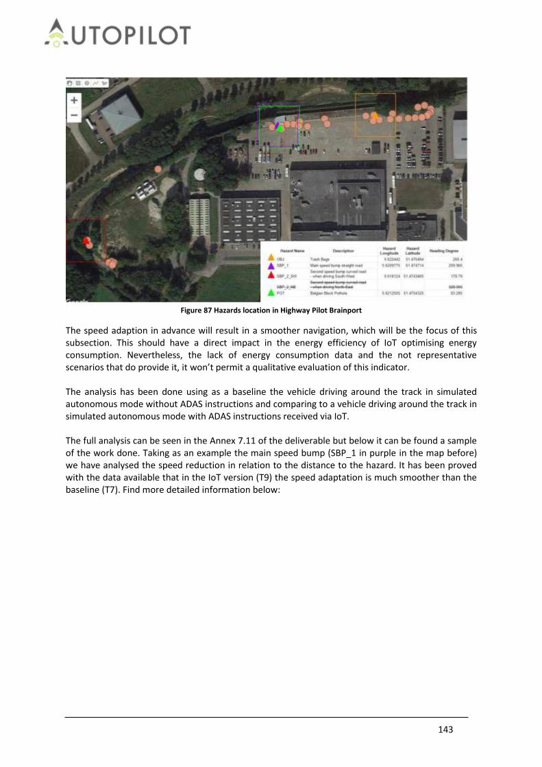
143
Figure 87 Hazards location in Highway Pilot Brainport
The speed adaption in advance will result in a smoother navigation, which will be the focus of this subsection. This should have a direct impact in the energy efficiency of IoT optimising energy consumption. Nevertheless, the lack of energy consumption data and the not representative scenarios that do provide it, it won’t permit a qualitative evaluation of this indicator. The analysis has been done using as a baseline the vehicle driving around the track in simulated autonomous mode without ADAS instructions and comparing to a vehicle driving around the track in simulated autonomous mode with ADAS instructions received via IoT. The full analysis can be seen in the Annex 7.11 of the deliverable but below it can be found a sample of the work done. Taking as an example the main speed bump (SBP_1 in purple in the map before) we have analysed the speed reduction in relation to the distance to the hazard. It has been proved with the data available that in the IoT version (T9) the speed adaptation is much smoother than the baseline (T7). Find more detailed information below:

144
Figure 88 Speed vs. Meters Analysis (Baseline-T7)
Figure 89 Speed vs. Meters Analysis (IoT enabled-T9)
With this analysis, it can be concluded that IoT helps making the navigation smoother.
4.7.4 Conclusions
The main research question to answer in this section was “How IoT adds value to navigation for Automated Driving functions” and we can determine that IoT helps reducing travel times and makes the navigation smoother. In the table below, there the main conclusions for this topic:
Table 64 Conclusions for positioning, localisation and navigation topic
Research Question Hypothesis Conclusion
How IoT adds value to navigation for Automated Driving functions?
The navigation data provided by IoT is enhancing and routing within automated vehicle functions and services.
YES
How can IoT reduce the travel time to drive?
The IoT data provided to the vehicle improves the quality of the route avoiding traffic jams or crowed zones and, therefore, reducing the time needed for completing the route.
YES
Does IoT data make smoother the speed profile of the vehicle?
Driving in the same route, the speed profile improves in a smarter way because of more information about the environment that could lead up to a reduction of the energy consumption.
YES (insufficient data to prove energy consumption saving)
4.8 Environmental detections
Environmental detections refer to the capability of automated driving functions and services to acquire information from the environment for cooperative and situational awareness. Relevant detections from the environment are obstacles and hazards in the vicinity and en-route of the vehicles, such as;
other road users like vehicles and vulnerable road users,
145
road surface hazards like potholes and puddles,
traffic signs and (dynamic) speed limits,
traffic conditions and information on congestion, or
adverse weather conditions The baseline situation is that on-board sensors, such as camera, laser scanners and radars, can detect nearby road users, lane markings, parking spaces.... The main technical hypothesis is that IoT data from the environment can also be obtained from IoT devices and cloud services via IoT platforms, and that the world model, or situational awareness, of automated driving vehicle functions and services can be enhanced with these additional data sources. The added value for environmental detection quality in this context is defined by the performance of detection, localisation and classification of an object or hazard. It is important to note here, that the localisation and classification of those detections is the actual added value. Detections are for the technical evaluation mostly just ‘event-data’, whereas when these detections are also linked to a location, this data becomes much more valuable and usable for evaluation. Therefore, in the indicators and measures, also position (in longitude and latitude) is considered here, however these are now focused on the obstacles as detected by environmental sensors (and not the location of the vehicle itself).
4.8.1 Technical Research Questions and Hypotheses
The technical research questions below which require use of environmental sensors have been derived: RQ: How are the environment detections enhanced by the IoT technology? HY: The IoT technology provides more accurate localization of the object in question and thus enhances the environment detections and in turn improves Automated Driving functionalities and enables new functionalities to be added. RQ: Can IoT be an enabler for safety applications? HY: IoT will increase safety by integrating additional / redundant sensor information (e.g. environmental data, hazards) to improve detection rate and reduce reaction time. As a result, it will increase the number of detected environmental objects and the range of its detection. RQ: Can heterogeneous IoT sources provide additional environment detections? HY: IoT will increase the interoperability between heterogeneous IoT sources and increase environmental context even if the vehicle is not directly using the sensor. RQ: How can VRUs be detected by IoT? HY: IoT is capable of integrating the sensors that VRUs may carry and provide more cautious reactions in the presence of pedestrians and hazards. RQ: How can IoT weather information improve the behaviour of the AD car? HY: The weather information can help AD cars avoid hazards or handle a hazardous situation (if it can’t be avoided), improves routes and navigation and adapts its speed depending on the weather conditions. Proper adaptation of in-vehicle environmental sensors to weather conditions can also improve the performance of the AD car.
4.8.2 Technical indicators, measurements and metrics
Potential improvements in environmental detection performance can be evaluated by indicators for

146
the type of environmental objects, detection accuracy, detection rate, detection delay, and the geographic position, location and range of detections. Technical indicators used to evaluate the environmental detections topic are:
Relative position accuracy. The relative position of an object with respect to the host vehicle’s attitude is a measure of how accurate objects are positioned for situational awareness. Relative positioning accuracy can be evaluated from alternative sensor data and from (accurate) absolute positioning of the environmental objects (e.g. VRUs and other vehicles) and maps.
Classification accuracy of object type, such as vehicle, road, hazard, or VRU. Detection of objects (false positives) is a measure to classify objects accordingly. This can be compared with the data received from an IoT device, for matching and preventing possible false positive detection by one environmental sensor. This can be road detections, vehicle detections, VRU detections, hazard detections etc.
Detection range of the environmental perception (early detection of objects): IoT can increase the ‘world model’ of the AD vehicle extending its range beyond the on-board sensors. Measuring occluded view of in-vehicle camera for example and adding IoT information can possibly extend the vehicle awareness of important objects, like VRUs.
In order to compute these KPI’s we need to log in each vehicle several measures in a specific format as shown in Table 65 Environmental vehicle measurements Table 65. More details on the measurements, logging and codes are provided in Annex 7.1.1 and D2.1 [14]. The measurements in this table are generic and can be logged from several on-board sensors and IoT devices. The sensor or device logging the measurements is uniquely identified by the log_applicationid of the log_stationid as described in Annex 7.1. The position of a detected environmental object, or obstacle, is logged either as an absolute position in WGS84 coordinates with a latitude and longitude, or as a relative position in local vehicle (x, y) coordinates – corrected for the mounting location of the sensor on the vehicle.
Table 65 Environmental vehicle measurements
Name Type Range Unit Description
longitude double from -90 to 90 [degree] Main object transformed to geolocalized coordinates longitudinal (log_applicationid identifies the sensor providing this measurement (e.g., camera, LIDAR, radar...)).
latitude double from -180 to 180
[degree] Main object transformed to geolocalized coordinates lateral position (log_applicationid identifies the sensor providing this measurement (e.g., camera, LIDAR, radar...)).
obstacle_ID int from 0 to 1000
[-] ID of the obstacle detected by environmental sensors.
x double from 0 to 500 [m] Main object relative distance longitudinal / x-direction (log_applicationid identifies the sensor providing this measurement (e.g., camera, LIDAR, radar...)).
y double from -50 to 50 [m] Main object relative distance lateral / y-direction (log_applicationid identifies the

147
sensor providing this measurement (e.g., camera, LIDAR, radar...)).
obstacle_covariance float64 Covariance matrix of positions of longitude, latitude, altitude of RADAR detected objects.
ObjectClass int from 0 to 65 [-] 65 classes from Mapillary dataset
2
lanewidthsensorbased double from 0 to 10 [m] Lane width measured by on-board sensor(s).
lanewidthmapbased double from 0 to 10 [m] Lane width from map information.
trafficsigndescription string [N/A] signrecognition3
speedlimit_sign double from 0 to 250 [km/h] signrecognition 4
servicecategory enum [ 'dangerWarning', 'regulatory', 'informative', 'publicFacilities', 'ambientCondition', 'roadCondition' ]
[N/A] signrecognition 5
servicecategorycode int [ 11, 12, 13, 21, 31, 32 ]
[N/A] signrecognition6
countrycode string [N/A] signrecognition 7
pictogramcategorycode int from 0 to 999 [N/A] signrecognition 8
VRU_pedestrian_class int from 0 - 3 1 = children, 2 = adults, 3 = elderly
Sub classes of pedestrians.
VRU_cyclist_class int from 0 - 3 1 = children, 2 = adults, 3 = elderly
Sub classes of cyclists/riders.
confidence_levels double from 0 - 100 [%] Indication for false positive detections (minimum default level).
Environ_info int from 1 - 6 [-] 1=sunny/day, 2=raining/day, 3=snow/day, 4=night/dry, 5=raining/night, 6=snow/night
Road_hazard int from 0 to 42 [N/A] No standardized dataset available --> current proposal: pothole detection, slippery road, black ice etc.
2 http://research.mapillary.com/publication/iccv17a/
3 IVI - ISO TS 19321 (2015) v1: https://www.iso.org/standard/64606.html
4 IVI - ISO TS 19321 (2015) v1: https://www.iso.org/standard/64606.html
5 IVI - ISO TS 19321 (2015) v1: https://www.iso.org/standard/64606.html
6 IVI - ISO TS 19321 (2015) v1: https://www.iso.org/standard/64606.html
7 ISO 3166-1 alpha-2: https://www.iso.org/iso-3166-country-codes.html
8 ISO TS 19321 (2015) v1: https://www.iso.org/standard/64606.html

148
sensor_position int from 0 to 1000
[mm] Position of sensor on vehicle wrt. CoG. required for correlating to environmental detection with IoT detections.
process_delay int from 0 to 1000
[ms] Is processing delay known or unknown?
4.8.2.1 Analysis of metrics In almost all use cases, it was not possible to receive the entire requested information from the in-
vehicle sensors as requested from Table 66, due to proprietary information or simply not available
(both relative and absolute).
Only the following minimal set of data was available as depicted table, for pilot sites Brainport,
Versailles, Livorno & Tampere:
Table 66 Available environment sensor measurements (relative and/or absolute)
Name Type Range Unit Description
longitude double from -90 to 90
[degree] Main object transformed to geolocalized coordinates longitudinal (log_applicationid identifies the sensor providing this measurement (e.g., camera, LIDAR, radar...)).
latitude double from -180 to 180
[degree] Main object transformed to geolocalized coordinates lateral position (log_applicationid identifies the sensor providing this measurement (e.g., camera, LIDAR, radar...)).
obstacle_ID int from 0 to 1000
[-] ID of the obstacle detected by environmental sensors.
x double from 0 to 500
[m] Main object relative distance longitudinal / x-direction (log_applicationid identifies the sensor providing this measurement (e.g., camera, LIDAR, radar...)).
y double from -50 to 50
[m] Main object relative distance lateral / y-direction (log_applicationid identifies the sensor providing this measurement (e.g., camera, LIDAR, radar...)).
4.8.3 Evaluation per Pilot Site and Use Case
The research questions have been evaluated, by assessing the following use cases based on the set-up description.
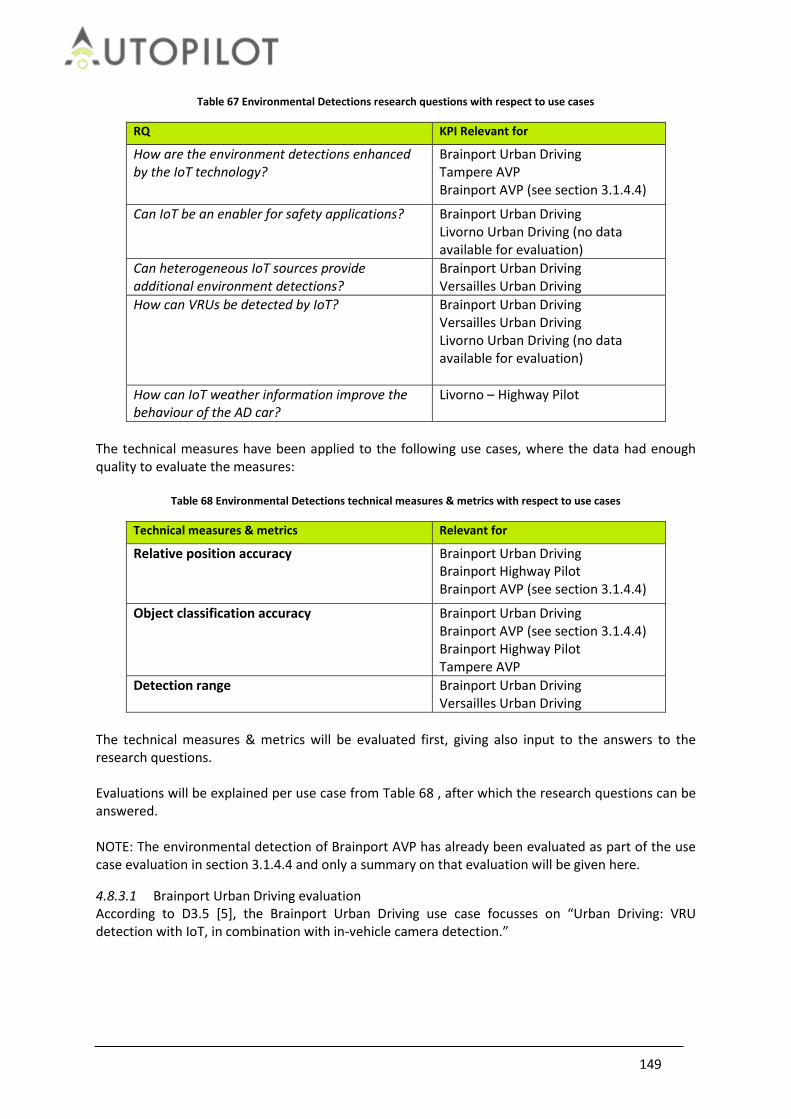
149
Table 67 Environmental Detections research questions with respect to use cases
RQ KPI Relevant for
How are the environment detections enhanced by the IoT technology?
Brainport Urban Driving Tampere AVP Brainport AVP (see section 3.1.4.4)
Can IoT be an enabler for safety applications? Brainport Urban Driving Livorno Urban Driving (no data available for evaluation)
Can heterogeneous IoT sources provide additional environment detections?
Brainport Urban Driving Versailles Urban Driving
How can VRUs be detected by IoT? Brainport Urban Driving Versailles Urban Driving Livorno Urban Driving (no data available for evaluation)
How can IoT weather information improve the behaviour of the AD car?
Livorno – Highway Pilot
The technical measures have been applied to the following use cases, where the data had enough quality to evaluate the measures:
Table 68 Environmental Detections technical measures & metrics with respect to use cases
Technical measures & metrics Relevant for
Relative position accuracy Brainport Urban Driving Brainport Highway Pilot Brainport AVP (see section 3.1.4.4)
Object classification accuracy Brainport Urban Driving Brainport AVP (see section 3.1.4.4) Brainport Highway Pilot Tampere AVP
Detection range Brainport Urban Driving Versailles Urban Driving
The technical measures & metrics will be evaluated first, giving also input to the answers to the research questions. Evaluations will be explained per use case from Table 68 , after which the research questions can be answered. NOTE: The environmental detection of Brainport AVP has already been evaluated as part of the use case evaluation in section 3.1.4.4 and only a summary on that evaluation will be given here.
4.8.3.1 Brainport Urban Driving evaluation According to D3.5 [5], the Brainport Urban Driving use case focusses on “Urban Driving: VRU detection with IoT, in combination with in-vehicle camera detection.”

150
Figure 90 Brainport Urban Driving / Rebalancing use case architecture
Figure 90 shows also the datalogs that have been evaluated. Specifically in the GeoFencing evaluation for environmental detection evaluation, data from VRU (smartphone), GeoFencing application on HUAWEI EAI and Prius (vehicle) data with the camera has been used.
The following methodology has been applied to position accuracy: In the Brainport Urban Driving dataset and use case, positions of smartphone detections have been correlated with detections from the in-vehicle camera. For this evaluation, the locations of the smartphone detections and the in-vehicle camera detections have been transformed into UTM coordinates. In this particular use case, the location from the smartphone data is already limited to the detections close to the vehicle (within 50 by 10 meters rectangle), by using the GeoFencing filter on HUAWEI OC IoT platform. The dimensions of this GeoFence filter in the evaluated dataset below is 50m in front of the vehicle and 5m left and 5m right of the vehicle (see Figure 91). This way, IoT location data that is not relevant to the behaviour of the vehicle is ignored and it also matched with the typical detection range of the in-vehicle camera (typically a 40-50 m range in front and a view angle of 60 degrees). Figure 92 shows a position plot in UTM coordinates, showing the vehicles driving path (in green), the VRU location as detected by smartphone (black crosses) and the VRU location as detected by the in-vehicle camera. In this particular case, two VRU walked on the route, of which one VRU on the top.

151
Figure 91 VRU smartphone interface
Figure 91 gives feedback of the Automated Vehicle warning system, showing the AD vehicle position with its GeoFence rectangle for detection of smartphones (NOTE: the blue dot is smartphone location; in this illustrative stationary test case shown here, the vehicle would have not been detected the VRU yet).
Figure 92 Typical output of in-vehicle camera detections compared with Smartphone GeoFencing (IoT) detections
start
end
VRU 1
VRU 2 False positive detections from in-vehicle camera

152
In this case the vehicle detects VRUs at two locations. On the top the vehicle camera already detects multiple objects. In the lower part, the vehicle detects a lot of false positives (>6 different colours of triangles indicating “vision hits” from the in-vehicle camera) with the camera output, while there is only 1 person walking alongside the road.
Since we do not have access to the confidence levels of the vision detections used in this use case, we assume that the accuracy of the VRU position as detected with the camera is constant. In reality this is dependent on the distance between camera and object. We evaluate the overlap of the position of the smartphone VRU position with the camera VRU position in order to find the match between both inputs. Simultaneously we evaluated with this metric the number of false positive detections from the camera. Spatial correlation methodology An IoT hit and vision hit are spatially correlated if the vision hit is < D [m] away from the IoT hit, with D being a circular diameter around the IoT hit. By increasing D from 1m to 10m, while analysing how many vision hits fall inside the resulting area, we get an indication of their degree of spatial correlation. When we increase D and only few additional vision hits fall inside the new area, then D gives an indication of how well the IoT hits and vision hits correspond to each other.
Figure 93 Position accuracy of the VRU smartphone GPS with respect to camera detections
In the figure above VRU position is indicated by red crosses, with 3m diameter and camera detections are marked by

153
magenta and green triangles.
By increasing the size of the position accuracy circle as depicted in Figure 94, we can find statistically the location accuracy of the smartphone positions. In the analysis we increased the size of the diameter in steps of 1[m] ranging from 1 to 10 [m], which typically corresponds with consumer grade GPS position accuracy. Figure 94 shows a series of bar graphs, were we showing the following (for all test runs):
Each sub plot corresponds to a specific run of the experiment. Each bar within each sub plot corresponds to a different distance threshold, ranging from
1m to 10m. The yellow part of each bar shows the number of vision hits that lies within the
corresponding distance threshold -- i.e. they are less than X meters away from the closest IoT hit -- whereas the green parts show the vision hits that lie outside the distance threshold.
As the distance threshold increases, more vision hits fall within the range of corresponding IoT hits. The idea behind this analysis is the following. When the yellow bars reach a plateau, while the distance threshold is being increased, few additional vision hits fall within the radius around the corresponding IOT hit. The distance threshold where this plateauing happens, gives an indication of the amount of correlation between vision hits and IOT hits (e.g. 5m).
Figure 94 Overall evaluation of distance threshold
The overall evaluation of distance threshold is shown with respect to number of overlapping matches between smartphone VRU positions (IoT) and camera VRU position (Vision)
Figure 94 shows that there are 3 runs that still had an amount of false positives detected by the in-vehicle camera: Runs 1, 6, & 10 show green bars within a range of 1 – 10m, indicating that the camera was detecting a large amount of false positives, that could not be correlated to the smartphones (IoT). This could be explained by the in-vehicle camera also detecting trees and traffic signs as pedestrians (false positives). Taking this into account, most important is the distance threshold at which the number of vision hits correlating, saturates. The mean over these runs is 4.55 [m], with a standard deviation of 1.86 [m]

154
Conclusions This evaluation shows that fusing the information of smartphone detections with the detections from the in-vehicle camera can provide an improvement on the correct detection of VRUs and therefore improve also the overall driving behaviour of an AD vehicle (as already shown in section 3.6.3.2.1 in more detail). Recommendations For further research, also confidence levels on camera data should be provided. This is required to make a good estimate on location accuracy of the camera. In the current analysis it is based on assumption that the camera accuracy is constant (which is actually dependent on distance to obstacle).
4.8.3.2 Brainport Highway Pilot According to D3.5 [5], the Brainport Highway Pilot use case used the following approach:
1. Detect road hazards (RH) for manual, assisted and autonomous driving, focusing on surface defects / features (potholes, bumps, etc.), and fallen objects (trash bags, carton boxes, etc.)
2. Using only regular sensors found on AD vehicles like LiDar, Camera and IMU (no specific device) + roadside cameras
3. Relying on a collaborative approach for better detection (both in the characterization and in the location of hazards)
4. Sharing consolidated and acknowledged information with interested 3rd parties through an open IoT platform
5. Pushing hazard warnings and driving instructions (ADASIN) to following vehicles; autonomous vehicles shall apply instructions automatically
6. Enhancing users experience and vehicles maintenance prevention in autonomous driving” The Brainport Highway Pilot use case uses 3 different modalities to enable environmental detections and the following data was analysed:
IMU data from the detection vehicle, detecting speed bumps and potholes
In-vehicle camera from the detection vehicle, detecting speed bumps and potholes
RSU camera data to detect obstacles on the road The following methodology has been applied to this use case: Using hazard detections from both the RSU camera and from the detection vehicle (VW Tiguan) with data from IMU and from its in-vehicle camera data, accuracy of the detections could be evaluated using the exact known position of the road hazards. The on-board camera is located on the detection vehicle to detect potholes, the IMU sensor is on the detection vehicle to detect speed bumps and potholes and road side camera is used to detect obstacles. Figure 95 shows the architecture in the Brainport Highway Pilot use case:

155
Figure 95 Brainport Highway Pilot architecture
Methodology
The hazard detection file comprised of different log stations that received and sent the hazard
detection data. For the analysis, the data from ‘3102’ (labelled as “publish road hazard” as output
from Valeo Cloud), which was Valeo cloud (see Figure 95) that sent hazard notification to IoT
OneM2M server from the VW Tiguan, was analysed.
The vehicle positioning data and the hazards data were matched using the log timestamp from each
of the files. The vehicle’s acceleration and deceleration profiles as well as the vehicle’s location were
examined for each of the drive cycle to examine the change in vehicle speed when the vehicle
approaches a hazard.
For the different drive cycles, hazards such as speed bump were detected several times during a
drive cycle. In order to identify the correct detection of the hazards, the distance from the original
hazard location and the hazard detection was calculated. The closest distance between the hazard
detected and the original hazard position was taken as a correct detection. In case where a hazard
was detected several times during a drive cycle, the other hazard detections were ignored to avoid
double counting.
According to specification, for each of the hazards detection, 60 meters distance before the actual
hazard and 30 meters distance after the actual hazard were taken as acceptable limits for a correct
detection.
The hazards that are too distant from the actual position than the limits provided, were considered
as a false detection (i.e., detection that are too late or early from the actual position of the hazard).
RSU (road-side camera) data was available for Variation 1, which could be compared with the IMU
detections from the same experiment. Comparing the detections from IMU and RSU for Variation 1,
it was observed that the road-side camera mostly detected only the object that was placed on the
test track. This is also expected, since the RSU software was trained for obstacle detection, not for

156
speed bump or pothole detection. In case of the IMU detections, the object was not detected any
time during the three test scenarios. Moreover, the precision of the detection was found to be more
accurate with the RSU compared to the IMU detection from vehicle.
Results
Table 69 and Table 70 show an evaluation of the number of false detections at different variations.
The results show that the IMU detected only speed bumps and potholes but not the object, thus the
total hazards that could be detected for each drive cycle were six (three hazards each way). In case
of the driving adaptation vehicle, the obstacle was also detected thus eight hazards could be
potentially detected in each drive cycle.
For each of the different experimental variations, the following statistics are obtained for the hazard
detection across the detection and driving adaptation vehicle respectively:
Table 69 Brainport Highway pilot – evaluation of false detections with respect to position accuracy with Detection
vehicle
Detection Vehicle (w/o RSU data)
Drive cycle (total hazards)
Total hazards detected
Correct detections
False detections
165 (Var 1 - IMU)
25 (150) 36 (24%) 14 (9.3%) 22 (14.67%)
284 (Var 2 - Camera)
21 (126) 46 (36.51%) 13 (10.3%) 33 (26.19%)
166 (Var 3 - Camera and IMU)
26 (156) 67 (42.9%) 15 (9.6%) 52 (33.3%)
Table 70 Brainport Highway pilot – evaluation of false detections with respect to position accuracy with driving adaptation vehicle
Driving Adaptation
Drive cycle (total hazards)
Total hazards detected
Correct detections
False detections
288 (ACC and ADASINs)
25 (200) 22 (11%) 6 (3%) 14 (7%)
289 (ACC and ADASINs)
20 (160) 104 (65%) 16 (10%) 88 (55%)
Comparing with the hazard detection from Variation 1 of the detection vehicle, we can observe that there is some difference in the hazard detected from the detection and driving adaptation vehicles. The driving adaptation vehicle detects hazards in drive cycle 1 and 25. For these drive cycles, the detection vehicle does not detect any hazards. However, the driving adaptation vehicle detects the speed bump number 2, the pothole and the object one time and the speed bump 1 two times. In case of drive cycle 25, speed bump 2 is detected once with the detection vehicle while the object is detected with the driving adaptation vehicle.

157
Figure 96 Hazard detection rate for Variation 1 across detection and driving adaptation vehicles
The percentage of correct hazard detection is 9.3% in total for all the drive cycles for the detection vehicle and 3% for the driving adaptation vehicle. For Variation 2, the following overview of hazards detected across the detection and driving adaptation vehicles can be given across the different drive cycles:
Figure 97 Hazard detection rate for Variation 2 across detection and driving adaptation vehicles
The percentage of the correct hazard detected across all the drive cycles in Variation 2 can be
estimated as 10.3% for the detection vehicle and 10% for the driving adaptation vehicle.
Comparing the results obtained from the different test scenarios, it can be observed that for each of
the test scenarios 2, 3 and 4, the total correct hazard detection was at a considerably lower rate (3-
10%) in relation to the number of times the vehicle had to pass near the hazard.
It can be concluded that while IoT can help in environmental detections to a considerable extent, a
better detection rate should be achieved while the detections from driving adaptation vehicle
should be more closely matched to that obtained by the detection vehicle.

158
The on-board camera, IMU and RSU data provide different hazard information to the detection vehicle. The data obtained from the RSU for the detection vehicle is not based on the drive cycle, so it is difficult to estimate how many times the detection vehicle received the information of the obstacle from RSU camera for each of the drive cycle. Enhancing the IMU/on-board camera ability to detect obstacles as well, can improve the estimation of hazard detection by the detection vehicle. Conclusions It can be concluded that while IoT can help in environmental detections to a considerable extent, a better detection rate could be achieved while the detections from driving adaptation vehicle should be more closely matched to the ones obtained by the detection vehicle. The on-board camera, IMU and RSU data provide different hazard information to the detection vehicle. The data obtained from the RSU for the detection vehicle is not based on the drive cycle, so it is difficult to estimate how many times the detection vehicle received the information of the obstacle from RSU camera for each of the drive cycle. Enhancing the IMU/on-board camera ability to detect obstacles as well, can improve the estimation of hazard detection by the detection vehicle.
4.8.3.3 Livorno Highway Pilot According to D3.5 [5], “The scope of these tests involves cars with IoT-enhanced AD functions, driving in a "smart" highway. The cars are Jeep Renegades with on-board equipment, the so-called IoT open vehicular platform, enabling IoT-triggered AD functions: speed adaptation, lane change, and lane-keeping. The "smart" highway is a freeway where a pervasive IoT ICT system is deployed based on a network of roadside sensors or other sources, capable of collecting information and making it available to cloud-based applications. Connected cars and the traffic control centre have an important role. For safety reasons, connected cars drive in a convoy, following the AD car. The goal is to show how the combined use of IoT and C-ITS can mitigate the risk of accident for an AD car when hazards occur on the road. Here, we deal with two types of hazards: (1) puddles and (2) road works.” Expected outcome is to have puddle information and road works detection available as well as in-vehicle camera data so correlation between these can be executed for the environmental detection evaluation. The Livorno dataset consists of several files with vehicle positioning and data from different IoT inputs. The vehicle drives near a puddle or a roadwork and the puddle monitoring service of the highway
trigger a puddle hazard warning, which the vehicle receives using IoT services.
It is expected that receiving the IoT information on puddle notification, the vehicle will smoothly
decelerate in order to enter the area with the proper speed. Following the dangerous area, the
vehicle will resume the normal cruising speed. Thus, it is expected that following the information
obtained from the IoT services, the vehicle will decelerate smoothly. In order to analyse whether
the vehicle received timely message from IoT regarding the position of the puddle, the vehicle speed
profile was examined for smooth deceleration.
In case of road works for Livorno data, the IoT sends message to the vehicle on the upcoming

159
roadwork, dynamically updating the maps of the connected e-Horizon installed on-board the vehicle.
The vehicle performs speed adaptation and lane change manoeuvre to handle the roadwork in the
track. Speed profile was examined to check smooth deceleration due to warning from the IoT
service.
The speed profile of the vehicle from the puddles data was mapped to check for smooth
deceleration. Across the different files it was observed that in various cases, a sharp deceleration is
observed while some smooth deceleration can also be seen. As an example, the following chart
provides the speed profile for different types of deceleration:
The speed profile of the vehicle from the puddle data was mapped to check for smooth deceleration. Across the different files it was observed that in various cases, a sharp deceleration is observed while some smooth deceleration can also be seen. As an example, the following chart provides the speed profile for vehicles with the red marked area showing vehicle deceleration at puddles or road works detection:
Figure 98 Vehicle speed profile and puddle detection 2
A speed profile was also generated for roadworks. The following chart provides two different examples of the speed profile for the roadworks notification to the vehicle:
Figure 99 Vehicle speed profile and roadworks detection 1

160
Figure 100 Vehicle speed profile and roadworks detection 2
It is observed that for most of the cases when the vehicle receives the roadwork notification, there is a much higher rate of sharp deceleration compared to when the vehicle receives the puddle notification. Position of the puddles/roadworks can be helpful to evaluate the deceleration profile at the exact location of the puddles/roadwork. How can IoT weather information improve the behaviour of the AD car? In case of the puddles data and detection, it can be observed that the IoT information can help make a smoother deceleration in some of the cases. Can IoT be an enabler for safety applications? While the IoT information has been found to make smoother deceleration in some cases for the puddles detection, in case of the roadworks detection, this has not been observed as a sharper deceleration profile is obtained in this case. It can be concluded that IoT information can enable safety applications to some extent, however, the technology needs to be further refined for wider applications.
4.8.3.4 Tampere AVP According to D3.5 [5], “Enabling Automated Valet Parking with the support of Traffic Cameras: - At provision of the destination, the automated vehicle automatically books a parking place near the drop-off point. - The parking management system determines the path of the vehicle from the drop-off point to the parking spot, based on the current configuration (e.g. objects in the alternative paths). Objects are identified by cameras installed in the parking facility. During the unmanned driving, the operator at the parking management system is responsible for the vehicle.” Expected outcome is to have (RSU) camera data available for parking detection as well as in-vehicle camera data correlation between these can be executed for the environmental detection evaluation. The Tampere data consisted of the different parking spots available for the vehicle parking and the vehicle’s location in longitude and latitude. Comparing the vehicle timestamp with the timestamp from the parking spot data, the comparison of

161
the vehicle location and the parking spot occupancy can be made. Comparison has been made of vehicle positioning and parking data with the parking spot position data. The data consisted of vehicle positioning and information on parking in each of the parking spots. The vehicle position data was compared with the exact position of the parking spots, in longitude and latitude to examine whether the vehicles are parked correctly. A selected data was taken for analysis, based on a 10 seconds time lag. Comparing the vehicle position data with the parking spot coordinates, it was observed that most of the vehicles were correctly parked in the parking spots specified in the parking spot data (please see Figure 101, Figure 102, Figure 103 for parking in spots 1-3). Thus, in case of Tampere data, it can be concluded that the vehicles are correctly parked in the spots specified in the data. No obstacles or hazard data were available. After matching the vehicle data with the parking spot data, a selected data was taken for analysis, based on a 10 seconds time lag. In the data file where multiple parking spots are shown to be occupied, the exact location of the vehicle in the parking spot has been verified using the parking spot location coordinates. It was found that in these cases, the vehicle parking position based on the location coordinates was between parking spots 2 and 3. The following figures show the different parking spots and the parking of the vehicle in each of these spots. Parking spot 1 is marked with white pins; parking spot 2 is marked with yellow pins while parking spot 3 is marked with blue pins. The vehicle parking position is marked in the corresponding colours for each of the parking spots.
Figure 101 Vehicle parking in Parking Spot 1

162
Figure 102 Vehicle parking in Parking Spot 2
Figure 103 Vehicle parking in Parking Spot 3
It was observed that a large amount of vehicle data is available as the timestamp varies in milliseconds. It is recommended to use a less detailed vehicle positioning.
4.8.3.5 Versailles Urban Driving According to D3.5 [5]: “The scope of the use case in Versailles is to perform urban driving for touristic applications. A ride sharing service gives the opportunity to a tourist to rent a vehicle for a connected and automated trip in the city and the castle’s garden. In the city, the vehicle is manually driven and point of interest notifications are received in the vehicle. In the castle’s garden, the driver

163
can switch on the automated driving mode. The IoT is considered for the detection of vulnerable road users (cyclists and pedestrians) during the trip in AD mode.” The implementation of this use case is very similar to the Brainport Urban Driving / Rebalancing use case analysed before: 2 VRUs are on the track where also an automated vehicle is driving: a cyclist and a pedestrian. In this case the information is sent to the IoT platform and the server sends a speed advise to the vehicle whenever the vehicle approaches the VRU (in contrast: in Brainport the speed set point was set by the vehicle itself, not by the server). In this use case a baseline test was executed, using the in-vehicle camera to detect the VRUs and causing the vehicle to brake till standstill.
Figure 104 Versailles Urban Driving – baseline test (IoT off)
Figure 104 shows vehicle position of a straight road with VRU detections by in-vehicle camera (pedestrian half-way, cyclist at the end). IoT is turned off here.
Figure 105 Versailles Urban Driving – baseline test (IoT on)

164
Figure 105 shows vehicle position of a straight road with VRU detections by in-vehicle camera (pedestrian half-way, cyclist at the end) and additionally the IoT detections (smartphone and smart watch).
Figure 106 Versailles Urban Driving – baseline test (IoT off)
Figure 106 top: travelled distance, middle: vehicle speed and obstacle detections from the in-vehicle camera, bottom: vehicle acceleration profile; this shows that when the VRU is detected the vehicle brakes till 0 km/h (similar to Brainport Urban Driving / Car Rebalancing evaluation).
Figure 107 shows a similar test with IoT on. In this case the IoT platform sends an “IOT set speeds” message to the vehicle with the maximum allowed speed. This message is based on the distance between vehicle and VRU. As shown below, also the camera in the vehicle detects the VRUs. However, the IOT set speed message is sent already earlier (see for example at 80 – 100 seconds), showing that the VRU is detected earlier than the vehicle’s camera.
Figure 107 Versailles Urban Driving – IoT enabled test (IoT on)

165
Figure 107 top: travelled distance, middle: vehicle speed, obstacle detections from the in-vehicle camera and IoT Set Speeds (advice sent from IoT server to vehicle), bottom: vehicle acceleration profile; this shows that now the vehicle receives already earlier a speed advice, because the VRU is close. I.e. at 80 sec. the vehicle first receives a set speed of 2.77m/s (10km/h) and at approx. 95 sec. it slows down to 1.35 m/s (5km/h) after which it also detects the VRU with the camera at 105 sec.
These tests show a similar result as the Brainport Urban Driving / Car Rebalancing use case; showing that the smartphone/smart watches indications can be used to detect VRUs earlier than the in-vehicle camera would do.
4.8.4 Conclusions
Summarizing, the following research questions and hypotheses can be answered as follows: RQ: How are the environment detections enhanced by the IoT technology? HY: The IoT technology provides more accurate localization of the object in question and thus enhances the environment detections and in turn improves Automated Driving functionalities and enables new functionalities to be added. In general, we have seen in the results above that IoT technology itself (focusing on IoT as a communication and data management tool), does not increase the position accuracy on itself. The position accuracy depends highly on the used positioning method used (consumer grade GPS, RTK-GPS, camera (SLAM technology), Wi-Fi triangulation, etc.). However, adding this kind of information to an already existing sensor (ie. in-vehicle camera) and fusing that information, can improve the detection range greatly (in case of for example blocked view of a camera). RQ: Can IoT be an enabler for safety applications? HY: IoT will increase safety by integrating additional / redundant sensor information (e.g. environmental data, hazards) to improve detection rate and reduce reaction time. As a result, it will increase the number of detected environmental objects and the range of its detection. Most use cases implemented IoT as an additional sensor for non-safety critical situations. IoT data was mainly used to increase the prediction horizon, rather than using it for <1 sec. time window decision making. Main difficulty for this last part, lies in both the use of typically consumer grade positioning sensors (see point above) and the delay in communication, due to the (in this case) typically 4G LTE connection (without using slicing, increase bandwidth etc.). See also the communication section on this. RQ: Can heterogeneous IoT sources provide additional environment detections? HY: IoT will increase the interoperability between heterogeneous IoT sources and increase environmental context even if the vehicle is not directly using the sensor. IoT can be used as a redundant sensor (see evaluation of Brainport Urban Driving use case specifically) and data can be fused for that reason with other sensory data. However, on itself it is not sufficiently accurate to be used in every application (typically not for safety critical, with time window <1 sec.) RQ: How can VRUs are detected by IoT? HY: IoT is capable of integrating the sensors that VRUs may carry and provide more cautious reactions in the presence of pedestrians and hazards. VRUs can be detected in multiple ways: in the use cases described 2 main categories can be derived: on person devices (smartphone, smartwatch, etc., using communication to the IoT platform indicating the VRUs status using sensors in those devices) & static devices (RSUs using a camera /

166
RADAR or LIDAR to detect the VRUs states). RQ: How can IoT weather information improve the behaviour of the AD car? HY: The weather information can help AD cars avoid hazards or handle a hazardous situation (if it can’t be avoided), improves routes and navigation and adapts its speed depending on the weather conditions. Proper adaptation of in-vehicle environmental sensors to weather conditions can also improve the performance of the AD car. In Livorno Highway Pilot a puddle sensor was used, to indicate the state of the road surface and use this information to inform the vehicle and adapt its behaviour.
167
5 Conclusions
After analysing the sets of data provided by the Pilot Sites many improvements to the Automated Driving have been able to be demonstrated thanks to IoT. The main improvements were focused on enabling the detection of obstacles in advance and informing the AV earlier resulting in an improvement on safety and on a smoother navigation and enabling traffic control information improving speed and route advising. For each use case, service and topic, IoT has added value to the implementation. The Automated Valet Parking enabled by the IoT has been developed and tested at three pilot sites: Brainport, Vigo and Tampere. During the various pilot tests conducted at the different pilot sites two main scenarios have been tested: the vehicle parking (drop-off) and the vehicle collection (pick-up). During the car parking and collection process, data was collected from AD-vehicles, micro aerial vehicle (MAV) or drone, IoT platforms, parking management system (PMS), routing application and AVP smart phone application. The data was used to assess the AVP use case based on the key performance indicators like parking duration, parking manoeuvre, manoeuvre precision, parking precision, optimal route selection, parking conflict, detection performance of free parking spots and obstacles using the stationary road side camera and MAV, the technical complexity of the implementation (indoor and outdoor parking) and the reliable information about the parking process to the driver. To analyse the benefits of IoT on the AVP, relevant information derived from the collected data have been used: travel time, GPS position of the car, transmission time, parking spot occupancy, obstacle information, parking spot occupancy information, routing information. From the analysis of the results of the technical evaluation of the AVP with regard to the IoT, we come to the following conclusion:
The IoT detection information like road and parking obstacles and free parking spots, provided by the stationary IoT devices, such as road side cameras and mobile IoT devices enables the enhancement of routing and parking management capabilities and therefore the AVP. Indeed, IoT improves:
o The performance of the dynamic routing to the parking location (shortest route or free obstacle route: IoT enables detection of obstacles to support AV parking and route planning).
o The entire parking operation (time saving because the vehicle does not have to explore the parking lot to find a free parking spot. The IoT provides this information to the vehicle, allowing the enhancement of manoeuvring time for searching and finding free parking spots and thus reducing the parking time).
It reduces the safety risk by avoiding obstacles, since IoT allows the detection of VRU or object before it enters the range of the car’s sensor.
The provision of the IoT information to the AD-vehicle allows it to focus on the autonomous function, and it could also use only a few detection sensors to perform the valet parking in a closed parking area.
IoT benefits autonomous Urban Driving mainly in the control of intersections. The GLOSA function allows the vehicle to react properly regardless of the visibility and position of traffic lights. In addition, receiving the information by IoT not only gives the current state of the traffic light but also the time to the next change, so that the information obtained not only equals but exceeds that of a vehicle without IoT, autonomous or manual. On the other hand, the VRU detection function allows ensuring low visibility areas with means external to the vehicle, either cameras or mobile phones. Bearing in mind that in a city it is very common to find this type of zones, the function of VRU detection by IoT improves the urban driving as it allows to secure such areas. Finally, it is possible to combine the two functions in a low visibility intersection, improving the safety and comfort of users.
168
For the Highway Pilot use case, the results show that the vehicle is clearly capable of detecting the hazards and confirm the performance improvement coming from the infrastructure. However, the system is extremely sensitive, and generates many false alarms. A much smaller detection rate may be implemented to increase reliability and hence reduce the false alarms. In Livorno, the RSUs have been capable of promptly notifying the vehicle on the presence of two types of hazards (puddle and roadwork), allowing the vehicle to automatically executing comfortable speed adaptations. For the Platooning use case, the IoT platform in Brainport enables to connect vehicles to a Platoon Service in the cloud. The vehicles can request to match and form a platoon from their current location to a common destination. The service can match vehicles from an area in and around the city of Helmond. IoT enables the match making service that cannot be realized using ITS-G5 V2X communication due to its limited communication range. The match making takes 10-15 sec once all vehicles needed for a match have made a request, and the first vehicle can start the platoon formation. Also the Platoon Service in Brainport provides support for platoon formation to the matched vehicles, with a route to a rendezvous point where a platoon should be formed, and a speed advice to coordinate the timing of matched vehicles to this point. The PlatoonService adapts the rendezvous point and advices upon delays of any of the matched vehicles, for example due to congestion or traffic lights. The IoT platform allows the vehicles to keep being informed on the progress of the formation process of other vehicles. Adapting the platoon formation takes 10-15 sec. Matching and platoon formation has been demonstrated successfully in 85 test runs (89%). Finally, traffic light information as IoT data sources is used to improve platooning in Brainport and Versailles. The Platoon Service in Brainport and the Traffic Light Assist service in Versailles receive traffic light information via the IoT platform from traffic light controllers, and calculate speed advices to the platoon via IoT as well (speed advice on the approach to intersections). For Ride sharing service, IoT enhances the routing function resulting in a minor reduction in travel time and accelerates the deployment of the service that can join other separate services using AV like AVP and platooning. For the Car Rebalancing service, travel time based on rerouting and travel time based on VRU detections have been evaluated. From this analysis the following can be concluded, with the use of these two IoT enabled services:
IoT, i.e., crowd estimation information, can be used to inform and to dynamically reroute the AD vehicle. When the reroute path is selected correctly to avoid crowds, it can decrease the total journey time.
When using IoT, the vehicle can keep longer at constant high speed, providing a shorter total travel time and in general smoother ride (less braking or standstill)
In the tested scenarios (low speed <15 km/h), Geofencing service can be used for the detection, tracking and VRU position communication, since the AD vehicle is able to use the collected information from the GeoFencing service and decelerate (slow down), before the VRU detection information coming from video camera is applied.
The service is not yet robust enough to act as a safety measure on its own: in some tests, VRU detection with GeoFencing is accomplished later. More research is required to find the cause (either latency / processing on IoT platform, or not accurate enough performance of smartphone).
For the safety topic, due to low number of test runs, we can only give an indication about “IoT enhancing safety”. Few safety interventions related to IoT data sources were compiled, meaning that there were not unintended safety interventions and IoT does not affect the safety related AV functions. Finally, an analysis has been done using the safety audits done in the verification phase

169
and comparing the status before and after applying the recommendations. For security and privacy topic, the implementations mostly lack some important security events that may be important for operational security of the solution. However, all the implementations rely on cloud component best practices. The most advanced ones used technique that prevented long term tracking.
Interoperability between platforms can be achieved out of the box in some cases, when a common set of standards is used and when data structures follow the same industrial model. What is more likely is that interoperability can be achieved by introducing an additional layer on top of IoT platforms and applications that seamlessly transforms incoming data into various standards consumable by connected systems. This has been proven in the project in Brainport where this interoperability layer is used to connect IoT platforms from different vendors. Application level interoperability is harder to achieve as usually applications tend to use custom data models and API that are easily transferrable between them and especially between pilot sites. So there is a room for improvements here. From the replicability evaluation, we see that replicability is for a large part applicable between Brainport and Versailles, based on the evaluation of data models, IoT platform implementations as well as IoT platform software and hardware implementations. From a use case point of view, AVP proves already to be very replicable, mainly caused by the fact that the use case itself is already quite a mature application and therefore a mature data model could be properly implemented in different pilot sites. Other use cases are less mature and this is reflected in the replicability evaluation: more effort is needed to work on common data models, and therefore, for example for moving Ride Sharing (RS) in Brainport to Versailles, the implementation of the data model from the first onto the second, requires quite some effort (depending on the application, this means effort on vehicle, IoT platform, any other mobile IoT devices (such as smartphone). Main drives for replicability are data models, IoT apps (Software) and stationary IoT devices, which seem to be difficult to align and standardize between pilot sites and therefore causing lower replicability values with respect to IoT platforms and mobile IoT devices. It should be noted that the IoT platforms in this project were aligned early in the project, so it should not be surprising that this scores quite high replicability values. Sustainability of the AUTOPILOT IoT-based automated driving uses cases (automated valet parking, platooning, highway pilot and urban driving) developed and tested at the six pilot sites has been evaluated from a technical point of view. In this context, sustainability focuses on industry acceptance by leveraging widely accepted standards, so that the product/service can be implemented quickly and be used for longer periods of time. Some evaluation criteria related to the technical aspects of the sustainability (e.g. reusability of software components, compatibility with standards, adaptation to industry standards, cost effectiveness of implementation, integration of system components into existing software and hardware modules) have been defined and evaluated for each use case at different pilot sites. The results of the evaluation show that the IoT/AD standards are used by most of the pilot sites (e.g. communication interfaces, IoT platform standards, IoT eco systems standards, client server architecture standards) are fully compliant with the existing standards in the automotive industry. Furthermore, the applications developed and tested at the pilot sites have been built in a modular way and can be easy reused or integrated with low cost and effort into industry products, depending on business attractiveness of each solution. In addition to the mentioned evaluation criteria we also considered criteria like time savings and comfort of the users, thus increasing the quality of life of the users, which is also one of the reasons to consider these solutions as sustainable.

170
For the data management topic, the evaluation results show that in-vehicle IoT-platforms are used for communication with the cloud based IoT-platform in order to make each use case operational, however the implemented standards and technologies for the vehicle IoT platforms are different from PS to PS. For the data communication topic, having access to alternative and similar data sources reduced the risk of failures of a communication technology or IoT data source. Measurements show large variations in delays when using IoT. For the positioning, localisation and navigation topic, the Pilot Sites implementations were not focused on improving position and localisation of the AV. Therefore, there were no major improvements in these two topics. However, thanks to IoT a smoother speed profile could be observed in some use cases as well as a reduction of route travel times. This implies an improvement on navigation. For the environmental detections topic, in general, we have seen in the results above that the IoT technology itself (focusing on IoT as a communication and data management tool), does not increase the position accuracy on itself. The position accuracy depends highly on the positioning method used (consumer grade GPS, RTK-GPS, camera (SLAM technology), Wi-Fi triangulation, etc.). However, adding this kind of information to an already existing sensor (i.e. in-vehicle camera) and fusing that information, can improve the detection range greatly (in case of for example blocked view of a camera) (see environmental detection section 0. Most use cases implemented IoT as an additional sensor for non-safety critical situations. IoT data was mainly used to increase the prediction horizon, rather than using it for <1 sec. time window decision making. The main difficulty for this last part, lies in both the use of typically consumer grade positioning sensors (see point above) and the delay in communication, due to the (in this case) typically 4G LTE connection (without using slicing, increase bandwidth etc.). See also the communication section on this. IoT can be used as a redundant sensor (see evaluation of Brainport Urban Driving use case specifically) and data can be fused for that reason with other sensory data. However, on itself the position is not sufficiently accurate (using consumer grade GPS) to be used in every application (typically not for safety critical, with time window <1 sec.) VRUs can be detected in multiple ways: in the use cases described two main categories can be derived: on person devices (smartphone, smartwatch, etc., using communication to the IoT platform indicating the VRUs status using sensors in those devices) and static devices (RSUs using a camera / RADAR or LIDAR to detect the VRUs states). Detection of parking lots can be achieved using either road side cameras or using a drone (see section 3.1.4.4).
Regarding the use of IoT for weather related info, only in Livorno Highway Pilot a puddle sensor was used, to indicate the state of the road surface and use this information to inform the vehicle and adapt its behaviour

171
6 References
[1] AUTOPILOT Deliverable D4.1 – Methodology for Evaluation, available on Sharepoint https://bit.ly/2PUA60w.
[2] AUTOPILOT Deliverable D4.2 - Initial Technical Evaluation available on Sharepoint https://bit.ly/2PthCFv.
[3] Report of the World Commission on Environment and Development: Our Common Future, http://www.un-documents.net/our-common-future.pdf.
[4] AUTOPILOT PILOT PLAN TEMPLATE.xlsx, available in Annex 7.3 and on Sharepoint https://bit.ly/2YXAxLF.
[5] AUTOPILOT Deliverable D3.5 - Pilot Sites test activity report (period 2), available in SharePoint https://bit.ly/2r2IvXl.
[6] AUTOPILOT Deliverable IR2.6 – Readiness verification report per pilot site per use case, available on Sharepoint https://bit.ly/2M49fy5.
[7] AUTOPILOT Deliverable D1.4 - Final ioT Self-organizing Platform for Self-driving vehicle, available in Sharepoint https://bit.ly/38MDnYl.
[8] AUTOPILOT Deliverable D1.10 - Final specification of Security and Privacy for IoT-enhanced AD, available in Sharepoint https://bit.ly/35x9QQD.
[9] AUTOPILOT Deliverable D1.9 Initial Specification of Security and Privacy for IoT available in Sharepoint https://bit.ly/2PqZ6xt.
[10] AUTOPILOT Deliverable D5.7 Standardisation plan available on Sharepoint https://bit.ly/2ElOEkx.
[11] AUTOPILOT Deliverable D2.3 - Report on the Implementation of the IoT Platform, available on Sharepoint https://bit.ly/2YTiGFB.
[12] AUTOPILOT Deliverable D1.8 - Final specification of Communication System for IoT-enhanced AD, available in Sharepoint https://bit.ly/34y4Cma.
[13] AUTOPILOT Deliverable D1.7 – Initial specification of communication system for IoT enhanced AD, available from Sharepoint https://bit.ly/2YUsTlk.
[14] AUTOPILOT Deliverable D2.1 - Vehicle IoT Integration Report, available from Sharepoint https://bit.ly/2LVaJuv.
[15] InterCor Common Log Format Description, version 0.7.7, available from the TEST FESTS specifications on the InterCor project website, on http://intercor-project.eu/.
[16] The Mapillary Vistas Dataset for Semantic Understanding of Street Scenes, available on http://research.mapillary.com/publication/iccv17a/.
[17] ISO TS 19321:2015 (2015-04-15). Dictionary of in-vehicle information (IVI) data structures.
[18] AUTOPILOT Common Log Format Description – Extension, version 0.7.8, available from Sharepoint https://bit.ly/2PODtq0.
[19] AUTOPILOT Deliverable D2.1 - Vehicle IoT Integration Report, available from Sharepoint https://bit.ly/2LVaJuv.
[20] AUTOPILOT Deliverable D5.3 - Performance and KPIs for autonomous vehicles and IoT pilot impact measurement, available on Sharepoint https://bit.ly/2tmdSgl.
[21] AUTOPILOT PILOT PLAN TEMPLATE.xlsx, available in Annex 7.3 and on Project Place https://service.projectplace.com/pp/pp.cgi/r823175960.
[22] AUTOPILOT Deliverable D2.3 - Report on the Implementation of the IoT Platform, available on Project Place https://service.projectplace.com/pp/pp.cgi/r13061162.

172
[23] AUTOPILOT Deliverable D5.3 - Performance and KPIs for autonomous vehicles and IoT pilot impact measurement, available on Project Place https://service.projectplace.com/pp/pp.cgi/r13061162.
[24] AUTOPILOT Common Log Format Description – Extension, version 0.7.7, available from Project Place https://service.projectplace.com/pp/pp.cgi/r1080659892.
[25] AUTOPILOT Deliverable D2.6 – Readiness verification report per pilot site per use case, available on Project place https://service.projectplace.com/pp/pp.cgi/r354064418.
[26] AUTOPILOT Deliverable D1.7 – Initial specification of communication system for IoT enhanced AD, available from Project Place https://service.projectplace.com/pp/pp.cgi/r1610425663.
[27] AUTOPILOT Deliverable D4.1 – Methodology for Evaluation, available on Project Place https://service.projectplace.com/pp/pp.cgi/r1690653003.
[28] AUTOPILOT Deliverable D5.7 Standardisation plan https://service.projectplace.com/pp/pp.cgi/r1299785435.
[29] AUTOPILOT Deliverable D2.1 - Vehicle IoT Integration Report, available from Project Place https://service.projectplace.com/pp/pp.cgi/r1564018789.
[30] AUTOPILOT Deliverable D1.9 Initial Specification of Security and Privacy for IoT, https://service.projectplace.com/pp/pp.cgi/r1770325159.
[31] AUTOPILOT Deliverable D2.1 - Vehicle IoT Integration Report, available from Project Place https://service.projectplace.com/pp/pp.cgi/r1564018789.

173
7 Annexes
7.1 Log data specifications
This annex presents a set of specifications for structured logging to collect the measurements needed for evaluation. The basis for the specifications is provided by the InterCor project in [5] . It provides the rational, structured approach, requirements and specifications to harmonise the log data from various sources and types. These InterCor specifications are extended for automated driving functions and IoT messages in AUTOPILOT in [6], in particular for vehicle data, automated driving functions and services and for IoT messages. This annex highlights the most essential information for logging in AUTOPILOT. The reader is referred to the living documents in [5] and [6] for the updated and detailed specifications. The approach to logging is based on several basic assumptions:
A logical entity, such as a vehicle, device, or server, is called a station and has a globally (or project) unique identifier; the log_stationid.
Every station organises and provides its own logging. The station may have one or more data sources, sensors, devices, units or applications that generate logging; the log_application. Every log_application has unique id within the log_stationid; the log_applicationid.
All log information must be timestamped with a log_timestamp. This is the timestamp at which the log_application logs the information. This is not necessarily the timestamp at which data is generated, sent or received.
The role of the log data in a data flow must be logged as the log_action. In communication for example the log_action identifies whether the message is ‘SENT’ or ‘RECEIVED’.
Data sources provide a data set or a message at a time to be logged by the log_application; a log_item. Every log_item must be logged with the meta data: log_stationid, log_applicationid, log_timestamp, log_action.
All log data from all log_stations is collected in a central data base. Therefore: o All log_stations should be time synchronised and provide time-synchronised data. o To organise data, all log data should be collected per test run, session or experiment
that has to be analysed and evaluated collectively. o To avoid logging duplicate data, the basic assumption is that the:
Provider, generator or sender of data should log all relevant data, including the unique identification information.
Consumer or receiver logs at least the unique identification information. Application specific interpretations of data should be logged. Derived data
does not have to be logged. o The unique identification information of log_items is defined per log_item.
All timestamps are in a single time format: Coordinated Universal Time (UTC) in milliseconds since UNIX epoch (number of milliseconds that have elapsed since January 1, 1970 (midnight UTC/GMT).
All locations or positions are in WGS84 coordinates: latitude, longitude, bearing/heading. Latitude and longitude should be in degrees with 10^-7 precision.
Log data is specified at 4 levels:
1. Definition of log parameters and organisation by data sources. Log parameters should be defined once and reused by every data source that generates similar parameters.
Log parameter names are unique and generic, and do not include the name of the data source. To avoid conversion issues between tools, parameter names contain no capitals (no camel case).

174
A log_item organises all mandatory and optional parameters of a (type of) data source that are logged simultaneously (with the same log_timestamp).
2. Encodings of messages, for example in UPER, XML or JSON. 3. File formats, for example in CSV or XML. 4. Database structure in SQL.
The rational for the four levels is that, once the parameters and their organisation are agreed, every pilot site, partner or device can use standard or proprietary tools to encode, collect, store and manage the data. Afterwards, standard tools can be used to harmonise all data in a central data store of choice by a project or partner for data analyses and evaluations. Specifications of log items and parameters are organised in several layers:
Vehicle data
Communication messages
Application logic
HMI events The rational for defining layers of logging is to enable or disable logging for specific purposes such as for verification, validation or specific evaluations. Whether parameters are mandatory or optional for specific purposes is indicated in the specifications of the parameters. The following subsections provide specifications for the log parameters and structure by data sources for different types of devices and logging components. The current specifications and requirements are maintained in spreadsheets as living documents that will be updated throughout the project.
7.1.1 Vehicle Log Data
In order to reduce the complexity of working with several data formats, a spreadsheet is defined among WP2, WP3 and WP4 where all the vehicle data is listed and the format is harmonized. This spreadsheet provides the mandatory metadata that needs to be logged with every message and the data vehicle related needed for the evaluation. The data is divided in different tabs:
Vehicle. Data collected from in-vehicle sensors.
Positioning system. Positioning information provided by GNSS systems.
Vehicle dynamics. Data describing vehicle dynamics and kinematics.
Driver-Vehicle interaction. Data describing the interaction between driver and vehicle.
Environment sensors (absolute and relative). Data describing the external environment.
Moreover, besides of the data format, the spreadsheet also contains the input from Technical Evaluation which consists of classifying each measure as mandatory or optional for each technical topic. Finally, each Pilot Site has also provided its feedback saying if they are able to provide the measure or not. AUTOPILOT_VehicleLogFormat Excel sheet is available here.
7.1.2 Communication Log Data
Communication Logging is the logging of the messages that are sent or received by a station via any communication medium, path or channel. The main purpose for communication logging is the data communication evaluation. Communication logging may also be used to minimize the logging for other purposes though. The contents of logged messages for example may also contain kinematic

175
data (position, speed), other vehicle data and application data that can be extracted for evaluation. The log_action in the meta data for logging identifies whether a logged message is ‘SENT’ or ‘RECEIVED’ by the log_stationid. The meta data extended with a label to identify the communication medium or channel is the log_communicationprofile. This enables to distinguish the performance of similar messages exchanged via peer-to-peer or ad-hoc communication and via IoT platforms for example. To trace individual messages a unique message identifier is needed. Specific data elements are defined in the C-ITS message standards to uniquely identify messages across stations. Tracing of messages across IoT devices, IoT platforms and cloud services is not provided in the oneM2M standard, or in all standard IoT message types. As an alternative a universal unique identifier (log_messageuuid) parameter is introduced in the logging meta data. Usage of this log_messageuuid assumes that the uuid is also included in the IoT message and used for logging by all receiving IoT devices, platforms and services. InterCor_CommonCommunicationLogFormat Excel sheet is available here. AUTOPILOT_CommonCommunicationLogFormat_extension Excel sheet is available here.
7.1.3 Application Log Data
Application logging is the logging from the applications on vehicles, devices and cloud services that implement automated driving functions and services. Application logging is not restricted to software applications, and also includes control functions and HMIs to interact with human drivers for example. Applications are typically proprietary implementations, even more so than vehicle data providers and communication units. For evaluation purposes though, applications can be considered as a black box component providing specific high level functionality. This high level application logic can be modelled by simple state machines to handle specific events that are relevant for evaluation purposes. The application logic is represented by a set of event models. Examples of event models are the sending and reception of messages, classification of the relevance, role of a vehicle in a platoon, road hazard, and control decisions to be made. The logic within an event model is represented by a set of possible event actions that the application can take. Examples of actions for the classification of relevance are the classifications of time validity, location proximity and information quality. Examples of actions for control decisions are the longitudinal and lateral control modes. Event models and actions can be defined simply as qualifications, classifications or enumerations. They can also be quantified with parameters for relevance, proximity or control settings for example. This makes the rational and implementation of application logic implementation independent, and easily reusable between use case implementations and projects. More details and examples are provided in following format specifications. InterCor_CommonApplicationLogFormat Excel sheet is available here. AUTOPILOT_CommonApplicationLogFormat_extension Excel sheet is available here.
7.2 Standards implementation list for replicability, sustainability & interoperability

176
7.2.1 List of Standards
This section gives an overview of the Standards and technologies implemented in AUTOPILOT use cases and pilot sites.
Table 71 Overview of standards and technologies implemented in the different use cases and pilot sites
Technology
Name
Urban Driving
(FI, FR, IT, NL, ES)
Automated
Valet Parking
(FI, NL, ES)
Highway
Pilot
(IT, NL)
Platooning
(FR, NL)
Ride
sharing
(FR, NL) SUM
IoT Platform
Fiware IoT
Platform
1
(NL)
1
Huawei Ocean
Connect
1
(NL) 1
Watson IoT
Platform
2??
(NL, ES??)
2??
(NL, ES??)
1
(NL)
3 or
5?
oneM2M IoT
platform coming
from Sensinov
4
(NL, FR, ES, FI)
2
(NL, ES)
1
(NL)
2
(NL, FR)
1
(NL) 10
ICON oneM2M
IoT platform
coming from
TIM
1
(IT)
1
(IT) 2
oneM2M
standard over
MQTT/MQTTS
requests
5
(NL, FR, IT, ES, FI)
2
(NL, IT)
2
(NL, FR)
2
(NL, FR) 11
Huawei Ocean
Connect over
HTTP/MQTT
1
(NL) 1
IBM Watson
over
HTTP/MQTT
1
(NL)
2
(NL, FI) 3
Fiware over
NGSI and
NGSI_LD
1
(NL) 1

177
Use of oneM2M
MCA interface
5
(NL, IT, FR, ES, FI)
3
(NL, ES, FI)
2
(NL, IT)
2
(NL, FR)
2
(NL, FR) 14
Use of oneM2M
Interworking
Proxy (on MCA
interface)
1
(NL)
1
(NL) 2
Use of oneM2M
MCC interface
1
(IT)
1
(IT) 2
Use of DDS 1
(FI)
1
(FI) 2
Use of MQTT 4
(NL, FR, ES, FI)
2
(NL,FI)
1
(NL)
2
(NL, FR)
2
(NL, FR) 11
Use of MQTTS 1
(IT)
1
(IT) 2
Use of JSON 1
(IT)
1
(IT) 2
Use of HTTP 1
(NL)
1
(NL)
1
(FR)
1
(FR) 4
Use of HTTPS 1
(IT) 1
Use of SOAP
protocol
1
(IT) 1
CEN/TS 16157
DATEX II
1
(IT) 1
DIASER NF P99-
071-1 G3
1
(FR) 1
IoT Platfom Sum 33 or 34? 13 or 14? 11 10 9 76 or
78?
Vehicle IoT Platform
CAN 3
(NL, FR, ES)
3
(NL, FI, ES)
1
(NL)
2
(NL, FR)
1
(NL) 10

178
DDS 1
(FI)
1
(FI) 2
ROS 1
(NL)
1
(NL)
1
(NL)
1
(NL) 4
OM2M 1
(ES)
1
(ES) 2
IP-V4 TCP/UDP 4
(FI, FR, IT, NL)
2
(FI, NL)
2
(IT, NL)
2
(FR, NL)
2
(FR, NL)
12
IP-V6 TCP/UDP 1
(FR)
- - 1
(FR)
1
(FR) 3
3GPP 4G (LTE) 5
(FI, FR, IT, NL, ES)
2
(FI, NL)
2
(IT, NL)
2
(FR, NL)
2
(FR, NL)
13
3GPP 4.5G (LTE
advanced)
1
(FR)
- - 1
(FR)
1
(FR)
3
LTE Cellular-
V2X-Release14
2
(IT, FR)
- 1
(IT)
1
(FR)
1
(FR)
5
IEEE 802.11 4
(FI, FR, IT, NL)
3
(FI, NL, ES)
- 2
(FR, NL)
2
(FR, NL)
11
IEEE 802.11-OCB 3
(FR, IT, ES)
- 1
(IT)
1
(FR)
1
(FR)
6
IEEE 802.15.4 1
(IT)
- 1
(IT)
- - 2
ETSI ITS G5 3
(IT, NL, ES)
1
(NL)
1
(IT)
1
(NL)
1
(NL)
7
ETSI CAM 4
(FR, IT, NL, ES)
2
(NL, ES)
1
(IT)
2
(FR, NL)
2
(FR, NL)
11
ETSI DENM 3
(IT, NL, ES)
2
(NL, ES)
1
(IT)
1
(NL)
1
(NL)
8
ETSI SPaT 2
(IT, ES)
1
(ES)
- - - 3
ETSI MAP 1
(IT)
- - - - 1

179
OSGi remote
management
tool
1
(IT)
1
(IT) 2
Sensoris module 1
(IT)
1
(IT) 2
COAP/6LoWPAN
connector
1
(IT)
1
(IT) 2
6LowPAN CNIT
vibration sensor
1
(IT)
1
(IT) 2
CAN CRF IMU 1
(IT)
1
(IT) 2
MQTT over Wifi 1
(IT)
1
(IT) 2
ETSI Local
Dynamic Map
1
(IT)
1
(IT) 2
Use of MQTT
connector
4
(NL, FR, ES, FI)
1
(FI)
1
(NL)
2
(NL, FR)
2
(NL, FR) 11
Use of MQTTS
connector
1
(IT)
1
(IT) 2
Huawei Ocean
Connect over
HTTP/MQTT
1
(NL) 1
IBM Watson
over
HTTP/MQTT
1
(NL)
2
(NL, FI) 3
Fiware over
NGSI and
NGSI_LD
1
(NL) 1
Use of oneM2M
MCA interface
5
(NL, IT, FR, ES, FI)
3
(NL, ES, FI)
2
(NL, IT)
2
(NL, FR)
2
(NL, FR) 14
oneM2M
standard over
MQTT/MQTTS
requests
5
(NL, FR, IT, ES, FI)
2
(NL, IT)
2
(NL, FR)
2
(NL, FR) 11

180
DOMINION
Interprocess
Communication
(IPC)
1
(NL) 1
Vehicle IoT
Platform Sum 64 or 65? 26 24 22 or 23? 21 -22?
157
or
160?
Communication Network: Long Range Wireless Communication Networks (from D1.8)
3GPP 4G (LTE) 5
(FI, FR, IT, NL, ES)
2
(FI, NL)
2
(IT, NL)
2
(FR, NL)
2
(FR, NL)
13
3GPP 4.5G (LTE
advanced)
1
(FR)
- - 1
(FR)
1
(FR)
3
Communication Network: IoT Wireless communication Technologies (from D1.8)
IEEE 802.15.4 1
(IT)
- 1
(IT)
- - 2
IEEE 802.11 4
(FI, FR, IT, NL)
3
(FI, NL, ES)
- 2
(FR, NL)
2
(FR, NL)
11
IETF 6LoWPAN/
LP-WAN
1
(IT)
- 1
(IT)
1
(NL)
1
(NL)
4
LoRaWAN 1
(FR)
- - 1
(FR)
1
(FR)
3
Bluetooth/BLE 2
(FR, NL)
1
(NL)
- 2
(FR, NL)
2
(FR, NL)
7
3GPP NB-IoT - - 1
(IT)
- - 1
Communication Network: Intelligent Transport Systems wireless technologies (from D1.8)
ETSI ITS G5 3
(IT, NL, ES)
1
(NL)
1
(IT)
1
(NL)
1
(NL)
7
IEEE 802.11-OCB 3
(FR, IT, ES)
- 1
(IT)
1
(FR)
1
(FR)
6
LTE Cellular-
V2X-Release14
2
(IT, FR)
- 1
(IT)
1
(FR)
1
(FR)
4
Communication Network: IP Communication (from D1.8)

181
IP-V4 TCP/UDP 4
(FI, FR, IT, NL)
2
(FI, NL)
2
(IT, NL)
2
(FR, NL)
2
(FR, NL)
12
IP-V6 TCP/UDP 1
(FR)
- - 1
(FR)
1
(FR) 3
Communication Network: IoT Protocols (from D1.8)
DDS 1
(FI)
1
(FI)
- - - 2
MQTT 2
(FI, FR)
1
(FI)
1
(NL)
2
(FR, NL)
1
(FR)
7
oneM2M
standard
5
(FI, FR, IT, NL, ES)
3
(FI, NL, ES)
2
(IT, NL)
2
(FR, NL)
2
(FR, NL)
14
Communication Network: Facilities, Transport and Application Protocols (from D1.8)
ETSI CAM 4
(FR, IT, NL, ES)
2
(NL, ES)
1
(IT)
2
(FR, NL)
2
(FR, NL)
11
ETSI DENM 3
(IT, NL, ES)
2
(NL, ES)
1
(IT)
1
(NL)
1
(NL)
8
ETSI SPaT 2
(IT, ES)
1
(ES)
- - - 3
ETSI MAP 1
(IT)
- - - - 1
CEN/TS 16157
DATEX II - -
1
(IT)
- - 1
DIASER NF P 99-
071-1 G3 - - -
1
(FR)
- 1
Communication
Network SUM 46 19 16 23 21 125
IoT Eco-system
NEC Crowd
Detector
1
(NL) 1
MQTT to Smart
phone
1
(NL) 1

182
HTTP to Smart
phone
1
(NL) 1
3GPP NB-IoT - - 1
(IT)
- - 1
IEEE 802.11-OCB 3
(FR, IT, ES)
- 1
(IT)
1
(FR)
1
(FR)
6
ETSI ITS G5 3
(IT, NL, ES)
1
(NL)
1
(IT)
1
(NL)
1
(NL)
7
3GPP 4G (LTE) 5
(FI, FR, IT, NL, ES)
2
(FI, NL)
2
(IT, NL)
2
(FR, NL)
2
(FR, NL)
13
LTE Cellular-
V2X-Release14
2
(IT, FR)
- 1
(IT)
1
(FR)
1
(FR)
5
IETF 6LoWPAN/
LP-WAN
1
(IT)
- 1
(IT)
1
(NL)
1
(NL)
4
IEEE 802.11 4
(FI, FR, IT, NL)
2
(FI, NL)
- 2
(FR, NL)
2
(FR, NL)
10
ETSI CAM 4
(FR, IT, NL, ES)
2
(NL, ES)
1
(IT)
2
(FR, NL)
2
(FR, NL)
11
ETSI DENM 3
(IT, NL, ES)
2
(NL, ES)
1
(IT)
1
(NL)
1
(NL)
8
ETSI SPaT 2
(IT, ES)
1
(ES)
- - - 3
ETSI MAP 1
(IT)
- - - - 1
LoRaWAN 1
(FR)
- - 1
(FR)
1
(FR)
3
Bluetooth/BLE 2
(FR, NL)
1
(NL)
- 2
(FR, NL)
2
(FR, NL)
7
IoT Ecosystem
SUM 33 11 9 14 14 51
7.2.2 Summary of standards and technologies implemented in use cases and pilot sites
This section provides an analysis of the Standards and technologies implemented in use cases and pilot sites.

183
7.2.2.1 IoT Platform
Urban driving uses 19 protocols and/or platforms; some of these protocols and/or IoT platforms are used in more than one pilot site, where the total sum of these protocols and/or IoT platforms used in more than one pilot site (up to 5 pilot sites) is: 33 to 34. The following ones are used in common:
o Watson IoT Platform is used in 2 pilot sites (NL and ES) o oneM2M IoT platform coming from Sensinov is used in 4 pilot sites (NL, FR, ES, FI) o oneM2M standard over MQTT/MQTTS requests, used in all 5 pilot sites o oneM2M MCA interface is used in all 5 pilot sites o MQTT used in 4 pilot sites (NL, FR, ES, FI)
AVP uses 8 protocols and/or platforms; some of these protocols and/or IoT platforms are used in more than one pilot site, where the total sum of these protocols and/or platforms used in more than one pilot site (up to 3 pilot sites) is: 13 to 14. The following ones are used in common:
o Watson IoT Platform is used in 2 pilot sites (NL and ES) o oneM2M IoT platform coming from Sensinov is used in 2 pilot sites (NL, ES) o IBM Watson over HTTP/MQTT is used in 2 pilot sites (NL, Fi) o oneM2M MCA interface is used in 3 pilot sites (NL, ES, Fi) o MQTT used in 2 pilot sites (NL, FR, ES, FI)
Highway pilot uses 9 protocols and/or platforms; some of these protocols and/or IoT platforms are used in more than one pilot site, where the total sum of these protocols and/or IoT platforms used in more than one pilot site (up to 2 pilot sites) is: 11. The following ones are used in common:
o IP-V4 TCP/UDP applied in the 2 pilot sites o 3GPP 4G (LTE) applied in the 2 pilot sites o Use of oneM2M MCA interface applied in 2 pilot sites o oneM2M standard over MQTT/MQTTS requests applied in 2 places
Platooning uses 6 protocols and/or IoT platforms; some of these protocols and/or IoT platforms are used in more than one pilot site, where the total sum of these protocols and technologies used in more than one pilot site (up to 2 pilot sites) is: 10. The following ones are used in common:
o oneM2M coming from Sensinov used in 2 pilot sites o oneM2M standard over MQTT/MQTTS requests applied in 2 places o Use of oneM2M MCA interface applied in 2 pilot sites o Use of MQTT connector in 2 pilot sites
Ride sharing uses 6 protocols and/or platforms; Some of these protocols and/or IoT platforms are used in more than one pilot site, where the total sum of these protocols and/or IoT platforms used in more than one pilot sites (up to 2 pilot sites) is: 9/ The following ones are used in common:
o oneM2M coming from Sensinov used in 2 pilot sites o oneM2M standard over MQTT/MQTTS requests applied in 2 places o Use of oneM2M MCA interface applied in 2 pilot sites o Use of MQTT connector in 2 pilot sites
7.2.2.2 Vehicle IoT Platform
Urban driving uses 31 protocols and/or specifications; some of these protocols and/or specifications are used in more than one pilot site, where the total sum of these protocols and/or specifications used in more than one pilot site (up to 5 pilot sites) is: 64 to 65. The following ones are used in common:
o CAN is used in 3 pilot sites (NL, FR, ES) o IPv4 TCP/UDP is used in 4 pilot sites (NL, FR, IT, FI)

184
o 3GPP 4G (LTE), used in all 5 pilot sites o LTE Cellular V2X – Release 14 is used in 1 or 2 pilot sites (IT, FR?) pilot sites o IEEE 802.11 used in 4 pilot sites (NL, FR, IT, FI) o IEEE 802.11-OCB used in 3 pilot sites (FR, IT, ES) o ETSI ITS G5 used in 3 pilot sites (IT, NL, ES) o ETSI CAM used in 4 pilot sites (FR, IT, NL, ES) o ETSI DENM used in 3 pilot sites (IT, NL, ES) o ETSI SPaT used in 2 pilot sites (IT, ES) o Use of MQTT connector used in 4 pilot sites (NL, FR, ES, FI) o oneM2M standard over MQTT/MQTTS requests, used in all 5 pilot sites o oneM2M MCA interface is used in all 5 pilot sites
AVP uses 15 protocols and/or specifications; some of these protocols and/or specifications are used in more than one pilot site, where the total sum of these protocols and/or specifications used in more than one pilot sites (up to 3 pilot sites) is: 26. The following ones are used in common:
o CAN is used in 3 pilot sites (NL, FI, ES) o IPv4 TCP/UDP is used in 2 pilot sites (NL, FI) o 3GPP 4G (LTE), used in 2 pilot sites (NL, FI) o IEEE 802.11 used in 3 pilot sites (NL, ES, FI) o ETSI CAM used in 2 pilot sites (NL, ES) o ETSI DENM used in 2 pilot sites (NL, ES) o IBM Watson over HTTP/MQTT used in 2 pilot sites (NL, FI) o oneM2M MCA interface is used in all 3 pilot sites
Highway pilot uses 20 protocols and/or specifications; some of these protocols and/or specifications are used in more than one pilot site, where the total sum of these protocols and/or specifications used in more than one pilot site (up to 2 pilot sites) is: 24. The following ones are used in common:
o IPv4 TCP/UDP is used in 2 pilot sites (NL, IT) o 3GPP 4G (LTE), used in 2 pilot sites (NL, IT) o oneM2M standard over MQTT/MQTTS requests, used in 2 pilot sites (NL, IT) o oneM2M MCA interface is used in 2 pilot sites (NL, IT)
Platooning uses 14 or 15 protocols and/or specifications; some of these protocols and/or specifications are used in more than one pilot site, where the total sum of these protocols and/or specifications used in more than one pilot site (up to 2 pilot sites) is: 22 or 23. The following ones are used in common:
o CAN is used in 2 pilot sites (NL, FR) o IPv4 TCP/UDP is used in 2 pilot sites (NL, FR) o 3GPP 4G (LTE), used in 2 pilot sites (NL, FR) o IEEE 802.11 used in 2 pilot sites (NL, FR) o ETSI CAM used in 2 pilot sites (NL, FR) o Use of MQTT connector used in 2 pilot sites (NL, FR) o oneM2M standard over MQTT/MQTTS requests, used in 2 pilot sites (NL, FR) o oneM2M MCA interface is used in 2 pilot sites (NL, FR)
Ride sharing uses 14 or 15 protocols and/or specifications; some of these protocols and/or specifications are used in more than one pilot site, where the total sum of these protocols and/or specifications used in more than one pilot site (up to 2 pilot sites) is: 21 or 22. The following ones are used in common:
o IPv4 TCP/UDP is used in 2 pilot sites (NL, FR) o IEEE 802.11 used in 2 pilot sites (NL, FR) o ETSI CAM used in 2 pilot sites (NL, FR)

185
7.2.2.3 Communication Network
Urban driving uses 19 protocols and/or specifications; some of these protocols and/or specifications are used in more than one pilot site, where the total sum of these protocols and/or specifications used in more than one pilot site (up to 5 pilot sites) is: 45 to 46. The following ones are used in common:
o 3GPP 4G (LTE), used in 5 pilot sites (FI, FR, IT, NL, ES) o IEEE 802.11 used in 4 pilot sites (NL, FI, IT, FR) o Bluetooth/BLE used in 2 pilot sites (FR, NL) o ETSI ITS G5 used in 3 pilot sites (IT, NL, ES) o IEEE 802.11-OCB used in 3 pilot sites (FR, IT, ES) o LTE Cellular V2X – Release 14 is used in 1 or 2 pilot sites (IT, FR?) pilot sites o IPv4 TCP/UDP is used in 4 pilot sites (NL, FR, IT, FI) o Use of MQTT connector used in 4 pilot sites (NL, FR, ES, FI) o oneM2M standard used in all 5 pilot sites o ETSI CAM used in 4 pilot sites (FR, IT, NL, ES) o ETSI DENM used in 3 pilot sites (IT, NL, ES) o ETSI SPaT used in 2 pilot sites (IT, ES)
AVP uses 11 protocols and/or specifications; some of these protocols and/or specifications are used in more than one pilot site, where the total sum of these protocols and/or specifications used in more than one pilot site (up to 3 pilot sites) is: 19. The following ones are used in common:
o 3GPP 4G (LTE), used in 2 pilot sites (NL, FI) o IEEE 802.11 used in 3 pilot sites (NL, ES, FI) o IPv4 TCP/UDP is used in 2 pilot sites (NL, FI) o oneM2M standard is used in all 3 pilot sites o ETSI CAM used in 2 pilot sites (NL, ES) o ETSI DENM used in 2 pilot sites (NL, ES)
Highway pilot uses 13 protocols and/or specifications; some of these protocols and/or specifications are used in more than one pilot site, where the total sum of these protocols and/or specifications used in more than one pilot site (up to 2 pilot sites) is: 16. The following ones are used in common:
o IPv4 TCP/UDP is used in 2 pilot sites (NL, IT) o 3GPP 4G (LTE), used in 2 pilot sites (NL, IT) o oneM2M standard used in 2 pilot sites (NL, IT)
Platooning uses 14 or 15 protocols and/or specifications; some of these protocols and/or specifications are used in more than one pilot site, where the total sum of these protocols and/or specifications used in more than one pilot site (up to 2 pilot sites) is: 22 or 23. The following ones are used in common:
o IPv4 TCP/UDP is used in 2 pilot sites (NL, FR) o 3GPP 4G (LTE), used in 2 pilot sites (NL, FR) o IEEE 802.11 used in 2 pilot sites (NL, FR) o ETSI CAM used in 2 pilot sites (NL, FR) o Use of MQTT connector used in 2 pilot sites (NL, FR) o oneM2M standards used in 2 pilot sites (NL, FR)
Ride sharing uses 14 or 15 protocols and/or specifications; some of these protocols and/or specifications are used in more than one pilot site, where the total sum of these protocols and/or specifications used in more than one pilot site (up to 2 pilot sites) is: 20 or 21. The following ones are used in common:
o IPv4 TCP/UDP is used in 2 pilot sites (NL, FR) o IEEE 802.11 used in 2 pilot sites (NL, FR) o ETSI CAM used in 2 pilot sites (NL, FR)

186
7.2.2.4 IoT Ecosystem
Urban driving uses 15 protocols and/or specifications; some of these protocols and/or specifications are used in more than one pilot site, where the total sum of these protocols and/or specifications used in more than one pilot site (up to 5 pilot sites) is: 32 to 33. The following ones are used in common:
o IEEE 802.11-OCB used in 3 pilot sites (FR, IT, ES) o ETSI ITS G5 used in 3 pilot sites (IT, NL, ES) o 3GPP 4G (LTE), used in 5 pilot sites (FI, FR, IT, NL, ES) o LTE Cellular V2X – Release 14 is used in 1 or 2 pilot sites (IT, FR?) pilot sites o IEEE 802.11 used in 4 pilot sites (NL, FI, IT, FR) o ETSI CAM used in 4 pilot sites (FR, IT, NL, ES) o ETSI DENM used in 3 pilot sites (IT, NL, ES) o ETSI SPaT used in 2 pilot sites (IT, ES) o Bluetooth/BLE used in 2 pilots (FR, NL)
AVP uses 7 protocols and/or specifications; some of these protocols and/or specifications are used in more than one pilot site, where the total sum of these protocols and/or specifications used in more than one pilot site (up to 3 pilot sites) is: 11. The following ones are used in common:
o 3GPP 4G (LTE), used in 2 pilot sites (NL, FI) o IEEE 802.11 used in 3 pilot sites (NL, ES, FI) o ETSI CAM used in 2 pilot sites (NL, ES) o ETSI DENM used in 2 pilot sites (NL, ES)
Highway pilot uses 8 protocols and/or specifications; Some of these protocols and/or specifications are used in more than one pilot site, where the total sum of these protocols and/or specifications used in more than one pilot sites (up to 2 pilot sites) is: 9. The following ones are used in common:
o 3GPP 4G (LTE), used in 2 pilot sites (NL, IT)
Platooning uses 9 or 10 protocols and/or specifications; some of these protocols and/or specifications are used in more than one pilot site, where the total sum of these protocols and/or specifications used in more than one pilot site (up to 2 pilot sites) is: 13 or 14. The following ones are used in common:
o 3GPP 4G (LTE), used in 2 pilot sites (NL, FR) o IEEE 802.11 used in 2 pilot sites (NL, FR) o ETSI CAM used in 2 pilot sites (NL, FR) o Bluetooth/BLE used in 2 pilot sites (FR, NL)
Ride sharing uses 9 or 10 protocols and/or specifications; some of these protocols and/or specifications are used in more than one pilot site, where the total sum of these protocols and/or specifications used in more than one pilot site (up to 2 pilot sites) is: 13 or 14. The following ones are used in common:
o IEEE 802.11 used in 2 pilot sites (NL, FR) o ETSI CAM used in 2 pilot sites (NL, FR) o Bluetooth/BLE used in 2 pilot sites (FR, NL)
7.2.3 Aggregated results on standards
Based on the information provided in the previous sections, in the context of IoT Platform, Vehicle IoT Platform, Communication Network and IoT Ecosystem, respectively, the following aggregated results are derived. IoT Platform Section 7.2.2.1 lists the IoT platform standards:

187
Urban driving uses 19 protocols and/or platforms, where the total sum of these protocols and/or platforms used in more than one pilot site (up to 5 pilot sites) is: 33 to 34.
o There are 5 common protocols and/or IoT platforms that are used, for this use case, in more than one pilot site. Moreover, the oneM2M standard is used in all 5 pilot sites and the oneM2M IoT platform coming from Sensinov is used in 4 pilot sites (NL, FR, ES, FI), while the oneM2M platform coming from TIM is used in the IT pilot site. Note that the interoperability between these two oneM2M IoT platforms can be realized based on the oneM2M MCC interface.
AVP uses 8 protocols and/or platforms, where the total sum of these protocols and/or platforms used in more than one pilot site (up to 3 pilot sites) is: 13 to 14.
o There are 5 common protocols and/or specifications that are used, for this use case, in more than one pilot site. Moreover, the oneM2M standard is used in 2 pilot sites (NL, ES) and the oneM2M IoT platform coming from Sensinov is used as well in these 2 pilot sites (NL, ES).
Highway pilot uses 9 protocols and/or platforms, where the total sum of these protocols and/or platforms used in more than one pilot site (up to 2 pilot sites) is: 11.
o There are 4 common protocols and/or specifications that are used, for this use case, in two pilot sites (IT, NL). Moreover, the oneM2M IoT platform coming from Sensinov is used in 1 pilot site (NL), while the oneM2M platform coming from TIM is used in the IT pilot site. Note that the interoperability between these two oneM2M IoT platforms is realized based on the oneM2M MCC interface.
Platooning uses 6 protocols and/or platforms, where the total sum of these protocols and technologies used in more than one pilot site (up to 2 pilot sites) is: 10.
o There are 4 common protocols and/or specifications that are used, for this use case, in two pilot sites (NL, FR). Moreover, the oneM2M standard is used in the 2 pilot sites (NL, FR) and the oneM2M IoT platform coming from Sensinov is as well used in 2 pilot sites (NL, FR).
Ride sharing uses 6 protocols and/or platforms, where the total sum of these protocols and/or platforms used in more than one pilot sites (up to 2 pilot sites) is: 9.
o There are 4 common protocols and/or specifications that are used, for this use case, in two pilot sites. Moreover, the oneM2M standard is used in the 2 pilot sites (NL, FR) and the oneM2M IoT platform coming from Sensinov is as well used in 2 pilot sites (NL, FR).
Vehicle IoT Platform Section 7.2.2.2 lists vehicle IoT platform standards:
Urban driving uses 31 protocols and/or specifications, where the total sum of these protocols and/or specifications used in more than one pilot site (up to 5 pilot sites) is: 64 to 65.
o There are 11 common protocols and/or specifications that are used, for this use case, in at least three pilot sites. (NL, FR, IT) or (NL, FR, ES);
AVP uses 15 protocols and/or specifications, where the total sum of these protocols and technologies used in more than one pilot site (up to 3 pilot sites) is: 26.
o There are 8 common protocols and/or specifications that are used, for this use case, in at least two pilot sites (NL, FI) or (NL, ES);
Highway pilot uses 20 protocols and/or specifications, where the total sum of these protocols and technologies used in more than one pilot site (up to 2 pilot sites) is: 24.
o There are lists 4 common protocols and/or specifications that are used, for this use case, in two pilot sites (IT, NL));
Platooning uses 14 or 15 protocols and/or specification, where the total sum of these protocols and/or specifications used in more than one pilot site (up to 2 pilot sites) is: 22 or 23.

188
o There are 8 common protocols and/or specifications that are used, for this use case, in two pilot sites (NL, FR);
Ride sharing uses 14 or 15 protocols and/or specifications, where the total sum of these protocols and/or specifications used in more than one pilot site (up to 2 pilot sites) is: 21 or 22.
o There are 3 common protocols and/or specifications that are used, for this use case, in two pilot sites (NL, FR);
Communication Network Section 7.2.2.3 lists communication network standards:
Urban driving uses 19 protocols and/or specifications, where the total sum of these protocols and/or specifications used in more than one pilot sites (up to 5 pilot sites) is: 45 to 46.
o There are 9 common protocols and/or specifications that are used, for this use case, in at least three pilot sites. (NL, FR, IT) or (NL, FR, ES);
AVP uses 11 protocols and/or specifications, where the total sum of these protocols and/or specifications used in more than one pilot site (up to 3 pilot sites) is: 19.
o There are 6 common protocols and/or specifications that are used, for this use case, in at least two pilot sites (NL, FI) or (NL, ES);
Highway pilot uses 13 protocols and/or specifications, where the total sum of these protocols and/or specifications used in more than one pilot sites (up to 2 pilot sites) is: 16.
o There are 3 common protocols and/or specifications that are used, for this use case, in two pilot sites (IT, NL));
Platooning uses 14 or 15 protocols and/or specifications, where the total sum of these protocols and/or specifications used in more than one pilot sites (up to 2 pilot sites) is: 22 or 23.
o There are 6 common protocols and/or specifications that are used, for this use case, in two pilot sites (NL, FR));
Ride sharing uses 14 or 15 protocols and/or specifications, where the total sum of these protocols and/or specifications used in more than one pilot sites (up to 2 pilot sites) is: 20 or 21.
o There are 3 common protocols and/or specifications that are used, for this use case, in two pilot sites (NL, FR));
IoT Ecosystem Section 7.2.2.4 lists IoT ecosystem standards:
Urban driving uses 15 protocols and/or specifications, where the total sum of these protocols and/or specifications used in more than one pilot sites (up to 5 pilot sites) is: 32 to 33.
o There are 7 common protocols and/or specifications that are used, for this use case, in at least three pilot sites. (NL, FR, IT) or (NL, FR, ES);
AVP uses 7 protocols and/or specification, where the total sum of these protocols and/or specifications used in more than one pilot sites (up to 3 pilot sites) is: 11.
o There are 4 common protocols and/or specifications that are used, for this use case, in at least two pilot sites (NL, FI) or (NL, ES);
Highway pilot uses 8 protocols and/or specifications, where the total sum of these protocols and/or specifications used in more than one pilot sites (up to 2 pilot sites) is: 9.
o There is 1 common protocol and/or specification that is used, for this use case, in two pilot sites (IT, NL));
Platooning uses 9 or 10 protocols and/or specifications, where the total sum of these protocols and/or specifications used in more than one pilot sites (up to 2 pilot sites) is: 13 or 14.
o There are 4 common protocols and/or specifications that are used, for this use case,

189
in two pilot sites (NL, FR));
Ride sharing uses 9 or 10 protocols and/or specifications, where the total sum of these protocols and/or specifications used in more than one pilot sites (up to 2 pilot sites) is: 13 or 14.
o There are 3 common protocols and/or specifications that are used, for this use case, in two pilot sites (NL, FR);
7.3 Replicability, sustainability, interoperability questionnaire
In this section we provide the three questionnaires provided to the Pilot Sites to evaluate the replicability, sustainability and interoperability. Question on interopability document is available here. Question on standards implemented document is available here. T4.2 Replicability, sustainability questonnaire sheet is available here.
7.4 Replicability assessment tables
7.4.1 Automated Valet Parking
Table 72 AVP replicability assessment
Use cases Brainport (The Netherlands, NL)
Tampere (Finland, FL) Vigo (Spain, ES)
Brainport (The Netherlands, NL)
Brainport2Tampere: - Data model: No
adaptation needed since Brainport AVP data model is supported by the Tampere compliant oneM2M platform and is adopted.
- IoT application (Software): Since DLR PMS and MAV are connected to the Watson IoT platform in Brainport, the IoT interface adaptation is needed to support Tampere oneM2M IoT platform, otherwise an instance of Watson IoT platform needed to be installed in Tampere. No adaptation of TNO and NEVS vehicles IoT interface to oneM2M is needed since the both already support the oneM2M platform in Brainport.
- IoT Platform: Tampere uses openMTC OneM2M platform - Sensinov OneM2M platform used
Brainport2Vigo: - Data model: Vigo and
Brainport uses the same data model as defined by the AUTOPILOT DMAG group, no adaptation is necessary
- IoT application (Software): No adaptation required by the PMS to AVP vi support the adaptation of TNO vehicle IoT interface to support the Watson IoT platform instead of oneM2M
- IoT Platform: Brainport and Vigo used Watson IoT platform. The software adaptation is required to support switch the previous
- Stationary IoT devices (ie. Road Side Infrastructure (RSI)): Vigo uses indoor and Tampere outdoor RSI. Deployment of Brainport AVP use

190
in Brainport. Minor platform configuration/adaptation is required to support the switch between the implementations.
- Stationary IoT devices (ie. Road Side Infrastructure (RSI): Brainport and Tampere use outdoor RSI. No adaptation to the RSI (parking lots and RSU cameras) is needed
- Mobile IoT devices (ie. vehicles etc.): while DLR vehicle and MAV are connected to the Watson IoT platform in Brainport, the IoT interface adaptation is needed to support Tampere oneM2M IoT platform, otherwise an instance of Watson IoT platform needed to be installed in Tampere. No adaptation of TNO and NEVS vehicles IoT interface to oneM2M is needed since the both already support the oneM2M platform in Brainport.
case in Vigo means the vehicle and devices need to be adapted to support the
- Mobile IoT devices (ie. vehicles etc.): while TNO and NEVS vehicle supported the oneM2 platform adaptation of the vehicle IoT interface to support the Watson IoT platform is required. No adaptation needs by the DLR vehicle since it already supports the Watson IoT platform. All Brainport vehicle geo-localisation on-board sensors need to be adapted to support the indoor AVP
Tampere (Finland, FI)
Tampere2Brainport - Data model:
Complete adaptation required as there’s a custom data model implemented in Tampere to support the Brainport data model conform to those defined by the AUTOPILOT DMAG group
- IoT application (Software): no adaptation of the parking service interface to the Sensinov IoT platform is needed
- IoT Platform: Tampere uses openMTC OneM2M platform - Sensinov OneM2M platform used in Brainport, minor configuration is needed to support the
Tampere2Vigo: - Data model:
Complete adaptation required as there’s a custom data model implemented in Tampere to support the Vigo data model conform to those defined by the AUTOPILOT DMAG group
- IoT application (Software): adaptation of the parking service IoT interface to support the Watson IoT platform
- IoT Platform: Tampere uses openMTC OneM2M platform – the Watson IoT platform used in Vigo, major configuration/adaptation is needed to support the Watson IoT platform

191
Sensinov IoT platform
- Stationary IoT devices (ie. Road Side Infrastructure (RSI): Since Tampere and Brainport outdoor RSI (parking lot and RSU camera) , no adaptation is needed
- Mobile IoT devices (ie. Vehicles etc.): No adaptation of the VTT vehicle IoT interface to support Sensinov oneM2M platform is needed
-
- Stationary IoT devices (ie. Road side Infrastructure (RSI)): adaptation of the RSU camera IoT interface to support the Watson IoT platform.
- Mobile IoT devices (ie. vehicles etc.): adaptation of the VTT AD-vehicle and mobile App devices IoT interface to support the Watson IoT platform. Adaptation of the VTT vehicle on board sensor to support the indoor geo-localisation
Vigo (Spain, ES)
Vigo2Brainport: - Data model: Vigo
and Brainport uses the same AVP data model defined by the AUTOPILOT DMAG group, no adaptation needed
- IoT application (Software): No adaptation of the parking service while the Watson IoT platform is used for the both pilot sites
- IoT Platform: Vigo and Brainport used Watson IoT Platform. No adaptation is needed
- Stationary IoT devices (ie. Road Side Infrastructure (RSI)): Vigo uses indoor and Tampere outdoor RSI. The configuration of RSI like RSU cameras and parking spots is required to support the AVP implementation in Brainport.
- Mobile IoT devices (ie. vehicles etc .): Adaptation of the CTAG AD vehicle on board sensor to support the outdoor geo-
Vigo2Tampere: - Data model: No
adaptation needed since Vigo AVP data model is supported by the Tampere compliant oneM2M platform and is adopted.
- IoT application (Software): complete adaptation of the parking service IoT interface is needed to support the openMTC oneM2M platform installed in Tampere
- IoT Platform: since Vigo use the Watson IoT platform and Tampere the oneM2M platform. Minor configuration of the oneM2M platform is required to support the Vigo AVP implementation
- Stationary IoT devices (ie. Road Side Infrastructure (RSI): Vigo uses indoor and Tampere outdoor RSI. The configuration of RSI like RSU cameras and parking spots is required to support the AVP implementation in Tampere.
- Mobile IoT devices (ie. vehicles etc .): adaptation of the CTAG AD-vehicle and mobile App device IoT interface to support the oneM2M IoT platform. The

192
localisation adaptation of the CTAG AD vehicle on board sensor to support the outdoor geo-localisation.
7.4.2 Platooning
Table 73 Platooning replicability assessment
Use cases Platooning (Brainport) Platooning (Versailles)
Platooning (Brainport)
Brainport to Versailles: - Data model: Complete adaptation required as
there’s a custom data model implemented in Versailles
- IoT application (Software): Brainport use case implementation is richer in functions, so no additional adaptation is required on this level.
- IoT Platform: Versailles and Brainport used Sensinov oneM2M platform. The platform configuration/adaptation is required to support switch between the implementations
- Stationary IoT devices (ie. Road Side Infrastructure (RSI)): Traffic lights may require adaptation to support platooning service.
- Mobile IoT devices (ie. vehicles etc.): ITS-G5 is used at the pilot sites for V2V communications to keep platoon driving.
Platooning (Versailles)
Versailles to Brainport - Data model: Complete adaptation
required as there’s a custom data model implemented in Versailles
- IoT application (Software): Versailles implementation does not support all the commands implemented at Brainport (e.g. platoon formation)
- IoT Platform: Versailles and Brainport used Sensinov oneM2M platform. The platform configuration/adaptation is required to support switch between the implementations
- Stationary IoT devices (ie. Road Side Infrastructure (RSI)): Traffic lights may require adaptation to enable safe intersection crossing
- Mobile IoT devices (ie. vehicles etc.): ITS-G5 is used at the pilot sites for V2V communications to keep platoon driving. Vehicle adaptation is required to support additional commands (e.g. platoon formation) implemented at Brainport

193
7.4.3 Highway Pilot
Table 74 Highway Pilot replicability assessment
Use cases Highway Pilot (Brainport) Highway Pilot (Livorno)
Highway pilot (Brainport)
Brainport to Livorno - Data model: Custom model is used,
substantial changes may be required. - IoT application (Software): According to the
interoperability assessment Highway Pilot implementation in Brainport is not interoperable with implementations in other Pilot Sites.
- IoT Platform: oneM2M compatible platform by Sensinov is used at Brainport, some configuration may require for adaptation
- Stationary IoT devices (ie. Road Side Infrastructure (RSI)): Only cameras are used as stationary devices, so IoT devices are not interchangeable with Livorno
- Mobile IoT devices (ie. vehicles etc.): Brainport implementation does not reply on RSU sensors but vehicles may be required to equipped with more sensors, like LIDARs, cameras, etc.
Highway pilot (Livorno)
Livorno to Brainport - Data model: The DMAG data
model is used in Livorno, no information available regarding the data model in Brainport, substantial changes may be required
- IoT application (Software):A cloud based Traffic Control Center which tightly coupled to the site infrastructure is implemented in Livorno.
- IoT Platform: oneM2M compatible platform by TIM is used in Livorno, some configuration may require for adaptation.
- Stationary IoT devices (ie. Road Side Infrastructure (RSI)): Livorno uses IoT sensors to detect puddle while in Brainport vehicles and cameras are used for event detection and confirmation. IoT devices are not interchangeable with Brainport.
- Mobile IoT devices (ie. vehicles etc.): Livorno vehicles are not used to detect events.
7.4.4 Urban Driving
Table 75 Urban Driving replicability assessment
Use cases
Tampere (Finland,
FI)
Versailles (France,
FR)
Livorno (Italy,
IT)
Brainport (The
Netherlands, NL)
Vigo (Spain,
ES)
Daejeon (South
Korea, SK)
Tampere Tampere2Versai Tampere2Livo Tampere2Brain Tampere2Vi Tampere2Daej

194
(Finland,
FI)
lles:- Data model: Complete adaptation required as there’s a custom data model implemented in Tampere (proprietary data model for traffic lights) [Interoperability document] - IoT application (software): proprietary traffic light server of City of Tampere used [D3.5] – no traffic light used on Versailles Urban Driving test grounds - IoT Platform: Tampere uses openMTC OneM2M platform - Sensinov OneM2M platform used in Versailles, possibly compatible? - Stationary IoT devices (ie. Road Side Infrastructure (RSI)): Traffic lights used in Tampere, no traffic lights available in Versailles on Urban Driving track - Mobile IoT devices (ie. vehicles etc.): Tampere does not use any mobile IoT devices, except the vehicle. Since data models do not align, adaptations are needed.
rno: Data model: Complete adaptation required as there’s a custom data model implemented Tampere (proprietary data model for traffic lights) [Interoperability document] - IoT application (software): proprietary traffic light server of City of Tampere used [D3.5] - Livorno uses a cloud based Traffic Control Center which tightly coupled to the site infrastructure is implemented in Livorno. - IoT Platform: TIM ICON OneM2M platform used in Livorno, Tampere uses openMTC OneM2M platform. Possibly compatible? - Stationary IoT devices (ie. Road Side Infrastructure (RSI)): Tampere uses traffic lights, but unclear about how VRU . - Mobile IoT devices (ie. vehicles etc.): Tampere does not use any mobile IoT devices, except the vehicle. Since
port Data model: Complete adaptation required as there’s a custom data model implemented Tampere (proprietary data model for traffic lights) [Interoperability document] - IoT application (software): proprietary traffic light server of City of Tampere used [D3.5] – no traffic lights server used on Brainport Urban Driving - IoT Platform: Tampere uses openMTC OneM2M platform - Sensinov OneM2M platform used in Brainport, possibly compatible? [Interoperability document] - Stationary IoT devices (ie. Road Side Infrastructure (RSI)): while Tampere uses traffic lights. - Brainport does not use any RSI for detection of VRU, - Mobile IoT devices (ie. vehicles etc.): Tampere does not use any mobile IoT devices, except the vehicle. Since data models do not align, adaptations are
go: Data model: Complete adaptation required as there’s a custom data model implemented Tampere (proprietary data model for traffic lights) [Interoperability document] - IoT application (software): proprietary traffic light server of City of Tampere used [D3.5] – combination of traffic light and camera for VRU detection. - IoT Platform: - Tampere uses openMTC OneM2M platform – Vigo uses Watson IoT platform [Interoperability document] - Stationary IoT devices (ie. Road Side Infrastructure (RSI)): Tampere uses traffic lights. - Brainport does not use any RSI for detection of VRU on Urban Driving site
on: Data model: Complete adaptation required as there’s a custom data model implemented Tampere (proprietary data model for traffic lights) [Interoperability document] - IoT application (software): proprietary traffic light server of City of Tampere used [D3.5] – Daejon also uses traffic light with ISS. - IoT Platform: Tampere uses openMTC OneM2M platform - Sensinov OneM2M platform used in Brainport, possibly compatible? [Interoperability document] - Stationary IoT devices (ie. Road Side Infrastructure (RSI)): while Tampere uses traffic lights. - Brainport does not use any RSI for detection of VRU, - Mobile IoT devices (ie. vehicles etc.): Tampere does not use any mobile IoT devices, except the vehicle. Since data models do not align, adaptations are

195
data models do not align, adaptations are needed.
needed.
- Mobile IoT devices (ie. vehicles etc.): Tampere does not use any mobile IoT devices, except the vehicle.
needed.
Versailles
(France,
FR)
Versailles2Tampere: - Data model: Complete adaptation required as there’s a custom data model implemented in Versailles [Interoperability document & CTS data analysis] - - IoT application (software): [D3.5] VRU detection algorithm on OneM2M could be ported over - IoT Platform: Sensinov OneM2M platform used in Versailles, Tampere uses openMTC OneM2M platform. Possibly be connected - Stationary IoT devices (ie. Road Side Infrastructure (RSI)): Versailles does not use any RSI in Urban Driving - Mobile IoT devices (ie. vehicles etc.): Versailles VRUs carry mobile IoT devices (smartwatches, smartphones), that are connected to OneM2M platform. Mobile device could be
Versailles2Livorno: - Data model: Complete adaptation required as there’s a custom data model implemented in Versailles [Interoperability document & CTS data analysis] - IoT application (software): [D3.5] VRU detection algorithm on OneM2M could be ported over - IoT Platform: Sensinov OneM2M platform used in Versailles & TIM ICON OneM2M platform used in Livorno - Stationary IoT devices (ie. Road Side Infrastructure (RSI)): Versailles does not use any RSI in Urban Driving - Mobile IoT devices (ie. vehicles etc.): Versailles VRUs carry mobile IoT devices (smartwatches, smartphones), that are
Versailles2Brainport: - Data model: Complete adaptation required as there’s a custom data model implemented in Versailles [Interoperability document & CTS data analysis] - IoT application (software): [D3.5] VRU detection algorithm on OneM2M could be ported over - IoT Platform: Sensinov OneM2M platform used in Versailles & Brainport - Stationary IoT devices (ie. Road Side Infrastructure (RSI)): Versailles does not use any RSI in Urban Driving - Mobile IoT devices (ie. vehicles etc.): Versailles VRUs carry mobile IoT devices (smartwatches, smartphones), that are connected to OneM2M platform. Mobile devices could be carried over to other pilot site?
Versailles2Vigo: - Data model: Complete adaptation required as there’s a custom data model implemented in Versailles [Interoperability document & CTS data analysis] - IoT application (software): [D3.5] VRU detection algorithm on OneM2M could be ported over - IoT Platform: Sensinov OneM2M platform used in Versailles & Brainport - Stationary IoT devices (ie. Road Side Infrastructure (RSI)): Versailles does not use any RSI in Urban Driving - Mobile IoT devices (ie. vehicles etc.): Versailles VRUs carry
Versailles2Daejeon: - Data model: Complete adaptation required as there’s a custom data model implemented in Versailles [Interoperability document & CTS data analysis] - IoT application (software): [D3.5] VRU detection algorithm on OneM2M could be ported over - IoT Platform: Sensinov OneM2M platform used in Versailles, Daejeon uses proprietary IoT platform? - Stationary IoT devices (ie. Road Side Infrastructure (RSI)): Versailles does not use any RSI in Urban Driving - Mobile IoT devices (ie. vehicles etc.): Versailles VRUs carry mobile IoT devices (smartwatches, smartphones), that are connected to OneM2M platform. Mobile devices

196
carried over to other pilot site?
connected to OneM2M platform. Mobile devices could be carried over to other pilot site?
mobile IoT devices (smartwatches, smartphones), that are connected to OneM2M platform. Mobile devices could be carried over to other pilot site?
could be carried over to other pilot site?
Livorno (I
taly, IT)
Livorno2Tampere: - Data model: Complete adaptation required as there’s a custom data model implemented in [Interoperability document] - IoT application (software):, - pedestrian detection, fallen bicycle detection & SPAT/MAP (GLOSA) in Livorno, only pedestrian detection in Tampere - IoT Platform: Tampere uses openMTC OneM2M platform – Livorno uses TIM ICON OneM2M platform - Stationary IoT devices (ie. Road Side Infrastructure (RSI)): Livorno use of RSU stereo camera and ITS-G5(?) RSU for pedestrian detection and uses GLOSA (trafficlights) Tampere uses traffic lights and camera for
Livorno2Versailles: - Data model: Complete adaptation required as there’s a custom data model implemented in Vigo (proprietary data model for traffic lights) [Interoperability document] - IoT application (software): - pedestrian detection, fallen bicycle detection & SPAT/MAP (GLOSA) in Livorno, only pedestrian detection in Versailles - IoT Platform: Versailles uses Sensinov OneM2M platform – Livorno uses TIM ICON OneM2M platform - Stationary IoT devices (ie. Road Side Infrastructure (RSI)): Traffic lights & RSU stereo camera used in Livorno, not available in
Livorno2Brainport: - Data model: Complete adaptation required as there’s a custom data model implemented in Vigo (proprietary data model for traffic lights) [Interoperability document] - IoT application (software): - pedestrian detection, fallen bicycle detection & SPAT/MAP (GLOSA) in Livorno, only pedestrian detection (GeoFencing) in Brainport - IoT Platform: Brainport uses Sensinov OneM2M & Watson IoT platform – Livorno uses TIM ICON OneM2M platform - Stationary IoT devices (ie. Road Side Infrastructure (RSI)): Traffic lights & RSU stereo camera used in
Livorno2Vigo: - Data model: Complete adaptation required as there’s a custom data model implemented in Vigo (proprietary data model for traffic lights) [Interoperability document] - IoT application (software): pedestrian detection, fallen bicycle detection & SPAT/MAP (GLOSA) in Livorno, only pedestrian detection in Vigo - IoT Platform: Livorno uses TIM ICON OneM2M platform – Vigo uses Watson IoT platform - Stationary IoT devices (ie. Road Side
Livorno2Daejeon: - Data model: Complete adaptation required as there’s a custom data model implemented in Vigo (proprietary data model for traffic lights) [Interoperability document] - IoT application (software): pedestrian detection, fallen bicycle detection & SPAT/MAP (GLOSA) in Livorno, only pedestrian detection using Radar in Daejeon - IoT Platform: Unclear what Daejeon uses– Livorno uses TIM ICON OneM2M platform - Stationary IoT devices (ie. Road Side Infrastructure (RSI)): Livorno use of RSU stereo camera and ITS-G5(?) RSU

197
pedestrian detection - Mobile IoT devices (ie. vehicles etc.): Connected bicycles used in Livorno. Mobile device could be carried over to other pilot site? Since data models do not align, adaptations are needed
Versailles on Urban Driving track - Mobile IoT devices (ie. vehicles etc.): Versailles also uses connected bicycles. Since data models do not align, adaptations are needed
Livorno, not traffic lights available in Brainport on Urban Driving track - Mobile IoT devices (ie. vehicles etc.): Connected bicycles used in Livorno. Mobile device could be carried over to other pilot site? Since data models do not align, adaptations are needed
Infrastructure (RSI)): Livorno use of RSU stereo camera and ITS-G5(?) RSU for pedestrian detection and uses GLOSA (trafficlights) Vigo uses traffic lights and camera for pedestrian detection - Mobile IoT devices (ie. vehicles etc.): Connected bicycles used in Livorno. Mobile device could be carried over to other pilot site? Since data models do not align, adaptations are needed
for pedestrian detection and uses GLOSA (trafficlights) Vigo uses traffic lights and camera for pedestrian detection , traffic lights available in Daejeon with radar - Mobile IoT devices (ie. vehicles etc.): Connected bicycles used in Livorno. Mobile device could be carried over to other pilot site?. Since data models do not align, adaptations are needed
Brainport
(The
Netherlan
ds, NL)
Brainport 2Tampere: - Data model: Partial adaptation required as there’s a custom data model implemented in Brainport. Only positionEstimate according to DMAG. [Interoperability document & CTS data analysis] - - IoT application (software): [D3.5] GeoFencing algorithm runs on HUAWEI IoT platform. Interworking proxy exist with
Brainport 2Versailles: - Data model: Partial adaptation required as there’s a custom data model implemented in Brainport. Only positionEstimate according to DMAG. [Interoperability document & CTS data analysis] - - IoT application (software): [D3.5] GeoFencing algorithm runs on HUAWEI IoT platform. Interworking proxy exist with
Brainport 2Livorno: - Data model: Partial adaptation required as there’s a custom data model implemented in Brainport. Only positionEstimate according to DMAG. [Interoperability document & CTS data analysis] - - IoT application (software): [D3.5] GeoFencing algorithm runs on HUAWEI
Brainport 2Vigo: - Data model: Partial adaptation required as there’s a custom data model implemented in Brainport. Only positionEstimate according to DMAG [Interoperability document & CTS data analysis] - - IoT application (software):
Brainport 2Daejeon: - Data model: Partial adaptation required as there’s a custom data model implemented in Brainport. Only positionEstimate according to DMAG [Interoperability document & CTS data analysis] - - IoT application (software): [D3.5] GeoFencing algorithm runs on HUAWEI IoT

198
OneM2M could be possibly be used to connect to Tampere OneM2M platform - IoT Platform: Sensinov OneM2M, HUAWEI OC & FIWARE platforms used in Brainport, Tampere uses openMTC OneM2M platform. Possibly could be connected - Stationary IoT devices (ie. Road Side Infrastructure (RSI)): Brainport does not use any fixed RSI - Mobile IoT devices (ie. vehicles etc.): Brainport VRUs carry mobile IoT devices (smartphones with dedicated app), that are connected to OneM2M platform & HUAWEI OC. Also uses NEC CEMA devices for crowd detection (portable). Mobile device could be carried over to another pilot site? Since data models do not align, adaptations are needed
OneM2M could be possibly be used to connect to Tampere OneM2M platform - IoT Platform: Sensinov OneM2M, HUAWEI OC & FIWARE platforms used in Brainport, Versailles uses Sensinov OneM2M. Possibly could be connected (both OneM2M platfroms) - Stationary IoT devices (ie. Road Side Infrastructure (RSI)): Brainport does not use any fixed RSI - Mobile IoT devices (ie. vehicles etc.): Brainport VRUs carry mobile IoT devices (smartphones with dedicated app), that are connected to OneM2M platform & HUAWEI OC. Smartphones also available at Versailles, but different app used. Also uses NEC CEMA devices for crowd detection (portable). Mobile device could be carried over to another pilot site? Since data models do not align, adaptations are needed
IoT platform. Interworking proxy exist with OneM2M could be possibly be used to connect to Livorno TIM ICON OneM2M platform - IoT Platform: Sensinov OneM2M, HUAWEI OC & FIWARE platforms used in Brainport, Versailles uses Sensinov OneM2M. Possibly could be connected (both OneM2M platfroms) - Stationary IoT devices (ie. Road Side Infrastructure (RSI)): Brainport does not use any fixed RSI - Mobile IoT devices (ie. vehicles etc.): Brainport VRUs carry mobile IoT devices (smartphones with dedicated app), that are connected to OneM2M platform & HUAWEI OC. Also uses NEC CEMA devices for crowd detection (portable). Mobile device could be carried over to another pilot site? Since data models do not align, adaptations are needed
[D3.5] GeoFencing algorithm runs on HUAWEI IoT platform. Interworking proxy exist with OneM2M could be possibly be used to connect to Livorno Sensinov OneM2M platform - IoT Platform: Sensinov OneM2M, HUAWEI OC & FIWARE platforms used in Brainport, Versailles uses Sensinov OneM2M. Possibly could be connected (both OneM2M platfroms) - Stationary IoT devices (ie. Road Side Infrastructure (RSI)): Brainport does not use any fixed RSI - Mobile IoT devices (ie. vehicles etc.): Brainport VRUs carry mobile IoT devices (smartphones with dedicated app), that are connected to OneM2M platform & HUAWEI OC.
platform. Interworking proxy exist with OneM2M à could be possibly be used to connect to Livorno Sensinov OneM2M platform - IoT Platform: Sensinov OneM2M, HUAWEI OC & FIWARE platforms used in Brainport, Versailles uses Sensinov OneM2M. Daejeon uses proprietary IoT platform? - Stationary IoT devices (ie. Road Side Infrastructure (RSI)): Brainport does not use any fixed RSI - Mobile IoT devices (ie. vehicles etc.): Brainport VRUs carry mobile IoT devices (smartphones with dedicated app), that are connected to OneM2M platform & HUAWEI OC. Also uses NEC CEMA devices for crowd detection (portable). Mobile device could be carried over to another pilot site? Since data models do not align, adaptations are needed
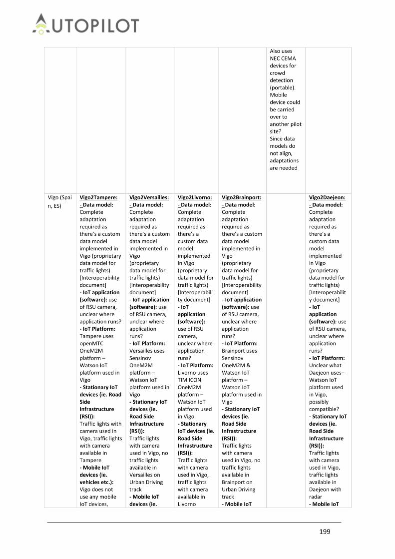
199
Also uses NEC CEMA devices for crowd detection (portable). Mobile device could be carried over to another pilot site? Since data models do not align, adaptations are needed
Vigo (Spai
n, ES)
Vigo2Tampere: - Data model: Complete adaptation required as there’s a custom data model implemented in Vigo (proprietary data model for traffic lights) [Interoperability document] - IoT application (software): use of RSU camera, unclear where application runs? - IoT Platform: Tampere uses openMTC OneM2M platform – Watson IoT platform used in Vigo - Stationary IoT devices (ie. Road Side Infrastructure (RSI)): Traffic lights with camera used in Vigo, traffic lights with camera available in Tampere - Mobile IoT devices (ie. vehicles etc.): Vigo does not use any mobile IoT devices,
Vigo2Versailles: - Data model: Complete adaptation required as there’s a custom data model implemented in Vigo (proprietary data model for traffic lights) [Interoperability document] - IoT application (software): use of RSU camera, unclear where application runs? - IoT Platform: Versailles uses Sensinov OneM2M platform – Watson IoT platform used in Vigo - Stationary IoT devices (ie. Road Side Infrastructure (RSI)): Traffic lights with camera used in Vigo, no traffic lights available in Versailles on Urban Driving track - Mobile IoT devices (ie.
Vigo2Livorno: - Data model: Complete adaptation required as there’s a custom data model implemented in Vigo (proprietary data model for traffic lights) [Interoperability document] - IoT application (software): use of RSU camera, unclear where application runs? - IoT Platform: Livorno uses TIM ICON OneM2M platform – Watson IoT platform used in Vigo - Stationary IoT devices (ie. Road Side Infrastructure (RSI)): Traffic lights with camera used in Vigo, traffic lights with camera available in Livorno
Vigo2Brainport: - Data model: Complete adaptation required as there’s a custom data model implemented in Vigo (proprietary data model for traffic lights) [Interoperability document] - IoT application (software): use of RSU camera, unclear where application runs? - IoT Platform: Brainport uses Sensinov OneM2M & Watson IoT platform – Watson IoT platform used in Vigo - Stationary IoT devices (ie. Road Side Infrastructure (RSI)): Traffic lights with camera used in Vigo, no traffic lights available in Brainport on Urban Driving track - Mobile IoT
Vigo2Daejeon: - Data model: Complete adaptation required as there’s a custom data model implemented in Vigo (proprietary data model for traffic lights) [Interoperability document] - IoT application (software): use of RSU camera, unclear where application runs? - IoT Platform: Unclear what Daejeon uses– Watson IoT platform used in Vigo, possibly compatible? - Stationary IoT devices (ie. Road Side Infrastructure (RSI)): Traffic lights with camera used in Vigo, traffic lights available in Daejeon with radar - Mobile IoT

200
except the vehicle. Since datamodels do not align, adaptations are needed
vehicles etc.): Vigo does not use any mobile IoT devices, except the vehicle. Since datamodels do not align, adaptations are needed
- Mobile IoT devices (ie. vehicles etc.): Vigo does not use any mobile IoT devices, except the vehicle. Since datamodels do not align, adaptations are needed
devices (ie. vehicles etc.): Vigo does not use any mobile IoT devices, except the vehicle. Since datamodels do not align, adaptations are needed
devices (ie. vehicles etc.): Vigo does not use any mobile IoT devices, except the vehicle. Since datamodels do not align, adaptations are needed
Daejeon
(South
Korea, SK)
Daejeon2Tampere: - Data model: Complete adaptation required as there’s a custom data model implemented in Vigo (proprietary data model for traffic lights) [Interoperability document] - IoT application (software): ISS (Intersection Safety System) - IoT Platform: Daejeon uses ??? - - Stationary IoT devices (ie. Road Side Infrastructure (RSI)): Pedestrian detection radar at trafficlight. no radar at Tampere - Mobile IoT devices (ie. vehicles etc.): Deajeon does not use any mobile IoT devices, except the vehicle. Since datamodels do not align, adaptations are needed
Daejeon2Versailles: - Data model: Complete adaptation required as there’s a custom data model implemented in Vigo (proprietary data model for traffic lights) [Interoperability document] - IoT application (software): ISS (Intersection Safety System. ) - IoT Platform: Daejeon uses ??? - - Stationary IoT devices (ie. Road Side Infrastructure (RSI)): Pedestrian detection radar at trafficlight. no radar or trafficlight at Versailles - Mobile IoT devices (ie. vehicles etc.): Deajeon does not use any mobile IoT devices, except the vehicle. Since datamodels do not align, adaptations are needed
Daejeon2Livorno: - Data model: Complete adaptation required as there’s a custom data model implemented in Vigo (proprietary data model for traffic lights) [Interoperability document] - IoT application (software): ISS (Intersection Safety System. ) - IoT Platform: Daejeon uses ??? - - Stationary IoT devices (ie. Road Side Infrastructure (RSI)): Pedestrian detection radar at trafficlight. no radar at Livorno? - Mobile IoT devices (ie. vehicles etc.): Deajeon does not use any mobile IoT devices, except the vehicle. Since datamodels do not align, adaptations are needed
Daejeon2Brainport: - Data model: Complete adaptation required as there’s a custom data model implemented in Vigo (proprietary data model for traffic lights) [Interoperability document] - IoT application (software): ISS (Intersection Safety System. ) - IoT Platform: Daejeon uses ??? - - Stationary IoT devices (ie. Road Side Infrastructure (RSI)): Pedestrian detection radar at trafficlight. no radar or trafficlight at Brainport - Mobile IoT devices (ie. vehicles etc.): Deajeon does not use any mobile IoT devices, except the vehicle. Since datamodels do not align, adaptations are needed
Daejeon2Vigo: - Data model: Complete adaptation required as there’s a custom data model implemented in Vigo (proprietary data model for traffic lights) [Interoperability document] - IoT application (software): ISS (Intersection Safety System. ) - IoT Platform: Daejeon uses ??? - - Stationary IoT devices (ie. Road Side Infrastructure (RSI)): Pedestrian detection radar at trafficlight. - Mobile IoT devices (ie. vehicles etc.): Deajeon does not use any mobile IoT devices, except the vehicle. Since

201
datamodels do not align, adaptations are needed

202
7.5 Pilot Plan
The Pilot Plan contains all the information to reproduce and evaluate on use case on each Pilot Site. The Technical Evaluation tab has been described in Section 2.5. The AUTOPILOT_PILOT PLAN TEMPLATE sheet is available here. The Pilot Plans for each Pilot Site are available via the links below:
Finland Tampere Automated Valet Parking Tampere Urban Driving
France Versailles Car Sharing & Urban Driving Versailles Platooning
Italy Livorno Urban Driving Livorno Highway Pilot
Korea Daejeon Urban Driving
Netherlands Brainport Highway Pilot Brainport Ridesharing Brainport Automated Valet Parking Brainport Platooning Brainport Rebalancing
Spain Vigo Automated Valet Parking Vigo Urban Driving
7.6 AUTOPILOT security evaluation questionnaire
7.6.1 Definition of a common list of events to be logged
As guideline for logging aspects the NIST 800-53r49 recommends that:
1. The audit events can include i.e. password changes, failed logons or failed accesses related to information systems, administrative privilege usage, PIV credential usage or third-party credential usage.
2. The organizations may determine that information systems must have the capability to log every file access both successful and unsuccessful, but not activate that capability except for specific circumstances due to the potential burden on system performance.
9 https://nvd.nist.gov/800-53/Rev4

203
3. The audit records can be generated at various levels of abstraction, including at the packet level as information traverses the network. Selecting the appropriate level of abstraction is a critical aspect of an audit capability and can facilitate the identification of root causes to problems.
In this policy AUTOPILOT defines that the following events should be logged:
Table 76 AUTOPILOT security events
Event Description Information
available
Invalid logical access attempts
Whenever an access to any resource (file, device, user account, etc.) fails, this must be present in the log.
Yes / No
Physical access attempts
If anti tampering devices are present any warning must be logged. Note that in this case it is paramount for the log information to be immediately transmitted outside the device before “it is too late”.
Creation and deletion of system-level objects
Files that are needed for the system to run correctly must not be created or deleted without logging that operation. Applications, libraries, and configurations must be monitored for changes.
Access to audit trail data and functions
If anything accesses to any audit log data or functionality it must be logged. Note that in this case it is paramount for the log information to be immediately transmitted outside the device before “it is too late”.
Initialization of auditing
In case the audit log is reinitialized, started, stopped or paused, this must be logged. Note that in this case it is paramount for the log information to be immediately transmitted outside the device before “it is too late”.
All action taken by privileged accounts
Privileged accounts should not be used during normal operation of the system, thus a privileged account operation must be carefully logged.
Start-ups and shutdowns of systems, applications, and application modules or components
In case the running state of any module changes it must be logged.
Errors affecting the application’s availability
Any error that causes the application to malfunction must be logged.

204
Exhausted resources, exceeded capacities, reached thresholds
When a limited resource limit is reached or reaches a defined threshold the event must be logged.
Connectivity issues and problems
Any problem related to connectivity like, but not limited to: timeouts, connection lost, change in latency, retries performed must be logged.
Invalid inputs Any malformed or otherwise invalid input received at any level must be logged
All types of privilege escalation Any call to OS APIs that allow higher privileges to be gained must be logged
All types of file modifications
Modifying files can be a frequent operation nonetheless some modifications can be a symptom of something happening. If an application only modifies a specific set of files, the log granularity can be reduced and only the infrequent modifications could be logged. Still it would be preferred to log all modifications.
All types of data-transfers to/from any device
In case files or records are sent or received a log event should be generated.
Application/device/system/subsystem status
This is the kind of information that domain expert can use to understand what the applications are doing from a service point of view. For an LRT system, for example, the fact that a train requests a route, that an operator performs a call to a driver, that signal changes aspect, that a train exit Wi-Fi coverage, train localization, etc. are all relevant information.
7.6.2 Definition of a common list of log-parameters
As guideline for logging aspects the NIST 800-53r4 recommends as log parameters:
1. Time stamps, source and destination addresses, user/process identifiers, event descriptions, success/fail indications, filenames involved and access control or flow control rules invoked.
2. Event outcomes can include indicators of event success or failure and event-specific results (e.g., the security state of the information system after the event occurred)
In this policy AUTOPILOT defines that the following parameters have to be documented in any log (if applicable and available):
Table 77 AUTOPILOT common list of log-parameters

205
Parameter Description Information
available
(UTC) timestamp with millisecond accuracy
This is important in order to match events in different parts of the system
Yes / No
User identifier What user is the code running as?
Process/thread identifier What is process/thread ID of the generating code?
Session ID
This is useful to link a group of log lines to the same “session”. The meaning of session can vary e.g. all actions generated by the same “system activity”.
State (begin/in-progress/terminated-successfully/failed)
Is this log line about an operation that is beginning, ongoing, successfully completed or failed?
Touched (data-)item – if any Are there any side effects related to this operation? Altered file, record, configuration …
Communications (source/destination, protocol, payload info)
If the log line is about communication to another device, what de-vice/interface/data are transferred? Payload info must be meaningful to under-stand system behavior. Not all data is needed most of the time.
Enumerated description of the event, e.g. log-on and log-off, privilege level change, failure, request sent, …
This is useful to filter events of some predefined kind. It is important to define and adhere to a list of generic enumerated descriptions that must be carefully described before implementing the system.
Device/resource identity or location if possible and system identifier
What device/system has generated this log line? This information can be also (e.g.) stored in the file name, but it must be present in case logs from multiple systems are collected into the same file
7.7 AUTOPILOT privacy assessment questionnaire
Privacy assessment will be done according to D1.9Initial Specification of Security and Privacy for IoT-enhanced AD [9]. The goal of the assessment is to evaluate privacy in two steps:
1. Review all data flows of the AUTOPILOT solution and identify where private information (PII) enters the system, where it is stored and how it is protected in transit and at rest.
2. Identify all services that may be potentially used to track individuals based on both real-time information that may be obtained from services exposed by IoT platform or from data persisted in the platform.
The assessment will be based on technical documentation of the platform and exposed services and log data may be considered only a supporting evidence for the review. Typically interface and service descriptions with an overview of data shared between solution layers and description of persisted information with means of protection should be provided. The review will be focused on PII so technical details about additional data are not needed unless it may be used for tracking (unique identification of users or vehicles). Possibility to track individual users or to track one specific car will

206
be assessed in a similar way. The questions that should be answered during evaluation are:
Is it possible to uniquely identify a particular vehicle and track it when it is connected to the platform?
Does the identifier of a vehicle (if any) changes or is it permanent?
What are the access rights to get this information?
Is there a possibility to track a vehicle based on location correlation? Changes of position happen at certain velocity and it is expected that attackers tracking users would calculate the position in case they miss part of the information.
The assessment will be based on information exposed by the platform and related services. It will not be focused on lower layers of the system (such as the interface between OneM2M and IoT devices). It is expected that the lower layers of the infrastructure will be covered by a different contract.

207
7.7.1 Privacy assessment of components
Ride sharing service component
Table 78 Ride sharing service component
Component name Vendor Description
Interfaces
Table 79 Privacy interfaces
Interface Server Client Description
Information exchanged on interfaces
Table 80 Information exchanged on interfaces
Exposed data Interface Identification/Tracking
Data persisted by the component
Table 81 Data persisted by the component
Information Exposed data Storage Protection
Authentication and authorization Additional assessment will be focused on authentication, authorization and accounting of the platform to assess:
1. Authorization of all service calls exposed by the platform for both to send commands to devices and to get information from the platform.
2. Each call will be assessed if the accountability is needed (to know responsible person in case of incident)
3. Translation of credentials between each layer and related authorization The assessment will be part of technical evaluation and in case it is done later in the project it may imply a rework of certain part of the system to mitigate selected critical privacy threats. From this point of view it is recommended to perform it as soon as possible to reduce impact of such rework. The evaluation should be done for the common platform and all platform implementations by each pilot site. Note that the rework does not need to imply technical development. It may be agreed that some issues will be addressed only in written report or deliverable amendment.
In order to assess all AUTOPILOT services for authentication and authorization each service used by each use case implementation should be listed in following table.

208
Table 82 Services used by each use case implementation
Interface name
Authentication Authorization
Credentials Accountable organization/person
7.8 Communication Performance Analyses
This annex presents results from the communication performance analysis at the Brainport site for the Platooning use case. The delays for V2V communication between platooning vehicles is on average 1 - 2msec for ITS-G5 and 4-5 msec for UWB. Figure 108 shows measurements from a single test run where the same vehicles used both NXP communication units for platooning. These delays are measured at the access layers of the sender and receiver.
Figure 108 V2V communication delays at the access layer for ITS-G5 (top) and UWB (bottom) in Brainport
End-to-end delays should be measured interface of the facilities layers where the messages are delivered to the applications. This was not measured for the NXP communication units used for platooning. A second communication unit from TNO is installed in both vehicles that are used for other services. The TNO units provide C-ITS services and communicate with road side units via ITS-G5 and cloud services via 4G. Cloud services outside an IoT platform have not been used in AUTOPILOT. The TNO units have been tested in other project though. Figure 109 shows the end-to-end communication delays analysed in the InterCor project. The average end-to-end delay is 25 msec for ITS-G5 and 150 msec for 4G/LTE communication to cloud services.

209
Figure 109 V2I end-to-end communication delay for ITS-G5 and 4G/LTE communication
(ref InterCor Milestone M13 Final Evaluation Report]
The TNO units are extended with an in-vehicle IoT platform in AUTOPILOT and connect via 4G/LTE communication to the SENSINOV IoT platform in the cloud of Brainport. The PositionEstimate messages are IoT messages with the contents and size comparable to CAM messages. These are sent by the TNO units from one platooning vehicle (StationID 3101) via the IoT cloud platform to the other platooning vehicle (3103) and to the Platoon service in the cloud (3199). Figure 110 shows the end-to-end communication delays. V2V communication via the IoT platform can be measured from the light blue messages between the two platooning vehicle units and is in the order of 250 msec.

210
Figure 110 End-to-end communication delays for V2I and I2V messages
Figure 110 shows the delays for V21 (top - PlatoonStatus) and I2V (bottom - PlatoonFormation) messages between the platooning vehicles and the cloud PlatoonService via the IoT cloud platform in Brainport.

211
7.9 Safety Intervention form
Table 83 Safety intervention form
Parameter Name Description and value enumeration
Timestamp Approximate timestamp of the intervention. This is necessary to align the log data and retrieve the IoT data for the intervention.
Intervention_Type Type of intervention is determined by whom or what intervened during automated driving. The value can be selected from the enumeration:
Test driver
User as a driver
Passenger
Other road user
Service operator
Bystander
Other
Intervention_Cause Assumed cause of the unsafe situation that required the intervention. The value can be selected from the enumeration:
Weather condition
Inattentive road user
Unwanted vehicle manoeuvre
Perception discrepancy
Hardware discrepancy
Software discrepancy
Road works
Emergency vehicle
Road surface condition
Obstacle on the road
Other
Intervention_Description Free text to describe the period or step in the pilot plan of the intervention, environmental conditions, the intervention (and who or what intervened and how) and assumed cause.
Severity_Perception Assess the severity of the safety risk and the required intervention. The value can be selected from the enumeration:
Dangerous
An accident could have happened if the subject
would not have intervened, e.g. a system failure
that can cause an accident and only the reaction
of the driver could avoid it.
Moderate
An accident could have happened, but the intervention to avoid it was trivial or automatic, e.g. a system failure could have caused an accident, but there are means that act automatically or the driver is warned in time to avoid the accident.
No risk Even if the subject wouldn’t have intervened, there was no risk, e.g. the driver has intervened

212
in response to a system fault, but if he hadn’t then an accident was unlikely to happen anyway.
AD_Vehicle_Situation Free text to describe the activated AD functions and systems, their modes/states, and observed behaviour or malfunctioning.
IoT_Situation Free text to describe the usage of IoT data sources, and clearly indicate whether and how IoT data is used for automated driving during the unsafe situation and intervention.
Traffic_Situation Free text to describe or sketch the traffic situation, traffic control and road users.
7.10 Navigation analysis for Brainport Platooning
The analysis from the navigation point of view of Brainport platooning is available here.
7.11 Navigation analysis for Brainport Highway Pilot
The analysis from the navigation point of view of Brainport highway pilot is available in the following links. We have analysed only the relevant tests that contain relevant data for the evaluation of navigation topic, which are T7 and T8 (for baseline) and T9 and T10 (for IoT improvement): T7 analysis is available here. T8 analysis is available here. T9 analysis is available here. T10 analysis is available here.
Related Documents
![4.3 [4] Technical Scope of M2M Consolidation](https://static.cupdf.com/doc/110x72/56813ae6550346895da3461d/43-4-technical-scope-of-m2m-consolidation.jpg)
![Annual Evaluation Overview Report - [Evaluation] · 4.1 TC Evaluation Coverage 27 4.2 Performance evaluation of TC operations 30 4.3 TC-Related Evaluation Work in 2007 31 5. VALIDATION](https://static.cupdf.com/doc/110x72/5ec802f243fef409d772d3ab/annual-evaluation-overview-report-evaluation-41-tc-evaluation-coverage-27-42.jpg)