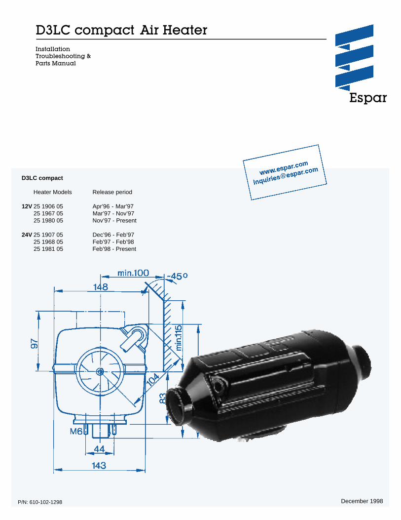
D3LC compact Air Heater Installation Troubleshooting & Parts Manual Espar December 1998 P/N: 610-102-1298 D3LC compact Heater Models Release period 12V 25 1906 05 Apr’96 - Mar’97 25 1967 05 Mar’97 - Nov’97 25 1980 05 Nov’97 - Present 24V 25 1907 05 Dec’96 - Feb’97 25 1968 05 Feb’97 - Feb’98 25 1981 05 Feb’98 - Present

Welcome message from author
This document is posted to help you gain knowledge. Please leave a comment to let me know what you think about it! Share it to your friends and learn new things together.
Transcript
D3LC compact Air HeaterInstallationTroubleshooting &Parts Manual
Espar
December 1998P/N: 610-102-1298
D3LC compact
Heater Models Release period
12V 25 1906 05 Apr’96 - Mar’9725 1967 05 Mar’97 - Nov’9725 1980 05 Nov’97 - Present
24V 25 1907 05 Dec’96 - Feb’9725 1968 05 Feb’97 - Feb’9825 1981 05 Feb’98 - Present
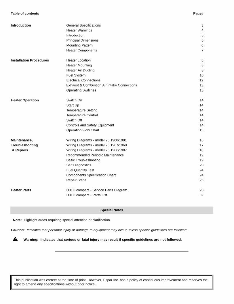
Table of contents Page#
Introduction General Specifications 3Heater Warnings 4Introduction 5Principal Dimensions 6Mounting Pattern 6Heater Components 7
Installation Procedures Heater Location 8Heater Mounting 8Heater Air Ducting 8Fuel System 10Electrical Connections 12Exhaust & Combustion Air Intake Connections 13Operating Switches 13
Heater Operation Switch On 14Start Up 14Temperature Setting 14Temperature Control 14Switch Off 14Controls and Safety Equipment 14Operation Flow Chart 15
Maintenance, Wiring Diagrams - model 25 1980/1981 16Troubleshooting Wiring Diagrams - model 25 1967/1968 17& Repairs Wiring Diagrams - model 25 1906/1907 18
Recommended Periodic Maintenance 19Basic Troubleshooting 19Self Diagnostics 20Fuel Quantity Test 24Components Specification Chart 24Repair Steps 25
Heater Parts D3LC compact - Service Parts Diagram 28D3LC compact - Parts List 32
Special Notes
Note: Highlight areas requiring special attention or clarification.
Caution: Indicates that personal injury or damage to equipment may occur unless specific guidelines are followed.
Warning: Indicates that serious or fatal injury may result if specific guidelines are not followed.
This publication was correct at the time of print. However, Espar Inc. has a policy of continuous improvement and reserves theright to amend any specifications without prior notice.
3
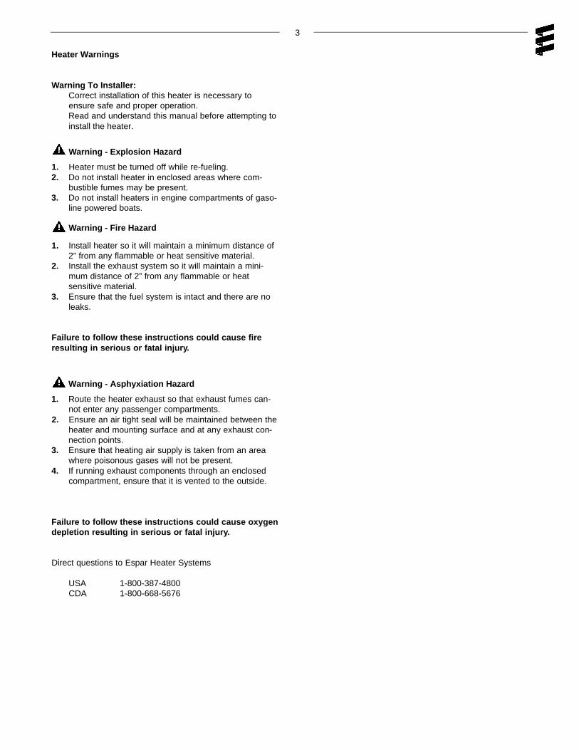
Heater Warnings
Warning To Installer:Correct installation of this heater is necessary toensure safe and proper operation. Read and understand this manual before attempting toinstall the heater.
Warning - Explosion Hazard
1. Heater must be turned off while re-fueling.2. Do not install heater in enclosed areas where com-
bustible fumes may be present.3. Do not install heaters in engine compartments of gaso-
line powered boats.
Warning - Fire Hazard
1. Install heater so it will maintain a minimum distance of2” from any flammable or heat sensitive material.
2. Install the exhaust system so it will maintain a mini-mum distance of 2” from any flammable or heat sensitive material.
3. Ensure that the fuel system is intact and there are noleaks.
Failure to follow these instructions could cause fireresulting in serious or fatal injury.
Warning - Asphyxiation Hazard
1. Route the heater exhaust so that exhaust fumes can-not enter any passenger compartments.
2. Ensure an air tight seal will be maintained between theheater and mounting surface and at any exhaust con-nection points.
3. Ensure that heating air supply is taken from an areawhere poisonous gases will not be present.
4. If running exhaust components through an enclosedcompartment, ensure that it is vented to the outside.
Failure to follow these instructions could cause oxygendepletion resulting in serious or fatal injury.
Direct questions to Espar Heater Systems
USA 1-800-387-4800CDA 1-800-668-5676
4
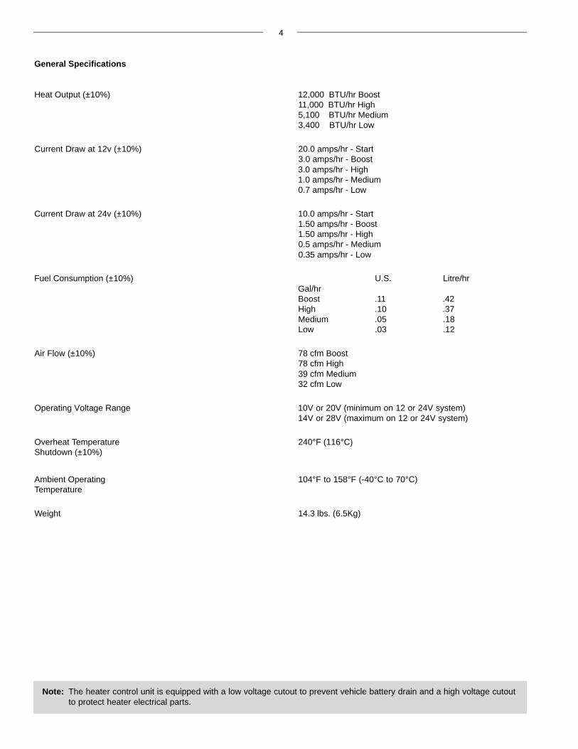
General Specifications
Heat Output (±10%) 12,000 BTU/hr Boost11,000 BTU/hr High5,100 BTU/hr Medium3,400 BTU/hr Low
Current Draw at 12v (±10%) 20.0 amps/hr - Start3.0 amps/hr - Boost3.0 amps/hr - High1.0 amps/hr - Medium0.7 amps/hr - Low
Current Draw at 24v (±10%) 10.0 amps/hr - Start1.50 amps/hr - Boost1.50 amps/hr - High0.5 amps/hr - Medium0.35 amps/hr - Low
Fuel Consumption (±10%) U.S. Litre/hrGal/hrBoost .11 .42High .10 .37Medium .05 .18Low .03 .12
Air Flow (±10%) 78 cfm Boost78 cfm High39 cfm Medium32 cfm Low
Operating Voltage Range 10V or 20V (minimum on 12 or 24V system)14V or 28V (maximum on 12 or 24V system)
Overheat Temperature 240°F (116°C)Shutdown (±10%)
Ambient Operating 104°F to 158°F (-40°C to 70°C)Temperature
Weight 14.3 lbs. (6.5Kg)
Note: The heater control unit is equipped with a low voltage cutout to prevent vehicle battery drain and a high voltage cutout to protect heater electrical parts.
Introduction
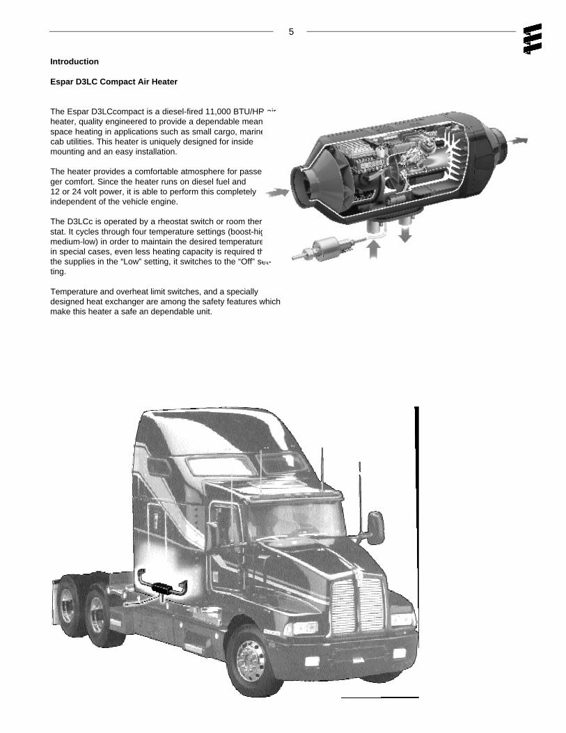
Espar D3LC Compact Air Heater
The Espar D3LCcompact is a diesel-fired 11,000 BTU/HR airheater, quality engineered to provide a dependable means ofspace heating in applications such as small cargo, marine andcab utilities. This heater is uniquely designed for insidemounting and an easy installation.
The heater provides a comfortable atmosphere for passen-ger comfort. Since the heater runs on diesel fuel and12 or 24 volt power, it is able to perform this completelyindependent of the vehicle engine.
The D3LCc is operated by a rheostat switch or room thermo-stat. It cycles through four temperature settings (boost-high-medium-low) in order to maintain the desired temperature. If,in special cases, even less heating capacity is required thanthe supplies in the “Low” setting, it switches to the “Off” set-ting.
Temperature and overheat limit switches, and a speciallydesigned heat exchanger are among the safety features whichmake this heater a safe an dependable unit.
5
6
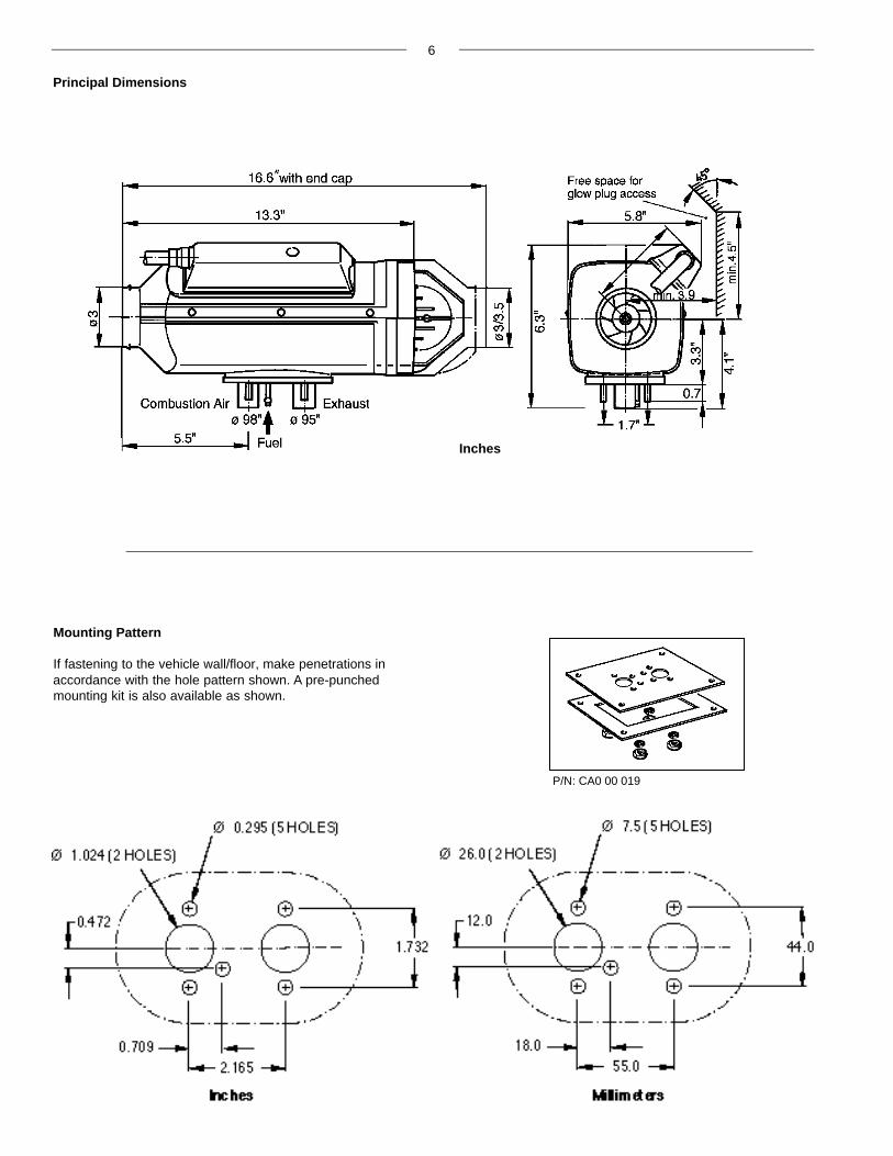
Mounting Pattern
If fastening to the vehicle wall/floor, make penetrations inaccordance with the hole pattern shown. A pre-punchedmounting kit is also available as shown.
Principal Dimensions
Inches
P/N: CA0 00 019

7
Parts List
1 Hot Air Blower Wheel 11 Operating Unit (Rheostat) F = Fresh Air2 Blower Motor 12 Outer Casing C = Combustion Air3 Combustion Air Blower Wheel 13 Exhaust Line D = Fuel4 Glow Plug 14 Flange Seal H = Hot Air5 Control Unit 15 Fuel Line E = Exhaust6 Safety Thermal Sensor 16 Main Fuse, 25 A7 Combustion Chamber 17 Combustion Air Intake Line8 Flame Monitor 18 Fuel Metering Pump9 Heat Exchanger 19 Fuel Strainer10 Operating Unit (Thermostat) 20 7 Day Timer (optional)
Heater Components
Heater Air Ducting
Installation
A 90mm flexible duct 40 inches long, hot air outlet andclamps are provided with the heater kit. In routing andinstalling the ducting the following criteria must beobserved:
• Run ducting with smooth bends. Avoid crushing duct.
• Position hot air outlet so that it cannot be obstructed.
• Use protective air intake grille on air inlet side of heaterto prevent objects from being sucked in.
• Ensure provisions are made for proper air return ventilation.
• Use return air ducting for best heating efficiency
8
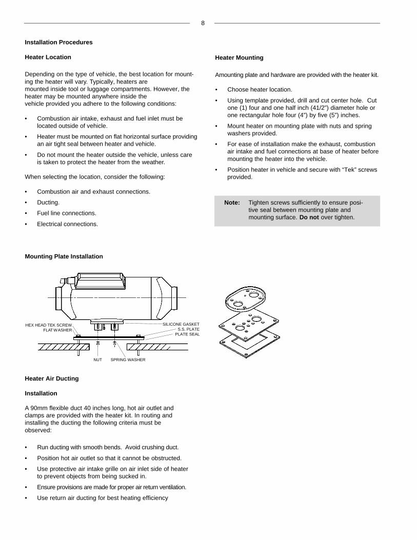
Mounting Plate Installation
HEX HEAD TEK SCREWFLAT WASHER
NUT SPRING WASHER
SILICONE GASKETS.S. PLATE
PLATE SEAL
Installation Procedures
Heater Location
Depending on the type of vehicle, the best location for mount-ing the heater will vary. Typically, heaters are mounted inside tool or luggage compartments. However, theheater may be mounted anywhere inside the vehicle provided you adhere to the following conditions:
• Combustion air intake, exhaust and fuel inlet must belocated outside of vehicle.
• Heater must be mounted on flat horizontal surface providingan air tight seal between heater and vehicle.
• Do not mount the heater outside the vehicle, unless careis taken to protect the heater from the weather.
When selecting the location, consider the following:
• Combustion air and exhaust connections.
• Ducting.
• Fuel line connections.
• Electrical connections.
Heater Mounting
Amounting plate and hardware are provided with the heater kit.
• Choose heater location.
• Using template provided, drill and cut center hole. Cutone (1) four and one half inch (41/2”) diameter hole orone rectangular hole four (4”) by five (5”) inches.
• Mount heater on mounting plate with nuts and springwashers provided.
• For ease of installation make the exhaust, combustionair intake and fuel connections at base of heater beforemounting the heater into the vehicle.
• Position heater in vehicle and secure with “Tek” screwsprovided.
Note: Tighten screws sufficiently to ensure posi-tive seal between mounting plate andmounting surface. Do not over tighten.
9
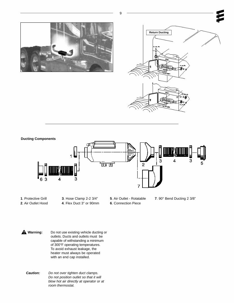
Warning: Do not use existing vehicle ducting oroutlets. Ducts and outlets must becapable of withstanding a minimumof 300°F operating temperatures.To avoid exhaust leakage, theheater must always be operatedwith an end cap installed.
Caution: Do not over tighten duct clamps.Do not position outlet so that it will blow hot air directly at operator or at room thermostat.
Ducting Components
1. Protective Grill 3. Hose Clamp 2-2 3/4” 5. Air Outlet - Rotatable 7. 90° Bend Ducting 2 3/8”2. Air Outlet Hood 4. Flex Duct 3” or 90mm 6. Connection Piece
Return Ducting

Fuel Pick-Up Pipe Installation (Standard Pick-Up)
• Choose a protected mounting location close to the fuelpump and heater. A spare fuel sender gauge plate pro-vides an ideal mounting location.
• Drill the mounting holes as shown
• Cut the fuel pick-up pipe to length.
• Mount the fuel pick-up pipe as shown.
• Lower the fuel pick-up pipe (with reinforcing washer) intothe tank using the slot created by the two 1/4” holes.
• Lift the assembly into position through the 1” hole.
• Assemble the rubber washer, metal cup washer and nut.
Note: Drill the two 1/4” holes first.
(Custom Pick-Up Pipe with NPT fitting)
• Remove an existing plug from the top of the fuel tank.
• Cut the fuel pick-up pipe to length.
• Secure the fuel pick-up pipe into position using thecombined NPT compression fitting as shown.
Note: NPT fittings are available in various sizes(Refer to parts section).
10
Fuel System
The fuel metering pump is the heart of the system and mustbe installed properly to ensure a successful heater opera-tion.
Fuel System Overview
Note: Butt joints and clamps on all connections.
Optional
1. Fuel Pick-Up Pipe2. 5.0 Rubber Connector3. 11mm Clamp4. 2.0mm Black Plastic Fuel Line5. Fuel Metering Pump6. 9mm Clamp7. 3.5mm Rubber Connector8. 1.5mm White Plastic Fuel Line9. 5mm Rubber Fuel Line
NPT fitting and pipe

11
Fuel Metering Pump
• Choose a protected mounting location close to thefuel pick-up pipe and heater.
• Using the bracket and rubber mount provided, installfuel pump as shown
Note: Proper mounting angle of the fuel pump isnecessary to allow any air or vapor in thefuel lines to pass through the pump ratherthan cause a blockage.
Fuel Line
• Route fuel lines from the fuel pick-up pipe to the fuelmetering pump then to the heater.
• Use fuel lines provided.
• Other sizes or types of fuel lines may inhibit properfuel flow.
• Make proper butt joints using clamps and connectorpieces as shown on page 8
• Use a sharp utility knife to cut plastic fuel lines toavoid burrs.
Note: All exposed electrical connections shouldbe coated with protective grease. (petrole-um gel, Vaseline, etc.).
12
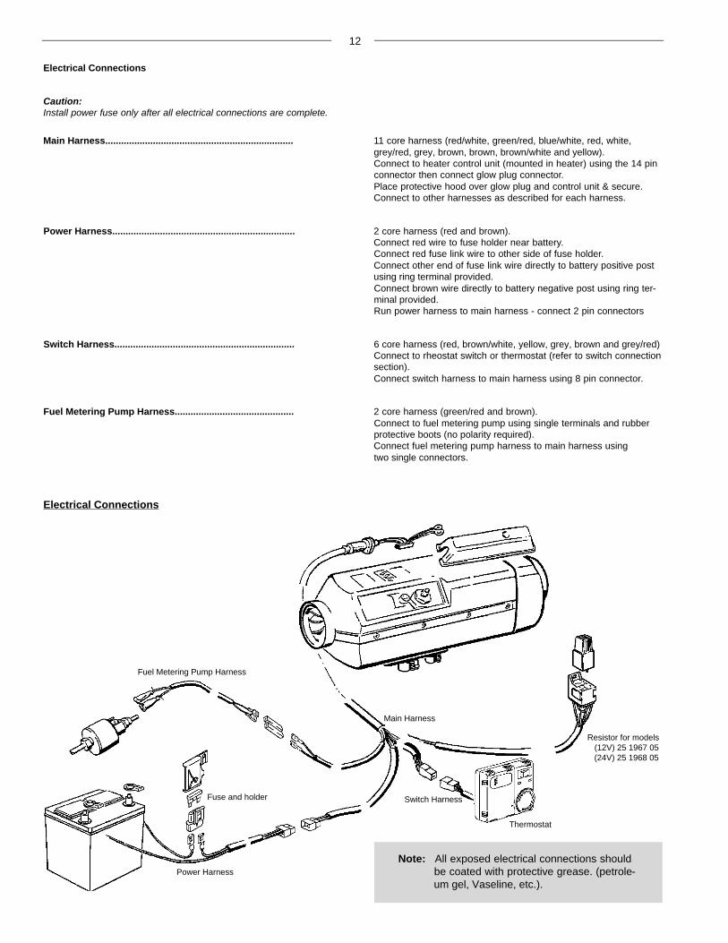
Electrical Connections
Caution:Install power fuse only after all electrical connections are complete.
Main Harness....................................................................... 11 core harness (red/white, green/red, blue/white, red, white,grey/red, grey, brown, brown, brown/white and yellow).Connect to heater control unit (mounted in heater) using the 14 pinconnector then connect glow plug connector.Place protective hood over glow plug and control unit & secure.Connect to other harnesses as described for each harness.
Power Harness..................................................................... 2 core harness (red and brown).Connect red wire to fuse holder near battery.Connect red fuse link wire to other side of fuse holder.Connect other end of fuse link wire directly to battery positive postusing ring terminal provided.Connect brown wire directly to battery negative post using ring ter-minal provided.Run power harness to main harness - connect 2 pin connectors
Switch Harness.................................................................... 6 core harness (red, brown/white, yellow, grey, brown and grey/red)Connect to rheostat switch or thermostat (refer to switch connectionsection).Connect switch harness to main harness using 8 pin connector.
Fuel Metering Pump Harness............................................. 2 core harness (green/red and brown).Connect to fuel metering pump using single terminals and rubberprotective boots (no polarity required).Connect fuel metering pump harness to main harness using two single connectors.
Main Harness
Thermostat
Switch Harness
Fuel Metering Pump Harness
Fuse and holder
Power Harness
Electrical Connections
Resistor for models(12V) 25 1967 05(24V) 25 1968 05
13
Warning: The exhaust is hot, keep a minimum of2” clearance from any heat sensitivematerial
Warning: Route exhaust so that the exhaustfumes cannot enter the passenger com-partment.
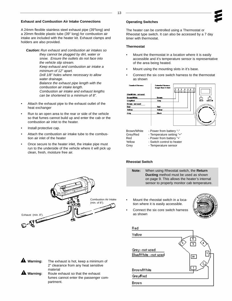
Exhaust and Combustion Air Intake Connections
A 24mm flexible stainless steel exhaust pipe (39”long) anda 20mm flexible plastic tube (39” long) for combustion airintake are included with the heater kit. Exhaust clamps andholders are also provided.
Caution: Run exhaust and combustion air intakes sothey cannot be plugged by dirt, water orsnow. Ensure the outlets do not face intothe vehicle slip stream.Keep exhaust and combustion air intake aminimum of 12” apart.Drill 1/8” holes where necessary to allowwater drainage.Balance the exhaust pipe length with the combustion air intake length.Combustion air intake and exhaust lengthscan be shortened to a minimum of 8”.
• Attach the exhaust pipe to the exhaust outlet of theheat exchanger
• Run to an open area to the rear or side of the vehicleso that fumes cannot build up and enter the cab or thecombustion air inlet to the heater.
• Install protective cap.
• Attach the combustion air intake tube to the combus-tion air inlet of the heater
• Once secure to the heater inlet, the intake pipe mustrun to the underside of the vehicle where it will pick upclean, fresh, moisture free air.
Exhaust (min. 8”).
Operating Switches
The heater can be controlled using a Thermostat orRheostat type switch. It can also be accessed by a 7 day timer with thermostat.
Thermostat
• Mount the thermostat in a location where it is easilyaccessible and it’s temperature sensor is representativeof the area being heated.
• Mount using the mounting slots in it’s base.
• Connect the six core switch harness to the thermostatas shown
Rheostat Switch
Note: When using Rheostat switch, the ReturnDucting method must be used as shownon page 9. This allows the heater’s internalsensor to properly monitor cab temperature.
• Mount the rheostat switch in a loca-tion where it is easily accessible.
• Connect the six core switch harnessas shown
Combustion Air Intake(min. of 8”).
Brown/White - Power from battery “-”Grey/Red - Temperature setting “+”Red - Power from battery “+’Yellow - Switch control to heaterGrey - Temperature sensor
14
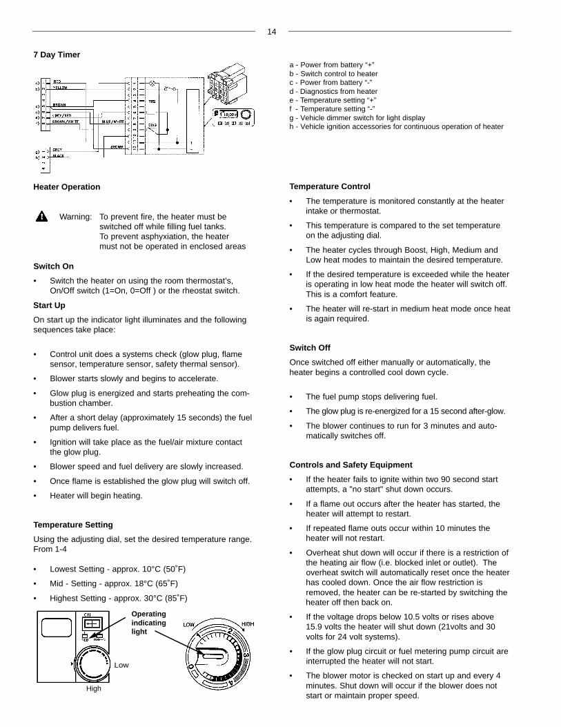
7 Day Timera - Power from battery “+”b - Switch control to heaterc - Power from battery “-”d - Diagnostics from heatere - Temperature setting “+”f - Temperature setting “-”g - Vehicle dimmer switch for light displayh - Vehicle ignition accessories for continuous operation of heater
Heater Operation
Warning: To prevent fire, the heater must be switched off while filling fuel tanks.To prevent asphyxiation, the heatermust not be operated in enclosed areas
Switch On
• Switch the heater on using the room thermostat’s,On/Off switch (1=On, 0=Off ) or the rheostat switch.
Start Up
On start up the indicator light illuminates and the followingsequences take place:
• Control unit does a systems check (glow plug, flamesensor, temperature sensor, safety thermal sensor).
• Blower starts slowly and begins to accelerate.
• Glow plug is energized and starts preheating the com-bustion chamber.
• After a short delay (approximately 15 seconds) the fuelpump delivers fuel.
• Ignition will take place as the fuel/air mixture contactthe glow plug.
• Blower speed and fuel delivery are slowly increased.
• Once flame is established the glow plug will switch off.
• Heater will begin heating.
Temperature Setting
Using the adjusting dial, set the desired temperature range.From 1-4
• Lowest Setting - approx. 10°C (50˚F)
• Mid - Setting - approx. 18°C (65˚F)
• Highest Setting - approx. 30°C (85˚F)
Temperature Control
• The temperature is monitored constantly at the heaterintake or thermostat.
• This temperature is compared to the set temperatureon the adjusting dial.
• The heater cycles through Boost, High, Medium andLow heat modes to maintain the desired temperature.
• If the desired temperature is exceeded while the heateris operating in low heat mode the heater will switch off.This is a comfort feature.
• The heater will re-start in medium heat mode once heatis again required.
Switch Off
Once switched off either manually or automatically, the heater begins a controlled cool down cycle.
• The fuel pump stops delivering fuel.
• The glow plug is re-energized for a 15 second after-glow.
• The blower continues to run for 3 minutes and auto-matically switches off.
Controls and Safety Equipment
• If the heater fails to ignite within two 90 second startattempts, a "no start" shut down occurs.
• If a flame out occurs after the heater has started, theheater will attempt to restart.
• If repeated flame outs occur within 10 minutes theheater will not restart.
• Overheat shut down will occur if there is a restriction ofthe heating air flow (i.e. blocked inlet or outlet). Theoverheat switch will automatically reset once the heaterhas cooled down. Once the air flow restriction isremoved, the heater can be re-started by switching theheater off then back on.
• If the voltage drops below 10.5 volts or rises above15.9 volts the heater will shut down (21volts and 30volts for 24 volt systems).
• If the glow plug circuit or fuel metering pump circuit areinterrupted the heater will not start.
• The blower motor is checked on start up and every 4minutes. Shut down will occur if the blower does notstart or maintain proper speed.
High
Low
Operatingindicatinglight

15
Operational Flow Chart
16
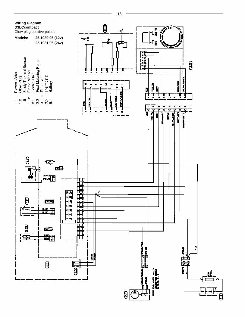
Wiring DiagramD3LCcompactGlow plug positive pulsed
Models: 25 1980 05 (12v)25 1981 05 (24v)
17
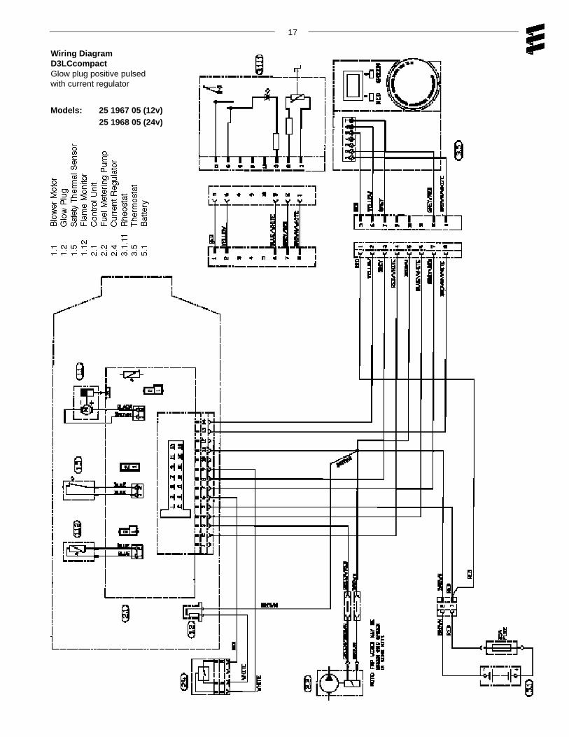
Wiring DiagramD3LCcompactGlow plug positive pulsedwith current regulator
Models: 25 1967 05 (12v)25 1968 05 (24v)

18
Wiring DiagramD3LCcompactGlow plug negative pulsed
Models: 25 1906 05 (12v)25 1907 05 (24v)
19
Maintenance, Troubleshooting and Repairs
Recommended Periodic Maintenance
• Remove the glow plug and inspect for carbon build up.Clean or replace.
• Remove the glow plug screen and inspect for carbonbuild up. Clean or replace. If cleaning is required, usebrass brush (Espar part number CA0 05 003).
• Make sure vent hole is open. Espar recommends theuse of non detergent 100% volatile carburetor cleaner and an air gun will also help. Remove loosecarbon from the glow plug chamber.
• Inspect the ducting, the air intake screen and air outletfor restriction or blockage.
• Inspect combustion air intake and exhaust for blockage.
• Run your heater and check for proper operation duringregular preventative maintenance throughout the year.
• Maintain your batteries and all electrical connections ingood condition. With insufficient power the heater willnot start. Low and high voltage cutouts will shut theheater down automatically.
• Use fuel suitable for the climate (see engine manufac-turers recommendations). Blending used engine oilwith diesel fuel is not permitted.
Basic Troubleshooting
Check LIst:
What happens when the heater is switched on and ....
Heater does not ignite
Blower motor does not run
Check: • Fuse in power harness.
• Power to control unit.
• Power to switch.
• Electrical connections.
Blower motor runs approximately 20 seconds and then shuts off
Check: • Ensure voltage at control unit remains above 9.5 volts during start up with glow plug circuit on.
Blower motor runs/fuel metering pump starts and thenshuts down after two 90 second start up cycles
Check: • Fuel lines and fuel filter.
• Fuel quantity.
• Combustion air or exhaust tube blockage.
Blower motor runs/no fuel metering pump
Check: • For electrical pulses at fuel metering pump.
• If pump is frozen.
• Blocked fuel line.
Heater ignites
Shuts down at random
Check: • Fuel metering pump quantity.
• Possible overheat.
• Control unit input voltage.
Heater smokes and carbons up
Check: • Exhaust pipe blocked.
• Combustion air intake blocked.
• Exhaust entering combustion air intake pipe.
• Short cycling, rapid on/off operation.
• Fuel system.
• Fuel metering pump quantity.
• Motor rpm.
20
Self Diagnostics
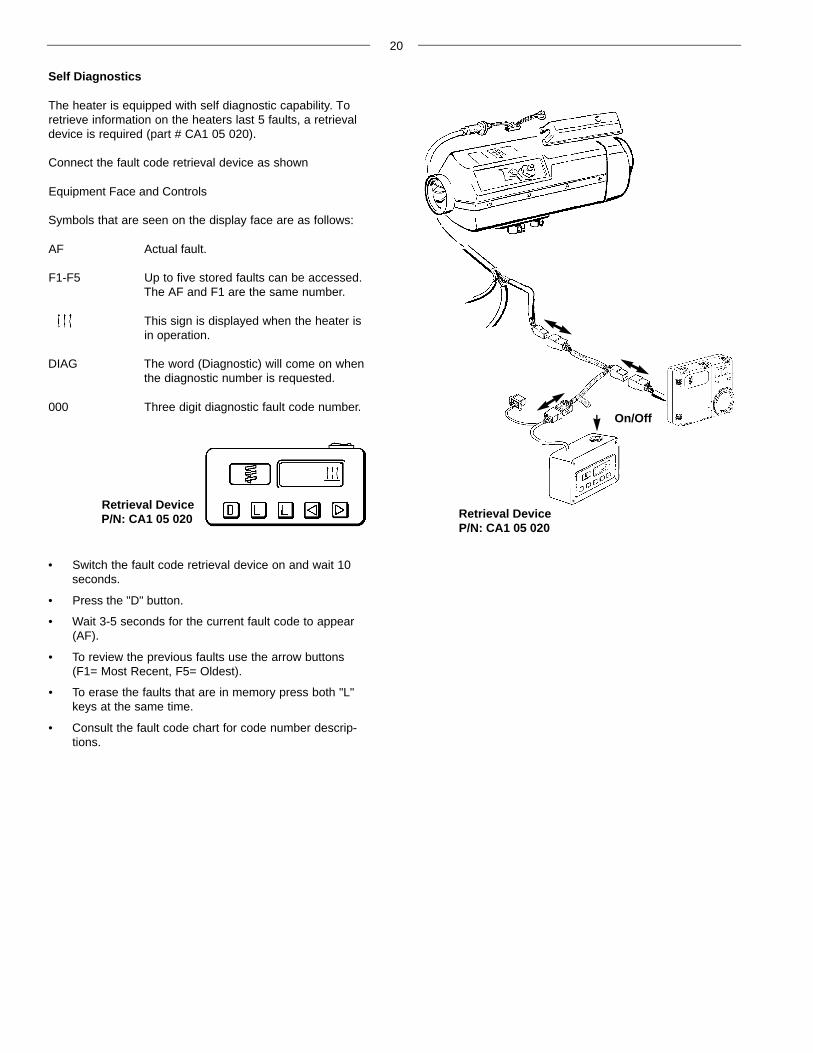
The heater is equipped with self diagnostic capability. Toretrieve information on the heaters last 5 faults, a retrievaldevice is required (part # CA1 05 020).
Connect the fault code retrieval device as shown
Equipment Face and Controls
Symbols that are seen on the display face are as follows:
AF Actual fault.
F1-F5 Up to five stored faults can be accessed.The AF and F1 are the same number.
This sign is displayed when the heater is in operation.
DIAG The word (Diagnostic) will come on when the diagnostic number is requested.
000 Three digit diagnostic fault code number.
• Switch the fault code retrieval device on and wait 10seconds.
• Press the "D" button.
• Wait 3-5 seconds for the current fault code to appear(AF).
• To review the previous faults use the arrow buttons(F1= Most Recent, F5= Oldest).
• To erase the faults that are in memory press both "L"keys at the same time.
• Consult the fault code chart for code number descrip-tions.
Retrieval DeviceP/N: CA1 05 020
Retrieval DeviceP/N: CA1 05 020
On/Off
21
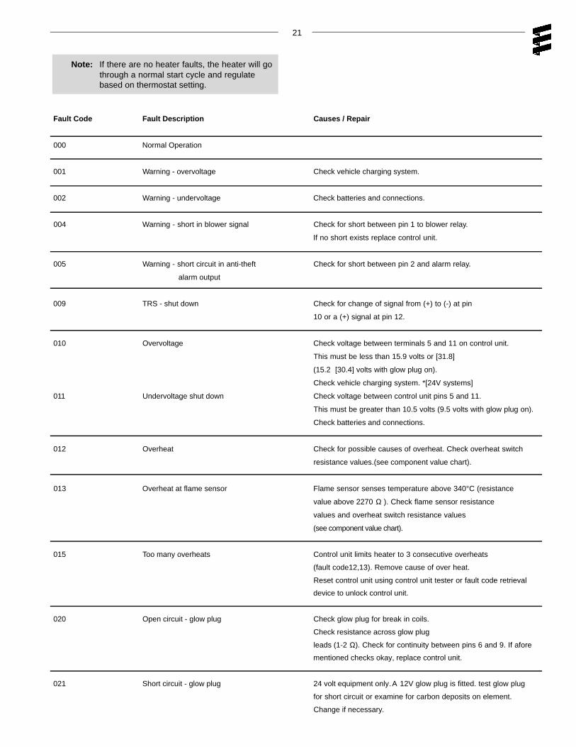
Note: If there are no heater faults, the heater will gothrough a normal start cycle and regulatebased on thermostat setting.
Fault Code Fault Description Causes / Repair
000 Normal Operation
001 Warning - overvoltage Check vehicle charging system.
002 Warning - undervoltage Check batteries and connections.
004 Warning - short in blower signal Check for short between pin 1 to blower relay.
If no short exists replace control unit.
005 Warning - short circuit in anti-theft Check for short between pin 2 and alarm relay.
alarm output
009 TRS - shut down Check for change of signal from (+) to (-) at pin
10 or a (+) signal at pin 12.
010 Overvoltage Check voltage between terminals 5 and 11 on control unit.
This must be less than 15.9 volts or [31.8]
(15.2 [30.4] volts with glow plug on).
Check vehicle charging system. *[24V systems]
011 Undervoltage shut down Check voltage between control unit pins 5 and 11.
This must be greater than 10.5 volts (9.5 volts with glow plug on).
Check batteries and connections.
012 Overheat Check for possible causes of overheat. Check overheat switch
resistance values.(see component value chart).
013 Overheat at flame sensor Flame sensor senses temperature above 340°C (resistance
value above 2270 Ω ). Check flame sensor resistance
values and overheat switch resistance values
(see component value chart).
015 Too many overheats Control unit limits heater to 3 consecutive overheats
(fault code12,13). Remove cause of over heat.
Reset control unit using control unit tester or fault code retrieval
device to unlock control unit.
020 Open circuit - glow plug Check glow plug for break in coils.
Check resistance across glow plug
leads (1-2 Ω). Check for continuity between pins 6 and 9. If afore
mentioned checks okay, replace control unit.
021 Short circuit - glow plug 24 volt equipment only.A 12V glow plug is fitted. test glow plug
for short circuit or examine for carbon deposits on element.
Change if necessary.
22
Fault Code Fault Description Causes / Repair
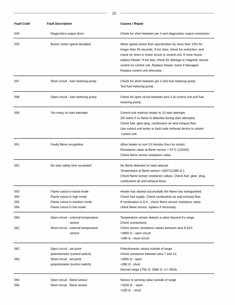
025 Diagnostics output short Check for short between pin 4 and diagnostics output connection.
033 Burner motor speed deviation Motor speed varies from specification by more than 10% for
longer than 30 seconds. If too slow, check for restriction, and
check for short in motor circuit or control unit. If none found,
replace blower. If too fast, check for damage to magnetic sensor
control on control unit. Replace blower motor if damaged.
Replace control unit otherwise.
047 Short circuit - fuel metering pump Check for short between pin 3 and fuel metering pump.
Test fuel metering pump.
048 Open circuit - fuel metering pump Check for open circuit between pins 3 at control unit and fuel
metering pump.
050 Too many no start attempts Control unit restricts heater to 10 start attempts
(20 starts if no flame is detected during start attempts).
Check fuel, glow plug, combustion air and exhaust flow.
Use control unit tester or fault code retrieval device to unlock
control unit.
051 Faulty flame recognition Allow heater to cool 15 minutes then try restart.
Resistance value at flame sensor > 57°C (1220Ω)
Check flame sensor resistance value.
052 No start safety time exceeded No flame detected on start attempt.
Temperature at flame sensor <100°C(1380 Ω ).
Check flame sensor resistance values. Check fuel, glow plug,
combustion air and exhaust flows.
053 Flame cutout in boost mode Heater has started successfully the flame has extinguished.
054 Flame cutout in high mode Check fuel supply. Check combustion air and exhaust flow.
055 Flame cutout in medium mode If combustion is O.K., check flame sensor resistance value
056 Flame cutout in low mode check flame sensor, replace if necessary.
060 Open circuit - external temperature Temperature sensor detects a value beyond it's range.
sensor Check connections.
061 Short circuit - external temperature Check sensor resistance values between pins 8 &13.
sensor >2800 Ω - open circuit
<280 Ω - short circuit
062 Open circuit - set point Potentiometer values outside of range
potentiometer (control switch) Check resistance between pins 7 and 13.
063 Short circuit - set point >2800 Ω - open
potentiometer (control switch) <280 Ω - short
Normal range 1750 Ω- 2080 Ω (+/- 80Ω).
064 Open circuit - flame sensor Sensor is sensing value outside of range
065 Short circuit - flame sensor >3200 Ω - open
<200 Ω - short

23
071 Open circuit - overheat sensor Overheating sensor signals values outside of range.
072 Short circuit - overheat sensor Check connecting leads.
>3200 Ω - open circuit
<200 Ω - short circuit. See sensor values on next page
090 Control unit defect Internal failure in microprocessor. Replace control unit.
091 External voltage disturbance Check vehicle charging system.
092 Control unit defective Internal failure in microprocessor. Replace control unit.
093 Control unit defective RAM fault
094 Control unit defective EEPROM fault
096 Control unit defective (internal Internal failure.
temperature sensor) Replace control unit or use external temperature sensor.
097 Control unit defective (power failure) Internal failure. Replace control unit.
Fault Code Fault Description Causes / Repair
24
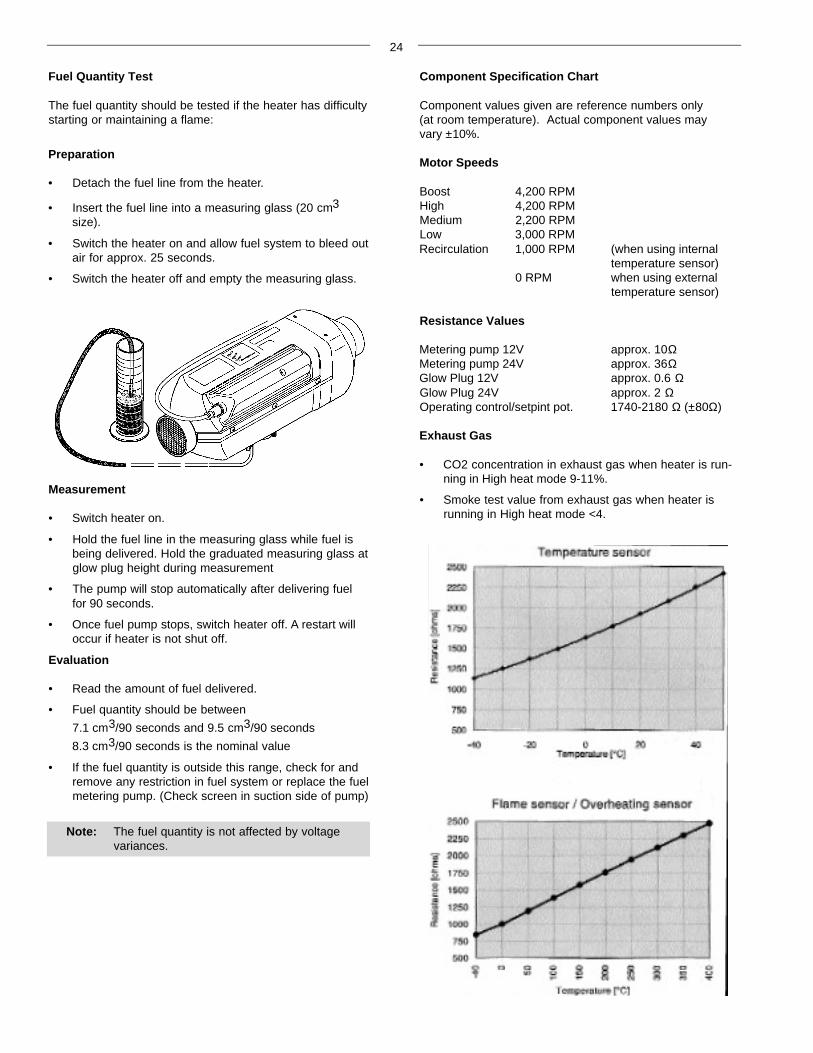
Fuel Quantity Test
The fuel quantity should be tested if the heater has difficultystarting or maintaining a flame:
Preparation
• Detach the fuel line from the heater.
• Insert the fuel line into a measuring glass (20 cm3
size).
• Switch the heater on and allow fuel system to bleed outair for approx. 25 seconds.
• Switch the heater off and empty the measuring glass.
Measurement
• Switch heater on.
• Hold the fuel line in the measuring glass while fuel isbeing delivered. Hold the graduated measuring glass atglow plug height during measurement
• The pump will stop automatically after delivering fuelfor 90 seconds.
• Once fuel pump stops, switch heater off. A restart willoccur if heater is not shut off.
Evaluation
• Read the amount of fuel delivered.
• Fuel quantity should be between
7.1 cm3/90 seconds and 9.5 cm3/90 seconds
8.3 cm3/90 seconds is the nominal value
• If the fuel quantity is outside this range, check for andremove any restriction in fuel system or replace the fuelmetering pump. (Check screen in suction side of pump)
Note: The fuel quantity is not affected by voltagevariances.
Component Specification Chart
Component values given are reference numbers only (at room temperature). Actual component values mayvary ±10%.
Motor Speeds
Boost 4,200 RPMHigh 4,200 RPMMedium 2,200 RPMLow 3,000 RPMRecirculation 1,000 RPM (when using internal
temperature sensor)0 RPM when using external
temperature sensor)
Resistance Values
Metering pump 12V approx. 10ΩMetering pump 24V approx. 36ΩGlow Plug 12V approx. 0.6 ΩGlow Plug 24V approx. 2 ΩOperating control/setpint pot. 1740-2180 Ω (±80Ω)
Exhaust Gas
• CO2 concentration in exhaust gas when heater is run-ning in High heat mode 9-11%.
• Smoke test value from exhaust gas when heater isrunning in High heat mode <4.

25
Note: Ensure seam of screen and tab do notblock the air vent hole or fuel port.
Fuel port &Air vent hole
Repair Steps
Inspection, Removal and Replacement of the:-
Glow Plug
Atomizer Screen
Control Unit
Heater Casing Disassembly
Overheat Sensor
Flame Sensor
Blower Removal and Replacement
Heat Exchanger Cleaning
Glow Plug Removal, Inspection and Replacement
• Remove glow plug connector.
• Remove glow plug.
• Inspect coils for carbon build up, breaks or metal fatigue.
• Clean or replace if necessary.
• Re-install in reverse order using a new gasket.
Atomizer Screen Removal, Inspection and Replacement
• Remove atomizing screen using the metal tab and apair of pliers.
• Clean screen using varsol, brass wire brush and com-pressed air.
• Inspect screen for deterioration and replace if necessary.
• Clean the glow plug chamber to remove carbon build up.
• Ensure air vent hole and fuel port are clear.
• Re-install fuel screen.
Disconnect
1. Glow Plug2. Atomizer Screen3. Glow Plug Connector
Caution: Remove power from the heater priorto any disassembly by unplugging main connection or removing main fuse.
Control Unit Removal and Replacement
• Unplug main harness and motor connectors. (1)
• To remove Control Unit, unlock and slide out. (2)
• Unplug overheat switch & flame sensor connectors. (3)
• Re-install in reverse order.
Control Unit
26
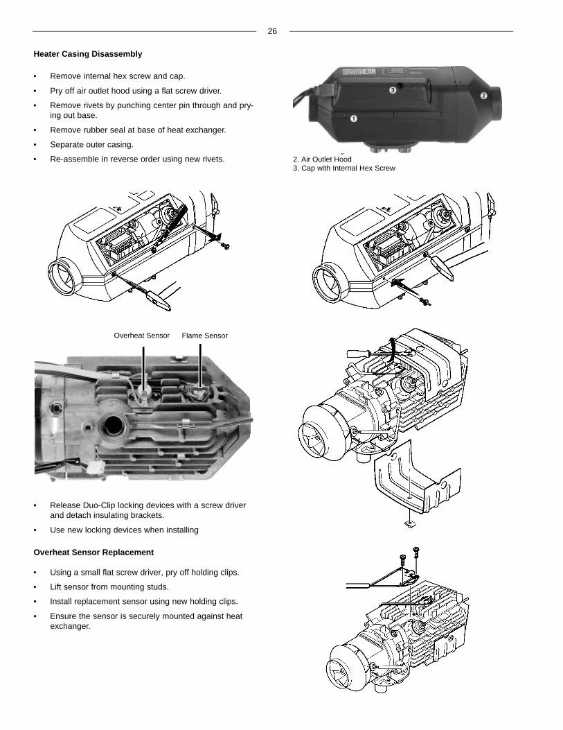
Overheat Sensor Flame Sensor
Heater Casing Disassembly
• Remove internal hex screw and cap.
• Pry off air outlet hood using a flat screw driver.
• Remove rivets by punching center pin through and pry-ing out base.
• Remove rubber seal at base of heat exchanger.
• Separate outer casing.
• Re-assemble in reverse order using new rivets.1. Outer Casing2. Air Outlet Hood3. Cap with Internal Hex Screw
• Release Duo-Clip locking devices with a screw driverand detach insulating brackets.
• Use new locking devices when installing
Overheat Sensor Replacement
• Using a small flat screw driver, pry off holding clips.
• Lift sensor from mounting studs.
• Install replacement sensor using new holding clips.
• Ensure the sensor is securely mounted against heatexchanger.
27
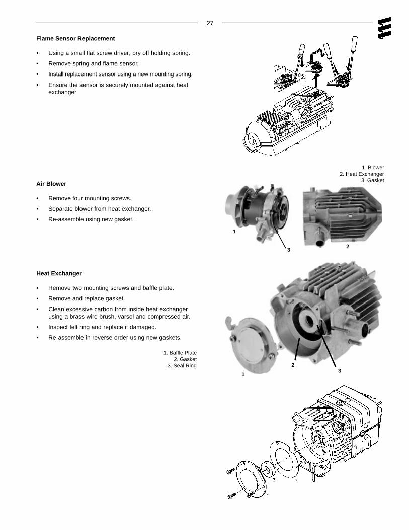
Flame Sensor Replacement
• Using a small flat screw driver, pry off holding spring.
• Remove spring and flame sensor.
• Install replacement sensor using a new mounting spring.
• Ensure the sensor is securely mounted against heatexchanger
1
3
Air Blower
• Remove four mounting screws.
• Separate blower from heat exchanger.
• Re-assemble using new gasket.
1. Blower2. Heat Exchanger
3. Gasket
2
Heat Exchanger
• Remove two mounting screws and baffle plate.
• Remove and replace gasket.
• Clean excessive carbon from inside heat exchangerusing a brass wire brush, varsol and compressed air.
• Inspect felt ring and replace if damaged.
• Re-assemble in reverse order using new gaskets.
1
23
1. Baffle Plate2. Gasket
3. Seal Ring

28
Parts Diagram
D3LCcompact
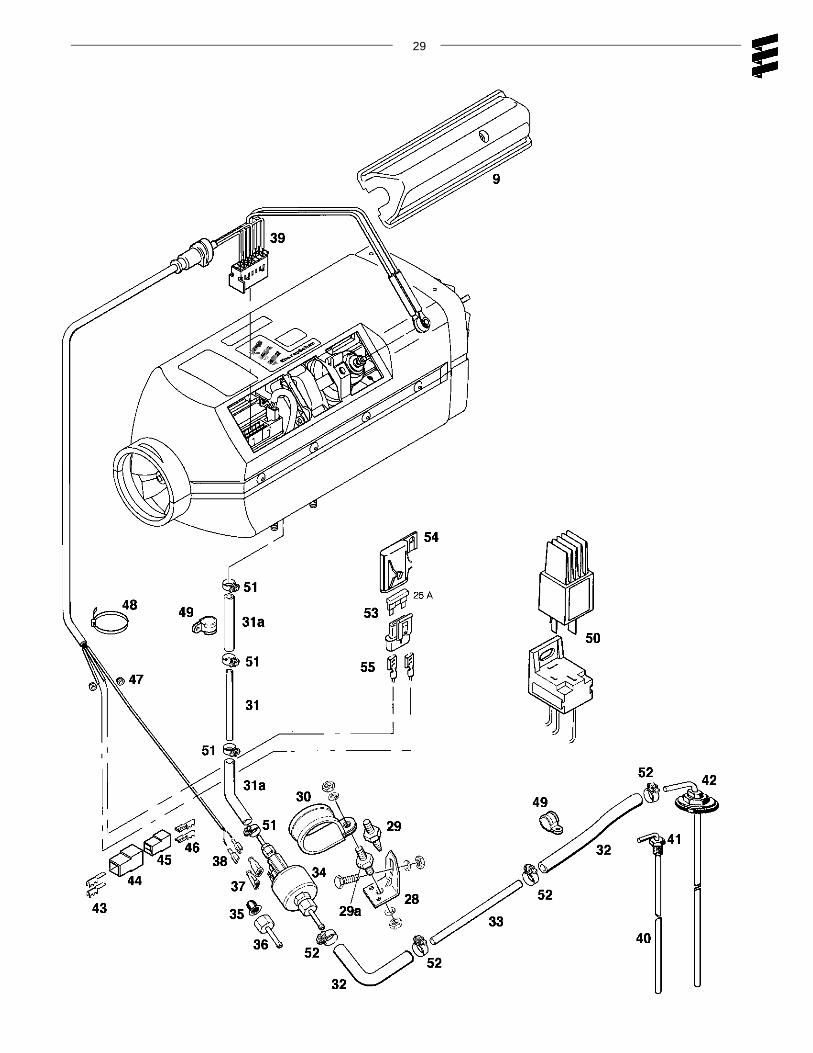
29
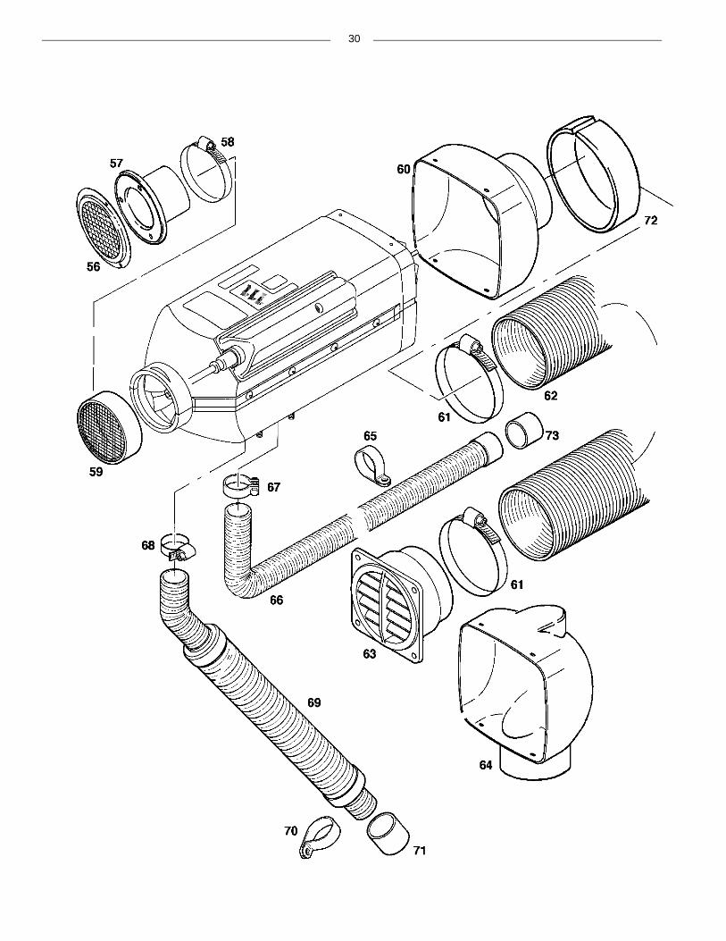
30

31

Parts List
D3LCcompact
Ref.Description Part Number
No.
1 Heat exchanger 25 1882 06 00 00 • • • • • •
2 Combustion air blower 12 Volt 25 1906 99 20 00 • • •24 Volt 25 1907 99 20 00 • • •
3 Flame sensor 25 1895 99 35 00 • • • • • •
4 Safety thermal sensor 25 1895 41 00 00 • • • • • •*includes cable section
5 Lower half of casing 25 1822 01 01 00 • • • • • •
6 Upper half of casing 25 1906 01 06 00 • • • • • •
7 Control unit 12 Volt 25 1895 50 00 03 • •24 Volt 25 1896 50 00 02 • •12 Volt 25 1976 51 00 03 •24 Volt 25 1977 51 00 02 •
* If replacing the contol unit on heater models 25 1906 and 25 1967to the latest control unit 12 Volt 25 1976 51 00 03 you must replace themain heater harness with the p/n. CA1 60 120 harness or follow the conversioninstructions provided with the control unit to modify the existing harness
* If replacing the contol unit on heater models 25 1907 and 25 1968to the latest control unit 24 Volt 25 1977 51 00 02 you must replace themain heater harness with the p/n. CA1 60 120 harness or follow the conversioninstructions provided with the control unit to modify the existing harness
8 Flange seal 25 1822 01 00 02 • • • • • •
9 Cable cover 25 1895 01 02 00 • • • • • •
10 Glow plug 12 Volt 25 1830 01 01 00 • • •24 Volt 25 1831 01 01 00 • • •
11 Seal ring 25 1830 01 01 01 • • • • • •
12 Glow plug screen 25 1822 06 04 00 • • • • • •
13 Gasket, blower 25 1822 01 00 03 • • • • • •
14 Gasket, heat exchanger 25 1822 06 00 02 • • • • • •
15 Seal ring, heat exchanger 25 1862 06 00 03 • • • • • •
16 Spring, flame sensor 25 1895 01 00 03 • • • • • •
17 Clip 171 42 082 • • • • • •
18 Heater bracket 25 1822 01 00 04 • • • • • •
19 Grub screw M6x20 DIN 835 106 10 022 • • • • • •
20 Fillister head bolt M5x20 103 10 461 • • • • • •
21 U-Clip 25 1688 01 00 03 • • • • • •
22 Rivet, black plastic 131 31 051 • • • • • •
23 Fillister head bolt M3x10 25 1822 01 00 05 • • • • • •
24 Gasket 25 1822 80 09 01 • • • •
25 Cable connection 25 1895 01 03 00 • • • •
26 Tapit Screw M5x16 109 00 044 • • • • • •
27 Mounting plate with hardware & seal CA0 00 019 • • • • • •
28 Angle bracket 20 1348 03 00 02 • • • • • •
29 Rubber mount 20 1673 80 01 01 • • • • • •
29a Rubber mount 6mm 20 1185 00 00 01 • • • • • •
30 Clamp for fuel metering pump 152 00 144 • • • • • •
31 Plastic fuel line 1.5mm ID 090 31 118 • • • • • •
32
Heater model
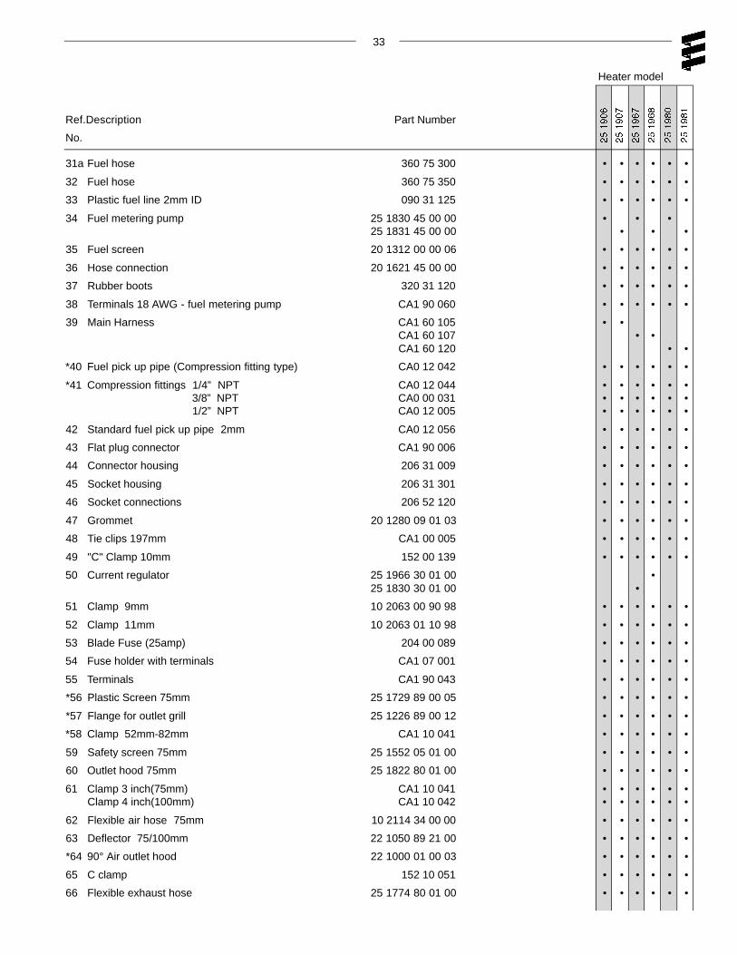
33
Ref.Description Part Number
No.
Heater model
31a Fuel hose 360 75 300 • • • • • •
32 Fuel hose 360 75 350 • • • • • •
33 Plastic fuel line 2mm ID 090 31 125 • • • • • •
34 Fuel metering pump 25 1830 45 00 00 • • •25 1831 45 00 00 • • •
35 Fuel screen 20 1312 00 00 06 • • • • • •
36 Hose connection 20 1621 45 00 00 • • • • • •
37 Rubber boots 320 31 120 • • • • • •
38 Terminals 18 AWG - fuel metering pump CA1 90 060 • • • • • •
39 Main Harness CA1 60 105 • •CA1 60 107 • •CA1 60 120 • •
*40 Fuel pick up pipe (Compression fitting type) CA0 12 042 • • • • • •
*41 Compression fittings 1/4” NPT CA0 12 044 • • • • • •3/8” NPT CA0 00 031 • • • • • •1/2” NPT CA0 12 005 • • • • • •
42 Standard fuel pick up pipe 2mm CA0 12 056 • • • • • •
43 Flat plug connector CA1 90 006 • • • • • •
44 Connector housing 206 31 009 • • • • • •
45 Socket housing 206 31 301 • • • • • •
46 Socket connections 206 52 120 • • • • • •
47 Grommet 20 1280 09 01 03 • • • • • •
48 Tie clips 197mm CA1 00 005 • • • • • •
49 "C" Clamp 10mm 152 00 139 • • • • • •
50 Current regulator 25 1966 30 01 00 •25 1830 30 01 00 •
51 Clamp 9mm 10 2063 00 90 98 • • • • • •
52 Clamp 11mm 10 2063 01 10 98 • • • • • •
53 Blade Fuse (25amp) 204 00 089 • • • • • •
54 Fuse holder with terminals CA1 07 001 • • • • • •
55 Terminals CA1 90 043 • • • • • •
*56 Plastic Screen 75mm 25 1729 89 00 05 • • • • • •
*57 Flange for outlet grill 25 1226 89 00 12 • • • • • •
*58 Clamp 52mm-82mm CA1 10 041 • • • • • •
59 Safety screen 75mm 25 1552 05 01 00 • • • • • •
60 Outlet hood 75mm 25 1822 80 01 00 • • • • • •
61 Clamp 3 inch(75mm) CA1 10 041 • • • • • •Clamp 4 inch(100mm) CA1 10 042 • • • • • •
62 Flexible air hose 75mm 10 2114 34 00 00 • • • • • •
63 Deflector 75/100mm 22 1050 89 21 00 • • • • • •
*64 90° Air outlet hood 22 1000 01 00 03 • • • • • •
65 C clamp 152 10 051 • • • • • •
66 Flexible exhaust hose 25 1774 80 01 00 • • • • • •
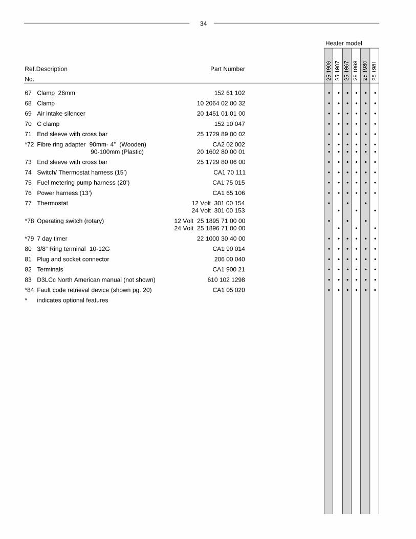
34
Heater model
67 Clamp 26mm 152 61 102 • • • • • •
68 Clamp 10 2064 02 00 32 • • • • • •
69 Air intake silencer 20 1451 01 01 00 • • • • • •
70 C clamp 152 10 047 • • • • • •
71 End sleeve with cross bar 25 1729 89 00 02 • • • • • •
*72 Fibre ring adapter 90mm- 4” (Wooden) CA2 02 002 • • • • • •90-100mm (Plastic) 20 1602 80 00 01 • • • • • •
73 End sleeve with cross bar 25 1729 80 06 00 • • • • • •
74 Switch/ Thermostat harness (15’) CA1 70 111 • • • • • •
75 Fuel metering pump harness (20’) CA1 75 015 • • • • • •
76 Power harness (13’) CA1 65 106 • • • • • •
77 Thermostat 12 Volt 301 00 154 • • •24 Volt 301 00 153 • • •
*78 Operating switch (rotary) 12 Volt 25 1895 71 00 00 • • •24 Volt 25 1896 71 00 00 • • •
*79 7 day timer 22 1000 30 40 00 • • • • • •
80 3/8” Ring terminal 10-12G CA1 90 014 • • • • • •
81 Plug and socket connector 206 00 040 • • • • • •
82 Terminals CA1 900 21 • • • • • •
83 D3LCc North American manual (not shown) 610 102 1298 • • • • • •
*84 Fault code retrieval device (shown pg. 20) CA1 05 020 • • • • • •
* indicates optional features
Ref.Description Part Number
No.
Service History Notes
Serial N°:________________________ Date installed:_______________________
Model N°:________________________
Date Service Details
1st. Printing - November 1998
Printed in Canada
P/N: 610-102-1298
Espar Products, Inc.
6435 Kestrel RoadMississauga, Ontario
Canada L5T 1Z8
17672 N. Laurel Park DriveSuite 400E
Livonia, MichiganUnited States48152-3984
Canada (Tel): 905-670-0960800-668-5676
Fax: 905-670-0728
U.S. (Tel): 800-387-4800
A member of the Worldwide Eberspächer GmbH Group of Companies
Related Documents