D1U54P-W-1200-12-HxxPC Series 54mm 1U Front End AC-DC Power Supply Converter D1U54P-W-1200-12-HxxPC.B02 Page 1 of 9 . www.murata-ps.com/support www.murata-ps.com/en/3d/acdc.html www.murata-ps.com/en/3d/acdc.html www.murata-ps.com/en/3d/acdc.html www.murata-ps.com/en/3d/acdc.html www.murata-ps.com/en/3d/acdc.html www.murata-ps.com/en/3d/acdc.html PRODUCT OVERVIEW The D1U54P-W-1200-12-HxxPC series are very high efficiency 1200 watt, power factor corrected front end supply with a 12V main output and a 5V or 3.3V (3A) standby. They have active current sharing and up to 8 supplies may be operated in parallel. The supply may be hot plugged; recovers from overtemperature faults, and has status LEDs on the front panel in addition to logic and PMBus™ status signals. The low profile 1U package and >28W/cubic inch power density make it ideal for delivering reliable, efficient power to servers, workstations, storage systems and other 12V distributed power systems ORDERING GUIDE Part Number Power Output Main Output Standby Output Airflow IEC 320-C16 Input Connector Option 200-240Vac 100-120Vac D1U54P-W-1200-12-HC4PC 1200W 1100W 12Vdc 3.3Vdc Back to Front D1U54P-W-1200-12-HA4PC 5Vdc HA4PTC 1 D1U54P-W-1200-12-HC3PC 3.3Vdc Front to Back D1U54P-W-1200-12-HA3PC 5Vdc HA3PTC 1 1. Refer to Pg. 9 for alternate input connector (HAxPTC) 2. The HAxPC variants are certified for compliance to 80 PLUS ® INPUT CHARACTERISTICS Parameter Conditions Min. Nom. Max. Units Input Voltage Operating Range 90 115/230 264 Vac Input Frequency 47 50/60 63 Hz Turn-on Input Voltage Ramp up 80 85 89 Vac Turn-off Input Voltage Ramp down 65 73 78 Maximum current at Vin = 100Vac 1100W 12 Arms Inrush Current Cold start between 0 to 200msec 25 Apk Power Factor At 230Vac, full load 0.99 Efficiency (230Vac) excluding fan load 20% load 90 % 50% load 94 100% load 91 OUTPUT VOLTAGE CHARACTERISTICS Nominal Output Voltage Parameter Conditions Min. Typ. Max. Units 12V Nominal Output Voltage 12 Vdc Output Set Point Accuracy 50% load; Tamb =25°C -0.5 +0.5 % Line and Load Regulation -1.0 +1.0 Ripple Voltage & Noise 3 20MHz Bandwidth 150 mV p-p Output Current (230Vac) 5 100 A Output Current (120Vac) 5 90 Load Capacitance 0 30,000 μF 3.3VSB Nominal Output Voltage 3.3 Vdc Line and Load Regulation 3.14 3.46 Ripple Voltage & Noise 3 20MHz Bandwidth 75 mV p-p Output Current 0 3 A Load Capacitance 0 1000 μF 5VSB Nominal Output Voltage 5.0 Vdc Line and Load Regulation 4.76 5.24 Ripple Voltage & Noise 12 20MHz Bandwidth 75 mV p-p Output Current 0 3 A Load Capacitance 0 1000 μF 3 Ripple and noise are measured with 0.1 μF of ceramic capacitance and 10 μF of tantalum capacitance on each of the power supply outputs. A short coaxial cable with 50Ω scope termination is used. FEATURES 1200W output power 80 PLUS ® Platinum efficiency 12V main output 3.3V and 5V standby output 1U height: 2.15" x 12.65" x 1.57" >28 Watts per cubic inch density N+1 redundancy capable, including hot plugging (up to 8 in parallel) Active current sharing on 12V main output; both outputs contain ORing FET isolation Overvoltage, overcurrent, overtemperature protection Internal cooling fan (variable speed) PMBus™ / I²C interface with status indicators RoHS compliant Two-year warranty Available now at: www.murata-ps.com/en/3d/acdc.html For full details go to www.murata-ps.com/rohs

Welcome message from author
This document is posted to help you gain knowledge. Please leave a comment to let me know what you think about it! Share it to your friends and learn new things together.
Transcript
D1U54P-W-1200-12-HxxPC Series 54mm 1U Front End AC-DC Power Supply Converter
www.murata-ps.com/support
D1U54P-W-1200-12-HxxPC.B02 Page 1 of 9
.
www.murata-ps.com/support
www.murata-ps.com/en/3d/acdc.html www.murata-ps.com/en/3d/acdc.html www.murata-ps.com/en/3d/acdc.html www.murata-ps.com/en/3d/acdc.html www.murata-ps.com/en/3d/acdc.html www.murata-ps.com/en/3d/acdc.html
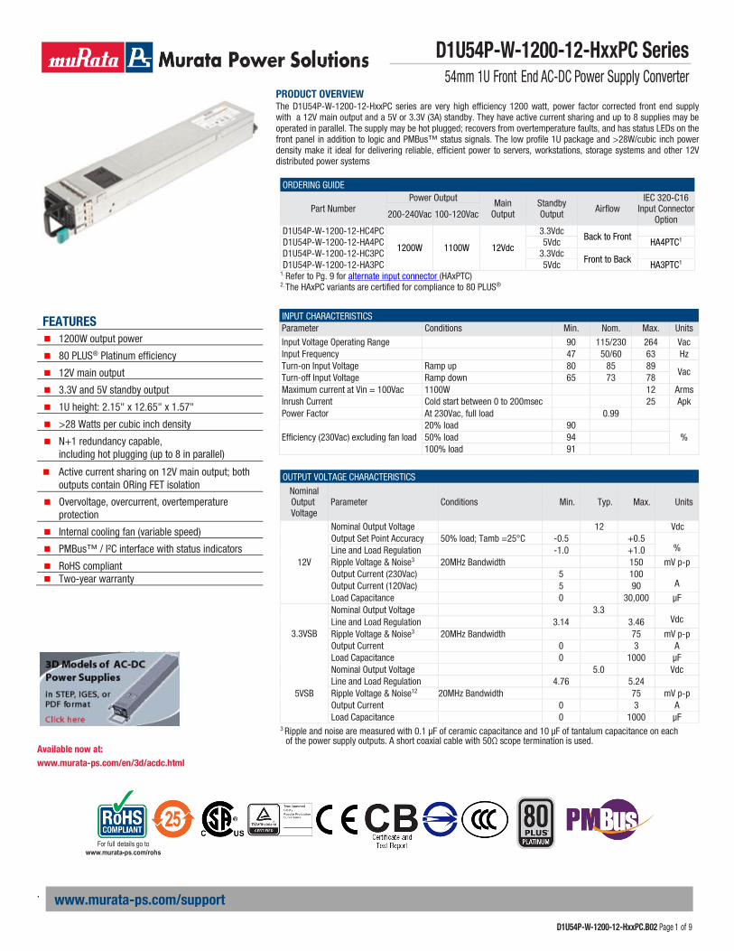
PRODUCT OVERVIEW The D1U54P-W-1200-12-HxxPC series are very high efficiency 1200 watt, power factor corrected front end supply with a 12V main output and a 5V or 3.3V (3A) standby. They have active current sharing and up to 8 supplies may be operated in parallel. The supply may be hot plugged; recovers from overtemperature faults, and has status LEDs on the front panel in addition to logic and PMBus™ status signals. The low profile 1U package and >28W/cubic inch power density make it ideal for delivering reliable, efficient power to servers, workstations, storage systems and other 12V distributed power systems
ORDERING GUIDE
Part Number Power Output Main
Output Standby Output Airflow
IEC 320-C16 Input Connector
Option 200-240Vac 100-120Vac
D1U54P-W-1200-12-HC4PC
1200W 1100W 12Vdc
3.3Vdc Back to Front
D1U54P-W-1200-12-HA4PC 5Vdc HA4PTC1
D1U54P-W-1200-12-HC3PC 3.3Vdc Front to Back
D1U54P-W-1200-12-HA3PC 5Vdc HA3PTC1
1. Refer to Pg. 9 for alternate input connector (HAxPTC) 2. The HAxPC variants are certified for compliance to 80 PLUS®
INPUT CHARACTERISTICS Parameter Conditions Min. Nom. Max. Units
Input Voltage Operating Range 90 115/230 264 Vac Input Frequency 47 50/60 63 Hz Turn-on Input Voltage Ramp up 80 85 89
Vac Turn-off Input Voltage Ramp down 65 73 78 Maximum current at Vin = 100Vac 1100W 12 Arms Inrush Current Cold start between 0 to 200msec 25 Apk Power Factor At 230Vac, full load 0.99
Efficiency (230Vac) excluding fan load 20% load 90
% 50% load 94 100% load 91
OUTPUT VOLTAGE CHARACTERISTICS
Nominal Output Voltage
Parameter Conditions Min. Typ. Max. Units
12V
Nominal Output Voltage 12 Vdc Output Set Point Accuracy 50% load; Tamb =25°C -0.5 +0.5
% Line and Load Regulation -1.0 +1.0 Ripple Voltage & Noise3
20MHz Bandwidth 150 mV p-p Output Current (230Vac) 5 100
A Output Current (120Vac) 5 90 Load Capacitance 0 30,000 μF
3.3VSB
Nominal Output Voltage 3.3
Vdc Line and Load Regulation 3.14 3.46 Ripple Voltage & Noise3
20MHz Bandwidth 75 mV p-p Output Current 0 3 A Load Capacitance 0 1000 μF
5VSB
Nominal Output Voltage 5.0 Vdc Line and Load Regulation 4.76 5.24 Ripple Voltage & Noise12 20MHz Bandwidth 75 mV p-p Output Current 0 3 A Load Capacitance 0 1000 μF
3 Ripple and noise are measured with 0.1 μF of ceramic capacitance and 10 μF of tantalum capacitance on each of the power supply outputs. A short coaxial cable with 50Ω scope termination is used.
FEATURES 1200W output power
80 PLUS® Platinum efficiency
12V main output
3.3V and 5V standby output
1U height: 2.15" x 12.65" x 1.57"
>28 Watts per cubic inch density
N+1 redundancy capable, including hot plugging (up to 8 in parallel)
Active current sharing on 12V main output; both outputs contain ORing FET isolation
Overvoltage, overcurrent, overtemperature protection
Internal cooling fan (variable speed)
PMBus™ / I²C interface with status indicators
RoHS compliant Two-year warranty
Available now at: www.murata-ps.com/en/3d/acdc.html
For full details go to www.murata-ps.com/rohs
D1U54P-W-1200-12-HxxPC Series 54mm 1U Front End AC-DC Power Supply Converter
www.murata-ps.com/support
D1U54P-W-1200-12-HxxPC.B02 Page 2 of 9
.
www.murata-ps.com/support
OUTPUT CHARACTERISTICS Parameter Conditions Min. Typ. Max. Units Startup Time AC ramp up 3 s
Transient Response 12V, 50% load step, 1A/μs di/dt ±5
% VSB, 50% load step, 1A/μs di/dt ±5
Current sharing accuracy (up to 8 in parallel)1
At 100% load
±7
%
Hot Swap Transients All outputs remain in regulation 5 % Holdup Time 100% load 12 ms
ENVIRONMENTAL CHARACTERISTICS Parameter Conditions Min. Typ. Max. Units Storage Temperature Range -40 70
°C Operating Temperature Range 0 60
Operating Humidity Noncondensing 5 90 % Storage Humidity 5 95
Altitude (without derating at 40°C) 3000 m Shock 30G non-operating Operational Vibration Sine sweep; 5-150Hz, 2G;
random vibration, 5-500Hz, 1.11G MTBF Per Telcordia SR-332 M1C1 @40°C 529K hrs
Safety Approval Standards
CAN/CSA C22.2 No 60950-1-07, Amendment 1:2011, Amendment 2:2014 (MOD) ANSI/UL 60950-1-2014 IEC60950-1:2005 (2nd ED.)+A1:2009+A2:2013 EN60950-1:2006+A11+A1+A12+A2 CCC GB4943.1-2011, GB9254-2008, GB17625. 1-2012 BSMI CNS14336-1; CNS13438
Input Fuse Power Supply has internal 15A/250V fast blow fuse on the AC line input Weight 2.43 lbs (1.10 kg)
PROTECTION CHARACTERISTICS
Output Voltage Parameter Conditions Min. Typ. Max. Units
Overtemperature (intake) Autorestart 70 80 °C
12V
Overvoltage Latching 13 14 V Overcurrent At 220Vac Hiccup 105 120 A Overcurrent At 110Vac4 Hiccup 99 117 A
3.3VSB Overvoltage Latching 3.6 4.0 V Overcurrent Hiccup 3.3 4.5 A
5VSB
Overvoltage Latching 5.4 6.0 V Overcurrent Hiccup 3.3 4.5 A
4 An output overload condition that caused the input current to exceed 13Aac shall initiate a latching shutdown. It will be necessary to recycle the ac input source in order to clear the latched condition.
ISOLATION CHARACTERISTICS Parameter Conditions Min. Typ. Max. Units
Insulation Safety Rating / Test Voltage
Input to Output - Reinforced 3000 Vrms Input to Chassis - Basic 1500 Vrms
Isolation Output to Chassis 500 Vdc
D1U54P-W-1200-12-HxxPC Series 54mm 1U Front End AC-DC Power Supply Converter
www.murata-ps.com/support
D1U54P-W-1200-12-HxxPC.B02 Page 3 of 9
.
www.murata-ps.com/support
STATUS INDICATORS AND CONTROL SIGNALS GREEN AMBER
Condition LED Status (Power) LED Status (Fault) Standby - ON; Main output - OFF; AC PRESENT Blinking green Off Standby - ON; Main output - ON Solid green Off Main output overcurrent, undervoltage, overvoltage Off On FAN_FAULT; overtemperature; standby overcurrent, undervoltage Off On No AC Power Off Off Power Supply Warning Event Off Blinking
STATUS AND CONTROL SIGNALS
Signal Name I/O Description Interface Details
ACOK (AC Source)
Output The signal output is driven high when input source is available and within acceptable limits. The output is driven low to indicate loss of input power.
Pulled up internally via 10K to VDD4
A logic high >2.0Vdc A logic low <0.8Vdc Driven low by internal CMOS buffer (open drain output).
PWOK (Output OK) Output
The signal is asserted, driven high, by the power supply to indicate that all outputs are valid. If any of the outputs fail then this output will be hi-Z or driven low. The output is driven low to indicate that the Main output is outside of lower limit of regulation (11.4Vdc).
Pulled up internally via 10K to VDD4
A logic high >2.0Vdc A logic low <0.8Vdc Driven low by internal CMOS buffer (open drain output).
SMB_ALERT (FAULT/ WARNING)
Output
The signal output is driven low to indicate that the power supply has detected a warning or fault and is intended to alert the system. This output must be driven high when the power is operating correctly (within specified limits). The signal will revert to a high level when the warning/fault stimulus (that caused the alert) is removed.
Pulled up internally via 10K to VDD4
A logic high >2.0Vdc A logic low <0.8Vdc Driven low by internal CMOS buffer (open drain output).
PRESENT_L (Power Supply Absent)
Output
The signal is used to detect the presence (installed) of a PSU by the host system. The signal is connected to PSU logic SGND within the power module.
Passive connection to +VSB_Return. A logic low <0.8Vdc
PS_ON (Power Supply Enable/Disable
Input
This signal is pulled up internally to the internal housekeeping supply (within the power supply). The power supply main 12Vdc output will be enabled when this signal is pulled low to +VSB_Return. In the low state the signal input shall not source more than 1mA of current. The 12Vdc output will be disabled when the input is driven higher than 2.4V, or open circuited. Cycling this signal shall clear latched fault conditions.
Pulled up internally via 10K to VDD4
PSKILL Input
This signal is used during hot swap to disable the main output during hot swap extraction. The input is pulled up internally to the internal housekeeping supply (within the power supply). The signal is provided on a short (lagging pin) and should be connected to +VSB_ Return.
A logic high >2.0Vdc
APS (Address Select)
Input
An analog input that is used to set the address of the internal slave devices (EEPROM and microprocessor) used for digital communications. Connection of a suitable resistor, to +VSB_Return, in conjunction with an internal resistor divider chain, will configure the required address.
DC voltage between the limits of 0 and VDD4
SCL (Serial Clock)
Both
A serial clock line compatible with PMBusTM Power Systems Management Protocol Part 1 – General Requirements Rev 1.1. No additional internal capacitance is added that would affect the speed of the bus. The signal is provided with a series isolator device to disconnect the internal power supply bus in the event that the power module is unpowered.
VIL is 0.8V maximum VOL is 0.4V maximum when sinking 3mA VIH is 2.1V minimum
SDA (Serial Data)
Both
A serial data line compatible with PMBusTM Power Systems Management Protocol
Part 1 – General Requirements Rev 1.1. The signal is provided with a series isolator device to disconnect the internal power supply bus in the event that the power module is unpowered.
VIL is 0.8V maximum VOL is 0.4V maximum when sinking 3mA VIH is 2.1V minimum
4VDD is an internal voltage rail derived from VSB and an internal housekeeping rail (“diode ORed” together) and is compatible with the voltage tolerances of VSB).
D1U54P-W-1200-12-HxxPC Series 54mm 1U Front End AC-DC Power Supply Converter
www.murata-ps.com/support
D1U54P-W-1200-12-HxxPC.B02 Page 4 of 9
.
www.murata-ps.com/support
STATUS AND CONTROL SIGNALS CONTINUED
V1_SENSE V1SENSE_RTN
Input
Remote sense connections intended to be connected at and sense the voltage at the point of load. The voltage sense will interact with the internal module regulation loop to compensate for voltage drops due to connection resistance between the output connector and the load. If remote sense compensation is not required then the voltage can be configured for local sense by: V1_SENSE directly connected to power blades 6 to 10 (inclusive) V1_SENSE_RTN directly connected to power blades 1 to 5 (inclusive)
Compensation for up to 0.12Vdc total connection drop (output and return connections).
ISHARE Bi-Directional Analogue Bus
The current sharing signal is connected between sharing units (forming an ISHARE bus). It is an input and/or an output (bi-directional analog bus) as the voltage on the line controls the current share between sharing units. A power supply will respond to a change in this voltage but a power supply can also change the voltage depending on the load drawn from it. On a single unit the voltage on the pin (and the common ISHARE bus would read approximately 8VDC at 100% load (module capability). For two identical units sharing the same 100% load this would read approximately 4VDC for perfect current sharing (i.e. 50% module load capability per unit).
Analogue voltage: +8V maximum; 4K to +12V_RTN
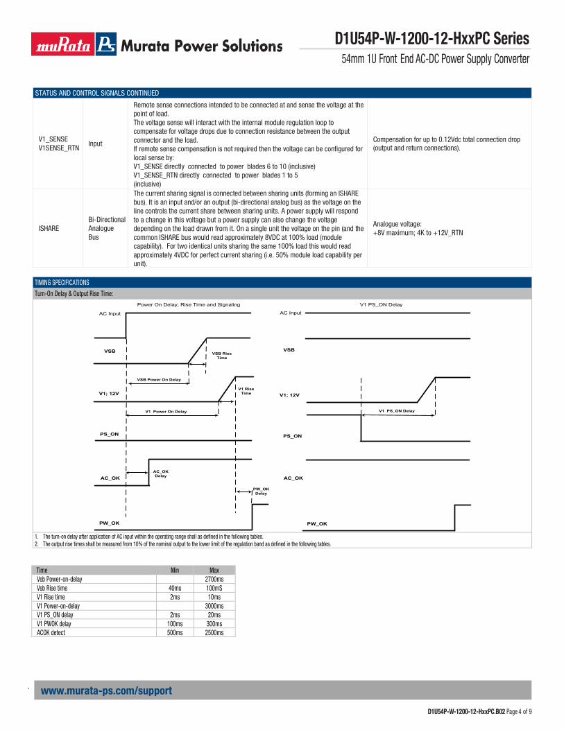
TIMING SPECIFICATIONS
Turn-On Delay & Output Rise Time:
V1 PS_ON Delay
V1 Rise Time
PW_OK Delay
AC_OK Delay
V1 Power On Delay
VSB Rise Time
VSB Power On Delay
VSBVSB
AC Input AC Input
V1; 12V
PS_ON
AC_OK
PS_ON
AC_OK
PW_OK PW_OK
V1 PS_ON DelayPower On Delay; Rise Time and Signaling
V1; 12V
1. The turn-on delay after application of AC input within the operating range shall as defined in the following tables. 2. The output rise times shall be measured from 10% of the nominal output to the lower limit of the regulation band as defined in the following tables.
Time Min Max Vsb Power-on-delay 2700ms Vsb Rise time 40ms 100mS V1 Rise time 2ms 10ms V1 Power-on-delay 3000ms V1 PS_ON delay 2ms 20ms V1 PWOK delay 100ms 300ms ACOK detect 500ms 2500ms

D1U54P-W-1200-12-HxxPC Series 54mm 1U Front End AC-DC Power Supply Converter
www.murata-ps.com/support
D1U54P-W-1200-12-HxxPC.B02 Page 5 of 9
.
www.murata-ps.com/support
TIMING SPECIFICATIONS Turn-Off (Shutdown by PS_ON)
Turn Off Fall Time and Signaling
V1 PS_OFF Delay
V1 Falltime
PWOK delayoff
AC Input
VSB
V1; 12V
PS_ON
AC_OK
PW_OK
Turn-Off Timing Min Max Notes
V1 Fall time - - Must be monotonic V1 PS_OFF delay 0ms 5ms PW_OK delay off 1.0ms
1. Note this characteristic is applicable for the main 12Vdc output shutdown from PS_ON pulled high.
TIMING SPECIFICATIONS Power Removal Holdup
Power Removal Timing Min Max Notes Vsb holdup 40ms - V1 holdup (Effective Total) 12ms - 100% load AC fail detect - 40ms PWOK delay off 1.0ms 100% load PWOK Hold Up 11.0ms 100% load
EMISSIONS AND IMMUNITY Characteristic Standard Compliance Input Current Harmonics IEC/EN 61000-3-2 Complies Voltage Fluctuation and Flicker IEC/EN 61000-3-3 Complies Conducted Emissions FCC 47 CFR Part 15/CISPR 22/EN55022 Class A with 6dB margin ESD Immunity IEC/EN 61000-4-2 Level 4 criteria A Radiated Field Immunity IEC/EN 61000-4-3 Level 3 criteria B Electrical Fast Transients/Burst I it
IEC/EN 61000-4-4 Level 3 criteria B Surge Immunity IEC/EN 61000-4-5 Level 3 criteria A RF Conducted Immunity IEC/EN 61000-4-6 Level 3 criteria A Magnetic Field Immunity IEC/EN 61000-4-8 3 A/m criteria B
Voltage Dips, Interruptions IEC/EN 61000-4-11 230Vin, 100% load, Phase 0°, Dip 100% Duration 10ms (A) 230Vin, 50% load, Phase 0°, Dip 100% Duration 20ms (VSB:A, V1:B) 230Vin, 100% load, Phase 0°, Dip 100% Duration > 20ms (VSB, V1:B)

D1U54P-W-1200-12-HxxPC Series 54mm 1U Front End AC-DC Power Supply Converter
www.murata-ps.com/support
D1U54P-W-1200-12-HxxPC.B02 Page 6 of 9
.
www.murata-ps.com/support
Main
Out
put c
urre
nt (A
dc)
Main
Out
put c
urre
nt (A
dc)
Main
Out
put c
urre
nt (A
dc)
DERATING CURVES
110
100
90
80
70
60
50
40
30
20
10
0
Output Current Derating vs Ambient Temperature (back to front airflow)
D1U54P-W-1200-12-Hx4PC
25 30 35 40 45 50 55 60
Ambient Temperature (˚ C)
90 Vac
115 Vac
120 Vac
180 Vac
105
100
95
90
85
80
75
70
65
60
Output Current Derating vs Ambient Temperature (back to front airflow) D1U54P-W-1200 -12- HA4PTC (with C16 AC Input Connector)
25 30 35 40 45 50 55 60
Ambient Temperature (˚ C)
90 Vac
115 Vac
120 Vac
180 Vac
105
100
95
90
85
80
75
70
65
60
Output Current Derating vs Ambient Temperature (front to back airflow)
All Models
25 30 35 40 45 50 55 60
Ambient Temperature (˚ C)
90 Vac
115 Vac
120 Vac
180 Vac

D1U54P-W-1200-12-HxxPC Series 54mm 1U Front End AC-DC Power Supply Converter
www.murata-ps.com/support
D1U54P-W-1200-12-HxxPC.B02 Page 7 of 9
.
www.murata-ps.com/support
OUTPUT CONNECTOR AND SIGNAL SPECIFICATION
E1
E2
E3
E4
E5
1
2
3
4
5
6
7
8
9
10
D1
D2
D3
D4
D5
C1
C2
C3
C4
C5
B1
B2
B3
B4
B5
A1
A2
A3
A4
A5
PIN ASSIGNMENTS - D1U54P-W-1200-12-HxxPC Tyco PN 1926734-2 (Power Supply) Pin Signal Name Comments 6, 7, 8, 9, 10 V1 + 12V main output 1, 2, 3, 4, 5 PGND + 12V main output return A1 VSB Standby output B1 VSB Standby output C1 VSB Standby output D1 VSB Standby output E1 VSB Standby output A2 VSB_return Standby return B2 VSB_return Standby return C2 unused D2 unused E2 unused
A3
APS I2C address and protocol selection, (select by a pull down resistor)
B3 unused C3 SDA I2C data signal line D3 V1_SENSE_R - Remote Sense return E3 V1_SENSE + Remote Sense A4 SCL I2C clock signal line B4 PS_ON Remote On/Off C4 SMB_ALERT I2C alert signal D4 unused E4 ACOK AC input OK A5 PSKILL Power supply kill, short pin B5 ISHARE Current share bus, short pin C5 PWOK Power OK, short pin D5 unused E5 PRESENT_L Power supply present, short pin
MATING CONNECTOR Part Number Description
Tyco Electronics 2-1926739-5 Right Angle

D1U54P-W-1200-12-HxxPC Series 54mm 1U Front End AC-DC Power Supply Converter
www.murata-ps.com/support
D1U54P-W-1200-12-HxxPC.B02 Page 8 of 9
.
www.murata-ps.com/support
WIRING DIAGRAM FOR OUTPUT
Dotted lines show optional remote sense connections. Optional remote sense lines can be attached to a load that is a distance away from the power supply to improve regulation at the load.
V1_SENSE (Main Output Remote Sense)
V1_SENSE (Main Output Remote Sense)
E3
6-10
+12V main output +12V main output 6-10 E3
D1U54P 12V load
D1U54P
1-5
D3
B5 (or D4)
+12V main output return V1_SENSE_R
ISHARE
+12V main output return
V1_SENSE_R
ISHARE
1-5
D3 B5 (or D4)
A1,B1,C1,D1,E1 VSB VSB A1,B1,C1,D1,E1
B4 PS_ON
FET, BJT, wire or switch (debounced )
VSB load
PS_ON B4
A2,B2 VSB_return to turn on +12V main output VSB_return A2,B2
A5 (or A3) PS_KILL PS_KILLA5 (or A3)
CURRENT SHARING NOTES
1. Main Output current sharing is achieved using the active current share method. (See wiring diagram for connection
details.) Current sharing can be achieved with or without remote sense connected to the common load.
2. +VSB outputs can be tied together for redundancy but total combined output power must not exceed the rated standby power. The +VSB output has internal ORing MOSFET for additional redundancy / internal short protection.
3. The current share pin B5 (or D4 for alternate pin out model) is a connection between the units. It is input and/or output as the voltage on the line controls the current share. A power supply will respond to a change in this voltage but a power supply can also change the voltage depending on the load drawn from it. On a single unit this would read approximately 8V at 100% load. For two units sharing load then this should read approximately 4V for perfect current sharing.
4. Up to 8 units can be paralleled together. Please consult your Murata sales representative if operation with more than 8 units in parallel is needed.
5. The load for both the main 12V and the VSB rails at initial startup shall not be allowed to exceed the capability of a single unit. The load can be increased after a delay of 3sec (minimum), to allow all sharing units to achieve steady state regulation.

D1U54P-W-1200-12-HxxPC Series 54mm 1U Front End AC-DC Power Supply Converter
www.murata-ps.com/support
D1U54P-W-1200-12-HxxPC.B02 Page 9 of 9
.
www.murata-ps.com/support
MECHANICAL DIMENSIONS
AC input connector: IEC 320-C14 Alternate input connector: IEC 320-C16 (for HAxPTC models); Link back to front page Dimensions: 2.15" x 12.657" x 1.575" [54.5mm x 322.0mm x 40.0mm]
MECHANICAL DIMENSIONS OPTIONAL ACCESSORIES Description Part Number
12V D1U54P Output Connector Card D1U54P-12-CONC
APPLICATION NOTES Document Number Description Link
ACAN-44 D1U54P Output Connector Card www.murata-ps.com/data/apnotes/acan-44.pdf
ACAN-45 D1U54P-x Communication Protocol www.murata-ps.com/data/apnotes/acan-45.pdf
This product is subject to the following operating requirements
and the Life and Safety Critical Application Sales Policy: Refer to: http://www.murata-ps.com/requirements/
Murata Power Solutions, Inc. makes no representation that the use of its products in the circuits described herein, or the use of other technical information contained herein, will not infringe upon existing or future patent rights. The descriptions contained herein do not imply the granting of licenses to make, use, or sell equipment constructed in accordance therewith. Specifications are subject to change without notice. © 2016 Murata Power Solutions, Inc.
Related Documents