D-ViewCam V3.0 Video Management System D-Link HQ, January 2010 D-Link confidential

D-ViewCam V3.0 Video Management System D-Link HQ, January 2010 D-Link confidential.
Dec 24, 2015
Welcome message from author
This document is posted to help you gain knowledge. Please leave a comment to let me know what you think about it! Share it to your friends and learn new things together.
Transcript

D-ViewCam V3.0Video Management System
D-Link HQ, January 2010
D-Link confidential
Contents Market Update Product Overview Product Features Product Comparison Software Interface Overview
• Main Console• Search and add camera• Smart Guard System• Schedule System• Start Playback• E-Map• Remote Live Viewer/Remote Playback• Web Live Viewer/Web Playback• Network Service
Product Roadmap Product Application

Market Update
Source: iSuppli 2007
Global video surveillance market in 2005-2011
112%91%
81%74%
69%
55%REVENUE ($US Million)
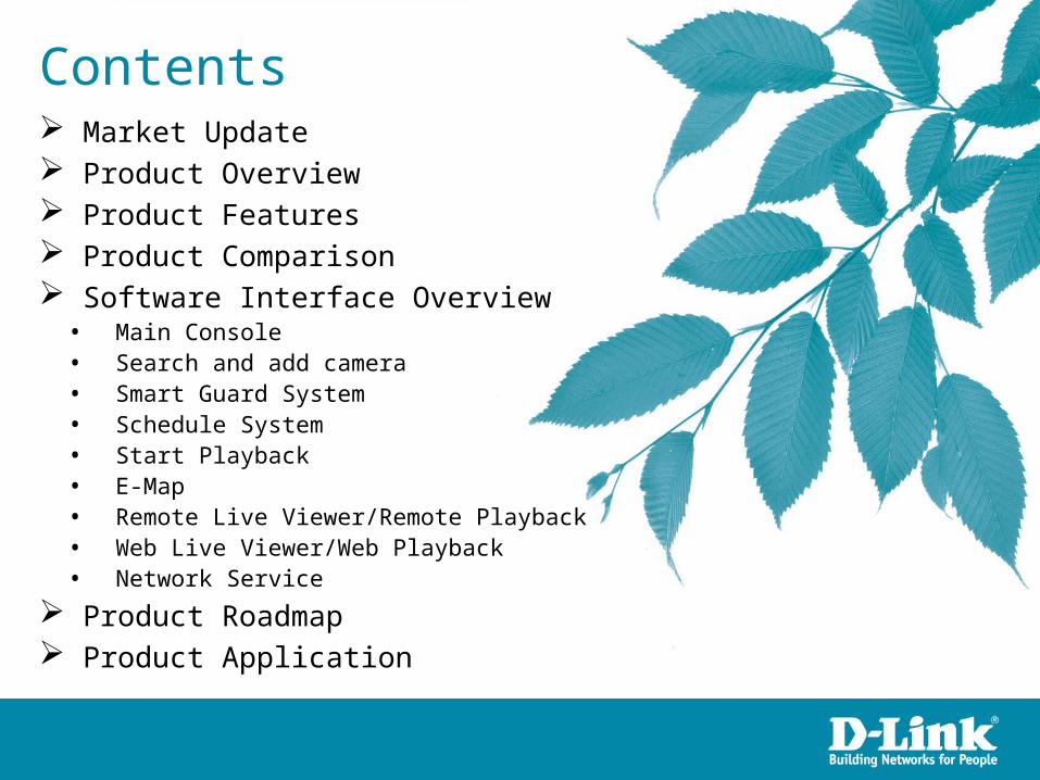
Market Update
Source: TRI 2007
REVENUE ($US Million)

MS-IE Browser Client
Remote Live Viewer/
Remote Playback
PC Client
Video/Audio Recording
Video/Audio Live View
Video/Audio Playback
Video Streaming
Audio Streaming
I/O or Event Trigger
D-ViewCam software is a video management system (VMS)- It just like DVR for CCTV system, D-ViewCam provides video/Audio recording, live view and playback management for IP camera or video server devices.
D-ViewCam Server
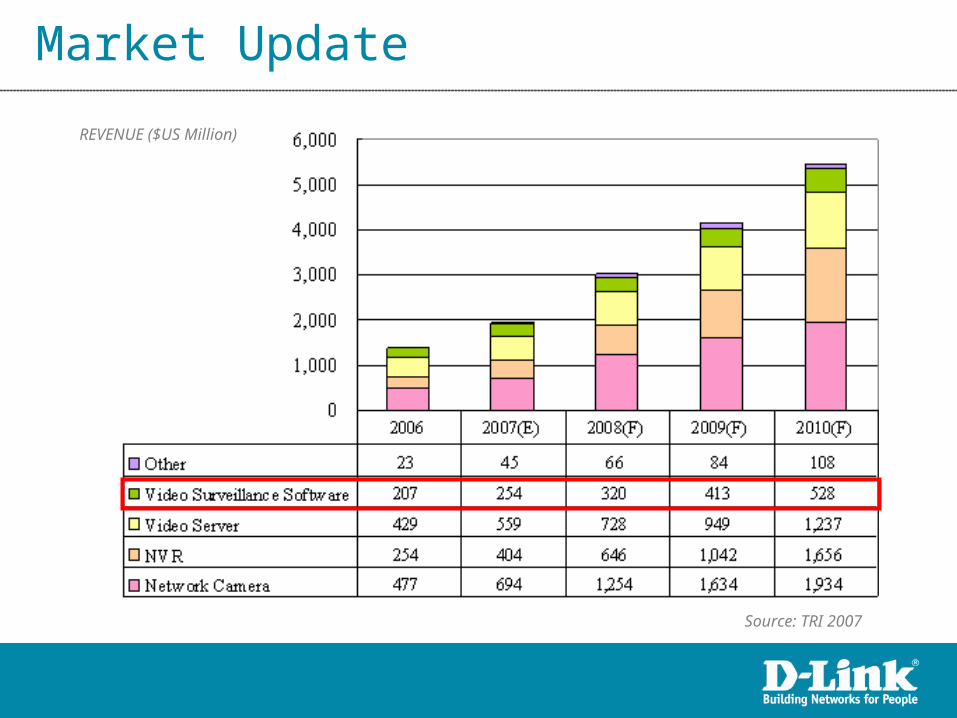
Product Overview
Remote Client
Browser (MS-IE) Client

D-ViewCam for SOHO/SMB level
D-ViewCam
• 32 channels, Free Bundle with IP Camera
• New V3.0 will replace current D-ViewCam V2.0x
• D-ViewCam V3.0 official release in January, 2010
• More stable & functions than V2.0x versions
• Support D-Link IP surveillance products, including IP Camera Video Server
Product Overview

Product Overview
D-ViewCam CVS for SMB/Enterprise level
D-ViewCam CVS
• D-ViewCam CVS V1.0 expect to release in Q1/2010
• Professional Video Management System
• Manage up to 32/64 channels
• License charge
• More Features than D-ViewCam 3.0
• Could manage other D-ViewCam CVS- Compatible with D-Link NVR- Compatible with 3rd party CMS
• Support D-Link IP surveillance products

Product Overview
D-ViewCam V3.0 HW Support List
• Pink color devices will be supported in DVC V3.01
Networkinfrastructure
IPsecurity
Videostreaming
Datastorage
Video Management
System
SystemService /Integration
Accessory
11
22
33
44
55
66
Product Overview

E D C B A
S of All Cameras
1200~600 600~480 480~240 240~120 120~Total FPS at CIF
CPU Intel Core 2Quad Q6600
Intel Core 2Duo E6400
Intel Core 2Duo E5200
Intel Core 2Duo E5200
Intel Core 2Duo E5200
RAM 2GB 1GB 1GB 512MB 512MB
Motherboard Intel G31 or above; ASUS, Gigabyte, or MSI vendor with Intel chipset recommended
Display ATi Radeon 9200, nVIDIA GeForce FX-5200, Intel945G/965G or above (ATi recommended)
Hard Drive 80GB or above
Ethernet 100-baseT or above, Gigabit LAN recommended
OS Microsoft Windows® XP Pro (SP2 or higher) / 2003 / Vista®
Minimum System Requirements
Product Overview

How to calculate S value
Product Overview
Parameter definition:
M: parameter of resolution of camera.
1 Mega-pixel : M=10
VGA or D1 resolution : M=5
CIF resolution : M=1
N: FPS of Camera
S=M*N
For example: 8 channel system
a) 1 camera at 1 Mega-pixel resolution with 10FPS
b) 2 cameras at D1 resolution with 15FPS
c) 5 cameras at CIF resolution with 30FPS
a) M=10; N=10, S=10*10=100
b) M=5; N=15, S=5*15=75
c) M=1; N=30, S=1*30=30
S of All Cam.=1*100+2*75+5*30=400
Therefore, the Minimum Hardware Requirement is C level.
C
480~240
Intel Core 2Duo E5200
1GB

How to calculate FPS value
Product Overview
If users apply Intel Core 2 Quad CPU with D-ViewCam software
and they want to calculate the FPS per channel, then it could be:
N (FPS per Channel)= S ÷ M ÷ 32
2. FPS for VGA or D1 resolution with 32 channels = 1200 ÷ 32 ÷ 5 = 7.5 FPS/Ch
It means D-ViewCam software can record at least 7.5 FPS per channel and display at
least 7.5 FPS for each channel with VGA or D1 resolution.
3. FPS for Mega-pixel resolution with 32 channels = 1200 ÷ 32 ÷ 10 = 3.75 FPS/Ch
It means D-ViewCam software can record at least 3.75 FPS per channel and display at
least 3.75 FPS for each channel with Mega-pixel resolution.
1. FPS for CIF resolution with 32 channels = 1200 ÷ 32 ÷ 1 = 37.5 FPS/Ch
It means D-ViewCam software can record 30 FPS per channel, and it can also display 30
FPS for each channel with CIF resolution.
Product Features
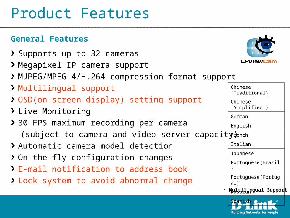
Supports up to 32 camerasMegapixel IP camera supportMJPEG/MPEG-4/H.264 compression format supportMultilingual supportOSD(on screen display) setting supportLive Monitoring30 FPS maximum recording per camera
(subject to camera and video server capacity)Automatic camera model detectionOn-the-fly configuration changesE-mail notification to address bookLock system to avoid abnormal change
General Features
Chinese (Traditional)
Chinese (Simplified )
German
English
French
Italian
Japanese
Portuguese(Brazil)
Portuguese(Portugal)
Russian
Spanish
• Multilingual Support

Product Features
User validation
User password restriction
User profiling
Access privilege control
System User Management
• User Account Setting

Product Features
Multiple storage locations support
Record by schedule
Record by event
Pre-record/Post-record support
Manual recording with up to 32 channel support
Support single way audio record of multiple channels
Record and live display at different frame rates and resolution
Video/Audio Recording
• Video Encoder

Product Features
Video playback control
Histogram quick search for video
Video Stamp
Video extract by snapshot
Video extract by AVI/ASF
Support remote playback/web playback to
play historical videos
Video Enhancement
Data Search and Playback
• Video Enhancement
Product Features
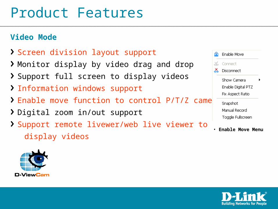
Screen division layout support
Monitor display by video drag and drop
Support full screen to display videos
Information windows support
Enable move function to control P/T/Z camera
Digital zoom in/out support
Support remote livewer/web live viewer to
display videos
Video Mode
• Enable Move Menu

Product Features
Multiple map support
Alarm notification
Customized map background support
Camera preview
Camera and I/O indicator
Map Mode
• Multiple patrol group
P/T/Z Control
Manual control
Preset positions (device dependent)
Preset patrolling
Multiple patrol group support

Product Features
Output port control
Input port trigger on event
Output port relay when event detected
I/O Feature
• I/O Device Control
Backup
Backup database for logs and videos
Import/Export configuration
DB tool
CD burning for backup videos and logs
in Windows XP

Cont …
Product Comparison between DVC V3.0 and V2.0x
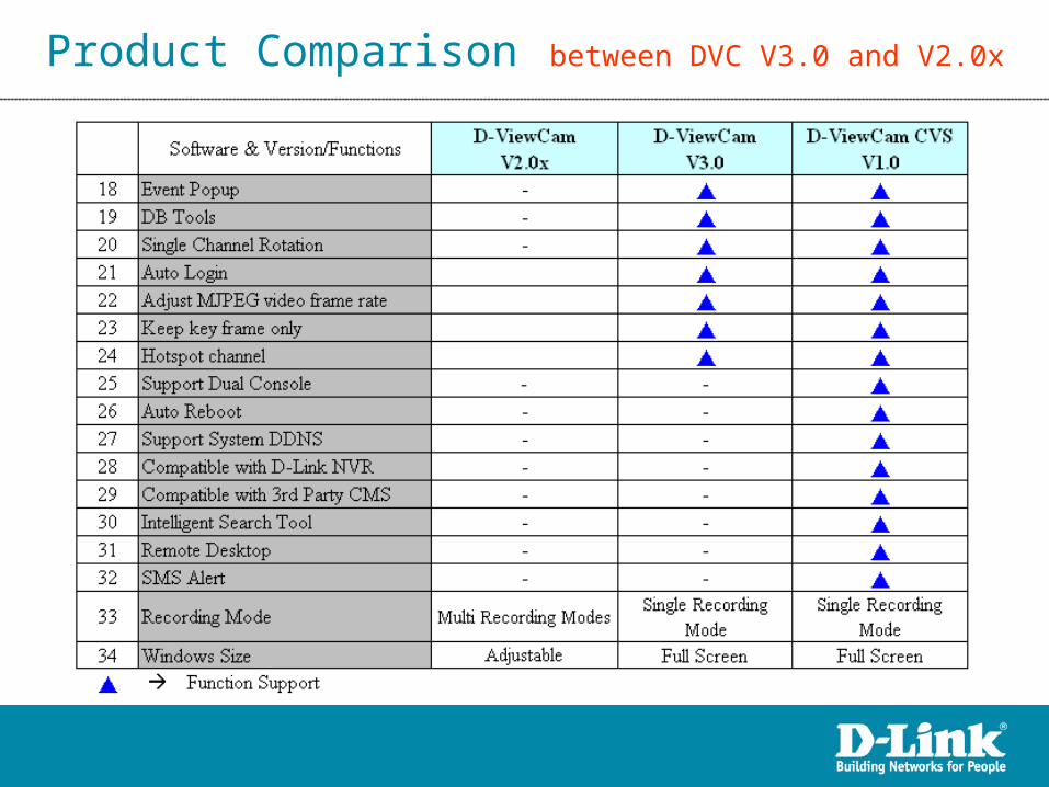
Product Comparison between DVC V3.0 and V2.0x

Cont …
Product Comparison between DVC V3.0 and DCVS V1.0

Cont …
Product Comparison between DVC V3.0 and DCVS V1.0

Product Comparison between DVC V3.0 and DCVS V1.0

Cont …
Product Comparison between NVR and DVC V3.0

Product Comparison between NVR and DVC V3.0

Cont …
Product Comparison between DVC V3.0 and Competitors

Cont …
Product Comparison between DVC V3.0 and Competitors
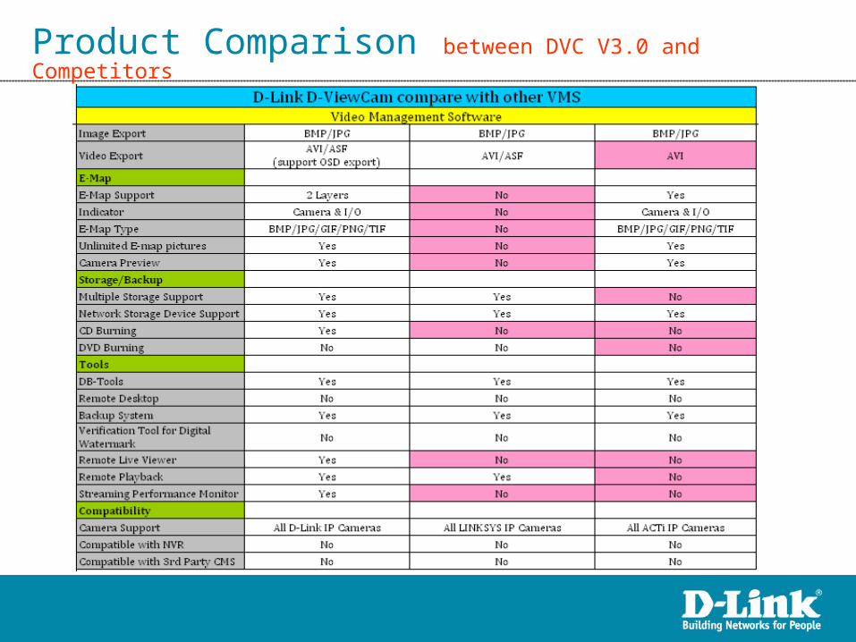
Product Comparison between DVC V3.0 and Competitors

Main Console
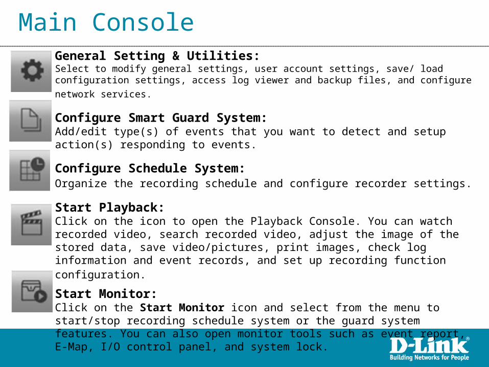
Main ConsoleGeneral Setting & Utilities:Select to modify general settings, user account settings, save/ load configuration
settings, access log viewer and backup files, and configure network services.
Configure Smart Guard System:Add/edit type(s) of events that you want to detect and setup action(s) responding to events.
Configure Schedule System:Organize the recording schedule and configure recorder settings.
Start Playback:Click on the icon to open the Playback Console. You can watch recorded video, search recorded video, adjust the image of the stored data, save video/pictures, print images, check log information and event records, and set up recording function configuration.
Start Monitor:Click on the Start Monitor icon and select from the menu to start/stop recording schedule system or the guard system features. You can also open monitor tools such as event report, E-Map, I/O control panel, and system lock.

Search and add camera
Fill in the user name and password for each IP camera found and click OK to add it to the camera list.
Note: Drag the mouse to multi-select thecameras and then insert the usernameand password. The username and password will be applied to all the selected cameras automatically.
Search: Click on the Search icon to obtain the Search IP Camera panel. The system will start scanning automatically once the panel is opened. You may manually stop scanning by clicking on the Stop Scan button.

Smart Guard System
There are 2 sources of events: 1. Camera (video image) 2. Digital Input
• Event and Action configuration

Smart Guard System – Camera Event
There are two types of events: 1. Signal Lost 2. General Motion
• Select Event Types

Smart Guard System – Digital Input Event
Step 1: Click and highlight the Digital Input on the event type list and then click the Insert Event icon.Step 2: Select the device that is connected to your camera(s).

Smart Guard System – Action
There are four types of actions: 1. On Screen Display 2. Play Sound 3. Send E-mail 4. DO Trigger
• Select Action Types

Schedule System
Adjust the Scheduled Setting
• Schedule Configuration

Schedule System
Configure schedule recording steps: 1. Load a preset mode or 2. Insert a new schedule manually or 3. Copy to other cameras after manually setup.
• Schedule Recording Configuration

Schedule System – Preset Mode
Mode Format Time Record FPS Quality Resolution
RegularM-JPEG
0:00-24:00 AlwaysMax
Max MaxMPEG-4 Max
OfficeM-JPEG
8:00-20:00 AlwaysMax
Max MaxMPEG-4 Max
ShopM-JPEG
10:00-22:00 AlwaysMax
Max MaxMPEG-4 Max
Highly SecureM-JPEG
0:00-24:00 AlwaysMax
Max MaxMPEG-4 Max
Disk SavingM-JPEG
0:00-24:00 Motion10
Max MaxMPEG-4 i-frame
MinorM-JPEG
0:00-24:00 Motion5
Max MaxMPEG-4 i-frame
• Preset mode definition
Preset modes of schedule recording:

Schedule System – Record on motion
Record on MotionSelect this option to start recording when motions are detected. Please adjust sensitivity, the frame interval and setup the detection zone to detect motion. To setup a single detection zone, left-click and drag the mouse to draw a rectangle. To setup more than one detection zones, simply repeat the same process. You may create up to 10 detection zones. Click All to select the entire detection zone.

Schedule System – Video Encoder
Keep Original Video formatSelect this option to lower the frame rate but not re-encode the video stream.
• Adjust MJPEG video frame rate:Use the slider to reduce or increase the frame rate.
Note: The maximum FPS (move the slider to the right) will be correspond with original video stream set up on camera configuration.
• Keep key-frame only: System will only record key frames of video streaming.
Note: The key frame interval is controlled by each camera manufacturer and cannot be adjusted.

Start Playback Playback windows layout

Start Playback Playback windows layout

Open Record and open Date Time search dialog
• Playback Open Record -> Date time search dialog
Start Playback

Start Playback Time Table & Show Records

Start Playback – Post Processing Tool
• Video Enhancement
Visibility: Check the option and adjust the gamma value of the image to enhance the image and make it cleaner.
Sharpen: Check the option to activate the function. Move the slider control to the right to sharpen the image, to the left to soften it.
Brightness: Check the option to activate the function. Move the slider control to the right to make the image brighter.
Contrast: Check the option to activate the function. Move the slider control to the right to increase contrast.
Grey Scale: Check the option to show the record in grey scale mode so the image displays in black and white.
Start Playback – Save Video
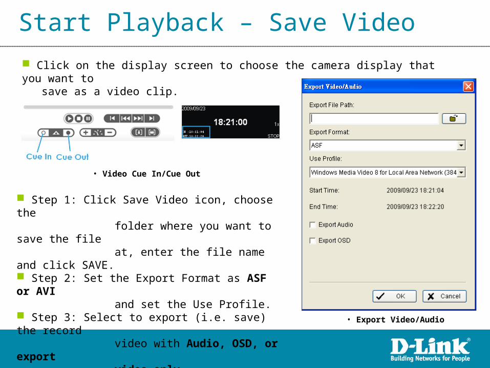
Click on the display screen to choose the camera display that you want to save as a video clip.
• Export Video/Audio
• Video Cue In/Cue Out
Step 1: Click Save Video icon, choose the folder where you want to save the file at, enter the file name and click SAVE. Step 2: Set the Export Format as ASF or AVI and set the Use Profile. Step 3: Select to export (i.e. save) the record video with Audio, OSD, or export video only. Step 4: Click OK to save the video.
Start Playback – Save Image
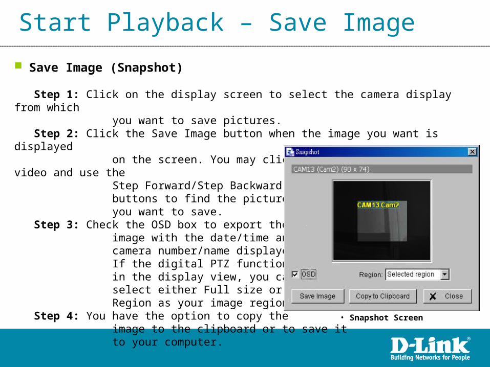
Save Image (Snapshot)
Step 1: Click on the display screen to select the camera display from which you want to save pictures. Step 2: Click the Save Image button when the image you want is displayed on the screen. You may click Pause to freeze the video and use the Step Forward/Step Backward buttons to find the picture that you want to save. Step 3: Check the OSD box to export the image with the date/time and camera number/name displayed. If the digital PTZ function is enabled in the display view, you can also select either Full size or Selected Region as your image region. Step 4: You have the option to copy the image to the clipboard or to save it to your computer.
• Snapshot Screen

Start Monitor
Option Function
Start/Stop Monitor All Click to start or stop all monitoring functions.
Start/Stop Recording Schedule Click to start or stop the recording schedule.
Start/Stop Smart Guard System Click to start or stop the smart guard system.
Open Event Report Click to open the event report which will log any events.
Open E-Map Click to open E-Map which monitors all devices with map indicators.
Open I/O Control Panel Click to open the I/O control panel which monitors the DI/DO and manual triggering the DO devices.
Lock System Click to lock the system.
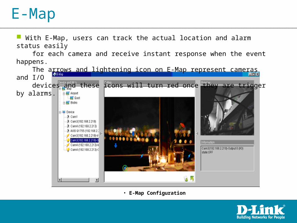
E-Map With E-Map, users can track the actual location and alarm status easily for each camera and receive instant response when the event happens. The arrows and lightening icon on E-Map represent cameras and I/O devices and these icons will turn red once they are trigger by alarms.
• E-Map Configuration

E-Map – Edit Mode
• E-Map Edit Mode
Edit Mode Users need to be in Edit Mode to activate the function buttons.
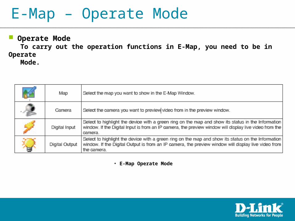
E-Map – Operate Mode
• E-Map Operate Mode
Operate Mode To carry out the operation functions in E-Map, you need to be in Operate Mode.

Remote Live Viewer
With the Remote Live Viewer console, remote users may watch up to 64 real-time video channels from remote live streaming servers.
• Remote Live Viewer Screen

Remote Live Viewer – Server Setting
Server List
• Remote Live Viewer – Server Setting

Remote Live Viewer – Group Setting
• Remote Live Viewer – Group Setting
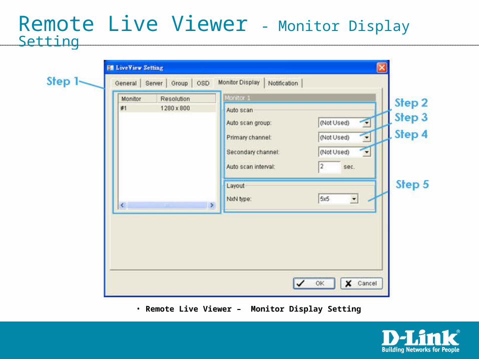
Remote Live Viewer - Monitor Display Setting
• Remote Live Viewer – Monitor Display Setting

Remote Playback
With the Remote Playback console, remote users may watch 1 historical video channels from remote D-ViewCam server.
• Remote Playback Screen

Remote Playback Open Record and Date-Time Panel
• Remote Playback Open Record -> Date Rime Panel
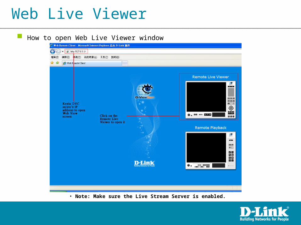
Web Live Viewer
• Note: Make sure the Live Stream Server is enabled.
How to open Web Live Viewer window

Web Live Viewer Web Live Viewer window

Web Playback How to open Remote Playback windows
• Open Remote Playback window through Web View
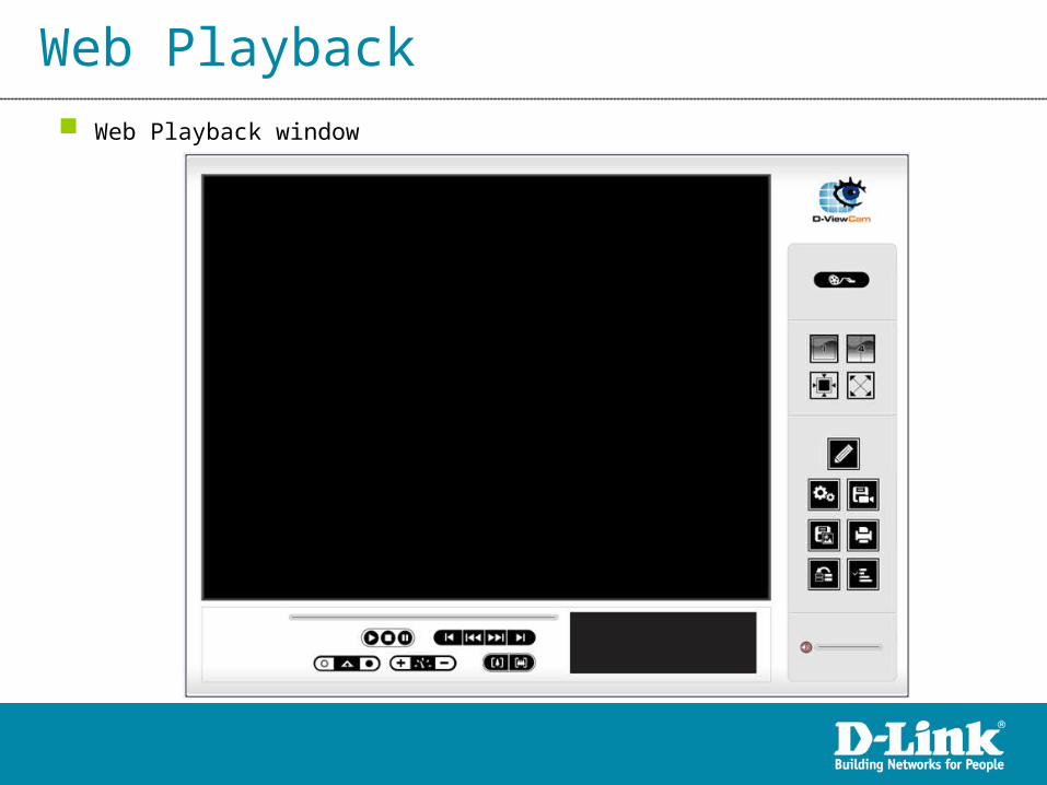
Web Playback Web Playback window

Network Service Live Streaming Server - When starting the live streaming function of computer, the system allows remote users to log in to the specific computer and view cameras that are connected to it.

Network Service Live Streaming Server - Black / White List.

Network Service Live Streaming Server – Performance Monitor.

D-V
iew
Ca
m C
VS
D-V
iew
Ca
m
Including all DCS-100 V3.0 Features
Multi-Channel Playback
Multi-Layer E-Map
Compatible with D-Link NVR
Compatible with 3rd party CMS
Intelligent search Tool
Auto Reboot
Remote Desktop
System DDNS
SMS Alert
DCS-220/230 V1.0(32ch/64ch)
Multilingual support
Web Viewer/Playback
Remote Viewer/Playback
Playback Enhancement
Access Privilege Control
Lock System
Full Screen E-map
DB Tools
CD Burning
Windows 7 O.S. support
More Languages support
Device Pack
Digital Watermark
DVD Burning
DCS-100 V3.1(32ch)
DCS-100 V3.0(32ch)
SO
HO
SM
BE
nterp
rise
Q4 / 2009 Q3 / 2010Q1 / 2010 Q2 / 2010
Available
In Development
In Plan
Product Roadmap

Product Application

Product Application

Thank You!Thank You!
Related Documents