To begin the configuration procedures To Finish the configuration prodecures and save new parameters in memory To give up all parameters you've just selected. To make all parameters back to default settings with * in this manual. COPYRIGHT ©2009,SCSC. Released Date: Oct 31, 2009 Manual P/No: SCCM - 80S-01A Interface setting Barcode setting other setting no yes yes no Thank you for purchasing the scanner. Inside each packaging box, you may find the scanner, the interface cable and user's fuide. Configuration manual might be optional for some users. If you can configure the scanner by yourself, please contact your dealer for the configuration manual. To avoid any misuse or confusion, we hightly recommend that the configuration manual must be used by an authorized dealer or experienced PC user for the proper custom setup. All printed material contained in this manual is for information only and is subject to change without notice. Reproduction of this manual, or any part of its contents. is not allowed without the prior written permission of SCSC. All software implemented in the scanner is proteced by copyright internation regulations. The scanner passes and complies with the following tests and regulations. A) Emission: EN55022 Class B B) Emission: EN55022 Class B which includes 1) IEC801-2 (ESD) Class B 2) IEC801-3 (RS) Class A 3) IEC801-4 (EFT) Class B C) CDRH class II and IEC class 2 laser product D) UL, CSA and TUV

Welcome message from author
This document is posted to help you gain knowledge. Please leave a comment to let me know what you think about it! Share it to your friends and learn new things together.
Transcript

To begin the configuration procedures
To Finish the configuration prodecures andsave new parameters in memory
To give up all parameters you've justselected.
To make all parameters back to defaultsettings with * in this manual.
COPYRIGHT ©2009,SCSC.
Released Date: Oct 31, 2009Manual P/No: SCCM - 80S-01A
Interface setting
Barcode setting
other setting
no
yes
yes
no
Thank you for purchasing the scanner. Inside each packaging
box, you may find the scanner, the interface cable and user's
fuide. Configuration manual might be optional for some users. If
you can configure the scanner by yourself, please contact your
dealer for the configuration manual.
To avoid any misuse or confusion, we hightly recommend that
the configuration manual must be used by an authorized dealer or
experienced PC user for the proper custom setup.
All printed material contained in this manual is for information
only and is subject to change without notice. Reproduction of
this manual, or any part of its contents. is not allowed without
the prior written permission of SCSC.
All software implemented in the scanner is proteced by copyright
internation regulations.
The scanner passes and complies with the following tests and
regulations.
A) Emission: EN55022 Class BB) Emission: EN55022 Class B which includes 1) IEC801-2 (ESD) Class B 2) IEC801-3 (RS) Class A 3) IEC801-4 (EFT) Class BC) CDRH class II and IEC class 2 laser productD) UL, CSA and TUV

1
TABLE OF ONTENTS2
CHAPTER 1 Using the CCD Scanner P.2
CHAPTER 2 Interface Setting
2.1 Keyboard Wedge parameters P.3
2.2 RS232C parameters P.5
CHAPTER 3
3.1 Reading Mode parameters P.9
3.2 Buzzer frequency P.11
3.3 Buzzer sound P.11
3.4 Pre-amble and Post-amble P.12
CHAPTER 4
4.1.1 CodeMark Setting P.13
4.1.2 Setting for Bar Code P.15
4.2 UPC-A code setting P.17
4.3 UPC-E code setting P.17
4.4 EAN-13 code setting P.18
4.5 EAN-8 code setting P.18
4.6 UPC/EAN Supplemental P.19
4.7 UPC/EAN Add 2/5 Lock P.19
4.8 Code 39 code setting P.19
4.9 Codabar code setting P.21
4.10 Code 93 code setting P.23
4.11 Code 128 code setting P.24
4.12 Code 2/5 code setting P.25
4.13 China Postage code setting P.28
4.14 MSI/Plessey code setting P.29
4.15 Code 4 code setting P.30
4.16 RSS code setting P.30
4.17 Code 11 code setting P.31
Appendix A. P.33
FULL ASCII TABLE & DECIMAL TABLE
APPENDIX B
CodeMark Default P.46
The CCD all default table P.47
CHAPTER 1 Using the CCD SCANNER
Troubleshooting ListThe CCD scanner automatically executes a self-testwhen the power is on. If the CCD scanner does not reada barcode label, please check the following list first.
If the barcode label is smeared or rough.●
● If the interface cable is firmly connected.
● If the power is applied.
● If the LED light is on.● If the buzzer tone is set to none.
● If the barcode label is wider than the sperture ofCCD scanner.
● Remove any visible dirt from the window of theaperture with a soft damp cloth.
● Be sure the configuration parameters of the barcodelabels, communication interface, and other optionsare properly selected.
The CCD scanner can be easily interfaced to akeyboard or a serial port to your computer. Nowfollow the procedures below for a proper installation.
On your first time installation, it is necessary to select acompatible computer type. (See the configurationmanual for the correct type.)
To install the scanner as keyboard wedge:
1)
2)
Plug the phone jack of scanner cable into yourCCD scanner.
Turn off your computer.
3)
4)
Remove the keyboard plug from our computer,plug it into the Din-5P or PS/2 female connector ofscanner cable, and then connect the Din-5P orPS/2 make connector to the keyboard port of yourcomputer.Turn on the power of computer, the red LEDindicator will light and the CCD scanner will beepto indicate a correct installation.
To install the scanner as a RS-232C device:1)
2)
Plug the phone jack of scanner cable into yourCCD scanner.Turn off your computer.
3)
4)
Plug the DB-9P female connector of serial cableinto RS-232C port on your computer.
If it is necessary, plug another end of DC jack tothe adapter.
5) Turn on the power of computer, the red LEDindicator will light and the CCD scanner will beepto indicate a correct installation.

*PC/AT & PS/2-50/60/80
Apple Macintosh
NEC 9800
PC/XT
IBM 5550
ACER 7300
3 4
CHAPTER 2 Interface Setting
There are 3 interfaces for this scanner to use, the default
interface is setting at Keyboard. The user could set any interface
that you want. Please note, only the setting of interface and your
terminal interface plug is the same, the data could be read.
Choosing the type that scanner connect with terminal.
Computer Type
Interface setting
Keyboard Wedge
RS-232
Notebook Keyboard Wedge
USB emulate PS2
2. Keyboard Layout
* US
Hong Kong
German
French
Spanish
Italy
Swiss
Swedish
* Use ALT(0-127)
3. Keyboard Upper/Lower Case
Lower
Upper
Lock at Upper
Lock at Lower
USB emulate RS232

*9600bps
4800 bps
38400 bps
2400 bps
19200 bps
57600 bps
* 8 bits
7 bits
5 6
The scanner also provides RS-232C inerface to meet your
application. Scan the label below for RS-232C interface.
RS-232C
1. Baud Rate
2. Data bit
4. Keyboard Data terminator
* Enter
None
Tab
RS-232 Pin Assignment:
DUSB-9P Female
1 N/C (=no connection)
2 TXD
5 GND
7 CTS
8 RTS
9 VCC (+5V)
DC Adapter+5v +- 10%150mA (min.)
RS-232C parameters include:
1. Baud rate
2. Data bits
3. Parity
4. Handshaking protocol
5. Character delay
6. Data terminator

RTS/CTS
Xon/Xoff
87
3. Parity
Odd
Even
4. Habdshaking
* None
Data Terminator
None
CR
LF
H Tab
STX/ETX
EOT
2 digit
Stop digit
* 1 digit
Scanner ready: The scanner will activate RTS signal right after power is on, and will transmit data upon receipt of CTS signal. Data Ready : The scanner will activate RTS signal to indicate a good read and will transmit data when receiving CTS signal.Inv. data ready: Same as scanner ready menioned above but the RTS logic is reserved.Remark: ACK/NAK and Xon/Xoff are optional.

9 10
This section allows your scanner to set other optional parameters.
These options include scanner reading modes, scanner delay
times, scanner flash mode, scanner stop mode, scanner scan,
LED indicator.
LED is always on. The barcode put in front of scanner only
decode once. Change another barcode will decode another time.
If you want to re-scan the same barcode, you have to move the
barcode away and put it in front of the scanner window side, will
do the second decode.
Mode 2 -Continuous/LED always on
Mode 1 Normal Reading Mode
Pushing the keytop, the LED is keeping on. Off the keytop or
while the scanner has a good read, the LED is off. When the
LED is off by losing the keytop, the LED will be On again while
we pushing the keytop again and ready to read decoding code.
Mode 3 - Continuous/ trigger off
LED is turned on by pressing the trigger, when the barcode put
in front of the scanner will decode, but only decode once, won't
read continuously. The read mode will be the same like Mode 2.
And when you pressing the trigger again, the LED will off and
won't read the code again. And press the 3rd time, the light will
be ON again will repeat the decode again.
Testing Reading mode
Reading off Mode
Continious/Trigger off
Reading Mode Parameters
CHAPTER 3 Other Optional Parameters
3.1 Reading Modes Parameters
Mode 1
Mode 2
Mode 3
Mode 4
Mode 5
Continuous /LED always on
Mode 6
Smart Reading Mode
Connect the power, pushing the trigger, and LED will be ON 5
sec continuously, if there is no decoding during these 5 sec the
LED will be off. And during this 5 sec while the scanner read
successfully, the LED will be off as well.
Mode 4 - Smart Reading mode
Mode 6 - Reading off Mode
Pushing the trigger no matter you release the keytop the LED
light will be on for a while and off again. During the light
timing, if the scanner is successfully read and LED will off.
Mode 5 - Testing Mode
Pushing the trigger no matter you release the keytop the LED
light will be on for a while and off again. During the light
timing, if the scanner is successfully read and LED will off.

11 12
3.2 Buzzer sound's frequency
Low frequency
Lower frequency
* Normal frequency
High frequency
3.3 The length of Buzzer sound
Quiet
* Short
Middle
Longer
3.4 Pre-amble and Post-amble dataSetting Pre-amble code
Setting Post-amble code
* None
* None
At all decoded barcode you can add 10 FULL TEST ASCIIPre-amble or Post-amble at most.
1. Choose "Pre-amble" or "Post-amble" and scan the parameters.
2. from the APPENDIX scan the FULL TEST you want to addfor your own setting for Pre-amble or Post-amble data.
3.4 Pre-amble and Post-amble Data
Character Delay
10 MMSEC
50 MMSEC
100 MMSEC
ACK/NAK/CTS/Time
0.5 sec
1 sec
5 sec
3.5 Character Delay & ACK/NAK/CTS Time

EAN-13
UPC-A
EAN-8
UPC-E
Code 39
Code 128
Codabar
13 14
CHAPTER 4 BARCODE Setting
Code mark (I.D.)
Interleave 2/5
Industrial 2/5
Matrix 2/5
China Postage 2/5
Code 93
Standard 2 of 5 (IATA)
MSI/Plessey
(Code Mark continued)
Cancel all the Code Mark settingCode Mark setting back to default
Cancel singleCodeMark setting
Cancel singleCodeMark setting
How to set the CodeMark::
For example, if you want to set Code 128 is CodeMark A,
here is the setting steps:
1. Scan the START barcode at the cover.
2. Scan the Code 128 barcode of CodeMark I.D..
3. Scan the A barcode at APPENDIX A.
4. Scan the "END" barcode at the cover to complete your
setting.
And then you will see the Code 128 barcodes you scan will
show up A in front of the data.
If you want to cancelation the CodeMark I.D. setting you
can do the steps as follow:
1. Scan the "START" barcode.
2. Scan the CANCEL single CodeMark set barcode of
CodeMark I.D.
3. Scan "END" barcode to complete your setting.
Then while you scan the barcode, it will be back to normal
data while it used to be.
Code 11
OFF
* ON
* ON
OFF
*ON
OFF
* ON
OFF
* ON
OFF
* ON
OFFCodabar
CODE
Code-39
CODE
EAN-8
CODE
EAN-13
code
UPC-A
codeOFF
* ON
* ON
OFF
* ON
OFF
* ON
OFF
* ON
OFF
ON
* OFF
Code 93CODE
Code 128Code
Interleaved 2 of 5
Code
Industrial 2 of 5
Code
Matrix 2 of 5
Code
* OFF
ON ON
* OFF
China
PostageMSI/Plessey
Code
15 16
* OFF
ON ON
* OFF
Code 4
CODERSS Code
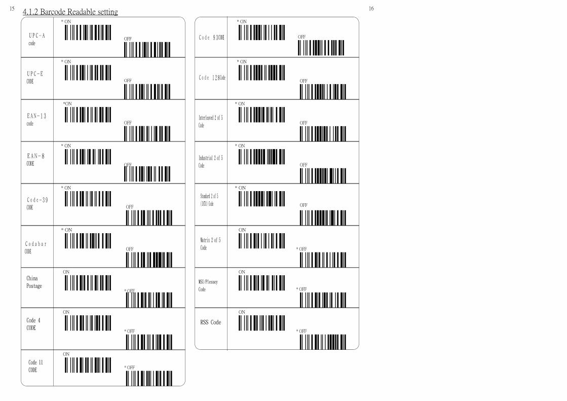
4.1.2 Barcode Readable setting
UPC-E
CODE
Code 11
CODE * OFF
ON
Standard 2 of 5
(IATA) Code

17 18
4.4.2. EAN-13=ISBN/ISSN
* OFF
ON
OFF
* ON
4.2.1. UPC-A Transmit Check digit
4.2 UPC-A Code setting
OFF
* ON
4.2.2 UPC-A First digit suppressed
4.3 UPC-E Code setting
OFF
* ON
4.3.1. UPC-E Transmit Check digit
OFF
* On
4.2.2 UPC-E First digit Suppressed
4.4 EAN-13 Code setting
OFF
* ON
4.4.1. EAN-13 Transmit Check digit
4.5 EAN-8 Code setting
OFF
* ON
4.5.1. EAN-8 Transmit check digit

19 20
4.8 Code 39 Code settingCode 39 includes as follow:
1. Barcode Type.2. START/Stop Character.3. Check Digit.4. Code Length5. Transmit check digit6. Front/Back digit Suppressed
1. Code Type
* Standard Code
Full ASCII Code
2. Transmit Start/Stop Character
* Not Transmitted
Transmitted
3. Verify Check Digit
* OFF
ON
4. Code Length
Min Length
Max Length
* Default (0~64) Min=0;Max=64
5. Transmit Check Digit
* OFF
ON
4.6.2 UPC-E=UPC-A
4.6.1. UPC-A=EAN-13
* Disable
* Disable
Enable
Enable
UPC/EAN Supplemental
* Add 2/5 OFF
2 or 5 on
Add 2 only
Add 5 only
4.6 UPC/EAN Supplemental
4.7 UPC/EAN Supplemental
6. Front / Back Digit Suppressed
Front Stop Character
Back Stop Character
* 0, no stop Character
* On
Off
Add 2/5 Lock

※OFF
ON
※ ABCD/ABCD
abcd/abcd
abcd/tn*e
※Disable
Enable
※OFF
ON
Verify Check Digit
Transmit Check Digit
Format of Start/Stop Transmission
Start/Stop Transmission
4.9 Codabar Code Setting
Min Length
Max Length
Code Length
Front Digit
* 0, None
Back Digit
Front/Back Digit suppressed
21 22
* Default (0~64) Min =5;Max=64

23 24
*OFF
OPEN
Transmit Check Digit
4.11 Code 128 Code Setting
Min Length
Max Length
Code Length
※ OFF
ON
※OFF
ON
Verify Check Digit
Transmit Check Digit
4.10 Code 93 Code Setting
Min Length
Max Length
Code Length
First digit suppressed
* 0, None
Last digit suppressed
Front /Back Digit suppressed
* Default (0~64) Min=5;Max=64
* Default (0~64) Min=0;Max=64
Front/Back Digit suppressedFirst digit suppressed
Last digit suppressed
* 0, None

25 26
4.12 Code 2 of 5 Code Setting
1. Interleaved 2 of 5
Verify Check Digit
ON
* OFF
Transmit Check Digit
ON
* OFF
Code LengthMin Length
Max Length
Front/Back Digit Suppressed
Front digit suppressed
* 0, no digit suppressed
Back digit suppressed
2. Industrial 2 of 5
Code Length
Min Length
Max Length
Front/Back Digit Suppressed
Front digit suppressed
* 0, Default, no digit suppressed
Back digit suppressed
3. Standard 2 of 5 (IATA Code)
Code LengthMin Length
Max Length
Front/Back Digit Suppressed
Front digit suppressed
* 0, no digit suppressed
Back digit suppressed
* Default (5~64) MinLength=5;Max Length=64
* Default (5~64) Min =5;Max=64
* Default (5~64) MinLength=5;Max Legnth=64

27 28
Transmit check digit
ON
* OFF
Code Length
Min Length
Max Length
Front/Back Digit Suppressed
Front Digit Suppressed
* 0, no digit suppressed
Back digit Suppressed
4.13. China Postage Code
Transmit check digit
ON
* OFF
Code Length
Min Length
Max Length
Front/Back Digit Suppressed
Front Digit Suppressed
* 0, no digit suppressed
Back digit suppressed
4. Matrix 2 of 5
Verify Check Digit
ON
* OFF
Verify Check Digit
ON
* OFF
* Default (5~64) Min=5;Max=64
* Default (5~64) Min=5;Max=64

29 30
4.14. MSI/ Plessey
Verify Check digit
* No Verify check
Code Length
Min Length
Max Length
Front/Back Digit Suppressed
Front Digit Suppressed
* 0, No digit suppressed
Back Digit Suppressed
Mode10 Transmit 0 digit
Mode10 Transmit 1 digit
Mode11 Transmit 0 digit
Mode11 Transmit 1 digit
Mode11 Transmit 2 digits
Mode10/ Mode 11 Transmit both
Mode10/ Mode 11 No transmit
4.15. Code 4
Code Length
Min Length
Max Length
Front/Back Digit Suppressed
Front Digit Suppressed
* 0, No Digit Suppressed
Back Digit Suppressed
4.16. RSS
Code Length
Min Length
Max Length
Front/Back Digit Suppressed
Front Digit Suppressed
* 0, No digit suppressed
Back Digit Suppressed
* Default (5~64) Min=5;Max=64
* Default (0~64) Min =5;Max =64
* Default (5~64) Min =5;Max =64

31 32
4.17. Code 11
Verify Check Digit
* 1 digit Check
Code Length
Min
Max
Front / Back Digit Suppressed
Front digit suppressed
* 0, no digit suppressed
Back digit suppressed
2 digits check
* Default (0~64) Min =5;Max=64
Transmit Check Digit* OFF
ON

NUL (0)
STX (2)
EOT (4)
BS (8)
SOH (1)
ETX (3)
ENQ (5)
BEL (7)
HT (9)
LF (10)
FF (12)
SO (14)
DLE (16)
DC2 (18)
VT (11)
CR (13)
SI (15)
DCI (17)
DC3 (19)
ACK (6)
33 34
The following table contains both full ASCII and decimal codes.
The decimal codes are parenthesized right next to each ASCII
code. This will make the configuration very easy to fit user's
application since some configurations can be done by just
scanning onc code only. The decoding softward of the scanner
can discriminate your setting(s) automatically no matter it's for a
text or a digit.
APPENDIX A. FULL ASCII TABLE & DECIMAL TABLE

DC4 (20)
SYN (22)
CAN (24)
SUB (26)
FS (28)
NAK ( 21)
ETB (23)
EM ( 25)
ESC (27)
GS (29)
RS (30)
SP (32)
" (34)
$ (36)
& (38)
' (39)
% ( 37)
# ( 35)
! (33 )
US (31)
35 36

( (40)
* (42)
, (44)
. ( 46)
0 (48)
) (41)
+ (43)
- (45)
/ (47)
1 (49)
2 (50)
4 (52)
6 (54)
8 (56)
: (58)
; (59)
9 (57)
7 (55)
5 (53)
3 (51)
37 38

< (60)
> (62)
@ (64)
B (66)
D (68)
= (61)
? (63)
A (65)
C (67)
E (69)
F (70)
H (72)
J (74)
L (76)
N (78)
G (71)
I (73)
K (75)
M (77)
O (79)
39 40
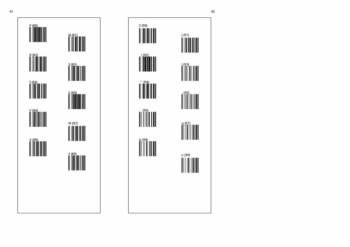
P (80)
R (82)
T (84)
V (86)
X (88)
Q (81)
S (83)
U (85)
W (87)
Y (89)
Z (90)
\ (92)
^ (94)
` (96)
b (98)
[ (91)
] (93)
- (95)
a (97)
c (99)
41 42

d (100)
f (102)
h ( 104)
j (106)
l (108)
e (101)
g (103)
i (105)
k (107)
m (109)
n (110)
p (112)
r (112)
t (116)
v (118)
w (119)
u (117)
s (115)
q (113)
o (111)
43 44

x (120)
z (122)
| (124)
~ (126)
y (121)
{ (123)
} ( 125)
DEL (127)
45
1) Default codemark for EAN-13 is 〝A〞
Default codemark for UPC-A is〝B〞
Default codemark EAN-8 is〝C〞
Default codemark UPC-E is〝D〞
Default codemark Code 4 is〝E〞
Default codemark Code 11 is〝F〞
Defaul codemark tCode 39 is〝G〞
Default codemark Code 93 is〝H〞
Default codemark Code 128 is〝I〞
Default codemark Codabar(NW-7) is〝J〞
Default codemark Interleave 2/5 (ITF2/5) is〝K〞
Default codemark IND 2/5 is〝L〞
Default codemark MTX 2/5 is〝M〞
Default codemark China postage(Datalogic 2/5) is〝N〞
Default codemark Standard 2 of 5 (IATA) is〝S〞
Default codemark MSI/Plessey is〝U〞
APPENDIX B Codemark Default Remarks :
2) Scan label of "Cancel All Code mark" to cancel all code
marks at one time.
46

47 48
APPENDIX C. The CCD Default setting
Interface
Computer Type PC/AT & PS/2-50/60/80
Keyboard Layout US
K/B Upper/Lower Case Use ALT (0-127)
RS 232C
Baud Rate 9600bps
Data Bit 8 bits
Parity None
Handshaking Protocol None
Stop Digit digit
Data Terminator CR/LF
Character Delay 0mm sec
Data transmit delay 0mm sec
Reading Mode Mode 1. Normal Reading Mode
The frequency of Buzzer sound normal
The length of Buzzer sound short
Pre-amble & Post-amble code None
Readable ON barcodes UPC-A、UPC-E、EAN-13、EAN-8、Code -39、Codabar、Code93、Code 128、Interleaved 2 of5、Insdustrial 2 of 5、Standard 2 of5
Readable OFF barcods.
(could set ON)
(Could set OFF)
China Postage、Matrix 2 of5、MSI/Plessey、Code 4、RSS。
UPC-A CodeTransmit check digit ON
Front digit suppressed ON
UPC-E Code
EAN-13 Code
OFF
UPC-E =UPC-A
Code 39
ISBN/ISSN switch OFF
EAN-8 Code
UPC=EAN
OFF
UPC/EANSupplemental
Add 2/5 Off
Verify Check Digit OFF
Transmit Check Digit OFF
Code Type Standard Code
Transmit Start/Stop digit OFF
Min/Max Code Min Length= 0Max Length= 64
Front/Back digit Suppressed 0,None
CodaBar
Verify Check digit
Transmit Check digit
Format of Start/Stop Transmission
Start/Stop Transmission OFF
ABCD/ABCD
OFF
OFF
Code LengthMin Length = 5Max Length =64
Front/Back digit Suppressed 0,None
Code 93
Verify Check Digit
Transmit Check digit
OFF
OFF
Code Length
Front/Back digit suppressed 0,None
Code 128
OFF
0,None
Transmit check digit ON
Front digit suppressed ON
Transmit check digit ON
Transmit check digit ON
Min Length = 5Max Length =64
Min Length = 0
Max Length =64
Transmit Check digit
Code Length
Front/Back digit suppressed

49
Interleaved 2 of 5
OFF
OFF
Min = 5Max = 64
0,None
Industrial 2 of 5
Matrix 2 of 5
Standard 2 of 5
China Postage
MSI/Plessey
Code 4
RSS
( IATA )
Code 11
Verify Check Digit
Transmit Check digit
Code Length
Front/Back digit suppressed
Min = 5Max = 64
0,None
Code Length
Front/Back digit suppressed
Code Length Min = 5Max = 64
Front/Back digit suppressed 0,NoneVerify Check Digit OFF
Transmit Check digit OFF
Code Length Min = 5Max = 64
Front/Back digit suppressed 0,None
Front/Back digit suppressed 0,None
Code LengthMin = 5Max = 64
Transmit Check digit OFF
Verify Check Digit OFF
Verify Check Digit OFF
Code Length Min = 5Max = 64
Front/Back digit suppressed 0,None
Code Length Min = 5Max = 64
Front/Back digit suppressed 0,None
Code Length Min = 5Max = 64
Front/Back digit suppressed 0,NoneVerify Check Digit 1 Verify check digit
Transmit Check digit OFF
Code LengthMin = 5Max = 64
Front/Back digit suppressed 0,None
Related Documents