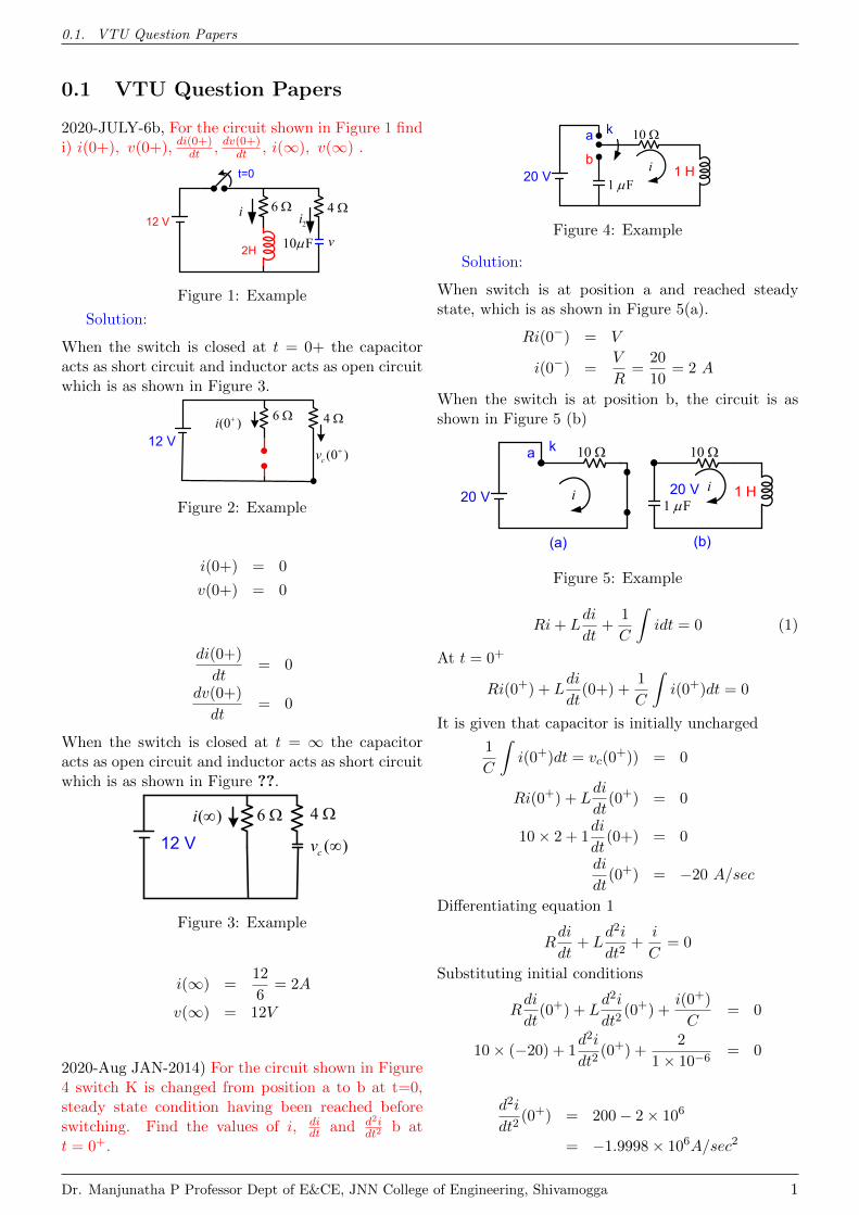
0.1. VTU Question Papers 0.1 VTU Question Papers 2020-JULY-6b, For the circuit shown in Figure 1 find i) i(0+),v(0+), di(0+) dt , dv(0+) dt , i(∞),v(∞). i t=0 2H 2 i 12 V 4 6 10 F v Figure 1: Example Solution: When the switch is closed at t = 0+ the capacitor acts as short circuit and inductor acts as open circuit which is as shown in Figure 3. (0 ) i 6 4 12 V (0 ) c v Figure 2: Example i(0+) = 0 v(0+) = 0 di(0+) dt = 0 dv(0+) dt = 0 When the switch is closed at t = ∞ the capacitor acts as open circuit and inductor acts as short circuit which is as shown in Figure ??. ( ) i 6 4 12 V ( ) c v Figure 3: Example i(∞) = 12 6 =2A v(∞) = 12V 2020-Aug JAN-2014) For the circuit shown in Figure 4 switch K is changed from position a to b at t=0, steady state condition having been reached before switching. Find the values of i, di dt and d 2 i dt 2 b at t =0 + . i k 1 H 10 1 F b a 20 V Figure 4: Example Solution: When switch is at position a and reached steady state, which is as shown in Figure 5(a). Ri(0 - ) = V i(0 - ) = V R = 20 10 =2 A When the switch is at position b, the circuit is as shown in Figure 5 (b) i k 10 a 20 V i 1 H 10 1 F (a) 20 V (b) Figure 5: Example Ri + L di dt + 1 C Z idt =0 (1) At t =0 + Ri(0 + )+ L di dt (0+) + 1 C Z i(0 + )dt =0 It is given that capacitor is initially uncharged 1 C Z i(0 + )dt = v c (0 + )) = 0 Ri(0 + )+ L di dt (0 + ) = 0 10 × 2+1 di dt (0+) = 0 di dt (0 + ) = -20 A/sec Differentiating equation 1 R di dt + L d 2 i dt 2 + i C =0 Substituting initial conditions R di dt (0 + )+ L d 2 i dt 2 (0 + )+ i(0 + ) C = 0 10 × (-20) + 1 d 2 i dt 2 (0 + )+ 2 1 × 10 -6 = 0 d 2 i dt 2 (0 + ) = 200 - 2 × 10 6 = -1.9998 × 10 6 A/sec 2 Dr. Manjunatha P Professor Dept of E&CE, JNN College of Engineering, Shivamogga 1

Welcome message from author
This document is posted to help you gain knowledge. Please leave a comment to let me know what you think about it! Share it to your friends and learn new things together.
Transcript
0.1. VTU Question Papers
0.1 VTU Question Papers
2020-JULY-6b, For the circuit shown in Figure 1 findi) i(0+), v(0+), di(0+)
dt , dv(0+)dt , i(∞), v(∞) .
i
t=0
2H
2i12 V4 6
10 F v
Figure 1: Example
Solution:
When the switch is closed at t = 0+ the capacitoracts as short circuit and inductor acts as open circuitwhich is as shown in Figure 3.
(0 )i 6 4
12 V(0 )cv
Figure 2: Example
i(0+) = 0
v(0+) = 0
di(0+)
dt= 0
dv(0+)
dt= 0
When the switch is closed at t = ∞ the capacitoracts as open circuit and inductor acts as short circuitwhich is as shown in Figure ??.
( )i 6 4
12 V ( )cv
Figure 3: Example
i(∞) =12
6= 2A
v(∞) = 12V
2020-Aug JAN-2014) For the circuit shown in Figure4 switch K is changed from position a to b at t=0,steady state condition having been reached beforeswitching. Find the values of i, di
dt and d2idt2
b att = 0+.
ik
1 H10
1 Fba
20 V
Figure 4: Example
Solution:
When switch is at position a and reached steadystate, which is as shown in Figure 5(a).
Ri(0−) = V
i(0−) =V
R=
20
10= 2 A
When the switch is at position b, the circuit is asshown in Figure 5 (b)
i
k 10 a
20 V i 1 H10
1 F(a)
20 V
(b)Figure 5: Example
Ri+ Ldi
dt+
1
C
∫idt = 0 (1)
At t = 0+
Ri(0+) + Ldi
dt(0+) +
1
C
∫i(0+)dt = 0
It is given that capacitor is initially uncharged
1
C
∫i(0+)dt = vc(0
+)) = 0
Ri(0+) + Ldi
dt(0+) = 0
10× 2 + 1di
dt(0+) = 0
di
dt(0+) = −20 A/sec
Differentiating equation 1
Rdi
dt+ L
d2i
dt2+
i
C= 0
Substituting initial conditions
Rdi
dt(0+) + L
d2i
dt2(0+) +
i(0+)
C= 0
10× (−20) + 1d2i
dt2(0+) +
2
1× 10−6= 0
d2i
dt2(0+) = 200− 2× 106
= −1.9998× 10⁶A/sec2
Dr. Manjunatha P Professor Dept of E&CE, JNN College of Engineering, Shivamogga 1
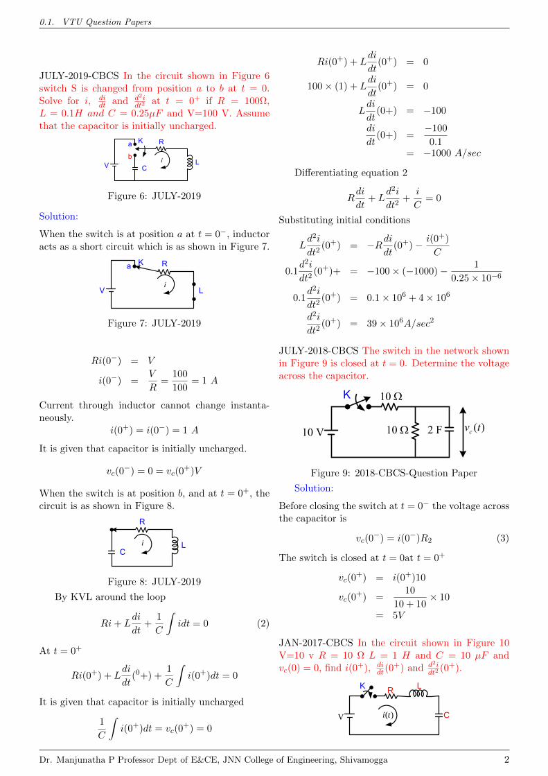
0.1. VTU Question Papers
JULY-2019-CBCS In the circuit shown in Figure 6switch S is changed from position a to b at t = 0.Solve for i, di
dt and d2idt2
at t = 0+ if R = 100Ω,L = 0.1H and C = 0.25µF and V=100 V. Assumethat the capacitor is initially uncharged.
i
K
Lb
a
V
R
C
Figure 6: JULY-2019
Solution:
When the switch is at position a at t = 0−, inductoracts as a short circuit which is as shown in Figure 7.
i
K
L
a
V
R
Figure 7: JULY-2019
Ri(0−) = V
i(0−) =V
R=
100
100= 1 A
Current through inductor cannot change instanta-neously.
i(0+) = i(0−) = 1 A
It is given that capacitor is initially uncharged.
vc(0−) = 0 = vc(0
+)V
When the switch is at position b, and at t = 0+, thecircuit is as shown in Figure 8.
i L
R
C
Figure 8: JULY-2019
By KVL around the loop
Ri+ Ldi
dt+
1
C
∫idt = 0 (2)
At t = 0+
Ri(0+) + Ldi
dt(0+) +
1
C
∫i(0+)dt = 0
It is given that capacitor is initially uncharged
1
C
∫i(0+)dt = vc(0
+) = 0
Ri(0+) + Ldi
dt(0+) = 0
100× (1) + Ldi
dt(0+) = 0
Ldi
dt(0+) = −100
di
dt(0+) =
−100
0.1= −1000 A/sec
Differentiating equation 2
Rdi
dt+ L
d2i
dt2+
i
C= 0
Substituting initial conditions
Ld2i
dt2(0+) = −Rdi
dt(0+)− i(0+)
C
0.1d2i
dt2(0+)+ = −100× (−1000)− 1
0.25× 10⁻⁶
0.1d2i
dt2(0+) = 0.1× 10⁶ + 4× 10⁶
d2i
dt2(0+) = 39× 106A/sec2
JULY-2018-CBCS The switch in the network shownin Figure 9 is closed at t = 0. Determine the voltageacross the capacitor.
10 V
K 10
2 F10 ( )cv t
Figure 9: 2018-CBCS-Question Paper
Solution:
Before closing the switch at t = 0− the voltage acrossthe capacitor is
vc(0−) = i(0−)R2 (3)
The switch is closed at t = 0at t = 0+
vc(0+) = i(0+)10
vc(0+) =
10
10 + 10× 10
= 5V
JAN-2017-CBCS In the circuit shown in Figure 10V=10 v R = 10 Ω L = 1 H and C = 10 µF andvc(0) = 0, find i(0+), di
dt(0+) and d2i
dt2(0+).
R
V ( )i t
K
C
L
Dr. Manjunatha P Professor Dept of E&CE, JNN College of Engineering, Shivamogga 2
0.1. VTU Question Papers
Figure 10: 2017-CBCS-Question Paper
Solution:
The switch is closed at t = 0+ the inductor acts asopen circuit and capacitor acts as short circuit whichis as shown in Figure 11. At t = 0−, i(0−) = i(0+) =0
R
V (0 )i +
Figure 11: Example
Ri+ Ldi
dt+
1
C
∫idt = 10 (4)
At t = 0+
Ri(0+) + Ldi
dt(0+) +
1
C
∫i(0+)dt = V
di
dt(0+) =
V
L= 10A/sec
Differentiating equation 4
Rdi
dt+ L
d2i
dt2+
i
C= 0 (5)
Substituting initial conditions
Rdi
dt(0+) + L
d2i
dt2(0+) +
i(0+)
C= 0 (6)
Ld2i
dt2(0+) = −10× 10− i(0+)
C
1d2i
dt2(0+) = 100− 0
Cd2i
dt2(0+) = −100A/sec2
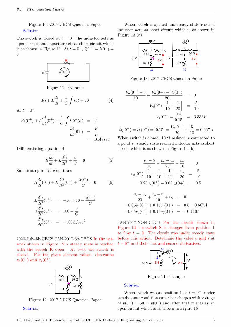
2020-July-5b-CBCS JAN-2017-6b-CBCS In the net-work shown in Figure 12 a steady state is reachedwith the switch K open. At t=0, the switch isclosed. For the given element values, determineva(0−) and va(0+)
5 V10 Ω 20 Ω
10 Ω
10 Ω2 H
avbv
Figure 12: 2017-CBCS-Question Paper
Solution:
When switch is opened and steady state reachedinductor acts as short circuit which is as shown inFigure 13 (a)
5 V10 20
10
10
av bv
S C
(a)
5 V10 20
10
10
av bvS C
(b)
Figure 13: 2017-CBCS-Question Paper
Va(0−)− 5
10+Va(0−)− Vb(0−)
20= 0
Va(0−)
[1
10+
1
20
]=
5
10
Va(0−) =0.5
0.15= 3.333V
iL(0−) = iL(0+) = [0.15] =Va(0−)
20+
5
10= 0.667A
When switch is closed, 10 Ω resistor is connected toa point va steady state reached inductor acts as shortcircuit which is as shown in Figure 13 (b)
va − 5
10+va − vb
20+va10
= 0
va(0+)
[1
10+
1
10+
1
20
]− vb
20=
5
10
0.25va(0+)− 0.05vb(0+) = 0.5
vb − va20
+vb − 5
10+ iL = 0
−0.05va(0+) + 0.15vb(0+) = 0.5− 0.667A
−0.05va(0+) + 0.15vb(0+) = −0.1667
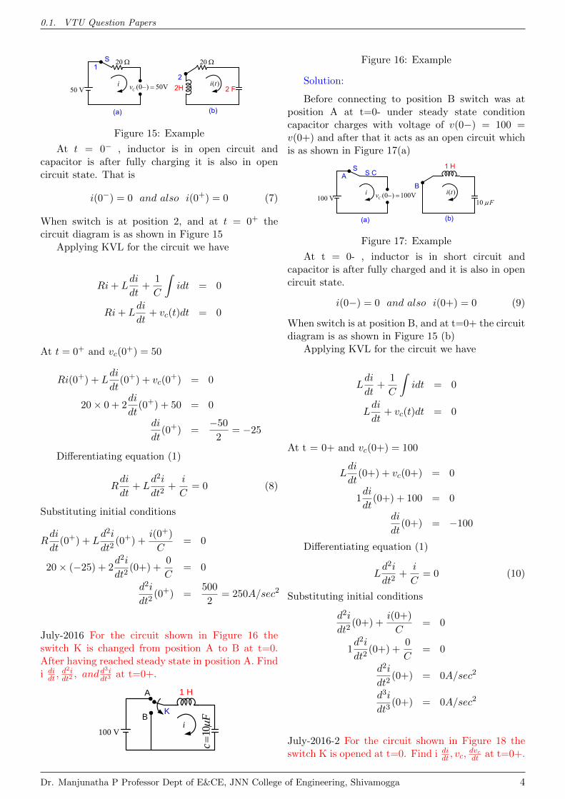
JAN-2017-NON-CBCS For the circuit shown inFigure 14 the switch S is changed from position 1to 2 at t = 0. The circuit was under steady statebefore this action. Determine the value v and i att = 0+ and their first and second derivatives.
50 V i
S
2 F2H
20 v2
1
Figure 14: Example
Solution:
When switch was at position 1 at t = 0−, understeady state condition capacitor charges with voltageof v(0−) = 50 = v(0+) and after that it acts as anopen circuit which is as shown in Figure 15
Dr. Manjunatha P Professor Dept of E&CE, JNN College of Engineering, Shivamogga 3
0.1. VTU Question Papers
50 V i
S 20
(0 ) 50VCv 1
(a)
( )i t 2 F2H
20 2
(b)
Figure 15: Example
At t = 0− , inductor is in open circuit andcapacitor is after fully charging it is also in opencircuit state. That is
i(0−) = 0 and also i(0+) = 0 (7)
When switch is at position 2, and at t = 0+ thecircuit diagram is as shown in Figure 15
Applying KVL for the circuit we have
Ri+ Ldi
dt+
1
C
∫idt = 0
Ri+ Ldi
dt+ vc(t)dt = 0
At t = 0+ and vc(0+) = 50
Ri(0+) + Ldi
dt(0+) + vc(0
+) = 0
20× 0 + 2di
dt(0+) + 50 = 0
di
dt(0+) =
−50
2= −25
Differentiating equation (1)
Rdi
dt+ L
d2i
dt2+
i
C= 0 (8)
Substituting initial conditions
Rdi
dt(0+) + L
d2i
dt2(0+) +
i(0+)
C= 0
20× (−25) + 2d2i
dt2(0+) +
0
C= 0
d2i
dt2(0+) =
500
2= 250A/sec2
July-2016 For the circuit shown in Figure 16 theswitch K is changed from position A to B at t=0.After having reached steady state in position A. Findi didt ,
d2idt2, andd3i
dt3at t=0+.
100 Vi
K
1 H
10c
Fμ=
A
B
Figure 16: Example
Solution:
Before connecting to position B switch was atposition A at t=0- under steady state conditioncapacitor charges with voltage of v(0−) = 100 =v(0+) and after that it acts as an open circuit whichis as shown in Figure 17(a)
100 V i
S
(0 ) 100VCv A
(a)
( )i t
1 H
10 FB
(b)
S C
Figure 17: Example
At t = 0- , inductor is in short circuit andcapacitor is after fully charged and it is also in opencircuit state.
i(0−) = 0 and also i(0+) = 0 (9)
When switch is at position B, and at t=0+ the circuitdiagram is as shown in Figure 15 (b)
Applying KVL for the circuit we have
Ldi
dt+
1
C
∫idt = 0
Ldi
dt+ vc(t)dt = 0
At t = 0+ and vc(0+) = 100
Ldi
dt(0+) + vc(0+) = 0
1di
dt(0+) + 100 = 0
di
dt(0+) = −100
Differentiating equation (1)
Ld2i
dt2+
i
C= 0 (10)
Substituting initial conditions
d2i
dt2(0+) +
i(0+)
C= 0
1d2i
dt2(0+) +
0
C= 0
d2i
dt2(0+) = 0A/sec2
d3i
dt3(0+) = 0A/sec2
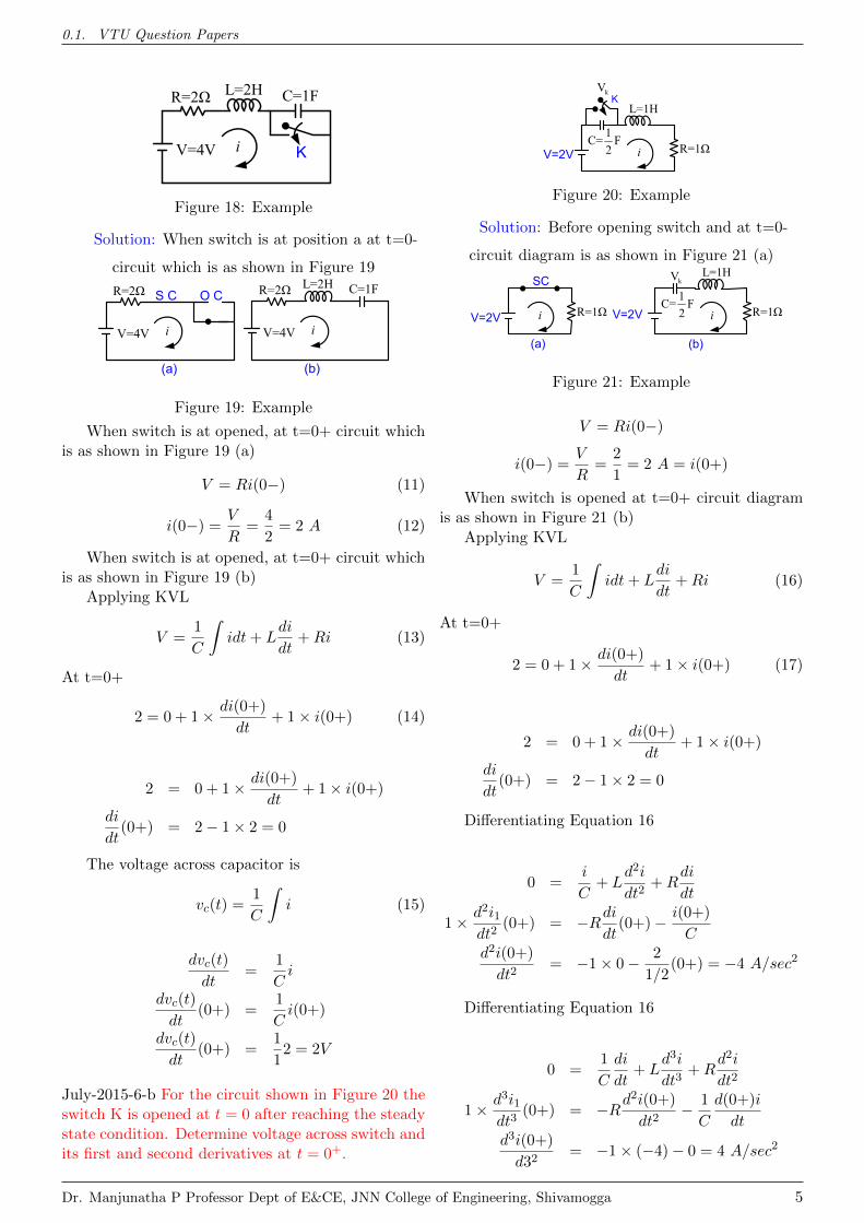
July-2016-2 For the circuit shown in Figure 18 theswitch K is opened at t=0. Find i di
dt , vc,dvcdt at t=0+.
Dr. Manjunatha P Professor Dept of E&CE, JNN College of Engineering, Shivamogga 4
0.1. VTU Question Papers
V=4V i K
R=2Ω L=2H C=1F
Figure 18: Example
Solution: When switch is at position a at t=0-
circuit which is as shown in Figure 19
V=4V iO CR=2Ω S C
(a) (b)V=4V i
R=2Ω L=2H C=1F
Figure 19: Example
When switch is at opened, at t=0+ circuit whichis as shown in Figure 19 (a)
V = Ri(0−) (11)
i(0−) =V
R=
4
2= 2 A (12)
When switch is at opened, at t=0+ circuit whichis as shown in Figure 19 (b)
Applying KVL
V =1
C
∫idt+ L
di
dt+Ri (13)
At t=0+
2 = 0 + 1× di(0+)
dt+ 1× i(0+) (14)
2 = 0 + 1× di(0+)
dt+ 1× i(0+)
di
dt(0+) = 2− 1× 2 = 0
The voltage across capacitor is
vc(t) =1
C
∫i (15)
dvc(t)
dt=
1
Ci
dvc(t)
dt(0+) =
1
Ci(0+)
dvc(t)
dt(0+) =
1
12 = 2V
July-2015-6-b For the circuit shown in Figure 20 theswitch K is opened at t = 0 after reaching the steadystate condition. Determine voltage across switch andits first and second derivatives at t = 0+.
i
K
R=1Ω
L=1H1C= F2V=2V
kV
Figure 20: Example
Solution: Before opening switch and at t=0-
circuit diagram is as shown in Figure 21 (a)
i R=1Ω
L=1H1C= F2V=2V
kV
(b)i R=1ΩV=2V
(a)
SC
Figure 21: Example
V = Ri(0−)
i(0−) =V
R=
2
1= 2 A = i(0+)
When switch is opened at t=0+ circuit diagramis as shown in Figure 21 (b)
Applying KVL
V =1
C
∫idt+ L
di
dt+Ri (16)
At t=0+
2 = 0 + 1× di(0+)
dt+ 1× i(0+) (17)
2 = 0 + 1× di(0+)
dt+ 1× i(0+)
di
dt(0+) = 2− 1× 2 = 0
Differentiating Equation 16
0 =i
C+ L
d2i
dt2+R
di
dt
1× d2i1dt2
(0+) = −Rdidt
(0+)− i(0+)
Cd2i(0+)
dt2= −1× 0− 2
1/2(0+) = −4 A/sec2
Differentiating Equation 16
0 =1
C
di
dt+ L
d3i
dt3+R
d2i
dt2
1× d3i1dt3
(0+) = −Rd2i(0+)
dt2− 1
C
d(0+)i
dtd3i(0+)
d32= −1× (−4)− 0 = 4 A/sec2
Dr. Manjunatha P Professor Dept of E&CE, JNN College of Engineering, Shivamogga 5
0.1. VTU Question Papers
The voltage across capacitor is
Vk + Ldi
dt+R× i = 2 (18)
dVkdt
+ Ld2i
dt2+R× di
dt= 0
dvc(t)
dt(0+) =
1
C(5− 5) = 0
Differentiating equation (1)
d2Vkdt2
+ Ld3i
dt3+R× d2i
dt2= 0 (19)
d2Vk(0+)
dt2= −Ld
3i(0+)
dt3+R× d2i(0+)
dt2
d2Vk(0+)
dt2= −1× 4− 1× (−4) = 0 V/sec2
DEC-2015 6-a For the circuit shown in Figure 22 theswitch K is changed from position A to B at t=0, thesteady state having been reached before switching.Calculate i, di
dt , andd2idt2
at t=0+.
50 V i
K
1H
20 BA
1 F
Figure 22: Example
Solution:
Before connecting to position 2 switch was atposition 1 at t=0- under steady state conditioncapacitor charges with voltage of v(0−) = 50 =v(0+) and after that it acts as an open circuit whichis as shown in Figure 23 (a)
50 V i
S 20
(0 ) 50VCv 1
(a)
( )i t1H
20 2
(b)1 F
Figure 23: Example
At t = 0- , inductor is in open circuit andcapacitor is after fully charging it is also in opencircuit state. That is
i(0−) = 0 and also i(0+) = 0 (20)
When switch is at position 2, and at t=0+ the circuitdiagram is as shown in Figure 23 (b)
Applying KVL for the circuit we have
Ri+ Ldi
dt+
1
C
∫idt = 0
Ri+ Ldi
dt+ vc(t)dt = 0
At t = 0+ and vc(0+) = 50
Ri(0+) + Ldi
dt(0+) + vc(0+) = 0
20× 0 + 1di
dt(0+) + 50 = 0
di
dt(0+) =
−50
1= −50 A/sec
Differentiating equation (1)
Rdi
dt+ L
d2i
dt2+
i
C= 0 (21)
Substituting initial conditions
Rdi
dt(0+) + L
d2i
dt2(0+) +
i(0+)
C= 0
20× (−50) + 1d2i
dt2(0+) +
0
C= 0
d2i
dt2(0+) =
1000
1= 1000A/sec2
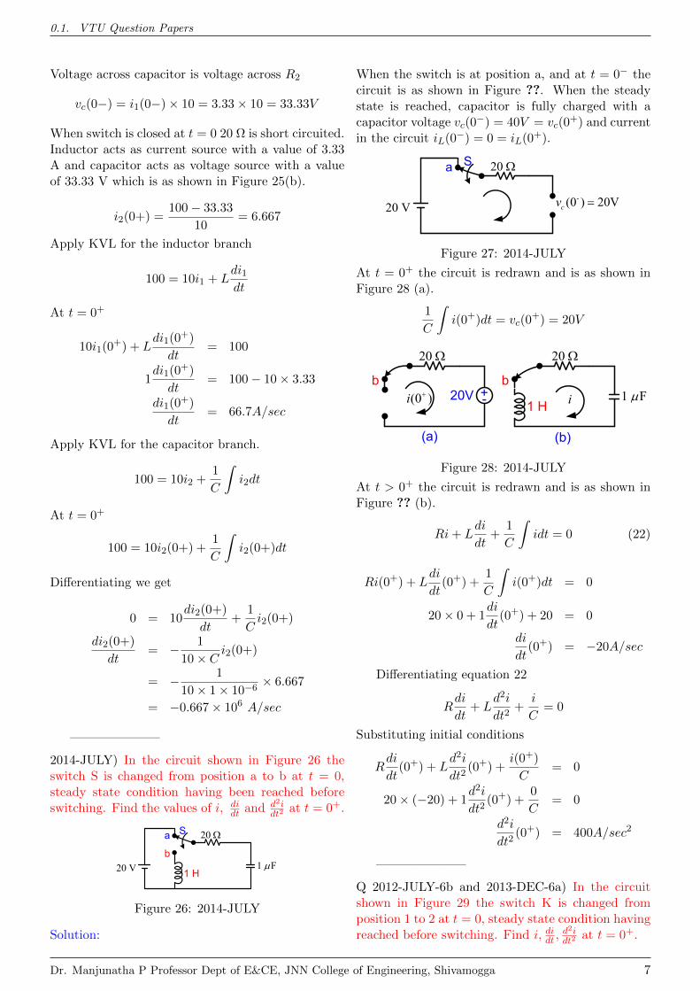
Q DEC-2015 6b) In the circuit shown in Figure 24 thesteady state is reached with switch K is open. Theswitch K is closed at t = 0. Solve for i1, i2,
di1dt ,
di2dt at
t = 0+.
1i
K
1H
20 2i100 V
10 10
1 F
Figure 24: Example
Solution:
When switch is opened and when steady state isreached capacitor acts as open circuit and inductoracts as short circuit which is as shown in Figure 25(a).
1(0 )i
20
2 (0 )i 1(0 )i
2 (0 )i
(a) (b)
10 10 10 10
100 V100 V +- 33.3 V(0 )cv
3.3 A
Figure 25: Example
i1(0−) =100
20 + 10= 3.33A
i2(0−) = 0
Dr. Manjunatha P Professor Dept of E&CE, JNN College of Engineering, Shivamogga 6
0.1. VTU Question Papers
Voltage across capacitor is voltage across R2
vc(0−) = i1(0−)× 10 = 3.33× 10 = 33.33V
When switch is closed at t = 0 20 Ω is short circuited.Inductor acts as current source with a value of 3.33A and capacitor acts as voltage source with a valueof 33.33 V which is as shown in Figure 25(b).
i2(0+) =100− 33.33
10= 6.667
Apply KVL for the inductor branch
100 = 10i1 + Ldi1dt
At t = 0+
10i1(0+) + L
di1(0+)
dt= 100
1di1(0
+)
dt= 100− 10× 3.33
di1(0+)
dt= 66.7A/sec
Apply KVL for the capacitor branch.
100 = 10i2 +1
C
∫i2dt
At t = 0+
100 = 10i2(0+) +1
C
∫i2(0+)dt
Differentiating we get
0 = 10di2(0+)
dt+
1
Ci2(0+)
di2(0+)
dt= − 1
10× Ci2(0+)
= − 1
10× 1× 10−6× 6.667
= −0.667× 10⁶ A/sec
———————
2014-JULY) In the circuit shown in Figure 26 theswitch S is changed from position a to b at t = 0,steady state condition having been reached beforeswitching. Find the values of i, di
dt and d2idt2
at t = 0+.
20 V
S
1 H
20
1 Fb
a
Figure 26: 2014-JULY
Solution:
When the switch is at position a, and at t = 0− thecircuit is as shown in Figure ??. When the steadystate is reached, capacitor is fully charged with acapacitor voltage vc(0
−) = 40V = vc(0+) and current
in the circuit iL(0−) = 0 = iL(0+).
20 V
S 20 a
-(0 ) 20Vcv
Figure 27: 2014-JULY
At t = 0+ the circuit is redrawn and is as shown inFigure 28 (a).
1
C
∫i(0+)dt = vc(0
+) = 20V
(0 )i
20
b
(a)
i1 H
20
1 Fb
(b)
+-20V
Figure 28: 2014-JULY
At t > 0+ the circuit is redrawn and is as shown inFigure ?? (b).
Ri+ Ldi
dt+
1
C
∫idt = 0 (22)
Ri(0+) + Ldi
dt(0+) +
1
C
∫i(0+)dt = 0
20× 0 + 1di
dt(0+) + 20 = 0
di
dt(0+) = −20A/sec
Differentiating equation 22
Rdi
dt+ L
d2i
dt2+
i
C= 0
Substituting initial conditions
Rdi
dt(0+) + L
d2i
dt2(0+) +
i(0+)
C= 0
20× (−20) + 1d2i
dt2(0+) +
0
C= 0
d2i
dt2(0+) = 400A/sec2
———————
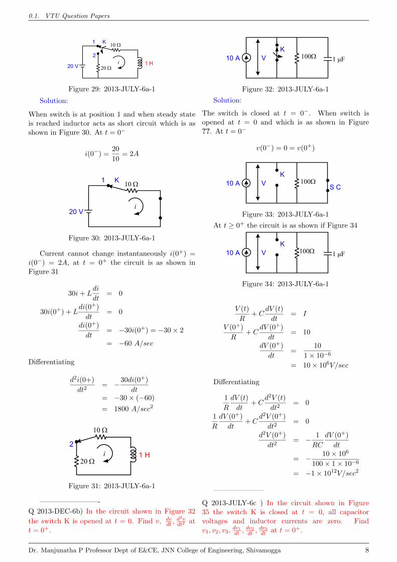
Q 2012-JULY-6b and 2013-DEC-6a) In the circuitshown in Figure 29 the switch K is changed fromposition 1 to 2 at t = 0, steady state condition havingreached before switching. Find i, didt ,
d2idt2
at t = 0+.
Dr. Manjunatha P Professor Dept of E&CE, JNN College of Engineering, Shivamogga 7
0.1. VTU Question Papers
i
K
1 H
10
2
1
20 V 20
Figure 29: 2013-JULY-6a-1
Solution:
When switch is at position 1 and when steady stateis reached inductor acts as short circuit which is asshown in Figure 30. At t = 0−
i(0−) =20
10= 2A
i
K10 1
20 V
Figure 30: 2013-JULY-6a-1
Current cannot change instantaneously i(0+) =i(0−) = 2A, at t = 0+ the circuit is as shown inFigure 31
30i+ Ldi
dt= 0
30i(0+) + Ldi(0+)
dt= 0
di(0+)
dt= −30i(0+) = −30× 2
= −60 A/sec
Differentiating
d2i(0+)
dt2= −30di(0+)
dt= −30× (−60)
= 1800 A/sec2
i 1 H
10
2
20
Figure 31: 2013-JULY-6a-1
————————-
Q 2013-DEC-6b) In the circuit shown in Figure 32
the switch K is opened at t = 0. Find v, dvdt ,
d2vdt2
att = 0+.
K10010 A 1 μFV
Figure 32: 2013-JULY-6a-1
Solution:
The switch is closed at t = 0−. When switch isopened at t = 0 and which is as shown in Figure??. At t = 0−
v(0−) = 0 = v(0+)
K10010 A V
S C
Figure 33: 2013-JULY-6a-1
At t ≥ 0+ the circuit is as shown if Figure 34
K10010 A 1 μFV
Figure 34: 2013-JULY-6a-1
V (t)
R+ C
dV (t)
dt= I
V (0+)
R+ C
dV (0+)
dt= 10
dV (0+)
dt=
10
1× 10−6
= 10× 106V/sec
Differentiating
1
R
dV (t)
dt+ C
d2V (t)
dt2= 0
1
R
dV (0+)
dt+ C
d2V (0+)
dt2= 0
d2V (0+)
dt2= − 1
RC
dV (0+)
dt
= − 10× 106
100× 1× 10−6
= −1× 10¹²V/sec2
———————
Q 2013-JULY-6c ) In the circuit shown in Figure35 the switch K is closed at t = 0, all capacitorvoltages and inductor currents are zero. Findv1, v2, v3,
dv1dt ,
dv2dt ,
dv3dt at t = 0+.
Dr. Manjunatha P Professor Dept of E&CE, JNN College of Engineering, Shivamogga 8
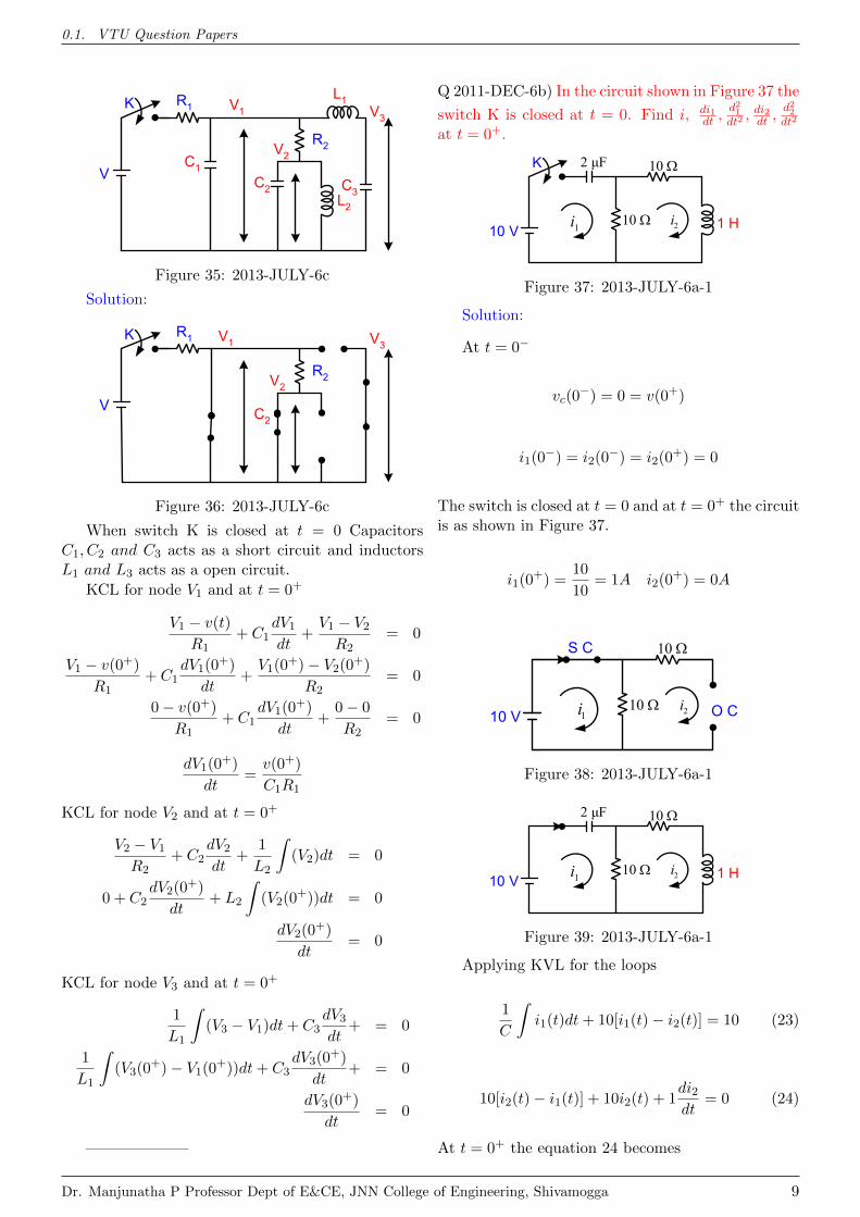
0.1. VTU Question Papers
K
V
V1
V2
V3
R1
C3C2
C1
R2
L1
L2
Figure 35: 2013-JULY-6c
Solution:
K
V
V1
V2
V3R1
C2
R2
Figure 36: 2013-JULY-6c
When switch K is closed at t = 0 CapacitorsC1, C2 and C3 acts as a short circuit and inductorsL1 and L3 acts as a open circuit.
KCL for node V1 and at t = 0+
V1 − v(t)
R1+ C1
dV1dt
+V1 − V2R2
= 0
V1 − v(0+)
R1+ C1
dV1(0+)
dt+V1(0
+)− V2(0+)
R2= 0
0− v(0+)
R1+ C1
dV1(0+)
dt+
0− 0
R2= 0
dV1(0+)
dt=v(0+)
C1R1
KCL for node V2 and at t = 0+
V2 − V1R2
+ C2dV2dt
+1
L2
∫(V2)dt = 0
0 + C2dV2(0
+)
dt+ L2
∫(V2(0
+))dt = 0
dV2(0+)
dt= 0
KCL for node V3 and at t = 0+
1
L1
∫(V3 − V1)dt+ C3
dV3dt
+ = 0
1
L1
∫(V3(0
+)− V1(0+))dt+ C3dV3(0
+)
dt+ = 0
dV3(0+)
dt= 0
——————–
Q 2011-DEC-6b) In the circuit shown in Figure 37 the
switch K is closed at t = 0. Find i, di1dt ,
d21dt2, di2dt ,
d22dt2
at t = 0+.
K
1 H
10
10 V10
2 μF
2i1i
Figure 37: 2013-JULY-6a-1
Solution:
At t = 0−
vc(0−) = 0 = v(0+)
i1(0−) = i2(0
−) = i2(0+) = 0
The switch is closed at t = 0 and at t = 0+ the circuitis as shown in Figure 37.
i1(0+) =
10
10= 1A i2(0
+) = 0A
10
10 V10 2i1i O C
S C
Figure 38: 2013-JULY-6a-1
1 H
10
10 V10
2 μF
2i1i
Figure 39: 2013-JULY-6a-1
Applying KVL for the loops
1
C
∫i1(t)dt+ 10[i1(t)− i2(t)] = 10 (23)
10[i2(t)− i1(t)] + 10i2(t) + 1di2dt
= 0 (24)
At t = 0+ the equation 24 becomes
Dr. Manjunatha P Professor Dept of E&CE, JNN College of Engineering, Shivamogga 9
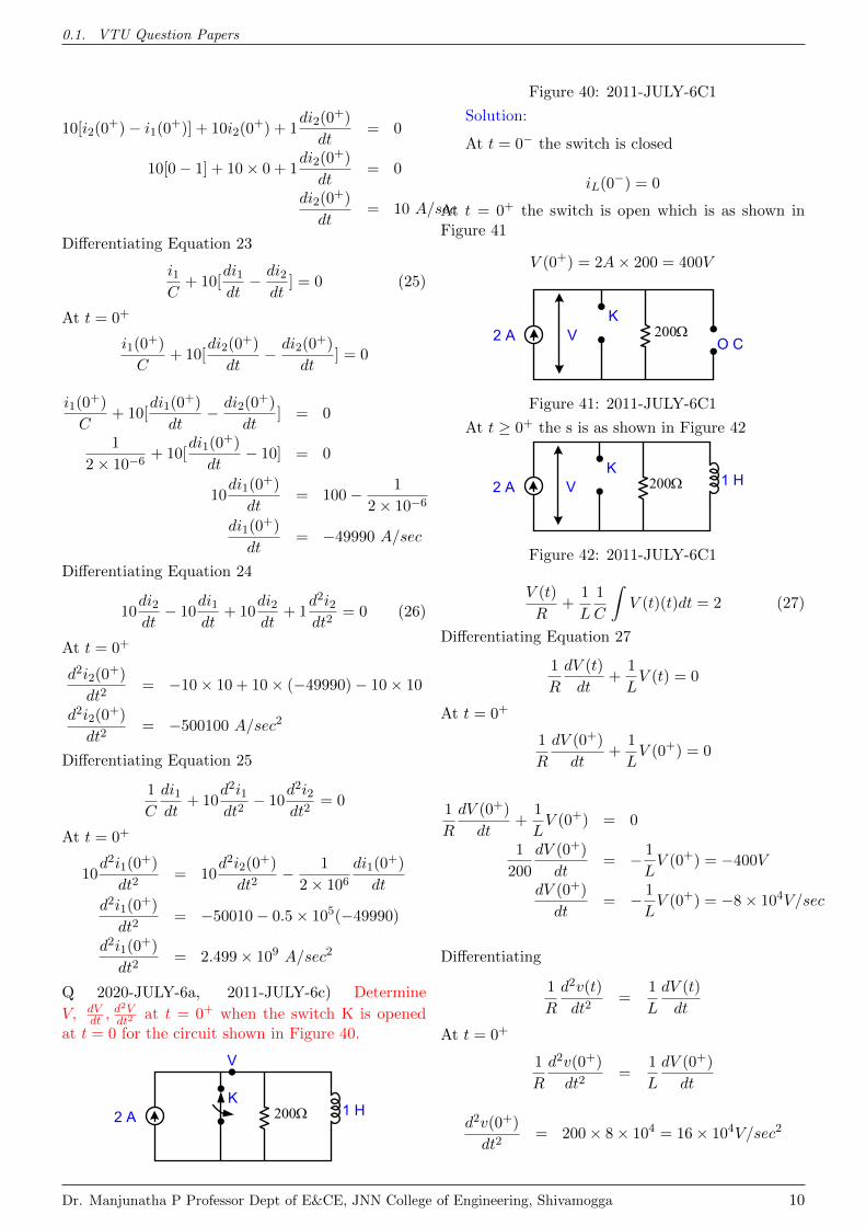
0.1. VTU Question Papers
10[i2(0+)− i1(0+)] + 10i2(0
+) + 1di2(0
+)
dt= 0
10[0− 1] + 10× 0 + 1di2(0
+)
dt= 0
di2(0+)
dt= 10 A/sec
Differentiating Equation 23
i1C
+ 10[di1dt− di2
dt] = 0 (25)
At t = 0+
i1(0+)
C+ 10[
di2(0+)
dt− di2(0
+)
dt] = 0
i1(0+)
C+ 10[
di1(0+)
dt− di2(0
+)
dt] = 0
1
2× 10⁻⁶+ 10[
di1(0+)
dt− 10] = 0
10di1(0
+)
dt= 100− 1
2× 10⁻⁶
di1(0+)
dt= −49990 A/sec
Differentiating Equation 24
10di2dt− 10
di1dt
+ 10di2dt
+ 1d2i2dt2
= 0 (26)
At t = 0+
d2i2(0+)
dt2= −10× 10 + 10× (−49990)− 10× 10
d2i2(0+)
dt2= −500100 A/sec2
Differentiating Equation 25
1
C
di1dt
+ 10d2i1dt2− 10
d2i2dt2
= 0
At t = 0+
10d2i1(0
+)
dt2= 10
d2i2(0+)
dt2− 1
2× 10⁶di1(0
+)
dt
d2i1(0+)
dt2= −50010− 0.5× 10⁵(−49990)
d2i1(0+)
dt2= 2.499× 10⁹ A/sec2
Q 2020-JULY-6a, 2011-JULY-6c) Determine
V, dVdt ,
d2Vdt2
at t = 0+ when the switch K is openedat t = 0 for the circuit shown in Figure 40.
K2002 A
V
1 H
Figure 40: 2011-JULY-6C1
Solution:
At t = 0− the switch is closed
iL(0−) = 0
At t = 0+ the switch is open which is as shown inFigure 41
V (0+) = 2A× 200 = 400V
K2002 A V
O C
Figure 41: 2011-JULY-6C1
At t ≥ 0+ the s is as shown in Figure 42
K2002 A V 1 H
Figure 42: 2011-JULY-6C1
V (t)
R+
1
L
1
C
∫V (t)(t)dt = 2 (27)
Differentiating Equation 27
1
R
dV (t)
dt+
1
LV (t) = 0
At t = 0+
1
R
dV (0+)
dt+
1
LV (0+) = 0
1
R
dV (0+)
dt+
1
LV (0+) = 0
1
200
dV (0+)
dt= − 1
LV (0+) = −400V
dV (0+)
dt= − 1
LV (0+) = −8× 10⁴V/sec
Differentiating
1
R
d2v(t)
dt2=
1
L
dV (t)
dt
At t = 0+
1
R
d2v(0+)
dt2=
1
L
dV (0+)
dt
d2v(0+)
dt2= 200× 8× 104 = 16× 104V/sec2
Dr. Manjunatha P Professor Dept of E&CE, JNN College of Engineering, Shivamogga 10
0.1. VTU Question Papers
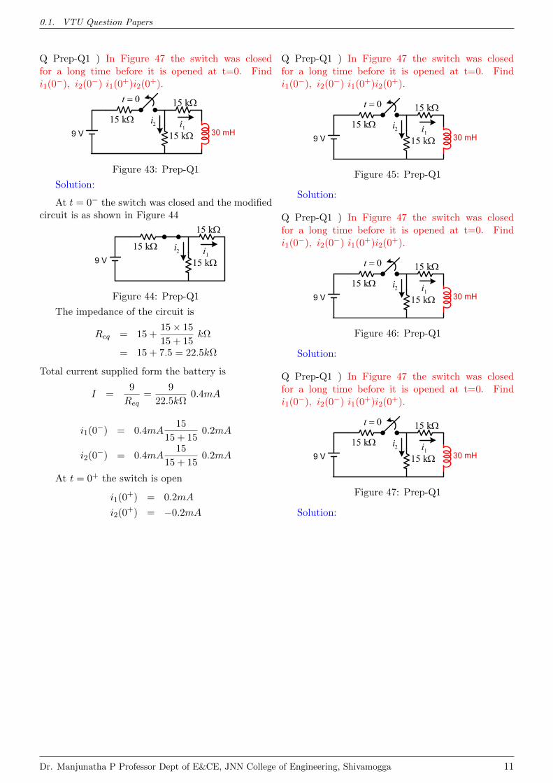
Q Prep-Q1 ) In Figure 47 the switch was closedfor a long time before it is opened at t=0. Findi1(0
−), i2(0−) i1(0
+)i2(0+).
1i30 mH
15 k2i
9 V 15 k
15 k0t
Figure 43: Prep-Q1
Solution:
At t = 0− the switch was closed and the modifiedcircuit is as shown in Figure 44
1i15 k
2i9 V 15 k
15 k
Figure 44: Prep-Q1
The impedance of the circuit is
Req = 15 +15× 15
15 + 15kΩ
= 15 + 7.5 = 22.5kΩ
Total current supplied form the battery is
I =9
Req=
9
22.5kΩ0.4mA
i1(0−) = 0.4mA
15
15 + 150.2mA
i2(0−) = 0.4mA
15
15 + 150.2mA
At t = 0+ the switch is open
i1(0+) = 0.2mA
i2(0+) = −0.2mA
Q Prep-Q1 ) In Figure 47 the switch was closedfor a long time before it is opened at t=0. Findi1(0
−), i2(0−) i1(0
+)i2(0+).
1i30 mH
15 k2i
9 V 15 k
15 k0t
Figure 45: Prep-Q1
Solution:
Q Prep-Q1 ) In Figure 47 the switch was closedfor a long time before it is opened at t=0. Findi1(0
−), i2(0−) i1(0
+)i2(0+).
1i30 mH
15 k2i
9 V 15 k
15 k0t
Figure 46: Prep-Q1
Solution:
Q Prep-Q1 ) In Figure 47 the switch was closedfor a long time before it is opened at t=0. Findi1(0
−), i2(0−) i1(0
+)i2(0+).
1i30 mH
15 k2i
9 V 15 k
15 k0t
Figure 47: Prep-Q1
Solution:
Dr. Manjunatha P Professor Dept of E&CE, JNN College of Engineering, Shivamogga 11
Related Documents