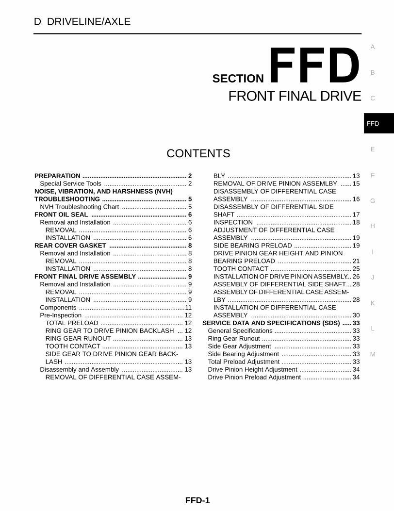
FFD-1 FRONT FINAL DRIVE D DRIVELINE/AXLE CONTENTS C E F G H I J K L M SECTION A B FFD PREPARATION .......................................................... 2 Special Service Tools .............................................. 2 NOISE, VIBRATION, AND HARSHNESS (NVH) TROUBLESHOOTING ............................................... 5 NVH Troubleshooting Chart .................................... 5 FRONT OIL SEAL ..................................................... 6 Removal and Installation ......................................... 6 REMOVAL ............................................................ 6 INSTALLATION .................................................... 6 REAR COVER GASKET ........................................... 8 Removal and Installation ......................................... 8 REMOVAL ............................................................ 8 INSTALLATION .................................................... 8 FRONT FINAL DRIVE ASSEMBLY ........................... 9 Removal and Installation ......................................... 9 REMOVAL ............................................................ 9 INSTALLATION .................................................... 9 Components ........................................................... 11 Pre-Inspection ....................................................... 12 TOTAL PRELOAD .............................................. 12 RING GEAR TO DRIVE PINION BACKLASH ... 12 RING GEAR RUNOUT ....................................... 13 TOOTH CONTACT ............................................. 13 SIDE GEAR TO DRIVE PINION GEAR BACK- LASH .................................................................. 13 Disassembly and Assembly .................................. 13 REMOVAL OF DIFFERENTIAL CASE ASSEM- BLY ..................................................................... 13 REMOVAL OF DRIVE PINION ASSEMLBY ...... 15 DISASSEMBLY OF DIFFERENTIAL CASE ASSEMBLY ........................................................ 16 DISASSEMBLY OF DIFFERENTIAL SIDE SHAFT ................................................................ 17 INSPECTION ..................................................... 18 ADJUSTMENT OF DIFFERENTIAL CASE ASSEMBLY ........................................................ 19 SIDE BEARING PRELOAD ................................ 19 DRIVE PINION GEAR HEIGHT AND PINION BEARING PRELOAD ......................................... 21 TOOTH CONTACT ............................................. 25 INSTALLATION OF DRIVE PINION ASSEMBLY ... 26 ASSEMBLY OF DIFFERENTIAL SIDE SHAFT... 28 ASSEMBLY OF DIFFERENTIAL CASE ASSEM- LBY ..................................................................... 28 INSTALLATION OF DIFFERENTIAL CASE ASSEMBLY ........................................................ 30 SERVICE DATA AND SPECIFICATIONS (SDS) ..... 33 General Specifications ........................................... 33 Ring Gear Runout .................................................. 33 Side Gear Adjustment ........................................... 33 Side Bearing Adjustment ....................................... 33 Total Preload Adjustment ....................................... 33 Drive Pinion Height Adjustment ............................. 34 Drive Pinion Preload Adjustment ........................... 34

Welcome message from author
This document is posted to help you gain knowledge. Please leave a comment to let me know what you think about it! Share it to your friends and learn new things together.
Transcript
FFD-1
FRONT FINAL DRIVE
D DRIVELINE/AXLE
CONTENTS
C
E
F
G
H
I
J
K
L
M
SECTION
A
B
FFD
PREPARATION ........................................................... 2Special Service Tools ............................................... 2
NOISE, VIBRATION, AND HARSHNESS (NVH) TROUBLESHOOTING ................................................ 5
NVH Troubleshooting Chart ..................................... 5FRONT OIL SEAL ...................................................... 6
Removal and Installation .......................................... 6REMOVAL ............................................................. 6INSTALLATION ..................................................... 6
REAR COVER GASKET ............................................ 8Removal and Installation .......................................... 8
REMOVAL ............................................................. 8INSTALLATION ..................................................... 8
FRONT FINAL DRIVE ASSEMBLY ............................ 9Removal and Installation .......................................... 9
REMOVAL ............................................................. 9INSTALLATION ..................................................... 9
Components ............................................................11Pre-Inspection ........................................................ 12
TOTAL PRELOAD ............................................... 12RING GEAR TO DRIVE PINION BACKLASH .... 12RING GEAR RUNOUT ........................................ 13TOOTH CONTACT .............................................. 13SIDE GEAR TO DRIVE PINION GEAR BACK-LASH ................................................................... 13
Disassembly and Assembly ................................... 13REMOVAL OF DIFFERENTIAL CASE ASSEM-
BLY ...................................................................... 13REMOVAL OF DRIVE PINION ASSEMLBY ....... 15DISASSEMBLY OF DIFFERENTIAL CASE ASSEMBLY ......................................................... 16DISASSEMBLY OF DIFFERENTIAL SIDE SHAFT ................................................................. 17INSPECTION ...................................................... 18ADJUSTMENT OF DIFFERENTIAL CASE ASSEMBLY ......................................................... 19SIDE BEARING PRELOAD ................................. 19DRIVE PINION GEAR HEIGHT AND PINION BEARING PRELOAD .......................................... 21TOOTH CONTACT .............................................. 25INSTALLATION OF DRIVE PINION ASSEMBLY ... 26ASSEMBLY OF DIFFERENTIAL SIDE SHAFT ... 28ASSEMBLY OF DIFFERENTIAL CASE ASSEM-LBY ...................................................................... 28INSTALLATION OF DIFFERENTIAL CASE ASSEMBLY ......................................................... 30
SERVICE DATA AND SPECIFICATIONS (SDS) ...... 33General Specifications ............................................ 33Ring Gear Runout ................................................... 33Side Gear Adjustment ............................................ 33Side Bearing Adjustment ........................................ 33Total Preload Adjustment ........................................ 33Drive Pinion Height Adjustment .............................. 34Drive Pinion Preload Adjustment ............................ 34
FFD-2
PREPARATION
PREPARATION PFP:00002
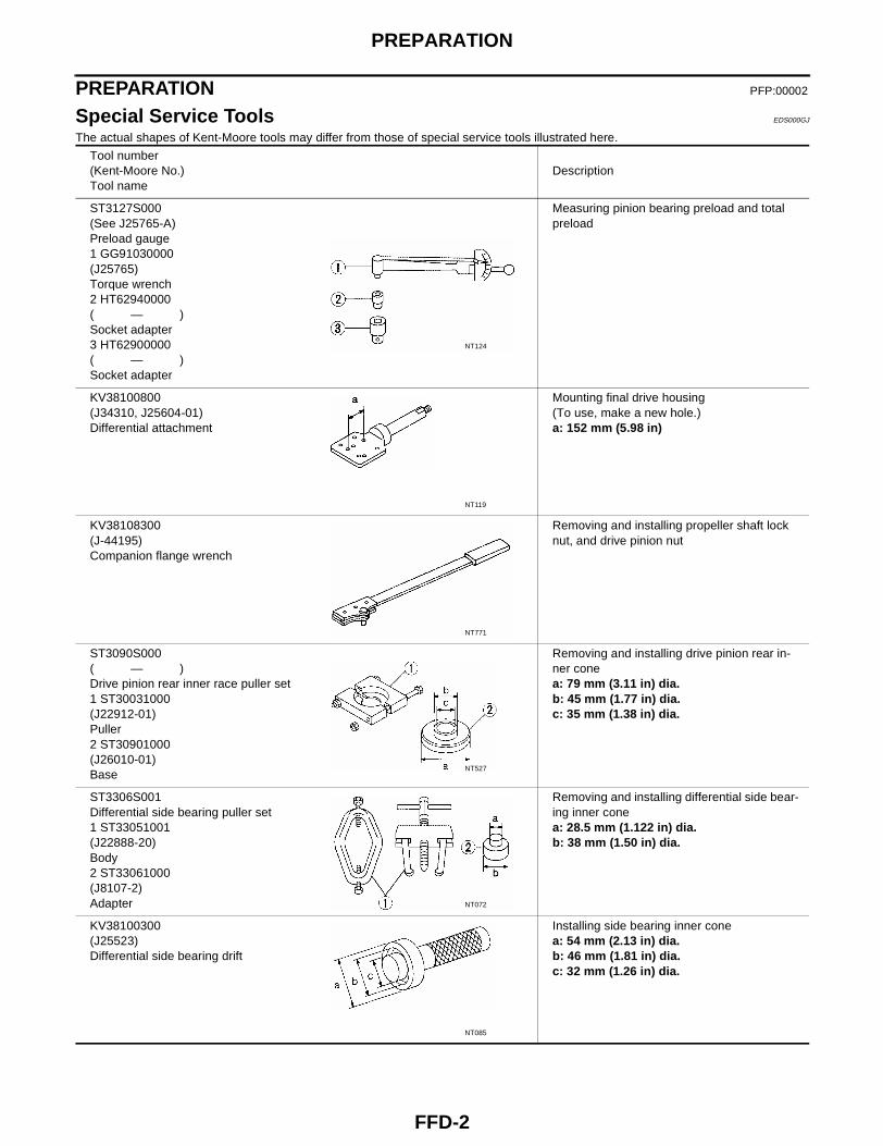
Special Service Tools EDS000GJ
The actual shapes of Kent-Moore tools may differ from those of special service tools illustrated here.
Tool number(Kent-Moore No.)Tool name
Description
ST3127S000(See J25765-A)Preload gauge1 GG91030000(J25765)Torque wrench2 HT62940000( — )Socket adapter3 HT62900000( — )Socket adapter
Measuring pinion bearing preload and total preload
KV38100800(J34310, J25604-01)Differential attachment
Mounting final drive housing(To use, make a new hole.)a: 152 mm (5.98 in)
KV38108300(J-44195)Companion flange wrench
Removing and installing propeller shaft lock nut, and drive pinion nut
ST3090S000( — )Drive pinion rear inner race puller set1 ST30031000(J22912-01)Puller2 ST30901000(J26010-01)Base
Removing and installing drive pinion rear in-ner conea: 79 mm (3.11 in) dia.b: 45 mm (1.77 in) dia.c: 35 mm (1.38 in) dia.
ST3306S001Differential side bearing puller set1 ST33051001(J22888-20)Body2 ST33061000(J8107-2)Adapter
Removing and installing differential side bear-ing inner conea: 28.5 mm (1.122 in) dia.b: 38 mm (1.50 in) dia.
KV38100300(J25523)Differential side bearing drift
Installing side bearing inner conea: 54 mm (2.13 in) dia.b: 46 mm (1.81 in) dia.c: 32 mm (1.26 in) dia.
NT124
NT119
NT771
NT527
NT072
NT085
PREPARATION
FFD-3
C
E
F
G
H
I
J
K
L
M
A
B
FFD
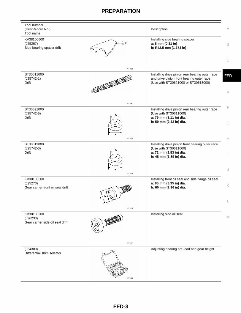
KV38100600(J25267)Side bearing spacer drift
Installing side bearing spacera: 8 mm (0.31 in)b: R42.5 mm (1.673 in)
ST30611000(J25742-1)Drift
Installing drive pinion rear bearing outer race and drive pinion front bearing outer race(Use with ST30621000 or ST30613000)
ST30621000(J25742-5)Drift
Installing drive pinion rear bearing outer race(Use with ST30611000)a: 79 mm (3.11 in) dia.b: 59 mm (2.32 in) dia.
ST30613000(J25742-3)Drift
Installing drive pinion front bearing outer race(Use with ST30611000)a: 72 mm (2.83 in) dia.b: 48 mm (1.89 in) dia.
KV38100500(J25273)Gear carrier front oil seal drift
Installing front oil seal and side flange oil seala: 85 mm (3.35 in) dia.b: 60 mm (2.36 in) dia.
KV38100200(J26233)Gear carrier side oil seal drift
Installing side oil seal
(J34309)Differential shim selector
Adjusting bearing pre-load and gear height
Tool number(Kent-Moore No.)Tool name
Description
NT528
NT090
NT073
NT073
NT115
NT120
NT134
FFD-4
PREPARATION
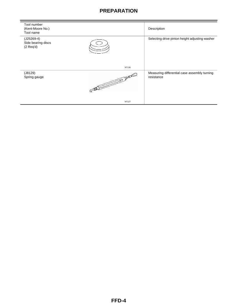
(J25269-4)Side bearing discs(2 Req'd)
Selecting drive pinion height adjusting washer
(J8129)Spring gauge
Measuring differential case assembly turning resistance
Tool number(Kent-Moore No.)Tool name
Description
NT136
NT127
NOISE, VIBRATION, AND HARSHNESS (NVH) TROUBLESHOOTING
FFD-5
C
E
F
G
H
I
J
K
L
M
A
B
FFD
NOISE, VIBRATION, AND HARSHNESS (NVH) TROUBLESHOOTING PFP:00003
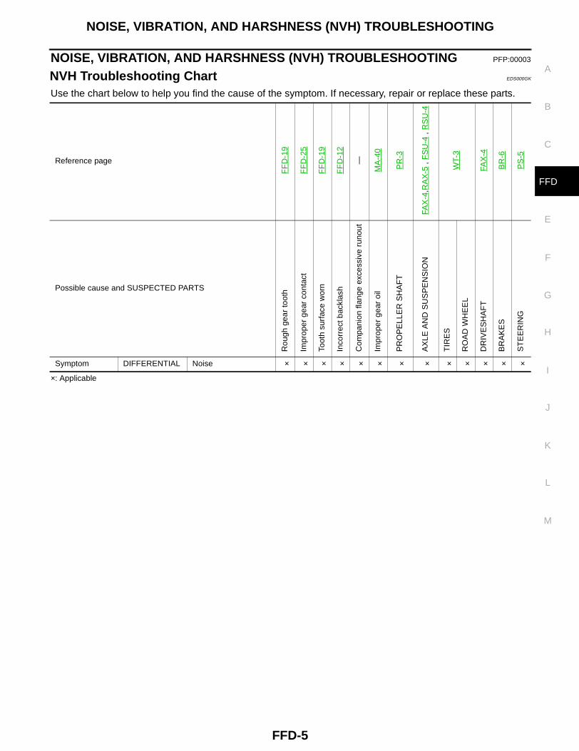
NVH Troubleshooting Chart EDS000GK
Use the chart below to help you find the cause of the symptom. If necessary, repair or replace these parts.
×: Applicable
Reference page
FF
D-1
9
FF
D-2
5
FF
D-1
9
FF
D-1
2
—
MA
-40
PR
-3
FAX
-4,R
AX
-5 ,
FS
U-4
, R
SU
-4
WT-
3
FAX
-4
BR
-6
PS
-5
Possible cause and SUSPECTED PARTSR
ough
gea
r to
oth
Impr
oper
gea
r co
ntac
t
Toot
h su
rfac
e w
orn
Inco
rrec
t bac
klas
h
Com
pani
on fl
ange
exc
essi
ve r
unou
t
Impr
oper
gea
r oi
l
PR
OP
ELL
ER
SH
AF
T
AX
LE A
ND
SU
SP
EN
SIO
N
TIR
ES
RO
AD
WH
EE
L
DR
IVE
SH
AF
T
BR
AK
ES
ST
EE
RIN
G
Symptom DIFFERENTIAL Noise × × × × × × × × × × × × ×
FFD-6
FRONT OIL SEAL
FRONT OIL SEAL PFP:38189
Removal and Installation EDS000SX
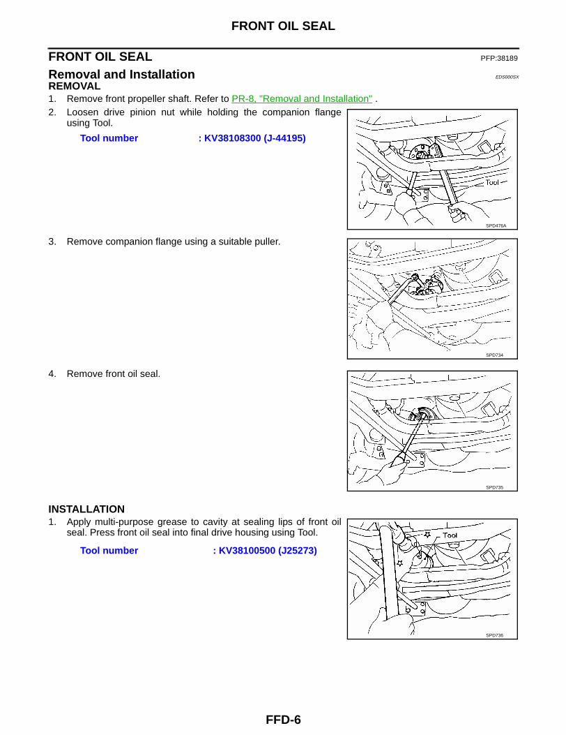
REMOVAL1. Remove front propeller shaft. Refer to PR-8, "Removal and Installation" .2. Loosen drive pinion nut while holding the companion flange
using Tool.
3. Remove companion flange using a suitable puller.
4. Remove front oil seal.
INSTALLATION1. Apply multi-purpose grease to cavity at sealing lips of front oil
seal. Press front oil seal into final drive housing using Tool.
Tool number : KV38108300 (J-44195)
SPD476A
SPD734
SPD735
Tool number : KV38100500 (J25273)
SPD736
FRONT OIL SEAL
FFD-7
C
E
F
G
H
I
J
K
L
M
A
B
FFD
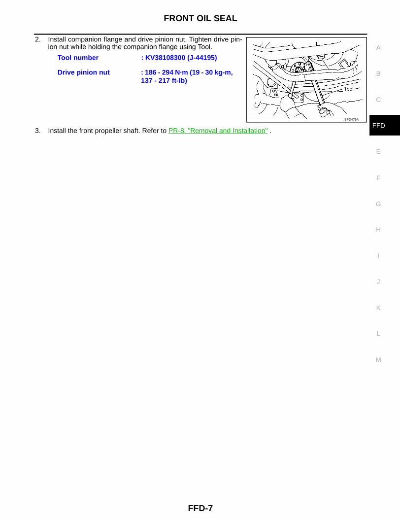
2. Install companion flange and drive pinion nut. Tighten drive pin-ion nut while holding the companion flange using Tool.
3. Install the front propeller shaft. Refer to PR-8, "Removal and Installation" .
Tool number : KV38108300 (J-44195)
Drive pinion nut : 186 - 294 N·m (19 - 30 kg-m, 137 - 217 ft-lb)
SPD476A
FFD-8
REAR COVER GASKET
REAR COVER GASKET PFP:38320
Removal and Installation EDS000SW
REMOVAL1. Drain gear oil. Refer to MA-40, "Changing Differential Gear Oil" .2. Remove rear cover and rear cover gasket.
INSTALLATION1. Install new rear cover gasket and rear cover.
2. Fill final drive with recommended gear oil. Refer to MA-12, "RECOMMENDED FLUIDS AND LUBRI-CANTS" .
Rear cover bolt : 39 - 49 N·m (4 - 5 kg-m, 29 - 36 ft-lb)
FRONT FINAL DRIVE ASSEMBLY
FFD-9
C
E
F
G
H
I
J
K
L
M
A
B
FFD
FRONT FINAL DRIVE ASSEMBLY PFP:38500
Removal and Installation EDS000SY
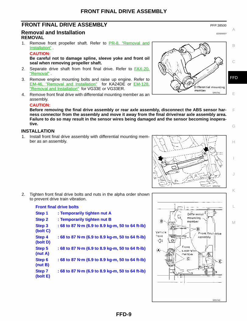
REMOVAL1. Remove front propeller shaft. Refer to PR-8, "Removal and
Installation" .CAUTION:Be careful not to damage spline, sleeve yoke and front oilseal when removing propeller shaft.
2. Separate drive shaft from front final drive. Refer to FAX-20,"Removal" .
3. Remove engine mounting bolts and raise up engine. Refer toEM-46, "Removal and Installation" for KA24DE or EM-128,"Removal and Installation" for VG33E or VG33ER.
4. Remove front final drive with differential mounting member as anassembly.CAUTION:Before removing the final drive assembly or rear axle assembly, disconnect the ABS sensor har-ness connector from the assembly and move it away from the final drive/rear axle assembly area.Failure to do so may result in the sensor wires being damaged and the sensor becoming inopera-tive.
INSTALLATION1. Install front final drive assembly with differential mounting mem-
ber as an assembly.
2. Tighten front final drive bolts and nuts in the alpha order shownto prevent drive train vibration.
SPD741
SPD742
Front final drive boltsStep 1 : Temporarily tighten nut AStep 2 : Temporarily tighten nut BStep 3 (bolt C)
: 68 to 87 N·m (6.9 to 8.9 kg-m, 50 to 64 ft-lb)
Step 4 (bolt D)
: 68 to 87 N·m (6.9 to 8.9 kg-m, 50 to 64 ft-lb)
Step 5 (nut A)
: 68 to 87 N·m (6.9 to 8.9 kg-m, 50 to 64 ft-lb)
Step 6 (nut B)
: 68 to 87 N·m (6.9 to 8.9 kg-m, 50 to 64 ft-lb)
Step 7 (bolt E)
: 68 to 87 N·m (6.9 to 8.9 kg-m, 50 to 64 ft-lb)
SPD743
FFD-10
FRONT FINAL DRIVE ASSEMBLY
3. Lower engine and install engine mounting bolts. Refer to EM-46, "Removal and Installation" for KA24DEor EM-128, "Removal and Installation" for VG33E or VG33ER.
4. Install drive shaft. Refer to FAX-25, "Installation" .5. Install front propeller shaft. Refer to PR-8, "Removal and Installation" .
FRONT FINAL DRIVE ASSEMBLY
FFD-11
C
E
F
G
H
I
J
K
L
M
A
B
FFD
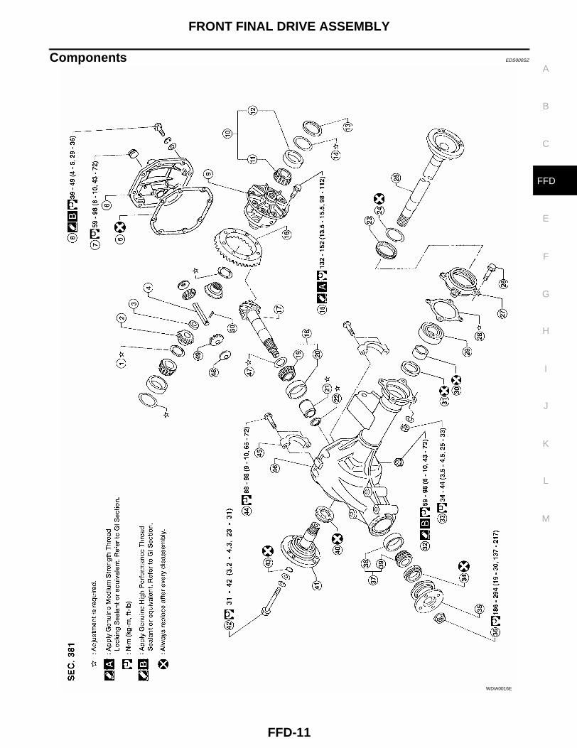
Components EDS000SZ
WDIA0016E
FFD-12
FRONT FINAL DRIVE ASSEMBLY
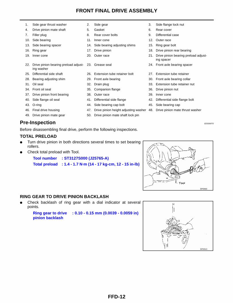
Pre-Inspection EDS000T0
Before disassembling final drive, perform the following inspections.
TOTAL PRELOAD● Turn drive pinion in both directions several times to set bearing
rollers.● Check total preload with Tool.
RING GEAR TO DRIVE PINION BACKLASH● Check backlash of ring gear with a dial indicator at several
points.
1. Side gear thrust washer 2. Side gear 3. Side flange lock nut
4. Drive pinion mate shaft 5. Gasket 6. Rear cover
7. Filler plug 8. Rear cover bolts 9. Differential case
10. Side bearing 11. Inner cone 12. Outer race
13. Side bearing spacer 14. Side bearing adjusting shims 15. Ring gear bolt
16. Ring gear 17. Drive pinion 18. Drive pinion rear bearing
19. Inner cone 20. Outer race 21. Drive pinion bearing preload adjust-ing spacer
22. Drive pinion bearing preload adjust-ing washer
23. Grease seal 24. Front axle bearing spacer
25. Differential side shaft 26. Extension tube retainer bolt 27. Extension tube retainer
28. Bearing adjusting shim 29. Front axle bearing 30. Front axle bearing collar
31. Oil seal 32. Drain plug 33. Extension tube retainer nut
34. Front oil seal 35. Companion flange 36. Drive pinion nut
37. Drive pinion front bearing 38. Outer race 39. Inner cone
40. Side flange oil seal 41. Differential side flange 42. Differential side flange bolt
43. O-ring 44. Side bearing cap bolt 45. Side bearing cap
46. Final drive housing 47. Drive pinion height adjusting washer 48. Drive pinion mate thrust washer
49. Drive pinion mate gear 50. Drive pinion mate shaft lock pin
Tool number : ST3127S000 (J25765-A)Total preload : 1.4 - 1.7 N·m (14 - 17 kg-cm, 12 - 15 in-lb)
SPD664
Ring gear to drive pinion backlash
: 0.10 - 0.15 mm (0.0039 - 0.0059 in)
SPD513
FRONT FINAL DRIVE ASSEMBLY
FFD-13
C
E
F
G
H
I
J
K
L
M
A
B
FFD
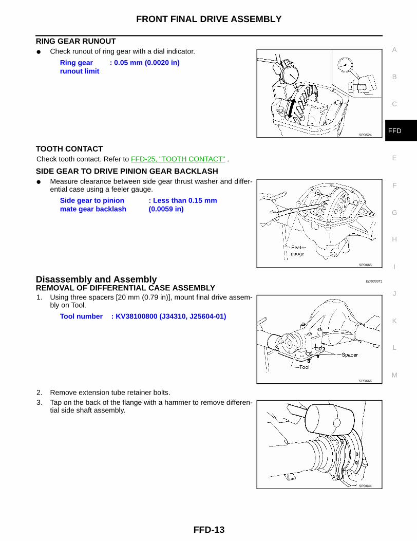
RING GEAR RUNOUT● Check runout of ring gear with a dial indicator.
TOOTH CONTACTCheck tooth contact. Refer to FFD-25, "TOOTH CONTACT" .
SIDE GEAR TO DRIVE PINION GEAR BACKLASH● Measure clearance between side gear thrust washer and differ-
ential case using a feeler gauge.
Disassembly and Assembly EDS000T1
REMOVAL OF DIFFERENTIAL CASE ASSEMBLY1. Using three spacers [20 mm (0.79 in)], mount final drive assem-
bly on Tool.
2. Remove extension tube retainer bolts.3. Tap on the back of the flange with a hammer to remove differen-
tial side shaft assembly.
Ring gear runout limit
: 0.05 mm (0.0020 in)
SPD524
Side gear to pinion mate gear backlash
: Less than 0.15 mm (0.0059 in)
SPD665
Tool number : KV38100800 (J34310, J25604-01)
SPD666
SPD644
FFD-14
FRONT FINAL DRIVE ASSEMBLY
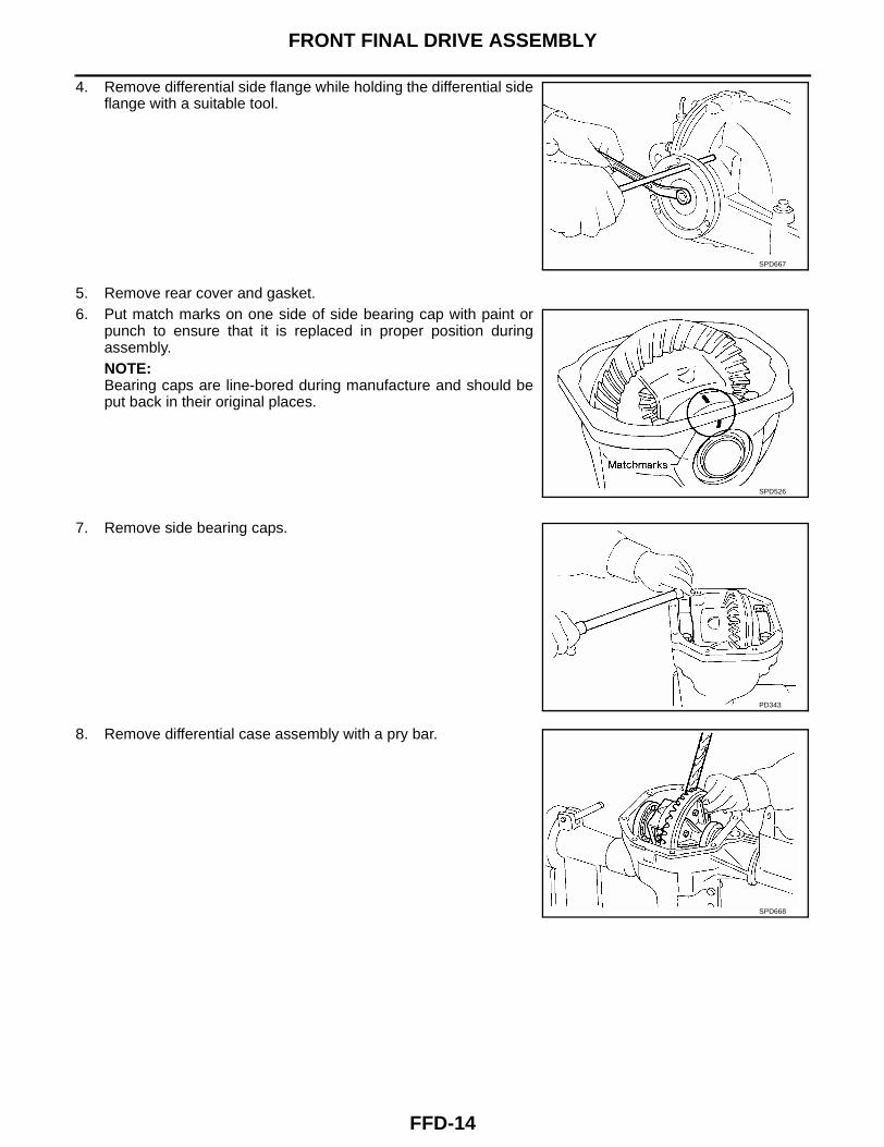
4. Remove differential side flange while holding the differential sideflange with a suitable tool.
5. Remove rear cover and gasket.6. Put match marks on one side of side bearing cap with paint or
punch to ensure that it is replaced in proper position duringassembly.NOTE:Bearing caps are line-bored during manufacture and should beput back in their original places.
7. Remove side bearing caps.
8. Remove differential case assembly with a pry bar.
SPD667
SPD526
PD343
SPD668
FRONT FINAL DRIVE ASSEMBLY
FFD-15
C
E
F
G
H
I
J
K
L
M
A
B
FFD
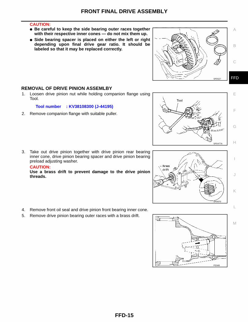
CAUTION:● Be careful to keep the side bearing outer races together
with their respective inner cones — do not mix them up.● Side bearing spacer is placed on either the left or right
depending upon final drive gear ratio. It should belabeled so that it may be replaced correctly.
REMOVAL OF DRIVE PINION ASSEMLBY1. Loosen drive pinion nut while holding companion flange using
Tool.
2. Remove companion flange with suitable puller.
3. Take out drive pinion together with drive pinion rear bearinginner cone, drive pinion bearing spacer and drive pinion bearingpreload adjusting washer.CAUTION:Use a brass drift to prevent damage to the drive pinionthreads.
4. Remove front oil seal and drive pinion front bearing inner cone.5. Remove drive pinion bearing outer races with a brass drift.
SPD527
Tool number : KV38108300 (J-44195)
SPD477A
SPD670
PD349
FFD-16
FRONT FINAL DRIVE ASSEMBLY
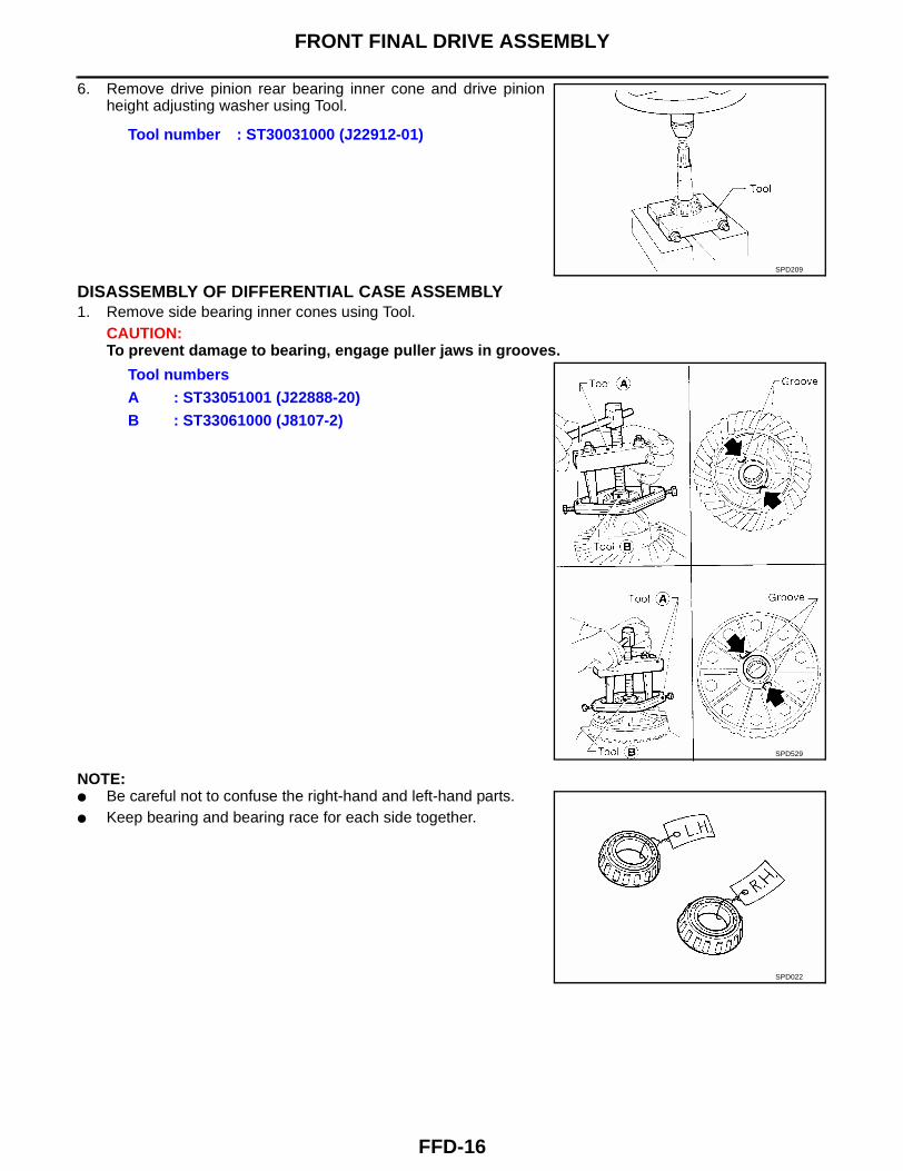
6. Remove drive pinion rear bearing inner cone and drive pinionheight adjusting washer using Tool.
DISASSEMBLY OF DIFFERENTIAL CASE ASSEMBLY1. Remove side bearing inner cones using Tool.
CAUTION:To prevent damage to bearing, engage puller jaws in grooves.
NOTE:● Be careful not to confuse the right-hand and left-hand parts.● Keep bearing and bearing race for each side together.
Tool number : ST30031000 (J22912-01)
SPD209
Tool numbersA : ST33051001 (J22888-20)B : ST33061000 (J8107-2)
SPD529
SPD022
FRONT FINAL DRIVE ASSEMBLY
FFD-17
C
E
F
G
H
I
J
K
L
M
A
B
FFD
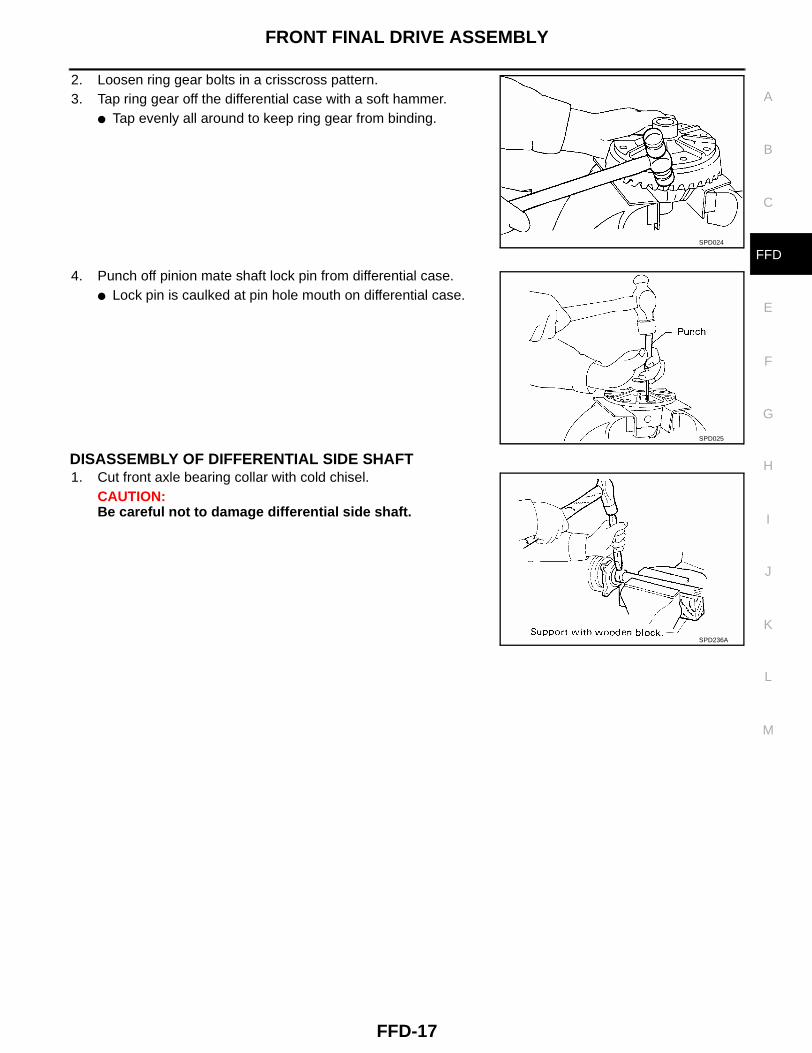
2. Loosen ring gear bolts in a crisscross pattern.3. Tap ring gear off the differential case with a soft hammer.
● Tap evenly all around to keep ring gear from binding.
4. Punch off pinion mate shaft lock pin from differential case.● Lock pin is caulked at pin hole mouth on differential case.
DISASSEMBLY OF DIFFERENTIAL SIDE SHAFT1. Cut front axle bearing collar with cold chisel.
CAUTION:Be careful not to damage differential side shaft.
SPD024
SPD025
SPD236A
FFD-18
FRONT FINAL DRIVE ASSEMBLY
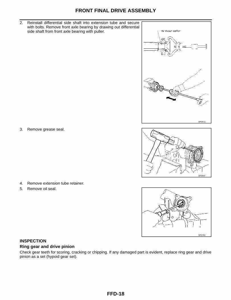
2. Reinstall differential side shaft into extension tube and securewith bolts. Remove front axle bearing by drawing out differentialside shaft from front axle bearing with puller.
3. Remove grease seal.
4. Remove extension tube retainer.5. Remove oil seal.
INSPECTIONRing gear and drive pinionCheck gear teeth for scoring, cracking or chipping. If any damaged part is evident, replace ring gear and drivepinion as a set (hypoid gear set).
SPD672
SPD647
SPD781
FRONT FINAL DRIVE ASSEMBLY
FFD-19
C
E
F
G
H
I
J
K
L
M
A
B
FFD
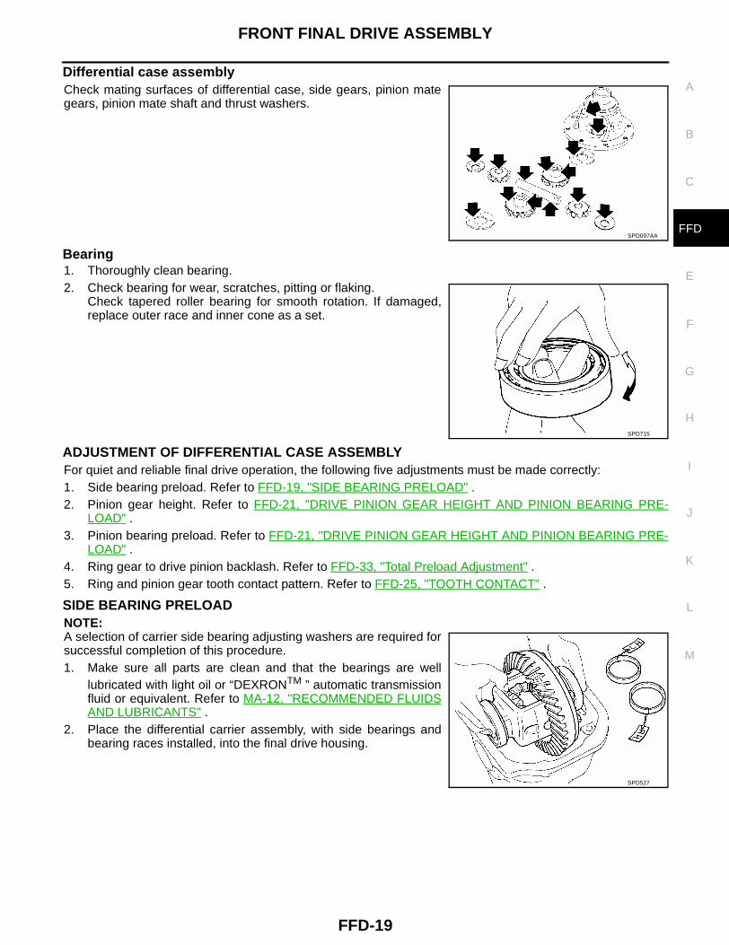
Differential case assemblyCheck mating surfaces of differential case, side gears, pinion mategears, pinion mate shaft and thrust washers.
Bearing1. Thoroughly clean bearing.2. Check bearing for wear, scratches, pitting or flaking.
Check tapered roller bearing for smooth rotation. If damaged,replace outer race and inner cone as a set.
ADJUSTMENT OF DIFFERENTIAL CASE ASSEMBLYFor quiet and reliable final drive operation, the following five adjustments must be made correctly:1. Side bearing preload. Refer to FFD-19, "SIDE BEARING PRELOAD" .2. Pinion gear height. Refer to FFD-21, "DRIVE PINION GEAR HEIGHT AND PINION BEARING PRE-
LOAD" .3. Pinion bearing preload. Refer to FFD-21, "DRIVE PINION GEAR HEIGHT AND PINION BEARING PRE-
LOAD" .4. Ring gear to drive pinion backlash. Refer to FFD-33, "Total Preload Adjustment" .5. Ring and pinion gear tooth contact pattern. Refer to FFD-25, "TOOTH CONTACT" .
SIDE BEARING PRELOADNOTE:A selection of carrier side bearing adjusting washers are required forsuccessful completion of this procedure.1. Make sure all parts are clean and that the bearings are well
lubricated with light oil or “DEXRONTM ” automatic transmissionfluid or equivalent. Refer to MA-12, "RECOMMENDED FLUIDSAND LUBRICANTS" .
2. Place the differential carrier assembly, with side bearings andbearing races installed, into the final drive housing.
SPD097AA
SPD715
SPD527
FFD-20
FRONT FINAL DRIVE ASSEMBLY
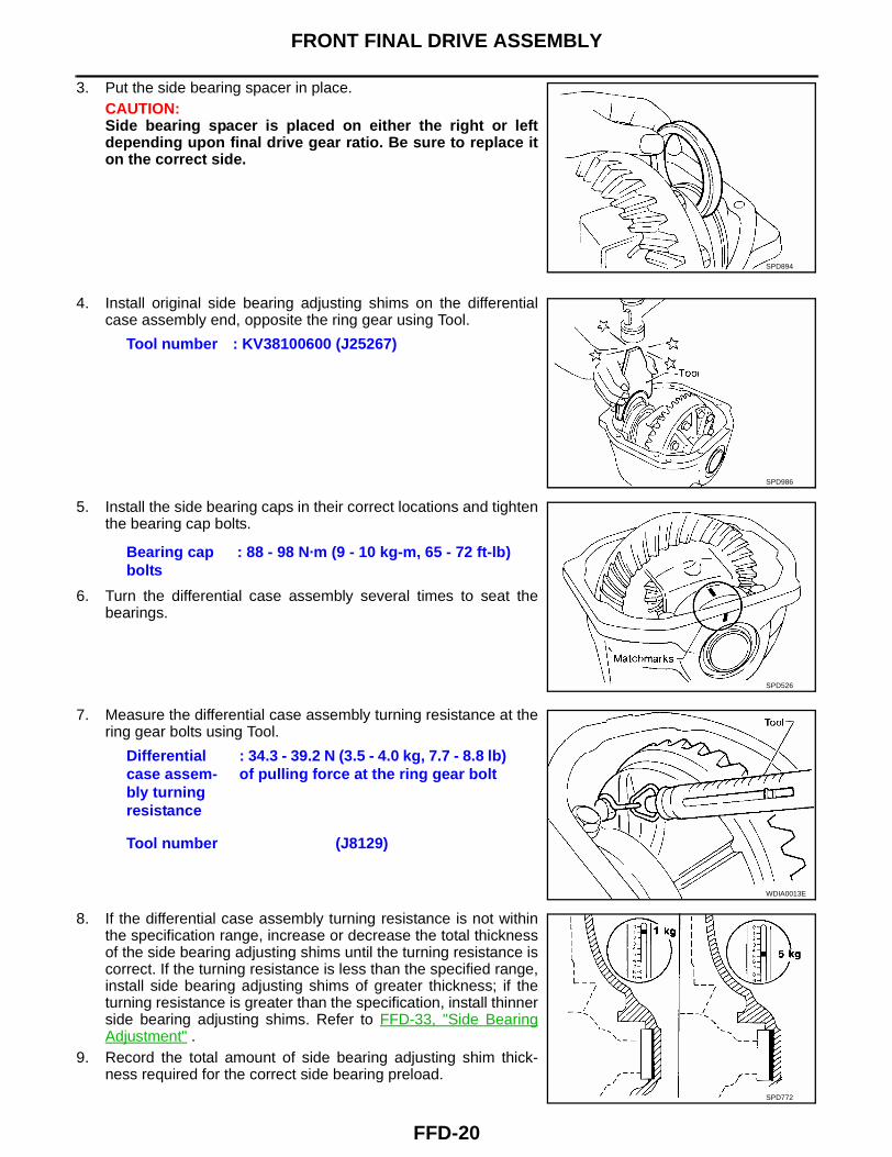
3. Put the side bearing spacer in place.CAUTION:Side bearing spacer is placed on either the right or leftdepending upon final drive gear ratio. Be sure to replace iton the correct side.
4. Install original side bearing adjusting shims on the differentialcase assembly end, opposite the ring gear using Tool.
5. Install the side bearing caps in their correct locations and tightenthe bearing cap bolts.
6. Turn the differential case assembly several times to seat thebearings.
7. Measure the differential case assembly turning resistance at thering gear bolts using Tool.
8. If the differential case assembly turning resistance is not withinthe specification range, increase or decrease the total thicknessof the side bearing adjusting shims until the turning resistance iscorrect. If the turning resistance is less than the specified range,install side bearing adjusting shims of greater thickness; if theturning resistance is greater than the specification, install thinnerside bearing adjusting shims. Refer to FFD-33, "Side BearingAdjustment" .
9. Record the total amount of side bearing adjusting shim thick-ness required for the correct side bearing preload.
SPD894
Tool number : KV38100600 (J25267)
SPD986
Bearing cap bolts
: 88 - 98 N·m (9 - 10 kg-m, 65 - 72 ft-lb)
SPD526
Differential case assem-bly turning resistance
: 34.3 - 39.2 N (3.5 - 4.0 kg, 7.7 - 8.8 lb) of pulling force at the ring gear bolt
Tool number (J8129)
WDIA0013E
SPD772
FRONT FINAL DRIVE ASSEMBLY
FFD-21
C
E
F
G
H
I
J
K
L
M
A
B
FFD
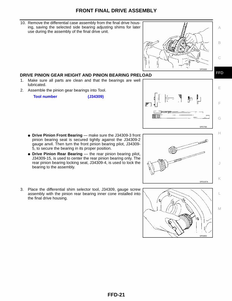
10. Remove the differential case assembly from the final drive hous-ing, saving the selected side bearing adjusting shims for lateruse during the assembly of the final drive unit.
DRIVE PINION GEAR HEIGHT AND PINION BEARING PRELOAD1. Make sure all parts are clean and that the bearings are well
lubricated.2. Assemble the pinion gear bearings into Tool.
● Drive Pinion Front Bearing — make sure the J34309-3 frontpinion bearing seat is secured tightly against the J34309-2gauge anvil. Then turn the front pinion bearing pilot, J34309-5, to secure the bearing in its proper position.
● Drive Pinion Rear Bearing — the rear pinion bearing pilot,J34309-15, is used to center the rear pinion bearing only. Therear pinion bearing locking seat, J34309-4, is used to lock thebearing to the assembly.
3. Place the differential shim selector tool, J34309, gauge screwassembly with the pinion rear bearing inner cone installed intothe final drive housing.
SPD668
Tool number (J34309)
SPD769
SPD197A
SPD893
FFD-22
FRONT FINAL DRIVE ASSEMBLY
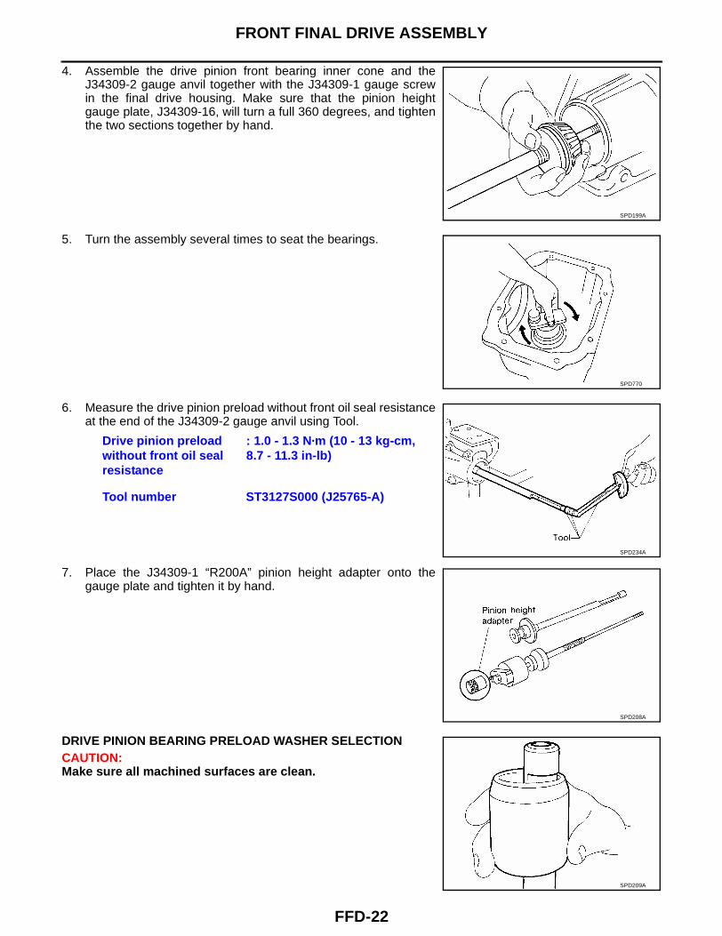
4. Assemble the drive pinion front bearing inner cone and theJ34309-2 gauge anvil together with the J34309-1 gauge screwin the final drive housing. Make sure that the pinion heightgauge plate, J34309-16, will turn a full 360 degrees, and tightenthe two sections together by hand.
5. Turn the assembly several times to seat the bearings.
6. Measure the drive pinion preload without front oil seal resistanceat the end of the J34309-2 gauge anvil using Tool.
7. Place the J34309-1 “R200A” pinion height adapter onto thegauge plate and tighten it by hand.
DRIVE PINION BEARING PRELOAD WASHER SELECTIONCAUTION:Make sure all machined surfaces are clean.
SPD199A
SPD770
Drive pinion preload without front oil seal resistance
: 1.0 - 1.3 N·m (10 - 13 kg-cm, 8.7 - 11.3 in-lb)
Tool number ST3127S000 (J25765-A)
SPD234A
SPD208A
SPD209A
FRONT FINAL DRIVE ASSEMBLY
FFD-23
C
E
F
G
H
I
J
K
L
M
A
B
FFD
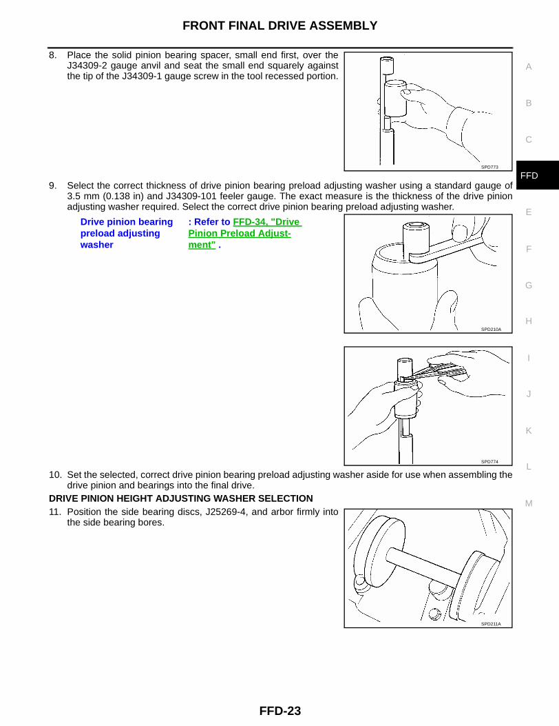
8. Place the solid pinion bearing spacer, small end first, over theJ34309-2 gauge anvil and seat the small end squarely againstthe tip of the J34309-1 gauge screw in the tool recessed portion.
9. Select the correct thickness of drive pinion bearing preload adjusting washer using a standard gauge of3.5 mm (0.138 in) and J34309-101 feeler gauge. The exact measure is the thickness of the drive pinionadjusting washer required. Select the correct drive pinion bearing preload adjusting washer.
10. Set the selected, correct drive pinion bearing preload adjusting washer aside for use when assembling thedrive pinion and bearings into the final drive.
DRIVE PINION HEIGHT ADJUSTING WASHER SELECTION11. Position the side bearing discs, J25269-4, and arbor firmly into
the side bearing bores.
SPD773
Drive pinion bearing preload adjusting washer
: Refer to FFD-34, "Drive Pinion Preload Adjust-ment" .
SPD210A
SPD774
SPD211A
FFD-24
FRONT FINAL DRIVE ASSEMBLY
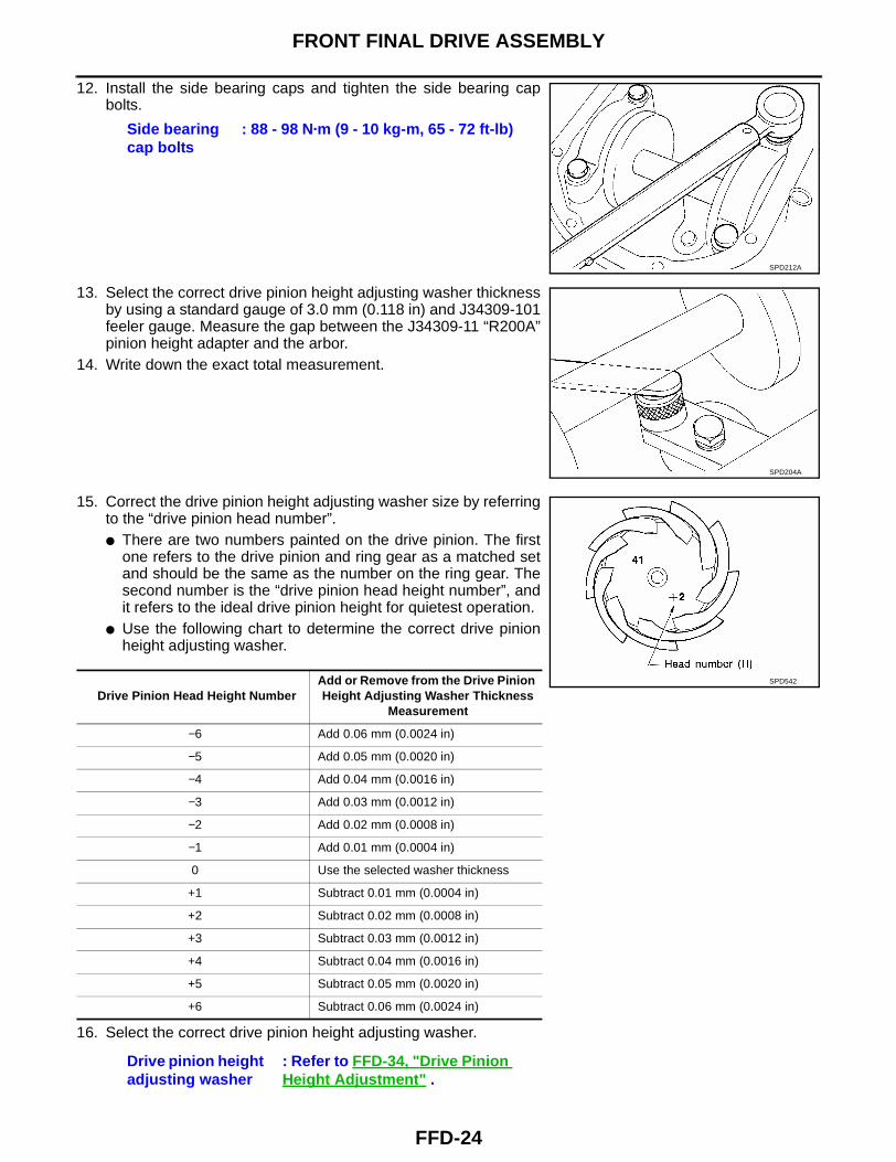
12. Install the side bearing caps and tighten the side bearing capbolts.
13. Select the correct drive pinion height adjusting washer thicknessby using a standard gauge of 3.0 mm (0.118 in) and J34309-101feeler gauge. Measure the gap between the J34309-11 “R200A”pinion height adapter and the arbor.
14. Write down the exact total measurement.
15. Correct the drive pinion height adjusting washer size by referringto the “drive pinion head number”.● There are two numbers painted on the drive pinion. The first
one refers to the drive pinion and ring gear as a matched setand should be the same as the number on the ring gear. Thesecond number is the “drive pinion head height number”, andit refers to the ideal drive pinion height for quietest operation.
● Use the following chart to determine the correct drive pinionheight adjusting washer.
16. Select the correct drive pinion height adjusting washer.
Side bearing cap bolts
: 88 - 98 N·m (9 - 10 kg-m, 65 - 72 ft-lb)
SPD212A
SPD204A
Drive Pinion Head Height NumberAdd or Remove from the Drive Pinion Height Adjusting Washer Thickness
Measurement
−6 Add 0.06 mm (0.0024 in)
−5 Add 0.05 mm (0.0020 in)
−4 Add 0.04 mm (0.0016 in)
−3 Add 0.03 mm (0.0012 in)
−2 Add 0.02 mm (0.0008 in)
−1 Add 0.01 mm (0.0004 in)
0 Use the selected washer thickness
+1 Subtract 0.01 mm (0.0004 in)
+2 Subtract 0.02 mm (0.0008 in)
+3 Subtract 0.03 mm (0.0012 in)
+4 Subtract 0.04 mm (0.0016 in)
+5 Subtract 0.05 mm (0.0020 in)
+6 Subtract 0.06 mm (0.0024 in)
Drive pinion height adjusting washer
: Refer to FFD-34, "Drive Pinion Height Adjustment" .
SPD542
FRONT FINAL DRIVE ASSEMBLY
FFD-25
C
E
F
G
H
I
J
K
L
M
A
B
FFD
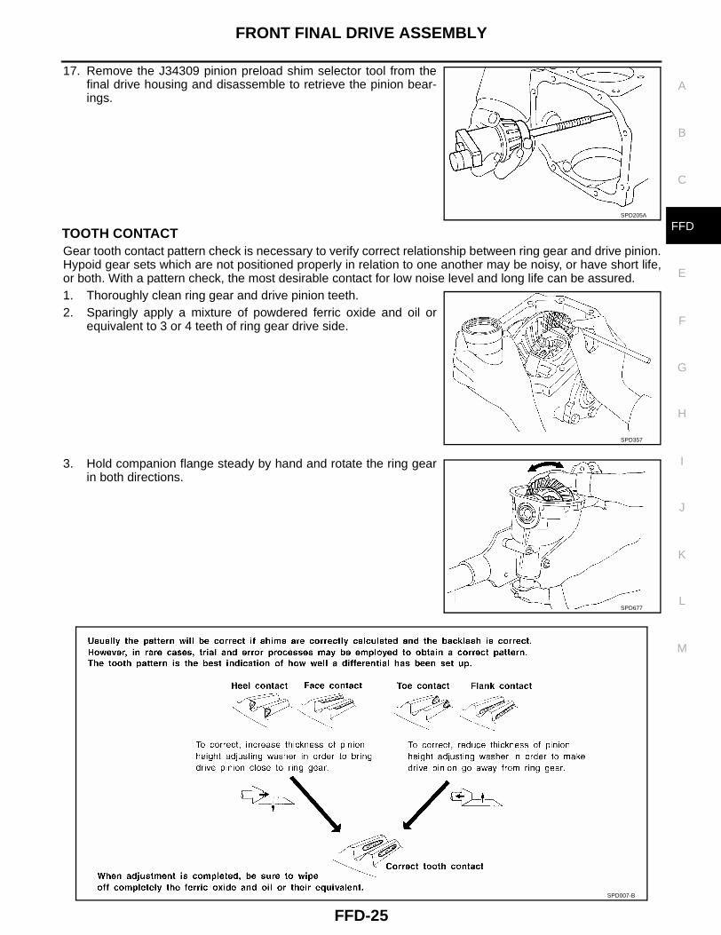
17. Remove the J34309 pinion preload shim selector tool from thefinal drive housing and disassemble to retrieve the pinion bear-ings.
TOOTH CONTACTGear tooth contact pattern check is necessary to verify correct relationship between ring gear and drive pinion.Hypoid gear sets which are not positioned properly in relation to one another may be noisy, or have short life,or both. With a pattern check, the most desirable contact for low noise level and long life can be assured.1. Thoroughly clean ring gear and drive pinion teeth.2. Sparingly apply a mixture of powdered ferric oxide and oil or
equivalent to 3 or 4 teeth of ring gear drive side.
3. Hold companion flange steady by hand and rotate the ring gearin both directions.
SPD205A
SPD357
SPD677
SPD007-B
FFD-26
FRONT FINAL DRIVE ASSEMBLY
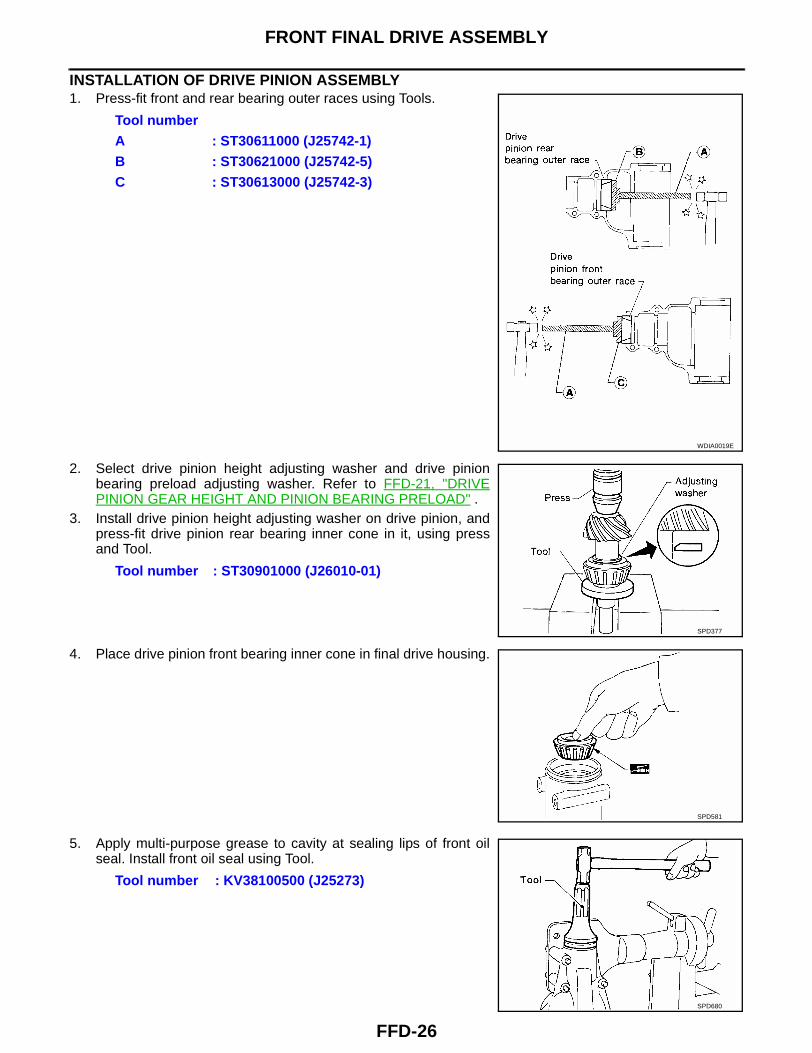
INSTALLATION OF DRIVE PINION ASSEMBLY1. Press-fit front and rear bearing outer races using Tools.
2. Select drive pinion height adjusting washer and drive pinionbearing preload adjusting washer. Refer to FFD-21, "DRIVEPINION GEAR HEIGHT AND PINION BEARING PRELOAD" .
3. Install drive pinion height adjusting washer on drive pinion, andpress-fit drive pinion rear bearing inner cone in it, using pressand Tool.
4. Place drive pinion front bearing inner cone in final drive housing.
5. Apply multi-purpose grease to cavity at sealing lips of front oilseal. Install front oil seal using Tool.
Tool numberA : ST30611000 (J25742-1)B : ST30621000 (J25742-5)C : ST30613000 (J25742-3)
WDIA0019E
Tool number : ST30901000 (J26010-01)
SPD377
SPD581
Tool number : KV38100500 (J25273)
SPD680
FRONT FINAL DRIVE ASSEMBLY
FFD-27
C
E
F
G
H
I
J
K
L
M
A
B
FFD
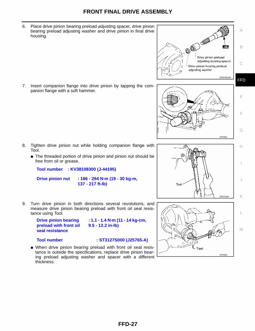
6. Place drive pinion bearing preload adjusting spacer, drive pinionbearing preload adjusting washer and drive pinion in final drivehousing.
7. Insert companion flange into drive pinion by tapping the com-panion flange with a soft hammer.
8. Tighten drive pinion nut while holding companion flange withTool.● The threaded portion of drive pinion and pinion nut should be
free from oil or grease.
9. Turn drive pinion in both directions several revolutions, andmeasure drive pinion bearing preload with front oil seal resis-tance using Tool.
● When drive pinion bearing preload with front oil seal resis-tance is outside the specifications, replace drive pinion bear-ing preload adjusting washer and spacer with a differentthickness.
WDIA0020E
SPD681
Tool number : KV38108300 (J-44195)
Drive pinion nut : 186 - 294 N·m (19 - 30 kg-m, 137 - 217 ft-lb)
SPD478A
Drive pinion bearing preload with front oil seal resistance
: 1.1 - 1.4 N·m (11 - 14 kg-cm, 9.5 - 12.2 in-lb)
Tool number : ST3127S000 (J25765-A)
SPD664
FFD-28
FRONT FINAL DRIVE ASSEMBLY
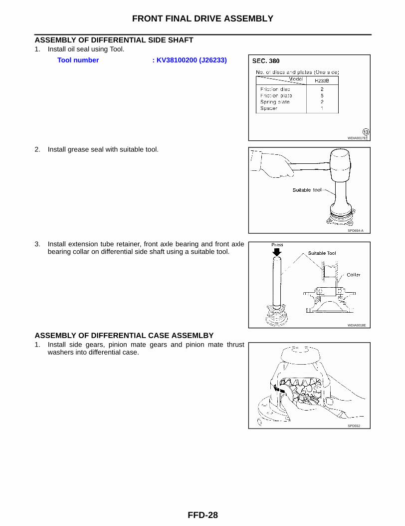
ASSEMBLY OF DIFFERENTIAL SIDE SHAFT1. Install oil seal using Tool.
2. Install grease seal with suitable tool.
3. Install extension tube retainer, front axle bearing and front axlebearing collar on differential side shaft using a suitable tool.
ASSEMBLY OF DIFFERENTIAL CASE ASSEMLBY1. Install side gears, pinion mate gears and pinion mate thrust
washers into differential case.
Tool number : KV38100200 (J26233)
WDIA0017E
SPD654-A
WDIA0018E
SPD552
FRONT FINAL DRIVE ASSEMBLY
FFD-29
C
E
F
G
H
I
J
K
L
M
A
B
FFD
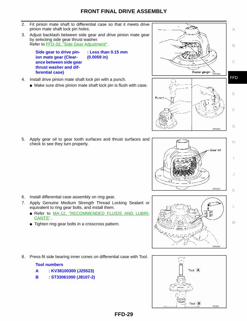
2. Fit pinion mate shaft to differential case so that it meets drivepinion mate shaft lock pin holes.
3. Adjust backlash between side gear and drive pinion mate gearby selecting side gear thrust washer.Refer to FFD-33, "Side Gear Adjustment" .
4. Install drive pinion mate shaft lock pin with a punch.● Make sure drive pinion mate shaft lock pin is flush with case.
5. Apply gear oil to gear tooth surfaces and thrust surfaces andcheck to see they turn properly.
6. Install differential case assembly on ring gear.7. Apply Genuine Medium Strength Thread Locking Sealant or
equivalent to ring gear bolts, and install them.● Refer to MA-12, "RECOMMENDED FLUIDS AND LUBRI-
CANTS" .● Tighten ring gear bolts in a crisscross pattern.
8. Press-fit side bearing inner cones on differential case with Tool.
Side gear to drive pin-ion mate gear (Clear-ance between side gear thrust washer and dif-ferential case)
: Less than 0.15 mm (0.0059 in)
SPD258
SPD030
SPD322
SPD554
Tool numbersA : KV38100300 (J25523)B : ST33061000 (J8107-2)
PD353
FFD-30
FRONT FINAL DRIVE ASSEMBLY
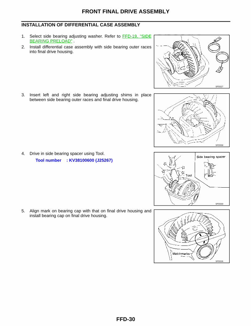
INSTALLATION OF DIFFERENTIAL CASE ASSEMBLY
1. Select side bearing adjusting washer. Refer to FFD-19, "SIDEBEARING PRELOAD" .
2. Install differential case assembly with side bearing outer racesinto final drive housing.
3. Insert left and right side bearing adjusting shims in placebetween side bearing outer races and final drive housing.
4. Drive in side bearing spacer using Tool.
5. Align mark on bearing cap with that on final drive housing andinstall bearing cap on final drive housing.
SPD527
SPD558
Tool number : KV38100600 (J25267)
SPD559
SPD526
FRONT FINAL DRIVE ASSEMBLY
FFD-31
C
E
F
G
H
I
J
K
L
M
A
B
FFD
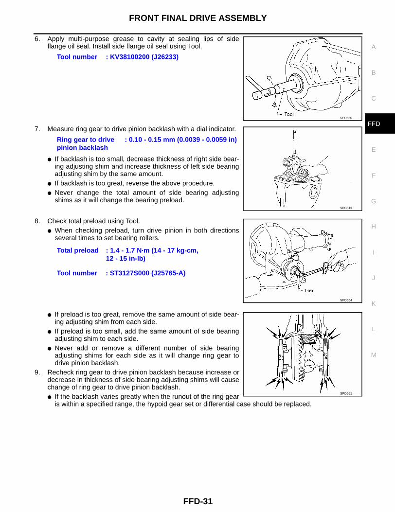
6. Apply multi-purpose grease to cavity at sealing lips of sideflange oil seal. Install side flange oil seal using Tool.
7. Measure ring gear to drive pinion backlash with a dial indicator.
● If backlash is too small, decrease thickness of right side bear-ing adjusting shim and increase thickness of left side bearingadjusting shim by the same amount.
● If backlash is too great, reverse the above procedure.● Never change the total amount of side bearing adjusting
shims as it will change the bearing preload.
8. Check total preload using Tool.● When checking preload, turn drive pinion in both directions
several times to set bearing rollers.
● If preload is too great, remove the same amount of side bear-ing adjusting shim from each side.
● If preload is too small, add the same amount of side bearingadjusting shim to each side.
● Never add or remove a different number of side bearingadjusting shims for each side as it will change ring gear todrive pinion backlash.
9. Recheck ring gear to drive pinion backlash because increase ordecrease in thickness of side bearing adjusting shims will causechange of ring gear to drive pinion backlash.● If the backlash varies greatly when the runout of the ring gear
is within a specified range, the hypoid gear set or differential case should be replaced.
Tool number : KV38100200 (J26233)
SPD560
Ring gear to drive pinion backlash
: 0.10 - 0.15 mm (0.0039 - 0.0059 in)
SPD513
Total preload : 1.4 - 1.7 N·m (14 - 17 kg-cm, 12 - 15 in-lb)
Tool number : ST3127S000 (J25765-A)
SPD664
SPD561
FFD-32
FRONT FINAL DRIVE ASSEMBLY
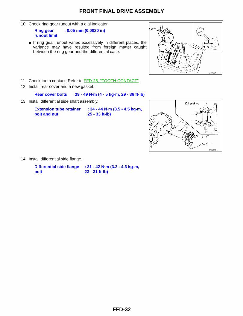
10. Check ring gear runout with a dial indicator.
● If ring gear runout varies excessively in different places, thevariance may have resulted from foreign matter caughtbetween the ring gear and the differential case.
11. Check tooth contact. Refer to FFD-25, "TOOTH CONTACT" .12. Install rear cover and a new gasket.
13. Install differential side shaft assembly.
14. Install differential side flange.
Ring gear runout limit
: 0.05 mm (0.0020 in)
SPD524
Rear cover bolts : 39 - 49 N·m (4 - 5 kg-m, 29 - 36 ft-lb)
Extension tube retainer bolt and nut
: 34 - 44 N·m (3.5 - 4.5 kg-m, 25 - 33 ft-lb)
SPD682
Differential side flange bolt
: 31 - 42 N·m (3.2 - 4.3 kg-m, 23 - 31 ft-lb)
SERVICE DATA AND SPECIFICATIONS (SDS)
FFD-33
C
E
F
G
H
I
J
K
L
M
A
B
FFD
SERVICE DATA AND SPECIFICATIONS (SDS) PFP:00030
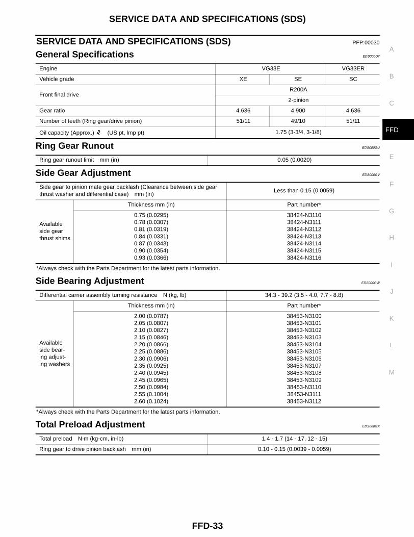
General Specifications EDS000GT
Ring Gear Runout EDS000GU
Side Gear Adjustment EDS000GV
*Always check with the Parts Department for the latest parts information.
Side Bearing Adjustment EDS000GW
*Always check with the Parts Department for the latest parts information.
Total Preload Adjustment EDS000GX
Engine VG33E VG33ER
Vehicle grade XE SE SC
Front final driveR200A
2-pinion
Gear ratio 4.636 4.900 4.636
Number of teeth (Ring gear/drive pinion) 51/11 49/10 51/11
Oil capacity (Approx.) (US pt, lmp pt) 1.75 (3-3/4, 3-1/8)
Ring gear runout limit mm (in) 0.05 (0.0020)
Side gear to pinion mate gear backlash (Clearance between side gear thrust washer and differential case) mm (in)
Less than 0.15 (0.0059)
Available side gear thrust shims
Thickness mm (in) Part number*
0.75 (0.0295)0.78 (0.0307)0.81 (0.0319)0.84 (0.0331)0.87 (0.0343)0.90 (0.0354)0.93 (0.0366)
38424-N311038424-N311138424-N311238424-N311338424-N311438424-N311538424-N3116
Differential carrier assembly turning resistance N (kg, lb) 34.3 - 39.2 (3.5 - 4.0, 7.7 - 8.8)
Available side bear-ing adjust-ing washers
Thickness mm (in) Part number*
2.00 (0.0787)2.05 (0.0807)2.10 (0.0827)2.15 (0.0846)2.20 (0.0866)2.25 (0.0886)2.30 (0.0906)2.35 (0.0925)2.40 (0.0945)2.45 (0.0965)2.50 (0.0984)2.55 (0.1004)2.60 (0.1024)
38453-N310038453-N310138453-N310238453-N310338453-N310438453-N310538453-N310638453-N310738453-N310838453-N310938453-N311038453-N311138453-N3112
Total preload N·m (kg-cm, in-lb) 1.4 - 1.7 (14 - 17, 12 - 15)
Ring gear to drive pinion backlash mm (in) 0.10 - 0.15 (0.0039 - 0.0059)
FFD-34
SERVICE DATA AND SPECIFICATIONS (SDS)
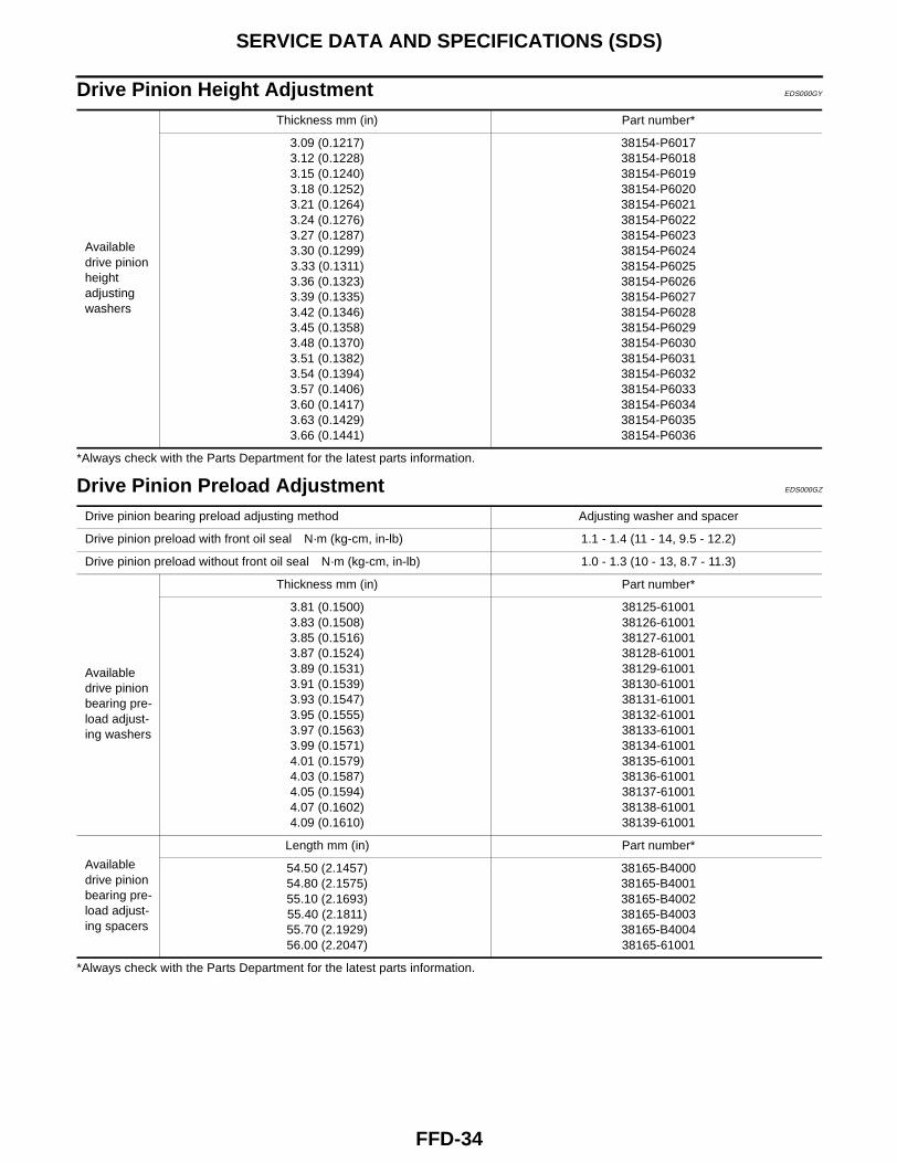
Drive Pinion Height Adjustment EDS000GY
*Always check with the Parts Department for the latest parts information.
Drive Pinion Preload Adjustment EDS000GZ
*Always check with the Parts Department for the latest parts information.
Available drive pinion height adjusting washers
Thickness mm (in) Part number*
3.09 (0.1217)3.12 (0.1228)3.15 (0.1240)3.18 (0.1252)3.21 (0.1264)3.24 (0.1276)3.27 (0.1287)3.30 (0.1299)3.33 (0.1311)3.36 (0.1323)3.39 (0.1335)3.42 (0.1346)3.45 (0.1358)3.48 (0.1370)3.51 (0.1382)3.54 (0.1394)3.57 (0.1406)3.60 (0.1417)3.63 (0.1429)3.66 (0.1441)
38154-P601738154-P601838154-P601938154-P602038154-P602138154-P602238154-P602338154-P602438154-P602538154-P602638154-P602738154-P602838154-P602938154-P603038154-P603138154-P603238154-P603338154-P603438154-P603538154-P6036
Drive pinion bearing preload adjusting method Adjusting washer and spacer
Drive pinion preload with front oil seal N·m (kg-cm, in-lb) 1.1 - 1.4 (11 - 14, 9.5 - 12.2)
Drive pinion preload without front oil seal N·m (kg-cm, in-lb) 1.0 - 1.3 (10 - 13, 8.7 - 11.3)
Available drive pinion bearing pre-load adjust-ing washers
Thickness mm (in) Part number*
3.81 (0.1500)3.83 (0.1508)3.85 (0.1516)3.87 (0.1524)3.89 (0.1531)3.91 (0.1539)3.93 (0.1547)3.95 (0.1555)3.97 (0.1563)3.99 (0.1571)4.01 (0.1579)4.03 (0.1587)4.05 (0.1594)4.07 (0.1602)4.09 (0.1610)
38125-6100138126-6100138127-6100138128-6100138129-6100138130-6100138131-6100138132-6100138133-6100138134-6100138135-6100138136-6100138137-6100138138-6100138139-61001
Available drive pinion bearing pre-load adjust-ing spacers
Length mm (in) Part number*
54.50 (2.1457)54.80 (2.1575)55.10 (2.1693)55.40 (2.1811)55.70 (2.1929)56.00 (2.2047)
38165-B400038165-B400138165-B400238165-B400338165-B400438165-61001
Related Documents