d-Color MF550 d-Color MF450 Color Printer SERVICE MANUAL Code Y107502-1

Welcome message from author
This document is posted to help you gain knowledge. Please leave a comment to let me know what you think about it! Share it to your friends and learn new things together.
Transcript
d-Color MF550d-Color MF450
Color Printer
SERVICE MANUAL
Code Y107502-1

PUBLICATION ISSUED BY:
Olivetti S.p.A.77, Via Jervis - 10015 Ivrea (TO)Italy
Copyright © 2008, OlivettiAll rights reserved
Revision historyAfter publication of this service manual, the parts and mechanism may be subject to change forimprovement of their performance. Therefore, the descriptions given in this service manual may not coincide with the actual machine.
When any change has been made to the descriptions in the service manual, a revised version will beissued with a revision mark added as required.
Revision mark:• To indicate clearly a section revised, is shown at the left margin of the revised section.
The number inside represents the number of times the revision has been made.
• To indicate clearly a page that contains the revision, is shown near the page number of thecorresponding page.The number inside represents the number of times the revision has been made.
NOTERevision marks shown in a page are restricted only to the latest ones with the old ones deleted.
• When a page revised in Ver. 2.0 has been changed in Ver. 3.0: The revision marks for Ver. 3.0 only are shown with those for Ver. 2.0 deleted.
• When a page revised in Ver. 2.0 has not been changed in Ver. 3.0: The revision marks for Ver. 2.0 are left as they are.
11
1
1

Mai
nten
ance
Adj
ustm
ent /
Set
ting
Trou
bles
hoot
ing
App
endi
x
Field Service Ver. 8.0 Jun. 2008
i
CONTENTS
d-Color MF550/MF450 Main body
Outline1. System configuration............................................................................................... 1
d-C
olor
MF5
50/M
F450
Out
line
1.2 MF550 .................................................................................................................. 1
1.3 MF450 .................................................................................................................. 3
2. Product specifications ............................................................................................. 5
Maintenance3. Periodical check .................................................................................................... 13
3.1 Maintenance items.............................................................................................. 13
3.1.1 Main body ................................................................................................... 13
3.1.2 DF-611 ........................................................................................................ 14
3.1.3 LU-301 ........................................................................................................ 15
3.1.4 ZU-603 ........................................................................................................ 15
3.1.5 FS-517/518/608 .......................................................................................... 16
3.1.6 PK-512/513 ................................................................................................. 17
3.1.7 PI-503 ......................................................................................................... 17
3.1.8 FS-519 ........................................................................................................ 18
3.1.9 JS-504......................................................................................................... 18
3.2 CMS corresponding parts................................................................................... 19
3.2.1 CMS corresponding parts ........................................................................... 19
3.2.2 CMS corresponding parts list...................................................................... 19
3.2.3 Replacing CMS corresponding parts as a set............................................. 19
3.3 Maintenance parts .............................................................................................. 20
3.3.1 Replacement parts...................................................................................... 20
3.3.2 Cleaning parts............................................................................................. 22
3.4 Concept of parts life............................................................................................ 24
3.4.1 Life value of consumables and parts........................................................... 24
3.4.2 Conditions for life specifications values....................................................... 27
3.4.3 Control causing inhibited printing for one part when an inhibited-printingevent occurs in another part........................................................................ 25
3.5 Maintenance procedure (periodical check parts)................................................ 26
3.5.1 Cleaning of the electrostatic charger wire Y/M/C........................................ 26
3.5.2 Cleaning of the PH window Y/M/C/K........................................................... 26
Mai
nten
ance
Adj
ustm
ent /
Set
ting
Trou
bles
hoot
ing
App
endi
xField Service Ver. 8.0 Jun. 2008
ii
3.5.3 Cleaning of the timing roller ........................................................................ 27
3.5.4 Cleaning of the paper dust remover............................................................ 28
3.5.5 Cleaning of the area around the waste toner collecting port ...................... 29
3.5.6 Cleaning of the duplex transport rollers ...................................................... 29
3.5.7 Replacing the tray 1 feed roller/tray 1 pick-up roller.................................... 30
3.5.8 Replacing the tray 1 separation roller assy................................................. 32
3.5.9 Replacing the tray 2 feed roller/tray 2 pick-up roller.................................... 33
3.5.10 Replacing the tray 2 separation roller assy................................................. 36
3.5.11 Replacing the tray 3 feed roller/tray 3 pick-up roller.................................... 37
3.5.12 Replacing the tray 3 separation roller ......................................................... 38
3.5.13 Replacing the tray 4 feed roller/tray 4 pick-up roller.................................... 40
3.5.14 Replacing the tray 4 separation roller ......................................................... 41
3.5.15 Replacing the manual bypass tray feed roller/manual bypass tray pick-uproller............................................................................................................ 43
3.5.16 Replacing the manual bypass tray separation roller assy........................... 45
3.5.17 Replacing the waste toner box.................................................................... 46
3.5.18 Replacing the imaging unit ......................................................................... 47
3.5.19 Replacing the ozone filter ........................................................................... 50
3.5.20 Replacing the color toner filter .................................................................... 51
3.5.21 Replacing the toner cartridge ..................................................................... 51
3.5.22 Replacing the transfer belt unit ................................................................... 53
3.5.23 Replacing the transfer roller unit ................................................................. 57
3.5.24 Replacing the fusing unit ............................................................................ 58
4. Service tool ........................................................................................................... 60
4.1 Service material list ............................................................................................ 60
4.2 CE tool list .......................................................................................................... 60
4.3 Copy materials ................................................................................................... 61
4.3.1 Imaging unit single parts (IU)...................................................................... 61
4.3.2 Toner cartridge single parts (T/C) ............................................................... 61
4.3.3 Waste toner box.......................................................................................... 62
4.3.4 Maintenance kit........................................................................................... 62
5. Firmware upgrade................................................................................................. 63
5.1 Outline ................................................................................................................ 63
5.2 Notes about firmware rewrite ............................................................................. 63
5.2.1 Types of firmware........................................................................................ 63
5.2.2 Rewrite to/from a function enhanced version of firmware........................... 63
5.3 Preparations for firmware rewriting by Windows Command Prompt .................. 69
5.3.1 Service environment ................................................................................... 69
d-C
olor
MF5
50/M
F450
Out
line
Mai
nten
ance
Adj
ustm
ent /
Set
ting
Trou
bles
hoot
ing
App
endi
x
Field Service Ver. 8.0 Jun. 2008
iii
5.3.2 Writing into the compact flash..................................................................... 69
5.4 Preparations for firmware rewriting by Firmware Imaging Toolkit 2006 .............. 72
5.4.1 Correspond model ...................................................................................... 72
5.4.2 Function outline........................................................................................... 72
5.4.3 System environment ................................................................................... 72
5.4.4 Installation of software ................................................................................ 73
5.4.5 Update of software ...................................................................................... 75
5.4.6 Screen......................................................................................................... 76
5.4.7 Details of each function............................................................................... 78
5.4.8 How to write firmware data ......................................................................... 80
5.5 Firmware rewriting by compact flash .................................................................. 85
5.5.1 Updating method......................................................................................... 85
5.5.2 Action when data transfer fails .................................................................... 88
5.6 Updating the firmware with the Internet ISW...................................................... 89
5.6.1 Outline......................................................................................................... 89
5.6.2 Service environment ................................................................................... 89
5.6.3 Preparations for firmware rewriting ............................................................. 89
5.6.4 Firmware rewriting ...................................................................................... 92
5.6.5 Error code list for the Internet ISW.............................................................. 94
6. Other ..................................................................................................................... 97
6.1 Disassembly/adjustment prohibited items .......................................................... 97
6.2 Disassembly/assembly/cleaning list (other parts)............................................... 98
6.2.1 Disassembly/assembly parts list ................................................................. 98
6.2.2 Cleaning parts list ..................................................................................... 102
6.2.3 Need lubrication parts list ......................................................................... 102
6.3 Disassembly/assembly procedure .................................................................... 103
6.3.1 Upper front door........................................................................................ 103
6.3.2 Lower front door ........................................................................................ 104
6.3.3 Upper front cover /1 .................................................................................. 106
6.3.4 Upper front cover /2 .................................................................................. 106
6.3.5 Right front cover........................................................................................ 107
6.3.6 Lower front cover ...................................................................................... 108
6.3.7 Upper left cover......................................................................................... 109
6.3.8 Lower left cover ......................................................................................... 109
6.3.9 Rear left cover........................................................................................... 110
6.3.10 Paper exit rear cover ................................................................................. 110
6.3.11 IR rear cover, IR right cover, IR upper rear cover /1, IR upper rear cover /2.................................................................................................................. 111
d-C
olor
MF5
50/M
F450
Out
line
Mai
nten
ance
Adj
ustm
ent /
Set
ting
Trou
bles
hoot
ing
App
endi
xField Service Ver. 8.0 Jun. 2008
iv
6.3.12 IR left cover, IR upper front cover ............................................................. 111
6.3.13 IR front cover ........................................................................................... 112
6.3.14 Original glass ............................................................................................ 112
6.3.15 Interface cover, rear right cover /1, rear right cover /2, rear right cover /3, rear right cover /4...................................................................................... 113
6.3.16 Manual bypass tray rear cover.................................................................. 114
6.3.17 Upper rear cover /1, upper rear cover /2, lower rear cover ....................... 114
6.3.18 Front right cover........................................................................................ 115
6.3.19 Control panel assy .................................................................................... 115
6.3.20 Exit tray (option: OT-503) .......................................................................... 117
6.3.21 Finisher rail (d-Color MF450 only) ............................................................ 118
6.3.22 Tray 1/2 ..................................................................................................... 119
6.3.23 Tray 3/4 ..................................................................................................... 120
6.3.24 LCD module.............................................................................................. 120
6.3.25 PH unit ...................................................................................................... 121
6.3.26 Duplex unit ................................................................................................ 124
6.3.27 Manual bypass tray unit ............................................................................ 125
6.3.28 CCD unit ................................................................................................... 127
6.3.29 Original glass moving unit......................................................................... 129
6.3.30 Glass step sheet ....................................................................................... 131
6.3.31 Scanner assy ............................................................................................ 133
6.3.32 Hard disk................................................................................................... 135
6.3.33 IH coil (FH1).............................................................................................. 136
6.3.34 Intermediate transport roller assy ............................................................. 140
6.3.35 Main drive unit .......................................................................................... 142
6.3.36 LCC drive unit ........................................................................................... 144
6.3.37 IR assy...................................................................................................... 150
6.3.38 Scanner relay board (REYB/SCAN) ......................................................... 152
6.3.39 Original glass position control board (OGPCB) ........................................ 153
6.3.40 Inverter board (INVB)................................................................................ 153
6.3.41 Image processing board (IPB) .................................................................. 154
6.3.42 PH relay board (REYB/PH)....................................................................... 156
6.3.43 Paper feed/transport drive board (PFTDB) ............................................... 157
6.3.44 DC power supply (DCPU)......................................................................... 158
6.3.45 Relay drive board (REDB) ........................................................................ 161
6.3.46 Printer control board (PRCB).................................................................... 162
6.3.47 Slide interface board (REYB/SL) .............................................................. 164
6.3.48 Fan motor relay board (REYB/FAN).......................................................... 165
d-C
olor
MF5
50/M
F450
Out
line
Mai
nten
ance
Adj
ustm
ent /
Set
ting
Trou
bles
hoot
ing
App
endi
x
Field Service Ver. 8.0 Jun. 2008
v
6.3.49 PCI board (PCIB) ...................................................................................... 166
6.3.50 MFP board (MFPB)................................................................................... 167
6.3.51 How to open PWB box .............................................................................. 170
6.3.52 High voltage unit/2 (HV2) .......................................................................... 171
6.3.53 Service EEPROM board (SV ERB)........................................................... 173
6.3.54 High voltage unit/1 (HV1) .......................................................................... 175
6.3.55 IH power supply (IHPU) ............................................................................ 181
6.3.56 Operation panel inverter board (OPINVB) ................................................ 184
6.3.57 Operation panel control board (OPCB)..................................................... 185
6.3.58 Operation panel I/O board (OPIOB).......................................................... 186
6.3.59 Paper size detect board/1 (PSDTB/1)....................................................... 186
6.3.60 Paper size detect board/2 (PSDTB/2)....................................................... 187
d-C
olor
MF5
50/M
F450
6.3.61 ADU transport motor/1 (M31).................................................................... 189
6.3.62 ADU transport motor/2 (M32).................................................................... 190
6.3.63 Bypass tray up down motor (M28) / bypass paper feed motor (M27) ....... 191
6.3.64 Scanner motor (M201) .............................................................................. 195
6.3.65 Original glass moving motor (M202) ......................................................... 198
6.3.66 Waste toner agitating motor (M20)............................................................ 200
6.3.67 Transport motor (M25) .............................................................................. 201
6.3.68 Vertical transport motor (M26) .................................................................. 202
6.3.69 Transfer belt motor (M1)............................................................................ 203
6.3.70 Color PC drum motor (M16)...................................................................... 203
6.3.71 Color developing motor (M17)................................................................... 204
6.3.72 2nd image transfer pressure retraction motor (M3)................................... 204
6.3.73 Registration motor (M2) ............................................................................ 205
6.3.74 Fusing pressure retraction motor (M29).................................................... 207
6.3.75 Fusing motor (M30)................................................................................... 208
6.3.76 Switchback motor (M33) ........................................................................... 210
6.3.77 Exit motor (M4) ......................................................................................... 211
6.3.78 K PC drum motor (M18)............................................................................ 212
6.3.79 K developing motor (M19)......................................................................... 213
6.3.80 Tray1 lift-up motor (M6) ............................................................................. 213
6.3.81 Tray2 lift-up motor (M8) ............................................................................. 214
6.3.82 Tray3 lift-up motor (M23) ........................................................................... 215
6.3.83 Tray4 lift-up motor (M24) ........................................................................... 215
Out
line
Mai
nten
ance
Adj
ustm
ent /
Set
ting
Trou
bles
hoot
ing
App
endi
xField Service Ver. 8.0 Jun. 2008
vi
6.3.84 Tray1 vertical transport motor (M5)........................................................... 216
6.3.85 Tray2 vertical transport motor (M7)........................................................... 217
6.3.86 Take-up motor (M22)................................................................................. 218
6.3.87 Charge cleaning motor/K (M15)................................................................ 219
6.3.88 Cleaner motor (M38)................................................................................. 221
6.3.89 1st image transfer pressure retraction motor (M21).................................. 226
6.3.90 Toner cartridge motor C/K (M14). ............................................................. 226
6.3.91 Toner cartridge motor Y/M (M13).............................................................. 227
6.3.92 Toner supply motor/Y (M9), toner supply motor/M (M10),toner supply motor/C (M11), toner supply motor/K (M12) ........................ 228
6.3.93 Tray 1 paper feed clutch (CL1).................................................................. 232
6.3.94 Tray 2 paper feed clutch 2 (CL2)............................................................... 233
6.3.95 Horizontal transport clutch 1 (CL3) ........................................................... 234
6.3.96 Horizontal transport clutch 2 (CL4) ........................................................... 234
6.3.97 Tray 3 paper feed clutch (CL5)/Tray 3 transport clutch (CL6) ................... 235
6.3.98 Tray 4 paper feed clutch (CL7).................................................................. 236
6.3.99 IDC registration sensor/F (IDCS/F), IDC registration sensor/R (IDCS/R). 237
6.3.100 Scanner drive cables ................................................................................ 239
6.3.101 Tray 3/4 lift wire ......................................................................................... 250
6.3.102 Fuse (F1) *USA only................................................................................. 256
6.4 Cleaning procedure .......................................................................................... 257
6.4.1 Transfer belt unit ....................................................................................... 257
6.4.2 Tray 1 feed roller/tray 1 pick-up roller ........................................................ 257
6.4.3 Tray 1 separation roller ............................................................................. 258
6.4.4 Tray 1 transport roller................................................................................ 258
6.4.5 Tray 2 feed roller/tray 2 pick-up roller ........................................................ 259
6.4.6 Tray 2 separation roller ............................................................................. 259
6.4.7 Tray 2 transport roller................................................................................ 260
6.4.8 Tray 3 feed roller/tray 3 pick-up roller ........................................................ 260
6.4.9 Tray 3 separation roller ............................................................................. 261
6.4.10 Tray 3 transport roller................................................................................ 261
6.4.11 Tray 4 feed roller/tray 4 pick-up roller ........................................................ 262
6.4.12 Tray 4 separation roller ............................................................................. 263
6.4.13 Tray 4 transport roller................................................................................ 263
6.4.14 Manual bypass tray feed roller .................................................................. 263
6.4.15 Manual bypass tray pick-up roller ............................................................. 264
6.4.16 Manual bypass tray separation roller ........................................................ 264
6.4.17 Intermediate transport roller ..................................................................... 264
d-C
olor
MF5
50/M
F450
Out
line

Mai
nten
ance
Adj
ustm
ent /
Set
ting
Trou
bles
hoot
ing
App
endi
x
Field Service Ver. 8.0 Jun. 2008
vii
6.4.18 Original glass ............................................................................................ 265
6.4.19 Scanner rails ............................................................................................. 265
6.4.20 Mirrors (1st/2nd/3rd) ................................................................................. 266
6.4.21 Lens .......................................................................................................... 266
6.4.22 CCD sensor .............................................................................................. 267
6.5 Mount the original size detection 2 sensor (PS205) ......................................... 268
6.6 Lubrication procedure....................................................................................... 270
6.6.1 Fusing unit ................................................................................................ 270
6.7 Option counter .................................................................................................. 272
6.7.1 Installation method for the key counter ..................................................... 272
Adjustment/Setting7. How to use the adjustment section ..................................................................... 275
8. Utility Mode ......................................................................................................... 276
8.1 Touch Panel Adjustment ................................................................................... 276
8.2 Utility Mode function tree .................................................................................. 277
8.3 Utility Mode function setting procedure............................................................. 289
8.3.1 Procedure ................................................................................................. 289
8.3.2 Exiting ....................................................................................................... 289
8.3.3 Changing the setting value in Utility Mode functions................................. 289
8.4 One-Touch User Box Registration .................................................................... 290
8.4.1 Create One-Touch destination .................................................................. 290
8.4.2 Create User Box........................................................................................ 292
8.4.3 Limiting Access to Destinations ................................................................ 293
8.5 User Settings .................................................................................................... 294
8.5.1 System Settings ........................................................................................ 294
8.5.2 Custom Display Settings ........................................................................... 298
8.5.3 Copier Settings ......................................................................................... 301
8.5.4 Scan/Fax Settings ..................................................................................... 306
8.5.5 Printer Settings ......................................................................................... 308
8.5.6 Change Password ..................................................................................... 313
8.5.7 Change E-mail Address ............................................................................ 314
8.6 Administrator Settings....................................................................................... 315
8.6.1 System Settings ........................................................................................ 315
8.6.2 Administrator/Machine Settings ................................................................ 345
8.6.3 One-Touch/User Box Registration............................................................. 345
8.6.4 User Authentication/Account Track ........................................................... 350
8.6.5 Network Setting......................................................................................... 358
d-C
olor
MF5
50/M
F450
Out
line
AppField Service Ver. 8.0 Jun. 2008
viii
8.6.6 Copier Settings ......................................................................................... 394
8.6.7 Printer Settings ......................................................................................... 395
8.6.8 Fax Settings .............................................................................................. 396
8.6.9 System Connection................................................................................... 410
8.6.10 Security Settings....................................................................................... 411
8.6.11 License Settings ....................................................................................... 426
8.7 Banner Printing (d-Color MF450 only) ............................................................. 426
8.8 My Panel Settings............................................................................................. 427
9. Adjustment item list............................................................................................. 428
10. Service Mode...................................................................................................... 430
10.1 Service Mode function setting procedure ......................................................... 430
10.2 Service Mode function tree............................................................................... 432
10.3 Date/Time Input mode...................................................................................... 438
10.3.1 Date & Time Setting mode screen............................................................ 438
10.4 Machine............................................................................................................ 439
10.4.1 Color Alignment Adjustment ..................................................................... 439
10.4.2 Fusing Temperature.................................................................................. 440
10.4.3 Fusing Transport Speed............................................................................ 441
10.4.4 Org. Size Detecting Sensor Adj. ............................................................... 442
10.4.5 Printer Area............................................................................................... 443
10.4.6 Scan Area ................................................................................................. 448
10.4.7 Printer Resist Loop ................................................................................... 452
10.4.8 Color Registration Adjustment .................................................................. 453
10.4.9 Skew adjustment....................................................................................... 454
10.4.10 LD adjustment........................................................................................... 454
10.4.11 Manual Bypass Tray Adjustment............................................................... 456
10.4.12 Lead Edge Erase Adjustment ................................................................... 456
10.4.13 Thick Paper Mode..................................................................................... 456
10.4.14 Split Line Prior Detection .......................................................................... 457
10.5 Firmware Version.............................................................................................. 457
10.6 Imaging Process Adjustment............................................................................ 457
10.6.1 Gradation Adjust ....................................................................................... 457
10.6.2 Transfer Belt.............................................................................................. 458
10.6.3 D Max Density .......................................................................................... 459
10.6.4 TCR Level Setting..................................................................................... 460
10.6.5 Background Voltage Margin...................................................................... 460
10.6.6 Transfer Output Fine Adjustment .............................................................. 461
10.6.7 Stabilizer ................................................................................................... 462
d-C
olor
MF5
50/M
F450
Out
line
Mai
nten
ance
Adj
ustm
ent /
Set
ting
Trou
bles
hoot
ing
App
endi
x

Mai
nten
ance
Adj
ustm
ent /
Set
ting
Trou
bles
hoot
ing
App
endi
x
Field Service Ver. 8.0 Jun. 2008
ix
10.6.8 Thick Paper Density Adjustment ............................................................... 462
10.6.9 Paper separation adjustment .................................................................... 463
10.6.10 TCR Toner Supply..................................................................................... 463
10.6.11 Monochrome Density Adjustment ............................................................. 463
10.6.12 Dev. Bias Choice....................................................................................... 464
10.7 CS Remote Care .............................................................................................. 465
10.7.1 Outlines..................................................................................................... 465
10.7.2 Setting up the CS Remote Care ............................................................... 465
10.7.3 Software SW setting for CS Remote Care ................................................ 468
10.7.4 Setup confirmation .................................................................................... 473
10.7.5 Calling the maintenance ........................................................................... 473
10.7.6 Calling the center from the administrator .................................................. 474
10.7.7 Checking the transmission log .................................................................. 474
10.7.8 Detail on settings ...................................................................................... 474
10.7.9 List of the CS Remote Care error code..................................................... 480
10.7.10 Troubleshooting for CS Remote Care ....................................................... 484
10.8 System 1........................................................................................................... 485
10.8.1 Marketing Area.......................................................................................... 485
10.8.2 Tel/Fax Number ......................................................................................... 485
10.8.3 Serial Number ........................................................................................... 486
10.8.4 No Sleep ................................................................................................... 486
10.8.5 Foolscap Size Setting ............................................................................... 486
10.8.6 Original Size Detection ............................................................................. 486
10.8.7 Install Date ................................................................................................ 487
10.8.8 Initialization ............................................................................................... 487
10.8.9 Charging CH cleaning............................................................................... 487
10.8.10 Trouble Isolation ........................................................................................ 488
10.8.11 IU Life Setting............................................................................................ 489
10.8.12 Post card transfer table ............................................................................. 489
10.8.13 Change Warm Up Time *d-Color MF450 only .......................................... 490
10.8.14 Machine State LED Setting....................................................................... 490
10.9 System 2........................................................................................................... 491
10.9.1 HDD .......................................................................................................... 491
10.9.2 Image Controller Setting ........................................................................... 491
10.9.3 Option Board Status.................................................................................. 492
10.9.4 Consumable Life Reminder....................................................................... 492
10.9.5 Unit Change .............................................................................................. 492
10.9.6 Software Switch Setting ............................................................................ 493
d-C
olor
MF5
50/M
F450
Out
line
Mai
nten
ance
Adj
ustm
ent /
Set
ting
Trou
bles
hoot
ing
App
endi
xField Service Ver. 8.0 Jun. 2008
x
10.9.7 Scan Caribration ....................................................................................... 494
10.9.8 LCC Size Setting ...................................................................................... 494
10.9.9 LCT Paper Size Setting ............................................................................ 494
10.9.10 Line Mag Setting....................................................................................... 495
10.9.11 Data Capture ............................................................................................ 495
10.9.12 Split Line Detect. Setting .......................................................................... 497
10.9.13 Stamp ....................................................................................................... 498
10.9.14 Network Fax Settings................................................................................ 499
10.10 Counter............................................................................................................. 500
10.10.1 Procedure ................................................................................................. 500
10.10.2 Life ............................................................................................................ 500
10.10.3 Jam ........................................................................................................... 501
10.10.4 Service Call Counter................................................................................. 501
10.10.5 Warning .................................................................................................... 501
10.10.6 Maintenance ............................................................................................. 502
10.10.7 Service Total ............................................................................................. 502
10.10.8 Counter of Each Mode.............................................................................. 502
10.10.9 Service Call History (Data) ....................................................................... 502
10.10.10 ADF Paper Pages ..................................................................................... 502
10.10.11 Paper Jam History .................................................................................... 503
10.10.12 Fax Connection Error................................................................................ 503
10.10.13 Split Line Counter ..................................................................................... 503
10.10.14 Parts Counter (Fixed)................................................................................ 504
10.11 List Output ........................................................................................................ 506
10.11.1 Machine Management List....................................................................... 506
10.11.2 Adjustment List ......................................................................................... 506
10.11.3 Parameter List........................................................................................... 506
10.11.4 Service Parameter .................................................................................... 506
10.11.5 Protocol Trace........................................................................................... 506
10.11.6 Fax Setting List ......................................................................................... 506
10.11.7 Fax Analysis List ....................................................................................... 506
10.12 State Confirmation............................................................................................ 507
10.12.1 Sensor Check ........................................................................................... 507
10.12.2 Sensor check screens .............................................................................. 508
10.12.3 Sensor check list....................................................................................... 514
10.12.4 Table Number ........................................................................................... 525
10.12.5 Level History1 ........................................................................................... 525
10.12.6 Level History 2 .......................................................................................... 525
d-C
olor
MF5
50/M
F450
Out
line
Mai
nten
ance
Adj
ustm
ent /
Set
ting
Trou
bles
hoot
ing
App
endi
x
Field Service Ver. 8.0 Jun. 2008
xi
10.12.7 Temp. & Humidity ...................................................................................... 526
10.12.8 CCD Check ............................................................................................... 526
10.12.9 Memory/HDD Adj. ..................................................................................... 526
10.12.10 Memory/HDD State................................................................................... 531
10.12.11 Color Regist .............................................................................................. 531
10.12.12 IU Lot No. .................................................................................................. 531
10.12.13 Adjustment Data List ................................................................................. 531
10.13 Test Mode ......................................................................................................... 532
10.13.1 Procedure for test pattern output .............................................................. 532
10.13.2 Gradation Pattern...................................................................................... 532
10.13.3 Halftone Pattern ........................................................................................ 533
10.13.4 Lattice Pattern ........................................................................................... 533
10.13.5 Solid Pattern.............................................................................................. 534
10.13.6 Color Sample ............................................................................................ 534
10.13.7 8 Color Solid Pattern ................................................................................. 535
10.13.8 CMM pattern ............................................................................................. 535
10.13.9 Running Mode........................................................................................... 535
10.13.10 Fax Test..................................................................................................... 536
10.14 ADF .................................................................................................................. 536
10.15 FAX................................................................................................................... 536
10.16 Finisher ............................................................................................................. 536
10.16.1 CB-FN adjustment .................................................................................... 536
10.16.2 FS-FN adjustment ..................................................................................... 536
10.16.3 Staple option setting ................................................................................. 537
10.16.4 Punch Option setting................................................................................. 537
10.16.5 Fold power of pages restrict...................................................................... 537
10.16.6 Job Separator ........................................................................................... 537
10.17 Internet ISW...................................................................................................... 538
10.17.1 Internet ISW Set........................................................................................ 538
10.17.2 HTTP Setting ............................................................................................ 538
10.17.3 FTP Setting ............................................................................................... 539
10.17.4 Forwarding Access Setting ....................................................................... 540
10.17.5 Download .................................................................................................. 541
11. Enhanced Security .............................................................................................. 542
11.1 Enhanced Security function setting procedure ................................................. 542
11.1.1 Procedure ................................................................................................. 542
11.1.2 Exiting ....................................................................................................... 542
11.2 Enhanced Security function tree....................................................................... 542
d-C
olor
MF5
50/M
F450
Out
line
Mai
nten
ance
Adj
ustm
ent /
Set
ting
Trou
bles
hoot
ing
App
endi
xField Service Ver. 8.0 Jun. 2008
xii
11.3 Settings in the Enhanced Security ................................................................... 543
11.3.1 CE Password ............................................................................................ 543
11.3.2 Administrator Password ............................................................................ 543
11.3.3 Administrator Feature Level ...................................................................... 544
11.3.4 CE Authentication ..................................................................................... 544
11.3.5 IU Life Stop Setting................................................................................... 544
11.3.6 NVRAM Data Backup ............................................................................... 545
11.3.7 Operation Ban release time ...................................................................... 545
11.3.8 Administrator unlocking............................................................................. 545
12. Billing Setting ...................................................................................................... 546
12.1 Billing Setting function setting procedure ......................................................... 546
12.1.1 Procedure ................................................................................................. 546
12.1.2 Exiting ....................................................................................................... 546
12.2 Billing Setting function tree............................................................................... 546
12.3 Settings in the Billing Setting............................................................................ 547
12.3.1 Counter Setting......................................................................................... 547
12.3.2 Management Function Choice.................................................................. 548
12.3.3 Coverage Rate Clear ................................................................................ 555
13. Procedure for resetting........................................................................................ 556
13.1 Trouble resetting ............................................................................................... 556
13.2 Contents to be cleared by reset function .......................................................... 556
14. Mechanical adjustment ....................................................................................... 557
14.1 Mechanical adjustment of the scanner section ................................................ 557
14.1.1 Adjustment of the scanner motor belt ....................................................... 557
14.1.2 Focus positioning of the scanner and mirrors unit .................................... 558
14.1.3 Scanner position adjustment .................................................................... 559
14.1.4 Adjusting the height of the original glass moving unit............................... 560
14.1.5 Adjusting the height of the guide support for the original glass moving unit.................................................................................................................. 562
14.2 Mechanical adjustment of the paper feed section ............................................ 563
14.2.1 Tray3/4 paper size change........................................................................ 563
14.2.2 Skew adjustment of the tray 1/2................................................................ 564
14.2.3 Centering adjustment of the tray 1/2......................................................... 565
14.2.4 Centering adjustment of the tray 3/4......................................................... 566
14.2.5 Pick-up roller load adjustment of the tray 3/4............................................ 567
14.3 Mechanical adjustment of the bypass tray section ........................................... 569
14.3.1 Adjustment of the bypass paper size unit ................................................. 569
14.4 Mechanical adjustment of the main drive unit section...................................... 571
14.4.1 PC drive gear positioning adjustment ....................................................... 571
d-C
olor
MF5
50/M
F450
Out
line
Mai
nten
ance
Adj
ustm
ent /
Set
ting
Trou
bles
hoot
ing
App
endi
x
Field Service Ver. 8.0 Jun. 2008
xiii
Troubleshooting15. Jam display ......................................................................................................... 573
15.1 Misfeed display ................................................................................................. 573
15.1.1 When the FS-517/518/608 is mounted ..................................................... 573
15.1.2 When the FS-519 is mounted ................................................................... 575
15.1.3 When the ZU-603 is mounted ................................................................... 577
15.1.4 When the JS-504 is mounted.................................................................... 578
15.1.5 Misfeed display resetting procedure ......................................................... 578
15.2 Sensor layout .................................................................................................... 579
15.3 Solution............................................................................................................. 580
15.3.1 Initial check items...................................................................................... 580
15.3.2 Misfeed at tray 1 feed section ................................................................... 581
15.3.3 Misfeed at tray 2 feed section ................................................................... 582
15.3.4 Misfeed at tray 3 feed section ................................................................... 583
15.3.5 Misfeed at tray 4 feed section ................................................................... 584
15.3.6 Misfeed at manual bypass feed section .................................................... 585
15.3.7 Misfeed at duplex pre-registration section................................................. 586
15.3.8 Misfeed at vertical transport section ......................................................... 587
15.3.9 Misfeed at tray 3/4 horizontal transport section ........................................ 588
15.3.10 Misfeed at 2nd image transfer section ...................................................... 589
15.3.11 Misfeed at tray 3/4 intermediate transport roller section ........................... 590
15.3.12 Misfeed at exit section............................................................................... 591
15.3.13 Misfeed at duplex transport section .......................................................... 592
16. Malfunction code ................................................................................................. 593
16.1 Alert code ......................................................................................................... 593
16.1.1 Alert code list ............................................................................................ 594
16.2 Solution............................................................................................................. 596
16.2.1 S-1: CCD gain adjustment failure.............................................................. 596
16.2.2 D-1: Split line detect.................................................................................. 596
16.2.3 D-2: Read guide trouble ............................................................................ 596
16.2.4 P-5: IDC sensor (front) failure ................................................................... 597
16.2.5 P-28 IDC sensor (rear) failure ................................................................... 597
16.2.6 P-6: Cyan imaging unit failure ................................................................... 597
16.2.7 P-7: Magenta imaging unit failure ............................................................. 597
16.2.8 P-8: Yellow imaging unit failure ................................................................. 597
16.2.9 P-9: Black imaging unit failure................................................................... 597
16.2.10 P-14: Skew correction trouble ................................................................... 598
16.2.11 P-16: PC charge cleaning trouble 1 .......................................................... 598
d-C
olor
MF5
50/M
F450
Out
line
Mai
nten
ance
Adj
ustm
ent /
Set
ting
Trou
bles
hoot
ing
App
endi
xField Service Ver. 8.0 Jun. 2008
xiv
16.2.12 P-18: PC charge cleaning trouble 2.......................................................... 598
16.2.13 P-21: Color regist test pattern failure ........................................................ 599
16.2.14 P-22: Color regist adjust failure................................................................. 599
16.2.15 P-27: Secondary transfer ATVC failure ..................................................... 599
16.2.16 P-31: PC home sensor (K) malfunction .................................................... 600
16.3 Trouble code ..................................................................................................... 601
16.3.1 Trouble code list ........................................................................................ 601
16.4 How to reset ..................................................................................................... 633
16.5 Solution ............................................................................................................ 634
16.5.1 C0104: Tray 3/4 feeder transportation motor failure to turn ...................... 634
16.5.2 C0105: Tray 3/4 feeder transportation motor turning at abnormal timing . 634
16.5.3 C0202: Tray 1 feeder up/down abnormality .............................................. 634
16.5.4 C0204: Tray 2 feeder up/down abnormality .............................................. 635
16.5.5 C0206: Tray 3 feeder up/down abnormality .............................................. 635
16.5.6 C0208: Tray 4 feeder up/down abnormality .............................................. 636
16.5.7 C0211: Manual feed up/down abnormality ............................................... 636
16.5.8 C0301: Suction fan motor’s failure to turn................................................. 637
16.5.9 C0351: Paper cooling fan trouble.............................................................. 637
16.5.10 C2101: PC charge cleaning malfunction .................................................. 638
16.5.11 C2151: Secondary transfer roller pressure welding alienation ................. 638
16.5.12 C2152: Transfer belt pressure welding alienation ..................................... 639
16.5.13 C2160: PC charge (C) malfunction........................................................... 639
16.5.14 C2161: PC charge (M) malfunction .......................................................... 639
16.5.15 C2162: PC charge (Y) malfunction ........................................................... 639
16.5.16 C2163: PC charge (K) malfunction ........................................................... 639
16.5.17 C2164: PC charge malfunction................................................................. 639
16.5.18 C2204: Waste toner agitating motor’s failure to turn................................. 640
16.5.19 C2253: Color PC drum motor’s failure to turn........................................... 640
16.5.20 C2254: Color PC drum motor’s turning at abnormal timing ...................... 640
16.5.21 C2255: Color developing motor’s failure to turn........................................ 641
16.5.22 C2256: Color developing motor’s turning at abnormal timing ................... 641
16.5.23 C2257: Cleaner motor’s failure to turn ...................................................... 641
16.5.24 C2258: Cleaner motor’s turning at abnormal timing ................................. 641
16.5.25 C2259: K developing motor’s failure to turn .............................................. 642
16.5.26 C225A: K developing motor’s turning at abnormal timing......................... 642
16.5.27 C225B: K PC drum motor’s failure to turn................................................. 642
16.5.28 C225C: K PC drum motor’s turning at abnormal timing............................ 642
16.5.29 C2351: K toner suction fan motor’s failure to turn..................................... 643
d-C
olor
MF5
50/M
F450
Out
line
Mai
nten
ance
Adj
ustm
ent /
Set
ting
Trou
bles
hoot
ing
App
endi
x
Field Service Ver. 8.0 Jun. 2008
xv
16.5.30 C2352: Color toner suction fan motor’s failure to turn............................... 643
16.5.31 C2353: IU cooling fan motor’s failure to turn ............................................. 644
16.5.32 C2354: Rear side cooling fan motor’s failure to turn ................................. 644
16.5.33 C2451: Release new transfer belt unit ...................................................... 645
16.5.34 C2551: Abnormally low toner density detected cyan TCR sensor ............ 645
16.5.35 C2553: Abnormally low toner density detected magenta TCR sensor ..... 645
16.5.36 C2555: Abnormally low toner density detected yellow TCR sensor.......... 645
16.5.37 C2552: Abnormally high toner density detected cyan TCR sensor .......... 646
16.5.38 C2554: Abnormally high toner density detected magenta TCR sensor .... 646
16.5.39 C2556: Abnormally high toner density detected yellow TCR sensor ........ 646
16.5.40 C2557: Abnormally low toner density detected black TCR sensor ........... 646
16.5.41 C2558: Abnormally high toner density detected black TCR sensor.......... 647
16.5.42 C2559: Cyan TCR sensor adjustment failure............................................ 647
16.5.43 C255A: Magenta TCR sensor adjustment failure...................................... 647
16.5.44 C255B: Yellow TCR sensor adjustment failure.......................................... 647
16.5.45 C255C: Black TCR sensor adjustment failure........................................... 648
16.5.46 C2650: Main backup media access error.................................................. 649
16.5.47 C2651: EEPROM access error (IU C)....................................................... 650
16.5.48 C2652: EEPROM access error (IU M) ...................................................... 650
16.5.49 C2653: EEPROM access error (IU Y)....................................................... 650
16.5.50 C2654: EEPROM access error (IU K)....................................................... 650
16.5.51 C2A01: EEPROM access error (TC C) ..................................................... 650
16.5.52 C2A02: EEPROM access error (TC M)..................................................... 650
16.5.53 C2A03: EEPROM access error (TC Y) ..................................................... 650
16.5.54 C2A04: EEPROM access error (TC K) ..................................................... 650
16.5.55 C3101: Fusing roller separation failure ..................................................... 651
16.5.56 C3102: Fusing roller failure to turn............................................................ 651
16.5.57 C3201: Fusing motor failure to turn .......................................................... 652
16.5.58 C3202: Fusing motor turning at abnormal timing...................................... 652
16.5.59 C3303: Fusing cooling fan motor/ 1 failure to turn .................................... 652
16.5.60 C3304: Fusing cooling fan motor/ 2 failure to turn .................................... 653
16.5.61 C3305: Fusing cooling fan motor/ 3 failure to turn .................................... 653
16.5.62 C3423: Fusing heaters trouble (pressurizing side) ................................... 654
16.5.63 C3424: Fusing heaters trouble (soaking side) .......................................... 654
16.5.64 C3425: Fusing heaters trouble (NC sensor) ............................................. 654
16.5.65 C3461: Release new fusing unit ............................................................... 655
16.5.66 C3721: Fusing abnormally high temperature detection (Center of the heating roller) ..................................................................... 655
d-C
olor
MF5
50/M
F450
Out
line
Mai
nten
ance
Adj
ustm
ent /
Set
ting
Trou
bles
hoot
ing
App
endi
xField Service Ver. 8.0 Jun. 2008
xvi
16.5.67 C3722: Fusing abnormally high temperature detection (Edge of the heating roller) ....................................................................... 655
16.5.68 C3725: Fusing abnormally high temperature detection (NC sensor)........ 655
16.5.69 C3723: Fusing abnormally high temperature detection (pressurizing side).................................................................................................................. 656
16.5.70 C3724: Fusing abnormally high temperature detection (soaking side)..... 656
16.5.71 C3822: Fusing abnormally low temperature detection (Edge of the heating roller) ....................................................................... 656
16.5.72 C3825: Fusing abnormally low temperature detection (NC sensor) ......... 656
16.5.73 C3823: Fusing abnormally low temperature detection (pressurizing side)657
16.5.74 C3824: Fusing abnormally low temperature detection (soaking side) ...... 657
16.5.75 C3921: Fusing sensor wire breaks detection (Center of the heating roller).................................................................................................................. 657
16.5.76 C3922: Fusing sensor wire breaks detection (Edge of the heating roller) 657
16.5.77 C3925: Fusing sensor wire breaks detection (NC sensor) ....................... 657
16.5.78 C3923: Fusing sensor wire breaks detection (pressurizing side) ............. 658
16.5.79 C3924: Fusing sensor wire breaks detection (soaking side) .................... 658
16.5.80 C3B02: IH malfunction (CPU)................................................................... 658
16.5.81 C3B03: IH malfunction (monitor) .............................................................. 658
16.5.82 C3B04: IH malfunction.............................................................................. 658
16.5.83 C4101: Polygon motor rotation trouble ..................................................... 659
16.5.84 C4301: PH cooling fan motor failure to turn.............................................. 659
16.5.85 C4501: Laser malfunction......................................................................... 660
16.5.86 C5104: Transfer belt motor’s failure to turn ............................................... 660
16.5.87 C5105: Transfer belt motor’s turning at abnormal timing .......................... 660
16.5.88 C5304: IH cooling fan motor/1’s failure to turn.......................................... 661
16.5.89 C5305: IH cooling fan motor/2’s failure to turn.......................................... 661
16.5.90 C5306: IH cooling fan motor/3’s failure to turn.......................................... 662
16.5.91 C5351: Power supply cooling fan motor/1’s failure to turn ........................ 662
16.5.92 C5354: Ozone ventilation fan motor’s failure to turn ................................. 663
16.5.93 C5356: Cooling fan motor’s failure to turn................................................. 663
16.5.94 C5370: MFP control board cooling fan motor’s failure to turn................... 664
16.5.95 C5371: MFP control board CPU cooling fan motor’s failure to turn .......... 664
16.5.96 C6102: Drive system home sensor malfunction ....................................... 665
16.5.97 C6103: Slider over running ....................................................................... 665
16.5.98 C6301: Optical cooling fan motor’s failure to turn ..................................... 665
16.5.99 C6704: Image input time out..................................................................... 666
16.5.100 C6751: CCD clamp/gain adjustment failure.............................................. 666
16.5.101 C6F01: Scanner sequence trouble 1 ........................................................ 667
d-C
olor
MF5
50/M
F450
Out
line
Mai
nten
ance
Adj
ustm
ent /
Set
ting
Trou
bles
hoot
ing
App
endi
x
Field Service Ver. 8.0 Jun. 2008
xvii
16.5.102 C9401: Exposure turning on the lamp trouble detection........................... 667
16.5.103 C9402: Exposure turning on the lamp abnormally detection .................... 667
16.5.104 CA051: Standard controller configuration failure ...................................... 668
16.5.105 CA052: Controller hardware error ............................................................. 668
16.5.106 CA053: Controller start failure................................................................... 668
16.5.107 CC001: Vendor connection failure ............................................................ 668
16.5.108 CC151: ROM contents error upon startup (MSC)..................................... 668
16.5.109 CC152: ROM contents error upon startup (Scanner) ............................... 668
16.5.110 CC153: ROM contents error upon startup (PRT)...................................... 668
16.5.111 CC163: ROM contents error (PRT)........................................................... 669
16.5.112 CC164: ROM contents error (MSC) .......................................................... 670
16.5.113 CC170: Dynamic link error during starting (AP0)...................................... 670
16.5.114 CC171: Dynamic link error during starting (AP1)...................................... 670
16.5.115 CC172: Dynamic link error during starting (AP2)...................................... 670
16.5.116 CC173: Dynamic link error during starting (AP3)...................................... 670
16.5.117 CC174: Dynamic link error during starting (AP4)...................................... 670
16.5.118 CC180: Dynamic link error during starting (LDR) ..................................... 670
16.5.119 CC181: Dynamic link error during starting (IBR) ...................................... 670
16.5.120 CC182: Dynamic link error during starting (IID) ........................................ 670
16.5.121 CC183: Dynamic link error during starting (IPF) ....................................... 670
16.5.122 CC184: Dynamic link error during starting (IMY) ...................................... 670
16.5.123 CD002: JOB RAM save error.................................................................... 671
16.5.124 CD004: Hard disk access error ................................................................. 671
16.5.125 CD005: Hard disk error 1 .......................................................................... 671
16.5.126 CD006: Hard disk error 2 .......................................................................... 671
16.5.127 CD007: Hard disk error 3 .......................................................................... 671
16.5.128 CD008: Hard disk error 4 .......................................................................... 671
16.5.129 CD009: Hard disk error 5 .......................................................................... 671
16.5.130 CD00A: Hard disk error 6.......................................................................... 671
16.5.131 CD00B: Hard disk error 7.......................................................................... 671
16.5.132 CD00C: Hard disk error 8 ......................................................................... 671
16.5.133 CD00D: Hard disk error 9 ......................................................................... 671
16.5.134 CD00E: Hard disk error A ......................................................................... 671
16.5.135 CD00F: Hard disk data transfer error........................................................ 671
16.5.136 CD020: Hard disk verify error.................................................................... 671
16.5.137 CD010: Hard disk unformat ...................................................................... 672
16.5.138 CD011: Hard disk out of specifications mounted ...................................... 672
d-C
olor
MF5
50/M
F450
Out
line
Mai
nten
ance
Adj
ustm
ent /
Set
ting
Trou
bles
hoot
ing
App
endi
xField Service Ver. 8.0 Jun. 2008
xviii
16.5.139 CD201: File memory mounting error ........................................................ 672
16.5.140 CD202: Memory capacity discrepancy ..................................................... 672
16.5.141 CD203: Memory capacity discrepancy 2 .................................................. 672
16.5.142 CD211: PCI-SDRAM DMA operation failure............................................. 673
16.5.143 CD212: Compression/extraction timeout detection................................... 673
16.5.144 CD231: No Fax memory at FAX board mounting ..................................... 673
16.5.145 CD241: Encryption board setting error ..................................................... 673
16.5.146 CD242: Encryption board mounting error ................................................. 673
16.5.147 CD251: No JPEG board mounting at JPEG board mount setting ............ 674
16.5.148 CD252: No relay circuit boards for IC-409 mounting at IC-409 mount setting.................................................................................................................. 674
16.5.149 CD261: USB host board failure................................................................ 674
16.5.150 CD271: i-Option activated and additional memory not installed ............... 675
16.5.151 CD401: NACK command incorrect ........................................................... 676
16.5.152 CD402: ACK command incorrect.............................................................. 676
16.5.153 CD403: Checksum error ........................................................................... 676
16.5.154 CD404: Receiving packet incorrect........................................................... 676
16.5.155 CD405: Receiving packet analysis error................................................... 676
16.5.156 CD406: ACK receiving timeout ................................................................. 676
16.5.157 CD407: Retransmission timeout ............................................................... 676
16.5.158 CE001: Abnormal message queue........................................................... 676
16.5.159 CE003: Task error..................................................................................... 676
16.5.160 CE004: Event error ................................................................................... 676
16.5.161 CE005: Memory access error ................................................................... 676
16.5.162 CE006: Header access error .................................................................... 676
16.5.163 CE007: DIMM initialize error..................................................................... 676
16.5.164 CD3##: NVRAM data error ....................................................................... 677
16.5.165 CE002: Message and method parameter failure ...................................... 678
16.5.166 CEEE1: MFP board malfunction............................................................... 678
16.5.167 CEEE2: Scanner section malfunction....................................................... 678
16.5.168 CEEE3: Printer control board malfunction ................................................ 679
17. Power supply trouble........................................................................................... 680
17.1 Machine is not energized at all (DCPU operation check) ................................. 680
17.2 Control panel indicators do not light. ................................................................ 680
17.3 Fusing heaters do not operate ......................................................................... 681
17.4 Power is not supplied to DF-611....................................................................... 681
17.5 Power is not supplied to option......................................................................... 681
17.5.1 LU-301 ...................................................................................................... 681
d-C
olor
MF5
50/M
F450
Out
line
Mai
nten
ance
Adj
ustm
ent /
Set
ting
Trou
bles
hoot
ing
App
endi
x
Field Service Ver. 8.0 Jun. 2008
xix
17.5.2 Finisher ..................................................................................................... 682
18. Image quality problem......................................................................................... 683
18.1 How to read element date................................................................................. 683
18.1.1 Table number ............................................................................................ 684
18.1.2 Level history 1 ........................................................................................... 685
18.1.3 Level history 2 ........................................................................................... 686
18.2 How to identify problematic part ....................................................................... 687
18.2.1 Initial check items...................................................................................... 687
18.3 Solution............................................................................................................. 689
18.3.1 Scanner system: white lines in sub scan direction, white bands in sub scandirection, colored lines in sub scan direction, and colored bands in sub scandirection .................................................................................................... 689
18.3.2 Scanner system: white lines in main scan direction, white bands in mainscan direction, colored lines in main scan direction, and colored bands inmain scan direction ................................................................................... 691
18.3.3 Scanner system: color spots..................................................................... 692
18.3.4 Scanner system: fog ................................................................................. 693
18.3.5 Scanner system: blurred image, blotchy image ........................................ 694
18.3.6 Scanner system: incorrect color image registration, sync shift (lines in mainscan direction)........................................................................................... 695
18.3.7 Scanner system: moire ............................................................................. 696
18.3.8 Scanner system: skewed image ............................................................... 697
18.3.9 Scanner system: distorted image.............................................................. 698
18.3.10 Scanner system: low image density, rough image .................................... 699
18.3.11 Scanner system: defective ACS................................................................ 700
18.3.12 Scanner system: blank copy, black copy................................................... 701
18.3.13 Scanner system: abnormal image ............................................................ 702
18.3.14 Scanner system: uneven density .............................................................. 703
18.3.15 Printer monocolor: white lines in sub scan direction, white bands in sub scandirection, colored lines colored bands in sub scan direction..................... 704
18.3.16 Printer monocolor: white lines in main scan direction, white bands in mainscan direction, colored lines in main scan direction, colored bands in mainscan direction............................................................................................ 705
18.3.17 Printer monocolor: uneven density in sub scan direction.......................... 706
18.3.18 Printer monocolor: uneven density in main scan direction........................ 707
18.3.19 Printer monocolor: low image density ....................................................... 708
18.3.20 Printer monocolor: gradation reproduction failure ..................................... 710
18.3.21 Printer monocolor: foggy background ....................................................... 711
18.3.22 Printer monocolor: void areas, white spots ............................................... 713
18.3.23 Printer monocolor: colored spots .............................................................. 714
d-C
olor
MF5
50/M
F450
Out
line
Mai
nten
ance
Adj
ustm
ent /
Set
ting
Trou
bles
hoot
ing
App
endi
xField Service Ver. 8.0 Jun. 2008
xx
18.3.24 Printer monocolor: blurred image ............................................................. 715
18.3.25 Printer monocolor: blank copy, black copy................................................ 716
18.3.26 Printer monocolor: uneven image............................................................. 717
18.3.27 Printer 4-color: white lines in sub scan direction, white bands in sub scandirection, colored lines in sub scan direction, and colored bands in sub scandirection .................................................................................................... 718
18.3.28 Printer 4-color: white lines in main scan direction, white bands in main scandirection, colored lines in main scan direction, and colored bands in mainscan direction............................................................................................ 719
18.3.29 Printer 4-color: uneven density in sub scan direction ............................... 720
18.3.30 Printer 4-color: uneven density in main scan direction ............................. 721
18.3.31 Printer 4-color: low image density ............................................................ 722
18.3.32 Printer 4-color: poor color reproduction .................................................... 723
18.3.33 Printer 4-color: incorrect color image registration..................................... 724
18.3.34 Printer 4-color: void areas, white spots..................................................... 725
18.3.35 Printer 4-color: colored spots.................................................................... 726
18.3.36 Printer 4-color: poor fusing performance, offset ....................................... 727
18.3.37 Printer 4-color: brush effect, blurred image .............................................. 728
18.3.38 Printer 4-color: back marking.................................................................... 729
18.3.39 Printer 4-color: uneven image................................................................... 730
Appendix19. Parts layout drawing............................................................................................ 731
19.1 Main body......................................................................................................... 731
19.1.1 IR section.................................................................................................. 731
19.1.2 Engine section .......................................................................................... 732
19.1.3 Bypass tray section................................................................................... 738
19.1.4 Tray1 ......................................................................................................... 739
19.1.5 Tray2 ......................................................................................................... 740
19.1.6 Tray3 ......................................................................................................... 741
19.1.7 Tray4 ......................................................................................................... 742
19.2 DF-611 ............................................................................................................. 743
d-C
olor
MF5
50/M
F450
Out
line
19.4 LU-301 (option) ................................................................................................ 745
19.5 OT-503 (option)................................................................................................. 746
19.6 ZU-603 (option) ................................................................................................ 747
19.7 FS-517/518/608 (option) .................................................................................. 749
19.8 PI-503 (option).................................................................................................. 753
19.9 PK-512/513 (option) ......................................................................................... 754
Mai
nten
ance
Adj
ustm
ent /
Set
ting
Trou
bles
hoot
ing
App
endi
x
Field Service Ver. 8.0 Jun. 2008
xxi
19.10 FS-519 (option)................................................................................................. 755
19.11 PK-510 (option)................................................................................................. 758
19.12 MT-502 (option)................................................................................................. 759
19.13 SD-503 (option) ................................................................................................ 760
19.14 JS-504 (option) ................................................................................................. 761
20. Connector layout drawing.................................................................................... 762
21. Timing chart ........................................................................................................ 769
21.1 Main body ......................................................................................................... 769
21.2 DF-611.............................................................................................................. 770
21.2.1 1-sided mode ............................................................................................ 770
21.2.2 2-sided mode ............................................................................................ 771
d-C
olor
MF5
50/M
F450
Out
line
Mai
nten
ance
Adj
ustm
ent /
Set
ting
Trou
bles
hoot
ing
App
endi
xField Service Ver. 8.0 Jun. 2008
xxii
Blank Page
d-C
olor
MF5
50/M
F450
Out
line
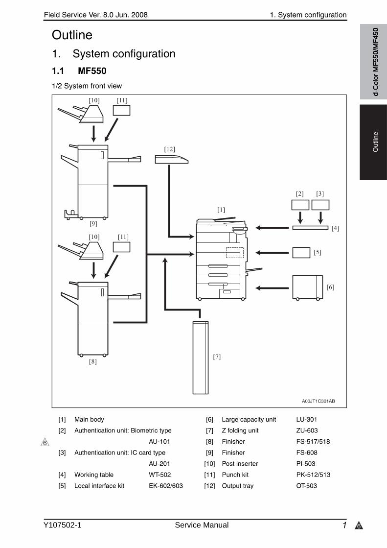
6
Field Service Ver. 8.0 Jun. 2008 1. System configuration
1
Out
line
d-C
olor
MF5
50/M
F450Outline
1. System configuration
1.1 MF550
1/2 System front view
[1] Main body [6] Large capacity unit LU-301
[2] Authentication unit: Biometric type [7] Z folding unit ZU-603
AU-101 [8] Finisher FS-517/518
[3] Authentication unit: IC card type [9] Finisher FS-608
AU-201 [10] Post inserter PI-503
[4] Working table WT-502 [11] Punch kit PK-512/513
[5] Local interface kit EK-602/603 [12] Output tray OT-503
[1]
[2]
[4]
[5]
[6]
[8]
[11]
[12]
A00JT1C301AB
[10]
[11][10]
[9]
[3]
[7]
6
Y107502-1 Service Manual

1. System configuration Field Service Ver. 8.0 Jun. 2008
24
Out
line
2/2 System rear view
*: Except for the North America area.
[1] Main body [7] Scan accelerator kit SA-501
[2] Stamp unit SP-501 [8] Fax multi line ML-501
[3] Fax kit FK-502 [9] Key counter kit KIT-1
[4] Security kit SC-503 [10] i-Option LK-101*/102*/103
[5] Image controller IC-409 [11] Upgrade kit UK-201
[6] Video interface kit VI-504
A00HT1E001DB
[2]
[1]
[4]
[3]
[9]
[10] [11]
[6]
[8]
[5]
[7]
4
4
4
d-C
olor
MF5
50/M
F450
Service Manual Y107502-1
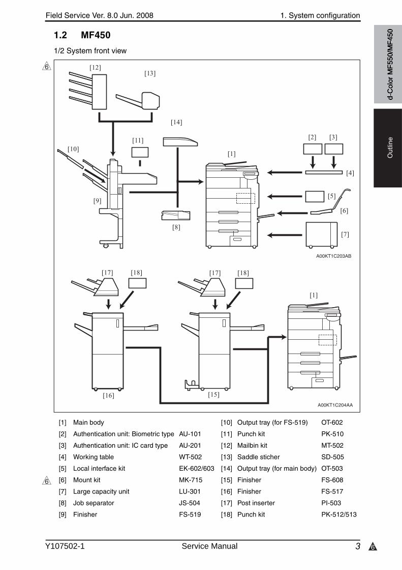
6
Field Service Ver. 8.0 Jun. 2008 1. System configuration
3
Out
line
1.2 MF450
1/2 System front view
[1] Main body [10] Output tray (for FS-519) OT-602
[2] Authentication unit: Biometric type AU-101 [11] Punch kit PK-510
[3] Authentication unit: IC card type AU-201 [12] Mailbin kit MT-502
[4] Working table WT-502 [13] Saddle sticher SD-505
[5] Local interface kit EK-602/603 [14] Output tray (for main body) OT-503
[6] Mount kit MK-715 [15] Finisher FS-608
[7] Large capacity unit LU-301 [16] Finisher FS-517
[8] Job separator JS-504 [17] Post inserter PI-503
[9] Finisher FS-519 [18] Punch kit PK-512/513
6
[1]
[2]
[4]
[5]
[7]
[11]
A00KT1C203AB
[9]
[12]
[3]
[6]
[8]
[14]
[13]
[10]
A00KT1C204AA
[1]
[16]
[18][17][18][17]
[15]
6
d-C
olor
MF5
50/M
F450
Y107502-1 Service Manual
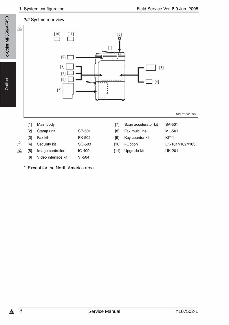
1. System configuration Field Service Ver. 8.0 Jun. 2008
44
Out
line
2/2 System rear view
*: Except for the North America area.
[1] Main body [7] Scan accelerator kit SA-501
[2] Stamp unit SP-501 [8] Fax multi line ML-501
[3] Fax kit FK-502 [9] Key counter kit KIT-1
[4] Security kit SC-503 [10] i-Option LK-101*/102*/103
[5] Image controller IC-409 [11] Upgrade kit UK-201
[6] Video interface kit VI-504
A00HT1E001DB
[2]
[1]
[4]
[3]
[9]
[10] [11]
[6]
[8]
[5]
[7]
4
4
4
d-C
olor
MF5
50/M
F450
Service Manual Y107502-1
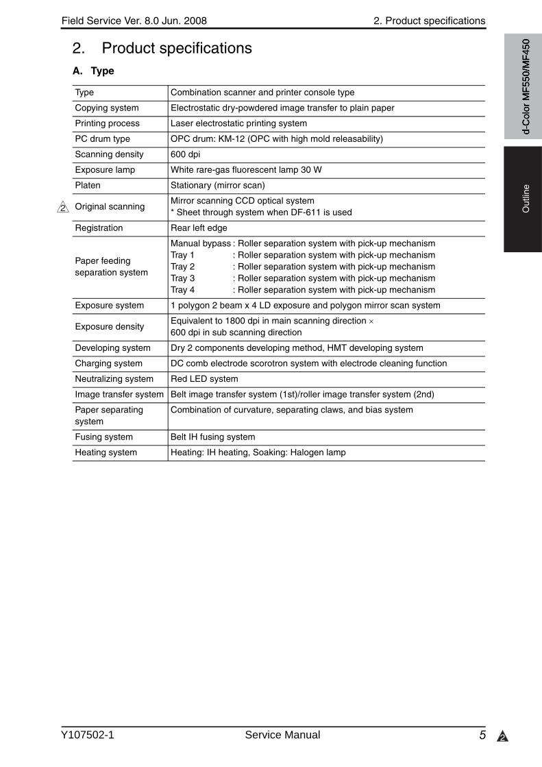
Field Service Ver. 8.0 Jun. 2008 2. Product specifications
5 2
Out
line
2. Product specificationsA. Type
Type Combination scanner and printer console type
Copying system Electrostatic dry-powdered image transfer to plain paper
Printing process Laser electrostatic printing system
PC drum type OPC drum: KM-12 (OPC with high mold releasability)
Scanning density 600 dpi
Exposure lamp White rare-gas fluorescent lamp 30 W
Platen Stationary (mirror scan)
Original scanningMirror scanning CCD optical system* Sheet through system when DF-611 is used
Registration Rear left edge
Paper feeding separation system
Manual bypass : Roller separation system with pick-up mechanismTray 1 : Roller separation system with pick-up mechanismTray 2 : Roller separation system with pick-up mechanismTray 3 : Roller separation system with pick-up mechanismTray 4 : Roller separation system with pick-up mechanism
Exposure system 1 polygon 2 beam x 4 LD exposure and polygon mirror scan system
Exposure densityEquivalent to 1800 dpi in main scanning direction 600 dpi in sub scanning direction
Developing system Dry 2 components developing method, HMT developing system
Charging system DC comb electrode scorotron system with electrode cleaning function
Neutralizing system Red LED system
Image transfer system Belt image transfer system (1st)/roller image transfer system (2nd)
Paper separating system
Combination of curvature, separating claws, and bias system
Fusing system Belt IH fusing system
Heating system Heating: IH heating, Soaking: Halogen lamp
2
d-C
olor
MF5
50/M
F450
Y107502-1 Service Manual
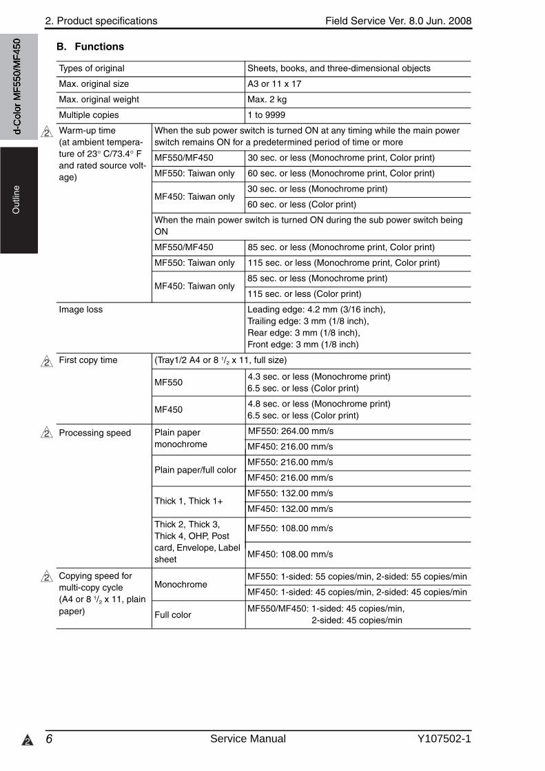
2. Product specifications Field Service Ver. 8.0 Jun. 2008
62
Out
line
B. Functions
Types of original Sheets, books, and three-dimensional objects
Max. original size A3 or 11 x 17
Max. original weight Max. 2 kg
Multiple copies 1 to 9999
Warm-up time(at ambient tempera-ture of 23 C/73.4 F and rated source volt-age)
When the sub power switch is turned ON at any timing while the main power switch remains ON for a predetermined period of time or more
MF550/MF450 30 sec. or less (Monochrome print, Color print)
MF550: Taiwan only 60 sec. or less (Monochrome print, Color print)
MF450: Taiwan only30 sec. or less (Monochrome print)
60 sec. or less (Color print)
When the main power switch is turned ON during the sub power switch being ON
MF550/MF450 85 sec. or less (Monochrome print, Color print)
MF550: Taiwan only 115 sec. or less (Monochrome print, Color print)
MF450: Taiwan only85 sec. or less (Monochrome print)
115 sec. or less (Color print)
Image loss Leading edge: 4.2 mm (3/16 inch), Trailing edge: 3 mm (1/8 inch), Rear edge: 3 mm (1/8 inch), Front edge: 3 mm (1/8 inch)
First copy time (Tray1/2 A4 or 8 1/2 x 11, full size)
2
2
2
2
d-C
olor
MF5
50/M
F450
MF550 4.3 sec. or less (Monochrome print)
6.5 sec. or less (Color print)
MF450 4.8 sec. or less (Monochrome print)
6.5 sec. or less (Color print)
MF550: 264.00 mm/s
MF450: 216.00 mm/s
Plain paper/full colorMF550: 216.00 mm/s
MF450: 216.00 mm/s
Thick 1, Thick 1+MF550: 132.00 mm/s
MF450: 132.00 mm/s
Thick 2, Thick 3, Thick 4, OHP, Post card, Envelope, Label sheet
MF550: 108.00 mm/s
MF450: 108.00 mm/s
Processing speed Plain papermonochrome
MF550: 1-sided: 55 copies/min, 2-sided: 55 copies/min
MF450: 1-sided: 45 copies/min, 2-sided: 45 copies/min
Copying speed for multi-copy cycle(A4 or 8 1/2 x 11, plain paper)
Monochrome
MF550/MF450: 1-sided: 45 copies/min, 2-sided: 45 copies/min
Full color
Service Manual Y107502-1
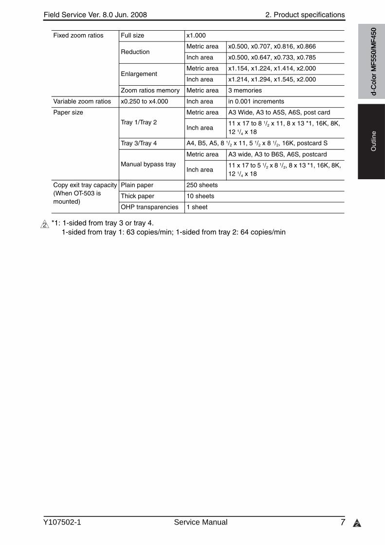
Field Service Ver. 8.0 Jun. 2008 2. Product specifications
7 2
Out
line
*1: 1-sided from tray 3 or tray 4. 1-sided from tray 1: 63 copies/min; 1-sided from tray 2: 64 copies/min
Fixed zoom ratios Full size x1.000
ReductionMetric area x0.500, x0.707, x0.816, x0.866
Inch area x0.500, x0.647, x0.733, x0.785
EnlargementMetric area x1.154, x1.224, x1.414, x2.000
Inch area x1.214, x1.294, x1.545, x2.000
Zoom ratios memory Metric area 3 memories
Variable zoom ratios x0.250 to x4.000 Inch area in 0.001 increments
Paper size
Tray 1/Tray 2
Metric area A3 Wide, A3 to A5S, A6S, post card
Inch area11 x 17 to 8 1/2 x 11, 8 x 13 *1, 16K, 8K,12 1/4 x 18
Tray 3/Tray 4 A4, B5, A5, 8 1/2 x 11, 5 1/2 x 8 1/2, 16K, postcard S
Manual bypass tray
Metric area A3 wide, A3 to B6S, A6S, postcard
Inch area11 x 17 to 5 1/2 x 8 1/2, 8 x 13 *1, 16K, 8K, 12 1/4 x 18
Copy exit tray capacity(When OT-503 is mounted)
Plain paper 250 sheets
Thick paper 10 sheets
OHP transparencies 1 sheet
2
d-C
olor
MF5
50/M
F450
Y107502-1 Service Manual
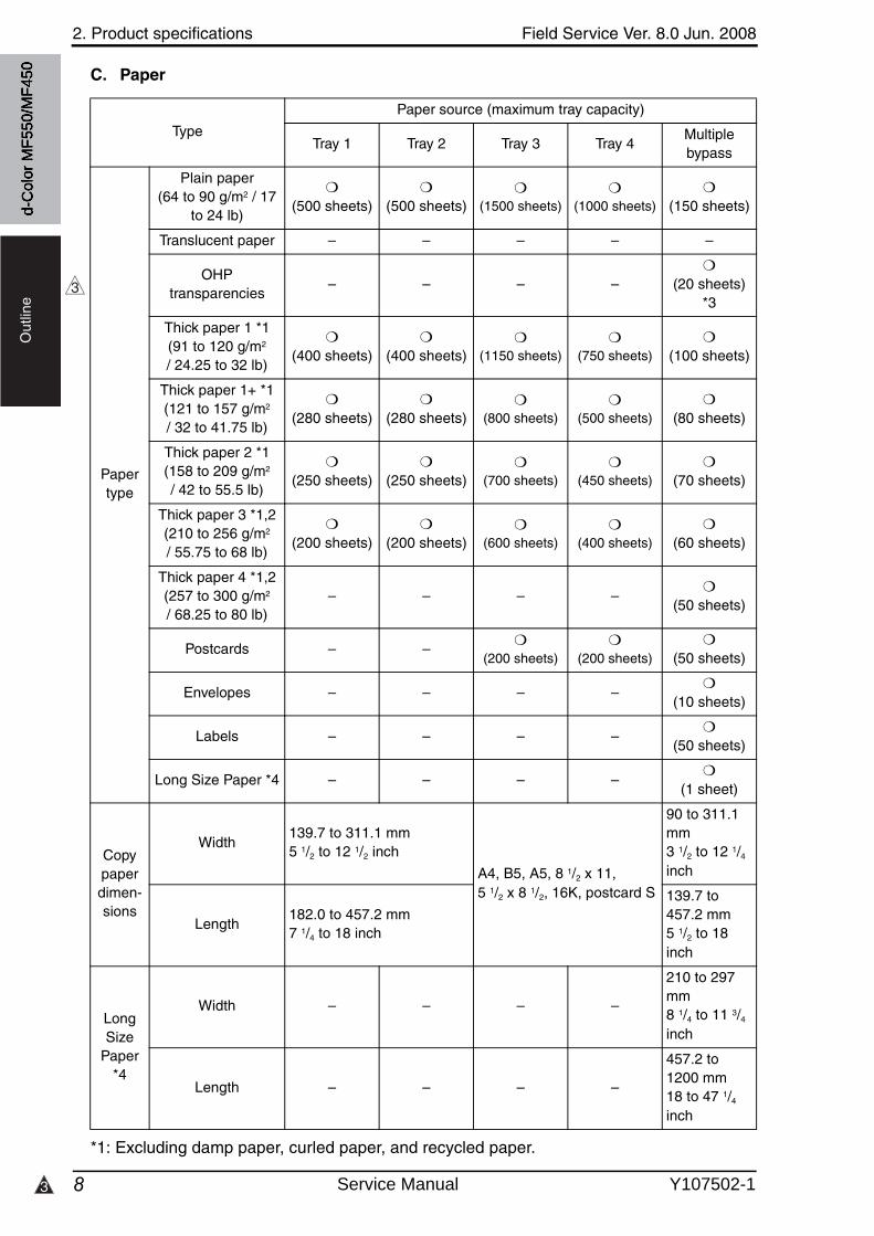
2. Product specifications Field Service Ver. 8.0 Jun. 2008
83
Out
line
C. Paper
*1: Excluding damp paper, curled paper, and recycled paper.
Type
Paper source (maximum tray capacity)
Tray 1 Tray 2 Tray 3 Tray 4Multiplebypass
Paper type
Plain paper (64 to 90 g/m2 / 17
to 24 lb)
❍
(500 sheets)❍
(500 sheets)❍
(1500 sheets)❍
(1000 sheets)❍
(150 sheets)
Translucent paper – – – – –
OHPtransparencies
– – – –❍
(20 sheets)*3
Thick paper 1 *1(91 to 120 g/m2
/ 24.25 to 32 lb)
❍
(400 sheets)❍
(400 sheets)❍
(1150 sheets)❍
(750 sheets)❍
(100 sheets)
Thick paper 1+ *1 (121 to 157 g/m2
/ 32 to 41.75 lb)
❍
(280 sheets)❍
(280 sheets)❍
(800 sheets)❍
(500 sheets)❍
(80 sheets)
Thick paper 2 *1(158 to 209 g/m2
/ 42 to 55.5 lb)
❍
(250 sheets)❍
(250 sheets)❍
(700 sheets)❍
(450 sheets)❍
(70 sheets)
Thick paper 3 *1,2(210 to 256 g/m2
/ 55.75 to 68 lb)
❍
(200 sheets)❍
(200 sheets)❍
(600 sheets)❍
(400 sheets)❍
(60 sheets)
Thick paper 4 *1,2(257 to 300 g/m2
/ 68.25 to 80 lb)– – – –
❍
(50 sheets)
Postcards – –❍
(200 sheets)❍
(200 sheets)❍
(50 sheets)
Envelopes – – – –❍
(10 sheets)
Labels – – – –❍
(50 sheets)
Long Size Paper *4 – – – –❍
(1 sheet)
Copy paper dimen-sions
Width139.7 to 311.1 mm5 1/2 to 12 1/2 inch
A4, B5, A5, 8 1/2 x 11, 5 1/2 x 8 1/2, 16K, postcard S
90 to 311.1 mm3 1/2 to 12 1/4
inch
Length182.0 to 457.2 mm7 1/4 to 18 inch
139.7 to 457.2 mm5 1/2 to 18inch
Long Size
Paper *4
Width – – – –
210 to 297 mm8 1/4 to 11 3/4
inch
Length – – – –
457.2 to 1200 mm18 to 47 1/4
inch
3
d-C
olor
MF5
50/M
F450
Service Manual Y107502-1
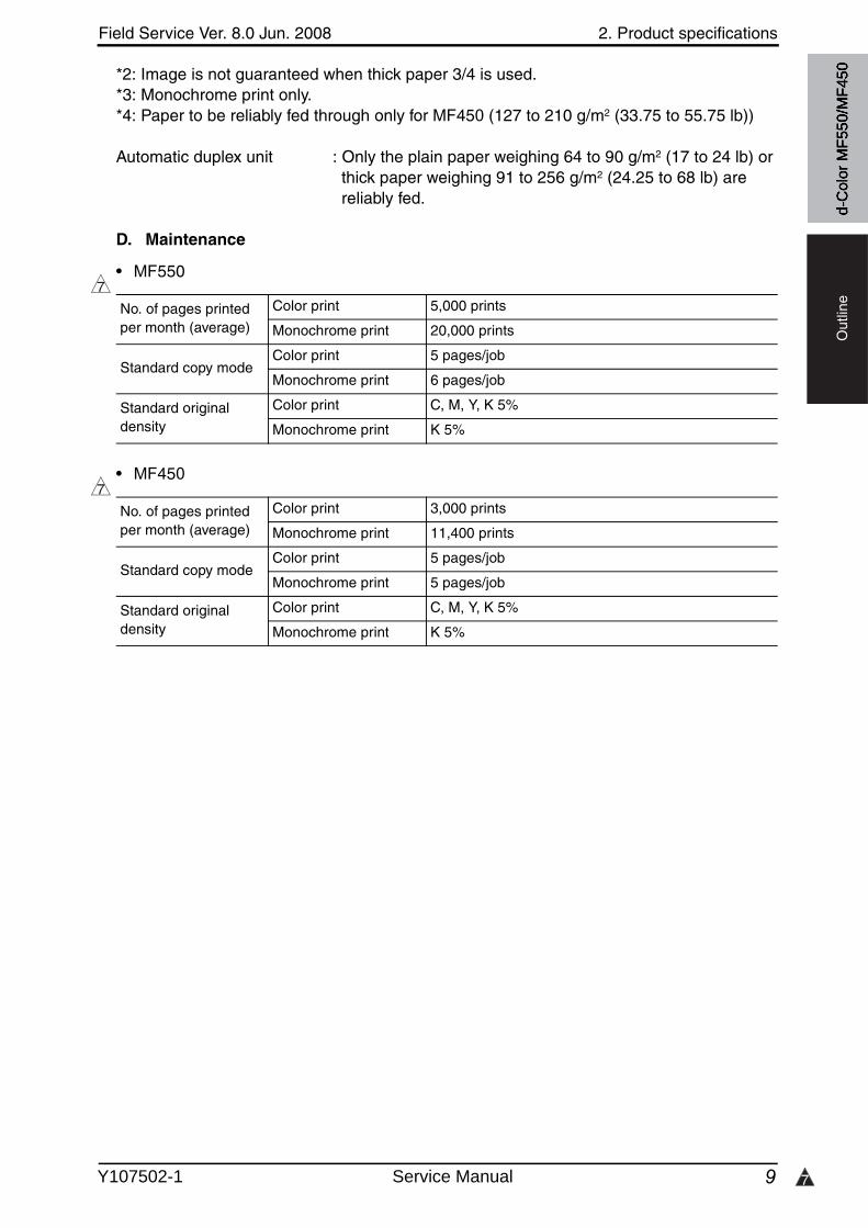
7
Field Service Ver. 8.0 Jun. 2008 2. Product specifications
9
Out
line
*2: Image is not guaranteed when thick paper 3/4 is used.*3: Monochrome print only.*4: Paper to be reliably fed through only for MF450 (127 to 210 g/m2 (33.75 to 55.75 lb))
Automatic duplex unit : Only the plain paper weighing 64 to 90 g/m2 (17 to 24 lb) or thick paper weighing 91 to 256 g/m2 (24.25 to 68 lb) are reliably fed.
D. Maintenance
d-C
olor
MF5
50/M
F450
• MF550
• MF450
7
No. of pages printed per month (average)
Color print 5,000 prints
Monochrome print 20,000 prints
Standard copy modeColor print 5 pages/job
Monochrome print 6 pages/job
Standard original density
Color print C, M, Y, K 5%
Monochrome print K 5%
7
No. of pages printed per month (average)
Color print 3,000 prints
Monochrome print 11,400 prints
Standard copy modeColor print 5 pages/job
Monochrome print 5 pages/job
Standard original density
Color print C, M, Y, K 5%
Monochrome print K 5%
Y107502-1 Service Manual
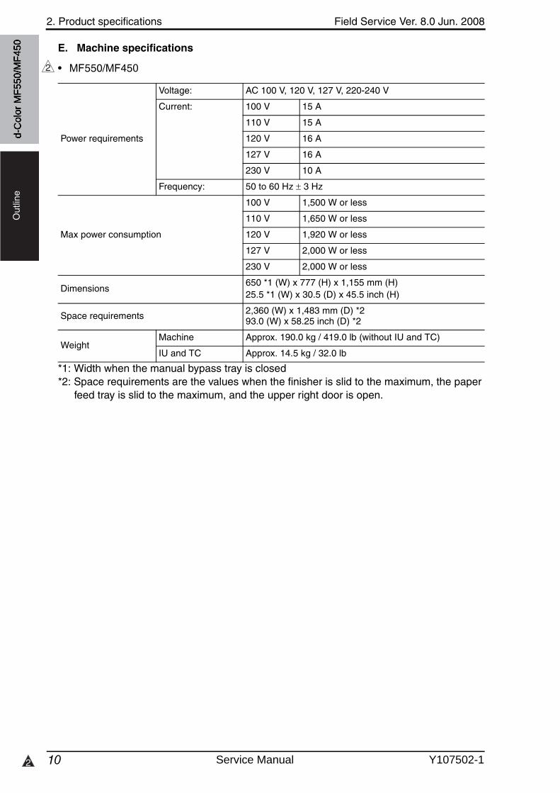
2. Product specifications Field Service Ver. 8.0 Jun. 2008
102
Out
line
E. Machine specifications
d-C
olor
MF5
50/M
F450
• MF550/MF450
*1: Width when the manual bypass tray is closed*2: Space requirements are the values when the finisher is slid to the maximum, the paper
feed tray is slid to the maximum, and the upper right door is open.
2
Power requirements
Voltage: AC 100 V, 120 V, 127 V, 220-240 V
Current: 100 V 15 A
110 V 15 A
120 V 16 A
127 V 16 A
230 V 10 A
Frequency: 50 to 60 Hz 3 Hz
Max power consumption
100 V 1,500 W or less
110 V 1,650 W or less
120 V 1,920 W or less
127 V 2,000 W or less
230 V 2,000 W or less
Dimensions650 *1 (W) x 777 (H) x 1,155 mm (H)25.5 *1 (W) x 30.5 (D) x 45.5 inch (H)
Space requirements 2,360 (W) x 1,483 mm (D) *293.0 (W) x 58.25 inch (D) *2
WeightMachine Approx. 190.0 kg / 419.0 lb (without IU and TC)
IU and TC Approx. 14.5 kg / 32.0 lb
Service Manual Y107502-1
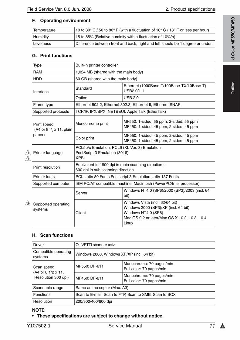
3
Field Service Ver. 8.0 Jun. 2008 2. Product specifications
11
Out
line
F. Operating environment
G. Print functions
H. Scan functions
NOTE• These specifications are subject to change without notice.
Temperature 10 to 30 C / 50 to 86 F (with a fluctuation of 10 C / 18 F or less per hour)
Humidity 15 to 85% (Relative humidity with a fluctuation of 10%/h)
Levelness Difference between front and back, right and left should be 1 degree or under.
Type Built-in printer controller
RAM 1,024 MB (shared with the main body)
HDD 60 GB (shared with the main body)
InterfaceStandard
Ethernet (1000Base-T/100Base-TX/10Base-T)USB2.0/1.1
Option USB 2.0
Frame type Ethernet 802.2, Ethernet 802.3, Ethernet II, Ethernet SNAP
Supported protocols TCP/IP, IPX/SPX, NETBEUI, Apple Talk (EtherTalk)
Print speed (A4 or 8 1/2 x 11, plain paper)
Monochrome print
Color printMF550: 1-sided: 45 ppm, 2-sided: 45 ppmMF450: 1-sided: 45 ppm, 2-sided: 45 ppm
Printer languagePCL5e/c Emulation, PCL6 (XL Ver. 3) EmulationPostScript 3 Emulation (3016)XPS
Print resolutionEquivalent to 1800 dpi in main scanning direction 600 dpi in sub scanning direction
Printer fonts PCL Latin 80 Fonts Postscript 3 Emulation Latin 137 Fonts
Supported computer IBM PC/AT compatible machine, Macintosh (PowerPC/Intel processor)
Supported operating systems
ServerWindows NT4.0 (SP6)/2000 (SP3)/2003 (incl. 64 bit)
Client
Windows Vista (incl. 32/64 bit)Windows 2000 (SP3)/XP (incl. 64 bit)Windows NT4.0 (SP6)Mac OS 9.2 or later/Mac OS X 10.2, 10.3, 10.4Linux
3
3
3
Driver OLIVETTI scanner driver
Compatible operating systems
Windows 2000, Windows XP/XP (incl. 64 bit)
Scan speed(A4 or 8 1/2 x 11, Resolution 300 dpi)
MF550: DF-611 Monochrome: 70 pages/min
Full color: 70 pages/min
MF450: DF-611Monochrome: 70 pages/minFull color: 70 pages/min
Scannable range Same as the copier (Max. A3)
Functions Scan to E-mail, Scan to FTP, Scan to SMB, Scan to BOX
Resolution 200/300/400/600 dpi
d-C
olor
MF5
50/M
F450
MF550: 1-sided: 55 ppm, 2-sided: 55 ppmMF450: 1-sided: 45 ppm, 2-sided: 45 ppm
Y107502-1 Service Manual
2. Product specifications Field Service Ver. 8.0 Jun. 2008
12
Out
line
Blank Page
d-C
olor
MF5
50/M
F450
Service Manual Y107502-1
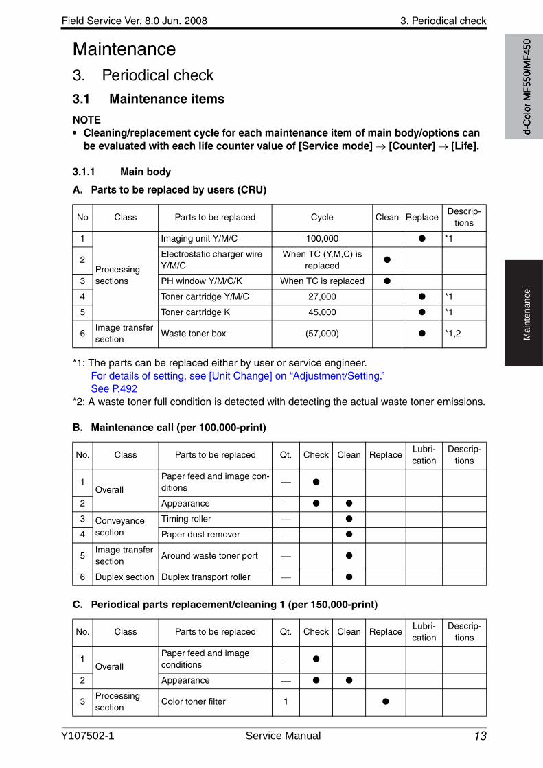
Field Service Ver. 8.0 Jun. 2008 3. Periodical check
13
Ma
inte
na
nce
Maintenance3. Periodical check
3.1 Maintenance items
NOTE• Cleaning/replacement cycle for each maintenance item of main body/options can
be evaluated with each life counter value of [Service mode] [Counter] [Life].
3.1.1 Main body
A. Parts to be replaced by users (CRU)
*1: The parts can be replaced either by user or service engineer.For details of setting, see [Unit Change] on “Adjustment/Setting.”See P.492
*2: A waste toner full condition is detected with detecting the actual waste toner emissions.
B. Maintenance call (per 100,000-print)
C. Periodical parts replacement/cleaning 1 (per 150,000-print)
No Class Parts to be replaced Cycle Clean ReplaceDescrip-
tions
1
Processing sections
Imaging unit Y/M/C 100,000 ● *1
2Electrostatic charger wire Y/M/C
When TC (Y,M,C) is replaced
●
3 PH window Y/M/C/K When TC is replaced ●
4 Toner cartridge Y/M/C 27,000 ● *1
5 Toner cartridge K 45,000 ● *1
6Image transfer section
Waste toner box (57,000) ● *1,2
No. Class Parts to be replaced Qt. Check Clean ReplaceLubri-cation
Descrip-tions
1Overall
Paper feed and image con-ditions
●
2 Appearance ● ●
3 Conveyance section
Timing roller ●
4 Paper dust remover ●
5Image transfer section
Around waste toner port ●
6 Duplex section Duplex transport roller ●
No. Class Parts to be replaced Qt. Check Clean ReplaceLubri-cation
Descrip-tions
1Overall
Paper feed and image conditions
●
2 Appearance ● ●
3Processing section
Color toner filter 1 ●
d-C
olor
MF5
50/M
F450
Y107502-1 Service Manual
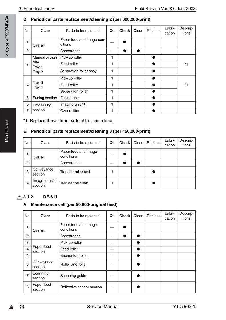
3. Periodical check Field Service Ver. 8.0 Jun. 2008
142
Ma
inte
na
nce
D. Periodical parts replacement/cleaning 2 (per 300,000-print)
*1: Replace those three parts at the same time.
E. Periodical parts replacement/cleaning 3 (per 450,000-print)
3.1.2 DF-611
A. Maintenance call (per 50,000-original feed)
No. Class Parts to be replaced Qt. Check Clean ReplaceLubri-cation
Descrip-tions
1Overall
Paper feed and image con-ditions
●
2 Appearance ● ●
3
Manual bypass trayTray 1Tray 2
Pick-up roller 1 ●
*1Feed roller 1 ●
Separation roller assy 1 ●
4Tray 3Tray 4
Pick-up roller 1 ●
*1Feed roller 1 ●
Separation roller 1 ●
5 Fusing section Fusing unit 1 ●
6 Processing section
Imaging unit /K 1 ●
7 Ozone filter 1 ●
No. Class Parts to be replaced Qt. Check Clean ReplaceLubri-cation
Descrip-tions
1Overall
Paper feed and image conditions
●
2 Appearance ● ●
3Conveyance section
Transfer roller unit 1 ●
4Image transfer section
Transfer belt unit 1 ●
2
No. Class Parts to be replaced Qt. Check Clean ReplaceLubri-cation
Descrip-tions
1Overall
Paper feed and image conditions
●
2 Appearance ● ●
3Paper feed section
Pick-up roller ●
4 Feed roller ●
5 Separation roller ●
6Conveyance section
Roller and rolls ●
7Scanning section
Scanning guide ●
8Paper feed section
Reflective sensor section ●
d-C
olor
MF5
50/M
F450
Service Manual Y107502-1
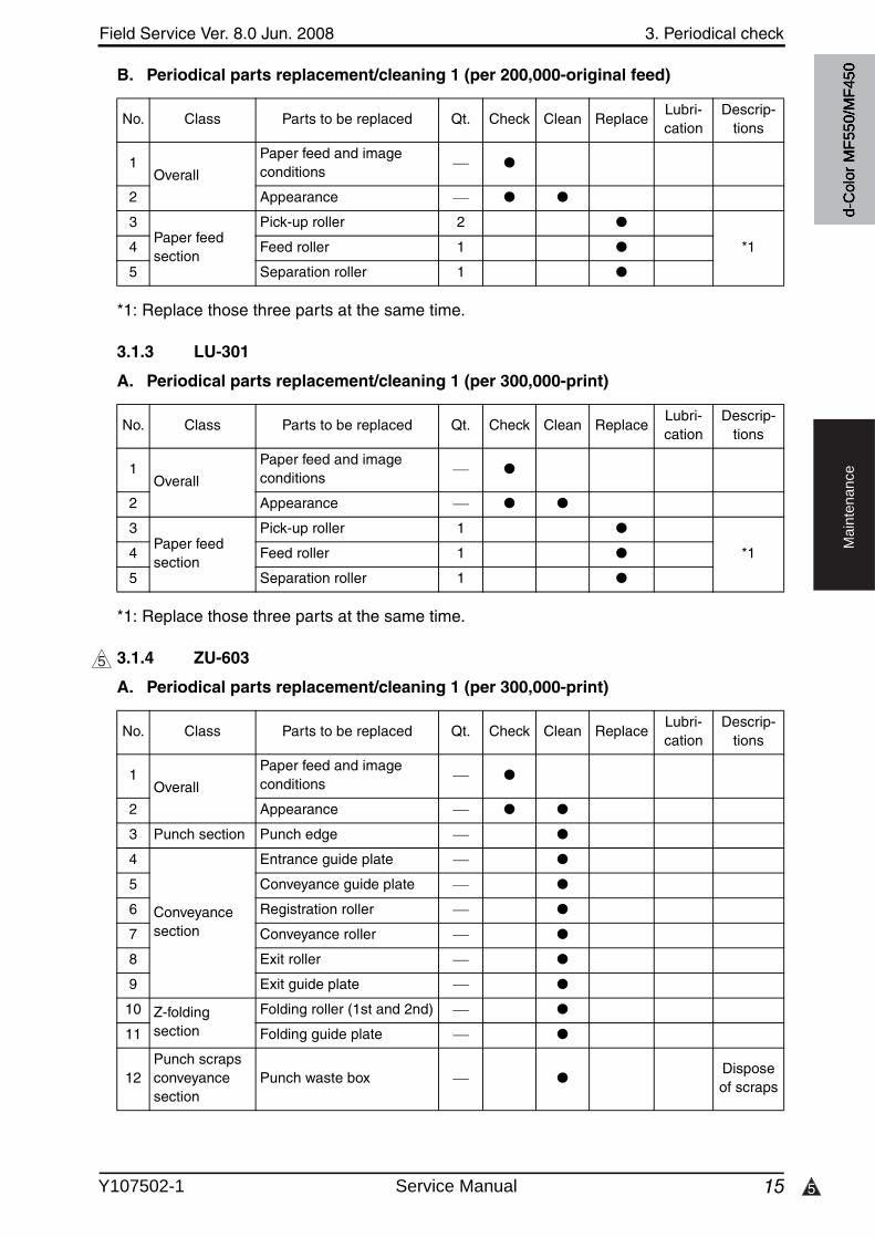
5
Field Service Ver. 8.0 Jun. 2008 3. Periodical check
15
Ma
inte
na
nce
B. Periodical parts replacement/cleaning 1 (per 200,000-original feed)
*1: Replace those three parts at the same time.
3.1.3 LU-301
A. Periodical parts replacement/cleaning 1 (per 300,000-print)
*1: Replace those three parts at the same time.
3.1.4 ZU-603
A. Periodical parts replacement/cleaning 1 (per 300,000-print)
No. Class Parts to be replaced Qt. Check Clean ReplaceLubri-cation
Descrip-tions
1Overall
Paper feed and image conditions
●
2 Appearance ● ●
3Paper feed section
Pick-up roller 2 ●
*14 Feed roller 1 ●
5 Separation roller 1 ●
No. Class Parts to be replaced Qt. Check Clean ReplaceLubri-cation
Descrip-tions
1Overall
Paper feed and image conditions
●
2 Appearance ● ●
3Paper feed section
Pick-up roller 1 ●
*14 Feed roller 1 ●
5 Separation roller 1 ●
5
No. Class Parts to be replaced Qt. Check Clean ReplaceLubri-cation
Descrip-tions
1Overall
Paper feed and image conditions
●
2 Appearance ● ●
3 Punch section Punch edge ●
4
Conveyance section
Entrance guide plate ●
5 Conveyance guide plate ●
6 Registration roller ●
7 Conveyance roller ●
8 Exit roller ●
9 Exit guide plate ●
10 Z-folding section
Folding roller (1st and 2nd) ●
11 Folding guide plate ●
12Punch scraps conveyance section
Punch waste box ●Dispose of scraps
d-C
olor
MF5
50/M
F450
Y107502-1 Service Manual
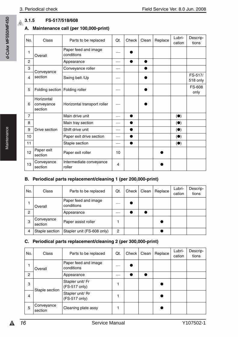
3. Periodical check Field Service Ver. 8.0 Jun. 2008
166
Ma
inte
na
nce
3.1.5 FS-517/518/608
A. Maintenance call (per 100,000-print)
B. Periodical parts replacement/cleaning 1 (per 200,000-print)
C. Periodical parts replacement/cleaning 2 (per 300,000-print)
6
No. Class Parts to be replaced Qt. Check Clean ReplaceLubri-cation
Descrip-tions
1Overall
Paper feed and image conditions
●
2 Appearance ● ●
3Conveyance section
Conveyance roller ●
4 Swing belt /Up ●FS-517/518 only
5 Folding section Folding roller ●FS-608
only
6Horizontal conveyance section
Horizontal transport roller ●
7
Drive section
Main drive unit ● (●)
8 Main tray section ● (●)
9 Shift drive unit ● (●)
10 Paper exit drive section ● (●)
11 Staple section ● (●)
12Paper exit section
Paper exit roller 10 ●
13Conveyance section
Intermediate conveyance roller
4 ●
No. Class Parts to be replaced Qt. Check Clean ReplaceLubri-cation
Descrip-tions
1Overall
Paper feed and image conditions
●
2 Appearance ● ●
3Conveyance section
Paper assist roller 1 ●
4 Staple section Stapler unit (FS-608 only) 2 ●
No. Class Parts to be replaced Qt. Check Clean ReplaceLubri-cation
Descrip-tions
1Overall
Paper feed and image conditions
●
2 Appearance ● ●
3
Staple section
Stapler unit/ Fr (FS-517 only)
1 ●
4Stapler unit/ Rr (FS-517 only)
1 ●
5Conveyance section
Cleaning plate assy 1 ●
d-C
olor
MF5
50/M
F450
Service Manual Y107502-1

6
Field Service Ver. 8.0 Jun. 2008 3. Periodical check
17
Ma
inte
na
nce
D. Periodical parts replacement/cleaning 3 (per 500,000-print) *FS-518 only
3.1.6 PK-512/513
A. Maintenance call (per 100,000-print)
3.1.7 PI-503
A. Maintenance call (per 100,000-print)
B. Periodical parts replacement/cleaning 1 (per 200,000-print)
6
No. Class Parts to be replaced Qt. Check Clean ReplaceLubri-cation
Descrip-tions
1Overall
Paper feed and image conditions
●
2 Appearance ● ●
3
Staple section
Stapler unit/ Fr (FS-518 only)
1 ●
4Stapler unit/ Rr (FS-518 only)
1 ●
No. Class Parts to be replaced Qt. Check Clean ReplaceLubri-cation
Descrip-tions
1Overall
Paper feed and image conditions
●
2 Appearance ● ●
3Punch unit main body
Punch edge ●
4 Punch scraps collection section
Punch scraps box ●
5 Punch scraps full sensor ●
6Exterior section
Exterior parts ●
No. Class Parts to be replaced Qt. Check Clean ReplaceLubri-cation
Descrip-tions
1Overall
Paper feed and image conditions
●
2 Appearance ● ●
3
Paper feed section
Feed roller/Up 1 ●
4 Feed roller/Lw 1 ●
5 Separation roller/Up 1 ●
6 Separation roller/Lw 1 ●
No. Class Parts to be replaced Qt. Check Clean ReplaceLubri-cation
Descrip-tions
1Overall
Paper feed and image conditions
●
2 Appearance ● ●
3 Paper feed section
Pick-up roller/Up 1 ●
4 Pick-up roller/Lw 1 ●
d-C
olor
MF5
50/M
F450
Y107502-1 Service Manual
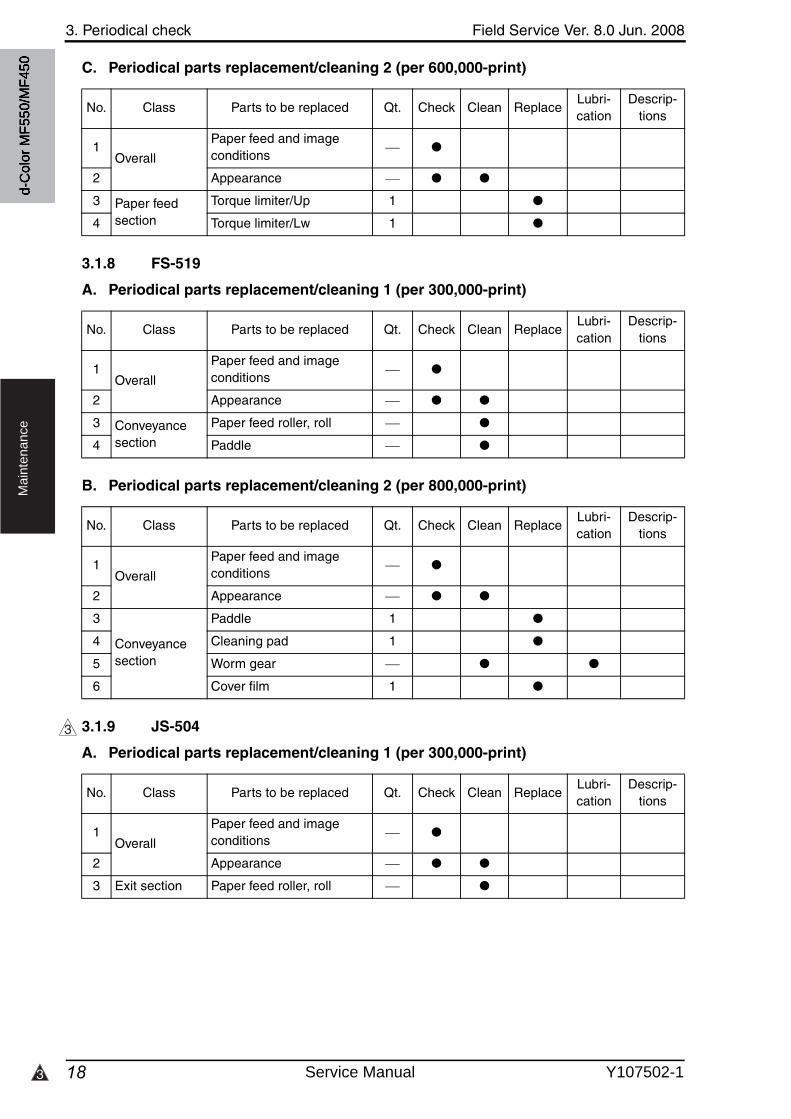
3. Periodical check Field Service Ver. 8.0 Jun. 2008
183
Ma
inte
na
nce
C. Periodical parts replacement/cleaning 2 (per 600,000-print)
3.1.8 FS-519
A. Periodical parts replacement/cleaning 1 (per 300,000-print)
B. Periodical parts replacement/cleaning 2 (per 800,000-print)
3.1.9 JS-504
A. Periodical parts replacement/cleaning 1 (per 300,000-print)
No. Class Parts to be replaced Qt. Check Clean ReplaceLubri-cation
Descrip-tions
1Overall
Paper feed and image conditions
●
2 Appearance ● ●
3 Paper feed section
Torque limiter/Up 1 ●
4 Torque limiter/Lw 1 ●
No. Class Parts to be replaced Qt. Check Clean ReplaceLubri-cation
Descrip-tions
1Overall
Paper feed and image conditions
●
2 Appearance ● ●
3 Conveyance section
Paper feed roller, roll ●
4 Paddle ●
No. Class Parts to be replaced Qt. Check Clean ReplaceLubri-cation
Descrip-tions
1Overall
Paper feed and image conditions
●
2 Appearance ● ●
3
Conveyance section
Paddle 1 ●
4 Cleaning pad 1 ●
5 Worm gear ● ●
6 Cover film 1 ●
3
No. Class Parts to be replaced Qt. Check Clean ReplaceLubri-cation
Descrip-tions
1Overall
Paper feed and image conditions
●
2 Appearance ● ●
3 Exit section Paper feed roller, roll ●
d-C
olor
MF5
50/M
F450
Service Manual Y107502-1
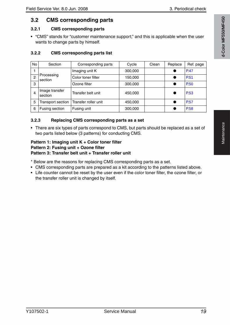
Field Service Ver. 8.0 Jun. 2008 3. Periodical check
19
Ma
inte
na
nce
3.2 CMS corresponding parts
3.2.1 CMS corresponding parts
• “CMS” stands for “customer maintenance support,” and this is applicable when the user wants to change parts by himself.
3.2.2 CMS corresponding parts list
3.2.3 Replacing CMS corresponding parts as a set
• There are six types of parts correspond to CMS, but parts should be replaced as a set of two parts listed below (3 patterns) for conducting CMS.
Pattern 1: Imaging unit K + Color toner filterPattern 2: Fusing unit + Ozone filterPattern 3: Transfer belt unit + Transfer roller unit
* Below are the reasons for replacing CMS corresponding parts as a set.• CMS corresponding parts are prepared as a kit according to the patterns listed above.• Life counter cannot be reset by the user even if the color toner filter, the ozone filter, or
the transfer roller unit is changed by itself.
No Section Corresponding parts Cycle Clean Replace Ref. page
1Processing section
Imaging unit K 300,000 ● P.47
2 Color toner filter 150,000 ● P.51
3 Ozone filter 300,000 ● P.50
4Image transfer section
Transfer belt unit 450,000 ● P.53
5 Transport section Transfer roller unit 450,000 ● P.57
6 Fusing section Fusing unit 300,000 ● P.58
d-C
olor
MF5
50/M
F450
Y107502-1 Service Manual
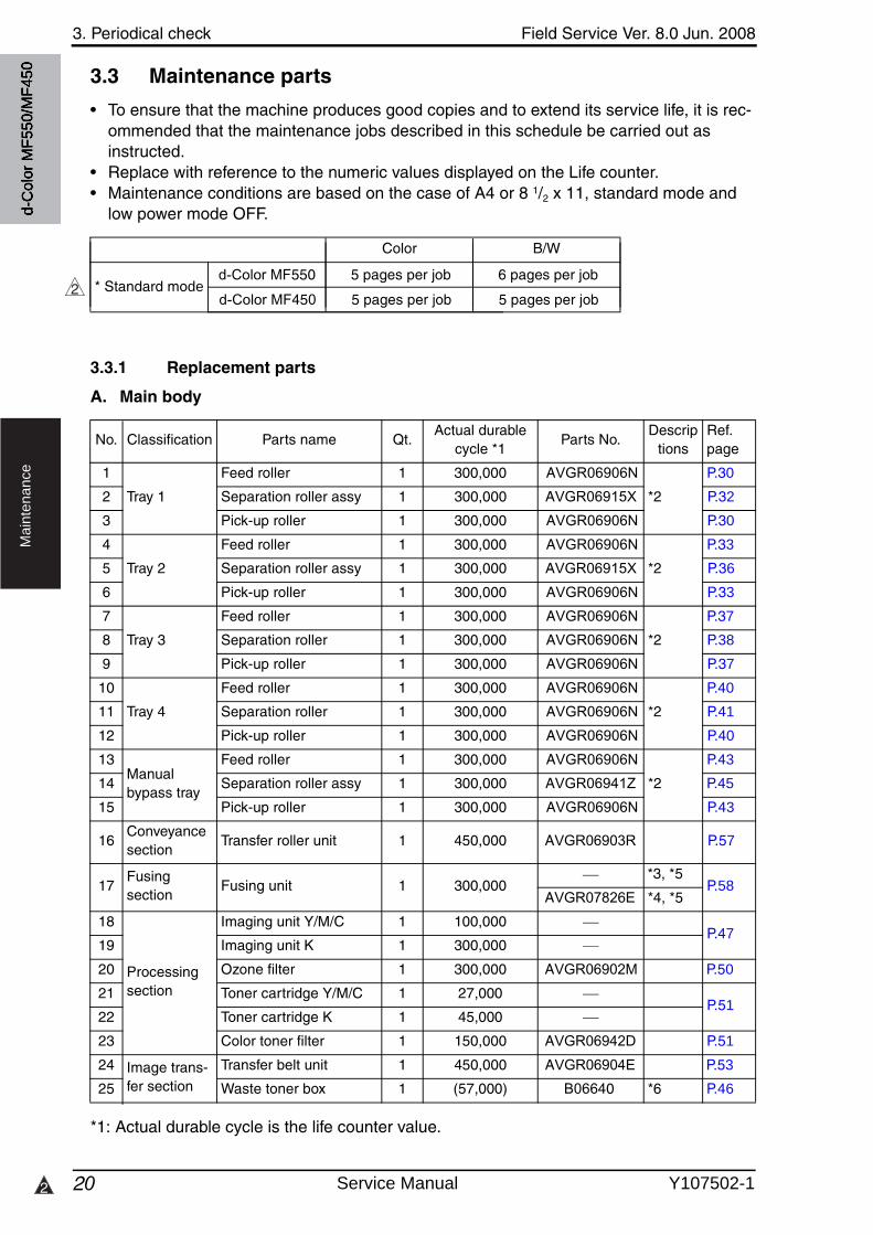
3. Periodical check Field Service Ver. 8.0 Jun. 2008
202
Ma
inte
na
nce
3.3 Maintenance parts
• To ensure that the machine produces good copies and to extend its service life, it is rec-ommended that the maintenance jobs described in this schedule be carried out as instructed.
• Replace with reference to the numeric values displayed on the Life counter.• Maintenance conditions are based on the case of A4 or 8 1/2 x 11, standard mode and
low power mode OFF.
3.3.1 Replacement parts
A. Main body
*1: Actual durable cycle is the life counter value.
No. Classification Parts name Qt.Actual durable
cycle *1Parts No.
Descriptions
Ref.page
1
Tray 1
Feed roller 1 300,000 AVGR06906N
*2
P.30
2 Separation roller assy 1 300,000 AVGR06915X P.32
3 Pick-up roller 1 300,000 AVGR06906N P.30
4
Tray 2
Feed roller 1 300,000 AVGR06906N
*2
P.33
5 Separation roller assy 1 300,000 AVGR06915X P.36
6 Pick-up roller 1 300,000 AVGR06906N P.33
7
Tray 3
Feed roller 1 300,000 AVGR06906N
*2
P.37
8 Separation roller 1 300,000 AVGR06906N P.38
9 Pick-up roller 1 300,000 AVGR06906N P.37
10
Tray 4
Feed roller 1 300,000 AVGR06906N
*2
P.40
11 Separation roller 1 300,000 AVGR06906N P.41
12 Pick-up roller 1 300,000 AVGR06906N P.40
13Manualbypass tray
Feed roller 1 300,000 AVGR06906N
*2
P.43
14 Separation roller assy 1 300,000 AVGR06941Z P.45
15 Pick-up roller 1 300,000 AVGR06906N P.43
16Conveyance section
Transfer roller unit 1 450,000 AVGR06903R P.57
17Fusingsection
Fusing unit 1 300,000*3, *5
P.58AVGR07826E *4, *5
18
Processing section
Imaging unit Y/M/C 1 100,000P.47
19 Imaging unit K 1 300,000
20 Ozone filter 1 300,000 AVGR06902M P.50
21 Toner cartridge Y/M/C 1 27,000P.51
22 Toner cartridge K 1 45,000
23 Color toner filter 1 150,000 AVGR06942D P.51
24 Image trans-fer section
Transfer belt unit 1 450,000 AVGR06904E P.53
25 Waste toner box 1 (57,000) B06640 *6 P.46
d-C
olor
MF5
50/M
F450
Color B/W
d-Color MF550 5 pages per job 6 pages per job
d-Color MF450 5 pages per job 5 pages per job* Standard mode2
Service Manual Y107502-1
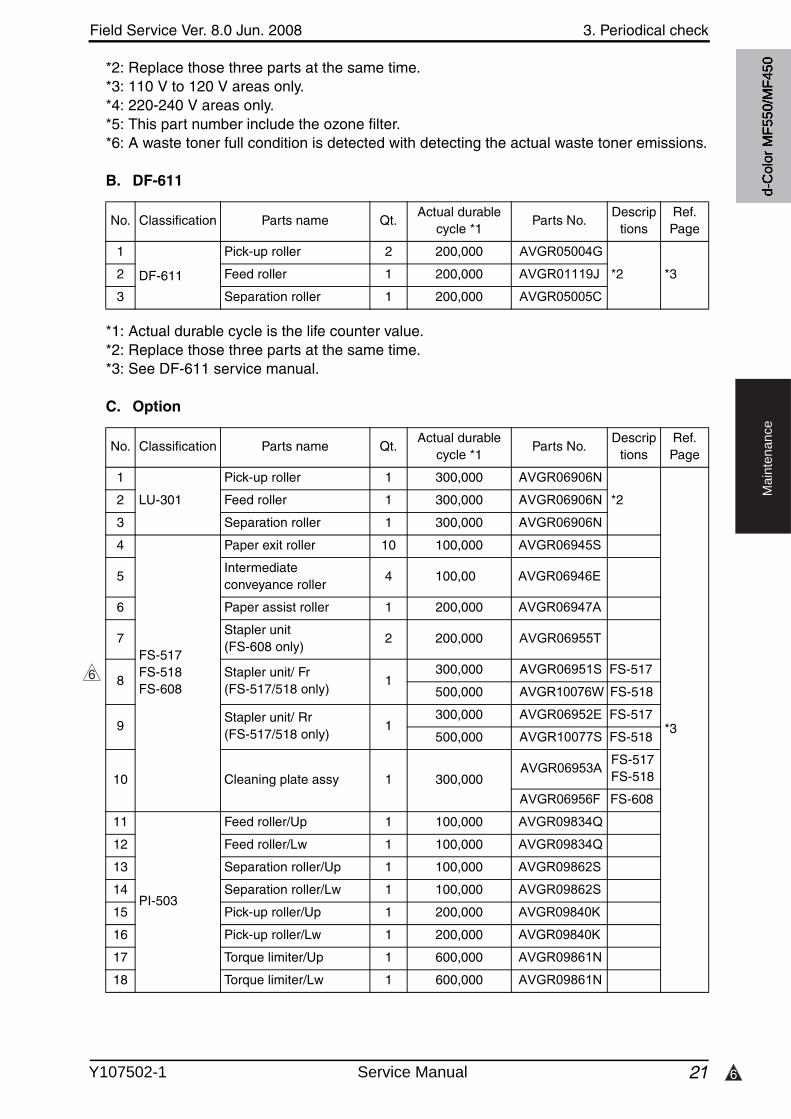
6
Field Service Ver. 8.0 Jun. 2008 3. Periodical check
21
Ma
inte
na
nce
*2: Replace those three parts at the same time.*3: 110 V to 120 V areas only.*4: 220-240 V areas only.*5: This part number include the ozone filter.*6: A waste toner full condition is detected with detecting the actual waste toner emissions.
B. DF-611
*1: Actual durable cycle is the life counter value.*2: Replace those three parts at the same time.*3: See DF-611 service manual.
C. Option
No. Classification Parts name Qt.Actual durable
cycle *1Parts No.
Descriptions
Ref.Page
1 Pick-up roller 2 200,000 AVGR05004G
*2 *32 Feed roller 1 200,000 AVGR01119J
3 Separation roller 1 200,000 AVGR05005C
No. Classification Parts name Qt.Actual durable
cycle *1Parts No.
Descriptions
Ref.Page
1
LU-301
Pick-up roller 1 300,000 AVGR06906N
*2
*3
2 Feed roller 1 300,000 AVGR06906N
3 Separation roller 1 300,000 AVGR06906N
4
FS-517FS-518FS-608
Paper exit roller 10 100,000 AVGR06945S
5Intermediate conveyance roller
4 100,00 AVGR06946E
6 Paper assist roller 1 200,000 AVGR06947A
7Stapler unit (FS-608 only)
2 200,000 AVGR06955T
8Stapler unit/ Fr (FS-517/518 only)
1300,000 AVGR06951S FS-517
500,000 AVGR10076W FS-518
9Stapler unit/ Rr (FS-517/518 only)
1300,000 AVGR06952E FS-517
500,000 AVGR10077S FS-518
10 Cleaning plate assy 1 300,000AVGR06953A
FS-517FS-518
AVGR06956F FS-608
11
PI-503
Feed roller/Up 1 100,000 AVGR09834Q
12 Feed roller/Lw 1 100,000 AVGR09834Q
13 Separation roller/Up 1 100,000 AVGR09862S
14 Separation roller/Lw 1 100,000 AVGR09862S
15 Pick-up roller/Up 1 200,000 AVGR09840K
16 Pick-up roller/Lw 1 200,000 AVGR09840K
17 Torque limiter/Up 1 600,000 AVGR09861N
18 Torque limiter/Lw 1 600,000 AVGR09861N
6
d-C
olor
MF5
50/M
F450
DF-611
Y107502-1 Service Manual
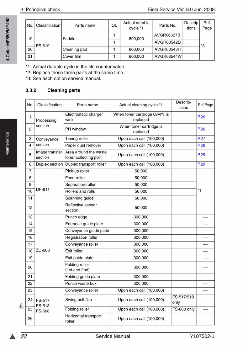
3. Periodical check Field Service Ver. 8.0 Jun. 2008
226
Ma
inte
na
nce
*1: Actual durable cycle is the life counter value.*2: Replace those three parts at the same time.*3: See each option service manual.
3.3.2 Cleaning parts
19
FS-519
Paddle1
800,000AVGR06327B
*31 AVGR08542D
20 Cleaning pad 1 800,000 AVGR08543H
21 Cover film 1 800,000 AVGR08544W
No. Classification Parts name Qt.Actual durable
cycle *1Parts No.
Descriptions
Ref.Page
No. Classification Parts name Actual cleaning cycle *1Descrip-
tionsRef.Page
1Processing section
Electrostatic charger wire
When toner cartridge C/M/Y is replaced
P.26
2 PH windowWhen toner cartridge is
replacedP.26
3 Conveyance section
Timing roller Upon each call (100,000) P.27
4 Paper dust remover Upon each call (100,000) P.28
5Image transfer section
Area around the waste toner collecting port
Upon each call (100,000) P.29
6 Duplex section Duplex transport roller Upon each call (100,000) P.29
7 Pick-up roller 50,000
*1
8 Feed roller 50,000
9 Separation roller 50,000
10 Rollers and rolls 50,000
11 Scanning guide 50,000
12Reflective sensor section
50,000
13
ZU-603
Punch edge 300,000
14 Entrance guide plate 300,000
15 Conveyance guide plate 300,000
16 Registration roller 300,000
17 Conveyance roller 300,000
18 Exit roller 300,000
19 Exit guide plate 300,000
20Folding roller (1st and 2nd)
300,000
21 Folding guide plate 300,000
22 Punch waste box 300,000
23
FS-517FS-518FS-608
Conveyance roller Upon each call (100,000)
24 Swing belt /Up Upon each call (100,000)FS-517/518only
25 Folding roller Upon each call (100,000) FS-608 only
26Horizontal transport roller
Upon each call (100,000)
6
d-C
olor
MF5
50/M
F450
DF-611
Service Manual Y107502-1
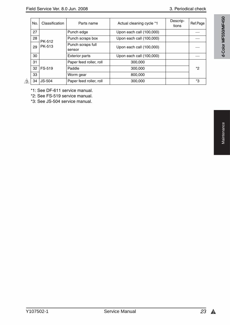
3
Field Service Ver. 8.0 Jun. 2008 3. Periodical check
23
Ma
inte
na
nce
*1: See DF-611 service manual.*2: See FS-519 service manual.*3: See JS-504 service manual.
27
PK-512PK-513
Punch edge Upon each call (100,000)
28 Punch scraps box Upon each call (100,000)
29Punch scraps full sensor
Upon each call (100,000)
30 Exterior parts Upon each call (100,000)
31
FS-519
Paper feed roller, roll 300,000
*232 Paddle 300,000
33 Worm gear 800,000
34 JS-504 Paper feed roller, roll 300,000 *3
No. Classification Parts name Actual cleaning cycle *1Descrip-
tionsRef.Page
3
d-C
olor
MF5
50/M
F450
Y107502-1 Service Manual
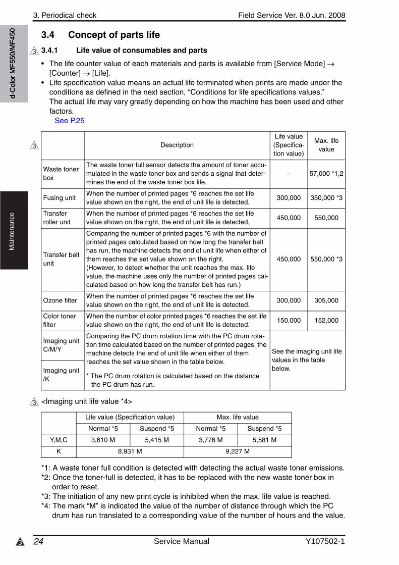
3. Periodical check Field Service Ver. 8.0 Jun. 2008
243
Ma
inte
na
nce
3.4 Concept of parts life
3.4.1 Life value of consumables and parts
• The life counter value of each materials and parts is available from [Service Mode] [Counter] [Life].
• Life specification value means an actual life terminated when prints are made under the conditions as defined in the next section, “Conditions for life specifications values.” The actual life may vary greatly depending on how the machine has been used and other factors.
See P.25
<Imaging unit life value *4>
*1: A waste toner full condition is detected with detecting the actual waste toner emissions.*2: Once the toner-full is detected, it has to be replaced with the new waste toner box in
order to reset.*3: The initiation of any new print cycle is inhibited when the max. life value is reached.*4: The mark “M” is indicated the value of the number of distance through which the PC
drum has run translated to a corresponding value of the number of hours and the value.
3
DescriptionLife value(Specifica-tion value)
Max. life value
Waste toner box
The waste toner full sensor detects the amount of toner accu-mulated in the waste toner box and sends a signal that deter-mines the end of the waste toner box life.
– 57,000 *1,2
Fusing unitWhen the number of printed pages *6 reaches the set life value shown on the right, the end of unit life is detected.
300,000 350,000 *3
Transfer roller unit
When the number of printed pages *6 reaches the set life value shown on the right, the end of unit life is detected.
450,000 550,000
Transfer belt unit
Comparing the number of printed pages *6 with the number of printed pages calculated based on how long the transfer belt has run, the machine detects the end of unit life when either of them reaches the set value shown on the right.(However, to detect whether the unit reaches the max. life value, the machine uses only the number of printed pages cal-culated based on how long the transfer belt has run.)
450,000 550,000 *3
Ozone filterWhen the number of printed pages *6 reaches the set life value shown on the right, the end of unit life is detected.
300,000 305,000
Color toner filter
When the number of color printed pages *6 reaches the set life value shown on the right, the end of unit life is detected.
150,000 152,000
Imaging unit C/M/Y
Comparing the PC drum rotation time with the PC drum rota-tion time calculated based on the number of printed pages, the machine detects the end of unit life when either of them reaches the set value shown in the table below.
* The PC drum rotation is calculated based on the distance the PC drum has run.
See the imaging unit life values in the table below.Imaging unit
/K
3
Life value (Specification value) Max. life value
Normal *5 Suspend *5 Normal *5 Suspend *5
Y,M,C 3,610 M 5,415 M 3,776 M 5,581 M
K 8,931 M 9,227 M
3
d-C
olor
MF5
50/M
F450
Service Manual Y107502-1
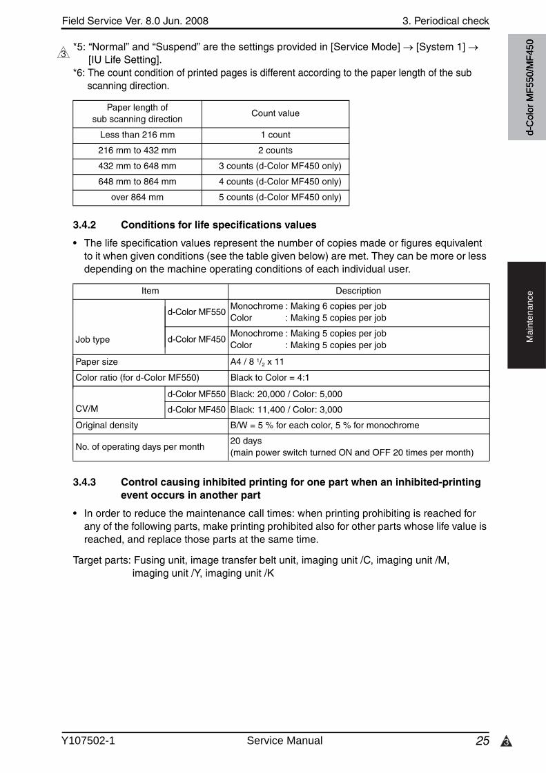
3
Field Service Ver. 8.0 Jun. 2008 3. Periodical check
25
Ma
inte
na
nce
*5: “Normal” and “Suspend” are the settings provided in [Service Mode] [System 1] [IU Life Setting].
*6: The count condition of printed pages is different according to the paper length of the subscanning direction.
3.4.2 Conditions for life specifications values
• The life specification values represent the number of copies made or figures equivalentto it when given conditions (see the table given below) are met. They can be more or less depending on the machine operating conditions of each individual user.
3
Paper length of sub scanning direction
Count value
Less than 216 mm 1 count
216 mm to 432 mm 2 counts
432 mm to 648 mm 3 counts (d-Color MF450 only)
648 mm to 864 mm 4 counts (d-Color MF450 only)
over 864 mm 5 counts (d-Color MF450 only)
Item Description
Job type
d-C
olor
MF5
50/M
F450
d-Color MF550Monochrome : Making 6 copies per jobColor : Making 5 copies per job
d-Color MF450Monochrome : Making 5 copies per jobColor : Making 5 copies per job
Paper size A4 / 8 1/2 x 11
Color ratio (for d-Color MF550) Black to Color = 4:1
CV/M
d-Color MF550 Black: 20,000 / Color: 5,000
d-Color MF450 Black: 11,400 / Color: 3,000
Original density B/W = 5 % for each color, 5 % for monochrome
No. of operating days per month20 days (main power switch turned ON and OFF 20 times per month)
3.4.3 Control causing inhibited printing for one part when an inhibited-printing event occurs in another part
• In order to reduce the maintenance call times: when printing prohibiting is reached for any of the following parts, make printing prohibited also for other parts whose life value is reached, and replace those parts at the same time.
Target parts: Fusing unit, image transfer belt unit, imaging unit /C, imaging unit /M, imaging unit /Y, imaging unit /K
Y107502-1 Service Manual
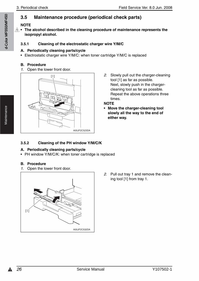
1
3. Periodical check Field Service Ver. 8.0 Jun. 2008
26
Ma
inte
na
nce
3.5 Maintenance procedure (periodical check parts)
NOTE• The alcohol described in the cleaning procedure of maintenance represents the
isopropyl alcohol.
3.5.1 Cleaning of the electrostatic charger wire Y/M/C
A. Periodically cleaning parts/cycle• Electrostatic charger wire Y/M/C: when toner cartridge Y/M/C is replaced
B. Procedure1. Open the lower front door.
2. Slowly pull out the charger-cleaning tool [1] as far as possible.Next, slowly push in the charger-cleaning tool as far as possible.Repeat the above operations three times.
NOTE• Move the charger-cleaning tool
slowly all the way to the end of either way.
3.5.2 Cleaning of the PH window Y/M/C/K
A. Periodically cleaning parts/cycle• PH window Y/M/C/K: when toner cartridge is replaced
B. Procedure1. Open the lower front door.
2. Pull out tray 1 and remove the clean-ing tool [1] from tray 1.
1
A00JF2C523DA
[1]
A00JF2C532DA
[1]
d-C
olor
MF5
50/M
F450
Service Manual Y107502-1
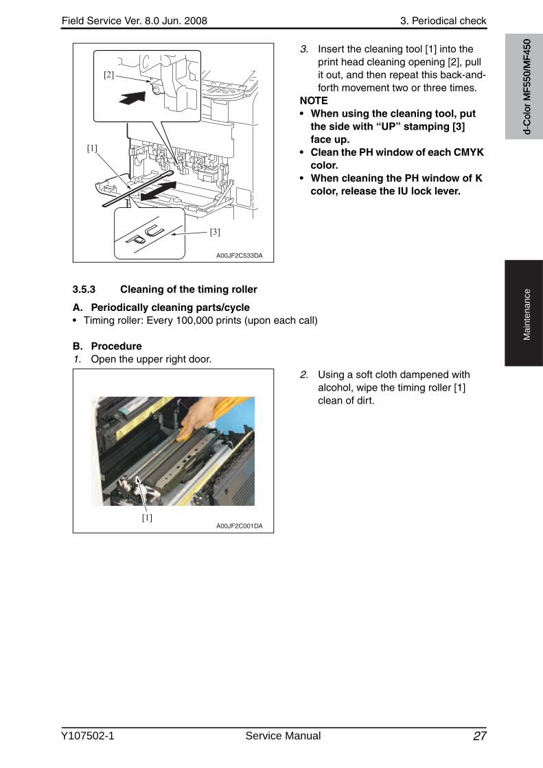
Field Service Ver. 8.0 Jun. 2008 3. Periodical check
27
Ma
inte
na
nce
3. Insert the cleaning tool [1] into the print head cleaning opening [2], pull it out, and then repeat this back-and-forth movement two or three times.
NOTE• When using the cleaning tool, put
the side with “UP” stamping [3] face up.
• Clean the PH window of each CMYK color.
• When cleaning the PH window of K color, release the IU lock lever.
3.5.3 Cleaning of the timing roller
A. Periodically cleaning parts/cycle• Timing roller: Every 100,000 prints (upon each call)
B. Procedure1. Open the upper right door.
2. Using a soft cloth dampened withalcohol, wipe the timing roller [1] clean of dirt.
A00JF2C533DA
[1]
[2]
[3]
[1]A00JF2C001DA
d-C
olor
MF5
50/M
F450
Y107502-1 Service Manual
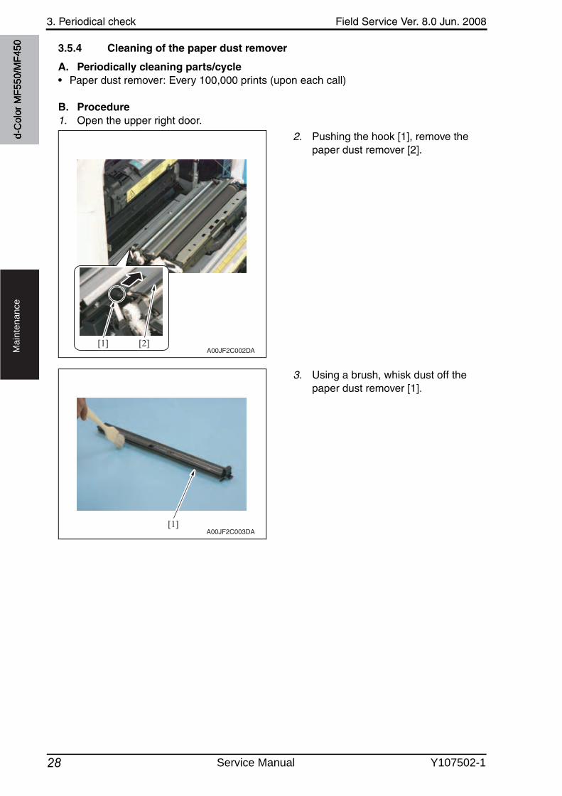
3. Periodical check Field Service Ver. 8.0 Jun. 2008
28
Ma
inte
na
nce
3.5.4 Cleaning of the paper dust remover
A. Periodically cleaning parts/cycle• Paper dust remover: Every 100,000 prints (upon each call)
B. Procedure1. Open the upper right door.
2. Pushing the hook [1], remove the paper dust remover [2].
3. Using a brush, whisk dust off the paper dust remover [1].
[1] [2]A00JF2C002DA
[1]A00JF2C003DA
d-C
olor
MF5
50/M
F450
Service Manual Y107502-1
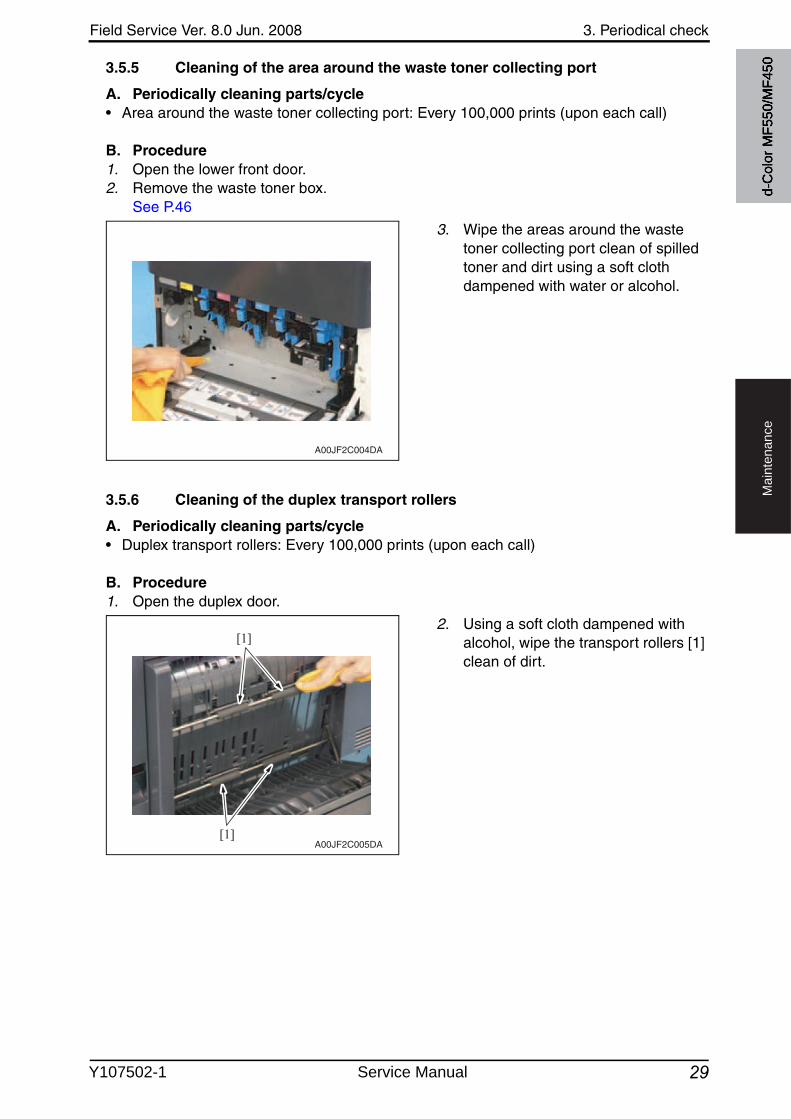
Field Service Ver. 8.0 Jun. 2008 3. Periodical check
29
Ma
inte
na
nce
3.5.5 Cleaning of the area around the waste toner collecting port
A. Periodically cleaning parts/cycle• Area around the waste toner collecting port: Every 100,000 prints (upon each call)
B. Procedure1. Open the lower front door.2. Remove the waste toner box.
See P.46
3. Wipe the areas around the wastetoner collecting port clean of spilled toner and dirt using a soft cloth dampened with water or alcohol.
3.5.6 Cleaning of the duplex transport rollers
A. Periodically cleaning parts/cycle• Duplex transport rollers: Every 100,000 prints (upon each call)
B. Procedure1. Open the duplex door.
2. Using a soft cloth dampened withalcohol, wipe the transport rollers [1] clean of dirt.
A00JF2C004DA
[1]
[1]A00JF2C005DA
d-C
olor
MF5
50/M
F450
Y107502-1 Service Manual
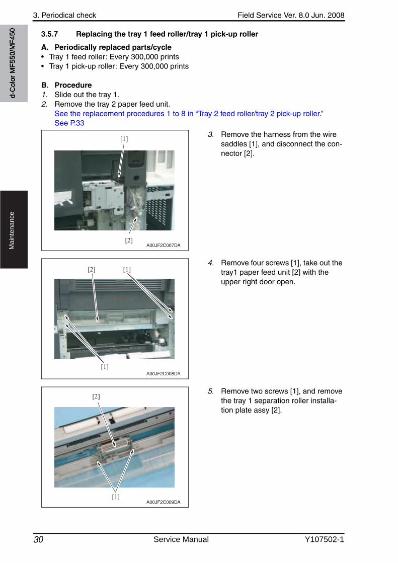
3. Periodical check Field Service Ver. 8.0 Jun. 2008
30
Ma
inte
na
nce
3.5.7 Replacing the tray 1 feed roller/tray 1 pick-up roller
A. Periodically replaced parts/cycle• Tray 1 feed roller: Every 300,000 prints• Tray 1 pick-up roller: Every 300,000 prints
B. Procedure1. Slide out the tray 1.2. Remove the tray 2 paper feed unit.
See the replacement procedures 1 to 8 in “Tray 2 feed roller/tray 2 pick-up roller.”See P.33
3. Remove the harness from the wire saddles [1], and disconnect the con-nector [2].
4. Remove four screws [1], take out the tray1 paper feed unit [2] with the upper right door open.
5. Remove two screws [1], and removethe tray 1 separation roller installa-tion plate assy [2].
[1]
[2]A00JF2C007DA
[1]
[1][2]
A00JF2C008DA
[1]
[2]
A00JF2C009DA
d-C
olor
MF5
50/M
F450
Service Manual Y107502-1
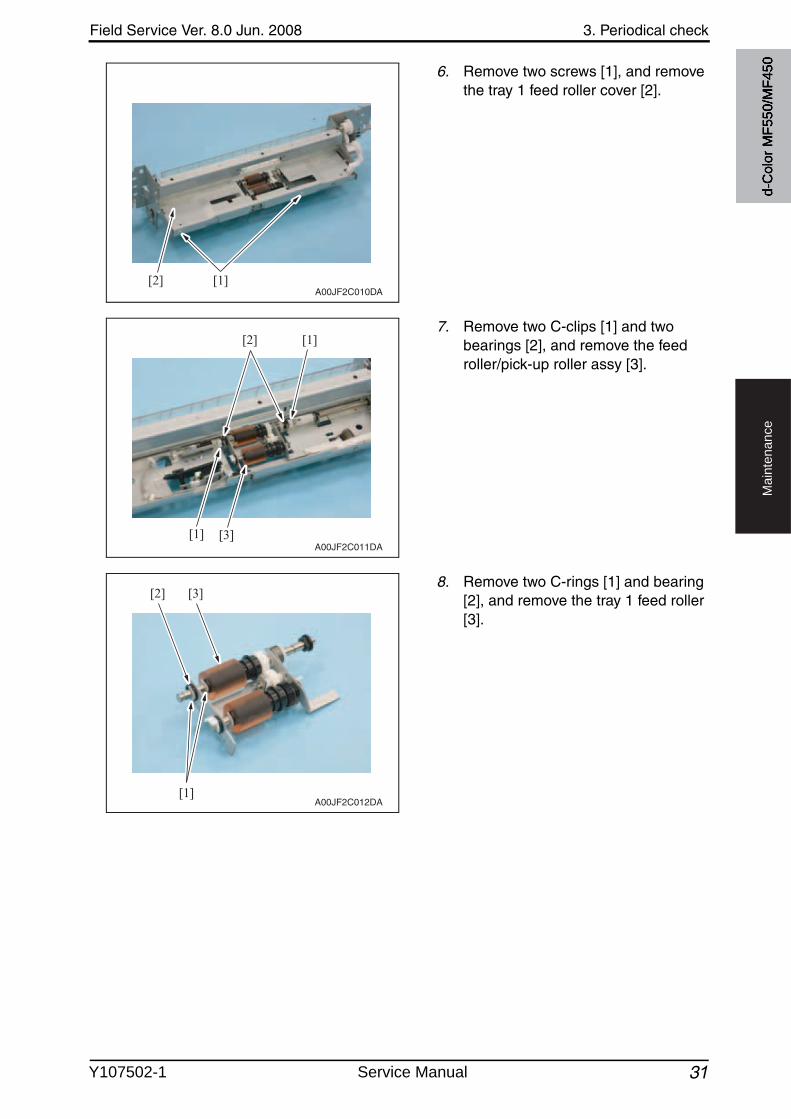
Field Service Ver. 8.0 Jun. 2008 3. Periodical check
31
Ma
inte
na
nce
6. Remove two screws [1], and removethe tray 1 feed roller cover [2].
7. Remove two C-clips [1] and twobearings [2], and remove the feed roller/pick-up roller assy [3].
8. Remove two C-rings [1] and bearing [2], and remove the tray 1 feed roller [3].
[1][2]A00JF2C010DA
[3]
[1]
[1]
[2]
A00JF2C011DA
[3]
[1]
[2]
A00JF2C012DA
d-C
olor
MF5
50/M
F450
Y107502-1 Service Manual
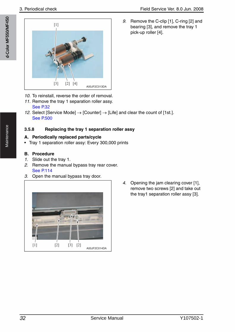
3. Periodical check Field Service Ver. 8.0 Jun. 2008
32
Ma
inte
na
nce
9. Remove the C-clip [1], C-ring [2] and bearing [3], and remove the tray 1 pick-up roller [4].
10. To reinstall, reverse the order of removal.11. Remove the tray 1 separation roller assy.
See P.3212. Select [Service Mode] [Counter] [Life] and clear the count of [1st.].
See P.500
3.5.8 Replacing the tray 1 separation roller assy
A. Periodically replaced parts/cycle• Tray 1 separation roller assy: Every 300,000 prints
B. Procedure1. Slide out the tray 1.2. Remove the manual bypass tray rear cover.
See P.1143. Open the manual bypass tray door.
4. Opening the jam clearing cover [1], remove two screws [2] and take outthe tray1 separation roller assy [3].
[3] [4]
[1]
[2]A00JF2C013DA
[1] [2] [3] [2]A00JF2C014DA
d-C
olor
MF5
50/M
F450
Service Manual Y107502-1
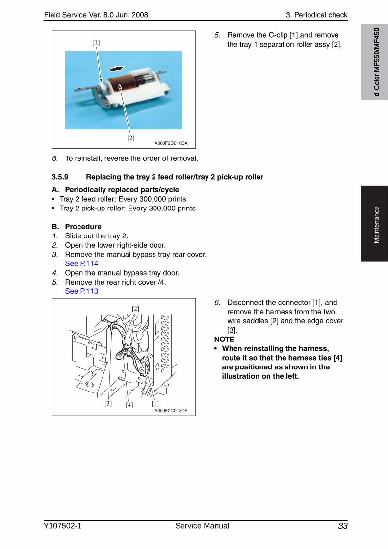
Field Service Ver. 8.0 Jun. 2008 3. Periodical check
33
Ma
inte
na
nce
5. Remove the C-clip [1],and removethe tray 1 separation roller assy [2].
6. To reinstall, reverse the order of removal.
3.5.9 Replacing the tray 2 feed roller/tray 2 pick-up roller
A. Periodically replaced parts/cycle• Tray 2 feed roller: Every 300,000 prints• Tray 2 pick-up roller: Every 300,000 prints
B. Procedure1. Slide out the tray 2.2. Open the lower right-side door.3. Remove the manual bypass tray rear cover.
See P.1144. Open the manual bypass tray door.5. Remove the rear right cover /4.
See P.113
6. Disconnect the connector [1], and remove the harness from the twowire saddles [2] and the edge cover[3].
NOTE• When reinstalling the harness,
route it so that the harness ties [4] are positioned as shown in the illustration on the left.
[2]
[1]
A00JF2C016DA
[3] [4]
[2]
[1]A00JF2C018DA
d-C
olor
MF5
50/M
F450
Y107502-1 Service Manual
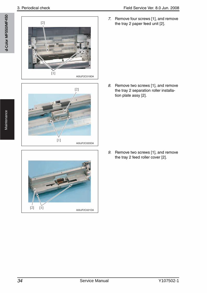
3. Periodical check Field Service Ver. 8.0 Jun. 2008
34
Ma
inte
na
nce
7. Remove four screws [1], and removethe tray 2 paper feed unit [2].
8. Remove two screws [1], and removethe tray 2 separation roller installa-tion plate assy [2].
9. Remove two screws [1], and removethe tray 2 feed roller cover [2].
[1]
[2]
A00JF2C019DA
[1]
[2]
A00JF2C020DA
[1][2]A00JF2C021DA
d-C
olor
MF5
50/M
F450
Service Manual Y107502-1
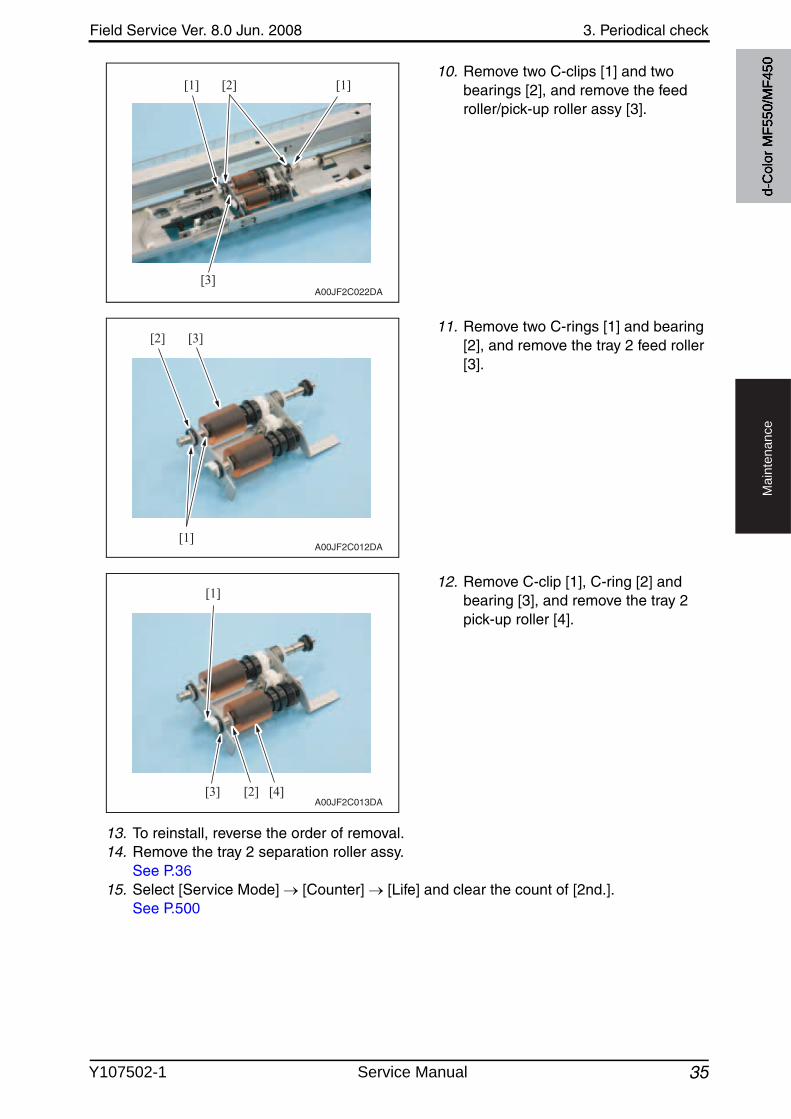
Field Service Ver. 8.0 Jun. 2008 3. Periodical check
35
Ma
inte
na
nce
10. Remove two C-clips [1] and twobearings [2], and remove the feed roller/pick-up roller assy [3].
11. Remove two C-rings [1] and bearing [2], and remove the tray 2 feed roller [3].
12. Remove C-clip [1], C-ring [2] and bearing [3], and remove the tray 2 pick-up roller [4].
13. To reinstall, reverse the order of removal.14. Remove the tray 2 separation roller assy.
See P.3615. Select [Service Mode] [Counter] [Life] and clear the count of [2nd.].
See P.500
[1] [1][2]
[3]A00JF2C022DA
[3]
[1]
[2]
A00JF2C012DA
[3] [4]
[1]
[2]A00JF2C013DA
d-C
olor
MF5
50/M
F450
Y107502-1 Service Manual
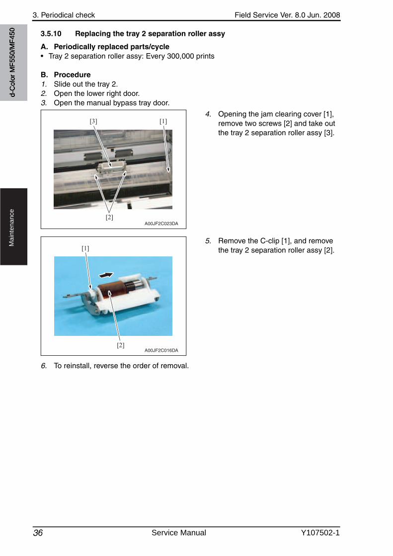
3. Periodical check Field Service Ver. 8.0 Jun. 2008
36
Ma
inte
na
nce
3.5.10 Replacing the tray 2 separation roller assy
A. Periodically replaced parts/cycle• Tray 2 separation roller assy: Every 300,000 prints
B. Procedure1. Slide out the tray 2.2. Open the lower right door.3. Open the manual bypass tray door.
4. Opening the jam clearing cover [1], remove two screws [2] and take outthe tray 2 separation roller assy [3].
5. Remove the C-clip [1], and removethe tray 2 separation roller assy [2].
6. To reinstall, reverse the order of removal.
[2]
[3] [1]
A00JF2C023DA
[2]
[1]
A00JF2C016DA
d-C
olor
MF5
50/M
F450
Service Manual Y107502-1
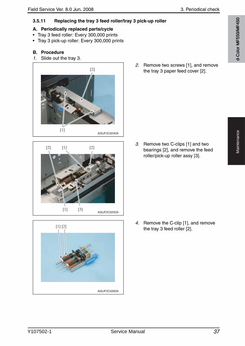
Field Service Ver. 8.0 Jun. 2008 3. Periodical check
37
Ma
inte
na
nce
3.5.11 Replacing the tray 3 feed roller/tray 3 pick-up roller
A. Periodically replaced parts/cycle• Tray 3 feed roller: Every 300,000 prints• Tray 3 pick-up roller: Every 300,000 prints
B. Procedure1. Slide out the tray 3.
2. Remove two screws [1], and removethe tray 3 paper feed cover [2].
3. Remove two C-clips [1] and twobearings [2], and remove the feed roller/pick-up roller assy [3].
4. Remove the C-clip [1], and removethe tray 3 feed roller [2].
[1]
[2]
A00JF2C024DA
[1]
[1][2] [2]
[3]A00JF2C025DA
[1] [2]
A00JF2C026DA
d-C
olor
MF5
50/M
F450
Y107502-1 Service Manual
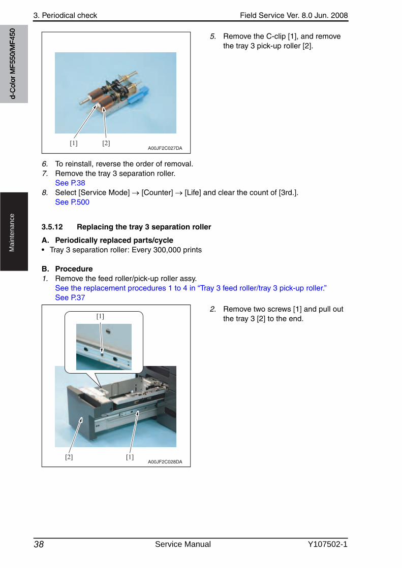
3. Periodical check Field Service Ver. 8.0 Jun. 2008
38
Ma
inte
na
nce
5. Remove the C-clip [1], and removethe tray 3 pick-up roller [2].
6. To reinstall, reverse the order of removal.7. Remove the tray 3 separation roller.
See P.388. Select [Service Mode] [Counter] [Life] and clear the count of [3rd.].
See P.500
3.5.12 Replacing the tray 3 separation roller
A. Periodically replaced parts/cycle• Tray 3 separation roller: Every 300,000 prints
B. Procedure1. Remove the feed roller/pick-up roller assy.
See the replacement procedures 1 to 4 in “Tray 3 feed roller/tray 3 pick-up roller.”See P.37
2. Remove two screws [1] and pull outthe tray 3 [2] to the end.
[1] [2]A00JF2C027DA
[1]
[1]
[2]A00JF2C028DA
d-C
olor
MF5
50/M
F450
Service Manual Y107502-1
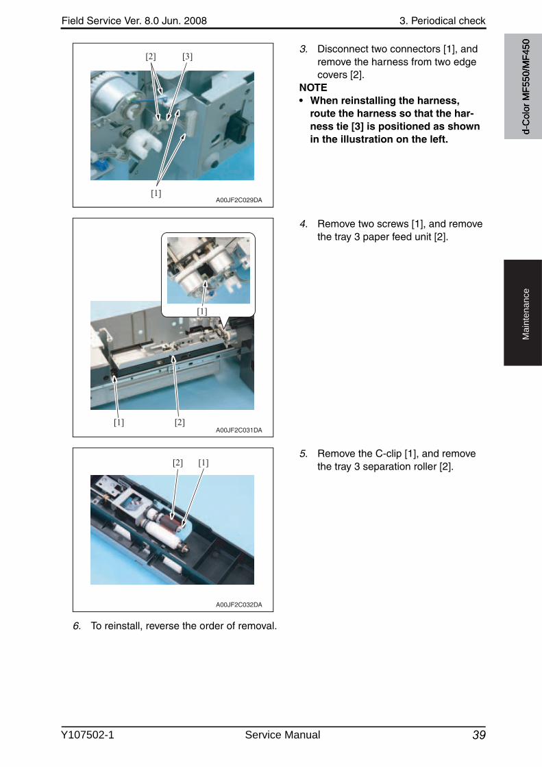
Field Service Ver. 8.0 Jun. 2008 3. Periodical check
39
Ma
inte
na
nce
3. Disconnect two connectors [1], and remove the harness from two edge covers [2].
NOTE• When reinstalling the harness,
route the harness so that the har-ness tie [3] is positioned as shown in the illustration on the left.
4. Remove two screws [1], and removethe tray 3 paper feed unit [2].
5. Remove the C-clip [1], and removethe tray 3 separation roller [2].
6. To reinstall, reverse the order of removal.
[1]
[2] [3]
A00JF2C029DA
[1]
[1]
[2]A00JF2C031DA
[1][2]
A00JF2C032DA
d-C
olor
MF5
50/M
F450
Y107502-1 Service Manual
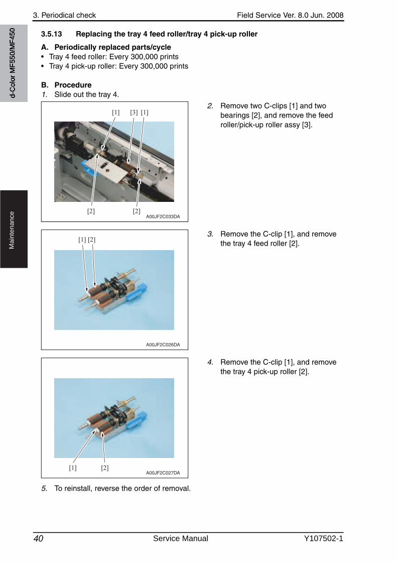
3. Periodical check Field Service Ver. 8.0 Jun. 2008
40
Ma
inte
na
nce
3.5.13 Replacing the tray 4 feed roller/tray 4 pick-up roller
A. Periodically replaced parts/cycle• Tray 4 feed roller: Every 300,000 prints• Tray 4 pick-up roller: Every 300,000 prints
B. Procedure1. Slide out the tray 4.
2. Remove two C-clips [1] and twobearings [2], and remove the feed roller/pick-up roller assy [3].
3. Remove the C-clip [1], and removethe tray 4 feed roller [2].
4. Remove the C-clip [1], and removethe tray 4 pick-up roller [2].
5. To reinstall, reverse the order of removal.
[2][2]
[1] [1][3]
A00JF2C033DA
[1] [2]
A00JF2C026DA
[1] [2]A00JF2C027DA
d-C
olor
MF5
50/M
F450
Service Manual Y107502-1
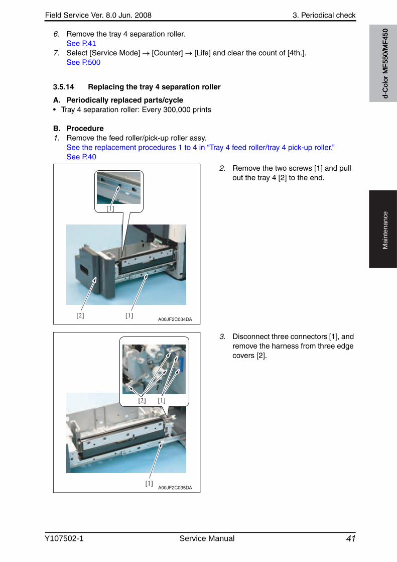
Field Service Ver. 8.0 Jun. 2008 3. Periodical check
41
Ma
inte
na
nce
6. Remove the tray 4 separation roller.See P.41
7. Select [Service Mode] [Counter] [Life] and clear the count of [4th.].See P.500
3.5.14 Replacing the tray 4 separation roller
A. Periodically replaced parts/cycle• Tray 4 separation roller: Every 300,000 prints
B. Procedure1. Remove the feed roller/pick-up roller assy.
See the replacement procedures 1 to 4 in “Tray 4 feed roller/tray 4 pick-up roller.”See P.40
2. Remove the two screws [1] and pull out the tray 4 [2] to the end.
3. Disconnect three connectors [1], and remove the harness from three edge covers [2].
[1]
[1][2]A00JF2C034DA
[1]
[2] [1]
A00JF2C035DA
d-C
olor
MF5
50/M
F450
Y107502-1 Service Manual
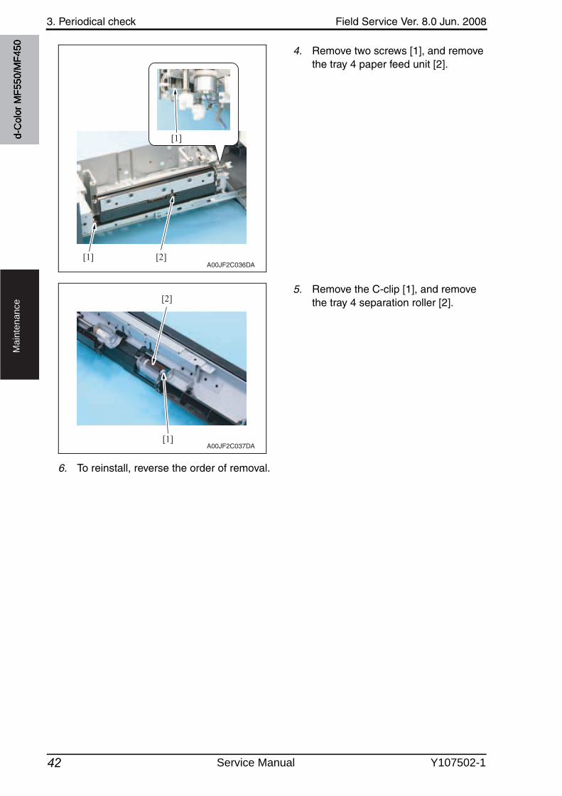
3. Periodical check Field Service Ver. 8.0 Jun. 2008
42
Ma
inte
na
nce
4. Remove two screws [1], and removethe tray 4 paper feed unit [2].
5. Remove the C-clip [1], and removethe tray 4 separation roller [2].
6. To reinstall, reverse the order of removal.
[1]
[2][1]A00JF2C036DA
[1]
[2]
A00JF2C037DA
d-C
olor
MF5
50/M
F450
Service Manual Y107502-1
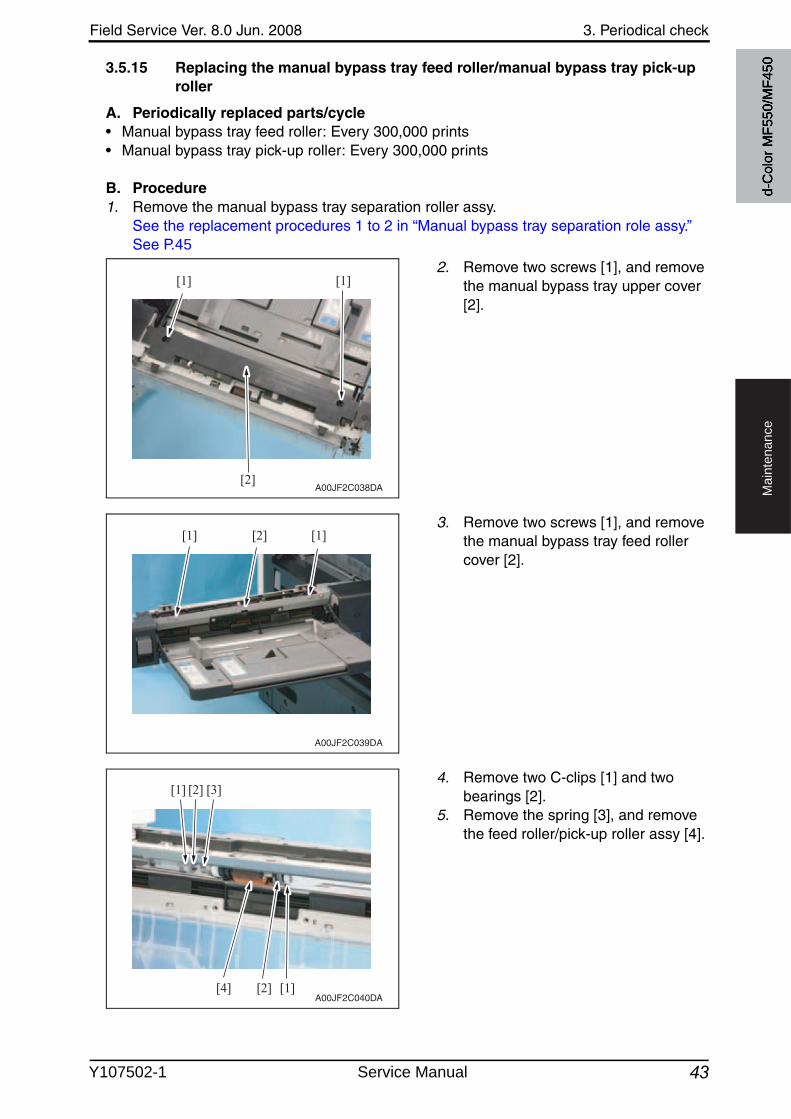
Field Service Ver. 8.0 Jun. 2008 3. Periodical check
43
Ma
inte
na
nce
3.5.15 Replacing the manual bypass tray feed roller/manual bypass tray pick-up roller
A. Periodically replaced parts/cycle• Manual bypass tray feed roller: Every 300,000 prints• Manual bypass tray pick-up roller: Every 300,000 prints
B. Procedure1. Remove the manual bypass tray separation roller assy.
See the replacement procedures 1 to 2 in “Manual bypass tray separation role assy.”See P.45
2. Remove two screws [1], and removethe manual bypass tray upper cover[2].
3. Remove two screws [1], and removethe manual bypass tray feed roller cover [2].
4. Remove two C-clips [1] and twobearings [2].
5. Remove the spring [3], and removethe feed roller/pick-up roller assy [4].
[1] [1]
[2]A00JF2C038DA
[1] [1][2]
A00JF2C039DA
[1][2][4]
[1] [2] [3]
A00JF2C040DA
d-C
olor
MF5
50/M
F450
Y107502-1 Service Manual
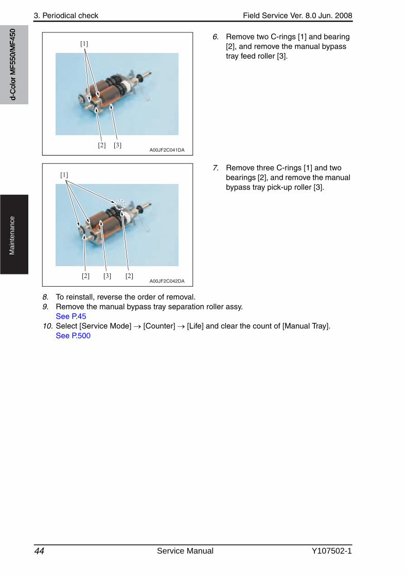
3. Periodical check Field Service Ver. 8.0 Jun. 2008
44
Ma
inte
na
nce
6. Remove two C-rings [1] and bearing [2], and remove the manual bypass tray feed roller [3].
7. Remove three C-rings [1] and twobearings [2], and remove the manualbypass tray pick-up roller [3].
8. To reinstall, reverse the order of removal.9. Remove the manual bypass tray separation roller assy.
See P.4510. Select [Service Mode] [Counter] [Life] and clear the count of [Manual Tray].
See P.500
[1]
[2] [3]A00JF2C041DA
[1]
[2] [3] [2]A00JF2C042DA
d-C
olor
MF5
50/M
F450
Service Manual Y107502-1
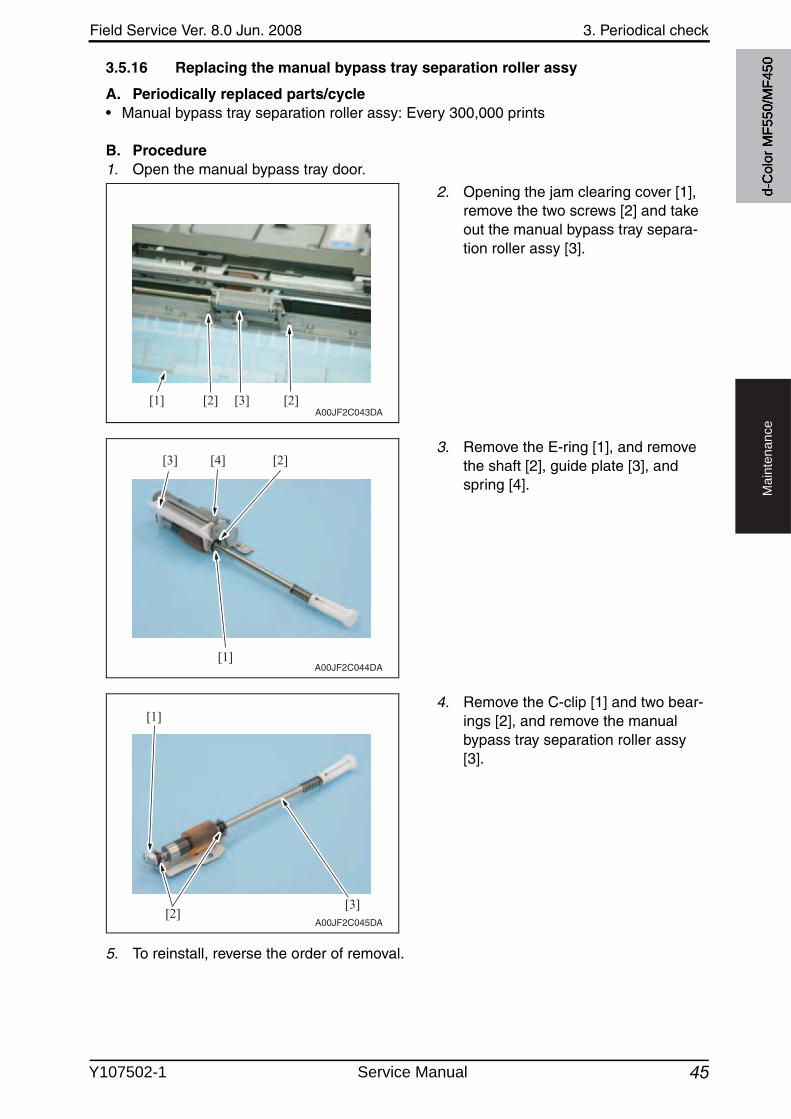
Field Service Ver. 8.0 Jun. 2008 3. Periodical check
45
Ma
inte
na
nce
3.5.16 Replacing the manual bypass tray separation roller assy
A. Periodically replaced parts/cycle• Manual bypass tray separation roller assy: Every 300,000 prints
B. Procedure1. Open the manual bypass tray door.
2. Opening the jam clearing cover [1], remove the two screws [2] and take out the manual bypass tray separa-tion roller assy [3].
3. Remove the E-ring [1], and removethe shaft [2], guide plate [3], and spring [4].
4. Remove the C-clip [1] and two bear-ings [2], and remove the manualbypass tray separation roller assy [3].
5. To reinstall, reverse the order of removal.
[1] [2] [2][3]A00JF2C043DA
[4]
[1]
[2][3]
A00JF2C044DA
[1]
[2][3]
A00JF2C045DA
d-C
olor
MF5
50/M
F450
Y107502-1 Service Manual
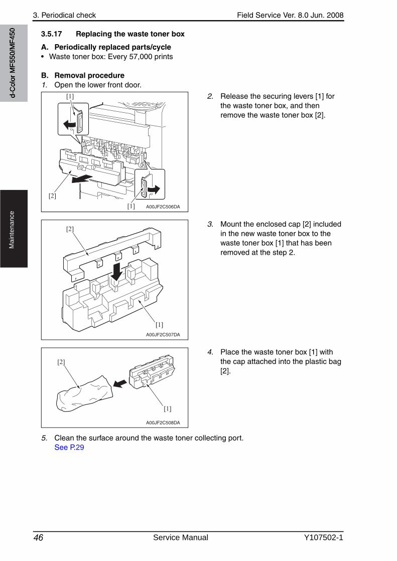
3. Periodical check Field Service Ver. 8.0 Jun. 2008
46
Ma
inte
na
nce
3.5.17 Replacing the waste toner box
A. Periodically replaced parts/cycle• Waste toner box: Every 57,000 prints
B. Removal procedure1. Open the lower front door.
2. Release the securing levers [1] for the waste toner box, and then remove the waste toner box [2].
3. Mount the enclosed cap [2] includedin the new waste toner box to the waste toner box [1] that has been removed at the step 2.
4. Place the waste toner box [1] with the cap attached into the plastic bag [2].
5. Clean the surface around the waste toner collecting port.See P.29
A00JF2C506DA
[2]
[1]
[1]
A00JF2C507DA
[2]
[1]
A00JF2C508DA
[2]
[1]
d-C
olor
MF5
50/M
F450
Service Manual Y107502-1
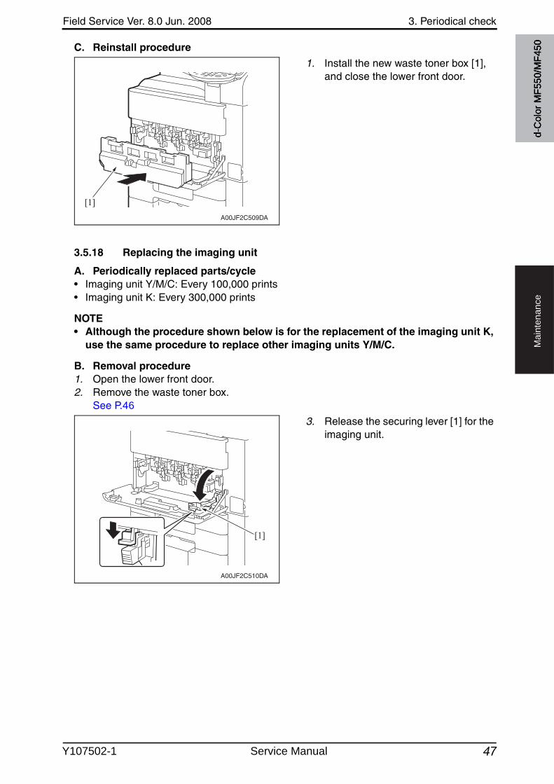
Field Service Ver. 8.0 Jun. 2008 3. Periodical check
47
Ma
inte
na
nce
C. Reinstall procedure
1. Install the new waste toner box [1], and close the lower front door.
3.5.18 Replacing the imaging unit
A. Periodically replaced parts/cycle• Imaging unit Y/M/C: Every 100,000 prints• Imaging unit K: Every 300,000 prints
NOTE• Although the procedure shown below is for the replacement of the imaging unit K,
use the same procedure to replace other imaging units Y/M/C.
B. Removal procedure1. Open the lower front door.2. Remove the waste toner box.
See P.46
3. Release the securing lever [1] for the imaging unit.
A00JF2C509DA
[1]
A00JF2C510DA
[1]d-
Col
or M
F550
/MF4
50
Y107502-1 Service Manual
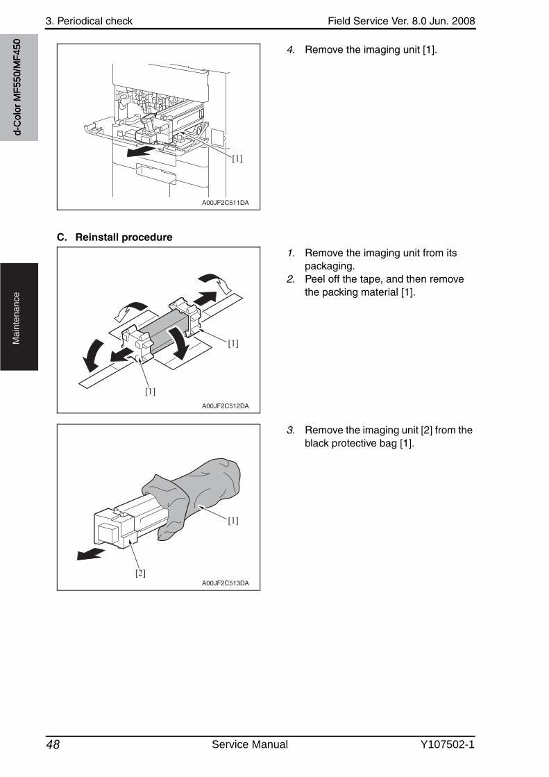
3. Periodical check Field Service Ver. 8.0 Jun. 2008
48
Ma
inte
na
nce
4. Remove the imaging unit [1].
C. Reinstall procedure
1. Remove the imaging unit from its packaging.
2. Peel off the tape, and then removethe packing material [1].
3. Remove the imaging unit [2] from the black protective bag [1].
A00JF2C511DA
[1]
A00JF2C512DA
[1]
[1]
A00JF2C513DA
[2]
[1]
d-C
olor
MF5
50/M
F450
Service Manual Y107502-1
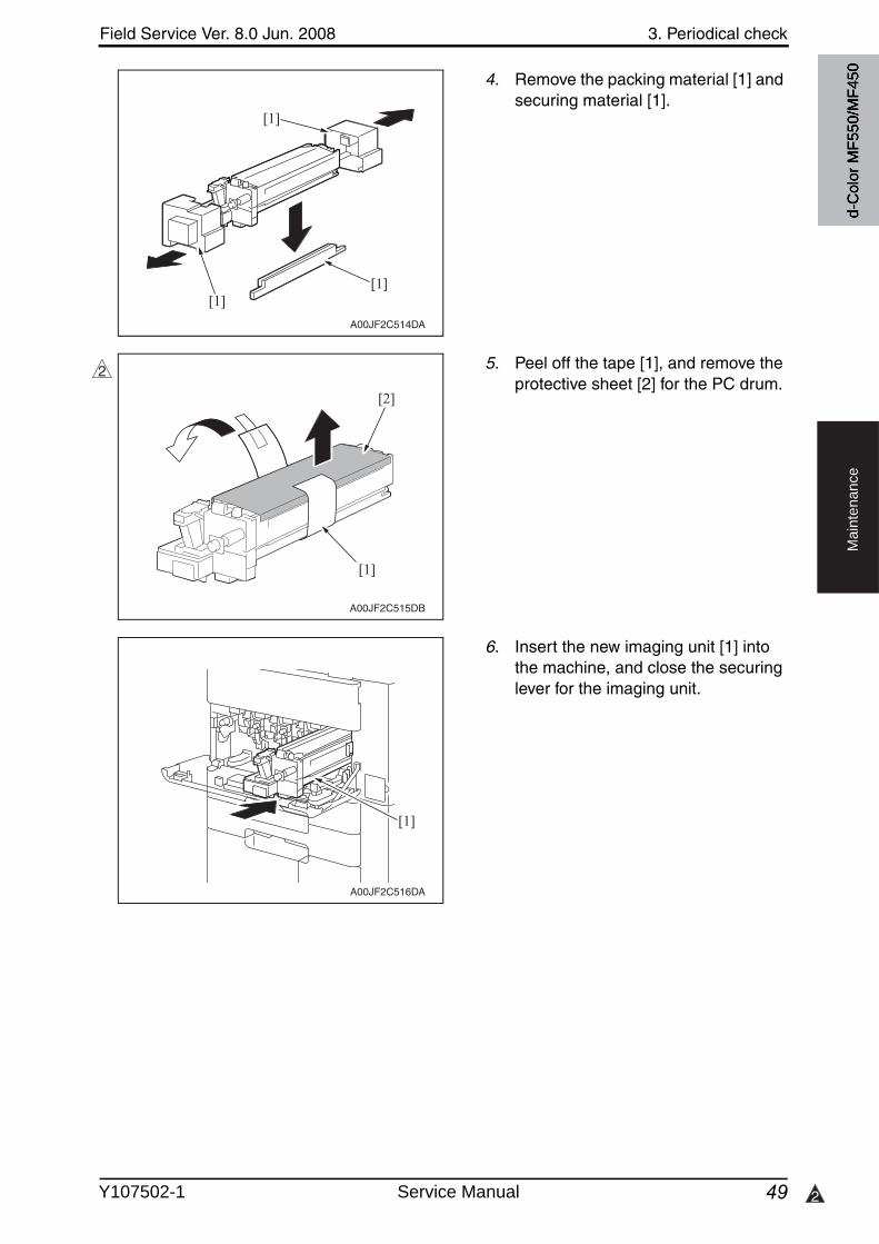
Field Service Ver. 8.0 Jun. 2008 3. Periodical check
49 2
Ma
inte
na
nce
4. Remove the packing material [1] and securing material [1].
5. Peel off the tape [1], and remove the protective sheet [2] for the PC drum.
6. Insert the new imaging unit [1] into the machine, and close the securing lever for the imaging unit.
A00JF2C514DA
[1][1]
[1]
A00JF2C515DB
[2]
[1]
2
A00JF2C516DA
[1]
d-C
olor
MF5
50/M
F450
Y107502-1 Service Manual
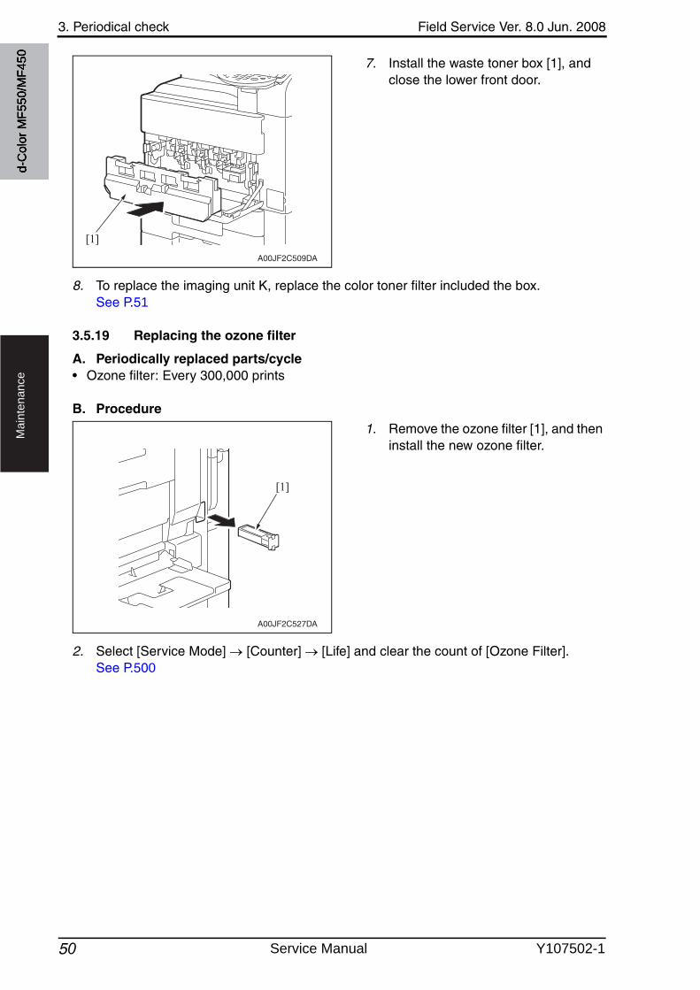
3. Periodical check Field Service Ver. 8.0 Jun. 2008
50
Ma
inte
na
nce
7. Install the waste toner box [1], and close the lower front door.
8. To replace the imaging unit K, replace the color toner filter included the box.See P.51
3.5.19 Replacing the ozone filter
A. Periodically replaced parts/cycle• Ozone filter: Every 300,000 prints
B. Procedure
1. Remove the ozone filter [1], and then install the new ozone filter.
2. Select [Service Mode] [Counter] [Life] and clear the count of [Ozone Filter].See P.500
A00JF2C509DA
[1]
A00JF2C527DA
[1]
d-C
olor
MF5
50/M
F450
Service Manual Y107502-1
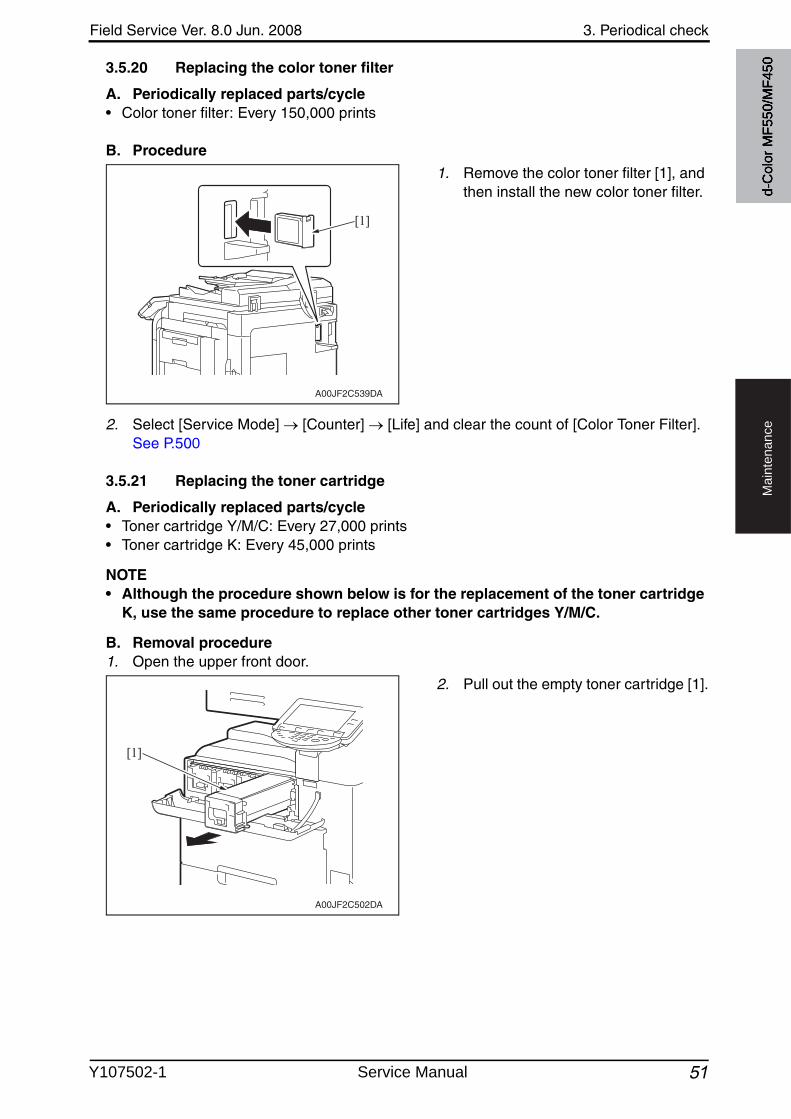
Field Service Ver. 8.0 Jun. 2008 3. Periodical check
51
Ma
inte
na
nce
3.5.20 Replacing the color toner filter
A. Periodically replaced parts/cycle• Color toner filter: Every 150,000 prints
B. Procedure
1. Remove the color toner filter [1], and then install the new color toner filter.
2. Select [Service Mode] [Counter] [Life] and clear the count of [Color Toner Filter].See P.500
3.5.21 Replacing the toner cartridge
A. Periodically replaced parts/cycle• Toner cartridge Y/M/C: Every 27,000 prints• Toner cartridge K: Every 45,000 prints
NOTE• Although the procedure shown below is for the replacement of the toner cartridge
K, use the same procedure to replace other toner cartridges Y/M/C.
B. Removal procedure1. Open the upper front door.
2. Pull out the empty toner cartridge [1].
A00JF2C539DA
[1]
A00JF2C502DA
[1]d-
Col
or M
F550
/MF4
50
Y107502-1 Service Manual
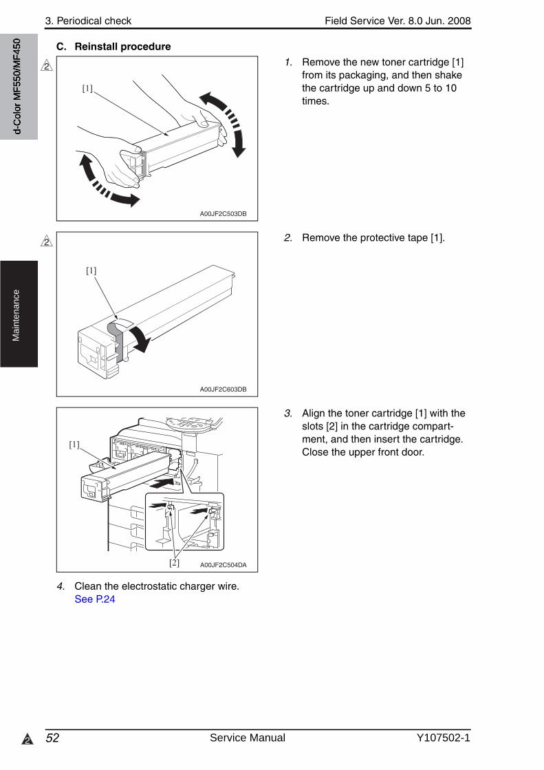
3. Periodical check Field Service Ver. 8.0 Jun. 2008
522
Ma
inte
na
nce
C. Reinstall procedure
1. Remove the new toner cartridge [1] from its packaging, and then shake the cartridge up and down 5 to 10 times.
2. Remove the protective tape [1].
3. Align the toner cartridge [1] with the slots [2] in the cartridge compart-ment, and then insert the cartridge.Close the upper front door.
4. Clean the electrostatic charger wire.See P.24
A00JF2C503DB
[1]
2
A00JF2C603DB
[1]
2
A00JF2C504DA
[1]
[2]
d-C
olor
MF5
50/M
F450
Service Manual Y107502-1
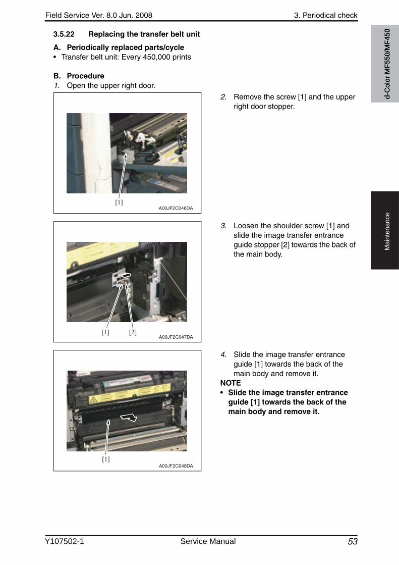
Field Service Ver. 8.0 Jun. 2008 3. Periodical check
53
Ma
inte
na
nce
3.5.22 Replacing the transfer belt unit
A. Periodically replaced parts/cycle• Transfer belt unit: Every 450,000 prints
B. Procedure1. Open the upper right door.
2. Remove the screw [1] and the upper right door stopper.
3. Loosen the shoulder screw [1] and slide the image transfer entrance guide stopper [2] towards the back of the main body.
4. Slide the image transfer entrance guide [1] towards the back of the main body and remove it.
NOTE• Slide the image transfer entrance
guide [1] towards the back of the main body and remove it.
[1]A00JF2C046DA
[1] [2]A00JF2C047DA
[1]A00JF2C048DA
d-C
olor
MF5
50/M
F450
Y107502-1 Service Manual
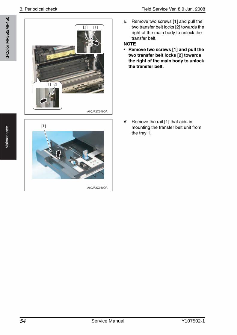
3. Periodical check Field Service Ver. 8.0 Jun. 2008
54
Ma
inte
na
nce
5. Remove two screws [1] and pull the two transfer belt locks [2] towards the right of the main body to unlock the transfer belt.
NOTE• Remove two screws [1] and pull the
two transfer belt locks [2] towards the right of the main body to unlock the transfer belt.
6. Remove the rail [1] that aids in mounting the transfer belt unit from the tray 1.
[2]
[1] [2]
[1]
A00JF2C049DA
[1]
A00JF2C050DA
d-C
olor
MF5
50/M
F450
Service Manual Y107502-1
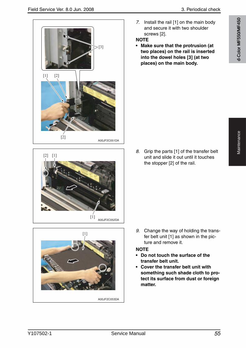
Field Service Ver. 8.0 Jun. 2008 3. Periodical check
55
Ma
inte
na
nce
7. Install the rail [1] on the main body and secure it with two shoulderscrews [2].
NOTE• Make sure that the protrusion (at
two places) on the rail is inserted into the dowel holes [3] (at two places) on the main body.
8. Grip the parts [1] of the transfer belt unit and slide it out until it touchesthe stopper [2] of the rail.
9. Change the way of holding the trans-fer belt unit [1] as shown in the pic-ture and remove it.
NOTE• Do not touch the surface of the
transfer belt unit.• Cover the transfer belt unit with
something such shade cloth to pro-tect its surface from dust or foreign matter.
[2]
[2][1]
[3]
A00JF2C051DA
[1][2]
[1]A00JF2C052DA
A00JF2C053DA
[1]d-
Col
or M
F550
/MF4
50
Y107502-1 Service Manual
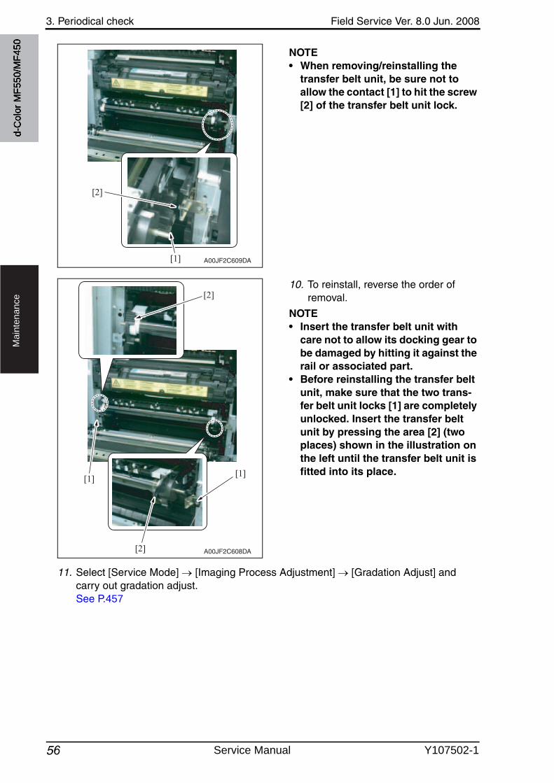
3. Periodical check Field Service Ver. 8.0 Jun. 2008
56
Ma
inte
na
nce
NOTE• When removing/reinstalling the
transfer belt unit, be sure not to allow the contact [1] to hit the screw [2] of the transfer belt unit lock.
10. To reinstall, reverse the order of removal.
NOTE• Insert the transfer belt unit with
care not to allow its docking gear to be damaged by hitting it against the rail or associated part.
• Before reinstalling the transfer belt unit, make sure that the two trans-fer belt unit locks [1] are completely unlocked. Insert the transfer belt unit by pressing the area [2] (two places) shown in the illustration on the left until the transfer belt unit is fitted into its place.
11. Select [Service Mode] [Imaging Process Adjustment] [Gradation Adjust] and carry out gradation adjust.See P.457
A00JF2C609DA[1]
[2]
A00JF2C608DA
[2]
[1]
[2]
[1]
d-C
olor
MF5
50/M
F450
Service Manual Y107502-1
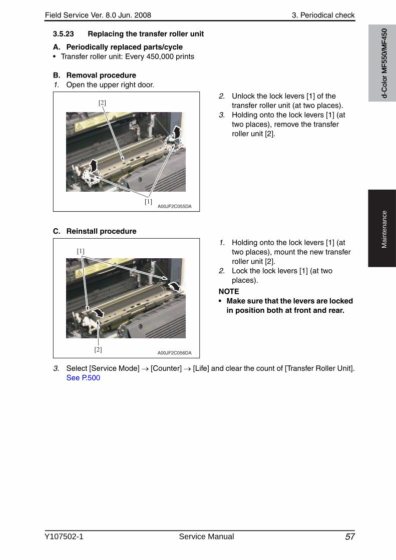
Field Service Ver. 8.0 Jun. 2008 3. Periodical check
57
Ma
inte
na
nce
3.5.23 Replacing the transfer roller unit
A. Periodically replaced parts/cycle• Transfer roller unit: Every 450,000 prints
B. Removal procedure1. Open the upper right door.
2. Unlock the lock levers [1] of the transfer roller unit (at two places).
3. Holding onto the lock levers [1] (at two places), remove the transfer roller unit [2].
C. Reinstall procedure
1. Holding onto the lock levers [1] (at two places), mount the new transfer roller unit [2].
2. Lock the lock levers [1] (at twoplaces).
NOTE• Make sure that the levers are locked
in position both at front and rear.
3. Select [Service Mode] [Counter] [Life] and clear the count of [Transfer Roller Unit].See P.500
[1]
[2]
A00JF2C055DA
[2]
[1]
A00JF2C056DA
d-C
olor
MF5
50/M
F450
Y107502-1 Service Manual
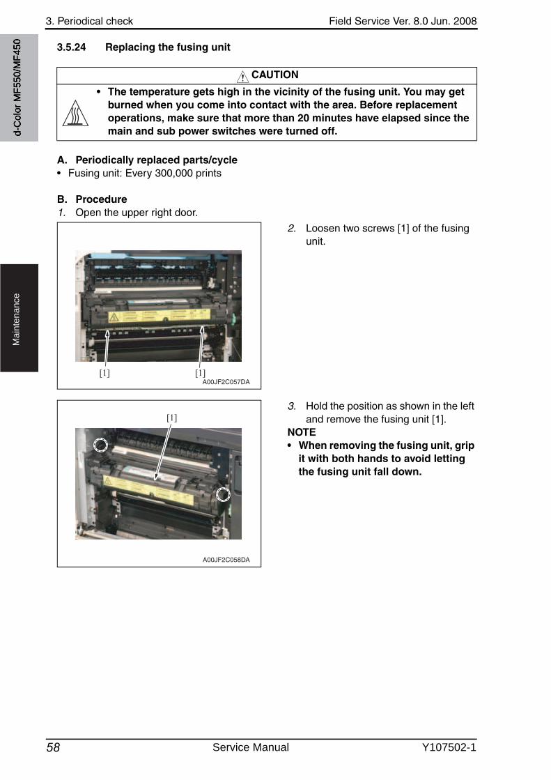
3. Periodical check Field Service Ver. 8.0 Jun. 2008
58
Ma
inte
na
nce
3.5.24 Replacing the fusing unit
A. Periodically replaced parts/cycle• Fusing unit: Every 300,000 prints
B. Procedure1. Open the upper right door.
2. Loosen two screws [1] of the fusingunit.
3. Hold the position as shown in the left and remove the fusing unit [1].
NOTE• When removing the fusing unit, grip
it with both hands to avoid letting the fusing unit fall down.
CAUTION
• The temperature gets high in the vicinity of the fusing unit. You may get burned when you come into contact with the area. Before replacement operations, make sure that more than 20 minutes have elapsed since the main and sub power switches were turned off.
[1] [1]A00JF2C057DA
[1]
A00JF2C058DA
d-C
olor
MF5
50/M
F450
Service Manual Y107502-1
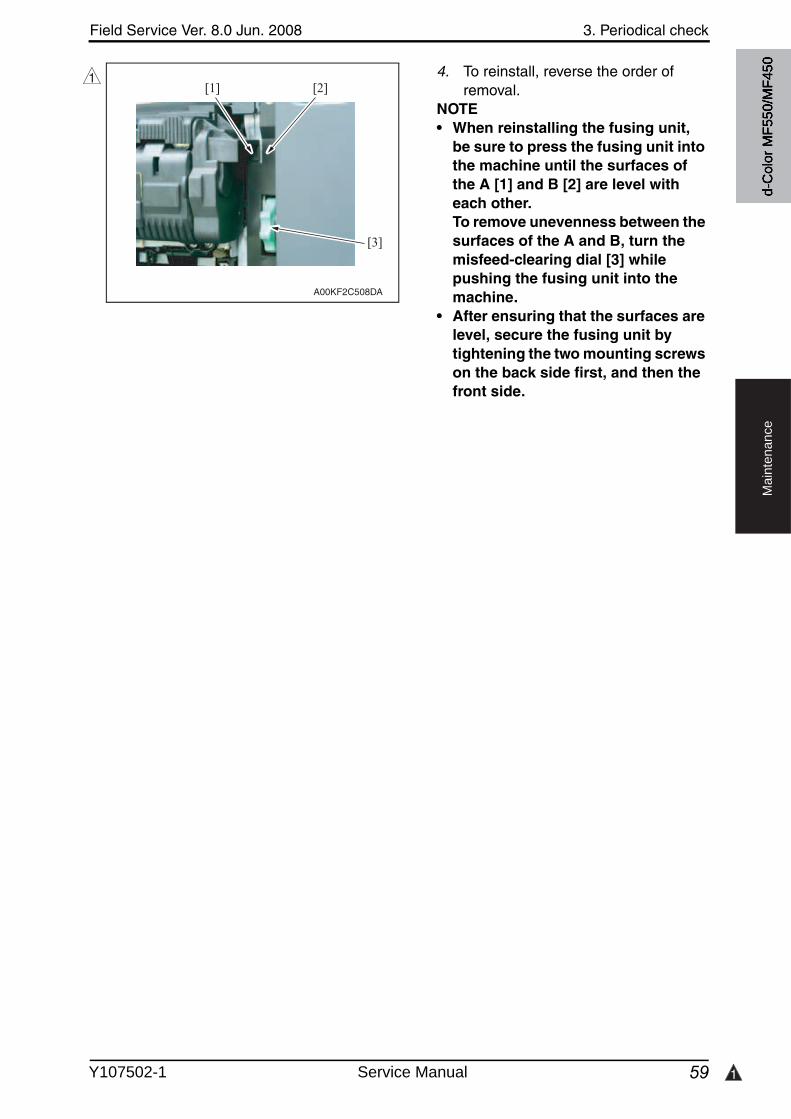
Field Service Ver. 8.0 Jun. 2008 3. Periodical check
59 1
Ma
inte
na
nce
4. To reinstall, reverse the order of removal.
NOTE• When reinstalling the fusing unit,
be sure to press the fusing unit into the machine until the surfaces of the A [1] and B [2] are level with each other.To remove unevenness between the surfaces of the A and B, turn the misfeed-clearing dial [3] while pushing the fusing unit into the machine.
• After ensuring that the surfaces are level, secure the fusing unit by tightening the two mounting screws on the back side first, and then the front side.
[2]
[3]
[1]
A00KF2C508DA
1
d-C
olor
MF5
50/M
F450
Y107502-1 Service Manual
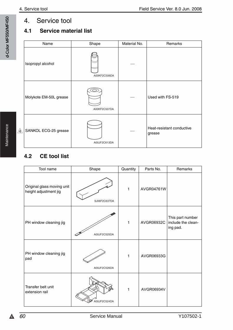
4. Service tool Field Service Ver. 8.0 Jun. 2008
604
Ma
inte
na
nce
4. Service tool
4.1 Service material list
4.2 CE tool list
Name Shape Material No. Remarks
Isopropyl alcohol
Molykote EM-50L grease 4478 7801 ## Used with FS-519
SANKOL ECG-25 grease A00J PP00 ##Heat-resistant conductivegrease
A00KF2C506DA
A00KF2C507DA
4
A00JF2C613DA
Tool name Shape Quantity Parts No. Remarks
Original glass moving unit height adjustment jig
1 AVGR04761W
PH window cleaning jig 1 AVGR06932CThis part numberinclude the clean-ing pad.
PH window cleaning jig pad
1 AVGR06933G
Transfer belt unitextension rail
1 AVGR06934V
9J06F2C637DA
A00JF2C525DA
A00JF2C526DA
A00JF2C524DA
d-C
olor
MF5
50/M
F450
Service Manual Y107502-1
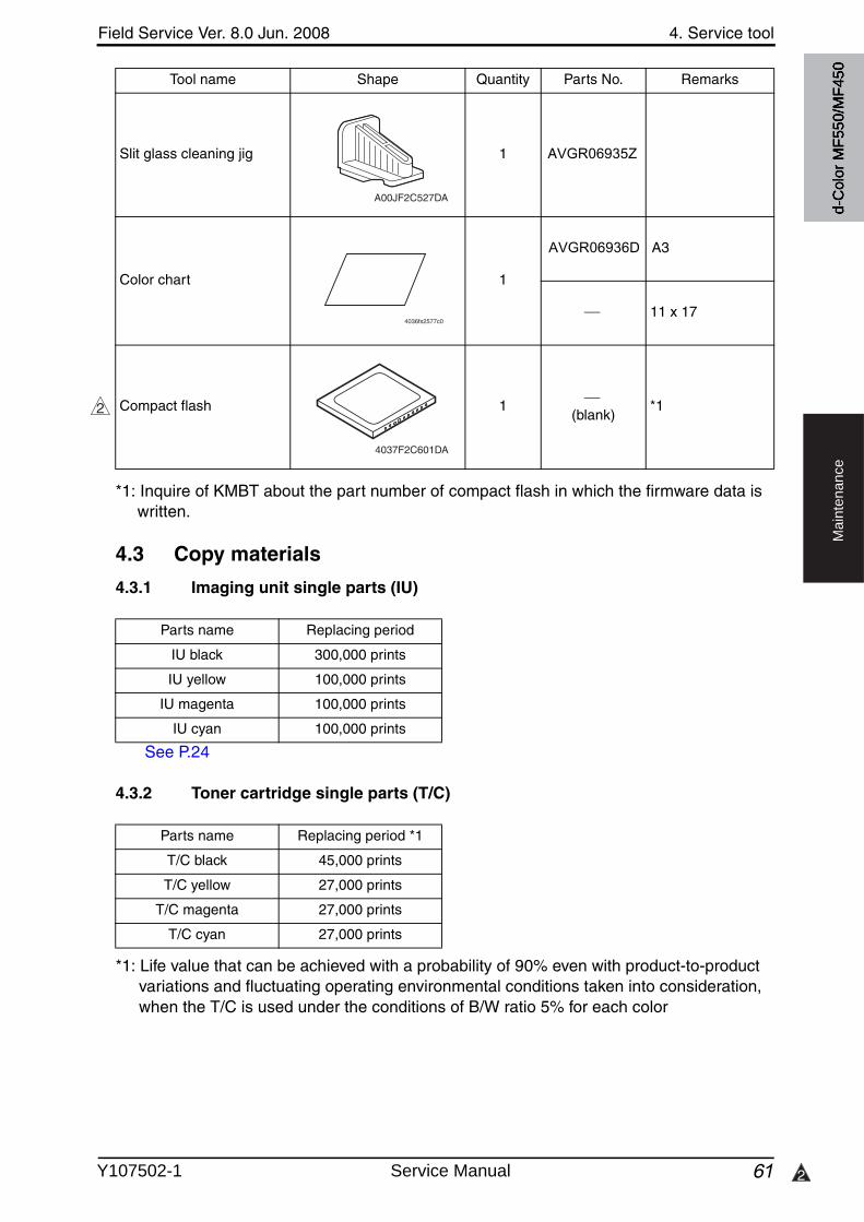
Field Service Ver. 8.0 Jun. 2008 4. Service tool
61 2
Ma
inte
na
nce
*1: Inquire of KMBT about the part number of compact flash in which the firmware data is written.
4.3 Copy materials
4.3.1 Imaging unit single parts (IU)
See P.24
4.3.2 Toner cartridge single parts (T/C)
*1: Life value that can be achieved with a probability of 90% even with product-to-productvariations and fluctuating operating environmental conditions taken into consideration, when the T/C is used under the conditions of B/W ratio 5% for each color
Slit glass cleaning jig 1 AVGR06935Z
Color chart 1
AVGR06936D A3
9J06 PJP2 ## 11 x 17
Compact flash 1(blank)
*1
Tool name Shape Quantity Parts No. Remarks
A00JF2C527DA
4036fs2577c0
2
4037F2C601DA
Parts name Replacing period
IU black 300,000 prints
IU yellow 100,000 prints
IU magenta 100,000 prints
IU cyan 100,000 prints
Parts name Replacing period *1
T/C black 45,000 prints
T/C yellow 27,000 prints
T/C magenta 27,000 prints
T/C cyan 27,000 prints
d-C
olor
MF5
50/M
F450
Y107502-1 Service Manual
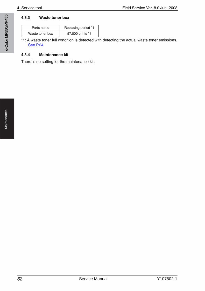
4. Service tool Field Service Ver. 8.0 Jun. 2008
62
Ma
inte
na
nce
4.3.3 Waste toner box
*1: A waste toner full condition is detected with detecting the actual waste toner emissions.See P.24
4.3.4 Maintenance kit
There is no setting for the maintenance kit.
Parts name Replacing period *1
Waste toner box 57,000 prints *1
d-C
olor
MF5
50/M
F450
Service Manual Y107502-1
7
Field Service Ver. 8.0 Jun. 2008 5. Firmware upgrade
63
Ma
inte
na
nce
5. Firmware upgrade
5.1 Outline
• There are two ways to update the firmware: One is by directly connecting with the main body using the compact flash, and the other is by downloading over a network using the Internet ISW.
5.2 Notes about firmware rewrite
5.2.1 Types of firmware
• Two types of firmware are released for d-Color MF550/MF450. They are a maintenancerelease version and an enhanced version.
Maintenance release version : Addresses remaining problemsFunction enhanced version : Adds new features and includes the contents of the
maintenance release version available at the same time• The function enhanced version firmware is available in four types:
“Function Enhancement 1”, “Function Enhancement 2”, “Function Enhancement 3” and “Function Enhancement 4.”
• Before rewriting a firmware, check the current firmware version of the machine and con-firm the type of the current firmware using CSES. Select an appropriate firmware and rewrite the current firmware.
5.2.2 Rewrite to/from a function enhanced version of firmware
• The processing that ensures compatibility is required when upgrading the firmware from the early mass-production one to the function enhanced version or downgrading the firm-ware from the function enhanced version to the early mass-production firmware.
• Four types of processing to ensure compatibilityConversion Up/Conversion Down : Converts and updates management infor-
mation data to make them compatible withthe rewritten firmware. (Necessary processing)
XPS Enable Format/XPS Disable Format : Performs a logical format of HDD to let the HDD support the printing of XPS files or returns HDD to its original format. (Neces-sary only for XPS file printing)
Up Version/Down Version : Expands mode information in order to respond to Scan To WebDAV and Scan To USB (only for Function Enhancement 2/3).
HDD Version Up (LK) : To maintain the compatibility of manage-ment information data and documents stored in HDD after the firmware upgrade. (only for Function Enhancement 3).
NOTE• Firmware can be rewritten only through the menu operation on the control panel
and cannot be rewritten with the CS Remote Care system.• When XPS Enable Format/XPS Disable Format is performed, HDD is logical format-
ted. Therefore, font data, macro data, and others that have been installed by users will disappear.
7
d-C
olor
MF5
50/M
F450
Y107502-1 Service Manual

5. Firmware upgrade Field Service Ver. 8.0 Jun. 2008
643
Ma
inte
na
nce
• Take the following steps to perform processing that ensures compatibility.
A. Upgrade to the function enhancement 1 from the early mass-production firmware(only for d-Color MF550/MF450)
(1) Conversion Up1. After rewriting the firmware, turn OFF and ON the main power switch and sub power
switch.2. Trouble code C-CC00 is displayed.3. Call the Service Mode to the screen.4. Touch [State Confirmation] [Memory/HDD Adj.] [ ] [Conversion Up].5. Check to see that the Start key is lit in blue. Touch the Start key to initiate Conversion
Up.6. When Conversion Up is completed, the result is displayed on the screen.7. Turn OFF and ON the main power switch and sub power switch.
(2) XPS Enable Format• After completing Conversion Up, take the following steps if XPS Enable Format needs to
be performed.1. Call the Service Mode to the screen.2. Touch [State Confirmation] [Memory/HDD Adj.] [ ] [XPS Enable Format].3. Check to see that the Start key is lit in blue. Touch the Start key to initiate XPS Enable
Format.4. When XPS Enable Format is completed, the result is displayed on the screen.5. Turn OFF and ON the main power switch and sub power switch.
B. Upgrade to the function enhancement 2 from the early mass-production firmware(1) Up Version1. After rewriting the firmware, turn OFF and ON the main power switch and sub power
switch.2. Trouble code C-E002 is displayed.3. Call the Service Mode to the screen.4. Touch [State Confirmation] [Memory/HDD Adj.] [Up Ver.].5. Check to see that the Start key is lit in blue. Touch the Start key to initiate UP Version.6. When Up Version is completed, the result is displayed on the screen.7. Turn OFF and ON the main power switch and sub power switch.
(2) Conversion Up (d-Color MF550/MF450 only)1. Trouble code C-CC00 is displayed.2. Call the Service Mode to the screen.3. Touch [State Confirmation] [Memory/HDD Adj.] [ ] [Conversion Up].4. Check to see that the Start key is lit in blue. Touch the Start key to initiate Conversion
Up.5. When Conversion Up is completed, the result is displayed on the screen.6. Turn OFF and ON the main power switch and sub power switch.
(3) XPS Enable Format (d-Color MF550/MF450 only)• After completing Conversion Up, take the following steps if XPS Enable Format needs to
be performed.1. Call the Service Mode to the screen.2. Touch [State Confirmation] [Memory/HDD Adj.] [ ] [XPS Enable Format].3. Check to see that the Start key is lit in blue. Touch the Start key to initiate XPS Enable
Format.
3
d-C
olor
MF5
50/M
F450
Service Manual Y107502-1
Field Service Ver. 8.0 Jun. 2008 5. Firmware upgrade
65
Ma
inte
na
nce
4. When XPS Enable Format is completed, the result is displayed on the screen.5. Turn OFF and ON the main power switch and sub power switch.
C. Upgrade to the function enhancement 2 from the function enhancement 1(1) Up Version1. After rewriting the firmware, turn OFF and ON the main power switch and sub power
switch.2. Trouble code C-E002 is displayed.3. Call the Service Mode to the screen.4. Touch [State Confirmation] [Memory/HDD Adj.] [Up Ver.].5. Check to see that the Start key is lit in blue. Touch the Start key to initiate UP Version.6. When Up Version is completed, the result is displayed on the screen.7. Turn OFF and ON the main power switch and sub power switch.
D. Downgrade from the function enhancement 1 to the early mass-production firm-ware (only for d-Color MF550/MF450)
NOTE• Before downgrading the firmware, the following steps are required to be taken.
(1) Conversion Down1. Call the Service Mode to the screen.2. Touch [State Confirmation] [Memory/HDD Adj.] [ ] [Conversion Down].3. Check to see that the Start key is lit in blue. Touch the Start key to initiate Conversion
Down.4. When Conversion Down is completed, the result is displayed on the screen.5. Turn OFF and ON the main power switch and sub power switch.
(2) XPS Disable Format• After completing Conversion Down, take the following steps if XPS Disable Format needs
to be performed.1. Call the Service Mode to the screen.2. Touch [State Confirmation] [Memory/HDD Adj.] [ ] [XPS Disable Format].3. Check to see that the Start key is lit in blue. Touch the Start key to initiate XPS Disable
Format.4. When XPS Disable Format is completed, the result is displayed on the screen.5. Turn OFF and ON the main power switch and sub power switch.6. Rewrite the firmware.
E. Downgrade from the function enhancement 2 to the early mass-production firm-ware
NOTE• Before downgrading the firmware, the following steps are required to be taken.
(1) Conversion Down (d-Color MF550/MF450 only)1. Call the Service Mode to the screen.2. Touch [State Confirmation] [Memory/HDD Adj.] [ ] [Conversion Down].3. Check to see that the Start key is lit in blue. Touch the Start key to initiate Conversion
Down.4. When Conversion Down is completed, the result is displayed on the screen.5. Turn OFF and ON the main power switch and sub power switch.
d-C
olor
MF5
50/M
F450
Y107502-1 Service Manual
5. Firmware upgrade Field Service Ver. 8.0 Jun. 2008
66
Ma
inte
na
nce
(2) XPS Disable Format (d-Color MF550/MF450 only)• After completing Conversion Down, take the following steps if XPS Disable Format needs
to be performed.1. Call the Service Mode to the screen.2. Touch [State Confirmation] [Memory/HDD Adj.] [ ] [XPS Disable Format].3. Check to see that the Start key is lit in blue. Touch the Start key to initiate XPS Disable
Format.4. When XPS Disable Format is completed, the result is displayed on the screen.5. Turn OFF and ON the main power switch and sub power switch.
(3) Down Version1. Call the Service Mode to the screen.2. Touch [State Confirmation] [Memory/HDD Adj.] [Down Version].3. Check to see that the Start key is lit in blue. Touch the Start key to initiate Down Ver-
sion.4. When Down Version is completed, the result is displayed on the screen.5. Turn OFF and ON the main power switch and sub power switch.6. Rewrite the firmware.7. Trouble code C-E002 is displayed.8. Call the Service Mode to the screen.9. Touch [State Confirmation] [Memory/HDD Adj.] [HDD Format] [Logical For-
mat].10. Check to see that the Start key is lit in blue. Touch the Start key to initiate Logical For-
mat.11. Turn OFF and ON the main power switch and sub power switch.
F. Downgrade from the function enhancement 2 to the function enhancement 1
NOTE• Before downgrading the firmware, the following steps are required to be taken.(1) Down Version1. Call the Service Mode to the screen.2. Touch [State Confirmation] [Memory/HDD Adj.] [Down Version].3. Check to see that the Start key is lit in blue. Touch the Start key to initiate Down Ver-
sion.4. When Done Version is completed, the result is displayed on the screen.5. Turn OFF and ON the main power switch and sub power switch.6. Rewrite the firmware.7. Trouble code C-E002 is displayed.8. Call the Service Mode to the screen.9. Touch [State Confirmation] [Memory/HDD Adj.] [HDD Format] [Logical For-
mat].10. Check to see that the Start key is lit in blue. Touch the Start key to initiate Logical For-
mat.11. Turn OFF and ON the main power switch and sub power switch.
d-C
olor
MF5
50/M
F450
Service Manual Y107502-1
Field Service Ver. 8.0 Jun. 2008 5. Firmware upgrade
67
Ma
inte
na
nce
G. Upgrade to the function enhancement 3 from the early mass-production firmware(1) HDD Version Up (LK)1. After rewriting the firmware, turn OFF and ON the main power switch and sub power
switch.2. Trouble code C-E002 is displayed.3. Call the Service Mode to the screen.4. Touch [State Confirmation] [Memory/HDD Adj.] [HDD Version Up (LK)].5. Check to see that the Start key is lit in blue. Touch the Start key to initiate version up.6. When version up is completed, the result is displayed on the screen.7. Turn OFF and ON the main power switch and sub power switch.
(2) Conversion Up (d-Color MF550/MF450 only)1. Trouble code C-CC00 is displayed.2. Call the Service Mode to the screen.3. Touch [State Confirmation] [Memory/HDD Adj.] [ ] [Conversion Up].4. Check to see that the Start key is lit in blue. Touch the Start key to initiate Conversion
Up.5. When Conversion Up is completed, the result is displayed on the screen.6. Turn OFF and ON the main power switch and sub power switch.
(3) XPS Enable Format (d-Color MF550/MF450 only)• After completing Conversion Up, take the following steps if XPS Enable Format needs to
be performed.1. Call the Service Mode to the screen.2. Touch [State Confirmation] [Memory/HDD Adj.] [ ] [XPS Enable Format].3. Check to see that the Start key is lit in blue. Touch the Start key to initiate XPS Enable
Format.4. When XPS Enable Format is completed, the result is displayed on the screen.5. Turn OFF and ON the main power switch and sub power switch.
H. Upgrade to the function enhancement 3 from the function enhancement 1 or 2(1) HDD Version Up (LK)1. After rewriting the firmware, turn OFF and ON the main power switch and sub power
switch.2. Trouble code C-E002 is displayed.3. Call the Service Mode to the screen.4. Touch [State Confirmation] [Memory/HDD Adj.] [HDD Version Up (LK)].5. Check to see that the Start key is lit in blue. Touch the Start key to initiate version up.6. When version up is completed, the result is displayed on the screen.7. Turn OFF and ON the main power switch and sub power switch.
d-C
olor
MF5
50/M
F450
Y107502-1 Service Manual
5. Firmware upgrade Field Service Ver. 8.0 Jun. 2008
687
Ma
inte
na
nce
I. Downgrade from the function enhancement 4 to the function enhancement 3
NOTE• Before downgrading the firmware, the following steps are required to be taken.
(1) Down Ver.1. Call the Service Mode to the screen.2. Touch [State Confirmation] [Memory/HDD Adj.] [Down Ver.].3. Check to see that the Start key is lit in blue. Touch the Start key to initiate Down Ver.4. When Done Ver. is completed, the result is displayed on the screen.5. Turn OFF and ON the main power switch and sub power switch.6. Rewrite the firmware.7. Trouble code C-E002 is displayed.8. Call the Service Mode to the screen.9. Touch [State Confirmation] [Memory/HDD Adj.] [HDD Format] [Logical For-
mat].10. Check to see that the Start key is lit in blue. Touch the Start key to initiate Logical For-
mat.11. Turn OFF and ON the main power switch and sub power switch.
7
d-C
olor
MF5
50/M
F450
Service Manual Y107502-1
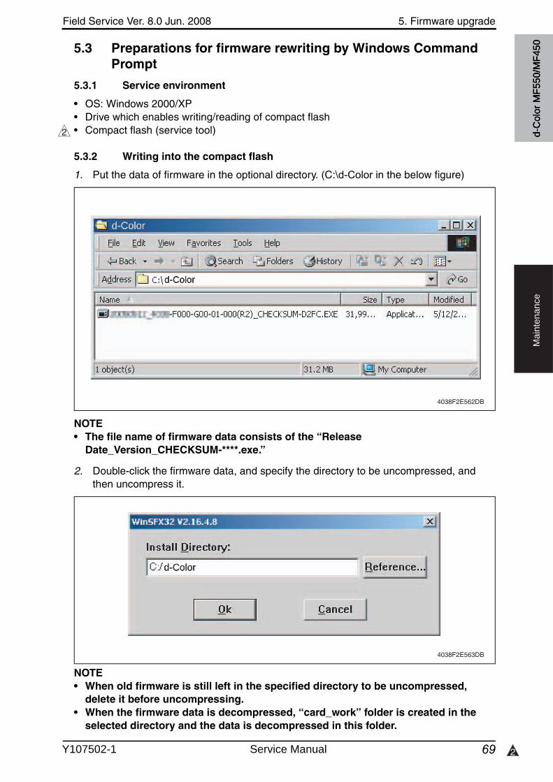
Field Service Ver. 8.0 Jun. 2008 5. Firmware upgrade
69 2
Ma
inte
na
nce
5.3 Preparations for firmware rewriting by Windows Command Prompt
5.3.1 Service environment
• OS: Windows 2000/XP• Drive which enables writing/reading of compact flash• Compact flash (service tool)
5.3.2 Writing into the compact flash
1. Put the data of firmware in the optional directory. (C:\d-Color in the below figure)
NOTE• The file name of firmware data consists of the “Release
Date_Version_CHECKSUM-****.exe.”
2. Double-click the firmware data, and specify the directory to be uncompressed, and then uncompress it.
NOTE• When old firmware is still left in the specified directory to be uncompressed,
delete it before uncompressing.• When the firmware data is decompressed, “card_work” folder is created in the
selected directory and the data is decompressed in this folder.
2
4038F2E562DB
4038F2E563DB
d-C
olor
MF5
50/M
F450
d-Color
d-Color
d-Color
Y107502-1 Service Manual
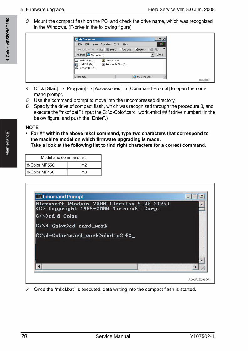
5. Firmware upgrade Field Service Ver. 8.0 Jun. 2008
70
Ma
inte
na
nce
3. Mount the compact flash on the PC, and check the drive name, which was recognized in the Windows. (F-drive in the following figure)
4. Click [Start] [Program] [Accessories] [Command Prompt] to open the com-mand prompt.
5. Use the command prompt to move into the uncompressed directory.6. Specify the drive of compact flash, which was recognized through the procedure 3, and
execute the “mkcf.bat.” (Input the C: \d-Color\card_work>mkcf ## f (drive number): in the below figure, and push the “Enter”.)
NOTE• For ## within the above mkcf command, type two characters that correspond to
the machine model on which firmware upgrading is made. Take a look at the following list to find right characters for a correct command.
7. Once the “mkcf.bat” is executed, data writing into the compact flash is started.
4036fs2623e0
Model and command list
A00JF2E568DA
d-C
olor
MF5
50/M
F450
d-Color MF550 m2
d-Color MF450 m3
Service Manual Y107502-1
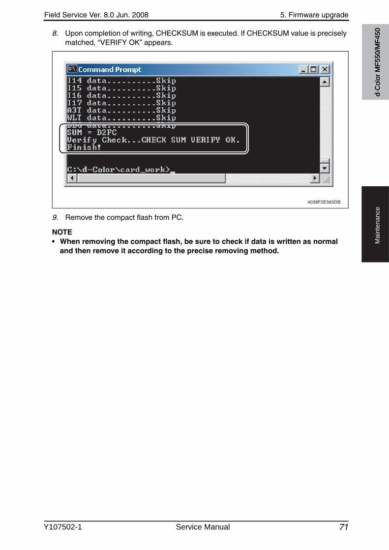
Field Service Ver. 8.0 Jun. 2008 5. Firmware upgrade
71
Ma
inte
na
nce
8. Upon completion of writing, CHECKSUM is executed. If CHECKSUM value is precisely matched, “VERIFY OK” appears.
9. Remove the compact flash from PC.
NOTE• When removing the compact flash, be sure to check if data is written as normal
and then remove it according to the precise removing method.
4038F2E565DB
d-C
olor
MF5
50/M
F450
Y107502-1 Service Manual
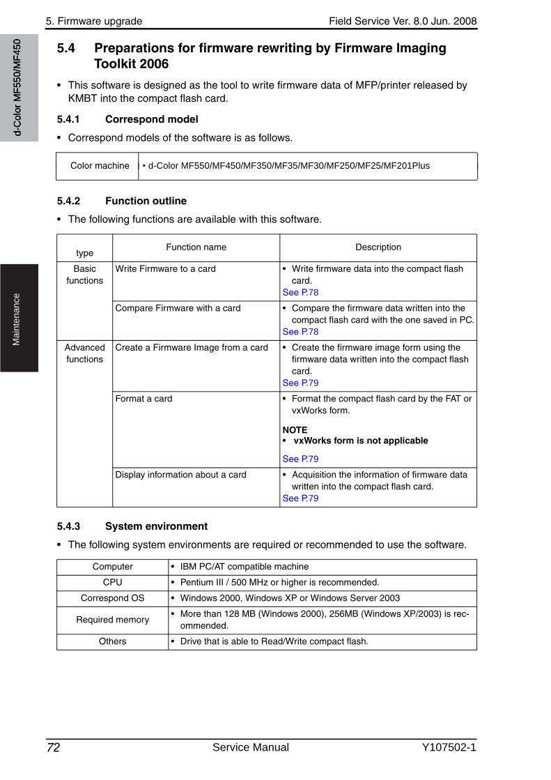
5. Firmware upgrade Field Service Ver. 8.0 Jun. 2008
72
Ma
inte
na
nce
5.4 Preparations for firmware rewriting by Firmware Imaging Toolkit 2006
• This software is designed as the tool to write firmware data of MFP/printer released by KMBT into the compact flash card.
5.4.1 Correspond model
• Correspond models of the software is as follows. d-C
olor
MF5
50/M
F450
Color machine • d-Color MF550/MF450/MF350/MF35/MF30/MF250/MF25/MF201Plus
5.4.2 Function outline
• The following functions are available with this software.
5.4.3 System environment
• The following system environments are required or recommended to use the software.
typeFunction name Description
Basic functions
Write Firmware to a card • Write firmware data into the compact flash card.
See P.78
Compare Firmware with a card • Compare the firmware data written into the compact flash card with the one saved in PC.
See P.78
Advanced functions
Create a Firmware Image from a card • Create the firmware image form using the firmware data written into the compact flash card.
See P.79
Format a card • Format the compact flash card by the FAT or vxWorks form.
NOTE• vxWorks form is not applicable
See P.79
Display information about a card • Acquisition the information of firmware data written into the compact flash card.
See P.79
Computer • IBM PC/AT compatible machine
CPU • Pentium III / 500 MHz or higher is recommended.
Correspond OS • Windows 2000, Windows XP or Windows Server 2003
Required memory• More than 128 MB (Windows 2000), 256MB (Windows XP/2003) is rec-
ommended.
Others • Drive that is able to Read/Write compact flash.
Service Manual Y107502-1

Field Service Ver. 8.0 Jun. 2008 5. Firmware upgrade
73
Ma
inte
na
nce
5.4.4 Installation of software
• Follow the procedures shown below to install the software.
NOTE• Install the software to the PC with the administration authentication.• When any anti-virus program is activated, quite the program before the installa-
tion.
1. Double click [setup.exe] to start the installation of the software.
2. Click [Next >].
9J06F2C673DA
9J06F2E700DA
d-C
olor
MF5
50/M
F450
Y107502-1 Service Manual
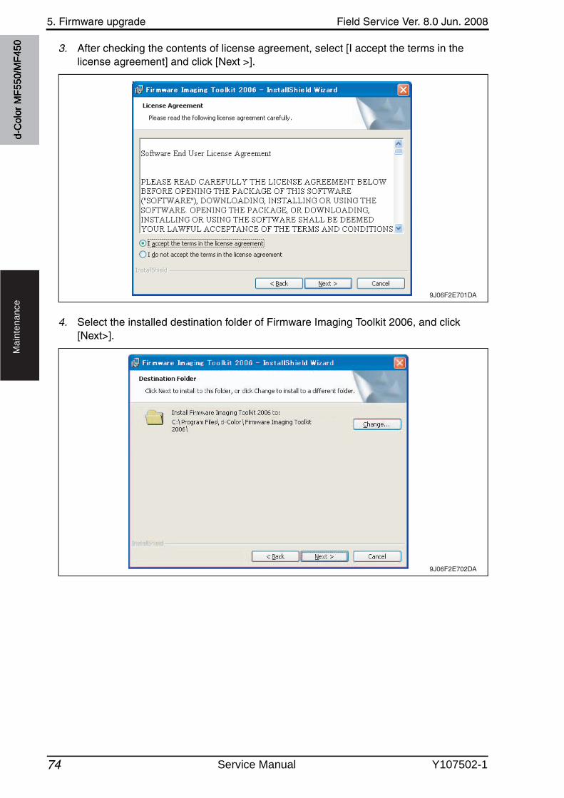
5. Firmware upgrade Field Service Ver. 8.0 Jun. 2008
74
Ma
inte
na
nce
3. After checking the contents of license agreement, select [I accept the terms in the license agreement] and click [Next >].
4. Select the installed destination folder of Firmware Imaging Toolkit 2006, and click [Next>].
9J06F2E701DA
9J06F2E702DA
d-C
olor
MF5
50/M
F450
Service Manual Y107502-1
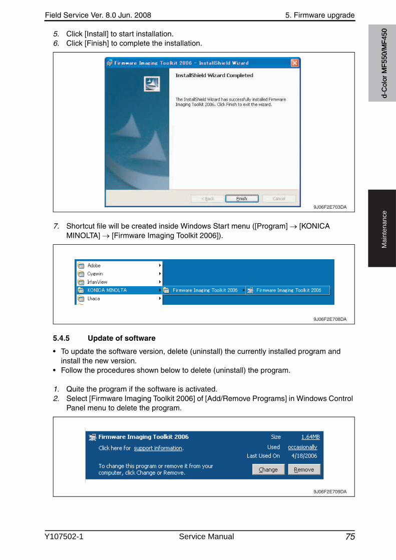
Field Service Ver. 8.0 Jun. 2008 5. Firmware upgrade
75
Ma
inte
na
nce
5. Click [Install] to start installation.6. Click [Finish] to complete the installation.
7. Shortcut file will be created inside Windows Start menu ([Program] [KONICA MINOLTA] [Firmware Imaging Toolkit 2006]).
5.4.5 Update of software
• To update the software version, delete (uninstall) the currently installed program and install the new version.
• Follow the procedures shown below to delete (uninstall) the program.
1. Quite the program if the software is activated.2. Select [Firmware Imaging Toolkit 2006] of [Add/Remove Programs] in Windows Control
Panel menu to delete the program.
9J06F2E703DA
9J06F2E708DA
9J06F2E709DA
d-C
olor
MF5
50/M
F450
Y107502-1 Service Manual
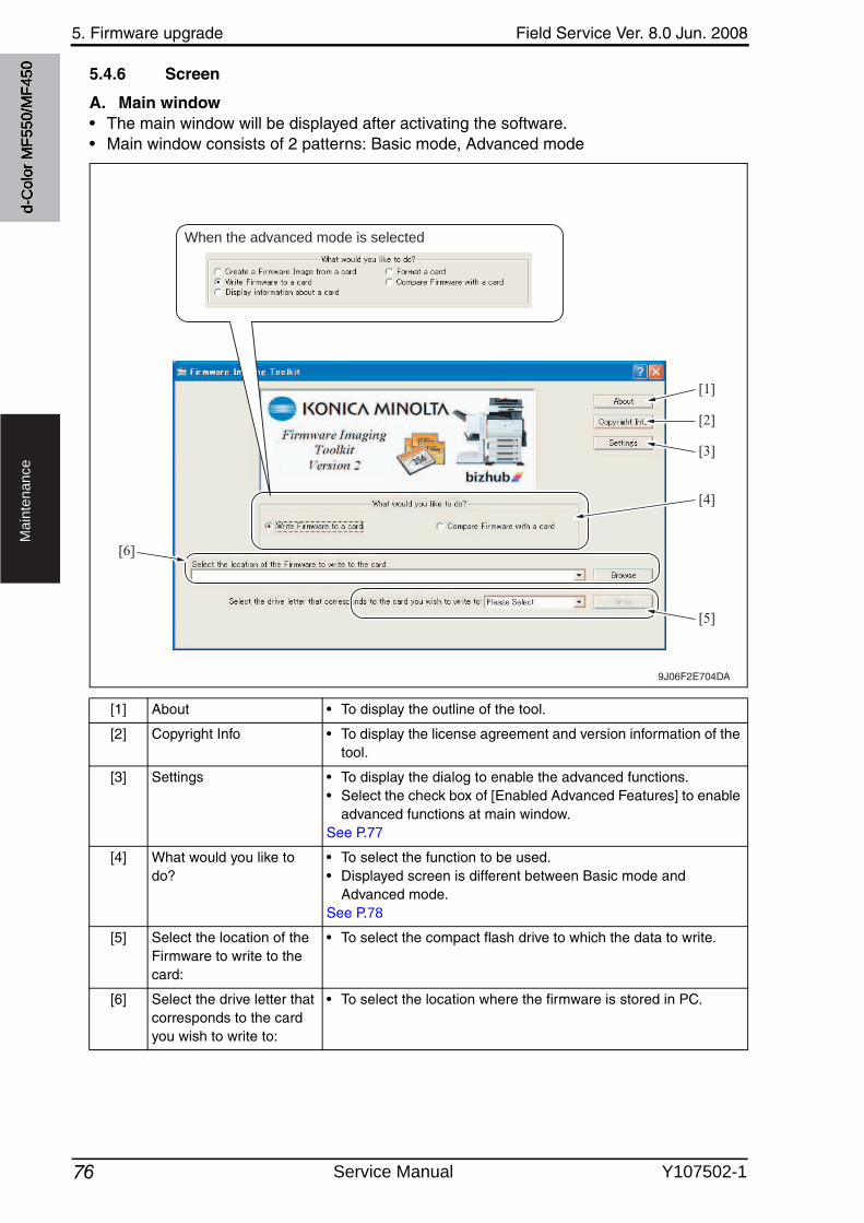
5. Firmware upgrade Field Service Ver. 8.0 Jun. 2008
76
Ma
inte
na
nce
5.4.6 Screen
A. Main window• The main window will be displayed after activating the software.• Main window consists of 2 patterns: Basic mode, Advanced mode
[1] About • To display the outline of the tool.
[2] Copyright Info • To display the license agreement and version information of the tool.
[3] Settings • To display the dialog to enable the advanced functions.• Select the check box of [Enabled Advanced Features] to enable
advanced functions at main window.See P.77
[4] What would you like to do?
• To select the function to be used.• Displayed screen is different between Basic mode and
Advanced mode.See P.78
[5] Select the location of the Firmware to write to the card:
• To select the compact flash drive to which the data to write.
[6] Select the drive letter that corresponds to the card you wish to write to:
• To select the location where the firmware is stored in PC.
9J06F2E704DA
When the advanced mode is selected
[1]
[2]
[3]
[5]
[6]
[4]
d-C
olor
MF5
50/M
F450
Service Manual Y107502-1
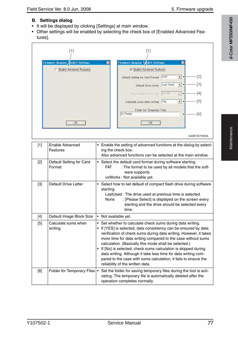
Field Service Ver. 8.0 Jun. 2008 5. Firmware upgrade
77
Ma
inte
na
nce
B. Settings dialog• It will be displayed by clicking [Settings] at main window.• Other settings will be enabled by selecting the check box of [Enabled Advanced Fea-
tures].
[1] Enable Advanced Features
• Enable the setting of advanced functions at the dialog by select-ing the check box.Also advanced functions can be selected at the main window.
[2] Default Setting for Card Format
• Select the default card format during software starting.FAT : The format to be used by all models that the soft-
ware supports.vxWorks : Not available yet.
[3] Default Drive Letter • Select how to set default of compact flash drive during software starting.
LastUsed : The drive used at previous time is selected.None : [Please Select] is displayed on the screen every
starting and the drive should be selected every time.
[4] Default Image Block Size • Not available yet.
[5] Calculate sums when writing
• Set whether to calculate check sums during data writing.• If [YES] is selected, data consistency can be ensured by data
verification of check sums during data writing. However, it takes more time for data writing compared to the case without sums calculation. (Basically this mode shall be selected.)
• If [No] is selected, check sums calculation is skipped during data writing. Although it take less time for data writing com-pared to the case with sums calculation, it fails to ensure the reliability of the written data.
[6] Folder for Temporary Files • Set the folder for saving temporary files during the tool is acti-vating. The temporary file is automatically deleted after the operation completes normally.
9J06F2E705DA
[1] [1]
[2]
[3]
[4]
[5]
[6]
d-C
olor
MF5
50/M
F450
Y107502-1 Service Manual
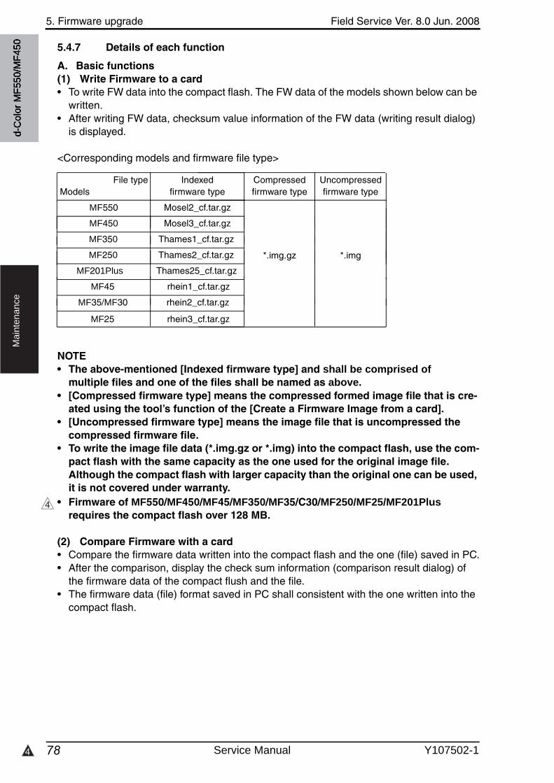
5. Firmware upgrade Field Service Ver. 8.0 Jun. 2008
784
Ma
inte
na
nce
5.4.7 Details of each function
A. Basic functions(1) Write Firmware to a card• To write FW data into the compact flash. The FW data of the models shown below can be
written.• After writing FW data, checksum value information of the FW data (writing result dialog)
is displayed.
<Corresponding models and firmware file type>
File typeModels
Indexed firmware type
Compressed firmware type
Uncompressed firmware type
d-C
olor
MF5
50/M
F450
MF550 Mosel2_cf.tar.gz
MF450 Mosel3_cf.tar.gz
MF350 Thames1_cf.tar.gz
MF250 Thames2_cf.tar.gz
MF201Plus Thames25_cf.tar.gz
MF45 rhein1_cf.tar.gz
MF35/MF30 rhein2_cf.tar.gz
MF25 rhein3_cf.tar.gz
*.img.gz *.img
NOTE• The above-mentioned [Indexed firmware type] and shall be comprised of
multiple files and one of the files shall be named as above. • [Compressed firmware type] means the compressed formed image file that is cre-
ated using the tool’s function of the [Create a Firmware Image from a card]. • [Uncompressed firmware type] means the image file that is uncompressed the
compressed firmware file.• To write the image file data (*.img.gz or *.img) into the compact flash, use the com-
pact flash with the same capacity as the one used for the original image file. Although the compact flash with larger capacity than the original one can be used, it is not covered under warranty.
• Firmware of MF550/MF450/MF45/MF350/MF35/C30/MF250/MF25/MF201Plusrequires the compact flash over 128 MB.
(2) Compare Firmware with a card• Compare the firmware data written into the compact flash and the one (file) saved in PC.• After the comparison, display the check sum information (comparison result dialog) of
the firmware data of the compact flush and the file.• The firmware data (file) format saved in PC shall consistent with the one written into the
compact flash.
4
Service Manual Y107502-1
4
Field Service Ver. 8.0 Jun. 2008 5. Firmware upgrade
79
Ma
inte
na
nce
B. Advanced functions(1) Create a Firmware Image from a card• Create the image file from the firmware data written into the compact flash.
Create the image file by dumping directly the data in the card. This function allows us to save the various type of firmware data in the compact flash as the image file and hold as copy data.
• The created FW image file is automatically compressed and created as the Compressed firmware file (*.img.gz). The image file is written into the compact flash in the uncompressed form, however, the uncompressed data would occupy too much capacity, which makes file control difficult.Therefore this tool doesn't create uncompressed firmware file (*.img).
(2) Format a card• Make format of the compact flash in FAT or vxWork form.• To write the firmware data into the compact flash, the card should be formatted in FAT
form to clear (initialize) the description of the compact flash.
NOTE• In current version, only FAT format is available but not vxWork format.• After the firmware data is written into the compact flash, it becomes the own file
style that is different from the FAT, and the compact flash that the firmware data is written cannot be browsed on the Windows OS.
(3) Display information about a card• Display the information of the firmware data written into the compact flash.
The information to be displayed is according to the type of written FW data.
4
d-C
olor
MF5
50/M
F450
• For the series of MF550/MF450/MF45/MF350/MF35/MF30/MF250/MF25/MF201Plus,check sums of each firmware data is displayed.
Y107502-1 Service Manual
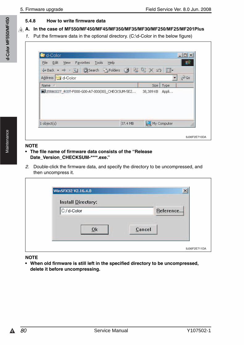
5. Firmware upgrade Field Service Ver. 8.0 Jun. 2008
804
Ma
inte
na
nce
5.4.8 How to write firmware data
A. In the case of MF550/MF450/MF45/MF350/MF35/MF30/MF250/MF25/MF201Plus4
d-C
olor
MF5
50/M
F450
1. Put the firmware data in the optional directory. (C:\d-Color in the below figure)
NOTE• The file name of firmware data consists of the “Release
Date_Version_CHECKSUM-****.exe.”
2. Double-click the firmware data, and specify the directory to be uncompressed, and then uncompress it.
NOTE• When old firmware is still left in the specified directory to be uncompressed,
delete it before uncompressing.
9J06F2E710DA
9J06F2E711DA
d-Color
Service Manual Y107502-1
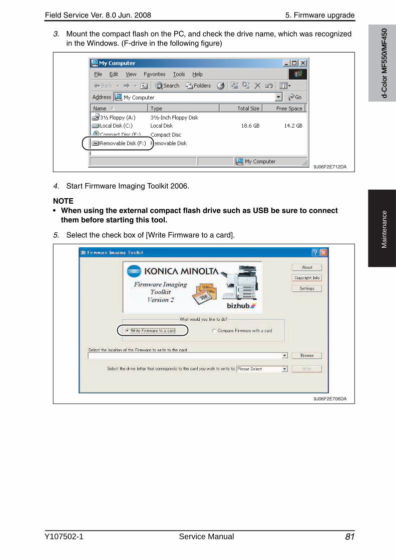
Field Service Ver. 8.0 Jun. 2008 5. Firmware upgrade
81
Ma
inte
na
nce
3. Mount the compact flash on the PC, and check the drive name, which was recognized in the Windows. (F-drive in the following figure)
4. Start Firmware Imaging Toolkit 2006.
NOTE• When using the external compact flash drive such as USB be sure to connect
them before starting this tool.
5. Select the check box of [Write Firmware to a card].
9J06F2E712DA
9J06F2E706DA
d-C
olor
MF5
50/M
F450
Y107502-1 Service Manual
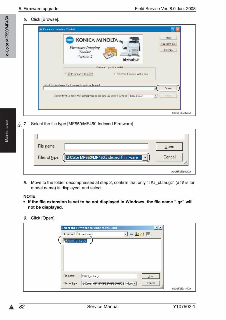
5. Firmware upgrade Field Service Ver. 8.0 Jun. 2008
822
Ma
inte
na
nce
6. Click [Browse].
7. Select the file type [MF550/MF450 Indexed Firmware].
8. Move to the folder decompressed at step 2, confirm that only "###_cf.tar.gz" (### is for model name) is displayed, and select.
NOTE• If the file extension is set to be not displayed in Windows, the file name “.gz” will
not be displayed.
9. Click [Open].
9J06F2E707DA
2
A00HF2E509DA
9J06F2E714DA
d-C
olor
MF5
50/M
F450
d-Color MF550/MF450
d-Color MF45/MF35/MF30/MF25
Service Manual Y107502-1
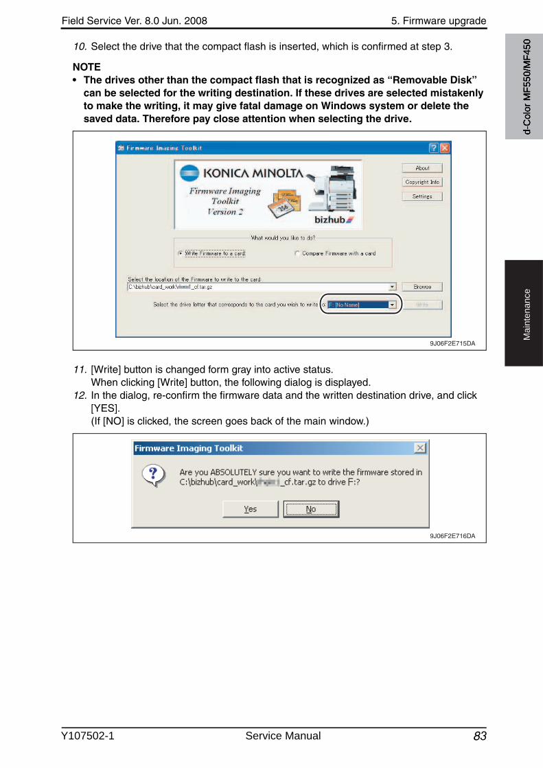
Field Service Ver. 8.0 Jun. 2008 5. Firmware upgrade
83
Ma
inte
na
nce
10. Select the drive that the compact flash is inserted, which is confirmed at step 3.
NOTE• The drives other than the compact flash that is recognized as “Removable Disk”
can be selected for the writing destination. If these drives are selected mistakenly to make the writing, it may give fatal damage on Windows system or delete the saved data. Therefore pay close attention when selecting the drive.
11. [Write] button is changed form gray into active status.When clicking [Write] button, the following dialog is displayed.
12. In the dialog, re-confirm the firmware data and the written destination drive, and click [YES].(If [NO] is clicked, the screen goes back of the main window.)
9J06F2E715DA
9J06F2E716DAd-
Col
or M
F550
/MF4
50
Y107502-1 Service Manual
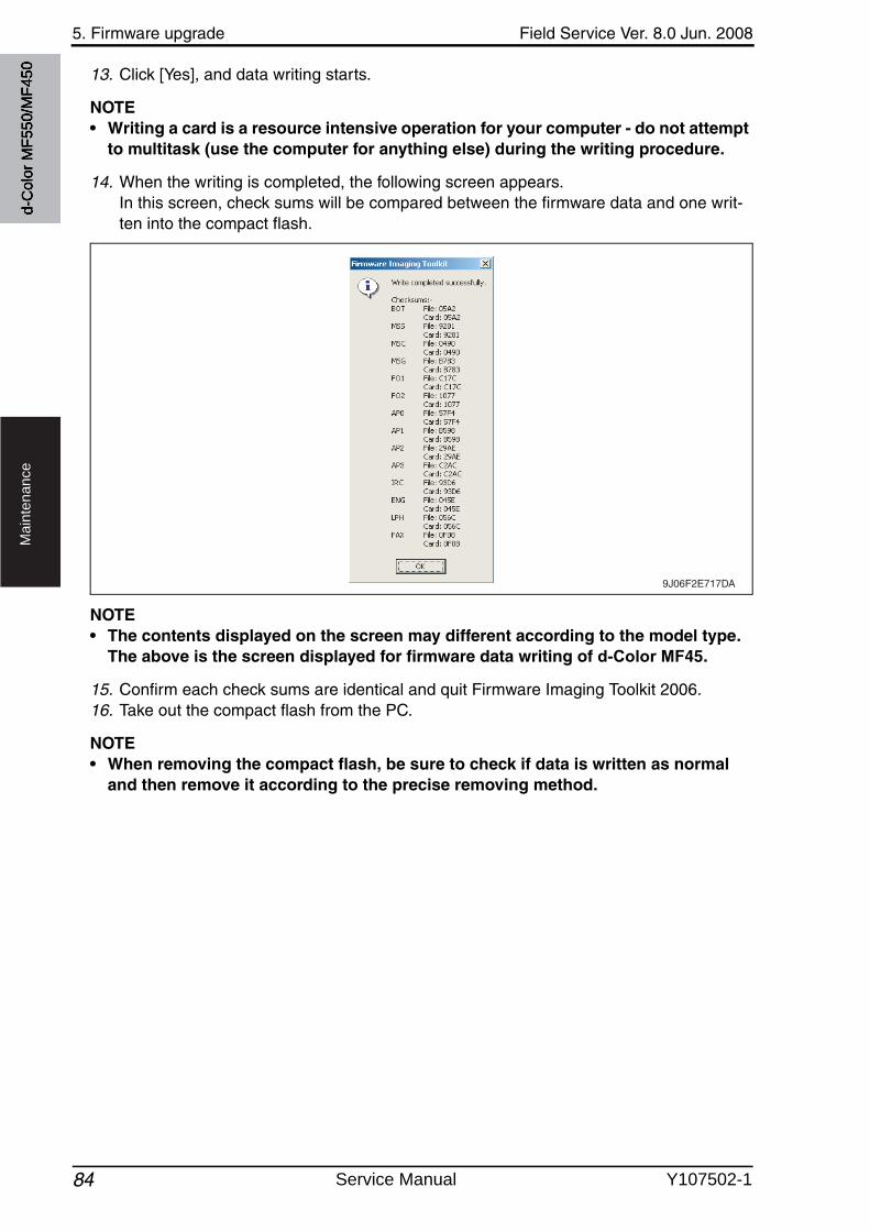
5. Firmware upgrade Field Service Ver. 8.0 Jun. 2008
84
Ma
inte
na
nce
13. Click [Yes], and data writing starts.
NOTE• Writing a card is a resource intensive operation for your computer - do not attempt
to multitask (use the computer for anything else) during the writing procedure.
14. When the writing is completed, the following screen appears. In this screen, check sums will be compared between the firmware data and one writ-ten into the compact flash.
NOTE• The contents displayed on the screen may different according to the model type.
The above is the screen displayed for firmware data writing of d-Color MF45.
15. Confirm each check sums are identical and quit Firmware Imaging Toolkit 2006.16. Take out the compact flash from the PC.
NOTE• When removing the compact flash, be sure to check if data is written as normal
and then remove it according to the precise removing method.
9J06F2E717DA
d-C
olor
MF5
50/M
F450
Service Manual Y107502-1
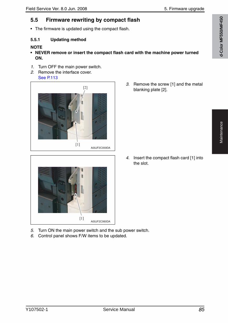
Field Service Ver. 8.0 Jun. 2008 5. Firmware upgrade
85
Ma
inte
na
nce
5.5 Firmware rewriting by compact flash
• The firmware is updated using the compact flash.
5.5.1 Updating method
NOTE• NEVER remove or insert the compact flash card with the machine power turned
ON.
1. Turn OFF the main power switch.2. Remove the interface cover.
See P.113
3. Remove the screw [1] and the metal blanking plate [2].
4. Insert the compact flash card [1] into the slot.
5. Turn ON the main power switch and the sub power switch.6. Control panel shows F/W items to be updated.
[1]
[2]
A00JF2C059DA
[1]A00JF2C060DA
d-C
olor
MF5
50/M
F450
Y107502-1 Service Manual
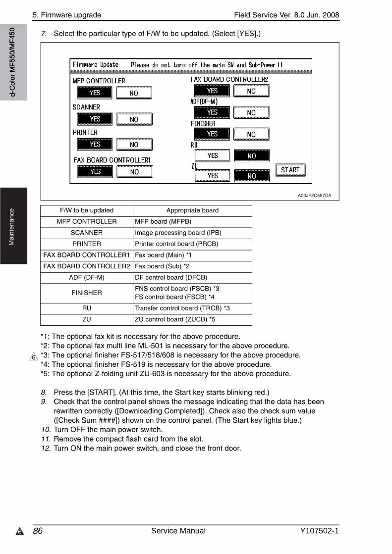
5. Firmware upgrade Field Service Ver. 8.0 Jun. 2008
866
Ma
inte
na
nce
7. Select the particular type of F/W to be updated. (Select [YES].)
*1: The optional fax kit is necessary for the above procedure.*2: The optional fax multi line ML-501 is necessary for the above procedure.*3: The optional finisher FS-517/518/608 is necessary for the above procedure.*4: The optional finisher FS-519 is necessary for the above procedure.*5: The optional Z-folding unit ZU-603 is necessary for the above procedure.
8. Press the [START]. (At this time, the Start key starts blinking red.)9. Check that the control panel shows the message indicating that the data has been
rewritten correctly ([Downloading Completed]). Check also the check sum value([Check Sum ####]) shown on the control panel. (The Start key lights blue.)
10. Turn OFF the main power switch.11. Remove the compact flash card from the slot.12. Turn ON the main power switch, and close the front door.
F/W to be updated Appropriate board
MFP CONTROLLER MFP board (MFPB)
SCANNER Image processing board (IPB)
PRINTER Printer control board (PRCB)
FAX BOARD CONTROLLER1 Fax board (Main) *1
FAX BOARD CONTROLLER2 Fax board (Sub) *2
ADF (DF-M) DF control board (DFCB)
FINISHERFNS control board (FSCB) *3FS control board (FSCB) *4
RU Transfer control board (TRCB) *3
ZU ZU control board (ZUCB) *5
A00JF2C557DA
6
d-C
olor
MF5
50/M
F450
Service Manual Y107502-1
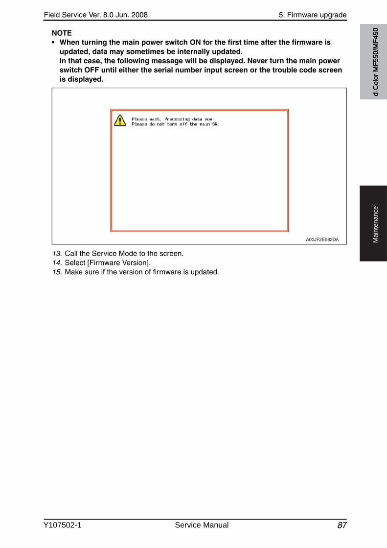
Field Service Ver. 8.0 Jun. 2008 5. Firmware upgrade
87
Ma
inte
na
nce
NOTE• When turning the main power switch ON for the first time after the firmware is
updated, data may sometimes be internally updated. In that case, the following message will be displayed. Never turn the main power switch OFF until either the serial number input screen or the trouble code screen is displayed.
13. Call the Service Mode to the screen.14. Select [Firmware Version].15. Make sure if the version of firmware is updated.
A00JF2E582DA
d-C
olor
MF5
50/M
F450
Y107502-1 Service Manual
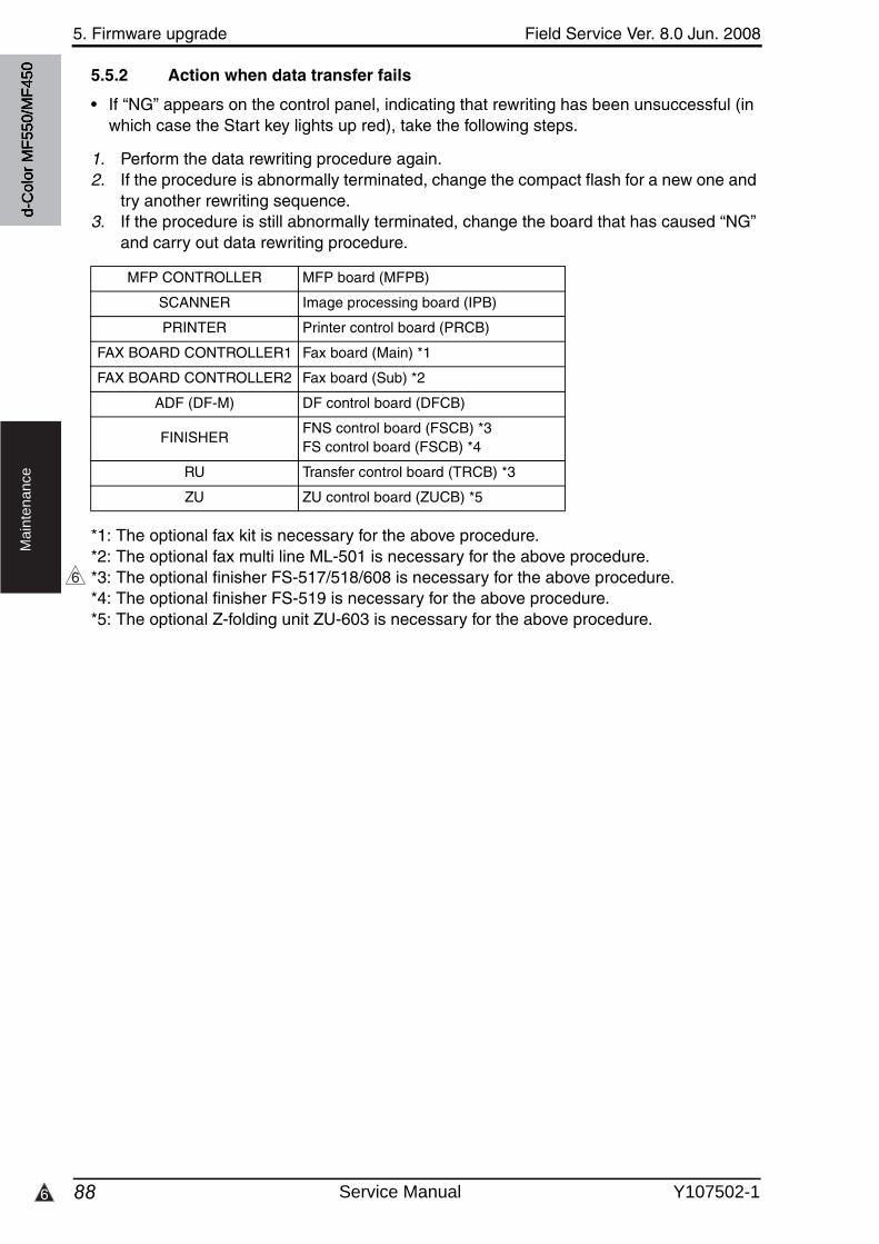
5. Firmware upgrade Field Service Ver. 8.0 Jun. 2008
886
Ma
inte
na
nce
5.5.2 Action when data transfer fails
• If “NG” appears on the control panel, indicating that rewriting has been unsuccessful (in which case the Start key lights up red), take the following steps.
1. Perform the data rewriting procedure again.2. If the procedure is abnormally terminated, change the compact flash for a new one and
try another rewriting sequence.3. If the procedure is still abnormally terminated, change the board that has caused “NG”
and carry out data rewriting procedure.
*1: The optional fax kit is necessary for the above procedure.*2: The optional fax multi line ML-501 is necessary for the above procedure.*3: The optional finisher FS-517/518/608 is necessary for the above procedure.*4: The optional finisher FS-519 is necessary for the above procedure.*5: The optional Z-folding unit ZU-603 is necessary for the above procedure.
MFP CONTROLLER MFP board (MFPB)
SCANNER Image processing board (IPB)
PRINTER Printer control board (PRCB)
FAX BOARD CONTROLLER1 Fax board (Main) *1
FAX BOARD CONTROLLER2 Fax board (Sub) *2
ADF (DF-M) DF control board (DFCB)
FINISHERFNS control board (FSCB) *3FS control board (FSCB) *4
RU Transfer control board (TRCB) *3
ZU ZU control board (ZUCB) *5
6
d-C
olor
MF5
50/M
F450
Service Manual Y107502-1
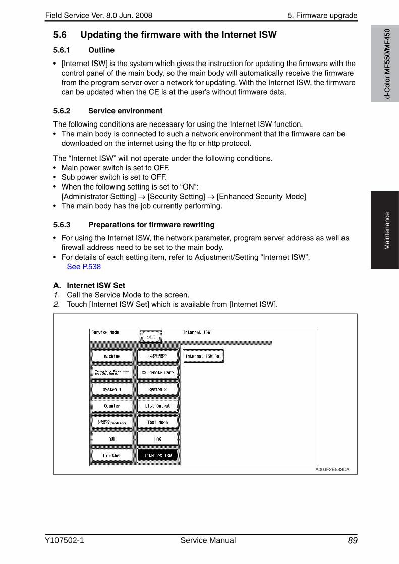
Field Service Ver. 8.0 Jun. 2008 5. Firmware upgrade
89
Ma
inte
na
nce
5.6 Updating the firmware with the Internet ISW
5.6.1 Outline
• [Internet ISW] is the system which gives the instruction for updating the firmware with the control panel of the main body, so the main body will automatically receive the firmware from the program server over a network for updating. With the Internet ISW, the firmwarecan be updated when the CE is at the user’s without firmware data.
5.6.2 Service environment
The following conditions are necessary for using the Internet ISW function.• The main body is connected to such a network environment that the firmware can be
downloaded on the internet using the ftp or http protocol.
The “Internet ISW” will not operate under the following conditions.• Main power switch is set to OFF.• Sub power switch is set to OFF.• When the following setting is set to “ON”:
[Administrator Setting] [Security Setting] [Enhanced Security Mode]• The main body has the job currently performing.
5.6.3 Preparations for firmware rewriting
• For using the Internet ISW, the network parameter, program server address as well as firewall address need to be set to the main body.
• For details of each setting item, refer to Adjustment/Setting “Internet ISW”.See P.538
A. Internet ISW Set1. Call the Service Mode to the screen.2. Touch [Internet ISW Set] which is available from [Internet ISW].
A00JF2E583DA
d-C
olor
MF5
50/M
F450
Y107502-1 Service Manual

5. Firmware upgrade Field Service Ver. 8.0 Jun. 2008
90
Ma
inte
na
nce
3. Touch [ON], and touch [END].
NOTE• Settings such as server setting, etc. will be available by selecting “ON” on this set-
ting.• When the following setting is set to “ON”, “ON” cannot be selected on this setting.
[Administrator Setting] [Security Setting] [Enhanced Security Mode]
B. Protocol setting• It performs the setting concerning the protocol (ftp or http) for connecting to the
Internet ISW.• When connecting to the program server using a proxy server, perform the setting
for a proxy server.
Step Connecting by http Connecting by ftp
0 Select [Internet ISW] which is available from [Service Mode].
1Data Input Setting• Touch [HTTP Setting], and select [ON].
Data Input Setting• Touch [FTP Setting], and select [ON].
2Connect Proxy• For connecting via proxy server, select [ON].
3
Proxy Server• For connecting via proxy server, set the proxy server address and the port number.
1. Select the [Server Address], and set the proxy server address by IP addressing scheme or FQDN scheme.
2. Select [Port Number], and set the port number for the proxy server from 1 through 65535.
4
Proxy Authentication• Set the login name and the password which
may be necessary for authentication whenaccessing to the proxy server.
1. When Authentication is necessary for accessing to the proxy server, select [Authentication], and select [ON].
2. Select [Log-in Name], and enter the login name on the on-screen keyboard.
3. Select [Password], and enter the password on the on-screen keyboard.
Connection Setting• Perform the setting for accessing FTP
server.
1. Select [Port Number], and set the port num-ber for FTP server from 1 through 65535.
2. Select [Connection Time Out], and set the time for the connection time out from 1 through 60.
3. When connecting in PASV mode, select [PASV Mode], and select [ON].
*PASV Mode: This mode is for transferring the file withFTP under the condition where communica-tion is restricted such as inside the firewall. Since with PASV mode, the client withrestriction sets the port number, data trans-mission port can be secured to enable the file transmission.
5
Connection Time-Out• Select [Connection Time-Out], and set the
time for the connection time out between 30 and 300 seconds.
d-C
olor
MF5
50/M
F450
Service Manual Y107502-1
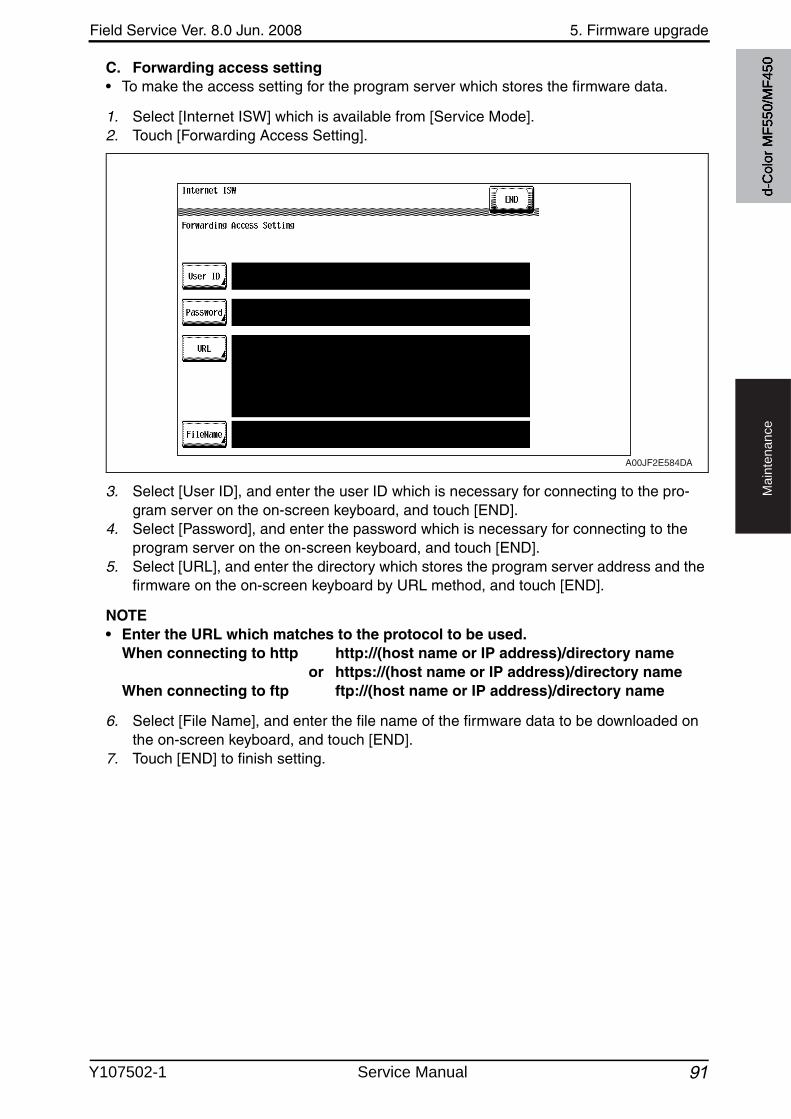
Field Service Ver. 8.0 Jun. 2008 5. Firmware upgrade
91
Ma
inte
na
nce
C. Forwarding access setting• To make the access setting for the program server which stores the firmware data.
1. Select [Internet ISW] which is available from [Service Mode].2. Touch [Forwarding Access Setting].
3. Select [User ID], and enter the user ID which is necessary for connecting to the pro-gram server on the on-screen keyboard, and touch [END].
4. Select [Password], and enter the password which is necessary for connecting to the program server on the on-screen keyboard, and touch [END].
5. Select [URL], and enter the directory which stores the program server address and the firmware on the on-screen keyboard by URL method, and touch [END].
NOTE• Enter the URL which matches to the protocol to be used.
When connecting to http http://(host name or IP address)/directory name or https://(host name or IP address)/directory name
When connecting to ftp ftp://(host name or IP address)/directory name
6. Select [File Name], and enter the file name of the firmware data to be downloaded on the on-screen keyboard, and touch [END].
7. Touch [END] to finish setting.
A00JF2E584DA
d-C
olor
MF5
50/M
F450
Y107502-1 Service Manual
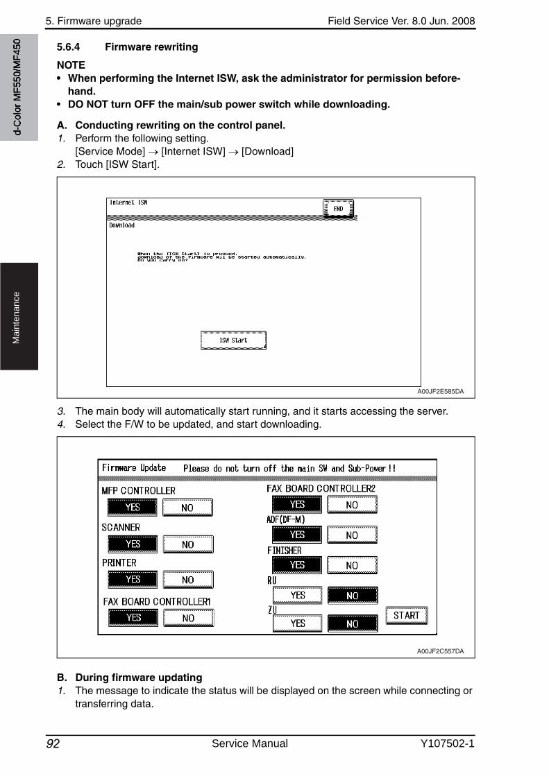
5. Firmware upgrade Field Service Ver. 8.0 Jun. 2008
92
Ma
inte
na
nce
5.6.4 Firmware rewriting
NOTE• When performing the Internet ISW, ask the administrator for permission before-
hand.• DO NOT turn OFF the main/sub power switch while downloading.
A. Conducting rewriting on the control panel.1. Perform the following setting.
[Service Mode] [Internet ISW] [Download]2. Touch [ISW Start].
3. The main body will automatically start running, and it starts accessing the server.4. Select the F/W to be updated, and start downloading.
B. During firmware updating1. The message to indicate the status will be displayed on the screen while connecting or
transferring data.
A00JF2E585DA
A00JF2C557DA
d-C
olor
MF5
50/M
F450
Service Manual Y107502-1
Field Service Ver. 8.0 Jun. 2008 5. Firmware upgrade
93
Ma
inte
na
nce
C. Completed or failed(1) Firmware updated normally1. When the Firmware is normally updated, restart the main body in auto or manual mode
to display the outcome, and touch [OK] to return to the main screen.
(2) Failing to update the firmware due to the network trouble1. When updating failed to complete due to the trouble on connecting to the network, an
error code and the message will be displayed.2. Restart the main body in auto or manual mode, and touch [OK]. It can be used with the
firmware version before conducting updating.3. Check the settings for the network by error codes, and try updating again.
NOTE• For error codes, refer to “Error code list for the Internet ISW”.
See P.94
(3) Failing to update the firmware after downloading has started1. Once firmware updating has started, the ROM in the main body will be deleted.
When it failed right after updating has started, restart the main body, and shift to the standby screen to retry downloading.
2. When updating on the control panel, touch [settings] on the standby screen, and check the Network settings again. Touch [Download], and restart the Internet ISW.
NOTE• Return to the standby screen without fail after turning the main power switch OFF/
ON if the firmware is not updated.• Firmware can be updated with the Compact flash with the main power switch OFF.
d-C
olor
MF5
50/M
F450
Y107502-1 Service Manual
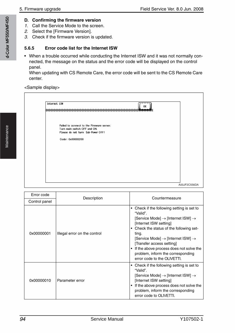
5. Firmware upgrade Field Service Ver. 8.0 Jun. 2008
94
Ma
inte
na
nce
D. Confirming the firmware version1. Call the Service Mode to the screen.2. Select the [Firmware Version].3. Check if the firmware version is updated.
5.6.5 Error code list for the Internet ISW
• When a trouble occurred while conducting the Internet ISW and it was not normally con-nected, the message on the status and the error code will be displayed on the control panel. When updating with CS Remote Care, the error code will be sent to the CS Remote Care center.
<Sample display>
Error codeDescription Countermeasure
Control panel
0x00000001 Illegal error on the control
• Check if the following setting is set to “Valid”. [Service Mode] [Internet ISW] [Internet ISW setting]
• Check the status of the following set-ting. [Service Mode] [Internet ISW] [Transfer access setting]
• If the above process does not solve the problem, inform the corresponding error code to the OLIVETTI.
0x00000010 Parameter error
• Check if the following setting is set to “Valid”. [Service Mode] [Internet ISW] [Internet ISW setting]
• If the above process does not solve the problem, inform the corresponding error code to OLIVETTI.
A00JF2C556DA
d-C
olor
MF5
50/M
F450
Service Manual Y107502-1
Field Service Ver. 8.0 Jun. 2008 5. Firmware upgrade
95
Ma
inte
na
nce
0x00111000Error concerning the network• Connection has been completed.
• Check the User’s network environment. (LAN cable’s connection)
• Check the status of the following set-ting. [Service Mode] [Internet ISW] [Transfer access setting]
• Check to see if the FTP server oper-ates normally.
0x00111001Error concerning the network• It cannot be connected to the server.
• Check the network environment of the User.
• Check to see if the FTP server oper-ates normally.0x00111100
Error concerning the network• Communication timeout.
0x00111101Error concerning the network• Disconnection occurred • Check the network environment of the
User.• Check to see if the FTP server oper-
ates normally.
0x00111110Error concerning the network• The network is not connected.
0x00110010Error concerning the network• Others
0x00001###FTP error• Reply code when it failed to be con-
nected
• Check to see if FTP server normally operates.
• Check the IP address, user’s name, etc.
0x00002###FTP error• Error reply code for the user command
or pass command • Check to see if FTP server operates normally.
0x00003###FTP error• Error reply code for CWD command
0x00004###FTP error• Error reply code for the TYPE com-
mand. • Check to see if FTP server operates normally.
0x00005###FTP error• Error reply code for the PORT com-
mand.
0x00006###FTP error• Error reply code for the PASV com-
mand.
• Check to see if FTP server operates normally.
• Set the PASV mode to “Invalid”, and try it again.
0x00007###FTP error• Error reply code for the RETR com-
mand.
• Check to see if FTP server operates normally.
• Wait for about 30 minutes and try it again.
0x1000 0100• It cannot be accepted because of the
job currently being executed.• ISW being executed by other method.
• Wait for the current job to be completed and try it again.
0x10000101• It cannot be accepted because the sub
power switch is OFF.• Turn sub power switch ON and try it
again.
0x10000102• The Internet ISW is already being exe-
cuted.• Wait for the current Internet ISW to be
completed.
Error codeDescription Countermeasure
Control panel
d-C
olor
MF5
50/M
F450
Y107502-1 Service Manual
5. Firmware upgrade Field Service Ver. 8.0 Jun. 2008
96
Ma
inte
na
nce
0x10000103
• It failed to prohibit the job. (It failed to lock the operation.)
It failed to lock the job because the operation is already locked with PSWC, etc.
• Check if the following setting is set to “Valid”. [Service Mode] [Internet ISW] [Internet ISW setting]
• If the above process does not solve the problem, inform the corresponding error code to the OLIVETTI.
0x10000104• There is no space for F/W data to be
downloaded.
0x10000106 • Check sum error
0x10000107
File access error• The file downloaded has an error.• The header of the file which has been
read has an error.• The size of the file to be downloaded is
too large.• When it is identified to be the different
type of F/W.
• Check to see if the downloaded F/W is of the correct type.
0x10000108• The area F/W is stored is destroyed,
and another ISW is necessary.
• Wait until ISW is automatically exe-cuted on MFP side.
0x20000000
The temporary error when running the subset• When starting the Internet ISW in a
normal program, the rebooting will start and the Internet ISW will be executed with the subset program. During the process by the subset pro-gram, it has to be in the “Failed” statusunless the Internet ISW is successfullyconducted. This code is used tempo-rarily to make it in error status.
Error codeDescription Countermeasure
Control panel
d-C
olor
MF5
50/M
F450
Service Manual Y107502-1
Field Service Ver. 8.0 Jun. 2008 6. Other
97
Ma
inte
na
nce
6. Other
6.1 Disassembly/adjustment prohibited items
A. Paint-locked screws
NOTE• To prevent loose screws, a screw lock in blue or green series color is applied to
the screws.• The screw lock is applied to the screws that may get loose due to the vibrations
and loads created by the use of machine or due to the vibrations created during transportation.
• If the screw lock coated screws are loosened or removed, be sure to apply a screw lock after the screws are tightened.
B. Red-painted screws
NOTE• The screws which are difficult to be adjusted in the field are painted in red in order
to prevent them from being removed by mistake.• Do not remove or loosen any of the red-painted screws in the field. It should also
be noted that, when two or more screws are used for a single part, only one repre-sentative screw may be marked with the red paint.
C. Variable resistors on board
NOTE• Do not turn the variable resistors on boards for which no adjusting instructions
are given in Adjustment/Setting.
D. Removal of PWBs
CAUTION• When removing a circuit board or other electrical component, refer to “Handling of
PWBs” and follow the corresponding removal procedures.• The removal procedures given in the following omit the removal of connectors and
screws securing the circuit board support or circuit board.• Where it is absolutely necessary to touch the ICs and other electrical components
on the board, be sure to ground your body.
d-C
olor
MF5
50/M
F450
Y107502-1 Service Manual
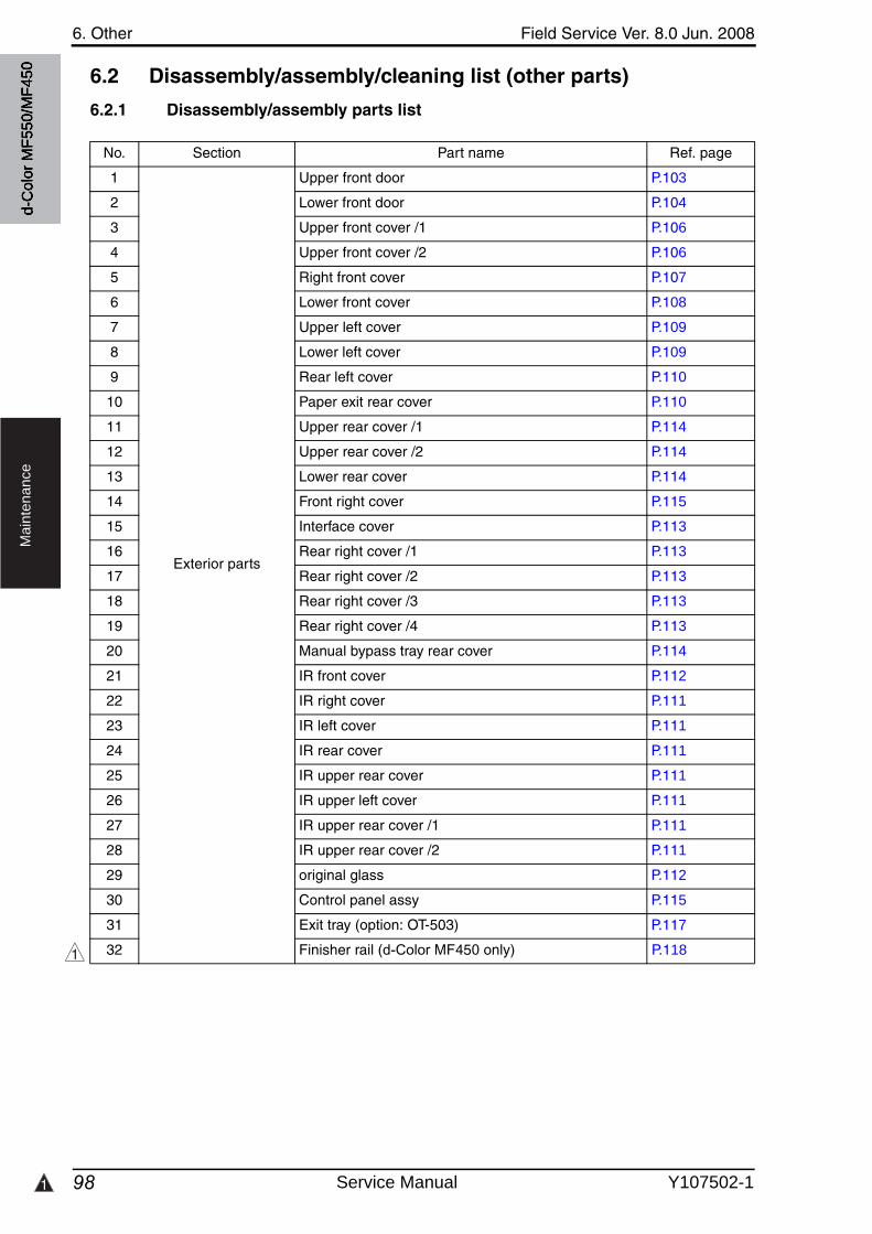
1
6. Other Field Service Ver. 8.0 Jun. 2008
98
Ma
inte
na
nce
6.2 Disassembly/assembly/cleaning list (other parts)
6.2.1 Disassembly/assembly parts list
No. Section Part name Ref. page
1
Exterior parts
Upper front door P.103
2 Lower front door P.104
3 Upper front cover /1 P.106
4 Upper front cover /2 P.106
5 Right front cover P.107
6 Lower front cover P.108
7 Upper left cover P.109
8 Lower left cover P.109
9 Rear left cover P.110
10 Paper exit rear cover P.110
11 Upper rear cover /1 P.114
12 Upper rear cover /2 P.114
13 Lower rear cover P.114
14 Front right cover P.115
15 Interface cover P.113
16 Rear right cover /1 P.113
17 Rear right cover /2 P.113
18 Rear right cover /3 P.113
19 Rear right cover /4 P.113
20 Manual bypass tray rear cover P.114
21 IR front cover P.112
22 IR right cover P.111
23 IR left cover P.111
24 IR rear cover P.111
25 IR upper rear cover P.111
26 IR upper left cover P.111
27 IR upper rear cover /1 P.111
28 IR upper rear cover /2 P.111
29 original glass P.112
30 Control panel assy P.115
31 Exit tray (option: OT-503) P.117
32 Finisher rail (d-Color MF450 only) P.1181
d-C
olor
MF5
50/M
F450
Service Manual Y107502-1
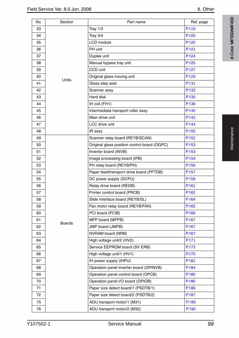
Field Service Ver. 8.0 Jun. 2008 6. Other
99
Ma
inte
na
nce
33
Units
Tray 1/2 P.119
34 Tray 3/4 P.120
35 LCD module P.120
36 PH unit P.121
37 Duplex unit P.124
38 Manual bypass tray unit P.125
39 CCD unit P.127
40 Original glass moving unit P.129
41 Glass step seat P.131
42 Scanner assy P.133
43 Hard disk P.135
44 IH coil (FH1) P.136
45 Intermediate transport roller assy P.140
46 Main drive unit P.142
47 LCC drive unit P.144
48 IR assy P.150
49
Boards
Scanner relay board (REYB/SCAN) P.152
50 Original glass position control board (OGPC) P.153
51 Inverter board (INVB) P.153
52 Image processing board (IPB) P.154
53 PH relay board (REYB/PH) P.156
54 Paper feed/transport drive board (PFTDB) P.157
55 DC power supply (DCPU) P.158
56 Relay drive board (REDB) P.161
57 Printer control board (PRCB) P.162
58 Slide Interface board (REYB/SL) P.164
59 Fan motor relay board (REYB/FAN) P.165
60 PCI board (PCIB) P.166
61 MFP board (MFPB) P.167
62 JMP board (JMPB) P.167
63 NVRAM board (NRB) P.167
64 High voltage unit/2 (HV2) P.171
65 Service EEPROM board (SV ERB) P.173
66 High voltage unit/1 (HV1) P.175
67 IH power supply (IHPU) P.181
68 Operation panel inverter board (OPINVB) P.184
69 Operation panel control board (OPCB) P.185
70 Operation panel I/O board (OPIOB) P.186
71 Paper size detect board/1 (PSDTB/1) P.186
72 Paper size detect board/2 (PSDTB/2) P.187
No. Section Part name Ref. page
d-C
olor
MF5
50/M
F450
75 ADU transport motor/1 (M31) P.189
76 ADU transport motor/2 (M32) P.190
Y107502-1 Service Manual
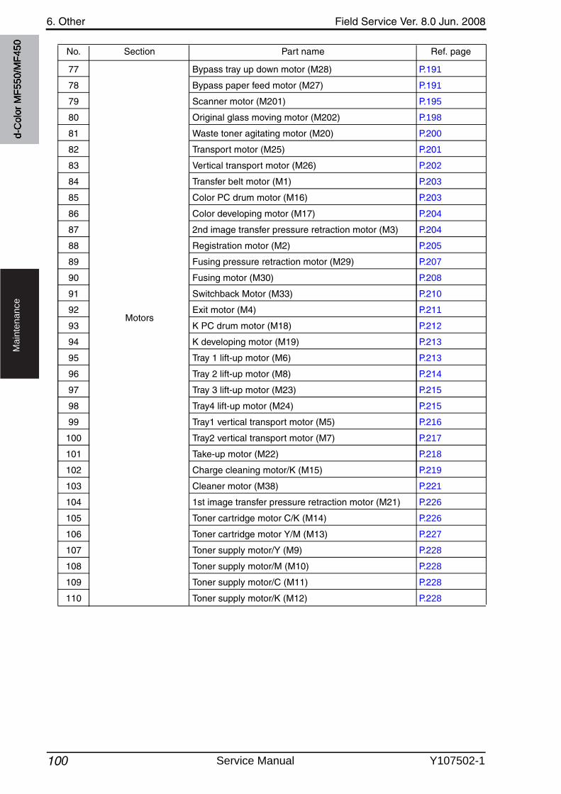
6. Other Field Service Ver. 8.0 Jun. 2008
100
Ma
inte
na
nce
No. Section Part name Ref. page
d-C
olor
MF5
50/M
F450
Motors
77 Bypass tray up down motor (M28) P.191
78 Bypass paper feed motor (M27) P.191
79 Scanner motor (M201) P.195
80 Original glass moving motor (M202) P.198
81 Waste toner agitating motor (M20) P.200
82 Transport motor (M25) P.201
83 Vertical transport motor (M26) P.202
84 Transfer belt motor (M1) P.203
85 Color PC drum motor (M16) P.203
86 Color developing motor (M17) P.204
87 2nd image transfer pressure retraction motor (M3) P.204
88 Registration motor (M2) P.205
89 Fusing pressure retraction motor (M29) P.207
90 Fusing motor (M30) P.208
91 Switchback Motor (M33) P.210
92 Exit motor (M4) P.211
93 K PC drum motor (M18) P.212
94 K developing motor (M19) P.213
95 Tray 1 lift-up motor (M6) P.213
96 Tray 2 lift-up motor (M8) P.214
97 Tray 3 lift-up motor (M23) P.215
98 Tray4 lift-up motor (M24) P.215
99 Tray1 vertical transport motor (M5) P.216
100 Tray2 vertical transport motor (M7) P.217
101 Take-up motor (M22) P.218
102 Charge cleaning motor/K (M15) P.219
103 Cleaner motor (M38) P.221
104 1st image transfer pressure retraction motor (M21) P.226
105 Toner cartridge motor C/K (M14) P.226
106 Toner cartridge motor Y/M (M13) P.227
107 Toner supply motor/Y (M9) P.228
108 Toner supply motor/M (M10) P.228
109 Toner supply motor/C (M11) P.228
110 Toner supply motor/K (M12) P.228
Service Manual Y107502-1
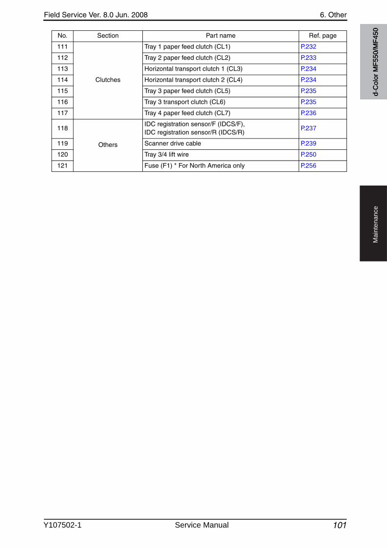
Field Service Ver. 8.0 Jun. 2008 6. Other
101
Ma
inte
na
nce
111
Clutches
Tray 1 paper feed clutch (CL1) P.232
112 Tray 2 paper feed clutch (CL2) P.233
113 Horizontal transport clutch 1 (CL3) P.234
114 Horizontal transport clutch 2 (CL4) P.234
115 Tray 3 paper feed clutch (CL5) P.235
116 Tray 3 transport clutch (CL6) P.235
117 Tray 4 paper feed clutch (CL7) P.236
118
Others
IDC registration sensor/F (IDCS/F), IDC registration sensor/R (IDCS/R)
P.237
119 Scanner drive cable P.239
120 Tray 3/4 lift wire P.250
121 Fuse (F1) * For North America only P.256
No. Section Part name Ref. page
d-C
olor
MF5
50/M
F450
Y107502-1 Service Manual
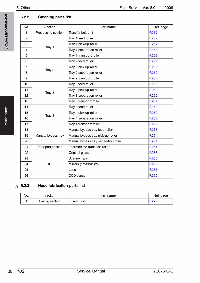
6. Other Field Service Ver. 8.0 Jun. 2008
1024
Ma
inte
na
nce
6.2.2 Cleaning parts list
6.2.3 Need lubrication parts list
No. Section Part name Ref. page
1 Processing section Transfer belt unit P.257
2
Tray 1
Tray 1 feed roller P.257
3 Tray 1 pick-up roller P.257
4 Tray 1 separation roller P.258
5 Tray 1 transport roller P.258
6
Tray 2
Tray 2 feed roller P.259
7 Tray 2 pick-up roller P.259
8 Tray 2 separation roller P.259
9 Tray 2 transport roller P.260
10
Tray 3
Tray 3 feed roller P.260
11 Tray 3 pick-up roller P.260
12 Tray 3 separation roller P.261
13 Tray 3 transport roller P.261
14
Tray 4
Tray 4 feed roller P.262
15 Tray 4 pick-up roller P.262
16 Tray 4 separation roller P.263
17 Tray 4 transport roller P.263
18
Manual bypass tray
Manual bypass tray feed roller P.263
19 Manual bypass tray pick-up roller P.264
20 Manual bypass tray separation roller P.264
21 Transport section Intermediate transport roller P.264
22
IR
Original glass P.265
23 Scanner rails P.265
24 Mirrors (1st/2nd/3rd) P.266
25 Lens P.266
26 CCD sensor P.267
4
No. Section Part name Ref. page
1 Fusing section Fusing unit P.270
d-C
olor
MF5
50/M
F450
Service Manual Y107502-1
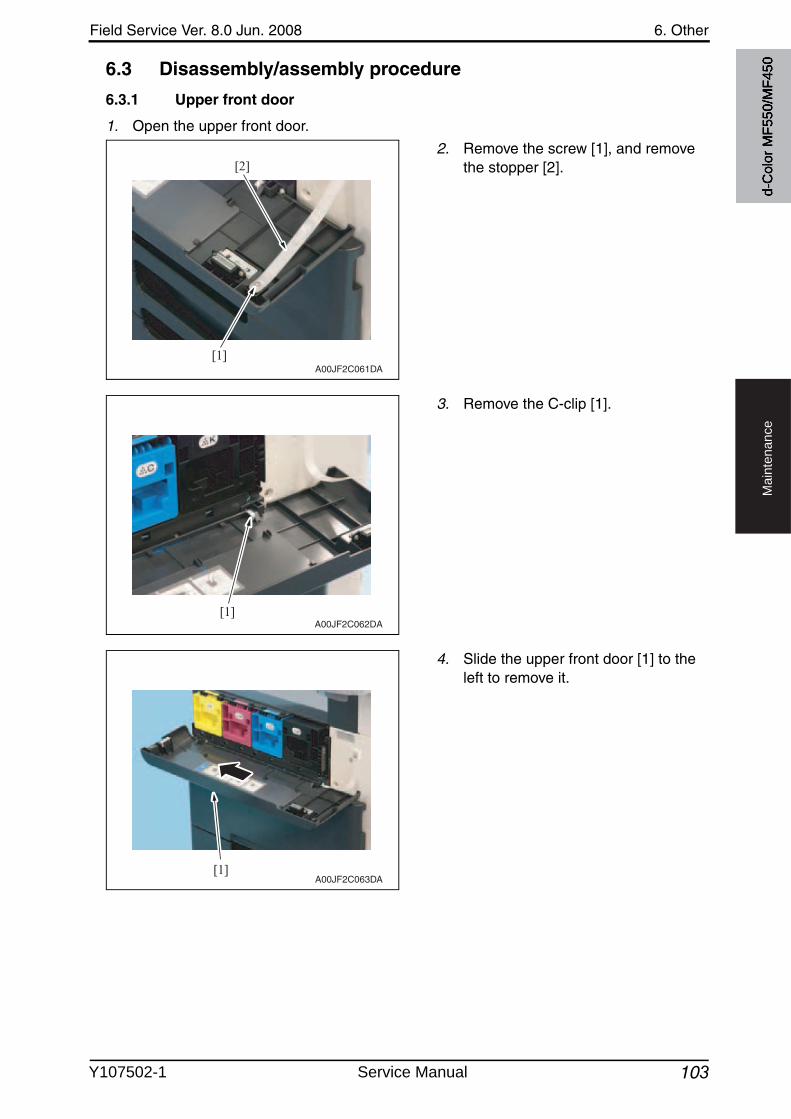
Field Service Ver. 8.0 Jun. 2008 6. Other
103
Ma
inte
na
nce
6.3 Disassembly/assembly procedure
6.3.1 Upper front door
1. Open the upper front door.
2. Remove the screw [1], and removethe stopper [2].
3. Remove the C-clip [1].
4. Slide the upper front door [1] to the left to remove it.
[1]
[2]
A00JF2C061DA
[1]A00JF2C062DA
[1]A00JF2C063DA
d-C
olor
MF5
50/M
F450
Y107502-1 Service Manual
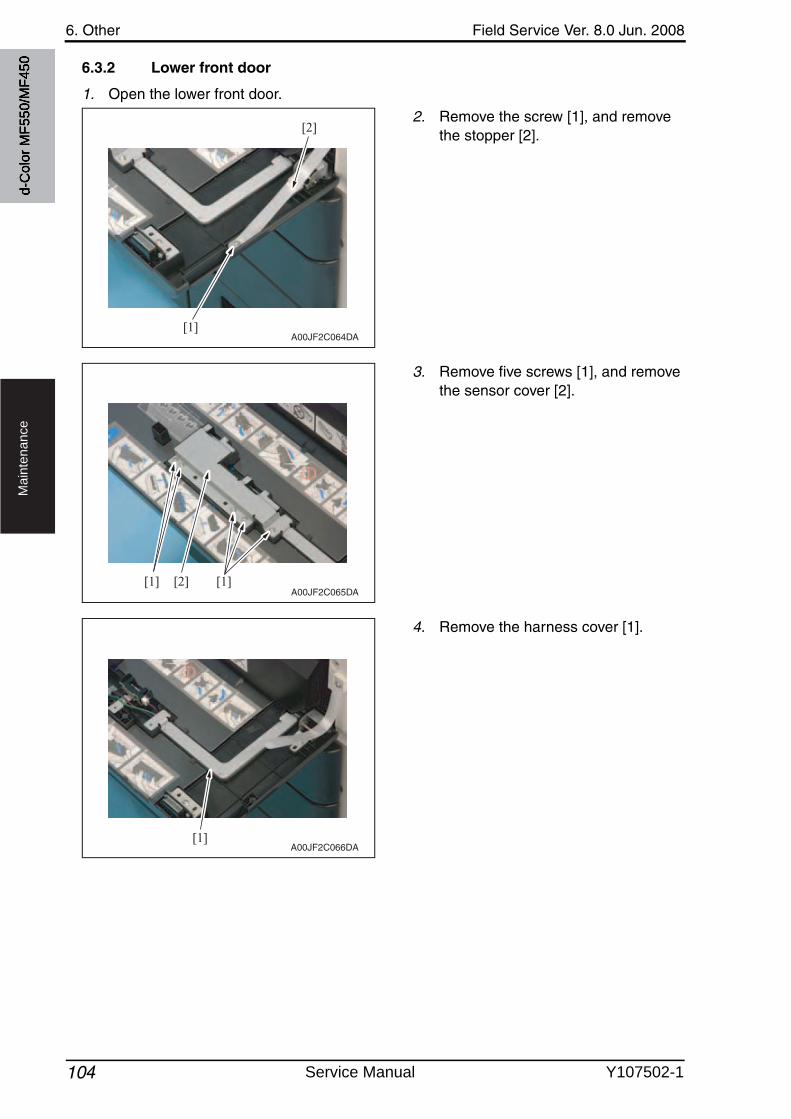
6. Other Field Service Ver. 8.0 Jun. 2008
104
Ma
inte
na
nce
6.3.2 Lower front door
1. Open the lower front door.
2. Remove the screw [1], and removethe stopper [2].
3. Remove five screws [1], and removethe sensor cover [2].
4. Remove the harness cover [1].
[1]
[2]
A00JF2C064DA
[1] [1][2]A00JF2C065DA
[1]A00JF2C066DA
d-C
olor
MF5
50/M
F450
Service Manual Y107502-1
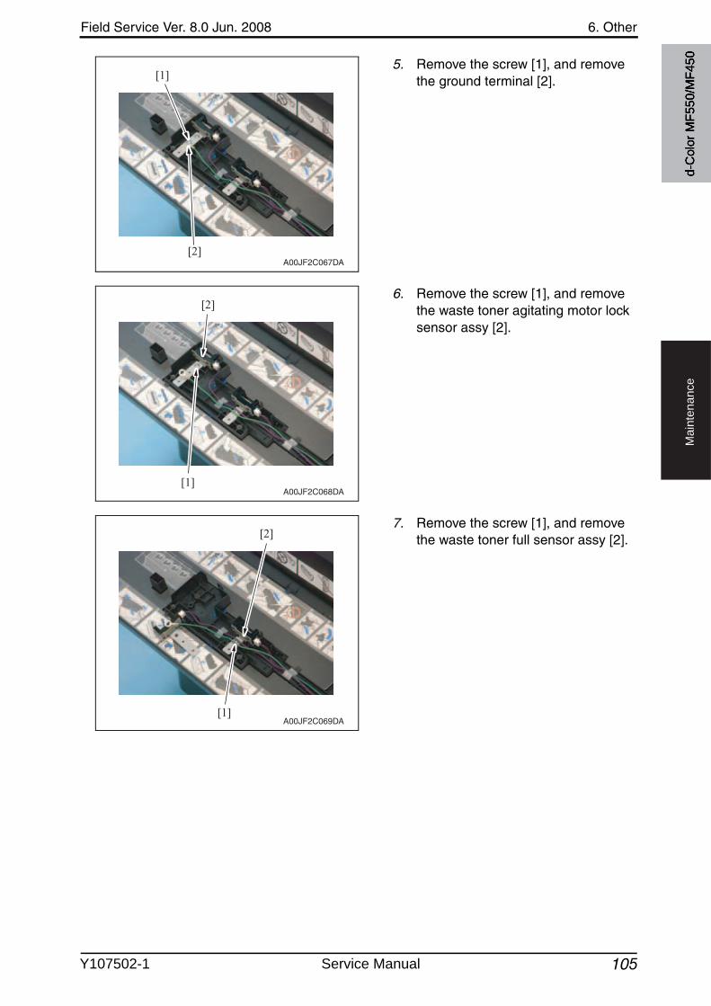
Field Service Ver. 8.0 Jun. 2008 6. Other
105
Ma
inte
na
nce
5. Remove the screw [1], and removethe ground terminal [2].
6. Remove the screw [1], and removethe waste toner agitating motor lock sensor assy [2].
7. Remove the screw [1], and removethe waste toner full sensor assy [2].
[1]
[2]A00JF2C067DA
[1]
[2]
A00JF2C068DA
[1]
[2]
A00JF2C069DA
d-C
olor
MF5
50/M
F450
Y107502-1 Service Manual
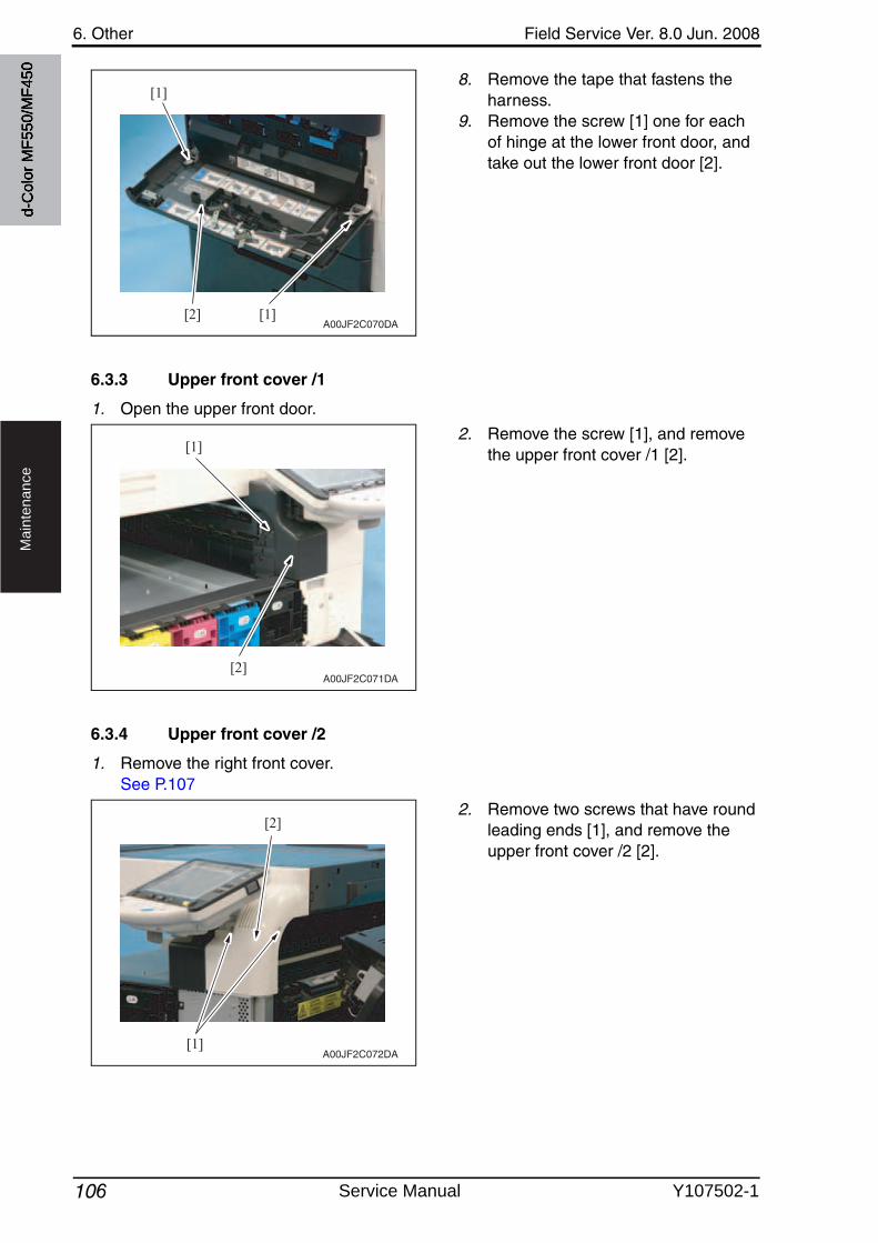
6. Other Field Service Ver. 8.0 Jun. 2008
106
Ma
inte
na
nce
8. Remove the tape that fastens the harness.
9. Remove the screw [1] one for each of hinge at the lower front door, and take out the lower front door [2].
6.3.3 Upper front cover /1
1. Open the upper front door.
2. Remove the screw [1], and removethe upper front cover /1 [2].
6.3.4 Upper front cover /2
1. Remove the right front cover.See P.107
2. Remove two screws that have round leading ends [1], and remove the upper front cover /2 [2].
[1]
[1][2]A00JF2C070DA
[1]
[2]A00JF2C071DA
[1]
[2]
A00JF2C072DA
d-C
olor
MF5
50/M
F450
Service Manual Y107502-1
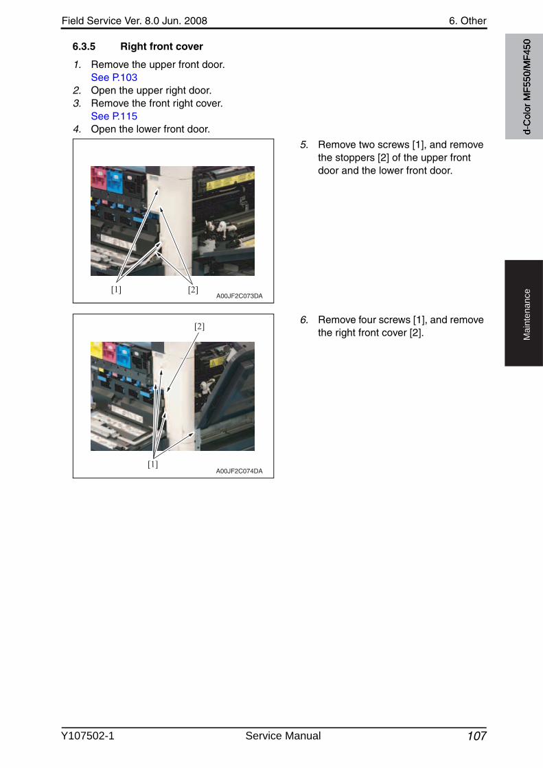
Field Service Ver. 8.0 Jun. 2008 6. Other
107
Ma
inte
na
nce
6.3.5 Right front cover
1. Remove the upper front door.See P.103
2. Open the upper right door.3. Remove the front right cover.
See P.1154. Open the lower front door.
5. Remove two screws [1], and removethe stoppers [2] of the upper front door and the lower front door.
6. Remove four screws [1], and removethe right front cover [2].
[1] [2]A00JF2C073DA
[1]
[2]
A00JF2C074DA
d-C
olor
MF5
50/M
F450
Y107502-1 Service Manual
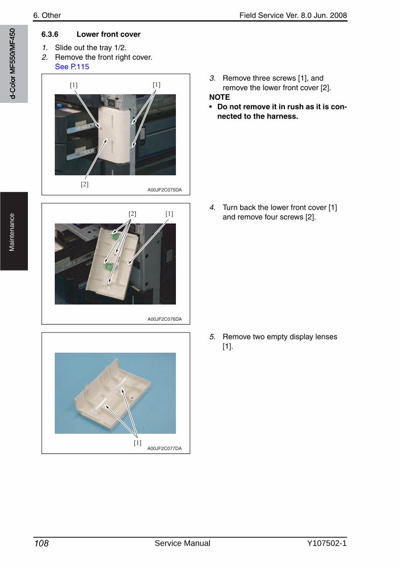
6. Other Field Service Ver. 8.0 Jun. 2008
108
Ma
inte
na
nce
6.3.6 Lower front cover
1. Slide out the tray 1/2.2. Remove the front right cover.
See P.115
3. Remove three screws [1], and remove the lower front cover [2].
NOTE• Do not remove it in rush as it is con-
nected to the harness.
4. Turn back the lower front cover [1] and remove four screws [2].
5. Remove two empty display lenses [1].
[1] [1]
[2]A00JF2C075DA
[2] [1]
A00JF2C076DA
[1]A00JF2C077DA
d-C
olor
MF5
50/M
F450
Service Manual Y107502-1
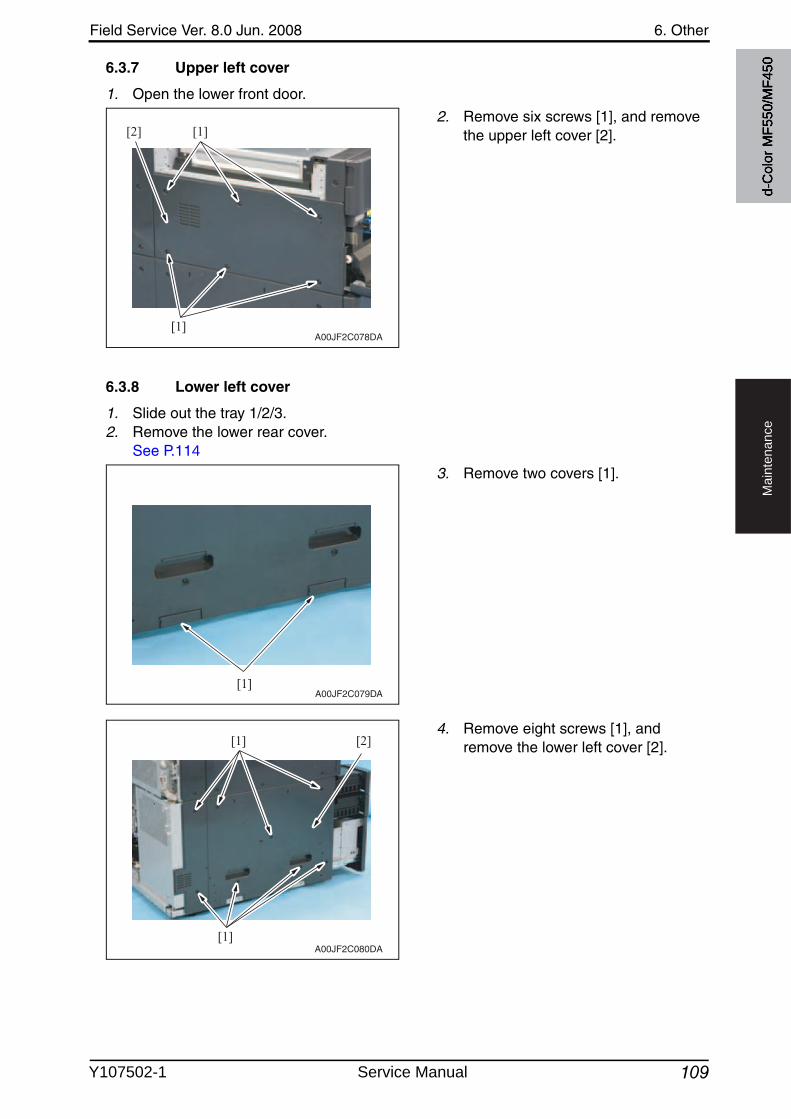
Field Service Ver. 8.0 Jun. 2008 6. Other
109
Ma
inte
na
nce
6.3.7 Upper left cover
1. Open the lower front door.
2. Remove six screws [1], and removethe upper left cover [2].
6.3.8 Lower left cover
1. Slide out the tray 1/2/3.2. Remove the lower rear cover.
See P.114
3. Remove two covers [1].
4. Remove eight screws [1], and remove the lower left cover [2].
[1]
[1][2]
A00JF2C078DA
[1]A00JF2C079DA
[1] [2]
[1]A00JF2C080DA
d-C
olor
MF5
50/M
F450
Y107502-1 Service Manual
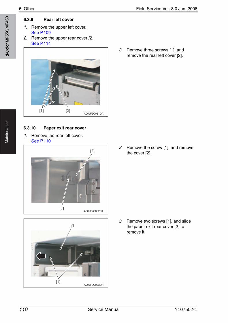
6. Other Field Service Ver. 8.0 Jun. 2008
110
Ma
inte
na
nce
6.3.9 Rear left cover
1. Remove the upper left cover.See P.109
2. Remove the upper rear cover /2.See P.114
3. Remove three screws [1], and remove the rear left cover [2].
6.3.10 Paper exit rear cover
1. Remove the rear left cover.See P.110
2. Remove the screw [1], and removethe cover [2].
3. Remove two screws [1], and slide the paper exit rear cover [2] to remove it.
[1] [2]A00JF2C081DA
[1]
[2]
A00JF2C082DA
[1]
[2]
A00JF2C083DA
d-C
olor
MF5
50/M
F450
Service Manual Y107502-1
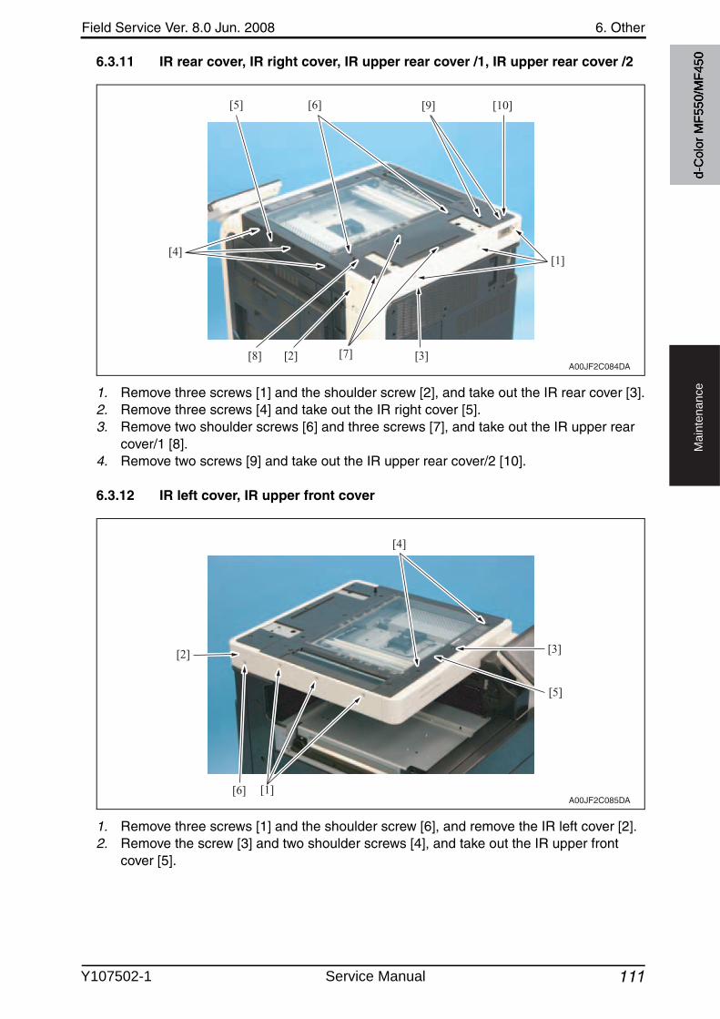
Field Service Ver. 8.0 Jun. 2008 6. Other
111
Ma
inte
na
nce
6.3.11 IR rear cover, IR right cover, IR upper rear cover /1, IR upper rear cover /2
1. Remove three screws [1] and the shoulder screw [2], and take out the IR rear cover [3].2. Remove three screws [4] and take out the IR right cover [5].3. Remove two shoulder screws [6] and three screws [7], and take out the IR upper rear
cover/1 [8].4. Remove two screws [9] and take out the IR upper rear cover/2 [10].
6.3.12 IR left cover, IR upper front cover
1. Remove three screws [1] and the shoulder screw [6], and remove the IR left cover [2].2. Remove the screw [3] and two shoulder screws [4], and take out the IR upper front
cover [5].
[4][1]
[7] [3][8]
[5] [6] [10][9]
[2]A00JF2C084DA
[4]
[1][6]
[2] [3]
[5]
A00JF2C085DA
d-C
olor
MF5
50/M
F450
Y107502-1 Service Manual
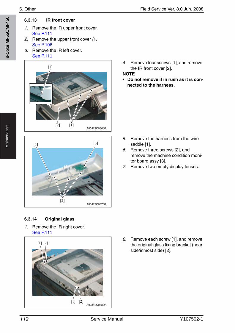
6. Other Field Service Ver. 8.0 Jun. 2008
112
Ma
inte
na
nce
6.3.13 IR front cover
1. Remove the IR upper front cover.See P.111
2. Remove the upper front cover /1.See P.106
3. Remove the IR left cover.See P.111
4. Remove four screws [1], and removethe IR front cover [2].
NOTE• Do not remove it in rush as it is con-
nected to the harness.
5. Remove the harness from the wire saddle [1].
6. Remove three screws [2], and remove the machine condition moni-tor board assy [3].
7. Remove two empty display lenses.
6.3.14 Original glass
1. Remove the IR right cover.See P.111
2. Remove each screw [1], and removethe original glass fixing bracket (near side/inmost side) [2].
[1]
[1]
[2]A00JF2C086DA
[2]
[3][1]
A00JF2C087DA
[1]
[1]
[2]
[2]
A00JF2C088DA
d-C
olor
MF5
50/M
F450
Service Manual Y107502-1
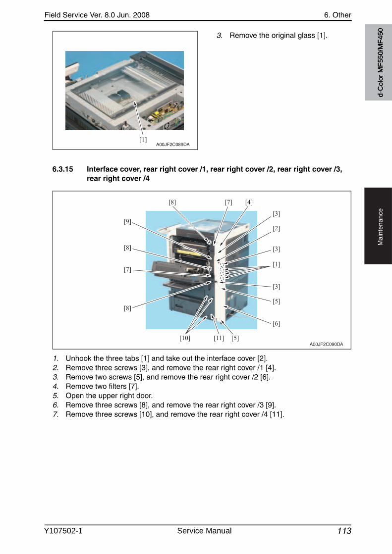
Field Service Ver. 8.0 Jun. 2008 6. Other
113
Ma
inte
na
nce
3. Remove the original glass [1].
6.3.15 Interface cover, rear right cover /1, rear right cover /2, rear right cover /3, rear right cover /4
1. Unhook the three tabs [1] and take out the interface cover [2].2. Remove three screws [3], and remove the rear right cover /1 [4].3. Remove two screws [5], and remove the rear right cover /2 [6].4. Remove two filters [7].5. Open the upper right door.6. Remove three screws [8], and remove the rear right cover /3 [9].7. Remove three screws [10], and remove the rear right cover /4 [11].
[1]A00JF2C089DA
A00JF2C090DA
[1]
[2]
[3]
[3]
[5]
[6]
[5][10] [11]
[3]
[4][7][8]
[7]
[8]
[9]
[8]
d-C
olor
MF5
50/M
F450
Y107502-1 Service Manual
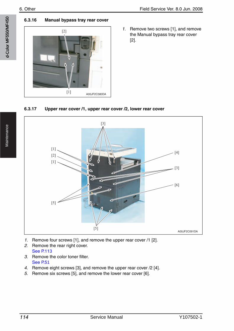
6. Other Field Service Ver. 8.0 Jun. 2008
114
Ma
inte
na
nce
6.3.16 Manual bypass tray rear cover
1. Remove two screws [1], and removethe Manual bypass tray rear cover [2].
6.3.17 Upper rear cover /1, upper rear cover /2, lower rear cover
1. Remove four screws [1], and remove the upper rear cover /1 [2].2. Remove the rear right cover.
See P.1133. Remove the color toner filter.
See P.514. Remove eight screws [3], and remove the upper rear cover /2 [4].5. Remove six screws [5], and remove the lower rear cover [6].
[1]
[2]
A00JF2C580DA
[1]
[3]
[4]
[3]
[6]
[1]
[2]
[5]
[5]A00JF2C091DA
d-C
olor
MF5
50/M
F450
Service Manual Y107502-1
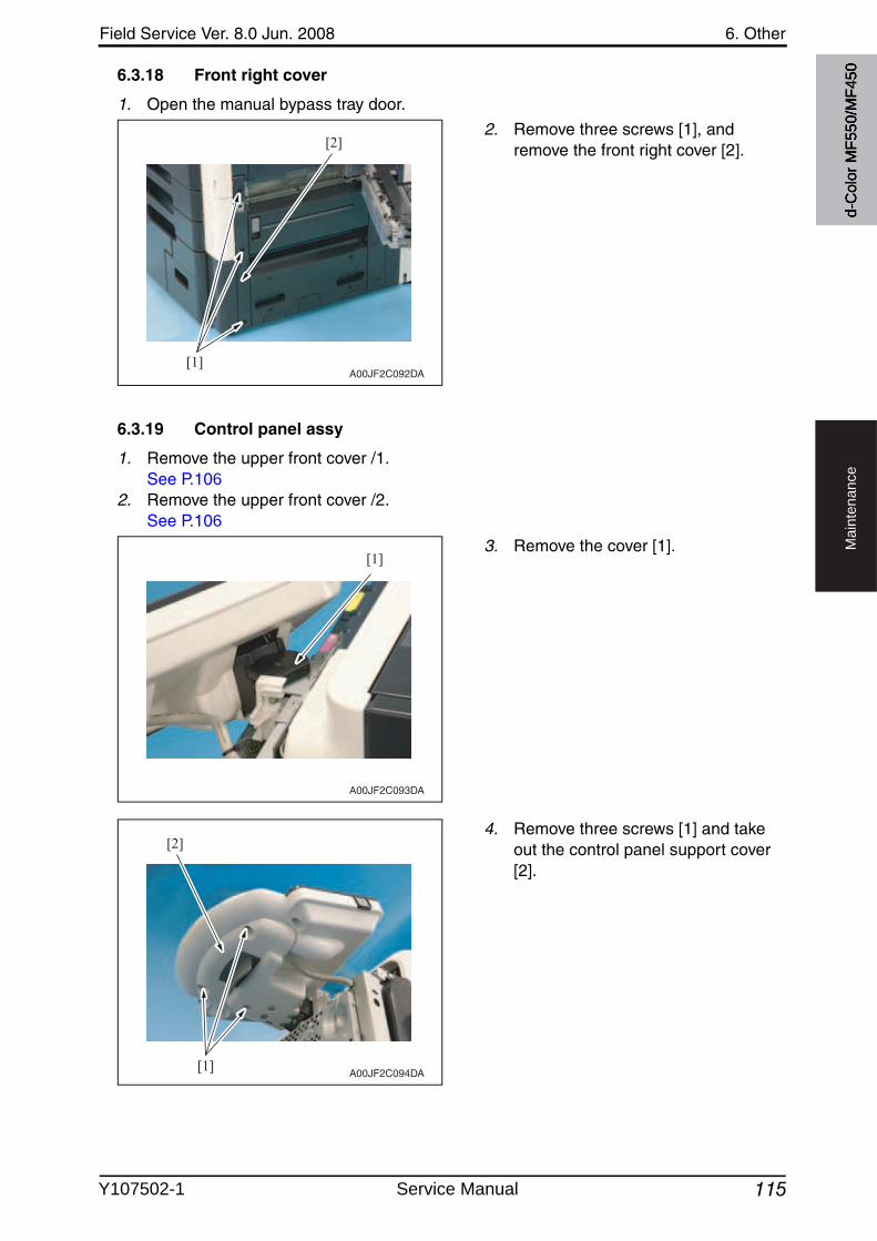
Field Service Ver. 8.0 Jun. 2008 6. Other
115
Ma
inte
na
nce
6.3.18 Front right cover
1. Open the manual bypass tray door.
2. Remove three screws [1], and remove the front right cover [2].
6.3.19 Control panel assy
1. Remove the upper front cover /1.See P.106
2. Remove the upper front cover /2.See P.106
3. Remove the cover [1].
4. Remove three screws [1] and take out the control panel support cover[2].
[1]
[2]
A00JF2C092DA
[1]
A00JF2C093DA
[1]
[2]
A00JF2C094DA
d-C
olor
MF5
50/M
F450
Y107502-1 Service Manual
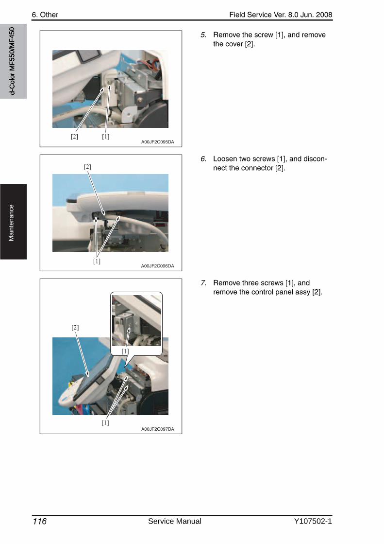
6. Other Field Service Ver. 8.0 Jun. 2008
116
Ma
inte
na
nce
5. Remove the screw [1], and removethe cover [2].
6. Loosen two screws [1], and discon-nect the connector [2].
7. Remove three screws [1], and remove the control panel assy [2].
[1][2]A00JF2C095DA
[1]
[2]
A00JF2C096DA
A00JF2C097DA
[1]
[1]
[2]
d-C
olor
MF5
50/M
F450
Service Manual Y107502-1
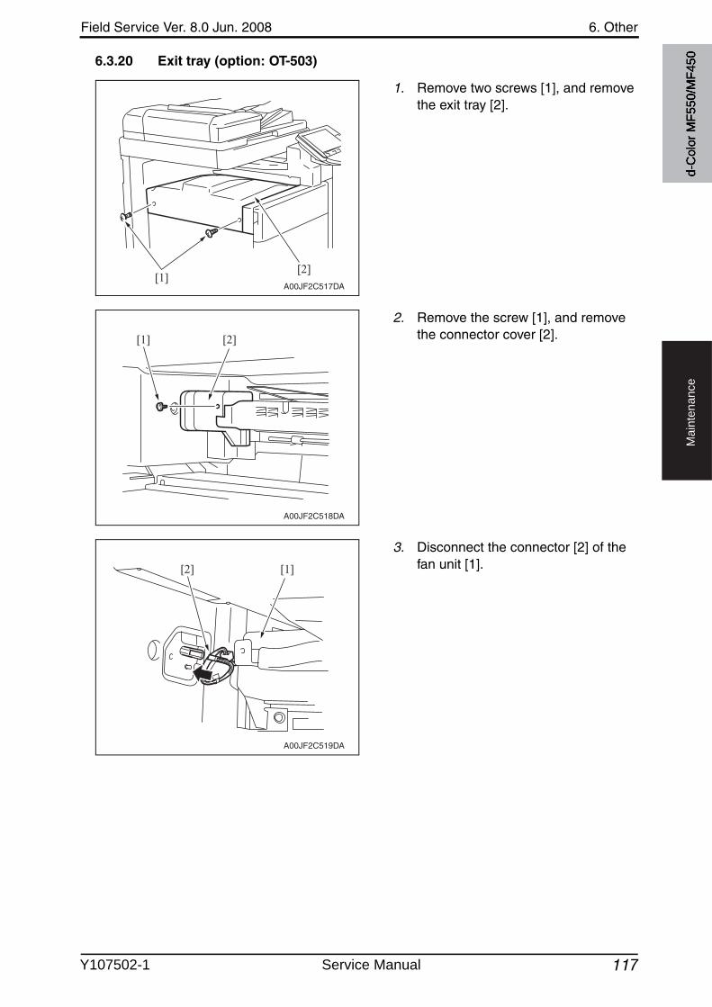
Field Service Ver. 8.0 Jun. 2008 6. Other
117
Ma
inte
na
nce
6.3.20 Exit tray (option: OT-503)
1. Remove two screws [1], and removethe exit tray [2].
2. Remove the screw [1], and removethe connector cover [2].
3. Disconnect the connector [2] of the fan unit [1].
A00JF2C517DA[1]
[2]
A00JF2C518DA
[2][1]
A00JF2C519DA
[1][2]
d-C
olor
MF5
50/M
F450
Y107502-1 Service Manual
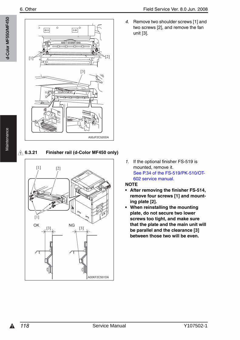
1
6. Other Field Service Ver. 8.0 Jun. 2008
118
Ma
inte
na
nce
4. Remove two shoulder screws [1] and two screws [2], and remove the fan unit [3].
6.3.21 Finisher rail (d-Color MF450 only)
1. If the optional finisher FS-519 is mounted, remove it.See P.34 of the FS-519/PK-510/OT-602 service manual.
NOTE• After removing the finisher FS-514,
remove four screws [1] and mount-ing plate [2].
• When reinstalling the mounting plate, do not secure two lower screws too tight, and make sure that the plate and the main unit will be parallel and the clearance [3] between those two will be even.
A00JF2C520DA
[3]
[1] [2]
1
A00KF2C501DA
[1]
[2][1]
[3] [3]
d-C
olor
MF5
50/M
F450
Service Manual Y107502-1
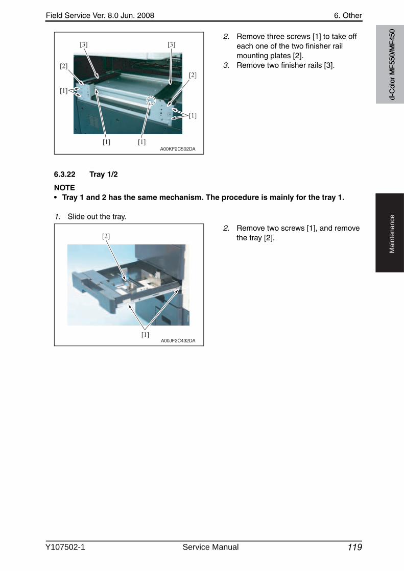
Field Service Ver. 8.0 Jun. 2008 6. Other
119
Ma
inte
na
nce
2. Remove three screws [1] to take off each one of the two finisher rail mounting plates [2].
3. Remove two finisher rails [3].
6.3.22 Tray 1/2
NOTE• Tray 1 and 2 has the same mechanism. The procedure is mainly for the tray 1.
1. Slide out the tray.
2. Remove two screws [1], and removethe tray [2].
A00KF2C502DA[1] [1]
[3]
[2][2]
[1]
[1]
[3]
A00JF2C432DA[1]
[2]
d-C
olor
MF5
50/M
F450
Y107502-1 Service Manual
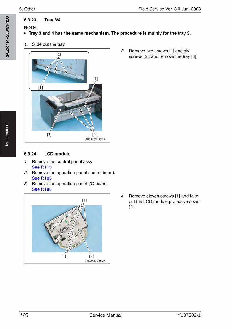
6. Other Field Service Ver. 8.0 Jun. 2008
120
Ma
inte
na
nce
6.3.23 Tray 3/4
NOTE• Tray 3 and 4 has the same mechanism. The procedure is mainly for the tray 3.
1. Slide out the tray.
2. Remove two screws [1] and six screws [2], and remove the tray [3].
6.3.24 LCD module
1. Remove the control panel assy.See P.115
2. Remove the operation panel control board.See P.185
3. Remove the operation panel I/O board.See P.186
4. Remove eleven screws [1] and take out the LCD module protective cover[2].
A00JF2C433DA
[2]
[1]
[3]
[2]
[1]
[1]
[1]
[2]A00JF2C098DA
d-C
olor
MF5
50/M
F450
Service Manual Y107502-1
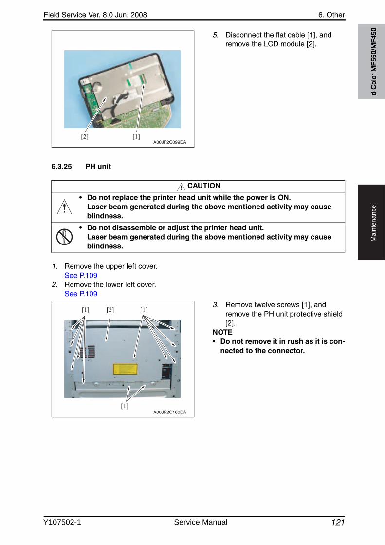
Field Service Ver. 8.0 Jun. 2008 6. Other
121
Ma
inte
na
nce
5. Disconnect the flat cable [1], and remove the LCD module [2].
6.3.25 PH unit
1. Remove the upper left cover.See P.109
2. Remove the lower left cover.See P.109
3. Remove twelve screws [1], and remove the PH unit protective shield [2].
NOTE• Do not remove it in rush as it is con-
nected to the connector.
[1][2]A00JF2C099DA
CAUTION
• Do not replace the printer head unit while the power is ON.Laser beam generated during the above mentioned activity may cause blindness.
• Do not disassemble or adjust the printer head unit.Laser beam generated during the above mentioned activity may cause blindness.
[1]
[1][1] [2]
A00JF2C160DA
d-C
olor
MF5
50/M
F450
Y107502-1 Service Manual
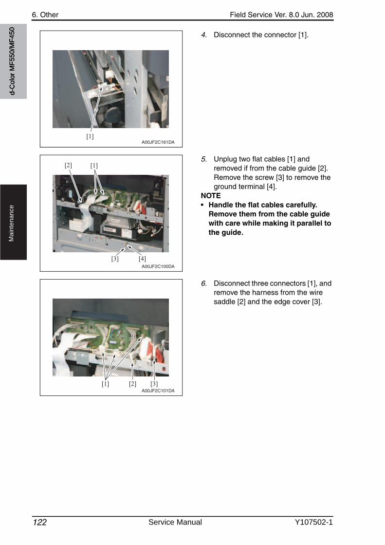
6. Other Field Service Ver. 8.0 Jun. 2008
122
Ma
inte
na
nce
4. Disconnect the connector [1].
5. Unplug two flat cables [1] and removed if from the cable guide [2]. Remove the screw [3] to remove the ground terminal [4].
NOTE• Handle the flat cables carefully.
Remove them from the cable guide with care while making it parallel to the guide.
6. Disconnect three connectors [1], and remove the harness from the wire saddle [2] and the edge cover [3].
[1]A00JF2C161DA
[4]
[1][2]
[3]A00JF2C100DA
[1] [2] [3]A00JF2C101DA
d-C
olor
MF5
50/M
F450
Service Manual Y107502-1
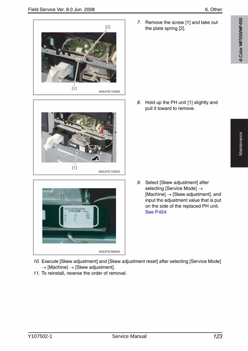
Field Service Ver. 8.0 Jun. 2008 6. Other
123
Ma
inte
na
nce
7. Remove the screw [1] and take outthe plate spring [2].
8. Hold up the PH unit [1] slightly and pull it toward to remove.
9. Select [Skew adjustment] after selecting [Service Mode] [Machine] [Skew adjustment], and input the adjustment value that is puton the side of the replaced PH unit.See P.454
10. Execute [Skew adjustment] and [Skew adjustment reset] after selecting [Service Mode] [Machine] [Skew adjustment].
11. To reinstall, reverse the order of removal.
[1]
[2]
A00JF2C102DA
[1]A00JF2C103DA
A00JF2C569DA
d-C
olor
MF5
50/M
F450
Y107502-1 Service Manual
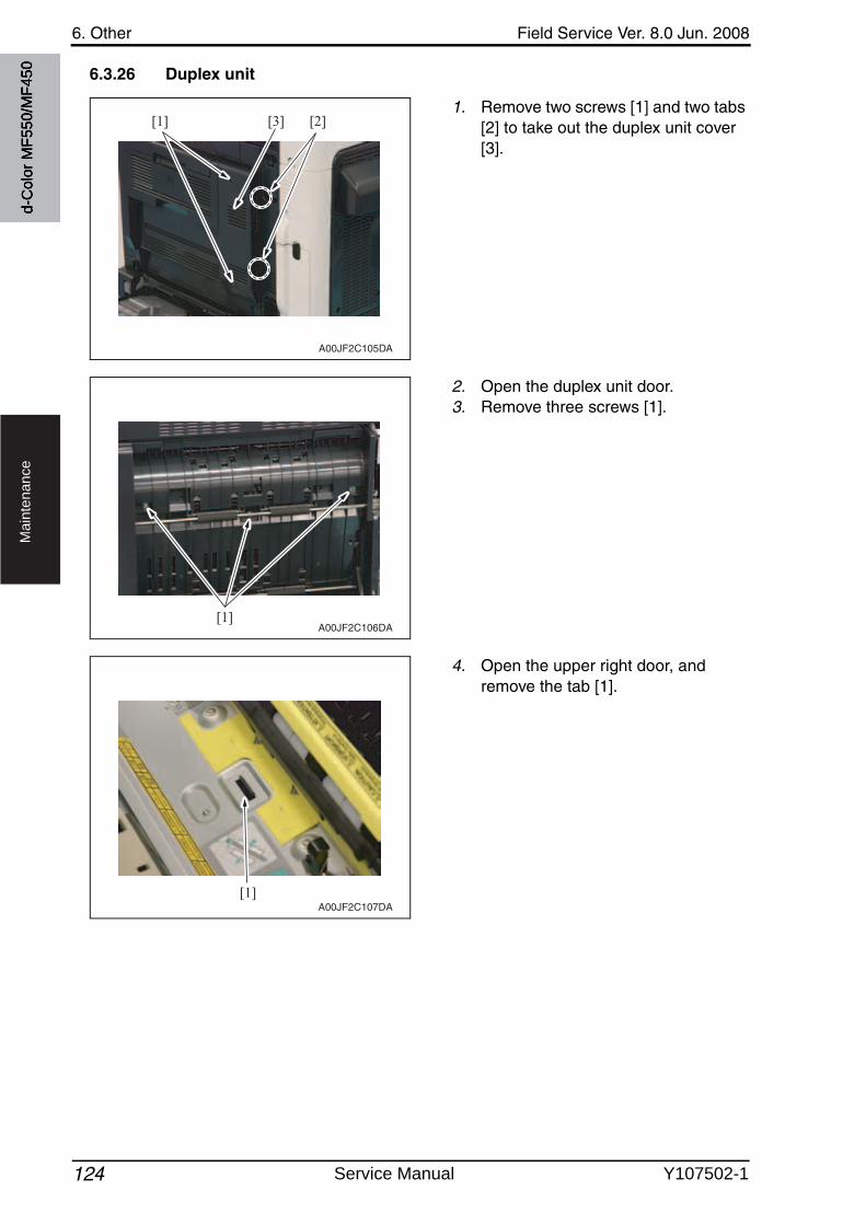
6. Other Field Service Ver. 8.0 Jun. 2008
124
Ma
inte
na
nce
6.3.26 Duplex unit
1. Remove two screws [1] and two tabs [2] to take out the duplex unit cover[3].
2. Open the duplex unit door.3. Remove three screws [1].
4. Open the upper right door, and remove the tab [1].
[1] [2][3]
A00JF2C105DA
[1]A00JF2C106DA
[1]A00JF2C107DA
d-C
olor
MF5
50/M
F450
Service Manual Y107502-1
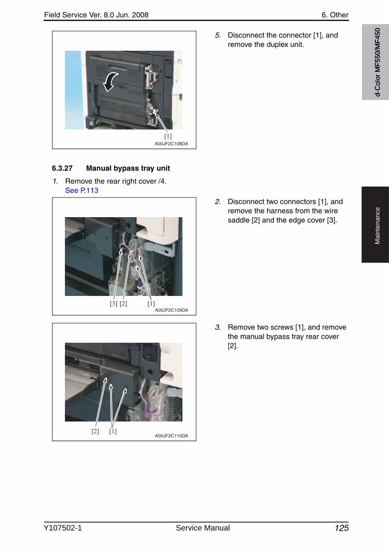
Field Service Ver. 8.0 Jun. 2008 6. Other
125
Ma
inte
na
nce
5. Disconnect the connector [1], and remove the duplex unit.
6.3.27 Manual bypass tray unit
1. Remove the rear right cover /4.See P.113
2. Disconnect two connectors [1], and remove the harness from the wire saddle [2] and the edge cover [3].
3. Remove two screws [1], and removethe manual bypass tray rear cover[2].
[1]A00JF2C108DA
[1][2][3]A00JF2C109DA
[1][2]A00JF2C110DA
d-C
olor
MF5
50/M
F450
Y107502-1 Service Manual
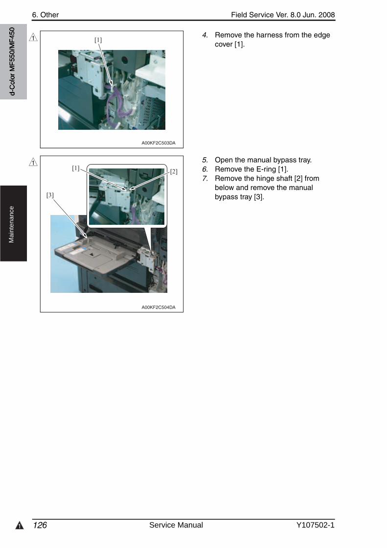
1
6. Other Field Service Ver. 8.0 Jun. 2008
126
Ma
inte
na
nce
4. Remove the harness from the edge cover [1].
5. Open the manual bypass tray.6. Remove the E-ring [1].7. Remove the hinge shaft [2] from
below and remove the manualbypass tray [3].
[1]
A00KF2C503DA
1
A00KF2C504DA
[1]
[3]
[2]1
d-C
olor
MF5
50/M
F450
Service Manual Y107502-1
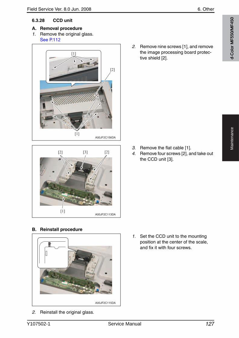
Field Service Ver. 8.0 Jun. 2008 6. Other
127
Ma
inte
na
nce
6.3.28 CCD unit
A. Removal procedure1. Remove the original glass.
See P.112
2. Remove nine screws [1], and removethe image processing board protec-tive shield [2].
3. Remove the flat cable [1].4. Remove four screws [2], and take out
the CCD unit [3].
B. Reinstall procedure
1. Set the CCD unit to the mountingposition at the center of the scale, and fix it with four screws.
2. Reinstall the original glass.
A00JF2C156DA
[1]
[2]
[1]
[1]
[2] [3] [2]
A00JF2C113DA
A00JF2C115DA
d-C
olor
MF5
50/M
F450
Y107502-1 Service Manual
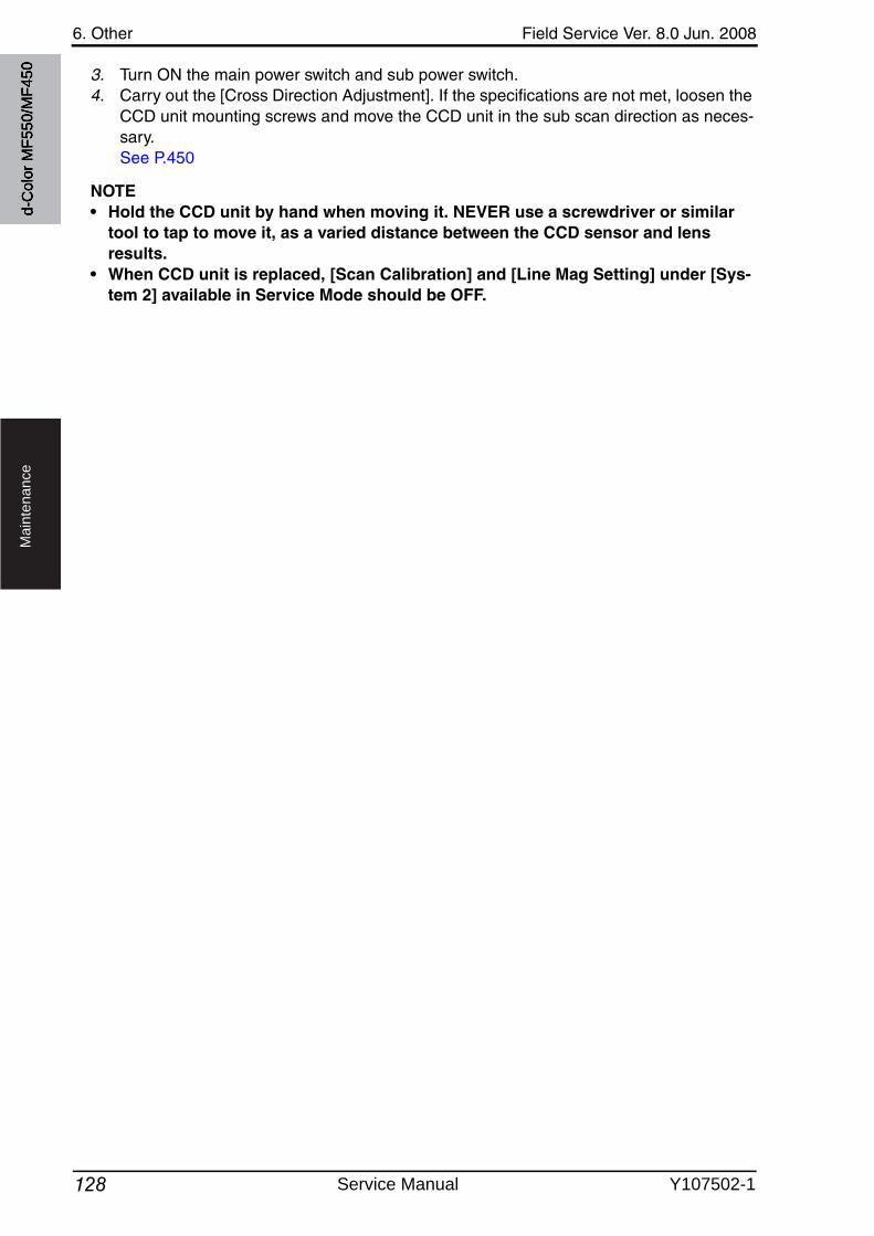
6. Other Field Service Ver. 8.0 Jun. 2008
128
Ma
inte
na
nce
3. Turn ON the main power switch and sub power switch.4. Carry out the [Cross Direction Adjustment]. If the specifications are not met, loosen the
CCD unit mounting screws and move the CCD unit in the sub scan direction as neces-sary.See P.450
NOTE• Hold the CCD unit by hand when moving it. NEVER use a screwdriver or similar
tool to tap to move it, as a varied distance between the CCD sensor and lens results.
• When CCD unit is replaced, [Scan Calibration] and [Line Mag Setting] under [Sys-tem 2] available in Service Mode should be OFF.
d-C
olor
MF5
50/M
F450
Service Manual Y107502-1
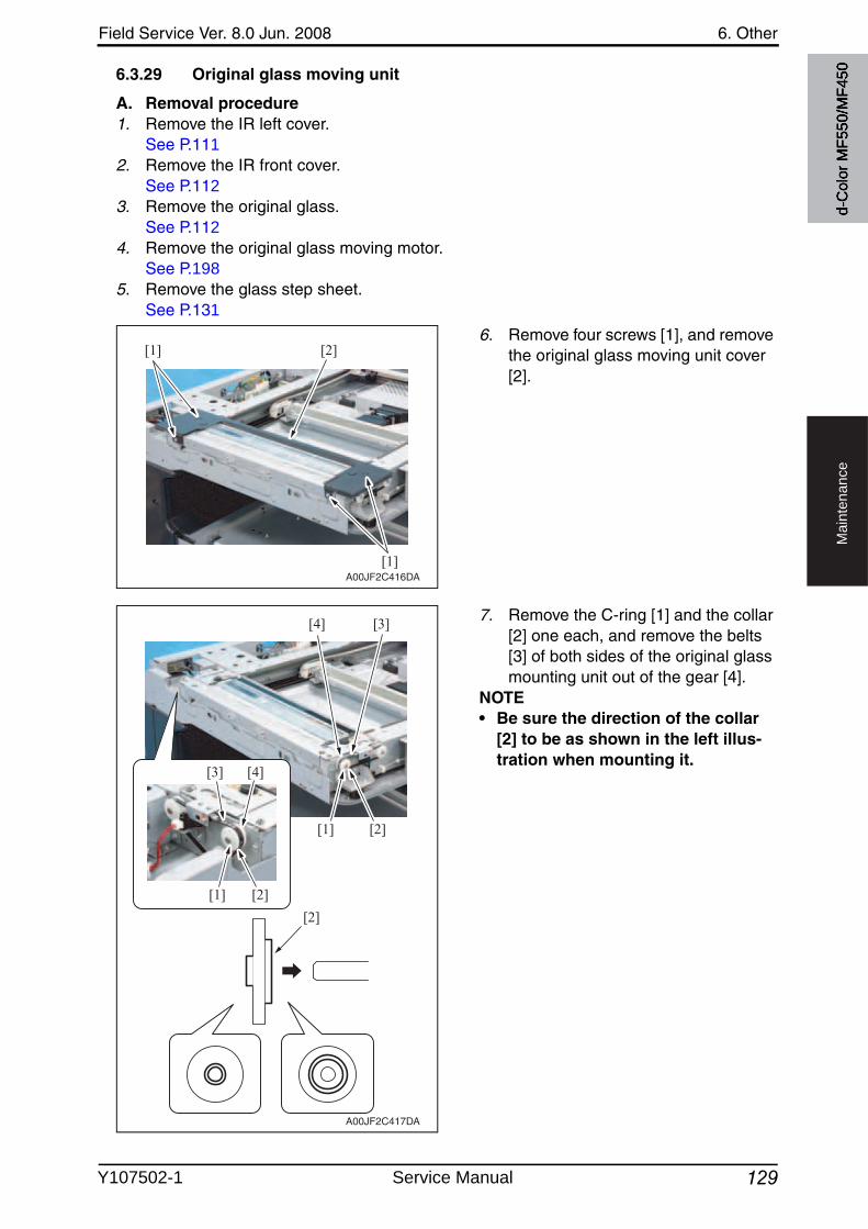
Field Service Ver. 8.0 Jun. 2008 6. Other
129
Ma
inte
na
nce
6.3.29 Original glass moving unit
A. Removal procedure1. Remove the IR left cover.
See P.1112. Remove the IR front cover.
See P.1123. Remove the original glass.
See P.1124. Remove the original glass moving motor.
See P.1985. Remove the glass step sheet.
See P.131
6. Remove four screws [1], and removethe original glass moving unit cover[2].
7. Remove the C-ring [1] and the collar [2] one each, and remove the belts [3] of both sides of the original glass mounting unit out of the gear [4].
NOTE• Be sure the direction of the collar
[2] to be as shown in the left illus-tration when mounting it.
[1]
[1]
[2]
A00JF2C416DA
[1] [2]
[1] [2]
[2]
[4] [3]
[3] [4]
A00JF2C417DA
d-C
olor
MF5
50/M
F450
Y107502-1 Service Manual
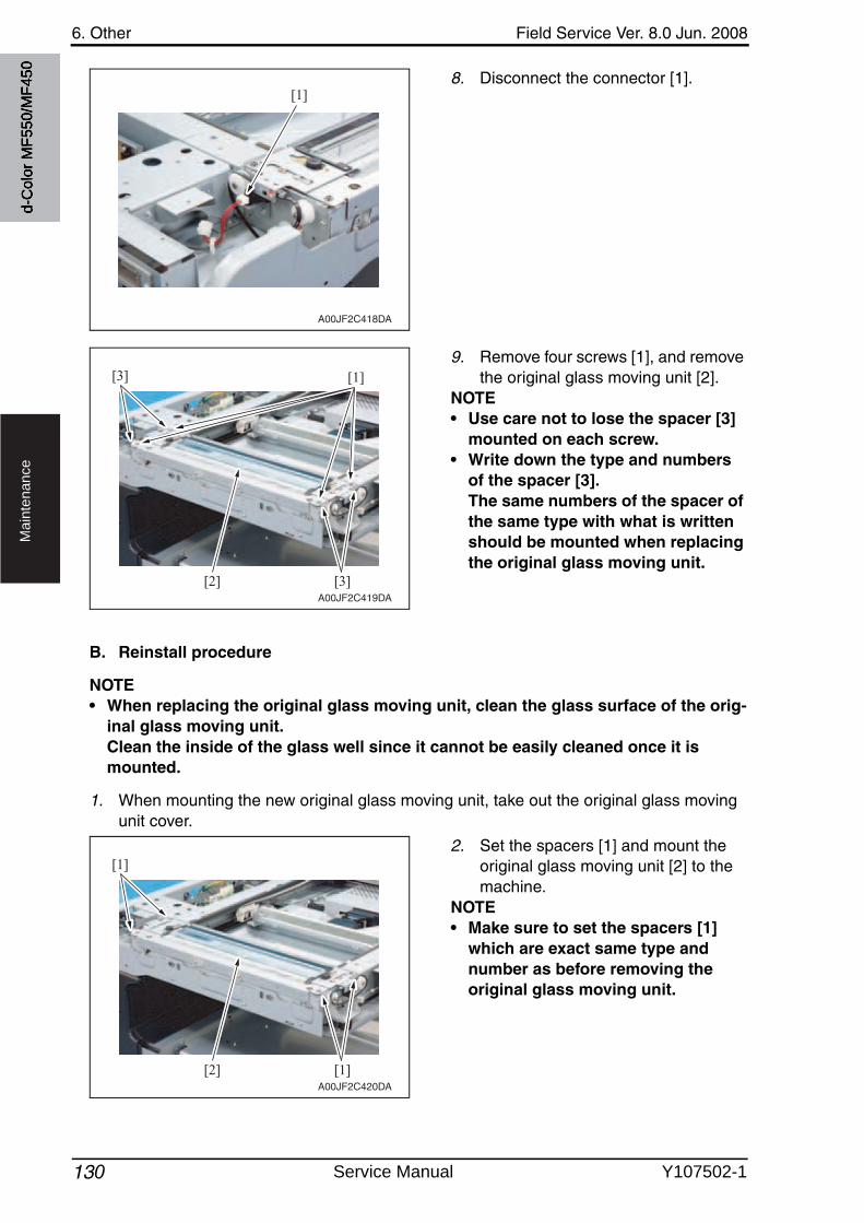
6. Other Field Service Ver. 8.0 Jun. 2008
130
Ma
inte
na
nce
8. Disconnect the connector [1].
9. Remove four screws [1], and removethe original glass moving unit [2].
NOTE• Use care not to lose the spacer [3]
mounted on each screw.• Write down the type and numbers
of the spacer [3].The same numbers of the spacer of the same type with what is written should be mounted when replacing the original glass moving unit.
B. Reinstall procedure
NOTE• When replacing the original glass moving unit, clean the glass surface of the orig-
inal glass moving unit.Clean the inside of the glass well since it cannot be easily cleaned once it is mounted.
1. When mounting the new original glass moving unit, take out the original glass movingunit cover.
2. Set the spacers [1] and mount the original glass moving unit [2] to the machine.
NOTE• Make sure to set the spacers [1]
which are exact same type and number as before removing the original glass moving unit.
[1]
A00JF2C418DA
A00JF2C419DA
[1]
[3][2]
[3]
A00JF2C420DA
[1][2]
[1]
d-C
olor
MF5
50/M
F450
Service Manual Y107502-1
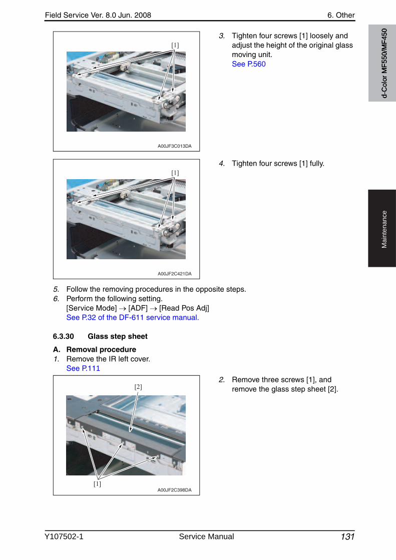
Field Service Ver. 8.0 Jun. 2008 6. Other
131
Ma
inte
na
nce
3. Tighten four screws [1] loosely and adjust the height of the original glass moving unit.See P.560
4. Tighten four screws [1] fully.
5. Follow the removing procedures in the opposite steps.6. Perform the following setting.
[Service Mode] [ADF] [Read Pos Adj]See P.32 of the DF-611 service manual.
6.3.30 Glass step sheet
A. Removal procedure1. Remove the IR left cover.
See P.111
2. Remove three screws [1], and remove the glass step sheet [2].
A00JF3C013DA
[1]
A00JF2C421DA
[1]
[1]
[2]
A00JF2C398DA
d-C
olor
MF5
50/M
F450
Y107502-1 Service Manual
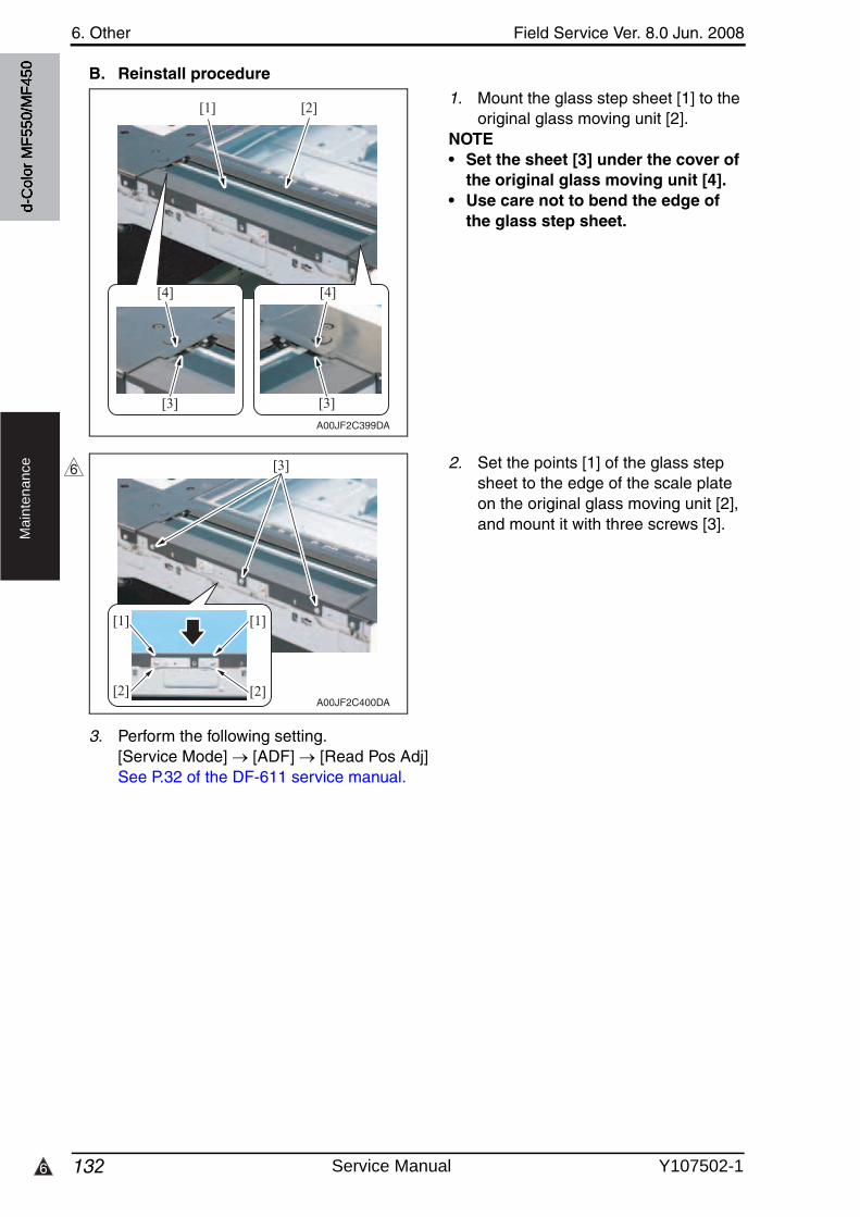
6. Other Field Service Ver. 8.0 Jun. 2008
1326
Ma
inte
na
nce
B. Reinstall procedure
1. Mount the glass step sheet [1] to the original glass moving unit [2].
NOTE• Set the sheet [3] under the cover of
the original glass moving unit [4].• Use care not to bend the edge of
the glass step sheet.
2. Set the points [1] of the glass step sheet to the edge of the scale plate on the original glass moving unit [2], and mount it with three screws [3].
3. Perform the following setting.[Service Mode] [ADF] [Read Pos Adj]See P.32 of the DF-611 service manual.
A00JF2C399DA
[4]
[1] [2]
[3]
[4]
[3]
A00JF2C400DA
[1] [1]
[2] [2]
[3]6
d-C
olor
MF5
50/M
F450
Service Manual Y107502-1
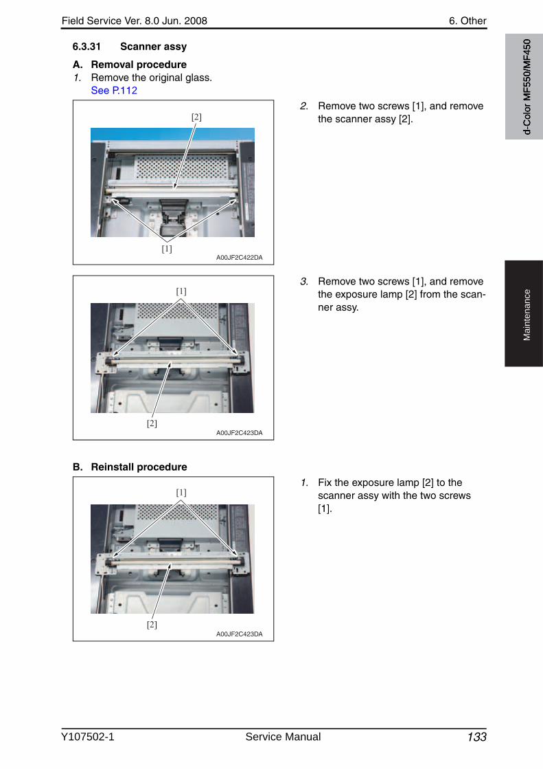
Field Service Ver. 8.0 Jun. 2008 6. Other
133
Ma
inte
na
nce
6.3.31 Scanner assy
A. Removal procedure1. Remove the original glass.
See P.112
2. Remove two screws [1], and removethe scanner assy [2].
3. Remove two screws [1], and removethe exposure lamp [2] from the scan-ner assy.
B. Reinstall procedure
1. Fix the exposure lamp [2] to the scanner assy with the two screws[1].
A00JF2C422DA[1]
[2]
A00JF2C423DA
[1]
[2]
A00JF2C423DA
[1]
[2]
d-C
olor
MF5
50/M
F450
Y107502-1 Service Manual
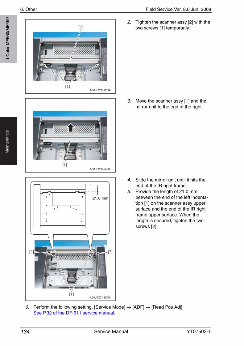
6. Other Field Service Ver. 8.0 Jun. 2008
134
Ma
inte
na
nce
2. Tighten the scanner assy [2] with the two screws [1] temporarily.
3. Move the scanner assy [1] and the mirror unit to the end of the right.
4. Slide the mirror unit until it hits the end of the IR right frame.
5. Provide the length of 21.0 mm between the end of the left indenta-tion [1] on the scanner assy uppersurface and the end of the IR right frame upper surface. When the length is ensured, tighten the twoscrews [2].
6. Perform the following setting. [Service Mode] [ADF] [Read Pos Adj]See P.32 of the DF-611 service manual.
A00JF2C422DA[1]
[2]
A00JF2C424DA[1]
A00JF2C425DA
21.0 mm
[1]
[2] [2]
d-C
olor
MF5
50/M
F450
Service Manual Y107502-1
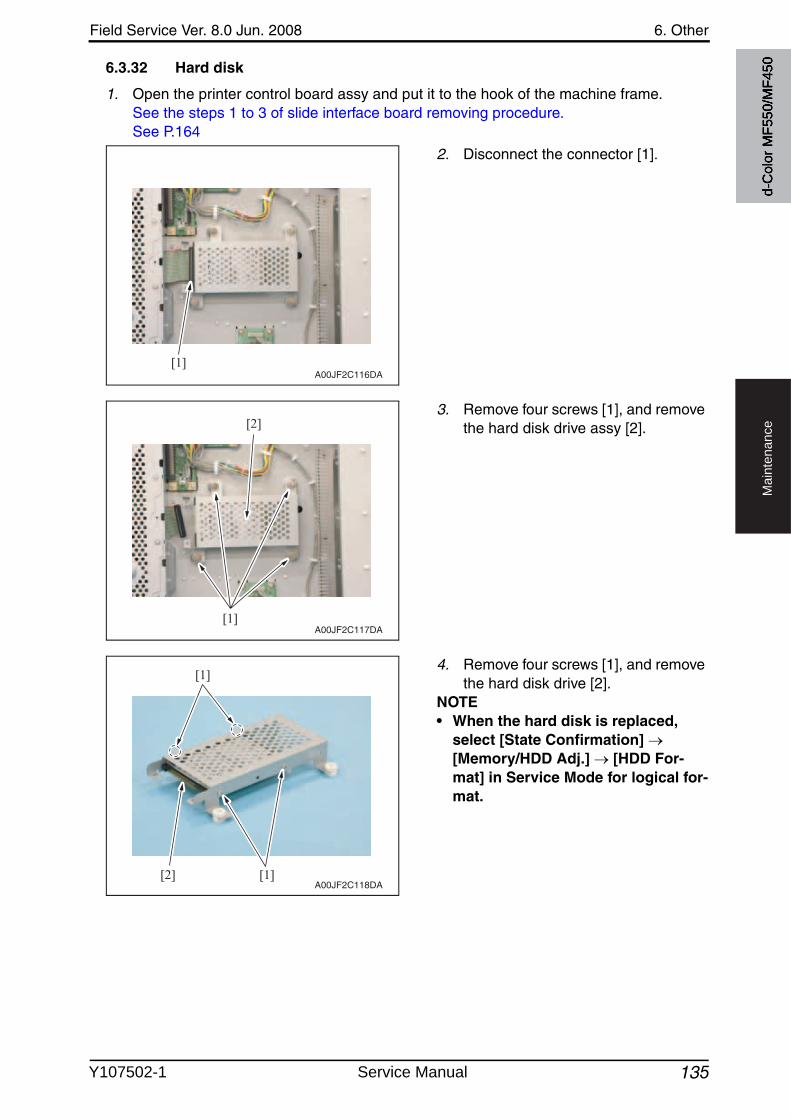
Field Service Ver. 8.0 Jun. 2008 6. Other
135
Ma
inte
na
nce
6.3.32 Hard disk
1. Open the printer control board assy and put it to the hook of the machine frame.See the steps 1 to 3 of slide interface board removing procedure.See P.164
2. Disconnect the connector [1].
3. Remove four screws [1], and removethe hard disk drive assy [2].
4. Remove four screws [1], and removethe hard disk drive [2].
NOTE• When the hard disk is replaced,
select [State Confirmation] [Memory/HDD Adj.] [HDD For-mat] in Service Mode for logical for-mat.
[1]A00JF2C116DA
[1]
[2]
A00JF2C117DA
[1]
[1][2]A00JF2C118DA
d-C
olor
MF5
50/M
F450
Y107502-1 Service Manual
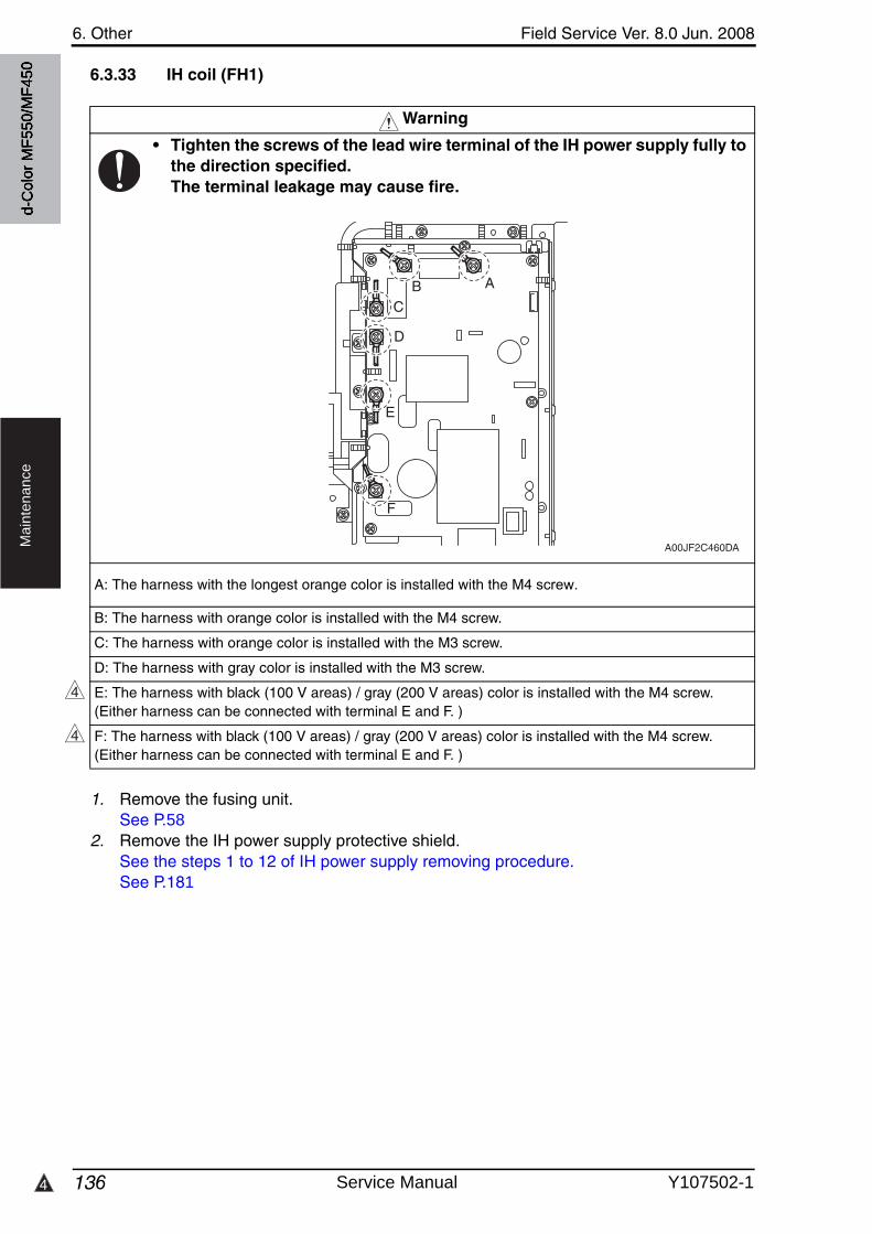
6. Other Field Service Ver. 8.0 Jun. 2008
1364
Ma
inte
na
nce
6.3.33 IH coil (FH1)
1. Remove the fusing unit.See P.58
2. Remove the IH power supply protective shield.See the steps 1 to 12 of IH power supply removing procedure.See P.181
Warning
• Tighten the screws of the lead wire terminal of the IH power supply fully to the direction specified.The terminal leakage may cause fire.
B: The harness with orange color is installed with the M4 screw.
C: The harness with orange color is installed with the M3 screw.
D: The harness with gray color is installed with the M3 screw.
E: The harness with black (100 V areas) / gray (200 V areas) color is installed with the M4 screw.(Either harness can be connected with terminal E and F. )
F: The harness with black (100 V areas) / gray (200 V areas) color is installed with the M4 screw.(Either harness can be connected with terminal E and F. )
A00JF2C460DA
ABC
D
E
F
4
4
d-C
olor
MF5
50/M
F450
A: The harness with the longest orange color is installed with the M4 screw.
Service Manual Y107502-1
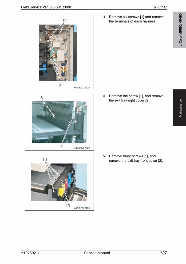
Field Service Ver. 8.0 Jun. 2008 6. Other
137
Ma
inte
na
nce
3. Remove six screws [1] and removethe terminals of each harness.
4. Remove the screw [1], and removethe exit tray right cover [2].
5. Remove three screws [1], and remove the exit tray front cover [2].
[1]
[1]
A00JF2C120DA
[2]
[1]
A00JF2C570DA
[2]
[1]
A00JF2C224DA
d-C
olor
MF5
50/M
F450
Y107502-1 Service Manual
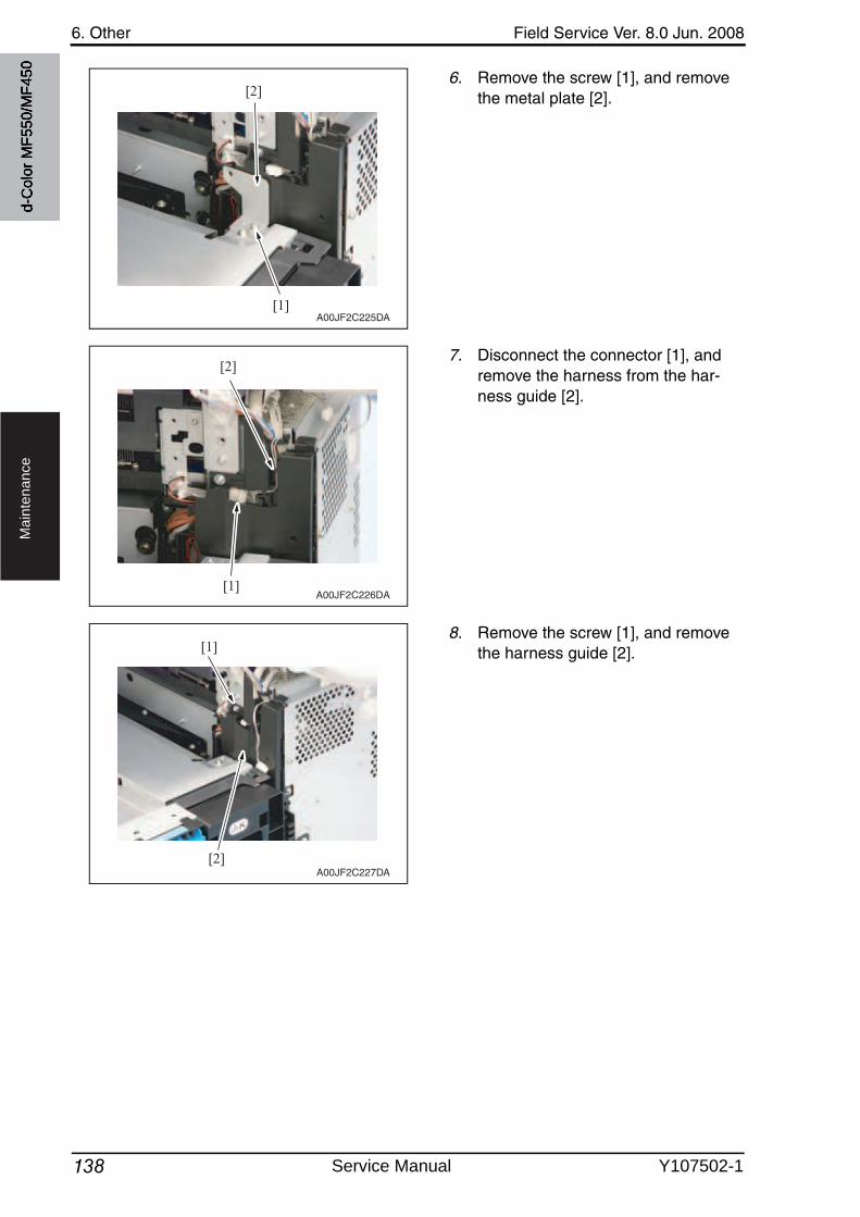
6. Other Field Service Ver. 8.0 Jun. 2008
138
Ma
inte
na
nce
6. Remove the screw [1], and removethe metal plate [2].
7. Disconnect the connector [1], and remove the harness from the har-ness guide [2].
8. Remove the screw [1], and removethe harness guide [2].
[1]
[2]
A00JF2C225DA
[1]
[2]
A00JF2C226DA
[1]
[2]A00JF2C227DA
d-C
olor
MF5
50/M
F450
Service Manual Y107502-1
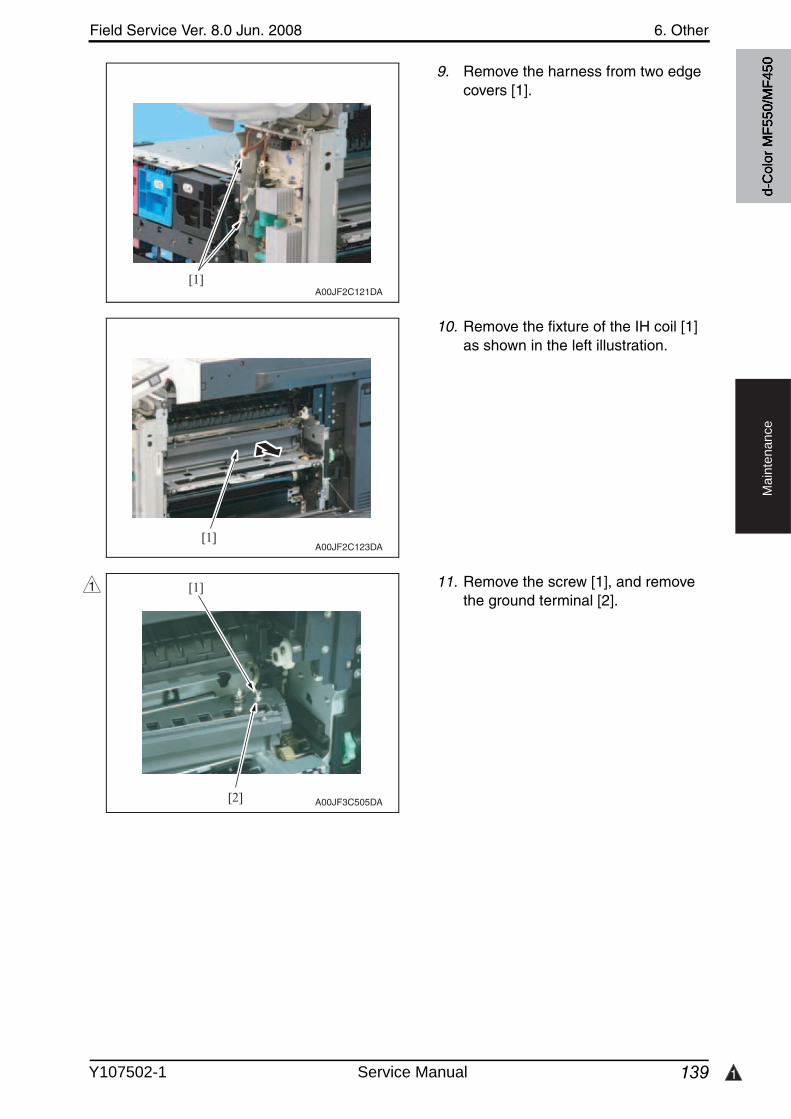
Field Service Ver. 8.0 Jun. 2008 6. Other
139 1
Ma
inte
na
nce
9. Remove the harness from two edge covers [1].
10. Remove the fixture of the IH coil [1] as shown in the left illustration.
11. Remove the screw [1], and removethe ground terminal [2].
[1]A00JF2C121DA
[1]A00JF2C123DA
[1]
[2] A00JF3C505DA
1
d-C
olor
MF5
50/M
F450
Y107502-1 Service Manual
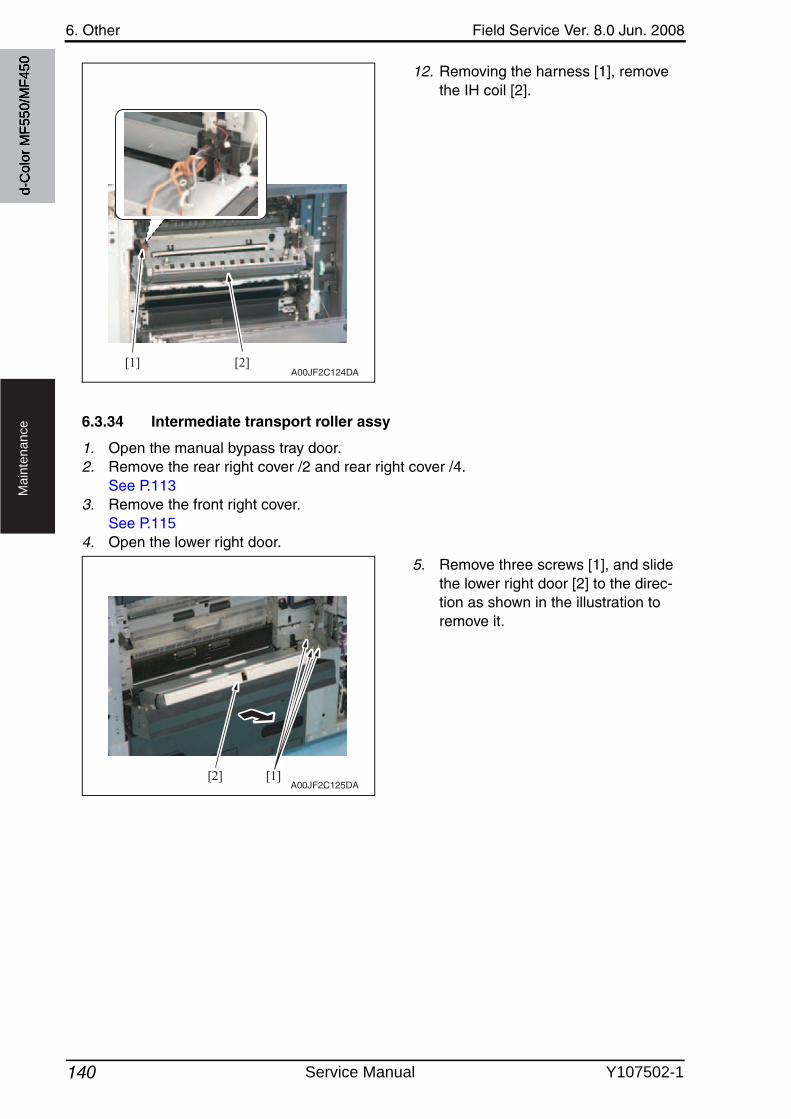
6. Other Field Service Ver. 8.0 Jun. 2008
140
Ma
inte
na
nce
12. Removing the harness [1], removethe IH coil [2].
6.3.34 Intermediate transport roller assy
1. Open the manual bypass tray door.2. Remove the rear right cover /2 and rear right cover /4.
See P.1133. Remove the front right cover.
See P.1154. Open the lower right door.
5. Remove three screws [1], and slide the lower right door [2] to the direc-tion as shown in the illustration to remove it.
A00JF2C124DA[1] [2]
[2] [1]A00JF2C125DA
d-C
olor
MF5
50/M
F450
Service Manual Y107502-1
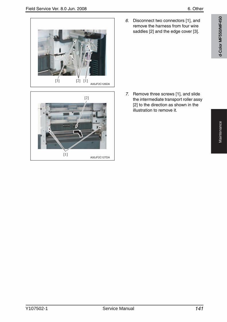
Field Service Ver. 8.0 Jun. 2008 6. Other
141
Ma
inte
na
nce
6. Disconnect two connectors [1], and remove the harness from four wire saddles [2] and the edge cover [3].
7. Remove three screws [1], and slide the intermediate transport roller assy [2] to the direction as shown in the illustration to remove it.
[1][2][3]A00JF2C126DA
[1]
[2]
A00JF2C127DA
d-C
olor
MF5
50/M
F450
Y107502-1 Service Manual
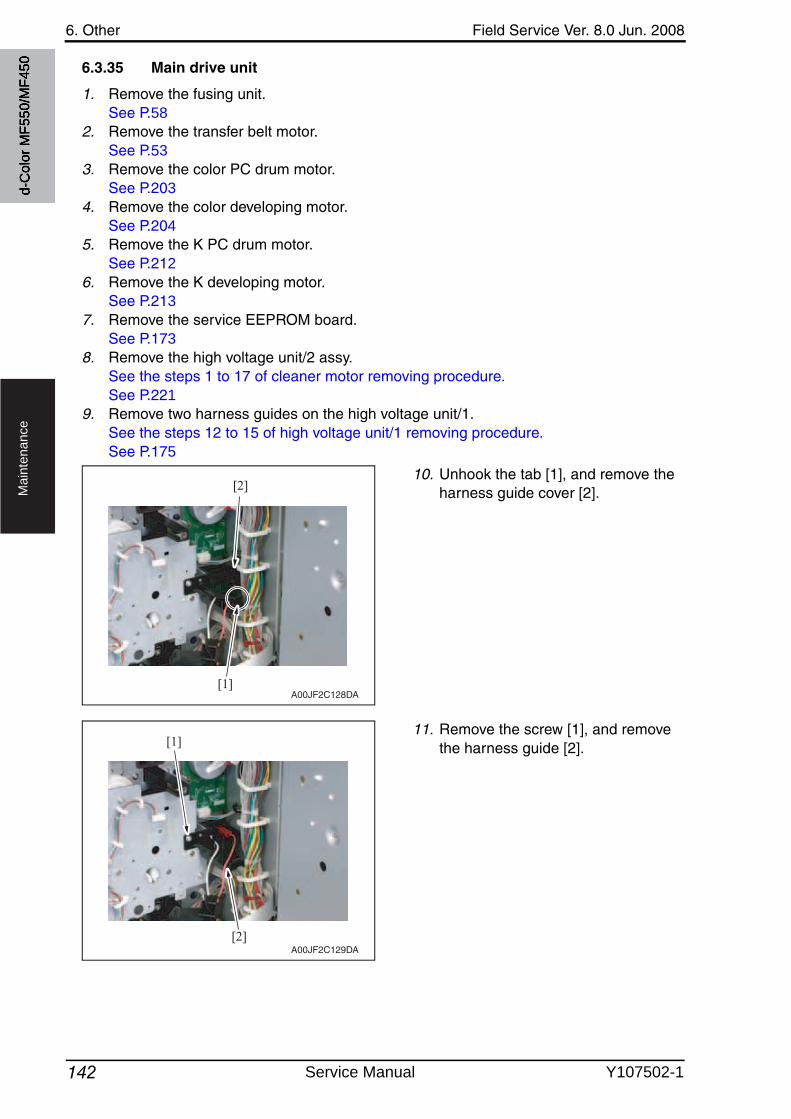
6. Other Field Service Ver. 8.0 Jun. 2008
142
Ma
inte
na
nce
6.3.35 Main drive unit
1. Remove the fusing unit.See P.58
2. Remove the transfer belt motor.See P.53
3. Remove the color PC drum motor.See P.203
4. Remove the color developing motor.See P.204
5. Remove the K PC drum motor.See P.212
6. Remove the K developing motor.See P.213
7. Remove the service EEPROM board.See P.173
8. Remove the high voltage unit/2 assy.See the steps 1 to 17 of cleaner motor removing procedure.See P.221
9. Remove two harness guides on the high voltage unit/1.See the steps 12 to 15 of high voltage unit/1 removing procedure.See P.175
10. Unhook the tab [1], and remove the harness guide cover [2].
11. Remove the screw [1], and removethe harness guide [2].
[1]
[2]
A00JF2C128DA
[1]
[2]A00JF2C129DA
d-C
olor
MF5
50/M
F450
Service Manual Y107502-1
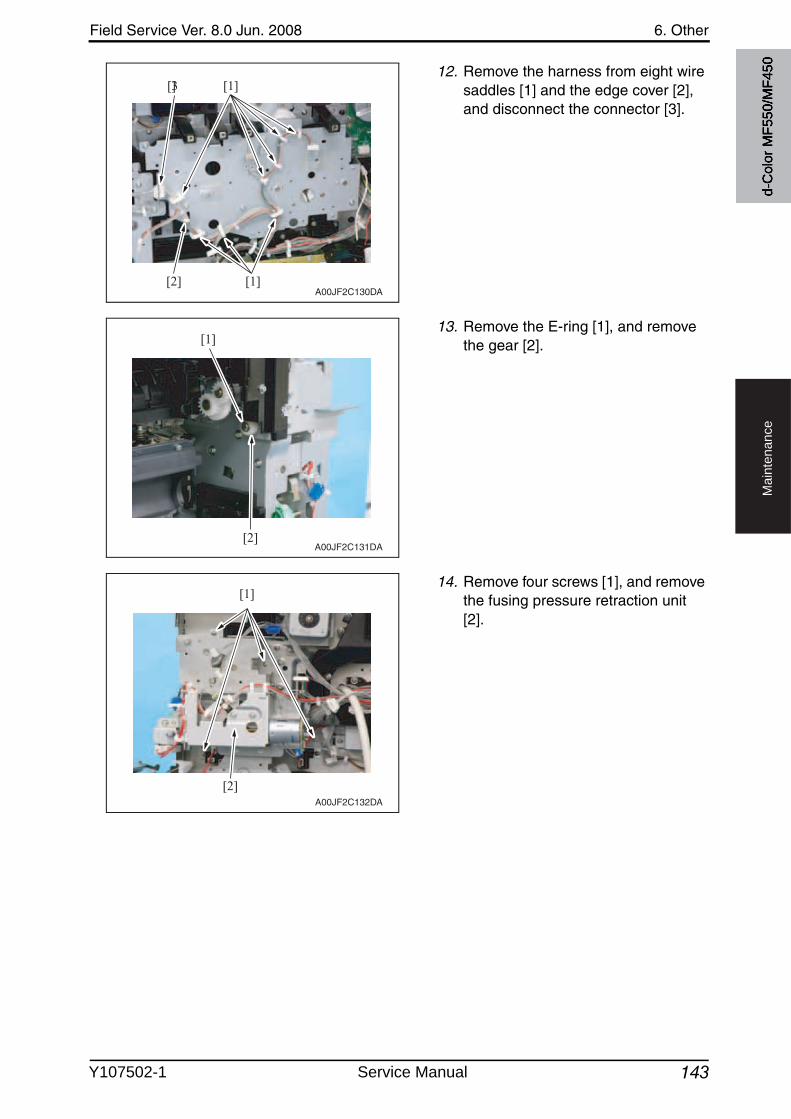
Field Service Ver. 8.0 Jun. 2008 6. Other
143
Ma
inte
na
nce
12. Remove the harness from eight wire saddles [1] and the edge cover [2], and disconnect the connector [3].
13. Remove the E-ring [1], and removethe gear [2].
14. Remove four screws [1], and removethe fusing pressure retraction unit[2].
[1]
[2] [1]
[3]
A00JF2C130DA
[1]
[2]A00JF2C131DA
A00JF2C132DA
[1]
[2]
d-C
olor
MF5
50/M
F450
Y107502-1 Service Manual
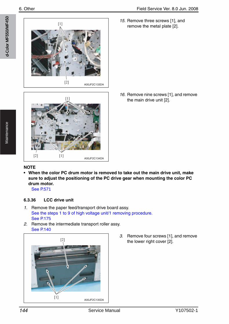
6. Other Field Service Ver. 8.0 Jun. 2008
144
Ma
inte
na
nce
15. Remove three screws [1], and remove the metal plate [2].
16. Remove nine screws [1], and removethe main drive unit [2].
NOTE• When the color PC drum motor is removed to take out the main drive unit, make
sure to adjust the positioning of the PC drive gear when mounting the color PC drum motor.
See P.571
6.3.36 LCC drive unit
1. Remove the paper feed/transport drive board assy.See the steps 1 to 9 of high voltage unit/1 removing procedure.See P.175
2. Remove the intermediate transport roller assy.See P.140
3. Remove four screws [1], and removethe lower right cover [2].
[1]
[2]A00JF2C133DA
[1]
[1]
[2]A00JF2C134DA
[1]
[2]
A00JF2C135DA
d-C
olor
MF5
50/M
F450
Service Manual Y107502-1
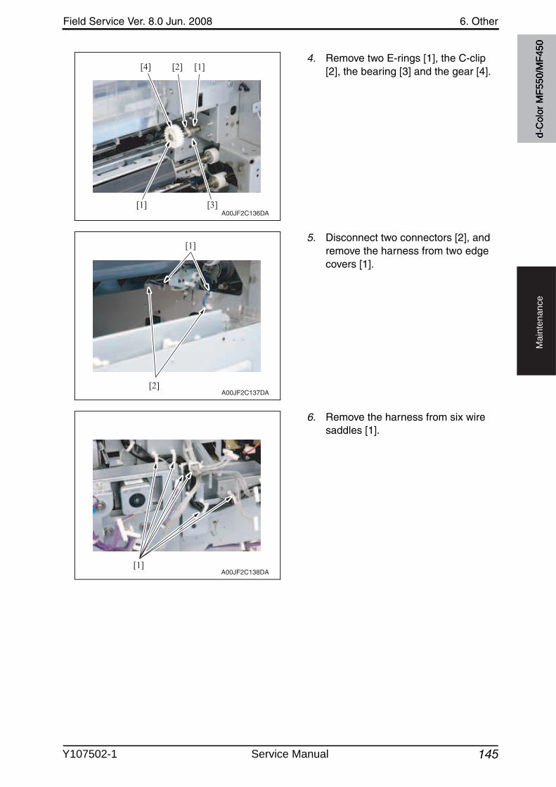
Field Service Ver. 8.0 Jun. 2008 6. Other
145
Ma
inte
na
nce
4. Remove two E-rings [1], the C-clip [2], the bearing [3] and the gear [4].
5. Disconnect two connectors [2], and remove the harness from two edge covers [1].
6. Remove the harness from six wire saddles [1].
A00JF2C136DA
[4]
[1]
[1][2]
[3]
[1]
[2]A00JF2C137DA
[1]A00JF2C138DA
d-C
olor
MF5
50/M
F450
Y107502-1 Service Manual
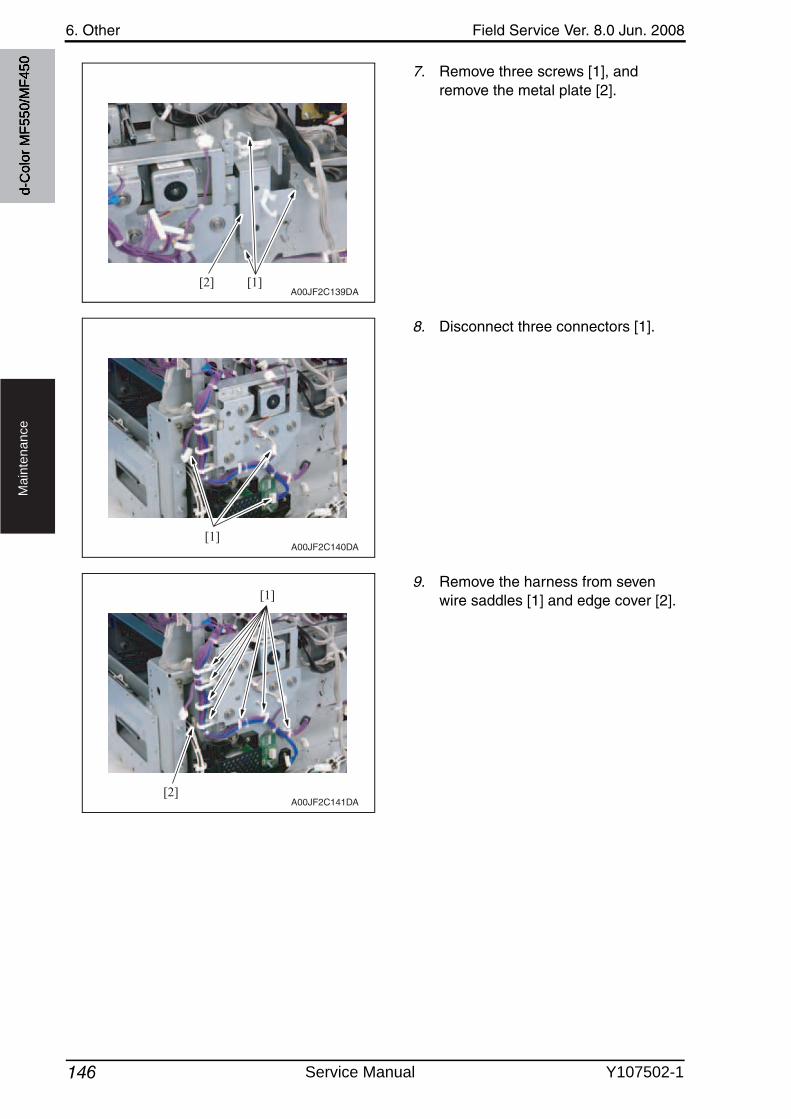
6. Other Field Service Ver. 8.0 Jun. 2008
146
Ma
inte
na
nce
7. Remove three screws [1], and remove the metal plate [2].
8. Disconnect three connectors [1].
9. Remove the harness from sevenwire saddles [1] and edge cover [2].
[1][2]A00JF2C139DA
[1]A00JF2C140DA
[1]
[2]A00JF2C141DA
d-C
olor
MF5
50/M
F450
Service Manual Y107502-1
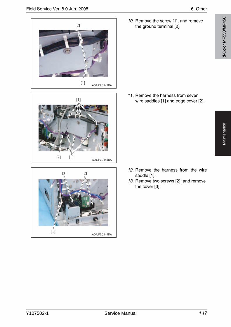
Field Service Ver. 8.0 Jun. 2008 6. Other
147
Ma
inte
na
nce
10. Remove the screw [1], and removethe ground terminal [2].
11. Remove the harness from sevenwire saddles [1] and edge cover [2].
12. Remove the harness from the wiresaddle [1].
13. Remove two screws [2], and removethe cover [3].
[1]
[2]
A00JF2C142DA
[1]
[1]
[2]A00JF2C143DA
A00JF2C144DA[1]
[2][3]
d-C
olor
MF5
50/M
F450
Y107502-1 Service Manual
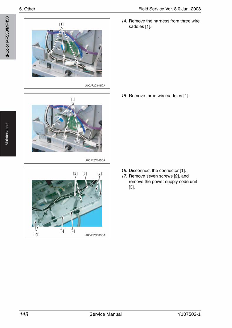
6. Other Field Service Ver. 8.0 Jun. 2008
148
Ma
inte
na
nce
14. Remove the harness from three wire saddles [1].
15. Remove three wire saddles [1].
16. Disconnect the connector [1].17. Remove seven screws [2], and
remove the power supply code unit[3].
[1]
A00JF2C145DA
[1]
A00JF2C146DA
[1][2]
[2][2][3]
[2]
A00JF2C606DA
d-C
olor
MF5
50/M
F450
Service Manual Y107502-1
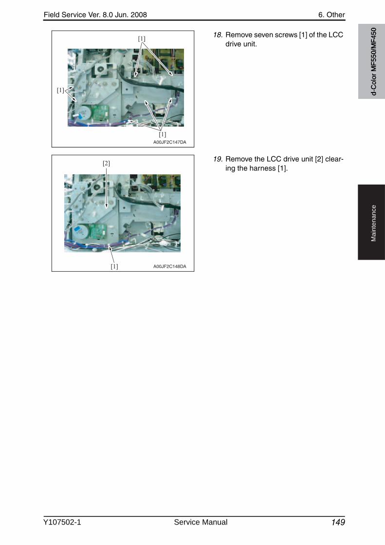
Field Service Ver. 8.0 Jun. 2008 6. Other
149
Ma
inte
na
nce
18. Remove seven screws [1] of the LCC drive unit.
19. Remove the LCC drive unit [2] clear-ing the harness [1].
[1]
[1]
[1]
A00JF2C147DA
[1]
[2]
A00JF2C148DA
d-C
olor
MF5
50/M
F450
Y107502-1 Service Manual
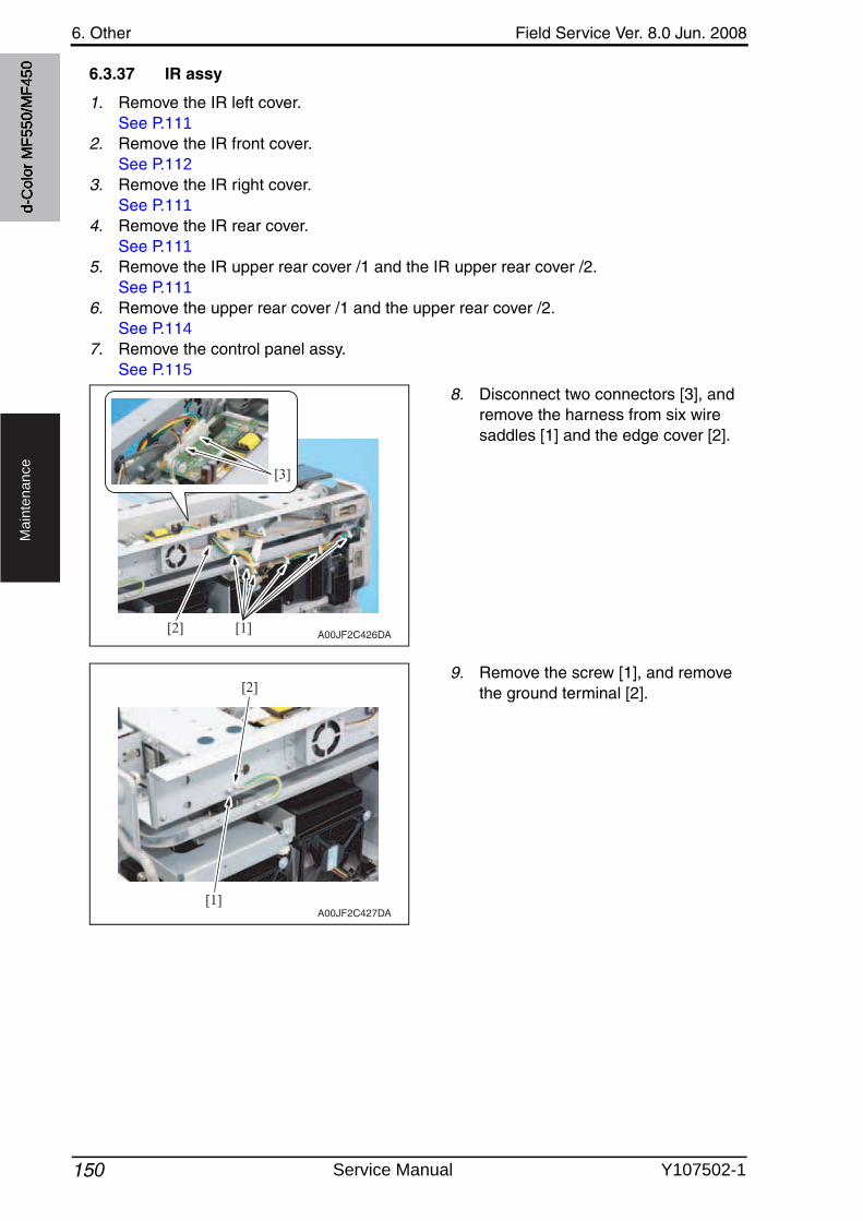
6. Other Field Service Ver. 8.0 Jun. 2008
150
Ma
inte
na
nce
6.3.37 IR assy
1. Remove the IR left cover.See P.111
2. Remove the IR front cover.See P.112
3. Remove the IR right cover.See P.111
4. Remove the IR rear cover.See P.111
5. Remove the IR upper rear cover /1 and the IR upper rear cover /2.See P.111
6. Remove the upper rear cover /1 and the upper rear cover /2.See P.114
7. Remove the control panel assy.See P.115
8. Disconnect two connectors [3], and remove the harness from six wire saddles [1] and the edge cover [2].
9. Remove the screw [1], and removethe ground terminal [2].
A00JF2C426DA[1]
[3]
[2]
A00JF2C427DA[1]
[2]
d-C
olor
MF5
50/M
F450
Service Manual Y107502-1
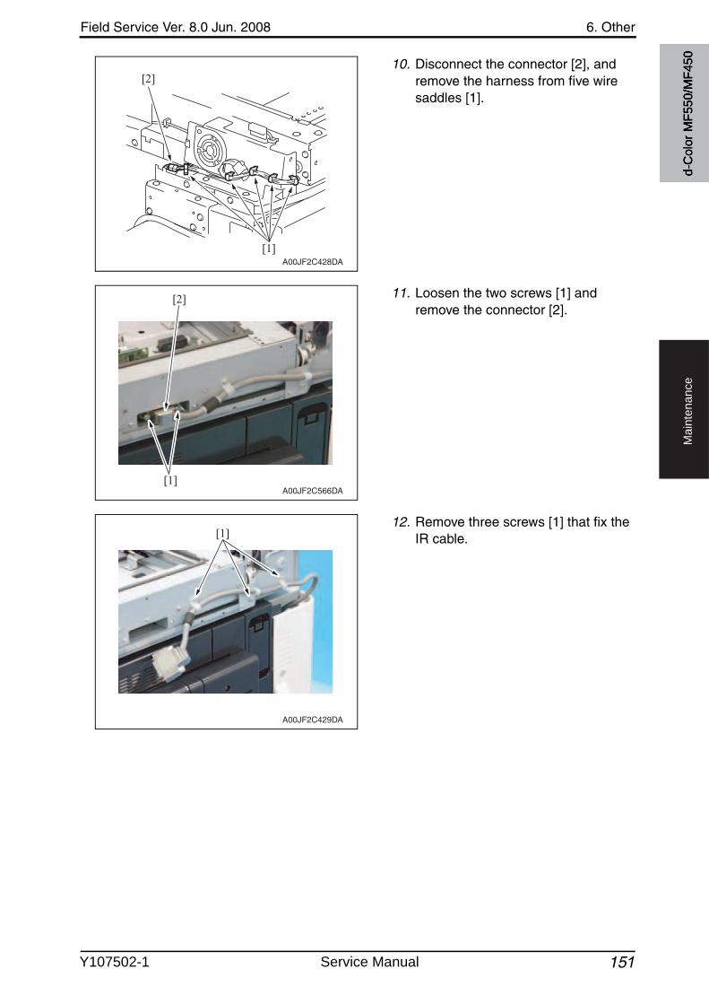
Field Service Ver. 8.0 Jun. 2008 6. Other
151
Ma
inte
na
nce
10. Disconnect the connector [2], and remove the harness from five wire saddles [1].
11. Loosen the two screws [1] and remove the connector [2].
12. Remove three screws [1] that fix the IR cable.
A00JF2C428DA
[1]
[2]
[2]
[1]A00JF2C566DA
A00JF2C429DA
[1]
d-C
olor
MF5
50/M
F450
Y107502-1 Service Manual
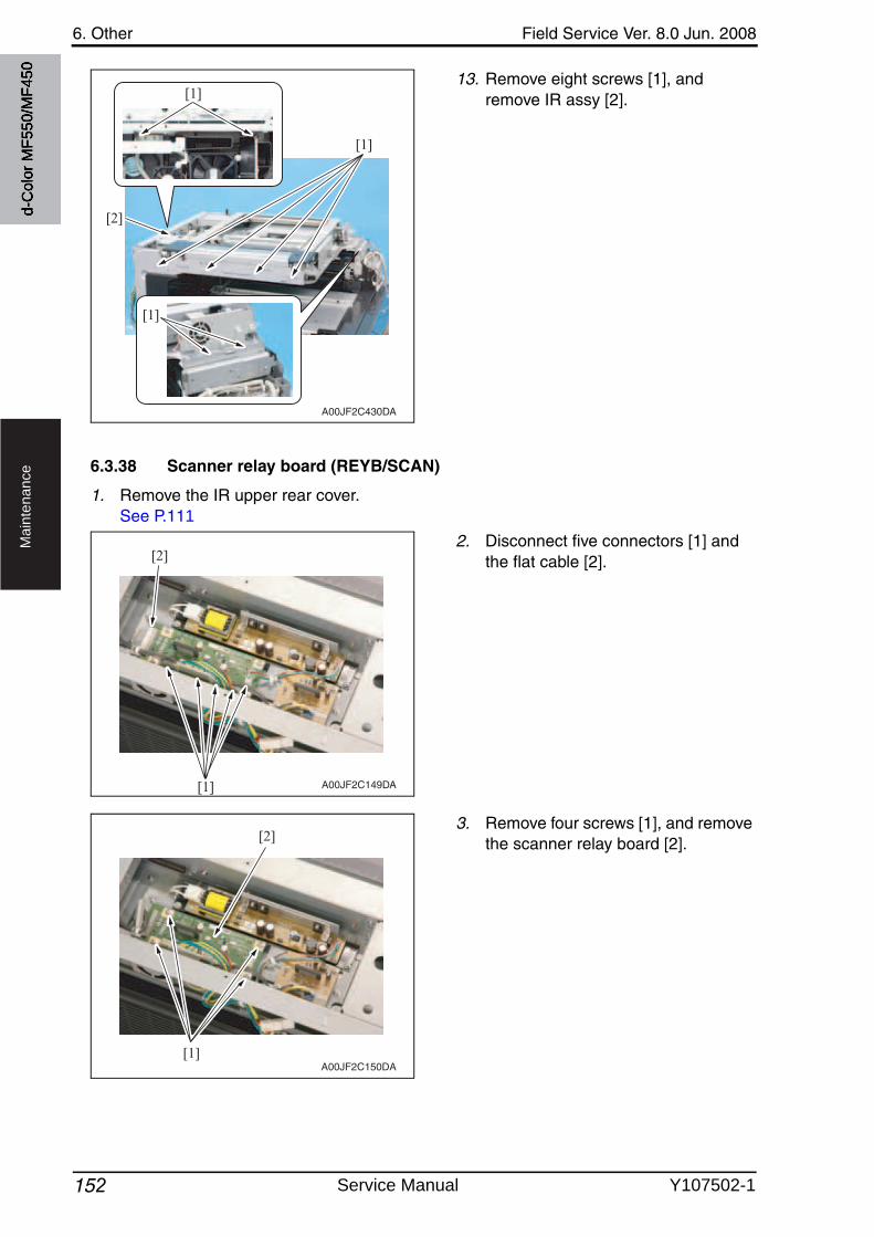
6. Other Field Service Ver. 8.0 Jun. 2008
152
Ma
inte
na
nce
13. Remove eight screws [1], and remove IR assy [2].
6.3.38 Scanner relay board (REYB/SCAN)
1. Remove the IR upper rear cover.See P.111
2. Disconnect five connectors [1] and the flat cable [2].
3. Remove four screws [1], and removethe scanner relay board [2].
A00JF2C430DA
[1]
[2]
[1]
[1]
[1]
[2]
A00JF2C149DA
[1]
[2]
A00JF2C150DA
d-C
olor
MF5
50/M
F450
Service Manual Y107502-1
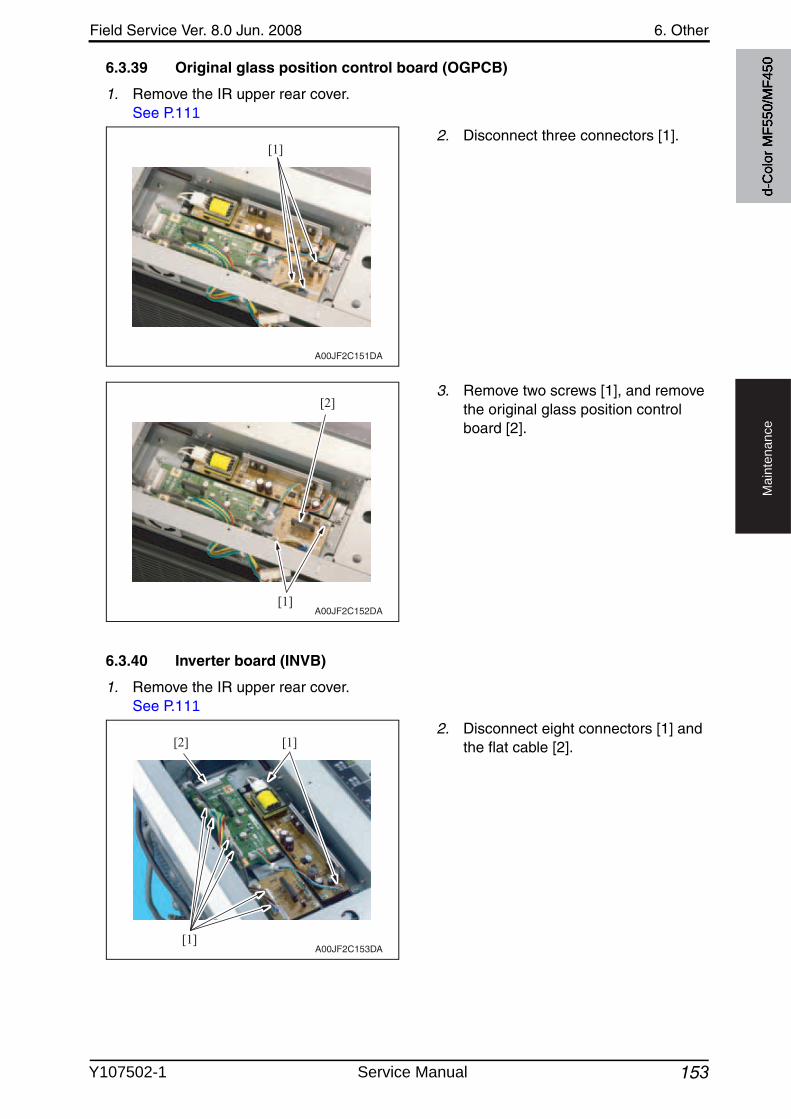
Field Service Ver. 8.0 Jun. 2008 6. Other
153
Ma
inte
na
nce
6.3.39 Original glass position control board (OGPCB)
1. Remove the IR upper rear cover.See P.111
2. Disconnect three connectors [1].
3. Remove two screws [1], and removethe original glass position control board [2].
6.3.40 Inverter board (INVB)
1. Remove the IR upper rear cover.See P.111
2. Disconnect eight connectors [1] and the flat cable [2].
[1]
A00JF2C151DA
[1]
[2]
A00JF2C152DA
[1][2]
[1]A00JF2C153DA
d-C
olor
MF5
50/M
F450
Y107502-1 Service Manual
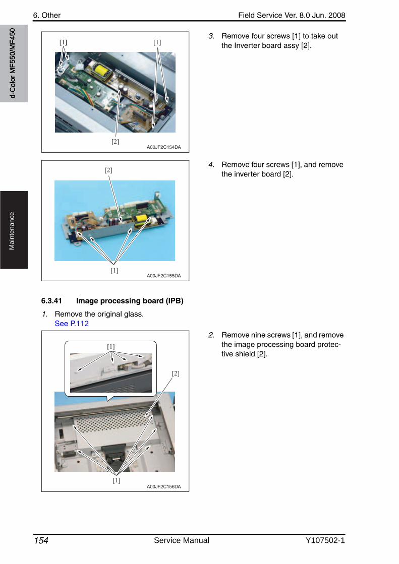
6. Other Field Service Ver. 8.0 Jun. 2008
154
Ma
inte
na
nce
3. Remove four screws [1] to take outthe Inverter board assy [2].
4. Remove four screws [1], and removethe inverter board [2].
6.3.41 Image processing board (IPB)
1. Remove the original glass.See P.112
2. Remove nine screws [1], and removethe image processing board protec-tive shield [2].
[1][1]
[2]A00JF2C154DA
[1]
[2]
A00JF2C155DA
A00JF2C156DA
[1]
[2]
[1]
d-C
olor
MF5
50/M
F450
Service Manual Y107502-1
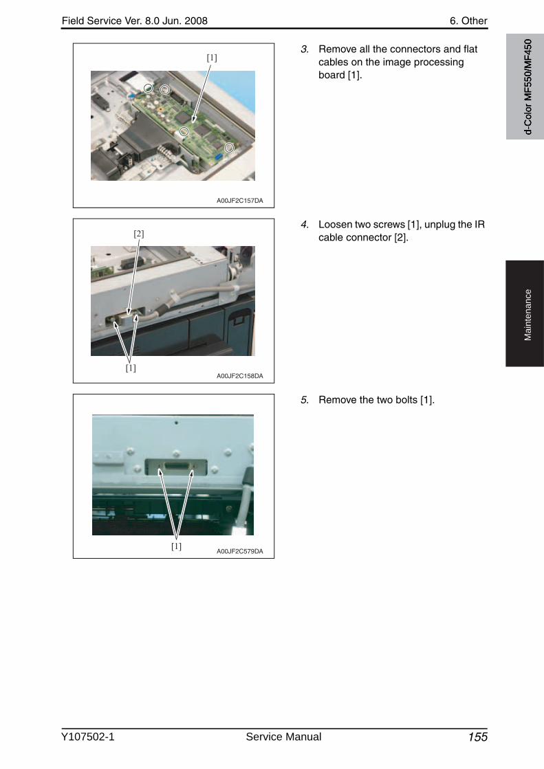
Field Service Ver. 8.0 Jun. 2008 6. Other
155
Ma
inte
na
nce
3. Remove all the connectors and flat cables on the image processing board [1].
4. Loosen two screws [1], unplug the IR cable connector [2].
5. Remove the two bolts [1].
[1]
A00JF2C157DA
[2]
[1]A00JF2C158DA
[1]A00JF2C579DA
d-C
olor
MF5
50/M
F450
Y107502-1 Service Manual
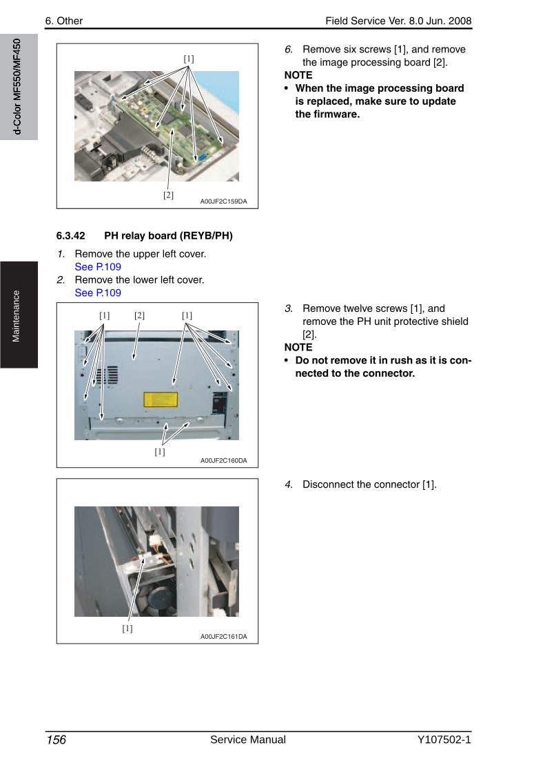
6. Other Field Service Ver. 8.0 Jun. 2008
156
Ma
inte
na
nce
6. Remove six screws [1], and removethe image processing board [2].
NOTE• When the image processing board
is replaced, make sure to update the firmware.
6.3.42 PH relay board (REYB/PH)
1. Remove the upper left cover.See P.109
2. Remove the lower left cover.See P.109
3. Remove twelve screws [1], and remove the PH unit protective shield [2].
NOTE• Do not remove it in rush as it is con-
nected to the connector.
4. Disconnect the connector [1].
[1]
[2]A00JF2C159DA
[1]
[1][1] [2]
A00JF2C160DA
[1]A00JF2C161DA
d-C
olor
MF5
50/M
F450
Service Manual Y107502-1
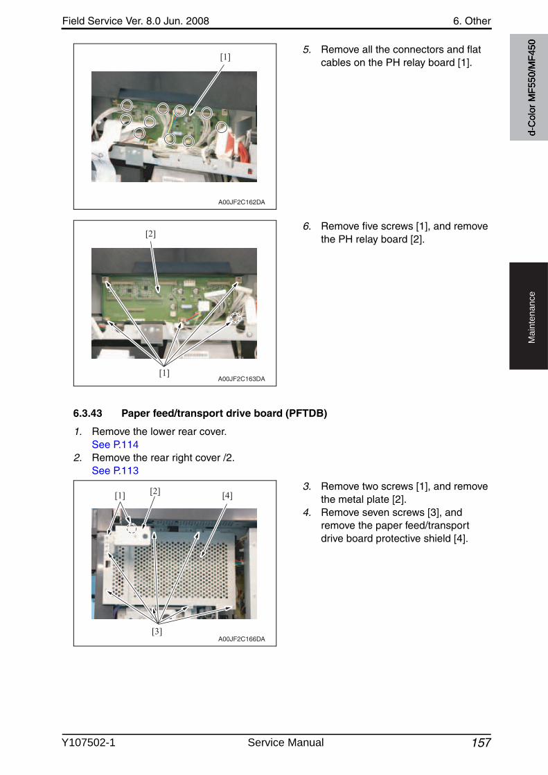
Field Service Ver. 8.0 Jun. 2008 6. Other
157
Ma
inte
na
nce
5. Remove all the connectors and flat cables on the PH relay board [1].
6. Remove five screws [1], and removethe PH relay board [2].
6.3.43 Paper feed/transport drive board (PFTDB)
1. Remove the lower rear cover.See P.114
2. Remove the rear right cover /2.See P.113
3. Remove two screws [1], and removethe metal plate [2].
4. Remove seven screws [3], and remove the paper feed/transport drive board protective shield [4].
[1]
A00JF2C162DA
[1]
[2]
A00JF2C163DA
[3]
[1] [2] [4]
A00JF2C166DA
d-C
olor
MF5
50/M
F450
Y107502-1 Service Manual
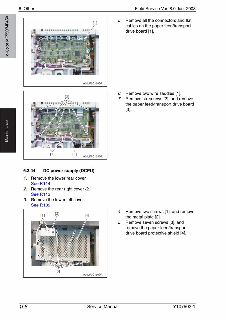
6. Other Field Service Ver. 8.0 Jun. 2008
158
Ma
inte
na
nce
5. Remove all the connectors and flat cables on the paper feed/transport drive board [1].
6. Remove two wire saddles [1].7. Remove six screws [2], and remove
the paper feed/transport drive board [3].
6.3.44 DC power supply (DCPU)
1. Remove the lower rear cover.See P.114
2. Remove the rear right cover /2.See P.113
3. Remove the lower left cover.See P.109
4. Remove two screws [1], and removethe metal plate [2].
5. Remove seven screws [3], and remove the paper feed/transport drive board protective shield [4].
A00JF2C164DA
[1]
[2]
[3][1]A00JF2C165DA
[3]
[1] [2] [4]
A00JF2C166DA
d-C
olor
MF5
50/M
F450
Service Manual Y107502-1
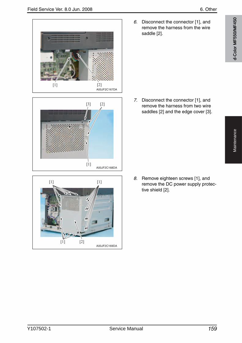
Field Service Ver. 8.0 Jun. 2008 6. Other
159
Ma
inte
na
nce
6. Disconnect the connector [1], and remove the harness from the wire saddle [2].
7. Disconnect the connector [1], and remove the harness from two wire saddles [2] and the edge cover [3].
8. Remove eighteen screws [1], and remove the DC power supply protec-tive shield [2].
[1] [2]A00JF2C167DA
[1]
[2][3]
A00JF2C168DA
[1]
[1] [1]
[2]A00JF2C169DA
d-C
olor
MF5
50/M
F450
Y107502-1 Service Manual
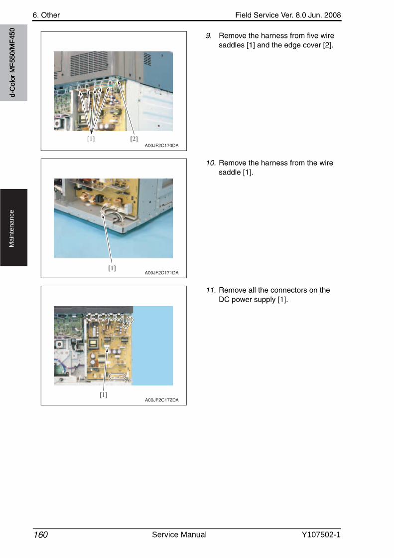
6. Other Field Service Ver. 8.0 Jun. 2008
160
Ma
inte
na
nce
9. Remove the harness from five wire saddles [1] and the edge cover [2].
10. Remove the harness from the wire saddle [1].
11. Remove all the connectors on the DC power supply [1].
[1] [2]A00JF2C170DA
[1]A00JF2C171DA
[1]A00JF2C172DA
d-C
olor
MF5
50/M
F450
Service Manual Y107502-1
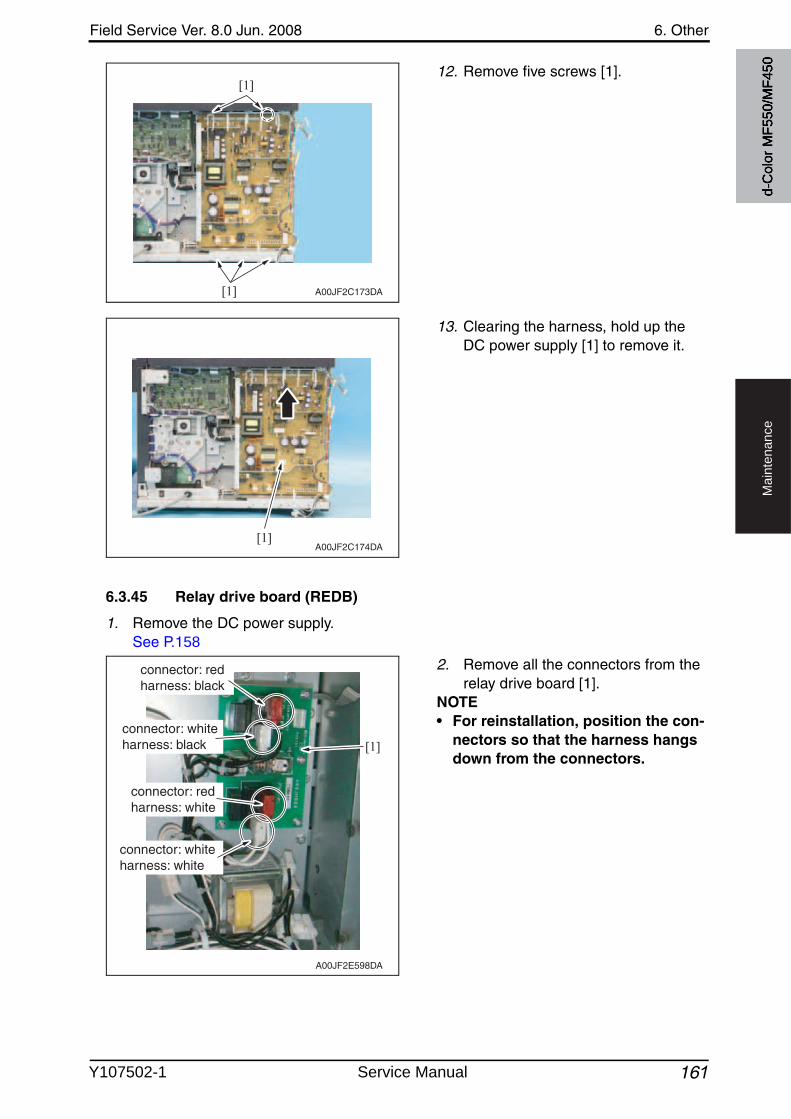
Field Service Ver. 8.0 Jun. 2008 6. Other
161
Ma
inte
na
nce
12. Remove five screws [1].
13. Clearing the harness, hold up the DC power supply [1] to remove it.
6.3.45 Relay drive board (REDB)
1. Remove the DC power supply.See P.158
2. Remove all the connectors from the relay drive board [1].
NOTE• For reinstallation, position the con-
nectors so that the harness hangs down from the connectors.
[1]
[1]
A00JF2C173DA
[1]A00JF2C174DA
[1]
connector: redharness: black
connector: whiteharness: black
connector: redharness: white
connector: whiteharness: white
A00JF2E598DA
d-C
olor
MF5
50/M
F450
Y107502-1 Service Manual
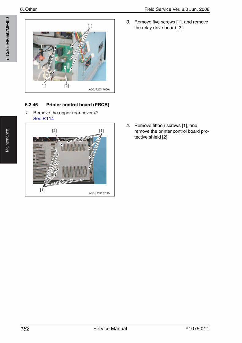
6. Other Field Service Ver. 8.0 Jun. 2008
162
Ma
inte
na
nce
3. Remove five screws [1], and removethe relay drive board [2].
6.3.46 Printer control board (PRCB)
1. Remove the upper rear cover /2.See P.114
2. Remove fifteen screws [1], and remove the printer control board pro-tective shield [2].
[1]
[1]
[2]A00JF2C176DA
[1]
[1][2]
A00JF2C177DA
d-C
olor
MF5
50/M
F450
Service Manual Y107502-1
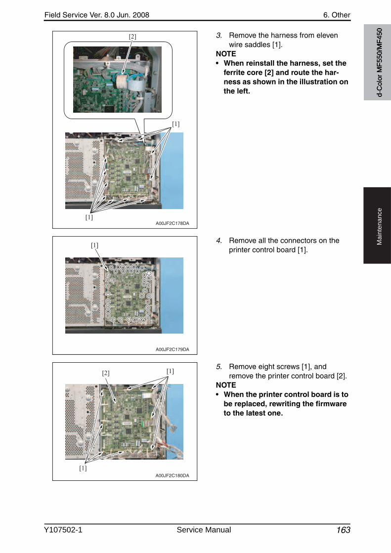
Field Service Ver. 8.0 Jun. 2008 6. Other
163
Ma
inte
na
nce
3. Remove the harness from elevenwire saddles [1].
NOTE• When reinstall the harness, set the
ferrite core [2] and route the har-ness as shown in the illustration on the left.
4. Remove all the connectors on the printer control board [1].
5. Remove eight screws [1], and remove the printer control board [2].
NOTE• When the printer control board is to
be replaced, rewriting the firmware to the latest one.
[1]
[1]
[2]
A00JF2C178DA
A00JF2C179DA
[1]
[1]
[1]
[2]
A00JF2C180DA
d-C
olor
MF5
50/M
F450
Y107502-1 Service Manual
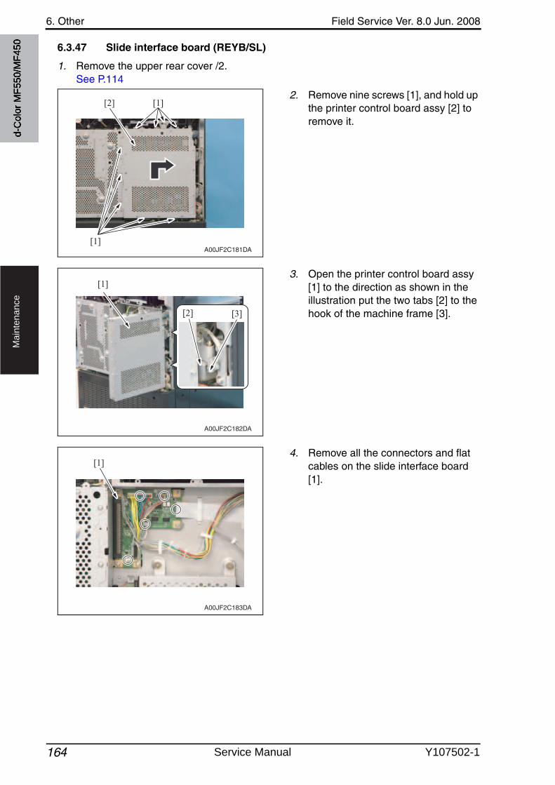
6. Other Field Service Ver. 8.0 Jun. 2008
164
Ma
inte
na
nce
6.3.47 Slide interface board (REYB/SL)
1. Remove the upper rear cover /2.See P.114
2. Remove nine screws [1], and hold upthe printer control board assy [2] to remove it.
3. Open the printer control board assy [1] to the direction as shown in the illustration put the two tabs [2] to the hook of the machine frame [3].
4. Remove all the connectors and flat cables on the slide interface board [1].
[1]
[1][2]
A00JF2C181DA
A00JF2C182DA
[1]
[3][2]
A00JF2C183DA
[1]
d-C
olor
MF5
50/M
F450
Service Manual Y107502-1
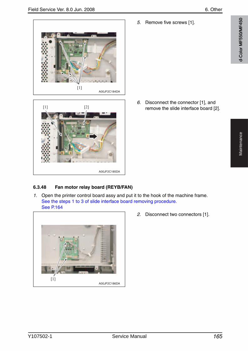
Field Service Ver. 8.0 Jun. 2008 6. Other
165
Ma
inte
na
nce
5. Remove five screws [1].
6. Disconnect the connector [1], and remove the slide interface board [2].
6.3.48 Fan motor relay board (REYB/FAN)
1. Open the printer control board assy and put it to the hook of the machine frame.See the steps 1 to 3 of slide interface board removing procedure.See P.164
2. Disconnect two connectors [1].
[1]A00JF2C184DA
[1] [2]
A00JF2C185DA
[1]A00JF2C186DA
d-C
olor
MF5
50/M
F450
Y107502-1 Service Manual
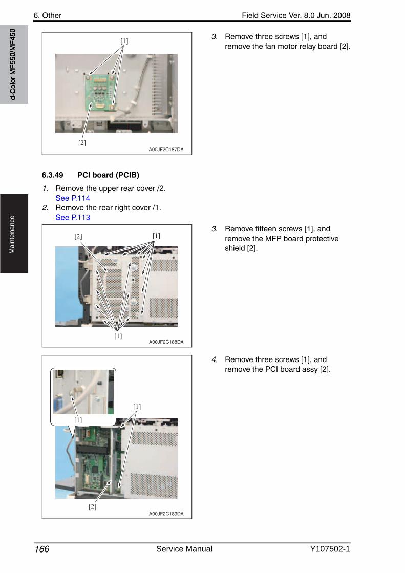
6. Other Field Service Ver. 8.0 Jun. 2008
166
Ma
inte
na
nce
3. Remove three screws [1], and remove the fan motor relay board [2].
6.3.49 PCI board (PCIB)
1. Remove the upper rear cover /2.See P.114
2. Remove the rear right cover /1.See P.113
3. Remove fifteen screws [1], and remove the MFP board protectiveshield [2].
4. Remove three screws [1], and remove the PCI board assy [2].
[1]
[2]A00JF2C187DA
[1]
[1][2]
A00JF2C188DA
A00JF2C189DA
[1]
[1]
[2]
d-C
olor
MF5
50/M
F450
Service Manual Y107502-1
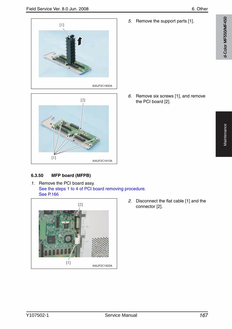
Field Service Ver. 8.0 Jun. 2008 6. Other
167
Ma
inte
na
nce
5. Remove the support parts [1].
6. Remove six screws [1], and removethe PCI board [2].
6.3.50 MFP board (MFPB)
1. Remove the PCI board assy.See the steps 1 to 4 of PCI board removing procedure.See P.166
2. Disconnect the flat cable [1] and the connector [2].
[1]
A00JF2C190DA
[1]
[2]
A00JF2C191DA
[1]
[2]
A00JF2C192DA
d-C
olor
MF5
50/M
F450
Y107502-1 Service Manual
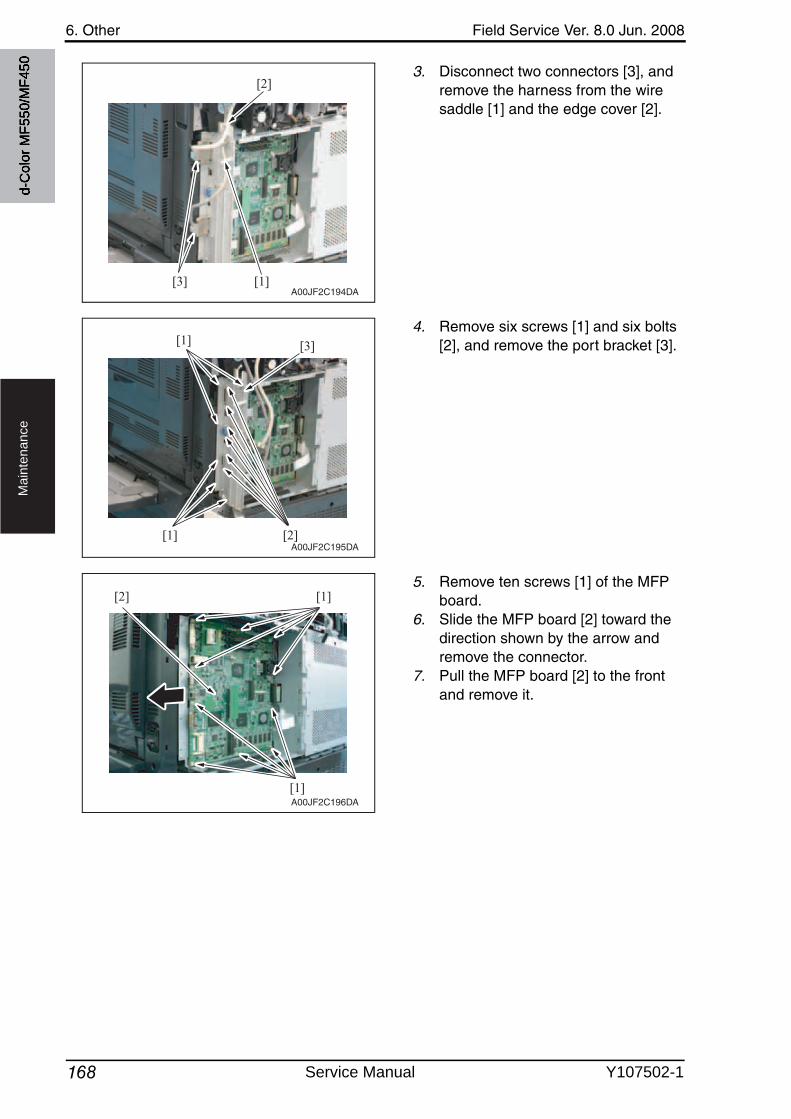
6. Other Field Service Ver. 8.0 Jun. 2008
168
Ma
inte
na
nce
3. Disconnect two connectors [3], and remove the harness from the wire saddle [1] and the edge cover [2].
4. Remove six screws [1] and six bolts [2], and remove the port bracket [3].
5. Remove ten screws [1] of the MFP board.
6. Slide the MFP board [2] toward the direction shown by the arrow and remove the connector.
7. Pull the MFP board [2] to the front and remove it.
[1]
[2]
[3]A00JF2C194DA
[1] [2]
[1] [3]
A00JF2C195DA
[1][2]
[1]A00JF2C196DA
d-C
olor
MF5
50/M
F450
Service Manual Y107502-1
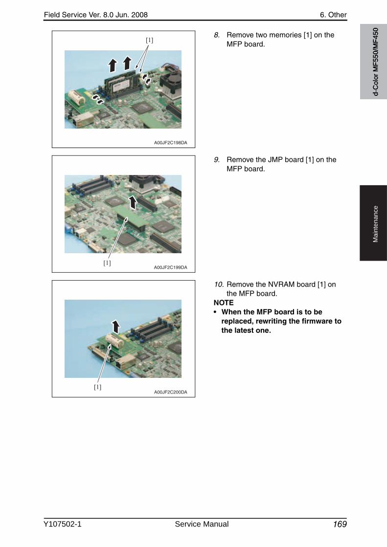
Field Service Ver. 8.0 Jun. 2008 6. Other
169
Ma
inte
na
nce
8. Remove two memories [1] on the MFP board.
9. Remove the JMP board [1] on the MFP board.
10. Remove the NVRAM board [1] on the MFP board.
NOTE• When the MFP board is to be
replaced, rewriting the firmware to the latest one.
[1]
A00JF2C198DA
[1]A00JF2C199DA
[1]A00JF2C200DA
d-C
olor
MF5
50/M
F450
Y107502-1 Service Manual
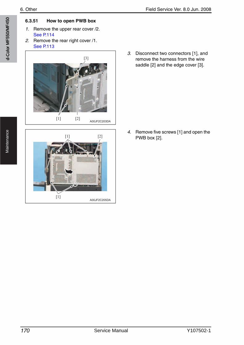
6. Other Field Service Ver. 8.0 Jun. 2008
170
Ma
inte
na
nce
6.3.51 How to open PWB box
1. Remove the upper rear cover /2.See P.114
2. Remove the rear right cover /1.See P.113
3. Disconnect two connectors [1], and remove the harness from the wire saddle [2] and the edge cover [3].
4. Remove five screws [1] and open the PWB box [2].
[1]
[3]
[2]A00JF2C203DA
[1]
[1] [2]
A00JF2C205DA
d-C
olor
MF5
50/M
F450
Service Manual Y107502-1
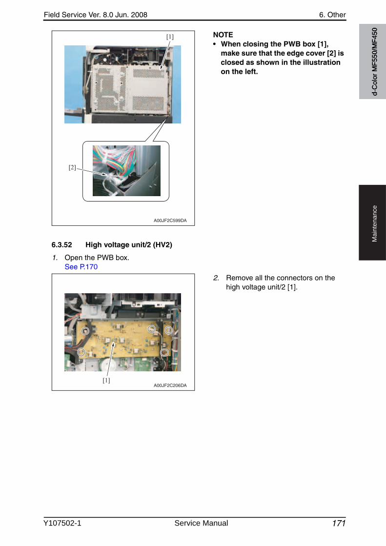
Field Service Ver. 8.0 Jun. 2008 6. Other
171
Ma
inte
na
nce
NOTE• When closing the PWB box [1],
make sure that the edge cover [2] is closed as shown in the illustration on the left.
6.3.52 High voltage unit/2 (HV2)
1. Open the PWB box.See P.170
2. Remove all the connectors on the high voltage unit/2 [1].
[1]
[2]
A00JF2C599DA
[1]A00JF2C206DA
d-C
olor
MF5
50/M
F450
Y107502-1 Service Manual

6. Other Field Service Ver. 8.0 Jun. 2008
172
Ma
inte
na
nce
3. Remove five screws [1], and removetwo harness guides [2].
4. Remove five screws [1] and four tap-ping screws [2], and remove the high voltage unit/2 [3].
[1]
[1]
[2] [2]
A00JF2C207DA
[2] [1][1]
[1][3]
A00JF2C208DA
d-C
olor
MF5
50/M
F450
Service Manual Y107502-1

Field Service Ver. 8.0 Jun. 2008 6. Other
173 2
Ma
inte
na
nce
6.3.53 Service EEPROM board (SV ERB)
1. Open the PWB box.See P.170
2. Remove two screws [1] and the con-nector [2], and take out the service EEPROM board [3].
NOTEAfter replacing the service EEPROM board, all parts shown below are required to be replaced with new ones.• Imaging unit Y/M/C/K• Toner cartridge Y/M/C/K• Waste toner box• Image transfer belt• Fusing unit• Ozone filter
NOTE• When service EEPROM is replaced, data of all adjustment settings stored in
EEPROM disappear and the adjustment settings are returned to the default ones.After replacing the service EEPROM board, take the following steps to make read-justments.
3. Open the upper front door and turn OFF and ON the main power switch and sub powerswitch.
4. Enter the Service Mode. Make individual adjustments shown in the following table in the order listed, using the machine maintenance list and the adjustment lists that were output at the time of main body installation and maintenance.
[1] [2]
[3]A00JF2C209DA
2
2
Order Items that require readjustment in the Service mode Ref. page
1 Machine Skew adjustment Skew adjustment P.454
2 LD adjustment LD delay adjust. P.454
3 Color Registration Adjustment
Cyan P.453
Magenta
Yellow
4 Imaging Process Adjustment
TCR Level Setting P.460
5 Background Voltage Margin P.460
6 D Max Density P.459
7 Dev. Bias Choice P.464
8 System 1 Change Warm Up Time (d-Color MF450 only) P.490
d-C
olor
MF5
50/M
F450
Y107502-1 Service Manual
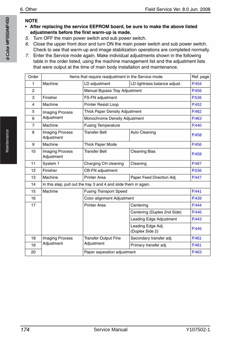
6. Other Field Service Ver. 8.0 Jun. 2008
174
Ma
inte
na
nce
NOTE• After replacing the service EEPROM board, be sure to make the above listed
adjustments before the first warm-up is made. 5. Turn OFF the main power switch and sub power switch.6. Close the upper front door and turn ON the main power switch and sub power switch.
Check to see that warm-up and image stabilization operations are completed normally.7. Enter the Service mode again. Make individual adjustments shown in the following
table in the order listed, using the machine management list and the adjustment lists that were output at the time of main body installation and maintenance.
Order Items that require readjustment in the Service mode Ref. page
1 Machine LD adjustment LD lightness balance adjust. P.454
2 Manual Bypass Tray Adjustment P.456
3 Finisher FS-FN adjustment P.536
4 Machine Printer Resist Loop P.452
5 Imaging Process Adjustment
Thick Paper Density Adjustment P.462
6 Monochrome Density Adjustment P.463
7 Machine Fusing Temperature P.440
8 Imaging Process Adjustment
Transfer Belt Auto CleaningP.458
9 Machine Thick Paper Mode P.456
10 Imaging Process Adjustment
Transfer Belt Cleaning BiasP.458
11 System 1 Charging CH cleaning Cleaning P.487
12 Finisher CB-FN adjustment P.536
13 Machine Printer Area Paper Feed Direction Adj. P.447
14 In this step, pull out the tray 3 and 4 and slide them in again.
15 Machine Fusing Transport Speed P.441
16 Color alignment Adjustment P.439
17 Printer Area Centering P.444
Centering (Duplex 2nd Side) P.446
Leading Edge Adjustment P.443
Leading Edge Adj. (Duplex Side 2)
P.445
18 Imaging Process Adjustment
Transfer Output Fine Adjustment
Secondary transfer adj. P.461
19 Primary transfer adj. P.461
20 Paper separation adjustment P.463
d-C
olor
MF5
50/M
F450
Service Manual Y107502-1
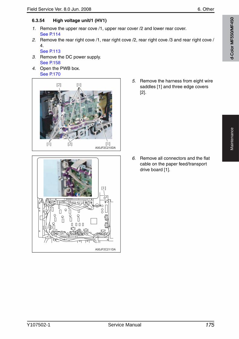
Field Service Ver. 8.0 Jun. 2008 6. Other
175
Ma
inte
na
nce
6.3.54 High voltage unit/1 (HV1)
1. Remove the upper rear cove /1, upper rear cover /2 and lower rear cover.See P.114
2. Remove the rear right cove /1, rear right cove /2, rear right cove /3 and rear right cove /4.See P.113
3. Remove the DC power supply.See P.158
4. Open the PWB box.See P.170
5. Remove the harness from eight wire saddles [1] and three edge covers[2].
6. Remove all connectors and the flat cable on the paper feed/transport drive board [1].
[1]
[1]
[2] [1]
[2]
A00JF2C210DA
A00JF2C211DA
[1]
d-C
olor
MF5
50/M
F450
Y107502-1 Service Manual
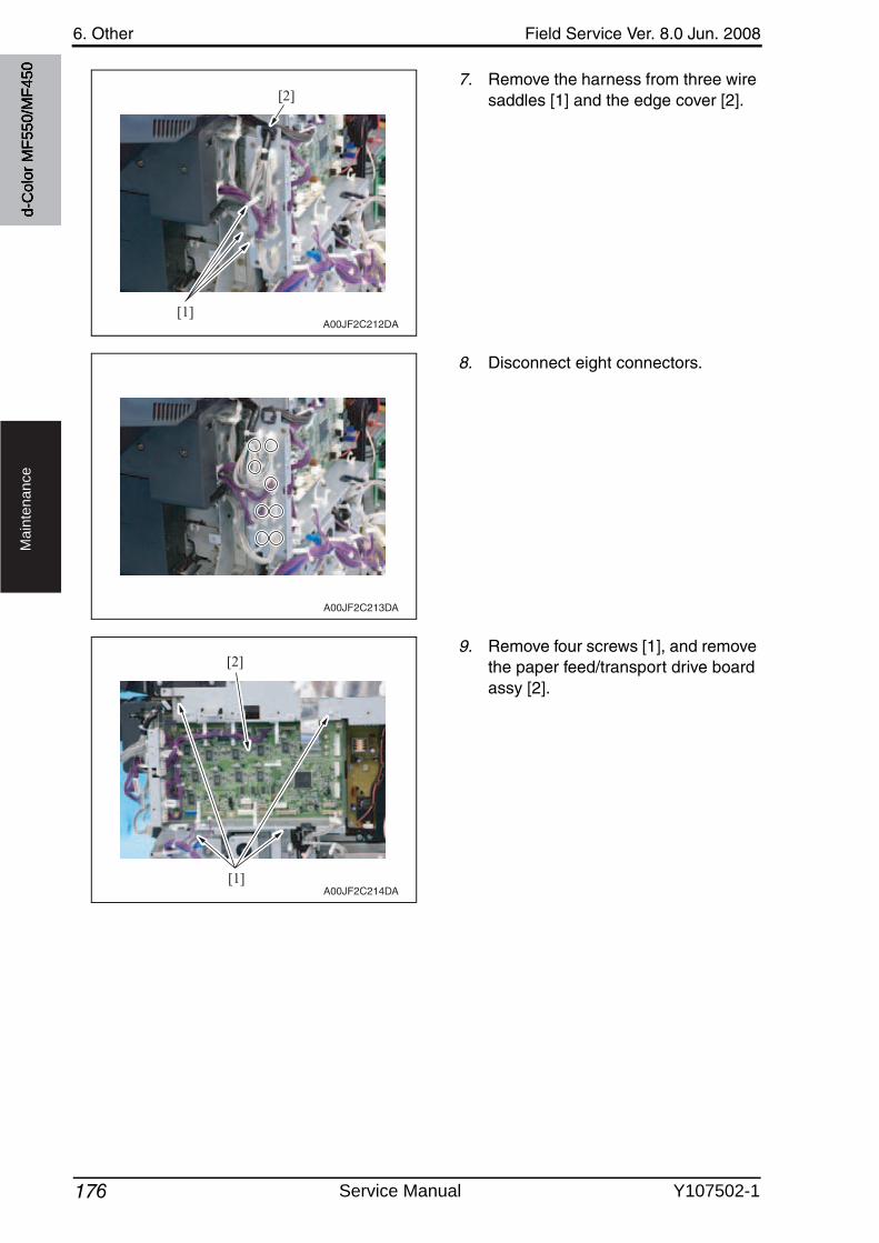
6. Other Field Service Ver. 8.0 Jun. 2008
176
Ma
inte
na
nce
7. Remove the harness from three wire saddles [1] and the edge cover [2].
8. Disconnect eight connectors.
9. Remove four screws [1], and removethe paper feed/transport drive board assy [2].
[1]
[2]
A00JF2C212DA
A00JF2C213DA
[1]
[2]
A00JF2C214DA
d-C
olor
MF5
50/M
F450
Service Manual Y107502-1
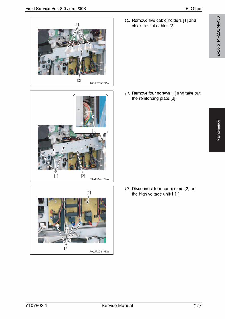
Field Service Ver. 8.0 Jun. 2008 6. Other
177
Ma
inte
na
nce
10. Remove five cable holders [1] and clear the flat cables [2].
11. Remove four screws [1] and take outthe reinforcing plate [2].
12. Disconnect four connectors [2] on the high voltage unit/1 [1].
[1]
[2]A00JF2C215DA
A00JF2C216DA[1]
[1]
[2]
[1]
[2]A00JF2C217DA
d-C
olor
MF5
50/M
F450
Y107502-1 Service Manual
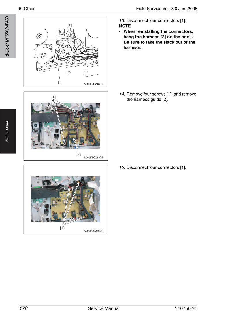
6. Other Field Service Ver. 8.0 Jun. 2008
178
Ma
inte
na
nce
13. Disconnect four connectors [1].NOTE• When reinstalling the connectors,
hang the harness [2] on the hook.Be sure to take the slack out of the harness.
14. Remove four screws [1], and removethe harness guide [2].
15. Disconnect four connectors [1].
[1]
[2]A00JF2C218DA
A00JF2C219DA
[1]
[2]
[1]A00JF2C246DA
d-C
olor
MF5
50/M
F450
Service Manual Y107502-1
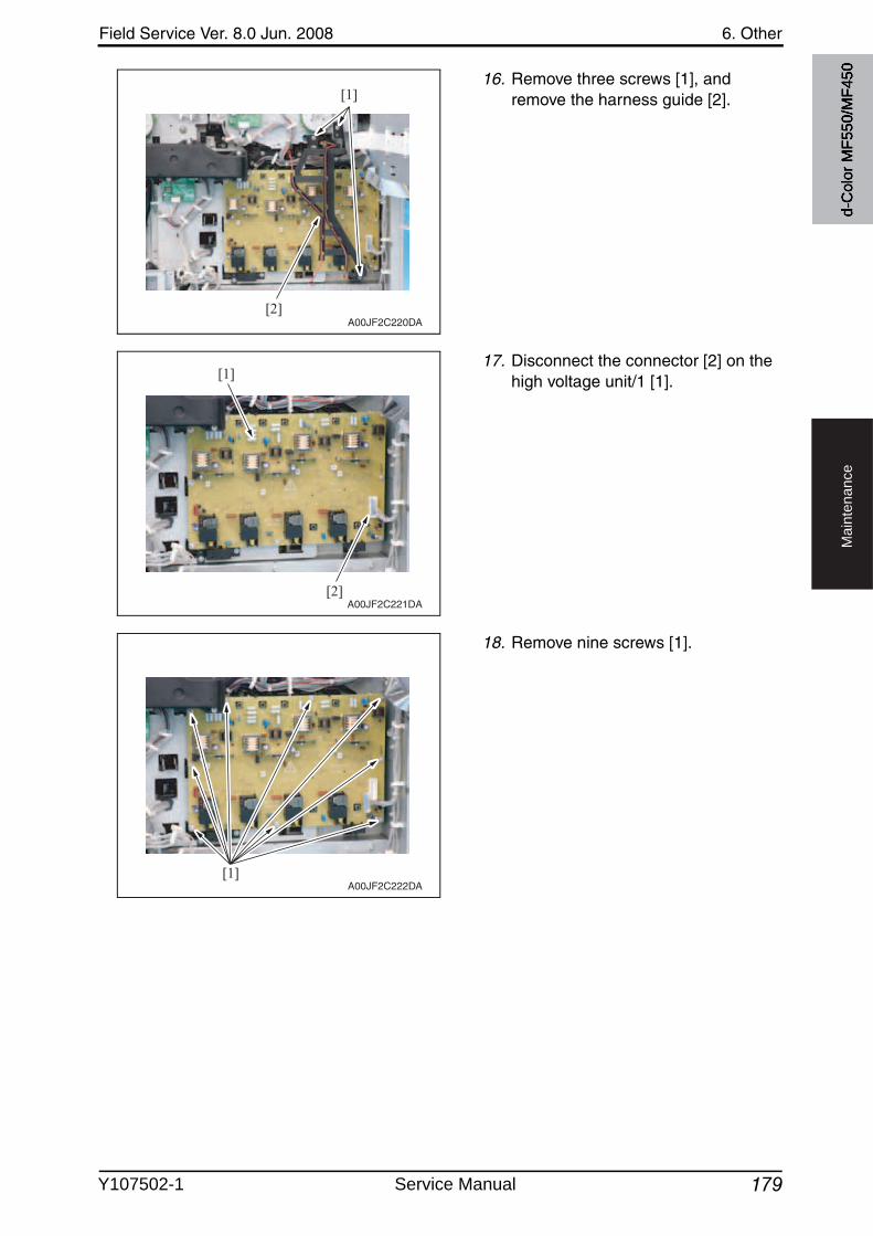
Field Service Ver. 8.0 Jun. 2008 6. Other
179
Ma
inte
na
nce
16. Remove three screws [1], and remove the harness guide [2].
17. Disconnect the connector [2] on the high voltage unit/1 [1].
18. Remove nine screws [1].
[1]
[2]A00JF2C220DA
[1]
[2]A00JF2C221DA
[1]A00JF2C222DA
d-C
olor
MF5
50/M
F450
Y107502-1 Service Manual
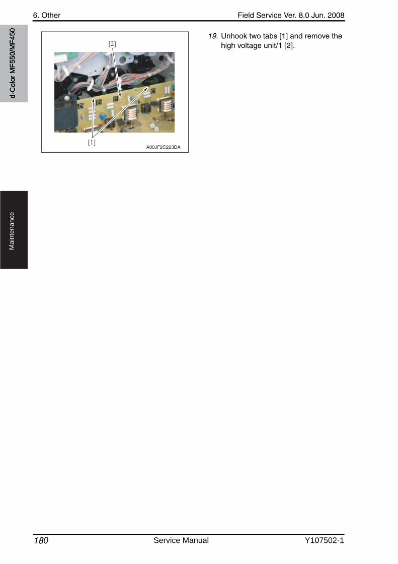
6. Other Field Service Ver. 8.0 Jun. 2008
180
Ma
inte
na
nce
19. Unhook two tabs [1] and remove the high voltage unit/1 [2].
[1]
[2]
A00JF2C223DA
d-C
olor
MF5
50/M
F450
Service Manual Y107502-1
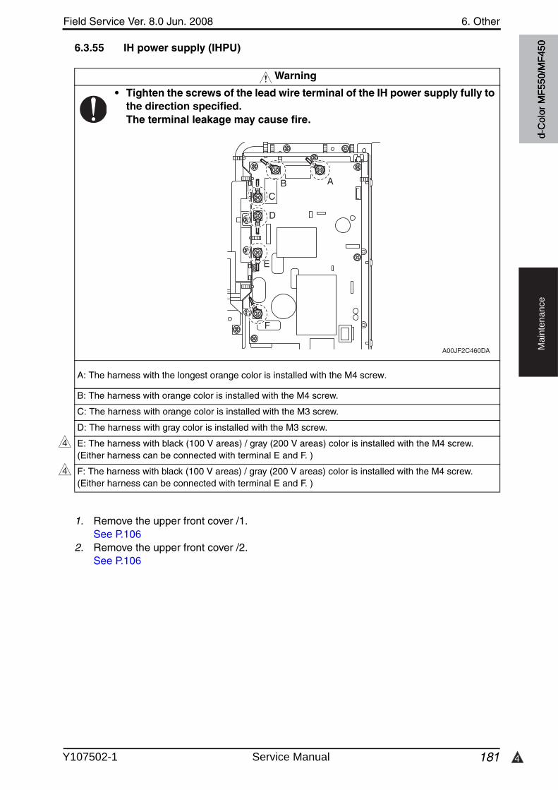
4
Field Service Ver. 8.0 Jun. 2008 6. Other
181
Ma
inte
na
nce
6.3.55 IH power supply (IHPU)
1. Remove the upper front cover /1.See P.106
2. Remove the upper front cover /2.See P.106
Warning
• Tighten the screws of the lead wire terminal of the IH power supply fully to the direction specified.The terminal leakage may cause fire.
B: The harness with orange color is installed with the M4 screw.
C: The harness with orange color is installed with the M3 screw.
D: The harness with gray color is installed with the M3 screw.
E: The harness with black (100 V areas) / gray (200 V areas) color is installed with the M4 screw.(Either harness can be connected with terminal E and F. )
F: The harness with black (100 V areas) / gray (200 V areas) color is installed with the M4 screw.(Either harness can be connected with terminal E and F. )
A00JF2C460DA
ABC
D
E
F
4
4
d-C
olor
MF5
50/M
F450
A: The harness with the longest orange color is installed with the M4 screw.
Y107502-1 Service Manual
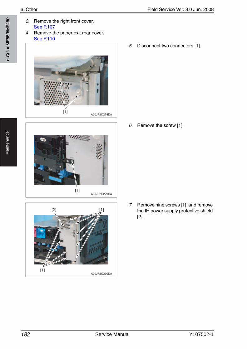
6. Other Field Service Ver. 8.0 Jun. 2008
182
Ma
inte
na
nce
3. Remove the right front cover.See P.107
4. Remove the paper exit rear cover.See P.110
5. Disconnect two connectors [1].
6. Remove the screw [1].
7. Remove nine screws [1], and removethe IH power supply protective shield [2].
[1]A00JF2C228DA
[1]A00JF2C229DA
[1]
[1][2]
A00JF2C230DA
d-C
olor
MF5
50/M
F450
Service Manual Y107502-1
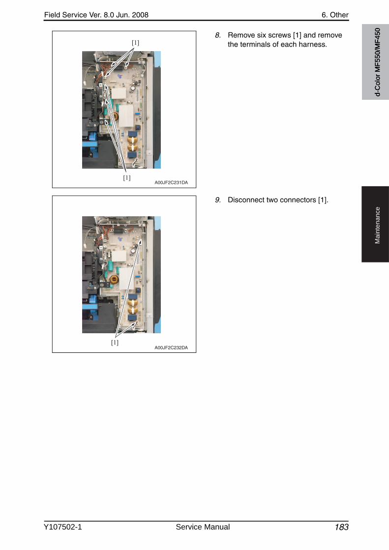
Field Service Ver. 8.0 Jun. 2008 6. Other
183
Ma
inte
na
nce
8. Remove six screws [1] and removethe terminals of each harness.
9. Disconnect two connectors [1].
[1]
[1]
A00JF2C231DA
[1]A00JF2C232DA
d-C
olor
MF5
50/M
F450
Y107502-1 Service Manual
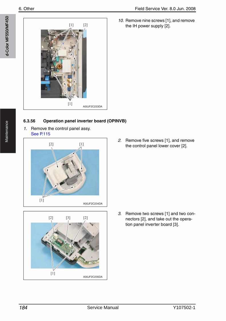
6. Other Field Service Ver. 8.0 Jun. 2008
184
Ma
inte
na
nce
10. Remove nine screws [1], and removethe IH power supply [2].
6.3.56 Operation panel inverter board (OPINVB)
1. Remove the control panel assy.See P.115
2. Remove five screws [1], and removethe control panel lower cover [2].
3. Remove two screws [1] and two con-nectors [2], and take out the opera-tion panel inverter board [3].
[1]
[1] [2]
A00JF2C233DA
[1]
[1][2]
A00JF2C234DA
[1]
[2] [2][3]
A00JF2C235DA
d-C
olor
MF5
50/M
F450
Service Manual Y107502-1
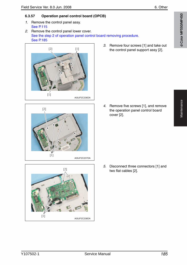
Field Service Ver. 8.0 Jun. 2008 6. Other
185
Ma
inte
na
nce
6.3.57 Operation panel control board (OPCB)
1. Remove the control panel assy.See P.115
2. Remove the control panel lower cover.See the step 2 of operation panel control board removing procedure.See P.185
3. Remove four screws [1] and take outthe control panel support assy [2].
4. Remove five screws [1], and removethe operation panel control board cover [2].
5. Disconnect three connectors [1] and two flat cables [2].
[1]
[1][2]
A00JF2C236DA
[1]
[2]
A00JF2C237DA
[1]
[2]
A00JF2C238DA
d-C
olor
MF5
50/M
F450
Y107502-1 Service Manual
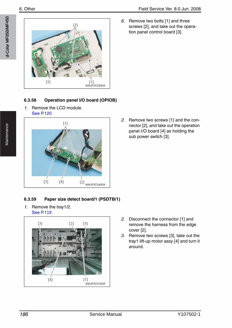
6. Other Field Service Ver. 8.0 Jun. 2008
186
Ma
inte
na
nce
6. Remove two bolts [1] and three screws [2], and take out the opera-tion panel control board [3].
6.3.58 Operation panel I/O board (OPIOB)
1. Remove the LCD module.See P.120
2. Remove two screws [1] and the con-nector [2], and take out the operation panel I/O board [4] as holding the sub power switch [3].
6.3.59 Paper size detect board/1 (PSDTB/1)
1. Remove the tray1/2.See P.119
2. Disconnect the connector [1] and remove the harness from the edge cover [2].
3. Remove two screws [3], take out the tray1 lift-up motor assy [4] and turn it around.
[1]
[2]
[3]A00JF2C239DA
[1]
[2][3] [4]A00JF2C240DA
[4] [1]
[3] [3][2]
A00JF2C310DA
d-C
olor
MF5
50/M
F450
Service Manual Y107502-1
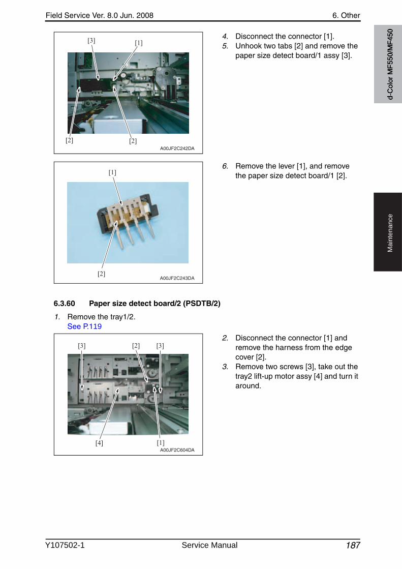
Field Service Ver. 8.0 Jun. 2008 6. Other
187
Ma
inte
na
nce
4. Disconnect the connector [1].5. Unhook two tabs [2] and remove the
paper size detect board/1 assy [3].
6. Remove the lever [1], and removethe paper size detect board/1 [2].
6.3.60 Paper size detect board/2 (PSDTB/2)
1. Remove the tray1/2.See P.119
2. Disconnect the connector [1] and remove the harness from the edge cover [2].
3. Remove two screws [3], take out the tray2 lift-up motor assy [4] and turn it around.
[2][2]
[3] [1]
A00JF2C242DA
[1]
[2]A00JF2C243DA
[4] [1]
[3] [3][2]
A00JF2C604DA
d-C
olor
MF5
50/M
F450
Y107502-1 Service Manual
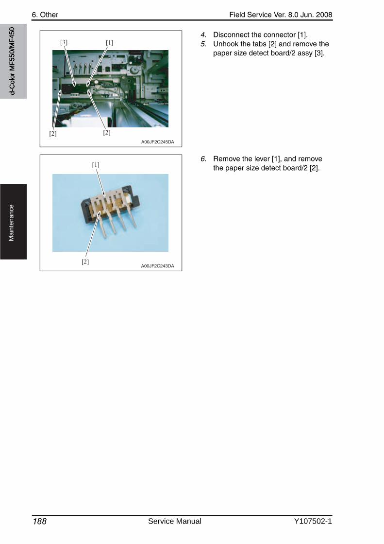
6. Other Field Service Ver. 8.0 Jun. 2008
188
Ma
inte
na
nce
4. Disconnect the connector [1].5. Unhook the tabs [2] and remove the
paper size detect board/2 assy [3].
6. Remove the lever [1], and removethe paper size detect board/2 [2].
[2][2]
[1][3]
A00JF2C245DA
[1]
[2]A00JF2C243DA
d-C
olor
MF5
50/M
F450
Service Manual Y107502-1
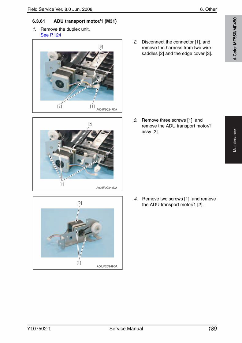
Field Service Ver. 8.0 Jun. 2008 6. Other
189
Ma
inte
na
nce
d-C
olor
MF5
50/M
F4506.3.61 ADU transport motor/1 (M31)
1. Remove the duplex unit.See P.124
2. Disconnect the connector [1], and remove the harness from two wire saddles [2] and the edge cover [3].
3. Remove three screws [1], and remove the ADU transport motor/1 assy [2].
[2] [1]
[3]
A00JF2C247DA
[1]
[2]
A00JF2C248DA
4. Remove two screws [1], and removethe ADU transport motor/1 [2].
[1]
[2]
A00JF2C249DA
Y107502-1 Service Manual
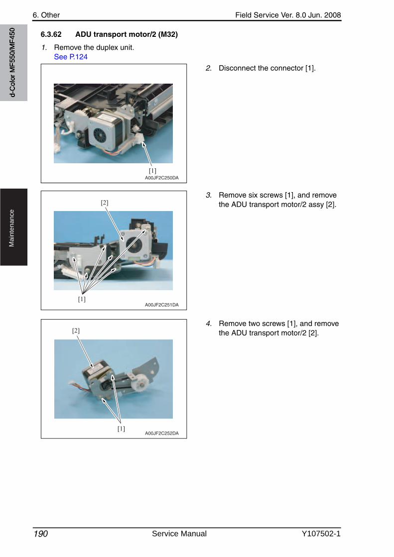
6. Other Field Service Ver. 8.0 Jun. 2008
190
Ma
inte
na
nce
d-C
olor
MF5
50/M
F450 6.3.62 ADU transport motor/2 (M32)
1. Remove the duplex unit.See P.124
2. Disconnect the connector [1].
3. Remove six screws [1], and removethe ADU transport motor/2 assy [2].
[1]A00JF2C250DA
[1]
[2]
A00JF2C251DA
4. Remove two screws [1], and removethe ADU transport motor/2 [2].
[1]
[2]
A00JF2C252DA
Service Manual Y107502-1
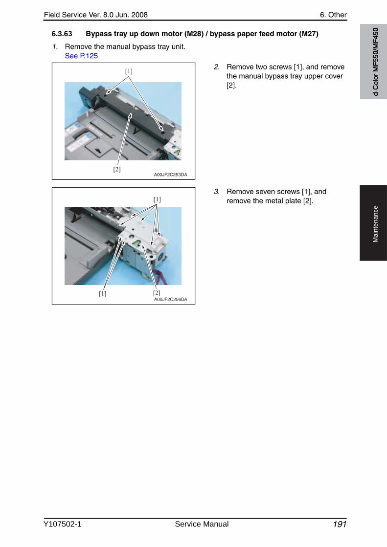
Field Service Ver. 8.0 Jun. 2008 6. Other
191
Ma
inte
na
nce
d-C
olor
MF5
50/M
F4506.3.63 Bypass tray up down motor (M28) / bypass paper feed motor (M27)
1. Remove the manual bypass tray unit.See P.125
2. Remove two screws [1], and removethe manual bypass tray upper cover[2].
3. Remove seven screws [1], and remove the metal plate [2].
[1]
[2]A00JF2C253DA
[1]
[1]
[2]A00JF2C256DA
Y107502-1 Service Manual
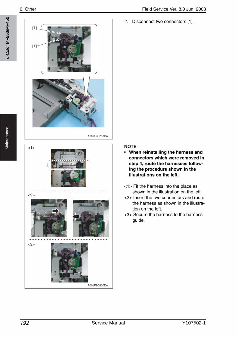
6. Other Field Service Ver. 8.0 Jun. 2008
192
Ma
inte
na
nce
4. Disconnect two connectors [1].
NOTE• When reinstalling the harness and
connectors which were removed in step 4, route the harnesses follow-ing the procedure shown in the illustrations on the left.
<1> Fit the harness into the place as shown in the illustration on the left.
<2> Insert the two connectors and route the harness as shown in the illustra-tion on the left.
<3> Secure the harness to the harness guide.
[1]
[1]
A00JF2C257DA
<1>
<2>
<3>
A00JF2C600DA
d-C
olor
MF5
50/M
F450
Service Manual Y107502-1
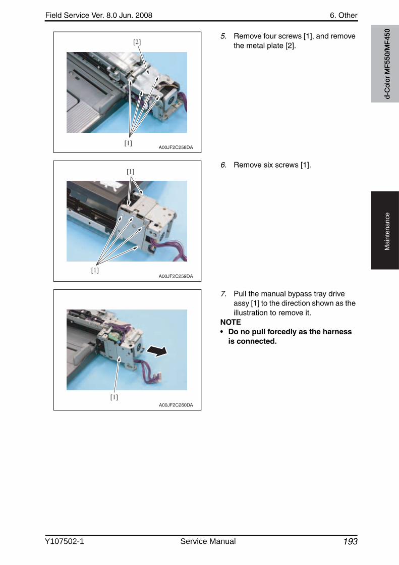
Field Service Ver. 8.0 Jun. 2008 6. Other
193
Ma
inte
na
nce
5. Remove four screws [1], and removethe metal plate [2].
6. Remove six screws [1].
7. Pull the manual bypass tray driveassy [1] to the direction shown as the illustration to remove it.
NOTE• Do no pull forcedly as the harness
is connected.
[1]
[2]
A00JF2C258DA
[1]
[1]
A00JF2C259DA
[1]A00JF2C260DA
d-C
olor
MF5
50/M
F450
Y107502-1 Service Manual
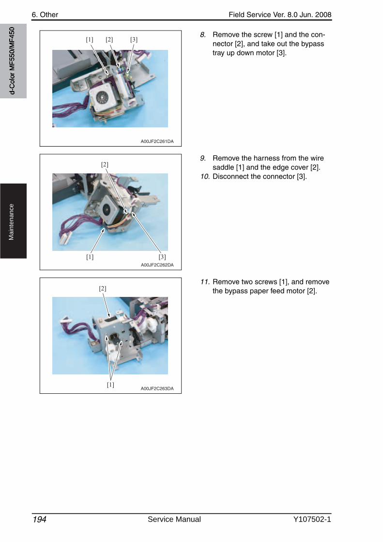
6. Other Field Service Ver. 8.0 Jun. 2008
194
Ma
inte
na
nce
8. Remove the screw [1] and the con-nector [2], and take out the bypass tray up down motor [3].
9. Remove the harness from the wire saddle [1] and the edge cover [2].
10. Disconnect the connector [3].
11. Remove two screws [1], and removethe bypass paper feed motor [2].
[1] [2] [3]
A00JF2C261DA
[2]
[3][1]A00JF2C262DA
[1]
[2]
A00JF2C263DA
d-C
olor
MF5
50/M
F450
Service Manual Y107502-1
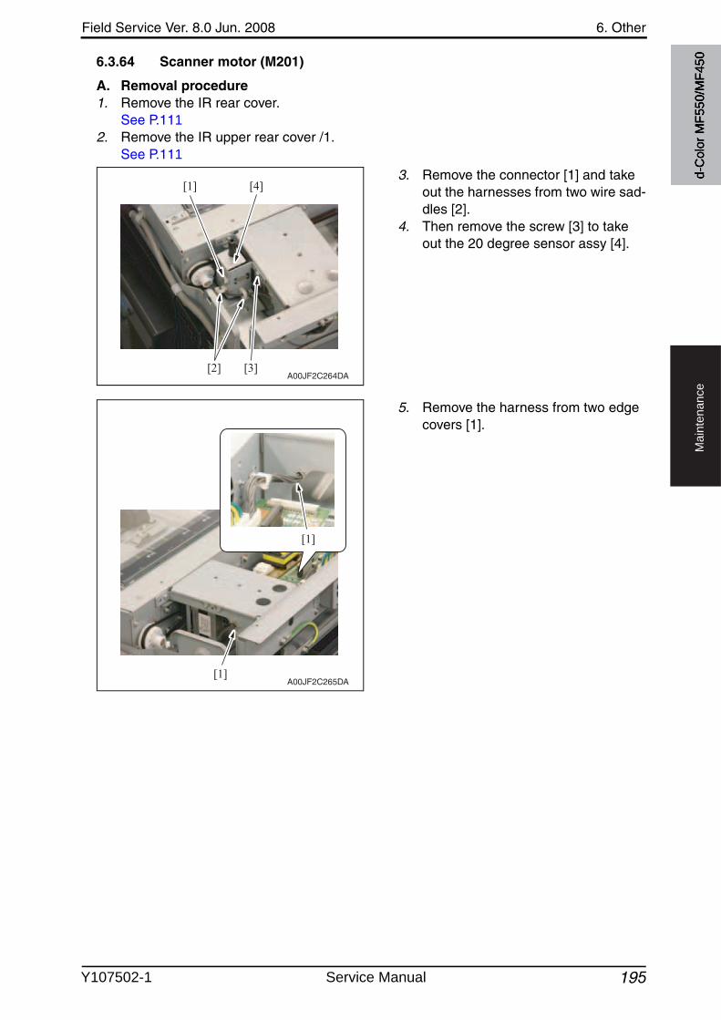
Field Service Ver. 8.0 Jun. 2008 6. Other
195
Ma
inte
na
nce
6.3.64 Scanner motor (M201)
A. Removal procedure1. Remove the IR rear cover.
See P.1112. Remove the IR upper rear cover /1.
See P.111
3. Remove the connector [1] and take out the harnesses from two wire sad-dles [2].
4. Then remove the screw [3] to take out the 20 degree sensor assy [4].
5. Remove the harness from two edge covers [1].
[4][1]
[2] [3]A00JF2C264DA
A00JF2C265DA
[1]
[1]
d-C
olor
MF5
50/M
F450
Y107502-1 Service Manual
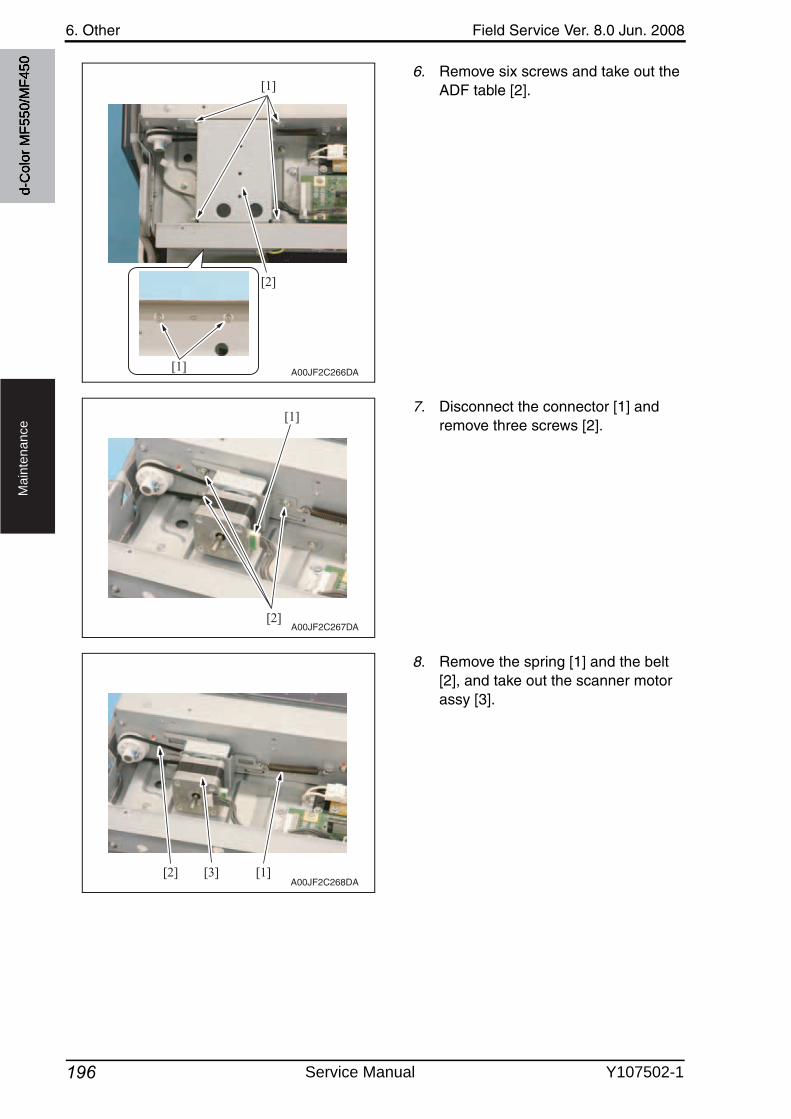
6. Other Field Service Ver. 8.0 Jun. 2008
196
Ma
inte
na
nce
6. Remove six screws and take out the ADF table [2].
7. Disconnect the connector [1] and remove three screws [2].
8. Remove the spring [1] and the belt [2], and take out the scanner motor assy [3].
A00JF2C266DA
[1]
[1]
[2]
[2]
[1]
A00JF2C267DA
[1][2] [3]A00JF2C268DA
d-C
olor
MF5
50/M
F450
Service Manual Y107502-1
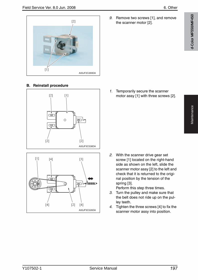
Field Service Ver. 8.0 Jun. 2008 6. Other
197
Ma
inte
na
nce
9. Remove two screws [1], and removethe scanner motor [2].
B. Reinstall procedure
1. Temporarily secure the scanner motor assy [1] with three screws [2].
2. With the scanner drive gear set screw [1] located on the right-hand side as shown on the left, slide the scanner motor assy [2] to the left and check that it is returned to the origi-nal position by the tension of the spring [3]. Perform this step three times.
3. Turn the pulley and make sure that the belt does not ride up on the pul-ley teeth.
4. Tighten the three screws [4] to fix the scanner motor assy into position.
[1]
[2]
A00JF2C269DA
A00JF3C538DA
[2] [1]
[2] [2]
A00JF3C526DA
[3]
[2]
[4][1]
[4] [4]
d-C
olor
MF5
50/M
F450
Y107502-1 Service Manual
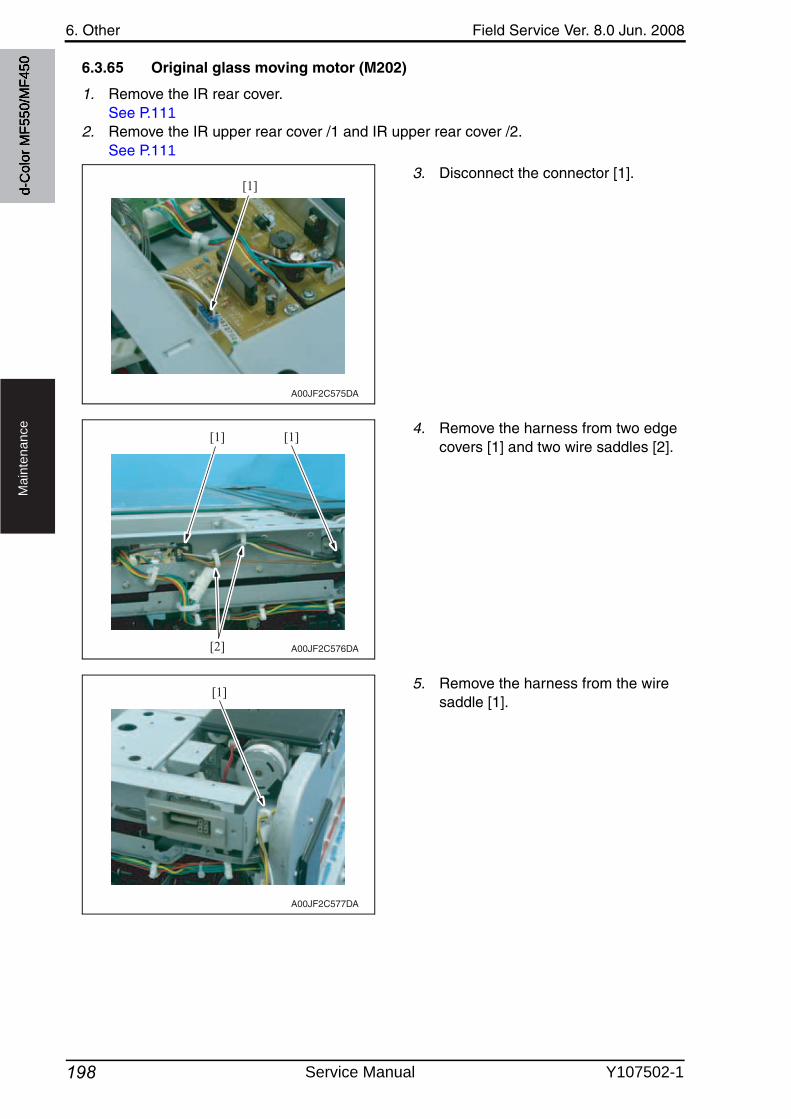
6. Other Field Service Ver. 8.0 Jun. 2008
198
Ma
inte
na
nce
6.3.65 Original glass moving motor (M202)
1. Remove the IR rear cover.See P.111
2. Remove the IR upper rear cover /1 and IR upper rear cover /2.See P.111
3. Disconnect the connector [1].
4. Remove the harness from two edge covers [1] and two wire saddles [2].
5. Remove the harness from the wire saddle [1].
[1]
A00JF2C575DA
[1]
[2]
[1]
A00JF2C576DA
[1]
A00JF2C577DA
d-C
olor
MF5
50/M
F450
Service Manual Y107502-1
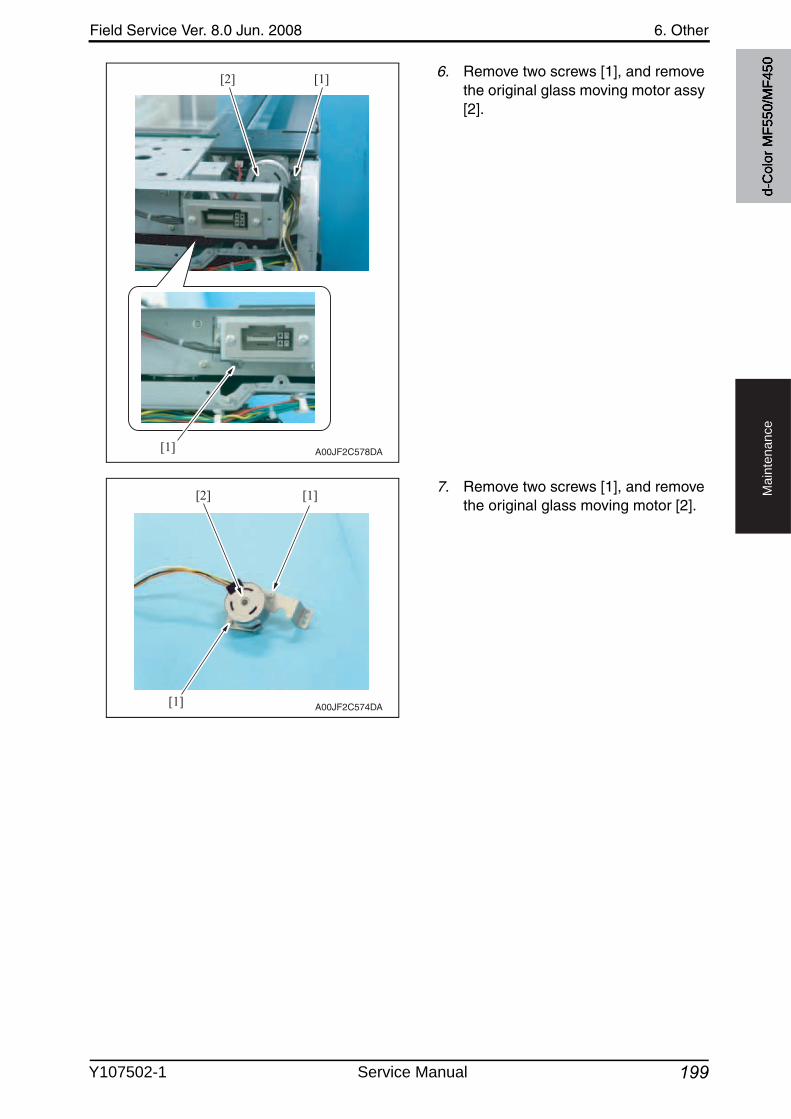
Field Service Ver. 8.0 Jun. 2008 6. Other
199
Ma
inte
na
nce
6. Remove two screws [1], and removethe original glass moving motor assy [2].
7. Remove two screws [1], and removethe original glass moving motor [2].
[1]
[1]
[2]
A00JF2C578DA
[2] [1]
[1] A00JF2C574DA
d-C
olor
MF5
50/M
F450
Y107502-1 Service Manual
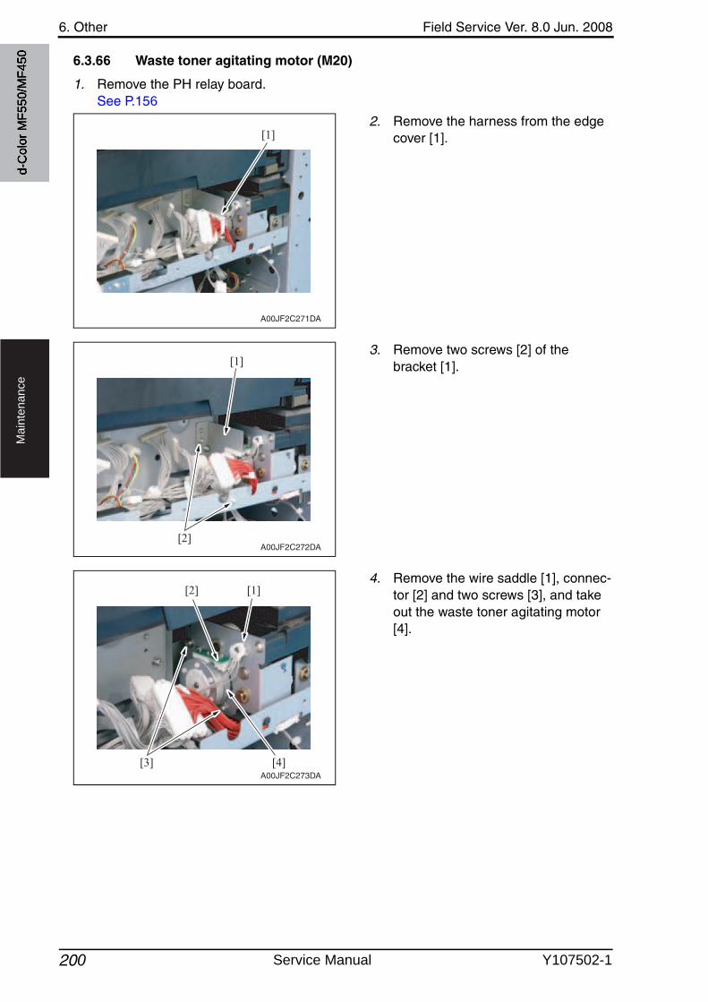
6. Other Field Service Ver. 8.0 Jun. 2008
200
Ma
inte
na
nce
6.3.66 Waste toner agitating motor (M20)
1. Remove the PH relay board.See P.156
2. Remove the harness from the edge cover [1].
3. Remove two screws [2] of the bracket [1].
4. Remove the wire saddle [1], connec-tor [2] and two screws [3], and take out the waste toner agitating motor [4].
[1]
A00JF2C271DA
[2]
[1]
A00JF2C272DA
[4][3]
[1][2]
A00JF2C273DA
d-C
olor
MF5
50/M
F450
Service Manual Y107502-1
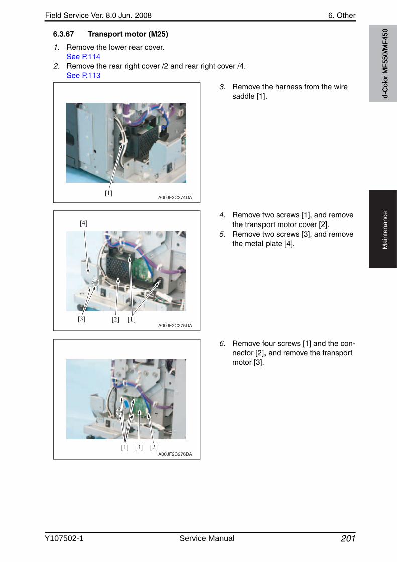
Field Service Ver. 8.0 Jun. 2008 6. Other
201
Ma
inte
na
nce
6.3.67 Transport motor (M25)
1. Remove the lower rear cover.See P.114
2. Remove the rear right cover /2 and rear right cover /4.See P.113
3. Remove the harness from the wire saddle [1].
4. Remove two screws [1], and removethe transport motor cover [2].
5. Remove two screws [3], and removethe metal plate [4].
6. Remove four screws [1] and the con-nector [2], and remove the transport motor [3].
[1]A00JF2C274DA
[1][2][3]
[4]
A00JF2C275DA
[1] [2][3]A00JF2C276DA
d-C
olor
MF5
50/M
F450
Y107502-1 Service Manual
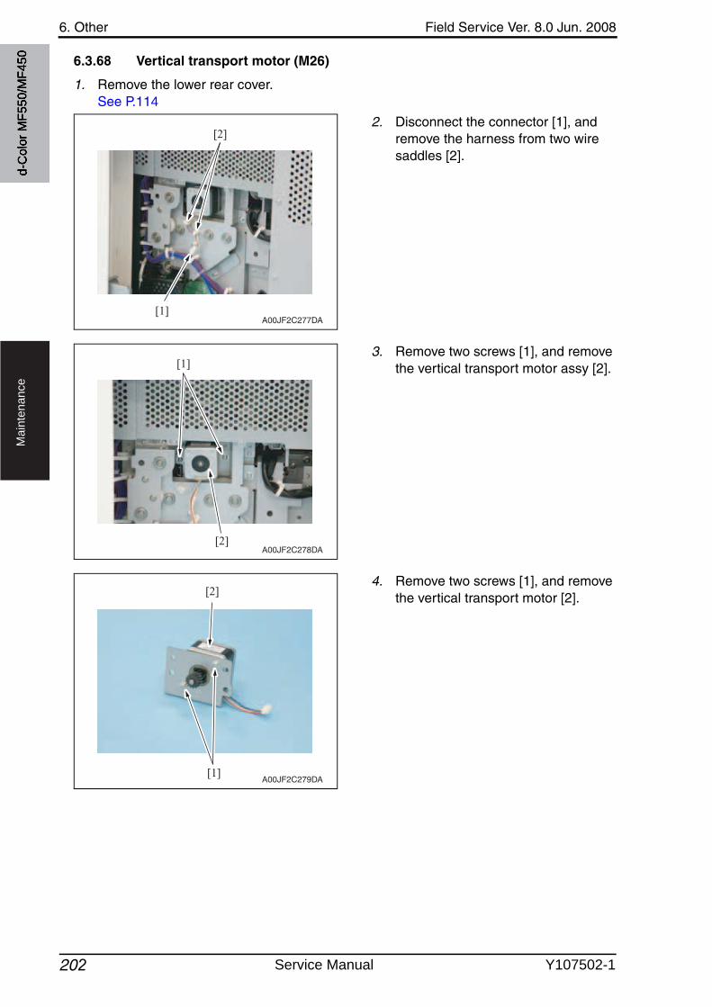
6. Other Field Service Ver. 8.0 Jun. 2008
202
Ma
inte
na
nce
6.3.68 Vertical transport motor (M26)
1. Remove the lower rear cover.See P.114
2. Disconnect the connector [1], and remove the harness from two wire saddles [2].
3. Remove two screws [1], and removethe vertical transport motor assy [2].
4. Remove two screws [1], and removethe vertical transport motor [2].
[1]
[2]
A00JF2C277DA
[1]
[2]A00JF2C278DA
[1]
[2]
A00JF2C279DA
d-C
olor
MF5
50/M
F450
Service Manual Y107502-1
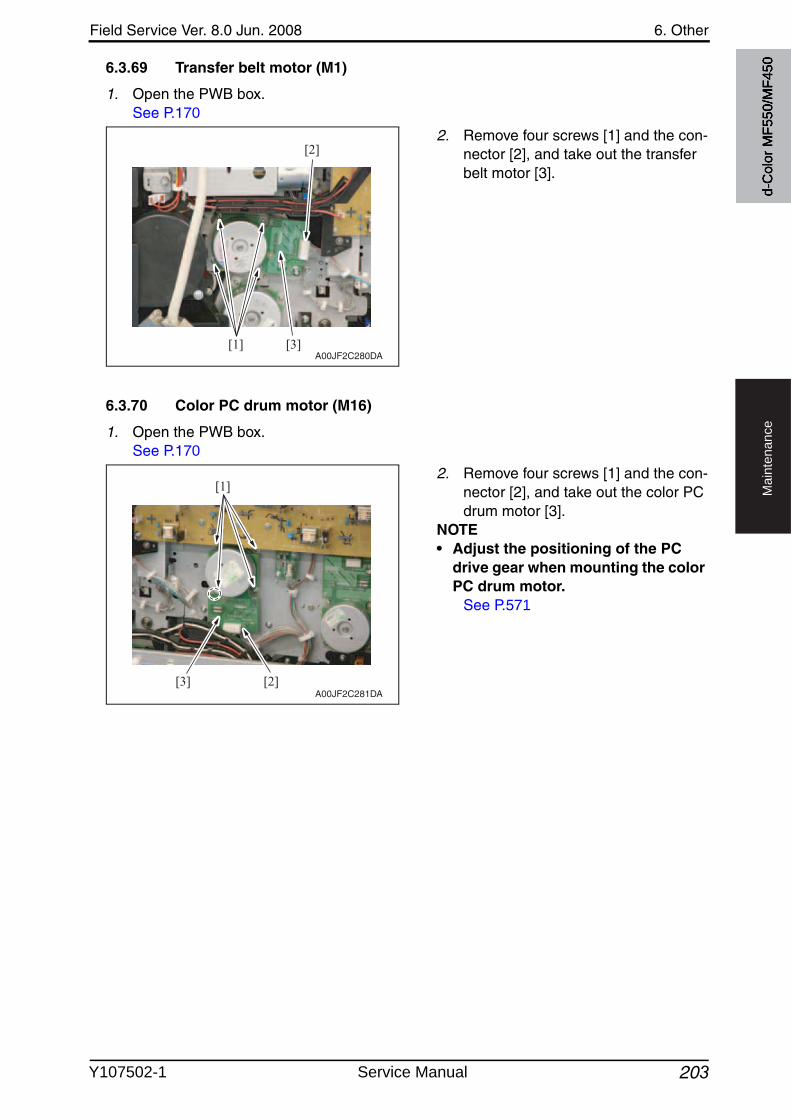
Field Service Ver. 8.0 Jun. 2008 6. Other
203
Ma
inte
na
nce
6.3.69 Transfer belt motor (M1)
1. Open the PWB box.See P.170
2. Remove four screws [1] and the con-nector [2], and take out the transfer belt motor [3].
6.3.70 Color PC drum motor (M16)
1. Open the PWB box.See P.170
2. Remove four screws [1] and the con-nector [2], and take out the color PC drum motor [3].
NOTE• Adjust the positioning of the PC
drive gear when mounting the color PC drum motor.
See P.571
[1]
[2]
[3]A00JF2C280DA
[1]
[2][3]A00JF2C281DA
d-C
olor
MF5
50/M
F450
Y107502-1 Service Manual
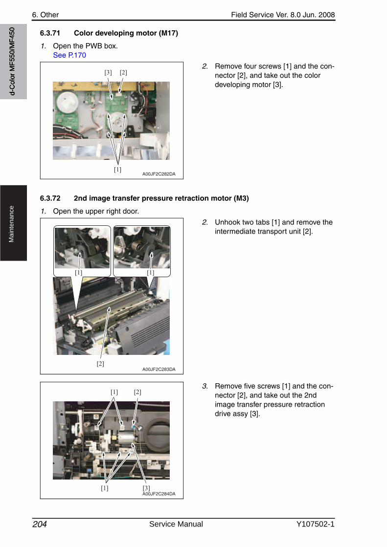
6. Other Field Service Ver. 8.0 Jun. 2008
204
Ma
inte
na
nce
6.3.71 Color developing motor (M17)
1. Open the PWB box.See P.170
2. Remove four screws [1] and the con-nector [2], and take out the color developing motor [3].
6.3.72 2nd image transfer pressure retraction motor (M3)
1. Open the upper right door.
2. Unhook two tabs [1] and remove the intermediate transport unit [2].
3. Remove five screws [1] and the con-nector [2], and take out the 2nd image transfer pressure retraction drive assy [3].
[1]
[2][3]
A00JF2C282DA
A00JF2C283DA
[1] [1]
[2]
[1]
[1] [2]
[3]A00JF2C284DA
d-C
olor
MF5
50/M
F450
Service Manual Y107502-1
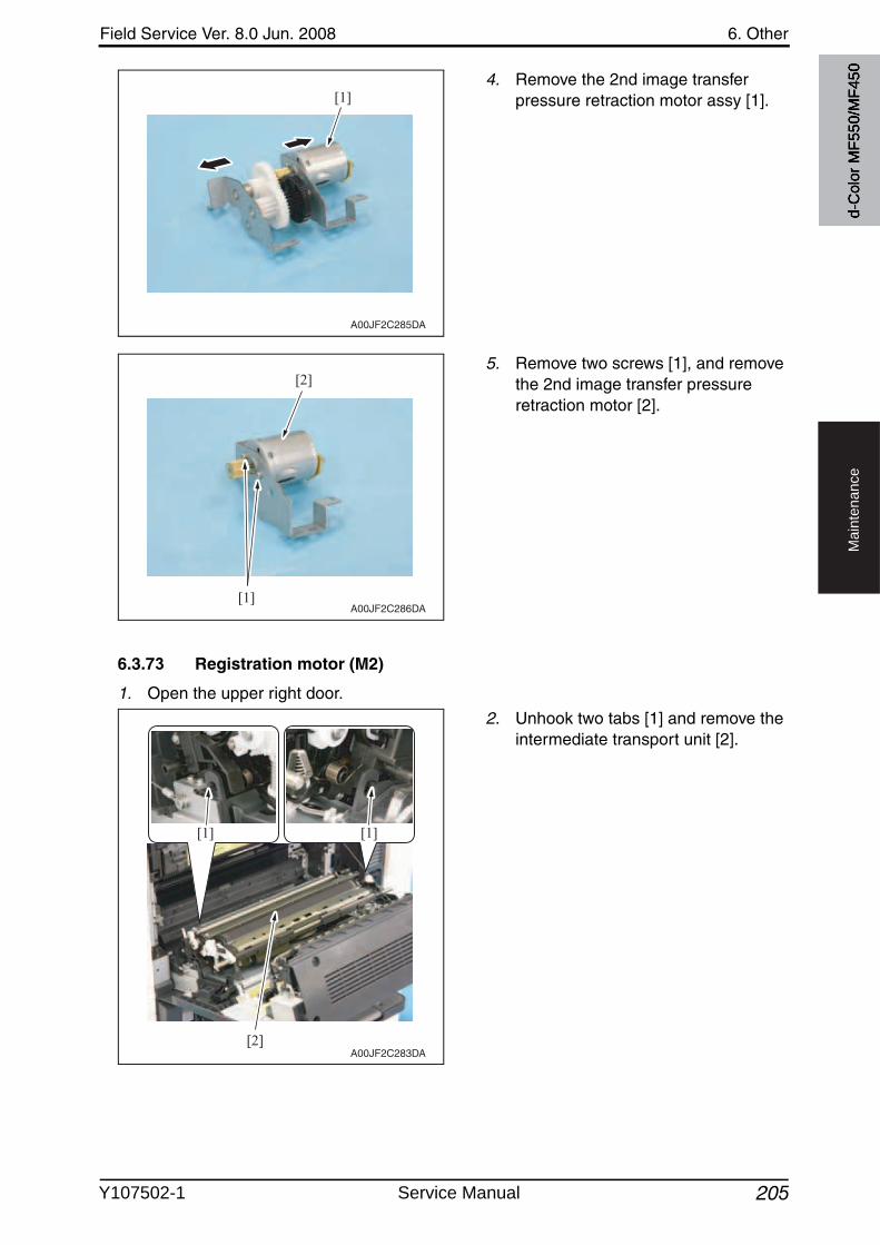
Field Service Ver. 8.0 Jun. 2008 6. Other
205
Ma
inte
na
nce
4. Remove the 2nd image transfer pressure retraction motor assy [1].
5. Remove two screws [1], and removethe 2nd image transfer pressureretraction motor [2].
6.3.73 Registration motor (M2)
1. Open the upper right door.
2. Unhook two tabs [1] and remove the intermediate transport unit [2].
[1]
A00JF2C285DA
[1]
[2]
A00JF2C286DA
A00JF2C283DA
[1] [1]
[2]
d-C
olor
MF5
50/M
F450
Y107502-1 Service Manual
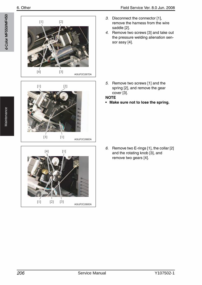
6. Other Field Service Ver. 8.0 Jun. 2008
206
Ma
inte
na
nce
3. Disconnect the connector [1], remove the harness from the wire saddle [2].
4. Remove two screws [3] and take outthe pressure welding alienation sen-sor assy [4].
5. Remove two screws [1] and the spring [2], and remove the gear cover [3].
NOTE• Make sure not to lose the spring.
6. Remove two E-rings [1], the collar [2] and the rotating knob [3], and remove two gears [4].
[4]
[1] [2]
[3]A00JF2C287DA
[1]
[2][1]
[3]A00JF2C288DA
[1]
[1]
[2]
[4]
[3]A00JF2C289DA
d-C
olor
MF5
50/M
F450
Service Manual Y107502-1
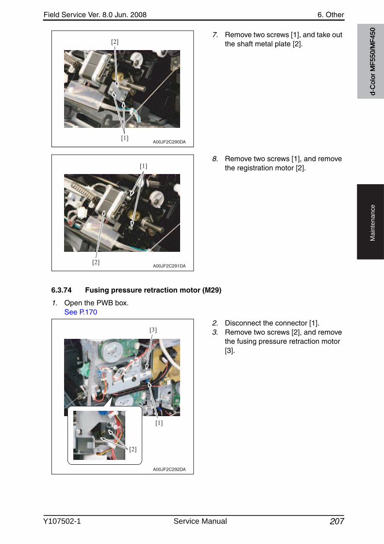
Field Service Ver. 8.0 Jun. 2008 6. Other
207
Ma
inte
na
nce
7. Remove two screws [1], and take outthe shaft metal plate [2].
8. Remove two screws [1], and removethe registration motor [2].
6.3.74 Fusing pressure retraction motor (M29)
1. Open the PWB box.See P.170
2. Disconnect the connector [1].3. Remove two screws [2], and remove
the fusing pressure retraction motor [3].
[1]
[2]
A00JF2C290DA
[1]
[2]A00JF2C291DA
A00JF2C292DA
[2]
[1]
[3]
d-C
olor
MF5
50/M
F450
Y107502-1 Service Manual
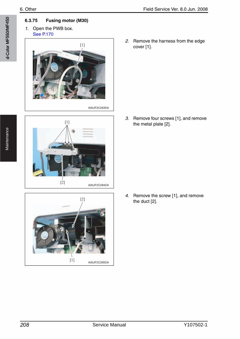
6. Other Field Service Ver. 8.0 Jun. 2008
208
Ma
inte
na
nce
6.3.75 Fusing motor (M30)
1. Open the PWB box.See P.170
2. Remove the harness from the edge cover [1].
3. Remove four screws [1], and removethe metal plate [2].
4. Remove the screw [1], and removethe duct [2].
[1]
A00JF2C293DA
[1]
[2]A00JF2C294DA
[1]
[2]
A00JF2C295DA
d-C
olor
MF5
50/M
F450
Service Manual Y107502-1
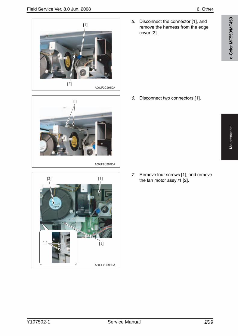
Field Service Ver. 8.0 Jun. 2008 6. Other
209
Ma
inte
na
nce
5. Disconnect the connector [1], and remove the harness from the edge cover [2].
6. Disconnect two connectors [1].
7. Remove four screws [1], and removethe fan motor assy /1 [2].
[1]
[2]A00JF2C296DA
[1]
A00JF2C297DA
A00JF2C298DA
[1] [1]
[2] [1]
d-C
olor
MF5
50/M
F450
Y107502-1 Service Manual
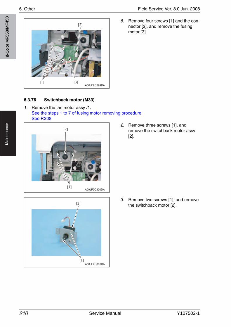
6. Other Field Service Ver. 8.0 Jun. 2008
210
Ma
inte
na
nce
8. Remove four screws [1] and the con-nector [2], and remove the fusingmotor [3].
6.3.76 Switchback motor (M33)
1. Remove the fan motor assy /1.See the steps 1 to 7 of fusing motor removing procedure.See P.208
2. Remove three screws [1], and remove the switchback motor assy [2].
3. Remove two screws [1], and removethe switchback motor [2].
[1]
[2]
[3]A00JF2C299DA
[1]
[2]
A00JF2C300DA
[1]
[2]
A00JF2C301DA
d-C
olor
MF5
50/M
F450
Service Manual Y107502-1
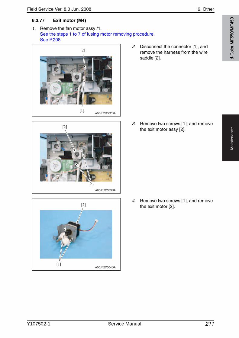
Field Service Ver. 8.0 Jun. 2008 6. Other
211
Ma
inte
na
nce
6.3.77 Exit motor (M4)
1. Remove the fan motor assy /1.See the steps 1 to 7 of fusing motor removing procedure.See P.208
2. Disconnect the connector [1], and remove the harness from the wire saddle [2].
3. Remove two screws [1], and removethe exit motor assy [2].
4. Remove two screws [1], and removethe exit motor [2].
[1]
[2]
A00JF2C302DA
[1]
[2]
A00JF2C303DA
[1]
[2]
A00JF2C304DA
d-C
olor
MF5
50/M
F450
Y107502-1 Service Manual
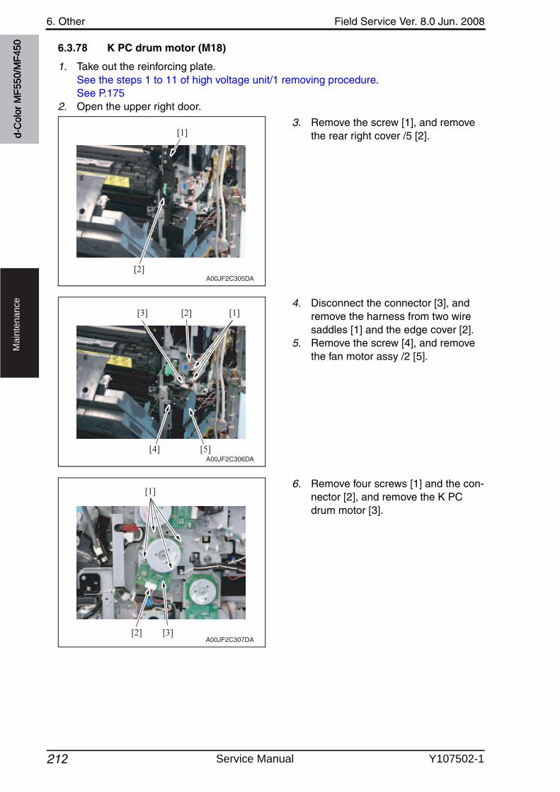
6. Other Field Service Ver. 8.0 Jun. 2008
212
Ma
inte
na
nce
6.3.78 K PC drum motor (M18)
1. Take out the reinforcing plate.See the steps 1 to 11 of high voltage unit/1 removing procedure.See P.175
2. Open the upper right door.
3. Remove the screw [1], and removethe rear right cover /5 [2].
4. Disconnect the connector [3], and remove the harness from two wire saddles [1] and the edge cover [2].
5. Remove the screw [4], and removethe fan motor assy /2 [5].
6. Remove four screws [1] and the con-nector [2], and remove the K PC drum motor [3].
[1]
[2]A00JF2C305DA
[4]
[1][2][3]
[5]A00JF2C306DA
[1]
[2] [3]A00JF2C307DA
d-C
olor
MF5
50/M
F450
Service Manual Y107502-1
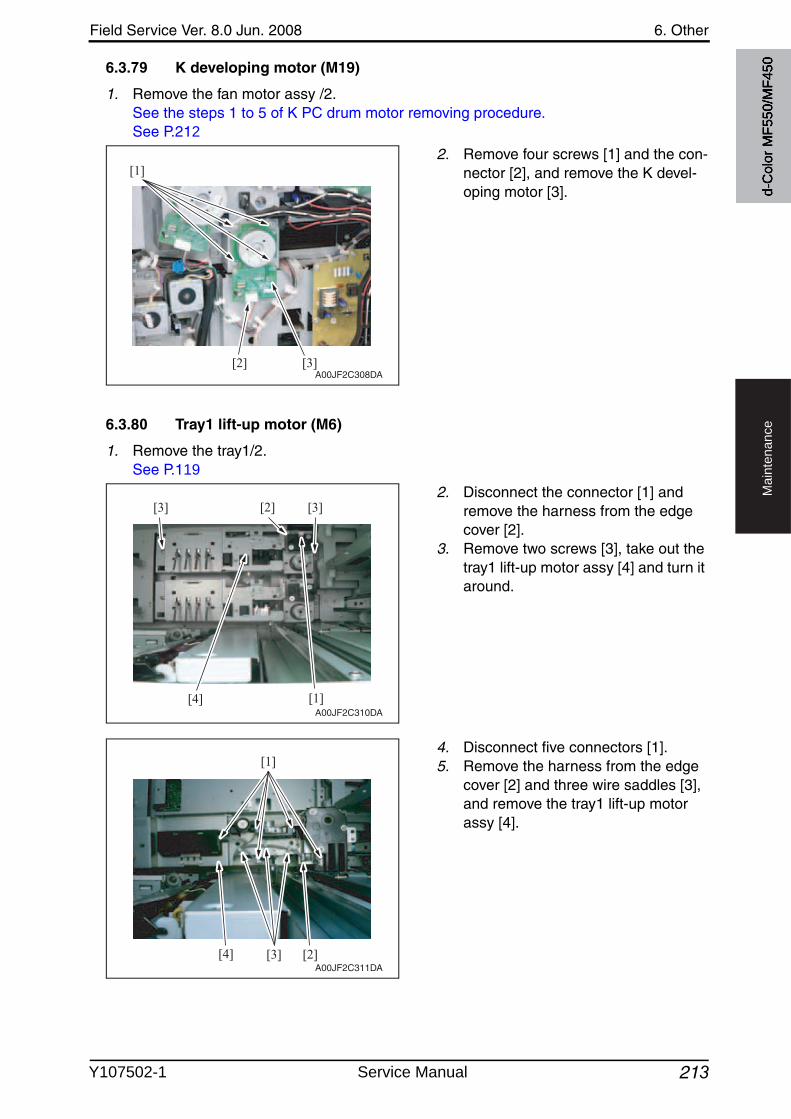
Field Service Ver. 8.0 Jun. 2008 6. Other
213
Ma
inte
na
nce
6.3.79 K developing motor (M19)
1. Remove the fan motor assy /2.See the steps 1 to 5 of K PC drum motor removing procedure.See P.212
2. Remove four screws [1] and the con-nector [2], and remove the K devel-oping motor [3].
6.3.80 Tray1 lift-up motor (M6)
1. Remove the tray1/2.See P.119
2. Disconnect the connector [1] and remove the harness from the edge cover [2].
3. Remove two screws [3], take out the tray1 lift-up motor assy [4] and turn it around.
4. Disconnect five connectors [1].5. Remove the harness from the edge
cover [2] and three wire saddles [3], and remove the tray1 lift-up motor assy [4].
[1]
[2] [3]A00JF2C308DA
[4] [1]
[3] [3][2]
A00JF2C310DA
[3] [2][4]
[1]
A00JF2C311DA
d-C
olor
MF5
50/M
F450
Y107502-1 Service Manual
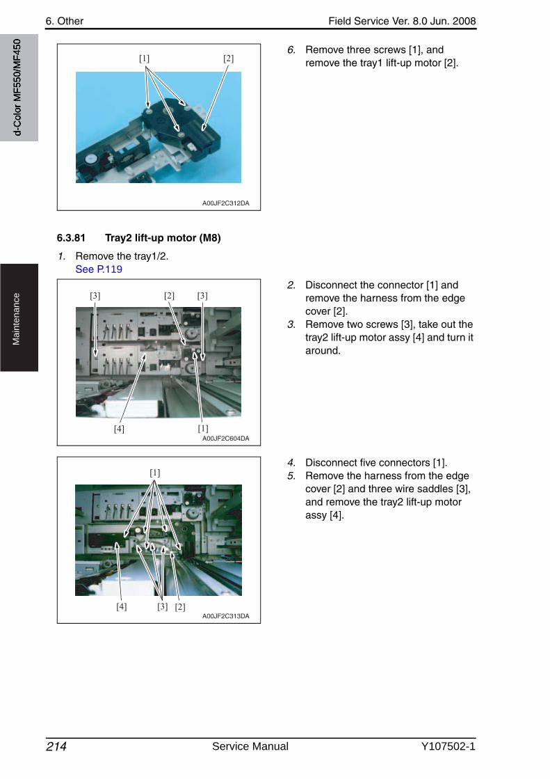
6. Other Field Service Ver. 8.0 Jun. 2008
214
Ma
inte
na
nce
6. Remove three screws [1], and remove the tray1 lift-up motor [2].
6.3.81 Tray2 lift-up motor (M8)
1. Remove the tray1/2.See P.119
2. Disconnect the connector [1] and remove the harness from the edge cover [2].
3. Remove two screws [3], take out the tray2 lift-up motor assy [4] and turn it around.
4. Disconnect five connectors [1].5. Remove the harness from the edge
cover [2] and three wire saddles [3], and remove the tray2 lift-up motor assy [4].
[1] [2]
A00JF2C312DA
[4] [1]
[3] [3][2]
A00JF2C604DA
[3] [2][4]
[1]
A00JF2C313DA
d-C
olor
MF5
50/M
F450
Service Manual Y107502-1
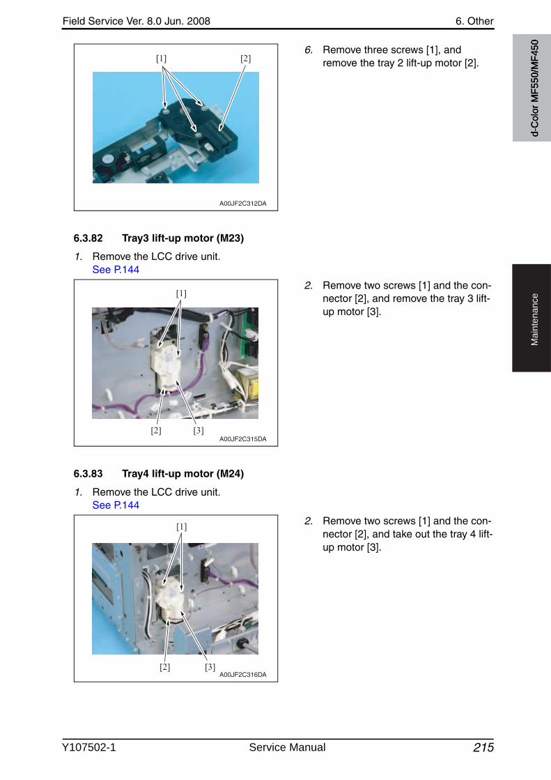
Field Service Ver. 8.0 Jun. 2008 6. Other
215
Ma
inte
na
nce
6. Remove three screws [1], and remove the tray 2 lift-up motor [2].
6.3.82 Tray3 lift-up motor (M23)
1. Remove the LCC drive unit.See P.144
2. Remove two screws [1] and the con-nector [2], and remove the tray 3 lift-up motor [3].
6.3.83 Tray4 lift-up motor (M24)
1. Remove the LCC drive unit.See P.144
2. Remove two screws [1] and the con-nector [2], and take out the tray 4 lift-up motor [3].
[1] [2]
A00JF2C312DA
[1]
[2] [3]A00JF2C315DA
[1]
[2] [3]A00JF2C316DA
d-C
olor
MF5
50/M
F450
Y107502-1 Service Manual
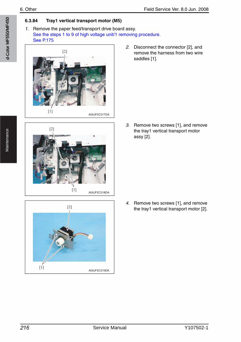
6. Other Field Service Ver. 8.0 Jun. 2008
216
Ma
inte
na
nce
6.3.84 Tray1 vertical transport motor (M5)
1. Remove the paper feed/transport drive board assy.See the steps 1 to 9 of high voltage unit/1 removing procedure.See P.175
2. Disconnect the connector [2], and remove the harness from two wire saddles [1].
3. Remove two screws [1], and removethe tray1 vertical transport motor assy [2].
4. Remove two screws [1], and removethe tray1 vertical transport motor [2].
[1]
[2]
A00JF2C317DA
[1]
[2]
A00JF2C318DA
[1]
[2]
A00JF2C319DA
d-C
olor
MF5
50/M
F450
Service Manual Y107502-1
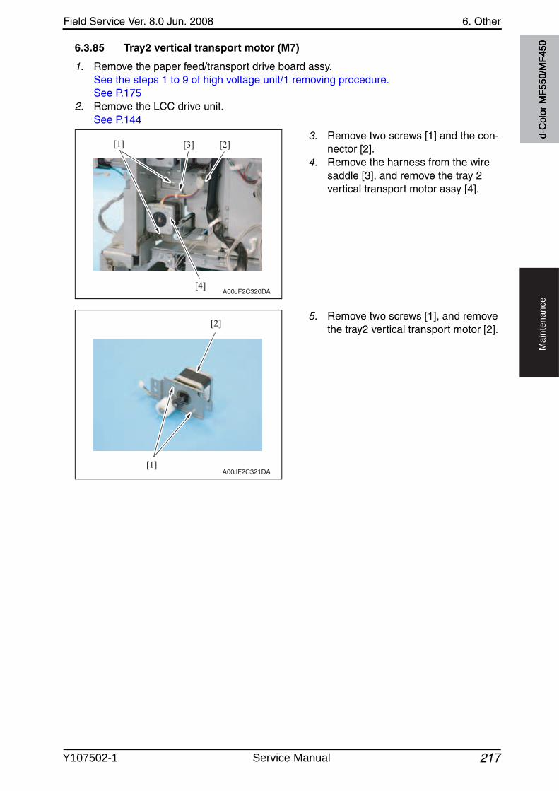
Field Service Ver. 8.0 Jun. 2008 6. Other
217
Ma
inte
na
nce
6.3.85 Tray2 vertical transport motor (M7)
1. Remove the paper feed/transport drive board assy.See the steps 1 to 9 of high voltage unit/1 removing procedure.See P.175
2. Remove the LCC drive unit.See P.144
3. Remove two screws [1] and the con-nector [2].
4. Remove the harness from the wire saddle [3], and remove the tray 2 vertical transport motor assy [4].
5. Remove two screws [1], and removethe tray2 vertical transport motor [2].
[1] [2][3]
[4]A00JF2C320DA
[1]
[2]
A00JF2C321DA
d-C
olor
MF5
50/M
F450
Y107502-1 Service Manual
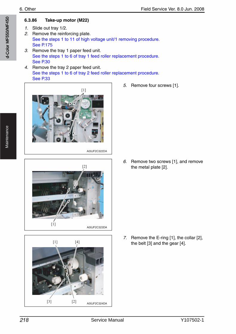
6. Other Field Service Ver. 8.0 Jun. 2008
218
Ma
inte
na
nce
6.3.86 Take-up motor (M22)
1. Slide out tray 1/2.2. Remove the reinforcing plate.
See the steps 1 to 11 of high voltage unit/1 removing procedure.See P.175
3. Remove the tray 1 paper feed unit.See the steps 1 to 6 of tray 1 feed roller replacement procedure.See P.30
4. Remove the tray 2 paper feed unit.See the steps 1 to 6 of tray 2 feed roller replacement procedure.See P.33
5. Remove four screws [1].
6. Remove two screws [1], and removethe metal plate [2].
7. Remove the E-ring [1], the collar [2], the belt [3] and the gear [4].
[1]
A00JF2C322DA
[1]
[2]
A00JF2C323DA
[4][1]
[2][3]A00JF2C324DA
d-C
olor
MF5
50/M
F450
Service Manual Y107502-1
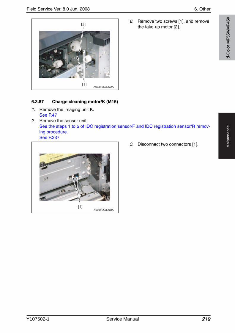
Field Service Ver. 8.0 Jun. 2008 6. Other
219
Ma
inte
na
nce
8. Remove two screws [1], and removethe take-up motor [2].
6.3.87 Charge cleaning motor/K (M15)
1. Remove the imaging unit K.See P.47
2. Remove the sensor unit.See the steps 1 to 5 of IDC registration sensor/F and IDC registration sensor/R remov-ing procedure.See P.237
3. Disconnect two connectors [1].
[1]
[2]
A00JF2C325DA
[1]A00JF2C326DA
d-C
olor
MF5
50/M
F450
Y107502-1 Service Manual
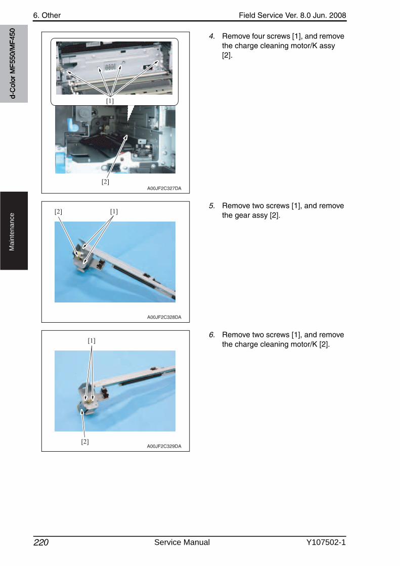
6. Other Field Service Ver. 8.0 Jun. 2008
220
Ma
inte
na
nce
4. Remove four screws [1], and removethe charge cleaning motor/K assy [2].
5. Remove two screws [1], and removethe gear assy [2].
6. Remove two screws [1], and removethe charge cleaning motor/K [2].
A00JF2C327DA[2]
[1]
[1][2]
A00JF2C328DA
[1]
[2]A00JF2C329DA
d-C
olor
MF5
50/M
F450
Service Manual Y107502-1
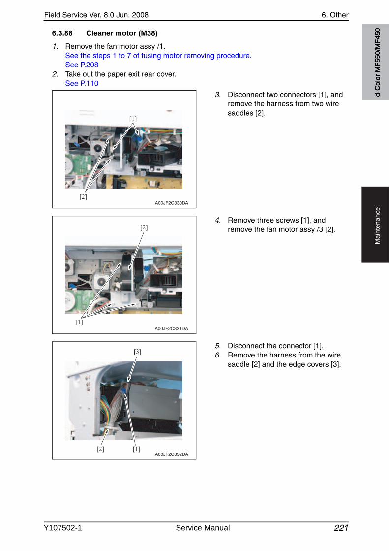
Field Service Ver. 8.0 Jun. 2008 6. Other
221
Ma
inte
na
nce
6.3.88 Cleaner motor (M38)
1. Remove the fan motor assy /1.See the steps 1 to 7 of fusing motor removing procedure.See P.208
2. Take out the paper exit rear cover.See P.110
3. Disconnect two connectors [1], and remove the harness from two wire saddles [2].
4. Remove three screws [1], and remove the fan motor assy /3 [2].
5. Disconnect the connector [1].6. Remove the harness from the wire
saddle [2] and the edge covers [3].
[1]
[2]A00JF2C330DA
[1]
[2]
A00JF2C331DA
[1][2]
[3]
A00JF2C332DA
d-C
olor
MF5
50/M
F450
Y107502-1 Service Manual
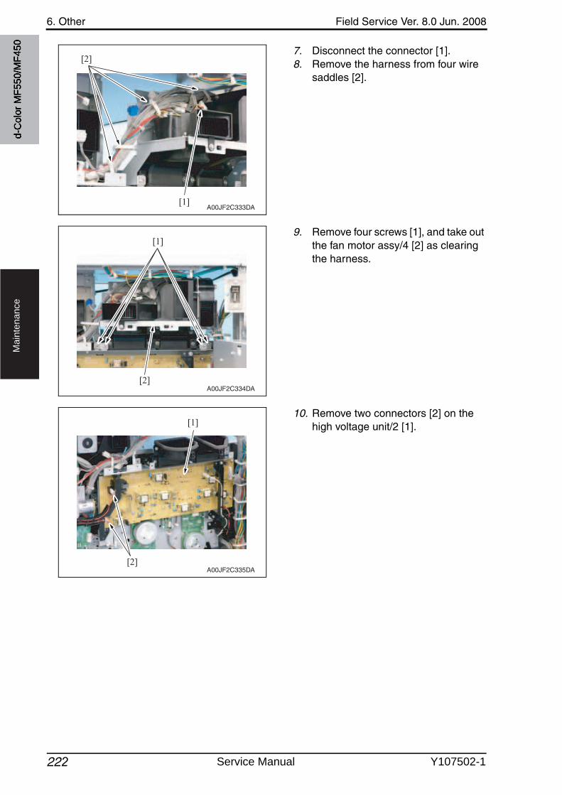
6. Other Field Service Ver. 8.0 Jun. 2008
222
Ma
inte
na
nce
7. Disconnect the connector [1].8. Remove the harness from four wire
saddles [2].
9. Remove four screws [1], and take outthe fan motor assy/4 [2] as clearing the harness.
10. Remove two connectors [2] on the high voltage unit/2 [1].
[1]
[2]
A00JF2C333DA
[2]
[1]
A00JF2C334DA
[1]
[2]A00JF2C335DA
d-C
olor
MF5
50/M
F450
Service Manual Y107502-1
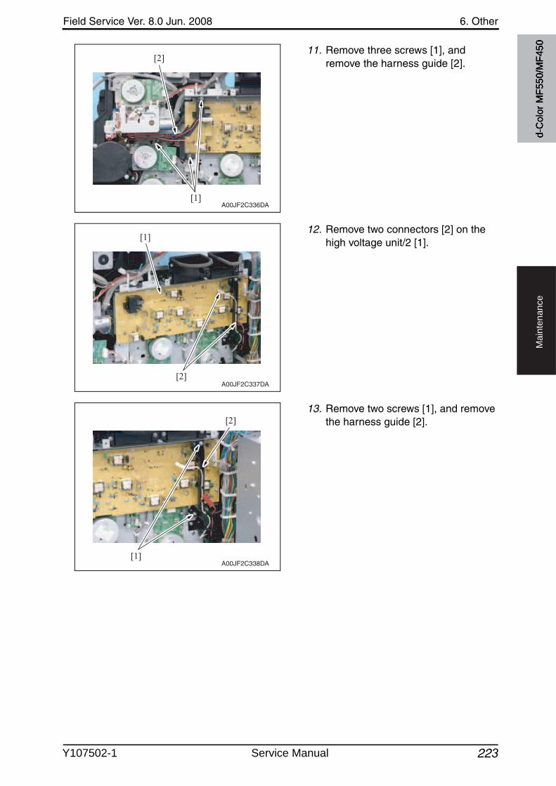
Field Service Ver. 8.0 Jun. 2008 6. Other
223
Ma
inte
na
nce
11. Remove three screws [1], and remove the harness guide [2].
12. Remove two connectors [2] on the high voltage unit/2 [1].
13. Remove two screws [1], and removethe harness guide [2].
[1]
[2]
A00JF2C336DA
[1]
[2]A00JF2C337DA
[1]
[2]
A00JF2C338DA
d-C
olor
MF5
50/M
F450
Y107502-1 Service Manual
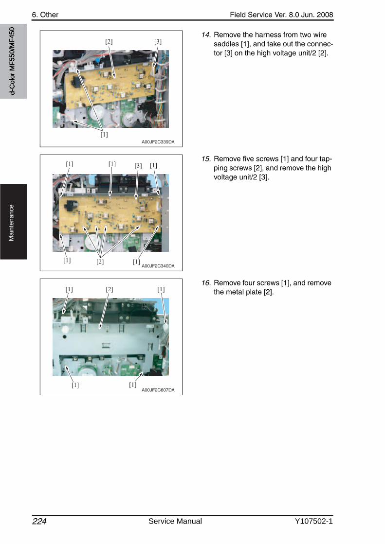
6. Other Field Service Ver. 8.0 Jun. 2008
224
Ma
inte
na
nce
14. Remove the harness from two wire saddles [1], and take out the connec-tor [3] on the high voltage unit/2 [2].
15. Remove five screws [1] and four tap-ping screws [2], and remove the high voltage unit/2 [3].
16. Remove four screws [1], and removethe metal plate [2].
[1]
[2] [3]
A00JF2C339DA
[2] [1][1]
[3][1][1] [1]
A00JF2C340DA
[1] [1]
[1][1] [2]
A00JF2C607DA
d-C
olor
MF5
50/M
F450
Service Manual Y107502-1
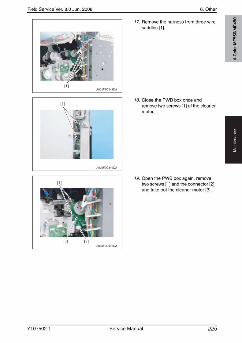
Field Service Ver. 8.0 Jun. 2008 6. Other
225
Ma
inte
na
nce
17. Remove the harness from three wire saddles [1].
18. Close the PWB box once and remove two screws [1] of the cleaner motor.
19. Open the PWB box again, removetwo screws [1] and the connector [2], and take out the cleaner motor [3].
[1]A00JF2C341DA
[1]
A00JF2C342DA
[1]
[2][3]A00JF2C343DA
d-C
olor
MF5
50/M
F450
Y107502-1 Service Manual
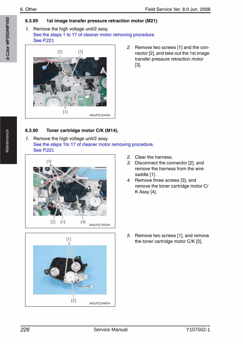
6. Other Field Service Ver. 8.0 Jun. 2008
226
Ma
inte
na
nce
6.3.89 1st image transfer pressure retraction motor (M21)
1. Remove the high voltage unit/2 assy.See the steps 1 to 17 of cleaner motor removing procedure.See P.221
2. Remove two screws [1] and the con-nector [2], and take out the 1st image transfer pressure retraction motor [3].
6.3.90 Toner cartridge motor C/K (M14).
1. Remove the high voltage unit/2 assy.See the steps 1to 17 of cleaner motor removing procedure.See P.221
2. Clear the harness.3. Disconnect the connector [2], and
remove the harness from the wire saddle [1].
4. Remove three screws [3], and remove the toner cartridge motor C/K Assy [4].
5. Remove two screws [1], and removethe toner cartridge motor C/K [2].
[1]
[2] [3]
A00JF2C344DA
[4][1][2]
[3]
A00JF2C345DA
[1]
[2]A00JF2C346DA
d-C
olor
MF5
50/M
F450
Service Manual Y107502-1
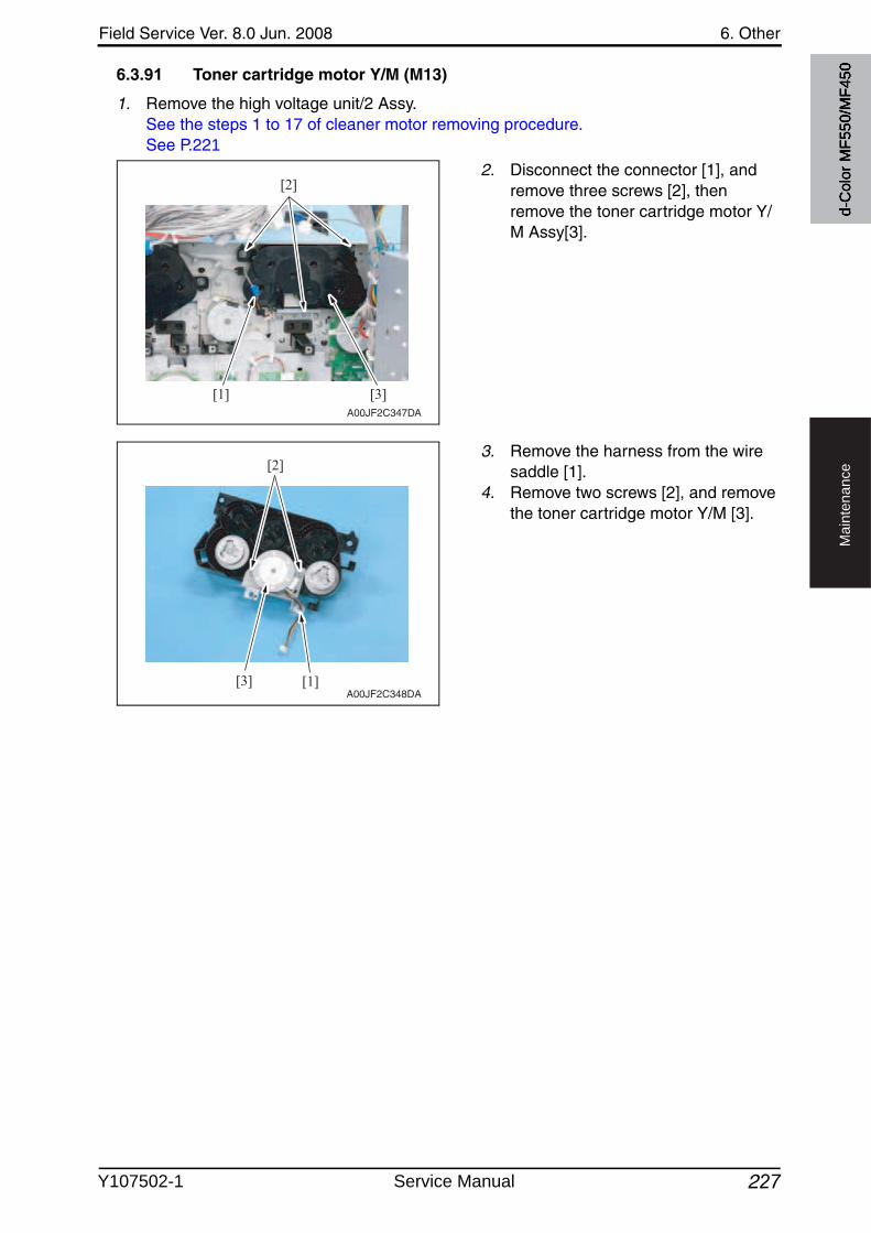
Field Service Ver. 8.0 Jun. 2008 6. Other
227
Ma
inte
na
nce
6.3.91 Toner cartridge motor Y/M (M13)
1. Remove the high voltage unit/2 Assy.See the steps 1 to 17 of cleaner motor removing procedure.See P.221
2. Disconnect the connector [1], and remove three screws [2], then remove the toner cartridge motor Y/M Assy[3].
3. Remove the harness from the wire saddle [1].
4. Remove two screws [2], and removethe toner cartridge motor Y/M [3].
[1]
[2]
[3]A00JF2C347DA
[1]
[2]
[3]A00JF2C348DA
d-C
olor
MF5
50/M
F450
Y107502-1 Service Manual
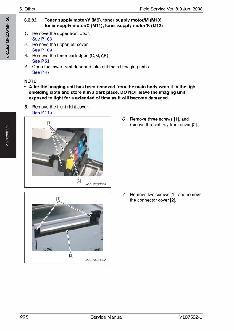
6. Other Field Service Ver. 8.0 Jun. 2008
228
Ma
inte
na
nce
6.3.92 Toner supply motor/Y (M9), toner supply motor/M (M10),toner supply motor/C (M11), toner supply motor/K (M12)
1. Remove the upper front door.See P.103
2. Remove the upper left cover.See P.109
3. Remove the toner cartridges (C,M,Y,K).See P.51
4. Open the lower front door and take out the all imaging units.See P.47
NOTE• After the imaging unit has been removed from the main body wrap it in the light
shielding cloth and store it in a dark place. DO NOT leave the imaging unit exposed to light for a extended of time as it will become damaged.
5. Remove the front right cover.See P.115
6. Remove three screws [1], and remove the exit tray front cover [2].
7. Remove two screws [1], and removethe connector cover [2].
[2]
[1]
A00JF2C224DA
[1]
[2]A00JF2C349DA
d-C
olor
MF5
50/M
F450
Service Manual Y107502-1
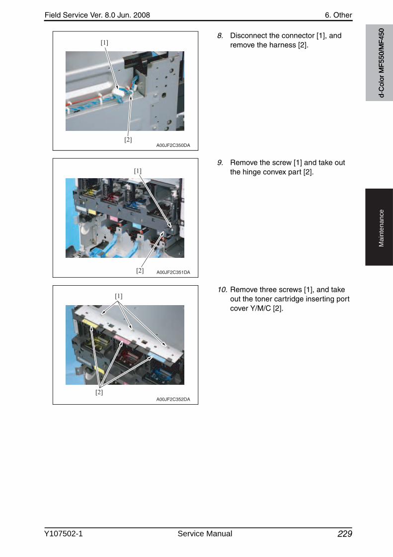
Field Service Ver. 8.0 Jun. 2008 6. Other
229
Ma
inte
na
nce
8. Disconnect the connector [1], and remove the harness [2].
9. Remove the screw [1] and take outthe hinge convex part [2].
10. Remove three screws [1], and take out the toner cartridge inserting port cover Y/M/C [2].
[1]
[2]A00JF2C350DA
[1]
[2] A00JF2C351DA
[1]
[2]A00JF2C352DA
d-C
olor
MF5
50/M
F450
Y107502-1 Service Manual
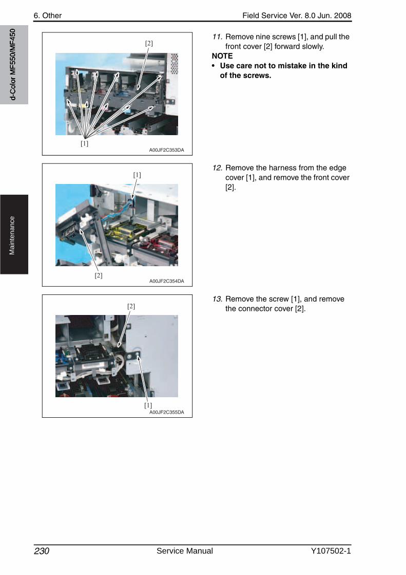
6. Other Field Service Ver. 8.0 Jun. 2008
230
Ma
inte
na
nce
11. Remove nine screws [1], and pull the front cover [2] forward slowly.
NOTE• Use care not to mistake in the kind
of the screws.
12. Remove the harness from the edge cover [1], and remove the front cover[2].
13. Remove the screw [1], and removethe connector cover [2].
[1]
[2]
A00JF2C353DA
[1]
[2]A00JF2C354DA
[1]
[2]
A00JF2C355DA
d-C
olor
MF5
50/M
F450
Service Manual Y107502-1
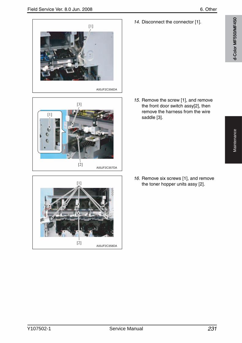
Field Service Ver. 8.0 Jun. 2008 6. Other
231
Ma
inte
na
nce
14. Disconnect the connector [1].
15. Remove the screw [1], and removethe front door switch assy[2], then remove the harness from the wire saddle [3].
16. Remove six screws [1], and removethe toner hopper units assy [2].
[1]
A00JF2C356DA
A00JF2C357DA[2]
[3]
[1]
[2]
[1]
A00JF2C358DA
d-C
olor
MF5
50/M
F450
Y107502-1 Service Manual
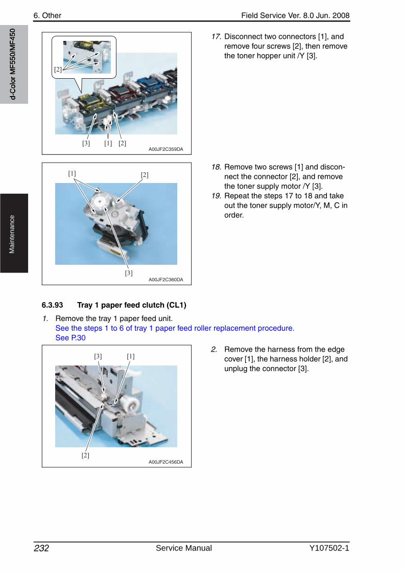
6. Other Field Service Ver. 8.0 Jun. 2008
232
Ma
inte
na
nce
17. Disconnect two connectors [1], and remove four screws [2], then removethe toner hopper unit /Y [3].
18. Remove two screws [1] and discon-nect the connector [2], and removethe toner supply motor /Y [3].
19. Repeat the steps 17 to 18 and take out the toner supply motor/Y, M, C in order.
6.3.93 Tray 1 paper feed clutch (CL1)
1. Remove the tray 1 paper feed unit.See the steps 1 to 6 of tray 1 paper feed roller replacement procedure.See P.30
2. Remove the harness from the edge cover [1], the harness holder [2], and unplug the connector [3].
A00JF2C359DA[1] [2]
[2]
[3]
[1]
[3]
[2]
A00JF2C360DA
A00JF2C456DA
[1]
[2]
[3]
d-C
olor
MF5
50/M
F450
Service Manual Y107502-1
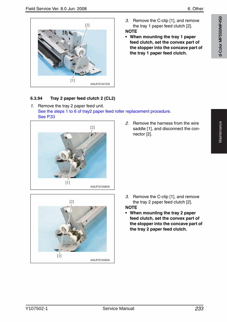
Field Service Ver. 8.0 Jun. 2008 6. Other
233
Ma
inte
na
nce
3. Remove the C-clip [1], and removethe tray 1 paper feed clutch [2].
NOTE• When mounting the tray 1 paper
feed clutch, set the convex part of the stopper into the concave part of the tray 1 paper feed clutch.
6.3.94 Tray 2 paper feed clutch 2 (CL2)
1. Remove the tray 2 paper feed unit.See the steps 1 to 6 of tray2 paper feed roller replacement procedure.See P.33
2. Remove the harness from the wire saddle [1], and disconnect the con-nector [2].
3. Remove the C-clip [1], and removethe tray 2 paper feed clutch [2].
NOTE• When mounting the tray 2 paper
feed clutch, set the convex part of the stopper into the concave part of the tray 2 paper feed clutch.
A00JF2C457DA[1]
[2]
A00JF2C458DA
[1]
[2]
A00JF2C459DA
[1]
[2]
d-C
olor
MF5
50/M
F450
Y107502-1 Service Manual
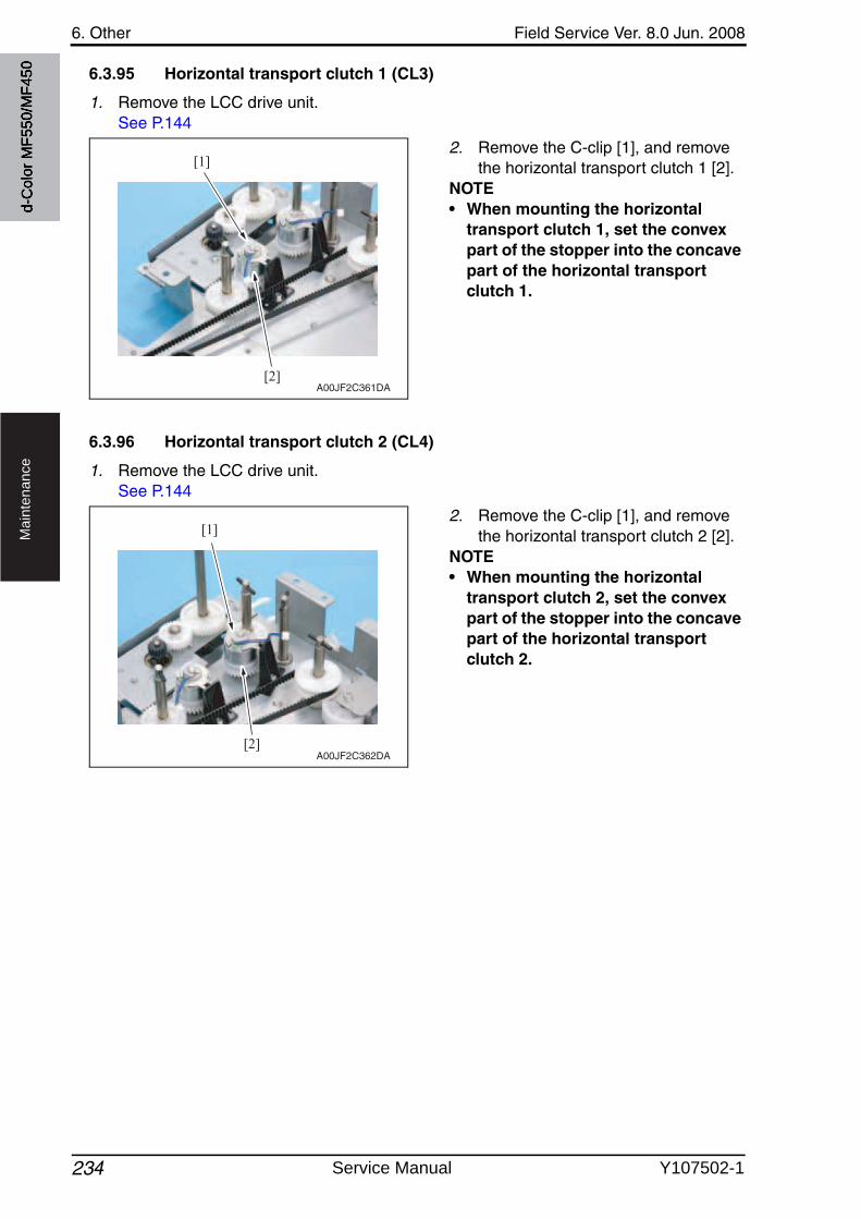
6. Other Field Service Ver. 8.0 Jun. 2008
234
Ma
inte
na
nce
6.3.95 Horizontal transport clutch 1 (CL3)
1. Remove the LCC drive unit.See P.144
2. Remove the C-clip [1], and removethe horizontal transport clutch 1 [2].
NOTE• When mounting the horizontal
transport clutch 1, set the convex part of the stopper into the concave part of the horizontal transport clutch 1.
6.3.96 Horizontal transport clutch 2 (CL4)
1. Remove the LCC drive unit.See P.144
2. Remove the C-clip [1], and removethe horizontal transport clutch 2 [2].
NOTE• When mounting the horizontal
transport clutch 2, set the convex part of the stopper into the concave part of the horizontal transport clutch 2.
[1]
[2]A00JF2C361DA
[1]
[2]A00JF2C362DA
d-C
olor
MF5
50/M
F450
Service Manual Y107502-1
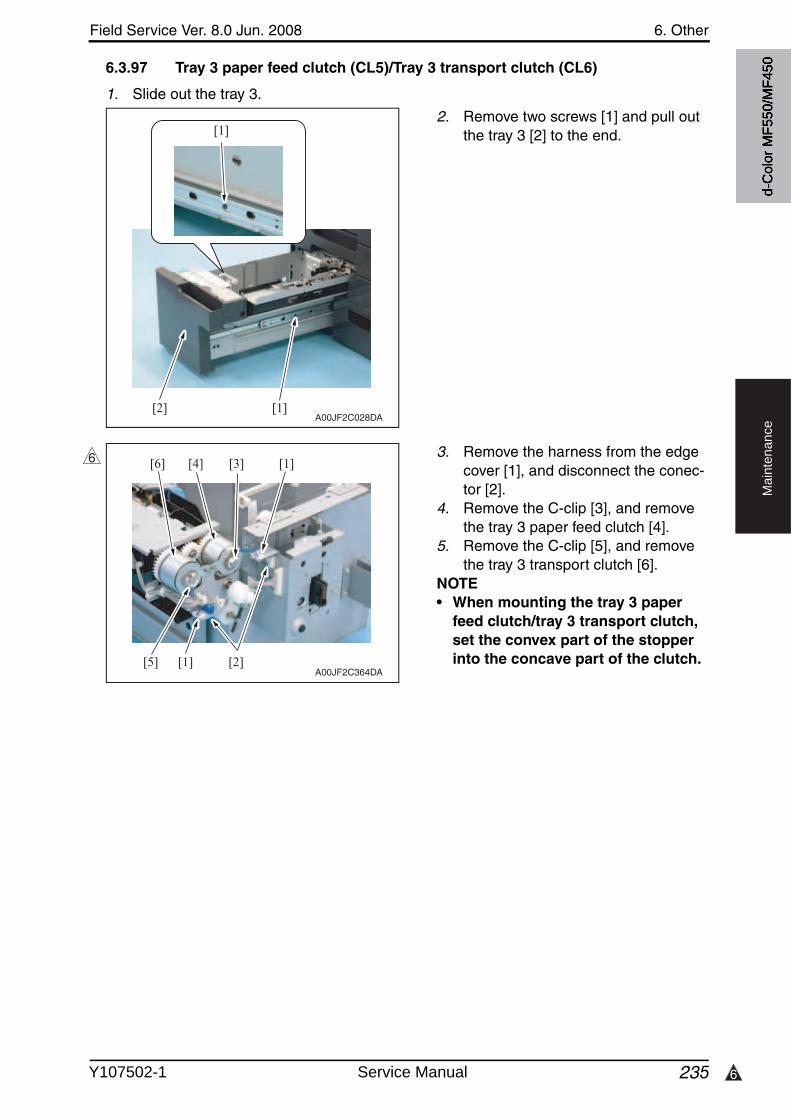
6
Field Service Ver. 8.0 Jun. 2008 6. Other
235
Ma
inte
na
nce
6.3.97 Tray 3 paper feed clutch (CL5)/Tray 3 transport clutch (CL6)
1. Slide out the tray 3.
2. Remove two screws [1] and pull outthe tray 3 [2] to the end.
3. Remove the harness from the edge cover [1], and disconnect the conec-tor [2].
4. Remove the C-clip [3], and removethe tray 3 paper feed clutch [4].
5. Remove the C-clip [5], and removethe tray 3 transport clutch [6].
NOTE• When mounting the tray 3 paper
feed clutch/tray 3 transport clutch, set the convex part of the stopper into the concave part of the clutch.
[1]
[1]
[2]A00JF2C028DA
[1]
[1]
[2][5]
[3][4][6]
A00JF2C364DA
6
d-C
olor
MF5
50/M
F450
Y107502-1 Service Manual
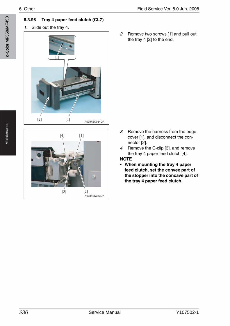
6. Other Field Service Ver. 8.0 Jun. 2008
236
Ma
inte
na
nce
6.3.98 Tray 4 paper feed clutch (CL7)
1. Slide out the tray 4.
2. Remove two screws [1] and pull outthe tray 4 [2] to the end.
3. Remove the harness from the edge cover [1], and disconnect the con-nector [2].
4. Remove the C-clip [3], and removethe tray 4 paper feed clutch [4].
NOTE• When mounting the tray 4 paper
feed clutch, set the convex part of the stopper into the concave part of the tray 4 paper feed clutch.
[1]
[1][2]A00JF2C034DA
[3]
[1][4]
[2]A00JF2C363DA
d-C
olor
MF5
50/M
F450
Service Manual Y107502-1
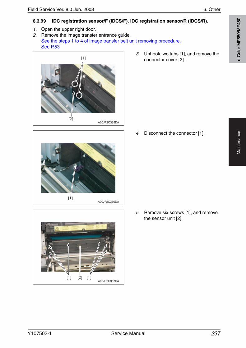
Field Service Ver. 8.0 Jun. 2008 6. Other
237
Ma
inte
na
nce
6.3.99 IDC registration sensor/F (IDCS/F), IDC registration sensor/R (IDCS/R).
1. Open the upper right door.2. Remove the image transfer entrance guide.
See the steps 1 to 4 of image transfer belt unit removing procedure.See P.53
3. Unhook two tabs [1], and remove the connector cover [2].
4. Disconnect the connector [1].
5. Remove six screws [1], and removethe sensor unit [2].
[1]
[2]A00JF2C365DA
[1]A00JF2C366DA
[1] [1][2]A00JF2C367DA
d-C
olor
MF5
50/M
F450
Y107502-1 Service Manual
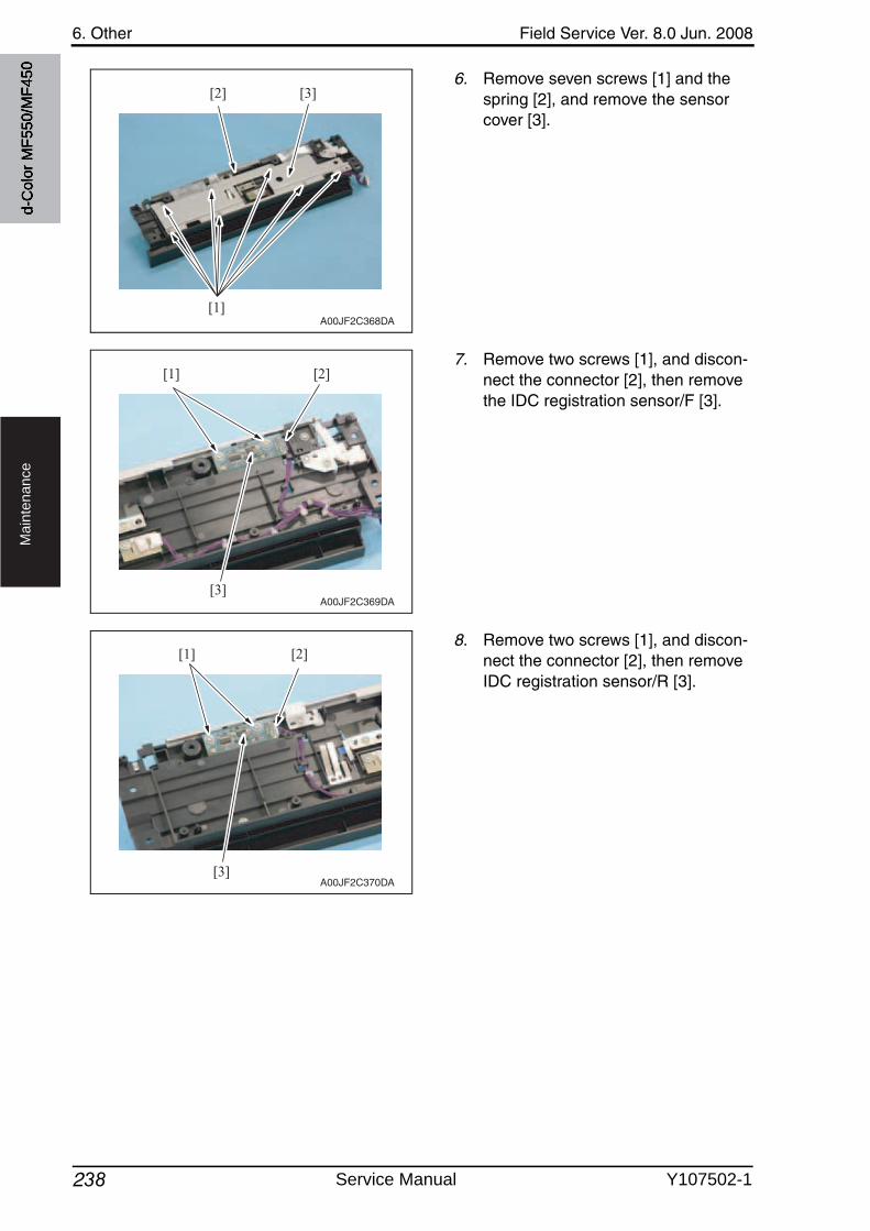
6. Other Field Service Ver. 8.0 Jun. 2008
238
Ma
inte
na
nce
6. Remove seven screws [1] and the spring [2], and remove the sensor cover [3].
7. Remove two screws [1], and discon-nect the connector [2], then removethe IDC registration sensor/F [3].
8. Remove two screws [1], and discon-nect the connector [2], then removeIDC registration sensor/R [3].
[1]
[2] [3]
A00JF2C368DA
[1] [2]
[3]A00JF2C369DA
[1] [2]
[3]A00JF2C370DA
d-C
olor
MF5
50/M
F450
Service Manual Y107502-1
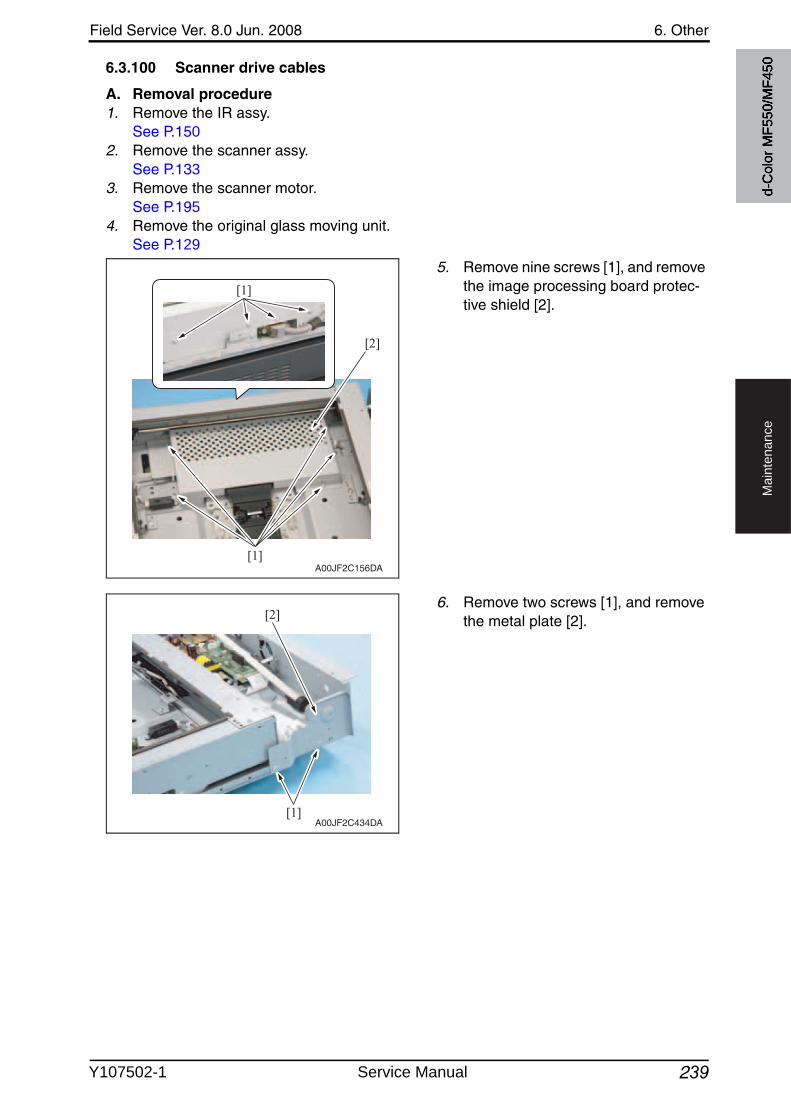
Field Service Ver. 8.0 Jun. 2008 6. Other
239
Ma
inte
na
nce
6.3.100 Scanner drive cables
A. Removal procedure1. Remove the IR assy.
See P.1502. Remove the scanner assy.
See P.1333. Remove the scanner motor.
See P.1954. Remove the original glass moving unit.
See P.129
5. Remove nine screws [1], and removethe image processing board protec-tive shield [2].
6. Remove two screws [1], and removethe metal plate [2].
A00JF2C156DA
[1]
[2]
[1]
A00JF2C434DA[1]
[2]
d-C
olor
MF5
50/M
F450
Y107502-1 Service Manual
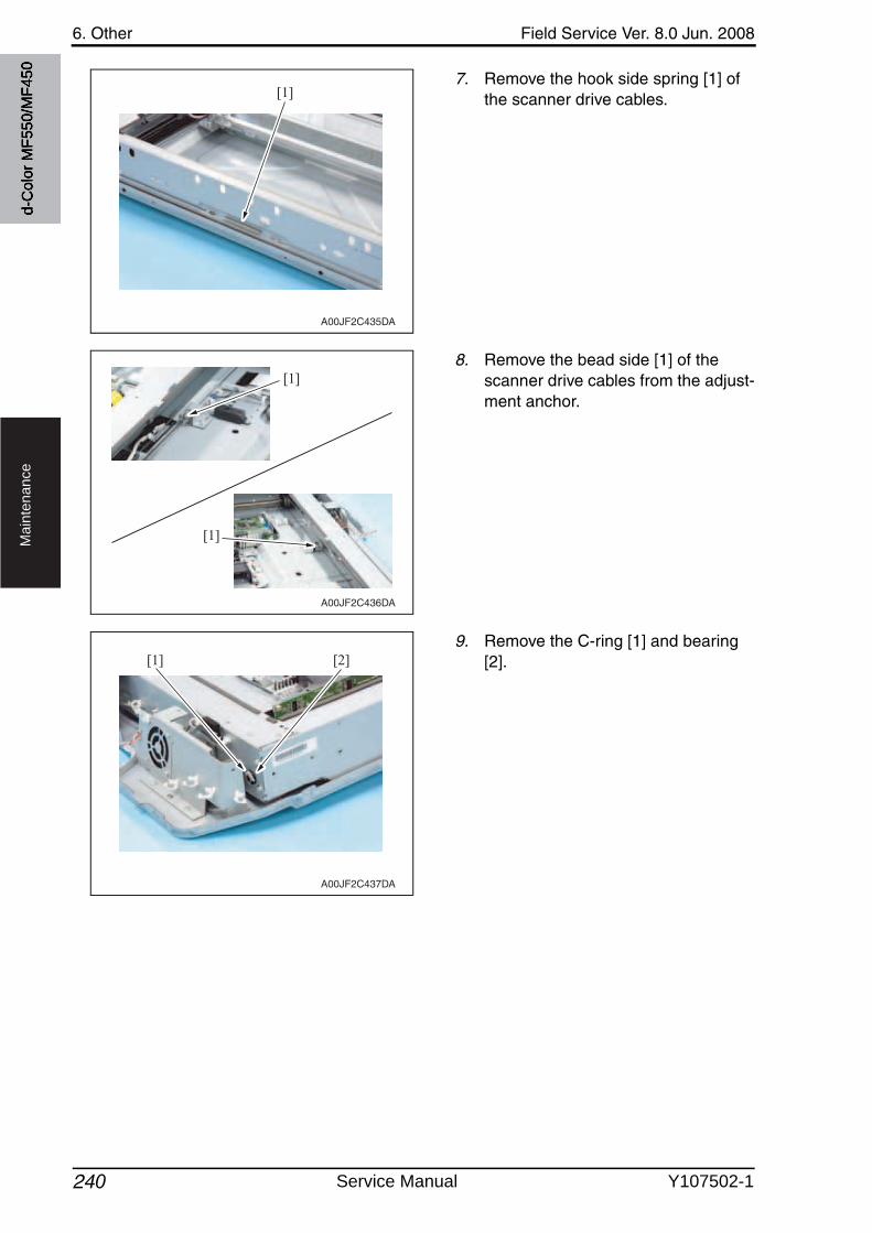
6. Other Field Service Ver. 8.0 Jun. 2008
240
Ma
inte
na
nce
7. Remove the hook side spring [1] of the scanner drive cables.
8. Remove the bead side [1] of the scanner drive cables from the adjust-ment anchor.
9. Remove the C-ring [1] and bearing [2].
A00JF2C435DA
[1]
A00JF2C436DA
[1]
[1]
A00JF2C437DA
[1] [2]
d-C
olor
MF5
50/M
F450
Service Manual Y107502-1
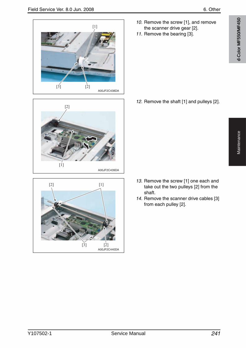
Field Service Ver. 8.0 Jun. 2008 6. Other
241
Ma
inte
na
nce
10. Remove the screw [1], and removethe scanner drive gear [2].
11. Remove the bearing [3].
12. Remove the shaft [1] and pulleys [2].
13. Remove the screw [1] one each and take out the two pulleys [2] from the shaft.
14. Remove the scanner drive cables [3] from each pulley [2].
A00JF2C438DA
[1]
[2][3]
A00JF2C439DA
[2]
[1]
A00JF2C440DA
[1][2]
[3] [2]
d-C
olor
MF5
50/M
F450
Y107502-1 Service Manual
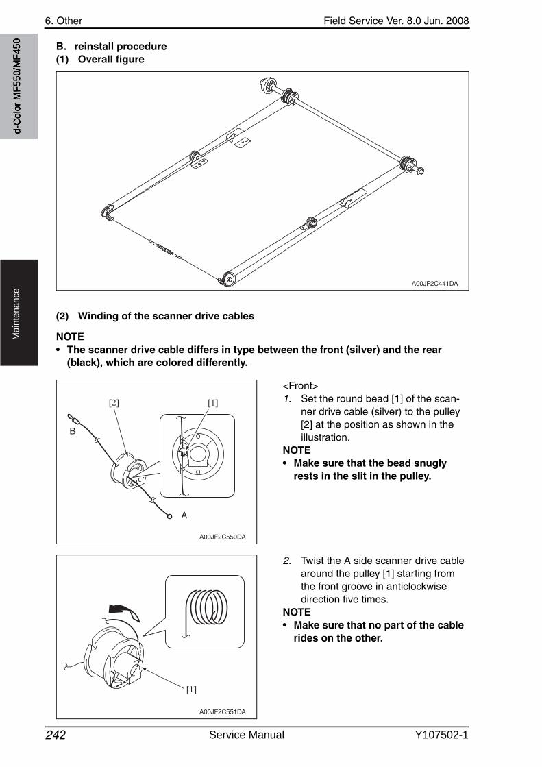
6. Other Field Service Ver. 8.0 Jun. 2008
242
Ma
inte
na
nce
B. reinstall procedure(1) Overall figure
(2) Winding of the scanner drive cables
NOTE• The scanner drive cable differs in type between the front (silver) and the rear
(black), which are colored differently.
<Front>1. Set the round bead [1] of the scan-
ner drive cable (silver) to the pulley [2] at the position as shown in the illustration.
NOTE• Make sure that the bead snugly
rests in the slit in the pulley.
2. Twist the A side scanner drive cable around the pulley [1] starting from the front groove in anticlockwisedirection five times.
NOTE• Make sure that no part of the cable
rides on the other.
A00JF2C441DA
A00JF2C550DA
[2] [1]
A
B
A00JF2C551DA
[1]
d-C
olor
MF5
50/M
F450
Service Manual Y107502-1
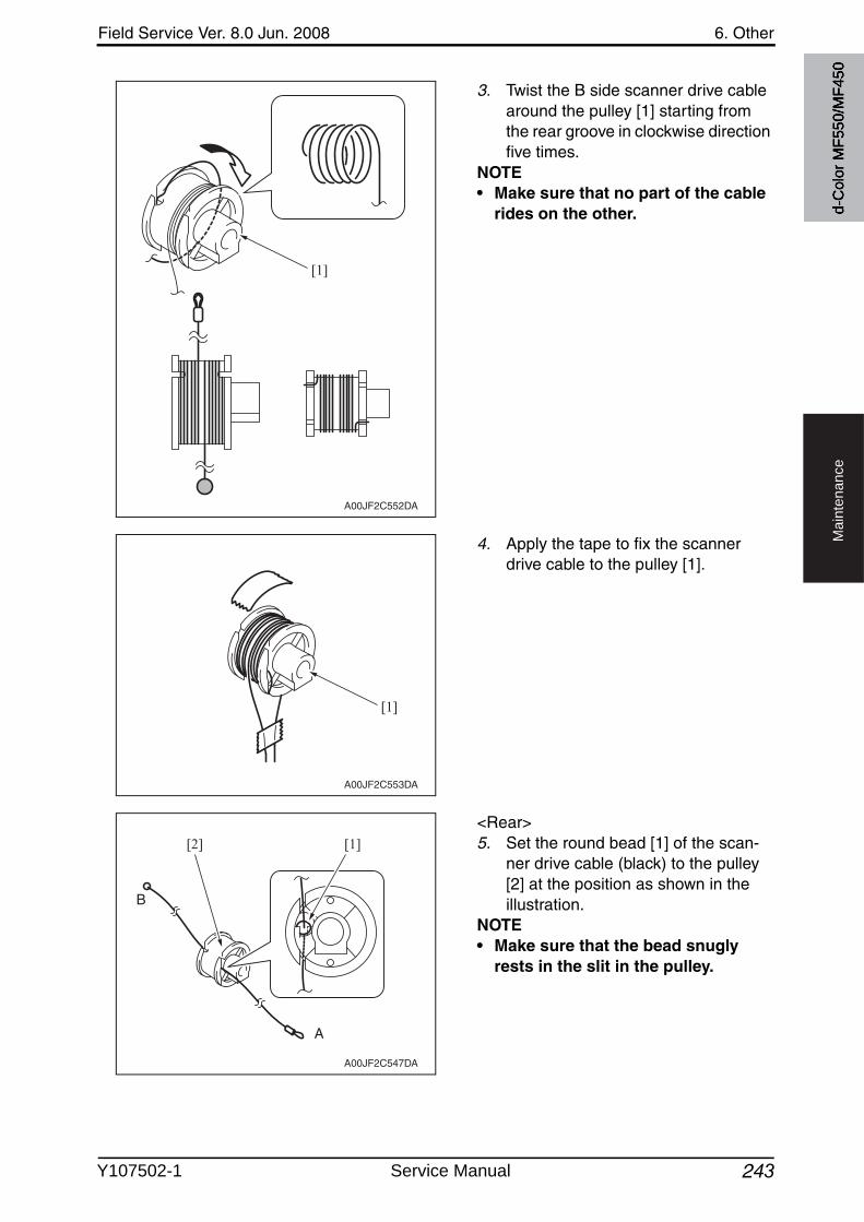
Field Service Ver. 8.0 Jun. 2008 6. Other
243
Ma
inte
na
nce
3. Twist the B side scanner drive cable around the pulley [1] starting from the rear groove in clockwise direction five times.
NOTE• Make sure that no part of the cable
rides on the other.
4. Apply the tape to fix the scanner drive cable to the pulley [1].
<Rear>5. Set the round bead [1] of the scan-
ner drive cable (black) to the pulley [2] at the position as shown in the illustration.
NOTE• Make sure that the bead snugly
rests in the slit in the pulley.
A00JF2C552DA
[1]
A00JF2C553DA
[1]
A00JF2C547DA
[2] [1]
A
B
d-C
olor
MF5
50/M
F450
Y107502-1 Service Manual
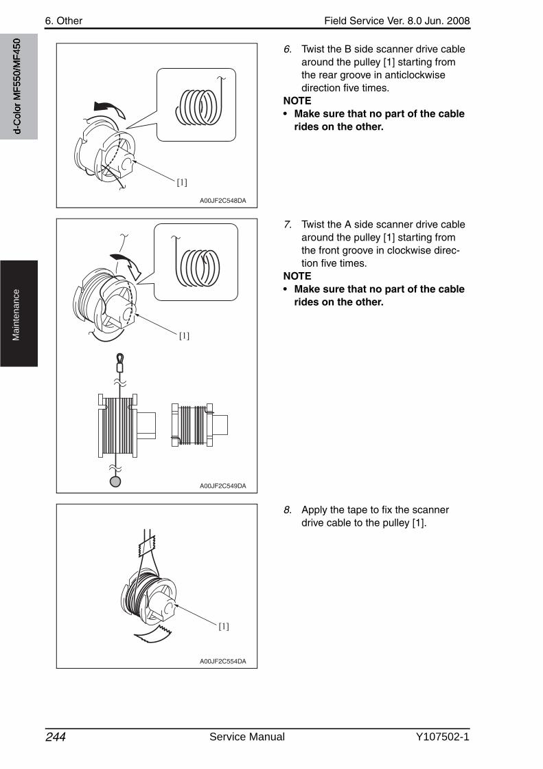
6. Other Field Service Ver. 8.0 Jun. 2008
244
Ma
inte
na
nce
6. Twist the B side scanner drive cable around the pulley [1] starting from the rear groove in anticlockwise direction five times.
NOTE• Make sure that no part of the cable
rides on the other.
7. Twist the A side scanner drive cable around the pulley [1] starting from the front groove in clockwise direc-tion five times.
NOTE• Make sure that no part of the cable
rides on the other.
8. Apply the tape to fix the scanner drive cable to the pulley [1].
A00JF2C548DA
[1]
A00JF2C549DA
[1]
A00JF2C554DA
[1]
d-C
olor
MF5
50/M
F450
Service Manual Y107502-1
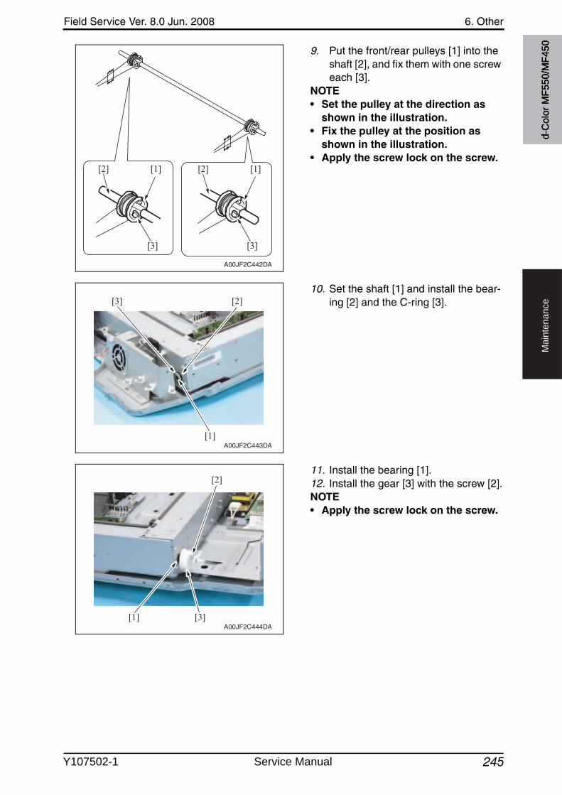
Field Service Ver. 8.0 Jun. 2008 6. Other
245
Ma
inte
na
nce
9. Put the front/rear pulleys [1] into the shaft [2], and fix them with one screweach [3].
NOTE• Set the pulley at the direction as
shown in the illustration.• Fix the pulley at the position as
shown in the illustration.• Apply the screw lock on the screw.
10. Set the shaft [1] and install the bear-ing [2] and the C-ring [3].
11. Install the bearing [1].12. Install the gear [3] with the screw [2].NOTE• Apply the screw lock on the screw.
A00JF2C442DA
[2] [1]
[3]
[2] [1]
[3]
A00JF2C443DA
[3]
[1]
[2]
A00JF2C444DA
[2]
[3][1]
d-C
olor
MF5
50/M
F450
Y107502-1 Service Manual
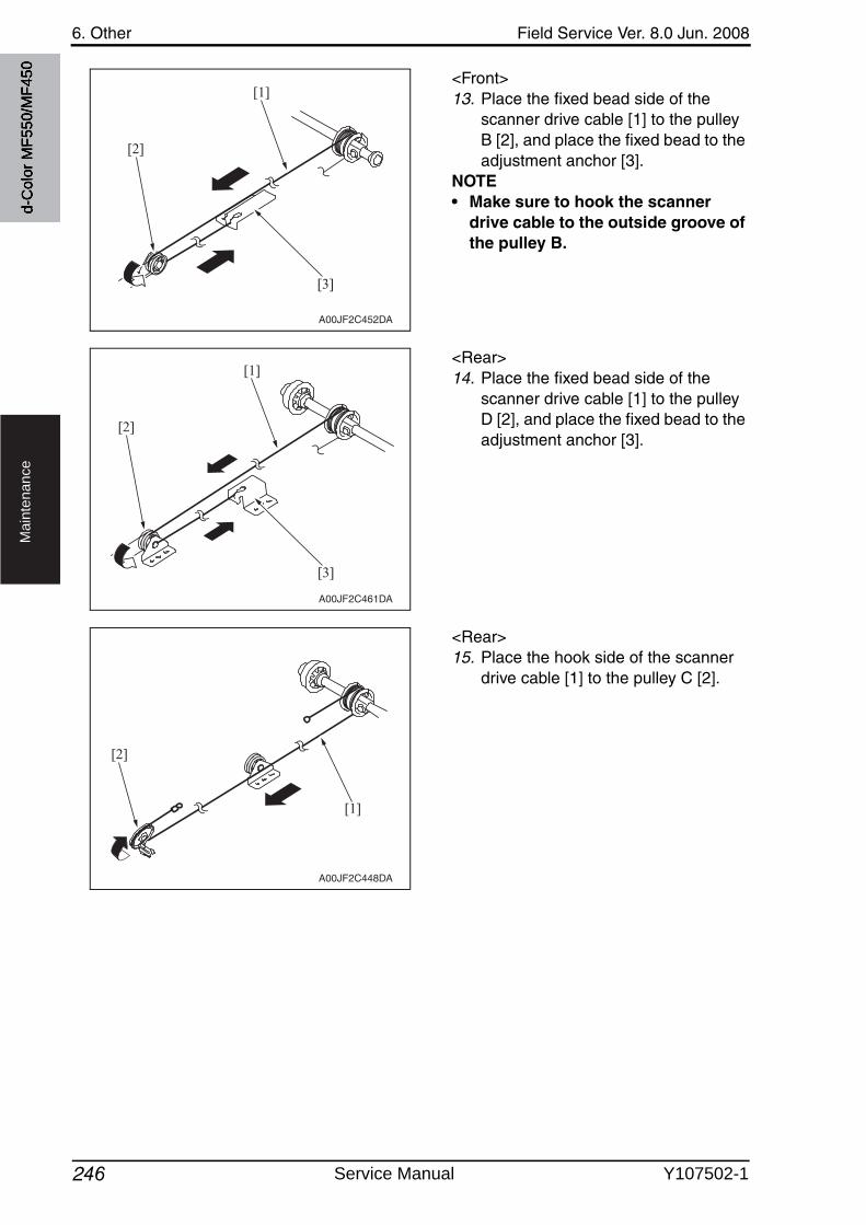
6. Other Field Service Ver. 8.0 Jun. 2008
246
Ma
inte
na
nce
<Front>13. Place the fixed bead side of the
scanner drive cable [1] to the pulley B [2], and place the fixed bead to the adjustment anchor [3].
NOTE• Make sure to hook the scanner
drive cable to the outside groove of the pulley B.
<Rear>14. Place the fixed bead side of the
scanner drive cable [1] to the pulley D [2], and place the fixed bead to the adjustment anchor [3].
<Rear>15. Place the hook side of the scanner
drive cable [1] to the pulley C [2].
A00JF2C452DA
[1]
[2]
[3]
A00JF2C461DA
[1]
[2]
[3]
A00JF2C448DA
[1]
[2]
d-C
olor
MF5
50/M
F450
Service Manual Y107502-1
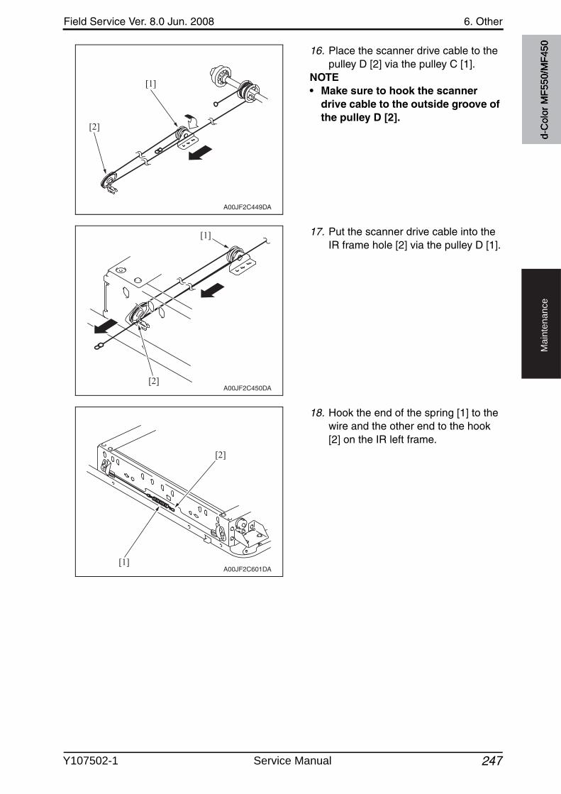
Field Service Ver. 8.0 Jun. 2008 6. Other
247
Ma
inte
na
nce
16. Place the scanner drive cable to the pulley D [2] via the pulley C [1].
NOTE• Make sure to hook the scanner
drive cable to the outside groove of the pulley D [2].
17. Put the scanner drive cable into the IR frame hole [2] via the pulley D [1].
18. Hook the end of the spring [1] to the wire and the other end to the hook [2] on the IR left frame.
A00JF2C449DA
[1]
[2]
A00JF2C450DA
[1]
[2]
A00JF2C601DA[1]
[2]
d-C
olor
MF5
50/M
F450
Y107502-1 Service Manual
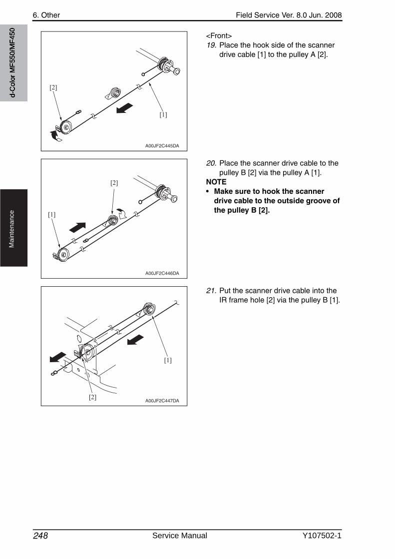
6. Other Field Service Ver. 8.0 Jun. 2008
248
Ma
inte
na
nce
<Front>19. Place the hook side of the scanner
drive cable [1] to the pulley A [2].
20. Place the scanner drive cable to the pulley B [2] via the pulley A [1].
NOTE• Make sure to hook the scanner
drive cable to the outside groove of the pulley B [2].
21. Put the scanner drive cable into the IR frame hole [2] via the pulley B [1].
A00JF2C445DA
[1]
[2]
A00JF2C446DA
[2]
[1]
A00JF2C447DA
[1]
[2]
d-C
olor
MF5
50/M
F450
Service Manual Y107502-1
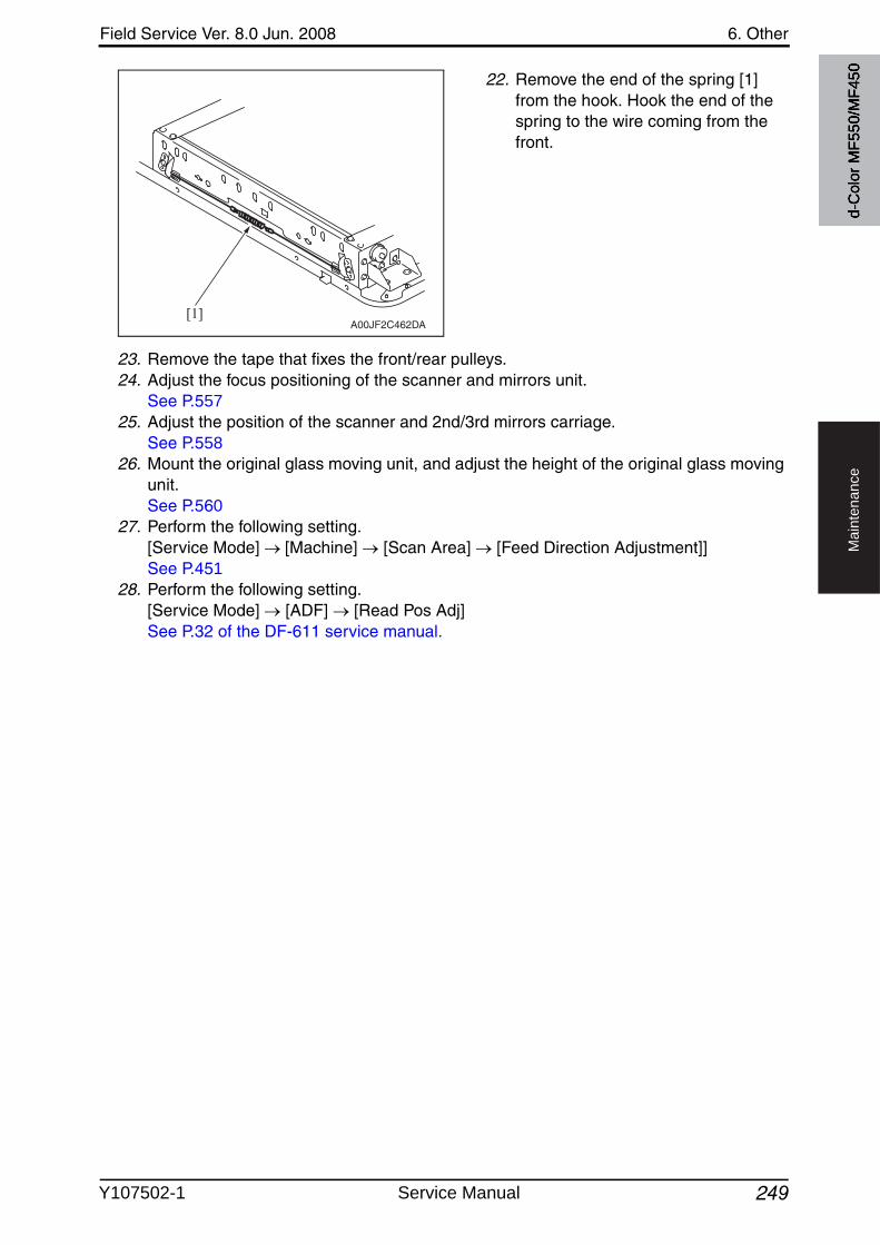
Field Service Ver. 8.0 Jun. 2008 6. Other
249
Ma
inte
na
nce
22. Remove the end of the spring [1] from the hook. Hook the end of the spring to the wire coming from the front.
23. Remove the tape that fixes the front/rear pulleys.24. Adjust the focus positioning of the scanner and mirrors unit.
See P.55725. Adjust the position of the scanner and 2nd/3rd mirrors carriage.
See P.55826. Mount the original glass moving unit, and adjust the height of the original glass moving
unit.See P.560
27. Perform the following setting.[Service Mode] [Machine] [Scan Area] [Feed Direction Adjustment]]See P.451
28. Perform the following setting.[Service Mode] [ADF] [Read Pos Adj]See P.32 of the DF-611 service manual.
A00JF2C462DA[1]
d-C
olor
MF5
50/M
F450
Y107502-1 Service Manual
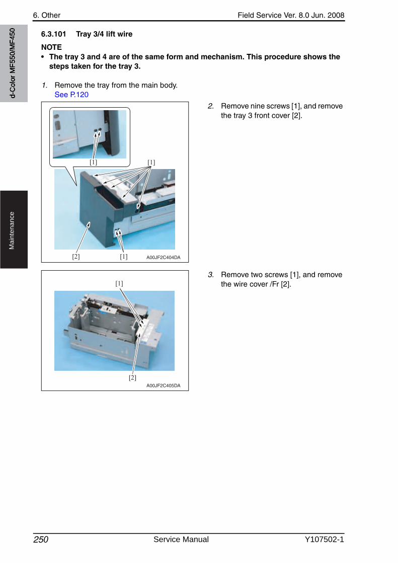
6. Other Field Service Ver. 8.0 Jun. 2008
250
Ma
inte
na
nce
6.3.101 Tray 3/4 lift wire
NOTE• The tray 3 and 4 are of the same form and mechanism. This procedure shows the
steps taken for the tray 3.
1. Remove the tray from the main body.See P.120
2. Remove nine screws [1], and removethe tray 3 front cover [2].
3. Remove two screws [1], and removethe wire cover /Fr [2].
A00JF2C404DA[1]
[1][1]
[2]
[2]
[1]
A00JF2C405DA
d-C
olor
MF5
50/M
F450
Service Manual Y107502-1
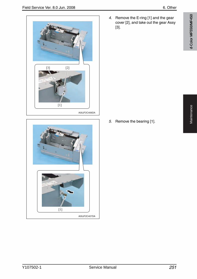
Field Service Ver. 8.0 Jun. 2008 6. Other
251
Ma
inte
na
nce
4. Remove the E-ring [1] and the gear cover [2], and take out the gear Assy [3].
5. Remove the bearing [1].
A00JF2C406DA
[1]
[2][3]
A00JF2C407DA
[1]
d-C
olor
MF5
50/M
F450
Y107502-1 Service Manual
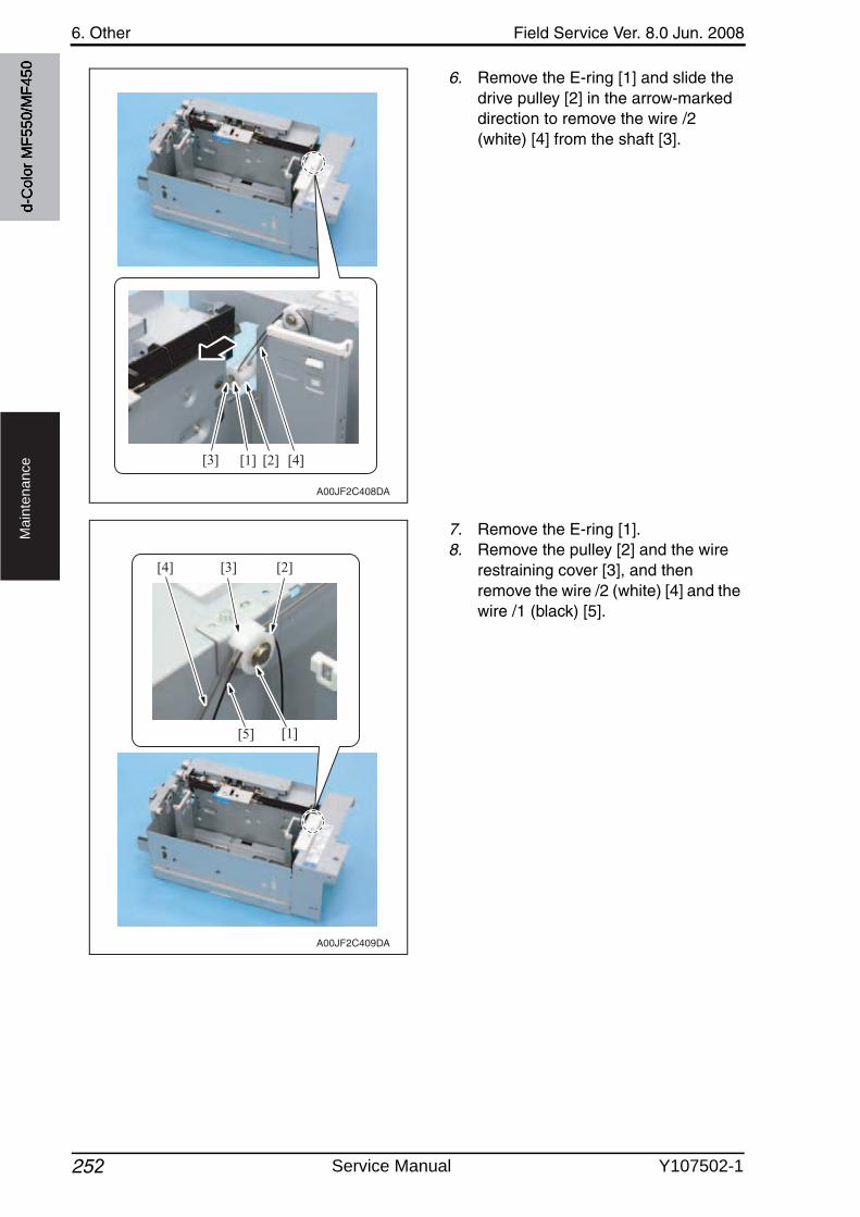
6. Other Field Service Ver. 8.0 Jun. 2008
252
Ma
inte
na
nce
6. Remove the E-ring [1] and slide the drive pulley [2] in the arrow-marked direction to remove the wire /2 (white) [4] from the shaft [3].
7. Remove the E-ring [1].8. Remove the pulley [2] and the wire
restraining cover [3], and then remove the wire /2 (white) [4] and the wire /1 (black) [5].
A00JF2C408DA
[1] [2] [4][3]
A00JF2C409DA
[4] [2][3]
[5] [1]
d-C
olor
MF5
50/M
F450
Service Manual Y107502-1
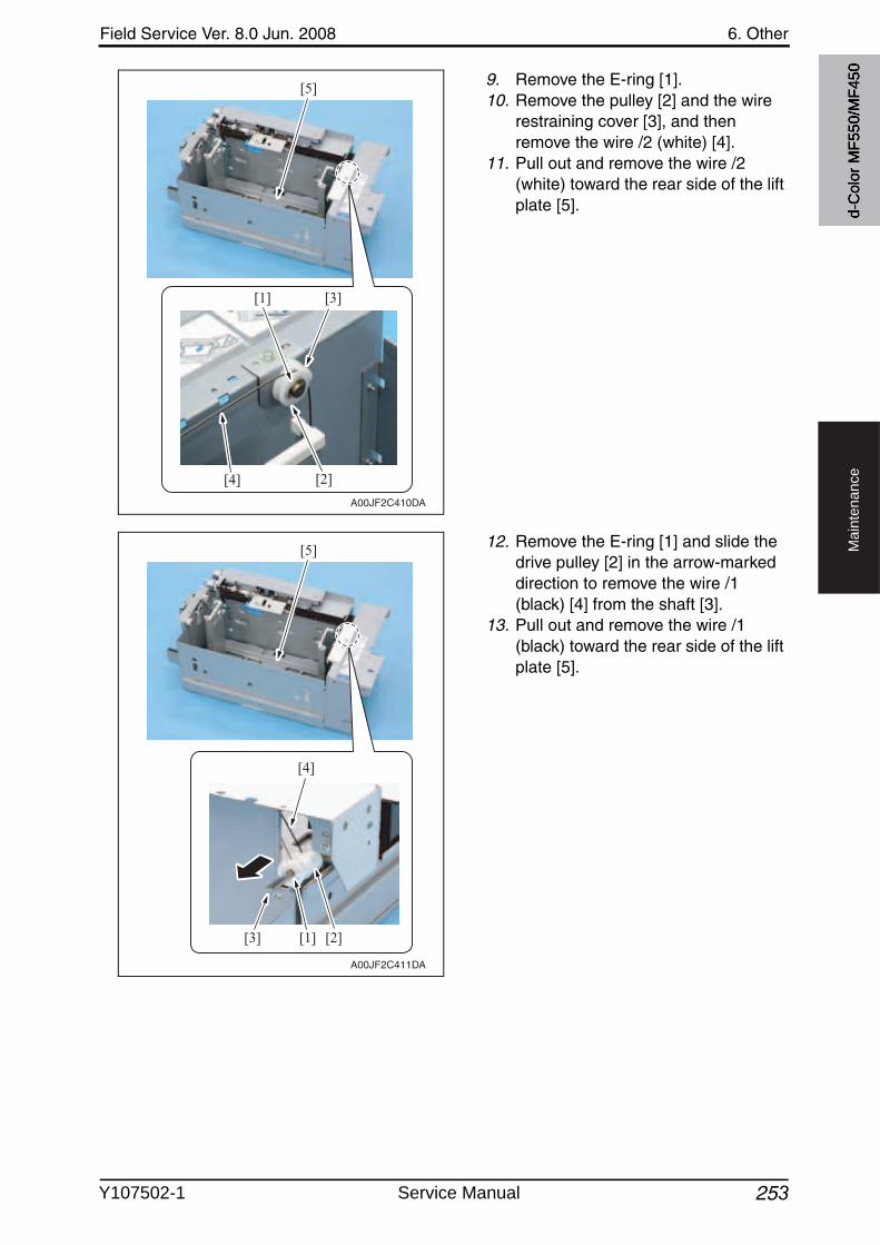
Field Service Ver. 8.0 Jun. 2008 6. Other
253
Ma
inte
na
nce
9. Remove the E-ring [1].10. Remove the pulley [2] and the wire
restraining cover [3], and then remove the wire /2 (white) [4].
11. Pull out and remove the wire /2 (white) toward the rear side of the lift plate [5].
12. Remove the E-ring [1] and slide the drive pulley [2] in the arrow-marked direction to remove the wire /1 (black) [4] from the shaft [3].
13. Pull out and remove the wire /1 (black) toward the rear side of the lift plate [5].
A00JF2C410DA
[4]
[1]
[2]
[3]
[5]
A00JF2C411DA
[1] [2]
[4]
[3]
[5]
d-C
olor
MF5
50/M
F450
Y107502-1 Service Manual
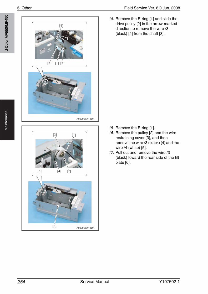
6. Other Field Service Ver. 8.0 Jun. 2008
254
Ma
inte
na
nce
14. Remove the E-ring [1] and slide the drive pulley [2] in the arrow-marked direction to remove the wire /3 (black) [4] from the shaft [3].
15. Remove the E-ring [1].16. Remove the pulley [2] and the wire
restraining cover [3], and then remove the wire /3 (black) [4] and the wire /4 (white) [5].
17. Pull out and remove the wire /3 (black) toward the rear side of the lift plate [6].
A00JF2C412DA
[4]
[2] [3][1]
A00JF2C413DA
[4][5] [2]
[3] [1]
[6]
d-C
olor
MF5
50/M
F450
Service Manual Y107502-1
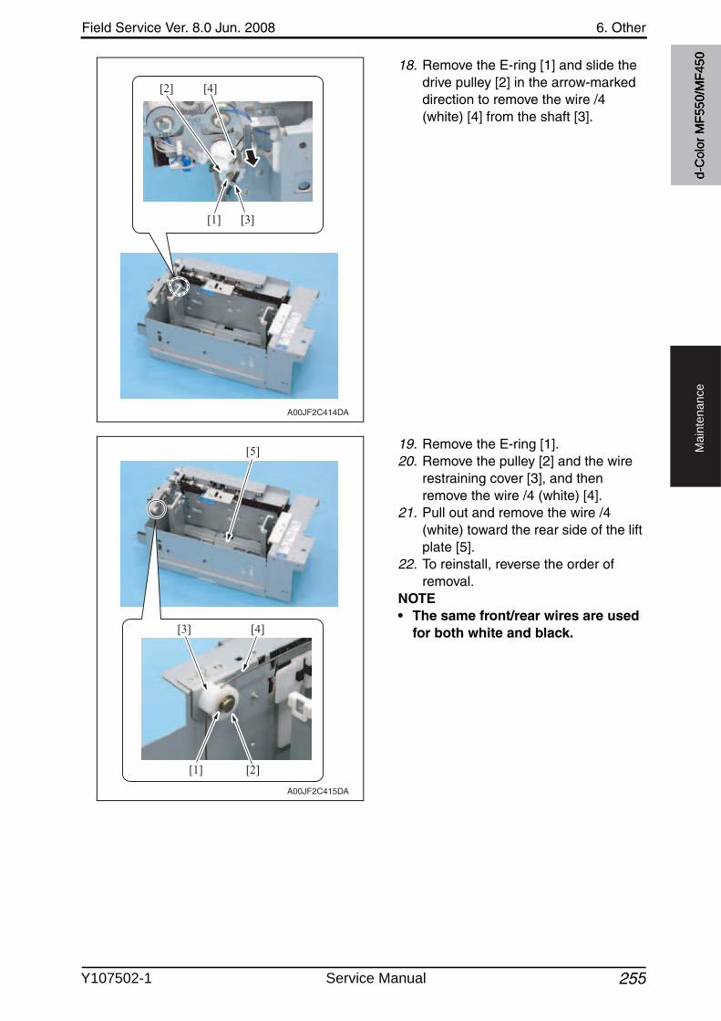
Field Service Ver. 8.0 Jun. 2008 6. Other
255
Ma
inte
na
nce
18. Remove the E-ring [1] and slide the drive pulley [2] in the arrow-marked direction to remove the wire /4 (white) [4] from the shaft [3].
19. Remove the E-ring [1].20. Remove the pulley [2] and the wire
restraining cover [3], and then remove the wire /4 (white) [4].
21. Pull out and remove the wire /4 (white) toward the rear side of the lift plate [5].
22. To reinstall, reverse the order of removal.
NOTE• The same front/rear wires are used
for both white and black.
A00JF2C414DA
[4][2]
[3][1]
A00JF2C415DA
[3]
[1] [2]
[4]
[5]
d-C
olor
MF5
50/M
F450
Y107502-1 Service Manual
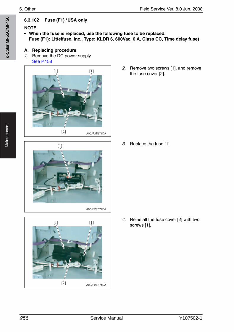
6. Other Field Service Ver. 8.0 Jun. 2008
256
Ma
inte
na
nce
6.3.102 Fuse (F1) *USA only
NOTE• When the fuse is replaced, use the following fuse to be replaced.
Fuse (F1): Littelfuse, Inc., Type: KLDR 6, 600Vac, 6 A, Class CC, Time delay fuse)
A. Replacing procedure1. Remove the DC power supply.
See P.158
2. Remove two screws [1], and removethe fuse cover [2].
3. Replace the fuse [1].
4. Reinstall the fuse cover [2] with twoscrews [1].
[1]
[2]
[1]
A00JF2E571DA
[1]
A00JF2E572DA
[1]
[2]
[1]
A00JF2E571DA
d-C
olor
MF5
50/M
F450
Service Manual Y107502-1
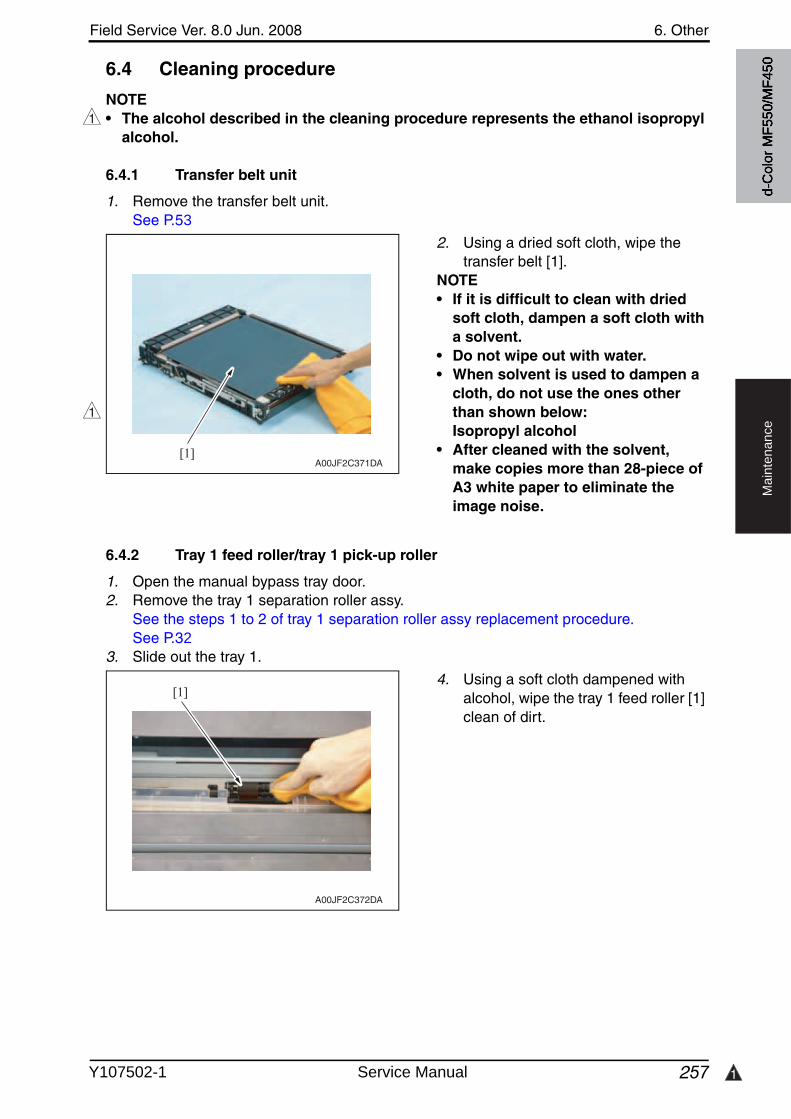
Field Service Ver. 8.0 Jun. 2008 6. Other
257 1
Ma
inte
na
nce
6.4 Cleaning procedure
NOTE• The alcohol described in the cleaning procedure represents the ethanol isopropyl
alcohol.
6.4.1 Transfer belt unit
1. Remove the transfer belt unit.See P.53
2. Using a dried soft cloth, wipe the transfer belt [1].
NOTE• If it is difficult to clean with dried
soft cloth, dampen a soft cloth with a solvent.
• Do not wipe out with water.• When solvent is used to dampen a
cloth, do not use the ones other than shown below:Isopropyl alcohol
• After cleaned with the solvent, make copies more than 28-piece of A3 white paper to eliminate the image noise.
6.4.2 Tray 1 feed roller/tray 1 pick-up roller
1. Open the manual bypass tray door.2. Remove the tray 1 separation roller assy.
See the steps 1 to 2 of tray 1 separation roller assy replacement procedure.See P.32
3. Slide out the tray 1.
4. Using a soft cloth dampened withalcohol, wipe the tray 1 feed roller [1] clean of dirt.
1
[1]A00JF2C371DA
1
[1]
A00JF2C372DA
d-C
olor
MF5
50/M
F450
Y107502-1 Service Manual
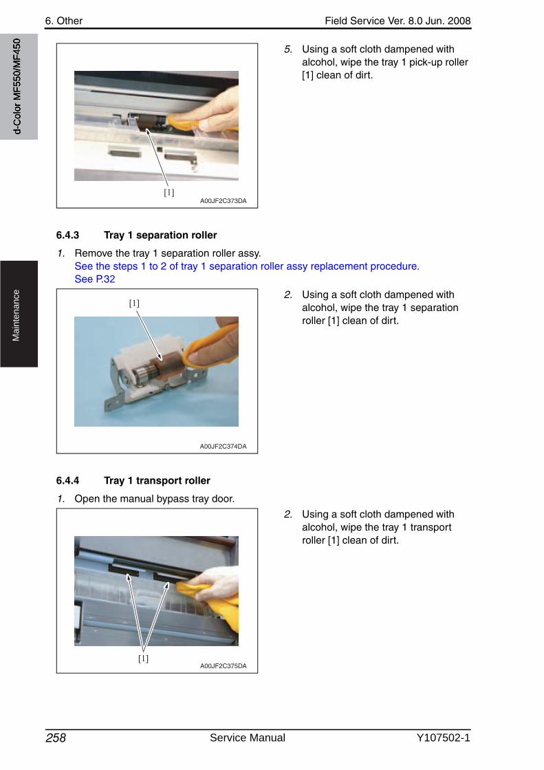
6. Other Field Service Ver. 8.0 Jun. 2008
258
Ma
inte
na
nce
5. Using a soft cloth dampened withalcohol, wipe the tray 1 pick-up roller [1] clean of dirt.
6.4.3 Tray 1 separation roller
1. Remove the tray 1 separation roller assy.See the steps 1 to 2 of tray 1 separation roller assy replacement procedure.See P.32
2. Using a soft cloth dampened withalcohol, wipe the tray 1 separation roller [1] clean of dirt.
6.4.4 Tray 1 transport roller
1. Open the manual bypass tray door.
2. Using a soft cloth dampened withalcohol, wipe the tray 1 transport roller [1] clean of dirt.
[1]A00JF2C373DA
[1]
A00JF2C374DA
A00JF2C375DA[1]
d-C
olor
MF5
50/M
F450
Service Manual Y107502-1
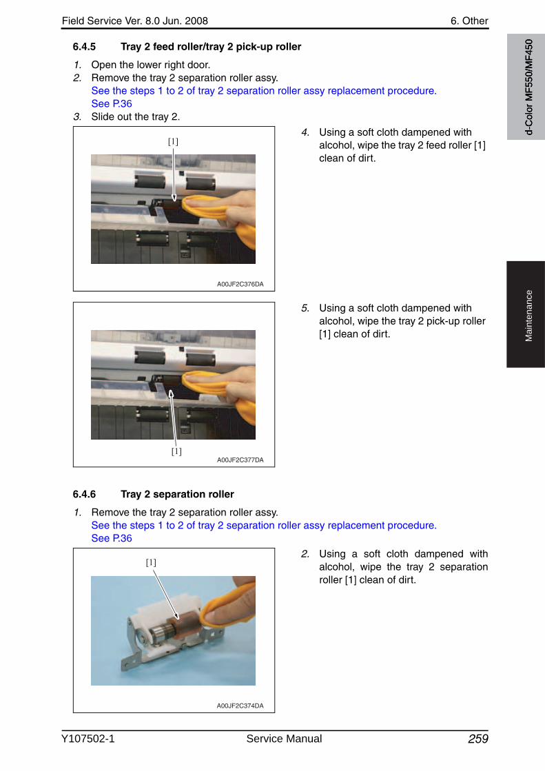
Field Service Ver. 8.0 Jun. 2008 6. Other
259
Ma
inte
na
nce
6.4.5 Tray 2 feed roller/tray 2 pick-up roller
1. Open the lower right door.2. Remove the tray 2 separation roller assy.
See the steps 1 to 2 of tray 2 separation roller assy replacement procedure.See P.36
3. Slide out the tray 2.
4. Using a soft cloth dampened withalcohol, wipe the tray 2 feed roller [1] clean of dirt.
5. Using a soft cloth dampened withalcohol, wipe the tray 2 pick-up roller [1] clean of dirt.
6.4.6 Tray 2 separation roller
1. Remove the tray 2 separation roller assy.See the steps 1 to 2 of tray 2 separation roller assy replacement procedure.See P.36
2. Using a soft cloth dampened withalcohol, wipe the tray 2 separationroller [1] clean of dirt.
[1]
A00JF2C376DA
[1]A00JF2C377DA
[1]
A00JF2C374DA
d-C
olor
MF5
50/M
F450
Y107502-1 Service Manual
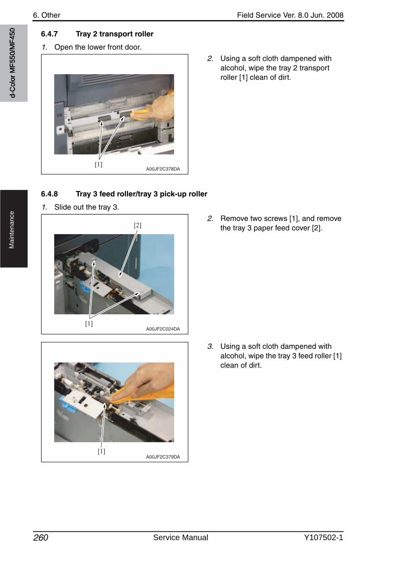
6. Other Field Service Ver. 8.0 Jun. 2008
260
Ma
inte
na
nce
6.4.7 Tray 2 transport roller
1. Open the lower front door.
2. Using a soft cloth dampened withalcohol, wipe the tray 2 transport roller [1] clean of dirt.
6.4.8 Tray 3 feed roller/tray 3 pick-up roller
1. Slide out the tray 3.
2. Remove two screws [1], and removethe tray 3 paper feed cover [2].
3. Using a soft cloth dampened withalcohol, wipe the tray 3 feed roller [1] clean of dirt.
[1]A00JF2C378DA
[1]
[2]
A00JF2C024DA
[1]A00JF2C379DA
d-C
olor
MF5
50/M
F450
Service Manual Y107502-1
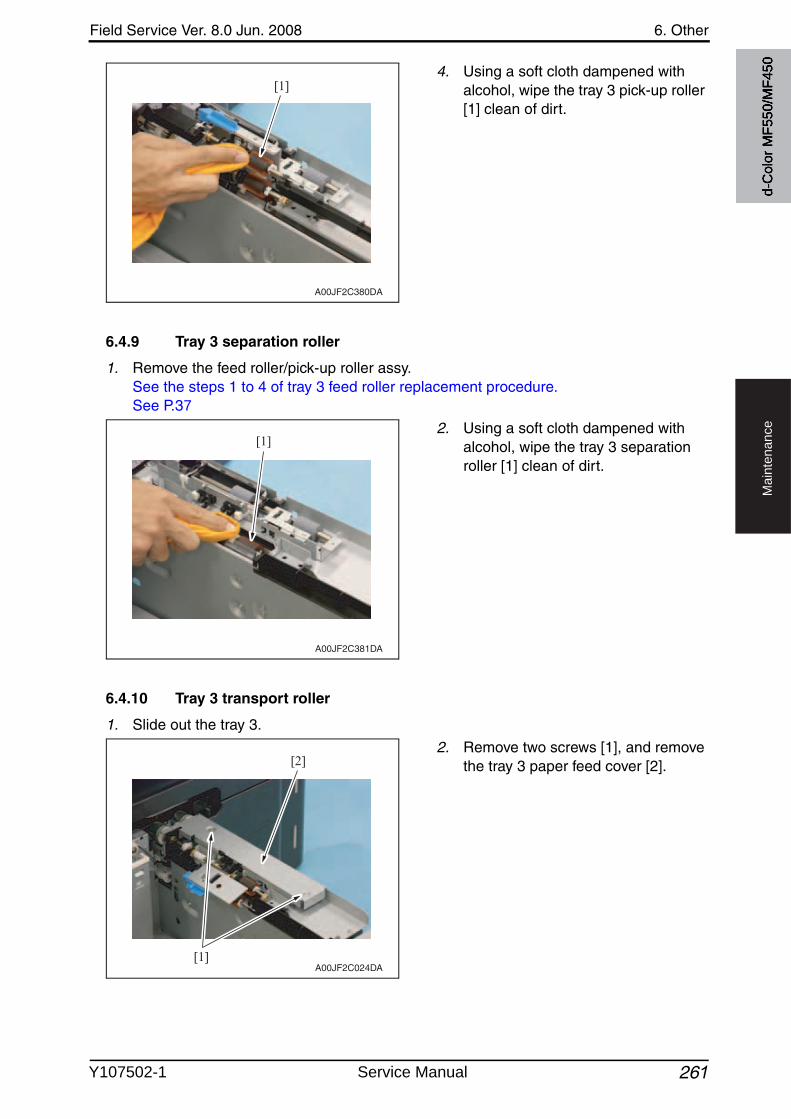
Field Service Ver. 8.0 Jun. 2008 6. Other
261
Ma
inte
na
nce
4. Using a soft cloth dampened withalcohol, wipe the tray 3 pick-up roller [1] clean of dirt.
6.4.9 Tray 3 separation roller
1. Remove the feed roller/pick-up roller assy.See the steps 1 to 4 of tray 3 feed roller replacement procedure.See P.37
2. Using a soft cloth dampened withalcohol, wipe the tray 3 separation roller [1] clean of dirt.
6.4.10 Tray 3 transport roller
1. Slide out the tray 3.
2. Remove two screws [1], and removethe tray 3 paper feed cover [2].
[1]
A00JF2C380DA
[1]
A00JF2C381DA
[1]
[2]
A00JF2C024DA
d-C
olor
MF5
50/M
F450
Y107502-1 Service Manual
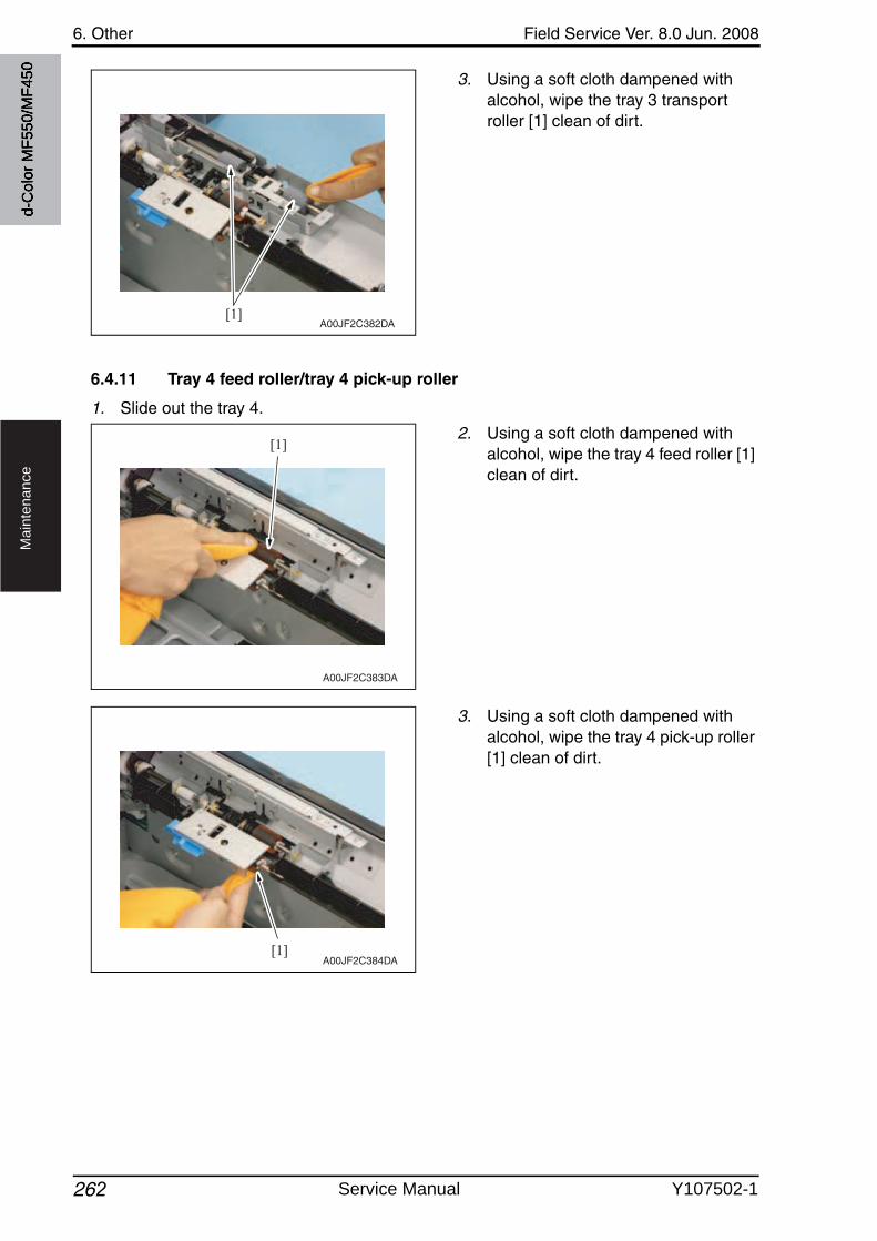
6. Other Field Service Ver. 8.0 Jun. 2008
262
Ma
inte
na
nce
3. Using a soft cloth dampened withalcohol, wipe the tray 3 transport roller [1] clean of dirt.
6.4.11 Tray 4 feed roller/tray 4 pick-up roller
1. Slide out the tray 4.
2. Using a soft cloth dampened withalcohol, wipe the tray 4 feed roller [1] clean of dirt.
3. Using a soft cloth dampened withalcohol, wipe the tray 4 pick-up roller [1] clean of dirt.
[1]A00JF2C382DA
[1]
A00JF2C383DA
[1]A00JF2C384DA
d-C
olor
MF5
50/M
F450
Service Manual Y107502-1
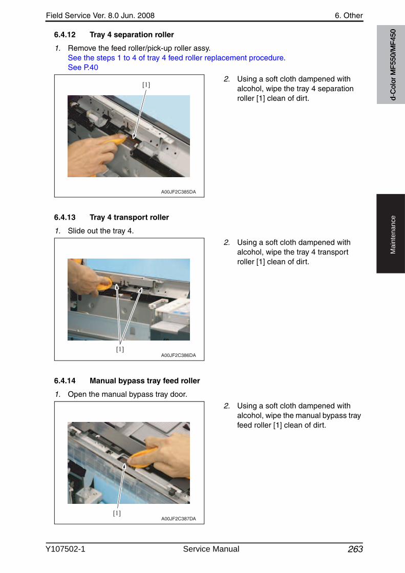
Field Service Ver. 8.0 Jun. 2008 6. Other
263
Ma
inte
na
nce
6.4.12 Tray 4 separation roller
1. Remove the feed roller/pick-up roller assy.See the steps 1 to 4 of tray 4 feed roller replacement procedure.See P.40
2. Using a soft cloth dampened withalcohol, wipe the tray 4 separation roller [1] clean of dirt.
6.4.13 Tray 4 transport roller
1. Slide out the tray 4.
2. Using a soft cloth dampened withalcohol, wipe the tray 4 transport roller [1] clean of dirt.
6.4.14 Manual bypass tray feed roller
1. Open the manual bypass tray door.
2. Using a soft cloth dampened withalcohol, wipe the manual bypass tray feed roller [1] clean of dirt.
[1]
A00JF2C385DA
[1]A00JF2C386DA
[1]A00JF2C387DA
d-C
olor
MF5
50/M
F450
Y107502-1 Service Manual
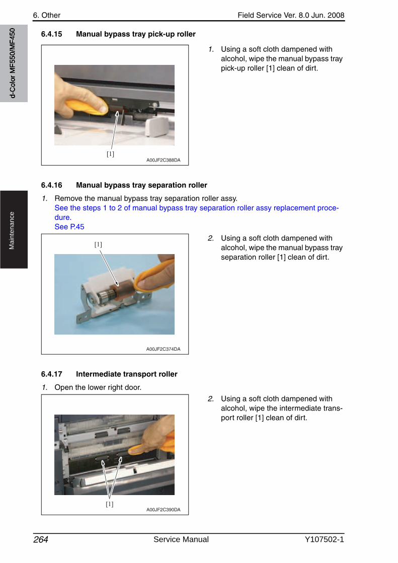
6. Other Field Service Ver. 8.0 Jun. 2008
264
Ma
inte
na
nce
6.4.15 Manual bypass tray pick-up roller
1. Using a soft cloth dampened withalcohol, wipe the manual bypass tray pick-up roller [1] clean of dirt.
6.4.16 Manual bypass tray separation roller
1. Remove the manual bypass tray separation roller assy.See the steps 1 to 2 of manual bypass tray separation roller assy replacement proce-dure.See P.45
2. Using a soft cloth dampened withalcohol, wipe the manual bypass tray separation roller [1] clean of dirt.
6.4.17 Intermediate transport roller
1. Open the lower right door.
2. Using a soft cloth dampened withalcohol, wipe the intermediate trans-port roller [1] clean of dirt.
[1]A00JF2C388DA
[1]
A00JF2C374DA
[1]A00JF2C390DA
d-C
olor
MF5
50/M
F450
Service Manual Y107502-1
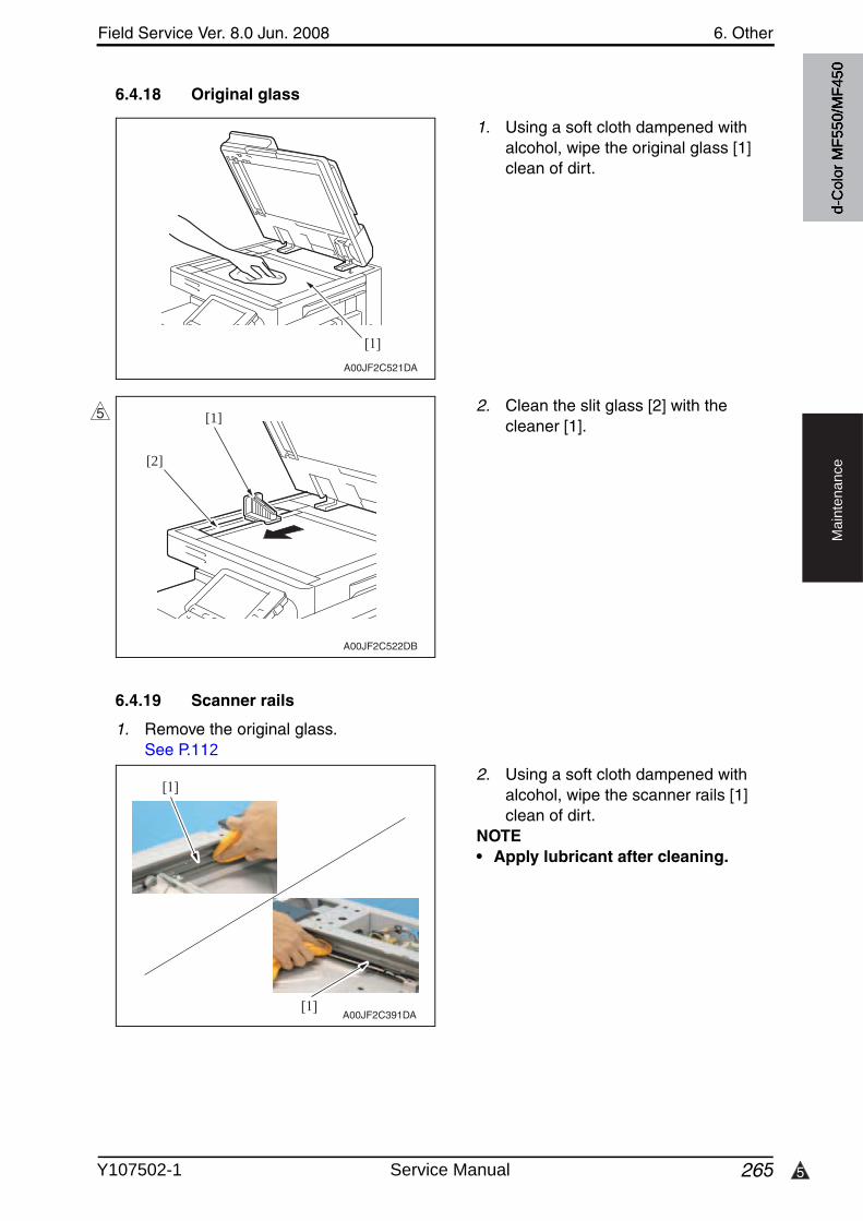
5
Field Service Ver. 8.0 Jun. 2008 6. Other
265
Ma
inte
na
nce
6.4.18 Original glass
1. Using a soft cloth dampened withalcohol, wipe the original glass [1] clean of dirt.
2. Clean the slit glass [2] with the cleaner [1].
6.4.19 Scanner rails
1. Remove the original glass.See P.112
2. Using a soft cloth dampened withalcohol, wipe the scanner rails [1] clean of dirt.
NOTE• Apply lubricant after cleaning.
A00JF2C521DA
[1]
A00JF2C522DB
[1]
[2]
5
[1]
[1]A00JF2C391DA
d-C
olor
MF5
50/M
F450
Y107502-1 Service Manual
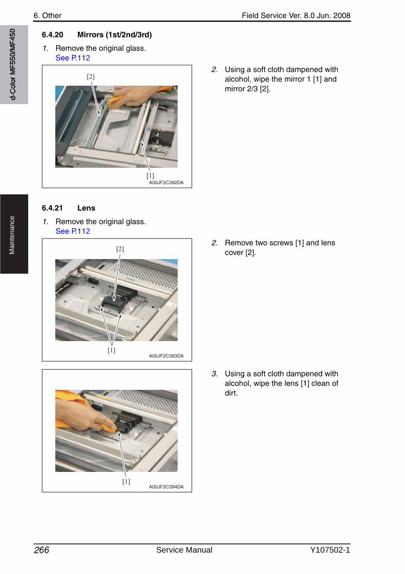
6. Other Field Service Ver. 8.0 Jun. 2008
266
Ma
inte
na
nce
6.4.20 Mirrors (1st/2nd/3rd)
1. Remove the original glass.See P.112
2. Using a soft cloth dampened withalcohol, wipe the mirror 1 [1] and mirror 2/3 [2].
6.4.21 Lens
1. Remove the original glass.See P.112
2. Remove two screws [1] and lens cover [2].
3. Using a soft cloth dampened withalcohol, wipe the lens [1] clean of dirt.
[1]
[2]
A00JF2C392DA
[1]
[2]
A00JF2C393DA
[1]A00JF2C394DA
d-C
olor
MF5
50/M
F450
Service Manual Y107502-1
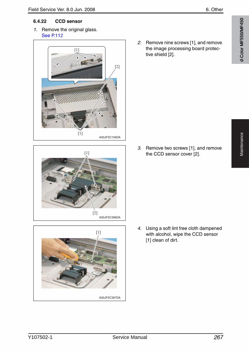
Field Service Ver. 8.0 Jun. 2008 6. Other
267
Ma
inte
na
nce
6.4.22 CCD sensor
1. Remove the original glass.See P.112
2. Remove nine screws [1], and removethe image processing board protec-tive shield [2].
3. Remove two screws [1], and removethe CCD sensor cover [2].
4. Using a soft lint free cloth dampened with alcohol, wipe the CCD sensor [1] clean of dirt.
A00JF2C156DA
[1]
[2]
[1]
[2]
[1]
A00JF2C396DA
[1]
A00JF2C397DA
d-C
olor
MF5
50/M
F450
Y107502-1 Service Manual
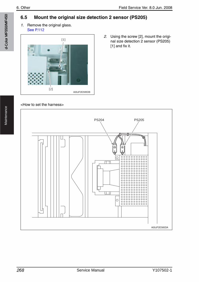
6. Other Field Service Ver. 8.0 Jun. 2008
268
Ma
inte
na
nce
6.5 Mount the original size detection 2 sensor (PS205)
1. Remove the original glass.See P.112
2. Using the screw [2], mount the origi-nal size detection 2 sensor (PS205) [1] and fix it.
<How to set the harness>
[2]
[1]
A00JF2E595DB
PS204 PS205
A00JF2E585DA
d-C
olor
MF5
50/M
F450
Service Manual Y107502-1
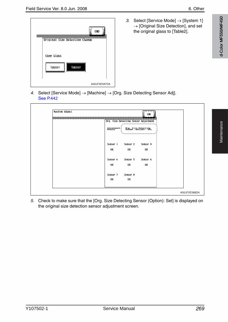
Field Service Ver. 8.0 Jun. 2008 6. Other
269
Ma
inte
na
nce
3. Select [Service Mode] [System 1] [Original Size Detection], and set
the original glass to [Table2].
4. Select [Service Mode] [Machine] [Org. Size Detecting Sensor Adj].See P.442
5. Check to make sure that the [Org. Size Detecting Sensor (Option): Set] is displayed on the original size detection sensor adjustment screen.
A00JF2E587DA
A00JF2E588DA
d-C
olor
MF5
50/M
F450
Y107502-1 Service Manual
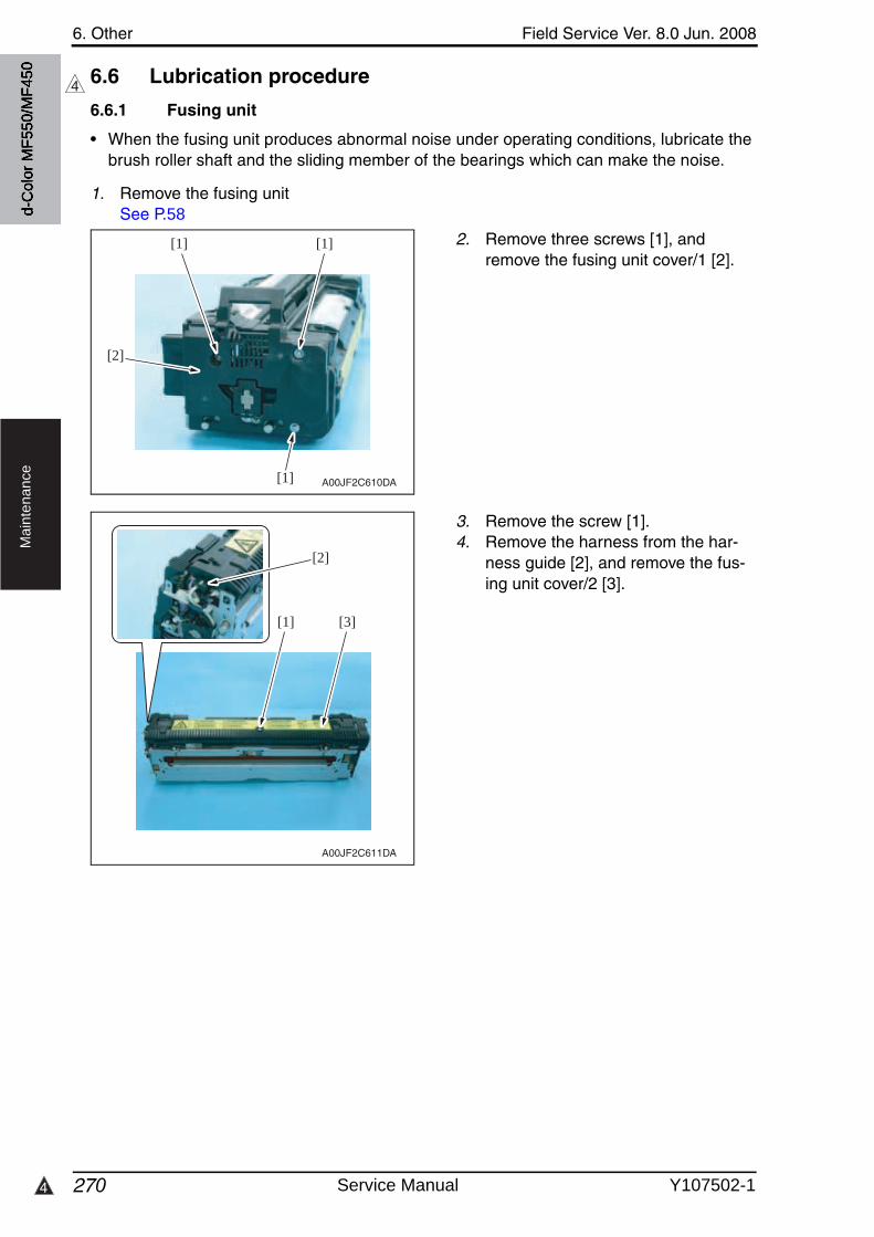
6. Other Field Service Ver. 8.0 Jun. 2008
2704
Ma
inte
na
nce
6.6 Lubrication procedure
6.6.1 Fusing unit
• When the fusing unit produces abnormal noise under operating conditions, lubricate the brush roller shaft and the sliding member of the bearings which can make the noise.
1. Remove the fusing unitSee P.58
2. Remove three screws [1], and remove the fusing unit cover/1 [2].
3. Remove the screw [1].4. Remove the harness from the har-
ness guide [2], and remove the fus-ing unit cover/2 [3].
4
[1][1]
[2]
[1] A00JF2C610DA
[3][1]
[2]
A00JF2C611DA
d-C
olor
MF5
50/M
F450
Service Manual Y107502-1
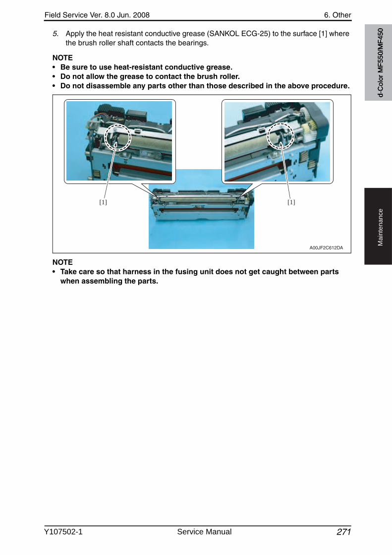
Field Service Ver. 8.0 Jun. 2008 6. Other
271
Ma
inte
na
nce
5. Apply the heat resistant conductive grease (SANKOL ECG-25) to the surface [1] wherethe brush roller shaft contacts the bearings.
NOTE• Be sure to use heat-resistant conductive grease.• Do not allow the grease to contact the brush roller.• Do not disassemble any parts other than those described in the above procedure.
NOTE• Take care so that harness in the fusing unit does not get caught between parts
when assembling the parts.
[1][1]
A00JF2C612DA
d-C
olor
MF5
50/M
F450
Y107502-1 Service Manual
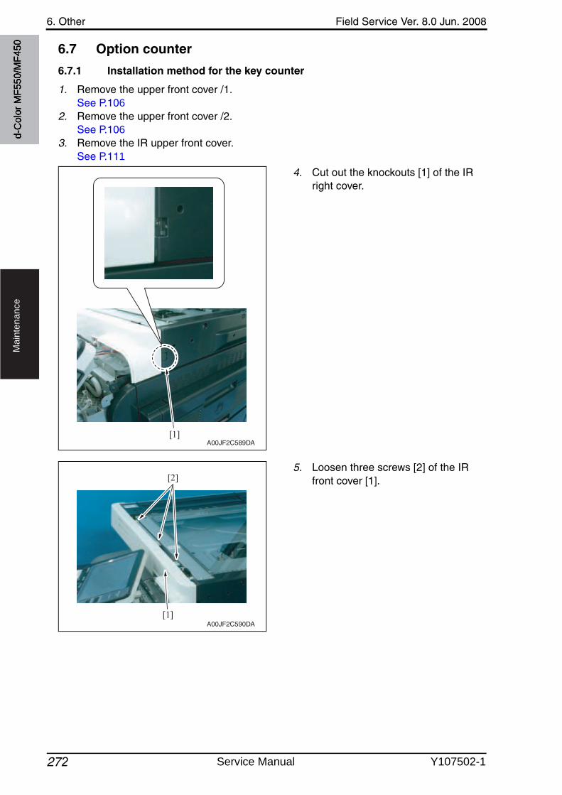
6. Other Field Service Ver. 8.0 Jun. 2008
272
Ma
inte
na
nce
6.7 Option counter
6.7.1 Installation method for the key counter
1. Remove the upper front cover /1.See P.106
2. Remove the upper front cover /2.See P.106
3. Remove the IR upper front cover.See P.111
4. Cut out the knockouts [1] of the IR right cover.
5. Loosen three screws [2] of the IR front cover [1].
[1]A00JF2C589DA
[1]
[2]
A00JF2C590DA
d-C
olor
MF5
50/M
F450
Service Manual Y107502-1
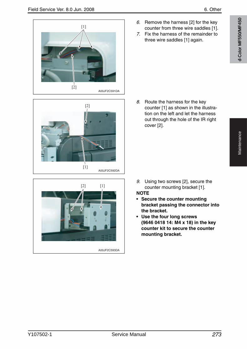
Field Service Ver. 8.0 Jun. 2008 6. Other
273
Ma
inte
na
nce
6. Remove the harness [2] for the key counter from three wire saddles [1].
7. Fix the harness of the remainder to three wire saddles [1] again.
8. Route the harness for the key counter [1] as shown in the illustra-tion on the left and let the harness out through the hole of the IR right cover [2].
9. Using two screws [2], secure the counter mounting bracket [1].
NOTE• Secure the counter mounting
bracket passing the connector into the bracket.
• Use the four long screws (9646 0418 14: M4 x 18) in the key counter kit to secure the counter mounting bracket.
[1]
[2]A00JF2C591DA
[1]
[2]
A00JF2C592DA
[1][2]
A00JF2C593DA
d-C
olor
MF5
50/M
F450
Y107502-1 Service Manual
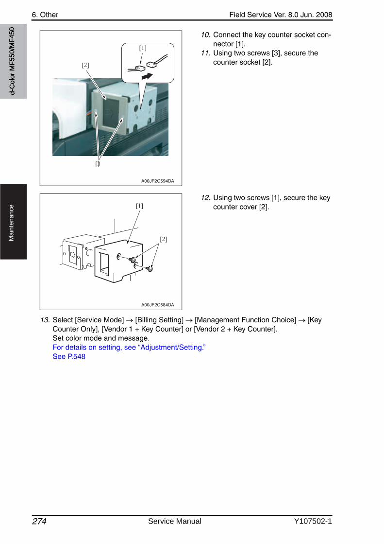
6. Other Field Service Ver. 8.0 Jun. 2008
274
Ma
inte
na
nce
10. Connect the key counter socket con-nector [1].
11. Using two screws [3], secure the counter socket [2].
12. Using two screws [1], secure the key counter cover [2].
13. Select [Service Mode] [Billing Setting] [Management Function Choice] [Key Counter Only], [Vendor 1 + Key Counter] or [Vendor 2 + Key Counter].Set color mode and message.For details on setting, see “Adjustment/Setting.”See P.548
[2]
[3]
[1]
A00JF2C594DA
A00JF2C584DA
[1]
[2]
d-C
olor
MF5
50/M
F450
Service Manual Y107502-1
Field Service Ver. 8.0 Jun. 2008 7. How to use the adjustment section
275
Ad
justm
en
t /
Se
ttin
g
Adjustment/Setting7. How to use the adjustment section• “Adjustment/Setting” contains detailed information on the adjustment items and proce-
dures for this machine.• Throughout this “Adjustment/Setting,” the default settings are indicated by “ ”.
Advance checks• Before attempting to solve the customer problem, the following advance checks must be
made. Check to see if:
• The power supply voltage meets the specifications.• The power supply is properly grounded.• The machine shares the power supply with any other machine that draws large current
intermittently (e.g., elevator and air conditioner that generate electric noise).• The installation site is environmentally appropriate: high temperature, high humidity,
direct sunlight, ventilation, etc.; levelness of the installation site.• The original has a problem that may cause a defective image.• The density is properly selected.• The original glass, slit glass, or related part is dirty.• Correct paper is being used for printing.• The units, parts, and supplies used for printing (developer, PC drum, etc.) are properly
replenished and replaced when they reach the end of their useful service life.• Toner is not running out.
CAUTION• To unplug the power cord of the machine before starting the service job proce-
dures.• If it is unavoidably necessary to service the machine with its power turned ON, use
utmost care not to be caught in the scanner cables or gears of the exposure unit.• Special care should be used when handling the fusing unit which can be
extremely hot.• The developing unit has a strong magnetic field. Keep watches and measuring
instruments away from it.• Take care not to damage the PC drum with a tool or similar device.• Do not touch IC pins with bare hands.
d-C
olor
MF5
50/M
F450
Y107502-1 Service Manual
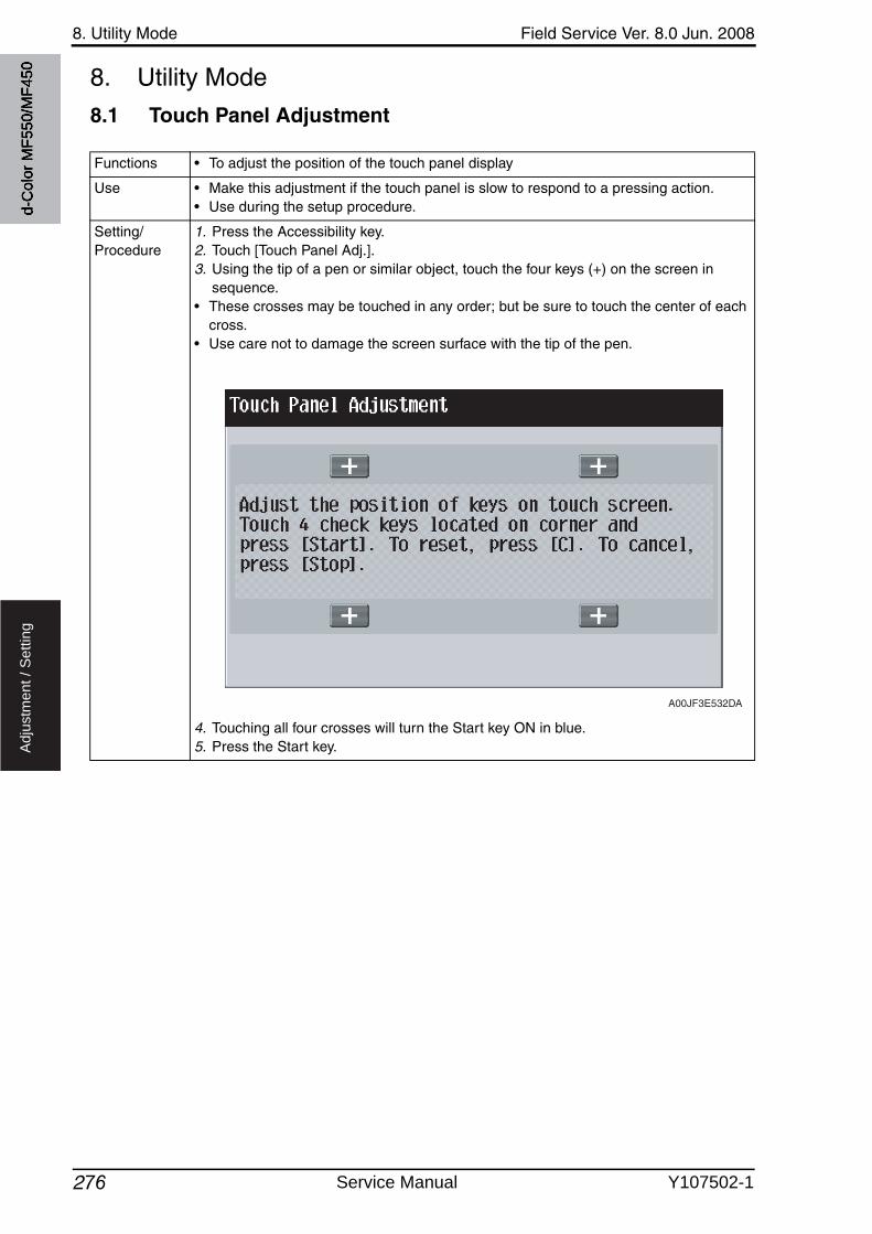
8. Utility Mode Field Service Ver. 8.0 Jun. 2008
276
Ad
justm
en
t /
Se
ttin
g
8. Utility Mode
8.1 Touch Panel Adjustment
Functions • To adjust the position of the touch panel display
Use • Make this adjustment if the touch panel is slow to respond to a pressing action.• Use during the setup procedure.
Setting/Procedure
1. Press the Accessibility key.2. Touch [Touch Panel Adj.].3. Using the tip of a pen or similar object, touch the four keys (+) on the screen in
sequence.• These crosses may be touched in any order; but be sure to touch the center of each
cross.• Use care not to damage the screen surface with the tip of the pen.
4. Touching all four crosses will turn the Start key ON in blue.5. Press the Start key.
A00JF3E532DA
d-C
olor
MF5
50/M
F450
Service Manual Y107502-1
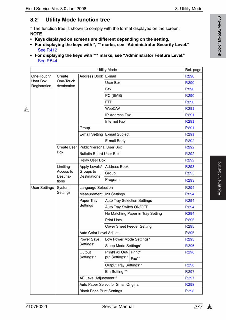
3
Field Service Ver. 8.0 Jun. 2008 8. Utility Mode
277
Ad
justm
en
t /
Se
ttin
g
8.2 Utility Mode function tree
* The function tree is shown to comply with the format displayed on the screen.NOTE• Keys displayed on screens are different depending on the setting.• For displaying the keys with *, ** marks, see “Administrator Security Level.”
See P.412• For displaying the keys with *** marks, see “Administrator Feature Level.”
See P.544
Utility Mode Ref. page
One-Touch/User Box Registration
Create One-Touchdestination
Address Book E-mail P.290
User Box P.290
Fax P.290
PC (SMB) P.290
FTP P.290
WebDAV P.291
IP Address Fax P.291
Internet Fax P.291
Group P.291
E-mail Setting E-mail Subject P.291
E-mail Body P.292
Create User Box
Public/Personal User Box P.292
Bulletin Board User Box P.292
Relay User Box P.292
Limiting Access to Destina-tions
Apply Levels/Groups to Destinations
Address Book P.293
Group P.293
Program P.293
User Settings System Settings
Language Selection P.294
Measurement Unit Settings P.294
Paper Tray Settings
Auto Tray Selection Settings P.294
Auto Tray Switch ON/OFF P.294
No Matching Paper in Tray Setting P.294
Print Lists P.295
Cover Sheet Feeder Setting P.295
Auto Color Level Adjust. P.295
Power SaveSettings*
Low Power Mode Settings* P.295
Sleep Mode Settings* P.296
OutputSettings**
Print/Fax Out-put Settings**
Print** P.296
Fax**
Output Tray Settings** P.296
Bin Setting ** P.297
AE Level Adjustment** P.297
Auto Paper Select for Small Original P.298
Blank Page Print Settings P.298
3
d-C
olor
MF5
50/M
F450
Y107502-1 Service Manual
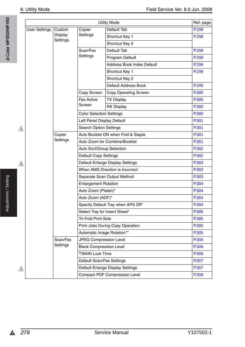
8. Utility Mode Field Service Ver. 8.0 Jun. 2008
2783
Ad
justm
en
t /
Se
ttin
g
User Settings Custom Display Settings
Copier Settings
Default Tab P.298
Shortcut Key 1 P.298
Shortcut Key 2
Scan/Fax Settings
Default Tab P.299
Program Default P.299
Address Book Index Default P.299
Shortcut Key 1 P.299
Shortcut Key 2
Default Address Book P.299
Copy Screen Copy Operating Screen P.300
Fax ActiveScreen
TX Display P.300
RX Display P.300
Color Selection Settings P.300
Left Panel Display Default P.301
Search Option Settings P.301
Copier Settings
Auto Booklet ON when Fold & Staple P.301
Auto Zoom for Combine/Booklet P.301
Auto Sort/Group Selection P.302
Default Copy Settings P.302
Default Enlarge Display Settings P.303
When AMS Direction is Incorrect P.303
Separate Scan Output Method P.303
Enlargement Rotation P.304
Auto Zoom (Platen)* P.304
Auto Zoom (ADF)* P.304
Specify Default Tray when APS Off* P.304
Select Tray for Insert Sheet* P.305
Tri-Fold Print Side P.305
Print Jobs During Copy Operation P.305
Automatic Image Rotation** P.305
Scan/Fax Settings
JPEG Compression Level P.306
Black Compression Level P.306
TWAIN Lock Time P.306
Default Scan/Fax Settings P.307
Default Enlarge Display Settings P.307
Compact PDF Compression Level P.308
Utility Mode Ref. page
3
3
3
d-C
olor
MF5
50/M
F450
Service Manual Y107502-1
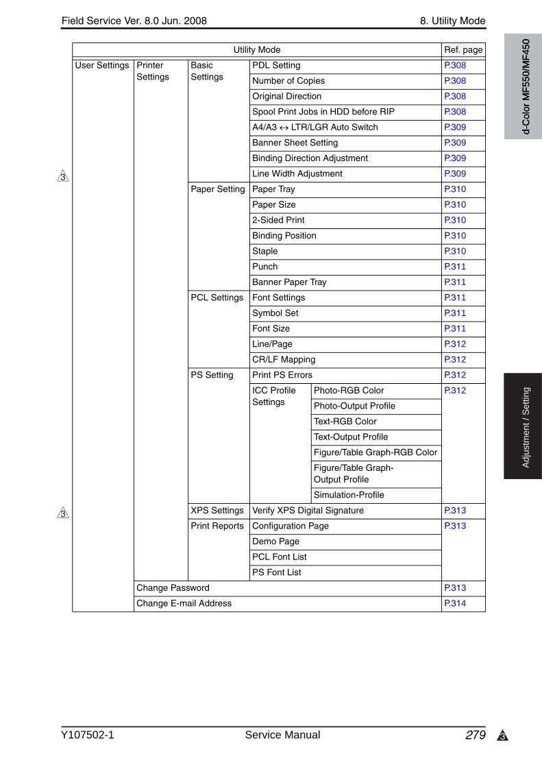
3
Field Service Ver. 8.0 Jun. 2008 8. Utility Mode
279
Ad
justm
en
t /
Se
ttin
g
User Settings Printer Settings
Basic Settings
PDL Setting P.308
Number of Copies P.308
Original Direction P.308
Spool Print Jobs in HDD before RIP P.308
A4/A3 LTR/LGR Auto Switch P.309
Banner Sheet Setting P.309
Binding Direction Adjustment P.309
Line Width Adjustment P.309
Paper Setting Paper Tray P.310
Paper Size P.310
2-Sided Print P.310
Binding Position P.310
Staple P.310
Punch P.311
Banner Paper Tray P.311
PCL Settings Font Settings P.311
Symbol Set P.311
Font Size P.311
Line/Page P.312
CR/LF Mapping P.312
PS Setting Print PS Errors P.312
ICC Profile Settings
Photo-RGB Color P.312
Photo-Output Profile
Text-RGB Color
Text-Output Profile
Figure/Table Graph-RGB Color
Figure/Table Graph-Output Profile
Simulation-Profile
XPS Settings Verify XPS Digital Signature P.313
Print Reports Configuration Page P.313
Demo Page
PCL Font List
PS Font List
Change Password P.313
Change E-mail Address P.314
Utility Mode Ref. page
3
3d-
Col
or M
F550
/MF4
50
Y107502-1 Service Manual
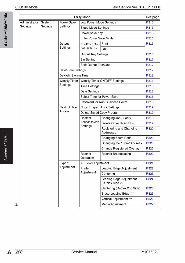
8. Utility Mode Field Service Ver. 8.0 Jun. 2008
2803
Ad
justm
en
t /
Se
ttin
g
Administrator Settings
System Settings
Power SaveSettings
Low Power Mode Settings P.315
Sleep Mode Settings P.315
Power Save Key P.315
Enter Power Save Mode P.316
OutputSettings
Print/Fax Out-put Settings
Print P.316
Fax
Output Tray Settings P.316
Bin Setting P.317
Shift Output Each Job P.317
Date/Time Settings P.317
Daylight Saving Time P.318
Weekly Timer Settings
Weekly Timer ON/OFF Settings P.318
Time Settings P.318
Date Settings P.318
Select Time for Power Save P.318
Password for Non-Business Hours P.319
Restrict User Access
Copy Program Lock Settings P.319
Delete Saved Copy Program P.319
Restrict Access to Job Settings
Changing Job Priority P.319
Delete Other User Jobs P.319
Registering and Changing Addresses
P.320
Changing Zoom Ratio P.320
Changing the “From” Address P.320
Change Registered Overlay P.320
Restrict Operation
Restrict Broadcasting P.320
Expert Adjustment
AE Level Adjustment P.321
Printer Adjustment
Leading Edge Adjustment P.322
Centering P.323
Leading Edge Adjustment (Duplex Side 2)
P.324
Centering (Duplex 2nd Side) P.325
Erase Leading Edge *** P.325
Vertical Adjustment *** P.326
Media Adjustment P.327
Utility Mode Ref. page
3
d-C
olor
MF5
50/M
F450
Service Manual Y107502-1
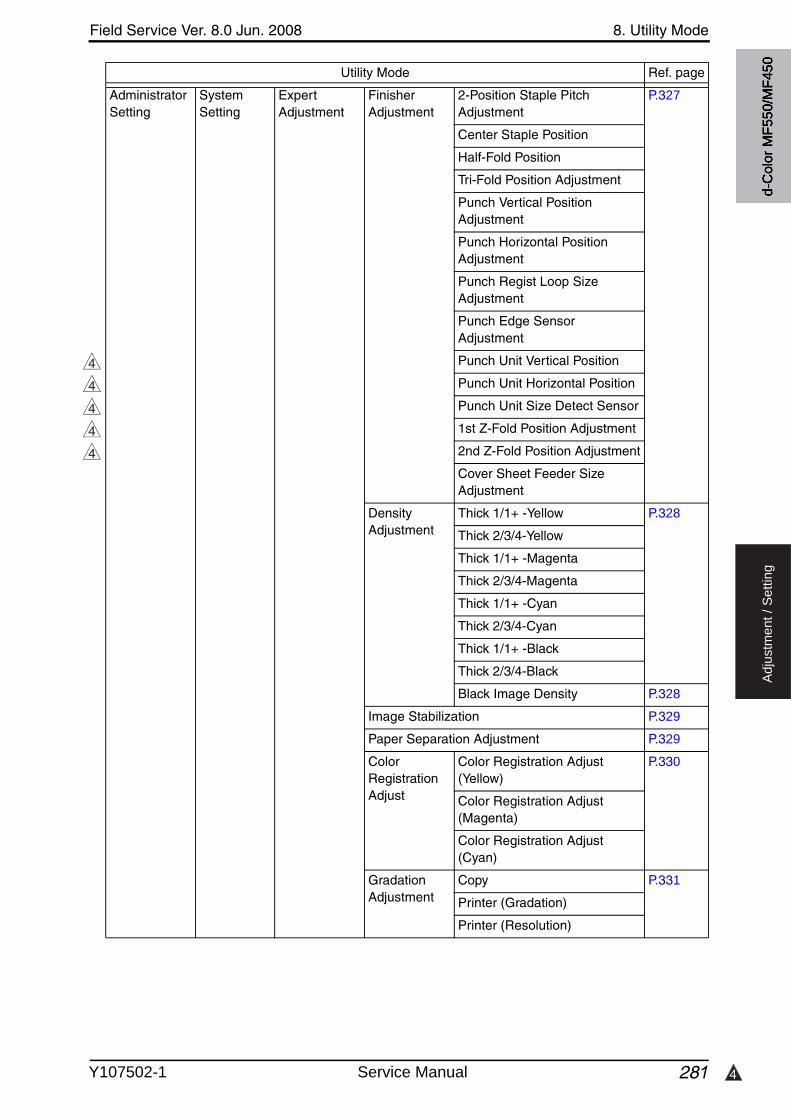
4
Field Service Ver. 8.0 Jun. 2008 8. Utility Mode
281
Ad
justm
en
t /
Se
ttin
g
Administrator Setting
System Setting
Expert Adjustment
FinisherAdjustment
2-Position Staple Pitch Adjustment
P.327
Center Staple Position
Half-Fold Position
Tri-Fold Position Adjustment
Punch Vertical Position Adjustment
Punch Horizontal Position Adjustment
Punch Regist Loop Size Adjustment
Punch Edge Sensor Adjustment
Punch Unit Vertical Position
Punch Unit Horizontal Position
Punch Unit Size Detect Sensor
1st Z-Fold Position Adjustment
2nd Z-Fold Position Adjustment
Cover Sheet Feeder Size Adjustment
Density Adjustment
Thick 1/1+ -Yellow P.328
Thick 2/3/4-Yellow
Thick 1/1+ -Magenta
Thick 2/3/4-Magenta
Thick 1/1+ -Cyan
Thick 2/3/4-Cyan
Thick 1/1+ -Black
Thick 2/3/4-Black
Black Image Density P.328
Image Stabilization P.329
Paper Separation Adjustment P.329
Color Registration Adjust
Color Registration Adjust (Yellow)
P.330
Color Registration Adjust (Magenta)
Color Registration Adjust (Cyan)
Gradation Adjustment
Copy P.331
Printer (Gradation)
Printer (Resolution)
Utility Mode Ref. page
4
4
4
4
4
d-C
olor
MF5
50/M
F450
Y107502-1 Service Manual
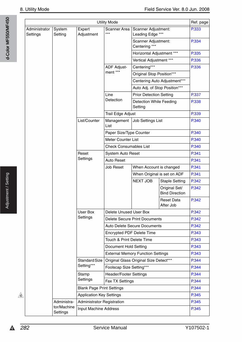
8. Utility Mode Field Service Ver. 8.0 Jun. 2008
2824
Ad
justm
en
t /
Se
ttin
g
Administrator Settings
System Setting
Expert Adjustment
Scanner Area ***
Scanner Adjustment: Leading Edge ***
P.333
Scanner Adjustment: Centering ***
P.334
Horizontal Adjustment *** P.335
Vertical Adjustment *** P.336
ADF Adjust-ment ***
Centering*** P.336
Original Stop Position***
Centering Auto Adjustment***
Auto Adj. of Stop Position***
Line Detection
Prior Detection Setting P.337
Detection While Feeding Setting
P.338
Trail Edge Adjust P.339
List/Counter Management List
Job Settings List P.340
Paper Size/Type Counter P.340
Meter Counter List P.340
Check Consumables List P.340
ResetSettings
System Auto Reset P.341
Auto Reset P.341
Job Reset When Account is changed P.341
When Original is set on ADF P.341
NEXT JOB Staple Setting P.342
Original Set/Bind Direction
P.342
Reset Data After Job
P.342
User Box Settings
Delete Unused User Box P.342
Delete Secure Print Documents P.342
Auto Delete Secure Documents P.342
Encrypted PDF Delete Time P.343
Touch & Print Delete Time P.343
Document Hold Setting P.343
External Memory Function Settings P.343
Standard Size Setting***
Original Glass Original Size Detect*** P.344
Foolscap Size Setting*** P.344
Stamp Settings
Header/Footer Settings P.344
Fax TX Settings P.344
Blank Page Print Settings P.344
Application Key Settings P.345
Administra-tor/Machine Settings
Administrator Registration P.345
Input Machine Address P.345
Utility Mode Ref. page
4
d-C
olor
MF5
50/M
F450
Service Manual Y107502-1
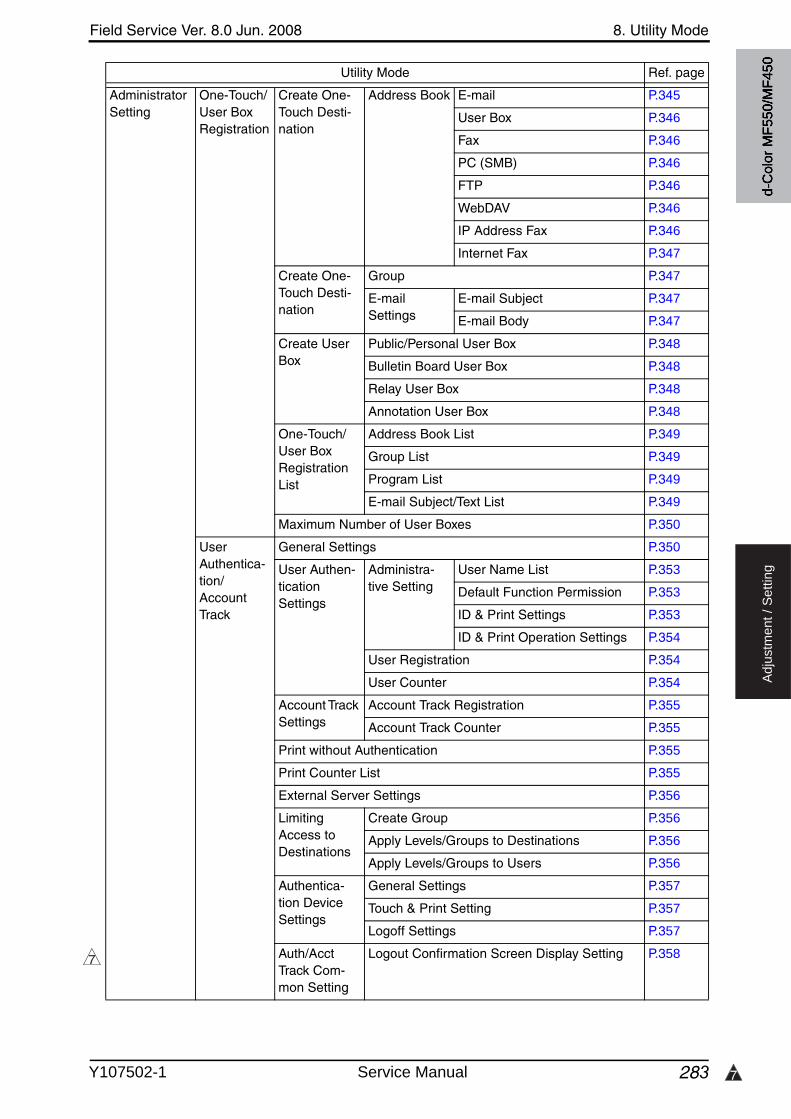
7
Field Service Ver. 8.0 Jun. 2008 8. Utility Mode
283
Ad
justm
en
t /
Se
ttin
g
Administrator Setting
One-Touch/User Box Registration
Create One-Touch Desti-nation
Address Book E-mail P.345
User Box P.346
Fax P.346
PC (SMB) P.346
FTP P.346
WebDAV P.346
IP Address Fax P.346
Internet Fax P.347
Create One-Touch Desti-nation
Group P.347
E-mail Settings
E-mail Subject P.347
E-mail Body P.347
Create User Box
Public/Personal User Box P.348
Bulletin Board User Box P.348
Relay User Box P.348
Annotation User Box P.348
One-Touch/User Box Registration List
Address Book List P.349
Group List P.349
Program List P.349
E-mail Subject/Text List P.349
Maximum Number of User Boxes P.350
UserAuthentica-tion/Account Track
General Settings P.350
User Authen-tication Settings
Administra-tive Setting
User Name List P.353
Default Function Permission P.353
ID & Print Settings P.353
ID & Print Operation Settings P.354
User Registration P.354
User Counter P.354
Account Track Settings
Account Track Registration P.355
Account Track Counter P.355
Print without Authentication P.355
Print Counter List P.355
External Server Settings P.356
Limiting Access to Destinations
Create Group P.356
Apply Levels/Groups to Destinations P.356
Apply Levels/Groups to Users P.356
Authentica-tion Device Settings
General Settings P.357
Touch & Print Setting P.357
Logoff Settings P.357
Auth/Acct Track Com-mon Setting
Logout Confirmation Screen Display Setting P.358
Utility Mode Ref. page
7
d-C
olor
MF5
50/M
F450
Y107502-1 Service Manual
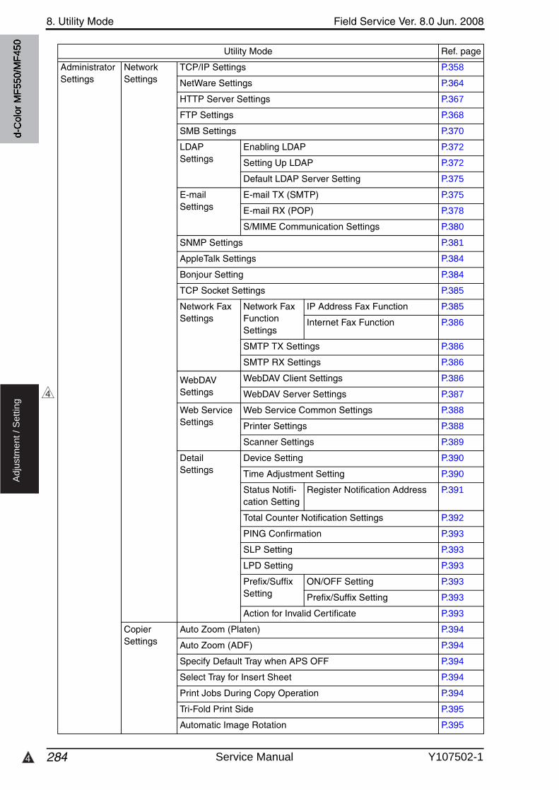
8. Utility Mode Field Service Ver. 8.0 Jun. 2008
2844
Ad
justm
en
t /
Se
ttin
g
Administrator Settings
Network Settings
TCP/IP Settings P.358
NetWare Settings P.364
HTTP Server Settings P.367
FTP Settings P.368
SMB Settings P.370
LDAP Settings
Enabling LDAP P.372
Setting Up LDAP P.372
Default LDAP Server Setting P.375
E-mail Settings
E-mail TX (SMTP) P.375
E-mail RX (POP) P.378
S/MIME Communication Settings P.380
SNMP Settings P.381
AppleTalk Settings P.384
Bonjour Setting P.384
TCP Socket Settings P.385
Network Fax Settings
Network Fax Function Settings
IP Address Fax Function P.385
Internet Fax Function P.386
SMTP TX Settings P.386
SMTP RX Settings P.386
WebDAVSettings
WebDAV Client Settings P.386
WebDAV Server Settings P.387
Web Service Settings
Web Service Common Settings P.388
Printer Settings P.388
Scanner Settings P.389
DetailSettings
Device Setting P.390
Time Adjustment Setting P.390
Status Notifi-cation Setting
Register Notification Address P.391
Total Counter Notification Settings P.392
PING Confirmation P.393
SLP Setting P.393
LPD Setting P.393
Prefix/Suffix Setting
ON/OFF Setting P.393
Prefix/Suffix Setting P.393
Action for Invalid Certificate P.393
Copier Settings
Auto Zoom (Platen) P.394
Auto Zoom (ADF) P.394
Specify Default Tray when APS OFF P.394
Select Tray for Insert Sheet P.394
Print Jobs During Copy Operation P.394
Tri-Fold Print Side P.395
Automatic Image Rotation P.395
Utility Mode Ref. page
4
d-C
olor
MF5
50/M
F450
Service Manual Y107502-1
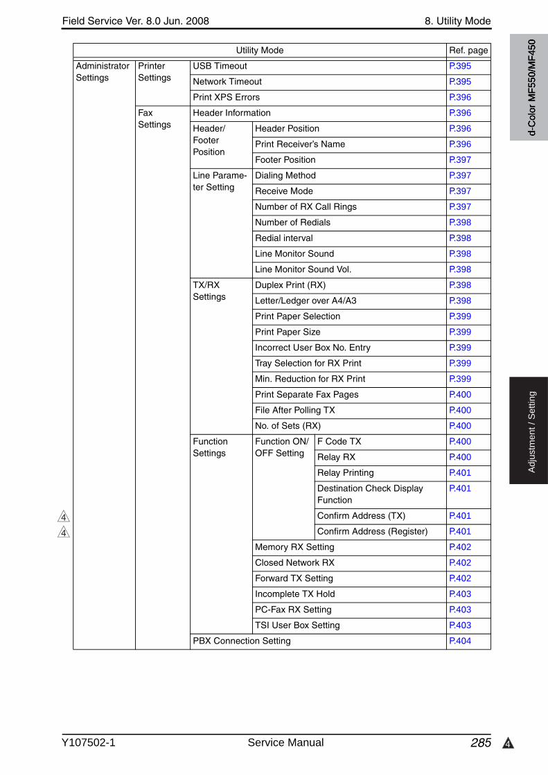
4
Field Service Ver. 8.0 Jun. 2008 8. Utility Mode
285
Ad
justm
en
t /
Se
ttin
g
Administrator Settings
Printer Settings
USB Timeout P.395
Network Timeout P.395
Print XPS Errors P.396
Fax Settings
Header Information P.396
Header/Footer Position
Header Position P.396
Print Receiver’s Name P.396
Footer Position P.397
Line Parame-ter Setting
Dialing Method P.397
Receive Mode P.397
Number of RX Call Rings P.397
Number of Redials P.398
Redial interval P.398
Line Monitor Sound P.398
Line Monitor Sound Vol. P.398
TX/RXSettings
Duplex Print (RX) P.398
Letter/Ledger over A4/A3 P.398
Print Paper Selection P.399
Print Paper Size P.399
Incorrect User Box No. Entry P.399
Tray Selection for RX Print P.399
Min. Reduction for RX Print P.399
Print Separate Fax Pages P.400
File After Polling TX P.400
No. of Sets (RX) P.400
Function Settings
Function ON/OFF Setting
F Code TX P.400
Relay RX P.400
Relay Printing P.401
Destination Check Display Function
P.401
Confirm Address (TX) P.401
Confirm Address (Register) P.401
Memory RX Setting P.402
Closed Network RX P.402
Forward TX Setting P.402
Incomplete TX Hold P.403
PC-Fax RX Setting P.403
TSI User Box Setting P.403
PBX Connection Setting P.404
Utility Mode Ref. page
4
4d-
Col
or M
F550
/MF4
50
Y107502-1 Service Manual
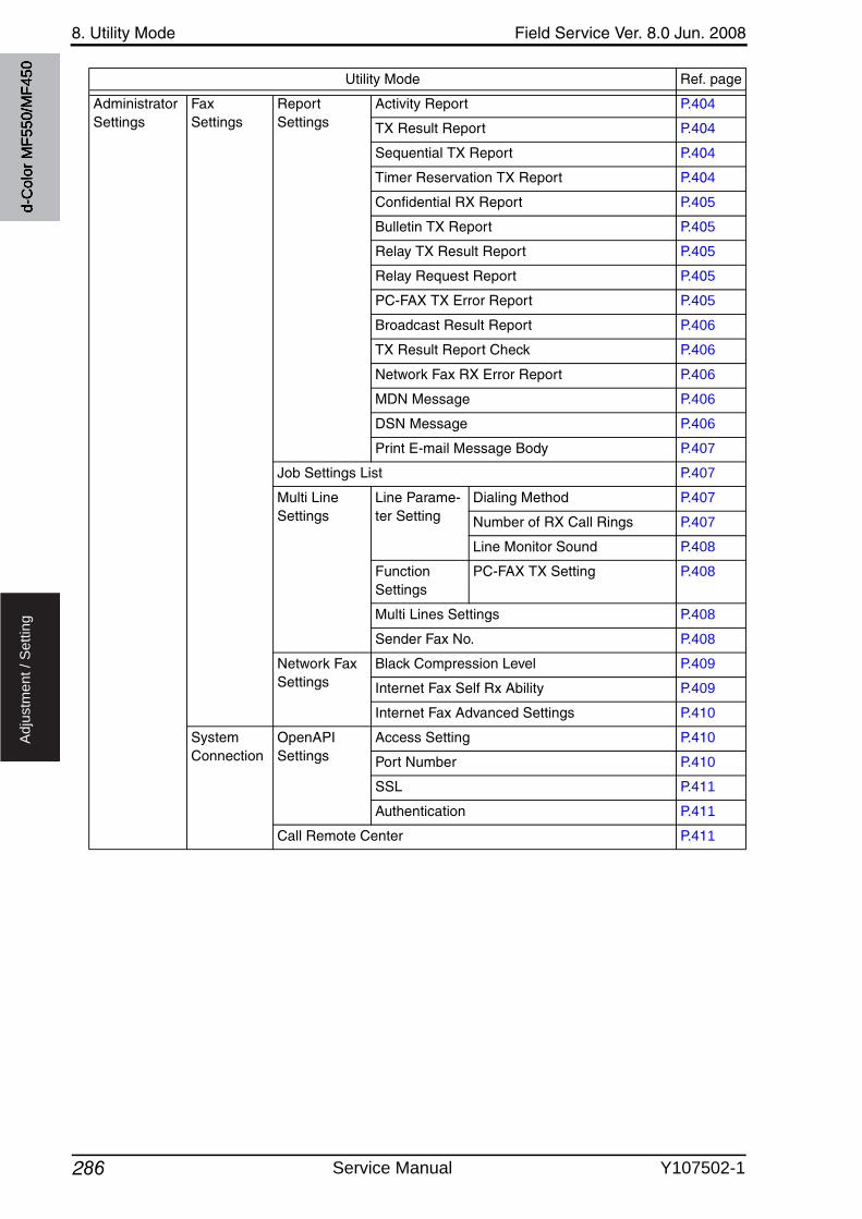
8. Utility Mode Field Service Ver. 8.0 Jun. 2008
286
Ad
justm
en
t /
Se
ttin
g
Administrator Settings
Fax Settings
Report Settings
Activity Report P.404
TX Result Report P.404
Sequential TX Report P.404
Timer Reservation TX Report P.404
Confidential RX Report P.405
Bulletin TX Report P.405
Relay TX Result Report P.405
Relay Request Report P.405
PC-FAX TX Error Report P.405
Broadcast Result Report P.406
TX Result Report Check P.406
Network Fax RX Error Report P.406
MDN Message P.406
DSN Message P.406
Print E-mail Message Body P.407
Job Settings List P.407
Multi Line Settings
Line Parame-ter Setting
Dialing Method P.407
Number of RX Call Rings P.407
Line Monitor Sound P.408
Function Settings
PC-FAX TX Setting P.408
Multi Lines Settings P.408
Sender Fax No. P.408
Network Fax Settings
Black Compression Level P.409
Internet Fax Self Rx Ability P.409
Internet Fax Advanced Settings P.410
System Connection
OpenAPI Settings
Access Setting P.410
Port Number P.410
SSL P.411
Authentication P.411
Call Remote Center P.411
Utility Mode Ref. page
d-C
olor
MF5
50/M
F450
Service Manual Y107502-1
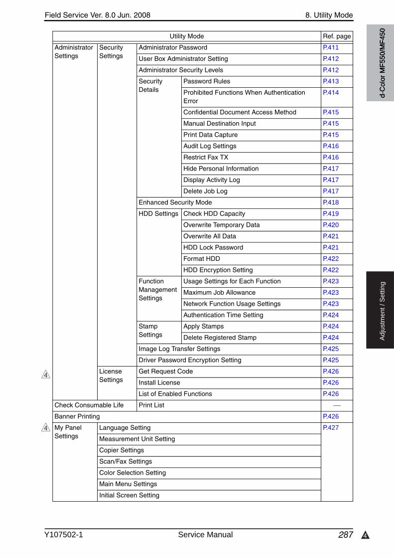
4
Field Service Ver. 8.0 Jun. 2008 8. Utility Mode
287
Ad
justm
en
t /
Se
ttin
g
Administrator Settings
Security Settings
Administrator Password P.411
User Box Administrator Setting P.412
Administrator Security Levels P.412
Security Details
Password Rules P.413
Prohibited Functions When Authentication Error
P.414
Confidential Document Access Method P.415
Manual Destination Input P.415
Print Data Capture P.415
Audit Log Settings P.416
Restrict Fax TX P.416
Hide Personal Information P.417
Display Activity Log P.417
Delete Job Log P.417
Enhanced Security Mode P.418
HDD Settings Check HDD Capacity P.419
Overwrite Temporary Data P.420
Overwrite All Data P.421
HDD Lock Password P.421
Format HDD P.422
HDD Encryption Setting P.422
Function Management Settings
Usage Settings for Each Function P.423
Maximum Job Allowance P.423
Network Function Usage Settings P.423
Authentication Time Setting P.424
Stamp Settings
Apply Stamps P.424
Delete Registered Stamp P.424
Image Log Transfer Settings P.425
Driver Password Encryption Setting P.425
LicenseSettings
Get Request Code P.426
Install License P.426
List of Enabled Functions P.426
Check Consumable Life Print List
Banner Printing P.426
My Panel Settings
Language Setting P.427
Measurement Unit Setting
Copier Settings
Scan/Fax Settings
Color Selection Setting
Main Menu Settings
Initial Screen Setting
Utility Mode Ref. page
4
4
d-C
olor
MF5
50/M
F450
Y107502-1 Service Manual
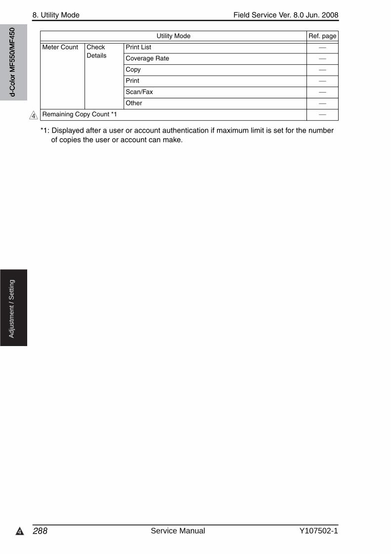
8. Utility Mode Field Service Ver. 8.0 Jun. 2008
2884
Ad
justm
en
t /
Se
ttin
g
*1: Displayed after a user or account authentication if maximum limit is set for the numberof copies the user or account can make.
Meter Count Check Details
Print List
Coverage Rate
Copy
Scan/Fax
Other
Remaining Copy Count *1
Utility Mode Ref. page
4
d-C
olor
MF5
50/M
F450
Service Manual Y107502-1
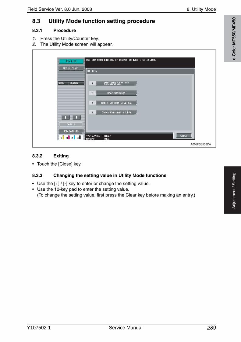
Field Service Ver. 8.0 Jun. 2008 8. Utility Mode
289
Ad
justm
en
t /
Se
ttin
g
8.3 Utility Mode function setting procedure
8.3.1 Procedure
1. Press the Utility/Counter key.2. The Utility Mode screen will appear.
8.3.2 Exiting
• Touch the [Close] key.
8.3.3 Changing the setting value in Utility Mode functions
• Use the [+] / [-] key to enter or change the setting value.• Use the 10-key pad to enter the setting value.
(To change the setting value, first press the Clear key before making an entry.)
A00JF3E533DA
d-C
olor
MF5
50/M
F450
Y107502-1 Service Manual

8. Utility Mode Field Service Ver. 8.0 Jun. 2008
290
Ad
justm
en
t /
Se
ttin
g
8.4 One-Touch User Box Registration
• In a copier where the user authentication function that uses an external server or MFP is set to ON, when you operate the copier without performing user authentication, this menu is not displayed.
• It will not be displayed when the authentication device is set to “Set” by the following set-ting.[Service Mode] [Billing Setting] [Management Function Choice]
8.4.1 Create One-Touch destination
A. Address Book(1) E-mail
(2) User Box• It will not be displayed when the following setting shows that authentication device or the
vendor is mounted.[Service Mode] [Billing Setting] [Management Function Choice](It will be displayed when the key counter is mounted.)
(3) Fax
(4) PC(SMB)
(5) FTP
Functions• To register/change e-mail address to send scanned data.
Use
Setting/Procedure
• A new address can be registered by touching [New].• Select any displayed address to check, edit or delete the setting.
Functions • To register/change the Box address when storing the scanned data in the box in the hard disk in the main body.Use
Setting/Procedure
• A new address can be registered by touching [New].• Select any displayed address to check, edit or delete the setting.• At least one User Box must be registered for registering a Box address.
Functions• To register/change the fax destinations.
Use
Setting/Procedure
• A new address can be registered by touching [New].• Select any displayed address to check, edit or delete the setting.
Functions• To register/change SMB address to send scanned data.
Use
Setting/Procedure
• A new address can be registered by touching [New].• Select any displayed address to check, edit or delete the setting.
Functions• To register/change FTP address to send scanned data.
Use
Setting/Procedure
• A new address can be registered by touching [New].• Select any displayed address to check, edit or delete the setting.
d-C
olor
MF5
50/M
F450
Service Manual Y107502-1

3
Field Service Ver. 8.0 Jun. 2008 8. Utility Mode
291
Ad
justm
en
t /
Se
ttin
g
(6) WebDAV• This is displayed only when the function enhanced version 2 or later firmware is installed.
(7) IP Address Fax• Setting will be available only when [IP Address FAX] is set to “ON” in the following set-
tings. [Administrator Settings] [Network Settings] [Network Fax Settings] [Network Fax Function Settings]
(8) Internet Fax• Setting will be available only when [Internet FAX] is set to “ON” in the following settings.
[Administrator Settings] [Network Settings] [Network Fax Settings] [Network Fax Function Settings]
B. Group
C. E-mail Settings• It will not be displayed when the following setting shows that the management device 2 is
mounted.[Service Mode] [Billing Setting] [Management Function Choice]
(1) E-mail Subject
3
Functions• To register/change WebDAV address to send scanned data.
Use
Setting/Procedure
• A new address can be registered by touching [New].• Select any displayed address to check, edit or delete the setting.
Functions • To register/change the IP address fax destination when transmitting the IP address fax data.Use
Setting/Procedure
• A new address can be registered by touching [New].• Select any displayed address to check, change or delete the setting.
Functions• To register/change the Internet fax address when transmitting the internet fax data.
Use
Setting/Procedure
• A new address can be registered by touching [New].• Select any displayed address to check, change or delete the setting.
Functions• To register/change a group to send scanned data/fax data simultaneously.
Use
Setting/Procedure
• A new address can be registered by touching [New].• Select any displayed group to check, edit or delete them.• At least one address must be registered for registering a new group.
Functions• To register the e-mail subject when transmitting the scanned data.
Use
Setting/Procedure
• A new address can be registered by touching [New].• Select any displayed address to detail check, edit or delete the setting.• The subject can be set as default by selecting the subject displayed on the screen
and pressing [Set as Default].
d-C
olor
MF5
50/M
F450
Y107502-1 Service Manual

8. Utility Mode Field Service Ver. 8.0 Jun. 2008
292
Ad
justm
en
t /
Se
ttin
g
(2) E-mail Body
8.4.2 Create User Box
• It will not be displayed when the authentication device is set to “Set” by the following set-ting.[Service Mode] [Billing Setting] [Management Function Choice]
• It will not be displayed when the following setting shows that the vendor is mounted.[Service Mode] [Billing Setting] [Management Function Choice](It will be displayed when the key counter is mounted.)
• This menu is not available due to functional restriction during user authentication when[User Box] is set to Restrict.
A. Public/Personal User Box
B. Bulletin Board User Box• It will be displayed only when the optional fax kit (FK-502) is mounted.• It will not be displayed during user authentication if the fax operation is set to “Restrict” by
the function restriction.
C. Relay User Box• It will be displayed only when the optional FAX kit (FK-502) is mounted.• It will be displayed when the following setting is set to “ON.”
[Service Mode] [FAX] [System] [Display Setting] [Relay]
Functions• To register the e-mail message when transmitting the scanned data.
Use
Setting/Procedure
• A new address can be registered by touching [New].• Select any displayed address to detail check or delete the setting.• The text can be set as default by selecting the text displayed on the screen and
pressing [Set as Default].
Functions • To register/change the box for storing text data in the hard disk of the machine.
Use • Shared or personal box can be registered according to its intended use.
Setting/Procedure
• A new box can be registered by touching [New].• Select any displayed box to change or delete it.
Functions• To register/change the bulletin board user box.
Use
Setting/Procedure
• A new box can be registered by touching [New].• Select any displayed box to change or delete it.
Functions• To register/change the Relay User Box.
Use
Setting/Procedure
• A new box can be registered by touching [New].• Select any displayed box to change or delete it.
d-C
olor
MF5
50/M
F450
Service Manual Y107502-1
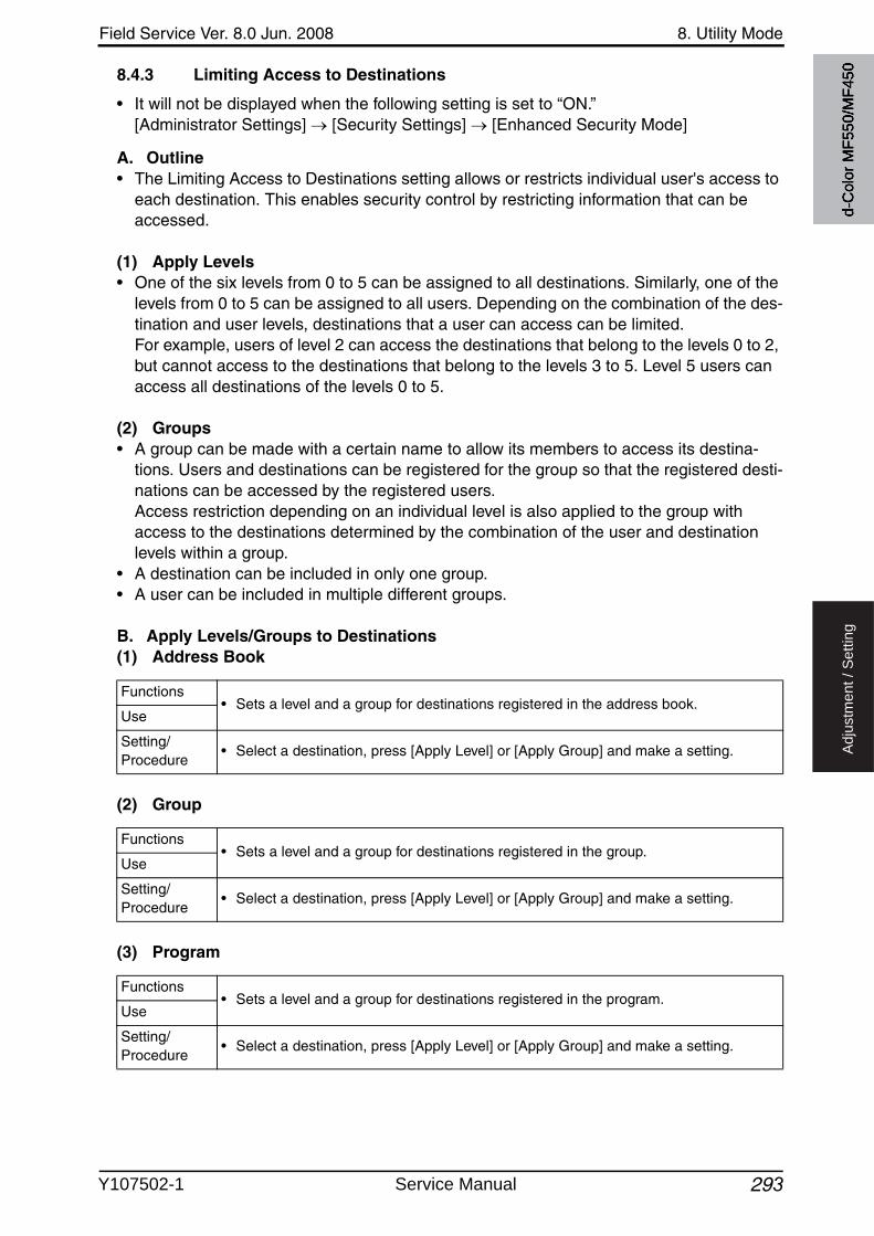
Field Service Ver. 8.0 Jun. 2008 8. Utility Mode
293
Ad
justm
en
t /
Se
ttin
g
8.4.3 Limiting Access to Destinations
• It will not be displayed when the following setting is set to “ON.”[Administrator Settings] [Security Settings] [Enhanced Security Mode]
A. Outline• The Limiting Access to Destinations setting allows or restricts individual user's access to
each destination. This enables security control by restricting information that can be accessed.
(1) Apply Levels• One of the six levels from 0 to 5 can be assigned to all destinations. Similarly, one of the
levels from 0 to 5 can be assigned to all users. Depending on the combination of the des-tination and user levels, destinations that a user can access can be limited. For example, users of level 2 can access the destinations that belong to the levels 0 to 2, but cannot access to the destinations that belong to the levels 3 to 5. Level 5 users can access all destinations of the levels 0 to 5.
(2) Groups• A group can be made with a certain name to allow its members to access its destina-
tions. Users and destinations can be registered for the group so that the registered desti-nations can be accessed by the registered users. Access restriction depending on an individual level is also applied to the group withaccess to the destinations determined by the combination of the user and destination levels within a group.
• A destination can be included in only one group.• A user can be included in multiple different groups.
B. Apply Levels/Groups to Destinations(1) Address Book
(2) Group
(3) Program
Functions• Sets a level and a group for destinations registered in the address book.
Use
Setting/Procedure
• Select a destination, press [Apply Level] or [Apply Group] and make a setting.
Functions• Sets a level and a group for destinations registered in the group.
Use
Setting/Procedure
• Select a destination, press [Apply Level] or [Apply Group] and make a setting.
Functions• Sets a level and a group for destinations registered in the program.
Use
Setting/Procedure
• Select a destination, press [Apply Level] or [Apply Group] and make a setting.
d-C
olor
MF5
50/M
F450
Y107502-1 Service Manual
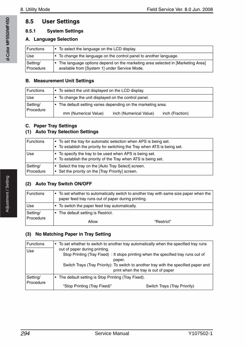
8. Utility Mode Field Service Ver. 8.0 Jun. 2008
294
Ad
justm
en
t /
Se
ttin
g
8.5 User Settings
8.5.1 System Settings
A. Language Selection
B. Measurement Unit Settings
C. Paper Tray Settings(1) Auto Tray Selection Settings
(2) Auto Tray Switch ON/OFF
(3) No Matching Paper in Tray Setting
Functions • To select the language on the LCD display.
Use • To change the language on the control panel to another language.
Setting/Procedure
• The language options depend on the marketing area selected in [Marketing Area] available from [System 1] under Service Mode.
Functions • To select the unit displayed on the LCD display.
Use • To change the unit displayed on the control panel.
Setting/Procedure
• The default setting varies depending on the marketing area.
mm (Numerical Value) inch (Numerical Value) inch (Fraction)
Functions • To set the tray for automatic selection when APS is being set.• To establish the priority for switching the Tray when ATS is being set.
Use • To specify the tray to be used when APS is being set.• To establish the priority of the Tray when ATS is being set.
Setting/Procedure
• Select the tray on the [Auto Tray Select] screen.• Set the priority on the [Tray Priority] screen.
Functions • To set whether to automatically switch to another tray with same size paper when the paper feed tray runs out of paper during printing.
Use • To switch the paper feed tray automatically.
Setting/Procedure
• The default setting is Restrict.
Allow “Restrict”
Functions • To set whether to switch to another tray automatically when the specified tray runs out of paper during printing.
Stop Printing (Tray Fixed) : It stops printing when the specified tray runs out of paper.
Switch Trays (Tray Priority): To switch to another tray with the specified paper and print when the tray is out of paper
Use
Setting/Procedure
• The default setting is Stop Printing (Tray Fixed).
“Stop Printing (Tray Fixed)” Switch Trays (Tray Priority)
d-C
olor
MF5
50/M
F450
Service Manual Y107502-1
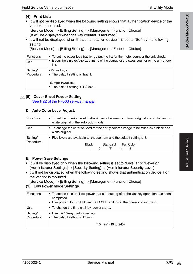
Field Service Ver. 8.0 Jun. 2008 8. Utility Mode
295 2
Ad
justm
en
t /
Se
ttin
g
(4) Print Lists• It will not be displayed when the following setting shows that authentication device or the
vendor is mounted. [Service Mode] [Billing Setting] [Management Function Choice] (It will be displayed when the key counter is mounted.)
• It will not be displayed when the authentication device 1 is set to “Set” by the followingsetting.[Service Mode] [Billing Setting] [Management Function Choice]
(5) Cover Sheet Feeder SettingSee P.22 of the PI-503 service manual.
D. Auto Color Level Adjust.
E. Power Save Settings• It will be displayed only when the following setting is set to “Level 1” or “Level 2.”
[Administrator Settings] [Security Setting] [Administrator Security Level]• t will not be displayed when the following setting shows that authentication device 1 or
the vendor is mounted.[Service Mode] [Billing Setting] [Management Function Choice]
(1) Low Power Mode Settings
Functions • To set the paper feed tray for output the list for the meter count or the unit check.• It sets the simplex/duplex printing of the output for the sales counter or the unit check
list.Use
Setting/Procedure
<Paper tray>• The default setting is Tray 1.
<Simplex/Duplex>• The default setting is 1-Sided.
2
Functions • To set the criterion level to discriminate between a colored original and a black-and-white original in the auto color mode.
Use • To change the criterion level for the partly colored image to be taken as a black-and-white original.
Setting/Procedure
• Five levels are available to choose from and the default setting is 3.
Black Standard Full Color1 2 “3” 4 5
Functions • To set the time until low power starts operating after the last key operation has been completed.
• Low power: To turn LED and LCD OFF, and lower the power consumption.
Use • To change the time until low power starts.
Setting/Procedure
• Use the 10-key pad for setting.• The default setting is 15 min.
“15 min.” (10 to 240)
d-C
olor
MF5
50/M
F450
Y107502-1 Service Manual
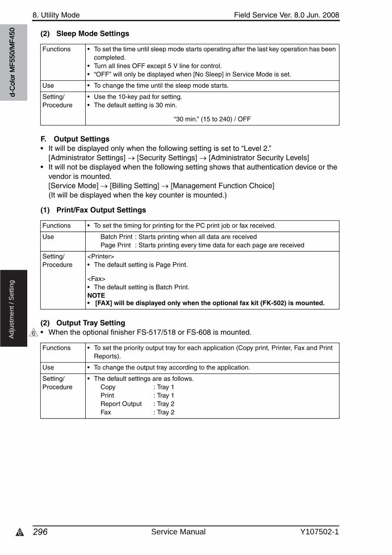
8. Utility Mode Field Service Ver. 8.0 Jun. 2008
2966
Ad
justm
en
t /
Se
ttin
g
(2) Sleep Mode Settings
F. Output Settings• It will be displayed only when the following setting is set to “Level 2.”
[Administrator Settings] [Security Settings] [Administrator Security Levels]• It will not be displayed when the following setting shows that authentication device or the
vendor is mounted.[Service Mode] [Billing Setting] [Management Function Choice] (It will be displayed when the key counter is mounted.)
(1) Print/Fax Output Settings
(2) Output Tray Setting• When the optional finisher FS-517/518 or FS-608 is mounted.
Functions • To set the time until sleep mode starts operating after the last key operation has been completed.
• Turn all lines OFF except 5 V line for control.• “OFF” will only be displayed when [No Sleep] in Service Mode is set.
Use • To change the time until the sleep mode starts.
Setting/Procedure
• Use the 10-key pad for setting.• The default setting is 30 min.
“30 min.” (15 to 240) / OFF
Functions • To set the timing for printing for the PC print job or fax received.
Use Batch Print : Starts printing when all data are receivedPage Print : Starts printing every time data for each page are received
Setting/Procedure
<Printer>• The default setting is Page Print.
<Fax>• The default setting is Batch Print.NOTE• [FAX] will be displayed only when the optional fax kit (FK-502) is mounted.
6
Functions • To set the priority output tray for each application (Copy print, Printer, Fax and Print Reports).
Use • To change the output tray according to the application.
Setting/Procedure
• The default settings are as follows.Copy : Tray 1Print : Tray 1Report Output : Tray 2Fax : Tray 2
d-C
olor
MF5
50/M
F450
Service Manual Y107502-1
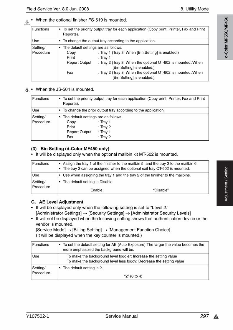
3
Field Service Ver. 8.0 Jun. 2008 8. Utility Mode
297
Ad
justm
en
t /
Se
ttin
g
• When the optional finisher FS-519 is mounted.
• When the JS-504 is mounted.
(3) Bin Setting (d-Color MF450 only)• It will be displayed only when the optional mailbin kit MT-502 is mounted.
G. AE Level Adjustment• It will be displayed only when the following setting is set to “Level 2.”
[Administrator Settings] [Security Settings] [Administrator Security Levels]• It will not be displayed when the following setting shows that authentication device or the
vendor is mounted. [Service Mode] [Billing Setting] [Management Function Choice] (It will be displayed when the key counter is mounted.)
3
Functions • To set the priority output tray for each application (Copy print, Printer, Fax and Print Reports).
Use • To change the output tray according to the application.
Setting/Procedure
• The default settings are as follows.Copy : Tray 1 (Tray 3: When [Bin Setting] is enabled.)Print : Tray 1Report Output : Tray 2 (Tray 3: When the optional OT-602 is mounted./When
[Bin Setting] is enabled.)Fax : Tray 2 (Tray 3: When the optional OT-602 is mounted./When
[Bin Setting] is enabled.)
3
Functions • To set the priority output tray for each application (Copy print, Printer, Fax and Print Reports).
Use • To change the prior output tray according to the application.
Setting/Procedure
• The default settings are as follows.Copy : Tray 1Print : Tray 2Report Output : Tray 1Fax : Tray 2
Functions • Assign the tray 1 of the finisher to the mailbin 5, and the tray 2 to the mailbin 6.• The tray 2 can be assigned when the optional exit tray OT-602 is mounted.
Use • Use when assigning the tray 1 and the tray 2 of the finisher to the mailbins.
Setting/Procedure
• The default setting is Disable.
Enable “Disable”
Functions • To set the default setting for AE (Auto Exposure) The larger the value becomes the more emphasized the background will be.
Use To make the background level foggier: Increase the setting valueTo make the background level less foggy: Decrease the setting value
Setting/Procedure
• The default setting is 2.
“2” (0 to 4)
d-C
olor
MF5
50/M
F450
Y107502-1 Service Manual

8. Utility Mode Field Service Ver. 8.0 Jun. 2008
298
Ad
justm
en
t /
Se
ttin
g
H. Auto Paper Select for Small Original
I. Blank Page Print Settings• It will be displayed only when the following setting is set to “Level 2.”
[Administrator Settings] [Security Settings] [Administrator Security Levels]• It will not be displayed when the following setting shows that vendor is mounted.
[Service Mode] [Billing Setting] [Management Function Choice]
8.5.2 Custom Display Settings
A. Copier Settings(1) Default Tab
(2) Shortcut Key 1/2
Functions • To make the copy setting when the paper is undetectably small, or no original is being set.
Use • To copy the original such as business cards with which the original detection is not effective.
Copy on Small Size : Copies on A5 paper.Copy on A4/Letter : Copies on A4 or Letter (8 1/2 x 11) size paper.Prohibit Copy : Does not copy since the original size cannot be detected.
paper feed tray needs to be selected prior to pressing the Start key.
Setting/Procedure
• The default setting is Prohibit Copy.
Copy on Small Size Copy on A4/Letter “Prohibit Copy”
Functions • Select wether or not to print the stamp/composition on blank pages.
Use • To print a stamp/composition on blank pages.
Setting/Procedure
• The default setting is Do Not Print.
Print “Do Not Print”
Functions • Selects a default tab display in the copy mode.
Use • To change the default tab display in the copy mode.Basic : Normal basic screenQuick Copy : This screen displays all options that can be selected for Paper,
Zoom, and Duplex/Combine functions. For color functions, all selectable options can be displayed on the screen. The normal [Basic] screen is also displayed as another tab on the screen.
Setting/Procedure
• The default setting is Basic.
“Basic” Quick Copy
Functions • Selects whether to use the shortcut key.• Adds frequently used shortcut keys of auxiliary functions to the basic screen.Use
Setting/Procedure
• The default setting is OFF.
ON “OFF”
• When this setting is set to ON, select auxiliary functions to get their shortcut keys dis-played on the screen.
d-C
olor
MF5
50/M
F450
Service Manual Y107502-1

Field Service Ver. 8.0 Jun. 2008 8. Utility Mode
299 2
Ad
justm
en
t /
Se
ttin
g
B. Scan/Fax Settings• It will not be displayed when the following setting shows that authentication device is
mounted.[Service Mode] [Billing Setting] [Management Function Choice]
(1) Default Tab
(2) Program Default
(3) Address Book Index Default
(4) Shortcut Key 1/2• [Shortcut Key 2] is not displayed when the optional image controller (IC-409) is installed.
(5) Default Address Book
Functions • To set the basic screen display in scan/fax mode.
Use • To change the basic screen display in scan/fax mode.
Setting/Procedure
• The default setting is Address Book.
Address Search (LDAP) Job History “Address Book” Direct Input
Functions • To set the default display for the program screen during scan/fax mode.
Use • To keep the default display on the program screen which frequently changes during scan/fax mode
Setting/Procedure
• The default setting is PAGE 1.
Temporary One-Touch/ “PAGE1” to PAGE27
Functions • To set the default display for the address book screen during scan/fax mode.
Use • To keep the default display instead of search string on the address book which fre-quently changes during scan/fax mode.
Setting/Procedure
• The default setting is Main.
“Favorite” /ABC to WXYZ / etc
2
Functions • Selects whether to use the shortcut key.• Adds frequently used shortcut keys of auxiliary functions to the basic screen.Use
Setting/Procedure
• The default setting is OFF.
ON “OFF”
• When this setting is set to ON, select auxiliary functions to get their shortcut keys dis-played on the screen.
Functions • Sets a default screen display for the scan/fax mode where the address book is set to be displayed.Use
Setting/Procedure
• The default setting is Index.
“Index” Address Type
d-C
olor
MF5
50/M
F450
Y107502-1 Service Manual
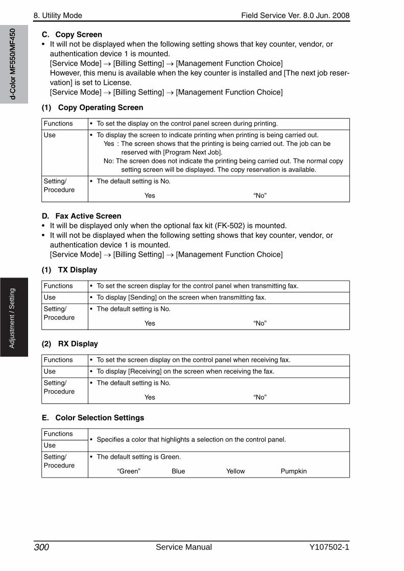
8. Utility Mode Field Service Ver. 8.0 Jun. 2008
300
Ad
justm
en
t /
Se
ttin
g
C. Copy Screen• It will not be displayed when the following setting shows that key counter, vendor, or
authentication device 1 is mounted.[Service Mode] [Billing Setting] [Management Function Choice]However, this menu is available when the key counter is installed and [The next job reser-vation] is set to License. [Service Mode] [Billing Setting] [Management Function Choice]
(1) Copy Operating Screen
D. Fax Active Screen• It will be displayed only when the optional fax kit (FK-502) is mounted.• It will not be displayed when the following setting shows that key counter, vendor, or
authentication device 1 is mounted.[Service Mode] [Billing Setting] [Management Function Choice]
(1) TX Display
(2) RX Display
E. Color Selection Settings
Functions • To set the display on the control panel screen during printing.
Use • To display the screen to indicate printing when printing is being carried out.Yes : The screen shows that the printing is being carried out. The job can be
reserved with [Program Next Job].No: The screen does not indicate the printing being carried out. The normal copy
setting screen will be displayed. The copy reservation is available.
Setting/Procedure
• The default setting is No.
Yes “No”
Functions • To set the screen display for the control panel when transmitting fax.
Use • To display [Sending] on the screen when transmitting fax.
Setting/Procedure
• The default setting is No.
Yes “No”
Functions • To set the screen display on the control panel when receiving fax.
Use • To display [Receiving] on the screen when receiving the fax.
Setting/Procedure
• The default setting is No.
Yes “No”
Functions• Specifies a color that highlights a selection on the control panel.
Use
Setting/Procedure
• The default setting is Green.
“Green” Blue Yellow Pumpkin
d-C
olor
MF5
50/M
F450
Service Manual Y107502-1
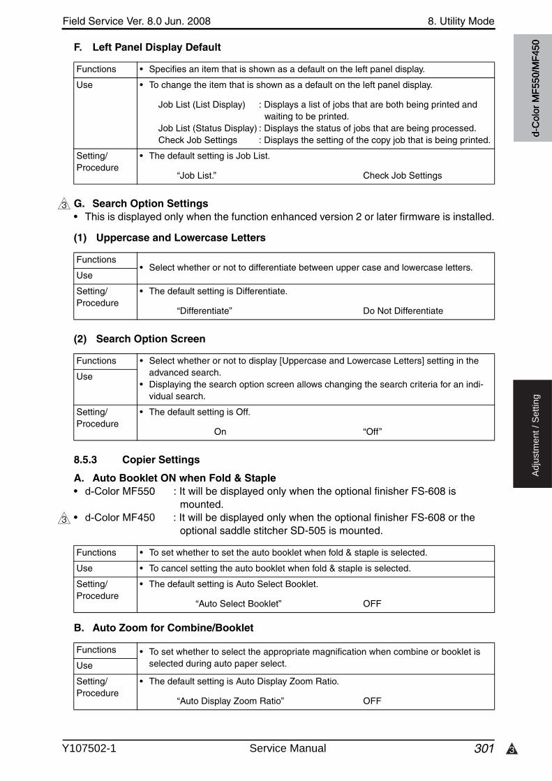
3
Field Service Ver. 8.0 Jun. 2008 8. Utility Mode
301
Ad
justm
en
t /
Se
ttin
g
F. Left Panel Display Default
G. Search Option Settings• This is displayed only when the function enhanced version 2 or later firmware is installed.
(1) Uppercase and Lowercase Letters
(2) Search Option Screen
8.5.3 Copier Settings
A. Auto Booklet ON when Fold & Staple• d-Color MF550 : It will be displayed only when the optional finisher FS-608 is
mounted.• d-Color MF450 : It will be displayed only when the optional finisher FS-608 or the
optional saddle stitcher SD-505 is mounted.
B. Auto Zoom for Combine/Booklet
Functions • Specifies an item that is shown as a default on the left panel display.
Use • To change the item that is shown as a default on the left panel display.
Job List (List Display) : Displays a list of jobs that are both being printed and waiting to be printed.
Job List (Status Display) : Displays the status of jobs that are being processed.Check Job Settings : Displays the setting of the copy job that is being printed.
Setting/Procedure
• The default setting is Job List.
“Job List.” Check Job Settings
3
Functions• Select whether or not to differentiate between upper case and lowercase letters.
Use
Setting/Procedure
• The default setting is Differentiate.
“Differentiate” Do Not Differentiate
Functions • Select whether or not to display [Uppercase and Lowercase Letters] setting in the advanced search.
• Displaying the search option screen allows changing the search criteria for an indi-vidual search.
Use
Setting/Procedure
• The default setting is Off.
On “Off”
3
Functions • To set whether to set the auto booklet when fold & staple is selected.
Use • To cancel setting the auto booklet when fold & staple is selected.
Setting/Procedure
• The default setting is Auto Select Booklet.
“Auto Select Booklet” OFF
Functions • To set whether to select the appropriate magnification when combine or booklet is selected during auto paper select.Use
Setting/Procedure
• The default setting is Auto Display Zoom Ratio.
“Auto Display Zoom Ratio” OFF
d-C
olor
MF5
50/M
F450
Y107502-1 Service Manual
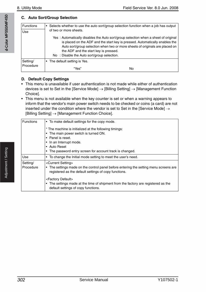
8. Utility Mode Field Service Ver. 8.0 Jun. 2008
302
Ad
justm
en
t /
Se
ttin
g
C. Auto Sort/Group Selection
D. Default Copy Settings• This menu is unavailable if user authentication is not made while either of authentication
devices is set to Set in the [Service Mode] [Billing Setting] [Management FunctionChoice].
• This menu is not available when the key counter is set or when a warning appears to inform that the vendor's main power switch needs to be checked or coins (a card) are not inserted under the condition where the vendor is set to Set in the [Service Mode] [Billing Setting] [Management Function Choice].
Functions • Selects whether to use the auto sort/group selection function when a job has outputof two or more sheets.
Yes : Automatically disables the Auto sort/group selection when a sheet of original is placed on the ADF and the start key is pressed. Automatically enables the Auto sort/group selection when two or more sheets of originals are placed on the ADF and the start key is pressed.
No : Disable the Auto sort/group selection.
Use
Setting/Procedure
• The default setting is Yes.
“Yes” No
Functions • To make default settings for the copy mode.
* The machine is initialized at the following timings:• The main power switch is turned ON.• Panel is reset.• In an Interrupt mode.• Auto Reset• The password entry screen for account track is changed.
Use • To change the Initial mode setting to meet the user’s need.
Setting/Procedure
<Current Setting>• The settings made on the control panel before entering the setting menu screens are
registered as the default settings of copy functions.
<Factory Default>• The settings made at the time of shipment from the factory are registered as the
default settings of copy functions.
d-C
olor
MF5
50/M
F450
Service Manual Y107502-1

3
Field Service Ver. 8.0 Jun. 2008 8. Utility Mode
303
Ad
justm
en
t /
Se
ttin
g
E. Default Enlarge Display Settings• This is displayed only when the function enhanced version 2 or later firmware is installed.• Displayed only when you select [Utility/Counter] [User Settings] [Copier Settings] in
the enlarge display mode.
F. When AMS Direction is Incorrect• It will not be displayed when the following setting shows that vendor1 is mounted.
[Service Mode] [Billing Setting] [Management Function Choice]
G. Separate Scan Output Method• It will not be displayed when the following setting shows that vendor1 is mounted.
[Service Mode] [Billing Setting] [Management Function Choice]
3
Functions • To make default settings for the enlarge display mode.
* The machine is initialized at the following timings:• The main power switch is turned ON.• Panel is reset.• In an Interrupt mode.• Auto Reset• The password entry screen for account track is changed.
Use • To change the Initial mode setting to meet the user’s need.
Setting/Procedure
<Current Setting>• The settings made on the control panel before entering the setting menu screens are
registered as the default settings of copy functions.
<Factory Default>• The settings made at the time of shipment from the factory are registered as the
default settings of copy functions.
Functions • To set whether to print when the original is set in different direction from the set paper during auto zoom select.
Use • To display alarm when original is set in different direction from paper and to cancel the job during auto zoom select.
Print : To print according to the selected direction and size of paperDelete Job : To display alarm and cancel the job
Setting/Procedure
• The default setting is Print.
“Print” Delete Job
Functions • To set the output mode at Separate Scan setting.
Use • To print all at once after reading all data.
Page Print : Print consecutively during the read operation.Batch print : Print all at once after reading all data.
Copy setting can be changed after the read operation.
Setting/Procedure
• The default setting is Page Print.
“Page Print” Batch Print
d-C
olor
MF5
50/M
F450
Y107502-1 Service Manual

8. Utility Mode Field Service Ver. 8.0 Jun. 2008
304
Ad
justm
en
t /
Se
ttin
g
H. Enlargement Rotation• It will not be displayed when the following setting shows that vendor1 is mounted.
[Service Mode] [Billing Setting] [Management Function Choice]
I. Auto Zoom (Platen)• It will be displayed only when the following setting is set to “Level 1” or “Level 2.”
[Administrator Settings] [Security Settings] [Administrator Security Levels]
J. Auto Zoom (ADF)• It will be displayed only when the following setting is set to “Level 1” or “Level 2”.
[Administrator Settings] [Security Settings] [Administrator Security Levels]
K. Specify Default Tray when APS Off• It will be displayed only when the following setting is set to “Level 1” or “Level 2.”
[Administrator Settings] [Security Settings] [Administrator Security Levels]
Functions • Sets whether to rotate images of which length is more than 297 mm in the main scan direction (in the horizontal direction on the ADF or the Original glass) in the copying process.
Allow : Makes an enlargement rotation only when black is selected for the color setting.
Restrict : Disables an enlargement rotation regardless of the color setting.
Use
Setting/Procedure
• The default setting is Restrict.
Allow “Restrict”
Functions • To set whether to function the auto magnification when the feed tray is selected with document set on the original glass (excepting at automatic paper selection mode.)
Use • To function the auto magnification when the Tray is selected.
Setting/Procedure
• The default setting is OFF.
ON “OFF”
Functions • To set whether to function the auto magnification when the feed tray is selected with document set on the ADF (excepting at automatic paper selection mode.)
Use • To function the auto magnification when the feed tray is selected.
Setting/Procedure
• The default setting is ON.
“ON” OFF
Functions • To set the tray to be used when APS is cancelled.
Use • To set the tray for the initial setting when APS is cancelled.
Setting/Procedure
• The default setting is Tray (Tray 1) Before APS OFF.
“Tray Before APS OFF” Default Tray
d-C
olor
MF5
50/M
F450
Service Manual Y107502-1
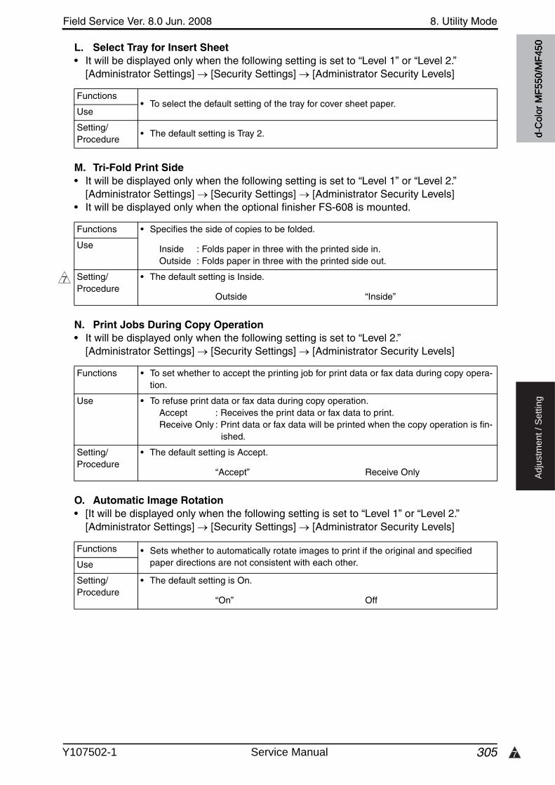
7
Field Service Ver. 8.0 Jun. 2008 8. Utility Mode
305
Ad
justm
en
t /
Se
ttin
g
L. Select Tray for Insert Sheet• It will be displayed only when the following setting is set to “Level 1” or “Level 2.”
[Administrator Settings] [Security Settings] [Administrator Security Levels]
M. Tri-Fold Print Side• It will be displayed only when the following setting is set to “Level 1” or “Level 2.”
[Administrator Settings] [Security Settings] [Administrator Security Levels]• It will be displayed only when the optional finisher FS-608 is mounted.
N. Print Jobs During Copy Operation• It will be displayed only when the following setting is set to “Level 2.”
[Administrator Settings] [Security Settings] [Administrator Security Levels]
O. Automatic Image Rotation• [It will be displayed only when the following setting is set to “Level 1” or “Level 2.”
[Administrator Settings] [Security Settings] [Administrator Security Levels]
Functions• To select the default setting of the tray for cover sheet paper.
Use
Setting/Procedure
• The default setting is Tray 2.
Functions • Specifies the side of copies to be folded.
Inside : Folds paper in three with the printed side in.Outside : Folds paper in three with the printed side out.
Use
Setting/Procedure
• The default setting is Inside.
Outside “Inside”
7
Functions • To set whether to accept the printing job for print data or fax data during copy opera-tion.
Use • To refuse print data or fax data during copy operation.Accept : Receives the print data or fax data to print.Receive Only : Print data or fax data will be printed when the copy operation is fin-
ished.
Setting/Procedure
• The default setting is Accept.
“Accept” Receive Only
Functions • Sets whether to automatically rotate images to print if the original and specified paper directions are not consistent with each other.Use
Setting/Procedure
• The default setting is On.
“On” Off
d-C
olor
MF5
50/M
F450
Y107502-1 Service Manual

8. Utility Mode Field Service Ver. 8.0 Jun. 2008
3062
Ad
justm
en
t /
Se
ttin
g
8.5.4 Scan/Fax Settings
A. JPEG Compression Level
B. Black Compression Level
C. TWAIN Lock Time• It will not be displayed when the optional image controller IC-409 is mounted.
Functions • To set the JPEG compression method when scanning with JPEG while in scan/fax mode.
Use • To change the compression rate when JPEG scanning.High Quality : Lowers the compression rate and puts priority in quality while
scanning.Standard : Compression rate and quality are normally balanced while
scanning.High Compression: Makes the compression rate higher and puts priority in lower-
ing the data volume while scanning.
Setting/Procedure
• The default setting is Standard.
High Quality “Standard” High Compression
Functions • To set the monochrome compression method for scanning in the monochrome mode while in scan/fax mode.
Use • To be used when changing the monochrome mode while in scanner mode.
Setting/Procedure
• The default setting is MMR.
MH “MMR”
2
Functions• To set the period of time for unlocking the operation panel while in TWAIN scanning.
Use
Setting/Procedure
• The default setting is 120 sec.
“120 sec.” (30 to 300 sec.)
d-C
olor
MF5
50/M
F450
Service Manual Y107502-1
3
Field Service Ver. 8.0 Jun. 2008 8. Utility Mode
307
Ad
justm
en
t /
Se
ttin
g
D. Default Scan/Fax Settings• This menu is unavailable if user authentication is not made while either of authentication
devices is set to set in the [Service Mode] [Billing Setting] [Management FunctionChoice].
• This menu is not available when the key counter is set or when a warning appears to inform that the vendor’s main power switch needs to be checked or coins (a card) are not inserted under the condition where the vendor is set to Set in the [Service Mode] [Bill-ing Setting] [Management Function Choice].
E. Default Enlarge Display Settings• This is displayed only when the function enhanced version 2 or later firmware is installed.• Displayed only when you select [Utility/Counter] [User Settings] [Scan/Fax Settings]
in the enlarge display mode.
Functions • To make default settings for the fax/scan mode.
* The machine is initialized at the following timings:• The main power switch is turned ON.• Panel is reset.• In an Interrupt mode.• Auto Reset• The password entry screen for account track is changed.
Use • To change the Initial mode setting to meet the user’s need.
Setting/Procedure
<Current Setting>• The settings made on the control panel before entering the setting menu screens are
registered as the default settings of fax/scan functions.
<Factory Default>• The settings made at the time of shipment from the factory are registered as the
default settings of fax/scan functions.
3
Functions • To make default settings for the enlarge display mode.
* The machine is initialized at the following timings:• The main power switch is turned ON.• Panel is reset.• In an Interrupt mode.• Auto Reset• The password entry screen for account track is changed.
Use • To change the Initial mode setting to meet the user’s need.
Setting/Procedure
<Current Setting>• The settings made on the control panel before entering the setting menu screens are
registered as the default settings of fax/scan functions.
<Factory Default>• The settings made at the time of shipment from the factory are registered as the
default settings of fax/scan functions.
d-C
olor
MF5
50/M
F450
Y107502-1 Service Manual
8. Utility Mode Field Service Ver. 8.0 Jun. 2008
308
Ad
justm
en
t /
Se
ttin
g
F. Compact PDF Compression Level
8.5.5 Printer Settings
A. Basic Settings(1) PDL Setting
(2) Number of Copies
(3) Original Direction
(4) Spool Print Jobs in HDD before RIP
Functions • Selects a compression method applied to scanned data that is produced with the use of Compact PDF in the scan/fax mode.
Use • To change the compression ratio applied to scanned data that is produced with the Compact PDF format.
High Quality : Lowers the compression rate and puts priority in quality while scanning.
Standard : Compression rate and quality are normally balanced while scanning.
High Compression: Makes the compression rate higher and puts priority in lower-ing the data volume while scanning.
Setting/Procedure
• The default setting is Standard.
High Quality “Standard” High Compression
Functions • To set the PDL (Page Description Language) for PC printing.
Use • To fix the PDL as necessary. It usually switches automatically.
Setting/Procedure
• The default setting is Auto.
“Auto” PCL PS
Functions • To set the number to be copied when not specified by the printer driver during PC printing.
Use • To use when the number cannot be specified by the printer driver during printing from Windows DOS, etc.
Setting/Procedure
• The default setting is 1.
“1” (1 to 9999)
Functions• To set the default setting for the direction of the original during PC printing.
Use
Setting/Procedure
• The default setting is Portrait.
“Portrait” Landscape
Functions • To set whether to store the print data to HDD when receiving the next job during RIP process of the current job.Use
Setting/Procedure
• The default setting is ON
“ON” OFF
d-C
olor
MF5
50/M
F450
Service Manual Y107502-1
3
Field Service Ver. 8.0 Jun. 2008 8. Utility Mode
309
Ad
justm
en
t /
Se
ttin
g
(5) A4/A3 LTR/LGR Auto Switch
(6) Banner Sheet Setting
(7) Binding Direction Adjustment
(8) Line Width Adjustment• This is displayed only when the function enhanced version 2 or later firmware is installed.
Functions • To set whether to switch between A4 and Letter (8 1/2 x 11) size paper, and A3 and Ledger (11 x 17) size paper in reading.
Use • To output Letter (8 1/2 x 11) size document to A4 size, and Ledger (11 x 17) size doc-ument to A3 size.
• To output A4 size document to Letter (8 1/2 x 11) size, and A3 size document to Led-ger (11 x 17) size.
NOTE• When switching the size, the image will be printed in the same magnification.• The image will not be reduced when there is image deficiency.
Setting/Procedure
• The default setting is OFF.
ON “OFF”
Functions • To set whether or not to print on the banner (front cover) page.
Use • To use when the banner (front cover) page is to be printed.
Setting/Procedure
• The default setting is OFF.
ON “OFF”
Functions • Specifies the alignment between the sides of paper (binding position adjustment) in duplex printing.
Use • To achieve faster printing performance, select Productivity Priority. To address mis-alignment problems between sides of copies in the horizontal and vertical directions, select Finishing Priority.
Finishing Priority : Able to optimize sides aligning operation as the process is performed after the machine receives all of the print data.
Productivity Priority : Able to accelerate print speed as sides alignment proceeds together with data reception and print operation.
Control Adjustments : Comply with the command from the printer driver and does not take the side alignment step.
Setting/Procedure
• The default setting is Finishing Priority.
“Finishing Priority” Productivity Priority Control Adjustments
3
Functions • To correct line width of the output data during PC print.
Use • To correct the line width of the output data according to user’s needs.
Setting/Procedure
• The default setting is Thin.
“Thin” Normal Thick
d-C
olor
MF5
50/M
F450
Y107502-1 Service Manual

8. Utility Mode Field Service Ver. 8.0 Jun. 2008
3106
Ad
justm
en
t /
Se
ttin
g
B. Paper Setting(1) Paper Tray
(2) Paper Size
(3) 2-Sided Print
(4) Binding Position
(5) Staple• d-Color MF550 : The menu is available only when the optional finisher FS-517/518/
608 is mounted.• d-Color MF450 : The menu is available only when the optional finisher FS-517/608 or
FS-519 is mounted.
Functions • To set the paper feed tray when not specified by the printer driver during PC printing.
Use • To use when paper feed tray cannot be specified by the printer driver when printing from Windows DOS, etc.
Setting/Procedure
• The default setting is Auto.
Functions • To set the paper size when not specified by the printer diver during printing.
Use • To use when the paper size cannot be specified by the printer driver during printing from Windows DOS, etc.
Functions • To set whether to carry out duplex print during PC printing when not specified by the printer driver.
Use • To use when 2-sided printing cannot be specified by the printer driver while printing by Windows DOS, etc.
Setting/Procedure
• The default setting is OFF.
ON “OFF”
Functions • To set the binding direction during duplex printing when not specified by the printer driver during PC printing.
Use • To use when binding direction cannot be specified by the printer driver during printing by Windows DOS, etc.
Setting/Procedure
• The default setting is Left Bind.
Top Bind “Left Bind” Right Bind
6
Functions • To set whether to staple or not when not specified by the printer driver during PC printing.
Use • To use hen staple is not specified by the printer driver during printing by the WindowsDOS, etc.
Setting/Procedure
• The default setting is OFF.
1 Position 2 Position “OFF”
d-C
olor
MF5
50/M
F450
Service Manual Y107502-1
6
Field Service Ver. 8.0 Jun. 2008 8. Utility Mode
311
Ad
justm
en
t /
Se
ttin
g
(6) Punch• d-Color MF550 : The menu is available only when the optional finisher FS-517/518/
608 and punch kit PK-512/513 is mounted.• d-Color MF450 : The menu is available only when the optional finisher FS-517/608 or
FS-519 and punch kit PK-510 is mounted.
(7) Banner Paper Tray
C. PCL Settings(1) Font Settings
(2) Symbol Set
(3) Font Size
6
Functions • To select whether to make punch-holes or not when not specified by the printer driverduring PC printing.
Use • To use when the printer driver cannot specify punching during printing from WindowsDOS, etc.
Setting/Procedure
• The default setting is OFF.
2-Hole/3-Hole/4-Hole “OFF”
* The number of punch holes being set is available from [Service Mode] [Finisher].
Functions • To set the feed tray for printing on the banner (front cover) page.
Use • To set the feed tray for printing on the banner (front cover) page.
Setting/Procedure
• The default setting is Auto.
Functions • To set the font when not specified by the printer driver during PC printing.
Use • To use when the printer driver cannot specify the font during printing from WindowsDOS, etc.
• It can be selected from the Resident font or the download font.
Setting/Procedure
• The default setting is Courier.
1. When selecting from the Internal font, touch [Internal], and select the one from the displayed font list.
Functions • To set the font symbol set when not specified by the printer driver during PC printing.
Use • To use when the font symbol set cannot be specified by the printer driver during print-ing from Windows DOS, etc.
Setting/Procedure
• The default setting is Roman-8 or PC8, Code Page 437.
Functions • To set the font size when not specified by the printer driver during PC printing.
Use • To set the font size when it cannot be specified by the printer driver during printing from Windows DOS, etc.
• To set scalable font (: Point) and bitmap font (: Pitch) respectively.
Setting/Procedure
• The default setting isScalable Font : 12.00 pointsBitmap Font : 10.00 pitch
d-C
olor
MF5
50/M
F450
Y107502-1 Service Manual
8. Utility Mode Field Service Ver. 8.0 Jun. 2008
3122
Ad
justm
en
t /
Se
ttin
g
(4) Line/Page
(5) CR/LF Mapping
D. PS Setting(1) Print PS Errors
(2) ICC Profile Settings
Functions • To set the number of lines per page for printing the text data.
Use • To change the number of lines per page for printing the text data.
Setting/Procedure
• Default setting value differs depending on the values by the following two different settings. [Utility] [User Setting] [Printer Setting] [Basic Setting] [Original Direction] [Utility] [User Setting] [Printer Setting] [Paper Setting] [Default Paper Size]
“60 or 64 lines” (5 to 128)
Functions • To set the mode for replacing data when printing the text data.
Use • To change the mode for replacing data when printing the text data.Mode 1 : CR CR-LF LF=LF FF=FFMode 2 : CR=CR LF CR-LF FF CR-FFMode 3 : CR CR-LF LF CR-LF FF CR-FFOFF : Does not replace
Setting/Procedure
• The default setting is OFF.
Mode 1 Mode 2 Mode 3 “OFF”
Functions • To set whether to print or not the error information when an error occurred during PS rasterizing.
Use • To print the information concerning the postscript error.
Setting/Procedure
• The default setting is OFF.
ON “OFF”
2
Functions • To select a profile to be used for print jobs from a computer when a profile is not specified by printer driver.
Use • Possible to set a profile separately for each of the following items.Photo-RGB ColorPhoto-Output ProfileText-RGB ColorText-Output ProfileFigure/Table/Graph-RGB ColorFigure/Table/Graph-Output ProfileSimulation Profile
Setting/Procedure
• The default settings are shown below.
Photo-RGB Color : Device ColorPhoto-Output Profile : AutoText-RGB Color : Device ColorText-Output Profile : AutoFigure/Table/Graph-RGB Color : Device ColorFigure/Table/Graph-Output Profile : AutoSimulation Profile : None
d-C
olor
MF5
50/M
F450
Service Manual Y107502-1
3
Field Service Ver. 8.0 Jun. 2008 8. Utility Mode
313
Ad
justm
en
t /
Se
ttin
g
E. XPS Settings• This is displayed only when the function enhanced version 2 or later firmware is installed.
(1) Verify XPS Digital Signature
F. Print Reports• It will not be displayed when the following setting shows that authentication device 1 or
vendor is mounted. [Service Mode] [Billing Setting] [Management Function Choice] (It will be displayed when the key counter is mounted.)
8.5.6 Change Password
• When conducting user authentication (MFP only), it will be displayed only when the authentication is complete.
• This menu is available only when box administrator authentication is established during user authentication or account track.
3
Functions • Selects whether to verify digital signatures attached to XPS (XML Paper Specifica-tion) files when printing the files.
• When digital signature verification is selected, files with invalid digital signatures are not printed.
Use
Setting/Procedure
• The default setting is OFF.
ON “OFF”
Functions • To output the report or demo page concerning the print setting.
Use • To check the setting concerning the printer.The types of report available for output are as follows.
Configuration Page : The list of printer setting will be output.Demo Page : The test page will be output.PCL Font List : PCL font list will be output.PS Font List : PS font list will be output.
Setting/Procedure
1. Touch [User Setting] [Printer Setting] [Print Reports].2. Select the report to be output.3. Select the feed tray.4. Select Simplex or Duplex print, and touch the Start key.
Functions • To modify the password used for the user authentication.
Use • To modify the user authentication password currently used.
Setting/Procedure
• Enter the user authentication password with the keys on the control panel.
Current Password : Enter the user authentication password currently used.New Password : Enter the new user authentication password to be used.Retype Password : Enter the new user authentication password again.
NOTE• When [Password Rules] which can be displayed by the following setting is set
to “ON”, password using the single letter or the password same with the previ-ous one, less than 8-digit will not be modified. [Utility] [Administrator Settings] [Security Setting]
• When the following setting is set to “ON”, entering the incorrect password three times will cause access lock. When an access lock occurred, turn the main power switch OFF, and wait for 10 seconds or more and turn main power switch ON again to enter the password again. [Administrator Settings] [Security Setting] [Enhanced Security Mode]
d-C
olor
MF5
50/M
F450
Y107502-1 Service Manual
8. Utility Mode Field Service Ver. 8.0 Jun. 2008
314
Ad
justm
en
t /
Se
ttin
g
8.5.7 Change E-mail Address
• When conducting user authentication (MFP only), it will be displayed only when the authentication is complete.
• It will be displayed only when the following setting is set to “Level 2.”[Administrator Settings] [Security Settings] [Administrator Security Levels]
Functions • To modify the e-mail address which is registered as a user.
Use • To use when modifying the e-mail address currently being used.
Setting/Procedure
• Enter the new e-mail address using the keys on the control panel.
d-C
olor
MF5
50/M
F450
Service Manual Y107502-1
Field Service Ver. 8.0 Jun. 2008 8. Utility Mode
315
Ad
justm
en
t /
Se
ttin
g
8.6 Administrator Settings
• The Administrator Settings will be available by entering the administrator password (8digits) set by the Administrator Settings or Service Mode. (The administrator password is initially set to “12345678.”)
NOTE• When the following setting is set to “ON”, entering the incorrect administrator
password three times will cause access lock. The access lock is released after the lapse of a predetermined period of time after the main power switch is turned OFF and then ON more than 10 seconds later. The access lock can be released by touching keys as follows. [Service Mode] [Enhanced Security] [Administrator unlocking].
8.6.1 System Settings
A. Power Save Settings(1) Low Power Mode Settings
(2) Sleep Mode Settings
(3) Power Save Key
Functions • To set the time until low power starts operating after the last key operation has been completed.
• Low power: To turn LED and LCD OFF, and lower the power consumption.
Use • To change the time until low power starts.
Setting/Procedure
• Use the 10-key pad for setting.• The default setting is 15 min.
“15 min.” (10 to 240)
Functions • To set the time until sleep mode starts operating after the last key operation has been completed.
• Turn all lines OFF except 5 V line for control.• “OFF” will only be displayed when “No Sleep” in Service Mode is set.
Use • To change the time until the sleep mode starts.NOTE• The sleep mode will begin in 48 hours even if it sets it to “OFF.”
Setting/Procedure
• Use the 10-key pad for setting.• The default setting is 30 min.
“30 min.” (15 to 240) / OFF
Functions • To set the type of the power save mode which starts by pressing the Power Save key.
Use • To change the power save function which starts by pressing the Power Save key.
Setting/Procedure
• The default setting is Low Power.
“Low Power” Sleep
d-C
olor
MF5
50/M
F450
Y107502-1 Service Manual
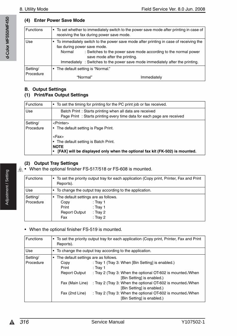
8. Utility Mode Field Service Ver. 8.0 Jun. 2008
3166
Ad
justm
en
t /
Se
ttin
g
(4) Enter Power Save Mode
B. Output Settings(1) Print/Fax Output Settings
(2) Output Tray Settings• When the optional finisher FS-517/518 or FS-608 is mounted.
• When the optional finisher FS-519 is mounted.
Functions • To set whether to immediately switch to the power save mode after printing in case of receiving the fax during power save mode.
Use • To immediately switch to the power save mode after printing in case of receiving the fax during power save mode.
Normal : Switches to the power save mode according to the normal powersave mode after the printing.
Immediately : Switches to the power save mode immediately after the printing.
Setting/Procedure
• The default setting is “Normal.”
“Normal” Immediately
Functions • To set the timing for printing for the PC print job or fax received.
Use Batch Print : Starts printing when all data are receivedPage Print : Starts printing every time data for each page are received
Setting/Procedure
<Printer>• The default setting is Page Print.
<Fax>• The default setting is Batch Print.NOTE• [FAX] will be displayed only when the optional fax kit (FK-502) is mounted.
6
Functions • To set the priority output tray for each application (Copy print, Printer, Fax and Print Reports).
Use • To change the output tray according to the application.
Setting/Procedure
• The default settings are as follows.Copy : Tray 1Print : Tray 1Report Output : Tray 2Fax : Tray 2
Functions • To set the priority output tray for each application (Copy print, Printer, Fax and Print Reports).
Use • To change the output tray according to the application.
Setting/Procedure
• The default settings are as follows.Copy : Tray 1 (Tray 3: When [Bin Setting] is enabled.)Print : Tray 1Report Output : Tray 2 (Tray 3: When the optional OT-602 is mounted./When
[Bin Setting] is enabled.)Fax (Main Line) : Tray 2 (Tray 3: When the optional OT-602 is mounted./When
[Bin Setting] is enabled.)Fax (2nd Line) : Tray 2 (Tray 3: When the optional OT-602 is mounted./When
[Bin Setting] is enabled.)
d-C
olor
MF5
50/M
F450
Service Manual Y107502-1
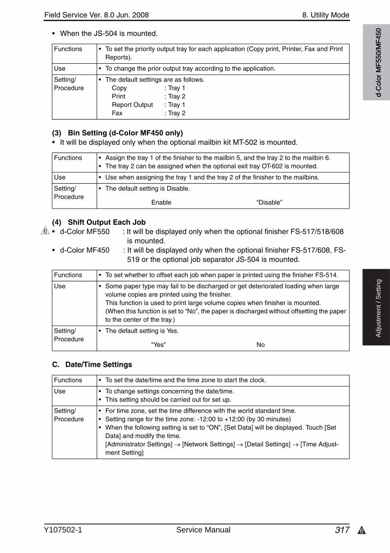
6
Field Service Ver. 8.0 Jun. 2008 8. Utility Mode
317
Ad
justm
en
t /
Se
ttin
g
• When the JS-504 is mounted.
(3) Bin Setting (d-Color MF450 only)• It will be displayed only when the optional mailbin kit MT-502 is mounted.
(4) Shift Output Each Job• d-Color MF550 : It will be displayed only when the optional finisher FS-517/518/608
is mounted.• d-Color MF450 : It will be displayed only when the optional finisher FS-517/608, FS-
519 or the optional job separator JS-504 is mounted.
C. Date/Time Settings
Functions • To set the priority output tray for each application (Copy print, Printer, Fax and Print Reports).
Use • To change the prior output tray according to the application.
Setting/Procedure
• The default settings are as follows.Copy : Tray 1Print : Tray 2Report Output : Tray 1Fax : Tray 2
Functions • Assign the tray 1 of the finisher to the mailbin 5, and the tray 2 to the mailbin 6.• The tray 2 can be assigned when the optional exit tray OT-602 is mounted.
Use • Use when assigning the tray 1 and the tray 2 of the finisher to the mailbins.
Setting/Procedure
• The default setting is Disable.
Enable “Disable”
6
Functions • To set whether to offset each job when paper is printed using the finisher FS-514.
Use • Some paper type may fail to be discharged or get deteriorated loading when large volume copies are printed using the finisher.This function is used to print large volume copies when finisher is mounted.(When this function is set to “No”, the paper is discharged without offsetting the paper to the center of the tray.)
Setting/Procedure
• The default setting is Yes.
“Yes” No
Functions • To set the date/time and the time zone to start the clock.
Use • To change settings concerning the date/time.• This setting should be carried out for set up.
Setting/Procedure
• For time zone, set the time difference with the world standard time.• Setting range for the time zone: -12:00 to +12:00 (by 30 minutes)• When the following setting is set to “ON”, [Set Data] will be displayed. Touch [Set
Data] and modify the time. [Administrator Settings] [Network Settings] [Detail Settings] [Time Adjust-ment Setting]
d-C
olor
MF5
50/M
F450
Y107502-1 Service Manual
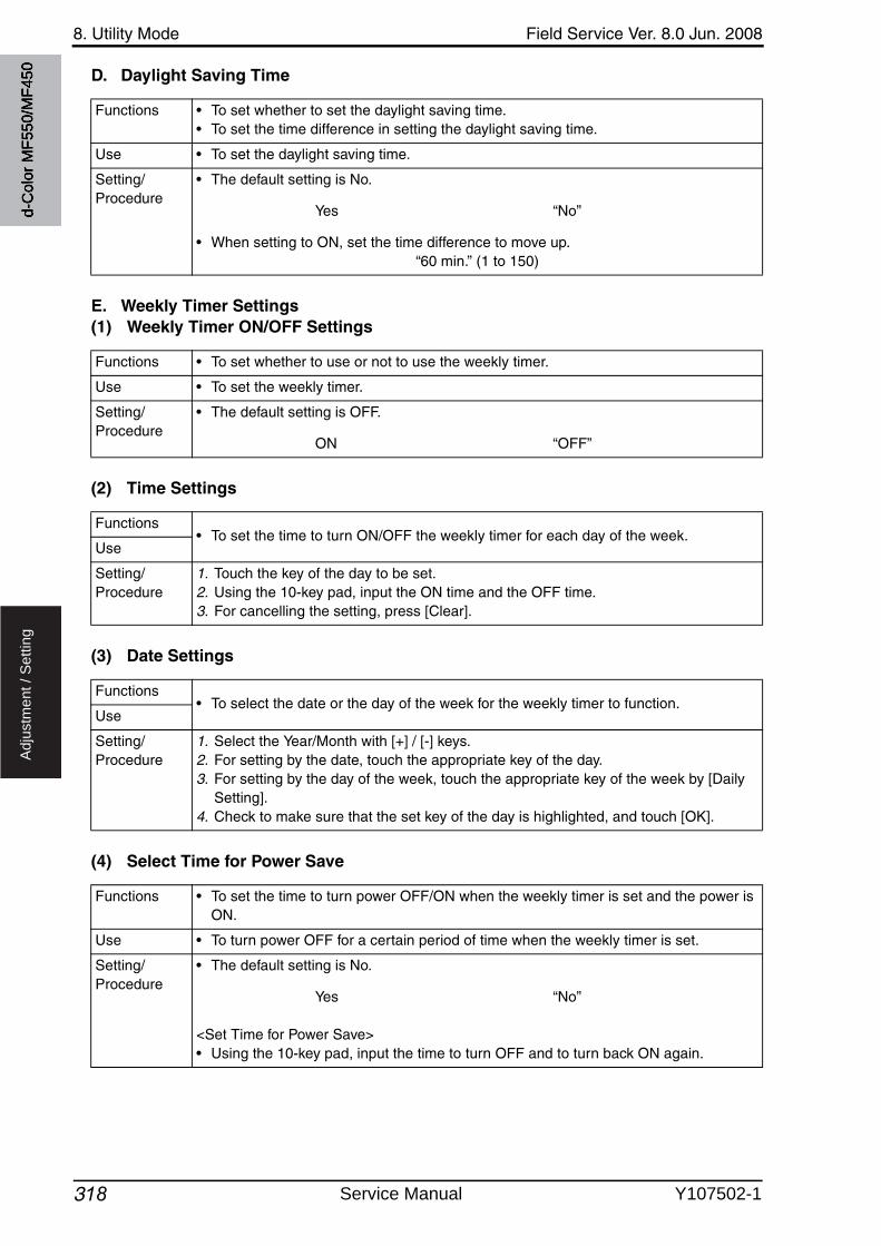
8. Utility Mode Field Service Ver. 8.0 Jun. 2008
318
Ad
justm
en
t /
Se
ttin
g
D. Daylight Saving Time
E. Weekly Timer Settings(1) Weekly Timer ON/OFF Settings
(2) Time Settings
(3) Date Settings
(4) Select Time for Power Save
Functions • To set whether to set the daylight saving time.• To set the time difference in setting the daylight saving time.
Use • To set the daylight saving time.
Setting/Procedure
• The default setting is No.
Yes “No”
• When setting to ON, set the time difference to move up.“60 min.” (1 to 150)
Functions • To set whether to use or not to use the weekly timer.
Use • To set the weekly timer.
Setting/Procedure
• The default setting is OFF.
ON “OFF”
Functions• To set the time to turn ON/OFF the weekly timer for each day of the week.
Use
Setting/Procedure
1. Touch the key of the day to be set.2. Using the 10-key pad, input the ON time and the OFF time.3. For cancelling the setting, press [Clear].
Functions• To select the date or the day of the week for the weekly timer to function.
Use
Setting/Procedure
1. Select the Year/Month with [+] / [-] keys.2. For setting by the date, touch the appropriate key of the day.3. For setting by the day of the week, touch the appropriate key of the week by [Daily
Setting].4. Check to make sure that the set key of the day is highlighted, and touch [OK].
Functions • To set the time to turn power OFF/ON when the weekly timer is set and the power is ON.
Use • To turn power OFF for a certain period of time when the weekly timer is set.
Setting/Procedure
• The default setting is No.
Yes “No”
<Set Time for Power Save>• Using the 10-key pad, input the time to turn OFF and to turn back ON again.
d-C
olor
MF5
50/M
F450
Service Manual Y107502-1

Field Service Ver. 8.0 Jun. 2008 8. Utility Mode
319
Ad
justm
en
t /
Se
ttin
g
(5) Password for Non-Business Hours
F. Restrict User Access(1) Copy Program Lock Settings
(2) Delete Saved Copy Program
(3) Restrict Access to Job Settings• It will not be displayed when the following setting shows that authentication device 1 or
vendor 2 is mounted.[Service Mode] [Billing Setting] [Management Function Choice]
<Changing Job Priority>
<Delete Other User Jobs>
Functions • To set whether to input the password before using when the weekly timer is set.
Use • To set the password for turning the power ON temporarily when the weekly timer is set.
Setting/Procedure
• The default setting is No.
Yes “No”
• When setting to Yes, enter the password (eight digits).
Functions • To set the prohibition for modifying the registered copy program.
Use • To be used when prohibiting the user from changing the copy program.
Setting/Procedure
1. Touch the key for the appropriate copy program.2. Touch [OK].
Functions • To delete the registered program job.
Use • To delete the registered program job.
Setting/Procedure
1. Touch the appropriate program job.2. Touch [Delete].3. Touch [Yes] on the check screen to delete the program job.
Functions• To set whether to allow or restrict the change on the print priority for the job.
Use
Setting/Procedure
• The default setting is Allow.
“Allow” Restrict
Functions • To set whether to allow or restrict job delete by other users when the user is authenti-cated.Use
Setting/Procedure
• The default setting is Restrict.
Allow “Restrict”
d-C
olor
MF5
50/M
F450
Y107502-1 Service Manual
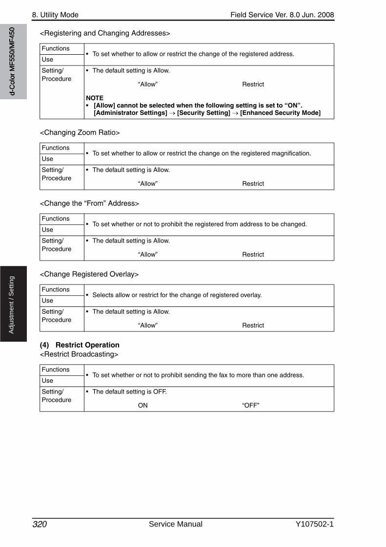
8. Utility Mode Field Service Ver. 8.0 Jun. 2008
320
Ad
justm
en
t /
Se
ttin
g
<Registering and Changing Addresses>
<Changing Zoom Ratio>
<Change the “From” Address>
<Change Registered Overlay>
(4) Restrict Operation<Restrict Broadcasting>
Functions• To set whether to allow or restrict the change of the registered address.
Use
Setting/Procedure
• The default setting is Allow.
“Allow” Restrict
NOTE• [Allow] cannot be selected when the following setting is set to “ON”.
[Administrator Settings] [Security Setting] [Enhanced Security Mode]
Functions• To set whether to allow or restrict the change on the registered magnification.
Use
Setting/Procedure
• The default setting is Allow.
“Allow” Restrict
Functions• To set whether or not to prohibit the registered from address to be changed.
Use
Setting/Procedure
• The default setting is Allow.
“Allow” Restrict
Functions• Selects allow or restrict for the change of registered overlay.
Use
Setting/Procedure
• The default setting is Allow.
“Allow” Restrict
Functions• To set whether or not to prohibit sending the fax to more than one address.
Use
Setting/Procedure
• The default setting is OFF.
ON “OFF”
d-C
olor
MF5
50/M
F450
Service Manual Y107502-1

Field Service Ver. 8.0 Jun. 2008 8. Utility Mode
321
Ad
justm
en
t /
Se
ttin
g
G. Expert Adjustment• It will not be displayed when the following setting shows that vendor 2 is mounted.
[Service Mode] [Billing Setting] [Management Function Choice] (It will be displayed when the Key Counter is mounted or when the following setting shows that switch No.33 is set to [01] at HEX assignment.[Service Mode] [System 2] [Software Switch Setting])
(1) AE Level Adjustment
Functions • To set the default setting for AE (Auto Exposure) the larger the value becomes the more emphasized the background will be.
Use To make the background level foggier: Increase the setting valueTo make the background level less foggy: Decrease the setting value
Setting/Procedure
• The default setting is 2.
“2” (0 to 4)
d-C
olor
MF5
50/M
F450
Y107502-1 Service Manual

8. Utility Mode Field Service Ver. 8.0 Jun. 2008
322
Ad
justm
en
t /
Se
ttin
g
(2) Printer Adjustment<Leading Edge Adjustment>• It will not be displayed when the following setting shows that Management Device 1 is
mounted during the device power is OFF or no authentication is set.[Service Mode] [Billing Setting] [Management Function Choice]
• This menu is unavailable when the key counter is not inserted while only the key counteris set to Set by [Service Mode] [Billing Setting] [Management Function Choice].
Functions • To vary the print start position in the sub scan direction for each of different paper types in the manual bypass tray.
Use • The PH unit has been replaced.• The paper type has been changed.• The image on the copy deviates in the sub scan direction.• A faint image occurs on the leading edge of the image.• Able to make an individual adjustment for each paper type of plain paper, thick 1/1+,
thick 2, thick 3, thick 4, transparencies, and envelopes.
Adjustment Specification Width A on the test pattern produced should
fall within the following range.
Specifications: 4.2 0.5 mmSetting range: -3.0 mm to +3.0 mm (in 0.2 mm increments)
Adjustment Instructions
If width A is longer than the specifications, make the setting value smaller than the cur-rent one.If width A is shorter than the specifications, make the setting value greater than the cur-rent one.
Setting/Procedure
1. Place A3 paper on the manual bypass tray.2. Call the Administrator Settings to the screen.3. Touch [System Settings] [Expert Adjustment] [Printer Adjustment] [Leading
Edge Adjustment].4. Select the [Normal].5. Press the Start key to let the machine produce a test pattern.6. Check the dimension of width A on the test pattern.7. If width A falls outside the specified range, change the setting using the [+] / [-] key.8. Press the Start key to let the machine produce a test pattern.9. Check the dimension of width A on the test pattern.10.If width A is outside the specified range, change the setting again and make a check
again.11.If width A falls within the specified range, touch [OK].12.Following the same procedure, adjust for thick 1 to 3, OHP, and envelope.
A00JF3C504DA
Width A
d-C
olor
MF5
50/M
F450
Service Manual Y107502-1
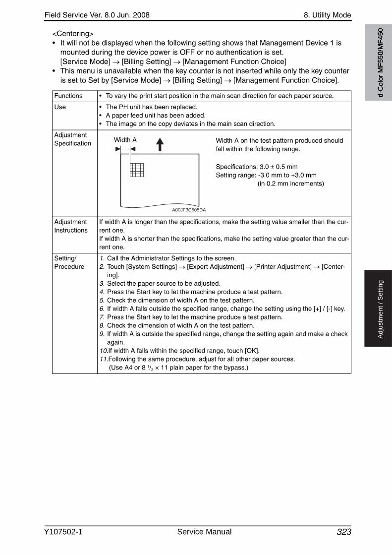
Field Service Ver. 8.0 Jun. 2008 8. Utility Mode
323
Ad
justm
en
t /
Se
ttin
g
<Centering>• It will not be displayed when the following setting shows that Management Device 1 is
mounted during the device power is OFF or no authentication is set.[Service Mode] [Billing Setting] [Management Function Choice]
• This menu is unavailable when the key counter is not inserted while only the key counteris set to Set by [Service Mode] [Billing Setting] [Management Function Choice].
Functions • To vary the print start position in the main scan direction for each paper source.
Use • The PH unit has been replaced.• A paper feed unit has been added.• The image on the copy deviates in the main scan direction.
Adjustment Specification Width A on the test pattern produced should
fall within the following range.
Specifications: 3.0 0.5 mmSetting range: -3.0 mm to +3.0 mm (in 0.2 mm increments)
Adjustment Instructions
If width A is longer than the specifications, make the setting value smaller than the cur-rent one.If width A is shorter than the specifications, make the setting value greater than the cur-rent one.
Setting/Procedure
1. Call the Administrator Settings to the screen.2. Touch [System Settings] [Expert Adjustment] [Printer Adjustment] [Center-
ing].3. Select the paper source to be adjusted.4. Press the Start key to let the machine produce a test pattern.5. Check the dimension of width A on the test pattern.6. If width A falls outside the specified range, change the setting using the [+] / [-] key.7. Press the Start key to let the machine produce a test pattern.8. Check the dimension of width A on the test pattern.9. If width A is outside the specified range, change the setting again and make a check
again.10.If width A falls within the specified range, touch [OK].11.Following the same procedure, adjust for all other paper sources.
(Use A4 or 8 1/2 × 11 plain paper for the bypass.)
A00JF3C505DA
Width A
d-C
olor
MF5
50/M
F450
Y107502-1 Service Manual

8. Utility Mode Field Service Ver. 8.0 Jun. 2008
324
Ad
justm
en
t /
Se
ttin
g
<Leading Edge Adjustment (Duplex Side 2)>• It will not be displayed when the following setting shows that Management Device 1 is
mounted during the device power is OFF or no authentication is set.[Service Mode] [Billing Setting] [Management Function Choice]
• This menu is unavailable when the key counter is not inserted while only the key counteris set to Set by [Service Mode] [Billing Setting] [Management Function Choice].
Functions • Makes an adjustment by changing the image write start position in the sub scan direction on the 2nd side of duplex printing for individual types of paper.
Use • When the 2nd side image on paper fed from the tray is shifted in the sub scan direc-tion.
• Able to make an individual adjustment for each paper type of plain paper, thick 1/1+, thick 2 and thick 3.
Adjustment Specification Width A on the test pattern produced should
fall within the following range.
Specifications: 4.2 0.5 mmSetting range: -3.0 mm to +3.0 mm (in 0.2 mm increments)
Adjustment Instructions
If width A is longer than the specifications, make the setting value smaller than the cur-rent one.If width A is shorter than the specifications, make the setting value greater than the cur-rent one.
Setting/Procedure
1. Call the Administrator Settings to the screen.2. Touch [System Settings] [Expert Adjustment] [Printer Adjustment] [Leading
Edge Adjustment (Duplex side 2)].3. Select the [Normal].4. Press the Start key to let the machine produce a test pattern.5. Check the dimension of width A on the test pattern.6. If width A falls outside the specified range, change the setting using the [+] / [-] key.7. Press the Start key to let the machine produce a test pattern.8. Check the dimension of width A on the test pattern.9. If width A is outside the specified range, change the setting again and make a check
again.10.If width A falls within the specified range, touch [OK].11.Following the same procedure, adjust for thick 1 to 3, OHP, and envelope.
A00JF3C504DA
Width A
Backside
d-C
olor
MF5
50/M
F450
Service Manual Y107502-1
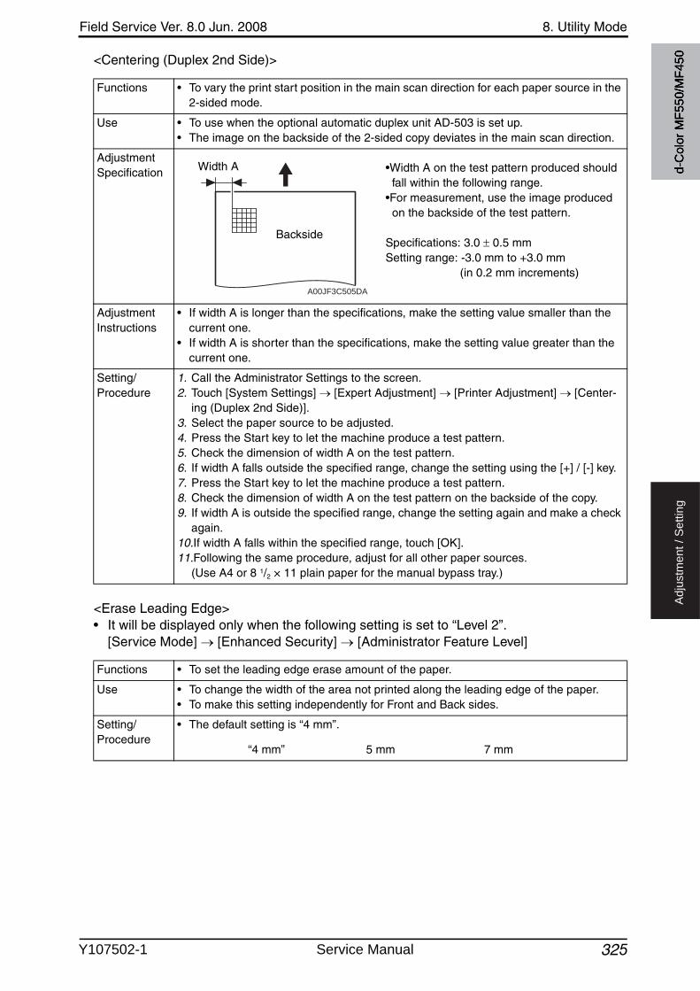
Field Service Ver. 8.0 Jun. 2008 8. Utility Mode
325
Ad
justm
en
t /
Se
ttin
g
<Centering (Duplex 2nd Side)>
<Erase Leading Edge>• It will be displayed only when the following setting is set to “Level 2”.
[Service Mode] [Enhanced Security] [Administrator Feature Level]
Functions • To vary the print start position in the main scan direction for each paper source in the 2-sided mode.
Use • To use when the optional automatic duplex unit AD-503 is set up.• The image on the backside of the 2-sided copy deviates in the main scan direction.
Adjustment Specification •Width A on the test pattern produced should
fall within the following range.•For measurement, use the image produced
on the backside of the test pattern.
Specifications: 3.0 0.5 mmSetting range: -3.0 mm to +3.0 mm (in 0.2 mm increments)
Adjustment Instructions
• If width A is longer than the specifications, make the setting value smaller than the current one.
• If width A is shorter than the specifications, make the setting value greater than the current one.
Setting/Procedure
1. Call the Administrator Settings to the screen.2. Touch [System Settings] [Expert Adjustment] [Printer Adjustment] [Center-
ing (Duplex 2nd Side)].3. Select the paper source to be adjusted.4. Press the Start key to let the machine produce a test pattern.5. Check the dimension of width A on the test pattern.6. If width A falls outside the specified range, change the setting using the [+] / [-] key.7. Press the Start key to let the machine produce a test pattern.8. Check the dimension of width A on the test pattern on the backside of the copy.9. If width A is outside the specified range, change the setting again and make a check
again.10.If width A falls within the specified range, touch [OK].11.Following the same procedure, adjust for all other paper sources.
(Use A4 or 8 1/2 × 11 plain paper for the manual bypass tray.)
A00JF3C505DA
Width A
Backside
Functions • To set the leading edge erase amount of the paper.
Use • To change the width of the area not printed along the leading edge of the paper.• To make this setting independently for Front and Back sides.
Setting/Procedure
• The default setting is “4 mm”.
“4 mm” 5 mm 7 mm
d-C
olor
MF5
50/M
F450
Y107502-1 Service Manual

8. Utility Mode Field Service Ver. 8.0 Jun. 2008
326
Ad
justm
en
t /
Se
ttin
g
<Vertical Adjustment>• It will be displayed only when the following setting is set to “Level 2.”
[Service Mode] [Enhanced Security] [Administrator Feature Level]
Functions • To synchronize the paper transport speed with the image writing speed.
Use • The l adjustment becomes necessary.• The printed image on the copy distorts (stretched, shrunk).• When the printed image on the copy is stretched in the sub scan direction.• Able to make an individual adjustment for each paper type of plain paper, thick 1/1+,
thick 2, thick 3 and thick 4.
Adjustment Specification Width A and width B on the test pattern pro-
duced should fall within the following ranges.Width A: equivalent to one gridWidth B: equivalent to 48 grids
SpecificationsA: 7.9 to 8.3B: 389.1 to 392.1
Setting RangeA, B: -7 to +7
Adjustment Instructions
If width A or B is longer than the specifications, make the setting value smaller than the current one.If width A or B is shorter than the specifications, make the setting value greater than the current one.
Adjustment Procedure
1. Load manual bypass tray with A3 or 11 × 17 plain paper.2. Call the Administrator Settings to the screen.3. Touch these keys in this order: [System Settings] [Expert Adjustment] [Vertical
Adjustment].4. Press the Start key to let the machine produce a test pattern.5. Check width A (equivalent to one grid) and width B (equivalent to 48 grids) on the
test pattern.6. If width of A or B falls outside the specified range, change the setting using the [+]/[-]
keys.7. Press the Start key to let the machine produce a test pattern again.8. Check width A and width B on the test pattern.9. If width A or B falls outside the specified range, change the setting value and make a
check again.10.If width A or B falls within the specified range, touch [OK].11.Following the same procedure, adjust for [Thick 1 to 3], [OHP], and [Envelope].
(Check width A only for [OHP] and [Envelope].)
A00JF3C506DA
A
B
d-C
olor
MF5
50/M
F450
Service Manual Y107502-1
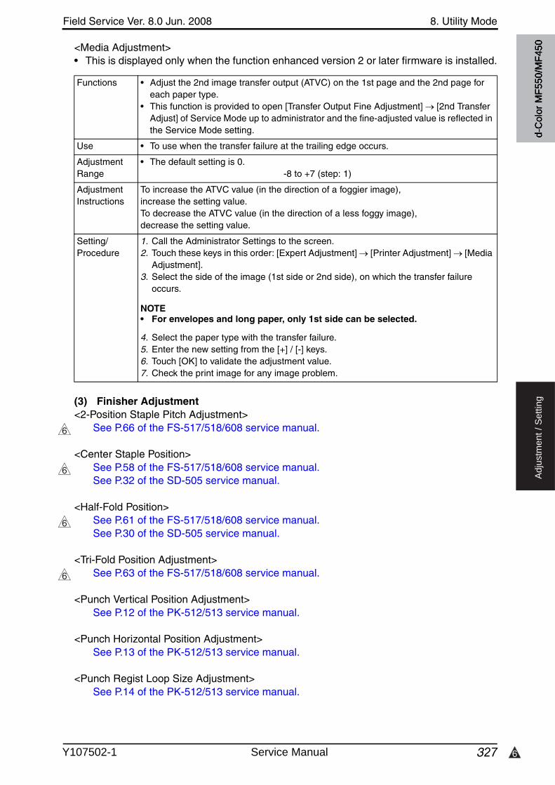
6
Field Service Ver. 8.0 Jun. 2008 8. Utility Mode
327
Ad
justm
en
t /
Se
ttin
g
<Media Adjustment>• This is displayed only when the function enhanced version 2 or later firmware is installed.
(3) Finisher Adjustment<2-Position Staple Pitch Adjustment>
See P.66 of the FS-517/518/608 service manual.
<Center Staple Position>See P.58 of the FS-517/518/608 service manual.See P.32 of the SD-505 service manual.
<Half-Fold Position>See P.61 of the FS-517/518/608 service manual.See P.30 of the SD-505 service manual.
<Tri-Fold Position Adjustment>See P.63 of the FS-517/518/608 service manual.
<Punch Vertical Position Adjustment>See P.12 of the PK-512/513 service manual.
<Punch Horizontal Position Adjustment>See P.13 of the PK-512/513 service manual.
<Punch Regist Loop Size Adjustment>See P.14 of the PK-512/513 service manual.
Functions • Adjust the 2nd image transfer output (ATVC) on the 1st page and the 2nd page for each paper type.
• This function is provided to open [Transfer Output Fine Adjustment] [2nd Transfer Adjust] of Service Mode up to administrator and the fine-adjusted value is reflected in the Service Mode setting.
Use • To use when the transfer failure at the trailing edge occurs.
Adjustment Range
• The default setting is 0.-8 to +7 (step: 1)
Adjustment Instructions
To increase the ATVC value (in the direction of a foggier image), increase the setting value.To decrease the ATVC value (in the direction of a less foggy image), decrease the setting value.
Setting/Procedure
1. Call the Administrator Settings to the screen.2. Touch these keys in this order: [Expert Adjustment] [Printer Adjustment] [Media
Adjustment].3. Select the side of the image (1st side or 2nd side), on which the transfer failure
occurs.
NOTE• For envelopes and long paper, only 1st side can be selected.
4. Select the paper type with the transfer failure.5. Enter the new setting from the [+] / [-] keys.6. Touch [OK] to validate the adjustment value.7. Check the print image for any image problem.
6
6
6
6
d-C
olor
MF5
50/M
F450
Y107502-1 Service Manual
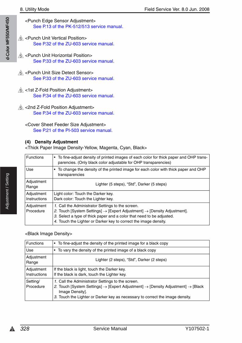
8. Utility Mode Field Service Ver. 8.0 Jun. 2008
3285
Ad
justm
en
t /
Se
ttin
g
<Punch Edge Sensor Adjustment>See P.13 of the PK-512/513 service manual.
<Punch Unit Vertical Position>See P.32 of the ZU-603 service manual.
<Punch Unit Horizontal Position>See P.33 of the ZU-603 service manual.
<Punch Unit Size Detect Sensor>See P.33 of the ZU-603 service manual.
<1st Z-Fold Position Adjustment>See P.34 of the ZU-603 service manual.
<2nd Z-Fold Position Adjustment>See P.34 of the ZU-603 service manual.
<Cover Sheet Feeder Size Adjustment>See P.21 of the PI-503 service manual.
(4) Density Adjustment<Thick Paper Image Density-Yellow, Magenta, Cyan, Black>
<Black Image Density>
5
5
5
5
5
Functions • To fine-adjust density of printed images of each color for thick paper and OHP trans-parencies. (Only black color adjustable for OHP transparencies)
Use • To change the density of the printed image for each color with thick paper and OHP transparencies
Adjustment Range
Lighter (5 steps), “Std”, Darker (5 steps)
Adjustment Instructions
Light color: Touch the Darker key. Dark color: Touch the Lighter key.
Adjustment Procedure
1. Call the Administrator Settings to the screen.2. Touch [System Settings] [Expert Adjustment] [Density Adjustment].3. Select a type of thick paper and a color that need to be adjusted.4. Touch the Lighter or Darker key to correct the image density.
Functions • To fine-adjust the density of the printed image for a black copy
Use • To vary the density of the printed image of a black copy
Adjustment Range
Lighter (2 steps), “Std”, Darker (2 steps)
Adjustment Instructions
If the black is light, touch the Darker key.If the black is dark, touch the Lighter key.
Setting/Procedure
1. Call the Administrator Settings to the screen.2. Touch [System Settings] [Expert Adjustment] [Density Adjustment] [Black
Image Density].3. Touch the Lighter or Darker key as necessary to correct the image density.
d-C
olor
MF5
50/M
F450
Service Manual Y107502-1
Field Service Ver. 8.0 Jun. 2008 8. Utility Mode
329
Ad
justm
en
t /
Se
ttin
g
(5) Image Stabilization<Image Stabilization Only>
<Initialize+Image Stabilization>
(6) Paper Separation Adjustment
Functions • The image stabilization sequence is carried out without clearing the historical data of image stabilization control.
Use • Use if an image problem persists even after [Gradation Adjustment] has been exe-cuted.
• When [D Max Density] and [Background Voltage Margin] of Service Mode are changed.
Setting/Procedure
1. Call the Administrator Settings to the screen.2. Touch [System Settings] [Expert Adjustment] [Image Stabilization] [Image
Stabilization Only].3. Press the Start key to start Stabilizer.
The Start key turns red and stays lit up red during the Stabilizer sequence.4. Stabilizer is completed when the Start key turns blue.
Functions • To carry out an image stabilization sequence after the historical data of image stabili-zation control has been initialized.
Use • Use if an image problem persists even after [Gradation Adjustment] has been exe-cuted.
• Use if tone reproduction and maximum density are faulty even after image stabiliza-tion has been executed.
Setting/Procedure
1. Call the Administrator Settings to the screen.2. Touch [System Settings] [Expert Adjustment] [Image Stabilization]
[Initialize+Image Stabilization].3. Press the Start key to start Stabilizer.
The Start key turns red and stays lit up red during the Stabilizer sequence.4. Stabilizer is completed when the Start key turns blue.
Functions • For duplex printing of thin paper, the paper separation position is adjusted for the first and second sides of paper.
Use • To adjust the balance between paper separation and image transfer performances by changing the paper separation position in duplex printing of thin paper (64 g/ m2) in hot and humid conditions.
Adjustment Range
• The default setting is 0.-2 mm to +2 mm (step:0.1 mm)
Adjustment Procedure
Priority on paper separation performance: Increase the setting valuePriority on image transfer performance: Decrease the setting value
Setting/Procedure
1. Call the Administrator Settings to the screen.2. Touch [System Settings] [Expert Adjustment] [Paper Separation Adjustment].3. Select [Front] or [Back].4. Change the setting value with [+] or [-] key.5. Touch [OK] to determine the adjusted value.6. Make a print and check the image.
d-C
olor
MF5
50/M
F450
Y107502-1 Service Manual
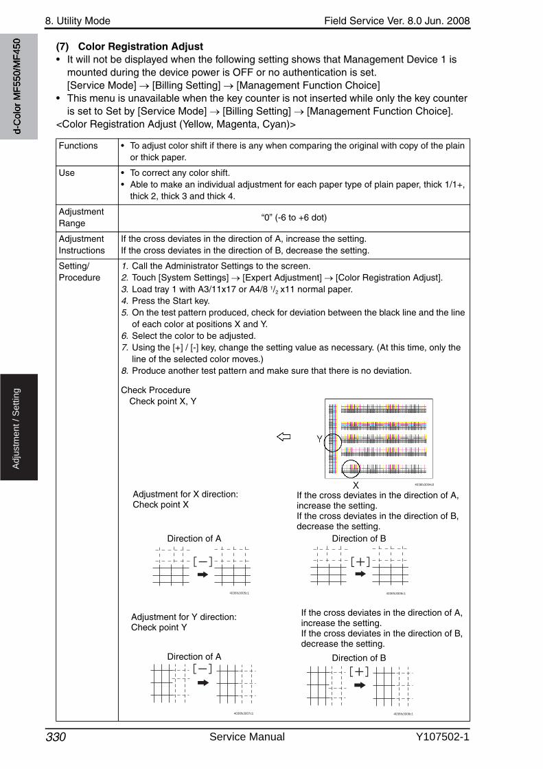
8. Utility Mode Field Service Ver. 8.0 Jun. 2008
330
Ad
justm
en
t /
Se
ttin
g
(7) Color Registration Adjust• It will not be displayed when the following setting shows that Management Device 1 is
mounted during the device power is OFF or no authentication is set.[Service Mode] [Billing Setting] [Management Function Choice]
• This menu is unavailable when the key counter is not inserted while only the key counteris set to Set by [Service Mode] [Billing Setting] [Management Function Choice].
<Color Registration Adjust (Yellow, Magenta, Cyan)>
Functions • To adjust color shift if there is any when comparing the original with copy of the plain or thick paper.
Use • To correct any color shift.• Able to make an individual adjustment for each paper type of plain paper, thick 1/1+,
thick 2, thick 3 and thick 4.
Adjustment Range
“0” (-6 to +6 dot)
Adjustment Instructions
If the cross deviates in the direction of A, increase the setting.If the cross deviates in the direction of B, decrease the setting.
Setting/Procedure
1. Call the Administrator Settings to the screen.2. Touch [System Settings] [Expert Adjustment] [Color Registration Adjust].3. Load tray 1 with A3/11x17 or A4/8 1/2 x11 normal paper.4. Press the Start key.5. On the test pattern produced, check for deviation between the black line and the line
of each color at positions X and Y.6. Select the color to be adjusted.7. Using the [+] / [-] key, change the setting value as necessary. (At this time, only the
line of the selected color moves.)8. Produce another test pattern and make sure that there is no deviation.
Check Procedure
4036fs3004c0
4036fs3005c1 4036fs3006c1
4036fs3007c1 4036fs3008c1
If the cross deviates in the direction of A, increase the setting.If the cross deviates in the direction of B, decrease the setting.
Check point X, Y
Adjustment for X direction: Check point X
Adjustment for Y direction: Check point Y
If the cross deviates in the direction of A, increase the setting.If the cross deviates in the direction of B, decrease the setting.
Direction of A Direction of B
Direction of A Direction of B
d-C
olor
MF5
50/M
F450
Service Manual Y107502-1
Field Service Ver. 8.0 Jun. 2008 8. Utility Mode
331
Ad
justm
en
t /
Se
ttin
g
(8) Gradation Adjustment• It will not be displayed when the following setting is set to “ON.”
[Service Mode] [Imaging Process Adjustment] [Dev. Bias Choice]• It will not be displayed when the following setting shows that Management Device 1 is
mounted during the device power is OFF or no authentication is set.[Service Mode] [Billing Setting] [Management Function Choice]
• This menu is unavailable when the key counter is not inserted while only the key counteris set to Set by [Service Mode] [Billing Setting] [Management Function Choice].
Functions • To make an automatic adjustment of gradation based on the test pattern producedand the readings taken by the scanner.
Use • Color reproduction performance becomes poor.• The IU has been replaced.• The image transfer belt unit has been replaced.
• Printer (Gradation) : It gives the highest priority to gradation performance of the image as it adjusts.
• Printer (Resolution) : It gives the highest priority to reproduction performance of letters and lines as it adjusts.
• Copy : It gives the highest priority to increasing the number of images to be stored in the memory as it adjusts.
Adjustment Procedure
1. Touch [Stabilizer] and the Start key to perform image stabilization.
NOTE• Before executing Gradation adjust, be sure to perform Stabilizer.
2. Call the Administrator Settings to the screen.3. Touch [System Settings] [Expert Adjustment] [Gradation Adjustment].4. Select the appropriate mode for the gradation adjustment.5. Press the Start key to let the machine produce a test pattern.6. Place the test pattern produced on the original glass.7. Place ten blank sheets of A3/11 x 17 paper on the test pattern and lower the original
cover.8. Press the Start key. (The machine will then start scanning the test pattern.)9. Touch [OK] and repeat steps from 2 through 7 twice (a total of three times).• If the image is faulty, perform the troubleshooting procedures for image problems.
d-C
olor
MF5
50/M
F450
Y107502-1 Service Manual
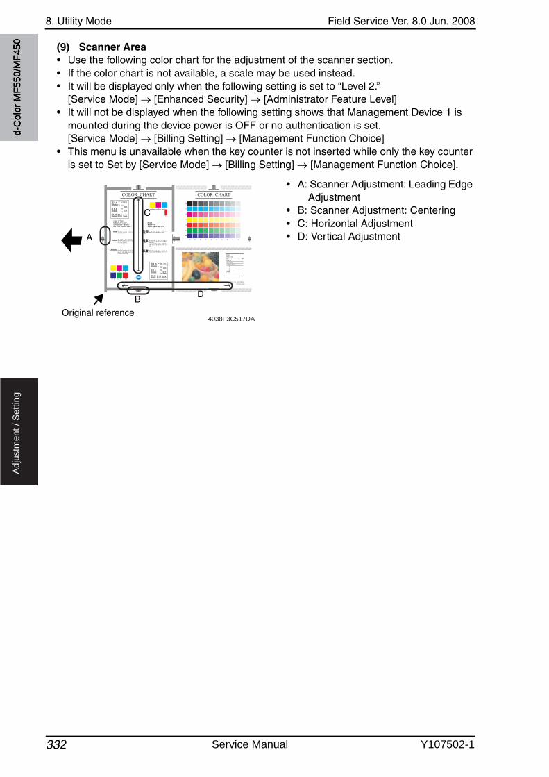
8. Utility Mode Field Service Ver. 8.0 Jun. 2008
332
Ad
justm
en
t /
Se
ttin
g
(9) Scanner Area• Use the following color chart for the adjustment of the scanner section.• If the color chart is not available, a scale may be used instead.• It will be displayed only when the following setting is set to “Level 2.”
[Service Mode] [Enhanced Security] [Administrator Feature Level]• It will not be displayed when the following setting shows that Management Device 1 is
mounted during the device power is OFF or no authentication is set.[Service Mode] [Billing Setting] [Management Function Choice]
• This menu is unavailable when the key counter is not inserted while only the key counteris set to Set by [Service Mode] [Billing Setting] [Management Function Choice].
• A: Scanner Adjustment: Leading Edge Adjustment
• B: Scanner Adjustment: Centering• C: Horizontal Adjustment• D: Vertical Adjustment
COLOR CHART
Y M C
C M C Y Y M
Color is “hue”,lightness is “value”,saturation is “chroma”:this is the world of color.
Hue
P2
P2
The quality of color which can be described by words such as red, yellow, blue etc.
Value The quality of color which can be described by words such as light, dark etc., relating the color to a gray of a similar lightness.
Chroma The quality of color which can be described by words such as vivid, dull etc., describing the extent to which a color differs from a gray having the same value.
P1
1.0
1.1
1.25 1.4 1.6
1.8
2.0
2.22.5
2.8
3.2
3.6
4.0
4.5
Y M C
C M C Y Y M
1.0
1.1
1.25 1.4 1.6
1.8
2.0
2.22.5
2.8
3.2
3.6
4.0
4.5
COLOR CHART
YM
CB
GR
MODEL :MACHINE S/N :DATE : / / °C %RHCOUNTER :COPY DENSITY :COLOR BALANCE Y : M : C : BK : OTHERS :
P1
10
BK
CHART NO. : CTC-008-01
PART NO. : 4036-7940-01
Printed In Japan
9 8 7 6 5 4 3 2 1
4038F3C517DAOriginal reference
B
A
C
D
d-C
olor
MF5
50/M
F450
Service Manual Y107502-1
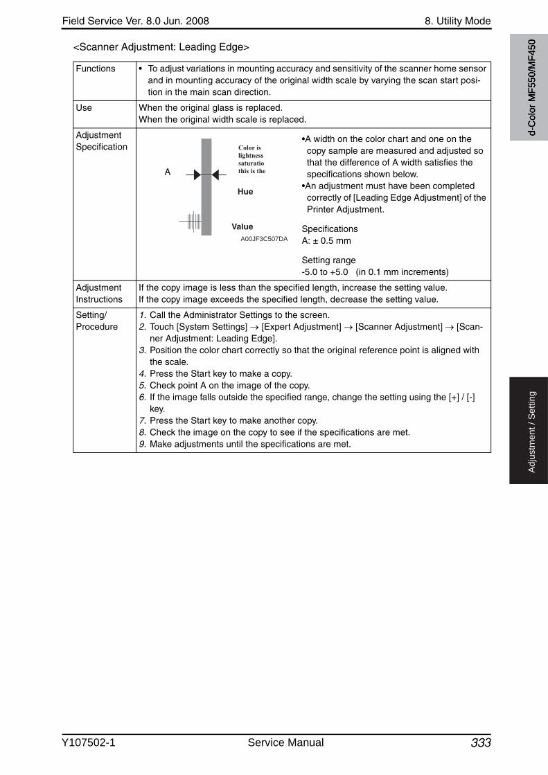
Field Service Ver. 8.0 Jun. 2008 8. Utility Mode
333
Ad
justm
en
t /
Se
ttin
g
<Scanner Adjustment: Leading Edge>
Functions • To adjust variations in mounting accuracy and sensitivity of the scanner home sensor and in mounting accuracy of the original width scale by varying the scan start posi-tion in the main scan direction.
Use When the original glass is replaced.When the original width scale is replaced.
Adjustment Specification
•A width on the color chart and one on the copy sample are measured and adjusted so that the difference of A width satisfies the specifications shown below.
•An adjustment must have been completed correctly of [Leading Edge Adjustment] of the Printer Adjustment.
SpecificationsA: ± 0.5 mm
Setting range-5.0 to +5.0 (in 0.1 mm increments)
Adjustment Instructions
If the copy image is less than the specified length, increase the setting value.If the copy image exceeds the specified length, decrease the setting value.
Setting/Procedure
1. Call the Administrator Settings to the screen.2. Touch [System Settings] [Expert Adjustment] [Scanner Adjustment] [Scan-
ner Adjustment: Leading Edge].3. Position the color chart correctly so that the original reference point is aligned with
the scale.4. Press the Start key to make a copy.5. Check point A on the image of the copy.6. If the image falls outside the specified range, change the setting using the [+] / [-]
key.7. Press the Start key to make another copy.8. Check the image on the copy to see if the specifications are met.9. Make adjustments until the specifications are met.
A00JF3C507DA
A
d-C
olor
MF5
50/M
F450
Y107502-1 Service Manual
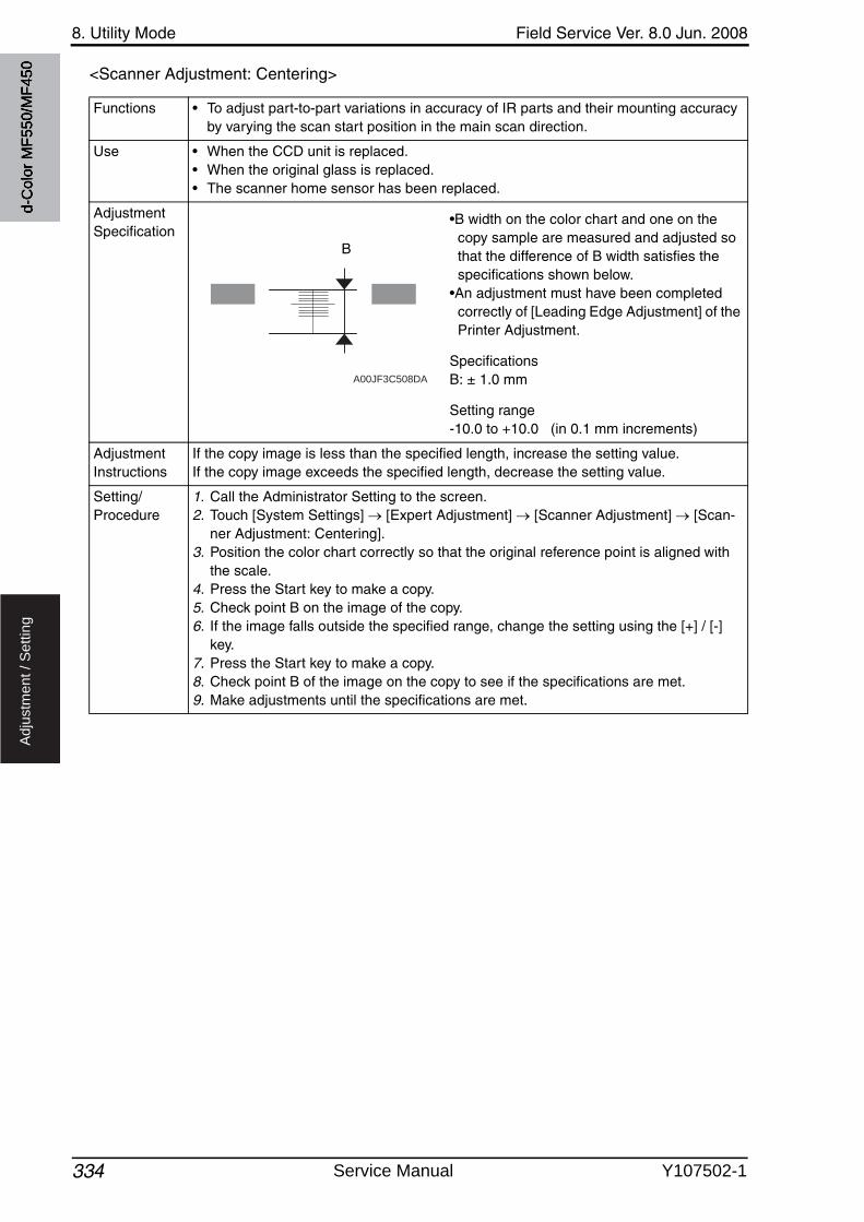
8. Utility Mode Field Service Ver. 8.0 Jun. 2008
334
Ad
justm
en
t /
Se
ttin
g
<Scanner Adjustment: Centering>
Functions • To adjust part-to-part variations in accuracy of IR parts and their mounting accuracy by varying the scan start position in the main scan direction.
Use • When the CCD unit is replaced.• When the original glass is replaced.• The scanner home sensor has been replaced.
Adjustment Specification
•B width on the color chart and one on the copy sample are measured and adjusted so that the difference of B width satisfies the specifications shown below.
•An adjustment must have been completed correctly of [Leading Edge Adjustment] of the Printer Adjustment.
SpecificationsB: ± 1.0 mm
Setting range-10.0 to +10.0 (in 0.1 mm increments)
Adjustment Instructions
If the copy image is less than the specified length, increase the setting value.If the copy image exceeds the specified length, decrease the setting value.
Setting/Procedure
1. Call the Administrator Setting to the screen.2. Touch [System Settings] [Expert Adjustment] [Scanner Adjustment] [Scan-
ner Adjustment: Centering].3. Position the color chart correctly so that the original reference point is aligned with
the scale.4. Press the Start key to make a copy.5. Check point B on the image of the copy.6. If the image falls outside the specified range, change the setting using the [+] / [-]
key.7. Press the Start key to make a copy.8. Check point B of the image on the copy to see if the specifications are met.9. Make adjustments until the specifications are met.
A00JF3C508DA
B
d-C
olor
MF5
50/M
F450
Service Manual Y107502-1
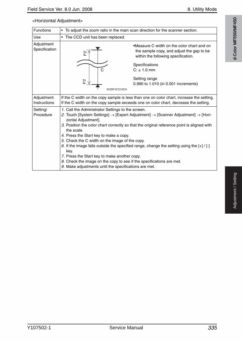
Field Service Ver. 8.0 Jun. 2008 8. Utility Mode
335
Ad
justm
en
t /
Se
ttin
g
<Horizontal Adjustment>
Functions • To adjust the zoom ratio in the main scan direction for the scanner section.
Use • The CCD unit has been replaced.
Adjustment Specification
•Measure C width on the color chart and on the sample copy, and adjust the gap to be within the following specification.
SpecificationsC: ± 1.0 mm
Setting range0.990 to 1.010 (in 0.001 increments)
Adjustment Instructions
If the C width on the copy sample is less than one on color chart, increase the setting.If the C width on the copy sample exceeds one on color chart, decrease the setting.
Setting/Procedure
1. Call the Administrator Settings to the screen.2. Touch [System Settings] [Expert Adjustment] [Scanner Adjustment] [Hori-
zontal Adjustment].3. Position the color chart correctly so that the original reference point is aligned with
the scale.4. Press the Start key to make a copy.5. Check the C width on the image of the copy.6. If the image falls outside the specified range, change the setting using the [+] / [-]
key.7. Press the Start key to make another copy.8. Check the image on the copy to see if the specifications are met.9. Make adjustments until the specifications are met.
4038F3C516DA
C
d-C
olor
MF5
50/M
F450
Y107502-1 Service Manual
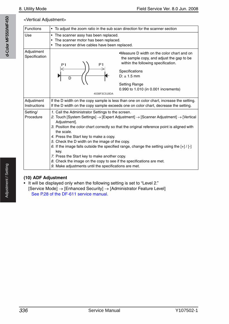
8. Utility Mode Field Service Ver. 8.0 Jun. 2008
336
Ad
justm
en
t /
Se
ttin
g
<Vertical Adjustment>
(10) ADF Adjustment• It will be displayed only when the following setting is set to “Level 2.”
[Service Mode] [Enhanced Security] [Administrator Feature Level]See P.28 of the DF-611 service manual.
Functions • To adjust the zoom ratio in the sub scan direction for the scanner section
Use • The scanner assy has been replaced.• The scanner motor has been replaced.• The scanner drive cables have been replaced.
Adjustment Specification
•Measure D width on the color chart and on the sample copy, and adjust the gap to be within the following specification.
SpecificationsD: ± 1.5 mm
Setting Range0.990 to 1.010 (in 0.001 increments)
Adjustment Instructions
If the D width on the copy sample is less than one on color chart, increase the setting.If the D width on the copy sample exceeds one on color chart, decrease the setting.
Setting/Procedure
1. Call the Administrator Settings to the screen.2. Touch [System Settings] [Expert Adjustment] [Scanner Adjustment] [Vertical
Adjustment].3. Position the color chart correctly so that the original reference point is aligned with
the scale.4. Press the Start key to make a copy.5. Check the D width on the image of the copy.6. If the image falls outside the specified range, change the setting using the [+] / [-]
key.7. Press the Start key to make another copy.8. Check the image on the copy to see if the specifications are met.9. Make adjustments until the specifications are met.
4038F3C518DA
D
d-C
olor
MF5
50/M
F450
Service Manual Y107502-1

Field Service Ver. 8.0 Jun. 2008 8. Utility Mode
337 2
Ad
justm
en
t /
Se
ttin
g
(11) Line Detection<Prior Detection Setting>
Functions • To set whether or not to perform pre-detection of stain on the ADF original glass.• To set the detection level of the pre-detection of stain on the ADF original glass.• To set how to display the warning when stain on the ADF original glass is detected.
Use • Use when changing the display of the warning which requests the cleaning of the stain on the glass detected by the pre-detection of the lines.
TYPE1 : Warning will be displayed by the maintenance mark. (warning code: D-1/D-2)
TYPE2 : Warning will be displayed on the message area on the basic screen.TYPE3 : Warning will be displayed on all screens.OFF : Warning will not be displayed.
• Use when changing the detection level for the pre-detection of stain on the original glass.
Low : Stain on the glass will not be detected easily.Normal : Normal detection levelHigh : Stain on the glass will easily be detected.
Setting/Procedure
• The default setting is Yes.
“Yes” No
NOTE• [Warning Level] and [Detection Level] can be set when “Yes” is selected.• Be aware that selecting “No” and performing the pre-detection with the follow-
ing setting will display “NG.”[Service Mode] [Machine] [Split Line Prior Detection]
• When “No” is selected, the original glass cleaning operation after the job ends does not operate.
<Warning Level>• The default setting is TYPE2.
TYPE1 “TYPE2” TYPE3 OFF
<Detection Level>• The default setting is Std.
Low “Std.” High
2
2
d-C
olor
MF5
50/M
F450
Y107502-1 Service Manual
8. Utility Mode Field Service Ver. 8.0 Jun. 2008
338
Ad
justm
en
t /
Se
ttin
g
<Detection While Feeding Setting>
Functions • To set the operation for detection and removing operation of stain on the ADF original glass when feeding the original.
Use • Use when changing the operation for detection and removing operation of stain on the ADF original glass when feeding the original.
0 : The glass will stop moving when the original is fed, and will not perform removing the stain.
1 : The glass will move between originals when feeding the original.2 : When the original is fed, the glass will move while reading the original in
order to remove the stain, and reduce the lines.3 to 6 : When the original is fed, the glass will move while reading the original in
order to remove the stain. The lines will be reduced also by the image process control.The level 3, 4, 5, and 6 of the image process are set in this order with 3 being the most efficient in reducing the lines.
NOTE• When this function is used, an image quality problem might be occurred in the
side effect by the image processing control according to the dirt condition of the original glass.
• When the following setting is set to “0” or “1”, the range which the administrator can set will be restricted to “0 (Disable)” or “1 (Enable).”[Service mode] [System 2] [Split Line Detect. Setting] [Paper Passaging Detection]
Setting/Procedure
• The default setting is 1.
0 to 6
d-C
olor
MF5
50/M
F450
Service Manual Y107502-1
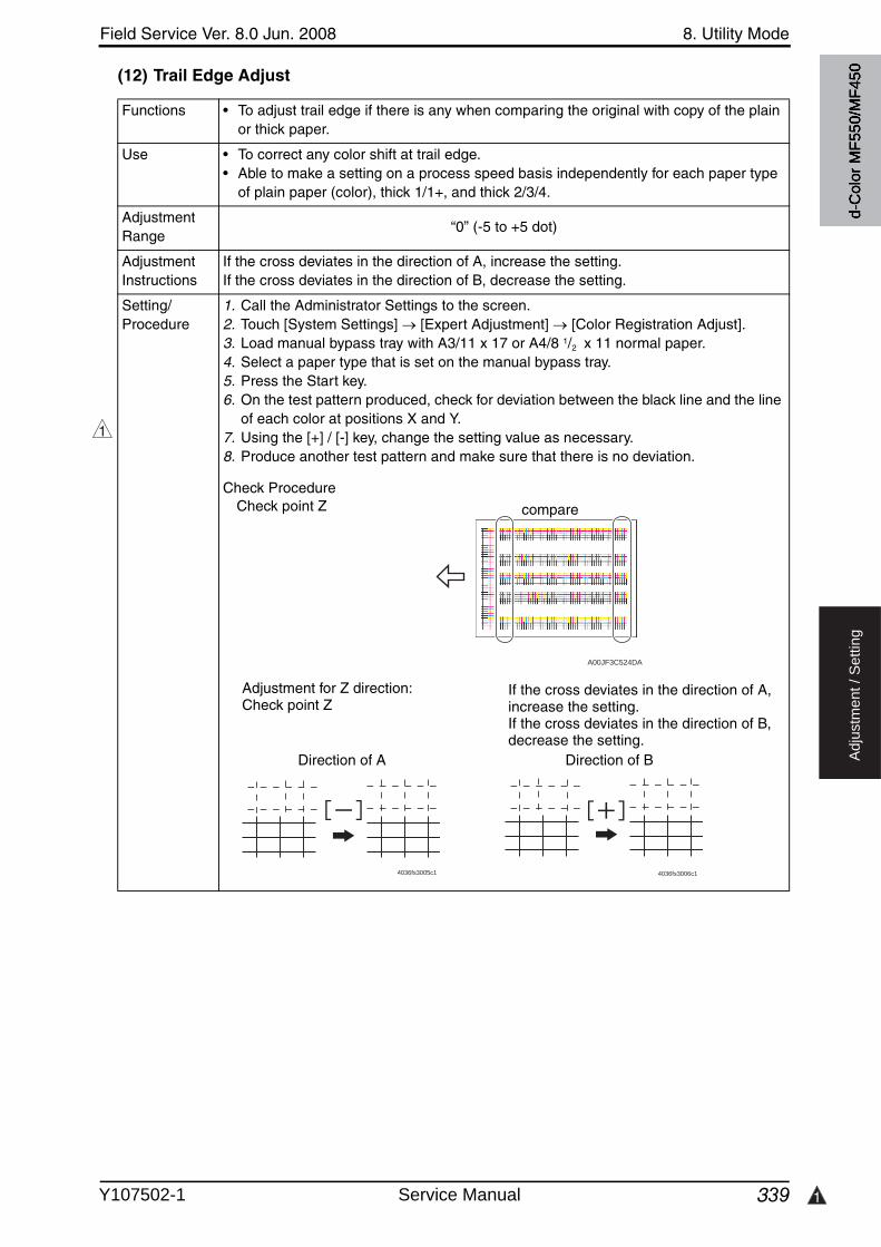
Field Service Ver. 8.0 Jun. 2008 8. Utility Mode
339 1
Ad
justm
en
t /
Se
ttin
g
(12) Trail Edge Adjust
Functions • To adjust trail edge if there is any when comparing the original with copy of the plain or thick paper.
Use • To correct any color shift at trail edge.• Able to make a setting on a process speed basis independently for each paper type
of plain paper (color), thick 1/1+, and thick 2/3/4.
Adjustment Range
“0” (-5 to +5 dot)
Adjustment Instructions
If the cross deviates in the direction of A, increase the setting.If the cross deviates in the direction of B, decrease the setting.
Setting/Procedure
1. Call the Administrator Settings to the screen.2. Touch [System Settings] [Expert Adjustment] [Color Registration Adjust].3. Load manual bypass tray with A3/11 x 17 or A4/8 1/2 x 11 normal paper.4. Select a paper type that is set on the manual bypass tray.5. Press the Start key.6. On the test pattern produced, check for deviation between the black line and the line
of each color at positions X and Y.7. Using the [+] / [-] key, change the setting value as necessary.8. Produce another test pattern and make sure that there is no deviation.
Check Procedure
1
4036fs3005c1 4036fs3006c1
If the cross deviates in the direction of A, increase the setting.If the cross deviates in the direction of B, decrease the setting.
Check point Z
Adjustment for Z direction: Check point Z
Direction of A Direction of B
A00JF3C524DA
compare
d-C
olor
MF5
50/M
F450
Y107502-1 Service Manual

8. Utility Mode Field Service Ver. 8.0 Jun. 2008
340
Ad
justm
en
t /
Se
ttin
g
H. List/Counter(1) Management List• It will not be displayed when the following setting shows that vendor is mounted.
[Service Mode] [Billing Setting] [Management Function Choice] (It will be displayed when the Key counter is mounted or when the following setting showsthat switch No.33 is set to [01] at HEX assignment.[Service Mode] [System 2] [Software Switch Setting])
<Job Settings List>
(2) Paper Size/Type Counter
(3) Meter Counter List• Setting will be available only when the following setting shows that either authentication
device, management device 2, vendor 2 is mounted. [Service Mode] [Billing Setting] [Management Function Choice]
(4) Check Consumables List• Setting will be available only when the following setting shows that either authentication
device, management device 2, vendor 2 is mounted. [Service Mode] [Billing Setting] [Management Function Choice]
Functions• To output the value set by the setting menu.
Use
Setting/Procedure
1. Touch [Job Settings List].2. Select the feed tray.3. Select simplex or duplex print, and touch the Start key.
Functions • To register the combination of the specific paper size and the paper type, and to set the count.Use
Setting/Procedure
1. Press a key out of 1 to 10 registration keys.2. Select the paper type.3. Touch the paper size key to select the paper size.
Functions • To output the meter counter list.
Use • To print out the list in this setting because counter list cannot be printed when the fol-lowing setting shows that vendor is mounted. [Meter Counter] [Details]
Setting/Procedure
1. Touch [Meter Counter List].2. Select the Feed tray.3. Select Simplex or Duplex print, and touch the Start key.
Functions • To output the consumable life list.
Use • To print out the list in this setting because the list cannot be printed when the follow-ing setting shows that Vendor is mounted. [Utility] [Check Consumable Life]
Setting/Procedure
1. Touch [Consumable Life List].2. Select the feed tray.3. Select Simplex or Duplex print, and touch the Start key.
d-C
olor
MF5
50/M
F450
Service Manual Y107502-1
Field Service Ver. 8.0 Jun. 2008 8. Utility Mode
341
Ad
justm
en
t /
Se
ttin
g
I. Reset Settings(1) System Auto Reset
(2) Auto Reset
(3) Job Reset<When Account is changed>• It will not be displayed when the following setting shows that authentication device is
mounted.[Service Mode] [Billing Setting] [Management Function Choice](It will be displayed when the key counter is mounted.)
<When Original is set on ADF>
Functions • To set the period of time until system auto reset starts functioning.
Use • To change the period of time until system auto reset starts functioning.
Setting/Procedure
<Priority Mode>• To set the functions displayed during system auto reset from Copy and Scan/Fax.
• The default setting is Copy.
“Copy” Scan/Fax
<System Auto Reset Time>• The default setting is 1 min.
“1 min.” (1 to 9, OFF)
Functions • To set the period of time until auto reset starts functioning in “Copy” and “Scan/Fax.”
Use • To change the period of time until auto reset starts functioning.
Setting/Procedure
• The default setting is 1 min.
“1 min.” (1 to 9, No)
Functions • Selects whether to reset (initialize) a machine when the key counter is unplugged, a magnetic card is pulled out, or user authentication/account track is set.
Use • To select not to reset to the default settings even when the accounts are changed through the use of a data management device.
Setting/Procedure
• The default setting is Reset.
“Reset” Do Not Reset
Functions • Select whether to reset the function when originals are placed on the ADF.
Use • Reset the function when originals are set on the ADF.
Setting/Procedure
• The default setting is Do Not Reset.
Reset “Do Not Reset”
d-C
olor
MF5
50/M
F450
Y107502-1 Service Manual

8. Utility Mode Field Service Ver. 8.0 Jun. 2008
342
Ad
justm
en
t /
Se
ttin
g
<Next Job: Staple Setting>
<Next Job: Original Set/Bind Direction>
<Next Job: Reset Data After Job>
J. User Box Settings(1) Delete Unused User Box
(2) Delete Secure Print Documents
(3) Auto Delete Secure Document
Functions • To set whether to cancel the staple setting when the staple setting job started and the next job setting has become available.Use
Setting/Procedure
• The default setting is OFF.
ON “OFF”
Functions • To set whether to cancel the original set/bind direction when the job (which original set/bind direction is set) started and the next job setting has become available.Use
Setting/Procedure
• The default setting is OFF.
ON “OFF”
Functions • To set whether to cancel the setting for scanning or transmitting fax when the scan-ning is finished or fax is transmitted, making the next job setting available. (The address will be cleared even when [OFF] is selected.)
Use
Setting/Procedure
• The default setting is ON.
“ON” OFF
Functions• To delete the unnecessary box without data.
Use
Setting/Procedure
1. Touch [Delete Unused User Box].2. Touch [Yes] on the Check screen.
Functions• To delete the whole classified documents in the box.
Use
Setting/Procedure
1. Touch [Delete Secure Documents].2. Touch [Yes] on the Check screen.
Functions • To set whether or not to delete the confidential documents in the box after a certain period of time. It also sets the period of time to store data.Use
Setting/Procedure
• The default setting is 1 Day.
12 Hours “1 Day” 2 Days 3 Days 7 Days 30 Days Save
d-C
olor
MF5
50/M
F450
Service Manual Y107502-1
3
Field Service Ver. 8.0 Jun. 2008 8. Utility Mode
343
Ad
justm
en
t /
Se
ttin
g
(4) Encrypted PDF Delete Time
(5) Touch & Print Delete Time
(6) Document Hold Setting
(7) External Memory Function Settings• This is displayed only when the function enhanced version 2 or later firmware is installed.• It will be displayed when the optional local inter face kit EK-602 or EK-603 is mounted.
Functions • Specifies whether to delete encrypted PDF data stored in the box after a lapse of a predetermined period of time.Sets the time period for which encrypted PDF data can be stored.
Use
Setting/Procedure
• The default setting is 1 Day.
12 Hours “1 Day” 2 Days 3 Days 7 Days 30 Days Save
Functions • Specifies whether to delete touch & print data stored in the box after a lapse of a pre-determined period of time.Sets the time period for which touch & print data can be stored
Use
Setting/Procedure
• The default setting is 1 Day.
12 Hours “1 Day” 2 Days 3 Days 7 Days 30 Days Save
Functions • Selects whether to store the document again in the box after it was retrieved from the box.
• If the function is set to No, the document is automatically deleted after it wasretrieved.
Use
Setting/Procedure
• The default setting is OFF.
ON “OFF”
3
Functions • This operation enables or disables functions using an external memory connected to this machine.
• Capability to enable [Save Document] and [Print Document] separately.
Save Document : a function that saves scanned documents into the external memory using [Save Document] in the box mode.
Print Document : a function that prints and sends documents saved in the external memory using [Use Document] in the box mode.
Use
Setting/Procedure
<Save Document>• The default setting is OFF.
ON “OFF”
<Print Document>• The default setting is ON.
“ON” OFF
d-C
olor
MF5
50/M
F450
Y107502-1 Service Manual
8. Utility Mode Field Service Ver. 8.0 Jun. 2008
344
Ad
justm
en
t /
Se
ttin
g
K. Standard Size Setting• It will be displayed only when the following setting is set to “Level 2.”
[Service Mode] [Enhanced Security] [Administrator Feature Level]
(1) Original Glass Original Size Detect
(2) Foolscap Size Setting
L. Stamp Settings(1) Header/Footer Settings
(2) Fax TX Settings
M. Blank Page Print Settings
Functions • To change the document size detection table.
Use • Use to change the setting for the document size detection table.
Setting/Procedure
• The default setting is Table1.
“Table1” Table2
Functions • To set the size for foolscap paper.
Use • Upon setup.• To change the size for foolscap paper.
Setting/Procedure
• Select the size from among the following five.
220 x 330 mm 81/2 x 13 81/4 x 13 81/8 x 131/4 “8 x 13”
Functions • Saves or deletes header/footer settings.• Able to obtain registered header/footer data by [Application] [Stamp/Composition]Use
Setting/Procedure
• Touch [New] to register new headers and footers.
Functions• Specifies whether to reset a stamp setting when fax is sent.
Use
Setting/Procedure
• The default setting is Cancel.
“Cancel” Do Not Cancel
Functions• Specifies whether to print a stamp/page number on blank pages.
Use
Setting/Procedure
• The default setting is Print.
“Print” Do Not Print
d-C
olor
MF5
50/M
F450
Service Manual Y107502-1
4
Field Service Ver. 8.0 Jun. 2008 8. Utility Mode
345
Ad
justm
en
t /
Se
ttin
g
N. Application Key Settings• This is displayed only when the function enhanced version 3 or later firmware is installed.• This is displayed only when the optional i-Option (LK-101 or LK-103) is activated.
8.6.2 Administrator/Machine Settings
A. Administrator Registration
B. Input Machine Address
8.6.3 One-Touch/User Box Registration
A. Create One-Touch Destination(1) Address Book<E-mail>
4
Functions • To assign the additional functions provided by i-Option to the application keys.
Use • This settings allow free application key assignment to additional functions providedby i-Option as well as to “User Box”, “Fax/Scan” and “Copy” to which the application keys were conventionally assigned. (However, Key 0 is assigned to the function of displaying the application menu so that other functions cannot be assigned to Key 0.)
• The functions that can be assigned are as follows:Copy, Fax/Scan, User Box, Image Panel, Web Browser, My Panel
Setting/Procedure
1. Select [Key 1] or [Key 2].2. Select a function to which the key is assigned, and touch [OK].
Functions • Registers administrator information displayed Help service/Administrator information screen as well as sender addresses used for E-mail transmission from the machine.Use
Setting/Procedure
1. Touch [Administrator Name], [E-mail Address] to input them.2. Using the 10-key pad, enter the extension No.
Functions • To register the name of the machine and e-mail address.
Use Machine Name : When the file name of the transmitted file or the document name of document registered in Box is generated automatically, it is added.
E-mail : To be used as from address at internal Fax transmission.
Setting/Procedure
1. Touch [Device Name] and input the name.2. Touch [E-mail Address] and input the E-mail address.
Functions• To register/change the e-mail address for transmitting the scanned data by e-mail.
Use
Setting/Procedure
• Touch [New] to register the new address.• Select any displayed address to check, edit, or delete the setting.
d-C
olor
MF5
50/M
F450
Y107502-1 Service Manual

8. Utility Mode Field Service Ver. 8.0 Jun. 2008
3463
Ad
justm
en
t /
Se
ttin
g
<User Box>• It will not be displayed when the following setting shows that authentication device or the
vendor is mounted.[Service Mode] [Billing Setting] [Management Function Choice](It will be displayed when the key counter is mounted.)
<Fax>
<PC (SMB)>
<FTP>
<WebDAV>• This is displayed only when the function enhanced version 2 or later firmware is installed.
<IP Address Fax>• Setting will be available only when [IP Address FAX] is set to “ON” in the following set-
tings.[Administrator Settings] [Network Settings] [Network Fax Settings] [Network Fax Function Settings]
Functions • To register or change the box address for storing the scanned data to the box in the hard disk of the machine.Use
Setting/Procedure
• Touch [New] to register the new address.• Select any displayed address to check, edit, or delete the setting.• At least one user box must be registered in order to register the box address.
Functions• To register or change the fax number for transmitting the fax.
Use
Setting/Procedure
• Touch [New] to register the new address.• Select any displayed address to check, edit, or delete the setting.
Functions• To register or change the SMB address for transmitting the scanned data by SMB.
Use
Setting/Procedure
• Touch [New] to register the new address.• Select any displayed address to check, edit, or delete the setting.
Functions• To register and change the FTP address for transmitting the scanned data by FTP.
Use
Setting/Procedure
• Touch [New] to register the new address.• Select any displayed address to check, edit, or delete the setting.
3
Functions • To register and change the WebDAV address for transmitting the scanned data by FTP.Use
Setting/Procedure
• Touch [New] to register the new address.• Select any displayed address to check, edit, or delete the setting.
Functions • To register/change the IP address fax destination when transmitting the IP address fax data.Use
Setting/Procedure
• A new address can be registered by touching [New].• Select any displayed address to check, change or delete the setting.
d-C
olor
MF5
50/M
F450
Service Manual Y107502-1

Field Service Ver. 8.0 Jun. 2008 8. Utility Mode
347
Ad
justm
en
t /
Se
ttin
g
<Internet Fax>• Setting will be available only when [Internet FAX] is set to “ON” in the following settings.
[Administrator Settings] [Network Settings] [Network Fax Settings] [Network Fax Function Settings]
(2) Group
(3) E-mail Settings• It will not be displayed when the management device 2 is set to “Set” by the following set-
ting.[Service Mode] [Billing Setting] [Management Function Choice]
<E-mail Subject>
<E-mail Body>
Functions• To register/change the Internet fax address when transmitting the internet fax data.
Use
Setting/Procedure
• A new address can be registered by touching [New].• Select any displayed address to check, change or delete the setting.
Functions • To register or change the group with a number of addresses to transmit data simulta-neously.Use
Setting/Procedure
• Touch [New] to register the new group.• elect any displayed group to check, edit, or delete the setting.• At least one address must be registered in order to register the group.
Functions• To register the e-mail subject for transmitting the scanned data by e-mail.
Use
Setting/Procedure
• Touch [New] to register the new subject.• Select any displayed subject to detail check, edit, or delete the setting.• The subject can be set as default by selecting the subject displayed on the screen
and pressing [Set as Default].
Functions• To register the e-mail message for transmitting the scanned data by e-mail.
Use
Setting/Procedure
• Touch [New] to register the new message.• Select any displayed message to detail check or delete the setting.• The text can be set as default by selecting the text displayed on the screen and
pressing [Set as Default].d-
Col
or M
F550
/MF4
50
Y107502-1 Service Manual

8. Utility Mode Field Service Ver. 8.0 Jun. 2008
348
Ad
justm
en
t /
Se
ttin
g
B. Create User Box• It will not be displayed when the following setting shows that authentication device 1 is
mounted. [Service Mode] [Billing Setting] [Management Function Choice]
• It will not be displayed when the following setting shows that vendor is mounted.[Service Mode] [Billing Setting] [Management Function Choice](It will be displayed when the key counter is mounted.)
(1) Public/Personal User Box
(2) Bulletin Board User Box
(3) Relay User Box• It will be displayed when the following setting is set to “ON.”
[Service Mode] [FAX] [System] [Display Setting] [Relay]
(4) Annotation User Box
Functions • To register or change the box for storing the text data in the hard disk of the machine.
Use • To register the shared or personal box for any purpose.
Setting/Procedure
• Touch [New] to register the new box.• Select any displayed box to edit or delete it.
Functions• To register or change the bulletin board user box.
Use
Setting/Procedure
• Touch [New] to register the new box.• Select any displayed box to edit or delete it.
Functions• To register/change the Relay User Box.
Use
Setting/Procedure
• A new box can be registered by touching [New].• Select any displayed box to change or delete it.
Functions • To register or change the annotation user box.
Use • To attach the image of the date, time, and/or filing number to the document data stored in the scanner mode, and to distribute them.
Setting/Procedure
• Touch [New] key to register the new box.• Select any displayed box to change or delete it.
d-C
olor
MF5
50/M
F450
Service Manual Y107502-1
Field Service Ver. 8.0 Jun. 2008 8. Utility Mode
349
Ad
justm
en
t /
Se
ttin
g
C. One-Touch/User Box Registration List• It will not be displayed when the following setting shows that vendor is mounted.
[Service Mode] [Billing Setting] [Management Function Choice] (It will be displayed when the Key counter is mounted or when the following setting showsthat switch No.33 is set to [01] at HEX assignment.[Service Mode] [System 2] [Software Switch Setting])
(1) Address Book List
(2) Group List
(3) Program List
(4) E-mail Subject/Text List
Functions • To output the address book list.
Use • To print the list of abbreviated addresses which are registered.
Setting/Procedure
1. Select the destination type to be output.2. Touch [Starting destination No.] and enter the number from which output starts.3. Touch [No. of Destinations] and specify the number of destinations to be output.4. Touch [Print], and select the paper feed tray.5. Select the simplex or duplex print, and press the Start key to output the list of abbre-
viated addresses.
Functions • To output the group list.
Use • To print out the list of addresses of the group which are registered.
Setting/Procedure
1. Touch [Starting destination No.] and enter the number from which output starts.2. Touch [No. of Destinations] and specify the number of destinations to be output.3. Touch [Print], and select the paper feed tray.4. Select the simplex or duplex print, and press the Start key to output the list of abbre-
viated addresses.
Functions • To output the program list.
Use • To print out the list of the program addresses which are registered.
Setting/Procedure
1. Select the destination type to be output.2. Touch [Starting destination No.] and enter the number from which output starts.3. Touch [No. of Destinations] and specify the number of destinations to be output.4. Touch [Print], and select the paper feed tray.5. Select the simplex or duplex print, and press the Start key to output the list of abbre-
viated addresses.
Functions • To output the subject or the text list.
Use • To print out the e-mail subject/text List which are registered.
Setting/Procedure
1. Select the paper feed tray.2. Select the simplex or duplex print, and press the Start key to output the list of abbre-
viated addresses.
d-C
olor
MF5
50/M
F450
Y107502-1 Service Manual
8. Utility Mode Field Service Ver. 8.0 Jun. 2008
3502
Ad
justm
en
t /
Se
ttin
g
D. Maximum Number of User Boxes
8.6.4 User Authentication/Account Track
• It will not be displayed when the following setting shows that key counter or vendor is mounted.[Service Mode] [Billing Setting] [Management Function Choice]
A. General Settings(1) User Authentication
(2) Public User Access
Functions• Set the maximum of public, personal, and group boxes that individual users can hold.
Use
Setting/Procedure
1. Select a user box type and name.2. If a maximum number of user boxes is not specified, set Max. No. of Use Boxes to
[OFF].3. If a maximum number of user boxes is not specified, set Max. No. of Use Boxes to
[OFF].
2
Functions • To set the user authentication method.
Use • To select whether to authenticate the user by the external server or MFP.
Setting/Procedure
• The default setting is OFF.
“OFF” ON (External Server) ON (MFP)
NOTE• [OFF] cannot be selected when the following setting is set to “ON.”
[Administrator Settings] [Security Setting] [Enhanced Security Mode]• [ON (External Server)] cannot be selected when external servers are not regis-
tered in the following setting. [Administrator Settings] [User Authentication/Account Track] [External Server Settings]
• Neither [ON (External Server)] or [ON (MFP)] can be selected when the pres-ence of management device is set in the following setting. [Service Mode] [Billing Setting] [Management Function Choice]
Functions • To set whether to allow or prohibit the nonregistered user to use the system whenUser authentication has been set.
• Able to use the machine without authentication by logging in as a public user when [ON (Without Login)] is selected.
Use
Setting/Procedure
• The default setting is Restrict.
“Restrict” Allow ON (Without Login)
NOTE• This setting is not available without user authentication.• [Allow] cannot be selected when the following setting is set to “ON.”
[Administrator Settings] [Security Setting] [Enhanced Security Mode]• [Allow] cannot be selected when [Synchronize User Authentication & Account
Track] is set to “Do Not Synchronize.”
d-C
olor
MF5
50/M
F450
Service Manual Y107502-1
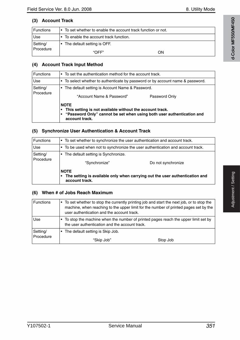
Field Service Ver. 8.0 Jun. 2008 8. Utility Mode
351
Ad
justm
en
t /
Se
ttin
g
(3) Account Track
(4) Account Track Input Method
(5) Synchronize User Authentication & Account Track
(6) When # of Jobs Reach Maximum
Functions • To set whether to enable the account track function or not.
Use • To enable the account track function.
Setting/Procedure
• The default setting is OFF.
“OFF” ON
Functions • To set the authentication method for the account track.
Use • To select whether to authenticate by password or by account name & password.
Setting/Procedure
• The default setting is Account Name & Password.
“Account Name & Password” Password Only
NOTE• This setting is not available without the account track.• “Password Only” cannot be set when using both user authentication and
account track.
Functions • To set whether to synchronize the user authentication and account track.
Use • To be used when not to synchronize the user authentication and account track.
Setting/Procedure
• The default setting is Synchronize.
“Synchronize” Do not synchronize
NOTE• The setting is available only when carrying out the user authentication and
account track.
Functions • To set whether to stop the currently printing job and start the next job, or to stop the machine, when reaching to the upper limit for the number of printed pages set by the user authentication and the account track.
Use • To stop the machine when the number of printed pages reach the upper limit set by the user authentication and the account track.
Setting/Procedure
• The default setting is Skip Job.
“Skip Job” Stop Job
d-C
olor
MF5
50/M
F450
Y107502-1 Service Manual

8. Utility Mode Field Service Ver. 8.0 Jun. 2008
3523
Ad
justm
en
t /
Se
ttin
g
(7) Number of User Counters Assigned• It will not be displayed when the following setting shows that management device 2 is
mounted.[Service Mode] [Billing Setting] [Management Function Choice]
(8) Ticket Hold Time Setting• This is displayed only when the function enhanced version 2 or later firmware is installed.
(9) Scanner Settings• It will be displayed only when the optional image controller IC-409 is mounted and user
authentication or account track has been set.
Functions • To set the number available to be assigned for the user registration and account reg-istration.
Use • To change the number available to be assigned for the user registration and account registration.
Setting/Procedure
• The default setting is 500.• The total number to be registered for the user authentication and account track is
1000. The number for the user registration will be set.When setting the [# of Counters Assigned for Users] to 50, the number available for Account Track will be 950.
NOTE• The setting is available only when carrying out the user authentication and
account track.
3
Functions • Specify the desired length of holding time of Kerberos authentication ticket.
NOTE• This setting takes effect only when the authentication server type is set to
active directory.
Use
Setting/Procedure
• The default settings is 60 min.
1 to 60 min.
Functions • To select whether to use TWAIN scan function available in Fiery Remote Scan whenuser authentication or account track is set to on.
Use • When user authentication or account track is set to on, select the use of TWAIN scan function available in Fiery Remote Scan software that is supplied with the image con-troller.
Setting/Procedure
• The default settings are Restrict.
Allow “Restrict”
d-C
olor
MF5
50/M
F450
Service Manual Y107502-1
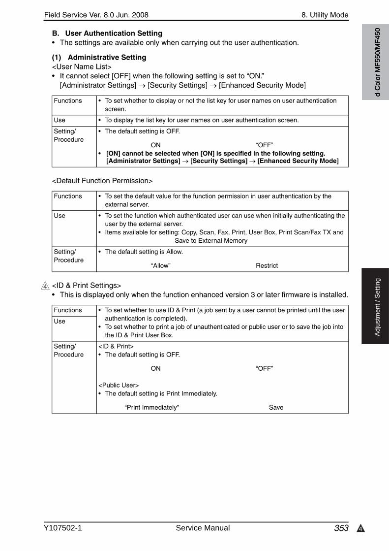
4
Field Service Ver. 8.0 Jun. 2008 8. Utility Mode
353
Ad
justm
en
t /
Se
ttin
g
B. User Authentication Setting• The settings are available only when carrying out the user authentication.
(1) Administrative Setting<User Name List>• It cannot select [OFF] when the following setting is set to “ON.”
[Administrator Settings] [Security Settings] [Enhanced Security Mode]
<Default Function Permission>
<ID & Print Settings>• This is displayed only when the function enhanced version 3 or later firmware is installed.
Functions • To set whether to display or not the list key for user names on user authentication screen.
Use • To display the list key for user names on user authentication screen.
Setting/Procedure
• The default setting is OFF.
ON “OFF”• [ON] cannot be selected when [ON] is specified in the following setting.
[Administrator Settings] [Security Settings] [Enhanced Security Mode]
Functions • To set the default value for the function permission in user authentication by the external server.
Use • To set the function which authenticated user can use when initially authenticating the user by the external server.
• Items available for setting: Copy, Scan, Fax, Print, User Box, Print Scan/Fax TX and Save to External Memory
Setting/Procedure
• The default setting is Allow.
“Allow” Restrict
4
Functions • To set whether to use ID & Print (a job sent by a user cannot be printed until the userauthentication is completed).
• To set whether to print a job of unauthenticated or public user or to save the job into the ID & Print User Box.
Use
Setting/Procedure
<ID & Print>• The default setting is OFF.
ON “OFF”
<Public User>• The default setting is Print Immediately.
“Print Immediately” Save
d-C
olor
MF5
50/M
F450
Y107502-1 Service Manual
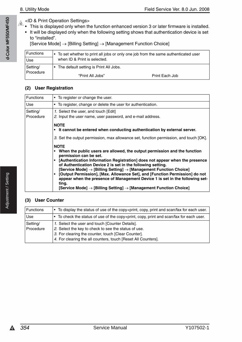
8. Utility Mode Field Service Ver. 8.0 Jun. 2008
3544
Ad
justm
en
t /
Se
ttin
g
<ID & Print Operation Settings>• This is displayed only when the function enhanced version 3 or later firmware is installed.• It will be displayed only when the following setting shows that authentication device is set
to “installed”.[Service Mode] [Billing Setting] [Management Function Choice]
(2) User Registration
(3) User Counter
4
Functions • To set whether to print all jobs or only one job from the same authenticated userwhen ID & Print is selected.Use
Setting/Procedure
• The default setting is Print All Jobs.
“Print All Jobs” Print Each Job
Functions • To register or change the user.
Use • To register, change or delete the user for authentication.
Setting/Procedure
1. Select the user, and touch [Edit]2. Input the user name, user password, and e-mail address.
NOTE• It cannot be entered when conducting authentication by external server.
3. Set the output permission, max allowance set, function permission, and touch [OK].
NOTE• When the public users are allowed, the output permission and the function
permission can be set.• [Authentication Information Registration] does not appear when the presence
of Authentication Device 2 is set in the following setting. [Service Mode] [Billing Setting] [Management Function Choice]
• [Output Permission], [Max. Allowance Set], and [Function Permission] do not appear when the presence of Management Device 1 is set in the following set-ting. [Service Mode] [Billing Setting] [Management Function Choice]
Functions • To display the status of use of the copy+print, copy, print and scan/fax for each user.
Use • To check the status of use of the copy+print, copy, print and scan/fax for each user.
Setting/Procedure
1. Select the user and touch [Counter Details].2. Select the key to check to see the status of use.3. For clearing the counter, touch [Clear Counter].4. For clearing the all counters, touch [Reset All Counters].
d-C
olor
MF5
50/M
F450
Service Manual Y107502-1
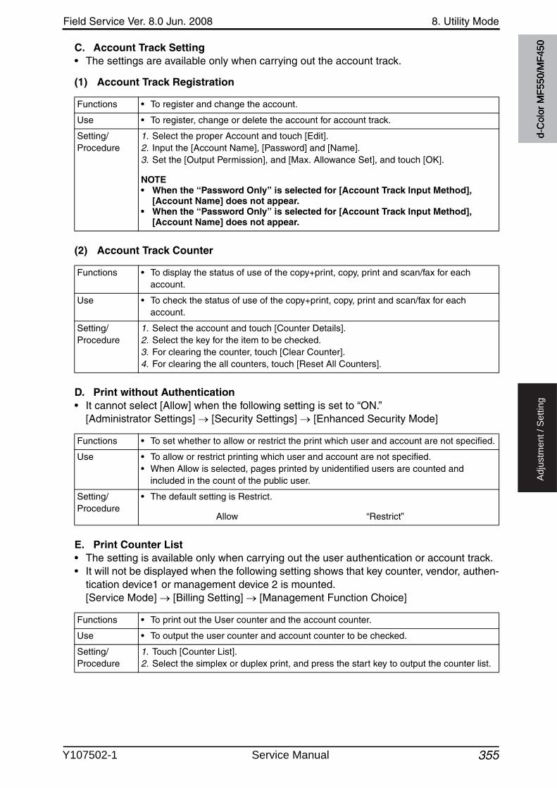
Field Service Ver. 8.0 Jun. 2008 8. Utility Mode
355
Ad
justm
en
t /
Se
ttin
g
C. Account Track Setting• The settings are available only when carrying out the account track.
(1) Account Track Registration
(2) Account Track Counter
D. Print without Authentication• It cannot select [Allow] when the following setting is set to “ON.”
[Administrator Settings] [Security Settings] [Enhanced Security Mode]
E. Print Counter List• The setting is available only when carrying out the user authentication or account track.• It will not be displayed when the following setting shows that key counter, vendor, authen-
tication device1 or management device 2 is mounted.[Service Mode] [Billing Setting] [Management Function Choice]
Functions • To register and change the account.
Use • To register, change or delete the account for account track.
Setting/Procedure
1. Select the proper Account and touch [Edit].2. Input the [Account Name], [Password] and [Name].3. Set the [Output Permission], and [Max. Allowance Set], and touch [OK].
NOTE• When the “Password Only” is selected for [Account Track Input Method],
[Account Name] does not appear.• When the “Password Only” is selected for [Account Track Input Method],
[Account Name] does not appear.
Functions • To display the status of use of the copy+print, copy, print and scan/fax for each account.
Use • To check the status of use of the copy+print, copy, print and scan/fax for each account.
Setting/Procedure
1. Select the account and touch [Counter Details].2. Select the key for the item to be checked.3. For clearing the counter, touch [Clear Counter].4. For clearing the all counters, touch [Reset All Counters].
Functions • To set whether to allow or restrict the print which user and account are not specified.
Use • To allow or restrict printing which user and account are not specified.• When Allow is selected, pages printed by unidentified users are counted and
included in the count of the public user.
Setting/Procedure
• The default setting is Restrict.
Allow “Restrict”
Functions • To print out the User counter and the account counter.
Use • To output the user counter and account counter to be checked.
Setting/Procedure
1. Touch [Counter List].2. Select the simplex or duplex print, and press the start key to output the counter list.
d-C
olor
MF5
50/M
F450
Y107502-1 Service Manual
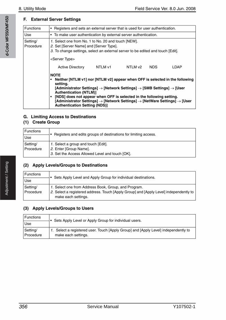
8. Utility Mode Field Service Ver. 8.0 Jun. 2008
356
Ad
justm
en
t /
Se
ttin
g
F. External Server Settings
G. Limiting Access to Destinations(1) Create Group
(2) Apply Levels/Groups to Destinations
(3) Apply Levels/Groups to Users
Functions • Registers and sets an external server that is used for user authentication.
Use • To make user authentication by external server authentication.
Setting/Procedure
1. Select one from No. 1 to No. 20 and touch [NEW].2. Set [Server Name] and [Server Type].3. To change settings, select an external server to be edited and touch [Edit].
<Server Type>
Active Directory NTLM v1 NTLM v2 NDS LDAP
NOTE• Neither [NTLM v1] nor [NTLM v2] appear when OFF is selected in the following
setting. [Administrator Settings] [Network Settings] [SMB Settings] [User Authentication (NTLM)]
• [NDS] does not appear when OFF is selected in the following setting. [Administrator Settings] [Network Settings] [NetWare Settings] [User Authentication Setting (NDS)]
Functions• Registers and edits groups of destinations for limiting access.
Use
Setting/Procedure
1. Select a group and touch [Edit].2. Enter [Group Name].3. Set the Access Allowed Level and touch [OK].
Functions• Sets Apply Level and Apply Group for individual destinations.
Use
Setting/Procedure
1. Select one from Address Book, Group, and Program.2. Select a registered address. Touch [Apply Group] and [Apply Level] independently to
make each settings.
Functions• Sets Apply Level or Apply Group for individual users.
Use
Setting/Procedure
1. Select a registered user. Touch [Apply Group] and [Apply Level] independently to make each settings.
d-C
olor
MF5
50/M
F450
Service Manual Y107502-1
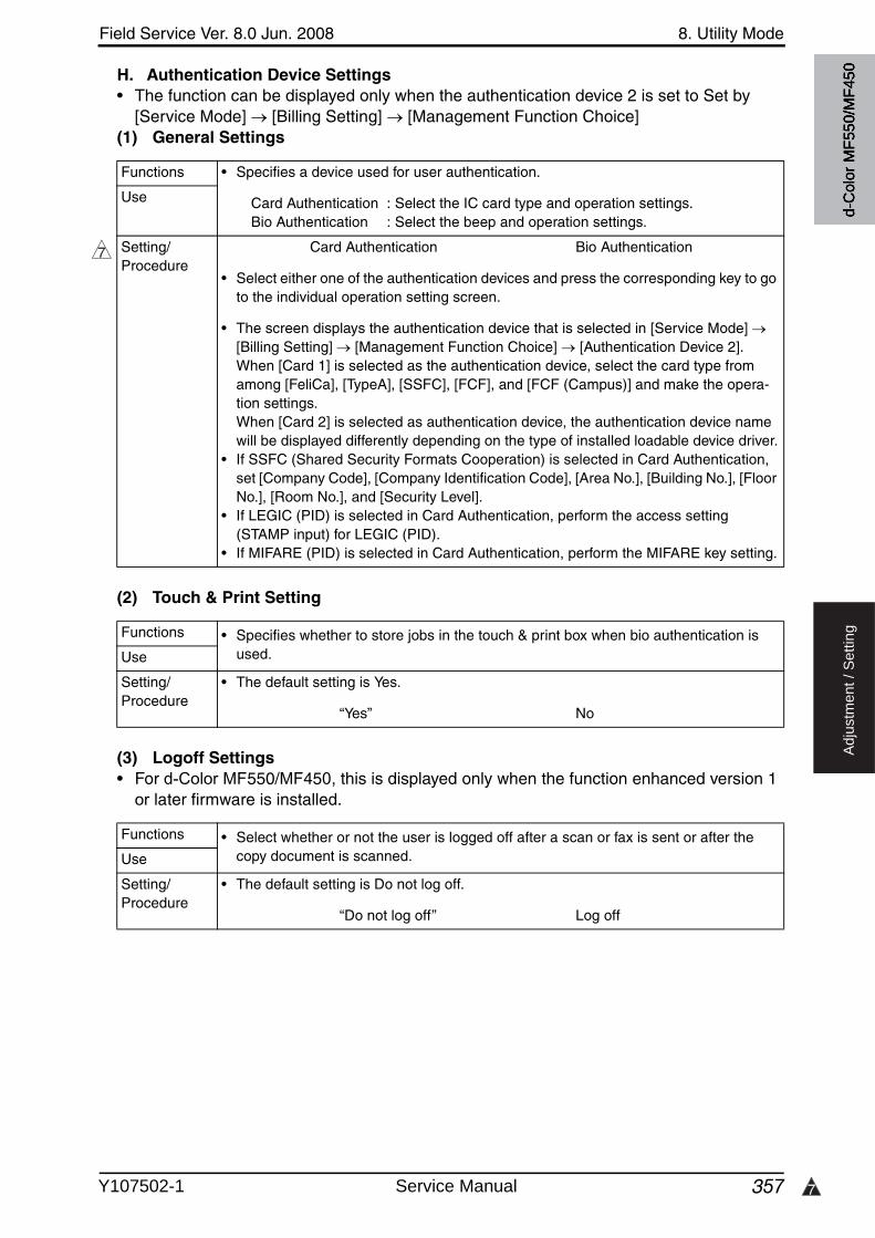
7
Field Service Ver. 8.0 Jun. 2008 8. Utility Mode
357
Ad
justm
en
t /
Se
ttin
g
H. Authentication Device Settings• The function can be displayed only when the authentication device 2 is set to Set by
[Service Mode] [Billing Setting] [Management Function Choice] (1) General Settings
(2) Touch & Print Setting
(3) Logoff Settings• For d-Color MF550/MF450, this is displayed only when the function enhanced version 1
or later firmware is installed.
Functions • Specifies a device used for user authentication.
Card Authentication : Select the IC card type and operation settings.Bio Authentication : Select the beep and operation settings.
Use
Setting/Procedure
Card Authentication Bio Authentication
• Select either one of the authentication devices and press the corresponding key to go to the individual operation setting screen.
• The screen displays the authentication device that is selected in [Service Mode] [Billing Setting] [Management Function Choice] [Authentication Device 2].When [Card 1] is selected as the authentication device, select the card type from among [FeliCa], [TypeA], [SSFC], [FCF], and [FCF (Campus)] and make the opera-tion settings.When [Card 2] is selected as authentication device, the authentication device name will be displayed differently depending on the type of installed loadable device driver.
• If SSFC (Shared Security Formats Cooperation) is selected in Card Authentication, set [Company Code], [Company Identification Code], [Area No.], [Building No.], [Floor No.], [Room No.], and [Security Level].
• If LEGIC (PID) is selected in Card Authentication, perform the access setting (STAMP input) for LEGIC (PID).
• If MIFARE (PID) is selected in Card Authentication, perform the MIFARE key setting.
7
Functions • Specifies whether to store jobs in the touch & print box when bio authentication is used.Use
Setting/Procedure
• The default setting is Yes.
“Yes” No
Functions • Select whether or not the user is logged off after a scan or fax is sent or after the copy document is scanned.Use
Setting/Procedure
• The default setting is Do not log off.
“Do not log off” Log off
d-C
olor
MF5
50/M
F450
Y107502-1 Service Manual
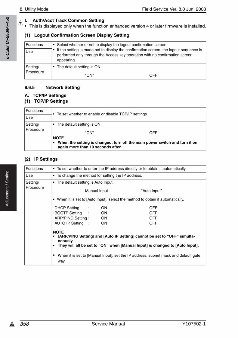
8. Utility Mode Field Service Ver. 8.0 Jun. 2008
3587
Ad
justm
en
t /
Se
ttin
g
I. Auth/Acct Track Common Setting• This is displayed only when the function enhanced version 4 or later firmware is installed.
(1) Logout Confirmation Screen Display Setting
8.6.5 Network Setting
A. TCP/IP Settings(1) TCP/IP Settings
(2) IP Settings
7
Functions • Select whether or not to display the logout confirmation screen.• If the setting is made not to display the confirmation screen, the logout sequence is
performed only through the Access key operation with no confirmation screen appearing.
Use
Setting/Procedure
• The default setting is ON.
“ON” OFF
Functions• To set whether to enable or disable TCP/IP settings.
Use
Setting/Procedure
• The default setting is ON.
“ON” OFFNOTE• When the setting is changed, turn off the main power switch and turn it on
again more than 10 seconds after.
Functions • To set whether to enter the IP address directly or to obtain it automatically.
Use • To change the method for setting the IP address.
Setting/Procedure
• The default setting is Auto Input.
Manual Input “Auto Input”
• When it is set to [Auto Input], select the method to obtain it automatically.
DHCP Setting : ON OFFBOOTP Setting : ON OFFARP/PING Setting : ON OFFAUTO IP Setting : ON OFF
NOTE• [ARP/PING Setting] and [Auto IP Setting] cannot be set to “OFF” simulta-
neously.• They will all be set to “ON” when [Manual Input] is changed to [Auto Input].
• When it is set to [Manual Input], set the IP address, subnet mask and default gate way.
d-C
olor
MF5
50/M
F450
Service Manual Y107502-1

Field Service Ver. 8.0 Jun. 2008 8. Utility Mode
359
Ad
justm
en
t /
Se
ttin
g
(3) DNS Host
(4) DNS Domain
(5) DNS Server Settings
Functions • To set the DNS host name.• To set whether or not to enable the dynamic DNS setting.
Use • To enter the DNS host name.• To set the dynamic DNS.
Setting/Procedure
<DNS Host Name>1. Touch [DNS Host Name].2. Enter the DNS host name on the screen key board, and touch [OK].
<Dynamic DNS Settings>• The default setting is No Limit.
Enable “No Limit”
Functions • To set whether or not to enable the auto obtaining for the DNS domain name.• To set the DNS default domain name.• To set the DNS search domain name.
Use • To enter the DNS default domain name.• To enter the DNS search domain name.
Setting/Procedure
<DNS Domain Name Auto Retrieval>• The default setting is Enable.
“Enable” No Limit
NOTE• “Enable” cannot be set when [IP Settings] is set to “Auto Input.”
<Domain Name>1. Touch [Default DNS Domain Name] or [DNS Search Domain Name 1 to 3].2. Enter the domain name using the keyboard on the screen and touch [OK].
Functions • To set whether or not to enable the auto obtaining of the DNS server address.• To set the priority/substitute DNS server.
Use • To enter priority/substitute DNS server.
Setting/Procedure
<DNS Server Auto Obtain>• The default setting is Enable.
“Enable” No Limit
NOTE• “Enable” cannot be set when [IP Settings] is set to “Auto Input.”
<Priority/substitute DNS server.>• Touch the corresponding key, and input the server address by IPv4 or the IPv6 for-
mat.
d-C
olor
MF5
50/M
F450
Y107502-1 Service Manual
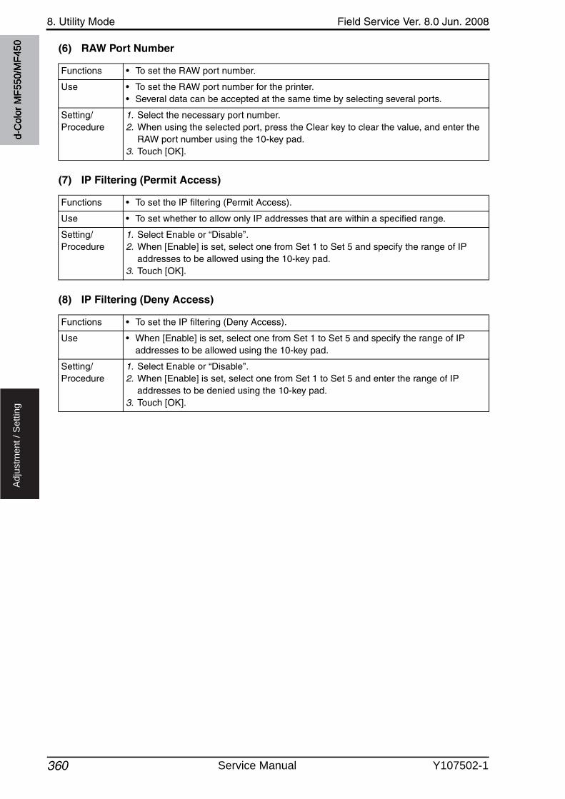
8. Utility Mode Field Service Ver. 8.0 Jun. 2008
360
Ad
justm
en
t /
Se
ttin
g
(6) RAW Port Number
(7) IP Filtering (Permit Access)
(8) IP Filtering (Deny Access)
Functions • To set the RAW port number.
Use • To set the RAW port number for the printer.• Several data can be accepted at the same time by selecting several ports.
Setting/Procedure
1. Select the necessary port number.2. When using the selected port, press the Clear key to clear the value, and enter the
RAW port number using the 10-key pad.3. Touch [OK].
Functions • To set the IP filtering (Permit Access).
Use • To set whether to allow only IP addresses that are within a specified range.
Setting/Procedure
1. Select Enable or “Disable”.2. When [Enable] is set, select one from Set 1 to Set 5 and specify the range of IP
addresses to be allowed using the 10-key pad.3. Touch [OK].
Functions • To set the IP filtering (Deny Access).
Use • When [Enable] is set, select one from Set 1 to Set 5 and specify the range of IP addresses to be allowed using the 10-key pad.
Setting/Procedure
1. Select Enable or “Disable”.2. When [Enable] is set, select one from Set 1 to Set 5 and enter the range of IP
addresses to be denied using the 10-key pad.3. Touch [OK].
d-C
olor
MF5
50/M
F450
Service Manual Y107502-1

Field Service Ver. 8.0 Jun. 2008 8. Utility Mode
361
Ad
justm
en
t /
Se
ttin
g
(9) IPv6 Settings
(10) IPsec Settings
Functions • To set whether to use IPv6 in IP network communication.• To set whether to use the IPv6 address automatic acquisition setting.• To set IPv6 addresses.
Use • To use IPv6 in IP network communication.
Setting/Procedure
<IPv6 Settings>• The default setting is ON.
“ON” OFF
<Auto IPv6 Settings>• The default setting is ON.
“ON” OFF
NOTE• When the setting is changed, turn off the main power switch and turn it on
again more than 10 seconds after.
<IPv6 address>• When [Auto IPv6 Settings] is set to OFF, make the settings of global address and
gateway address.1. Touch [Global Address] or [Gateway Address].2. Enter the address with the keys on the screen.3. To change the prefix length of global address, touch [Prefix Length] and specify the
number of bits within the range of 1 to 128.
NOTE• [Link-Local Address] key appears, but its settings are not allowed to be
changed.
Functions • To set whether to use IPsec protocol for IP network communication.
Use • When IPsec protocol is used to perform encrypted communication.
Setting/Procedure
• The default setting is OFF.
ON “OFF”
d-C
olor
MF5
50/M
F450
Y107502-1 Service Manual
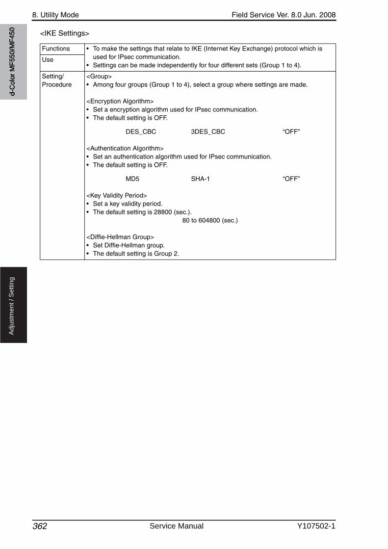
8. Utility Mode Field Service Ver. 8.0 Jun. 2008
362
Ad
justm
en
t /
Se
ttin
g
<IKE Settings>
Functions • To make the settings that relate to IKE (Internet Key Exchange) protocol which is used for IPsec communication.
• Settings can be made independently for four different sets (Group 1 to 4).Use
Setting/Procedure
<Group>• Among four groups (Group 1 to 4), select a group where settings are made.
<Encryption Algorithm>• Set a encryption algorithm used for IPsec communication.• The default setting is OFF.
DES_CBC 3DES_CBC “OFF”
<Authentication Algorithm>• Set an authentication algorithm used for IPsec communication.• The default setting is OFF.
MD5 SHA-1 “OFF”
<Key Validity Period>• Set a key validity period.• The default setting is 28800 (sec.).
80 to 604800 (sec.)
<Diffie-Hellman Group>• Set Diffie-Hellman group.• The default setting is Group 2.
d-C
olor
MF5
50/M
F450
Service Manual Y107502-1
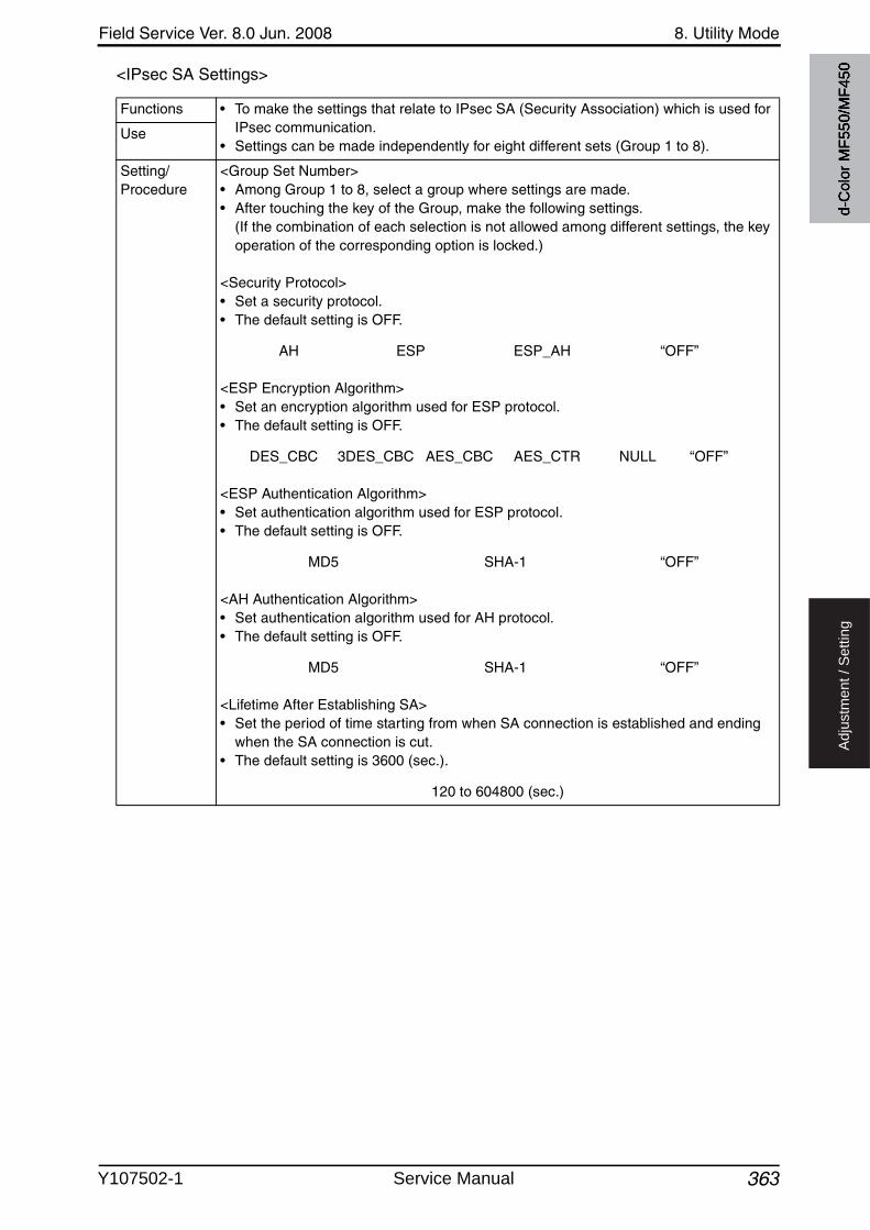
Field Service Ver. 8.0 Jun. 2008 8. Utility Mode
363
Ad
justm
en
t /
Se
ttin
g
<IPsec SA Settings>
Functions • To make the settings that relate to IPsec SA (Security Association) which is used for IPsec communication.
• Settings can be made independently for eight different sets (Group 1 to 8).Use
Setting/Procedure
<Group Set Number>• Among Group 1 to 8, select a group where settings are made.• After touching the key of the Group, make the following settings.
(If the combination of each selection is not allowed among different settings, the key operation of the corresponding option is locked.)
<Security Protocol>• Set a security protocol.• The default setting is OFF.
AH ESP ESP_AH “OFF”
<ESP Encryption Algorithm>• Set an encryption algorithm used for ESP protocol.• The default setting is OFF.
DES_CBC 3DES_CBC AES_CBC AES_CTR NULL “OFF”
<ESP Authentication Algorithm>• Set authentication algorithm used for ESP protocol.• The default setting is OFF.
MD5 SHA-1 “OFF”
<AH Authentication Algorithm>• Set authentication algorithm used for AH protocol.• The default setting is OFF.
MD5 SHA-1 “OFF”
<Lifetime After Establishing SA>• Set the period of time starting from when SA connection is established and ending
when the SA connection is cut.• The default setting is 3600 (sec.).
120 to 604800 (sec.)
d-C
olor
MF5
50/M
F450
Y107502-1 Service Manual
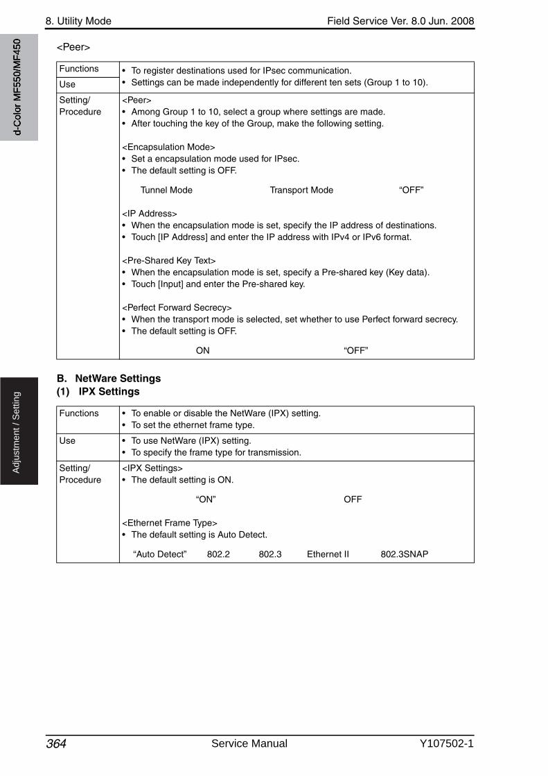
8. Utility Mode Field Service Ver. 8.0 Jun. 2008
364
Ad
justm
en
t /
Se
ttin
g
<Peer>
B. NetWare Settings(1) IPX Settings
Functions • To register destinations used for IPsec communication.• Settings can be made independently for different ten sets (Group 1 to 10).Use
Setting/Procedure
<Peer>• Among Group 1 to 10, select a group where settings are made.• After touching the key of the Group, make the following setting.
<Encapsulation Mode>• Set a encapsulation mode used for IPsec.• The default setting is OFF.
Tunnel Mode Transport Mode “OFF”
<IP Address>• When the encapsulation mode is set, specify the IP address of destinations.• Touch [IP Address] and enter the IP address with IPv4 or IPv6 format.
<Pre-Shared Key Text>• When the encapsulation mode is set, specify a Pre-shared key (Key data).• Touch [Input] and enter the Pre-shared key.
<Perfect Forward Secrecy>• When the transport mode is selected, set whether to use Perfect forward secrecy.• The default setting is OFF.
ON “OFF”
Functions • To enable or disable the NetWare (IPX) setting.• To set the ethernet frame type.
Use • To use NetWare (IPX) setting.• To specify the frame type for transmission.
Setting/Procedure
<IPX Settings>• The default setting is ON.
“ON” OFF
<Ethernet Frame Type>• The default setting is Auto Detect.
“Auto Detect” 802.2 802.3 Ethernet II 802.3SNAP
d-C
olor
MF5
50/M
F450
Service Manual Y107502-1
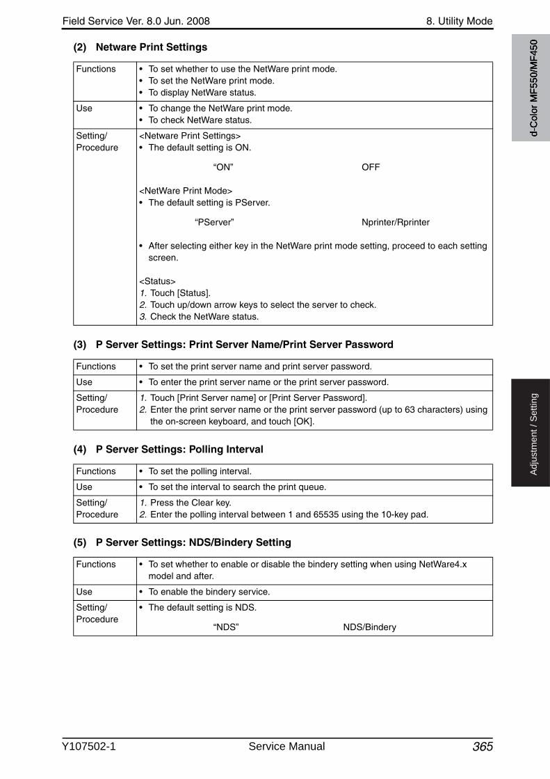
Field Service Ver. 8.0 Jun. 2008 8. Utility Mode
365
Ad
justm
en
t /
Se
ttin
g
(2) Netware Print Settings
(3) P Server Settings: Print Server Name/Print Server Password
(4) P Server Settings: Polling Interval
(5) P Server Settings: NDS/Bindery Setting
Functions • To set whether to use the NetWare print mode.• To set the NetWare print mode.• To display NetWare status.
Use • To change the NetWare print mode.• To check NetWare status.
Setting/Procedure
<Netware Print Settings>• The default setting is ON.
“ON” OFF
<NetWare Print Mode>• The default setting is PServer.
“PServer” Nprinter/Rprinter
• After selecting either key in the NetWare print mode setting, proceed to each setting screen.
<Status>1. Touch [Status].2. Touch up/down arrow keys to select the server to check.3. Check the NetWare status.
Functions • To set the print server name and print server password.
Use • To enter the print server name or the print server password.
Setting/Procedure
1. Touch [Print Server name] or [Print Server Password].2. Enter the print server name or the print server password (up to 63 characters) using
the on-screen keyboard, and touch [OK].
Functions • To set the polling interval.
Use • To set the interval to search the print queue.
Setting/Procedure
1. Press the Clear key.2. Enter the polling interval between 1 and 65535 using the 10-key pad.
Functions • To set whether to enable or disable the bindery setting when using NetWare4.x model and after.
Use • To enable the bindery service.
Setting/Procedure
• The default setting is NDS.
“NDS” NDS/Bindery
d-C
olor
MF5
50/M
F450
Y107502-1 Service Manual
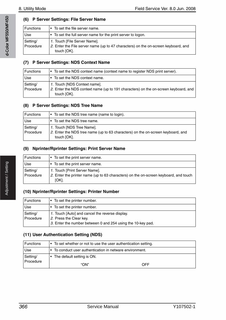
8. Utility Mode Field Service Ver. 8.0 Jun. 2008
366
Ad
justm
en
t /
Se
ttin
g
(6) P Server Settings: File Server Name
(7) P Server Settings: NDS Context Name
(8) P Server Settings: NDS Tree Name
(9) Nprinter/Rprinter Settings: Print Server Name
(10) Nprinter/Rprinter Settings: Printer Number
(11) User Authentication Setting (NDS)
Functions • To set the file server name.
Use • To set the full server name for the print server to logon.
Setting/Procedure
1. Touch [File Server Name].2. Enter the File server name (up to 47 characters) on the on-screen keyboard, and
touch [OK].
Functions • To set the NDS context name (context name to register NDS print server).
Use • To set the NDS context name.
Setting/Procedure
1. Touch [NDS Context name].2. Enter the NDS context name (up to 191 characters) on the on-screen keyboard, and
touch [OK].
Functions • To set the NDS tree name (name to login).
Use • To set the NDS tree name.
Setting/Procedure
1. Touch [NDS Tree Name].2. Enter the NDS tree name (up to 63 characters) on the on-screen keyboard, and
touch [OK].
Functions • To set the print server name.
Use • To set the print server name.
Setting/Procedure
1. Touch [Print Server Name].2. Enter the printer name (up to 63 characters) on the on-screen keyboard, and touch
[OK].
Functions • To set the printer number.
Use • To set the printer number.
Setting/Procedure
1. Touch [Auto] and cancel the reverse display.2. Press the Clear key.3. Enter the number between 0 and 254 using the 10-key pad.
Functions • To set whether or not to use the user authentication setting.
Use • To conduct user authentication in netware environment.
Setting/Procedure
• The default setting is ON.
“ON” OFF
d-C
olor
MF5
50/M
F450
Service Manual Y107502-1

Field Service Ver. 8.0 Jun. 2008 8. Utility Mode
367
Ad
justm
en
t /
Se
ttin
g
C. http Server Settings• It will not be displayed when the following setting shows that authentication device is
mounted.[Service Mode] [Billing Setting] [Management Function Choice]
(1) http Server Settings
(2) PSWC Settings
(3) IPP Settings
(4) Accept IPP jobs
(5) Support Information
(6) Printer Information
Functions• To set whether or not to use the http server setting.
Use
Setting/Procedure
• The default setting is ON.
“ON” OFF
Functions• To set whether to use the PageScope Web Connection.
Use
Setting/Procedure
• The default setting is ON.
“ON” OFF
Functions• To set whether to enable or disable IPP (Internet Printing Protocol) setting.
Use
Setting/Procedure
• The default setting is ON.
“ON” OFF
Functions• To set whether to allow or restrict the IPP job.
Use
Setting/Procedure
• The default setting is ON.
“ON” OFF
Functions • To set the operation support information.
Use • For the response setting to see if IPP transmission supports each function.
Setting/Procedure
1. Touch [Support Information].2. Set “ON” or OFF for each item.
Functions • To set the printer information.
Use • To set the printer information.
Setting/Procedure
1. Touch [Printer Information].2. Enter the printer name, printer location, and printer information on the on-screen
keyboard.3. Touch [Print URI] to check the printer URI information.
d-C
olor
MF5
50/M
F450
Y107502-1 Service Manual
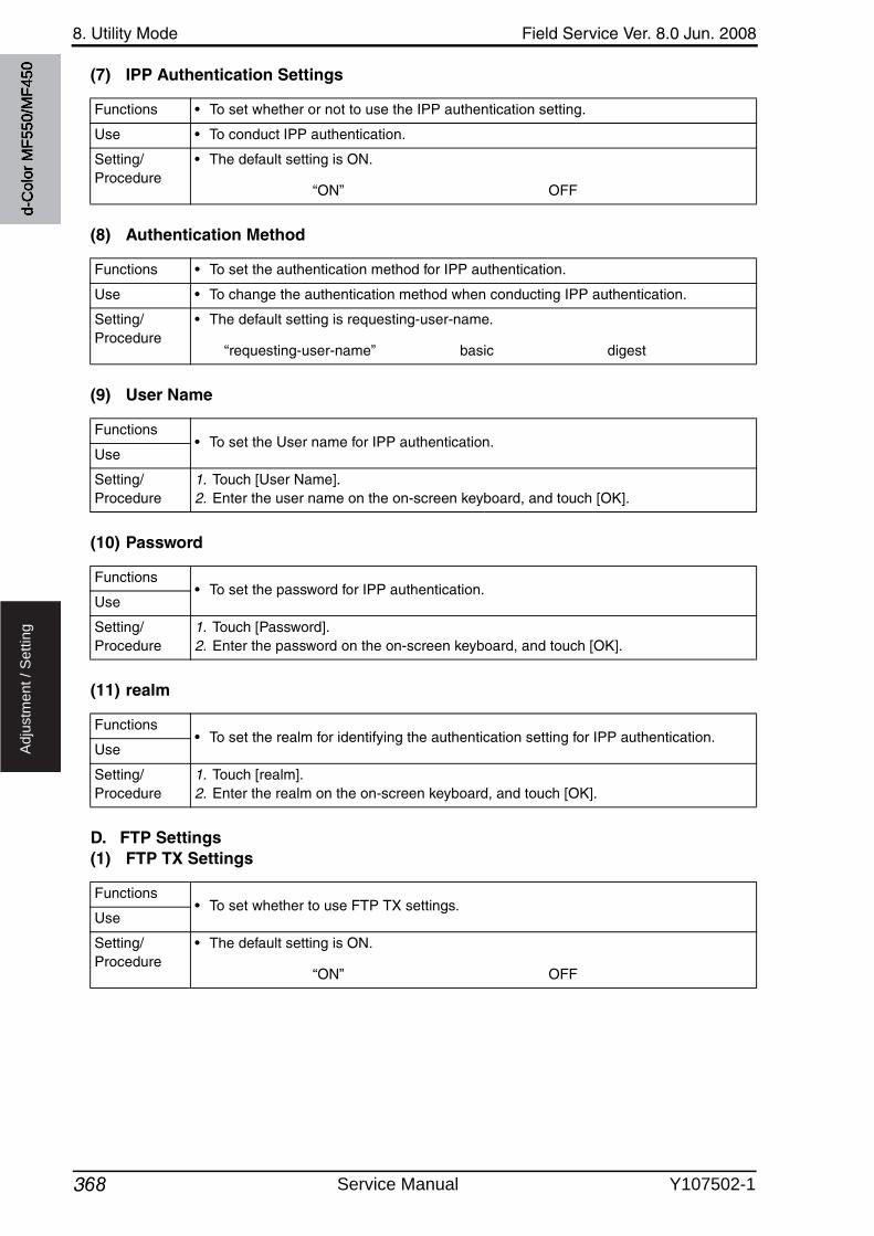
8. Utility Mode Field Service Ver. 8.0 Jun. 2008
368
Ad
justm
en
t /
Se
ttin
g
(7) IPP Authentication Settings
(8) Authentication Method
(9) User Name
(10) Password
(11) realm
D. FTP Settings(1) FTP TX Settings
Functions • To set whether or not to use the IPP authentication setting.
Use • To conduct IPP authentication.
Setting/Procedure
• The default setting is ON.
“ON” OFF
Functions • To set the authentication method for IPP authentication.
Use • To change the authentication method when conducting IPP authentication.
Setting/Procedure
• The default setting is requesting-user-name.
“requesting-user-name” basic digest
Functions• To set the User name for IPP authentication.
Use
Setting/Procedure
1. Touch [User Name].2. Enter the user name on the on-screen keyboard, and touch [OK].
Functions• To set the password for IPP authentication.
Use
Setting/Procedure
1. Touch [Password].2. Enter the password on the on-screen keyboard, and touch [OK].
Functions• To set the realm for identifying the authentication setting for IPP authentication.
Use
Setting/Procedure
1. Touch [realm].2. Enter the realm on the on-screen keyboard, and touch [OK].
Functions• To set whether to use FTP TX settings.
Use
Setting/Procedure
• The default setting is ON.
“ON” OFF
d-C
olor
MF5
50/M
F450
Service Manual Y107502-1

Field Service Ver. 8.0 Jun. 2008 8. Utility Mode
369
Ad
justm
en
t /
Se
ttin
g
(2) FTP TX Settings: Proxy Server Address
(3) FTP TX Settings: Proxy Server Port Number
(4) FTP TX Settings: Port No.
(5) FTP TX Settings: Connection Timeout
(6) FTP Server Settings
Functions • To set the proxy server address.
Use • To enter the proxy server address.
Setting/Procedure
1. Touch [Host Address].2. Select [Input Host Name], [IPv4 Address Input], or [IPv6 Address Input] and enter a
host address.
Functions • To set the proxy server port number.
Use • To enter the proxy server port number.
Setting/Procedure
• Press the Clear key.• Enter the proxy server port number between 1 and 65535 using the 10-key pad.
Functions • To set the port number to be used for transmission with FTP server.
Use • To enter the port number to be used for transmission with FTP server.
Setting/Procedure
1. Touch [Input].2. Press the Clear key.3. Enter the proxy server port number between 1 and 65535 using the 10-Kay pad.
Functions • To set the timeout period for connecting to FTP server.
Use • To change the timeout period for connecting.
Setting/Procedure
1. Touch [Input].2. Press the Clear key.3. Enter the connecting timeout period between 5 and 300 using the 10-key pad.
Functions • To set whether to use this machine as FTP server.
Use • Not to use the machine as FTP server.
Setting/Procedure
• The default setting is ON.
“ON” OFF
NOTE• [ON] cannot be selected when the following setting is set to “ON.”
[Administrator Settings] [Security Settings] [Enhanced Security Mode]
d-C
olor
MF5
50/M
F450
Y107502-1 Service Manual
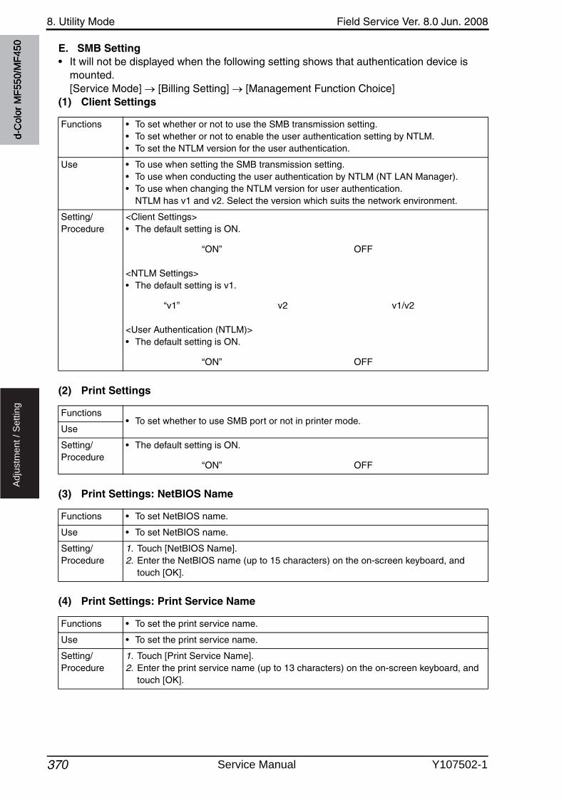
8. Utility Mode Field Service Ver. 8.0 Jun. 2008
370
Ad
justm
en
t /
Se
ttin
g
E. SMB Setting• It will not be displayed when the following setting shows that authentication device is
mounted.[Service Mode] [Billing Setting] [Management Function Choice]
(1) Client Settings
(2) Print Settings
(3) Print Settings: NetBIOS Name
(4) Print Settings: Print Service Name
Functions • To set whether or not to use the SMB transmission setting.• To set whether or not to enable the user authentication setting by NTLM.• To set the NTLM version for the user authentication.
Use • To use when setting the SMB transmission setting.• To use when conducting the user authentication by NTLM (NT LAN Manager).• To use when changing the NTLM version for user authentication.
NTLM has v1 and v2. Select the version which suits the network environment.
Setting/Procedure
<Client Settings>• The default setting is ON.
“ON” OFF
<NTLM Settings>• The default setting is v1.
“v1” v2 v1/v2
<User Authentication (NTLM)>• The default setting is ON.
“ON” OFF
Functions• To set whether to use SMB port or not in printer mode.
Use
Setting/Procedure
• The default setting is ON.
“ON” OFF
Functions • To set NetBIOS name.
Use • To set NetBIOS name.
Setting/Procedure
1. Touch [NetBIOS Name].2. Enter the NetBIOS name (up to 15 characters) on the on-screen keyboard, and
touch [OK].
Functions • To set the print service name.
Use • To set the print service name.
Setting/Procedure
1. Touch [Print Service Name].2. Enter the print service name (up to 13 characters) on the on-screen keyboard, and
touch [OK].
d-C
olor
MF5
50/M
F450
Service Manual Y107502-1
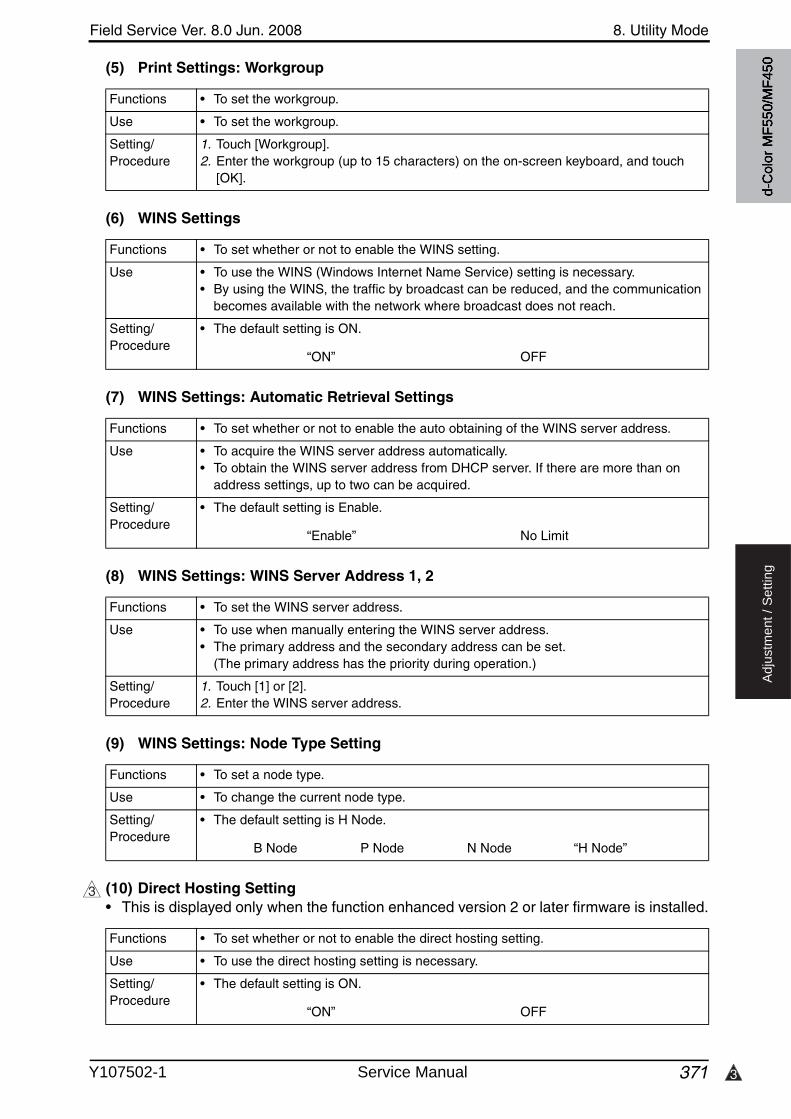
3
Field Service Ver. 8.0 Jun. 2008 8. Utility Mode
371
Ad
justm
en
t /
Se
ttin
g
(5) Print Settings: Workgroup
(6) WINS Settings
(7) WINS Settings: Automatic Retrieval Settings
(8) WINS Settings: WINS Server Address 1, 2
(9) WINS Settings: Node Type Setting
(10) Direct Hosting Setting• This is displayed only when the function enhanced version 2 or later firmware is installed.
Functions • To set the workgroup.
Use • To set the workgroup.
Setting/Procedure
1. Touch [Workgroup].2. Enter the workgroup (up to 15 characters) on the on-screen keyboard, and touch
[OK].
Functions • To set whether or not to enable the WINS setting.
Use • To use the WINS (Windows Internet Name Service) setting is necessary.• By using the WINS, the traffic by broadcast can be reduced, and the communication
becomes available with the network where broadcast does not reach.
Setting/Procedure
• The default setting is ON.
“ON” OFF
Functions • To set whether or not to enable the auto obtaining of the WINS server address.
Use • To acquire the WINS server address automatically.• To obtain the WINS server address from DHCP server. If there are more than on
address settings, up to two can be acquired.
Setting/Procedure
• The default setting is Enable.
“Enable” No Limit
Functions • To set the WINS server address.
Use • To use when manually entering the WINS server address.• The primary address and the secondary address can be set.
(The primary address has the priority during operation.)
Setting/Procedure
1. Touch [1] or [2].2. Enter the WINS server address.
Functions • To set a node type.
Use • To change the current node type.
Setting/Procedure
• The default setting is H Node.
B Node P Node N Node “H Node”
3
Functions • To set whether or not to enable the direct hosting setting.
Use • To use the direct hosting setting is necessary.
Setting/Procedure
• The default setting is ON.
“ON” OFF
d-C
olor
MF5
50/M
F450
Y107502-1 Service Manual

8. Utility Mode Field Service Ver. 8.0 Jun. 2008
372
Ad
justm
en
t /
Se
ttin
g
F. LDAP Settings• It will not be displayed when the following setting shows that authentication device is
mounted.[Service Mode] [Billing Setting] [Management Function Choice]
(1) Enabling LDAP
(2) Setting Up LDAP• Registration and/or setting concerning the LDAP server can be conducted.• Touch [Setting Up LDAP], and select the optional blank key to register and/or set.
<LDAP Server Name>
<Max. Search Results>
<Timeout>
<Initial Setting for Search Details>
Functions • To set whether to enable or disable the LDAP function.
Use • To use LDAP function.
Setting/Procedure
• The default setting is OFF.
ON “OFF”
Functions• Set the LDAP server name.
Use
Setting/Procedure
1. Touch [Server Name].2. Enter the server name (up to 32 one-byte characters) on the on-screen keyboard,
and touch [OK].
Functions • To set the Max. results of address for LDAP search.
Use • To change the Max. results of address for LDAP search.
Setting/Procedure
1. Touch [Max. Search Results].2. Press the Clear key.3. Enter the Max. Search result numbers between 5 and 1000 using the 10-key pad.
Functions • To set the Max. timeout period for LDAP search.
Use • To change the Max. timeout period for LDAP search.
Setting/Procedure
1. Touch [Timeout].2. Press the Clear key.3. Enter the timeout period between 5 and 300 using the 10-key pad.
Functions • To set the initial items for search conditions in LDAP detail search.
Use • To set the initial items for search conditions in LDAP detail search.
Setting/Procedure
1. Touch [Initial Setting for Search Details].2. Touch the key about condition for each search item, and select the condition.
d-C
olor
MF5
50/M
F450
Service Manual Y107502-1
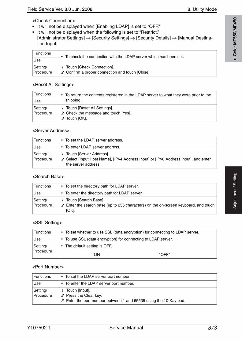
Field Service Ver. 8.0 Jun. 2008 8. Utility Mode
373
Ad
justm
en
t /
Se
ttin
g
<Check Connection>• It will not be displayed when [Enabling LDAP] is set to “OFF.”• It will not be displayed when the following is set to “Restrict.”
[Administrator Settings] [Security Settings] [Security Details] [Manual Destina-tion Input]
<Reset All Settings>
<Server Address>
<Search Base>
<SSL Setting>
<Port Number>
Functions• To check the connection with the LDAP server which has been set.
Use
Setting/Procedure
1. Touch [Check Connection].2. Confirm a proper connection and touch [Close].
Functions • To return the contents registered in the LDAP server to what they were prior to the shipping.Use
Setting/Procedure
1. Touch [Reset All Settings].2. Check the message and touch [Yes].3. Touch [OK].
Functions • To set the LDAP server address.
Use • To enter LDAP server address.
Setting/Procedure
1. Touch [Server Address].2. Select [Input Host Name], [IPv4 Address Input] or [IPv6 Address Input], and enter
the server address.
Functions • To set the directory path for LDAP server.
Use • To enter the directory path for LDAP server.
Setting/Procedure
1. Touch [Search Base].2. Enter the search base (up to 255 characters) on the on-screen keyboard, and touch
[OK].
Functions • To set whether to use SSL (data encryption) for connecting to LDAP server.
Use • To use SSL (data encryption) for connecting to LDAP server.
Setting/Procedure
• The default setting is OFF.
ON “OFF”
Functions • To set the LDAP server port number.
Use • To enter the LDAP server port number.
Setting/Procedure
1. Touch [Input].2. Press the Clear key.3. Enter the port number between 1 and 65535 using the 10-Kay pad.
d-C
olor
MF5
50/M
F450
Y107502-1 Service Manual
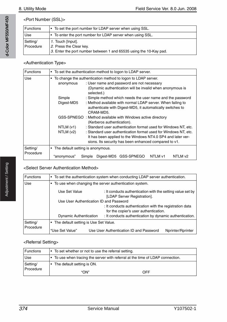
8. Utility Mode Field Service Ver. 8.0 Jun. 2008
374
Ad
justm
en
t /
Se
ttin
g
<Port Number (SSL)>
<Authentication Type>
<Select Server Authentication Method>
<Referral Setting>
Functions • To set the port number for LDAP server when using SSL.
Use • To enter the port number for LDAP server when using SSL.
Setting/Procedure
1. Touch [Input].2. Press the Clear key.3. Enter the port number between 1 and 65535 using the 10-Kay pad.
Functions • To set the authentication method to logon to LDAP server.
Use • To change the authentication method to logon to LDAP server.anonymous : User name and password are not necessary
(Dynamic authentication will be invalid when anonymous is selected.)
Simple : Simple method which needs the user name and the passwordDigest-MD5 : Method available with normal LDAP server. When failing to
authenticate with Digest-MD5, it automatically switches to CRAM-MD5.
GSS-SPNEGO : Method available with Windows active directory (Kerberos authentication).
NTLM (v1) : Standard user authentication format used for Windows NT, etc.NTLM (v2) : Standard user authentication format used for Windows NT, etc.
It has been applied to the Windows NT4.0 SP4 and later ver-sions. Its security has been enhanced compared to v1.
Setting/Procedure
• The default setting is anonymous.
“anonymous” Simple Digest-MD5 GSS-SPNEGO NTLM v1 NTLM v2
Functions • To set the authentication system when conducting LDAP server authentication.
Use • To use when changing the server authentication system.
Use Set Value : It conducts authentication with the setting value set by [LDAP Server Registration].
Use User Authentication ID and Password: It conducts authentication with the registration data
for the copier’s user authentication.Dynamic Authentication : It conducts authentication by dynamic authentication.
Setting/Procedure
• The default setting is Use Set Value.
“Use Set Value” Use User Authentication ID and Password Nprinter/Rprinter
Functions • To set whether or not to use the referral setting.
Use • To use when tracing the server with referral at the time of LDAP connection.
Setting/Procedure
• The default setting is ON.
“ON” OFF
d-C
olor
MF5
50/M
F450
Service Manual Y107502-1

Field Service Ver. 8.0 Jun. 2008 8. Utility Mode
375
Ad
justm
en
t /
Se
ttin
g
<Login Name>
<Password>
<Domain Name>
(3) Default LDAP Server Setting
G. E-mail Settings• It will not be displayed when the following setting shows that authentication device is
mounted.[Service Mode] [Billing Setting] [Management Function Choice]
(1) E-mail TX (SMTP)<E-mail TX (SMTP)>
Functions • To set the login name to connect to LDAP server.
Use • To set the login name to connect to LDAP server.
Setting/Procedure
1. Touch [Login Name].2. Enter the logon name (up to 255 characters) on the on-screen keyboard, and touch
[OK].
NOTE• The setting is not available when authentication method is set to anonymous.
Functions • To set the password for connecting to LDAP server.
Use • To set the password for connecting to LDAP server.
Setting/Procedure
• Touch [Password].• Enter the password (up to 63 characters) on the on-screen keyboard, and touch [OK].
NOTE• The setting is not available when authentication method is set to anonymous.
Functions • To set the domain name for connecting to LDAP server.
Use • To set the domain name for connecting to LDAP server.
Setting/Procedure
1. Touch [Domain Name].2. Enter the domain name (up to 64 characters) on the on-screen keyboard, and touch
[OK].
Functions• To set the server to be used as the default when searching LDAP.
Use
Setting/Procedure
1. Touch [Default LDAP Server Setting].2. Select the optional server.
Functions • To set whether to enable or disable the e-mail transmission setting.
Use • To disable the e-mail transmission setting.
Setting/Procedure
• The default setting is ON.
“ON” OFF
d-C
olor
MF5
50/M
F450
Y107502-1 Service Manual

8. Utility Mode Field Service Ver. 8.0 Jun. 2008
376
Ad
justm
en
t /
Se
ttin
g
<Scan to E-mail>
<Status Notification>
<Total Counter Notification>
<SMTP Server Address>
<Binary Division>
<Divided Mail Size>
Functions • To set whether or not to transfer scanned data by e-mail.
Use • To use when not transferring scanned data by e-mail.
Setting/Procedure
• The default setting is ON.
“ON” OFF
Functions • To set whether or not to inform the status by e-mail.
Use • To use when not informing the status by e-mail.
Setting/Procedure
• The default setting is ON.
“ON” OFF
Functions • To set whether or not to inform the total counter by e-mail.
Use • To use when not informing the total counter by e-mail.
Setting/Procedure
• The default setting is ON.
“ON” OFF
Functions • To set the SMTP server address.
Use • To enter the SMTP server address.
Setting/Procedure
1. Touch [Host Address].2. Select [Input Host Name], [IPv4 Address Input] or [IPv6 Address Input], and enter
the server address.
Functions • To set whether to carry out binary division for data to be transmitted.
Use • Not to carry out binary division for data to be transmitted.
Setting/Procedure
• The default setting is OFF.
ON “OFF”
Functions • To set the dividing size when carrying out the binary division for data to be transmit-ted.
Use • To change the dividing size of the data.
Setting/Procedure
1. Press the Clear key.2. Enter the dividing mail size between 100 and 15000 (in 100 increments) using the
10-key pad.
d-C
olor
MF5
50/M
F450
Service Manual Y107502-1

3
Field Service Ver. 8.0 Jun. 2008 8. Utility Mode
377
Ad
justm
en
t /
Se
ttin
g
<Connection Timeout>
<Server Capacity>
<SSL Setting>
<Port No.>
<Port Number (SSL)>
<Detail Settings: SMTP Authentication>
Functions • To set the timeout period for connection in transmitting e-mail to SMTP server.
Use • To change the timeout period for connection in transmitting e-mail to SMTP server.
Setting/Procedure
• Select the timeout period using [+] / [-] keys.• The default setting is 60 sec.
“60 sec.” (30 to 300, in 30 sec. increments)
Functions • To set the Max. capacity per mail which SMTP server can receive.
Use • To change the Max. capacity per mail which SMTP server can receive.
Setting/Procedure
• The default setting is No Limit.
“No Limit” (1 to 100)
Functions • To set whether or not to use SSL when sending an e-mail.
Use • To use when sending an e-mail using SSL.
Setting/Procedure
• The default setting is OFF.
SMTP over SSL Start TLS “OFF”
3
Functions • To set the port number for transmission with SMTP server.
Use • To enter the port number for transmission with SMTP server.
Setting/Procedure
1. Touch [Input].2. Press the Clear key.3. Enter the port number between 1 and 65535 using the 10-key pad.
Functions • To set the port number when using SSL.
Use • To use for entering the port number when using SSL.
Setting/Procedure
1. Touch [Input].2. Touch the Clear key.3. Enter the port number (SSL) between 1 and 65535 using the 10-key pad.
Functions • To set whether or not to enable SMTP authentication.
Use • To use when conducting SMTP authentication.
Setting/Procedure
• The default setting is OFF.
ON “OFF”
• When set to “ON”, enter the [User ID], [Password] and [Domain Name].
d-C
olor
MF5
50/M
F450
Y107502-1 Service Manual
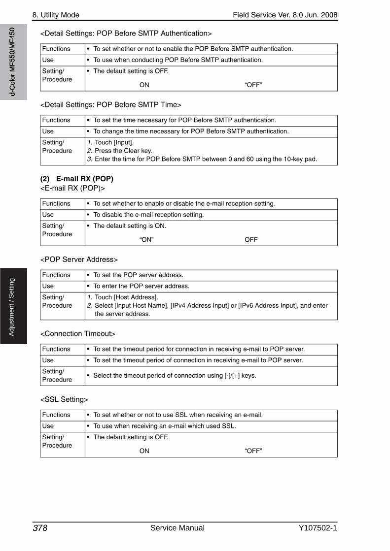
8. Utility Mode Field Service Ver. 8.0 Jun. 2008
378
Ad
justm
en
t /
Se
ttin
g
<Detail Settings: POP Before SMTP Authentication>
<Detail Settings: POP Before SMTP Time>
(2) E-mail RX (POP)<E-mail RX (POP)>
<POP Server Address>
<Connection Timeout>
<SSL Setting>
Functions • To set whether or not to enable the POP Before SMTP authentication.
Use • To use when conducting POP Before SMTP authentication.
Setting/Procedure
• The default setting is OFF.
ON “OFF”
Functions • To set the time necessary for POP Before SMTP authentication.
Use • To change the time necessary for POP Before SMTP authentication.
Setting/Procedure
1. Touch [Input].2. Press the Clear key.3. Enter the time for POP Before SMTP between 0 and 60 using the 10-key pad.
Functions • To set whether to enable or disable the e-mail reception setting.
Use • To disable the e-mail reception setting.
Setting/Procedure
• The default setting is ON.
“ON” OFF
Functions • To set the POP server address.
Use • To enter the POP server address.
Setting/Procedure
1. Touch [Host Address].2. Select [Input Host Name], [IPv4 Address Input] or [IPv6 Address Input], and enter
the server address.
Functions • To set the timeout period for connection in receiving e-mail to POP server.
Use • To set the timeout period of connection in receiving e-mail to POP server.
Setting/Procedure
• Select the timeout period of connection using [-]/[+] keys.
Functions • To set whether or not to use SSL when receiving an e-mail.
Use • To use when receiving an e-mail which used SSL.
Setting/Procedure
• The default setting is OFF.
ON “OFF”
d-C
olor
MF5
50/M
F450
Service Manual Y107502-1
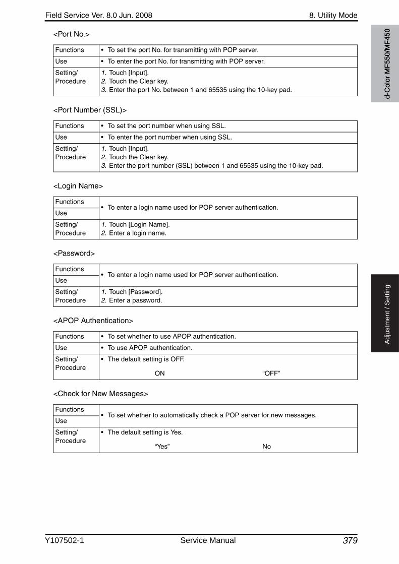
Field Service Ver. 8.0 Jun. 2008 8. Utility Mode
379
Ad
justm
en
t /
Se
ttin
g
<Port No.>
<Port Number (SSL)>
<Login Name>
<Password>
<APOP Authentication>
<Check for New Messages>
Functions • To set the port No. for transmitting with POP server.
Use • To enter the port No. for transmitting with POP server.
Setting/Procedure
1. Touch [Input].2. Touch the Clear key.3. Enter the port No. between 1 and 65535 using the 10-key pad.
Functions • To set the port number when using SSL.
Use • To enter the port number when using SSL.
Setting/Procedure
1. Touch [Input].2. Touch the Clear key.3. Enter the port number (SSL) between 1 and 65535 using the 10-key pad.
Functions• To enter a login name used for POP server authentication.
Use
Setting/Procedure
1. Touch [Login Name].2. Enter a login name.
Functions• To enter a login name used for POP server authentication.
Use
Setting/Procedure
1. Touch [Password].2. Enter a password.
Functions • To set whether to use APOP authentication.
Use • To use APOP authentication.
Setting/Procedure
• The default setting is OFF.
ON “OFF”
Functions• To set whether to automatically check a POP server for new messages.
Use
Setting/Procedure
• The default setting is Yes.
“Yes” No
d-C
olor
MF5
50/M
F450
Y107502-1 Service Manual
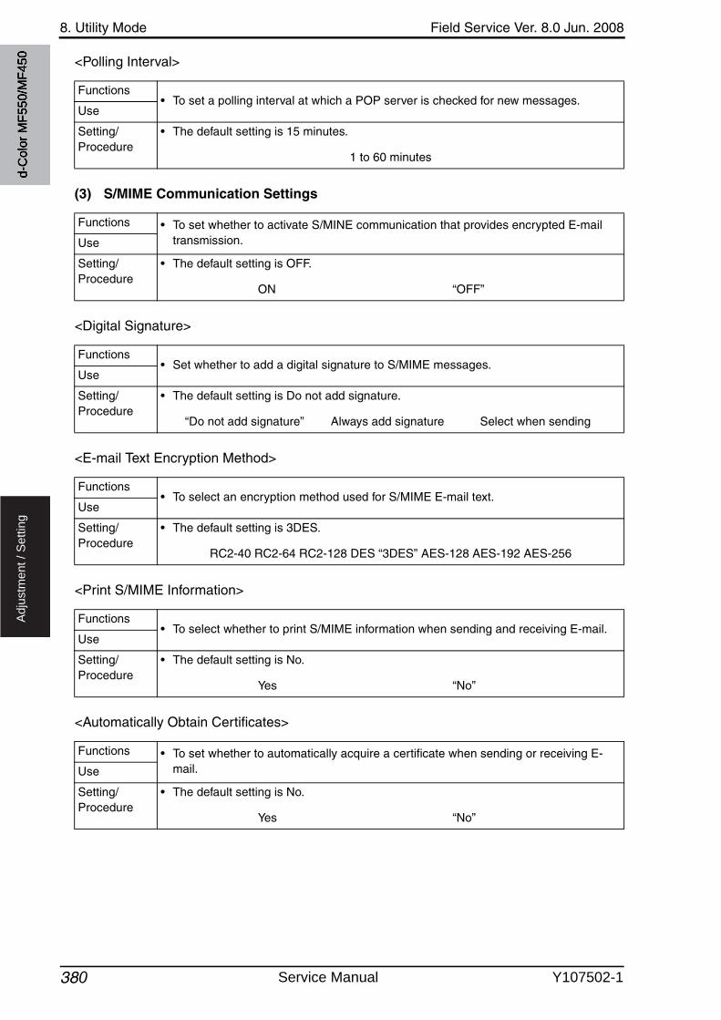
8. Utility Mode Field Service Ver. 8.0 Jun. 2008
380
Ad
justm
en
t /
Se
ttin
g
<Polling Interval>
(3) S/MIME Communication Settings
<Digital Signature>
<E-mail Text Encryption Method>
<Print S/MIME Information>
<Automatically Obtain Certificates>
Functions• To set a polling interval at which a POP server is checked for new messages.
Use
Setting/Procedure
• The default setting is 15 minutes.
1 to 60 minutes
Functions • To set whether to activate S/MINE communication that provides encrypted E-mail transmission.Use
Setting/Procedure
• The default setting is OFF.
ON “OFF”
Functions• Set whether to add a digital signature to S/MIME messages.
Use
Setting/Procedure
• The default setting is Do not add signature.
“Do not add signature” Always add signature Select when sending
Functions• To select an encryption method used for S/MIME E-mail text.
Use
Setting/Procedure
• The default setting is 3DES.
RC2-40 RC2-64 RC2-128 DES “3DES” AES-128 AES-192 AES-256
Functions• To select whether to print S/MIME information when sending and receiving E-mail.
Use
Setting/Procedure
• The default setting is No.
Yes “No”
Functions • To set whether to automatically acquire a certificate when sending or receiving E-mail.Use
Setting/Procedure
• The default setting is No.
Yes “No”
d-C
olor
MF5
50/M
F450
Service Manual Y107502-1
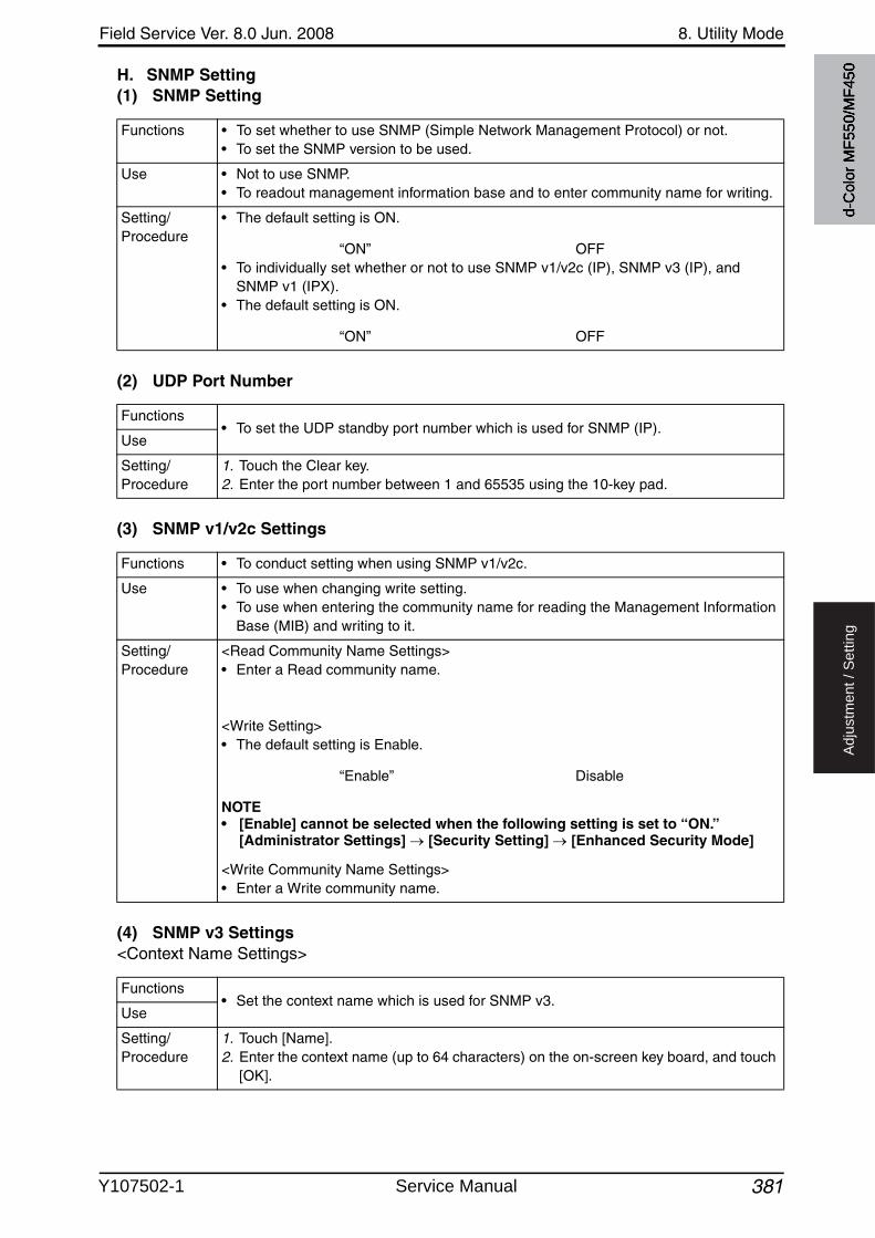
Field Service Ver. 8.0 Jun. 2008 8. Utility Mode
381
Ad
justm
en
t /
Se
ttin
g
H. SNMP Setting(1) SNMP Setting
(2) UDP Port Number
(3) SNMP v1/v2c Settings
(4) SNMP v3 Settings<Context Name Settings>
Functions • To set whether to use SNMP (Simple Network Management Protocol) or not.• To set the SNMP version to be used.
Use • Not to use SNMP.• To readout management information base and to enter community name for writing.
Setting/Procedure
• The default setting is ON.
“ON” OFF• To individually set whether or not to use SNMP v1/v2c (IP), SNMP v3 (IP), and
SNMP v1 (IPX).• The default setting is ON.
“ON” OFF
Functions• To set the UDP standby port number which is used for SNMP (IP).
Use
Setting/Procedure
1. Touch the Clear key.2. Enter the port number between 1 and 65535 using the 10-key pad.
Functions • To conduct setting when using SNMP v1/v2c.
Use • To use when changing write setting.• To use when entering the community name for reading the Management Information
Base (MIB) and writing to it.
Setting/Procedure
<Read Community Name Settings>• Enter a Read community name.
<Write Setting>• The default setting is Enable.
“Enable” Disable
NOTE• [Enable] cannot be selected when the following setting is set to “ON.”
[Administrator Settings] [Security Setting] [Enhanced Security Mode]
<Write Community Name Settings>• Enter a Write community name.
Functions• Set the context name which is used for SNMP v3.
Use
Setting/Procedure
1. Touch [Name].2. Enter the context name (up to 64 characters) on the on-screen key board, and touch
[OK].
d-C
olor
MF5
50/M
F450
Y107502-1 Service Manual
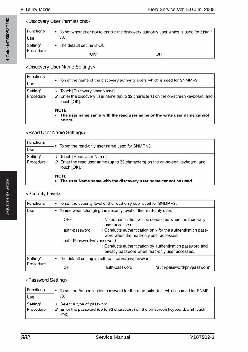
8. Utility Mode Field Service Ver. 8.0 Jun. 2008
382
Ad
justm
en
t /
Se
ttin
g
<Discovery User Permissions>
<Discovery User Name Settings>
<Read User Name Settings>
<Security Level>
<Password Setting>
Functions • To set whether or not to enable the discovery authority user which is used for SNMP v3.Use
Setting/Procedure
• The default setting is ON.
“ON” OFF
Functions• To set the name of the discovery authority users which is used for SNMP v3.
Use
Setting/Procedure
1. Touch [Discovery User Name].2. Enter the discovery user name (up to 32 characters) on the on-screen keyboard, and
touch [OK].
NOTE• The user name same with the read user name or the write user name cannot
be set.
Functions• To set the read-only user name used for SNMP v3.
Use
Setting/Procedure
1. Touch [Read User Name].2. Enter the read user name (up to 32 characters) on the on-screen keyboard, and
touch [OK].
NOTE• The user Name same with the discovery user name cannot be used.
Functions • To set the security level of the read-only user used for SNMP v3.
Use • To use when changing the security level of the read-only user.
OFF : No authentication will be conducted when the read-only user accesses.
auth-password : Conducts authentication only for the authentication pass-word when the read-only user accesses.
auth-Password/privpassword: Conducts authentication by authentication password and
privacy password when read-only user accesses.
Setting/Procedure
• The default setting is auth-password/privpassword.
OFF auth-password “auth-password/privpassword”
Functions • To set the Authentication password for the read-only User which is used for SNMP v3.Use
Setting/Procedure
1. Select a type of password.2. Enter the password (up to 32 characters) on the on-screen keyboard, and touch
[OK].
d-C
olor
MF5
50/M
F450
Service Manual Y107502-1

3
Field Service Ver. 8.0 Jun. 2008 8. Utility Mode
383
Ad
justm
en
t /
Se
ttin
g
<Write User Name Settings>
<Security Level>
<Encryption Algorithm>• This is displayed only when the function enhanced version 2 or later firmware is installed.
<Authentication Algorithm>• This is displayed only when the function enhanced version 2 or later firmware is installed.
Functions• To set the name of the reading/writing authority user which is used for SNMP v3.
Use
Setting/Procedure
1. Touch [Write User Name].2. Enter the write user name (up to 32 characters) on the on-screen keyboard, and
touch [OK].
NOTE• The user name same with the discovery use name cannot be used.
Functions • To set the security level for the reading/writing authority user which is used for SNMP v3.
Use • To use for changing the security level of the reading/writing authority user.
OFF : Authentication will not be conducted when reading/writing authority user accesses.
auth-password : Conducts authentication only with authentication passwordwhen reading/writing authority user accesses.
auth-password/privpassword: Conducts authentication by authentication password and
privacy password when reading/writing authority useraccesses.
Setting/Procedure
• The default setting is auth-password/privpassword.
OFF auth-password “auth-password/privpassword”
NOTE• [Authentication OFF] cannot be selected when the following setting is set to
“ON.” [Administrator Settings] [Security Settings] [Enhanced Security Mode]
3
Functions• To set the encryption algorithm in SNMPv3 communication.
Use
Setting/Procedure
• The default setting is DES.
“DES” AES-128
3
Functions• To set the authentication algorithm in SNMPv3 communication.
Use
Setting/Procedure
• The default setting is MD5.
“MD5” SHA-1
d-C
olor
MF5
50/M
F450
Y107502-1 Service Manual

8. Utility Mode Field Service Ver. 8.0 Jun. 2008
384
Ad
justm
en
t /
Se
ttin
g
I. AppleTalk Settings• It will not be displayed when the following setting shows that authentication device is
mounted.[Service Mode] [Billing Setting] [Management Function Choice]
(1) AppleTalk Settings
(2) Printer Name
(3) Zone Name
(4) Current Zone
J. Bonjour Setting(1) Bonjour Setting
(2) Bonjour Name
Functions • To set whether to enable or disable the AppleTalk setting.
Use • To use AppleTalk setting.
Setting/Procedure
• The default setting is OFF.
ON “OFF”
Functions • To set the printer name displayed on the AppleTalk network.
Use • To set the printer name displayed on the AppleTalk network.
Setting/Procedure
1. Touch [Printer Name].2. Enter the printer name (up to 31 characters) on the on-screen keyboard, and touch
[OK].
Functions • To set the zone name connected with AppleTalk network.
Use • To set the zone name connected with AppleTalk network.
Setting/Procedure
1. Touch [Zone Name].2. Enter the zone name (up to 31 characters) on the on-screen keyboard, and touch
[OK].
Functions • To display the current zone on AppleTalk network.
Use • To check the current zone on the AppleTalk network.
Functions • To set whether or not to use the Bonjour setting.
Use • To use when operating under the Bonjour service environment.
Setting/Procedure
• The default setting is ON.
“ON” OFF
Functions • To set the bonjour name.
Use • To set the name for identifying over the bonjour network.
Setting/Procedure
1. Touch [Bonjour Name].2. Enter the Bonjour name (up to 64 characters) on the on-screen keyboard, and touch
[OK].
d-C
olor
MF5
50/M
F450
Service Manual Y107502-1
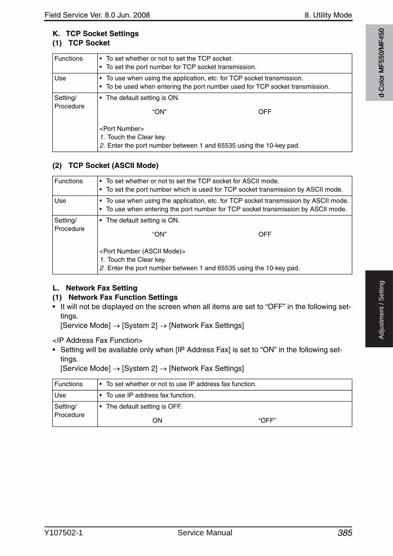
Field Service Ver. 8.0 Jun. 2008 8. Utility Mode
385
Ad
justm
en
t /
Se
ttin
g
K. TCP Socket Settings(1) TCP Socket
(2) TCP Socket (ASCII Mode)
L. Network Fax Setting(1) Network Fax Function Settings• It will not be displayed on the screen when all items are set to “OFF” in the following set-
tings.[Service Mode] [System 2] [Network Fax Settings]
<IP Address Fax Function>• Setting will be available only when [IP Address Fax] is set to “ON” in the following set-
tings.[Service Mode] [System 2] [Network Fax Settings]
Functions • To set whether or not to set the TCP socket.• To set the port number for TCP socket transmission.
Use • To use when using the application, etc. for TCP socket transmission.• To be used when entering the port number used for TCP socket transmission.
Setting/Procedure
• The default setting is ON.
“ON” OFF
<Port Number>1. Touch the Clear key.2. Enter the port number between 1 and 65535 using the 10-key pad.
Functions • To set whether or not to set the TCP socket for ASCII mode.• To set the port number which is used for TCP socket transmission by ASCII mode.
Use • To use when using the application, etc. for TCP socket transmission by ASCII mode.• To use when entering the port number for TCP socket transmission by ASCII mode.
Setting/Procedure
• The default setting is ON.
“ON” OFF
<Port Number (ASCII Mode)>1. Touch the Clear key.2. Enter the port number between 1 and 65535 using the 10-key pad.
Functions • To set whether or not to use IP address fax function.
Use • To use IP address fax function.
Setting/Procedure
• The default setting is OFF.
ON “OFF”
d-C
olor
MF5
50/M
F450
Y107502-1 Service Manual

8. Utility Mode Field Service Ver. 8.0 Jun. 2008
3864
Ad
justm
en
t /
Se
ttin
g
<Internet Fax Function>• Setting will be available only when [Internet Fax] is set to “ON” in the following settings.
[Service Mode] [System 2] [Network Fax Settings]
(2) SMTP TX Settings
(3) SMTP RX Settings
M. WebDAV Settings(1) WebDAV Client Settings• This is displayed only when the function enhanced version 2 or later firmware is installed.
<WebDAV Client Setting>
Functions • To set whether or not to use Internet fax function.
Use • To use Internet fax function.
Setting/Procedure
• The default setting is OFF.
ON “OFF”
Functions • To set SMTP TX when network fax function is being used.
Use • To set SMTP TX port number and connecting time out period when network fax func-tion is being used.
Setting/Procedure
<Port Number>1. Touch [Input].2. Enter the port number between 1 and 65535 using the 10-key pad.
<Connection Timeout>1. Touch [Input].2. Enter the connection timeout time between 5 and 1000 (sec.) using the 10-key pad.
Functions • To set SMTP RX when network fax function is being used.
Use • To use SMTP RX function when network fax function is being used.• To set SMTP RX port number and connecting time out period when network fax func-
tion is being used.
Setting/Procedure
<SMTP RX>• The default setting is ON.
“ON” OFF
<Port No.>1. Touch [Input].2. Enter the port number between 1 and 65535 using the 10-key pad.
<Connection Timeout>1. Touch [Input].2. Enter the connection timeout time between 5 and 1000 (sec.) using the 10-key pad.
4
Functions• To set whether to use WebDAV Client Settings.
Use
Setting/Procedure
• The default setting is ON.
“ON” OFF
d-C
olor
MF5
50/M
F450
Service Manual Y107502-1

4
Field Service Ver. 8.0 Jun. 2008 8. Utility Mode
387
Ad
justm
en
t /
Se
ttin
g
<WebDAV Client Settings: Proxy Server Address>
<WebDAV Client Settings: Proxy Server Port Number>
<WebDAV Client Settings: User Name>
<WebDAV Client Settings: Password>
<WebDAV Client Settings: Connection Timeout>
(2) WebDAV Server Settings• This is displayed only when the function enhanced version 3 or later firmware is installed.
<WebDAV Server Setting>
Functions • To set the proxy server address.
Use • To enter the proxy server address.
Setting/Procedure
1. Touch [Host Address].2. Select [Input Host Name], [IPv4 Address Input], or [IPv6 Address Input] and enter a
host address.
Functions • To set the proxy server port number.
Use • To enter the proxy server port number.
Setting/Procedure
• Press the Clear key.• Enter the proxy server port number between 1 and 65535 using the 10-key pad.
Functions• To set the user name for WebDAV authentication.
Use
Setting/Procedure
3. Touch [User Name].4. Enter the user name on the on-screen keyboard, and touch [OK].
Functions• To set the password for WebDAV authentication.
Use
Setting/Procedure
5. Touch [Password].6. Enter the password on the on-screen keyboard, and touch [OK].
Functions • To set the timeout period for connecting to WebDAV server.
Use • To change the timeout period for connecting.
Setting/Procedure
7. Touch [Input].8. Press the Clear key.9. Enter the connecting timeout period between 5 and 300 using the 10-key pad.
4
Functions• To set whether to use WebDAV Server Settings.
Use
Setting/Procedure
• The default setting is ON.
“ON” OFF
d-C
olor
MF5
50/M
F450
Y107502-1 Service Manual

8. Utility Mode Field Service Ver. 8.0 Jun. 2008
3883
Ad
justm
en
t /
Se
ttin
g
<WebDAV Server Settings: SSL Setting>
<WebDAV Server Settings: Password Setting
N. Web Service Settings• This is displayed only when the function enhanced version 2 or later firmware is installed.
(1) Web Service Common Settings<Web Service Common Settings: Friendly Name>
<Web Service Common Settings: SSL Setting>
(2) Printer Settings<Printer Settings>
Functions • To set whether to use SSL/TSL for communications when using the machine as WebDAV server.Use
Setting/Procedure
• The default setting is Non-SSL Only.
“Non-SSL Only” SSL Only SSL/Non-SSL
Functions• To set a password to access WebDAV server.
Use
Setting/Procedure
1. Touch [Password Setting].2. Enter a password with the keyboard on the screen, and touch [OK].• Touching [Initial Password] can restore the default password setting.
(Default password: sysadm)
3
3
Functions • To define a friendly name that is used when printing a job with WSD (Web Service on Devices) function.Use
Setting/Procedure
1. Touch [Friendly Name].2. Enter the friendly name (up to 62 characters) on the on-screen keyboard, and touch
[OK].
3
Functions• To set whether to use SSL when using WSD (Web Service on Devices) function.
Use
Setting/Procedure
• The default setting is OFF.
ON “OFF”
3
Functions• To set whether to use this printer as a WSD printer.
Use
Setting/Procedure
• The default setting is OFF.
ON “OFF”
d-C
olor
MF5
50/M
F450
Service Manual Y107502-1
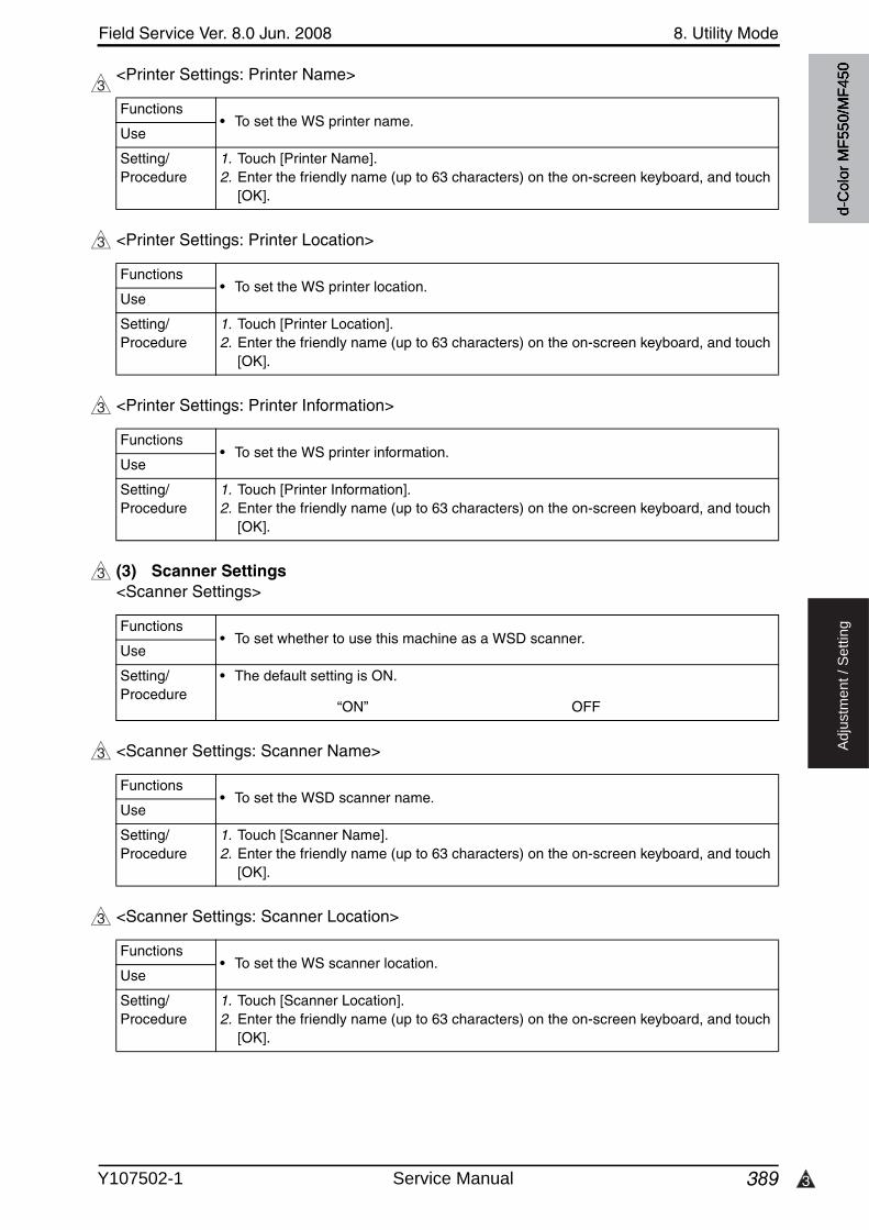
3
Field Service Ver. 8.0 Jun. 2008 8. Utility Mode
389
Ad
justm
en
t /
Se
ttin
g
<Printer Settings: Printer Name>
<Printer Settings: Printer Location>
<Printer Settings: Printer Information>
(3) Scanner Settings<Scanner Settings>
<Scanner Settings: Scanner Name>
<Scanner Settings: Scanner Location>
3
Functions• To set the WS printer name.
Use
Setting/Procedure
1. Touch [Printer Name].2. Enter the friendly name (up to 63 characters) on the on-screen keyboard, and touch
[OK].
3
Functions• To set the WS printer location.
Use
Setting/Procedure
1. Touch [Printer Location].2. Enter the friendly name (up to 63 characters) on the on-screen keyboard, and touch
[OK].
3
Functions• To set the WS printer information.
Use
Setting/Procedure
1. Touch [Printer Information].2. Enter the friendly name (up to 63 characters) on the on-screen keyboard, and touch
[OK].
3
Functions• To set whether to use this machine as a WSD scanner.
Use
Setting/Procedure
• The default setting is ON.
“ON” OFF
3
Functions• To set the WSD scanner name.
Use
Setting/Procedure
1. Touch [Scanner Name].2. Enter the friendly name (up to 63 characters) on the on-screen keyboard, and touch
[OK].
3
Functions• To set the WS scanner location.
Use
Setting/Procedure
1. Touch [Scanner Location].2. Enter the friendly name (up to 63 characters) on the on-screen keyboard, and touch
[OK].
d-C
olor
MF5
50/M
F450
Y107502-1 Service Manual

8. Utility Mode Field Service Ver. 8.0 Jun. 2008
3903
Ad
justm
en
t /
Se
ttin
g
<Scanner Settings: Scanner Information>
<Scanner Settings: Connection Timeout>
O. Detail Settings(1) Device Setting<MAC Address>
<Network Speed>
(2) Time Adjustment Setting
3
Functions• To set the WS scanner information.
Use
Setting/Procedure
1. Touch [Scanner Information].2. Enter the friendly name (up to 63 characters) on the on-screen keyboard, and touch
[OK].
3
Functions• To set the timeout period for connection of WS scanner.
Use
Setting/Procedure
1. Press the Clear key.2. Enter the connecting timeout period between 30 and 300 using the 10-key pad.
Functions • To display the MAC address of the machine.
Use • To check the MAC address of the machine.
Setting/Procedure
• The address cannot be changed.
Functions • To set the network speed.
Use • To set the specific network speed.
Setting/Procedure
• The default setting is Auto.
“Auto” 10Mbps Full Duplex 10Mbps Half Duplex 100Mbps Full Duplex 100Mbps Half Duplex 1Gbps Full Duplex
NOTE• When Network speed setting is changed, turn off the main power switch and
turn it on again more than 10 seconds after.
Functions • To set whether to enable or disable the NTP setting.
Use • To synchronize the time between the server and the client.
Setting/Procedure
• The default setting is OFF.
ON “OFF”
d-C
olor
MF5
50/M
F450
Service Manual Y107502-1
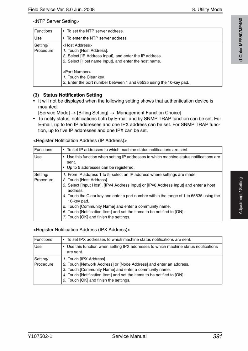
Field Service Ver. 8.0 Jun. 2008 8. Utility Mode
391
Ad
justm
en
t /
Se
ttin
g
<NTP Server Setting>
(3) Status Notification Setting• It will not be displayed when the following setting shows that authentication device is
mounted.[Service Mode] [Billing Setting] [Management Function Choice]
• To notify status, notifications both by E-mail and by SNMP TRAP function can be set. For E-mail, up to ten IP addresses and one IPX address can be set. For SNMP TRAP func-tion, up to five IP addresses and one IPX can be set.
<Register Notification Address (IP Address)>
<Register Notification Address (IPX Address)>
Functions • To set the NTP server address.
Use • To enter the NTP server address.
Setting/Procedure
<Host Address>1. Touch [Host Address].2. Select [IP Address Input], and enter the IP address.3. Select [Host name Input], and enter the host name.
<Port Number>1. Touch the Clear key.2. Enter the port number between 1 and 65535 using the 10-key pad.
Functions • To set IP addresses to which machine status notifications are sent.
Use • Use this function when setting IP addresses to which machine status notifications are sent.
• Up to 5 addresses can be registered.
Setting/Procedure
1. From IP address 1 to 5, select an IP address where settings are made. 2. Touch [Host Address].3. Select [Input Host], [IPv4 Address Input] or [IPv6 Address Input] and enter a host
address.4. Touch the Clear key and enter a port number within the range of 1 to 65535 using the
10-key pad.5. Touch [Community Name] and enter a community name.6. Touch [Notification Item] and set the items to be notified to [ON].7. Touch [OK] and finish the settings.
Functions • To set IPX addresses to which machine status notifications are sent.
Use • Use this function when setting IPX addresses to which machine status notifications are sent.
Setting/Procedure
1. Touch [IPX Address].2. Touch [Network Address] or [Node Address] and enter an address.3. Touch [Community Name] and enter a community name.4. Touch [Notification Item] and set the items to be notified to [ON].5. Touch [OK] and finish the settings.
d-C
olor
MF5
50/M
F450
Y107502-1 Service Manual
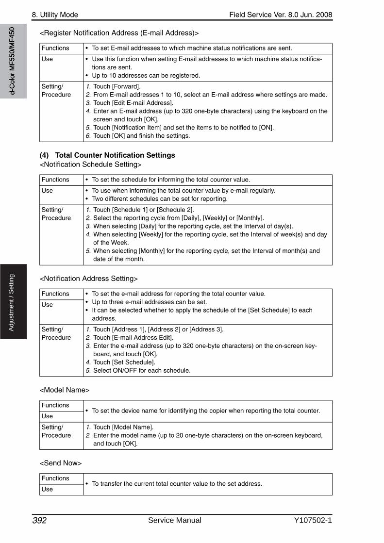
8. Utility Mode Field Service Ver. 8.0 Jun. 2008
392
Ad
justm
en
t /
Se
ttin
g
<Register Notification Address (E-mail Address)>
(4) Total Counter Notification Settings<Notification Schedule Setting>
<Notification Address Setting>
<Model Name>
<Send Now>
Functions • To set E-mail addresses to which machine status notifications are sent.
Use • Use this function when setting E-mail addresses to which machine status notifica-tions are sent.
• Up to 10 addresses can be registered.
Setting/Procedure
1. Touch [Forward].2. From E-mail addresses 1 to 10, select an E-mail address where settings are made.3. Touch [Edit E-mail Address].4. Enter an E-mail address (up to 320 one-byte characters) using the keyboard on the
screen and touch [OK].5. Touch [Notification Item] and set the items to be notified to [ON].6. Touch [OK] and finish the settings.
Functions • To set the schedule for informing the total counter value.
Use • To use when informing the total counter value by e-mail regularly.• Two different schedules can be set for reporting.
Setting/Procedure
1. Touch [Schedule 1] or [Schedule 2].2. Select the reporting cycle from [Daily], [Weekly] or [Monthly].3. When selecting [Daily] for the reporting cycle, set the Interval of day(s).4. When selecting [Weekly] for the reporting cycle, set the Interval of week(s) and day
of the Week.5. When selecting [Monthly] for the reporting cycle, set the Interval of month(s) and
date of the month.
Functions • To set the e-mail address for reporting the total counter value.• Up to three e-mail addresses can be set.• It can be selected whether to apply the schedule of the [Set Schedule] to each
address.
Use
Setting/Procedure
1. Touch [Address 1], [Address 2] or [Address 3].2. Touch [E-mail Address Edit].3. Enter the e-mail address (up to 320 one-byte characters) on the on-screen key-
board, and touch [OK].4. Touch [Set Schedule].5. Select ON/OFF for each schedule.
Functions• To set the device name for identifying the copier when reporting the total counter.
Use
Setting/Procedure
1. Touch [Model Name].2. Enter the model name (up to 20 one-byte characters) on the on-screen keyboard,
and touch [OK].
Functions• To transfer the current total counter value to the set address.
Use
d-C
olor
MF5
50/M
F450
Service Manual Y107502-1

Field Service Ver. 8.0 Jun. 2008 8. Utility Mode
393
Ad
justm
en
t /
Se
ttin
g
(5) PING Confirmation
(6) SLP Setting
(7) LPD Setting
(8) Prefix/Suffix Setting<ON/OFF Setting>
<Prefix/Suffix Setting>
(9) Action for Invalid Certificate
Functions • To set the TCP/IP network diagnosis by PING.
Use • To check the condition of TCP/IP network.
Setting/Procedure
1. Touch [Host Address] for PING transmission.2. Select [Input Host Name], [IPv4 Address Input], or [IPv6 Address Input] and enter a
host address.3. Touch [Check Connection] key to check the connection.
Functions • To set whether to use SLP or not.Device search will be available with TWAIN by setting SLP enable.Use
Setting/Procedure
• The default setting is Enable.
“Enable” Disable
Functions• To set whether to use LPD during printing or not.
Use
Setting/Procedure
• The default setting is Enable.
“Enable” Disable
Functions • To set whether to add prefix or suffix to the address when calling or entering an address.
Use • To add prefix or suffix to the address.
Setting/Procedure
• The default setting is OFF.
ON “OFF”
Functions • To register or change the prefix or suffix.• Eight types of prefix and suffix can be added.
Prefix: Letters added to the top of the text (header part)Suffix: Letters added to the bottom of the text (footer part)
Use • To register or change the address displayed for prefix or suffix.
Setting/Procedure
• Available number to be registered as prefix is up to 20 characters.• Available number to be registered as suffix is up to 64 characters.
Functions• To set how to process the job when SSL certificate becomes invalid.
Use
Setting/Procedure
• The default setting is Continue.
“Continue” Delete the Job
d-C
olor
MF5
50/M
F450
Y107502-1 Service Manual
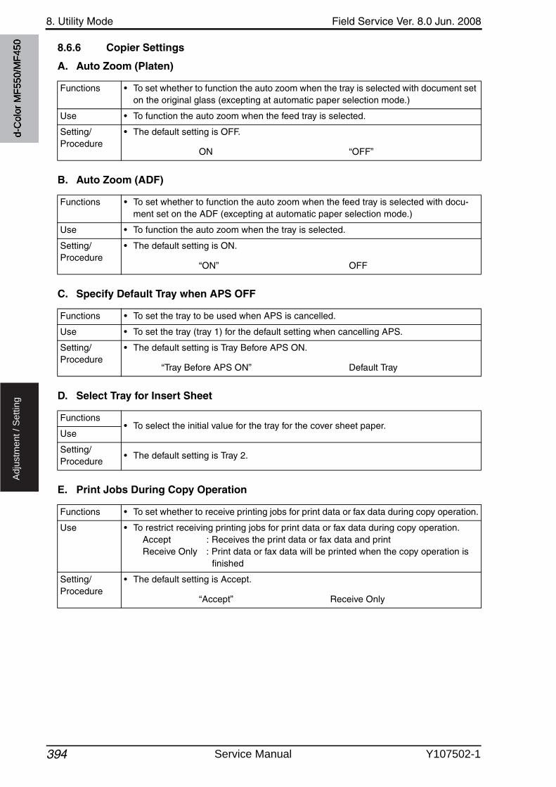
8. Utility Mode Field Service Ver. 8.0 Jun. 2008
394
Ad
justm
en
t /
Se
ttin
g
8.6.6 Copier Settings
A. Auto Zoom (Platen)
B. Auto Zoom (ADF)
C. Specify Default Tray when APS OFF
D. Select Tray for Insert Sheet
E. Print Jobs During Copy Operation
Functions • To set whether to function the auto zoom when the tray is selected with document set on the original glass (excepting at automatic paper selection mode.)
Use • To function the auto zoom when the feed tray is selected.
Setting/Procedure
• The default setting is OFF.
ON “OFF”
Functions • To set whether to function the auto zoom when the feed tray is selected with docu-ment set on the ADF (excepting at automatic paper selection mode.)
Use • To function the auto zoom when the tray is selected.
Setting/Procedure
• The default setting is ON.
“ON” OFF
Functions • To set the tray to be used when APS is cancelled.
Use • To set the tray (tray 1) for the default setting when cancelling APS.
Setting/Procedure
• The default setting is Tray Before APS ON.
“Tray Before APS ON” Default Tray
Functions• To select the initial value for the tray for the cover sheet paper.
Use
Setting/Procedure
• The default setting is Tray 2.
Functions • To set whether to receive printing jobs for print data or fax data during copy operation.
Use • To restrict receiving printing jobs for print data or fax data during copy operation.Accept : Receives the print data or fax data and printReceive Only : Print data or fax data will be printed when the copy operation is
finished
Setting/Procedure
• The default setting is Accept.
“Accept” Receive Only
d-C
olor
MF5
50/M
F450
Service Manual Y107502-1
7
Field Service Ver. 8.0 Jun. 2008 8. Utility Mode
395
Ad
justm
en
t /
Se
ttin
g
F. Tri-Fold Print Side• It will be displayed only when the optional finisher FS-608 is mounted.
G. Automatic Image Rotation
8.6.7 Printer Settings
A. USB Timeout
B. Network Timeout
Functions • Specifies the side of copies to be folded.
Inside : Folds paper in three with the printed side in.Outside : Folds paper in three with the printed side out.
Use
Setting/Procedure
• The default setting is Inside.
Outside “Inside”
7
Functions • Select whether or not the image is automatically rotated when the document and copy paper orientations are different.
Use When Auto Paper / Auto Zoom / Reduce is set: If the “Auto” Paper setting, “Auto” Zoom setting or a Reduce setting is selected, the image is automatically rotated to fit the orientation of the paper.
When Auto Paper / Auto Zoom is set : If the “Auto” Paper setting or “Auto” Zoom setting is selected, the image is automatically rotated to fit the orienta-tion of the paper.
When Auto Zoom / Reduce is set : If the “Auto” Zoom setting or a Reducesetting is selected, the image is auto-matically rotated to fit the orientation of the paper.
When Auto Zoom is set : If the “Auto” Zoom setting is selected, the image is automatically rotated to fit the orientation of the paper.
Setting/Procedure
• The default setting is When Auto Paper / Auto Zoom is set.
When Auto Paper / Auto Zoom / Reduce is set “When Auto Paper / Auto Zoom is set”When Auto Zoom / Reduce is set When Auto Zoom is set
Functions • To set a period of time that elapses before input and output timeouts of communica-tion are activated.
Use • To set a period of time that elapses before input and output timeouts of communica-tion are activated.
Setting/Procedure
• The default setting is 60 seconds for input and output timeouts.
“60 seconds” (10 to 1000 seconds)
Functions • To set a period of time that elapses before input and output timeouts of communica-tion are activated.
Use • To set a longer time period when timeout happens under some network statuses.
Setting/Procedure
• The default setting is 60 seconds for input and output timeouts.
“60 seconds” (10 to 1000 seconds)
d-C
olor
MF5
50/M
F450
Y107502-1 Service Manual
8. Utility Mode Field Service Ver. 8.0 Jun. 2008
3963
Ad
justm
en
t /
Se
ttin
g
C. Print XPS Errors• This is displayed only when the function enhanced version 2 or later firmware is installed.
8.6.8 Fax Settings
• Settings are available only when the optional fax kit (FK-502) is mounted.
A. Header Information
B. Header/Footer Position(1) Header Position
(2) Print Receiver’s Name• It will not be displayed on the screen when [Fax Target] is set to “US” or “HK” in the fol-
lowing settings.[Service Mode] [System 1] [Marketing Area]
3
Functions • To set whether to print error information when an error occurs while printing a XPS file.Use
Setting/Procedure
• The default setting is Yes.
“Yes” No
Functions • To register the name of the sender and fax ID which will be printed when transmitting fax.
Use • To register or change the name of the sender and fax ID.
Setting/Procedure
1. Touch [Sender] and enter the name of the sender (up to 30 characters) on the on-screen keyboard.
2. Enter Sender Fax No. (up to 20 characters) using the 10-key pad and [+], [Space] displayed on the screen.
Functions • To set the position to print the header when transmitting fax.
Use • To change the position to print the header.
Setting/Procedure
• The default setting is Outside Body Text.
Inside Body Text “Outside Body Text” OFF
NOTE• [Outside Body Text] cannot be selected for Internet Fax/IP Address Fax.
Functions • To set whether to print the information of TX destination (Registered name or Fax No.) when transmitting fax.
Use • To print information of TX destination. (Registered name or Fax No.)
Setting/Procedure
• The default setting is OFF.
ON “OFF”
d-C
olor
MF5
50/M
F450
Service Manual Y107502-1
Field Service Ver. 8.0 Jun. 2008 8. Utility Mode
397
Ad
justm
en
t /
Se
ttin
g
(3) Footer Position
C. Line Parameter Setting(1) Dialing Method
(2) Receive Mode• It will not be displayed when the following setting shows that management device 2 is
mounted.[Service Mode] [Billing Setting] [Management Function Choice]
(3) Number of RX Call Rings
Functions • To set whether to print the footer when transmitting fax.
Use • To print the footer when transmitting fax.
Setting/Procedure
• The default setting is OFF.
Inside Body Text Outside Body Text “OFF”
NOTE• [Outside Body Text] cannot be selected for the color mode of Internet Fax/IP
Address Fax.
Functions • To set the dialing method.
Use • To change the dialing method.• The displays are different depending on the country.
Setting/Procedure
• The default setting is PB.
“PB” 10 pps
NOTE• The displays are different depending on the country.
Functions • To set the fax reception mode.
Use • To change to manual reception when using the remote reception function, etc. whenconnected to the external telephone.
Setting/Procedure
• The default setting is Auto RX.
“Auto RX” Manual RX
Functions • To set the number of times to receive call rings.
Use • To change the number of times of the fake ringback tone after it starts calling until it starts receiving.
Setting/Procedure
• The default setting is 2 X.
“2 X” (0 to 15)
d-C
olor
MF5
50/M
F450
Y107502-1 Service Manual
8. Utility Mode Field Service Ver. 8.0 Jun. 2008
398
Ad
justm
en
t /
Se
ttin
g
(4) Number of Redials
(5) Redial Interval
(6) Line Monitor Sound
(7) Line Monitor Sound Vol.
D. TX/RX Settings(1) Duplex Print (RX)• It will not be displayed when [Print Separate Fax Pages] is set to “ON.”
(2) Letter/Ledger over A4/A3
Functions • To set the number of redials.
Use • To change the number of times to redial when the line is busy, etc.• The line which can be set up is different depending on the country.
Setting/Procedure
• The default setting is 3 X.
“3 X” (0 to 7)
NOTE• The line which can be set up is different depending on the country.
Functions • To set the interval for redialing.
Use • To change the interval for redialing.
Setting/Procedure
• The default setting is 3 min.
“3 min” (1 to 15)
Functions• To set whether to output the line monitor sound from the speaker or not.
Use
Setting/Procedure
• The default setting is ON.
“ON” OFF
Functions • To set the volume of the speaker.
Use • To change the volume of the speaker.
Setting/Procedure
• Change the volume by touching the [Lower] or [Higher].
Functions • To set whether to carry out the duplex print for the received original when receiving fax.
Use • To carry out the duplex print for the received original.
Setting/Procedure
• The default setting is OFF.
ON “OFF”
Functions • To set weather to use the inch paper priority when receiving fax.
Use • To use the inch paper priority when receiving fax.
Setting/Procedure ON OFF
NOTE• The default setting is different depending on the country.
d-C
olor
MF5
50/M
F450
Service Manual Y107502-1
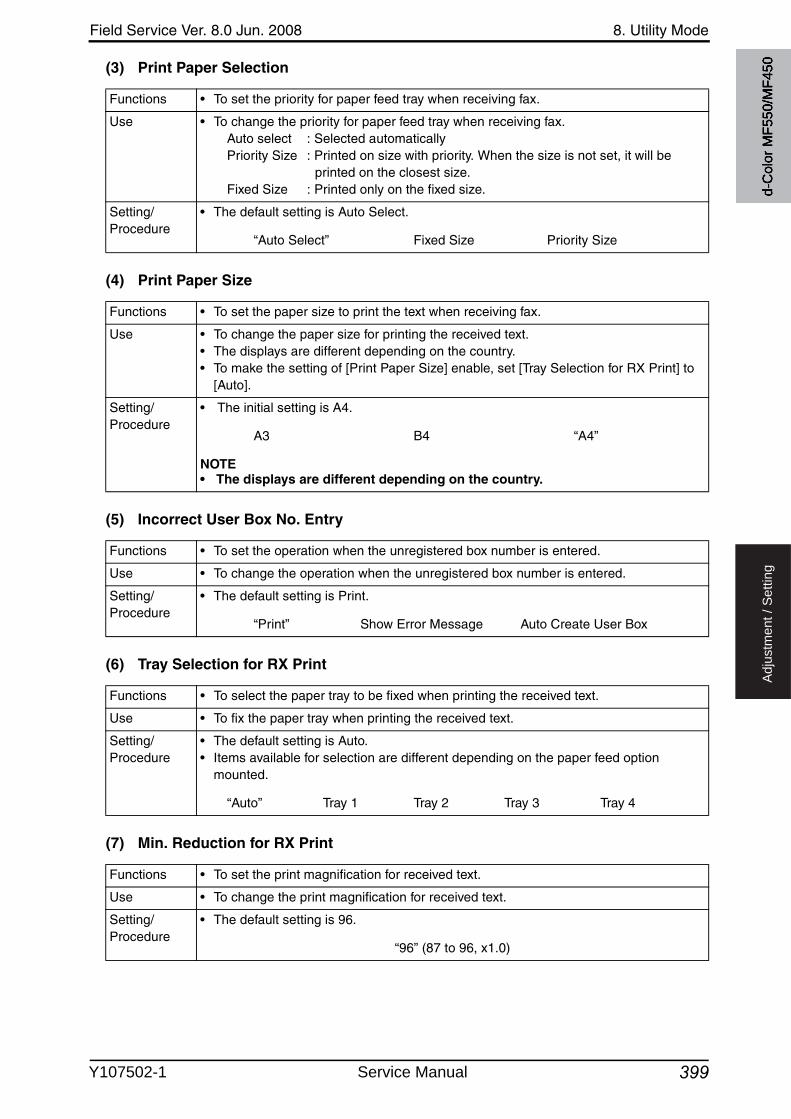
Field Service Ver. 8.0 Jun. 2008 8. Utility Mode
399
Ad
justm
en
t /
Se
ttin
g
(3) Print Paper Selection
(4) Print Paper Size
(5) Incorrect User Box No. Entry
(6) Tray Selection for RX Print
(7) Min. Reduction for RX Print
Functions • To set the priority for paper feed tray when receiving fax.
Use • To change the priority for paper feed tray when receiving fax.Auto select : Selected automaticallyPriority Size : Printed on size with priority. When the size is not set, it will be
printed on the closest size.Fixed Size : Printed only on the fixed size.
Setting/Procedure
• The default setting is Auto Select.
“Auto Select” Fixed Size Priority Size
Functions • To set the paper size to print the text when receiving fax.
Use • To change the paper size for printing the received text.• The displays are different depending on the country.• To make the setting of [Print Paper Size] enable, set [Tray Selection for RX Print] to
[Auto].
Setting/Procedure
• The initial setting is A4.
A3 B4 “A4”
NOTE• The displays are different depending on the country.
Functions • To set the operation when the unregistered box number is entered.
Use • To change the operation when the unregistered box number is entered.
Setting/Procedure
• The default setting is Print.
“Print” Show Error Message Auto Create User Box
Functions • To select the paper tray to be fixed when printing the received text.
Use • To fix the paper tray when printing the received text.
Setting/Procedure
• The default setting is Auto.• Items available for selection are different depending on the paper feed option
mounted.
“Auto” Tray 1 Tray 2 Tray 3 Tray 4
Functions • To set the print magnification for received text.
Use • To change the print magnification for received text.
Setting/Procedure
• The default setting is 96.
“96” (87 to 96, x1.0)
d-C
olor
MF5
50/M
F450
Y107502-1 Service Manual
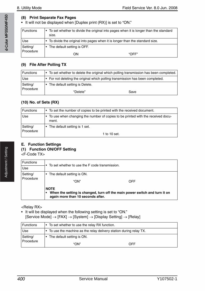
8. Utility Mode Field Service Ver. 8.0 Jun. 2008
400
Ad
justm
en
t /
Se
ttin
g
(8) Print Separate Fax Pages• It will not be displayed when [Duplex print (RX)] is set to “ON.”
(9) File After Polling TX
(10) No. of Sets (RX)
E. Function Settings(1) Function ON/OFF Setting<F-Code TX>
<Relay RX>• It will be displayed when the following setting is set to “ON.”
[Service Mode] [FAX] [System] [Display Setting] [Relay]
Functions • To set whether to divide the original into pages when it is longer than the standard size.
Use • To divide the original into pages when it is longer than the standard size.
Setting/Procedure
• The default setting is OFF.
ON “OFF”
Functions • To set whether to delete the original which polling transmission has been completed.
Use • For not deleting the original which polling transmission has been completed.
Setting/Procedure
• The default setting is Delete.
“Delete” Save
Functions • To set the number of copies to be printed with the received document.
Use • To use when changing the number of copies to be printed with the received docu-ment.
Setting/Procedure
• The default setting is 1 set.
1 to 10 set.
Functions• To set whether to use the F code transmission.
Use
Setting/Procedure
• The default setting is ON.
“ON” OFF
NOTE• When the setting is changed, turn off the main power switch and turn it on
again more than 10 seconds after.
Functions • To set whether to use the relay RX function.
Use • To use the machine as the relay delivery station during relay TX.
Setting/Procedure
• The default setting is ON.
“ON” OFF
d-C
olor
MF5
50/M
F450
Service Manual Y107502-1
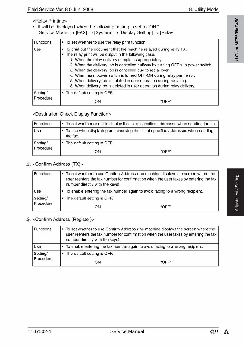
4
Field Service Ver. 8.0 Jun. 2008 8. Utility Mode
401
Ad
justm
en
t /
Se
ttin
g
<Relay Printing>• It will be displayed when the following setting is set to “ON.”
[Service Mode] [FAX] [System] [Display Setting] [Relay]
<Destination Check Display Function>
<Confirm Address (TX)>
<Confirm Address (Register)>
Functions • To set whether to use the relay print function.
Use • To print out the document that the machine relayed during relay TX.• The relay print will be output in the following case.
1. When the relay delivery completes appropriately.2. When the delivery job is cancelled halfway by turning OFF sub power switch.3. When the delivery job is cancelled due to redial over.4. When main power switch is turned OFF/ON during relay print error. 5. When delivery job is deleted in user operation during redialing.6. When delivery job is deleted in user operation during relay delivery.
Setting/Procedure
• The default setting is OFF.
ON “OFF”
Functions • To set whether or not to display the list of specified addresses when sending the fax.
Use • To use when displaying and checking the list of specified addresses when sending the fax.
Setting/Procedure
• The default setting is OFF.
ON “OFF”
4
Functions • To set whether to use Confirm Address (the machine displays the screen where the user reenters the fax number for confirmation when the user faxes by entering the fax number directly with the keys).
Use • To enable entering the fax number again to avoid faxing to a wrong recipient.
Setting/Procedure
• The default setting is OFF.
ON “OFF”
d-C
olor
MF5
50/M
F450
Y107502-1 Service Manual

8. Utility Mode Field Service Ver. 8.0 Jun. 2008
402
Ad
justm
en
t /
Se
ttin
g
(2) Memory RX Setting• It will be displayed only when the following setting is set to “ON.”
[Service Mode] [FAX] [System] [Display Setting] [Compulsory Memory RX]• It will not be displayed when [PC-FAX RX Setting], [Forward TX Setting] or [TSI User Box
Setting] is set to “ON.”• It will not be displayed when the following setting shows that vendor is mounted.
[Service Mode] [Billing Setting] [Management Function Choice]
(3) Closed Network RX• It will be displayed when the following setting is set to “ON.”
[Service Mode] [FAX] [System] [Display Setting] [Closed area RX]
(4) Forward TX Setting• It will not be displayed when [PC-FAX RX Setting], [Memory RX] or [TSI User Box Set-
ting] is set to “ON.”• It will not be displayed when the following setting shows that Vendor or Authentication
Device is mounted.[Service Mode] [Billing Setting] [Management Function Choice]
Functions • To set whether to use the forced memory RX function.
Use • To store the received text in the hard disk without printing, and print it out whenordered.
Setting/Procedure
• The default setting is NO.
• Enter the password (up to 8 digits) for printing when set to [ON].
Functions • To set whether to use the closed network function.
Use • To receive data only from the device which password matches.
Setting/Procedure
• The default setting is OFF.
• When set to [ON], enter the password (up to 4 digits) to be used.
Functions • To set whether to use the forward fax function.
Use • To forward the received text to the receiver which has been specified.Forward & Print : Forward the received text, and print all outForward & Print (If TX Fails) : Forward the received text, and prints out only when
fails to be forwarded
Setting/Procedure
<Forward TX Setting>• The default setting is No.
• When set to [Yes], set the address to forward to.
d-C
olor
MF5
50/M
F450
Service Manual Y107502-1

Field Service Ver. 8.0 Jun. 2008 8. Utility Mode
403
Ad
justm
en
t /
Se
ttin
g
(5) Incomplete TX Hold• It will be displayed when the following setting is set to “ON.”
[Service Mode] [FAX] [System] [Display Setting] [Re-Transmission]• It will not be displayed when the following setting shows that Management Device 2 is
mounted.[Service Mode] [Billing Setting] [Management Function Choice]
(6) PC-Fax RX Setting• It will not be displayed when [Forward TX Setting], [Memory RX] or [TSI User Box Set-
ting] is set to “ON.”
(7) TSI User Box Setting• It will not be displayed when [Forward TX Setting], [Memory RX] or [PC-Fax RX Setting]
is set to “ON.”
Functions • To set whether to use incomplete TX hold function.
Use • To re-send the data failed to be sent after a given time.
Setting/Procedure
• The default setting is No.
ON “No”
• When set to Yes, specify the Incomplete TX Hold Time.
Functions • To set whether to use the PC-FAX reception function.
Use • To store the received text file in the box in the hard disk.
Setting/Procedure
• The default setting is Restrict.
Allow “Restrict”
• When Allow is selected, make the settings of Receiving user box destination, Print ON/OFF, and Password check ON/OFF.
Functions • To set whether to use TSI distribution or not.• To set setting method when there is no matched box at receiving.
Use • To use TSI distribution.• To change setting method when there is no matched box at receiving.
Automatically Print : To print the received data.Memory RX Use Box : To store the received data in the forced memory receiving
box.
Setting/Procedure
<TSI User Box Setting>• The default setting is No.
Yes “No”
• Press [TSI User Box Registration] and register the distribution.
<Non-matched Box Setting>• The default setting is Automatically Print.
“Automatically Print” Memory RX User Box
d-C
olor
MF5
50/M
F450
Y107502-1 Service Manual
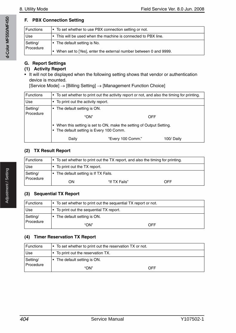
8. Utility Mode Field Service Ver. 8.0 Jun. 2008
404
Ad
justm
en
t /
Se
ttin
g
F. PBX Connection Setting
G. Report Settings(1) Activity Report• It will not be displayed when the following setting shows that vendor or authentication
device is mounted.[Service Mode] [Billing Setting] [Management Function Choice]
(2) TX Result Report
(3) Sequential TX Report
(4) Timer Reservation TX Report
Functions • To set whether to use PBX connection setting or not.
Use • This will be used when the machine is connected to PBX line.
Setting/Procedure
• The default setting is No.
• When set to [Yes], enter the external number between 0 and 9999.
Functions • To set whether to print out the activity report or not, and also the timing for printing.
Use • To print out the activity report.
Setting/Procedure
• The default setting is ON.
“ON” OFF
• When this setting is set to ON, make the setting of Output Setting.• The default setting is Every 100 Comm.
Daily “Every 100 Comm.” 100/ Daily
Functions • To set whether to print out the TX report, and also the timing for printing.
Use • To print out the TX report.
Setting/Procedure
• The default setting is If TX Fails.
ON “If TX Fails” OFF
Functions • To set whether to print out the sequential TX report or not.
Use • To print out the sequential TX report.
Setting/Procedure
• The default setting is ON.
“ON” OFF
Functions • To set whether to print out the reservation TX or not.
Use • To print out the reservation TX.
Setting/Procedure
• The default setting is ON.
“ON” OFF
d-C
olor
MF5
50/M
F450
Service Manual Y107502-1
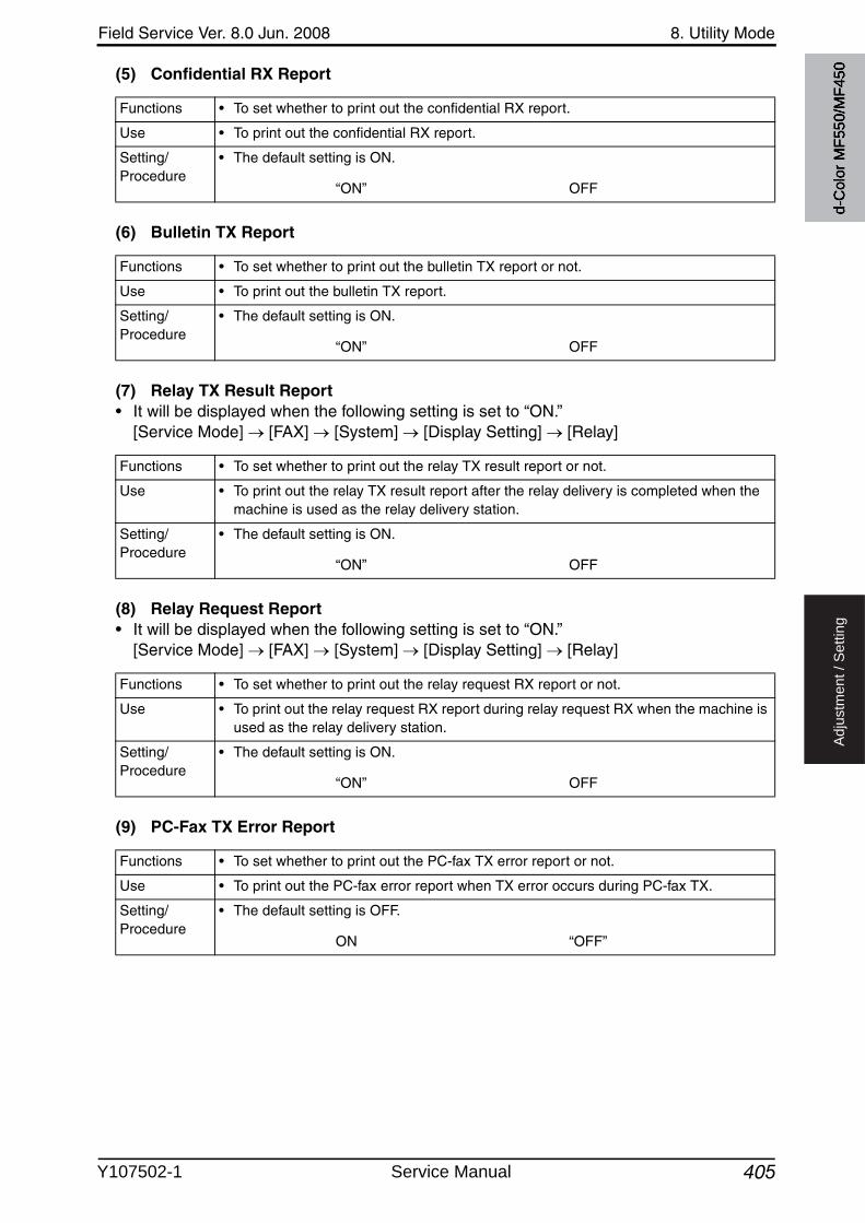
Field Service Ver. 8.0 Jun. 2008 8. Utility Mode
405
Ad
justm
en
t /
Se
ttin
g
(5) Confidential RX Report
(6) Bulletin TX Report
(7) Relay TX Result Report• It will be displayed when the following setting is set to “ON.”
[Service Mode] [FAX] [System] [Display Setting] [Relay]
(8) Relay Request Report• It will be displayed when the following setting is set to “ON.”
[Service Mode] [FAX] [System] [Display Setting] [Relay]
(9) PC-Fax TX Error Report
Functions • To set whether to print out the confidential RX report.
Use • To print out the confidential RX report.
Setting/Procedure
• The default setting is ON.
“ON” OFF
Functions • To set whether to print out the bulletin TX report or not.
Use • To print out the bulletin TX report.
Setting/Procedure
• The default setting is ON.
“ON” OFF
Functions • To set whether to print out the relay TX result report or not.
Use • To print out the relay TX result report after the relay delivery is completed when the machine is used as the relay delivery station.
Setting/Procedure
• The default setting is ON.
“ON” OFF
Functions • To set whether to print out the relay request RX report or not.
Use • To print out the relay request RX report during relay request RX when the machine is used as the relay delivery station.
Setting/Procedure
• The default setting is ON.
“ON” OFF
Functions • To set whether to print out the PC-fax TX error report or not.
Use • To print out the PC-fax error report when TX error occurs during PC-fax TX.
Setting/Procedure
• The default setting is OFF.
ON “OFF”
d-C
olor
MF5
50/M
F450
Y107502-1 Service Manual

8. Utility Mode Field Service Ver. 8.0 Jun. 2008
406
Ad
justm
en
t /
Se
ttin
g
(10) Broadcast Result Report
(11) TX Result Report Check
(12) Network Fax RX Error Report• Settings will be available when either [IP Address Fax] or [Internet Fax] is set to “ON” in
the following settings.[Administrator Settings] [Network Setting] [Network Fax Setting] [Network Fax Function Settings]
(13) MDN Message• Settings will be available only when [Internet Fax] is set to “ON” in the following settings.
[Administrator Settings] [Network Setting] [Network Fax Setting] [Network Fax Function Settings]
(14) DSN Message• Settings will be available only when [Internet Fax] is set to “ON” in the following settings.
[Administrator Settings] [Network Setting] [Network Fax Setting] [Network Fax Function Settings]
Functions • To set the format to output the broadcast result report.
Use • To print out the broadcast result reportAll Destinations : Outputs all reports after transmitting to all addressesEach Destination : Outputs a report after each transmission
Setting/Procedure
• The default setting is All Destinations.
“All Destinations” Each Destination
Functions • To set whether to display the TX result report screen.
Use • To display the TX result report screen.
Setting/Procedure
• The default setting is OFF.
ON “OFF”
Functions • To set whether to print RX error report when network fax function is being used.
Use • To print the error report at unusual situation such as receiving the image data that cannot be processed.
Setting/Procedure
• The default setting is OFF.
ON “OFF”
Functions • To set whether to print message when receiving response message to MDN requestwhen internet fax function is being used.Use
Setting/Procedure
• The default setting is ON
“ON” OFF
Functions • To set whether to print message when receiving response message to DSN request when network fax function is being used.Use
Setting/Procedure
• The default setting is OFF.
ON “OFF”
d-C
olor
MF5
50/M
F450
Service Manual Y107502-1
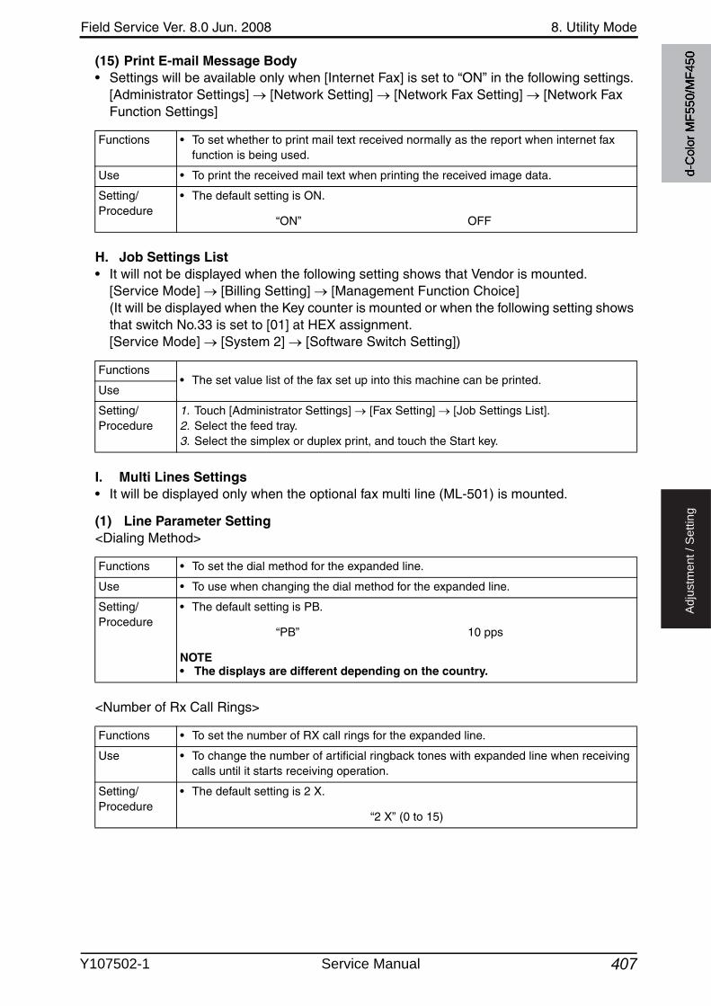
Field Service Ver. 8.0 Jun. 2008 8. Utility Mode
407
Ad
justm
en
t /
Se
ttin
g
(15) Print E-mail Message Body• Settings will be available only when [Internet Fax] is set to “ON” in the following settings.
[Administrator Settings] [Network Setting] [Network Fax Setting] [Network Fax Function Settings]
H. Job Settings List• It will not be displayed when the following setting shows that Vendor is mounted.
[Service Mode] [Billing Setting] [Management Function Choice] (It will be displayed when the Key counter is mounted or when the following setting showsthat switch No.33 is set to [01] at HEX assignment. [Service Mode] [System 2] [Software Switch Setting])
I. Multi Lines Settings• It will be displayed only when the optional fax multi line (ML-501) is mounted.
(1) Line Parameter Setting<Dialing Method>
<Number of Rx Call Rings>
Functions • To set whether to print mail text received normally as the report when internet fax function is being used.
Use • To print the received mail text when printing the received image data.
Setting/Procedure
• The default setting is ON.
“ON” OFF
Functions• The set value list of the fax set up into this machine can be printed.
Use
Setting/Procedure
1. Touch [Administrator Settings] [Fax Setting] [Job Settings List].2. Select the feed tray.3. Select the simplex or duplex print, and touch the Start key.
Functions • To set the dial method for the expanded line.
Use • To use when changing the dial method for the expanded line.
Setting/Procedure
• The default setting is PB.
“PB” 10 pps
NOTE• The displays are different depending on the country.
Functions • To set the number of RX call rings for the expanded line.
Use • To change the number of artificial ringback tones with expanded line when receiving calls until it starts receiving operation.
Setting/Procedure
• The default setting is 2 X.
“2 X” (0 to 15)
d-C
olor
MF5
50/M
F450
Y107502-1 Service Manual
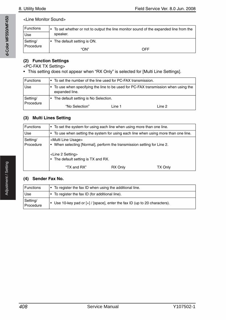
8. Utility Mode Field Service Ver. 8.0 Jun. 2008
408
Ad
justm
en
t /
Se
ttin
g
<Line Monitor Sound>
(2) Function Settings<PC-FAX TX Setting>• This setting does not appear when “RX Only” is selected for [Multi Line Settings].
(3) Multi Lines Setting
(4) Sender Fax No.
Functions • To set whether or not to output the line monitor sound of the expanded line from the speaker.Use
Setting/Procedure
• The default setting is ON.
“ON” OFF
Functions • To set the number of the line used for PC-FAX transmission.
Use • To use when specifying the line to be used for PC-FAX transmission when using the expanded line.
Setting/Procedure
• The default setting is No Selection.
“No Selection” Line 1 Line 2
Functions • To set the system for using each line when using more than one line.
Use • To use when setting the system for using each line when using more than one line.
Setting/Procedure
<Multi Line Usage>• When selecting [Normal], perform the transmission setting for Line 2.
<Line 2 Setting>• The default setting is TX and RX.
“TX and RX” RX Only TX Only
Functions • To register the fax ID when using the additional line.
Use • To register the fax ID (for additional line).
Setting/Procedure
• Use 10-key pad or [+] / [space], enter the fax ID (up to 20 characters).
d-C
olor
MF5
50/M
F450
Service Manual Y107502-1
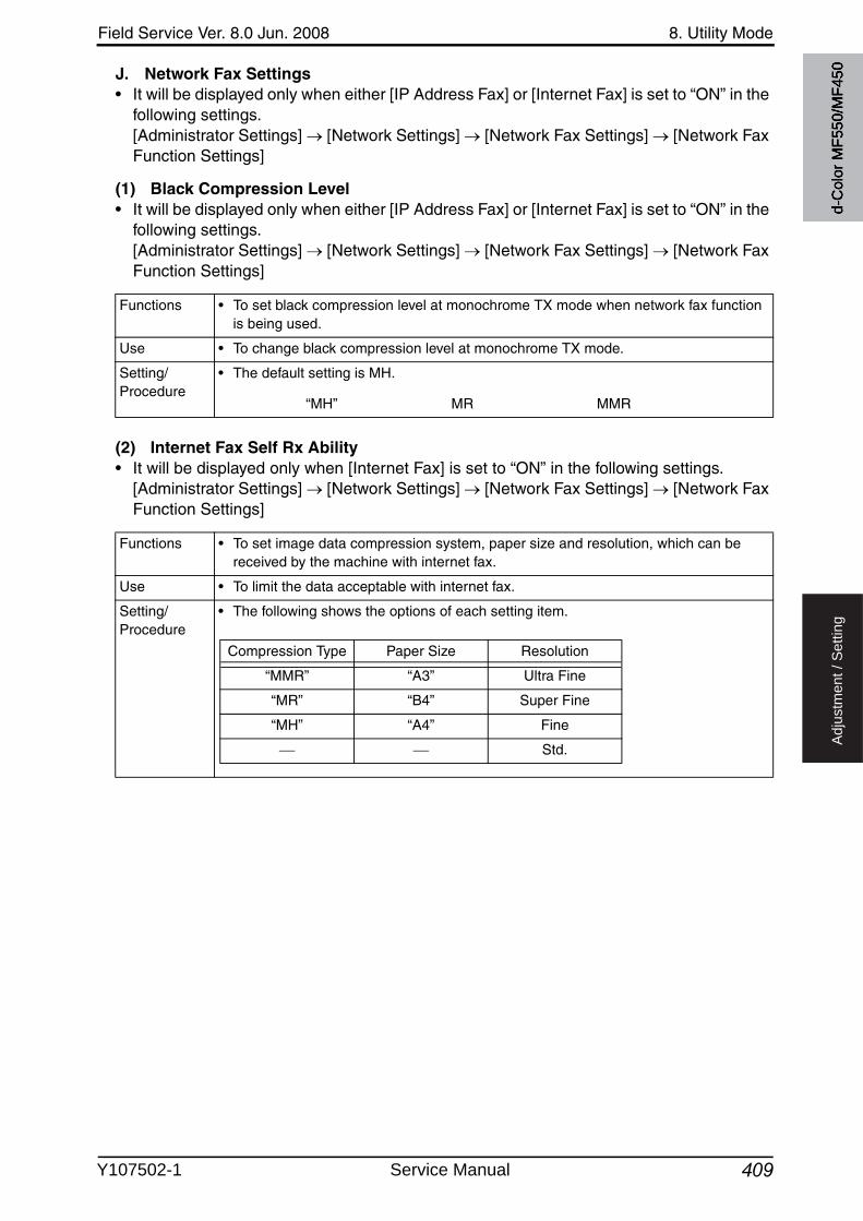
Field Service Ver. 8.0 Jun. 2008 8. Utility Mode
409
Ad
justm
en
t /
Se
ttin
g
J. Network Fax Settings• It will be displayed only when either [IP Address Fax] or [Internet Fax] is set to “ON” in the
following settings.[Administrator Settings] [Network Settings] [Network Fax Settings] [Network Fax Function Settings]
(1) Black Compression Level• It will be displayed only when either [IP Address Fax] or [Internet Fax] is set to “ON” in the
following settings.[Administrator Settings] [Network Settings] [Network Fax Settings] [Network Fax Function Settings]
(2) Internet Fax Self Rx Ability• It will be displayed only when [Internet Fax] is set to “ON” in the following settings.
[Administrator Settings] [Network Settings] [Network Fax Settings] [Network Fax Function Settings]
Functions • To set black compression level at monochrome TX mode when network fax function is being used.
Use • To change black compression level at monochrome TX mode.
Setting/Procedure
• The default setting is MH.
“MH” MR MMR
Functions • To set image data compression system, paper size and resolution, which can be received by the machine with internet fax.
Use • To limit the data acceptable with internet fax.
Setting/Procedure
• The following shows the options of each setting item.
Compression Type Paper Size Resolution
“MMR” “A3” Ultra Fine
“MR” “B4” Super Fine
“MH” “A4” Fine
Std.
d-C
olor
MF5
50/M
F450
Y107502-1 Service Manual
8. Utility Mode Field Service Ver. 8.0 Jun. 2008
410
Ad
justm
en
t /
Se
ttin
g
(3) I-Fax Advanced Settings• It will be displayed only when [Internet Fax] is set to “ON” in the following settings.
[Administrator Settings] [Network Settings] [Network Fax Settings] [Network Fax Function Settings]
8.6.9 System Connection
A. OpenAPI Settings(1) Access Setting
(2) Port Number
Functions • To set advanced functions of internet fax.
MDN Request : To set whether to send MDN (Message Dispo-sition Notification) request when transmitting through internet fax.
DSN Request : To set whether to send DSN (Delivery StatusNotification) request when transmitting through internet fax.
MDN Response : To set whether to response for MDN request made by the other machine when receiving through internet fax.
MDN/DSN Response Watch Time : To set the period to observe the response from the other machine when sending MDN/DSN request. In the case of time over, time out mes-sage is notified.
Max Resolution : To set maximum resolution for reading, TX/RX and record when internet fax function is being used.
NOTE• Only MDN Request will be sent when both MDN Request and DSN Request are
set to “ON.”
Use
Setting/Procedure
• Default settings are shown below.
MDN Request : “ON” OFFDSN Request : ON “OFF”MDN Response : “ON” OFFMDN/DSN Response Watch Time : “24 hours” (1 to 99) OFFMax Resolution : 400 x 400 “600 x 600”
Functions • To allow or restrict the access from other systems with OpenAPI when using Page Scope Data Administrator.
Use • To restrict access from other systems with OpenAPI.
Setting/Procedure
• The default setting is Allow.
“Allow” Restrict
Functions • To set the access port for other systems with OpenAPI when using PageScope Data Administrator.
Use • To change the access port number for other systems with OpenAPI.
Setting/Procedure
1. Select Port No. or Port Number (SSL), and touch [Input].2. Press the Clear key.3. Enter the port number between 1 and 65535 using the 10-key pad.
d-C
olor
MF5
50/M
F450
Service Manual Y107502-1
Field Service Ver. 8.0 Jun. 2008 8. Utility Mode
411
Ad
justm
en
t /
Se
ttin
g
(3) SSL• It will be displayed when certificate is issued from PageScope Web Connection.
(4) Authentication
B. Call Remote Center• It will be displayed when the setup at the CS Remote Care center is complete.
8.6.10 Security Settings
A. Administrator Password
Functions • To set whether to encrypt access from other systems by SSL when using Page Scope Data Administrator.
Use • To encrypt access by SSL from other systems using OpenAPI.
Setting/Procedure
• The default setting is OFF.
ON “OFF”
Functions • To set whether to authenticate access of other systems which uses OpenAPI when using PageScope Data Administrator.
Use • To set authentication of the access from other systems using OpenAPI.
Setting/Procedure
• The default setting is OFF.
ON “OFF”
• When setting to [ON], enter the login name and the password to be set.
Functions • To call the CS Remote Care center from the administrator, when the CS Remote Care setup is complete.Use
Setting/Procedure
For details, see “CS Remote Care.”See P.465
Functions • To set/change the administrator password.
Use • To change the administrator password.
Setting/Procedure
• Enter the administrator password on the on-screen keyboard.
Current Password : Enter the current administrator passwordNew Password : Enter the new administrator password to be usedRe-Input Password : Re-enter the new administrator password
NOTE• When selecting [Utility] [Administrator Settings] [Security Setting]
[Security Details] leads to [Password Rules] being ON, the password with the same letters, the password which is same as the previous one and the pass-word of less than eight digits cannot be changed.
d-C
olor
MF5
50/M
F450
Y107502-1 Service Manual
8. Utility Mode Field Service Ver. 8.0 Jun. 2008
4123
Ad
justm
en
t /
Se
ttin
g
B. User Box Admin. Setting• Setting is disabled if user authentication or account track is not performed.
C. Administrator Security Levels• It will not be displayed when the following setting shows that vendor or authentication
device 1 is mounted.[Service Mode] [Billing Setting] [Management Function Choice]
3
Functions • To set whether to allow or restrict the box administrator to use the system.
Use • To allow the box administrator to use the system.The box administrator is the special administrator for box, who is allowed to browsecontents in common box / individual box without the password.
NOTE• [Allow] cannot be set when the user authentication or account track is not car-
ried out.
Setting/Procedure
• The default setting is Restrict.
Allow “Restrict”
NOTE• [Allow] cannot be selected when user authentication and account track are not
conducted.• [Allow] cannot be selected when the following setting is set to “ON.”
[Administrator Settings] [Security Settings] [Enhanced Security Mode]
• Set the password when setting to [Allow].
NOTE• When the following setting shows that [Password Rules] is set to “ON”, the
Password using only a single letter or the password same with the previous one, or the password with less than eight letters cannot be accepted. [Administrator Settings] [Security Settings]
Functions • To set the level for administrator settings item open to the user.
Use • To make part of the administrator settings items open to the user.Level 1 : [Power Save Setting], [Auto Magnification Selection (Platen)], [Auto
Magnification Selection (ADF)], [Specify Default Tray when APS Off], and [Select Tray for Insert Sheet] are available to users.
Level 2 : [Power Save Setting], [Output Setting], [Date/Time Setting], [Daylight Savings Time Setting], [AE Level Adjustment], [Auto Magnification Selection (Platen)], [Auto Magnification Selection (ADF)], [Specify Default Tray when APS Off], [Select Tray for Insert Sheet], and [Print Jobs During Copy Operation] are available to users.
Prohibit : Not to allow the user to set neither Level 1 nor Level 2
Setting/Procedure
• The default setting is Prohibit.
Level 1 Level 2 “Prohibit”
d-C
olor
MF5
50/M
F450
Service Manual Y107502-1
Field Service Ver. 8.0 Jun. 2008 8. Utility Mode
413
Ad
justm
en
t /
Se
ttin
g
D. Security Details(1) Password Rules
Functions • To set whether to apply the password rules.
Use • To apply the password rule to enhance security.• Passwords to be covered: CE password, administrator password, user box password,
user password, account track password, passwords for con-fidential documents.
• Details of the password rules:Password except user password, user box password shall be 8 digits of one-bite alphanumeric characters. (Case-sensitive)User password shall be 8 digits of one-bite alphanumeric characters. (Case-sensitive)User box password shall be 8 digits of one-bite alphanumeric characters.Password with only the same letter is prohibited.Password same with the one prior to change is prohibited.
When the password rule is set to [ON], the password cannot be changed or registered unless it follows the above conditions.
Setting/Procedure
• The default setting is OFF.
ON “OFF”
NOTE• [OFF] cannot be selected when the following setting is set to “ON.”
[Administrator Settings] [Security Settings] [Enhances Security Mode]• [ON] cannot be selected when the following setting is set to “OFF.”
[Service Mode] [Enhanced Security] [CE Authentication] [CE Authentication] will not be displayed and cannot be set to “OFF” when [Password Rules] is set to “ON.”
d-C
olor
MF5
50/M
F450
Y107502-1 Service Manual
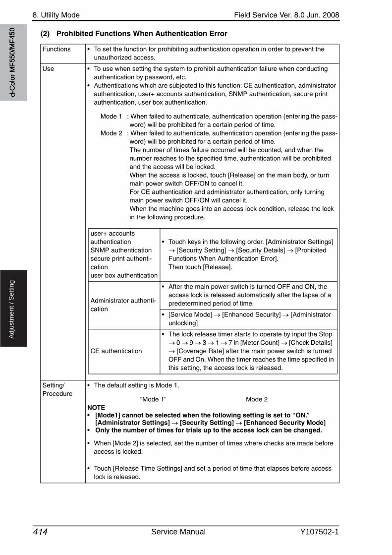
8. Utility Mode Field Service Ver. 8.0 Jun. 2008
414
Ad
justm
en
t /
Se
ttin
g
(2) Prohibited Functions When Authentication Error
Functions • To set the function for prohibiting authentication operation in order to prevent the unauthorized access.
Use • To use when setting the system to prohibit authentication failure when conducting authentication by password, etc.
• Authentications which are subjected to this function: CE authentication, administrator authentication, user+ accounts authentication, SNMP authentication, secure print authentication, user box authentication.
Mode 1 : When failed to authenticate, authentication operation (entering the pass-word) will be prohibited for a certain period of time.
Mode 2 : When failed to authenticate, authentication operation (entering the pass-word) will be prohibited for a certain period of time. The number of times failure occurred will be counted, and when the number reaches to the specified time, authentication will be prohibited and the access will be locked. When the access is locked, touch [Release] on the main body, or turn main power switch OFF/ON to cancel it. For CE authentication and administrator authentication, only turning main power switch OFF/ON will cancel it.When the machine goes into an access lock condition, release the lock in the following procedure.
Setting/Procedure
• The default setting is Mode 1.
“Mode 1” Mode 2NOTE• [Mode1] cannot be selected when the following setting is set to “ON.”
[Administrator Settings] [Security Setting] [Enhanced Security Mode]• Only the number of times for trials up to the access lock can be changed.
• When [Mode 2] is selected, set the number of times where checks are made before access is locked.
• Touch [Release Time Settings] and set a period of time that elapses before access lock is released.
user+ accountsauthenticationSNMP authenticationsecure print authenti-cationuser box authentication
• Touch keys in the following order. [Administrator Settings] [Security Setting] [Security Details] [Prohibited
Functions When Authentication Error]. Then touch [Release].
Administrator authenti-cation
• After the main power switch is turned OFF and ON, the access lock is released automatically after the lapse of a predetermined period of time.
• [Service Mode] [Enhanced Security] [Administrator unlocking]
CE authentication
• The lock release timer starts to operate by input the Stop 0 9 3 1 7 in [Meter Count] [Check Details] [Coverage Rate] after the main power switch is turned
OFF and On. When the timer reaches the time specified in this setting, the access lock is released.
d-C
olor
MF5
50/M
F450
Service Manual Y107502-1
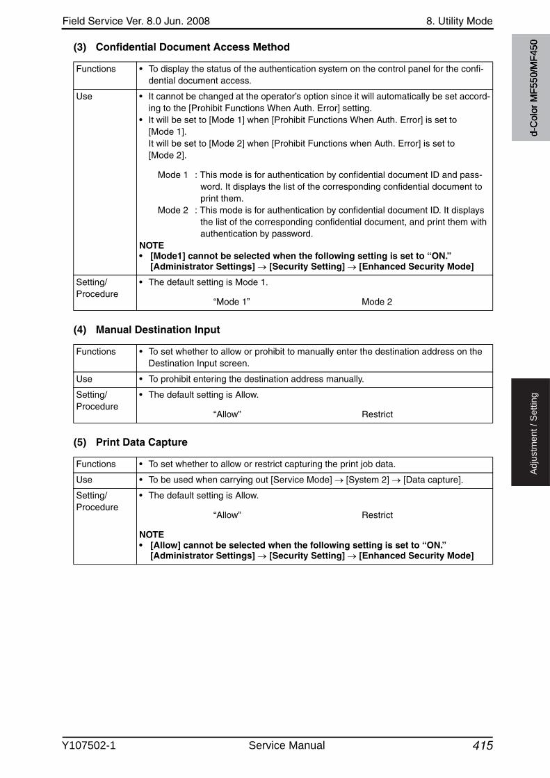
Field Service Ver. 8.0 Jun. 2008 8. Utility Mode
415
Ad
justm
en
t /
Se
ttin
g
(3) Confidential Document Access Method
(4) Manual Destination Input
(5) Print Data Capture
Functions • To display the status of the authentication system on the control panel for the confi-dential document access.
Use • It cannot be changed at the operator’s option since it will automatically be set accord-ing to the [Prohibit Functions When Auth. Error] setting.
• It will be set to [Mode 1] when [Prohibit Functions When Auth. Error] is set to [Mode 1]. It will be set to [Mode 2] when [Prohibit Functions when Auth. Error] is set to [Mode 2].
Mode 1 : This mode is for authentication by confidential document ID and pass-word. It displays the list of the corresponding confidential document to print them.
Mode 2 : This mode is for authentication by confidential document ID. It displays the list of the corresponding confidential document, and print them withauthentication by password.
NOTE• [Mode1] cannot be selected when the following setting is set to “ON.”
[Administrator Settings] [Security Setting] [Enhanced Security Mode]
Setting/Procedure
• The default setting is Mode 1.
“Mode 1” Mode 2
Functions • To set whether to allow or prohibit to manually enter the destination address on the Destination Input screen.
Use • To prohibit entering the destination address manually.
Setting/Procedure
• The default setting is Allow.
“Allow” Restrict
Functions • To set whether to allow or restrict capturing the print job data.
Use • To be used when carrying out [Service Mode] [System 2] [Data capture].
Setting/Procedure
• The default setting is Allow.
“Allow” Restrict
NOTE• [Allow] cannot be selected when the following setting is set to “ON.”
[Administrator Settings] [Security Setting] [Enhanced Security Mode]
d-C
olor
MF5
50/M
F450
Y107502-1 Service Manual

8. Utility Mode Field Service Ver. 8.0 Jun. 2008
4163
Ad
justm
en
t /
Se
ttin
g
(6) Audit Log Settings• This is displayed only when the function enhanced version 2 or later firmware is installed.• It will be displayed when the following setting shows that switch No.42 is set to [01] at
HEX assignment.[Service Mode] [System 2] [Software Switch Setting]
(7) Restrict Fax TX
3
Functions • Selects whether to keep logs of operations and access made by users and serviceengineers.
• To set whether to overwrite existing logs.
Use • To ensure security, this settings is used to keep logs of operations and access includ-ing security settings changes, authentication, and job executions by users and ser-vice engineers.
• Audit logs are saved in HDD and NVRAM.
Setting/Procedure
• The default setting is No.
Yes “No”
NOTE• After selecting “Yes”, the main power switch must be turned OFF and ON so
that the new setting takes effect.• When ON is selected in [Administrator Settings] [Security Settings]
[Enhanced Security Mode], this setting is automatically set to “Yes.”
<Overwrite>• Set whether to allow or restrict overwriting existing logs when saving audit logs.• The default setting is Restrict.
Allow “Restrict”
• To erase audit logs, press [Erase Audit Log].
Functions • To set whether or not to prohibit sending fax.
Use • To prohibit sending fax.
Setting/Procedure
• The default setting is OFF.
ON “OFF”
d-C
olor
MF5
50/M
F450
Service Manual Y107502-1
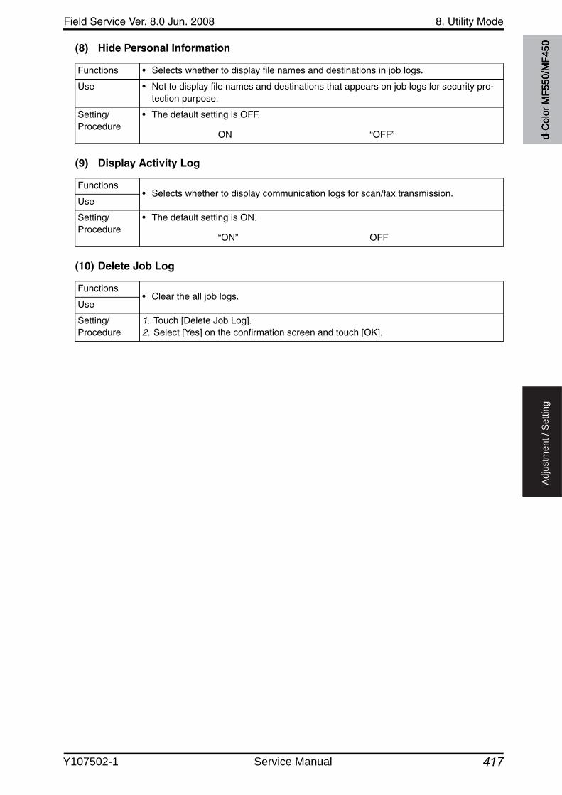
Field Service Ver. 8.0 Jun. 2008 8. Utility Mode
417
Ad
justm
en
t /
Se
ttin
g
(8) Hide Personal Information
(9) Display Activity Log
(10) Delete Job Log
Functions • Selects whether to display file names and destinations in job logs.
Use • Not to display file names and destinations that appears on job logs for security pro-tection purpose.
Setting/Procedure
• The default setting is OFF.
ON “OFF”
Functions• Selects whether to display communication logs for scan/fax transmission.
Use
Setting/Procedure
• The default setting is ON.
“ON” OFF
Functions• Clear the all job logs.
Use
Setting/Procedure
1. Touch [Delete Job Log].2. Select [Yes] on the confirmation screen and touch [OK].
d-C
olor
MF5
50/M
F450
Y107502-1 Service Manual
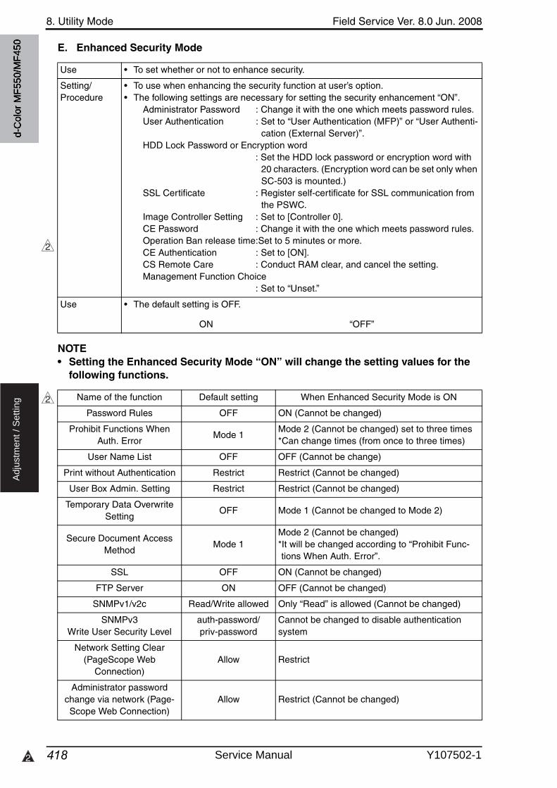
8. Utility Mode Field Service Ver. 8.0 Jun. 2008
4182
Ad
justm
en
t /
Se
ttin
g
E. Enhanced Security Mode
NOTE• Setting the Enhanced Security Mode “ON” will change the setting values for the
following functions.
Use • To set whether or not to enhance security.
Setting/Procedure
• To use when enhancing the security function at user’s option.• The following settings are necessary for setting the security enhancement “ON”.
Administrator Password : Change it with the one which meets password rules.User Authentication : Set to “User Authentication (MFP)” or “User Authenti-
cation (External Server)”.HDD Lock Password or Encryption word
: Set the HDD lock password or encryption word with 20 characters. (Encryption word can be set only whenSC-503 is mounted.)
SSL Certificate : Register self-certificate for SSL communication from the PSWC.
Image Controller Setting : Set to [Controller 0].CE Password : Change it with the one which meets password rules.Operation Ban release time:Set to 5 minutes or more.CE Authentication : Set to [ON].CS Remote Care : Conduct RAM clear, and cancel the setting.Management Function Choice
: Set to “Unset.”
Use • The default setting is OFF.
ON “OFF”
2
2 Name of the function Default setting When Enhanced Security Mode is ON
Password Rules OFF ON (Cannot be changed)
Prohibit Functions When Auth. Error
Mode 1Mode 2 (Cannot be changed) set to three times*Can change times (from once to three times)
User Name List OFF OFF (Cannot be change)
Print without Authentication Restrict Restrict (Cannot be changed)
User Box Admin. Setting Restrict Restrict (Cannot be changed)
Temporary Data Overwrite Setting
OFF Mode 1 (Cannot be changed to Mode 2)
Secure Document Access Method
Mode 1Mode 2 (Cannot be changed)*It will be changed according to “Prohibit Func-tions When Auth. Error”.
SSL OFF ON (Cannot be changed)
FTP Server ON OFF (Cannot be changed)
SNMPv1/v2c Read/Write allowed Only “Read” is allowed (Cannot be changed)
SNMPv3Write User Security Level
auth-password/priv-password
Cannot be changed to disable authentication system
Network Setting Clear(PageScope Web
Connection)Allow Restrict
Administrator password change via network (Page-Scope Web Connection)
Allow Restrict (Cannot be changed)
d-C
olor
MF5
50/M
F450
Service Manual Y107502-1

Field Service Ver. 8.0 Jun. 2008 8. Utility Mode
419
Ad
justm
en
t /
Se
ttin
g
F. HDD Settings(1) Check HDD Capacity
Registering and Changing Addresses by user
Allow Restrict (Cannot be changed)
Public User Access Restrict Restrict (Cannot be changed)
Print Data Capture Allowed Prohibited (Cannot be changed)
Release Time Settings 5 min.The lower limit of settable range is 5 minutes. (Cannot be set to less than 5 minutes)
Secure print user box preview
Image display/List display/document
detail display
Only list display available before passwordauthentication (Mode 2)
Internet ISW (Service Mode)
Disabled Disabled (Cannot be changed)
Operation Ban release time (Service Mode)
5 min.The lower limit of settable range is 5 minutes. (Cannot be set to less than 5 minutes)
Name of the function Default setting When Enhanced Security Mode is ON
Functions • To display the used space capacity, total space capacity, and the remaining capacity of the hard disk.
Use • To check the capacity and the status of use of the hard disk.
d-C
olor
MF5
50/M
F450
Y107502-1 Service Manual
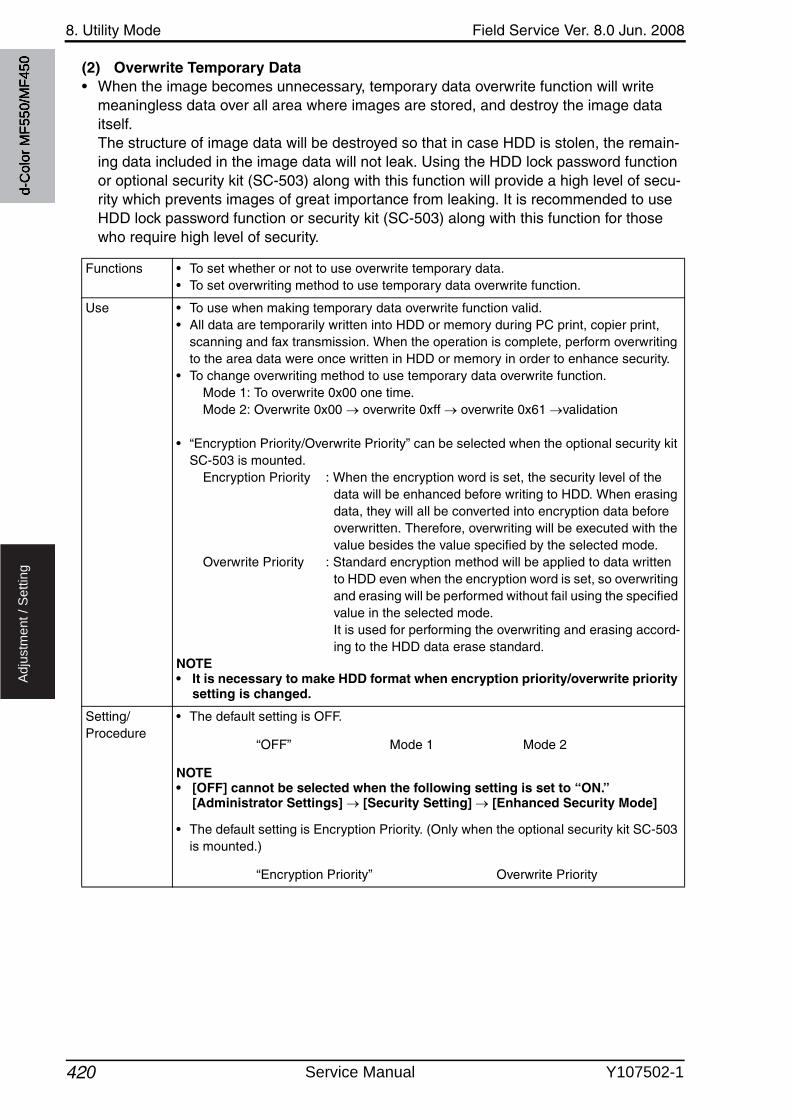
8. Utility Mode Field Service Ver. 8.0 Jun. 2008
420
Ad
justm
en
t /
Se
ttin
g
(2) Overwrite Temporary Data• When the image becomes unnecessary, temporary data overwrite function will write
meaningless data over all area where images are stored, and destroy the image data itself. The structure of image data will be destroyed so that in case HDD is stolen, the remain-ing data included in the image data will not leak. Using the HDD lock password function or optional security kit (SC-503) along with this function will provide a high level of secu-rity which prevents images of great importance from leaking. It is recommended to useHDD lock password function or security kit (SC-503) along with this function for those who require high level of security.
Functions • To set whether or not to use overwrite temporary data.• To set overwriting method to use temporary data overwrite function.
Use • To use when making temporary data overwrite function valid.• All data are temporarily written into HDD or memory during PC print, copier print,
scanning and fax transmission. When the operation is complete, perform overwriting to the area data were once written in HDD or memory in order to enhance security.
• To change overwriting method to use temporary data overwrite function.Mode 1: To overwrite 0x00 one time.Mode 2: Overwrite 0x00 overwrite 0xff overwrite 0x61 validation
• “Encryption Priority/Overwrite Priority” can be selected when the optional security kit SC-503 is mounted.
Encryption Priority : When the encryption word is set, the security level of the data will be enhanced before writing to HDD. When erasing data, they will all be converted into encryption data before overwritten. Therefore, overwriting will be executed with the value besides the value specified by the selected mode.
Overwrite Priority : Standard encryption method will be applied to data written to HDD even when the encryption word is set, so overwriting and erasing will be performed without fail using the specified value in the selected mode. It is used for performing the overwriting and erasing accord-ing to the HDD data erase standard.
NOTE• It is necessary to make HDD format when encryption priority/overwrite priority
setting is changed.
Setting/Procedure
• The default setting is OFF.
“OFF” Mode 1 Mode 2
NOTE• [OFF] cannot be selected when the following setting is set to “ON.”
[Administrator Settings] [Security Setting] [Enhanced Security Mode]
• The default setting is Encryption Priority. (Only when the optional security kit SC-503 is mounted.)
“Encryption Priority” Overwrite Priority
d-C
olor
MF5
50/M
F450
Service Manual Y107502-1
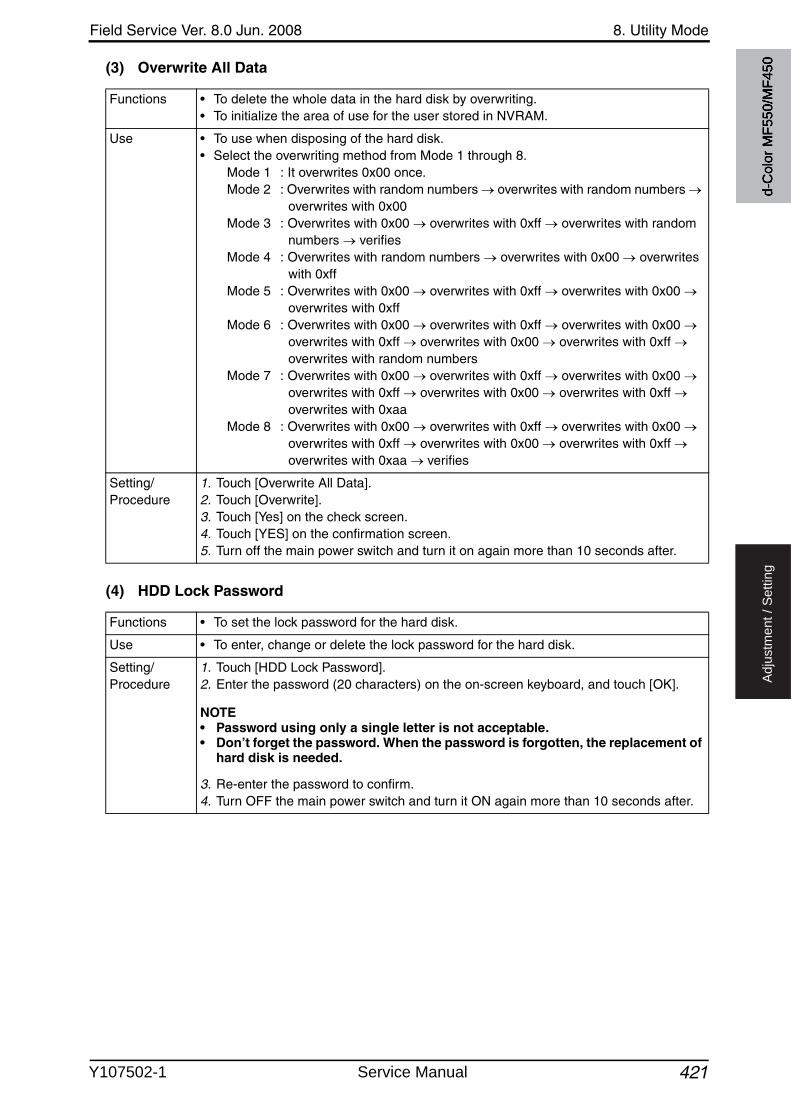
Field Service Ver. 8.0 Jun. 2008 8. Utility Mode
421
Ad
justm
en
t /
Se
ttin
g
(3) Overwrite All Data
(4) HDD Lock Password
Functions • To delete the whole data in the hard disk by overwriting.• To initialize the area of use for the user stored in NVRAM.
Use • To use when disposing of the hard disk.• Select the overwriting method from Mode 1 through 8.
Mode 1 : It overwrites 0x00 once.Mode 2 : Overwrites with random numbers overwrites with random numbers
overwrites with 0x00Mode 3 : Overwrites with 0x00 overwrites with 0xff overwrites with random
numbers verifiesMode 4 : Overwrites with random numbers overwrites with 0x00 overwrites
with 0xffMode 5 : Overwrites with 0x00 overwrites with 0xff overwrites with 0x00
overwrites with 0xffMode 6 : Overwrites with 0x00 overwrites with 0xff overwrites with 0x00
overwrites with 0xff overwrites with 0x00 overwrites with 0xff overwrites with random numbers
Mode 7 : Overwrites with 0x00 overwrites with 0xff overwrites with 0x00 overwrites with 0xff overwrites with 0x00 overwrites with 0xff overwrites with 0xaa
Mode 8 : Overwrites with 0x00 overwrites with 0xff overwrites with 0x00 overwrites with 0xff overwrites with 0x00 overwrites with 0xff overwrites with 0xaa verifies
Setting/Procedure
1. Touch [Overwrite All Data].2. Touch [Overwrite].3. Touch [Yes] on the check screen.4. Touch [YES] on the confirmation screen.5. Turn off the main power switch and turn it on again more than 10 seconds after.
Functions • To set the lock password for the hard disk.
Use • To enter, change or delete the lock password for the hard disk.
Setting/Procedure
1. Touch [HDD Lock Password].2. Enter the password (20 characters) on the on-screen keyboard, and touch [OK].
NOTE• Password using only a single letter is not acceptable.• Don’t forget the password. When the password is forgotten, the replacement of
hard disk is needed.
3. Re-enter the password to confirm.4. Turn OFF the main power switch and turn it ON again more than 10 seconds after.
d-C
olor
MF5
50/M
F450
Y107502-1 Service Manual
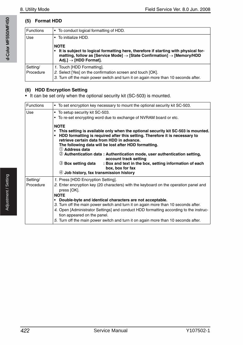
8. Utility Mode Field Service Ver. 8.0 Jun. 2008
422
Ad
justm
en
t /
Se
ttin
g
(5) Format HDD
(6) HDD Encryption Setting• It can be set only when the optional security kit (SC-503) is mounted.
Functions • To conduct logical formatting of HDD.
Use • To initialize HDD.
NOTE• It is subject to logical formatting here, therefore if starting with physical for-
matting, follow as [Service Mode] [State Confirmation] [Memory/HDD Adj.] [HDD Format].
Setting/Procedure
1. Touch [HDD Formatting].2. Select [Yes] on the confirmation screen and touch [OK].3. Turn off the main power switch and turn it on again more than 10 seconds after.
Functions • To set encryption key necessary to mount the optional security kit SC-503.
Use • To setup security kit SC-503.• To re-set encrypting word due to exchange of NVRAM board or etc.
NOTE• This setting is available only when the optional security kit SC-503 is mounted.• HDD formatting is required after this setting. Therefore it is necessary to
retrieve certain data from HDD in advance. The following data will be lost after HDD formatting.➀ Address data➁ Authentication data : Authentication mode, user authentication setting,
account track setting➂ Box setting data : Box and text in the box, setting information of each
box, box for fax➃ Job history, fax transmission history
Setting/Procedure
1. Press [HDD Encryption Setting].2. Enter encryption key (20 characters) with the keyboard on the operation panel and
press [OK].NOTE• Double-byte and identical characters are not acceptable.3. Turn off the main power switch and turn it on again more than 10 seconds after.4. Open [Administrator Settings] and conduct HDD formatting according to the instruc-
tion appeared on the panel.5. Turn off the main power switch and turn it on again more than 10 seconds after.
d-C
olor
MF5
50/M
F450
Service Manual Y107502-1
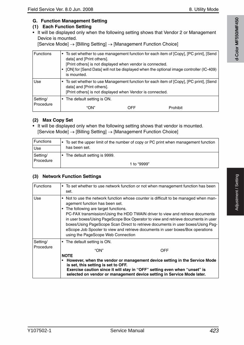
Field Service Ver. 8.0 Jun. 2008 8. Utility Mode
423
Ad
justm
en
t /
Se
ttin
g
G. Function Management Setting(1) Each Function Setting• It will be displayed only when the following setting shows that Vendor 2 or Management
Device is mounted.[Service Mode] [Billing Setting] [Management Function Choice]
(2) Max Copy Set• It will be displayed only when the following setting shows that vendor is mounted.
[Service Mode] [Billing Setting] [Management Function Choice]
(3) Network Function Settings
Functions • To set whether to use management function for each item of [Copy], [PC print], [Send data] and [Print others]. [Print others] is not displayed when vendor is connected.
• [ON] for [Send Data] will not be displayed when the optional image controller (IC-409) is mounted.
Use • To set whether to use Management function for each item of [Copy], [PC print], [Send data] and [Print others]. [Print others] is not displayed when Vendor is connected.
Setting/Procedure
• The default setting is ON.
“ON” OFF Prohibit
Functions • To set the upper limit of the number of copy or PC print when management function has been set.Use
Setting/Procedure
• The default setting is 9999.
1 to “9999”
Functions • To set whether to use network function or not when management function has been set.
Use • Not to use the network function whose counter is difficult to be managed when man-agement function has been set.
• The following are target functions. PC-FAX transmission/Using the HDD TWAIN driver to view and retrieve documents in user boxes/Using PageScope Box Operator to view and retrieve documents in userboxes/Using PageScope Scan Direct to retrieve documents in user boxes/Using Pag-eScope Job Spooler to view and retrieve documents in user boxes/Box operations using the PageScope Web Connection
Setting/Procedure
• The default setting is ON.
“ON” OFFNOTE• However, when the vendor or management device setting in the Service Mode
is set, this setting is set to OFF. Exercise caution since it will stay in “OFF” setting even when “unset” is selected on vendor or management device setting in Service Mode later.
d-C
olor
MF5
50/M
F450
Y107502-1 Service Manual
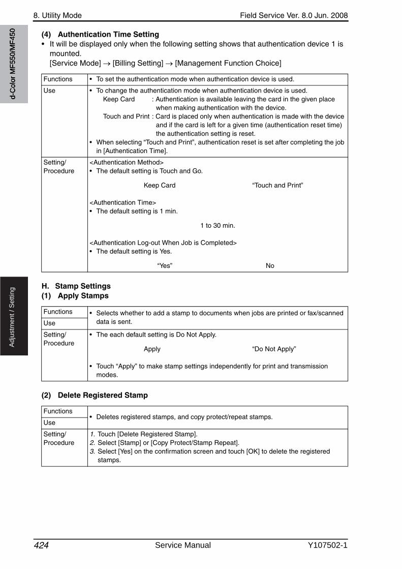
8. Utility Mode Field Service Ver. 8.0 Jun. 2008
424
Ad
justm
en
t /
Se
ttin
g
(4) Authentication Time Setting• It will be displayed only when the following setting shows that authentication device 1 is
mounted. [Service Mode] [Billing Setting] [Management Function Choice]
H. Stamp Settings(1) Apply Stamps
(2) Delete Registered Stamp
Functions • To set the authentication mode when authentication device is used.
Use • To change the authentication mode when authentication device is used.Keep Card : Authentication is available leaving the card in the given place
when making authentication with the device.Touch and Print : Card is placed only when authentication is made with the device
and if the card is left for a given time (authentication reset time) the authentication setting is reset.
• When selecting “Touch and Print”, authentication reset is set after completing the job in [Authentication Time].
Setting/Procedure
<Authentication Method>• The default setting is Touch and Go.
Keep Card “Touch and Print”
<Authentication Time>• The default setting is 1 min.
1 to 30 min.
<Authentication Log-out When Job is Completed>• The default setting is Yes.
“Yes” No
Functions • Selects whether to add a stamp to documents when jobs are printed or fax/scanned data is sent.Use
Setting/Procedure
• The each default setting is Do Not Apply.
Apply “Do Not Apply”
• Touch “Apply” to make stamp settings independently for print and transmission modes.
Functions• Deletes registered stamps, and copy protect/repeat stamps.
Use
Setting/Procedure
1. Touch [Delete Registered Stamp].2. Select [Stamp] or [Copy Protect/Stamp Repeat].3. Select [Yes] on the confirmation screen and touch [OK] to delete the registered
stamps.
d-C
olor
MF5
50/M
F450
Service Manual Y107502-1

4
Field Service Ver. 8.0 Jun. 2008 8. Utility Mode
425
Ad
justm
en
t /
Se
ttin
g
I. Image Log Transfer Settings• This is displayed only when the function enhanced version 2 or later firmware is installed.• It will be displayed when the following setting shows that switch No.63 is set to [01] at
HEX assignment.[Service Mode] [System 2] [Software Switch Setting]
J. Driver Password Encryption Setting• For d-Color MF550/MF450, this is displayed only when the function enhanced version 1
or later firmware is installed.
Functions • Specifies whether to transfer the input or output image data to the server using when-ever MFP inputs or outputs image data. Makes the settings of the WebDAV server or the FTP server where image data are transferred.
Use • Use this settings to keep logs of input and output image data for security purpose.
Setting/Procedure
• The each default setting is No.
Yes “No”
• When selecting [Yes], make the settings of the FTP server where data are trans-ferred.
• Set the following item.
<WebDAV Server setting>• Host Name, File Path, User Name, Password, Port Number, Proxy, SSL Setting.
<FTP Server setting>• Host Name, File Path, User Name, Password, Port Number, PASV, and Proxy.
NOTE• When [Yes] is selected, a person who is registered as User cannot use Scan To
FTP/WebDAV function.
4
4
Functions • To set whether to use the factory default encryption word or user-defined one as a common key that encrypts a password used for a print job.
User-Defined : Sets an encryption word. Enter an encryption word of 20 let-ters.
Use Factory Default : Uses the factory default encryption word (undisclosed pre-defined encryption key).
NOTE• When selecting [User-Defined], set an encryption key being consisted of the
same letters in the printer driver. If the encryption word set in the main body differs from the encryption key set in the printer driver, different encrypted passwords are created and printing cannot be made.
• The use of OpenAPI allows an encryption key to be obtained from the main body.
Use
Setting/Procedure
• The default setting is Use Factory Default.
User-Defined “Use Factory Default”
d-C
olor
MF5
50/M
F450
Y107502-1 Service Manual
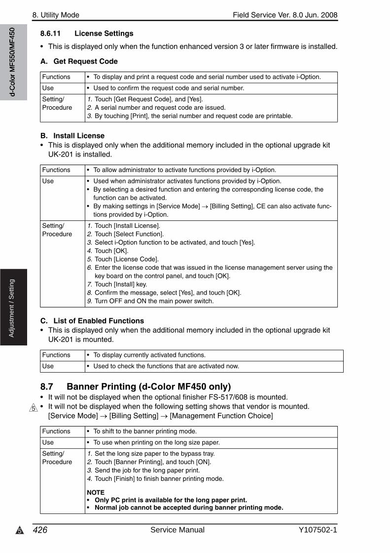
8. Utility Mode Field Service Ver. 8.0 Jun. 2008
4265
Ad
justm
en
t /
Se
ttin
g
8.6.11 License Settings
• This is displayed only when the function enhanced version 3 or later firmware is installed.
A. Get Request Code
B. Install License• This is displayed only when the additional memory included in the optional upgrade kit
UK-201 is installed.
C. List of Enabled Functions• This is displayed only when the additional memory included in the optional upgrade kit
UK-201 is mounted.
8.7 Banner Printing (d-Color MF450 only)• It will not be displayed when the optional finisher FS-517/608 is mounted.• It will not be displayed when the following setting shows that vendor is mounted.
[Service Mode] [Billing Setting] [Management Function Choice]
Functions • To display and print a request code and serial number used to activate i-Option.
Use • Used to confirm the request code and serial number.
Setting/Procedure
1. Touch [Get Request Code], and [Yes].2. A serial number and request code are issued.3. By touching [Print], the serial number and request code are printable.
Functions • To allow administrator to activate functions provided by i-Option.
Use • Used when administrator activates functions provided by i-Option.• By selecting a desired function and entering the corresponding license code, the
function can be activated.• By making settings in [Service Mode] [Billing Setting], CE can also activate func-
tions provided by i-Option.
Setting/Procedure
1. Touch [Install License].2. Touch [Select Function].3. Select i-Option function to be activated, and touch [Yes].4. Touch [OK].5. Touch [License Code].6. Enter the license code that was issued in the license management server using the
key board on the control panel, and touch [OK].7. Touch [Install] key.8. Confirm the message, select [Yes], and touch [OK].9. Turn OFF and ON the main power switch.
Functions • To display currently activated functions.
Use • Used to check the functions that are activated now.
5
Functions • To shift to the banner printing mode.
Use • To use when printing on the long size paper.
Setting/Procedure
1. Set the long size paper to the bypass tray.2. Touch [Banner Printing], and touch [ON].3. Send the job for the long paper print.4. Touch [Finish] to finish banner printing mode.
NOTE• Only PC print is available for the long paper print.• Normal job cannot be accepted during banner printing mode.
d-C
olor
MF5
50/M
F450
Service Manual Y107502-1
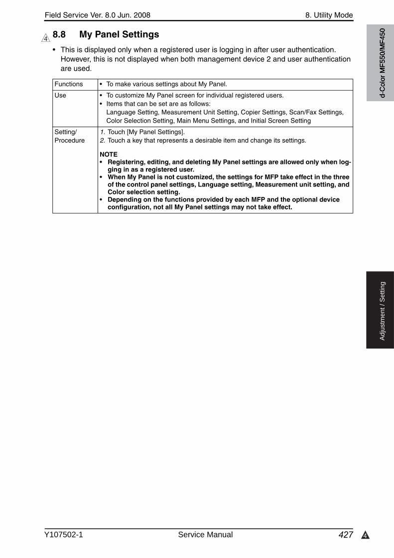
4
Field Service Ver. 8.0 Jun. 2008 8. Utility Mode
427
Ad
justm
en
t /
Se
ttin
g
8.8 My Panel Settings
• This is displayed only when a registered user is logging in after user authentication. However, this is not displayed when both management device 2 and user authentication are used.
4
Functions • To make various settings about My Panel.
Use • To customize My Panel screen for individual registered users.• Items that can be set are as follows:
Language Setting, Measurement Unit Setting, Copier Settings, Scan/Fax Settings, Color Selection Setting, Main Menu Settings, and Initial Screen Setting
Setting/Procedure
1. Touch [My Panel Settings].2. Touch a key that represents a desirable item and change its settings.
NOTE• Registering, editing, and deleting My Panel settings are allowed only when log-
ging in as a registered user.• When My Panel is not customized, the settings for MFP take effect in the three
of the control panel settings, Language setting, Measurement unit setting, and Color selection setting.
• Depending on the functions provided by each MFP and the optional device configuration, not all My Panel settings may not take effect.
d-C
olor
MF5
50/M
F450
Y107502-1 Service Manual
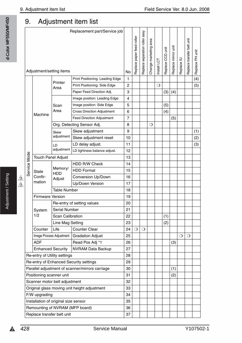
9. Adjustment item list Field Service Ver. 8.0 Jun. 2008
4283
Ad
justm
en
t /
Se
ttin
g
9. Adjustment item listReplacement part/Service job
Adjustment/setting items No Rep
lace
pap
er fe
ed r
olle
r
Rep
lace
sep
arat
ion
rolle
r as
sy
Cha
nge
mar
ketin
g ar
ea
Inst
all L
CT
Rep
lace
CC
D u
nit
Rep
lace
mirr
or u
nit
Rep
lace
IU
Rep
lace
tran
sfer
bel
t uni
t
Rep
lace
PH
uni
t
Ser
vice
Mod
e
Machine
Printer Area
Print Positioning: Leading Edge 1 (4)
Print Positioning: Side Edge 2 ❍ (5)
Paper Feed Direction Adj. 3 (3) (4)
Scan Area
Image position: Leading Edge 4
Image position: Side Edge 5 (5)
Cross Direction Adjustment 6 (4)
Feed Direction Adjustment 7 (5)
Org. Detecting Sensor Adj. 8 ❍
Skewadjustment
Skew adjustment 9 (1)
Skew adjustment reset 10 (2)
LDadjustment
LD delay adjust. 11 (3)
LD lightness balance adjust. 12
Touch Panel Adjust 13
State Confir-mation
Memory/HDDAdjust
HDD R/W Check 14
HDD Format 15
Conversion Up/Down 16
Up/Down Version 17
Table Number 18
Firmware Version 19
System1/2
Re-entry of setting values 20
Serial Number 21
Scan Calibration 22 (1)
Line Mag Setting 23 (2)
Counter Life Counter Clear 24 ❍ ❍
Image Process Adjustment Gradation Adjust 25 ❍ ❍
ADF Read Pos Adj *1 26 (3)
Enhanced Security NVRAM Data Backup 27
Re-entry of Utility settings 28
Re-entry of Enhanced Security settings 29
Parallel adjustment of scanner/mirrors carriage 30 (1)
Positioning scanner unit 31 (2)
Scanner motor belt adjustment 32
Original glass moving unit height adjustment 33
F/W upgrading 34
Installation of original size sensor 35
Remounting of NVRAM (MFP board) 36
Replace transfer belt unit 37
3
3
d-C
olor
MF5
50/M
F450
Service Manual Y107502-1
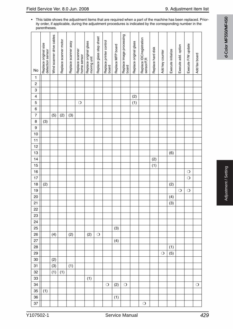
Field Service Ver. 8.0 Jun. 2008 9. Adjustment item list
429
Ad
justm
en
t /
Se
ttin
g
• This table shows the adjustment items that are required when a part of the machine has been replaced. Prior-ity order, if applicable, during the adjustment procedures is indicated by the corresponding number in the parentheses.
No Rep
lace
orig
inal
siz
e de
tect
ion
sens
or
Win
d sc
anne
r dr
ive
cabl
es
Rep
lace
sca
nner
mot
or
Rep
lace
sca
nner
ass
y
Rep
lace
sca
nner
ho
me
sens
or
Rep
lace
orig
inal
gla
ss
mov
ing
unit
Rep
lace
gla
ss s
tep
shee
t
Rep
lace
prin
ter
cont
rol
boar
d
Rep
lace
MF
P b
oard
Rep
lace
imag
e pr
oces
sing
bo
ard
Rep
lace
orig
inal
gla
ss
Rep
lace
IDC
/reg
istr
atio
n se
nsor
/F,R
Rep
lace
har
d di
sk
Add
key
cou
nter
Exe
cute
initi
aliz
e
Exe
cute
add
. opt
ion
Exe
cute
F/W
upd
ate
Add
fax
boar
d
1
2
3
4 (2)
5 ❍ (1)
6
7 (5) (2) (3)
8 (3)
9
10
11
12
13 (6)
14 (2)
15 (1)
16 ❍
17 ❍
18 (2) (2)
19 ❍ ❍
20 (4)
21 (3)
22
23
24
25 (3)
26 (4) (2) (2) ❍
27 (4)
28 (1)
29 ❍ (5)
30 (2)
31 (3) (1)
32 (1) (1)
33 (1)
34 ❍ (2) ❍ ❍
35 (1)
36 (1)
37 ❍
d-C
olor
MF5
50/M
F450
Y107502-1 Service Manual
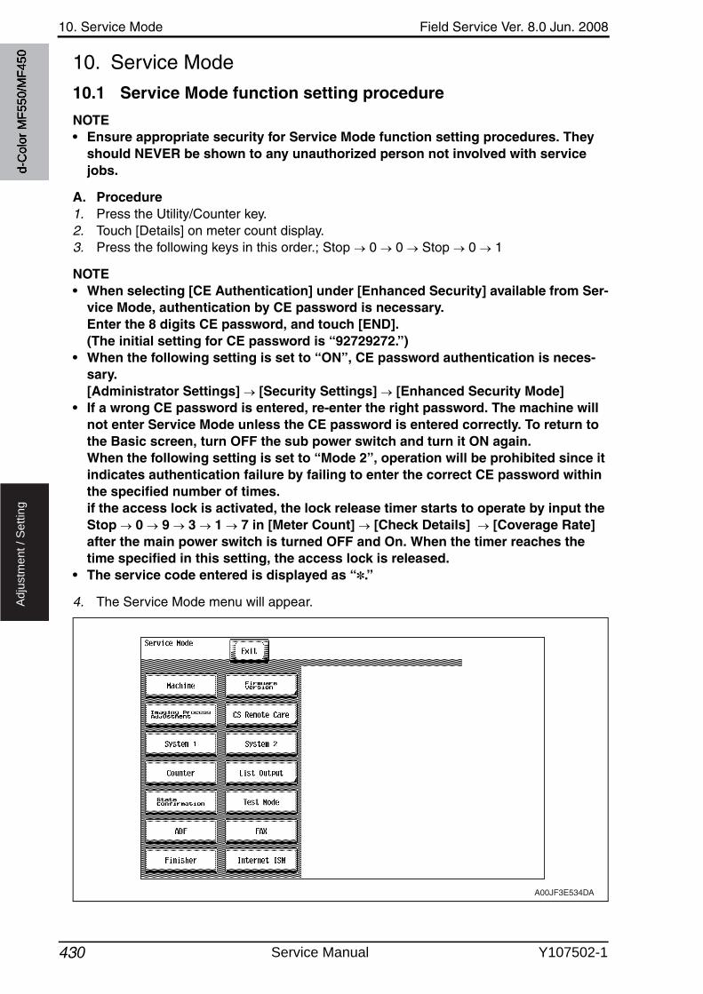
10. Service Mode Field Service Ver. 8.0 Jun. 2008
430
Ad
justm
en
t /
Se
ttin
g
10. Service Mode
10.1 Service Mode function setting procedure
NOTE• Ensure appropriate security for Service Mode function setting procedures. They
should NEVER be shown to any unauthorized person not involved with service jobs.
A. Procedure1. Press the Utility/Counter key.2. Touch [Details] on meter count display.3. Press the following keys in this order.; Stop 0 0 Stop 0 1
NOTE• When selecting [CE Authentication] under [Enhanced Security] available from Ser-
vice Mode, authentication by CE password is necessary.Enter the 8 digits CE password, and touch [END].(The initial setting for CE password is “92729272.”)
• When the following setting is set to “ON”, CE password authentication is neces-sary. [Administrator Settings] [Security Settings] [Enhanced Security Mode]
• If a wrong CE password is entered, re-enter the right password. The machine will not enter Service Mode unless the CE password is entered correctly. To return to the Basic screen, turn OFF the sub power switch and turn it ON again. When the following setting is set to “Mode 2”, operation will be prohibited since it indicates authentication failure by failing to enter the correct CE password within the specified number of times. if the access lock is activated, the lock release timer starts to operate by input the Stop 0 9 3 1 7 in [Meter Count] [Check Details] [Coverage Rate] after the main power switch is turned OFF and On. When the timer reaches the time specified in this setting, the access lock is released.
• The service code entered is displayed as “✽.”
4. The Service Mode menu will appear.
A00JF3E534DA
d-C
olor
MF5
50/M
F450
Service Manual Y107502-1
Field Service Ver. 8.0 Jun. 2008 10. Service Mode
431
Ad
justm
en
t /
Se
ttin
g
NOTE• Be sure to change the CE password from its default value.• For the procedure to change the CE password, see the Enhanced Security.
See P.542
B. Exiting• Touch the [Exit] key.
C. Changing the setting value in Service Mode functions• Use the [+] / [-] key to enter or change the setting value.• Use the 10-key pad to enter the setting value. (To change the setting value, first press the
Clear key before making an entry.)
d-C
olor
MF5
50/M
F450
Y107502-1 Service Manual
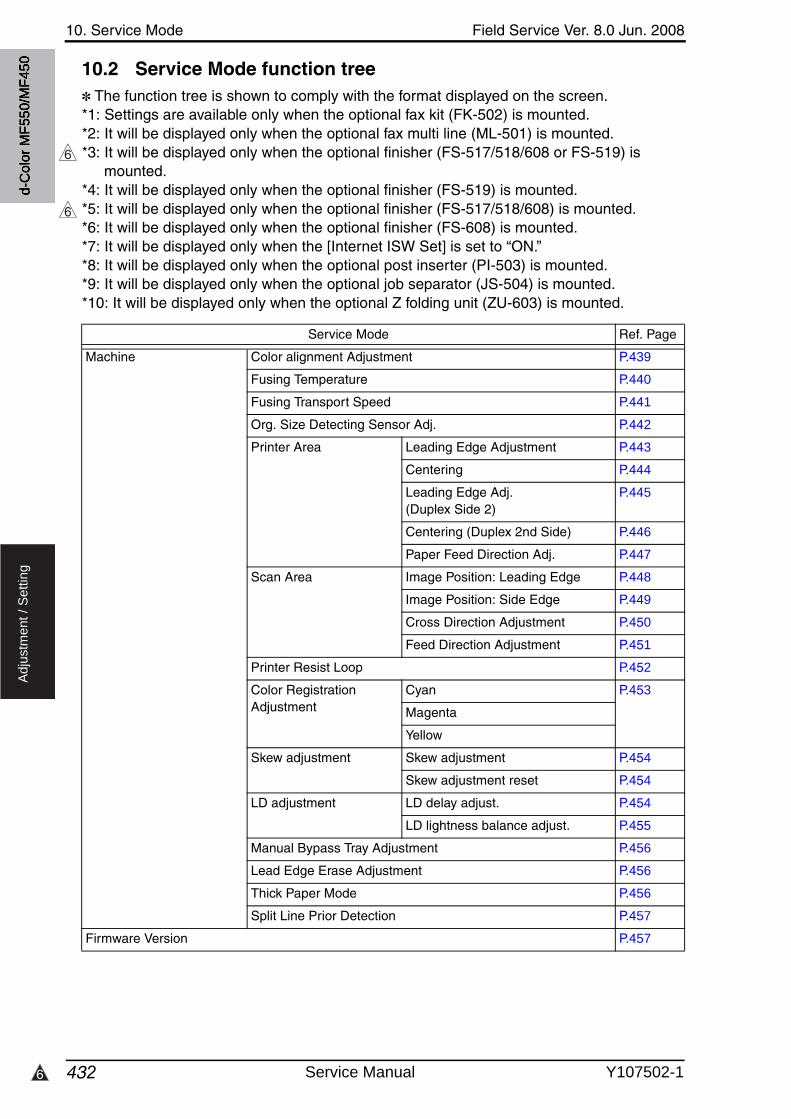
10. Service Mode Field Service Ver. 8.0 Jun. 2008
4326
Ad
justm
en
t /
Se
ttin
g
10.2 Service Mode function tree✽ The function tree is shown to comply with the format displayed on the screen.*1: Settings are available only when the optional fax kit (FK-502) is mounted.*2: It will be displayed only when the optional fax multi line (ML-501) is mounted.*3: It will be displayed only when the optional finisher (FS-517/518/608 or FS-519) is
mounted.*4: It will be displayed only when the optional finisher (FS-519) is mounted.*5: It will be displayed only when the optional finisher (FS-517/518/608) is mounted.*6: It will be displayed only when the optional finisher (FS-608) is mounted.*7: It will be displayed only when the [Internet ISW Set] is set to “ON.”*8: It will be displayed only when the optional post inserter (PI-503) is mounted.*9: It will be displayed only when the optional job separator (JS-504) is mounted.*10: It will be displayed only when the optional Z folding unit (ZU-603) is mounted.
6
6
Service Mode Ref. Page
Machine Color alignment Adjustment P.439
Fusing Temperature P.440
Fusing Transport Speed P.441
Org. Size Detecting Sensor Adj. P.442
Printer Area Leading Edge Adjustment P.443
Centering P.444
Leading Edge Adj. (Duplex Side 2)
P.445
Centering (Duplex 2nd Side) P.446
Paper Feed Direction Adj. P.447
Scan Area Image Position: Leading Edge P.448
Image Position: Side Edge P.449
Cross Direction Adjustment P.450
Feed Direction Adjustment P.451
Printer Resist Loop P.452
Color Registration Adjustment
Cyan P.453
Magenta
Yellow
Skew adjustment Skew adjustment P.454
Skew adjustment reset P.454
LD adjustment LD delay adjust. P.454
LD lightness balance adjust. P.455
Manual Bypass Tray Adjustment P.456
Lead Edge Erase Adjustment P.456
Thick Paper Mode P.456
Split Line Prior Detection P.457
Firmware Version P.457
d-C
olor
MF5
50/M
F450
Service Manual Y107502-1
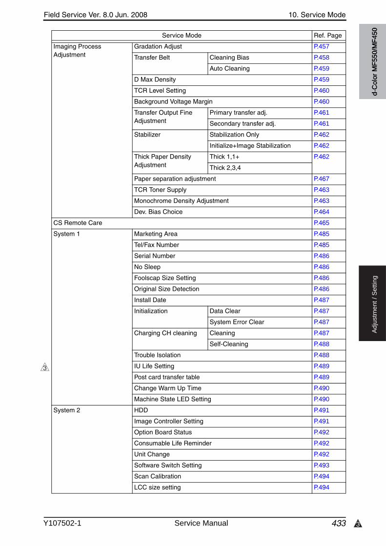
3
Field Service Ver. 8.0 Jun. 2008 10. Service Mode
433
Ad
justm
en
t /
Se
ttin
g
Imaging Process Adjustment
Gradation Adjust P.457
Transfer Belt Cleaning Bias P.458
Auto Cleaning P.459
D Max Density P.459
TCR Level Setting P.460
Background Voltage Margin P.460
Transfer Output Fine Adjustment
Primary transfer adj. P.461
Secondary transfer adj. P.461
Stabilizer Stabilization Only P.462
Initialize+Image Stabilization P.462
Thick Paper Density Adjustment
Thick 1,1+ P.462
Thick 2,3,4
Paper separation adjustment P.467
TCR Toner Supply P.463
Monochrome Density Adjustment P.463
Dev. Bias Choice P.464
CS Remote Care P.465
System 1 Marketing Area P.485
Tel/Fax Number P.485
Serial Number P.486
No Sleep P.486
Foolscap Size Setting P.486
Original Size Detection P.486
Install Date P.487
Initialization Data Clear P.487
System Error Clear P.487
Charging CH cleaning Cleaning P.487
Self-Cleaning P.488
Trouble Isolation P.488
IU Life Setting P.489
Post card transfer table P.489
Change Warm Up Time P.490
Machine State LED Setting P.490
System 2 HDD P.491
Image Controller Setting P.491
Option Board Status P.492
Consumable Life Reminder P.492
Unit Change P.492
Software Switch Setting P.493
Scan Calibration P.494
LCC size setting P.494
Service Mode Ref. Page
3d-
Col
or M
F550
/MF4
50
Y107502-1 Service Manual
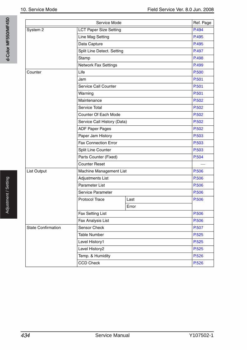
10. Service Mode Field Service Ver. 8.0 Jun. 2008
434
Ad
justm
en
t /
Se
ttin
g
System 2 LCT Paper Size Setting P.494
Line Mag Setting P.495
Data Capture P.495
Split Line Detect. Setting P.497
Stamp P.498
Network Fax Settings P.499
Counter Life P.500
Jam P.501
Service Call Counter P.501
Warning P.501
Maintenance P.502
Service Total P.502
Counter Of Each Mode P.502
Service Call History (Data) P.502
ADF Paper Pages P.502
Paper Jam History P.503
Fax Connection Error P.503
Split Line Counter P.503
Parts Counter (Fixed) P.504
Counter Reset
List Output Machine Management List P.506
Adjustments List P.506
Parameter List P.506
Service Parameter P.506
Protocol Trace Last P.506
Error
Fax Setting List P.506
Fax Analysis List P.506
State Confirmation Sensor Check P.507
Table Number P.525
Level History1 P.525
Level History2 P.525
Temp. & Humidity P.526
CCD Check P.526
Service Mode Ref. Page
d-C
olor
MF5
50/M
F450
Service Manual Y107502-1
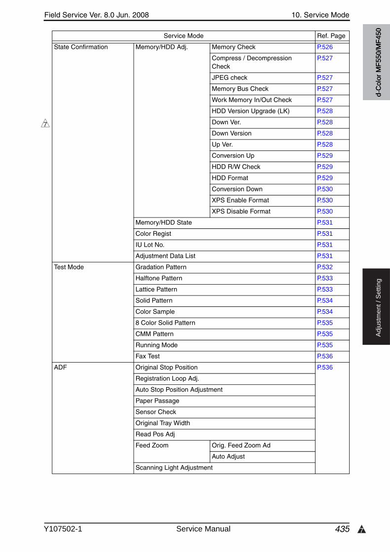
7
Field Service Ver. 8.0 Jun. 2008 10. Service Mode
435
Ad
justm
en
t /
Se
ttin
g
State Confirmation Memory/HDD Adj. Memory Check P.526
Compress / Decompression Check
P.527
JPEG check P.527
Memory Bus Check P.527
Work Memory In/Out Check P.527
HDD Version Upgrade (LK) P.528
Down Ver. P.528
Down Version P.528
Up Ver. P.528
Conversion Up P.529
HDD R/W Check P.529
HDD Format P.529
Conversion Down P.530
XPS Enable Format P.530
XPS Disable Format P.530
Memory/HDD State P.531
Color Regist P.531
IU Lot No. P.531
Adjustment Data List P.531
Test Mode Gradation Pattern P.532
Halftone Pattern P.533
Lattice Pattern P.533
Solid Pattern P.534
Color Sample P.534
8 Color Solid Pattern P.535
CMM Pattern P.535
Running Mode P.535
Fax Test P.536
ADF Original Stop Position P.536
Registration Loop Adj.
Auto Stop Position Adjustment
Paper Passage
Sensor Check
Original Tray Width
Read Pos Adj
Feed Zoom Orig. Feed Zoom Ad
Auto Adjust
Scanning Light Adjustment
Service Mode Ref. Page
7
d-C
olor
MF5
50/M
F450
Y107502-1 Service Manual
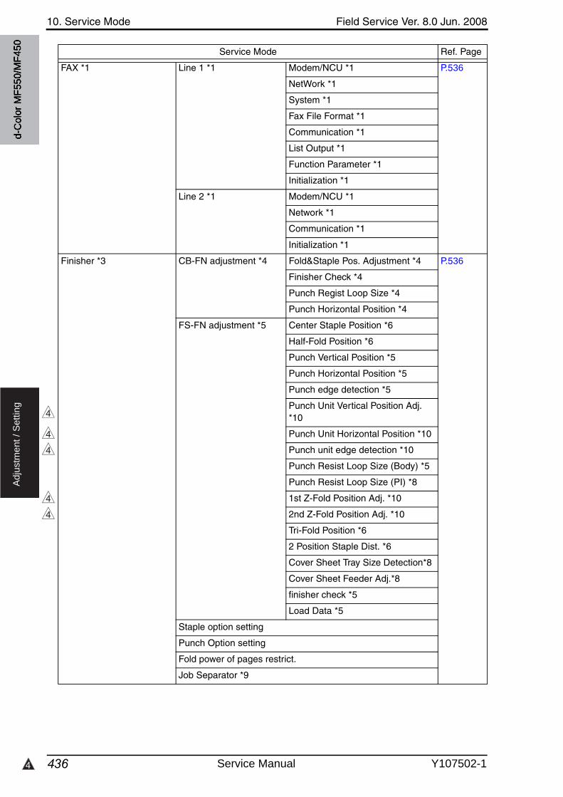
10. Service Mode Field Service Ver. 8.0 Jun. 2008
4364
Ad
justm
en
t /
Se
ttin
g
FAX *1 Line 1 *1 Modem/NCU *1 P.536
NetWork *1
System *1
Fax File Format *1
Communication *1
List Output *1
Function Parameter *1
Initialization *1
Line 2 *1 Modem/NCU *1
Network *1
Communication *1
Initialization *1
Finisher *3 CB-FN adjustment *4 Fold&Staple Pos. Adjustment *4 P.536
Finisher Check *4
Punch Regist Loop Size *4
Punch Horizontal Position *4
FS-FN adjustment *5 Center Staple Position *6
Half-Fold Position *6
Punch Vertical Position *5
Punch Horizontal Position *5
Punch edge detection *5
Punch Unit Vertical Position Adj. *10
Punch Unit Horizontal Position *10
Punch unit edge detection *10
Punch Resist Loop Size (Body) *5
Punch Resist Loop Size (PI) *8
1st Z-Fold Position Adj. *10
2nd Z-Fold Position Adj. *10
Tri-Fold Position *6
2 Position Staple Dist. *6
Cover Sheet Tray Size Detection*8
Cover Sheet Feeder Adj.*8
finisher check *5
Load Data *5
Staple option setting
Punch Option setting
Fold power of pages restrict.
Job Separator *9
Service Mode Ref. Page
4
4
4
4
4
d-C
olor
MF5
50/M
F450
Service Manual Y107502-1
Field Service Ver. 8.0 Jun. 2008 10. Service Mode
437
Ad
justm
en
t /
Se
ttin
g
Internet ISW Internet ISW Set P.538
HTTP Setting *5 P.538
FTP Setting *5 P.539
Forwarding Access Setting *5 P.540
Download *5 P.541
Service Mode Ref. Page
d-C
olor
MF5
50/M
F450
Y107502-1 Service Manual
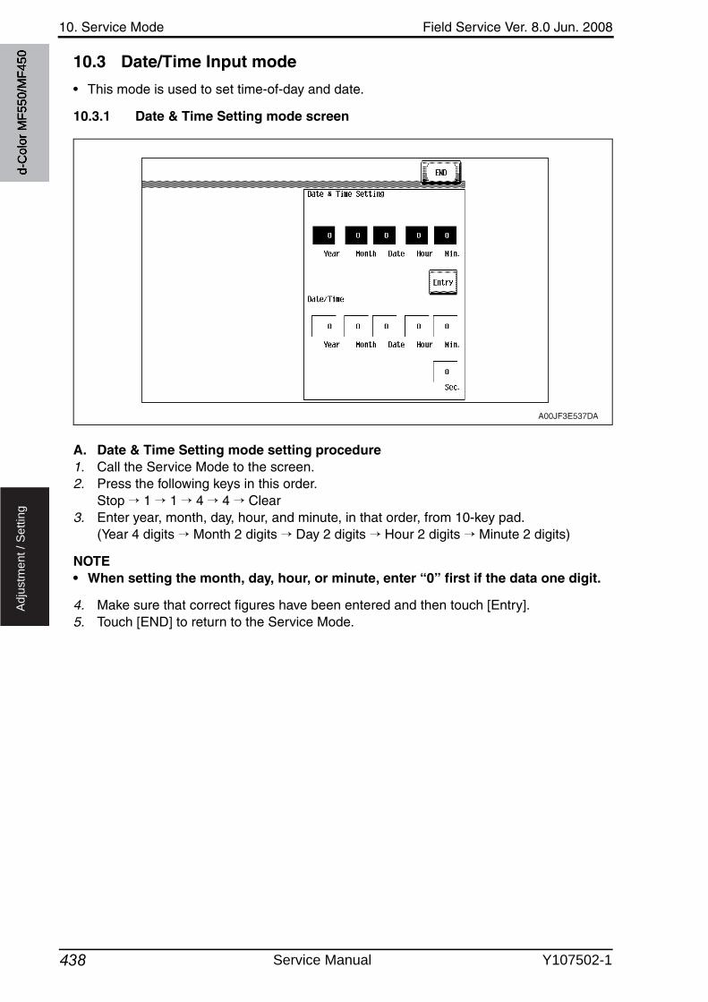
10. Service Mode Field Service Ver. 8.0 Jun. 2008
438
Ad
justm
en
t /
Se
ttin
g
10.3 Date/Time Input mode
• This mode is used to set time-of-day and date.
10.3.1 Date & Time Setting mode screen
A. Date & Time Setting mode setting procedure1. Call the Service Mode to the screen.2. Press the following keys in this order.
Stop → 1 → 1 → 4 → 4 → Clear3. Enter year, month, day, hour, and minute, in that order, from 10-key pad.
(Year 4 digits → Month 2 digits → Day 2 digits → Hour 2 digits → Minute 2 digits)
NOTE• When setting the month, day, hour, or minute, enter “0” first if the data one digit.
4. Make sure that correct figures have been entered and then touch [Entry].5. Touch [END] to return to the Service Mode.
A00JF3E537DA
d-C
olor
MF5
50/M
F450
Service Manual Y107502-1
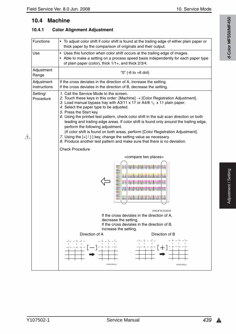
Field Service Ver. 8.0 Jun. 2008 10. Service Mode
439 1
Ad
justm
en
t /
Se
ttin
g
10.4 Machine
10.4.1 Color Alignment Adjustment
Functions • To adjust color shift if color shift is found at the trailing edge of either plain paper or thick paper by the comparison of originals and their output.
Use • Uses this function when color shift occurs at the trailing edge of images.• Able to make a setting on a process speed basis independently for each paper type
of plain paper (color), thick 1/1+, and thick 2/3/4.
Adjustment Range
“0” (-6 to +6 dot)
Adjustment Instructions
If the cross deviates in the direction of A, increase the setting.If the cross deviates in the direction of B, decrease the setting.
Setting/Procedure
1. Call the Service Mode to the screen.2. Touch these keys in this order: [Machine] [Color Registration Adjustment].3. Load manual bypass tray with A3/11 x 17 or A4/8 1/2 x 11 plain paper.4. Select the paper type to be adjusted.5. Press the Start key.6. Using the printed test pattern, check color shift in the sub scan direction on both
leading and trailing edge areas. If color shift is found only around the trailing edge, perform the following adjustment.(If color shift is found on both areas, perform [Color Registration Adjustment].
7. Using the [+] / [-] key, change the setting value as necessary.8. Produce another test pattern and make sure that there is no deviation.
Check Procedure
1
A00JF3C524DA
4036fs3005c1 4036fs3006c1
If the cross deviates in the direction of A, decrease the setting.If the cross deviates in the direction of B, increase the setting.
<compare two places>
Direction of A Direction of Bd-
Col
or M
F550
/MF4
50
Y107502-1 Service Manual
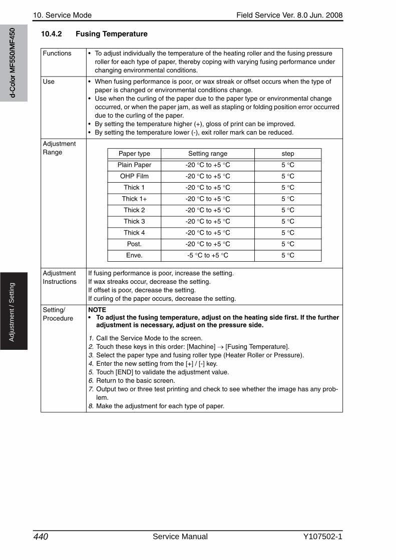
10. Service Mode Field Service Ver. 8.0 Jun. 2008
440
Ad
justm
en
t /
Se
ttin
g
10.4.2 Fusing Temperature
Functions • To adjust individually the temperature of the heating roller and the fusing pressure roller for each type of paper, thereby coping with varying fusing performance under changing environmental conditions.
Use • When fusing performance is poor, or wax streak or offset occurs when the type of paper is changed or environmental conditions change.
• Use when the curling of the paper due to the paper type or environmental change occurred, or when the paper jam, as well as stapling or folding position error occurred due to the curling of the paper.
• By setting the temperature higher (+), gloss of print can be improved.• By setting the temperature lower (-), exit roller mark can be reduced.
Adjustment Range
Adjustment Instructions
If fusing performance is poor, increase the setting.If wax streaks occur, decrease the setting.If offset is poor, decrease the setting.If curling of the paper occurs, decrease the setting.
Setting/Procedure
NOTE• To adjust the fusing temperature, adjust on the heating side first. If the further
adjustment is necessary, adjust on the pressure side.
1. Call the Service Mode to the screen.2. Touch these keys in this order: [Machine] [Fusing Temperature].3. Select the paper type and fusing roller type (Heater Roller or Pressure).4. Enter the new setting from the [+] / [-] key.5. Touch [END] to validate the adjustment value.6. Return to the basic screen.7. Output two or three test printing and check to see whether the image has any prob-
lem.8. Make the adjustment for each type of paper.
Paper type Setting range step
Plain Paper -20 C to +5 C 5 C
OHP Film -20 C to +5 C 5 C
Thick 1 -20 C to +5 C 5 C
Thick 1+ -20 C to +5 C 5 C
Thick 2 -20 C to +5 C 5 C
Thick 3 -20 C to +5 C 5 C
Thick 4 -20 C to +5 C 5 C
Post. -20 C to +5 C 5 C
Enve. -5 C to +5 C 5 C
d-C
olor
MF5
50/M
F450
Service Manual Y107502-1

Field Service Ver. 8.0 Jun. 2008 10. Service Mode
441 2
Ad
justm
en
t /
Se
ttin
g
10.4.3 Fusing Transport Speed
Functions • To adjust the speed of the fusing drive motor so as to match the fusing speed with transport speed.
Use • Brush effect or blurred image is evident as a result of changes in environmental con-ditions or degraded durability.
Variable Range
-20 to +20 (in 1 increments)
Adjustment Instructions
If brush effect is evident, vary the setting value and check for image.If a blurred image occurs, decrease the setting.
Setting/Procedure
1. Call the Service Mode to the screen.2. Touch these keys in this order: [Machine] [Fusing Transport Speed].3. Select the transport speed, at which the brush effect or blurred image has occurred.
2
d-C
olor
MF5
50/M
F450
4. Enter the new setting from the 10-key pad.5. Touch [END] to validate the adjustment value.6. Check the copy image for any image problem.
<d-Color MF550>
<d-Color MF450>
Transport speed Paper Setting
264 mm/s Plain paper: monochrome
216 mm/s Plain paper: color
132 mm/s Thick 1, Thick 1+: monochrome/color
108 mm/sThick 2, Thick 3, Thick 4, envelope, postcard: monochrome/colorOHP film: monochrome
Transport speed Paper Setting
216 mm/s Plain paper: monochrome/color
132 mm/s Thick 1, Thick 1+: monochrome/color
108 mm/sThick 2, Thick 3, Thick 4, envelope, postcard: monochrome/colorOHP film: monochrome
Y107502-1 Service Manual
10. Service Mode Field Service Ver. 8.0 Jun. 2008
442
Ad
justm
en
t /
Se
ttin
g
10.4.4 Org. Size Detecting Sensor Adj.
Functions • To automatically adjust the original detection distance for the original size sensor.• To display if the original size detection 2 Sensor is mounted.
Use • When the sensor is replaced with a new one.• When an optional sensor has been added.• When an erroneous original size detection is made.• When the marketing area setting is changed.
Adjustment Instructions
If the adjustment has been successfully made, it completes the adjustment procedure.If the adjustment has turned out to be unsuccessful, check the optional original size sensors for correct installation and change the defective sensor or harness.
Setting/Procedure
1. Place a blank sheet of A3 or 11 × 17 paper on the original glass and lower the origi-nal cover.
2. Call the Service Mode to the screen.3. Touch these keys in this order: [Machine] [Org. Size Detecting Sensor Adj.].4. Press the Start key.
d-C
olor
MF5
50/M
F450
Service Manual Y107502-1

Field Service Ver. 8.0 Jun. 2008 10. Service Mode
443
Ad
justm
en
t /
Se
ttin
g
10.4.5 Printer Area
A. Leading Edge Adjustment
Functions • To vary the print start position in the sub scan direction for each of different paper types in the manual bypass tray. (To adjust the timing where paper is sent out from the timing roller)
Use • The PH unit has been replaced.• The paper type has been changed.• The image on the copy deviates in the sub scan direction.• A faint image occurs on the leading edge of the image.• This setting can be made independently for plain paper, Thick 1/1+, Thick 2, Thick 3,
Thick 4, OHP transparencies, and envelopes.
Adjustment Specification Width A on the test pattern produced should
fall within the following range.
Specifications: 4.2 0.5 mmSetting range: -3.0 mm to +3.0 mm (in 0.2 mm increments)
Adjustment Instructions
If width A is longer than the specifications, make the setting value smaller than the cur-rent one.If width A is shorter than the specifications, make the setting value greater than the cur-rent one.
Setting/Procedure
1. Place A3 paper on the manual bypass tray.2. Call the Service Mode to the screen.3. Touch [Machine] [Printer Area] [Leading Edge Adjustment].4. Select the [Plain Paper].5. Press the Start key to let the machine produce a test pattern.6. Check the dimension of width A on the test pattern.7. If width A falls outside the specified range, change the setting using the [+] / [-] key.8. Press the Start key to let the machine produce a test pattern.9. Check the dimension of width A on the test pattern.10.If width A is outside the specified range, change the setting again and make a check
again.11.If width A falls within the specified range, touch [END].12.Following the same procedure, adjust for Thick 1 to 3, OHP film, and Enve.
A00JF3C504DA
Width A
d-C
olor
MF5
50/M
F450
Y107502-1 Service Manual

10. Service Mode Field Service Ver. 8.0 Jun. 2008
444
Ad
justm
en
t /
Se
ttin
g
B. Centering
Functions • To vary the print start position in the main scan direction for each paper source.
Use • The PH Unit has been replaced.• A paper feed unit has been added.• The image on the copy deviates in the main scan direction.
Adjustment Specification Width A on the test pattern produced should
fall within the following range.
Specifications: 3.0 0.5 mmSetting range: -3.0 mm to +3.0 mm (in 0.2 mm increments)
Adjustment Instructions
If width A is longer than the specifications, make the setting value smaller than the cur-rent one.If width A is shorter than the specifications, make the setting value greater than the cur-rent one.
Setting/Procedure
1. Call the Service Mode to the screen.2. Touch [Machine] [Printer Area] [Centering].3. Select the paper source to be adjusted.4. Press the Start key to let the machine produce a test pattern.5. Check the dimension of width A on the test pattern.6. If width A falls outside the specified range, change the setting using the [+] / [-] key.7. Press the Start key to let the machine produce a test pattern.8. Check the dimension of width A on the test pattern.9. If width A is outside the specified range, change the setting again and make a check
again.10.If width A falls within the specified range, touch [END].11.Following the same procedure, adjust for all other paper sources.
(Use A4 or 8 1/2 × 11 plain paper for the bypass.)
A00JF3C505DA
Width Ad-C
olor
MF5
50/M
F450
Service Manual Y107502-1
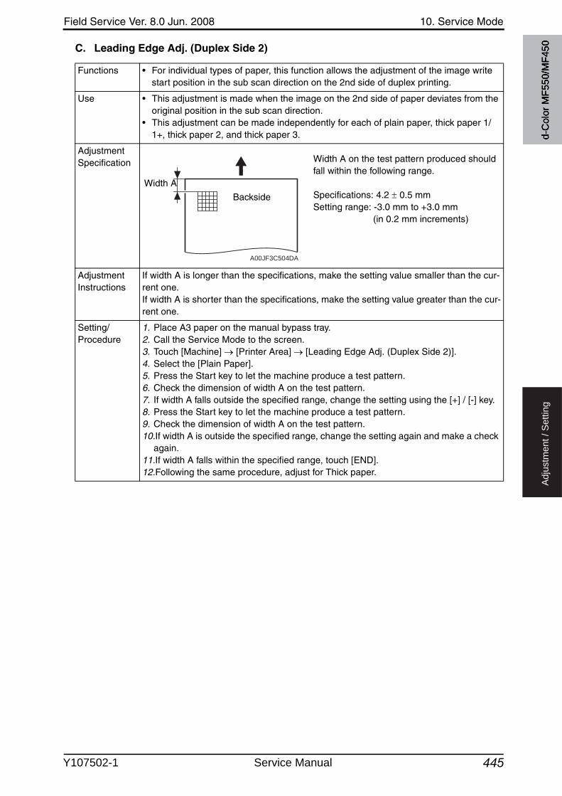
Field Service Ver. 8.0 Jun. 2008 10. Service Mode
445
Ad
justm
en
t /
Se
ttin
g
C. Leading Edge Adj. (Duplex Side 2)
Functions • For individual types of paper, this function allows the adjustment of the image write start position in the sub scan direction on the 2nd side of duplex printing.
Use • This adjustment is made when the image on the 2nd side of paper deviates from the original position in the sub scan direction.
• This adjustment can be made independently for each of plain paper, thick paper 1/1+, thick paper 2, and thick paper 3.
Adjustment Specification Width A on the test pattern produced should
fall within the following range.
Specifications: 4.2 0.5 mmSetting range: -3.0 mm to +3.0 mm (in 0.2 mm increments)
Adjustment Instructions
If width A is longer than the specifications, make the setting value smaller than the cur-rent one.If width A is shorter than the specifications, make the setting value greater than the cur-rent one.
Setting/Procedure
1. Place A3 paper on the manual bypass tray.2. Call the Service Mode to the screen.3. Touch [Machine] [Printer Area] [Leading Edge Adj. (Duplex Side 2)].4. Select the [Plain Paper].5. Press the Start key to let the machine produce a test pattern.6. Check the dimension of width A on the test pattern.7. If width A falls outside the specified range, change the setting using the [+] / [-] key.8. Press the Start key to let the machine produce a test pattern.9. Check the dimension of width A on the test pattern.10.If width A is outside the specified range, change the setting again and make a check
again.11.If width A falls within the specified range, touch [END].12.Following the same procedure, adjust for Thick paper.
A00JF3C504DA
Width A
Backside
d-C
olor
MF5
50/M
F450
Y107502-1 Service Manual
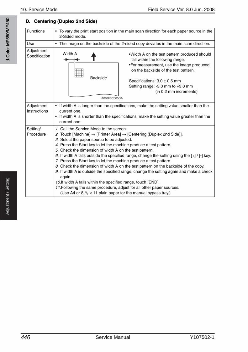
10. Service Mode Field Service Ver. 8.0 Jun. 2008
446
Ad
justm
en
t /
Se
ttin
g
D. Centering (Duplex 2nd Side)
Functions • To vary the print start position in the main scan direction for each paper source in the 2-Sided mode.
Use • The image on the backside of the 2-sided copy deviates in the main scan direction.
Adjustment Specification •Width A on the test pattern produced should
fall within the following range.•For measurement, use the image produced
on the backside of the test pattern.
Specifications: 3.0 0.5 mmSetting range: -3.0 mm to +3.0 mm (in 0.2 mm increments)
Adjustment Instructions
• If width A is longer than the specifications, make the setting value smaller than the current one.
• If width A is shorter than the specifications, make the setting value greater than the current one.
Setting/Procedure
1. Call the Service Mode to the screen.2. Touch [Machine] [Printer Area] [Centering (Duplex 2nd Side)].3. Select the paper source to be adjusted.4. Press the Start key to let the machine produce a test pattern.5. Check the dimension of width A on the test pattern.6. If width A falls outside the specified range, change the setting using the [+] / [-] key.7. Press the Start key to let the machine produce a test pattern.8. Check the dimension of width A on the test pattern on the backside of the copy.9. If width A is outside the specified range, change the setting again and make a check
again.10.If width A falls within the specified range, touch [END].11.Following the same procedure, adjust for all other paper sources.
(Use A4 or 8 1/2 × 11 plain paper for the manual bypass tray.)
A00JF3C505DA
Width A
Backside
d-C
olor
MF5
50/M
F450
Service Manual Y107502-1
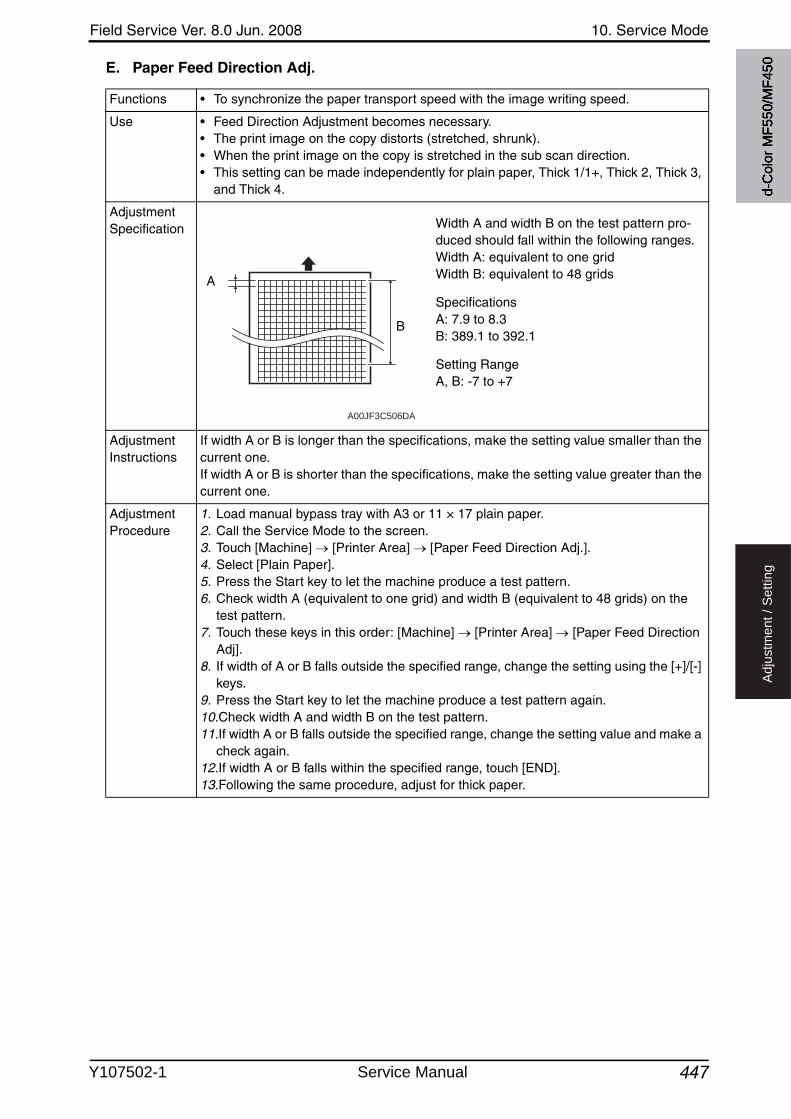
Field Service Ver. 8.0 Jun. 2008 10. Service Mode
447
Ad
justm
en
t /
Se
ttin
g
E. Paper Feed Direction Adj.
Functions • To synchronize the paper transport speed with the image writing speed.
Use • Feed Direction Adjustment becomes necessary.• The print image on the copy distorts (stretched, shrunk).• When the print image on the copy is stretched in the sub scan direction.• This setting can be made independently for plain paper, Thick 1/1+, Thick 2, Thick 3,
and Thick 4.
Adjustment Specification Width A and width B on the test pattern pro-
duced should fall within the following ranges.Width A: equivalent to one gridWidth B: equivalent to 48 grids
SpecificationsA: 7.9 to 8.3B: 389.1 to 392.1
Setting RangeA, B: -7 to +7
Adjustment Instructions
If width A or B is longer than the specifications, make the setting value smaller than the current one.If width A or B is shorter than the specifications, make the setting value greater than the current one.
Adjustment Procedure
1. Load manual bypass tray with A3 or 11 × 17 plain paper.2. Call the Service Mode to the screen.3. Touch [Machine] [Printer Area] [Paper Feed Direction Adj.].4. Select [Plain Paper].5. Press the Start key to let the machine produce a test pattern.6. Check width A (equivalent to one grid) and width B (equivalent to 48 grids) on the
test pattern.7. Touch these keys in this order: [Machine] [Printer Area] [Paper Feed Direction
Adj].8. If width of A or B falls outside the specified range, change the setting using the [+]/[-]
keys.9. Press the Start key to let the machine produce a test pattern again.10.Check width A and width B on the test pattern.11.If width A or B falls outside the specified range, change the setting value and make a
check again.12.If width A or B falls within the specified range, touch [END].13.Following the same procedure, adjust for thick paper.
A00JF3C506DA
A
B
d-C
olor
MF5
50/M
F450
Y107502-1 Service Manual
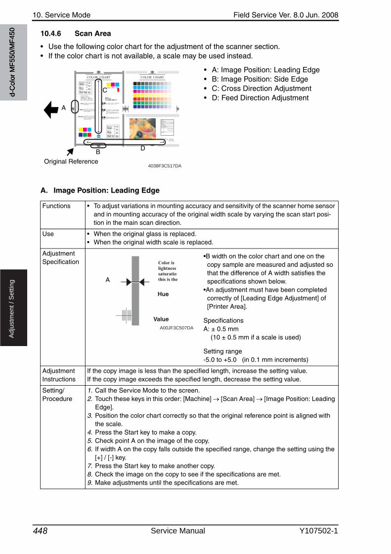
10. Service Mode Field Service Ver. 8.0 Jun. 2008
448
Ad
justm
en
t /
Se
ttin
g
10.4.6 Scan Area
• Use the following color chart for the adjustment of the scanner section.• If the color chart is not available, a scale may be used instead.
• A: Image Position: Leading Edge• B: Image Position: Side Edge• C: Cross Direction Adjustment• D: Feed Direction Adjustment
A. Image Position: Leading Edge
COLOR CHART
Y M C
C M C Y Y M
Color is “hue”,lightness is “value”,saturation is “chroma”:this is the world of color.
Hue
P2
P2
The quality of color which can be described by words such as red, yellow, blue etc.
Value The quality of color which can be described by words such as light, dark etc., relating the color to a gray of a similar lightness.
Chroma The quality of color which can be described by words such as vivid, dull etc., describing the extent to which a color differs from a gray having the same value.
P1
1.0
1.1
1.25 1.4 1.6
1.8
2.0
2.22.5
2.8
3.2
3.6
4.0
4.5
Y M C
C M C Y Y M
1.0
1.1
1.25 1.4 1.6
1.8
2.0
2.22.5
2.8
3.2
3.6
4.0
4.5
COLOR CHART
YM
CB
GR
MODEL :MACHINE S/N :DATE : / / °C %RHCOUNTER :COPY DENSITY :COLOR BALANCE Y : M : C : BK : OTHERS :
P1
10
BK
CHART NO. : CTC-008-01
PART NO. : 4036-7940-01
Printed In Japan
9 8 7 6 5 4 3 2 1
4038F3C517DAOriginal Reference
B
A
C
D
Functions • To adjust variations in mounting accuracy and sensitivity of the scanner home sensor and in mounting accuracy of the original width scale by varying the scan start posi-tion in the main scan direction.
Use • When the original glass is replaced.• When the original width scale is replaced.
Adjustment Specification
•B width on the color chart and one on the copy sample are measured and adjusted so that the difference of A width satisfies the specifications shown below.
•An adjustment must have been completed correctly of [Leading Edge Adjustment] of [Printer Area].
SpecificationsA: ± 0.5 mm (10 ± 0.5 mm if a scale is used)
Setting range-5.0 to +5.0 (in 0.1 mm increments)
Adjustment Instructions
If the copy image is less than the specified length, increase the setting value.If the copy image exceeds the specified length, decrease the setting value.
Setting/Procedure
1. Call the Service Mode to the screen.2. Touch these keys in this order: [Machine] [Scan Area] [Image Position: Leading
Edge].3. Position the color chart correctly so that the original reference point is aligned with
the scale.4. Press the Start key to make a copy.5. Check point A on the image of the copy.6. If width A on the copy falls outside the specified range, change the setting using the
[+] / [-] key.7. Press the Start key to make another copy.8. Check the image on the copy to see if the specifications are met.9. Make adjustments until the specifications are met.
A00JF3C507DA
A
d-C
olor
MF5
50/M
F450
Service Manual Y107502-1
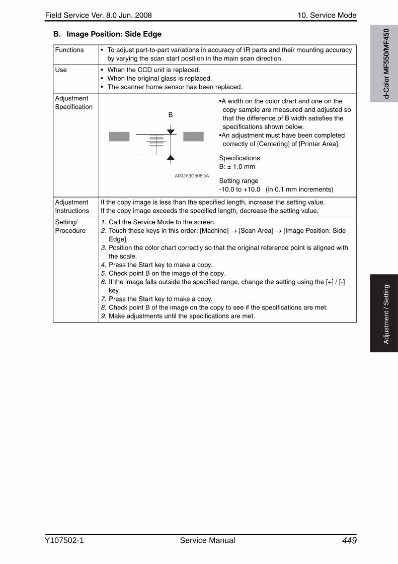
Field Service Ver. 8.0 Jun. 2008 10. Service Mode
449
Ad
justm
en
t /
Se
ttin
g
B. Image Position: Side Edge
Functions • To adjust part-to-part variations in accuracy of IR parts and their mounting accuracy by varying the scan start position in the main scan direction.
Use • When the CCD unit is replaced.• When the original glass is replaced.• The scanner home sensor has been replaced.
Adjustment Specification
•A width on the color chart and one on the copy sample are measured and adjusted so that the difference of B width satisfies the specifications shown below.
•An adjustment must have been completed correctly of [Centering] of [Printer Area].
SpecificationsB: ± 1.0 mm
Setting range-10.0 to +10.0 (in 0.1 mm increments)
Adjustment Instructions
If the copy image is less than the specified length, increase the setting value.If the copy image exceeds the specified length, decrease the setting value.
Setting/Procedure
1. Call the Service Mode to the screen.2. Touch these keys in this order: [Machine] [Scan Area] [Image Position: Side
Edge].3. Position the color chart correctly so that the original reference point is aligned with
the scale.4. Press the Start key to make a copy.5. Check point B on the image of the copy.6. If the image falls outside the specified range, change the setting using the [+] / [-]
key.7. Press the Start key to make a copy.8. Check point B of the image on the copy to see if the specifications are met.9. Make adjustments until the specifications are met.
A00JF3C508DA
B
d-C
olor
MF5
50/M
F450
Y107502-1 Service Manual
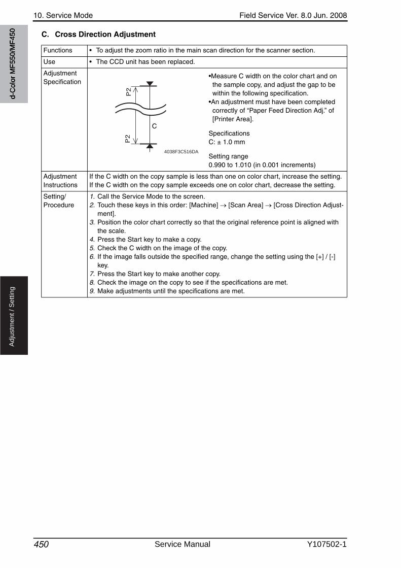
10. Service Mode Field Service Ver. 8.0 Jun. 2008
450
Ad
justm
en
t /
Se
ttin
g
C. Cross Direction Adjustment
Functions • To adjust the zoom ratio in the main scan direction for the scanner section.
Use • The CCD unit has been replaced.
Adjustment Specification
•Measure C width on the color chart and on the sample copy, and adjust the gap to be within the following specification.
•An adjustment must have been completed correctly of “Paper Feed Direction Adj.” of [Printer Area].
SpecificationsC: ± 1.0 mm
Setting range0.990 to 1.010 (in 0.001 increments)
Adjustment Instructions
If the C width on the copy sample is less than one on color chart, increase the setting.If the C width on the copy sample exceeds one on color chart, decrease the setting.
Setting/Procedure
1. Call the Service Mode to the screen.2. Touch these keys in this order: [Machine] [Scan Area] [Cross Direction Adjust-
ment].3. Position the color chart correctly so that the original reference point is aligned with
the scale.4. Press the Start key to make a copy.5. Check the C width on the image of the copy.6. If the image falls outside the specified range, change the setting using the [+] / [-]
key.7. Press the Start key to make another copy.8. Check the image on the copy to see if the specifications are met.9. Make adjustments until the specifications are met.
4038F3C516DA
C
d-C
olor
MF5
50/M
F450
Service Manual Y107502-1
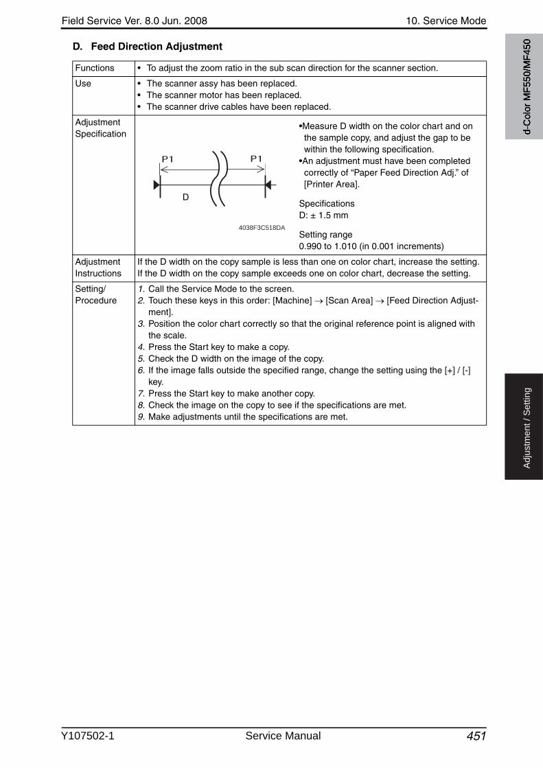
Field Service Ver. 8.0 Jun. 2008 10. Service Mode
451
Ad
justm
en
t /
Se
ttin
g
D. Feed Direction Adjustment
Functions • To adjust the zoom ratio in the sub scan direction for the scanner section.
Use • The scanner assy has been replaced.• The scanner motor has been replaced.• The scanner drive cables have been replaced.
Adjustment Specification
•Measure D width on the color chart and on the sample copy, and adjust the gap to be within the following specification.
•An adjustment must have been completed correctly of “Paper Feed Direction Adj.” of [Printer Area].
SpecificationsD: ± 1.5 mm
Setting range0.990 to 1.010 (in 0.001 increments)
Adjustment Instructions
If the D width on the copy sample is less than one on color chart, increase the setting.If the D width on the copy sample exceeds one on color chart, decrease the setting.
Setting/Procedure
1. Call the Service Mode to the screen.2. Touch these keys in this order: [Machine] [Scan Area] [Feed Direction Adjust-
ment].3. Position the color chart correctly so that the original reference point is aligned with
the scale.4. Press the Start key to make a copy.5. Check the D width on the image of the copy.6. If the image falls outside the specified range, change the setting using the [+] / [-]
key.7. Press the Start key to make another copy.8. Check the image on the copy to see if the specifications are met.9. Make adjustments until the specifications are met.
4038F3C518DA
D
d-C
olor
MF5
50/M
F450
Y107502-1 Service Manual
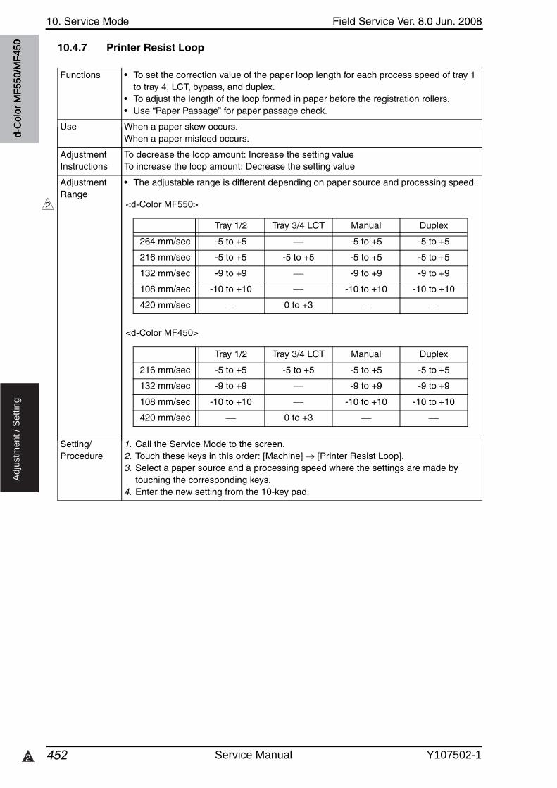
10. Service Mode Field Service Ver. 8.0 Jun. 2008
4522
Ad
justm
en
t /
Se
ttin
g
10.4.7 Printer Resist Loop
Functions • To set the correction value of the paper loop length for each process speed of tray 1 to tray 4, LCT, bypass, and duplex.
• To adjust the length of the loop formed in paper before the registration rollers.• Use “Paper Passage” for paper passage check.
Use When a paper skew occurs.When a paper misfeed occurs.
Adjustment Instructions
To decrease the loop amount: Increase the setting valueTo increase the loop amount: Decrease the setting value
Adjustment Range
• The adjustable range is different depending on paper source and processing speed.
2
d-C
olor
MF5
50/M
F450
<d-Color MF550>
<d-Color MF450>
Tray 1/2 Tray 3/4 LCT Manual Duplex
264 mm/sec -5 to +5 -5 to +5 -5 to +5
216 mm/sec -5 to +5 -5 to +5 -5 to +5 -5 to +5
132 mm/sec -9 to +9 -9 to +9 -9 to +9
108 mm/sec -10 to +10 -10 to +10 -10 to +10
420 mm/sec 0 to +3
Tray 1/2 Tray 3/4 LCT Manual Duplex
216 mm/sec -5 to +5 -5 to +5 -5 to +5 -5 to +5
132 mm/sec -9 to +9 -9 to +9 -9 to +9
108 mm/sec -10 to +10 -10 to +10 -10 to +10
420 mm/sec 0 to +3
Setting/Procedure
1. Call the Service Mode to the screen.2. Touch these keys in this order: [Machine] [Printer Resist Loop].3. Select a paper source and a processing speed where the settings are made by
touching the corresponding keys.4. Enter the new setting from the 10-key pad.
Service Manual Y107502-1
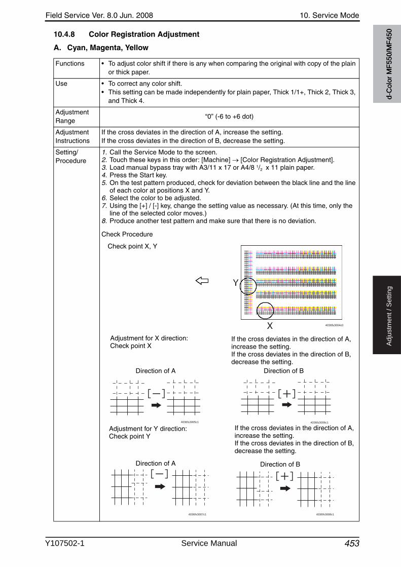
Field Service Ver. 8.0 Jun. 2008 10. Service Mode
453
Ad
justm
en
t /
Se
ttin
g
10.4.8 Color Registration Adjustment
A. Cyan, Magenta, Yellow
Functions • To adjust color shift if there is any when comparing the original with copy of the plain or thick paper.
Use • To correct any color shift.• This setting can be made independently for plain paper, Thick 1/1+, Thick 2, Thick 3,
and Thick 4.
Adjustment Range
“0” (-6 to +6 dot)
Adjustment Instructions
If the cross deviates in the direction of A, increase the setting.If the cross deviates in the direction of B, decrease the setting.
Setting/Procedure
1. Call the Service Mode to the screen.2. Touch these keys in this order: [Machine] [Color Registration Adjustment].3. Load manual bypass tray with A3/11 x 17 or A4/8 1/2 x 11 plain paper.4. Press the Start key.5. On the test pattern produced, check for deviation between the black line and the line
of each color at positions X and Y.6. Select the color to be adjusted.7. Using the [+] / [-] key, change the setting value as necessary. (At this time, only the
line of the selected color moves.)8. Produce another test pattern and make sure that there is no deviation.
Check Procedure
4036fs3005c1 4036fs3006c1
4036fs3007c1 4036fs3008c1
If the cross deviates in the direction of A, increase the setting.If the cross deviates in the direction of B, decrease the setting.
Check point X, Y
Adjustment for X direction: Check point X
Adjustment for Y direction: Check point Y
If the cross deviates in the direction of A, increase the setting.If the cross deviates in the direction of B, decrease the setting.
Direction of A Direction of B
Direction of A Direction of B
4036fs3004c0
d-C
olor
MF5
50/M
F450
Y107502-1 Service Manual
10. Service Mode Field Service Ver. 8.0 Jun. 2008
454
Ad
justm
en
t /
Se
ttin
g
10.4.9 Skew adjustment
A. Skew adjustment
B. Skew adjustment reset
10.4.10 LD adjustment
A. LD delay adjust.
Functions • This function allows you to set the default position of the skew correction motor.• Adjusts and sets a value that is used as an individual skew correction motor's refer-
ence position for skew correction control.
Use • This setting is made after the PH unit is replaced.• Use this function when the information of the motor’s position setting is lost due to the
replacement of the service EEPROM board or other reasons.
Adjustment Range
0 to 480 (step:1)
Setting/Procedure
1. Call the Service Mode to the screen.2. Touch these keys in this order:
[Machine] [Skew adjustment] [Skew adjustment].3. Select the color to be set.4. Enter the skew value described on the new PH unit with the 10-key pad.5. Touch [OK].6. Proceed to [Skew adjustment reset].
Functions • Returns the skew correction motor to the default position and clear the backup copies of the cumulative skew amount.
Use • After PH unit replacement, perform [Skew adjustment] and then execute this function.• After addressing the alert code P-14 and completing an action to the problem, per-
form this function.• Use this function when the current skew correction motor’s position becomes unavail-
able due to the skew adjustment interrupted by the door being opened or the main power switch being turned OFF.
Setting/Procedure
1. Call the Service Mode to the screen.2. Touch these keys in this order:
[Machine] [Skew adjustment] [Skew adjustment reset].3. Touch the start key and execute the skew adjustment reset.
NOTE• After the skew adjustment reset is complete, be sure to perform [Initialize +
Image Stabilization].
Functions • LD delay adjust sets adjustment values by adjusting LD light emission delay amount.(Values to be entered are described on the side of the PH unit.)
Use • This setting is made after the PH unit is replaced.• This adjustment is made when the service EEPROM board is replaced or the backup
of information on position settings is lost.
Setting/Procedure
1. Call the Service Mode to the screen.2. Touch these keys in this order:
[Machine] [LD adjustment] [LD delay adjust.].3. Select the color to be set.4. Enter the values described on the side of the PH unit using 10-key pad.5. Touch [OK].
d-C
olor
MF5
50/M
F450
Service Manual Y107502-1
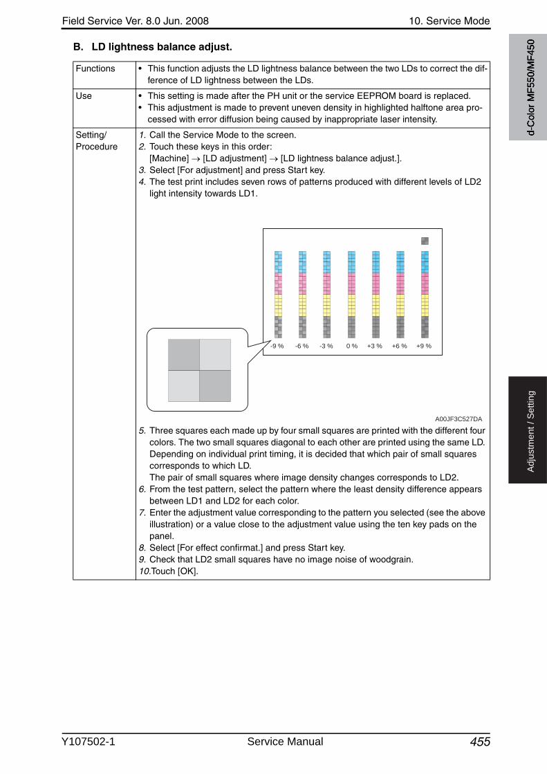
Field Service Ver. 8.0 Jun. 2008 10. Service Mode
455
Ad
justm
en
t /
Se
ttin
g
B. LD lightness balance adjust.
Functions • This function adjusts the LD lightness balance between the two LDs to correct the dif-ference of LD lightness between the LDs.
Use • This setting is made after the PH unit or the service EEPROM board is replaced.• This adjustment is made to prevent uneven density in highlighted halftone area pro-
cessed with error diffusion being caused by inappropriate laser intensity.
Setting/Procedure
1. Call the Service Mode to the screen.2. Touch these keys in this order:
[Machine] [LD adjustment] [LD lightness balance adjust.].3. Select [For adjustment] and press Start key.4. The test print includes seven rows of patterns produced with different levels of LD2
light intensity towards LD1.
5. Three squares each made up by four small squares are printed with the different fourcolors. The two small squares diagonal to each other are printed using the same LD. Depending on individual print timing, it is decided that which pair of small squares corresponds to which LD. The pair of small squares where image density changes corresponds to LD2.
6. From the test pattern, select the pattern where the least density difference appears between LD1 and LD2 for each color.
7. Enter the adjustment value corresponding to the pattern you selected (see the aboveillustration) or a value close to the adjustment value using the ten key pads on the panel.
8. Select [For effect confirmat.] and press Start key.9. Check that LD2 small squares have no image noise of woodgrain.10.Touch [OK].
A00JF3C527DA
-9 % -6 % -3 % 0 % +3 % +6 % +9 %
d-C
olor
MF5
50/M
F450
Y107502-1 Service Manual
10. Service Mode Field Service Ver. 8.0 Jun. 2008
456
Ad
justm
en
t /
Se
ttin
g
10.4.11 Manual Bypass Tray Adjustment
10.4.12 Lead Edge Erase Adjustment
10.4.13 Thick Paper Mode
Functions • To set the maximum width and the minimum width for the manual bypass paper size unit of the manual bypass guide.
Use • Use when the manual bypass paper size unit of the manual bypass guide has been changed.
• Use when a false paper size is displayed when the manual bypass is used.
Setting/Procedure
1. Call the Service Mode to the screen.2. Touch these keys in this order: [Machine] [Manual Bypass Tray Adjustment].3. Touch [Max. Width].4. Load the bypass tray with paper having a width of 301 mm.5. Press the Start key and check that the results are [OK].6. Touch [Min. Width.].7. Load the bypass tray with paper having a width of 89 mm.8. Press the Start key and check that the results are [OK].✽ Make the adjustment again if the results are [NG].
Functions • To set the leading edge erase amount of the paper.
Use • Upon user requests, it is possible to specify the void area where image is not printed along the leading edge.
Setting/Procedure
• The default setting is 4 mm.
“4 mm” 5 mm 7 mm
NOTE• When “4 mm” is selected, 4.2 mm is the actual amount to be erased in print
based on the control system of the machine.
Functions • For thick paper, the paper interval can be changed.
Use • To resolve image failure (black streaks) in the main scan direction due to the vibra-tions created when the trailing edge of the preceding paper is passing by the timing roller.
• To reduce the effect of vibrations on image quality by widening paper interval.
Image Quality : Operates with the paper interval longer than normal. Productivity : Operates with the paper interval closer to the normal
Setting/Procedure
• The default setting is Productivity.
Image Quality “Productivity”
d-C
olor
MF5
50/M
F450
Service Manual Y107502-1
Field Service Ver. 8.0 Jun. 2008 10. Service Mode
457
Ad
justm
en
t /
Se
ttin
g
10.4.14 Split Line Prior Detection
10.5 Firmware Version
10.6 Imaging Process Adjustment
10.6.1 Gradation Adjust
• It will not be displayed when the following setting is set to “ON”. [Service Mode] [Image Process Adjustment] [Dev. Bias Choice]
Functions • To check the stain on the ADF original glass and display the result.
Use • To manually perform the pre-detection of the stain which is normally conducted when the main/sub power switch is turned ON, recovering from the sleep/low power mode, etc.
• [Split Line Prior Detection] will be conducted with the detection level set by the follow-ing setting.[Service Mode] [System 2] [Split Line Detect. Setting] [Prior Detection]When the above setting is set to “Not Set”, “NG” will be displayed even though the pre-detection is conducted.
Setting/Procedure
1. Call the Service Mode to the screen.2. Touch these keys in this order: [Machine] [Split Line Prior Detection].3. Press the start key to start the pre-detection.4. Check to make sure that “OK” is displayed for the result.
* When the result says “NG”, clean the glass and check again.
Functions • To check the firmware version.
Use • Use when the firmware is upgraded.• When the firmware is upgraded or PWB is replaced.
Setting/Procedure
1. Call the Service Mode to the screen.2. Touch [Firmware Version].3. Select the appropriate key from 1 to 3 to check the Firmware Version.
Functions • To make an automatic adjustment of gradation based on the test pattern producedand the readings taken by the scanner.
Use • Color reproduction performance becomes poor.• The IU has been replaced.• The image transfer belt unit has been replaced.✽ The Adj. Values of “Dark” and “Highlight” shown on the gradation adjust screen repre-
sent how much corrections are made to produce an ideal image output. Conv. Valueshows the difference from the ideal image density.
✽ The closer the Conv. Value to 0, the more ideal the image.
• Stablizer : Before gradation adjust, perform image stabilization.• Gradation Mode : It gives the highest priority to gradation performance of
the image as it adjusts.• Resolution Mode : It gives the highest priority to reproduction performance
of letters and lines as it adjusts.• High Compression Mode : It gives the highest priority to increasing the number of
images to be stored in the memory as it adjusts.
Adjustment Specification
Dark : 0 ± 100Highlight : 0 ± 60
d-C
olor
MF5
50/M
F450
Y107502-1 Service Manual
10. Service Mode Field Service Ver. 8.0 Jun. 2008
458
Ad
justm
en
t /
Se
ttin
g
10.6.2 Transfer Belt
A. Cleaning Bias
Setting/Procedure
1. Call the Service Mode to the screen.2. Touch these keys in this order: [Image Process Adjustment] [Gradation Adjust].3. Touch [Stabilizer] and the Start key to perform image stabilization.
NOTE• Before executing Gradation adjust, be sure to perform Stabilizer.
4. Select the appropriate mode for the gradation adjustment.5. Press the Start key to let the machine produce a test pattern.
NOTE• When the image stabilization performed in step 3 is NG, the Start key stops
functioning.• When one of the alert codes, P-5, P-6, P-7, P-8, P-9, and P-28 is on the screen
and [Gradation Mode] is selected, the Start key stops functioning.
6. Place the test pattern produced on the original glass.7. Place ten blank sheets of A3/11x17 paper on the test pattern and lower the original
cover.8. Press the Start key. (The machine will then start scanning the test pattern.)9. Touch [OK] and repeat steps from 4 through 8 twice (a total of three times).10.Touch [Gradation Adjust] to display the Adj. Values and Conv. Values of each color
(C, M, Y and K) for Dark and Highlight.11.Use the following procedures to check the Conv. Value.
Dark: 0 ± 100 and Highlight: 0 ± 60: It completes the adjustment procedure.If neither Dark nor Highlight falls outside the ranges specified above: Perform steps from 4 to 8.
NOTE• If the convergence falls within the specified range after the second Gradation
Adjustment, further adjustment may not be necessary.
• If a fault is detected, “0” is displayed for all values. In that case, after turning off the main power switch, turn it on again more than 10 seconds after and then make the gradation adjustment again.
• If either dark or highlight still remains outside the specified ranges perform D Max Density.
• If a total of four sequences of gradation adjust do not bring the values into the speci-fied range, check the image.
• If the image is faulty, perform the troubleshooting procedures for image problems.
Functions • To set the level of transfer belt cleaning bias independently for each process speed.
Use • When the image pattern is not completely removed, it strengthen the transfer belt cleaning bias in order to make the cleaner more effective.
• For each processing speed, positive and negative output values can be set.
Setting/Procedure
• The each default setting is 0.-5 to +5 (step:1 *)
*: One step corresponds to 5 A.
d-C
olor
MF5
50/M
F450
Service Manual Y107502-1
Field Service Ver. 8.0 Jun. 2008 10. Service Mode
459
Ad
justm
en
t /
Se
ttin
g
B. Auto Cleaning
10.6.3 D Max Density
Functions • To set whether to perform the long regular transfer belt cleaning operation (approx. 30 sec).
Use • The long cleaning operation (approx. 30 seconds) can be used to take more effectivemeasures against toner filming on the surface of the transfer belt.
Enable : Performs the long cleaning operation (approx. 30 sec) after the normal regular cleaning operations (approx. 10 sec) which are performed nine times.
Disable : Performs only the normal regular operations (approx. 10 sec) but not the long cleaning operation (approx. 30 sec).
Setting/Procedure
• The default setting is Enable.
“Enable” Disable
Functions • To adjust gradation, color, and image density to target reproduction levels by varying the maximum amount of toner sticking to paper through auxiliary manual fine-adjust-ment of gamma of each color after gradation adjust.
Use • An image quality problem is not corrected even after gradation adjust has been run.
Adjustment Range
• The default setting is 0.-10 to +10 (step: 1 *)
*: 1 step corresponds to 0.03 in density difference.
Adjustment Instructions
To increase the maximum amount of toner sticking, increase the setting value.To decrease the maximum amount of toner sticking, decrease the setting value.
Setting/Procedure
1. Call the Service Mode to the screen.2. Touch these keys in this order: [Imaging Process Adjustment] [D Max Density].3. Select [COPY] or [Printer].4. Select the color to be adjusted.5. Enter the new setting from the 10-key pad or [+/-].6. Touch [END] to return to the [Process] menu screen.7. Touch [Stabilizer].8. Touch [Stabilizer Mode].9. Press the Start key to validate the adjustment value.10.Check the copy image for any image problem.
NOTE• If the setting value has been changed, be sure to run an image stabilization
sequence to make valid the new value.d-
Col
or M
F550
/MF4
50
Y107502-1 Service Manual

10. Service Mode Field Service Ver. 8.0 Jun. 2008
460
Ad
justm
en
t /
Se
ttin
g
10.6.4 TCR Level Setting
10.6.5 Background Voltage Margin
Functions • To adjust the T/C control level when an abnormal image density occurs as a result of a change in the amount of charge of toner and carrier due to an environmental change.
Use • Use when T/C changes due to changes in environmental conditions of the user site.
Adjustment Range
• The default setting is 0.-3 to +3
(1 step in positive (+) direction: 0.5 % increase, 1 step in negative (-) direction: 0.05 % decrease, Center value 0 corresponds to 7 % T/C ratio.)
Adjustment Instructions
To increase T/C, increase the setting value.To decrease T/C, decrease the setting value.
Adjustment Procedure
1. Call the Service Mode to the screen.2. Touch these keys in this order: [Process] [TCR Level Setting].3. Select the color to be adjusted.4. Enter the new setting from the 10-Key pad and [+/-] key.5. Touch [END] to validate the adjustment value.6. Check the copy image for any image problem.
Functions • To adjust the highlight portion (fog level) to the target reproduction level by making an auxiliary manual fine-adjustment of of each color after gradation adjust.
Use • Use when a foggy background occurs due to a printer problem.
Adjustment Range
• The default setting is 0.-5 to +5 (step: 1)
Adjustment Instructions
To make the background level foggier, decrease the setting value.To make the background level less foggy, increase the setting value.
Setting/Procedure
1. Call the Service Mode to the screen.2. Touch these keys in this order: [Imaging Process Adjustment] [Background Volt-
age Margin].3. Select the color to be adjusted.4. Enter the new setting from the 10-key pad.5. Touch [END] to return to the [Image Adjust] menu screen.6. Touch [Stabilizer].7. Touch [Stabilization Only].8. Press the Start key to validate the adjustment value.9. Check the copy image for any image problem.
NOTE• If the setting value has been changed, be sure to run an image stabilization
sequence to make valid the new value.
d-C
olor
MF5
50/M
F450
Service Manual Y107502-1
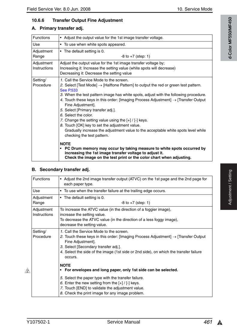
Field Service Ver. 8.0 Jun. 2008 10. Service Mode
461 2
Ad
justm
en
t /
Se
ttin
g
10.6.6 Transfer Output Fine Adjustment
A. Primary transfer adj.
B. Secondary transfer adj.
Functions • Adjust the output value for the 1st image transfer voltage.
Use • To use when white spots appeared.
Adjustment Range
• The default setting is 0.-8 to +7 (step: 1)
Adjustment Instructions
Adjust the output value for the 1st image transfer voltage by;Increasing it: Increase the setting value (white spots will decrease)Decreasing it: Decrease the setting value
Setting/Procedure
1. Call the Service Mode to the screen.2. Select [Test Mode] [Halftone Pattern] to output the red or green test pattern.See P.5333. When the test pattern image has white spots, adjust with the following procedure.4. Touch these keys in this order: [Imaging Process Adjustment] [Transfer Output
Fine Adjustment].5. Select [Primary transfer adj.].6. Select the color.7. Change the setting value using the [+] / [-] keys.8. Touch [OK] key to set the adjustment value.
Gradually increase the adjustment value to the acceptable white spots level while checking the test pattern.
NOTE• PC Drum memory may occur by taking measure to white spots occurred by
increasing the 1st image transfer voltage to adjust it.Check the image on the test print or the color chart when adjusting.
Functions • Adjust the 2nd image transfer output (ATVC) on the 1st page and the 2nd page for each paper type.
Use • To use when the transfer failure at the trailing edge occurs.
Adjustment Range
• The default setting is 0.-8 to +7 (step: 1)
Adjustment Instructions
To increase the ATVC value (in the direction of a foggier image), increase the setting value.To decrease the ATVC value (in the direction of a less foggy image), decrease the setting value.
Setting/Procedure
1. Call the Service Mode to the screen.2. Touch these keys in this order: [Imaging Process Adjustment] [Transfer Output
Fine Adjustment].3. Select [Secondary transfer adj.].4. Select the side of the image (1st side or 2nd side), on which the transfer failure
occurs.
NOTE• For envelopes and long paper, only 1st side can be selected.
5. Select the paper type with the transfer failure.6. Enter the new setting from the [+] / [-] keys.7. Touch [END] to validate the adjustment value.8. Check the print image for any image problem.
2
d-C
olor
MF5
50/M
F450
Y107502-1 Service Manual
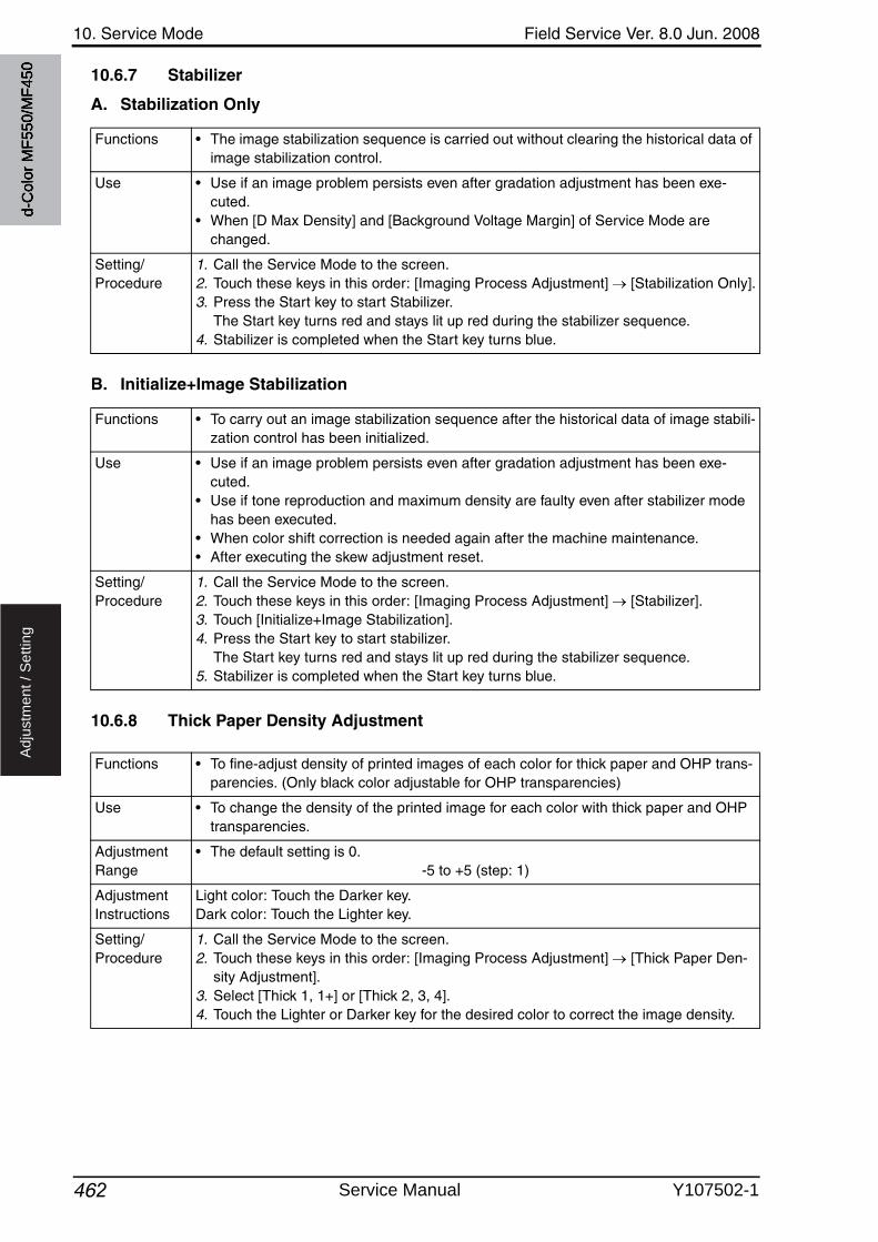
10. Service Mode Field Service Ver. 8.0 Jun. 2008
462
Ad
justm
en
t /
Se
ttin
g
10.6.7 Stabilizer
A. Stabilization Only
B. Initialize+Image Stabilization
10.6.8 Thick Paper Density Adjustment
Functions • The image stabilization sequence is carried out without clearing the historical data of image stabilization control.
Use • Use if an image problem persists even after gradation adjustment has been exe-cuted.
• When [D Max Density] and [Background Voltage Margin] of Service Mode are changed.
Setting/Procedure
1. Call the Service Mode to the screen.2. Touch these keys in this order: [Imaging Process Adjustment] [Stabilization Only].3. Press the Start key to start Stabilizer.
The Start key turns red and stays lit up red during the stabilizer sequence.4. Stabilizer is completed when the Start key turns blue.
Functions • To carry out an image stabilization sequence after the historical data of image stabili-zation control has been initialized.
Use • Use if an image problem persists even after gradation adjustment has been exe-cuted.
• Use if tone reproduction and maximum density are faulty even after stabilizer mode has been executed.
• When color shift correction is needed again after the machine maintenance.• After executing the skew adjustment reset.
Setting/Procedure
1. Call the Service Mode to the screen.2. Touch these keys in this order: [Imaging Process Adjustment] [Stabilizer].3. Touch [Initialize+Image Stabilization].4. Press the Start key to start stabilizer.
The Start key turns red and stays lit up red during the stabilizer sequence.5. Stabilizer is completed when the Start key turns blue.
Functions • To fine-adjust density of printed images of each color for thick paper and OHP trans-parencies. (Only black color adjustable for OHP transparencies)
Use • To change the density of the printed image for each color with thick paper and OHP transparencies.
Adjustment Range
• The default setting is 0.-5 to +5 (step: 1)
Adjustment Instructions
Light color: Touch the Darker key.Dark color: Touch the Lighter key.
Setting/Procedure
1. Call the Service Mode to the screen.2. Touch these keys in this order: [Imaging Process Adjustment] [Thick Paper Den-
sity Adjustment].3. Select [Thick 1, 1+] or [Thick 2, 3, 4].4. Touch the Lighter or Darker key for the desired color to correct the image density.
d-C
olor
MF5
50/M
F450
Service Manual Y107502-1
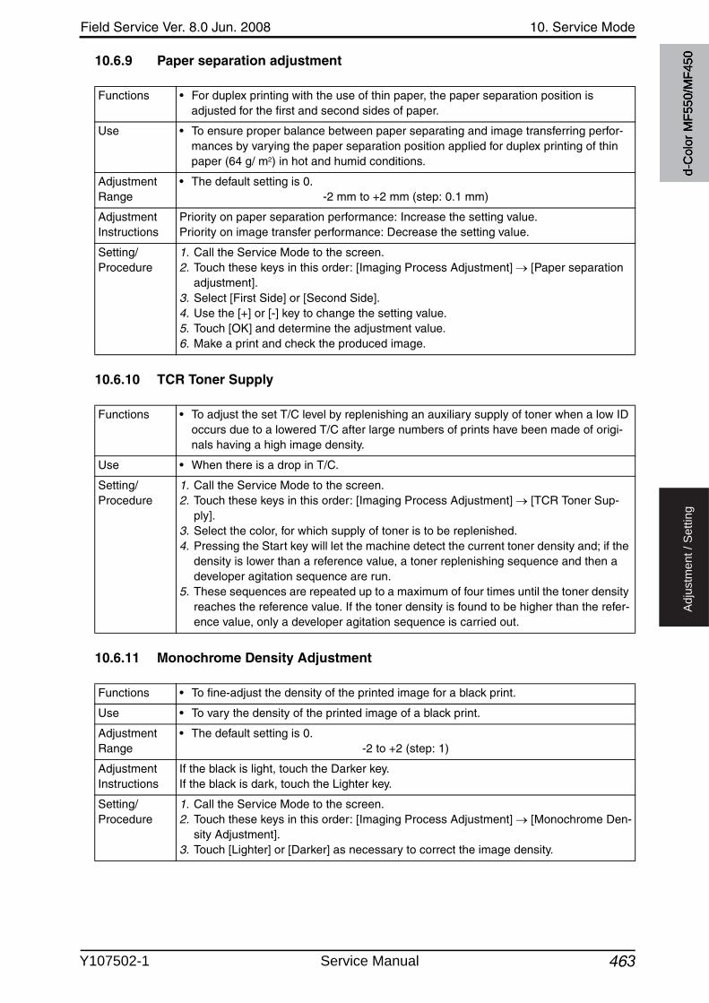
Field Service Ver. 8.0 Jun. 2008 10. Service Mode
463
Ad
justm
en
t /
Se
ttin
g
10.6.9 Paper separation adjustment
10.6.10 TCR Toner Supply
10.6.11 Monochrome Density Adjustment
Functions • For duplex printing with the use of thin paper, the paper separation position is adjusted for the first and second sides of paper.
Use • To ensure proper balance between paper separating and image transferring perfor-mances by varying the paper separation position applied for duplex printing of thin paper (64 g/ m2) in hot and humid conditions.
Adjustment Range
• The default setting is 0.-2 mm to +2 mm (step: 0.1 mm)
Adjustment Instructions
Priority on paper separation performance: Increase the setting value.Priority on image transfer performance: Decrease the setting value.
Setting/Procedure
1. Call the Service Mode to the screen.2. Touch these keys in this order: [Imaging Process Adjustment] [Paper separation
adjustment].3. Select [First Side] or [Second Side].4. Use the [+] or [-] key to change the setting value.5. Touch [OK] and determine the adjustment value.6. Make a print and check the produced image.
Functions • To adjust the set T/C level by replenishing an auxiliary supply of toner when a low ID occurs due to a lowered T/C after large numbers of prints have been made of origi-nals having a high image density.
Use • When there is a drop in T/C.
Setting/Procedure
1. Call the Service Mode to the screen.2. Touch these keys in this order: [Imaging Process Adjustment] [TCR Toner Sup-
ply].3. Select the color, for which supply of toner is to be replenished.4. Pressing the Start key will let the machine detect the current toner density and; if the
density is lower than a reference value, a toner replenishing sequence and then a developer agitation sequence are run.
5. These sequences are repeated up to a maximum of four times until the toner density reaches the reference value. If the toner density is found to be higher than the refer-ence value, only a developer agitation sequence is carried out.
Functions • To fine-adjust the density of the printed image for a black print.
Use • To vary the density of the printed image of a black print.
Adjustment Range
• The default setting is 0.-2 to +2 (step: 1)
Adjustment Instructions
If the black is light, touch the Darker key.If the black is dark, touch the Lighter key.
Setting/Procedure
1. Call the Service Mode to the screen.2. Touch these keys in this order: [Imaging Process Adjustment] [Monochrome Den-
sity Adjustment].3. Touch [Lighter] or [Darker] as necessary to correct the image density.
d-C
olor
MF5
50/M
F450
Y107502-1 Service Manual
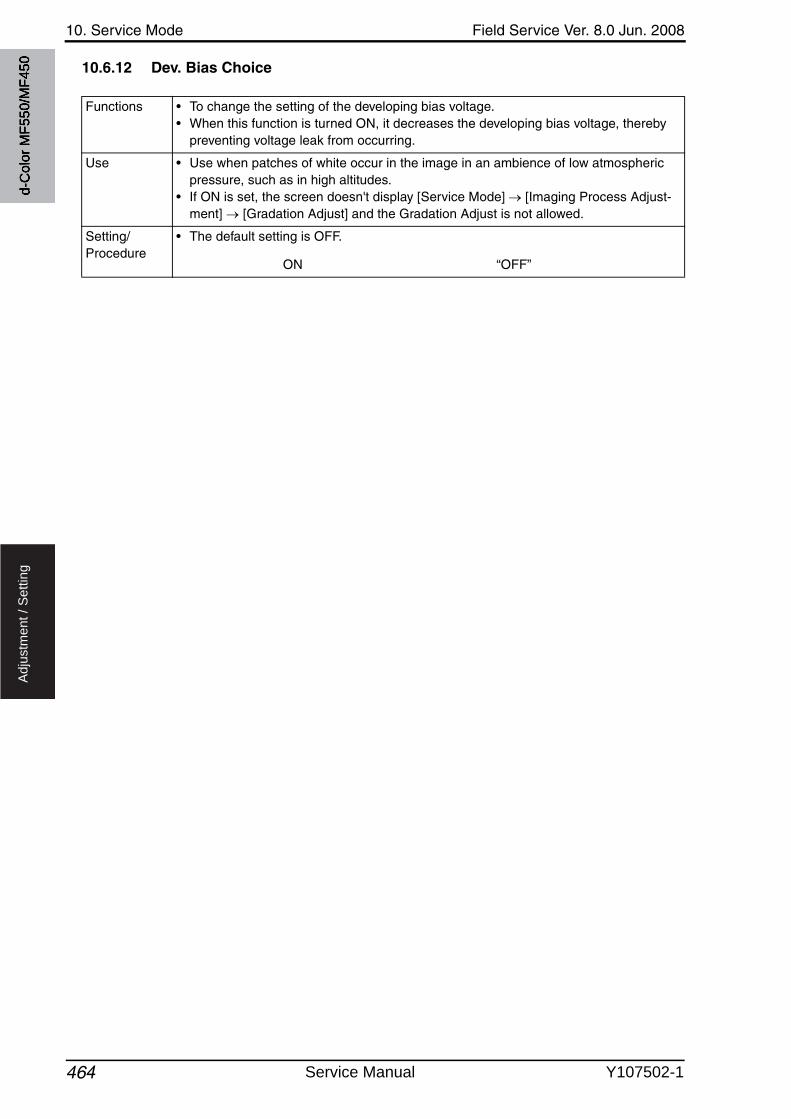
10. Service Mode Field Service Ver. 8.0 Jun. 2008
464
Ad
justm
en
t /
Se
ttin
g
10.6.12 Dev. Bias Choice
Functions • To change the setting of the developing bias voltage.• When this function is turned ON, it decreases the developing bias voltage, thereby
preventing voltage leak from occurring.
Use • Use when patches of white occur in the image in an ambience of low atmospheric pressure, such as in high altitudes.
• If ON is set, the screen doesn't display [Service Mode] [Imaging Process Adjust-ment] [Gradation Adjust] and the Gradation Adjust is not allowed.
Setting/Procedure
• The default setting is OFF.
ON “OFF”
d-C
olor
MF5
50/M
F450
Service Manual Y107502-1
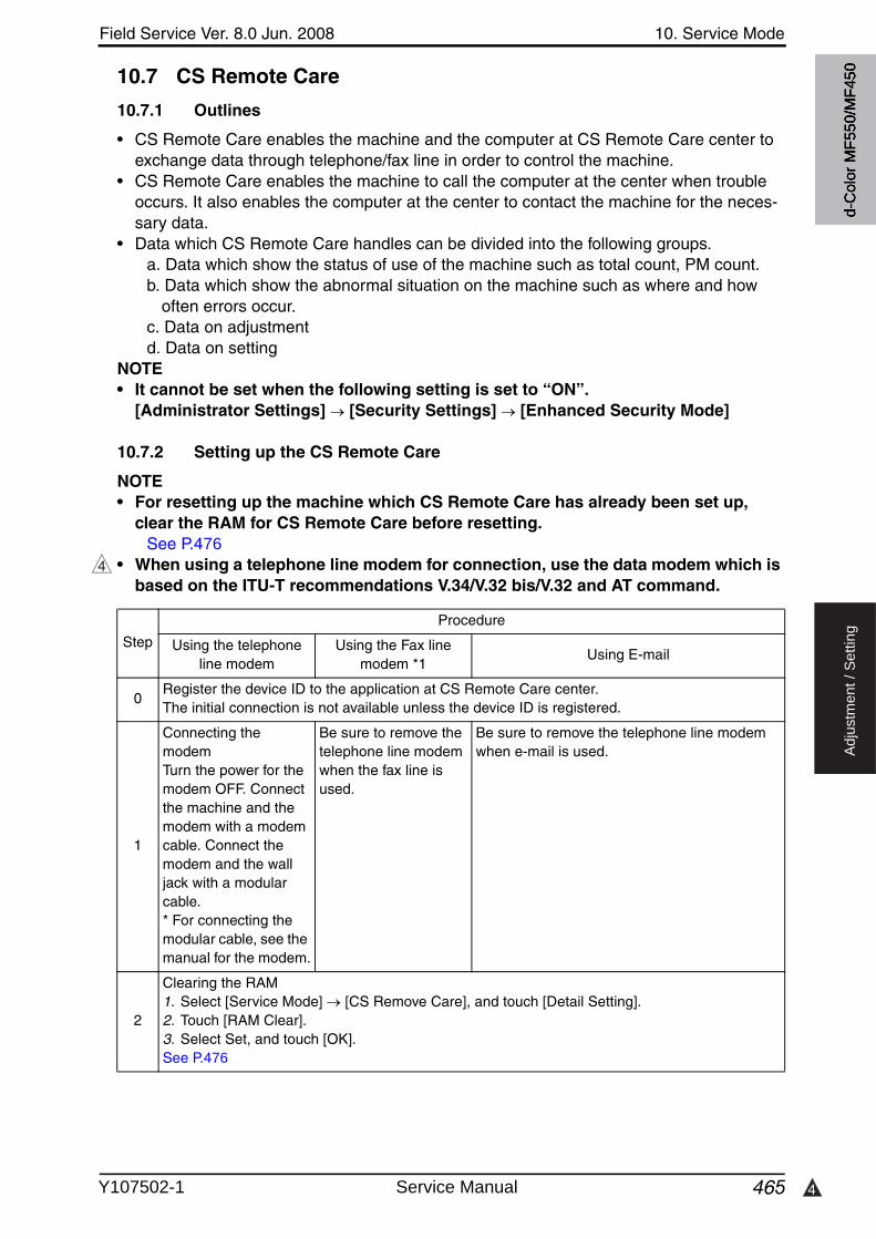
4
Field Service Ver. 8.0 Jun. 2008 10. Service Mode
465
Ad
justm
en
t /
Se
ttin
g
10.7 CS Remote Care
10.7.1 Outlines
• CS Remote Care enables the machine and the computer at CS Remote Care center to exchange data through telephone/fax line in order to control the machine.
• CS Remote Care enables the machine to call the computer at the center when trouble occurs. It also enables the computer at the center to contact the machine for the neces-sary data.
• Data which CS Remote Care handles can be divided into the following groups.a. Data which show the status of use of the machine such as total count, PM count.b. Data which show the abnormal situation on the machine such as where and how
often errors occur.c. Data on adjustmentd. Data on setting
NOTE• It cannot be set when the following setting is set to “ON”.
[Administrator Settings] [Security Settings] [Enhanced Security Mode]
10.7.2 Setting up the CS Remote Care
NOTE• For resetting up the machine which CS Remote Care has already been set up,
clear the RAM for CS Remote Care before resetting.See P.476
• When using a telephone line modem for connection, use the data modem which is based on the ITU-T recommendations V.34/V.32 bis/V.32 and AT command.
4
Step
Procedure
Using the telephone line modem
Using the Fax line modem *1
Using E-mail
0Register the device ID to the application at CS Remote Care center.The initial connection is not available unless the device ID is registered.
1
Connecting the modemTurn the power for the modem OFF. Connect the machine and the modem with a modem cable. Connect the modem and the wall jack with a modular cable.* For connecting the modular cable, see the manual for the modem.
Be sure to remove the telephone line modem when the fax line is used.
Be sure to remove the telephone line modemwhen e-mail is used.
2
Clearing the RAM1. Select [Service Mode] [CS Remove Care], and touch [Detail Setting].2. Touch [RAM Clear].3. Select Set, and touch [OK].See P.476
d-C
olor
MF5
50/M
F450
Y107502-1 Service Manual
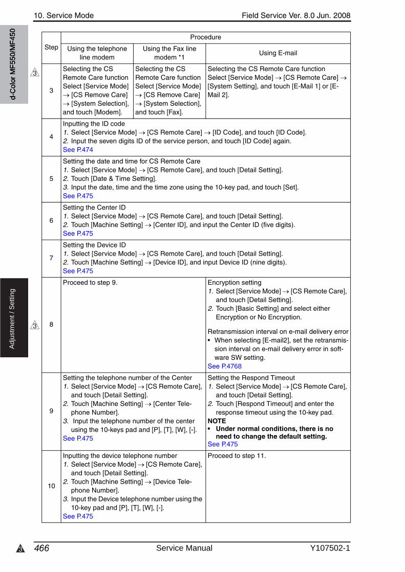
10. Service Mode Field Service Ver. 8.0 Jun. 2008
4663
Ad
justm
en
t /
Se
ttin
g
3
Selecting the CS Remote Care functionSelect [Service Mode]
[CS Remove Care] [System Selection],
and touch [Modem].
Selecting the CS Remote Care functionSelect [Service Mode]
[CS Remove Care] [System Selection],
and touch [Fax].
Selecting the CS Remote Care functionSelect [Service Mode] [CS Remote Care] [System Setting], and touch [E-Mail 1] or [E-Mail 2].
4
Inputting the ID code1. Select [Service Mode] [CS Remote Care] [ID Code], and touch [ID Code].2. Input the seven digits ID of the service person, and touch [ID Code] again.See P.474
5
Setting the date and time for CS Remote Care1. Select [Service Mode] [CS Remote Care], and touch [Detail Setting].2. Touch [Date & Time Setting].3. Input the date, time and the time zone using the 10-key pad, and touch [Set].See P.475
6
Setting the Center ID1. Select [Service Mode] [CS Remote Care], and touch [Detail Setting].2. Touch [Machine Setting] [Center ID], and input the Center ID (five digits).See P.475
7
Setting the Device ID1. Select [Service Mode] [CS Remote Care], and touch [Detail Setting].2. Touch [Machine Setting] [Device ID], and input Device ID (nine digits).See P.475
8
Proceed to step 9. Encryption setting1. Select [Service Mode] [CS Remote Care],
and touch [Detail Setting].2. Touch [Basic Setting] and select either
Encryption or No Encryption.
Retransmission interval on e-mail delivery error• When selecting [E-mail2], set the retransmis-
sion interval on e-mail delivery error in soft-ware SW setting.
See P.4768
9
Setting the telephone number of the Center1. Select [Service Mode] [CS Remote Care],
and touch [Detail Setting].2. Touch [Machine Setting] [Center Tele-
phone Number].3. Input the telephone number of the center
using the 10-keys pad and [P], [T], [W], [-].See P.475
Setting the Respond Timeout1. Select [Service Mode] [CS Remote Care],
and touch [Detail Setting].2. Touch [Respond Timeout] and enter the
response timeout using the 10-key pad.NOTE• Under normal conditions, there is no
need to change the default setting.See P.475
10
Inputting the device telephone number1. Select [Service Mode] [CS Remote Care],
and touch [Detail Setting].2. Touch [Machine Setting] [Device Tele-
phone Number].3. Input the Device telephone number using the
10-key pad and [P], [T], [W], [-].See P.475
Proceed to step 11.
Step
Procedure
Using the telephone line modem
Using the Fax line modem *1
Using E-mail
3
3
d-C
olor
MF5
50/M
F450
Service Manual Y107502-1
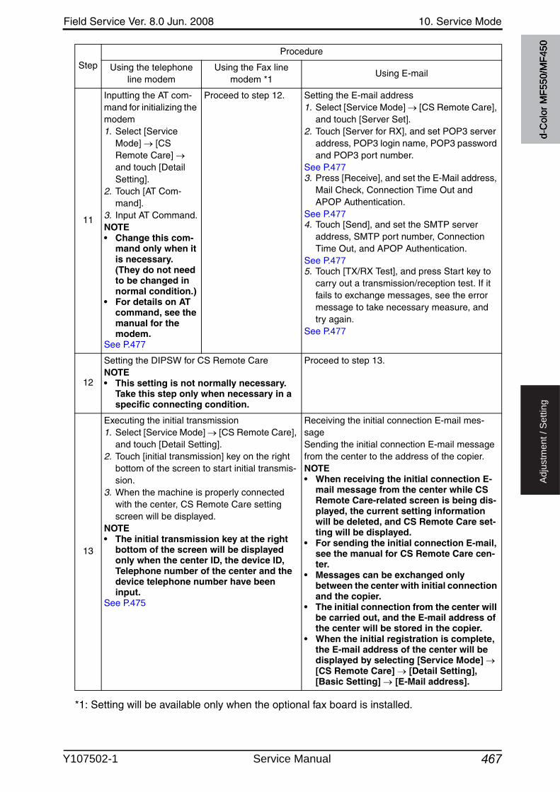
Field Service Ver. 8.0 Jun. 2008 10. Service Mode
467
Ad
justm
en
t /
Se
ttin
g
*1: Setting will be available only when the optional fax board is installed.
11
Inputting the AT com-mand for initializing the modem1. Select [Service
Mode] [CS Remote Care] and touch [Detail Setting].
2. Touch [AT Com-mand].
3. Input AT Command.NOTE• Change this com-
mand only when it is necessary. (They do not need to be changed in normal condition.)
• For details on AT command, see the manual for the modem.
See P.477
Proceed to step 12. Setting the E-mail address1. Select [Service Mode] [CS Remote Care],
and touch [Server Set].2. Touch [Server for RX], and set POP3 server
address, POP3 login name, POP3 password and POP3 port number.
See P.4773. Press [Receive], and set the E-Mail address,
Mail Check, Connection Time Out and APOP Authentication.
See P.4774. Touch [Send], and set the SMTP server
address, SMTP port number, Connection Time Out, and APOP Authentication.
See P.4775. Touch [TX/RX Test], and press Start key to
carry out a transmission/reception test. If it fails to exchange messages, see the error message to take necessary measure, and try again.
See P.477
12
Setting the DIPSW for CS Remote CareNOTE• This setting is not normally necessary.
Take this step only when necessary in a specific connecting condition.
Proceed to step 13.
13
Executing the initial transmission1. Select [Service Mode] [CS Remote Care],
and touch [Detail Setting].2. Touch [initial transmission] key on the right
bottom of the screen to start initial transmis-sion.
3. When the machine is properly connected with the center, CS Remote Care setting screen will be displayed.
NOTE• The initial transmission key at the right
bottom of the screen will be displayed only when the center ID, the device ID, Telephone number of the center and the device telephone number have been input.
See P.475
Receiving the initial connection E-mail mes-sageSending the initial connection E-mail message from the center to the address of the copier.NOTE• When receiving the initial connection E-
mail message from the center while CS Remote Care-related screen is being dis-played, the current setting information will be deleted, and CS Remote Care set-ting will be displayed.
• For sending the initial connection E-mail, see the manual for CS Remote Care cen-ter.
• Messages can be exchanged only between the center with initial connection and the copier.
• The initial connection from the center will be carried out, and the E-mail address of the center will be stored in the copier.
• When the initial registration is complete, the E-mail address of the center will be displayed by selecting [Service Mode] [CS Remote Care] [Detail Setting], [Basic Setting] [E-Mail address].
Step
Procedure
Using the telephone line modem
Using the Fax line modem *1
Using E-mail
d-C
olor
MF5
50/M
F450
Y107502-1 Service Manual
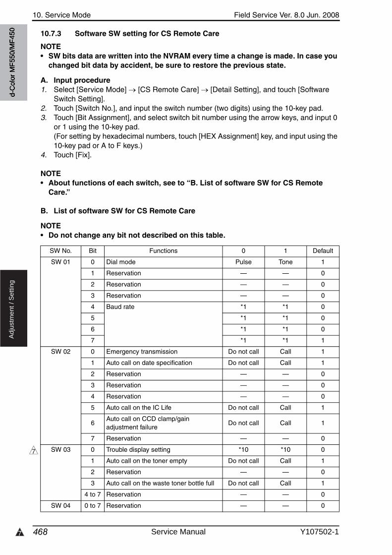
10. Service Mode Field Service Ver. 8.0 Jun. 2008
4687
Ad
justm
en
t /
Se
ttin
g
10.7.3 Software SW setting for CS Remote Care
NOTE• SW bits data are written into the NVRAM every time a change is made. In case you
changed bit data by accident, be sure to restore the previous state.
A. Input procedure1. Select [Service Mode] [CS Remote Care] [Detail Setting], and touch [Software
Switch Setting].2. Touch [Switch No.], and input the switch number (two digits) using the 10-key pad.3. Touch [Bit Assignment], and select switch bit number using the arrow keys, and input 0
or 1 using the 10-key pad.(For setting by hexadecimal numbers, touch [HEX Assignment] key, and input using the 10-key pad or A to F keys.)
4. Touch [Fix].
NOTE• About functions of each switch, see to “B. List of software SW for CS Remote
Care.”
B. List of software SW for CS Remote Care
NOTE• Do not change any bit not described on this table.
SW No. Bit Functions 0 1 Default
SW 01 0 Dial mode Pulse Tone 1
1 Reservation — — 0
2 Reservation — — 0
3 Reservation — — 0
4 Baud rate *1 *1 0
5 *1 *1 0
6 *1 *1 0
7 *1 *1 1
SW 02 0 Emergency transmission Do not call Call 1
1 Auto call on date specification Do not call Call 1
2 Reservation — — 0
3 Reservation — — 0
4 Reservation — — 0
5 Auto call on the IC Life Do not call Call 1
6Auto call on CCD clamp/gain adjustment failure
Do not call Call 1
7 Reservation — — 0
SW 03 0 Trouble display setting *10 *10 0
1 Auto call on the toner empty Do not call Call 1
2 Reservation — — 0
3 Auto call on the waste toner bottle full Do not call Call 1
4 to 7 Reservation — — 0
SW 04 0 to 7 Reservation — — 0
7
d-C
olor
MF5
50/M
F450
Service Manual Y107502-1
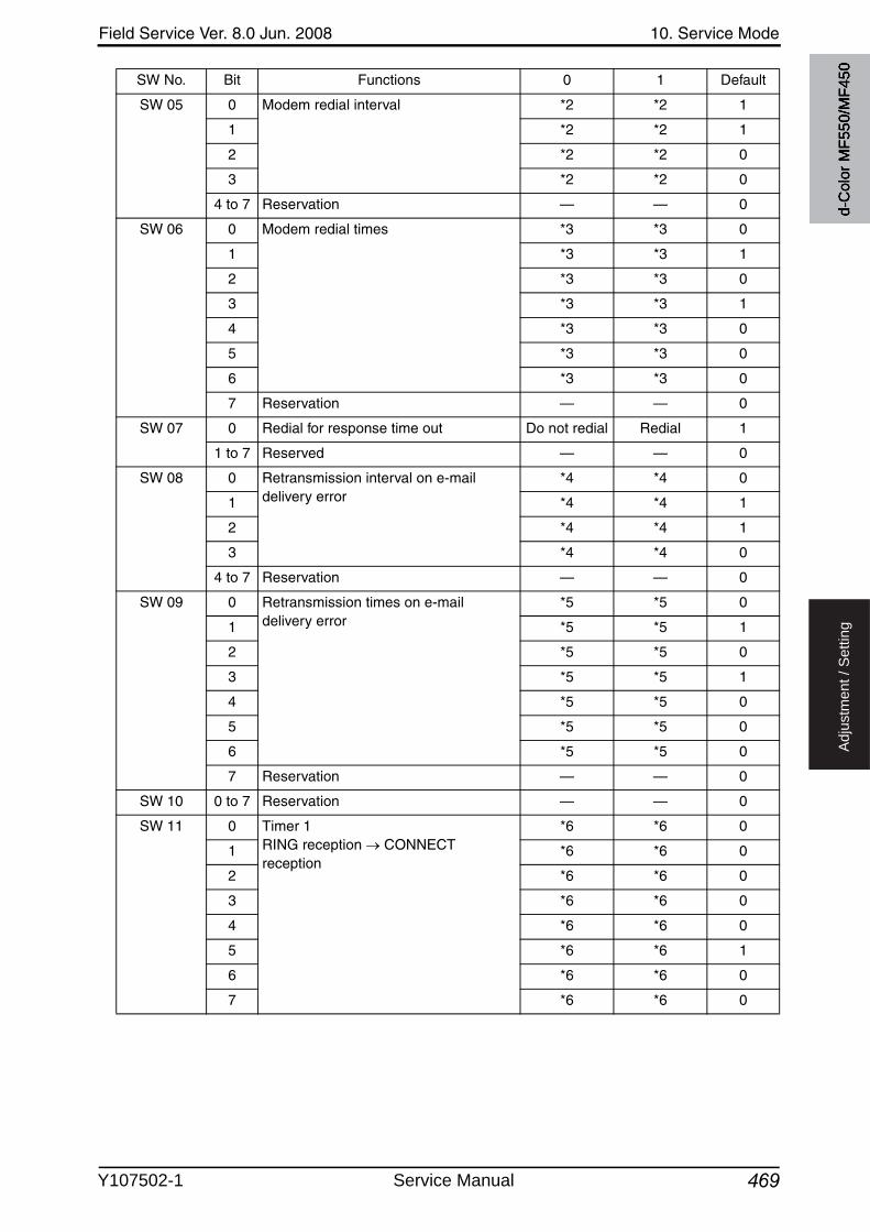
Field Service Ver. 8.0 Jun. 2008 10. Service Mode
469
Ad
justm
en
t /
Se
ttin
g
SW 05 0 Modem redial interval *2 *2 1
1 *2 *2 1
2 *2 *2 0
3 *2 *2 0
4 to 7 Reservation — — 0
SW 06 0 Modem redial times *3 *3 0
1 *3 *3 1
2 *3 *3 0
3 *3 *3 1
4 *3 *3 0
5 *3 *3 0
6 *3 *3 0
7 Reservation — — 0
SW 07 0 Redial for response time out Do not redial Redial 1
1 to 7 Reserved — — 0
SW 08 0 Retransmission interval on e-mail delivery error
*4 *4 0
1 *4 *4 1
2 *4 *4 1
3 *4 *4 0
4 to 7 Reservation — — 0
SW 09 0 Retransmission times on e-mail delivery error
*5 *5 0
1 *5 *5 1
2 *5 *5 0
3 *5 *5 1
4 *5 *5 0
5 *5 *5 0
6 *5 *5 0
7 Reservation — — 0
SW 10 0 to 7 Reservation — — 0
SW 11 0 Timer 1RING reception CONNECT reception
*6 *6 0
1 *6 *6 0
2 *6 *6 0
3 *6 *6 0
4 *6 *6 0
5 *6 *6 1
6 *6 *6 0
7 *6 *6 0
SW No. Bit Functions 0 1 Default
d-C
olor
MF5
50/M
F450
Y107502-1 Service Manual
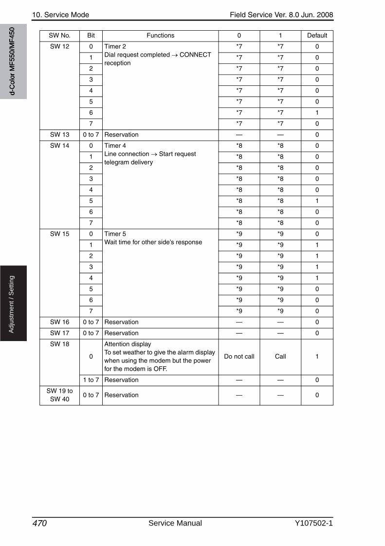
10. Service Mode Field Service Ver. 8.0 Jun. 2008
470
Ad
justm
en
t /
Se
ttin
g
SW 12 0 Timer 2Dial request completed CONNECT reception
*7 *7 0
1 *7 *7 0
2 *7 *7 0
3 *7 *7 0
4 *7 *7 0
5 *7 *7 0
6 *7 *7 1
7 *7 *7 0
SW 13 0 to 7 Reservation — — 0
SW 14 0 Timer 4Line connection Start request telegram delivery
*8 *8 0
1 *8 *8 0
2 *8 *8 0
3 *8 *8 0
4 *8 *8 0
5 *8 *8 1
6 *8 *8 0
7 *8 *8 0
SW 15 0 Timer 5Wait time for other side’s response
*9 *9 0
1 *9 *9 1
2 *9 *9 1
3 *9 *9 1
4 *9 *9 1
5 *9 *9 0
6 *9 *9 0
7 *9 *9 0
SW 16 0 to 7 Reservation — — 0
SW 17 0 to 7 Reservation — — 0
SW 18
0
Attention displayTo set weather to give the alarm display when using the modem but the power for the modem is OFF.
Do not call Call 1
1 to 7 Reservation — — 0
SW 19 to SW 40
0 to 7 Reservation — — 0
SW No. Bit Functions 0 1 Default
d-C
olor
MF5
50/M
F450
Service Manual Y107502-1
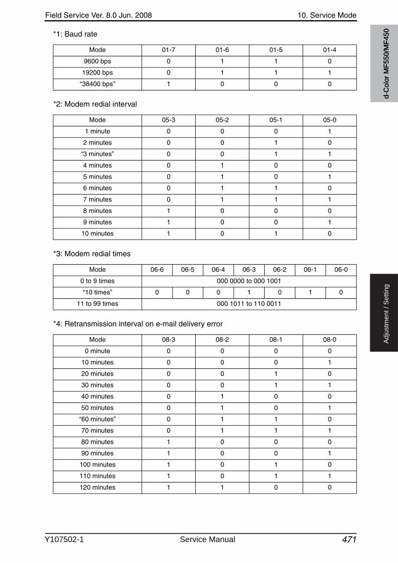
Field Service Ver. 8.0 Jun. 2008 10. Service Mode
471
Ad
justm
en
t /
Se
ttin
g
*1: Baud rate
*2: Modem redial interval
*3: Modem redial times
*4: Retransmission interval on e-mail delivery error
Mode 01-7 01-6 01-5 01-4
9600 bps 0 1 1 0
19200 bps 0 1 1 1
“38400 bps” 1 0 0 0
Mode 05-3 05-2 05-1 05-0
1 minute 0 0 0 1
2 minutes 0 0 1 0
“3 minutes” 0 0 1 1
4 minutes 0 1 0 0
5 minutes 0 1 0 1
6 minutes 0 1 1 0
7 minutes 0 1 1 1
8 minutes 1 0 0 0
9 minutes 1 0 0 1
10 minutes 1 0 1 0
Mode 06-6 06-5 06-4 06-3 06-2 06-1 06-0
0 to 9 times 000 0000 to 000 1001
“10 times” 0 0 0 1 0 1 0
11 to 99 times 000 1011 to 110 0011
Mode 08-3 08-2 08-1 08-0
0 minute 0 0 0 0
10 minutes 0 0 0 1
20 minutes 0 0 1 0
30 minutes 0 0 1 1
40 minutes 0 1 0 0
50 minutes 0 1 0 1
“60 minutes” 0 1 1 0
70 minutes 0 1 1 1
80 minutes 1 0 0 0
90 minutes 1 0 0 1
100 minutes 1 0 1 0
110 minutes 1 0 1 1
120 minutes 1 1 0 0
d-C
olor
MF5
50/M
F450
Y107502-1 Service Manual
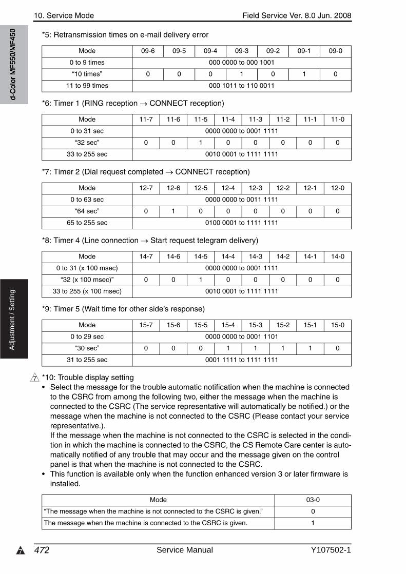
10. Service Mode Field Service Ver. 8.0 Jun. 2008
4727
Ad
justm
en
t /
Se
ttin
g
*5: Retransmission times on e-mail delivery error
*6: Timer 1 (RING reception CONNECT reception)
*7: Timer 2 (Dial request completed CONNECT reception)
*8: Timer 4 (Line connection Start request telegram delivery)
*9: Timer 5 (Wait time for other side’s response)
*10: Trouble display setting• Select the message for the trouble automatic notification when the machine is connected
to the CSRC from among the following two, either the message when the machine is connected to the CSRC (The service representative will automatically be notified.) or the message when the machine is not connected to the CSRC (Please contact your service representative.). If the message when the machine is not connected to the CSRC is selected in the condi-tion in which the machine is connected to the CSRC, the CS Remote Care center is auto-matically notified of any trouble that may occur and the message given on the control panel is that when the machine is not connected to the CSRC.
• This function is available only when the function enhanced version 3 or later firmware is installed.
Mode 09-6 09-5 09-4 09-3 09-2 09-1 09-0
0 to 9 times 000 0000 to 000 1001
“10 times” 0 0 0 1 0 1 0
11 to 99 times 000 1011 to 110 0011
Mode 11-7 11-6 11-5 11-4 11-3 11-2 11-1 11-0
0 to 31 sec 0000 0000 to 0001 1111
“32 sec” 0 0 1 0 0 0 0 0
33 to 255 sec 0010 0001 to 1111 1111
Mode 12-7 12-6 12-5 12-4 12-3 12-2 12-1 12-0
0 to 63 sec 0000 0000 to 0011 1111
“64 sec” 0 1 0 0 0 0 0 0
65 to 255 sec 0100 0001 to 1111 1111
Mode 14-7 14-6 14-5 14-4 14-3 14-2 14-1 14-0
0 to 31 (x 100 msec) 0000 0000 to 0001 1111
“32 (x 100 msec)” 0 0 1 0 0 0 0 0
33 to 255 (x 100 msec) 0010 0001 to 1111 1111
Mode 15-7 15-6 15-5 15-4 15-3 15-2 15-1 15-0
0 to 29 sec 0000 0000 to 0001 1101
“30 sec” 0 0 0 1 1 1 1 0
31 to 255 sec 0001 1111 to 1111 1111
7
Mode 03-0
“The message when the machine is not connected to the CSRC is given.” 0
The message when the machine is connected to the CSRC is given. 1
d-C
olor
MF5
50/M
F450
Service Manual Y107502-1
Field Service Ver. 8.0 Jun. 2008 10. Service Mode
473
Ad
justm
en
t /
Se
ttin
g
10.7.4 Setup confirmation
• Follow the steps below to make sure that CS Remote Care has been properly set up.
1. Call the Service Mode to the screen.2. Touch [CS Remote Care].3. Check to make sure that only selected item is displayed.
10.7.5 Calling the maintenance
• When CE starts maintenance, inputting the ID code of CE (seven digits: numbers whichCE can identify. They are controlled by the distributor.) will transmit the information to the Center side and tells that the maintenance has started. When the maintenance is fin-ished, touching [Maintenance Complete] key will transmit the information to the center and tells that it is finished.
A. When starting the maintenance1. Select Service Mode and touch [CS Remote Care].2. Touch [ID Code], and input ID Code.3. Touch [ID Coke].
* The Start key blinks while maintenance is being carried out.
B. When finishing the maintenance1. Select Service Mode and touch [CS Remote Care].2. Touch [Maintenance Complete].
d-C
olor
MF5
50/M
F450
Y107502-1 Service Manual
10. Service Mode Field Service Ver. 8.0 Jun. 2008
474
Ad
justm
en
t /
Se
ttin
g
10.7.6 Calling the center from the administrator
• When the CS Remote Care setup is complete, the administrator can call the CS Remote Care center.
1. Select [Administrator Settings], and touch [System Connection].2. Touch [Admin. transmission].3. Press the Start key.
When the setup is not complete or another transmission is being carried out, the Admin. transmission key will not be displayed, and the transmission is not available.
NOTE• For transmitting data of the machine by calling the center on the specified date
and time, refer to the manual for CS Remote Care center.
10.7.7 Checking the transmission log
• The transmission log list will be output to be checked.
1. Select [Service Mode] [CS Remote Care], and touch [Detail setting].2. Touch [Communication Log Print].3. Load tray 1 or bypass tray with A4S paper.4. Press the Start key to output transmission log.
10.7.8 Detail on settings
A. System Selection
B. ID Code
Functions • To select the system type for remote diagnosis.
Use • Use to newly build or change the system.
Setting/Procedure
• Select E-Mail, Modem, or Fax.• Fax is available only when the optional fax kit is being installed.
E-Mail Modem Fax
Functions • To register the service ID.
Use • Use when registering and changing service ID.
Setting/Procedure
• Enter a 7-digit code from the 10-key pad. (0000001 to 9999999)
<Registration>• Touch ID code and enter the service ID.• Touch [ID code] to register the ID.• The [Detail Setting] will appear when the ID has been registered.
d-C
olor
MF5
50/M
F450
Service Manual Y107502-1
3
Field Service Ver. 8.0 Jun. 2008 10. Service Mode
475
Ad
justm
en
t /
Se
ttin
g
C. Detail Setting(1) Basic Setting
Functions • Execute the primary setting.
Use • Use to change the set contents.• Use to register the machine to the CS Remote Care center.
Setting/Procedure
1. Call the Service Mode to the screen.2. Touch [CS Remote Care].3. Touching the [Detail Setting] will display the primary setting.
<Center Setting>• Set the center ID, Device ID, and the phone No.• When e-mail is selected for system and all setup procedures are completed, e-mail
address of the center is displayed.
* When entering the phone number, 10-keys and keys on the screen have followingmeanings.
[-] Pose : Waits to start transmitting after dialing[W] Wait : Detects the dial tone of the other end[T] Tone dial : Carry out tone dialing[P] Pulse dial : Carry out pulse dialing[*], [#] : To be used as necessary
<Schedule (Only when the [E-Mail2] is selected)>• Set the schedule of notification to the center.• Up to three different notification schedules can be registered.• Select the notification cycle from [Day], [Week], or [Month].
When selecting [Day] for the notification cycle, set the Day Frequency.When selecting [Week] for the notification cycle, set the Week Frequency and day of the week.When selecting [Month], set the Month Frequency and the date of the month.
<Center Notification (Only when the [E-Mail2] is selected)>• Select the items of data that will be sent to the center in one-way transmission
through E-Mail2.• The following table shows each of the notification item keys and corresponding data.
NOTE• Multiple items of data can be selected and sent at one time. However, be sure
that only EKC data cannot be sent together with other items of data.
Initial Transmission• Touching the Initial Transmission key will sent the information to the CS Remote Care
center to register the machine.(Only when the modem or fax is selected on the system Input.)
3
3
[1] Sales count data [7] EKC data
[2] Error count data [8] Adjustment data
[3] Service count data [9] Coverage data
[4]Life count dataLife cycle data
[10] Not used
[5]CSRC-System dataDevice config data
[11] Not used
[6] History data [12] Not used
d-C
olor
MF5
50/M
F450
Y107502-1 Service Manual
10. Service Mode Field Service Ver. 8.0 Jun. 2008
476
Ad
justm
en
t /
Se
ttin
g
(2) Date & Time Setting
(3) RAM Clear
(4) Communication Log Print
(5) Software Switch Setting
(6) Response Time Out
Functions • To set the data and time-of-day.
Use • Use to set or change the date and time-of-day.
Setting/Procedure
1. Call the Service Mode to the screen.2. Touch [CS Remote Care].3. Touch [Detail Setting] to access Date & Time Setting.4. Enter the date (month, day and year), time-of-day, and the time zone from the 10-key
pad.5. Touch [SET] to start the clock.
Functions • To clear the following data at the centerID Code, Primary Setting, Date/Time Input (Time Zone), Software SW Setting and AT Command.
Use • To be used for setting CS Remote Care.• To be used for reset the every data of the center to default.NOTE• If RAM clear is selected during transmission, RAM clear processing will be
implemented at the time the transmission is completed regardless of whether it is done properly or not.
Setting/Procedure
• The default setting is “Unset.”
Set “Unset”
Functions • To print out the communication log.
Use • Use to output and use the communication log.
Setting/Procedure
1. Call the Service Mode on the screen.2. Touch [CS Remote Care].3. Touch [Detail Setting] to access communication log print.4. Load tray 1 or bypass tray with A4S or 81/2 x 11 paper.5. Press Start key to print out the communication log.
Functions • To change the CS Remote Care settings.
Use • To change the settings for CS Remote Care as necessary.
Setting/Procedure
• Refer to “Software SW setting for CS Remote Care” for the setting.See P.468
Functions • It sets the intervals for resending e-mails when transmission error occurred.• It can be set only when [E-Mail] is selected by System Setting.
Use • To use when changing the intervals for resending e-mails when transmission error occurred.
Setting/Procedure
• The default setting is 60 minute.
“60 minute” (10 to 1440)
d-C
olor
MF5
50/M
F450
Service Manual Y107502-1
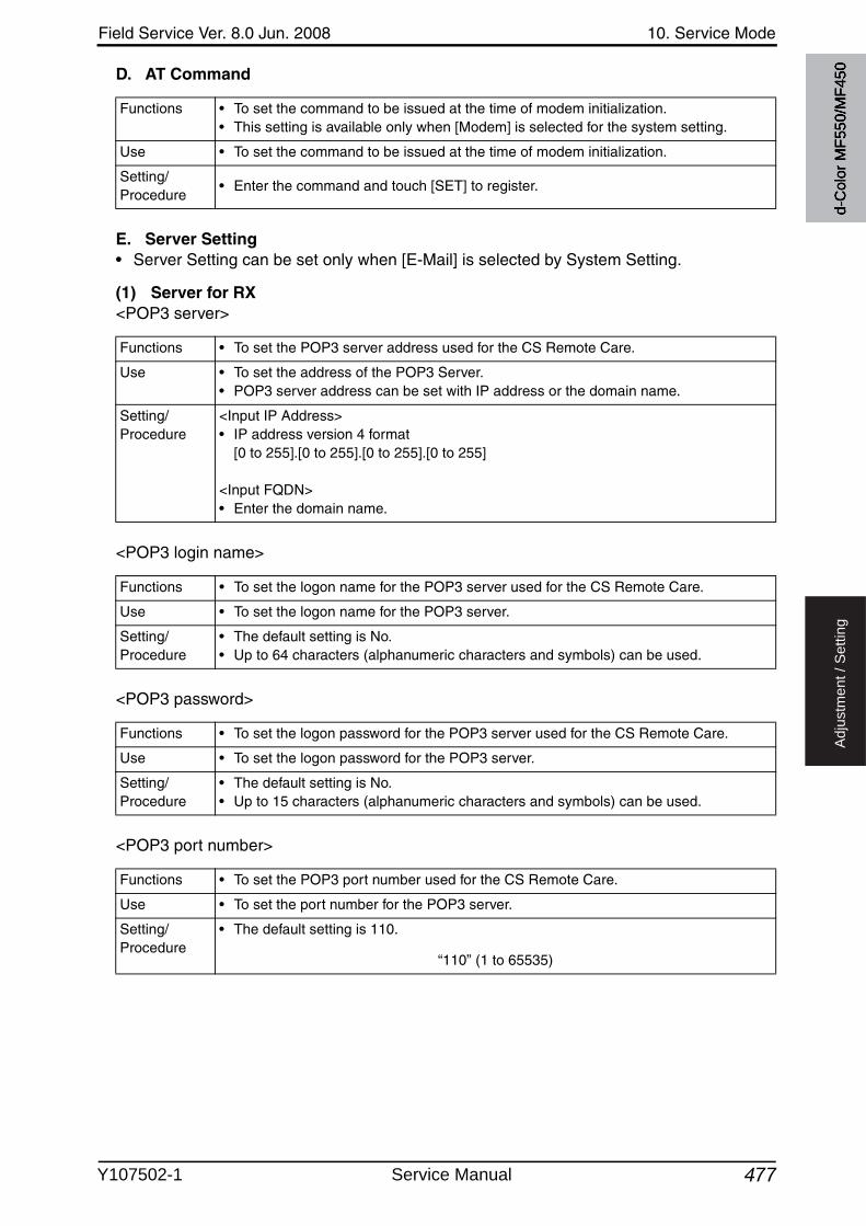
Field Service Ver. 8.0 Jun. 2008 10. Service Mode
477
Ad
justm
en
t /
Se
ttin
g
D. AT Command
E. Server Setting• Server Setting can be set only when [E-Mail] is selected by System Setting.
(1) Server for RX<POP3 server>
<POP3 login name>
<POP3 password>
<POP3 port number>
Functions • To set the command to be issued at the time of modem initialization.• This setting is available only when [Modem] is selected for the system setting.
Use • To set the command to be issued at the time of modem initialization.
Setting/Procedure
• Enter the command and touch [SET] to register.
Functions • To set the POP3 server address used for the CS Remote Care.
Use • To set the address of the POP3 Server.• POP3 server address can be set with IP address or the domain name.
Setting/Procedure
<Input IP Address>• IP address version 4 format
[0 to 255].[0 to 255].[0 to 255].[0 to 255]
<Input FQDN>• Enter the domain name.
Functions • To set the logon name for the POP3 server used for the CS Remote Care.
Use • To set the logon name for the POP3 server.
Setting/Procedure
• The default setting is No.• Up to 64 characters (alphanumeric characters and symbols) can be used.
Functions • To set the logon password for the POP3 server used for the CS Remote Care.
Use • To set the logon password for the POP3 server.
Setting/Procedure
• The default setting is No.• Up to 15 characters (alphanumeric characters and symbols) can be used.
Functions • To set the POP3 port number used for the CS Remote Care.
Use • To set the port number for the POP3 server.
Setting/Procedure
• The default setting is 110.
“110” (1 to 65535)
d-C
olor
MF5
50/M
F450
Y107502-1 Service Manual

10. Service Mode Field Service Ver. 8.0 Jun. 2008
478
Ad
justm
en
t /
Se
ttin
g
(2) Receive<E-mail Address>
<Mail Check>
<Connection timeout>
<APOP Authentication>
(3) Send<SMTP server>
Functions • To set the e-mail address used for the CS Remote Care.
Use • To set the e-mail address.
Setting/Procedure
• The default setting is No.• Up to 129 characters (alphanumeric characters and symbols) can be used.
Functions • To set whether or not to use mail check and the time interval for the POP server usedfor the CS Remote Care.
Use • To set whether or not to use mail check and the time interval for the POP server usedfor the CS Remote Care.
• To change the time interval for mail check.
Setting/Procedure
• The default setting is No.
“No” (1 to120 min., No)
Functions • To set the timeout period for connection during reception.
Use • To change the timeout period for connection during reception.
Setting/Procedure
• The default setting is 60 Sec.
“60 Sec” (30 to 300 Sec)
Functions • To set whether or not to authenticate the APOP during reception.
Use • To authenticate the APOP during reception.
Setting/Procedure
• The default setting is No.
Yes “No”
Functions • To set the SMTP sever address for transmission used for the CS Remote Care.
Use • To set the SMTP server address.• SMTP server address can be set by the IP address or the domain name.
Setting/Procedure
<Input IP Address>• IP address version 4 format
[0 to 255].[0 to 255].[0 to 255].[0 to 255]
<Input FQDN>• Enter the domain name.
d-C
olor
MF5
50/M
F450
Service Manual Y107502-1
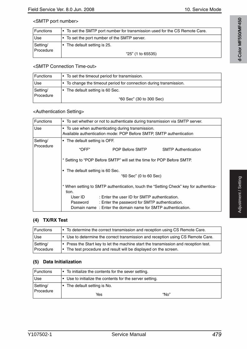
Field Service Ver. 8.0 Jun. 2008 10. Service Mode
479
Ad
justm
en
t /
Se
ttin
g
<SMTP port number>
<SMTP Connection Time-out>
<Authentication Setting>
(4) TX/RX Test
(5) Data Initialization
Functions • To set the SMTP port number for transmission used for the CS Remote Care.
Use • To set the port number of the SMTP server.
Setting/Procedure
• The default setting is 25.
“25” (1 to 65535)
Functions • To set the timeout period for transmission.
Use • To change the timeout period for connection during transmission.
Setting/Procedure
• The default setting is 60 Sec.
“60 Sec” (30 to 300 Sec)
Functions • To set whether or not to authenticate during transmission via SMTP server.
Use • To use when authenticating during transmission.Available authentication mode: POP Before SMTP, SMTP authentication
Setting/Procedure
• The default setting is OFF.
“OFF” POP Before SMTP SMTP Authentication
* Setting to “POP Before SMTP” will set the time for POP Before SMTP.
• The default setting is 60 Sec.“60 Sec” (0 to 60 Sec)
* When setting to SMTP authentication, touch the “Setting Check” key for authentica-tion.
User ID : Enter the user ID for SMTP authentication.Password : Enter the password for SMTP authentication.Domain name : Enter the domain name for SMTP authentication.
Functions • To determine the correct transmission and reception using CS Remote Care.
Use • Use to determine the correct transmission and reception using CS Remote Care.
Setting/Procedure
• Press the Start key to let the machine start the transmission and reception test.• The test procedure and result will be displayed on the screen.
Functions • To initialize the contents for the sever setting.
Use • Use to initialize the contents for the server setting.
Setting/Procedure
• The default setting is No.
Yes “No”
d-C
olor
MF5
50/M
F450
Y107502-1 Service Manual
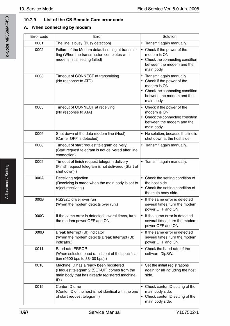
10. Service Mode Field Service Ver. 8.0 Jun. 2008
480
Ad
justm
en
t /
Se
ttin
g
10.7.9 List of the CS Remote Care error code
A. When connecting by modem
Error code Error Solution
0001 The line is busy (Busy detection) • Transmit again manually.
0002 Failure of the Modem default setting at transmit-ting (When the transmission completes with modem initial setting failed)
• Check if the power of the modem is ON.
• Check the connecting condition between the modem and the main body.
0003 Timeout of CONNECT at transmitting (No response to ATD)
• Transmit again manually• Check if the power of the
modem is ON.• Check the connecting condition
between the modem and the main body.
0005 Timeout of CONNECT at receiving(No response to ATA)
• Check if the power of the modem is ON.
• Check the connecting condition between the modem and the main body.
0006 Shut down of the data modem line (Host)(Carrier OFF is detected)
• No solution, because the line is shut down at the host side.
0008 Timeout of start request telegram delivery(Start request telegram is not delivered after line connection)
• Transmit again manually.
0009 Timeout of finish request telegram delivery(Finish request telegram is not delivered (Start of shut down).)
• Transmit again manually.
000A Receiving rejection(Receiving is made when the main body is set to reject receiving.)
• Check the setting condition of the host side.
• Check the setting condition of the main body side.
000B RS232C driver over run(When the modem detects over run.)
• If the same error is detected several times, turn the modem power OFF and ON.
000C If the same error is detected several times, turn the modem power OFF and ON.
• If the same error is detected several times, turn the modem power OFF and ON.
000D Break Interrupt (BI) indicator(When the modem detects Break Interrupt (BI) indicator.)
• If the same error is detected several times, turn the modem power OFF and ON.
0011 Baud rate ERROR (When selected baud rate is out of the specifica-tion (9600 bps to 38400 bps).)
• Check the baud rate of the software DipSW.
0018 Machine ID has already been registered(Request telegram 2 (SET-UP) comes from the main body that has already registered machine ID.)
• Set the initial registrations again for all including the host side.
0019 Center ID error(Center ID of the host is not identical with the one of start request telegram.)
• Check center ID setting of the main body side.
• Check center ID setting of the main body side.
d-C
olor
MF5
50/M
F450
Service Manual Y107502-1
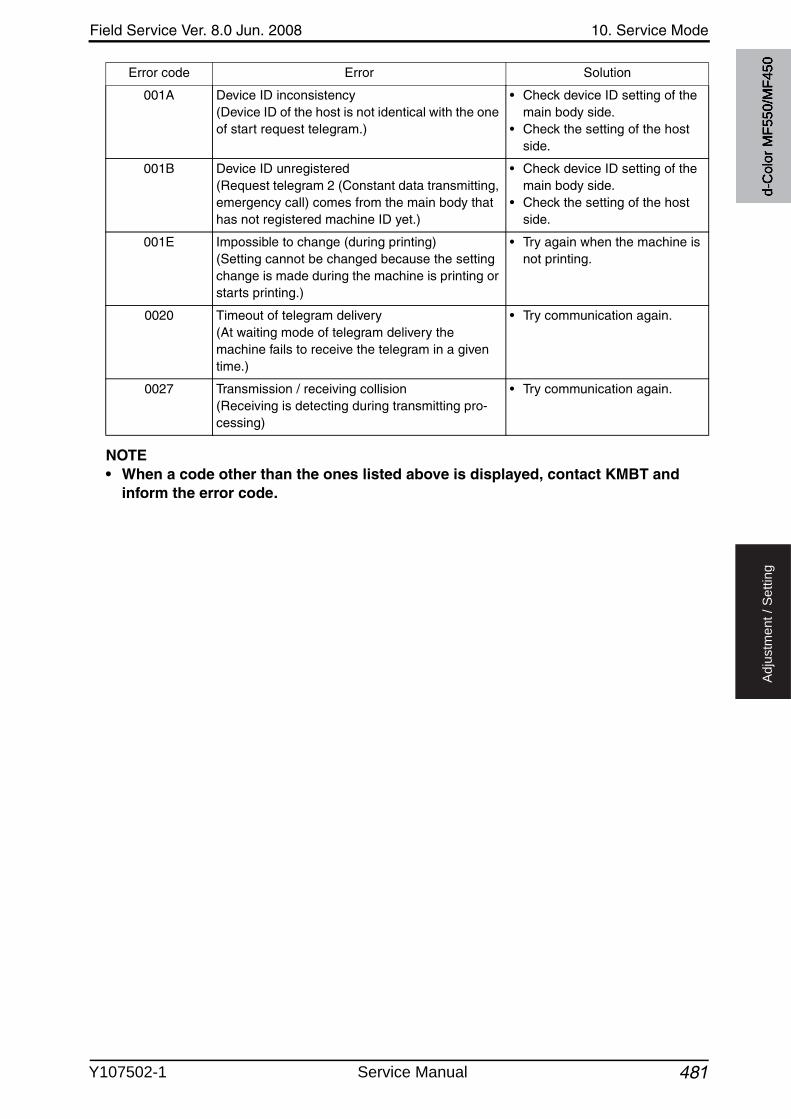
Field Service Ver. 8.0 Jun. 2008 10. Service Mode
481
Ad
justm
en
t /
Se
ttin
g
NOTE• When a code other than the ones listed above is displayed, contact KMBT and
inform the error code.
001A Device ID inconsistency(Device ID of the host is not identical with the one of start request telegram.)
• Check device ID setting of the main body side.
• Check the setting of the host side.
001B Device ID unregistered(Request telegram 2 (Constant data transmitting, emergency call) comes from the main body that has not registered machine ID yet.)
• Check device ID setting of the main body side.
• Check the setting of the host side.
001E Impossible to change (during printing)(Setting cannot be changed because the setting change is made during the machine is printing or starts printing.)
• Try again when the machine is not printing.
0020 Timeout of telegram delivery(At waiting mode of telegram delivery the machine fails to receive the telegram in a giventime.)
• Try communication again.
0027 Transmission / receiving collision(Receiving is detecting during transmitting pro-cessing)
• Try communication again.
Error code Error Solution
d-C
olor
MF5
50/M
F450
Y107502-1 Service Manual
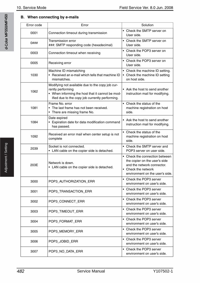
10. Service Mode Field Service Ver. 8.0 Jun. 2008
482
Ad
justm
en
t /
Se
ttin
g
B. When connecting by e-mails
Error code Error Solution
0001 Connection timeout during transmission• Check the SMTP server on
User side.
0###Transmission error###: SMTP responding code (hexadecimal)
• Check the SMTP server on User side.
0003 Connection timeout when receiving• Check the POP3 server on
User side.
0005 Receiving error• Check the POP3 server on
User side.
1030Machine ID mismatching• Received an e-mail which tells that machine ID
mismatches.
• Check the machine ID setting.• Check the machine ID setting
on host side.
1062
Modifying not available due to the copy job cur-rently performing• When informing the host that it cannot be mod-
ified due to the copy job currently performing.
• Ask the host to send another instruction mail for modifying.
1081Frame No. error• The last frame has not been received.• There are missing frame No.
• Check the status of the machine registration on host side.
1084Date expired• Expiration date for data modification command
has passed.
• Ask the host to send another instruction mail for modifying.
1092Received an error mail when center setup is not complete
• Check the status of the machine registration on host side.
2039Socket is not connected.• LAN cable on the copier side is detached.
• Check the SMTP server and POP3 server on user side.
203ENetwork is down.• LAN cable on the copier side is detached.
• Check the connection between the copier on the user’s side and the network connector.
• Check the network environment on the user’s side.
3000 POP3_AUTHORIZATION_ERR• Check the POP3 server
environment on user’s side.
3001 POP3_TRANSACTION_ERR• Check the POP3 server
environment on user’s side.
3002 POP3_CONNECT_ERR• Check the POP3 server
environment on user’s side.
3003 POP3_TIMEOUT_ERR• Check the POP3 server
environment on user’s side.
3004 POP3_FORMAT_ERR• Check the POP3 server
environment on user’s side.
3005 POP3_MEMORY_ERR• Check the POP3 server
environment on user’s side.
3006 POP3_JOBID_ERR• Check the POP3 server
environment on user’s side.
3007 POP3_NO_DATA_ERR• Check the POP3 server
environment on user’s side.
d-C
olor
MF5
50/M
F450
Service Manual Y107502-1
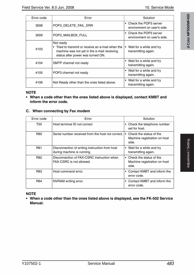
Field Service Ver. 8.0 Jun. 2008 10. Service Mode
483
Ad
justm
en
t /
Se
ttin
g
NOTE• When a code other than the ones listed above is displayed, contact KMBT and
inform the error code.
C. When connecting by Fax modem
NOTE• When a code other than the ones listed above is displayed, see the FK-502 Service
Manual.
3008 POP3_DELETE_FAIL_ERR• Check the POP3 server
environment on user’s side.
3009 POP3_MAILBOX_FULL• Check the POP3 server
environment on user’s side.
4103
Not ready• Tried to transmit or receive an e-mail when the
machine was not yet in the e-mail receivingstatus after power was turned ON.
• Wait for a while and try transmitting again.
4104 SMTP channel not ready• Wait for a while and try
transmitting again.
4105 POP3 channel not ready• Wait for a while and try
transmitting again.
4106 Not Ready other than the ones listed above.• Wait for a while and try
transmitting again.
Error code Error Solution
Error code Error Solution
T50 Host terminal ID not correct • Check the telephone numberset for host.
R80 Serial number received from the host not correct. • Check the status of the Machine registration on host side.
R81 Disconnection of writing instruction from host during machine is running.
• Wait for a while and try transmitting again.
R82 Disconnection of FAX-CSRC instruction when FAX-CSRC is not allowed.
• Check the status of the Machine registration on host side.
R83 Host command error. • Contact KMBT and inform the error code.
R84 NVRAM writing error. • Contact KMBT and inform the error code.
d-C
olor
MF5
50/M
F450
Y107502-1 Service Manual
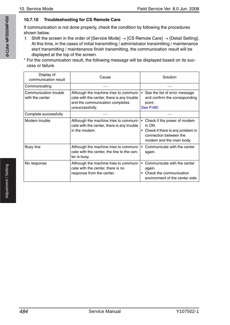
10. Service Mode Field Service Ver. 8.0 Jun. 2008
484
Ad
justm
en
t /
Se
ttin
g
10.7.10 Troubleshooting for CS Remote Care
If communication is not done properly, check the condition by following the procedures shown below.1. Shift the screen in the order of [Service Mode] [CS Remote Care] [Detail Setting].
At this time, in the cases of initial transmitting / administrator transmitting / maintenance start transmitting / maintenance finish transmitting, the communication result will be displayed at the top of the screen.
* For the communication result, the following message will be displayed based on its suc-cess or failure.
Display of communication result
Cause Solution
Communicating
Communication trouble with the center
Although the machine tries to communi-cate with the center, there is any trouble and the communication completes unsuccessfully.
• See the list of error message and confirm the corresponding point.
See P.480
Complete successfully
Modem trouble Although the machine tries to communi-cate with the center, there is any trouble in the modem.
• Check if the power of modem in ON.
• Check if there is any problem in connection between the modem and the main body.
Busy line Although the machine tries to communi-cate with the center, the line to the cen-ter is busy.
• Communicate with the center again.
No response Although the machine tries to communi-cate with the center, there is no response from the center.
• Communicate with the center again.
• Check the communication environment of the center side.
d-C
olor
MF5
50/M
F450
Service Manual Y107502-1

Field Service Ver. 8.0 Jun. 2008 10. Service Mode
485
Ad
justm
en
t /
Se
ttin
g
10.8 System 1
10.8.1 Marketing Area
10.8.2 Tel/Fax Number
Functions • To make the various settings (language, paper size, fixed zoom ratios, etc.) according to the applicable marketing area.
Use • Upon setup.
Setting/Procedure
<Marketing Area>• Select the applicable marketing area and touch [END] to set the marketing area.
JAPAN US Europe Others1 Others2 Others3 Others4
✽ These are the languages that can be selected on the Utility screen according to dif-ferent marketing area settings:
<Fax Target>1. Touch the [Fax Target].2. Select the applicable marketing area using [+] and [-] keys, and touch [END].
Japan English, Japanese
US English, French, Spanish, Japanese
Europe English, French, Italian, German, Spanish, Japanese
Others1 English, French, Spanish, Japanese
Others2 English, French, Spanish, Traditional Chinese, Hungle
Others3 English, Simplified Chinese
Others4 English, Traditional Chinese
Functions • To enter the tel/fax number of the service contact that will appear on the control panel when a malfunction occurs in the machine.
Use • Upon setup.
Setting/Procedure
• Enter the tel/fax number (19 digits) from the 10-key pad.• Use Interrupt key to enter “-.”
d-C
olor
MF5
50/M
F450
Y107502-1 Service Manual
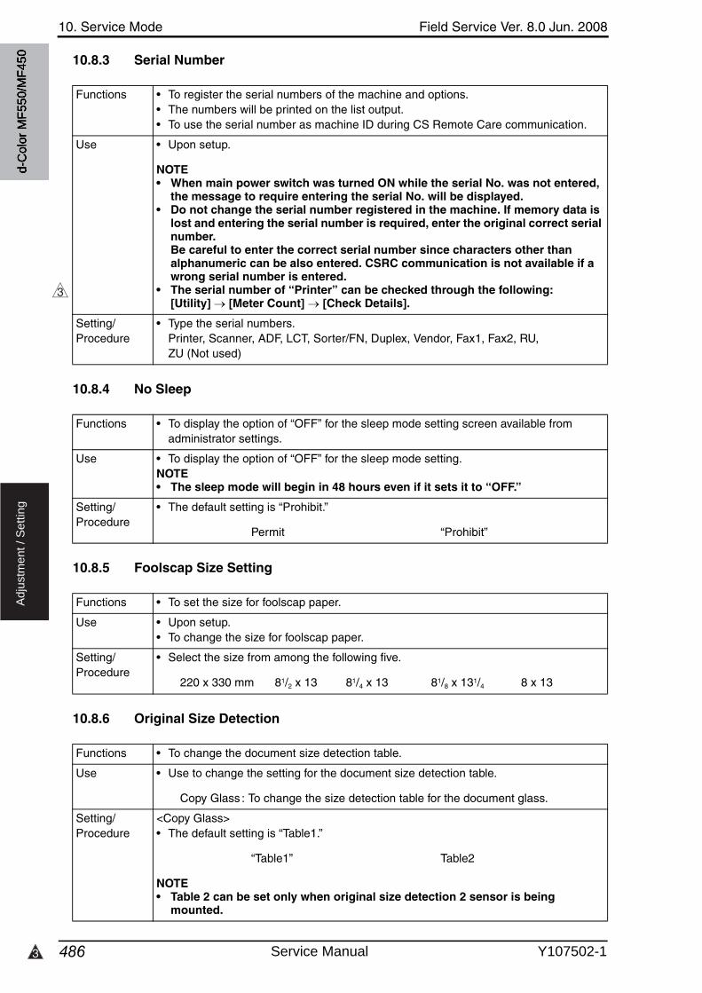
10. Service Mode Field Service Ver. 8.0 Jun. 2008
4863
Ad
justm
en
t /
Se
ttin
g
10.8.3 Serial Number
10.8.4 No Sleep
10.8.5 Foolscap Size Setting
10.8.6 Original Size Detection
Functions • To register the serial numbers of the machine and options.• The numbers will be printed on the list output.• To use the serial number as machine ID during CS Remote Care communication.
Use • Upon setup.
NOTE• When main power switch was turned ON while the serial No. was not entered,
the message to require entering the serial No. will be displayed.• Do not change the serial number registered in the machine. If memory data is
lost and entering the serial number is required, enter the original correct serial number.Be careful to enter the correct serial number since characters other than alphanumeric can be also entered. CSRC communication is not available if a wrong serial number is entered.
• The serial number of “Printer” can be checked through the following: [Utility] [Meter Count] [Check Details].
Setting/Procedure
• Type the serial numbers.Printer, Scanner, ADF, LCT, Sorter/FN, Duplex, Vendor, Fax1, Fax2, RU, ZU (Not used)
3
Functions • To display the option of “OFF” for the sleep mode setting screen available from administrator settings.
Use • To display the option of “OFF” for the sleep mode setting.NOTE• The sleep mode will begin in 48 hours even if it sets it to “OFF.”
Setting/Procedure
• The default setting is “Prohibit.”
Permit “Prohibit”
Functions • To set the size for foolscap paper.
Use • Upon setup.• To change the size for foolscap paper.
Setting/Procedure
• Select the size from among the following five.
220 x 330 mm 81/2 x 13 81/4 x 13 81/8 x 131/4 8 x 13
Functions • To change the document size detection table.
Use • Use to change the setting for the document size detection table.
Copy Glass : To change the size detection table for the document glass.
Setting/Procedure
<Copy Glass>• The default setting is “Table1.”
“Table1” Table2
NOTE• Table 2 can be set only when original size detection 2 sensor is being
mounted.
d-C
olor
MF5
50/M
F450
Service Manual Y107502-1
Field Service Ver. 8.0 Jun. 2008 10. Service Mode
487
Ad
justm
en
t /
Se
ttin
g
10.8.7 Install Date
10.8.8 Initialization
A. Data Clear
B. System Error Clear
10.8.9 Charging CH cleaning
A. Cleaning
Functions • To register the date the main body was installed.
Use • Upon setup.
Setting/Procedure
1. Call the Service Mode on the screen.2. Select the key as follows.
[System 1] [Install Date].3. Enter the date (Year 4 digit Month 2 digit date 2 digit) from the 10-key pad.4. Touch [Entry] to set the date of installation.
Functions • To initialize the setting data.
Use • To clears the setting data.For details on items to be cleared, see “Contents to be cleared by reset function.”See P.556
NOTE• When removing or installing the hard disk after registering the data below, be
sure to clear the data.Referring data: One-touch registration, user authentication/account track.
Setting/Procedure
1. Call the Service Mode to the screen.2. Select the key as follows.
[System 1] [Initialization] [Data clear].3. Press the Start key.4. When [OK] is displayed, turn off the main power switch and turn it on again more
than 10 seconds after.
Functions • To reset the trouble data.
Use • Use to clear the [Jam], [Trouble], [Error] displays, and other improper displays.For details on items to be cleared, see “Contents to be cleared by reset function.”See P.556
Setting/Procedure
1. Call the Service Mode to the screen.2. Select the key as follows.
[System 1] [Initialization] [System Error Clear].3. Press the Start key.4. When [OK] is displayed, turn off the main power switch and turn it on again more
than 10 seconds after.
Functions • Cleaning operation can be executed to the comb electrode of the imaging unit /K.
Use • When image problems occur, you can execute the cleaning operation manually.
Setting/Procedure
1. Call the Service Mode to the screen.2. Select the key as follows.
[System 1] [Charging CH cleaning] [Cleaning].3. Press the Start key.4. When the Start key changes its lighting from red to blue, you can confirm that the
cleaning operation has been completed.
d-C
olor
MF5
50/M
F450
Y107502-1 Service Manual
10. Service Mode Field Service Ver. 8.0 Jun. 2008
4882
Ad
justm
en
t /
Se
ttin
g
B. Self-Cleaning
10.8.10 Trouble Isolation
Functions • This setting allows you to select the self cleaning of the comb electrode section in the imaging unit /K.
Use • This setting can be used to temporarily stop the self cleaning operation in order to address problems.
ON : The self cleaning operation occurs every 2,700 sheets of print, synchroniz-ing the transfer belt cleaning operation.
OFF : The machine does not perform the self cleaning operation.
NOTE• For color imaging units, the comb electrode section needs to be cleaned by
hand every time when a toner cartridge of the corresponding color is replaced.
Setting/Procedure
• The default setting is ON.
“ON” OFF
Functions • Individual units and options have a set or unset setting for the trouble isolation func-tion.
Use • When a problem occurs, this function enables the continuous use of the units that are not affected by separately controlling them and isolating other units that have a prob-lem.
• The machine isolates only units that have a “set” setting.
NOTE• The malfunction detection mechanism is not applied to units and options that
are being isolated.
• This function can be selected for the following units and options.
• Though trouble isolation is not selected, if the specified malfunctions occur on the above listed units or options, an alert screen appears and asks users whether to iso-late the units or options where malfunction occurs.See the “Trouble shooting” section for the corresponding trouble codes.
See P.601
Setting/Procedure
• The default setting is Unset for individual units and options.
Set “Unset”
• After changing the setting, touch [Decision] and turn the main power switch OFF and ON to make the new setting effective.
2
Tray 1Half-Fold/Tri-Fold Center
StaplingScanner
Tray 2 Post Inserter
Tray 3 Z fold
Tray 4 Punch
LCT Staple
manual
d-C
olor
MF5
50/M
F450
Service Manual Y107502-1
3
Field Service Ver. 8.0 Jun. 2008 10. Service Mode
489
Ad
justm
en
t /
Se
ttin
g
10.8.11 IU Life Setting
• This is displayed only when the function enhanced version 2 or later firmware is installed.
10.8.12 Post card transfer table
3
Functions • To set the life threshold for imaging units.
Use • Use this setting when a gap appears between the actual life value of imaging unit and the life specification value due to the way * a machine is used.
• Comparing the PC drum rotation time with the PC drum rotation time calculated based on the number of printed pages, the machine detects the end of unit life usingthe one that reaches the life specification value earlier.This setting aims to extend the life threshold for the PC drum rotation time and achieve a longer imaging unit life.
Normal : detects the end of life when the life specification value is reached.Suspend : detects the end of life when a value greater (longer) than the life speci-
fication value is reached.
*The product specification value is determined based on what types of printing are made on the machine. If the types of printing made on the machine are different from the specified printing conditions, the life value of the imaging unit tends to be different from the life specification value.See conditions for life specification values in the service manual titled maintenance for more information on printing conditions.
See P.25
NOTE• When “Suspend” is selected, images printed after the life specification value
is out of guarantee.The life counter value of imaging unit is accessed from [Service Mode] [Counter] [Life].
• Before making this setting, be sure to check that the machine does not display any message that warns each of imaging units, fusing unit, or image transfer belt unit reaches their life value.
Setting/Procedure
• The default setting is Normal.
“Normal” Suspend
NOTE• When the setting has been changed, turn off the sub power switch and turn it
on again.
Functions • This setting allows you to select the transfer table to be used for thick3 postcards.
Use • For the use of thick 3 postcards, you can select the transfer table suitable for post-cards.
• This setting is used to improve transfer performance to postcards.
Post. : The postcard 2nd image transfer table is used when printing on thick3 postcards.
Thick 3 : The normal thick3 2nd image transfer table is used when printing on thick 3 postcards.
Setting/Procedure
• The default setting is Thick 3.
Post. “Thick 3”
d-C
olor
MF5
50/M
F450
Y107502-1 Service Manual
10. Service Mode Field Service Ver. 8.0 Jun. 2008
4904
Ad
justm
en
t /
Se
ttin
g
10.8.13 Change Warm Up Time *d-Color C450 only
• This function is only for Taiwan.
10.8.14 Machine State LED Setting
• For d-Color MF550/MF450, this is displayed only when the function enhanced version 1 or later firmware is installed.
Functions • To change the warm up time to be spent before the start of monochrome printing.
Use • When a paper curl problem occurs in monochrome printing immediately after the completion of warm up operation under Mode 1 selection (30 seconds for mono-chrome prints), the mode selection needs to be changed into Mode 2 (60 seconds for monochrome prints).
Mode 1: Default, 30 seconds of warm up time for monochrome printingMode 2: 60 seconds of warm up time for monochrome printing
Setting/Procedure
• The default setting is Mode 1.
“Mode 1” Mode 2
Functions • To set how to display main body statuses on the machine state LED (state display lamp, paper empty lamp).
• Each of Type1 and Type2 has the following LED display forms.Use
Setting/Procedure
• Each default setting is Type1.
“Type 1” Type 2
NOTE• [Type 2] is the default setting, if the firmware of function enhanced version 3 or
later is mounted.
Machine State LED Setting Type1 Type2
Warning statuses
Attention• Toner supply door open• Improper toner cartridge placement
Blinking Blinking
Near life Blinking Unlit
Alert code Unlit Unlit
Trouble isolation Blinking Blinking
Fatal error• Trouble code• Jam• Door opened• Life stop
Lit Lit
Amount of paper remaining (Tray 1 and 2)
100 % to near empty Unlit Unlit
Near empty Blinking Unlit
Empty Lit Lit
Being lifted upDoor opened or closed
Unlit Unlit
Amount of paper remaining (Tray 3 and 4, LCT)
100 % to near empty Unlit Unlit
Near empty Blinking Unlit
Empty Lit Lit
Being lifted upDoor opened or closed
Unlit Unlit
4
d-C
olor
MF5
50/M
F450
Service Manual Y107502-1
Field Service Ver. 8.0 Jun. 2008 10. Service Mode
491 2
Ad
justm
en
t /
Se
ttin
g
10.9 System 2
10.9.1 HDD
10.9.2 Image Controller Setting
Functions
• Not used.Use
Setting/Procedure
Functions • To set the type of the controller.• [Peripheral Mode] appears when [Others] is selected.
Use • When setting up the controller.
Setting/Procedure
Image Controller Setting• Select the controller to be used. “Controller 0” : The standard controller is used. Controller 1 : The optional image controller IC-409 is used. Controller 2 : undefined. Controller 3 : undefined. Others : undefined.
Peripheral Mode• Select the operating mode of the Scanner. Mode 1: undefined. Mode 2: undefined. Mode 3: undefined.NOTE• When the following setting is “ON”, this setting should be set to “Controller
0”.[Administrator Settings] [Security Settings] [Enhanced Security Mode] When [Enhanced Security Mode] is set to “ON”, this setting cannot be changed.
• After changing setting, make sure to turn off the main power switch and turn it on again more than 10 seconds after.
Note on returning the setting from “Controller 1” to “Controller 0”.• Selecting “Controller 0” will initialize the following settings made while “Controller 1”
was selected. Reset the following items as necessary when using the internal stan-dard controller.
<Control panel on the machine>• Setting items included in [Network Setting] available from [Administrator Setting].
(Except [Status Notification Setting] and [Prefix/Suffix Setting] available from the fol-lowing setting. [Administrator Settings] [Network Settings] [Detail Settings].)
• The following setting [Administrator Settings] [User Authentication /Account Track] [General Settings]
[External Server]• The following setting
[Administrator Settings] [System Connection] [IS OpenAPI Setting]• Mailbox Destination (scan)• Information on the original specified by the program destination
<Page Scope Web Connection>• SSL/TLS
2
2
d-C
olor
MF5
50/M
F450
Y107502-1 Service Manual

10. Service Mode Field Service Ver. 8.0 Jun. 2008
492
Ad
justm
en
t /
Se
ttin
g
10.9.3 Option Board Status
10.9.4 Consumable Life Reminder
10.9.5 Unit Change
Functions • To set when the optional fax mount kit, scan accelerator is mounted.
Use • Use when setting up the optional fax mount kit, scan accelerator is mounted.
Setting/Procedure
• Setting modes are Fax (circuit 1), Fax (circuit 2) and JPEG.• The default settings are “Unset.”
Fax (circuit 1) : Set “Unset”Fax (circuit 2) : Set “Unset”JPEG : Set “Unset”
NOTE• When the setting has been changed, turn off the main power switch and turn it
on again more than 10 seconds after.
Functions • To select whether or not to give the display of PM parts lifetimePM parts lifetime display: An entire screen warning is given when the service life
of a specific unit has been reached, prompting the user to replace the part.
• Applicable units: Transfer belt unit, fusing unit, imaging unit (C, M, Y, K)
Use • Use to select not to give the display of PM parts lifetime.
Setting/Procedure
• The default setting is “Yes.”
“Yes” No
Functions • To select who is to replace a unit.• When the unit life arrives, the warning display is intended for the specific person who
is going to replace the unit. When “User” is selected : Printing is inhibited. When “Service” is selected : Life warning.
Use • Upon setup
Setting/Procedure
• The following are the default settings:
US, Japan, Others 4 Europe, Others1/2/3Toner Cartridge : “User” Service “User” ServiceImaging Unit : User “Service” “User” ServiceWaste Toner Box : User “Service” “User” ServicePunch Dust Box : User “Service” “User” Service
d-C
olor
MF5
50/M
F450
Service Manual Y107502-1
7
Field Service Ver. 8.0 Jun. 2008 10. Service Mode
493
Ad
justm
en
t /
Se
ttin
g
10.9.6 Software Switch Setting
A. Setting items in the software switch setting(1) ACS mode control change
(2) Secure Print shortcut key display in the User Box mode menu• This function is available only when the function enhanced version 4 or later firmware is
installed.
Functions • To set the operating characteristic of each function from software switch depending on what types of printing are normally made.Use
Setting/Procedure
1. Touch [Software Switch Setting].2. Touch [Switch No.] and enter the intended switch number with the ten-key pad.3. Touch [Bit Assignment].4. Use [ ] or [ ] to select a bit. To set the bit, enter 0 or 1 with the ten-key pad.5. To set the bit in hex, touch [HEX Assignment] and use the ten-key pad and [A] to [F]
keys to enter numbers and characters.6. Touch [Fix].
Functions • To change the 1st image transfer roller pressure/retraction operation control in ACS mode.
Use • When a user makes mainly monochrome prints, selecting 01 may allow avoiding the PC drum wear-out caused by unnecessary rotation of color imaging units.
HEX Assignment 00: The color print (pressed) position is set as the default position of the 1st image transfer roller. (Default setting)
HEX Assignment 01: The monochrome print (retracted) position is set as the defaultposition of the 1st image transfer roller.
Setting/Procedure
1. Touch [Software Switch Setting].2. Touch [Switch No.] and enter “50” with the ten-key pad.3. Touch [HEX Assignment] and enter “00” or “01” with the ten-key pad.4. Touch [Fix].
7
Functions • To display the [Secure Print] shortcut key in the User Box mode menu (the defaultsetting is not shown).
bit0-0: Does not display the shortcut keybit0-1: Displays the shortcut key
Use
Setting/Procedure
1. Touch [Software Switch Setting].2. Touch [Switch No.] and enter “69” with the ten-key pad.3. Touch [BIT Assignment] and select “bit0” with [ ]/[ ] key.4. Enter “0” or “1” with the 10-key pad.5. Touch [Fix].
d-C
olor
MF5
50/M
F450
Y107502-1 Service Manual

10. Service Mode Field Service Ver. 8.0 Jun. 2008
4947
Ad
justm
en
t /
Se
ttin
g
(3) Printing on paper of nonstandard size fed from the bypass tray (AnySize mode)• This function is available only when the function enhanced version 4 or later firmware is
installed.
10.9.7 Scan Caribration
10.9.8 LCC Size Setting
10.9.9 LCT Paper Size Setting
7
Functions • To enable printing only by the setting made on the printer driver when printing is attempted on paper of nonstandard size fed by way of the bypass tray (the defaultsetting is the conventional operation).
bit0-0: Conventional operationbit0-1: The print cycle is initiated for the paper specified on the printer driver
regardless of the bypass tray paper setting.
Use
Setting/Procedure
1. Touch [Software Switch Setting].2. Touch [Switch No.] and enter “69” with the ten-key pad.3. Touch [BIT Assignment] and select “bit2” with [ ]/[ ] key.4. Enter “0” or “1” with the 10-key pad.5. Touch [Fix].
Functions • To set whether to use the calibration adjustment value set prior to the shipping.
Use • To be used when CCD unit has been changed.After replacing the CCD unit, the default value needs to be set since the calibration value set for each unit changes to control the differences in reading performance on each scanner (CCD).
• The original calibration adjustment value can be disabled to address image failureand other problems caused by individual CCD performance difference.
Setting/Procedure
• The default setting is ON.
“ON” OFF
NOTE• When the setting is changed, the function becomes available by turning the
sub power switch OFF and ON again.
Functions • To set the paper size for the LCC.
Use • Use to change the paper size for the LCC (tray 3/4).
Setting/Procedure
• The default setting depends on the setting made for the applicable marketing area.
A4 B5 8 1/2 x 11 16K A5 5 1/2 x 8 1/2 Post. S
Functions • To set the paper size for the LCT.
Use • Use to change the paper size for the LCT (LU-301).
Setting/Procedure
• The default setting depends on the setting made for the applicable marketing area.
A4 81/2 x 11
d-C
olor
MF5
50/M
F450
Service Manual Y107502-1
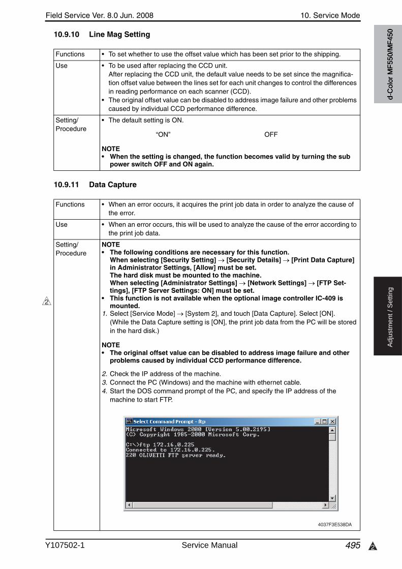
Field Service Ver. 8.0 Jun. 2008 10. Service Mode
495 2
Ad
justm
en
t /
Se
ttin
g
10.9.10 Line Mag Setting
10.9.11 Data Capture
Functions • To set whether to use the offset value which has been set prior to the shipping.
Use • To be used after replacing the CCD unit.After replacing the CCD unit, the default value needs to be set since the magnifica-tion offset value between the lines set for each unit changes to control the differences in reading performance on each scanner (CCD).
• The original offset value can be disabled to address image failure and other problems caused by individual CCD performance difference.
Setting/Procedure
• The default setting is ON.
“ON” OFF
NOTE• When the setting is changed, the function becomes valid by turning the sub
power switch OFF and ON again.
Functions • When an error occurs, it acquires the print job data in order to analyze the cause of the error.
Use • When an error occurs, this will be used to analyze the cause of the error according to the print job data.
Setting/Procedure
NOTE• The following conditions are necessary for this function.
When selecting [Security Setting] [Security Details] [Print Data Capture] in Administrator Settings, [Allow] must be set.The hard disk must be mounted to the machine.When selecting [Administrator Settings] [Network Settings] [FTP Set-tings], [FTP Server Settings: ON] must be set.
• This function is not available when the optional image controller IC-409 is mounted.
1. Select [Service Mode] [System 2], and touch [Data Capture]. Select [ON].(While the Data Capture setting is [ON], the print job data from the PC will be stored in the hard disk.)
NOTE• The original offset value can be disabled to address image failure and other
problems caused by individual CCD performance difference.
2. Check the IP address of the machine.3. Connect the PC (Windows) and the machine with ethernet cable.4. Start the DOS command prompt of the PC, and specify the IP address of the
machine to start FTP.
2
4037F3E538DA
d-C
olor
MF5
50/M
F450
Y107502-1 Service Manual
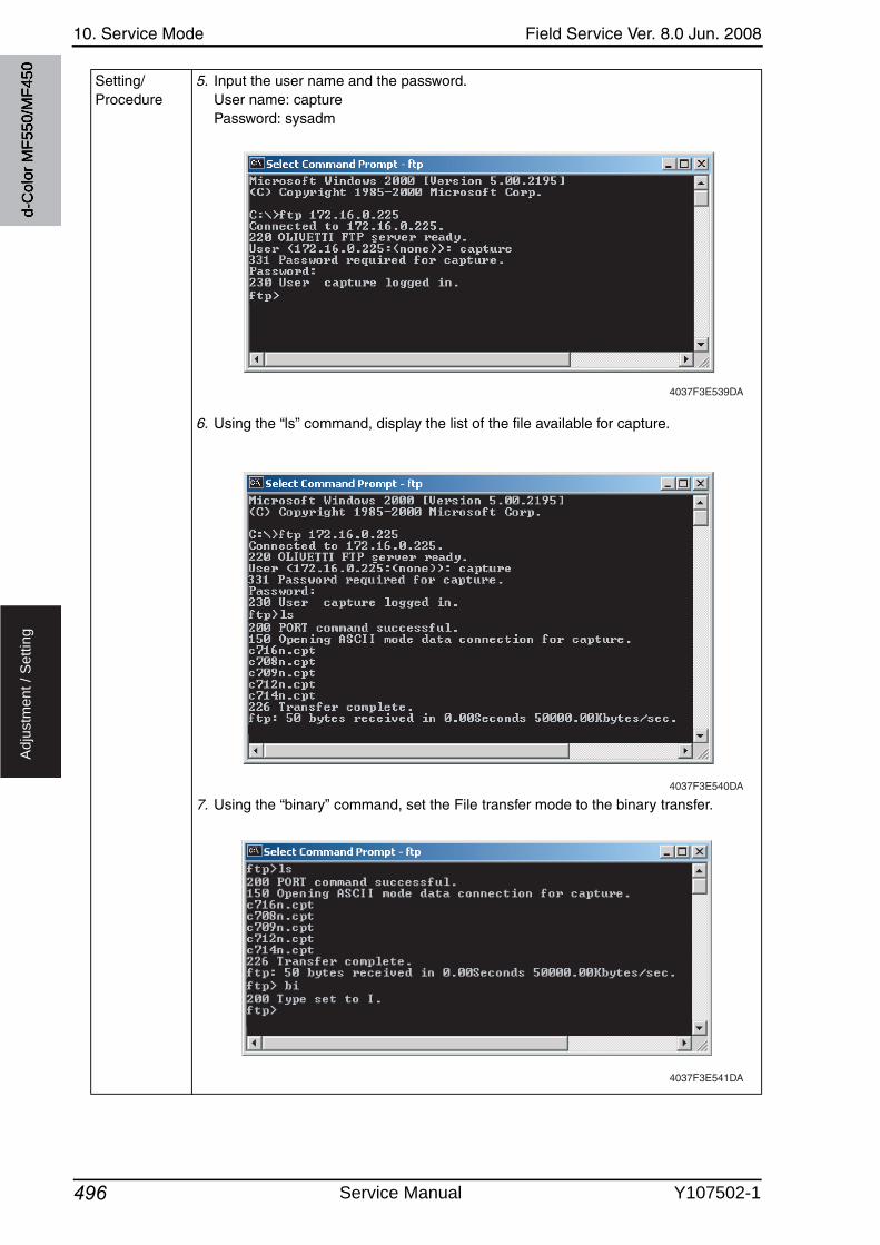
10. Service Mode Field Service Ver. 8.0 Jun. 2008
496
Ad
justm
en
t /
Se
ttin
g
Setting/Procedure
5. Input the user name and the password.User name: capturePassword: sysadm
6. Using the “ls” command, display the list of the file available for capture.
7. Using the “binary” command, set the File transfer mode to the binary transfer.
4037F3E539DA
4037F3E540DA
4037F3E541DA
d-C
olor
MF5
50/M
F450
Service Manual Y107502-1
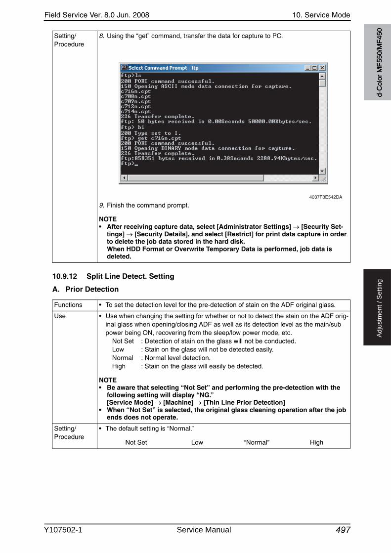
Field Service Ver. 8.0 Jun. 2008 10. Service Mode
497
Ad
justm
en
t /
Se
ttin
g
10.9.12 Split Line Detect. Setting
A. Prior Detection
Setting/Procedure
8. Using the “get” command, transfer the data for capture to PC.
9. Finish the command prompt.
NOTE• After receiving capture data, select [Administrator Settings] [Security Set-
tings] [Security Details], and select [Restrict] for print data capture in order to delete the job data stored in the hard disk.When HDD Format or Overwrite Temporary Data is performed, job data is deleted.
4037F3E542DA
Functions • To set the detection level for the pre-detection of stain on the ADF original glass.
Use • Use when changing the setting for whether or not to detect the stain on the ADF orig-inal glass when opening/closing ADF as well as its detection level as the main/subpower being ON, recovering from the sleep/low power mode, etc.
Not Set : Detection of stain on the glass will not be conducted.Low : Stain on the glass will not be detected easily.Normal : Normal level detection.High : Stain on the glass will easily be detected.
NOTE• Be aware that selecting “Not Set” and performing the pre-detection with the
following setting will display “NG.”[Service Mode] [Machine] [Thin Line Prior Detection]
• When “Not Set” is selected, the original glass cleaning operation after the job ends does not operate.
Setting/Procedure
• The default setting is “Normal.”
Not Set Low “Normal” High
d-C
olor
MF5
50/M
F450
Y107502-1 Service Manual
10. Service Mode Field Service Ver. 8.0 Jun. 2008
498
Ad
justm
en
t /
Se
ttin
g
B. Warning Level
C. Paper Passaging Detection
10.9.13 Stamp
Functions • To set how to display the warning when stain on the ADF original glass is detected.
Use • Use when changing the display of the warning which requests the cleaning of the stain on the glass detected by the pre-detection of the lines.
0: Warning will not be displayed.1: Warning will be displayed by the maintenance mark. (warning code: D-1/D-2)2: Warning will be displayed on the message area on the basic screen.3: Warning will be displayed on all screens.
NOTE• This setting is invalid when [Prior Detection] is set to “Not Set.”
Setting/Procedure
• The default setting is 2.
0 1 “2” 3
Functions • To set the operation for detection and removing operation of stain on the ADF original glass when feeding the original.
Use • Use when changing the operation for detection and removing operation of stain on the ADF original glass when feeding the original.
0 : The glass will stop moving when the original is fed, and will not perform removing the stain.
1 : The glass will move between originals when feeding the original.2 : When the original is fed, the glass will move while reading the original in
order to remove the stain, and reduce the lines.3 to 6 : When the original is fed, the glass will move while reading the original in
order to remove the stain. The lines will be reduced also by the image process control.The level 3, 4, 5, and 6 of the image process are set in this order with 3 being the most efficient in reducing the lines.
NOTE• When this function is used, an image quality problem might be occurred in the
side effect by the image processing control according to the dirt condition of the original glass.
• When setting to “0” or “1”, the setting area available for the administrator by the fol-lowing setting will be restricted to “0 (Disable)” or “1 (Enable).”[Administrator Setting] [System Setting] [Expert Adjustment] [Line Detection]
[Detection While Feeding Setting]
Setting/Procedure
• The default setting is 1.
0 to 6
Functions • To set the mounting status of the optional stamp unit SP-501.
Use • To use when setting up the stamp unit SP-501.
Setting/Procedure
• The default setting is Unset.
Set “Unset”
d-C
olor
MF5
50/M
F450
Service Manual Y107502-1
Field Service Ver. 8.0 Jun. 2008 10. Service Mode
499
Ad
justm
en
t /
Se
ttin
g
10.9.14 Network Fax Settings
Functions • To set whether or not to use network fax function.
Use • To use network fax function (IP address fax, internet fax).• Selection will be available when each network fax function is set to “ON” in the follow-
ing settings. [Administrator Settings] [Network Settings] [Network Fax Settings] [Network Fax Function Settings]
Setting/Procedure
• The default settings are OFF.
IP Address Fax : ON “OFF”SIP-Fax : Not UsedInternet Fax : ON “OFF”
d-C
olor
MF5
50/M
F450
Y107502-1 Service Manual
10. Service Mode Field Service Ver. 8.0 Jun. 2008
500
Ad
justm
en
t /
Se
ttin
g
10.10 Counter
• The counter displays the counts of various counters to allow the technical representativeto check or set as necessary.
10.10.1 Procedure
1. Touch [Counter] to show the counter menu.2. Select the specific counter to be displayed.3. To clear the counts of two or more counters within a group or across different groups at
once, touch [Counter Reset], select the specific counters to be cleared, and touch[END]. Two or more counters can be selected.
10.10.2 Life
Functions • To check the number of hours or times each of the different maintenance parts has been used.
• To clear the count of each counter.
Use • When each of the maintenance parts is replaced.
Setting/Procedure
• To clear the count of a counter, select the specific part and press the Clear key.• If a counter is cleared mistakenly, press the Interrupt key, which will undo the clearing
operation.• It is not possible to clear the count of the counters for the fusing unit, transfer belt
unit, Imaging Unit and TCR new article detection, which are provided with a new unit detection function.
<1>• Fusing Unit : Number of times a sheet of paper is fed through• Transfer Roller Unit : Number of times a sheet of paper is fed through• Image Transfer Belt Unit : Number of times a sheet of paper is fed through• Ozone Filter : Number of times the ozone filter has been used.• Color Toner Filter : Number of times the color toner filter has been used.• 1st. : Number of sheets of paper fed from tray 1• 2nd. : Number of sheets of paper fed from tray 2• 3rd. : Number of sheets of paper fed from tray 3• 4th. : Number of sheets of paper fed from tray 4• Manual Tray : Number of sheets of paper fed from the bypass
<2>• Imaging Unit (C) : Period of time over which the cyan imaging unit has
been used.• Imaging Unit (M) : Period of time over which the magenta imaging unit has
been used.• Imaging Unit (Y) : Period of time over which the yellow imaging unit has
been used.• Imaging Unit (K) : Period of time over which the black imaging unit has
been used.• LCT Parts : Number of sheets of paper fed from the LCT• ADF Feed : Number of sheets of paper fed through the take-up sec-
tion of the ADF• ADF Reverse : Number of sheets of paper fed through the turnover unit
of the ADF• Sorter/Finisher : Number of sheets of paper fed out of the sorter/finisher
d-C
olor
MF5
50/M
F450
Service Manual Y107502-1
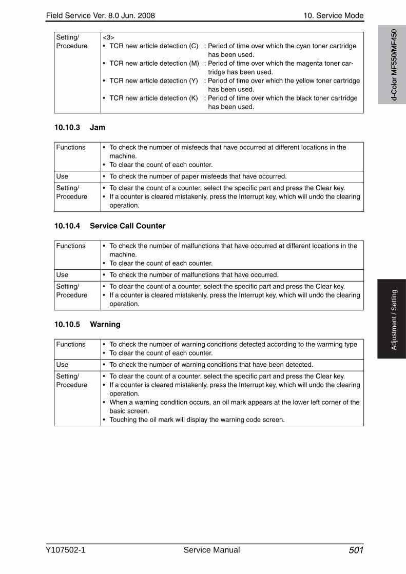
Field Service Ver. 8.0 Jun. 2008 10. Service Mode
501
Ad
justm
en
t /
Se
ttin
g
10.10.3 Jam
10.10.4 Service Call Counter
10.10.5 Warning
Setting/Procedure
<3>• TCR new article detection (C) : Period of time over which the cyan toner cartridge
has been used.• TCR new article detection (M) : Period of time over which the magenta toner car-
tridge has been used.• TCR new article detection (Y) : Period of time over which the yellow toner cartridge
has been used.• TCR new article detection (K) : Period of time over which the black toner cartridge
has been used.
Functions • To check the number of misfeeds that have occurred at different locations in the machine.
• To clear the count of each counter.
Use • To check the number of paper misfeeds that have occurred.
Setting/Procedure
• To clear the count of a counter, select the specific part and press the Clear key.• If a counter is cleared mistakenly, press the Interrupt key, which will undo the clearing
operation.
Functions • To check the number of malfunctions that have occurred at different locations in the machine.
• To clear the count of each counter.
Use • To check the number of malfunctions that have occurred.
Setting/Procedure
• To clear the count of a counter, select the specific part and press the Clear key.• If a counter is cleared mistakenly, press the Interrupt key, which will undo the clearing
operation.
Functions • To check the number of warning conditions detected according to the warming type• To clear the count of each counter.
Use • To check the number of warning conditions that have been detected.
Setting/Procedure
• To clear the count of a counter, select the specific part and press the Clear key.• If a counter is cleared mistakenly, press the Interrupt key, which will undo the clearing
operation.• When a warning condition occurs, an oil mark appears at the lower left corner of the
basic screen.• Touching the oil mark will display the warning code screen.
d-C
olor
MF5
50/M
F450
Y107502-1 Service Manual
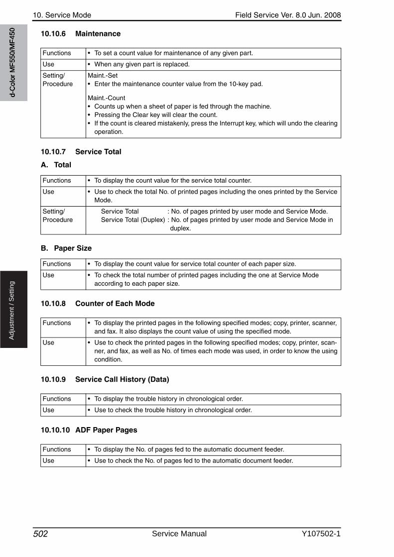
10. Service Mode Field Service Ver. 8.0 Jun. 2008
502
Ad
justm
en
t /
Se
ttin
g
10.10.6 Maintenance
10.10.7 Service Total
A. Total
B. Paper Size
10.10.8 Counter of Each Mode
10.10.9 Service Call History (Data)
10.10.10 ADF Paper Pages
Functions • To set a count value for maintenance of any given part.
Use • When any given part is replaced.
Setting/Procedure
Maint.-Set• Enter the maintenance counter value from the 10-key pad.
Maint.-Count• Counts up when a sheet of paper is fed through the machine.• Pressing the Clear key will clear the count.• If the count is cleared mistakenly, press the Interrupt key, which will undo the clearing
operation.
Functions • To display the count value for the service total counter.
Use • Use to check the total No. of printed pages including the ones printed by the ServiceMode.
Setting/Procedure
Service Total : No. of pages printed by user mode and Service Mode.Service Total (Duplex) : No. of pages printed by user mode and Service Mode in
duplex.
Functions • To display the count value for service total counter of each paper size.
Use • To check the total number of printed pages including the one at Service Mode according to each paper size.
Functions • To display the printed pages in the following specified modes; copy, printer, scanner, and fax. It also displays the count value of using the specified mode.
Use • Use to check the printed pages in the following specified modes; copy, printer, scan-ner, and fax, as well as No. of times each mode was used, in order to know the usingcondition.
Functions • To display the trouble history in chronological order.
Use • Use to check the trouble history in chronological order.
Functions • To display the No. of pages fed to the automatic document feeder.
Use • Use to check the No. of pages fed to the automatic document feeder.
d-C
olor
MF5
50/M
F450
Service Manual Y107502-1
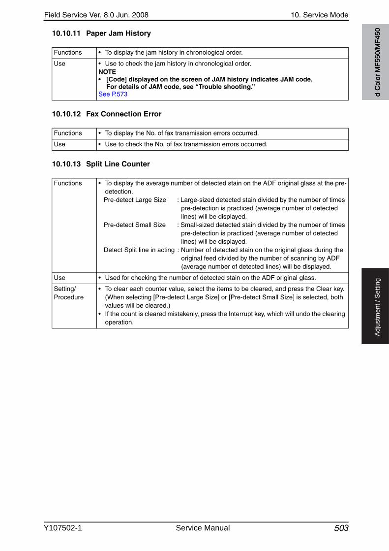
Field Service Ver. 8.0 Jun. 2008 10. Service Mode
503
Ad
justm
en
t /
Se
ttin
g
10.10.11 Paper Jam History
10.10.12 Fax Connection Error
10.10.13 Split Line Counter
Functions • To display the jam history in chronological order.
Use • Use to check the jam history in chronological order.NOTE• [Code] displayed on the screen of JAM history indicates JAM code.
For details of JAM code, see “Trouble shooting.”See P.573
Functions • To display the No. of fax transmission errors occurred.
Use • Use to check the No. of fax transmission errors occurred.
Functions • To display the average number of detected stain on the ADF original glass at the pre-detection.Pre-detect Large Size : Large-sized detected stain divided by the number of times
pre-detection is practiced (average number of detected lines) will be displayed.
Pre-detect Small Size : Small-sized detected stain divided by the number of times pre-detection is practiced (average number of detected lines) will be displayed.
Detect Split line in acting : Number of detected stain on the original glass during the original feed divided by the number of scanning by ADF (average number of detected lines) will be displayed.
Use • Used for checking the number of detected stain on the ADF original glass.
Setting/Procedure
• To clear each counter value, select the items to be cleared, and press the Clear key.(When selecting [Pre-detect Large Size] or [Pre-detect Small Size] is selected, both values will be cleared.)
• If the count is cleared mistakenly, press the Interrupt key, which will undo the clearing operation.
d-C
olor
MF5
50/M
F450
Y107502-1 Service Manual
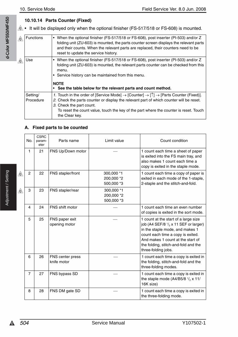
10. Service Mode Field Service Ver. 8.0 Jun. 2008
5046
Ad
justm
en
t /
Se
ttin
g
10.10.14 Parts Counter (Fixed)
• It will be displayed only when the optional finisher (FS-517/518 or FS-608) is mounted.
A. Fixed parts to be counted
6
Functions • When the optional finisher (FS-517/518 or FS-608), post inserter (PI-503) and/or Z folding unit (ZU-603) is mounted, the parts counter screen displays the relevant parts and their counts. When the relevant parts are replaced, their counters need to be reset to update the service history.
Use • When the optional finisher (FS-517/518 or FS-608), post inserter (PI-503) and/or Z folding unit (ZU-603) is mounted, the relevant parts counter can be checked from this menu.
• Service history can be maintained from this menu.
NOTE• See the table below for the relevant parts and count method.
Setting/Procedure
1. Touch in the order of [Service Mode] [Counter] [ ] [Parts Counter (Fixed)].2. Check the parts counter or display the relevant part of which counter will be reset.3. Check the part count.
To reset the count value, touch the key of the part where the counter is reset. Touchthe Clear key.
6
6
No.CSRCparam-
eterParts name Limit value Count condition
1 21 FNS Up/Down motor 1 count each time a sheet of paper is exited into the FS main tray, and also makes 1 count each time a copy is exited in the staple mode.
2 22 FNS stapler/front 300,000 *1200,000 *2500,000 *3
1 count each time a copy of paper is exited in each mode of the 1-staple, 2-staple and the stitch-and-fold.
3 23 FNS stapler/rear 300,000 *1200,000 *2500,000 *3
4 24 FNS shift motor 1 count each time an even number of copies is exited in the sort mode.
5 25 FNS paper exit opening motor
1 count at the start of a large size job (A4 SEF/8 1/2 x 11 SEF or larger) in the staple mode, and makes 1 count each time a copy is exited. And makes 1 count at the start of the folding, stitch-and-fold and the three-folding jobs.
6 26 FNS center press knife motor
1 count each time a copy is exited in the folding, stitch-and-fold and the three-folding modes.
7 27 FNS bypass SD 1 count each time a copy is exited in the staple mode (A4/B5/8 1/2 x 11/16K size)
8 28 FNS DM gate SD 1 count each time a copy is exited in the three-folding mode.
6
6
d-C
olor
MF5
50/M
F450
Service Manual Y107502-1
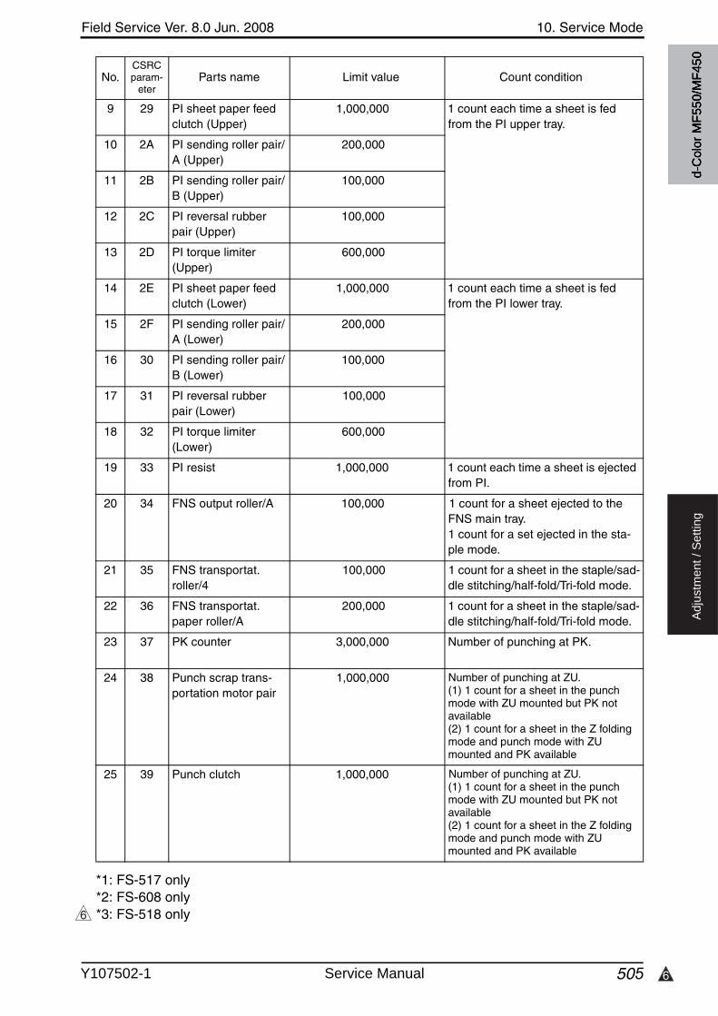
6
Field Service Ver. 8.0 Jun. 2008 10. Service Mode
505
Ad
justm
en
t /
Se
ttin
g
*1: FS-517 only*2: FS-608 only*3: FS-518 only
9 29 PI sheet paper feed clutch (Upper)
1,000,000 1 count each time a sheet is fed from the PI upper tray.
10 2A PI sending roller pair/A (Upper)
200,000
11 2B PI sending roller pair/B (Upper)
100,000
12 2C PI reversal rubber pair (Upper)
100,000
13 2D PI torque limiter (Upper)
600,000
14 2E PI sheet paper feed clutch (Lower)
1,000,000 1 count each time a sheet is fed from the PI lower tray.
15 2F PI sending roller pair/A (Lower)
200,000
16 30 PI sending roller pair/B (Lower)
100,000
17 31 PI reversal rubber pair (Lower)
100,000
18 32 PI torque limiter (Lower)
600,000
19 33 PI resist 1,000,000 1 count each time a sheet is ejected from PI.
20 34 FNS output roller/A 100,000 1 count for a sheet ejected to the FNS main tray.1 count for a set ejected in the sta-ple mode.
21 35 FNS transportat. roller/4
100,000 1 count for a sheet in the staple/sad-dle stitching/half-fold/Tri-fold mode.
22 36 FNS transportat. paper roller/A
200,000 1 count for a sheet in the staple/sad-dle stitching/half-fold/Tri-fold mode.
23 37 PK counter 3,000,000 Number of punching at PK.
24 38 Punch scrap trans-portation motor pair
1,000,000 Number of punching at ZU.(1) 1 count for a sheet in the punchmode with ZU mounted but PK not available(2) 1 count for a sheet in the Z folding mode and punch mode with ZU mounted and PK available
25 39 Punch clutch 1,000,000 Number of punching at ZU.(1) 1 count for a sheet in the punchmode with ZU mounted but PK not available(2) 1 count for a sheet in the Z folding mode and punch mode with ZU mounted and PK available
No.CSRCparam-
eterParts name Limit value Count condition
6
d-C
olor
MF5
50/M
F450
Y107502-1 Service Manual
10. Service Mode Field Service Ver. 8.0 Jun. 2008
506
Ad
justm
en
t /
Se
ttin
g
10.11 List Output
10.11.1 Machine Management List
10.11.2 Adjustment List
10.11.3 Parameter List
• For details, see FK-502 Service Manual.
10.11.4 Service Parameter
• For details, see FK-502 Service Manual.
10.11.5 Protocol Trace
• For details, see FK-502 Service Manual.
10.11.6 Fax Setting List
• For details, see FK-502 Service Manual.
10.11.7 Fax Analysis List
• For details, see FK-502 Service Manual.
Functions • To produce an output of a list of setting values, adjustment values, total counter val-ues, and others.
Use • At the end of setup or when a malfunction occurs.
Setting/Procedure
• Load the A4S plain paper to a paper source.• Press the Start key, which will let the machine produce the list.• The time-of-day and date will also be printed.
Functions • To output the adjustment list for machine adjustment, process adjustment, etc. in Service Mode.
Use • At the end of setup or when a malfunction occurs.
Setting/Procedure
• Load the A4S plain paper to a paper source.• Press the Start key, which will let the machine produce the list.• The time-of-day and date will also be printed.
d-C
olor
MF5
50/M
F450
Service Manual Y107502-1
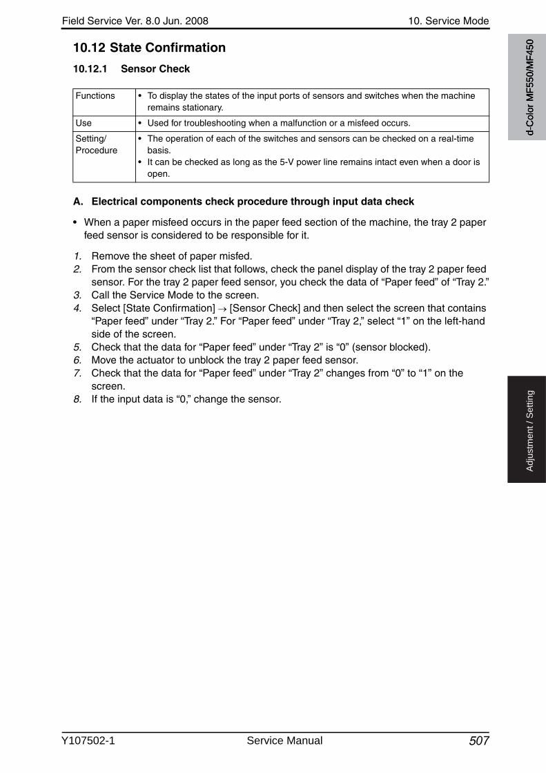
Field Service Ver. 8.0 Jun. 2008 10. Service Mode
507
Ad
justm
en
t /
Se
ttin
g
10.12 State Confirmation
10.12.1 Sensor Check
A. Electrical components check procedure through input data check
• When a paper misfeed occurs in the paper feed section of the machine, the tray 2 paper feed sensor is considered to be responsible for it.
1. Remove the sheet of paper misfed.2. From the sensor check list that follows, check the panel display of the tray 2 paper feed
sensor. For the tray 2 paper feed sensor, you check the data of “Paper feed” of “Tray 2.”3. Call the Service Mode to the screen.4. Select [State Confirmation] [Sensor Check] and then select the screen that contains
“Paper feed” under “Tray 2.” For “Paper feed” under “Tray 2,” select “1” on the left-hand side of the screen.
5. Check that the data for “Paper feed” under “Tray 2” is “0” (sensor blocked).6. Move the actuator to unblock the tray 2 paper feed sensor.7. Check that the data for “Paper feed” under “Tray 2” changes from “0” to “1” on the
screen.8. If the input data is “0,” change the sensor.
Functions • To display the states of the input ports of sensors and switches when the machine remains stationary.
Use • Used for troubleshooting when a malfunction or a misfeed occurs.
Setting/Procedure
• The operation of each of the switches and sensors can be checked on a real-time basis.
• It can be checked as long as the 5-V power line remains intact even when a door is open.
d-C
olor
MF5
50/M
F450
Y107502-1 Service Manual

10. Service Mode Field Service Ver. 8.0 Jun. 2008
5082
Ad
justm
en
t /
Se
ttin
g
10.12.2 Sensor check screens
• These are only typical screens which may be different from what are shown on each indi-vidual machine.
A. Sensor monitor(1) Sensor monitor 1,2
2
A00JF3E514DC
d-C
olor
MF5
50/M
F450
Service Manual Y107502-1
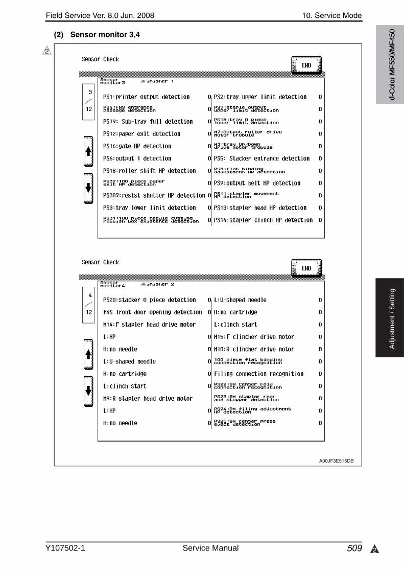
Field Service Ver. 8.0 Jun. 2008 10. Service Mode
509 2
Ad
justm
en
t /
Se
ttin
g
(2) Sensor monitor 3,4
2
A00JF3E515DB
d-C
olor
MF5
50/M
F450
Y107502-1 Service Manual
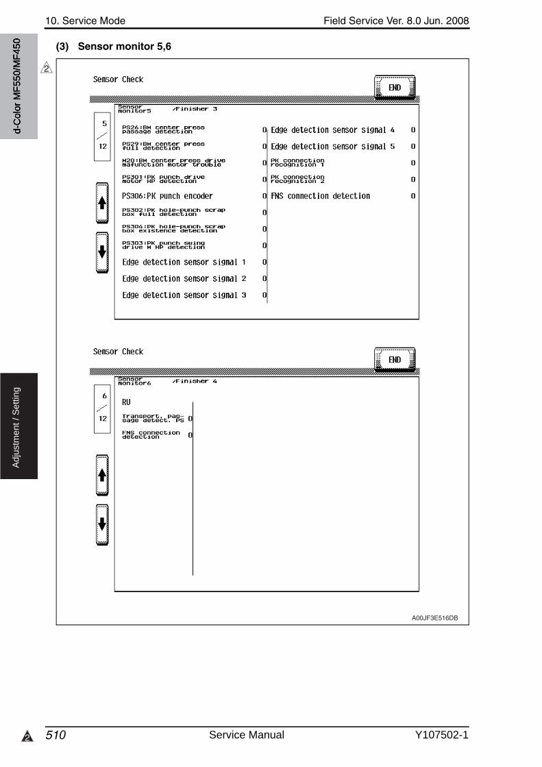
10. Service Mode Field Service Ver. 8.0 Jun. 2008
5102
Ad
justm
en
t /
Se
ttin
g
(3) Sensor monitor 5,6
2
A00JF3E516DB
d-C
olor
MF5
50/M
F450
Service Manual Y107502-1
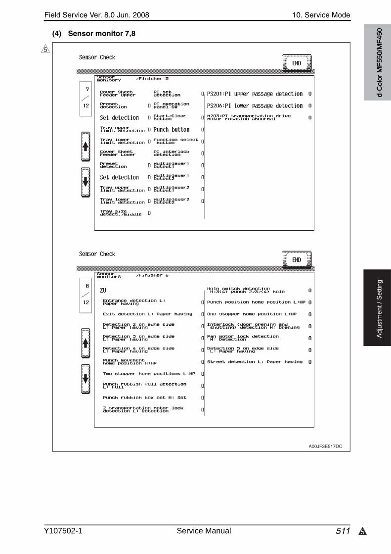
5
Field Service Ver. 8.0 Jun. 2008 10. Service Mode
511
Ad
justm
en
t /
Se
ttin
g
(4) Sensor monitor 7,8
5
A00JF3E517DC
d-C
olor
MF5
50/M
F450
Y107502-1 Service Manual

10. Service Mode Field Service Ver. 8.0 Jun. 2008
512
Ad
justm
en
t /
Se
ttin
g
(5) Sensor monitor 9,10
A00KF3E511DA
d-C
olor
MF5
50/M
F450
Service Manual Y107502-1

3
Field Service Ver. 8.0 Jun. 2008 10. Service Mode
513
Ad
justm
en
t /
Se
ttin
g
(6) Sensor monitor 11,12
3
A00KF3E512DB
d-C
olor
MF5
50/M
F450
Y107502-1 Service Manual
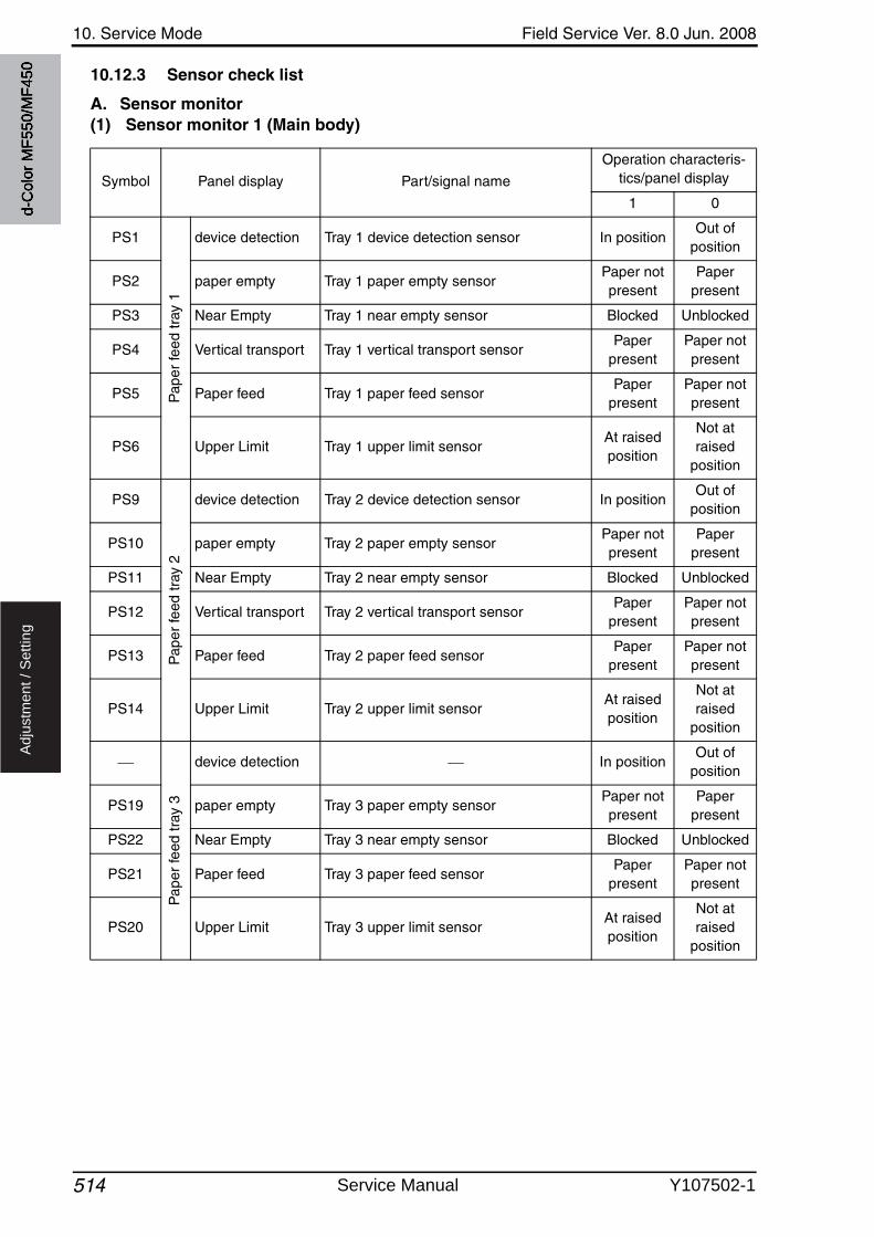
10. Service Mode Field Service Ver. 8.0 Jun. 2008
514
Ad
justm
en
t /
Se
ttin
g
10.12.3 Sensor check list
A. Sensor monitor(1) Sensor monitor 1 (Main body)
Symbol Panel display Part/signal name
Operation characteris-tics/panel display
1 0
PS1
Pap
er fe
ed tr
ay 1
device detection Tray 1 device detection sensor In positionOut of
position
PS2 paper empty Tray 1 paper empty sensorPaper not present
Paper present
PS3 Near Empty Tray 1 near empty sensor Blocked Unblocked
PS4 Vertical transport Tray 1 vertical transport sensorPaper
presentPaper not present
PS5 Paper feed Tray 1 paper feed sensorPaper
presentPaper not present
PS6 Upper Limit Tray 1 upper limit sensor At raised position
Not at raised
position
PS9
Pap
er fe
ed tr
ay 2
device detection Tray 2 device detection sensor In positionOut of
position
PS10 paper empty Tray 2 paper empty sensorPaper not present
Paper present
PS11 Near Empty Tray 2 near empty sensor Blocked Unblocked
PS12 Vertical transport Tray 2 vertical transport sensorPaper
presentPaper not present
PS13 Paper feed Tray 2 paper feed sensorPaper
presentPaper not present
PS14 Upper Limit Tray 2 upper limit sensorAt raised position
Not at raised
position
Pap
er fe
ed tr
ay 3
device detection In positionOut of
position
PS19 paper empty Tray 3 paper empty sensorPaper not present
Paper present
PS22 Near Empty Tray 3 near empty sensor Blocked Unblocked
PS21 Paper feed Tray 3 paper feed sensorPaper
presentPaper not present
PS20 Upper Limit Tray 3 upper limit sensor At raised position
Not at raised
position
d-C
olor
MF5
50/M
F450
Service Manual Y107502-1
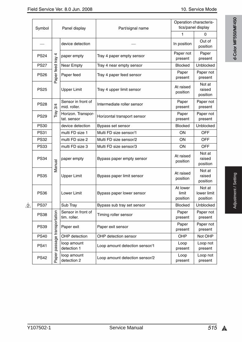
Field Service Ver. 8.0 Jun. 2008 10. Service Mode
515 2
Ad
justm
en
t /
Se
ttin
g
Pap
er fe
ed tr
ay 4
device detection In positionOut of
position
PS24 paper empty Tray 4 paper empty sensorPaper not present
Paper present
PS27 Near Empty Tray 4 near empty sensor Blocked Unblocked
PS26 Paper feed Tray 4 paper feed sensorPaper
presentPaper not present
PS25 Upper Limit Tray 4 upper limit sensor At raised position
Not at raised
position
PS28
Tray
3/4
Sensor in front of mid. roller.
Intermediate roller sensorPaper
presentPaper not present
PS29Horizon. Transpor-tat. sensor
Horizontal transport sensorPaper
presentPaper not present
PS30
Man
ual
device detection Bypass set sensor Blocked Unblocked
PS31 multi FD size 1 Multi FD size sensor/1 ON OFF
PS32 multi FD size 2 Multi FD size sensor/2 ON OFF
PS33 multi FD size 3 Multi FD size sensor/3 ON OFF
PS34 paper empty Bypass paper empty sensorAt raised position
Not at raised
position
PS35 Upper Limit Bypass paper limit sensorAt raised position
Not at raised
position
PS36 Lower Limit Bypass paper lower sensorAt lower
limit position
Not at lower limit position
PS37 Sub Tray Bypass sub tray set sensor Blocked Unblocked
PS38
Pap
er p
assa
ge tr
ansp
orta
tion Sensor in front of
tim. roller.Timing roller sensor
Paper present
Paper not present
PS39 Paper exit Paper exit sensorPaper
presentPaper not present
PS40 OHP detection OHP detection sensor OHP Not OHP
PS41loop amount detection 1
Loop amount detection sensor/1Loop
presentLoop not present
PS42loop amount detection 2
Loop amount detection sensor/2Loop
presentLoop not present
Symbol Panel display Part/signal name
Operation characteris-tics/panel display
1 0
2
d-C
olor
MF5
50/M
F450
Y107502-1 Service Manual
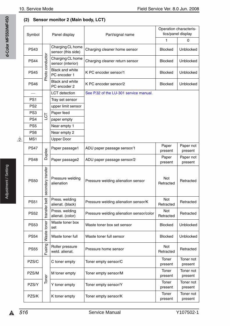
10. Service Mode Field Service Ver. 8.0 Jun. 2008
5162
Ad
justm
en
t /
Se
ttin
g
(2) Sensor monitor 2 (Main body, LCT)
Symbol Panel display Part/signal name
Operation characteris-tics/panel display
1 0
PS43P
hoto
con
duct
orCharging CL home sensor (this side)
Charging cleaner home sensor Blocked Unblocked
PS44Charging CL home sensor (interior)
Charging cleaner return sensor Blocked Unblocked
PS45Black and white PC encoder 1
K PC encoder sensor/1 Blocked Unblocked
PS46Black and white PC encoder 2
K PC encoder sensor/2 Blocked Unblocked
LCT
LCT detection See P.32 of the LU-301 service manual.
PS1 Tray set sensor
PS2 upper limit sensor
PS3 Paper feed
PS4 paper empty
PS5 Near empty 1
PS6 Near empty 2
MS1 Upper Door
PS47
Dup
lex Paper passage1 ADU paper passage sensor/1
Paper present
Paper not present
PS48 Paper passage2 ADU paper passage sensor/2Paper
presentPaper not present
PS50
seco
ndar
y tra
nsfe
r
Pressure welding alienation
Pressure welding alienation sensorNot
RetractedRetracted
PS51
tran
sfer
bel
t Press. welding alienat. (black)
Pressure welding alienation sensor/KNot
RetractedRetracted
PS52Press. welding alienat. (color)
Pressure welding alienation sensor/colorNot
RetractedRetracted
PS53
Was
te to
ner Waste toner box
setWaste toner box set sensor Blocked Unblocked
PS54 Waste toner full Waste toner full sensor Blocked Unblocked
PS55
Fus
ing Roller pressure
weld. alienat.Pressure home sensor
NotRetracted
Retracted
PZS/C
Tone
r
C toner empty Toner empty sensor/CToner
presentToner not present
PZS/M M toner empty Toner empty sensor/MToner
presentToner not present
PZS/Y Y toner empty Toner empty sensor/YToner
presentToner not present
PZS/K K toner empty Toner empty sensor/KToner
presentToner not present
2
d-C
olor
MF5
50/M
F450
Service Manual Y107502-1
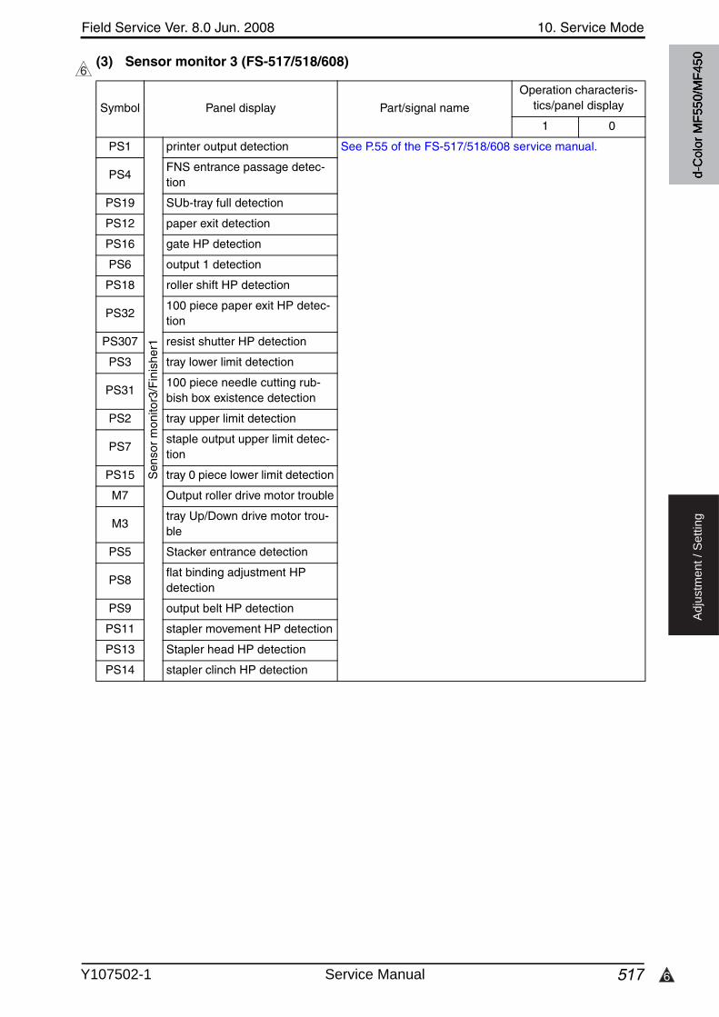
6
Field Service Ver. 8.0 Jun. 2008 10. Service Mode
517
Ad
justm
en
t /
Se
ttin
g
(3) Sensor monitor 3 (FS-517/518/608)6
Symbol Panel display Part/signal name
Operation characteris-tics/panel display
1 0
PS1S
enso
r m
onito
r3/F
inis
her1
printer output detection See P.55 of the FS-517/518/608 service manual.
PS4FNS entrance passage detec-tion
PS19 SUb-tray full detection
PS12 paper exit detection
PS16 gate HP detection
PS6 output 1 detection
PS18 roller shift HP detection
PS32100 piece paper exit HP detec-tion
PS307 resist shutter HP detection
PS3 tray lower limit detection
PS31100 piece needle cutting rub-bish box existence detection
PS2 tray upper limit detection
PS7staple output upper limit detec-tion
PS15 tray 0 piece lower limit detection
M7 Output roller drive motor trouble
M3tray Up/Down drive motor trou-ble
PS5 Stacker entrance detection
PS8flat binding adjustment HP detection
PS9 output belt HP detection
PS11 stapler movement HP detection
PS13 Stapler head HP detection
PS14 stapler clinch HP detection
d-C
olor
MF5
50/M
F450
Y107502-1 Service Manual
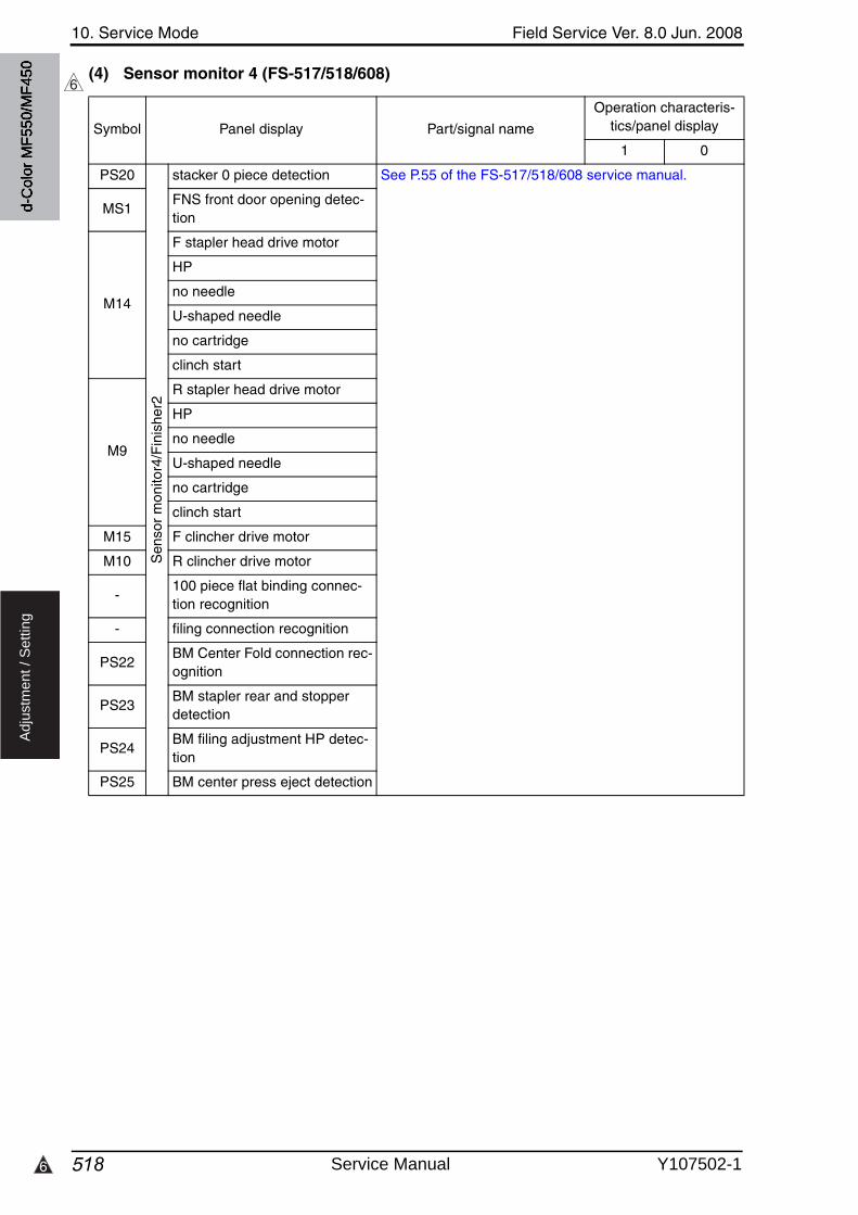
10. Service Mode Field Service Ver. 8.0 Jun. 2008
5186
Ad
justm
en
t /
Se
ttin
g
(4) Sensor monitor 4 (FS-517/518/608)6
Symbol Panel display Part/signal name
Operation characteris-tics/panel display
1 0
PS20S
enso
r m
onito
r4/F
inis
her2
stacker 0 piece detection See P.55 of the FS-517/518/608 service manual.
MS1FNS front door opening detec-tion
M14
F stapler head drive motor
HP
no needle
U-shaped needle
no cartridge
clinch start
M9
R stapler head drive motor
HP
no needle
U-shaped needle
no cartridge
clinch start
M15 F clincher drive motor
M10 R clincher drive motor
-100 piece flat binding connec-tion recognition
- filing connection recognition
PS22BM Center Fold connection rec-ognition
PS23BM stapler rear and stopper detection
PS24BM filing adjustment HP detec-tion
PS25 BM center press eject detection
d-C
olor
MF5
50/M
F450
Service Manual Y107502-1
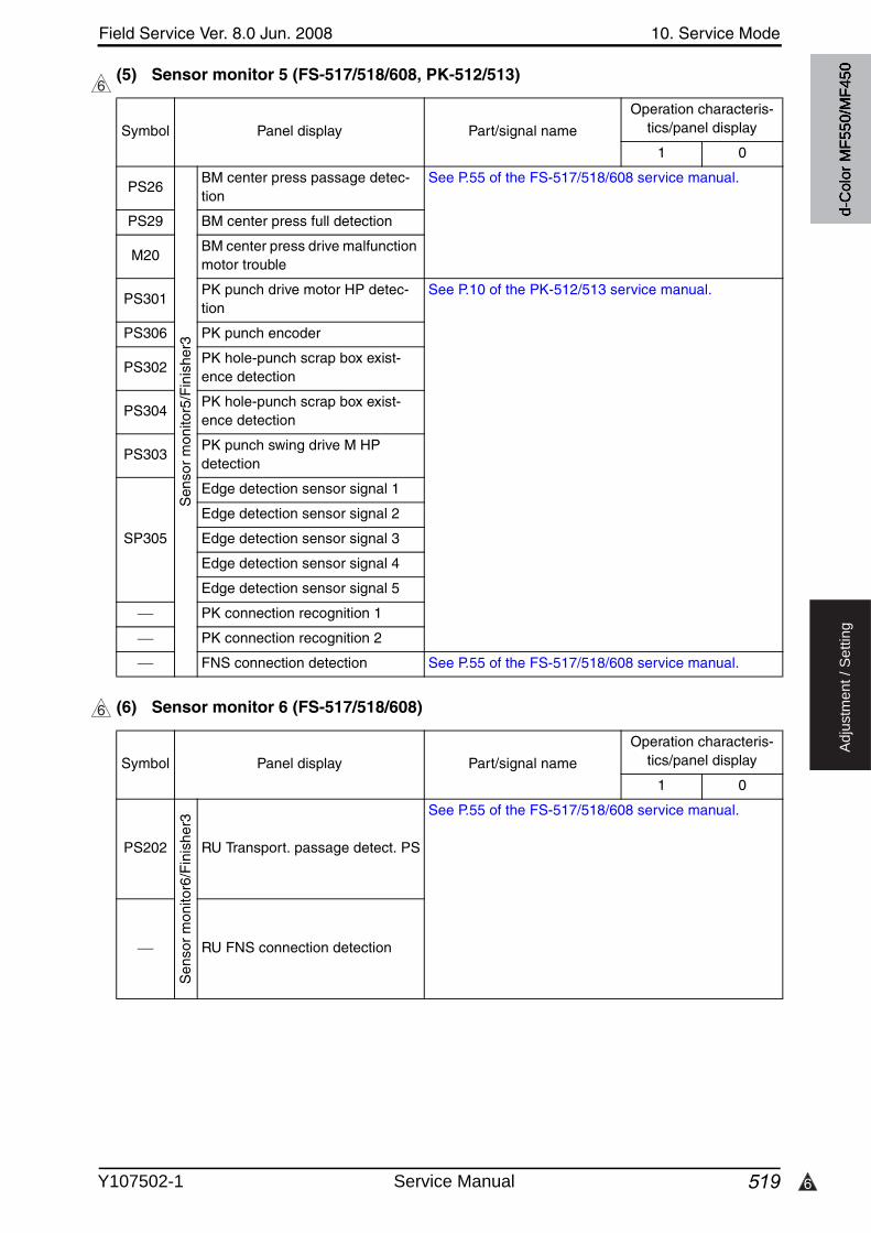
6
Field Service Ver. 8.0 Jun. 2008 10. Service Mode
519
Ad
justm
en
t /
Se
ttin
g
(5) Sensor monitor 5 (FS-517/518/608, PK-512/513)
(6) Sensor monitor 6 (FS-517/518/608)
6
Symbol Panel display Part/signal name
Operation characteris-tics/panel display
1 0
PS26S
enso
r m
onito
r5/F
inis
her3
BM center press passage detec-tion
See P.55 of the FS-517/518/608 service manual.
PS29 BM center press full detection
M20BM center press drive malfunction motor trouble
PS301PK punch drive motor HP detec-tion
See P.10 of the PK-512/513 service manual.
PS306 PK punch encoder
PS302PK hole-punch scrap box exist-ence detection
PS304PK hole-punch scrap box exist-ence detection
PS303PK punch swing drive M HP detection
SP305
Edge detection sensor signal 1
Edge detection sensor signal 2
Edge detection sensor signal 3
Edge detection sensor signal 4
Edge detection sensor signal 5
PK connection recognition 1
PK connection recognition 2
FNS connection detection See P.55 of the FS-517/518/608 service manual.
6
Symbol Panel display Part/signal name
Operation characteris-tics/panel display
1 0
PS202
Sen
sor
mon
itor6
/Fin
ishe
r3
RU Transport. passage detect. PS
See P.55 of the FS-517/518/608 service manual.
RU FNS connection detection
d-C
olor
MF5
50/M
F450
Y107502-1 Service Manual
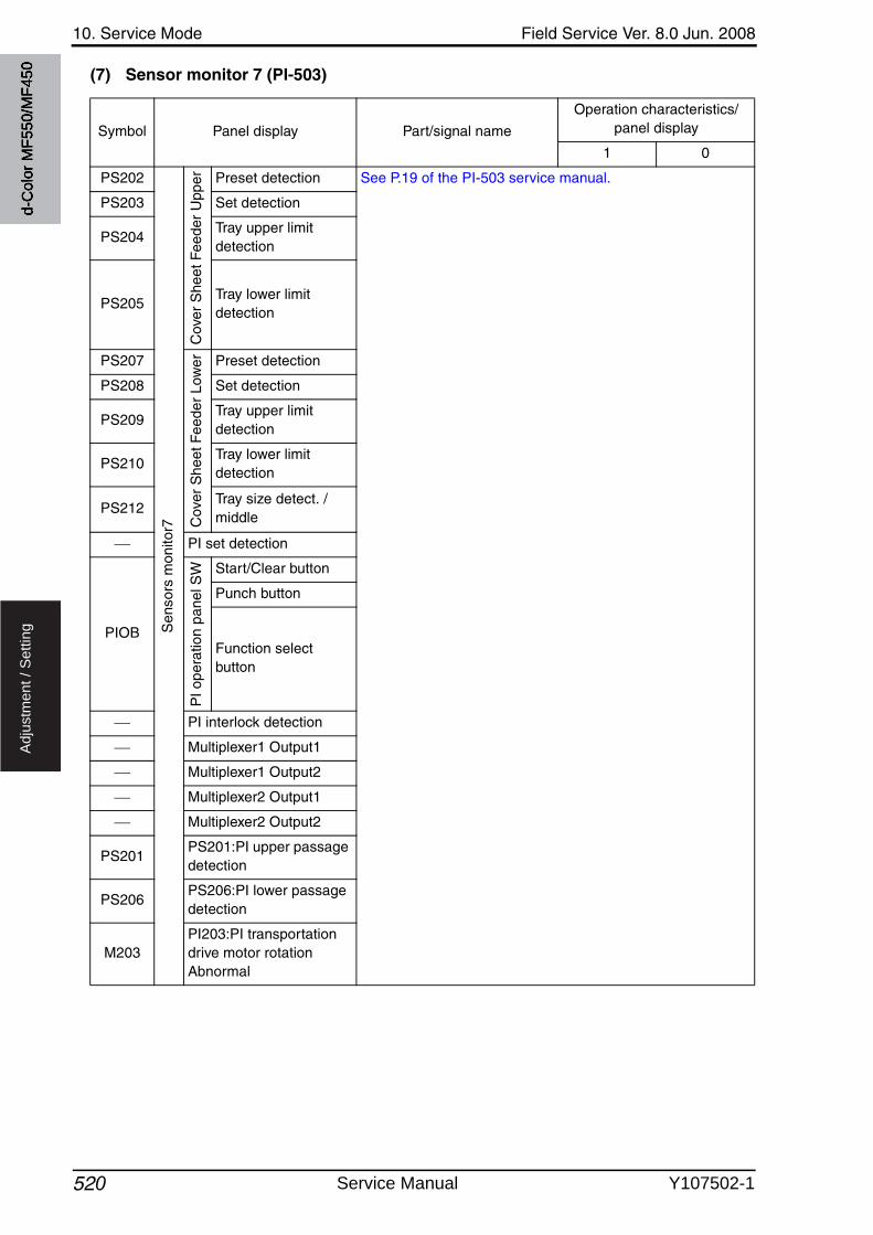
10. Service Mode Field Service Ver. 8.0 Jun. 2008
520
Ad
justm
en
t /
Se
ttin
g
(7) Sensor monitor 7 (PI-503)
Symbol Panel display Part/signal name
Operation characteristics/panel display
1 0
PS202S
enso
rs m
onito
r7
Cov
er S
heet
Fee
der
Upp
er Preset detection See P.19 of the PI-503 service manual.
PS203 Set detection
PS204Tray upper limit detection
PS205Tray lower limit detection
PS207
Cov
er S
heet
Fee
der
Low
er Preset detection
PS208 Set detection
PS209Tray upper limit detection
PS210Tray lower limit detection
PS212Tray size detect. /middle
PI set detection
PIOB
PI o
pera
tion
pane
l SW Start/Clear button
Punch button
Function select button
PI interlock detection
Multiplexer1 Output1
Multiplexer1 Output2
Multiplexer2 Output1
Multiplexer2 Output2
PS201PS201:PI upper passage detection
PS206PS206:PI lower passage detection
M203PI203:PI transportation drive motor rotation Abnormal
d-C
olor
MF5
50/M
F450
Service Manual Y107502-1
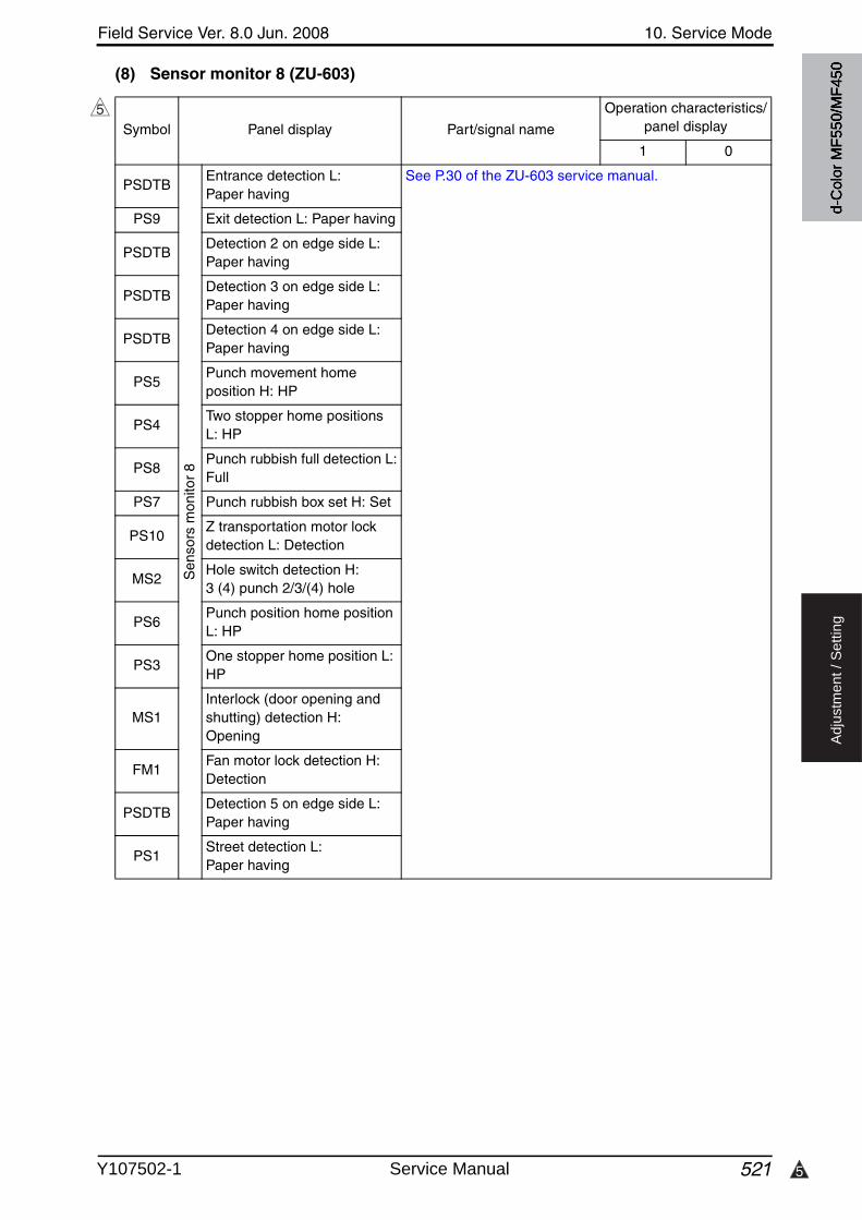
5
Field Service Ver. 8.0 Jun. 2008 10. Service Mode
521
Ad
justm
en
t /
Se
ttin
g
(8) Sensor monitor 8 (ZU-603)
5Symbol Panel display Part/signal name
Operation characteristics/panel display
1 0
PSDTBS
enso
rs m
onito
r 8
Entrance detection L: Paper having
See P.30 of the ZU-603 service manual.
PS9 Exit detection L: Paper having
PSDTBDetection 2 on edge side L:Paper having
PSDTBDetection 3 on edge side L: Paper having
PSDTBDetection 4 on edge side L: Paper having
PS5Punch movement home position H: HP
PS4Two stopper home positions L: HP
PS8Punch rubbish full detection L:Full
PS7 Punch rubbish box set H: Set
PS10Z transportation motor lock detection L: Detection
MS2Hole switch detection H: 3 (4) punch 2/3/(4) hole
PS6Punch position home position L: HP
PS3One stopper home position L: HP
MS1Interlock (door opening and shutting) detection H: Opening
FM1Fan motor lock detection H: Detection
PSDTBDetection 5 on edge side L: Paper having
PS1Street detection L: Paper having
d-C
olor
MF5
50/M
F450
Y107502-1 Service Manual
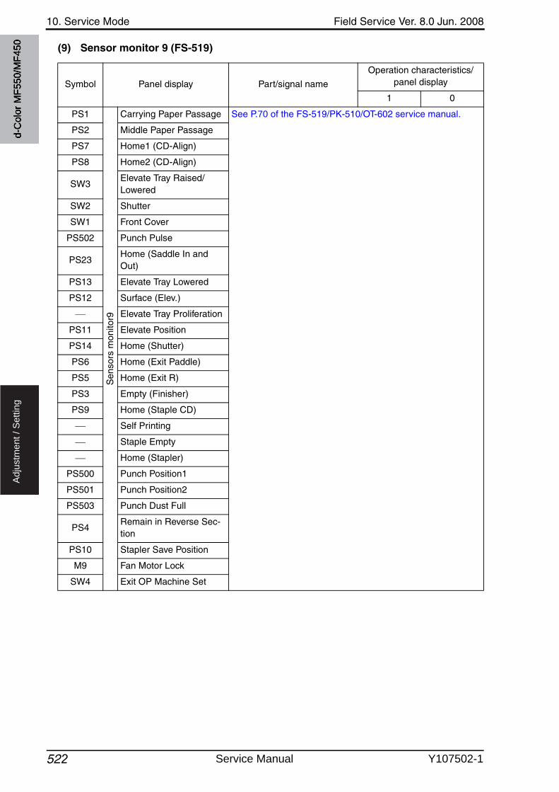
10. Service Mode Field Service Ver. 8.0 Jun. 2008
522
Ad
justm
en
t /
Se
ttin
g
(9) Sensor monitor 9 (FS-519)
Symbol Panel display Part/signal name
Operation characteristics/panel display
1 0
PS1S
enso
rs m
onito
r9Carrying Paper Passage See P.70 of the FS-519/PK-510/OT-602 service manual.
PS2 Middle Paper Passage
PS7 Home1 (CD-Align)
PS8 Home2 (CD-Align)
SW3Elevate Tray Raised/Lowered
SW2 Shutter
SW1 Front Cover
PS502 Punch Pulse
PS23Home (Saddle In and Out)
PS13 Elevate Tray Lowered
PS12 Surface (Elev.)
Elevate Tray Proliferation
PS11 Elevate Position
PS14 Home (Shutter)
PS6 Home (Exit Paddle)
PS5 Home (Exit R)
PS3 Empty (Finisher)
PS9 Home (Staple CD)
Self Printing
Staple Empty
Home (Stapler)
PS500 Punch Position1
PS501 Punch Position2
PS503 Punch Dust Full
PS4Remain in Reverse Sec-tion
PS10 Stapler Save Position
M9 Fan Motor Lock
SW4 Exit OP Machine Set
d-C
olor
MF5
50/M
F450
Service Manual Y107502-1
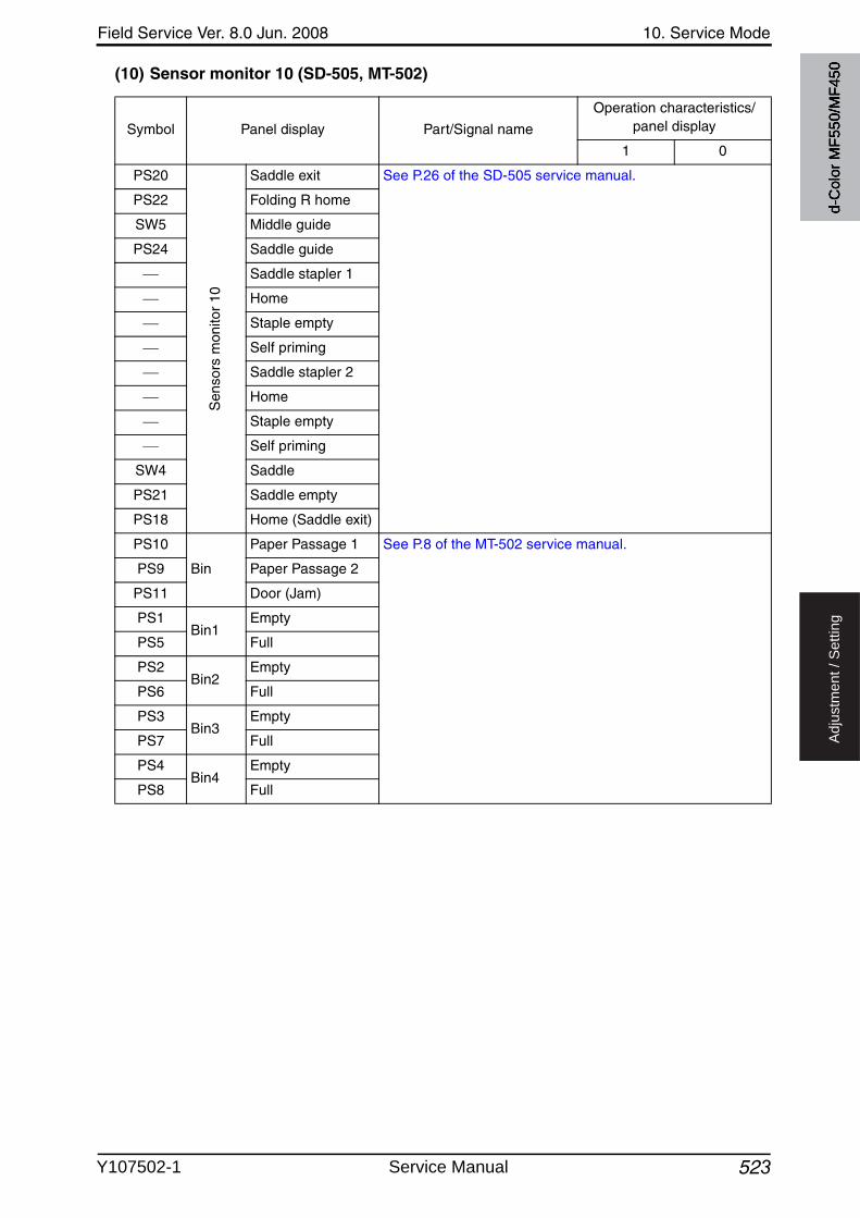
Field Service Ver. 8.0 Jun. 2008 10. Service Mode
523
Ad
justm
en
t /
Se
ttin
g
(10) Sensor monitor 10 (SD-505, MT-502)
Symbol Panel display Part/Signal name
Operation characteristics/panel display
1 0
PS20
Sen
sors
mon
itor
10
Saddle exit See P.26 of the SD-505 service manual.
PS22 Folding R home
SW5 Middle guide
PS24 Saddle guide
Saddle stapler 1
Home
Staple empty
Self priming
Saddle stapler 2
Home
Staple empty
Self priming
SW4 Saddle
PS21 Saddle empty
PS18 Home (Saddle exit)
PS10
Bin
Paper Passage 1 See P.8 of the MT-502 service manual.
PS9 Paper Passage 2
PS11 Door (Jam)
PS1Bin1
Empty
PS5 Full
PS2Bin2
Empty
PS6 Full
PS3Bin3
Empty
PS7 Full
PS4Bin4
Empty
PS8 Full
d-C
olor
MF5
50/M
F450
Y107502-1 Service Manual
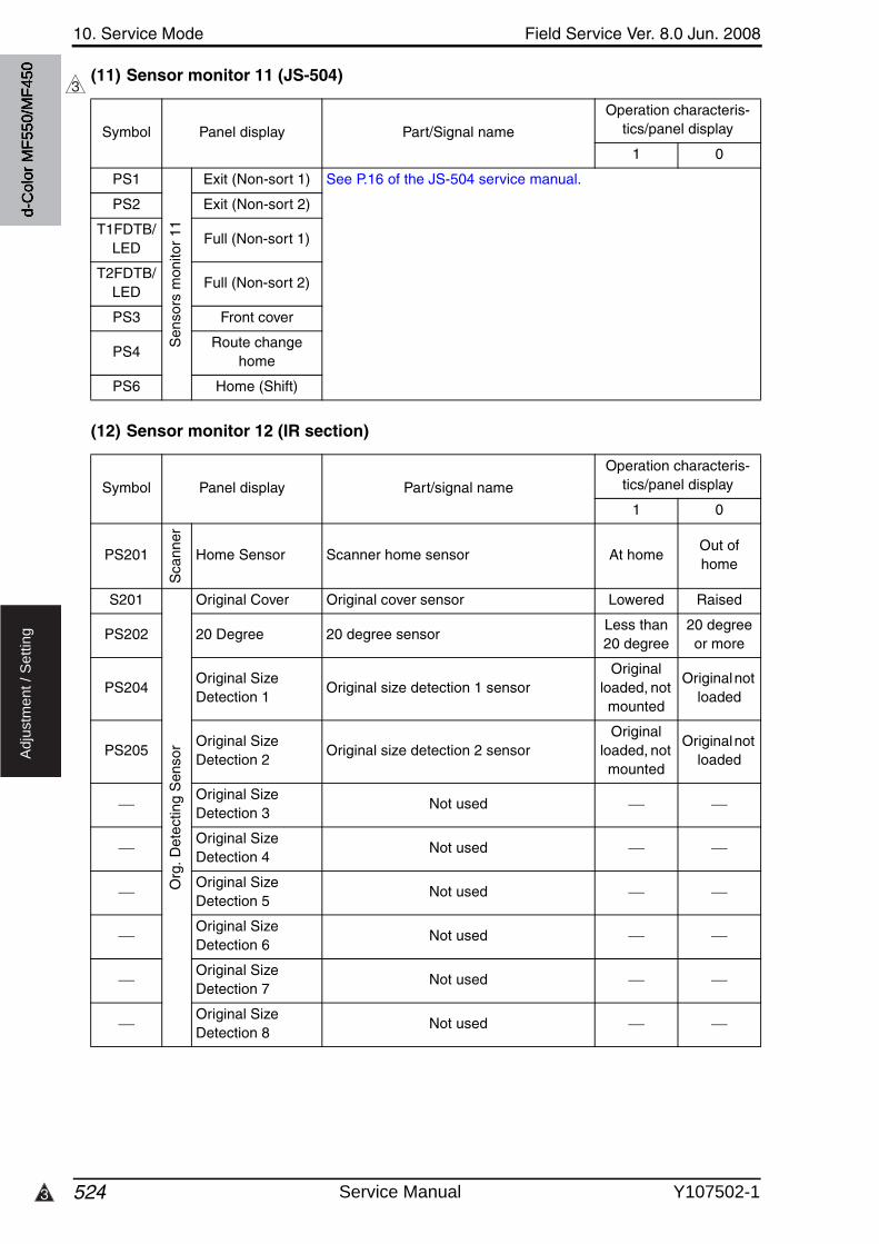
10. Service Mode Field Service Ver. 8.0 Jun. 2008
5243
Ad
justm
en
t /
Se
ttin
g
(11) Sensor monitor 11 (JS-504)
(12) Sensor monitor 12 (IR section)
3
Symbol Panel display Part/Signal name
Operation characteris-tics/panel display
1 0
PS1S
enso
rs m
onito
r 11
Exit (Non-sort 1) See P.16 of the JS-504 service manual.
PS2 Exit (Non-sort 2)
T1FDTB/LED
Full (Non-sort 1)
T2FDTB/LED
Full (Non-sort 2)
PS3 Front cover
PS4Route change
home
PS6 Home (Shift)
Symbol Panel display Part/signal name
Operation characteris-tics/panel display
1 0
PS201
Sca
nner
Home Sensor Scanner home sensor At homeOut of home
S201
Org
. Det
ectin
g S
enso
r
Original Cover Original cover sensor Lowered Raised
PS202 20 Degree 20 degree sensorLess than 20 degree
20 degree or more
PS204Original Size Detection 1
Original size detection 1 sensorOriginal
loaded, not mounted
Original not loaded
PS205Original Size Detection 2
Original size detection 2 sensorOriginal
loaded, not mounted
Original not loaded
Original Size Detection 3
Not used
Original Size Detection 4
Not used
Original Size Detection 5
Not used
Original Size Detection 6
Not used
Original Size Detection 7
Not used
Original Size Detection 8
Not used
d-C
olor
MF5
50/M
F450
Service Manual Y107502-1
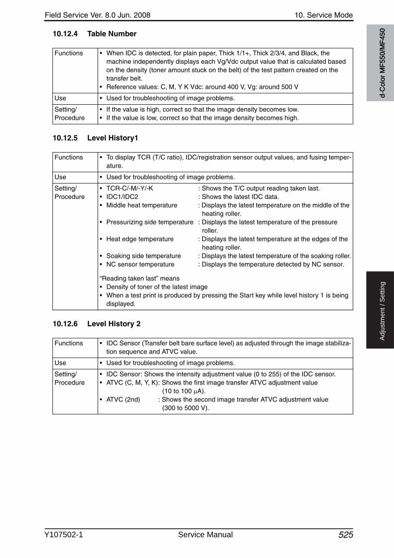
Field Service Ver. 8.0 Jun. 2008 10. Service Mode
525
Ad
justm
en
t /
Se
ttin
g
10.12.4 Table Number
10.12.5 Level History1
10.12.6 Level History 2
Functions • When IDC is detected, for plain paper, Thick 1/1+, Thick 2/3/4, and Black, the machine independently displays each Vg/Vdc output value that is calculated based on the density (toner amount stuck on the belt) of the test pattern created on the transfer belt.
• Reference values: C, M, Y K Vdc: around 400 V, Vg: around 500 V
Use • Used for troubleshooting of image problems.
Setting/Procedure
• If the value is high, correct so that the image density becomes low.• If the value is low, correct so that the image density becomes high.
Functions • To display TCR (T/C ratio), IDC/registration sensor output values, and fusing temper-ature.
Use • Used for troubleshooting of image problems.
Setting/Procedure
• TCR-C/-M/-Y/-K : Shows the T/C output reading taken last.• IDC1/IDC2 : Shows the latest IDC data.• Middle heat temperature : Displays the latest temperature on the middle of the
heating roller.• Pressurizing side temperature : Displays the latest temperature of the pressure
roller.• Heat edge temperature : Displays the latest temperature at the edges of the
heating roller.• Soaking side temperature : Displays the latest temperature of the soaking roller.• NC sensor temperature : Displays the temperature detected by NC sensor.
“Reading taken last” means• Density of toner of the latest image• When a test print is produced by pressing the Start key while level history 1 is being
displayed.
Functions • IDC Sensor (Transfer belt bare surface level) as adjusted through the image stabiliza-tion sequence and ATVC value.
Use • Used for troubleshooting of image problems.
Setting/Procedure
• IDC Sensor: Shows the intensity adjustment value (0 to 255) of the IDC sensor.• ATVC (C, M, Y, K): Shows the first image transfer ATVC adjustment value
(10 to 100 A).• ATVC (2nd) : Shows the second image transfer ATVC adjustment value
(300 to 5000 V).
d-C
olor
MF5
50/M
F450
Y107502-1 Service Manual
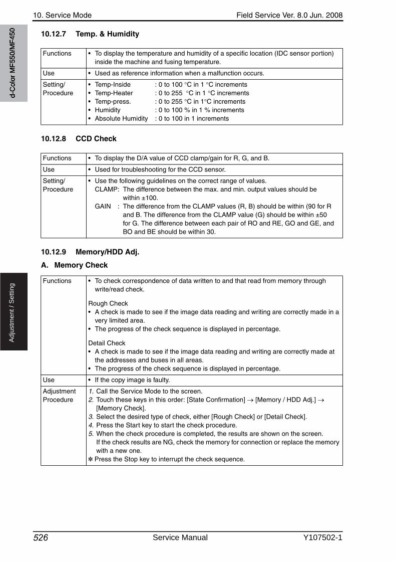
10. Service Mode Field Service Ver. 8.0 Jun. 2008
526
Ad
justm
en
t /
Se
ttin
g
10.12.7 Temp. & Humidity
10.12.8 CCD Check
10.12.9 Memory/HDD Adj.
A. Memory Check
Functions • To display the temperature and humidity of a specific location (IDC sensor portion) inside the machine and fusing temperature.
Use • Used as reference information when a malfunction occurs.
Setting/Procedure
• Temp-Inside : 0 to 100 C in 1 C increments• Temp-Heater : 0 to 255 C in 1 C increments• Temp-press. : 0 to 255 C in 1 C increments• Humidity : 0 to 100 % in 1 % increments• Absolute Humidity : 0 to 100 in 1 increments
Functions • To display the D/A value of CCD clamp/gain for R, G, and B.
Use • Used for troubleshooting for the CCD sensor.
Setting/Procedure
• Use the following guidelines on the correct range of values.CLAMP: The difference between the max. and min. output values should be
within ±100.GAIN : The difference from the CLAMP values (R, B) should be within (90 for R
and B. The difference from the CLAMP value (G) should be within ±50 for G. The difference between each pair of RO and RE, GO and GE, and BO and BE should be within 30.
Functions • To check correspondence of data written to and that read from memory throughwrite/read check.
Rough Check• A check is made to see if the image data reading and writing are correctly made in a
very limited area.• The progress of the check sequence is displayed in percentage.
Detail Check• A check is made to see if the image data reading and writing are correctly made at
the addresses and buses in all areas.• The progress of the check sequence is displayed in percentage.
Use • If the copy image is faulty.
Adjustment Procedure
1. Call the Service Mode to the screen.2. Touch these keys in this order: [State Confirmation] [Memory / HDD Adj.]
[Memory Check].3. Select the desired type of check, either [Rough Check] or [Detail Check].4. Press the Start key to start the check procedure.5. When the check procedure is completed, the results are shown on the screen.
If the check results are NG, check the memory for connection or replace the memory with a new one.
✽ Press the Stop key to interrupt the check sequence.
d-C
olor
MF5
50/M
F450
Service Manual Y107502-1
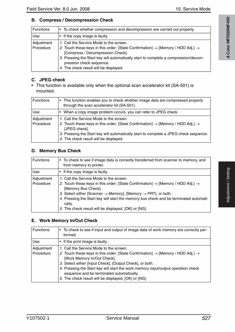
Field Service Ver. 8.0 Jun. 2008 10. Service Mode
527
Ad
justm
en
t /
Se
ttin
g
B. Compress / Decompression Check
C. JPEG check• This function is available only when the optional scan accelerator kit (SA-501) is
mounted.
D. Memory Bus Check
E. Work Memory In/Out Check
Functions • To check whether compression and decompression are carried out properly.
Use • If the copy image is faulty.
Adjustment Procedure
1. Call the Service Mode to the screen.2. Touch these keys in this order: [State Confirmation] [Memory / HDD Adj.]
[Compress / Decompression Check].3. Pressing the Start key will automatically start to complete a compression/decom-
pression check sequence.4. The check result will be displayed.
Functions • This function enables you to check whether image data are compressed properly through the scan accelerator kit (SA-501).
Use • When a copy image problem occurs, you can refer to JPEG check.
Adjustment Procedure
1. Call the Service Mode to the screen.2. Touch these keys in this order: [State Confirmation] [Memory / HDD Adj.]
[JPEG check].3. Pressing the Start key will automatically start to complete a JPEG check sequence.4. The check result will be displayed.
Functions • To check to see if image data is correctly transferred from scanner to memory, and from memory to printer.
Use • If the copy image is faulty.
Adjustment Procedure
1. Call the Service Mode to the screen.2. Touch these keys in this order: [State Confirmation] [Memory / HDD Adj.]
[Memory Bus Check].3. Select either [Scanner Memory], [Memory PRT], or both.4. Pressing the Start key will start the memory bus check and be terminated automati-
cally.5. The check result will be displayed, [OK] or [NG].
Functions • To check to see if input and output of image data of work memory are correctly per-formed.
Use • If the print image is faulty.
Adjustment Procedure
1. Call the Service Mode to the screen.2. Touch these keys in this order: [State Confirmation] [Memory / HDD Adj.]
[Work Memory In/Out Check].3. Select either [Input Check], [Output Check], or both.4. Pressing the Start key will start the work memory input/output operation check
sequence and be terminated automatically.5. The check result will be displayed, [OK] or [NG].
d-C
olor
MF5
50/M
F450
Y107502-1 Service Manual
10. Service Mode Field Service Ver. 8.0 Jun. 2008
5287
Ad
justm
en
t /
Se
ttin
g
F. HDD Version Upgrade (LK)• This is displayed only when the function enhanced version 3 or later firmware is installed.
G. Down Ver.• This is displayed only when the function enhanced version 4 or later firmware is installed.
H. Down Version• This is displayed only when the function enhanced version 2 or the function enhanced
version 3 firmware is installed.
I. Up Ver.• This is displayed only when the function enhanced version 2 or the function enhanced
version 3 firmware is installed.
Functions • To maintain the compatibility of management information data and documents stored in HDD after the firmware upgrade.
Use • This must be performed after upgrading the firmware to the function enhanced ver-sion 3.
Adjustment Procedure
1. Call the Service Mode to the screen.2. Touch [State Confirmation] [Memory/HDD Adj.] [HDD Version Upgrade (LK)].3. Touch Start key to initiate upgrading the current HDD version.4. When the upgrade is completed, the result is displayed on the screen.
NOTE• Make sure to turn OFF the main power switch when firmware upgrade is com-
pleted, and turn it ON again more than 10 seconds after.
7
Functions • In the process of firmware downgrade from the function enhanced version 4 firmware to the function enhanced version 3, use this function before rewriting the firmware.Use
Adjustment Procedure
• For the details about how to use this function, see “Firmware upgrade.”See P.63
Functions • To convert the mode information for responding to Scan To WebDAV and Scan To USB to a form compatible with the older firmware version.
Use • In the process of firmware downgrade from the function enhanced version 2 firm-ware, use this function before rewriting the firmware.
Adjustment Procedure
• For the details about how to use this function, see “Firmware upgrade.”See P.63
Functions • To expand the mode information for responding to Scan To WebDAV and Scan To USB.
Use • In the process of firmware upgrade to the function enhanced version 2 firmware, usethis function after rewriting the firmware.
Adjustment Procedure
• For the details about how to use this function, See “Firmware upgrade.”See P.63
d-C
olor
MF5
50/M
F450
Service Manual Y107502-1
Field Service Ver. 8.0 Jun. 2008 10. Service Mode
529
Ad
justm
en
t /
Se
ttin
g
J. Conversion Up• For d-Color MF550/MF450, this is displayed only when the function enhanced version 1
or later firmware is installed.
K. HDD R/W Check
L. HDD Format
Functions • To convert and update management information data so that they become compati-ble with the enhanced version of firmware.
Use • In the process of firmware upgrade to the function enhanced version 1 or 2 firmware, use this function after rewriting the firmware.
Adjustment Procedure
1. Call the Service Mode to the screen.2. Touch [State Confirmation] [Memory /HDD Adj.] [Conversion Up].3. Check to see that the Start key is lit in blue. Touch the Start key to initiate Conversion
Up.4. When Conversion Up is completed, the result is displayed on the screen.
NOTE• Make sure to turn off the main power switch when Conversion Up is complete,
and turn it on again more than 10 seconds after.
Functions • To check to see if the hard disk is connected properly, and if read/write operation of the hard disk is correctly performed.
Use • When the hard disk is mounted.
Adjustment Procedure
1. Call the Service Mode to the screen.2. Touch these keys in this order: [State Confirmation] [Memory / HDD Adj.] [HDD
R/W Check].3. Pressing the Start key will start the hard disk R/W check sequence and be termi-
nated automatically.4. The check result will be displayed, [OK] or [NG].
Functions • To format the hard disk.• The function proceeds in the order of physical format to logical format.• If the hard disk is yet to be formatted, the malfunction code “C-D010” will appear.
Ignore this code and continue with the formatting procedure.
Use • When the hard disk is mounted.• When the hard disk is to be initialized. (Physical format to logical format)
Adjustment Procedure
1. Call the Service Mode to the screen.2. Touch these keys in this order: [State Confirmation] [Memory / HDD Adj.] [HDD
Format].
(1) Physical Format 1. Touch [Physical Format].2. Press the Start key to start the formatting sequence.3. The sequence will be automatically terminated as it is completed.4. Turn off the main power switch and turn it on again more than 10 seconds after.
(2) Logical Format (only when initial is set up)1. Touch [Logical Format].2. Press the Start key to start the formatting sequence.3. The sequence will be automatically terminated as it is completed.4. Turn off the main power switch and turn it on again more than 10 seconds after.✽ Formatting the hard disk will erase all data contained in it.
d-C
olor
MF5
50/M
F450
Y107502-1 Service Manual
10. Service Mode Field Service Ver. 8.0 Jun. 2008
5302
Ad
justm
en
t /
Se
ttin
g
M. Conversion Down• For d-Color MF550/MF450, this is displayed only when the function enhanced version 1
or later firmware is installed.
N. XPS Enable Format• For d-Color MF550/MF450, this is displayed only when the function enhanced version 1
or later firmware is installed.
O. XPS Disable Format• For d-Color MF550/MF450, this is displayed only when the function enhanced version 1
or later firmware is installed.
2
Functions • To convert and update management information data so that they become compati-ble with the earlier version of firmware.
Use • In the process of firmware downgrade from the function enhanced version 1 or 2 firm-ware, use this function before rewriting the firmware.
Adjustment Procedure
1. Call the Service Mode to the screen.2. Touch [State Confirmation] [Memory /HDD Adj.] [Conversion Down].3. Check to see that the Start key is lit in blue. Touch the Start key to initiate Conversion
down.4. When Conversion down is completed, the result is displayed on the screen.
NOTE• Make sure to turn off the main power switch when Conversion Down is com-
plete, and turn it on again more than 10 seconds after.
2
Functions • To perform a logical format of HDD and let HDD support the printing of XPS files.
Use • After upgrading the firmware to the function enhanced version 1 or 2 firmware, usethis function if there is a need of printing XPS files.
Adjustment Procedure
1. Call the Service Mode to the screen.2. Touch [State Confirmation] [Memory /HDD Adj.] [XPS Enable Format].3. Check to see that the Start key is lit in blue. Touch the Start key to start formatting.4. When formatting is completed, the result is displayed on the screen.
NOTE• Make sure to turn off the main power switch when XPS Enable Format is com-
plete, and turn it on again more than 10 seconds after.• When XPS Enable Format is performed, HDD is logical formatted. Font data,
macro data, and others that have been installed by users disappear.• When XPS Enable Format is not performed, print jobs of XPS file format are
cancelled.
2
Functions • To perform a logical format of HDD and stop supporting XPS file format.
Use • In the process of firmware downgrade from the function enhanced version 1 or 2 firm-ware, use this function before rewriting the firmware.
Adjustment Procedure
1. Call the Service Mode to the screen.2. Touch [State Confirmation] [Memory /HDD Adj.] [XPS Disable Format].3. Check to see that the Start key is lit in blue. Touch the Start key to start formatting.4. When formatting is completed, the result is displayed on the screen.
NOTE• Make sure to turn off the main power switch when XPS Disable Format is com-
plete, and turn it on again more than 10 seconds after.• When XPS Disable Format is performed, HDD is logical formatted. Font data,
macro data and others that have been installed by users disappear.
d-C
olor
MF5
50/M
F450
Service Manual Y107502-1

Field Service Ver. 8.0 Jun. 2008 10. Service Mode
531
Ad
justm
en
t /
Se
ttin
g
10.12.10 Memory/HDD State
10.12.11 Color Regist
10.12.12 IU Lot No.
10.12.13 Adjustment Data List
Functions • To display the condition and amount of the memory and hard disk.• To display the mounting condition of the optional encryption board (security kit SC-
503).
Use • Use to check the condition and amount of the memory and hard disk.• Use to setup the optional security kit SC-503.
Setting/Procedure
• When the encryption board is mounted, the machine automatically recognizes it and displays [Set].
Functions • To check each of C, M, and Y for color shift amount.• The data is updated after a color shift correction has been made or color shift adjust-
ment has been completed.
Use • Use for check when color shift is evident.
Setting/Procedure
• For each of C, M, and Y, the color shift amount (in X and Y directions) at two locations (one at the front and the other in the rear) and the difference in color shift amount between the front and rear (X and Y directions) are displayed.
• Display unit: dots
Functions • To display the 10-digit lot number for each of Cyan, Magenta, Yellow, and Black IUs.• The lot number data is stored in EEPROM of each IU.
Use • Use for checking the IU Lot No.
Setting/Procedure
• The IU lot number is displayed even with the front door opened; however, the display is blank, since the machine is unable to read the lot number when the main powerswitch is turned ON with the front door open. Nonetheless, the lot number will be dis-played when the front door is closed. (The engine obtains the IU lot number information when the front door is closed.)
Functions • To display the adjustment and setting value set in the main body.
Use • Use to check the adjustment and setting value set in the main body.
d-C
olor
MF5
50/M
F450
Y107502-1 Service Manual
10. Service Mode Field Service Ver. 8.0 Jun. 2008
532
Ad
justm
en
t /
Se
ttin
g
10.13 Test Mode
• To check the image on the printer side by letting the machine produce various types of test pattern. It also tests the printing operation in running mode, as well as the fax trans-mission.
• The machine searches through the paper sources in the order of tray 2, tray 3, tray 4, and tray 1 for paper of the maximum size for printing.
10.13.1 Procedure for test pattern output
1. Touch [Test Mode] to display the test mode menu.2. Touch the desired test pattern key.3. Set up the desired functions and press the Start key.
10.13.2 Gradation Pattern
Functions • To produce a gradation pattern.
Use • Used for checking gradation reproducibility.
Pattern
Setting/Procedure
• # of Print (“1” to 999)• Select “SINGLE” (single copy) or MULTI (multi copy).• Select FEET or “HYPER”.• Select “Gradation” or Resolution if HYPER has been selected.• Select the color mode.
“Cyan”, Magenta, Yellow, Black (4PC), CMYK, 8Color, 4Color, Black (1PC)
• Black (4PC): Uses four colors.• Black (1PC): Uses one color of black.
4036fs3042c0
SINGLEHYPERGradationCyan
d-C
olor
MF5
50/M
F450
Service Manual Y107502-1
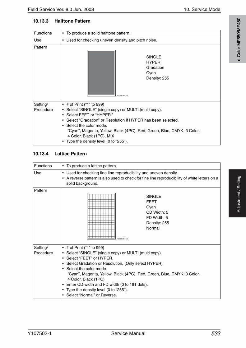
Field Service Ver. 8.0 Jun. 2008 10. Service Mode
533
Ad
justm
en
t /
Se
ttin
g
10.13.3 Halftone Pattern
10.13.4 Lattice Pattern
Functions • To produce a solid halftone pattern.
Use • Used for checking uneven density and pitch noise.
Pattern
Setting/Procedure
• # of Print (“1” to 999)• Select “SINGLE” (single copy) or MULTI (multi copy).• Select FEET or “HYPER.”• Select “Gradation” or Resolution if HYPER has been selected.• Select the color mode.
“Cyan”, Magenta, Yellow, Black (4PC), Red, Green, Blue, CMYK, 3 Color, 4 Color, Black (1PC), MIX
• Type the density level (0 to “255”).
4036fs3043c0
SINGLEHYPERGradationCyanDensity: 255
Functions • To produce a lattice pattern.
Use • Used for checking fine line reproducibility and uneven density.• A reverse pattern is also used to check for fine line reproducibility of white letters on a
solid background.
Pattern
Setting/Procedure
• # of Print (“1” to 999)• Select “SINGLE” (single copy) or MULTI (multi copy).• Select “FEET” or HYPER.• Select Gradation or Resolution. (Only select HYPER)• Select the color mode.
“Cyan”, Magenta, Yellow, Black (4PC), Red, Green, Blue, CMYK, 3 Color, 4 Color, Black (1PC)
• Enter CD width and FD width (0 to 191 dots).• Type the density level (0 to “255”).• Select “Normal” or Reverse.
4036fs3044c0
SINGLEFEETCyanCD Width: 5FD Width: 5Density: 255Normal
d-C
olor
MF5
50/M
F450
Y107502-1 Service Manual
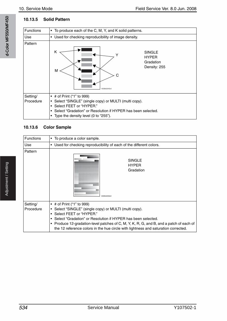
10. Service Mode Field Service Ver. 8.0 Jun. 2008
534
Ad
justm
en
t /
Se
ttin
g
10.13.5 Solid Pattern
10.13.6 Color Sample
Functions • To produce each of the C, M, Y, and K solid patterns.
Use • Used for checking reproducibility of image density.
Pattern
Setting/Procedure
• # of Print (“1” to 999)• Select “SINGLE” (single copy) or MULTI (multi copy).• Select FEET or “HYPER.”• Select “Gradation” or Resolution if HYPER has been selected.• Type the density level (0 to “255”).
4036fs3045c0
SINGLEHYPERGradationDensity: 255
Y
C
K
M
Functions • To produce a color sample.
Use • Used for checking reproducibility of each of the different colors.
Pattern
Setting/Procedure
• # of Print (“1” to 999)• Select “SINGLE” (single copy) or MULTI (multi copy).• Select FEET or “HYPER.”• Select “Gradation” or Resolution if HYPER has been selected.• Produce 12-gradation-level patches of C, M, Y, K, R, G, and B, and a patch of each of
the 12 reference colors in the hue circle with lightness and saturation corrected.
4036fs3046c0
SINGLEHYPERGradation
d-C
olor
MF5
50/M
F450
Service Manual Y107502-1
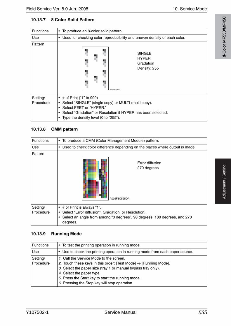
Field Service Ver. 8.0 Jun. 2008 10. Service Mode
535
Ad
justm
en
t /
Se
ttin
g
10.13.7 8 Color Solid Pattern
10.13.8 CMM pattern
10.13.9 Running Mode
Functions • To produce an 8-color solid pattern.
Use • Used for checking color reproducibility and uneven density of each color.
Pattern
Setting/Procedure
• # of Print (“1” to 999)• Select “SINGLE” (single copy) or MULTI (multi copy).• Select FEET or “HYPER.”• Select “Gradation” or Resolution if HYPER has been selected.• Type the density level (0 to “255”).
SINGLEHYPERGradationDensity: 255
4036fs3047c0
Functions • To produce a CMM (Color Management Module) pattern.
Use • Used to check color difference depending on the places where output is made.
Pattern
Setting/Procedure
• # of Print is always “1”.• Select “Error diffusion”, Gradation, or Resolution.• Select an angle from among “0 degrees”, 90 degrees, 180 degrees, and 270
degrees.
Error diffusion270 degrees
A00JF3C525DA
Functions • To test the printing operation in running mode.
Use • Use to check the printing operation in running mode from each paper source.
Setting/Procedure
1. Call the Service Mode to the screen.2. Touch these keys in this order: [Test Mode] [Running Mode].3. Select the paper size (tray 1 or manual bypass tray only).4. Select the paper type.5. Press the Start key to start the running mode.6. Pressing the Stop key will stop operation.
d-C
olor
MF5
50/M
F450
Y107502-1 Service Manual
10. Service Mode Field Service Ver. 8.0 Jun. 2008
5366
Ad
justm
en
t /
Se
ttin
g
10.13.10 Fax Test
• For details, see FK-502 Service Manual.
10.14 ADF
See P.28 of the DF-611 service manual.
10.15 FAX
• For details, see FK-502 Service Manual.
10.16 Finisher
10.16.1 CB-FN adjustment
A. Fold&Staple Pos. AdjustmentSee P.30 of the SD-505 service manual.
B. Finisher CheckSee P.72 of the FS-519/PK-510/OT-602 service manual.
C. Punch Regist Loop SizeSee P.74 of the FS-519/PK-510/OT-602 service manual.
D. Punch Horizontal PositionSee P.75 of the FS-519/PK-510/OT-602 service manual.
10.16.2 FS-FN adjustment
A. Center Staple PositionSee P.58 of the FS-517/518/608 service manual.
B. Half-Fold PositionSee P.61 of the FS-517/518/608 service manual.
C. Punch Vertical PositionSee P.12 of the PK-512/513 service manual.
D. Punch Horizontal PositionSee P.13 of the PK-512/513 service manual.
E. Punch edge detectionSee P.13 of the PK-512/513 service manual.
F. Punch Unit Vertical Position Adj.See P.32 of the ZU-603 service manual.
G. Punch Unit Horizontal PositionSee P.33 of the ZU-603 service manual.
H. Punch unit edge detectionSee P.33 of the ZU-603 service manual.
6
6
d-C
olor
MF5
50/M
F450
Service Manual Y107502-1
6
Field Service Ver. 8.0 Jun. 2008 10. Service Mode
537
Ad
justm
en
t /
Se
ttin
g
I. Punch Resist Loop Size (Body)See P.14 of the PK-512/513 service manual.
J. Punch Resist Loop Size (PI)See P.21 of the PI-503 service manual.
K. 1st Z-Fold Position Adj.See P.34 of the ZU-603 service manual.
L. 2nd Z-Fold Position Adj.See P.34 of the ZU-603 service manual.
M. Tri-Fold PositionSee P.63 of the FS-517/518/608 service manual.
N. 2 Position Staple Dist.See P.66 of the FS-517/518/608 service manual.
O. Cover Sheet Tray Size DetectionSee P.21 of the PI-503 service manual.
P. Cover Sheet Feeder Adj.See P.22 of the PI-503 service manual.
Q. finisher checkSee P.68 of the FS-517/518/608 service manual.See P.35 of the ZU-603 service manual.
R. Load DataSee P.70 of the FS-517/518/608 service manual.
10.16.3 Staple option setting
See P.73 of the FS-517/518/608 service manual.See P.78 of the FS-519/PK-510/OT-602 service manual.
10.16.4 Punch Option setting
See P.14 of the PK-512/513 service manual.See P.76 of the FS-519/PK-510/OT-602 service manual.See P.36 of the ZU-603 service manual.
10.16.5 Fold power of pages restrict.
See P.74 of the FS-517/518/608 service manual.See P.37 of the ZU-603 service manual.
10.16.6 Job Separator
See P.17 of the JS-504 service manual.
6
6
6
6
6
6
d-C
olor
MF5
50/M
F450
Y107502-1 Service Manual
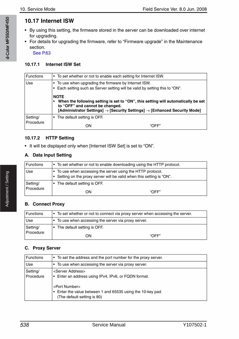
10. Service Mode Field Service Ver. 8.0 Jun. 2008
538
Ad
justm
en
t /
Se
ttin
g
10.17 Internet ISW
• By using this setting, the firmware stored in the server can be downloaded over internet for upgrading.
• For details for upgrading the firmware, refer to “Firmware upgrade” in the Maintenance section.
See P.63
10.17.1 Internet ISW Set
10.17.2 HTTP Setting
• It will be displayed only when [Internet ISW Set] is set to “ON”.
A. Data Input Setting
B. Connect Proxy
C. Proxy Server
Functions • To set whether or not to enable each setting for Internet ISW.
Use • To use when upgrading the firmware by Internet ISW.• Each setting such as Server setting will be valid by setting this to “ON”.
NOTE• When the following setting is set to “ON”, this setting will automatically be set
to “OFF” and cannot be changed. [Administrator Settings] [Security Settings] [Enhanced Security Mode]
Setting/Procedure
• The default setting is OFF.
ON “OFF”
Functions • To set whether or not to enable downloading using the HTTP protocol.
Use • To use when accessing the server using the HTTP protocol.• Setting on the proxy server will be valid when this setting is “ON”.
Setting/Procedure
• The default setting is OFF.
ON “OFF”
Functions • To set whether or not to connect via proxy server when accessing the server.
Use • To use when accessing the server via proxy server.
Setting/Procedure
• The default setting is OFF.
ON “OFF”
Functions • To set the address and the port number for the proxy server.
Use • To use when accessing the server via proxy server.
Setting/Procedure
<Server Address>• Enter an address using IPv4, IPv6, or FQDN format.
<Port Number>• Enter the value between 1 and 65535 using the 10-key pad.
(The default setting is 80)
d-C
olor
MF5
50/M
F450
Service Manual Y107502-1
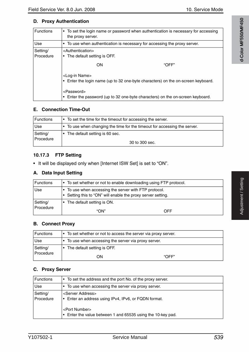
Field Service Ver. 8.0 Jun. 2008 10. Service Mode
539
Ad
justm
en
t /
Se
ttin
g
D. Proxy Authentication
E. Connection Time-Out
10.17.3 FTP Setting
• It will be displayed only when [Internet ISW Set] is set to “ON”.
A. Data Input Setting
B. Connect Proxy
C. Proxy Server
Functions • To set the login name or password when authentication is necessary for accessing the proxy server.
Use • To use when authentication is necessary for accessing the proxy server.
Setting/Procedure
<Authentication>• The default setting is OFF.
ON “OFF”
<Log-in Name>• Enter the login name (up to 32 one-byte characters) on the on-screen keyboard.
<Password>• Enter the password (up to 32 one-byte characters) on the on-screen keyboard.
Functions • To set the time for the timeout for accessing the server.
Use • To use when changing the time for the timeout for accessing the server.
Setting/Procedure
• The default setting is 60 sec.
30 to 300 sec.
Functions • To set whether or not to enable downloading using FTP protocol.
Use • To use when accessing the server with FTP protocol.• Setting this to “ON” will enable the proxy server setting.
Setting/Procedure
• The default setting is ON.
“ON” OFF
Functions • To set whether or not to access the server via proxy server.
Use • To use when accessing the server via proxy server.
Setting/Procedure
• The default setting is OFF.
ON “OFF”
Functions • To set the address and the port No. of the proxy server.
Use • To use when accessing the server via proxy server.
Setting/Procedure
<Server Address>• Enter an address using IPv4, IPv6, or FQDN format.
<Port Number>• Enter the value between 1 and 65535 using the 10-key pad.
d-C
olor
MF5
50/M
F450
Y107502-1 Service Manual
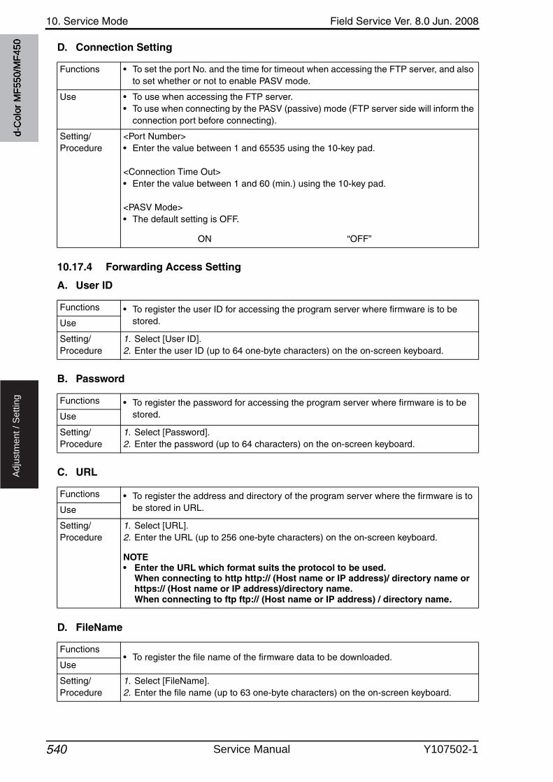
10. Service Mode Field Service Ver. 8.0 Jun. 2008
540
Ad
justm
en
t /
Se
ttin
g
D. Connection Setting
10.17.4 Forwarding Access Setting
A. User ID
B. Password
C. URL
D. FileName
Functions • To set the port No. and the time for timeout when accessing the FTP server, and also to set whether or not to enable PASV mode.
Use • To use when accessing the FTP server.• To use when connecting by the PASV (passive) mode (FTP server side will inform the
connection port before connecting).
Setting/Procedure
<Port Number>• Enter the value between 1 and 65535 using the 10-key pad.
<Connection Time Out>• Enter the value between 1 and 60 (min.) using the 10-key pad.
<PASV Mode>• The default setting is OFF.
ON “OFF”
Functions • To register the user ID for accessing the program server where firmware is to be stored.Use
Setting/Procedure
1. Select [User ID].2. Enter the user ID (up to 64 one-byte characters) on the on-screen keyboard.
Functions • To register the password for accessing the program server where firmware is to be stored.Use
Setting/Procedure
1. Select [Password].2. Enter the password (up to 64 characters) on the on-screen keyboard.
Functions • To register the address and directory of the program server where the firmware is to be stored in URL.Use
Setting/Procedure
1. Select [URL].2. Enter the URL (up to 256 one-byte characters) on the on-screen keyboard.
NOTE• Enter the URL which format suits the protocol to be used.
When connecting to http http:// (Host name or IP address)/ directory name or https:// (Host name or IP address)/directory name. When connecting to ftp ftp:// (Host name or IP address) / directory name.
Functions• To register the file name of the firmware data to be downloaded.
Use
Setting/Procedure
1. Select [FileName].2. Enter the file name (up to 63 one-byte characters) on the on-screen keyboard.
d-C
olor
MF5
50/M
F450
Service Manual Y107502-1
Field Service Ver. 8.0 Jun. 2008 10. Service Mode
541
Ad
justm
en
t /
Se
ttin
g
10.17.5 Download
Functions • Access the program server according to the Internet ISW setting, and download the firmware.
Use • To use when updating the firmware via network.
Setting/Procedure
1. Select [Download].2. Touch [ISW Start] to start downloading the firmware.3. The message to show the status will be displayed on the screen while connecting
and transferring data.
NOTE• When it failed to connect to the program server, or failed to download, the
error code and the message will be displayed. Check the cause of the error by the error code, and follow the message for resetting. Refer to “Error cord list” for the error codes.
See P.944. When the firmware is normally upgraded, the main body will automatically be
restarted to complete the Internet ISW.
d-C
olor
MF5
50/M
F450
Y107502-1 Service Manual
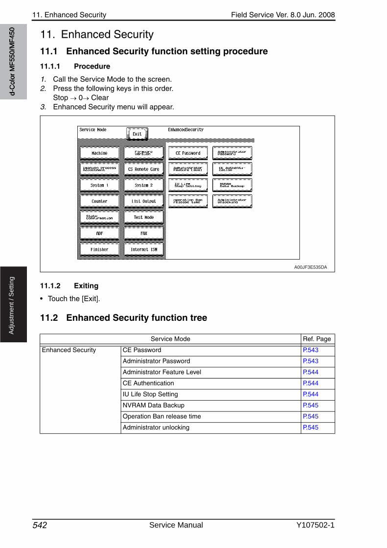
11. Enhanced Security Field Service Ver. 8.0 Jun. 2008
542
Ad
justm
en
t /
Se
ttin
g
11. Enhanced Security
11.1 Enhanced Security function setting procedure
11.1.1 Procedure
1. Call the Service Mode to the screen.2. Press the following keys in this order.
Stop 0 Clear3. Enhanced Security menu will appear.
11.1.2 Exiting
• Touch the [Exit].
11.2 Enhanced Security function tree
A00JF3E535DA
Service Mode Ref. Page
Enhanced Security CE Password P.543
Administrator Password P.543
Administrator Feature Level P.544
CE Authentication P.544
IU Life Stop Setting P.544
NVRAM Data Backup P.545
Operation Ban release time P.545
Administrator unlocking P.545
d-C
olor
MF5
50/M
F450
Service Manual Y107502-1
Field Service Ver. 8.0 Jun. 2008 11. Enhanced Security
543
Ad
justm
en
t /
Se
ttin
g
11.3 Settings in the Enhanced Security
11.3.1 CE Password
11.3.2 Administrator Password
Functions • To set and change the CE password.
Use • Use to change the CE password.
Setting/Procedure
• Enter the CE password (8 digits) on the on-screen keyboard.• The initial setting is “92729272.”
Current Password : Enter the currently using CE password.New Password : Enter the new CE password.Re-Input Password : Enter the new CE password again.
NOTE• When the following setting leads to the Password Rules [ON], the password
with the same letters as well as the password which is same as the previous one cannot be changed.[Administrator Settings] [Security Settings]
• NEVER forget the CE password. When forgetting the CE password, call responsible person of KMBT.
Functions • To set and change the administrator password.
Use • Use to change the administrator password.• Use this function when the administrator forget the administrator password because
a new password can be set without entering the current administrator password withthis.
Setting/Procedure
• Enter the administrator password (8 digits) on the on-screen keyboard.• The initial setting is “12345678.”
New Password : Enter the new administrator password.Re-Input Password : Enter the new administrator password again.
NOTE• When the following setting leads to the Password Rules [ON], the password
with the same letters, the password which is same as the previous one and the password of less than eight digits cannot be changed.[Administrator Settings] [Security Settings]
d-C
olor
MF5
50/M
F450
Y107502-1 Service Manual
11. Enhanced Security Field Service Ver. 8.0 Jun. 2008
544
Ad
justm
en
t /
Se
ttin
g
11.3.3 Administrator Feature Level
11.3.4 CE Authentication
• It will not be displayed when the following settings are set to “ON”. [Administrator Settings] [Security Setting] [Enhanced Security Mode] or [PasswordRules].
11.3.5 IU Life Stop Setting
Functions • To set which modes to be allowed for the administrator to use in Service Mode.
Use • Use when allowing the administrator to use some modes in Service Mode.• The modes allowed for the administrator to use in each setting are as follows.
Setting/Procedure
• The default setting is Prohibit.
Level1 Level2 “Prohibit”
Administrator settings function Level 1 Level 2
[System Setting] [Expert Setting]
Printer Adjustment
Erase Leading Edge
Scanner Adjustment
Leading Edge Adjustment
Centering
Horizontal Adjustment
Vertical Adjustment
ADF Adjust-ment
Centering
Original Stop Position
Centering Auto Adjustment
Auto Adj. of Stop Position
[Standard Size Setting]
Original Glass Original Size Detect
Foolscap Size Setting
Functions • To determine whether or not to authenticate CE password as entering Service Mode.
Use • Use when authenticating CE password as entering Service Mode.
NOTE• For setting the following setting to “ON”, set the CE Authentication to “ON”
and change the initial CE password beforehand. [Administrator Settings] [Security Setting] [Enhanced Security Mode] or [Password Rules]
Setting/Procedure
• The default setting is OFF.
ON “OFF”
Functions • To select whether or not to stop a print cycle when the IU reaches its service life.
Use • Use to select not to stop the print cycle when the IU reaches its service life.
Setting/Procedure
The default setting is Stop.
“Stop” No Stop
d-C
olor
MF5
50/M
F450
Service Manual Y107502-1
Field Service Ver. 8.0 Jun. 2008 11. Enhanced Security
545
Ad
justm
en
t /
Se
ttin
g
11.3.6 NVRAM Data Backup
11.3.7 Operation Ban release time
11.3.8 Administrator unlocking
Functions • To backup NVRAM data in the main body to the flash memory.
Use • To backup current data in order to prevent data in NVRAM from being erased unex-pectedly.
• To backup data manually. It usually makes backup every hour automatically.• Backup data can be restored by following the specified procedure when the trouble
(CD3XX) occurred.Refer to “Troubleshooting” for details on restoration procedure.See P.677
Setting/Procedure
1. Touch [NVRAM Data Backup].2. Touch [Start] to start making a backup.3. Check the message [Backup is completed.], and turn main power switch OFF. Wait
for ten seconds or more and turn main power switch back ON.
Functions • To set the time that elapses before the machine releases an access lock that is acti-vated after the CE password authentication.
Use • To set the period of time that elapses before the machine releases the access lock, which aims to prevent the unintentional release of the access lock.
• After the CE password authentication, if the access lock is activated, the lock release timer starts to operate by input the Stop 0 9 3 1 7 in [Meter Count] [Check Details] [Coverage Rate] after the main power switch is turned OFF and On. When the timer reaches the time specified in this setting, the access lock is released.
Setting/Procedure
• The default setting is 1 (minutes).
1 to 60 (minutes)
NOTE• When Enhanced Security Mode is set to ON in [Administrator Settings]
[Security Settings] [Enhanced Security Mode], the period of time that can be set in this setting is 5 minutes or more.
Functions • To release an access lock that is activated after an administrator password authenti-cation.
Use • To release the access lock with service authority when an administrator password authentication fails and the access lock is activated.
• When the main power switch is turned OFF and ON or the period of time set in the Release Time Settings elapses, the machine releases the access lock that is acti-vated after the administrator password authentication. In addition to these operations, this setting provides another way to release the access lock.
Setting/Procedure
1. Touch [Administrator unlocking].2. Touch [unlocking] to release an access lock.3. When [OK] is displayed, touch [OK].
d-C
olor
MF5
50/M
F450
Y107502-1 Service Manual
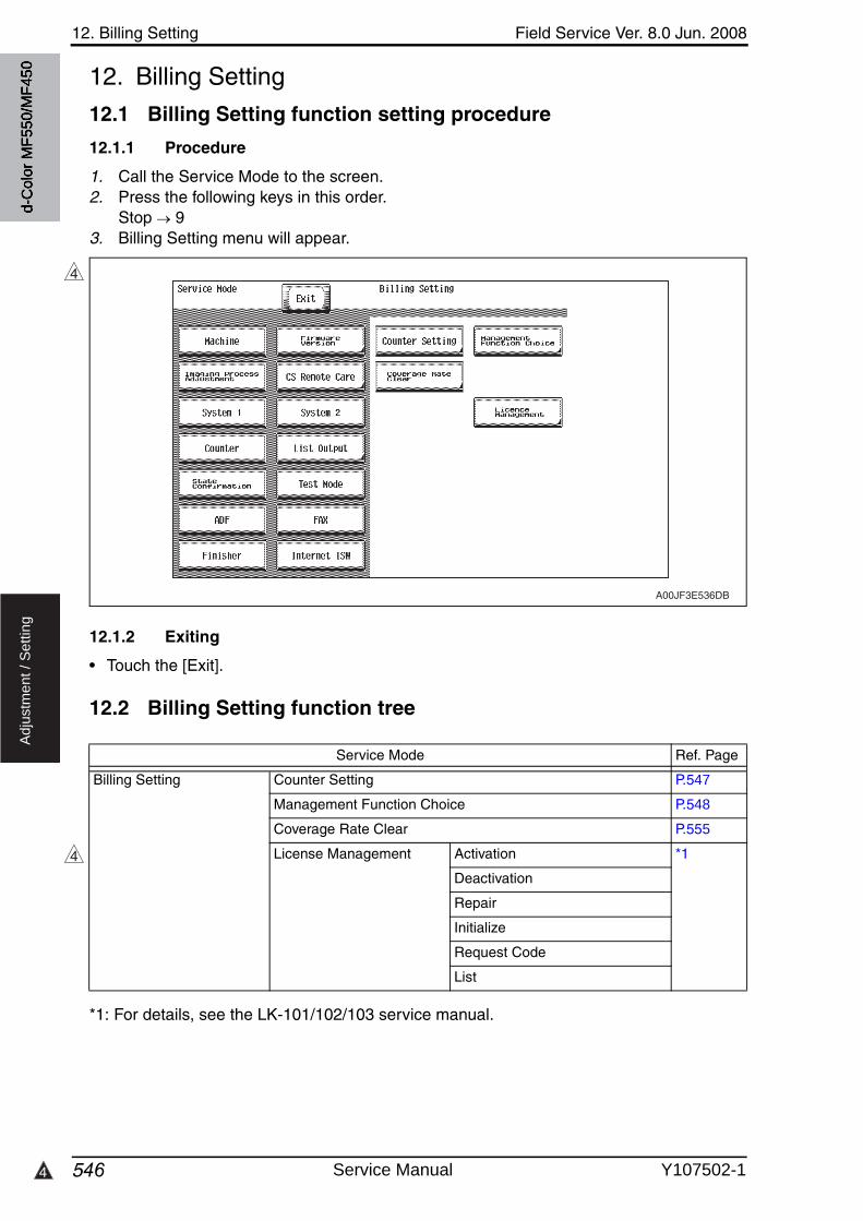
12. Billing Setting Field Service Ver. 8.0 Jun. 2008
5464
Ad
justm
en
t /
Se
ttin
g
12. Billing Setting
12.1 Billing Setting function setting procedure
12.1.1 Procedure
1. Call the Service Mode to the screen.2. Press the following keys in this order.
Stop 93. Billing Setting menu will appear.
12.1.2 Exiting
• Touch the [Exit].
12.2 Billing Setting function tree
*1: For details, see the LK-101/102/103 service manual.
4
A00JF3E536DB
Service Mode Ref. Page
Billing Setting Counter Setting P.547
Management Function Choice P.548
Coverage Rate Clear P.555
License Management Activation *1
Deactivation
Repair
Initialize
Request Code
List
4
d-C
olor
MF5
50/M
F450
Service Manual Y107502-1
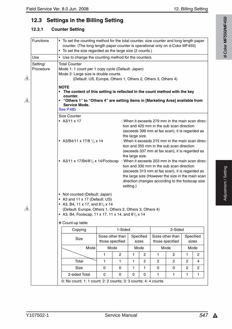
4
Field Service Ver. 8.0 Jun. 2008 12. Billing Setting
547
Ad
justm
en
t /
Se
ttin
g
12.3 Settings in the Billing Setting
12.3.1 Counter Setting
Functions • To set the counting method for the total counter, size counter and long length paper counter. (The long length paper counter is operational only on d-Color MF450)
• To set the size regarded as the large size (2 counts.)
Use • Use to change the counting method for the counters.
Setting/Procedure
Total CounterMode 1: 1 count per 1 copy cycle (Default: Japan)Mode 2: Large size is double counts
(Default: US, Europe, Others 1, Others 2, Others 3, Others 4)
NOTE• The content of this setting is reflected in the count method with the key
counter. • “Others 1” to “Others 4” are setting items in [Marketing Area] available from
Service Mode.See P.485
Size Counter• A3/11 x 17 : When it exceeds 279 mm in the main scan direc-
tion and 420 mm in the sub scan direction (exceeds 399 mm at fax scan), it is regarded as the large size.
• A3/B4/11 x 17/8 1/2 x 14 : When it exceeds 215 mm in the main scan direc-tion and 355 mm in the sub scan direction (exceeds 337 mm at fax scan), it is regarded as the large size.
• A3/11 x 17/B4/81/2 x 14/Foolscap : When it exceeds 203 mm in the main scan direc-tion and 330 mm in the sub scan direction (exceeds 313 mm at fax scan), it is regarded as the large size (However the size in the main scan direction changes according to the foolscap size setting.)
• Not counted (Default: Japan)• A3 and 11 x 17 (Default: US)• A3, B4, 11 x 17, and 81/2 x 14
(Default: Europe, Others 1, Others 2, Others 3, Others 4)• A3, B4, Foolscap, 11 x 17, 11 x 14, and 81/2 x 14
✽ Count-up table
4
4
4
0: No count; 1: 1 count; 2: 2 counts; 3: 3 counts; 4: 4 counts
Copying 1-Sided 2-Sided
SizeSizes other than those specified
Specified sizes
Sizes other than those specified
Specified sizes
Mode Mode Mode Mode Mode
1 2 1 2 1 2 1 2
Total 1 1 1 2 2 2 2 4
Size 0 0 1 1 0 0 2 2
2-sided Total 0 0 0 0 1 1 1 1
d-C
olor
MF5
50/M
F450
Y107502-1 Service Manual
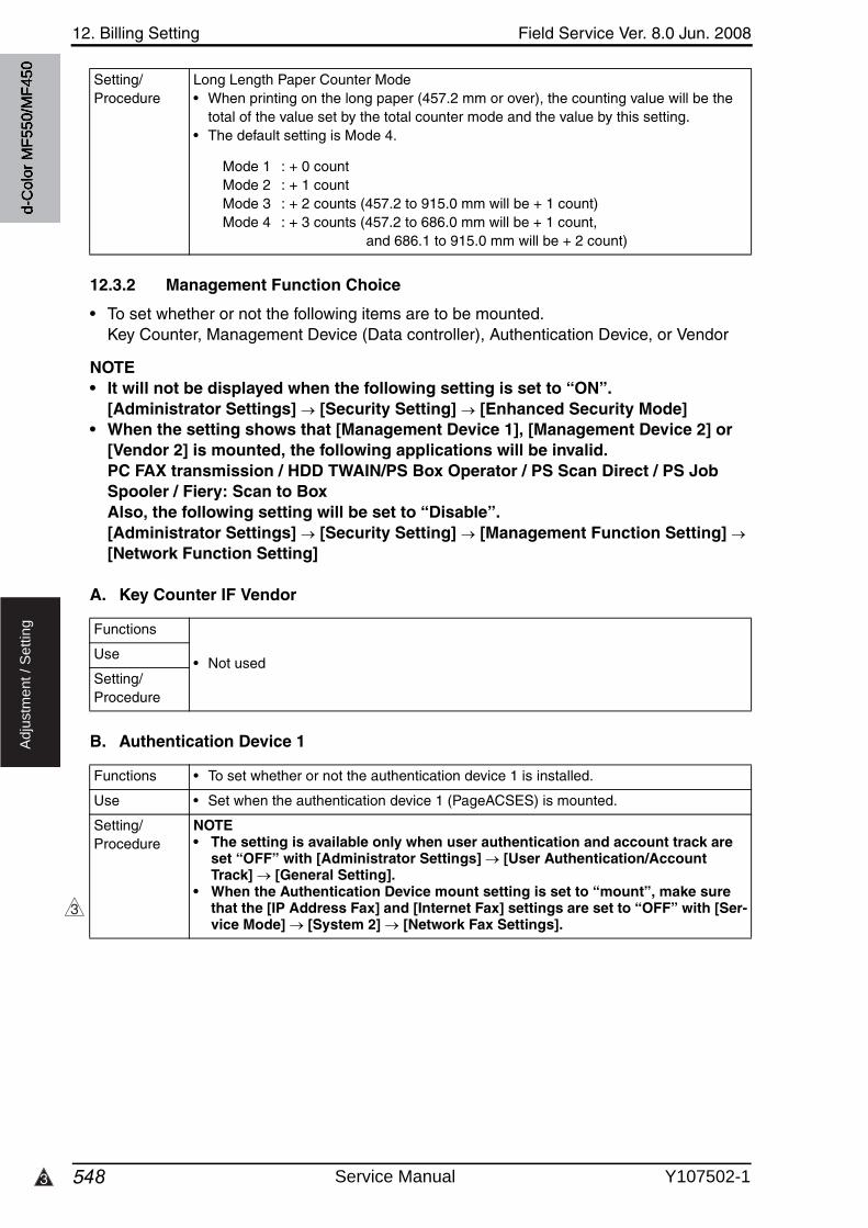
12. Billing Setting Field Service Ver. 8.0 Jun. 2008
5483
Ad
justm
en
t /
Se
ttin
g
12.3.2 Management Function Choice
• To set whether or not the following items are to be mounted.Key Counter, Management Device (Data controller), Authentication Device, or Vendor
NOTE• It will not be displayed when the following setting is set to “ON”.
[Administrator Settings] [Security Setting] [Enhanced Security Mode]• When the setting shows that [Management Device 1], [Management Device 2] or
[Vendor 2] is mounted, the following applications will be invalid. PC FAX transmission / HDD TWAIN/PS Box Operator / PS Scan Direct / PS Job Spooler / Fiery: Scan to Box Also, the following setting will be set to “Disable”. [Administrator Settings] [Security Setting] [Management Function Setting] [Network Function Setting]
A. Key Counter IF Vendor
B. Authentication Device 1
Setting/Procedure
Long Length Paper Counter Mode• When printing on the long paper (457.2 mm or over), the counting value will be the
total of the value set by the total counter mode and the value by this setting.• The default setting is Mode 4.
Mode 1 : + 0 countMode 2 : + 1 countMode 3 : + 2 counts (457.2 to 915.0 mm will be + 1 count)Mode 4 : + 3 counts (457.2 to 686.0 mm will be + 1 count,
and 686.1 to 915.0 mm will be + 2 count)
Functions
• Not usedUse
Setting/Procedure
Functions • To set whether or not the authentication device 1 is installed.
Use • Set when the authentication device 1 (PageACSES) is mounted.
Setting/Procedure
NOTE• The setting is available only when user authentication and account track are
set “OFF” with [Administrator Settings] [User Authentication/Account Track] [General Setting].
• When the Authentication Device mount setting is set to “mount”, make sure that the [IP Address Fax] and [Internet Fax] settings are set to “OFF” with [Ser-vice Mode] [System 2] [Network Fax Settings].
3
d-C
olor
MF5
50/M
F450
Service Manual Y107502-1
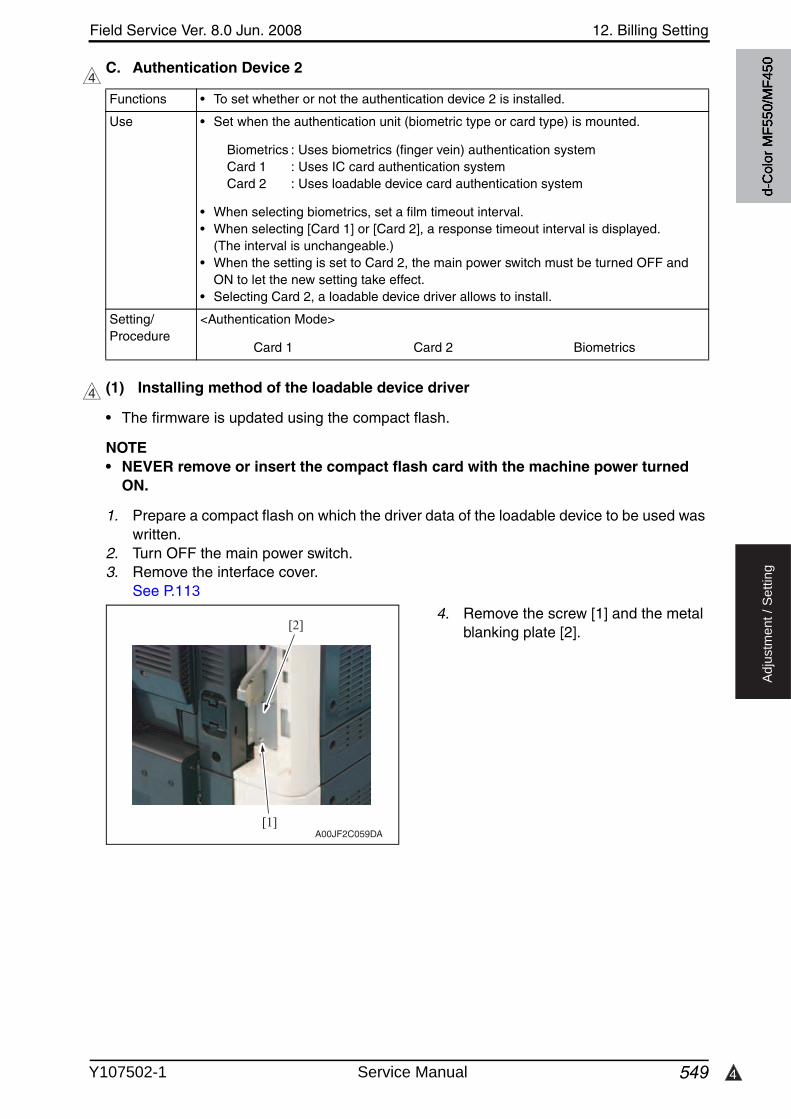
4
Field Service Ver. 8.0 Jun. 2008 12. Billing Setting
549
Ad
justm
en
t /
Se
ttin
g
C. Authentication Device 2
(1) Installing method of the loadable device driver
• The firmware is updated using the compact flash.
NOTE• NEVER remove or insert the compact flash card with the machine power turned
ON.
1. Prepare a compact flash on which the driver data of the loadable device to be used waswritten.
2. Turn OFF the main power switch.3. Remove the interface cover.
See P.113
4. Remove the screw [1] and the metal blanking plate [2].
4
Functions • To set whether or not the authentication device 2 is installed.
Use • Set when the authentication unit (biometric type or card type) is mounted.
Biometrics : Uses biometrics (finger vein) authentication system Card 1 : Uses IC card authentication systemCard 2 : Uses loadable device card authentication system
• When selecting biometrics, set a film timeout interval.• When selecting [Card 1] or [Card 2], a response timeout interval is displayed.
(The interval is unchangeable.)• When the setting is set to Card 2, the main power switch must be turned OFF and
ON to let the new setting take effect.• Selecting Card 2, a loadable device driver allows to install.
Setting/Procedure
<Authentication Mode>
Card 1 Card 2 Biometrics
4
[1]
[2]
A00JF2C059DA
d-C
olor
MF5
50/M
F450
Y107502-1 Service Manual
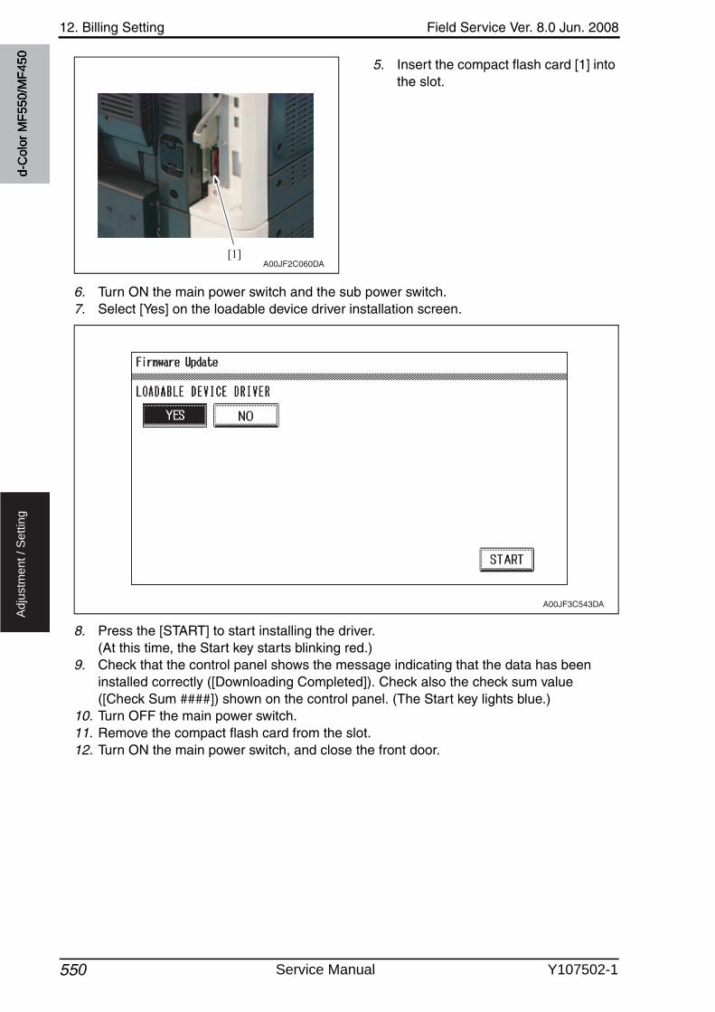
12. Billing Setting Field Service Ver. 8.0 Jun. 2008
550
Ad
justm
en
t /
Se
ttin
g
5. Insert the compact flash card [1] into the slot.
6. Turn ON the main power switch and the sub power switch.7. Select [Yes] on the loadable device driver installation screen.
8. Press the [START] to start installing the driver. (At this time, the Start key starts blinking red.)
9. Check that the control panel shows the message indicating that the data has been installed correctly ([Downloading Completed]). Check also the check sum value([Check Sum ####]) shown on the control panel. (The Start key lights blue.)
10. Turn OFF the main power switch.11. Remove the compact flash card from the slot.12. Turn ON the main power switch, and close the front door.
[1]A00JF2C060DA
A00JF3C543DA
d-C
olor
MF5
50/M
F450
Service Manual Y107502-1

Field Service Ver. 8.0 Jun. 2008 12. Billing Setting
551
Ad
justm
en
t /
Se
ttin
g
D. Key Counter Only
Functions • To set whether or not the key counter is installed.
Use • Set when the key counter is mounted.• Select [Color Mode] and [Message] when the key counter is mounted.
Setting/Procedure
✽ Color Mode• When [Mode 1] is set on [Total Counter Mode] after selecting [Billing Setting]
[Counter setting]. Mode 1: 1 count per 1 copy cycle Mode 2: 2 counts per 1 copy cycle Mode 3: 3 counts per 1 copy cycle Mode 4: 4 counts per 1 copy cycle Mode 5: 5 counts per 1 copy cycle
• When [Mode 2] is set on [Total Counter Mode] after selecting [Billing Setting] [Counter setting] and large size is selected on [Large Size Counter Mode]
Mode 1: 2 counts per 1 copy cycle Mode 2: 4 counts per 1 copy cycle Mode 3: 6 counts per 1 copy cycle Mode 4: 8 counts per 1 copy cycle Mode 5: 10 counts per 1 copy cycle
• When [Mode 2] is set on [Total Counter Mode] after selecting [Billing Setting] [Counter setting] and sizes other than large size are selected on [Large Size Counter Mode]
Mode 1: 1 count per 1 copy cycle Mode 2: 2 counts per 1 copy cycle Mode 3: 3 counts per 1 copy cycle Mode 4: 4 counts per 1 copy cycle Mode 5: 5 counts per 1 copy cycle
Setting/Procedure
✽ MessageSelect the message type when the administrative unit is mounted. Type 1: Message for key counter Type 2: Message for card scanning Type 3: Message for ID management Type 4: Message for remote SW
✽ Confirmation copy• Set whether to allow a confirmation copy when a key counter is installed.• The default setting is Ban.
License “Ban”
✽ The next job reservation• Set whether to allow the reservation of the next job when a key counter is installed.• The default setting is Ban.
License “Ban”
NOTE• The setting is available only when user authentication and account track are
set “OFF” with [Administrator Settings] [User Authentication/Account Track] [General Setting].
d-C
olor
MF5
50/M
F450
Y107502-1 Service Manual
12. Billing Setting Field Service Ver. 8.0 Jun. 2008
552
Ad
justm
en
t /
Se
ttin
g
E. Management Device 1
F. Management Device 2
G. Vendor 1
Functions • To set whether or not the management device 1 is installed.
Use • Set when the management device 1 is mounted.
Setting/Procedure
NOTE• The setting is available only when user authentication is set “OFF” and
account track is set “Off” or “Account Name + Password” with [Administrator Settings] [User Authentication/Account Track] [General Settings].
Functions • To set whether or not the management device 2 is installed.
Use • Set when the management device 2 is mounted.
Setting/Procedure
✽ Management Setting• Select the Management Setting Mode
Mode 1: Use contact type device (Logout with ID key is not allowed.)Mode 2: Use non-contact type device (Logout with ID key is allowed.)
NOTE• The setting is not available when either “External Server” of user authentica-
tion, “Password Only” of account track, “Do not synchronize” of user authenti-cation and account track or “Allow” of public user access has been set with [Administrator Settings] [User Authentication/Account Track] [General Settings].
Functions
• Not used.Use
Setting/Procedure
d-C
olor
MF5
50/M
F450
Service Manual Y107502-1
Field Service Ver. 8.0 Jun. 2008 12. Billing Setting
553
Ad
justm
en
t /
Se
ttin
g
H. Vendor 2
Functions • To set whether or not the vendor 2 is installed.
Use • Set when the vendor 2 is mounted.NOTE• When using the vendor along with the key counter, inserting the key counter
will set it to the “Key Counter Mode” and removing it will set it to the “Vendor Mode”.
Setting/Procedure
• Select color mode and message of key counter. (Only for key counter, the type of the color mode and message are same after mount-ing.)
✽ Confirmation copy• Set whether to allow a confirmation copy when a key counter is installed.• The default setting is Ban.
License “Ban”
✽ The next job reservation• Set whether to allow the reservation of the next job when a key counter is installed.• The default setting is Ban.
License “Ban”
• Select message of vendor.
✽ Message Type 1: Message for key counter Type 2: Message for card scanning Type 3: Message for ID management
NOTE• The setting is available only when user authentication and account track are
set “OFF” with [Administrator Settings] [User Authentication/Account Track] [General Setting].
d-C
olor
MF5
50/M
F450
Y107502-1 Service Manual

12. Billing Setting Field Service Ver. 8.0 Jun. 2008
5544
Ad
justm
en
t /
Se
ttin
g
NOTE• Performing the setup for each unit to be mounted will internally change the setting
values below. It needs resetting when cancelling the setting in order to set back to “not mounted” because the setting value will remain.
Setting Item Vendor 2Authentication
Device 1Authentication
Device 2Management
Device 1Management
Device 2
Util
ity
Default Copy Settings
Factory Default
Default Scan/Fax Settings
Factory Default
Copy Operating Screen
[Yes]
Fax Active Screen Rx Display [Yes]
Scan/Fax Settings Default Tab
Direct Input
Left Panel Display Default
[Job List]
Adm
inis
trat
or S
ettin
gs
Each Function Setting (When IC-409 is not mounted)
Copy, PC print, Send Data, and Print others willbe set to “ON”.
Copy, PC print, Send Data, and Print others will be set to “ON”.
Copy will be set to “ON”.PC print, Send Data, and Print others will be set to “OFF”.
Copy, PC print, Send Data, and Print others will be set to “ON”.
Each Function Setting (When IC-409 is mounted)
Send Data will be set to “ON”.
Administrator Security Level
Prohibit
Weekly Timer ON/OFF Setting
OFF
Reset SettingReset Data After Job will be set to “ON”.
Application Key Settings
When Key 1 is set to My Panel, reset the setting and assign Key 1 to [FAX/SCAN]. When Key 2 is set to My Panel, reset the setting and assign Key 2 to [Copy].
When Key 1 is set to My Panel, reset the setting and assign Key 1 to [FAX/SCAN]. When Key 2 is set to My Panel, reset the setting and assign Key 2 to [Copy].
Restrict Access to Job Settings
Changing Job Priority, Deleting Other User’s Jobs, Registering and Changing Addresses, Changing Zoom Ratio will be set to “Restrict”.
External Memory Function Settings
Save Document and Print Document will be set to “OFF”.
ID & Print SettingsID & Print will be set to “ON”.
System Settings
Forward TX Setting
OFF
OpenAPI Setting
Access Setting will be set to “Restrict” and Authentication will be changed to “OFF” setting.
Access Setting will be set to “Restrict”.
4
4
4
d-C
olor
MF5
50/M
F450
Service Manual Y107502-1
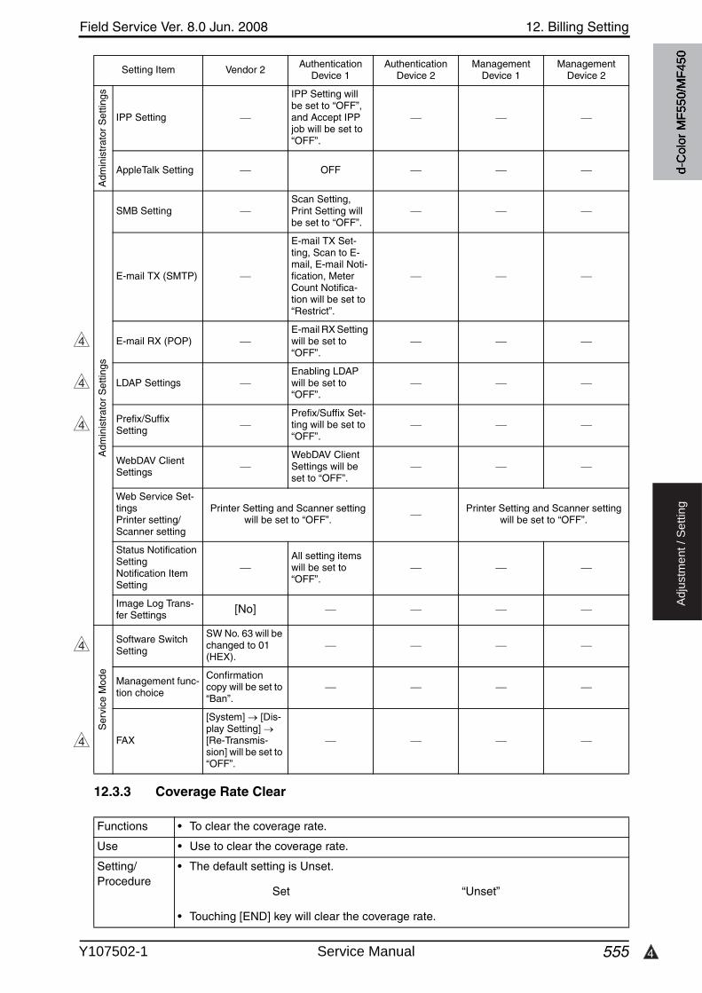
4
Field Service Ver. 8.0 Jun. 2008 12. Billing Setting
555
Ad
justm
en
t /
Se
ttin
g
12.3.3 Coverage Rate Clear
Adm
inis
trat
or S
ettin
gs
IPP Setting
IPP Setting will be set to “OFF”, and Accept IPP job will be set to “OFF”.
AppleTalk Setting OFF
Adm
inis
trat
or S
ettin
gs
SMB SettingScan Setting, Print Setting will be set to “OFF”.
E-mail TX (SMTP)
E-mail TX Set-ting, Scan to E-mail, E-mail Noti-fication, Meter Count Notifica-tion will be set to “Restrict”.
E-mail RX (POP)E-mail RX Setting will be set to “OFF”.
LDAP SettingsEnabling LDAP will be set to “OFF”.
Prefix/SuffixSetting
Prefix/Suffix Set-ting will be set to “OFF”.
WebDAV Client Settings
WebDAV Client Settings will be set to “OFF”.
Web Service Set-tingsPrinter setting/Scanner setting
Printer Setting and Scanner setting will be set to “OFF”.
Printer Setting and Scanner setting will be set to “OFF”.
Status Notification SettingNotification Item Setting
All setting items will be set to “OFF”.
Image Log Trans-fer Settings [No]
Ser
vice
Mod
e
Software Switch Setting
SW No. 63 will be changed to 01 (HEX).
Management func-tion choice
Confirmation copy will be set to “Ban”.
FAX
[System] [Dis-play Setting] [Re-Transmis-sion] will be set to “OFF”.
Setting Item Vendor 2Authentication
Device 1Authentication
Device 2Management
Device 1Management
Device 2
4
4
4
4
4
Functions • To clear the coverage rate.
Use • Use to clear the coverage rate.
Setting/Procedure
• The default setting is Unset.
Set “Unset”
• Touching [END] key will clear the coverage rate.
d-C
olor
MF5
50/M
F450
Y107502-1 Service Manual
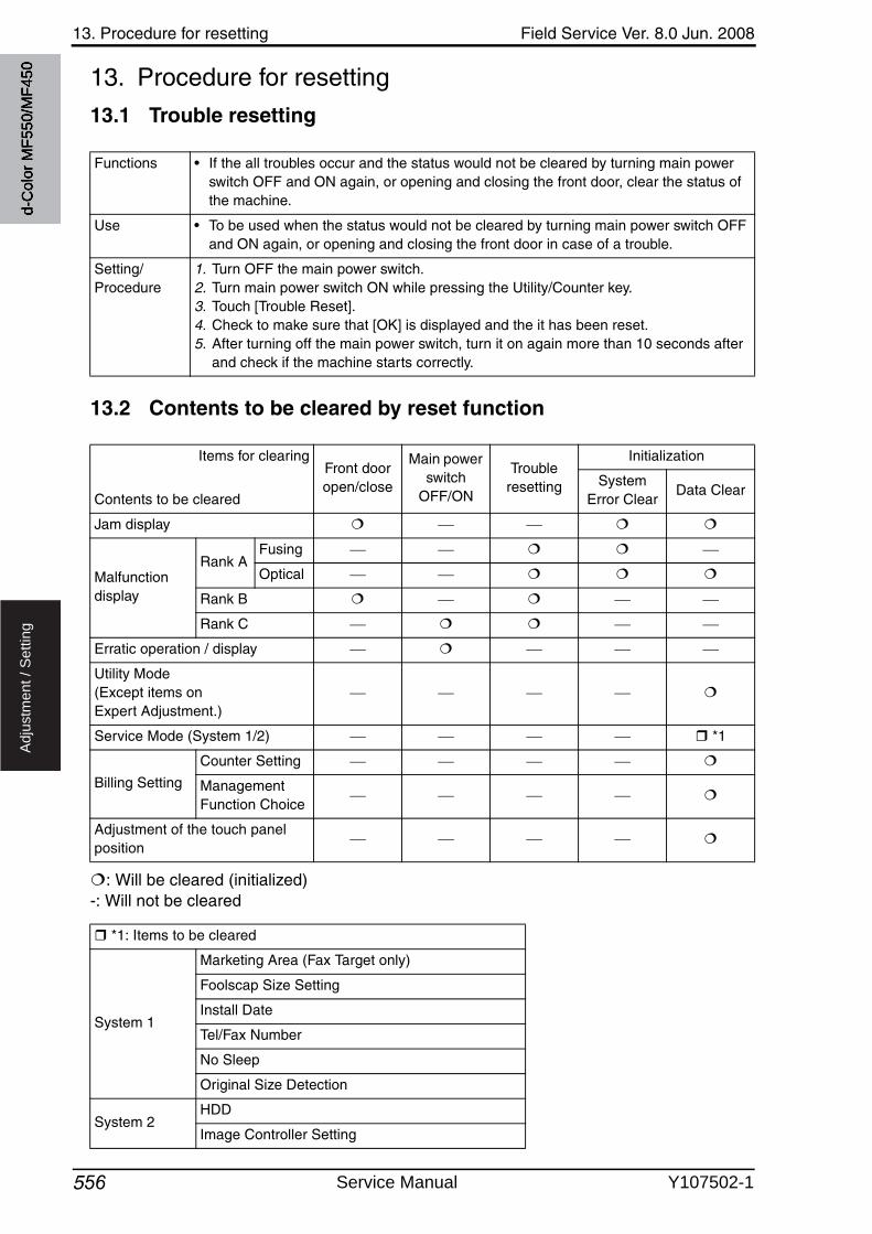
13. Procedure for resetting Field Service Ver. 8.0 Jun. 2008
556
Ad
justm
en
t /
Se
ttin
g
13. Procedure for resetting
13.1 Trouble resetting
13.2 Contents to be cleared by reset function
: Will be cleared (initialized) -: Will not be cleared
Functions • If the all troubles occur and the status would not be cleared by turning main power switch OFF and ON again, or opening and closing the front door, clear the status of the machine.
Use • To be used when the status would not be cleared by turning main power switch OFF and ON again, or opening and closing the front door in case of a trouble.
Setting/Procedure
1. Turn OFF the main power switch.2. Turn main power switch ON while pressing the Utility/Counter key.3. Touch [Trouble Reset].4. Check to make sure that [OK] is displayed and the it has been reset.5. After turning off the main power switch, turn it on again more than 10 seconds after
and check if the machine starts correctly.
Items for clearing
Contents to be cleared
Front door open/close
Main powerswitch
OFF/ON
Trouble resetting
Initialization
System Error Clear
Data Clear
Jam display
Malfunction display
Rank AFusing
Optical
Rank B
Rank C
Erratic operation / display
Utility Mode(Except items on Expert Adjustment.)
Service Mode (System 1/2) *1
Billing Setting
Counter Setting
Management Function Choice
Adjustment of the touch panel position
*1: Items to be cleared
System 1
Marketing Area (Fax Target only)
Foolscap Size Setting
Install Date
Tel/Fax Number
No Sleep
Original Size Detection
System 2HDD
Image Controller Setting
d-C
olor
MF5
50/M
F450
Service Manual Y107502-1
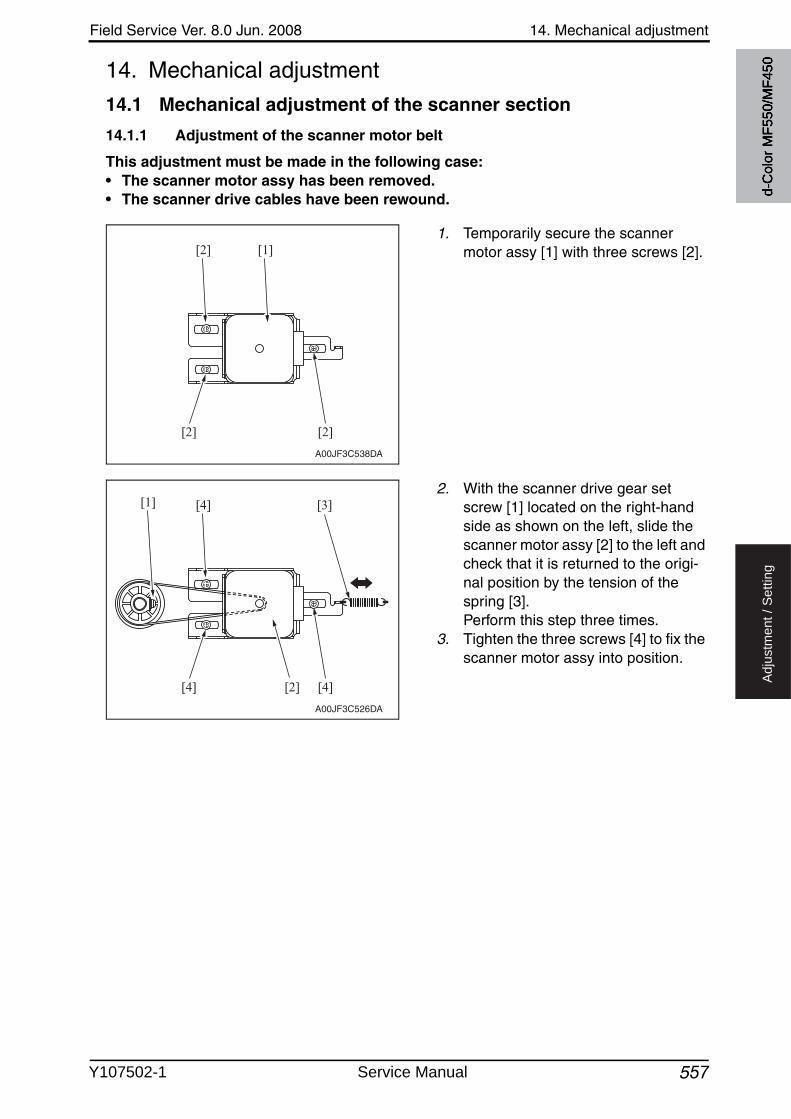
Field Service Ver. 8.0 Jun. 2008 14. Mechanical adjustment
557
Ad
justm
en
t /
Se
ttin
g
14. Mechanical adjustment
14.1 Mechanical adjustment of the scanner section
14.1.1 Adjustment of the scanner motor belt
This adjustment must be made in the following case:• The scanner motor assy has been removed.• The scanner drive cables have been rewound.
1. Temporarily secure the scanner motor assy [1] with three screws [2].
2. With the scanner drive gear set screw [1] located on the right-hand side as shown on the left, slide the scanner motor assy [2] to the left and check that it is returned to the origi-nal position by the tension of the spring [3]. Perform this step three times.
3. Tighten the three screws [4] to fix the scanner motor assy into position.
A00JF3C538DA
[2] [1]
[2] [2]
A00JF3C526DA
[3]
[2]
[4][1]
[4] [4]
d-C
olor
MF5
50/M
F450
Y107502-1 Service Manual
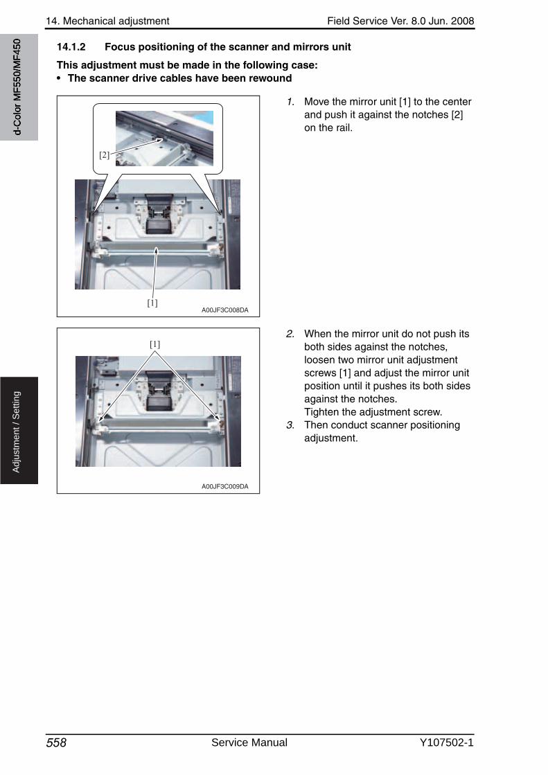
14. Mechanical adjustment Field Service Ver. 8.0 Jun. 2008
558
Ad
justm
en
t /
Se
ttin
g
14.1.2 Focus positioning of the scanner and mirrors unit
This adjustment must be made in the following case:• The scanner drive cables have been rewound
1. Move the mirror unit [1] to the center and push it against the notches [2] on the rail.
2. When the mirror unit do not push its both sides against the notches, loosen two mirror unit adjustmentscrews [1] and adjust the mirror unit position until it pushes its both sides against the notches. Tighten the adjustment screw.
3. Then conduct scanner positioning adjustment.
A00JF3C008DA[1]
[2]
A00JF3C009DA
[1]
d-C
olor
MF5
50/M
F450
Service Manual Y107502-1
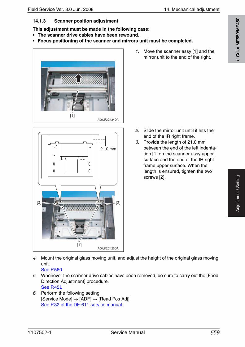
Field Service Ver. 8.0 Jun. 2008 14. Mechanical adjustment
559
Ad
justm
en
t /
Se
ttin
g
14.1.3 Scanner position adjustment
This adjustment must be made in the following case:• The scanner drive cables have been rewound.• Focus positioning of the scanner and mirrors unit must be completed.
1. Move the scanner assy [1] and the mirror unit to the end of the right.
2. Slide the mirror unit until it hits the end of the IR right frame.
3. Provide the length of 21.0 mm between the end of the left indenta-tion [1] on the scanner assy upper surface and the end of the IR right frame upper surface. When the length is ensured, tighten the twoscrews [2].
4. Mount the original glass moving unit, and adjust the height of the original glass movingunit.See P.560
5. Whenever the scanner drive cables have been removed, be sure to carry out the [Feed Direction Adjustment] procedure.See P.451
6. Perform the following setting.[Service Mode] [ADF] [Read Pos Adj]See P.32 of the DF-611 service manual.
A00JF2C424DA[1]
A00JF2C425DA
21.0 mm
[1]
[2] [2]
d-C
olor
MF5
50/M
F450
Y107502-1 Service Manual
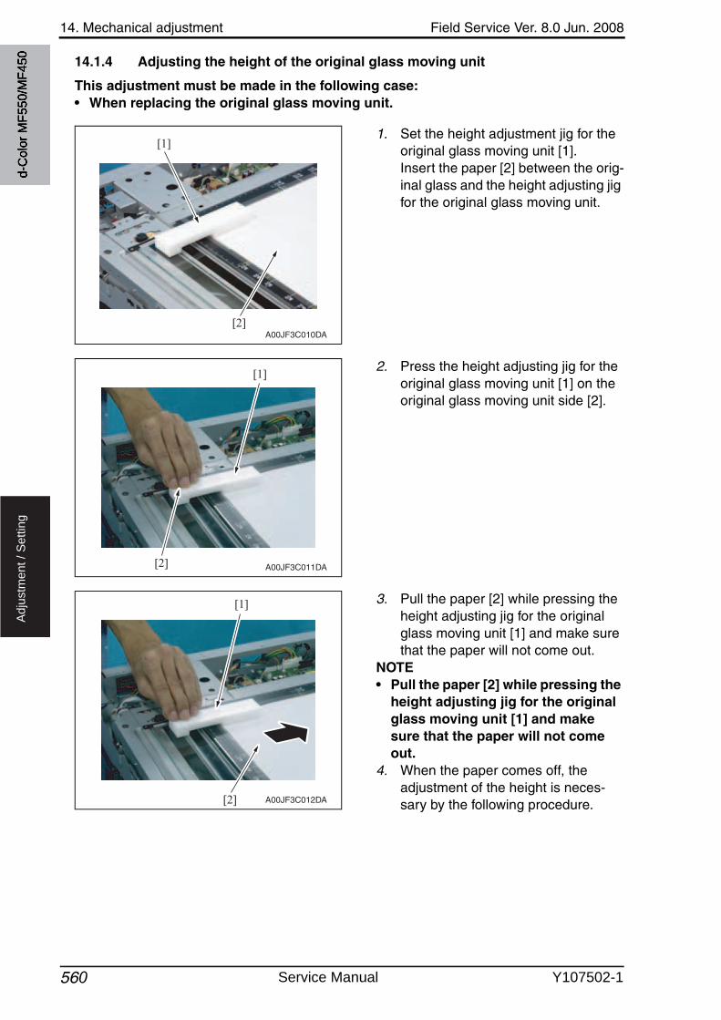
14. Mechanical adjustment Field Service Ver. 8.0 Jun. 2008
560
Ad
justm
en
t /
Se
ttin
g
14.1.4 Adjusting the height of the original glass moving unit
This adjustment must be made in the following case:• When replacing the original glass moving unit.
1. Set the height adjustment jig for the original glass moving unit [1]. Insert the paper [2] between the orig-inal glass and the height adjusting jig for the original glass moving unit.
2. Press the height adjusting jig for the original glass moving unit [1] on the original glass moving unit side [2].
3. Pull the paper [2] while pressing the height adjusting jig for the original glass moving unit [1] and make sure that the paper will not come out.
NOTE• Pull the paper [2] while pressing the
height adjusting jig for the original glass moving unit [1] and make sure that the paper will not come out.
4. When the paper comes off, the adjustment of the height is neces-sary by the following procedure.
A00JF3C010DA
[1]
[2]
A00JF3C011DA[2]
[1]
A00JF3C012DA[2]
[1]
d-C
olor
MF5
50/M
F450
Service Manual Y107502-1
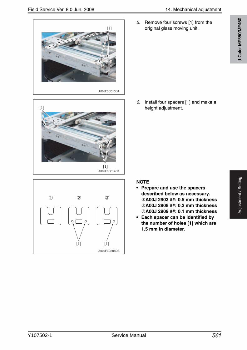
Field Service Ver. 8.0 Jun. 2008 14. Mechanical adjustment
561
Ad
justm
en
t /
Se
ttin
g
5. Remove four screws [1] from the original glass moving unit.
6. Install four spacers [1] and make a height adjustment.
NOTE• Prepare and use the spacers
described below as necessary.A00J 2903 ##: 0.5 mm thicknessA00J 2908 ##: 0.2 mm thicknessA00J 2909 ##: 0.1 mm thickness
• Each spacer can be identified by the number of holes [1] which are 1.5 mm in diameter.
A00JF3C013DA
[1]
A00JF3C014DA
[1]
[1]
A00JF3C608DA
[1] [1]d-
Col
or M
F550
/MF4
50
Y107502-1 Service Manual
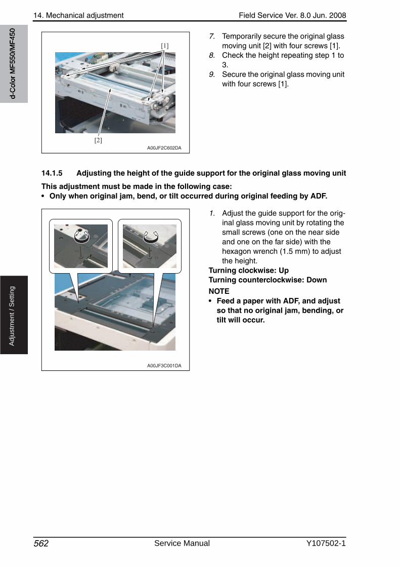
14. Mechanical adjustment Field Service Ver. 8.0 Jun. 2008
562
Ad
justm
en
t /
Se
ttin
g
7. Temporarily secure the original glass moving unit [2] with four screws [1].
8. Check the height repeating step 1 to 3.
9. Secure the original glass moving unitwith four screws [1].
14.1.5 Adjusting the height of the guide support for the original glass moving unit
This adjustment must be made in the following case:• Only when original jam, bend, or tilt occurred during original feeding by ADF.
1. Adjust the guide support for the orig-inal glass moving unit by rotating the small screws (one on the near side and one on the far side) with the hexagon wrench (1.5 mm) to adjustthe height.
Turning clockwise: UpTurning counterclockwise: Down
NOTE• Feed a paper with ADF, and adjust
so that no original jam, bending, or tilt will occur.
A00JF2C602DA
[1]
[2]
A00JF3C001DA
d-C
olor
MF5
50/M
F450
Service Manual Y107502-1
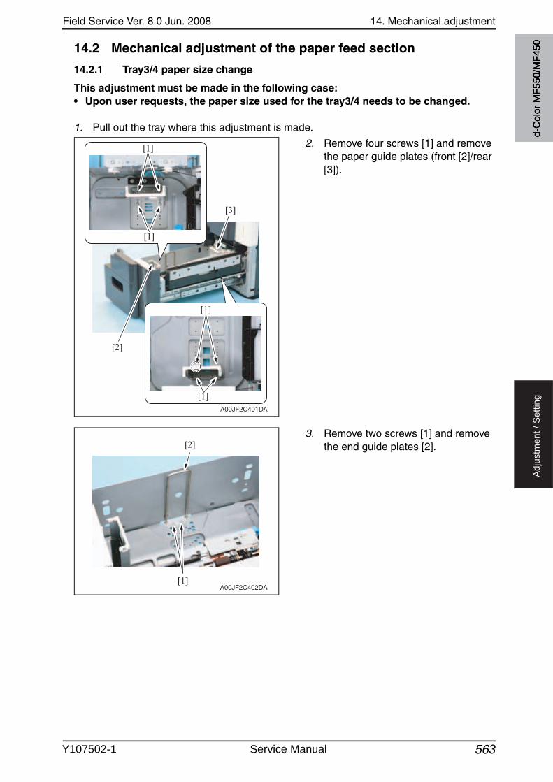
Field Service Ver. 8.0 Jun. 2008 14. Mechanical adjustment
563
Ad
justm
en
t /
Se
ttin
g
14.2 Mechanical adjustment of the paper feed section
14.2.1 Tray3/4 paper size change
This adjustment must be made in the following case:• Upon user requests, the paper size used for the tray3/4 needs to be changed.
1. Pull out the tray where this adjustment is made.
2. Remove four screws [1] and removethe paper guide plates (front [2]/rear [3]).
3. Remove two screws [1] and removethe end guide plates [2].
A00JF2C401DA
[1]
[1]
[1]
[1]
[2]
[3]
[1]
[2]
A00JF2C402DA
d-C
olor
MF5
50/M
F450
Y107502-1 Service Manual
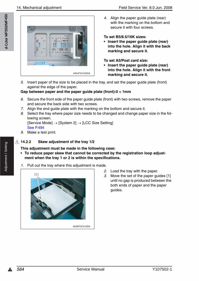
1
14. Mechanical adjustment Field Service Ver. 8.0 Jun. 2008
564
Ad
justm
en
t /
Se
ttin
g
4. Align the paper guide plate (rear) with the marking on the bottom and secure it with four screws.
To set B5/8.5/16K sizes:• Insert the paper guide plate (rear)
into the hole. Align it with the back marking and secure it.
To set A5/Post card size:• Insert the paper guide plate (rear)
into the hole. Align it with the front marking and secure it.
5. Insert paper of the size to be placed in the tray, and set the paper guide plate (front) against the edge of the paper.
Gap between paper and the paper guide plate (front):0 < 1mm
6. Secure the front side of the paper guide plate (front) with two screws, remove the paper and secure the back side with two screws.
7. Align the end guide plate with the marking on the bottom and secure it.8. Select the tray where paper size needs to be changed and change paper size in the fol-
lowing screen. [Service Mode] [System 2] [LCC Size Setting]See P.494
9. Make a test print.
14.2.2 Skew adjustment of the tray 1/2
This adjustment must be made in the following case:• To reduce paper skew that cannot be corrected by the registration loop adjust-
ment when the tray 1 or 2 is within the specifications.
1. Pull out the tray where this adjustment is made.
2. Load the tray with the paper.3. Move the set of the paper guides [1]
until no gap is produced between the both ends of paper and the paper guides.
A00JF2C403DA
10
0
8.5
"
11"
PO
ST
A5
B5
16
K
A4
1
[1]
A00KF3C516DA
d-C
olor
MF5
50/M
F450
Service Manual Y107502-1
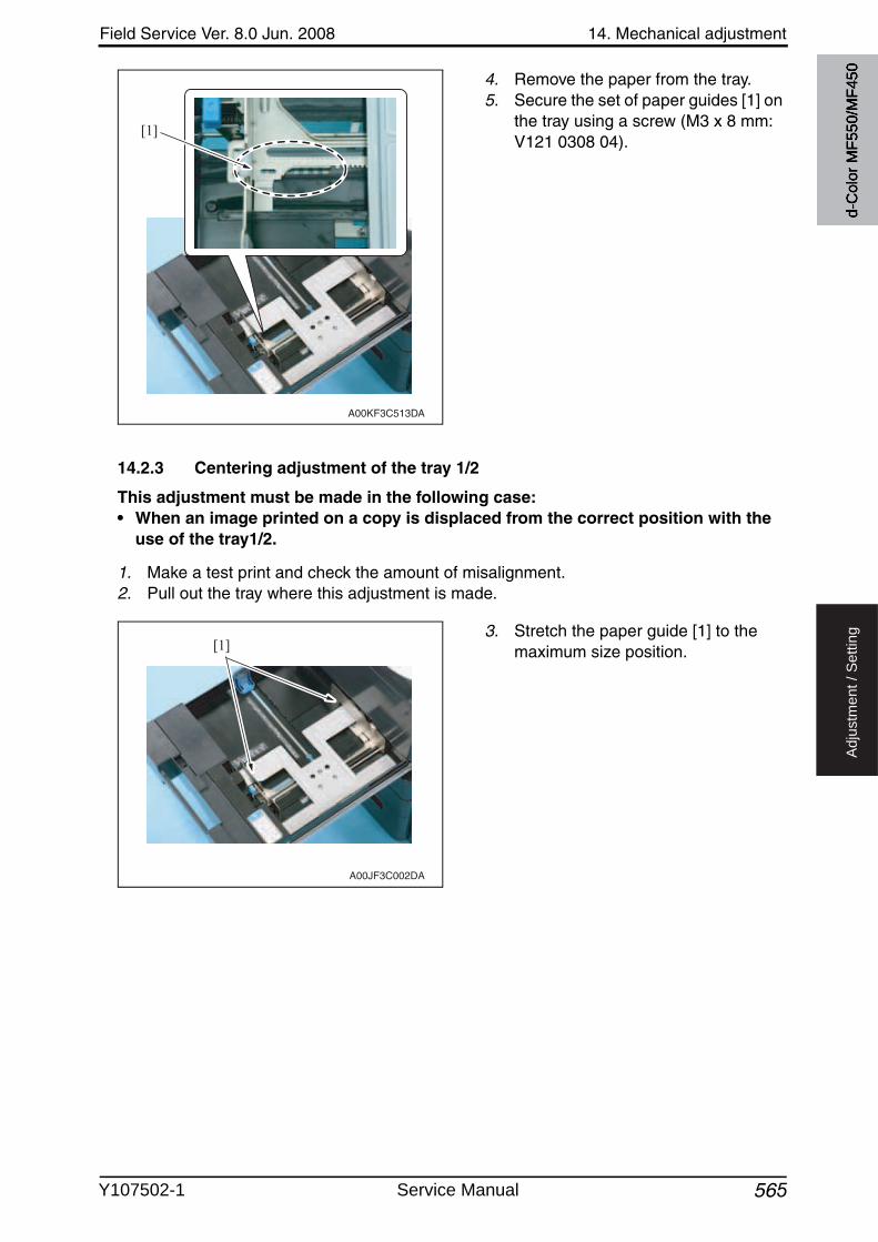
Field Service Ver. 8.0 Jun. 2008 14. Mechanical adjustment
565
Ad
justm
en
t /
Se
ttin
g
4. Remove the paper from the tray.5. Secure the set of paper guides [1] on
the tray using a screw (M3 x 8 mm: V121 0308 04).
14.2.3 Centering adjustment of the tray 1/2
This adjustment must be made in the following case:• When an image printed on a copy is displaced from the correct position with the
use of the tray1/2.
1. Make a test print and check the amount of misalignment.2. Pull out the tray where this adjustment is made.
3. Stretch the paper guide [1] to the maximum size position.
[1]
A00KF3C513DA
[1]
A00JF3C002DA
d-C
olor
MF5
50/M
F450
Y107502-1 Service Manual
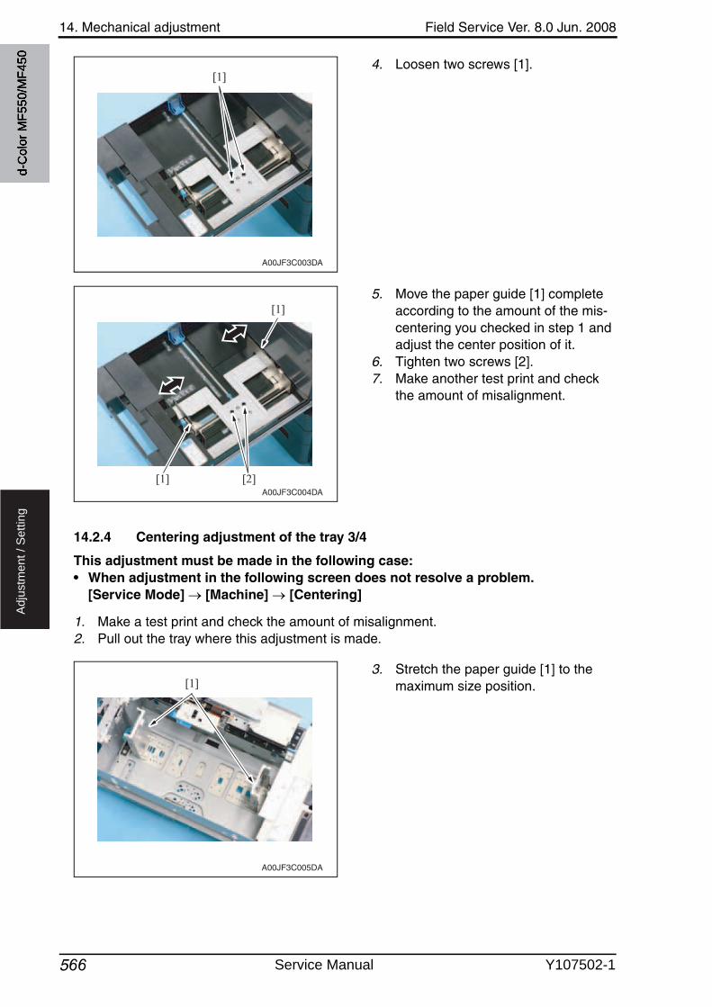
14. Mechanical adjustment Field Service Ver. 8.0 Jun. 2008
566
Ad
justm
en
t /
Se
ttin
g
4. Loosen two screws [1].
5. Move the paper guide [1] complete according to the amount of the mis-centering you checked in step 1 and adjust the center position of it.
6. Tighten two screws [2].7. Make another test print and check
the amount of misalignment.
14.2.4 Centering adjustment of the tray 3/4
This adjustment must be made in the following case:• When adjustment in the following screen does not resolve a problem.
[Service Mode] [Machine] [Centering]
1. Make a test print and check the amount of misalignment.2. Pull out the tray where this adjustment is made.
3. Stretch the paper guide [1] to the maximum size position.
[1]
A00JF3C003DA
[2][1]
[1]
A00JF3C004DA
[1]
A00JF3C005DA
d-C
olor
MF5
50/M
F450
Service Manual Y107502-1
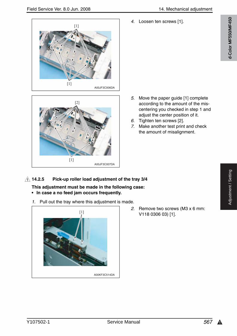
Field Service Ver. 8.0 Jun. 2008 14. Mechanical adjustment
567 1
Ad
justm
en
t /
Se
ttin
g
4. Loosen ten screws [1].
5. Move the paper guide [1] complete according to the amount of the mis-centering you checked in step 1 and adjust the center position of it.
6. Tighten ten screws [2].7. Make another test print and check
the amount of misalignment.
14.2.5 Pick-up roller load adjustment of the tray 3/4
This adjustment must be made in the following case:• In case a no feed jam occurs frequently.
1. Pull out the tray where this adjustment is made.
2. Remove two screws (M3 x 6 mm: V118 0306 03) [1].
[1]
[1]A00JF3C006DA
[2]
[1]A00JF3C007DA
1
[1]
A00KF3C514DA
d-C
olor
MF5
50/M
F450
Y107502-1 Service Manual
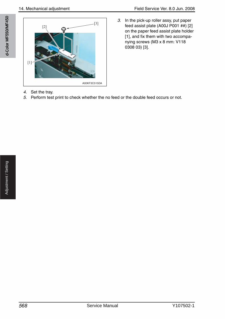
14. Mechanical adjustment Field Service Ver. 8.0 Jun. 2008
568
Ad
justm
en
t /
Se
ttin
g
3. In the pick-up roller assy, put paper feed assist plate (A00J P001 ##) [2] on the paper feed assist plate holder [1], and fix them with two accompa-nying screws (M3 x 8 mm: V1180308 03) [3].
4. Set the tray.5. Perform test print to check whether the no feed or the double feed occurs or not.
[2][3]
[1]
A00KF3C515DA
d-C
olor
MF5
50/M
F450
Service Manual Y107502-1
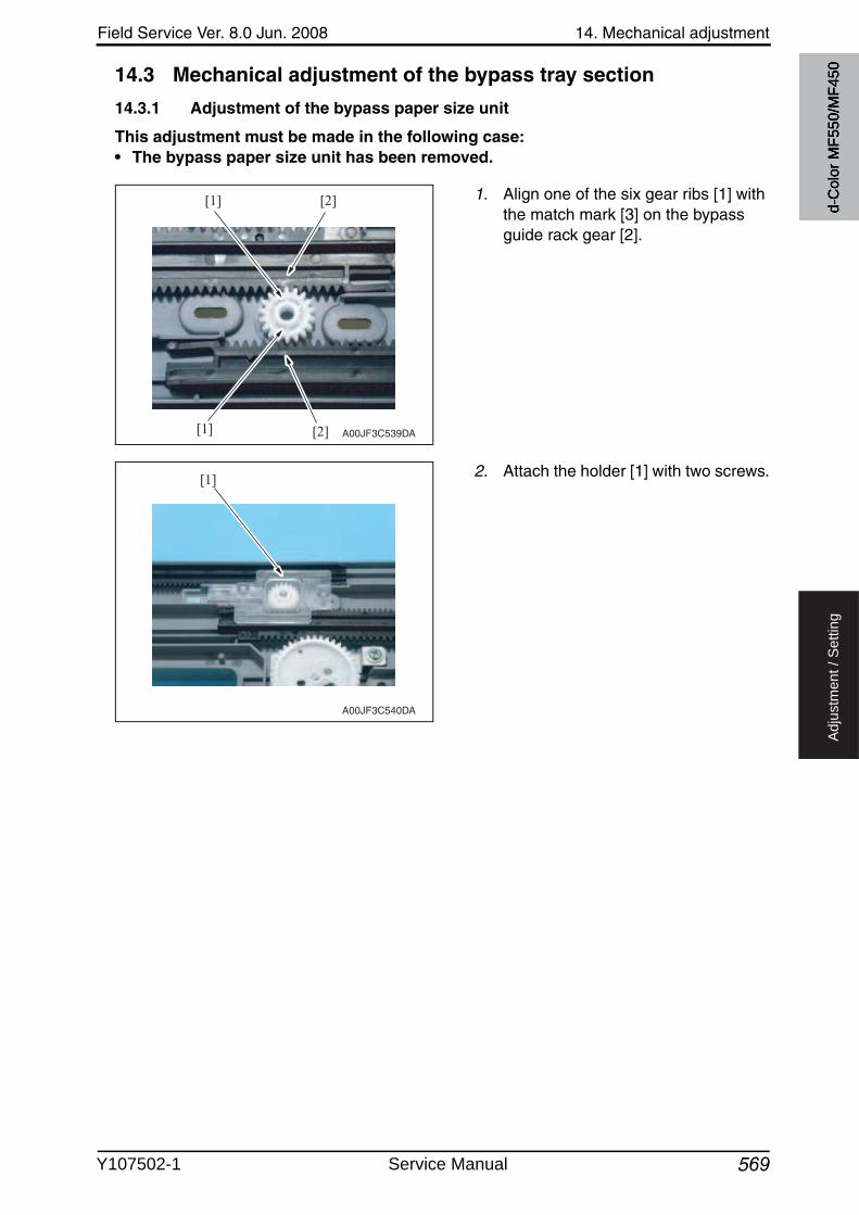
Field Service Ver. 8.0 Jun. 2008 14. Mechanical adjustment
569
Ad
justm
en
t /
Se
ttin
g
14.3 Mechanical adjustment of the bypass tray section
14.3.1 Adjustment of the bypass paper size unit
This adjustment must be made in the following case:• The bypass paper size unit has been removed.
1. Align one of the six gear ribs [1] withthe match mark [3] on the bypass guide rack gear [2].
2. Attach the holder [1] with two screws.
[2][1]
[2][1] A00JF3C539DA
[1]
A00JF3C540DA
d-C
olor
MF5
50/M
F450
Y107502-1 Service Manual
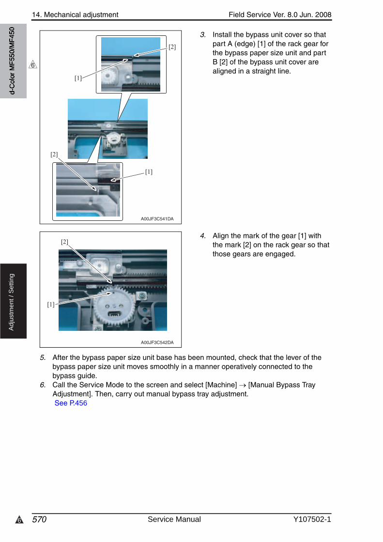
14. Mechanical adjustment Field Service Ver. 8.0 Jun. 2008
5706
Ad
justm
en
t /
Se
ttin
g
3. Install the bypass unit cover so that part A (edge) [1] of the rack gear for the bypass paper size unit and part B [2] of the bypass unit cover are aligned in a straight line.
4. Align the mark of the gear [1] withthe mark [2] on the rack gear so that those gears are engaged.
5. After the bypass paper size unit base has been mounted, check that the lever of the bypass paper size unit moves smoothly in a manner operatively connected to the bypass guide.
6. Call the Service Mode to the screen and select [Machine] [Manual Bypass Tray Adjustment]. Then, carry out manual bypass tray adjustment. See P.456
[1]
[2]
[2]
[1]
A00JF3C541DA
6
[1]
[2]
A00JF3C542DA
d-C
olor
MF5
50/M
F450
Service Manual Y107502-1
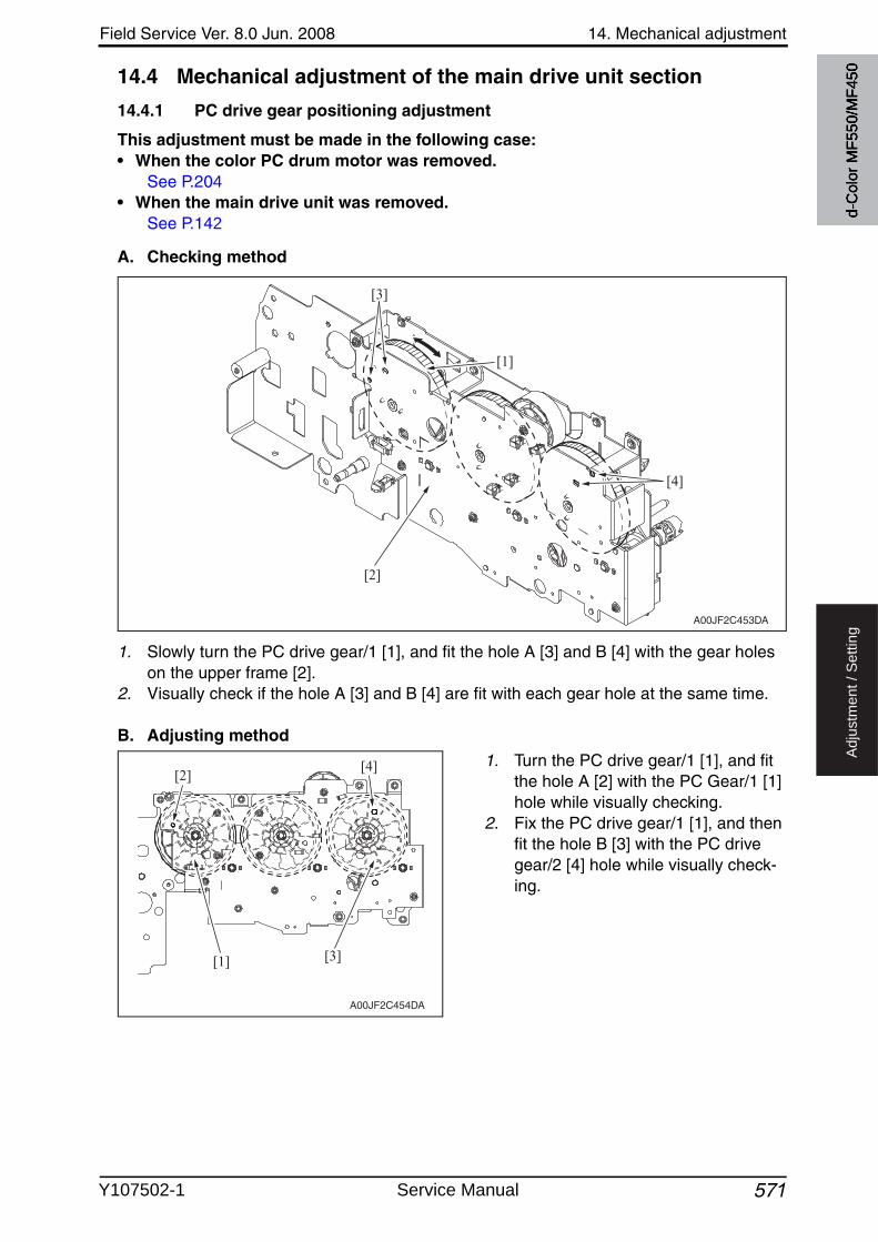
Field Service Ver. 8.0 Jun. 2008 14. Mechanical adjustment
571
Ad
justm
en
t /
Se
ttin
g
14.4 Mechanical adjustment of the main drive unit section
14.4.1 PC drive gear positioning adjustment
This adjustment must be made in the following case:• When the color PC drum motor was removed.
See P.204• When the main drive unit was removed.
See P.142
A. Checking method
1. Slowly turn the PC drive gear/1 [1], and fit the hole A [3] and B [4] with the gear holes on the upper frame [2].
2. Visually check if the hole A [3] and B [4] are fit with each gear hole at the same time.
B. Adjusting method
1. Turn the PC drive gear/1 [1], and fit the hole A [2] with the PC Gear/1 [1] hole while visually checking.
2. Fix the PC drive gear/1 [1], and then fit the hole B [3] with the PC drivegear/2 [4] hole while visually check-ing.
[1]
[2]
[3]
[4]
A00JF2C453DA
[1]
[2]
[3]
[4]
A00JF2C454DA
d-C
olor
MF5
50/M
F450
Y107502-1 Service Manual
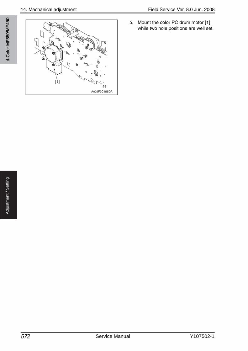
14. Mechanical adjustment Field Service Ver. 8.0 Jun. 2008
572
Ad
justm
en
t /
Se
ttin
g
3. Mount the color PC drum motor [1] while two hole positions are well set.
[1]
A00JF2C455DA
d-C
olor
MF5
50/M
F450
Service Manual Y107502-1
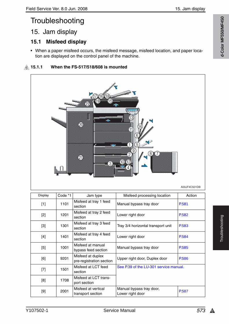
6
Field Service Ver. 8.0 Jun. 2008 15. Jam display
573
Tro
ub
lesh
oo
tin
g
Troubleshooting15. Jam display
15.1 Misfeed display
• When a paper misfeed occurs, the misfeed message, misfeed location, and paper loca-tion are displayed on the control panel of the machine.
15.1.1 When the FS-517/518/608 is mounted6
Display Code *1 Jam type Misfeed processing location Action
[1] 1101Misfeed at tray 1 feed section
Manual bypass tray door P.581
[2] 1201Misfeed at tray 2 feed section
Lower right door P.582
[3] 1301Misfeed at tray 3 feed section
Tray 3/4 horizontal transport unit P.583
[4] 1401Misfeed at tray 4 feed section
Lower right door P.584
[5] 1001Misfeed at manualbypass feed section
Manual bypass tray door P.585
[6] 9201Misfeed at duplex pre-registration section
Upper right door, Duplex door P.586
[7] 1501Misfeed at LCT feed section
See P.39 of the LU-301 service manual.
[8] 1708Misfeed at LCT trans-port section
[9] 2001Misfeed at vertical transport section
Manual bypass tray door, Lower right door
P.587
A00JF4C501DB
d-C
olor
MF5
50/M
F450
Y107502-1 Service Manual
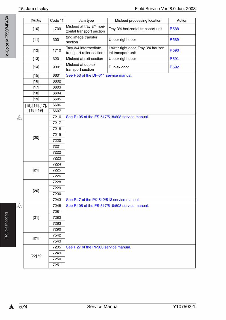
15. Jam display Field Service Ver. 8.0 Jun. 2008
5746
Tro
ub
lesh
oo
tin
g
[10] 1709Misfeed at tray 3/4 hori-zontal transport section
Tray 3/4 horizontal transport unit P.588
[11] 30012nd image transfer section
Upper right door P.589
[12] 1710Tray 3/4 intermediate transport roller section
Lower right door, Tray 3/4 horizon-tal transport unit
P.590
[13] 3201 Misfeed at exit section Upper right door P.591
[14] 9301Misfeed at duplex transport section
Duplex door P.592
[15] 6601 See P.53 of the DF-611 service manual.
[16] 6602
[17] 6603
[18] 6604
[19] 6605
[15],[16],[17],[18],[19]
6606
6607
[20]
7216 See P.105 of the FS-517/518/608 service manual.
7217
7218
7219
7220
7221
7222
7223
[21]
7224
7225
7226
[20]
7228
7229
7230
7243 See P.17 of the PK-512/513 service manual.
[21]
7248 See P.105 of the FS-517/518/608 service manual.
7281
7282
7283
7290
[21]7542
7543
[22] *2
7235 See P.27 of the PI-503 service manual.
7249
7250
7251
Display Code *1 Jam type Misfeed processing location Action
6
6
d-C
olor
MF5
50/M
F450
Service Manual Y107502-1
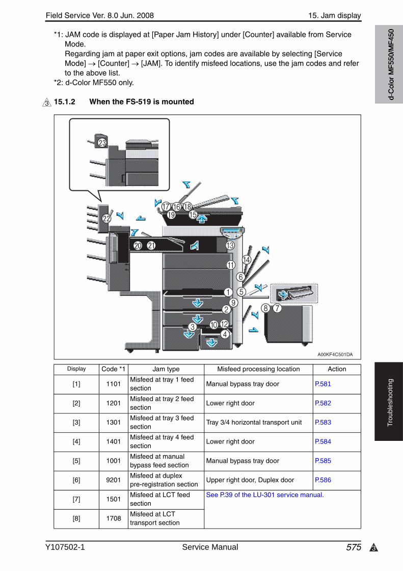
3
Field Service Ver. 8.0 Jun. 2008 15. Jam display
575
Tro
ub
lesh
oo
tin
g
*1: JAM code is displayed at [Paper Jam History] under [Counter] available from Service Mode.Regarding jam at paper exit options, jam codes are available by selecting [Service Mode] [Counter] [JAM]. To identify misfeed locations, use the jam codes and refer to the above list.
*2: d-Color MF550 only.
15.1.2 When the FS-519 is mounted3
Display Code *1 Jam type Misfeed processing location Action
[1] 1101Misfeed at tray 1 feed section
Manual bypass tray door P.581
[2] 1201Misfeed at tray 2 feed section
Lower right door P.582
[3] 1301Misfeed at tray 3 feed section
Tray 3/4 horizontal transport unit P.583
[4] 1401Misfeed at tray 4 feed section
Lower right door P.584
[5] 1001Misfeed at manualbypass feed section
Manual bypass tray door P.585
[6] 9201Misfeed at duplex pre-registration section
Upper right door, Duplex door P.586
[7] 1501Misfeed at LCT feed section
See P.39 of the LU-301 service manual.
[8] 1708Misfeed at LCT transport section
A00KF4C501DA
d-C
olor
MF5
50/M
F450
Y107502-1 Service Manual
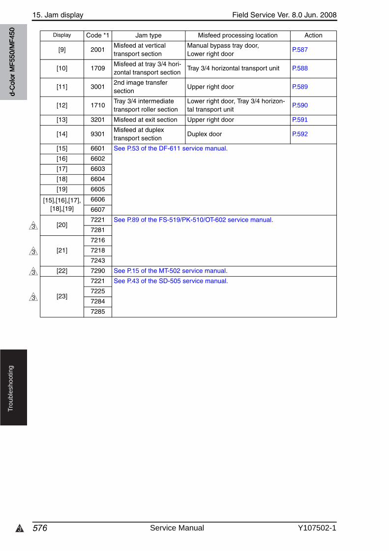
15. Jam display Field Service Ver. 8.0 Jun. 2008
5763
Tro
ub
lesh
oo
tin
g
[9] 2001Misfeed at vertical transport section
Manual bypass tray door, Lower right door
P.587
[10] 1709Misfeed at tray 3/4 hori-zontal transport section
Tray 3/4 horizontal transport unit P.588
[11] 30012nd image transfer section
Upper right door P.589
[12] 1710Tray 3/4 intermediate transport roller section
Lower right door, Tray 3/4 horizon-tal transport unit
P.590
[13] 3201 Misfeed at exit section Upper right door P.591
[14] 9301Misfeed at duplex transport section
Duplex door P.592
[15] 6601 See P.53 of the DF-611 service manual.
[16] 6602
[17] 6603
[18] 6604
[19] 6605
[15],[16],[17],[18],[19]
6606
6607
[20]7221 See P.89 of the FS-519/PK-510/OT-602 service manual.
7281
[21]
7216
7218
7243
[22] 7290 See P.15 of the MT-502 service manual.
[23]
7221 See P.43 of the SD-505 service manual.
7225
7284
7285
Display Code *1 Jam type Misfeed processing location Action
3
3
3
3
d-C
olor
MF5
50/M
F450
Service Manual Y107502-1
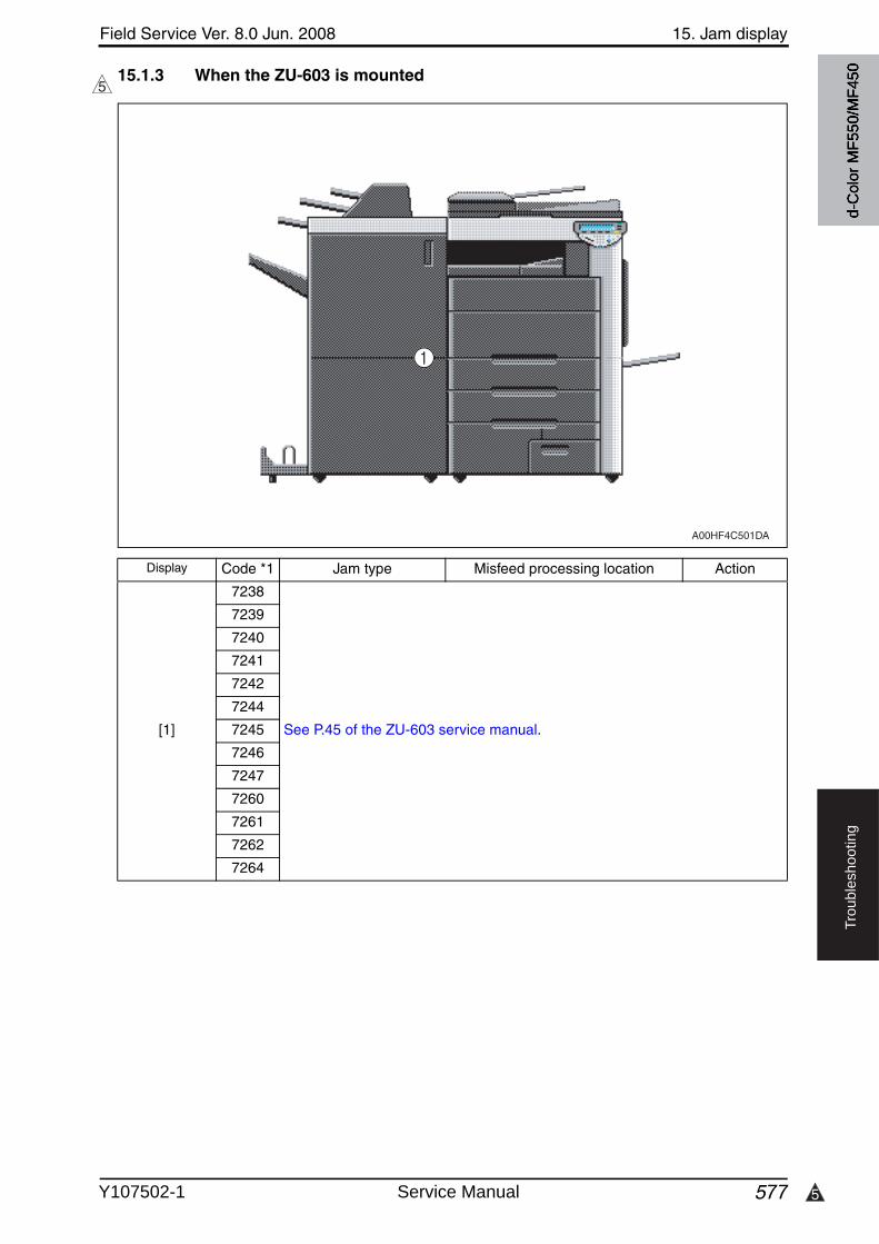
5
Field Service Ver. 8.0 Jun. 2008 15. Jam display
577
Tro
ub
lesh
oo
tin
g
15.1.3 When the ZU-603 is mounted5
Display Code *1 Jam type Misfeed processing location Action
[1]
7238
See P.45 of the ZU-603 service manual.
7239
7240
7241
7242
7244
7245
7246
7247
7260
7261
7262
7264
A00HF4C501DA
d-C
olor
MF5
50/M
F450
Y107502-1 Service Manual
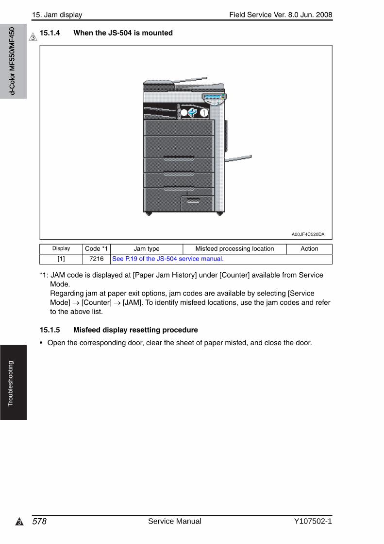
15. Jam display Field Service Ver. 8.0 Jun. 2008
5783
Tro
ub
lesh
oo
tin
g
15.1.4 When the JS-504 is mounted
*1: JAM code is displayed at [Paper Jam History] under [Counter] available from Service Mode.Regarding jam at paper exit options, jam codes are available by selecting [ServiceMode] [Counter] [JAM]. To identify misfeed locations, use the jam codes and refer to the above list.
15.1.5 Misfeed display resetting procedure
• Open the corresponding door, clear the sheet of paper misfed, and close the door.
3
Display Code *1 Jam type Misfeed processing location Action
[1] 7216 See P.19 of the JS-504 service manual.
A00JF4C520DA
d-C
olor
MF5
50/M
F450
Service Manual Y107502-1
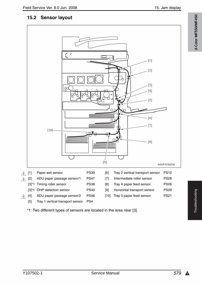
Field Service Ver. 8.0 Jun. 2008 15. Jam display
579 1
Tro
ub
lesh
oo
tin
g
15.2 Sensor layout
*1: Two different types of sensors are located in the area near [3].
[1] Paper exit sensor PS39 [6] Tray 2 vertical transport sensor PS12
[2] ADU paper passage sensor/1 PS47 [7] Intermediate roller sensor PS28
[3]*1 Timing roller sensor PS38 [8] Tray 4 paper feed sensor PS26
[3]*1 OHP detection sensor PS40 [9] Horizontal transport sensor PS29
[4] ADU paper passage sensor/2 PS48 [10] Tray 3 paper feed sensor PS21
[5] Tray 1 vertical transport sensor PS4
A00JF4C502DA
[5]
[7]
[8]
[4]
[2]
[1]
[3]
[6]
[10]
[9]
1
1
1d-
Col
or M
F550
/MF4
50
Y107502-1 Service Manual
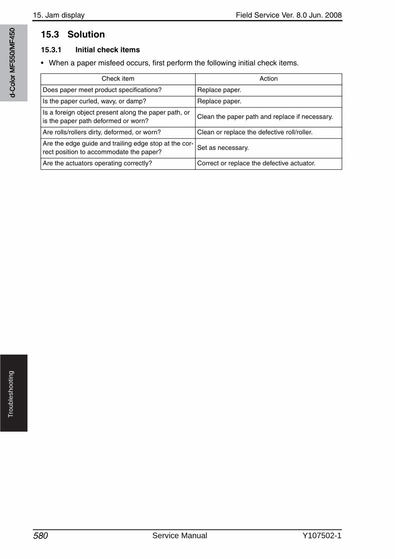
15. Jam display Field Service Ver. 8.0 Jun. 2008
580
Tro
ub
lesh
oo
tin
g
15.3 Solution
15.3.1 Initial check items
• When a paper misfeed occurs, first perform the following initial check items.
Check item Action
Does paper meet product specifications? Replace paper.
Is the paper curled, wavy, or damp? Replace paper.
Is a foreign object present along the paper path, or is the paper path deformed or worn?
Clean the paper path and replace if necessary.
Are rolls/rollers dirty, deformed, or worn? Clean or replace the defective roll/roller.
Are the edge guide and trailing edge stop at the cor-rect position to accommodate the paper?
Set as necessary.
Are the actuators operating correctly? Correct or replace the defective actuator.
d-C
olor
MF5
50/M
F450
Service Manual Y107502-1
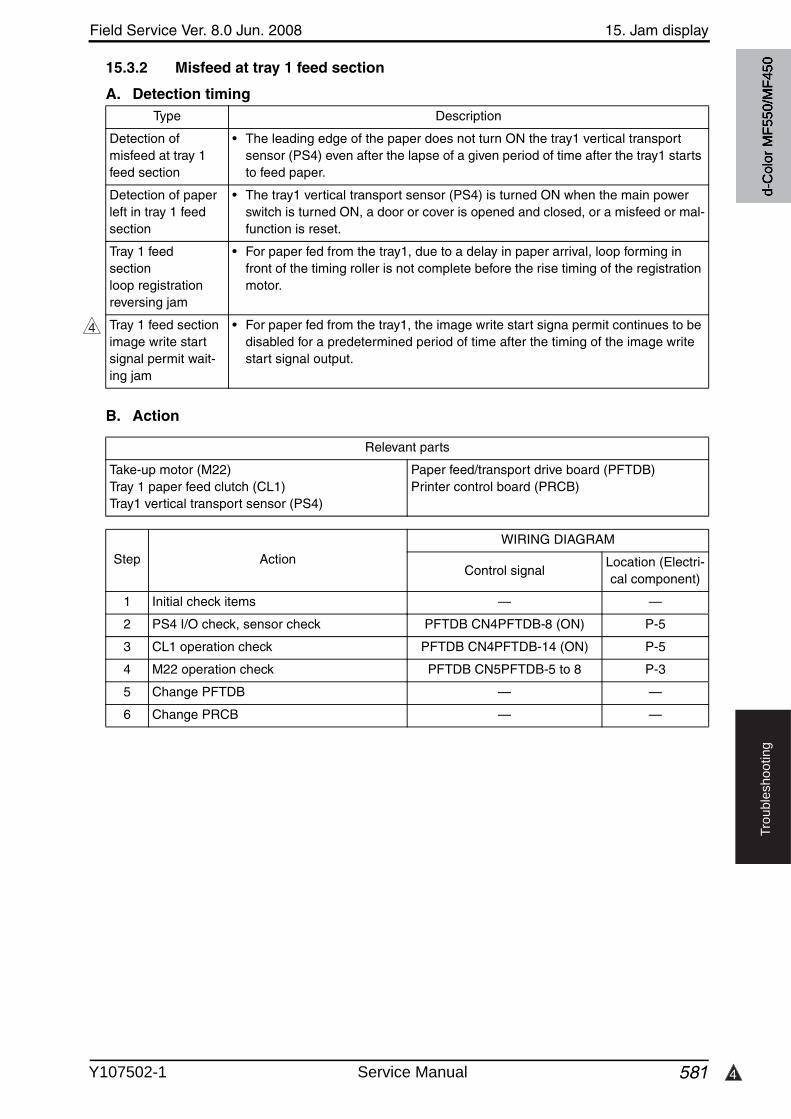
4
Field Service Ver. 8.0 Jun. 2008 15. Jam display
581
Tro
ub
lesh
oo
tin
g
15.3.2 Misfeed at tray 1 feed section
A. Detection timing
B. Action
Type Description
Detection of misfeed at tray 1 feed section
• The leading edge of the paper does not turn ON the tray1 vertical transport sensor (PS4) even after the lapse of a given period of time after the tray1 starts to feed paper.
Detection of paper left in tray 1 feed section
• The tray1 vertical transport sensor (PS4) is turned ON when the main power switch is turned ON, a door or cover is opened and closed, or a misfeed or mal-function is reset.
Tray 1 feed sectionloop registrationreversing jam
• For paper fed from the tray1, due to a delay in paper arrival, loop forming in front of the timing roller is not complete before the rise timing of the registration motor.
Tray 1 feed section image write start signal permit wait-ing jam
• For paper fed from the tray1, the image write start signa permit continues to be disabled for a predetermined period of time after the timing of the image write start signal output.
4
Relevant parts
Take-up motor (M22)Tray 1 paper feed clutch (CL1)Tray1 vertical transport sensor (PS4)
Paper feed/transport drive board (PFTDB)Printer control board (PRCB)
Step Action
WIRING DIAGRAM
Control signalLocation (Electri-cal component)
1 Initial check items — —
2 PS4 I/O check, sensor check PFTDB CN4PFTDB-8 (ON) P-5
3 CL1 operation check PFTDB CN4PFTDB-14 (ON) P-5
4 M22 operation check PFTDB CN5PFTDB-5 to 8 P-3
5 Change PFTDB — —
6 Change PRCB — —
d-C
olor
MF5
50/M
F450
Y107502-1 Service Manual
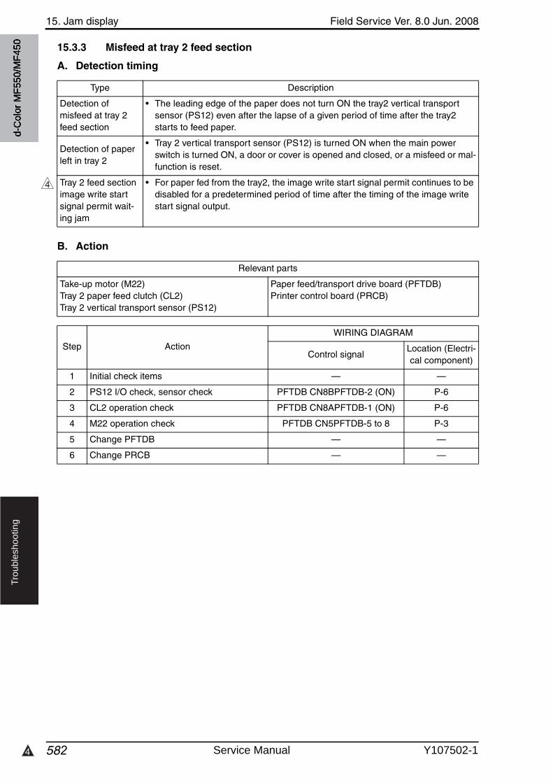
15. Jam display Field Service Ver. 8.0 Jun. 2008
5824
Tro
ub
lesh
oo
tin
g
15.3.3 Misfeed at tray 2 feed section
A. Detection timing
B. Action
Type Description
Detection of misfeed at tray 2 feed section
• The leading edge of the paper does not turn ON the tray2 vertical transport sensor (PS12) even after the lapse of a given period of time after the tray2 starts to feed paper.
Detection of paper left in tray 2
• Tray 2 vertical transport sensor (PS12) is turned ON when the main powerswitch is turned ON, a door or cover is opened and closed, or a misfeed or mal-function is reset.
Tray 2 feed section image write start signal permit wait-ing jam
• For paper fed from the tray2, the image write start signal permit continues to be disabled for a predetermined period of time after the timing of the image write start signal output.
4
Relevant parts
Take-up motor (M22)Tray 2 paper feed clutch (CL2)Tray 2 vertical transport sensor (PS12)
Paper feed/transport drive board (PFTDB)Printer control board (PRCB)
Step Action
WIRING DIAGRAM
Control signalLocation (Electri-cal component)
1 Initial check items — —
2 PS12 I/O check, sensor check PFTDB CN8BPFTDB-2 (ON) P-6
3 CL2 operation check PFTDB CN8APFTDB-1 (ON) P-6
4 M22 operation check PFTDB CN5PFTDB-5 to 8 P-3
5 Change PFTDB — —
6 Change PRCB — —
d-C
olor
MF5
50/M
F450
Service Manual Y107502-1
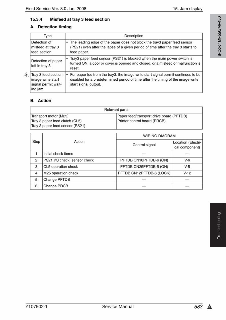
4
Field Service Ver. 8.0 Jun. 2008 15. Jam display
583
Tro
ub
lesh
oo
tin
g
15.3.4 Misfeed at tray 3 feed section
A. Detection timing
B. Action
Type Description
Detection of misfeed at tray 3 feed section
• The leading edge of the paper does not block the tray3 paper feed sensor (PS21) even after the lapse of a given period of time after the tray 3 starts to feed paper.
Detection of paper left in tray 3
• Tray3 paper feed sensor (PS21) is blocked when the main power switch is turned ON, a door or cover is opened and closed, or a misfeed or malfunction is reset.
Tray 3 feed section image write start signal permit wait-ing jam
• For paper fed from the tray3, the image write start signal permit continues to be disabled for a predetermined period of time after the timing of the image write start signal output.
4
Relevant parts
Transport motor (M25)Tray 3 paper feed clutch (CL5)Tray 3 paper feed sensor (PS21)
Paper feed/transport drive board (PFTDB)Printer control board (PRCB)
Step Action
WIRING DIAGRAM
Control signalLocation (Electri-cal component)
1 Initial check items — —
2 PS21 I/O check, sensor check PFTDB CN10PFTDB-6 (ON) V-6
3 CL5 operation check PFTDB CN25PFTDB-5 (ON) V-5
4 M25 operation check PFTDB CN12PFTDB-6 (LOCK) V-12
5 Change PFTDB — —
6 Change PRCB — —
d-C
olor
MF5
50/M
F450
Y107502-1 Service Manual
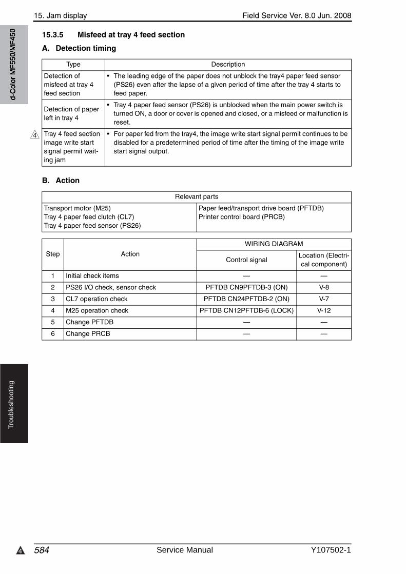
15. Jam display Field Service Ver. 8.0 Jun. 2008
5844
Tro
ub
lesh
oo
tin
g
15.3.5 Misfeed at tray 4 feed section
A. Detection timing
B. Action
Type Description
Detection of misfeed at tray 4 feed section
• The leading edge of the paper does not unblock the tray4 paper feed sensor (PS26) even after the lapse of a given period of time after the tray 4 starts to feed paper.
Detection of paper left in tray 4
• Tray 4 paper feed sensor (PS26) is unblocked when the main power switch is turned ON, a door or cover is opened and closed, or a misfeed or malfunction is reset.
Tray 4 feed section image write start signal permit wait-ing jam
• For paper fed from the tray4, the image write start signal permit continues to be disabled for a predetermined period of time after the timing of the image write start signal output.
4
Relevant parts
Transport motor (M25)Tray 4 paper feed clutch (CL7)Tray 4 paper feed sensor (PS26)
Paper feed/transport drive board (PFTDB)Printer control board (PRCB)
Step Action
WIRING DIAGRAM
Control signalLocation (Electri-cal component)
1 Initial check items — —
2 PS26 I/O check, sensor check PFTDB CN9PFTDB-3 (ON) V-8
3 CL7 operation check PFTDB CN24PFTDB-2 (ON) V-7
4 M25 operation check PFTDB CN12PFTDB-6 (LOCK) V-12
5 Change PFTDB — —
6 Change PRCB — —
d-C
olor
MF5
50/M
F450
Service Manual Y107502-1
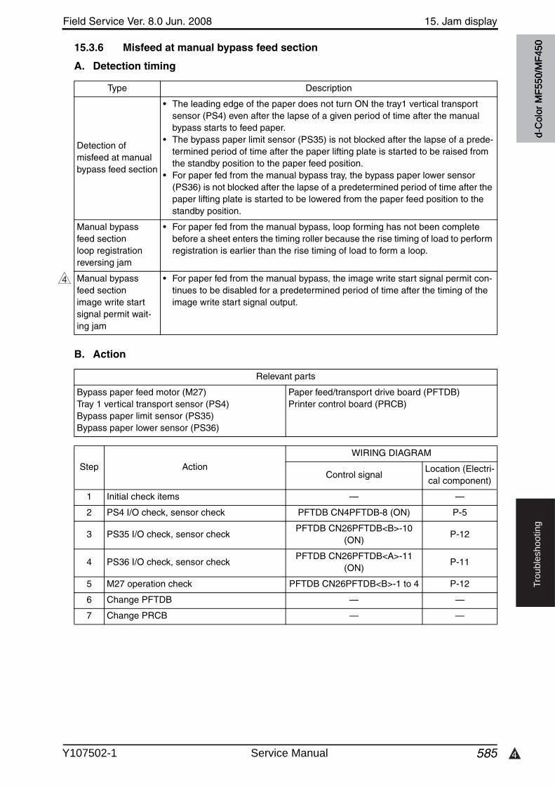
4
Field Service Ver. 8.0 Jun. 2008 15. Jam display
585
Tro
ub
lesh
oo
tin
g
15.3.6 Misfeed at manual bypass feed section
A. Detection timing
B. Action
Type Description
Detection of misfeed at manualbypass feed section
• The leading edge of the paper does not turn ON the tray1 vertical transport sensor (PS4) even after the lapse of a given period of time after the manualbypass starts to feed paper.
• The bypass paper limit sensor (PS35) is not blocked after the lapse of a prede-termined period of time after the paper lifting plate is started to be raised from the standby position to the paper feed position.
• For paper fed from the manual bypass tray, the bypass paper lower sensor (PS36) is not blocked after the lapse of a predetermined period of time after the paper lifting plate is started to be lowered from the paper feed position to the standby position.
Manual bypass feed section loop registration reversing jam
• For paper fed from the manual bypass, loop forming has not been complete before a sheet enters the timing roller because the rise timing of load to perform registration is earlier than the rise timing of load to form a loop.
Manual bypass feed section image write start signal permit wait-ing jam
• For paper fed from the manual bypass, the image write start signal permit con-tinues to be disabled for a predetermined period of time after the timing of the image write start signal output.
4
Relevant parts
Bypass paper feed motor (M27)Tray 1 vertical transport sensor (PS4)Bypass paper limit sensor (PS35)Bypass paper lower sensor (PS36)
Paper feed/transport drive board (PFTDB)Printer control board (PRCB)
Step Action
WIRING DIAGRAM
Control signalLocation (Electri-cal component)
1 Initial check items — —
2 PS4 I/O check, sensor check PFTDB CN4PFTDB-8 (ON) P-5
3 PS35 I/O check, sensor checkPFTDB CN26PFTDB<B>-10
(ON)P-12
4 PS36 I/O check, sensor checkPFTDB CN26PFTDB<A>-11
(ON)P-11
5 M27 operation check PFTDB CN26PFTDB<B>-1 to 4 P-12
6 Change PFTDB — —
7 Change PRCB — —
d-C
olor
MF5
50/M
F450
Y107502-1 Service Manual
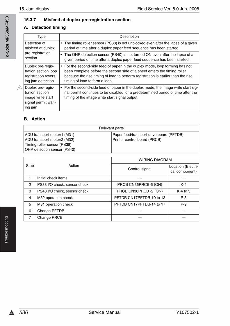
15. Jam display Field Service Ver. 8.0 Jun. 2008
5864
Tro
ub
lesh
oo
tin
g
15.3.7 Misfeed at duplex pre-registration section
A. Detection timing
B. Action
Type Description
Detection of misfeed at duplex pre-registration section
• The timing roller sensor (PS38) is not unblocked even after the lapse of a givenperiod of time after a duplex paper feed sequence has been started.
• The OHP detection sensor (PS40) is not turned ON even after the lapse of a given period of time after a duplex paper feed sequence has been started.
Duplex pre-regis-tration section loop registration revers-ing jam detection
• For the second-side feed of paper in the duplex mode, loop forming has not been complete before the second side of a sheet enters the timing roller because the rise timing of load to perform registration is earlier than the rise timing of load to form a loop.
Duplex pre-regis-tration section image write start signal permit wait-ing jam
• For the second-side feed of paper in the duplex mode, the image write start sig-nal permit continues to be disabled for a predetermined period of time after the timing of the image write start signal output.
4
Relevant parts
ADU transport motor/1 (M31)ADU transport motor/2 (M32)Timing roller sensor (PS38)OHP detection sensor (PS40)
Paper feed/transport drive board (PFTDB)Printer control board (PRCB)
Step Action
WIRING DIAGRAM
Control signalLocation (Electri-cal component)
1 Initial check items — —
2 PS38 I/O check, sensor check PRCB CN36PRCB-6 (ON) K-4
3 PS40 I/O check, sensor check PRCB CN36PRCB -2 (ON) K-4 to 5
4 M32 operation check PFTDB CN17PFTDB-10 to 13 P-8
5 M31 operation check PFTDB CN17PFTDB-14 to 17 P-9
6 Change PFTDB — —
7 Change PRCB — —
d-C
olor
MF5
50/M
F450
Service Manual Y107502-1
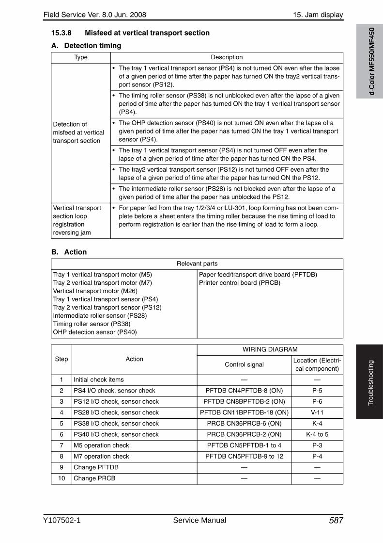
Field Service Ver. 8.0 Jun. 2008 15. Jam display
587
Tro
ub
lesh
oo
tin
g
15.3.8 Misfeed at vertical transport section
A. Detection timing
B. Action
Type Description
Detection of misfeed at vertical transport section
• The tray 1 vertical transport sensor (PS4) is not turned ON even after the lapse of a given period of time after the paper has turned ON the tray2 vertical trans-port sensor (PS12).
• The timing roller sensor (PS38) is not unblocked even after the lapse of a givenperiod of time after the paper has turned ON the tray 1 vertical transport sensor (PS4).
• The OHP detection sensor (PS40) is not turned ON even after the lapse of a given period of time after the paper has turned ON the tray 1 vertical transport sensor (PS4).
• The tray 1 vertical transport sensor (PS4) is not turned OFF even after the lapse of a given period of time after the paper has turned ON the PS4.
• The tray2 vertical transport sensor (PS12) is not turned OFF even after the lapse of a given period of time after the paper has turned ON the PS12.
• The intermediate roller sensor (PS28) is not blocked even after the lapse of a given period of time after the paper has unblocked the PS12.
Vertical transport section loop registration reversing jam
• For paper fed from the tray 1/2/3/4 or LU-301, loop forming has not been com-plete before a sheet enters the timing roller because the rise timing of load to perform registration is earlier than the rise timing of load to form a loop.
Relevant parts
Tray 1 vertical transport motor (M5)Tray 2 vertical transport motor (M7)Vertical transport motor (M26)Tray 1 vertical transport sensor (PS4)Tray 2 vertical transport sensor (PS12)Intermediate roller sensor (PS28)Timing roller sensor (PS38)OHP detection sensor (PS40)
Paper feed/transport drive board (PFTDB)Printer control board (PRCB)
Step Action
WIRING DIAGRAM
Control signalLocation (Electri-cal component)
1 Initial check items — —
2 PS4 I/O check, sensor check PFTDB CN4PFTDB-8 (ON) P-5
3 PS12 I/O check, sensor check PFTDB CN8BPFTDB-2 (ON) P-6
4 PS28 I/O check, sensor check PFTDB CN11BPFTDB-18 (ON) V-11
5 PS38 I/O check, sensor check PRCB CN36PRCB-6 (ON) K-4
6 PS40 I/O check, sensor check PRCB CN36PRCB-2 (ON) K-4 to 5
7 M5 operation check PFTDB CN5PFTDB-1 to 4 P-3
8 M7 operation check PFTDB CN5PFTDB-9 to 12 P-4
9 Change PFTDB — —
10 Change PRCB — —
d-C
olor
MF5
50/M
F450
Y107502-1 Service Manual
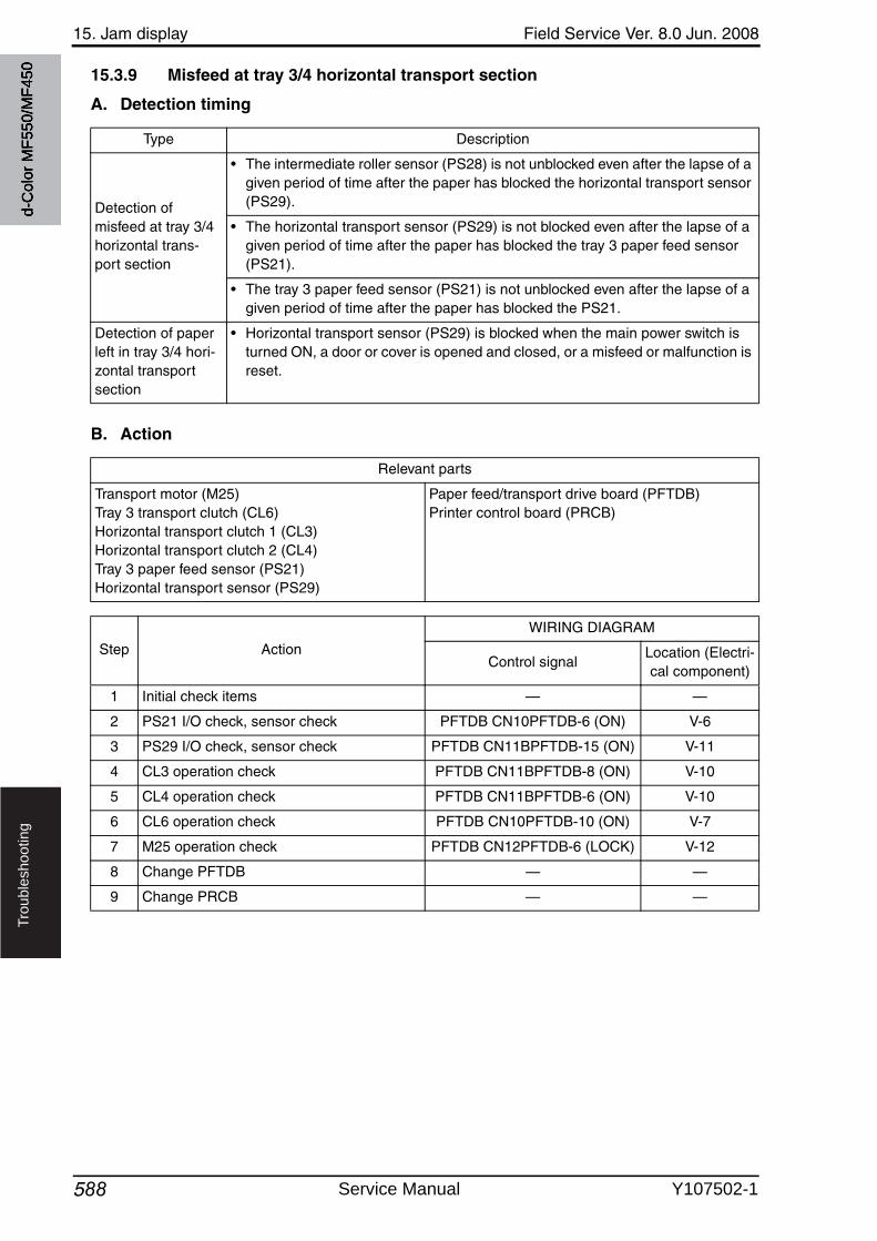
15. Jam display Field Service Ver. 8.0 Jun. 2008
588
Tro
ub
lesh
oo
tin
g
15.3.9 Misfeed at tray 3/4 horizontal transport section
A. Detection timing
B. Action
Type Description
Detection of misfeed at tray 3/4 horizontal trans-port section
• The intermediate roller sensor (PS28) is not unblocked even after the lapse of a given period of time after the paper has blocked the horizontal transport sensor (PS29).
• The horizontal transport sensor (PS29) is not blocked even after the lapse of a given period of time after the paper has blocked the tray 3 paper feed sensor (PS21).
• The tray 3 paper feed sensor (PS21) is not unblocked even after the lapse of a given period of time after the paper has blocked the PS21.
Detection of paper left in tray 3/4 hori-zontal transport section
• Horizontal transport sensor (PS29) is blocked when the main power switch is turned ON, a door or cover is opened and closed, or a misfeed or malfunction is reset.
Relevant parts
Transport motor (M25)Tray 3 transport clutch (CL6)Horizontal transport clutch 1 (CL3)Horizontal transport clutch 2 (CL4)Tray 3 paper feed sensor (PS21)Horizontal transport sensor (PS29)
Paper feed/transport drive board (PFTDB)Printer control board (PRCB)
Step Action
WIRING DIAGRAM
Control signalLocation (Electri-cal component)
1 Initial check items — —
2 PS21 I/O check, sensor check PFTDB CN10PFTDB-6 (ON) V-6
3 PS29 I/O check, sensor check PFTDB CN11BPFTDB-15 (ON) V-11
4 CL3 operation check PFTDB CN11BPFTDB-8 (ON) V-10
5 CL4 operation check PFTDB CN11BPFTDB-6 (ON) V-10
6 CL6 operation check PFTDB CN10PFTDB-10 (ON) V-7
7 M25 operation check PFTDB CN12PFTDB-6 (LOCK) V-12
8 Change PFTDB — —
9 Change PRCB — —
d-C
olor
MF5
50/M
F450
Service Manual Y107502-1
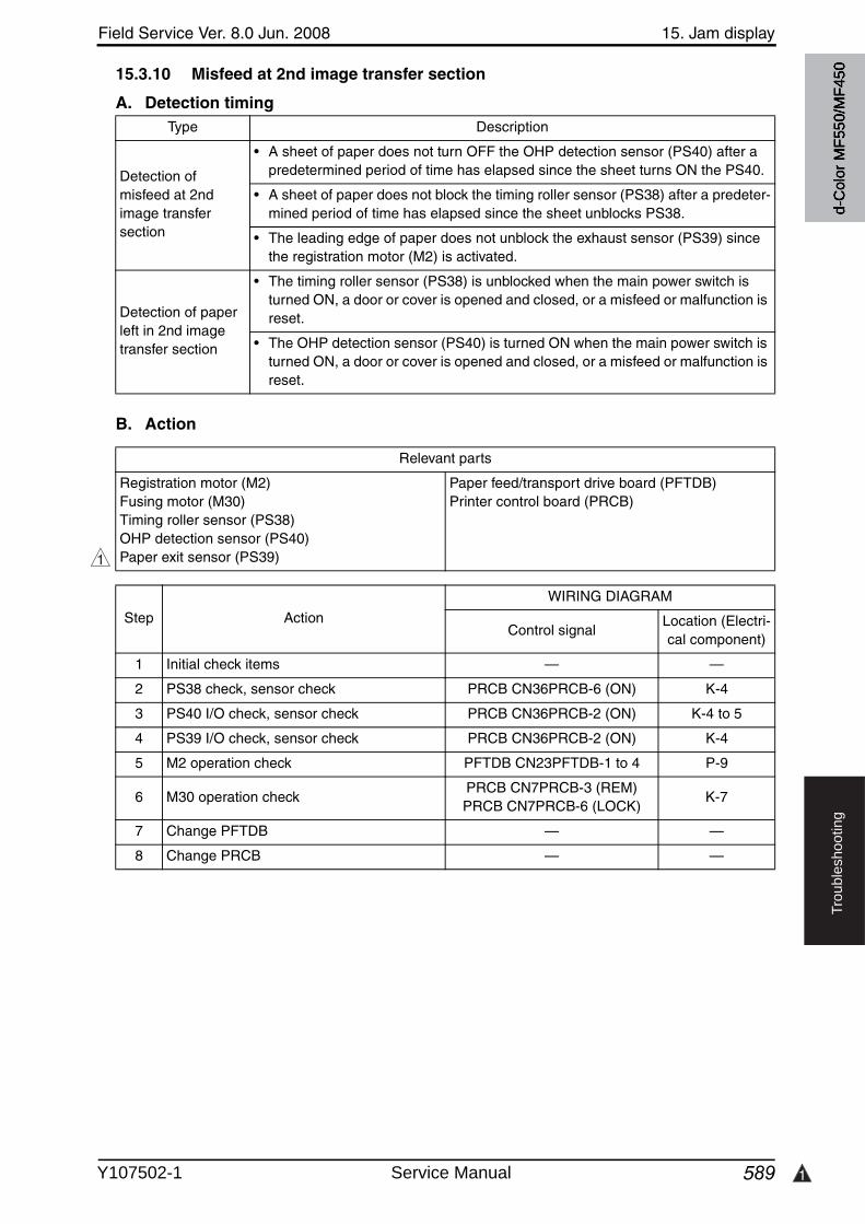
Field Service Ver. 8.0 Jun. 2008 15. Jam display
589 1
Tro
ub
lesh
oo
tin
g
15.3.10 Misfeed at 2nd image transfer section
A. Detection timing
B. Action
Type Description
Detection of misfeed at 2nd image transfer section
• A sheet of paper does not turn OFF the OHP detection sensor (PS40) after a predetermined period of time has elapsed since the sheet turns ON the PS40.
• A sheet of paper does not block the timing roller sensor (PS38) after a predeter-mined period of time has elapsed since the sheet unblocks PS38.
• The leading edge of paper does not unblock the exhaust sensor (PS39) since the registration motor (M2) is activated.
Detection of paper left in 2nd image transfer section
• The timing roller sensor (PS38) is unblocked when the main power switch is turned ON, a door or cover is opened and closed, or a misfeed or malfunction is reset.
• The OHP detection sensor (PS40) is turned ON when the main power switch is turned ON, a door or cover is opened and closed, or a misfeed or malfunction is reset.
Relevant parts
Registration motor (M2)Fusing motor (M30)Timing roller sensor (PS38)OHP detection sensor (PS40)Paper exit sensor (PS39)
Paper feed/transport drive board (PFTDB)Printer control board (PRCB)
Step Action
WIRING DIAGRAM
Control signalLocation (Electri-cal component)
1 Initial check items — —
2 PS38 check, sensor check PRCB CN36PRCB-6 (ON) K-4
3 PS40 I/O check, sensor check PRCB CN36PRCB-2 (ON) K-4 to 5
4 PS39 I/O check, sensor check PRCB CN36PRCB-2 (ON) K-4
5 M2 operation check PFTDB CN23PFTDB-1 to 4 P-9
6 M30 operation checkPRCB CN7PRCB-3 (REM)PRCB CN7PRCB-6 (LOCK)
K-7
7 Change PFTDB — —
8 Change PRCB — —
1
d-C
olor
MF5
50/M
F450
Y107502-1 Service Manual
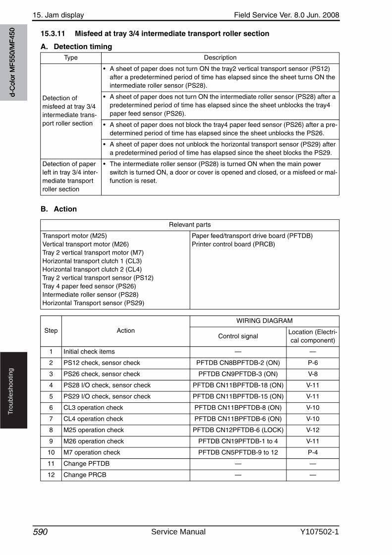
15. Jam display Field Service Ver. 8.0 Jun. 2008
590
Tro
ub
lesh
oo
tin
g
15.3.11 Misfeed at tray 3/4 intermediate transport roller section
A. Detection timing
B. Action
Type Description
Detection of misfeed at tray 3/4 intermediate trans-port roller section
• A sheet of paper does not turn ON the tray2 vertical transport sensor (PS12) after a predetermined period of time has elapsed since the sheet turns ON the intermediate roller sensor (PS28).
• A sheet of paper does not turn ON the intermediate roller sensor (PS28) after a predetermined period of time has elapsed since the sheet unblocks the tray4 paper feed sensor (PS26).
• A sheet of paper does not block the tray4 paper feed sensor (PS26) after a pre-determined period of time has elapsed since the sheet unblocks the PS26.
• A sheet of paper does not unblock the horizontal transport sensor (PS29) after a predetermined period of time has elapsed since the sheet blocks the PS29.
Detection of paper left in tray 3/4 inter-mediate transport roller section
• The intermediate roller sensor (PS28) is turned ON when the main powerswitch is turned ON, a door or cover is opened and closed, or a misfeed or mal-function is reset.
Relevant parts
Transport motor (M25)Vertical transport motor (M26)Tray 2 vertical transport motor (M7)Horizontal transport clutch 1 (CL3)Horizontal transport clutch 2 (CL4)Tray 2 vertical transport sensor (PS12)Tray 4 paper feed sensor (PS26)Intermediate roller sensor (PS28)Horizontal Transport sensor (PS29)
Paper feed/transport drive board (PFTDB)Printer control board (PRCB)
Step Action
WIRING DIAGRAM
Control signalLocation (Electri-cal component)
1 Initial check items — —
2 PS12 check, sensor check PFTDB CN8BPFTDB-2 (ON) P-6
3 PS26 check, sensor check PFTDB CN9PFTDB-3 (ON) V-8
4 PS28 I/O check, sensor check PFTDB CN11BPFTDB-18 (ON) V-11
5 PS29 I/O check, sensor check PFTDB CN11BPFTDB-15 (ON) V-11
6 CL3 operation check PFTDB CN11BPFTDB-8 (ON) V-10
7 CL4 operation check PFTDB CN11BPFTDB-6 (ON) V-10
8 M25 operation check PFTDB CN12PFTDB-6 (LOCK) V-12
9 M26 operation check PFTDB CN19PFTDB-1 to 4 V-11
10 M7 operation check PFTDB CN5PFTDB-9 to 12 P-4
11 Change PFTDB — —
12 Change PRCB — —
d-C
olor
MF5
50/M
F450
Service Manual Y107502-1
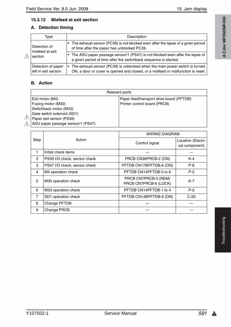
Field Service Ver. 8.0 Jun. 2008 15. Jam display
591 1
Tro
ub
lesh
oo
tin
g
15.3.12 Misfeed at exit section
A. Detection timing
B. Action
Type Description
Detection of misfeed at exit section
• The exhaust sensor (PC39) is not blocked even after the lapse of a given period of time after the paper has unblocked PC39.
• The ADU paper passage sensor/1 (PS47) is not blocked even after the lapse of a given period of time after the switchback sequence is started.
Detection of paper left in exit section
• The exhaust sensor (PC39) is unblocked when the main power switch is turned ON, a door or cover is opened and closed, or a misfeed or malfunction is reset.
1
Relevant parts
Exit motor (M4)Fusing motor (M30)Switchback motor (M33)Gate switch solenoid (SD1)Paper exit sensor (PS39)ADU paper passage sensor/1 (PS47)
Paper feed/transport drive board (PFTDB)Printer control board (PRCB)
Step Action
WIRING DIAGRAM
Control signalLocation (Electri-cal component)
1 Initial check items — —
2 PS39 I/O check, sensor check PRCB CN36PRCB-2 (ON) K-4
3 PS47 I/O check, sensor check PFTDB CN17BPFTDB-6 (ON) P-8
4 M4 operation check PFTDB CN14PFTDB-5 to 8 P-2
5 M30 operation checkPRCB CN7PRCB-3 (REM)PRCB CN7PRCB-6 (LOCK)
K-7
6 M33 operation check PFTDB CN14PFTDB-1 to 4 P-2
7 SD1 operation check PFTDB CN14BPFTDB-9 (ON) C-20
8 Change PFTDB — —
9 Change PRCB — —
1
1
d-C
olor
MF5
50/M
F450
Y107502-1 Service Manual
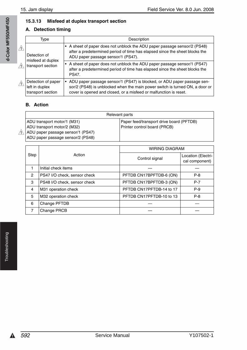
1
15. Jam display Field Service Ver. 8.0 Jun. 2008
592
Tro
ub
lesh
oo
tin
g
15.3.13 Misfeed at duplex transport section
A. Detection timing
B. Action
Type Description
Detection of misfeed at duplex transport section
• A sheet of paper does not unblock the ADU paper passage sensor/2 (PS48)after a predetermined period of time has elapsed since the sheet blocks the ADU paper passage sensor/1 (PS47).
• A sheet of paper does not unblock the ADU paper passage sensor/1 (PS47) after a predetermined period of time has elapsed since the sheet blocks the PS47.
Detection of paper left in duplex transport section
• ADU paper passage sensor/1 (PS47) is blocked, or ADU paper passage sen-sor/2 (PS48) is unblocked when the main power switch is turned ON, a door or cover is opened and closed, or a misfeed or malfunction is reset.
1
1
1
Relevant parts
ADU transport motor/1 (M31)ADU transport motor/2 (M32)ADU paper passage sensor/1 (PS47)ADU paper passage sensor/2 (PS48)
Paper feed/transport drive board (PFTDB)Printer control board (PRCB)
Step Action
WIRING DIAGRAM
Control signalLocation (Electri-cal component)
1 Initial check items — —
2 PS47 I/O check, sensor check PFTDB CN17BPFTDB-6 (ON) P-8
3 PS48 I/O check, sensor check PFTDB CN17BPFTDB-3 (ON) P-7
4 M31 operation check PFTDB CN17PFTDB-14 to 17 P-9
5 M32 operation check PFTDB CN17PFTDB-10 to 13 P-8
6 Change PFTDB — —
7 Change PRCB — —
1
d-C
olor
MF5
50/M
F450
Service Manual Y107502-1
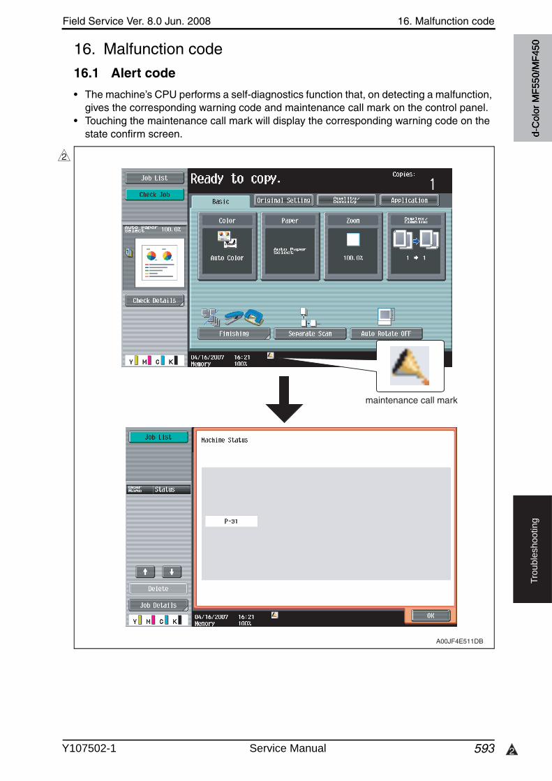
Field Service Ver. 8.0 Jun. 2008 16. Malfunction code
593 2
Tro
ub
lesh
oo
tin
g
16. Malfunction code
16.1 Alert code
• The machine’s CPU performs a self-diagnostics function that, on detecting a malfunction,gives the corresponding warning code and maintenance call mark on the control panel.
• Touching the maintenance call mark will display the corresponding warning code on the state confirm screen.
2
A00JF4E511DB
maintenance call mark
d-C
olor
MF5
50/M
F450
Y107502-1 Service Manual
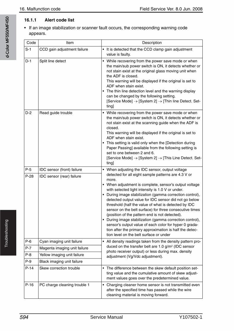
16. Malfunction code Field Service Ver. 8.0 Jun. 2008
594
Tro
ub
lesh
oo
tin
g
16.1.1 Alert code list
• If an image stabilization or scanner fault occurs, the corresponding warning code appears.
Code Item Description
S-1 CCD gain adjustment failure • It is detected that the CCD clamp gain adjustment value is faulty.
D-1 Split line detect • While recovering from the power save mode or whenthe main/sub power switch is ON, it detects whether or not stain exist at the original glass moving unit when the ADF is closed. This warning will be displayed if the original is set to ADF when stain exist.
• The thin line detection level and the warning display can be changed by the following setting.[Service Mode] [System 2] [Thin line Detect. Set-ting]
D-2 Read guide trouble • While recovering from the power save mode or whenthe main/sub power switch is ON, it detects whether or not stain exist at the scanning guide when the ADF is closed. This warning will be displayed if the original is set to ADF when stain exist.
• This setting is valid only when the [Detection during Paper Passing] available from the following setting is set to one between 2 and 6.[Service Mode] [System 2] [This Line Detect. Set-ting]
P-5 IDC sensor (front) failure • When adjusting the IDC sensor, output voltage detected for all eight sample patterns are 4.3 V or more.
• When adjustment is complete, sensor’s output voltage with selected light intensity is 1.0 V or under.
• During image stabilization (gamma correction control), detected output value for IDC sensor did not go belowthreshold (half the value of what is detected by IDC sensor on the belt surface) for three consecutive times (position of the pattern end is not detected).
• During image stabilization (gamma correction control), sensor’s output value of each color for hyper 0 grada-tion after the primary approximation is half the detec-tion level on the belt surface or under
P-28 IDC sensor (rear) failure
P-6 Cyan imaging unit failure • All density readings taken from the density pattern pro-duced on the transfer belt are 1.0 g/m2 (IDC sensor photo receiver output) or less during max. density adjustment (Vg/Vdc adjustment).
P-7 Magenta imaging unit failure
P-8 Yellow imaging unit failure
P-9 Black imaging unit failure
P-14 Skew correction trouble • The difference between the skew default position set-ting value and the cumulative amount of skew adjust-ment values goes over the predetermined value.
P-16 PC charge cleaning trouble 1 • Charging cleaner home sensor is not transmitted evenafter the specified time has passed while the wire cleaning material is moving forward.
d-C
olor
MF5
50/M
F450
Service Manual Y107502-1
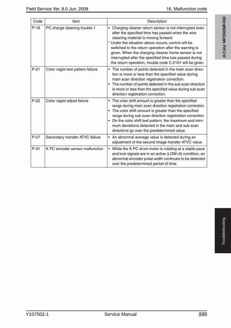
Field Service Ver. 8.0 Jun. 2008 16. Malfunction code
595
Tro
ub
lesh
oo
tin
g
P-18 PC charge cleaning trouble 1 • Charging cleaner return sensor is not interrupted evenafter the specified time has passed when the wire cleaning material is moving forward.
* Under the situation above occurs, control will be switched to the return operation after the warning is given. When the charging cleaner home sensor is not interrupted after the specified time has passed during the return operation, trouble code C-2101 will be given.
P-21 Color regist test pattern failure • The number of points detected in the main scan direc-tion is more or less than the specified value during main scan direction registration correction.
• The number of points detected in the sub scan direction is more or less than the specified value during sub scan direction registration correction.
P-22 Color regist adjust failure • The color shift amount is greater than the specified range during main scan direction registration correction.
• The color shift amount is greater than the specified range during sub scan direction registration correction.
• On the color shift test pattern, the maximum and mini-mum deviations detected in the main and sub scan directions go over the predetermined value.
P-27 Secondary transfer ATVC failure • An abnormal average value is detected during an adjustment of the second image transfer ATVC value.
P-31 K PC encoder sensor malfunction • While the K PC drum motor is rotating at a stable pace and lock signals are in an active (LOW=0) condition, an abnormal encoder pulse width continues to be detected over the predetermined period of time.
Code Item Description
d-C
olor
MF5
50/M
F450
Y107502-1 Service Manual
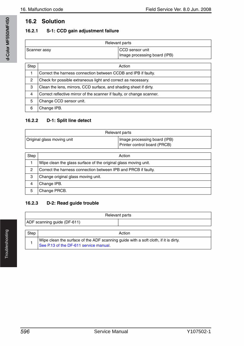
16. Malfunction code Field Service Ver. 8.0 Jun. 2008
596
Tro
ub
lesh
oo
tin
g
16.2 Solution
16.2.1 S-1: CCD gain adjustment failure
16.2.2 D-1: Split line detect
16.2.3 D-2: Read guide trouble
Relevant parts
Scanner assy CCD sensor unitImage processing board (IPB)
Step Action
1 Correct the harness connection between CCDB and IPB if faulty.
2 Check for possible extraneous light and correct as necessary.
3 Clean the lens, mirrors, CCD surface, and shading sheet if dirty.
4 Correct reflective mirror of the scanner if faulty, or change scanner.
5 Change CCD sensor unit.
6 Change IPB.
Relevant parts
Original glass moving unit Image processing board (IPB)Printer control board (PRCB)
Step Action
1 Wipe clean the glass surface of the original glass moving unit.
2 Correct the harness connection between IPB and PRCB if faulty.
3 Change original glass moving unit.
4 Change IPB.
5 Change PRCB.
Relevant parts
ADF scanning guide (DF-611)
Step Action
1Wipe clean the surface of the ADF scanning guide with a soft cloth, if it is dirty.See P.13 of the DF-611 service manual.
d-C
olor
MF5
50/M
F450
Service Manual Y107502-1
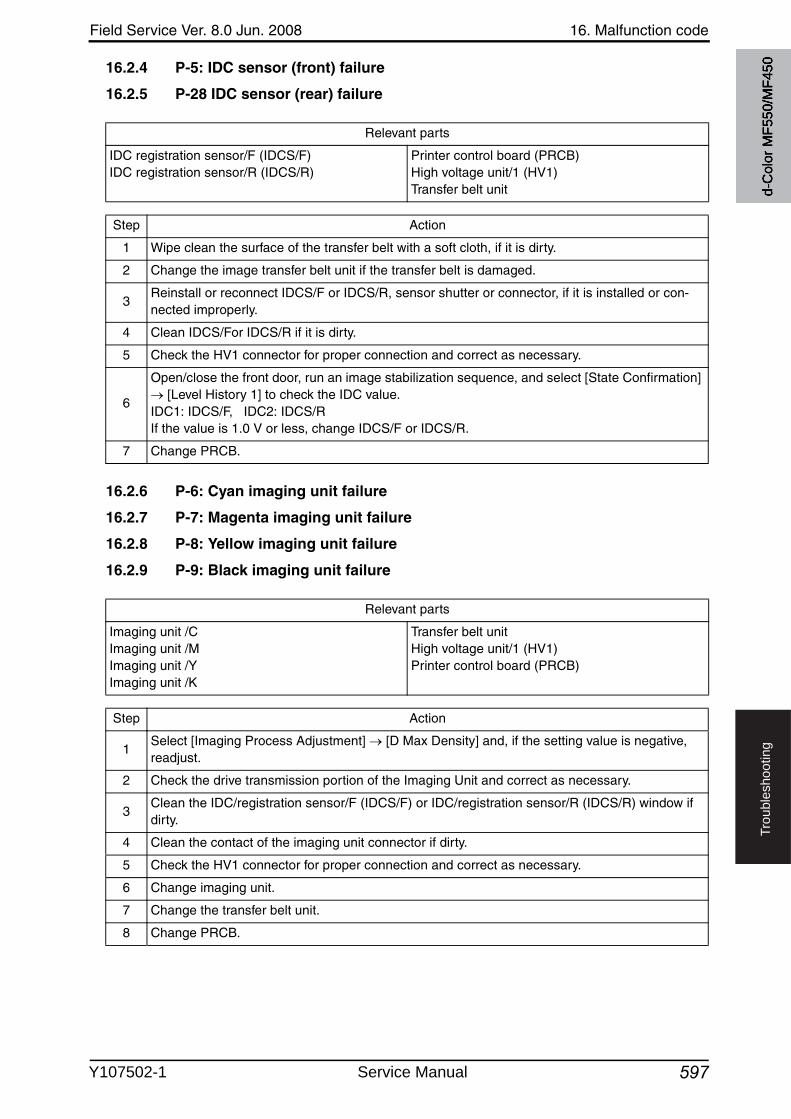
Field Service Ver. 8.0 Jun. 2008 16. Malfunction code
597
Tro
ub
lesh
oo
tin
g
16.2.4 P-5: IDC sensor (front) failure
16.2.5 P-28 IDC sensor (rear) failure
16.2.6 P-6: Cyan imaging unit failure
16.2.7 P-7: Magenta imaging unit failure
16.2.8 P-8: Yellow imaging unit failure
16.2.9 P-9: Black imaging unit failure
Relevant parts
IDC registration sensor/F (IDCS/F)IDC registration sensor/R (IDCS/R)
Printer control board (PRCB)High voltage unit/1 (HV1)Transfer belt unit
Step Action
1 Wipe clean the surface of the transfer belt with a soft cloth, if it is dirty.
2 Change the image transfer belt unit if the transfer belt is damaged.
3Reinstall or reconnect IDCS/F or IDCS/R, sensor shutter or connector, if it is installed or con-nected improperly.
4 Clean IDCS/For IDCS/R if it is dirty.
5 Check the HV1 connector for proper connection and correct as necessary.
6
Open/close the front door, run an image stabilization sequence, and select [State Confirmation] [Level History 1] to check the IDC value.
IDC1: IDCS/F, IDC2: IDCS/RIf the value is 1.0 V or less, change IDCS/F or IDCS/R.
7 Change PRCB.
Relevant parts
Imaging unit /CImaging unit /MImaging unit /YImaging unit /K
Transfer belt unitHigh voltage unit/1 (HV1)Printer control board (PRCB)
Step Action
1Select [Imaging Process Adjustment] [D Max Density] and, if the setting value is negative, readjust.
2 Check the drive transmission portion of the Imaging Unit and correct as necessary.
3Clean the IDC/registration sensor/F (IDCS/F) or IDC/registration sensor/R (IDCS/R) window if dirty.
4 Clean the contact of the imaging unit connector if dirty.
5 Check the HV1 connector for proper connection and correct as necessary.
6 Change imaging unit.
7 Change the transfer belt unit.
8 Change PRCB.
d-C
olor
MF5
50/M
F450
Y107502-1 Service Manual
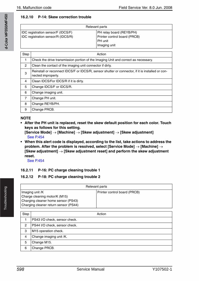
16. Malfunction code Field Service Ver. 8.0 Jun. 2008
598
Tro
ub
lesh
oo
tin
g
16.2.10 P-14: Skew correction trouble
NOTE• After the PH unit is replaced, reset the skew default position for each color. Touch
keys as follows for this setting. [Service Mode] [Machine] [Skew adjustment] [Skew adjustment]
See P.454• When this alert code is displayed, according to the list, take actions to address the
problem. After the problem is resolved, select [Service Mode] [Machine] [Skew adjustment] [Skew adjustment reset] and perform the skew adjustment reset.
See P.454
16.2.11 P-16: PC charge cleaning trouble 1
16.2.12 P-18: PC charge cleaning trouble 2
Relevant parts
IDC registration sensor/F (IDCS/F)IDC registration sensor/R (IDCS/R)
PH relay board (REYB/PH)Printer control board (PRCB)PH unitImaging unit
Step Action
1 Check the drive transmission portion of the Imaging Unit and correct as necessary.
2 Clean the contact of the imaging unit connector if dirty.
3Reinstall or reconnect IDCS/F or IDCS/R, sensor shutter or connector, if it is installed or con-nected improperly.
4 Clean IDCS/For IDCS/R if it is dirty.
5 Change IDCS/F or IDCS/R.
6 Change imaging unit.
7 Change PH unit.
8 Change REYB/PH.
9 Change PRCB.
Relevant parts
Imaging unit /KCharge cleaning motor/K (M15)Charging cleaner home sensor (PS43)Charging cleaner return sensor (PS44)
Printer control board (PRCB)
Step Action
1 PS43 I/O check, sensor check.
2 PS44 I/O check, sensor check.
3 M15 operation check.
4 Change imaging unit /K.
5 Change M15.
6 Change PRCB.
d-C
olor
MF5
50/M
F450
Service Manual Y107502-1
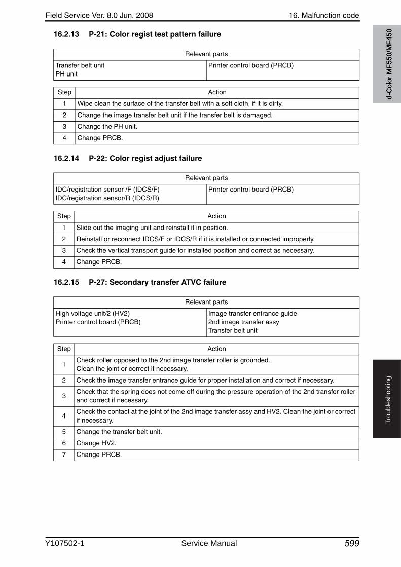
Field Service Ver. 8.0 Jun. 2008 16. Malfunction code
599
Tro
ub
lesh
oo
tin
g
16.2.13 P-21: Color regist test pattern failure
16.2.14 P-22: Color regist adjust failure
16.2.15 P-27: Secondary transfer ATVC failure
Relevant parts
Transfer belt unitPH unit
Printer control board (PRCB)
Step Action
1 Wipe clean the surface of the transfer belt with a soft cloth, if it is dirty.
2 Change the image transfer belt unit if the transfer belt is damaged.
3 Change the PH unit.
4 Change PRCB.
Relevant parts
IDC/registration sensor /F (IDCS/F)IDC/registration sensor/R (IDCS/R)
Printer control board (PRCB)
Step Action
1 Slide out the imaging unit and reinstall it in position.
2 Reinstall or reconnect IDCS/F or IDCS/R if it is installed or connected improperly.
3 Check the vertical transport guide for installed position and correct as necessary.
4 Change PRCB.
Relevant parts
High voltage unit/2 (HV2)Printer control board (PRCB)
Image transfer entrance guide2nd image transfer assyTransfer belt unit
Step Action
1Check roller opposed to the 2nd image transfer roller is grounded. Clean the joint or correct if necessary.
2 Check the image transfer entrance guide for proper installation and correct if necessary.
3Check that the spring does not come off during the pressure operation of the 2nd transfer roller and correct if necessary.
4Check the contact at the joint of the 2nd image transfer assy and HV2. Clean the joint or correct if necessary.
5 Change the transfer belt unit.
6 Change HV2.
7 Change PRCB.
d-C
olor
MF5
50/M
F450
Y107502-1 Service Manual
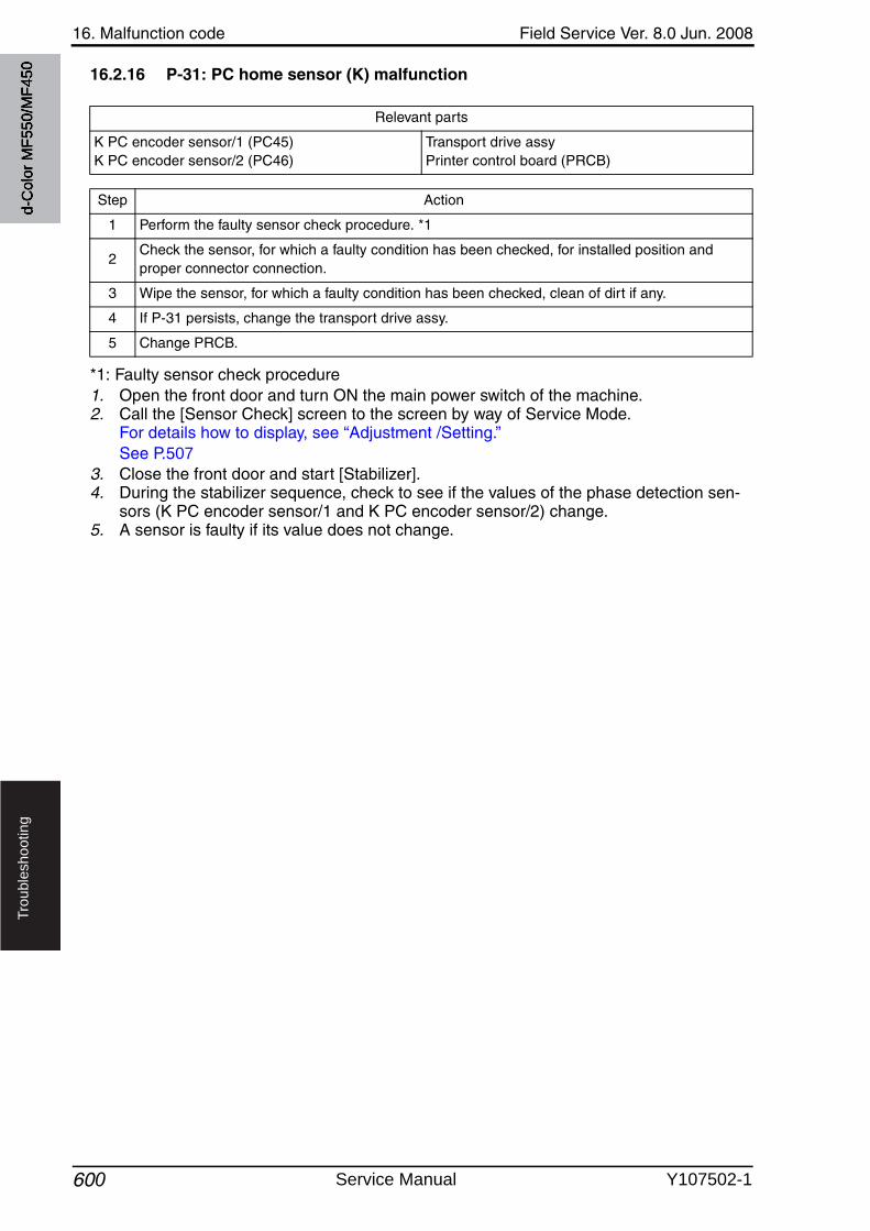
16. Malfunction code Field Service Ver. 8.0 Jun. 2008
600
Tro
ub
lesh
oo
tin
g
16.2.16 P-31: PC home sensor (K) malfunction
*1: Faulty sensor check procedure1. Open the front door and turn ON the main power switch of the machine.2. Call the [Sensor Check] screen to the screen by way of Service Mode.
For details how to display, see “Adjustment /Setting.”See P.507
3. Close the front door and start [Stabilizer].4. During the stabilizer sequence, check to see if the values of the phase detection sen-
sors (K PC encoder sensor/1 and K PC encoder sensor/2) change.5. A sensor is faulty if its value does not change.
Relevant parts
K PC encoder sensor/1 (PC45)K PC encoder sensor/2 (PC46)
Transport drive assyPrinter control board (PRCB)
Step Action
1 Perform the faulty sensor check procedure. *1
2Check the sensor, for which a faulty condition has been checked, for installed position and proper connector connection.
3 Wipe the sensor, for which a faulty condition has been checked, clean of dirt if any.
4 If P-31 persists, change the transport drive assy.
5 Change PRCB.
d-C
olor
MF5
50/M
F450
Service Manual Y107502-1
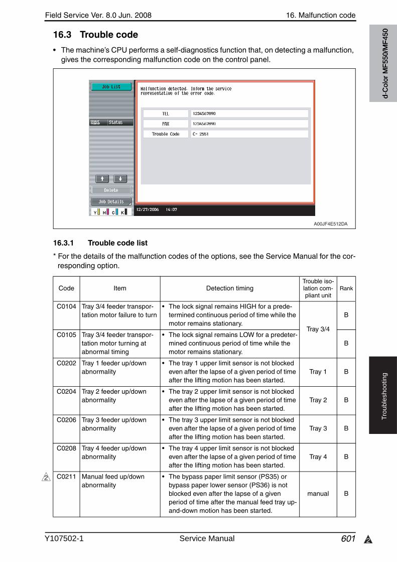
Field Service Ver. 8.0 Jun. 2008 16. Malfunction code
601 2
Tro
ub
lesh
oo
tin
g
16.3 Trouble code
• The machine’s CPU performs a self-diagnostics function that, on detecting a malfunction,gives the corresponding malfunction code on the control panel.
16.3.1 Trouble code list
* For the details of the malfunction codes of the options, see the Service Manual for the cor-responding option.
A00JF4E512DA
Code Item Detection timingTrouble iso-lation com-pliant unit
Rank
C0104 Tray 3/4 feeder transpor-tation motor failure to turn
• The lock signal remains HIGH for a prede-termined continuous period of time while the motor remains stationary.
Tray 3/4
B
C0105 Tray 3/4 feeder transpor-tation motor turning at abnormal timing
• The lock signal remains LOW for a predeter-mined continuous period of time while the motor remains stationary.
B
C0202 Tray 1 feeder up/downabnormality
• The tray 1 upper limit sensor is not blocked even after the lapse of a given period of time after the lifting motion has been started.
Tray 1 B
C0204 Tray 2 feeder up/downabnormality
• The tray 2 upper limit sensor is not blocked even after the lapse of a given period of time after the lifting motion has been started.
Tray 2 B
C0206 Tray 3 feeder up/downabnormality
• The tray 3 upper limit sensor is not blocked even after the lapse of a given period of time after the lifting motion has been started.
Tray 3 B
C0208 Tray 4 feeder up/downabnormality
• The tray 4 upper limit sensor is not blocked even after the lapse of a given period of time after the lifting motion has been started.
Tray 4 B
C0211 Manual feed up/downabnormality
• The bypass paper limit sensor (PS35) or bypass paper lower sensor (PS36) is not blocked even after the lapse of a givenperiod of time after the manual feed tray up-and-down motion has been started.
manual B
2
d-C
olor
MF5
50/M
F450
Y107502-1 Service Manual
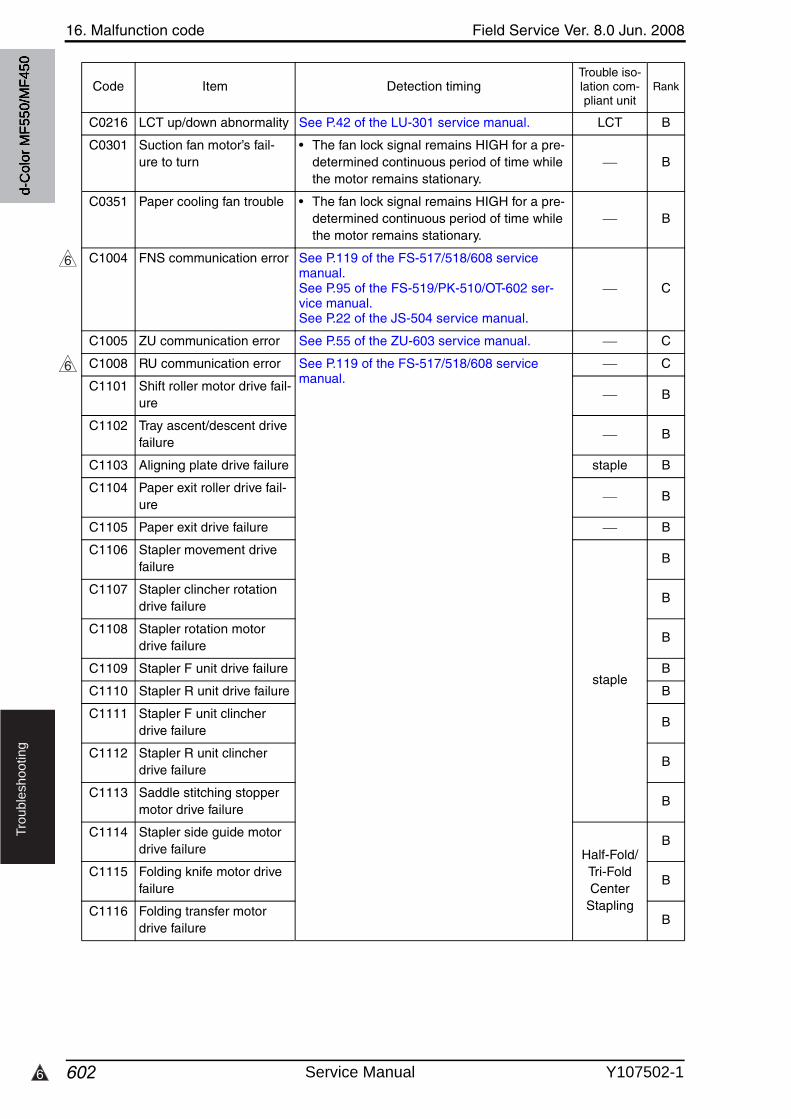
16. Malfunction code Field Service Ver. 8.0 Jun. 2008
6026
Tro
ub
lesh
oo
tin
g
C0216 LCT up/down abnormality See P.42 of the LU-301 service manual. LCT B
C0301 Suction fan motor’s fail-ure to turn
• The fan lock signal remains HIGH for a pre-determined continuous period of time while the motor remains stationary.
B
C0351 Paper cooling fan trouble • The fan lock signal remains HIGH for a pre-determined continuous period of time while the motor remains stationary.
B
C1004 FNS communication error See P.119 of the FS-517/518/608 service manual.See P.95 of the FS-519/PK-510/OT-602 ser-vice manual.See P.22 of the JS-504 service manual.
C
C1005 ZU communication error See P.55 of the ZU-603 service manual. C
C1008 RU communication error See P.119 of the FS-517/518/608 service manual.
C
C1101 Shift roller motor drive fail-ure
B
C1102 Tray ascent/descent drivefailure
B
C1103 Aligning plate drive failure staple B
C1104 Paper exit roller drive fail-ure
B
C1105 Paper exit drive failure B
C1106 Stapler movement drivefailure
staple
B
C1107 Stapler clincher rotation drive failure
B
C1108 Stapler rotation motor drive failure
B
C1109 Stapler F unit drive failure B
C1110 Stapler R unit drive failure B
C1111 Stapler F unit clincher drive failure
B
C1112 Stapler R unit clincher drive failure
B
C1113 Saddle stitching stopper motor drive failure
B
C1114 Stapler side guide motor drive failure Half-Fold/
Tri-Fold Center
Stapling
B
C1115 Folding knife motor drivefailure
B
C1116 Folding transfer motor drive failure
B
Code Item Detection timingTrouble iso-lation com-pliant unit
Rank
6
6
d-C
olor
MF5
50/M
F450
Service Manual Y107502-1
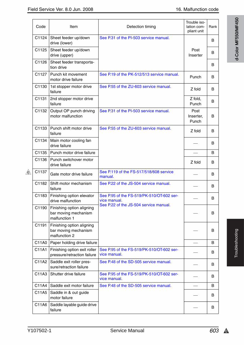
6
Field Service Ver. 8.0 Jun. 2008 16. Malfunction code
603
Tro
ub
lesh
oo
tin
g
C1124 Sheet feeder up/downdrive (lower)
See P.31 of the PI-503 service manual.
Post Inserter
B
C1125 Sheet feeder up/downdrive (upper)
B
C1126 Sheet feeder transporta-tion drive
B
C1127 Punch kit movement motor drive failure
See P.19 of the PK-512/513 service manual.Punch B
C1130 1st stopper motor drivefailure
See P.55 of the ZU-603 service manual.Z fold B
C1131 2nd stopper motor drivefailure
Z fold, Punch
B
C1132 Output OP punch drivingmotor malfunction
See P.31 of the PI-503 service manual. Post Inserter, Punch
B
C1133 Punch shift motor drivefailure
See P.55 of the ZU-603 service manual.Z fold B
C1134 Main motor cooling fan drive failure
B
C1135 Punch motor drive failure B
C1136 Punch switchover motor drive failure
Z fold B
C1137 Gate motor drive failure See P.119 of the FS-517/518/608 servicemanual. B
C1182 Shift motor mechanism failure
See P.22 of the JS-504 service manual.B
C1183 Finishing option elevator drive malfunction
See P.95 of the FS-519/PK-510/OT-602 ser-vice manual.See P.22 of the JS-504 service manual.
B
C1190 Finishing option aligning bar moving mechanism malfunction 1
B
C1191 Finishing option aligning bar moving mechanism malfunction 2
B
C11A0 Paper holding drive failure B
C11A1 Finishing option exit roller pressure/retraction failure
See P.95 of the FS-519/PK-510/OT-602 ser-vice manual. B
C11A2 Saddle exit roller pres-sure/retraction failure
See P.48 of the SD-505 service manual.B
C11A3 Shutter drive failure See P.95 of the FS-519/PK-510/OT-602 ser-vice manual. B
C11A4 Saddle exit motor failure See P.48 of the SD-505 service manual. B
C11A5 Saddle in & out guidemotor failure
B
C11A6 Saddle layable guide drivefailure
B
Code Item Detection timingTrouble iso-lation com-pliant unit
Rank
6
d-C
olor
MF5
50/M
F450
Y107502-1 Service Manual
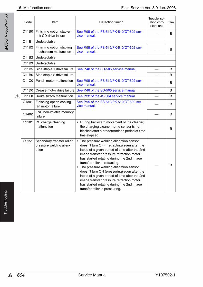
16. Malfunction code Field Service Ver. 8.0 Jun. 2008
6043
Tro
ub
lesh
oo
tin
g
C11B0 Finishing option stapler unit CD drive failure
See P.95 of the FS-519/PK-510/OT-602 ser-vice manual. B
C11B1 Undetectable
C11B2 Finishing option stapling mechanism malfunction 1
See P.95 of the FS-519/PK-510/OT-602 ser-vice manual. B
C11B2 Undetectable
C11B3 Undetectable
C11B5 Side staple 1 drive failure See P.48 of the SD-505 service manual. B
C11B6 Side staple 2 drive failure B
C11C0 Punch motor malfunction See P.95 of the FS-519/PK-510/OT-602 ser-vice manual. B
C11D0 Crease motor drive failure See P.48 of the SD-505 service manual. B
C11E0 Route switch malfunction See P.22 of the JS-504 service manual. B
C1301 Finishing option cooling fan motor failure
See P.95 of the FS-519/PK-510/OT-602 ser-vice manual. B
C1402FNS non-volatile memory failure
B
C2101 PC charge cleaning malfunction
• During backward movement of the cleaner, the charging cleaner home sensor is not blocked after a predetermined period of time has elapsed.
B
C2151 Secondary transfer roller pressure welding alien-ation
• The pressure welding alienation sensor doesn’t turn OFF (retracting) even after the lapse of a given period of time after the 2nd image transfer pressure retraction motor has started rotating during the 2nd image transfer roller is retracting.
• The pressure welding alienation sensor doesn’t turn ON (pressuring) even after the lapse of a given period of time after the 2nd image transfer pressure retraction motor has started rotating during the 2nd image transfer roller is pressuring.
B
Code Item Detection timingTrouble iso-lation com-pliant unit
Rank
3
d-C
olor
MF5
50/M
F450
Service Manual Y107502-1
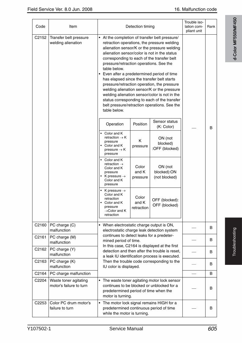
Field Service Ver. 8.0 Jun. 2008 16. Malfunction code
605
Tro
ub
lesh
oo
tin
g
C2152 Transfer belt pressure welding alienation
• At the completion of transfer belt pressure/retraction operations, the pressure welding alienation sensor/K or the pressure welding alienation sensor/color is not in the statuscorresponding to each of the transfer belt pressure/retraction operations. See the table below.
• Even after a predetermined period of time has elapsed since the transfer belt starts pressure/retraction operation, the pressurewelding alienation sensor/K or the pressure welding alienation sensor/color is not in the status corresponding to each of the transfer belt pressure/retraction operations. See the table below.
B
C2160 PC charge (C) malfunction
• When electrostatic charge output is ON, electrostatic charge leak detection system continues to detect leaks for a predeter-mined period of time. In this case, C2164 is displayed at the first detection and then after the trouble is reset, a leak IU identification process is executed. Then the trouble code corresponding to the IU color is displayed.
B
C2161 PC charge (M) malfunction
B
C2162 PC charge (Y) malfunction
B
C2163 PC charge (K) malfunction
B
C2164 PC charge malfunction B
C2204 Waste toner agitating motor’s failure to turn
• The waste toner agitating motor lock sensor continues to be blocked or unblocked for a predetermined period of time when the motor is turning.
B
C2253 Color PC drum motor’s failure to turn
• The motor lock signal remains HIGH for a predetermined continuous period of time while the motor is turning.
B
Code Item Detection timingTrouble iso-lation com-pliant unit
Rank
Operation PositionSensor status
(K: Color)
• Color and K retraction K pressure
• Color and K pressure K pressure
Kpressure
ON (not blocked)
:OFF (blocked)
• Color and K retraction Color and K pressure
• K pressure Color and K pressure
Colorand K
pressure
ON (not blocked):ON (not blocked)
• K pressure Color and K retraction
• Color and K pressure
Color and K retraction
Colorand K
retraction
OFF (blocked):OFF (blocked)
d-C
olor
MF5
50/M
F450
Y107502-1 Service Manual
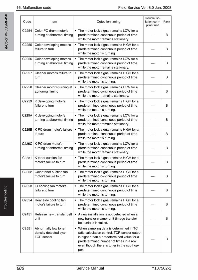
16. Malfunction code Field Service Ver. 8.0 Jun. 2008
606
Tro
ub
lesh
oo
tin
g
C2254 Color PC drum motor’s turning at abnormal timing
• The motor lock signal remains LOW for a predetermined continuous period of time while the motor remains stationary.
B
C2255 Color developing motor’s failure to turn
• The motor lock signal remains HIGH for a predetermined continuous period of time while the motor is turning.
B
C2256 Color developing motor’s turning at abnormal timing
• The motor lock signal remains LOW for a predetermined continuous period of time while the motor remains stationary.
B
C2257 Cleaner motor’s failure to turn
• The motor lock signal remains HIGH for a predetermined continuous period of time while the motor is turning.
B
C2258 Cleaner motor’s turning at abnormal timing
• The motor lock signal remains LOW for a predetermined continuous period of time while the motor remains stationary.
B
C2259 K developing motor’s failure to turn
• The motor lock signal remains HIGH for a predetermined continuous period of time while the motor is turning.
B
C225A K developing motor’s turning at abnormal timing
• The motor lock signal remains LOW for a predetermined continuous period of time while the motor remains stationary.
B
C225B K PC drum motor’s failureto turn
• The motor lock signal remains HIGH for a predetermined continuous period of time while the motor is turning.
B
C225C K PC drum motor’s turning at abnormal timing
• The motor lock signal remains LOW for a predetermined continuous period of time while the motor remains stationary.
B
C2351 K toner suction fan motor’s failure to turn
• The motor lock signal remains HIGH for a predetermined continuous period of time while the motor is turning.
B
C2352 Color toner suction fan motor’s failure to turn
• The motor lock signal remains HIGH for a predetermined continuous period of time while the motor is turning.
B
C2353 IU cooling fan motor’s failure to turn
• The motor lock signal remains HIGH for a predetermined continuous period of time while the motor is turning.
B
C2354 Rear side cooling fan motor’s failure to turn
• The motor lock signal remains HIGH for a predetermined continuous period of time while the motor is turning.
B
C2451 Release new transfer belt unit
• A new installation is not detected when a new transfer cleaner unit (image transfer belt unit) is installed.
B
C2551 Abnormally low toner density detected cyan TCR sensor
• When sampling data is determined in TC ratio calculation control, TCR sensor outputis higher than a predetermined value for a predetermined number of times in a roweven though there is toner in the sub hop-per.
B
Code Item Detection timingTrouble iso-lation com-pliant unit
Rank
d-C
olor
MF5
50/M
F450
Service Manual Y107502-1
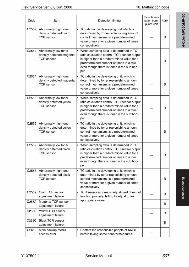
Field Service Ver. 8.0 Jun. 2008 16. Malfunction code
607
Tro
ub
lesh
oo
tin
g
C2552 Abnormally high toner density detected cyan TCR sensor
• TC ratio in the developing unit which is determined by Toner replenishing amount control mechanism, is a predetermined value or more for a given number of times consecutively.
B
C2553 Abnormally low toner density detected magenta TCR sensor
• When sampling data is determined in TC ratio calculation control, TCR sensor outputis higher than a predetermined value for a predetermined number of times in a roweven though there is toner in the sub hop-per.
B
C2554 Abnormally high toner density detected magenta TCR sensor
• TC ratio in the developing unit, which is determined by toner replenishing amountcontrol mechanism, is a predetermined value or more for a given number of times consecutively.
B
C2555 Abnormally low toner density detected yellowTCR sensor
• When sampling data is determined in TC ratio calculation control, TCR sensor outputis higher than a predetermined value for a predetermined number of times in a roweven though there is toner in the sub hop-per.
B
C2556 Abnormally high toner density detected yellowTCR sensor
• TC ratio in the developing unit, which is determined by toner replenishing amountcontrol mechanism, is a predetermined value or more for a given number of times consecutively.
B
C2557 Abnormally low toner density detected black TCR sensor
• When sampling data is determined in TC ratio calculation control, TCR sensor outputis higher than a predetermined value for a predetermined number of times in a roweven though there is toner in the sub hop-per.
B
C2558 Abnormally high toner density detected black TCR sensor
• TC ratio in the developing unit, which is determined by toner replenishing amountcontrol mechanism, is a predetermined value or more for a given number of times consecutively.
B
C2559 Cyan TCR sensor adjustment failure
• TCR sensor automatic adjustment does not function properly, failing to adjust to an appropriate value.
B
C255A Magenta TCR sensor adjustment failure
B
C255B Yellow TCR sensor adjustment failure
B
C255C Black TCR sensor adjustment failure
B
C2650 Main backup media access error
• Contact the responsible people of KMBT before taking some countermeasures.
Code Item Detection timingTrouble iso-lation com-pliant unit
Rank
d-C
olor
MF5
50/M
F450
Y107502-1 Service Manual
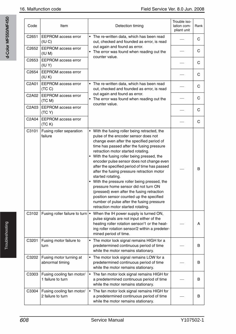
16. Malfunction code Field Service Ver. 8.0 Jun. 2008
608
Tro
ub
lesh
oo
tin
g
C2651 EEPROM access error(IU C)
• The re-written data, which has been read out, checked and founded as error, is read out again and found as error.
• The error was found when reading out the counter value.
C
C2652 EEPROM access error(IU M)
C
C2653 EEPROM access error(IU Y)
C
C2654 EEPROM access error(IU K)
C
C2A01 EEPROM access error(TC C)
• The re-written data, which has been read out, checked and founded as error, is read out again and found as error.
• The error was found when reading out the counter value.
C
C2A02 EEPROM access error(TC M)
C
C2A03 EEPROM access error(TC Y)
C
C2A04 EEPROM access error(TC K)
C
C3101 Fusing roller separation failure
• With the fusing roller being retracted, the pulse of the encoder sensor does not change even after the specified period of time has passed after the fusing pressureretraction motor started rotating.
• With the fusing roller being pressed, the encoder pulse sensor does not change evenafter the specified period of time has passed after the fusing pressure retraction motor started rotating.
• With the pressure roller being pressed, the pressure home sensor did not turn ON (pressed) even after the fusing retraction position sensor counted up the specified number of pulse after the fusing pressureretraction motor started rotating.
B
C3102 Fusing roller failure to turn • When the IH power supply is turned ON, pulse signals are not input either of the heating roller rotation sensor/1 or the heat-ing roller rotation sensor/2 within a predeter-mined period of time.
A
C3201 Fusing motor failure to turn
• The motor lock signal remains HIGH for a predetermined continuous period of time while the motor remains stationary.
B
C3202 Fusing motor turning at abnormal timing
• The motor lock signal remains LOW for a predetermined continuous period of time while the motor remains stationary.
B
C3303 Fusing cooling fan motor/1 failure to turn
• The fan motor lock signal remains HIGH for a predetermined continuous period of time while the motor remains stationary.
B
C3304 Fusing cooling fan motor/2 failure to turn
• The fan motor lock signal remains HIGH for a predetermined continuous period of time while the motor remains stationary.
B
Code Item Detection timingTrouble iso-lation com-pliant unit
Rank
d-C
olor
MF5
50/M
F450
Service Manual Y107502-1
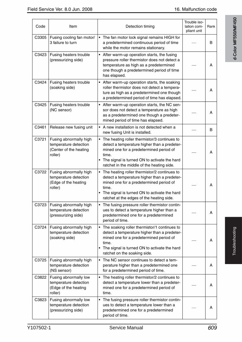
Field Service Ver. 8.0 Jun. 2008 16. Malfunction code
609
Tro
ub
lesh
oo
tin
g
C3305 Fusing cooling fan motor/3 failure to turn
• The fan motor lock signal remains HIGH for a predetermined continuous period of time while the motor remains stationary.
B
C3423 Fusing heaters trouble (pressurizing side)
• After warm-up operation starts, the fusingpressure roller thermistor does not detect a temperature as high as a predetermined one though a predetermined period of time has elapsed.
A
C3424 Fusing heaters trouble (soaking side)
• After warm-up operation starts, the soaking roller thermistor does not detect a tempera-ture as high as a predetermined one though a predetermined period of time has elapsed.
A
C3425 Fusing heaters trouble (NC sensor)
• After warm-up operation starts, the NC sen-sor does not detect a temperature as high as a predetermined one though a predeter-mined period of time has elapsed.
A
C3461 Release new fusing unit • A new installation is not detected when a new fusing Unit is installed.
B
C3721 Fusing abnormally high temperature detection(Center of the heating roller)
• The heating roller thermistor/3 continues to detect a temperature higher than a predeter-mined one for a predetermined period of time.
• The signal is turned ON to activate the hard ratchet in the middle of the heating side.
A
C3722 Fusing abnormally high temperature detection(Edge of the heating roller)
• The heating roller thermistor/2 continues to detect a temperature higher than a predeter-mined one for a predetermined period of time.
• The signal is turned ON to activate the hard ratchet at the edges of the heating side.
A
C3723 Fusing abnormally high temperature detection(pressurizing side)
• The fusing pressure roller thermistor contin-ues to detect a temperature higher than a predetermined one for a predetermined period of time.
A
C3724 Fusing abnormally high temperature detection (soaking side)
• The soaking roller thermistor/1 continues to detect a temperature higher than a predeter-mined one for a predetermined period of time.
• The signal is turned ON to activate the hard ratchet on the soaking side.
A
C3725 Fusing abnormally high temperature detection (NS sensor)
• The NC sensor continues to detect a tem-perature higher than a predetermined one for a predetermined period of time.
A
C3822 Fusing abnormally lowtemperature detection(Edge of the heating roller)
• The heating roller thermistor/2 continues to detect a temperature lower than a predeter-mined one for a predetermined period of time.
A
C3823 Fusing abnormally lowtemperature detection(pressurizing side)
• The fusing pressure roller thermistor contin-ues to detect a temperature lower than a predetermined one for a predetermined period of time.
A
Code Item Detection timingTrouble iso-lation com-pliant unit
Rank
d-C
olor
MF5
50/M
F450
Y107502-1 Service Manual
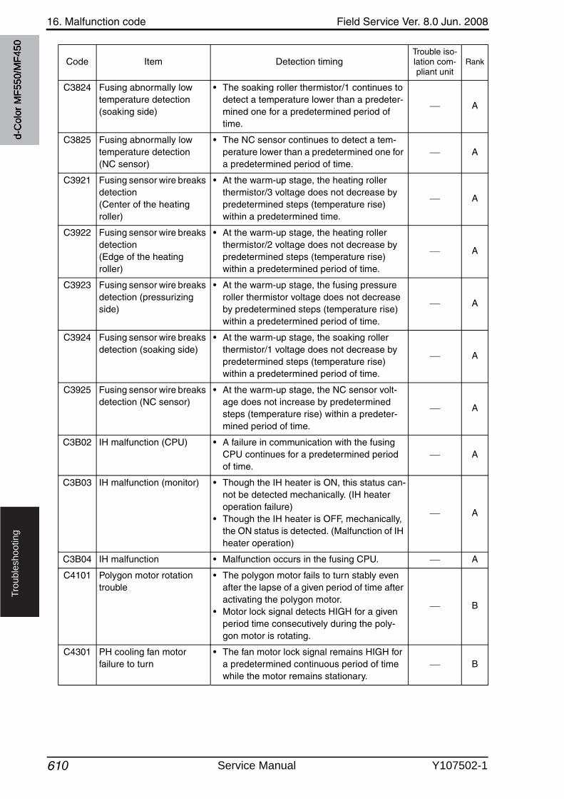
16. Malfunction code Field Service Ver. 8.0 Jun. 2008
610
Tro
ub
lesh
oo
tin
g
C3824 Fusing abnormally lowtemperature detection(soaking side)
• The soaking roller thermistor/1 continues to detect a temperature lower than a predeter-mined one for a predetermined period of time.
A
C3825 Fusing abnormally lowtemperature detection(NC sensor)
• The NC sensor continues to detect a tem-perature lower than a predetermined one for a predetermined period of time.
A
C3921 Fusing sensor wire breaks detection (Center of the heating roller)
• At the warm-up stage, the heating roller thermistor/3 voltage does not decrease by predetermined steps (temperature rise) within a predetermined time.
A
C3922 Fusing sensor wire breaks detection (Edge of the heating roller)
• At the warm-up stage, the heating roller thermistor/2 voltage does not decrease by predetermined steps (temperature rise) within a predetermined period of time.
A
C3923 Fusing sensor wire breaks detection (pressurizing side)
• At the warm-up stage, the fusing pressure roller thermistor voltage does not decrease by predetermined steps (temperature rise) within a predetermined period of time.
A
C3924 Fusing sensor wire breaks detection (soaking side)
• At the warm-up stage, the soaking roller thermistor/1 voltage does not decrease by predetermined steps (temperature rise) within a predetermined period of time.
A
C3925 Fusing sensor wire breaks detection (NC sensor)
• At the warm-up stage, the NC sensor volt-age does not increase by predetermined steps (temperature rise) within a predeter-mined period of time.
A
C3B02 IH malfunction (CPU) • A failure in communication with the fusingCPU continues for a predetermined period of time.
A
C3B03 IH malfunction (monitor) • Though the IH heater is ON, this status can-not be detected mechanically. (IH heater operation failure)
• Though the IH heater is OFF, mechanically, the ON status is detected. (Malfunction of IH heater operation)
A
C3B04 IH malfunction • Malfunction occurs in the fusing CPU. A
C4101 Polygon motor rotation trouble
• The polygon motor fails to turn stably evenafter the lapse of a given period of time after activating the polygon motor.
• Motor lock signal detects HIGH for a given period time consecutively during the poly-gon motor is rotating.
B
C4301 PH cooling fan motor failure to turn
• The fan motor lock signal remains HIGH for a predetermined continuous period of time while the motor remains stationary.
B
Code Item Detection timingTrouble iso-lation com-pliant unit
Rank
d-C
olor
MF5
50/M
F450
Service Manual Y107502-1
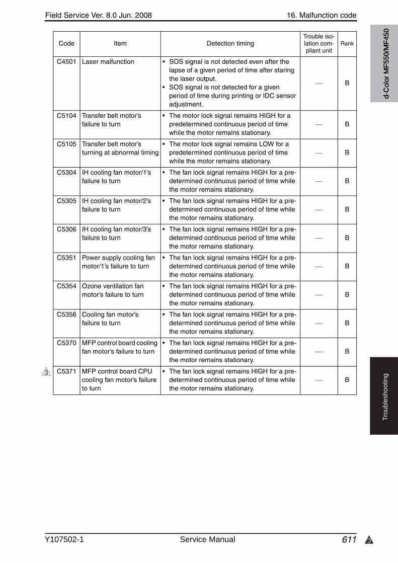
3
Field Service Ver. 8.0 Jun. 2008 16. Malfunction code
611
Tro
ub
lesh
oo
tin
g
C4501 Laser malfunction • SOS signal is not detected even after the lapse of a given period of time after staring the laser output.
• SOS signal is not detected for a given period of time during printing or IDC sensor adjustment.
B
C5104 Transfer belt motor’s failure to turn
• The motor lock signal remains HIGH for a predetermined continuous period of time while the motor remains stationary.
B
C5105 Transfer belt motor’s turning at abnormal timing
• The motor lock signal remains LOW for a predetermined continuous period of time while the motor remains stationary.
B
C5304 IH cooling fan motor/1’s failure to turn
• The fan lock signal remains HIGH for a pre-determined continuous period of time whilethe motor remains stationary.
B
C5305 IH cooling fan motor/2’s failure to turn
• The fan lock signal remains HIGH for a pre-determined continuous period of time whilethe motor remains stationary.
B
C5306 IH cooling fan motor/3’s failure to turn
• The fan lock signal remains HIGH for a pre-determined continuous period of time whilethe motor remains stationary.
B
C5351 Power supply cooling fan motor/1’s failure to turn
• The fan lock signal remains HIGH for a pre-determined continuous period of time whilethe motor remains stationary.
B
C5354 Ozone ventilation fan motor’s failure to turn
• The fan lock signal remains HIGH for a pre-determined continuous period of time whilethe motor remains stationary.
B
C5356 Cooling fan motor’s failure to turn
• The fan lock signal remains HIGH for a pre-determined continuous period of time whilethe motor remains stationary.
B
C5370 MFP control board cooling fan motor’s failure to turn
• The fan lock signal remains HIGH for a pre-determined continuous period of time whilethe motor remains stationary.
B
C5371 MFP control board CPU cooling fan motor’s failureto turn
• The fan lock signal remains HIGH for a pre-determined continuous period of time whilethe motor remains stationary.
B
Code Item Detection timingTrouble iso-lation com-pliant unit
Rank
3
d-C
olor
MF5
50/M
F450
Y107502-1 Service Manual
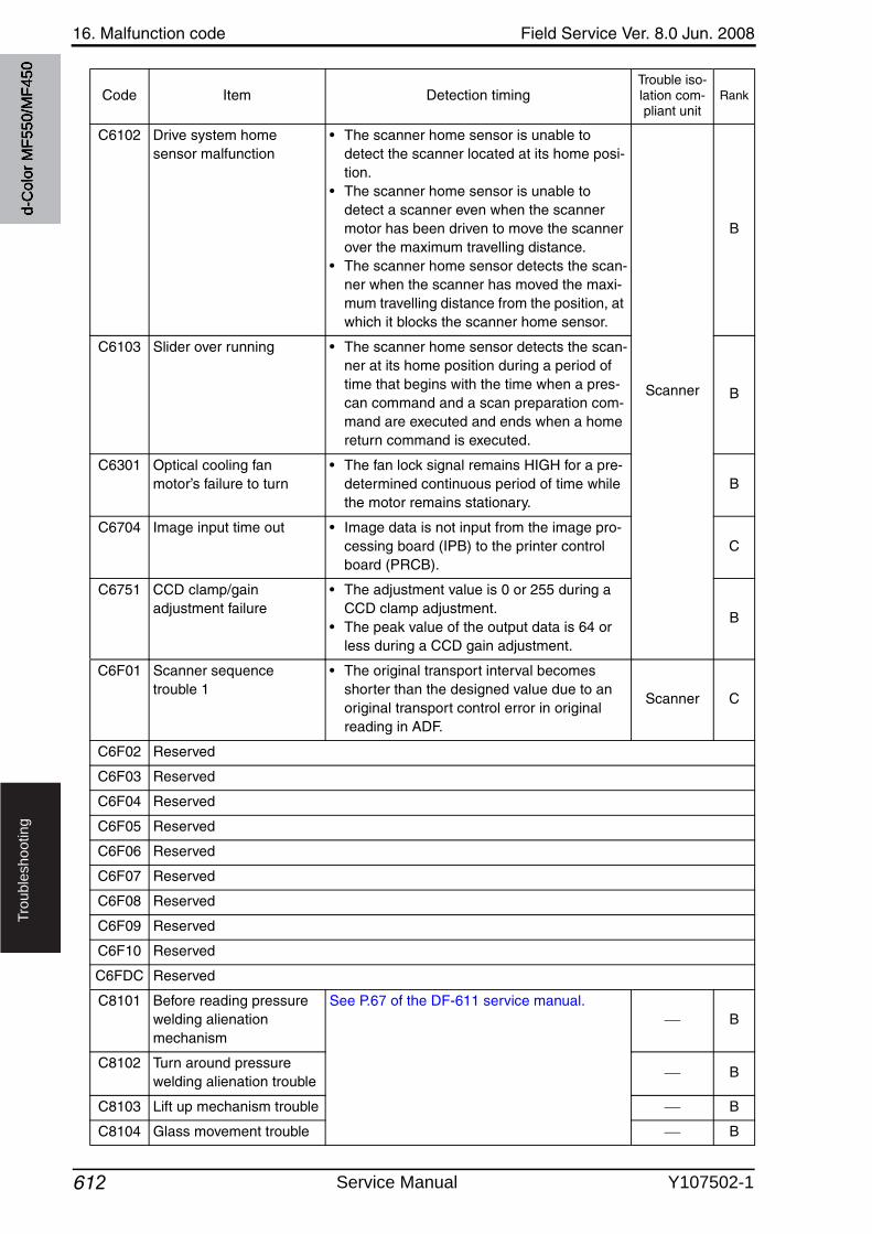
16. Malfunction code Field Service Ver. 8.0 Jun. 2008
612
Tro
ub
lesh
oo
tin
g
C6102 Drive system home sensor malfunction
• The scanner home sensor is unable to detect the scanner located at its home posi-tion.
• The scanner home sensor is unable to detect a scanner even when the scanner motor has been driven to move the scanner over the maximum travelling distance.
• The scanner home sensor detects the scan-ner when the scanner has moved the maxi-mum travelling distance from the position, at which it blocks the scanner home sensor.
Scanner
B
C6103 Slider over running • The scanner home sensor detects the scan-ner at its home position during a period of time that begins with the time when a pres-can command and a scan preparation com-mand are executed and ends when a home return command is executed.
B
C6301 Optical cooling fan motor’s failure to turn
• The fan lock signal remains HIGH for a pre-determined continuous period of time while the motor remains stationary.
B
C6704 Image input time out • Image data is not input from the image pro-cessing board (IPB) to the printer control board (PRCB).
C
C6751 CCD clamp/gain adjustment failure
• The adjustment value is 0 or 255 during a CCD clamp adjustment.
• The peak value of the output data is 64 or less during a CCD gain adjustment.
B
C6F01 Scanner sequencetrouble 1
• The original transport interval becomes shorter than the designed value due to an original transport control error in original reading in ADF.
Scanner C
C6F02 Reserved
C6F03 Reserved
C6F04 Reserved
C6F05 Reserved
C6F06 Reserved
C6F07 Reserved
C6F08 Reserved
C6F09 Reserved
C6F10 Reserved
C6FDC Reserved
C8101 Before reading pressurewelding alienation mechanism
See P.67 of the DF-611 service manual.B
C8102 Turn around pressurewelding alienation trouble
B
C8103 Lift up mechanism trouble B
C8104 Glass movement trouble B
Code Item Detection timingTrouble iso-lation com-pliant unit
Rank
d-C
olor
MF5
50/M
F450
Service Manual Y107502-1
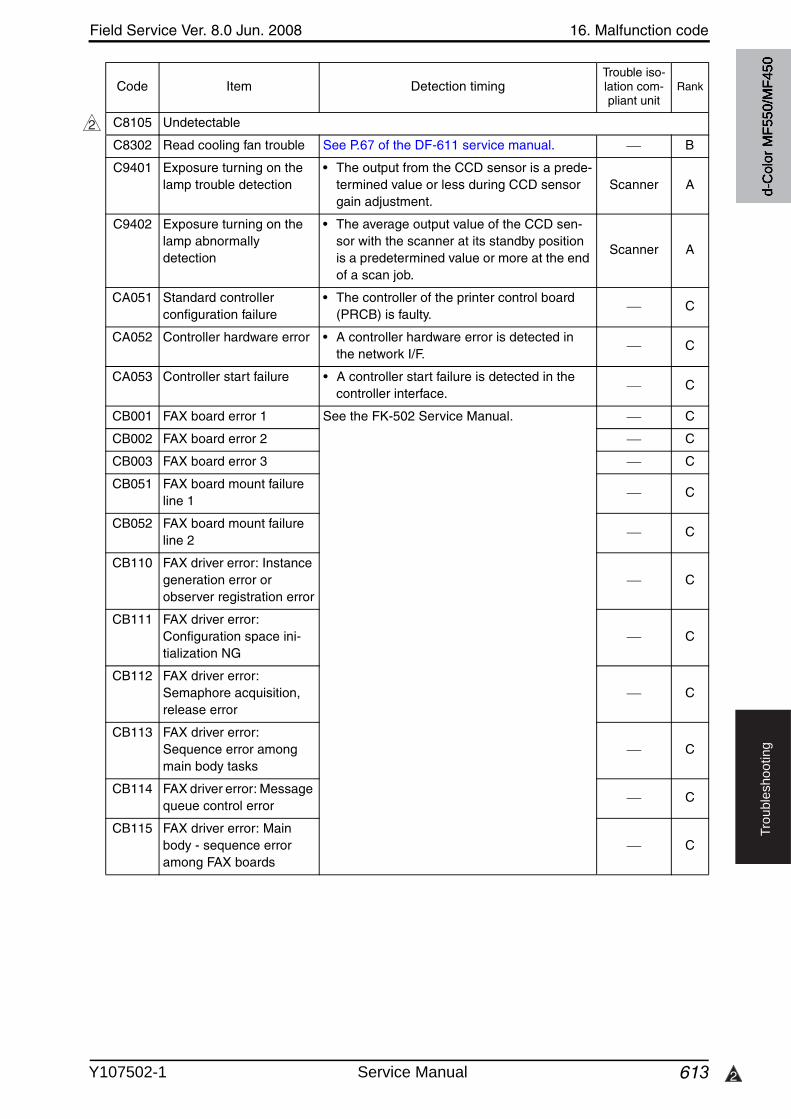
Field Service Ver. 8.0 Jun. 2008 16. Malfunction code
613 2
Tro
ub
lesh
oo
tin
g
C8105 Undetectable
C8302 Read cooling fan trouble See P.67 of the DF-611 service manual. B
C9401 Exposure turning on the lamp trouble detection
• The output from the CCD sensor is a prede-termined value or less during CCD sensor gain adjustment.
Scanner A
C9402 Exposure turning on the lamp abnormally detection
• The average output value of the CCD sen-sor with the scanner at its standby position is a predetermined value or more at the end of a scan job.
Scanner A
CA051 Standard controller configuration failure
• The controller of the printer control board (PRCB) is faulty.
C
CA052 Controller hardware error • A controller hardware error is detected in the network I/F.
C
CA053 Controller start failure • A controller start failure is detected in the controller interface.
C
CB001 FAX board error 1 See the FK-502 Service Manual. C
CB002 FAX board error 2 C
CB003 FAX board error 3 C
CB051 FAX board mount failure line 1
C
CB052 FAX board mount failure line 2
C
CB110 FAX driver error: Instance generation error or observer registration error
C
CB111 FAX driver error: Configuration space ini-tialization NG
C
CB112 FAX driver error: Semaphore acquisition, release error
C
CB113 FAX driver error: Sequence error among main body tasks
C
CB114 FAX driver error: Message queue control error
C
CB115 FAX driver error: Main body - sequence error among FAX boards
C
Code Item Detection timingTrouble iso-lation com-pliant unit
Rank
2
d-C
olor
MF5
50/M
F450
Y107502-1 Service Manual
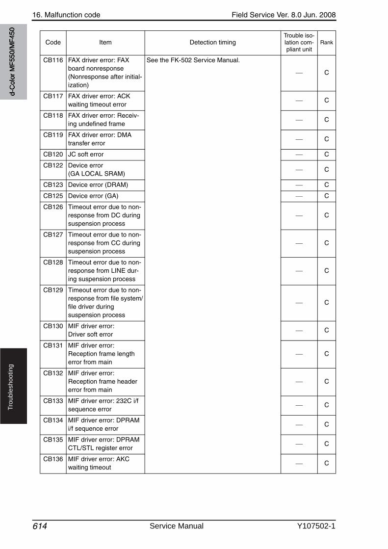
16. Malfunction code Field Service Ver. 8.0 Jun. 2008
614
Tro
ub
lesh
oo
tin
g
CB116 FAX driver error: FAX board nonresponse (Nonresponse after initial-ization)
See the FK-502 Service Manual.
C
CB117 FAX driver error: ACK waiting timeout error
C
CB118 FAX driver error: Receiv-ing undefined frame
C
CB119 FAX driver error: DMA transfer error
C
CB120 JC soft error C
CB122 Device error (GA LOCAL SRAM)
C
CB123 Device error (DRAM) C
CB125 Device error (GA) C
CB126 Timeout error due to non-response from DC during suspension process
C
CB127 Timeout error due to non-response from CC during suspension process
C
CB128 Timeout error due to non-response from LINE dur-ing suspension process
C
CB129 Timeout error due to non-response from file system/file driver during suspension process
C
CB130 MIF driver error: Driver soft error
C
CB131 MIF driver error: Reception frame length error from main
C
CB132 MIF driver error: Reception frame header error from main
C
CB133 MIF driver error: 232C i/f sequence error
C
CB134 MIF driver error: DPRAM i/f sequence error
C
CB135 MIF driver error: DPRAM CTL/STL register error
C
CB136 MIF driver error: AKC waiting timeout
C
Code Item Detection timingTrouble iso-lation com-pliant unit
Rank
d-C
olor
MF5
50/M
F450
Service Manual Y107502-1
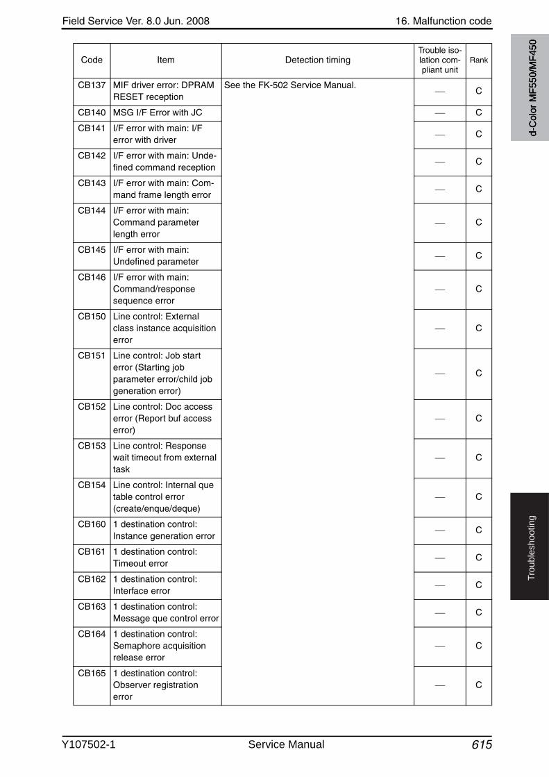
Field Service Ver. 8.0 Jun. 2008 16. Malfunction code
615
Tro
ub
lesh
oo
tin
g
CB137 MIF driver error: DPRAM RESET reception
See the FK-502 Service Manual.C
CB140 MSG I/F Error with JC C
CB141 I/F error with main: I/F error with driver
C
CB142 I/F error with main: Unde-fined command reception
C
CB143 I/F error with main: Com-mand frame length error
C
CB144 I/F error with main: Command parameter length error
C
CB145 I/F error with main: Undefined parameter
C
CB146 I/F error with main: Command/response sequence error
C
CB150 Line control: External class instance acquisitionerror
C
CB151 Line control: Job start error (Starting job parameter error/child job generation error)
C
CB152 Line control: Doc access error (Report buf access error)
C
CB153 Line control: Response wait timeout from external task
C
CB154 Line control: Internal quetable control error (create/enque/deque)
C
CB160 1 destination control: Instance generation error
C
CB161 1 destination control: Timeout error
C
CB162 1 destination control: Interface error
C
CB163 1 destination control: Message que control error
C
CB164 1 destination control: Semaphore acquisition release error
C
CB165 1 destination control: Observer registration error
C
Code Item Detection timingTrouble iso-lation com-pliant unit
Rank
d-C
olor
MF5
50/M
F450
Y107502-1 Service Manual
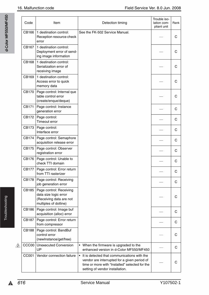
16. Malfunction code Field Service Ver. 8.0 Jun. 2008
6162
Tro
ub
lesh
oo
tin
g
CB166 1 destination control: Reception resource check error
See the FK-502 Service Manual.C
CB167 1 destination control: Deployment error of send-ing image information
C
CB168 1 destination control: Serialization error of receiving image
C
CB169 1 destination control: Access error to quick memory data
C
CB170 Page control: Internal quetable control error (create/enque/deque)
C
CB171 Page control: Instance generation error
C
CB172 Page control: Timeout error
C
CB173 Page control: Interface error
C
CB174 Page control: Semaphore acquisition release error
C
CB175 Page control: Observer registration error
C
CB176 Page control: Unable to check TTI domain
C
CB177 Page control: Error return from TTI rasterizer
C
CB178 Page control: Receiving job generation error
C
CB185 Page control: Receiving data size logic error (Receiving data are not multiples of dotline)
C
CB186 Page control: Image bufacquisition (alloc) error
C
CB187 Page control: Error return from compressor
C
CB188 Page control: BandBufcontrol error (newInstance/get/free)
C
CCC00 Unexecuted ConversionUP
• When the firmware is upgraded to the enhanced version in d-Color MF550/MF450
C
CC001 Vendor connection failure • It is detected that communications with the vendor are interrupted for a given period of time or more with “Installed” selected for the setting of vendor installation.
C
Code Item Detection timingTrouble iso-lation com-pliant unit
Rank
2
d-C
olor
MF5
50/M
F450
Service Manual Y107502-1
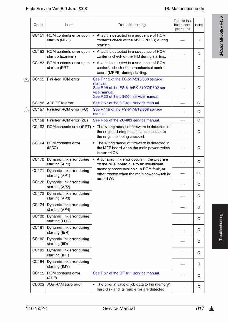
6
Field Service Ver. 8.0 Jun. 2008 16. Malfunction code
617
Tro
ub
lesh
oo
tin
g
CC151 ROM contents error upon startup (MSC)
• A fault is detected in a sequence of ROM contents check of the MSC (PRCB) during starting
C
CC152 ROM contents error upon startup (scanner)
• A fault is detected in a sequence of ROM contents check of the IPB during starting.
C
CC153 ROM contents error upon startup (PRT)
• A fault is detected in a sequence of ROM contents check of the mechanical control board (MFPB) during starting.
C
CC155 Finisher ROM error See P.119 of the FS-517/518/608 servicemanual.See P.95 of the FS-519/PK-510/OT-602 ser-vice manual.See P.22 of the JS-504 service manual.
C
CC156 ADF ROM error See P.67 of the DF-611 service manual. C
CC157 Finisher ROM error (RU) See P.119 of the FS-517/518/608 servicemanual. C
CC158 Finisher ROM error (ZU) See P.55 of the ZU-603 service manual. C
CC163 ROM contents error (PRT) • The wrong model of firmware is detected in the engine during the initial connection to the engine is being checked.
C
CC164 ROM contents error (MSC)
• The wrong model of firmware is detected in the MFP board when the main power switchis turned ON.
C
CC170 Dynamic link error during starting (AP0)
• A dynamic link error occurs in the program on the MFP board due to an insufficientmemory space available, a ROM fault, or other reason when the main power switch is turned ON.
C
CC171 Dynamic link error during starting (AP1)
C
CC172 Dynamic link error during starting (AP2)
C
CC173 Dynamic link error during starting (AP3)
C
CC174 Dynamic link error during starting (AP4)
C
CC180 Dynamic link error during starting (LDR)
C
CC181 Dynamic link error during starting (IBR)
C
CC182 Dynamic link error during starting (IID)
C
CC183 Dynamic link error during starting (IPF)
C
CC184 Dynamic link error during starting (IMY)
C
CC165 ROM contents error (ADF)
See P.67 of the DF-611 service manual.C
CD002 JOB RAM save error • The error in save of job data to the memory/ hard disk and its read error are detected.
C
Code Item Detection timingTrouble iso-lation com-pliant unit
Rank
6
6
d-C
olor
MF5
50/M
F450
Y107502-1 Service Manual
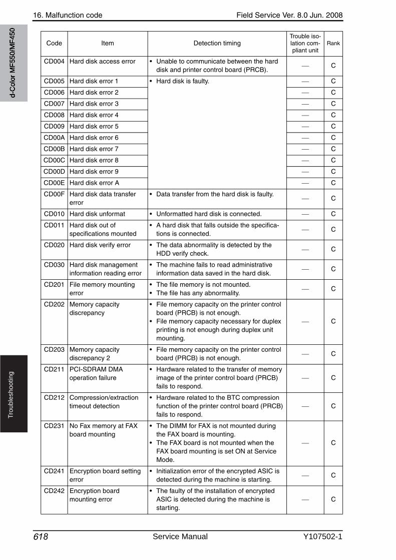
16. Malfunction code Field Service Ver. 8.0 Jun. 2008
618
Tro
ub
lesh
oo
tin
g
CD004 Hard disk access error • Unable to communicate between the hard disk and printer control board (PRCB).
C
CD005 Hard disk error 1 • Hard disk is faulty. C
CD006 Hard disk error 2 C
CD007 Hard disk error 3 C
CD008 Hard disk error 4 C
CD009 Hard disk error 5 C
CD00A Hard disk error 6 C
CD00B Hard disk error 7 C
CD00C Hard disk error 8 C
CD00D Hard disk error 9 C
CD00E Hard disk error A C
CD00F Hard disk data transfer error
• Data transfer from the hard disk is faulty.C
CD010 Hard disk unformat • Unformatted hard disk is connected. C
CD011 Hard disk out of specifications mounted
• A hard disk that falls outside the specifica-tions is connected.
C
CD020 Hard disk verify error • The data abnormality is detected by the HDD verify check.
C
CD030 Hard disk management information reading error
• The machine fails to read administrativeinformation data saved in the hard disk.
C
CD201 File memory mounting error
• The file memory is not mounted.• The file has any abnormality.
C
CD202 Memory capacity discrepancy
• File memory capacity on the printer control board (PRCB) is not enough.
• File memory capacity necessary for duplex printing is not enough during duplex unit mounting.
C
CD203 Memory capacity discrepancy 2
• File memory capacity on the printer control board (PRCB) is not enough.
C
CD211 PCI-SDRAM DMA operation failure
• Hardware related to the transfer of memory image of the printer control board (PRCB) fails to respond.
C
CD212 Compression/extraction timeout detection
• Hardware related to the BTC compression function of the printer control board (PRCB) fails to respond.
C
CD231 No Fax memory at FAX board mounting
• The DIMM for FAX is not mounted during the FAX board is mounting.
• The FAX board is not mounted when the FAX board mounting is set ON at Service Mode.
C
CD241 Encryption board setting error
• Initialization error of the encrypted ASIC is detected during the machine is starting.
C
CD242 Encryption board mounting error
• The faulty of the installation of encrypted ASIC is detected during the machine is starting.
C
Code Item Detection timingTrouble iso-lation com-pliant unit
Rank
d-C
olor
MF5
50/M
F450
Service Manual Y107502-1
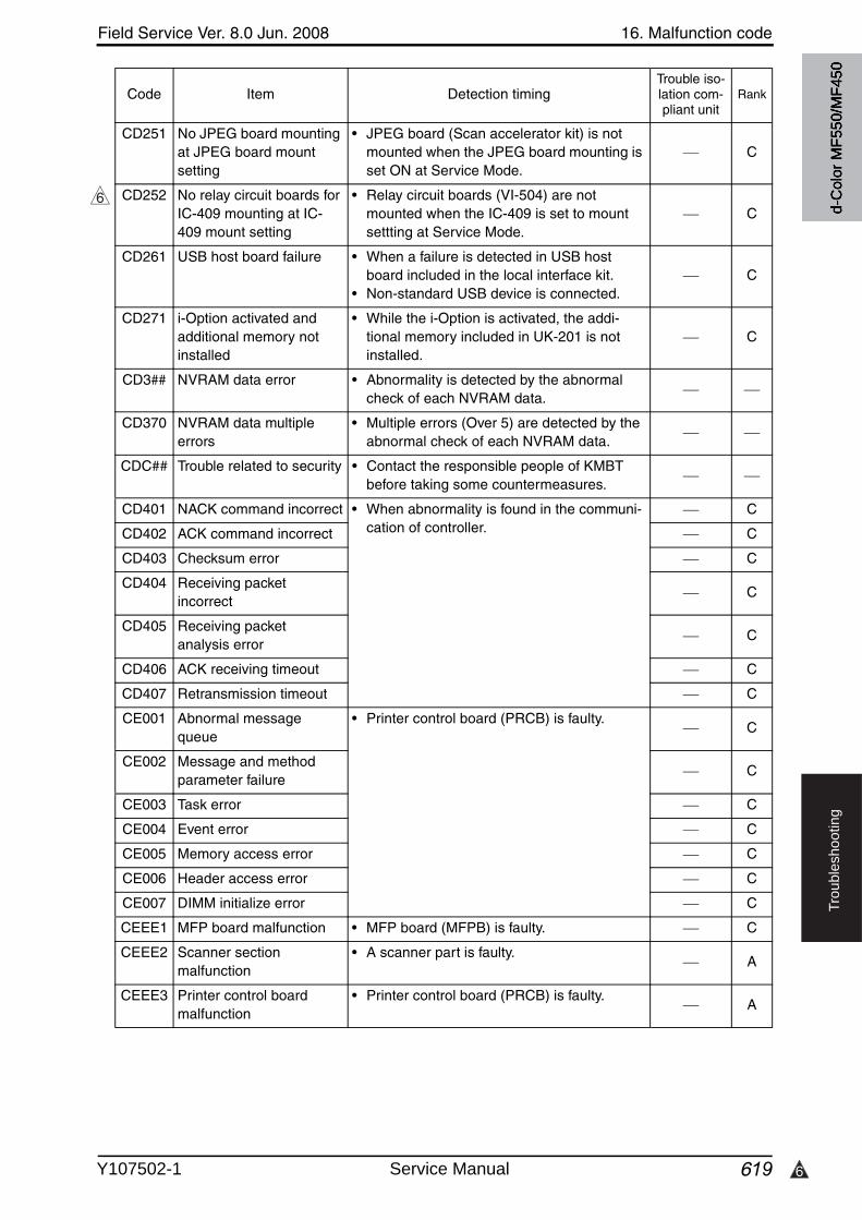
6
Field Service Ver. 8.0 Jun. 2008 16. Malfunction code
619
Tro
ub
lesh
oo
tin
g
CD251 No JPEG board mounting at JPEG board mountsetting
• JPEG board (Scan accelerator kit) is not mounted when the JPEG board mounting is set ON at Service Mode.
C
CD252 No relay circuit boards for IC-409 mounting at IC-409 mount setting
• Relay circuit boards (VI-504) are not mounted when the IC-409 is set to mount settting at Service Mode.
C
CD261 USB host board failure • When a failure is detected in USB host board included in the local interface kit.
• Non-standard USB device is connected.C
CD271 i-Option activated and additional memory not installed
• While the i-Option is activated, the addi-tional memory included in UK-201 is not installed.
C
CD3## NVRAM data error • Abnormality is detected by the abnormal check of each NVRAM data.
CD370 NVRAM data multipleerrors
• Multiple errors (Over 5) are detected by the abnormal check of each NVRAM data.
CDC## Trouble related to security • Contact the responsible people of KMBT before taking some countermeasures.
CD401 NACK command incorrect • When abnormality is found in the communi-cation of controller.
C
CD402 ACK command incorrect C
CD403 Checksum error C
CD404 Receiving packet incorrect
C
CD405 Receiving packet analysis error
C
CD406 ACK receiving timeout C
CD407 Retransmission timeout C
CE001 Abnormal message queue
• Printer control board (PRCB) is faulty.C
CE002 Message and method parameter failure
C
CE003 Task error C
CE004 Event error C
CE005 Memory access error C
CE006 Header access error C
CE007 DIMM initialize error C
CEEE1 MFP board malfunction • MFP board (MFPB) is faulty. C
CEEE2 Scanner section malfunction
• A scanner part is faulty.A
CEEE3 Printer control board malfunction
• Printer control board (PRCB) is faulty.A
Code Item Detection timingTrouble iso-lation com-pliant unit
Rank
6
d-C
olor
MF5
50/M
F450
Y107502-1 Service Manual
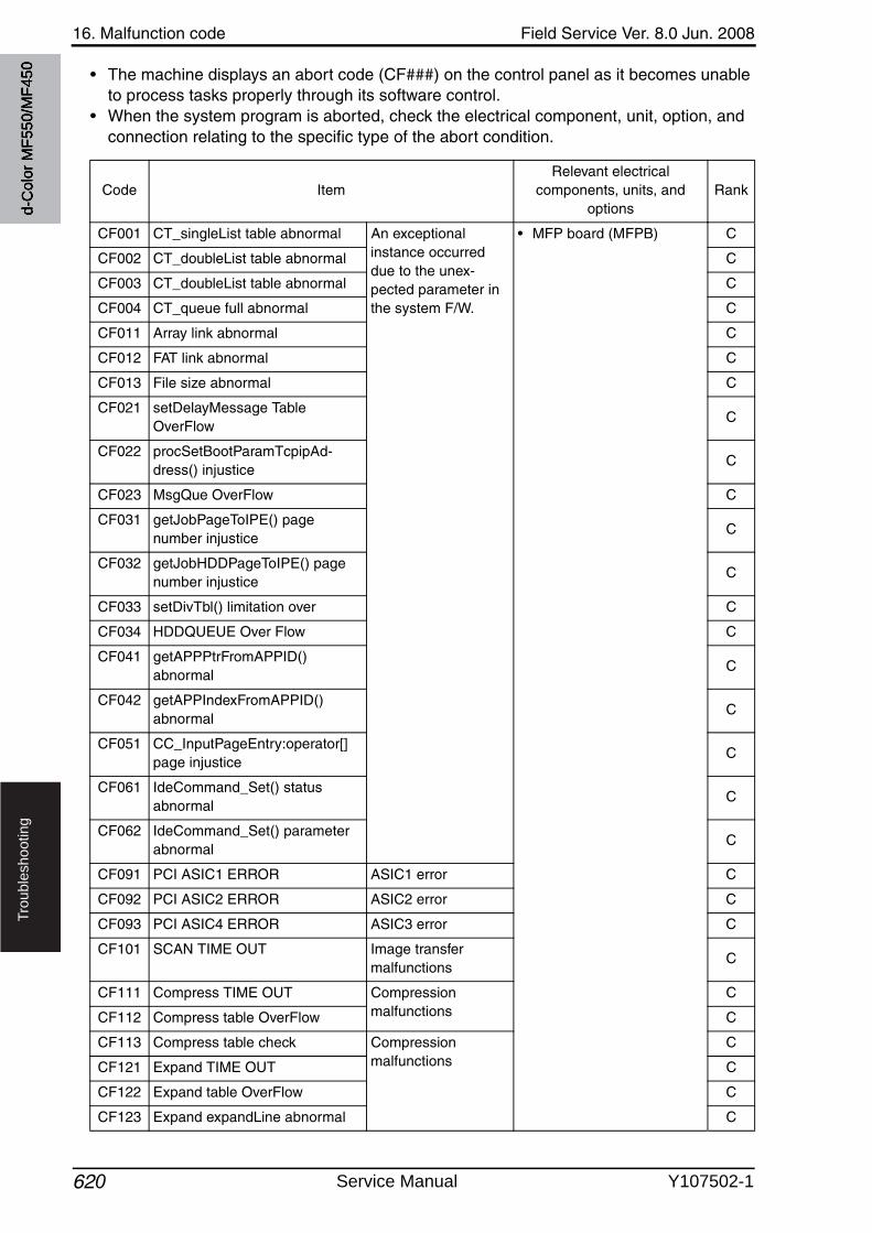
16. Malfunction code Field Service Ver. 8.0 Jun. 2008
620
Tro
ub
lesh
oo
tin
g
• The machine displays an abort code (CF###) on the control panel as it becomes unable to process tasks properly through its software control.
• When the system program is aborted, check the electrical component, unit, option, and connection relating to the specific type of the abort condition.
Code ItemRelevant electrical
components, units, and options
Rank
CF001 CT_singleList table abnormal An exceptional instance occurred due to the unex-pected parameter in the system F/W.
• MFP board (MFPB) C
CF002 CT_doubleList table abnormal C
CF003 CT_doubleList table abnormal C
CF004 CT_queue full abnormal C
CF011 Array link abnormal C
CF012 FAT link abnormal C
CF013 File size abnormal C
CF021 setDelayMessage Table OverFlow
C
CF022 procSetBootParamTcpipAd-dress() injustice
C
CF023 MsgQue OverFlow C
CF031 getJobPageToIPE() page number injustice
C
CF032 getJobHDDPageToIPE() pagenumber injustice
C
CF033 setDivTbl() limitation over C
CF034 HDDQUEUE Over Flow C
CF041 getAPPPtrFromAPPID() abnormal
C
CF042 getAPPIndexFromAPPID() abnormal
C
CF051 CC_InputPageEntry:operator[] page injustice
C
CF061 IdeCommand_Set() statusabnormal
C
CF062 IdeCommand_Set() parameter abnormal
C
CF091 PCI ASIC1 ERROR ASIC1 error C
CF092 PCI ASIC2 ERROR ASIC2 error C
CF093 PCI ASIC4 ERROR ASIC3 error C
CF101 SCAN TIME OUT Image transfer malfunctions
C
CF111 Compress TIME OUT Compression malfunctions
C
CF112 Compress table OverFlow C
CF113 Compress table check Compression malfunctions
C
CF121 Expand TIME OUT C
CF122 Expand table OverFlow C
CF123 Expand expandLine abnormal C
d-C
olor
MF5
50/M
F450
Service Manual Y107502-1
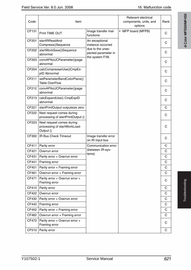
Field Service Ver. 8.0 Jun. 2008 16. Malfunction code
621
Tro
ub
lesh
oo
tin
g
CF131Print TIME OUT
Image transfer mal-functions
• MFP board (MFPB)C
CF201 startIRReadAndCompress()Sequence
An exceptional instance occurred due to the unex-pected parameter in the system F/W.
C
CF202 startWorkSave()Sequenceabnormal
C
CF203 convAPItoIJCParameter()page abnormal
C
CF204 calcCompresserUse()CmpEx-pID Abnormal
C
CF211 setParameterBandColorPlane() Table OverFlow
C
CF212 convAPItoIJCParameter()page abnormal
C
CF213 calcExpandUse() CmpExpID abnormal
C
CF221 startPrintOutput outputsize zero C
CF222 Next request comes during processing of startPrintOutput ()
C
CF223 Next request comes during processing of startWorkLoad-Output ()
C
CF300 IR Bus Check Timeout Image transfer error on IR input bus
C
CF411 Parity error Communication error (between IR-sys-tems)
C
CF421 Overrun error C
CF431 Parity error + Overrun error C
CF441 Framing error C
CF451 Parity error + Framing error C
CF461 Overrun error + Framing error C
CF471 Parity error + Overrun error + Framing error
C
CF412 Parity error C
CF422 Overrun error C
CF432 Parity error + Overrun error C
CF442 Framing error C
CF452 Parity error + Framing error C
CF462 Overrun error + Framing error C
CF472 Parity error + Overrun error + Framing error
C
CF510 Parity error C
Code ItemRelevant electrical
components, units, and options
Rank
d-C
olor
MF5
50/M
F450
Y107502-1 Service Manual
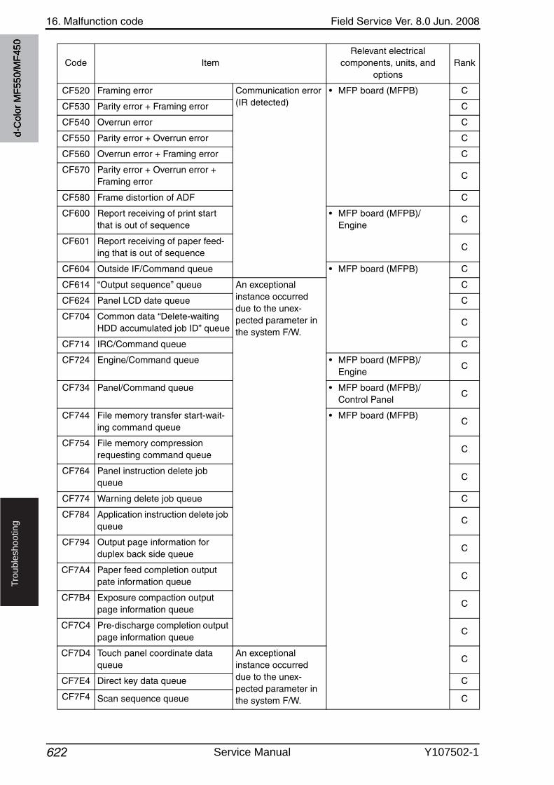
16. Malfunction code Field Service Ver. 8.0 Jun. 2008
622
Tro
ub
lesh
oo
tin
g
CF520 Framing error Communication error (IR detected)
• MFP board (MFPB) C
CF530 Parity error + Framing error C
CF540 Overrun error C
CF550 Parity error + Overrun error C
CF560 Overrun error + Framing error C
CF570 Parity error + Overrun error + Framing error
C
CF580 Frame distortion of ADF C
CF600 Report receiving of print start that is out of sequence
• MFP board (MFPB)/Engine
C
CF601 Report receiving of paper feed-ing that is out of sequence
C
CF604 Outside IF/Command queue • MFP board (MFPB) C
CF614 “Output sequence” queue An exceptional instance occurred due to the unex-pected parameter in the system F/W.
C
CF624 Panel LCD date queue C
CF704 Common data “Delete-waiting HDD accumulated job ID” queue
C
CF714 IRC/Command queue C
CF724 Engine/Command queue • MFP board (MFPB)/Engine
C
CF734 Panel/Command queue • MFP board (MFPB)/Control Panel
C
CF744 File memory transfer start-wait-ing command queue
• MFP board (MFPB)C
CF754 File memory compression requesting command queue
C
CF764 Panel instruction delete job queue
C
CF774 Warning delete job queue C
CF784 Application instruction delete job queue
C
CF794 Output page information for duplex back side queue
C
CF7A4 Paper feed completion outputpate information queue
C
CF7B4 Exposure compaction outputpage information queue
C
CF7C4 Pre-discharge completion outputpage information queue
C
CF7D4 Touch panel coordinate data queue
An exceptional instance occurred due to the unex-pected parameter in the system F/W.
C
CF7E4 Direct key data queue C
CF7F4 Scan sequence queue C
Code ItemRelevant electrical
components, units, and options
Rank
d-C
olor
MF5
50/M
F450
Service Manual Y107502-1
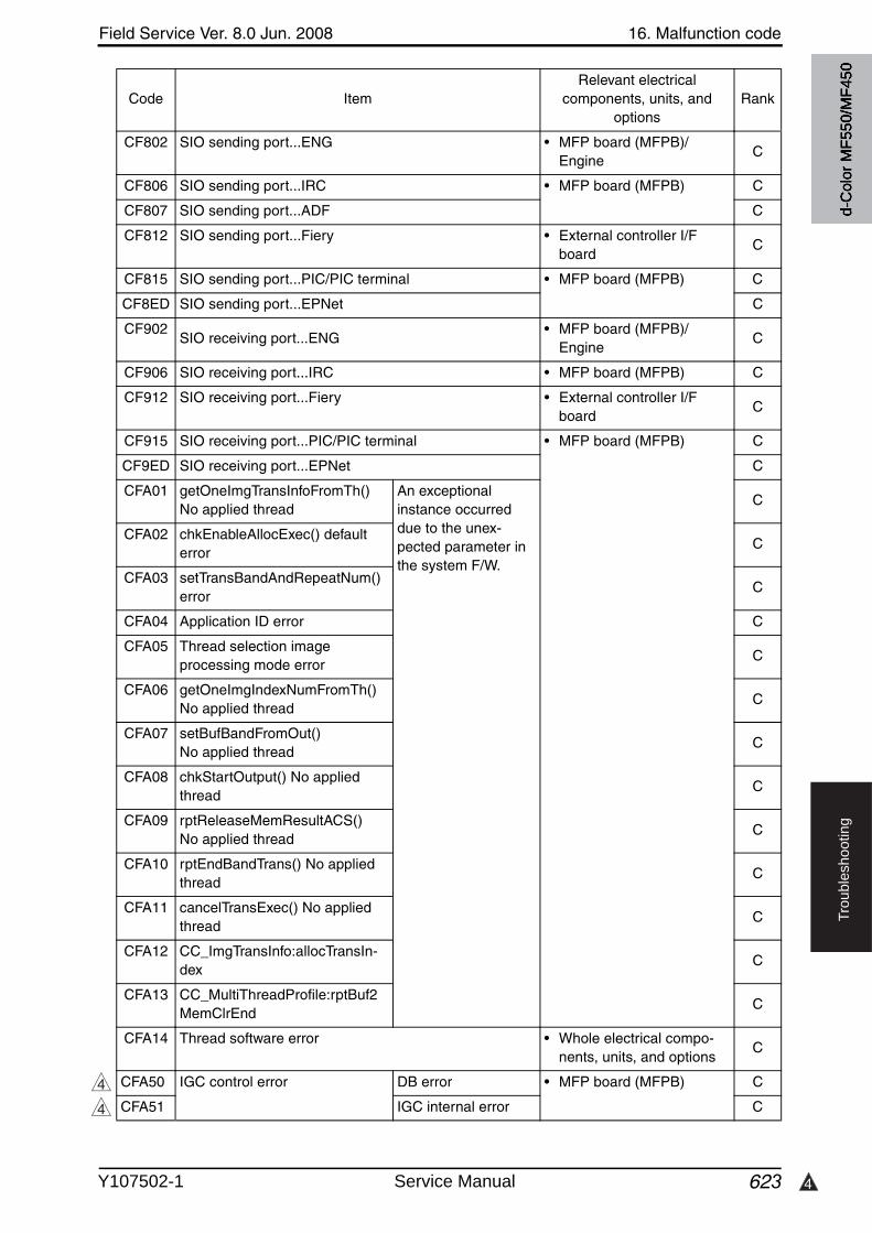
4
Field Service Ver. 8.0 Jun. 2008 16. Malfunction code
623
Tro
ub
lesh
oo
tin
g
CF802 SIO sending port...ENG • MFP board (MFPB)/Engine
C
CF806 SIO sending port...IRC • MFP board (MFPB) C
CF807 SIO sending port...ADF C
CF812 SIO sending port...Fiery • External controller I/F board
C
CF815 SIO sending port...PIC/PIC terminal • MFP board (MFPB) C
CF8ED SIO sending port...EPNet C
CF902SIO receiving port...ENG
• MFP board (MFPB)/Engine
C
CF906 SIO receiving port...IRC • MFP board (MFPB) C
CF912 SIO receiving port...Fiery • External controller I/F board
C
CF915 SIO receiving port...PIC/PIC terminal • MFP board (MFPB) C
CF9ED SIO receiving port...EPNet C
CFA01 getOneImgTransInfoFromTh() No applied thread
An exceptional instance occurred due to the unex-pected parameter in the system F/W.
C
CFA02 chkEnableAllocExec() defaulterror
C
CFA03 setTransBandAndRepeatNum()error
C
CFA04 Application ID error C
CFA05 Thread selection image processing mode error
C
CFA06 getOneImgIndexNumFromTh() No applied thread
C
CFA07 setBufBandFromOut() No applied thread
C
CFA08 chkStartOutput() No applied thread
C
CFA09 rptReleaseMemResultACS() No applied thread
C
CFA10 rptEndBandTrans() No applied thread
C
CFA11 cancelTransExec() No applied thread
C
CFA12 CC_ImgTransInfo:allocTransIn-dex
C
CFA13 CC_MultiThreadProfile:rptBuf2MemClrEnd
C
CFA14 Thread software error • Whole electrical compo-nents, units, and options
C
CFA50 IGC control error DB error • MFP board (MFPB) C
CFA51 IGC internal error C
Code ItemRelevant electrical
components, units, and options
Rank
4
4
d-C
olor
MF5
50/M
F450
Y107502-1 Service Manual
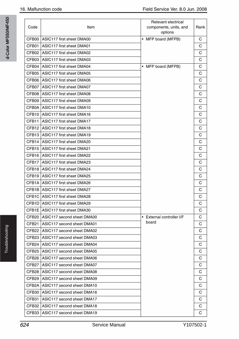
16. Malfunction code Field Service Ver. 8.0 Jun. 2008
624
Tro
ub
lesh
oo
tin
g
CFB00 ASIC117 first sheet DMA00 • MFP board (MFPB) C
CFB01 ASIC117 first sheet DMA01 C
CFB02 ASIC117 first sheet DMA02 C
CFB03 ASIC117 first sheet DMA03 C
CFB04 ASIC117 first sheet DMA04 • MFP board (MFPB) C
CFB05 ASIC117 first sheet DMA05 C
CFB06 ASIC117 first sheet DMA06 C
CFB07 ASIC117 first sheet DMA07 C
CFB08 ASIC117 first sheet DMA08 C
CFB09 ASIC117 first sheet DMA09 C
CFB0A ASIC117 first sheet DMA10 C
CFB10 ASIC117 first sheet DMA16 C
CFB11 ASIC117 first sheet DMA17 C
CFB12 ASIC117 first sheet DMA18 C
CFB13 ASIC117 first sheet DMA19 C
CFB14 ASIC117 first sheet DMA20 C
CFB15 ASIC117 first sheet DMA21 C
CFB16 ASIC117 first sheet DMA22 C
CFB17 ASIC117 first sheet DMA23 C
CFB18 ASIC117 first sheet DMA24 C
CFB19 ASIC117 first sheet DMA25 C
CFB1A ASIC117 first sheet DMA26 C
CFB1B ASIC117 first sheet DMA27 C
CFB1C ASIC117 first sheet DMA28 C
CFB1D ASIC117 first sheet DMA29 C
CFB1E ASIC117 first sheet DMA30 C
CFB20 ASIC117 second sheet DMA00 • External controller I/F board
C
CFB21 ASIC117 second sheet DMA01 C
CFB22 ASIC117 second sheet DMA02 C
CFB23 ASIC117 second sheet DMA03 C
CFB24 ASIC117 second sheet DMA04 C
CFB25 ASIC117 second sheet DMA05 C
CFB26 ASIC117 second sheet DMA06 C
CFB27 ASIC117 second sheet DMA07 C
CFB28 ASIC117 second sheet DMA08 C
CFB29 ASIC117 second sheet DMA09 C
CFB2A ASIC117 second sheet DMA10 C
CFB30 ASIC117 second sheet DMA16 C
CFB31 ASIC117 second sheet DMA17 C
CFB32 ASIC117 second sheet DMA18 C
CFB33 ASIC117 second sheet DMA19 C
Code ItemRelevant electrical
components, units, and options
Rank
d-C
olor
MF5
50/M
F450
Service Manual Y107502-1
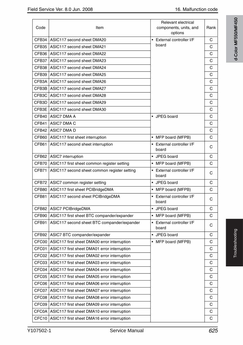
Field Service Ver. 8.0 Jun. 2008 16. Malfunction code
625
Tro
ub
lesh
oo
tin
g
CFB34 ASIC117 second sheet DMA20 • External controller I/F board
C
CFB35 ASIC117 second sheet DMA21 C
CFB36 ASIC117 second sheet DMA22 C
CFB37 ASIC117 second sheet DMA23 C
CFB38 ASIC117 second sheet DMA24 C
CFB39 ASIC117 second sheet DMA25 C
CFB3A ASIC117 second sheet DMA26 C
CFB3B ASIC117 second sheet DMA27 C
CFB3C ASIC117 second sheet DMA28 C
CFB3D ASIC117 second sheet DMA29 C
CFB3E ASIC117 second sheet DMA30 C
CFB40 ASIC7 DMA A • JPEG board C
CFB41 ASIC7 DMA C C
CFB42 ASIC7 DMA D C
CFB60 ASIC117 first sheet interruption • MFP board (MFPB) C
CFB61 ASIC117 second sheet interruption • External controller I/F board
C
CFB62 ASIC7 interruption • JPEG board C
CFB70 ASIC117 first sheet common register setting • MFP board (MFPB) C
CFB71 ASIC117 second sheet common register setting • External controller I/F board
C
CFB72 ASIC7 common register setting • JPEG board C
CFB80 ASIC117 first sheet PCIBridgeDMA • MFP board (MFPB) C
CFB81 ASIC117 second sheet PCIBridgeDMA • External controller I/F board
C
CFB82 ASIC7 PCIBridgeDMA • JPEG board C
CFB90 ASIC117 first sheet BTC compander/expander • MFP board (MFPB) C
CFB91 ASIC117 second sheet BTC compander/expander • External controller I/F board
C
CFB92 ASIC7 BTC compander/expander • JPEG board C
CFC00 ASIC117 first sheet DMA00 error interruption • MFP board (MFPB) C
CFC01 ASIC117 first sheet DMA01 error interruption C
CFC02 ASIC117 first sheet DMA02 error interruption C
CFC03 ASIC117 first sheet DMA03 error interruption C
CFC04 ASIC117 first sheet DMA04 error interruption C
CFC05 ASIC117 first sheet DMA05 error interruption C
CFC06 ASIC117 first sheet DMA06 error interruption C
CFC07 ASIC117 first sheet DMA07 error interruption C
CFC08 ASIC117 first sheet DMA08 error interruption C
CFC09 ASIC117 first sheet DMA09 error interruption C
CFC0A ASIC117 first sheet DMA10 error interruption C
CFC10 ASIC117 first sheet DMA16 error interruption C
Code ItemRelevant electrical
components, units, and options
Rank
d-C
olor
MF5
50/M
F450
Y107502-1 Service Manual
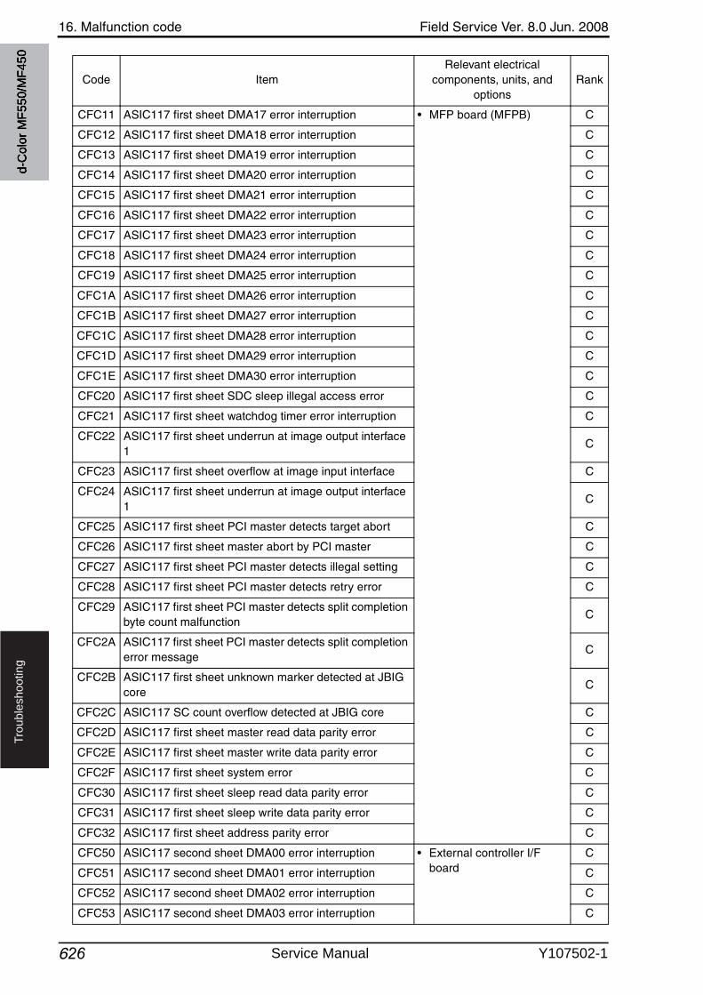
16. Malfunction code Field Service Ver. 8.0 Jun. 2008
626
Tro
ub
lesh
oo
tin
g
CFC11 ASIC117 first sheet DMA17 error interruption • MFP board (MFPB) C
CFC12 ASIC117 first sheet DMA18 error interruption C
CFC13 ASIC117 first sheet DMA19 error interruption C
CFC14 ASIC117 first sheet DMA20 error interruption C
CFC15 ASIC117 first sheet DMA21 error interruption C
CFC16 ASIC117 first sheet DMA22 error interruption C
CFC17 ASIC117 first sheet DMA23 error interruption C
CFC18 ASIC117 first sheet DMA24 error interruption C
CFC19 ASIC117 first sheet DMA25 error interruption C
CFC1A ASIC117 first sheet DMA26 error interruption C
CFC1B ASIC117 first sheet DMA27 error interruption C
CFC1C ASIC117 first sheet DMA28 error interruption C
CFC1D ASIC117 first sheet DMA29 error interruption C
CFC1E ASIC117 first sheet DMA30 error interruption C
CFC20 ASIC117 first sheet SDC sleep illegal access error C
CFC21 ASIC117 first sheet watchdog timer error interruption C
CFC22 ASIC117 first sheet underrun at image output interface 1
C
CFC23 ASIC117 first sheet overflow at image input interface C
CFC24 ASIC117 first sheet underrun at image output interface 1
C
CFC25 ASIC117 first sheet PCI master detects target abort C
CFC26 ASIC117 first sheet master abort by PCI master C
CFC27 ASIC117 first sheet PCI master detects illegal setting C
CFC28 ASIC117 first sheet PCI master detects retry error C
CFC29 ASIC117 first sheet PCI master detects split completion byte count malfunction
C
CFC2A ASIC117 first sheet PCI master detects split completion error message
C
CFC2B ASIC117 first sheet unknown marker detected at JBIG core
C
CFC2C ASIC117 SC count overflow detected at JBIG core C
CFC2D ASIC117 first sheet master read data parity error C
CFC2E ASIC117 first sheet master write data parity error C
CFC2F ASIC117 first sheet system error C
CFC30 ASIC117 first sheet sleep read data parity error C
CFC31 ASIC117 first sheet sleep write data parity error C
CFC32 ASIC117 first sheet address parity error C
CFC50 ASIC117 second sheet DMA00 error interruption • External controller I/F board
C
CFC51 ASIC117 second sheet DMA01 error interruption C
CFC52 ASIC117 second sheet DMA02 error interruption C
CFC53 ASIC117 second sheet DMA03 error interruption C
Code ItemRelevant electrical
components, units, and options
Rank
d-C
olor
MF5
50/M
F450
Service Manual Y107502-1
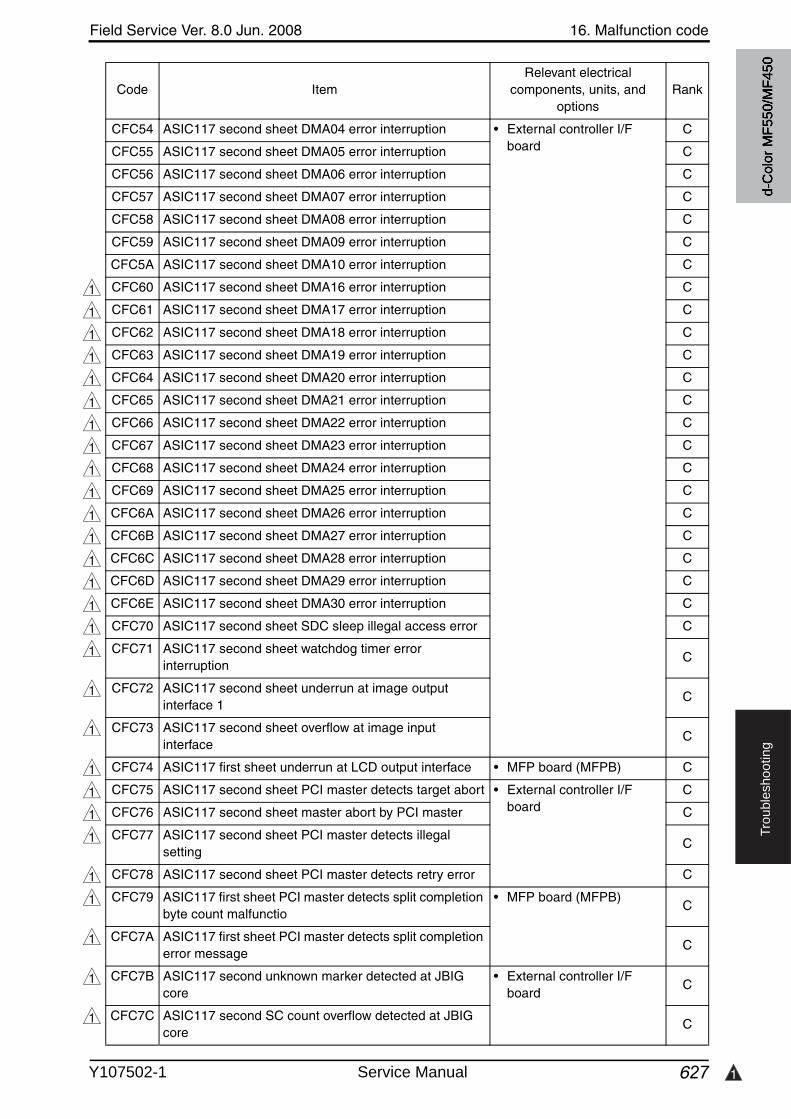
Field Service Ver. 8.0 Jun. 2008 16. Malfunction code
627 1
Tro
ub
lesh
oo
tin
g
CFC54 ASIC117 second sheet DMA04 error interruption • External controller I/F board
C
CFC55 ASIC117 second sheet DMA05 error interruption C
CFC56 ASIC117 second sheet DMA06 error interruption C
CFC57 ASIC117 second sheet DMA07 error interruption C
CFC58 ASIC117 second sheet DMA08 error interruption C
CFC59 ASIC117 second sheet DMA09 error interruption C
CFC5A ASIC117 second sheet DMA10 error interruption C
CFC60 ASIC117 second sheet DMA16 error interruption C
CFC61 ASIC117 second sheet DMA17 error interruption C
CFC62 ASIC117 second sheet DMA18 error interruption C
CFC63 ASIC117 second sheet DMA19 error interruption C
CFC64 ASIC117 second sheet DMA20 error interruption C
CFC65 ASIC117 second sheet DMA21 error interruption C
CFC66 ASIC117 second sheet DMA22 error interruption C
CFC67 ASIC117 second sheet DMA23 error interruption C
CFC68 ASIC117 second sheet DMA24 error interruption C
CFC69 ASIC117 second sheet DMA25 error interruption C
CFC6A ASIC117 second sheet DMA26 error interruption C
CFC6B ASIC117 second sheet DMA27 error interruption C
CFC6C ASIC117 second sheet DMA28 error interruption C
CFC6D ASIC117 second sheet DMA29 error interruption C
CFC6E ASIC117 second sheet DMA30 error interruption C
CFC70 ASIC117 second sheet SDC sleep illegal access error C
CFC71 ASIC117 second sheet watchdog timer error interruption
C
CFC72 ASIC117 second sheet underrun at image outputinterface 1
C
CFC73 ASIC117 second sheet overflow at image inputinterface
C
CFC74 ASIC117 first sheet underrun at LCD output interface • MFP board (MFPB) C
CFC75 ASIC117 second sheet PCI master detects target abort • External controller I/F board
C
CFC76 ASIC117 second sheet master abort by PCI master C
CFC77 ASIC117 second sheet PCI master detects illegal setting
C
CFC78 ASIC117 second sheet PCI master detects retry error C
CFC79 ASIC117 first sheet PCI master detects split completion byte count malfunctio
• MFP board (MFPB)C
CFC7A ASIC117 first sheet PCI master detects split completion error message
C
CFC7B ASIC117 second unknown marker detected at JBIG core
• External controller I/F board
C
CFC7C ASIC117 second SC count overflow detected at JBIG core
C
Code ItemRelevant electrical
components, units, and options
Rank
1
1
1
1
1
1
1
1
1
1
1
1
1
1
1
1
1
1
1
1
1
1
1
1
1
1
1
1
d-C
olor
MF5
50/M
F450
Y107502-1 Service Manual
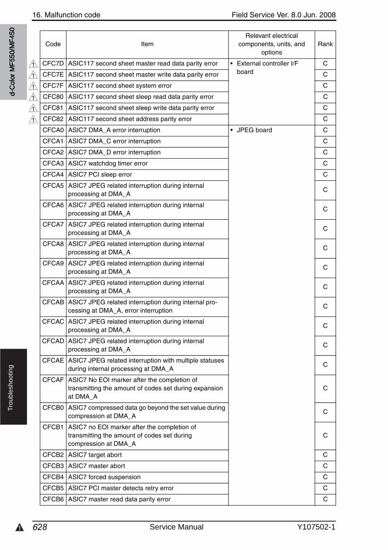
1
16. Malfunction code Field Service Ver. 8.0 Jun. 2008
628
Tro
ub
lesh
oo
tin
g
CFC7D ASIC117 second sheet master read data parity error • External controller I/F board
C
CFC7E ASIC117 second sheet master write data parity error C
CFC7F ASIC117 second sheet system error C
CFC80 ASIC117 second sheet sleep read data parity error C
CFC81 ASIC117 second sheet sleep write data parity error C
CFC82 ASIC117 second sheet address parity error C
CFCA0 ASIC7 DMA_A error interruption • JPEG board C
CFCA1 ASIC7 DMA_C error interruption C
CFCA2 ASIC7 DMA_D error interruption C
CFCA3 ASIC7 watchdog timer error C
CFCA4 ASIC7 PCI sleep error C
CFCA5 ASIC7 JPEG related interruption during internal processing at DMA_A
C
CFCA6 ASIC7 JPEG related interruption during internal processing at DMA_A
C
CFCA7 ASIC7 JPEG related interruption during internal processing at DMA_A
C
CFCA8 ASIC7 JPEG related interruption during internal processing at DMA_A
C
CFCA9 ASIC7 JPEG related interruption during internal processing at DMA_A
C
CFCAA ASIC7 JPEG related interruption during internal processing at DMA_A
C
CFCAB ASIC7 JPEG related interruption during internal pro-cessing at DMA_A, error interruption
C
CFCAC ASIC7 JPEG related interruption during internal processing at DMA_A
C
CFCAD ASIC7 JPEG related interruption during internal processing at DMA_A
C
CFCAE ASIC7 JPEG related interruption with multiple statusesduring internal processing at DMA_A
C
CFCAF ASIC7 No EOI marker after the completion of transmitting the amount of codes set during expansion at DMA_A
C
CFCB0 ASIC7 compressed data go beyond the set value during compression at DMA_A
C
CFCB1 ASIC7 no EOI marker after the completion of transmitting the amount of codes set during compression at DMA_A
C
CFCB2 ASIC7 target abort C
CFCB3 ASIC7 master abort C
CFCB4 ASIC7 forced suspension C
CFCB5 ASIC7 PCI master detects retry error C
CFCB6 ASIC7 master read data parity error C
Code ItemRelevant electrical
components, units, and options
Rank
1
1
1
1
1
1
d-C
olor
MF5
50/M
F450
Service Manual Y107502-1
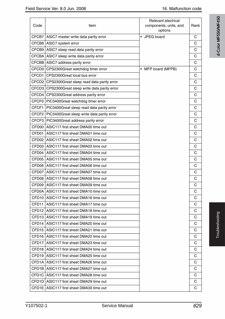
Field Service Ver. 8.0 Jun. 2008 16. Malfunction code
629
Tro
ub
lesh
oo
tin
g
CFCB7 ASIC7 master write data parity error • JPEG board C
CFCB8 ASIC7 system error C
CFCB9 ASIC7 sleep read data parity error C
CFCBA ASIC7 sleep write data parity error C
CFCBB ASIC7 address parity error C
CFCD0 CPS2300Great watchdog timer error • MFP board (MFPB) C
CFCD1 CPS2300Great local bus error C
CFCD2 CPS2300Great sleep read data parity error C
CFCD3 CPS2300Great sleep write data parity error C
CFCD4 CPS2300Great address parity error C
CFCF0 PIC3400Great watchdog timer error C
CFCF1 PIC3400Great sleep read data parity error C
CFCF2 PIC3400Great sleep write data parity error C
CFCF3 PIC3400Great address parity error C
CFD00 ASIC117 first sheet DMA00 time out C
CFD01 ASIC117 first sheet DMA01 time out C
CFD02 ASIC117 first sheet DMA02 time out C
CFD03 ASIC117 first sheet DMA03 time out C
CFD04 ASIC117 first sheet DMA04 time out C
CFD05 ASIC117 first sheet DMA05 time out C
CFD06 ASIC117 first sheet DMA06 time out C
CFD07 ASIC117 first sheet DMA07 time out C
CFD08 ASIC117 first sheet DMA08 time out C
CFD09 ASIC117 first sheet DMA09 time out C
CFD0A ASIC117 first sheet DMA10 time out C
CFD10 ASIC117 first sheet DMA16 time out C
CFD11 ASIC117 first sheet DMA17 time out C
CFD12 ASIC117 first sheet DMA18 time out C
CFD13 ASIC117 first sheet DMA19 time out C
CFD14 ASIC117 first sheet DMA20 time out C
CFD15 ASIC117 first sheet DMA21 time out C
CFD16 ASIC117 first sheet DMA22 time out C
CFD17 ASIC117 first sheet DMA23 time out C
CFD18 ASIC117 first sheet DMA24 time out C
CFD19 ASIC117 first sheet DMA25 time out C
CFD1A ASIC117 first sheet DMA26 time out C
CFD1B ASIC117 first sheet DMA27 time out C
CFD1C ASIC117 first sheet DMA28 time out C
CFD1D ASIC117 first sheet DMA29 time out C
CFD1E ASIC117 first sheet DMA30 time out C
Code ItemRelevant electrical
components, units, and options
Rank
d-C
olor
MF5
50/M
F450
Y107502-1 Service Manual
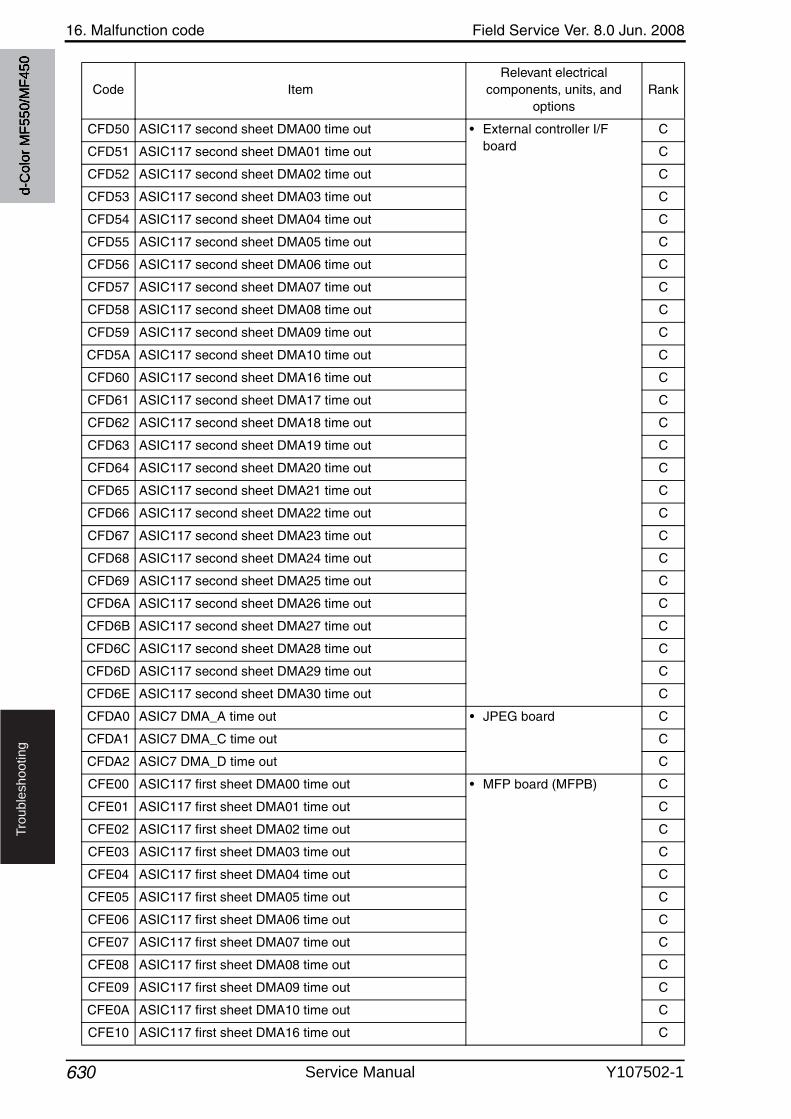
16. Malfunction code Field Service Ver. 8.0 Jun. 2008
630
Tro
ub
lesh
oo
tin
g
CFD50 ASIC117 second sheet DMA00 time out • External controller I/F board
C
CFD51 ASIC117 second sheet DMA01 time out C
CFD52 ASIC117 second sheet DMA02 time out C
CFD53 ASIC117 second sheet DMA03 time out C
CFD54 ASIC117 second sheet DMA04 time out C
CFD55 ASIC117 second sheet DMA05 time out C
CFD56 ASIC117 second sheet DMA06 time out C
CFD57 ASIC117 second sheet DMA07 time out C
CFD58 ASIC117 second sheet DMA08 time out C
CFD59 ASIC117 second sheet DMA09 time out C
CFD5A ASIC117 second sheet DMA10 time out C
CFD60 ASIC117 second sheet DMA16 time out C
CFD61 ASIC117 second sheet DMA17 time out C
CFD62 ASIC117 second sheet DMA18 time out C
CFD63 ASIC117 second sheet DMA19 time out C
CFD64 ASIC117 second sheet DMA20 time out C
CFD65 ASIC117 second sheet DMA21 time out C
CFD66 ASIC117 second sheet DMA22 time out C
CFD67 ASIC117 second sheet DMA23 time out C
CFD68 ASIC117 second sheet DMA24 time out C
CFD69 ASIC117 second sheet DMA25 time out C
CFD6A ASIC117 second sheet DMA26 time out C
CFD6B ASIC117 second sheet DMA27 time out C
CFD6C ASIC117 second sheet DMA28 time out C
CFD6D ASIC117 second sheet DMA29 time out C
CFD6E ASIC117 second sheet DMA30 time out C
CFDA0 ASIC7 DMA_A time out • JPEG board C
CFDA1 ASIC7 DMA_C time out C
CFDA2 ASIC7 DMA_D time out C
CFE00 ASIC117 first sheet DMA00 time out • MFP board (MFPB) C
CFE01 ASIC117 first sheet DMA01 time out C
CFE02 ASIC117 first sheet DMA02 time out C
CFE03 ASIC117 first sheet DMA03 time out C
CFE04 ASIC117 first sheet DMA04 time out C
CFE05 ASIC117 first sheet DMA05 time out C
CFE06 ASIC117 first sheet DMA06 time out C
CFE07 ASIC117 first sheet DMA07 time out C
CFE08 ASIC117 first sheet DMA08 time out C
CFE09 ASIC117 first sheet DMA09 time out C
CFE0A ASIC117 first sheet DMA10 time out C
CFE10 ASIC117 first sheet DMA16 time out C
Code ItemRelevant electrical
components, units, and options
Rank
d-C
olor
MF5
50/M
F450
Service Manual Y107502-1
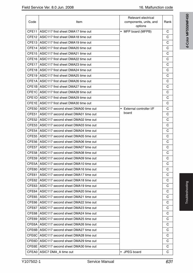
Field Service Ver. 8.0 Jun. 2008 16. Malfunction code
631
Tro
ub
lesh
oo
tin
g
CFE11 ASIC117 first sheet DMA17 time out • MFP board (MFPB) C
CFE12 ASIC117 first sheet DMA18 time out C
CFE13 ASIC117 first sheet DMA19 time out C
CFE14 ASIC117 first sheet DMA20 time out C
CFE15 ASIC117 first sheet DMA21 time out C
CFE16 ASIC117 first sheet DMA22 time out C
CFE17 ASIC117 first sheet DMA23 time out C
CFE18 ASIC117 first sheet DMA24 time out C
CFE19 ASIC117 first sheet DMA25 time out C
CFE1A ASIC117 first sheet DMA26 time out C
CFE1B ASIC117 first sheet DMA27 time out C
CFE1C ASIC117 first sheet DMA28 time out C
CFE1D ASIC117 first sheet DMA29 time out C
CFE1E ASIC117 first sheet DMA30 time out C
CFE50 ASIC117 second sheet DMA00 time out • External controller I/F board
C
CFE51 ASIC117 second sheet DMA01 time out C
CFE52 ASIC117 second sheet DMA02 time out C
CFE53 ASIC117 second sheet DMA03 time out C
CFE54 ASIC117 second sheet DMA04 time out C
CFE55 ASIC117 second sheet DMA05 time out C
CFE56 ASIC117 second sheet DMA06 time out C
CFE57 ASIC117 second sheet DMA07 time out C
CFE58 ASIC117 second sheet DMA08 time out C
CFE59 ASIC117 second sheet DMA09 time out C
CFE5A ASIC117 second sheet DMA10 time out C
CFE60 ASIC117 second sheet DMA16 time out C
CFE61 ASIC117 second sheet DMA17 time out C
CFE62 ASIC117 second sheet DMA18 time out C
CFE63 ASIC117 second sheet DMA19 time out C
CFE64 ASIC117 second sheet DMA20 time out C
CFE65 ASIC117 second sheet DMA21 time out C
CFE66 ASIC117 second sheet DMA22 time out C
CFE67 ASIC117 second sheet DMA23 time out C
CFE68 ASIC117 second sheet DMA24 time out C
CFE69 ASIC117 second sheet DMA25 time out C
CFE6A ASIC117 second sheet DMA26 time out C
CFE6B ASIC117 second sheet DMA27 time out C
CFE6C ASIC117 second sheet DMA28 time out C
CFE6D ASIC117 second sheet DMA29 time out C
CFE6E ASIC117 second sheet DMA30 time out C
CFEA0 ASIC7 DMA_A time out • JPEG board C
Code ItemRelevant electrical
components, units, and options
Rank
d-C
olor
MF5
50/M
F450
Y107502-1 Service Manual
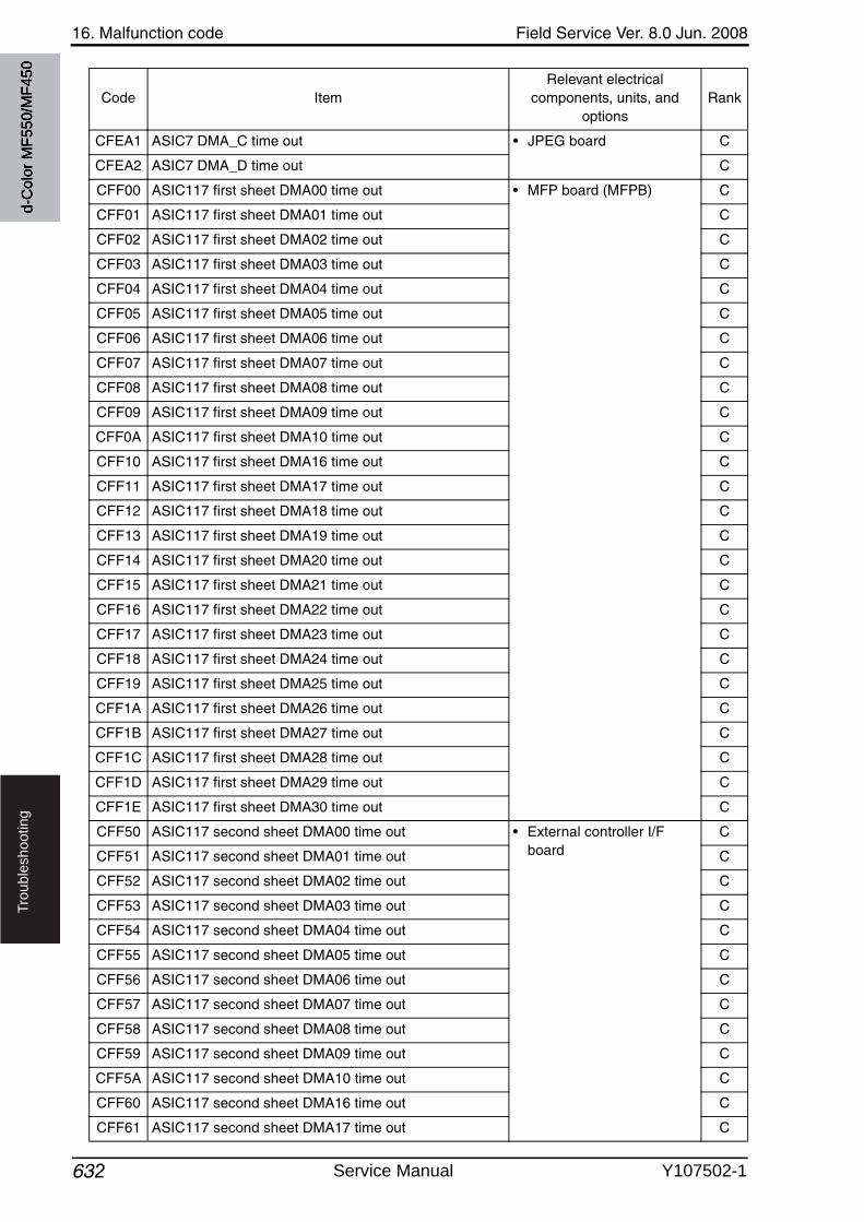
16. Malfunction code Field Service Ver. 8.0 Jun. 2008
632
Tro
ub
lesh
oo
tin
g
CFEA1 ASIC7 DMA_C time out • JPEG board C
CFEA2 ASIC7 DMA_D time out C
CFF00 ASIC117 first sheet DMA00 time out • MFP board (MFPB) C
CFF01 ASIC117 first sheet DMA01 time out C
CFF02 ASIC117 first sheet DMA02 time out C
CFF03 ASIC117 first sheet DMA03 time out C
CFF04 ASIC117 first sheet DMA04 time out C
CFF05 ASIC117 first sheet DMA05 time out C
CFF06 ASIC117 first sheet DMA06 time out C
CFF07 ASIC117 first sheet DMA07 time out C
CFF08 ASIC117 first sheet DMA08 time out C
CFF09 ASIC117 first sheet DMA09 time out C
CFF0A ASIC117 first sheet DMA10 time out C
CFF10 ASIC117 first sheet DMA16 time out C
CFF11 ASIC117 first sheet DMA17 time out C
CFF12 ASIC117 first sheet DMA18 time out C
CFF13 ASIC117 first sheet DMA19 time out C
CFF14 ASIC117 first sheet DMA20 time out C
CFF15 ASIC117 first sheet DMA21 time out C
CFF16 ASIC117 first sheet DMA22 time out C
CFF17 ASIC117 first sheet DMA23 time out C
CFF18 ASIC117 first sheet DMA24 time out C
CFF19 ASIC117 first sheet DMA25 time out C
CFF1A ASIC117 first sheet DMA26 time out C
CFF1B ASIC117 first sheet DMA27 time out C
CFF1C ASIC117 first sheet DMA28 time out C
CFF1D ASIC117 first sheet DMA29 time out C
CFF1E ASIC117 first sheet DMA30 time out C
CFF50 ASIC117 second sheet DMA00 time out • External controller I/F board
C
CFF51 ASIC117 second sheet DMA01 time out C
CFF52 ASIC117 second sheet DMA02 time out C
CFF53 ASIC117 second sheet DMA03 time out C
CFF54 ASIC117 second sheet DMA04 time out C
CFF55 ASIC117 second sheet DMA05 time out C
CFF56 ASIC117 second sheet DMA06 time out C
CFF57 ASIC117 second sheet DMA07 time out C
CFF58 ASIC117 second sheet DMA08 time out C
CFF59 ASIC117 second sheet DMA09 time out C
CFF5A ASIC117 second sheet DMA10 time out C
CFF60 ASIC117 second sheet DMA16 time out C
CFF61 ASIC117 second sheet DMA17 time out C
Code ItemRelevant electrical
components, units, and options
Rank
d-C
olor
MF5
50/M
F450
Service Manual Y107502-1
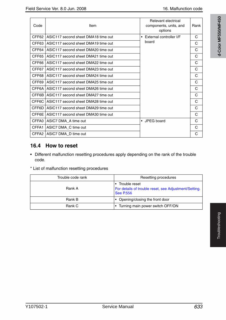
Field Service Ver. 8.0 Jun. 2008 16. Malfunction code
633
Tro
ub
lesh
oo
tin
g
16.4 How to reset
• Different malfunction resetting procedures apply depending on the rank of the trouble code.
* List of malfunction resetting procedures
CFF62 ASIC117 second sheet DMA18 time out • External controller I/F board
C
CFF63 ASIC117 second sheet DMA19 time out C
CFF64 ASIC117 second sheet DMA20 time out C
CFF65 ASIC117 second sheet DMA21 time out C
CFF66 ASIC117 second sheet DMA22 time out C
CFF67 ASIC117 second sheet DMA23 time out C
CFF68 ASIC117 second sheet DMA24 time out C
CFF69 ASIC117 second sheet DMA25 time out C
CFF6A ASIC117 second sheet DMA26 time out C
CFF6B ASIC117 second sheet DMA27 time out C
CFF6C ASIC117 second sheet DMA28 time out C
CFF6D ASIC117 second sheet DMA29 time out C
CFF6E ASIC117 second sheet DMA30 time out C
CFFA0 ASIC7 DMA_A time out • JPEG board C
CFFA1 ASIC7 DMA_C time out C
CFFA2 ASIC7 DMA_D time out C
Code ItemRelevant electrical
components, units, and options
Rank
Trouble code rank Resetting procedures
Rank A• Trouble resetFor details of trouble reset, see Adjustment/Setting.See P.556
Rank B • Opening/closing the front door
Rank C • Turning main power switch OFF/ON
d-C
olor
MF5
50/M
F450
Y107502-1 Service Manual
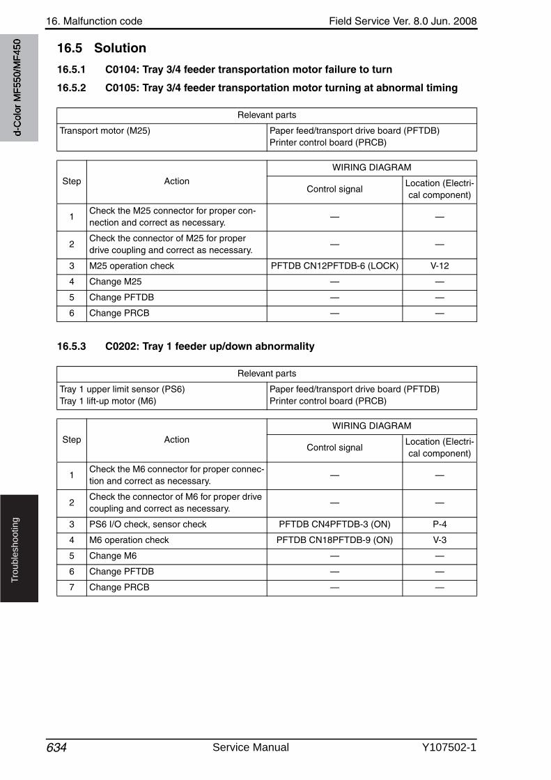
16. Malfunction code Field Service Ver. 8.0 Jun. 2008
634
Tro
ub
lesh
oo
tin
g
16.5 Solution
16.5.1 C0104: Tray 3/4 feeder transportation motor failure to turn
16.5.2 C0105: Tray 3/4 feeder transportation motor turning at abnormal timing
16.5.3 C0202: Tray 1 feeder up/down abnormality
Relevant parts
Transport motor (M25) Paper feed/transport drive board (PFTDB)Printer control board (PRCB)
Step Action
WIRING DIAGRAM
Control signalLocation (Electri-cal component)
1Check the M25 connector for proper con-nection and correct as necessary.
— —
2Check the connector of M25 for proper drive coupling and correct as necessary.
— —
3 M25 operation check PFTDB CN12PFTDB-6 (LOCK) V-12
4 Change M25 — —
5 Change PFTDB — —
6 Change PRCB — —
Relevant parts
Tray 1 upper limit sensor (PS6)Tray 1 lift-up motor (M6)
Paper feed/transport drive board (PFTDB)Printer control board (PRCB)
Step Action
WIRING DIAGRAM
Control signalLocation (Electri-cal component)
1Check the M6 connector for proper connec-tion and correct as necessary.
— —
2Check the connector of M6 for proper drivecoupling and correct as necessary.
— —
3 PS6 I/O check, sensor check PFTDB CN4PFTDB-3 (ON) P-4
4 M6 operation check PFTDB CN18PFTDB-9 (ON) V-3
5 Change M6 — —
6 Change PFTDB — —
7 Change PRCB — —
d-C
olor
MF5
50/M
F450
Service Manual Y107502-1
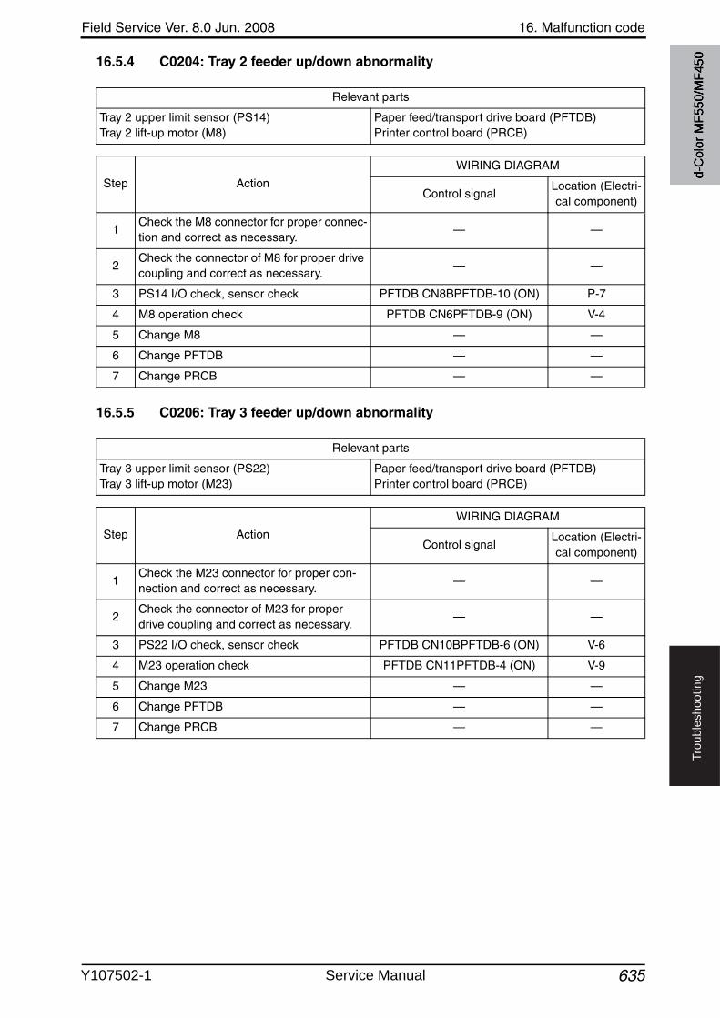
Field Service Ver. 8.0 Jun. 2008 16. Malfunction code
635
Tro
ub
lesh
oo
tin
g
16.5.4 C0204: Tray 2 feeder up/down abnormality
16.5.5 C0206: Tray 3 feeder up/down abnormality
Relevant parts
Tray 2 upper limit sensor (PS14)Tray 2 lift-up motor (M8)
Paper feed/transport drive board (PFTDB)Printer control board (PRCB)
Step Action
WIRING DIAGRAM
Control signalLocation (Electri-cal component)
1Check the M8 connector for proper connec-tion and correct as necessary.
— —
2Check the connector of M8 for proper drivecoupling and correct as necessary.
— —
3 PS14 I/O check, sensor check PFTDB CN8BPFTDB-10 (ON) P-7
4 M8 operation check PFTDB CN6PFTDB-9 (ON) V-4
5 Change M8 — —
6 Change PFTDB — —
7 Change PRCB — —
Relevant parts
Tray 3 upper limit sensor (PS22)Tray 3 lift-up motor (M23)
Paper feed/transport drive board (PFTDB)Printer control board (PRCB)
Step Action
WIRING DIAGRAM
Control signalLocation (Electri-cal component)
1Check the M23 connector for proper con-nection and correct as necessary.
— —
2Check the connector of M23 for proper drive coupling and correct as necessary.
— —
3 PS22 I/O check, sensor check PFTDB CN10BPFTDB-6 (ON) V-6
4 M23 operation check PFTDB CN11PFTDB-4 (ON) V-9
5 Change M23 — —
6 Change PFTDB — —
7 Change PRCB — —
d-C
olor
MF5
50/M
F450
Y107502-1 Service Manual
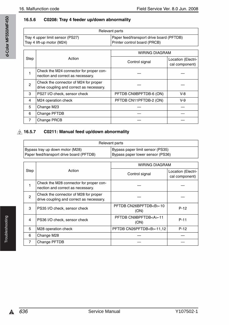
16. Malfunction code Field Service Ver. 8.0 Jun. 2008
6362
Tro
ub
lesh
oo
tin
g
16.5.6 C0208: Tray 4 feeder up/down abnormality
16.5.7 C0211: Manual feed up/down abnormality
Relevant parts
Tray 4 upper limit sensor (PS27)Tray 4 lift-up motor (M24)
Paper feed/transport drive board (PFTDB)Printer control board (PRCB)
Step Action
WIRING DIAGRAM
Control signalLocation (Electri-cal component)
1Check the M24 connector for proper con-nection and correct as necessary.
— —
2Check the connector of M24 for proper drive coupling and correct as necessary.
— —
3 PS27 I/O check, sensor check PFTDB CN9BPFTDB-6 (ON) V-8
4 M24 operation check PFTDB CN11PFTDB-2 (ON) V-9
5 Change M23 — —
6 Change PFTDB — —
7 Change PRCB — —
2
Relevant parts
Bypass tray up down motor (M28)Paper feed/transport drive board (PFTDB)
Bypass paper limit sensor (PS35)Bypass paper lower sensor (PS36)
Step Action
WIRING DIAGRAM
Control signalLocation (Electri-cal component)
1Check the M28 connector for proper con-nection and correct as necessary.
— —
2Check the connector of M28 for proper drive coupling and correct as necessary.
— —
3 PS35 I/O check, sensor checkPFTDB CN26BPFTDB<B>-10
(ON)P-12
4 PS36 I/O check, sensor checkPFTDB CN9BPFTDB<A>-11
(ON)P-11
5 M28 operation check PFTDB CN26PFTDB<B>-11,12 P-12
6 Change M28 — —
7 Change PFTDB — —
d-C
olor
MF5
50/M
F450
Service Manual Y107502-1
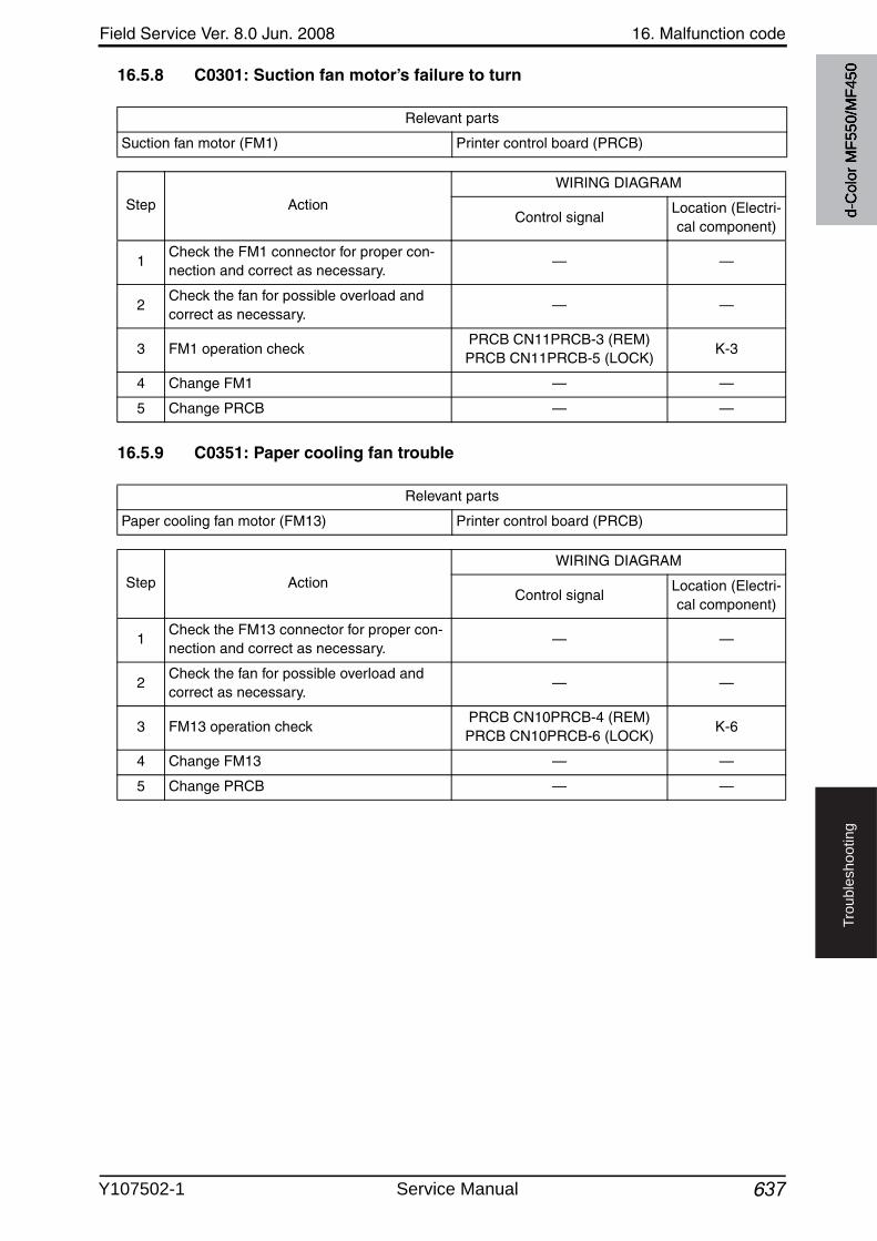
Field Service Ver. 8.0 Jun. 2008 16. Malfunction code
637
Tro
ub
lesh
oo
tin
g
16.5.8 C0301: Suction fan motor’s failure to turn
16.5.9 C0351: Paper cooling fan trouble
Relevant parts
Suction fan motor (FM1) Printer control board (PRCB)
Step Action
WIRING DIAGRAM
Control signalLocation (Electri-cal component)
1Check the FM1 connector for proper con-nection and correct as necessary.
— —
2Check the fan for possible overload and correct as necessary.
— —
3 FM1 operation checkPRCB CN11PRCB-3 (REM)PRCB CN11PRCB-5 (LOCK)
K-3
4 Change FM1 — —
5 Change PRCB — —
Relevant parts
Paper cooling fan motor (FM13) Printer control board (PRCB)
Step Action
WIRING DIAGRAM
Control signalLocation (Electri-cal component)
1Check the FM13 connector for proper con-nection and correct as necessary.
— —
2Check the fan for possible overload and correct as necessary.
— —
3 FM13 operation checkPRCB CN10PRCB-4 (REM)PRCB CN10PRCB-6 (LOCK)
K-6
4 Change FM13 — —
5 Change PRCB — —
d-C
olor
MF5
50/M
F450
Y107502-1 Service Manual
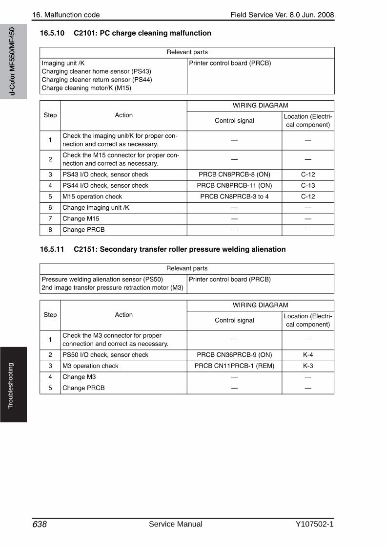
16. Malfunction code Field Service Ver. 8.0 Jun. 2008
638
Tro
ub
lesh
oo
tin
g
16.5.10 C2101: PC charge cleaning malfunction
16.5.11 C2151: Secondary transfer roller pressure welding alienation
Relevant parts
Imaging unit /KCharging cleaner home sensor (PS43)Charging cleaner return sensor (PS44)Charge cleaning motor/K (M15)
Printer control board (PRCB)
Step Action
WIRING DIAGRAM
Control signalLocation (Electri-cal component)
1Check the imaging unit/K for proper con-nection and correct as necessary.
— —
2Check the M15 connector for proper con-nection and correct as necessary.
— —
3 PS43 I/O check, sensor check PRCB CN8PRCB-8 (ON) C-12
4 PS44 I/O check, sensor check PRCB CN8PRCB-11 (ON) C-13
5 M15 operation check PRCB CN8PRCB-3 to 4 C-12
6 Change imaging unit /K — —
7 Change M15 — —
8 Change PRCB — —
Relevant parts
Pressure welding alienation sensor (PS50)2nd image transfer pressure retraction motor (M3)
Printer control board (PRCB)
Step Action
WIRING DIAGRAM
Control signalLocation (Electri-cal component)
1Check the M3 connector for proper connection and correct as necessary.
— —
2 PS50 I/O check, sensor check PRCB CN36PRCB-9 (ON) K-4
3 M3 operation check PRCB CN11PRCB-1 (REM) K-3
4 Change M3 — —
5 Change PRCB — —
d-C
olor
MF5
50/M
F450
Service Manual Y107502-1
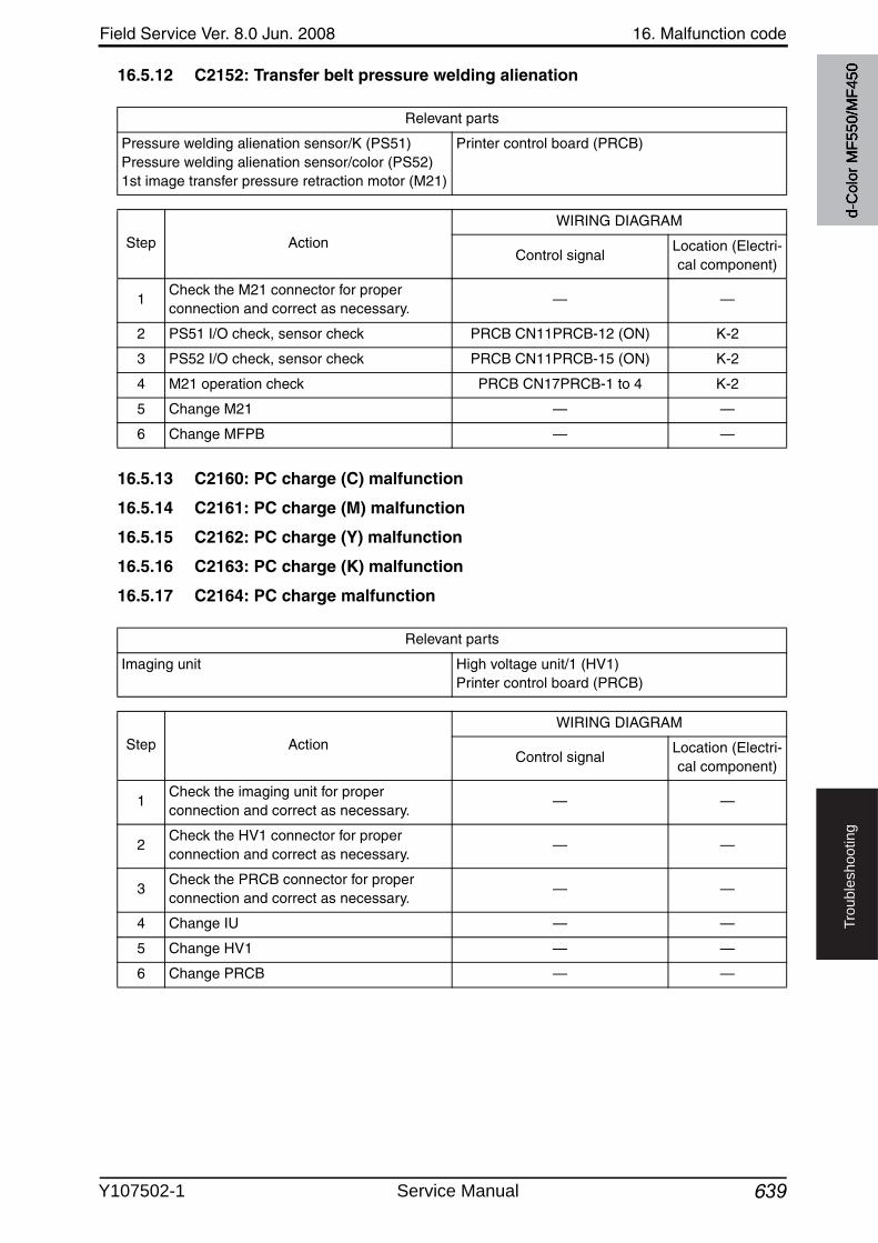
Field Service Ver. 8.0 Jun. 2008 16. Malfunction code
639
Tro
ub
lesh
oo
tin
g
16.5.12 C2152: Transfer belt pressure welding alienation
16.5.13 C2160: PC charge (C) malfunction
16.5.14 C2161: PC charge (M) malfunction
16.5.15 C2162: PC charge (Y) malfunction
16.5.16 C2163: PC charge (K) malfunction
16.5.17 C2164: PC charge malfunction
Relevant parts
Pressure welding alienation sensor/K (PS51)Pressure welding alienation sensor/color (PS52)1st image transfer pressure retraction motor (M21)
Printer control board (PRCB)
Step Action
WIRING DIAGRAM
Control signalLocation (Electri-cal component)
1Check the M21 connector for proper connection and correct as necessary.
— —
2 PS51 I/O check, sensor check PRCB CN11PRCB-12 (ON) K-2
3 PS52 I/O check, sensor check PRCB CN11PRCB-15 (ON) K-2
4 M21 operation check PRCB CN17PRCB-1 to 4 K-2
5 Change M21 — —
6 Change MFPB — —
Relevant parts
Imaging unit High voltage unit/1 (HV1)Printer control board (PRCB)
Step Action
WIRING DIAGRAM
Control signalLocation (Electri-cal component)
1Check the imaging unit for proper connection and correct as necessary.
— —
2Check the HV1 connector for proper connection and correct as necessary.
— —
3Check the PRCB connector for proper connection and correct as necessary.
— —
4 Change IU — —
5 Change HV1 — —
6 Change PRCB — —
d-C
olor
MF5
50/M
F450
Y107502-1 Service Manual

16. Malfunction code Field Service Ver. 8.0 Jun. 2008
640
Tro
ub
lesh
oo
tin
g
16.5.18 C2204: Waste toner agitating motor’s failure to turn
16.5.19 C2253: Color PC drum motor’s failure to turn
16.5.20 C2254: Color PC drum motor’s turning at abnormal timing
Relevant parts
Waste toner agitating motor lock sensor (PS23)Waste toner agitating motor (M20)
Printer control board (PRCB)
Step Action
WIRING DIAGRAM
Control signalLocation (Electri-cal component)
1 Change the waste toner box. — —
2Check the M20 connector for proper connection and correct as necessary.
— —
3Check the connector of motor for proper drive coupling and correct as necessary.
— —
4 M20 operation check PRCB CN15PRCB-11 to 14 C-12
5 Change M20 — —
6 Change PRCB — —
Relevant parts
Color PC drum motor (M16) Printer control board (PRCB)
Step Action
WIRING DIAGRAM
Control signalLocation (Electri-cal component)
1Check the M16 connector for proper connection and correct as necessary.
— —
2Check the M16 connector for proper drivecoupling and correct as necessary.
— —
3Check the PRCB connector for proper connection and correct as necessary.
— —
4 M16 operation checkPRCB CN12PRCB-9 (REM)
PRCB CN12PRCB-12 (LOCK)K-9
5 Change M16 — —
6 Change PRCB — —
d-C
olor
MF5
50/M
F450
Service Manual Y107502-1
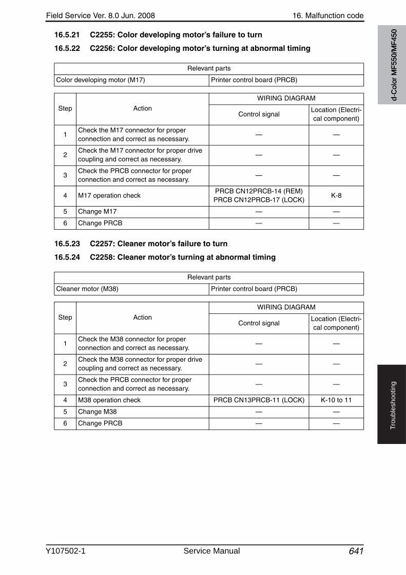
Field Service Ver. 8.0 Jun. 2008 16. Malfunction code
641
Tro
ub
lesh
oo
tin
g
16.5.21 C2255: Color developing motor’s failure to turn
16.5.22 C2256: Color developing motor’s turning at abnormal timing
16.5.23 C2257: Cleaner motor’s failure to turn
16.5.24 C2258: Cleaner motor’s turning at abnormal timing
Relevant parts
Color developing motor (M17) Printer control board (PRCB)
Step Action
WIRING DIAGRAM
Control signalLocation (Electri-cal component)
1Check the M17 connector for proper connection and correct as necessary.
— —
2Check the M17 connector for proper drivecoupling and correct as necessary.
— —
3Check the PRCB connector for proper connection and correct as necessary.
— —
4 M17 operation checkPRCB CN12PRCB-14 (REM)PRCB CN12PRCB-17 (LOCK)
K-8
5 Change M17 — —
6 Change PRCB — —
Relevant parts
Cleaner motor (M38) Printer control board (PRCB)
Step Action
WIRING DIAGRAM
Control signalLocation (Electri-cal component)
1Check the M38 connector for proper connection and correct as necessary.
— —
2Check the M38 connector for proper drivecoupling and correct as necessary.
— —
3Check the PRCB connector for proper connection and correct as necessary.
— —
4 M38 operation check PRCB CN13PRCB-11 (LOCK) K-10 to 11
5 Change M38 — —
6 Change PRCB — —
d-C
olor
MF5
50/M
F450
Y107502-1 Service Manual
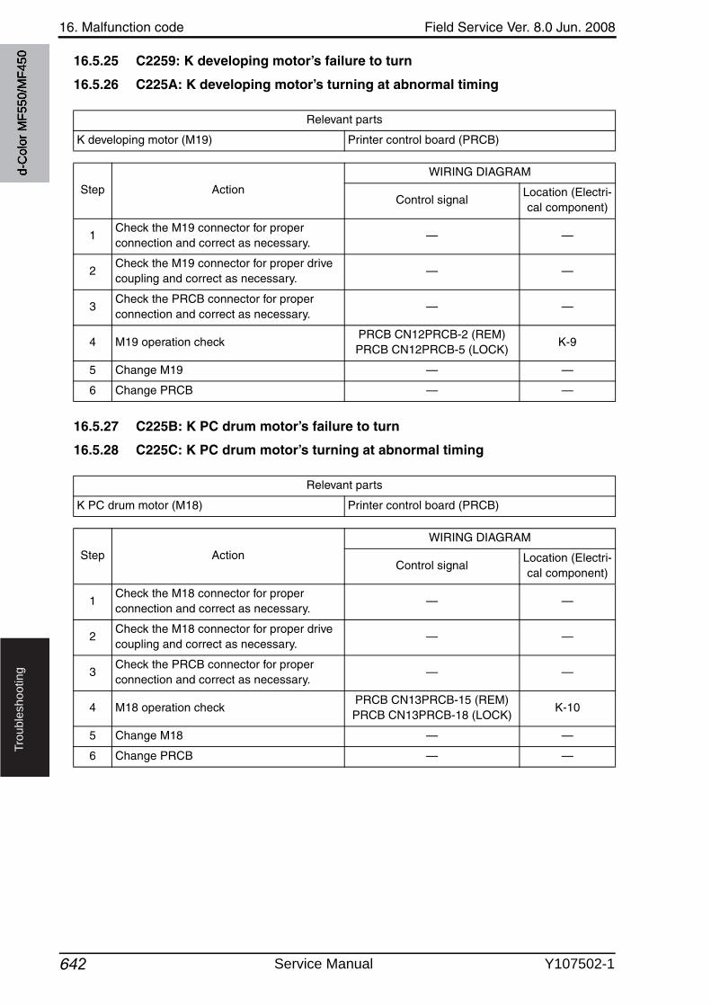
16. Malfunction code Field Service Ver. 8.0 Jun. 2008
642
Tro
ub
lesh
oo
tin
g
16.5.25 C2259: K developing motor’s failure to turn
16.5.26 C225A: K developing motor’s turning at abnormal timing
16.5.27 C225B: K PC drum motor’s failure to turn
16.5.28 C225C: K PC drum motor’s turning at abnormal timing
Relevant parts
K developing motor (M19) Printer control board (PRCB)
Step Action
WIRING DIAGRAM
Control signalLocation (Electri-cal component)
1Check the M19 connector for proper connection and correct as necessary.
— —
2Check the M19 connector for proper drivecoupling and correct as necessary.
— —
3Check the PRCB connector for proper connection and correct as necessary.
— —
4 M19 operation checkPRCB CN12PRCB-2 (REM)PRCB CN12PRCB-5 (LOCK)
K-9
5 Change M19 — —
6 Change PRCB — —
Relevant parts
K PC drum motor (M18) Printer control board (PRCB)
Step Action
WIRING DIAGRAM
Control signalLocation (Electri-cal component)
1Check the M18 connector for proper connection and correct as necessary.
— —
2Check the M18 connector for proper drivecoupling and correct as necessary.
— —
3Check the PRCB connector for proper connection and correct as necessary.
— —
4 M18 operation checkPRCB CN13PRCB-15 (REM)PRCB CN13PRCB-18 (LOCK)
K-10
5 Change M18 — —
6 Change PRCB — —
d-C
olor
MF5
50/M
F450
Service Manual Y107502-1

Field Service Ver. 8.0 Jun. 2008 16. Malfunction code
643
Tro
ub
lesh
oo
tin
g
16.5.29 C2351: K toner suction fan motor’s failure to turn
16.5.30 C2352: Color toner suction fan motor’s failure to turn
Relevant parts
K toner suction fan motor (FM8) Printer control board (PRCB)
Step Action
WIRING DIAGRAM
Control signalLocation (Electri-cal component)
1Check the FM8 connector for proper con-nection and correct as necessary.
— —
2Check the fan for possible overload and correct as necessary.
— —
3 FM8 operation checkPRCB CN10PRCB-10 (REM)PRCB CN10PRCB-12 (LOCK)
K-5
4 Change FM8 — —
5 Change PRCB — —
Relevant parts
Color toner suction fan motor (FM7) Printer control board (PRCB)
Step Action
WIRING DIAGRAM
Control signalLocation (Electri-cal component)
1Check the FM7 connector for proper connection and correct as necessary.
— —
2Check the fan for possible overload and correct as necessary.
— —
3 FM7 operation checkPRCB CN10PRCB-7 (REM)PRCB CN10PRCB-9 (LOCK)
K-5
4 Change FM7 — —
5 Change PRCB — —
d-C
olor
MF5
50/M
F450
Y107502-1 Service Manual
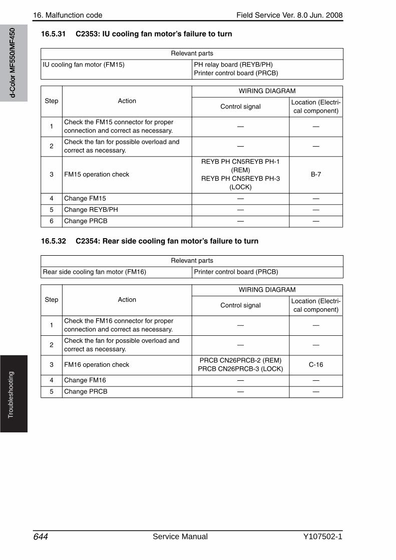
16. Malfunction code Field Service Ver. 8.0 Jun. 2008
644
Tro
ub
lesh
oo
tin
g
16.5.31 C2353: IU cooling fan motor’s failure to turn
16.5.32 C2354: Rear side cooling fan motor’s failure to turn
Relevant parts
IU cooling fan motor (FM15) PH relay board (REYB/PH)Printer control board (PRCB)
Step Action
WIRING DIAGRAM
Control signalLocation (Electri-cal component)
1Check the FM15 connector for proper connection and correct as necessary.
— —
2Check the fan for possible overload and correct as necessary.
— —
3 FM15 operation check
REYB PH CN5REYB PH-1 (REM)
REYB PH CN5REYB PH-3 (LOCK)
B-7
4 Change FM15 — —
5 Change REYB/PH — —
6 Change PRCB — —
Relevant parts
Rear side cooling fan motor (FM16) Printer control board (PRCB)
Step Action
WIRING DIAGRAM
Control signalLocation (Electri-cal component)
1Check the FM16 connector for proper connection and correct as necessary.
— —
2Check the fan for possible overload and correct as necessary.
— —
3 FM16 operation checkPRCB CN26PRCB-2 (REM)PRCB CN26PRCB-3 (LOCK)
C-16
4 Change FM16 — —
5 Change PRCB — —
d-C
olor
MF5
50/M
F450
Service Manual Y107502-1
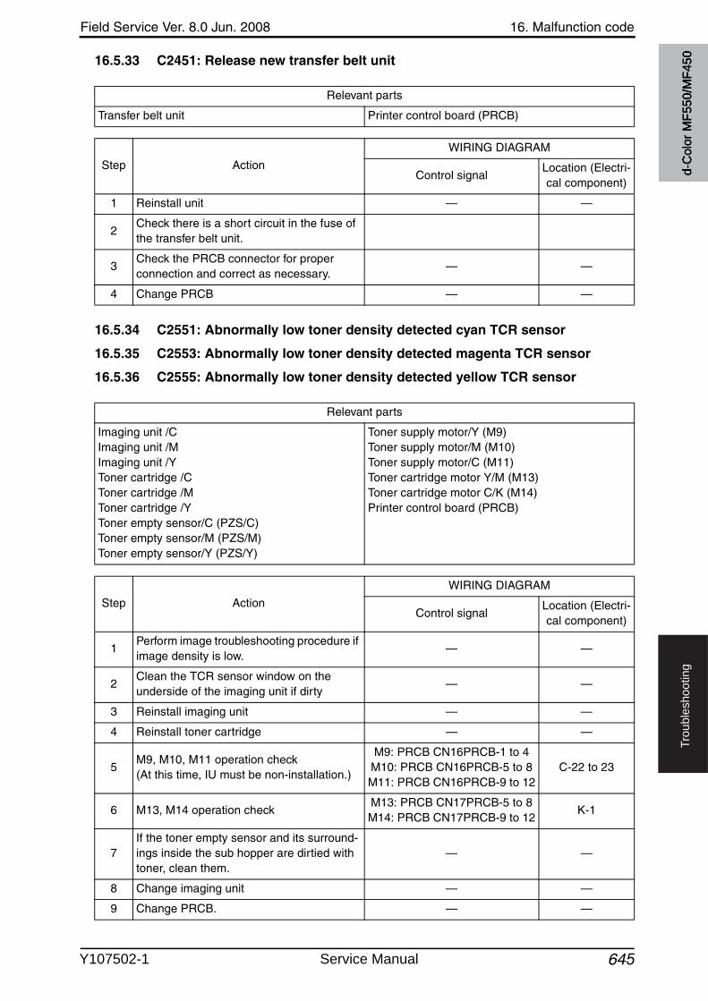
Field Service Ver. 8.0 Jun. 2008 16. Malfunction code
645
Tro
ub
lesh
oo
tin
g
16.5.33 C2451: Release new transfer belt unit
16.5.34 C2551: Abnormally low toner density detected cyan TCR sensor
16.5.35 C2553: Abnormally low toner density detected magenta TCR sensor
16.5.36 C2555: Abnormally low toner density detected yellow TCR sensor
Relevant parts
Transfer belt unit Printer control board (PRCB)
Step Action
WIRING DIAGRAM
Control signalLocation (Electri-cal component)
1 Reinstall unit — —
2Check there is a short circuit in the fuse of the transfer belt unit.
3Check the PRCB connector for proper connection and correct as necessary.
— —
4 Change PRCB — —
Relevant parts
Imaging unit /CImaging unit /MImaging unit /YToner cartridge /CToner cartridge /MToner cartridge /YToner empty sensor/C (PZS/C)Toner empty sensor/M (PZS/M)Toner empty sensor/Y (PZS/Y)
Toner supply motor/Y (M9)Toner supply motor/M (M10)Toner supply motor/C (M11)Toner cartridge motor Y/M (M13)Toner cartridge motor C/K (M14)Printer control board (PRCB)
Step Action
WIRING DIAGRAM
Control signalLocation (Electri-cal component)
1Perform image troubleshooting procedure if image density is low.
— —
2Clean the TCR sensor window on the underside of the imaging unit if dirty
— —
3 Reinstall imaging unit — —
4 Reinstall toner cartridge — —
5M9, M10, M11 operation check(At this time, IU must be non-installation.)
M9: PRCB CN16PRCB-1 to 4M10: PRCB CN16PRCB-5 to 8M11: PRCB CN16PRCB-9 to 12
C-22 to 23
6 M13, M14 operation checkM13: PRCB CN17PRCB-5 to 8M14: PRCB CN17PRCB-9 to 12
K-1
7If the toner empty sensor and its surround-ings inside the sub hopper are dirtied withtoner, clean them.
— —
8 Change imaging unit — —
9 Change PRCB. — —
d-C
olor
MF5
50/M
F450
Y107502-1 Service Manual
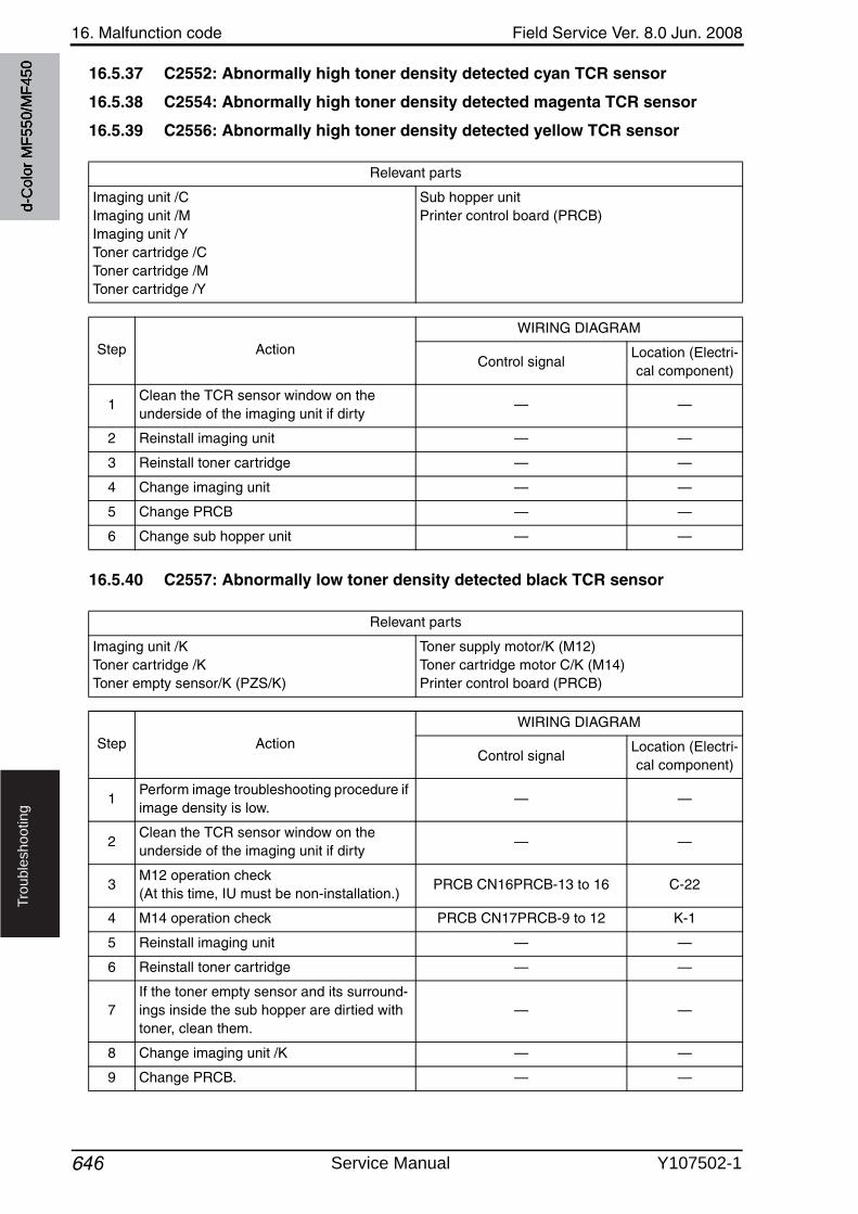
16. Malfunction code Field Service Ver. 8.0 Jun. 2008
646
Tro
ub
lesh
oo
tin
g
16.5.37 C2552: Abnormally high toner density detected cyan TCR sensor
16.5.38 C2554: Abnormally high toner density detected magenta TCR sensor
16.5.39 C2556: Abnormally high toner density detected yellow TCR sensor
16.5.40 C2557: Abnormally low toner density detected black TCR sensor
Relevant parts
Imaging unit /CImaging unit /MImaging unit /YToner cartridge /CToner cartridge /MToner cartridge /Y
Sub hopper unitPrinter control board (PRCB)
Step Action
WIRING DIAGRAM
Control signalLocation (Electri-cal component)
1Clean the TCR sensor window on the underside of the imaging unit if dirty
— —
2 Reinstall imaging unit — —
3 Reinstall toner cartridge — —
4 Change imaging unit — —
5 Change PRCB — —
6 Change sub hopper unit — —
Relevant parts
Imaging unit /KToner cartridge /KToner empty sensor/K (PZS/K)
Toner supply motor/K (M12)Toner cartridge motor C/K (M14)Printer control board (PRCB)
Step Action
WIRING DIAGRAM
Control signalLocation (Electri-cal component)
1Perform image troubleshooting procedure if image density is low.
— —
2Clean the TCR sensor window on the underside of the imaging unit if dirty
— —
3M12 operation check(At this time, IU must be non-installation.)
PRCB CN16PRCB-13 to 16 C-22
4 M14 operation check PRCB CN17PRCB-9 to 12 K-1
5 Reinstall imaging unit — —
6 Reinstall toner cartridge — —
7If the toner empty sensor and its surround-ings inside the sub hopper are dirtied with toner, clean them.
— —
8 Change imaging unit /K — —
9 Change PRCB. — —
d-C
olor
MF5
50/M
F450
Service Manual Y107502-1
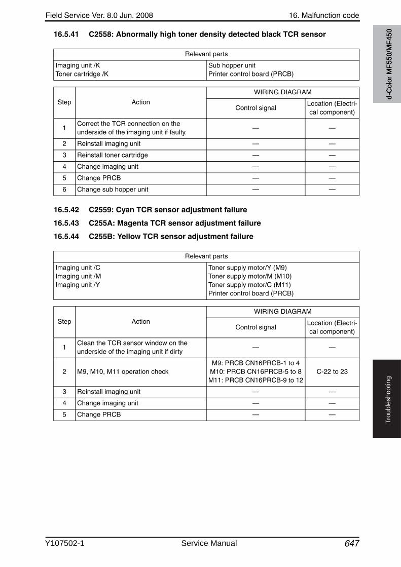
Field Service Ver. 8.0 Jun. 2008 16. Malfunction code
647
Tro
ub
lesh
oo
tin
g
16.5.41 C2558: Abnormally high toner density detected black TCR sensor
16.5.42 C2559: Cyan TCR sensor adjustment failure
16.5.43 C255A: Magenta TCR sensor adjustment failure
16.5.44 C255B: Yellow TCR sensor adjustment failure
Relevant parts
Imaging unit /KToner cartridge /K
Sub hopper unitPrinter control board (PRCB)
Step Action
WIRING DIAGRAM
Control signalLocation (Electri-cal component)
1Correct the TCR connection on the underside of the imaging unit if faulty.
— —
2 Reinstall imaging unit — —
3 Reinstall toner cartridge — —
4 Change imaging unit — —
5 Change PRCB — —
6 Change sub hopper unit — —
Relevant parts
Imaging unit /CImaging unit /MImaging unit /Y
Toner supply motor/Y (M9)Toner supply motor/M (M10)Toner supply motor/C (M11)Printer control board (PRCB)
Step Action
WIRING DIAGRAM
Control signalLocation (Electri-cal component)
1Clean the TCR sensor window on the underside of the imaging unit if dirty
— —
2 M9, M10, M11 operation checkM9: PRCB CN16PRCB-1 to 4
M10: PRCB CN16PRCB-5 to 8M11: PRCB CN16PRCB-9 to 12
C-22 to 23
3 Reinstall imaging unit — —
4 Change imaging unit — —
5 Change PRCB — —
d-C
olor
MF5
50/M
F450
Y107502-1 Service Manual
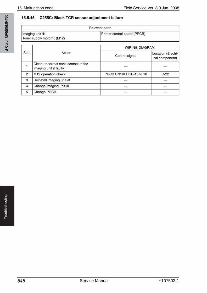
16. Malfunction code Field Service Ver. 8.0 Jun. 2008
648
Tro
ub
lesh
oo
tin
g
16.5.45 C255C: Black TCR sensor adjustment failure
Relevant parts
Imaging unit /KToner supply motor/K (M12)
Printer control board (PRCB)
Step Action
WIRING DIAGRAM
Control signalLocation (Electri-cal component)
1Clean or correct each contact of the imaging unit if faulty.
— —
2 M12 operation check PRCB CN16PRCB-13 to 16 C-22
3 Reinstall imaging unit /K — —
4 Change imaging unit /K — —
5 Change PRCB — —
d-C
olor
MF5
50/M
F450
Service Manual Y107502-1
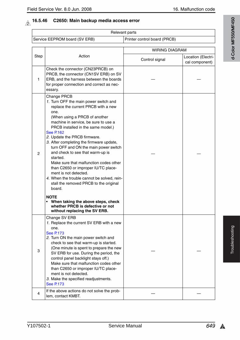
Field Service Ver. 8.0 Jun. 2008 16. Malfunction code
649 2
Tro
ub
lesh
oo
tin
g
16.5.46 C2650: Main backup media access error2
Relevant parts
Service EEPROM board (SV ERB) Printer control board (PRCB)
Step Action
WIRING DIAGRAM
Control signalLocation (Electri-cal component)
1
Check the connector (CN23PRCB) on PRCB, the connector (CN1SV ERB) on SVERB, and the harness between the boards for proper connection and correct as nec-essary.
— —
2
Change PRCB1. Turn OFF the main power switch and
replace the current PRCB with a newone. (When using a PRCB of another machine in service, be sure to use a PRCB installed in the same model.)
See P.1622. Update the PRCB firmware.3. After completing the firmware update,
turn OFF and ON the main power switchand check to see that warm-up is started. Make sure that malfunction codes other than C2650 or improper IU/TC place-ment is not detected.
4. When the trouble cannot be solved, rein-stall the removed PRCB to the original board.
NOTE• When taking the above steps, check
whether PRCB is defective or not without replacing the SV ERB.
— —
3
Change SV ERB1. Replace the current SV ERB with a new
one.See P.1732. Turn ON the main power switch and
check to see that warm-up is started. (One minute is spent to prepare the newSV ERB for use. During the period, the control panel backlight stays off.) Make sure that malfunction codes other than C2650 or improper IU/TC place-ment is not detected.
3. Make the specified readjustments.See P.173
— —
4If the above actions do not solve the prob-lem, contact KMBT.
— —
d-C
olor
MF5
50/M
F450
Y107502-1 Service Manual
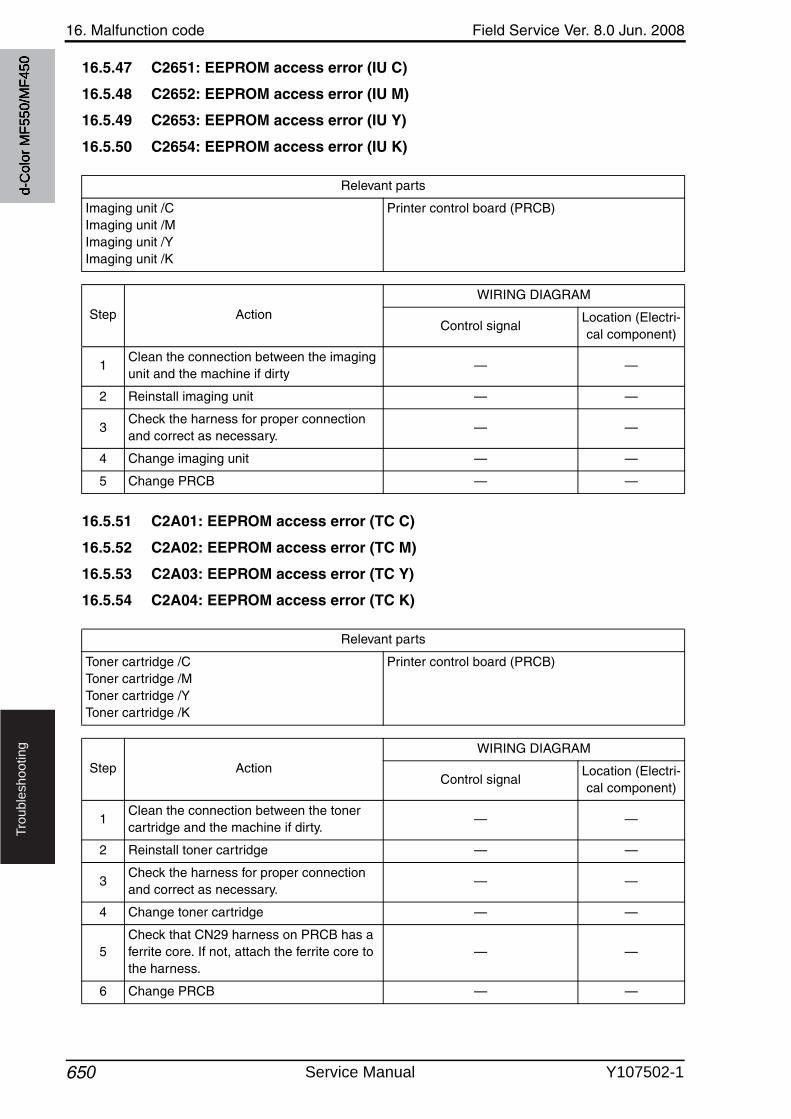
16. Malfunction code Field Service Ver. 8.0 Jun. 2008
650
Tro
ub
lesh
oo
tin
g
16.5.47 C2651: EEPROM access error (IU C)
16.5.48 C2652: EEPROM access error (IU M)
16.5.49 C2653: EEPROM access error (IU Y)
16.5.50 C2654: EEPROM access error (IU K)
16.5.51 C2A01: EEPROM access error (TC C)
16.5.52 C2A02: EEPROM access error (TC M)
16.5.53 C2A03: EEPROM access error (TC Y)
16.5.54 C2A04: EEPROM access error (TC K)
Relevant parts
Imaging unit /CImaging unit /MImaging unit /YImaging unit /K
Printer control board (PRCB)
Step Action
WIRING DIAGRAM
Control signalLocation (Electri-cal component)
1Clean the connection between the imaging unit and the machine if dirty
— —
2 Reinstall imaging unit — —
3Check the harness for proper connection and correct as necessary.
— —
4 Change imaging unit — —
5 Change PRCB — —
Relevant parts
Toner cartridge /CToner cartridge /MToner cartridge /YToner cartridge /K
Printer control board (PRCB)
Step Action
WIRING DIAGRAM
Control signalLocation (Electri-cal component)
1Clean the connection between the toner cartridge and the machine if dirty.
— —
2 Reinstall toner cartridge — —
3Check the harness for proper connection and correct as necessary.
— —
4 Change toner cartridge — —
5Check that CN29 harness on PRCB has a ferrite core. If not, attach the ferrite core to the harness.
— —
6 Change PRCB — —
d-C
olor
MF5
50/M
F450
Service Manual Y107502-1
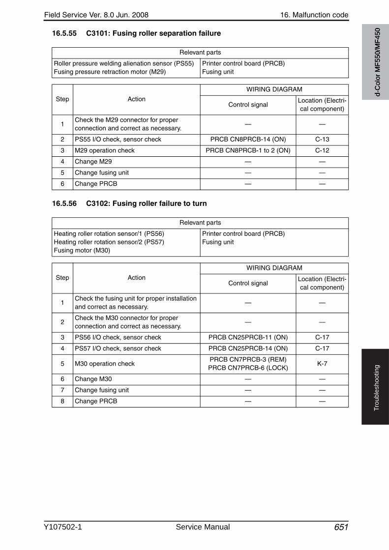
Field Service Ver. 8.0 Jun. 2008 16. Malfunction code
651
Tro
ub
lesh
oo
tin
g
16.5.55 C3101: Fusing roller separation failure
16.5.56 C3102: Fusing roller failure to turn
Relevant parts
Roller pressure welding alienation sensor (PS55)Fusing pressure retraction motor (M29)
Printer control board (PRCB)Fusing unit
Step Action
WIRING DIAGRAM
Control signalLocation (Electri-cal component)
1Check the M29 connector for proper connection and correct as necessary.
— —
2 PS55 I/O check, sensor check PRCB CN8PRCB-14 (ON) C-13
3 M29 operation check PRCB CN8PRCB-1 to 2 (ON) C-12
4 Change M29 — —
5 Change fusing unit — —
6 Change PRCB — —
Relevant parts
Heating roller rotation sensor/1 (PS56)Heating roller rotation sensor/2 (PS57)Fusing motor (M30)
Printer control board (PRCB)Fusing unit
Step Action
WIRING DIAGRAM
Control signalLocation (Electri-cal component)
1Check the fusing unit for proper installation and correct as necessary.
— —
2Check the M30 connector for proper connection and correct as necessary.
— —
3 PS56 I/O check, sensor check PRCB CN25PRCB-11 (ON) C-17
4 PS57 I/O check, sensor check PRCB CN25PRCB-14 (ON) C-17
5 M30 operation checkPRCB CN7PRCB-3 (REM)PRCB CN7PRCB-6 (LOCK)
K-7
6 Change M30 — —
7 Change fusing unit — —
8 Change PRCB — —
d-C
olor
MF5
50/M
F450
Y107502-1 Service Manual

16. Malfunction code Field Service Ver. 8.0 Jun. 2008
652
Tro
ub
lesh
oo
tin
g
16.5.57 C3201: Fusing motor failure to turn
16.5.58 C3202: Fusing motor turning at abnormal timing
16.5.59 C3303: Fusing cooling fan motor/ 1 failure to turn
Relevant parts
Fusing motor (M30) Printer control board (PRCB)
Step Action
WIRING DIAGRAM
Control signalLocation (Electri-cal component)
1Check the M30 connector for proper connection and correct as necessary.
— —
2Check the loading status of the fusing unit drive, and correct the error as necessary.
— —
3Check the fusing unit, PRCB for proper connection and correct or change as necessary.
— —
4 M30 operation checkPRCB CN7PRCB-3 (REM)PRCB CN7PRCB-6 (LOCK)
K-7
5 Change M30 — —
6 Change PRCB — —
Relevant parts
Fusing cooling fan motor/1 (FM2) Printer control board (PRCB)
Step Action
WIRING DIAGRAM
Control signalLocation (Electri-cal component)
1Check the FM2 connector for proper connection and correct as necessary.
— —
2Check the fan for possible overload and correct as necessary.
— —
3 FM2 operation checkPRCB CN6PRCB-4 (REM)PRCB CN6PRCB-6 (LOCK)
K-6
4 Change FM2 — —
5 Change PRCB — —
d-C
olor
MF5
50/M
F450
Service Manual Y107502-1

Field Service Ver. 8.0 Jun. 2008 16. Malfunction code
653
Tro
ub
lesh
oo
tin
g
16.5.60 C3304: Fusing cooling fan motor/ 2 failure to turn
16.5.61 C3305: Fusing cooling fan motor/ 3 failure to turn
Relevant parts
Fusing cooling fan motor/2 (FM4) Printer control board (PRCB)
Step Action
WIRING DIAGRAM
Control signalLocation (Electri-cal component)
1Check the FM4 connector for proper connection and correct as necessary.
— —
2Check the fan for possible overload and correct as necessary.
— —
3 FM4 operation checkPRCB CN11PRCB-6 (REM)PRCB CN11PRCB-8 (LOCK)
K-3
4 Change FM4 — —
5 Change PRCB — —
Relevant parts
Fusing cooling fan motor/3 (FM5) Printer control board (PRCB)
Step Action
WIRING DIAGRAM
Control signalLocation (Electri-cal component)
1Check the FM5 connector for proper connection and correct as necessary.
— —
2Check the fan for possible overload and correct as necessary.
— —
3 FM5 operation checkPRCB CN11PRCB-9 (REM)
PRCB CN11PRCB-11 (LOCK)K-3
4 Change FM5 — —
5 Change PRCB — —
d-C
olor
MF5
50/M
F450
Y107502-1 Service Manual
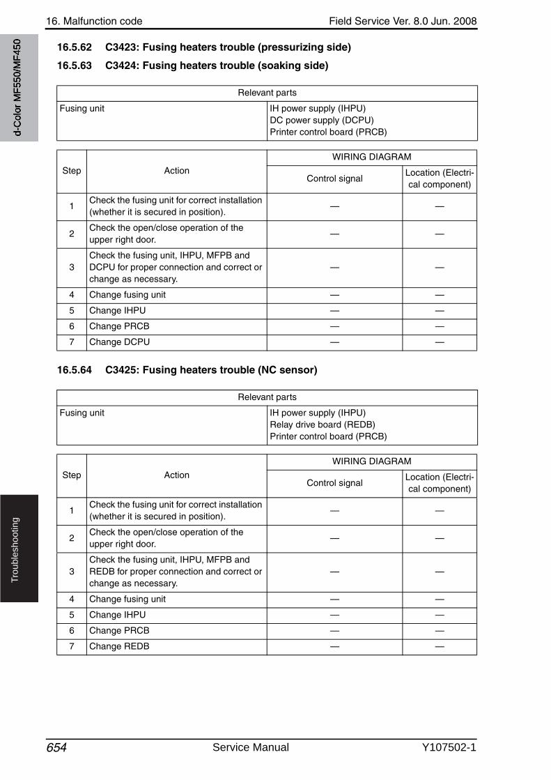
16. Malfunction code Field Service Ver. 8.0 Jun. 2008
654
Tro
ub
lesh
oo
tin
g
16.5.62 C3423: Fusing heaters trouble (pressurizing side)
16.5.63 C3424: Fusing heaters trouble (soaking side)
16.5.64 C3425: Fusing heaters trouble (NC sensor)
Relevant parts
Fusing unit IH power supply (IHPU)DC power supply (DCPU)Printer control board (PRCB)
Step Action
WIRING DIAGRAM
Control signalLocation (Electri-cal component)
1Check the fusing unit for correct installation (whether it is secured in position).
— —
2Check the open/close operation of the upper right door.
— —
3Check the fusing unit, IHPU, MFPB and DCPU for proper connection and correct or change as necessary.
— —
4 Change fusing unit — —
5 Change IHPU — —
6 Change PRCB — —
7 Change DCPU — —
Relevant parts
Fusing unit IH power supply (IHPU)Relay drive board (REDB)Printer control board (PRCB)
Step Action
WIRING DIAGRAM
Control signalLocation (Electri-cal component)
1Check the fusing unit for correct installation (whether it is secured in position).
— —
2Check the open/close operation of the upper right door.
— —
3Check the fusing unit, IHPU, MFPB and REDB for proper connection and correct or change as necessary.
— —
4 Change fusing unit — —
5 Change IHPU — —
6 Change PRCB — —
7 Change REDB — —
d-C
olor
MF5
50/M
F450
Service Manual Y107502-1
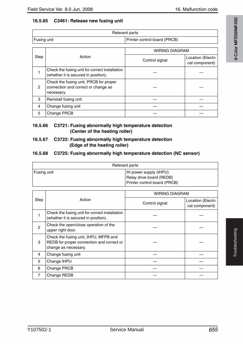
Field Service Ver. 8.0 Jun. 2008 16. Malfunction code
655
Tro
ub
lesh
oo
tin
g
16.5.65 C3461: Release new fusing unit
16.5.66 C3721: Fusing abnormally high temperature detection (Center of the heating roller)
16.5.67 C3722: Fusing abnormally high temperature detection (Edge of the heating roller)
16.5.68 C3725: Fusing abnormally high temperature detection (NC sensor)
Relevant parts
Fusing unit Printer control board (PRCB)
Step Action
WIRING DIAGRAM
Control signalLocation (Electri-cal component)
1Check the fusing unit for correct installation (whether it is secured in position).
— —
2Check the fusing unit, PRCB for proper connection and correct or change as necessary.
— —
3 Reinstall fusing unit — —
4 Change fusing unit — —
5 Change PRCB — —
Relevant parts
Fusing unit IH power supply (IHPU)Relay drive board (REDB)Printer control board (PRCB)
Step Action
WIRING DIAGRAM
Control signalLocation (Electri-cal component)
1Check the fusing unit for correct installation (whether it is secured in position).
— —
2Check the open/close operation of the upper right door.
— —
3Check the fusing unit, IHPU, MFPB and REDB for proper connection and correct or change as necessary.
— —
4 Change fusing unit — —
5 Change IHPU — —
6 Change PRCB — —
7 Change REDB — —
d-C
olor
MF5
50/M
F450
Y107502-1 Service Manual
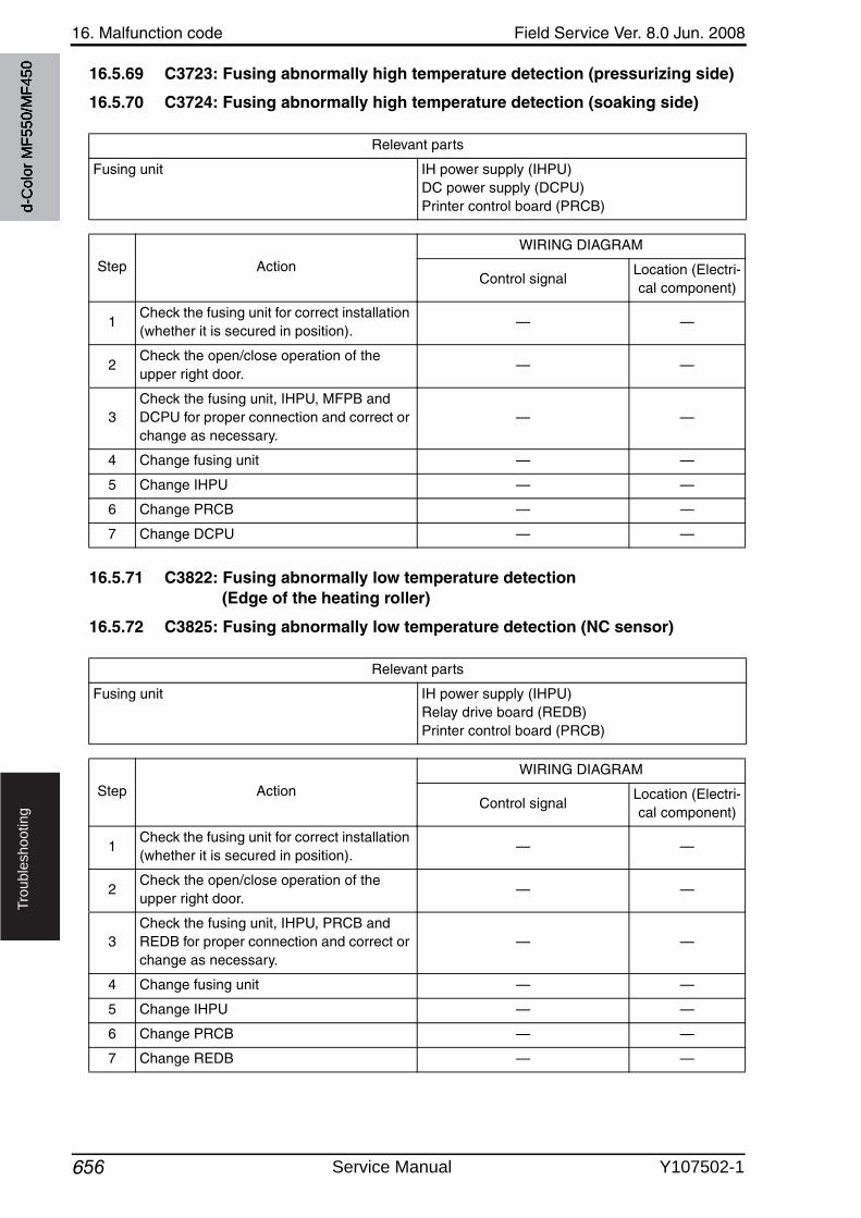
16. Malfunction code Field Service Ver. 8.0 Jun. 2008
656
Tro
ub
lesh
oo
tin
g
16.5.69 C3723: Fusing abnormally high temperature detection (pressurizing side)
16.5.70 C3724: Fusing abnormally high temperature detection (soaking side)
16.5.71 C3822: Fusing abnormally low temperature detection (Edge of the heating roller)
16.5.72 C3825: Fusing abnormally low temperature detection (NC sensor)
Relevant parts
Fusing unit IH power supply (IHPU)DC power supply (DCPU)Printer control board (PRCB)
Step Action
WIRING DIAGRAM
Control signalLocation (Electri-cal component)
1Check the fusing unit for correct installation (whether it is secured in position).
— —
2Check the open/close operation of the upper right door.
— —
3Check the fusing unit, IHPU, MFPB and DCPU for proper connection and correct or change as necessary.
— —
4 Change fusing unit — —
5 Change IHPU — —
6 Change PRCB — —
7 Change DCPU — —
Relevant parts
Fusing unit IH power supply (IHPU)Relay drive board (REDB)Printer control board (PRCB)
Step Action
WIRING DIAGRAM
Control signalLocation (Electri-cal component)
1Check the fusing unit for correct installation (whether it is secured in position).
— —
2Check the open/close operation of the upper right door.
— —
3Check the fusing unit, IHPU, PRCB and REDB for proper connection and correct or change as necessary.
— —
4 Change fusing unit — —
5 Change IHPU — —
6 Change PRCB — —
7 Change REDB — —
d-C
olor
MF5
50/M
F450
Service Manual Y107502-1
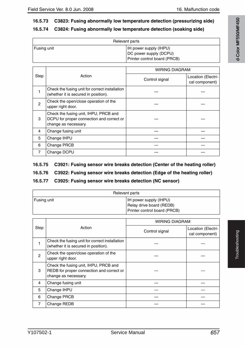
Field Service Ver. 8.0 Jun. 2008 16. Malfunction code
657
Tro
ub
lesh
oo
tin
g
16.5.73 C3823: Fusing abnormally low temperature detection (pressurizing side)
16.5.74 C3824: Fusing abnormally low temperature detection (soaking side)
16.5.75 C3921: Fusing sensor wire breaks detection (Center of the heating roller)
16.5.76 C3922: Fusing sensor wire breaks detection (Edge of the heating roller)
16.5.77 C3925: Fusing sensor wire breaks detection (NC sensor)
Relevant parts
Fusing unit IH power supply (IHPU)DC power supply (DCPU)Printer control board (PRCB)
Step Action
WIRING DIAGRAM
Control signalLocation (Electri-cal component)
1Check the fusing unit for correct installation (whether it is secured in position).
— —
2Check the open/close operation of the upper right door.
— —
3Check the fusing unit, IHPU, PRCB and DCPU for proper connection and correct or change as necessary.
— —
4 Change fusing unit — —
5 Change IHPU — —
6 Change PRCB — —
7 Change DCPU — —
Relevant parts
Fusing unit IH power supply (IHPU)Relay drive board (REDB)Printer control board (PRCB)
Step Action
WIRING DIAGRAM
Control signalLocation (Electri-cal component)
1Check the fusing unit for correct installation (whether it is secured in position).
— —
2Check the open/close operation of the upper right door.
— —
3Check the fusing unit, IHPU, PRCB and REDB for proper connection and correct or change as necessary.
— —
4 Change fusing unit — —
5 Change IHPU — —
6 Change PRCB — —
7 Change REDB — —
d-C
olor
MF5
50/M
F450
Y107502-1 Service Manual
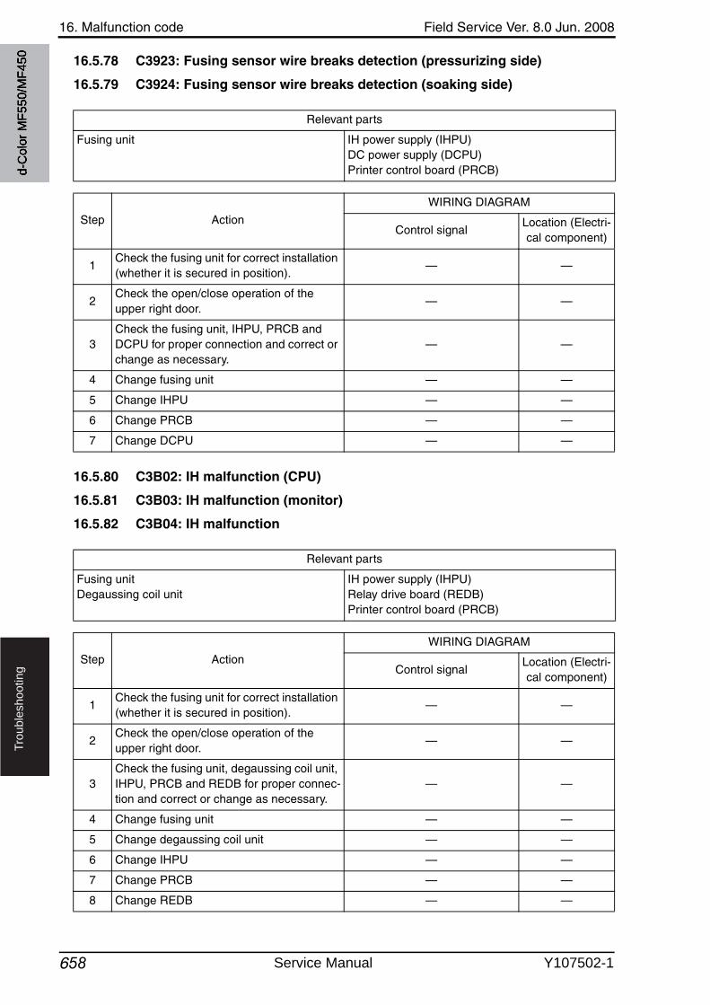
16. Malfunction code Field Service Ver. 8.0 Jun. 2008
658
Tro
ub
lesh
oo
tin
g
16.5.78 C3923: Fusing sensor wire breaks detection (pressurizing side)
16.5.79 C3924: Fusing sensor wire breaks detection (soaking side)
16.5.80 C3B02: IH malfunction (CPU)
16.5.81 C3B03: IH malfunction (monitor)
16.5.82 C3B04: IH malfunction
Relevant parts
Fusing unit IH power supply (IHPU)DC power supply (DCPU)Printer control board (PRCB)
Step Action
WIRING DIAGRAM
Control signalLocation (Electri-cal component)
1Check the fusing unit for correct installation (whether it is secured in position).
— —
2Check the open/close operation of the upper right door.
— —
3Check the fusing unit, IHPU, PRCB and DCPU for proper connection and correct or change as necessary.
— —
4 Change fusing unit — —
5 Change IHPU — —
6 Change PRCB — —
7 Change DCPU — —
Relevant parts
Fusing unitDegaussing coil unit
IH power supply (IHPU)Relay drive board (REDB)Printer control board (PRCB)
Step Action
WIRING DIAGRAM
Control signalLocation (Electri-cal component)
1Check the fusing unit for correct installation (whether it is secured in position).
— —
2Check the open/close operation of the upper right door.
— —
3Check the fusing unit, degaussing coil unit, IHPU, PRCB and REDB for proper connec-tion and correct or change as necessary.
— —
4 Change fusing unit — —
5 Change degaussing coil unit — —
6 Change IHPU — —
7 Change PRCB — —
8 Change REDB — —
d-C
olor
MF5
50/M
F450
Service Manual Y107502-1
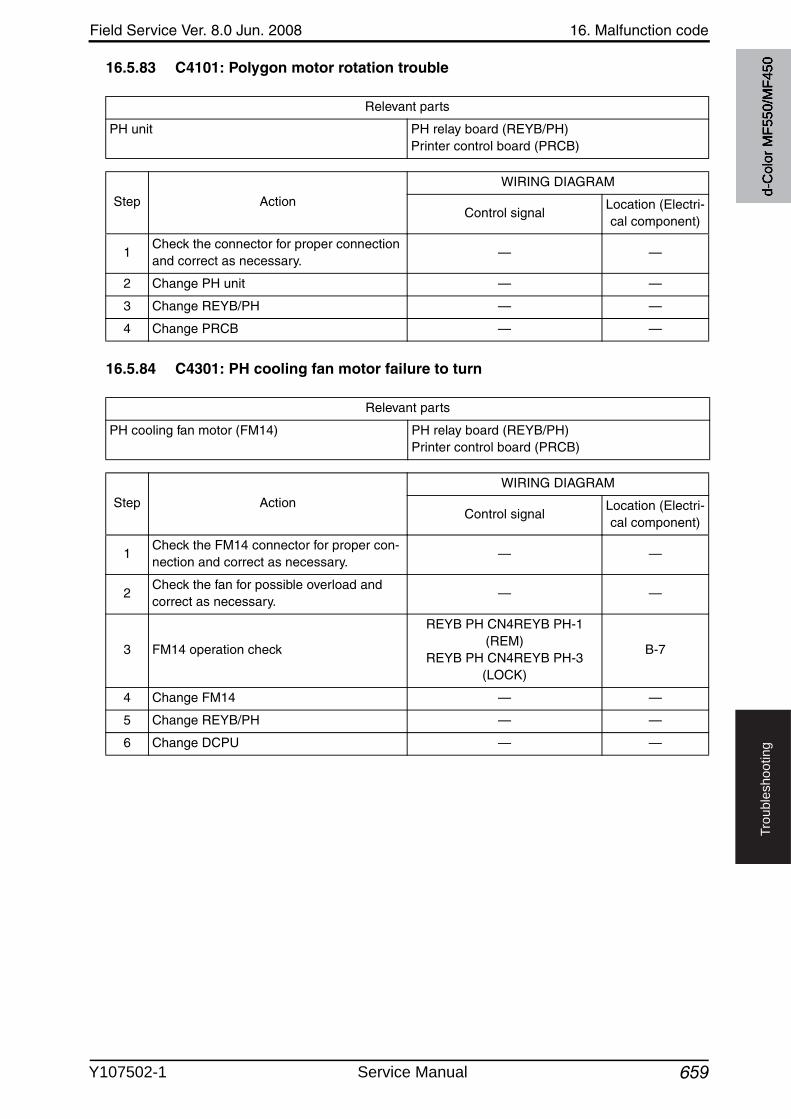
Field Service Ver. 8.0 Jun. 2008 16. Malfunction code
659
Tro
ub
lesh
oo
tin
g
16.5.83 C4101: Polygon motor rotation trouble
16.5.84 C4301: PH cooling fan motor failure to turn
Relevant parts
PH unit PH relay board (REYB/PH)Printer control board (PRCB)
Step Action
WIRING DIAGRAM
Control signalLocation (Electri-cal component)
1Check the connector for proper connection and correct as necessary.
— —
2 Change PH unit — —
3 Change REYB/PH — —
4 Change PRCB — —
Relevant parts
PH cooling fan motor (FM14) PH relay board (REYB/PH)Printer control board (PRCB)
Step Action
WIRING DIAGRAM
Control signalLocation (Electri-cal component)
1Check the FM14 connector for proper con-nection and correct as necessary.
— —
2Check the fan for possible overload and correct as necessary.
— —
3 FM14 operation check
REYB PH CN4REYB PH-1 (REM)
REYB PH CN4REYB PH-3 (LOCK)
B-7
4 Change FM14 — —
5 Change REYB/PH — —
6 Change DCPU — —
d-C
olor
MF5
50/M
F450
Y107502-1 Service Manual
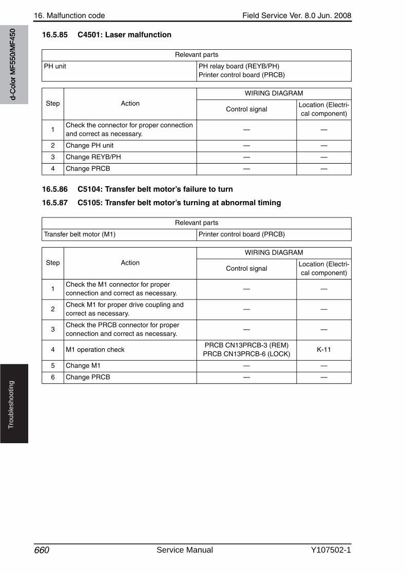
16. Malfunction code Field Service Ver. 8.0 Jun. 2008
660
Tro
ub
lesh
oo
tin
g
16.5.85 C4501: Laser malfunction
16.5.86 C5104: Transfer belt motor’s failure to turn
16.5.87 C5105: Transfer belt motor’s turning at abnormal timing
Relevant parts
PH unit PH relay board (REYB/PH)Printer control board (PRCB)
Step Action
WIRING DIAGRAM
Control signalLocation (Electri-cal component)
1Check the connector for proper connection and correct as necessary.
— —
2 Change PH unit — —
3 Change REYB/PH — —
4 Change PRCB — —
Relevant parts
Transfer belt motor (M1) Printer control board (PRCB)
Step Action
WIRING DIAGRAM
Control signalLocation (Electri-cal component)
1Check the M1 connector for proper connection and correct as necessary.
— —
2Check M1 for proper drive coupling and correct as necessary.
— —
3Check the PRCB connector for proper connection and correct as necessary.
— —
4 M1 operation checkPRCB CN13PRCB-3 (REM)PRCB CN13PRCB-6 (LOCK)
K-11
5 Change M1 — —
6 Change PRCB — —
d-C
olor
MF5
50/M
F450
Service Manual Y107502-1

Field Service Ver. 8.0 Jun. 2008 16. Malfunction code
661
Tro
ub
lesh
oo
tin
g
16.5.88 C5304: IH cooling fan motor/1’s failure to turn
16.5.89 C5305: IH cooling fan motor/2’s failure to turn
Relevant parts
IH cooling fan motor/1 (FM10) Printer control board (PRCB)
Step Action
WIRING DIAGRAM
Control signalLocation (Electri-cal component)
1Check the FM10 connector for proper connection and correct as necessary.
— —
2Check the fan for possible overload and correct as necessary.
— —
3 FM10 operation checkPRCB CN26PRCB-4 (REM)PRCB CN26PRCB-6 (LOCK)
C-16
4 Change FM10 — —
5 Change PRCB — —
Relevant parts
IH cooling fan motor/2 (FM11) Printer control board (PRCB)
Step Action
WIRING DIAGRAM
Control signalLocation (Electri-cal component)
1Check the FM11 connector for proper connection and correct as necessary.
— —
2Check the fan for possible overload and correct as necessary.
— —
3 FM11 operation checkPRCB CN26PRCB-7 (REM)PRCB CN26PRCB-9 (LOCK)
C-16
4 Change FM11 — —
5 Change PRCB — —
d-C
olor
MF5
50/M
F450
Y107502-1 Service Manual
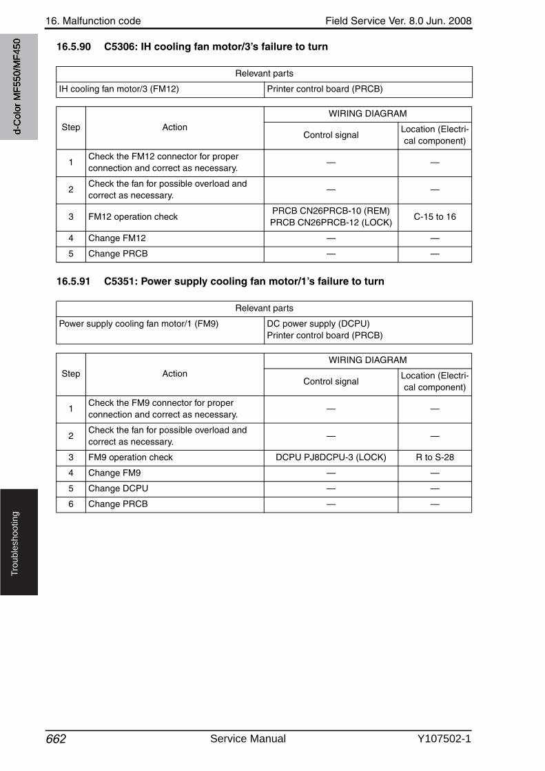
16. Malfunction code Field Service Ver. 8.0 Jun. 2008
662
Tro
ub
lesh
oo
tin
g
16.5.90 C5306: IH cooling fan motor/3’s failure to turn
16.5.91 C5351: Power supply cooling fan motor/1’s failure to turn
Relevant parts
IH cooling fan motor/3 (FM12) Printer control board (PRCB)
Step Action
WIRING DIAGRAM
Control signalLocation (Electri-cal component)
1Check the FM12 connector for proper connection and correct as necessary.
— —
2Check the fan for possible overload and correct as necessary.
— —
3 FM12 operation checkPRCB CN26PRCB-10 (REM)PRCB CN26PRCB-12 (LOCK)
C-15 to 16
4 Change FM12 — —
5 Change PRCB — —
Relevant parts
Power supply cooling fan motor/1 (FM9) DC power supply (DCPU)Printer control board (PRCB)
Step Action
WIRING DIAGRAM
Control signalLocation (Electri-cal component)
1Check the FM9 connector for proper connection and correct as necessary.
— —
2Check the fan for possible overload and correct as necessary.
— —
3 FM9 operation check DCPU PJ8DCPU-3 (LOCK) R to S-28
4 Change FM9 — —
5 Change DCPU — —
6 Change PRCB — —
d-C
olor
MF5
50/M
F450
Service Manual Y107502-1

Field Service Ver. 8.0 Jun. 2008 16. Malfunction code
663 2
Tro
ub
lesh
oo
tin
g
16.5.92 C5354: Ozone ventilation fan motor’s failure to turn
16.5.93 C5356: Cooling fan motor’s failure to turn
Relevant parts
Ozone ventilation fan motor (FM6) Printer control board (PRCB)
Step Action
WIRING DIAGRAM
Control signalLocation (Electri-cal component)
1Check the FM6 connector for proper connection and correct as necessary.
— —
2Check the fan for possible overload and correct as necessary.
— —
3 FM6 operation checkPRCB CN6PRCB-1 (REM)PRCB CN6PRCB-3 (LOCK)
K-6 to 7
4 Change FM6 — —
5 Change MFPB — —
2
Relevant parts
Cooling fan motor (FM3) Printer control board (PRCB)
Step Action
WIRING DIAGRAM
Control signalLocation (Electri-cal component)
1Check the FM3 connector for proper connection and correct as necessary.
— —
2Check the fan for possible overload and correct as necessary.
— —
3 FM3 operation checkPRCB CN10PRCB-1 (REM)PRCB CN10PRCB-3 (LOCK)
K-6
4 Change FM3 — —
5 Change MFPB — —
d-C
olor
MF5
50/M
F450
Y107502-1 Service Manual
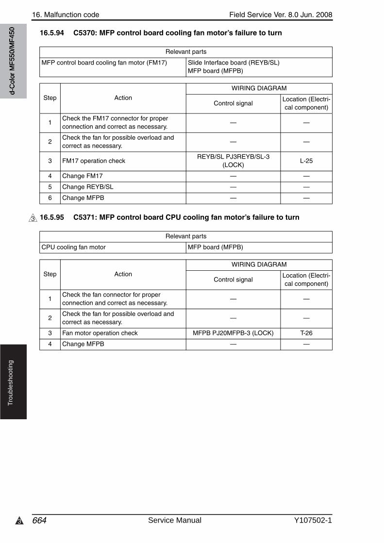
16. Malfunction code Field Service Ver. 8.0 Jun. 2008
6643
Tro
ub
lesh
oo
tin
g
16.5.94 C5370: MFP control board cooling fan motor’s failure to turn
16.5.95 C5371: MFP control board CPU cooling fan motor’s failure to turn
Relevant parts
MFP control board cooling fan motor (FM17) Slide Interface board (REYB/SL)MFP board (MFPB)
Step Action
WIRING DIAGRAM
Control signalLocation (Electri-cal component)
1Check the FM17 connector for proper connection and correct as necessary.
— —
2Check the fan for possible overload and correct as necessary.
— —
3 FM17 operation checkREYB/SL PJ3REYB/SL-3
(LOCK)L-25
4 Change FM17 — —
5 Change REYB/SL — —
6 Change MFPB — —
3
Relevant parts
CPU cooling fan motor MFP board (MFPB)
Step Action
WIRING DIAGRAM
Control signalLocation (Electri-cal component)
1Check the fan connector for proper connection and correct as necessary.
— —
2Check the fan for possible overload and correct as necessary.
— —
3 Fan motor operation check MFPB PJ20MFPB-3 (LOCK) T-26
4 Change MFPB — —
d-C
olor
MF5
50/M
F450
Service Manual Y107502-1
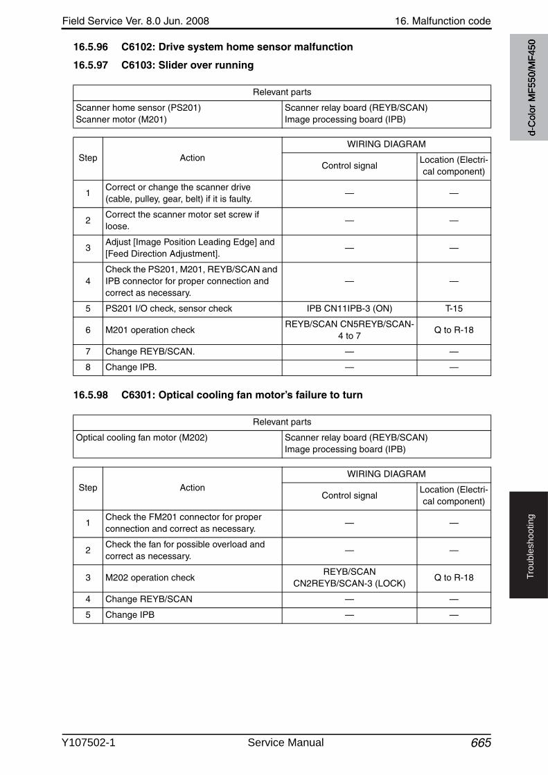
Field Service Ver. 8.0 Jun. 2008 16. Malfunction code
665
Tro
ub
lesh
oo
tin
g
16.5.96 C6102: Drive system home sensor malfunction
16.5.97 C6103: Slider over running
16.5.98 C6301: Optical cooling fan motor’s failure to turn
Relevant parts
Scanner home sensor (PS201)Scanner motor (M201)
Scanner relay board (REYB/SCAN)Image processing board (IPB)
Step Action
WIRING DIAGRAM
Control signalLocation (Electri-cal component)
1Correct or change the scanner drive(cable, pulley, gear, belt) if it is faulty.
— —
2Correct the scanner motor set screw if loose.
— —
3Adjust [Image Position Leading Edge] and [Feed Direction Adjustment].
— —
4Check the PS201, M201, REYB/SCAN and IPB connector for proper connection and correct as necessary.
— —
5 PS201 I/O check, sensor check IPB CN11IPB-3 (ON) T-15
6 M201 operation checkREYB/SCAN CN5REYB/SCAN-
4 to 7Q to R-18
7 Change REYB/SCAN. — —
8 Change IPB. — —
Relevant parts
Optical cooling fan motor (M202) Scanner relay board (REYB/SCAN)Image processing board (IPB)
Step Action
WIRING DIAGRAM
Control signalLocation (Electri-cal component)
1Check the FM201 connector for proper connection and correct as necessary.
— —
2Check the fan for possible overload and correct as necessary.
— —
3 M202 operation checkREYB/SCAN
CN2REYB/SCAN-3 (LOCK)Q to R-18
4 Change REYB/SCAN — —
5 Change IPB — —
d-C
olor
MF5
50/M
F450
Y107502-1 Service Manual
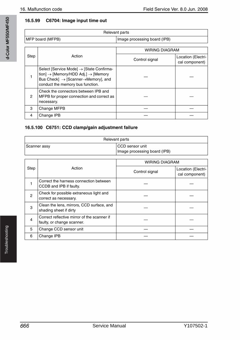
16. Malfunction code Field Service Ver. 8.0 Jun. 2008
666
Tro
ub
lesh
oo
tin
g
16.5.99 C6704: Image input time out
16.5.100 C6751: CCD clamp/gain adjustment failure
Relevant parts
MFP board (MFPB) Image processing board (IPB)
Step Action
WIRING DIAGRAM
Control signalLocation (Electri-cal component)
1
Select [Service Mode] [State Confirma-tion] [Memory/HDD Adj.] [Memory Bus Check] [Scanner Memory], and conduct the memory bus function.
— —
2Check the connectors between IPB and MFPB for proper connection and correct as necessary.
— —
3 Change MFPB — —
4 Change IPB — —
Relevant parts
Scanner assy CCD sensor unitImage processing board (IPB)
Step Action
WIRING DIAGRAM
Control signalLocation (Electri-cal component)
1Correct the harness connection between CCDB and IPB if faulty.
— —
2Check for possible extraneous light and correct as necessary.
— —
3Clean the lens, mirrors, CCD surface, and shading sheet if dirty
— —
4Correct reflective mirror of the scanner if faulty, or change scanner.
— —
5 Change CCD sensor unit — —
6 Change IPB — —
d-C
olor
MF5
50/M
F450
Service Manual Y107502-1
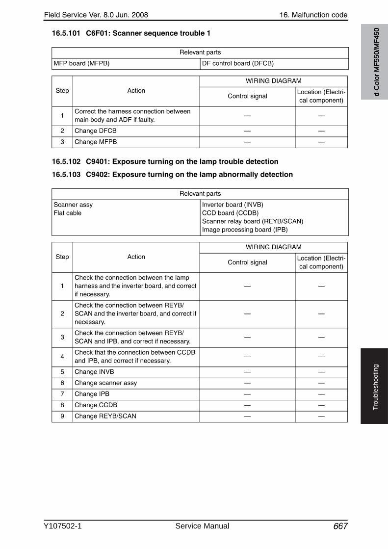
Field Service Ver. 8.0 Jun. 2008 16. Malfunction code
667
Tro
ub
lesh
oo
tin
g
16.5.101 C6F01: Scanner sequence trouble 1
16.5.102 C9401: Exposure turning on the lamp trouble detection
16.5.103 C9402: Exposure turning on the lamp abnormally detection
Relevant parts
MFP board (MFPB) DF control board (DFCB)
Step Action
WIRING DIAGRAM
Control signalLocation (Electri-cal component)
1Correct the harness connection between main body and ADF if faulty.
— —
2 Change DFCB — —
3 Change MFPB — —
Relevant parts
Scanner assyFlat cable
Inverter board (INVB)CCD board (CCDB)Scanner relay board (REYB/SCAN)Image processing board (IPB)
Step Action
WIRING DIAGRAM
Control signalLocation (Electri-cal component)
1Check the connection between the lamp harness and the inverter board, and correct if necessary.
— —
2Check the connection between REYB/SCAN and the inverter board, and correct if necessary.
— —
3Check the connection between REYB/SCAN and IPB, and correct if necessary.
— —
4Check that the connection between CCDB and IPB, and correct if necessary.
— —
5 Change INVB — —
6 Change scanner assy — —
7 Change IPB — —
8 Change CCDB — —
9 Change REYB/SCAN — —
d-C
olor
MF5
50/M
F450
Y107502-1 Service Manual
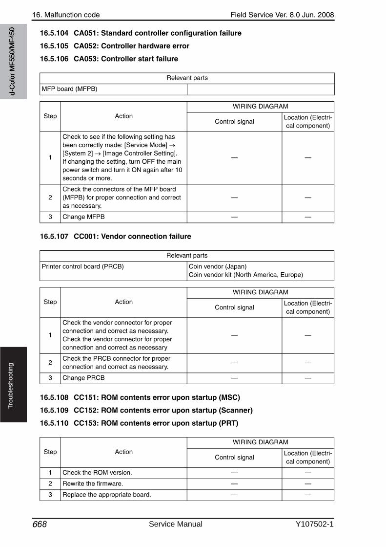
16. Malfunction code Field Service Ver. 8.0 Jun. 2008
668
Tro
ub
lesh
oo
tin
g
16.5.104 CA051: Standard controller configuration failure
16.5.105 CA052: Controller hardware error
16.5.106 CA053: Controller start failure
16.5.107 CC001: Vendor connection failure
16.5.108 CC151: ROM contents error upon startup (MSC)
16.5.109 CC152: ROM contents error upon startup (Scanner)
16.5.110 CC153: ROM contents error upon startup (PRT)
Relevant parts
MFP board (MFPB)
Step Action
WIRING DIAGRAM
Control signalLocation (Electri-cal component)
1
Check to see if the following setting has been correctly made: [Service Mode] [System 2] [Image Controller Setting].If changing the setting, turn OFF the main power switch and turn it ON again after 10 seconds or more.
— —
2Check the connectors of the MFP board (MFPB) for proper connection and correct as necessary.
— —
3 Change MFPB — —
Relevant parts
Printer control board (PRCB) Coin vendor (Japan)Coin vendor kit (North America, Europe)
Step Action
WIRING DIAGRAM
Control signalLocation (Electri-cal component)
1
Check the vendor connector for proper connection and correct as necessary.Check the vendor connector for proper connection and correct as necessary
— —
2Check the PRCB connector for proper connection and correct as necessary.
— —
3 Change PRCB — —
Step Action
WIRING DIAGRAM
Control signalLocation (Electri-cal component)
1 Check the ROM version. — —
2 Rewrite the firmware. — —
3 Replace the appropriate board. — —
d-C
olor
MF5
50/M
F450
Service Manual Y107502-1
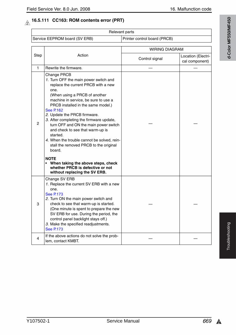
Field Service Ver. 8.0 Jun. 2008 16. Malfunction code
669 2
Tro
ub
lesh
oo
tin
g
16.5.111 CC163: ROM contents error (PRT)2
Relevant parts
Service EEPROM board (SV ERB) Printer control board (PRCB)
Step Action
WIRING DIAGRAM
Control signalLocation (Electri-cal component)
1 Rewrite the firmware. — —
2
Change PRCB1. Turn OFF the main power switch and
replace the current PRCB with a newone. (When using a PRCB of another machine in service, be sure to use a PRCB installed in the same model.)
See P.1622. Update the PRCB firmware.3. After completing the firmware update,
turn OFF and ON the main power switchand check to see that warm-up is started.
4. When the trouble cannot be solved, rein-stall the removed PRCB to the original board.
NOTE• When taking the above steps, check
whether PRCB is defective or not without replacing the SV ERB.
— —
3
Change SV ERB1. Replace the current SV ERB with a new
one.See P.1732. Turn ON the main power switch and
check to see that warm-up is started. (One minute is spent to prepare the newSV ERB for use. During the period, the control panel backlight stays off.)
3. Make the specified readjustments.See P.173
— —
4If the above actions do not solve the prob-lem, contact KMBT.
— —
d-C
olor
MF5
50/M
F450
Y107502-1 Service Manual
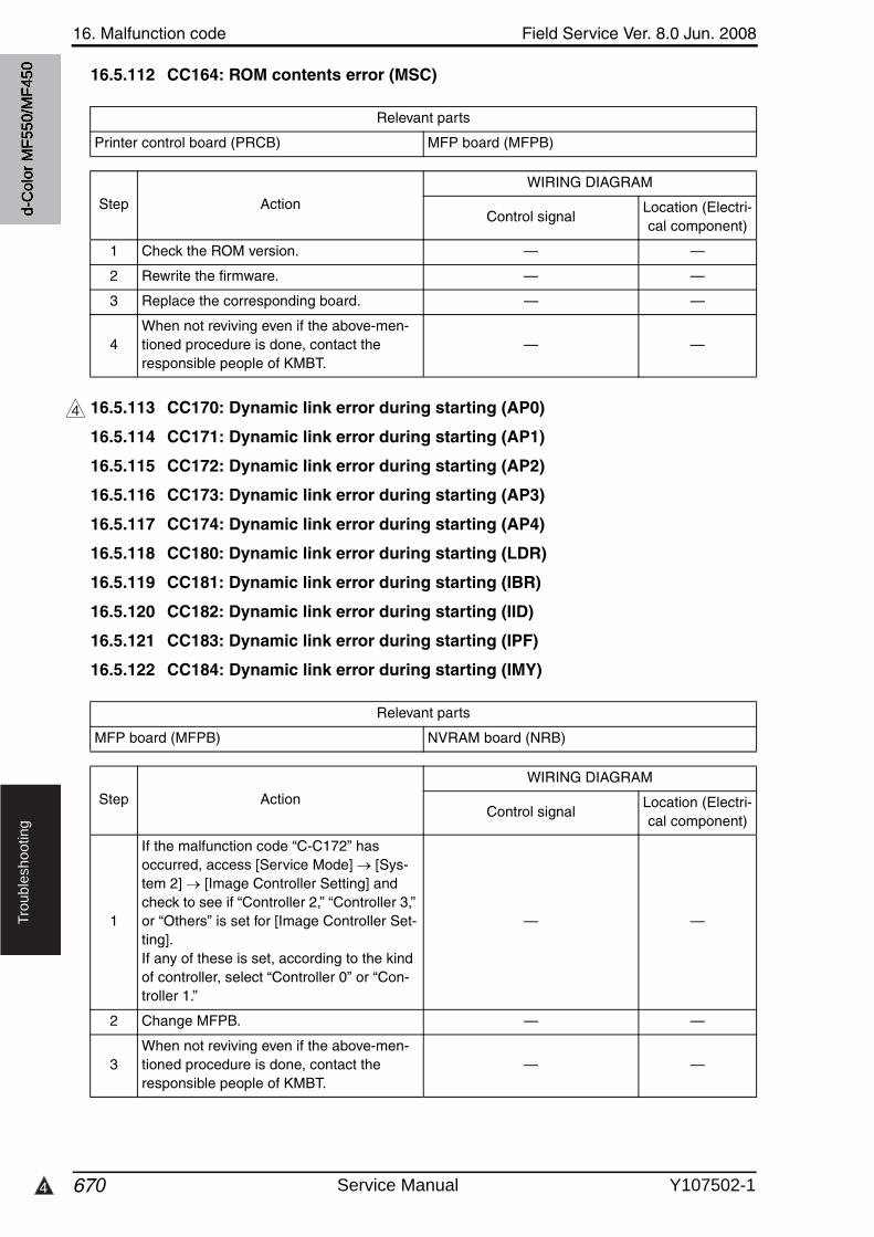
16. Malfunction code Field Service Ver. 8.0 Jun. 2008
6704
Tro
ub
lesh
oo
tin
g
16.5.112 CC164: ROM contents error (MSC)
16.5.113 CC170: Dynamic link error during starting (AP0)
16.5.114 CC171: Dynamic link error during starting (AP1)
16.5.115 CC172: Dynamic link error during starting (AP2)
16.5.116 CC173: Dynamic link error during starting (AP3)
16.5.117 CC174: Dynamic link error during starting (AP4)
16.5.118 CC180: Dynamic link error during starting (LDR)
16.5.119 CC181: Dynamic link error during starting (IBR)
16.5.120 CC182: Dynamic link error during starting (IID)
16.5.121 CC183: Dynamic link error during starting (IPF)
16.5.122 CC184: Dynamic link error during starting (IMY)
Relevant parts
Printer control board (PRCB) MFP board (MFPB)
Step Action
WIRING DIAGRAM
Control signalLocation (Electri-cal component)
1 Check the ROM version. — —
2 Rewrite the firmware. — —
3 Replace the corresponding board. — —
4When not reviving even if the above-men-tioned procedure is done, contact the responsible people of KMBT.
— —
4
Relevant parts
MFP board (MFPB) NVRAM board (NRB)
Step Action
WIRING DIAGRAM
Control signalLocation (Electri-cal component)
1
If the malfunction code “C-C172” has occurred, access [Service Mode] [Sys-tem 2] [Image Controller Setting] and check to see if “Controller 2,” “Controller 3,” or “Others” is set for [Image Controller Set-ting].If any of these is set, according to the kind of controller, select “Controller 0” or “Con-troller 1.”
— —
2 Change MFPB. — —
3When not reviving even if the above-men-tioned procedure is done, contact the responsible people of KMBT.
— —
d-C
olor
MF5
50/M
F450
Service Manual Y107502-1
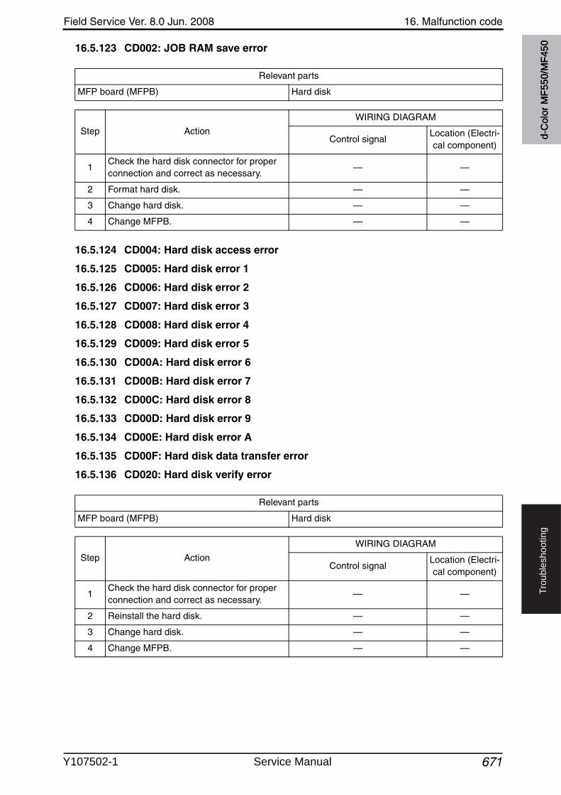
Field Service Ver. 8.0 Jun. 2008 16. Malfunction code
671
Tro
ub
lesh
oo
tin
g
16.5.123 CD002: JOB RAM save error
16.5.124 CD004: Hard disk access error
16.5.125 CD005: Hard disk error 1
16.5.126 CD006: Hard disk error 2
16.5.127 CD007: Hard disk error 3
16.5.128 CD008: Hard disk error 4
16.5.129 CD009: Hard disk error 5
16.5.130 CD00A: Hard disk error 6
16.5.131 CD00B: Hard disk error 7
16.5.132 CD00C: Hard disk error 8
16.5.133 CD00D: Hard disk error 9
16.5.134 CD00E: Hard disk error A
16.5.135 CD00F: Hard disk data transfer error
16.5.136 CD020: Hard disk verify error
Relevant parts
MFP board (MFPB) Hard disk
Step Action
WIRING DIAGRAM
Control signalLocation (Electri-cal component)
1Check the hard disk connector for proper connection and correct as necessary.
— —
2 Format hard disk. — —
3 Change hard disk. — —
4 Change MFPB. — —
Relevant parts
MFP board (MFPB) Hard disk
Step Action
WIRING DIAGRAM
Control signalLocation (Electri-cal component)
1Check the hard disk connector for proper connection and correct as necessary.
— —
2 Reinstall the hard disk. — —
3 Change hard disk. — —
4 Change MFPB. — —
d-C
olor
MF5
50/M
F450
Y107502-1 Service Manual
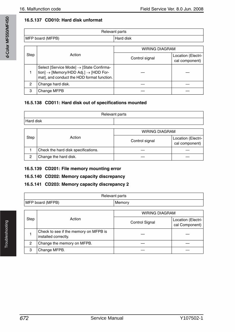
16. Malfunction code Field Service Ver. 8.0 Jun. 2008
672
Tro
ub
lesh
oo
tin
g
16.5.137 CD010: Hard disk unformat
16.5.138 CD011: Hard disk out of specifications mounted
16.5.139 CD201: File memory mounting error
16.5.140 CD202: Memory capacity discrepancy
16.5.141 CD203: Memory capacity discrepancy 2
Relevant parts
MFP board (MFPB) Hard disk
Step Action
WIRING DIAGRAM
Control signalLocation (Electri-cal component)
1Select [Service Mode] [State Confirma-tion] [Memory/HDD Adj.] [HDD For-mat], and conduct the HDD format function.
— —
2 Change hard disk. — —
3 Change MFPB — —
Relevant parts
Hard disk
Step Action
WIRING DIAGRAM
Control signalLocation (Electri-cal component)
1 Check the hard disk specifications. — —
2 Change the hard disk. — —
Relevant parts
MFP board (MFPB) Memory
Step Action
WIRING DIAGRAM
Control SignalLocation (Electri-cal Component)
1Check to see if the memory on MFPB is installed correctly.
— —
2 Change the memory on MFPB. — —
3 Change MFPB. — —
d-C
olor
MF5
50/M
F450
Service Manual Y107502-1
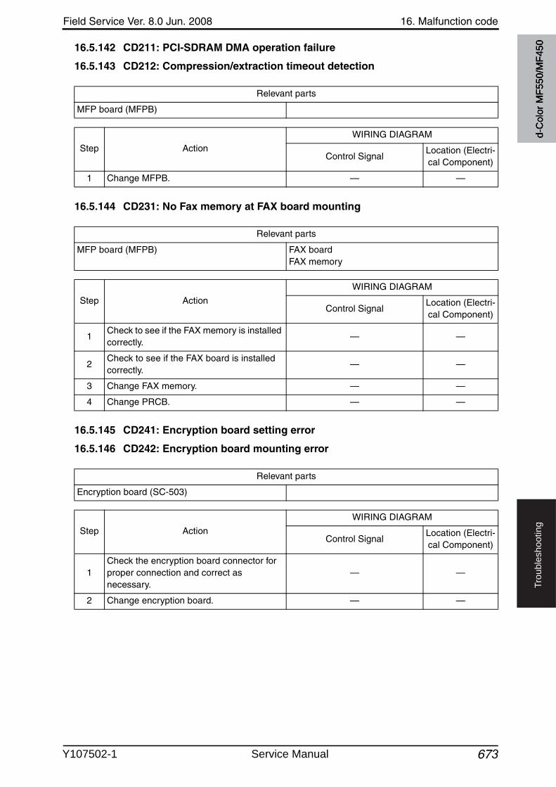
Field Service Ver. 8.0 Jun. 2008 16. Malfunction code
673
Tro
ub
lesh
oo
tin
g
16.5.142 CD211: PCI-SDRAM DMA operation failure
16.5.143 CD212: Compression/extraction timeout detection
16.5.144 CD231: No Fax memory at FAX board mounting
16.5.145 CD241: Encryption board setting error
16.5.146 CD242: Encryption board mounting error
Relevant parts
MFP board (MFPB)
Step Action
WIRING DIAGRAM
Control SignalLocation (Electri-cal Component)
1 Change MFPB. — —
Relevant parts
MFP board (MFPB) FAX boardFAX memory
Step Action
WIRING DIAGRAM
Control SignalLocation (Electri-cal Component)
1Check to see if the FAX memory is installed correctly.
— —
2Check to see if the FAX board is installed correctly.
— —
3 Change FAX memory. — —
4 Change PRCB. — —
Relevant parts
Encryption board (SC-503)
Step Action
WIRING DIAGRAM
Control SignalLocation (Electri-cal Component)
1Check the encryption board connector for proper connection and correct as necessary.
— —
2 Change encryption board. — —
d-C
olor
MF5
50/M
F450
Y107502-1 Service Manual
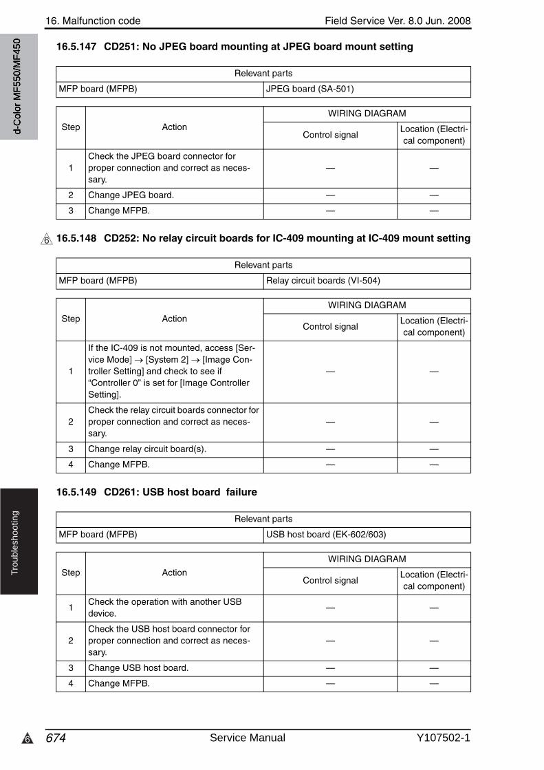
16. Malfunction code Field Service Ver. 8.0 Jun. 2008
6746
Tro
ub
lesh
oo
tin
g
16.5.147 CD251: No JPEG board mounting at JPEG board mount setting
16.5.148 CD252: No relay circuit boards for IC-409 mounting at IC-409 mount setting
16.5.149 CD261: USB host board failure
Relevant parts
MFP board (MFPB) JPEG board (SA-501)
Step Action
WIRING DIAGRAM
Control signalLocation (Electri-cal component)
1Check the JPEG board connector for proper connection and correct as neces-sary.
— —
2 Change JPEG board. — —
3 Change MFPB. — —
6
Relevant parts
MFP board (MFPB) Relay circuit boards (VI-504)
Step Action
WIRING DIAGRAM
Control signalLocation (Electri-cal component)
1
If the IC-409 is not mounted, access [Ser-vice Mode] [System 2] [Image Con-troller Setting] and check to see if “Controller 0” is set for [Image Controller Setting].
— —
2Check the relay circuit boards connector for proper connection and correct as neces-sary.
— —
3 Change relay circuit board(s). — —
4 Change MFPB. — —
Relevant parts
MFP board (MFPB) USB host board (EK-602/603)
Step Action
WIRING DIAGRAM
Control signalLocation (Electri-cal component)
1Check the operation with another USB device.
— —
2Check the USB host board connector for proper connection and correct as neces-sary.
— —
3 Change USB host board. — —
4 Change MFPB. — —
d-C
olor
MF5
50/M
F450
Service Manual Y107502-1
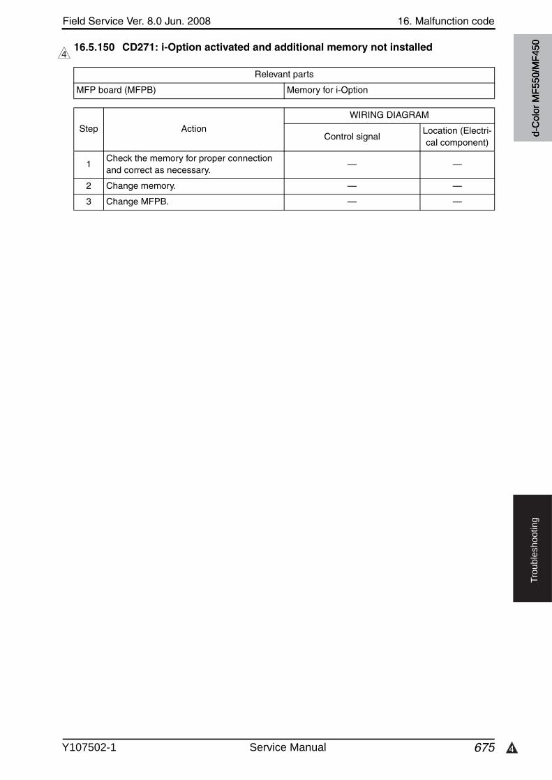
4
Field Service Ver. 8.0 Jun. 2008 16. Malfunction code
675
Tro
ub
lesh
oo
tin
g
16.5.150 CD271: i-Option activated and additional memory not installed4
Relevant parts
MFP board (MFPB) Memory for i-Option
Step Action
WIRING DIAGRAM
Control signalLocation (Electri-cal component)
1Check the memory for proper connection and correct as necessary.
— —
2 Change memory. — —
3 Change MFPB. — —
d-C
olor
MF5
50/M
F450
Y107502-1 Service Manual
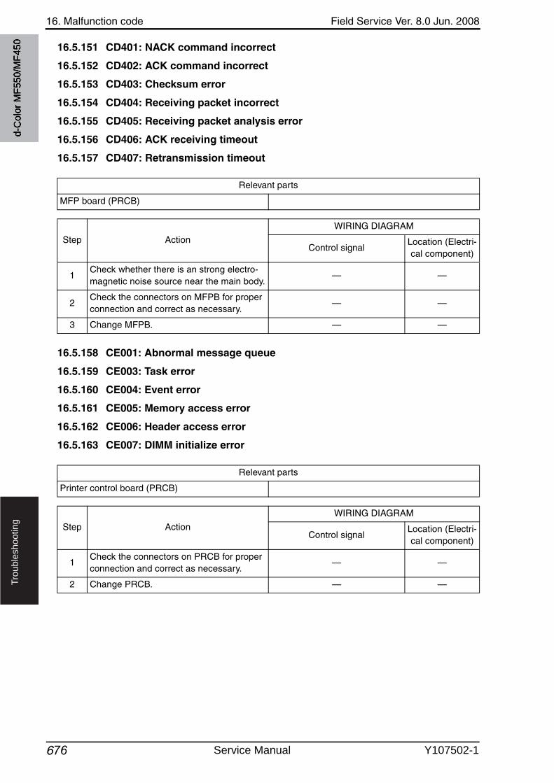
16. Malfunction code Field Service Ver. 8.0 Jun. 2008
676
Tro
ub
lesh
oo
tin
g
16.5.151 CD401: NACK command incorrect
16.5.152 CD402: ACK command incorrect
16.5.153 CD403: Checksum error
16.5.154 CD404: Receiving packet incorrect
16.5.155 CD405: Receiving packet analysis error
16.5.156 CD406: ACK receiving timeout
16.5.157 CD407: Retransmission timeout
16.5.158 CE001: Abnormal message queue
16.5.159 CE003: Task error
16.5.160 CE004: Event error
16.5.161 CE005: Memory access error
16.5.162 CE006: Header access error
16.5.163 CE007: DIMM initialize error
Relevant parts
MFP board (PRCB)
Step Action
WIRING DIAGRAM
Control signalLocation (Electri-cal component)
1Check whether there is an strong electro-magnetic noise source near the main body.
— —
2Check the connectors on MFPB for proper connection and correct as necessary.
— —
3 Change MFPB. — —
Relevant parts
Printer control board (PRCB)
Step Action
WIRING DIAGRAM
Control signalLocation (Electri-cal component)
1Check the connectors on PRCB for proper connection and correct as necessary.
— —
2 Change PRCB. — —
d-C
olor
MF5
50/M
F450
Service Manual Y107502-1
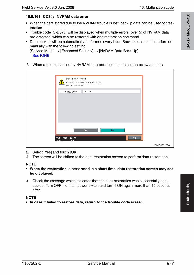
Field Service Ver. 8.0 Jun. 2008 16. Malfunction code
677
Tro
ub
lesh
oo
tin
g
16.5.164 CD3##: NVRAM data error
• When the data stored due to the NVRAM trouble is lost, backup data can be used for res-toration.
• Trouble code [C-D370] will be displayed when multiple errors (over 5) of NVRAM data are detected, which can be restored with one restoration command.
• Data backup will be automatically performed every hour. Backup can also be performed manually with the following setting. [Service Mode] [Enhanced Security] [NVRAM Data Back Up]
See P.545
1. When a trouble caused by NVRAM data error occurs, the screen below appears.
2. Select [Yes] and touch [OK].3. The screen will be shifted to the data restoration screen to perform data restoration.
NOTE• When the restoration is performed in a short time, data restoration screen may not
be displayed.
4. Check the message which indicates that the data restoration was successfully con-ducted. Turn OFF the main power switch and turn it ON again more than 10 seconds after.
NOTE• In case it failed to restore data, return to the trouble code screen.
A00JF4E517DA
d-C
olor
MF5
50/M
F450
Y107502-1 Service Manual
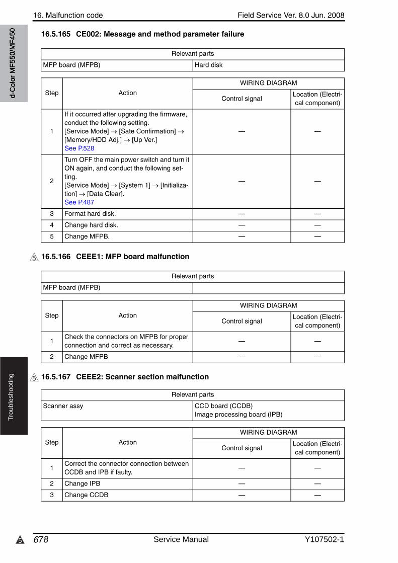
16. Malfunction code Field Service Ver. 8.0 Jun. 2008
6785
Tro
ub
lesh
oo
tin
g
16.5.165 CE002: Message and method parameter failure
16.5.166 CEEE1: MFP board malfunction
16.5.167 CEEE2: Scanner section malfunction
Relevant parts
MFP board (MFPB) Hard disk
Step Action
WIRING DIAGRAM
Control signalLocation (Electri-cal component)
1
If it occurred after upgrading the firmware, conduct the following setting. [Service Mode] [Sate Confirmation] [Memory/HDD Adj.] [Up Ver.]See P.528
— —
2
Turn OFF the main power switch and turn it ON again, and conduct the following set-ting. [Service Mode] [System 1] [Initializa-tion] [Data Clear].See P.487
— —
3 Format hard disk. — —
4 Change hard disk. — —
5 Change MFPB. — —
5
Relevant parts
MFP board (MFPB)
Step Action
WIRING DIAGRAM
Control signalLocation (Electri-cal component)
1Check the connectors on MFPB for proper connection and correct as necessary.
— —
2 Change MFPB — —
5
Relevant parts
Scanner assy CCD board (CCDB)Image processing board (IPB)
Step Action
WIRING DIAGRAM
Control signalLocation (Electri-cal component)
1Correct the connector connection betweenCCDB and IPB if faulty.
— —
2 Change IPB — —
3 Change CCDB — —
d-C
olor
MF5
50/M
F450
Service Manual Y107502-1
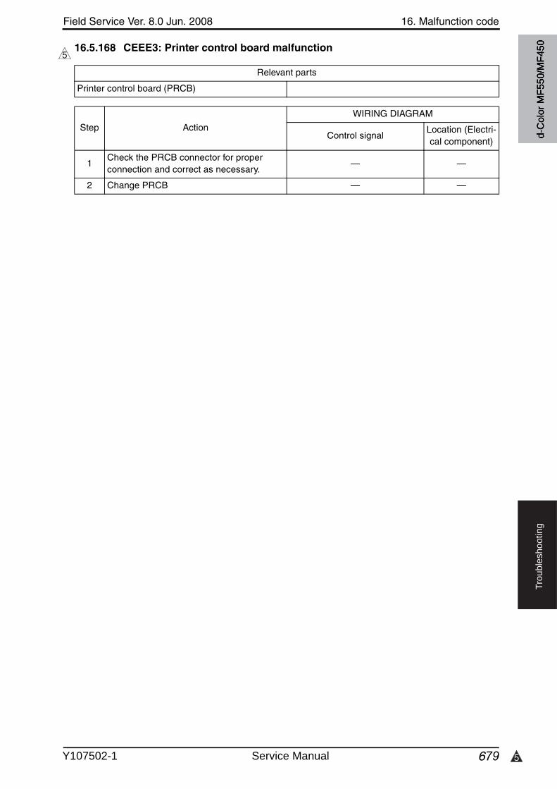
5
Field Service Ver. 8.0 Jun. 2008 16. Malfunction code
679
Tro
ub
lesh
oo
tin
g
16.5.168 CEEE3: Printer control board malfunction5
Relevant parts
Printer control board (PRCB)
Step Action
WIRING DIAGRAM
Control signalLocation (Electri-cal component)
1Check the PRCB connector for proper connection and correct as necessary.
— —
2 Change PRCB — —
d-C
olor
MF5
50/M
F450
Y107502-1 Service Manual
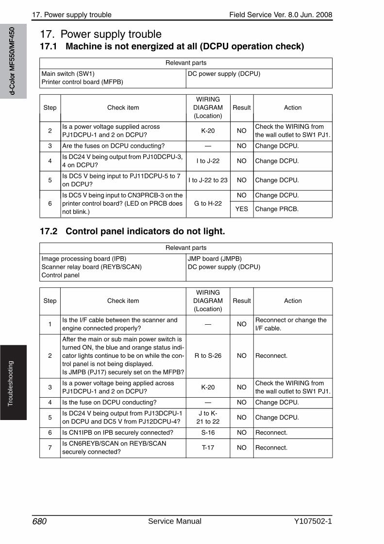
17. Power supply trouble Field Service Ver. 8.0 Jun. 2008
680
Tro
ub
lesh
oo
tin
g
17. Power supply trouble17.1 Machine is not energized at all (DCPU operation check)
Relevant parts
Main switch (SW1)Printer control board (MFPB)
DC power supply (DCPU)
Step Check itemWIRING
DIAGRAM (Location)
Result Action
d-C
olor
MF5
50/M
F450
2Is a power voltage supplied across PJ1DCPU-1 and 2 on DCPU?
K-20 NOCheck the WIRING from the wall outlet to SW1 PJ1.
3 Are the fuses on DCPU conducting? — NO Change DCPU.
4Is DC24 V being output from PJ10DCPU-3, 4 on DCPU?
I to J-22 NO Change DCPU.
5Is DC5 V being input to PJ11DCPU-5 to 7 on DCPU?
I to J-22 to 23 NO Change DCPU.
6Is DC5 V being input to CN3PRCB-3 on the printer control board? (LED on PRCB does not blink.)
G to H-22NO Change DCPU.
YES Change PRCB.
17.2 Control panel indicators do not light.
Relevant parts
Image processing board (IPB)Scanner relay board (REYB/SCAN)Control panel
JMP board (JMPB)DC power supply (DCPU)
Step Check itemWIRING
DIAGRAM (Location)
Result Action
1Is the I/F cable between the scanner and engine connected properly?
— NOReconnect or change the I/F cable.
2
After the main or sub main power switch is turned ON, the blue and orange status indi-cator lights continue to be on while the con-trol panel is not being displayed.Is JMPB (PJ17) securely set on the MFPB?
R to S-26 NO Reconnect.
3Is a power voltage being applied across PJ1DCPU-1 and 2 on DCPU?
K-20 NOCheck the WIRING from the wall outlet to SW1 PJ1.
4 Is the fuse on DCPU conducting? — NO Change DCPU.
5Is DC24 V being output from PJ13DCPU-1 on DCPU and DC5 V from PJ12DCPU-4?
J to K-21 to 22
NO Change DCPU.
6 Is CN1IPB on IPB securely connected? S-16 NO Reconnect.
7Is CN6REYB/SCAN on REYB/SCAN securely connected?
T-17 NO Reconnect.
Service Manual Y107502-1
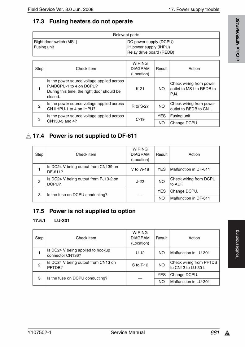
Field Service Ver. 8.0 Jun. 2008 17. Power supply trouble
681 2
Tro
ub
lesh
oo
tin
g
17.3 Fusing heaters do not operate
17.4 Power is not supplied to DF-611
17.5 Power is not supplied to option
17.5.1 LU-301
Relevant parts
Right door switch (MS1)Fusing unit
DC power supply (DCPU)IH power supply (IHPU)Relay drive board (REDB)
Step Check itemWIRING
DIAGRAM (Location)
Result Action
1
Is the power source voltage applied across PJ4DCPU-1 to 4 on DCPU?During this time, the right door should be closed.
K-21 NOCheck wiring from poweroutlet to MS1 to REDB to PJ4.
2Is the power source voltage applied across CN1IHPU-1 to 4 on IHPU?
R to S-27 NOCheck wiring from poweroutlet to REDB to CN1.
3Is the power source voltage applied across CN150-3 and 4? C-19
YES Fusing unit
NO Change DCPU.
2
Step Check itemWIRING
DIAGRAM (Location)
Result Action
1Is DC24 V being output from CN139 on DF-611?/61?
V to W-18 YES Malfunction in DF-611
2Is DC24 V being output from PJ13-2 on DCPU?
J-22 NOCheck wiring from DCPU to ADF.
3 Is the fuse on DCPU conducting? —YES Change DCPU.
NO Malfunction in DF-611
Step Check itemWIRING
DIAGRAM (Location)
Result Action
1Is DC24 V being applied to hookupconnector CN136?
U-12 NO Malfunction in LU-301
2Is DC24 V being output from CN13 on PFTDB?
S to T-12 NOCheck wiring from PFTDB to CN13 to LU-301.
3 Is the fuse on DCPU conducting? —YES Change DCPU.
NO Malfunction in LU-301
d-C
olor
MF5
50/M
F450
Y107502-1 Service Manual
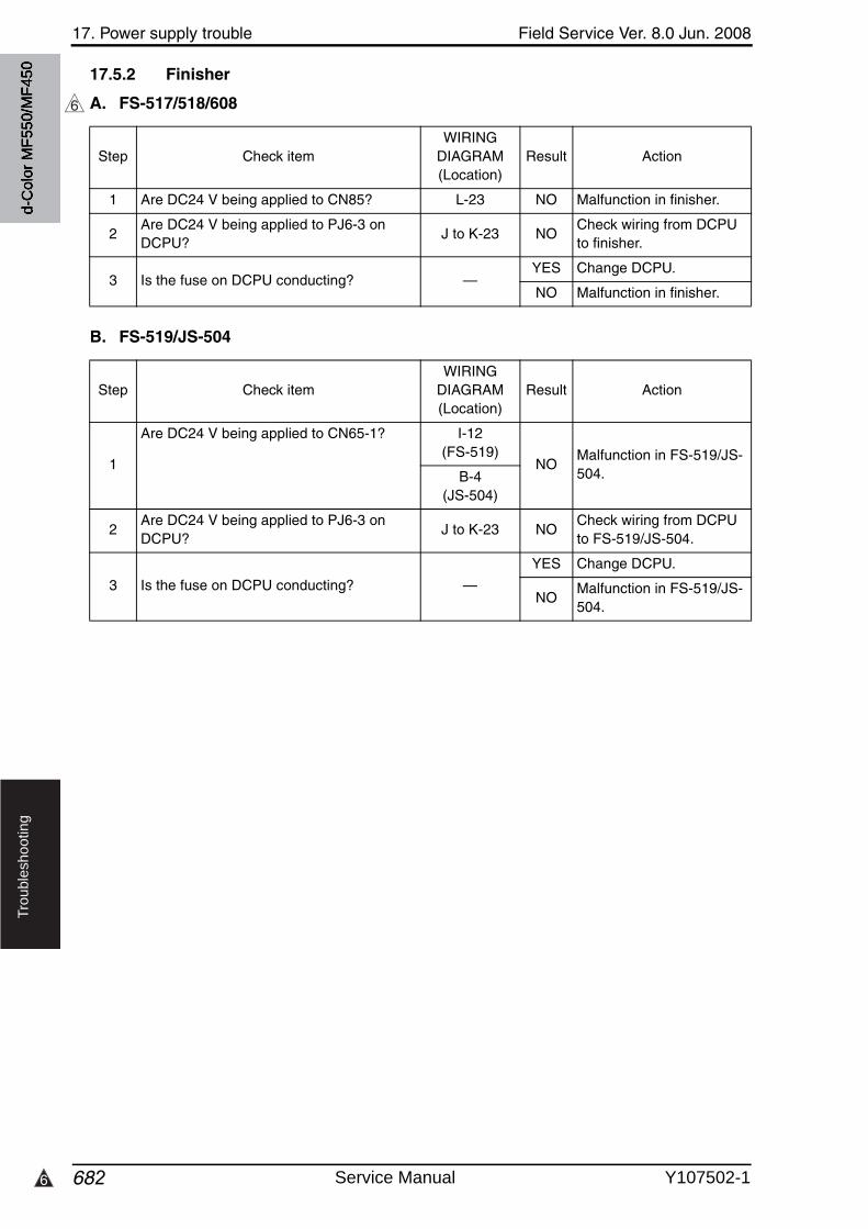
17. Power supply trouble Field Service Ver. 8.0 Jun. 2008
6826
Tro
ub
lesh
oo
tin
g
17.5.2 Finisher
A. FS-517/518/608
B. FS-519/JS-504
6
Step Check itemWIRING
DIAGRAM (Location)
Result Action
1 Are DC24 V being applied to CN85? L-23 NO Malfunction in finisher.
2Are DC24 V being applied to PJ6-3 on DCPU?
J to K-23 NOCheck wiring from DCPU to finisher.
3 Is the fuse on DCPU conducting? —YES Change DCPU.
NO Malfunction in finisher.
Step Check itemWIRING
DIAGRAM (Location)
Result Action
1
Are DC24 V being applied to CN65-1? I-12(FS-519)
NOMalfunction in FS-519/JS-504.B-4
(JS-504)
2Are DC24 V being applied to PJ6-3 on DCPU?
J to K-23 NOCheck wiring from DCPU to FS-519/JS-504.
3 Is the fuse on DCPU conducting? —
YES Change DCPU.
NOMalfunction in FS-519/JS-504.
d-C
olor
MF5
50/M
F450
Service Manual Y107502-1
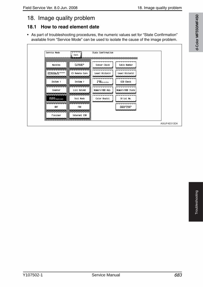
Field Service Ver. 8.0 Jun. 2008 18. Image quality problem
683
Tro
ub
lesh
oo
tin
g
18. Image quality problem
18.1 How to read element date
• As part of troubleshooting procedures, the numeric values set for “State Confirmation” available from “Service Mode” can be used to isolate the cause of the image problem.
A00JF4E513DA
d-C
olor
MF5
50/M
F450
Y107502-1 Service Manual
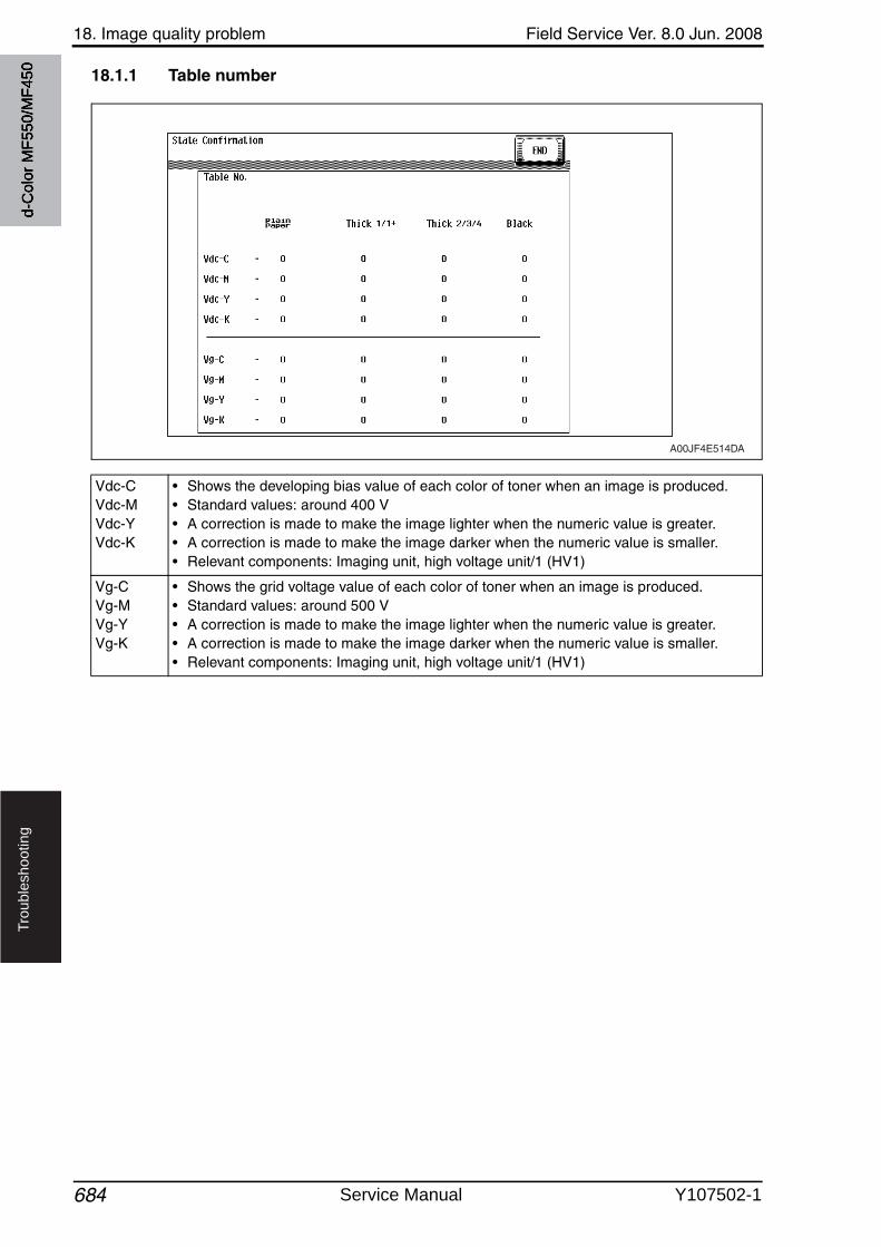
18. Image quality problem Field Service Ver. 8.0 Jun. 2008
684
Tro
ub
lesh
oo
tin
g
18.1.1 Table number
Vdc-CVdc-MVdc-YVdc-K
• Shows the developing bias value of each color of toner when an image is produced.• Standard values: around 400 V• A correction is made to make the image lighter when the numeric value is greater.• A correction is made to make the image darker when the numeric value is smaller.• Relevant components: Imaging unit, high voltage unit/1 (HV1)
Vg-CVg-MVg-YVg-K
• Shows the grid voltage value of each color of toner when an image is produced.• Standard values: around 500 V• A correction is made to make the image lighter when the numeric value is greater.• A correction is made to make the image darker when the numeric value is smaller.• Relevant components: Imaging unit, high voltage unit/1 (HV1)
A00JF4E514DA
d-C
olor
MF5
50/M
F450
Service Manual Y107502-1
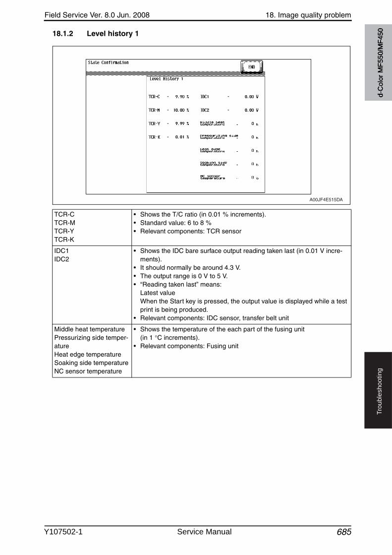
Field Service Ver. 8.0 Jun. 2008 18. Image quality problem
685
Tro
ub
lesh
oo
tin
g
18.1.2 Level history 1
TCR-CTCR-MTCR-YTCR-K
• Shows the T/C ratio (in 0.01 % increments).• Standard value: 6 to 8 %• Relevant components: TCR sensor
IDC1IDC2
• Shows the IDC bare surface output reading taken last (in 0.01 V incre-ments).
• It should normally be around 4.3 V.• The output range is 0 V to 5 V.• “Reading taken last” means:
Latest valueWhen the Start key is pressed, the output value is displayed while a test print is being produced.
• Relevant components: IDC sensor, transfer belt unit
Middle heat temperaturePressurizing side temper-atureHeat edge temperatureSoaking side temperatureNC sensor temperature
• Shows the temperature of the each part of the fusing unit (in 1 C increments).
• Relevant components: Fusing unit
A00JF4E515DA
d-C
olor
MF5
50/M
F450
Y107502-1 Service Manual
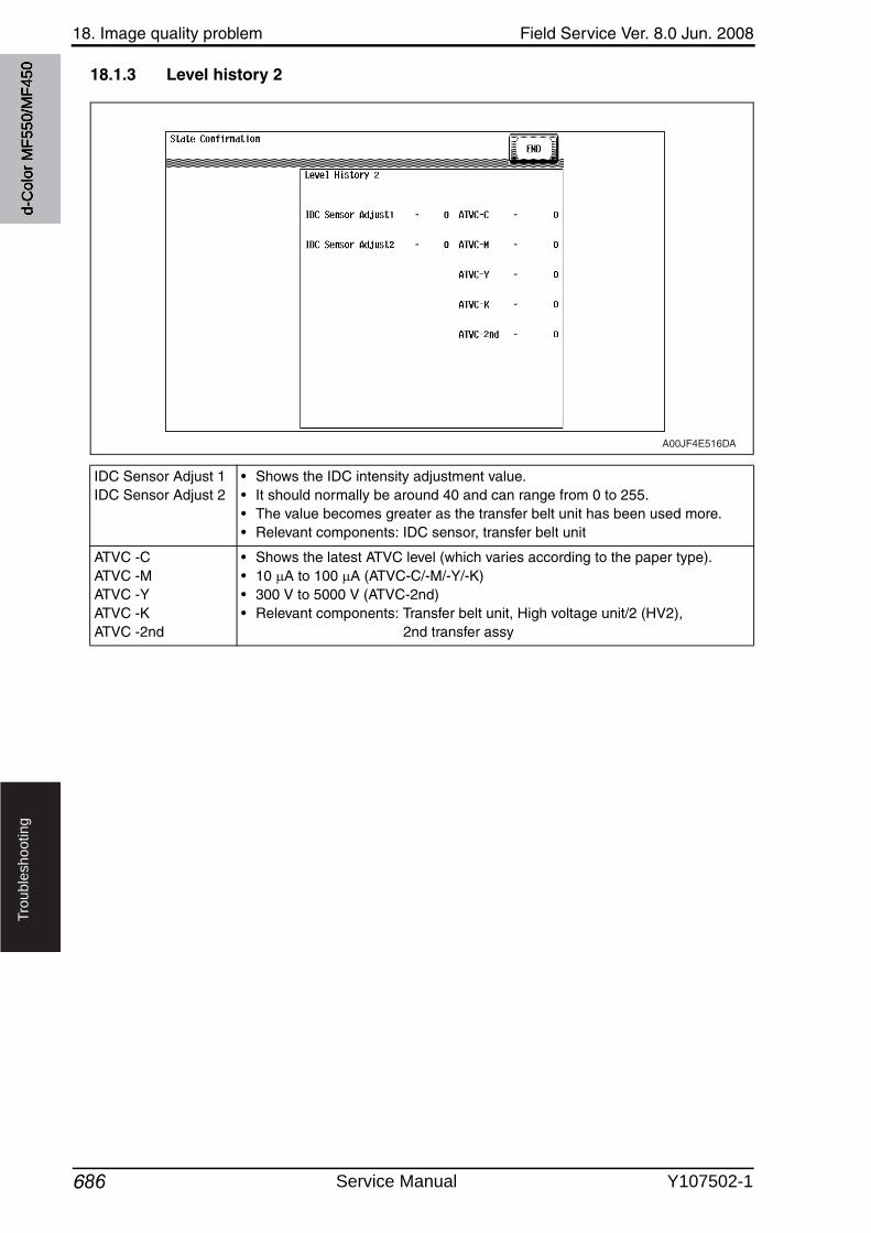
18. Image quality problem Field Service Ver. 8.0 Jun. 2008
686
Tro
ub
lesh
oo
tin
g
18.1.3 Level history 2
IDC Sensor Adjust 1IDC Sensor Adjust 2
• Shows the IDC intensity adjustment value.• It should normally be around 40 and can range from 0 to 255.• The value becomes greater as the transfer belt unit has been used more.• Relevant components: IDC sensor, transfer belt unit
ATVC -CATVC -MATVC -YATVC -KATVC -2nd
• Shows the latest ATVC level (which varies according to the paper type).• 10 A to 100 A (ATVC-C/-M/-Y/-K)• 300 V to 5000 V (ATVC-2nd)• Relevant components: Transfer belt unit, High voltage unit/2 (HV2),
2nd transfer assy
A00JF4E516DA
d-C
olor
MF5
50/M
F450
Service Manual Y107502-1
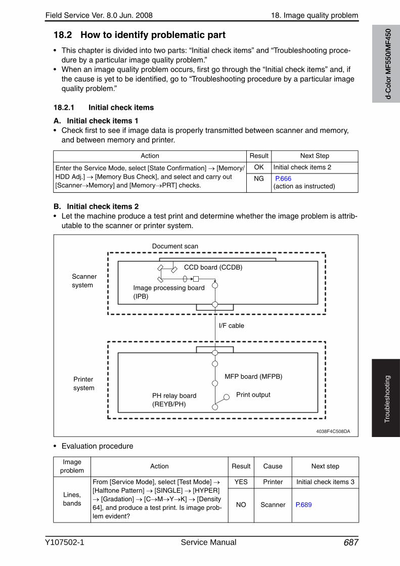
Field Service Ver. 8.0 Jun. 2008 18. Image quality problem
687
Tro
ub
lesh
oo
tin
g
18.2 How to identify problematic part
• This chapter is divided into two parts: “Initial check items” and “Troubleshooting proce-dure by a particular image quality problem.”
• When an image quality problem occurs, first go through the “Initial check items” and, if the cause is yet to be identified, go to “Troubleshooting procedure by a particular image quality problem.”
18.2.1 Initial check items
A. Initial check items 1• Check first to see if image data is properly transmitted between scanner and memory,
and between memory and printer.
B. Initial check items 2• Let the machine produce a test print and determine whether the image problem is attrib-
utable to the scanner or printer system.
• Evaluation procedure
Action Result Next Step
Enter the Service Mode, select [State Confirmation] [Memory/HDD Adj.] [Memory Bus Check], and select and carry out[Scanner Memory] and [Memory PRT] checks.
OK Initial check items 2
NG P.666(action as instructed)
4038F4C508DA
CCD board (CCDB)
Image processing board(IPB)
MFP board (MFPB)
PH relay board(REYB/PH)
Scanner system
Printer system
Document scan
Print output
I/F cable
Image problem
Action Result Cause Next step
Lines, bands
From [Service Mode], select [Test Mode] [Halftone Pattern] [SINGLE] [HYPER]
[Gradation] [C M Y K] [Density 64], and produce a test print. Is image prob-lem evident?
YES Printer Initial check items 3
NO Scanner P.689
d-C
olor
MF5
50/M
F450
Y107502-1 Service Manual
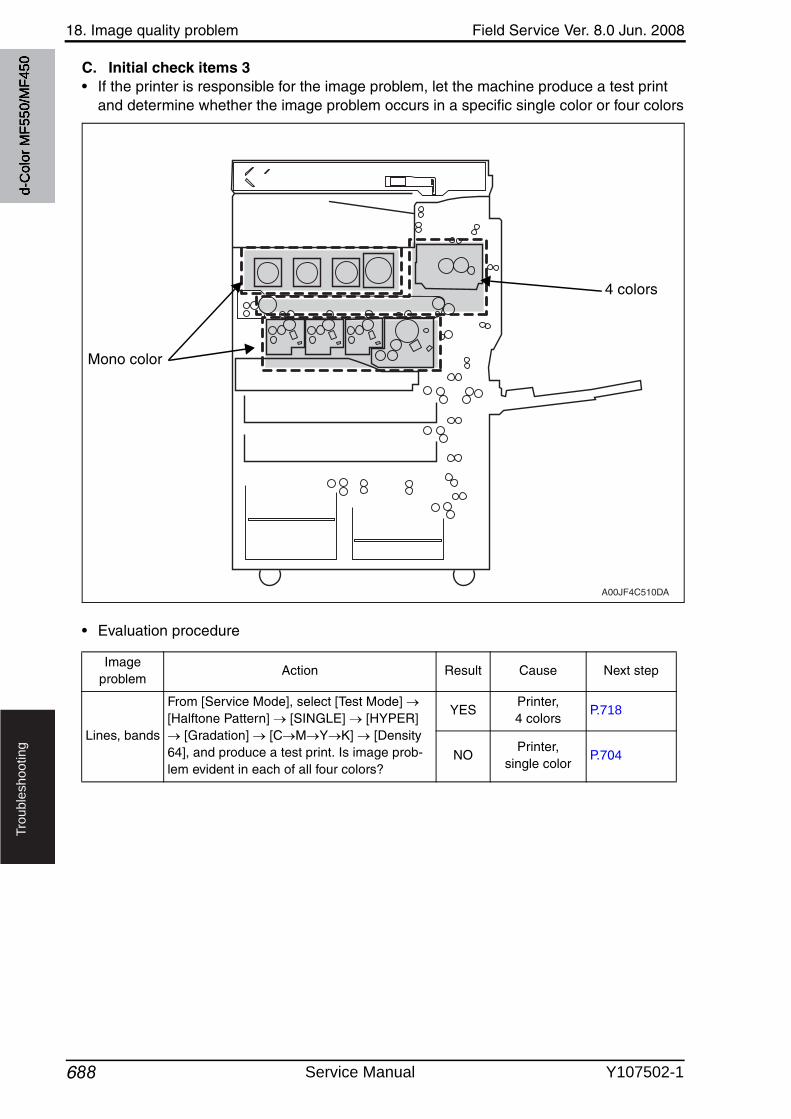
18. Image quality problem Field Service Ver. 8.0 Jun. 2008
688
Tro
ub
lesh
oo
tin
g
C. Initial check items 3• If the printer is responsible for the image problem, let the machine produce a test print
and determine whether the image problem occurs in a specific single color or four colors
• Evaluation procedure
A00JF4C510DA
Mono color
4 colors
Image problem
Action Result Cause Next step
Lines, bands
From [Service Mode], select [Test Mode] [Halftone Pattern] [SINGLE] [HYPER]
[Gradation] [C M Y K] [Density 64], and produce a test print. Is image prob-lem evident in each of all four colors?
YESPrinter, 4 colors
P.718
NOPrinter,
single colorP.704
d-C
olor
MF5
50/M
F450
Service Manual Y107502-1
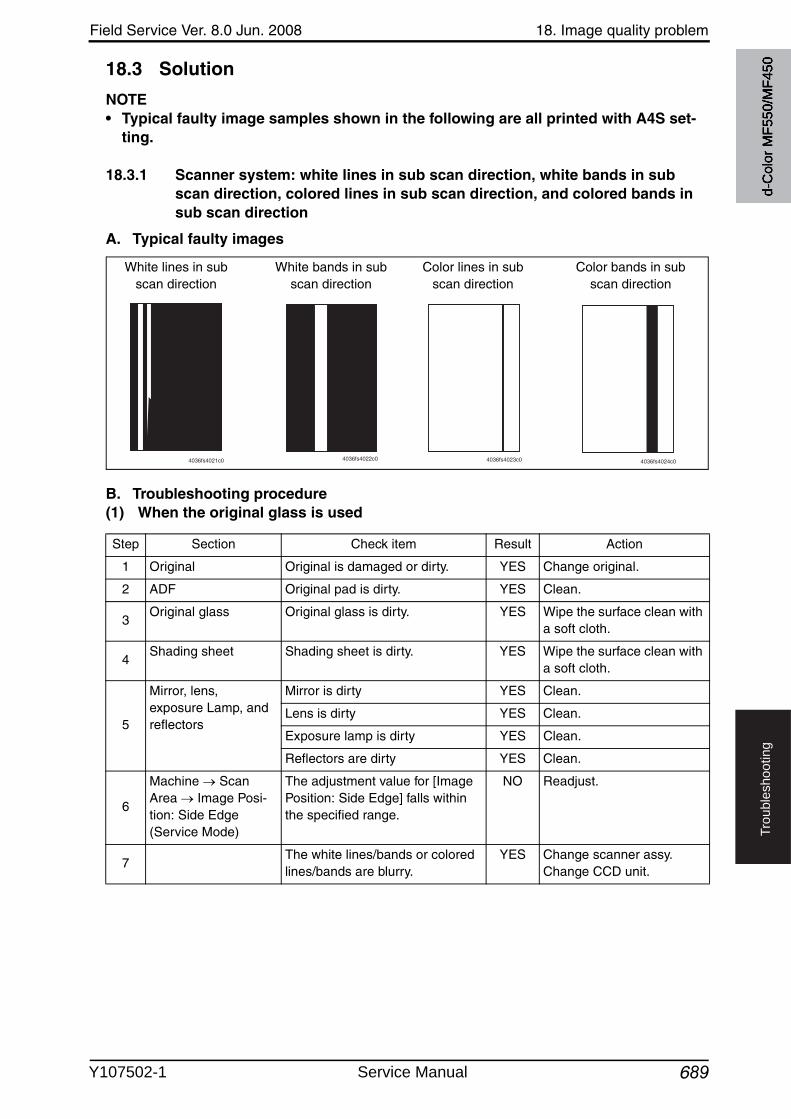
Field Service Ver. 8.0 Jun. 2008 18. Image quality problem
689
Tro
ub
lesh
oo
tin
g
18.3 Solution
NOTE• Typical faulty image samples shown in the following are all printed with A4S set-
ting.
18.3.1 Scanner system: white lines in sub scan direction, white bands in sub scan direction, colored lines in sub scan direction, and colored bands in sub scan direction
A. Typical faulty images
B. Troubleshooting procedure(1) When the original glass is used
4036fs4021c0 4036fs4022c0 4036fs4023c0 4036fs4024c0
White lines in subscan direction
White bands in subscan direction
Color bands in subscan direction
Color lines in subscan direction
Step Section Check item Result Action
1 Original Original is damaged or dirty. YES Change original.
2 ADF Original pad is dirty. YES Clean.
3Original glass Original glass is dirty. YES Wipe the surface clean with
a soft cloth.
4Shading sheet Shading sheet is dirty. YES Wipe the surface clean with
a soft cloth.
5
Mirror, lens, exposure Lamp, and reflectors
Mirror is dirty YES Clean.
Lens is dirty YES Clean.
Exposure lamp is dirty YES Clean.
Reflectors are dirty YES Clean.
6
Machine Scan Area Image Posi-tion: Side Edge (Service Mode)
The adjustment value for [Image Position: Side Edge] falls within the specified range.
NO Readjust.
7The white lines/bands or colored lines/bands are blurry.
YES Change scanner assy.Change CCD unit.
d-C
olor
MF5
50/M
F450
Y107502-1 Service Manual
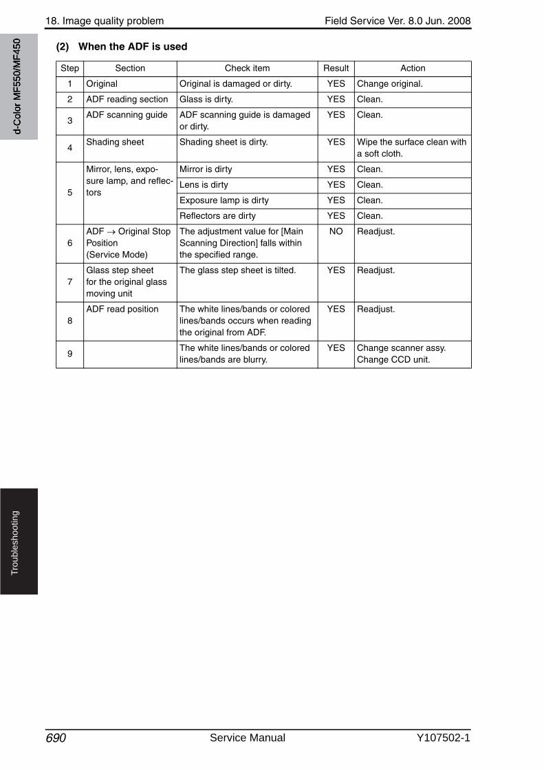
18. Image quality problem Field Service Ver. 8.0 Jun. 2008
690
Tro
ub
lesh
oo
tin
g
(2) When the ADF is used
Step Section Check item Result Action
1 Original Original is damaged or dirty. YES Change original.
2 ADF reading section Glass is dirty. YES Clean.
3ADF scanning guide ADF scanning guide is damaged
or dirty.YES Clean.
4Shading sheet Shading sheet is dirty. YES Wipe the surface clean with
a soft cloth.
5
Mirror, lens, expo-sure lamp, and reflec-tors
Mirror is dirty YES Clean.
Lens is dirty YES Clean.
Exposure lamp is dirty YES Clean.
Reflectors are dirty YES Clean.
6ADF Original Stop Position(Service Mode)
The adjustment value for [Main Scanning Direction] falls within the specified range.
NO Readjust.
7Glass step sheet for the original glass moving unit
The glass step sheet is tilted. YES Readjust.
8ADF read position The white lines/bands or colored
lines/bands occurs when reading the original from ADF.
YES Readjust.
9The white lines/bands or colored lines/bands are blurry.
YES Change scanner assy.Change CCD unit.
d-C
olor
MF5
50/M
F450
Service Manual Y107502-1
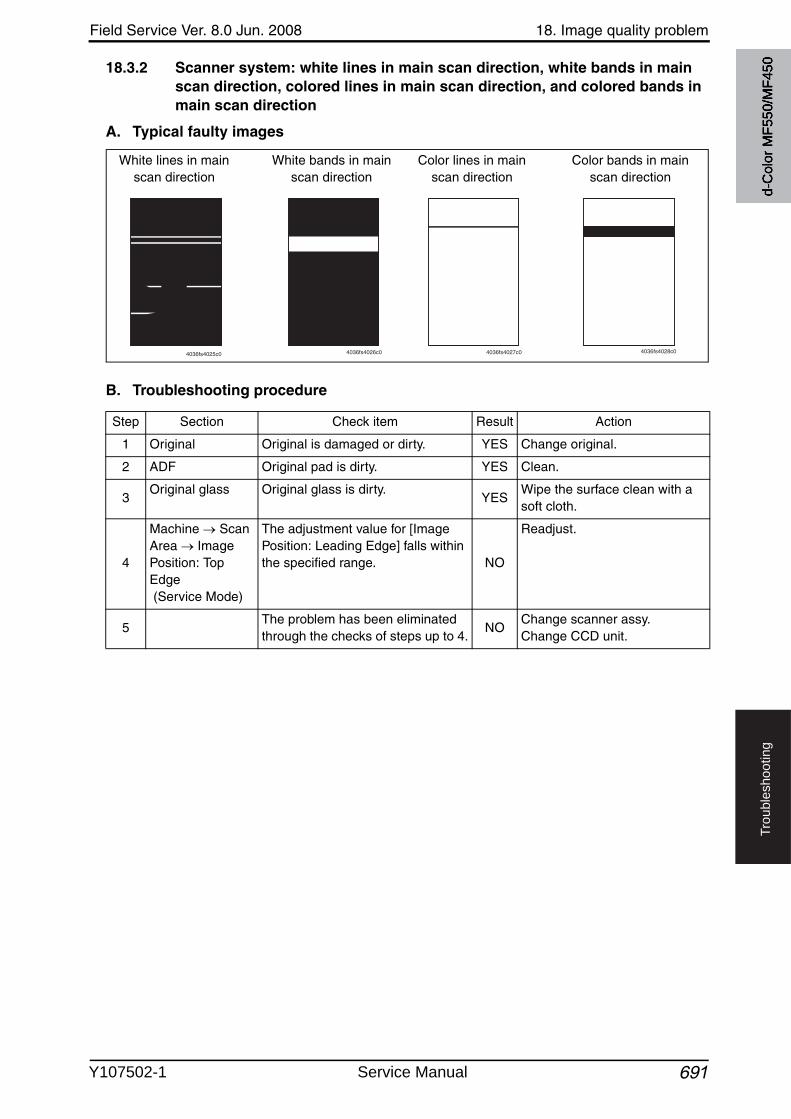
Field Service Ver. 8.0 Jun. 2008 18. Image quality problem
691
Tro
ub
lesh
oo
tin
g
18.3.2 Scanner system: white lines in main scan direction, white bands in main scan direction, colored lines in main scan direction, and colored bands in main scan direction
A. Typical faulty images
B. Troubleshooting procedure
4036fs4025c0 4036fs4026c0 4036fs4027c0 4036fs4028c0
White lines in main scan direction
White bands in main scan direction
Color bands in main scan direction
Color lines in main scan direction
Step Section Check item Result Action
1 Original Original is damaged or dirty. YES Change original.
2 ADF Original pad is dirty. YES Clean.
3Original glass Original glass is dirty.
YESWipe the surface clean with a soft cloth.
4
Machine Scan Area Image Position: Top Edge (Service Mode)
The adjustment value for [Image Position: Leading Edge] falls within the specified range. NO
Readjust.
5The problem has been eliminated through the checks of steps up to 4.
NOChange scanner assy.Change CCD unit.
d-C
olor
MF5
50/M
F450
Y107502-1 Service Manual
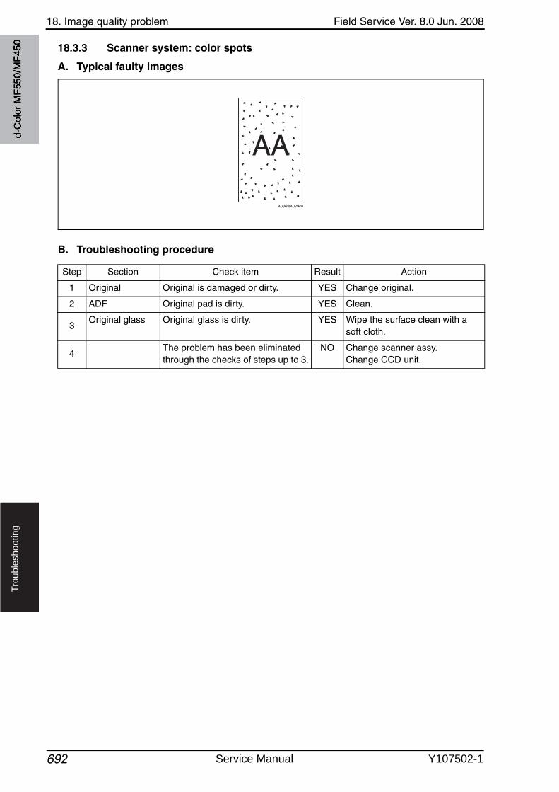
18. Image quality problem Field Service Ver. 8.0 Jun. 2008
692
Tro
ub
lesh
oo
tin
g
18.3.3 Scanner system: color spots
A. Typical faulty images
B. Troubleshooting procedure
AA
4036fs4029c0
Step Section Check item Result Action
1 Original Original is damaged or dirty. YES Change original.
2 ADF Original pad is dirty. YES Clean.
3Original glass Original glass is dirty. YES Wipe the surface clean with a
soft cloth.
4The problem has been eliminated through the checks of steps up to 3.
NO Change scanner assy.Change CCD unit.
d-C
olor
MF5
50/M
F450
Service Manual Y107502-1
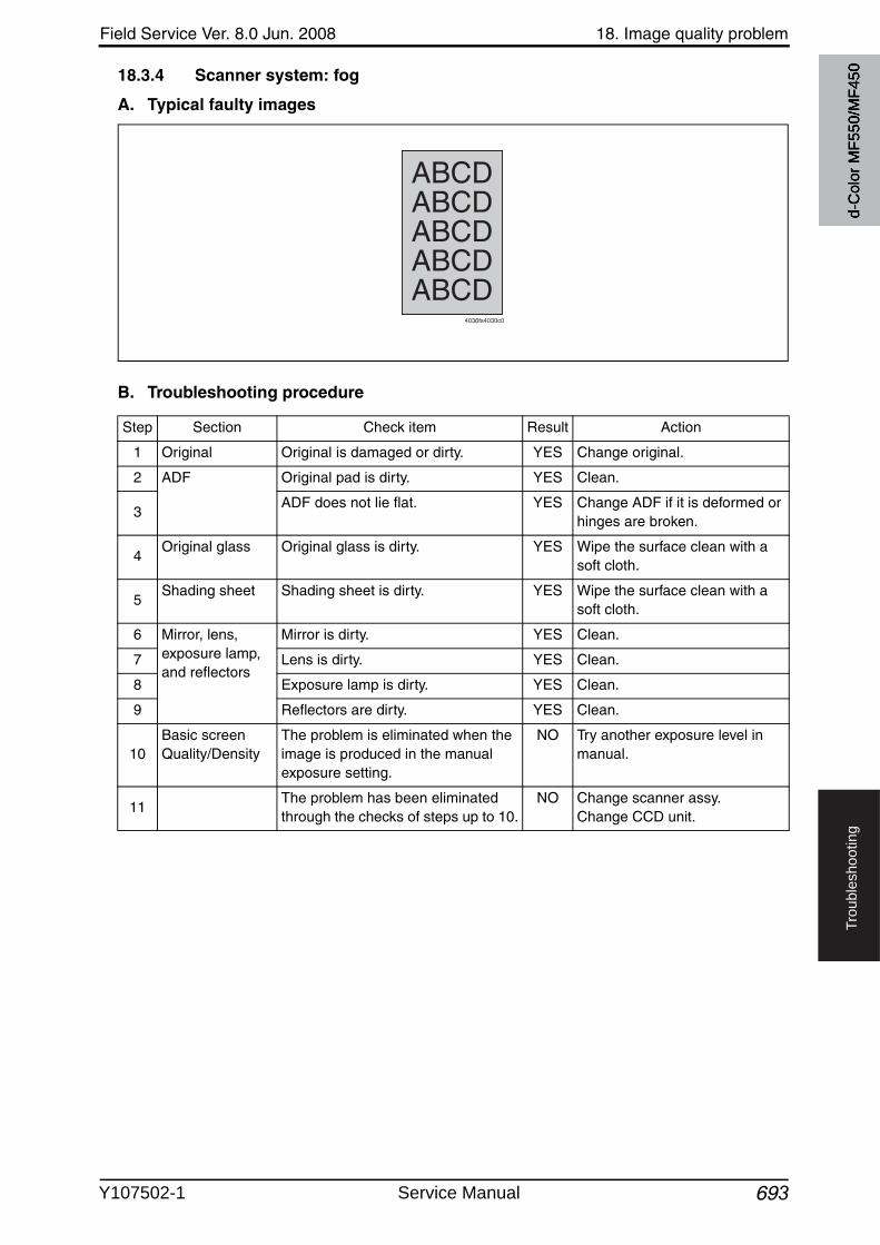
Field Service Ver. 8.0 Jun. 2008 18. Image quality problem
693
Tro
ub
lesh
oo
tin
g
18.3.4 Scanner system: fog
A. Typical faulty images
B. Troubleshooting procedure
4036fs4030c0
ABCDABCDABCDABCDABCD
Step Section Check item Result Action
1 Original Original is damaged or dirty. YES Change original.
2 ADF Original pad is dirty. YES Clean.
3ADF does not lie flat. YES Change ADF if it is deformed or
hinges are broken.
4Original glass Original glass is dirty. YES Wipe the surface clean with a
soft cloth.
5Shading sheet Shading sheet is dirty. YES Wipe the surface clean with a
soft cloth.
6 Mirror, lens, exposure lamp, and reflectors
Mirror is dirty. YES Clean.
7 Lens is dirty. YES Clean.
8 Exposure lamp is dirty. YES Clean.
9 Reflectors are dirty. YES Clean.
10Basic screenQuality/Density
The problem is eliminated when the image is produced in the manual exposure setting.
NO Try another exposure level in manual.
11The problem has been eliminated through the checks of steps up to 10.
NO Change scanner assy.Change CCD unit.
d-C
olor
MF5
50/M
F450
Y107502-1 Service Manual
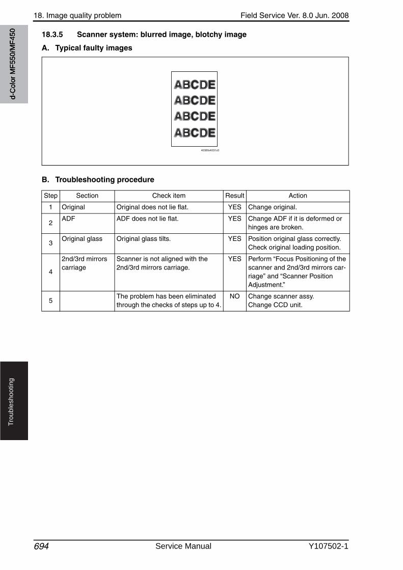
18. Image quality problem Field Service Ver. 8.0 Jun. 2008
694
Tro
ub
lesh
oo
tin
g
18.3.5 Scanner system: blurred image, blotchy image
A. Typical faulty images
B. Troubleshooting procedure
4036fs4031c0
Step Section Check item Result Action
1 Original Original does not lie flat. YES Change original.
2ADF ADF does not lie flat. YES Change ADF if it is deformed or
hinges are broken.
3Original glass Original glass tilts. YES Position original glass correctly.
Check original loading position.
4
2nd/3rd mirrors carriage
Scanner is not aligned with the 2nd/3rd mirrors carriage.
YES Perform “Focus Positioning of the scanner and 2nd/3rd mirrors car-riage” and “Scanner Position Adjustment.”
5The problem has been eliminated through the checks of steps up to 4.
NO Change scanner assy.Change CCD unit.
d-C
olor
MF5
50/M
F450
Service Manual Y107502-1
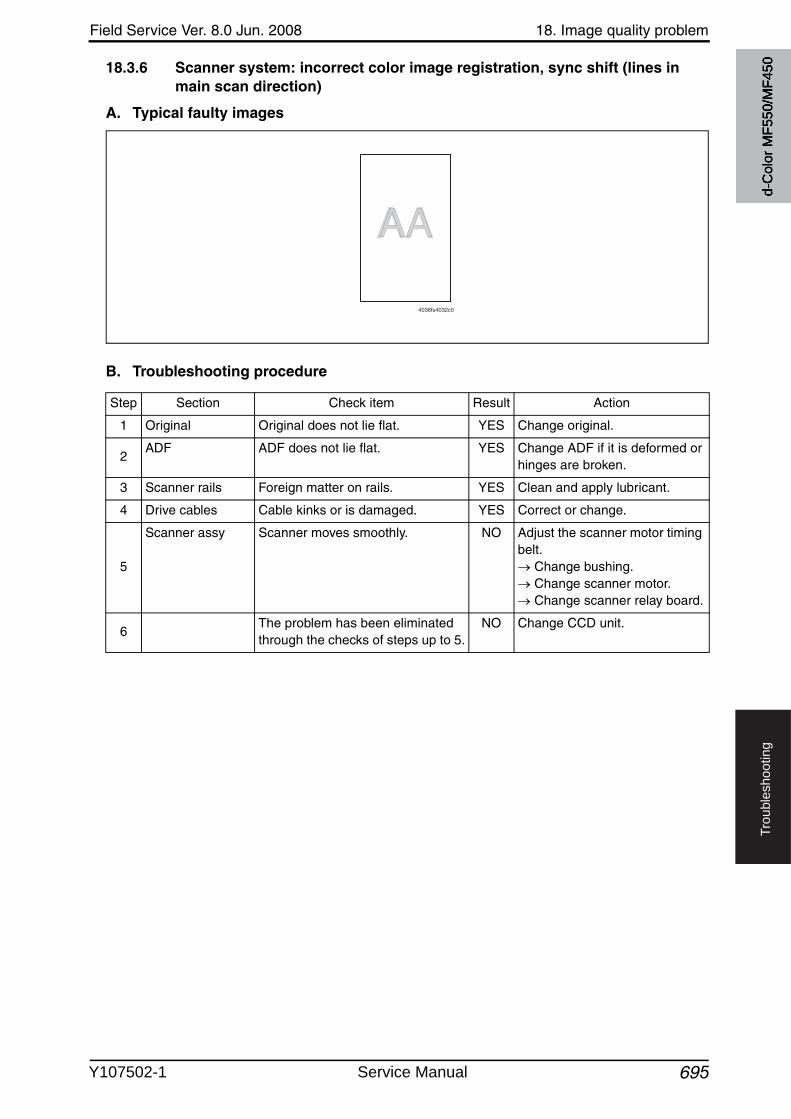
Field Service Ver. 8.0 Jun. 2008 18. Image quality problem
695
Tro
ub
lesh
oo
tin
g
18.3.6 Scanner system: incorrect color image registration, sync shift (lines in main scan direction)
A. Typical faulty images
B. Troubleshooting procedure
AAAA
4036fs4032c0
Step Section Check item Result Action
1 Original Original does not lie flat. YES Change original.
2ADF ADF does not lie flat. YES Change ADF if it is deformed or
hinges are broken.
3 Scanner rails Foreign matter on rails. YES Clean and apply lubricant.
4 Drive cables Cable kinks or is damaged. YES Correct or change.
5
Scanner assy Scanner moves smoothly. NO Adjust the scanner motor timing belt.
Change bushing. Change scanner motor. Change scanner relay board.
6The problem has been eliminated through the checks of steps up to 5.
NO Change CCD unit.
d-C
olor
MF5
50/M
F450
Y107502-1 Service Manual
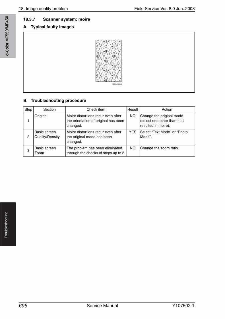
18. Image quality problem Field Service Ver. 8.0 Jun. 2008
696
Tro
ub
lesh
oo
tin
g
18.3.7 Scanner system: moire
A. Typical faulty images
B. Troubleshooting procedure
4036fs4033c0
Step Section Check item Result Action
1Original Moire distortions recur even after
the orientation of original has been changed.
NO Change the original mode (select one other than that resulted in moire).
2Basic screenQuality/Density
Moire distortions recur even after the original mode has been changed.
YES Select “Text Mode” or “Photo Mode”.
3Basic screenZoom
The problem has been eliminated through the checks of steps up to 2.
NO Change the zoom ratio.
d-C
olor
MF5
50/M
F450
Service Manual Y107502-1

Field Service Ver. 8.0 Jun. 2008 18. Image quality problem
697
Tro
ub
lesh
oo
tin
g
18.3.8 Scanner system: skewed image
A. Typical faulty images
B. Troubleshooting procedure
AA
4036fs4034c0
Step Section Check item Result Action
1 Original Original is skew. YES Reposition original.
2Original glass Original glass is in positive contact
with the flat spring without being tilt.NO Reinstall the glass.
Check the original loading posi-tion.
3
2nd/3rd mirrors carriage
Scanner assy is not properly aligned with 2nd/3rd mirrors carriage.
YES Perform “Focus Positioning of the scanner and 2nd/3rd mirrors car-riage” and “Scanner Position Adjustment.”
4The problem has been eliminated through the checks of steps up to 3.
NO Change scanner assy.Change CCD unit.
d-C
olor
MF5
50/M
F450
Y107502-1 Service Manual
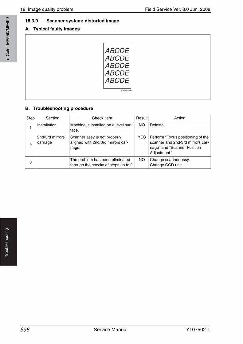
18. Image quality problem Field Service Ver. 8.0 Jun. 2008
698
Tro
ub
lesh
oo
tin
g
18.3.9 Scanner system: distorted image
A. Typical faulty images
B. Troubleshooting procedure
ABCDEABCDEABCDEABCDEABCDE
4036fs4035c0
Step Section Check item Result Action
1Installation Machine is installed on a level sur-
face.NO Reinstall.
2
2nd/3rd mirrors carriage
Scanner assy is not properly aligned with 2nd/3rd mirrors car-riage.
YES Perform “Focus positioning of the scanner and 2nd/3rd mirrors car-riage” and “Scanner Position Adjustment.”
3The problem has been eliminated through the checks of steps up to 2.
NO Change scanner assy.Change CCD unit.
d-C
olor
MF5
50/M
F450
Service Manual Y107502-1
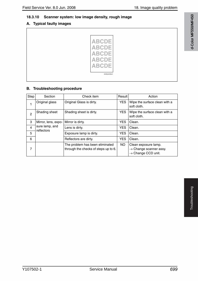
Field Service Ver. 8.0 Jun. 2008 18. Image quality problem
699
Tro
ub
lesh
oo
tin
g
18.3.10 Scanner system: low image density, rough image
A. Typical faulty images
B. Troubleshooting procedure
ABCDEABCDEABCDEABCDEABCDE
4036fs4036c0
Step Section Check item Result Action
1Original glass Original Glass is dirty. YES Wipe the surface clean with a
soft cloth.
2Shading sheet Shading sheet is dirty. YES Wipe the surface clean with a
soft cloth.
3 Mirror, lens, expo-sure lamp, and reflectors
Mirror is dirty. YES Clean.
4 Lens is dirty. YES Clean.
5 Exposure lamp is dirty. YES Clean.
6 Reflectors are dirty. YES Clean.
7The problem has been eliminated through the checks of steps up to 6.
NO Clean exposure lamp. Change scanner assy. Change CCD unit.
d-C
olor
MF5
50/M
F450
Y107502-1 Service Manual
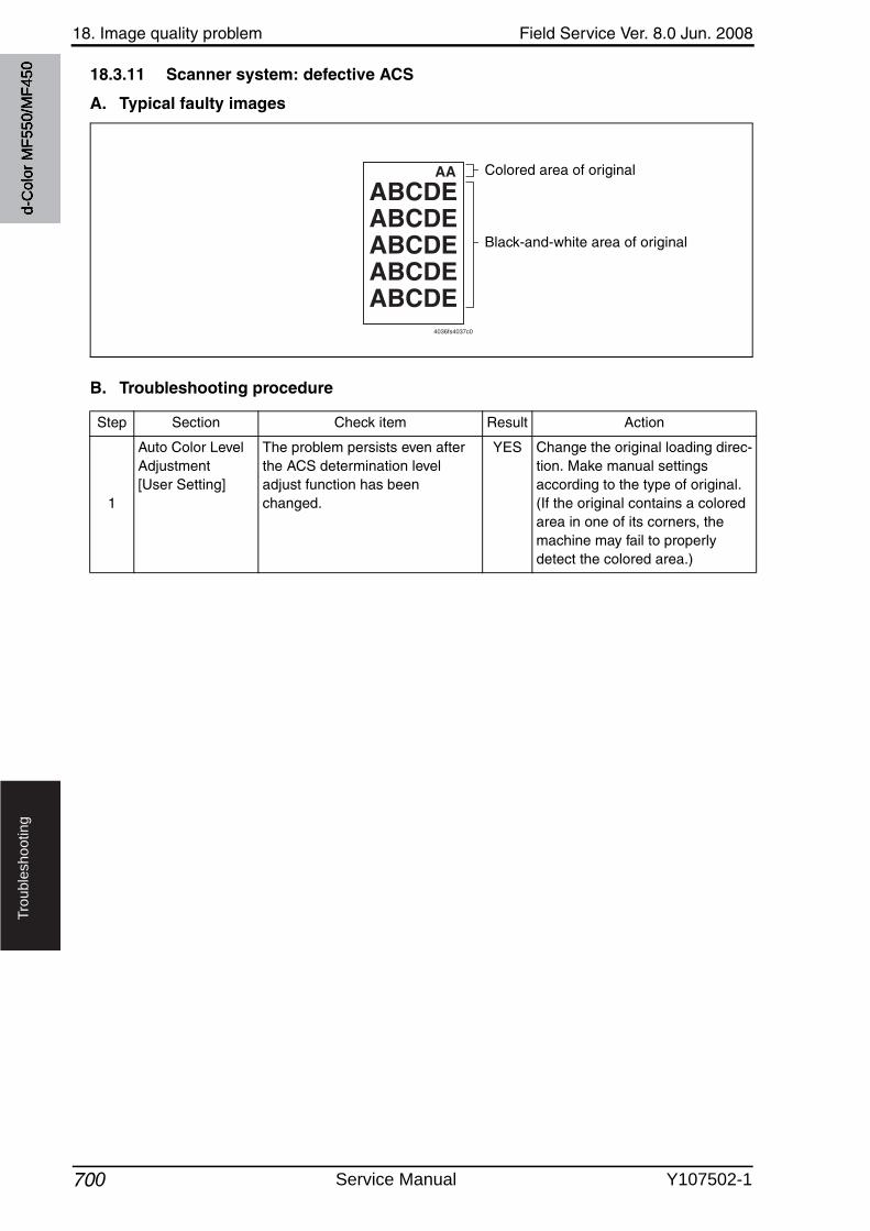
18. Image quality problem Field Service Ver. 8.0 Jun. 2008
700
Tro
ub
lesh
oo
tin
g
18.3.11 Scanner system: defective ACS
A. Typical faulty images
B. Troubleshooting procedure
ABCDEAA
ABCDEABCDEABCDEABCDE
4036fs4037c0
Colored area of original
Black-and-white area of original
Step Section Check item Result Action
1
Auto Color LevelAdjustment [User Setting]
The problem persists even after the ACS determination leveladjust function has been changed.
YES Change the original loading direc-tion. Make manual settings according to the type of original. (If the original contains a colored area in one of its corners, the machine may fail to properly detect the colored area.)
d-C
olor
MF5
50/M
F450
Service Manual Y107502-1
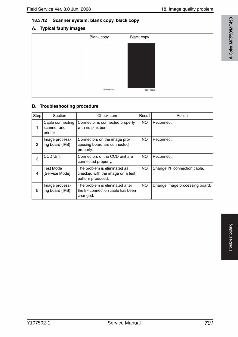
Field Service Ver. 8.0 Jun. 2008 18. Image quality problem
701
Tro
ub
lesh
oo
tin
g
18.3.12 Scanner system: blank copy, black copy
A. Typical faulty images
B. Troubleshooting procedure
4036fs4038c0
Blank copy Black copy
4036fs4039c0
Step Section Check item Result Action
1Cable connecting scanner and printer
Connector is connected properly with no pins bent.
NO Reconnect.
2Image process-ing board (IPB)
Connectors on the image pro-cessing board are connected properly.
NO Reconnect.
3CCD Unit Connectors of the CCD unit are
connected properly.NO Reconnect.
4Test Mode [Service Mode]
The problem is eliminated as checked with the image on a test pattern produced.
NO Change I/F connection cable.
5Image process-ing board (IPB)
The problem is eliminated after the I/F connection cable has been changed.
NO Change image processing board.
d-C
olor
MF5
50/M
F450
Y107502-1 Service Manual
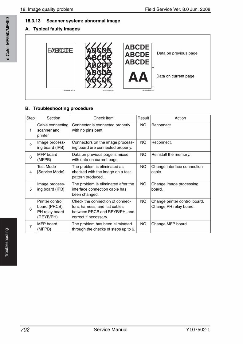
18. Image quality problem Field Service Ver. 8.0 Jun. 2008
702
Tro
ub
lesh
oo
tin
g
18.3.13 Scanner system: abnormal image
A. Typical faulty images
B. Troubleshooting procedure
4036fs4040c0
ABCDEABCDEABCDEABCDEABCDE
4036fs4041c0
AA
ABCDEABCDEABCDE
4036fs4042c0
Data on previous page
Data on current page
Step Section Check item Result Action
1Cable connecting scanner and printer
Connector is connected properly with no pins bent.
NO Reconnect.
2Image process-ing board (IPB)
Connectors on the image process-ing board are connected properly.
NO Reconnect.
3MFP board (MFPB)
Data on previous page is mixed with data on current page.
NO Reinstall the memory.
4Test Mode[Service Mode]
The problem is eliminated as checked with the image on a test pattern produced.
NO Change interface connection cable.
5Image process-ing board (IPB)
The problem is eliminated after the interface connection cable has been changed.
NO Change image processing board.
6
Printer control board (PRCB)PH relay board (REYB/PH)
Check the connection of connec-tors, harness, and flat cables between PRCB and REYB/PH, and correct if necessary.
NO Change printer control board.Change PH relay board.
7MFP board (MFPB)
The problem has been eliminated through the checks of steps up to 6.
NO Change MFP board.
d-C
olor
MF5
50/M
F450
Service Manual Y107502-1
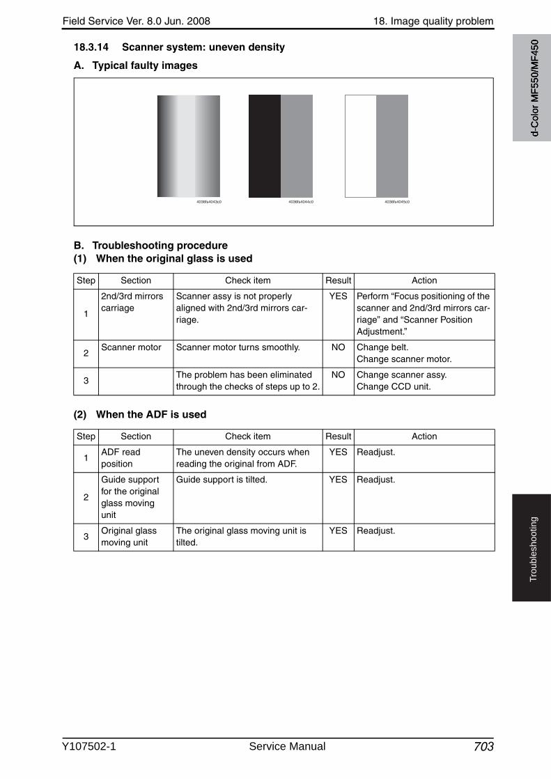
Field Service Ver. 8.0 Jun. 2008 18. Image quality problem
703
Tro
ub
lesh
oo
tin
g
18.3.14 Scanner system: uneven density
A. Typical faulty images
B. Troubleshooting procedure(1) When the original glass is used
(2) When the ADF is used
4036fs4043c0 4036fs4044c0 4036fs4045c0
Step Section Check item Result Action
1
2nd/3rd mirrors carriage
Scanner assy is not properly aligned with 2nd/3rd mirrors car-riage.
YES Perform “Focus positioning of the scanner and 2nd/3rd mirrors car-riage” and “Scanner Position Adjustment.”
2Scanner motor Scanner motor turns smoothly. NO Change belt.
Change scanner motor.
3The problem has been eliminated through the checks of steps up to 2.
NO Change scanner assy.Change CCD unit.
Step Section Check item Result Action
1ADF read position
The uneven density occurs whenreading the original from ADF.
YES Readjust.
2
Guide support for the original glass movingunit
Guide support is tilted. YES Readjust.
3Original glass moving unit
The original glass moving unit is tilted.
YES Readjust.d-
Col
or M
F550
/MF4
50
Y107502-1 Service Manual
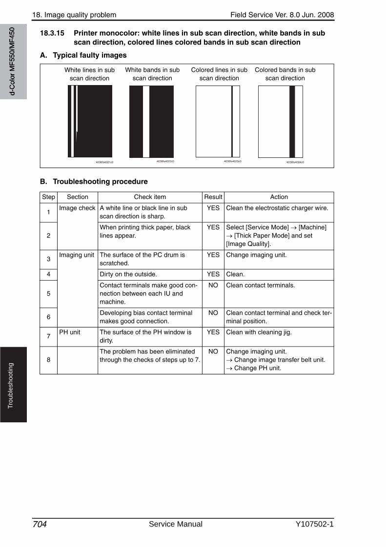
18. Image quality problem Field Service Ver. 8.0 Jun. 2008
704
Tro
ub
lesh
oo
tin
g
18.3.15 Printer monocolor: white lines in sub scan direction, white bands in sub scan direction, colored lines colored bands in sub scan direction
A. Typical faulty images
B. Troubleshooting procedure
White lines in subscan direction
White bands in subscan direction
Colored lines in subscan direction
Colored bands in subscan direction
4036fs4021c0 4036fs4022c0 4036fs4023c0 4036fs4024c0
Step Section Check item Result Action
1Image check A white line or black line in sub
scan direction is sharp.YES Clean the electrostatic charger wire.
2When printing thick paper, black lines appear.
YES Select [Service Mode] [Machine] [Thick Paper Mode] and set
[Image Quality].
3Imaging unit The surface of the PC drum is
scratched.YES Change imaging unit.
4 Dirty on the outside. YES Clean.
5Contact terminals make good con-nection between each IU and machine.
NO Clean contact terminals.
6Developing bias contact terminal makes good connection.
NO Clean contact terminal and check ter-minal position.
7PH unit The surface of the PH window is
dirty.YES Clean with cleaning jig.
8The problem has been eliminated through the checks of steps up to 7.
NO Change imaging unit. Change image transfer belt unit. Change PH unit.
d-C
olor
MF5
50/M
F450
Service Manual Y107502-1
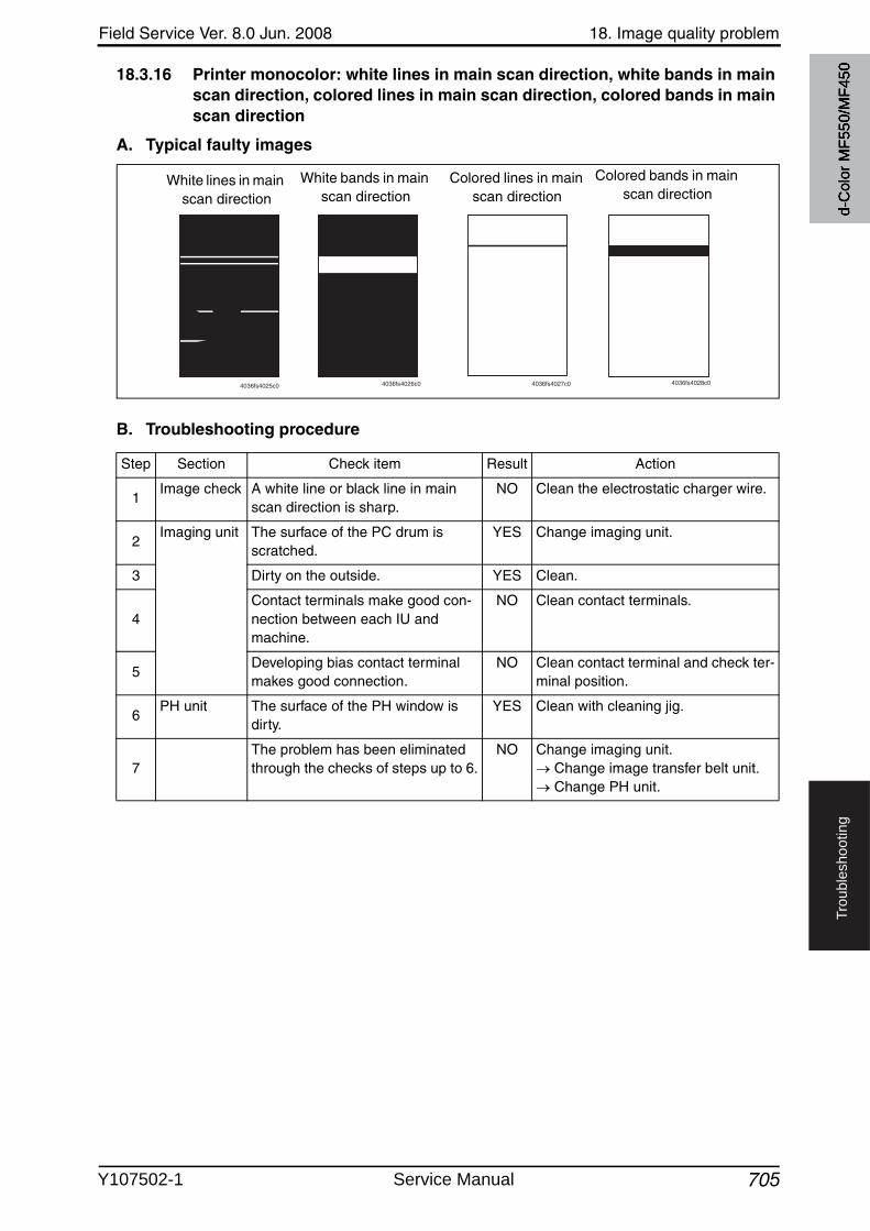
Field Service Ver. 8.0 Jun. 2008 18. Image quality problem
705
Tro
ub
lesh
oo
tin
g
18.3.16 Printer monocolor: white lines in main scan direction, white bands in main scan direction, colored lines in main scan direction, colored bands in main scan direction
A. Typical faulty images
B. Troubleshooting procedure
White lines in main scan direction
White bands in main scan direction
Colored lines in main scan direction
Colored bands in main scan direction
4036fs4025c0 4036fs4026c0 4036fs4027c0 4036fs4028c0
Step Section Check item Result Action
1Image check A white line or black line in main
scan direction is sharp.NO Clean the electrostatic charger wire.
2Imaging unit The surface of the PC drum is
scratched.YES Change imaging unit.
3 Dirty on the outside. YES Clean.
4Contact terminals make good con-nection between each IU and machine.
NO Clean contact terminals.
5Developing bias contact terminal makes good connection.
NO Clean contact terminal and check ter-minal position.
6PH unit The surface of the PH window is
dirty.YES Clean with cleaning jig.
7The problem has been eliminated through the checks of steps up to 6.
NO Change imaging unit. Change image transfer belt unit. Change PH unit.
d-C
olor
MF5
50/M
F450
Y107502-1 Service Manual
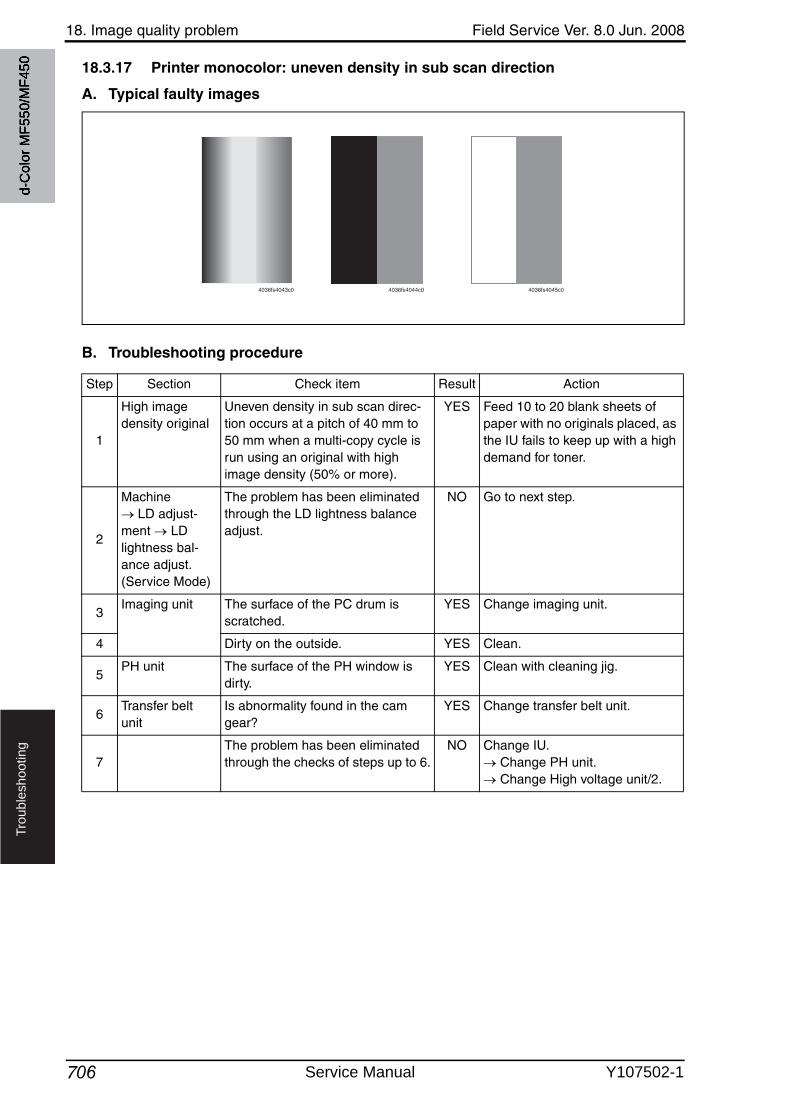
18. Image quality problem Field Service Ver. 8.0 Jun. 2008
706
Tro
ub
lesh
oo
tin
g
18.3.17 Printer monocolor: uneven density in sub scan direction
A. Typical faulty images
B. Troubleshooting procedure
4036fs4043c0 4036fs4044c0 4036fs4045c0
Step Section Check item Result Action
1
High image density original
Uneven density in sub scan direc-tion occurs at a pitch of 40 mm to 50 mm when a multi-copy cycle is run using an original with high image density (50% or more).
YES Feed 10 to 20 blank sheets of paper with no originals placed, as the IU fails to keep up with a high demand for toner.
2
Machine LD adjust-
ment LD lightness bal-ance adjust. (Service Mode)
The problem has been eliminated through the LD lightness balance adjust.
NO Go to next step.
3Imaging unit The surface of the PC drum is
scratched.YES Change imaging unit.
4 Dirty on the outside. YES Clean.
5PH unit The surface of the PH window is
dirty.YES Clean with cleaning jig.
6Transfer belt unit
Is abnormality found in the cam gear?
YES Change transfer belt unit.
7The problem has been eliminated through the checks of steps up to 6.
NO Change IU. Change PH unit. Change High voltage unit/2.
d-C
olor
MF5
50/M
F450
Service Manual Y107502-1
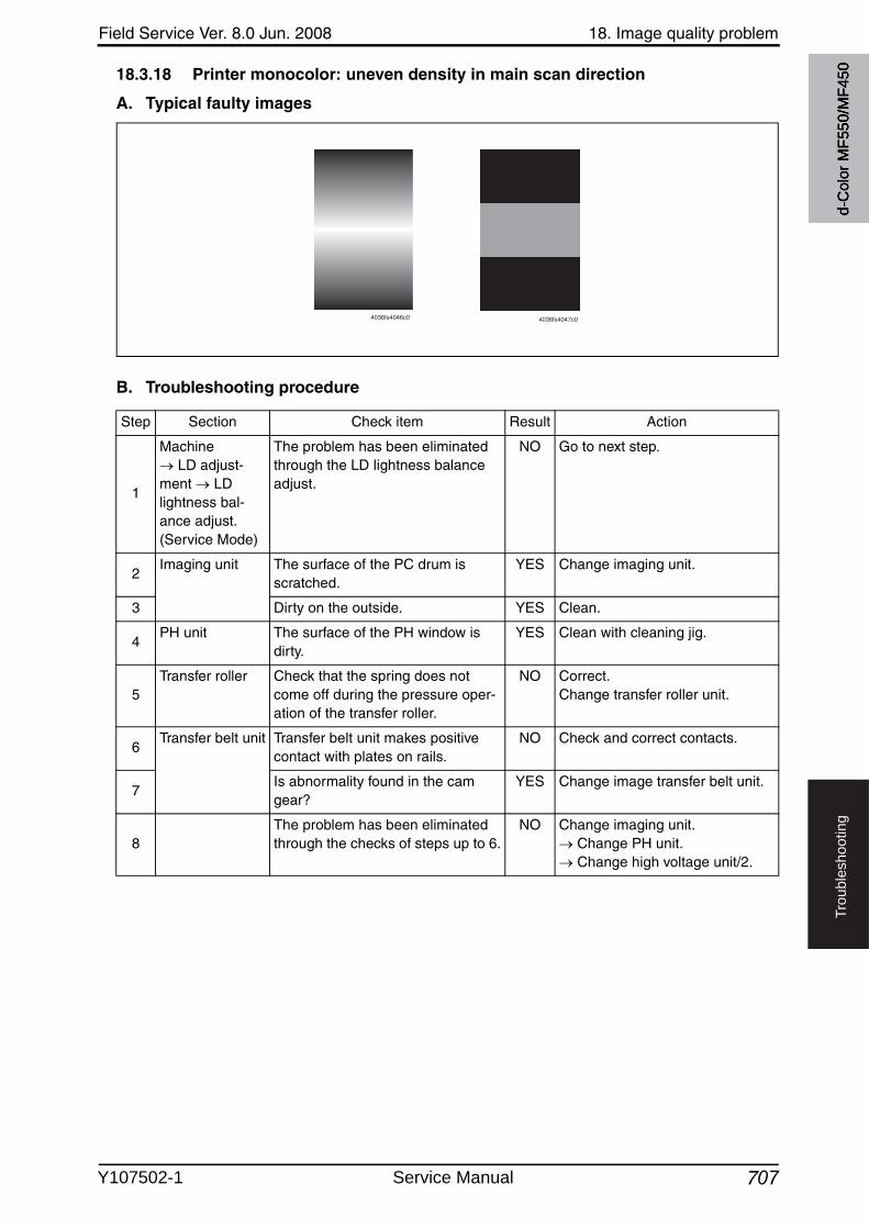
Field Service Ver. 8.0 Jun. 2008 18. Image quality problem
707
Tro
ub
lesh
oo
tin
g
18.3.18 Printer monocolor: uneven density in main scan direction
A. Typical faulty images
B. Troubleshooting procedure
4036fs4046c0 4036fs4047c0
Step Section Check item Result Action
1
Machine LD adjust-
ment LD lightness bal-ance adjust. (Service Mode)
The problem has been eliminated through the LD lightness balance adjust.
NO Go to next step.
2Imaging unit The surface of the PC drum is
scratched.YES Change imaging unit.
3 Dirty on the outside. YES Clean.
4PH unit The surface of the PH window is
dirty.YES Clean with cleaning jig.
5Transfer roller Check that the spring does not
come off during the pressure oper-ation of the transfer roller.
NO Correct.Change transfer roller unit.
6Transfer belt unit Transfer belt unit makes positive
contact with plates on rails.NO Check and correct contacts.
7Is abnormality found in the cam gear?
YES Change image transfer belt unit.
8The problem has been eliminated through the checks of steps up to 6.
NO Change imaging unit. Change PH unit. Change high voltage unit/2.
d-C
olor
MF5
50/M
F450
Y107502-1 Service Manual
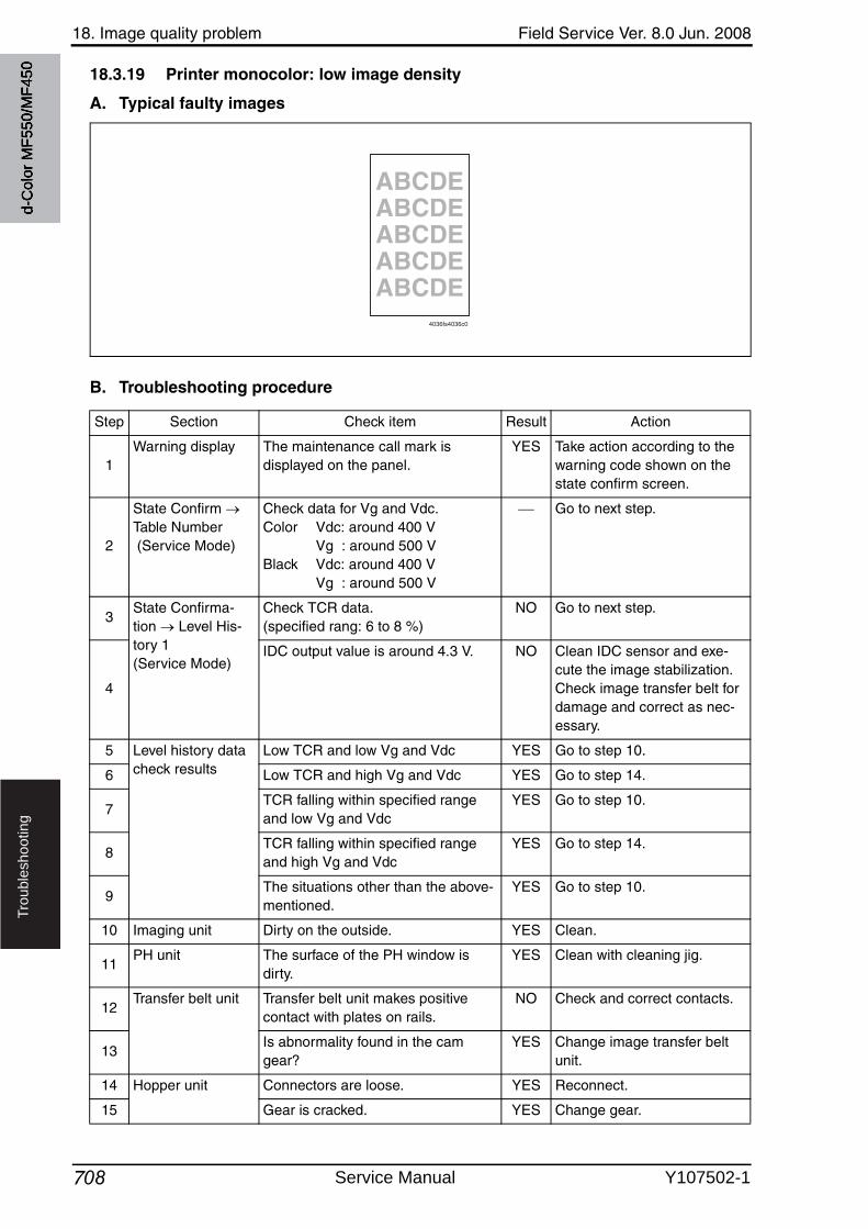
18. Image quality problem Field Service Ver. 8.0 Jun. 2008
708
Tro
ub
lesh
oo
tin
g
18.3.19 Printer monocolor: low image density
A. Typical faulty images
B. Troubleshooting procedure
ABCDEABCDEABCDEABCDEABCDE
4036fs4036c0
Step Section Check item Result Action
1Warning display The maintenance call mark is
displayed on the panel.YES Take action according to the
warning code shown on the state confirm screen.
2
State Confirm Table Number (Service Mode)
Check data for Vg and Vdc.Color Vdc: around 400 V
Vg : around 500 VBlack Vdc: around 400 V
Vg : around 500 V
Go to next step.
3State Confirma-tion Level His-tory 1 (Service Mode)
Check TCR data.(specified rang: 6 to 8 %)
NO Go to next step.
4
IDC output value is around 4.3 V. NO Clean IDC sensor and exe-cute the image stabilization.Check image transfer belt for damage and correct as nec-essary.
5 Level history data check results
Low TCR and low Vg and Vdc YES Go to step 10.
6 Low TCR and high Vg and Vdc YES Go to step 14.
7TCR falling within specified range and low Vg and Vdc
YES Go to step 10.
8TCR falling within specified range and high Vg and Vdc
YES Go to step 14.
9The situations other than the above-mentioned.
YES Go to step 10.
10 Imaging unit Dirty on the outside. YES Clean.
11PH unit The surface of the PH window is
dirty.YES Clean with cleaning jig.
12Transfer belt unit Transfer belt unit makes positive
contact with plates on rails.NO Check and correct contacts.
13Is abnormality found in the cam gear?
YES Change image transfer belt unit.
14 Hopper unit Connectors are loose. YES Reconnect.
15 Gear is cracked. YES Change gear.
d-C
olor
MF5
50/M
F450
Service Manual Y107502-1
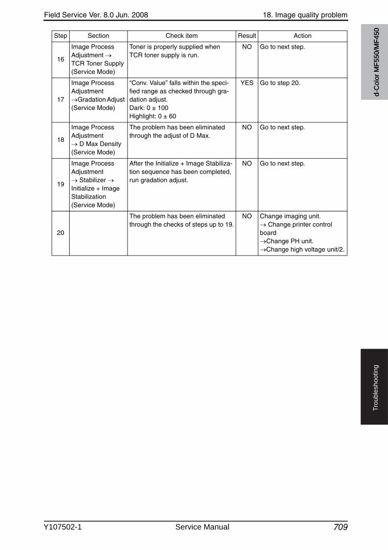
Field Service Ver. 8.0 Jun. 2008 18. Image quality problem
709
Tro
ub
lesh
oo
tin
g
16
Image Process Adjustment TCR Toner Supply(Service Mode)
Toner is properly supplied when TCR toner supply is run.
NO Go to next step.
17
Image Process Adjustment
Gradation Adjust(Service Mode)
“Conv. Value” falls within the speci-fied range as checked through gra-dation adjust.Dark: 0 ± 100Highlight: 0 ± 60
YES Go to step 20.
18
Image Process Adjustment
D Max Density (Service Mode)
The problem has been eliminated through the adjust of D Max.
NO Go to next step.
19
Image Process Adjustment
Stabilizer Initialize + Image Stabilization (Service Mode)
After the Initialize + Image Stabiliza-tion sequence has been completed, run gradation adjust.
NO Go to next step.
20
The problem has been eliminated through the checks of steps up to 19.
NO Change imaging unit. Change printer control
boardChange PH unit.Change high voltage unit/2.
Step Section Check item Result Action
d-C
olor
MF5
50/M
F450
Y107502-1 Service Manual
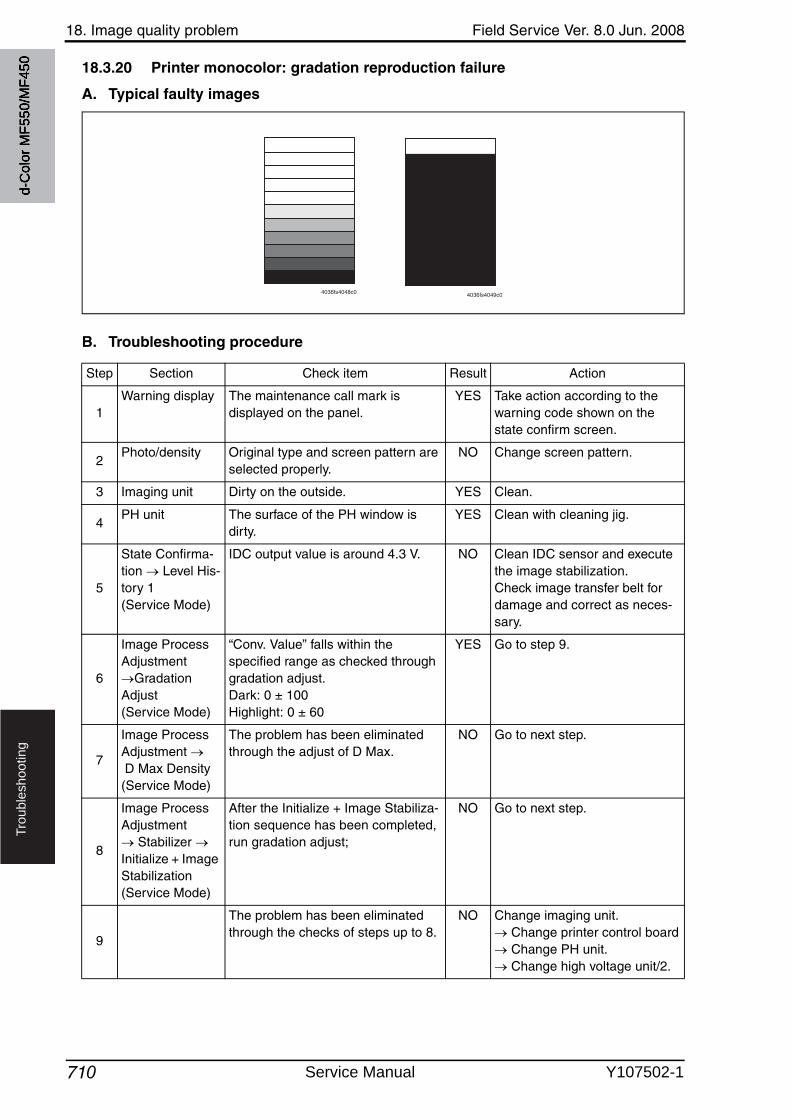
18. Image quality problem Field Service Ver. 8.0 Jun. 2008
710
Tro
ub
lesh
oo
tin
g
18.3.20 Printer monocolor: gradation reproduction failure
A. Typical faulty images
B. Troubleshooting procedure
4036fs4048c0 4036fs4049c0
Step Section Check item Result Action
1Warning display The maintenance call mark is
displayed on the panel.YES Take action according to the
warning code shown on the state confirm screen.
2Photo/density Original type and screen pattern are
selected properly.NO Change screen pattern.
3 Imaging unit Dirty on the outside. YES Clean.
4PH unit The surface of the PH window is
dirty.YES Clean with cleaning jig.
5
State Confirma-tion Level His-tory 1 (Service Mode)
IDC output value is around 4.3 V. NO Clean IDC sensor and executethe image stabilization.Check image transfer belt for damage and correct as neces-sary.
6
Image Process Adjustment
Gradation Adjust (Service Mode)
“Conv. Value” falls within the specified range as checked throughgradation adjust.Dark: 0 ± 100Highlight: 0 ± 60
YES Go to step 9.
7
Image Process Adjustment D Max Density (Service Mode)
The problem has been eliminated through the adjust of D Max.
NO Go to next step.
8
Image Process Adjustment
Stabilizer Initialize + Image Stabilization (Service Mode)
After the Initialize + Image Stabiliza-tion sequence has been completed, run gradation adjust;
NO Go to next step.
9
The problem has been eliminated through the checks of steps up to 8.
NO Change imaging unit. Change printer control board Change PH unit. Change high voltage unit/2.
d-C
olor
MF5
50/M
F450
Service Manual Y107502-1
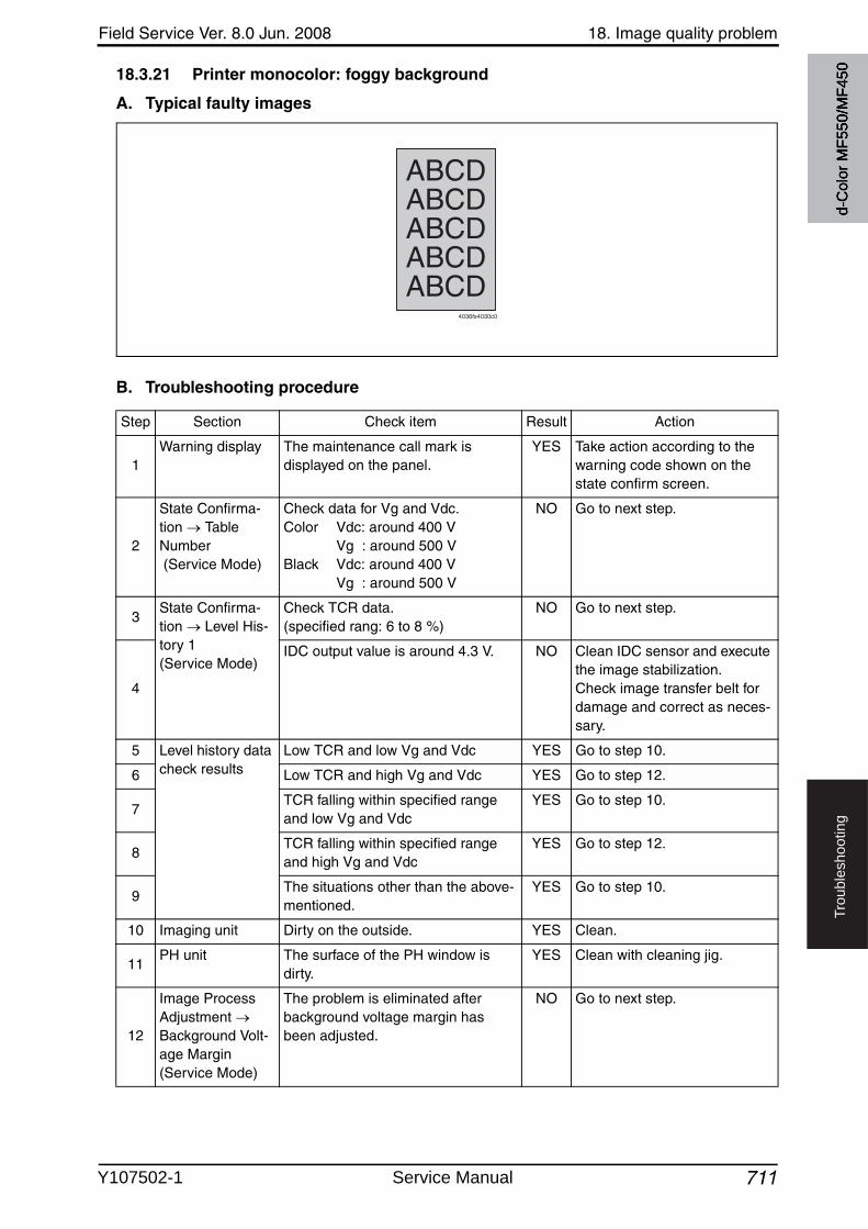
Field Service Ver. 8.0 Jun. 2008 18. Image quality problem
711
Tro
ub
lesh
oo
tin
g
18.3.21 Printer monocolor: foggy background
A. Typical faulty images
B. Troubleshooting procedure
4036fs4030c0
ABCDABCDABCDABCDABCD
Step Section Check item Result Action
1Warning display The maintenance call mark is
displayed on the panel.YES Take action according to the
warning code shown on the state confirm screen.
2
State Confirma-tion Table Number (Service Mode)
Check data for Vg and Vdc.Color Vdc: around 400 V
Vg : around 500 VBlack Vdc: around 400 V
Vg : around 500 V
NO Go to next step.
3State Confirma-tion Level His-tory 1 (Service Mode)
Check TCR data.(specified rang: 6 to 8 %)
NO Go to next step.
4
IDC output value is around 4.3 V. NO Clean IDC sensor and execute the image stabilization.Check image transfer belt for damage and correct as neces-sary.
5 Level history data check results
Low TCR and low Vg and Vdc YES Go to step 10.
6 Low TCR and high Vg and Vdc YES Go to step 12.
7TCR falling within specified range and low Vg and Vdc
YES Go to step 10.
8TCR falling within specified range and high Vg and Vdc
YES Go to step 12.
9The situations other than the above-mentioned.
YES Go to step 10.
10 Imaging unit Dirty on the outside. YES Clean.
11PH unit The surface of the PH window is
dirty.YES Clean with cleaning jig.
12
Image Process Adjustment Background Volt-age Margin (Service Mode)
The problem is eliminated after background voltage margin has been adjusted.
NO Go to next step.
d-C
olor
MF5
50/M
F450
Y107502-1 Service Manual
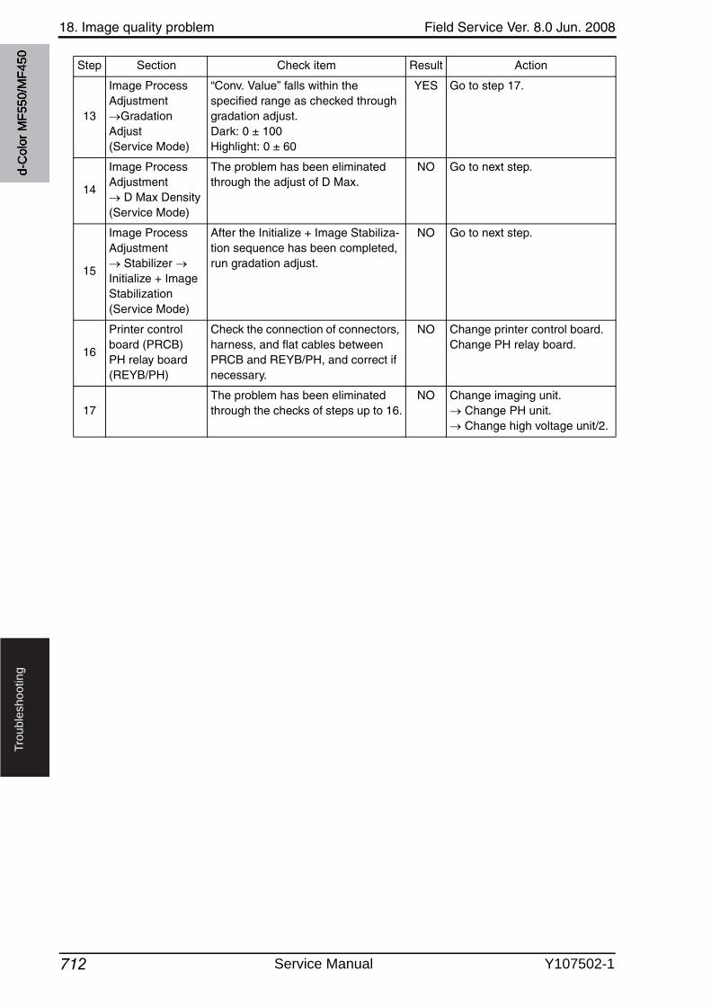
18. Image quality problem Field Service Ver. 8.0 Jun. 2008
712
Tro
ub
lesh
oo
tin
g
13
Image Process Adjustment
Gradation Adjust (Service Mode)
“Conv. Value” falls within the specified range as checked throughgradation adjust.Dark: 0 ± 100Highlight: 0 ± 60
YES Go to step 17.
14
Image Process Adjustment
D Max Density (Service Mode)
The problem has been eliminated through the adjust of D Max.
NO Go to next step.
15
Image Process Adjustment
Stabilizer Initialize + Image Stabilization (Service Mode)
After the Initialize + Image Stabiliza-tion sequence has been completed, run gradation adjust.
NO Go to next step.
16
Printer control board (PRCB)PH relay board (REYB/PH)
Check the connection of connectors, harness, and flat cables between PRCB and REYB/PH, and correct if necessary.
NO Change printer control board.Change PH relay board.
17The problem has been eliminated through the checks of steps up to 16.
NO Change imaging unit. Change PH unit. Change high voltage unit/2.
Step Section Check item Result Action
d-C
olor
MF5
50/M
F450
Service Manual Y107502-1
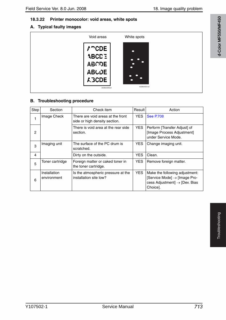
Field Service Ver. 8.0 Jun. 2008 18. Image quality problem
713
Tro
ub
lesh
oo
tin
g
18.3.22 Printer monocolor: void areas, white spots
A. Typical faulty images
B. Troubleshooting procedure
4036fs4050c04036fs4051c0
Void areas White spots
Step Section Check item Result Action
1Image Check There are void areas at the front
side or high density section.YES See P.708
2There is void area at the rear side section.
YES Perform [Transfer Adjust] of [Image Process Adjustment] under Service Mode.
3Imaging unit The surface of the PC drum is
scratched.YES Change imaging unit.
4 Dirty on the outside. YES Clean.
5Toner cartridge Foreign matter or caked toner in
the toner cartridge.YES Remove foreign matter.
6
Installation environment
Is the atmospheric pressure at the installation site low?
YES Make the following adjustment: [Service Mode] [Image Pro-cess Adjustment] [Dev. Bias Choice].
d-C
olor
MF5
50/M
F450
Y107502-1 Service Manual
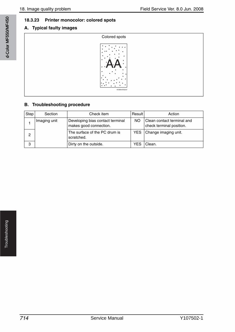
18. Image quality problem Field Service Ver. 8.0 Jun. 2008
714
Tro
ub
lesh
oo
tin
g
18.3.23 Printer monocolor: colored spots
A. Typical faulty images
B. Troubleshooting procedure
AA
4036fs4052c0
Colored spots
Step Section Check item Result Action
1Imaging unit Developing bias contact terminal
makes good connection.NO Clean contact terminal and
check terminal position.
2The surface of the PC drum is scratched.
YES Change imaging unit.
3 Dirty on the outside. YES Clean.
d-C
olor
MF5
50/M
F450
Service Manual Y107502-1
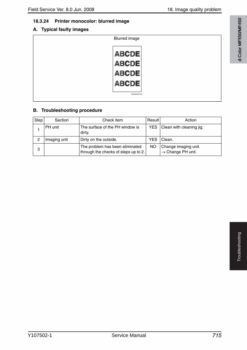
Field Service Ver. 8.0 Jun. 2008 18. Image quality problem
715
Tro
ub
lesh
oo
tin
g
18.3.24 Printer monocolor: blurred image
A. Typical faulty images
B. Troubleshooting procedure
4036fs4031c0
Blurred image
Step Section Check item Result Action
1PH unit The surface of the PH window is
dirty.YES Clean with cleaning jig.
2 Imaging unit Dirty on the outside. YES Clean.
3The problem has been eliminated through the checks of steps up to 2.
NO Change imaging unit. Change PH unit.
d-C
olor
MF5
50/M
F450
Y107502-1 Service Manual
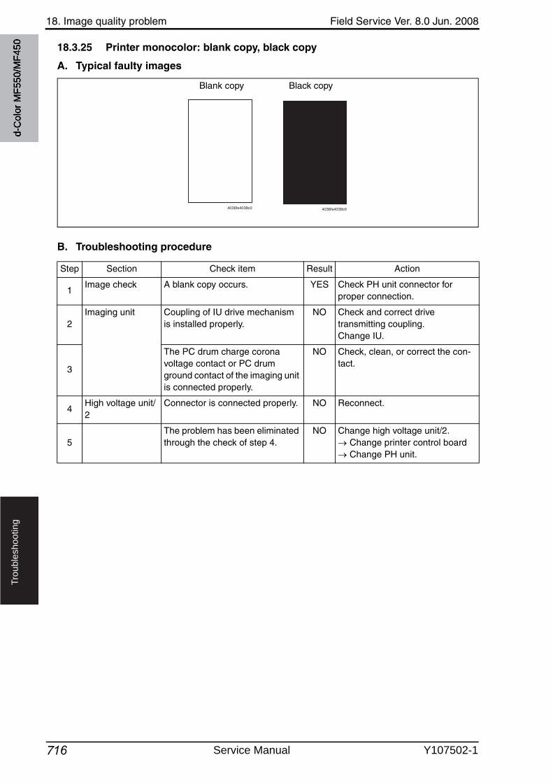
18. Image quality problem Field Service Ver. 8.0 Jun. 2008
716
Tro
ub
lesh
oo
tin
g
18.3.25 Printer monocolor: blank copy, black copy
A. Typical faulty images
B. Troubleshooting procedure
Blank copy Black copy
4036fs4038c0 4036fs4039c0
Step Section Check item Result Action
1Image check A blank copy occurs. YES Check PH unit connector for
proper connection.
2Imaging unit Coupling of IU drive mechanism
is installed properly.NO Check and correct drive
transmitting coupling. Change IU.
3
The PC drum charge corona voltage contact or PC drumground contact of the imaging unit is connected properly.
NO Check, clean, or correct the con-tact.
4High voltage unit/2
Connector is connected properly. NO Reconnect.
5The problem has been eliminated through the check of step 4.
NO Change high voltage unit/2. Change printer control board Change PH unit.
d-C
olor
MF5
50/M
F450
Service Manual Y107502-1
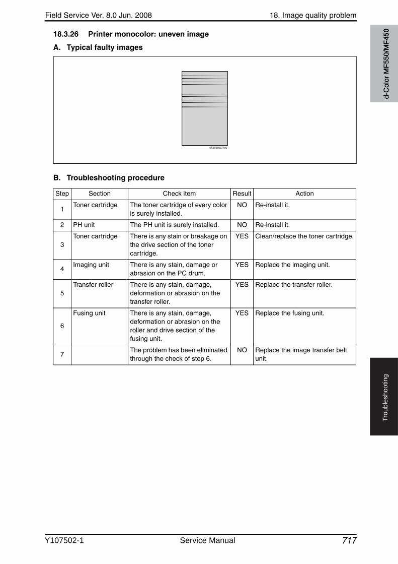
Field Service Ver. 8.0 Jun. 2008 18. Image quality problem
717
Tro
ub
lesh
oo
tin
g
18.3.26 Printer monocolor: uneven image
A. Typical faulty images
B. Troubleshooting procedure
4138fs4507c0
Step Section Check item Result Action
1Toner cartridge The toner cartridge of every color
is surely installed.NO Re-install it.
2 PH unit The PH unit is surely installed. NO Re-install it.
3Toner cartridge There is any stain or breakage on
the drive section of the toner cartridge.
YES Clean/replace the toner cartridge.
4Imaging unit There is any stain, damage or
abrasion on the PC drum.YES Replace the imaging unit.
5Transfer roller There is any stain, damage,
deformation or abrasion on the transfer roller.
YES Replace the transfer roller.
6
Fusing unit There is any stain, damage, deformation or abrasion on the roller and drive section of the fusing unit.
YES Replace the fusing unit.
7The problem has been eliminated through the check of step 6.
NO Replace the image transfer belt unit.
d-C
olor
MF5
50/M
F450
Y107502-1 Service Manual
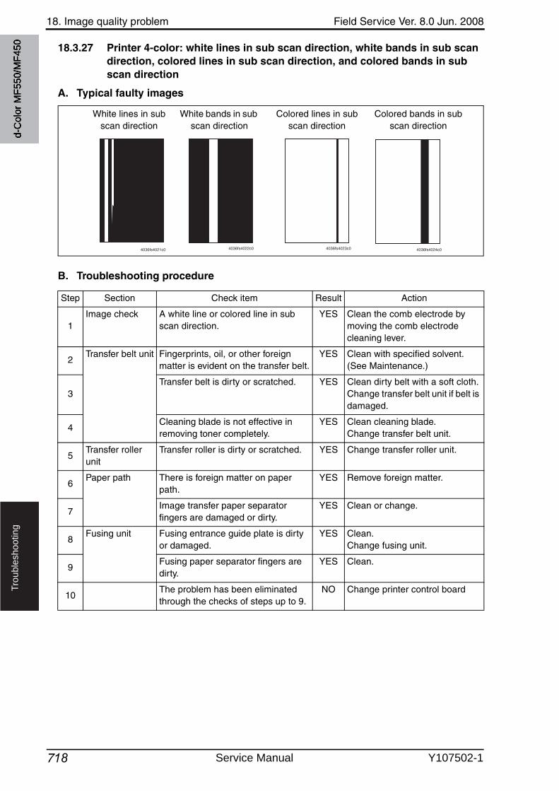
18. Image quality problem Field Service Ver. 8.0 Jun. 2008
718
Tro
ub
lesh
oo
tin
g
18.3.27 Printer 4-color: white lines in sub scan direction, white bands in sub scan direction, colored lines in sub scan direction, and colored bands in sub scan direction
A. Typical faulty images
B. Troubleshooting procedure
White lines in subscan direction
White bands in subscan direction
Colored bands in subscan direction
Colored lines in subscan direction
4036fs4021c0 4036fs4022c0 4036fs4023c0 4036fs4024c0
Step Section Check item Result Action
1Image check A white line or colored line in sub
scan direction.YES Clean the comb electrode by
moving the comb electrode cleaning lever.
2Transfer belt unit Fingerprints, oil, or other foreign
matter is evident on the transfer belt.YES Clean with specified solvent.
(See Maintenance.)
3Transfer belt is dirty or scratched. YES Clean dirty belt with a soft cloth.
Change transfer belt unit if belt is damaged.
4Cleaning blade is not effective in removing toner completely.
YES Clean cleaning blade.Change transfer belt unit.
5Transfer roller unit
Transfer roller is dirty or scratched. YES Change transfer roller unit.
6Paper path There is foreign matter on paper
path.YES Remove foreign matter.
7Image transfer paper separator fingers are damaged or dirty.
YES Clean or change.
8Fusing unit Fusing entrance guide plate is dirty
or damaged.YES Clean.
Change fusing unit.
9Fusing paper separator fingers are dirty.
YES Clean.
10The problem has been eliminated through the checks of steps up to 9.
NO Change printer control board
d-C
olor
MF5
50/M
F450
Service Manual Y107502-1
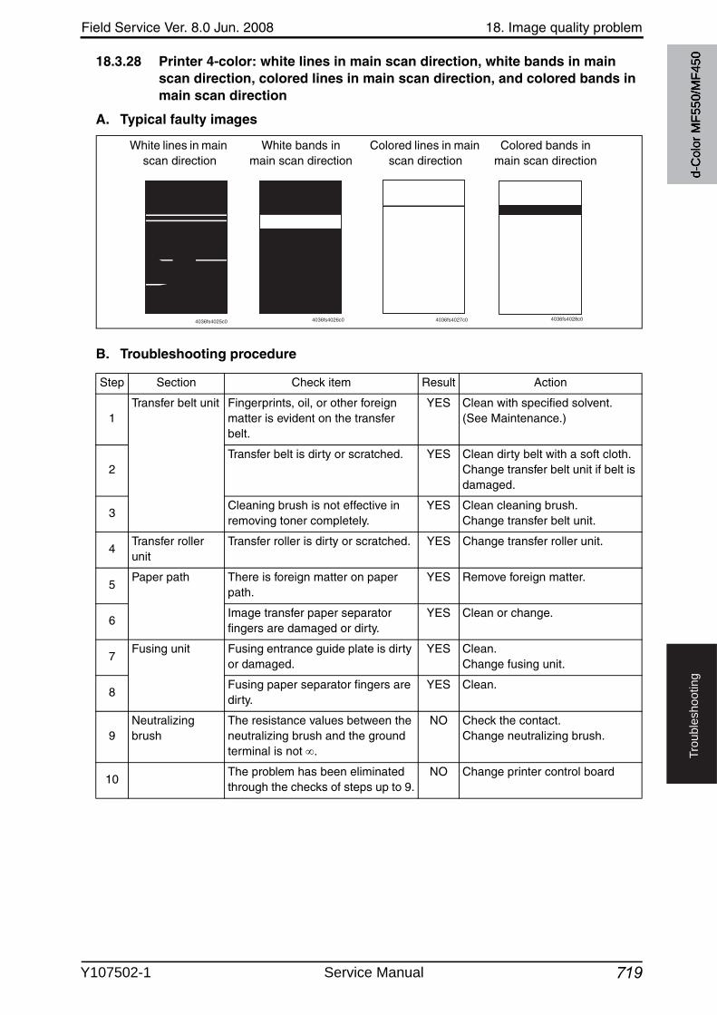
Field Service Ver. 8.0 Jun. 2008 18. Image quality problem
719
Tro
ub
lesh
oo
tin
g
18.3.28 Printer 4-color: white lines in main scan direction, white bands in main scan direction, colored lines in main scan direction, and colored bands in main scan direction
A. Typical faulty images
B. Troubleshooting procedure
White lines in main scan direction
White bands in main scan direction
Colored lines in main scan direction
Colored bands in main scan direction
4036fs4025c0 4036fs4026c0 4036fs4027c0 4036fs4028c0
Step Section Check item Result Action
1Transfer belt unit Fingerprints, oil, or other foreign
matter is evident on the transfer belt.
YES Clean with specified solvent. (See Maintenance.)
2Transfer belt is dirty or scratched. YES Clean dirty belt with a soft cloth.
Change transfer belt unit if belt is damaged.
3Cleaning brush is not effective in removing toner completely.
YES Clean cleaning brush.Change transfer belt unit.
4Transfer roller unit
Transfer roller is dirty or scratched. YES Change transfer roller unit.
5Paper path There is foreign matter on paper
path.YES Remove foreign matter.
6Image transfer paper separator fingers are damaged or dirty.
YES Clean or change.
7Fusing unit Fusing entrance guide plate is dirty
or damaged.YES Clean.
Change fusing unit.
8Fusing paper separator fingers are dirty.
YES Clean.
9Neutralizing brush
The resistance values between the neutralizing brush and the ground terminal is not .
NO Check the contact.Change neutralizing brush.
10The problem has been eliminated through the checks of steps up to 9.
NO Change printer control board
d-C
olor
MF5
50/M
F450
Y107502-1 Service Manual
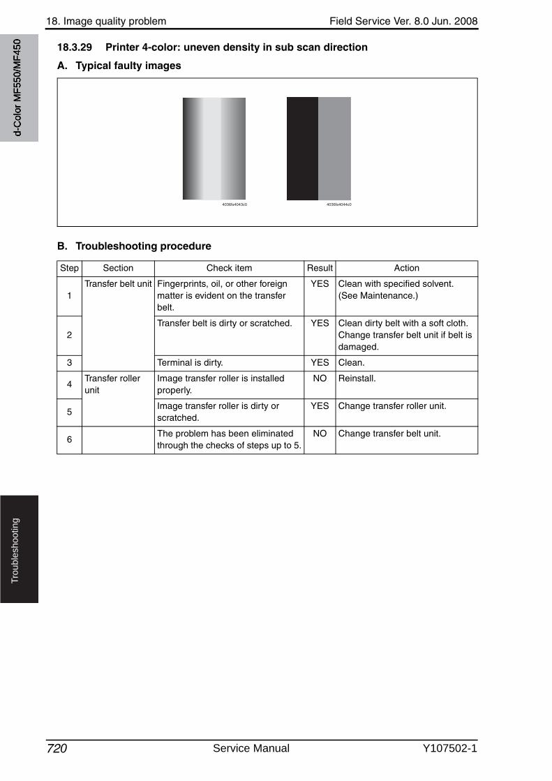
18. Image quality problem Field Service Ver. 8.0 Jun. 2008
720
Tro
ub
lesh
oo
tin
g
18.3.29 Printer 4-color: uneven density in sub scan direction
A. Typical faulty images
B. Troubleshooting procedure
4036fs4043c0 4036fs4044c0
Step Section Check item Result Action
1Transfer belt unit Fingerprints, oil, or other foreign
matter is evident on the transfer belt.
YES Clean with specified solvent.(See Maintenance.)
2Transfer belt is dirty or scratched. YES Clean dirty belt with a soft cloth.
Change transfer belt unit if belt is damaged.
3 Terminal is dirty. YES Clean.
4Transfer roller unit
Image transfer roller is installed properly.
NO Reinstall.
5Image transfer roller is dirty or scratched.
YES Change transfer roller unit.
6The problem has been eliminated through the checks of steps up to 5.
NO Change transfer belt unit.
d-C
olor
MF5
50/M
F450
Service Manual Y107502-1
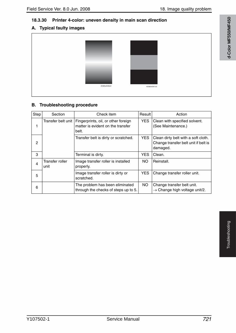
Field Service Ver. 8.0 Jun. 2008 18. Image quality problem
721
Tro
ub
lesh
oo
tin
g
18.3.30 Printer 4-color: uneven density in main scan direction
A. Typical faulty images
B. Troubleshooting procedure
4036fs4046c0 4036fs4047c0
Step Section Check item Result Action
1Transfer belt unit Fingerprints, oil, or other foreign
matter is evident on the transfer belt.
YES Clean with specified solvent.(See Maintenance.)
2Transfer belt is dirty or scratched. YES Clean dirty belt with a soft cloth.
Change transfer belt unit if belt is damaged.
3 Terminal is dirty. YES Clean.
4Transfer roller unit
Image transfer roller is installed properly.
NO Reinstall.
5Image transfer roller is dirty or scratched.
YES Change transfer roller unit.
6The problem has been eliminated through the checks of steps up to 5.
NO Change transfer belt unit. Change high voltage unit/2.
d-C
olor
MF5
50/M
F450
Y107502-1 Service Manual
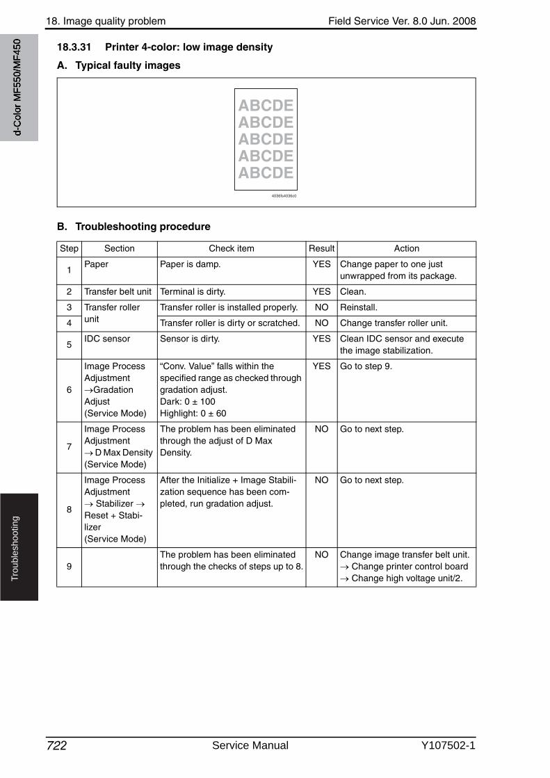
18. Image quality problem Field Service Ver. 8.0 Jun. 2008
722
Tro
ub
lesh
oo
tin
g
18.3.31 Printer 4-color: low image density
A. Typical faulty images
B. Troubleshooting procedure
ABCDEABCDEABCDEABCDEABCDE
4036fs4036c0
Step Section Check item Result Action
1Paper Paper is damp. YES Change paper to one just
unwrapped from its package.
2 Transfer belt unit Terminal is dirty. YES Clean.
3 Transfer roller unit
Transfer roller is installed properly. NO Reinstall.
4 Transfer roller is dirty or scratched. NO Change transfer roller unit.
5IDC sensor Sensor is dirty. YES Clean IDC sensor and execute
the image stabilization.
6
Image Process Adjustment
Gradation Adjust (Service Mode)
“Conv. Value” falls within the specified range as checked through gradation adjust.Dark: 0 ± 100Highlight: 0 ± 60
YES Go to step 9.
7
Image Process Adjustment
D Max Density (Service Mode)
The problem has been eliminated through the adjust of D Max Density.
NO Go to next step.
8
Image Process Adjustment
Stabilizer Reset + Stabi-lizer (Service Mode)
After the Initialize + Image Stabili-zation sequence has been com-pleted, run gradation adjust.
NO Go to next step.
9The problem has been eliminated through the checks of steps up to 8.
NO Change image transfer belt unit. Change printer control board Change high voltage unit/2.
d-C
olor
MF5
50/M
F450
Service Manual Y107502-1
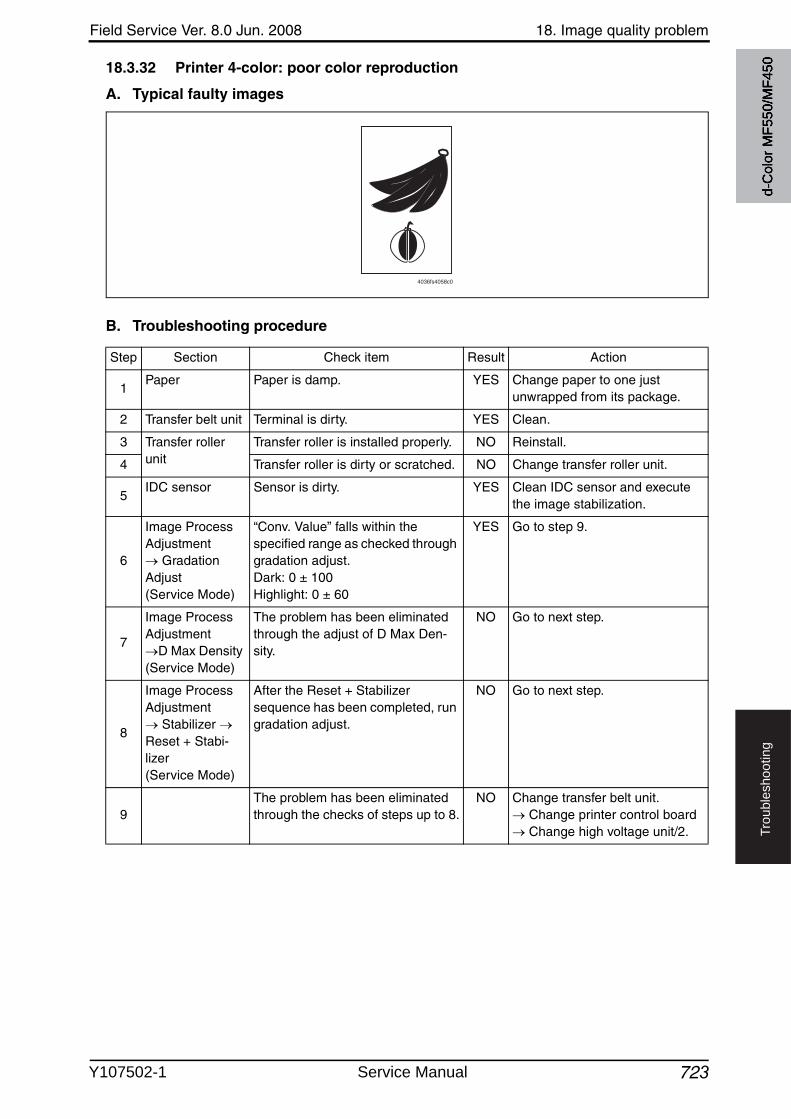
Field Service Ver. 8.0 Jun. 2008 18. Image quality problem
723
Tro
ub
lesh
oo
tin
g
18.3.32 Printer 4-color: poor color reproduction
A. Typical faulty images
B. Troubleshooting procedure
4036fs4058c0
Step Section Check item Result Action
1Paper Paper is damp. YES Change paper to one just
unwrapped from its package.
2 Transfer belt unit Terminal is dirty. YES Clean.
3 Transfer roller unit
Transfer roller is installed properly. NO Reinstall.
4 Transfer roller is dirty or scratched. NO Change transfer roller unit.
5IDC sensor Sensor is dirty. YES Clean IDC sensor and execute
the image stabilization.
6
Image Process Adjustment
Gradation Adjust(Service Mode)
“Conv. Value” falls within the specified range as checked throughgradation adjust.Dark: 0 ± 100Highlight: 0 ± 60
YES Go to step 9.
7
Image Process Adjustment
D Max Density (Service Mode)
The problem has been eliminated through the adjust of D Max Den-sity.
NO Go to next step.
8
Image Process Adjustment
Stabilizer Reset + Stabi-lizer (Service Mode)
After the Reset + Stabilizer sequence has been completed, rungradation adjust.
NO Go to next step.
9The problem has been eliminated through the checks of steps up to 8.
NO Change transfer belt unit. Change printer control board Change high voltage unit/2.
d-C
olor
MF5
50/M
F450
Y107502-1 Service Manual
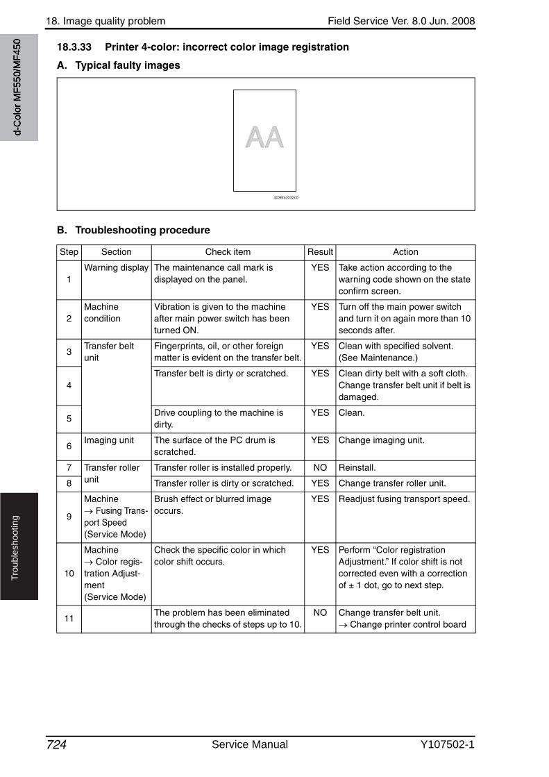
18. Image quality problem Field Service Ver. 8.0 Jun. 2008
724
Tro
ub
lesh
oo
tin
g
18.3.33 Printer 4-color: incorrect color image registration
A. Typical faulty images
B. Troubleshooting procedure
AAAA
4036fs4032c0
Step Section Check item Result Action
1Warning display The maintenance call mark is
displayed on the panel.YES Take action according to the
warning code shown on the state confirm screen.
2Machine condition
Vibration is given to the machine after main power switch has been turned ON.
YES Turn off the main power switchand turn it on again more than 10 seconds after.
3Transfer belt unit
Fingerprints, oil, or other foreign matter is evident on the transfer belt.
YES Clean with specified solvent. (See Maintenance.)
4Transfer belt is dirty or scratched. YES Clean dirty belt with a soft cloth.
Change transfer belt unit if belt is damaged.
5Drive coupling to the machine is dirty.
YES Clean.
6Imaging unit The surface of the PC drum is
scratched.YES Change imaging unit.
7 Transfer roller unit
Transfer roller is installed properly. NO Reinstall.
8 Transfer roller is dirty or scratched. YES Change transfer roller unit.
9
MachineFusing Trans-
port Speed (Service Mode)
Brush effect or blurred image occurs.
YES Readjust fusing transport speed.
10
Machine Color regis-
tration Adjust-ment (Service Mode)
Check the specific color in whichcolor shift occurs.
YES Perform “Color registration Adjustment.” If color shift is not corrected even with a correction of ± 1 dot, go to next step.
11The problem has been eliminated through the checks of steps up to 10.
NO Change transfer belt unit. Change printer control board
d-C
olor
MF5
50/M
F450
Service Manual Y107502-1
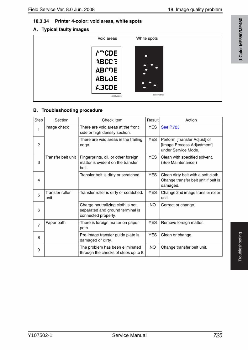
Field Service Ver. 8.0 Jun. 2008 18. Image quality problem
725
Tro
ub
lesh
oo
tin
g
18.3.34 Printer 4-color: void areas, white spots
A. Typical faulty images
B. Troubleshooting procedure
Void areas White spots
4036fs4050c04036fs4051c0
Step Section Check item Result Action
1Image check There are void areas at the front
side or high density section.YES See P.723
2There are void areas in the trailing edge.
YES Perform [Transfer Adjust] of [Image Process Adjustment] under Service Mode.
3Transfer belt unit Fingerprints, oil, or other foreign
matter is evident on the transfer belt.
YES Clean with specified solvent. (See Maintenance.)
4Transfer belt is dirty or scratched. YES Clean dirty belt with a soft cloth.
Change transfer belt unit if belt is damaged.
5Transfer roller unit
Transfer roller is dirty or scratched. YES Change 2nd image transfer roller unit.
6Charge neutralizing cloth is not separated and ground terminal is connected properly.
NO Correct or change.
7Paper path There is foreign matter on paper
path.YES Remove foreign matter.
8Pre-image transfer guide plate is damaged or dirty.
YES Clean or change.
9The problem has been eliminated through the checks of steps up to 8.
NO Change transfer belt unit.
d-C
olor
MF5
50/M
F450
Y107502-1 Service Manual
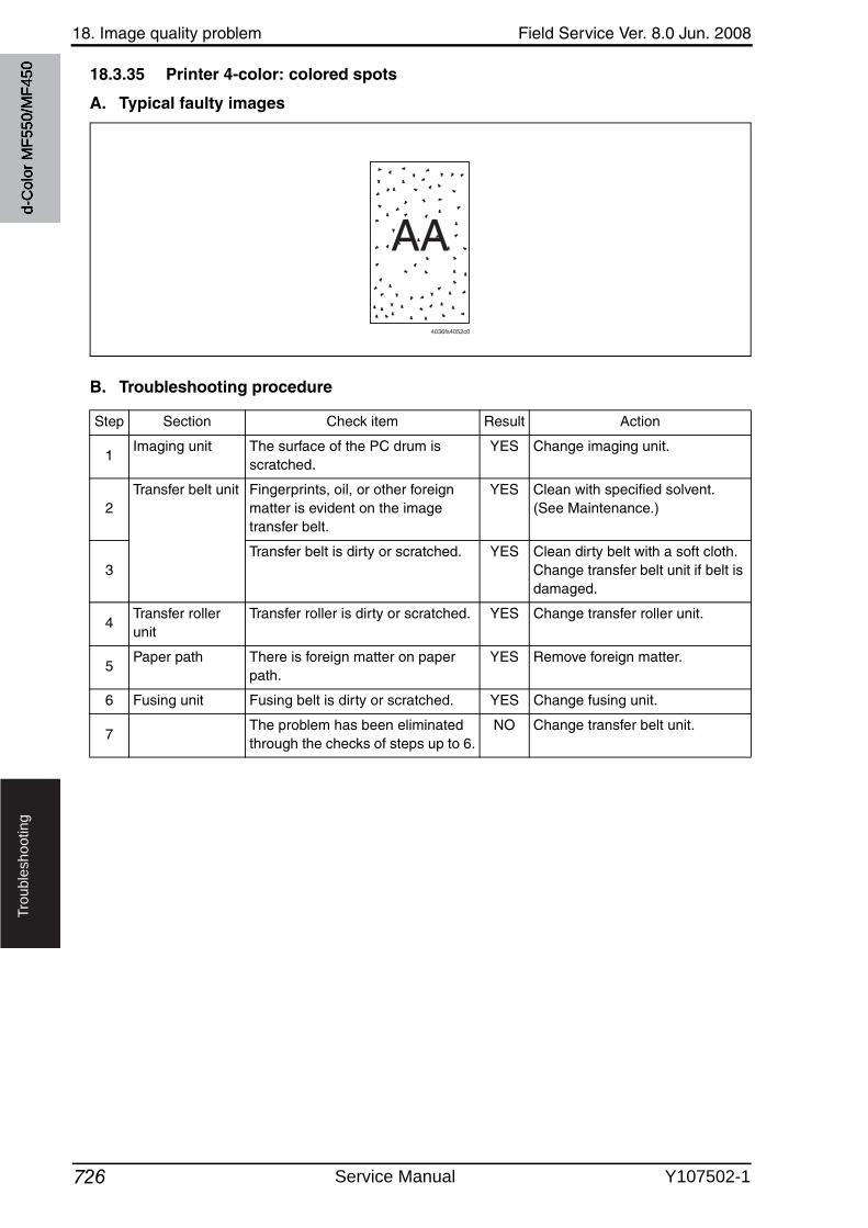
18. Image quality problem Field Service Ver. 8.0 Jun. 2008
726
Tro
ub
lesh
oo
tin
g
18.3.35 Printer 4-color: colored spots
A. Typical faulty images
B. Troubleshooting procedure
AA
4036fs4052c0
Step Section Check item Result Action
1Imaging unit The surface of the PC drum is
scratched.YES Change imaging unit.
2Transfer belt unit Fingerprints, oil, or other foreign
matter is evident on the image transfer belt.
YES Clean with specified solvent. (See Maintenance.)
3Transfer belt is dirty or scratched. YES Clean dirty belt with a soft cloth.
Change transfer belt unit if belt is damaged.
4Transfer roller unit
Transfer roller is dirty or scratched. YES Change transfer roller unit.
5Paper path There is foreign matter on paper
path.YES Remove foreign matter.
6 Fusing unit Fusing belt is dirty or scratched. YES Change fusing unit.
7The problem has been eliminated through the checks of steps up to 6.
NO Change transfer belt unit.
d-C
olor
MF5
50/M
F450
Service Manual Y107502-1
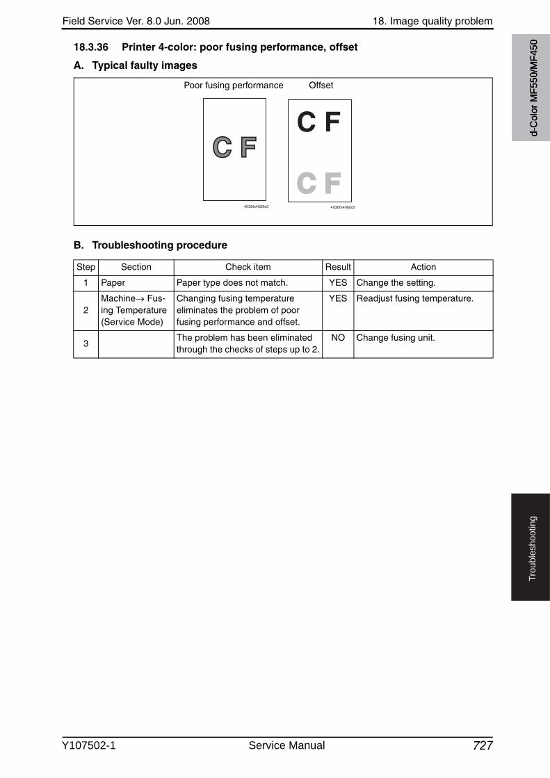
Field Service Ver. 8.0 Jun. 2008 18. Image quality problem
727
Tro
ub
lesh
oo
tin
g
18.3.36 Printer 4-color: poor fusing performance, offset
A. Typical faulty images
B. Troubleshooting procedure
C FC F
4036fs4059c0
C F
C FC F4036fs4060c0
OffsetPoor fusing performance
Step Section Check item Result Action
1 Paper Paper type does not match. YES Change the setting.
2Machine Fus-ing Temperature(Service Mode)
Changing fusing temperature eliminates the problem of poor fusing performance and offset.
YES Readjust fusing temperature.
3The problem has been eliminated through the checks of steps up to 2.
NO Change fusing unit.
d-C
olor
MF5
50/M
F450
Y107502-1 Service Manual
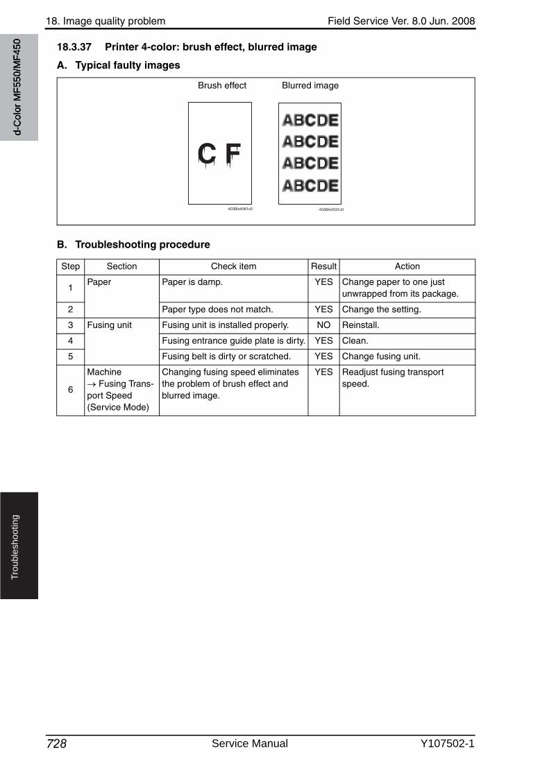
18. Image quality problem Field Service Ver. 8.0 Jun. 2008
728
Tro
ub
lesh
oo
tin
g
18.3.37 Printer 4-color: brush effect, blurred image
A. Typical faulty images
B. Troubleshooting procedure
4036fs4061c0
Blurred imageBrush effect
4036fs4031c0
Step Section Check item Result Action
1Paper Paper is damp. YES Change paper to one just
unwrapped from its package.
2 Paper type does not match. YES Change the setting.
3 Fusing unit Fusing unit is installed properly. NO Reinstall.
4 Fusing entrance guide plate is dirty. YES Clean.
5 Fusing belt is dirty or scratched. YES Change fusing unit.
6
Machine Fusing Trans-
port Speed (Service Mode)
Changing fusing speed eliminates the problem of brush effect and blurred image.
YES Readjust fusing transport speed.
d-C
olor
MF5
50/M
F450
Service Manual Y107502-1
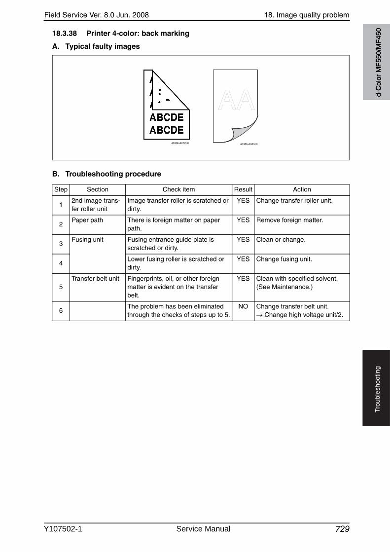
Field Service Ver. 8.0 Jun. 2008 18. Image quality problem
729
Tro
ub
lesh
oo
tin
g
18.3.38 Printer 4-color: back marking
A. Typical faulty images
B. Troubleshooting procedure
4036fs4062c0
AA4036fs4063c0
Step Section Check item Result Action
12nd image trans-fer roller unit
Image transfer roller is scratched or dirty.
YES Change transfer roller unit.
2Paper path There is foreign matter on paper
path.YES Remove foreign matter.
3Fusing unit Fusing entrance guide plate is
scratched or dirty.YES Clean or change.
4Lower fusing roller is scratched or dirty.
YES Change fusing unit.
5Transfer belt unit Fingerprints, oil, or other foreign
matter is evident on the transfer belt.
YES Clean with specified solvent. (See Maintenance.)
6The problem has been eliminated through the checks of steps up to 5.
NO Change transfer belt unit. Change high voltage unit/2.
d-C
olor
MF5
50/M
F450
Y107502-1 Service Manual
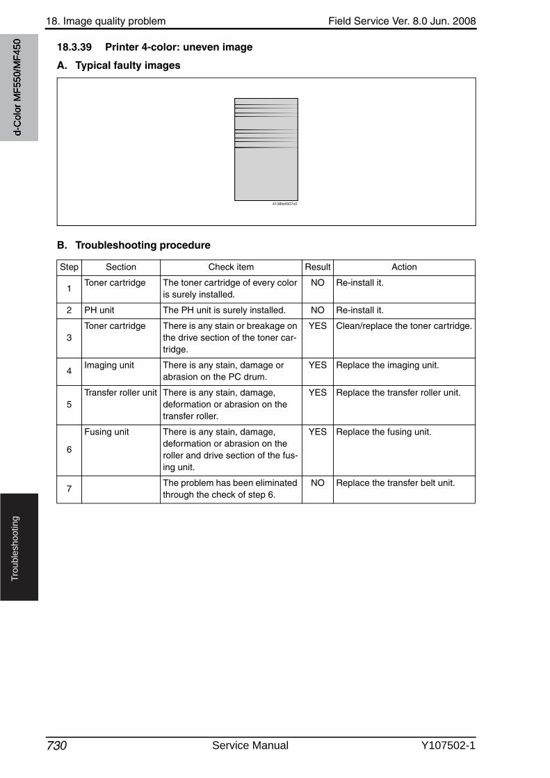
18. Image quality problem Field Service Ver. 8.0 Jun. 2008
730
Tro
ub
lesh
oo
tin
g
18.3.39 Printer 4-color: uneven image
A. Typical faulty images
B. Troubleshooting procedure
4138fs4507c0
Step Section Check item Result Action
1Toner cartridge The toner cartridge of every color
is surely installed.NO Re-install it.
2 PH unit The PH unit is surely installed. NO Re-install it.
3Toner cartridge There is any stain or breakage on
the drive section of the toner car-tridge.
YES Clean/replace the toner cartridge.
4Imaging unit There is any stain, damage or
abrasion on the PC drum.YES Replace the imaging unit.
5Transfer roller unit There is any stain, damage,
deformation or abrasion on the transfer roller.
YES Replace the transfer roller unit.
6
Fusing unit There is any stain, damage, deformation or abrasion on the roller and drive section of the fus-ing unit.
YES Replace the fusing unit.
7The problem has been eliminated through the check of step 6.
NO Replace the transfer belt unit.
d-C
olor
MF5
50/M
F450
Service Manual Y107502-1
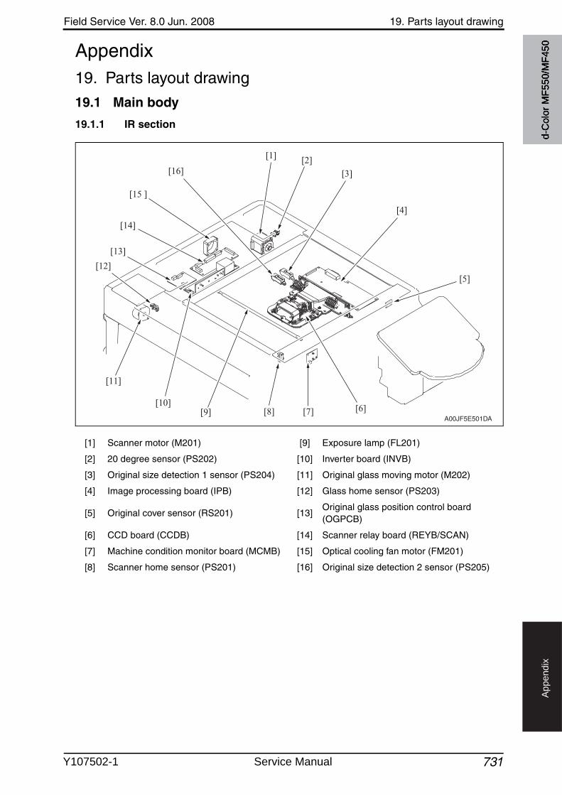
Field Service Ver. 8.0 Jun. 2008 19. Parts layout drawing
731
Ap
pe
nd
ix
Appendix19. Parts layout drawing
19.1 Main body
19.1.1 IR section
[1] Scanner motor (M201) [9] Exposure lamp (FL201)
[2] 20 degree sensor (PS202) [10] Inverter board (INVB)
[3] Original size detection 1 sensor (PS204) [11] Original glass moving motor (M202)
[4] Image processing board (IPB) [12] Glass home sensor (PS203)
[5] Original cover sensor (RS201) [13]Original glass position control board (OGPCB)
[6] CCD board (CCDB) [14] Scanner relay board (REYB/SCAN)
[7] Machine condition monitor board (MCMB) [15] Optical cooling fan motor (FM201)
[8] Scanner home sensor (PS201) [16] Original size detection 2 sensor (PS205)
A00JF5E501DA
[1]
[16]
[15 ]
[14]
[12]
[11]
[10][9] [6][8] [7]
[13]
[2]
[3]
[4]
[5]
d-C
olor
MF5
50/M
F450
Y107502-1 Service Manual
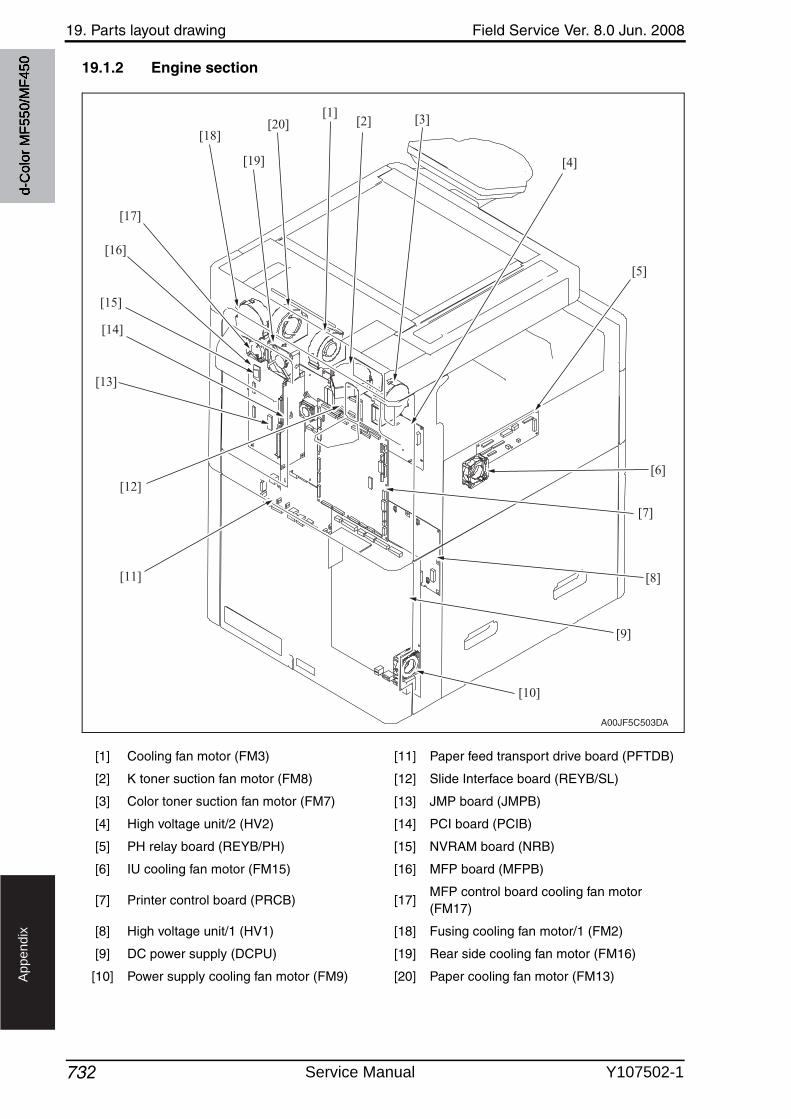
19. Parts layout drawing Field Service Ver. 8.0 Jun. 2008
732
Ap
pe
nd
ix
19.1.2 Engine section
[1] Cooling fan motor (FM3) [11] Paper feed transport drive board (PFTDB)
[2] K toner suction fan motor (FM8) [12] Slide Interface board (REYB/SL)
[3] Color toner suction fan motor (FM7) [13] JMP board (JMPB)
[4] High voltage unit/2 (HV2) [14] PCI board (PCIB)
[5] PH relay board (REYB/PH) [15] NVRAM board (NRB)
[6] IU cooling fan motor (FM15) [16] MFP board (MFPB)
[7] Printer control board (PRCB) [17]MFP control board cooling fan motor (FM17)
[8] High voltage unit/1 (HV1) [18] Fusing cooling fan motor/1 (FM2)
[9] DC power supply (DCPU) [19] Rear side cooling fan motor (FM16)
[10] Power supply cooling fan motor (FM9) [20] Paper cooling fan motor (FM13)
A00JF5C503DA
[18]
[17]
[16]
[14]
[15]
[13]
[11]
[12]
[20]
[19]
[1][2] [3]
[4]
[5]
[6]
[7]
[8]
[9]
[10]
d-C
olor
MF5
50/M
F450
Service Manual Y107502-1
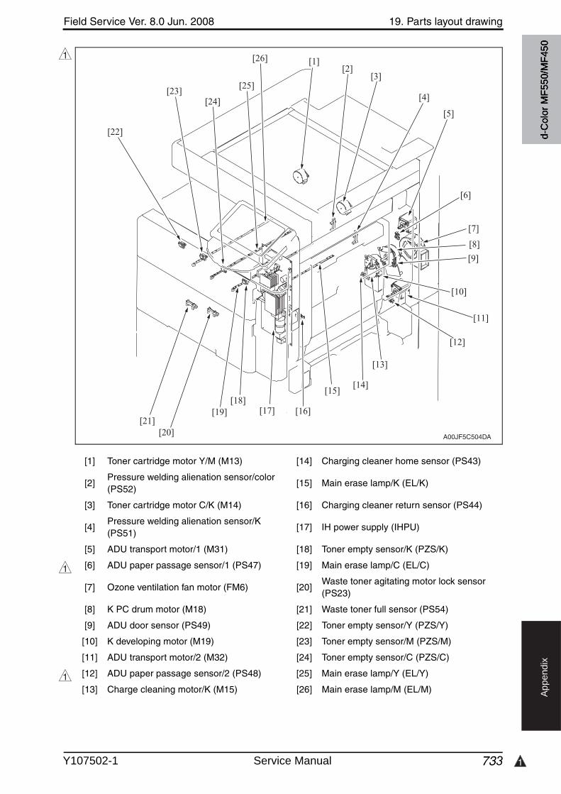
Field Service Ver. 8.0 Jun. 2008 19. Parts layout drawing
733 1
Ap
pe
nd
ix
[1] Toner cartridge motor Y/M (M13) [14] Charging cleaner home sensor (PS43)
[2]Pressure welding alienation sensor/color (PS52)
[15] Main erase lamp/K (EL/K)
[3] Toner cartridge motor C/K (M14) [16] Charging cleaner return sensor (PS44)
[4]Pressure welding alienation sensor/K (PS51)
[17] IH power supply (IHPU)
[5] ADU transport motor/1 (M31) [18] Toner empty sensor/K (PZS/K)
[6] ADU paper passage sensor/1 (PS47) [19] Main erase lamp/C (EL/C)
[7] Ozone ventilation fan motor (FM6) [20]Waste toner agitating motor lock sensor (PS23)
[8] K PC drum motor (M18) [21] Waste toner full sensor (PS54)
[9] ADU door sensor (PS49) [22] Toner empty sensor/Y (PZS/Y)
[10] K developing motor (M19) [23] Toner empty sensor/M (PZS/M)
[11] ADU transport motor/2 (M32) [24] Toner empty sensor/C (PZS/C)
[12] ADU paper passage sensor/2 (PS48) [25] Main erase lamp/Y (EL/Y)
[13] Charge cleaning motor/K (M15) [26] Main erase lamp/M (EL/M)
1
A00JF5C504DA
[25]
[26]
[24][23]
[22]
[21][20]
[19] [17] [16]
[15][18]
[1][2]
[3]
[4]
[5]
[6]
[7]
[8]
[9]
[10]
[11]
[12]
[13]
[14]
1
1
d-C
olor
MF5
50/M
F450
Y107502-1 Service Manual
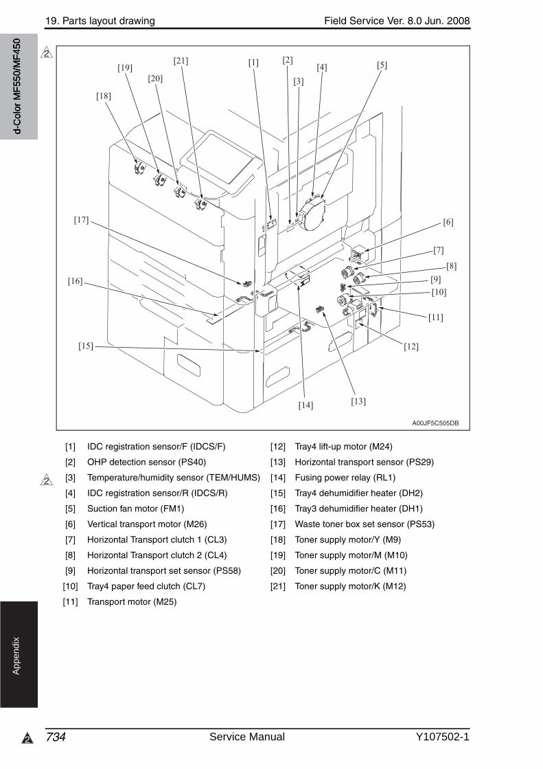
19. Parts layout drawing Field Service Ver. 8.0 Jun. 2008
7342
Ap
pe
nd
ix
[1] IDC registration sensor/F (IDCS/F) [12] Tray4 lift-up motor (M24)
[2] OHP detection sensor (PS40) [13] Horizontal transport sensor (PS29)
[3] Temperature/humidity sensor (TEM/HUMS) [14] Fusing power relay (RL1)
[4] IDC registration sensor/R (IDCS/R) [15] Tray4 dehumidifier heater (DH2)
[5] Suction fan motor (FM1) [16] Tray3 dehumidifier heater (DH1)
[6] Vertical transport motor (M26) [17] Waste toner box set sensor (PS53)
[7] Horizontal Transport clutch 1 (CL3) [18] Toner supply motor/Y (M9)
[8] Horizontal Transport clutch 2 (CL4) [19] Toner supply motor/M (M10)
[9] Horizontal transport set sensor (PS58) [20] Toner supply motor/C (M11)
[10] Tray4 paper feed clutch (CL7) [21] Toner supply motor/K (M12)
[11] Transport motor (M25)
A00JF5C505DB
[1][21]
[20][19]
[18]
[17]
[16]
[15]
[2]
[3]
[4] [5]
[6]
[7]
[8]
[9][10]
[11]
[12]
[13][14]
2
2
d-C
olor
MF5
50/M
F450
Service Manual Y107502-1
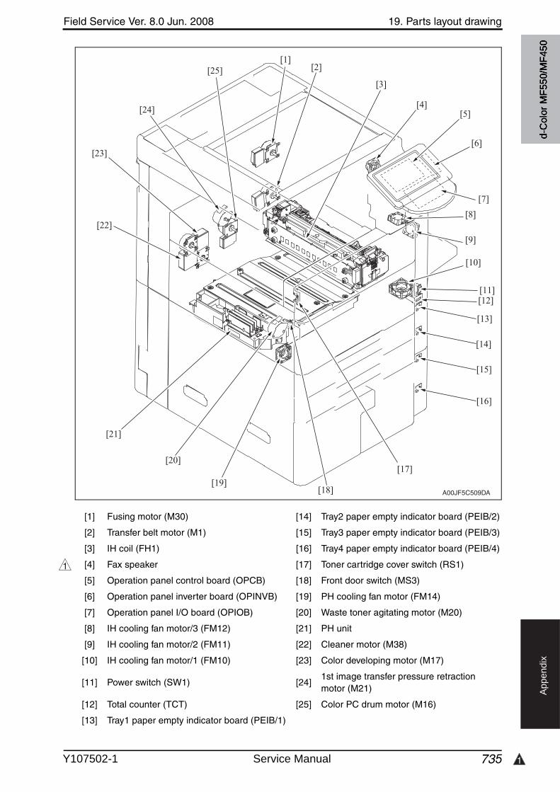
Field Service Ver. 8.0 Jun. 2008 19. Parts layout drawing
735 1
Ap
pe
nd
ix
[1] Fusing motor (M30) [14] Tray2 paper empty indicator board (PEIB/2)
[2] Transfer belt motor (M1) [15] Tray3 paper empty indicator board (PEIB/3)
[3] IH coil (FH1) [16] Tray4 paper empty indicator board (PEIB/4)
[4] Fax speaker [17] Toner cartridge cover switch (RS1)
[5] Operation panel control board (OPCB) [18] Front door switch (MS3)
[6] Operation panel inverter board (OPINVB) [19] PH cooling fan motor (FM14)
[7] Operation panel I/O board (OPIOB) [20] Waste toner agitating motor (M20)
[8] IH cooling fan motor/3 (FM12) [21] PH unit
[9] IH cooling fan motor/2 (FM11) [22] Cleaner motor (M38)
[10] IH cooling fan motor/1 (FM10) [23] Color developing motor (M17)
[11] Power switch (SW1) [24]1st image transfer pressure retraction motor (M21)
[12] Total counter (TCT) [25] Color PC drum motor (M16)
[13] Tray1 paper empty indicator board (PEIB/1)
A00JF5C509DA
[23]
[24]
[25]
[22]
[1][2]
[3]
[4]
[10]
[9]
[8]
[11][12]
[13]
[14]
[15]
[16]
[17]
[18]
[21]
[19]
[20]
[5]
[6]
[7]
1
d-C
olor
MF5
50/M
F450
Y107502-1 Service Manual
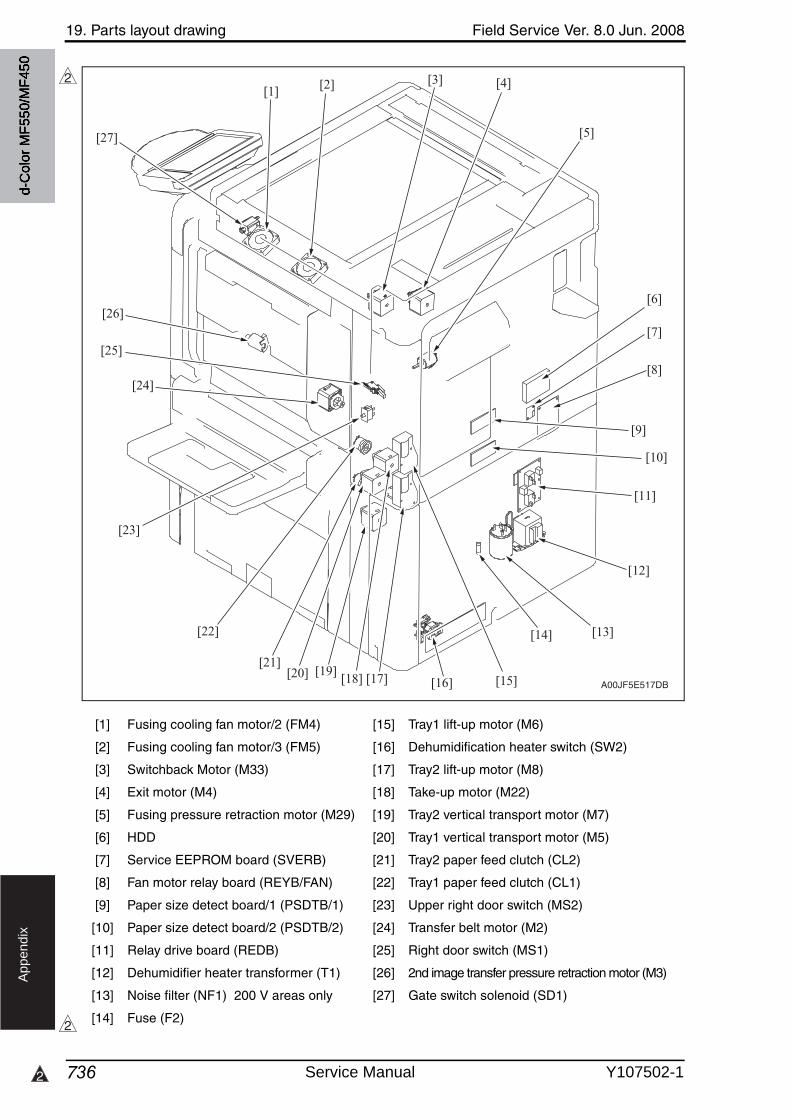
19. Parts layout drawing Field Service Ver. 8.0 Jun. 2008
7362
Ap
pe
nd
ix
[1] Fusing cooling fan motor/2 (FM4) [15] Tray1 lift-up motor (M6)
[2] Fusing cooling fan motor/3 (FM5) [16] Dehumidification heater switch (SW2)
[3] Switchback Motor (M33) [17] Tray2 lift-up motor (M8)
[4] Exit motor (M4) [18] Take-up motor (M22)
[5] Fusing pressure retraction motor (M29) [19] Tray2 vertical transport motor (M7)
[6] HDD [20] Tray1 vertical transport motor (M5)
[7] Service EEPROM board (SVERB) [21] Tray2 paper feed clutch (CL2)
[8] Fan motor relay board (REYB/FAN) [22] Tray1 paper feed clutch (CL1)
[9] Paper size detect board/1 (PSDTB/1) [23] Upper right door switch (MS2)
[10] Paper size detect board/2 (PSDTB/2) [24] Transfer belt motor (M2)
[11] Relay drive board (REDB) [25] Right door switch (MS1)
[12] Dehumidifier heater transformer (T1) [26] 2nd image transfer pressure retraction motor (M3)
[13] Noise filter (NF1) 200 V areas only [27] Gate switch solenoid (SD1)
[14] Fuse (F2)
A00JF5E517DB
[1] [2] [3] [4]
[5]
[9]
[10]
[11]
[12]
[13]
[15][16][17][19]
[18][20][21]
[22]
[23]
[26]
[27]
[25]
[24]
[6]
[7]
[8]
[14]
2
2
d-C
olor
MF5
50/M
F450
Service Manual Y107502-1
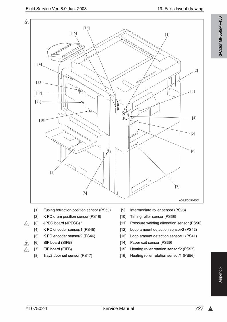
Field Service Ver. 8.0 Jun. 2008 19. Parts layout drawing
737 2
Ap
pe
nd
ix
[1] Fusing retraction position sensor (PS59) [9] Intermediate roller sensor (PS28)
[2] K PC drum position sensor (PS18) [10] Timing roller sensor (PS38)
[3] JPEG board (JPEGB) * [11] Pressure welding alienation sensor (PS50)
[4] K PC encoder sensor/1 (PS45) [12] Loop amount detection sensor/2 (PS42)
[5] K PC encoder sensor/2 (PS46) [13] Loop amount detection sensor/1 (PS41)
[6] SIF board (SIFB) * [14] Paper exit sensor (PS39)
[7] EIF board (EIFB) * [15] Heating roller rotation sensor/2 (PS57)
[8] Tray2 door set sensor (PS17) [16] Heating roller rotation sensor/1 (PS56)
A00JF5C516DC
[1]
[2]
[3]
[4]
[5]
[6]
[7]
[8]
[9]
[13]
[14]
[15][16]
[12]
[11]
[10]
2
2
2
2
d-C
olor
MF5
50/M
F450
Y107502-1 Service Manual
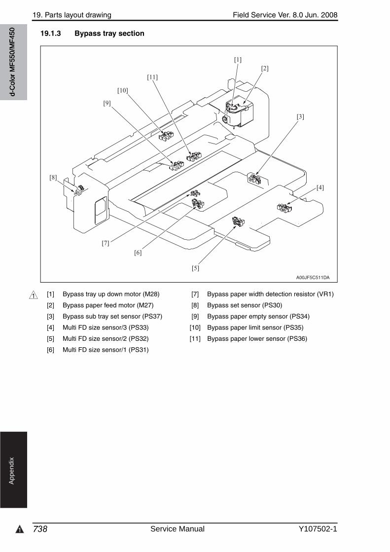
1
19. Parts layout drawing Field Service Ver. 8.0 Jun. 2008
738
Ap
pe
nd
ix
19.1.3 Bypass tray section
[1] Bypass tray up down motor (M28) [7] Bypass paper width detection resistor (VR1)
[2] Bypass paper feed motor (M27) [8] Bypass set sensor (PS30)
[3] Bypass sub tray set sensor (PS37) [9] Bypass paper empty sensor (PS34)
[4] Multi FD size sensor/3 (PS33) [10] Bypass paper limit sensor (PS35)
[5] Multi FD size sensor/2 (PS32) [11] Bypass paper lower sensor (PS36)
[6] Multi FD size sensor/1 (PS31)
A00JF5C511DA
[1][2]
[3]
[4]
[5]
[6]
[7]
[8]
[9]
[11]
[10]
1
d-C
olor
MF5
50/M
F450
Service Manual Y107502-1
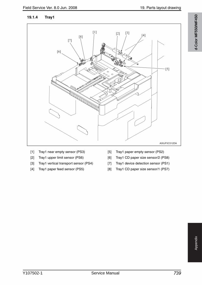
Field Service Ver. 8.0 Jun. 2008 19. Parts layout drawing
739
Ap
pe
nd
ix
19.1.4 Tray1
[1] Tray1 near empty sensor (PS3) [5] Tray1 paper empty sensor (PS2)
[2] Tray1 upper limit sensor (PS6) [6] Tray1 CD paper size sensor/2 (PS8)
[3] Tray1 vertical transport sensor (PS4) [7] Tray1 device detection sensor (PS1)
[4] Tray1 paper feed sensor (PS5) [8] Tray1 CD paper size sensor/1 (PS7)
A00JF5C512DA
[5]
[1][8]
[7]
[6]
[2] [3][4]
d-C
olor
MF5
50/M
F450
Y107502-1 Service Manual
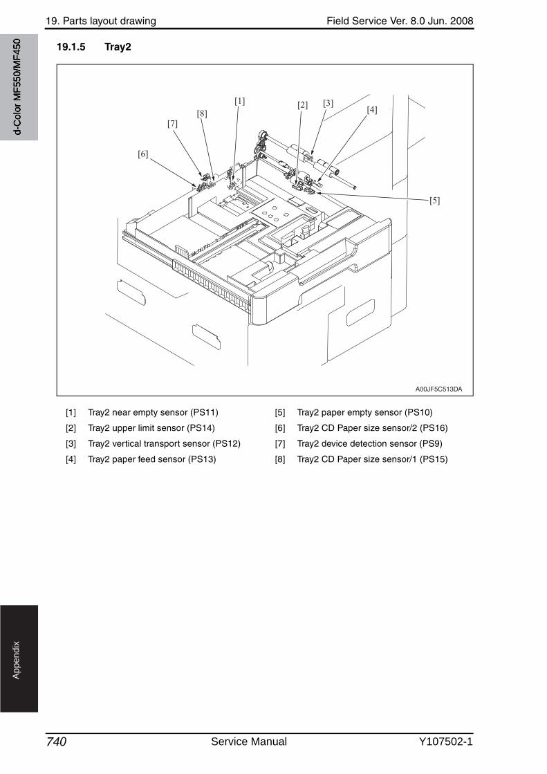
19. Parts layout drawing Field Service Ver. 8.0 Jun. 2008
740
Ap
pe
nd
ix
19.1.5 Tray2
[1] Tray2 near empty sensor (PS11) [5] Tray2 paper empty sensor (PS10)
[2] Tray2 upper limit sensor (PS14) [6] Tray2 CD Paper size sensor/2 (PS16)
[3] Tray2 vertical transport sensor (PS12) [7] Tray2 device detection sensor (PS9)
[4] Tray2 paper feed sensor (PS13) [8] Tray2 CD Paper size sensor/1 (PS15)
A00JF5C513DA
[5]
[1][8]
[7]
[6]
[2] [3][4]
d-C
olor
MF5
50/M
F450
Service Manual Y107502-1

Field Service Ver. 8.0 Jun. 2008 19. Parts layout drawing
741
Ap
pe
nd
ix
19.1.6 Tray3
[1] Tray3 upper limit sensor (PS20) [5] Tray3 near empty sensor (PS22)
[2] Tray3 paper empty sensor (PS19) [6] Tray3 paper feed clutch (CL5)
[3] Tray3 paper feed sensor (PS21) [7] Tray3 transport clutch (CL6)
[4] Tray3 lift-up motor (M23)
A00JF5C514DA
[4]
[5] [6] [7] [1]
[2]
[3] d-C
olor
MF5
50/M
F450
Y107502-1 Service Manual
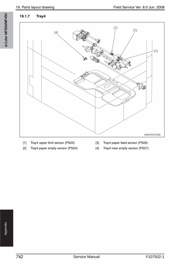
19. Parts layout drawing Field Service Ver. 8.0 Jun. 2008
742
Ap
pe
nd
ix
19.1.7 Tray4
[1] Tray4 upper limit sensor (PS25) [3] Tray4 paper feed sensor (PS26)
[2] Tray4 paper empty sensor (PS24) [4] Tray4 near empty sensor (PS27)
A00JF5C515DA
[4]
[1][2]
[3]
d-C
olor
MF5
50/M
F450
Service Manual Y107502-1
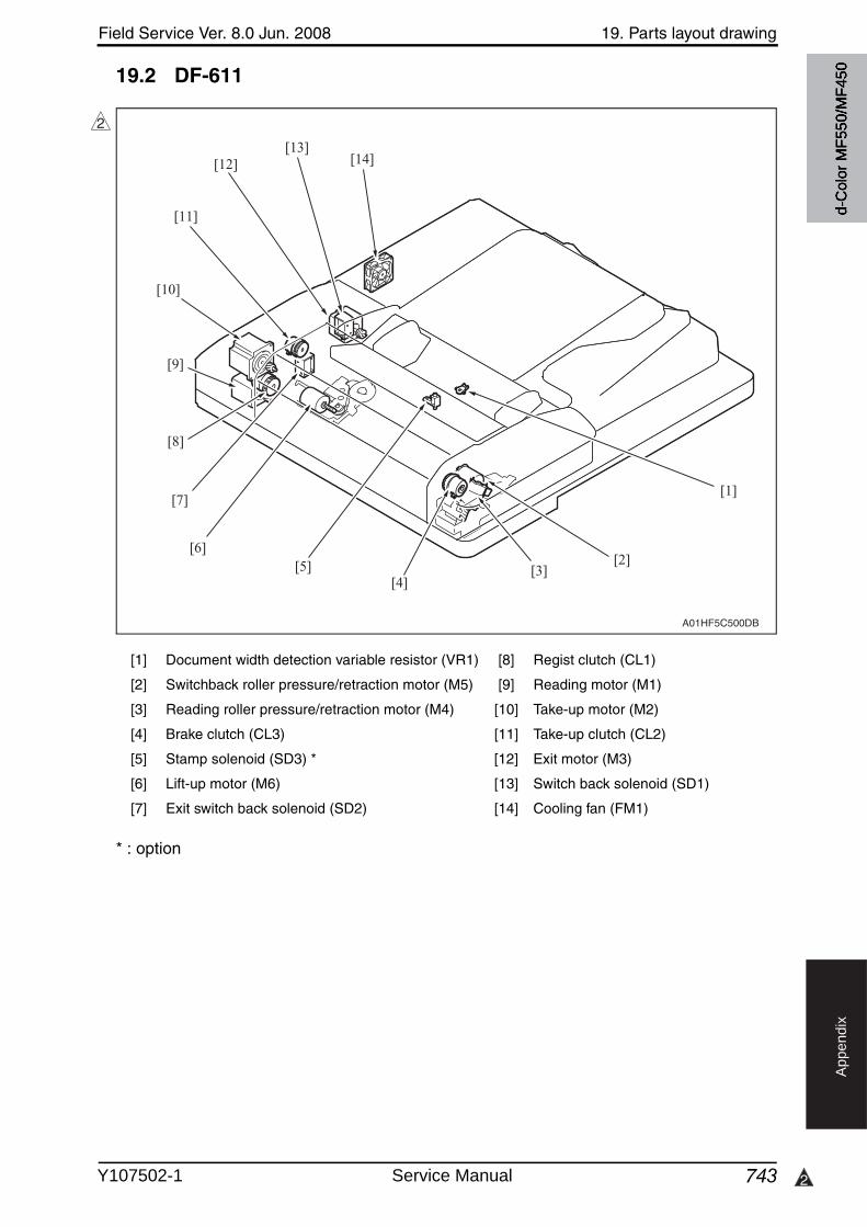
Field Service Ver. 8.0 Jun. 2008 19. Parts layout drawing
743 2
Ap
pe
nd
ix
19.2 DF-611
* : option
[1] Document width detection variable resistor (VR1) [8] Regist clutch (CL1)
[2] Switchback roller pressure/retraction motor (M5) [9] Reading motor (M1)
[3] Reading roller pressure/retraction motor (M4) [10] Take-up motor (M2)
[4] Brake clutch (CL3) [11] Take-up clutch (CL2)
[5] Stamp solenoid (SD3) * [12] Exit motor (M3)
[6] Lift-up motor (M6) [13] Switch back solenoid (SD1)
[7] Exit switch back solenoid (SD2) [14] Cooling fan (FM1)
2
[1]
[2][3]
[4][5]
[6]
[7]
[8]
[9]
[12][13]
[14]
[11]
[10]
A01HF5C500DB
d-C
olor
MF5
50/M
F450
Y107502-1 Service Manual
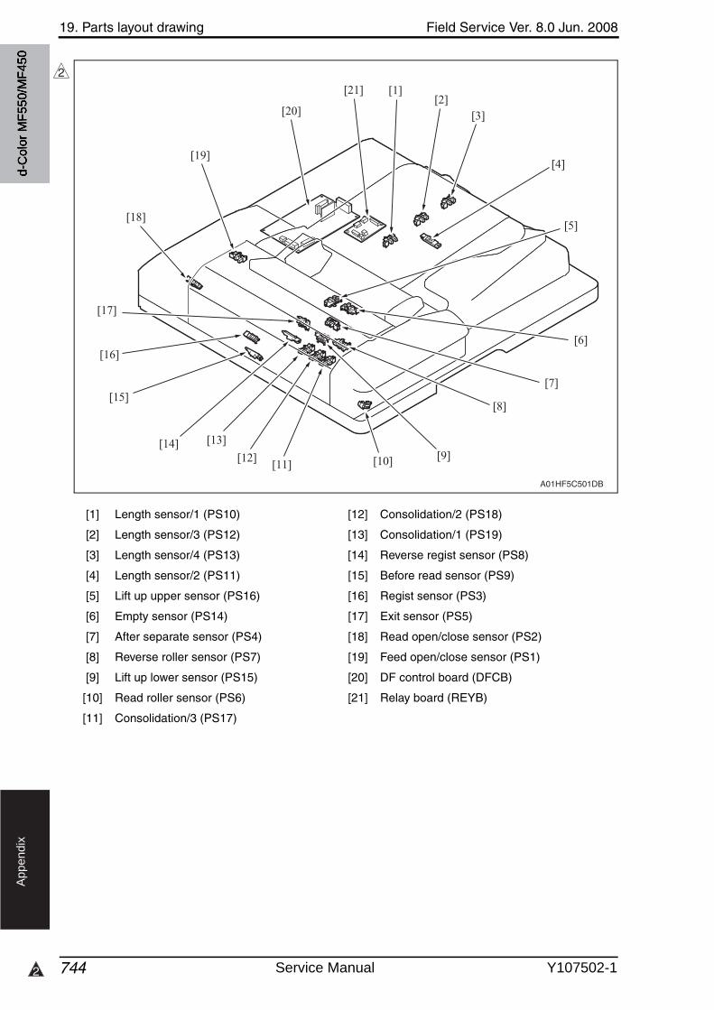
19. Parts layout drawing Field Service Ver. 8.0 Jun. 2008
7442
Ap
pe
nd
ix
[1] Length sensor/1 (PS10) [12] Consolidation/2 (PS18)
[2] Length sensor/3 (PS12) [13] Consolidation/1 (PS19)
[3] Length sensor/4 (PS13) [14] Reverse regist sensor (PS8)
[4] Length sensor/2 (PS11) [15] Before read sensor (PS9)
[5] Lift up upper sensor (PS16) [16] Regist sensor (PS3)
[6] Empty sensor (PS14) [17] Exit sensor (PS5)
[7] After separate sensor (PS4) [18] Read open/close sensor (PS2)
[8] Reverse roller sensor (PS7) [19] Feed open/close sensor (PS1)
[9] Lift up lower sensor (PS15) [20] DF control board (DFCB)
[10] Read roller sensor (PS6) [21] Relay board (REYB)
[11] Consolidation/3 (PS17)
2
[1][2]
[3]
[4]
[5]
[6]
[7]
[8]
[9][10][11][12]
[13][14]
[16]
[15]
[17]
[18]
[19]
[21]
[20]
A01HF5C501DB
d-C
olor
MF5
50/M
F450
Service Manual Y107502-1
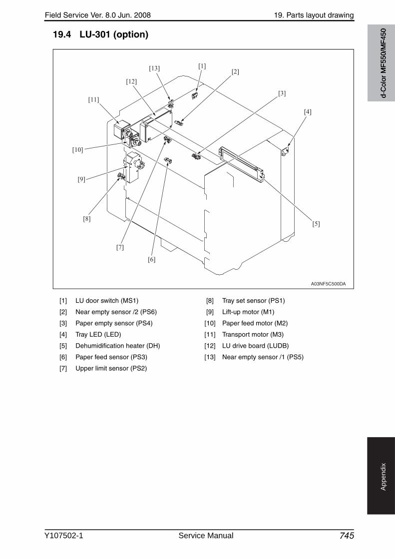
Field Service Ver. 8.0 Jun. 2008 19. Parts layout drawing
745
Ap
pe
nd
ix
19.4 LU-301 (option)
[1] LU door switch (MS1) [8] Tray set sensor (PS1)
[2] Near empty sensor /2 (PS6) [9] Lift-up motor (M1)
[3] Paper empty sensor (PS4) [10] Paper feed motor (M2)
[4] Tray LED (LED) [11] Transport motor (M3)
[5] Dehumidification heater (DH) [12] LU drive board (LUDB)
[6] Paper feed sensor (PS3) [13] Near empty sensor /1 (PS5)
[7] Upper limit sensor (PS2)
A03NF5C500DA
[1][2]
[3]
[4]
[5]
[6]
[7]
[8]
[9]
[10]
[11]
[12]
[13]
d-C
olor
MF5
50/M
F450
Y107502-1 Service Manual
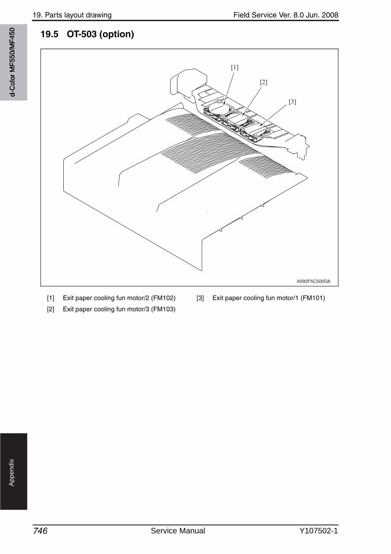
19. Parts layout drawing Field Service Ver. 8.0 Jun. 2008
746
Ap
pe
nd
ix
19.5 OT-503 (option)
[1] Exit paper cooling fun motor/2 (FM102) [3] Exit paper cooling fun motor/1 (FM101)
[2] Exit paper cooling fun motor/3 (FM103)
A092F5C500DA
[3]
[2]
[1]
d-C
olor
MF5
50/M
F450
Service Manual Y107502-1
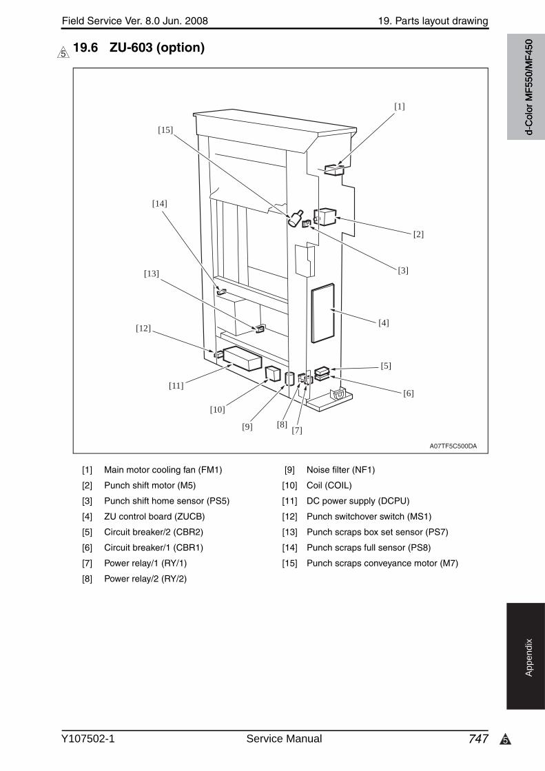
5
Field Service Ver. 8.0 Jun. 2008 19. Parts layout drawing
747
Ap
pe
nd
ix
19.6 ZU-603 (option)5
[1] Main motor cooling fan (FM1) [9] Noise filter (NF1)
[2] Punch shift motor (M5) [10] Coil (COIL)
[3] Punch shift home sensor (PS5) [11] DC power supply (DCPU)
[4] ZU control board (ZUCB) [12] Punch switchover switch (MS1)
[5] Circuit breaker/2 (CBR2) [13] Punch scraps box set sensor (PS7)
[6] Circuit breaker/1 (CBR1) [14] Punch scraps full sensor (PS8)
[7] Power relay/1 (RY/1) [15] Punch scraps conveyance motor (M7)
[8] Power relay/2 (RY/2)
A07TF5C500DA
[1]
[2]
[3]
[4]
[5]
[6]
[7][8][9]
[10]
[11]
[12]
[13]
[14]
[15] d-C
olor
MF5
50/M
F450
Y107502-1 Service Manual
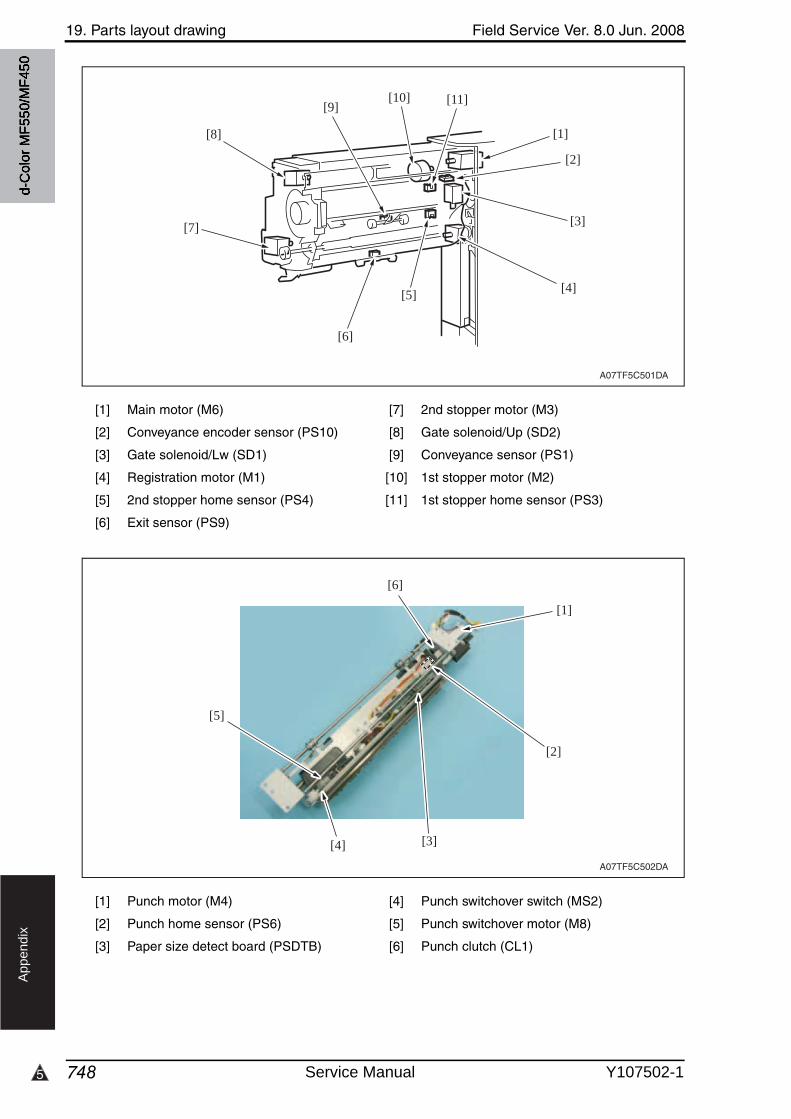
19. Parts layout drawing Field Service Ver. 8.0 Jun. 2008
7485
Ap
pe
nd
ix
[1] Main motor (M6) [7] 2nd stopper motor (M3)
[2] Conveyance encoder sensor (PS10) [8] Gate solenoid/Up (SD2)
[3] Gate solenoid/Lw (SD1) [9] Conveyance sensor (PS1)
[4] Registration motor (M1) [10] 1st stopper motor (M2)
[5] 2nd stopper home sensor (PS4) [11] 1st stopper home sensor (PS3)
[6] Exit sensor (PS9)
[1] Punch motor (M4) [4] Punch switchover switch (MS2)
[2] Punch home sensor (PS6) [5] Punch switchover motor (M8)
[3] Paper size detect board (PSDTB) [6] Punch clutch (CL1)
A07TF5C501DA
[4]
[3]
[2]
[1]
[11][10][9]
[5]
[6]
[7]
[8]
A07TF5C502DA
[1]
[2]
[3][4]
[5]
[6]
d-C
olor
MF5
50/M
F450
Service Manual Y107502-1
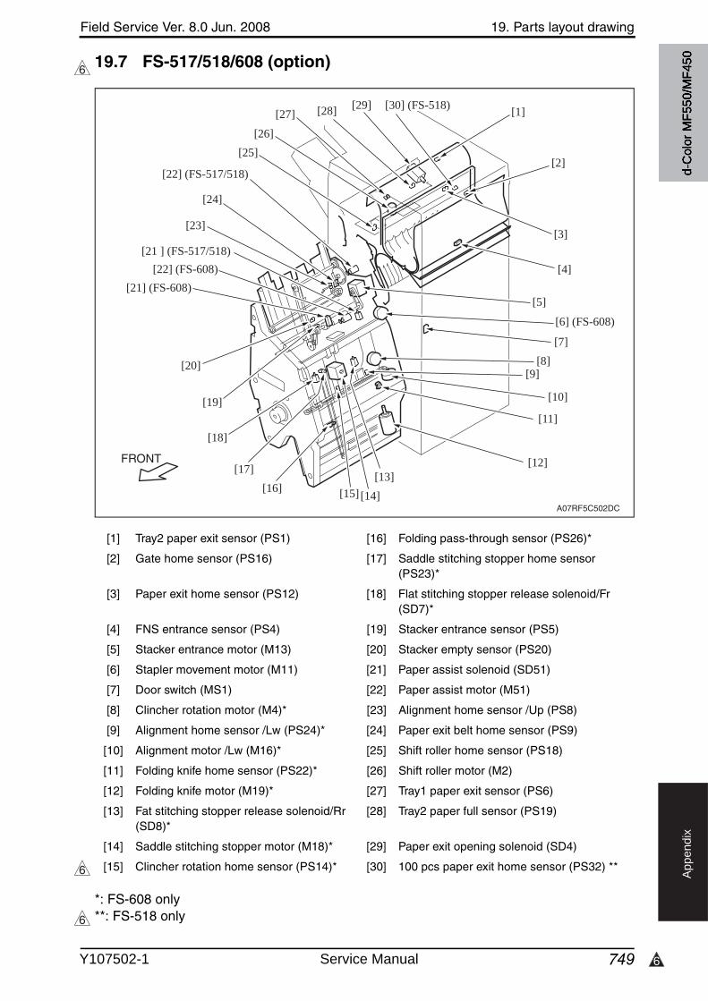
6
Field Service Ver. 8.0 Jun. 2008 19. Parts layout drawing
749
Ap
pe
nd
ix
19.7 FS-517/518/608 (option)
*: FS-608 only**: FS-518 only
6
[1] Tray2 paper exit sensor (PS1) [16] Folding pass-through sensor (PS26)*
[2] Gate home sensor (PS16) [17] Saddle stitching stopper home sensor (PS23)*
[3] Paper exit home sensor (PS12) [18] Flat stitching stopper release solenoid/Fr (SD7)*
[4] FNS entrance sensor (PS4) [19] Stacker entrance sensor (PS5)
[5] Stacker entrance motor (M13) [20] Stacker empty sensor (PS20)
[6] Stapler movement motor (M11) [21] Paper assist solenoid (SD51)
[7] Door switch (MS1) [22] Paper assist motor (M51)
[8] Clincher rotation motor (M4)* [23] Alignment home sensor /Up (PS8)
[9] Alignment home sensor /Lw (PS24)* [24] Paper exit belt home sensor (PS9)
[10] Alignment motor /Lw (M16)* [25] Shift roller home sensor (PS18)
[11] Folding knife home sensor (PS22)* [26] Shift roller motor (M2)
[12] Folding knife motor (M19)* [27] Tray1 paper exit sensor (PS6)
[13] Fat stitching stopper release solenoid/Rr (SD8)*
[28] Tray2 paper full sensor (PS19)
[14] Saddle stitching stopper motor (M18)* [29] Paper exit opening solenoid (SD4)
[15] Clincher rotation home sensor (PS14)* [30] 100 pcs paper exit home sensor (PS32) **
FRONT
A07RF5C502DC
[1]
[3]
[2]
[4]
[5]
[6] (FS-608)
[7][8]
[9]
[10]
[11]
[12][13]
[14][15][16][17]
[18]
[19]
[20]
[25][26]
[27] [28] [29] [30] (FS-518)
[23]
[24]
[22] (FS-517/518)
[21] (FS-608)[22] (FS-608)
[21 ] (FS-517/518)
6
6
d-C
olor
MF5
50/M
F450
Y107502-1 Service Manual
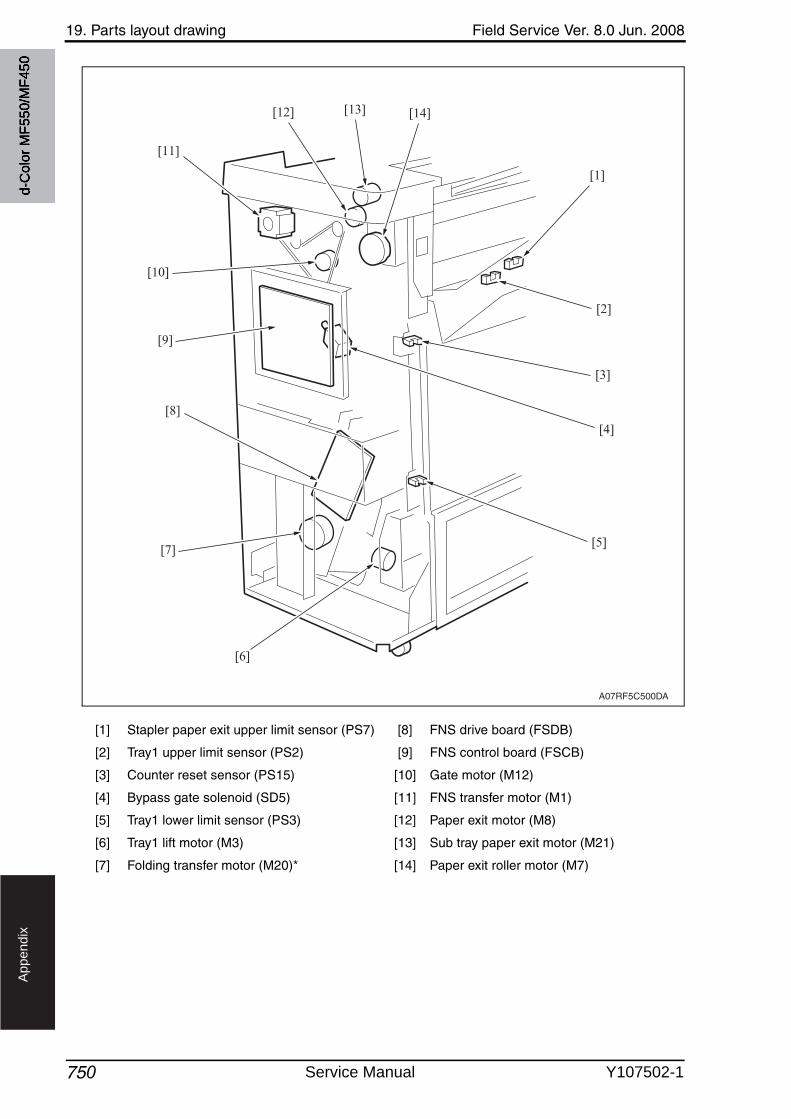
19. Parts layout drawing Field Service Ver. 8.0 Jun. 2008
750
Ap
pe
nd
ix
[1] Stapler paper exit upper limit sensor (PS7) [8] FNS drive board (FSDB)
[2] Tray1 upper limit sensor (PS2) [9] FNS control board (FSCB)
[3] Counter reset sensor (PS15) [10] Gate motor (M12)
[4] Bypass gate solenoid (SD5) [11] FNS transfer motor (M1)
[5] Tray1 lower limit sensor (PS3) [12] Paper exit motor (M8)
[6] Tray1 lift motor (M3) [13] Sub tray paper exit motor (M21)
[7] Folding transfer motor (M20)* [14] Paper exit roller motor (M7)
A07RF5C500DA
[1]
[2]
[3]
[4]
[5]
[6]
[7]
[8]
[9]
[10]
[11]
[12] [13] [14]
d-C
olor
MF5
50/M
F450
Service Manual Y107502-1
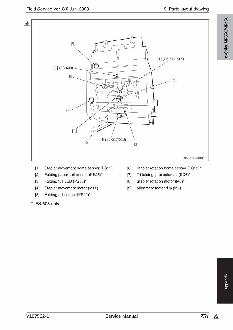
6
Field Service Ver. 8.0 Jun. 2008 19. Parts layout drawing
751
Ap
pe
nd
ix
*: FS-608 only
[1] Stapler movement home sensor (PS11) [6] Stapler rotation home sensor (PS13)*
[2] Folding paper exit sensor (PS25)* [7] Tri-folding gate solenoid (SD6)*
[3] Folding full LED (PS30)* [8] Stapler rotation motor (M6)*
[4] Stapler movement motor (M11) [9] Alignment motor /Up (M5)
[5] Folding full sensor (PS29)*
A07RF5C501DB
[2]
[1] (FS-517/518)
[3][4] (FS-517/518)
[5]
[6]
[7]
[8]
[1] (FS-608)
[9]
6
d-C
olor
MF5
50/M
F450
Y107502-1 Service Manual
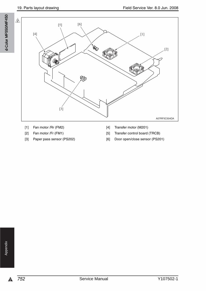
19. Parts layout drawing Field Service Ver. 8.0 Jun. 2008
7522
Ap
pe
nd
ix
[1] Fan motor /Rr (FM2) [4] Transfer motor (M201)
[2] Fan motor /Fr (FM1) [5] Transfer control board (TRCB)
[3] Paper pass sensor (PS202) [6] Door open/close sensor (PS201)
A07RF5C504DA
[1]
[2]
[3]
[4]
[5] [6]2
d-C
olor
MF5
50/M
F450
Service Manual Y107502-1
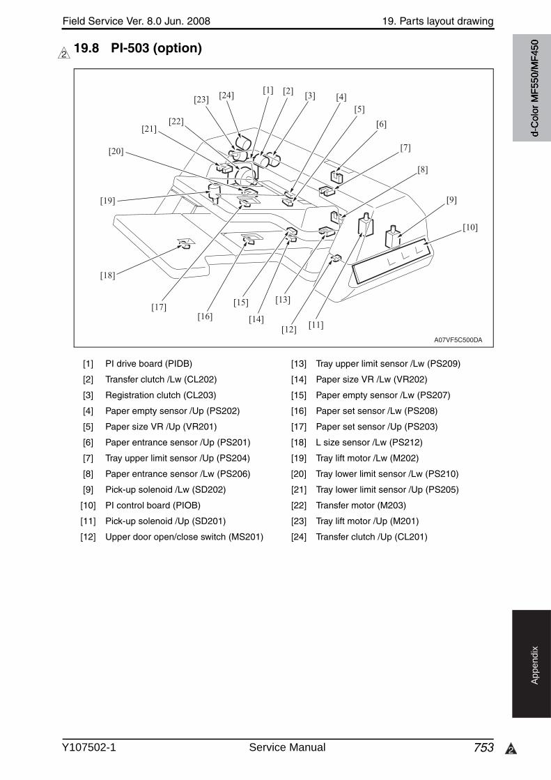
Field Service Ver. 8.0 Jun. 2008 19. Parts layout drawing
753 2
Ap
pe
nd
ix
19.8 PI-503 (option)2
[1] PI drive board (PIDB) [13] Tray upper limit sensor /Lw (PS209)
[2] Transfer clutch /Lw (CL202) [14] Paper size VR /Lw (VR202)
[3] Registration clutch (CL203) [15] Paper empty sensor /Lw (PS207)
[4] Paper empty sensor /Up (PS202) [16] Paper set sensor /Lw (PS208)
[5] Paper size VR /Up (VR201) [17] Paper set sensor /Up (PS203)
[6] Paper entrance sensor /Up (PS201) [18] L size sensor /Lw (PS212)
[7] Tray upper limit sensor /Up (PS204) [19] Tray lift motor /Lw (M202)
[8] Paper entrance sensor /Lw (PS206) [20] Tray lower limit sensor /Lw (PS210)
[9] Pick-up solenoid /Lw (SD202) [21] Tray lower limit sensor /Up (PS205)
[10] PI control board (PIOB) [22] Transfer motor (M203)
[11] Pick-up solenoid /Up (SD201) [23] Tray lift motor /Up (M201)
[12] Upper door open/close switch (MS201) [24] Transfer clutch /Up (CL201)
A07VF5C500DA
[1] [2] [3] [4][5]
[6]
[7]
[8]
[9]
[10]
[11][12]
[13]
[14]
[15]
[16][17]
[18]
[19]
[20]
[21][22]
[23] [24]
d-C
olor
MF5
50/M
F450
Y107502-1 Service Manual
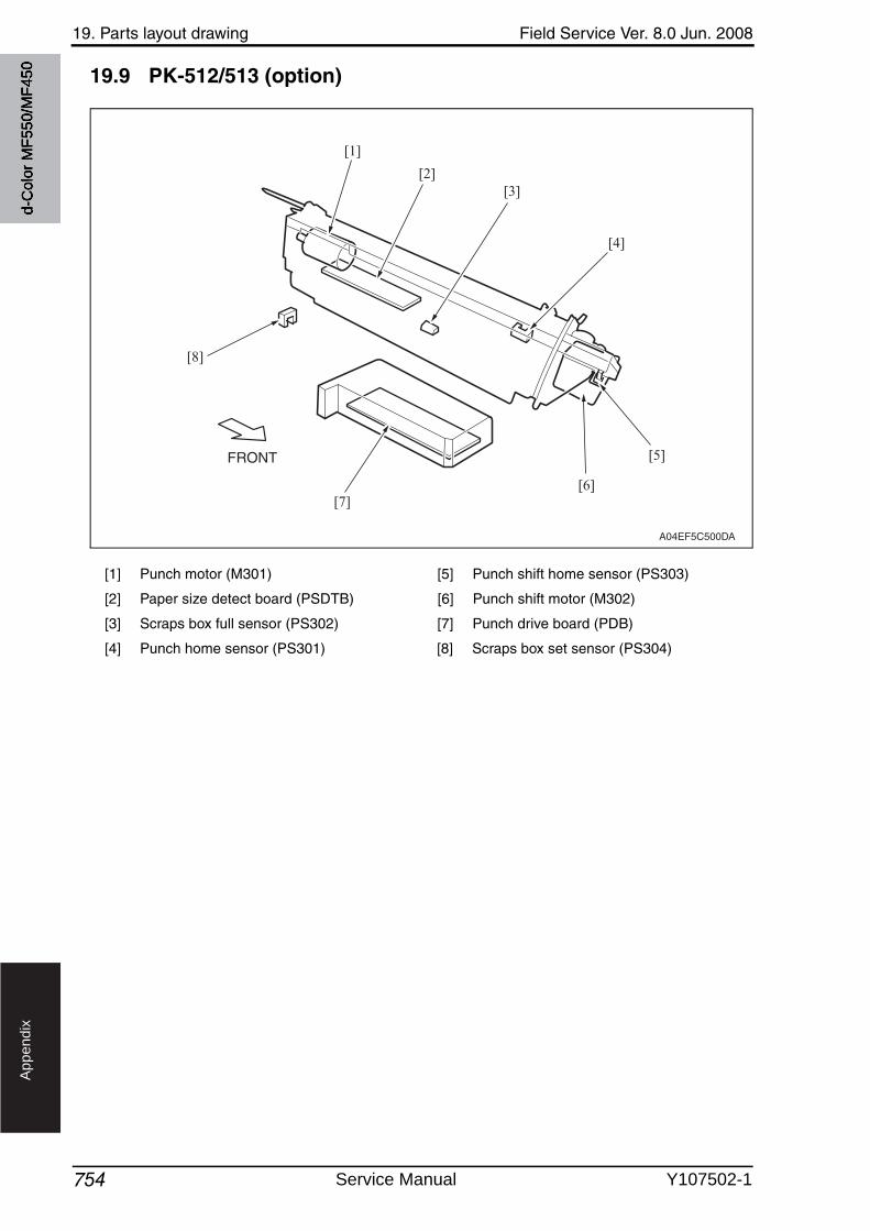
19. Parts layout drawing Field Service Ver. 8.0 Jun. 2008
754
Ap
pe
nd
ix
19.9 PK-512/513 (option)
[1] Punch motor (M301) [5] Punch shift home sensor (PS303)
[2] Paper size detect board (PSDTB) [6] Punch shift motor (M302)
[3] Scraps box full sensor (PS302) [7] Punch drive board (PDB)
[4] Punch home sensor (PS301) [8] Scraps box set sensor (PS304)
FRONT
A04EF5C500DA
[1]
[2][3]
[4]
[5]
[6][7]
[8]
d-C
olor
MF5
50/M
F450
Service Manual Y107502-1
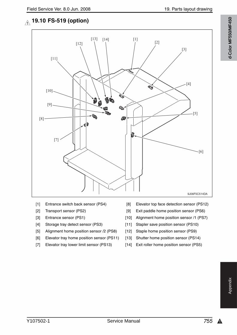
Field Service Ver. 8.0 Jun. 2008 19. Parts layout drawing
755 1
Ap
pe
nd
ix
19.10 FS-519 (option)1
[1] Entrance switch back sensor (PS4) [8] Elevator top face detection sensor (PS12)
[2] Transport sensor (PS2) [9] Exit paddle home position sensor (PS6)
[3] Entrance sensor (PS1) [10] Alignment home position sensor /1 (PS7)
[4] Storage tray detect sensor (PS3) [11] Stapler save position sensor (PS10)
[5] Alignment home position sensor /2 (PS8) [12] Staple home position sensor (PS9)
[6] Elevator tray home position sensor (PS11) [13] Shutter home position sensor (PS14)
[7] Elevator tray lower limit sensor (PS13) [14] Exit roller home position sensor (PS5)
9J06F5C514DA
[1]
[3]
[2]
[4]
[5]
[6]
[7]
[14][13][12]
[11]
[10]
[9]
[8]
d-C
olor
MF5
50/M
F450
Y107502-1 Service Manual
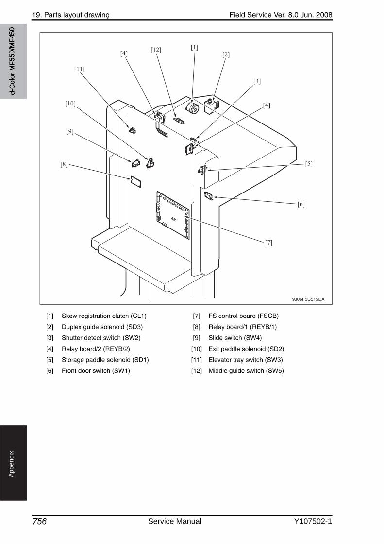
19. Parts layout drawing Field Service Ver. 8.0 Jun. 2008
756
Ap
pe
nd
ix
[1] Skew registration clutch (CL1) [7] FS control board (FSCB)
[2] Duplex guide solenoid (SD3) [8] Relay board/1 (REYB/1)
[3] Shutter detect switch (SW2) [9] Slide switch (SW4)
[4] Relay board/2 (REYB/2) [10] Exit paddle solenoid (SD2)
[5] Storage paddle solenoid (SD1) [11] Elevator tray switch (SW3)
[6] Front door switch (SW1) [12] Middle guide switch (SW5)
9J06F5C515DA
[1][2]
[3]
[4]
[5]
[6]
[7]
[11]
[10]
[9]
[8]
[12][4]
d-C
olor
MF5
50/M
F450
Service Manual Y107502-1
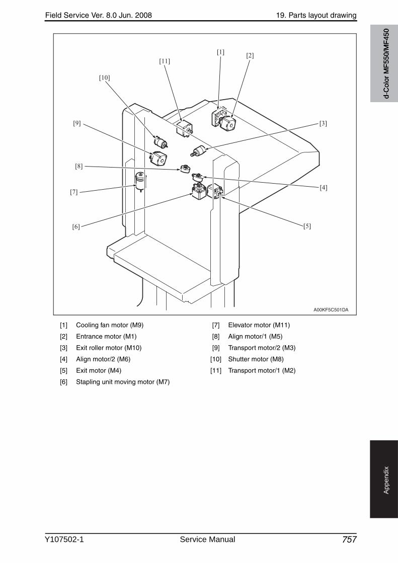
Field Service Ver. 8.0 Jun. 2008 19. Parts layout drawing
757
Ap
pe
nd
ix
[1] Cooling fan motor (M9) [7] Elevator motor (M11)
[2] Entrance motor (M1) [8] Align motor/1 (M5)
[3] Exit roller motor (M10) [9] Transport motor/2 (M3)
[4] Align motor/2 (M6) [10] Shutter motor (M8)
[5] Exit motor (M4) [11] Transport motor/1 (M2)
[6] Stapling unit moving motor (M7)
A00KF5C501DA
[3]
[4]
[5]
[10]
[9]
[7]
[6]
[8]
[11][1] [2]
d-C
olor
MF5
50/M
F450
Y107502-1 Service Manual
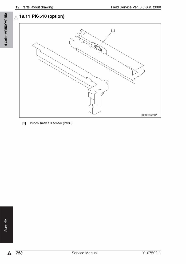
1
19. Parts layout drawing Field Service Ver. 8.0 Jun. 2008
758
Ap
pe
nd
ix
19.11 PK-510 (option)1
[1] Punch Trash full sensor (PS30)
9J06F5C505DA
[1]
d-C
olor
MF5
50/M
F450
Service Manual Y107502-1
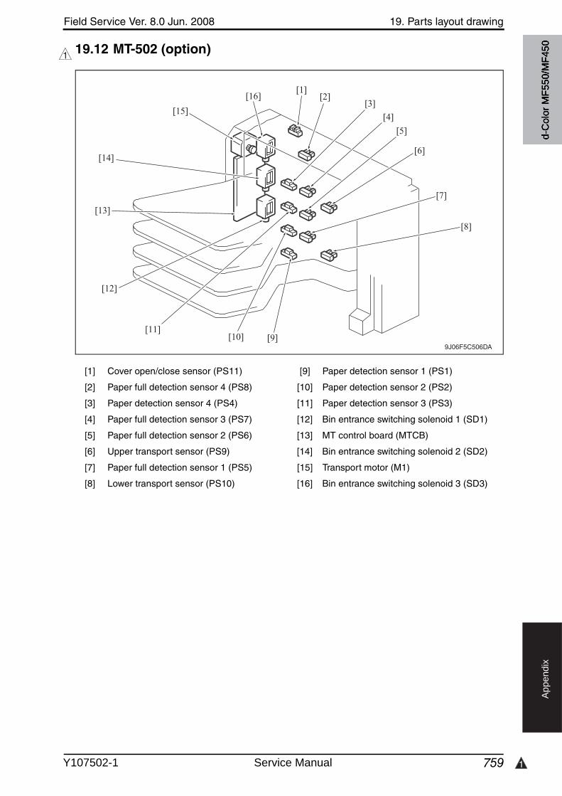
Field Service Ver. 8.0 Jun. 2008 19. Parts layout drawing
759 1
Ap
pe
nd
ix
19.12 MT-502 (option)1
[1] Cover open/close sensor (PS11) [9] Paper detection sensor 1 (PS1)
[2] Paper full detection sensor 4 (PS8) [10] Paper detection sensor 2 (PS2)
[3] Paper detection sensor 4 (PS4) [11] Paper detection sensor 3 (PS3)
[4] Paper full detection sensor 3 (PS7) [12] Bin entrance switching solenoid 1 (SD1)
[5] Paper full detection sensor 2 (PS6) [13] MT control board (MTCB)
[6] Upper transport sensor (PS9) [14] Bin entrance switching solenoid 2 (SD2)
[7] Paper full detection sensor 1 (PS5) [15] Transport motor (M1)
[8] Lower transport sensor (PS10) [16] Bin entrance switching solenoid 3 (SD3)
9J06F5C506DA
[1][2]
[3]
[4]
[5]
[6]
[7]
[8]
[9][10][11]
[12]
[13]
[14]
[15]
[16]
d-C
olor
MF5
50/M
F450
Y107502-1 Service Manual
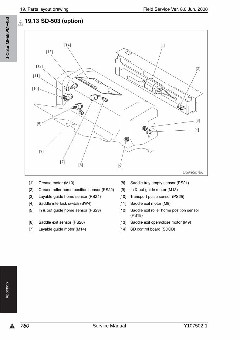
1
19. Parts layout drawing Field Service Ver. 8.0 Jun. 2008
760
Ap
pe
nd
ix
19.13 SD-503 (option)1
[1] Crease motor (M10) [8] Saddle tray empty sensor (PS21)
[2] Crease roller home position sensor (PS22) [9] In & out guide motor (M13)
[3] Layable guide home sensor (PS24) [10] Transport pulse sensor (PS25)
[4] Saddle interlock switch (SW4) [11] Saddle exit motor (M8)
[5] In & out guide home sensor (PS23) [12] Saddle exit roller home position sensor (PS18)
[6] Saddle exit sensor (PS20) [13] Saddle exit open/close motor (M9)
[7] Layable guide motor (M14) [14] SD control board (SDCB)
9J06F5C507DA
[1]
[2]
[3]
[4]
[5][6][7]
[8]
[9]
[14]
[13]
[12]
[11]
[10]
d-C
olor
MF5
50/M
F450
Service Manual Y107502-1
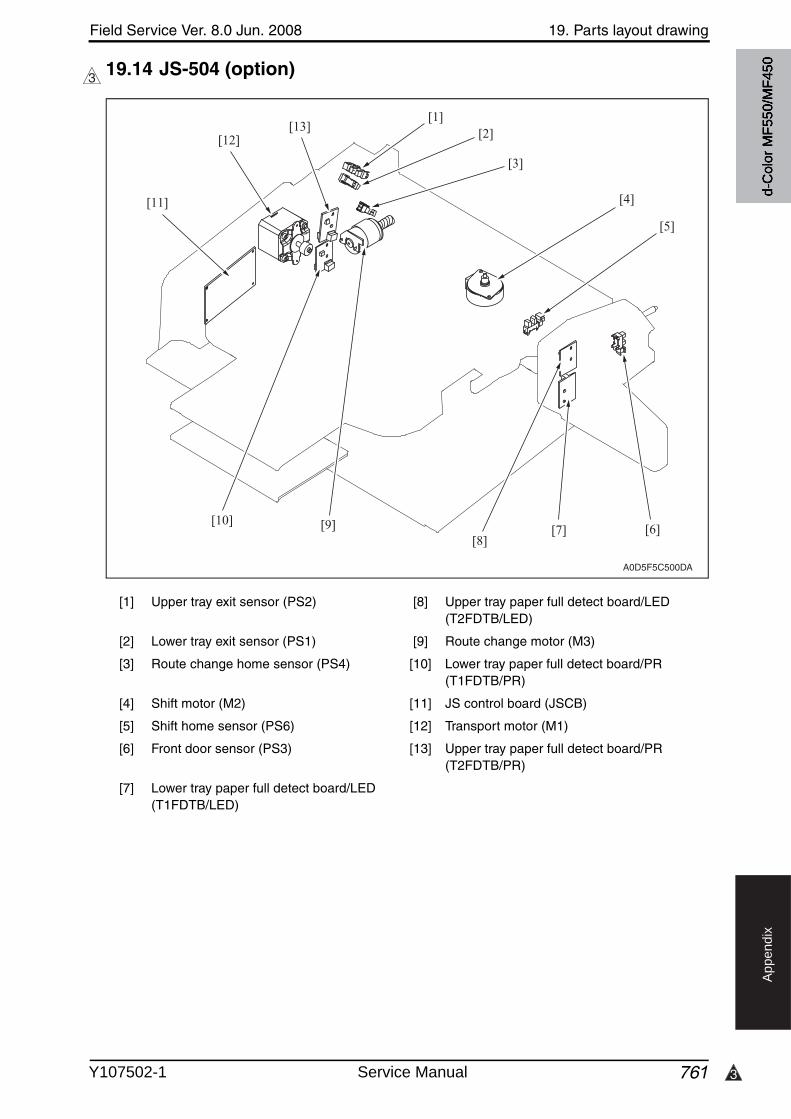
3
Field Service Ver. 8.0 Jun. 2008 19. Parts layout drawing
761
Ap
pe
nd
ix
19.14 JS-504 (option)3
[1] Upper tray exit sensor (PS2) [8] Upper tray paper full detect board/LED (T2FDTB/LED)
[2] Lower tray exit sensor (PS1) [9] Route change motor (M3)
[3] Route change home sensor (PS4) [10] Lower tray paper full detect board/PR (T1FDTB/PR)
[4] Shift motor (M2) [11] JS control board (JSCB)
[5] Shift home sensor (PS6) [12] Transport motor (M1)
[6] Front door sensor (PS3) [13] Upper tray paper full detect board/PR (T2FDTB/PR)
[7] Lower tray paper full detect board/LED(T1FDTB/LED)
A0D5F5C500DA
[1][2]
[3]
[4]
[5]
[6][7][8]
[9][10]
[11]
[12][13]
d-C
olor
MF5
50/M
F450
Y107502-1 Service Manual
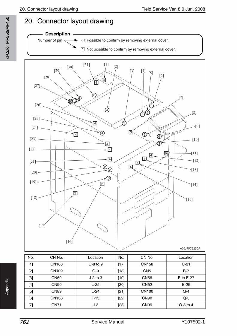
20. Connector layout drawing Field Service Ver. 8.0 Jun. 2008
762
Ap
pe
nd
ix
20. Connector layout drawing
No. CN No. Location No. CN No. Location
[1] CN108 Q-8 to 9 [17] CN158 U-21
[2] CN109 Q-9 [18] CN5 B-7
[3] CN69 J-2 to 3 [19] CN56 E to F-27
[4] CN90 L-25 [20] CN52 E-25
[5] CN89 L-24 [21] CN100 Q-4
[6] CN138 T-15 [22] CN98 Q-3
[7] CN71 J-3 [23] CN99 Q-3 to 4
DescriptionNumber of pin Possible to confirm by removing external cover.
Not possible to confirm by removing external cover.
➀
1
A00JF5C523DA
[1][2]
[3] [4][5]
[6]
[7]
[8]
[9]
[10]
[11]
[12]
[13]
[14]
[15]
[16]
[17]
[18]
[19]
[20]
[21]
[22]
[23]
[24]
[25]
[26]
[27]
[28]
[29][30]
[31]
d-C
olor
MF5
50/M
F450
Service Manual Y107502-1
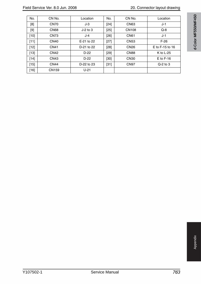
Field Service Ver. 8.0 Jun. 2008 20. Connector layout drawing
763
Ap
pe
nd
ix
[8] CN70 J-3 [24] CN63 J-1
[9] CN68 J-2 to 3 [25] CN108 Q-8
[10] CN73 J-4 [26] CN61 J-1
[11] CN40 E-21 to 22 [27] CN53 F-26
[12] CN41 D-21 to 22 [28] CN26 E to F-15 to 16
[13] CN42 D-22 [29] CN88 K to L-25
[14] CN43 D-22 [30] CN30 E to F-16
[15] CN44 D-22 to 23 [31] CN97 Q-2 to 3
[16] CN159 U-21
No. CN No. Location No. CN No. Location
d-C
olor
MF5
50/M
F450
Y107502-1 Service Manual
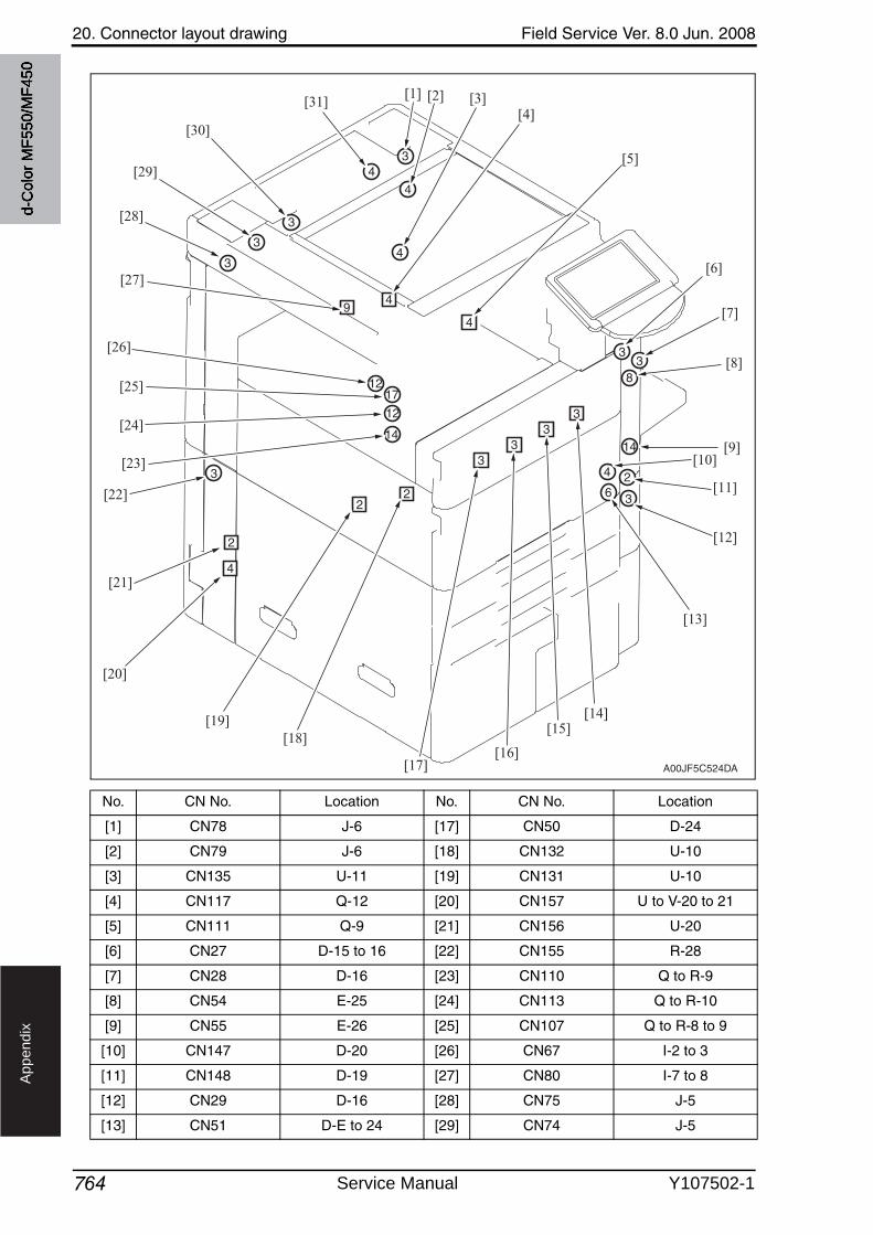
20. Connector layout drawing Field Service Ver. 8.0 Jun. 2008
764
Ap
pe
nd
ix
No. CN No. Location No. CN No. Location
[1] CN78 J-6 [17] CN50 D-24
[2] CN79 J-6 [18] CN132 U-10
[3] CN135 U-11 [19] CN131 U-10
[4] CN117 Q-12 [20] CN157 U to V-20 to 21
[5] CN111 Q-9 [21] CN156 U-20
[6] CN27 D-15 to 16 [22] CN155 R-28
[7] CN28 D-16 [23] CN110 Q to R-9
[8] CN54 E-25 [24] CN113 Q to R-10
[9] CN55 E-26 [25] CN107 Q to R-8 to 9
[10] CN147 D-20 [26] CN67 I-2 to 3
[11] CN148 D-19 [27] CN80 I-7 to 8
[12] CN29 D-16 [28] CN75 J-5
[13] CN51 D-E to 24 [29] CN74 J-5
A00JF5C524DA
[1] [2] [3][4]
[5]
[6]
[7]
[8]
[9][10]
[11]
[12]
[13]
[14][15]
[16][17]
[18][19]
[20]
[21]
[22]
[23]
[24]
[25]
[26]
[27]
[28]
[29]
[30]
[31]
d-C
olor
MF5
50/M
F450
Service Manual Y107502-1
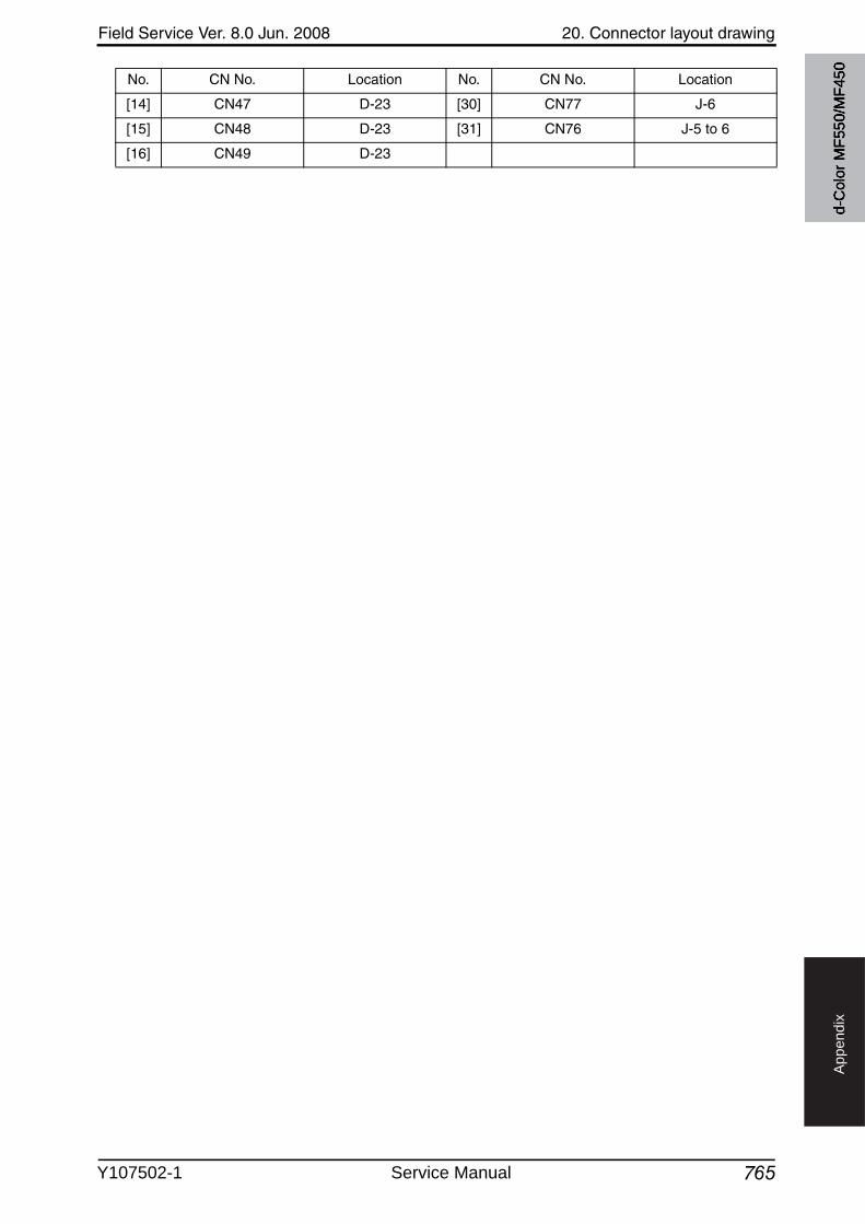
Field Service Ver. 8.0 Jun. 2008 20. Connector layout drawing
765
Ap
pe
nd
ix
[14] CN47 D-23 [30] CN77 J-6
[15] CN48 D-23 [31] CN76 J-5 to 6
[16] CN49 D-23
No. CN No. Location No. CN No. Location
d-C
olor
MF5
50/M
F450
Y107502-1 Service Manual
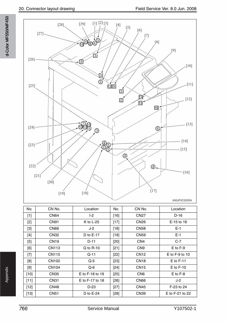
20. Connector layout drawing Field Service Ver. 8.0 Jun. 2008
766
Ap
pe
nd
ix
No. CN No. Location No. CN No. Location
[1] CN64 I-2 [16] CN27 D-16
[2] CN91 K to L-25 [17] CN26 E-15 to 16
[3] CN66 J-2 [18] CN58 E-1
[4] CN32 D to E-17 [19] CN59 E-1
[5] CN19 D-11 [20] CN4 C-7
[6] CN113 Q to R-10 [21] CN9 E to F-9
[7] CN115 Q-11 [22] CN12 E to F-9 to 10
[8] CN102 Q-5 [23] CN18 E to F-11
[9] CN104 Q-6 [24] CN15 E to F-10
[10] CN35 E to F-18 to 19 [25] CN6 E to F-8
[11] CN31 E to F-17 to 18 [26] CN66 J-2
[12] CN48 D-23 [27] CN45 F-23 to 24
[13] CN51 D to E-24 [28] CN39 E to F-21 to 22
A00JF5C525DA
[1] [2] [3] [4][5]
[7]
[8]
[9]
[10]
[11]
[12]
[13]
[14]
[15]
[16]
[17][18][19]
[20]
[21]
[22]
[23]
[24]
[25]
[26]
[27]
[28] [29]
[6]
d-C
olor
MF5
50/M
F450
Service Manual Y107502-1
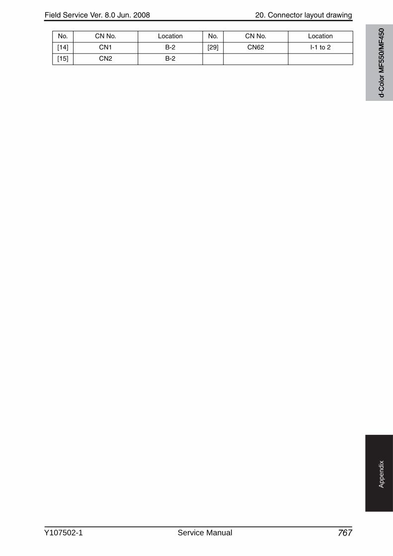
Field Service Ver. 8.0 Jun. 2008 20. Connector layout drawing
767
Ap
pe
nd
ix
[14] CN1 B-2 [29] CN62 I-1 to 2
[15] CN2 B-2
No. CN No. Location No. CN No. Location
d-C
olor
MF5
50/M
F450
Y107502-1 Service Manual
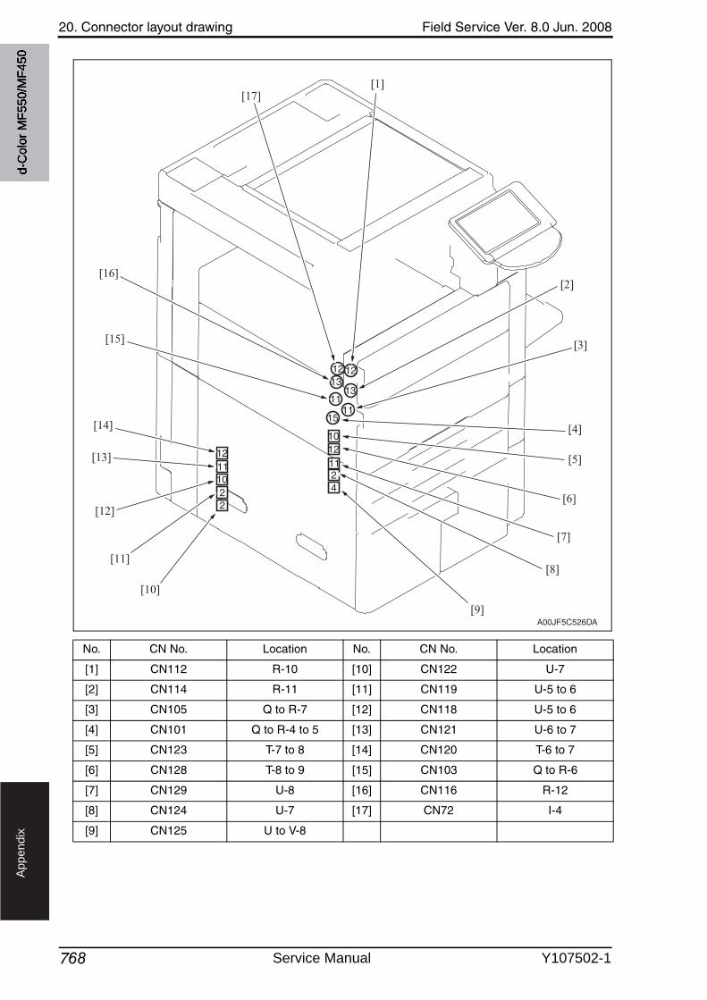
20. Connector layout drawing Field Service Ver. 8.0 Jun. 2008
768
Ap
pe
nd
ix
No. CN No. Location No. CN No. Location
[1] CN112 R-10 [10] CN122 U-7
[2] CN114 R-11 [11] CN119 U-5 to 6
[3] CN105 Q to R-7 [12] CN118 U-5 to 6
[4] CN101 Q to R-4 to 5 [13] CN121 U-6 to 7
[5] CN123 T-7 to 8 [14] CN120 T-6 to 7
[6] CN128 T-8 to 9 [15] CN103 Q to R-6
[7] CN129 U-8 [16] CN116 R-12
[8] CN124 U-7 [17] CN72 I-4
[9] CN125 U to V-8
A00JF5C526DA
[1][17]
[2]
[3]
[4]
[5]
[6]
[7]
[8]
[9]
[10]
[11]
[12]
[13]
[14]
[15]
[16]
d-C
olor
MF5
50/M
F450
Service Manual Y107502-1
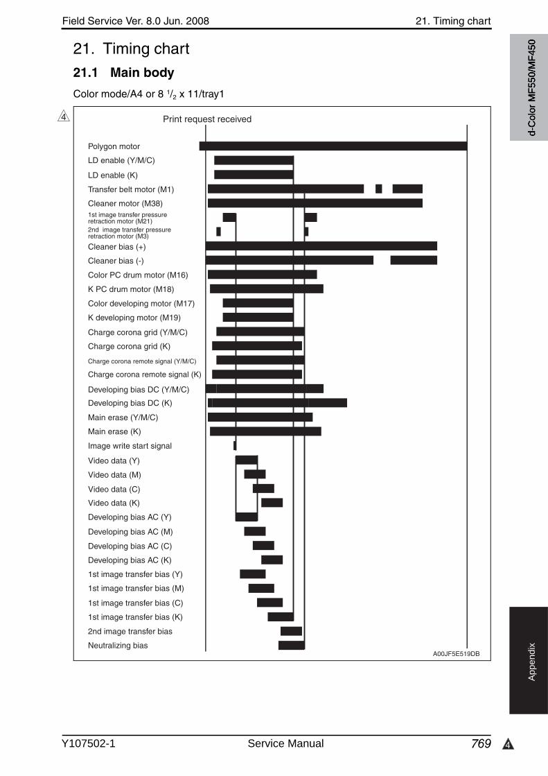
4
Field Service Ver. 8.0 Jun. 2008 21. Timing chart
769
Ap
pe
nd
ix
21. Timing chart
21.1 Main body
Color mode/A4 or 8 1/2 x 11/tray1
4
A00JF5E519DB
Print request received
K PC drum motor (M18)
K developing motor (M19)
Polygon motor
LD enable (K)
Color PC drum motor (M16)
Color developing motor (M17)
Developing bias DC (Y/M/C)
Developing bias DC (K)
Main erase (Y/M/C)
Main erase (K)
Developing bias AC (Y)
Developing bias AC (M)
Developing bias AC (C)
Developing bias AC (K)
Image write start signal
Video data (Y)
Video data (M)
Video data (C)
Video data (K)
Transfer belt motor (M1)
Cleaner motor (M38)1st image transfer pressure retraction motor (M21)2nd image transfer pressure retraction motor (M3)
Cleaner bias (+)
Cleaner bias (-)
Charge corona grid (K)
Charge corona grid (Y/M/C)
Charge corona remote signal (Y/M/C)
Charge corona remote signal (K)
1st image transfer bias (Y)
1st image transfer bias (M)
1st image transfer bias (C)
1st image transfer bias (K)
2nd image transfer bias
Neutralizing bias
LD enable (Y/M/C)
d-C
olor
MF5
50/M
F450
Y107502-1 Service Manual
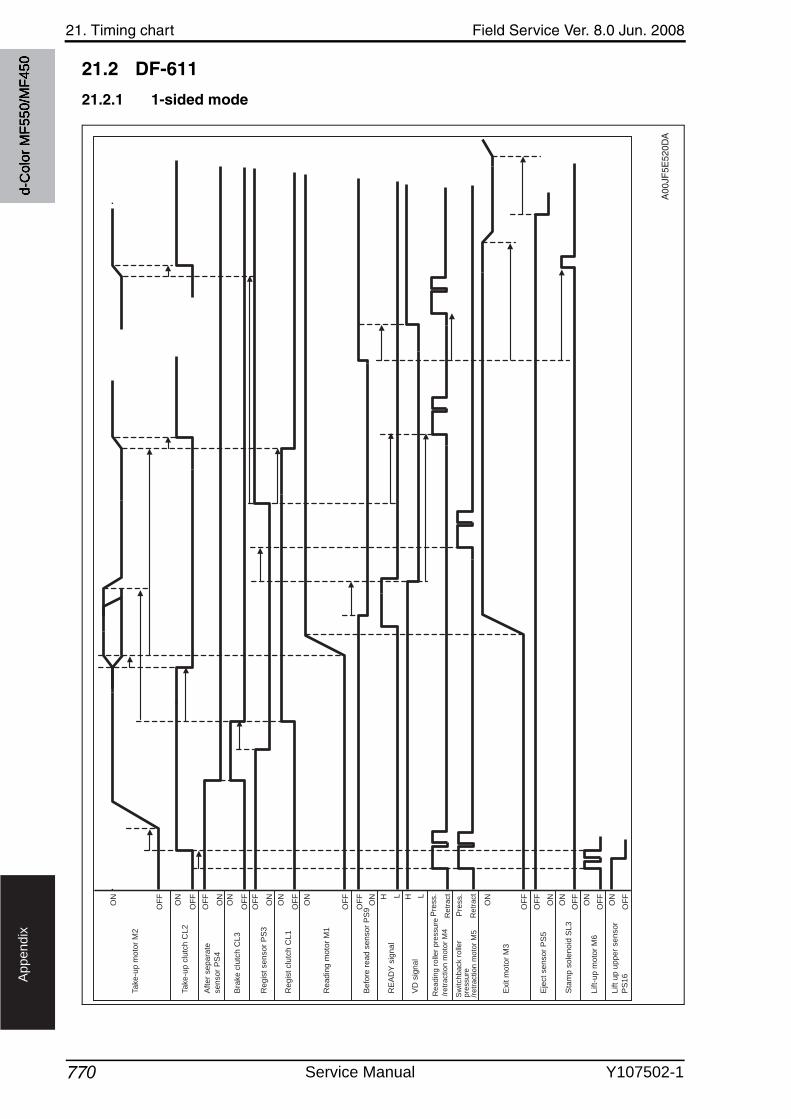
21. Timing chart Field Service Ver. 8.0 Jun. 2008
770
Ap
pe
nd
ix
21.2 DF-611
21.2.1 1-sided mode
A00
JF5E
520D
A
Ta
ke
-up
mo
tor
M2
ON
ON
OF
F
OF
F
Ta
ke
-up
clu
tch
CL
2
OF
F
ON
Aft
er
se
pa
rate
se
nso
r P
S4
ON
OF
FB
rake
clu
tch
CL
3
ON
OF
FR
eg
ist clu
tch
CL
1
OF
F
ON
Be
fore
re
ad
se
nso
r P
S9 O
FF
ON
Eje
ct se
nso
r P
S5
ON
OF
FS
tam
p s
ole
no
id S
L3
ON
OF
FL
ift-
up
mo
tor
M6
ON
OF
F
Lift
up
up
pe
r se
nso
r
PS
16
H LR
EA
DY
sig
na
l
H LV
D s
ign
al
Pre
ss.
Re
tra
ct
Pre
ss.
Re
tra
ct
Re
ad
ing
ro
lle
r p
ressu
re
/retr
action m
oto
r M
4
Sw
itch
ba
ck r
olle
r
pre
ssure
/retr
action m
oto
r M
5
ON
OF
F
Re
ad
ing
mo
tor
M1
ON
OF
F
Exit m
oto
r M
3
OF
F
ON
Re
gis
t se
nso
r P
S3
d-C
olor
MF5
50/M
F450
Service Manual Y107502-1
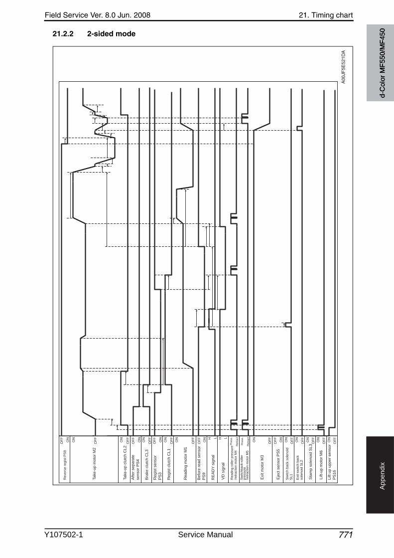
Field Service Ver. 8.0 Jun. 2008 21. Timing chart
771
Ap
pe
nd
ix
21.2.2 2-sided mode
A00
JF5E
521D
A
Revers
e r
egis
t P
S8
ON
ON
OF
F
OF
F
OF
F
ON
OF
F
ON
ON
OF
F
ON
OF
F
OF
F
ON
OF
F
ON
ON
OF
F
ON
OF
F
ON
OF
F
Sw
itch
ba
ck s
ole
no
id
SL1
ON
OF
F
Exit s
witch b
ack
so
len
oid
SL
2
ON
OF
FH L H L
Pre
ss.
Re
tra
ct
Pre
ss.
Re
tra
ct
ON
OF
F
ON
OF
F
OF
F
ON
Ta
ke
-up
mo
tor
M2
Ta
ke
-up
clu
tch
CL
2
Aft
er
se
pa
rate
se
nso
r P
S4
Bra
ke
clu
tch
CL
3
Re
gis
t clu
tch
CL
1
Be
fore
re
ad
se
nso
r
PS
9
Eje
ct
se
nso
r P
S5
Sta
mp
so
len
oid
SL
3
Lift-
up
mo
tor
M6
Lift
up
up
pe
r se
nso
r
PS
16
RE
AD
Y s
ign
al
VD
sig
na
l
Re
ad
ing
ro
lle
r p
ressu
re
/re
tra
ctio
n m
oto
r M
4
Sw
itch
ba
ck r
olle
rp
ressu
re/r
etr
actio
n m
oto
r M
5
Re
ad
ing
mo
tor
M1
Exit m
oto
r M
3
Re
gis
t se
nso
r
PS
3
d-C
olor
MF5
50/M
F450
Y107502-1 Service Manual
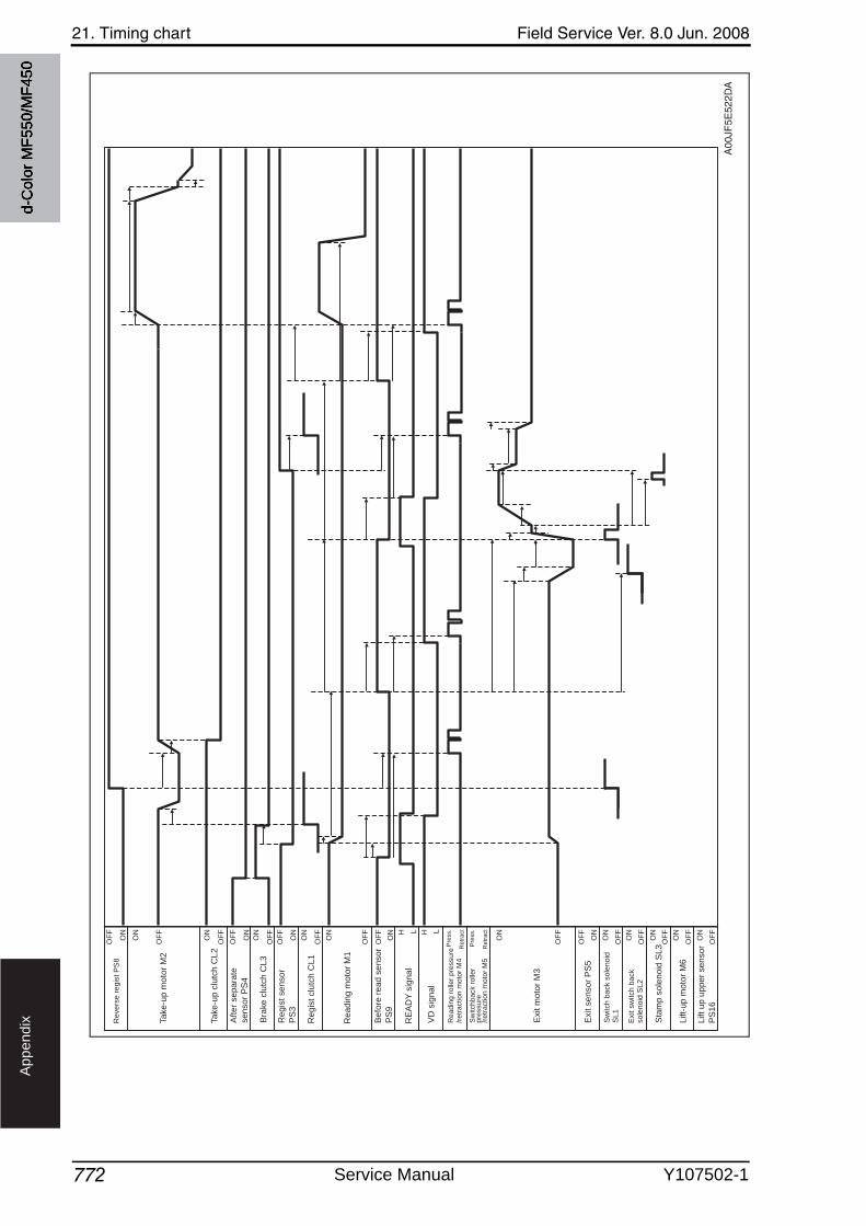
21. Timing chart Field Service Ver. 8.0 Jun. 2008
772
Ap
pe
nd
ix
A00
JF5E
522D
A
ON
ON
OF
F
OF
F
OF
F
ON
OF
F
ON
ON
OF
F
ON
OF
F
OF
F
ON
OF
F
ON
ON
OF
F
ON
OF
F
ON
OF
F
ON
OF
F
ON
OF
FH L H L
Pre
ss.
Retr
act
Pre
ss.
Retr
act
ON
OF
F
ON
OF
F
OF
F
ON
Revers
e r
egis
t P
S8
Sw
itch
ba
ck s
ole
no
id
SL
1
Exit s
witch b
ack
so
len
oid
SL
2
Ta
ke
-up
mo
tor
M2
Ta
ke
-up
clu
tch
CL
2
Aft
er
se
pa
rate
se
nso
r P
S4
Bra
ke
clu
tch
CL
3
Re
gis
t clu
tch
CL
1
Be
fore
re
ad
se
nso
r
PS
9
Exit s
en
so
r P
S5
Sta
mp
so
len
oid
SL
3
Lift-
up
mo
tor
M6
Lift
up
up
pe
r se
nso
r
PS
16
RE
AD
Y s
ign
al
VD
sig
na
l
Re
ad
ing
ro
lle
r p
ressu
re
/re
tra
ctio
n m
oto
r M
4
Sw
itch
ba
ck r
olle
rp
ressu
re/r
etr
actio
n m
oto
r M
5
Re
ad
ing
mo
tor
M1
Exit m
oto
r M
3
Re
gis
t se
nso
r
PS
3
d-C
olor
MF5
50/M
F450
Service Manual Y107502-1

UPDATING STATUS
DATE UPDATED PAGES PAGES CODE
10/2008 1ST EDITION 798 Y107502-1
Related Documents