Cylinders & Valves Full Line Catalog Catalog 1000

Welcome message from author
This document is posted to help you gain knowledge. Please leave a comment to let me know what you think about it! Share it to your friends and learn new things together.
Transcript
Cylinders & ValvesFull Line Catalog
Catalog 1000

2
3www.nopak.com
TABLE OF CONTENTS
Class 1, 2, M Low Pressure Cast-Head Cylinders . . . . . . . . . . . . . . . 5
Class 1 SVR Severe Service Hydraulic and Pneumatic Cylinders . . . . . . . . . .21
Class 3 High Pressure Square-Head Cylinders . . . . . . . . . . . 25
Class 5A Low Pressure NFPA Aluminum Cylinders . . . . . . . . . . . . . . .71
Class 6 Intermediate Pressure Square-Head Cylinders . . . . . . . . . . . 95
Directional Control Valves Hand, Foot and Solenoid . . . . . . . . . 145
Boosters, Intensifiers and Air/Oil Tanks Ram and Piston Type . . . . . . . . . . . . .173
Terms and Conditions of Sale . . . . . . . . . . . . 191
TABLE OF CONTENTS

4
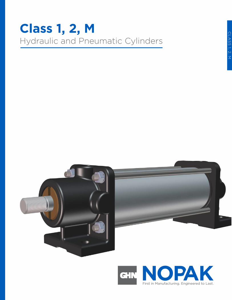
Class 1, 2, MHydraulic and Pneumatic Cylinders
Class 1, 2, M Hydraulic and Pneumatic Cylinders
CL
AS
S 1, 2
, M
6
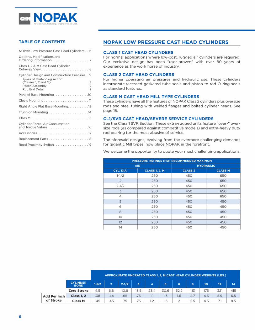
NOPAK LOW PRESSURE CAST HEAD CYLINDERS
CLASS 1 CAST HEAD CYLINDERS For normal applications where low-cost, rugged air cylinders are required. Our exclusive design has been “user-proven” with over 80 years of experience as the work horse of industry.
CLASS 2 CAST HEAD CYLINDERS For higher operating air pressures and hydraulic use. These cylinders incorporate recessed gasketed tube seals and piston to rod O-ring seals as standard features.
CLASS M CAST HEAD MILL TYPE CYLINDERS These cylinders have all the features of NOPAK Class 2 cylinders plus oversize rods and steel tubing with welded flanges and bolted cylinder heads. See page 15.
CL1/SVR CAST HEAD/SEVERE SERVICE CYLINDERS See the Class 1 SVR Section. These extra-rugged units feature “over-” over-size rods (as compared against competitive models) and extra-heavy duty rod bearing for the most abusive of service.
The aforesaid designs, evolving from the evermore challenging demands for gigantic Mill types, now place NOPAK in the forefront.
We welcome the opportunity to quote your most challenging applications.
PRESSURE RATINGS (PSI) RECOMMENDED MAXIMUM
AIR HYDRAULIC
CYL. DIA. CLASS 1, 2, M CLASS 2 CLASS M
1-1/2 250 450 650
2 250 450 650
2-1/2 250 450 650
3 250 450 650
4 250 450 650
5 250 450 450
6 250 450 450
8 250 450 450
10 250 450 450
12 250 450 450
14 250 450 450
APPROXIMATE UNCRATED CLASS 1, 2, M CAST HEAD CYLINDER WEIGHTS (LBS.)
CYLINDER BORE 1-1/2 2 2-1/2 3 4 5 6 8 10 12 14
Zero Stroke 4.5 6.8 10.6 13.5 23.4 30.6 52.2 113 175 321 415
Add Per Inch of Stroke
Class 1, 2 .38 .44 .65 .75 1.1 1.3 1.6 2.7 4.5 5.9 6.5
Class M .45 .45 .75 .75 1.2 1.5 2 2.5 4.5 7.1 8.5
TABLE OF CONTENTS
NOPAK Low Pressure Cast Head Cylinders . . 6
Options, Modifications and Ordering Information . . . . . . . . . . . . . . . . . . . . . .7
Class 1, 2 & M Cast Head Cylinder Cutaway View . . . . . . . . . . . . . . . . . . . . . . . . . . . . 8
Cylinder Design and Construction Features . 9Types of Cushioning Action (Classes 1, 2 and M) 9Piston Assembly 9Rod End Detail 9
Parallel Base Mounting . . . . . . . . . . . . . . . . . . . .10
Clevis Mounting . . . . . . . . . . . . . . . . . . . . . . . . . . 11
Right Angle Flat Base Mounting . . . . . . . . . . . . 12
Trunnion Mounting . . . . . . . . . . . . . . . . . . . . . . . 14
Class M . . . . . . . . . . . . . . . . . . . . . . . . . . . . . . . . . . 15
Cylinder Force, Air Consumption and Torque Values . . . . . . . . . . . . . . . . . . . . . . . . 16
Accessories . . . . . . . . . . . . . . . . . . . . . . . . . . . . . . 17
Replacement Parts . . . . . . . . . . . . . . . . . . . . . . . 18
Reed Proximity Switch . . . . . . . . . . . . . . . . . . . . 19
7www.nopak.com CLASS 1, 2, M
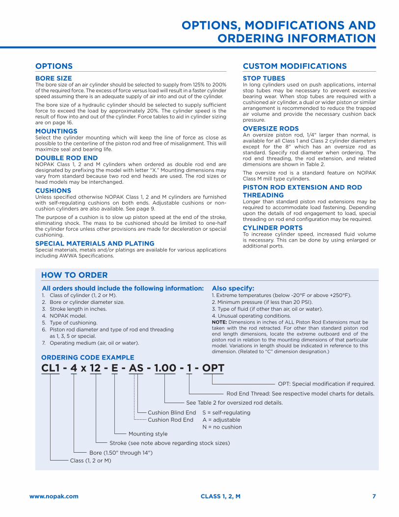
OPTIONS BORE SIZE The bore size of an air cylinder should be selected to supply from 125% to 200% of the required force. The excess of force versus load will result in a faster cylinder speed assuming there is an adequate supply of air into and out of the cylinder.
The bore size of a hydraulic cylinder should be selected to supply sufficient force to exceed the load by approximately 20%. The cylinder speed is the result of flow into and out of the cylinder. Force tables to aid in cylinder sizing are on page 16.
MOUNTINGS Select the cylinder mounting which will keep the line of force as close as possible to the centerline of the piston rod and free of misalignment. This will maximize seal and bearing life.
DOUBLE ROD END NOPAK Class 1, 2 and M cylinders when ordered as double rod end are designated by prefixing the model with letter “X.” Mounting dimensions may vary from standard because two rod end heads are used. The rod sizes or head models may be interchanged.
CUSHIONS Unless specified otherwise NOPAK Class 1, 2 and M cylinders are furnished with self-regulating cushions on both ends. Adjustable cushions or non-cushion cylinders are also available. See page 9.
The purpose of a cushion is to slow up piston speed at the end of the stroke, eliminating shock. The mass to be cushioned should be limited to one-half the cylinder force unless other provisions are made for deceleration or special cushioning.
SPECIAL MATERIALS AND PLATING Special materials, metals and/or platings are available for various applications including AWWA Specifications.
CUSTOM MODIFICATIONS STOP TUBES In long cylinders used on push applications, internal stop tubes may be necessary to prevent excessive bearing wear. When stop tubes are required with a cushioned air cylinder, a dual or wider piston or similar arrangement is recommended to reduce the trapped air volume and provide the necessary cushion back pressure.
OVERSIZE RODS An oversize piston rod, 1/4" larger than normal, is available for all Class 1 and Class 2 cylinder diameters except for the 8" which has an oversize rod as standard. Specify rod diameter when ordering. The rod end threading, the rod extension, and related dimensions are shown in Table 2.
The oversize rod is a standard feature on NOPAK Class M mill type cylinders.
PISTON ROD EXTENSION AND ROD THREADING Longer than standard piston rod extensions may be required to accommodate load fastening. Depending upon the details of rod engagement to load, special threading on rod end configuration may be required.
CYLINDER PORTS To increase cylinder speed, increased fluid volume is necessary. This can be done by using enlarged or additional ports.
HOW TO ORDERAll orders should include the following information:1. Class of cylinder (1, 2 or M).2. Bore or cylinder diameter size.3. Stroke length in inches.4. NOPAK model.5. Type of cushioning.6. Piston rod diameter and type of rod end threading
as 1, 3, 5 or special.7. Operating medium (air, oil or water).
Also specify:1. Extreme temperatures (below -20°F or above +250°F).2. Minimum pressure (if less than 20 PSI).3. Type of fluid (if other than air, oil or water).4. Unusual operating conditions.NOTE: Dimensions in inches of ALL Piston Rod Extensions must be taken with the rod retracted. For other than standard piston rod end length dimensions, locate the extreme outboard end of the piston rod in relation to the mounting dimensions of that particular model. Variations in length should be indicated in reference to this dimension. (Related to “C” dimension designation.)
ORDERING CODE EXAMPLE
CL1 - 4 x 12 - E - AS - 1.00 - 1 - OPT OPT: Special modification if required.
Rod End Thread: See respective model charts for details.
See Table 2 for oversized rod details.
Mounting style
Bore (1.50" through 14")
Stroke (see note above regarding stock sizes)
Class (1, 2 or M)
Cushion Blind EndCushion Rod End
S = self-regulating A = adjustable N = no cushion
OPTIONS, MODIFICATIONS AND ORDERING INFORMATION
8
CLASS 1, 2 & M CAST HEAD CYLINDER CUTAWAY VIEW
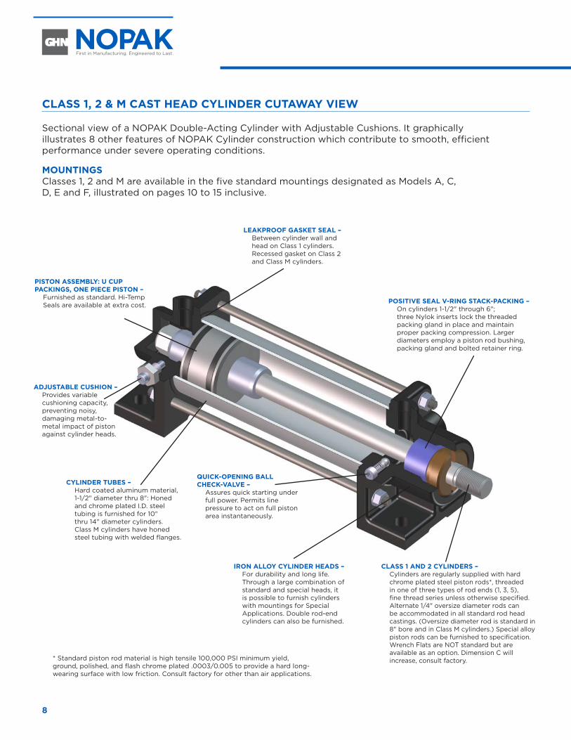
Sectional view of a NOPAK Double-Acting Cylinder with Adjustable Cushions. It graphically illustrates 8 other features of NOPAK Cylinder construction which contribute to smooth, efficient performance under severe operating conditions.
MOUNTINGS Classes 1, 2 and M are available in the five standard mountings designated as Models A, C, D, E and F, illustrated on pages 10 to 15 inclusive.
CLASS 1 AND 2 CYLINDERS – Cylinders are regularly supplied with hard chrome plated steel piston rods*, threaded in one of three types of rod ends (1, 3, 5), fine thread series unless otherwise specified. Alternate 1/4" oversize diameter rods can be accommodated in all standard rod head castings. (Oversize diameter rod is standard in 8" bore and in Class M cylinders.) Special alloy piston rods can be furnished to specification. Wrench Flats are NOT standard but are available as an option. Dimension C will increase, consult factory.
IRON ALLOY CYLINDER HEADS – For durability and long life. Through a large combination of standard and special heads, it is possible to furnish cylinders with mountings for Special Applications. Double rod-end cylinders can also be furnished.
POSITIVE SEAL V-RING STACK-PACKING – On cylinders 1-1/2" through 6"; three Nylok inserts lock the threaded packing gland in place and maintain proper packing compression. Larger diameters employ a piston rod bushing, packing gland and bolted retainer ring.
CYLINDER TUBES – Hard coated aluminum material, 1-1/2" diameter thru 8": Honed and chrome plated I.D. steel tubing is furnished for 10" thru 14" diameter cylinders. Class M cylinders have honed steel tubing with welded flanges.
LEAKPROOF GASKET SEAL – Between cylinder wall and head on Class 1 cylinders. Recessed gasket on Class 2 and Class M cylinders.
PISTON ASSEMBLY: U CUP PACKINGS, ONE PIECE PISTON –
Furnished as standard. Hi-Temp Seals are available at extra cost.
ADJUSTABLE CUSHION – Provides variable cushioning capacity, preventing noisy, damaging metal-to-metal impact of piston against cylinder heads.
QUICK-OPENING BALL CHECK-VALVE –
Assures quick starting under full power. Permits line pressure to act on full piston area instantaneously.
* Standard piston rod material is high tensile 100,000 PSI minimum yield, ground, polished, and flash chrome plated .0003/0.005 to provide a hard long-wearing surface with low friction. Consult factory for other than air applications.
9www.nopak.com CLASS 1, 2, M
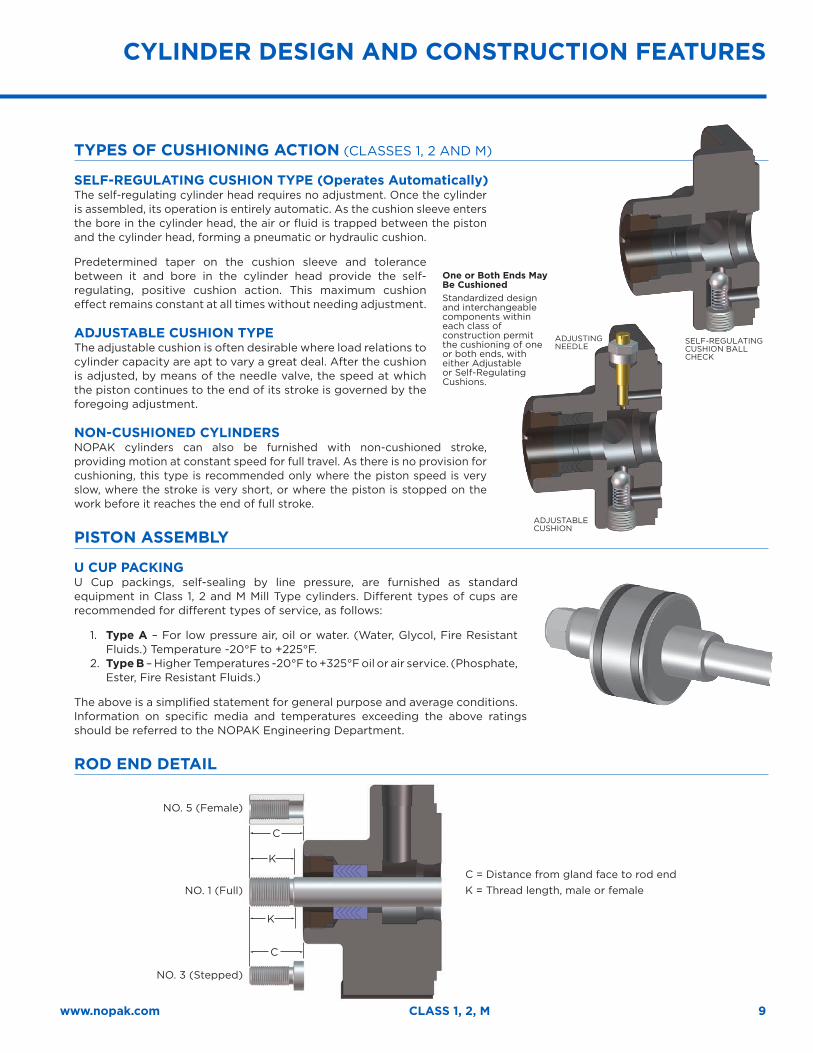
TYPES OF CUSHIONING ACTION (CLASSES 1, 2 AND M)
SELF-REGULATING CUSHION TYPE (Operates Automatically)The self-regulating cylinder head requires no adjustment. Once the cylinder is assembled, its operation is entirely automatic. As the cushion sleeve enters the bore in the cylinder head, the air or fluid is trapped between the piston and the cylinder head, forming a pneumatic or hydraulic cushion.
Predetermined taper on the cushion sleeve and tolerance between it and bore in the cylinder head provide the self-regulating, positive cushion action. This maximum cushion effect remains constant at all times without needing adjustment.
ADJUSTABLE CUSHION TYPEThe adjustable cushion is often desirable where load relations to cylinder capacity are apt to vary a great deal. After the cushion is adjusted, by means of the needle valve, the speed at which the piston continues to the end of its stroke is governed by the foregoing adjustment.
NON-CUSHIONED CYLINDERSNOPAK cylinders can also be furnished with non-cushioned stroke, providing motion at constant speed for full travel. As there is no provision for cushioning, this type is recommended only where the piston speed is very slow, where the stroke is very short, or where the piston is stopped on the work before it reaches the end of full stroke.
PISTON ASSEMBLY
U CUP PACKINGU Cup packings, self-sealing by line pressure, are furnished as standard equipment in Class 1, 2 and M Mill Type cylinders. Different types of cups are recommended for different types of service, as follows:
1. Type A – For low pressure air, oil or water. (Water, Glycol, Fire Resistant Fluids.) Temperature -20°F to +225°F.
2. Type B – Higher Temperatures -20°F to +325°F oil or air service. (Phosphate, Ester, Fire Resistant Fluids.)
The above is a simplified statement for general purpose and average conditions. Information on specific media and temperatures exceeding the above ratings should be referred to the NOPAK Engineering Department.
ROD END DETAIL
CYLINDER DESIGN AND CONSTRUCTION FEATURES
One or Both Ends May Be CushionedStandardized design and interchangeable components within each class of construction permit the cushioning of one or both ends, with either Adjustable or Self-Regulating Cushions.
SELF-REGULATING CUSHION BALL CHECK
ADJUSTING NEEDLE
ADJUSTABLE CUSHION
C
C
K
K
C = Distance from gland face to rod endK = Thread length, male or femaleNO. 1 (Full)
NO. 3 (Stepped)
NO. 5 (Female)
10
MODEL A
A + STROKE
N + STROKE
I
M
JI
J
G
C
O O
K
DIA.
L
R
S
F
PQ
D D
H(NPTTYPE)
R
EF
PQ
D D
S
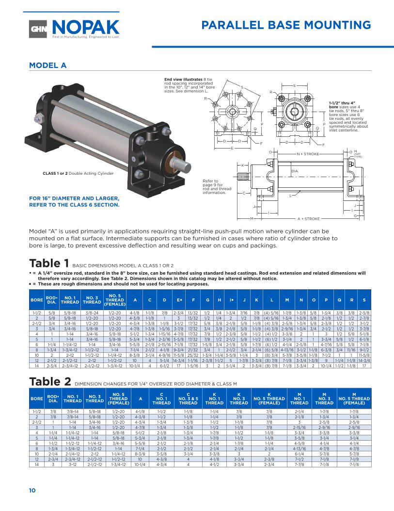
Model “A” is used primarily in applications requiring straight-line push-pull motion where cylinder can be mounted on a flat surface. Intermediate supports can be furnished in cases where ratio of cylinder stroke to bore is large, to prevent excessive deflection and resulting wear on cups and packings.
Table 1 BASIC DIMENSIONS MODEL A CLASS 1 OR 2
• = A 1/4" oversize rod, standard in the 8" bore size, can be furnished using standard head castings. Rod end extension and related dimensions will therefore vary accordingly. See Table 2. Dimensions shown in this catalog may be altered without notice.
� = These are rough dimensions and should not be used for locating purposes.
BORE ROD• DIA.
NO. 1 THREAD
NO. 3 THREAD
NO. 5 THREAD
(FEMALE) A C D E� F G H I� J K L M N O P Q R S
1-1/2 5/8 5/8–18 3/8–24 1/2–20 4-1/8 1-1/8 7/8 2-3/4 13/32 1/2 1/4 1-3/4 7/16 7/8 (4) 5/16 1-7/8 1-3/8 5/8 1-3/4 3/8 3/8 2-5/82 5/8 5/8–18 1/2–20 1/2–20 4-3/8 1-1/8 1 3 13/32 1/2 1/4 2 1/2 7/8 (4) 5/16 1-3/4 1-3/8 5/8 2-1/8 1/2 1/2 2-7/8
2-1/2 3/4 3/4–16 1/2–20 1/2–20 4-3/4 1-3/8 1-1/8 3-1/2 17/32 5/8 3/8 2-1/8 5/8 1-1/8 (4) 3/8 2-5/8 1-3/4 5/8 2-3/8 1/2 1/2 3-1/23 3/4 3/4–16 5/8–18 1/2–20 4-7/8 1-3/8 1-5/16 3-7/8 17/32 3/4 3/8 2-1/8 5/8 1-1/8 (4) 3/8 2-9/16 1-3/4 3/4 2-1/2 1/2 1/2 3-7/84 1 1–14 3/4–16 5/8–18 5-1/2 1-3/4 1-15/16 4-7/8 17/32 7/8 1/2 2-3/8 5/8 1-1/2 (4) 1/2 3-3/8 2 1 3 1/2 5/8 5-1/85 1 1–14 3/4–16 5/8–18 5-3/4 1-3/4 2-3/16 5-5/8 17/32 7/8 1/2 2-1/2 5/8 1-1/2 (6) 1/2 3-1/4 2 1 3-3/4 5/8 1/2 6-1/86 1-1/4 1–1/4–12 1–14 3/4–16 5-5/8 2-1/8 2-15/16 7-1/8 17/32 1-5/8 3/4 2-1/8 5/8 1-7/8 (6) 1/2 4-1/4 2-5/8 1 4-7/16 5/8 5/8 7-1/88 1-3/4 1–3/4–12 1–1/2–12 1–14 7-1/4 2-1/2 4-1/8 9-3/4 21/32 3/4 1 2-1/2 3/4 2-1/4 (6) 5/8 4-13/16 3-1/2 1-1/8 6-3/8 3/4 11/16 9-1/210 2 2–12 1–1/2–12 1–1/4–12 8-3/8 3-1/4 4-9/16 11-5/8 25/32 1-3/4 1-1/4 3-5/8 1-1/4 3 (8) 3/4 5-7/8 3-5/8 1-1/8 7-1/2 1 1 11-5/812 2-1/2 2–1/2–12 2–12 1–1/2–12 10 4 5-1/4 14-3/4 1-1/16 2-3/8 1-1/2 5 1-7/8 3-3/4 (8) 7/8 7-1/8 3-3/4 1-3/8 9 1-1/4 1-1/8 14-3/414 2-3/4 2–3/4–12 2–1/2–12 1–3/4–12 10-1/4 4 6-1/2 17 1-5/16 3 2 5-1/4 2 3-3/4 (8) 7/8 7-1/8 3-3/4 2 10-1/4 1-1/2 1-1/8 17
Table 2 DIMENSION CHANGES FOR 1/4" OVERSIZE ROD DIAMETER & CLASS M
BORE ROD• DIA.
NO. 1 THREAD
NO. 3 THREAD
NO. 5 THREAD
(FEMALE) A
C NO. 1
THREAD
CNO. 3 & 5 THREAD
K NO. 1
THREAD
K NO. 3
THREAD
K NO. 5 THREAD
(FEMALE)
M NO. 1
THREAD
M NO. 3
THREAD
M NO. 5 THREAD
(FEMALE)
1-1/2 7/8 7/8–14 5/8–18 1/2–20 4-1/8 1-1/2 1-1/8 1-1/4 7/8 7/8 2-1/4 1-7/8 1-7/82 7/8 7/8–14 5/8–18 1/2–20 4-3/8 1-1/2 1-1/8 1-1/4 7/8 7/8 2-1/8 1-3/4 1-3/4
2-1/2 1 1–14 3/4–16 1/2–20 4-3/4 1-3/4 1-3/8 1-1/2 1-1/8 7/8 3 2-5/8 2-5/83 1 1–14 3/4–16 1/2–20 4-7/8 1-3/4 1-3/8 1-1/2 1-1/8 7/8 2-15/16 2-9/16 2-9/164 1-1/4 1-1/4–12 1–14 5/8–18 5-1/2 2-1/8 1-3/4 1-7/8 1-1/2 1-1/8 3-3/4 3-3/8 3-3/85 1-1/4 1-1/4–12 1–14 5/8–18 5-3/4 2-1/8 1-3/4 1-7/8 1-1/2 1-1/8 3-5/8 3-1/4 3-1/46 1-1/2 1-1/2–12 1-1/4–12 3/4–16 5-5/8 2-1/2 2-1/8 2-1/4 1-7/8 1-1/4 4-5/8 4-1/4 4-1/48 1-3/4 1-3/4–12 1-1/2–12 1–14 7-1/4 2-1/2 2-1/2 2-1/4 2-1/4 2-1/4 4-13/16 4-7/8 4-7/810 2-1/4 2-1/4–12 2–12 1-1/4–12 8-3/8 3-5/8 3-1/4 3-3/8 3 2 6-1/4 5-7/8 5-7/812 2-3/4 2-3/4–12 2-1/2–12 1-1/2–12 10 4-3/8 4 4-1/8 3-3/4 2-3/8 7-1/2 7-1/8 7-1/814 3 3–12 2-1/2–12 1-3/4–12 10-1/4 4-3/4 4 4-1/2 3-3/4 2-3/4 7-7/8 7-1/8 7-1/8
CLASS 1 or 2 Double Acting Cylinder
1-1/2" thru 4" bore sizes use 4 tie rods, 5" thru 8" bore sizes use 6 tie rods, all evenly spaced and located symmetrically about inlet centerline.
PARALLEL BASE MOUNTING
FOR 16" DIAMETER AND LARGER, REFER TO THE CLASS 6 SECTION.
Refer to page 9 for rod and thread information.
End view illustrates 8 tie rod spacing incorporated in the 10", 12" and 14" bore sizes. See dimension L.
11www.nopak.com CLASS 1, 2, M
MODEL E
INLET
O
E
N
A + STROKE
M + STROKE
Q D
C
JJ H
(NPTTYPE)
F
DIA.
L
P
G
G
I
K
INLET
O
E
N
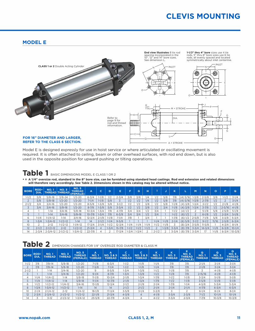
Model E is designed expressly for use in hoist service or where articulated or oscillating movement is required. It is often attached to ceiling, beam or other overhead surfaces, with rod end down, but is also used in the opposite position for upward pushing or tilting operations.
Table 1 BASIC DIMENSIONS MODEL E CLASS 1 OR 2
• = A 1/4" oversize rod, standard in the 8" bore size, can be furnished using standard head castings. Rod end extension and related dimensions will therefore vary accordingly. See Table 2. Dimensions shown in this catalog may be altered without notice.
BORE ROD• DIA.
NO. 1 THREAD
NO. 3 THREAD
NO. 5 THREAD
(FEMALE) A C D E F G H I J K L M N O P Q
1-1/2 5/8 5/8–18 3/8–24 1/2–20 6-3/4 1-1/8 1/2 2-3/4 3/8 3/8 1/4 1/2 5/8 7/8 (4) 5/16 1-3/8 2-5/8 3/8 1-1/2 3-1/42 5/8 5/8–18 1/2–20 1/2–20 7-1/4 1-1/8 5/8 3 1/2 1/2 1/4 1/2 5/8 7/8 (4) 5/16 1-3/8 2-7/8 1/2 2 3-1/4
2-1/2 3/4 3/4–16 1/2–20 1/2–20 8-5/8 1-3/8 5/8 3-1/2 1/2 1/2 3/8 1/2 5/8 1-1/8 (4) 3/8 1-3/4 3-1/2 1/2 2-1/8 4-1/83 3/4 3/4–16 5/8–18 1/2–20 8-7/8 1-3/8 5/8 3-3/4 1/2 1/2 3/8 1/2 3/4 1-1/8 (4) 3/8 1-3/4 3-7/8 1/2 2-5/16 4-1/84 1 1–14 3/4–16 5/8–18 10-3/4 1-3/4 7/8 4-7/8 3/4 3/4 1/2 3/4 1 1-1/2 (4) 1/2 2 5-1/8 5/8 2-5/8 5-1/85 1 1–14 3/4–16 5/8–18 10-7/8 1-3/4 7/8 6-3/8 3/4 3/4 1/2 3/4 1 1-1/2 (6) 1/2 2 6-1/8 1/2 2-3/4 5-1/86 1-1/4 1-1/4–12 1–14 3/4–16 12-3/4 2-1/8 1-1/8 7-1/4 7/8 1 3/4 1 1 1-7/8 (6) 1/2 2-5/8 7-1/8 5/8 3-3/8 5-3/48 1-3/4 1-3/4–12 1-1/2–12 1–14 14 2-1/2 1-1/4 9-5/8 1 1 1 1-1/4 1-1/8 2-1/4 (6) 5/8 3-1/2 9-1/2 11/16 2-5/8 6-3/410 2 2–12 1-1/2–12 1-1/4–12 17-3/4 3-1/4 1-1/2 12-3/4 1-1/4 1-1/4 1-1/4 1-1/2 1-1/8 3 (8) 3/4 3-5/8 11-5/8 1 4-3/4 8-1/412 2-1/2 2-1/2–12 2–12 1-1/2–12 21-3/4 4 1-3/4 15-7/8 1-1/2 1-1/2 1-1/2 2 1-3/8 3-3/4 (8) 7/8 3-3/4 14-3/4 1-1/8 6-3/8 10-1/414 2-3/4 2-3/4–12 2-1/2–12 1-3/4–12 22-7/8 4 2 17-3/4 1-3/4 1-3/4 2 2-1/2 2 3-3/4 (8) 7/8 3-3/4 17 1-1/8 6-3/4 10-3/8
Table 2 DIMENSION CHANGES FOR 1/4" OVERSIZE ROD DIAMETER & CLASS M
BORE ROD• DIA.
NO. 1 THREAD
NO. 3 THREAD
NO. 5 THREAD
(FEMALE)
A NO. 1
THREAD
ANO. 3 & 5 THREAD
C NO. 1
THREAD
CNO. 3 & 5 THREAD
K NO. 1
THREAD
K NO. 3
THREAD
K NO. 5
THREAD (FEMALE)
Q NO. 1
THREAD
Q NO. 3
THREAD
Q NO. 5
THREAD (FEMALE)
1-1/2 7/8 7/8–14 5/8–18 1/2–20 7-1/8 6-3/4 1-1/2 1-1/8 1-1/4 7/8 7/8 2-1/4 3-1/4 3-1/42 7/8 7/8–14 5/8–18 1/2–20 7-5/8 7-1/4 1-1/2 1-1/8 1-1/4 7/8 7/8 2-1/8 3-1/4 3-1/4
2-1/2 1 1–14 3/4–16 1/2–20 9 8-5/8 1-3/4 1-3/8 1-1/2 1-1/8 7/8 3 4-1/8 4-1/83 1 1–14 3/4–16 1/2–20 9-1/4 8-7/8 1-3/4 1-3/8 1-1/2 1-1/8 7/8 2-15/16 4-1/8 4-1/84 1-1/4 1-1/4–12 1–14 5/8–18 11-1/8 10-3/4 2-1/8 1-3/4 1-7/8 1-1/2 1-1/8 3-3/4 5-1/8 5-1/85 1-1/4 1-1/4–12 1–14 5/8–18 11-1/4 10-7/8 2-1/8 1-3/4 1-7/8 1-1/2 1-1/8 3-5/8 5-1/8 5-1/86 1-1/2 1-1/2–12 1-1/4–12 3/4–16 13-1/8 12-3/4 2-1/2 2-1/8 2-1/4 1-7/8 1-1/4 4-5/8 5-3/4 5-3/48 1-3/4 1-3/4–12 1-1/2–12 1–14 14 14 2-1/2 2-1/2 2-1/4 2-1/4 2-1/4 4-7/8 6-3/4 6-3/410 2-1/4 2-1/4–12 2–12 1-1/4–12 18-1/8 17-3/4 3-5/8 3-1/4 3-3/8 3 2 6-1/4 8-1/4 8-1/412 2-3/4 2-3/4–12 2-1/2–12 1-1/2–12 22-1/8 21-3/4 4-3/8 4 4-1/8 3-3/4 2-3/8 7-1/2 10-1/4 10-1/414 3 3–12 2-1/2–12 1-3/4–12 23-5/8 22-7/8 4-3/4 4 4-1/2 3-3/4 2-3/4 7-7/8 10-3/8 10-3/8
End view illustrates 8 tie rod spacing incorporated in the 10", 12" and 14" bore sizes. See dimension L.
CLASS 1 or 2 Double Acting Cylinder
CLEVIS MOUNTING
Refer to page 9 for rod and thread information.
FOR 16" DIAMETER AND LARGER, REFER TO THE CLASS 6 SECTION.
1-1/2" thru 4" bore sizes use 4 tie rods, 5" thru 8" bore sizes use 6 tie rods, all evenly spaced and located symmetrically about inlet centerline.
12
MODEL C BLANK END MOUNTING
A + STROKE
GI
J
L
F (DIA.) F (DIA.)N (RAD.)
C
K
E
M
D
N (RAD.)
E
D
INLET
H (NPT TYPE)
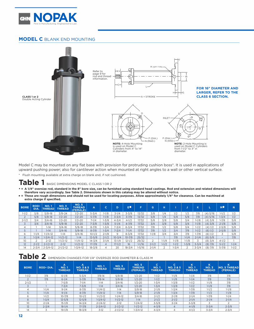
Model C may be mounted on any flat base with provision for protruding cushion boss*. It is used in applications of upward pushing power; also for cantilever action when mounted at right angles to a wall or other vertical surface.* Flush mounting available at extra charge on blank end, if not cushioned.
Table 1 BASIC DIMENSIONS MODEL C CLASS 1 OR 2
• = A 1/4" oversize rod, standard in the 8" bore size, can be furnished using standard head castings. Rod end extension and related dimensions will therefore vary accordingly. See Table 2. Dimensions shown in this catalog may be altered without notice.
� = These are rough dimensions and should not be used for locating purposes. Allow approximately 1/4" for clearance. Can be machined at extra charge if specified.
BORE ROD• DIA.
NO. 1 THREAD
NO. 3 THREAD
NO. 5 THREAD
(FEMALE) A C D E� F G H I J K L M� N
1-1/2 5/8 5/8–18 3/8–24 1/2–20 5-3/4 1-1/8 3-1/4 3-3/8 13/32 3/8 1/4 1/2 1/2 7/8 (4) 5/16 1-1/2 1/22 5/8 5/8–18 1/2–20 1/2–20 5-7/8 1-1/8 3-3/4 3-7/8 13/32 5/8 1/4 5/8 5/8 7/8 (4) 5/16 1-3/4 1/2
2-1/2 3/4 3/4–16 1/2–20 1/2–20 7-1/4 1-3/8 4-3/4 4-1/2 17/32 5/8 3/8 5/8 3/4 1-1/8 (4) 3/8 1-7/8 5/83 3/4 3/4–16 5/8–18 1/2–20 7-3/8 1-3/8 5-1/4 4-7/8 17/32 3/4 3/8 5/8 3/4 1-1/8 (4) 3/8 2-1/8 5/84 1 1–14 3/4–16 5/8–18 8-7/8 1-3/4 7-3/4 6-3/4 17/32 7/8 1/2 5/8 3/4 1-1/2 (4) 1/2 2-5/8 5/85 1 1–14 3/4–16 5/8–18 8-7/8 1-3/4 7-3/4 7-1/4 17/32 7/8 1/2 3/4 7/8 1-1/2 (6) 1/2 2-5/8 5/86 1-1/4 1-1/4–12 1–14 3/4–16 10-1/2 2-1/8 9 8-3/8 17/32 1-1/8 3/4 3/4 7/8 1-7/8 (6) 1/2 3 5/88 1-3/4 1-3/4–12 1-1/2–12 1–14 12-5/8 2-1/2 10-3/4 10-7/8 25/32 – 1 7/8 1-1/4 2-1/4 (6) 5/8 – 7/810 2 2–12 1-1/2–12 1-1/4–12 14-3/4 3-1/4 13-1/4 12-1/2 29/32 2 1-1/4 1-1/8 1-1/8 3 (8) 3/4 4-1/2 112 2-1/2 2-1/2–12 2–12 1-1/2–12 17-7/8 4 17-1/2 16 1-1/16 2-1/2 1-1/2 1-1/2 1-3/8 3-3/4 (8) 7/8 5-1/2 1-1/414 2-3/4 2-3/4–12 2-1/2–12 1-3/4–12 18-3/8 4 20 18-3/4 1-5/16 2-1/4 2 1-3/4 2 3-3/4 (8) 7/8 5-7/8 1-1/2
Table 2 DIMENSION CHANGES FOR 1/4" OVERSIZE ROD DIAMETER & CLASS M
BORE ROD• DIA.A
NO. 1 THREAD
ANO. 3 & 5 THREAD
NO. 1 THREAD
NO. 3 THREAD
NO. 5 THREAD
(FEMALE)
C NO. 1
THREAD
CNO. 3 & 5 THREAD
K NO. 1
THREAD
K NO. 3
THREAD
K NO. 5 THREAD
(FEMALE)
1-1/2 7/8 6-1/8 5-3/4 7/8-14 5/8-18 1/2-20 1-1/2 1-1/8 1-1/4 7/8 7/82 7/8 6-1/4 5-7/8 7/8-14 5/8-18 1/2-20 1-1/2 1-1/8 1-1/4 7/8 7/8
2-1/2 1 7-5/8 7-1/4 1-14 3/4-16 1/2-20 1-3/4 1-3/8 1-1/2 1-1/8 7/83 1 7-3/4 7-3/8 1-14 3/4-16 1/2-20 1-3/4 1-3/8 1-1/2 1-1/8 7/84 1-1/4 9-1/4 8-7/8 1-1/4-12 1-14 5/8-18 2-1/8 1-3/4 1-7/8 1-1/2 1-1/85 1-1/4 9-1/4 8-7/8 1-1/4-12 1-14 5/8-18 2-1/8 1-3/4 1-7/8 1-1/2 1-1/86 1-1/2 10-7/8 10-1/2 1-1/2-12 1-1/4-12 3/4-16 2-1/2 2-1/8 2-1/4 1-7/8 1-1/48 1-3/4 12-5/8 12-5/8 1-3/4-12 1-1/2-12 1-14 2-1/2 2-1/2 2-1/4 2-1/4 2-1/410 2-1/4 15-1/8 14-3/4 2-1/4-12 2-12 1-1/4-12 3-5/8 3-1/4 3-3/8 3 212 2-3/4 18-1/4 17-7/8 2-3/4-12 2-1/2-12 1-1/2-12 4-3/8 4 4-1/8 3-3/4 2-3/814 3 19-1/8 18-3/8 3-12 2-1/2-12 1-3/4-12 4-3/4 4 4-1/2 3-3/4 2-3/4
CLASS 1 or 2 Double Acting Cylinder
NOTE: 2-Hole Mounting is used on Model C Cylinders from 1-1/2" to 3" in diameter.
NOTE: 4-Hole Mounting is used on Model C Cylinders from 4" to 14" in diameter.
RIGHT ANGLE FLAT BASE MOUNTINGRIGHT ANGLE FLAT BASE MOUNTING
FOR 16" DIAMETER AND LARGER, REFER TO THE CLASS 6 SECTION.
Refer to page 9 for rod and thread information.
13www.nopak.com CLASS 1, 2, M
MODEL D ROD END MOUNTING
A + STROKE
G
O
I
J
L
F (DIA.)F (DIA.)
N (RAD.)
C
K
E
D
N (RAD.)
E
D
M
INLET
H (NPT TYPE)
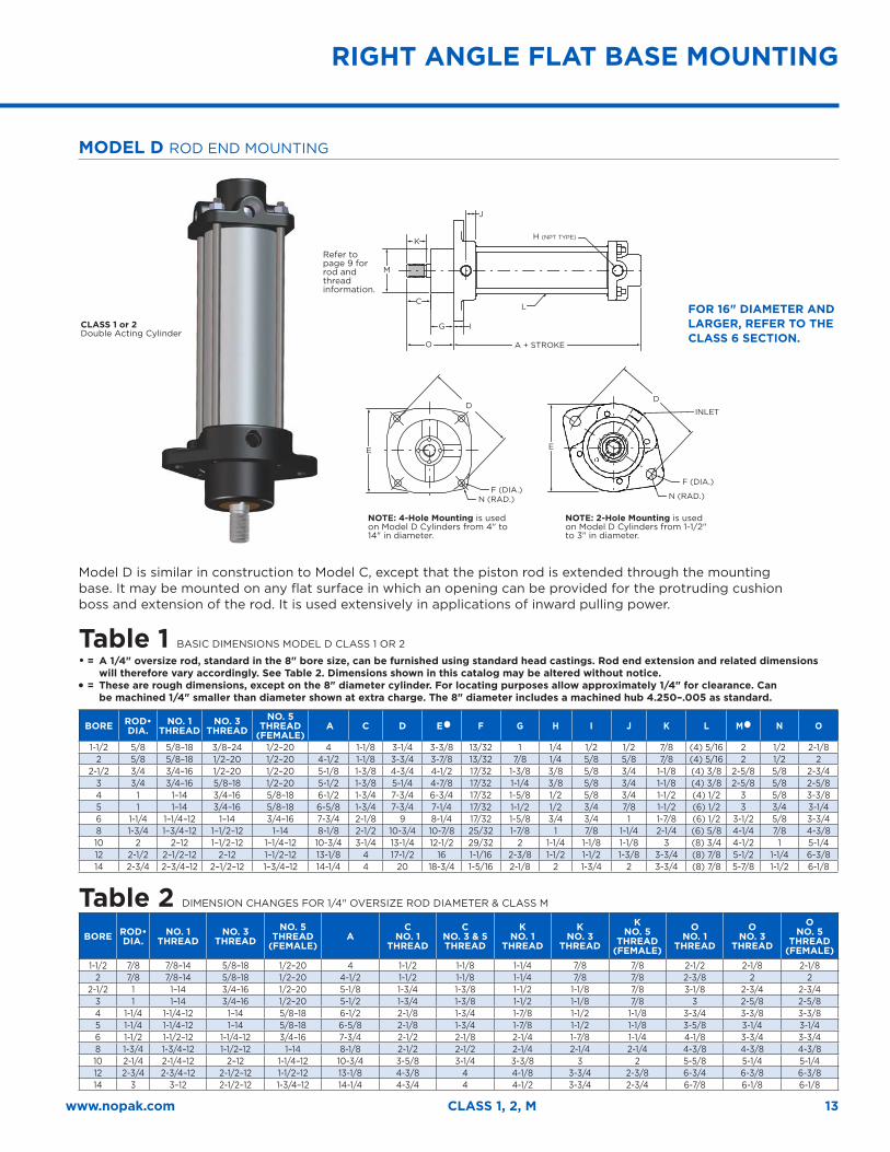
Model D is similar in construction to Model C, except that the piston rod is extended through the mounting base. It may be mounted on any flat surface in which an opening can be provided for the protruding cushion boss and extension of the rod. It is used extensively in applications of inward pulling power.
Table 1 BASIC DIMENSIONS MODEL D CLASS 1 OR 2
• = A 1/4" oversize rod, standard in the 8" bore size, can be furnished using standard head castings. Rod end extension and related dimensions will therefore vary accordingly. See Table 2. Dimensions shown in this catalog may be altered without notice.
� = These are rough dimensions, except on the 8" diameter cylinder. For locating purposes allow approximately 1/4" for clearance. Can be machined 1/4" smaller than diameter shown at extra charge. The 8" diameter includes a machined hub 4.250–.005 as standard.
BORE ROD• DIA.
NO. 1 THREAD
NO. 3 THREAD
NO. 5 THREAD
(FEMALE) A C D E� F G H I J K L M� N O
1-1/2 5/8 5/8–18 3/8–24 1/2–20 4 1-1/8 3-1/4 3-3/8 13/32 1 1/4 1/2 1/2 7/8 (4) 5/16 2 1/2 2-1/82 5/8 5/8–18 1/2–20 1/2–20 4-1/2 1-1/8 3-3/4 3-7/8 13/32 7/8 1/4 5/8 5/8 7/8 (4) 5/16 2 1/2 2
2-1/2 3/4 3/4–16 1/2–20 1/2–20 5-1/8 1-3/8 4-3/4 4-1/2 17/32 1-3/8 3/8 5/8 3/4 1-1/8 (4) 3/8 2-5/8 5/8 2-3/43 3/4 3/4–16 5/8–18 1/2–20 5-1/2 1-3/8 5-1/4 4-7/8 17/32 1-1/4 3/8 5/8 3/4 1-1/8 (4) 3/8 2-5/8 5/8 2-5/84 1 1–14 3/4–16 5/8–18 6-1/2 1-3/4 7-3/4 6-3/4 17/32 1-5/8 1/2 5/8 3/4 1-1/2 (4) 1/2 3 5/8 3-3/85 1 1–14 3/4–16 5/8–18 6-5/8 1-3/4 7-3/4 7-1/4 17/32 1-1/2 1/2 3/4 7/8 1-1/2 (6) 1/2 3 3/4 3-1/46 1-1/4 1–1/4–12 1–14 3/4–16 7-3/4 2-1/8 9 8-1/4 17/32 1-5/8 3/4 3/4 1 1-7/8 (6) 1/2 3-1/2 5/8 3-3/48 1-3/4 1–3/4–12 1–1/2–12 1–14 8-1/8 2-1/2 10-3/4 10-7/8 25/32 1-7/8 1 7/8 1-1/4 2-1/4 (6) 5/8 4-1/4 7/8 4-3/810 2 2–12 1–1/2–12 1–1/4–12 10-3/4 3-1/4 13-1/4 12-1/2 29/32 2 1-1/4 1-1/8 1-1/8 3 (8) 3/4 4-1/2 1 5-1/412 2-1/2 2–1/2–12 2–12 1–1/2–12 13-1/8 4 17-1/2 16 1-1/16 2-3/8 1-1/2 1-1/2 1-3/8 3-3/4 (8) 7/8 5-1/2 1-1/4 6-3/814 2-3/4 2–3/4–12 2–1/2–12 1–3/4–12 14-1/4 4 20 18-3/4 1-5/16 2-1/8 2 1-3/4 2 3-3/4 (8) 7/8 5-7/8 1-1/2 6-1/8
Table 2 DIMENSION CHANGES FOR 1/4" OVERSIZE ROD DIAMETER & CLASS M
BORE ROD• DIA.
NO. 1 THREAD
NO. 3 THREAD
NO. 5 THREAD
(FEMALE)A
C NO. 1
THREAD
CNO. 3 & 5 THREAD
K NO. 1
THREAD
K NO. 3
THREAD
K NO. 5
THREAD (FEMALE)
O NO. 1
THREAD
O NO. 3
THREAD
O NO. 5
THREAD (FEMALE)
1-1/2 7/8 7/8–14 5/8–18 1/2–20 4 1-1/2 1-1/8 1-1/4 7/8 7/8 2-1/2 2-1/8 2-1/82 7/8 7/8–14 5/8–18 1/2–20 4-1/2 1-1/2 1-1/8 1-1/4 7/8 7/8 2-3/8 2 2
2-1/2 1 1–14 3/4–16 1/2–20 5-1/8 1-3/4 1-3/8 1-1/2 1-1/8 7/8 3-1/8 2-3/4 2-3/43 1 1–14 3/4–16 1/2–20 5-1/2 1-3/4 1-3/8 1-1/2 1-1/8 7/8 3 2-5/8 2-5/84 1-1/4 1-1/4–12 1–14 5/8–18 6-1/2 2-1/8 1-3/4 1-7/8 1-1/2 1-1/8 3-3/4 3-3/8 3-3/85 1-1/4 1-1/4–12 1–14 5/8–18 6-5/8 2-1/8 1-3/4 1-7/8 1-1/2 1-1/8 3-5/8 3-1/4 3-1/46 1-1/2 1-1/2–12 1-1/4–12 3/4–16 7-3/4 2-1/2 2-1/8 2-1/4 1-7/8 1-1/4 4-1/8 3-3/4 3-3/48 1-3/4 1-3/4–12 1-1/2–12 1–14 8-1/8 2-1/2 2-1/2 2-1/4 2-1/4 2-1/4 4-3/8 4-3/8 4-3/810 2-1/4 2-1/4–12 2–12 1-1/4–12 10-3/4 3-5/8 3-1/4 3-3/8 3 2 5-5/8 5-1/4 5-1/412 2-3/4 2-3/4–12 2-1/2–12 1-1/2–12 13-1/8 4-3/8 4 4-1/8 3-3/4 2-3/8 6-3/4 6-3/8 6-3/814 3 3–12 2-1/2–12 1-3/4–12 14-1/4 4-3/4 4 4-1/2 3-3/4 2-3/4 6-7/8 6-1/8 6-1/8
NOTE: 2-Hole Mounting is used on Model D Cylinders from 1-1/2" to 3" in diameter.
NOTE: 4-Hole Mounting is used on Model D Cylinders from 4" to 14" in diameter.
RIGHT ANGLE FLAT BASE MOUNTING
FOR 16" DIAMETER AND LARGER, REFER TO THE CLASS 6 SECTION.
CLASS 1 or 2 Double Acting Cylinder
Refer to page 9 for rod and thread information.
14
MODEL F
A + STROKE
M + STROKE
I - MINIMUM
C
K
J
L
G
TOP INLET (H)
FN
ED
JO
H(NPTTYPE)
G
TOP INLET (H)
F
N
ED
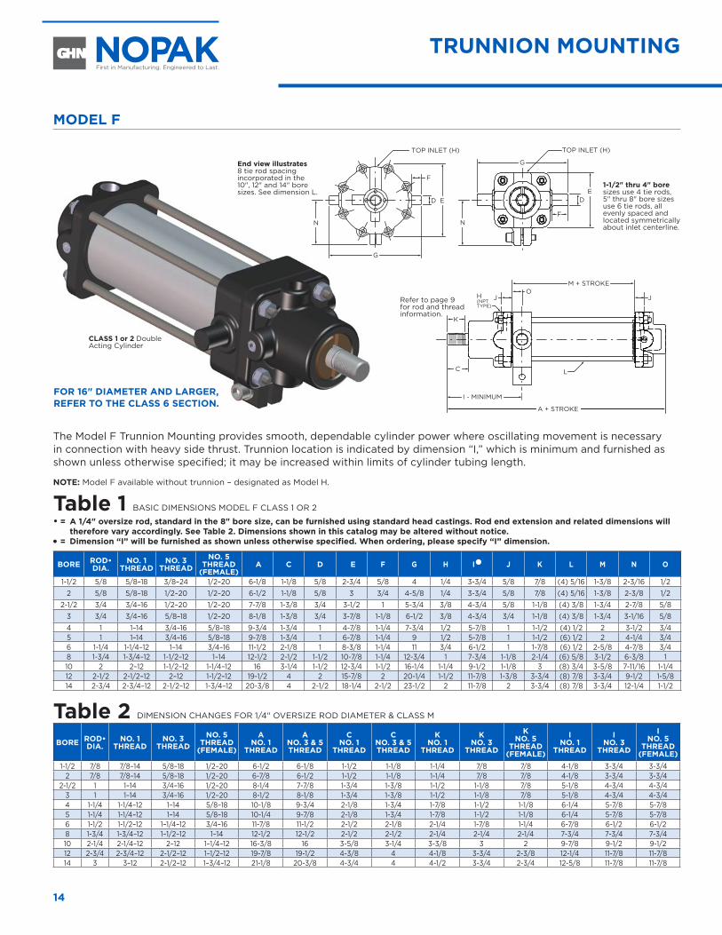
The Model F Trunnion Mounting provides smooth, dependable cylinder power where oscillating movement is necessary in connection with heavy side thrust. Trunnion location is indicated by dimension “I,” which is minimum and furnished as shown unless otherwise specified; it may be increased within limits of cylinder tubing length.
NOTE: Model F available without trunnion – designated as Model H.
Table 1 BASIC DIMENSIONS MODEL F CLASS 1 OR 2
• = A 1/4" oversize rod, standard in the 8" bore size, can be furnished using standard head castings. Rod end extension and related dimensions will therefore vary accordingly. See Table 2. Dimensions shown in this catalog may be altered without notice.
� = Dimension “I” will be furnished as shown unless otherwise specified. When ordering, please specify “I” dimension.
BORE ROD• DIA.
NO. 1 THREAD
NO. 3 THREAD
NO. 5 THREAD
(FEMALE) A C D E F G H I� J K L M N O
1-1/2 5/8 5/8–18 3/8–24 1/2–20 6-1/8 1-1/8 5/8 2-3/4 5/8 4 1/4 3-3/4 5/8 7/8 (4) 5/16 1-3/8 2-3/16 1/22 5/8 5/8–18 1/2–20 1/2–20 6-1/2 1-1/8 5/8 3 3/4 4-5/8 1/4 3-3/4 5/8 7/8 (4) 5/16 1-3/8 2-3/8 1/2
2-1/2 3/4 3/4–16 1/2–20 1/2–20 7-7/8 1-3/8 3/4 3-1/2 1 5-3/4 3/8 4-3/4 5/8 1-1/8 (4) 3/8 1-3/4 2-7/8 5/83 3/4 3/4–16 5/8–18 1/2–20 8-1/8 1-3/8 3/4 3-7/8 1-1/8 6-1/2 3/8 4-3/4 3/4 1-1/8 (4) 3/8 1-3/4 3-1/16 5/84 1 1–14 3/4–16 5/8–18 9-3/4 1-3/4 1 4-7/8 1-1/4 7-3/4 1/2 5-7/8 1 1-1/2 (4) 1/2 2 3-1/2 3/45 1 1–14 3/4–16 5/8–18 9-7/8 1-3/4 1 6-7/8 1-1/4 9 1/2 5-7/8 1 1-1/2 (6) 1/2 2 4-1/4 3/46 1-1/4 1-1/4–12 1–14 3/4–16 11-1/2 2-1/8 1 8-3/8 1-1/4 11 3/4 6-1/2 1 1-7/8 (6) 1/2 2-5/8 4-7/8 3/48 1-3/4 1-3/4–12 1-1/2–12 1–14 12-1/2 2-1/2 1-1/2 10-7/8 1-1/4 12-3/4 1 7-3/4 1-1/8 2-1/4 (6) 5/8 3-1/2 6-3/8 110 2 2–12 1-1/2–12 1-1/4–12 16 3-1/4 1-1/2 12-3/4 1-1/2 16-1/4 1-1/4 9-1/2 1-1/8 3 (8) 3/4 3-5/8 7-11/16 1-1/412 2-1/2 2-1/2–12 2–12 1-1/2–12 19-1/2 4 2 15-7/8 2 20-1/4 1-1/2 11-7/8 1-3/8 3-3/4 (8) 7/8 3-3/4 9-1/2 1-5/814 2-3/4 2-3/4–12 2-1/2–12 1-3/4–12 20-3/8 4 2-1/2 18-1/4 2-1/2 23-1/2 2 11-7/8 2 3-3/4 (8) 7/8 3-3/4 12-1/4 1-1/2
Table 2 DIMENSION CHANGES FOR 1/4" OVERSIZE ROD DIAMETER & CLASS M
BORE ROD• DIA.
NO. 1 THREAD
NO. 3 THREAD
NO. 5 THREAD
(FEMALE)
A NO. 1
THREAD
ANO. 3 & 5 THREAD
C NO. 1
THREAD
CNO. 3 & 5 THREAD
K NO. 1
THREAD
K NO. 3
THREAD
K NO. 5
THREAD (FEMALE)
I NO. 1
THREAD
I NO. 3
THREAD
I NO. 5
THREAD (FEMALE)
1-1/2 7/8 7/8–14 5/8–18 1/2–20 6-1/2 6-1/8 1-1/2 1-1/8 1-1/4 7/8 7/8 4-1/8 3-3/4 3-3/42 7/8 7/8–14 5/8–18 1/2–20 6-7/8 6-1/2 1-1/2 1-1/8 1-1/4 7/8 7/8 4-1/8 3-3/4 3-3/4
2-1/2 1 1–14 3/4–16 1/2–20 8-1/4 7-7/8 1-3/4 1-3/8 1-1/2 1-1/8 7/8 5-1/8 4-3/4 4-3/43 1 1–14 3/4–16 1/2–20 8-1/2 8-1/8 1-3/4 1-3/8 1-1/2 1-1/8 7/8 5-1/8 4-3/4 4-3/44 1-1/4 1-1/4–12 1–14 5/8–18 10-1/8 9-3/4 2-1/8 1-3/4 1-7/8 1-1/2 1-1/8 6-1/4 5-7/8 5-7/85 1-1/4 1-1/4–12 1–14 5/8–18 10-1/4 9-7/8 2-1/8 1-3/4 1-7/8 1-1/2 1-1/8 6-1/4 5-7/8 5-7/86 1-1/2 1-1/2–12 1–1/4–12 3/4–16 11-7/8 11-1/2 2-1/2 2-1/8 2-1/4 1-7/8 1-1/4 6-7/8 6-1/2 6-1/28 1-3/4 1-3/4–12 1–1/2–12 1–14 12-1/2 12-1/2 2-1/2 2-1/2 2-1/4 2-1/4 2-1/4 7-3/4 7-3/4 7-3/410 2-1/4 2-1/4–12 2–12 1–1/4–12 16-3/8 16 3-5/8 3-1/4 3-3/8 3 2 9-7/8 9-1/2 9-1/212 2-3/4 2-3/4–12 2-1/2–12 1–1/2–12 19-7/8 19-1/2 4-3/8 4 4-1/8 3-3/4 2-3/8 12-1/4 11-7/8 11-7/814 3 3–12 2-1/2–12 1–3/4–12 21-1/8 20-3/8 4-3/4 4 4-1/2 3-3/4 2-3/4 12-5/8 11-7/8 11-7/8
CLASS MTRUNNION MOUNTING
CLASS 1 or 2 Double Acting Cylinder
End view illustrates 8 tie rod spacing incorporated in the 10", 12" and 14" bore sizes. See dimension L.
FOR 16" DIAMETER AND LARGER, REFER TO THE CLASS 6 SECTION.
Refer to page 9 for rod and thread information.
1-1/2" thru 4" bore sizes use 4 tie rods, 5" thru 8" bore sizes use 6 tie rods, all evenly spaced and located symmetrically about inlet centerline.
15www.nopak.com CLASS 1, 2, M
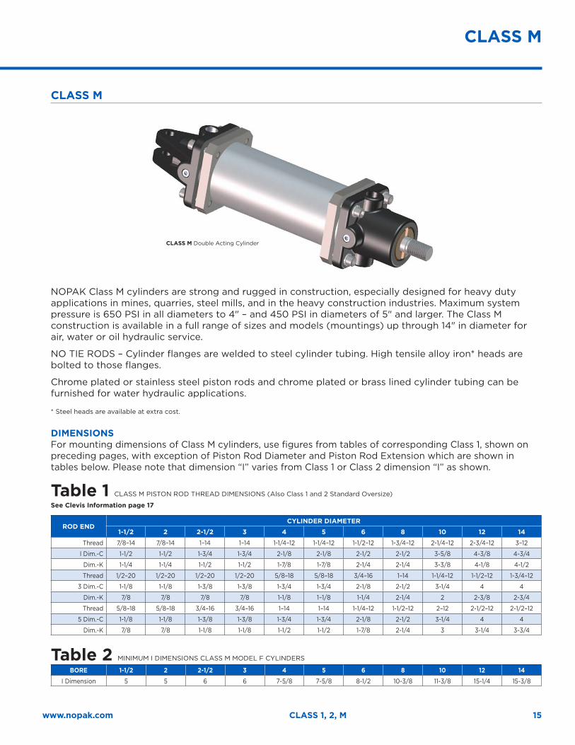
CLASS M
NOPAK Class M cylinders are strong and rugged in construction, especially designed for heavy duty applications in mines, quarries, steel mills, and in the heavy construction industries. Maximum system pressure is 650 PSI in all diameters to 4" – and 450 PSI in diameters of 5" and larger. The Class M construction is available in a full range of sizes and models (mountings) up through 14" in diameter for air, water or oil hydraulic service.
NO TIE RODS – Cylinder flanges are welded to steel cylinder tubing. High tensile alloy iron* heads are bolted to those flanges.
Chrome plated or stainless steel piston rods and chrome plated or brass lined cylinder tubing can be furnished for water hydraulic applications.
* Steel heads are available at extra cost.
DIMENSIONSFor mounting dimensions of Class M cylinders, use figures from tables of corresponding Class 1, shown on preceding pages, with exception of Piston Rod Diameter and Piston Rod Extension which are shown in tables below. Please note that dimension “I” varies from Class 1 or Class 2 dimension “I” as shown.
Table 1 CLASS M PISTON ROD THREAD DIMENSIONS (Also Class 1 and 2 Standard Oversize)
See Clevis Information page 17
ROD ENDCYLINDER DIAMETER
1-1/2 2 2-1/2 3 4 5 6 8 10 12 14
Thread 7/8–14 7/8–14 1–14 1–14 1-1/4–12 1-1/4–12 1-1/2–12 1-3/4–12 2-1/4–12 2-3/4–12 3–12
l Dim.-C 1-1/2 1-1/2 1-3/4 1-3/4 2-1/8 2-1/8 2-1/2 2-1/2 3-5/8 4-3/8 4-3/4
Dim.-K 1-1/4 1-1/4 1-1/2 1-1/2 1-7/8 1-7/8 2-1/4 2-1/4 3-3/8 4-1/8 4-1/2
Thread 1/2–20 1/2–20 1/2–20 1/2–20 5/8–18 5/8–18 3/4–16 1–14 1-1/4–12 1-1/2–12 1-3/4–12
3 Dim.-C 1-1/8 1-1/8 1-3/8 1-3/8 1-3/4 1-3/4 2-1/8 2-1/2 3-1/4 4 4
Dim.-K 7/8 7/8 7/8 7/8 1-1/8 1–1/8 1-1/4 2-1/4 2 2-3/8 2-3/4
Thread 5/8–18 5/8–18 3/4–16 3/4–16 1–14 1–14 1-1/4–12 1-1/2–12 2–12 2-1/2–12 2-1/2–12
5 Dim.-C 1-1/8 1-1/8 1-3/8 1-3/8 1-3/4 1-3/4 2-1/8 2-1/2 3-1/4 4 4
Dim.-K 7/8 7/8 1-1/8 1-1/8 1-1/2 1-1/2 1-7/8 2-1/4 3 3-1/4 3-3/4
Table 2 MINIMUM I DIMENSIONS CLASS M MODEL F CYLINDERS
BORE 1-1/2 2 2-1/2 3 4 5 6 8 10 12 14
I Dimension 5 5 6 6 7-5/8 7-5/8 8-1/2 10-3/8 11-3/8 15-1/4 15-3/8
CLASS M
CLASS M Double Acting Cylinder
16
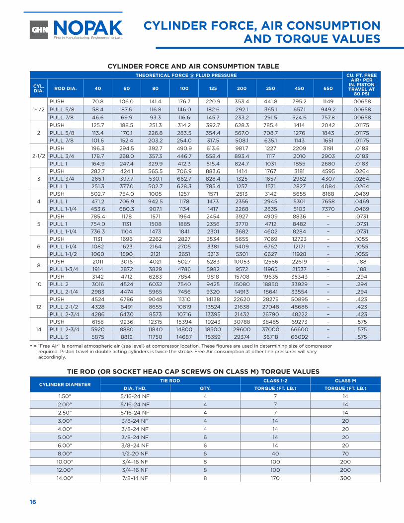
CYLINDER FORCE AND AIR CONSUMPTION TABLE THEORETICAL FORCE @ FLUID PRESSURE CU. FT. FREE
AIR• PER IN. PISTON TRAVEL AT
80 PSI
CYL. DIA. ROD DIA. 40 60 80 100 125 200 250 450 650
1-1/2PUSH 70.8 106.0 141.4 176.7 220.9 353.4 441.8 795.2 1149 .00658PULL 5/8 58.4 87.6 116.8 146.0 182.6 292.1 365.1 657.1 949.2 .00658PULL 7/8 46.6 69.9 93.3 116.6 145.7 233.2 291.5 524.6 757.8 .00658
2PUSH 125.7 188.5 251.3 314.2 392.7 628.3 785.4 1414 2042 .01175PULL 5/8 113.4 170.1 226.8 283.5 354.4 567.0 708.7 1276 1843 .01175PULL 7/8 101.6 152.4 203.2 254.0 317.5 508.1 635.1 1143 1651 .01175
2-1/2PUSH 196.3 294.5 392.7 490.9 613.6 981.7 1227 2209 3191 .0183PULL 3/4 178.7 268.0 357.3 446.7 558.4 893.4 1117 2010 2903 .0183PULL 1 164.9 247.4 329.9 412.3 515.4 824.7 1031 1855 2680 .0183
3PUSH 282.7 424.1 565.5 706.9 883.6 1414 1767 3181 4595 .0264PULL 3/4 265.1 397.7 530.1 662.7 828.4 1325 1657 2982 4307 .0264PULL 1 251.3 377.0 502.7 628.3 785.4 1257 1571 2827 4084 .0264
4PUSH 502.7 754.0 1005 1257 1571 2513 3142 5655 8168 .0469PULL 1 471.2 706.9 942.5 1178 1473 2356 2945 5301 7658 .0469PULL 1-1/4 453.6 680.3 907.1 1134 1417 2268 2835 5103 7370 .0469
5PUSH 785.4 1178 1571 1964 2454 3927 4909 8836 – .0731PULL 1 754.0 1131 1508 1885 2356 3770 4712 8482 – .0731PULL 1-1/4 736.3 1104 1473 1841 2301 3682 4602 8284 – .0731
6PUSH 1131 1696 2262 2827 3534 5655 7069 12723 – .1055PULL 1-1/4 1082 1623 2164 2705 3381 5409 6762 12171 – .1055PULL 1-1/2 1060 1590 2121 2651 3313 5301 6627 11928 – .1055
8PUSH 2011 3016 4021 5027 6283 10053 12566 22619 – .188PULL 1-3/4 1914 2872 3829 4786 5982 9572 11965 21537 – .188
10PUSH 3142 4712 6283 7854 9818 15708 19635 35343 – .294PULL 2 3016 4524 6032 7540 9425 15080 18850 33929 – .294PULL 2-1/4 2983 4474 5965 7456 9320 14913 18641 33554 – .294
12PUSH 4524 6786 9048 11310 14138 22620 28275 50895 – .423PULL 2-1/2 4328 6491 8655 10819 13524 21638 27048 48686 – .423PULL 2-3/4 4286 6430 8573 10716 13395 21432 26790 48222 – .423
14PUSH 6158 9236 12315 15394 19243 30788 38485 69273 – .575PULL 2-3/4 5920 8880 11840 14800 18500 29600 37000 66600 – .575PULL 3 5875 8812 11750 14687 18359 29374 36718 66092 – .575
• = “Free Air” is normal atmospheric air (sea level) at compressor location. These figures are used in determining size of compressor required. Piston travel in double acting cylinders is twice the stroke. Free Air consumption at other line pressures will vary accordingly.
TIE ROD (OR SOCKET HEAD CAP SCREWS ON CLASS M) TORQUE VALUES
CYLINDER DIAMETERTIE ROD CLASS 1-2 CLASS M
DIA. THD. QTY. TORQUE (FT. LB.) TORQUE (FT. LB.)
1.50" 5/16–24 NF 4 7 14
2.00" 5/16–24 NF 4 7 14
2.50" 5/16–24 NF 4 7 14
3.00" 3/8–24 NF 4 14 20
4.00" 3/8–24 NF 4 14 20
5.00" 3/8–24 NF 6 14 20
6.00" 3/8–24 NF 6 14 20
8.00" 1/2–20 NF 6 40 70
10.00" 3/4–16 NF 8 100 200
12.00" 3/4–16 NF 8 100 200
14.00" 7/8–14 NF 8 170 300
CYLINDER FORCE, AIR CONSUMPTION AND TORQUE VALUES
ACCESSORIES
17www.nopak.com CLASS 1, 2, M
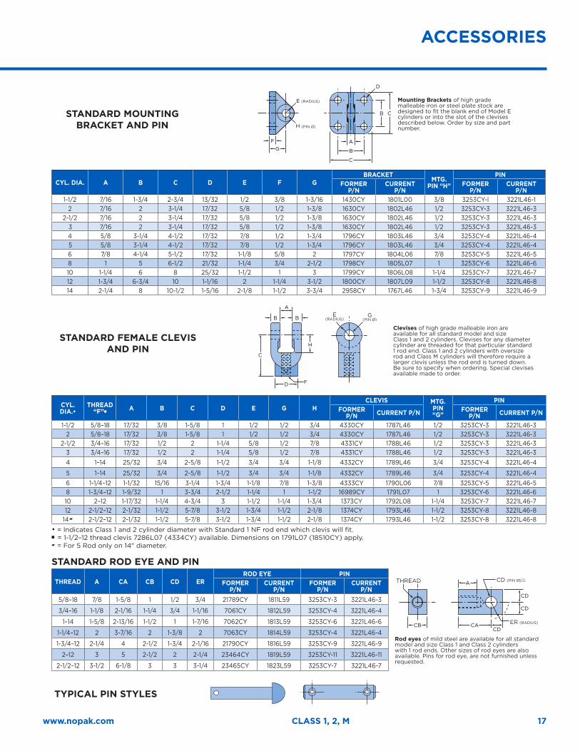
STANDARD MOUNTING BRACKET AND PIN
FG
H
E
D
A
B
A
D
CB CA
A
CD
B
B
C
B
H
CD
CD
C
C
F
(RADIUS)
(PIN Ø)
Mounting Brackets of high grade malleable iron or steel plate stock are designed to fit the blank end of Model E cylinders or into the slot of the clevises described below. Order by size and part number.
CYL. DIA. A B C D E F GBRACKET
MTG. PIN “H”
PINFORMER
P/NCURRENT
P/NFORMER
P/NCURRENT
P/N1-1/2 7/16 1-3/4 2-3/4 13/32 1/2 3/8 1-3/16 1430CY 1801L00 3/8 3253CY-l 3221L46-1
2 7/16 2 3-1/4 17/32 5/8 1/2 1-3/8 1630CY 1802L46 1/2 3253CY-3 3221L46-32-1/2 7/16 2 3-1/4 17/32 5/8 1/2 1-3/8 1630CY 1802L46 1/2 3253CY-3 3221L46-3
3 7/16 2 3-1/4 17/32 5/8 1/2 1-3/8 1630CY 1802L46 1/2 3253CY-3 3221L46-34 5/8 3-1/4 4-1/2 17/32 7/8 1/2 1-3/4 1796CY 1803L46 3/4 3253CY-4 3221L46-4 5 5/8 3-1/4 4-1/2 17/32 7/8 1/2 1-3/4 1796CY 1803L46 3/4 3253CY-4 3221L46-46 7/8 4-1/4 5-1/2 17/32 1-1/8 5/8 2 1797CY 1804L06 7/8 3253CY-5 3221L46-58 1 5 6-1/2 21/32 1-1/4 3/4 2-1/2 1798CY 1805L07 1 3253CY-6 3221L46-610 1-1/4 6 8 25/32 1-1/2 1 3 1799CY 1806L08 1-1/4 3253CY-7 3221L46-712 1-3/4 6-3/4 10 1-1/16 2 1-1/4 3-1/2 1800CY 1807L09 1-1/2 3253CY-8 3221L46-814 2-1/4 8 10-1/2 1-5/16 2-1/8 1-1/2 3-3/4 2958CY 1767L46 1-3/4 3253CY-9 3221L46-9
STANDARD FEMALE CLEVIS AND PIN
FG
H
E
D
A
B
A
D
CB CA
A
CD
B
B
C
B
H
CD
CD
C
C
F
E (RADIUS)
G (PIN Ø)
Clevises of high grade malleable iron are available for all standard model and size Class 1 and 2 cylinders. Clevises for any diameter cylinder are threaded for that particular standard 1 rod end. Class 1 and 2 cylinders with oversize rod and Class M cylinders will therefore require a larger clevis unless the rod end is turned down. Be sure to specify when ordering. Special clevises available made to order.
CYL. DIA.•
THREAD “F”�
A B C D E G HCLEVIS MTG.
PIN “G”
PINFORMER
P/N CURRENT P/N FORMER P/N CURRENT P/N
1-1/2 5/8–18 17/32 3/8 1-5/8 1 1/2 1/2 3/4 4330CY 1787L46 1/2 3253CY-3 3221L46-32 5/8–18 17/32 3/8 1-5/8 1 1/2 1/2 3/4 4330CY 1787L46 1/2 3253CY-3 3221L46-3
2-1/2 3/4–16 17/32 1/2 2 1-1/4 5/8 1/2 7/8 4331CY 1788L46 1/2 3253CY-3 3221L46-33 3/4–16 17/32 1/2 2 1-1/4 5/8 1/2 7/8 4331CY 1788L46 1/2 3253CY-3 3221L46-34 1–14 25/32 3/4 2-5/8 1-1/2 3/4 3/4 1-1/8 4332CY 1789L46 3/4 3253CY-4 3221L46-4
5 1–14 25/32 3/4 2-5/8 1-1/2 3/4 3/4 1-1/8 4332CY 1789L46 3/4 3253CY-4 3221L46-46 1-1/4–12 1-1/32 15/16 3-1/4 1-3/4 1-1/8 7/8 1-3/8 4333CY 1790L06 7/8 3253CY-5 3221L46-58 1-3/4–12 1-9/32 1 3-3/4 2-1/2 1-1/4 1 1-1/2 16989CY 1791L07 1 3253CY-6 3221L46-610 2–12 1-17/32 1-1/4 4-3/4 3 1-1/2 1-1/4 1-3/4 1373CY 1792L08 1-1/4 3253CY-7 3221L46-712 2-1/2–12 2-1/32 1-1/2 5-7/8 3-1/2 1-3/4 1-1/2 2-1/8 1374CY 1793L46 1-1/2 3253CY-8 3221L46-8
14� 2-1/2–12 2-1/32 1-1/2 5-7/8 3-1/2 1-3/4 1-1/2 2-1/8 1374CY 1793L46 1-1/2 3253CY-8 3221L46-8• = Indicates Class 1 and 2 cylinder diameter with Standard 1 NF rod end which clevis will fit. n = 1-1/2–12 thread clevis 7286L07 (4334CY) available. Dimensions on 1791L07 (18510CY) apply. � = For 5 Rod only on 14" diameter.
STANDARD ROD EYE AND PIN
THREAD A CA CB CD ERROD EYE PIN
THREAD + .002+ .004
FG
H
E
D
A
B
A
D
CB CA
A
CD
B
B
C
B
H
CD
CD
C
C
F
ER (RADIUS)
CD (PIN Ø)
Rod eyes of mild steel are available for all standard model and size Class 1 and Class 2 cylinders with 1 rod ends. Other sizes of rod eyes are also available. Pins for rod eye, are not furnished unless requested.
FORMER P/N
CURRENT P/N
FORMER P/N
CURRENT P/N
5/8–18 7/8 1-5/8 1 1/2 3/4 21789CY 1811L59 3253CY-3 3221L46-3
3/4–16 1-1/8 2-1/16 1-1/4 3/4 1-1/16 7061CY 1812L59 3253CY-4 3221L46-4
1–14 1-5/8 2-13/16 1-1/2 1 1-7/16 7062CY 1813L59 3253CY-6 3221L46-6
1-1/4–12 2 3-7/16 2 1-3/8 2 7063CY 1814L59 3253CY-4 3221L46-4
1-3/4–12 2-1/4 4 2-1/2 1-3/4 2-1/16 21790CY 1816L59 3253CY-9 3221L46-9
2–12 3 5 2-1/2 2 2-1/4 23464CY 1819L59 3253CY-11 3221L46-11
2-1/2–12 3-1/2 6-1/8 3 3 3-1/4 23465CY 1823L59 3253CY-7 3221L46-7
TYPICAL PIN STYLES
FG
H
E
D
A
B
A
D
CB CA
A
CD
B
B
C
B
H
CD
CD
C
C
F
ACCESSORIES
18
22 24
25
23
1921
20
18
13
1
1
7 28 8
42
6
5
26
7
28
8 99
27
27
15
10
12
1411 28
289 10 11
12
2
1617
1617
5
287
8
4
1
536
2
REPLACEMENT PARTS
ADJUSTABLE NEEDLE VALVE
8" DIAMETER CYLINDER ROD SEAL ASSEMBLY
8–14" DIAMETER CYLINDER
PISTON ASSEMBLY
10–14" DIAMETER CYLINDER
ROD SEAL ASSEMBLY
BALL CHECK VALVE
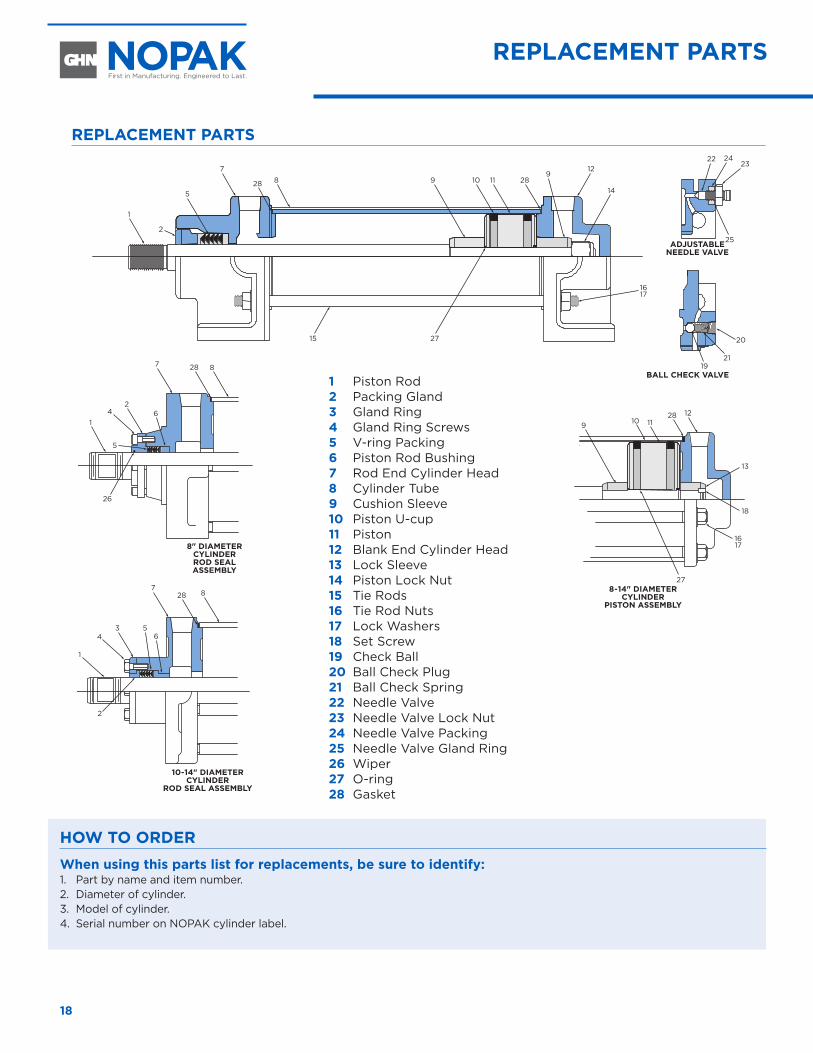
HOW TO ORDERWhen using this parts list for replacements, be sure to identify:1. Part by name and item number.2. Diameter of cylinder.3. Model of cylinder.4. Serial number on NOPAK cylinder label.
1 Piston Rod 2 Packing Gland 3 Gland Ring 4 Gland Ring Screws 5 V-ring Packing 6 Piston Rod Bushing 7 Rod End Cylinder Head 8 Cylinder Tube 9 Cushion Sleeve 10 Piston U-cup11 Piston 12 Blank End Cylinder Head 13 Lock Sleeve14 Piston Lock Nut15 Tie Rods 16 Tie Rod Nuts 17 Lock Washers18 Set Screw19 Check Ball 20 Ball Check Plug 21 Ball Check Spring 22 Needle Valve 23 Needle Valve Lock Nut 24 Needle Valve Packing 25 Needle Valve Gland Ring 26 Wiper27 O-ring28 Gasket
REPLACEMENT PARTS
19www.nopak.com CLASS 1, 2, M
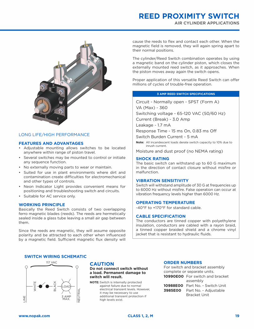
REED PROXIMITY SWITCHAIR CYLINDER APPLICATIONS
LONG LIFE/HIGH PERFORMANCE
FEATURES AND ADVANTAGES• Adjustable mounting allows switches to be located
anywhere within range of piston travel. • Several switches may be mounted to control or initiate
any sequence function. • No externally moving parts to wear or maintain. • Suited for use in plant environments where dirt and
contamination create difficulties for electromechanical and other types of controls.
• Neon Indicator Light provides convenient means for positioning and troubleshooting switch and circuits.
• Suitable for AC service only.
WORKING PRINCIPLEBasically the Reed Switch consists of two overlapping ferro magnetic blades (reeds). The reeds are hermetically sealed inside a glass tube leaving a small air gap between them.
Since the reeds are magnetic, they will assume opposite polarity and be attracted to each other when influenced by a magnetic field. Sufficient magnetic flux density will
cause the reeds to flex and contact each other. When the magnetic field is removed, they will again spring apart to their normal positions.
The cylinder/Reed Switch combination operates by using a magnetic band on the cylinder piston, which closes the externally mounted reed switch, as it approaches. When the piston moves away again the switch opens.
Proper application of this versatile Reed Switch can offer millions of cycles of trouble-free operation.
3 AMP REED SWITCH SPECIFICATIONS
Circuit - Normally open - SPST (Form A) VA (Max) - 360 Switching voltage - 65-120 VAC (50/60 Hz)Current (Break) - 3.0 Amp Leakage - 1.7 mA Response Time - 15 ms On, 0.83 ms OffSwitch Burden Current - 5 mA Note: All incandescent loads derate switch capacity to 10% due to
inrush current.
Moisture and dust proof (no NEMA rating)
SHOCK RATINGThe basic switch can withstand up to 60 G maximum in the direction of contact closure without misfire or malfunction.
VIBRATION SENSITIVITYSwitch will withstand amplitude of 30 G at frequencies up to 6000 Hz without misfire. False operation can occur at vibration frequency levels higher than 6000 Hz.
OPERATING TEMPERATURE-40°F to +170°F for standard cable.
CABLE SPECIFICATIONThe conductors are tinned copper with polyethylene insulation, conductors are cabled with a rayon braid, a tinned copper braided shield and a chrome vinyl jacket that is resistant to hydraulic fluids.
CAUTION Do not connect switch without a load. Permanent damage to switch will result. NOTE: Switch is internally protected
against failure due to normal electrical transient levels. However, it may be necessary to use additional transient protection if high levels exist.
117 VAC
LOAD
3 AMP MAX.
LIN
E
WH
ITE
BLA
CK
NE
UT
RA
L
SWITCH WIRING SCHEMATICORDER NUMBERSFor switch and bracket assembly complete or separate units. 10990E00 For switch and bracket
assembly 10988E00 Part No. - Switch Unit 3985E00 Part No. - Adjustable
Bracket Unit

20
Class 1 SVRSevere Service Hydraulic and Pneumatic Cylinders
Class 1 SVR Severe Service Hydraulic and Pneumatic Cylinders
CL
AS
S 1 S
VR
22
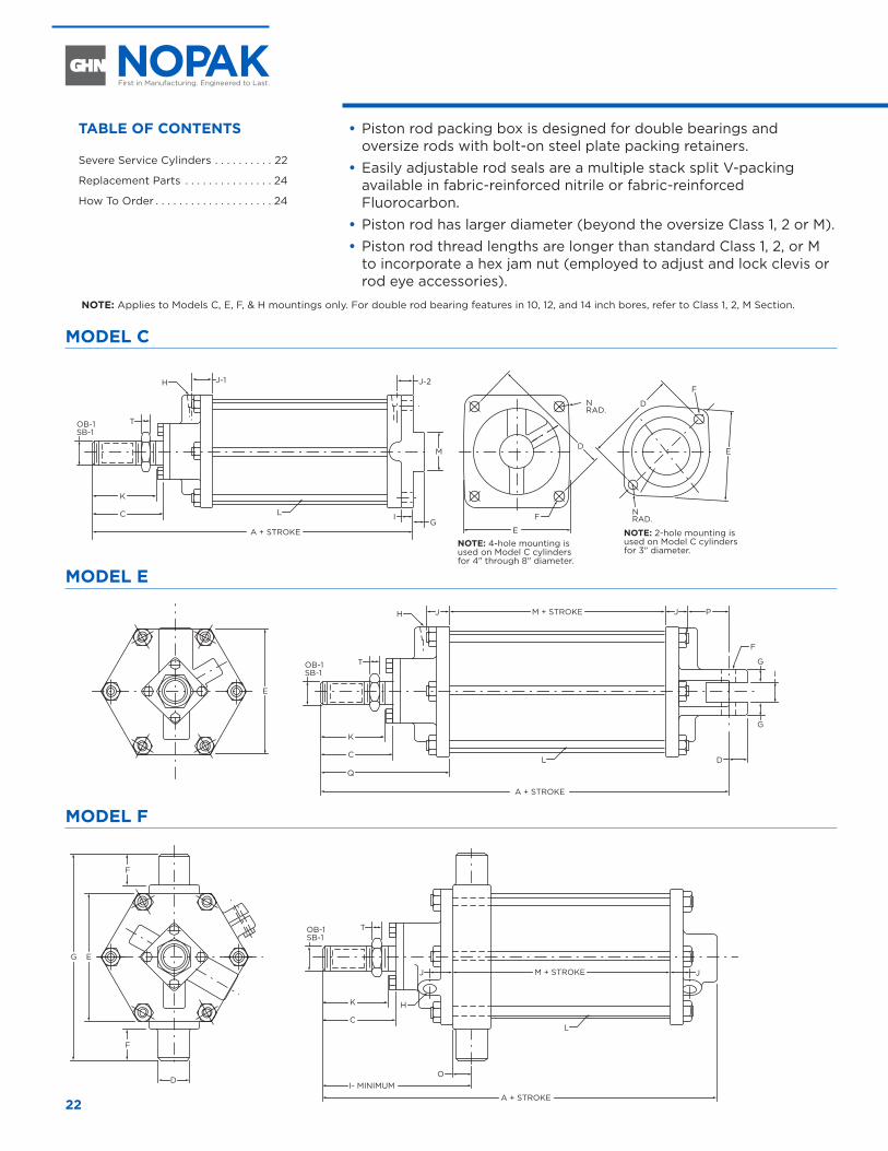
•Piston rod packing box is designed for double bearings and oversize rods with bolt-on steel plate packing retainers.
•Easily adjustable rod seals are a multiple stack split V-packing available in fabric-reinforced nitrile or fabric-reinforced Fluorocarbon.
•Piston rod has larger diameter (beyond the oversize Class 1, 2 or M). •Piston rod thread lengths are longer than standard Class 1, 2, or M
to incorporate a hex jam nut (employed to adjust and lock clevis or rod eye accessories).
NOTE: Applies to Models C, E, F, & H mountings only. For double rod bearing features in 10, 12, and 14 inch bores, refer to Class 1, 2, M Section.
MODEL C
A + STROKE
Q
PJJ
T
D
OB-1SB-1
M + STROKE
JJ M + STROKE
JJ M + STROKE
DC
K
TOB-1SB-1
C IG
K
K
E
EG
F
H
J-1 J-2H
E
H
E
E
F
NRAD.
NRAD.
L
A + STROKE
L
L
F
L
H
F
I- MINIMUMA + STROKE
A + STROKE
TOB-1SB-1
C
O
Q
TOB-1SB-1
C
K
G
GI
M
F
D
D
NOTE: 4-hole mounting is used on Model C cylinders for 4" through 8" diameter.
MODEL E
A + STROKE
Q
PJJ
T
D
OB-1SB-1
M + STROKE
JJ M + STROKE
JJ M + STROKE
DC
K
TOB-1SB-1
C IG
K
K
E
EG
F
H
J-1 J-2H
E
H
E
E
F
NRAD.
NRAD.
L
A + STROKE
L
L
F
L
H
F
I- MINIMUMA + STROKE
A + STROKE
TOB-1SB-1
C
O
Q
TOB-1SB-1
C
K
G
GI
M
F
D
D
MODEL FA + STROKE
Q
PJJ
T
D
OB-1SB-1
M + STROKE
JJ M + STROKE
JJ M + STROKE
DC
K
TOB-1SB-1
C IG
K
K
E
EG
F
H
J-1 J-2H
E
H
E
E
F
NRAD.
NRAD.
L
A + STROKE
L
L
F
L
H
F
I- MINIMUMA + STROKE
A + STROKE
TOB-1SB-1
C
O
Q
TOB-1SB-1
C
K
G
GI
M
F
D
D
NOTE: 2-hole mounting is used on Model C cylinders for 3" diameter.
SEVERE SERVICE CYLINDERS
TABLE OF CONTENTS
Severe Service Cylinders . . . . . . . . . . 22
Replacement Parts . . . . . . . . . . . . . . . 24
How To Order . . . . . . . . . . . . . . . . . . . . 24
23www.nopak.com CLASS 1 SVR
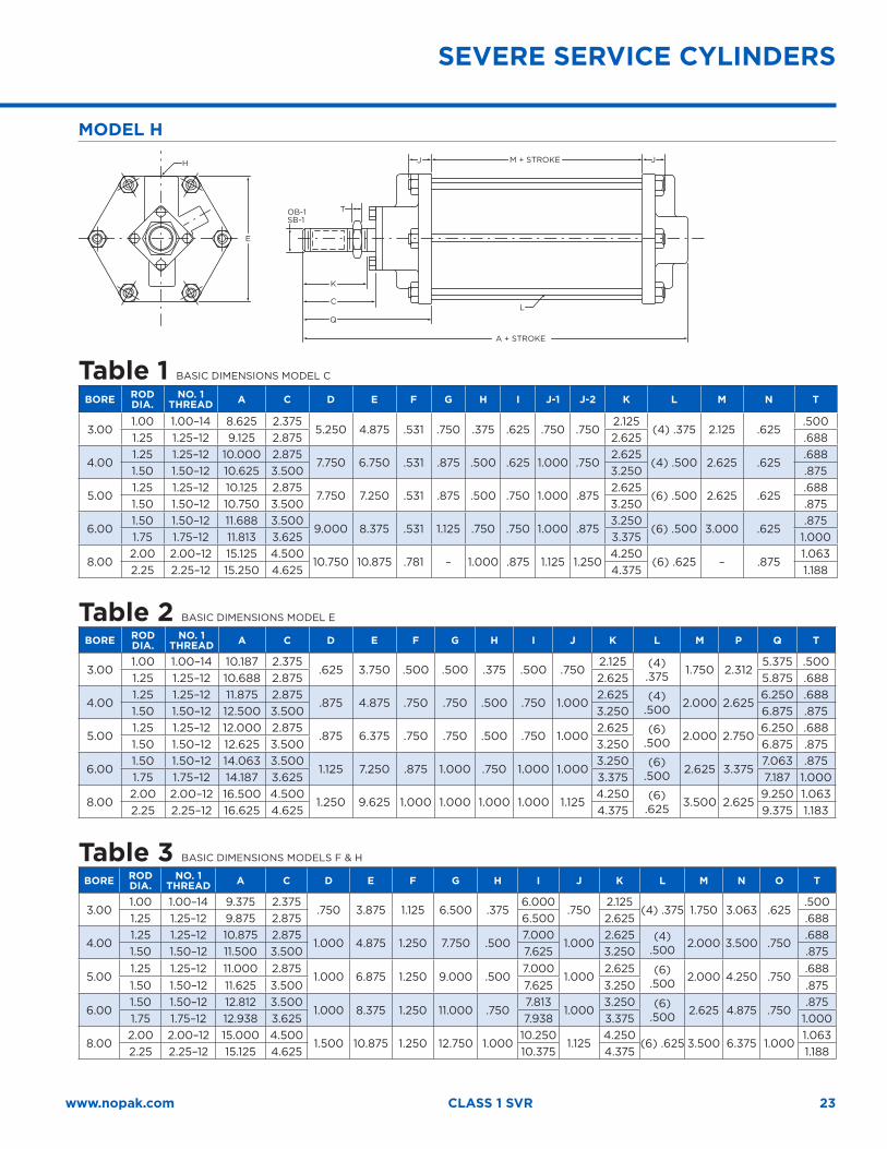
MODEL H
A + STROKE
Q
PJJ
T
D
OB-1SB-1
M + STROKE
JJ M + STROKE
JJ M + STROKE
DC
K
TOB-1SB-1
C IG
K
K
E
EG
F
H
J-1 J-2H
E
H
E
E
F
NRAD.
NRAD.
L
A + STROKE
L
L
F
L
H
F
I- MINIMUMA + STROKE
A + STROKE
TOB-1SB-1
C
O
Q
TOB-1SB-1
C
K
G
GI
M
F
D
D
Table 1 BASIC DIMENSIONS MODEL C BORE ROD
DIA.NO. 1
THREAD A C D E F G H I J-1 J-2 K L M N T
3.001.00 1.00–14 8.625 2.375
5.250 4.875 .531 .750 .375 .625 .750 .7502.125
(4) .375 2.125 .625.500
1.25 1.25–12 9.125 2.875 2.625 .688
4.001.25 1.25–12 10.000 2.875
7.750 6.750 .531 .875 .500 .625 1.000 .7502.625
(4) .500 2.625 .625.688
1.50 1.50–12 10.625 3.500 3.250 .875
5.001.25 1.25–12 10.125 2.875
7.750 7.250 .531 .875 .500 .750 1.000 .8752.625
(6) .500 2.625 .625.688
1.50 1.50–12 10.750 3.500 3.250 .875
6.001.50 1.50–12 11.688 3.500
9.000 8.375 .531 1.125 .750 .750 1.000 .8753.250
(6) .500 3.000 .625.875
1.75 1.75–12 11.813 3.625 3.375 1.000
8.002.00 2.00–12 15.125 4.500
10.750 10.875 .781 – 1.000 .875 1.125 1.2504.250
(6) .625 – .8751.063
2.25 2.25–12 15.250 4.625 4.375 1.188
Table 2 BASIC DIMENSIONS MODEL E BORE ROD
DIA.NO. 1
THREAD A C D E F G H I J K L M P Q T
3.001.00 1.00–14 10.187 2.375
.625 3.750 .500 .500 .375 .500 .7502.125 (4)
.375 1.750 2.3125.375 .500
1.25 1.25–12 10.688 2.875 2.625 5.875 .688
4.001.25 1.25–12 11.875 2.875
.875 4.875 .750 .750 .500 .750 1.0002.625 (4)
.500 2.000 2.6256.250 .688
1.50 1.50–12 12.500 3.500 3.250 6.875 .875
5.001.25 1.25–12 12.000 2.875
.875 6.375 .750 .750 .500 .750 1.0002.625 (6)
.500 2.000 2.7506.250 .688
1.50 1.50–12 12.625 3.500 3.250 6.875 .875
6.00 1.50 1.50–12 14.063 3.500
1.125 7.250 .875 1.000 .750 1.000 1.0003.250 (6)
.500 2.625 3.3757.063 .875
1.75 1.75–12 14.187 3.625 3.375 7.187 1.000
8.002.00 2.00–12 16.500 4.500
1.250 9.625 1.000 1.000 1.000 1.000 1.1254.250 (6)
.625 3.500 2.6259.250 1.063
2.25 2.25–12 16.625 4.625 4.375 9.375 1.183
Table 3 BASIC DIMENSIONS MODELS F & H BORE ROD
DIA.NO. 1
THREAD A C D E F G H I J K L M N O T
3.001.00 1.00–14 9.375 2.375
.750 3.875 1.125 6.500 .3756.000
.7502.125
(4) .375 1.750 3.063 .625.500
1.25 1.25–12 9.875 2.875 6.500 2.625 .688
4.001.25 1.25–12 10.875 2.875
1.000 4.875 1.250 7.750 .5007.000
1.0002.625 (4)
.500 2.000 3.500 .750.688
1.50 1.50–12 11.500 3.500 7.625 3.250 .875
5.001.25 1.25–12 11.000 2.875
1.000 6.875 1.250 9.000 .5007.000
1.0002.625 (6)
.500 2.000 4.250 .750.688
1.50 1.50–12 11.625 3.500 7.625 3.250 .875
6.001.50 1.50–12 12.812 3.500
1.000 8.375 1.250 11.000 .7507.813
1.0003.250 (6)
.500 2.625 4.875 .750.875
1.75 1.75–12 12.938 3.625 7.938 3.375 1.000
8.002.00 2.00–12 15.000 4.500
1.500 10.875 1.250 12.750 1.00010.250
1.1254.250
(6) .625 3.500 6.375 1.0001.063
2.25 2.25–12 15.125 4.625 10.375 4.375 1.188
SEVERE SERVICE CYLINDERS
24
REPLACEMENT PARTS
1
25
3
2
728 8 13
9
1427
21
23
24
22
1920
18
15261617
465
9 11
12
10
ORDERING CODE EXAMPLE
1 - CL1/SVR - 4 x 16 - E - S A - 1.00 - 1
Rod DiameterRod End Thread
Cushion Blind End
Model: C, E, F or H
Bore: 3", 4", 5", 6" or 8"Stroke: Inches and/or fractions
Class: 1, 2, or M
Cushion Rod End Cushion code for rod or blind end
S = self-regulating A = adjustableN = no cushion
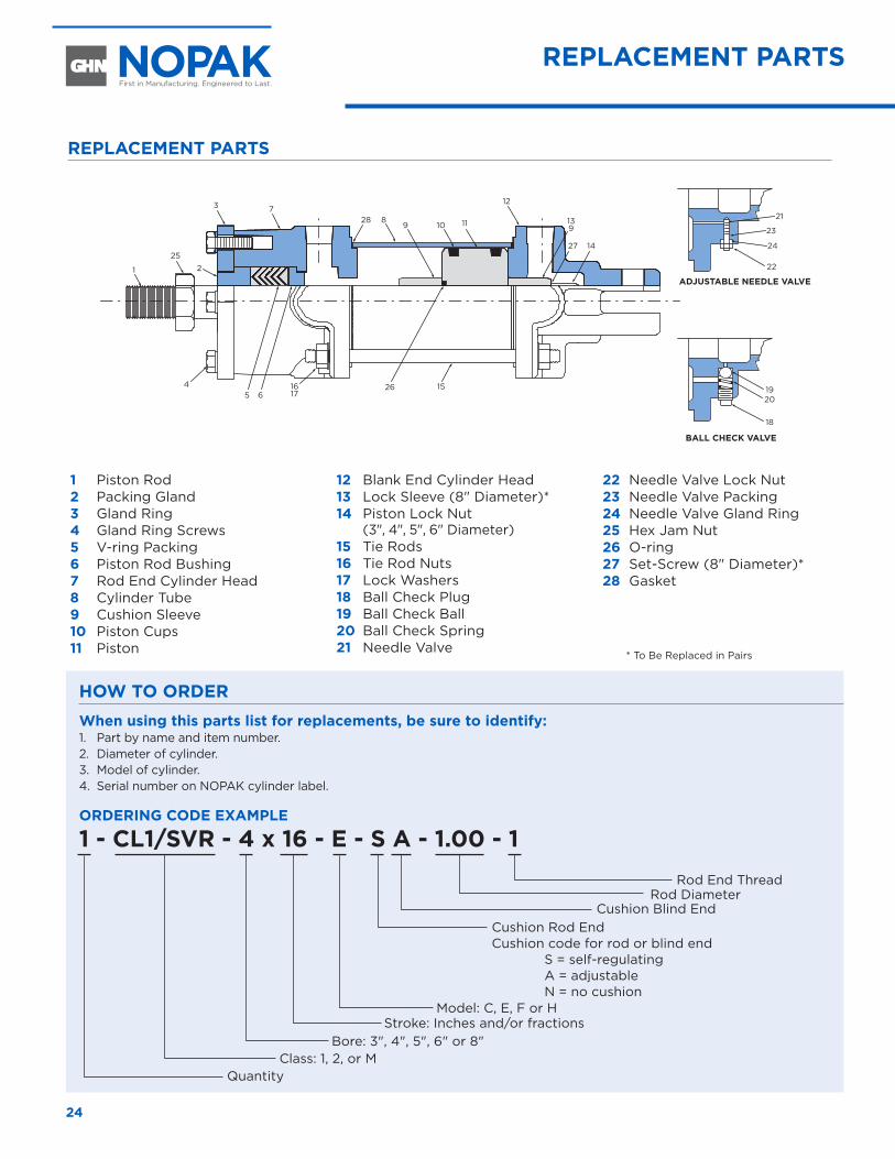
1 Piston Rod 2 Packing Gland 3 Gland Ring 4 Gland Ring Screws 5 V-ring Packing 6 Piston Rod Bushing 7 Rod End Cylinder Head 8 Cylinder Tube 9 Cushion Sleeve 10 Piston Cups 11 Piston
12 Blank End Cylinder Head 13 Lock Sleeve (8" Diameter)* 14 Piston Lock Nut
(3", 4", 5", 6" Diameter)15 Tie Rods 16 Tie Rod Nuts 17 Lock Washers 18 Ball Check Plug 19 Ball Check Ball 20 Ball Check Spring 21 Needle Valve
22 Needle Valve Lock Nut 23 Needle Valve Packing 24 Needle Valve Gland Ring 25 Hex Jam Nut 26 O-ring27 Set-Screw (8" Diameter)*28 Gasket
ADJUSTABLE NEEDLE VALVE
BALL CHECK VALVE
Quantity
* To Be Replaced in Pairs
HOW TO ORDERWhen using this parts list for replacements, be sure to identify:1. Part by name and item number.2. Diameter of cylinder.3. Model of cylinder.4. Serial number on NOPAK cylinder label.
REPLACEMENT PARTS
Class 3High Pressure Square-Head Cylinders
Class 3 High Pressure Square-Head Cylinders
CL
AS
S 3
26
PRESSURE RATINGS (PSI)
CYL. BORE 4/1• RECOMMENDED MAXIMUM CONTINUOUS PRESSURE
1-1/2 2265 3000
2 3209 3000
2-1/2 3209 3000
3-1/4 2465 3000
4 2288 3000
5 2752 3000
6 2326 3000
7 2632 3000
8 2326 3000
10 3072 3000
12 2710 3000
14 2631 3000
16 2014 3000
18 2099 3000
20 2064 3000
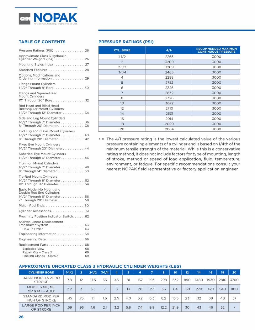
• = The 4/1 pressure rating is the lowest calculated value of the various pressure containing elements of a cylinder and is based on 1/4th of the minimum tensile strength of the material. While this is a conservative rating method, it does not include factors for type of mounting, length of stroke, method or speed of load application, fluid, temperature, environment, or fatigue. For specific recommendations consult your nearest NOPAK field representative or factory application engineer.
APPROXIMATE UNCRATED CLASS 3 HYDRAULIC CYLINDER WEIGHTS (LBS) CYLINDER BORE 1-1/2 2 2-1/2 3-1/4 4 5 6 7 8 10 12 14 16 18 20
BASIC MODELS ZERO STROKE 7.8 12 17.5 33 45 81 137 193 298 532 890 1480 1930 2810 3700
MODELS ME, MF, MP & MT – ADD: 2.2 3 3.5 7 8 13 20 27 36 84 130 270 420 540 800
STANDARD ROD PER INCH OF STROKE .45 .75 1.1 1.6 2.5 4.0 5.2 6.3 8.2 15.5 23 32 38 48 57
LARGE ROD PER INCH OF STROKE .59 .95 1.6 2.1 3.2 5.8 7.4 9.9 12.2 21.9 30 43 46 52 –
TABLE OF CONTENTS
Pressure Ratings (PSI) . . . . . . . . . . . . . . . . . . 26
Approximate Class 3 Hydraulic Cylinder Weights (lbs) . . . . . . . . . . . . . . . . . . 26
Mounting Styles Index . . . . . . . . . . . . . . . . . . 27
Standard Features . . . . . . . . . . . . . . . . . . . . . . 28
Options, Modifications and Ordering Information . . . . . . . . . . . . . . . . . . . 29
Flange Mount Cylinders 1-1/2" Through 8" Bore . . . . . . . . . . . . . . . . . .30
Flange and Square-Head Mount Cylinders 10" Through 20" Bore . . . . . . . . . . . . . . . . . . . 32
Rod Head and Blind Head Rectangular Mount Cylinders 1-1/2" Through 12" Diameter . . . . . . . . . . . . . 34
Side and Lug Mount Cylinders 1-1/2" Through 7" Diameter . . . . . . . . . . . . . . 368" Through 20" Diameter . . . . . . . . . . . . . . . . 38
End Lug and Clevis Mount Cylinders 1-1/2" Through 7" Diameter . . . . . . . . . . . . . .408" Through 20" Diameter . . . . . . . . . . . . . . . . 42
Fixed Eye Mount Cylinders 1-1/2" Through 20" Diameter . . . . . . . . . . . . .44
Spherical Eye Mount Cylinders 1-1/2" Through 6" Diameter . . . . . . . . . . . . . .46
Trunnion Mount Cylinders 1-1/2" Through 7" Diameter . . . . . . . . . . . . . .488" Through 14" Diameter . . . . . . . . . . . . . . . .50
Tie-Rod Mount Cylinders 1-1/2" Through 8" Diameter . . . . . . . . . . . . . . 5210" Through 14" Diameter . . . . . . . . . . . . . . . 54
Basic Model No Mount and Double Rod End Cylinders 1-1/2" Through 6" Diameter . . . . . . . . . . . . . . 567" Through 20" Diameter . . . . . . . . . . . . . . . . 58
Piston Rod Ends . . . . . . . . . . . . . . . . . . . . . . . .60
Cylinder Accessories . . . . . . . . . . . . . . . . . . . . 61
Proximity Position Indicator Switch . . . . . . . 62
NOPAK Linear Displacement Transducer System . . . . . . . . . . . . . . . . . . . . . 63
How To Order 63
Engineering Information . . . . . . . . . . . . . . . .64
Engineering Data . . . . . . . . . . . . . . . . . . . . . . . 66
Replacement Parts . . . . . . . . . . . . . . . . . . . . . 68Exploded View 68Repair Kits – Class 3 69Packing Glands – Class 3 69
27www.nopak.com CLASS 3
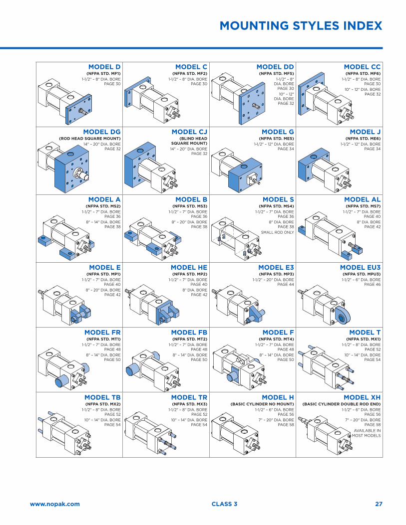
MOUNTING STYLES INDEX
MODEL D(NFPA STD. MF1)
1-1/2" – 8" DIA. BORE PAGE 30
MODEL C(NFPA STD. MF2)
1-1/2" – 8" DIA. BORE PAGE 30
MODEL DD(NFPA STD. MF5)
1-1/2" – 8" DIA. BORE
PAGE 3010" – 12"
DIA. BORE PAGE 32
MODEL CC(NFPA STD. MF6)
1-1/2" – 8" DIA. BORE PAGE 30
10" – 12" DIA. BORE PAGE 32
MODEL DG(ROD HEAD SQUARE MOUNT)
14" – 20" DIA. BORE PAGE 32
MODEL CJ(BLIND HEAD
SQUARE MOUNT) 14" – 20" DIA. BORE
PAGE 32
MODEL G(NFPA STD. ME5)
1-1/2" – 12" DIA. BORE PAGE 34
MODEL J(NFPA STD. ME6)
1-1/2" – 12" DIA. BORE PAGE 34
MODEL A(NFPA STD. MS2)
1-1/2" – 7" DIA. BORE PAGE 36
8" – 14" DIA. BORE PAGE 38
MODEL B(NFPA STD. MS3)
1-1/2" – 7" DIA. BORE PAGE 36
8" – 20" DIA. BORE PAGE 38
MODEL S(NFPA STD. MS4)
1-1/2" – 7" DIA. BORE PAGE 36
8" DIA. BORE PAGE 38
SMALL ROD ONLY
MODEL AL(NFPA STD. MS7)
1-1/2" – 7" DIA. BORE PAGE 40
8" DIA. BORE PAGE 42
MODEL E(NFPA STD. MP1)
1-1/2" – 7" DIA. BORE PAGE 40
8" – 20" DIA. BORE PAGE 42
MODEL HE(NFPA STD. MP2)
1-1/2" – 7" DIA. BORE PAGE 40
8" DIA. BORE PAGE 42
MODEL E3(NFPA STD. MP3)
1-1/2" – 20" DIA. BORE PAGE 44
MODEL EU3(NFPA STD. MPU3)1-1/2" – 6" DIA. BORE
PAGE 46
MODEL FR(NFPA STD. MT1)
1-1/2" – 7" DIA. BORE PAGE 48
8" – 14" DIA. BORE PAGE 50
MODEL FB(NFPA STD. MT2)
1-1/2" – 7" DIA. BORE PAGE 48
8" – 14" DIA. BORE PAGE 50
MODEL F(NFPA STD. MT4)
1-1/2" – 7" DIA. BORE PAGE 48
8" – 14" DIA. BORE PAGE 50
MODEL T(NFPA STD. MX1)
1-1/2" – 8" DIA. BORE PAGE 52
10" – 14" DIA. BORE PAGE 54
MODEL TB(NFPA STD. MX2)
1-1/2" – 8" DIA. BORE PAGE 52
10" – 14" DIA. BORE PAGE 54
MODEL TR(NFPA STD. MX3)
1-1/2" – 8" DIA. BORE PAGE 52
10" – 14" DIA. BORE PAGE 54
MODEL H(BASIC CYLINDER NO MOUNT)
1-1/2" – 6" DIA. BORE PAGE 56
7" – 20" DIA. BORE PAGE 58
MODEL XH(BASIC CYLINDER DOUBLE ROD END)
1-1/2" – 6" DIA. BORE PAGE 56
7" – 20" DIA. BORE PAGE 58
AVAILABLE INMOST MODELS
28
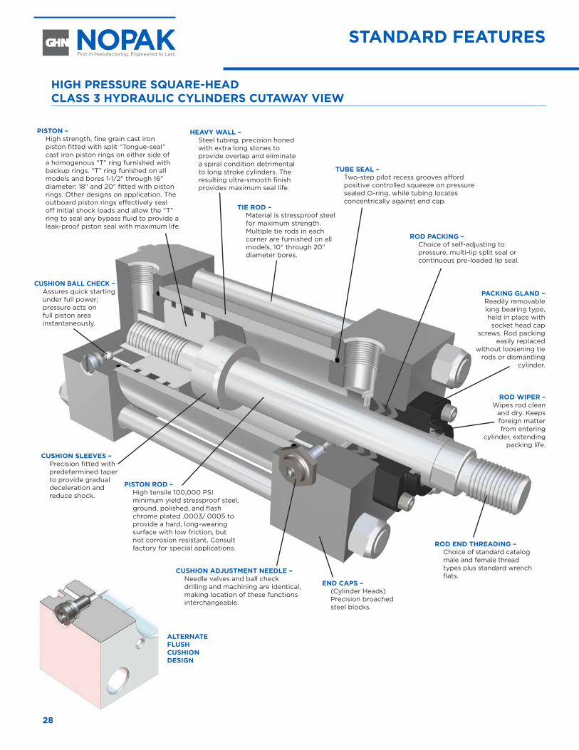
HIGH PRESSURE SQUARE-HEAD CLASS 3 HYDRAULIC CYLINDERS CUTAWAY VIEW
ROD END THREADING – Choice of standard catalog male and female thread types plus standard wrench flats.
CUSHION BALL CHECK – Assures quick starting under full power; pressure acts on full piston area instantaneously.
TIE ROD – Material is stressproof steel for maximum strength. Multiple tie rods in each corner are furnished on all models, 10" through 20" diameter bores.
PISTON ROD – High tensile 100,000 PSI minimum yield stressproof steel, ground, polished, and flash chrome plated .0003/.0005 to provide a hard, long-wearing surface with low friction, but not corrosion resistant. Consult factory for special applications.
CUSHION ADJUSTMENT NEEDLE – Needle valves and ball check drilling and machining are identical, making location of these functions interchangeable.
PISTON – High strength, fine grain cast iron piston fitted with split “Tongue-seal” cast iron piston rings on either side of a homogenous “T” ring furnished with backup rings. “T” ring funished on all models and bores 1-1/2" through 16" diameter; 18" and 20" fitted with piston rings. Other designs on application. The outboard piston rings effectively seal off initial shock loads and allow the “T” ring to seal any bypass fluid to provide a leak-proof piston seal with maximum life.
PACKING GLAND – Readily removable long bearing type, held in place with socket head cap
screws. Rod packing easily replaced
without loosening tie rods or dismantling
cylinder.
ROD WIPER – Wipes rod clean
and dry. Keeps foreign matter from entering
cylinder, extending packing life.
TUBE SEAL – Two-step pilot recess grooves afford positive controlled squeeze on pressure sealed O-ring, while tubing locates concentrically against end cap.
ROD PACKING – Choice of self-adjusting to pressure, multi-lip split seal or continuous pre-loaded lip seal.
HEAVY WALL – Steel tubing, precision honed with extra long stones to provide overlap and eliminate a spiral condition detrimental to long stroke cylinders. The resulting ultra-smooth finish provides maximum seal life.
CUSHION SLEEVES – Precision fitted with predetermined taper to provide gradual deceleration and reduce shock.
END CAPS – (Cylinder Heads) Precision broached steel blocks.
STANDARD FEATURES
ALTERNATE FLUSH CUSHION DESIGN
29www.nopak.com CLASS 3
HOW TO ORDER
OPTIONS, MODIFICATIONS AND ORDERING INFORMATION
Any special requirements should be described IN WORDS below model number.
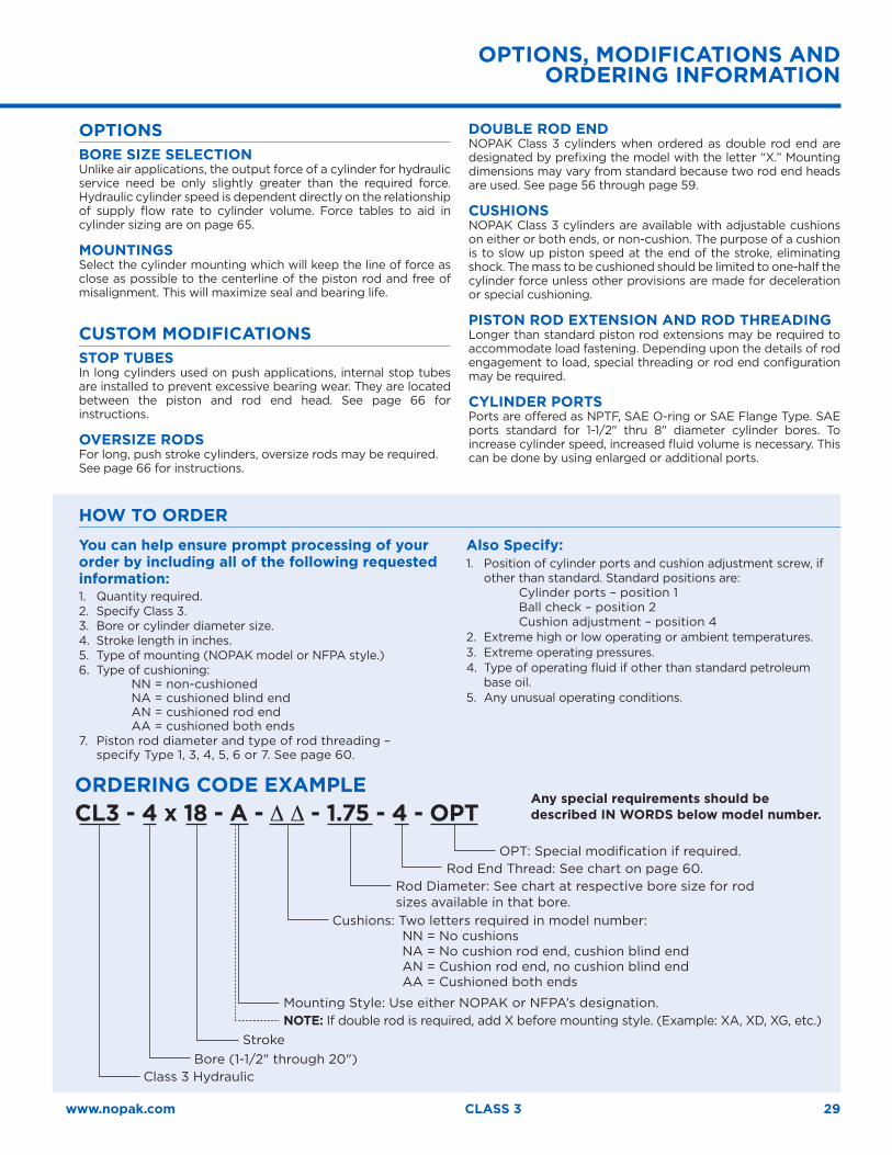
ORDERING CODE EXAMPLECL3 - 4 x 18 - A - ∆ ∆ - 1.75 - 4 - OPT
OPT: Special modification if required. Rod End Thread: See chart on page 60.
Rod Diameter: See chart at respective bore size for rod sizes available in that bore.
Cushions: Two letters required in model number: NN = No cushions NA = No cushion rod end, cushion blind end AN = Cushion rod end, no cushion blind end AA = Cushioned both ends
Mounting Style: Use either NOPAK or NFPA’s designation.
OPTIONS BORE SIZE SELECTIONUnlike air applications, the output force of a cylinder for hydraulic service need be only slightly greater than the required force. Hydraulic cylinder speed is dependent directly on the relationship of supply flow rate to cylinder volume. Force tables to aid in cylinder sizing are on page 65.
MOUNTINGSSelect the cylinder mounting which will keep the line of force as close as possible to the centerline of the piston rod and free of misalignment. This will maximize seal and bearing life.
CUSTOM MODIFICATIONS STOP TUBESIn long cylinders used on push applications, internal stop tubes are installed to prevent excessive bearing wear. They are located between the piston and rod end head. See page 66 for instructions.
OVERSIZE RODSFor long, push stroke cylinders, oversize rods may be required. See page 66 for instructions.
DOUBLE ROD ENDNOPAK Class 3 cylinders when ordered as double rod end are designated by prefixing the model with the letter “X.” Mounting dimensions may vary from standard because two rod end heads are used. See page 56 through page 59.
CUSHIONSNOPAK Class 3 cylinders are available with adjustable cushions on either or both ends, or non-cushion. The purpose of a cushion is to slow up piston speed at the end of the stroke, eliminating shock. The mass to be cushioned should be limited to one-half the cylinder force unless other provisions are made for deceleration or special cushioning.
PISTON ROD EXTENSION AND ROD THREADINGLonger than standard piston rod extensions may be required to accommodate load fastening. Depending upon the details of rod engagement to load, special threading or rod end configuration may be required.
CYLINDER PORTSPorts are offered as NPTF, SAE O-ring or SAE Flange Type. SAE ports standard for 1-1/2" thru 8" diameter cylinder bores. To increase cylinder speed, increased fluid volume is necessary. This can be done by using enlarged or additional ports.
Stroke NOTE: If double rod is required, add X before mounting style. (Example: XA, XD, XG, etc.)
Bore (1-1/2" through 20") Class 3 Hydraulic
You can help ensure prompt processing of your order by including all of the following requested information: 1. Quantity required. 2. Specify Class 3. 3. Bore or cylinder diameter size. 4. Stroke length in inches. 5. Type of mounting (NOPAK model or NFPA style.) 6. Type of cushioning:
NN = non-cushioned NA = cushioned blind end AN = cushioned rod end AA = cushioned both ends
7. Piston rod diameter and type of rod threading – specify Type 1, 3, 4, 5, 6 or 7. See page 60.
Also Specify: 1. Position of cylinder ports and cushion adjustment screw, if
other than standard. Standard positions are: Cylinder ports – position 1 Ball check – position 2 Cushion adjustment – position 4
2. Extreme high or low operating or ambient temperatures. 3. Extreme operating pressures. 4. Type of operating fluid if other than standard petroleum
base oil. 5. Any unusual operating conditions.
30
FLANGE MOUNT CYLINDERS 1-1/2" THROUGH 8" BORE
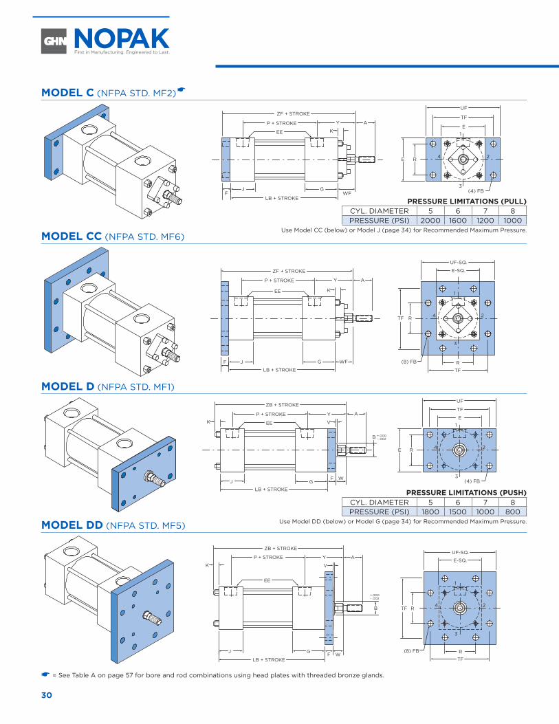
MODEL C (NFPA STD. MF2) �
AYP + STROKE
ZF + STROKE
EE K
J GF
LB + STROKE
E1
3
24
TF
UF
E R
(4) FBWF
MODEL CC (NFPA STD. MF6)
AYP + STROKE
ZF + STROKE
EE K
J G WFF
LB + STROKE
E-SQ.
1
3
24
R
TF
UF-SQ.
TF R
(8) FB
MODEL D (NFPA STD. MF1)
AYP + STROKE
ZB + STROKE
EEK
J GWF
LB + STROKE
E1
3
24
TF
UF
E R
(4) FB
V
B +.000– .002
MODEL DD (NFPA STD. MF5)
AYP + STROKE
ZB + STROKE
EE
K
J GWF
LB + STROKE
1
3
24
VE-SQ.
R
TF
UF-SQ.
TF RB
(8) FB
+.000– .002
� = See Table A on page 57 for bore and rod combinations using head plates with threaded bronze glands.
PRESSURE LIMITATIONS (PULL)CYL. DIAMETER 5 6 7 8PRESSURE (PSI) 2000 1600 1200 1000
Use Model CC (below) or Model J (page 34) for Recommended Maximum Pressure.
PRESSURE LIMITATIONS (PUSH)CYL. DIAMETER 5 6 7 8PRESSURE (PSI) 1800 1500 1000 800
Use Model DD (below) or Model G (page 34) for Recommended Maximum Pressure.
31www.nopak.com CLASS 3
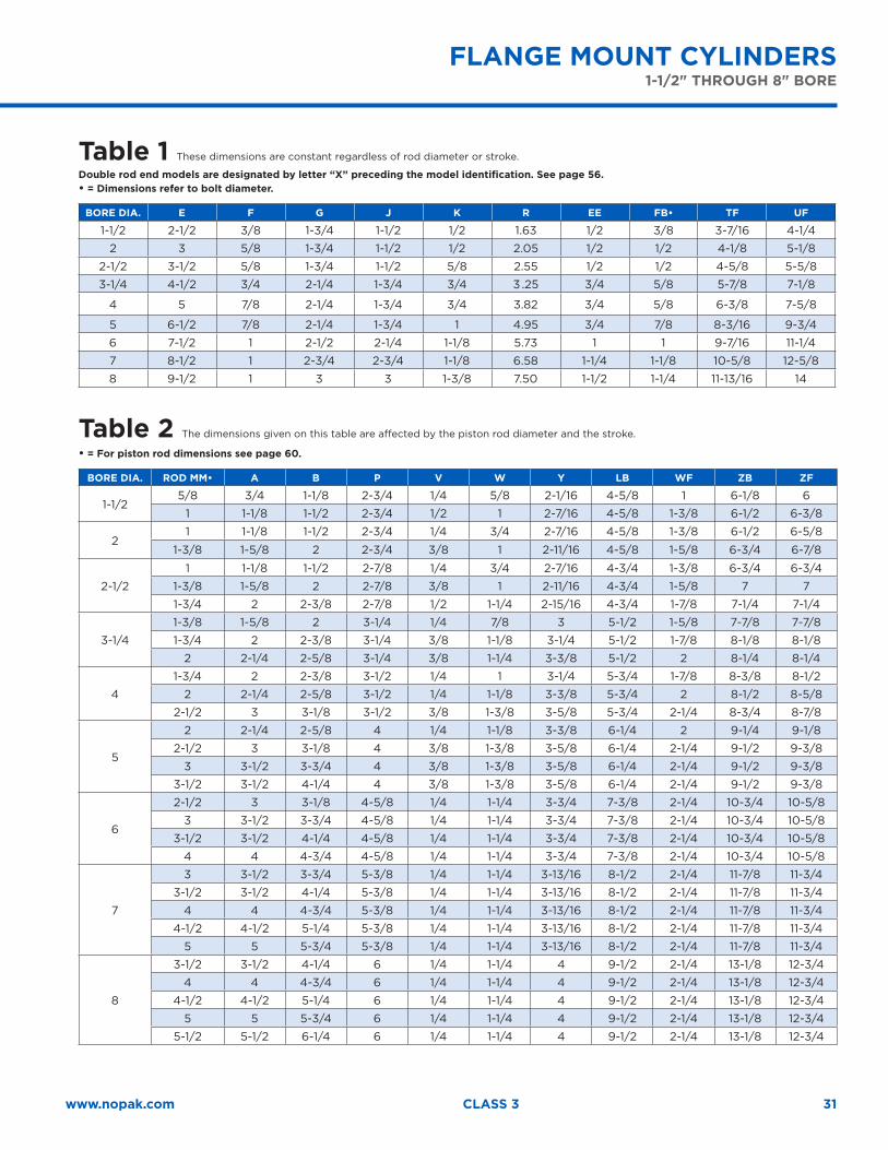
FLANGE MOUNT CYLINDERS1-1/2" THROUGH 8" BORE
Table 1 These dimensions are constant regardless of rod diameter or stroke.
Double rod end models are designated by letter “X” preceding the model identification. See page 56.• = Dimensions refer to bolt diameter.
BORE DIA. E F G J K R EE FB• TF UF
1-1/2 2-1/2 3/8 1-3/4 1-1/2 1/2 1.63 1/2 3/8 3-7/16 4-1/4
2 3 5/8 1-3/4 1-1/2 1/2 2.05 1/2 1/2 4-1/8 5-1/8
2-1/2 3-1/2 5/8 1-3/4 1-1/2 5/8 2.55 1/2 1/2 4-5/8 5-5/8
3-1/4 4-1/2 3/4 2-1/4 1-3/4 3/4 3 .25 3/4 5/8 5-7/8 7-1/8
4 5 7/8 2-1/4 1-3/4 3/4 3.82 3/4 5/8 6-3/8 7-5/8
5 6-1/2 7/8 2-1/4 1-3/4 1 4.95 3/4 7/8 8-3/16 9-3/4
6 7-1/2 1 2-1/2 2-1/4 1-1/8 5.73 1 1 9-7/16 11-1/4
7 8-1/2 1 2-3/4 2-3/4 1-1/8 6.58 1-1/4 1-1/8 10-5/8 12-5/8
8 9-1/2 1 3 3 1-3/8 7.50 1-1/2 1-1/4 11-13/16 14
Table 2 The dimensions given on this table are affected by the piston rod diameter and the stroke.
• = For piston rod dimensions see page 60.
BORE DIA. ROD MM• A B P V W Y LB WF ZB ZF
1-1/25/8 3/4 1-1/8 2-3/4 1/4 5/8 2-1/16 4-5/8 1 6-1/8 6
1 1-1/8 1-1/2 2-3/4 1/2 1 2-7/16 4-5/8 1-3/8 6-1/2 6-3/8
21 1-1/8 1-1/2 2-3/4 1/4 3/4 2-7/16 4-5/8 1-3/8 6-1/2 6-5/8
1-3/8 1-5/8 2 2-3/4 3/8 1 2-11/16 4-5/8 1-5/8 6-3/4 6-7/8
2-1/2
1 1-1/8 1-1/2 2-7/8 1/4 3/4 2-7/16 4-3/4 1-3/8 6-3/4 6-3/4
1-3/8 1-5/8 2 2-7/8 3/8 1 2-11/16 4-3/4 1-5/8 7 7
1-3/4 2 2-3/8 2-7/8 1/2 1-1/4 2-15/16 4-3/4 1-7/8 7-1/4 7-1/4
3-1/4
1-3/8 1-5/8 2 3-1/4 1/4 7/8 3 5-1/2 1-5/8 7-7/8 7-7/8
1-3/4 2 2-3/8 3-1/4 3/8 1-1/8 3-1/4 5-1/2 1-7/8 8-1/8 8-1/8
2 2-1/4 2-5/8 3-1/4 3/8 1-1/4 3-3/8 5-1/2 2 8-1/4 8-1/4
4
1-3/4 2 2-3/8 3-1/2 1/4 1 3-1/4 5-3/4 1-7/8 8-3/8 8-1/2
2 2-1/4 2-5/8 3-1/2 1/4 1-1/8 3-3/8 5-3/4 2 8-1/2 8-5/8
2-1/2 3 3-1/8 3-1/2 3/8 1-3/8 3-5/8 5-3/4 2-1/4 8-3/4 8-7/8
5
2 2-1/4 2-5/8 4 1/4 1-1/8 3-3/8 6-1/4 2 9-1/4 9-1/8
2-1/2 3 3-1/8 4 3/8 1-3/8 3-5/8 6-1/4 2-1/4 9-1/2 9-3/8
3 3-1/2 3-3/4 4 3/8 1-3/8 3-5/8 6-1/4 2-1/4 9-1/2 9-3/8
3-1/2 3-1/2 4-1/4 4 3/8 1-3/8 3-5/8 6-1/4 2-1/4 9-1/2 9-3/8
6
2-1/2 3 3-1/8 4-5/8 1/4 1-1/4 3-3/4 7-3/8 2-1/4 10-3/4 10-5/8
3 3-1/2 3-3/4 4-5/8 1/4 1-1/4 3-3/4 7-3/8 2-1/4 10-3/4 10-5/8
3-1/2 3-1/2 4-1/4 4-5/8 1/4 1-1/4 3-3/4 7-3/8 2-1/4 10-3/4 10-5/8
4 4 4-3/4 4-5/8 1/4 1-1/4 3-3/4 7-3/8 2-1/4 10-3/4 10-5/8
7
3 3-1/2 3-3/4 5-3/8 1/4 1-1/4 3-13/16 8-1/2 2-1/4 11-7/8 11-3/4
3-1/2 3-1/2 4-1/4 5-3/8 1/4 1-1/4 3-13/16 8-1/2 2-1/4 11-7/8 11-3/4
4 4 4-3/4 5-3/8 1/4 1-1/4 3-13/16 8-1/2 2-1/4 11-7/8 11-3/4
4-1/2 4-1/2 5-1/4 5-3/8 1/4 1-1/4 3-13/16 8-1/2 2-1/4 11-7/8 11-3/4
5 5 5-3/4 5-3/8 1/4 1-1/4 3-13/16 8-1/2 2-1/4 11-7/8 11-3/4
8
3-1/2 3-1/2 4-1/4 6 1/4 1-1/4 4 9-1/2 2-1/4 13-1/8 12-3/4
4 4 4-3/4 6 1/4 1-1/4 4 9-1/2 2-1/4 13-1/8 12-3/4
4-1/2 4-1/2 5-1/4 6 1/4 1-1/4 4 9-1/2 2-1/4 13-1/8 12-3/4
5 5 5-3/4 6 1/4 1-1/4 4 9-1/2 2-1/4 13-1/8 12-3/4
5-1/2 5-1/2 6-1/4 6 1/4 1-1/4 4 9-1/2 2-1/4 13-1/8 12-3/4
32
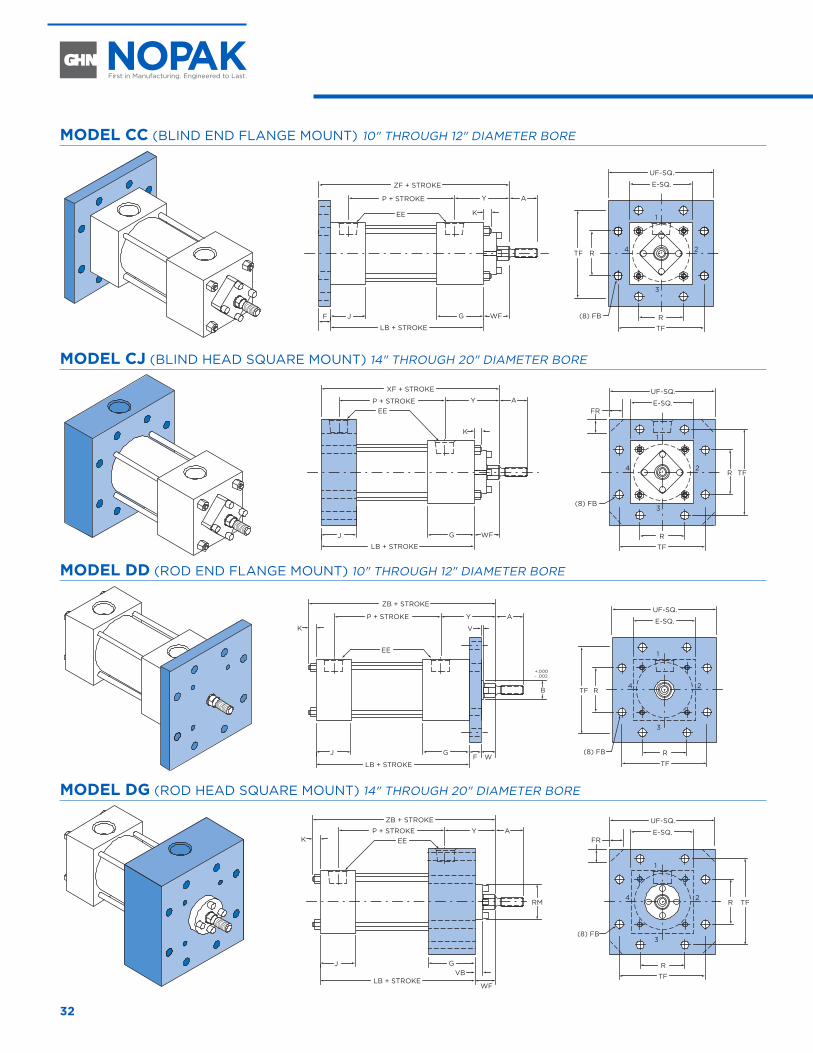
MODEL CC (BLIND END FLANGE MOUNT) 10" THROUGH 12" DIAMETER BORE
AYP + STROKE
ZF + STROKE
EE K
J G WFF
LB + STROKE
E-SQ.
1
3
24
R
TF
UF-SQ.
TF R
(8) FB
MODEL CJ (BLIND HEAD SQUARE MOUNT) 14" THROUGH 20" DIAMETER BORE
AYP + STROKE
XF + STROKE
EE
K
J G WF
LB + STROKE
E-SQ.
1
3
24
R
TF
UF-SQ.
FR
TFR
(8) FB
MODEL DD (ROD END FLANGE MOUNT) 10" THROUGH 12" DIAMETER BORE
AYP + STROKE
ZB + STROKE
EE
K
J GWF
LB + STROKE
1
3
24
VE-SQ.
R
TF
UF-SQ.
TF RB
(8) FB
+.000– .002
MODEL DG (ROD HEAD SQUARE MOUNT) 14" THROUGH 20" DIAMETER BORE
AYP + STROKE
ZB + STROKE
EEK
J G
WF
VBLB + STROKE
1
3
24
E-SQ.FR
R
TF
UF-SQ.
TFRRM
(8) FB
FLANGE AND SQUARE-HEAD MOUNT CYLINDERS10" THROUGH 20" BORE
FLANGE AND SQUARE-HEAD MOUNT CYLINDERS 10" THROUGH 20" BORE
33www.nopak.com CLASS 3
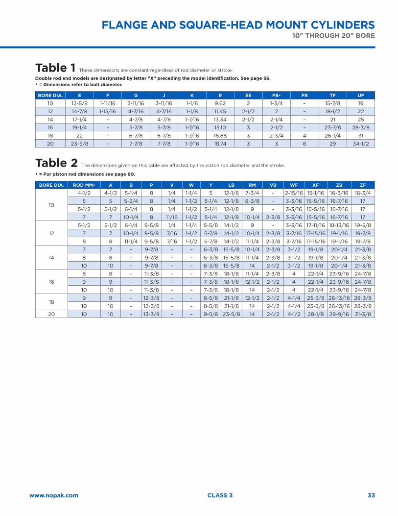
Table 1 These dimensions are constant regardless of rod diameter or stroke.
Double rod end models are designated by letter “X” preceding the model identification. See page 56.• = Dimensions refer to bolt diameter.
BORE DIA. E F G J K R EE FB• FR TF UF
10 12-5/8 1-11/16 3-11/16 3-11/16 1-1/8 9.62 2 1-3/4 – 15-7/8 19
12 14-7/8 1-15/16 4-7/16 4-7/16 1-1/8 11.45 2-1/2 2 – 18-1/2 22
14 17-1/4 – 4-7/8 4-7/8 1-7/16 13.34 2-1/2 2-1/4 – 21 25
16 19-1/4 – 5-7/8 5-7/8 1-7/16 15.10 3 2-1/2 – 23-7/8 28-3/8
18 22 – 6-7/8 6-7/8 1-7/16 16.88 3 2-3/4 4 26-1/4 31
20 23-5/8 – 7-7/8 7-7/8 1-7/16 18.74 3 3 6 29 34-1/2
Table 2 The dimensions given on this table are affected by the piston rod diameter and the stroke.
• = For piston rod dimensions see page 60.
BORE DIA. ROD MM• A B P V W Y LB RM VB WF XF ZB ZF
10
4-1/2 4-1/2 5-1/4 8 1/4 1-1/4 5 12-1/8 7-3/4 – 2-15/16 15-1/16 16-3/16 16-3/4
5 5 5-3/4 8 1/4 1-1/2 5-1/4 12-1/8 8-3/8 – 3-3/16 15-5/16 16-7/16 17
5-1/2 5-1/2 6-1/4 8 1/4 1-1/2 5-1/4 12-1/8 9 – 3-3/16 15-5/16 16-7/16 17
7 7 10-1/4 8 11/16 1-1/2 5-1/4 12-1/8 10-1/4 2-3/8 3-3/16 15-5/16 16-7/16 17
12
5-1/2 5-1/2 6-1/4 9-5/8 1/4 1-1/4 5-5/8 14-1/2 9 – 3-3/16 17-11/16 18-13/16 19-5/8
7 7 10-1/4 9-5/8 7/16 1-1/2 5-7/8 14-1/2 10-1/4 2-3/8 3-7/16 17-15/16 19-1/16 19-7/8
8 8 11-1/4 9-5/8 7/16 1-1/2 5-7/8 14-1/2 11-1/4 2-3/8 3-7/16 17-15/16 19-1/16 19-7/8
14
7 7 – 9-7/8 – – 6-3/8 15-5/8 10-1/4 2-3/8 3-1/2 19-1/8 20-1/4 21-3/8
8 8 – 9-7/8 – – 6-3/8 15-5/8 11-1/4 2-3/8 3-1/2 19-1/8 20-1/4 21-3/8
10 10 – 9-7/8 – – 6-3/8 15-5/8 14 2-1/2 3-1/2 19-1/8 20-1/4 21-3/8
16
8 8 – 11-3/8 – – 7-3/8 18-1/8 11-1/4 2-3/8 4 22-1/4 23-9/16 24-7/8
9 9 – 11-3/8 – – 7-3/8 18-1/8 12-1/2 2-1/2 4 22-1/4 23-9/16 24-7/8
10 10 – 11-3/8 – – 7-3/8 18-1/8 14 2-1/2 4 22-1/4 23-9/16 24-7/8
189 9 – 12-3/8 – – 8-5/8 21-1/8 12-1/2 2-1/2 4-1/4 25-3/8 26-13/16 28-3/8
10 10 – 12-3/8 – – 8-5/8 21-1/8 14 2-1/2 4-1/4 25-3/8 26-13/16 28-3/8
20 10 10 – 13-3/8 – – 9-5/8 23-5/8 14 2-1/2 4-1/2 28-1/8 29-9/16 31-3/8
FLANGE AND SQUARE-HEAD MOUNT CYLINDERS10" THROUGH 20" BORE
34
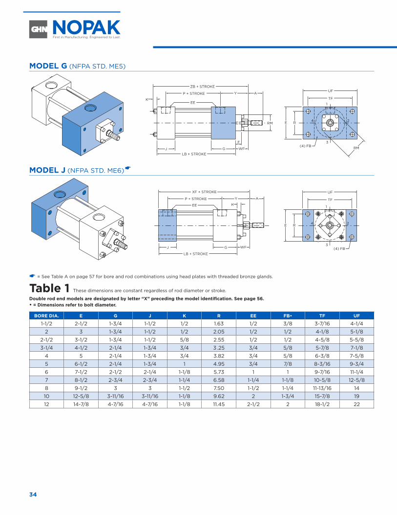
MODEL G (NFPA STD. ME5)
AYP + STROKE
ZB + STROKE
EEK
J GLB + STROKE
RMWF
F
1
3
24
TF
UF
E R
(4) FB
RM
MODEL J (NFPA STD. ME6) �
AYP + STROKE
XF + STROKE
EE K
J G
LB + STROKE
1
3
24
TF
UF
E R
(4) FBWF
� = See Table A on page 57 for bore and rod combinations using head plates with threaded bronze glands.
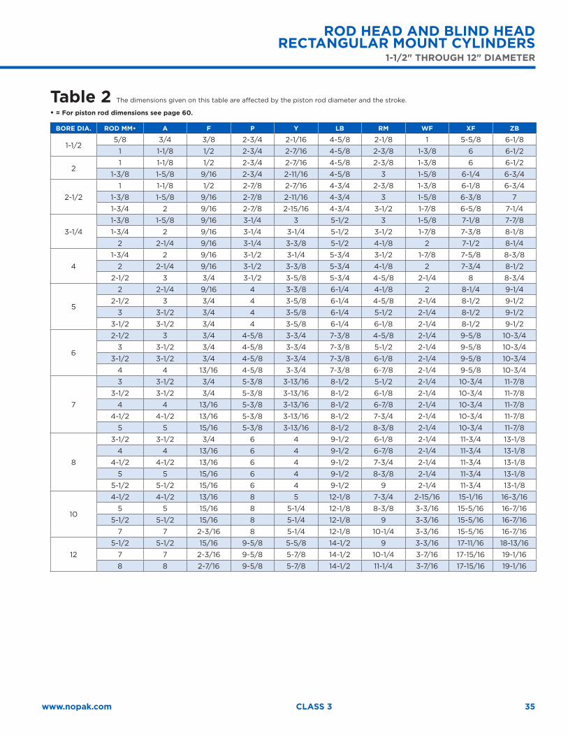
Table 1 These dimensions are constant regardless of rod diameter or stroke.
Double rod end models are designated by letter “X” preceding the model identification. See page 56.• = Dimensions refer to bolt diameter.
BORE DIA. E G J K R EE FB• TF UF
1-1/2 2-1/2 1-3/4 1-1/2 1/2 1.63 1/2 3/8 3-7/16 4-1/4
2 3 1-3/4 1-1/2 1/2 2.05 1/2 1/2 4-1/8 5-1/8
2-1/2 3-1/2 1-3/4 1-1/2 5/8 2.55 1/2 1/2 4-5/8 5-5/8
3-1/4 4-1/2 2-1/4 1-3/4 3/4 3 .25 3/4 5/8 5-7/8 7-1/8
4 5 2-1/4 1-3/4 3/4 3.82 3/4 5/8 6-3/8 7-5/8
5 6-1/2 2-1/4 1-3/4 1 4.95 3/4 7/8 8-3/16 9-3/4
6 7-1/2 2-1/2 2-1/4 1-1/8 5.73 1 1 9-7/16 11-1/4
7 8-1/2 2-3/4 2-3/4 1-1/4 6.58 1-1/4 1-1/8 10-5/8 12-5/8
8 9-1/2 3 3 1-1/2 7.50 1-1/2 1-1/4 11-13/16 14
10 12-5/8 3-11/16 3-11/16 1-1/8 9.62 2 1-3/4 15-7/8 19
12 14-7/8 4-7/16 4-7/16 1-1/8 11.45 2-1/2 2 18-1/2 22
ROD HEAD AND BLIND HEAD RECTANGULAR MOUNT CYLINDERS
1-1/2" THROUGH 12" DIAMETER
35www.nopak.com CLASS 3
Table 2 The dimensions given on this table are affected by the piston rod diameter and the stroke.
• = For piston rod dimensions see page 60.
BORE DIA. ROD MM• A F P Y LB RM WF XF ZB
1-1/25/8 3/4 3/8 2-3/4 2-1/16 4-5/8 2-1/8 1 5-5/8 6-1/8
1 1-1/8 1/2 2-3/4 2-7/16 4-5/8 2-3/8 1-3/8 6 6-1/2
21 1-1/8 1/2 2-3/4 2-7/16 4-5/8 2-3/8 1-3/8 6 6-1/2
1-3/8 1-5/8 9/16 2-3/4 2-11/16 4-5/8 3 1-5/8 6-1/4 6-3/4
2-1/2
1 1-1/8 1/2 2-7/8 2-7/16 4-3/4 2-3/8 1-3/8 6-1/8 6-3/4
1-3/8 1-5/8 9/16 2-7/8 2-11/16 4-3/4 3 1-5/8 6-3/8 7
1-3/4 2 9/16 2-7/8 2-15/16 4-3/4 3-1/2 1-7/8 6-5/8 7-1/4
3-1/4
1-3/8 1-5/8 9/16 3-1/4 3 5-1/2 3 1-5/8 7-1/8 7-7/8
1-3/4 2 9/16 3-1/4 3-1/4 5-1/2 3-1/2 1-7/8 7-3/8 8-1/8
2 2-1/4 9/16 3-1/4 3-3/8 5-1/2 4-1/8 2 7-1/2 8-1/4
4
1-3/4 2 9/16 3-1/2 3-1/4 5-3/4 3-1/2 1-7/8 7-5/8 8-3/8
2 2-1/4 9/16 3-1/2 3-3/8 5-3/4 4-1/8 2 7-3/4 8-1/2
2-1/2 3 3/4 3-1/2 3-5/8 5-3/4 4-5/8 2-1/4 8 8-3/4
5
2 2-1/4 9/16 4 3-3/8 6-1/4 4-1/8 2 8-1/4 9-1/4
2-1/2 3 3/4 4 3-5/8 6-1/4 4-5/8 2-1/4 8-1/2 9-1/2
3 3-1/2 3/4 4 3-5/8 6-1/4 5-1/2 2-1/4 8-1/2 9-1/2
3-1/2 3-1/2 3/4 4 3-5/8 6-1/4 6-1/8 2-1/4 8-1/2 9-1/2
6
2-1/2 3 3/4 4-5/8 3-3/4 7-3/8 4-5/8 2-1/4 9-5/8 10-3/4
3 3-1/2 3/4 4-5/8 3-3/4 7-3/8 5-1/2 2-1/4 9-5/8 10-3/4
3-1/2 3-1/2 3/4 4-5/8 3-3/4 7-3/8 6-1/8 2-1/4 9-5/8 10-3/4
4 4 13/16 4-5/8 3-3/4 7-3/8 6-7/8 2-1/4 9-5/8 10-3/4
7
3 3-1/2 3/4 5-3/8 3-13/16 8-1/2 5-1/2 2-1/4 10-3/4 11-7/8
3-1/2 3-1/2 3/4 5-3/8 3-13/16 8-1/2 6-1/8 2-1/4 10-3/4 11-7/8
4 4 13/16 5-3/8 3-13/16 8-1/2 6-7/8 2-1/4 10-3/4 11-7/8
4-1/2 4-1/2 13/16 5-3/8 3-13/16 8-1/2 7-3/4 2-1/4 10-3/4 11-7/8
5 5 15/16 5-3/8 3-13/16 8-1/2 8-3/8 2-1/4 10-3/4 11-7/8
8
3-1/2 3-1/2 3/4 6 4 9-1/2 6-1/8 2-1/4 11-3/4 13-1/8
4 4 13/16 6 4 9-1/2 6-7/8 2-1/4 11-3/4 13-1/8
4-1/2 4-1/2 13/16 6 4 9-1/2 7-3/4 2-1/4 11-3/4 13-1/8
5 5 15/16 6 4 9-1/2 8-3/8 2-1/4 11-3/4 13-1/8
5-1/2 5-1/2 15/16 6 4 9-1/2 9 2-1/4 11-3/4 13-1/8
10
4-1/2 4-1/2 13/16 8 5 12-1/8 7-3/4 2-15/16 15-1/16 16-3/16
5 5 15/16 8 5-1/4 12-1/8 8-3/8 3-3/16 15-5/16 16-7/16
5-1/2 5-1/2 15/16 8 5-1/4 12-1/8 9 3-3/16 15-5/16 16-7/16
7 7 2-3/16 8 5-1/4 12-1/8 10-1/4 3-3/16 15-5/16 16-7/16
12
5-1/2 5-1/2 15/16 9-5/8 5-5/8 14-1/2 9 3-3/16 17-11/16 18-13/16
7 7 2-3/16 9-5/8 5-7/8 14-1/2 10-1/4 3-7/16 17-15/16 19-1/16
8 8 2-7/16 9-5/8 5-7/8 14-1/2 11-1/4 3-7/16 17-15/16 19-1/16
ROD HEAD AND BLIND HEAD RECTANGULAR MOUNT CYLINDERS
1-1/2" THROUGH 12" DIAMETER
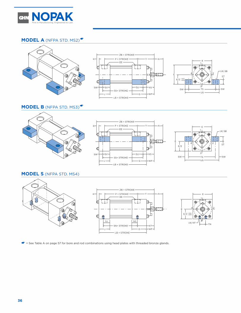
36
SIDE AND LUG MOUNT CYLINDERS 1-1/2" THROUGH 7" DIAMETER
MODEL A (NFPA STD. MS2) �
AYP + STROKE
ZB + STROKE
EEK
.005–– .009
E1
3
24
TSSWUS
SW
E
E/2ST
(4) SB
J G
SS+ STROKEXSSV
LB + STROKE
SW SU
WF
MODEL B (NFPA STD. MS3) �
E1
3
24
TSSW
US
SW
E
E/2ST
(4) SB
AYP + STROKE
ZB + STROKE
EEK
J GSS+ STROKE
XSSV
LB + STROKE
SW SU
WF
MODEL S (NFPA STD. MS4)
AYP + STROKE
ZB + STROKE
EEK
J GSN+ STROKE
WF
SJ
LB + STROKE
.005–– .009
E
1
33
24
TN
E
E/2
(4) NTSG
XT
� = See Table A on page 57 for bore and rod combinations using head plates with threaded bronze glands.
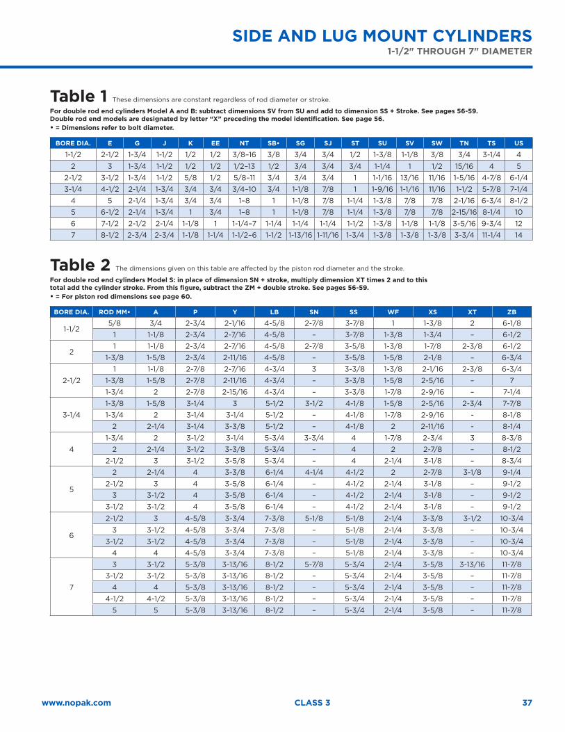
37www.nopak.com CLASS 3
SIDE AND LUG MOUNT CYLINDERS 1-1/2" THROUGH 7" DIAMETER
Table 1 These dimensions are constant regardless of rod diameter or stroke.
For double rod end cylinders Model A and B: subtract dimensions SV from SU and add to dimension SS + Stroke. See pages 56-59.Double rod end models are designated by letter “X” preceding the model identification. See page 56.• = Dimensions refer to bolt diameter.
BORE DIA. E G J K EE NT SB• SG SJ ST SU SV SW TN TS US
1-1/2 2-1/2 1-3/4 1-1/2 1/2 1/2 3/8–16 3/8 3/4 3/4 1/2 1-3/8 1-1/8 3/8 3/4 3-1/4 4
2 3 1-3/4 1-1/2 1/2 1/2 1/2–13 1/2 3/4 3/4 3/4 1-1/4 1 1/2 15/16 4 5
2-1/2 3-1/2 1-3/4 1-1/2 5/8 1/2 5/8–11 3/4 3/4 3/4 1 1-1/16 13/16 11/16 1-5/16 4-7/8 6-1/4
3-1/4 4-1/2 2-1/4 1-3/4 3/4 3/4 3/4–10 3/4 1-1/8 7/8 1 1-9/16 1-1/16 11/16 1-1/2 5-7/8 7-1/4
4 5 2-1/4 1-3/4 3/4 3/4 1–8 1 1-1/8 7/8 1-1/4 1-3/8 7/8 7/8 2-1/16 6-3/4 8-1/2
5 6-1/2 2-1/4 1-3/4 1 3/4 1–8 1 1-1/8 7/8 1-1/4 1-3/8 7/8 7/8 2-15/16 8-1/4 10
6 7-1/2 2-1/2 2-1/4 1-1/8 1 1-1/4–7 1-1/4 1-1/4 1-1/4 1-1/2 1-3/8 1-1/8 1-1/8 3-5/16 9-3/4 12
7 8-1/2 2-3/4 2-3/4 1-1/8 1-1/4 1-1/2–6 1-1/2 1-13/16 1-11/16 1-3/4 1-3/8 1-3/8 1-3/8 3-3/4 11-1/4 14
Table 2 The dimensions given on this table are affected by the piston rod diameter and the stroke.
For double rod end cylinders Model S: in place of dimension SN + stroke, multiply dimension XT times 2 and to this total add the cylinder stroke. From this figure, subtract the ZM + double stroke. See pages 56-59.• = For piston rod dimensions see page 60.
BORE DIA. ROD MM• A P Y LB SN SS WF XS XT ZB
1-1/25/8 3/4 2-3/4 2-1/16 4-5/8 2-7/8 3-7/8 1 1-3/8 2 6-1/8
1 1-1/8 2-3/4 2-7/16 4-5/8 – 3-7/8 1-3/8 1-3/4 – 6-1/2
21 1-1/8 2-3/4 2-7/16 4-5/8 2-7/8 3-5/8 1-3/8 1-7/8 2-3/8 6-1/2
1-3/8 1-5/8 2-3/4 2-11/16 4-5/8 – 3-5/8 1-5/8 2-1/8 – 6-3/4
2-1/2
1 1-1/8 2-7/8 2-7/16 4-3/4 3 3-3/8 1-3/8 2-1/16 2-3/8 6-3/4
1-3/8 1-5/8 2-7/8 2-11/16 4-3/4 – 3-3/8 1-5/8 2-5/16 – 7
1-3/4 2 2-7/8 2-15/16 4-3/4 – 3-3/8 1-7/8 2-9/16 – 7-1/4
3-1/4
1-3/8 1-5/8 3-1/4 3 5-1/2 3-1/2 4-1/8 1-5/8 2-5/16 2-3/4 7-7/8
1-3/4 2 3-1/4 3-1/4 5-1/2 – 4-1/8 1-7/8 2-9/16 - 8-1/8
2 2-1/4 3-1/4 3-3/8 5-1/2 – 4-1/8 2 2-11/16 - 8-1/4
4
1-3/4 2 3-1/2 3-1/4 5-3/4 3-3/4 4 1-7/8 2-3/4 3 8-3/8
2 2-1/4 3-1/2 3-3/8 5-3/4 – 4 2 2-7/8 – 8-1/2
2-1/2 3 3-1/2 3-5/8 5-3/4 – 4 2-1/4 3-1/8 – 8-3/4
5
2 2-1/4 4 3-3/8 6-1/4 4-1/4 4-1/2 2 2-7/8 3-1/8 9-1/4
2-1/2 3 4 3-5/8 6-1/4 – 4-1/2 2-1/4 3-1/8 – 9-1/2
3 3-1/2 4 3-5/8 6-1/4 – 4-1/2 2-1/4 3-1/8 – 9-1/2
3-1/2 3-1/2 4 3-5/8 6-1/4 – 4-1/2 2-1/4 3-1/8 – 9-1/2
6
2-1/2 3 4-5/8 3-3/4 7-3/8 5-1/8 5-1/8 2-1/4 3-3/8 3-1/2 10-3/4
3 3-1/2 4-5/8 3-3/4 7-3/8 – 5-1/8 2-1/4 3-3/8 – 10-3/4
3-1/2 3-1/2 4-5/8 3-3/4 7-3/8 – 5-1/8 2-1/4 3-3/8 – 10-3/4
4 4 4-5/8 3-3/4 7-3/8 – 5-1/8 2-1/4 3-3/8 – 10-3/4
7
3 3-1/2 5-3/8 3-13/16 8-1/2 5-7/8 5-3/4 2-1/4 3-5/8 3-13/16 11-7/8
3-1/2 3-1/2 5-3/8 3-13/16 8-1/2 – 5-3/4 2-1/4 3-5/8 – 11-7/8
4 4 5-3/8 3-13/16 8-1/2 – 5-3/4 2-1/4 3-5/8 – 11-7/8
4-1/2 4-1/2 5-3/8 3-13/16 8-1/2 – 5-3/4 2-1/4 3-5/8 – 11-7/8
5 5 5-3/8 3-13/16 8-1/2 – 5-3/4 2-1/4 3-5/8 – 11-7/8
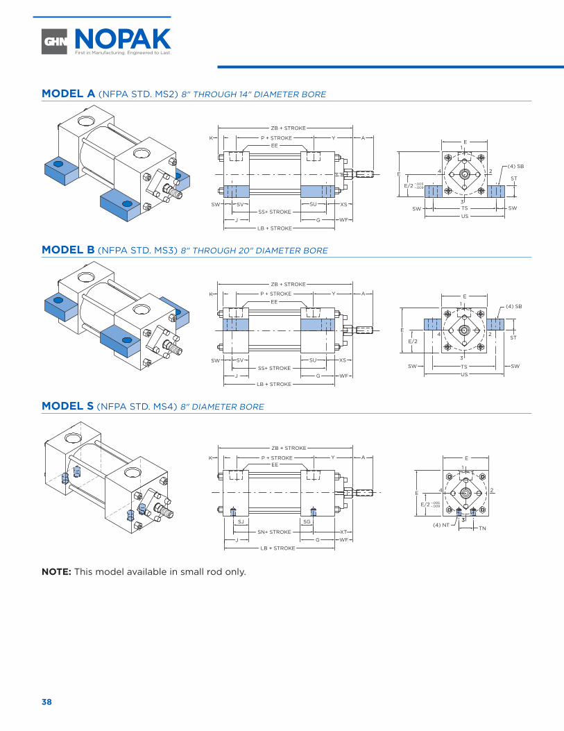
38
MODEL A (NFPA STD. MS2) 8" THROUGH 14" DIAMETER BORE
AYP + STROKE
ZB + STROKE
EEK
.005–– .009
E1
3
24
TSSWUS
SW
E
E/2ST
(4) SB
J G
SS+ STROKEXSSV
LB + STROKE
SW SU
WF
MODEL B (NFPA STD. MS3) 8" THROUGH 20" DIAMETER BORE
E1
3
24
TSSW
US
SW
E
E/2ST
(4) SB
AYP + STROKE
ZB + STROKE
EEK
J GSS+ STROKE
XSSV
LB + STROKE
SW SU
WF
MODEL S (NFPA STD. MS4) 8" DIAMETER BORE
AYP + STROKE
ZB + STROKE
EEK
J GSN+ STROKE
WF
SJ
LB + STROKE
.005–– .009
E
1
33
24
TN
E
E/2
(4) NTSG
XT
NOTE: This model available in small rod only.
8" THROUGH 20" DIAMETER
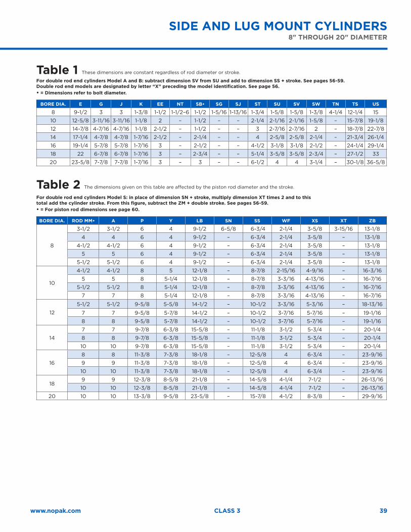
39www.nopak.com CLASS 3
Table 1 These dimensions are constant regardless of rod diameter or stroke.
For double rod end cylinders Model A and B: subtract dimension SV from SU and add to dimension SS + stroke. See pages 56-59.Double rod end models are designated by letter “X” preceding the model identification. See page 56.• = Dimensions refer to bolt diameter.
BORE DIA. E G J K EE NT SB• SG SJ ST SU SV SW TN TS US
8 9-1/2 3 3 1-3/8 1-1/2 1-1/2–6 1-1/2 1-5/16 1-13/16 1-3/4 1-5/8 1-5/8 1-3/8 4-1/4 12-1/4 15
10 12-5/8 3-11/16 3-11/16 1-1/8 2 – 1-1/2 – – 2-1/4 2-1/16 2-1/16 1-5/8 – 15-7/8 19-1/8
12 14-7/8 4-7/16 4-7/16 1-1/8 2-1/2 – 1-1/2 – – 3 2-7/16 2-7/16 2 – 18-7/8 22-7/8
14 17-1/4 4-7/8 4-7/8 1-7/16 2-1/2 – 2-1/4 – – 4 2-5/8 2-5/8 2-1/4 – 21-3/4 26-1/4
16 19-1/4 5-7/8 5-7/8 1-7/16 3 – 2-1/2 – – 4-1/2 3-1/8 3-1/8 2-1/2 – 24-1/4 29-1/4
18 22 6-7/8 6-7/8 1-7/16 3 – 2-3/4 – – 5-1/4 3-5/8 3-5/8 2-3/4 – 27-1/2 33
20 23-5/8 7-7/8 7-7/8 1-7/16 3 – 3 – – 6-1/2 4 4 3-1/4 – 30-1/8 36-5/8
Table 2 The dimensions given on this table are affected by the piston rod diameter and the stroke.
For double rod end cylinders Model S: in place of dimension SN + stroke, multiply dimension XT times 2 and to this total add the cylinder stroke. From this figure, subtract the ZM + double stroke. See pages 56-59.• = For piston rod dimensions see page 60.
BORE DIA. ROD MM• A P Y LB SN SS WF XS XT ZB
8
3-1/2 3-1/2 6 4 9-1/2 6-5/8 6-3/4 2-1/4 3-5/8 3-15/16 13-1/8
4 4 6 4 9-1/2 – 6-3/4 2-1/4 3-5/8 – 13-1/8
4-1/2 4-1/2 6 4 9-1/2 – 6-3/4 2-1/4 3-5/8 – 13-1/8
5 5 6 4 9-1/2 – 6-3/4 2-1/4 3-5/8 – 13-1/8
5-1/2 5-1/2 6 4 9-1/2 – 6-3/4 2-1/4 3-5/8 – 13-1/8
10
4-1/2 4-1/2 8 5 12-1/8 – 8-7/8 2-15/16 4-9/16 – 16-3/16
5 5 8 5-1/4 12-1/8 – 8-7/8 3-3/16 4-13/16 – 16-7/16
5-1/2 5-1/2 8 5-1/4 12-1/8 – 8-7/8 3-3/16 4-13/16 – 16-7/16
7 7 8 5-1/4 12-1/8 – 8-7/8 3-3/16 4-13/16 – 16-7/16
12
5-1/2 5-1/2 9-5/8 5-5/8 14-1/2 – 10-1/2 3-3/16 5-3/16 – 18-13/16
7 7 9-5/8 5-7/8 14-1/2 – 10-1/2 3-7/16 5-7/16 – 19-1/16
8 8 9-5/8 5-7/8 14-1/2 – 10-1/2 3-7/16 5-7/16 – 19-1/16
14
7 7 9-7/8 6-3/8 15-5/8 – 11-1/8 3-1/2 5-3/4 – 20-1/4
8 8 9-7/8 6-3/8 15-5/8 – 11-1/8 3-1/2 5-3/4 – 20-1/4
10 10 9-7/8 6-3/8 15-5/8 – 11-1/8 3-1/2 5-3/4 – 20-1/4
16
8 8 11-3/8 7-3/8 18-1/8 – 12-5/8 4 6-3/4 – 23-9/16
9 9 11-3/8 7-3/8 18-1/8 – 12-5/8 4 6-3/4 – 23-9/16
10 10 11-3/8 7-3/8 18-1/8 – 12-5/8 4 6-3/4 – 23-9/16
189 9 12-3/8 8-5/8 21-1/8 – 14-5/8 4-1/4 7-1/2 – 26-13/16
10 10 12-3/8 8-5/8 21-1/8 – 14-5/8 4-1/4 7-1/2 – 26-13/16
20 10 10 13-3/8 9-5/8 23-5/8 – 15-7/8 4-1/2 8-3/8 – 29-9/16
SIDE AND LUG MOUNT CYLINDERS 8" THROUGH 20" DIAMETER
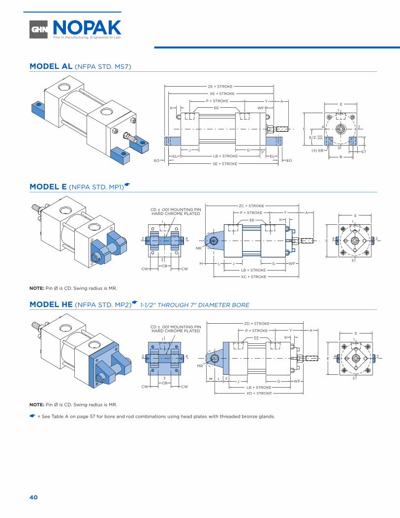
40
MODEL AL (NFPA STD. MS7)
AYP + STROKE
ZE + STROKE
XE + STROKE
EEK WF
J G
SE + STROKE
EL ELEOEO
FLB + STROKE
.005–– .009
E
1
3
24
R
E
E/2
(4) EB ET
MODEL E (NFPA STD. MP1)�
WF
AYP + STROKE
ZC + STROKE
EE K
J GCB
CWCWL
MR
M
LB + STROKE
XC + STROKE
E
1
3
1
3
242 4 E
NOTE: Pin Ø is CD. Swing radius is MR.
MODEL HE (NFPA STD. MP2)� 1-1/2" THROUGH 7" DIAMETER BORE
AYP + STROKE
ZD + STROKE
EE K
J GCBCWCW
L F
MR
M
LB + STROKE
XD + STROKE
E
1
3
24
1
3
2 4 E
WF
NOTE: Pin Ø is CD. Swing radius is MR.
� = See Table A on page 57 for bore and rod combinations using head plates with threaded bronze glands.
END LUG AND CLEVIS MOUNT CYLINDERS 1-1/2" THROUGH 7" DIAMETER
CD ± .001 MOUNTING PINHARD CHROME PLATED
CD ± .001 MOUNTING PINHARD CHROME PLATED
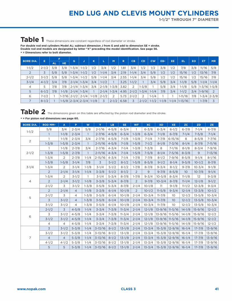
41www.nopak.com CLASS 3
Table 1 These dimensions are constant regardless of rod diameter or stroke.
For double rod end cylinders Model AL: subtract dimension J from G and add to dimension SE + stroke.Double rod end models are designated by letter “X” preceding the model identification. See page 56.• = Dimensions refer to bolt diameter.
BORE DIA. EF
G J K L M R CB CD CW EB• EE EL EO ET MRAL HE
1-1/2 2-1/2 3/8 3/8 1-3/4 1-1/2 1/2 3/4 1/2 1.81 3/4 1/2 1/2 3/8 1/2 7/8 3/8 11/16 5/8
2 3 5/8 5/8 1-3/4 1-1/2 1/2 1-1/4 3/4 2.19 1-1/4 3/4 5/8 1/2 1/2 15/16 1/2 13/16 7/8
2-1/2 3-1/2 5/8 5/8 1-3/4 1-1/2 5/8 1-1/4 3/4 2.55 1-1/4 3/4 5/8 1/2 1/2 15/16 1/2 15/16 7/8
3-1/4 4-1/2 3/4 7/8 2-1/4 1-3/4 3/4 1-1/2 1 3.25 1-1/2 1 3/4 5/8 3/4 1-1/8 5/8 1-1/4 1-1/4
4 5 7/8 7/8 2-1/4 1-3/4 3/4 2-1/8 1-3/8 3.82 2 1-3/8 1 5/8 3/4 1-1/8 5/8 1-3/16 1-5/8
5 6-1/2 7/8 1-1/8 2-1/4 1-3/4 1 2-1/4 1-3/4 4.95 2-1/2 1-3/4 1-1/4 7/8 3/4 1-1/2 3/4 1-9/16 2
6 7-1/2 1 1-7/16 2-1/2 2-1/4 1-1/8 2-1/2 2 5.73 2-1/2 2 1-1/4 1 1 1-11/16 7/8 1-3/4 2-3/8
7 8-1/2 1 1-5/8 2-3/4 2-3/4 1-1/8 3 2-1/2 6.58 3 2-1/2 1-1/2 1-1/8 1-1/4 1-13/16 1 1-7/8 3
Table 2 The dimensions given on this table are affected by the piston rod diameter and the stroke.
• = For piston rod dimensions see page 60.
BORE DIA. ROD MM• A P W Y LB SE WF XC XD XE ZC ZD ZE
1-1/25/8 3/4 2-3/4 5/8 2-1/16 4-5/8 6-3/4 1 6-3/8 6-3/4 6-1/2 6-7/8 7-1/4 6-7/8
1 1-1/8 2-3/4 1 2-7/16 4-5/8 6-3/4 1-3/8 6-3/4 7-1/8 6-7/8 7-1/4 7-5/8 7-1/4
21 1-1/8 2-3/4 3/4 2-7/16 4-5/8 7-1/8 1-3/8 7-1/4 7-7/8 6-15/16 8 8-5/8 7-7/16
1-3/8 1-5/8 2-3/4 1 2-11/16 4-5/8 7-1/8 1-5/8 7-1/2 8-1/8 7-3/16 8-1/4 8-7/8 7-11/16
2-1/2
1 1-1/8 2-7/8 3/4 2-7/16 4-3/4 7-1/4 1-3/8 7-3/8 8 7-1/16 8-1/8 8-3/4 7-9/16
1-3/8 1-5/8 2-7/8 1 2-11/16 4-3/4 7-1/4 1-5/8 7-5/8 8-1/4 7-5/16 8-3/8 9 7-13/16
1-3/4 2 2-7/8 1-1/4 2-15/16 4-3/4 7-1/4 1-7/8 7-7/8 8-1/2 7-9/16 8-5/8 9-1/4 8-1/16
3-1/4
1-3/8 1-5/8 3-1/4 7/8 3 5-1/2 8-1/2 1-5/8 8-5/8 9-1/2 8-1/4 9-5/8 10-1/2 8-7/8
1-3/4 2 3-1/4 1-1/8 3-1/4 5-1/2 8-1/2 1-7/8 8-7/8 9-3/4 8-1/2 9-7/8 10-3/4 9-1/8
2 2-1/4 3-1/4 1-1/4 3-3/8 5-1/2 8-1/2 2 9 9-7/8 8-5/8 10 10-7/8 9-1/4
4
1-3/4 2 3-1/2 1 3-1/4 5-3/4 8-7/8 1-7/8 9-3/4 10-5/8 8-3/4 11-1/8 12 9-3/8
2 2-1/4 3-1/2 1-1/8 3-3/8 5-3/4 8-7/8 2 9-7/8 10-3/4 8-7/8 11-1/4 12-1/8 9-1/2
2-1/2 3 3-1/2 1-3/8 3-5/8 5-3/4 8-7/8 2-1/4 10-1/8 11 9-1/8 11-1/2 12-3/8 9-3/4
5
2 2-1/4 4 1-1/8 3-3/8 6-1/4 10-1/8 2 10-1/2 11-5/8 9-3/4 12-1/4 13-3/8 10-1/2
2-1/2 3 4 1-3/8 3-5/8 6-1/4 10-1/8 2-1/4 10-3/4 11-7/8 10 12-1/2 13-5/8 10-3/4
3 3-1/2 4 1-3/8 3-5/8 6-1/4 10-1/8 2-1/4 10-3/4 11-7/8 10 12-1/2 13-5/8 10-3/4
3-1/2 3-1/2 4 1-3/8 3-5/8 6-1/4 10-1/8 2-1/4 10-3/4 11-7/8 10 12-1/2 13-5/8 10-3/4
6
2-1/2 3 4-5/8 1-1/4 3-3/4 7-3/8 11-3/4 2-1/4 12-1/8 13-9/16 11-5/16 14-1/8 15-9/16 12-1/2
3 3-1/2 4-5/8 1-1/4 3-3/4 7-3/8 11-3/4 2-1/4 12-1/8 13-9/16 11-5/16 14-1/8 15-9/16 12-1/2
3-1/2 3-1/2 4-5/8 1-1/4 3-3/4 7-3/8 11-3/4 2-1/4 12-1/8 13-9/16 11-5/16 14-1/8 15-9/16 12-1/2
4 4 4-5/8 1-1/4 3-3/4 7-3/8 11-3/4 2-1/4 12-1/8 13-9/16 11-5/16 14-1/8 15-9/16 12-1/2
7
3 3-1/2 5-3/8 1-1/4 3-13/16 8-1/2 13-1/8 2-1/4 13-3/4 15-3/8 12-9/16 16-1/4 17-7/8 13-9/16
3-1/2 3-1/2 5-3/8 1-1/4 3-13/16 8-1/2 13-1/8 2-1/4 13-3/4 15-3/8 12-9/16 16-1/4 17-7/8 13-9/16
4 4 5-3/8 1-1/4 3-13/16 8-1/2 13-1/8 2-1/4 13-3/4 15-3/8 12-9/16 16-1/4 17-7/8 13-9/16
4-1/2 4-1/2 5-3/8 1-1/4 3-13/16 8-1/2 13-1/8 2-1/4 13-3/4 15-3/8 12-9/16 16-1/4 17-7/8 13-9/16
5 5 5-3/8 1-1/4 3-13/16 8-1/2 13-1/8 2-1/4 13-3/4 15-3/8 12-9/16 16-1/4 17-7/8 13-9/16
END LUG AND CLEVIS MOUNT CYLINDERS1-1/2" THROUGH 7" DIAMETER
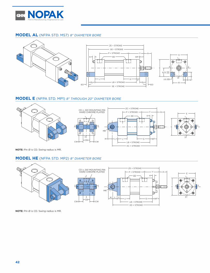
42
MODEL AL (NFPA STD. MS7) 8" DIAMETER BORE
AYP + STROKE
ZE + STROKE
XE + STROKE
EEK WF
J G
SE + STROKE
EL ELEOEO
FLB + STROKE
.005–– .009
E
1
3
24
R
E
E/2
(4) EB ET
MODEL E (NFPA STD. MP1) 8" THROUGH 20" DIAMETER BORE
WF
AYP + STROKE
ZC + STROKE
EE K
J GCB
CWCWL
MR
M
LB + STROKE
XC + STROKE
E
1
3
1
3
242 4 E
NOTE: Pin Ø is CD. Swing radius is MR.
MODEL HE (NFPA STD. MP2) 8" DIAMETER BORE
AYP + STROKE
ZD + STROKE
EE K
J GCBCWCW
L F
MR
M
LB + STROKE
XD + STROKE
E
1
3
24
1
3
2 4 E
WF
NOTE: Pin Ø is CD. Swing radius is MR.
8" THROUGH 20" DIAMETER
CD ± .001 MOUNTING PINHARD CHROME PLATED
CD ± .001 MOUNTING PINHARD CHROME PLATED
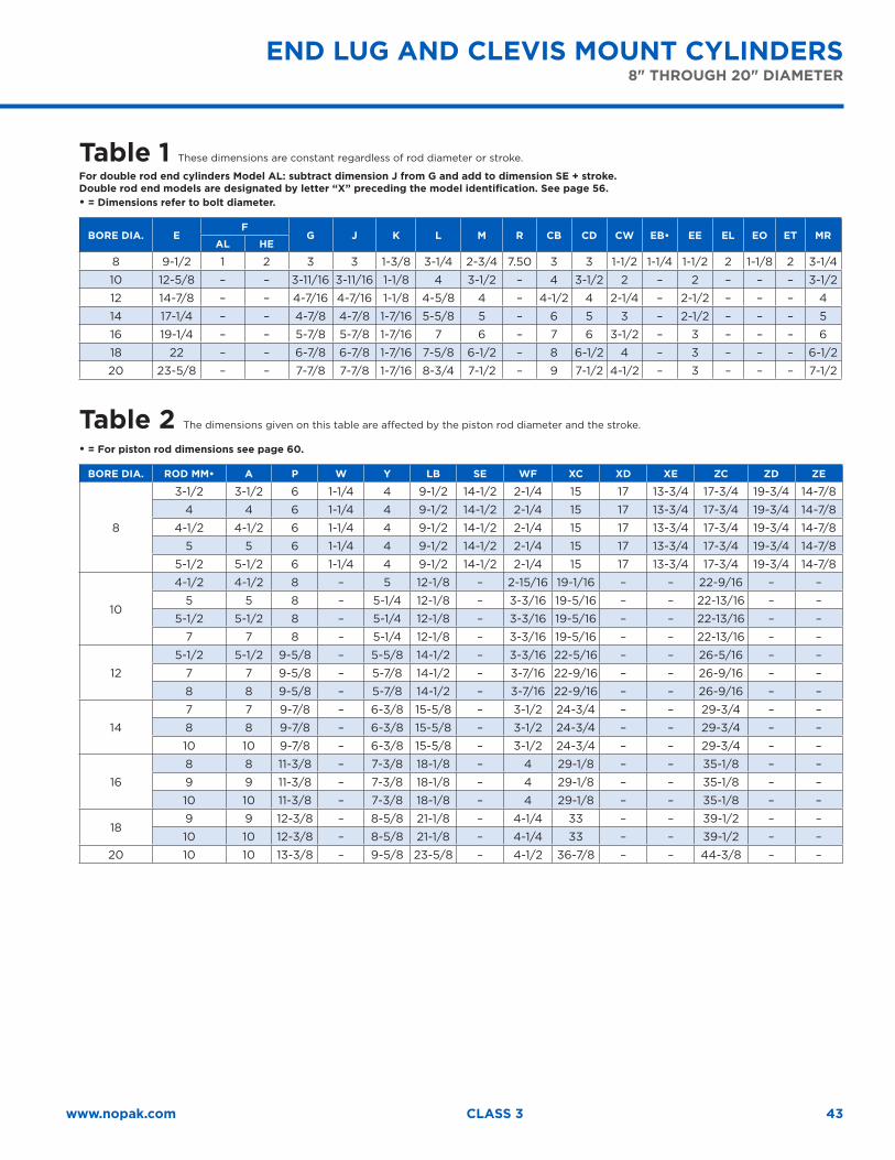
43www.nopak.com CLASS 3
Table 1 These dimensions are constant regardless of rod diameter or stroke.
For double rod end cylinders Model AL: subtract dimension J from G and add to dimension SE + stroke.Double rod end models are designated by letter “X” preceding the model identification. See page 56.• = Dimensions refer to bolt diameter.
BORE DIA. EF
G J K L M R CB CD CW EB• EE EL EO ET MRAL HE
8 9-1/2 1 2 3 3 1-3/8 3-1/4 2-3/4 7.50 3 3 1-1/2 1-1/4 1-1/2 2 1-1/8 2 3-1/4
10 12-5/8 – – 3-11/16 3-11/16 1-1/8 4 3-1/2 – 4 3-1/2 2 – 2 – – – 3-1/2
12 14-7/8 – – 4-7/16 4-7/16 1-1/8 4-5/8 4 – 4-1/2 4 2-1/4 – 2-1/2 – – – 4
14 17-1/4 – – 4-7/8 4-7/8 1-7/16 5-5/8 5 – 6 5 3 – 2-1/2 – – – 5
16 19-1/4 – – 5-7/8 5-7/8 1-7/16 7 6 – 7 6 3-1/2 – 3 – – – 6
18 22 – – 6-7/8 6-7/8 1-7/16 7-5/8 6-1/2 – 8 6-1/2 4 – 3 – – – 6-1/2
20 23-5/8 – – 7-7/8 7-7/8 1-7/16 8-3/4 7-1/2 – 9 7-1/2 4-1/2 – 3 – – – 7-1/2
Table 2 The dimensions given on this table are affected by the piston rod diameter and the stroke.
• = For piston rod dimensions see page 60.
BORE DIA. ROD MM• A P W Y LB SE WF XC XD XE ZC ZD ZE
8
3-1/2 3-1/2 6 1-1/4 4 9-1/2 14-1/2 2-1/4 15 17 13-3/4 17-3/4 19-3/4 14-7/8
4 4 6 1-1/4 4 9-1/2 14-1/2 2-1/4 15 17 13-3/4 17-3/4 19-3/4 14-7/8
4-1/2 4-1/2 6 1-1/4 4 9-1/2 14-1/2 2-1/4 15 17 13-3/4 17-3/4 19-3/4 14-7/8
5 5 6 1-1/4 4 9-1/2 14-1/2 2-1/4 15 17 13-3/4 17-3/4 19-3/4 14-7/8
5-1/2 5-1/2 6 1-1/4 4 9-1/2 14-1/2 2-1/4 15 17 13-3/4 17-3/4 19-3/4 14-7/8
10
4-1/2 4-1/2 8 – 5 12-1/8 – 2-15/16 19-1/16 – – 22-9/16 – –
5 5 8 – 5-1/4 12-1/8 – 3-3/16 19-5/16 – – 22-13/16 – –
5-1/2 5-1/2 8 – 5-1/4 12-1/8 – 3-3/16 19-5/16 – – 22-13/16 – –
7 7 8 – 5-1/4 12-1/8 – 3-3/16 19-5/16 – – 22-13/16 – –
12
5-1/2 5-1/2 9-5/8 – 5-5/8 14-1/2 – 3-3/16 22-5/16 – – 26-5/16 – –
7 7 9-5/8 – 5-7/8 14-1/2 – 3-7/16 22-9/16 – – 26-9/16 – –
8 8 9-5/8 – 5-7/8 14-1/2 – 3-7/16 22-9/16 – – 26-9/16 – –
14
7 7 9-7/8 – 6-3/8 15-5/8 – 3-1/2 24-3/4 – – 29-3/4 – –
8 8 9-7/8 – 6-3/8 15-5/8 – 3-1/2 24-3/4 – – 29-3/4 – –
10 10 9-7/8 – 6-3/8 15-5/8 – 3-1/2 24-3/4 – – 29-3/4 – –
16
8 8 11-3/8 – 7-3/8 18-1/8 – 4 29-1/8 – – 35-1/8 – –
9 9 11-3/8 – 7-3/8 18-1/8 – 4 29-1/8 – – 35-1/8 – –
10 10 11-3/8 – 7-3/8 18-1/8 – 4 29-1/8 – – 35-1/8 – –
189 9 12-3/8 – 8-5/8 21-1/8 – 4-1/4 33 – – 39-1/2 – –
10 10 12-3/8 – 8-5/8 21-1/8 – 4-1/4 33 – – 39-1/2 – –
20 10 10 13-3/8 – 9-5/8 23-5/8 – 4-1/2 36-7/8 – – 44-3/8 – –
END LUG AND CLEVIS MOUNT CYLINDERS8" THROUGH 20" DIAMETER
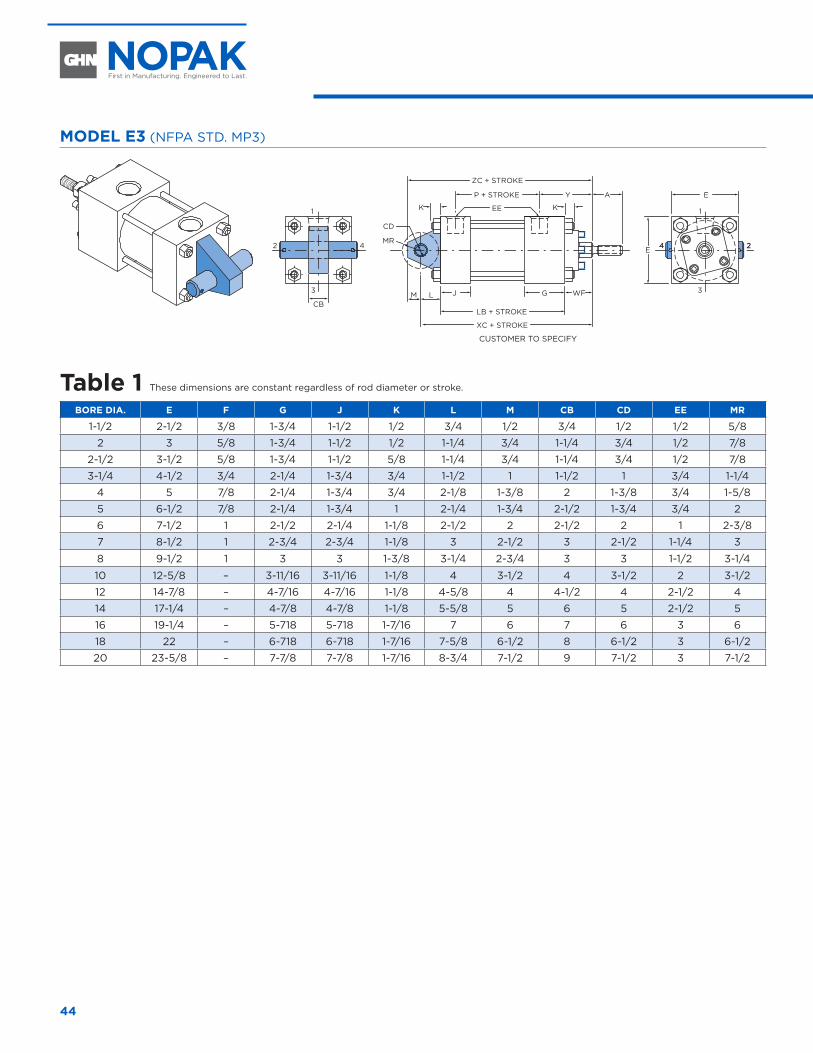
44
MODEL E3 (NFPA STD. MP3)
WF
24 24
AYP + STROKE
ZC + STROKE
EE K
J G
MR
CD
LB + STROKE
XC + STROKE
E
1
3
E
K
LMCB
1
3
2 4
Table 1 These dimensions are constant regardless of rod diameter or stroke.
BORE DIA. E F G J K L M CB CD EE MR
1-1/2 2-1/2 3/8 1-3/4 1-1/2 1/2 3/4 1/2 3/4 1/2 1/2 5/8
2 3 5/8 1-3/4 1-1/2 1/2 1-1/4 3/4 1-1/4 3/4 1/2 7/8
2-1/2 3-1/2 5/8 1-3/4 1-1/2 5/8 1-1/4 3/4 1-1/4 3/4 1/2 7/8
3-1/4 4-1/2 3/4 2-1/4 1-3/4 3/4 1-1/2 1 1-1/2 1 3/4 1-1/4
4 5 7/8 2-1/4 1-3/4 3/4 2-1/8 1-3/8 2 1-3/8 3/4 1-5/8
5 6-1/2 7/8 2-1/4 1-3/4 1 2-1/4 1-3/4 2-1/2 1-3/4 3/4 2
6 7-1/2 1 2-1/2 2-1/4 1-1/8 2-1/2 2 2-1/2 2 1 2-3/8
7 8-1/2 1 2-3/4 2-3/4 1-1/8 3 2-1/2 3 2-1/2 1-1/4 3
8 9-1/2 1 3 3 1-3/8 3-1/4 2-3/4 3 3 1-1/2 3-1/4
10 12-5/8 – 3-11/16 3-11/16 1-1/8 4 3-1/2 4 3-1/2 2 3-1/2
12 14-7/8 – 4-7/16 4-7/16 1-1/8 4-5/8 4 4-1/2 4 2-1/2 4
14 17-1/4 – 4-7/8 4-7/8 1-1/8 5-5/8 5 6 5 2-1/2 5
16 19-1/4 – 5-718 5-718 1-7/16 7 6 7 6 3 6
18 22 – 6-718 6-718 1-7/16 7-5/8 6-1/2 8 6-1/2 3 6-1/2
20 23-5/8 – 7-7/8 7-7/8 1-7/16 8-3/4 7-1/2 9 7-1/2 3 7-1/2
CUSTOMER TO SPECIFY
FIXED EYE MOUNT CYLINDERS 1-1/2" THROUGH 20" DIAMETER
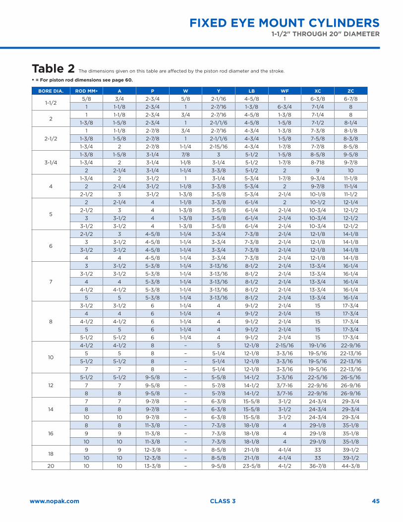
45www.nopak.com CLASS 3
Table 2 The dimensions given on this table are affected by the piston rod diameter and the stroke.
• = For piston rod dimensions see page 60.
BORE DIA. ROD MM• A P W Y LB WF XC ZC
1-1/25/8 3/4 2-3/4 5/8 2-1/16 4-5/8 1 6-3/8 6-7/8
1 1-1/8 2-3/4 1 2-7/16 1-3/8 6-3/4 7-1/4 8
21 1-1/8 2-3/4 3/4 2-7/16 4-5/8 1-3/8 7-1/4 8
1-3/8 1-5/8 2-3/4 1 2-1/1/6 4-5/8 1-5/8 7-1/2 8-1/4
2-1/21 1-1/8 2-7/8 3/4 2-7/16 4-3/4 1-3/8 7-3/8 8-1/8
1-3/8 1-5/8 2-7/8 1 2-1/1/6 4-3/4 1-5/8 7-5/8 8-3/81-3/4 2 2-7/8 1-1/4 2-15/16 4-3/4 1-7/8 7-7/8 8-5/8
3-1/41-3/8 1-5/8 3-1/4 7/8 3 5-1/2 1-5/8 8-5/8 9-5/81-3/4 2 3-1/4 1-1/8 3-1/4 5-1/2 1-7/8 8-718 9-7/8
2 2-1/4 3-1/4 1-1/4 3-3/8 5-1/2 2 9 10
41-3/4 2 3-1/2 1 3-1/4 5-3/4 1-7/8 9-3/4 11-1/8
2 2-1/4 3-1/2 1-1/8 3-3/8 5-3/4 2 9-7/8 11-1/42-1/2 3 3-1/2 1-3/8 3-5/8 5-3/4 2-1/4 10-1/8 11-1/2
5
2 2-1/4 4 1-1/8 3-3/8 6-1/4 2 10-1/2 12-1/42-1/2 3 4 1-3/8 3-5/8 6-1/4 2-1/4 10-3/4 12-1/2
3 3-1/2 4 1-3/8 3-5/8 6-1/4 2-1/4 10-3/4 12-1/23-1/2 3-1/2 4 1-3/8 3-5/8 6-1/4 2-1/4 10-3/4 12-1/2
6
2-1/2 3 4-5/8 1-1/4 3-3/4 7-3/8 2-1/4 12-1/8 14-1/83 3-1/2 4-5/8 1-1/4 3-3/4 7-3/8 2-1/4 12-1/8 14-1/8
3-1/2 3-1/2 4-5/8 1-1/4 3-3/4 7-3/8 2-1/4 12-1/8 14-1/84 4 4-5/8 1-1/4 3-3/4 7-3/8 2-1/4 12-1/8 14-1/8
7
3 3-1/2 5-3/8 1-1/4 3-13/16 8-1/2 2-1/4 13-3/4 16-1/43-1/2 3-1/2 5-3/8 1-1/4 3-13/16 8-1/2 2-1/4 13-3/4 16-1/4
4 4 5-3/8 1-1/4 3-13/16 8-1/2 2-1/4 13-3/4 16-1/44-1/2 4-1/2 5-3/8 1-1/4 3-13/16 8-1/2 2-1/4 13-3/4 16-1/4
5 5 5-3/8 1-1/4 3-13/16 8-1/2 2-1/4 13-3/4 16-1/4
8
3-1/2 3-1/2 6 1-1/4 4 9-1/2 2-1/4 15 17-3/44 4 6 1-1/4 4 9-1/2 2-1/4 15 17-3/4
4-1/2 4-1/2 6 1-1/4 4 9-1/2 2-1/4 15 17-3/45 5 6 1-1/4 4 9-1/2 2-1/4 15 17-3/4
5-1/2 5-1/2 6 1-1/4 4 9-1/2 2-1/4 15 17-3/4
10
4-1/2 4-1/2 8 – 5 12-1/8 2-15/16 19-1/16 22-9/165 5 8 – 5-1/4 12-1/8 3-3/16 19-5/16 22-13/16
5-1/2 5-1/2 8 – 5-1/4 12-1/8 3-3/16 19-5/16 22-13/167 7 8 – 5-1/4 12-1/8 3-3/16 19-5/16 22-13/16
125-1/2 5-1/2 9-5/8 – 5-5/8 14-1/2 3-3/16 22-5/16 26-5/16
7 7 9-5/8 – 5-7/8 14-1/2 3/7-16 22-9/16 26-9/168 8 9-5/8 – 5-7/8 14-1/2 3/7-16 22-9/16 26-9/16
147 7 9-7/8 – 6-3/8 15-5/8 3-1/2 24-3/4 29-3/48 8 9-7/8 – 6-3/8 15-5/8 3-1/2 24-3/4 29-3/410 10 9-7/8 – 6-3/8 15-5/8 3-1/2 24-3/4 29-3/4
16
8 8 11-3/8 – 7-3/8 18-1/8 4 29-1/8 35-1/8
9 9 11-3/8 – 7-3/8 18-1/8 4 29-1/8 35-1/8
10 10 11-3/8 – 7-3/8 18-1/8 4 29-1/8 35-1/8
189 9 12-3/8 – 8-5/8 21-1/8 4-1/4 33 39-1/210 10 12-3/8 – 8-5/8 21-1/8 4-1/4 33 39-1/2
20 10 10 13-3/8 – 9-5/8 23-5/8 4-1/2 36-7/8 44-3/8
FIXED EYE MOUNT CYLINDERS1-1/2" THROUGH 20" DIAMETER
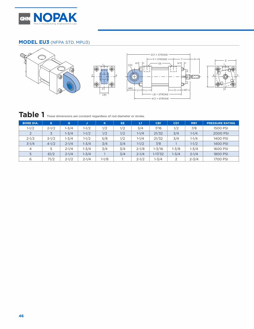
46
MODEL EU3 (NFPA STD. MPU3)
WF
AYP + STROKE
ZC1 + STROKE
EE KK
J G
CB1
L1
CD1
MR1
LB + STROKE
XC1 + STROKE
E
1
3
24
1
3
2 4 E
Table 1 These dimensions are constant regardless of rod diameter or stroke.
BORE DIA. E G J K EE L1 CB1 CD1 MR1 PRESSURE RATING
1-1/2 2-1/2 1-3/4 1-1/2 1/2 1/2 3/4 7/16 1/2 7/8 1500 PSI
2 3 1-3/4 1-1/2 1/2 1/2 1-1/4 21/32 3/4 1-1/4 2000 PSI
2-1/2 3-1/2 1-3/4 1-1/2 5/8 1/2 1-1/4 21/32 3/4 1-1/4 1400 PSI
3-1/4 4-1/2 2-1/4 1-3/4 3/4 3/4 1-1/2 7/8 1 1-1/2 1400 PSI
4 5 2-1/4 1-3/4 3/4 3/4 2-1/8 1-3/16 1-3/8 1-3/4 1600 PSI
5 61/2 2-1/4 1-3/4 1 3/4 2-1/4 1-17/32 1-3/4 2-1/4 1800 PSI
6 71/2 2-1/2 2-1/4 1-1/8 1 2-1/2 1-3/4 2 2-3/4 1700 PSI
SPHERICAL EYE MOUNT CYLINDERS 1-1/2" THROUGH 6" DIAMETER
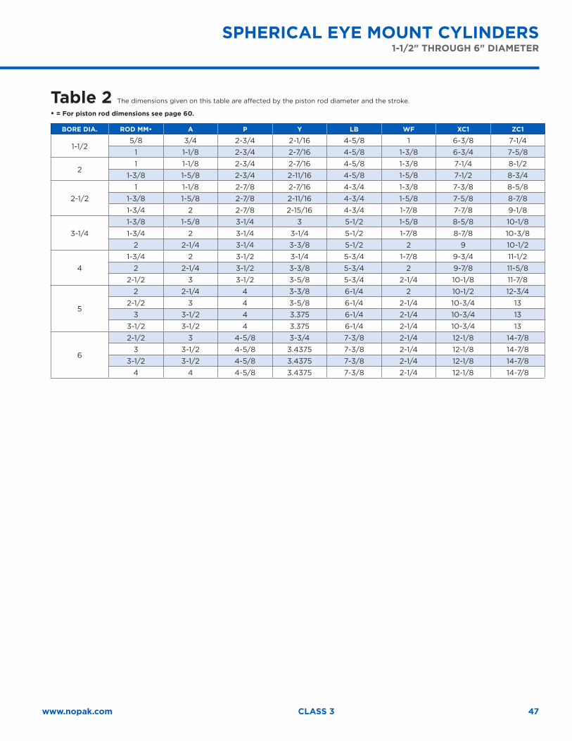
47www.nopak.com CLASS 3
Table 2 The dimensions given on this table are affected by the piston rod diameter and the stroke.
• = For piston rod dimensions see page 60.
BORE DIA. ROD MM• A P Y LB WF XC1 ZC1
1-1/25/8 3/4 2-3/4 2-1/16 4-5/8 1 6-3/8 7-1/4
1 1-1/8 2-3/4 2-7/16 4-5/8 1-3/8 6-3/4 7-5/8
21 1-1/8 2-3/4 2-7/16 4-5/8 1-3/8 7-1/4 8-1/2
1-3/8 1-5/8 2-3/4 2-11/16 4-5/8 1-5/8 7-1/2 8-3/4
2-1/2
1 1-1/8 2-7/8 2-7/16 4-3/4 1-3/8 7-3/8 8-5/8
1-3/8 1-5/8 2-7/8 2-11/16 4-3/4 1-5/8 7-5/8 8-7/8
1-3/4 2 2-7/8 2-15/16 4-3/4 1-7/8 7-7/8 9-1/8
3-1/4
1-3/8 1-5/8 3-1/4 3 5-1/2 1-5/8 8-5/8 10-1/8
1-3/4 2 3-1/4 3-1/4 5-1/2 1-7/8 8-7/8 10-3/8
2 2-1/4 3-1/4 3-3/8 5-1/2 2 9 10-1/2
4
1-3/4 2 3-1/2 3-1/4 5-3/4 1-7/8 9-3/4 11-1/2
2 2-1/4 3-1/2 3-3/8 5-3/4 2 9-7/8 11-5/8
2-1/2 3 3-1/2 3-5/8 5-3/4 2-1/4 10-1/8 11-7/8
5
2 2-1/4 4 3-3/8 6-1/4 2 10-1/2 12-3/4
2-1/2 3 4 3-5/8 6-1/4 2-1/4 10-3/4 13
3 3-1/2 4 3.375 6-1/4 2-1/4 10-3/4 13
3-1/2 3-1/2 4 3.375 6-1/4 2-1/4 10-3/4 13
6
2-1/2 3 4-5/8 3-3/4 7-3/8 2-1/4 12-1/8 14-7/8
3 3-1/2 4-5/8 3.4375 7-3/8 2-1/4 12-1/8 14-7/8
3-1/2 3-1/2 4-5/8 3.4375 7-3/8 2-1/4 12-1/8 14-7/8
4 4 4-5/8 3.4375 7-3/8 2-1/4 12-1/8 14-7/8
SPHERICAL EYE MOUNT CYLINDERS1-1/2" THROUGH 6" DIAMETER
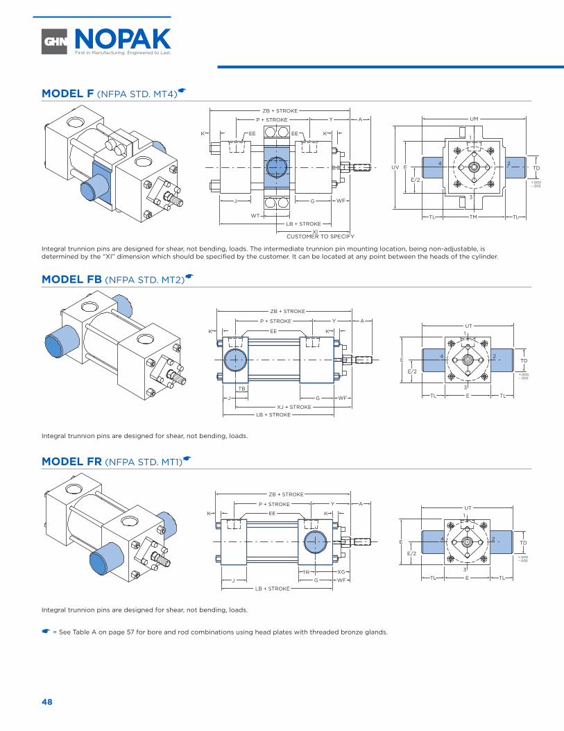
48
MODEL F (NFPA STD. MT4)�
AYP + STROKE
ZB + STROKE
EEK KEE
J G WF
LB + STROKE
XI
1
3
24
TMTL TL
EUV
UM
E/2
TD
WT
+.000– .002
Integral trunnion pins are designed for shear, not bending, loads. The intermediate trunnion pin mounting location, being non-adjustable, is determined by the “XI” dimension which should be specified by the customer. It can be located at any point between the heads of the cylinder.
MODEL FB (NFPA STD. MT2)�
AYP + STROKE
ZB + STROKE
EEK K
J G WF
LB + STROKEXJ + STROKE
UT1
3
24
ETL TL
E
E/2
TD
TB
+.000– .002
Integral trunnion pins are designed for shear, not bending, loads.
MODEL FR (NFPA STD. MT1)�
AYP + STROKE
ZB + STROKE
EEK K
J G WF
XG
LB + STROKE
UT1
3
24
ETL TL
E
E/2
TD
TR
+.000– .002
Integral trunnion pins are designed for shear, not bending, loads.
� = See Table A on page 57 for bore and rod combinations using head plates with threaded bronze glands.
TRUNNION MOUNT CYLINDERS 1-1/2" THROUGH 7" DIAMETER
CUSTOMER TO SPECIFY
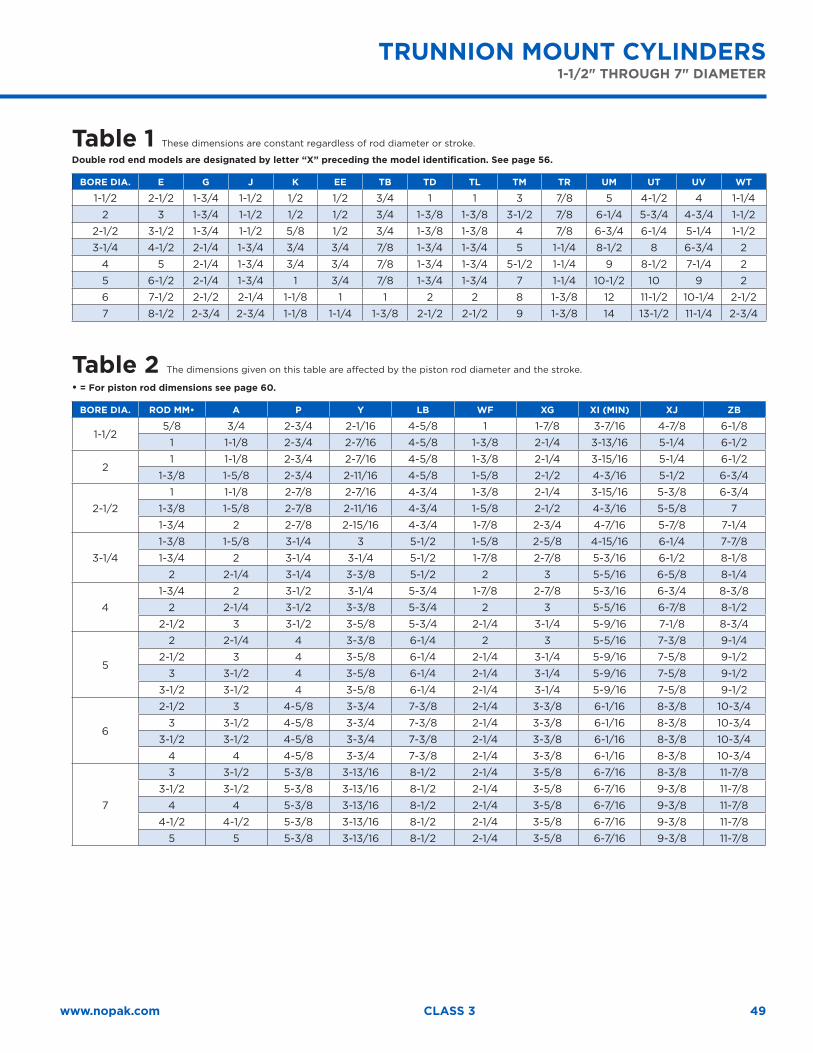
49www.nopak.com CLASS 3
Table 1 These dimensions are constant regardless of rod diameter or stroke.
Double rod end models are designated by letter “X” preceding the model identification. See page 56.
BORE DIA. E G J K EE TB TD TL TM TR UM UT UV WT
1-1/2 2-1/2 1-3/4 1-1/2 1/2 1/2 3/4 1 1 3 7/8 5 4-1/2 4 1-1/4
2 3 1-3/4 1-1/2 1/2 1/2 3/4 1-3/8 1-3/8 3-1/2 7/8 6-1/4 5-3/4 4-3/4 1-1/2
2-1/2 3-1/2 1-3/4 1-1/2 5/8 1/2 3/4 1-3/8 1-3/8 4 7/8 6-3/4 6-1/4 5-1/4 1-1/2
3-1/4 4-1/2 2-1/4 1-3/4 3/4 3/4 7/8 1-3/4 1-3/4 5 1-1/4 8-1/2 8 6-3/4 2
4 5 2-1/4 1-3/4 3/4 3/4 7/8 1-3/4 1-3/4 5-1/2 1-1/4 9 8-1/2 7-1/4 2
5 6-1/2 2-1/4 1-3/4 1 3/4 7/8 1-3/4 1-3/4 7 1-1/4 10-1/2 10 9 2
6 7-1/2 2-1/2 2-1/4 1-1/8 1 1 2 2 8 1-3/8 12 11-1/2 10-1/4 2-1/2
7 8-1/2 2-3/4 2-3/4 1-1/8 1-1/4 1-3/8 2-1/2 2-1/2 9 1-3/8 14 13-1/2 11-1/4 2-3/4
Table 2 The dimensions given on this table are affected by the piston rod diameter and the stroke.
• = For piston rod dimensions see page 60.
BORE DIA. ROD MM• A P Y LB WF XG XI (MIN) XJ ZB
1-1/25/8 3/4 2-3/4 2-1/16 4-5/8 1 1-7/8 3-7/16 4-7/8 6-1/8
1 1-1/8 2-3/4 2-7/16 4-5/8 1-3/8 2-1/4 3-13/16 5-1/4 6-1/2
21 1-1/8 2-3/4 2-7/16 4-5/8 1-3/8 2-1/4 3-15/16 5-1/4 6-1/2
1-3/8 1-5/8 2-3/4 2-11/16 4-5/8 1-5/8 2-1/2 4-3/16 5-1/2 6-3/4
2-1/2
1 1-1/8 2-7/8 2-7/16 4-3/4 1-3/8 2-1/4 3-15/16 5-3/8 6-3/4
1-3/8 1-5/8 2-7/8 2-11/16 4-3/4 1-5/8 2-1/2 4-3/16 5-5/8 7
1-3/4 2 2-7/8 2-15/16 4-3/4 1-7/8 2-3/4 4-7/16 5-7/8 7-1/4
3-1/4
1-3/8 1-5/8 3-1/4 3 5-1/2 1-5/8 2-5/8 4-15/16 6-1/4 7-7/8
1-3/4 2 3-1/4 3-1/4 5-1/2 1-7/8 2-7/8 5-3/16 6-1/2 8-1/8
2 2-1/4 3-1/4 3-3/8 5-1/2 2 3 5-5/16 6-5/8 8-1/4
4
1-3/4 2 3-1/2 3-1/4 5-3/4 1-7/8 2-7/8 5-3/16 6-3/4 8-3/8
2 2-1/4 3-1/2 3-3/8 5-3/4 2 3 5-5/16 6-7/8 8-1/2
2-1/2 3 3-1/2 3-5/8 5-3/4 2-1/4 3-1/4 5-9/16 7-1/8 8-3/4
5
2 2-1/4 4 3-3/8 6-1/4 2 3 5-5/16 7-3/8 9-1/4
2-1/2 3 4 3-5/8 6-1/4 2-1/4 3-1/4 5-9/16 7-5/8 9-1/2
3 3-1/2 4 3-5/8 6-1/4 2-1/4 3-1/4 5-9/16 7-5/8 9-1/2
3-1/2 3-1/2 4 3-5/8 6-1/4 2-1/4 3-1/4 5-9/16 7-5/8 9-1/2
6
2-1/2 3 4-5/8 3-3/4 7-3/8 2-1/4 3-3/8 6-1/16 8-3/8 10-3/4
3 3-1/2 4-5/8 3-3/4 7-3/8 2-1/4 3-3/8 6-1/16 8-3/8 10-3/4
3-1/2 3-1/2 4-5/8 3-3/4 7-3/8 2-1/4 3-3/8 6-1/16 8-3/8 10-3/4
4 4 4-5/8 3-3/4 7-3/8 2-1/4 3-3/8 6-1/16 8-3/8 10-3/4
7
3 3-1/2 5-3/8 3-13/16 8-1/2 2-1/4 3-5/8 6-7/16 8-3/8 11-7/8
3-1/2 3-1/2 5-3/8 3-13/16 8-1/2 2-1/4 3-5/8 6-7/16 9-3/8 11-7/8
4 4 5-3/8 3-13/16 8-1/2 2-1/4 3-5/8 6-7/16 9-3/8 11-7/8
4-1/2 4-1/2 5-3/8 3-13/16 8-1/2 2-1/4 3-5/8 6-7/16 9-3/8 11-7/8
5 5 5-3/8 3-13/16 8-1/2 2-1/4 3-5/8 6-7/16 9-3/8 11-7/8
TRUNNION MOUNT CYLINDERS 1-1/2" THROUGH 7" DIAMETER
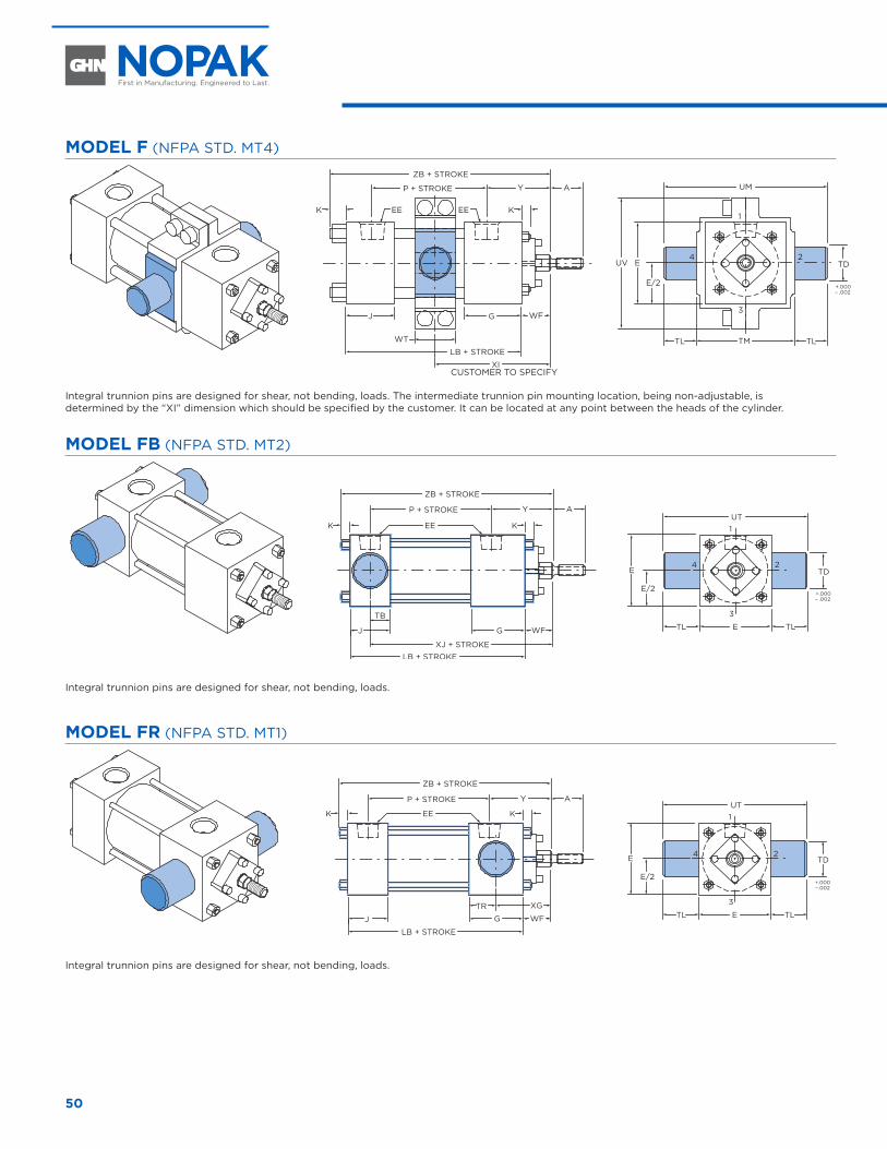
50
MODEL F (NFPA STD. MT4)
AYP + STROKE
ZB + STROKE
EEK KEE
J G WF
LB + STROKE
XI
1
3
24
TMTL TL
EUV
UM
E/2
TD
WT
+.000– .002
Integral trunnion pins are designed for shear, not bending, loads. The intermediate trunnion pin mounting location, being non-adjustable, is determined by the “XI” dimension which should be specified by the customer. It can be located at any point between the heads of the cylinder.
MODEL FB (NFPA STD. MT2)
AYP + STROKE
ZB + STROKE
EEK K
J G WF
LB + STROKEXJ + STROKE
UT1
3
24
ETL TL
E
E/2
TD
TB
+.000– .002
Integral trunnion pins are designed for shear, not bending, loads.
MODEL FR (NFPA STD. MT1)
AYP + STROKE
ZB + STROKE
EEK K
J G WF
XG
LB + STROKE
UT1
3
24
ETL TL
E
E/2
TD
TR
+.000– .002
Integral trunnion pins are designed for shear, not bending, loads.
8" THROUGH 14" DIAMETER
CUSTOMER TO SPECIFY
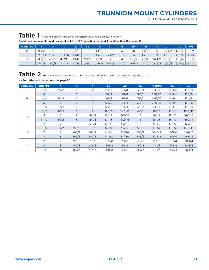
51www.nopak.com CLASS 3
Table 1 These dimensions are constant regardless of rod diameter or stroke.
Double rod end models are designated by letter “X” preceding the model identification. See page 56.
BORE DIA. E G J K EE TB TD TL TM TR UM UT UV WT
8 9-1/2 3 3 1-3/8 1-1/2 1-1/2 3 3 10 1-1/2 16 15-1/2 12-1/2 3-1/4
10 12-5/8 3-11/16 3-11/16 1-1/8 2 1-7/8 3-1/2 3-1/2 14 1-7/8 21 19-5/8 16-1/2 4-1/2
12 14-7/8 4-7/16 4-7/16 1-1/8 2-1/2 2-1/4 4 4 16-1/2 2-1/4 24-1/2 22-7/8 19-1/4 5-1/2
14 17-1/4 4-7/8 4-7/8 1-7/16 2-1/2 2-7/16 4-1/2 4-1/2 19-5/8 2-1/2 28-5/8 26-1/8 22-1/2 5-1/2
Table 2 The dimensions given on this table are affected by the piston rod diameter and the stroke.
• = For piston rod dimensions see page 60.
BORE DIA. ROD MM• A P Y LB WF XG XI (MIN) XJ ZB
8
3-1/2 3-1/2 6 4 9-1/2 2-1/4 3-3/4 6-15/16 10-1/4 13-1/8
4 4 6 4 9-1/2 2-1/4 3-3/4 6-15/16 10-1/4 13-1/8
4-1/2 4-1/2 6 4 9-1/2 2-1/4 3-3/4 6-15/16 10-1/4 13-1/8
5 5 6 4 9-1/2 2-1/4 3-3/4 6-15/16 10-1/4 13-1/8
5-1/2 5-1/2 6 4 9-1/2 2-1/4 3-3/4 6-15/16 10-1/4 13-1/8
10
4-1/2 4-1/2 8 5 12-1/8 2-15/16 4-3/4 8-7/8 13-1/4 16-3/16
5 5 8 5-1/4 12-1/8 3-3/16 5 9-1/8 13-1/2 16-7/16
5-1/2 5-1/2 8 5-1/4 12-1/8 3-3/16 5 9-1/8 13-1/2 16-7/16
7 7 8 5-1/4 12-1/8 3-3/16 5 9-1/8 13-1/2 16-7/16
12
5-1/2 5-1/2 9-5/8 5-5/8 14-1/2 3-3/16 5-3/8 10-3/8 15-1/2 18-3/16
7 7 9-5/8 5-7/8 14-1/2 3-7/16 5-5/8 10-5/8 15-3/4 19-1/16
8 8 9-5/8 5-7/8 14-1/2 3-7/16 5-5/8 10-5/8 15-3/4 19-1/16
14
7 7 9-7/8 6-3/8 15-5/8 3-1/2 5-7/8 11-1/8 16-3/4 20-1/4
8 8 9-7/8 6-3/8 15-5/8 3-1/2 5-7/8 11-1/8 16-3/4 20-1/4
10 10 9-7/8 6-3/8 15-5/8 3-1/2 5-7/8 11-1/8 16-3/4 20-1/4
TRUNNION MOUNT CYLINDERS 8" THROUGH 14" DIAMETER
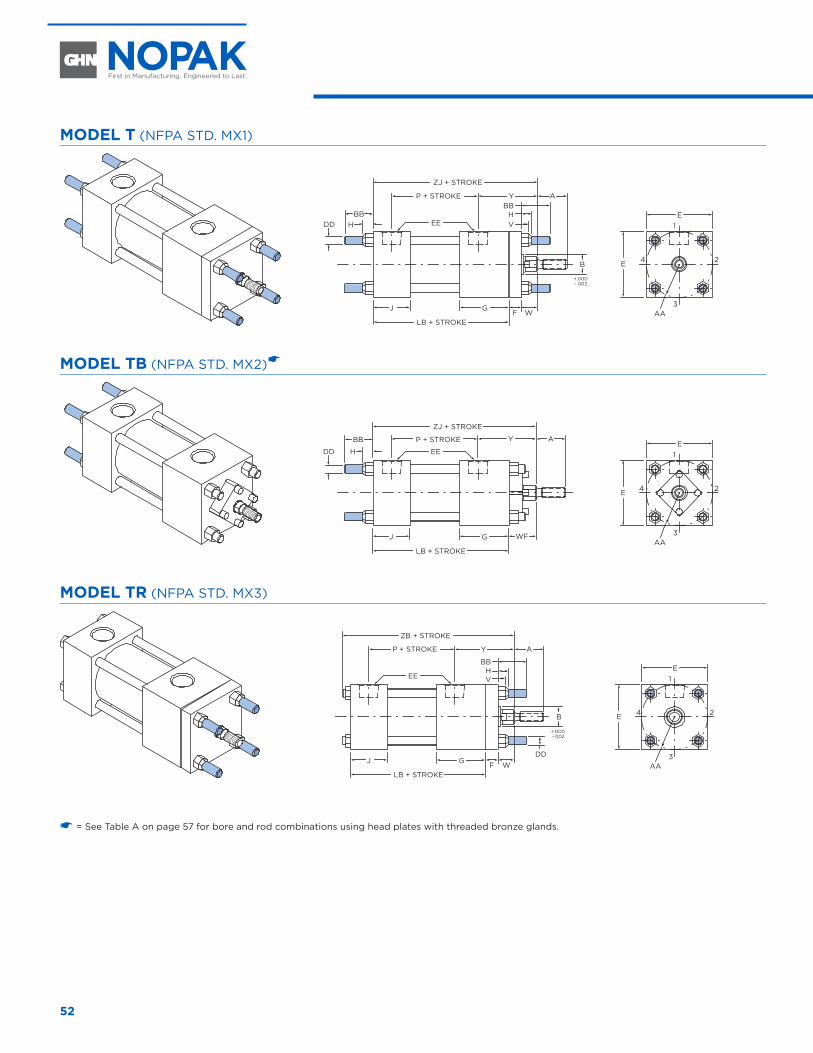
52
MODEL T (NFPA STD. MX1)
AA
AYP + STROKE
ZJ + STROKE
EE
J G
H
LB + STROKE
E1
3
24E
DDBB
WF
B
+.000– .002
BB
VH
MODEL TB (NFPA STD. MX2)�
AA
AYP + STROKE
ZJ + STROKE
EE
J G
H
LB + STROKE
E1
3
24E
DD
BB
WF
MODEL TR (NFPA STD. MX3)
B
+.000 –.002
AA
AYP + STROKE
ZB + STROKE
EE
J G
LB + STROKE
E1
3
24E
WFDD
V
BBH
� = See Table A on page 57 for bore and rod combinations using head plates with threaded bronze glands.
TIE-ROD MOUNT CYLINDERS 1-1/2" THROUGH 8" DIAMETER
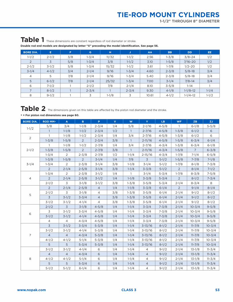
53www.nopak.com CLASS 3
Table 1 These dimensions are constant regardless of rod diameter or stroke.
Double rod end models are designated by letter “X” preceding the model identification. See page 56.
BORE DIA. E F G H J AA BB DD EE
1-1/2 2-1/2 3/8 1-3/4 11/32 1-1/2 2.56 1-3/8 3/8–24 1/2
2 3 5/8 1-3/4 3/8 1-1/2 3.10 1-5/8 7/16–20 1/2
2-1/2 3-1/2 5/8 1-3/4 15/32 1-1/2 3.61 1-7/8 1/2–20 1/2
3-1/4 4-1/2 3/4 2-1/4 9/16 1-3/4 4.60 2-3/8 5/8–18 3/4
4 5 7/8 2-1/4 9/16 1-3/4 5.40 2-3/8 5/8–18 3/4
5 6-1/2 7/8 2-1/4 25/32 1-3/4 7.00 3-1/4 7/8–14 3/4
6 7-1/2 1 2-1/2 7/8 2-1/4 8.10 3-5/8 1–14 1
7 8-1/2 1 2-3/4 1 2-3/4 9.30 4-1/8 1-1/8–12 1-1/4
8 9-1/2 1 3 1-1/8 3 10.61 4-1/2 1-1/4–12 1-1/2
Table 2 The dimensions given on this table are affected by the piston rod diameter and the stroke.
• = For piston rod dimensions see page 60.
BORE DIA. ROD MM• A B P V W Y LB WF ZB ZJ
1-1/25/8 3/4 1-1/8 2-3/4 1/4 5/8 2-1/16 4-5/8 1 6-1/8 5-5/8
1 1-1/8 1-1/2 2-3/4 1/2 1 2-7/16 4-5/8 1-3/8 6-1/2 6
21 1-1/8 1-1/2 2-3/4 1/4 3/4 2-7/16 4-5/8 1-3/8 6-1/2 6
1-3/8 1-5/8 2 2-3/4 3/8 1 2-11/16 4-5/8 1-5/8 6-3/4 6-1/4
2-1/2
1 1-1/8 1-1/2 2-7/8 1/4 3/4 2-7/16 4-3/4 1-3/8 6-3/4 6-1/8
1-3/8 1-5/8 2 2-7/8 3/8 1 2-11/16 4-3/4 1-5/8 7 6-3/8
1-3/4 2 2-3/8 2-7/8 1/2 1-1/4 2-15/16 4-3/4 1-7/8 7-1/4 6-5/8
3-1/4
1-3/8 1-5/8 2 3-1/4 1/4 7/8 3 5-1/2 1-5/8 7-7/8 7-1/8
1-3/4 2 2-3/8 3-1/4 3/8 1-1/8 3-1/4 5-1/2 1-7/8 8-1/8 7-3/8
2 2-1/4 2-5/8 3-1/4 3/8 1-1/4 3-3/8 5-1/2 2 8-1/4 7-1/2
4
1-3/4 2 2-3/8 3-1/2 1/4 1 3-1/4 5-3/4 1-7/8 8-3/8 7-5/8
2 2-1/4 2-5/8 3-1/2 1/4 1-1/8 3-3/8 5-3/4 2 8-1/2 7-3/4
2-1/2 3 3-1/8 3-1/2 3/8 1-3/8 3-5/8 5-3/4 2-1/4 8-3/4 8
5
2 2-1/4 2-5/8 4 1/4 1-1/8 3-3/8 6-1/4 2 9-1/4 8-1/4
2-1/2 3 3-1/8 4 3/8 1-3/8 3-5/8 6-1/4 2-1/4 9-1/2 8-1/2
3 3-1/2 3-3/4 4 3/8 1-3/8 3-5/8 6-1/4 2-1/4 9-1/2 8-1/2
3-1/2 3-1/2 4-1/4 4 3/8 1-3/8 3-5/8 6-1/4 2-1/4 9-1/2 8-1/2
6
2-1/2 3 3-1/8 4-5/8 1/4 1-1/4 3-3/4 7-3/8 2-1/4 10-3/4 9-5/8
3 3-1/2 3-3/4 4-5/8 1/4 1-1/4 3-3/4 7-3/8 2-1/4 10-3/4 9-5/8
3-1/2 3-1/2 4-1/4 4-5/8 1/4 1-1/4 3-3/4 7-3/8 2-1/4 10-3/4 9-5/8
4 4 4-3/4 4-5/8 1/4 1-1/4 3-3/4 7-3/8 2-1/4 10-3/4 9-5/8
7
3 3-1/2 3-3/4 5-3/8 1/4 1-1/4 3-13/16 8-1/2 2-1/4 11-7/8 10-3/4
3-1/2 3-1/2 4-1/4 5-3/8 1/4 1-1/4 3-13/16 8-1/2 2-1/4 11-7/8 10-3/4
4 4 4-3/4 5-3/8 1/4 1-1/4 3-13/16 8-1/2 2-1/4 11-7/8 10-3/4
4-1/2 4-1/2 5-1/4 5-3/8 1/4 1-1/4 3-13/16 8-1/2 2-1/4 11-7/8 10-3/4
5 5 5-3/4 5-3/8 1/4 1-1/4 3-13/16 8-1/2 2-1/4 11-7/8 10-3/4
8
3-1/2 3-1/2 4-1/4 6 1/4 1-1/4 4 9-1/2 2-1/4 13-1/8 11-3/4
4 4 4-3/4 6 1/4 1-1/4 4 9-1/2 2-1/4 13-1/8 11-3/4
4-1/2 4-1/2 5-1/4 6 1/4 1-1/4 4 9-1/2 2-1/4 13-1/8 11-3/4
5 5 5-3/4 6 1/4 1-1/4 4 9-1/2 2-1/4 13-1/8 11-3/4
5-1/2 5-1/2 6-1/4 6 1/4 1-1/4 4 9-1/2 2-1/4 13-1/8 11-3/4
TIE-ROD MOUNT CYLINDERS 1-1/2" THROUGH 8" DIAMETER
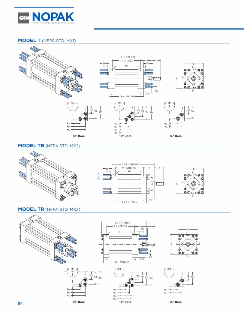
54
MODEL T (NFPA STD. MX1)
AYP + STROKE
ZJ + STROKE
EEBB
JLB + STROKE
E1
3
24E
DD
BB
WFG
H H
RA
RM
RBRC
RCRBRA
RARBRCRD
RDRB RC
RA
RBRC
RCRB
RM RM
10" Bore 12" Bore 14" Bore
MODEL TB (NFPA STD. MX2)
AYP + STROKE
ZJ + STROKE
EE
JLB + STROKE
E1
3
24E
DD
WFG
BBH
MODEL TR (NFPA STD. MX3)
P + STROKEZB + STROKE
EE
JLB + STROKE
E1
3
24E
G
AYBB
DDWF
H
RA
RM
RBRC
RCRBRA
RARBRCRD
RDRB RC
RA
RBRC
RCRB
RM RM
10" Bore 12" Bore 14" Bore
10" THROUGH 14" DIAMETER
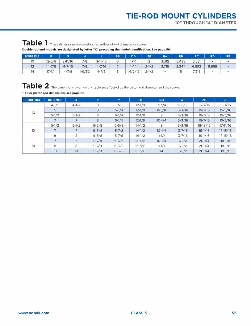
55www.nopak.com CLASS 3
Table 1 These dimensions are constant regardless of rod diameter or stroke.
Double rod end models are designated by letter “X” preceding the model identification. See page 56.
BORE DIA. E G H J BB DD EE RA RB RC RD RE
10 12-5/8 3-11/16 7/8 3-11/16 6 1–14 2 3.312 5.438 5.531 – –
12 14-7/8 4-7/16 7/8 4-7/16 7 1–14 2-1/2 3.718 5.344 6.593 6.656 –
14 17-1/4 4-7/8 1-9/32 4-7/8 8 1-1/2–12 2-1/2 – 5 7.313 – –
Table 2 The dimensions given on this table are affected by the piston rod diameter and the stroke.
• = For piston rod dimensions see page 60.
BORE DIA. ROD MM• A P Y LB RM WF ZB ZJ
10
4-1/2 4-1/2 8 5 12-1/8 7-3/4 2-15/16 16-3/16 15-1/16
5 5 8 5-1/4 12-1/8 8-3/8 3-3/16 16-7/16 15-5/16
5-1/2 5-1/2 8 5-1/4 12-1/8 9 3-3/16 16-7/16 15-5/16
7 7 8 5-1/4 12-1/8 10-1/4 3-3/16 16-7/16 15-5/16
12
5-1/2 5-1/2 9-5/8 5-5/8 14-1/2 9 3-3/16 18-13/16 17-11/16
7 7 9-5/8 5-7/8 14-1/2 10-1/4 3-7/16 19-1/16 17-15/16
8 8 9-5/8 5-7/8 14-1/2 11-1/4 3-7/16 19-1/16 17-15/16
14
7 7 9-7/8 6-3/8 15-5/8 10-1/4 3-1/2 20-1/4 19-1/8
8 8 9-7/8 6-3/8 15-5/8 11-1/4 3-1/2 20-1/4 19-1/8
10 10 9-7/8 6-3/8 15-5/8 14 3-1/2 20-1/4 19-1/8
TIE-ROD MOUNT CYLINDERS 10" THROUGH 14" DIAMETER
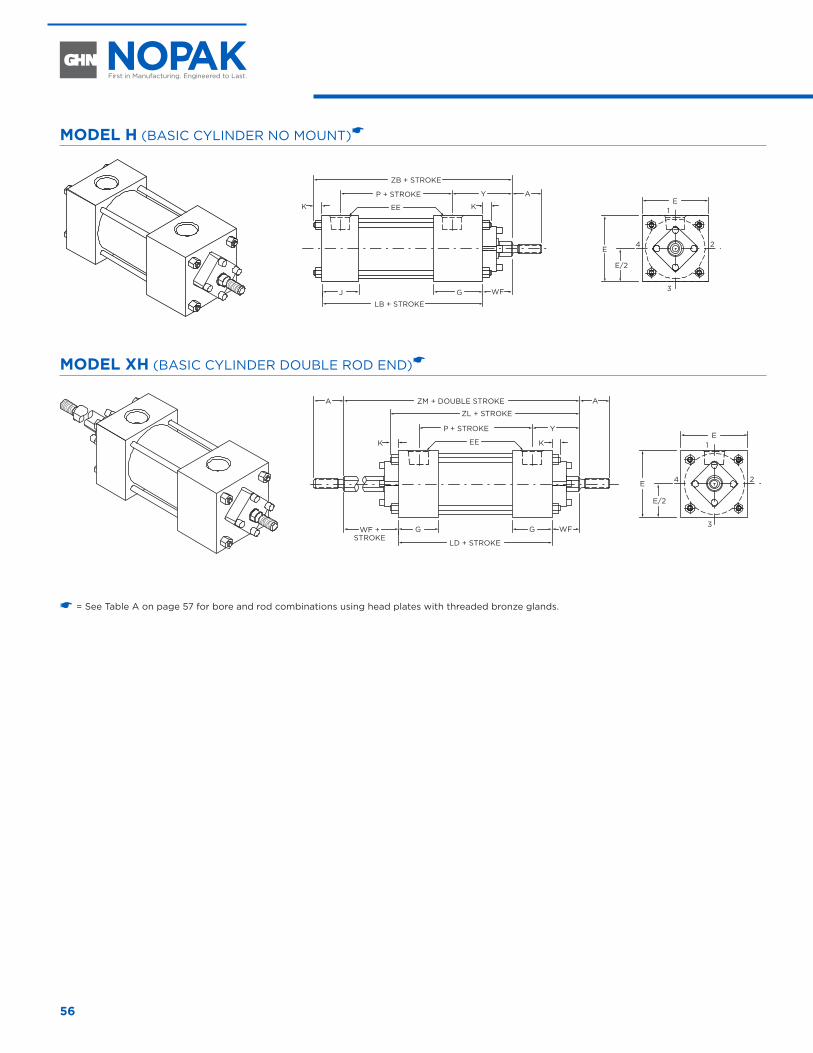
56
MODEL H (BASIC CYLINDER NO MOUNT)�
AYP + STROKE
ZB + STROKE
EEK K
J G
LB + STROKE
1
3
24
WF
E
E
E/2
MODEL XH (BASIC CYLINDER DOUBLE ROD END)�
A
YP + STROKE
ZL + STROKE
ZM + DOUBLE STROKEA
EEK K
G G
LD + STROKE
1
3
24
WFWF +STROKE
E
E
E/2
� = See Table A on page 57 for bore and rod combinations using head plates with threaded bronze glands.
BASIC MODEL NO MOUNT AND DOUBLE ROD END CYLINDERS 1-1/2" THROUGH 6" DIAMETER
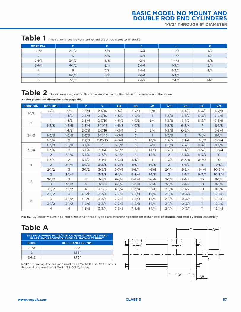
57www.nopak.com CLASS 3
Table 1 These dimensions are constant regardless of rod diameter or stroke.
BORE DIA. E F G J K
1-1/2 2-1/2 3/8 1-3/4 1-1/2 1/2
2 3 5/8 1-3/4 1-1/2 1/2
2-1/2 3-1/2 5/8 1-3/4 1-1/2 5/8
3-1/4 4-1/2 3/4 2-1/4 1-3/4 3/4
4 5 7/8 2-1/4 1-3/4 3/4
5 6-1/2 7/8 2-1/4 1-3/4 1
6 7-1/2 1 2-1/2 2-1/4 1-1/8
Table 2 The dimensions given on this table are affected by the piston rod diameter and the stroke.
• = For piston rod dimensions see page 60.
BORE DIA. ROD MM• A P Y LB LD W WF ZB ZL ZM
1-1/25/8 3/4 2-3/4 2-1/16 4-5/8 4-7/8 5/8 1 6-1/8 6-3/8 6-7/8
1 1-1/8 2-3/4 2-7/16 4-5/8 4-7/8 1 1-3/8 6-1/2 6-3/4 7-5/8
21 1-1/8 2-3/4 2-7/16 4-5/8 4-7/8 3/4 1-3/8 6-1/2 6-3/4 7-5/8
1-3/8 1-5/8 2-3/4 2-11/16 4-5/8 4-7/8 1 1-5/8 6-3/4 7 8-1/8
2-1/2
1 1-1/8 2-7/8 2-7/16 4-3/4 5 3/4 1-3/8 6-3/4 7 7-3/4
1-3/8 1-5/8 2-7/8 2-11/16 4-3/4 5 1 1-5/8 7 7-1/4 8-1/4
1-3/4 2 2-7/8 2-15/16 4-3/4 5 1-1/4 1-7/8 7-1/4 7-1/2 8-3/4
3-1/4
1-3/8 1-5/8 3-1/4 3 5-1/2 6 7/8 1-5/8 7-7/8 8-3/8 9-1/4
1-3/4 2 3-1/4 3-1/4 5-1/2 6 1-1/8 1-7/8 8-1/8 8-5/8 9-3/4
2 2-1/4 3-1/4 3-3/8 5-1/2 6 1-1/4 2 8-1/4 8-3/4 10
4
1-3/4 2 3-1/2 3-1/4 5-3/4 6-1/4 1 1-7/8 8-3/8 8-7/8 10
2 2-1/4 3-1/2 3-3/8 5-3/4 6-1/4 1-1/8 2 8-1/2 9 10-1/4
2-1/2 3 3-1/2 3-5/8 5-3/4 6-1/4 1-3/8 2-1/4 8-3/4 9-1/4 10-3/4
5
2 2-1/4 4 3-3/8 6-1/4 6-3/4 1-1/8 2 9-1/4 9-3/4 10-3/4
2-1/2 3 4 3-5/8 6-1/4 6-3/4 1-3/8 2-1/4 9-1/2 10 11-1/4
3 3-1/2 4 3-5/8 6-1/4 6-3/4 1-3/8 2-1/4 9-1/2 10 11-1/4
3-1/2 3-1/2 4 3-5/8 6-1/4 6-3/4 1-3/8 2-1/4 9-1/2 10 11-1/4
6
2-1/2 3 4-5/8 3-3/4 7-3/8 7-5/8 1-1/4 2-1/4 10-3/4 11 12-1/8
3 3-1/2 4-5/8 3-3/4 7-3/8 7-5/8 1-1/4 2-1/4 10-3/4 11 12-1/8
3-1/2 3-1/2 4-5/8 3-3/4 7-3/8 7-5/8 1-1/4 2-1/4 10-3/4 11 12-1/8
4 4 4-5/8 3-3/4 7-3/8 7-5/8 1-1/4 2-1/4 10-3/4 11 12-1/8
NOTE: Cylinder mountings, rod sizes and thread types are interchangeable on either end of double rod end cylinder assembly.
Table ATHE FOLLOWING BORE/ROD COMBINATIONS USE HEAD
PLATE AND BRONZE GLANDS AS SHOWN AT RIGHT
BORE ROD DIAMETER (MM)
1-1/2 1.00"
2 1.38"
2-1/2 1.75"
NOTE: Threaded Bronze Gland used on all Model D and DD Cylinders. Bolt-on Gland used on all Model G & DG Cylinders.
G W
AY
F
BASIC MODEL NO MOUNT AND DOUBLE ROD END CYLINDERS
1-1/2" THROUGH 6" DIAMETER
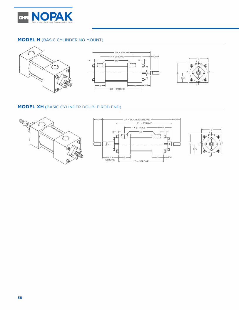
58
MODEL H (BASIC CYLINDER NO MOUNT)
AYP + STROKE
ZB + STROKE
EEK K
J G
LB + STROKE
1
3
24
WF
E
E
E/2
MODEL XH (BASIC CYLINDER DOUBLE ROD END)
A
YP + STROKE
ZL + STROKE
ZM + DOUBLE STROKEA
EEK K
G G
LD + STROKE
1
3
24
WFWF +STROKE
E
E
E/2
7" THROUGH 20" DIAMETER
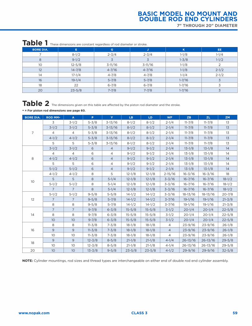
59www.nopak.com CLASS 3
Table 1 These dimensions are constant regardless of rod diameter or stroke.
BORE DIA. E G J K EE
7 8-1/2 2-3/4 2-3/4 1-1/8 1-1/4
8 9-1/2 3 3 1-3/8 1-1/2
10 12-5/8 3-11/16 3-11/16 1-1/8 2
12 14-7/8 4-7/16 4-7/16 1-1/8 2-1/2
14 17-1/4 4-7/8 4-7/8 1-1/4 2-1/2
16 19-1/4 5-7/8 5-7/8 1-7/16 3
18 22 6-7/8 6-7/8 1-7/16 3
20 23-5/8 7-7/8 7-7/8 1-7/16 3
Table 2 The dimensions given on this table are affected by the piston rod diameter and the stroke.
• = For piston rod dimensions see page 60.
BORE DIA. ROD MM• A P Y LB LD WF ZB ZL ZM
7
3 3-1/2 5-3/8 3-13/16 8-1/2 8-1/2 2-1/4 11-7/8 11-7/8 13
3-1/2 3-1/2 5-3/8 3-13/16 8-1/2 8-1/2 2-1/4 11-7/8 11-7/8 13
4 4 5-3/8 3-13/16 8-1/2 8-1/2 2-1/4 11-7/8 11-7/8 13
4-1/2 4-1/2 5-3/8 3-13/16 8-1/2 8-1/2 2-1/4 11-7/8 11-7/8 13
5 5 5-3/8 3-13/16 8-1/2 8-1/2 2-1/4 11-7/8 11-7/8 13
8
3-1/2 3-1/2 6 4 9-1/2 9-1/2 2-1/4 13-1/8 13-1/8 14
4 4 6 4 9-1/2 9-1/2 2-1/4 13-1/8 13-1/8 14
4-1/2 4-1/2 6 4 9-1/2 9-1/2 2-1/4 13-1/8 13-1/8 14
5 5 6 4 9-1/2 9-1/2 2-1/4 13-1/8 13-1/8 14
5-1/2 5-1/2 6 4 9-1/2 9-1/2 2-1/4 13-1/8 13-1/8 14
10
4-1/2 4-1/2 8 5 12-1/8 12-1/8 2-15/16 16-3/16 16-3/16 18
5 5 8 5-1/4 12-1/8 12-1/8 3-3/16 16-7/16 16-7/16 18-1/2
5-1/2 5-1/2 8 5-1/4 12-1/8 12-1/8 3-3/16 16-7/16 16-7/16 18-1/2
7 7 8 5-1/4 12-1/8 12-1/8 3-3/16 16-7/16 16-7/16 18-1/2
12
5-1/2 5-1/2 9-5/8 5-5/8 14-1/2 14-1/2 3-3/16 18-13/16 18-13/16 20-7/8
7 7 9-5/8 5-7/8 14-1/2 14-1/2 3-7/16 19-1/16 19-1/16 21-3/8
8 8 9-5/8 5-7/8 14-1/2 14-1/2 3-7/16 19-1/16 19-1/16 21-3/8
14
7 7 9-7/8 6-3/8 15-5/8 15-5/8 3-1/2 20-1/4 20-1/4 22-5/8
8 8 9-7/8 6-3/8 15-5/8 15-5/8 3-1/2 20-1/4 20-1/4 22-5/8
10 10 9-7/8 6-3/8 15-5/8 15-5/8 3-1/2 20-1/4 20-1/4 22-5/8
16
8 8 11-3/8 7-3/8 18-1/8 18-1/8 4 23-9/16 23-9/16 26-1/8
9 9 11-3/8 7-3/8 18-1/8 18-1/8 4 23-9/16 23-9/16 26-1/8
10 10 11-3/8 7-3/8 18-1/8 18-1/8 4 23-9/16 23-9/16 26-1/8
189 9 12-3/8 8-5/8 21-1/8 21-1/8 4-1/4 26-13/16 26-13/16 29-5/8
10 10 12-3/8 8-5/8 21-1/8 21-1/8 4-1/4 26-13/16 26-13/16 29-5/8
20 10 10 13-3/8 9-5/8 23-5/8 23-5/8 4-1/2 29-9/16 29-9/16 32-5/8
NOTE: Cylinder mountings, rod sizes and thread types are interchangeable on either end of double rod end cylinder assembly.
BASIC MODEL NO MOUNT AND DOUBLE ROD END CYLINDERS
7" THROUGH 20" DIAMETER
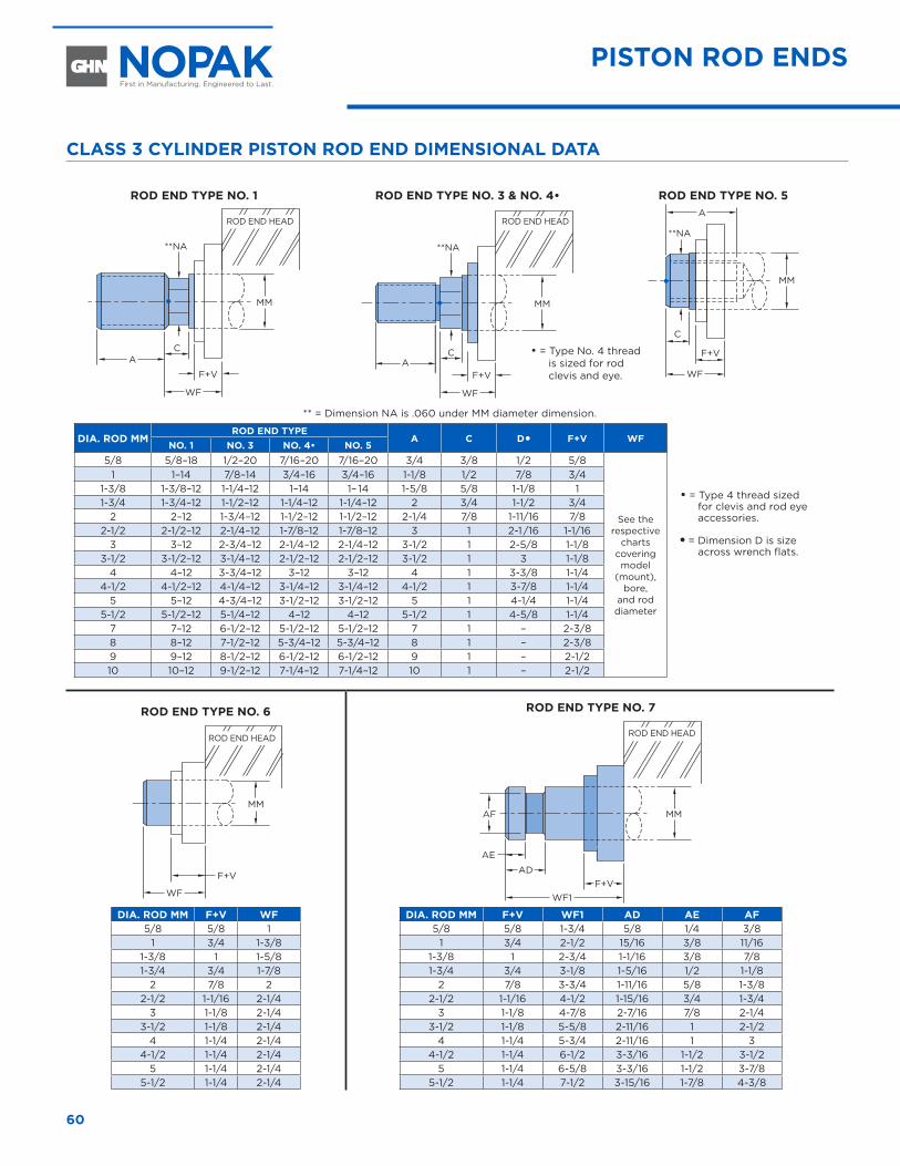
60
CLASS 3 CYLINDER PISTON ROD END DIMENSIONAL DATA
ROD END TYPE NO. 1
MM
A
WF
F+V
C
**NA
ROD END TYPE NO. 3 & NO. 4•
MM
A
WF
F+V
C
**NA
ROD END TYPE NO. 5
MM
A
WF
F+V
C
**NA
** = Dimension NA is .060 under MM diameter dimension.
DIA. ROD MMROD END TYPE
A C D� F+V WF
• = Type 4 thread sized for clevis and rod eye accessories.
� = Dimension D is size across wrench flats.
NO. 1 NO. 3 NO. 4• NO. 55/8 5/8–18 1/2–20 7/16–20 7/16–20 3/4 3/8 1/2 5/8
See the respective
charts covering model
(mount), bore,
and rod diameter
1 1–14 7/8–14 3/4–16 3/4–16 1-1/8 1/2 7/8 3/41-3/8 1-3/8–12 1-1/4–12 1–14 1– 14 1-5/8 5/8 1-1/8 11-3/4 1-3/4–12 1-1/2–12 1-1/4–12 1-1/4–12 2 3/4 1-1/2 3/4
2 2–12 1-3/4–12 1-1/2–12 1-1/2–12 2-1/4 7/8 1-11/16 7/82-1/2 2-1/2–12 2-1/4–12 1-7/8–12 1-7/8–12 3 1 2-1 /16 1-1/16
3 3–12 2-3/4–12 2-1/4–12 2-1/4–12 3-1/2 1 2-5/8 1-1/83-1/2 3-1/2–12 3-1/4–12 2-1/2–12 2-1/2–12 3-1/2 1 3 1-1/8
4 4–12 3-3/4–12 3–12 3–12 4 1 3-3/8 1-1/44-1/2 4-1/2–12 4-1/4–12 3-1/4–12 3-1/4–12 4-1/2 1 3-7/8 1-1/4
5 5–12 4-3/4–12 3-1/2–12 3-1/2–12 5 1 4-1/4 1-1/45-1/2 5-1/2–12 5-1/4–12 4–12 4–12 5-1/2 1 4-5/8 1-1/4
7 7–12 6-1/2–12 5-1/2–12 5-1/2–12 7 1 – 2-3/88 8–12 7-1/2–12 5-3/4–12 5-3/4–12 8 1 – 2-3/89 9–12 8-1/2–12 6-1/2–12 6-1/2–12 9 1 – 2-1/210 10–12 9-1/2–12 7-1/4–12 7-1/4–12 10 1 – 2-1/2
ROD END TYPE NO. 6
MM
WF
F+V
DIA. ROD MM F+V WF5/8 5/8 1
1 3/4 1-3/81-3/8 1 1-5/81-3/4 3/4 1-7/8
2 7/8 22-1/2 1-1/16 2-1/4
3 1-1/8 2-1/43-1/2 1-1/8 2-1/4
4 1-1/4 2-1/44-1/2 1-1/4 2-1/4
5 1-1/4 2-1/45-1/2 1-1/4 2-1/4
ROD END TYPE NO. 7
AF MM
AE
ADF+V
WF1
DIA. ROD MM F+V WF1 AD AE AF5/8 5/8 1-3/4 5/8 1/4 3/8
1 3/4 2-1/2 15/16 3/8 11/161-3/8 1 2-3/4 1-1/16 3/8 7/81-3/4 3/4 3-1/8 1-5/16 1/2 1-1/8
2 7/8 3-3/4 1-11/16 5/8 1-3/82-1/2 1-1/16 4-1/2 1-15/16 3/4 1-3/4
3 1-1/8 4-7/8 2-7/16 7/8 2-1/43-1/2 1-1/8 5-5/8 2-11/16 1 2-1/2
4 1-1/4 5-3/4 2-11/16 1 34-1/2 1-1/4 6-1/2 3-3/16 1-1/2 3-1/2
5 1-1/4 6-5/8 3-3/16 1-1/2 3-7/85-1/2 1-1/4 7-1/2 3-15/16 1-7/8 4-3/8
ROD END HEAD ROD END HEAD
ROD END HEAD ROD END HEAD
• = Type No. 4 thread is sized for rod clevis and eye.
PISTON ROD ENDS
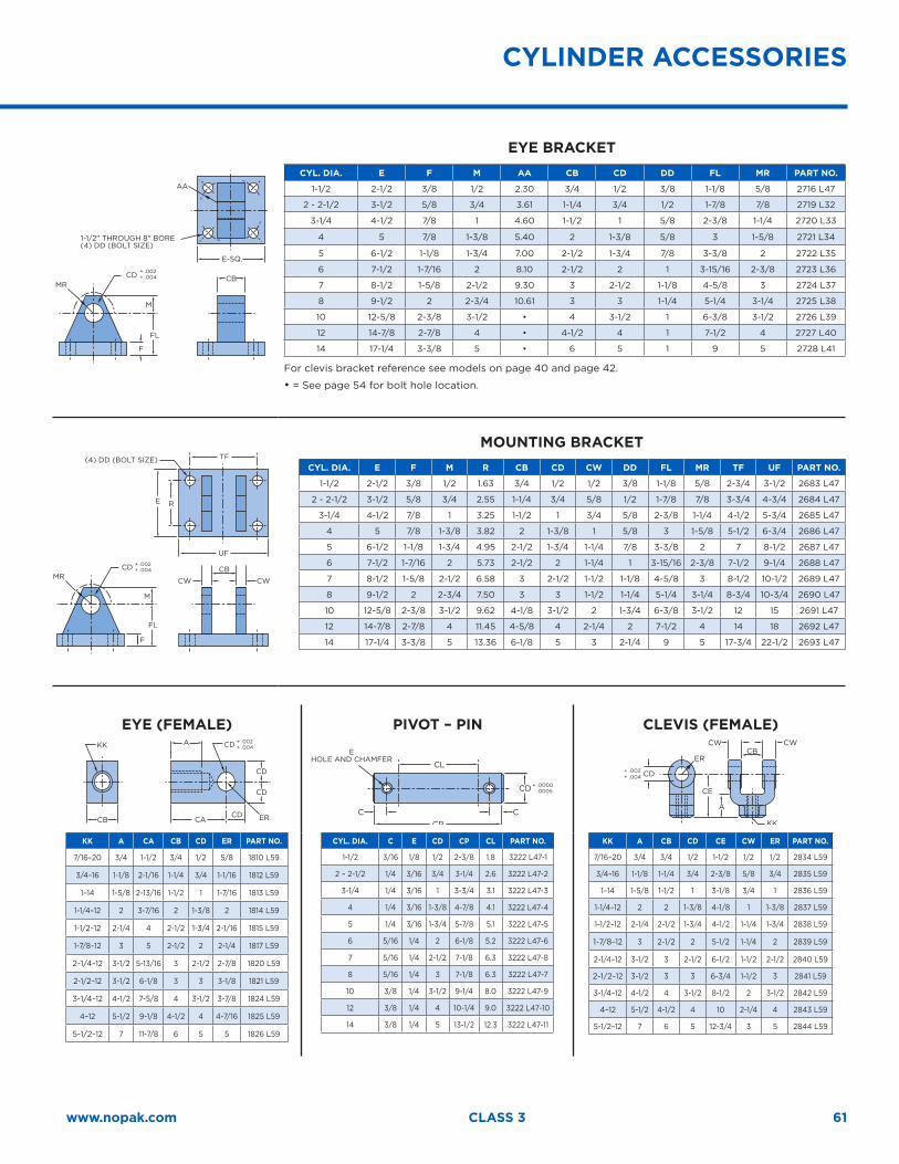
61www.nopak.com CLASS 3
1-1/2" THROUGH 8" BORE(4) DD (BOLT SIZE)
E-SQ.
AA
CBCD
FL
F
M
MR
+ .002+ .004
EYE BRACKETCYL. DIA. E F M AA CB CD DD FL MR PART NO.
1-1/2 2-1/2 3/8 1/2 2.30 3/4 1/2 3/8 1-1/8 5/8 2716 L47
2 - 2-1/2 3-1/2 5/8 3/4 3.61 1-1/4 3/4 1/2 1-7/8 7/8 2719 L32
3-1/4 4-1/2 7/8 1 4.60 1-1/2 1 5/8 2-3/8 1-1/4 2720 L33
4 5 7/8 1-3/8 5.40 2 1-3/8 5/8 3 1-5/8 2721 L34
5 6-1/2 1-1/8 1-3/4 7.00 2-1/2 1-3/4 7/8 3-3/8 2 2722 L35
6 7-1/2 1-7/16 2 8.10 2-1/2 2 1 3-15/16 2-3/8 2723 L36
7 8-1/2 1-5/8 2-1/2 9.30 3 2-1/2 1-1/8 4-5/8 3 2724 L37
8 9-1/2 2 2-3/4 10.61 3 3 1-1/4 5-1/4 3-1/4 2725 L38
10 12-5/8 2-3/8 3-1/2 • 4 3-1/2 1 6-3/8 3-1/2 2726 L39
12 14-7/8 2-7/8 4 • 4-1/2 4 1 7-1/2 4 2727 L40
14 17-1/4 3-3/8 5 • 6 5 1 9 5 2728 L41
For clevis bracket reference see models on page 40 and page 42.
• = See page 54 for bolt hole location.
(4) DD (BOLT SIZE)
UF
TF
CB
CWCW
CD
FL
RE
F
M
MR
+ .002+ .004
MOUNTING BRACKETCYL. DIA. E F M R CB CD CW DD FL MR TF UF PART NO.
1-1/2 2-1/2 3/8 1/2 1.63 3/4 1/2 1/2 3/8 1-1/8 5/8 2-3/4 3-1/2 2683 L47
2 - 2-1/2 3-1/2 5/8 3/4 2.55 1-1/4 3/4 5/8 1/2 1-7/8 7/8 3-3/4 4-3/4 2684 L47
3-1/4 4-1/2 7/8 1 3.25 1-1/2 1 3/4 5/8 2-3/8 1-1/4 4-1/2 5-3/4 2685 L47
4 5 7/8 1-3/8 3.82 2 1-3/8 1 5/8 3 1-5/8 5-1/2 6-3/4 2686 L47
5 6-1/2 1-1/8 1-3/4 4.95 2-1/2 1-3/4 1-1/4 7/8 3-3/8 2 7 8-1/2 2687 L47
6 7-1/2 1-7/16 2 5.73 2-1/2 2 1-1/4 1 3-15/16 2-3/8 7-1/2 9-1/4 2688 L47
7 8-1/2 1-5/8 2-1/2 6.58 3 2-1/2 1-1/2 1-1/8 4-5/8 3 8-1/2 10-1/2 2689 L47
8 9-1/2 2 2-3/4 7.50 3 3 1-1/2 1-1/4 5-1/4 3-1/4 8-3/4 10-3/4 2690 L47
10 12-5/8 2-3/8 3-1/2 9.62 4-1/8 3-1/2 2 1-3/4 6-3/8 3-1/2 12 15 2691 L47
12 14-7/8 2-7/8 4 11.45 4-5/8 4 2-1/4 2 7-1/2 4 14 18 2692 L47
14 17-1/4 3-3/8 5 13.36 6-1/8 5 3 2-1/4 9 5 17-3/4 22-1/2 2693 L47
EYE (FEMALE)
CACD
CD
CD
A
CB
KK CD + .002+ .004
ER
PIVOT – PIN
EHOLE AND CHAMFER
CL
CP
CD + .0000 .0005
CC
CLEVIS (FEMALE)
CD+ .002+ .004
CE
A
KK
CWCWCB
ER
KK A CA CB CD ER PART NO.
7/16–20 3/4 1-1/2 3/4 1/2 5/8 1810 L59
3/4–16 1-1/8 2-1/16 1-1/4 3/4 1-1/16 1812 L59
1–14 1-5/8 2-13/16 1-1/2 1 1-7/16 1813 L59
1-1/4–12 2 3-7/16 2 1-3/8 2 1814 L59
1-1/2–12 2-1/4 4 2-1/2 1-3/4 2-1/16 1815 L59
1-7/8–12 3 5 2-1/2 2 2-1/4 1817 L59
2-1/4–12 3-1/2 5-13/16 3 2-1/2 2-7/8 1820 L59
2-1/2–12 3-1/2 6-1/8 3 3 3-1/8 1821 L59
3-1/4–12 4-1/2 7-5/8 4 3-1/2 3-7/8 1824 L59
4–12 5-1/2 9-1/8 4-1/2 4 4-7/16 1825 L59
5-1/2–12 7 11-7/8 6 5 5 1826 L59
CYL. DIA. C E CD CP CL PART NO.
1-1/2 3/16 1/8 1/2 2-3/8 1.8 3222 L47-1
2 – 2-1/2 1/4 3/16 3/4 3-1/4 2.6 3222 L47-2
3-1/4 1/4 3/16 1 3-3/4 3.1 3222 L47-3
4 1/4 3/16 1-3/8 4-7/8 4.1 3222 L47-4
5 1/4 3/16 1-3/4 5-7/8 5.1 3222 L47-5
6 5/16 1/4 2 6-1/8 5.2 3222 L47-6
7 5/16 1/4 2-1/2 7-1/8 6.3 3222 L47-8
8 5/16 1/4 3 7-1/8 6.3 3222 L47-7
10 3/8 1/4 3-1/2 9-1/4 8.0 3222 L47-9
12 3/8 1/4 4 10-1/4 9.0 3222 L47-10
14 3/8 1/4 5 13-1/2 12.3 3222 L47-11
KK A CB CD CE CW ER PART NO.
7/16–20 3/4 3/4 1/2 1-1/2 1/2 1/2 2834 L59
3/4–16 1-1/8 1-1/4 3/4 2-3/8 5/8 3/4 2835 L59
1–14 1-5/8 1-1/2 1 3-1/8 3/4 1 2836 L59
1-1/4–12 2 2 1-3/8 4-1/8 1 1-3/8 2837 L59
1-1/2–12 2-1/4 2-1/2 1-3/4 4-1/2 1-1/4 1-3/4 2838 L59
1-7/8–12 3 2-1/2 2 5-1/2 1-1/4 2 2839 L59
2-1/4–12 3-1/2 3 2-1/2 6-1/2 1-1/2 2-1/2 2840 L59
2-1/2–12 3-1/2 3 3 6-3/4 1-1/2 3 2841 L59
3-1/4–12 4-1/2 4 3-1/2 8-1/2 2 3-1/2 2842 L59
4–12 5-1/2 4-1/2 4 10 2-1/4 4 2843 L59
5-1/2–12 7 6 5 12-3/4 3 5 2844 L59
CYLINDER ACCESSORIES
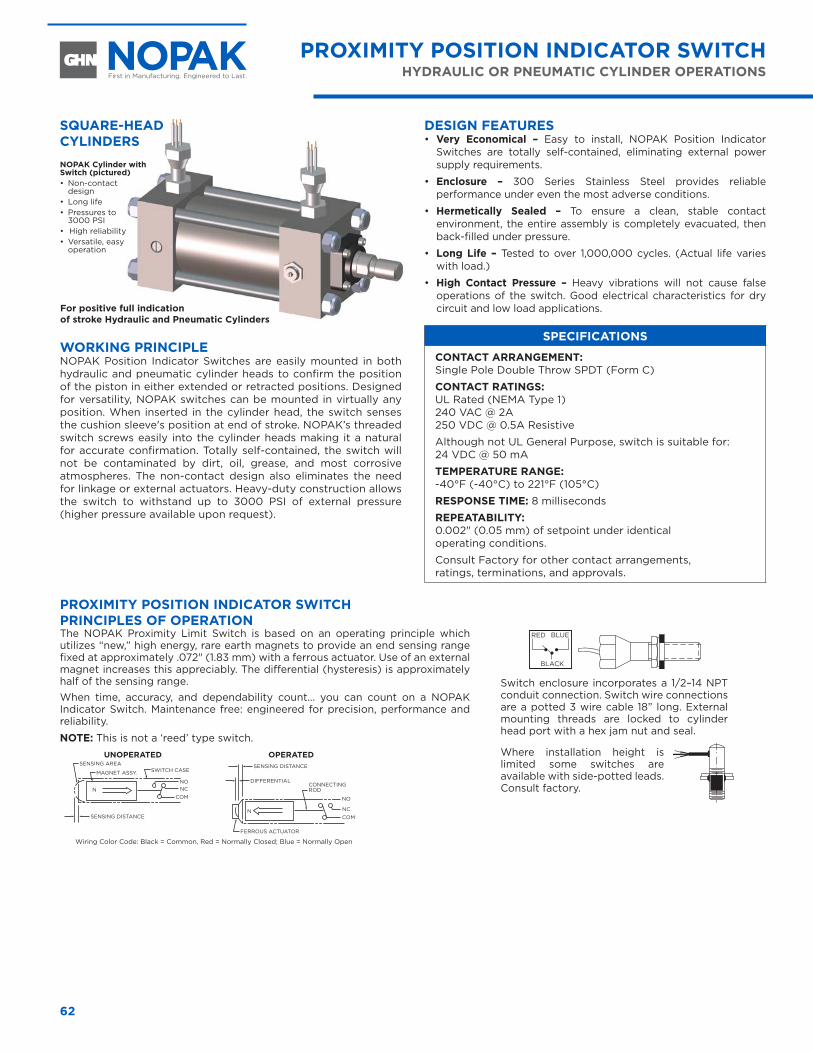
62
WORKING PRINCIPLENOPAK Position Indicator Switches are easily mounted in both hydraulic and pneumatic cylinder heads to confirm the position of the piston in either extended or retracted positions. Designed for versatility, NOPAK switches can be mounted in virtually any position. When inserted in the cylinder head, the switch senses the cushion sleeve's position at end of stroke. NOPAK’s threaded switch screws easily into the cylinder heads making it a natural for accurate confirmation. Totally self-contained, the switch will not be contaminated by dirt, oil, grease, and most corrosive atmospheres. The non-contact design also eliminates the need for linkage or external actuators. Heavy-duty construction allows the switch to withstand up to 3000 PSI of external pressure (higher pressure available upon request).
DESIGN FEATURES• Very Economical – Easy to install, NOPAK Position Indicator
Switches are totally self-contained, eliminating external power supply requirements.
• Enclosure – 300 Series Stainless Steel provides reliable performance under even the most adverse conditions.
• Hermetically Sealed – To ensure a clean, stable contact environment, the entire assembly is completely evacuated, then back-filled under pressure.
• Long Life – Tested to over 1,000,000 cycles. (Actual life varies with load.)
• High Contact Pressure – Heavy vibrations will not cause false operations of the switch. Good electrical characteristics for dry circuit and low load applications.
SPECIFICATIONS
CONTACT ARRANGEMENT: Single Pole Double Throw SPDT (Form C)
CONTACT RATINGS: UL Rated (NEMA Type 1) 240 VAC @ 2A 250 VDC @ 0.5A Resistive
Although not UL General Purpose, switch is suitable for: 24 VDC @ 50 mA
TEMPERATURE RANGE: -40°F (-40°C) to 221°F (105°C)
RESPONSE TIME: 8 milliseconds
REPEATABILITY: 0.002" (0.05 mm) of setpoint under identical operating conditions.
Consult Factory for other contact arrangements, ratings, terminations, and approvals.
PROXIMITY POSITION INDICATOR SWITCHHYDRAULIC OR PNEUMATIC CYLINDER OPERATIONS
NOPAK Cylinder with Switch (pictured)• Non-contact
design• Long life• Pressures to
3000 PSI• High reliability • Versatile, easy
operation
For positive full indication of stroke Hydraulic and Pneumatic Cylinders
SQUARE-HEAD CYLINDERS
SENSING AREA
FERROUS ACTUATOR
SENSING DISTANCE
SENSING DISTANCE
DIFFERENTIALMAGNET ASSY.
CONNECTING ROD
SWITCH CASE
NO
NO
NC
NC
COM
COM
PROXIMITY POSITION INDICATOR SWITCH PRINCIPLES OF OPERATIONThe NOPAK Proximity Limit Switch is based on an operating principle which utilizes “new,” high energy, rare earth magnets to provide an end sensing range fixed at approximately .072" (1.83 mm) with a ferrous actuator. Use of an external magnet increases this appreciably. The differential (hysteresis) is approximately half of the sensing range. When time, accuracy, and dependability count... you can count on a NOPAK Indicator Switch. Maintenance free: engineered for precision, performance and reliability.
NOTE: This is not a ‘reed’ type switch.
Switch enclosure incorporates a 1/2–14 NPT conduit connection. Switch wire connections are a potted 3 wire cable 18” long. External mounting threads are locked to cylinder head port with a hex jam nut and seal.
Where installation height is limited some switches are available with side-potted leads. Consult factory.
RED BLUE
BLACK
Wiring Color Code: Black = Common, Red = Normally Closed; Blue = Normally Open
UNOPERATED OPERATED
N
N
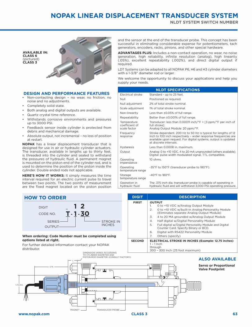
63www.nopak.com CLASS 3
DESIGN AND PERFORMANCE FEATURES• Non-contacting design – no wear, no friction, no
noise and no adjustments. • Completely solid state. • Both analog and digital outputs are available. • Quartz crystal time reference.• Withstands corrosive environments and pressures
up to 3000 PSI. • Feedback sensor inside cylinder is protected from
debris and mechanical damage. • Absolute output, not incremental – no loss of position
at restart. NOPAK has a linear displacement transducer that is designed for use in air or hydraulic cylinder actuators. The transducer, available in lengths up to thirty feet, is threaded into the cylinder and sealed to withstand the pressures of hydraulic fluid. A permanent magnet is mounted on the piston end of the cylinder rod, and is used to determine the position of the piston inside the cylinder. Double ended rods not applicable.
HERE’S HOW IT WORKS: It simply measures the time interval required for an electric current pulse to travel between two points. The two points of measurement are the fixed magnet located on the piston position
DIGIT
CODE NO.
SERIES
OUTPUT
STROKE IN INCHES
T
11
230- -
NOPAK LINEAR DISPLACEMENT TRANSDUCER SYSTEMNLDT SYSTEM SWITCH NUMBER
and the sensor at the end of the transducer probe. This concept has been successful in eliminating considerable expense for potentiometers, tach generators, encoders, racks, pinions, and other special hardware.
ADVANTAGES PLUS: Includes a non-contact operation, no wear, no noise generation, high reliability, infinite resolution (analog), high linearity (.05%), excellent repeatability (.002%), and direct digital output if required.
LDT Systems can be adapted to all NOPAK P6, H6 and H3 cylinder diameters with a 1-3/8" diameter rod or larger.
We welcome the opportunity to discuss your applications and help you supply your needs.
NLDT SPECIFICATIONSElectrical stroke Standard - up to 25 feet.
Null Positioned as required.
Null adjustment 2% of total stroke nominal.
Scale adjustment 1% of total stroke nominal.
Non-linearity Less than ±0.05% of full range.
Repeatability Better than ±0.001% of full range.
Temperature coefficient of scale factor
Transducer: less than 0.00011 inch/°F + [3 ppm/°F per inch of full stroke].Analog Output Module: 20 ppm/°F.
Frequency response
Stroke dependent. 200 Hz to 50 Hz is typical for lengths of 12 inch to 100 inch respectively – wider response frequencies are available upon request. For digital systems, output is updated at discrete intervals.
Hysteresis Less than 0.0008 in. maximum.
Output Analog: 0 to +10 VDC, 4 to 20 mA ungrounded (others available). Digital: pulse width modulated signal, TTL compatible.
Operating impendance
10 ohms.
Operating temperature range
-35°F to 150°F (transducer probe to 180°F).
Storage temperature range
-40°F to 180°F.
Operation in hydraulic fluid
The .375 inch dia. transducer probe is capable of operating in hydraulic fluid and will withstand 3,000 PSI operating pressure.
HOW TO ORDER DIGIT DESCRIPTIONFIRST OUTPUT
1. 0 to +10 VDC w/Analog Output Module 2. 0 to +10 VDC w/built-in Analog Personality Module
(Eliminates separate Analog Output Module) 3. 4 to 20 MA grounded w/Analog Output Module 4. Half digital w/Digital Personality Module 5. Full digital w/Digital Personality Module and Digital
Counter Card. Specify Binary or BCD. 6. Digital with RS422 Personality Module 7. Others (specify)
SECOND ELECTRICAL STROKE IN INCHES (Example: 12.75 inches)1 – 1 Inch through 300 – 300 Inch (25 foot maximum)
When ordering: Code Number must be completed using options listed at right. For further detailed information contact your NOPAK distributor.
DIMENSION VARIES ACCORDING TO CYLINDER DIAMETER AND PISTON ROD DIAMETER. (CONSULT FACTORY)
MAGNET TRANSDUCER PROBE
1.75 DIA.
3.75
L ALSO AVAILABLEServo or Proportional Valve Footprint
AVAILABLE IN: CLASS 6 (pictured)CLASS 3
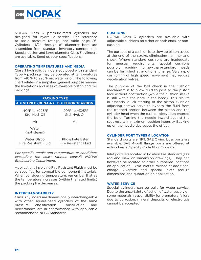
64
NOPAK Class 3 pressure-rated cylinders are designed for hydraulic service. For reference to basic pressure ratings, see table page 26. Cylinders 1-1/2" through 8" diameter bore are assembled from standard inventory components. Special design and large diameter Class 3 cylinders are available. Send us your specifications.
OPERATING TEMPERATURES AND MEDIA Class 3 hydraulic cylinders equipped with standard Type A packings may be operated at temperatures from -40°F to 225°F air, water or oil. The following chart relates in a simplified general purpose manner the limitations and uses of available piston and rod packings.
PACKING TYPEA = NITRILE (BUNA-N) B = FLUOROCARBON
-40°F to +225°F Std. Hyd. Oil
Air
Water (not steam)
Water Glycol Fire Resistant Fluid
-20°F to +325°F Std. Hyd. Oil
Air
Phosphate Ester Fire Resistant Fluid
For specific media and temperature or conditions exceeding the chart ratings, consult NOPAK Engineering Department.
Applications involving Fire Resistant Fluids must be so specified for compatible component materials. When considering temperature, remember that as the temperature increases (within the rated limits) the packing life decreases.
INTERCHANGEABILITY Class 3 cylinders are dimensionally interchangeable with other square-head cylinders of the same pressure classification. Construction and performance are in conformance with applicable recommended NFPA Standards.
CUSHIONS NOPAK Class 3 cylinders are available with adjustable cushions on either or both ends, or non-cushion.
The purpose of a cushion is to slow up piston speed at the end of the stroke, eliminating hammer and shock. Where standard cushions are inadequate for unusual requirements, special cushions possibly requiring longer-than-standard heads can be furnished at additional charge. Very rapid cushioning of high speed movement may require deceleration valves.
The purpose of the ball check in the cushion mechanism is to allow fluid to pass to the piston face without obstruction (while the cushion sleeve is still within the bore in the head). This results in essential quick starting of the piston. Cushion adjusting screws serve to bypass the fluid from the trapped section between the piston and the cylinder head when the cushion sleeve has entered the bore. Turning the needle inward against the seat results in maximum cushion intensity. Backing up on the needle decreases the effect.
CYLINDER PORT TYPES & LOCATION Standard ports are NPT. SAE O-ring boss ports are available. SAE 4-bolt flange ports are offered at extra charge. Specify Code 61 or Code 62.
Inlet ports are located in Position 1 as standard (see rod end view on dimension drawings). They can however, be located at other numbered locations on application. Extra inlets furnished at additional charge. Oversize and special inlets require dimensions and quotation on application.
WATER SERVICE Special cylinders can be built for water service. Due to the uncertainty of action of water supply on some materials, responsibility for premature failure due to corrosion, mineral deposits or electrolysis cannot be accepted.
ENGINEERING INFORMATION
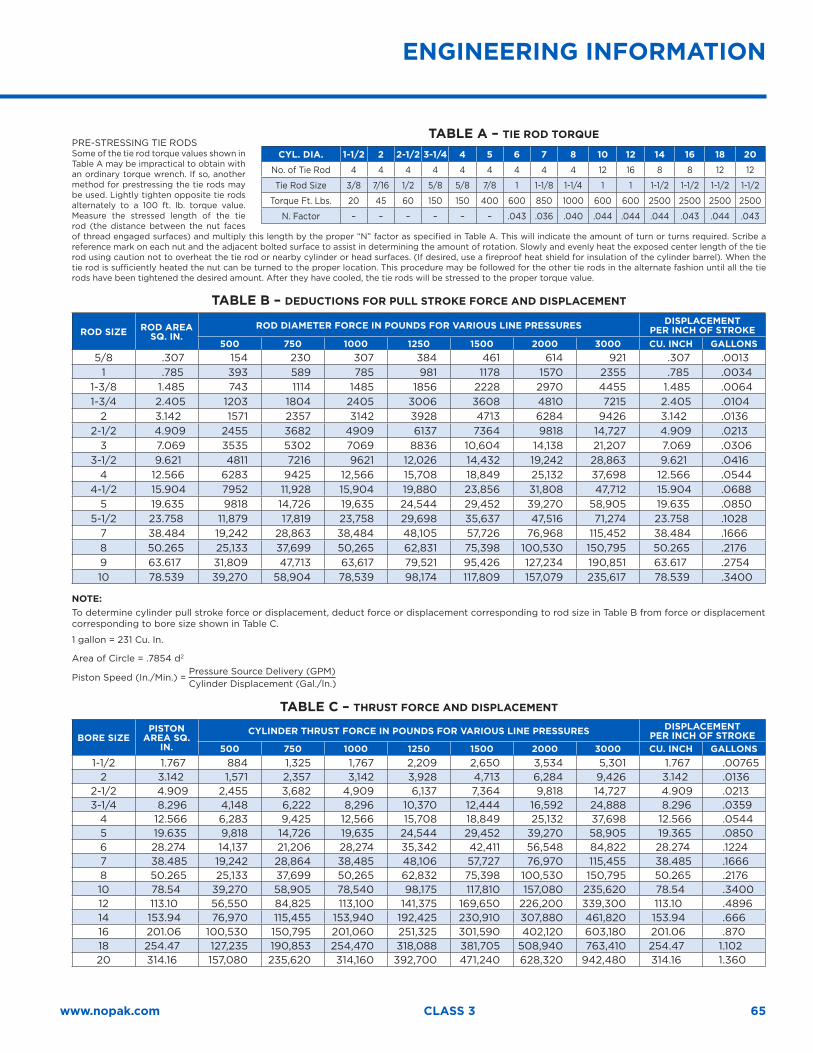
65www.nopak.com CLASS 3
PRE-STRESSING TIE RODS Some of the tie rod torque values shown in Table A may be impractical to obtain with an ordinary torque wrench. If so, another method for prestressing the tie rods may be used. Lightly tighten opposite tie rods alternately to a 100 ft. lb. torque value. Measure the stressed length of the tie rod (the distance between the nut faces of thread engaged surfaces) and multiply this length by the proper “N” factor as specified in Table A. This will indicate the amount of turn or turns required. Scribe a reference mark on each nut and the adjacent bolted surface to assist in determining the amount of rotation. Slowly and evenly heat the exposed center length of the tie rod using caution not to overheat the tie rod or nearby cylinder or head surfaces. (If desired, use a fireproof heat shield for insulation of the cylinder barrel). When the tie rod is sufficiently heated the nut can be turned to the proper location. This procedure may be followed for the other tie rods in the alternate fashion until all the tie rods have been tightened the desired amount. After they have cooled, the tie rods will be stressed to the proper torque value.
TABLE B – DEDUCTIONS FOR PULL STROKE FORCE AND DISPLACEMENT
ROD SIZE ROD AREA SQ. IN.
ROD DIAMETER FORCE IN POUNDS FOR VARIOUS LINE PRESSURES DISPLACEMENTPER INCH OF STROKE
500 750 1000 1250 1500 2000 3000 CU. INCH GALLONS5/8 .307 154 230 307 384 461 614 921 .307 .0013
1 .785 393 589 785 981 1178 1570 2355 .785 .00341-3/8 1.485 743 1114 1485 1856 2228 2970 4455 1.485 .00641-3/4 2.405 1203 1804 2405 3006 3608 4810 7215 2.405 .0104
2 3.142 1571 2357 3142 3928 4713 6284 9426 3.142 .01362-1/2 4.909 2455 3682 4909 6137 7364 9818 14,727 4.909 .0213
3 7.069 3535 5302 7069 8836 10,604 14,138 21,207 7.069 .03063-1/2 9.621 4811 7216 9621 12,026 14,432 19,242 28,863 9.621 .0416
4 12.566 6283 9425 12,566 15,708 18,849 25,132 37,698 12.566 .05444-1/2 15.904 7952 11,928 15,904 19,880 23,856 31,808 47,712 15.904 .0688
5 19.635 9818 14,726 19,635 24,544 29,452 39,270 58,905 19.635 .08505-1/2 23.758 11,879 17,819 23,758 29,698 35,637 47,516 71,274 23.758 .1028
7 38.484 19,242 28,863 38,484 48,105 57,726 76,968 115,452 38.484 .16668 50.265 25,133 37,699 50,265 62,831 75,398 100,530 150,795 50.265 .21769 63.617 31,809 47,713 63,617 79,521 95,426 127,234 190,851 63.617 .275410 78.539 39,270 58,904 78,539 98,174 117,809 157,079 235,617 78.539 .3400
NOTE: To determine cylinder pull stroke force or displacement, deduct force or displacement corresponding to rod size in Table B from force or displacement corresponding to bore size shown in Table C.
1 gallon = 231 Cu. In.
Area of Circle = .7854 d2
Piston Speed (In./Min.) = Pressure Source Delivery (GPM)Cylinder Displacement (Gal./ln.)
TABLE C – THRUST FORCE AND DISPLACEMENT
BORE SIZEPISTON
AREA SQ. IN.
CYLINDER THRUST FORCE IN POUNDS FOR VARIOUS LINE PRESSURES DISPLACEMENTPER INCH OF STROKE
500 750 1000 1250 1500 2000 3000 CU. INCH GALLONS1-1/2 1.767 884 1,325 1,767 2,209 2,650 3,534 5,301 1.767 .00765
2 3.142 1,571 2,357 3,142 3,928 4,713 6,284 9,426 3.142 .01362-1/2 4.909 2,455 3,682 4,909 6,137 7,364 9,818 14,727 4.909 .02133-1/4 8.296 4,148 6,222 8,296 10,370 12,444 16,592 24,888 8.296 .0359
4 12.566 6,283 9,425 12,566 15,708 18,849 25,132 37,698 12.566 .05445 19.635 9,818 14,726 19,635 24,544 29,452 39,270 58,905 19.365 .08506 28.274 14,137 21,206 28,274 35,342 42,411 56,548 84,822 28.274 .12247 38.485 19,242 28,864 38,485 48,106 57,727 76,970 115,455 38.485 .16668 50.265 25,133 37,699 50,265 62,832 75,398 100,530 150,795 50.265 .217610 78.54 39,270 58,905 78,540 98,175 117,810 157,080 235,620 78.54 .340012 113.10 56,550 84,825 113,100 141,375 169,650 226,200 339,300 113.10 .489614 153.94 76,970 115,455 153,940 192,425 230,910 307,880 461,820 153.94 .66616 201.06 100,530 150,795 201,060 251,325 301,590 402,120 603,180 201.06 .87018 254.47 127,235 190,853 254,470 318,088 381,705 508,940 763,410 254.47 1.10220 314.16 157,080 235,620 314,160 392,700 471,240 628,320 942,480 314.16 1.360
TABLE A – TIE ROD TORQUE
CYL. DIA. 1-1/2 2 2-1/2 3-1/4 4 5 6 7 8 10 12 14 16 18 20
No. of Tie Rod 4 4 4 4 4 4 4 4 4 12 16 8 8 12 12
Tie Rod Size 3/8 7/16 1/2 5/8 5/8 7/8 1 1-1/8 1-1/4 1 1 1-1/2 1-1/2 1-1/2 1-1/2
Torque Ft. Lbs. 20 45 60 150 150 400 600 850 1000 600 600 2500 2500 2500 2500
N. Factor – – – – – – .043 .036 .040 .044 .044 .044 .043 .044 .043
ENGINEERING INFORMATION
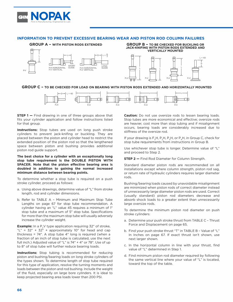
66
INFORMATION TO PREVENT EXCESSIVE BEARING WEAR AND PISTON ROD COLUMN FAILURESGROUP A – WITH PISTON RODS EXTENDED
L L D L = D2
P1V
GROUP B – TO BE CHECKED FOR BUCKLING OR JACK-KNIFING WITH PISTON RODS EXTENDED AND
VERTICALLY MOUNTED
L
P2V
L
P3V
L
P4V
D
L = 4D
F3V
GROUP C – TO BE CHECKED FOR LOAD ON BEARING WITH PISTON RODS EXTENDED AND HORIZONTALLY MOUNTED
L
P4H
L
P1H
L
P2H
L
P3HF3H
L = 4DD
STEP 1 — Find drawing in one of three groups above that fits your cylinder application and follow instructions listed for that group.
Instructions: Stop tubes are used on long push stroke cylinders to prevent jack-knifing or buckling. They are placed between the piston and cylinder head to restrict the extended position of the piston rod so that the lengthened space between piston and bushing provides additional piston rod guide support.
The best choice for a cylinder with an exceptionally long stop tube requirement is the DOUBLE PISTON WITH SPACER. Note that the piston effective bearing area is doubled in addition to gaining the normal increased minimum distance between bearing points.
To determine whether a stop tube is required on a push stroke cylinder, proceed as follows:
a. Using above drawings, determine value of “L” from stroke length, rod and cylinder dimensions.
b. Refer to TABLE A – Minimum and Maximum Stop Tube Lengths on page 67 for stop tube recommendation. A cylinder having an “L” value 45 requires a minimum of 1" stop tube and a maximum of 5" stop tube. Specifications for more than the maximum stop tube will usually adversely increase the cylinder weight.
Example: In a P2V type application requiring 32" of stroke, “L” = 32" + 32" + approximately 10" for head and cap thickness = 74". A stop tube 4" long is required (when a fraction of an inch of stop tube is calculated, use the next full inch.) Adjusted value of “L” is 74" + 4" or 78". Use of up to 8" of stop tube will further reduce bearing loads.
Instructions: Stop tubing is recommended for reducing piston and bushing/bearing loads on long stroke cylinders of the types shown. To determine length of stop tube required for this type of application, resolve the turning moments and loads between the piston and rod bushing. Include the weight of the fluid, especially on large bore cylinders. It is ideal to keep projected bearing area loads lower than 200 PSI.
Caution: Do not use oversize rods to lessen bearing loads. Stop tubes are more economical and effective; oversize rods are heavier, cost more than stop tubing and if misalignment occurs, bearing loads are considerably increased due to stiffness of the oversize rod.
If your drawing is F3H, P2H, P3H, or P4H, in Group C, check for stop tube requirements from instructions in Group B.
Use whichever stop tube is longer. Determine value of “L” and proceed to Step 2.
STEP 2 — Find Rod Diameter for Column Strength.
Standard diameter piston rods are recommended on all installations except where column strength, piston rod sag, or return rate of hydraulic cylinders requires larger diameter rods.
Bushing/bearing loads caused by unavoidable misalignment are minimized when piston rods of correct diameter instead of unnecessarily large diameter piston rods are used. Correct (usually standard) piston rod diameters decrease and absorb shock loads to a greater extent than unnecessarily large oversize rods.
To determine the minimum piston rod diameter on push stroke cylinders:
a. Determine your push stroke thrust from TABLE C – Thrust Force and Displacement on page 65.
b. Find your push stroke thrust “T” in TABLE B – Value of “L” In Inches on page 67. If exact thrust isn’t shown, use next larger shown.
c. In the horizontal column in line with your thrust, find value of “L” determined in Step 1.
d. Find minimum piston rod diameter required by following the same vertical line where your value of “L” is located, toward the top of the table.
F1H HORIZONTALF1V VERTICAL
SHORT GUIDE
LONG GUIDEF2H HORIZONTAL
F2V VERTICAL
ENGINEERING DATA

67www.nopak.com CLASS 3
TABLE A – MINIMUM AND MAXIMUM STOP TUBE LENGTHS
“L” INCHES
MINIMUM STOP TUBE LENGTH
(INCHES)
MAXIMUM STOP TUBE LENGTH
(INCHES)
5-10 – 1
11-20 – 2
21-30 – 3
31-40 – 4
41-50 1 5
51-60 2 6
61-70 3 7
71-80 4 8
81-90 5 9
91-100 6 10
101-110 7 11
“L” INCHES
MINIMUM STOP TUBE LENGTH
(INCHES)
MAXIMUM STOP TUBE LENGTH
(INCHES)
111-120 8 12
121-130 9 13
131-140 10 14
141-150 11 15
151-160 12 16
161-170 13 17
171-180 14 18
181-190 15 19
191-200 16 20
201-210 17 21
“L” INCHES
MINIMUM STOP TUBE LENGTH
(INCHES)
MAXIMUM STOP TUBE LENGTH
(INCHES)
211-220 18 22
221-230 19 23
231-240 20 24
241-250 21 25
251-260 22 26
261-270 23 27
271-280 24 28
281-290 25 29
291-300 26 30
301-310 27 31
NOTE: Using stop tube lengths greater than “Maximum Stop Tube” has diminishing effect on reducing bearing loads.
TABLE B – VALUE OF “L” IN INCHESVALUE OF “T” IN LBS.
IN THIS COLUMN
PISTON ROD DIAMETERS
0.63 1.00 1.38 1.75 2.00 2.50 3.00 3.50 4.00 4.50 5.00 5.50 7.00 8.00 9.00 10.00
1,0001,4001,800
272423
605348
1059282
155142127
190174160
257244230
330308296
385366 440
2,4003,2004,000
191613
454138
756763
11410394
145130119
213194175
281261240
347329310
415400378
488461446
5,0006,0008,000
9 343026
605650
878276
11010293
163152137
225208188
289274245
360342310
426410375
494476447
10,00012,00016,000
2117
454134
706557
898475
125118110
172155142
222210188
279269235
349326292
412388350
482454420
20,00030,00040,000
28 523922
685543
1038774
136120108
172156142
218189177
270230210
326285248
385330294
50,00060,00080,000
30 665736
968871
130119104
165154137
200190170
234225204
269256240
408384336
100,000120,000140,000
5745
907764
12010898
154140128
189175160
222207194
324313301
400377365
160,000200,000250,000
47 8667
1189872
148131109
182161141
279260236
350330301
421402375
300,000350,000400,000
8652
12010077
212195182
281261241
351328309
420396374
500,000600,000700,000
15211470
212183162
274247221
341310280
800,000900,000
1,000,000
11882
197168115
260237212
Values of “L” less than those shown have a slenderness ratio (length ÷ radius of gyration which is length ÷ 1/4 diameter of piston rod) of less than 50. Thus, the compressive strength formula (s = thrust ÷ rod area) is used rather than the column strength formula on which Table B is based. For very low slenderness ratios (below 20), compressive strength formulae with a 2 to 1 factor of safety are satisfactory. For slenderness ratios between 20 and 50, use compressive strength formulae with proportionate factors between 2 to 1 and 5 to 1.
ENGINEERING DATA
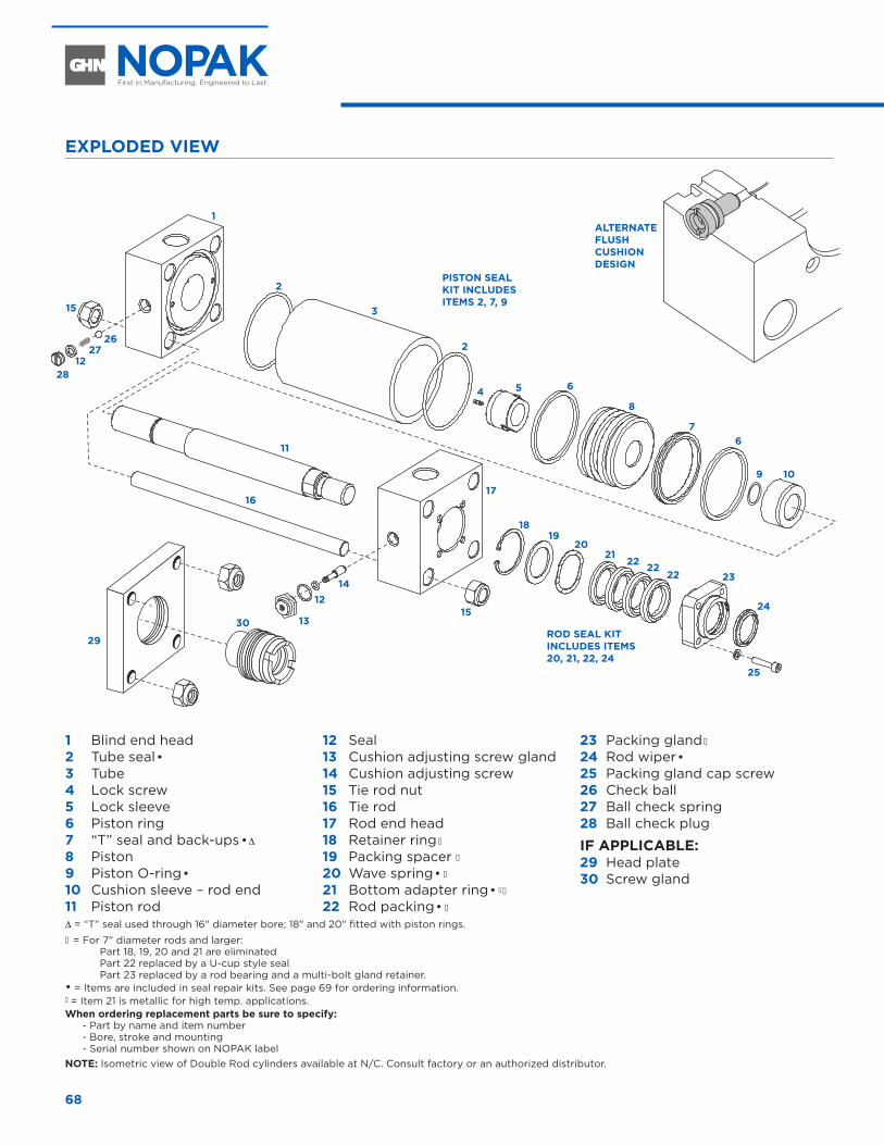
68
1 Blind end head 2 Tube seal•3 Tube4 Lock screw5 Lock sleeve6 Piston ring7 “T” seal and back-ups•∆
8 Piston9 Piston O-ring•10 Cushion sleeve – rod end 11 Piston rod
12 Seal 13 Cushion adjusting screw gland 14 Cushion adjusting screw 15 Tie rod nut 16 Tie rod 17 Rod end head 18 Retainer ring �
19 Packing spacer �
20 Wave spring• �
21 Bottom adapter ring• � �
22 Rod packing• �
23 Packing gland �
24 Rod wiper•25 Packing gland cap screw 26 Check ball 27 Ball check spring 28 Ball check plug
IF APPLICABLE: 29 Head plate 30 Screw gland
ALTERNATE FLUSH CUSHION DESIGN
PISTON SEAL KIT INCLUDES ITEMS 2, 7, 9
ROD SEAL KIT INCLUDES ITEMS 20, 21, 22, 24
∆ = “T” seal used through 16" diameter bore; 18" and 20" fitted with piston rings. � = For 7" diameter rods and larger: Part 18, 19, 20 and 21 are eliminated
Part 22 replaced by a U-cup style seal Part 23 replaced by a rod bearing and a multi-bolt gland retainer. • = Items are included in seal repair kits. See page 69 for ordering information. � = Item 21 is metallic for high temp. applications. When ordering replacement parts be sure to specify:
- Part by name and item number- Bore, stroke and mounting- Serial number shown on NOPAK label
NOTE: Isometric view of Double Rod cylinders available at N/C. Consult factory or an authorized distributor.
1
2
2
54 6
6
9 10
25
24
23222222
2120
1918
15
2627
1228
16
11
29
30
17
7
8
315
12
13
14
EXPLODED VIEW
REPLACEMENT PARTS
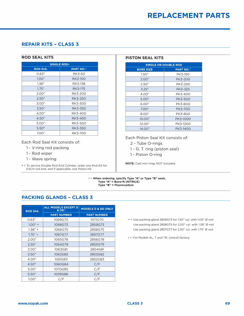
69www.nopak.com CLASS 3
REPLACEMENT PARTS
REPAIR KITS – CLASS 3
ROD SEAL KITS
SINGLE ROD•
ROD DIA. PART NO. �
0.63" RK3-63
1.00" RK3-100
1.38" RK3-138
1.75" RK3-175
2.00" RK3-200
2.50" RK3-250
3.00" RK3-300
3.50" RK3-350
4.00" RK3-400
4.50" RK3-450
5.00" RK3-500
5.50" RK3-550
7.00" RK3-700
Each Rod Seal Kit consists of: 1 - V-ring rod packing 1 - Rod wiper 1 - Wave spring
• = To service Double Rod End Cylinder, order one Rod Kit for EACH rod end, and if applicable, one Piston Kit.
PISTON SEAL KITS
SINGLE OR DOUBLE ROD
BORE SIZE PART NO. �
1.50" PK3-150
2.00" PK3-200
2.50" PK3-250
3.25" PK3-325
4.00" PK3-400
5.00" PK3-500
6.00" PK3-600
7.00" PK3-700
8.00" PK3-800
10.00" PK3-1000
12.00" PK3-1200
14.00" PK3-1400
Each Piston Seal Kit consists of: 2 - Tube O-rings1 - G. T. ring (piston seal)1 - Piston O-ring
NOTE: Cast iron rings NOT included.
� = When ordering, specify Type “A” or Type “B” seals. Type “A” = Buna-N (NITRILE) Type “B” = Fluorocarbon
PACKING GLANDS – CLASS 3
ROD DIA.ALL MODELS EXCEPT D
& DD� MODELS D & DD ONLY
PART NUMBER PART NUMBER
0.63" 1069G70 1071G70
1.00" • 1068G73 2859G73
1.38" • 1066G75 2858G75
1.75" • 1067G77 2857G77
2.00" 1065G78 2856G78
2.50" 1064G79 2855G79
3.00" 1063G81 2854G81
3.50" 1062G82 2853G82
4.00" 1061G83 2852G83
4.50" 1060G84 C/F
5.00" 1070G85 C/F
5.50" 1059G86 C/F
7.00" C/F C/F
• = Use packing gland 2859G73 for 1.50" cyl. with 1.00" Ø rod
Use packing gland 2858G75 for 2.00" cyl. with 1.38" Ø rod
Use packing gland 2857G77 for 2.50" cyl. with 1.75" Ø rod
� = For Models AL, T and TR, consult factory.
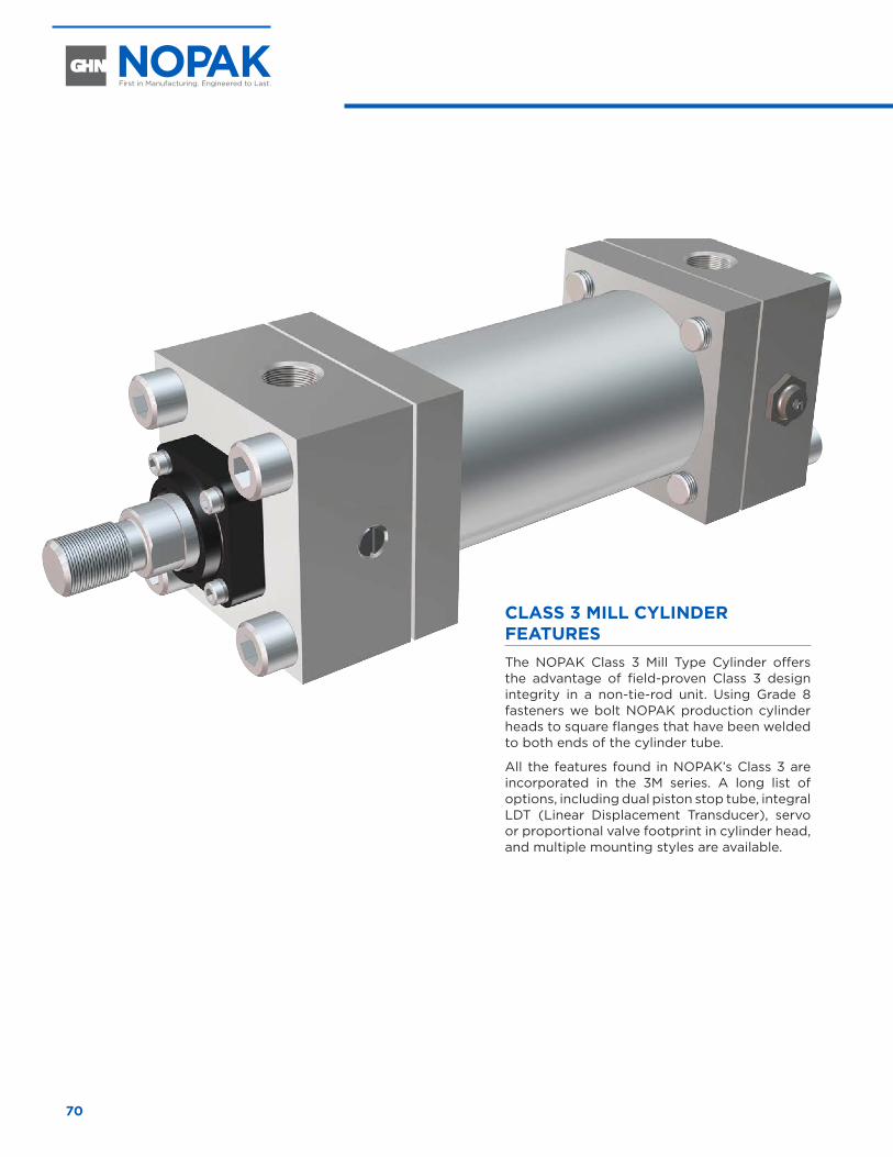
70
CLASS 3 MILL CYLINDER FEATURESThe NOPAK Class 3 Mill Type Cylinder offers the advantage of field-proven Class 3 design integrity in a non-tie-rod unit. Using Grade 8 fasteners we bolt NOPAK production cylinder heads to square flanges that have been welded to both ends of the cylinder tube.
All the features found in NOPAK’s Class 3 are incorporated in the 3M series. A long list of options, including dual piston stop tube, integral LDT (Linear Displacement Transducer), servo or proportional valve footprint in cylinder head, and multiple mounting styles are available.
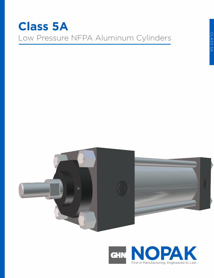
Class 5ALow Pressure NFPA Aluminum Cylinders
CL
AS
S 5
A
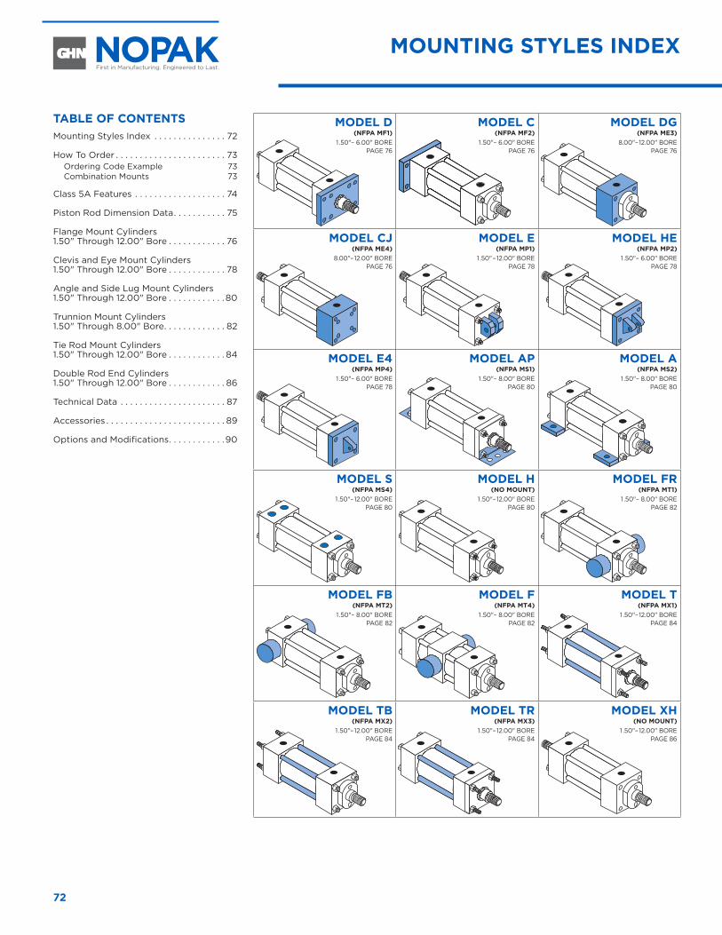
72
MOUNTING STYLES INDEX
MODEL D(NFPA MF1)
1 .50"– 6.00" BORE PAGE 76
MODEL C(NFPA MF2)
1 .50"– 6.00" BORE PAGE 76
MODEL DG(NFPA ME3)
8.00"– 12.00" BORE PAGE 76
MODEL CJ(NFPA ME4)
8.00"– 12.00" BORE PAGE 76
MODEL E(NFPA MP1)
1 .50" – 12.00" BORE PAGE 78
MODEL HE(NFPA MP2)
1 .50"– 6.00" BORE PAGE 78
MODEL E4(NFPA MP4)
1 .50"– 6.00" BORE PAGE 78
MODEL AP(NFPA MS1)
1 .50"– 8.00" BORE PAGE 80
MODEL A(NFPA MS2)
1 .50"– 8.00" BORE PAGE 80
MODEL S(NFPA MS4)
1 .50"– 12.00" BORE PAGE 80
MODEL H(NO MOUNT)
1 .50"– 12.00" BORE PAGE 80
MODEL FR(NFPA MT1)
1 .50"– 8.00" BORE PAGE 82
MODEL FB(NFPA MT2)
1 .50"– 8.00" BORE PAGE 82
MODEL F(NFPA MT4)
1 .50"– 8.00" BORE PAGE 82
MODEL T(NFPA MX1)
1 .50"– 12.00" BORE PAGE 84
MODEL TB(NFPA MX2)
1 .50"– 12.00" BORE PAGE 84
MODEL TR(NFPA MX3)
1 .50"– 12.00" BORE PAGE 84
MODEL XH(NO MOUNT)
1 .50"– 12.00" BORE PAGE 86
TABLE OF CONTENTSMounting Styles Index . . . . . . . . . . . . . . . 72
How To Order . . . . . . . . . . . . . . . . . . . . . . . 73Ordering Code Example 73Combination Mounts 73
Class 5A Features . . . . . . . . . . . . . . . . . . . 74
Piston Rod Dimension Data . . . . . . . . . . . 75
Flange Mount Cylinders 1.50" Through 12.00" Bore . . . . . . . . . . . . 76
Clevis and Eye Mount Cylinders 1.50" Through 12.00" Bore . . . . . . . . . . . . 78
Angle and Side Lug Mount Cylinders 1.50" Through 12.00" Bore . . . . . . . . . . . . 80
Trunnion Mount Cylinders 1.50" Through 8.00" Bore . . . . . . . . . . . . . 82
Tie Rod Mount Cylinders 1.50" Through 12.00" Bore . . . . . . . . . . . . 84
Double Rod End Cylinders 1.50" Through 12.00" Bore . . . . . . . . . . . . 86
Technical Data . . . . . . . . . . . . . . . . . . . . . . 87
Accessories . . . . . . . . . . . . . . . . . . . . . . . . . 89
Options and Modifications . . . . . . . . . . . .90
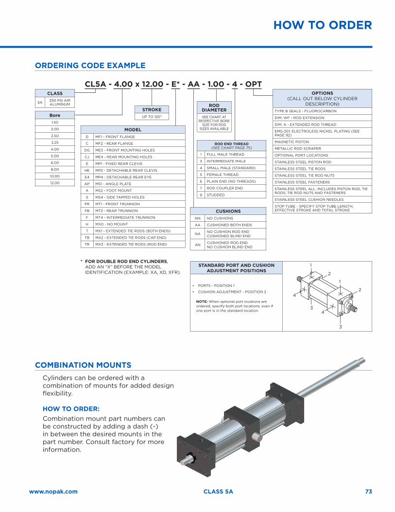
ORDERING CODE EXAMPLE
73www.nopak.com CLASS 5A
HOW TO ORDER
COMBINATION MOUNTSCylinders can be ordered with a combination of mounts for added design flexibility.
HOW TO ORDER:Combination mount part numbers can be constructed by adding a dash (-) in between the desired mounts in the part number. Consult factory for more information.
CLASS
5A 250 PSI AIR ALUMINUM
STROKEUP TO 120"Bore
1.50
2.00
2.50
3.25
4.00
5.00
6.00
8.00
10.00
12.00
MODELD MF1 - FRONT FLANGE
C MF2 - REAR FLANGE
DG ME3 - FRONT MOUNTING HOLES
CJ ME4 - REAR MOUNTING HOLES
E MP1 - FIXED REAR CLEVIS
HE MP2 - DETACHABLE REAR CLEVIS
E4 MP4 - DETACHABLE REAR EYE
AP MS1 - ANGLE PLATE
A MS2 - FOOT MOUNT
S MS4 - SIDE TAPPED HOLES
FR MT1 - FRONT TRUNNION
FB MT2 - REAR TRUNNION
F MT4 - INTERMEDIATE TRUNNION
H MX0 - NO MOUNT
T MX1 - EXTENDED TIE RODS (BOTH ENDS)
TB MX2 - EXTENDED TIE RODS (CAP END)
TR MX3 - EXTENDED TIE RODS (ROD END)
CUSHIONSNN NO CUSHIONS
AA CUSHIONED BOTH ENDS
NA NO CUSHION ROD END CUSHIONED BLIND END
AN CUSHIONED ROD ENDNO CUSHION BLIND END
ROD DIAMETERSEE CHART AT
RESPECTIVE BORE SIZE FOR ROD
SIZES AVAILABLE
ROD END THREAD (SEE CHART PAGE 75)
1 FULL MALE THREAD
3 INTERMEDIATE MALE
4 SMALL MALE (STANDARD)
5 FEMALE THREAD
6 PLAIN END (NO THREADS)
7 ROD COUPLER END
9 STUDDED
OPTIONS (CALL OUT BELOW CYLINDER
DESCRIPTION)TYPE B SEALS - FLUOROCARBON
DIM. WF - ROD EXTENSION
DIM. A - EXTENDED ROD THREAD
EMS-201: ELECTROLESS NICKEL PLATING (SEE PAGE 92)
MAGNETIC PISTON
METALLIC ROD SCRAPER
OPTIONAL PORT LOCATIONS
STAINLESS STEEL PISTON ROD
STAINLESS STEEL TIE RODS
STAINLESS STEEL TIE ROD NUTS
STAINLESS STEEL FASTENERS
STAINLESS STEEL ALL: INCLUDES PISTON ROD, TIE RODS, TIE ROD NUTS AND FASTENERS
STAINLESS STEEL CUSHION NEEDLES
STOP TUBE - SPECIFY STOP TUBE LENGTH, EFFECTIVE STROKE AND TOTAL STROKE
STANDARD PORT AND CUSHION ADJUSTMENT POSITIONS
1
2
1
2
3
43
4
• PORTS - POSITION 1
• CUSHION ADJUSTMENT - POSITION 2
NOTE: When optional port locations are ordered, specify both port locations, even if one port is in the standard location.
CL5A - 4.00 x 12.00 - E* - AA - 1.00 - 4 - OPT
* FOR DOUBLE ROD END CYLINDERS, ADD AN “X” BEFORE THE MODEL
IDENTIFICATION (EXAMPLE: XA, XD, XFR).
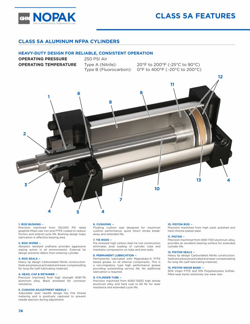
74
CLASS 5A FEATURES
CLASS 5A ALUMINUM NFPA CYLINDERS
HEAVY-DUTY DESIGN FOR RELIABLE, CONSISTENT OPERATIONOPERATING PRESSURE 250 PSI Air OPERATING TEMPERATURE Type A (Nitrile): 20°F to 200°F (-25°C to 90°C) Type B (Fluorocarbon): 0°F to 400°F ( -20°C to 200°C)
1. ROD BUSHING – Precision machined from 150,000 PSI rated graphite-filled cast iron and PTFE coated to reduce friction and extend cycle life. Bushing design traps lubrication in effective bearing area.
2. ROD WIPER – Abrasion resistant urethane provides aggressive wiping action in all environments. External lip design prevents debris from entering cylinder.
3. ROD SEALS – Heavy lip design Carboxilated Nitrile construction. Seals are pressure activated and wear-compensating for long life (self-lubricating material).
4. HEAD, CAP & RETAINER – Precision machined from high strength 6061-T6 aluminum alloy. Black anodized for corrosion resistance.
5. CUSHION ADJUSTMENT NEEDLE – Adjustable steel needle design has fine thread metering and is positively captured to prevent needle ejection during adjustment.
6. CUSHIONS – Floating cushion seal designed for maximum cushion performance, quick return stroke break-away and extended life.
7. TIE RODS – Pre-stressed high carbon steel tie rod construction eliminates axial loading of cylinder tube and maintains compression on tube and end seals.
8. PERMANENT LUBRICATION – Permanently lubricated with Magnalube-G PTFE based grease on all internal components. This is a non-migratory type high performance grease providing outstanding service life. No additional lubrication is required.
9. CYLINDER TUBE – Precision machined from 6063-T6832 high tensile aluminum alloy and hard coat to 60 Rc for wear resistance and extended cycle life.
10. PISTON ROD – Precision machined from high yield, polished and hard chrome plated steel.
11. PISTON – Precision machined from 6061-T651 aluminum alloy, provides an excellent bearing surface for extended cylinder life.
12. PISTON SEALS – Heavy lip design Carboxilated Nitrile construction. Seals are pressure activated and wear-compensating for long life (self-lubricating material).
13. PISTON WEAR BAND – 90% Virgin PTFE and 10% Polyphenylene Sulfide-filled wear band; extremely low wear rate.
1
2
3
4 5 4
4
7
10
13
11
12
6
8
9
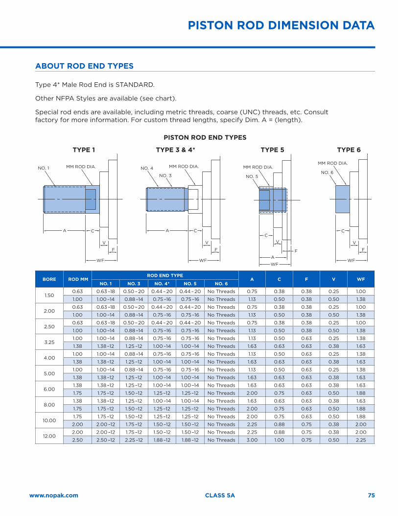
75www.nopak.com CLASS 5A
ABOUT ROD END TYPES
Type 4* Male Rod End is STANDARD.
Other NFPA Styles are available (see chart).
Special rod ends are available, including metric threads, coarse (UNC) threads, etc. Consult factory for more information. For custom thread lengths, specify Dim. A = (length).
PISTON ROD END TYPES
TYPE 1 TYPE 3 & 4* TYPE 5 TYPE 6
NO. 4 MM ROD DIA.
NO. 3 NO. 5
MM ROD DIA.NO. 6
MM ROD DIA.
A
NO. 1 MM ROD DIA.
C
WF
V
F
A C
WF
V
F
C
WF
A
V
F
C
WF
V
F
BORE ROD MMROD END TYPE
A C F V WFNO. 1 NO. 3 NO. 4* NO. 5 NO. 6
1.500.63 0.63 –18 0.50 – 20 0.44 – 20 0.44 – 20 No Threads 0.75 0.38 0.38 0.25 1.00
1.00 1.00 –14 0.88 –14 0.75 –16 0.75 –16 No Threads 1.13 0.50 0.38 0.50 1.38
2.000.63 0.63 –18 0.50 – 20 0.44 – 20 0.44 – 20 No Threads 0.75 0.38 0.38 0.25 1.00
1.00 1.00 –14 0.88 –14 0.75 –16 0.75 –16 No Threads 1.13 0.50 0.38 0.50 1.38
2.500.63 0.63 –18 0.50 – 20 0.44 – 20 0.44 – 20 No Threads 0.75 0.38 0.38 0.25 1.00
1.00 1.00 –14 0.88 –14 0.75 –16 0.75 –16 No Threads 1.13 0.50 0.38 0.50 1.38
3.251.00 1.00 –14 0.88 –14 0.75 –16 0.75 –16 No Threads 1.13 0.50 0.63 0.25 1.38
1.38 1.38 –12 1.25 –12 1.00 –14 1.00 –14 No Threads 1.63 0.63 0.63 0.38 1.63
4.001.00 1.00 –14 0.88 –14 0.75 –16 0.75 –16 No Threads 1.13 0.50 0.63 0.25 1.38
1.38 1.38 –12 1.25 –12 1.00 –14 1.00 –14 No Threads 1.63 0.63 0.63 0.38 1.63
5.001.00 1.00 –14 0.88 –14 0.75 –16 0.75 –16 No Threads 1.13 0.50 0.63 0.25 1.38
1.38 1.38 –12 1.25 –12 1.00 –14 1.00 –14 No Threads 1.63 0.63 0.63 0.38 1.63
6.001.38 1.38 –12 1.25 –12 1.00 –14 1.00 –14 No Threads 1.63 0.63 0.63 0.38 1.63
1.75 1.75 –12 1.50 –12 1.25 –12 1.25 –12 No Threads 2.00 0.75 0.63 0.50 1.88
8.001.38 1.38 –12 1.25 –12 1.00 –14 1.00 –14 No Threads 1.63 0.63 0.63 0.38 1.63
1.75 1.75 –12 1.50 –12 1.25 –12 1.25 –12 No Threads 2.00 0.75 0.63 0.50 1.88
10.001.75 1.75 –12 1.50 –12 1.25 –12 1.25 –12 No Threads 2.00 0.75 0.63 0.50 1.88
2.00 2.00 –12 1.75 –12 1.50 –12 1.50 –12 No Threads 2.25 0.88 0.75 0.38 2.00
12.002.00 2.00 –12 1.75 –12 1.50 –12 1.50 –12 No Threads 2.25 0.88 0.75 0.38 2.00
2.50 2.50 –12 2.25 –12 1.88 –12 1.88 –12 No Threads 3.00 1.00 0.75 0.50 2.25
PISTON ROD DIMENSION DATA
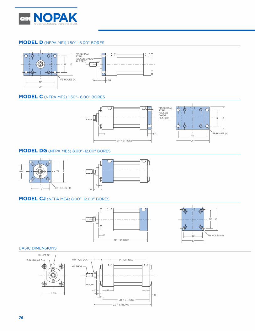
76
MODEL D (NFPA MF1) 1.50"– 6.00" BORES
TF
UF
ZF + STROKE
FHF
FHW
F
W
ER
ETE
TE
ETE
E
TE
RM
TF
UF
ER
MATERIAL: STEEL(BLACK OXIDEPLATED)
MATERIAL: STEEL(BLACK OXIDEPLATED)
ZF + STROKE
F
FB HOLES (4)
FB HOLES (4)
FB HOLES (4)
FB HOLES (4)
MODEL C (NFPA MF2) 1.50"– 6.00" BORES
TF
UF
ZF + STROKE
FHF
FHW
F
W
ER
ETE
TE
ETE
E
TE
RM
TF
UF
ER
MATERIAL: STEEL(BLACK OXIDEPLATED)
MATERIAL: STEEL(BLACK OXIDEPLATED)
ZF + STROKE
F
FB HOLES (4)
FB HOLES (4)
FB HOLES (4)
FB HOLES (4)
MODEL DG (NFPA ME3) 8.00"–12.00" BORES
TF
UF
ZF + STROKE
FHF
FHW
F
W
ER
ETE
TE
ETE
E
TE
RM
TF
UF
ER
MATERIAL: STEEL(BLACK OXIDEPLATED)
MATERIAL: STEEL(BLACK OXIDEPLATED)
ZF + STROKE
F
FB HOLES (4)
FB HOLES (4)
FB HOLES (4)
FB HOLES (4)
MODEL CJ (NFPA ME4) 8.00"–12.00" BORES
TF
UF
ZF + STROKE
FHF
FHW
F
W
ER
ETE
TE
ETE
E
TE
RM
TF
UF
ER
MATERIAL: STEEL(BLACK OXIDEPLATED)
MATERIAL: STEEL(BLACK OXIDEPLATED)
ZF + STROKE
F
FB HOLES (4)
FB HOLES (4)
FB HOLES (4)
FB HOLES (4)
BASIC DIMENSIONS
YMM ROD DIA.B BUSHING DIA.
EE NPT (2)
KK THDS.
P + STROKE
C JG
A
LB + STROKE
ZB + STROKE
E SQ.K
FV
FLANGE MOUNT CYLINDERS 1.50" THROUGH 12.00" BORE
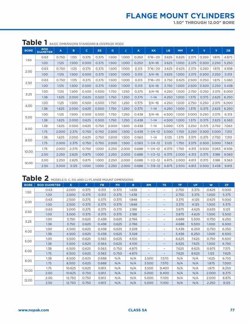
77www.nopak.com CLASS 5A
FLANGE MOUNT CYLINDERS1.50" THROUGH 12.00" BORE
Table 1 BASIC DIMENSIONS STANDARD & OVERSIZE RODS
BORE RODDIAMETER A B C EE G J K KK LB MM P V Y ZB
1.500.63 0.750 1.125 0.375 0.375 1.500 1.000 0.250 7/16 – 20 3.625 0.625 2.375 0.250 1.875 4.875
1.00 1.125 1.500 0.500 0.375 1.500 1.000 0.250 3/4 –16 3.625 1.000 2.375 0.500 2.250 5.250
2.000.63 0.750 1.125 0.375 0.375 1.500 1.000 0.313 7/16 – 20 3.625 0.625 2.375 0.250 1.875 4.938
1.00 1.125 1.500 0.500 0.375 1.500 1.000 0.313 3/4 –16 3.625 1.000 2.375 0.500 2.250 5.313
2.500.63 0.750 1.125 0.375 0.375 1.500 1.000 0.313 7/16 – 20 3.750 0.625 2.500 0.250 1.875 5.063
1.00 1.125 1.500 0.500 0.375 1.500 1.000 0.313 3/4 –16 3.750 1.000 2.500 0.500 2.250 5.438
3.251.00 1.125 1.500 0.500 0.500 1.750 1.250 0.375 3/4 –16 4.250 1.000 2.750 0.250 2.375 6.000
1.38 1.625 2.000 0.625 0.500 1.750 1.250 0.375 1 –14 4.250 1.000 1.375 0.375 2.625 6.250
4.001.00 1.125 1.500 0.500 0.500 1.750 1.250 0.375 3/4 –16 4.250 1.000 2.750 0.250 2.375 6.000
1.38 1.625 2.000 0.625 0.500 1.750 1.250 0.375 1 –14 4.250 1.000 1.375 0.375 2.625 6.250
5.001.00 1.125 1.500 0.500 0.500 1.750 1.250 0.438 3/4 –16 4.500 1.000 3.000 0.250 2.375 6.313
1.38 1.625 2.000 0.625 0.500 1.750 1.250 0.438 1 –14 4.500 1.000 1.375 0.375 2.625 6.563
6.001.38 1.625 2.000 0.625 0.750 2.000 1.500 0.438 1 –14 5.000 1.375 3.250 0.375 2.750 7.063
1.75 2.000 2.375 0.750 0.750 2.000 1.500 0.438 1 - 1/4 –12 5.000 1.750 3.250 0.500 3.000 7.313
8.001.38 1.625 2.000 0.625 0.750 2.000 1.500 0.563 1 –14 5.125 1.375 3.375 0.375 2.750 7.313
1.75 2.000 2.375 0.750 0.750 2.000 1.500 0.563 1 - 1/4 –12 5.125 1.750 3.375 0.500 3.000 7.563
10.001.75 2.000 2.375 0.750 1.000 2.250 2.000 0.688 1 - 1/4 –12 6.375 1.750 4.313 0.500 3.063 8.938
2.00 2.250 2.625 0.875 1.000 2.250 2.000 0.688 1 - 1/2 –12 6.375 2.000 4.313 0.375 3.188 9.063
12.002.00 2.250 2.625 0.875 1.000 2.250 2.000 0.688 1 - 1/2 –12 6.875 2.000 4.813 0.375 3.188 9.563
2.50 3.000 3.125 1.000 1.000 2.250 2.000 0.688 1 - 7/8 –12 6.875 2.500 4.813 0.500 3.438 9.813
Table 2 MODELS D, C, DG AND CJ FLANGE MOUNT DIMENSIONS
BORE ROD DIAMETER E F FB FH R RM TE TF UF W ZF
1.500.63 2.000 0.375 0.313 0.375 1.438 – – 2.750 3.375 0.625 5.000
1.00 2.000 0.375 0.313 0.375 1.438 – – 2.750 3.375 1.000 5.375
2.000.63 2.500 0.375 0.375 0.375 1.848 – – 3.375 4.125 0.625 5.000
1.00 2.500 0.375 0.375 0.375 1.848 – – 3.375 4.125 1.000 5.375
2.500.63 3.000 0.375 0.375 0.375 2.188 – – 3.875 4.625 0.625 5.125
1.00 3.000 0.375 0.375 0.375 2.188 – – 3.875 4.625 1.000 5.500
3.251.00 3.750 0.625 0.438 0.625 2.766 – – 4.688 5.500 0.750 6.250
1.38 3.750 0.625 0.438 0.625 2.766 – – 4.688 5.500 1.000 6.500
4.001.00 4.500 0.625 0.438 0.625 3.328 – – 5.438 6.250 0.750 6.250
1.38 4.500 0.625 0.438 0.625 3.328 – – 5.438 6.250 1.000 6.500
5.001.00 5.500 0.625 0.563 0.625 4.100 – – 6.625 7.625 0.750 6.500
1.38 5.500 0.625 0.563 0.625 4.100 – – 6.625 7.625 1.000 6.750
6.001.38 6.500 0.625 0.563 0.750 4.875 – – 7.625 8.625 0.875 7.375
1.75 6.500 0.625 0.563 0.750 4.875 – – 7.625 8.625 1.125 7.625
8.001.38 8.500 0.625 0.688 N/A N/A 3.500 7.570 N/A N/A 1.625 6.750
1.75 8.500 0.625 0.688 N/A N/A 3.500 7.570 N/A N/A 1.875 7.000
10.001.75 10.625 0.625 0.813 N/A N/A 3.500 9.400 N/A N/A 1.875 8.250
2.00 10.625 0.750 0.813 N/A N/A 5.000 9.400 N/A N/A 2.000 8.375
12.002.00 12.750 0.750 0.813 N/A N/A 5.000 11.100 N/A N/A 2.000 8.875
2.50 12.750 0.750 0.813 N/A N/A 5.000 11.100 N/A N/A 2.250 9.125
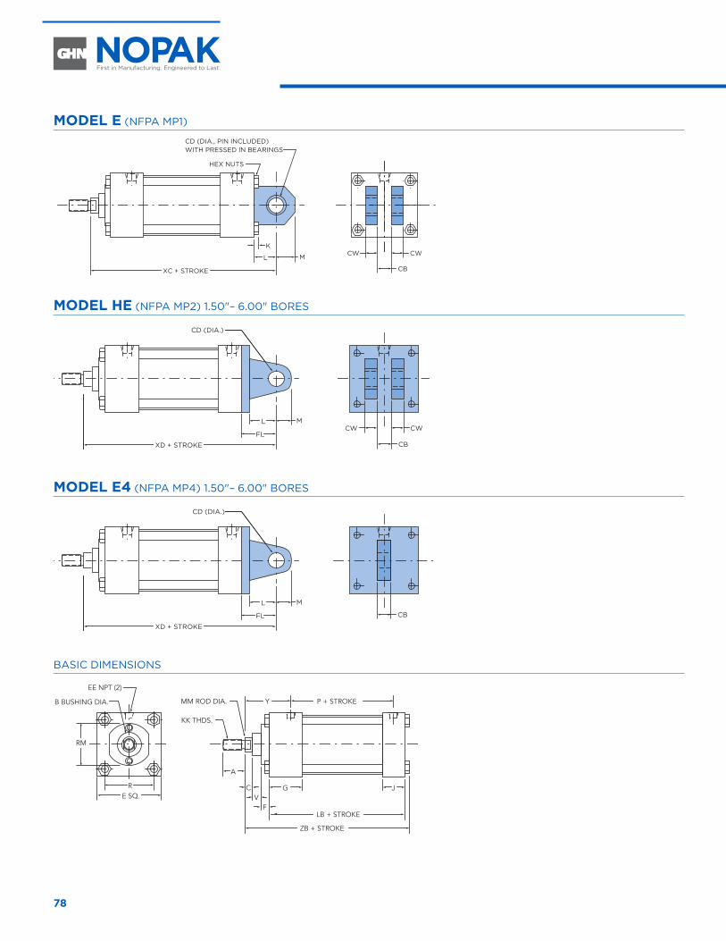
78
CLEVIS AND EYE MOUNT CYLINDERS 1.50" THROUGH 12.00" BORE
MODEL E (NFPA MP1)
CB
CWCW
XC + STROKE
L
P + STROKE
CD (DIA.)EE NPT(2)
L
L
FL
XD + STROKE
CD (DIA.)
CB
CWCW
CB
K
M
XC + STROKE
L
L
FL
XD + STROKE
CD (DIA.)
CB
CWCW
CD (DIA., PIN INCLUDED)WITH PRESSED IN BEARINGS
HEX NUTS
CD (DIA., PIN INCLUDED)WITH PRESSED IN BEARINGS
M
XC + STROKE
L
CB
CWCW
M
M
M
MODEL HE (NFPA MP2) 1.50"– 6.00" BORES
CB
CWCW
XC + STROKE
L
P + STROKE
CD (DIA.)EE NPT(2)
L
L
FL
XD + STROKE
CD (DIA.)
CB
CWCW
CB
K
M
XC + STROKE
L
L
FL
XD + STROKE
CD (DIA.)
CB
CWCW
CD (DIA., PIN INCLUDED)WITH PRESSED IN BEARINGS
HEX NUTS
CD (DIA., PIN INCLUDED)WITH PRESSED IN BEARINGS
M
XC + STROKE
L
CB
CWCW
M
M
M
MODEL E4 (NFPA MP4) 1.50"– 6.00" BORES
CB
CWCW
XC + STROKE
L
P + STROKE
CD (DIA.)EE NPT(2)
L
L
FL
XD + STROKE
CD (DIA.)
CB
CWCW
CB
K
M
XC + STROKE
L
L
FL
XD + STROKE
CD (DIA.)
CB
CWCW
CD (DIA., PIN INCLUDED)WITH PRESSED IN BEARINGS
HEX NUTS
CD (DIA., PIN INCLUDED)WITH PRESSED IN BEARINGS
M
XC + STROKE
L
CB
CWCW
M
M
M
BASIC DIMENSIONS
YMM ROD DIA.B BUSHING DIA.
EE NPT (2)
KK THDS.
P + STROKE
C JG
A
LB + STROKE
ZB + STROKE
E SQ.R
RM
FV
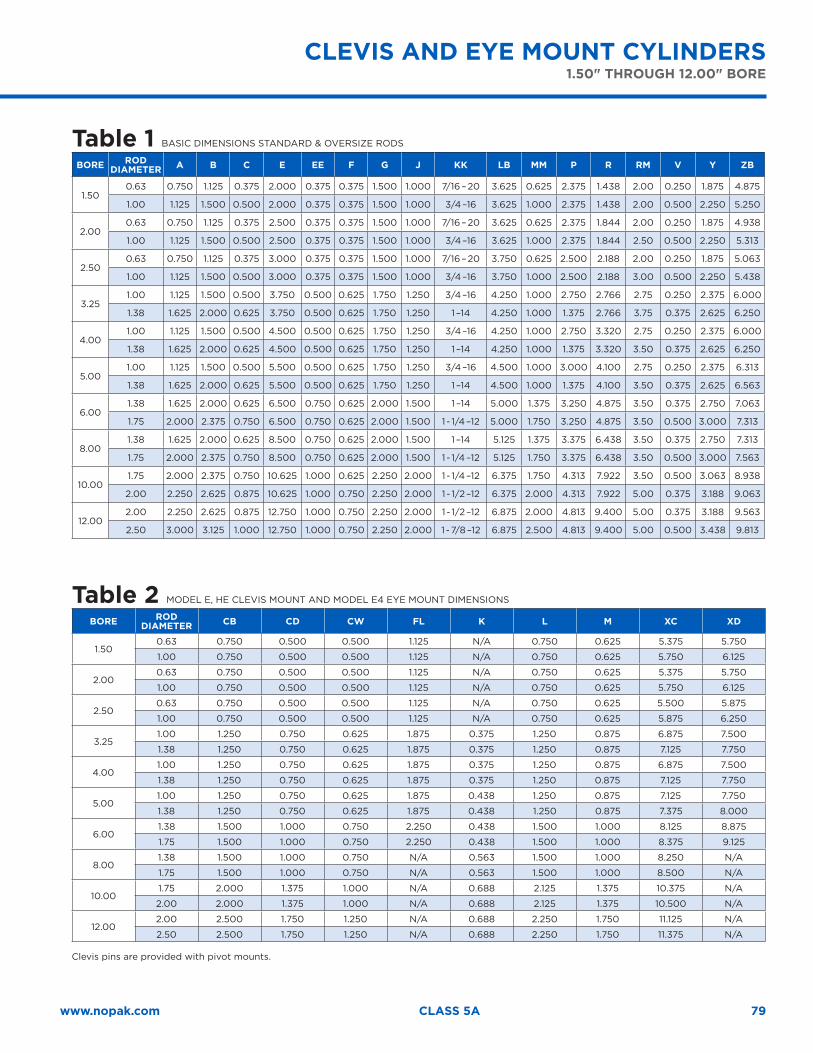
79www.nopak.com CLASS 5A
Table 1 BASIC DIMENSIONS STANDARD & OVERSIZE RODS
BORE RODDIAMETER A B C E EE F G J KK LB MM P R RM V Y ZB
1.500.63 0.750 1.125 0.375 2.000 0.375 0.375 1.500 1.000 7/16 – 20 3.625 0.625 2.375 1.438 2.00 0.250 1.875 4.875
1.00 1.125 1.500 0.500 2.000 0.375 0.375 1.500 1.000 3/4 –16 3.625 1.000 2.375 1.438 2.00 0.500 2.250 5.250
2.000.63 0.750 1.125 0.375 2.500 0.375 0.375 1.500 1.000 7/16 – 20 3.625 0.625 2.375 1.844 2.00 0.250 1.875 4.938
1.00 1.125 1.500 0.500 2.500 0.375 0.375 1.500 1.000 3/4 –16 3.625 1.000 2.375 1.844 2.50 0.500 2.250 5.313
2.500.63 0.750 1.125 0.375 3.000 0.375 0.375 1.500 1.000 7/16 – 20 3.750 0.625 2.500 2.188 2.00 0.250 1.875 5.063
1.00 1.125 1.500 0.500 3.000 0.375 0.375 1.500 1.000 3/4 –16 3.750 1.000 2.500 2.188 3.00 0.500 2.250 5.438
3.251.00 1.125 1.500 0.500 3.750 0.500 0.625 1.750 1.250 3/4 –16 4.250 1.000 2.750 2.766 2.75 0.250 2.375 6.000
1.38 1.625 2.000 0.625 3.750 0.500 0.625 1.750 1.250 1 –14 4.250 1.000 1.375 2.766 3.75 0.375 2.625 6.250
4.001.00 1.125 1.500 0.500 4.500 0.500 0.625 1.750 1.250 3/4 –16 4.250 1.000 2.750 3.320 2.75 0.250 2.375 6.000
1.38 1.625 2.000 0.625 4.500 0.500 0.625 1.750 1.250 1 –14 4.250 1.000 1.375 3.320 3.50 0.375 2.625 6.250
5.001.00 1.125 1.500 0.500 5.500 0.500 0.625 1.750 1.250 3/4 –16 4.500 1.000 3.000 4.100 2.75 0.250 2.375 6.313
1.38 1.625 2.000 0.625 5.500 0.500 0.625 1.750 1.250 1 –14 4.500 1.000 1.375 4.100 3.50 0.375 2.625 6.563
6.001.38 1.625 2.000 0.625 6.500 0.750 0.625 2.000 1.500 1 –14 5.000 1.375 3.250 4.875 3.50 0.375 2.750 7.063
1.75 2.000 2.375 0.750 6.500 0.750 0.625 2.000 1.500 1 - 1/4 –12 5.000 1.750 3.250 4.875 3.50 0.500 3.000 7.313
8.001.38 1.625 2.000 0.625 8.500 0.750 0.625 2.000 1.500 1 –14 5.125 1.375 3.375 6.438 3.50 0.375 2.750 7.313
1.75 2.000 2.375 0.750 8.500 0.750 0.625 2.000 1.500 1 - 1/4 –12 5.125 1.750 3.375 6.438 3.50 0.500 3.000 7.563
10.001.75 2.000 2.375 0.750 10.625 1.000 0.625 2.250 2.000 1 - 1/4 –12 6.375 1.750 4.313 7.922 3.50 0.500 3.063 8.938
2.00 2.250 2.625 0.875 10.625 1.000 0.750 2.250 2.000 1 - 1/2 –12 6.375 2.000 4.313 7.922 5.00 0.375 3.188 9.063
12.002.00 2.250 2.625 0.875 12.750 1.000 0.750 2.250 2.000 1 - 1/2 –12 6.875 2.000 4.813 9.400 5.00 0.375 3.188 9.563
2.50 3.000 3.125 1.000 12.750 1.000 0.750 2.250 2.000 1 - 7/8 –12 6.875 2.500 4.813 9.400 5.00 0.500 3.438 9.813
Table 2 MODEL E, HE CLEVIS MOUNT AND MODEL E4 EYE MOUNT DIMENSIONS
BORE ROD DIAMETER CB CD CW FL K L M XC XD
1.500.63 0.750 0.500 0.500 1.125 N/A 0.750 0.625 5.375 5.750
1.00 0.750 0.500 0.500 1.125 N/A 0.750 0.625 5.750 6.125
2.000.63 0.750 0.500 0.500 1.125 N/A 0.750 0.625 5.375 5.750
1.00 0.750 0.500 0.500 1.125 N/A 0.750 0.625 5.750 6.125
2.500.63 0.750 0.500 0.500 1.125 N/A 0.750 0.625 5.500 5.875
1.00 0.750 0.500 0.500 1.125 N/A 0.750 0.625 5.875 6.250
3.251.00 1.250 0.750 0.625 1.875 0.375 1.250 0.875 6.875 7.500
1.38 1.250 0.750 0.625 1.875 0.375 1.250 0.875 7.125 7.750
4.001.00 1.250 0.750 0.625 1.875 0.375 1.250 0.875 6.875 7.500
1.38 1.250 0.750 0.625 1.875 0.375 1.250 0.875 7.125 7.750
5.001.00 1.250 0.750 0.625 1.875 0.438 1.250 0.875 7.125 7.750
1.38 1.250 0.750 0.625 1.875 0.438 1.250 0.875 7.375 8.000
6.001.38 1.500 1.000 0.750 2.250 0.438 1.500 1.000 8.125 8.875
1.75 1.500 1.000 0.750 2.250 0.438 1.500 1.000 8.375 9.125
8.001.38 1.500 1.000 0.750 N/A 0.563 1.500 1.000 8.250 N/A
1.75 1.500 1.000 0.750 N/A 0.563 1.500 1.000 8.500 N/A
10.001.75 2.000 1.375 1.000 N/A 0.688 2.125 1.375 10.375 N/A
2.00 2.000 1.375 1.000 N/A 0.688 2.125 1.375 10.500 N/A
12.002.00 2.500 1.750 1.250 N/A 0.688 2.250 1.750 11.125 N/A
2.50 2.500 1.750 1.250 N/A 0.688 2.250 1.750 11.375 N/A
Clevis pins are provided with pivot mounts.
CLEVIS AND EYE MOUNT CYLINDERS1.50" THROUGH 12.00" BORE
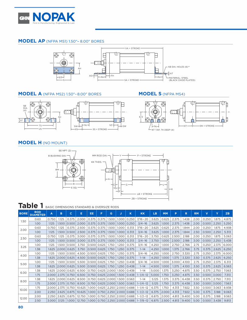
80
MODEL AP (NFPA MS1) 1.50"– 8.00" BORES
TN
NT TAP, TK DEEP (4)
SN + STROKEXT
E/2
SBDIA.(4)
AB DIA. HOLES (6)**
MATERIAL: STEEL(BLACK OXIDE PLATED)S
S/2
AH
TS
US
SH
ST
SA + STROKEALFH
ATAO AL
SS + STROKE
SZ SWXS
XA + STROKE
SUSW
MODEL A (NFPA MS2) 1.50"– 8.00" BORES
TN
NT TAP, TK DEEP (4)
SN + STROKEXT
E/2
SBDIA.(4)
AB DIA. HOLES (6)**
MATERIAL: STEEL(BLACK OXIDE PLATED)S
S/2
AH
TS
US
SH
ST
SA + STROKEALFH
ATAO AL
SS + STROKE
SZ SWXS
XA + STROKE
SUSW
MODEL S (NFPA MS4)
TN
NT TAP, TK DEEP (4)
SN + STROKEXT
E/2
SBDIA.(4)
AB DIA. HOLES (6)**
MATERIAL: STEEL(BLACK OXIDE PLATED)S
S/2
AH
TS
US
SH
ST
SA + STROKEALFH
ATAO AL
SS + STROKE
SZ SWXS
XA + STROKE
SUSW
MODEL H (NO MOUNT)
YMM ROD DIA.B BUSHING DIA.
EE NPT (2)
KK THDS.
P + STROKE
C JG
A
LB + STROKE
ZB + STROKE
E SQ.
R
RM
KF
V
Table 1 BASIC DIMENSIONS STANDARD & OVERSIZE RODS
BORE RODDIAMETER A B C E EE F G J K KK LB MM P R RM V Y ZB
1.500.63 0.750 1.125 0.375 2.000 0.375 0.375 1.500 1.000 0.250 7/16 – 20 3.625 0.625 2.375 1.438 2.00 0.250 1.875 4.8751.00 1.125 1.500 0.500 2.000 0.375 0.375 1.500 1.000 0.250 3/4 –16 3.625 1.000 2.375 1.438 2.00 0.500 2.250 5.250
2.000.63 0.750 1.125 0.375 2.500 0.375 0.375 1.500 1.000 0.313 7/16 – 20 3.625 0.625 2.375 1.844 2.00 0.250 1.875 4.9381.00 1.125 1.500 0.500 2.500 0.375 0.375 1.500 1.000 0.313 3/4 –16 3.625 1.000 2.375 1.844 2.50 0.500 2.250 5.313
2.500.63 0.750 1.125 0.375 3.000 0.375 0.375 1.500 1.000 0.313 7/16 – 20 3.750 0.625 2.500 2.188 2.00 0.250 1.875 5.0631.00 1.125 1.500 0.500 3.000 0.375 0.375 1.500 1.000 0.313 3/4 –16 3.750 1.000 2.500 2.188 3.00 0.500 2.250 5.438
3.251.00 1.125 1.500 0.500 3.750 0.500 0.625 1.750 1.250 0.375 3/4 –16 4.250 1.000 2.750 2.766 2.75 0.250 2.375 6.0001.38 1.625 2.000 0.625 3.750 0.500 0.625 1.750 1.250 0.375 1 –14 4.250 1.000 1.375 2.766 3.75 0.375 2.625 6.250
4.001.00 1.125 1.500 0.500 4.500 0.500 0.625 1.750 1.250 0.375 3/4 –16 4.250 1.000 2.750 3.320 2.75 0.250 2.375 6.0001.38 1.625 2.000 0.625 4.500 0.500 0.625 1.750 1.250 0.375 1 –14 4.250 1.000 1.375 3.320 3.50 0.375 2.625 6.250
5.001.00 1.125 1.500 0.500 5.500 0.500 0.625 1.750 1.250 0.438 3/4 –16 4.500 1.000 3.000 4.100 2.75 0.250 2.375 6.3131.38 1.625 2.000 0.625 5.500 0.500 0.625 1.750 1.250 0.438 1 –14 4.500 1.000 1.375 4.100 3.50 0.375 2.625 6.563
6.001.38 1.625 2.000 0.625 6.500 0.750 0.625 2.000 1.500 0.438 1 –14 5.000 1.375 3.250 4.875 3.50 0.375 2.750 7.0631.75 2.000 2.375 0.750 6.500 0.750 0.625 2.000 1.500 0.438 1 - 1/4 –12 5.000 1.750 3.250 4.875 3.50 0.500 3.000 7.313
8.001.38 1.625 2.000 0.625 8.500 0.750 0.625 2.000 1.500 0.563 1 –14 5.125 1.375 3.375 6.438 3.50 0.375 2.750 7.3131.75 2.000 2.375 0.750 8.500 0.750 0.625 2.000 1.500 0.563 1 - 1/4 –12 5.125 1.750 3.375 6.438 3.50 0.500 3.000 7.563
10.001.75 2.000 2.375 0.750 10.625 1.000 0.625 2.250 2.000 0.688 1 - 1/4 –12 6.375 1.750 4.313 7.922 3.50 0.500 3.063 8.9382.00 2.250 2.625 0.875 10.625 1.000 0.750 2.250 2.000 0.688 1 - 1/2 –12 6.375 2.000 4.313 7.922 5.00 0.375 3.188 9.063
12.002.00 2.250 2.625 0.875 12.750 1.000 0.750 2.250 2.000 0.688 1 - 1/2 –12 6.875 2.000 4.813 9.400 5.00 0.375 3.188 9.5632.50 3.000 3.125 1.000 12.750 1.000 0.750 2.250 2.000 0.688 1 - 7/8 –12 6.875 2.500 4.813 9.400 5.00 0.500 3.438 9.813
ANGLE AND SIDE LUG MOUNT CYLINDERS 1.50" THROUGH 12.00" BORE
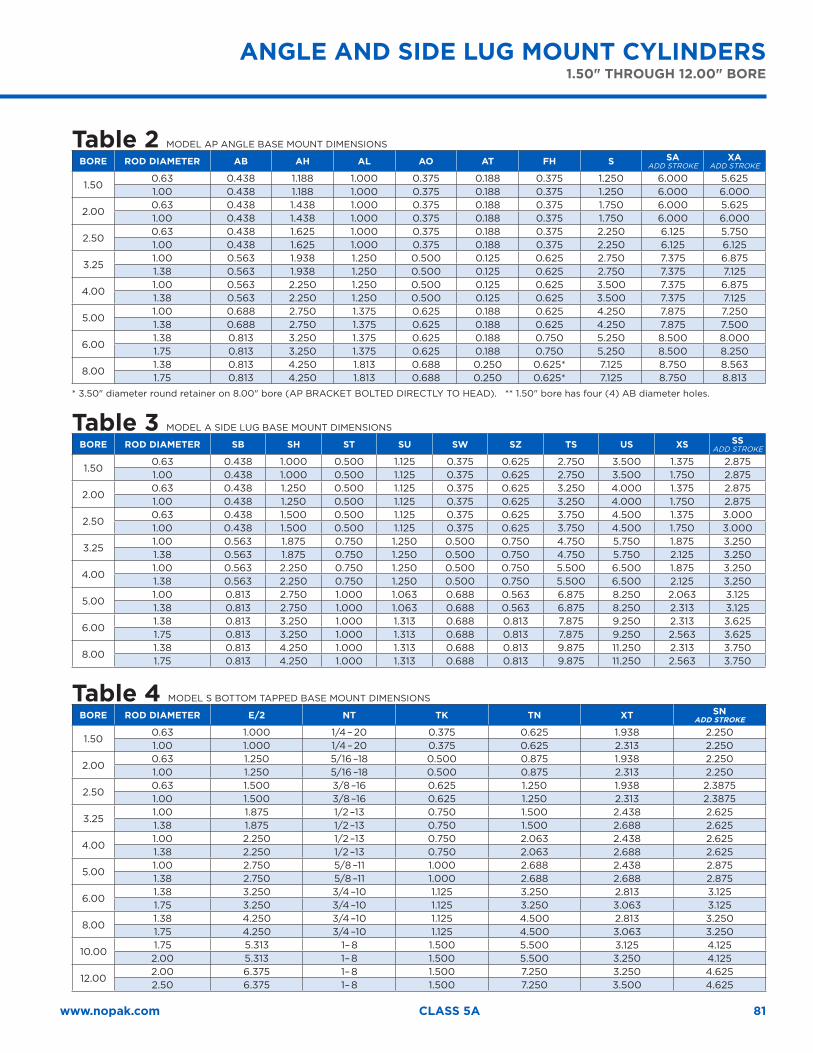
81www.nopak.com CLASS 5A
Table 2 MODEL AP ANGLE BASE MOUNT DIMENSIONS
BORE ROD DIAMETER AB AH AL AO AT FH S SAADD STROKE
XAADD STROKE
1.500.63 0.438 1.188 1.000 0.375 0.188 0.375 1.250 6.000 5.6251.00 0.438 1.188 1.000 0.375 0.188 0.375 1.250 6.000 6.000
2.000.63 0.438 1.438 1.000 0.375 0.188 0.375 1.750 6.000 5.6251.00 0.438 1.438 1.000 0.375 0.188 0.375 1.750 6.000 6.000
2.500.63 0.438 1.625 1.000 0.375 0.188 0.375 2.250 6.125 5.7501.00 0.438 1.625 1.000 0.375 0.188 0.375 2.250 6.125 6.125
3.251.00 0.563 1.938 1.250 0.500 0.125 0.625 2.750 7.375 6.8751.38 0.563 1.938 1.250 0.500 0.125 0.625 2.750 7.375 7.125
4.001.00 0.563 2.250 1.250 0.500 0.125 0.625 3.500 7.375 6.8751.38 0.563 2.250 1.250 0.500 0.125 0.625 3.500 7.375 7.125
5.001.00 0.688 2.750 1.375 0.625 0.188 0.625 4.250 7.875 7.2501.38 0.688 2.750 1.375 0.625 0.188 0.625 4.250 7.875 7.500
6.001.38 0.813 3.250 1.375 0.625 0.188 0.750 5.250 8.500 8.0001.75 0.813 3.250 1.375 0.625 0.188 0.750 5.250 8.500 8.250
8.001.38 0.813 4.250 1.813 0.688 0.250 0.625* 7.125 8.750 8.5631.75 0.813 4.250 1.813 0.688 0.250 0.625* 7.125 8.750 8.813
* 3.50" diameter round retainer on 8.00" bore (AP BRACKET BOLTED DIRECTLY TO HEAD). ** 1.50" bore has four (4) AB diameter holes.
Table 3 MODEL A SIDE LUG BASE MOUNT DIMENSIONS
BORE ROD DIAMETER SB SH ST SU SW SZ TS US XS SSADD STROKE
1.500.63 0.438 1.000 0.500 1.125 0.375 0.625 2.750 3.500 1.375 2.8751.00 0.438 1.000 0.500 1.125 0.375 0.625 2.750 3.500 1.750 2.875
2.000.63 0.438 1.250 0.500 1.125 0.375 0.625 3.250 4.000 1.375 2.8751.00 0.438 1.250 0.500 1.125 0.375 0.625 3.250 4.000 1.750 2.875
2.500.63 0.438 1.500 0.500 1.125 0.375 0.625 3.750 4.500 1.375 3.0001.00 0.438 1.500 0.500 1.125 0.375 0.625 3.750 4.500 1.750 3.000
3.251.00 0.563 1.875 0.750 1.250 0.500 0.750 4.750 5.750 1.875 3.2501.38 0.563 1.875 0.750 1.250 0.500 0.750 4.750 5.750 2.125 3.250
4.001.00 0.563 2.250 0.750 1.250 0.500 0.750 5.500 6.500 1.875 3.2501.38 0.563 2.250 0.750 1.250 0.500 0.750 5.500 6.500 2.125 3.250
5.001.00 0.813 2.750 1.000 1.063 0.688 0.563 6.875 8.250 2.063 3.1251.38 0.813 2.750 1.000 1.063 0.688 0.563 6.875 8.250 2.313 3.125
6.001.38 0.813 3.250 1.000 1.313 0.688 0.813 7.875 9.250 2.313 3.6251.75 0.813 3.250 1.000 1.313 0.688 0.813 7.875 9.250 2.563 3.625
8.001.38 0.813 4.250 1.000 1.313 0.688 0.813 9.875 11.250 2.313 3.7501.75 0.813 4.250 1.000 1.313 0.688 0.813 9.875 11.250 2.563 3.750
Table 4 MODEL S BOTTOM TAPPED BASE MOUNT DIMENSIONS
BORE ROD DIAMETER E/2 NT TK TN XT SNADD STROKE
1.500.63 1.000 1/4 – 20 0.375 0.625 1.938 2.2501.00 1.000 1/4 – 20 0.375 0.625 2.313 2.250
2.000.63 1.250 5/16 –18 0.500 0.875 1.938 2.2501.00 1.250 5/16 –18 0.500 0.875 2.313 2.250
2.500.63 1.500 3/8 –16 0.625 1.250 1.938 2.38751.00 1.500 3/8 –16 0.625 1.250 2.313 2.3875
3.251.00 1.875 1/2 –13 0.750 1.500 2.438 2.6251.38 1.875 1/2 –13 0.750 1.500 2.688 2.625
4.001.00 2.250 1/2 –13 0.750 2.063 2.438 2.6251.38 2.250 1/2 –13 0.750 2.063 2.688 2.625
5.001.00 2.750 5/8 –11 1.000 2.688 2.438 2.8751.38 2.750 5/8 –11 1.000 2.688 2.688 2.875
6.001.38 3.250 3/4 –10 1.125 3.250 2.813 3.1251.75 3.250 3/4 –10 1.125 3.250 3.063 3.125
8.001.38 4.250 3/4 –10 1.125 4.500 2.813 3.2501.75 4.250 3/4 –10 1.125 4.500 3.063 3.250
10.001.75 5.313 1– 8 1.500 5.500 3.125 4.1252.00 5.313 1– 8 1.500 5.500 3.250 4.125
12.002.00 6.375 1– 8 1.500 7.250 3.250 4.6252.50 6.375 1– 8 1.500 7.250 3.500 4.625
ANGLE AND SIDE LUG MOUNT CYLINDERS1.50" THROUGH 12.00" BORE
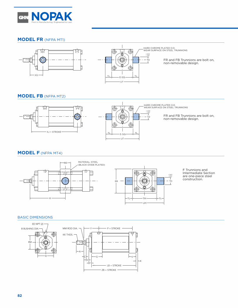
82
MODEL FR (NFPA MT1)
TLTL
UT
TD
E-SQ.XG
XJ + STROKE
MATERIAL: STEEL(BLACK OXIDE PLATED)
HARD CHROME PLATED O.D.WEAR SURFACE ON STEEL TRUNNIONS
HARD CHROME PLATED O.D.WEAR SURFACE ON STEEL TRUNNIONS
+.000– .001
TLTL
UT
TD
E-SQ.
+.000– .001
TL TL
UM
XI
BD
EB TD
TM
+.000– .001
MODEL FB (NFPA MT2)
TLTL
UT
TD
E-SQ.XG
XJ + STROKE
MATERIAL: STEEL(BLACK OXIDE PLATED)
HARD CHROME PLATED O.D.WEAR SURFACE ON STEEL TRUNNIONS
HARD CHROME PLATED O.D.WEAR SURFACE ON STEEL TRUNNIONS
+.000– .001
TLTL
UT
TD
E-SQ.
+.000– .001
TL TL
UM
XI
BD
EB TD
TM
+.000– .001
MODEL F (NFPA MT4)
TLTL
UT
TD
E-SQ.XG
XJ + STROKE
MATERIAL: STEEL(BLACK OXIDE PLATED)
HARD CHROME PLATED O.D.WEAR SURFACE ON STEEL TRUNNIONS
HARD CHROME PLATED O.D.WEAR SURFACE ON STEEL TRUNNIONS
+.000– .001
TLTL
UT
TD
E-SQ.
+.000– .001
TL TL
UM
XI
BD
EB TD
TM
+.000– .001
BASIC DIMENSIONS
YMM ROD DIA.B BUSHING DIA.
EE NPT (2)
KK THDS.
P + STROKE
C JG
A
LB + STROKE
ZB + STROKE
R
RM
KF
V
FR and FB Trunnions are bolt on, non-removable design.
FR and FB Trunnions are bolt on, non-removable design.
F Trunnions and Intermediate Section are one-piece steel construction.
TRUNNION MOUNT CYLINDERS 1.50" THROUGH 8.00" BORE
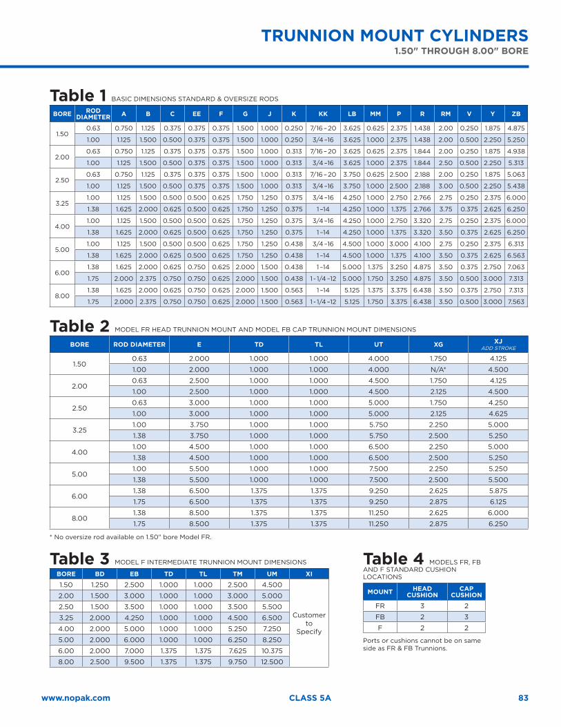
83www.nopak.com CLASS 5A
Table 1 BASIC DIMENSIONS STANDARD & OVERSIZE RODS
BORE RODDIAMETER A B C EE F G J K KK LB MM P R RM V Y ZB
1.500.63 0.750 1.125 0.375 0.375 0.375 1.500 1.000 0.250 7/16 – 20 3.625 0.625 2.375 1.438 2.00 0.250 1.875 4.875
1.00 1.125 1.500 0.500 0.375 0.375 1.500 1.000 0.250 3/4 –16 3.625 1.000 2.375 1.438 2.00 0.500 2.250 5.250
2.000.63 0.750 1.125 0.375 0.375 0.375 1.500 1.000 0.313 7/16 – 20 3.625 0.625 2.375 1.844 2.00 0.250 1.875 4.938
1.00 1.125 1.500 0.500 0.375 0.375 1.500 1.000 0.313 3/4 –16 3.625 1.000 2.375 1.844 2.50 0.500 2.250 5.313
2.500.63 0.750 1.125 0.375 0.375 0.375 1.500 1.000 0.313 7/16 – 20 3.750 0.625 2.500 2.188 2.00 0.250 1.875 5.063
1.00 1.125 1.500 0.500 0.375 0.375 1.500 1.000 0.313 3/4 –16 3.750 1.000 2.500 2.188 3.00 0.500 2.250 5.438
3.251.00 1.125 1.500 0.500 0.500 0.625 1.750 1.250 0.375 3/4 –16 4.250 1.000 2.750 2.766 2.75 0.250 2.375 6.000
1.38 1.625 2.000 0.625 0.500 0.625 1.750 1.250 0.375 1 –14 4.250 1.000 1.375 2.766 3.75 0.375 2.625 6.250
4.001.00 1.125 1.500 0.500 0.500 0.625 1.750 1.250 0.375 3/4 –16 4.250 1.000 2.750 3.320 2.75 0.250 2.375 6.000
1.38 1.625 2.000 0.625 0.500 0.625 1.750 1.250 0.375 1 –14 4.250 1.000 1.375 3.320 3.50 0.375 2.625 6.250
5.001.00 1.125 1.500 0.500 0.500 0.625 1.750 1.250 0.438 3/4 –16 4.500 1.000 3.000 4.100 2.75 0.250 2.375 6.313
1.38 1.625 2.000 0.625 0.500 0.625 1.750 1.250 0.438 1 –14 4.500 1.000 1.375 4.100 3.50 0.375 2.625 6.563
6.001.38 1.625 2.000 0.625 0.750 0.625 2.000 1.500 0.438 1 –14 5.000 1.375 3.250 4.875 3.50 0.375 2.750 7.063
1.75 2.000 2.375 0.750 0.750 0.625 2.000 1.500 0.438 1 - 1/4 –12 5.000 1.750 3.250 4.875 3.50 0.500 3.000 7.313
8.001.38 1.625 2.000 0.625 0.750 0.625 2.000 1.500 0.563 1 –14 5.125 1.375 3.375 6.438 3.50 0.375 2.750 7.313
1.75 2.000 2.375 0.750 0.750 0.625 2.000 1.500 0.563 1 - 1/4 –12 5.125 1.750 3.375 6.438 3.50 0.500 3.000 7.563
Table 2 MODEL FR HEAD TRUNNION MOUNT AND MODEL FB CAP TRUNNION MOUNT DIMENSIONS
BORE ROD DIAMETER E TD TL UT XG XJADD STROKE
1.500.63 2.000 1.000 1.000 4.000 1.750 4.125
1.00 2.000 1.000 1.000 4.000 N/A* 4.500
2.000.63 2.500 1.000 1.000 4.500 1.750 4.125
1.00 2.500 1.000 1.000 4.500 2.125 4.500
2.500.63 3.000 1.000 1.000 5.000 1.750 4.250
1.00 3.000 1.000 1.000 5.000 2.125 4.625
3.251.00 3.750 1.000 1.000 5.750 2.250 5.000
1.38 3.750 1.000 1.000 5.750 2.500 5.250
4.001.00 4.500 1.000 1.000 6.500 2.250 5.000
1.38 4.500 1.000 1.000 6.500 2.500 5.250
5.001.00 5.500 1.000 1.000 7.500 2.250 5.250
1.38 5.500 1.000 1.000 7.500 2.500 5.500
6.001.38 6.500 1.375 1.375 9.250 2.625 5.875
1.75 6.500 1.375 1.375 9.250 2.875 6.125
8.001.38 8.500 1.375 1.375 11.250 2.625 6.000
1.75 8.500 1.375 1.375 11.250 2.875 6.250
* No oversize rod available on 1.50" bore Model FR.
Table 3 MODEL F INTERMEDIATE TRUNNION MOUNT DIMENSIONS
BORE BD EB TD TL TM UM XI
1.50 1.250 2.500 1.000 1.000 2.500 4.500
Customer to
Specify
2.00 1.500 3.000 1.000 1.000 3.000 5.000
2.50 1.500 3.500 1.000 1.000 3.500 5.500
3.25 2.000 4.250 1.000 1.000 4.500 6.500
4.00 2.000 5.000 1.000 1.000 5.250 7.250
5.00 2.000 6.000 1.000 1.000 6.250 8.250
6.00 2.000 7.000 1.375 1.375 7.625 10.375
8.00 2.500 9.500 1.375 1.375 9.750 12.500
Table 4 MODELS FR, FBAND F STANDARD CUSHION LOCATIONS
MOUNT HEAD CUSHION
CAP CUSHION
FR 3 2
FB 2 3
F 2 2
Ports or cushions cannot be on same side as FR & FB Trunnions.
TRUNNION MOUNT CYLINDERS1.50" THROUGH 8.00" BORE
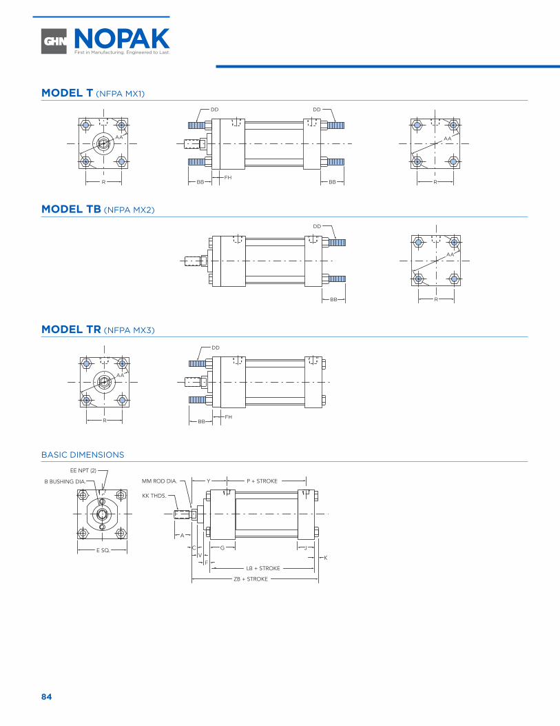
84
MODEL T (NFPA MX1)
R R
R
BBFH
BBFH
BB
BB
R
DD
DD
DD
DD
AA AA
AA
AA
MODEL TB (NFPA MX2)R R
R
BBFH
BBFH
BB
BB
R
DD
DD
DD
DD
AA AA
AA
AA
MODEL TR (NFPA MX3)
R R
R
BBFH
BBFH
BB
BB
R
DD
DD
DD
DD
AA AA
AA
AA
BASIC DIMENSIONS
YMM ROD DIA.B BUSHING DIA.
EE NPT (2)
KK THDS.
P + STROKE
C JG
A
LB + STROKE
ZB + STROKE
E SQ.K
FV
TIE ROD MOUNT CYLINDERS 1.50" THROUGH 12.00" BORE
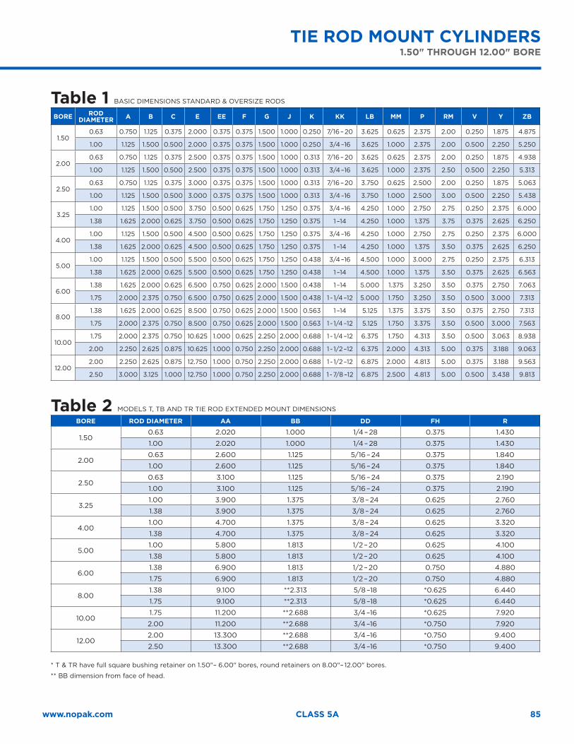
85www.nopak.com CLASS 5A
Table 1 BASIC DIMENSIONS STANDARD & OVERSIZE RODS
BORE RODDIAMETER A B C E EE F G J K KK LB MM P RM V Y ZB
1.500.63 0.750 1.125 0.375 2.000 0.375 0.375 1.500 1.000 0.250 7/16 – 20 3.625 0.625 2.375 2.00 0.250 1.875 4.875
1.00 1.125 1.500 0.500 2.000 0.375 0.375 1.500 1.000 0.250 3/4 –16 3.625 1.000 2.375 2.00 0.500 2.250 5.250
2.000.63 0.750 1.125 0.375 2.500 0.375 0.375 1.500 1.000 0.313 7/16 – 20 3.625 0.625 2.375 2.00 0.250 1.875 4.938
1.00 1.125 1.500 0.500 2.500 0.375 0.375 1.500 1.000 0.313 3/4 –16 3.625 1.000 2.375 2.50 0.500 2.250 5.313
2.500.63 0.750 1.125 0.375 3.000 0.375 0.375 1.500 1.000 0.313 7/16 – 20 3.750 0.625 2.500 2.00 0.250 1.875 5.063
1.00 1.125 1.500 0.500 3.000 0.375 0.375 1.500 1.000 0.313 3/4 –16 3.750 1.000 2.500 3.00 0.500 2.250 5.438
3.251.00 1.125 1.500 0.500 3.750 0.500 0.625 1.750 1.250 0.375 3/4 –16 4.250 1.000 2.750 2.75 0.250 2.375 6.000
1.38 1.625 2.000 0.625 3.750 0.500 0.625 1.750 1.250 0.375 1 –14 4.250 1.000 1.375 3.75 0.375 2.625 6.250
4.001.00 1.125 1.500 0.500 4.500 0.500 0.625 1.750 1.250 0.375 3/4 –16 4.250 1.000 2.750 2.75 0.250 2.375 6.000
1.38 1.625 2.000 0.625 4.500 0.500 0.625 1.750 1.250 0.375 1 –14 4.250 1.000 1.375 3.50 0.375 2.625 6.250
5.001.00 1.125 1.500 0.500 5.500 0.500 0.625 1.750 1.250 0.438 3/4 –16 4.500 1.000 3.000 2.75 0.250 2.375 6.313
1.38 1.625 2.000 0.625 5.500 0.500 0.625 1.750 1.250 0.438 1 –14 4.500 1.000 1.375 3.50 0.375 2.625 6.563
6.001.38 1.625 2.000 0.625 6.500 0.750 0.625 2.000 1.500 0.438 1 –14 5.000 1.375 3.250 3.50 0.375 2.750 7.063
1.75 2.000 2.375 0.750 6.500 0.750 0.625 2.000 1.500 0.438 1 - 1/4 –12 5.000 1.750 3.250 3.50 0.500 3.000 7.313
8.001.38 1.625 2.000 0.625 8.500 0.750 0.625 2.000 1.500 0.563 1 –14 5.125 1.375 3.375 3.50 0.375 2.750 7.313
1.75 2.000 2.375 0.750 8.500 0.750 0.625 2.000 1.500 0.563 1 - 1/4 –12 5.125 1.750 3.375 3.50 0.500 3.000 7.563
10.001.75 2.000 2.375 0.750 10.625 1.000 0.625 2.250 2.000 0.688 1 - 1/4 –12 6.375 1.750 4.313 3.50 0.500 3.063 8.938
2.00 2.250 2.625 0.875 10.625 1.000 0.750 2.250 2.000 0.688 1 - 1/2 –12 6.375 2.000 4.313 5.00 0.375 3.188 9.063
12.002.00 2.250 2.625 0.875 12.750 1.000 0.750 2.250 2.000 0.688 1 - 1/2 –12 6.875 2.000 4.813 5.00 0.375 3.188 9.563
2.50 3.000 3.125 1.000 12.750 1.000 0.750 2.250 2.000 0.688 1 - 7/8 –12 6.875 2.500 4.813 5.00 0.500 3.438 9.813
Table 2 MODELS T, TB AND TR TIE ROD EXTENDED MOUNT DIMENSIONS
BORE ROD DIAMETER AA BB DD FH R
1.500.63 2.020 1.000 1/4 – 28 0.375 1.430
1.00 2.020 1.000 1/4 – 28 0.375 1.430
2.000.63 2.600 1.125 5/16 – 24 0.375 1.840
1.00 2.600 1.125 5/16 – 24 0.375 1.840
2.500.63 3.100 1.125 5/16 – 24 0.375 2.190
1.00 3.100 1.125 5/16 – 24 0.375 2.190
3.251.00 3.900 1.375 3/8 – 24 0.625 2.760
1.38 3.900 1.375 3/8 – 24 0.625 2.760
4.001.00 4.700 1.375 3/8 – 24 0.625 3.320
1.38 4.700 1.375 3/8 – 24 0.625 3.320
5.001.00 5.800 1.813 1/2 – 20 0.625 4.100
1.38 5.800 1.813 1/2 – 20 0.625 4.100
6.001.38 6.900 1.813 1/2 – 20 0.750 4.880
1.75 6.900 1.813 1/2 – 20 0.750 4.880
8.001.38 9.100 **2.313 5/8 –18 *0.625 6.440
1.75 9.100 **2.313 5/8 –18 *0.625 6.440
10.001.75 11.200 **2.688 3/4 –16 *0.625 7.920
2.00 11.200 **2.688 3/4 –16 *0.750 7.920
12.002.00 13.300 **2.688 3/4 –16 *0.750 9.400
2.50 13.300 **2.688 3/4 –16 *0.750 9.400
* T & TR have full square bushing retainer on 1.50"– 6.00" bores, round retainers on 8.00"– 12.00" bores.
** BB dimension from face of head.
TIE ROD MOUNT CYLINDERS1.50" THROUGH 12.00" BORE
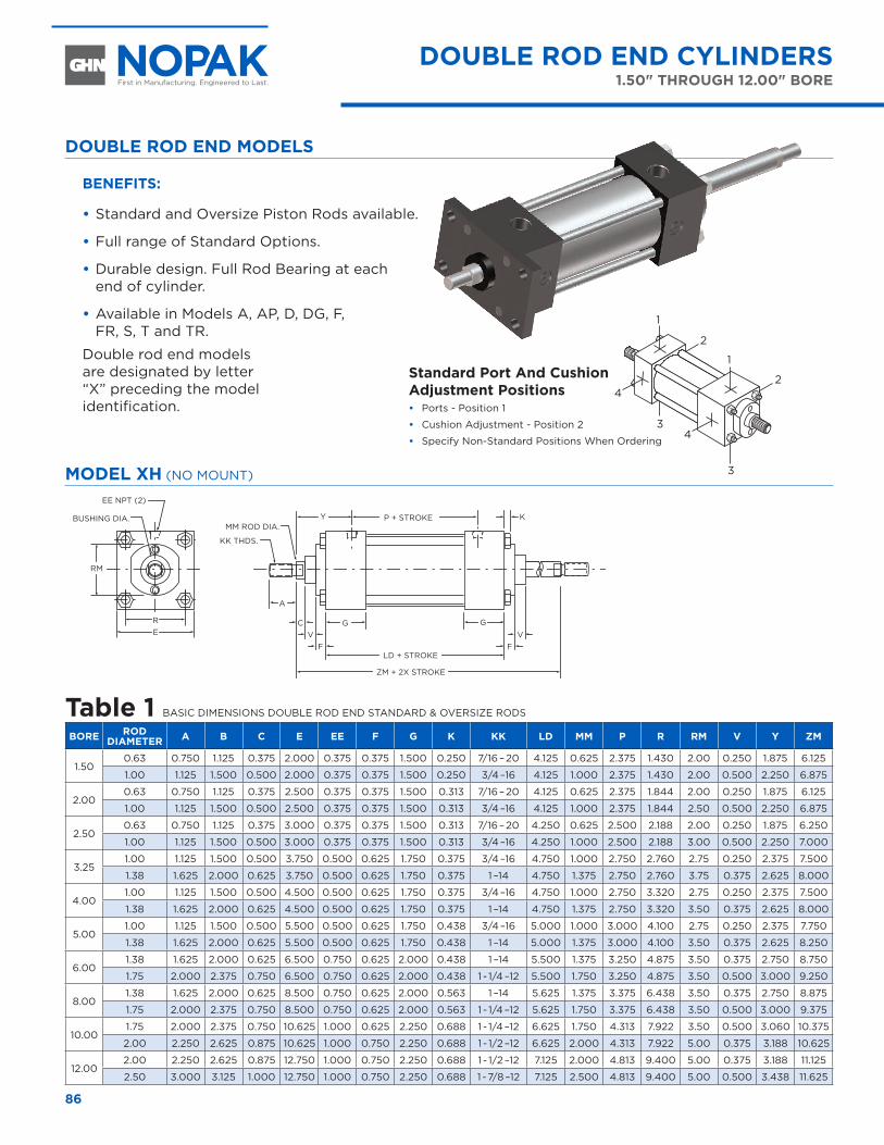
86
DOUBLE ROD END MODELS
BENEFITS:
•Standard and Oversize Piston Rods available.
•Full range of Standard Options.
•Durable design. Full Rod Bearing at each end of cylinder.
•Available in Models A, AP, D, DG, F, FR, S, T and TR.
Double rod end models are designated by letter “X” preceding the model identification.
MODEL XH (NO MOUNT)
YMM ROD DIA.
B BUSHING DIA.
EE NPT (2)
KK THDS.
P + STROKE
C GG
A
LD + STROKE
ZM + 2X STROKE
E R
RM
FV
F
K
V
Table 1 BASIC DIMENSIONS DOUBLE ROD END STANDARD & OVERSIZE RODS
BORE ROD DIAMETER A B C E EE F G K KK LD MM P R RM V Y ZM
1.500.63 0.750 1.125 0.375 2.000 0.375 0.375 1.500 0.250 7/16 – 20 4.125 0.625 2.375 1.430 2.00 0.250 1.875 6.125
1.00 1.125 1.500 0.500 2.000 0.375 0.375 1.500 0.250 3/4 –16 4.125 1.000 2.375 1.430 2.00 0.500 2.250 6.875
2.000.63 0.750 1.125 0.375 2.500 0.375 0.375 1.500 0.313 7/16 – 20 4.125 0.625 2.375 1.844 2.00 0.250 1.875 6.125
1.00 1.125 1.500 0.500 2.500 0.375 0.375 1.500 0.313 3/4 –16 4.125 1.000 2.375 1.844 2.50 0.500 2.250 6.875
2.500.63 0.750 1.125 0.375 3.000 0.375 0.375 1.500 0.313 7/16 – 20 4.250 0.625 2.500 2.188 2.00 0.250 1.875 6.250
1.00 1.125 1.500 0.500 3.000 0.375 0.375 1.500 0.313 3/4 –16 4.250 1.000 2.500 2.188 3.00 0.500 2.250 7.000
3.251.00 1.125 1.500 0.500 3.750 0.500 0.625 1.750 0.375 3/4 –16 4.750 1.000 2.750 2.760 2.75 0.250 2.375 7.500
1.38 1.625 2.000 0.625 3.750 0.500 0.625 1.750 0.375 1 –14 4.750 1.375 2.750 2.760 3.75 0.375 2.625 8.000
4.001.00 1.125 1.500 0.500 4.500 0.500 0.625 1.750 0.375 3/4 –16 4.750 1.000 2.750 3.320 2.75 0.250 2.375 7.500
1.38 1.625 2.000 0.625 4.500 0.500 0.625 1.750 0.375 1 –14 4.750 1.375 2.750 3.320 3.50 0.375 2.625 8.000
5.001.00 1.125 1.500 0.500 5.500 0.500 0.625 1.750 0.438 3/4 –16 5.000 1.000 3.000 4.100 2.75 0.250 2.375 7.750
1.38 1.625 2.000 0.625 5.500 0.500 0.625 1.750 0.438 1 –14 5.000 1.375 3.000 4.100 3.50 0.375 2.625 8.250
6.001.38 1.625 2.000 0.625 6.500 0.750 0.625 2.000 0.438 1 –14 5.500 1.375 3.250 4.875 3.50 0.375 2.750 8.750
1.75 2.000 2.375 0.750 6.500 0.750 0.625 2.000 0.438 1 - 1/4 –12 5.500 1.750 3.250 4.875 3.50 0.500 3.000 9.250
8.001.38 1.625 2.000 0.625 8.500 0.750 0.625 2.000 0.563 1 –14 5.625 1.375 3.375 6.438 3.50 0.375 2.750 8.875
1.75 2.000 2.375 0.750 8.500 0.750 0.625 2.000 0.563 1 - 1/4 –12 5.625 1.750 3.375 6.438 3.50 0.500 3.000 9.375
10.001.75 2.000 2.375 0.750 10.625 1.000 0.625 2.250 0.688 1 - 1/4 –12 6.625 1.750 4.313 7.922 3.50 0.500 3.060 10.375
2.00 2.250 2.625 0.875 10.625 1.000 0.750 2.250 0.688 1 - 1/2 –12 6.625 2.000 4.313 7.922 5.00 0.375 3.188 10.625
12.002.00 2.250 2.625 0.875 12.750 1.000 0.750 2.250 0.688 1 - 1/2 –12 7.125 2.000 4.813 9.400 5.00 0.375 3.188 11.125
2.50 3.000 3.125 1.000 12.750 1.000 0.750 2.250 0.688 1 - 7/8 –12 7.125 2.500 4.813 9.400 5.00 0.500 3.438 11.625
DOUBLE ROD END CYLINDERS1.50" THROUGH 12.00" BORE
DOUBLE ROD END CYLINDERS 1.50" THROUGH 12.00" BORE
1
2
1
2
3
43
4
Standard Port And Cushion Adjustment Positions• Ports - Position 1
• Cushion Adjustment - Position 2
• Specify Non-Standard Positions When Ordering
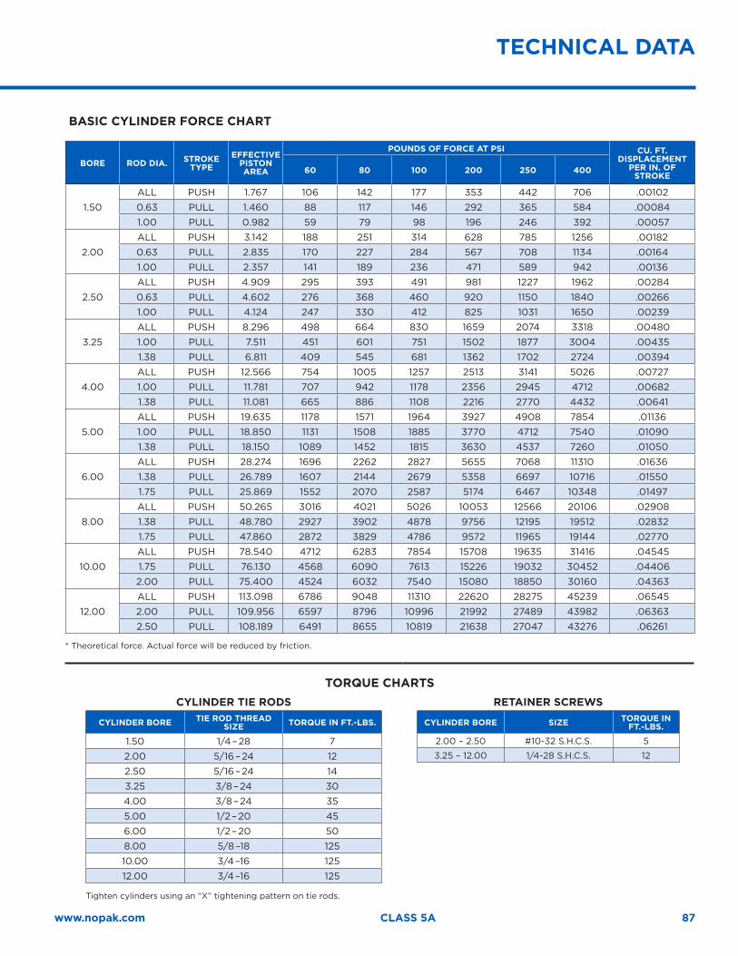
87www.nopak.com CLASS 5A
BASIC CYLINDER FORCE CHART
BORE ROD DIA. STROKE TYPE
EFFECTIVE PISTON AREA
POUNDS OF FORCE AT PSI CU. FT. DISPLACEMENT
PER IN. OF STROKE
60 80 100 200 250 400
1.50
ALL PUSH 1.767 106 142 177 353 442 706 .00102
0.63 PULL 1.460 88 117 146 292 365 584 .00084
1.00 PULL 0.982 59 79 98 196 246 392 .00057
2.00
ALL PUSH 3.142 188 251 314 628 785 1256 .00182
0.63 PULL 2.835 170 227 284 567 708 1134 .00164
1.00 PULL 2.357 141 189 236 471 589 942 .00136
2.50
ALL PUSH 4.909 295 393 491 981 1227 1962 .00284
0.63 PULL 4.602 276 368 460 920 1150 1840 .00266
1.00 PULL 4.124 247 330 412 825 1031 1650 .00239
3.25
ALL PUSH 8.296 498 664 830 1659 2074 3318 .00480
1.00 PULL 7.511 451 601 751 1502 1877 3004 .00435
1.38 PULL 6.811 409 545 681 1362 1702 2724 .00394
4.00
ALL PUSH 12.566 754 1005 1257 2513 3141 5026 .00727
1.00 PULL 11.781 707 942 1178 2356 2945 4712 .00682
1.38 PULL 11.081 665 886 1108 2216 2770 4432 .00641
5.00
ALL PUSH 19.635 1178 1571 1964 3927 4908 7854 .01136
1.00 PULL 18.850 1131 1508 1885 3770 4712 7540 .01090
1.38 PULL 18.150 1089 1452 1815 3630 4537 7260 .01050
6.00
ALL PUSH 28.274 1696 2262 2827 5655 7068 11310 .01636
1.38 PULL 26.789 1607 2144 2679 5358 6697 10716 .01550
1.75 PULL 25.869 1552 2070 2587 5174 6467 10348 .01497
8.00
ALL PUSH 50.265 3016 4021 5026 10053 12566 20106 .02908
1.38 PULL 48.780 2927 3902 4878 9756 12195 19512 .02832
1.75 PULL 47.860 2872 3829 4786 9572 11965 19144 .02770
10.00
ALL PUSH 78.540 4712 6283 7854 15708 19635 31416 .04545
1.75 PULL 76.130 4568 6090 7613 15226 19032 30452 .04406
2.00 PULL 75.400 4524 6032 7540 15080 18850 30160 .04363
12.00
ALL PUSH 113.098 6786 9048 11310 22620 28275 45239 .06545
2.00 PULL 109.956 6597 8796 10996 21992 27489 43982 .06363
2.50 PULL 108.189 6491 8655 10819 21638 27047 43276 .06261
* Theoretical force. Actual force will be reduced by friction.
TORQUE CHARTSCYLINDER TIE RODS RETAINER SCREWS
CYLINDER BORE TIE ROD THREAD SIZE TORQUE IN FT.-LBS.
1.50 1/4 – 28 7
2.00 5/16 – 24 12
2.50 5/16 – 24 14
3.25 3/8 – 24 30
4.00 3/8 – 24 35
5.00 1/2 – 20 45
6.00 1/2 – 20 50
8.00 5/8 –18 125
10.00 3/4 –16 125
12.00 3/4 –16 125
Tighten cylinders using an “X” tightening pattern on tie rods.
CYLINDER BORE SIZE TORQUE IN FT.-LBS.
2.00 – 2.50 #10-32 S.H.C.S. 5
3.25 – 12.00 1/4-28 S.H.C.S. 12
TECHNICAL DATA
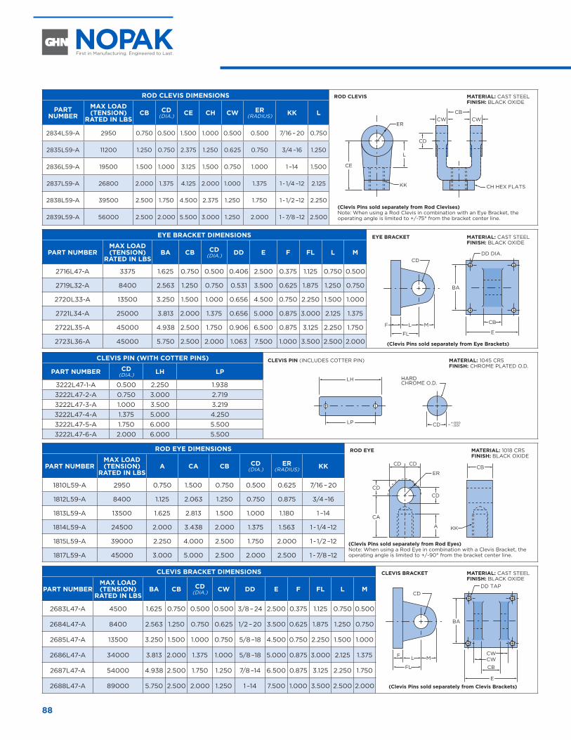
88
ROD CLEVIS DIMENSIONS
CBCW CW
CB
EFL
LF M
CE
BAL
ER
KK
KK
CH HEX FLATS
CD
CD
FL
E
LF M
CD
DD DIA.
CBCWCW
BA
CA
CDCD
ERCB
CD CD
A
DD TAP
PART NUMBER
MAX LOAD (TENSION)
RATED IN LBS CB CD
(DIA.) CE CH CW ER (RADIUS) KK L
2834L59-A 2950 0.750 0.500 1.500 1.000 0.500 0.500 7/16 – 20 0.750
2835L59-A 11200 1.250 0.750 2.375 1.250 0.625 0.750 3/4 –16 1.250
2836L59-A 19500 1.500 1.000 3.125 1.500 0.750 1.000 1 –14 1.500
2837L59-A 26800 2.000 1.375 4.125 2.000 1.000 1.375 1 - 1/4 –12 2.125
2838L59-A 39500 2.500 1.750 4.500 2.375 1.250 1.750 1 - 1/2 –12 2.250
2839L59-A 56000 2.500 2.000 5.500 3.000 1.250 2.000 1 - 7/8 –12 2.500
EYE BRACKET DIMENSIONSCB
CW CW
CB
EFL
LF M
CE
BAL
ER
KK
KK
CH HEX FLATS
CD
CD
FL
E
LF M
CD
DD DIA.
CBCWCW
BA
CA
CDCD
ERCB
CD CD
A
DD TAP
PART NUMBERMAX LOAD (TENSION)
RATED IN LBS BA CB CD
(DIA.) DD E F FL L M
2716L47-A 3375 1.625 0.750 0.500 0.406 2.500 0.375 1.125 0.750 0.500
2719L32-A 8400 2.563 1.250 0.750 0.531 3.500 0.625 1.875 1.250 0.750
2720L33-A 13500 3.250 1.500 1.000 0.656 4.500 0.750 2.250 1.500 1.000
2721L34-A 25000 3.813 2.000 1.375 0.656 5.000 0.875 3.000 2.125 1.375
2722L35-A 45000 4.938 2.500 1.750 0.906 6.500 0.875 3.125 2.250 1.750
2723L36-A 45000 5.750 2.500 2.000 1.063 7.500 1.000 3.500 2.500 2.000
CLEVIS PIN (WITH COTTER PINS)
–
LH
CD H
LP
HP+.000 .002
LH
LP
HARDCHROME O.D.
CD +.000– –.001
LH
LP
HPCD
LH
LP CD+.000– .001
LH
CE
CW
CW
CB
CHSQ.
CDL
KK
PART NUMBER CD (DIA.) LH LP
3222L47-1-A 0.500 2.250 1.9383222L47-2-A 0.750 3.000 2.7193222L47-3-A 1.000 3.500 3.2193222L47-4-A 1.375 5.000 4.2503222L47-5-A 1.750 6.000 5.5003222L47-6-A 2.000 6.000 5.500
ROD EYE DIMENSIONS
CBCW CW
CB
EFL
LF M
CE
BAL
ER
KK
KK
CH HEX FLATS
CD
CD
FL
E
LF M
CD
DD DIA.
CBCWCW
BA
CA
CDCD
ERCB
CD CD
A
DD TAPPART NUMBERMAX LOAD (TENSION)
RATED IN LBS A CA CB CD
(DIA.)ER
(RADIUS) KK
1810L59-A 2950 0.750 1.500 0.750 0.500 0.625 7/16 – 20
1812L59-A 8400 1.125 2.063 1.250 0.750 0.875 3/4 –16
1813L59-A 13500 1.625 2.813 1.500 1.000 1.180 1 –14
1814L59-A 24500 2.000 3.438 2.000 1.375 1.563 1 - 1/4 –12
1815L59-A 39000 2.250 4.000 2.500 1.750 2.000 1 - 1/2 –12
1817L59-A 45000 3.000 5.000 2.500 2.000 2.500 1 - 7/8 –12
CLEVIS BRACKET DIMENSIONS
CBCW CW
CB
EFL
LF M
CE
BAL
ER
KK
KK
CH HEX FLATS
CD
CD
FL
E
LF M
CD
DD DIA.
CBCWCW
BA
CA
CDCD
ERCB
CD CD
A
DD TAPPART NUMBERMAX LOAD (TENSION)
RATED IN LBS BA CB CD
(DIA.) CW DD E F FL L M
2683L47-A 4500 1.625 0.750 0.500 0.500 3/8 – 24 2.500 0.375 1.125 0.750 0.500
2684L47-A 8400 2.563 1.250 0.750 0.625 1/2 – 20 3.500 0.625 1.875 1.250 0.750
2685L47-A 13500 3.250 1.500 1.000 0.750 5/8 –18 4.500 0.750 2.250 1.500 1.000
2686L47-A 34000 3.813 2.000 1.375 1.000 5/8 –18 5.000 0.875 3.000 2.125 1.375
2687L47-A 54000 4.938 2.500 1.750 1.250 7/8 –14 6.500 0.875 3.125 2.250 1.750
2688L47-A 89000 5.750 2.500 2.000 1.250 1 –14 7.500 1.000 3.500 2.500 2.000
MATERIAL: 1045 CRSFINISH: CHROME PLATED O.D.
MATERIAL: CAST STEELFINISH: BLACK OXIDE
MATERIAL: CAST STEELFINISH: BLACK OXIDE
MATERIAL: CAST STEELFINISH: BLACK OXIDE
MATERIAL: 1018 CRSFINISH: BLACK OXIDE
CLEVIS PIN (INCLUDES COTTER PIN)
ROD CLEVIS
(Clevis Pins sold separately from Rod Clevises)Note: When using a Rod Clevis in combination with an Eye Bracket, the operating angle is limited to +/-75° from the bracket center line.
(Clevis Pins sold separately from Rod Eyes)Note: When using a Rod Eye in combination with a Clevis Bracket, the operating angle is limited to +/-90° from the bracket center line.
(Clevis Pins sold separately from Clevis Brackets)
(Clevis Pins sold separately from Eye Brackets)
ROD EYE
CLEVIS BRACKET
EYE BRACKET
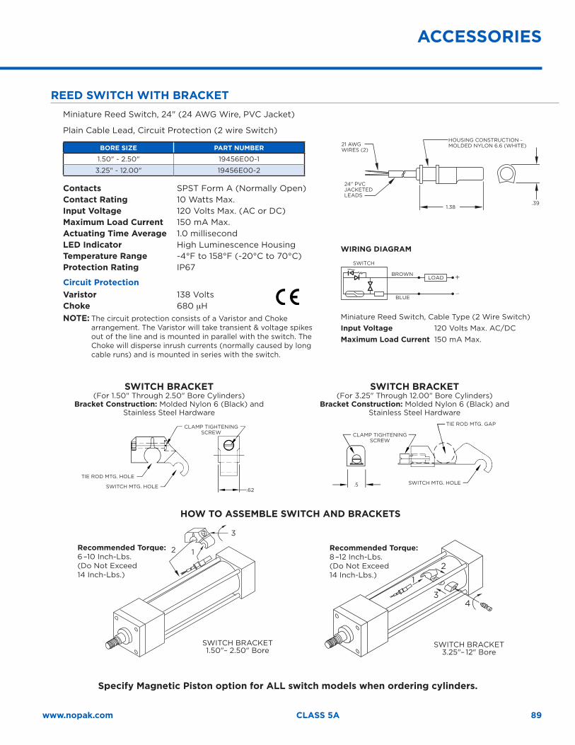
89www.nopak.com CLASS 5A
ACCESSORIES
REED SWITCH WITH BRACKETMiniature Reed Switch, 24" (24 AWG Wire, PVC Jacket)
Plain Cable Lead, Circuit Protection (2 wire Switch)
BORE SIZE PART NUMBER
1.50" - 2.50" 19456E00-1
3.25" - 12.00" 19456E00-2
Contacts SPST Form A (Normally Open)Contact Rating 10 Watts Max.Input Voltage 120 Volts Max. (AC or DC)Maximum Load Current 150 mA Max. Actuating Time Average 1.0 millisecondLED Indicator High Luminescence HousingTemperature Range -4°F to 158°F (-20°C to 70°C)Protection Rating IP67
Circuit ProtectionVaristor 138 VoltsChoke 680 µHNOTE: The circuit protection consists of a Varistor and Choke
arrangement. The Varistor will take transient & voltage spikes out of the line and is mounted in parallel with the switch. The Choke will disperse inrush currents (normally caused by long cable runs) and is mounted in series with the switch.
SWITCH BRACKET(For 1.50" Through 2.50" Bore Cylinders)
Bracket Construction: Molded Nylon 6 (Black) and Stainless Steel Hardware
SWITCH BRACKET (For 3.25" Through 12.00" Bore Cylinders)
Bracket Construction: Molded Nylon 6 (Black) and Stainless Steel Hardware
CLAMP TIGHTENING SCREW
TIE ROD MTG. HOLE
SWITCH MTG. HOLE.62
CLAMP TIGHTENING SCREW
TIE ROD MTG. GAP
SWITCH MTG. HOLE.5
HOW TO ASSEMBLE SWITCH AND BRACKETS
12
3
Recommended Torque:6 –10 Inch-Lbs.(Do Not Exceed14 Inch-Lbs.)
1
2
34
Recommended Torque:8 –12 Inch-Lbs.(Do Not Exceed14 Inch-Lbs.)
WIRING DIAGRAM
BROWN
SWITCH
BLUE
LOAD
Miniature Reed Switch, Cable Type (2 Wire Switch)Input Voltage 120 Volts Max. AC/DCMaximum Load Current 150 mA Max.
21 AWG WIRES (2)
HOUSING CONSTRUCTION - MOLDED NYLON 6.6 (WHITE)
24" PVC JACKETED LEADS
1.38.39
Specify Magnetic Piston option for ALL switch models when ordering cylinders.
SWITCH BRACKET 3.25"– 12" Bore
SWITCH BRACKET 1.50"– 2.50" Bore
ACCESSORIES
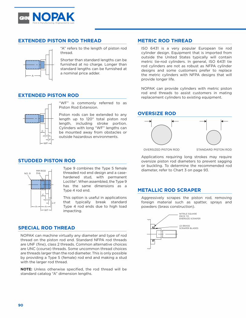
90
EXTENDED PISTON ROD THREAD
A
“A” refers to the length of piston rod thread.
Shorter than standard lengths can be furnished at no charge. Longer than standard lengths can be furnished at a nominal price adder.
METRIC ROD THREADISO 6431 is a very popular European tie rod cylinder design. Equipment that is imported from outside the United States typically will contain metric tie-rod cylinders. In general, ISO 6431 tie rod cylinders are not as robust as NFPA cylinder designs and some customers prefer to replace the metric cylinders with NFPA designs that will provide longer life.
NOPAK can provide cylinders with metric piston rod end threads to assist customers in mating replacement cylinders to existing equipment. EXTENDED PISTON ROD
C
V
FWF
“WF” is commonly referred to as Piston Rod Extension.
Piston rods can be extended to any length up to 120" total piston rod length, including stroke portion. Cylinders with long “WF” lengths can be mounted away from obstacles or outside hazardous environments.
OVERSIZE ROD
Applications requiring long strokes may require oversize piston rod diameters to prevent sagging or buckling. To determine the recommended rod diameter, refer to Chart 3 on page 93.
STUDDED PISTON ROD
C
VF
WF
AA
NO. 9MM RODDIA.
Type 9 combines the Type 5 female threaded rod end design and a case-hardened stud, with permanent Loctite®. When assembled, the Type 9 has the same dimensions as a Type 4 rod end.
This option is useful in applications that typically break standard Type 4 rod ends due to high load impacting.
METALLIC ROD SCRAPERAggressively scrapes the piston rod, removing foreign material such as spatter, sprays and powders (brass construction).
SPECIAL ROD THREADNOPAK can machine virtually any diameter and type of rod thread on the piston rod end. Standard NFPA rod threads are UNF (fine), class 2 threads. Common alternative choices are UNC (course) threads. Some uncommon thread choices are threads larger than the rod diameter. This is only possible by providing a Type 5 (female) rod end and making a stud with the larger rod thread.
NOTE: Unless otherwise specified, the rod thread will be standard catalog “A” dimension lengths.
OPTIONS AND MODIFICATIONS
OVERSIZED PISTON ROD
NITRILE SQUARE PIECE TO ENERGIZE SCRAPER
(2) BRASS SCRAPER BLADES
STANDARD PISTON ROD
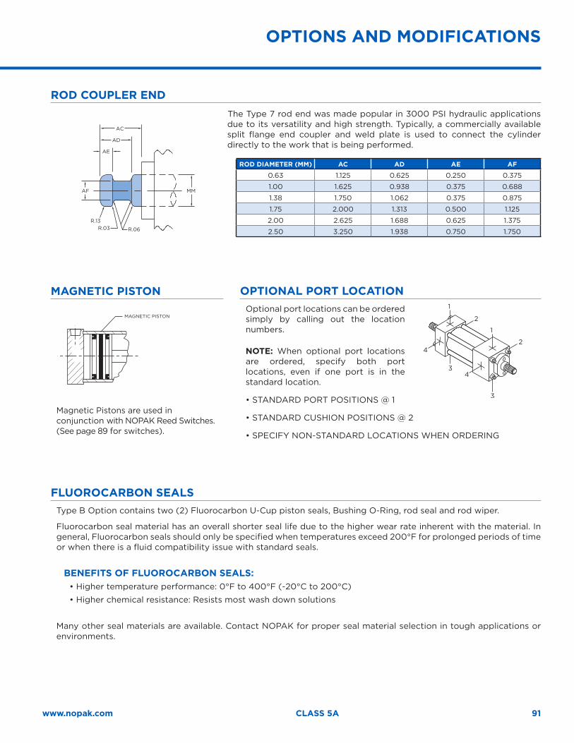
91www.nopak.com CLASS 5A
ROD COUPLER END
AC
AD
AF
R.13R.03 R.06
MM
AE
The Type 7 rod end was made popular in 3000 PSI hydraulic applications due to its versatility and high strength. Typically, a commercially available split flange end coupler and weld plate is used to connect the cylinder directly to the work that is being performed.
ROD DIAMETER (MM) AC AD AE AF
0.63 1.125 0.625 0.250 0.375
1.00 1.625 0.938 0.375 0.688
1.38 1.750 1.062 0.375 0.875
1.75 2.000 1.313 0.500 1.125
2.00 2.625 1.688 0.625 1.375
2.50 3.250 1.938 0.750 1.750
MAGNETIC PISTON
Magnetic Pistons are used in conjunction with NOPAK Reed Switches. (See page 89 for switches).
OPTIONAL PORT LOCATIONOptional port locations can be ordered simply by calling out the location numbers.
NOTE: When optional port locations are ordered, specify both port locations, even if one port is in the standard location.
• STANDARD PORT POSITIONS @ 1
• STANDARD CUSHION POSITIONS @ 2
• SPECIFY NON-STANDARD LOCATIONS WHEN ORDERING
1
2
1
2
3
43
4
OPTIONS AND MODIFICATIONS
FLUOROCARBON SEALSType B Option contains two (2) Fluorocarbon U-Cup piston seals, Bushing O-Ring, rod seal and rod wiper.
Fluorocarbon seal material has an overall shorter seal life due to the higher wear rate inherent with the material. In general, Fluorocarbon seals should only be specified when temperatures exceed 200°F for prolonged periods of time or when there is a fluid compatibility issue with standard seals.
BENEFITS OF FLUOROCARBON SEALS:• Higher temperature performance: 0°F to 400°F (-20°C to 200°C)
• Higher chemical resistance: Resists most wash down solutions
Many other seal materials are available. Contact NOPAK for proper seal material selection in tough applications or environments.
MAGNETIC PISTON
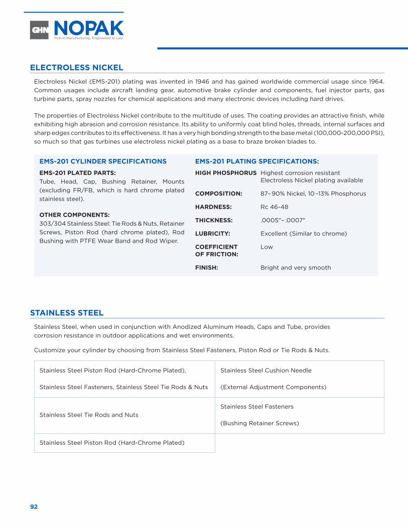
92
ELECTROLESS NICKEL
Electroless Nickel (EMS-201) plating was invented in 1946 and has gained worldwide commercial usage since 1964. Common usages include aircraft landing gear, automotive brake cylinder and components, fuel injector parts, gas turbine parts, spray nozzles for chemical applications and many electronic devices including hard drives.
The properties of Electroless Nickel contribute to the multitude of uses. The coating provides an attractive finish, while exhibiting high abrasion and corrosion resistance. Its ability to uniformly coat blind holes, threads, internal surfaces and sharp edges contributes to its effectiveness. It has a very high bonding strength to the base metal (100,000-200,000 PSI), so much so that gas turbines use electroless nickel plating as a base to braze broken blades to.
EMS-201 CYLINDER SPECIFICATIONS
EMS-201 PLATED PARTS:Tube, Head, Cap, Bushing Retainer, Mounts (excluding FR/FB, which is hard chrome plated stainless steel).
OTHER COMPONENTS:303/304 Stainless Steel: Tie Rods & Nuts, Retainer Screws, Piston Rod (hard chrome plated), Rod Bushing with PTFE Wear Band and Rod Wiper.
EMS-201 PLATING SPECIFICATIONS:
HIGH PHOSPHORUS Highest corrosion resistant Electroless Nickel plating available
COMPOSITION: 87– 90% Nickel, 10 –13% Phosphorus
HARDNESS: Rc 46-48
THICKNESS: .0005"– .0007"
LUBRICITY: Excellent (Similar to chrome)
COEFFICIENT Low OF FRICTION:
FINISH: Bright and very smooth
STAINLESS STEEL
Stainless Steel, when used in conjunction with Anodized Aluminum Heads, Caps and Tube, provides corrosion resistance in outdoor applications and wet environments.
Customize your cylinder by choosing from Stainless Steel Fasteners, Piston Rod or Tie Rods & Nuts.
Stainless Steel Piston Rod (Hard-Chrome Plated),
Stainless Steel Fasteners, Stainless Steel Tie Rods & Nuts
Stainless Steel Cushion Needle
(External Adjustment Components)
Stainless Steel Tie Rods and NutsStainless Steel Fasteners
(Bushing Retainer Screws)
Stainless Steel Piston Rod (Hard-Chrome Plated)
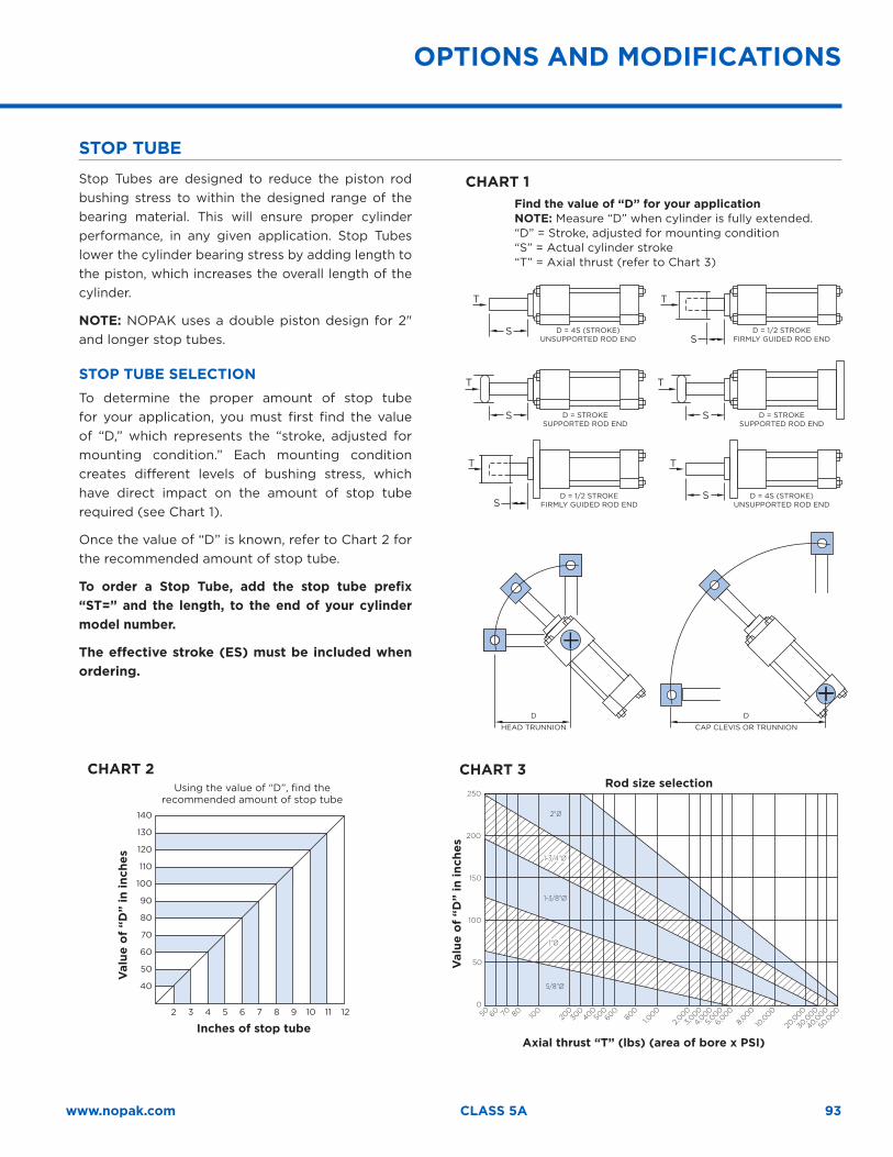
93www.nopak.com CLASS 5A
STOP TUBE
Stop Tubes are designed to reduce the piston rod bushing stress to within the designed range of the bearing material. This will ensure proper cylinder performance, in any given application. Stop Tubes lower the cylinder bearing stress by adding length to the piston, which increases the overall length of the cylinder.
NOTE: NOPAK uses a double piston design for 2" and longer stop tubes.
STOP TUBE SELECTIONTo determine the proper amount of stop tube for your application, you must first find the value of “D,” which represents the “stroke, adjusted for mounting condition.” Each mounting condition creates different levels of bushing stress, which have direct impact on the amount of stop tube required (see Chart 1).
Once the value of “D” is known, refer to Chart 2 for the recommended amount of stop tube.
To order a Stop Tube, add the stop tube prefix “ST=” and the length, to the end of your cylinder model number.
The effective stroke (ES) must be included when ordering.
OPTIONS AND MODIFICATIONS
S
T T
S
T
S
T
S
T
S
S
T
CHART 1Find the value of “D” for your applicationNOTE: Measure “D” when cylinder is fully extended.“D” = Stroke, adjusted for mounting condition“S” = Actual cylinder stroke“T” = Axial thrust (refer to Chart 3)
140
130
120
110
100
90
80
70
60
50
40
2 3 4 5 6 7 8 9 10 11 12
CHART 2
Inches of stop tube
Using the value of “D”, find the recommended amount of stop tube
Val
ue o
f “D
” in
inch
es
250
200
150
100
50
050 60 70 80 10
020
030
0400
500
800
1,000
3,000
2,000
4,000
5,000
6,000
8,000
10,0
00
20,0
00
30,0
00
40,000
50,0
00600
2"∅
1-3/4"∅1-3/4"∅
1-3/8"∅
1"∅1"∅
5/8"∅
CHART 3
Axial thrust “T” (lbs) (area of bore x PSI)
Rod size selection
Val
ue o
f “D
” in
inch
es
CAP CLEVIS OR TRUNNIONHEAD TRUNNION
D = 1/2 STROKEFIRMLY GUIDED ROD END
D = 1/2 STROKEFIRMLY GUIDED ROD END
D = STROKESUPPORTED ROD END
D = 4S (STROKE)UNSUPPORTED ROD END
D = 4S (STROKE)UNSUPPORTED ROD END
D = STROKESUPPORTED ROD END
DD

94
Class 6Intermediate Pressure Square-Head Cylinders
CL
AS
S 6
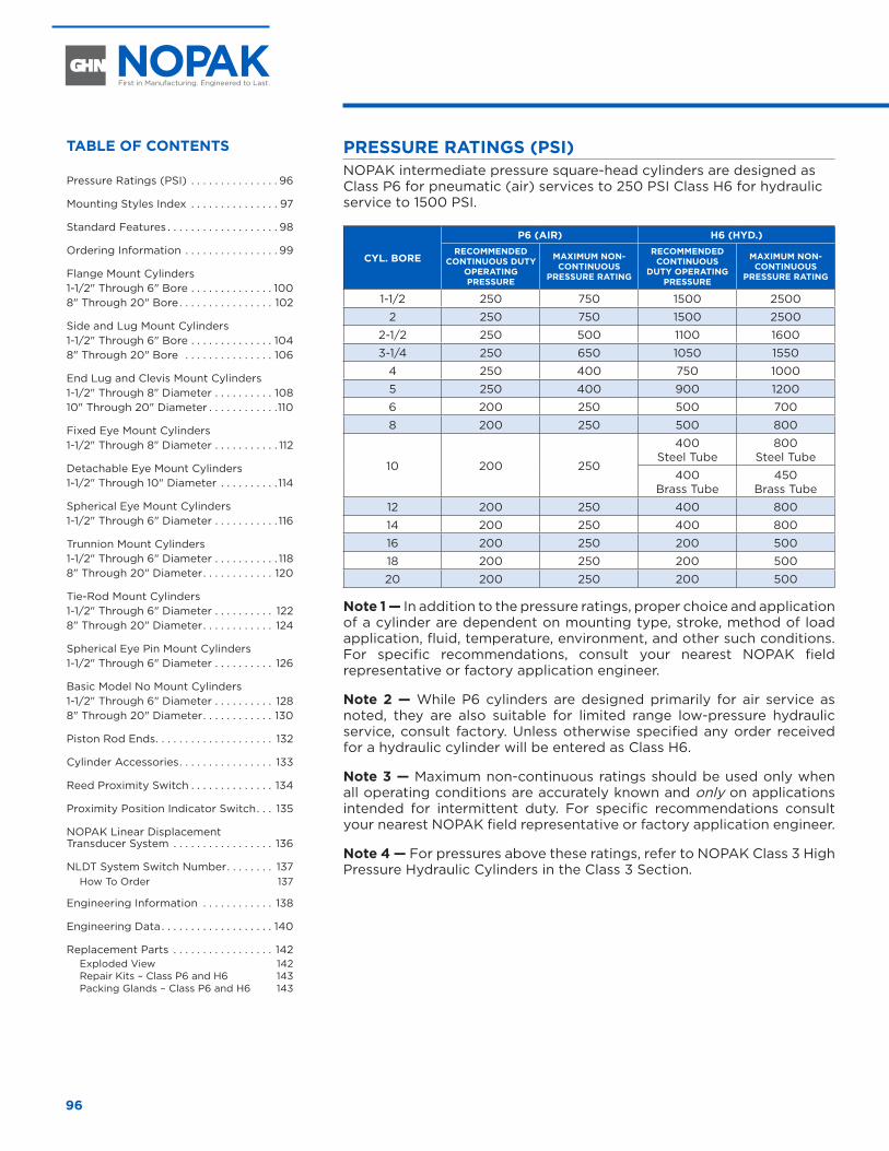
96
PRESSURE RATINGS (PSI)NOPAK intermediate pressure square-head cylinders are designed as Class P6 for pneumatic (air) services to 250 PSI Class H6 for hydraulic service to 1500 PSI.
CYL. BORE
P6 (AIR) H6 (HYD.)RECOMMENDED
CONTINUOUS DUTY OPERATING PRESSURE
MAXIMUM NON-CONTINUOUS
PRESSURE RATING
RECOMMENDED CONTINUOUS
DUTY OPERATING PRESSURE
MAXIMUM NON-CONTINUOUS
PRESSURE RATING
1-1/2 250 750 1500 2500
2 250 750 1500 2500
2-1/2 250 500 1100 1600
3-1/4 250 650 1050 1550
4 250 400 750 1000
5 250 400 900 1200
6 200 250 500 700
8 200 250 500 800
10 200 250
400Steel Tube
800Steel Tube
400Brass Tube
450Brass Tube
12 200 250 400 800
14 200 250 400 800
16 200 250 200 500
18 200 250 200 500
20 200 250 200 500
Note 1 — In addition to the pressure ratings, proper choice and application of a cylinder are dependent on mounting type, stroke, method of load application, fluid, temperature, environment, and other such conditions. For specific recommendations, consult your nearest NOPAK field representative or factory application engineer.
Note 2 — While P6 cylinders are designed primarily for air service as noted, they are also suitable for limited range low-pressure hydraulic service, consult factory. Unless otherwise specified any order received for a hydraulic cylinder will be entered as Class H6.
Note 3 — Maximum non-continuous ratings should be used only when all operating conditions are accurately known and only on applications intended for intermittent duty. For specific recommendations consult your nearest NOPAK field representative or factory application engineer.
Note 4 — For pressures above these ratings, refer to NOPAK Class 3 High Pressure Hydraulic Cylinders in the Class 3 Section.
TABLE OF CONTENTS
Pressure Ratings (PSI) . . . . . . . . . . . . . . . 96
Mounting Styles Index . . . . . . . . . . . . . . . 97
Standard Features . . . . . . . . . . . . . . . . . . . 98
Ordering Information . . . . . . . . . . . . . . . . 99
Flange Mount Cylinders 1-1/2" Through 6" Bore . . . . . . . . . . . . . . 1008" Through 20" Bore . . . . . . . . . . . . . . . . 102
Side and Lug Mount Cylinders 1-1/2" Through 6" Bore . . . . . . . . . . . . . . 1048" Through 20" Bore . . . . . . . . . . . . . . . 106
End Lug and Clevis Mount Cylinders 1-1/2" Through 8" Diameter . . . . . . . . . . 10810" Through 20" Diameter . . . . . . . . . . . .110
Fixed Eye Mount Cylinders 1-1/2" Through 8" Diameter . . . . . . . . . . . 112
Detachable Eye Mount Cylinders 1-1/2" Through 10" Diameter . . . . . . . . . . 114
Spherical Eye Mount Cylinders 1-1/2" Through 6" Diameter . . . . . . . . . . . 116
Trunnion Mount Cylinders 1-1/2" Through 6" Diameter . . . . . . . . . . . 1188" Through 20" Diameter . . . . . . . . . . . . 120
Tie-Rod Mount Cylinders 1-1/2" Through 6" Diameter . . . . . . . . . . 1228" Through 20" Diameter . . . . . . . . . . . . 124
Spherical Eye Pin Mount Cylinders 1-1/2" Through 6" Diameter . . . . . . . . . . 126
Basic Model No Mount Cylinders 1-1/2" Through 6" Diameter . . . . . . . . . . 1288" Through 20" Diameter . . . . . . . . . . . . 130
Piston Rod Ends . . . . . . . . . . . . . . . . . . . . 132
Cylinder Accessories . . . . . . . . . . . . . . . . 133
Reed Proximity Switch . . . . . . . . . . . . . . 134
Proximity Position Indicator Switch . . . 135
NOPAK Linear Displacement Transducer System . . . . . . . . . . . . . . . . . 136
NLDT System Switch Number . . . . . . . . 137How To Order 137
Engineering Information . . . . . . . . . . . . 138
Engineering Data . . . . . . . . . . . . . . . . . . . 140
Replacement Parts . . . . . . . . . . . . . . . . . 142Exploded View 142Repair Kits – Class P6 and H6 143Packing Glands – Class P6 and H6 143
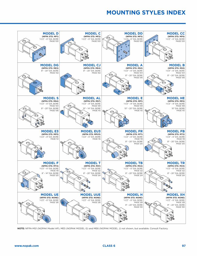
97www.nopak.com CLASS 6
MOUNTING STYLES INDEX
MODEL D(NFPA STD. MF1)
1-1/2" – 6" DIA. BORE PAGE 100
MODEL C(NFPA STD. MF2)
1-1/2" – 6" DIA. BORE PAGE 100
MODEL DD(NFPA STD. MF5)
1-1/2" – 6" DIA. BORE PAGE 100
MODEL CC(NFPA STD. MF6)
1-1/2" – 6" DIA. BORE PAGE 100
MODEL DG(NFPA STD. ME3) 8" – 20" DIA. BORE
PAGE 102
MODEL CJ(NFPA STD. ME4) 8" – 20" DIA. BORE
PAGE 102
MODEL A(NFPA STD. MS2)
1-1/2" – 6" DIA. BORE PAGE 104
8" – 20" DIA. BORE PAGE 106
MODEL B(NFPA STD. MS3)
1-1/2" – 6" DIA. BORE PAGE 104
8" – 20" DIA. BORE PAGE 106
MODEL S(NFPA STD. MS4)
1-1/2" – 6" DIA. BORE PAGE 104
8" – 20" DIA. BORE PAGE 106
MODEL AL(NFPA STD. MS7)
1-1/2" – 8" DIA. BORE PAGE 108
10" – 14" DIA. BORE PAGE 110
MODEL E(NFPA STD. MP1)
1-1/2" – 8" DIA. BORE PAGE 108
10" – 20" DIA. BORE PAGE 110
MODEL HE(NFPA STD. MP2)
1-1/2" – 8" DIA. BORE PAGE 108
10" DIA. BORE PAGE 110
MODEL E3(NFPA STD. MP3)
1-1/2" – 8" DIA. BORE PAGE 112
MODEL EU3(NFPA STD. MPU3)1-1/2" – 6" DIA. BORE
PAGE 116
MODEL FR(NFPA STD. MT1)
1-1/2" – 6" DIA. BORE PAGE 118
8" – 20" DIA. BORE PAGE 120
MODEL FB(NFPA STD. MT2)
1-1/2" – 6" DIA. BORE PAGE 118
8" – 20" DIA. BORE PAGE 120
MODEL F(NFPA STD. MT4)
1-1/2" – 6" DIA. BORE PAGE 118
8" – 14" DIA. BORE PAGE 120
MODEL T(NFPA STD. MX1)
1-1/2" – 6" DIA. BORE PAGE 122
8" – 20" DIA. BORE PAGE 124
MODEL TB(NFPA STD. MX2)
1-1/2" – 6" DIA. BORE PAGE 122
8" – 20" DIA. BORE PAGE 124
MODEL TR(NFPA STD. MX3)
1-1/2" – 6" DIA. BORE PAGE 122
8" – 20" DIA. BORE PAGE 124
MODEL UE(NFPA STD. NONE)1-1/2" – 6" DIA. BORE
PAGE 126
MODEL UUE(NFPA STD. NONE)1-1/2" – 6" DIA. BORE
PAGE 126
MODEL H(NFPA STD. NONE)1-1/2" – 6" DIA. BORE
PAGE 1288" – 20" DIA. BORE
PAGE 130
MODEL XH(NFPA STD. NONE)1-1/2" – 6" DIA. BORE
PAGE 1288" – 20" DIA. BORE
PAGE 130
NOTE: NFPA-MS1 (NOPAK Model AP), ME5 (NOPAK MODEL G) and ME6 (NOPAK MODEL J) not shown, but available. Consult Factory.
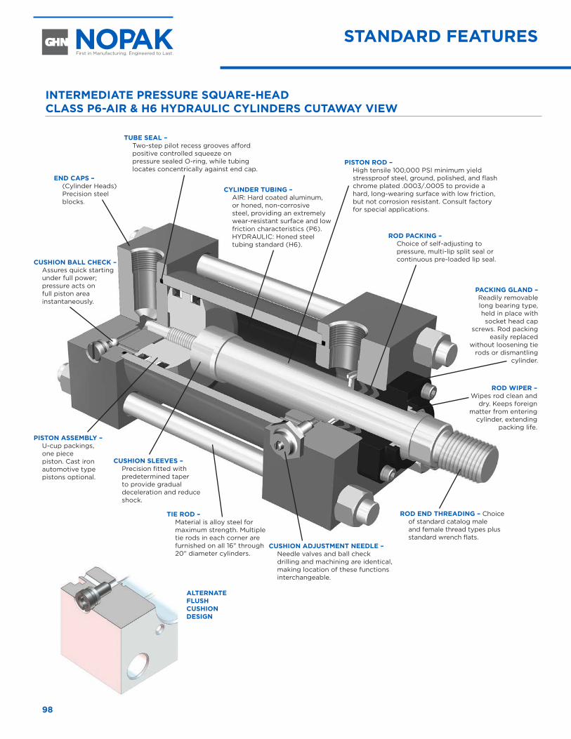
98
INTERMEDIATE PRESSURE SQUARE-HEAD CLASS P6-AIR & H6 HYDRAULIC CYLINDERS CUTAWAY VIEW
ROD END THREADING – Choice of standard catalog male and female thread types plus standard wrench flats.
CUSHION BALL CHECK – Assures quick starting under full power; pressure acts on full piston area instantaneously.
TIE ROD – Material is alloy steel for maximum strength. Multiple tie rods in each corner are furnished on all 16" through 20" diameter cylinders.
ALTERNATE FLUSH CUSHION DESIGN
PISTON ROD – High tensile 100,000 PSI minimum yield stressproof steel, ground, polished, and flash chrome plated .0003/.0005 to provide a hard, long-wearing surface with low friction, but not corrosion resistant. Consult factory for special applications.
CUSHION ADJUSTMENT NEEDLE – Needle valves and ball check drilling and machining are identical, making location of these functions interchangeable.
PISTON ASSEMBLY – U-cup packings, one piece piston. Cast iron automotive type pistons optional.
PACKING GLAND – Readily removable long bearing type, held in place with socket head cap
screws. Rod packing easily replaced
without loosening tie rods or dismantling
cylinder.
ROD WIPER – Wipes rod clean and
dry. Keeps foreign matter from entering
cylinder, extending packing life.
TUBE SEAL – Two-step pilot recess grooves afford positive controlled squeeze on pressure sealed O-ring, while tubing locates concentrically against end cap.
ROD PACKING – Choice of self-adjusting to pressure, multi-lip split seal or continuous pre-loaded lip seal.
CYLINDER TUBING – AIR: Hard coated aluminum, or honed, non-corrosive steel, providing an extremely wear-resistant surface and low friction characteristics (P6). HYDRAULIC: Honed steel tubing standard (H6).
CUSHION SLEEVES – Precision fitted with predetermined taper to provide gradual deceleration and reduce shock.
END CAPS – (Cylinder Heads) Precision steel blocks.
STANDARD FEATURES
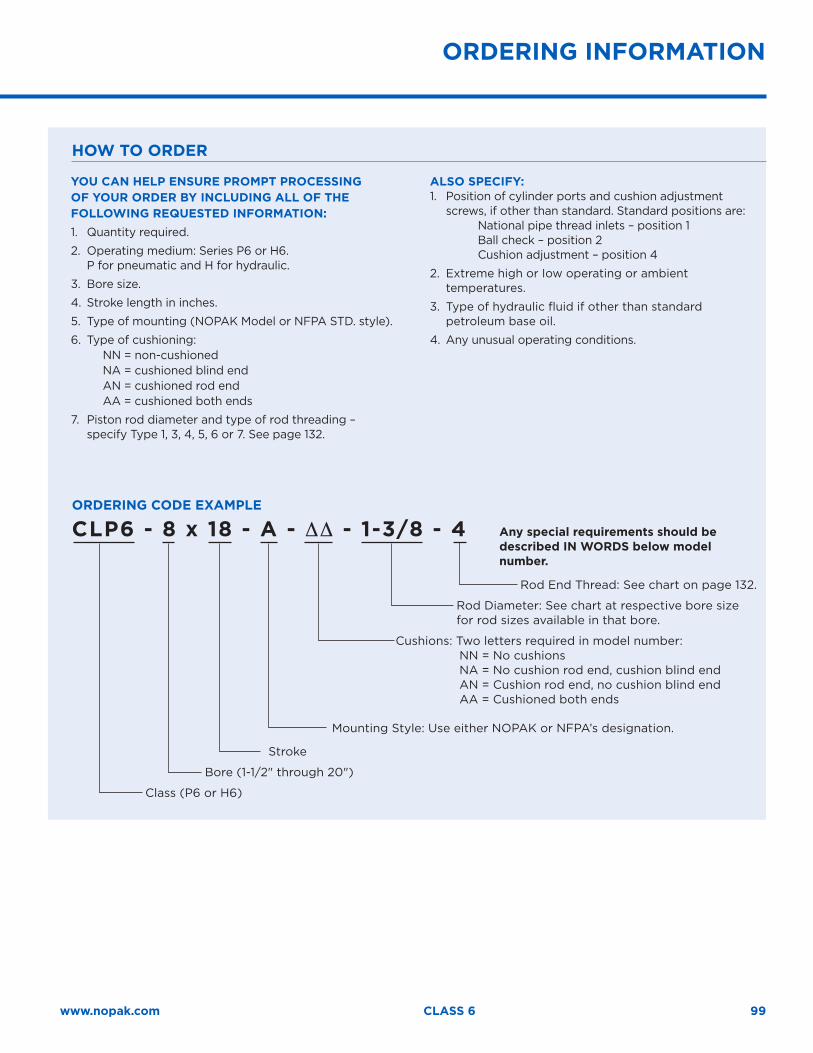
99www.nopak.com CLASS 6
ORDERING INFORMATION
YOU CAN HELP ENSURE PROMPT PROCESSING OF YOUR ORDER BY INCLUDING ALL OF THE FOLLOWING REQUESTED INFORMATION: 1. Quantity required.
2. Operating medium: Series P6 or H6. P for pneumatic and H for hydraulic.
3. Bore size.
4. Stroke length in inches.
5. Type of mounting (NOPAK Model or NFPA STD. style).
6. Type of cushioning:NN = non-cushionedNA = cushioned blind endAN = cushioned rod endAA = cushioned both ends
7. Piston rod diameter and type of rod threading – specify Type 1, 3, 4, 5, 6 or 7. See page 132.
ALSO SPECIFY:1. Position of cylinder ports and cushion adjustment
screws, if other than standard. Standard positions are: National pipe thread inlets – position 1 Ball check – position 2 Cushion adjustment – position 4
2. Extreme high or Iow operating or ambient temperatures.
3. Type of hydraulic fluid if other than standard petroleum base oil.
4. Any unusual operating conditions.
Any special requirements should be described IN WORDS below model number.
ORDERING CODE EXAMPLE
CLP6 - 8 x 18 - A - ∆∆ - 1-3/8 - 4
Rod End Thread: See chart on page 132.
Rod Diameter: See chart at respective bore size for rod sizes available in that bore.
Cushions: Two letters required in model number: NN = No cushions NA = No cushion rod end, cushion blind end AN = Cushion rod end, no cushion blind end AA = Cushioned both ends
Mounting Style: Use either NOPAK or NFPA’s designation.
Stroke
Bore (1-1/2" through 20")
Class (P6 or H6)
HOW TO ORDER
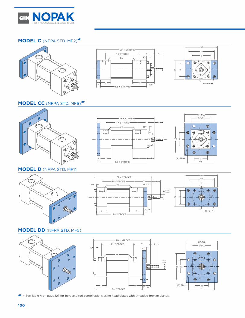
100
MODEL C (NFPA STD. MF2)�
AYP + STROKE
ZF + STROKE
EE K
J GF
LB + STROKE
E1
3
24
TF
UF
E R
(4) FBWF
MODEL CC (NFPA STD. MF6) �
AYP + STROKE
ZF + STROKE
EE K
J G WFF
LB + STROKE
E-SQ.
1
3
24
R
TF
UF-SQ.
TF R
(8) FB
MODEL D (NFPA STD. MF1)
AYP + STROKE
ZB + STROKE
EEK
J GWF
LB + STROKE
E1
3
24
TF
UF
E R
(4) FB
V
B +.000– .002
MODEL DD (NFPA STD. MF5)
AYP + STROKE
ZB + STROKE
EE
K
J GWF
LB + STROKE
1
3
24
VE-SQ.
R
TF
UF-SQ.
TF RB
(8) FB
+.000– .002
� = See Table A on page 127 for bore and rod combinations using head plates with threaded bronze glands.
FLANGE MOUNT CYLINDERS 1-1/2" THROUGH 6" BORE
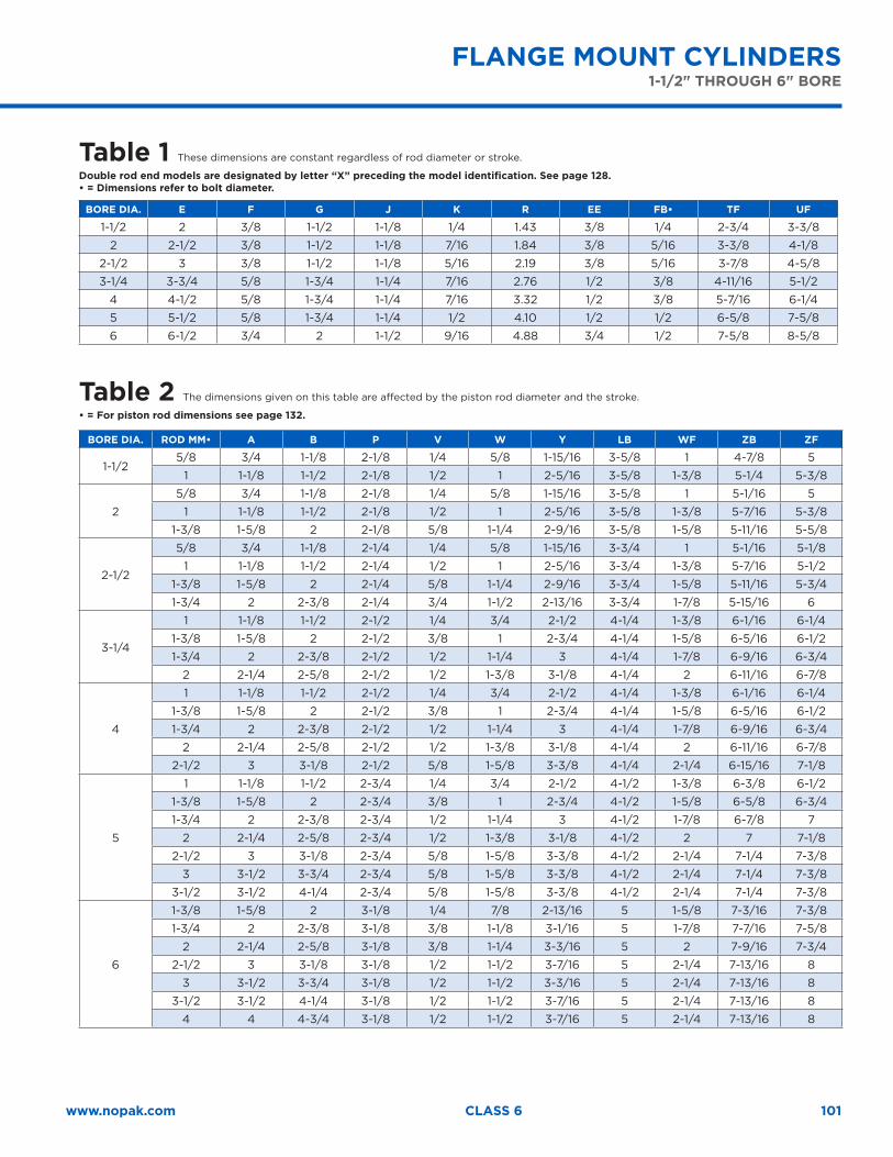
101www.nopak.com CLASS 6
FLANGE MOUNT CYLINDERS1-1/2" THROUGH 6" BORE
Table 1 These dimensions are constant regardless of rod diameter or stroke.
Double rod end models are designated by letter “X” preceding the model identification. See page 128.• = Dimensions refer to bolt diameter.
BORE DIA. E F G J K R EE FB• TF UF
1-1/2 2 3/8 1-1/2 1-1/8 1/4 1.43 3/8 1/4 2-3/4 3-3/8
2 2-1/2 3/8 1-1/2 1-1/8 7/16 1.84 3/8 5/16 3-3/8 4-1/8
2-1/2 3 3/8 1-1/2 1-1/8 5/16 2.19 3/8 5/16 3-7/8 4-5/8
3-1/4 3-3/4 5/8 1-3/4 1-1/4 7/16 2.76 1/2 3/8 4-11/16 5-1/2
4 4-1/2 5/8 1-3/4 1-1/4 7/16 3.32 1/2 3/8 5-7/16 6-1/4
5 5-1/2 5/8 1-3/4 1-1/4 1/2 4.10 1/2 1/2 6-5/8 7-5/8
6 6-1/2 3/4 2 1-1/2 9/16 4.88 3/4 1/2 7-5/8 8-5/8
Table 2 The dimensions given on this table are affected by the piston rod diameter and the stroke.
• = For piston rod dimensions see page 132.
BORE DIA. ROD MM• A B P V W Y LB WF ZB ZF
1-1/25/8 3/4 1-1/8 2-1/8 1/4 5/8 1-15/16 3-5/8 1 4-7/8 5
1 1-1/8 1-1/2 2-1/8 1/2 1 2-5/16 3-5/8 1-3/8 5-1/4 5-3/8
2
5/8 3/4 1-1/8 2-1/8 1/4 5/8 1-15/16 3-5/8 1 5-1/16 5
1 1-1/8 1-1/2 2-1/8 1/2 1 2-5/16 3-5/8 1-3/8 5-7/16 5-3/8
1-3/8 1-5/8 2 2-1/8 5/8 1-1/4 2-9/16 3-5/8 1-5/8 5-11/16 5-5/8
2-1/2
5/8 3/4 1-1/8 2-1/4 1/4 5/8 1-15/16 3-3/4 1 5-1/16 5-1/8
1 1-1/8 1-1/2 2-1/4 1/2 1 2-5/16 3-3/4 1-3/8 5-7/16 5-1/2
1-3/8 1-5/8 2 2-1/4 5/8 1-1/4 2-9/16 3-3/4 1-5/8 5-11/16 5-3/4
1-3/4 2 2-3/8 2-1/4 3/4 1-1/2 2-13/16 3-3/4 1-7/8 5-15/16 6
3-1/4
1 1-1/8 1-1/2 2-1/2 1/4 3/4 2-1/2 4-1/4 1-3/8 6-1/16 6-1/4
1-3/8 1-5/8 2 2-1/2 3/8 1 2-3/4 4-1/4 1-5/8 6-5/16 6-1/2
1-3/4 2 2-3/8 2-1/2 1/2 1-1/4 3 4-1/4 1-7/8 6-9/16 6-3/4
2 2-1/4 2-5/8 2-1/2 1/2 1-3/8 3-1/8 4-1/4 2 6-11/16 6-7/8
4
1 1-1/8 1-1/2 2-1/2 1/4 3/4 2-1/2 4-1/4 1-3/8 6-1/16 6-1/4
1-3/8 1-5/8 2 2-1/2 3/8 1 2-3/4 4-1/4 1-5/8 6-5/16 6-1/2
1-3/4 2 2-3/8 2-1/2 1/2 1-1/4 3 4-1/4 1-7/8 6-9/16 6-3/4
2 2-1/4 2-5/8 2-1/2 1/2 1-3/8 3-1/8 4-1/4 2 6-11/16 6-7/8
2-1/2 3 3-1/8 2-1/2 5/8 1-5/8 3-3/8 4-1/4 2-1/4 6-15/16 7-1/8
5
1 1-1/8 1-1/2 2-3/4 1/4 3/4 2-1/2 4-1/2 1-3/8 6-3/8 6-1/2
1-3/8 1-5/8 2 2-3/4 3/8 1 2-3/4 4-1/2 1-5/8 6-5/8 6-3/4
1-3/4 2 2-3/8 2-3/4 1/2 1-1/4 3 4-1/2 1-7/8 6-7/8 7
2 2-1/4 2-5/8 2-3/4 1/2 1-3/8 3-1/8 4-1/2 2 7 7-1/8
2-1/2 3 3-1/8 2-3/4 5/8 1-5/8 3-3/8 4-1/2 2-1/4 7-1/4 7-3/8
3 3-1/2 3-3/4 2-3/4 5/8 1-5/8 3-3/8 4-1/2 2-1/4 7-1/4 7-3/8
3-1/2 3-1/2 4-1/4 2-3/4 5/8 1-5/8 3-3/8 4-1/2 2-1/4 7-1/4 7-3/8
6
1-3/8 1-5/8 2 3-1/8 1/4 7/8 2-13/16 5 1-5/8 7-3/16 7-3/8
1-3/4 2 2-3/8 3-1/8 3/8 1-1/8 3-1/16 5 1-7/8 7-7/16 7-5/8
2 2-1/4 2-5/8 3-1/8 3/8 1-1/4 3-3/16 5 2 7-9/16 7-3/4
2-1/2 3 3-1/8 3-1/8 1/2 1-1/2 3-7/16 5 2-1/4 7-13/16 8
3 3-1/2 3-3/4 3-1/8 1/2 1-1/2 3-3/16 5 2-1/4 7-13/16 8
3-1/2 3-1/2 4-1/4 3-1/8 1/2 1-1/2 3-7/16 5 2-1/4 7-13/16 8
4 4 4-3/4 3-1/8 1/2 1-1/2 3-7/16 5 2-1/4 7-13/16 8
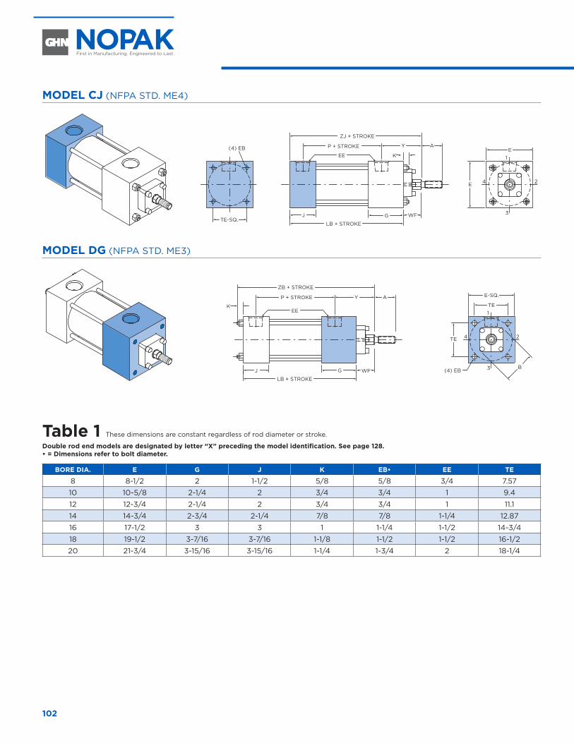
102
MODEL CJ (NFPA STD. ME4)
AYP + STROKE
ZJ + STROKE
EE K
J G
LB + STROKE
E1
3
24E
TE-SQ.
(4) EB
WF
MODEL DG (NFPA STD. ME3)
(4) EB
AYP + STROKE
ZB + STROKE
EEK
J G
LB + STROKE
TE1
3
24
E-SQ.
TE
BWF
Table 1 These dimensions are constant regardless of rod diameter or stroke.
Double rod end models are designated by letter “X” preceding the model identification. See page 128.• = Dimensions refer to bolt diameter.
BORE DIA. E G J K EB• EE TE
8 8-1/2 2 1-1/2 5/8 5/8 3/4 7.57
10 10-5/8 2-1/4 2 3/4 3/4 1 9.4
12 12-3/4 2-1/4 2 3/4 3/4 1 11.1
14 14-3/4 2-3/4 2-1/4 7/8 7/8 1-1/4 12.87
16 17-1/2 3 3 1 1-1/4 1-1/2 14-3/4
18 19-1/2 3-7/16 3-7/16 1-1/8 1-1/2 1-1/2 16-1/2
20 21-3/4 3-15/16 3-15/16 1-1/4 1-3/4 2 18-1/4
8" THROUGH 20" BORE
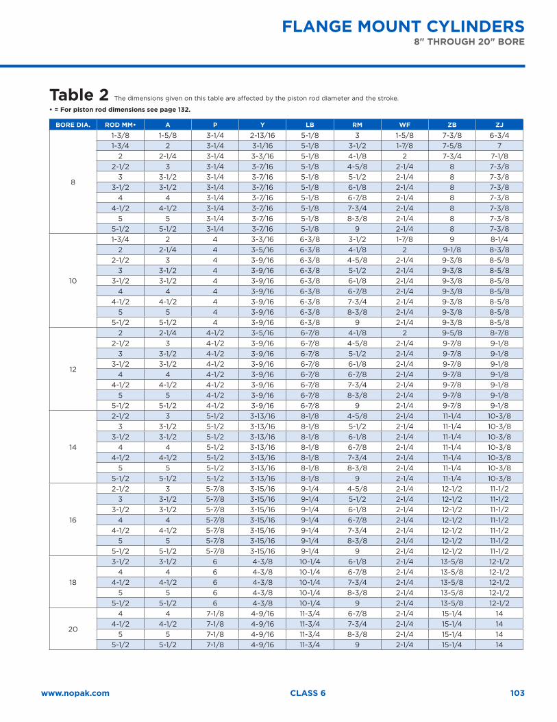
103www.nopak.com CLASS 6
Table 2 The dimensions given on this table are affected by the piston rod diameter and the stroke.
• = For piston rod dimensions see page 132.
BORE DIA. ROD MM• A P Y LB RM WF ZB ZJ
8
1-3/8 1-5/8 3-1/4 2-13/16 5-1/8 3 1-5/8 7-3/8 6-3/41-3/4 2 3-1/4 3-1/16 5-1/8 3-1/2 1-7/8 7-5/8 7
2 2-1/4 3-1/4 3-3/16 5-1/8 4-1/8 2 7-3/4 7-1/82-1/2 3 3-1/4 3-7/16 5-1/8 4-5/8 2-1/4 8 7-3/8
3 3-1/2 3-1/4 3-7/16 5-1/8 5-1/2 2-1/4 8 7-3/83-1/2 3-1/2 3-1/4 3-7/16 5-1/8 6-1/8 2-1/4 8 7-3/8
4 4 3-1/4 3-7/16 5-1/8 6-7/8 2-1/4 8 7-3/84-1/2 4-1/2 3-1/4 3-7/16 5-1/8 7-3/4 2-1/4 8 7-3/8
5 5 3-1/4 3-7/16 5-1/8 8-3/8 2-1/4 8 7-3/85-1/2 5-1/2 3-1/4 3-7/16 5-1/8 9 2-1/4 8 7-3/8
10
1-3/4 2 4 3-3/16 6-3/8 3-1/2 1-7/8 9 8-1/42 2-1/4 4 3-5/16 6-3/8 4-1/8 2 9-1/8 8-3/8
2-1/2 3 4 3-9/16 6-3/8 4-5/8 2-1/4 9-3/8 8-5/83 3-1/2 4 3-9/16 6-3/8 5-1/2 2-1/4 9-3/8 8-5/8
3-1/2 3-1/2 4 3-9/16 6-3/8 6-1/8 2-1/4 9-3/8 8-5/84 4 4 3-9/16 6-3/8 6-7/8 2-1/4 9-3/8 8-5/8
4-1/2 4-1/2 4 3-9/16 6-3/8 7-3/4 2-1/4 9-3/8 8-5/85 5 4 3-9/16 6-3/8 8-3/8 2-1/4 9-3/8 8-5/8
5-1/2 5-1/2 4 3-9/16 6-3/8 9 2-1/4 9-3/8 8-5/8
12
2 2-1/4 4-1/2 3-5/16 6-7/8 4-1/8 2 9-5/8 8-7/82-1/2 3 4-1/2 3-9/16 6-7/8 4-5/8 2-1/4 9-7/8 9-1/8
3 3-1/2 4-1/2 3-9/16 6-7/8 5-1/2 2-1/4 9-7/8 9-1/83-1/2 3-1/2 4-1/2 3-9/16 6-7/8 6-1/8 2-1/4 9-7/8 9-1/8
4 4 4-1/2 3-9/16 6-7/8 6-7/8 2-1/4 9-7/8 9-1/84-1/2 4-1/2 4-1/2 3-9/16 6-7/8 7-3/4 2-1/4 9-7/8 9-1/8
5 5 4-1/2 3-9/16 6-7/8 8-3/8 2-1/4 9-7/8 9-1/85-1/2 5-1/2 4-1/2 3-9/16 6-7/8 9 2-1/4 9-7/8 9-1/8
14
2-1/2 3 5-1/2 3-13/16 8-1/8 4-5/8 2-1/4 11-1/4 10-3/83 3-1/2 5-1/2 3-13/16 8-1/8 5-1/2 2-1/4 11-1/4 10-3/8
3-1/2 3-1/2 5-1/2 3-13/16 8-1/8 6-1/8 2-1/4 11-1/4 10-3/84 4 5-1/2 3-13/16 8-1/8 6-7/8 2-1/4 11-1/4 10-3/8
4-1/2 4-1/2 5-1/2 3-13/16 8-1/8 7-3/4 2-1/4 11-1/4 10-3/85 5 5-1/2 3-13/16 8-1/8 8-3/8 2-1/4 11-1/4 10-3/8
5-1/2 5-1/2 5-1/2 3-13/16 8-1/8 9 2-1/4 11-1/4 10-3/8
16
2-1/2 3 5-7/8 3-15/16 9-1/4 4-5/8 2-1/4 12-1/2 11-1/23 3-1/2 5-7/8 3-15/16 9-1/4 5-1/2 2-1/4 12-1/2 11-1/2
3-1/2 3-1/2 5-7/8 3-15/16 9-1/4 6-1/8 2-1/4 12-1/2 11-1/24 4 5-7/8 3-15/16 9-1/4 6-7/8 2-1/4 12-1/2 11-1/2
4-1/2 4-1/2 5-7/8 3-15/16 9-1/4 7-3/4 2-1/4 12-1/2 11-1/25 5 5-7/8 3-15/16 9-1/4 8-3/8 2-1/4 12-1/2 11-1/2
5-1/2 5-1/2 5-7/8 3-15/16 9-1/4 9 2-1/4 12-1/2 11-1/2
18
3-1/2 3-1/2 6 4-3/8 10-1/4 6-1/8 2-1/4 13-5/8 12-1/24 4 6 4-3/8 10-1/4 6-7/8 2-1/4 13-5/8 12-1/2
4-1/2 4-1/2 6 4-3/8 10-1/4 7-3/4 2-1/4 13-5/8 12-1/25 5 6 4-3/8 10-1/4 8-3/8 2-1/4 13-5/8 12-1/2
5-1/2 5-1/2 6 4-3/8 10-1/4 9 2-1/4 13-5/8 12-1/2
20
4 4 7-1/8 4-9/16 11-3/4 6-7/8 2-1/4 15-1/4 144-1/2 4-1/2 7-1/8 4-9/16 11-3/4 7-3/4 2-1/4 15-1/4 14
5 5 7-1/8 4-9/16 11-3/4 8-3/8 2-1/4 15-1/4 145-1/2 5-1/2 7-1/8 4-9/16 11-3/4 9 2-1/4 15-1/4 14
FLANGE MOUNT CYLINDERS8" THROUGH 20" BORE
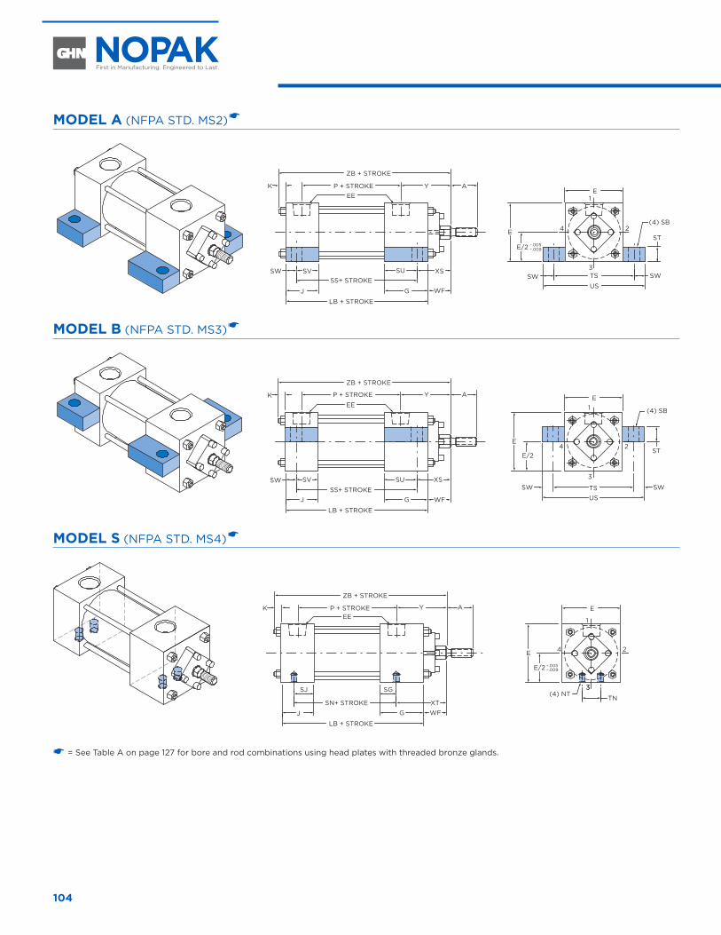
104
MODEL A (NFPA STD. MS2) �
AYP + STROKE
ZB + STROKE
EEK
.005–– .009
E1
3
24
TSSWUS
SW
E
E/2ST
(4) SB
J G
SS+ STROKEXSSV
LB + STROKE
SW SU
WF
MODEL B (NFPA STD. MS3) �
E1
3
24
TSSW
US
SW
E
E/2ST
(4) SB
AYP + STROKE
ZB + STROKE
EEK
J GSS+ STROKE
XSSV
LB + STROKE
SW SU
WF
MODEL S (NFPA STD. MS4) �
AYP + STROKE
ZB + STROKE
EEK
J GSN+ STROKE
WF
SJ
LB + STROKE
.005–– .009
E
1
33
24
TN
E
E/2
(4) NTSG
XT
� = See Table A on page 127 for bore and rod combinations using head plates with threaded bronze glands.
SIDE AND LUG MOUNT CYLINDERS 1-1/2" THROUGH 6" BORE
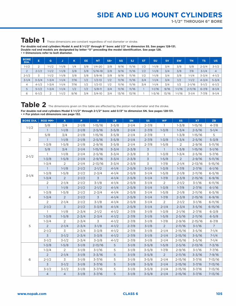
105www.nopak.com CLASS 6
SIDE AND LUG MOUNT CYLINDERS 1-1/2" THROUGH 6" BORE
Table 1 These dimensions are constant regardless of rod diameter or stroke.
For double rod end cylinders Model A and B 1-1/2" through 6" bore: add 1/2" to dimension SS. See pages 128-131.Double rod end models are designated by letter “X” preceding the model identification. See page 128.• = Dimensions refer to bolt diameter.
BORE DIA. E G J K EE NT SB• SG SJ ST SU SV SW TN TS US
1-1/2 2 1-1/2 1-1/8 1/4 3/8 1/4-20 3/8 9/16 11/16 1/2 1-1/8 3/4 3/8 5/8 2-3/4 3-1/2
2 2-1/2 1-1/2 1-1/8 3/8 3/8 5/16-18 3/8 9/16 11/16 1/2 1-1/8 3/4 3/8 7/8 3-1/4 4
2-1/2 3 1-1/2 1-1/8 3/8 3/8 3/8-16 3/8 9/16 11/16 1/2 1-1/8 3/4 3/8 1-1/4 3-3/4 4-1/2
3-1/4 3-3/4 1-3/4 1-1/4 7/16 1/2 1/2-13 1/2 11/16 11/16 3/4 1-1/4 3/4 1/2 1-1/2 4-3/4 5-3/4
4 4-1/2 1-3/4 1-1/4 7/16 1/2 1/2-13 1/2 11/16 11/16 3/4 1-1/4 3/4 1/2 2-1/16 5-1/2 6-1/2
5 5-1/2 1-3/4 1-1/4 1/2 1/2 5/8-11 3/4 11/16 11/16 1 1-1/16 9/16 1-1/16 2-11/16 6-7/8 8-1/4
6 6-1/2 2 1-1/2 9/16 3/4 3/4-10 3/4 13/16 13/16 1 1-5/16 13/16 1-1/16 3-1/4 7-7/8 9-1/4
Table 2 The dimensions given on this table are affected by the piston rod diameter and the stroke.
For double rod end cylinders Model S 1-1/2" through 2-1/2" bore: add 0.13" to dimension SN. See pages 128-131.• = For piston rod dimensions see page 132.
BORE DIA. ROD MM• A P Y LB SN SS WF XS XT ZB
1-1/25/8 3/4 2-1/8 1-15/16 3-5/8 2-1/4 2-7/8 1 1-3/8 1-15/16 4-7/8
1 1-1/8 2-1/8 2-5/16 3-5/8 2-1/4 2-7/8 1-3/8 1-3/4 2-5/16 5-1/4
2
5/8 3/4 2-1/8 1-15/16 3-5/8 2-1/4 2-7/8 1 1-3/8 1-15/16 5
1 1-1/8 2-1/8 2-5/16 3-5/8 2-1/4 2-7/8 1-3/8 1-3/4 2-5/16 5-3/8
1-3/8 1-5/8 2-1/8 2-9/16 3-5/8 2-1/4 2-7/8 1-5/8 2 2-9/16 5-11/16
2-1/2
5/8 3/4 2-1/4 1-15/16 3-3/4 2-3/8 3 1 1-3/8 1-15/16 5-1/16
1 1-1/8 2-1/4 2-5/16 3-3/4 2-3/8 3 1-3/8 1-3/4 2-5/16 5-7/16
1-3/8 1-5/8 2-1/4 2-9/16 3-3/4 2-3/8 3 1-5/8 2 2-9/16 5-11/16
1-3/4 2 2-1/4 2-13/16 3-3/4 2-3/8 3 1-7/8 2-1/4 2-13/16 5-15/16
3-1/4
1 1-1/8 2-1/2 2-1/2 4-1/4 2-5/8 3-1/4 1-3/8 1-7/8 2-7/16 6-1/16
1-3/8 1-5/8 2-1/2 2-3/4 4-1/4 2-5/8 3-1/4 1-5/8 2-1/8 2-11/16 6-5/16
1-3/4 2 2-1/2 3 4-1/4 2-5/8 3-1/4 1-7/8 2-3/8 2-15/16 6-9/16
2 2-1/4 2-1/2 3-1/8 4-1/4 2-5/8 3-1/4 2 2-1/2 3-1/16 6-11/16
4
1 1-1/8 2-1/2 2-1/2 4-1/4 2-5/8 3-1/4 1-3/8 1-7/8 2-7/16 6-1/16
1-3/8 1-5/8 2-1/2 2-3/4 4-1/4 2-5/8 3-1/4 1-5/8 2-1/8 2-11/16 6-5/16
1-3/4 2 2-1/2 3 4-1/4 2-5/8 3-1/4 1-7/8 2-3/8 2-15/16 6-9/16
2 2-1/4 2-1/2 3-1/8 4-1/4 2-5/8 3-1/4 2 2-1/2 3-1/16 6-11/16
2-1/2 3 2-1/2 3-3/8 4-1/4 2-5/8 3-1/4 2-1/4 2-3/4 3-5/16 6-15/16
5
1 1-1/8 2-3/4 2-1/2 4-1/2 2-7/8 3-1/8 1-3/8 2-1/16 2-7/16 6-3/8
1-3/8 1-5/8 2-3/4 2-3/4 4-1/2 2-7/8 3-1/8 1-5/8 2-5/16 2-11/16 6-5/8
1-3/4 2 2-3/4 3 4-1/2 2-7/8 3-1/8 1-7/8 2-9/16 2-15/16 6-7/8
2 2-1/4 2-3/4 3-1/8 4-1/2 2-7/8 3-1/8 2 2-11/16 3-1/16 7
2-1/2 3 2-3/4 3-3/8 4-1/2 2-7/8 3-1/8 2-1/4 2-15/16 3-5/16 7-1/4
3 3-1/2 2-3/4 3-3/8 4-1/2 2-7/8 3-1/8 2-1/4 2-15/16 3-5/16 7-1/4
3-1/2 3-1/2 2-3/4 3-3/8 4-1/2 2-7/8 3-1/8 2-1/4 2-15/16 3-5/16 7-1/4
6
1-3/8 1-5/8 3-1/8 2-13/16 5 3-1/8 3-5/8 1-5/8 2-5/16 2-13/16 7-3/16
1-3/4 2 3-1/8 3-1/16 5 3-1/8 3-5/8 1-7/8 2-9/16 3-1/16 7-7/16
2 2-1/4 3-1/8 3-3/16 5 3-1/8 3-5/8 2 2-11/16 3-3/16 7-9/16
2-1/2 3 3-1/8 3-7/16 5 3-1/8 3-5/8 2-1/4 2-15/16 3-7/16 7-13/16
3 3-1/2 3-1/8 3-7/16 5 3-1/8 3-5/8 2-1/4 2-15/16 3-7/16 7-13/16
3-1/2 3-1/2 3-1/8 3-7/16 5 3-1/8 3-5/8 2-1/4 2-15/16 3-7/16 7-13/16
4 4 3-1/8 3-7/16 5 3-1/8 3-5/8 2-1/4 2-15/16 3-7/16 7-13/16
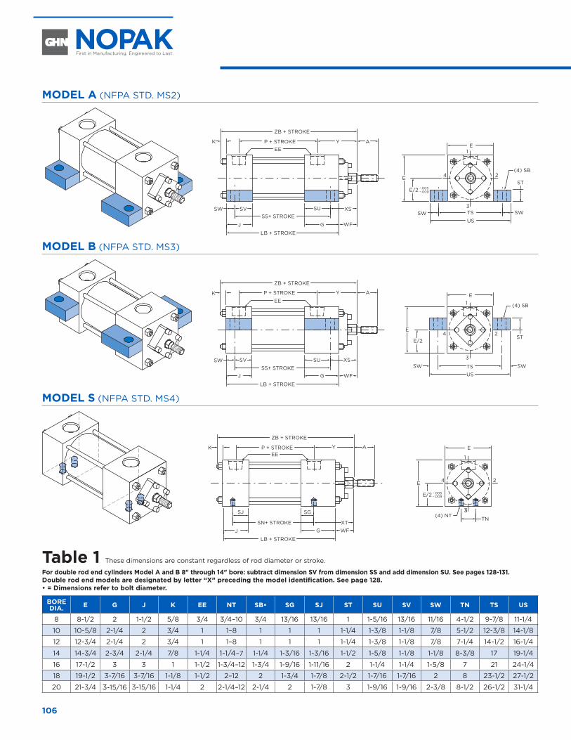
106
MODEL A (NFPA STD. MS2)
AYP + STROKE
ZB + STROKE
EEK
.005–– .009
E1
3
24
TSSWUS
SW
E
E/2ST
(4) SB
J G
SS+ STROKEXSSV
LB + STROKE
SW SU
WF
MODEL B (NFPA STD. MS3)
E1
3
24
TSSW
US
SW
E
E/2ST
(4) SB
AYP + STROKE
ZB + STROKE
EEK
J GSS+ STROKE
XSSV
LB + STROKE
SW SU
WF
MODEL S (NFPA STD. MS4)
AYP + STROKE
ZB + STROKE
EEK
J GSN+ STROKE
WF
SJ
LB + STROKE
.005–– .009
E
1
33
24
TN
E
E/2
(4) NTSG
XT
Table 1 These dimensions are constant regardless of rod diameter or stroke.
For double rod end cylinders Model A and B 8" through 14" bore: subtract dimension SV from dimension SS and add dimension SU. See pages 128-131.Double rod end models are designated by letter “X” preceding the model identification. See page 128.• = Dimensions refer to bolt diameter.
BORE DIA. E G J K EE NT SB• SG SJ ST SU SV SW TN TS US
8 8-1/2 2 1-1/2 5/8 3/4 3/4–10 3/4 13/16 13/16 1 1-5/16 13/16 11/16 4-1/2 9-7/8 11-1/4
10 10-5/8 2-1/4 2 3/4 1 1–8 1 1 1 1-1/4 1-3/8 1-1/8 7/8 5-1/2 12-3/8 14-1/8
12 12-3/4 2-1/4 2 3/4 1 1–8 1 1 1 1-1/4 1-3/8 1-1/8 7/8 7-1/4 14-1/2 16-1/4
14 14-3/4 2-3/4 2-1/4 7/8 1-1/4 1-1/4–7 1-1/4 1-3/16 1-3/16 1-1/2 1-5/8 1-1/8 1-1/8 8-3/8 17 19-1/4
16 17-1/2 3 3 1 1-1/2 1-3/4–12 1-3/4 1-9/16 1-11/16 2 1-1/4 1-1/4 1-5/8 7 21 24-1/4
18 19-1/2 3-7/16 3-7/16 1-1/8 1-1/2 2–12 2 1-3/4 1-7/8 2-1/2 1-7/16 1-7/16 2 8 23-1/2 27-1/2
20 21-3/4 3-15/16 3-15/16 1-1/4 2 2-1/4–12 2-1/4 2 1-7/8 3 1-9/16 1-9/16 2-3/8 8-1/2 26-1/2 31-1/4
8" THROUGH 20" BORE
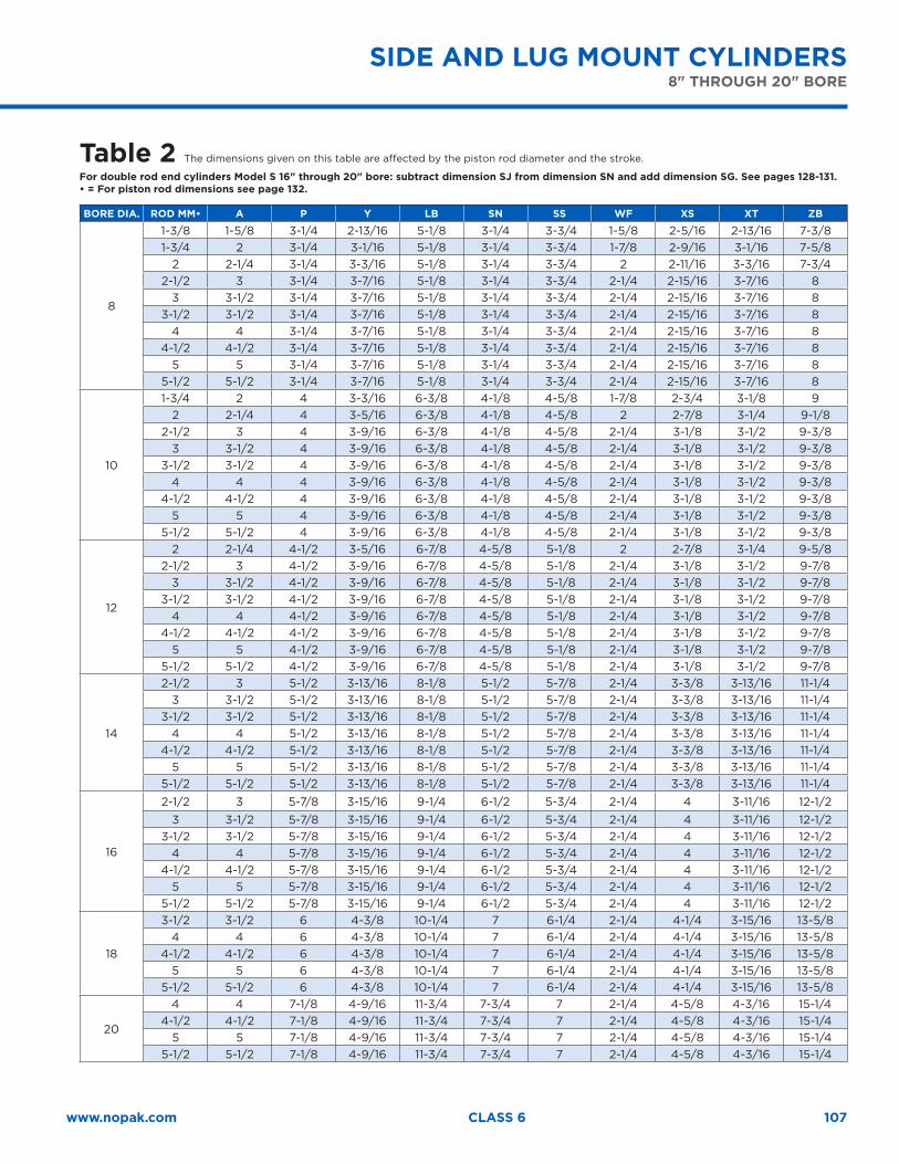
107www.nopak.com CLASS 6
SIDE AND LUG MOUNT CYLINDERS 8" THROUGH 20" BORE
Table 2 The dimensions given on this table are affected by the piston rod diameter and the stroke.
For double rod end cylinders Model S 16" through 20" bore: subtract dimension SJ from dimension SN and add dimension SG. See pages 128-131.• = For piston rod dimensions see page 132.
BORE DIA. ROD MM• A P Y LB SN SS WF XS XT ZB
8
1-3/8 1-5/8 3-1/4 2-13/16 5-1/8 3-1/4 3-3/4 1-5/8 2-5/16 2-13/16 7-3/81-3/4 2 3-1/4 3-1/16 5-1/8 3-1/4 3-3/4 1-7/8 2-9/16 3-1/16 7-5/8
2 2-1/4 3-1/4 3-3/16 5-1/8 3-1/4 3-3/4 2 2-11/16 3-3/16 7-3/42-1/2 3 3-1/4 3-7/16 5-1/8 3-1/4 3-3/4 2-1/4 2-15/16 3-7/16 8
3 3-1/2 3-1/4 3-7/16 5-1/8 3-1/4 3-3/4 2-1/4 2-15/16 3-7/16 83-1/2 3-1/2 3-1/4 3-7/16 5-1/8 3-1/4 3-3/4 2-1/4 2-15/16 3-7/16 8
4 4 3-1/4 3-7/16 5-1/8 3-1/4 3-3/4 2-1/4 2-15/16 3-7/16 84-1/2 4-1/2 3-1/4 3-7/16 5-1/8 3-1/4 3-3/4 2-1/4 2-15/16 3-7/16 8
5 5 3-1/4 3-7/16 5-1/8 3-1/4 3-3/4 2-1/4 2-15/16 3-7/16 85-1/2 5-1/2 3-1/4 3-7/16 5-1/8 3-1/4 3-3/4 2-1/4 2-15/16 3-7/16 8
10
1-3/4 2 4 3-3/16 6-3/8 4-1/8 4-5/8 1-7/8 2-3/4 3-1/8 92 2-1/4 4 3-5/16 6-3/8 4-1/8 4-5/8 2 2-7/8 3-1/4 9-1/8
2-1/2 3 4 3-9/16 6-3/8 4-1/8 4-5/8 2-1/4 3-1/8 3-1/2 9-3/83 3-1/2 4 3-9/16 6-3/8 4-1/8 4-5/8 2-1/4 3-1/8 3-1/2 9-3/8
3-1/2 3-1/2 4 3-9/16 6-3/8 4-1/8 4-5/8 2-1/4 3-1/8 3-1/2 9-3/84 4 4 3-9/16 6-3/8 4-1/8 4-5/8 2-1/4 3-1/8 3-1/2 9-3/8
4-1/2 4-1/2 4 3-9/16 6-3/8 4-1/8 4-5/8 2-1/4 3-1/8 3-1/2 9-3/85 5 4 3-9/16 6-3/8 4-1/8 4-5/8 2-1/4 3-1/8 3-1/2 9-3/8
5-1/2 5-1/2 4 3-9/16 6-3/8 4-1/8 4-5/8 2-1/4 3-1/8 3-1/2 9-3/8
12
2 2-1/4 4-1/2 3-5/16 6-7/8 4-5/8 5-1/8 2 2-7/8 3-1/4 9-5/82-1/2 3 4-1/2 3-9/16 6-7/8 4-5/8 5-1/8 2-1/4 3-1/8 3-1/2 9-7/8
3 3-1/2 4-1/2 3-9/16 6-7/8 4-5/8 5-1/8 2-1/4 3-1/8 3-1/2 9-7/83-1/2 3-1/2 4-1/2 3-9/16 6-7/8 4-5/8 5-1/8 2-1/4 3-1/8 3-1/2 9-7/8
4 4 4-1/2 3-9/16 6-7/8 4-5/8 5-1/8 2-1/4 3-1/8 3-1/2 9-7/84-1/2 4-1/2 4-1/2 3-9/16 6-7/8 4-5/8 5-1/8 2-1/4 3-1/8 3-1/2 9-7/8
5 5 4-1/2 3-9/16 6-7/8 4-5/8 5-1/8 2-1/4 3-1/8 3-1/2 9-7/85-1/2 5-1/2 4-1/2 3-9/16 6-7/8 4-5/8 5-1/8 2-1/4 3-1/8 3-1/2 9-7/8
14
2-1/2 3 5-1/2 3-13/16 8-1/8 5-1/2 5-7/8 2-1/4 3-3/8 3-13/16 11-1/43 3-1/2 5-1/2 3-13/16 8-1/8 5-1/2 5-7/8 2-1/4 3-3/8 3-13/16 11-1/4
3-1/2 3-1/2 5-1/2 3-13/16 8-1/8 5-1/2 5-7/8 2-1/4 3-3/8 3-13/16 11-1/44 4 5-1/2 3-13/16 8-1/8 5-1/2 5-7/8 2-1/4 3-3/8 3-13/16 11-1/4
4-1/2 4-1/2 5-1/2 3-13/16 8-1/8 5-1/2 5-7/8 2-1/4 3-3/8 3-13/16 11-1/45 5 5-1/2 3-13/16 8-1/8 5-1/2 5-7/8 2-1/4 3-3/8 3-13/16 11-1/4
5-1/2 5-1/2 5-1/2 3-13/16 8-1/8 5-1/2 5-7/8 2-1/4 3-3/8 3-13/16 11-1/4
16
2-1/2 3 5-7/8 3-15/16 9-1/4 6-1/2 5-3/4 2-1/4 4 3-11/16 12-1/23 3-1/2 5-7/8 3-15/16 9-1/4 6-1/2 5-3/4 2-1/4 4 3-11/16 12-1/2
3-1/2 3-1/2 5-7/8 3-15/16 9-1/4 6-1/2 5-3/4 2-1/4 4 3-11/16 12-1/24 4 5-7/8 3-15/16 9-1/4 6-1/2 5-3/4 2-1/4 4 3-11/16 12-1/2
4-1/2 4-1/2 5-7/8 3-15/16 9-1/4 6-1/2 5-3/4 2-1/4 4 3-11/16 12-1/25 5 5-7/8 3-15/16 9-1/4 6-1/2 5-3/4 2-1/4 4 3-11/16 12-1/2
5-1/2 5-1/2 5-7/8 3-15/16 9-1/4 6-1/2 5-3/4 2-1/4 4 3-11/16 12-1/2
18
3-1/2 3-1/2 6 4-3/8 10-1/4 7 6-1/4 2-1/4 4-1/4 3-15/16 13-5/84 4 6 4-3/8 10-1/4 7 6-1/4 2-1/4 4-1/4 3-15/16 13-5/8
4-1/2 4-1/2 6 4-3/8 10-1/4 7 6-1/4 2-1/4 4-1/4 3-15/16 13-5/85 5 6 4-3/8 10-1/4 7 6-1/4 2-1/4 4-1/4 3-15/16 13-5/8
5-1/2 5-1/2 6 4-3/8 10-1/4 7 6-1/4 2-1/4 4-1/4 3-15/16 13-5/8
20
4 4 7-1/8 4-9/16 11-3/4 7-3/4 7 2-1/4 4-5/8 4-3/16 15-1/44-1/2 4-1/2 7-1/8 4-9/16 11-3/4 7-3/4 7 2-1/4 4-5/8 4-3/16 15-1/4
5 5 7-1/8 4-9/16 11-3/4 7-3/4 7 2-1/4 4-5/8 4-3/16 15-1/45-1/2 5-1/2 7-1/8 4-9/16 11-3/4 7-3/4 7 2-1/4 4-5/8 4-3/16 15-1/4
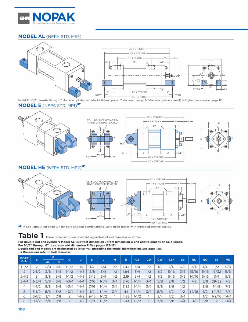
108
MODEL AL (NFPA STD. MS7)
AYP + STROKE
ZE + STROKE
XE + STROKE
EEK WF
J G
SE + STROKE
EL ELEOEO
FLB + STROKE
.005–– .009
E
1
3
24
R
E
E/2
(4) EB ET
Model AL 1-1/2" diameter through 6" diameter cylinders furnished with head plates. 8" diameter through 14" diameter cylinders use (4) bolt glands as shown on page 110.
MODEL E (NFPA STD. MP1)�
CD ± .001 MOUNTING PINHARD CHROME PLATED
WF
AYP + STROKE
ZC + STROKE
EE K
J GCB
CWCWL
MR
M
LB + STROKE
XC + STROKE
E
1
3
1
3
242 4 E
MODEL HE (NFPA STD. MP2)�
CD ± .001 MOUNTING PINHARD CHROME PLATED AYP + STROKE
ZD + STROKE
EE K
J GCBCWCW
L F
MR
M
LB + STROKE
XD + STROKE
E
1
3
24
1
3
2 4 E
WF
� = See Table A on page 127 for bore and rod combinations using head plates with threaded bronze glands.
Table 1 These dimensions are constant regardless of rod diameter or stroke.
For double rod end cylinders Model AL: subtract dimension J from dimension G and add to dimension SE + stroke. For 1-1/2" through 6" bore: also add dimension F. See pages 128-131.Double rod end models are designated by letter “X” preceding the model identification. See page 128. • = Dimensions refer to bolt diameter.
BORE DIA. E
FG J K L M R CB CD CW EB• EE EL EO ET MR
AL HE
1-1/2 2 3/8 3/8 1-1/2 1-1/8 1/4 3/4 1/2 1.43 3/4 1/2 1/2 1/4 3/8 3/4 1/4 1/2 5/82 2-1/2 3/8 3/8 1-1/2 1-1/8 3/8 3/4 1/2 1.84 3/4 1/2 1/2 5/16 3/8 15/16 5/16 19/32 5/8
2-1/2 3 3/8 3/8 1-1/2 1-1/8 5/16 3/4 1/2 2.19 3/4 1/2 1/2 5/16 3/8 1-1/16 5/16 3/4 5/83-1/4 3-3/4 5/8 5/8 1-3/4 1-1/4 7/16 1-1/4 3/4 2.76 1-1/4 3/4 5/8 3/8 1/2 7/8 3/8 29/32 7/8
4 4-1/2 5/8 5/8 1-3/4 1-1/4 7/16 1-1/4 3/4 3.32 1-1/4 3/4 5/8 3/8 1/2 1 3/8 1-1/8 7/8
5 5-1/2 5/8 5/8 1-3/4 1-1/4 1/2 1-1/4 3/4 4.1 1-1/4 3/4 5/8 1/2 1/2 1-1/16 1/2 1-11/32 7/86 6-1/2 3/4 7/8 2 1-1/2 9/16 1-1/2 1 4.88 1-1/2 1 3/4 1/2 3/4 1 1/2 1-9/16 1-1/48 8-1/2 3/4 7/8 2 1-1/2 5/8 1-1/2 1 6.44 1-1/2 1 3/4 5/8 3/4 1-1/8 5/8 2 1-1/4
END LUG AND CLEVIS MOUNT CYLINDERS 1-1/2" THROUGH 8" DIAMETER
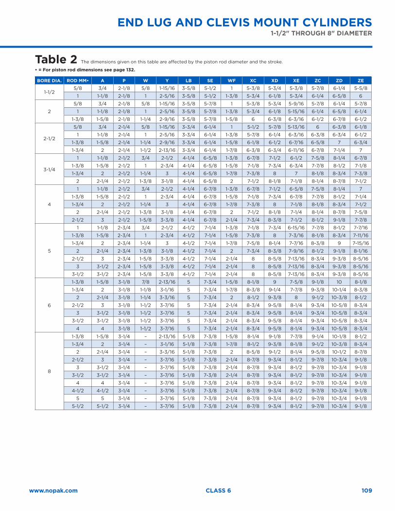
109www.nopak.com CLASS 6
END LUG AND CLEVIS MOUNT CYLINDERS1-1/2" THROUGH 8" DIAMETER
Table 2 The dimensions given on this table are affected by the piston rod diameter and the stroke.
• = For piston rod dimensions see page 132.
BORE DIA. ROD MM• A P W Y LB SE WF XC XD XE ZC ZD ZE
1-1/25/8 3/4 2-1/8 5/8 1-15/16 3-5/8 5-1/2 1 5-3/8 5-3/4 5-3/8 5-7/8 6-1/4 5-5/8
1 1-1/8 2-1/8 1 2-5/16 3-5/8 5-1/2 1-3/8 5-3/4 6-1/8 5-3/4 6-1/4 6-5/8 6
2
5/8 3/4 2-1/8 5/8 1-15/16 3-5/8 5-7/8 1 5-3/8 5-3/4 5-9/16 5-7/8 6-1/4 5-7/8
1 1-1/8 2-1/8 1 2-5/16 3-5/8 5-7/8 1-3/8 5-3/4 6-1/8 5-15/16 6-1/4 6-5/8 6-1/4
1-3/8 1-5/8 2-1/8 1-1/4 2-9/16 3-5/8 5-7/8 1-5/8 6 6-3/8 6-3/16 6-1/2 6-7/8 6-1/2
2-1/2
5/8 3/4 2-1/4 5/8 1-15/16 3-3/4 6-1/4 1 5-1/2 5-7/8 5-13/16 6 6-3/8 6-1/8
1 1-1/8 2-1/4 1 2-5/16 3-3/4 6-1/4 1-3/8 5-7/8 6-1/4 6-3/16 6-3/8 6-3/4 6-1/2
1-3/8 1-5/8 2-1/4 1-1/4 2-9/16 3-3/4 6-1/4 1-5/8 6-1/8 6-1/2 6-7/16 6-5/8 7 6-3/4
1-3/4 2 2-1/4 1-1/2 2-13/16 3-3/4 6-1/4 1-7/8 6-3/8 6-3/4 6-11/16 6-7/8 7-1/4 7
3-1/4
1 1-1/8 2-1/2 3/4 2-1/2 4-1/4 6-5/8 1-3/8 6-7/8 7-1/2 6-1/2 7-5/8 8-1/4 6-7/8
1-3/8 1-5/8 2-1/2 1 2-3/4 4-1/4 6-5/8 1-5/8 7-1/8 7-3/4 6-3/4 7-7/8 8-1/2 7-1/8
1-3/4 2 2-1/2 1-1/4 3 4-1/4 6-5/8 1-7/8 7-3/8 8 7 8-1/8 8-3/4 7-3/8
2 2-1/4 2-1/2 1-3/8 3-1/8 4-1/4 6-5/8 2 7-1/2 8-1/8 7-1/8 8-1/4 8-7/8 7-1/2
4
1 1-1/8 2-1/2 3/4 2-1/2 4-1/4 6-7/8 1-3/8 6-7/8 7-1/2 6-5/8 7-5/8 8-1/4 7
1-3/8 1-5/8 2-1/2 1 2-3/4 4-1/4 6-7/8 1-5/8 7-1/8 7-3/4 6-7/8 7-7/8 8-1/2 7-1/4
1-3/4 2 2-1/2 1-1/4 3 4-1/4 6-7/8 1-7/8 7-3/8 8 7-1/8 8-1/8 8-3/4 7-1/2
2 2-1/4 2-1/2 1-3/8 3-1/8 4-1/4 6-7/8 2 7-1/2 8-1/8 7-1/4 8-1/4 8-7/8 7-5/8
2-1/2 3 2-1/2 1-5/8 3-3/8 4-1/4 6-7/8 2-1/4 7-3/4 8-3/8 7-1/2 8-1/2 9-1/8 7-7/8
5
1 1-1/8 2-3/4 3/4 2-1/2 4-1/2 7-1/4 1-3/8 7-1/8 7-3/4 6-15/16 7-7/8 8-1/2 7-7/16
1-3/8 1-5/8 2-3/4 1 2-3/4 4-1/2 7-1/4 1-5/8 7-3/8 8 7-3/16 8-1/8 8-3/4 7-11/16
1-3/4 2 2-3/4 1-1/4 3 4-1/2 7-1/4 1-7/8 7-5/8 8-1/4 7-7/16 8-3/8 9 7-15/16
2 2-1/4 2-3/4 1-3/8 3-1/8 4-1/2 7-1/4 2 7-3/4 8-3/8 7-9/16 8-1/2 9-1/8 8-1/16
2-1/2 3 2-3/4 1-5/8 3-3/8 4-1/2 7-1/4 2-1/4 8 8-5/8 7-13/16 8-3/4 9-3/8 8-5/16
3 3-1/2 2-3/4 1-5/8 3-3/8 4-1/2 7-1/4 2-1/4 8 8-5/8 7-13/16 8-3/4 9-3/8 8-5/16
3-1/2 3-1/2 2-3/4 1-5/8 3-3/8 4-1/2 7-1/4 2-1/4 8 8-5/8 7-13/16 8-3/4 9-3/8 8-5/16
6
1-3/8 1-5/8 3-1/8 7/8 2-13/16 5 7-3/4 1-5/8 8-1/8 9 7-5/8 9-1/8 10 8-1/8
1-3/4 2 3-1/8 1-1/8 3-1/16 5 7-3/4 1-7/8 8-3/8 9-1/4 7-7/8 9-3/8 10-1/4 8-3/8
2 2-1/4 3-1/8 1-1/4 3-3/16 5 7-3/4 2 8-1/2 9-3/8 8 9-1/2 10-3/8 8-1/2
2-1/2 3 3-1/8 1-1/2 3-7/16 5 7-3/4 2-1/4 8-3/4 9-5/8 8-1/4 9-3/4 10-5/8 8-3/4
3 3-1/2 3-1/8 1-1/2 3-7/16 5 7-3/4 2-1/4 8-3/4 9-5/8 8-1/4 9-3/4 10-5/8 8-3/4
3-1/2 3-1/2 3-1/8 1-1/2 3-7/16 5 7-3/4 2-1/4 8-3/4 9-5/8 8-1/4 9-3/4 10-5/8 8-3/4
4 4 3-1/8 1-1/2 3-7/16 5 7-3/4 2-1/4 8-3/4 9-5/8 8-1/4 9-3/4 10-5/8 8-3/4
8
1-3/8 1-5/8 3-1/4 – 2-13/16 5-1/8 7-3/8 1-5/8 8-1/4 9-1/8 7-7/8 9-1/4 10-1/8 8-1/2
1-3/4 2 3-1/4 – 3-1/16 5-1/8 7-3/8 1-7/8 8-1/2 9-3/8 8-1/8 9-1/2 10-3/8 8-3/4
2 2-1/4 3-1/4 – 3-3/16 5-1/8 7-3/8 2 8-5/8 9-1/2 8-1/4 9-5/8 10-1/2 8-7/8
2-1/2 3 3-1/4 – 3-7/16 5-1/8 7-3/8 2-1/4 8-7/8 9-3/4 8-1/2 9-7/8 10-3/4 9-1/8
3 3-1/2 3-1/4 – 3-7/16 5-1/8 7-3/8 2-1/4 8-7/8 9-3/4 8-1/2 9-7/8 10-3/4 9-1/8
3-1/2 3-1/2 3-1/4 – 3-7/16 5-1/8 7-3/8 2-1/4 8-7/8 9-3/4 8-1/2 9-7/8 10-3/4 9-1/8
4 4 3-1/4 – 3-7/16 5-1/8 7-3/8 2-1/4 8-7/8 9-3/4 8-1/2 9-7/8 10-3/4 9-1/8
4-1/2 4-1/2 3-1/4 – 3-7/16 5-1/8 7-3/8 2-1/4 8-7/8 9-3/4 8-1/2 9-7/8 10-3/4 9-1/8
5 5 3-1/4 – 3-7/16 5-1/8 7-3/8 2-1/4 8-7/8 9-3/4 8-1/2 9-7/8 10-3/4 9-1/8
5-1/2 5-1/2 3-1/4 – 3-7/16 5-1/8 7-3/8 2-1/4 8-7/8 9-3/4 8-1/2 9-7/8 10-3/4 9-1/8
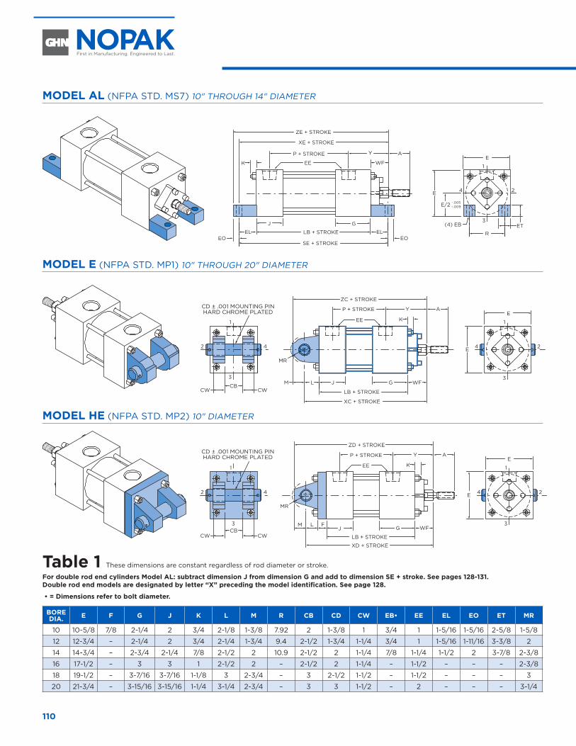
110
MODEL AL (NFPA STD. MS7) 10" THROUGH 14" DIAMETER
AYP + STROKE
ZE + STROKE
XE + STROKE
EEK WF
J G
SE + STROKE
EL ELEOEO
LB + STROKE
.005–– .009
E
1
3
24
R
E
E/2
(4) EB ET
MODEL E (NFPA STD. MP1) 10" THROUGH 20" DIAMETER
CD ± .001 MOUNTING PINHARD CHROME PLATED
WF
AYP + STROKE
ZC + STROKE
EE K
J GCB
CWCWL
MR
M
LB + STROKE
XC + STROKE
E
1
3
1
3
242 4 E
MODEL HE (NFPA STD. MP2) 10" DIAMETER
CD ± .001 MOUNTING PINHARD CHROME PLATED AYP + STROKE
ZD + STROKE
EE K
J GCBCWCW
L F
MR
M
LB + STROKE
XD + STROKE
E
1
3
24
1
3
2 4 E
WF
Table 1 These dimensions are constant regardless of rod diameter or stroke.
For double rod end cylinders Model AL: subtract dimension J from dimension G and add to dimension SE + stroke. See pages 128-131.Double rod end models are designated by letter “X” preceding the model identification. See page 128.
• = Dimensions refer to bolt diameter.
BORE DIA. E F G J K L M R CB CD CW EB• EE EL EO ET MR
10 10-5/8 7/8 2-1/4 2 3/4 2-1/8 1-3/8 7.92 2 1-3/8 1 3/4 1 1-5/16 1-5/16 2-5/8 1-5/8
12 12-3/4 – 2-1/4 2 3/4 2-1/4 1-3/4 9.4 2-1/2 1-3/4 1-1/4 3/4 1 1-5/16 1-11/16 3-3/8 2
14 14-3/4 – 2-3/4 2-1/4 7/8 2-1/2 2 10.9 2-1/2 2 1-1/4 7/8 1-1/4 1-1/2 2 3-7/8 2-3/8
16 17-1/2 – 3 3 1 2-1/2 2 – 2-1/2 2 1-1/4 – 1-1/2 – – – 2-3/8
18 19-1/2 – 3-7/16 3-7/16 1-1/8 3 2-3/4 – 3 2-1/2 1-1/2 – 1-1/2 – – – 3
20 21-3/4 – 3-15/16 3-15/16 1-1/4 3-1/4 2-3/4 – 3 3 1-1/2 – 2 – – – 3-1/4
10" THROUGH 20" DIAMETER
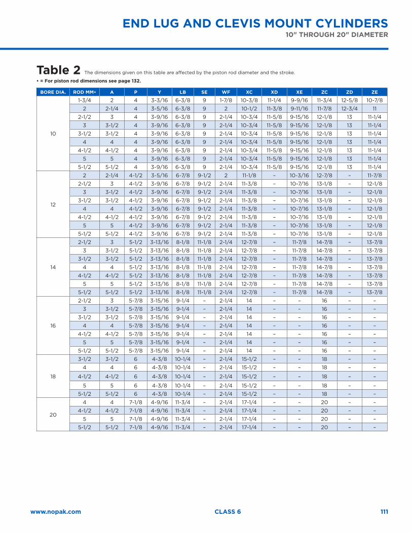
111www.nopak.com CLASS 6
Table 2 The dimensions given on this table are affected by the piston rod diameter and the stroke.
• = For piston rod dimensions see page 132.
BORE DIA. ROD MM• A P Y LB SE WF XC XD XE ZC ZD ZE
10
1-3/4 2 4 3-3/16 6-3/8 9 1-7/8 10-3/8 11-1/4 9-9/16 11-3/4 12-5/8 10-7/8
2 2-1/4 4 3-5/16 6-3/8 9 2 10-1/2 11-3/8 9-11/16 11-7/8 12-3/4 11
2-1/2 3 4 3-9/16 6-3/8 9 2-1/4 10-3/4 11-5/8 9-15/16 12-1/8 13 11-1/4
3 3-1/2 4 3-9/16 6-3/8 9 2-1/4 10-3/4 11-5/8 9-15/16 12-1/8 13 11-1/4
3-1/2 3-1/2 4 3-9/16 6-3/8 9 2-1/4 10-3/4 11-5/8 9-15/16 12-1/8 13 11-1/4
4 4 4 3-9/16 6-3/8 9 2-1/4 10-3/4 11-5/8 9-15/16 12-1/8 13 11-1/4
4-1/2 4-1/2 4 3-9/16 6-3/8 9 2-1/4 10-3/4 11-5/8 9-15/16 12-1/8 13 11-1/4
5 5 4 3-9/16 6-3/8 9 2-1/4 10-3/4 11-5/8 9-15/16 12-1/8 13 11-1/4
5-1/2 5-1/2 4 3-9/16 6-3/8 9 2-1/4 10-3/4 11-5/8 9-15/16 12-1/8 13 11-1/4
12
2 2-1/4 4-1/2 3-5/16 6-7/8 9-1/2 2 11-1/8 – 10-3/16 12-7/8 – 11-7/8
2-1/2 3 4-1/2 3-9/16 6-7/8 9-1/2 2-1/4 11-3/8 – 10-7/16 13-1/8 – 12-1/8
3 3-1/2 4-1/2 3-9/16 6-7/8 9-1/2 2-1/4 11-3/8 – 10-7/16 13-1/8 – 12-1/8
3-1/2 3-1/2 4-1/2 3-9/16 6-7/8 9-1/2 2-1/4 11-3/8 – 10-7/16 13-1/8 – 12-1/8
4 4 4-1/2 3-9/16 6-7/8 9-1/2 2-1/4 11-3/8 – 10-7/16 13-1/8 – 12-1/8
4-1/2 4-1/2 4-1/2 3-9/16 6-7/8 9-1/2 2-1/4 11-3/8 – 10-7/16 13-1/8 – 12-1/8
5 5 4-1/2 3-9/16 6-7/8 9-1/2 2-1/4 11-3/8 – 10-7/16 13-1/8 – 12-1/8
5-1/2 5-1/2 4-1/2 3-9/16 6-7/8 9-1/2 2-1/4 11-3/8 – 10-7/16 13-1/8 – 12-1/8
14
2-1/2 3 5-1/2 3-13/16 8-1/8 11-1/8 2-1/4 12-7/8 – 11-7/8 14-7/8 – 13-7/8
3 3-1/2 5-1/2 3-13/16 8-1/8 11-1/8 2-1/4 12-7/8 – 11-7/8 14-7/8 – 13-7/8
3-1/2 3-1/2 5-1/2 3-13/16 8-1/8 11-1/8 2-1/4 12-7/8 – 11-7/8 14-7/8 – 13-7/8
4 4 5-1/2 3-13/16 8-1/8 11-1/8 2-1/4 12-7/8 – 11-7/8 14-7/8 – 13-7/8
4-1/2 4-1/2 5-1/2 3-13/16 8-1/8 11-1/8 2-1/4 12-7/8 – 11-7/8 14-7/8 – 13-7/8
5 5 5-1/2 3-13/16 8-1/8 11-1/8 2-1/4 12-7/8 – 11-7/8 14-7/8 – 13-7/8
5-1/2 5-1/2 5-1/2 3-13/16 8-1/8 11-1/8 2-1/4 12-7/8 – 11-7/8 14-7/8 – 13-7/8
16
2-1/2 3 5-7/8 3-15/16 9-1/4 – 2-1/4 14 – – 16 – –
3 3-1/2 5-7/8 3-15/16 9-1/4 – 2-1/4 14 – – 16 – –
3-1/2 3-1/2 5-7/8 3-15/16 9-1/4 – 2-1/4 14 – – 16 – –
4 4 5-7/8 3-15/16 9-1/4 – 2-1/4 14 – – 16 – –
4-1/2 4-1/2 5-7/8 3-15/16 9-1/4 – 2-1/4 14 – – 16 – –
5 5 5-7/8 3-15/16 9-1/4 – 2-1/4 14 – – 16 – –
5-1/2 5-1/2 5-7/8 3-15/16 9-1/4 – 2-1/4 14 – – 16 – –
18
3-1/2 3-1/2 6 4-3/8 10-1/4 – 2-1/4 15-1/2 – – 18 – –
4 4 6 4-3/8 10-1/4 – 2-1/4 15-1/2 – – 18 – –
4-1/2 4-1/2 6 4-3/8 10-1/4 – 2-1/4 15-1/2 – – 18 – –
5 5 6 4-3/8 10-1/4 – 2-1/4 15-1/2 – – 18 – –
5-1/2 5-1/2 6 4-3/8 10-1/4 – 2-1/4 15-1/2 – – 18 – –
20
4 4 7-1/8 4-9/16 11-3/4 – 2-1/4 17-1/4 – – 20 – –
4-1/2 4-1/2 7-1/8 4-9/16 11-3/4 – 2-1/4 17-1/4 – – 20 – –
5 5 7-1/8 4-9/16 11-3/4 – 2-1/4 17-1/4 – – 20 – –
5-1/2 5-1/2 7-1/8 4-9/16 11-3/4 – 2-1/4 17-1/4 – – 20 – –
END LUG AND CLEVIS MOUNT CYLINDERS10" THROUGH 20" DIAMETER
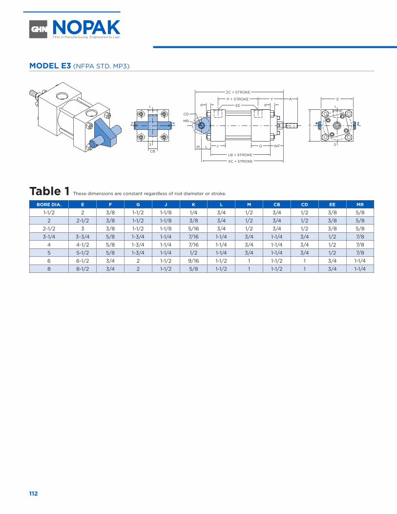
112
MODEL E3 (NFPA STD. MP3)
WF
24 24
AYP + STROKE
ZC + STROKE
EE K
J G
MR
CD
LB + STROKE
XC + STROKE
E
1
3
E
K
LMCB
1
3
2 4
Table 1 These dimensions are constant regardless of rod diameter or stroke.
BORE DIA. E F G J K L M CB CD EE MR
1-1/2 2 3/8 1-1/2 1-1/8 1/4 3/4 1/2 3/4 1/2 3/8 5/8
2 2-1/2 3/8 1-1/2 1-1/8 3/8 3/4 1/2 3/4 1/2 3/8 5/8
2-1/2 3 3/8 1-1/2 1-1/8 5/16 3/4 1/2 3/4 1/2 3/8 5/8
3-1/4 3-3/4 5/8 1-3/4 1-1/4 7/16 1-1/4 3/4 1-1/4 3/4 1/2 7/8
4 4-1/2 5/8 1-3/4 1-1/4 7/16 1-1/4 3/4 1-1/4 3/4 1/2 7/8
5 5-1/2 5/8 1-3/4 1-1/4 1/2 1-1/4 3/4 1-1/4 3/4 1/2 7/8
6 6-1/2 3/4 2 1-1/2 9/16 1-1/2 1 1-1/2 1 3/4 1-1/4
8 8-1/2 3/4 2 1-1/2 5/8 1-1/2 1 1-1/2 1 3/4 1-1/4
FIXED EYE MOUNT CYLINDERS 1-1/2" THROUGH 8" DIAMETER
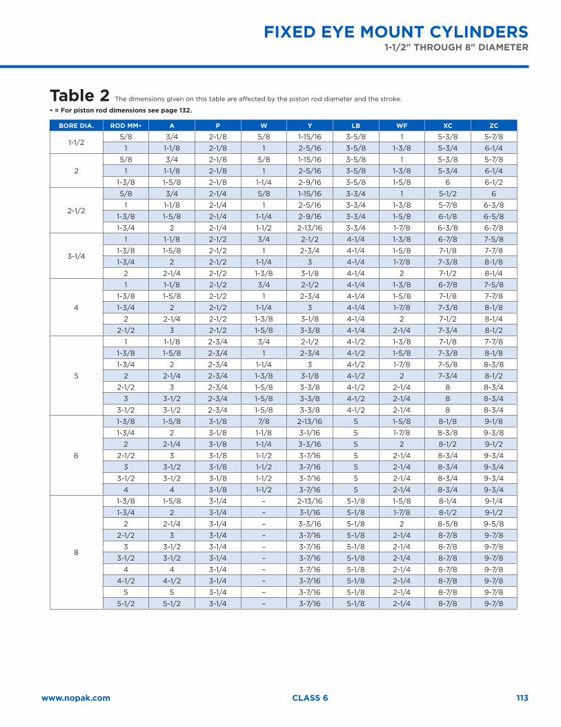
113www.nopak.com CLASS 6
Table 2 The dimensions given on this table are affected by the piston rod diameter and the stroke.
• = For piston rod dimensions see page 132.
BORE DIA. ROD MM• A P W Y LB WF XC ZC
1-1/25/8 3/4 2-1/8 5/8 1-15/16 3-5/8 1 5-3/8 5-7/8
1 1-1/8 2-1/8 1 2-5/16 3-5/8 1-3/8 5-3/4 6-1/4
2
5/8 3/4 2-1/8 5/8 1-15/16 3-5/8 1 5-3/8 5-7/8
1 1-1/8 2-1/8 1 2-5/16 3-5/8 1-3/8 5-3/4 6-1/4
1-3/8 1-5/8 2-1/8 1-1/4 2-9/16 3-5/8 1-5/8 6 6-1/2
2-1/2
5/8 3/4 2-1/4 5/8 1-15/16 3-3/4 1 5-1/2 6
1 1-1/8 2-1/4 1 2-5/16 3-3/4 1-3/8 5-7/8 6-3/8
1-3/8 1-5/8 2-1/4 1-1/4 2-9/16 3-3/4 1-5/8 6-1/8 6-5/8
1-3/4 2 2-1/4 1-1/2 2-13/16 3-3/4 1-7/8 6-3/8 6-7/8
3-1/4
1 1-1/8 2-1/2 3/4 2-1/2 4-1/4 1-3/8 6-7/8 7-5/8
1-3/8 1-5/8 2-1/2 1 2-3/4 4-1/4 1-5/8 7-1/8 7-7/8
1-3/4 2 2-1/2 1-1/4 3 4-1/4 1-7/8 7-3/8 8-1/8
2 2-1/4 2-1/2 1-3/8 3-1/8 4-1/4 2 7-1/2 8-1/4
4
1 1-1/8 2-1/2 3/4 2-1/2 4-1/4 1-3/8 6-7/8 7-5/8
1-3/8 1-5/8 2-1/2 1 2-3/4 4-1/4 1-5/8 7-1/8 7-7/8
1-3/4 2 2-1/2 1-1/4 3 4-1/4 1-7/8 7-3/8 8-1/8
2 2-1/4 2-1/2 1-3/8 3-1/8 4-1/4 2 7-1/2 8-1/4
2-1/2 3 2-1/2 1-5/8 3-3/8 4-1/4 2-1/4 7-3/4 8-1/2
5
1 1-1/8 2-3/4 3/4 2-1/2 4-1/2 1-3/8 7-1/8 7-7/8
1-3/8 1-5/8 2-3/4 1 2-3/4 4-1/2 1-5/8 7-3/8 8-1/8
1-3/4 2 2-3/4 1-1/4 3 4-1/2 1-7/8 7-5/8 8-3/8
2 2-1/4 2-3/4 1-3/8 3-1/8 4-1/2 2 7-3/4 8-1/2
2-1/2 3 2-3/4 1-5/8 3-3/8 4-1/2 2-1/4 8 8-3/4
3 3-1/2 2-3/4 1-5/8 3-3/8 4-1/2 2-1/4 8 8-3/4
3-1/2 3-1/2 2-3/4 1-5/8 3-3/8 4-1/2 2-1/4 8 8-3/4
6
1-3/8 1-5/8 3-1/8 7/8 2-13/16 5 1-5/8 8-1/8 9-1/8
1-3/4 2 3-1/8 1-1/8 3-1/16 5 1-7/8 8-3/8 9-3/8
2 2-1/4 3-1/8 1-1/4 3-3/16 5 2 8-1/2 9-1/2
2-1/2 3 3-1/8 1-1/2 3-7/16 5 2-1/4 8-3/4 9-3/4
3 3-1/2 3-1/8 1-1/2 3-7/16 5 2-1/4 8-3/4 9-3/4
3-1/2 3-1/2 3-1/8 1-1/2 3-7/16 5 2-1/4 8-3/4 9-3/4
4 4 3-1/8 1-1/2 3-7/16 5 2-1/4 8-3/4 9-3/4
8
1-3/8 1-5/8 3-1/4 – 2-13/16 5-1/8 1-5/8 8-1/4 9-1/4
1-3/4 2 3-1/4 – 3-1/16 5-1/8 1-7/8 8-1/2 9-1/2
2 2-1/4 3-1/4 – 3-3/16 5-1/8 2 8-5/8 9-5/8
2-1/2 3 3-1/4 – 3-7/16 5-1/8 2-1/4 8-7/8 9-7/8
3 3-1/2 3-1/4 – 3-7/16 5-1/8 2-1/4 8-7/8 9-7/8
3-1/2 3-1/2 3-1/4 – 3-7/16 5-1/8 2-1/4 8-7/8 9-7/8
4 4 3-1/4 – 3-7/16 5-1/8 2-1/4 8-7/8 9-7/8
4-1/2 4-1/2 3-1/4 – 3-7/16 5-1/8 2-1/4 8-7/8 9-7/8
5 5 3-1/4 – 3-7/16 5-1/8 2-1/4 8-7/8 9-7/8
5-1/2 5-1/2 3-1/4 – 3-7/16 5-1/8 2-1/4 8-7/8 9-7/8
FIXED EYE MOUNT CYLINDERS1-1/2" THROUGH 8" DIAMETER
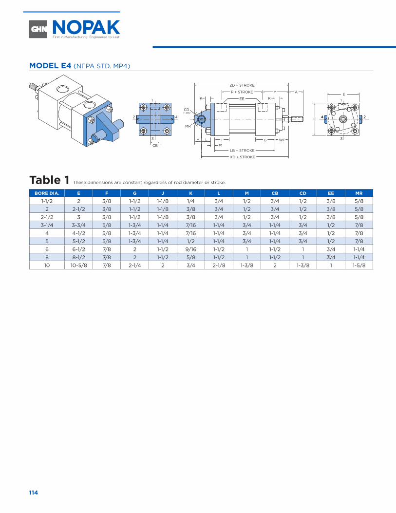
114
MODEL E4 (NFPA STD. MP4)
WF
24
AYP + STROKE
ZD + STROKE
EE K
J GCB
L
F1
MR
CD
M
LB + STROKE
XD + STROKE
E
1
3
24
1
3
2 4 E
± .002
K
Table 1 These dimensions are constant regardless of rod diameter or stroke.
BORE DIA. E F G J K L M CB CD EE MR
1-1/2 2 3/8 1-1/2 1-1/8 1/4 3/4 1/2 3/4 1/2 3/8 5/8
2 2-1/2 3/8 1-1/2 1-1/8 3/8 3/4 1/2 3/4 1/2 3/8 5/8
2-1/2 3 3/8 1-1/2 1-1/8 3/8 3/4 1/2 3/4 1/2 3/8 5/8
3-1/4 3-3/4 5/8 1-3/4 1-1/4 7/16 1-1/4 3/4 1-1/4 3/4 1/2 7/8
4 4-1/2 5/8 1-3/4 1-1/4 7/16 1-1/4 3/4 1-1/4 3/4 1/2 7/8
5 5-1/2 5/8 1-3/4 1-1/4 1/2 1-1/4 3/4 1-1/4 3/4 1/2 7/8
6 6-1/2 7/8 2 1-1/2 9/16 1-1/2 1 1-1/2 1 3/4 1-1/4
8 8-1/2 7/8 2 1-1/2 5/8 1-1/2 1 1-1/2 1 3/4 1-1/4
10 10-5/8 7/8 2-1/4 2 3/4 2-1/8 1-3/8 2 1-3/8 1 1-5/8
DETACHABLE EYE MOUNT CYLINDERS 1-1/2" THROUGH 10" DIAMETER
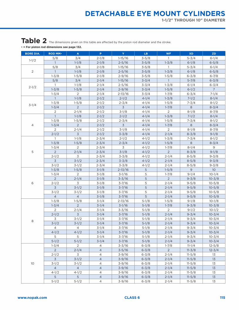
115www.nopak.com CLASS 6
Table 2 The dimensions given on this table are affected by the piston rod diameter and the stroke.
• = For piston rod dimensions see page 132.
BORE DIA. ROD MM• A P Y LB WF XD ZD
1-1/25/8 3/4 2-1/8 1-15/16 3-5/8 1 5-3/4 6-1/4
1 1-1/8 2-1/8 2-5/16 3-5/8 1-3/8 6-1/8 6-5/8
25/8 3/4 2-1/8 1-15/16 3-5/8 1 5-3/4 6-1/4
1 1-1/8 2-1/8 2-5/16 3-5/8 1-3/8 6-1/8 6-5/81-3/8 1-5/8 2-1/8 2-9/16 3-5/8 1-5/8 6-3/8 6-7/8
2-1/2
5/8 3/4 2-1/4 1-15/16 3-3/4 1 5-7/8 6-3/81 1-1/8 2-1/4 2-5/16 3-3/4 1-3/8 6-1/4 6-3/4
1-3/8 1-5/8 2-1/4 2-9/16 3-3/4 1-5/8 6-1/2 71-3/4 2 2-1/4 2-13/16 3-3/4 1-7/8 6-3/4 7-1/4
3-1/4
1 1-1/8 2-1/2 2-1/2 4-1/4 1-3/8 7-1/2 8-1/41-3/8 1-5/8 2-1/2 2-3/4 4-1/4 1-5/8 7-3/4 8-1/21-3/4 2 2-1/2 3 4-1/4 1-7/8 8 8-3/4
2 2-1/4 2-1/2 3-1/8 4-1/4 2 8-1/8 8-7/8
4
1 1-1/8 2-1/2 2-1/2 4-1/4 1-3/8 7-1/2 8-1/41-3/8 1-5/8 2-1/2 2-3/4 4-1/4 1-5/8 7-3/4 8-1/21-3/4 2 2-1/2 3 4-1/4 1-7/8 8 8-3/4
2 2-1/4 2-1/2 3-1/8 4-1/4 2 8-1/8 8-7/82-1/2 3 2-1/2 3-3/8 4-1/4 2-1/4 8-3/8 9-1/8
5
1 1-1/8 2-3/4 2-1/2 4-1/2 1-3/8 7-3/4 8-1/21-3/8 1-5/8 2-3/4 2-3/4 4-1/2 1-5/8 8 8-3/41-3/4 2 2-3/4 3 4-1/2 1-7/8 8-1/4 9
2 2-1/4 2-3/4 3-1/8 4-1/2 2 8-3/8 9-1/82-1/2 3 2-3/4 3-3/8 4-1/2 2-1/4 8-5/8 9-3/8
3 3-1/2 2-3/4 3-3/8 4-1/2 2-1/4 8-5/8 9-3/83-1/2 3-1/2 2-3/4 3-3/8 4-1/2 2-1/4 8-5/8 9-3/8
6
1-3/8 1-5/8 3-1/8 2-13/16 5 1-5/8 9 101-3/4 2 3-1/8 3-1/16 5 1-7/8 9-1/4 10-1/4
2 2-1/4 3-1/8 3-3/16 5 2 9-3/8 10-3/82-1/2 3 3-1/8 3-7/16 5 2-1/4 9-5/8 10-5/8
3 3-1/2 3-1/8 3-7/16 5 2-1/4 9-5/8 10-5/83-1/2 3-1/2 3-1/8 3-7/16 5 2-1/4 9-5/8 10-5/8
4 4 3-1/8 3-7/16 5 2-1/4 9-5/8 10-5/8
8
1-3/8 1-5/8 3-1/4 2-13/16 5-1/8 1-5/8 9-1/8 10-1/81-3/4 2 3-1/4 3-1/16 5-1/8 1-7/8 9-3/8 10-3/8
2 2-1/4 3-1/4 3-3/16 5-1/8 2 9-1/2 10-1/22-1/2 3 3-1/4 3-7/16 5-1/8 2-1/4 9-3/4 10-3/4
3 3-1/2 3-1/4 3-7/16 5-1/8 2-1/4 9-3/4 10-3/43-1/2 3-1/2 3-1/4 3-7/16 5-1/8 2-1/4 9-3/4 10-3/4
4 4 3-1/4 3-7/16 5-1/8 2-1/4 9-3/4 10-3/44-1/2 4-1/2 3-1/4 3-7/16 5-1/8 2-1/4 9-3/4 10-3/4
5 5 3-1/4 3-7/16 5-1/8 2-1/4 9-3/4 10-3/45-1/2 5-1/2 3-1/4 3-7/16 5-1/8 2-1/4 9-3/4 10-3/4
10
1-3/4 2 4 3-3/16 6-3/8 1-7/8 11-1/4 12-5/82 2-1/4 4 3-5/16 6-3/8 2 11-3/8 12-3/4
2-1/2 3 4 3-9/16 6-3/8 2-1/4 11-5/8 133 3-1/2 4 3-9/16 6-3/8 2-1/4 11-5/8 13
3-1/2 3-1/2 4 3-9/16 6-3/8 2-1/4 11-5/8 134 4 4 3-9/16 6-3/8 2-1/4 11-5/8 13
4-1/2 4-1/2 4 3-9/16 6-3/8 2-1/4 11-5/8 135 5 4 3-9/16 6-3/8 2-1/4 11-5/8 13
5-1/2 5-1/2 4 3-9/16 6-3/8 2-1/4 11-5/8 13
DETACHABLE EYE MOUNT CYLINDERS1-1/2" THROUGH 10" DIAMETER
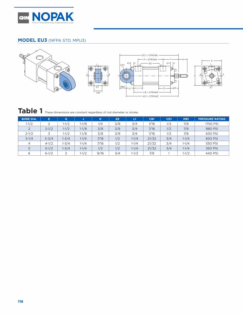
116
MODEL EU3 (NFPA STD. MPU3)
WF
AYP + STROKE
ZC1 + STROKE
EE KK
J G
CB1
L1
CD1
MR1
LB + STROKE
XC1 + STROKE
E
1
3
24
1
3
2 4 E
Table 1 These dimensions are constant regardless of rod diameter or stroke.
BORE DIA. E G J K EE L1 CB1 CD1 MR1 PRESSURE RATING
1-1/2 2 1-1/2 1-1/8 1/4 3/8 3/4 7/16 1/2 7/8 1750 PSI
2 2-1/2 1-1/2 1-1/8 3/8 3/8 3/4 7/16 1/2 7/8 980 PSI
2-1/2 3 1-1/2 1-1/8 3/8 3/8 3/4 7/16 1/2 7/8 630 PSI
3-1/4 3-3/4 1-3/4 1-1/4 7/16 1/2 1-1/4 21/32 3/4 1-1/4 830 PSI
4 4-1/2 1-3/4 1-1/4 7/16 1/2 1-1/4 21/32 3/4 1-1/4 550 PSI
5 5-1/2 1-3/4 1-1/4 1/2 1/2 1-1/4 21/32 3/4 1-1/4 350 PSI
6 6-1/2 2 1-1/2 9/16 3/4 1-1/2 7/8 1 1-1/2 440 PSI
SPHERICAL EYE MOUNT CYLINDERS 1-1/2" THROUGH 6" DIAMETER
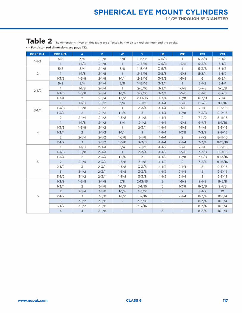
117www.nopak.com CLASS 6
Table 2 The dimensions given on this table are affected by the piston rod diameter and the stroke.
• = For piston rod dimensions see page 132.
BORE DIA. ROD MM• A P W Y LB WF XC1 ZC1
1-1/25/8 3/4 2-1/8 5/8 1-15/16 3-5/8 1 5-3/8 6-1/8
1 1-1/8 2-1/8 1 2-5/16 3-5/8 1-3/8 5-3/4 6-1/2
2
5/8 3/4 2-1/8 5/8 1-15/16 3-5/8 1 5-3/8 6-1/8
1 1-1/8 2-1/8 1 2-5/16 3-5/8 1-3/8 5-3/4 6-1/2
1-3/8 1-5/8 2-1/8 1-1/4 2-9/16 3-5/8 1-5/8 6 6-3/4
2-1/2
5/8 3/4 2-1/4 5/8 1-15/16 3-3/4 1 5-1/2 6-1/4
1 1-1/8 2-1/4 1 2-5/16 3-3/4 1-3/8 5-7/8 5-5/8
1-3/8 1-5/8 2-1/4 1-1/4 2-9/16 3-3/4 1-5/8 6-1/8 6-7/8
1-3/4 2 2-1/4 1-1/2 2-13/16 3-3/4 1-7/8 6-3/8 7-1/8
3-1/4
1 1-1/8 2-1/2 3/4 2-1/2 4-1/4 1-3/8 6-7/8 8-1/16
1-3/8 1-5/8 2-1/2 1 2-3/4 4-1/4 1-5/8 7-1/8 8-5/16
1-3/4 2 2-1/2 1-1/4 3 4-1/4 1-7/8 7-3/8 8-9/16
2 2-1/4 2-1/2 1-3/8 3-1/8 4-1/4 2 7-1 /2 8-11/16
4
1 1-1/8 2-1/2 3/4 2-1/2 4-1/4 1-3/8 6-7/8 8-1/16
1-3/8 1-5/8 2-1/2 1 2-3/4 4-1/4 1-5/8 7-1/8 8-5/16
1-3/4 2 2-1/2 1-1/4 3 4-1/4 1-7/8 7-3/8 8-9/16
2 2-1/4 2-1/2 1-3/8 3-1/8 4-1/4 2 7-1/2 8-11/16
2-1/2 3 2-1/2 1-5/8 3-3/8 4-1/4 2-1/4 7-3/4 8-15/16
5
1 1-1/8 2-3/4 3/4 2-1/2 4-1/2 1-3/8 7-1/8 8-5/16
1-3/8 1-5/8 2-3/4 1 2-3/4 4-1/2 1-5/8 7-3/8 8-9/16
1-3/4 2 2-3/4 1-1/4 3 4-1/2 1-7/8 7-5/8 8-13/16
2 2-1/4 2-3/4 1-3/8 3-1/8 4-1/2 2 7-3/4 8-15/16
2-1/2 3 2-3/4 1-5/8 3-3/8 4-1/2 2-1/4 8 9-3/16
3 3-1/2 2-3/4 1-5/8 3-3/8 4-1/2 2-1/4 8 9-3/16
3-1/2 3-1/2 2-3/4 1-5/8 3-3/8 4-1/2 2-1/4 8 9-3/16
6
1-3/8 1-5/8 3-1/8 7/8 2-13/16 5 1-5/8 8-1/8 9-5/8
1-3/4 2 3-1/8 1-1/8 3-1/16 5 1-7/8 8-3/8 9-7/8
2 2-1/4 3-1/8 1-1/4 3-3/16 5 2 8-1/2 10
2-1/2 3 3-1/8 1-1/2 3-7/16 5 2-1/4 8-3/4 10-1/4
3 3-1/2 3-1/8 – 3-3/16 5 – 8-3/4 10-1/4
3-1/2 3-1/2 3-1/8 – 3-7/16 5 – 8-3/4 10-1/4
4 4 3-1/8 – – 5 – 8-3/4 10-1/4
SPHERICAL EYE MOUNT CYLINDERS1-1/2" THROUGH 6" DIAMETER
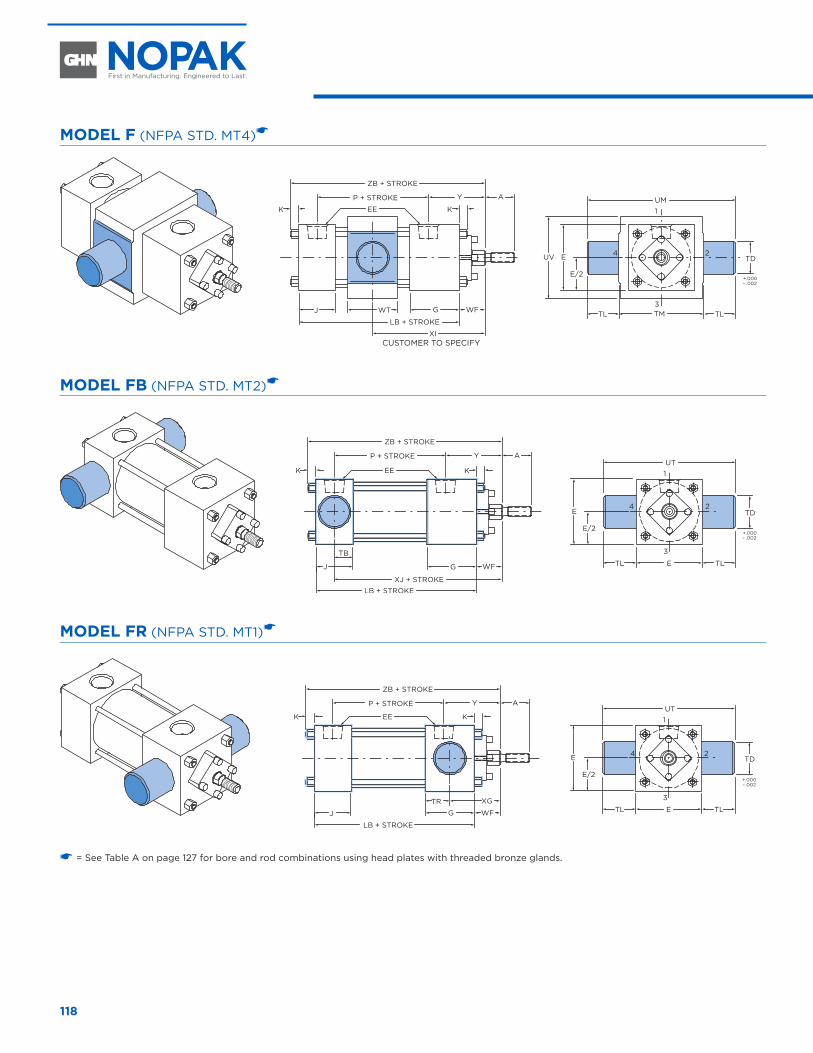
118
MODEL F (NFPA STD. MT4)�
CUSTOMER TO SPECIFY
AYP + STROKE
ZB + STROKE
EEK K
J G WF
LB + STROKE
XI
1
3
24
TMTL TL
EUV
UM
E/2
TD
WT
+.000– .002
MODEL FB (NFPA STD. MT2)�
AYP + STROKE
ZB + STROKE
EEK K
J G WF
LB + STROKEXJ + STROKE
UT1
3
24
ETL TL
E
E/2
TD
TB
+.000– .002
MODEL FR (NFPA STD. MT1)�
AYP + STROKE
ZB + STROKE
EEK K
J G WF
XG
LB + STROKE
UT1
3
24
ETL TL
E
E/2
TD
TR
+.000– .002
� = See Table A on page 127 for bore and rod combinations using head plates with threaded bronze glands.
TRUNNION MOUNT CYLINDERS 1-1/2" THROUGH 6" DIAMETER
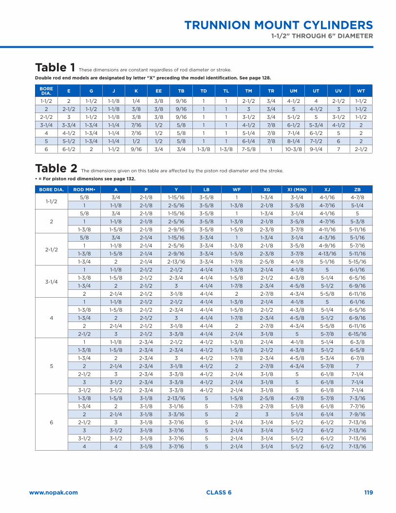
119www.nopak.com CLASS 6
TRUNNION MOUNT CYLINDERS 1-1/2" THROUGH 6" DIAMETER
Table 1 These dimensions are constant regardless of rod diameter or stroke.
Double rod end models are designated by letter “X” preceding the model identification. See page 128.
BORE DIA. E G J K EE TB TD TL TM TR UM UT UV WT
1-1/2 2 1-1/2 1-1/8 1/4 3/8 9/16 1 1 2-1/2 3/4 4-1/2 4 2-1/2 1-1/2
2 2-1/2 1-1/2 1-1/8 3/8 3/8 9/16 1 1 3 3/4 5 4-1/2 3 1-1/2
2-1/2 3 1-1/2 1-1/8 3/8 3/8 9/16 1 1 3-1/2 3/4 5-1/2 5 3-1/2 1-1/2
3-1/4 3-3/4 1-3/4 1-1/4 7/16 1/2 5/8 1 1 4-1/2 7/8 6-1/2 5-3/4 4-1/2 2
4 4-1/2 1-3/4 1-1/4 7/16 1/2 5/8 1 1 5-1/4 7/8 7-1/4 6-1/2 5 2
5 5-1/2 1-3/4 1-1/4 1/2 1/2 5/8 1 1 6-1/4 7/8 8-1/4 7-1/2 6 2
6 6-1/2 2 1-1/2 9/16 3/4 3/4 1-3/8 1-3/8 7-5/8 1 10-3/8 9-1/4 7 2-1/2
Table 2 The dimensions given on this table are affected by the piston rod diameter and the stroke.
• = For piston rod dimensions see page 132.
BORE DIA. ROD MM• A P Y LB WF XG XI (MIN) XJ ZB
1-1/25/8 3/4 2-1/8 1-15/16 3-5/8 1 1-3/4 3-1/4 4-1/16 4-7/8
1 1-1/8 2-1/8 2-5/16 3-5/8 1-3/8 2-1/8 3-5/8 4-7/16 5-1/4
2
5/8 3/4 2-1/8 1-15/16 3-5/8 1 1-3/4 3-1/4 4-1/16 5
1 1-1/8 2-1/8 2-5/16 3-5/8 1-3/8 2-1/8 3-5/8 4-7/16 5-3/8
1-3/8 1-5/8 2-1/8 2-9/16 3-5/8 1-5/8 2-3/8 3-7/8 4-11/16 5-11/16
2-1/2
5/8 3/4 2-1/4 1-15/16 3-3/4 1 1-3/4 3-1/4 4-3/16 5-1/16
1 1-1/8 2-1/4 2-5/16 3-3/4 1-3/8 2-1/8 3-5/8 4-9/16 5-7/16
1-3/8 1-5/8 2-1/4 2-9/16 3-3/4 1-5/8 2-3/8 3-7/8 4-13/16 5-11/16
1-3/4 2 2-1/4 2-13/16 3-3/4 1-7/8 2-5/8 4-1/8 5-1/16 5-15/16
3-1/4
1 1-1/8 2-1/2 2-1/2 4-1/4 1-3/8 2-1/4 4-1/8 5 6-1/16
1-3/8 1-5/8 2-1/2 2-3/4 4-1/4 1-5/8 2-1/2 4-3/8 5-1/4 6-5/16
1-3/4 2 2-1/2 3 4-1/4 1-7/8 2-3/4 4-5/8 5-1/2 6-9/16
2 2-1/4 2-1/2 3-1/8 4-1/4 2 2-7/8 4-3/4 5-5/8 6-11/16
4
1 1-1/8 2-1/2 2-1/2 4-1/4 1-3/8 2-1/4 4-1/8 5 6-1/16
1-3/8 1-5/8 2-1/2 2-3/4 4-1/4 1-5/8 2-1/2 4-3/8 5-1/4 6-5/16
1-3/4 2 2-1/2 3 4-1/4 1-7/8 2-3/4 4-5/8 5-1/2 6-9/16
2 2-1/4 2-1/2 3-1/8 4-1/4 2 2-7/8 4-3/4 5-5/8 6-11/16
2-1/2 3 2-1/2 3-3/8 4-1/4 2-1/4 3-1/8 5 5-7/8 6-15/16
5
1 1-1/8 2-3/4 2-1/2 4-1/2 1-3/8 2-1/4 4-1/8 5-1/4 6-3/8
1-3/8 1-5/8 2-3/4 2-3/4 4-1/2 1-5/8 2-1/2 4-3/8 5-1/2 6-5/8
1-3/4 2 2-3/4 3 4-1/2 1-7/8 2-3/4 4-5/8 5-3/4 6-7/8
2 2-1/4 2-3/4 3-1/8 4-1/2 2 2-7/8 4-3/4 5-7/8 7
2-1/2 3 2-3/4 3-3/8 4-1/2 2-1/4 3-1/8 5 6-1/8 7-1/4
3 3-1/2 2-3/4 3-3/8 4-1/2 2-1/4 3-1/8 5 6-1/8 7-1/4
3-1/2 3-1/2 2-3/4 3-3/8 4-1/2 2-1/4 3-1/8 5 6-1/8 7-1/4
6
1-3/8 1-5/8 3-1/8 2-13/16 5 1-5/8 2-5/8 4-7/8 5-7/8 7-3/16
1-3/4 2 3-1/8 3-1/16 5 1-7/8 2-7/8 5-1/8 6-1/8 7-7/16
2 2-1/4 3-1/8 3-3/16 5 2 3 5-1/4 6-1/4 7-9/16
2-1/2 3 3-1/8 3-7/16 5 2-1/4 3-1/4 5-1/2 6-1/2 7-13/16
3 3-1/2 3-1/8 3-7/16 5 2-1/4 3-1/4 5-1/2 6-1/2 7-13/16
3-1/2 3-1/2 3-1/8 3-7/16 5 2-1/4 3-1/4 5-1/2 6-1/2 7-13/16
4 4 3-1/8 3-7/16 5 2-1/4 3-1/4 5-1/2 6-1/2 7-13/16
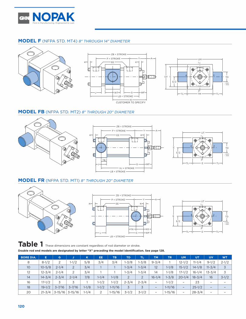
120
MODEL F (NFPA STD. MT4) 8" THROUGH 14" DIAMETER
CUSTOMER TO SPECIFY
AYP + STROKE
ZB + STROKE
EEK K
J G WF
LB + STROKE
XI
1
3
24
TMTL TL
EUV
UM
E/2
TD
WT
+.000– .002
MODEL FB (NFPA STD. MT2) 8" THROUGH 20" DIAMETER
AYP + STROKE
ZB + STROKE
EEK K
J G WF
LB + STROKEXJ + STROKE
UT1
3
24
ETL TL
E
E/2
TD
TB
+.000– .002
MODEL FR (NFPA STD. MT1) 8" THROUGH 20" DIAMETER
AYP + STROKE
ZB + STROKE
EEK K
J G WF
XG
LB + STROKE
UT1
3
24
ETL TL
E
E/2
TD
TR
+.000– .002
Table 1 These dimensions are constant regardless of rod diameter or stroke.
Double rod end models are designated by letter “X” preceding the model identification. See page 128.
BORE DIA. E G J K EE TB TD TL TM TR UM UT UV WT
8 8-1/2 2 1-1/2 5/8 3/4 3/4 1-3/8 1-3/8 9-3/4 1 12-1/2 11-1/4 9-1/2 2-1/2
10 10-5/8 2-1/4 2 3/4 1 1 1-3/4 1-3/4 12 1-1/8 15-1/2 14-1/8 11-3/4 3
12 12-3/4 2-1/4 2 3/4 1 1 1-3/4 1-3/4 14 1-1/8 17-1/2 16-1/4 13-3/4 3
14 14-3/4 2-3/4 2-1/4 7/8 1-1/4 1-1/8 2 2 16-1/4 1-3/8 20-1/4 18-3/4 16 3-1/2
16 17-1/2 3 3 1 1-1/2 1-1/2 2-3/4 2-3/4 – 1-1/2 – 23 – –
18 19-1/2 3-7/16 3-7/16 1-1/8 1-1/2 1-11/16 3 3 – 1-11/16 – 25-1/2 – –
20 21-3/4 3-15/16 3-15/16 1-1/4 2 1-15/16 3-1/2 3-1/2 – 1-15/16 – 28-3/4 – –
8" THROUGH 20" DIAMETER
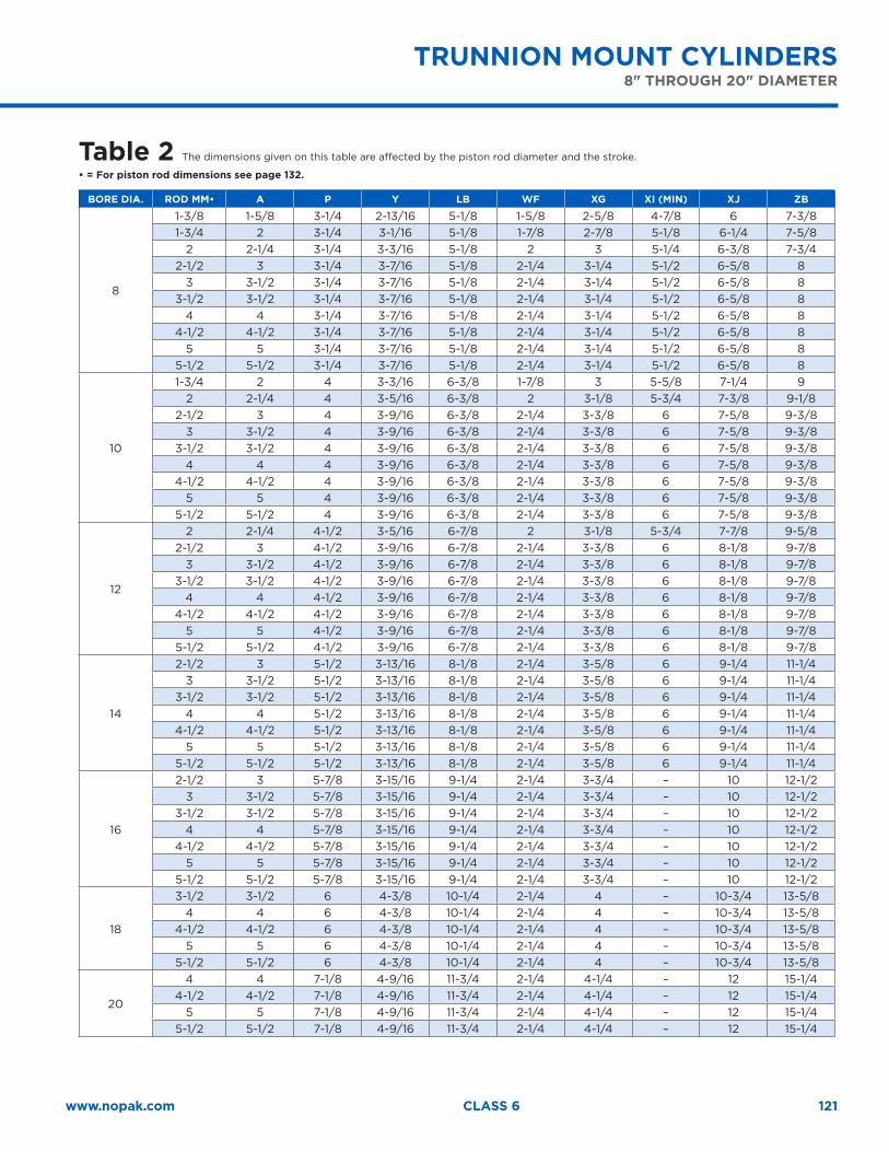
121www.nopak.com CLASS 6
TRUNNION MOUNT CYLINDERS 8" THROUGH 20" DIAMETER
Table 2 The dimensions given on this table are affected by the piston rod diameter and the stroke.
• = For piston rod dimensions see page 132.
BORE DIA. ROD MM• A P Y LB WF XG XI (MIN) XJ ZB
8
1-3/8 1-5/8 3-1/4 2-13/16 5-1/8 1-5/8 2-5/8 4-7/8 6 7-3/81-3/4 2 3-1/4 3-1/16 5-1/8 1-7/8 2-7/8 5-1/8 6-1/4 7-5/8
2 2-1/4 3-1/4 3-3/16 5-1/8 2 3 5-1/4 6-3/8 7-3/42-1/2 3 3-1/4 3-7/16 5-1/8 2-1/4 3-1/4 5-1/2 6-5/8 8
3 3-1/2 3-1/4 3-7/16 5-1/8 2-1/4 3-1/4 5-1/2 6-5/8 83-1/2 3-1/2 3-1/4 3-7/16 5-1/8 2-1/4 3-1/4 5-1/2 6-5/8 8
4 4 3-1/4 3-7/16 5-1/8 2-1/4 3-1/4 5-1/2 6-5/8 84-1/2 4-1/2 3-1/4 3-7/16 5-1/8 2-1/4 3-1/4 5-1/2 6-5/8 8
5 5 3-1/4 3-7/16 5-1/8 2-1/4 3-1/4 5-1/2 6-5/8 85-1/2 5-1/2 3-1/4 3-7/16 5-1/8 2-1/4 3-1/4 5-1/2 6-5/8 8
10
1-3/4 2 4 3-3/16 6-3/8 1-7/8 3 5-5/8 7-1/4 92 2-1/4 4 3-5/16 6-3/8 2 3-1/8 5-3/4 7-3/8 9-1/8
2-1/2 3 4 3-9/16 6-3/8 2-1/4 3-3/8 6 7-5/8 9-3/83 3-1/2 4 3-9/16 6-3/8 2-1/4 3-3/8 6 7-5/8 9-3/8
3-1/2 3-1/2 4 3-9/16 6-3/8 2-1/4 3-3/8 6 7-5/8 9-3/84 4 4 3-9/16 6-3/8 2-1/4 3-3/8 6 7-5/8 9-3/8
4-1/2 4-1/2 4 3-9/16 6-3/8 2-1/4 3-3/8 6 7-5/8 9-3/85 5 4 3-9/16 6-3/8 2-1/4 3-3/8 6 7-5/8 9-3/8
5-1/2 5-1/2 4 3-9/16 6-3/8 2-1/4 3-3/8 6 7-5/8 9-3/8
12
2 2-1/4 4-1/2 3-5/16 6-7/8 2 3-1/8 5-3/4 7-7/8 9-5/82-1/2 3 4-1/2 3-9/16 6-7/8 2-1/4 3-3/8 6 8-1/8 9-7/8
3 3-1/2 4-1/2 3-9/16 6-7/8 2-1/4 3-3/8 6 8-1/8 9-7/83-1/2 3-1/2 4-1/2 3-9/16 6-7/8 2-1/4 3-3/8 6 8-1/8 9-7/8
4 4 4-1/2 3-9/16 6-7/8 2-1/4 3-3/8 6 8-1/8 9-7/84-1/2 4-1/2 4-1/2 3-9/16 6-7/8 2-1/4 3-3/8 6 8-1/8 9-7/8
5 5 4-1/2 3-9/16 6-7/8 2-1/4 3-3/8 6 8-1/8 9-7/85-1/2 5-1/2 4-1/2 3-9/16 6-7/8 2-1/4 3-3/8 6 8-1/8 9-7/8
14
2-1/2 3 5-1/2 3-13/16 8-1/8 2-1/4 3-5/8 6 9-1/4 11-1/43 3-1/2 5-1/2 3-13/16 8-1/8 2-1/4 3-5/8 6 9-1/4 11-1/4
3-1/2 3-1/2 5-1/2 3-13/16 8-1/8 2-1/4 3-5/8 6 9-1/4 11-1/44 4 5-1/2 3-13/16 8-1/8 2-1/4 3-5/8 6 9-1/4 11-1/4
4-1/2 4-1/2 5-1/2 3-13/16 8-1/8 2-1/4 3-5/8 6 9-1/4 11-1/45 5 5-1/2 3-13/16 8-1/8 2-1/4 3-5/8 6 9-1/4 11-1/4
5-1/2 5-1/2 5-1/2 3-13/16 8-1/8 2-1/4 3-5/8 6 9-1/4 11-1/4
16
2-1/2 3 5-7/8 3-15/16 9-1/4 2-1/4 3-3/4 – 10 12-1/23 3-1/2 5-7/8 3-15/16 9-1/4 2-1/4 3-3/4 – 10 12-1/2
3-1/2 3-1/2 5-7/8 3-15/16 9-1/4 2-1/4 3-3/4 – 10 12-1/24 4 5-7/8 3-15/16 9-1/4 2-1/4 3-3/4 – 10 12-1/2
4-1/2 4-1/2 5-7/8 3-15/16 9-1/4 2-1/4 3-3/4 – 10 12-1/25 5 5-7/8 3-15/16 9-1/4 2-1/4 3-3/4 – 10 12-1/2
5-1/2 5-1/2 5-7/8 3-15/16 9-1/4 2-1/4 3-3/4 – 10 12-1/2
18
3-1/2 3-1/2 6 4-3/8 10-1/4 2-1/4 4 – 10-3/4 13-5/84 4 6 4-3/8 10-1/4 2-1/4 4 – 10-3/4 13-5/8
4-1/2 4-1/2 6 4-3/8 10-1/4 2-1/4 4 – 10-3/4 13-5/85 5 6 4-3/8 10-1/4 2-1/4 4 – 10-3/4 13-5/8
5-1/2 5-1/2 6 4-3/8 10-1/4 2-1/4 4 – 10-3/4 13-5/8
20
4 4 7-1/8 4-9/16 11-3/4 2-1/4 4-1/4 – 12 15-1/44-1/2 4-1/2 7-1/8 4-9/16 11-3/4 2-1/4 4-1/4 – 12 15-1/4
5 5 7-1/8 4-9/16 11-3/4 2-1/4 4-1/4 – 12 15-1/45-1/2 5-1/2 7-1/8 4-9/16 11-3/4 2-1/4 4-1/4 – 12 15-1/4
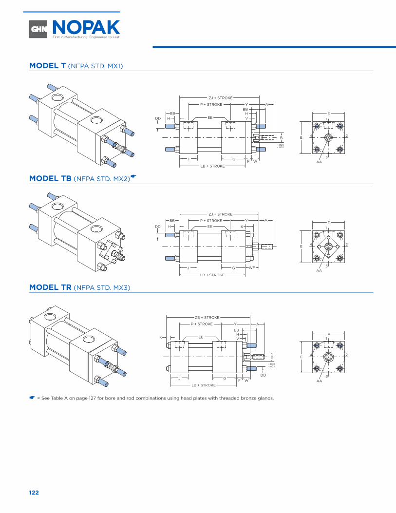
122
MODEL T (NFPA STD. MX1)
AA
AYP + STROKE
ZJ + STROKE
EE
J G
H
LB + STROKE
E1
3
24E
DDBB
WF
B
+.000– .002
BB
VH
MODEL TB (NFPA STD. MX2)�
AA
AYP + STROKE
ZJ + STROKE
EE
J G
H
LB + STROKE
E1
3
24E
DD
BB
WF
K
MODEL TR (NFPA STD. MX3)
K
B
+.000 –.002
AA
AYP + STROKE
ZB + STROKE
EE
J G
LB + STROKE
E1
3
24E
WFDD
V
BBH
� = See Table A on page 127 for bore and rod combinations using head plates with threaded bronze glands.
TIE-ROD MOUNT CYLINDERS 1-1/2" THROUGH 6" DIAMETER
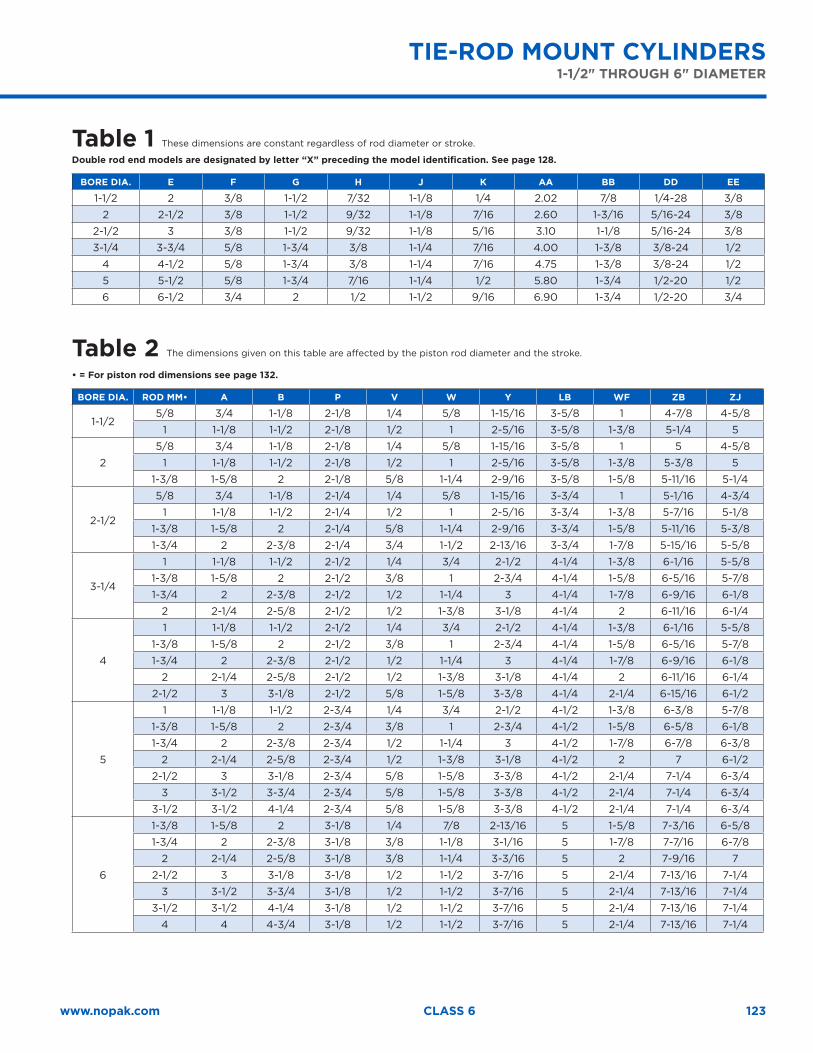
123www.nopak.com CLASS 6
TIE-ROD MOUNT CYLINDERS 1-1/2" THROUGH 6" DIAMETER
Table 1 These dimensions are constant regardless of rod diameter or stroke.
Double rod end models are designated by letter “X” preceding the model identification. See page 128.
BORE DIA. E F G H J K AA BB DD EE
1-1/2 2 3/8 1-1/2 7/32 1-1/8 1/4 2.02 7/8 1/4-28 3/8
2 2-1/2 3/8 1-1/2 9/32 1-1/8 7/16 2.60 1-3/16 5/16-24 3/8
2-1/2 3 3/8 1-1/2 9/32 1-1/8 5/16 3.10 1-1/8 5/16-24 3/8
3-1/4 3-3/4 5/8 1-3/4 3/8 1-1/4 7/16 4.00 1-3/8 3/8-24 1/2
4 4-1/2 5/8 1-3/4 3/8 1-1/4 7/16 4.75 1-3/8 3/8-24 1/2
5 5-1/2 5/8 1-3/4 7/16 1-1/4 1/2 5.80 1-3/4 1/2-20 1/2
6 6-1/2 3/4 2 1/2 1-1/2 9/16 6.90 1-3/4 1/2-20 3/4
Table 2 The dimensions given on this table are affected by the piston rod diameter and the stroke.
• = For piston rod dimensions see page 132.
BORE DIA. ROD MM• A B P V W Y LB WF ZB ZJ
1-1/25/8 3/4 1-1/8 2-1/8 1/4 5/8 1-15/16 3-5/8 1 4-7/8 4-5/8
1 1-1/8 1-1/2 2-1/8 1/2 1 2-5/16 3-5/8 1-3/8 5-1/4 5
2
5/8 3/4 1-1/8 2-1/8 1/4 5/8 1-15/16 3-5/8 1 5 4-5/8
1 1-1/8 1-1/2 2-1/8 1/2 1 2-5/16 3-5/8 1-3/8 5-3/8 5
1-3/8 1-5/8 2 2-1/8 5/8 1-1/4 2-9/16 3-5/8 1-5/8 5-11/16 5-1/4
2-1/2
5/8 3/4 1-1/8 2-1/4 1/4 5/8 1-15/16 3-3/4 1 5-1/16 4-3/4
1 1-1/8 1-1/2 2-1/4 1/2 1 2-5/16 3-3/4 1-3/8 5-7/16 5-1/8
1-3/8 1-5/8 2 2-1/4 5/8 1-1/4 2-9/16 3-3/4 1-5/8 5-11/16 5-3/8
1-3/4 2 2-3/8 2-1/4 3/4 1-1/2 2-13/16 3-3/4 1-7/8 5-15/16 5-5/8
3-1/4
1 1-1/8 1-1/2 2-1/2 1/4 3/4 2-1/2 4-1/4 1-3/8 6-1/16 5-5/8
1-3/8 1-5/8 2 2-1/2 3/8 1 2-3/4 4-1/4 1-5/8 6-5/16 5-7/8
1-3/4 2 2-3/8 2-1/2 1/2 1-1/4 3 4-1/4 1-7/8 6-9/16 6-1/8
2 2-1/4 2-5/8 2-1/2 1/2 1-3/8 3-1/8 4-1/4 2 6-11/16 6-1/4
4
1 1-1/8 1-1/2 2-1/2 1/4 3/4 2-1/2 4-1/4 1-3/8 6-1/16 5-5/8
1-3/8 1-5/8 2 2-1/2 3/8 1 2-3/4 4-1/4 1-5/8 6-5/16 5-7/8
1-3/4 2 2-3/8 2-1/2 1/2 1-1/4 3 4-1/4 1-7/8 6-9/16 6-1/8
2 2-1/4 2-5/8 2-1/2 1/2 1-3/8 3-1/8 4-1/4 2 6-11/16 6-1/4
2-1/2 3 3-1/8 2-1/2 5/8 1-5/8 3-3/8 4-1/4 2-1/4 6-15/16 6-1/2
5
1 1-1/8 1-1/2 2-3/4 1/4 3/4 2-1/2 4-1/2 1-3/8 6-3/8 5-7/8
1-3/8 1-5/8 2 2-3/4 3/8 1 2-3/4 4-1/2 1-5/8 6-5/8 6-1/8
1-3/4 2 2-3/8 2-3/4 1/2 1-1/4 3 4-1/2 1-7/8 6-7/8 6-3/8
2 2-1/4 2-5/8 2-3/4 1/2 1-3/8 3-1/8 4-1/2 2 7 6-1/2
2-1/2 3 3-1/8 2-3/4 5/8 1-5/8 3-3/8 4-1/2 2-1/4 7-1/4 6-3/4
3 3-1/2 3-3/4 2-3/4 5/8 1-5/8 3-3/8 4-1/2 2-1/4 7-1/4 6-3/4
3-1/2 3-1/2 4-1/4 2-3/4 5/8 1-5/8 3-3/8 4-1/2 2-1/4 7-1/4 6-3/4
6
1-3/8 1-5/8 2 3-1/8 1/4 7/8 2-13/16 5 1-5/8 7-3/16 6-5/8
1-3/4 2 2-3/8 3-1/8 3/8 1-1/8 3-1/16 5 1-7/8 7-7/16 6-7/8
2 2-1/4 2-5/8 3-1/8 3/8 1-1/4 3-3/16 5 2 7-9/16 7
2-1/2 3 3-1/8 3-1/8 1/2 1-1/2 3-7/16 5 2-1/4 7-13/16 7-1/4
3 3-1/2 3-3/4 3-1/8 1/2 1-1/2 3-7/16 5 2-1/4 7-13/16 7-1/4
3-1/2 3-1/2 4-1/4 3-1/8 1/2 1-1/2 3-7/16 5 2-1/4 7-13/16 7-1/4
4 4 4-3/4 3-1/8 1/2 1-1/2 3-7/16 5 2-1/4 7-13/16 7-1/4
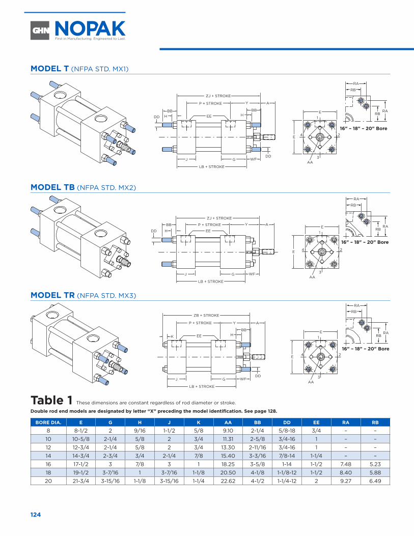
124
MODEL T (NFPA STD. MX1)
16" – 18" – 20" Bore
AA
DD
BBH
A
WF
YP + STROKE
ZJ + STROKE
EE
J G
LB + STROKE
E
RB
RA
1
3
24E
DD
BBH
RBRA
MODEL TB (NFPA STD. MX2)
16" – 18" – 20" Bore
AA
AYP + STROKE
ZJ + STROKE
EE
J G
H
LB + STROKE
E1
3
24E
DD
BB
WF
RB
RA
RBRA
MODEL TR (NFPA STD. MX3)
16" – 18" – 20" Bore
RB
RA
RBRA
AA
P + STROKE
ZB + STROKE
EE
J G
K
LB + STROKE
E1
3
24E
DD
BBH
AY
WF
Table 1 These dimensions are constant regardless of rod diameter or stroke.
Double rod end models are designated by letter “X” preceding the model identification. See page 128.
BORE DIA. E G H J K AA BB DD EE RA RB
8 8-1/2 2 9/16 1-1/2 5/8 9.10 2-1/4 5/8-18 3/4 – –
10 10-5/8 2-1/4 5/8 2 3/4 11.31 2-5/8 3/4-16 1 – –
12 12-3/4 2-1/4 5/8 2 3/4 13.30 2-11/16 3/4-16 1 – –
14 14-3/4 2-3/4 3/4 2-1/4 7/8 15.40 3-3/16 7/8-14 1-1/4 – –
16 17-1/2 3 7/8 3 1 18.25 3-5/8 1-14 1-1/2 7.48 5.23
18 19-1/2 3-7/16 1 3-7/16 1-1/8 20.50 4-1/8 1-1/8-12 1-1/2 8.40 5.88
20 21-3/4 3-15/16 1-1/8 3-15/16 1-1/4 22.62 4-1/2 1-1/4-12 2 9.27 6.49
8" THROUGH 20" DIAMETER
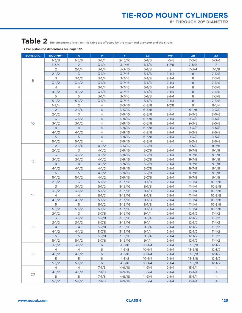
125www.nopak.com CLASS 6
TIE-ROD MOUNT CYLINDERS 8" THROUGH 20" DIAMETER
Table 2 The dimensions given on this table are affected by the piston rod diameter and the stroke.
• = For piston rod dimensions see page 132.
BORE DIA. ROD MM• A P Y LB WF ZB ZJ
8
1-3/8 1-5/8 3-1/4 2-13/16 5-1/8 1-5/8 7-3/8 6-3/41-3/4 2 3-1/4 3-1/16 5-1/8 1-7/8 7-5/8 7
2 2-1/4 3-1/4 3-3/16 5-1/8 2 7-3/4 7-1/82-1/2 3 3-1/4 3-7/16 5-1/8 2-1/4 8 7-3/8
3 3-1/2 3-1/4 3-7/16 5-1/8 2-1/4 8 7-3/83-1/2 3-1/2 3-1/4 3-7/16 5-1/8 2-1/4 8 7-3/8
4 4 3-1/4 3-7/16 5-1/8 2-1/4 8 7-3/84-1/2 4-1/2 3-1/4 3-7/16 5-1/8 2-1/4 8 7-3/8
5 5 3-1/4 3-7/16 5-1/8 2-1/4 8 7-3/85-1/2 5-1/2 3-1/4 3-7/16 5-1/8 2-1/4 8 7-3/8
10
1-3/4 2 4 3-3/16 6-3/8 1-7/8 9 8-1/42 2-1/4 4 3-5/16 6-3/8 2 9-1/8 8-3/8
2-1/2 3 4 3-9/16 6-3/8 2-1/4 9-3/8 8-5/83 3-1/2 4 3-9/16 6-3/8 2-1/4 9-3/8 8-5/8
3-1/2 3-1/2 4 3-9/16 6-3/8 2-1/4 9-3/8 8-5/84 4 4 3-9/16 6-3/8 2-1/4 9-3/8 8-5/8
4-1/2 4-1/2 4 3-9/16 6-3/8 2-1/4 9-3/8 8-5/85 5 4 3-9/16 6-3/8 2-1/4 9-3/8 8-5/8
5-1/2 5-1/2 4 3-9/16 6-3/8 2-1/4 9-3/8 8-5/8
12
2 2-1/4 4-1/2 3-5/16 6-7/8 2 9-5/8 8-7/82-1/2 3 4-1/2 3-9/16 6-7/8 2-1/4 9-7/8 9-1/8
3 3-1/2 4-1/2 3-9/16 6-7/8 2-1/4 9-7/8 9-1/83-1/2 3-1/2 4-1/2 3-9/16 6-7/8 2-1/4 9-7/8 9-1/8
4 4 4-1/2 3-9/16 6-7/8 2-1/4 9-7/8 9-1/84-1/2 4-1/2 4-1/2 3-9/16 6-7/8 2-1/4 9-7/8 9-1/8
5 5 4-1/2 3-9/16 6-7/8 2-1/4 9-7/8 9-1/85-1/2 5-1/2 4-1/2 3-9/16 6-7/8 2-1/4 9-7/8 9-1/8
14
2-1/2 3 5-1/2 3-13/16 8-1/8 2-1/4 11-1/4 10-3/83 3-1/2 5-1/2 3-13/16 8-1/8 2-1/4 11-1/4 10-3/8
3-1/2 3-1/2 5-1/2 3-13/16 8-1/8 2-1/4 11-1/4 10-3/84 4 5-1/2 3-13/16 8-1/8 2-1/4 11-1/4 10-3/8
4-1/2 4-1/2 5-1/2 3-13/16 8-1/8 2-1/4 11-1/4 10-3/85 5 5-1/2 3-13/16 8-1/8 2-1/4 11-1/4 10-3/8
5-1/2 5-1/2 5-1/2 3-13/16 8-1/8 2-1/4 11-1/4 10-3/8
16
2-1/2 3 5-7/8 3-15/16 9-1/4 2-1/4 12-1/2 11-1/23 3-1/2 5-7/8 3-15/16 9-1/4 2-1/4 12-1/2 11-1/2
3-1/2 3-1/2 5-7/8 3-15/16 9-1/4 2-1/4 12-1/2 11-1/24 4 5-7/8 3-15/16 9-1/4 2-1/4 12-1/2 11-1/2
4-1/2 4-1/2 5-7/8 3-15/16 9-1/4 2-1/4 12-1/2 11-1/25 5 5-7/8 3-15/16 9-1/4 2-1/4 12-1/2 11-1/2
5-1/2 5-1/2 5-7/8 3-15/16 9-1/4 2-1/4 12-1/2 11-1/2
18
3-1/2 3-1/2 6 4-3/8 10-1/4 2-1/4 13-5/8 12-1/24 4 6 4-3/8 10-1/4 2-1/4 13-5/8 12-1/2
4-1/2 4-1/2 6 4-3/8 10-1/4 2-1/4 13-5/8 12-1/25 5 6 4-3/8 10-1/4 2-1/4 13-5/8 12-1/2
5-1/2 5-1/2 6 4-3/8 10-1/4 2-1/4 13-5/8 12-1/2
20
4 4 7-1/8 4-9/16 11-3/4 2-1/4 15-1/4 144-1/2 4-1/2 7-1/8 4-9/16 11-3/4 2-1/4 15-1/4 14
5 5 7-1/8 4-9/16 11-3/4 2-1/4 15-1/4 145-1/2 5-1/2 7-1/8 4-9/16 11-3/4 2-1/4 15-1/4 14
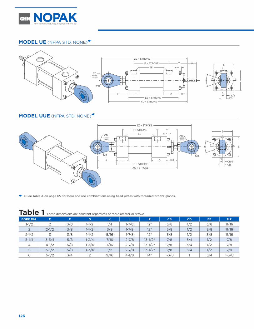
126
MODEL UE (NFPA STD. NONE)�
AYP + STROKE
ZC + STROKE
EE K
J GL
LB + STROKE
XC + STROKE
E1
3
2 4
CBCB/2
R E
WF
MR
CD+.0015– .0005
MODEL UUE (NFPA STD. NONE)�
YP + STROKE
ZZ + STROKE
EE K
J GLLB + STROKE
XC + STROKE
E1
3
2 4
CBCB/2
R E
WF
MR
CD+.0015– .0005
CD+.0015– .0005
MR
–
� = See Table A on page 127 for bore and rod combinations using head plates with threaded bronze glands.
Table 1 These dimensions are constant regardless of rod diameter or stroke.
BORE DIA. E F G K L R CB CD EE MR
1-1/2 2 3/8 1-1/2 1/4 1-7/8 12° 5/8 1/2 3/8 11/16
2 2-1/2 3/8 1-1/2 3/8 1-7/8 12° 5/8 1/2 3/8 11/16
2-1/2 3 3/8 1-1/2 5/16 1-7/8 12° 5/8 1/2 3/8 11/16
3-1/4 3-3/4 5/8 1-3/4 7/16 2-7/8 13-1/2° 7/8 3/4 1/2 7/8
4 4-1/2 5/8 1-3/4 7/16 2-7/8 13-1/2° 7/8 3/4 1/2 7/8
5 5-1/2 5/8 1-3/4 1/2 2-7/8 13-1/2° 7/8 3/4 1/2 7/8
6 6-1/2 3/4 2 9/16 4-1/8 14° 1-3/8 1 3/4 1-3/8
SPHERICAL EYE PIN MOUNT CYLINDERS 1-1/2" THROUGH 6" DIAMETER
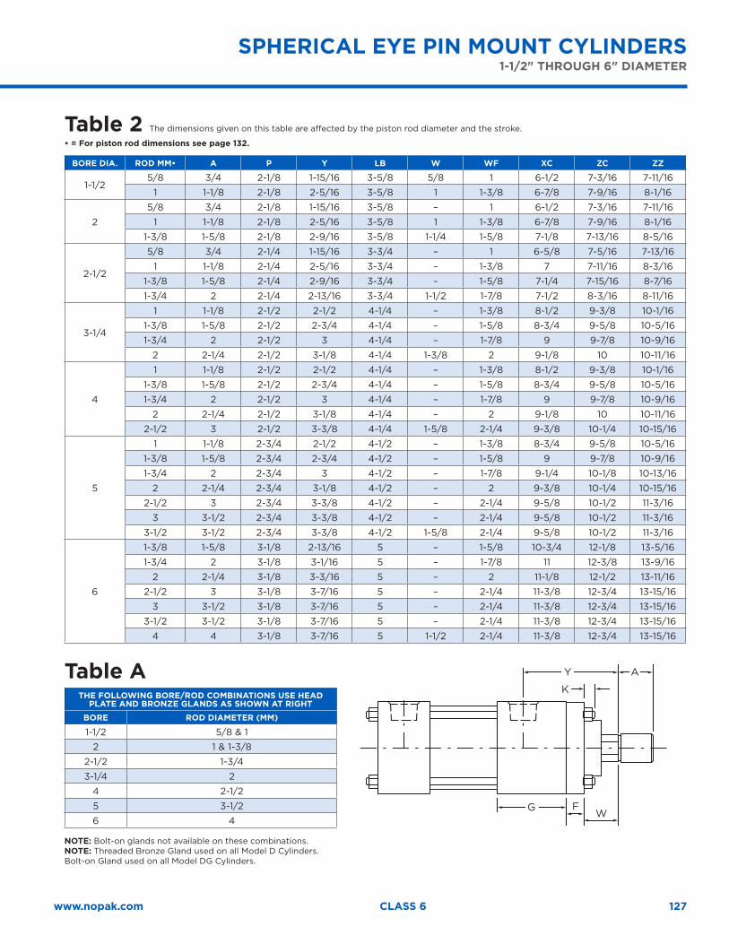
127www.nopak.com CLASS 6
SPHERICAL EYE PIN MOUNT CYLINDERS 1-1/2" THROUGH 6" DIAMETER
Table 2 The dimensions given on this table are affected by the piston rod diameter and the stroke.
• = For piston rod dimensions see page 132.
BORE DIA. ROD MM• A P Y LB W WF XC ZC ZZ
1-1/25/8 3/4 2-1/8 1-15/16 3-5/8 5/8 1 6-1/2 7-3/16 7-11/16
1 1-1/8 2-1/8 2-5/16 3-5/8 1 1-3/8 6-7/8 7-9/16 8-1/16
2
5/8 3/4 2-1/8 1-15/16 3-5/8 – 1 6-1/2 7-3/16 7-11/16
1 1-1/8 2-1/8 2-5/16 3-5/8 1 1-3/8 6-7/8 7-9/16 8-1/16
1-3/8 1-5/8 2-1/8 2-9/16 3-5/8 1-1/4 1-5/8 7-1/8 7-13/16 8-5/16
2-1/2
5/8 3/4 2-1/4 1-15/16 3-3/4 – 1 6-5/8 7-5/16 7-13/16
1 1-1/8 2-1/4 2-5/16 3-3/4 – 1-3/8 7 7-11/16 8-3/16
1-3/8 1-5/8 2-1/4 2-9/16 3-3/4 – 1-5/8 7-1/4 7-15/16 8-7/16
1-3/4 2 2-1/4 2-13/16 3-3/4 1-1/2 1-7/8 7-1/2 8-3/16 8-11/16
3-1/4
1 1-1/8 2-1/2 2-1/2 4-1/4 – 1-3/8 8-1/2 9-3/8 10-1/16
1-3/8 1-5/8 2-1/2 2-3/4 4-1/4 – 1-5/8 8-3/4 9-5/8 10-5/16
1-3/4 2 2-1/2 3 4-1/4 – 1-7/8 9 9-7/8 10-9/16
2 2-1/4 2-1/2 3-1/8 4-1/4 1-3/8 2 9-1/8 10 10-11/16
4
1 1-1/8 2-1/2 2-1/2 4-1/4 – 1-3/8 8-1/2 9-3/8 10-1/16
1-3/8 1-5/8 2-1/2 2-3/4 4-1/4 – 1-5/8 8-3/4 9-5/8 10-5/16
1-3/4 2 2-1/2 3 4-1/4 – 1-7/8 9 9-7/8 10-9/16
2 2-1/4 2-1/2 3-1/8 4-1/4 – 2 9-1/8 10 10-11/16
2-1/2 3 2-1/2 3-3/8 4-1/4 1-5/8 2-1/4 9-3/8 10-1/4 10-15/16
5
1 1-1/8 2-3/4 2-1/2 4-1/2 – 1-3/8 8-3/4 9-5/8 10-5/16
1-3/8 1-5/8 2-3/4 2-3/4 4-1/2 – 1-5/8 9 9-7/8 10-9/16
1-3/4 2 2-3/4 3 4-1/2 – 1-7/8 9-1/4 10-1/8 10-13/16
2 2-1/4 2-3/4 3-1/8 4-1/2 – 2 9-3/8 10-1/4 10-15/16
2-1/2 3 2-3/4 3-3/8 4-1/2 – 2-1/4 9-5/8 10-1/2 11-3/16
3 3-1/2 2-3/4 3-3/8 4-1/2 – 2-1/4 9-5/8 10-1/2 11-3/16
3-1/2 3-1/2 2-3/4 3-3/8 4-1/2 1-5/8 2-1/4 9-5/8 10-1/2 11-3/16
6
1-3/8 1-5/8 3-1/8 2-13/16 5 – 1-5/8 10-3/4 12-1/8 13-5/16
1-3/4 2 3-1/8 3-1/16 5 – 1-7/8 11 12-3/8 13-9/16
2 2-1/4 3-1/8 3-3/16 5 – 2 11-1/8 12-1/2 13-11/16
2-1/2 3 3-1/8 3-7/16 5 – 2-1/4 11-3/8 12-3/4 13-15/16
3 3-1/2 3-1/8 3-7/16 5 – 2-1/4 11-3/8 12-3/4 13-15/16
3-1/2 3-1/2 3-1/8 3-7/16 5 – 2-1/4 11-3/8 12-3/4 13-15/16
4 4 3-1/8 3-7/16 5 1-1/2 2-1/4 11-3/8 12-3/4 13-15/16
Table ATHE FOLLOWING BORE/ROD COMBINATIONS USE HEAD
PLATE AND BRONZE GLANDS AS SHOWN AT RIGHT
BORE ROD DIAMETER (MM)
1-1/2 5/8 & 1
2 1 & 1-3/8
2-1/2 1-3/4
3-1/4 2
4 2-1/2
5 3-1/2
6 4
NOTE: Bolt-on glands not available on these combinations.NOTE: Threaded Bronze Gland used on all Model D Cylinders. Bolt-on Gland used on all Model DG Cylinders.
G W
AY
F
K
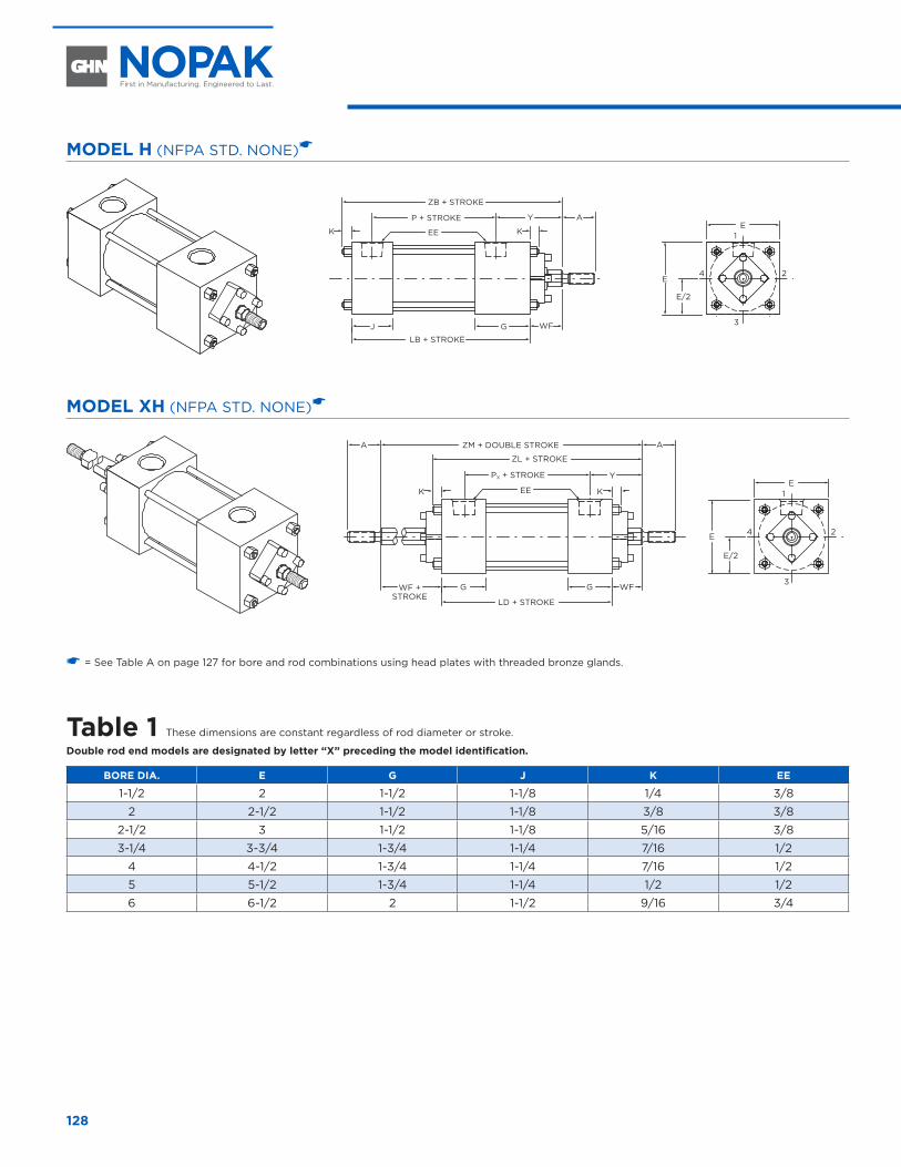
128
MODEL H (NFPA STD. NONE)�
AYP + STROKE
ZB + STROKE
EEK K
J G
LB + STROKE
1
3
24
WF
E
E
E/2
MODEL XH (NFPA STD. NONE)�
A
Y
ZL + STROKE
ZM + DOUBLE STROKEA
EEK K
G G
LD + STROKE
1
3
24
WFWF +STROKE
E
E
E/2
PX + STROKE
� = See Table A on page 127 for bore and rod combinations using head plates with threaded bronze glands.
Table 1 These dimensions are constant regardless of rod diameter or stroke.
Double rod end models are designated by letter “X” preceding the model identification.
BORE DIA. E G J K EE
1-1/2 2 1-1/2 1-1/8 1/4 3/8
2 2-1/2 1-1/2 1-1/8 3/8 3/8
2-1/2 3 1-1/2 1-1/8 5/16 3/8
3-1/4 3-3/4 1-3/4 1-1/4 7/16 1/2
4 4-1/2 1-3/4 1-1/4 7/16 1/2
5 5-1/2 1-3/4 1-1/4 1/2 1/2
6 6-1/2 2 1-1/2 9/16 3/4
BASIC MODEL NO MOUNT CYLINDERS 1-1/2" THROUGH 6" DIAMETER
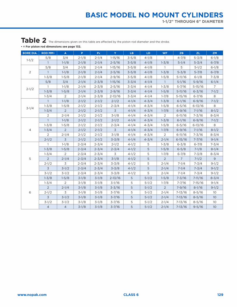
129www.nopak.com CLASS 6
BASIC MODEL NO MOUNT CYLINDERS 1-1/2" THROUGH 6" DIAMETER
Table 2 The dimensions given on this table are affected by the piston rod diameter and the stroke.
• = For piston rod dimensions see page 132.
BORE DIA. ROD MM• A P PX Y LB LD WF ZB ZL ZM
1-1/25/8 3/4 2-1/8 2-1/4 1-15/16 3-5/8 4-1/8 1 4-7/8 5-3/8 6-1/8
1 1-1/8 2-1/8 2-1/4 2-5/16 3-5/8 4-1/8 1-3/8 5-1/4 5-3/4 6-7/8
2
5/8 3/4 2-1/8 2-1/4 1-15/16 3-5/8 4-1/8 1 5 5-1/2 6-1/8
1 1-1/8 2-1/8 2-1/4 2-5/16 3-5/8 4-1/8 1-3/8 5-3/8 5-7/8 6-7/8
1-3/8 1-5/8 2-1/8 2-1/4 2-9/16 3-5/8 4-1/8 1-5/8 5-11/16 6-1/8 7-3/8
2-1/2
5/8 3/4 2-1/4 2-3/8 1-15/16 3-3/4 4-1/4 1 5-1/16 5-9/16 6-1/4
1 1-1/8 2-1/4 2-3/8 2-5/16 3-3/4 4-1/4 1-3/8 5-7/16 5-15/16 7
1-3/8 1-5/8 2-1/4 2-3/8 2-9/16 3-3/4 4-1/4 1-5/8 5-11/16 6-3/16 7-1/2
1-3/4 2 2-1/4 2-3/8 2-13/16 3-3/4 4-1/4 1-7/8 5-15/16 6-7/16 8
3-1/4
1 1-1/8 2-1/2 2-1/2 2-1/2 4-1/4 4-3/4 1-3/8 6-1/16 6-9/16 7-1/2
1-3/8 1-5/8 2-1/2 2-1/2 2-3/4 4-1/4 4-3/4 1-5/8 6-5/16 6-13/16 8
1-3/4 2 2-1/2 2-1/2 3 4-1/4 4-3/4 1-7/8 6-9/16 7-1/16 8-1/2
2 2-1/4 2-1/2 2-1/2 3-1/8 4-1/4 4-3/4 2 6-11/16 7-3/16 8-3/4
4
1 1-1/8 2-1/2 2-1/2 2-1/2 4-1/4 4-3/4 1-3/8 6-1/16 6-9/16 7-1/2
1-3/8 1-5/8 2-1/2 2-1/2 2-3/4 4-1/4 4-3/4 1-5/8 6-5/16 6-13/16 8
1-3/4 2 2-1/2 2-1/2 3 4-1/4 4-3/4 1-7/8 6-9/16 7-1/16 8-1/2
2 2-1/4 2-1/2 2-1/2 3-1/8 4-1/4 4-3/4 2 6-11/16 7-3/16 8-3/4
2-1/2 3 2-1/2 2-1/2 3-3/8 4-1/4 4-3/4 2-1/4 6-15/16 7-7/16 9-1/4
5
1 1-1/8 2-3/4 2-3/4 2-1/2 4-1/2 5 1-3/8 6-3/8 6-7/8 7-3/4
1-3/8 1-5/8 2-3/4 2-3/4 2-3/4 4-1/2 5 1-5/8 6-5/8 7-1/8 8-1/4
1-3/4 2 2-3/4 2-3/4 3 4-1/2 5 1-7/8 6-7/8 7-3/8 8-3/4
2 2-1/4 2-3/4 2-3/4 3-1/8 4-1/2 5 2 7 7-1/2 9
2-1/2 3 2-3/4 2-3/4 3-3/8 4-1/2 5 2-1/4 7-1/4 7-3/4 9-1/2
3 3-1/2 2-3/4 2-3/4 3-3/8 4-1/2 5 2-1/4 7-1/4 7-3/4 9-1/2
3-1/2 3-1/2 2-3/4 2-3/4 3-3/8 4-1/2 5 2-1/4 7-1/4 7-3/4 9-1/2
6
1-3/8 1-5/8 3-1/8 3-1/8 2-13/16 5 5-1/2 1-5/8 7-3/16 7-11/16 8-3/4
1-3/4 2 3-1/8 3-1/8 3-1/16 5 5-1/2 1-7/8 7-7/16 7-15/16 9-1/4
2 2-1/4 3-1/8 3-1/8 3-3/16 5 5-1/2 2 7-9/16 8-1/16 9-1/2
2-1/2 3 3-1/8 3-1/8 3-7/16 5 5-1/2 2-1/4 7-13/16 8-5/16 10
3 3-1/2 3-1/8 3-1/8 3-7/16 5 5-1/2 2-1/4 7-13/16 8-5/16 10
3-1/2 3-1/2 3-1/8 3-1/8 3-7/16 5 5-1/2 2-1/4 7-13/16 8-5/16 10
4 4 3-1/8 3-1/8 3-7/16 5 5-1/2 2-1/4 7-13/16 9-5/16 10
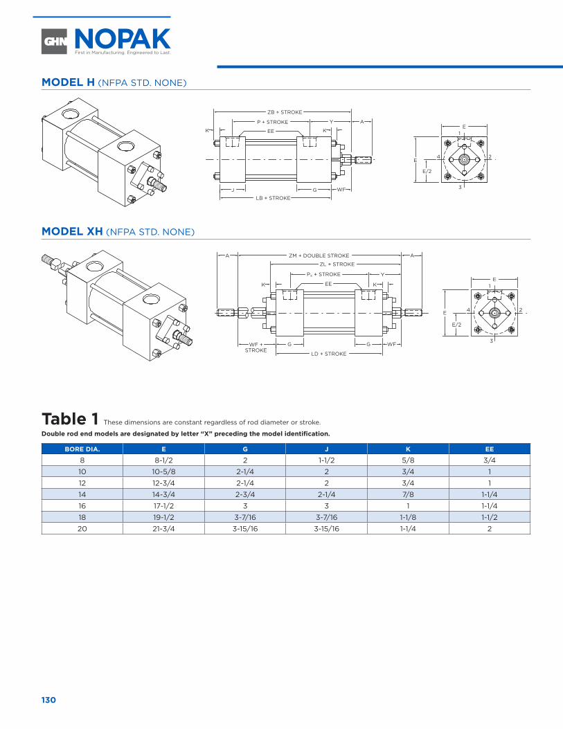
130
MODEL H (NFPA STD. NONE)
AYP + STROKE
ZB + STROKE
EEK K
J G
LB + STROKE
1
3
24
WF
E
E
E/2
MODEL XH (NFPA STD. NONE)
A
Y
ZL + STROKE
ZM + DOUBLE STROKEA
EEK K
G G
LD + STROKE
1
3
24
WFWF +STROKE
E
E
E/2
PX + STROKE
Table 1 These dimensions are constant regardless of rod diameter or stroke.
Double rod end models are designated by letter “X” preceding the model identification.
BORE DIA. E G J K EE
8 8-1/2 2 1-1/2 5/8 3/4
10 10-5/8 2-1/4 2 3/4 1
12 12-3/4 2-1/4 2 3/4 1
14 14-3/4 2-3/4 2-1/4 7/8 1-1/4
16 17-1/2 3 3 1 1-1/4
18 19-1/2 3-7/16 3-7/16 1-1/8 1-1/2
20 21-3/4 3-15/16 3-15/16 1-1/4 2
8" THROUGH 20" DIAMETER
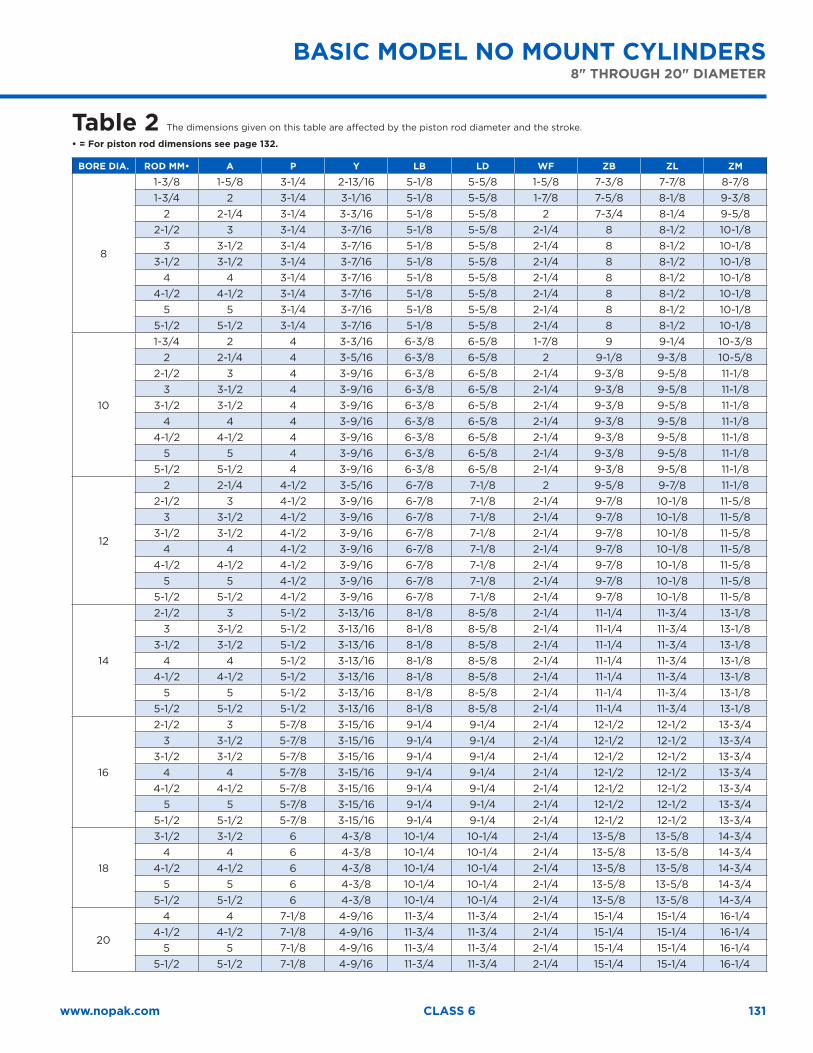
131www.nopak.com CLASS 6
BASIC MODEL NO MOUNT CYLINDERS 8" THROUGH 20" DIAMETER
Table 2 The dimensions given on this table are affected by the piston rod diameter and the stroke.
• = For piston rod dimensions see page 132.
BORE DIA. ROD MM• A P Y LB LD WF ZB ZL ZM
8
1-3/8 1-5/8 3-1/4 2-13/16 5-1/8 5-5/8 1-5/8 7-3/8 7-7/8 8-7/81-3/4 2 3-1/4 3-1/16 5-1/8 5-5/8 1-7/8 7-5/8 8-1/8 9-3/8
2 2-1/4 3-1/4 3-3/16 5-1/8 5-5/8 2 7-3/4 8-1/4 9-5/82-1/2 3 3-1/4 3-7/16 5-1/8 5-5/8 2-1/4 8 8-1/2 10-1/8
3 3-1/2 3-1/4 3-7/16 5-1/8 5-5/8 2-1/4 8 8-1/2 10-1/83-1/2 3-1/2 3-1/4 3-7/16 5-1/8 5-5/8 2-1/4 8 8-1/2 10-1/8
4 4 3-1/4 3-7/16 5-1/8 5-5/8 2-1/4 8 8-1/2 10-1/84-1/2 4-1/2 3-1/4 3-7/16 5-1/8 5-5/8 2-1/4 8 8-1/2 10-1/8
5 5 3-1/4 3-7/16 5-1/8 5-5/8 2-1/4 8 8-1/2 10-1/85-1/2 5-1/2 3-1/4 3-7/16 5-1/8 5-5/8 2-1/4 8 8-1/2 10-1/8
10
1-3/4 2 4 3-3/16 6-3/8 6-5/8 1-7/8 9 9-1/4 10-3/82 2-1/4 4 3-5/16 6-3/8 6-5/8 2 9-1/8 9-3/8 10-5/8
2-1/2 3 4 3-9/16 6-3/8 6-5/8 2-1/4 9-3/8 9-5/8 11-1/83 3-1/2 4 3-9/16 6-3/8 6-5/8 2-1/4 9-3/8 9-5/8 11-1/8
3-1/2 3-1/2 4 3-9/16 6-3/8 6-5/8 2-1/4 9-3/8 9-5/8 11-1/84 4 4 3-9/16 6-3/8 6-5/8 2-1/4 9-3/8 9-5/8 11-1/8
4-1/2 4-1/2 4 3-9/16 6-3/8 6-5/8 2-1/4 9-3/8 9-5/8 11-1/85 5 4 3-9/16 6-3/8 6-5/8 2-1/4 9-3/8 9-5/8 11-1/8
5-1/2 5-1/2 4 3-9/16 6-3/8 6-5/8 2-1/4 9-3/8 9-5/8 11-1/8
12
2 2-1/4 4-1/2 3-5/16 6-7/8 7-1/8 2 9-5/8 9-7/8 11-1/82-1/2 3 4-1/2 3-9/16 6-7/8 7-1/8 2-1/4 9-7/8 10-1/8 11-5/8
3 3-1/2 4-1/2 3-9/16 6-7/8 7-1/8 2-1/4 9-7/8 10-1/8 11-5/83-1/2 3-1/2 4-1/2 3-9/16 6-7/8 7-1/8 2-1/4 9-7/8 10-1/8 11-5/8
4 4 4-1/2 3-9/16 6-7/8 7-1/8 2-1/4 9-7/8 10-1/8 11-5/84-1/2 4-1/2 4-1/2 3-9/16 6-7/8 7-1/8 2-1/4 9-7/8 10-1/8 11-5/8
5 5 4-1/2 3-9/16 6-7/8 7-1/8 2-1/4 9-7/8 10-1/8 11-5/85-1/2 5-1/2 4-1/2 3-9/16 6-7/8 7-1/8 2-1/4 9-7/8 10-1/8 11-5/8
14
2-1/2 3 5-1/2 3-13/16 8-1/8 8-5/8 2-1/4 11-1/4 11-3/4 13-1/83 3-1/2 5-1/2 3-13/16 8-1/8 8-5/8 2-1/4 11-1/4 11-3/4 13-1/8
3-1/2 3-1/2 5-1/2 3-13/16 8-1/8 8-5/8 2-1/4 11-1/4 11-3/4 13-1/84 4 5-1/2 3-13/16 8-1/8 8-5/8 2-1/4 11-1/4 11-3/4 13-1/8
4-1/2 4-1/2 5-1/2 3-13/16 8-1/8 8-5/8 2-1/4 11-1/4 11-3/4 13-1/85 5 5-1/2 3-13/16 8-1/8 8-5/8 2-1/4 11-1/4 11-3/4 13-1/8
5-1/2 5-1/2 5-1/2 3-13/16 8-1/8 8-5/8 2-1/4 11-1/4 11-3/4 13-1/8
16
2-1/2 3 5-7/8 3-15/16 9-1/4 9-1/4 2-1/4 12-1/2 12-1/2 13-3/43 3-1/2 5-7/8 3-15/16 9-1/4 9-1/4 2-1/4 12-1/2 12-1/2 13-3/4
3-1/2 3-1/2 5-7/8 3-15/16 9-1/4 9-1/4 2-1/4 12-1/2 12-1/2 13-3/44 4 5-7/8 3-15/16 9-1/4 9-1/4 2-1/4 12-1/2 12-1/2 13-3/4
4-1/2 4-1/2 5-7/8 3-15/16 9-1/4 9-1/4 2-1/4 12-1/2 12-1/2 13-3/45 5 5-7/8 3-15/16 9-1/4 9-1/4 2-1/4 12-1/2 12-1/2 13-3/4
5-1/2 5-1/2 5-7/8 3-15/16 9-1/4 9-1/4 2-1/4 12-1/2 12-1/2 13-3/4
18
3-1/2 3-1/2 6 4-3/8 10-1/4 10-1/4 2-1/4 13-5/8 13-5/8 14-3/44 4 6 4-3/8 10-1/4 10-1/4 2-1/4 13-5/8 13-5/8 14-3/4
4-1/2 4-1/2 6 4-3/8 10-1/4 10-1/4 2-1/4 13-5/8 13-5/8 14-3/45 5 6 4-3/8 10-1/4 10-1/4 2-1/4 13-5/8 13-5/8 14-3/4
5-1/2 5-1/2 6 4-3/8 10-1/4 10-1/4 2-1/4 13-5/8 13-5/8 14-3/4
20
4 4 7-1/8 4-9/16 11-3/4 11-3/4 2-1/4 15-1/4 15-1/4 16-1/44-1/2 4-1/2 7-1/8 4-9/16 11-3/4 11-3/4 2-1/4 15-1/4 15-1/4 16-1/4
5 5 7-1/8 4-9/16 11-3/4 11-3/4 2-1/4 15-1/4 15-1/4 16-1/45-1/2 5-1/2 7-1/8 4-9/16 11-3/4 11-3/4 2-1/4 15-1/4 15-1/4 16-1/4
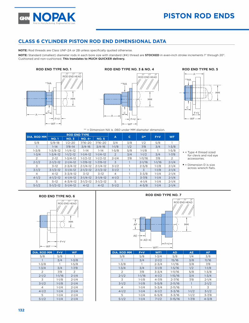
132
CLASS 6 CYLINDER PISTON ROD END DIMENSIONAL DATA
NOTE: Rod threads are Class UNF-2A or 2B unless specifically quoted otherwise.
NOTE: Standard (smallest) diameter rods in each bore size with standard (#4) thread are STOCKED in even-inch stroke increments 1" through 20". Cushioned and non-cushioned. This translates to MUCH QUICKER delivery.
ROD END TYPE NO. 1
MM
A
WF
F+V
C
**NA
ROD END TYPE NO. 3 & NO. 4
MM
A
WF
F+V
C
**NA
ROD END TYPE NO. 5
MM
A
WF
F+V
C
**NA
** = Dimension NA is .060 under MM diameter dimension.
DIA. ROD MMROD END TYPE
A C D� F+V WF
• = Type 4 thread sized for clevis and rod eye accessories.
� = Dimension D is size across wrench flats.
NO. 1 NO. 3 NO. 4• NO. 55/8 5/8–18 1/2–20 7/16–20 7/16–20 3/4 3/8 1/2 5/8 1
1 1–14 7/8–14 3/4–16 3/4–16 1-1/8 1/2 7/8 3/4 1-3/81-3/8 1-3/8–12 1-1/4–12 1–14 1–14 1-5/8 5/8 1-1/8 1 1-5/8 1-3/4 1-3/4–12 1-1/2–12 1-1/4–12 1-1/4–12 2 3/4 1-1/2 3/4 1-7/8
2 2–12 1-3/4–12 1-1/2–12 1-1/2–12 2-1/4 7/8 1-11/16 7/8 22-1/2 2-1/2–12 2-1/4–12 1-7/8–12 1-7/8–12 3 1 2-1/16 1-1/16 2-1/4
3 3–12 2-3/4–12 2-1/4–12 2-1/4–12 3-1/2 1 2-5/8 1-1/8 2-1/43-1/2 3-1/2–12 3-1/4–12 2-1/2–12 2-1/2–12 3-1/2 1 3 1-1/8 2-1/4
4 4–12 3-3/4–12 3–12 3–12 4 1 3-3/8 1-1/4 2-1/44-1/2 4-1/2–12 4-1/4–12 3-1/4–12 3-1/4–12 4-1/2 1 3-7/8 1-1/4 2-1/4
5 5–12 4-3/4–12 3-1/2–12 3-1/2–12 5 1 4-1/4 1-1/4 2-1/45-1/2 5-1/2–12 5-1/4–12 4–12 4–12 5-1/2 1 4-5/8 1-1/4 2-1/4
ROD END TYPE NO. 6
MM
WF
F+V
DIA. ROD MM F+V WF5/8 5/8 1
1 3/4 1-3/81-3/8 1 1-5/81-3/4 3/4 1-7/8
2 7/8 22-1/2 1-1/16 2-1/4
3 1-1/8 2-1/43-1/2 1-1/8 2-1/4
4 1-1/4 2-1/44-1/2 1-1/4 2-1/4
5 1-1/4 2-1/45-1/2 1-1/4 2-1/4
ROD END TYPE NO. 7
AF MM
AE
ADF+V
WF1
DIA. ROD MM F+V WF1 AD AE AF5/8 5/8 1-3/4 5/8 1/4 3/8
1 3/4 2-1/2 15/16 3/8 11/161-3/8 1 2-3/4 1-1/16 3/8 7/81-3/4 3/4 3-1/8 1-5/16 1/2 1-1/8
2 7/8 3-3/4 1-11/16 5/8 1-3/82-1/2 1-1/16 4-1/2 1-15/16 3/4 1-3/4
3 1-1/8 4-7/8 2-7/16 7/8 2-1/43-1/2 1-1/8 5-5/8 2-11/16 1 2-1/2
4 1-1/4 5-3/4 2-11/16 1 34-1/2 1-1/4 6-1/2 3-3/16 1-1/2 3-1/2
5 1-1/4 6-5/8 3-3/16 1-1/2 3-7/85-1/2 1-1/4 7-1/2 3-15/16 1-7/8 4-3/8
ROD END HEAD ROD END HEAD
ROD END HEAD ROD END HEAD
PISTON ROD ENDS
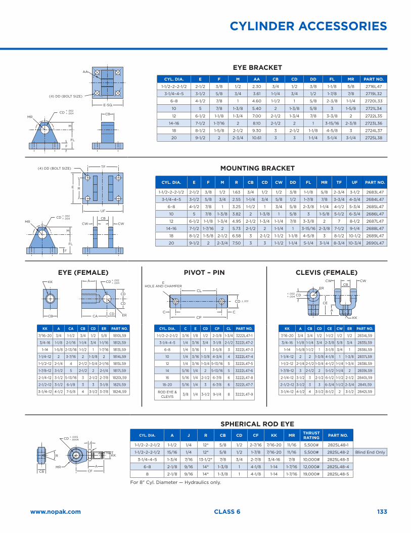
133www.nopak.com CLASS 6
E-SQ.
AA
CBCD
FL
F
M
MR
+ .002+ .004
EYE BRACKETCYL. DIA. E F M AA CB CD DD FL MR PART NO.
1-1/2–2–2-1/2 2-1/2 3/8 1/2 2.30 3/4 1/2 3/8 1-1/8 5/8 2716L47
3-1/4–4–5 3-1/2 5/8 3/4 3.61 1-1/4 3/4 1/2 1-7/8 7/8 2719L32
6–8 4-1/2 7/8 1 4.60 1-1/2 1 5/8 2-3/8 1-1/4 2720L33
10 5 7/8 1-3/8 5.40 2 1-3/8 5/8 3 1-5/8 2721L34
12 6-1/2 1-1/8 1-3/4 7.00 2-1/2 1-3/4 7/8 3-3/8 2 2722L35
14–16 7-1/2 1-7/16 2 8.10 2-1/2 2 1 3-15/16 2-3/8 2723L36
18 8-1/2 1-5/8 2-1/2 9.30 3 2-1/2 1-1/8 4-5/8 3 2724L37
20 9-1/2 2 2-3/4 10.61 3 3 1-1/4 5-1/4 3-1/4 2725L38
UF
TF
CB
CWCW
CD
FL
RE
F
M
MR
+ .002+ .004
MOUNTING BRACKET
CYL. DIA. E F M R CB CD CW DD FL MR TF UF PART NO.
1-1/2–2–2-1/2 2-1/2 3/8 1/2 1.63 3/4 1/2 1/2 3/8 1-1/8 5/8 2-3/4 3-1/2 2683L47
3-1/4–4–5 3-1/2 5/8 3/4 2.55 1-1/4 3/4 5/8 1/2 1-7/8 7/8 3-3/4 4-3/4 2684L47
6–8 4-1/2 7/8 1 3.25 1-1/2 1 3/4 5/8 2-3/8 1-1/4 4-1/2 5-3/4 2685L47
10 5 7/8 1-3/8 3.82 2 1-3/8 1 5/8 3 1-5/8 5-1/2 6-3/4 2686L47
12 6-1/2 1-1/8 1-3/4 4.95 2-1/2 1-3/4 1-1/4 7/8 3-3/8 2 7 8-1/2 2687L47
14–16 7-1/2 1-7/16 2 5.73 2-1/2 2 1-1/4 1 3-15/16 2-3/8 7-1/2 9-1/4 2688L47
18 8-1/2 1-5/8 2-1/2 6.58 3 2-1/2 1-1/2 1-1/8 4-5/8 3 8-1/2 10-1/2 2689L47
20 9-1/2 2 2-3/4 7.50 3 3 1-1/2 1-1/4 5-1/4 3-1/4 8-3/4 10-3/4 2690L47
EYE (FEMALE)
CACD
CD
CD
A
CB
KK CD + .002+ .004
ER
PIVOT – PIN
CL
CP
CD ± .001
CC
CLEVIS (FEMALE)
CD+ .002+ .004
CE
A
KK
CWCWCB
ER
KK A CA CB CD ER PART NO.
7/16–20 3/4 1-1/2 3/4 1/2 5/8 1810L59
3/4–16 1-1/8 2-1/16 1-1/4 3/4 1-1/16 1812L59
1–14 1-5/8 2-13/16 1-1/2 1 1-7/16 1813L59
1-1/4–12 2 3-7/16 2 1-3/8 2 1814L59
1-1/2–12 2-1/4 4 2-1/2 1-3/4 2-1/16 1815L59
1-7/8–12 3-1/2 5 2-1/2 2 2-1/4 1817L59
2-1/4–12 3-1/2 5-13/16 3 2-1/2 2-7/8 1820L59
2-1/2–12 3-1/2 6-1/8 3 3 3-1/8 1821L59
3-1/4–12 4-1/2 7-5/8 4 3-1/2 3-7/8 1824L59
CYL. DIA. C E CD CP CL PART NO.
1-1/2–2–2-1/2 3/16 1/8 1/2 2-3/8 1-3/4 3222L47-1
3-1/4–4–5 1/4 3/16 3/4 3-1/8 2-1/2 3222L47-2
6–8 1/4 3/16 1 3-5/8 3 3222L47-3
10 1/4 3/16 1-3/8 4-3/4 4 3222L47-4
12 1/4 3/16 1-3/4 5-13/16 5 3222L47-5
14 5/16 1/4 2 5-13/16 5 3222L47-6
16 5/16 1/4 2-1/2 6-7/8 6 3222L47-8
18–20 5/16 1/4 3 6-7/8 6 3222L47-7
ROD EYE & CLEVIS 3/8 1/4 3-1/2 9-1/4 8 3222L47-9
KK A CB CD CE CW ER PART NO.
7/16–20 3/4 3/4 1/2 1-1/2 1/2 1/2 2834L59
3/4–16 1-1/8 1-1/4 3/4 2-3/8 5/8 3/4 2835L59
1–14 1-5/8 1-1/2 1 3-1/8 3/4 1 2836L59
1-1/4–12 2 2 1-3/8 4-1/8 1 1-3/8 2837L59
1-1/2–12 2-1/4 2-1/2 1-3/4 4-1/2 1-1/4 1-3/4 2838L59
1-7/8–12 3 2-1/2 2 5-1/2 1-1/4 2 2839L59
2-1/4–12 3-1/2 3 2-1/2 6-1/2 1-1/2 2-1/2 2840L59
2-1/2–12 3-1/2 3 3 6-3/4 1-1/2 2-3/4 2841L59
3-1/4–12 4-1/2 4 3-1/2 8-1/2 2 3-1/2 2842L59
CFCB
R
MR
CD
A
KK
J
+ .0015– .0005
SPHERICAL ROD EYECYL. DIA. A J R CB CD CF KK MR THRUST
RATING PART NO.
1-1/2–2–2-1/2 1-1/2 1/4 12° 5/8 1/2 2-7/16 7/16-20 11/16 5,500# 2825L48-1
1-1/2–2–2-1/2 15/16 1/4 12° 5/8 1/2 1-7/8 7/16-20 11/16 5,500# 2825L48-2 Blind End Only
3-1/4–4–5 1-3/4 7/16 13-1/2° 7/8 3/4 2-7/8 3/4-16 7/8 10,000# 2825L48-3
6–8 2-1/8 9/16 14° 1-3/8 1 4-1/8 1-14 1-7/16 12,000# 2825L48-4
8 2-1/8 9/16 14° 1-3/8 1 4-1/8 1-14 1-7/16 19,000# 2825L48-5
For 8" Cyl. Diameter — Hydraulics only.
(4) DD (BOLT SIZE)
EHOLE AND CHAMFER
JAM NUT
(4) DD (BOLT SIZE)
CYLINDER ACCESSORIES
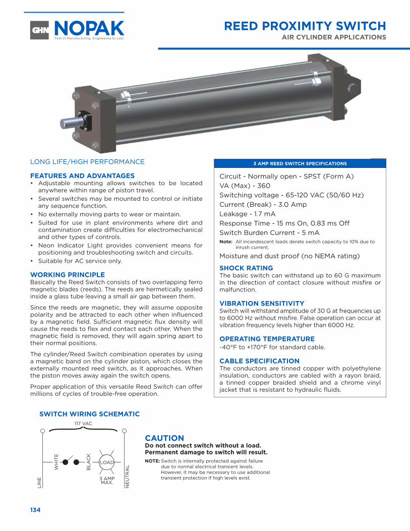
134
REED PROXIMITY SWITCHAIR CYLINDER APPLICATIONS
LONG LIFE/HIGH PERFORMANCE
FEATURES AND ADVANTAGES• Adjustable mounting allows switches to be located
anywhere within range of piston travel. • Several switches may be mounted to control or initiate
any sequence function. • No externally moving parts to wear or maintain. • Suited for use in plant environments where dirt and
contamination create difficulties for electromechanical and other types of controls.
• Neon Indicator Light provides convenient means for positioning and troubleshooting switch and circuits.
• Suitable for AC service only.
WORKING PRINCIPLEBasically the Reed Switch consists of two overlapping ferro magnetic blades (reeds). The reeds are hermetically sealed inside a glass tube leaving a small air gap between them.
Since the reeds are magnetic, they will assume opposite polarity and be attracted to each other when influenced by a magnetic field. Sufficient magnetic flux density will cause the reeds to flex and contact each other. When the magnetic field is removed, they will again spring apart to their normal positions.
The cylinder/Reed Switch combination operates by using a magnetic band on the cylinder piston, which closes the externally mounted reed switch, as it approaches. When the piston moves away again the switch opens.
Proper application of this versatile Reed Switch can offer millions of cycles of trouble-free operation.
3 AMP REED SWITCH SPECIFICATIONS
Circuit - Normally open - SPST (Form A) VA (Max) - 360 Switching voltage - 65-120 VAC (50/60 Hz)Current (Break) - 3.0 Amp Leakage - 1.7 mA Response Time - 15 ms On, 0.83 ms OffSwitch Burden Current - 5 mA Note: All incandescent loads derate switch capacity to 10% due to
inrush current.
Moisture and dust proof (no NEMA rating)
SHOCK RATINGThe basic switch can withstand up to 60 G maximum in the direction of contact closure without misfire or malfunction.
VIBRATION SENSITIVITYSwitch will withstand amplitude of 30 G at frequencies up to 6000 Hz without misfire. False operation can occur at vibration frequency levels higher than 6000 Hz.
OPERATING TEMPERATURE-40°F to +170°F for standard cable.
CABLE SPECIFICATIONThe conductors are tinned copper with polyethylene insulation, conductors are cabled with a rayon braid, a tinned copper braided shield and a chrome vinyl jacket that is resistant to hydraulic fluids.
CAUTION Do not connect switch without a load. Permanent damage to switch will result. NOTE: Switch is internally protected against failure
due to normal electrical transient levels. However, it may be necessary to use additional transient protection if high levels exist.
117 VAC
LOAD
3 AMP MAX.
LIN
E
WH
ITE
BLA
CK
NE
UT
RA
L
SWITCH WIRING SCHEMATIC
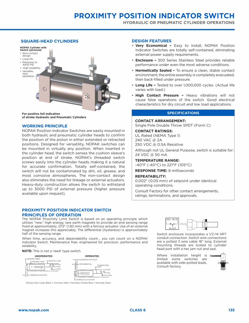
135www.nopak.com CLASS 6
PROXIMITY POSITION INDICATOR SWITCHHYDRAULIC OR PNEUMATIC CYLINDER OPERATIONS
WORKING PRINCIPLENOPAK Position Indicator Switches are easily mounted in both hydraulic and pneumatic cylinder heads to confirm the position of the piston in either extended or retracted positions. Designed for versatility, NOPAK switches can be mounted in virtually any position. When inserted in the cylinder head, the switch senses the cushion sleeve's position at end of stroke. NOPAK’s threaded switch screws easily into the cylinder heads making it a natural for accurate confirmation. Totally self-contained, the switch will not be contaminated by dirt, oil, grease, and most corrosive atmospheres. The non-contact design also eliminates the need for linkage or external actuators. Heavy-duty construction allows the switch to withstand up to 3000 PSI of external pressure (higher pressure available upon request).
DESIGN FEATURES• Very Economical – Easy to install, NOPAK Position
Indicator Switches are totally self-contained, eliminating external power supply requirements.
• Enclosure – 300 Series Stainless Steel provides reliable performance under even the most adverse conditions.
• Hermetically Sealed – To ensure a clean, stable contact environment, the entire assembly is completely evacuated, then back-filled under pressure.
• Long Life – Tested to over 1,000,000 cycles. (Actual life varies with load.)
• High Contact Pressure – Heavy vibrations will not cause false operations of the switch. Good electrical characteristics for dry circuit and low load applications.
SPECIFICATIONS
CONTACT ARRANGEMENT: Single Pole Double Throw SPDT (Form C)
CONTACT RATINGS: UL Rated (NEMA Type 1) 240 VAC @ 2A 250 VDC @ 0.5A Resistive
Although not UL General Purpose, switch is suitable for: 24 VDC @ 50 mA
TEMPERATURE RANGE: -40°F (-40°C) to 221°F (105°C)
RESPONSE TIME: 8 milliseconds
REPEATABILITY: 0.002" (0.05 mm) of setpoint under identical operating conditions.
Consult Factory for other contact arrangements, ratings, terminations, and approvals.
SENSING AREA
FERROUS ACTUATOR
SENSING DISTANCE
SENSING DISTANCE
DIFFERENTIALMAGNET ASSY.
CONNECTING ROD
SWITCH CASE
NO
NO
NC
NC
COM
COM
PROXIMITY POSITION INDICATOR SWITCH PRINCIPLES OF OPERATIONThe NOPAK Proximity Limit Switch is based on an operating principle which utilizes “new,” high energy, rare earth magnets to provide an end sensing range fixed at approximately .072" (1.83 mm) with a ferrous actuator. Use of an external magnet increases this appreciably. The differential (hysteresis) is approximately half of the sensing range. When time, accuracy, and dependability count... you can count on a NOPAK Indicator Switch. Maintenance free: engineered for precision, performance and reliability.
NOTE: This is not a ‘reed’ type switch.
Switch enclosure incorporates a 1/2–14 NPT conduit connection. Switch wire connections are a potted 3 wire cable 18” long. External mounting threads are locked to cylinder head port with a hex jam nut and seal.
Where installation height is limited some switches are available with side-potted leads. Consult factory.
RED BLUE
BLACK
Wiring Color Code: Black = Common, Red = Normally Closed; Blue = Normally Open
UNOPERATED OPERATED
N
N
NOPAK Cylinder with Switch (pictured)•Non-contact
design• Long life• Pressures to
3000 PSI• High reliability •Versatile,
easy operation
SQUARE-HEAD CYLINDERS
For positive full indication of stroke Hydraulic and Pneumatic Cylinders
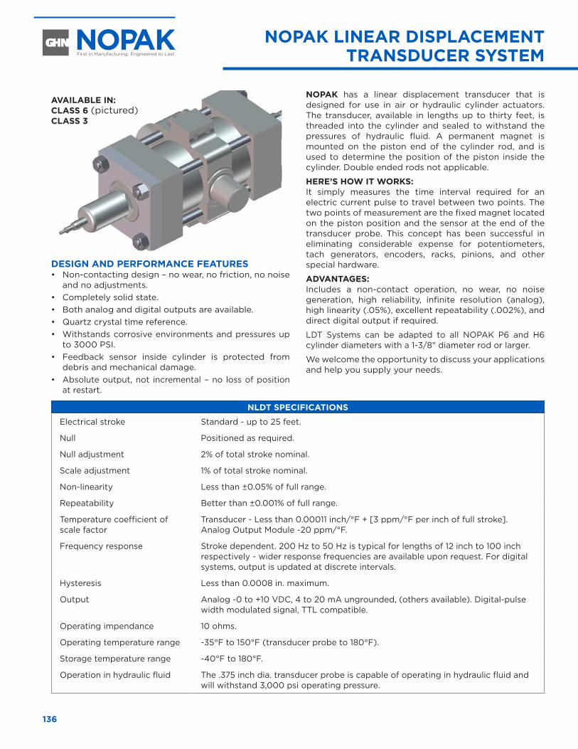
136
NOPAK LINEAR DISPLACEMENT TRANSDUCER SYSTEM
DESIGN AND PERFORMANCE FEATURES• Non-contacting design – no wear, no friction, no noise
and no adjustments. • Completely solid state. • Both analog and digital outputs are available. • Quartz crystal time reference.• Withstands corrosive environments and pressures up
to 3000 PSI. • Feedback sensor inside cylinder is protected from
debris and mechanical damage. • Absolute output, not incremental – no loss of position
at restart.
NOPAK has a linear displacement transducer that is designed for use in air or hydraulic cylinder actuators. The transducer, available in lengths up to thirty feet, is threaded into the cylinder and sealed to withstand the pressures of hydraulic fluid. A permanent magnet is mounted on the piston end of the cylinder rod, and is used to determine the position of the piston inside the cylinder. Double ended rods not applicable.
HERE’S HOW IT WORKS:It simply measures the time interval required for an electric current pulse to travel between two points. The two points of measurement are the fixed magnet located on the piston position and the sensor at the end of the transducer probe. This concept has been successful in eliminating considerable expense for potentiometers, tach generators, encoders, racks, pinions, and other special hardware.
ADVANTAGES: Includes a non-contact operation, no wear, no noise generation, high reliability, infinite resolution (analog), high linearity (.05%), excellent repeatability (.002%), and direct digital output if required.
LDT Systems can be adapted to all NOPAK P6 and H6 cylinder diameters with a 1-3/8" diameter rod or larger.
We welcome the opportunity to discuss your applications and help you supply your needs.
NLDT SPECIFICATIONS
Electrical stroke Standard - up to 25 feet.
Null Positioned as required.
Null adjustment 2% of total stroke nominal.
Scale adjustment 1% of total stroke nominal.
Non-linearity Less than ±0.05% of full range.
Repeatability Better than ±0.001% of full range.
Temperature coefficient of scale factor
Transducer - Less than 0.00011 inch/°F + [3 ppm/°F per inch of full stroke].Analog Output Module -20 ppm/°F.
Frequency response Stroke dependent. 200 Hz to 50 Hz is typical for lengths of 12 inch to 100 inch respectively - wider response frequencies are available upon request. For digital systems, output is updated at discrete intervals.
Hysteresis Less than 0.0008 in. maximum.
Output Analog -0 to +10 VDC, 4 to 20 mA ungrounded, (others available). Digital-pulse width modulated signal, TTL compatible.
Operating impendance 10 ohms.
Operating temperature range -35°F to 150°F (transducer probe to 180°F).
Storage temperature range -40°F to 180°F.
Operation in hydraulic fluid The .375 inch dia. transducer probe is capable of operating in hydraulic fluid and will withstand 3,000 psi operating pressure.
AVAILABLE IN: CLASS 6 (pictured)CLASS 3
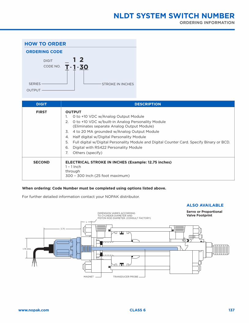
137www.nopak.com CLASS 6
ALSO AVAILABLEServo or Proportional Valve Footprint
HOW TO ORDER
NLDT SYSTEM SWITCH NUMBERORDERING INFORMATION
DIGIT
CODE NO.
ORDERING CODE
SERIES
OUTPUT
STROKE IN INCHES
T
11
230- -
DIGIT DESCRIPTION
FIRST OUTPUT1. 0 to +10 VDC w/Analog Output Module 2. 0 to +10 VDC w/built-in Analog Personality Module
(Eliminates separate Analog Output Module) 3. 4 to 20 MA grounded w/Analog Output Module 4. Half digital w/Digital Personality Module 5. Full digital w/Digital Personality Module and Digital Counter Card. Specify Binary or BCD. 6. Digital with RS422 Personality Module 7. Others (specify)
SECOND ELECTRICAL STROKE IN INCHES (Example: 12.75 inches)1 – 1 Inch through 300 – 300 Inch (25 foot maximum)
When ordering: Code Number must be completed using options listed above.
For further detailed information contact your NOPAK distributor.
DIMENSION VARIES ACCORDING TO CYLINDER DIAMETER AND PISTON ROD DIAMETER. (CONSULT FACTORY)
MAGNET TRANSDUCER PROBE
1.75 DIA.
3.75
L
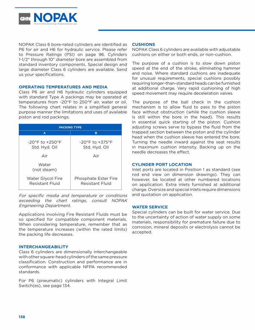
138
NOPAK Class 6 bore-rated cylinders are identified as P6 for air and H6 for hydraulic service. Please refer to Pressure Ratings (PSI) on page 96. Cylinders 1-1/2" through 10" diameter bore are assembled from standard inventory components. Special design and large diameter Class 6 cylinders are available. Send us your specifications.
OPERATING TEMPERATURES AND MEDIA Class P6 air and H6 hydraulic cylinders equipped with standard Type A packings may be operated at temperatures from -20°F to 250°F air, water or oil. The following chart relates in a simplified general purpose manner the limitations and uses of available piston and rod packings.
PACKING TYPE
A B
-20°F to +250°F Std. Hyd. Oil
Air
Water (not steam)
Water Glycol Fire Resistant Fluid
-20°F to +375°F Std. Hyd. Oil
Air
Phosphate Ester Fire Resistant Fluid
For specific media and temperature or conditions exceeding the chart ratings, consult NOPAK Engineering Department.
Applications involving Fire Resistant Fluids must be so specified for compatible component materials. When considering temperature, remember that as the temperature increases (within the rated limits) the packing life decreases.
INTERCHANGEABILITY Class 6 cylinders are dimensionally interchangeable with other square-head cylinders of the same pressure classification. Construction and performance are in conformance with applicable NFPA recommended standards.
For P6 (pneumatic) cylinders with Integral Limit Switch(es), see page 134.
CUSHIONS NOPAK Class 6 cylinders are available with adjustable cushions on either or both ends, or non-cushion.
The purpose of a cushion is to slow down piston speed at the end of the stroke, eliminating hammer and noise. Where standard cushions are inadequate for unusual requirements, special cushions possibly requiring longer-than-standard heads can be furnished at additional charge. Very rapid cushioning of high speed movement may require deceleration valves.
The purpose of the ball check in the cushion mechanism is to allow fluid to pass to the piston face without obstruction (while the cushion sleeve is still within the bore in the head). This results in essential quick starting of the piston. Cushion adjusting screws serve to bypass the fluid from the trapped section between the piston and the cylinder head when the cushion sleeve has entered the bore. Turning the needle inward against the seat results in maximum cushion intensity. Backing up on the needle decreases the effect.
CYLINDER PORT LOCATION Inlet ports are located in Position 1 as standard (see rod end view on dimension drawings). They can however, be located at other numbered locations on application. Extra inlets furnished at additional charge. Oversize and special inlets require dimensions and quotation on application.
WATER SERVICE Special cylinders can be built for water service. Due to the uncertainty of action of water supply on some materials, responsibility for premature failure due to corrosion, mineral deposits or electrolysis cannot be accepted.
ENGINEERING INFORMATION
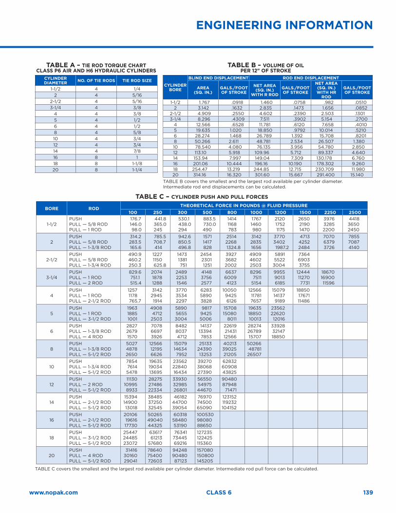
139www.nopak.com CLASS 6
ENGINEERING INFORMATION
TABLE A – TIE ROD TORQUE CHART CLASS P6 AIR AND H6 HYDRAULIC CYLINDERS
CYLINDER DIAMETER NO. OF TIE RODS TIE ROD SIZE
1-1/2 4 1/42 4 5/16
2-1/2 4 5/163-1/4 4 3/8
4 4 3/85 4 1/26 4 1/28 4 5/810 4 3/412 4 3/414 4 7/816 8 118 8 1-1/820 8 1-1/4
TABLE B – VOLUME OF OIL PER 12" OF STROKE
CYLINDER BORE
BLIND END DISPLACEMENT ROD END DISPLACEMENT
AREA(SQ. IN.)
GALS./FOOT OF STROKE
NET AREA (SQ. IN.)
WITH R RODGALS./FOOT OF STROKE
NET AREA (SQ. IN.) WITH HR
ROD
GALS./FOOT OF STROKE
1-1/2 1.767 .0918 1.460 .0758 .982 .0510 2 3.142 .1632 2.835 .1473 1.656 .0852
2-1/2 4.909 .2550 4.602 .2390 2.503 .1301 3-1/4 8.296 .4309 7.511 .3902 5.154 .2700
4 12.566 .6528 11.781 .6120 7.658 .4010 5 19.635 1.020 18.850 .9792 10.014 .5210 6 28.274 1.468 26.789 1.392 15.708 .8201 8 50.266 2.611 48.781 2.534 26.507 1.380 10 78.540 4.080 76.135 3.956 54.780 2.850 12 113.10 5.918 109.96 5.712 89.337 4.640 14 153.94 7.997 149.04 7.309 130.178 6.760 16 201.06 10.444 196.16 10.190 178.302 9.260 18 254.47 13.219 244.85 12.715 230.709 11.980 20 314.16 16.320 301.60 15.667 291.400 15.140
TABLE B covers the smallest and the largest rod available per cylinder diameter. Intermediate rod end displacements can be calculated.
TABLE C – CYLINDER PUSH AND PULL FORCES
BORE ROD THEORETICAL FORCE IN POUNDS @ FLUID PRESSURE100 250 300 500 800 1000 1200 1500 2250 2500
1-1/2PUSHPULL — 5/8 RODPULL — 1 ROD
176.7 146.0 98.0
441.8 365.0
245
530.1 438.0
294
883.5 730.0
490
1414 1168
783
1767 1460
980
2120 1752 1175
2650 2190 1470
3976 3285 2200
4418 3650 2450
2PUSHPULL — 5/8 RODPULL — 1-3/8 ROD
314.2 283.5 165.6
785.5 708.7
414
942.6 850.5 496.8
1571 1417
828
2514 2268 1324.8
3142 2835 1656
3770 3402 1987.2
4713 4252 2484
7070 6379 3726
7855 7087 4140
2-1/2PUSHPULL — 5/8 RODPULL — 1-3/4 ROD
490.9 460.2 250.3
1227 1150 625.8
1473 1381
751
2454 2301 1251
3927 3682 2002
4909 4602 2503
5891 5522 3004
7364 6903 3755
3-1/4PUSHPULL — 1 RODPULL — 2 ROD
829.6 751.1 515.4
2074 1878 1288
2489 2253 1546
4148 3756 2577
6637 6009 4123
8296 7511 5154
9955 9013 6185
12444 11270 7731
18670 16900 11596
4PUSHPULL — 1 RODPULL — 2-1/2 ROD
1257 1178 765.7
3142 2945 1914
3770 3534 2297
6283 5890 3828
10050 9425 6126
12566 11781 7657
15079 14137 9189
18850 17671 11486
5PUSHPULL — 1 RODPULL — 3-1/2 ROD
1963 1885 1001
4908 4712 2503
5890 5655 3004
9817 9425 5006
15708 15080 8011
19635 18850 10013
23562 22620 12016
6PUSHPULL — 1-3/8 RODPULL — 4 ROD
2827 2679 1570
7078 6697 3926
8482 8037 4712
14137 13394 7853
22619 21431 12566
28274 26789 15707
33928 32147 18850
8PUSHPULL — 1-3/8 RODPULL — 5-1/2 ROD
5027 4878 2650
12566 12195 6626
15079 14634 7952
25133 24390 13253
40213 39025 21205
50266 48781 26507
10PUSHPULL — 1-3/4 RODPULL — 5-1/2 ROD
7854 7614 5478
19635 19034 13695
23562 22840 16434
39270 38068 27390
62832 60908 43825
12PUSHPULL — 2 RODPULL — 5-1/2 ROD
11130 10995 8933
28275 27486 22334
33930 32985 26801
56550 54975 44670
90480 87948 71471
14PUSHPULL — 2-1/2 RODPULL — 5-1/2 ROD
15394 14900 13018
38485 37250 32545
46182 44700 39054
76970 74500 65090
123152 119232 104152
16PUSHPULL — 2-1/2 RODPULL — 5-1/2 ROD
20106 19616 17730
50265 49040 44325
60318 58480 53190
100530 98080 88650
18PUSHPULL — 3-1/2 RODPULL — 5-1/2 ROD
25447 24485 23072
63617 61213 57680
76341 73445 69216
127235 122425 115360
20PUSHPULL — 4 RODPULL — 5-1/2 ROD
31416 30160 29041
78640 75400 72603
94248 90480 87123
157080 150800 145205
TABLE C covers the smallest and the largest rod available per cylinder diameter. Intermediate rod pull force can be calculated.
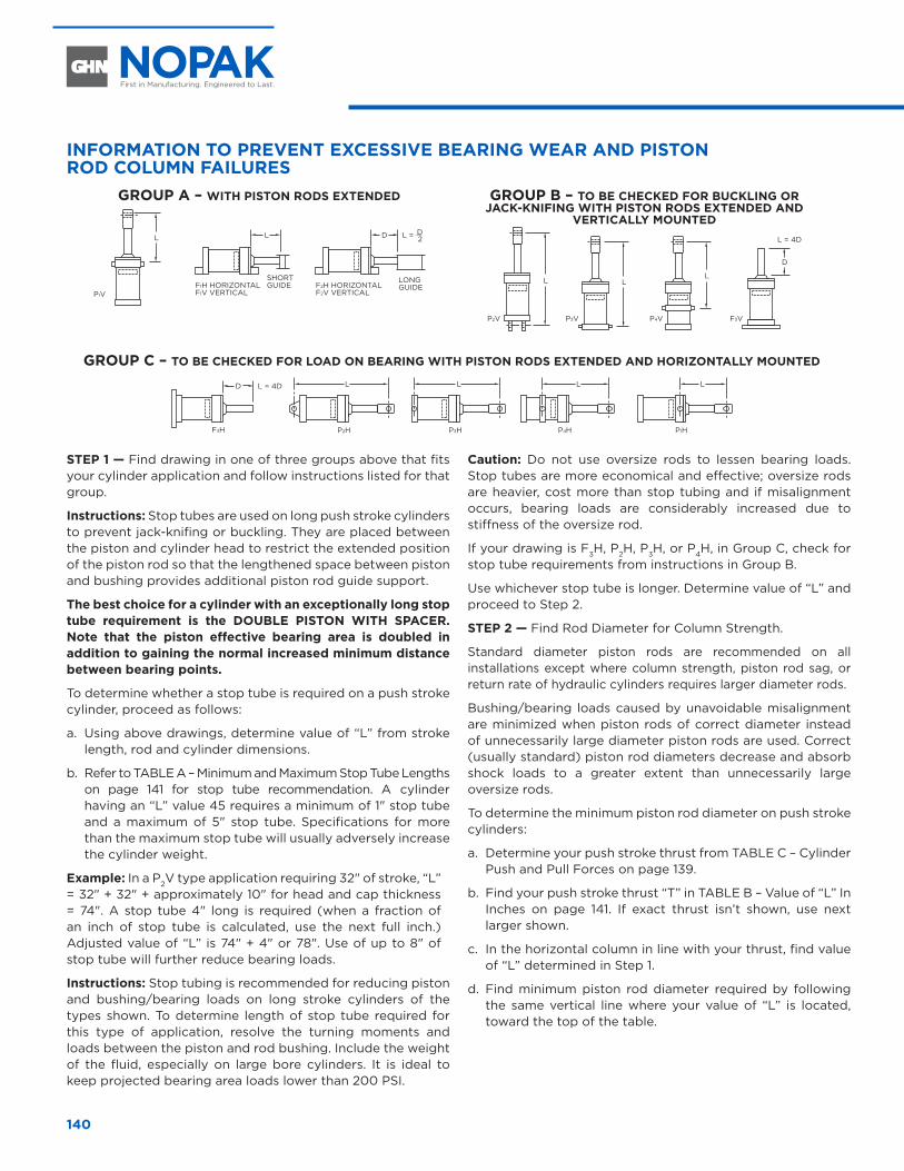
140
INFORMATION TO PREVENT EXCESSIVE BEARING WEAR AND PISTON ROD COLUMN FAILURES
GROUP A – WITH PISTON RODS EXTENDED
L L D L = D2
P1V
GROUP B – TO BE CHECKED FOR BUCKLING OR
JACK-KNIFING WITH PISTON RODS EXTENDED AND VERTICALLY MOUNTED
L
P2V
L
P3V
L
P4V
D
L = 4D
F3V
GROUP C – TO BE CHECKED FOR LOAD ON BEARING WITH PISTON RODS EXTENDED AND HORIZONTALLY MOUNTED
L
P4H
L
P1H
L
P2H
L
P3HF3H
L = 4DD
F1H HORIZONTALF1V VERTICAL
SHORT GUIDE
LONG GUIDEF2H HORIZONTAL
F2V VERTICAL
STEP 1 — Find drawing in one of three groups above that fits your cylinder application and follow instructions listed for that group.
Instructions: Stop tubes are used on long push stroke cylinders to prevent jack-knifing or buckling. They are placed between the piston and cylinder head to restrict the extended position of the piston rod so that the lengthened space between piston and bushing provides additional piston rod guide support.
The best choice for a cylinder with an exceptionally long stop tube requirement is the DOUBLE PISTON WITH SPACER. Note that the piston effective bearing area is doubled in addition to gaining the normal increased minimum distance between bearing points.
To determine whether a stop tube is required on a push stroke cylinder, proceed as follows:
a. Using above drawings, determine value of “L” from stroke length, rod and cylinder dimensions.
b. Refer to TABLE A – Minimum and Maximum Stop Tube Lengths on page 141 for stop tube recommendation. A cylinder having an “L” value 45 requires a minimum of 1" stop tube and a maximum of 5" stop tube. Specifications for more than the maximum stop tube will usually adversely increase the cylinder weight.
Example: In a P2V type application requiring 32" of stroke, “L” = 32" + 32" + approximately 10" for head and cap thickness = 74". A stop tube 4" long is required (when a fraction of an inch of stop tube is calculated, use the next full inch.) Adjusted value of “L” is 74" + 4" or 78". Use of up to 8" of stop tube will further reduce bearing loads.
Instructions: Stop tubing is recommended for reducing piston and bushing/bearing loads on long stroke cylinders of the types shown. To determine length of stop tube required for this type of application, resolve the turning moments and loads between the piston and rod bushing. Include the weight of the fluid, especially on large bore cylinders. It is ideal to keep projected bearing area loads lower than 200 PSI.
Caution: Do not use oversize rods to lessen bearing loads. Stop tubes are more economical and effective; oversize rods are heavier, cost more than stop tubing and if misalignment occurs, bearing loads are considerably increased due to stiffness of the oversize rod.
If your drawing is F3H, P2H, P3H, or P4H, in Group C, check for stop tube requirements from instructions in Group B.
Use whichever stop tube is longer. Determine value of “L” and proceed to Step 2.
STEP 2 — Find Rod Diameter for Column Strength.
Standard diameter piston rods are recommended on all installations except where column strength, piston rod sag, or return rate of hydraulic cylinders requires larger diameter rods.
Bushing/bearing loads caused by unavoidable misalignment are minimized when piston rods of correct diameter instead of unnecessarily large diameter piston rods are used. Correct (usually standard) piston rod diameters decrease and absorb shock loads to a greater extent than unnecessarily large oversize rods.
To determine the minimum piston rod diameter on push stroke cylinders:
a. Determine your push stroke thrust from TABLE C – Cylinder Push and Pull Forces on page 139.
b. Find your push stroke thrust “T” in TABLE B – Value of “L” In Inches on page 141. If exact thrust isn’t shown, use next larger shown.
c. In the horizontal column in line with your thrust, find value of “L” determined in Step 1.
d. Find minimum piston rod diameter required by following the same vertical line where your value of “L” is located, toward the top of the table.
ENGINEERING DATA
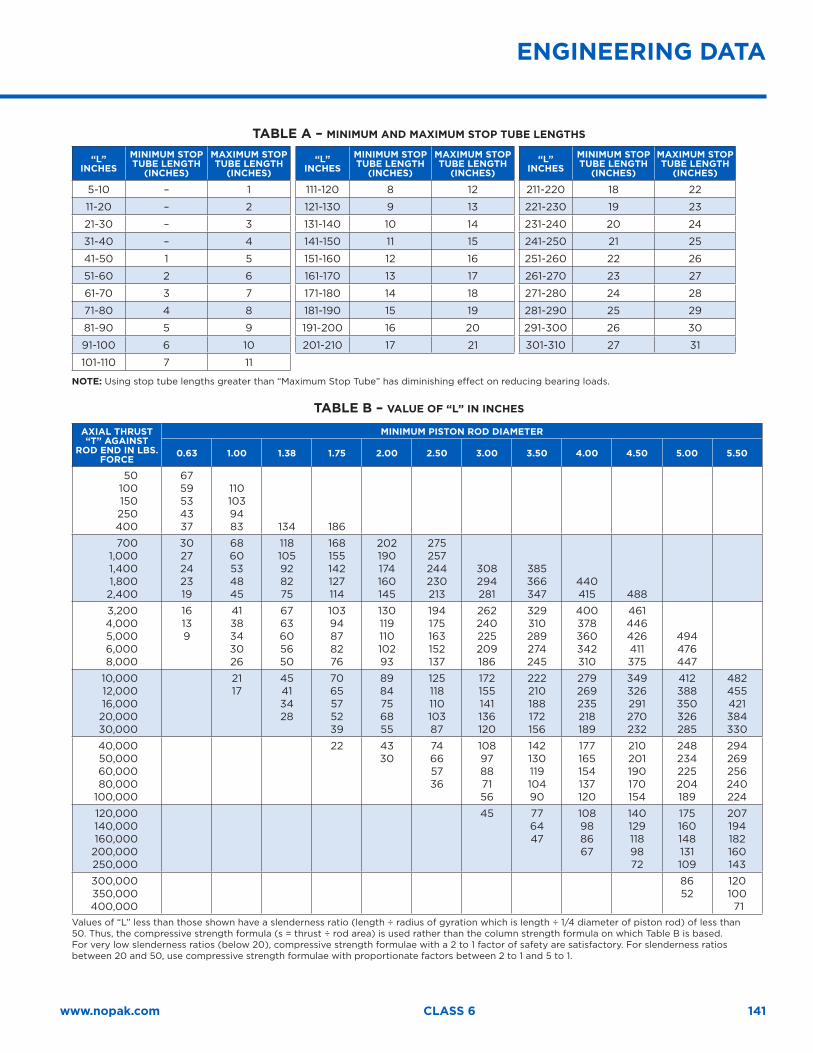
141www.nopak.com CLASS 6
TABLE A – MINIMUM AND MAXIMUM STOP TUBE LENGTHS
“L” INCHES
MINIMUM STOP TUBE LENGTH
(INCHES)
MAXIMUM STOP TUBE LENGTH
(INCHES)
5-10 – 1
11-20 – 2
21-30 – 3
31-40 – 4
41-50 1 5
51-60 2 6
61-70 3 7
71-80 4 8
81-90 5 9
91-100 6 10
101-110 7 11
“L” INCHES
MINIMUM STOP TUBE LENGTH
(INCHES)
MAXIMUM STOP TUBE LENGTH
(INCHES)
111-120 8 12
121-130 9 13
131-140 10 14
141-150 11 15
151-160 12 16
161-170 13 17
171-180 14 18
181-190 15 19
191-200 16 20
201-210 17 21
“L” INCHES
MINIMUM STOP TUBE LENGTH
(INCHES)
MAXIMUM STOP TUBE LENGTH
(INCHES)
211-220 18 22
221-230 19 23
231-240 20 24
241-250 21 25
251-260 22 26
261-270 23 27
271-280 24 28
281-290 25 29
291-300 26 30
301-310 27 31
NOTE: Using stop tube lengths greater than “Maximum Stop Tube” has diminishing effect on reducing bearing loads.
TABLE B – VALUE OF “L” IN INCHES
AXIAL THRUST “T” AGAINST
ROD END IN LBS. FORCE
MINIMUM PISTON ROD DIAMETER
0.63 1.00 1.38 1.75 2.00 2.50 3.00 3.50 4.00 4.50 5.00 5.50
50100150250400
6759534337
1101039483 134 186
7001,0001,4001,8002,400
3027242319
6860534845
118105928275
168155142127114
202190174160145
275257244230213
308294281
385366347
440415 488
3,2004,0005,0006,0008,000
16139
4138343026
6763605650
10394878276
13011911010293
194175163152137
262240225209186
329310289274245
400378360342310
461446426411375
494476447
10,00012,00016,00020,00030,000
2117
45413428
7065575239
8984756855
12511811010387
172155141136120
222210188172156
279269235218189
349326291270232
412388350326285
482455421384330
40,00050,00060,00080,000
100,000
22 4330
74665736
10897887156
14213011910490
177165154137120
210201190170154
248234225204189
294269256240224
120,000140,000160,000
200,000250,000
45 776447
108988667
1401291189872
175160148131109
207194182160143
300,000350,000400,000
8652
120100 71
Values of “L” less than those shown have a slenderness ratio (length ÷ radius of gyration which is length ÷ 1/4 diameter of piston rod) of less than 50. Thus, the compressive strength formula (s = thrust ÷ rod area) is used rather than the column strength formula on which Table B is based. For very low slenderness ratios (below 20), compressive strength formulae with a 2 to 1 factor of safety are satisfactory. For slenderness ratios between 20 and 50, use compressive strength formulae with proportionate factors between 2 to 1 and 5 to 1.
ENGINEERING DATA
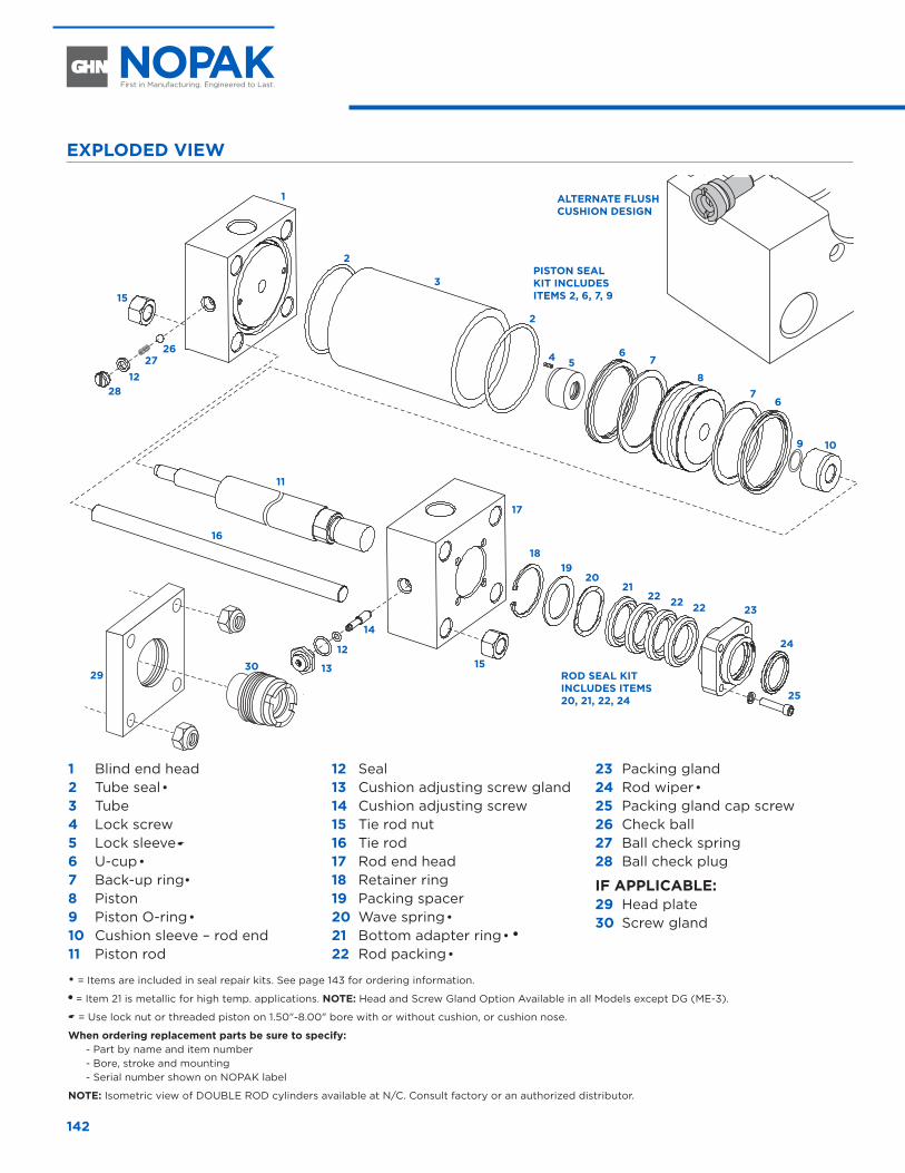
142
1 Blind end head 2 Tube seal•3 Tube 4 Lock screw5 Lock sleeve�
6 U-cup•7 Back-up ring•8 Piston9 Piston O-ring•10 Cushion sleeve – rod end 11 Piston rod
12 Seal 13 Cushion adjusting screw gland 14 Cushion adjusting screw 15 Tie rod nut 16 Tie rod 17 Rod end head 18 Retainer ring 19 Packing spacer 20 Wave spring•21 Bottom adapter ring•�
22 Rod packing•
23 Packing gland24 Rod wiper•25 Packing gland cap screw26 Check ball 27 Ball check spring 28 Ball check plug
IF APPLICABLE: 29 Head plate 30 Screw gland
ALTERNATE FLUSH CUSHION DESIGN
• = Items are included in seal repair kits. See page 143 for ordering information. � = Item 21 is metallic for high temp. applications. NOTE: Head and Screw Gland Option Available in all Models except DG (ME-3).
� = Use lock nut or threaded piston on 1.50"-8.00" bore with or without cushion, or cushion nose.
When ordering replacement parts be sure to specify: - Part by name and item number- Bore, stroke and mounting- Serial number shown on NOPAK label
NOTE: Isometric view of DOUBLE ROD cylinders available at N/C. Consult factory or an authorized distributor.
1
2
2
54 6
6
9 10
25
24
2322222221
2019
18
15
2627
1228
16
11
2930
17
7
78
315
12
13
14
EXPLODED VIEWREPLACEMENT PARTS
PISTON SEAL KIT INCLUDES ITEMS 2, 6, 7, 9
ROD SEAL KIT INCLUDES ITEMS 20, 21, 22, 24
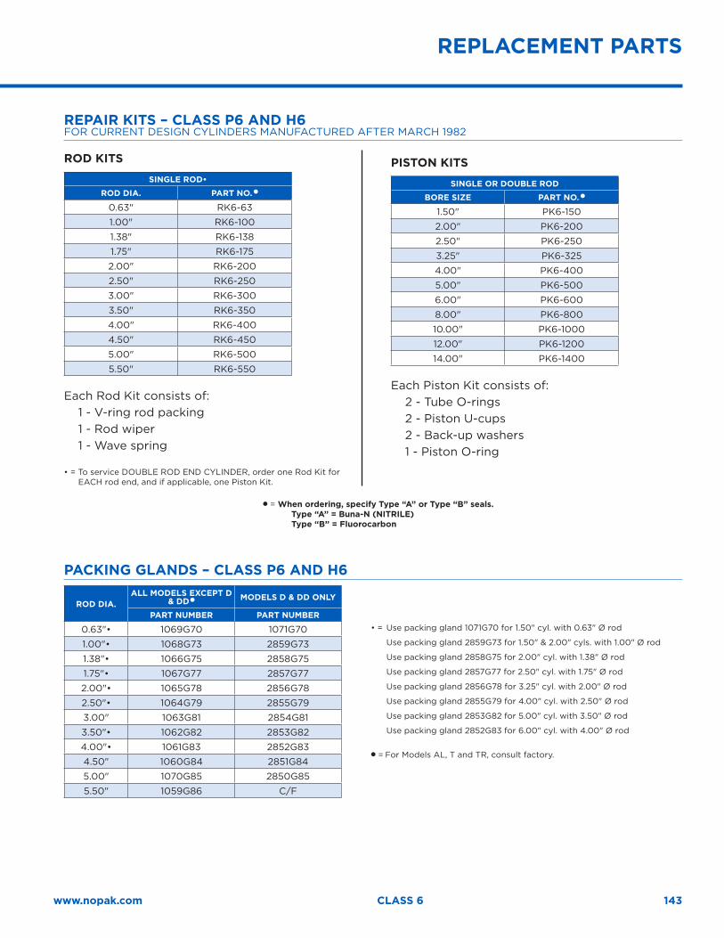
143www.nopak.com CLASS 6
REPLACEMENT PARTS
REPAIR KITS – CLASS P6 AND H6FOR CURRENT DESIGN CYLINDERS MANUFACTURED AFTER MARCH 1982
ROD KITS
SINGLE ROD•
ROD DIA. PART NO. �
0.63" RK6-63
1.00" RK6-100
1.38" RK6-138
1.75" RK6-175
2.00" RK6-200
2.50" RK6-250
3.00" RK6-300
3.50" RK6-350
4.00" RK6-400
4.50" RK6-450
5.00" RK6-500
5.50" RK6-550
Each Rod Kit consists of: 1 - V-ring rod packing 1 - Rod wiper 1 - Wave spring
•=ToserviceDOUBLERODENDCYLINDER,orderoneRodKitforEACH rod end, and if applicable, one Piston Kit.
PISTON KITS
SINGLE OR DOUBLE ROD
BORE SIZE PART NO. �
1.50" PK6-150
2.00" PK6-200
2.50" PK6-250
3.25" PK6-325
4.00" PK6-400
5.00" PK6-500
6.00" PK6-600
8.00" PK6-800
10.00" PK6-1000
12.00" PK6-1200
14.00" PK6-1400
Each Piston Kit consists of: 2 - Tube O-rings2 - Piston U-cups2 - Back-up washers1 - Piston O-ring
� = When ordering, specify Type “A” or Type “B” seals. Type “A” = Buna-N (NITRILE) Type “B” = Fluorocarbon
PACKING GLANDS – CLASS P6 AND H6
ROD DIA.ALL MODELS EXCEPT D
& DD� MODELS D & DD ONLY
PART NUMBER PART NUMBER
0.63"• 1069G70 1071G70
1.00"• 1068G73 2859G73
1.38"• 1066G75 2858G75
1.75"• 1067G77 2857G77
2.00"• 1065G78 2856G78
2.50"• 1064G79 2855G79
3.00" 1063G81 2854G81
3.50"• 1062G82 2853G82
4.00"• 1061G83 2852G83
4.50" 1060G84 2851G84
5.00" 1070G85 2850G85
5.50" 1059G86 C/F
•=Usepackinggland1071G70for1.50"cyl.with0.63"Ørod
Usepackinggland2859G73for1.50"&2.00"cyls.with1.00"Ørod
Usepackinggland2858G75for2.00"cyl.with1.38"Ørod
Usepackinggland2857G77for2.50"cyl.with1.75"Ørod
Usepackinggland2856G78for3.25"cyl.with2.00"Ørod
Usepackinggland2855G79for4.00"cyl.with2.50"Ørod
Usepackinggland2853G82for5.00"cyl.with3.50"Ørod
Usepackinggland2852G83for6.00"cyl.with4.00"Ørod
� = For Models AL, T and TR, consult factory.

144
Directional Control ValvesHand, Foot and Solenoid
Directional Control Valves Hand, Foot and Solenoid
VA
LVE
S
146
NOPAK DIRECTIONAL CONTROL VALVESNOPAK Directional Control Valves are noted throughout industry for their simplicity of design, rugged construction, long-lived, trouble-free service, and low maintenance. The original NOPAK Valve design, with its patented, rotating lapped disc, has been augmented with other designs until today the NOPAK line includes valves for control of fluid power under practically all operating conditions.
In specifying NOPAK Valves, operating requirements are the most important consideration. Such factors as unusual working conditions (heat, cold or moisture), the operating medium to be used (air, oil or water), line pressure and capacity, type of control (hand, foot, solenoid or pilot valve) – all must be considered in choosing the particular NOPAK Valve best suited for the application.
TABLE OF CONTENTS
Hand & Foot Valves . . . . . . . . . . . . . . . . . . . .146
Features and Benefits . . . . . . . . . . . . . . . . . . . 147
How To Order . . . . . . . . . . . . . . . . . . . . . . . . . . . 147
“Foundry Tough” Hand Valves – Disc Type . . . . . . . . . . . . . . . . . . . . . . .148
Foot Valves – Disc Type . . . . . . . . . . . . . . . . . . 152
Flotrol Valves . . . . . . . . . . . . . . . . . . . . . . . . . . .154
Parts List – NOPAK Disc Valves . . . . . . . . . . . . . . . . . . . . . .154
Replacement Parts – NOPAK Disc Valves . . . . . . . . . . . . . . . . . . . . . .154
Disc Valves . . . . . . . . . . . . . . . . . . . . . . . . . . . . . 155
Solenoid Valves . . . . . . . . . . . . . . . . . . . . . . .156
Series 310, 320, 410 & 420 – Features and Benefits . . . . . . . . . . . . . . . . . . . .156
Series 310PP & 410PP – Features and Benefits . . . . . . . . . . . . . . . . . . . . 157
How To Order . . . . . . . . . . . . . . . . . . . . . . . . . . . 157
3-Way and 4-Way Valve Use . . . . . . . . . . . . . . 158
The Flow-Director . . . . . . . . . . . . . . . . . . . . . . .159
3-Way Series 300 . . . . . . . . . . . . . . . . . . . . . . 160
3-Way Series 310PP . . . . . . . . . . . . . . . . . . . . . . 161
3-Way Series 310 . . . . . . . . . . . . . . . . . . . . . . . . 162
3-Way Series 320 . . . . . . . . . . . . . . . . . . . . . . . . 163
4-Way Series 400 . . . . . . . . . . . . . . . . . . . . . . .164
4-Way Series 410PP . . . . . . . . . . . . . . . . . . . . .165
4-Way Series 410 . . . . . . . . . . . . . . . . . . . . . . . .166
4-Way Series 420 . . . . . . . . . . . . . . . . . . . . . . . 167
Disassembly . . . . . . . . . . . . . . . . . . . . . . . . . . . .168
Make-Up Bleed . . . . . . . . . . . . . . . . . . . . . . . . . .169
Direct Current Solenoids . . . . . . . . . . . . . . . . .170
Cv Factors . . . . . . . . . . . . . . . . . . . . . . . . . . . . . . 171
Pressure Drop vs. Air Flow Graph . . . . . . . . . 172
HAND & FOOT VALVES
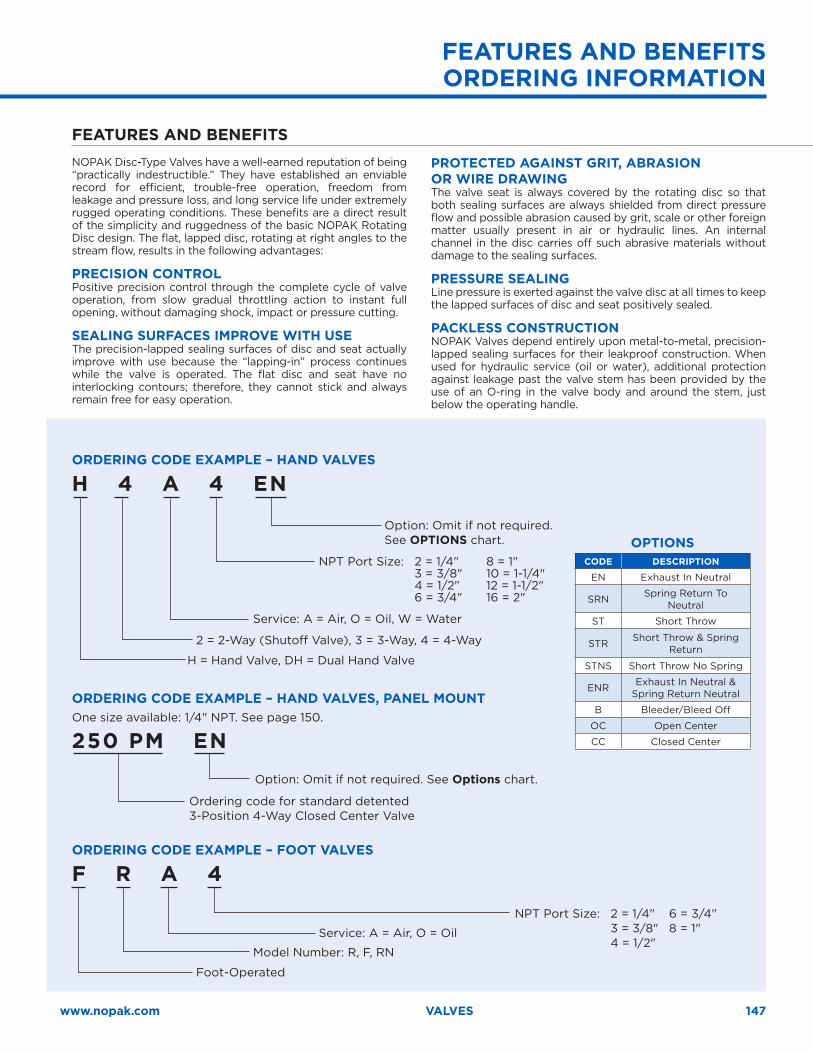
147www.nopak.com VALVES
ORDERING CODE EXAMPLE – HAND VALVES
H 4 A 4 EN
ORDERING CODE EXAMPLE – FOOT VALVES
F R A 4
ORDERING CODE EXAMPLE – HAND VALVES, PANEL MOUNTOne size available: 1/4" NPT. See page 150.
250 PM EN
Option: Omit if not required. See OPTIONS chart.
NPT Port Size: 2 = 1/4" 6 = 3/4" 3 = 3/8" 8 = 1" 4 = 1/2"
Option: Omit if not required. See Options chart.
NPT Port Size: 2 = 1/4" 8 = 1" 3 = 3/8" 10 = 1-1/4" 4 = 1/2" 12 = 1-1/2" 6 = 3/4" 16 = 2"
Service: A = Air, O = Oil
Ordering code for standard detented 3-Position 4-Way Closed Center Valve
2 = 2-Way (Shutoff Valve), 3 = 3-Way, 4 = 4-Way
Foot-Operated
Service: A = Air, O = Oil, W = Water
Model Number: R, F, RN
H = Hand Valve, DH = Dual Hand Valve
FEATURES AND BENEFITS
OPTIONSCODE DESCRIPTION
EN Exhaust In Neutral
SRN Spring Return To Neutral
ST Short Throw
STR Short Throw & Spring Return
STNS Short Throw No Spring
ENR Exhaust In Neutral & Spring Return Neutral
B Bleeder/Bleed Off
OC Open Center
CC Closed Center
FEATURES AND BENEFITS ORDERING INFORMATION
NOPAK Disc-Type Valves have a well-earned reputation of being “practically indestructible.” They have established an enviable record for efficient, trouble-free operation, freedom from leakage and pressure loss, and long service life under extremely rugged operating conditions. These benefits are a direct result of the simplicity and ruggedness of the basic NOPAK Rotating Disc design. The flat, lapped disc, rotating at right angles to the stream flow, results in the following advantages:
PRECISION CONTROLPositive precision control through the complete cycle of valve operation, from slow gradual throttling action to instant full opening, without damaging shock, impact or pressure cutting.
SEALING SURFACES IMPROVE WITH USEThe precision-lapped sealing surfaces of disc and seat actually improve with use because the “lapping-in” process continues while the valve is operated. The flat disc and seat have no interlocking contours; therefore, they cannot stick and always remain free for easy operation.
PROTECTED AGAINST GRIT, ABRASION OR WIRE DRAWINGThe valve seat is always covered by the rotating disc so that both sealing surfaces are always shielded from direct pressure flow and possible abrasion caused by grit, scale or other foreign matter usually present in air or hydraulic lines. An internal channel in the disc carries off such abrasive materials without damage to the sealing surfaces.
PRESSURE SEALINGLine pressure is exerted against the valve disc at all times to keep the lapped surfaces of disc and seat positively sealed.
PACKLESS CONSTRUCTIONNOPAK Valves depend entirely upon metal-to-metal, precision-lapped sealing surfaces for their leakproof construction. When used for hydraulic service (oil or water), additional protection against leakage past the valve stem has been provided by the use of an O-ring in the valve body and around the stem, just below the operating handle.
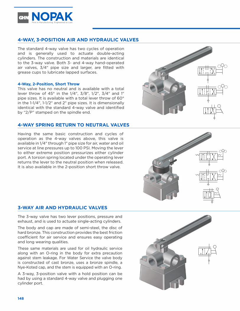
148
“FOUNDRY TOUGH” HAND VALVES – DISC TYPE
4-WAY, 3-POSITION AIR AND HYDRAULIC VALVES
The standard 4-way valve has two cycles of operation and is generally used to actuate double-acting cylinders. The construction and materials are identical to the 3-way valve. Both 3- and 4-way hand-operated air valves, 3/4" pipe size and larger, are fitted with grease cups to lubricate lapped surfaces.
4-Way, 2-Position, Short ThrowThis valve has no neutral and is available with a total lever throw of 45° in the 1/4", 3/8", 1/2", 3/4" and 1" pipe sizes. It is available with a total lever throw of 60° in the 1-1/4", 1-1/2" and 2" pipe sizes. It is dimensionally identical with the standard 4-way valve and identified by “2/P” stamped on the spindle end.
4-WAY SPRING RETURN TO NEUTRAL VALVES
Having the same basic construction and cycles of operation as the 4-way valves above, this valve is available in 1/4" through 1" pipe size for air, water and oil service at line pressures up to 100 PSI. Moving the lever to either extreme position pressurizes either cylinder port. A torsion spring located under the operating lever returns the lever to the neutral position when released. It is also available in the 2-position short throw valve.
3-WAY AIR AND HYDRAULIC VALVES
The 3-way valve has two lever positions, pressure and exhaust, and is used to actuate single-acting cylinders.
The body and cap are made of semi-steel, the disc of hard bronze. This construction provides the best friction coefficient for air service and ensures easy operating and long wearing qualities.
These same materials are used for oil hydraulic service along with an O-ring in the body for extra precaution against stem leakage. For Water Service the valve body is constructed of cast bronze, uses a bronze spindle, a Nye-Koted cap, and the stem is equipped with an O-ring.
A 3-way, 3-position valve with a hold position can be had by using a standard 4-way valve and plugging one cylinder port.
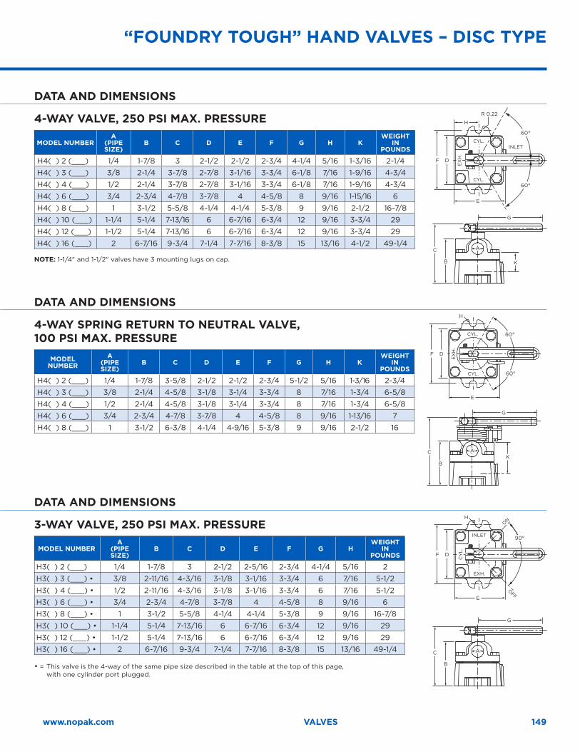
149www.nopak.com VALVES
DATA AND DIMENSIONS
4-WAY VALVE, 250 PSI MAX . PRESSURE
MODEL NUMBERA
(PIPE SIZE)
B C D E F G H KWEIGHT
IN POUNDS
H4( ) 2 (___) 1/4 1-7/8 3 2-1/2 2-1/2 2-3/4 4-1/4 5/16 1-3/16 2-1/4
H4( ) 3 (___) 3/8 2-1/4 3-7/8 2-7/8 3-1/16 3-3/4 6-1/8 7/16 1-9/16 4-3/4
H4( ) 4 (___) 1/2 2-1/4 3-7/8 2-7/8 3-1/16 3-3/4 6-1/8 7/16 1-9/16 4-3/4
H4( ) 6 (___) 3/4 2-3/4 4-7/8 3-7/8 4 4-5/8 8 9/16 1-15/16 6
H4( ) 8 (___) 1 3-1/2 5-5/8 4-1/4 4-1/4 5-3/8 9 9/16 2-1/2 16-7/8
H4( ) 10 (___) 1-1/4 5-1/4 7-13/16 6 6-7/16 6-3/4 12 9/16 3-3/4 29
H4( ) 12 (___) 1-1/2 5-1/4 7-13/16 6 6-7/16 6-3/4 12 9/16 3-3/4 29
H4( ) 16 (___) 2 6-7/16 9-3/4 7-1/4 7-7/16 8-3/8 15 13/16 4-1/2 49-1/4
NOTE: 1-1/4" and 1-1/2" valves have 3 mounting lugs on cap.
F
C
E
H
G
D
B K
R 0.22
AA
60°
60°
DATA AND DIMENSIONS
4-WAY SPRING RETURN TO NEUTRAL VALVE, 100 PSI MAX . PRESSURE
MODEL NUMBER
A(PIPE SIZE)
B C D E F G H KWEIGHT
IN POUNDS
H4( ) 2 (___) 1/4 1-7/8 3-5/8 2-1/2 2-1/2 2-3/4 5-1/2 5/16 1-3/16 2-3/4
H4( ) 3 (___) 3/8 2-1/4 4-5/8 3-1/8 3-1/4 3-3/4 8 7/16 1-3/4 6-5/8
H4( ) 4 (___) 1/2 2-1/4 4-5/8 3-1/8 3-1/4 3-3/4 8 7/16 1-3/4 6-5/8
H4( ) 6 (___) 3/4 2-3/4 4-7/8 3-7/8 4 4-5/8 8 9/16 1-13/16 7
H4( ) 8 (___) 1 3-1/2 6-3/8 4-1/4 4-9/16 5-3/8 9 9/16 2-1/2 16
60°
60°
F
C
E
G
D
BK
H
AA
DATA AND DIMENSIONS
3-WAY VALVE, 250 PSI MAX . PRESSURE
MODEL NUMBERA
(PIPE SIZE)
B C D E F G HWEIGHT
IN POUNDS
H3( ) 2 (___) 1/4 1-7/8 3 2-1/2 2-5/16 2-3/4 4-1/4 5/16 2
H3( ) 3 (___) • 3/8 2-11/16 4-3/16 3-1/8 3-1/16 3-3/4 6 7/16 5-1/2
H3( ) 4 (___) • 1/2 2-11/16 4-3/16 3-1/8 3-1/16 3-3/4 6 7/16 5-1/2
H3( ) 6 (___) • 3/4 2-3/4 4-7/8 3-7/8 4 4-5/8 8 9/16 6
H3( ) 8 (___) • 1 3-1/2 5-5/8 4-1/4 4-1/4 5-3/8 9 9/16 16-7/8
H3( ) 10 (___) • 1-1/4 5-1/4 7-13/16 6 6-7/16 6-3/4 12 9/16 29
H3( ) 12 (___) • 1-1/2 5-1/4 7-13/16 6 6-7/16 6-3/4 12 9/16 29
H3( ) 16 (___) • 2 6-7/16 9-3/4 7-1/4 7-7/16 8-3/8 15 13/16 49-1/4
• = This valve is the 4-way of the same pipe size described in the table at the top of this page, with one cylinder port plugged.
F
C
E
G
D
B
H
AA
90°
OFF
ON
CY
L.
INLET
EXH.
“FOUNDRY TOUGH” HAND VALVES – DISC TYPE
EX
H.
CYL.
CYL.
CYL.
CYL.
INLET
EX
H.
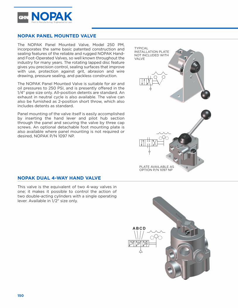
150
NOPAK PANEL MOUNTED VALVE
The NOPAK Panel Mounted Valve, Model 250 PM, incorporates the same basic patented construction and sealing features of the reliable and rugged NOPAK Hand- and Foot-Operated Valves, so well known throughout the industry for many years. The rotating lapped disc feature gives you precision control, sealing surfaces that improve with use, protection against grit, abrasion and wire drawing, pressure sealing, and packless construction.
The NOPAK Panel Mounted Valve is suitable for air and oil pressures to 250 PSI, and is presently offered in the 1/4" pipe size only. All-position detents are standard. An exhaust in neutral cycle is also available. The valve can also be furnished as 2-position short throw, which also includes detents as standard.
Panel mounting of the valve itself is easily accomplished by inserting the hand lever and pilot hub section through the panel and securing the valve by three cap screws. An optional detachable foot mounting plate is also available where panel mounting is not required or desired, NOPAK P/N 1097 NP.
NOPAK DUAL 4-WAY HAND VALVE
This valve is the equivalent of two 4-way valves in one; it makes it possible to control the action of two double-acting cylinders with a single operating lever. Available in 1/2" size only.
TYPICAL INSTALLATION PLATE NOT INCLUDED WITH VALVE
PLATE AVAILABLE AS OPTION P/N 1097 NP
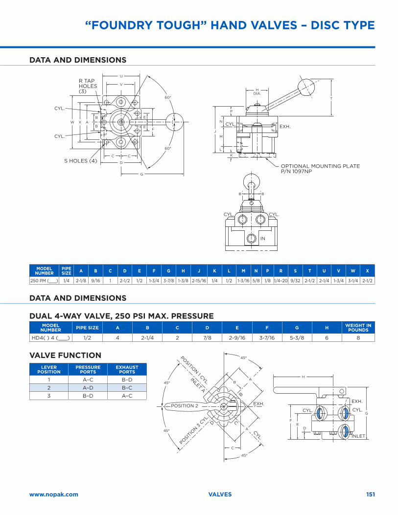
151www.nopak.com VALVES
60°
60°
U
W X A
J
T
P
N
M
L
B B
FB
B
E
E
V
D
G
C C K
DATA AND DIMENSIONS
MODEL NUMBER
PIPE SIZE A B C D E F G H J K L M N P R S T U V W X
250 PM (___) 1/4 2-1/8 9/16 1 2-1/2 1/2 1-3/4 3-7/8 1-3/8 2-15/16 1/4 1/2 1-3/16 5/8 1/8 1/4–20 9/32 2-1/2 2-1/4 1-3/4 3-1/4 2-1/2
DATA AND DIMENSIONS
DUAL 4-WAY VALVE, 250 PSI MAX . PRESSUREMODEL
NUMBER PIPE SIZE A B C D E F G H WEIGHT IN POUNDS
HD4( ) 4 (___) 1/2 4 2-1/4 2 7/8 2-9/16 3-7/16 5-3/8 6 8
VALVE FUNCTIONLEVER
POSITIONPRESSURE
PORTSEXHAUST
PORTS
1 A–C B–D
2 A–D B–C
3 B–D A–C
H
G
FE
D
A
A
C
B45°
45°
45°
45°
OPTIONAL MOUNTING PLATE P/N 1097NP
S HOLES (4)
R TAP HOLES (3) H
DIA.
IN
CYL.
CYL. CYL.
CYL.
CYL.
EXH.
INLET
CYL.CYL.
EXH.EXH.POSITION 2
POSITIO
N 3 C
YL.
POSITION 1 CYL.
CYL.
CD
B
INLET A
“FOUNDRY TOUGH” HAND VALVES – DISC TYPE
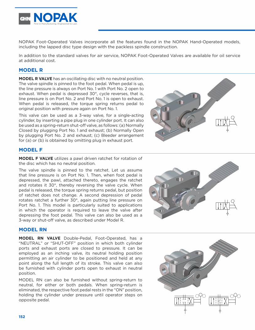
152
NOPAK Foot-Operated Valves incorporate all the features found in the NOPAK Hand-Operated models, including the lapped disc type design with the packless spindle construction.
In addition to the standard valves for air service, NOPAK Foot-Operated Valves are available for oil service at additional cost.
MODEL R
MODEL R VALVE has an oscillating disc with no neutral position. The valve spindle is pinned to the foot pedal. When pedal is up, the line pressure is always on Port No. 1 with Port No. 2 open to exhaust. When pedal is depressed 30°, cycle reverses, that is, line pressure is on Port No. 2 and Port No. 1 is open to exhaust. When pedal is released, the torque spring returns pedal to original position with pressure again on Port No. 1.
This valve can be used as a 3-way valve, for a single-acting cylinder, by inserting a pipe plug in one cylinder port. It can also be used as a spring-return shut-off valve, as follows: (a) Normally Closed by plugging Port No. 1 and exhaust; (b) Normally Open by plugging Port No. 2 and exhaust; (c) Bleeder arrangement for (a) or (b) is obtained by omitting plug in exhaust port.
MODEL F
MODEL F VALVE utilizes a pawl driven ratchet for rotation of the disc which has no neutral position.
The valve spindle is pinned to the ratchet. Let us assume that line pressure is on Port No. 1. Then, when foot pedal is depressed, the pawl, attached thereto, engages the ratchet and rotates it 30°, thereby reversing the valve cycle. When pedal is released, the torque spring returns pedal, but position of ratchet does not change. A second depression of pedal rotates ratchet a further 30°, again putting line pressure on Port No. 1. This model is particularly suited to applications in which the operator is required to leave the valve after depressing the foot pedal. This valve can also be used as a 3-way or shut-off valve, as described under Model R.
MODEL RN
MODEL RN VALVE Double-Pedal, Foot-Operated, has a “NEUTRAL” or “SHUT-OFF” position in which both cylinder ports and exhaust ports are closed to pressure. It can be employed as an inching valve, its neutral holding position permitting an air cylinder to be positioned and held at any point along the full length of its stroke. This valve can also be furnished with cylinder ports open to exhaust in neutral position.
MODEL RN can also be furnished without spring-return to neutral, for either or both pedals. When spring-return is eliminated, the respective foot pedal rests in the “ON” position, holding the cylinder under pressure until operator steps on opposite pedal.
FOOT VALVES – DISC TYPE
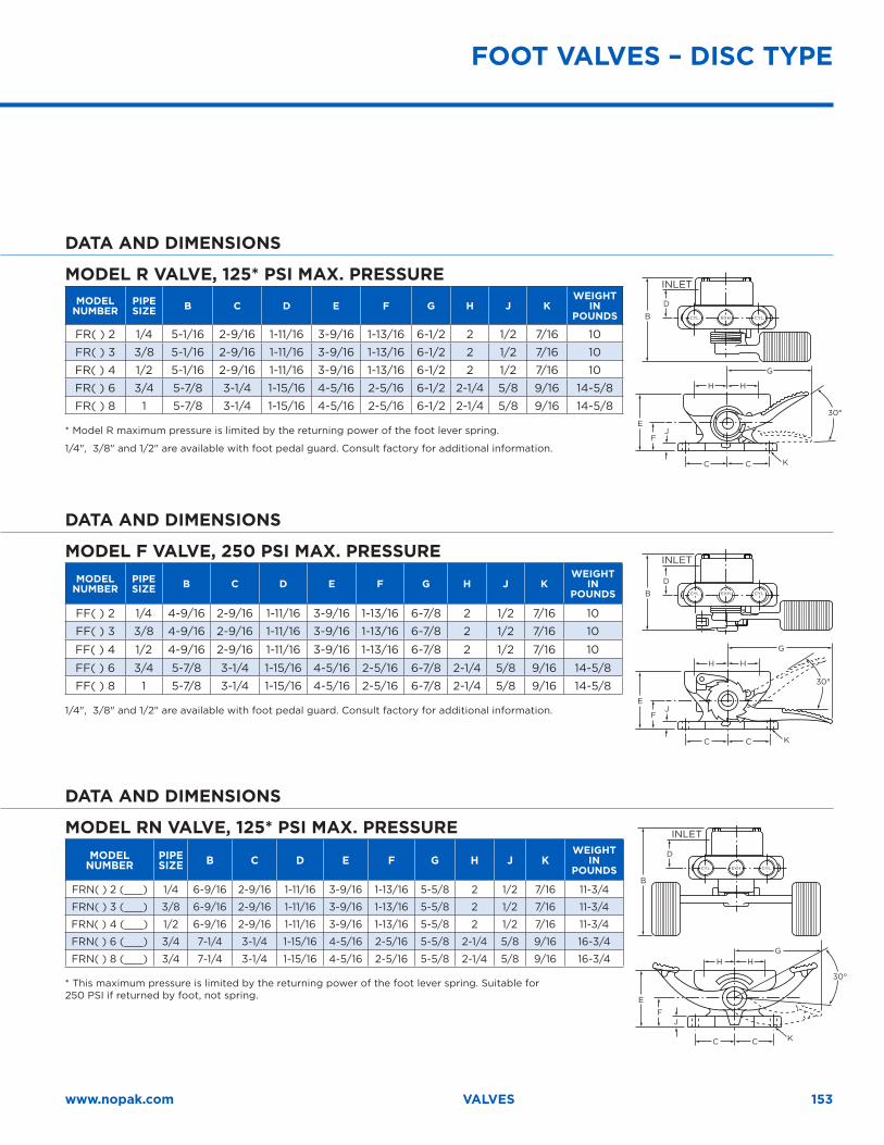
153www.nopak.com VALVES
DATA AND DIMENSIONS
MODEL R VALVE, 125* PSI MAX . PRESSUREMODEL
NUMBERPIPE SIZE B C D E F G H J K
WEIGHT IN
POUNDS
FR( ) 2 1/4 5-1/16 2-9/16 1-11/16 3-9/16 1-13/16 6-1/2 2 1/2 7/16 10
FR( ) 3 3/8 5-1/16 2-9/16 1-11/16 3-9/16 1-13/16 6-1/2 2 1/2 7/16 10
FR( ) 4 1/2 5-1/16 2-9/16 1-11/16 3-9/16 1-13/16 6-1/2 2 1/2 7/16 10
FR( ) 6 3/4 5-7/8 3-1/4 1-15/16 4-5/16 2-5/16 6-1/2 2-1/4 5/8 9/16 14-5/8
FR( ) 8 1 5-7/8 3-1/4 1-15/16 4-5/16 2-5/16 6-1/2 2-1/4 5/8 9/16 14-5/8
* Model R maximum pressure is limited by the returning power of the foot lever spring.
1/4", 3/8" and 1/2" are available with foot pedal guard. Consult factory for additional information.K
B
D
E
FJ
C C
H H
G
30°
DATA AND DIMENSIONS
MODEL F VALVE, 250 PSI MAX . PRESSUREMODEL
NUMBERPIPE SIZE B C D E F G H J K
WEIGHT IN
POUNDS
FF( ) 2 1/4 4-9/16 2-9/16 1-11/16 3-9/16 1-13/16 6-7/8 2 1/2 7/16 10
FF( ) 3 3/8 4-9/16 2-9/16 1-11/16 3-9/16 1-13/16 6-7/8 2 1/2 7/16 10
FF( ) 4 1/2 4-9/16 2-9/16 1-11/16 3-9/16 1-13/16 6-7/8 2 1/2 7/16 10
FF( ) 6 3/4 5-7/8 3-1/4 1-15/16 4-5/16 2-5/16 6-7/8 2-1/4 5/8 9/16 14-5/8
FF( ) 8 1 5-7/8 3-1/4 1-15/16 4-5/16 2-5/16 6-7/8 2-1/4 5/8 9/16 14-5/8
1/4", 3/8" and 1/2" are available with foot pedal guard. Consult factory for additional information.
K
B
D
E
FJ
C C
H H
G
30°
DATA AND DIMENSIONS
MODEL RN VALVE, 125* PSI MAX . PRESSUREMODEL
NUMBERPIPE SIZE B C D E F G H J K
WEIGHT IN
POUNDS
FRN( ) 2 (___) 1/4 6-9/16 2-9/16 1-11/16 3-9/16 1-13/16 5-5/8 2 1/2 7/16 11-3/4
FRN( ) 3 (___) 3/8 6-9/16 2-9/16 1-11/16 3-9/16 1-13/16 5-5/8 2 1/2 7/16 11-3/4
FRN( ) 4 (___) 1/2 6-9/16 2-9/16 1-11/16 3-9/16 1-13/16 5-5/8 2 1/2 7/16 11-3/4
FRN( ) 6 (___) 3/4 7-1/4 3-1/4 1-15/16 4-5/16 2-5/16 5-5/8 2-1/4 5/8 9/16 16-3/4
FRN( ) 8 (___) 3/4 7-1/4 3-1/4 1-15/16 4-5/16 2-5/16 5-5/8 2-1/4 5/8 9/16 16-3/4
* This maximum pressure is limited by the returning power of the foot lever spring. Suitable for 250 PSI if returned by foot, not spring. E
B
D
FJ
C C K
H HG
30°
FOOT VALVES – DISC TYPE
INLET
INLET
INLET
CYL.
CYL.
CYL.
CYL.
CYL.
CYL.
EXH.
EXH.
EXH.
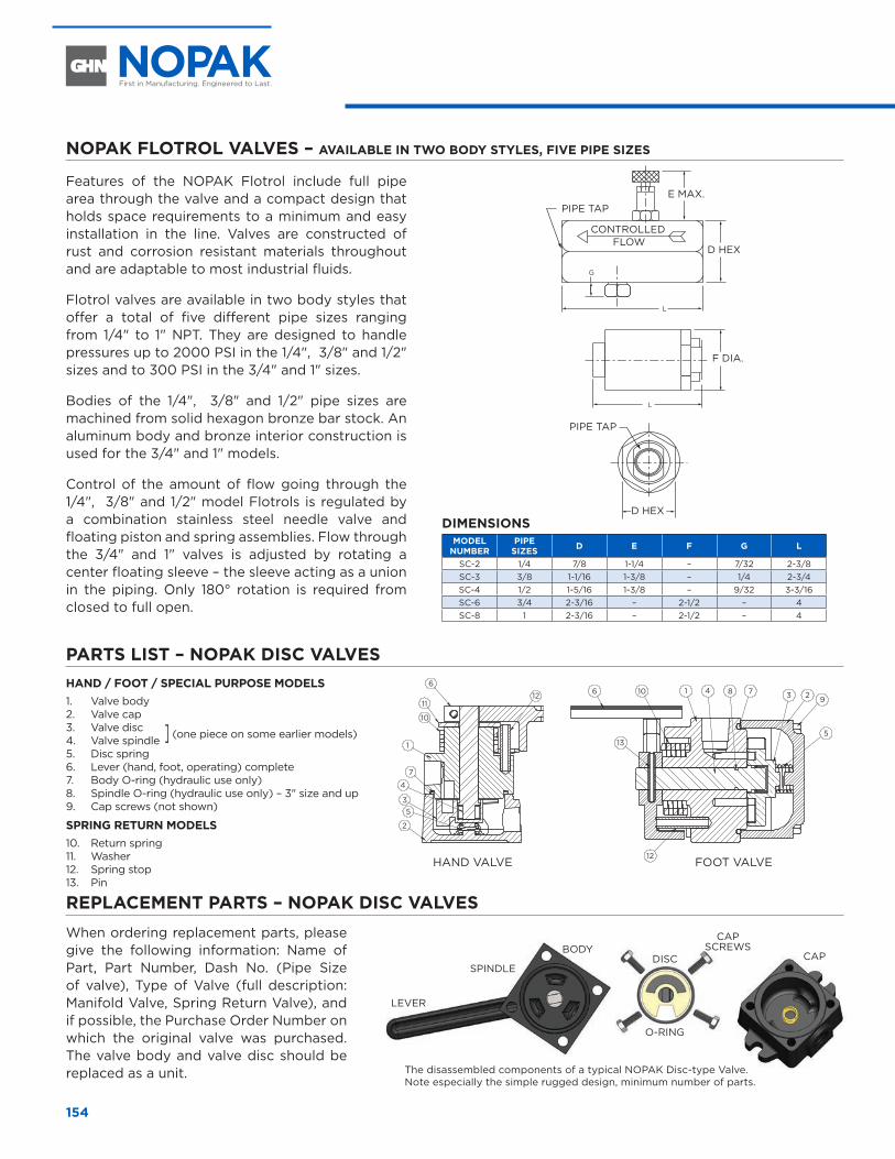
154
NOPAK FLOTROL VALVES – AVAILABLE IN TWO BODY STYLES, FIVE PIPE SIZES
Features of the NOPAK Flotrol include full pipe area through the valve and a compact design that holds space requirements to a minimum and easy installation in the line. Valves are constructed of rust and corrosion resistant materials throughout and are adaptable to most industrial fluids.
Flotrol valves are available in two body styles that offer a total of five different pipe sizes ranging from 1/4" to 1" NPT. They are designed to handle pressures up to 2000 PSI in the 1/4", 3/8" and 1/2" sizes and to 300 PSI in the 3/4" and 1" sizes.
Bodies of the 1/4", 3/8" and 1/2" pipe sizes are machined from solid hexagon bronze bar stock. An aluminum body and bronze interior construction is used for the 3/4" and 1" models.
Control of the amount of flow going through the 1/4", 3/8" and 1/2" model Flotrols is regulated by a combination stainless steel needle valve and floating piston and spring assemblies. Flow through the 3/4" and 1" valves is adjusted by rotating a center floating sleeve – the sleeve acting as a union in the piping. Only 180° rotation is required from closed to full open.
G
L
L
DIMENSIONSMODEL
NUMBERPIPE
SIZES D E F G L
SC-2 1/4 7/8 1-1/4 – 7/32 2-3/8SC-3 3/8 1-1/16 1-3/8 – 1/4 2-3/4SC-4 1/2 1-5/16 1-3/8 – 9/32 3-3/16SC-6 3/4 2-3/16 – 2-1/2 – 4SC-8 1 2-3/16 – 2-1/2 – 4
PARTS LIST – NOPAK DISC VALVESHAND / FOOT / SPECIAL PURPOSE MODELS1. Valve body2. Valve cap3. Valve disc ] (one piece on some earlier models)4. Valve spindle5. Disc spring6. Lever (hand, foot, operating) complete7. Body O-ring (hydraulic use only)8. Spindle O-ring (hydraulic use only) – 3" size and up9. Cap screws (not shown)
SPRING RETURN MODELS10. Return spring11. Washer12. Spring stop 13. Pin
6 10 81 7 23
5
9
12
13
46
11
10
1
7
4
35
2
12
REPLACEMENT PARTS – NOPAK DISC VALVESWhen ordering replacement parts, please give the following information: Name of Part, Part Number, Dash No. (Pipe Size of valve), Type of Valve (full description: Manifold Valve, Spring Return Valve), and if possible, the Purchase Order Number on which the original valve was purchased. The valve body and valve disc should be replaced as a unit.
BODY
SPINDLE
PIPE TAP
PIPE TAPE MAX.
D HEX
HAND VALVE FOOT VALVE
D HEX
F DIA.
CONTROLLED
DISC
O-RING
CAP SCREWS
LEVER
FLOW
FLOTROL VALVES
CAP
The disassembled components of a typical NOPAK Disc-type Valve. Note especially the simple rugged design, minimum number of parts.
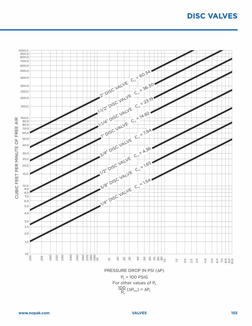
155www.nopak.com VALVES
CU
BIC
FE
ET
PE
R M
INU
TE
OF
FR
EE
AIR
.010
1.0
1.5
2.0
2.5
3.0
4.0
5.0
6.0
7.08.09.0
10.0
15.0
20.0
25.0
30.0
40.0
50.0
60.0
70.080.090.0
100.0
150.0
200.0
250.0
300.0
400.0
500.0
600.0
700.0
800.0900.0
1000.0
.015
.020
.025
.03
0
.04
0
.05
0
.06
0
.070
.08
0.0
90
.10
.15
.20
.25
.30
.40
.50
.60
.70
.80
.90
1.0 1.5
2.0
2.5
3.0
4.0
5.0
6.0 7.0
8.0
9.0
10.0
DISC VALVES
2" DISC VALVE C V
= 60.34
1-1/2" D
ISC VALVE C V = 36.30
1-1/4" D
ISC VALVE C V = 23.19
1" DISC VALVE C V
= 14.82
3/4" DISC VALVE C V
= 7.94
1/2" D
ISC VALVE C V = 4.36
3/8" DISC VALVE C V
= 1.65
1/4" D
ISC VALVE C V = 1.5
4
PRESSURE DROP IN PSI (∆P)
PS = 100 PSIGFor other values of PS
100 (∆P100) = ∆PSPS
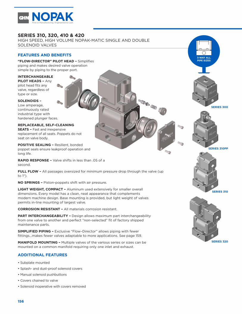
156
SERIES 310, 320, 410 & 420 HIGH SPEED, HIGH VOLUME NOPAK-MATIC SINGLE AND DOUBLE SOLENOID VALVES
FEATURES AND BENEFITS “FLOW-DIRECTOR” PILOT HEAD – Simplifies piping and makes desired valve operation simple by piping to the proper port.
INTERCHANGEABLE PILOT HEADS – Any pilot head fits any valve, regardless of type or size.
SOLENOIDS – Low amperage, continuously rated industrial type with hardened plunger faces.
REPLACEABLE, SELF-CLEANING SEATS – Fast and inexpensive replacement of all seats. Poppets do not seat on valve body.
POSITIVE SEALING – Resilient, bonded poppet seals ensure leakproof operation and long life.
RAPID RESPONSE – Valve shifts in less than .05 of a second.
FULL FLOW – All passages oversized for minimum pressure drop through the valve (up to 1").
NO SPRINGS – Piston-poppets shift with air pressure.
LIGHT WEIGHT, COMPACT – Aluminum used extensively for smaller overall dimensions. Every model has a clean, neat appearance that complements modern machine design. Base mounting is provided, but light weight of valves permits in-line mounting of largest valve.
CORROSION RESISTANT – All materials corrosion resistant.
PART INTERCHANGEABILITY – Design allows maximum part interchangeability from one valve to another and perfect “non–selected” fit of factory shipped maintenance parts.
SIMPLIFIED PIPING – Exclusive “Flow–Director” allows piping with fewer fittings…makes fewer valves adaptable to more applications. See page 159.
MANIFOLD MOUNTING – Multiple valves of the various series or sizes can be mounted on a common manifold requiring only one inlet and exhaust.
ADDITIONAL FEATURES
• Subplate mounted
• Splash- and dust-proof solenoid covers
• Manual solenoid pushbuttons
• Covers chained to valve
• Solenoid inoperative with covers removed
3-WAY ALL PIPE SIZES
SERIES 300
SERIES 310PP
SERIES 310
SERIES 320
SOLENOID VALVESSERIES 310, 320, 410 & 420 – FEATURES AND BENEFITS
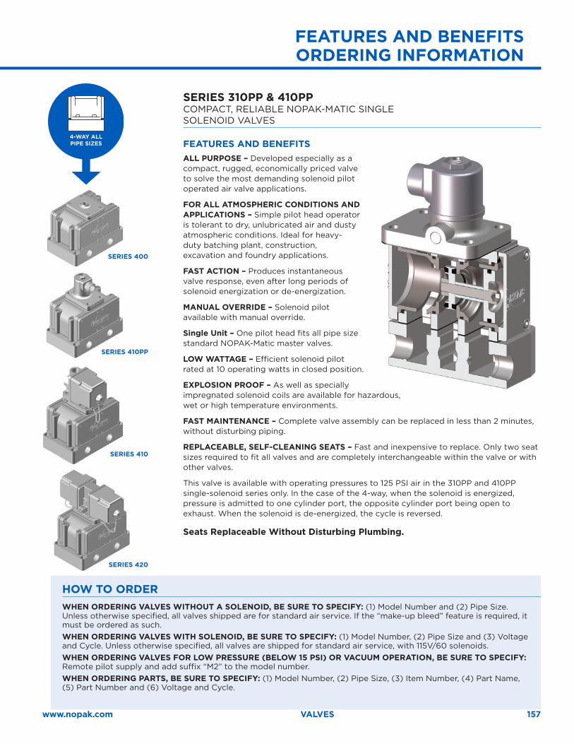
157www.nopak.com VALVES
HOW TO ORDERWHEN ORDERING VALVES WITHOUT A SOLENOID, BE SURE TO SPECIFY: (1) Model Number and (2) Pipe Size. Unless otherwise specified, all valves shipped are for standard air service. If the “make-up bleed” feature is required, it must be ordered as such. WHEN ORDERING VALVES WITH SOLENOID, BE SURE TO SPECIFY: (1) Model Number, (2) Pipe Size and (3) Voltage and Cycle. Unless otherwise specified, all valves are shipped for standard air service, with 115V/60 solenoids. WHEN ORDERING VALVES FOR LOW PRESSURE (BELOW 15 PSI) OR VACUUM OPERATION, BE SURE TO SPECIFY: Remote pilot supply and add suffix “M2” to the model number. WHEN ORDERING PARTS, BE SURE TO SPECIFY: (1) Model Number, (2) Pipe Size, (3) Item Number, (4) Part Name, (5) Part Number and (6) Voltage and Cycle.
FEATURES AND BENEFITS ORDERING INFORMATION
SERIES 310PP & 410PP COMPACT, RELIABLE NOPAK-MATIC SINGLE SOLENOID VALVES
FEATURES AND BENEFITS ALL PURPOSE – Developed especially as a compact, rugged, economically priced valve to solve the most demanding solenoid pilot operated air valve applications.
FOR ALL ATMOSPHERIC CONDITIONS AND APPLICATIONS – Simple pilot head operator is tolerant to dry, unlubricated air and dusty atmospheric conditions. Ideal for heavy-duty batching plant, construction, excavation and foundry applications.
FAST ACTION – Produces instantaneous valve response, even after long periods of solenoid energization or de-energization.
MANUAL OVERRIDE – Solenoid pilot available with manual override.
Single Unit – One pilot head fits all pipe size standard NOPAK-Matic master valves.
LOW WATTAGE – Efficient solenoid pilot rated at 10 operating watts in closed position.
EXPLOSION PROOF – As well as specially impregnated solenoid coils are available for hazardous, wet or high temperature environments.
FAST MAINTENANCE – Complete valve assembly can be replaced in less than 2 minutes, without disturbing piping.
REPLACEABLE, SELF-CLEANING SEATS – Fast and inexpensive to replace. Only two seat sizes required to fit all valves and are completely interchangeable within the valve or with other valves.
This valve is available with operating pressures to 125 PSI air in the 310PP and 410PP single-solenoid series only. In the case of the 4-way, when the solenoid is energized, pressure is admitted to one cylinder port, the opposite cylinder port being open to exhaust. When the solenoid is de-energized, the cycle is reversed.
Seats Replaceable Without Disturbing Plumbing .
4-WAY ALL PIPE SIZES
SERIES 400
SERIES 410PP
SERIES 410
SERIES 420
SERIES 310PP & 410PP – FEATURES AND BENEFITS
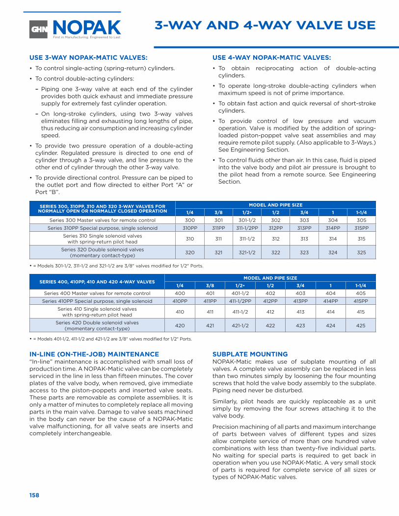
158
SERIES 300, 310PP, 310 AND 320 3-WAY VALVES FOR NORMALLY OPEN OR NORMALLY CLOSED OPERATION
MODEL AND PIPE SIZE
1/4 3/8 1/2• 1/2 3/4 1 1-1/4
Series 300 Master valves for remote control 300 301 301-1/2 302 303 304 305
Series 310PP Special purpose, single solenoid 310PP 311PP 311-1/2PP 312PP 313PP 314PP 315PP
Series 310 Single solenoid valves with spring-return pilot head 310 311 311-1/2 312 313 314 315
Series 320 Double solenoid valves (momentary contact-type) 320 321 321-1/2 322 323 324 325
• = Models 301-1/2, 311-1/2 and 321-1/2 are 3/8" valves modified for 1/2" Ports.
SERIES 400, 410PP, 410 AND 420 4-WAY VALVES MODEL AND PIPE SIZE
1/4 3/8 1/2• 1/2 3/4 1 1-1/4
Series 400 Master valves for remote control 400 401 401-1/2 402 403 404 405
Series 410PP Special purpose, single solenoid 410PP 411PP 411-1/2PP 412PP 413PP 414PP 415PP
Series 410 Single solenoid valves with spring-return pilot head 410 411 411-1/2 412 413 414 415
Series 420 Double solenoid valves (momentary contact-type) 420 421 421-1/2 422 423 424 425
• = Models 401-1/2, 411-1/2 and 421-1/2 are 3/8" valves modified for 1/2" Ports.
USE 3-WAY NOPAK-MATIC VALVES:• To control single-acting (spring-return) cylinders.
• To control double-acting cylinders:
– Piping one 3-way valve at each end of the cylinder provides both quick exhaust and immediate pressure supply for extremely fast cylinder operation.
– On long-stroke cylinders, using two 3-way valves eliminates filling and exhausting long lengths of pipe, thus reducing air consumption and increasing cylinder speed.
• To provide two pressure operation of a double-acting cylinder. Regulated pressure is directed to one end of cylinder through a 3-way valve, and line pressure to the other end of cylinder through the other 3-way valve.
• To provide directional control. Pressure can be piped to the outlet port and flow directed to either Port “A” or Port “B”.
USE 4-WAY NOPAK-MATIC VALVES:• To obtain reciprocating action of double-acting
cylinders.
• To operate long-stroke double-acting cylinders when maximum speed is not of prime importance.
• To obtain fast action and quick reversal of short-stroke cylinders.
• To provide control of low pressure and vacuum operation. Valve is modified by the addition of spring-loaded piston-poppet valve seat assemblies and may require remote pilot supply. (Also applicable to 3-Ways.) See Engineering Section.
• To control fluids other than air. In this case, fluid is piped into the valve body and pilot air pressure is brought to the pilot head from a remote source. See Engineering Section.
3-WAY AND 4-WAY VALVE USE
IN-LINE (ON-THE-JOB) MAINTENANCE“In-line” maintenance is accomplished with small loss of production time. A NOPAK-Matic valve can be completely serviced in the line in less than fifteen minutes. The cover plates of the valve body, when removed, give immediate access to the piston-poppets and inserted valve seats. These parts are removable as complete assemblies. It is only a matter of minutes to completely replace all moving parts in the main valve. Damage to valve seats machined in the body can never be the cause of a NOPAK-Matic valve malfunctioning, for all valve seats are inserts and completely interchangeable.
SUBPLATE MOUNTINGNOPAK-Matic makes use of subplate mounting of all valves. A complete valve assembly can be replaced in less than two minutes simply by loosening the four mounting screws that hold the valve body assembly to the subplate. Piping need never be disturbed.
Similarly, pilot heads are quickly replaceable as a unit simply by removing the four screws attaching it to the valve body.
Precision machining of all parts and maximum interchange of parts between valves of different types and sizes allow complete service of more than one hundred valve combinations with less than twenty-five individual parts. No waiting for special parts is required to get back in operation when you use NOPAK-Matic. A very small stock of parts is required for complete service of all sizes or types of NOPAK-Matic valves.
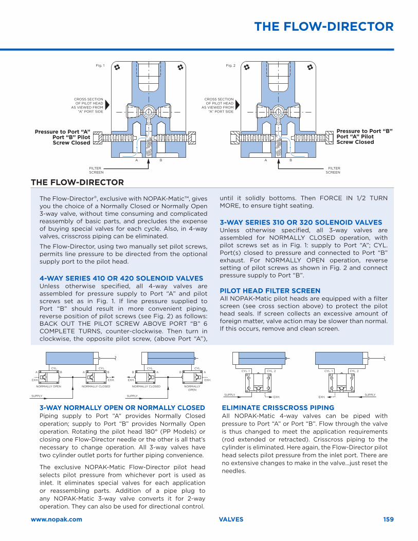
159www.nopak.com VALVES
THE FLOW-DIRECTOR
THE FLOW-DIRECTOR
FILTER SCREEN
Fig. 1 Fig. 2
A AB B
FILTER SCREEN
CROSS SECTION OF PILOT HEAD
AS VIEWED FROM “A” PORT SIDE
CROSS SECTION OF PILOT HEAD
AS VIEWED FROM “A” PORT SIDE
SUPPLY SUPPLYEXH. EXH.
CYL. 1 CYL. 1CYL. 2 CYL. 2
SUPPLY SUPPLY
A A B BB B A A
EXH. EXH. EXH. EXH.
NORMALLY OPEN NORMALLY CLOSED NORMALLY CLOSED NORMALLY OPEN
CYL. CYL. CYL. CYL.
Pressure to Port “A” Port “B” Pilot Screw Closed
Pressure to Port “B” Port “A” Pilot Screw Closed
The Flow-Director®, exclusive with NOPAK-Matic™, gives you the choice of a Normally Closed or Normally Open 3-way valve, without time consuming and complicated reassembly of basic parts, and precludes the expense of buying special valves for each cycle. Also, in 4-way valves, crisscross piping can be eliminated.
The Flow-Director, using two manually set pilot screws, permits line pressure to be directed from the optional supply port to the pilot head.
4-WAY SERIES 410 OR 420 SOLENOID VALVESUnless otherwise specified, all 4-way valves are assembled for pressure supply to Port “A” and pilot screws set as in Fig. 1. If line pressure supplied to Port “B” should result in more convenient piping, reverse position of pilot screws (see Fig. 2) as follows: BACK OUT THE PILOT SCREW ABOVE PORT “B” 6 COMPLETE TURNS, counter-clockwise. Then turn in clockwise, the opposite pilot screw, (above Port “A”),
until it solidly bottoms. Then FORCE IN 1/2 TURN MORE, to ensure tight seating.
3-WAY SERIES 310 OR 320 SOLENOID VALVESUnless otherwise specified, all 3-way valves are assembled for NORMALLY CLOSED operation, with pilot screws set as in Fig. 1: supply to Port “A”; CYL. Port(s) closed to pressure and connected to Port “B” exhaust. For NORMALLY OPEN operation, reverse setting of pilot screws as shown in Fig. 2 and connect pressure supply to Port “B”.
PILOT HEAD FILTER SCREENAll NOPAK-Matic pilot heads are equipped with a filter screen (see cross section above) to protect the pilot head seals. If screen collects an excessive amount of foreign matter, valve action may be slower than normal. If this occurs, remove and clean screen.
3-WAY NORMALLY OPEN OR NORMALLY CLOSEDPiping supply to Port “A“ provides Normally Closed operation; supply to Port “B” provides Normally Open operation. Rotating the pilot head 180° (PP Models) or closing one Flow-Director needle or the other is all that’s necessary to change operation. All 3-way valves have two cylinder outlet ports for further piping convenience.
The exclusive NOPAK-Matic Flow-Director pilot head selects pilot pressure from whichever port is used as inlet. It eliminates special valves for each application or reassembling parts. Addition of a pipe plug to any NOPAK-Matic 3-way valve converts it for 2-way operation. They can also be used for directional control.
ELIMINATE CRISSCROSS PIPINGAll NOPAK-Matic 4-way valves can be piped with pressure to Port “A” or Port “B”. Flow through the valve is thus changed to meet the application requirements (rod extended or retracted). Crisscross piping to the cylinder is eliminated. Here again, the Flow-Director pilot head selects pilot pressure from the inlet port. There are no extensive changes to make in the valve…just reset the needles.
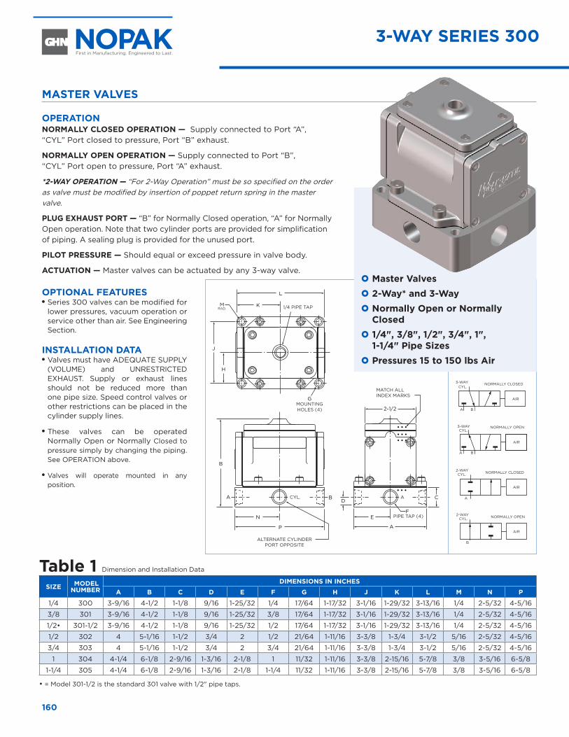
L
J
H
K
A
E
B
D
P
N
A B
G
F
C
2-1/2
1/4 PIPE TAP
MOUNTING HOLES (4)
PIPE TAP (4)
MATCH ALL INDEX MARKS
ALTERNATE CYLINDER PORT OPPOSITE
CYL.
AIR
A
CYL. NORMALLY CLOSED2-WAY
AIR
A
CYL.
B
NORMALLY CLOSED3-WAY
CYL.
B
AIR
NORMALLY OPEN2-WAY
CYL.
A B
AIR
NORMALLY OPEN3-WAY
A
MRAD.
160
MASTER VALVES
OPERATION NORMALLY CLOSED OPERATION — Supply connected to Port “A”, “CYL” Port closed to pressure, Port “B” exhaust.
NORMALLY OPEN OPERATION — Supply connected to Port “B”, “CYL” Port open to pressure, Port “A” exhaust.
*2-WAY OPERATION — “For 2-Way Operation” must be so specified on the order as valve must be modified by insertion of poppet return spring in the master valve.
PLUG EXHAUST PORT — “B” for Normally Closed operation, “A” for Normally Open operation. Note that two cylinder ports are provided for simplification of piping. A sealing plug is provided for the unused port.
PILOT PRESSURE — Should equal or exceed pressure in valve body.
ACTUATION — Master valves can be actuated by any 3-way valve.
OPTIONAL FEATURESOO Series 300 valves can be modified for lower pressures, vacuum operation or service other than air. See Engineering Section.
INSTALLATION DATA OO Valves must have ADEQUATE SUPPLY (VOLUME) and UNRESTRICTED EXHAUST. Supply or exhaust lines should not be reduced more than one pipe size. Speed control valves or other restrictions can be placed in the cylinder supply lines.
OO These valves can be operated Normally Open or Normally Closed to pressure simply by changing the piping. See OPERATION above.
OO Valves will operate mounted in any position.
Table 1 Dimension and Installation Data
SIZE MODEL NUMBER
DIMENSIONS IN INCHES
A B C D E F G H J K L M N P
1/4 300 3-9/16 4-1/2 1-1/8 9/16 1-25/32 1/4 17/64 1-17/32 3-1/16 1-29/32 3-13/16 1/4 2-5/32 4-5/16
3/8 301 3-9/16 4-1/2 1-1/8 9/16 1-25/32 3/8 17/64 1-17/32 3-1/16 1-29/32 3-13/16 1/4 2-5/32 4-5/16
1/2• 301-1/2 3-9/16 4-1/2 1-1/8 9/16 1-25/32 1/2 17/64 1-17/32 3-1/16 1-29/32 3-13/16 1/4 2-5/32 4-5/16
1/2 302 4 5-1/16 1-1/2 3/4 2 1/2 21/64 1-11/16 3-3/8 1-3/4 3-1/2 5/16 2-5/32 4-5/16
3/4 303 4 5-1/16 1-1/2 3/4 2 3/4 21/64 1-11/16 3-3/8 1-3/4 3-1/2 5/16 2-5/32 4-5/16
1 304 4-1/4 6-1/8 2-9/16 1-3/16 2-1/8 1 11/32 1-11/16 3-3/8 2-15/16 5-7/8 3/8 3-5/16 6-5/8
1-1/4 305 4-1/4 6-1/8 2-9/16 1-3/16 2-1/8 1-1/4 11/32 1-11/16 3-3/8 2-15/16 5-7/8 3/8 3-5/16 6-5/8
• = Model 301-1/2 is the standard 301 valve with 1/2" pipe taps.
3-WAY SERIES 300
} Master Valves } 2-Way* and 3-Way } Normally Open or Normally Closed
} 1/4", 3/8", 1/2", 3/4", 1", 1-1/4" Pipe Sizes
} Pressures 15 to 150 lbs Air
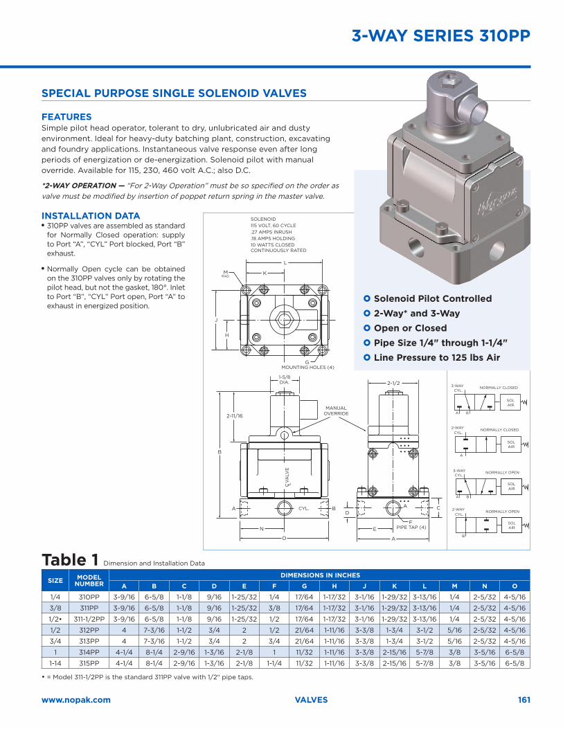
F
A AB
B
2-11/16
E
CD
2-1/2
A
N
O
G
H
K
L
J
CYL.
C L V
ALV
E
PIPE TAP (4)
MOUNTING HOLES (4)
MANUAL OVERRIDE
SOLAIR
A
CYL.NORMALLY CLOSED2-WAY
CYL.
A B
SOLAIR
NORMALLY OPEN3-WAY
SOLAIR
A
CYL.
B
NORMALLY CLOSED3-WAY
CYL.
B
SOLAIR
NORMALLY OPEN2-WAY
1-5/8DIA.
MRAD.
161www.nopak.com VALVES
SPECIAL PURPOSE SINGLE SOLENOID VALVES
FEATURES Simple pilot head operator, tolerant to dry, unlubricated air and dusty environment. Ideal for heavy-duty batching plant, construction, excavating and foundry applications. Instantaneous valve response even after long periods of energization or de-energization. Solenoid pilot with manual override. Available for 115, 230, 460 volt A.C.; also D.C.
*2-WAY OPERATION — “For 2-Way Operation” must be so specified on the order as valve must be modified by insertion of poppet return spring in the master valve.
INSTALLATION DATA OO 310PP valves are assembled as standard for Normally Closed operation: supply to Port “A”, “CYL” Port blocked, Port “B” exhaust.
OO Normally Open cycle can be obtained on the 310PP valves only by rotating the pilot head, but not the gasket, 180°. Inlet to Port “B”, “CYL” Port open, Port “A” to exhaust in energized position.
} Solenoid Pilot Controlled } 2-Way* and 3-Way } Open or Closed } Pipe Size 1/4" through 1-1/4" } Line Pressure to 125 lbs Air
Table 1 Dimension and Installation Data
SIZE MODEL NUMBER
DIMENSIONS IN INCHES
A B C D E F G H J K L M N O
1/4 310PP 3-9/16 6-5/8 1-1/8 9/16 1-25/32 1/4 17/64 1-17/32 3-1/16 1-29/32 3-13/16 1/4 2-5/32 4-5/16
3/8 311PP 3-9/16 6-5/8 1-1/8 9/16 1-25/32 3/8 17/64 1-17/32 3-1/16 1-29/32 3-13/16 1/4 2-5/32 4-5/16
1/2• 311-1/2PP 3-9/16 6-5/8 1-1/8 9/16 1-25/32 1/2 17/64 1-17/32 3-1/16 1-29/32 3-13/16 1/4 2-5/32 4-5/16
1/2 312PP 4 7-3/16 1-1/2 3/4 2 1/2 21/64 1-11/16 3-3/8 1-3/4 3-1/2 5/16 2-5/32 4-5/16
3/4 313PP 4 7-3/16 1-1/2 3/4 2 3/4 21/64 1-11/16 3-3/8 1-3/4 3-1/2 5/16 2-5/32 4-5/16
1 314PP 4-1/4 8-1/4 2-9/16 1-3/16 2-1/8 1 11/32 1-11/16 3-3/8 2-15/16 5-7/8 3/8 3-5/16 6-5/8
1-14 315PP 4-1/4 8-1/4 2-9/16 1-3/16 2-1/8 1-1/4 11/32 1-11/16 3-3/8 2-15/16 5-7/8 3/8 3-5/16 6-5/8
• = Model 311-1/2PP is the standard 311PP valve with 1/2" pipe taps.
SOLENOID 115 VOLT, 60 CYCLE .27 AMPS INRUSH .18 AMPS HOLDING 10 WATTS CLOSED CONTINUOUSLY RATED
3-WAY SERIES 310PP

SOLAIR
A
CYL.NORMALLY CLOSED2-WAY
CYL.
A B
SOLAIR
NORMALLY OPEN3-WAY
SOLAIR
A
CYL.
B
NORMALLY CLOSED3-WAY
CYL.
B
SOLAIR
NORMALLY OPEN2-WAY
G
BA
N
B
1/2 R
R
4-23/32
E
CD
2-1/2
A
H
K
L
J
F
ALTERNATE CYLINDER PORT OPPOSITE
1/2–14 STRAIGHT PIPE TAP
INDICATOR LIGHT (OPTIONAL)
CYL.
MOUNTING HOLES (4)
1/8 PIPE TAP (2) FOR REMOTE PILOT SUPPLY (MUST BE SPECIFIED)
PIPE TAP (4)
MATCH ALL INDEX MARKS
3-WAY SERIES 310
162
SINGLE SOLENOID VALVES
OPERATION NORMALLY CLOSED OPERATION — Supply connected to Port “A”, “CYL” Port closed to pressure, Port “B” exhaust.
NORMALLY OPEN OPERATION — Supply connected to Port “B”, “CYL” Port open to pressure, Port “A” exhaust.
*2-WAY OPERATION — “For 2-Way Operation” must be so specified on the order as valve must be modified by insertion of poppet return spring in the master valve.
PLUG EXHAUST PORT — “B” for Normally Closed operation, “A” for Normally Open operation. Note that two cylinder ports are provided for simplification of piping. A sealing plug is provided for the unused port. Also, on all valves with pilot heads, a remote supply must be provided to operate properly.
OPTIONAL FEATURES OO Indicator light: a neon pilot light can be provided to indicate the solenoid energizing.
OO Solenoids for 115/50, 115/60, 230/50, 230/60, 460/50, 460/60, and 550/60 volt A.C. and 12, 16, 24, 32, 50, 90, 125, and 250 volt D.C. are in stock. Special coils, also heavy-duty and oil-immersed solenoids available on inquiry.
OO Series 310 valves can be modified for lower pressures, vacuum operation or service other than air. See Engineering Section.
INSTALLATION DATA OO Valves must have ADEQUATE SUPPLY (VOLUME) and UNRESTRICTED EXHAUST. Supply or exhaust lines should not be reduced more than one pipe size. Speed control valves or other restrictions can be placed in the cylinder supply lines.
OO Unless otherwise specified, Flow-Director in pilot head is set for Normally Closed operation. See OPERATION above. For Normally Open operation, setting must be reversed. – Flow-Director.
OO If valve must be mounted with solenoid in a vertical position, then valve should be mounted so plunger and pilot stem climb when solenoid is energized. They are returned by spring and gravity.
OO These valves should be operated with a remote pilot supply when used for service other than air, or for vacuum operation. See Engineering Section.
} Solenoid Pilot Controlled } 2-Way* and 3-Way } Normally Open or Normally Closed
} 1/4", 3/8", 1/2", 3/4", 1", 1-1/4" Pipe Sizes
} Pressures 15 to 125 lbs Air
Table 1 Dimension and Installation DataD .C . solenoids are longer than A .C . shown here . See Engineering Section for D .C . dimensions .
SIZE MODEL NUMBER
DIMENSIONS IN INCHES A B C D E F G H J K L N R
1/4 310 3-9/16 7-1/4 1-1/8 9/16 1-25/32 1/4 17/64 1-17/32 3-1/16 1-29/32 3-13/16 5-1/2 4-5/163/8 311 3-9/16 7-1/4 1-1/8 9/16 1-25/32 3/8 17/64 1-17/32 3-1/16 1-29/32 3-13/16 5-1/2 4-5/161/2• 311-1/2 3-9/16 7-1/4 1-1/8 9/16 1-25/32 1/2 17/64 1-17/32 3-1/16 1-29/32 3-13/16 5-1/2 4-5/161/2 312 4 7-25/32 1-1/2 3/4 2 1/2 21/64 1-11/16 3-3/8 1-3/4 3-1/2 6-1/16 4-5/163/4 313 4 7-25/32 1-1/2 3/4 2 3/4 21/64 1-11/16 3-3/8 1-3/4 3-1/2 6-1/16 4-5/16
1 314 4-1/4 8-3/4 2-9/16 1-3/16 2-1/8 1 21/64 1-11/16 3-3/8 2-15/16 5-7/8 7-1/4 6-5/81-1/4 315 4-1/4 8-3/4 2-9/16 1-3/16 2-1/8 1-1/4 21/64 1-11/16 3-3/8 2-15/16 5-7/8 7-1/4 6-5/8
• = Model 311-1/2 is the standard 311 valve with 1/2" pipe taps.
SOLENOID 115 VOLT, 60 CYCLE 1.62 AMPS INRUSH .375 AMPS HOLDING 13.5 CLOSED WATTS CONTINUOUSLY RATED
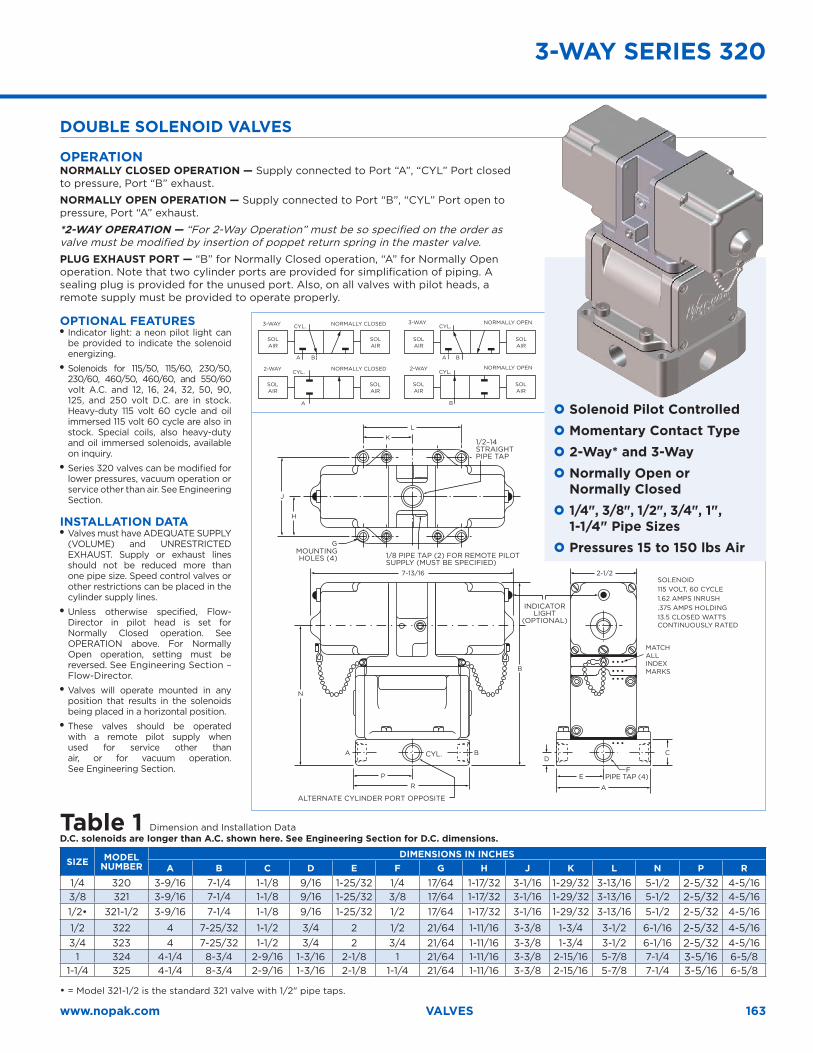
E
CD
A
F
BA
N
B
PR
2-1/27-13/16
G
H
KL
J
A B
SOLAIR
A
CYL.
SOLAIR
NORMALLY CLOSED2-WAY
CYL.
SOLAIR
SOLAIR
NORMALLY OPEN3-WAY
SOLAIR
A
CYL.
B
SOLAIR
NORMALLY CLOSED3-WAY
CYL.
B
SOLAIR
SOLAIR
NORMALLY OPEN2-WAY
ALTERNATE CYLINDER PORT OPPOSITE
1/2–14 STRAIGHT PIPE TAP
INDICATOR LIGHT
(OPTIONAL)
CYL.
MOUNTING HOLES (4) 1/8 PIPE TAP (2) FOR REMOTE PILOT
SUPPLY (MUST BE SPECIFIED)
PIPE TAP (4)
SOLENOID115 VOLT, 60 CYCLE 1.62 AMPS INRUSH .375 AMPS HOLDING 13.5 CLOSED WATTS CONTINUOUSLY RATED
MATCH ALL INDEX MARKS
3-WAY SERIES 320
163www.nopak.com VALVES
Table 1 Dimension and Installation DataD .C . solenoids are longer than A .C . shown here . See Engineering Section for D .C . dimensions .
SIZE MODEL NUMBER
DIMENSIONS IN INCHESA B C D E F G H J K L N P R
1/4 320 3-9/16 7-1/4 1-1/8 9/16 1-25/32 1/4 17/64 1-17/32 3-1/16 1-29/32 3-13/16 5-1/2 2-5/32 4-5/163/8 321 3-9/16 7-1/4 1-1/8 9/16 1-25/32 3/8 17/64 1-17/32 3-1/16 1-29/32 3-13/16 5-1/2 2-5/32 4-5/161/2• 321-1/2 3-9/16 7-1/4 1-1/8 9/16 1-25/32 1/2 17/64 1-17/32 3-1/16 1-29/32 3-13/16 5-1/2 2-5/32 4-5/16
1/2 322 4 7-25/32 1-1/2 3/4 2 1/2 21/64 1-11/16 3-3/8 1-3/4 3-1/2 6-1/16 2-5/32 4-5/163/4 323 4 7-25/32 1-1/2 3/4 2 3/4 21/64 1-11/16 3-3/8 1-3/4 3-1/2 6-1/16 2-5/32 4-5/16
1 324 4-1/4 8-3/4 2-9/16 1-3/16 2-1/8 1 21/64 1-11/16 3-3/8 2-15/16 5-7/8 7-1/4 3-5/16 6-5/81-1/4 325 4-1/4 8-3/4 2-9/16 1-3/16 2-1/8 1-1/4 21/64 1-11/16 3-3/8 2-15/16 5-7/8 7-1/4 3-5/16 6-5/8
• = Model 321-1/2 is the standard 321 valve with 1/2" pipe taps.
DOUBLE SOLENOID VALVES
OPERATION NORMALLY CLOSED OPERATION — Supply connected to Port “A”, “CYL” Port closed to pressure, Port “B” exhaust.
NORMALLY OPEN OPERATION — Supply connected to Port “B”, “CYL” Port open to pressure, Port “A” exhaust.
*2-WAY OPERATION — “For 2-Way Operation” must be so specified on the order as valve must be modified by insertion of poppet return spring in the master valve. PLUG EXHAUST PORT — “B” for Normally Closed operation, “A” for Normally Open operation. Note that two cylinder ports are provided for simplification of piping. A sealing plug is provided for the unused port. Also, on all valves with pilot heads, a remote supply must be provided to operate properly.
OPTIONAL FEATURES OO Indicator light: a neon pilot light can be provided to indicate the solenoid energizing.
OO Solenoids for 115/50, 115/60, 230/50, 230/60, 460/50, 460/60, and 550/60 volt A.C. and 12, 16, 24, 32, 50, 90, 125, and 250 volt D.C. are in stock. Heavy-duty 115 volt 60 cycle and oil immersed 115 volt 60 cycle are also in stock. Special coils, also heavy-duty and oil immersed solenoids, available on inquiry.
OO Series 320 valves can be modified for lower pressures, vacuum operation or service other than air. See Engineering Section.
INSTALLATION DATA OO Valves must have ADEQUATE SUPPLY (VOLUME) and UNRESTRICTED EXHAUST. Supply or exhaust lines should not be reduced more than one pipe size. Speed control valves or other restrictions can be placed in the cylinder supply lines.
OO Unless otherwise specified, Flow-Director in pilot head is set for Normally Closed operation. See OPERATION above. For Normally Open operation, setting must be reversed. See Engineering Section – Flow-Director.
OO Valves will operate mounted in any position that results in the solenoids being placed in a horizontal position.
OO These valves should be operated with a remote pilot supply when used for service other than air, or for vacuum operation. See Engineering Section.
} Solenoid Pilot Controlled } Momentary Contact Type } 2-Way* and 3-Way } Normally Open or Normally Closed
} 1/4", 3/8", 1/2", 3/4", 1", 1-1/4" Pipe Sizes
} Pressures 15 to 150 lbs Air
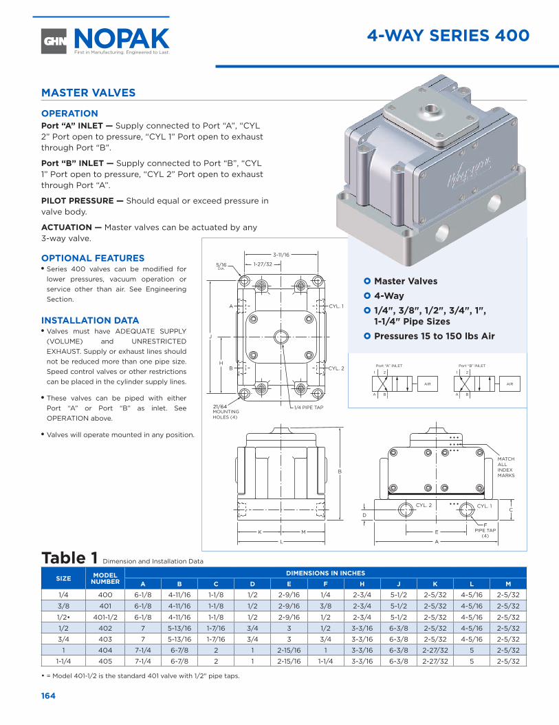
21/64
B
A
B
E
CD
A
K M
L
H
3-11/16
1-27/32
J
F
1/4 PIPE TAP
CYL. 2
CYL. 1
MOUNTING HOLES (4)
PIPE TAP (4)
MATCH ALL INDEX MARKS
AIR
Port “A” INLET
A
1
B
2
Port “B” INLET
A
1
B
2
AIR
CYL. 2 CYL. 1
164
MASTER VALVES
OPERATION Port “A” INLET — Supply connected to Port “A”, “CYL 2” Port open to pressure, “CYL 1” Port open to exhaust through Port “B”.
Port “B” INLET — Supply connected to Port “B”, “CYL 1” Port open to pressure, “CYL 2” Port open to exhaust through Port “A”.
PILOT PRESSURE — Should equal or exceed pressure in valve body.
ACTUATION — Master valves can be actuated by any 3-way valve.
OPTIONAL FEATURES OO Series 400 valves can be modified for lower pressures, vacuum operation or service other than air. See Engineering Section.
INSTALLATION DATA OO Valves must have ADEQUATE SUPPLY (VOLUME) and UNRESTRICTED EXHAUST. Supply or exhaust lines should not be reduced more than one pipe size. Speed control valves or other restrictions can be placed in the cylinder supply lines.
OO These valves can be piped with either Port “A” or Port “B” as inlet. See OPERATION above.
OO Valves will operate mounted in any position.
} Master Valves } 4-Way } 1/4", 3/8", 1/2", 3/4", 1", 1-1/4" Pipe Sizes
} Pressures 15 to 150 lbs Air
Table 1 Dimension and Installation Data
SIZE MODEL NUMBER
DIMENSIONS IN INCHES
A B C D E F H J K L M
1/4 400 6-1/8 4-11/16 1-1/8 1/2 2-9/16 1/4 2-3/4 5-1/2 2-5/32 4-5/16 2-5/32
3/8 401 6-1/8 4-11/16 1-1/8 1/2 2-9/16 3/8 2-3/4 5-1/2 2-5/32 4-5/16 2-5/32
1/2• 401-1/2 6-1/8 4-11/16 1-1/8 1/2 2-9/16 1/2 2-3/4 5-1/2 2-5/32 4-5/16 2-5/32
1/2 402 7 5-13/16 1-7/16 3/4 3 1/2 3-3/16 6-3/8 2-5/32 4-5/16 2-5/32
3/4 403 7 5-13/16 1-7/16 3/4 3 3/4 3-3/16 6-3/8 2-5/32 4-5/16 2-5/32
1 404 7-1/4 6-7/8 2 1 2-15/16 1 3-3/16 6-3/8 2-27/32 5 2-5/32
1-1/4 405 7-1/4 6-7/8 2 1 2-15/16 1-1/4 3-3/16 6-3/8 2-27/32 5 2-5/32
• = Model 401-1/2 is the standard 401 valve with 1/2" pipe taps.
4-WAY SERIES 400
5/16DIA.
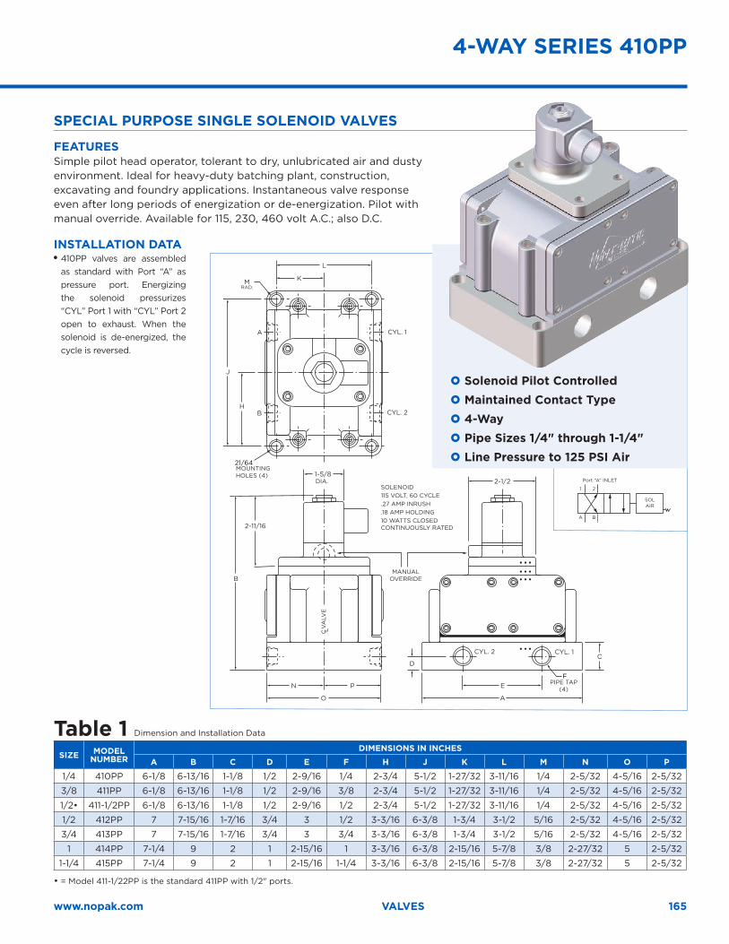
SOL AIR
Port “A” INLET
A
1
B
2
B
2-11/16
N P
O
B
A
H
L
K
J
21/64
E
CD
2-1/21-5/8
A
F
MANUALOVERRIDE
CYL. 2
CYL. 1
MOUNTING HOLES (4)
PIPE TAP (4)
CYL. 2
SOLENOID 115 VOLT, 60 CYCLE .27 AMP INRUSH .18 AMP HOLDING 10 WATTS CLOSED CONTINUOUSLY RATED
M RAD.
CYL. 1
DIA.
C L V
ALV
E
165www.nopak.com VALVES
SPECIAL PURPOSE SINGLE SOLENOID VALVES
FEATURESSimple pilot head operator, tolerant to dry, unlubricated air and dusty environment. Ideal for heavy-duty batching plant, construction, excavating and foundry applications. Instantaneous valve response even after long periods of energization or de-energization. Pilot with manual override. Available for 115, 230, 460 volt A.C.; also D.C.
INSTALLATION DATA OO 410PP valves are assembled as standard with Port “A” as pressure port. Energizing the solenoid pressurizes “CYL” Port 1 with “CYL” Port 2 open to exhaust. When the solenoid is de-energized, the cycle is reversed.
} Solenoid Pilot Controlled } Maintained Contact Type } 4-Way } Pipe Sizes 1/4" through 1-1/4" } Line Pressure to 125 PSI Air
Table 1 Dimension and Installation Data
SIZE MODEL NUMBER
DIMENSIONS IN INCHES
A B C D E F H J K L M N O P
1/4 410PP 6-1/8 6-13/16 1-1/8 1/2 2-9/16 1/4 2-3/4 5-1/2 1-27/32 3-11/16 1/4 2-5/32 4-5/16 2-5/32
3/8 411PP 6-1/8 6-13/16 1-1/8 1/2 2-9/16 3/8 2-3/4 5-1/2 1-27/32 3-11/16 1/4 2-5/32 4-5/16 2-5/32
1/2• 411-1/2PP 6-1/8 6-13/16 1-1/8 1/2 2-9/16 1/2 2-3/4 5-1/2 1-27/32 3-11/16 1/4 2-5/32 4-5/16 2-5/32
1/2 412PP 7 7-15/16 1-7/16 3/4 3 1/2 3-3/16 6-3/8 1-3/4 3-1/2 5/16 2-5/32 4-5/16 2-5/32
3/4 413PP 7 7-15/16 1-7/16 3/4 3 3/4 3-3/16 6-3/8 1-3/4 3-1/2 5/16 2-5/32 4-5/16 2-5/32
1 414PP 7-1/4 9 2 1 2-15/16 1 3-3/16 6-3/8 2-15/16 5-7/8 3/8 2-27/32 5 2-5/32
1-1/4 415PP 7-1/4 9 2 1 2-15/16 1-1/4 3-3/16 6-3/8 2-15/16 5-7/8 3/8 2-27/32 5 2-5/32
• = Model 411-1/22PP is the standard 411PP with 1/2" ports.
4-WAY SERIES 410PP
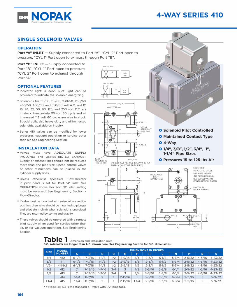
E
CD
A
F
N
B
P
RS
A
BH
3-11/16
1-27/32
J
11/32 1-1/8
1/2–14 STRAIGHT PIPE TAP
INDICATOR LIGHT
(OPTIONAL)
MOUNTING HOLES (4) 1/8 PIPE TAP (2) FOR REMOTE PILOT
SUPPLY (MUST BE SPECIFIED)
PIPE TAP
(4)
MATCH ALL INDEX MARKS
SOLAIR
Port “A” INLET
A
1
B
2
Port “B” INLET
A
1
B
2
SOLAIR
SOLENOID115 VOLT, 60 CYCLE 1.62 AMPS INRUSH .375 AMPS HOLDING 13.5 CLOSED WATTS CONTINUOUSLY RATED
CYL. 2
CYL. 2
CYL. 1
CYL. 1
166
4-WAY SERIES 410
SINGLE SOLENOID VALVES
OPERATION Port “A” INLET — Supply connected to Port “A”, “CYL 2” Port open to pressure, “CYL 1” Port open to exhaust through Port “B”.
Port “B” INLET — Supply connected to Port “B”, “CYL 1” Port open to pressure, “CYL 2” Port open to exhaust through Port “A”.
OPTIONAL FEATURES OO Indicator light: a neon pilot light can be provided to indicate the solenoid energizing.
OO Solenoids for 115/50, 115/60, 230/50, 230/60, 460/50, 460/60, and 550/60 volt A.C. and 12, 16, 24, 32, 50, 90, 125, and 250 volt D.C. are in stock. Heavy-duty 115 volt 60 cycle and oil immersed 115 volt 60 cycle are also in stock. Special coils, also heavy-duty and oil immersed solenoids, available on inquiry.
OO Series 410 valves can be modified for lower pressures, vacuum operation or service other than air. See Engineering Section.
INSTALLATION DATA OO Valves must have ADEQUATE SUPPLY (VOLUME) and UNRESTRICTED EXHAUST. Supply or exhaust lines should not be reduced more than one pipe size. Speed control valves or other restrictions can be placed in the cylinder supply lines.
OO Unless otherwise specified, Flow-Director in pilot head is set for Port “A” inlet. See OPERATION above. For Port “B” inlet, setting must be reversed. See Engineering Section – Flow-Director.
OO If valve must be mounted with solenoid in a vertical position, then valve should be mounted so plunger and pilot stem climb when solenoid is energized. They are returned by spring and gravity.
OO These valves should be operated with a remote pilot supply when used for service other than air, or for vacuum operation. See Engineering Section.
} Solenoid Pilot Controlled } Maintained Contact Type } 4-Way } 1/4", 3/8", 1/2", 3/4", 1", 1-1/4" Pipe Sizes
} Pressures 15 to 125 lbs Air
Table 1 Dimension and Installation DataD .C . solenoids are longer than A .C . shown here . See Engineering Section for D .C . dimensions .
SIZE MODEL NUMBER
DIMENSIONS IN INCHES A B C D E F H J N P R S
1/4 410 6-1/8 7-7/16 1-1/8 1/2 2-9/16 1/4 2-3/4 5-1/2 5-3/4 2-5/32 4-5/16 4-23/323/8 411 6-1/8 7-7/16 1-1/8 1/2 2-9/16 3/8 2-3/4 5-1/2 5-3/4 2-5/32 4-5/16 4-23/321/2• 411-1/2 6-1/8 7-7/16 1-1/8 1/2 2-9/16 1/2 2-3/4 5-1/2 5-3/4 2-5/32 4-5/16 4-23/321/2 412 7 7-15/16 1-7/16 3/4 3 1/2 3-3/16 6-3/8 6-1/4 2-5/32 4-5/16 4-23/323/4 413 7 7-15/16 1-7/16 3/4 3 3/4 3-3/16 6-3/8 6-1/4 2-5/32 4-5/16 4-23/32
1 414 7-1/4 8-7/16 2 1 2-15/16 1 3-3/16 6-3/8 6-3/4 2-11/16 5 5-9/321-1/4 415 7-1/4 8-7/16 2 1 2-15/16 1-1/4 3-3/16 6-3/8 6-3/4 2-11/16 5 5-9/32
• = Model 411-1/2 is the standard 411 valve with 1/2" pipe taps.

E
CD
A
F
N
B
R
P
A
BH
3-11/16
1-27/32
J
21/642-5/32
7-13/16
INDICATOR LIGHT
(OPTIONAL)
MOUNTING HOLES (4)
1/8 PIPE TAP (2) FOR REMOTE PILOT SUPPLY (MUST BE SPECIFIED)
PIPE TAP
(4)
MATCH ALL INDEX MARKS
SOLENOID115 VOLT, 60 CYCLE 1.62 AMPS INRUSH .375 AMPS HOLDING 13.5 CLOSED WATTS CONTINUOUSLY RATED
CYL. 2
CYL. 1
1/2–14 STRAIGHT PIPE TAP
CYL. 2 CYL. 1
SOLAIR
Port “A” INLET
A
1
B
2
SOLAIR
Port “B” INLET
A
1
B
2
SOLAIR
SOLAIR
167www.nopak.com VALVES
DOUBLE SOLENOID VALVES
OPERATION Port “A” INLET — Supply connected to Port “A”, “CYL 2” Port open to pressure, “CYL 1” Port open to exhaust through Port “B”.
Port “B” INLET — Supply connected to Port “B”, “CYL 1” Port open to pressure, “CYL 2” Port open to exhaust through Port “A”.
OPTIONAL FEATURES OO Indicator light: a neon pilot light can be provided to indicate the solenoid energizing.
OO Solenoids for 115/50, 115/60, 230/50, 230/60, 460/50, 460/60, and 550/60 volt A.C. and 12, 16, 24, 32, 50, 90, 125, and 250 volt D.C. are in stock. Heavy-duty 115 volt 60 cycle and oil immersed 115 volt 60 cycle are also in stock. Special coils, also heavy-duty and oil immersed solenoids, available on inquiry.
OO 1" and 1-1/4" valves can be modified for lower pressures, vacuum operation or service other than air. See Engineering Section.
INSTALLATION DATA OO Valves must have ADEQUATE SUPPLY (VOLUME) and UNRESTRICTED EXHAUST. Supply or exhaust lines should not be reduced more than one pipe size. Speed control valves or other restrictions can be placed in the cylinder supply lines.
OO Unless otherwise specified, Flow-Director in pilot head is set for Port “A” inlet. See OPERATION above. For Port “B” inlet, setting must be reversed. See Engineering Section – Flow-Director.
OO Valves will operate mounted in any position that results in the solenoids being placed in a horizontal position.
OO These valves should be operated with a remote pilot supply when used for service other than air, or for vacuum operation. See Engineering Section.
Table 1 Dimension and Installation DataD .C . solenoids are longer than A .C . shown here . See Engineering Section for D .C . dimensions .
SIZE MODEL NUMBER
DIMENSIONS IN INCHES A B C D E F H J N P R
1/4 420 6-1/8 7-7/16 1-1/8 1/2 2-9/16 1/4 2-3/4 5-1/2 5-3/4 2-5/32 4-5/163/8 421 6-1/8 7-7/16 1-1/8 1/2 2-9/16 3/8 2-3/4 5-1/2 5-3/4 2-5/32 4-5/161/2• 421-1/2 6-1/8 7-7/16 1-1/8 1/2 2-9/16 1/2 2-3/4 5-1/2 5-3/4 2-5/32 4-5/161/2 422 7 7-15/16 1-7/16 3/4 3 1/2 3-3/16 6-3/8 6-1/4 2-5/32 4-5/163/4 423 7 7-15/16 1-7/16 3/4 3 3/4 3-3/16 6-3/8 6-1/4 2-5/32 4-5/16
1 424 7-1/4 8-7/16 2 1 2-15/16 1 3-3/16 6-3/8 6-3/4 2-11/16 51-1/4 425 7-1/4 8-7/16 2 1 2-15/16 1-1/4 3-3/16 6-3/8 6-3/4 2-11/16 5
• = Model 421-1/2 is the standard 421 valve with 1/2" pipe taps.
4-WAY SERIES 420
} Solenoid Pilot Controlled } Momentary Contact Type } 4-Way } 1/4", 3/8", 1/2", 3/4", 1", 1-1/4" Pipe Sizes
} Pressures 15 to 150 lbs Air
5/16RAD.
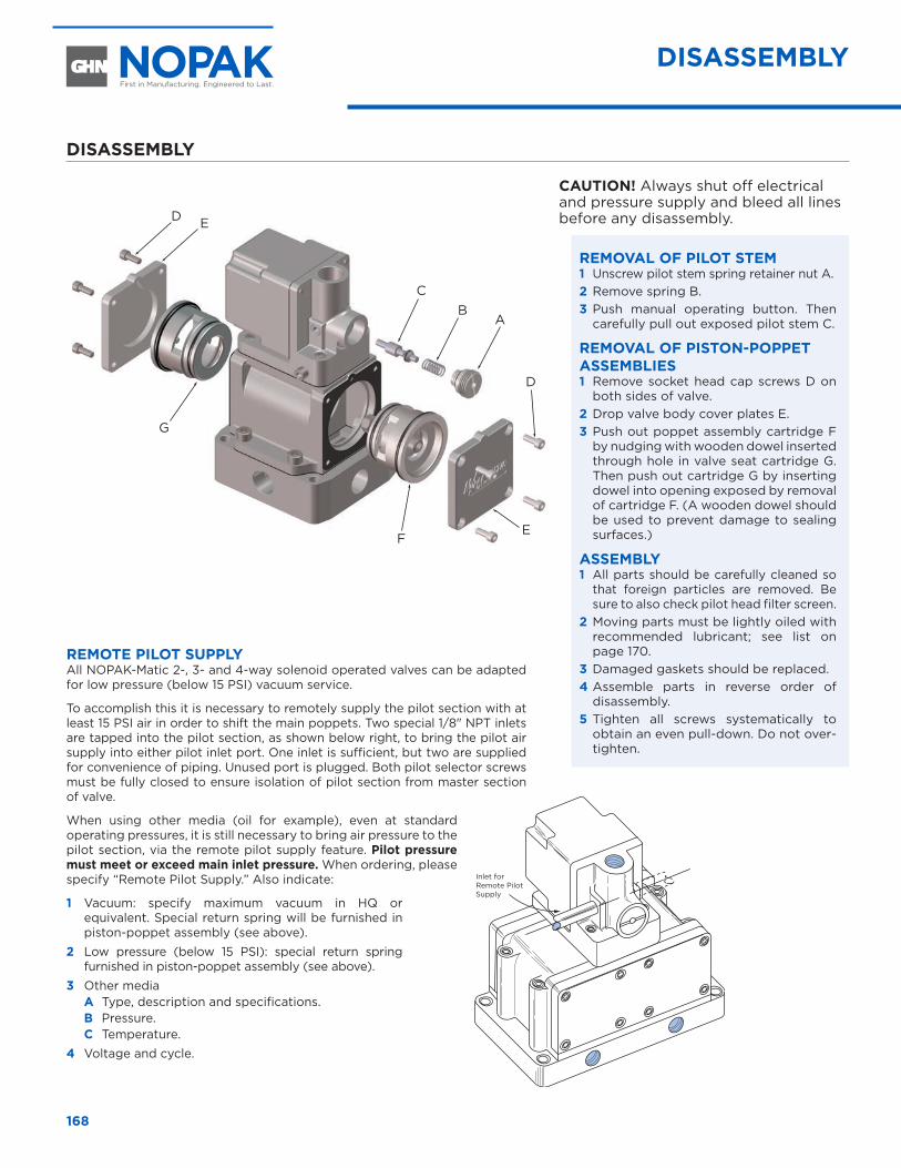
168
DISASSEMBLY
CAUTION! Always shut off electrical and pressure supply and bleed all lines before any disassembly.
REMOVAL OF PILOT STEM 1 Unscrew pilot stem spring retainer nut A. 2 Remove spring B. 3 Push manual operating button. Then
carefully pull out exposed pilot stem C.
REMOVAL OF PISTON-POPPET ASSEMBLIES1 Remove socket head cap screws D on
both sides of valve. 2 Drop valve body cover plates E. 3 Push out poppet assembly cartridge F
by nudging with wooden dowel inserted through hole in valve seat cartridge G. Then push out cartridge G by inserting dowel into opening exposed by removal of cartridge F. (A wooden dowel should be used to prevent damage to sealing surfaces.)
ASSEMBLY1 All parts should be carefully cleaned so
that foreign particles are removed. Be sure to also check pilot head filter screen.
2 Moving parts must be lightly oiled with recommended lubricant; see list on page 170.
3 Damaged gaskets should be replaced. 4 Assemble parts in reverse order of
disassembly. 5 Tighten all screws systematically to
obtain an even pull-down. Do not over-tighten.
REMOTE PILOT SUPPLYAll NOPAK-Matic 2-, 3- and 4-way solenoid operated valves can be adapted for low pressure (below 15 PSI) vacuum service.
To accomplish this it is necessary to remotely supply the pilot section with at least 15 PSI air in order to shift the main poppets. Two special 1/8" NPT inlets are tapped into the pilot section, as shown below right, to bring the pilot air supply into either pilot inlet port. One inlet is sufficient, but two are supplied for convenience of piping. Unused port is plugged. Both pilot selector screws must be fully closed to ensure isolation of pilot section from master section of valve.
When using other media (oil for example), even at standard operating pressures, it is still necessary to bring air pressure to the pilot section, via the remote pilot supply feature. Pilot pressure must meet or exceed main inlet pressure . When ordering, please specify “Remote Pilot Supply.” Also indicate:
1 Vacuum: specify maximum vacuum in HQ or equivalent. Special return spring will be furnished in piston-poppet assembly (see above).
2 Low pressure (below 15 PSI): special return spring furnished in piston-poppet assembly (see above).
3 Other mediaA Type, description and specifications. B Pressure. C Temperature.
4 Voltage and cycle.
Inlet for Remote Pilot Supply
G
E
AB
D
D
EF
C
DISASSEMBLY
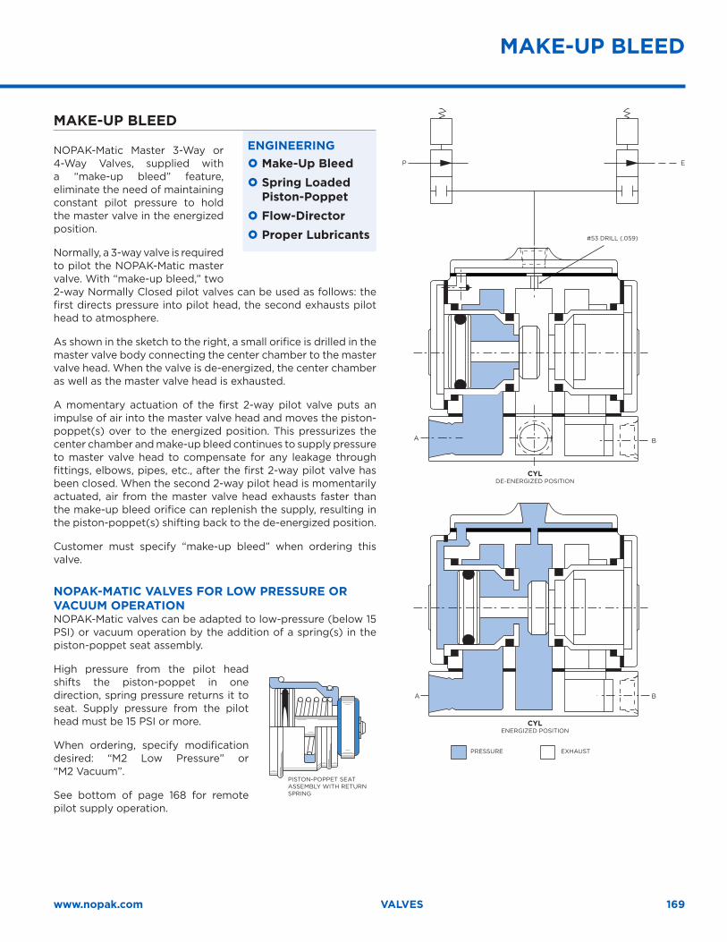
169www.nopak.com VALVES
MAKE-UP BLEED
NOPAK-Matic Master 3-Way or 4-Way Valves, supplied with a “make-up bleed” feature, eliminate the need of maintaining constant pilot pressure to hold the master valve in the energized position.
Normally, a 3-way valve is required to pilot the NOPAK-Matic master valve. With “make-up bleed,” two 2-way Normally Closed pilot valves can be used as follows: the first directs pressure into pilot head, the second exhausts pilot head to atmosphere.
As shown in the sketch to the right, a small orifice is drilled in the master valve body connecting the center chamber to the master valve head. When the valve is de-energized, the center chamber as well as the master valve head is exhausted.
A momentary actuation of the first 2-way pilot valve puts an impulse of air into the master valve head and moves the piston-poppet(s) over to the energized position. This pressurizes the center chamber and make-up bleed continues to supply pressure to master valve head to compensate for any leakage through fittings, elbows, pipes, etc., after the first 2-way pilot valve has been closed. When the second 2-way pilot head is momentarily actuated, air from the master valve head exhausts faster than the make-up bleed orifice can replenish the supply, resulting in the piston-poppet(s) shifting back to the de-energized position.
Customer must specify “make-up bleed” when ordering this valve.
NOPAK-MATIC VALVES FOR LOW PRESSURE OR VACUUM OPERATIONNOPAK-Matic valves can be adapted to low-pressure (below 15 PSI) or vacuum operation by the addition of a spring(s) in the piston-poppet seat assembly.
High pressure from the pilot head shifts the piston-poppet in one direction, spring pressure returns it to seat. Supply pressure from the pilot head must be 15 PSI or more.
When ordering, specify modification desired: “M2 Low Pressure” or “M2 Vacuum”.
See bottom of page 168 for remote pilot supply operation.
ENGINEERING } Make-Up Bleed } Spring Loaded Piston-Poppet
} Flow-Director } Proper Lubricants
PISTON-POPPET SEAT ASSEMBLY WITH RETURN SPRING
BA
BA
P E
PRESSURE EXHAUST
CYLENERGIZED POSITION
CYLDE-ENERGIZED POSITION
#53 DRILL (.059)
MAKE-UP BLEED
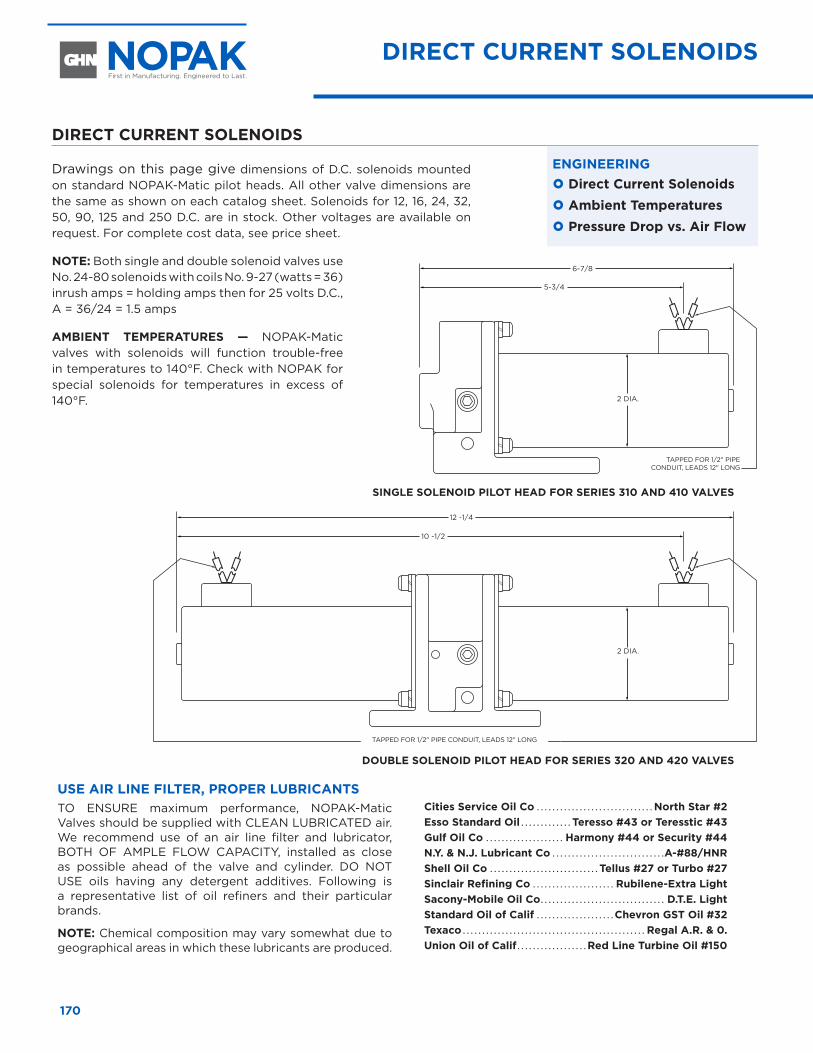
170
DIRECT CURRENT SOLENOIDS
Drawings on this page give dimensions of D.C. solenoids mounted on standard NOPAK-Matic pilot heads. All other valve dimensions are the same as shown on each catalog sheet. Solenoids for 12, 16, 24, 32, 50, 90, 125 and 250 D.C. are in stock. Other voltages are available on request. For complete cost data, see price sheet.
NOTE: Both single and double solenoid valves use No. 24-80 solenoids with coils No. 9-27 (watts = 36) inrush amps = holding amps then for 25 volts D.C., A = 36/24 = 1.5 amps
AMBIENT TEMPERATURES — NOPAK-Matic valves with solenoids will function trouble-free in temperatures to 140°F. Check with NOPAK for special solenoids for temperatures in excess of 140°F.
ENGINEERING } Direct Current Solenoids } Ambient Temperatures } Pressure Drop vs . Air Flow
5-3/4
6-7/8
10 -1/2
12 -1/4
SINGLE SOLENOID PILOT HEAD FOR SERIES 310 AND 410 VALVES
DOUBLE SOLENOID PILOT HEAD FOR SERIES 320 AND 420 VALVES
USE AIR LINE FILTER, PROPER LUBRICANTSTO ENSURE maximum performance, NOPAK-Matic Valves should be supplied with CLEAN LUBRICATED air. We recommend use of an air line filter and lubricator, BOTH OF AMPLE FLOW CAPACITY, installed as close as possible ahead of the valve and cylinder. DO NOT USE oils having any detergent additives. Following is a representative list of oil refiners and their particular brands.
NOTE: Chemical composition may vary somewhat due to geographical areas in which these lubricants are produced.
Cities Service Oil Co . . . . . . . . . . . . . . . . . . . . . . . . . . . . . . North Star #2 Esso Standard Oil . . . . . . . . . . . . . Teresso #43 or Teresstic #43 Gulf Oil Co . . . . . . . . . . . . . . . . . . . . Harmony #44 or Security #44 N .Y . & N .J . Lubricant Co . . . . . . . . . . . . . . . . . . . . . . . . . . . . .A-#88/HNR Shell Oil Co . . . . . . . . . . . . . . . . . . . . . . . . . . . . Tellus #27 or Turbo #27 Sinclair Refining Co . . . . . . . . . . . . . . . . . . . . . Rubilene-Extra Light Sacony-Mobile Oil Co . . . . . . . . . . . . . . . . . . . . . . . . . . . . . . . . D .T .E . Light Standard Oil of Calif . . . . . . . . . . . . . . . . . . . . Chevron GST Oil #32 Texaco . . . . . . . . . . . . . . . . . . . . . . . . . . . . . . . . . . . . . . . . . . . . . . . Regal A .R . & 0 . Union Oil of Calif . . . . . . . . . . . . . . . . . . Red Line Turbine Oil #150
DIRECT CURRENT SOLENOIDS
TAPPED FOR 1/2" PIPE CONDUIT, LEADS 12" LONG
TAPPED FOR 1/2" PIPE CONDUIT, LEADS 12" LONG
2 DIA.
2 DIA.
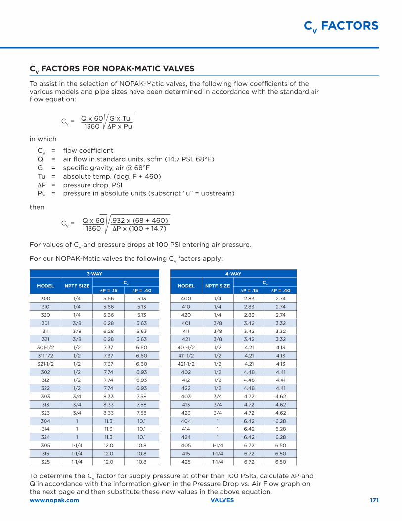
171www.nopak.com VALVES
CV FACTORS FOR NOPAK-MATIC VALVES
To assist in the selection of NOPAK-Matic valves, the following flow coefficients of the various models and pipe sizes have been determined in accordance with the standard air flow equation:
CV = Q x 60 G x Tu 1360 ∆P x Pu in which
CV = flow coefficient Q = air flow in standard units, scfm (14.7 PSI, 68°F) G = specific gravity, air @ 68°F Tu = absolute temp. (deg. F + 460) ∆P = pressure drop, PSI Pu = pressure in absolute units (subscript “u” = upstream)
then
CV = Q x 60 .932 x (68 + 460) 1360 ∆P x (100 + 14.7)
For values of CV and pressure drops at 100 PSI entering air pressure.
For our NOPAK-Matic valves the following CV factors apply:
3-WAY 4-WAY
MODEL NPTF SIZECV MODEL NPTF SIZE
CV
∆P = .15 ∆P = .40 ∆P = .15 ∆P = .40
300 1/4 5.66 5.13 400 1/4 2.83 2.74
310 1/4 5.66 5.13 410 1/4 2.83 2.74
320 1/4 5.66 5.13 420 1/4 2.83 2.74
301 3/8 6.28 5.63 401 3/8 3.42 3.32
311 3/8 6.28 5.63 411 3/8 3.42 3.32
321 3/8 6.28 5.63 421 3/8 3.42 3.32
301-1/2 1/2 7.37 6.60 401-1/2 1/2 4.21 4.13
311-1/2 1/2 7.37 6.60 411-1/2 1/2 4.21 4.13
321-1/2 1/2 7.37 6.60 421-1/2 1/2 4.21 4.13
302 1/2 7.74 6.93 402 1/2 4.48 4.41
312 1/2 7.74 6.93 412 1/2 4.48 4.41
322 1/2 7.74 6.93 422 1/2 4.48 4.41
303 3/4 8.33 7.58 403 3/4 4.72 4.62
313 3/4 8.33 7.58 413 3/4 4.72 4.62
323 3/4 8.33 7.58 423 3/4 4.72 4.62
304 1 11.3 10.1 404 1 6.42 6.28
314 1 11.3 10.1 414 1 6.42 6.28
324 1 11.3 10.1 424 1 6.42 6.28
305 1-1/4 12.0 10.8 405 1-1/4 6.72 6.50
315 1-1/4 12.0 10.8 415 1-1/4 6.72 6.50
325 1-1/4 12.0 10.8 425 1-1/4 6.72 6.50
To determine the CV factor for supply pressure at other than 100 PSIG, calculate ∆P and Q in accordance with the information given in the Pressure Drop vs. Air Flow graph on the next page and then substitute these new values in the above equation.
CV FACTORS
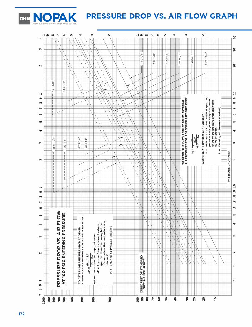
1000
78
91
23
45
67
89
12
34
56
78
91
23
45
67
89
10.2
.15
.1.3
.4.5
.6.7
.8.9
1.0
2030
40
23
41 9 8 7 6 5 4 3 2 1 9 8 7 6 5 4 3 2
900
800
700
600
500
400
300
200
100 90 80 70 60 50 40 30 25 20 15
#31
5–1-
1/4
"#
311–
3/8"
#31
4–1
"#
310
–1/4
"
#4
10–1
/4"
#4
11–3
/8"
#4
12–1
/2"
#4
13–3
/4"
#4
14–1
"
#4
15–1
-1/4
"
#31
3–3/
4"
#31
2–1/
2"
PRES
SUR
E D
RO
P PS
IG
CU
BIC
FEE
T O
F ST
AN
DA
RD
FR
EE A
IR P
ER M
INU
TE
PRES
SUR
E D
RO
P V
S . A
IR F
LOW
A
T 10
0 P
SIG
EN
TER
ING
PR
ESSU
RE
TO D
ETE
RM
INE
PR
ESS
UR
E D
RO
P A
T O
THE
R
EN
TER
ING
AIR
PR
ESS
UR
ES
FOR
A S
PE
CIF
IED
FLO
W:
∆
P2
= ∆
P1 X
114
.7
Whe
re: ∆
P2
= P
ress
ure
Dro
p (
Unk
now
n)
∆P
1 = P
ress
ure
Dro
p f
or
corr
ect
valv
e at
sp
ecifi
ed fl
ow (
read
alo
ng b
ott
om
o
f ch
art
whe
re fl
ow a
nd v
alve
cur
ve
inte
rsec
t)
P2
= E
nter
ing
Air
Pre
ssur
e (D
esir
ed)
P2
+ 14
.7
TO D
ETE
RM
INE
FLO
W R
ATE
AT
OTH
ER
EN
TER
ING
A
IR P
RE
SSU
RE
S FO
R A
SP
EC
IFIE
D P
RE
SSU
RE
DR
OP
:
Q
2 =
Whe
re:
Q2
= Fl
ow R
ate
CFM
(U
nkno
wn)
Q
1 =
Flow
Rat
e fo
r co
rrec
t va
lve
at s
pec
ified
p
ress
ure
dro
p (
read
alo
ng le
ft s
ide
of
char
t w
here
pre
ssur
e d
rop
and
val
ve
curv
e in
ters
ect)
P
2 =
Ent
erin
g A
ir P
ress
ure
(Des
ired
)
P2
+ 14
.711
4 .7
Q1
172
PRESSURE DROP VS . AIR FLOW GRAPH
Boosters, Intensifiers and Air/Oil TanksRam and Piston Type
Boosters, Intensifiers and Air/Oil Tanks Ram and Piston Type
BO
OS
TE
RS
/TA
NK
S
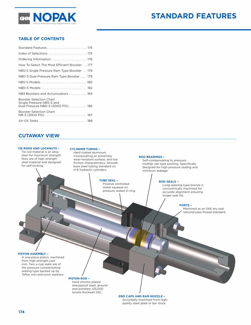
174
STANDARD FEATURES
CUTAWAY VIEW
ROD SEALS – Long-wearing type bronze is concentrically machined for accurate alignment ensuring longer seal life.
END CAPS AND RAM NOZZLE – Accurately machined from high-quality steel plate or bar stock.
ROD BEARINGS – Self-compensating to pressure, multilip vee type packing. Specifically designed for high pressure sealing and minimum leakage.
PISTON ASSEMBLY – A one-piece piston, machined from high strength cast iron. Two u-cup seals are of the pressure compensating sealing type backed up by Teflon non-extrusion washers.
CYLINDER TUBING – Hard coated aluminum, incorporating an extremely wear-resistant surface, and low friction characteristics. Smooth bore steel tubing standard on H-6 hydraulic cylinders.
TUBE SEAL – Positive controlled metal squeeze on pressure sealed O-ring.
PORTS – Machined as an SAE dry seal national pipe thread standard.
TIE RODS AND LOCKNUTS – Tie rod material is an alloy steel for maximum strength. Nuts are of high strength steel material and designed for self-locking.
PISTON ROD – Hard chrome plated stressproof steel, ground and polished, 125,000 tensile Rockwell 25C.
TABLE OF CONTENTS
Standard Features . . . . . . . . . . . . . . . . . . . . . . . . 174
Index of Selections . . . . . . . . . . . . . . . . . . . . . . . 175
Ordering Information . . . . . . . . . . . . . . . . . . . . . 176
How To Select The Most Efficient Booster . . . 177
NBS-5 Single Pressure Ram Type Booster . . 178
NBD-5 Dual Pressure Ram Type Booster . . . . 179
NBS-5 Models . . . . . . . . . . . . . . . . . . . . . . . . . . . . 180
NBD-5 Models . . . . . . . . . . . . . . . . . . . . . . . . . . . 182
NB3 Boosters and Accumulators . . . . . . . . . . . 184
Booster Selection Chart Single Pressure NBS-5 and Dual Pressure NBD-5 (5000 PSI) . . . . . . . . . . . 186
Booster Selection Chart NB-3 (3000 PSI) . . . . . . . . . . . . . . . . . . . . . . . . . 187
Air-Oil Tanks . . . . . . . . . . . . . . . . . . . . . . . . . . . . . 188
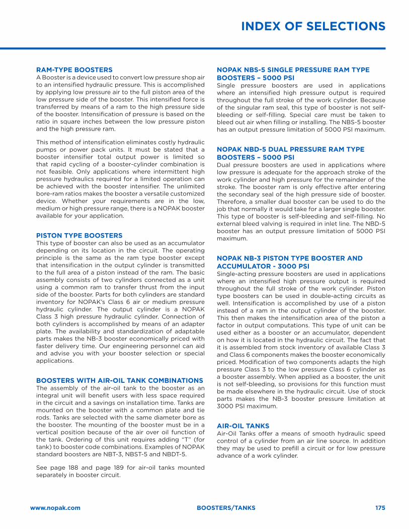
175www.nopak.com BOOSTERS/TANKS
RAM-TYPE BOOSTERS A Booster is a device used to convert low pressure shop air to an intensified hydraulic pressure. This is accomplished by applying low pressure air to the full piston area of the low pressure side of the booster. This intensified force is transferred by means of a ram to the high pressure side of the booster. Intensification of pressure is based on the ratio in square inches between the low pressure piston and the high pressure ram.
This method of intensification eliminates costly hydraulic pumps or power pack units. It must be stated that a booster intensifier total output power is limited so that rapid cycling of a booster-cylinder combination is not feasible. Only applications where intermittent high pressure hydraulics required for a limited operation can be achieved with the booster intensifier. The unlimited bore-ram ratios makes the booster a versatile customized device. Whether your requirements are in the low, medium or high pressure range, there is a NOPAK booster available for your application.
PISTON TYPE BOOSTERS This type of booster can also be used as an accumulator depending on its location in the circuit. The operating principle is the same as the ram type booster except that intensification in the output cylinder is transmitted to the full area of a piston instead of the ram. The basic assembly consists of two cylinders connected as a unit using a common ram to transfer thrust from the input side of the booster. Parts for both cylinders are standard inventory for NOPAK’s Class 6 air or medium pressure hydraulic cylinder. The output cylinder is a NOPAK Class 3 high pressure hydraulic cylinder. Connection of both cylinders is accomplished by means of an adapter plate. The availability and standardization of adaptable parts makes the NB-3 booster economically priced with faster delivery time. Our engineering personnel can aid and advise you with your booster selection or special applications.
BOOSTERS WITH AIR-OIL TANK COMBINATIONS The assembly of the air-oil tank to the booster as an integral unit will benefit users with less space required in the circuit and a savings on installation time. Tanks are mounted on the booster with a common plate and tie rods. Tanks are selected with the same diameter bore as the booster. The mounting of the booster must be in a vertical position because of the air over oil function of the tank. Ordering of this unit requires adding “T” (for tank) to booster code combinations. Examples of NOPAK standard boosters are NBT-3, NBST-5 and NBDT-5.
See page 188 and page 189 for air-oil tanks mounted separately in booster circuit.
NOPAK NBS-5 SINGLE PRESSURE RAM TYPE BOOSTERS – 5000 PSI Single pressure boosters are used in applications where an intensified high pressure output is required throughout the full stroke of the work cylinder. Because of the singular ram seal, this type of booster is not self-bleeding or self-filling. Special care must be taken to bleed out air when filling or installing. The NBS-5 booster has an output pressure limitation of 5000 PSI maximum.
NOPAK NBD-5 DUAL PRESSURE RAM TYPE BOOSTERS – 5000 PSI Dual pressure boosters are used in applications where low pressure is adequate for the approach stroke of the work cylinder and high pressure for the remainder of the stroke. The booster ram is only effective after entering the secondary seal of the high pressure side of booster. Therefore, a smaller dual booster can be used to do the job that normally it would take for a larger single booster. This type of booster is self-bleeding and self-filling. No external bleed valving is required in inlet line. The NBD-5 booster has an output pressure limitation of 5000 PSI maximum.
NOPAK NB-3 PISTON TYPE BOOSTER AND ACCUMULATOR - 3000 PSI Single-acting pressure boosters are used in applications where an intensified high pressure output is required throughout the full stroke of the work cylinder. Piston type boosters can be used in double-acting circuits as well. Intensification is accomplished by use of a piston instead of a ram in the output cylinder of the booster. This then makes the intensification area of the piston a factor in output computations. This type of unit can be used either as a booster or an accumulator, dependent on how it is located in the hydraulic circuit. The fact that it is assembled from stock inventory of available Class 3 and Class 6 components makes the booster economically priced. Modification of two components adapts the high pressure Class 3 to the low pressure Class 6 cylinder as a booster assembly. When applied as a booster, the unit is not self-bleeding, so provisions for this function must be made elsewhere in the hydraulic circuit. Use of stock parts makes the NB-3 booster pressure limitation at 3000 PSI maximum.
AIR-OIL TANKS Air-Oil Tanks offer a means of smooth hydraulic speed control of a cylinder from an air line source. In addition they may be used to prefill a circuit or for low pressure advance of a work cylinder.
INDEX OF SELECTIONS
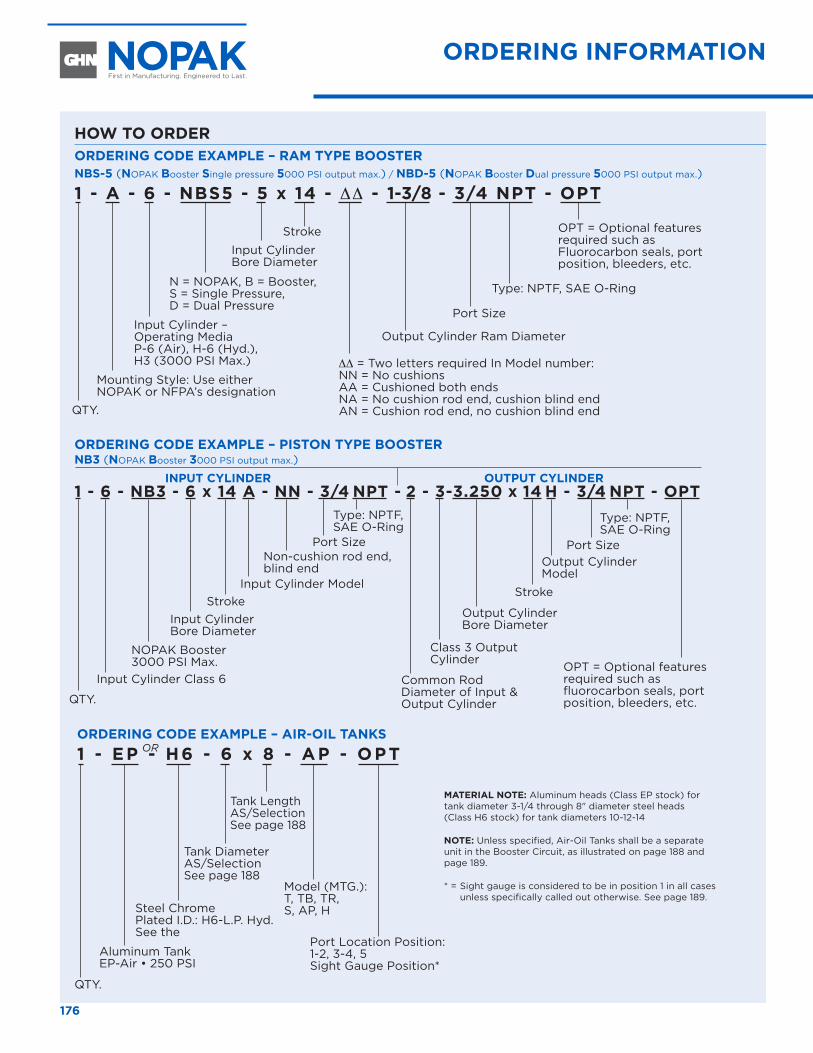
176
ORDERING INFORMATION HOW TO SELECT THE MOST EFFICIENT BOOSTER
ORDERING CODE EXAMPLE – RAM TYPE BOOSTERNBS-5 (NOPAK Booster Single pressure 5000 PSI output max.) / NBD-5 (NOPAK Booster Dual pressure 5000 PSI output max.)
1 - A - 6 - NBS5 - 5 x 14 - ∆∆ - 1-3/8 - 3/4 NPT - OPT
ORDERING CODE EXAMPLE – PISTON TYPE BOOSTERNB3 (NOPAK Booster 3000 PSI output max.)
INPUT CYLINDER OUTPUT CYLINDER1 - 6 - NB3 - 6 x 14 A - NN - 3/4 NPT - 2 - 3-3.250 x 14 H - 3/4 NPT - OPT
HOW TO ORDER
QTY.
QTY.
Input Cylinder – Operating Media P-6 (Air), H-6 (Hyd.), H3 (3000 PSI Max.)
Input Cylinder Class 6
Class 3 Output Cylinder
Output Cylinder Bore Diameter
Stroke
Mounting Style: Use either NOPAK or NFPA’s designation
N = NOPAK, B = Booster, S = Single Pressure, D = Dual Pressure
NOPAK Booster 3000 PSI Max.
Input Cylinder Bore Diameter
Input Cylinder Bore Diameter
Common Rod Diameter of Input & Output Cylinder
Input Cylinder Model
Output Cylinder Model
Port SizePort Size
Stroke
Stroke
∆∆ = Two letters required In Model number: NN = No cushions AA = Cushioned both ends NA = No cushion rod end, cushion blind end AN = Cushion rod end, no cushion blind end
Non-cushion rod end, blind end
Type: NPTF, SAE O-Ring
Type: NPTF, SAE O-Ring
Type: NPTF, SAE O-Ring
Port Size
Output Cylinder Ram Diameter
OPT = Optional features required such as Fluorocarbon seals, port position, bleeders, etc.
OPT = Optional features required such as fluorocarbon seals, port position, bleeders, etc.
ORDERING CODE EXAMPLE – AIR-OIL TANKS1 - E P - H6 - 6 x 8 - AP - OPT
QTY.
Steel Chrome Plated I.D.: H6-L.P. Hyd. See the
Aluminum Tank EP-Air • 250 PSI
Tank Diameter AS/Selection See page 188
Tank Length AS/SelectionSee page 188
Model (MTG.): T, TB, TR, S, AP, H
Port Location Position: 1-2, 3-4, 5 Sight Gauge Position*
OR
MATERIAL NOTE: Aluminum heads (Class EP stock) for tank diameter 3-1/4 through 8" diameter steel heads (Class H6 stock) for tank diameters 10-12-14
NOTE: Unless specified, Air-Oil Tanks shall be a separate unit in the Booster Circuit, as illustrated on page 188 and page 189.
* = Sight gauge is considered to be in position 1 in all cases unless specifically called out otherwise. See page 189.
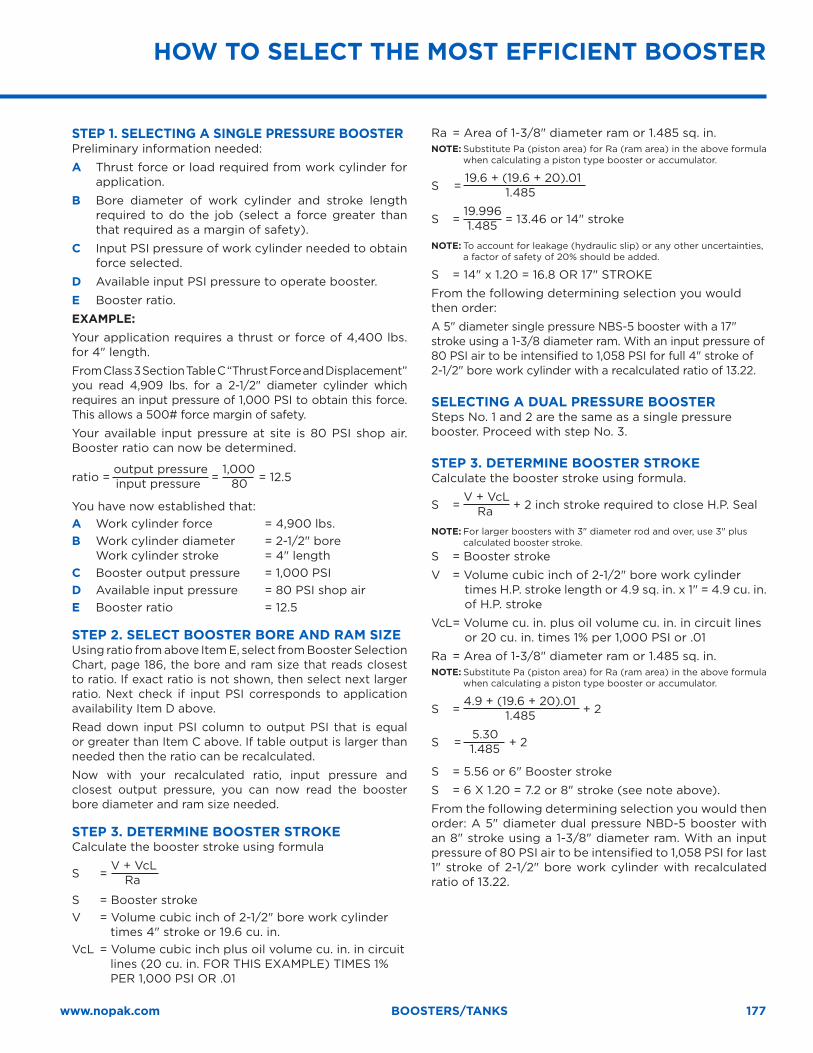
177www.nopak.com BOOSTERS/TANKS
STEP 1. SELECTING A SINGLE PRESSURE BOOSTERPreliminary information needed:
A Thrust force or load required from work cylinder for application.
B Bore diameter of work cylinder and stroke length required to do the job (select a force greater than that required as a margin of safety).
C Input PSI pressure of work cylinder needed to obtain force selected.
D Available input PSI pressure to operate booster.
E Booster ratio.
EXAMPLE:Your application requires a thrust or force of 4,400 lbs. for 4" length.
From Class 3 Section Table C “Thrust Force and Displacement” you read 4,909 lbs. for a 2-1/2" diameter cylinder which requires an input pressure of 1,000 PSI to obtain this force. This allows a 500# force margin of safety.
Your available input pressure at site is 80 PSI shop air. Booster ratio can now be determined.
ratio = output pressure
= 1,000
= 12.5 input pressure 80
You have now established that: A Work cylinder force = 4,900 lbs.B Work cylinder diameter = 2-1/2" bore
Work cylinder stroke = 4" lengthC Booster output pressure = 1,000 PSI D Available input pressure = 80 PSI shop air E Booster ratio = 12.5
STEP 2. SELECT BOOSTER BORE AND RAM SIZEUsing ratio from above Item E, select from Booster Selection Chart, page 186, the bore and ram size that reads closest to ratio. If exact ratio is not shown, then select next larger ratio. Next check if input PSI corresponds to application availability Item D above.
Read down input PSI column to output PSI that is equal or greater than Item C above. If table output is larger than needed then the ratio can be recalculated.
Now with your recalculated ratio, input pressure and closest output pressure, you can now read the booster bore diameter and ram size needed.
STEP 3. DETERMINE BOOSTER STROKE Calculate the booster stroke using formula
S = V + VcL
Ra
S = Booster stroke V = Volume cubic inch of 2-1/2" bore work cylinder
times 4" stroke or 19.6 cu. in.VcL = Volume cubic inch plus oil volume cu. in. in circuit
lines (20 cu. in. FOR THIS EXAMPLE) TIMES 1% PER 1,000 PSI OR .01
Ra = Area of 1-3/8" diameter ram or 1.485 sq. in. NOTE: Substitute Pa (piston area) for Ra (ram area) in the above formula
when calculating a piston type booster or accumulator.
S = 19.6 + (19.6 + 20).01
1.485
S = 19.996
= 13.46 or 14" stroke 1.485
NOTE: To account for leakage (hydraulic slip) or any other uncertainties, a factor of safety of 20% should be added.
S = 14" x 1.20 = 16.8 OR 17" STROKE
From the following determining selection you would then order:
A 5" diameter single pressure NBS-5 booster with a 17" stroke using a 1-3/8 diameter ram. With an input pressure of 80 PSI air to be intensified to 1,058 PSI for full 4" stroke of 2-1/2" bore work cylinder with a recalculated ratio of 13.22.
SELECTING A DUAL PRESSURE BOOSTER Steps No. 1 and 2 are the same as a single pressure booster. Proceed with step No. 3.
STEP 3. DETERMINE BOOSTER STROKECalculate the booster stroke using formula.
S = V + VcL
+ 2 inch stroke required to close H.P. Seal
Ra
NOTE: For larger boosters with 3" diameter rod and over, use 3" plus calculated booster stroke.
S = Booster stroke
V = Volume cubic inch of 2-1/2" bore work cylinder times H.P. stroke length or 4.9 sq. in. x 1" = 4.9 cu. in. of H.P. stroke
VcL = Volume cu. in. plus oil volume cu. in. in circuit lines or 20 cu. in. times 1% per 1,000 PSI or .01
Ra = Area of 1-3/8" diameter ram or 1.485 sq. in. NOTE: Substitute Pa (piston area) for Ra (ram area) in the above formula
when calculating a piston type booster or accumulator.
S = 4.9 + (19.6 + 20).01
+ 2 1.485
S = 5.30
+ 2 1.485
S = 5.56 or 6" Booster stroke
S = 6 X 1.20 = 7.2 or 8" stroke (see note above).
From the following determining selection you would then order: A 5" diameter dual pressure NBD-5 booster with an 8" stroke using a 1-3/8" diameter ram. With an input pressure of 80 PSI air to be intensified to 1,058 PSI for last 1" stroke of 2-1/2" bore work cylinder with recalculated ratio of 13.22.
HOW TO SELECT THE MOST EFFICIENT BOOSTER
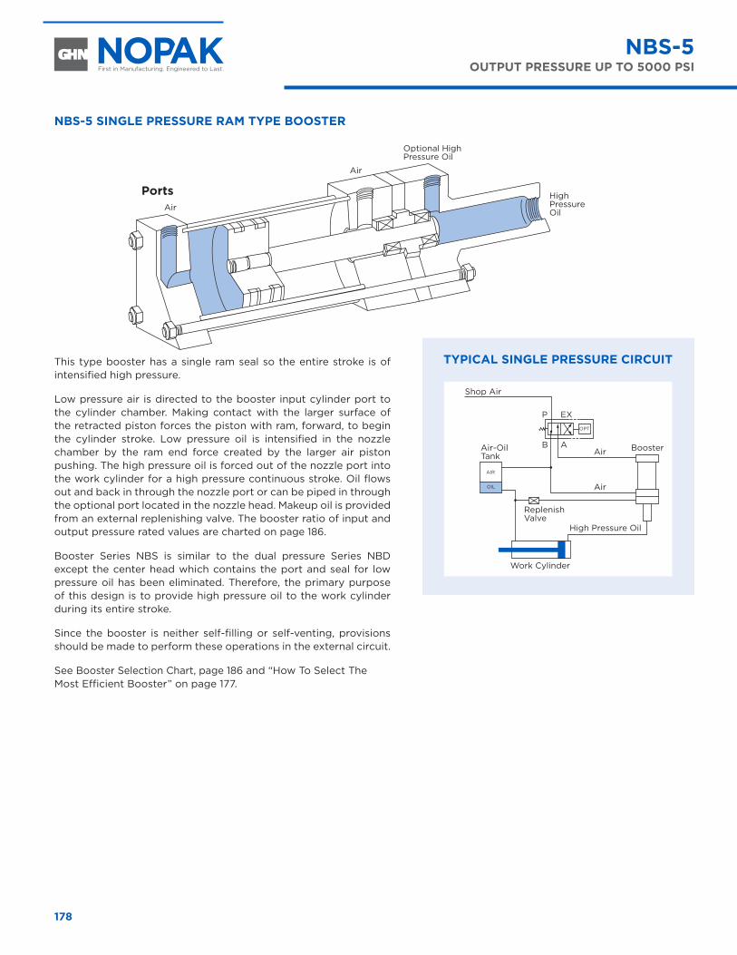
178
NBS-5 SINGLE PRESSURE RAM TYPE BOOSTER
PortsAir
Air
Optional High Pressure Oil
High Pressure Oil
This type booster has a single ram seal so the entire stroke is of intensified high pressure.
Low pressure air is directed to the booster input cylinder port to the cylinder chamber. Making contact with the larger surface of the retracted piston forces the piston with ram, forward, to begin the cylinder stroke. Low pressure oil is intensified in the nozzle chamber by the ram end force created by the larger air piston pushing. The high pressure oil is forced out of the nozzle port into the work cylinder for a high pressure continuous stroke. Oil flows out and back in through the nozzle port or can be piped in through the optional port located in the nozzle head. Makeup oil is provided from an external replenishing valve. The booster ratio of input and output pressure rated values are charted on page 186.
Booster Series NBS is similar to the dual pressure Series NBD except the center head which contains the port and seal for low pressure oil has been eliminated. Therefore, the primary purpose of this design is to provide high pressure oil to the work cylinder during its entire stroke.
Since the booster is neither self-filling or self-venting, provisions should be made to perform these operations in the external circuit.
See Booster Selection Chart, page 186 and “How To Select The Most Efficient Booster” on page 177.
NBS-5OUTPUT PRESSURE UP TO 5000 PSI
Shop Air
Air-Oil Tank
P EXOPT
AIR
OIL
B AAir Booster
Replenish Valve
High Pressure Oil
Work Cylinder
Air
TYPICAL SINGLE PRESSURE CIRCUIT
NBS-5 SINGLE PRESSURE RAM TYPE BOOSTER
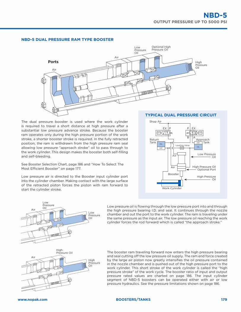
179www.nopak.com BOOSTERS/TANKS
NBD-5 DUAL PRESSURE RAM TYPE BOOSTER
Ports
Air
Air
Optional High Pressure Oil
Low Pressure Oil
High Pressure Oil
The dual pressure booster is used where the work cylinder is required to travel a short distance at high pressure after a substantial low pressure advance stroke. Because the booster ram operates only during the high pressure portion of the work stroke, a shorter booster stroke is required. In the fully retracted position, the ram is withdrawn from the high pressure ram seal allowing low pressure “approach stroke” oil to pass through to the work cylinder. This design makes the booster both self-filling and self-bleeding.
See Booster Selection Chart, page 186 and “How To Select The Most Efficient Booster” on page 177.
Low pressure air is directed to the Booster input cylinder port into the cylinder chamber. Making contact with the large surface of the retracted piston forces the piston with ram forward to start the cylinder stroke.
Air
Low Pressure Oil
Low Pressure Oil
Low pressure oil is flowing through the low pressure port into and through the high pressure bearing I.D. and seal. It continues through the nozzle chamber and out the port to the work cylinder. The ram is traveling under the same pressure as the input air. The low pressure oil reaching the work cylinder forces the rod forward which is called “the approach stroke.”
Air
High Pressure Oil
High Pressure Oil
The booster ram traveling forward now enters the high pressure bearing and seal cutting off the low pressure oil supply. The ram end force created by the large air piston now greatly intensifies the oil pressure contained in the nozzle chamber and is pushed out of the high pressure port to the work cylinder. This short stroke of the work cylinder is called the “high pressure stroke” of the work cycle. The booster ratio of input and output pressure rated values are charted on page 186. The input cylinder segment of NBD-5 boosters can be operated either with air or low pressure hydraulics. See the pressure limitations shown on page 186.
NBD-5OUTPUT PRESSURE UP TO 5000 PSI
TYPICAL DUAL PRESSURE CIRCUITShop Air
Return Tank
Approach Tank
Low Pressure Oil
High Pressure Oil Optional Port
High Pressure Oil
PP EXEXOPTOPT
AIR
AIROIL
OIL
B A
Air
Air
Booster
Leveling Valve
Work Cylinder
NBD-5 DUAL PRESSURE RAM TYPE BOOSTER
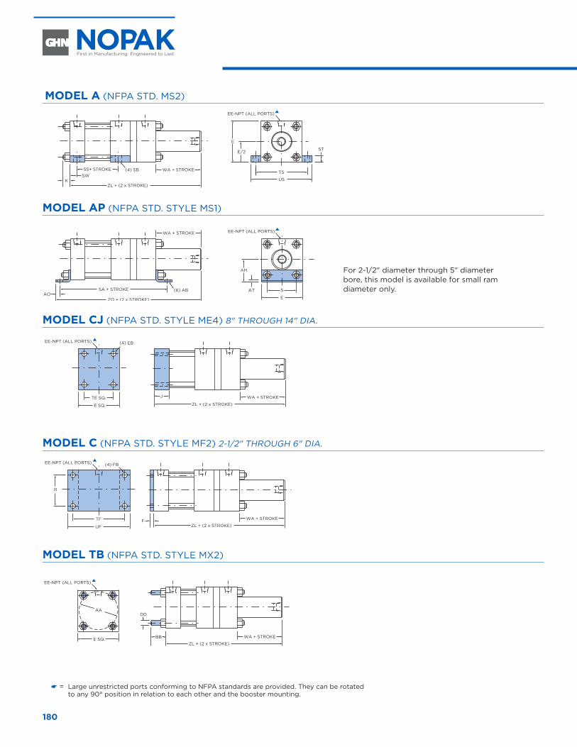
180
MODEL A (NFPA STD. MS2)
TS
US
E
E/2 ST
SS+ STROKE WA + STROKE
ZL + (2 x STROKE)
(4) SB
KSW
S
E
AH
AT
ZO + (2 x STROKE)
(6) ABAO
SA + STROKE
WA + STROKE
EE-NPT (ALL PORTS)
EE-NPT (ALL PORTS)
WA + STROKE
ZL + (2 x STROKE)F
WA + STROKE
ZL + (2 x STROKE)
DD
BB
EE-NPT (ALL PORTS)
E SQ.
AA
R
WA + STROKE
ZL + (2 x STROKE)
J
EE-NPT (ALL PORTS)
EE-NPT (ALL PORTS) (4) FB
(4) EB
E SQ.
TE SQ.
UF
TF
MODEL AP (NFPA STD. STYLE MS1)
TS
US
E
E/2 ST
SS+ STROKE WA + STROKE
ZL + (2 x STROKE)
(4) SB
KSW
S
E
AH
AT
ZO + (2 x STROKE)
(6) ABAO
SA + STROKE
WA + STROKE
EE-NPT (ALL PORTS)
EE-NPT (ALL PORTS)
WA + STROKE
ZL + (2 x STROKE)F
WA + STROKE
ZL + (2 x STROKE)
DD
BB
EE-NPT (ALL PORTS)
E SQ.
AA
R
WA + STROKE
ZL + (2 x STROKE)
J
EE-NPT (ALL PORTS)
EE-NPT (ALL PORTS) (4) FB
(4) EB
E SQ.
TE SQ.
UF
TF
MODEL CJ (NFPA STD. STYLE ME4) 8" THROUGH 14" DIA.
TS
US
E
E/2 ST
SS+ STROKE WA + STROKE
ZL + (2 x STROKE)
(4) SB
KSW
S
E
AH
AT
ZO + (2 x STROKE)
(6) ABAO
SA + STROKE
WA + STROKE
EE-NPT (ALL PORTS)
EE-NPT (ALL PORTS)
WA + STROKE
ZL + (2 x STROKE)F
WA + STROKE
ZL + (2 x STROKE)
DD
BB
EE-NPT (ALL PORTS)
E SQ.
AA
R
WA + STROKE
ZL + (2 x STROKE)
J
EE-NPT (ALL PORTS)
EE-NPT (ALL PORTS) (4) FB
(4) EB
E SQ.
TE SQ.
UF
TF
MODEL C (NFPA STD. STYLE MF2) 2-1/2" THROUGH 6" DIA.
TS
US
E
E/2 ST
SS+ STROKE WA + STROKE
ZL + (2 x STROKE)
(4) SB
KSW
S
E
AH
AT
ZO + (2 x STROKE)
(6) ABAO
SA + STROKE
WA + STROKE
EE-NPT (ALL PORTS)
EE-NPT (ALL PORTS)
WA + STROKE
ZL + (2 x STROKE)F
WA + STROKE
ZL + (2 x STROKE)
DD
BB
EE-NPT (ALL PORTS)
E SQ.
AA
R
WA + STROKE
ZL + (2 x STROKE)
J
EE-NPT (ALL PORTS)
EE-NPT (ALL PORTS) (4) FB
(4) EB
E SQ.
TE SQ.
UF
TF
MODEL TB (NFPA STD. STYLE MX2)
TS
US
E
E/2 ST
SS+ STROKE WA + STROKE
ZL + (2 x STROKE)
(4) SB
KSW
S
E
AH
AT
ZO + (2 x STROKE)
(6) ABAO
SA + STROKE
WA + STROKE
EE-NPT (ALL PORTS)
EE-NPT (ALL PORTS)
WA + STROKE
ZL + (2 x STROKE)F
WA + STROKE
ZL + (2 x STROKE)
DD
BB
EE-NPT (ALL PORTS)
E SQ.
AA
R
WA + STROKE
ZL + (2 x STROKE)
J
EE-NPT (ALL PORTS)
EE-NPT (ALL PORTS) (4) FB
(4) EB
E SQ.
TE SQ.
UF
TF
NBS-5 MODELS
� = Large unrestricted ports conforming to NFPA standards are provided. They can be rotated to any 90° position in relation to each other and the booster mounting.
For 2-1/2" diameter through 5" diameter bore, this model is available for small ram diameter only.
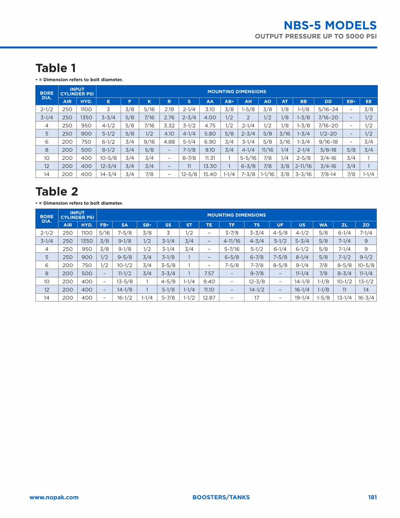
181www.nopak.com BOOSTERS/TANKS
Table 1• = Dimension refers to bolt diameter.
BORE DIA.
INPUT CYLINDER PSI MOUNTING DIMENSIONS
AIR HYD. E F K R S AA AB• AH AO AT BB DD EB• EE
2-1/2 250 1100 3 3/8 5/16 2.19 2-1/4 3.10 3/8 1-5/8 3/8 1/8 1-1/8 5/16–24 – 3/8
3-1/4 250 1350 3-3/4 5/8 7/16 2.76 2-3/4 4.00 1/2 2 1/2 1/8 1-3/8 7/16–20 – 1/2
4 250 950 4-1/2 5/8 7/16 3.32 3-1/2 4.75 1/2 2-1/4 1/2 1/8 1-3/8 7/16–20 – 1/2
5 250 900 5-1/2 5/8 1/2 4.10 4-1/4 5.80 5/8 2-3/4 5/8 3/16 1-3/4 1/2–20 – 1/2
6 200 750 6-1/2 3/4 9/16 4.88 5-1/4 6.90 3/4 3-1/4 5/8 3/16 1-3/4 9/16–18 – 3/4
8 200 500 8-1/2 3/4 5/8 – 7-1/8 9.10 3/4 4-1/4 11/16 1/4 2-1/4 5/8-18 5/8 3/4
10 200 400 10-5/8 3/4 3/4 – 8-7/8 11.31 1 5-5/16 7/8 1/4 2-5/8 3/4-16 3/4 1
12 200 400 12-3/4 3/4 3/4 – 11 13.30 1 6-3/8 7/8 3/8 2-11/16 3/4-16 3/4 1
14 200 400 14-3/4 3/4 7/8 – 12-5/8 15.40 1-1/4 7-3/8 1-1/16 3/8 3-3/16 7/8-14 7/8 1-1/4
Table 2• = Dimension refers to bolt diameter.
BORE DIA.
INPUT CYLINDER PSI MOUNTING DIMENSIONS
AIR HYD. FB• SA SB• SS ST TE TF TS UF US WA ZL ZO
2-1/2 250 1100 5/16 7-5/8 3/8 3 1/2 – 3-7/8 3-3/4 4-5/8 4-1/2 5/8 6-1/4 7-1/4
3-1/4 250 1350 3/8 9-1/8 1/2 3-1/4 3/4 – 4-11/16 4-3/4 5-1/2 5-3/4 5/8 7-1/4 9
4 250 950 3/8 9-1/8 1/2 3-1/4 3/4 – 5-7/16 5-1/2 6-1/4 6-1/2 5/8 7-1/4 9
5 250 900 1/2 9-5/8 3/4 3-1/8 1 – 6-5/8 6-7/8 7-5/8 8-1/4 5/8 7-1/2 9-1/2
6 200 750 1/2 10-1/2 3/4 3-5/8 1 – 7-5/8 7-7/8 8-5/8 9-1/4 7/8 8-5/8 10-5/8
8 200 500 – 11-1/2 3/4 3-3/4 1 7.57 – 9-7/8 – 11-1/4 7/8 8-3/4 11-1/4
10 200 400 – 13-5/8 1 4-5/8 1-1/4 9.40 – 12-3/8 – 14-1/8 1-1/8 10-1/2 13-1/2
12 200 400 – 14-1/8 1 5-1/8 1-1/4 11.10 – 14-1/2 – 16-1/4 1-1/8 11 14
14 200 400 – 16-1/2 1-1/4 5-7/8 1-1/2 12.87 – 17 – 19-1/4 1-5/8 13-1/4 16-3/4
NBS-5 MODELSOUTPUT PRESSURE UP TO 5000 PSI
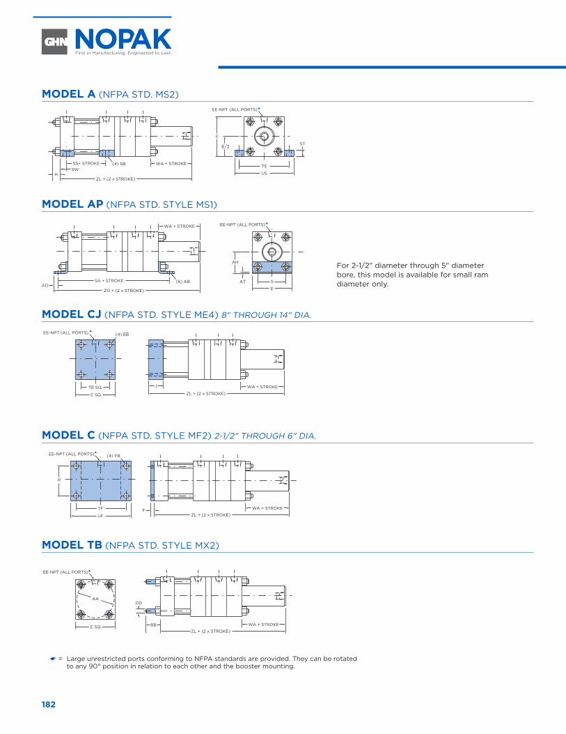
182
MODEL A (NFPA STD. MS2)
TS
US
E
E/2 ST
SS+ STROKE WA + STROKE
ZL + (2 x STROKE)
(4) SB
KSW
S
E
AH
AT
ZO + (2 x STROKE)
(6) ABAO
SA + STROKE
WA + STROKE
EE-NPT (ALL PORTS)
EE-NPT (ALL PORTS)
R
WA + STROKE
ZL + (2 x STROKE)F
J WA + STROKE
ZL + (2 x STROKE)
WA + STROKE
ZL + (2 x STROKE)
DD
BB
EE-NPT (ALL PORTS)
EE-NPT (ALL PORTS)
EE-NPT (ALL PORTS) (4) FB
(4) EB
E SQ.
E SQ.
TE SQ.
UF
TF
AA
MODEL AP (NFPA STD. STYLE MS1)
TS
US
E
E/2 ST
SS+ STROKE WA + STROKE
ZL + (2 x STROKE)
(4) SB
KSW
S
E
AH
AT
ZO + (2 x STROKE)
(6) ABAO
SA + STROKE
WA + STROKE
EE-NPT (ALL PORTS)
EE-NPT (ALL PORTS)
R
WA + STROKE
ZL + (2 x STROKE)F
J WA + STROKE
ZL + (2 x STROKE)
WA + STROKE
ZL + (2 x STROKE)
DD
BB
EE-NPT (ALL PORTS)
EE-NPT (ALL PORTS)
EE-NPT (ALL PORTS) (4) FB
(4) EB
E SQ.
E SQ.
TE SQ.
UF
TF
AA
MODEL CJ (NFPA STD. STYLE ME4) 8" THROUGH 14" DIA.
TS
US
E
E/2 ST
SS+ STROKE WA + STROKE
ZL + (2 x STROKE)
(4) SB
KSW
S
E
AH
AT
ZO + (2 x STROKE)
(6) ABAO
SA + STROKE
WA + STROKE
EE-NPT (ALL PORTS)
EE-NPT (ALL PORTS)
R
WA + STROKE
ZL + (2 x STROKE)F
J WA + STROKE
ZL + (2 x STROKE)
WA + STROKE
ZL + (2 x STROKE)
DD
BB
EE-NPT (ALL PORTS)
EE-NPT (ALL PORTS)
EE-NPT (ALL PORTS) (4) FB
(4) EB
E SQ.
E SQ.
TE SQ.
UF
TF
AA
MODEL C (NFPA STD. STYLE MF2) 2-1/2" THROUGH 6" DIA.
TS
US
E
E/2 ST
SS+ STROKE WA + STROKE
ZL + (2 x STROKE)
(4) SB
KSW
S
E
AH
AT
ZO + (2 x STROKE)
(6) ABAO
SA + STROKE
WA + STROKE
EE-NPT (ALL PORTS)
EE-NPT (ALL PORTS)
R
WA + STROKE
ZL + (2 x STROKE)F
J WA + STROKE
ZL + (2 x STROKE)
WA + STROKE
ZL + (2 x STROKE)
DD
BB
EE-NPT (ALL PORTS)
EE-NPT (ALL PORTS)
EE-NPT (ALL PORTS) (4) FB
(4) EB
E SQ.
E SQ.
TE SQ.
UF
TF
AA
MODEL TB (NFPA STD. STYLE MX2)
TS
US
E
E/2 ST
SS+ STROKE WA + STROKE
ZL + (2 x STROKE)
(4) SB
KSW
S
E
AH
AT
ZO + (2 x STROKE)
(6) ABAO
SA + STROKE
WA + STROKE
EE-NPT (ALL PORTS)
EE-NPT (ALL PORTS)
R
WA + STROKE
ZL + (2 x STROKE)F
J WA + STROKE
ZL + (2 x STROKE)
WA + STROKE
ZL + (2 x STROKE)
DD
BB
EE-NPT (ALL PORTS)
EE-NPT (ALL PORTS)
EE-NPT (ALL PORTS) (4) FB
(4) EB
E SQ.
E SQ.
TE SQ.
UF
TF
AA
NBD-5 MODELS
� = Large unrestricted ports conforming to NFPA standards are provided. They can be rotated to any 90° position in relation to each other and the booster mounting.
For 2-1/2" diameter through 5" diameter bore, this model is available for small ram diameter only.

183www.nopak.com BOOSTERS/TANKS
Table 1• = Dimension refers to bolt diameter.
BORE DIA.
INPUT CYLINDER PSI MOUNTING DIMENSIONS
AIR HYD. E F J K R S AA AB• AH AO AT BB DD EB• EE
2-1/2 250 1100 3 3/8 1-1/8 5/16 2.19 2-1/4 3.10 3/8 1-5/8 3/8 1/8 1-1/8 5/16–24 – 3/8
3-1/4 250 1350 3-3/4 5/8 1-1/4 7/16 2.76 2-3/4 4.00 1/2 2 1/2 1/8 1-3/8 7/16–20 – 1/2
4 250 950 4-1/2 5/8 1-1/4 7/16 3.32 3-1/2 4.75 1/2 2-1/4 1/2 1/8 1-3/8 7/16–20 – 1/2
5 250 900 5-1/2 5/8 1-1/4 1/2 4.10 4-1/4 5.80 5/8 2-3/4 5/8 3/16 1-3/4 1/2–20 – 1/2
6 200 750 6-1/2 3/4 1-1/2 9/16 4.88 5-1/4 6.90 3/4 3-1/4 5/8 3/16 1-3/4 9/16–18 – 3/4
8 200 500 8-1/2 3/4 1-1/2 5/8 – 7-1/8 9.10 3/4 4-1/4 11/16 1/4 2-1/4 5/8-18 5/8 3/4
10 200 400 10-5/8 3/4 2 3/4 – 8-7/8 11.31 1 5-5/16 7/8 1/4 2-5/8 3/4-16 3/4 1
12 200 400 12-3/4 3/4 2 3/4 – 11 13.30 1 6-3/8 7/8 3/8 2-11/16 3/4-16 3/4 1
14 200 400 14-3/4 3/4 2-1/4 7/8 – 12-5/8 15.40 1-1/4 7-3/8 1-1/16 3/8 3-3/16 7/8-14 7/8 1-1/4
Table 2• = Dimension refers to bolt diameter.
BORE DIA.
INPUT CYLINDER PSI MOUNTING DIMENSIONS
AIR HYD. FB• SA SB• SS ST SW TE TF TS UF US WA ZL ZO
2-1/2 250 1100 5/16 9-1/8 3/8 3 1/2 3/8 – 3-7/8 3-3/4 4-5/8 4-1/2 5/8 7-3/4 9-1/8
3-1/4 250 1350 3/8 10-7/8 1/2 3-1/4 3/4 1/2 – 4-11/16 4-3/4 5-1/2 5-3/4 5/8 9 10-3/4
4 250 950 3/8 10-7/8 1/2 3-1/4 3/4 1/2 – 5-7/16 5-1/2 6-1/4 6-1/2 5/8 9 10-3/4
5 250 900 1/2 11-3/8 3/4 3-1/8 1 11/16 – 6-5/8 6-7/8 7-5/8 8-1/4 5/8 9-1/4 11-1/4
6 200 750 1/2 12-1/2 3/4 3-5/8 1 11/16 – 7-5/8 7-7/8 8-5/8 9-1/4 7/8 10-5/8 12-5/8
8 200 500 – 13-1/2 3/4 3-3/4 1 11/16 7.57 – 9-7/8 – 11-1/4 7/8 10-3/4 13-1/4
10 200 400 – 15-7/8 1 4-5/8 1-1/4 7/8 9.40 – 12-3/8 – 14-1/8 1-1/8 12-3/4 15-3/4
12 200 400 – 16-3/8 1 5-1/8 1-1/4 7/8 11.10 – 14-1/2 – 16-1/4 1-1/8 13-1/4 16-1/4
14 200 400 – 19-1/4 1-1/4 5-7/8 1-1/2 1-1/8 12.87 – 17 – 19-1/4 1-5/8 16 19-1/2
NBD-5 MODELSOUTPUT PRESSURE UP TO 5000 PSI
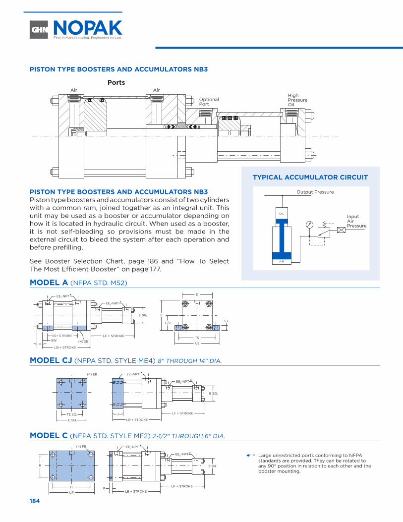
184
PISTON TYPE BOOSTERS AND ACCUMULATORS NB3
PortsAir Air
Optional Port
High Pressure Oil
PISTON TYPE BOOSTERS AND ACCUMULATORS NB3 Piston type boosters and accumulators consist of two cylinders with a common ram, joined together as an integral unit. This unit may be used as a booster or accumulator depending on how it is located in hydraulic circuit. When used as a booster, it is not self-bleeding so provisions must be made in the external circuit to bleed the system after each operation and before prefilling.
See Booster Selection Chart, page 186 and “How To Select The Most Efficient Booster” on page 177.
MODEL A (NFPA STD. MS2)
TS
US
E
E
E SQ.
E/2 ST
SS+ STROKE LF + STROKE
LB + STROKE
(4) SBK
SW
EE1-NPT
EE1-NPT
EE2-NPT
EE1-NPT
EE2-NPT
R
F
J
(4) FB
(4) EB
E SQ.
TE SQ.
UF
TF
EE1-NPT
EE2-NPT
LF + STROKE
EE2-NPT
E SQ.
E SQ.
E SQ.
LB + STROKE
DD
BB
LF + STROKE
LB + STROKE
LF + STROKE
LB + STROKE
E SQ.
AA
MODEL CJ (NFPA STD. STYLE ME4) 8" THROUGH 14" DIA.
TS
US
E
E
E SQ.
E/2 ST
SS+ STROKE LF + STROKE
LB + STROKE
(4) SBK
SW
EE1-NPT
EE1-NPT
EE2-NPT
EE1-NPT
EE2-NPT
R
F
J
(4) FB
(4) EB
E SQ.
TE SQ.
UF
TF
EE1-NPT
EE2-NPT
LF + STROKE
EE2-NPT
E SQ.
E SQ.
E SQ.
LB + STROKE
DD
BB
LF + STROKE
LB + STROKE
LF + STROKE
LB + STROKE
E SQ.
AA
MODEL C (NFPA STD. STYLE MF2) 2-1/2" THROUGH 6" DIA.
TS
US
E
E
E SQ.
E/2 ST
SS+ STROKE LF + STROKE
LB + STROKE
(4) SBK
SW
EE1-NPT
EE1-NPT
EE2-NPT
EE1-NPT
EE2-NPT
R
F
J
(4) FB
(4) EB
E SQ.
TE SQ.
UF
TF
EE1-NPT
EE2-NPT
LF + STROKE
EE2-NPT
E SQ.
E SQ.
E SQ.
LB + STROKE
DD
BB
LF + STROKE
LB + STROKE
LF + STROKE
LB + STROKE
E SQ.
AA
NB3 BOOSTERS AND ACCUMULATORS
Output Pressure
Input Air Pressure
AIR
OIL
TYPICAL ACCUMULATOR CIRCUIT
� = Large unrestricted ports conforming to NFPA standards are provided. They can be rotated to any 90° position in relation to each other and the booster mounting.
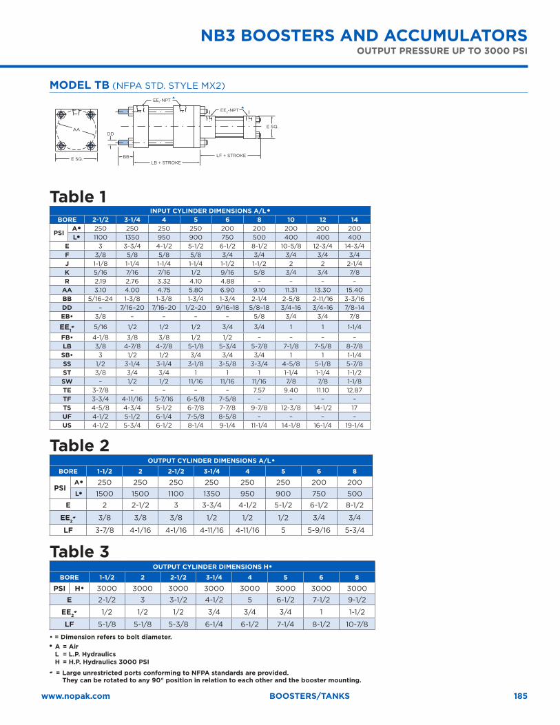
185www.nopak.com BOOSTERS/TANKS
MODEL TB (NFPA STD. STYLE MX2)
TS
US
E
E
E SQ.
E/2 ST
SS+ STROKE LF + STROKE
LB + STROKE
(4) SBK
SW
EE1-NPT
EE1-NPT
EE2-NPT
EE1-NPT
EE2-NPT
R
F
J
(4) FB
(4) EB
E SQ.
TE SQ.
UF
TF
EE1-NPT
EE2-NPT
LF + STROKE
EE2-NPT
E SQ.
E SQ.
E SQ.
LB + STROKE
DD
BB
LF + STROKE
LB + STROKE
LF + STROKE
LB + STROKE
E SQ.
AA
Table 1INPUT CYLINDER DIMENSIONS A/L �
BORE 2-1/2 3-1/4 4 5 6 8 10 12 14
PSIA� 250 250 250 250 200 200 200 200 200L� 1100 1350 950 900 750 500 400 400 400
E 3 3-3/4 4-1/2 5-1/2 6-1/2 8-1/2 10-5/8 12-3/4 14-3/4F 3/8 5/8 5/8 5/8 3/4 3/4 3/4 3/4 3/4J 1-1/8 1-1/4 1-1/4 1-1/4 1-1/2 1-1/2 2 2 2-1/4K 5/16 7/16 7/16 1/2 9/16 5/8 3/4 3/4 7/8R 2.19 2.76 3.32 4.10 4.88 – – – –
AA 3.10 4.00 4.75 5.80 6.90 9.10 11.31 13.30 15.40BB 5/16–24 1-3/8 1-3/8 1-3/4 1-3/4 2-1/4 2-5/8 2-11/16 3-3/16DD – 7/16–20 7/16–20 1/2–20 9/16–18 5/8–18 3/4–16 3/4–16 7/8–14EB• 3/8 – – – – 5/8 3/4 3/4 7/8
EE1� 5/16 1/2 1/2 1/2 3/4 3/4 1 1 1-1/4
FB• 4-1/8 3/8 3/8 1/2 1/2 – – – –LB 3/8 4-7/8 4-7/8 5-1/8 5-3/4 5-7/8 7-1/8 7-5/8 8-7/8SB• 3 1/2 1/2 3/4 3/4 3/4 1 1 1-1/4SS 1/2 3-1/4 3-1/4 3-1/8 3-5/8 3-3/4 4-5/8 5-1/8 5-7/8ST 3/8 3/4 3/4 1 1 1 1-1/4 1-1/4 1-1/2SW – 1/2 1/2 11/16 11/16 11/16 7/8 7/8 1-1/8TE 3-7/8 – – – – 7.57 9.40 11.10 12.87TF 3-3/4 4-11/16 5-7/16 6-5/8 7-5/8 – – – –TS 4-5/8 4-3/4 5-1/2 6-7/8 7-7/8 9-7/8 12-3/8 14-1/2 17UF 4-1/2 5-1/2 6-1/4 7-5/8 8-5/8 – – – –US 4-1/2 5-3/4 6-1/2 8-1/4 9-1/4 11-1/4 14-1/8 16-1/4 19-1/4
Table 2OUTPUT CYLINDER DIMENSIONS A/L �
BORE 1-1/2 2 2-1/2 3-1/4 4 5 6 8
PSIA� 250 250 250 250 250 250 200 200L� 1500 1500 1100 1350 950 900 750 500
E 2 2-1/2 3 3-3/4 4-1/2 5-1/2 6-1/2 8-1/2
EE2� 3/8 3/8 3/8 1/2 1/2 1/2 3/4 3/4
LF 3-7/8 4-1/16 4-1/16 4-11/16 4-11/16 5 5-9/16 5-3/4
Table 3 OUTPUT CYLINDER DIMENSIONS H�
BORE 1-1/2 2 2-1/2 3-1/4 4 5 6 8
PSI H� 3000 3000 3000 3000 3000 3000 3000 3000
E 2-1/2 3 3-1/2 4-1/2 5 6-1/2 7-1/2 9-1/2
EE2� 1/2 1/2 1/2 3/4 3/4 3/4 1 1-1/2
LF 5-1/8 5-1/8 5-3/8 6-1/4 6-1/2 7-1/4 8-1/2 10-7/8
• = Dimension refers to bolt diameter.� A = Air L = L.P. Hydraulics H = H.P. Hydraulics 3000 PSI� = Large unrestricted ports conforming to NFPA standards are provided.
They can be rotated to any 90° position in relation to each other and the booster mounting.
NB3 BOOSTERS AND ACCUMULATORSOUTPUT PRESSURE UP TO 3000 PSI
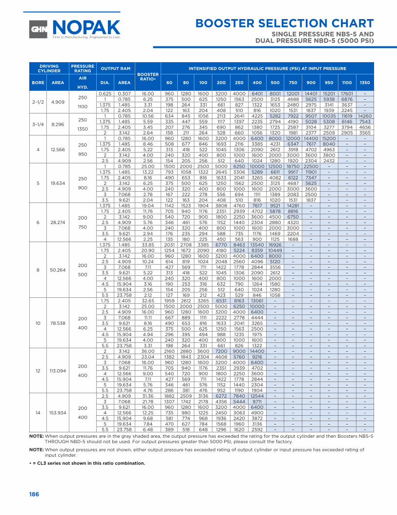
186
DRIVING CYLINDER
PRESSURE RATING OUTPUT RAM
BOOSTER RATIO•
INTENSIFIED OUTPUT HYDRAULIC PRESSURE (PSI) AT INPUT PRESSURE
BORE AREAAIR
HYD.
DIA. AREA 60 80 100 200 250 400 500 750 900 950 1100 1350
2–1/2 4.909250
1100
0.625 0.307 16.00 960 1280 1600 3200 4000 6401 8001 12001 14401 15201 17601 –1 0.785 6.25 375 500 625 1250 1563 2500 3125 4688 5625 5938 6876 –
1.375 1.485 3.31 198 264 331 661 827 1322 1653 2480 2975 3141 3637 –1.75 2.405 2.04 122 163 204 408 510 816 1020 1531 1837 1939 2245 –
3–1/4 8.296250
1350
1 0.785 10.56 634 845 1056 2113 2641 4225 5282 7922 9507 10035 11619 142601.375 1.485 5.59 335 447 559 1117 1397 2235 2794 4190 5028 5308 6146 75431.75 2.405 3.45 207 276 345 690 862 1380 1725 2587 3104 3277 3794 46562 3.142 2.64 158 211 264 528 660 1056 1320 1981 2377 2509 2905 3565
4 12.566250
950
1 0.785 16.00 960 1280 1600 3200 4000 6400 8000 12000 14400 15200 – –1.375 1.485 8.46 508 677 846 1693 2116 3385 4231 6347 7617 8040 – –1.75 2.405 5.22 313 418 522 1045 1306 2090 2612 3918 4702 4963 – –2 3.142 4.00 240 320 400 800 1000 1600 2000 3000 3600 3800 – –
2.5 4.909 2.56 154 205 256 512 640 1024 1280 1920 2304 2432 – –
5 19.634250
900
1 0.785 25.00 1500 2000 2500 5000 6250 10000 12500 18750 22500 – – –1.375 1.485 13.22 793 1058 1322 2645 3306 5289 6611 9917 11901 – – –1.75 2.405 8.16 490 653 816 1633 2041 3265 4082 6122 7347 – – –2 3.142 6.25 375 500 625 1250 1562 2500 3125 4687 5625 – – –
2.5 4.909 4.00 240 320 400 800 1000 1600 2000 3000 3600 – – –3 7.068 2.78 167 222 278 556 694 1111 1389 2083 2500 – – –
3.5 9.621 2.04 122 163 204 408 510 816 1020 1531 1837 – – –
6 28.274200
750
1.375 1.485 19.04 1142 1523 1904 3808 4760 7617 9521 14281 – – – –1.75 2.405 11.76 705 940 1176 2351 2939 4702 5878 8816 – – – –2 3.142 9.00 540 720 900 1800 2250 3600 4500 6750 – – – –
2.5 4.909 5.76 346 461 576 1152 1440 2304 2880 4320 – – – –3 7.068 4.00 240 320 400 800 1000 1600 2000 3000 – – – –
3.5 9.621 2.94 176 235 294 588 735 1176 1469 2204 – – – –4 12.566 2.25 135 180 225 450 563 900 1125 1688 – – – –
8 50.264200
500
1.375 1.485 33.85 2031 2708 3385 6770 8463 13540 16926 – – – – –1.75 2.405 20.90 1254 1672 2090 4180 5224 8359 10449 – – – – –2 3.142 16.00 960 1280 1600 3200 4000 6400 8000 – – – – –
2.5 4.909 10.24 614 819 1024 2048 2560 4096 5120 – – – – –3 7.068 7.11 427 569 711 1422 1778 2844 3556 – – – – –
3.5 9.621 5.22 313 418 522 1045 1306 2090 2612 – – – – –4 12.566 4.00 240 320 400 800 1000 1600 2000 – – – – –
4.5 15.904 3.16 190 253 316 632 790 1264 1580 – – – – –5 19.634 2.56 154 205 256 512 640 1024 1280 – – – – –
5.5 23.758 2.12 127 169 212 423 529 846 1058 – – – – –
10 78.538200
400
1.75 2.405 32.65 1959 2612 3265 6531 8163 13061 – – – – – –2 3.142 25.00 1500 2000 2500 5000 6250 10000 – – – – – –
2.5 4.909 16.00 960 1280 1600 3200 4000 6400 – – – – – –3 7.068 11.11 667 889 1111 2222 2778 4444 – – – – – –
3.5 9.621 8.16 490 653 816 1633 2041 3265 – – – – – –4 12.566 6.25 375 500 625 1250 1563 2500 – – – – – –
4.5 15.904 4.94 296 395 494 988 1235 1975 – – – – – –5 19.634 4.00 240 320 400 800 1000 1600 – – – – – –
5.5 23.758 3.31 198 264 331 661 826 1322 – – – – – –
12 113.094200
400
2 3.142 36.00 2160 2880 3600 7200 9000 14400 – – – – – –2.5 4.909 23.04 1382 1843 2304 4608 5760 9216 – – – – – –3 7.068 16.00 960 1280 1600 3200 4000 6400 – – – – – –
3.5 9.621 11.76 705 940 1176 2351 2939 4702 – – – – – –4 12.566 9.00 540 720 900 1800 2250 3600 – – – – – –
4.5 15.904 7.11 427 569 711 1422 1778 2844 – – – – – –5 19.634 5.76 346 461 576 1152 1440 2304 – – – – – –
5.5 23.758 4.76 286 381 476 952 1190 1904 – – – – – –
14 153.934200
400
2.5 4.909 31.36 1882 2509 3136 6272 7840 12544 – – – – – –3 7.068 21.78 1307 1742 2178 4356 5444 8711 – – – – – –
3.5 9.621 16.00 960 1280 1600 3200 4000 6400 – – – – – –4 12.566 12.25 735 980 1225 2450 3063 4900 – – – – – –
4.5 15.904 9.68 581 774 968 1936 2420 3872 – – – – – –5 19.634 7.84 470 627 784 1568 1960 3136 – – – – – –
5.5 23.758 6.48 389 518 648 1296 1620 2592 – – – – – –NOTE: When output pressures are in the gray shaded area, the output pressure has exceeded the rating for the output cylinder and then Boosters NBS-5
THROUGH NBD-5 should not be used. For output pressures greater than 5000 PSI, please consult the factory.
NOTE: When output pressures are not shown, either output pressure has exceeded rating of output cylinder or input pressure has exceeded rating of input cylinder.
• = CL3 series not shown in this ratio combination.
BOOSTER SELECTION CHARTSINGLE PRESSURE NBS-5 AND
DUAL PRESSURE NBD-5 (5000 PSI)
BOOSTER SELECTION CHART SINGLE PRESSURE NBS-5 AND DUAL PRESSURE NBD-5 (5000 PSI)
BOOSTER SELECTION CHARTNB-3 (3000 PSI)
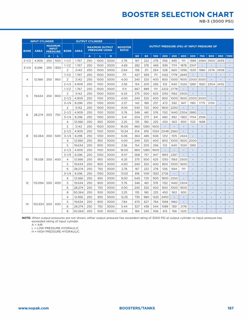
187www.nopak.com BOOSTERS/TANKS
INPUT CYLINDER OUTPUT CYLINDER
BOOSTER RATIO
OUTPUT PRESSURE (PSI) AT INPUT PRESSURE OF
BORE AREA
MAXIMUM INPUT
PRESSURE BORE AREAMAXIMUM OUTPUT PRESSURE USING
A L A L H 60 80 100 200 250 400 500 750 900 950 1100
2–1/2 4.909 250 1100 1–1/2 1.767 250 1500 3000 2.78 167 222 278 556 695 1111 1389 2084 2500 2639 –
3–1/4 8.296 250 13501–1/2 1.767 250 1500 3000 4.69 282 376 469 939 1174 1878 2347 – – – –
2 3.142 250 1500 3000 2.64 158 211 264 528 660 1056 1320 1980 2376 2508 –
4 12.566 250 950
1–1/2 1.767 250 1500 3000 7.11 427 569 711 1422 1778 2845 – – – – –
2 3.142 250 1500 3000 4.00 240 320 400 800 1000 1600 2000 3000 – – –
2–1/2 4.909 250 1100 3000 2.56 154 205 256 512 640 1024 1280 1920 2304 2432 –
5 19.634 250 900
1–1/2 1.767 250 1500 3000 11.11 667 889 1111 2222 2778 – – – – – –
2 3.142 250 1500 3000 6.25 375 500 625 1250 1562 2500 – – – – –
2–1/2 4.909 250 1100 3000 4.00 240 320 400 800 1000 1600 2000 3000 – – –
3–1/4 8.296 250 1350 3000 2.37 142 189 237 473 592 947 1183 1775 2130 – –
6 28.274 200 750
2 3.142 250 1500 3000 9.00 540 720 900 1800 2250 – – – – – –
2–1/2 4.909 250 1100 3000 5.76 346 461 576 1152 1440 2304 2880 – – – –
3–1/4 8.296 250 1350 3000 3.41 204 273 341 682 852 1363 1704 2556 – – –
4 12.566 250 950 3000 2.25 135 180 225 450 563 900 1125 1688 – – –
8 50.264 200 500
2 3.142 250 1500 3000 16.00 960 1280 1600 – – – – – – – –
2–1/2 4.909 250 1100 3000 10.24 614 819 1024 2048 2560 – – – – – –
3–1/4 8.296 250 1350 3000 6.06 364 485 606 1212 1515 2424 – – – – –
4 12.566 250 950 3000 4.00 240 320 400 800 1000 1600 2000 – – – –
5 19.634 250 900 3000 2.56 154 205 256 512 640 1024 1280 – – – –
10 78.538 200 400
2–1/2 4.909 250 1100 3000 16.00 960 1280 1600 – – – – – – – –
3–1/4 8.296 250 1350 3000 9.47 568 757 947 1893 2367 – – – – – –
4 12.566 250 950 3000 6.25 375 500 625 1250 1563 2500 – – – – –
5 19.634 250 900 3000 4.00 240 320 400 800 1000 1600 – – – – –
6 28.274 250 750 3000 2.78 167 222 278 556 694 1111 – – – – –
12 113.094 200 400
3–1/4 8.296 250 1350 3000 13.63 818 1091 1363 2726 – – – – – – –
4 12.566 250 950 3000 9.00 540 720 900 1800 2250 – – – – – –
5 19.634 250 900 3000 5.76 346 461 576 1152 1440 2304 – – – – –
6 28.274 250 750 3000 4.00 240 320 400 800 1000 1600 – – – – –
8 50.264 250 500 3000 2.25 135 180 225 450 563 900 – – – – –
14 153.934 200 400
4 12.566 250 950 3000 12.25 735 980 1225 2450 – – – – – – –
5 19.634 250 900 3000 7.84 470 627 784 1568 1960 – – – – – –
6 28.274 250 750 3000 5.44 327 436 544 1089 1361 2178 – – – – –
8 50.264 250 500 3000 3.06 184 245 306 613 766 1225 – – – – –
NOTE: When output pressures are not shown, either output pressure has exceeded rating of 3000 PSI at output cylinder or input pressure has exceeded rating of input cylinder. A = AIR L = LOW PRESSURE HYDRAULIC H = HIGH PRESSURE HYDRAULIC
BOOSTER SELECTION CHARTNB-3 (3000 PSI) BOOSTER SELECTION CHART
NB-3 (3000 PSI)
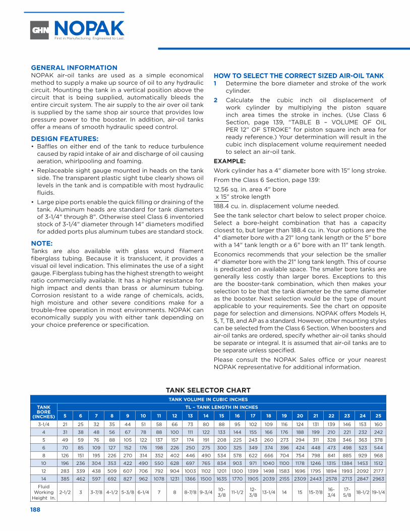
188
GENERAL INFORMATION NOPAK air-oil tanks are used as a simple economical method to supply a make up source of oil to any hydraulic circuit. Mounting the tank in a vertical position above the circuit that is being supplied, automatically bleeds the entire circuit system. The air supply to the air over oil tank is supplied by the same shop air source that provides low pressure power to the booster. In addition, air-oil tanks offer a means of smooth hydraulic speed control.
DESIGN FEATURES: • Baffles on either end of the tank to reduce turbulence
caused by rapid intake of air and discharge of oil causing aeration, whirlpooling and foaming.
• Replaceable sight gauge mounted in heads on the tank side. The transparent plastic sight tube clearly shows oil levels in the tank and is compatible with most hydraulic fluids.
• Large pipe ports enable the quick filling or draining of the tank. Aluminum heads are standard for tank diameters of 3-1/4" through 8". Otherwise steel Class 6 inventoried stock of 3-1/4" diameter through 14" diameters modified for added ports plus aluminum tubes are standard stock.
NOTE: Tanks are also available with glass wound filament fiberglass tubing. Because it is translucent, it provides a visual oil level indication. This eliminates the use of a sight gauge. Fiberglass tubing has the highest strength to weight ratio commercially available. It has a higher resistance for high impact and dents than brass or aluminum tubing. Corrosion resistant to a wide range of chemicals, acids, high moisture and other severe conditions make for a trouble-free operation in most environments. NOPAK can economically supply you with either tank depending on your choice preference or specification.
HOW TO SELECT THE CORRECT SIZED AIR-OIL TANK1 Determine the bore diameter and stroke of the work
cylinder.
2 Calculate the cubic inch oil displacement of work cylinder by multiplying the piston square inch area times the stroke in inches. (Use Class 6 Section, page 139, “TABLE B – VOLUME OF OIL PER 12” OF STROKE” for piston square inch area for ready reference.) Your determination will result in the cubic inch displacement volume requirement needed to select an air-oil tank.
EXAMPLE: Work cylinder has a 4" diameter bore with 15" long stroke.
From the Class 6 Section, page 139:
12.56 sq. in. area 4" bore x 15" stroke length
188.4 cu. in. displacement volume needed.
See the tank selector chart below to select proper choice. Select a bore-height combination that has a capacity closest to, but larger than 188.4 cu. in. Your options are the 4" diameter bore with a 21" long tank length or the 5" bore with a 14" tank length or a 6" bore with an 11" tank length.
Economics recommends that your selection be the smaller 4" diameter bore with the 21" long tank length. This of course is predicated on available space. The smaller bore tanks are generally less costly than larger bores. Exceptions to this are the booster-tank combination, which then makes your selection to be that the tank diameter be the same diameter as the booster. Next selection would be the type of mount applicable to your requirements. See the chart on opposite page for selection and dimensions. NOPAK offers Models H, S, T, TB, and AP as a standard. However, other mounting styles can be selected from the Class 6 Section. When boosters and air-oil tanks are ordered, specify whether air-oil tanks should be separate or integral. It is assumed that air-oil tanks are to be separate unless specified.
Please consult the NOPAK Sales office or your nearest NOPAK representative for additional information.
AIR-OIL TANKSAIR-OIL TANKS
TANK SELECTOR CHARTTANK VOLUME IN CUBIC INCHES
TANK BORE
(INCHES)
TL – TANK LENGTH IN INCHES
5 6 7 8 9 10 11 12 13 14 15 16 17 18 19 20 21 22 23 24 25
3-1/4 21 25 32 35 44 51 58 66 73 80 88 95 102 109 116 124 131 139 146 153 160
4 31 38 48 56 67 78 88 100 111 122 133 144 155 166 176 188 199 210 221 232 242
5 49 59 76 88 105 122 137 157 174 191 208 225 243 260 273 294 311 328 346 363 378
6 70 85 109 127 152 176 198 226 250 275 300 325 349 374 396 424 448 473 498 523 544
8 126 151 195 226 270 314 352 402 446 490 534 578 622 666 704 754 798 841 885 929 968
10 196 236 304 353 422 490 550 628 697 765 834 903 971 1040 1100 1178 1246 1315 1384 1453 1512
12 283 339 438 509 607 706 792 904 1003 1102 1201 1300 1399 1498 1583 1696 1795 1894 1993 2092 2177
14 385 462 597 692 827 962 1078 1231 1366 1500 1635 1770 1905 2039 2155 2309 2443 2578 2713 2847 2963
Fluid Working
Height In.2-1/2 3 3-7/8 4-1/2 5-3/8 6-1/4 7 8 8-7/8 9-3/4 10-
3/8 11-1/2 12-3/8 13-1/4 14 15 15-7/8 16-
3/417-5/8 18-1/2 19-1/4
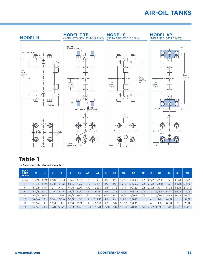
189www.nopak.com BOOSTERS/TANKS
MODEL HMODEL T-TB (NFPA STD. STYLE MX1 & MX2)
MODEL S (NFPA STD. STYLE MS4)
MODEL AP (NFPA STD. STYLE MS1)
EE-NPT (PORTS)EE-NPT (PORTS)
EE-NPT(FILLER PORT)EE-NPT(FILLER PORT)
EE-NPT(DRAIN PORT)EE-NPT(DRAIN PORT)
(6) AB(6) AB
(4) NT(4) NT
44 22
11
33
L. MAXL. MAX
DDDDS/2S/2
SS
BBBB
TNTN
44 22
11
33
44 22
11
33
AAAAAH
AT
FLUIDWORKHEIGHT
AO
AO
SA +TANKLENGTH (TL)
SN +TANKLENGTH (TL)
LB +TANKLENGTH (TL)
TL
J
J
44
EE-NPT(DRAIN PORT)EE-NPT(DRAIN PORT)E SQ.E SQ.
44
22
1133
FLUIDWORKHEIGHT
FLUIDWORKHEIGHT
Table 1• = Dimension refers to bolt diameter.
TANK BORE
(INCHES)E J U S L AA AB• AT AH AO BB DD EE LB NT SA SN TN
3-1/4 3-3/4 1-1/4 1-3/8 2-3/4 3-1/4 4.00 1/2 2 1/2 1/8 1-3/8 7/16–20 1/2 2-1/2 1/2–13 5 1-3/8 1-1/2
4 4-1/2 1-1/4 1-5/8 3-1/2 3-5/8 4.75 1/2 2-1/4 1/2 1/8 1-3/8 7/16–20 1/2 2-1/2 1/2–13 5 1-3/8 2-1/16
5 5-1/2 1-1/4 2 4-1/4 4-1/8 5.80 5/8 2-3/4 5/8 3/16 1-3/4 1/2–20 1/2 2-1/2 5/8–11 5-1/4 1-3/8 2-11/16
6 6-1/2 1-1/2 2-1/4 5-1/4 4-5/8 6.90 3/4 3-1/4 5/8 3/16 1-3/4 9/16–18 3/4 3 3/4–10 5-3/4 1-5/8 3-1/4
8 8-1/2 1-1/2 3 7-1/8 5-5/8 9.10 3/4 4-1/4 11/16 1/4 2-1/4 5/8–18 3/4 3 3/4–10 6-5/8 1-5/8 4-1/2
10 10-5/8 2 3-1/4 8-7/8 6-3/4 11.30 1 5-5/16 7/8 1/4 2-5/8 3/4–16 1 4 1–8 8-1/4 2 5-1/2
12 12-3/4 2 3-3/4 11 7-3/4 13.31 1 6-3/8 7/8 3/8 2-11/16 3/4–16 1 4 1–8 8-1/4 2 7-1/4
14 14-3/4 2-1/4 3-7/8 12-5/8 8-3/4 15.40 1-1/4 7-3/8 1-1/16 3/8 3-3/16 7/8–14 1-1/4 4-1/2 1-1/4–7 9-3/8 2-3/8 8-3/8
AIR-OIL TANKS

190

Terms and Conditions of Sale
Terms and Conditions of Sale
TE
RM
S/C
ON
DIT
ION
S
192
TERMS AND CONDITIONS OF SALEEffective January 1, 2015
These Galland Henning NOPAK, Inc. (“Seller”) Terms and Conditions of Sale shall govern all sales and all orders placed by buyer (“Buyer”) for goods or products (collectively, “Products”) from Seller.
1 ACCEPTANCE; CONTRARY TERMS; ENTIRE AGREEMENT. All orders for Products are subject to acceptance by Seller at its offices in Franklin, Wisconsin. Seller’s written price quotation, if any (“Seller’s Quotation”) and these Terms and Conditions of Sale are intended by the parties to be the complete and exclusive agreement of the parties with respect to the subject matter hereof and supersede all prior understandings, representations, warranties or agreements between the parties, whether written or oral. BUYER’S ORDERS ARE ACCEPTED ONLY ON THE TERMS AND CONDITIONS CONTAINED HEREIN AND THE PROVISIONS OF ANY PURCHASE ORDER OR OTHER WRITING WHICH ARE INCONSISTENT HEREWITH SHALL NOT CONSTITUTE PART OF THESE TERMS AND CONDITIONS OF SALE. SELLER’S ACCEPTANCE OF BUYER’S ORDER IS SUBJECT TO AND CONDITIONED ON BUYER’S ASSENT TO THESE TERMS AND CONDITIONS OF SALE.
2 PRICE AND DELIVERY: Prices shall be as set forth on Seller’s Quotations, provided however, that prices may be adjusted by Seller without notice to conform to prices in effect at the time of shipment. Unless otherwise specified by Seller in writing, all prices are F.O.B. Seller’s plant. All Seller’s Quotations automatically expire thirty (30) calendar days from date of issuance unless communicated otherwise by Seller. Unless otherwise specified by Seller in writing, prices stated on Seller’s Quotations do not include any sales, use or value-added taxes, or any other taxes, charges or duties applicable to the sale of Products, which taxes, charges and duties (including any interest and penalties) shall be the sole responsibility of Buyer. Buyer shall provide Seller with tax exemption certificates if requested by Seller. Unless otherwise agreed to by the parties in writing, all Products are shipped F.O.B Seller’s plant. Risk of loss shall pass to Buyer at the time the Products are delivered to a carrier at Seller’s plant and Buyer shall be solely responsible for procuring commercially reasonable insurance coverage for the Products after such delivery for the benefit of Seller and Buyer. Title to the Products will remain with Seller until full payment (including deferred payments) is received by Seller. All freight, storage, insurance or other fees or charges (including, without limitation, any sales, use or value-added taxes and import duties on the Products, if any) shall be paid by Buyer and if advanced by Seller, shall be added to Seller’s invoice and payable together with payment for the Products purchased. Seller will package the Products in a commercially reasonable manner acceptable to commercial carriers. All risk of loss relating to any goods or products not manufactured by Seller which are delivered by Buyer to Seller shall at all times remain the sole and exclusive responsibility of Buyer.
3 DELAYS; PERFORMANCE: Seller does not guarantee arrival of shipment(s) at a particular time or date under any circumstances. Seller shall have no liability whatsoever for any failure or delay in shipment or other nonperformance if shipment or performance is rendered impossible, impracticable or unreasonably burdensome by any event, whether or not forseen or forseeable, brought about by any cause other than the willful conduct of Seller, including, without limitation, accidents; breakdowns; riots; war; terrorism; interruptions in or failures of sources or subcontractors to supply materials or equipment; failures in manufacturing processes or equipment; strikes, labor or transportation problems; fires, explosions or other acts of God; or orders, contracts, priorities, directives, requisitions or requests of the federal or state governments, whether or not voluntarily assumed. In the event of any such failure or delay in shipment or other nonperformance,
Seller may, at its option and without liability, cancel all or any portion of Buyer’s order and/or extend any date upon which any performance hereunder is due.
4 PAYMENT TERMS: Unless otherwise agreed to in writing by the parties, all invoices for Products shall be paid net 30 days and shall be payable in U.S. Dollars. If all Product(s) from an order are not shipped on the same date, pro rata invoices shall be rendered for such partial shipments. If shipment of any Product(s) (and/or materials or parts thereof) is delayed, either directly or indirectly by the Buyer, the date of completion of the Product(s) shall be deemed as the date of shipment and invoice. No orders by Buyer can be cancelled or returned without the written consent of Seller (in which case Buyer shall reimburse Seller for its reasonable costs associated with such cancelled or returned Products). OUTSTANDING BALANCES NOT PAID WHEN DUE SHALL BE SUBJECT TO A DELINQUENCY CHARGE ACCRUING AT THE RATE OF THE LOWER OF 1.5% PER MONTH OR THE MAXIMUM INTEREST RATE ALLOWABLE UNDER LAW. Buyer shall also pay Seller any collection fees and reasonable attorneys’ fees incurred by Seller in collecting payment of the purchase prices or any other amounts for which Buyer is liable under the terms and conditions hereof. Seller shall have the right to cancel all or any portion of Buyer’s order in the event Buyer has outstanding balances which are delinquent by 15 days or more.
5 EXCLUSIVE WARRANTY: Seller warrants to the Buyer that the Products sold are to be free from defects in material and workmanship for (i) with respect to Products that contain perishable elastomers (e.g. rubber), a period of six (6) months from the date of shipment, (ii) with respect to the paint and finish of any Products, a period of six (6) months from the date of shipment and (iii) for all other Products (excluding paint and finish of Products), a period of five (5) years from the date of shipment, subject to the terms and limitations of the exclusive warranty and remedies described herein. THIS FOREGOING WARRANTY IS EXCLUSIVE AND IN LIEU OF ANY OTHER WARRANTY, EXPRESS OR IMPLIED, INCLUDING, BUT NOT LIMITED TO, ANY IMPLIED WARRANTY OF MERCHANTABILITY OR FITNESS FOR A PARTICULAR PURPOSE. SELLER NEITHER ASSUMES (NOR HAS AUTHORIZED ANY PERSON TO ASSUME) ANY OTHER WARRANTY OR LIABILITY IN CONNECTION WITH SELLER’S PRODUCTS. IF BUYER’S ORDER IS FOR PRODUCTS WHICH CONTAIN COMPONENTS MANUFACTURED BY A PARTY OTHER THAN SELLER, BUYER ACKNOWLEDGES THAT SELLER IS NOT THE MANUFACTURER OF SUCH COMPONENTS AND AGREES THAT ALL SUCH COMPONENTS ARE NOT COVERED BY THE WARRANTY PROVIDED HEREIN AND ARE WARRANTED ONLY TO THE EXTENT OF THE MANUFACTURER’S EXPRESS WARRANTIES TO SELLER, WHICH SELLER SHALL PROVIDE TO BUYER AT BUYER’S REQUEST. SELLER’S WARRANTIES CONTAINED IN THESE TERMS AND CONDITIONS SHALL AUTOMATICALLY BECOME NULL AND VOID IN THE EVENT OF (I) INSTALLATION OF ANY PARTS NOT SUPPLIED OR AUTHORIZED IN WRITING BY SELLER, (II) MODIFICATION OF A PRODUCT, OR (III) IMPROPER OR UNAUTHORIZED REPAIRS ARE MADE TO A PRODUCT. THE FAILURE OF BUYER TO PAY THE FULL PURCHASE PRICE FOR ANY PRODUCT ACCORDING TO THESE TERMS AND CONDITIONS OF SALE OR ANY OTHER OUTSTANDING BALANCE DUE FOR A PRIOR, CURRENT OR FUTURE OBLIGATION OWED TO SELLER SHALL AUTOMATICALLY VOID ANY OF SELLER’S WARRANTY OBLIGATIONS CONTAINED HEREIN.
6 LIMITATION OF REMEDIES AND DAMAGES: Buyer shall provide Seller with written notice of any alleged defects in material or workmanship that arise under proper and normal use of the Products during the warranty period set forth in Section 5, above.
193www.nopak.com TERMS/CONDITIONS
Seller shall arrange for inspection of such Products within fifteen (15) days of its receipt of such notice. Before the end of such fifteen (15) day period, Seller shall advise Buyer whether Seller will, at its sole option, repair or replace Products found to be defective or credit Buyer for the same. Seller shall not be liable for damage to any Product resulting from (i) improper installation or operation, (ii) installation of any parts not supplied or authorized by Seller, (iii) modification of such Product, (iv) improper or unauthorized repairs, (v) improper storage or handling of such Product, (vi) negligent or willful misconduct of Buyer or (vii) Buyer’s designs, change orders or changes in specifications. No Products shall be returned to Seller without its prior written consent. EXCEPT AS OTHERWISE EXPRESSLY PROVIDED HEREIN, SELLER WILL NOT BE LIABLE TO BUYER OR ANY THIRD PARTY FOR ANY CONSEQUENTIAL, INCIDENTAL, INDIRECT, PUNITIVE, OR SPECIAL DAMAGES ARISING OUT OF OR RELATING TO THESE TERMS AND CONDITIONS OF SALE OR THE PERFORMANCE OR BREACH HEREOF, INCLUDING, BUT NOT LIMITED TO, LABOR COSTS, LOSS OF USE, LOST REVENUES, LOST PROFITS, DAMAGE TO ASSOCIATED EQUIPMENT OR FACILITIES, COSTS OF REPLACEMENT POWER, COSTS ASSOCIATED WITH DOWNTIME, AND ANY SIMILAR LOSSES, COSTS OR DAMAGES, AND REGARDLESS OF HOWEVER CAUSED, WHETHER BASED ON CONTRACT, TORT, OR ANY OTHER LEGAL THEORY AND IN NO EVENT SHALL SELLER’S LIABILITY WITH RESPECT TO A BREACH OF THE LIMITED WARRANTY PROVIDED BY THESE TERMS AND CONDITIONS EXCEED THE PURCHASE PRICE PAID BY BUYER FOR THE PRODUCT(S) IN QUESTION.
7 INTELLECTUAL PROPERTY: Buyer represents and warrants that Buyer has all right, title and interest to and in, or has been granted a license to use, any patent, trademark and/or other intellectual property that Buyer has or will request Seller to affix to, or use in the production of an any Product supplied hereunder. Buyer further represents and warrants that the use or omission of any designs, devices, or words, including any wording required by any Federal, State or local laws or ordinances which Buyer may from time to time order incorporated in or imprinted or placed on the Products is in conformance with all applicable laws and does not infringe on any third party’s intellectual property rights (regardless of whether or not Seller consulted thereon or performed design work or other special services in connection therewith).
8 CLAIMS AND MODIFICATIONS: Buyer shall have ten (10) days after receipt of the Products to inspect and make any claims for error in design and specifications. Failure to make such a claim and reject Products within such period shall constitute an irrevocable acceptance of the Products and an admission that the Products fully comply with design and specifications. Seller reserves the right to accept or reject any such claim in whole or part. Replacement of defective Products or repayment of the purchase price for non-conforming Products shall be made only upon return thereof after inspection by Seller and Buyer’s compliance with written shipping instructions from Seller. Any claims for loss or damage during transit must be prosecuted by Buyer solely against the carrier and/or insurer. Buyer may not make any changes to Buyer’s order without the prior written consent of Seller. Any price variation from any such changes shall become effective immediately upon the acceptance of such changes by Seller.
9 INDEMNIFICATION: Buyer shall indemnify and hold Seller and each of its officers, directors, employees, shareholders, affiliates, agents, representatives, successors and assigns harmless from and against any and all claims, actions, demands, legal proceedings, judgments, settlements, sums, costs, liabilities, losses, obligations, damages, penalties, fines, costs and other expenses (including, but
not limited to, reasonable attorneys’ fees) relating to, arising out of or resulting from (i) Buyer’s use of any Product, including, without limitation, any third party claims for personal injury or property damage resulting from Buyer’s negligence or willful misconduct, (ii) any act by Buyer or its employees, agents or representatives, which causes the warranties contained in these terms and conditions to be null and void, (iii) any infringement or claim of infringement of any proprietary right of a third party by reason of Buyer’s plans, specifications or the production, use or sale of any Product purchased by Buyer and (iv) Buyer’s violation or alleged violation of any Federal, state, county or local laws or regulations, including, without limitation, the laws and regulations governing product safety, labeling, packaging and labor practices. If any claim should be asserted or action commenced against Seller for which Seller is entitled to indemnification hereunder, Buyer shall, upon Seller’s demand, promptly undertake the defense of such claim or action, employing counsel satisfactory to Seller or, alternatively, Seller may elect to defend the same on its own behalf. In either case, Buyer will, upon demand, pay all reasonable attorney’s fees and other costs or expenses incurred by Seller in connection with such defense, including, but not limited to, any judgment or award resulting from any such claim or action and any settlement paid by Seller with Buyer’s consent.
10 ASSIGNMENT: Buyer may not assign any of its rights, duties or obligations under these Terms and Conditions of Sale without Seller’s prior written consent. Any attempted assignment without Seller’s written consent, even if by operation of law, shall be null and void.
11 CONTROLLING LAW; VENUE: These Terms and Conditions of Sale and the interpretation, construction and enforcement thereof and all provisions, suits and special proceedings thereunder shall be governed by the internal laws of the State of Wisconsin, without regard to rules of construction concerning the drafter thereof and without regard to conflicts of law principles. Buyer (i) consents to submit to the exclusive jurisdiction of the state and federal courts located in Milwaukee County, Wisconsin for the resolution of any dispute between the parties concerning any Products or these Terms and Conditions of Sale; (ii) agrees not to commence any such proceeding except in such courts; and (iii) waives any objection to the laying of venue of any such proceeding in the state or federal courts located in Milwaukee County, Wisconsin.
12 INVALIDITY; UNENFORCEABILITY: In the event that any provision of these Terms and Conditions of Sale is found invalid or unenforceable, whether in whole or in part, for any reason, such provision shall be changed and interpreted so as to best accomplish the objectives of such provision within the limits of applicable law or applicable court decisions. The invalidity or unenforceability of any such provision or part of such provision will not affect the validity or enforceability of the remaining terms and conditions hereof.
13 WAIVER: The failure of Seller or Buyer, at any time, to require the performance of any obligation or to assert a right contained herein will not affect either party’s right to require such performance or assert such right at any time thereafter; nor shall the waiver of any right or obligation be construed in any way as a waiver of any succeeding breach.

10179 S. 57th Street; Franklin, WI 53132p 414.645.6000 | f 414.645.6048www.NOPAK.com | [email protected]
Related Documents