This is a reproduction of a library book that was digitized by Google as part of an ongoing effort to preserve the information in books and make it universally accessible. https://books.google.com

Welcome message from author
This document is posted to help you gain knowledge. Please leave a comment to let me know what you think about it! Share it to your friends and learn new things together.
Transcript

This is a reproduction of a library book that was digitized by Google as part of an ongoing effort to preserve the information in books and make it universally accessible.
https://books.google.com


Xibrars
ot tbc
IDlniverstt^ of TWUsconsin


_


r
Cyclopedia
of
Engineering
A General Reference Work on
STEAM BOILERS AND PUMPS; STEAM, STATIONARY, LOCOMOTIVE, AND MARINE
ENGINES; STEAM TURBINES; GAS AND OIL ENGINES; GAS-PRODUCERS;
COMPRESSED AIR; REFRIGERATION; ELEVATORS; HEATING
AND VENTILATION; MANAGEMENT OF DYNAMO-
ELECTRIC MACHINERY; POWER
STATIONS; ETC.
Editor-in- Chief
LOUIS DERR, S. B., A. M.
PROFESSOR OF PHYSICS, MASSACHUSETTS INSTITUTE OF TECHNOLOGY
Assisted by
CONSULTING ENGINEERS, TECHNICAL EXPERTS, AND DESIGNERS OF THE
HIGHEST PROFESSIONAL STANDING
Illustrated with over Two Thousand Engravings
SEVEN VOLUMES
AMERICAN TECHNICAL SOCIETY
CHICAGO
1919
Copyright, 1902. 1903, 1904, 1906. 1907, 1909. 1912, 1916, 1918, 1919
BY
AMERICAN TECHNICAL SOCIETY
Copyrighted in Great Britain
All Rights Reserved
224 8 7^
APR 29 1919 Woorio*].
'^f Editor-in-Chief
LOUIS DERR, S. B., A. M.
Professor of Physics, Massachusetts Institute of Technology
Authors and Collaborators
LIONEL S. MARKS, S. B., M. M. E.
Professor of Mechanical Engineering, in Harvard University and Massachusetts Insti
tute of Technology
American Society of Mechanical Engineers
LLEWELLYN V. LUDY, M. E.
Professor of Experimental Engineering, Purdue University
American Society of Mechanical Engineers
LUCIUS I. WIGHTMAN, E. E.
Consulting Engineer and Counsellor in Technical Advertising, New York City '
FRANCIS B. CROCKER, E. M., Ph. D.
Professor of Electrical Engineering, Columbia University, New York
Past President, American Institute of Electrical Engineers
GEORGE C. SHAAD, E. E.
Professor of Electrical Engineering, University of Kansas
WALTER S. LELAND, S. B.
Representing Erie City Iron Works, San Francisco, California
Formerly Assistant Professor of Naval Architecture, Massachusetts Institute of
Technology
American Society of Naval Architects and Marine Engineers
Authors and Collaborators—Continued
ARTHUR L. RICE, M. M. E.
Editor, Power Plant Engineering
Treasurer, Technical Publishing Company, Chicago
CHARLES L. HUBBARD, S. B., M. E.
Consulting: Engineer on Heating, Ventilating, Lighting, and Power
ROBERT H. KUSS, M. E.
Consulting Mechanical Engineer
International Railway Fuel Association
American Society Mechanical Engineers
H. S. McDEWELL, S. B., M. M. E.
Instructor in Mechanical Engineering, University of Illinois
Formerly Gas Engine Erection Engineer, Allis- Chalmers Manufacturing Company,
Milwaukee, Wisconsin
American Society of Mechanical Engineers
GLENN M. HOBBS, Ph. D.
Secretary and Educational Director, American School of Correspondence
Formerly Instructor in Physics, University of Chicago
American Physical Society
LOUIS DERR, S. B., A. M.
Professor of Physics, Massachusetts Institute of Technology
JOHN H. JALLINGS
Mechanical Engineer and Elevator Expert
With Kaestner & Hecht Company, Chicago
For Twenty Years Superintendent and Chief Constructor for J. W. Reedy Elevator
Company
Authors and Collaborators—Continued
MILTON W. ARROWOOD
Graduate, United States Naval Academy
Refrigerating and Mechanical Engineer
Consulting Engineer
HENRY L. NACHMAN
Associate Professor of Kinematics and Machine Design. Armour Institute of Technology
C. C. ADAMS, B. S.
Switchboard Engineer with General Electric Company
CHESTER A. GAUSS, E. E.
Formerly Associate Editor, Electrical Review and Western Electrician
ALEXANDER D. BAILEY
Chief Engineer, Fisk Street and Quarry Street Stations, Commonwealth Edison
Company, Chicago
WILLIAM S. NEWELL, S. B.
With Bath Iron Works
Formerly Instructor, Massachusetts Institute of Technology
CARL S. DOW, S. B.
With Walter B. Snow, Publicity Engineer, Boston
American Society of Mechanical Engineers
JESSIE M. SHEPHERD, A. B.
Head, Publication Department, American Technical Society
Authorities Consulted
TIE editors have freely consulted the standard technical literature of
Europe and America in the preparation of these volumes. They
desire to express their indebtedness particularly to the following
eminent authorities, whose well-known treatises should be in the library of
every engineer.
Grateful acknowledgment is made here also for the invaluable co-opera
tion of the foremost engineering firms in making these volumes thoroughly
representative of the best and latest practice in the design and construction
of steam and electrical machines; also for the valuable drawings and data,
suggestions, criticisms, and other courtesies.
JAMES AMBROSE MOYER, S. B., A. M.
Member of the American Society of Mechanical Engineers; American Institute of Elec
trical Engineers, etc.; Engineer, Westinghouse, Church, Kerr and Company
Author of "The Steam Turbine," etc.
E. G. CONSTANTINE
Member of the Institution of Mechanical Engineers; Associate Member of the Institu
tion of Civil Engineers
Author of "Marine Engineers"
C. W. MacCORD, A. M.
Professor of Mechanical Drawing, Stevens Institute of Technology
Author of "Movement of Slide Valves by Eccentrics"
CECIL H. PEABODY, S. B.
Professor of Marine Engineering and Naval Architecture, Massachusetts Institute of
Technology
Author of "Thermodynamics of the Steam Engine," "Tables of the Properties of
Saturated Steam," "Valve Gears to Steam Engines," etc.
FRANCIS BACON CROCKER, M. E., Ph. D.
Professor of Electrical Engineering, Columbia University; Past President, American
Institute of Electrical Engineers
Author of "Electric Lighting," "Practical Management of Dynamos and Motors"
SAMUEL S. WYER
Mechanical Engineer; American Society of Mechanical Engineers
Author of "Treatise on Producer Gas and Gas-Producers," "Catechism on Producer Gas"
E. W. ROBERTS, M. E.
Member, American Society of Mechanical Engineers
Author of "Gas-Engine Handbook," "Gas Engines and Their Troubles," "The Automo
bile Pocket-Book," etc.
Authorities Consulted—Continued
GARDNER D. HISCOX, M. E.
Author of "Compressed Air," "Gas, Gasoline, and Oil Engines," "Mechanical Move
ments," "Horseless Vehicles, Automobiles, and Motorcycles," "Hydraulic Engineer
ing," "Modern Steam Engineering," etc.
EDWARD F. MILLER
Professor of Steam Engineering, Massachusetts Institute of Technology
Author of "Steam Boilers"
ROBERT M. NEILSON
Associate Member, Institution of Mechanical Engineers; Member of Cleveland Institu
tion of Engineers; Chief of the Technical Department of Richardsons, Westgarth,
and Company, Ltd.
Author of "The Steam Turbine"
ROBERT WILSON
Author of ''Treatise on Steam Boilers," "Boiler and Factory Chimneys," etc.
CHARLES PROTEUS STEINMETZ
Consulting Engineer, with the General Electric Company; Professor of Electrical Engi
neering, Union College
Author of "The Theory and Calculation of Alternating-Current Phenomena," "Theo
retical Elements of Electrical Engineering," etc.
V*
JAMES J. LAWLER
Author of "Modern Plumbing, Steam and Hot-Water Heating"
WILLIAM F. DURAND, Ph. D.
Professor of Marine Engineering, Cornell University
Author of "Resistance and Propulsion of Ships," "Practical Marine Engineering"
HORATIO A. FOSTER
Member, American Institute of Electrical Engineers; American Society of Mechanical
Engineers, Consulting Engineer
Author of "Electrical Engineer's Pocket-Book"
ROBERT GRIMSHAW, M. E.
Author of "Steam Engine Catechism," "Boiler Catechism," "Locomotive Catechism,"
"Engine Runners' Catechism," "Shop Kinks," etc.
SCHUYLER S. WHEELER, D. Sc.
Electrical Expert of the Board of Electrical Control, New York City; Member American
Societies of Civil and Mechanical Engineers
Author of "Practical Management of Dynamos and Motors"
Authorities Consulted—Continued
J. A. EWING, C. B., LL. D., F. R. S.
Member, Institute .of Civil Engineers; formerly Professor of Mechanism and Applied
Mechanics in the University of Cambridge; Director of Naval Education
Author of "The Mechanical Production of Cold," "The Steam Engine and Other Heat
Engines"
LESTER G. FRENCH, S. B.
Mechanical Engineer
Author of "SteamiTurbines"
ROLLA C. CARPENTER, M. S., C. E., M. M. E.
Professor of Experimental Engineering, Cornell University; Member, American Society
of Heating and Ventilating Engineers; Member, American Society of Mechanical
Engineers
Author of "Heating and Ventilating Buildings".
J. E. SIEBEL
Director, Zymotechnic Institute, Chicago
Author of "Compend of Mechanical Refrigeration"
WILLIAM KENT, M. E.
Consulting Engineer; Member, American Society of Mechanical Engineers, etc.
Author of "Strength of Materials," "Mechanical Engineer's Pocket-Book," etc.
WILLIAM M. BARR
Member, American Society of Mechanical Engineers
Author- of "Boilers and Furnaces," "Pumping Machinery," "Chimneys of Brick and
Metal," etc.
V*
WILLIAM RIPPER
Professor of Mechanical Engineering in the Sheffield Technical School; Member, The
Institute of Mechanical Engineers
Author of "Machine Drawing and Design," "Practical Chemistry," "Steam," etc.
J. FISHER-HINNEN
Late Chief of the Drawing Department at the Oerlikon Works
Author of "Continuous Current Dynamos"
SYLVANUS P. THOMPSON, D. Sc., B. A., F. R. S., F. R. A. S.
Late Principal and Professor of Physics in the City and Guilds of London Technical
College
Author of "Electricity and Magnetism," "Dynamo-Electric Machinery," etc.
ROBERT H. THURSTON, C. E., Ph. B., A. M., LL. D.
Director of Sibley College, Cornell University
Author of "Manual of the Steam Engine, " "Manual of Steam Boilers," "History of the
Steam Engine," etc.
Authorities Consulted—Continued
JOSEPH G. BRANCH, B. S., M. E.
Chief of the Department of Inspection, Boilers and Elevators; Member of the Board of
Examining Engineers for the City of St. Louis
Author of "Stationary Engineering," "Heat and Light from Municipal and Other
Waste, " etc.
JOSHUA ROSE, M. E.
Author of "Mechanical Drawing Self Taught," "Modern Steam Engineering," "Steam
Boilers," "The Slide Valve," "Pattern Maker's Assistant." "Complete Machinist,"
etc
CHARLES H. INNES, M. A.
Lecturer on Engineering at Rutherford College
Author of "Air Compressors and Blowing Engines," "Problems in Machine Design,"
"Centrifugal Pumps, Turbines, and Water Motors," etc.
GEORGE C. V. HOLMES
Whitworth Scholar; Secretary of the Institute of Naval Architects, etc.
Author of "The Steam Engine"
FREDERIC REMSEN HUTTON, E. M., Ph. D.
Emeritus Professor of Mechanical Engineering in Columbia University; Past Secretary
and President of American Society of Mechanical Engineers
Author of "The Gas Engine," "Mechanical Engineering of Power Plants," etc.
MAURICE A. OUDIN, M. S.
Member of American Institute of Electrical Engineers
Author of "Standard Polyphase Apparatus and Systems"
WILLIAM JOHN MACQUORN RANKINE, LL. D., F. R. S. S.
Civil Engineer; Late Regius Professor of Civil Engineering in University of Glasgow
Author of "Applied Mechanics," "The Steam Engine," "Civil Engineering," "Useful
Rules and Tables," "Machinery and Mill Work," "A Mechanical Textbook"
DUGALD C. JACKSON, C.
Head of Department of Electrical Engineering, Massachusetts Institute of Technology
Member of American Institute o Electrical Engineers
• Author of "A Textbook on Electro-Magnetism and the Construction of Dynamos,"
"Alternating Currents and Alternating-Current Machinery"
A. E. SEATON
Author of "A Manual of Marine Engineering"
WILLIAM C. UNWIN, F. R. S., M. Inst. C. E.
Professor of Civil and Mechanical Engineering, Central Technical College, City and
Guilds of London Institute, etc.
Author of "Machine Design," "The Development and Transmission of Power," etc.

Foreword
THE "prime mover", whether it be a massive, majestic
Corliss, a rapidly rotating steam turbine, or an iron
"greyhound" drawing the Limited, is a work of
mechanical art which commands the admiration of everyone.
And yet, the complicated mechanisms are so efficiently designed
and everything works so noiselessly, that we lose sight of the
wonderful theoretical and mechanical development which was
.necessary to bring these machines to their present state of
perfection. Notwithstanding the genius of Watt, which was so
great that his basic conception of the steam engine and many
of his inventions in connection with it exist today practically as
he gave them to the world over a hundred years ago, yet the
mechanics of his time could not build engine cylinders nearer
true than three-eighths of an inch — the error in the modern
engine cylinders must not be greater than two-thousandths
of an inch.
C But the developments did not stop with Watt. The little
refinements brought about by the careful study of the theory
of the heat engine ; the reduction in heat losses ; the use of
superheated steam; the idea of compound expansion ; the devel
opment of the Stephenson and Walschaert valve gears — all
have contributed toward making the steam engine almost
mechanically perfect and as efficient as is inherently possible.
C. The development of the steam turbine within recent years
has opened up a new field of engineering, and the adoption of
this form of prime mover in so many stationary plants like the
immense Fisk Station of the Commonwealth Edison Company,
as well as its use on the gigantic ocean liners like the Lusitania,
makes this angle of steam engineering of especial interest.
C Adding to this the wonderful advance in the gas engine
field — not only in the automobile type where requirements of
lightness, speed, and reliability under trying conditions have
developed a most perfect mechanism, but in the stationary type
which has so many fields of application in competition with
its steam-driven brother as well as in fields where the latter
can not be of service — you have a brief survey of the almost
unprecedented development in this most fascinating branch of
Engineering.
C This story has been developed in these volumes from the
historical standpoint and along sound theoretical and prac
tical lines. It is absorbingly interesting and instructive to the
stationary engineer and also to all who wish to follow modern
engineering development. The formulas of higher mathematics
have been avoided as far as possible, and every care has been
exercised to elucidate the text by abundant and appropriate
illustrations.
C The Cyclopedia has been compiled with the idea of making it
a work thoroughly technical, yet easily comprehendible by the
man who has but little time in which to acquaint himself with
the fundamental branches of practical engineering. If, there
fore, it should benefit any of the large number of workers who
need, yet lack, technical training, the publishers will feel that
its mission has been accomplished.
C Grateful acknowledgment is due the corps of authors and
collaborators — engineers and designers of wide practical expe
rience, and teachers of well-recognized ability— without whose
co-operation this work would have been impossible.
Table of Contents
VOLUME III
Locomotive Boilers and Engines . . By L. V. Ludy.f Page* 11
Historical Development—Classification—Compound Type—Action of Steam in
Operating Locomotive: Entering Steam Chest, Entering Cylinder, In Cylinder,
After Leaving Cylinder—Locomotive Boilers: Fire Box, Flues, Stay Bolts, Grates,
Ash Pans, Brick Arches, Smoke-Box, Exhaust Nozzles, Stack, Rate of Combus
tion, Spark Losses, High Steam Pressures, Heating Surface, Superheaters,
Boiler Design, Boiler Capacity (Area of Heating Surface, Tube Length, Scale,
Radiation, Horsepower)— Locomotive Engines: Lead, Lap, Clearance, Valve
Motion (Requirements, Stephenson Gear, Walschaert Gear, Comparison, Valves,
Valve Friction), Running Gear (Wheels, Axles, Crank-Pins, Frames, Pistons and
Rods, Crossheads and Guides, Connecting Rods, Trucks, Tender) , Locomotive
Stokers, Design, Locomotive Appliances (Safety Valves, Injectors, Whistles,
Gages, Blower, Throttle Valve, Dry Pipe, Lubricator)—Railway Signaling:
Whistle, Bell Cord, Movable Signals, Train Signals, Semaphores, Block Systems
—Locomotive Operation: Running, Inspection, Train Rules, Time Tables—Loco
motive Troubles and Remedies: Knocks, Steam Waste, Care of Boiler, Drifting,
Fuel Waste, Breakdowns (Causes, Collisions, Derailments, Explosion of Boiler,
Collapse of Flue, Disconnecting after Breakdown)—Duties of Locomotive Driver:
Acquaintance with Route, Regulating Steam Supply, Curves, Switches, Running
Time, Block Signals, Watching Engine, Oiling Parts, On Road, End of Run
Air Brakes By L. V. Ludy Page 205
Early Forms—Straight Air Brake—Automatic Air Brake—Interchangeable Sys
tems —Westinghouse System: Characteristics of System: Elements, Defini
tions, Operation—Air Compressors: Single-Stage Type, Two-Stage Type, Air
Strainer, Air Cylinder Lubrication, Shop and Road Tests—Steam-Compressor
Governors—Main Reservoir—Valves and Valve Appliances: Automatic Brake
Valves ("G-6," "H-6", "S-6", Duplex Air Gage), Feed Valves ("C-6", "B-6"),
Triple Valves (Plain, Quick Action, "K", "L"), Pressure-Retaining Valve,
Conductor's Valve, High-Speed Reducing Valve, "E-6" Safety Varve—Brakes
and Foundation Brake Gear—High-Speed Brake Equipment—Schedule "U*',
"LN" Equipment—"E-7" Safety Valve—No. 6 "ET" Equipment: Manipulation,
Distributing Valve and Double-Chamber Reservoir—"PC" Brake Equipment:
Special Features, Control Valve, Instructions for Operating "PC" Equipment—
Westinghouse Train Air-Signal System — Use and Care of Equipment — Air
Brakes for Electric Cars: Hand Brakes—Early Air Form —"SME" Brake
Equipment: Working Parts, Operation Rules, Proper Braking Methods, Equip
ment ("D-EG" Compressor, Electric Compressor Governor, "M-18" Brake Valve,
Duplex Air Gage, Emergency Valve, Conductor's Valve), Methods of Operating
(Charging, Service Application, Holding Brakes, Release, Emergency, Storage
Air-Brake Equipment, Stopping Car)
Review Questions
Index
Page 431
Page 435
*For page numbers, see foot of pages.
tFor professional standing of authors, see list of Authors and Collaborators at
front of volume.

ROD LOCOMOTIVE ERECTING ROOM
Courtesy of Lima Locomotive Corporation, Lima, Ohio
LOCOMOTIVE BOILERS AND
ENGINES
PART I
HISTORICAL DEVELOPMENT OF THE LOCOMOTIVE
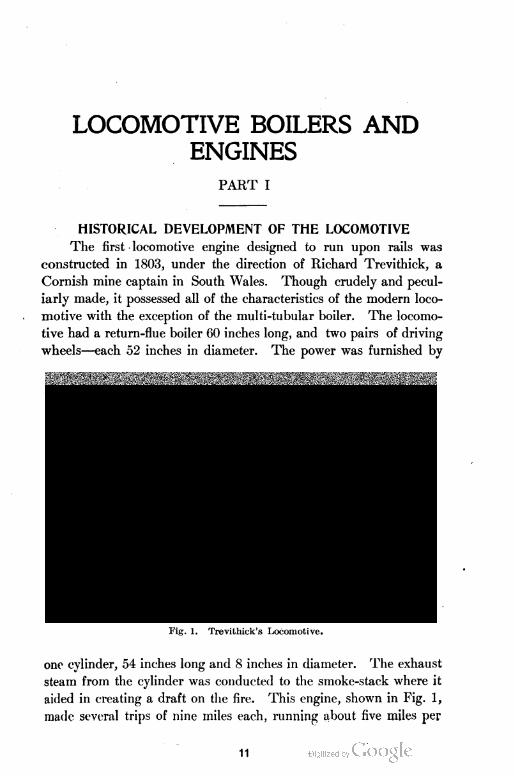
The first locomotive engine designed to run upon rails was
constructed in 1803, under the direction of Richard Trevithick, a
Cornish mine captain in South Wales. Though crudely and pecul
iarly made, it possessed all of the characteristics of the modern loco
motive with the exception of the multi-tubular boiler. The locomo
tive had a return-flue boiler 60 inches long, and two pairs of driving
wheels—each 52 inches in diameter. The power was furnished by
Fig. l. Trevitliick's Locomotive.
one cylinder, 54 inches long and 8 inches in diameter. The exhaust
steam from the cylinder was conducted to the smoke-stack where it
aided in creating a draft on the fire. This engine, shown in Fig. 1,
made several trips of nine miles each, running about five miles per
11
2 LOCOMOTIVE BOILERS AND ENGINES
hour and carrying about two tons. Although the machine was a
commercial failure, yet from a mechanical standpoint, it was a great
success.
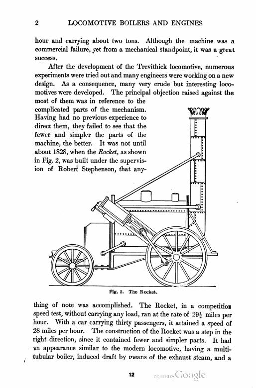
After the development of the Trevithick locomotive, numerous
experiments were tried out and many engineers were working on a new
design. As a consequence, many very crude but interesting loco
motives were developed. The principal objection raised against the
most of them was in reference to the
complicated parts of the mechanism. ^Q[W
Having had no previous experience to J ,. i
direct them, they failed to see that the :
fewer and simpler the parts of the Jj—.
machine, the better. It was not until •
Fig. 2. The Rocket.
thing of note was accomplished. The Rocket, in a competitioa
speed test, without carrying any load, ran at the rate of 29^ miles per
hour. With a car carrying thirty passengers, it attained a speed of
28 miles per hour. The construction of the Rocket was a step in the
right direction, since it contained fewer and simpler parts, It had
an appearance similar to the modern locomotive, having a multi
tubular boiler, induced draft by means of the exhaust steam, and a
12
LOCOMOTIVE BOILERS AND ENGINES 3
direct connection between the piston rod and the crank pin secured
to the driving wheel. The cylinder was inclined and the proportions
were very peculiar as compared with the modern locomotive, yet
much had been gained by this advancement.
While these things were being accomplished in England, the fact
must be noted that agitation in favor of
railroad building in America was being car
ried on with zeal and success. Much of the
machinery for operating the American rail
roads was being designed and built by
American engineers, so it is quite generally
believed that railroad and locomotive build
ing in America would not have been very
much delayed had there never been a Watt
or a Stephenson.
The first railroad opened to general
traffic was the Baltimore & Ohio, which
was chartered in 1827, a portion being
opened for business in 1830. About the
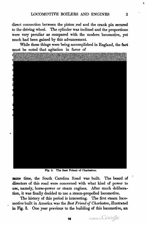
Fig. 3. The Best Friend ol Charleston.
same time, the South Carolina Road was built. The board of
directors of this road were concerned with what kind of power to
use, namely, horse-power or steam engines. After much delibera
tion, it was finally decided to use a steam-propelled locomotive.
The history of this period is interesting. The first steam loco
motive built in America was the Best Friend of Charleston, illustrated
in Fig. 3. One year previous to the building of this locomotive, an
13
4 LOCOMOTIVE BOILERS AND ENGINES
English locomotive called Stourlrridyc hum was imported by the
Delaware-Hudson Canal Co. It was tried near Homesdale. A
celebrated American engineer by the name of Horatio Allen, made a
number of trial trips on this locomotive and pronounced it too heavy
for the American roadbeds and bridges; so it was that the Best
Friend of Charleston, an American locomotive constructed in 1830,
gave the first successful service in America. The Best Friend of
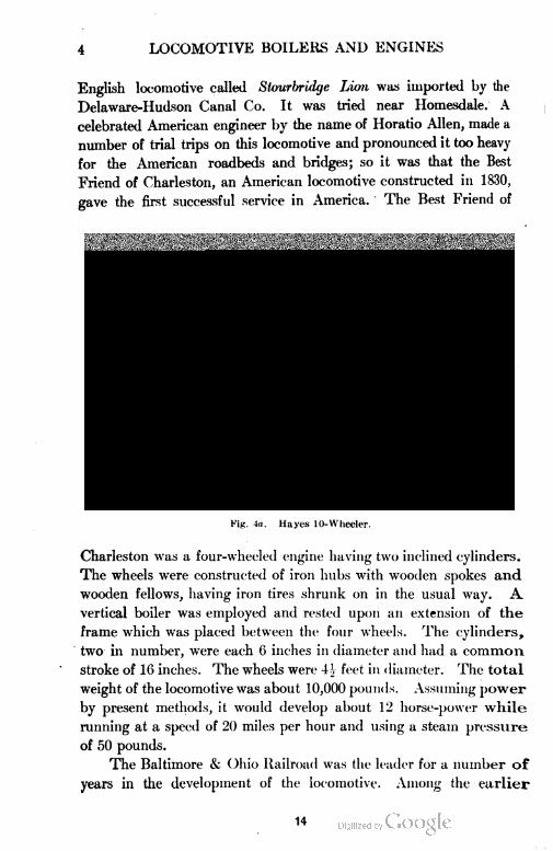
Fig. 4u. Hayes 10-\Vlieeler.
Charleston was a four-wheeled engine having two inclined cylinders.
The wheels were constructed of iron hubs with wooden spokes and
wooden fellows, having iron tires shrunk on in the usual way. A
vertical boiler was employed and rested upon an extension of the
frame which was placed between the four wheels. The cylinders,
two in number, were each 6 inches in diameter and had a common
stroke of 16 inches. The wheels were 4 \ feet in diameter. The total
weight of the locomotive was about 10,000 pounds. Assuming power
by present methods, it would develop about 12 horse-power while
running at a speed of 20 miles per hour and using a steam pressure
of 50 pounds.
The Baltimore & Ohio Railroad was the leader for a number of
years in the development of the locomotive. Among the earlier
14
LOCOMOTIVE BOILERS AND ENGINES 5
designs brought out by this road was an 8-wheeled engine known as
the Camel-Back, so-called from its appearance, and frequently spoken
of as the Winans, as its design was developed in 1844 by Ross Winans,
a prominent locomotive builder of a half century ago.
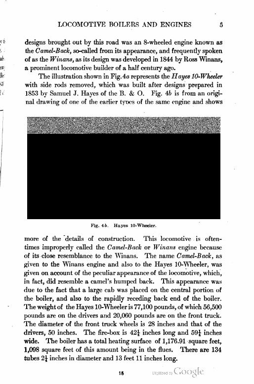
The illustration shown in Fig. 4a represents the Hayes 10-Wheeler
with side rods removed, which was built after designs prepared in
1853 by Samuel J. Hayes of the B. & O. Fig. 4b is from an origi
nal drawing of one of the earlier tyoes of the same engine and shows
Fig. 4 6. Hayes 10-Wheeler.
more of the details of construction. This locomotive is often
times improperly called the Camel-Back or Winans engine because
of its close resemblance to the Winans. The name Camel-Back, as
given to the Winans engine and also to the Hayes lO-WTieeler, was
given on account of the peculiar appearance of the locomotive, which,
in fact, did resemble a camel's humped back. This appearance was
due to the fact that a large cab was placed on the central portion of
the boiler, and also to the rapidly receding back end of the boiler.
The weight of the Hayes 10-Wheeler is 77,100 pounds, of which 56,500
pounds are on the drivers and 20,060 pounds are on the front truck.
The diameter of the front truck wheels is 28 inches and that of the
drivers, 50 inches. The fire-box is 42-£ inches long and 59| inches
wide. The boiler has a total heating surface of 1,176.91 square feet,
1,098 square feet of this amount being in the flues. There are 134
tubes 2\ inches in diameter and 13 feet 11 inches long.
15
6 LOCOMOTIVE BOILERS AND ENGINES
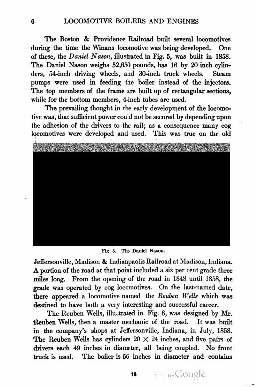
The Boston & Providence Railroad built several locomotives
during the time the Winans locomotive was being developed. One
of these, the Daniel Nason, illustrated in Fig. 5, was built in 1858.
The Daniel Nason weighs 52,650 pounds, has 16 by 20 inch cylin
ders, 54-inch driving wheels, and 30-inch truck wheels. Steam
pumps were used in feeding the boiler instead of the injectors.
The top members of the frame are built up of rectangular sections,
while for the bottom members, 4-inch tubes are used.
The prevailing thought in the early development of the locomo
tive was, that sufficient power could not be secured by depending upon
the adhesion of the drivers to the rail; as a consequence many cog
locomotives were developed and used. This was true on the old
Fig. 5. The Daniel Nason.
Jeffersonville, Madison & Indianpaolis Railroad at Madison, Indiana.
A portion of the road at that point included a six per cent grade three
miles long. From the opening of the road in 1848 until 1858, the
grade was operated by cog locomotives. On the last-named date,
there appeared a locomotive named the Reuben Wells which was
destined to have both a very interesting and successful career.
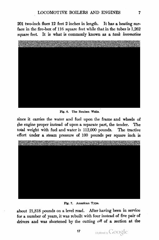
The Reuben Wells, illustrated in Fig. 6, was designed by Mr.
iteuben Wells, then a master mechanic of the road. It was built
in the company's shops at Jeffersonville, Indiana, in July, 1858.
The Reuben Wells has cylinders 20 X 24 inches, and five pairs of
drivers each 49 inches in diameter, all being coupled. No front
truck is used. The boiler is 56 inches in diameter and contains
16
LOCOMOTIVE BOILERS AND ENGINES 7
201 two-inch flues 12 feet 2 inches in length. It has a heating sur
face in the fire-box of 116 square feet while that in the tubes is 1,262
square feet. It is what is commonly known as a tank locomotive
Fig. 6. The Reuben Wells.
since it carries the water and fuel upon the frame and wheels of
the engine proper instead of upon a separate part, the tender. The
total weight with fuel and water is 112,000 pounds. The tractive
effort under a steam pressure of 100 pounds per square inch is
Fig. 7. American Type.
about 21,818 pounds on a level road. After having been in service
for a number of years, it was rebuilt with four instead of five pair of
drivers and was shortened by the cutting off of a section at the
17
8 LOCOMOTIVE BOILERS AND ENGINES
rear which had been used for coal and water. Sufficient water
capacity was provided by placing a tank over the boiler.
The American type locomotive, illustrated in Fig. 7, is typical of
the small sized engines of this construction which are now being
rapidly replaced by other types. For a period of nearly fifty years,
ending about 1895, the American type locomotive was more commonly
used for passenger service than any other type.
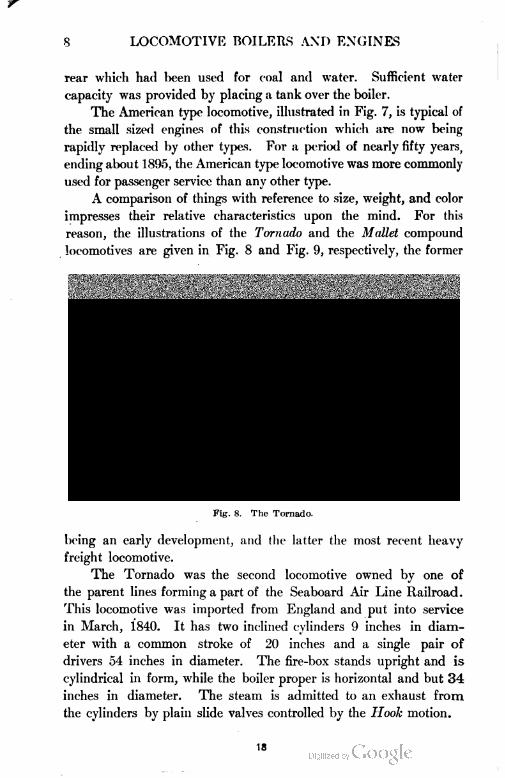
A comparison of things with reference to size, weight, and color
impresses their relative characteristics upon the mind. For this
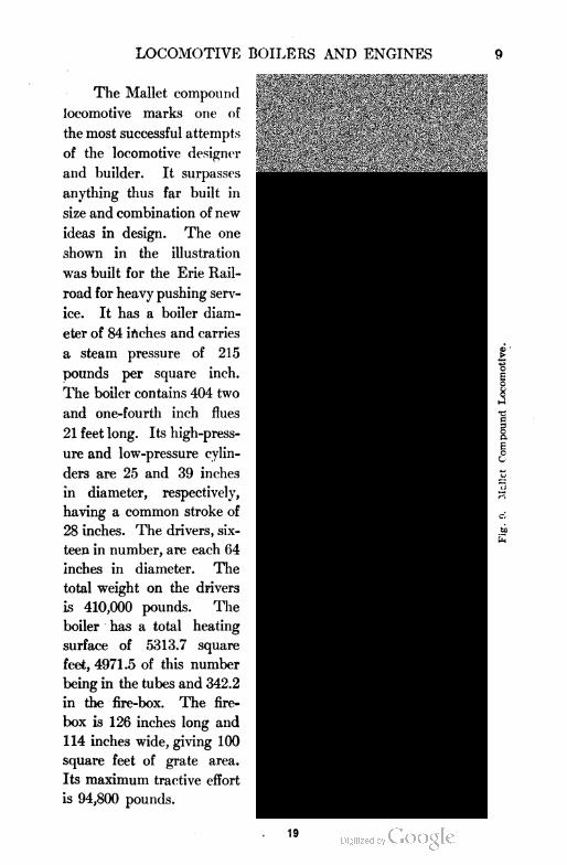
reason, the illustrations of the Tornado and the Mallet compound
locomotives are given in Fig. 8 and Fig. 9, respectively, the former
Kig. 8. The Tornado.
being an early development, and the latter the most recent heavy
freight locomotive.
The Tornado was the second locomotive owned by one of
the parent lines forming a part of the Seaboard Air Line Railroad.
This locomotive was imported from England and put into service
in March, 1840. It has two inclined cylinders 9 inches in diam
eter with a common stroke of 20 inches and a single pair of
drivers 54 inches in diameter. The fire-box stands upright and is
cylindrical in form, while the boiler proper is horizontal and but 34
inches in diameter. The steam is admitted to an exhaust from
the cylinders by plain slide valves controlled by the Hook motion.
18
LOCOMOTIVE BOILERS AND ENGINES 9
The Mallet compound
locomotive marks one of
the most successful attempts
of the locomotive designer
and builder. It surpasses
anything thus far built in
size and combination of new
ideas in design. The one
shown in the illustration
was built for the Erie Rail
road for heavy pushing serv
ice. It has a boiler diam
eter of 84 inches and carries
a steam pressure of 215
pounds per square inch.
The boiler contains 404 two
and one-fourth inch flues
21 feet long. Its high-press
ure and low-pressure cylin
ders are 25 and 39 inches
in diameter, respectively,
having a common stroke of
28 inches. The drivers, six
teen in number, are each 64
inches in diameter. The
total weight on the drivers
is 410,000 pounds. The
boiler has a total heating
surface of 5313.7 square
feet, 4971.5 of this number
being in the tubes and 342.2
in the fire-box. The fire
box is 126 inches long and
114 inches wide, giving 100
square feet of grate area.
Its maximum tractive effort
is 94,800 pounds.
19
10 LOCOMOTIVE BOILERS AND ENGINES
It is of much interest to compare in a general way the develop
ments of the locomotive in England and in America. The types
differ in many respects, as shown in Table I.
TABLE I
♦Comparison of English and American Locomotives
Parts English American
Frames Plate
Inside
Bar
Cylinders Outside
Drivers Not equalized Equalized
Driver Centers Wrought iron Cast iron or steel
Fire-box Copper Steel
Tubes Brass Iron
Cab Small Large
Pilot No Yes
Reverse gear
Boiler
Screw Lever
Small and low Large and high
CLASSIFICATION OF LOCOMOTIVES
In order that a clear understanding may be had of the various
types of locomotives, a classification is given according to wheel ar
rangement. In the Whyte system of classification, which is quite
largely used, each set of trucks and driving wheels is grouped by
number beginning at the pilot or front end of the engine. Thus, 260
means a Mogul, and 460, a 10-wheel engine. The first figure, 2, in
260 denotes that a 2-wheeled truck is used in front; the figure 6, that
there are six coupled divers, three on each side; and the 0, that no
trailing truck is used. This scheme gives both a convenient and easy
method of classifying locomotives.
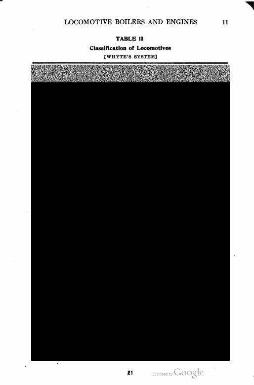
In Table II is given the classification of the locomotives used on
American railroads.
The method may be further extended to include the weights of
locomotives. The total weight is expressed in units of 1,000 pounds.
Thus: A Pacific locomotive weighing 189,000 pounds would be
classified as Type 462—189. If the locomotive is a compound, a
letter C would be used instead of the dash. Thus : Type 462-C-189.
If tanks are used instead of a separate tender, the letter T would be
substituted for the dash. Thus: A tank locomotive having four
driving wheels, a 4-wheel leading truck, and a 4-wheel rear truck,
weighing 114,000 pounds would be classified as Type 444-T-114.
*The comparisons are not strictly true for every case but represent the con
ditions usually found.
20
LOCOMOTIVE BOILERS AND ENGINES 11
TABLE II
Classification of Locomotives
[WHYTE'S SYSTEM]
040 A OO 4 Wheel
060 iOOO 6 Wheel
080 ^0000 8 Wheel
0440 A OO OO Articulated
0660 A OOO OOO Articulated
240 An OO 4 Coupled
260 ^0 OOO Mogul
280 ^0000 Consolidation
2440 An no OO Articulated
2100 An OOOOO Decapod
440 An n OO 8 Wheel
460 An n OOO 10 >•
480 An oOOOO 12 "
042 A OO O 4 Coupled and Trailinq
062 A OOO o 6 » » »
082 A OOOO o 8 >> w "
044 A OO n o Forneu 4 Coupled
064 A OOO o o j< 6 "
046 A OO OOO « 4 "
066 A OOO n o o » 6 a
242 inOO O Columbia
262 JnOOO o Prairie
282 inonnoo 8 Coupled
sioaioOOOOOn 10
244 An OO o o 4
264 inOOO o o 6
284 inOOOO n n 8
246 An DO n n n 4
266 inOOO ooo 6
442 An o OO o Atlantic
462 An n OOO o Pacific
444 An n OO n o 4 Coupled Double Ender
464 An n OOO o o 6 i» i) »
446 An oOO 0 0 0 4 " >• >>
21
12 LOCOMOTTVE BOTLERS AND ENGINES
22
LOCOMOTIVE BOILERS AND ENGINES la
From the classification table given, it s apparent that there are
' a great many different types of locomoti /es in service. Only the
more commonly used types will be discussed, which are as follows:
040, 060, 080, 260, 280, 440, 442, 460, and 462. The types 040, 060,
and 080 are largely used for switching service. The 040 type is of the
smallest proportions and weights, being found in small yards where
only light work is required. The call for heavy duty was met by the
060 type. The fact that the 060 type, being much heavier, has a
greater tractive effort and a correspondingly larger steaming capacity,
has caused them to be used very extensively. The following figures
will aid in giving an idea of their size and capacity:
Weight on drivers (pounds) 145,000 to 170,000
Diameter of cylinders (inches) 19 to 22
Stroke of piston (inches) 24 to 26
Diameter of driving wheels (inches) 50 to 56
Working steam pressure (pounds per square inch). . . 180 to 200
The demand for power, steadily increasing beyond that which
could be secured by locomotives of the 060 type, created a new design
known as the 8-wheel, or 080 type. This type is used in switching
and pushing service and has about 171,000 pounds weight on drivers,
cylinders 21 inches in diameter, stroke 28 inches, drivers 51 inches
in diameter, and carries 175 to 200 pounds steam pressure. The
switching engines of the 060 and 080 type were converted into high-
class freight engines by adding two wheel trucks to each, thus develop
ing the 260, or Mogul, and the 280, or Consolidation types.
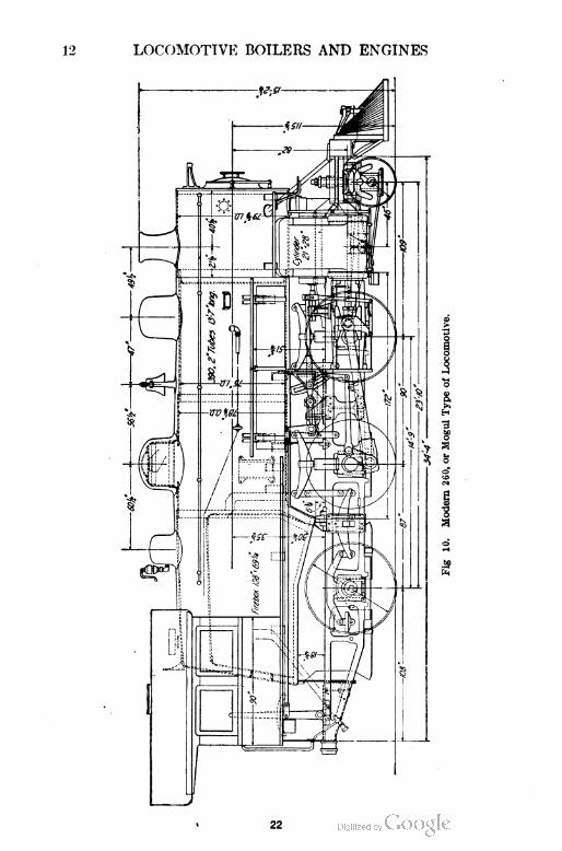
The Mogul was primarily intended for freight service only, but
it is sometimes used in heavy passenger service. The object of the
design was to obtain greater tractive force on driving wheels than is
possible to obtain with four drivers, as in the 440 type. Fig. 10
illustrates a modern 260, or Mogul type, giving its principal dimen
sions. This type was more generally used than any other before the
increasing requirements of heavy freight service resulted in the [de
velopment of the 280, or Consolidation type. It is profitable from
the standpoint of economy in repairs in selecting the type of locomo
tive for any service, to use the minimum number of drive wheels
possible within the limits of the necessary tractive power, although for
freight service involving the handling of heavy trains on steep grades,
the 280,or Consolidation type, is required. Where the requirements are
23
LOCOMOTIVE BOILERS AND ENGINES
LOCOMOTIVE BOILERS AND ENGINES 15
not too severe, however, there is a large field for the Mogul type in
freight service. Where a large axle load is permitted, the Mogul
type may give sufficient hauling capacity to meet ordinary require
ments in freight service on comparatively level roads. While not
generally recommended for what may be called fast freight service,
the 280, or Consolidation type, is sometimes used. Many Mogul
locomotives are successfully handling such trains.
The 260 type provides a two-wheel leading truck with good
guiding qualities and places a large percentage of the total weight on
the driving wheels. A large number of locomotives of this type show
an average of 87J per cent of the total weight of the locomotive on the
drivers. Boilers with sufficient capacity for moderate speed may be
provided in this type; and with relatively small diameters of driving
wheels, it will lend itself readily to wide variations in grates and fire
boxes
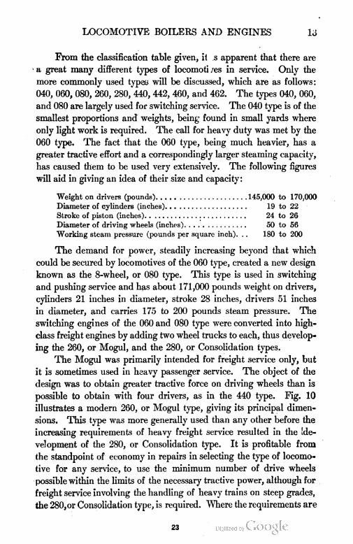
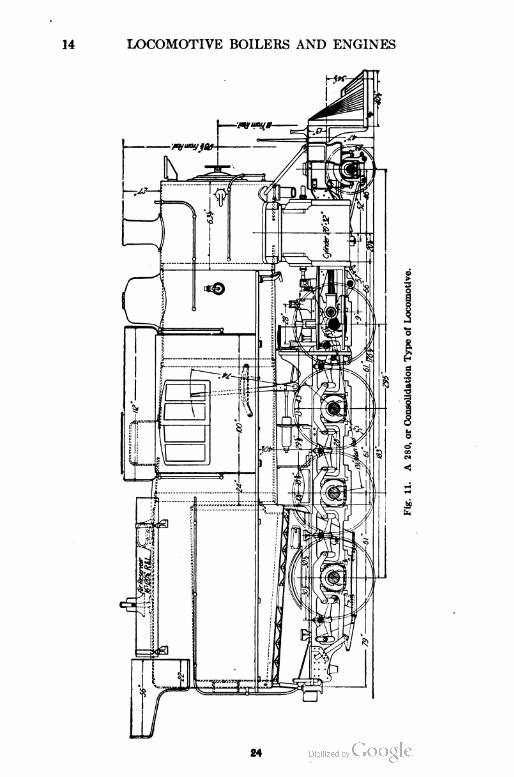
The Consolidation locomotive, or 280 type, shown in Fig. 11,
was designed, as has been mentioned, for hauling heavy trains over
steep grades. It is perhaps more generally used as a high class freight
engine than any other type so far developed. Locomotives of this
type have been designed and built with total weights varying between
150,000 to 300,000 pounds.
The four most prominent types of passenger locomotives, namely,
440, 442, 460, and 462, have each been developed at different times
and in successive order to meet the ever-increasing and changing
demands. The 8-wheel or 440 type, commonly known as the Amer
ican type, was for some time the favorite passenger locomotive, but as
the demands for meeting the conditions of modern fast passenger
service increased, a locomotive of new design was required. The
conditions which were to be met were sustained high speed and
regular service. This did not mean bursts of high speed under
favorable conditions with a light train running as an extra or special
with clear orders, but it meart rather the more exacting requirements
of regular service.
Where regular train service had to be sustained day after day at
a schedule of 50 miles per hour, it required reserve power to meet the
unfavorable conditions of the weather and for an occasional extra
car in the train. For such exacting demands, much steam is required
and ample heating and grate surface must be provided. In the 440
i26
LOCOMOTIVE BOILERS AND ENGINES
LOCOMOTIVE BOILERS AND ENGINES
27
IS LOCOMOTIVE BOILERS AND ENGINES
type with a 4-wheel leading truck and four driving wheels without a
trailing truck, the boiler capacity is limited. Not only is the heating
surface also limited but the grate area as well, because the grates
must be placed between the driving wheels. The desirability of
larger boilers and wider grates than the distance between the wheels
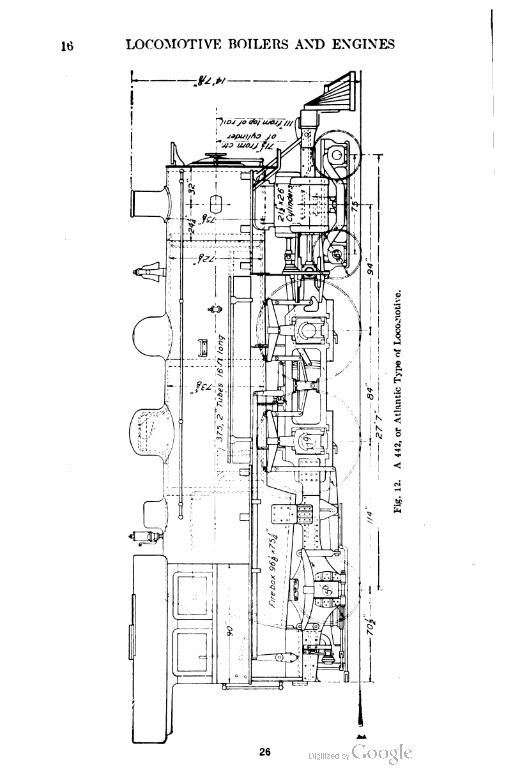
in the 440 type will permit, led to a ready acceptance of the 442, or
Atlantic type locomotive, as shown in Fig. 12. The 442 type com
bines a 4-wheel leading truck, providing good guiding qualities, and
four coupled driving wheels having a starting capacity sufficient for
trains of moderate weight, and a trailing truck. The use of the
trailing truck permits the extension of the grates beyond the
driving wheels thus obtaining a much larger grate area. This wheel
arrangement also permits the use of a deep as well as a wide fire-box
which is especially advantageous in the burning of bituminous coal.
It also gives a much greater depth at the front or throat of the fire-box,
which is very important.
As modern passenger service increased and heavier trains had
to be drawn, four driving wheels would not give sufficient starting
power. Because of the heating surface and grate area being limited
by the same factors as mentioned in the 440 type, another type, the
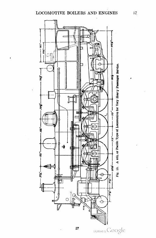
462, or Pacific type, came into favor. As this type was called upon
to pull the heaviest passenger trains, much power was required even
under very favorable conditions. For such trains, a locomotive
having a combination of large cylinders, heavy tractive weight, and
large boiler capacity is required. The Pacific type meets these
requirements in a very successful way. From a study of Fig. 13,
which illustrates such a locomotive, it is obvious that the 462 type
differs from the general design of the Atlantic type only in the
addition of another pair of driving wheels. This, however, makes
possible a much heavier boiler; therefore, more heating surface,
more grate area, and greater tractive weight are obtained. Grate areas
of from 40 to 50 square feet are possible in this type which provides
for the large fuel consumption that is required for the rather severe
service. The heating surface is of equal importance since large
cylinders require large steaming capacity. The 402 type meets this
need also. A comparison of passenger locomotives shows that the
Pacific type has more heating surface for a given total weight than is
found in any other type of passenger locomotive.
28
20 LOCOMOTIVE BOILERS AND ENGINES
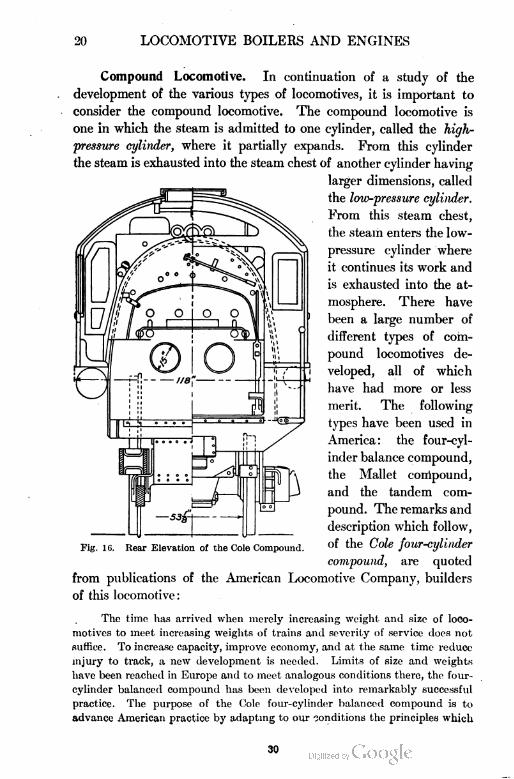
Compound Locomotive. In continuation of a study of the
development of the various types of locomotives, it is important to
consider the compound locomotive. The compound locomotive is
one in which the steam is admitted to one cylinder, called the high-
pressure cylinder, where it partially expands. From this cylinder
the steam is exhausted into the steam chest of another cylinder having
larger dimensions, called
the low-pressure cylinder.
From this steam chest,
the steam enters the low-
pressure cylinder where
it continues its work and
is exhausted into the at
mosphere. There have
been a large number of
different types of com
pound locomotives de
veloped, all of which
have had more or less
merit. The following
types have been used in
America : the four-cyl
inder balance compound,
the Mallet compound,
and the tandem com
pound. The remarks and
description which follow,
of the Cole four-cylinder
compound, are quoted
from publications of the American Locomotive Company, builders
of this locomotive:
The time has arrived when merely increasing weight and size of loco
motives to meet increasing weights of trains and severity of service does not
suffice. To increase capacity, improve economy, and at the same time reduce
injury to track, a new development is needed. Limits of size and weights
have been reached in Europe and to meet analogous conditions there, the four-
cylinder balanced compound has been developed into remarkably successful
practice. The purpose of the Cole four-cylinder balanced compound is to
advance American practice by adapting to our conditions the principles which
Fig. 16. Rear Elevation of the Cole Compound.
30
LOCOMOTIVE BOILERS AND ENGINES 21
have brought such advantageous results abroad, especially the principles of
the de Glehn compound.
The Cole four-cylinder balanced compound employs the principle of
subdivided power to the cylinders; the high pressure (between the frames)
drives the forward or crank axle and the others; the low pressure (outside of
the frames) drives the second driving axle. In order to secure a good length
for connecting rods without lengthening the boiler, the high-pressure cylinders
are located in advance of their usual position.
Special stress is laid on perfect balancing and the elimination of the
usual unbalanced vertical component of the counterbalance stresses as a
means for increasing the
capacity, improving econ
omy of operation and main
tenance, and promoting
good conditions of the track.
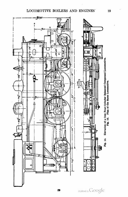
The relative positions
of the high-pressure cylinder
A and the low-pressure cylin
der B may be seen in Fig. 14
and Fig. 15. The high-pres
sure guides, Fig. 15, are
located under and attach to
the low-pressure saddle,
whereas the low-pressure
guides are in the usual loca
tion outside of the frames
The cranks of the driving
wheels are 180 degrees apart.
In order to equalize the
weights of the pistons, those
of the high-pressure cylin
ders are solid and those of
the low-pressure cylinders
are dished, and made as light
as possible. A single valve
motion, of the Stephenson
type, operates a single valve
stem on each side of the engine. Each valve stem carries two piston valves,
one for the high- and the other for the low-pressure cylinder, as illustrated
and explained later.
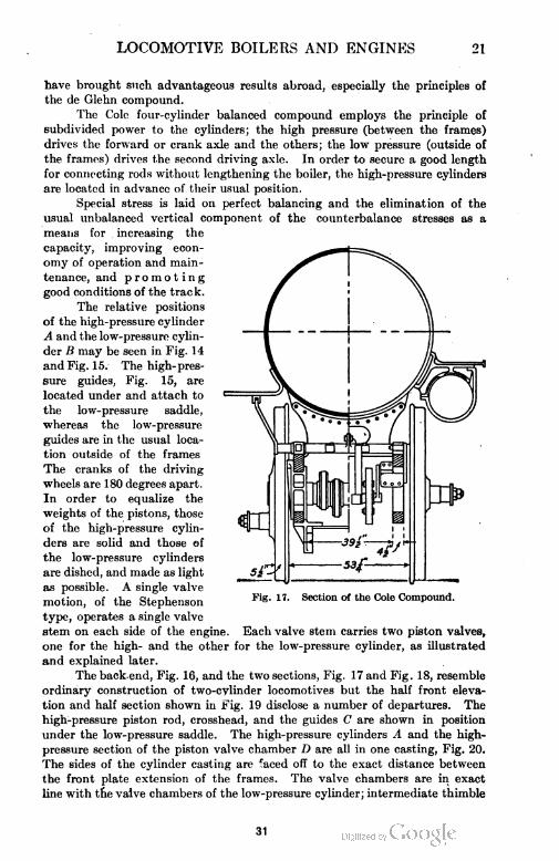
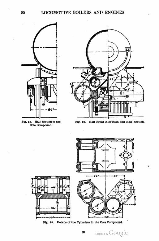
The back.end, Fig. 16, and the two sections, Fig. 17 and Fig. 18, resemble
ordinary construction of two-cylinder locomotives but the half front eleva
tion and half section shown in Fig. 19 disclose a number of departures. The
high-pressure piston rod, crosshead, and the guides C are shown in position
under the low-pressure saddle. The high-pressure cylinders A and the high-
pressure section of the piston valve chamber D are all in one casting, Fig. 20.
The sides of the cylinder casting are faced off to the exact distance between
the front plate extension of the frames. The valve chambers are in exact
line with the valve chambers of the low-pressure cylinder; intermediate thimble
Section ot the Cole Compound.
31
22 LOCOMOTIVE BOILERS AND ENGINES
LOCOMOTIVE BOILERS AND ENGINES 23
21 LOCOMOTIVE BOILERS AND ENGINES
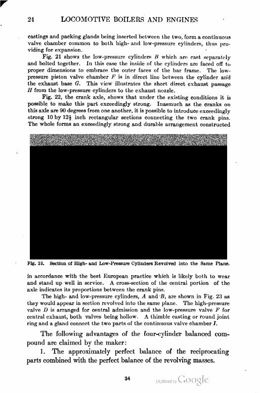
castings and packing glands being inserted between the two, form a continuous
valve chamber common to both high- and low-pressure cylinders, thus pro
viding for expansion.
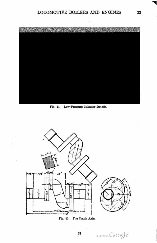
Fig. 21 shows the low-pressure cylinders B which are cast separately
and bolted together. In this case the inside of the cylinders are faced off to
proper dimensions to embrace the outer faces of the bar frame. The low-
pressure piston valve chamber F is in direct line between the cylinder arid
the exhaust base G. This view illustrates the short direct exhaust passage
H from the low-pressure cylinders to the exhaust nozzle.
Fig. 22, the crank axle, shows that under the existing conditions it is
possible to make this part exceedingly strong. Inasmuch as the cranks on
this axle are 90 degrees from one another, it is possible to introduce exceedingly
strong 10 by 12£ inch rectangular sections connecting the two crank pins.
The whole forms an exceedingly strong and durable arrangement constructed
Fig. 23. Section of High- and Low-Pressure Cylinders Revolved into the Same Plane.
in accordance with the best European practice which is likely both to wear
and stand up well in service. A cross-section of the central portion of the
axle indicates its proportions between the crank pins.
The high- and low-pressure cylinders, A and B, are shown in Fig. 23 as
they would appear in section revolved into the same plane. The high-pressure
valve D is arranged for central admission and the low-pressure valve F for
central exhaust, both valves being hollow. A thimble casting or round joint
ring and a gland connect the two parts of the continuous valve chamber /.
The following advantages of the four-cylinder balanced com
pound are claimed by the maker:
1. The approximately perfect balance of the reciprocating
parts combined with the perfect balance of the revolving masses.
34
35
26 LOCOMOTIVE BOILERS AND ENGINES
2. The permissible increase of weight on the driving wheels
on account of the complete elimination of the hammer blow.
3. An increase in sustained horse-power at high speeds without
modification of the boiler.
4. Economy of fuel and water.
5. The subdivision of power between the four cylinders and
between the two axles, and the reduction of bending stress on the
crank axle due to piston thrust because of this division of power.
6. The advantage of
light moving parts which
render them easily
handled and which will
minimize wear and re
pairs.
7. Simplicity of de
sign One set of valve
gears with comparatively
few parts when compar
ed with other designs
which have duplicate sets
of value gears for similar
locomotives.
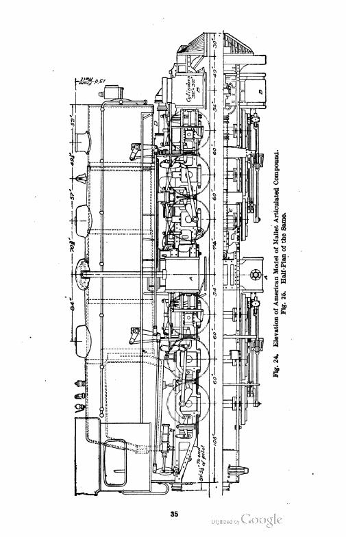
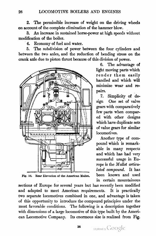
Another type of com
pound which is remark
able in many respects
and which has had very
successful usage in Eu
rope is the Mallet articu
lated compound. It has
been known and used
in certain mountainous
sections of Europe for several years but has recently been modified
and adapted to meet American requirements. It is practically
two separate locomotives combined in one, and advantage is taken
of this opportunity to introduce the compound principles under the
most favorable conditions. The following is a description together
with dimensions of a large locomotive of this type built by the Ameri
can Locomotive Company. Its enormous size is realized from Fig.
Fig. 26. Bear Elevation of the American Mallet.
36
LOCOMOTIVE BOILERS AND ENGINES 27
24 -and Fig. 25. The weight of this particular locomotive in working
order is nearly 335,000 pounds and the flues are 21 feet long. The
rear three pairs of drivers are carried in frames rigidly attached to
the boiler. To these frames, and to the boiler as well, are attached the
high-pressure cylinders. The forward three pairs of drivers, how
ever, are carried in frames which are not rigidly connected to the
barrel of the boiler but which are in fact a truck. This truck swivels
radially from a center
pin located in advance
of the high-pressure
cylinder saddles. The
weight of the forward
end of the boiler is
transmitted to the for
ward truck through
the medium of side
bearings, illustrated in
Fig. 24, between the
second and third pair
of drivers. In order to
secure the proper dis
tribution of weight,
the back ends of the
front frames are con
nected by vertical bolts
with the front ends of
the rear frames.
These bolts are so
arranged that they
have a universal mo
tion, top and bottom, which permits of a certain amount of play
between the front and rear frames when the locomotive is rounding
a curve. The low-pressure cylinders are attached to the forward
truck frames. <
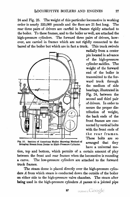
The steam dome is placed directly over the high-pressure cylin
ders A from which steam is conducted down the outside of the boiler
on either side to the high-pressure valve chamber. The steam after
being used in the high-pressure cylinders A passes to a jointed pipe
Fig, 27. Section ol American Mallet Showing Method of
Bringing Steam from Dome to High-Pressure Cylinder.
37
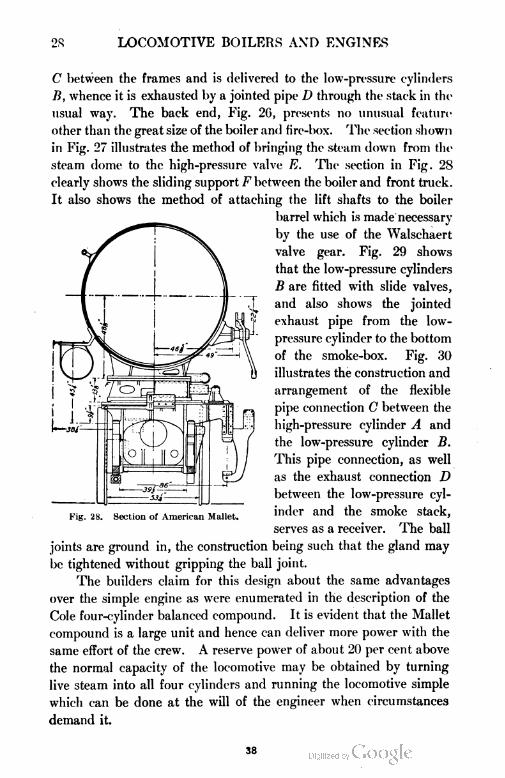
2S LOCOMOTIVE BOILERS AND ENGINES
C between the frames and is delivered to the low-pressure cylinders
B, whence it is exhausted by a jointed pipe D through the stack in the
usual way. The back end, Fig. 20, presents no unusual feature
other than the great size of the boiler and fire-box. The section shown
in Fig. 27 illustrates the method of bringing the steam down from the
steam dome to the high-pressure valve E. The section in Fig. 28
clearly shows the sliding support F between the boiler and front truck.
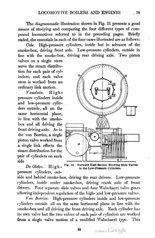
It also shows the method of attaching the lift shafts to the boiler
barrel which is made necessary
by the use of the Walschaert
valve gear. Fig. 29 shows
that the low-pressure cylinders
B are fitted with slide valves,
and also shows the jointed
exhaust pipe from the low-
pressure cylinder to the bottom
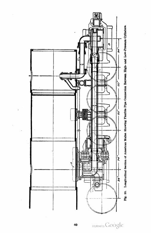
of the smoke-box. Fig. 30
illustrates the construction and
arrangement of the flexible
pipe connection C between the
high-pressure cylinder A and
the low-pressure cylinder B.
This pipe connection, as well
as the exhaust connection D
between the low-pressure cyl
inder and the smoke stack,
serves as a receiver. The ball
joints are ground in, the construction being such that the gland may
be tightened without gripping the ball joint.
The builders claim for this design about the same advantages
over the simple engine as were enumerated in the description of the
Cole four-cylinder balanced compound. It is evident that the Mallet
compound is a large unit and hence can deliver more power with the
same effort of the crew. A reserve power of about 20 per cent above
the normal capacity of the locomotive may be obtained by turning
live steam into all four cylinders and running the locomotive simple
which can be done at the will of the engineer when circumstances
demand it.
Fig. 28. Section of American Mallet.
38
LOCOMOTIVE BOILERS AND ENGINES . 29
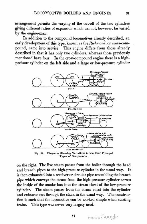
The diagrammatic illustration shown in Fig. 31 presents a good
means of studying and comparing the four different types of com
pound locomotives referred to in the preceding pages. Briefly
stated, the essentials in each of the four cases illustrated are as follows :
Cole. High-pressure cylinders, inside but in advance of the
smoke-box, driving front axle. Low-pressure cylinders, outside in
line with the smoke-box, driving rear driving axle. Two piston
valves on a single stem
serve the steam distribu
tion for each pair of cyl
inders, and each valve
stem is worked from an
ordinary link motion.
Vauclain. High-
pressure cylinders inside
and low-pressure cylin
ders outside, all on. the
same horizontal plane,
in line with the smoke-
box and all driving the
front driving axle. As in
the von Borries, a single
piston valve worked from
a single link effects the
steam distribution for the
pair of cylinders on each
side
DeGlehn. High-
pressure cylinders, out
side and behind smoke-box, driving the rear drivers. Low-pressure
cylinders, inside under smoke-box, driving crank axle of front
drivers. Four separate slide valves and four Walschaert valve gears
allowing independent regulation of the high- and low-pressure valves.
Von Borries. High-pressure cylinders inside and low-pressure
cylinders outside all on the same horizontal plane in line with the
sinoke-box and all driving the front driving axle. Each cylinder has
its own valve but the two valves of each pair of cylinders are worked
from a single valve motion of a modified Walschaert type. This
Fig. 29. Forward Hall-Section Showing Slide Valves
in the Low-Pressure Cylinders.
39
40
LOCOMOTIVE BOILERS AND ENGINES 31
arrangement permits the varying of the cut-off of the two cylinders
giving different ratios of expansion which cannot, however, be varied
by the engine-man.
In addition to the compound locomotives already described, an
early development of this type, known as the Richmond, or cross-com
pound, came into service. This engine differs from those already
described in that it has only two cylinders, whereas those previously
mentioned have four. In the cross-compound engine there is a high-
pressure cylinder on the left side and a large or low-pressure cylinder
Tandem Piston
VON BORRIES.
Fig. 31. Diagrams Showing Variations in the Four Principal
Types of Compounds.
on the right. The live steam passes from the boiler through the head
and branch pipes to the high-pressure cylinder in the usual way. It
is then exhausted into a receiver or circular pipe resembling the branch
pipe which conveys the steam from the high-pressure cylinder across
the inside of the smoke-box into the steam chest of the low-pressure
cylinder. The steam passes from the steam chest into the cylinder
and exhausts out through the stack in the usual way. The construc
tion is such that the locomotive can be worked simple when starting
trains. This type was never very largely used.
41
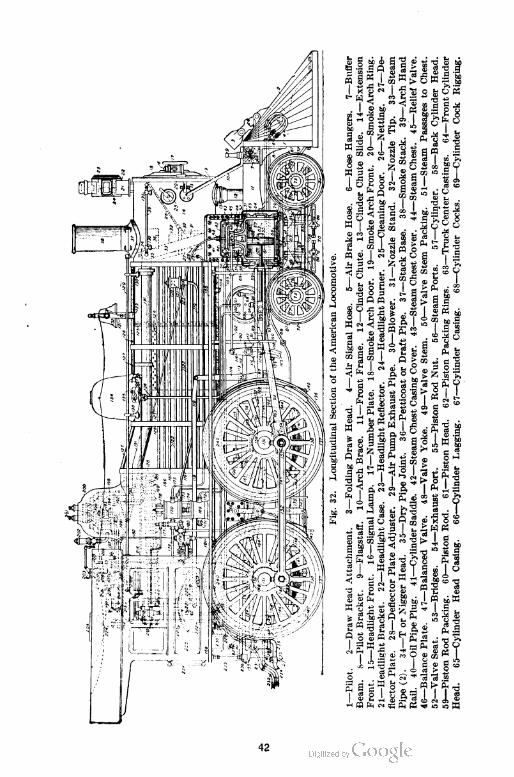
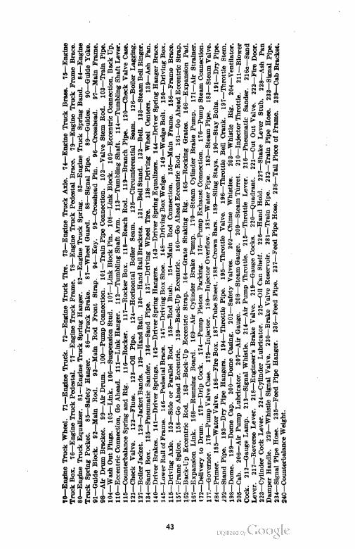
Fig.32.LongitudinalSectionoftheAmericanLocomotive.
1—Pilot.2—DrawHeadAttachment.3—FoldingDrawHead.4—AirSignalHose.5—AirBrakeHose.6—HoseHangers.7—Buffer Beam.8—PilotBracket.9—Flagstaff.10—ArchBrace.11—FrontFrame.12—CinderChute.13—CinderChuteSlide.14—Extension Front.15—HeadlightFront.16—SignalLamp.17—NumberPlate.18—SmokeArchDoor.19—SmokeArchFront.20—SmokeArchRing. 21—HeadlightBracket.22—HeadlightCase.23—HeadlightReflector.24—HeadlightBurner.25—CleaningDoor.26—Netting.27—De flectorPlate.28—DeflectorPlateAdjuster.29—AirPumpExhaustPipe.30—Blower.31—NozzleStand.32—NozzleTip.33—Steam Pipe(2).34—TorNiggerHead.35—DryPipeJoint.36—PetticoatorDraftPipe.37—StackBase.38—Smokestack.39—ArchHand Rail.40—OilPipePlug.41—CylinderSaddle.42—SteamChestCasingCover.43—SteamChestCover.44—SteamChest.45—ReliefValve. 46—BalancePlate.47—BalancedValve.48—ValveYoke.49—ValveStem.50—ValveStemPacking.51—SteamPassagestoChest. 52—ValveSeat.53—Bridges.54—ExhaustPort.55—PistonRodNut.56—SteamPorts.57—Cylinder.58—BackCylinderHead.59—PistonRodPacking.60—PistonRod.61—PistonHead.62—PistonPackingRings.63—TruckCenterCastings.64—FrontCylinder
Head.65—CylinderHeadCasing.66—CylinderLagging.67—CylinderCasing.68—CylinderCocks.69—CylinderCockRigging.
43
44
LOCOMOTIVE BOILERS AND ENGINES 35
ACTION OF STEAM IN OPERATING LOCOMOTIVE
General Course of Steam. One of the most important fea
tures in locomotive operation is the action of the steam in trans
mitting the heat energy liberated in the fire-box to the driving
wheels in the form of mechanical energy. It is therefore important
that we should have a clear understanding, in the beginning, of
the various changes which occur while the steam is passing from
the boiler to the atmosphere in performing its different functions.
In making this study it will prove of much assistance if reference
is made to Fig. 32.
Before this is done, however, a brief statement of the charac
teristics of steam and the precautions which must be taken as the
steam passes through the cylinder may not be out of place. At
normal pressure water boils at 212°F., but with an increase of pres
sure the boiling temperature and the consequent temperature of
the steam rises. Now if the steam formed at 212° F. and atmos
pheric pressure were passed into the cool steam chest and later
into the cylinder, it would become cooled below 212°F., would
condense, and would therefore lose its power. To avoid this possi
bility, the steam is generated in the boiler at a high pressure so
that, when allowed to expand into the cylinder and lose some of
its energy by virtue of the work it has done on the piston, the
temperature is still above the condensation temperature for the
pressure under which it is acting.
With this in mind let us follow the steam in its path and note
the changes to which it is subject and the direct results of its
action. When the throttle is opened the steam, which is generated
in the boiler and there held at high pressure, enters the dry pipe at
a point near the top of the dome and flows forward to the smoke-
box, where it enters the T-head and is conducted downward on
either side into the steam chest and ultimately through the
cylinders and out through the exhaust to the atmosphere.
Steam Enters Steam Chest. At the very outset when the
throttle valve is opened and steam enters the dry pipe, a change
takes place. This change is a loss in pressure; for when the steam
reaches the steam chest its pressure is reduced several pounds per
square inch, as evidenced by gages placed on the boiler and steam
45
36 LOCOMOTIVE BOILERS AND ENGINES
chest or by steam chest diagrams taken simultaneously with the
regular cylinder diagrams. This pressure drop would not appear
were it not for the fact that the locomotive is set into motion at
the opening of the throttle. Consequently, motion is transmitted
to the steam in the various pipes and passages, and the frictional
resistance offered retards its flow, with the result that a pressure
less than that in the boiler is maintained. The exact amount of
this pressure drop depends upon the throttle opening and the rate
at which steam is drawn off. This latter feature is a function of
the engine speed, which in a measure depends upon the opening
of the throttle. Under all conditions, so long as the locomotive
is in motion, the pressure in the steam chest will be less than that
in the boiler.
Steam Enters Cylinder. The steam, after reaching the steam
chest, is admitted alternately to first one end of the cylinder then
the other through the action of the valve. The opening and clos
ing of the valve is a continuous process, the amount of opening
increasing from zero to a maximum and then decreasing to zero.
Because of this fact there will be two periods of wire drawing
during each admission, independent of the fact that there may or
may not be wire drawing during the period of maximum opening.
This action causes a further drop in pressure when the steam
finally gets into the cylinder, which loss increases with the speed
of the engine.
Steam in Cylinder. After the steam reaches the cylinder it
experiences a still further loss caused by condensation due to the
comparatively cool cylinder walls, heads, and piston. This loss
can be minimized to a limited extent by the use of an efficient
lagging but it can never be entirely eliminated. Even if there
were no loss in the cylinder due to radiation, there still would be a
loss because of the exhaust, which occurs at a temperature much
lower than that of the entering steam and which would cool the
cylinder walls and parts to at least the average temperature of
the steam in the cylinder during the stroke.
When the steam expands in the cylinder in the performance
of its work still another drop in pressure occurs, the amount
depending upon the point of cut-off. As this can be varied at the
will of the operator, it can be seen that the pressure drop can be
46
LOCOMOTIVE BOILERS AND ENGINES 37
very great or very small. During this portion of its travel the
steam does its first useful work since leaving the boiler. The
steam while in the steam chest exerts a pressure on the valve
which causes friction and thereby absorbs a portion of the useful
work generated by the action of the steam on the piston.
The steam acting on the piston and causing it to move pro
duces rotation of the driving wheels through the medium of the
connecting rod, crank-pin, and various other parts, with an effort
which varies throughout the stroke owing to the expansion of the
steam, the exhaust and compression, which is taking place on the
opposite side of the piston, and the angularity of the connecting
rod. The pressure on the guides, due to the angularity of the
connecting rod, causes friction which reduces the effectiveness of
the work done on the piston. The effect of the inertia of the
parts at high rotative speeds affects the thrust on the crank-pin
to a marked degree. These points and many others which might
be mentioned are of much importance in the study of the locomo
tive and its ability to do useful work in hauling trains.
Steam after Leaving Cylinder. The steam having pushed
the piston to the end of its stroke is exhausted on the return
stroke, but at a slight back pressure, which opposes the effective
ness of the return stroke and results in a direct loss. The closing
of the valve before the completion of the return stroke causes an
additional resistance in compressing the steam remaining in the
cylinder, but this is not without some advantage. The steam in
being exhausted from the cylinder is discharged into the exhaust
cavity in the cylinder and from thence into the exhaust passage in
the cylinder saddle and out through the exhaust nozzle into the
smoke-box. At this point the steam is very much reduced in
pressure but, owing to its relatively high velocity, as it leaves
the exhaust nozzle and enters the stack, it is still able to do
useful work by producing a slight vacuum in the smoke-box in
an ejector-like action. The useful work performed is not in the
way of moving the machine but in increasing the rate of combus
tion in the fire-box. The action is such as to cause a rate
of combustion unequaled in any other form of steam power plant
with the exception, perhaps, of the steam fire engine which a few
years ago was so popular.
47
38 LOCOMOTIVE BOILERS AND ENGINES
LOCOMOTIVE BOILERS
Before entering into the details of the various elements com
prising a locomotive, it is thought advisable to give them some
study in order to become familiar with the names of the various
parts and their relation to each other. Fig. 32 is given for this pur
pose and represents a longitudinal section of a 440 type locomotive
with all parts numbered and named. This figure should be carefully
studied in order that the future work of the text may be clearly under
stood.
A locomotive boiler may be defined as a steel shell containing
water which is converted into steam, by the heat of the fire in the fire
box, to furnish energy to move the locomotive.
Locomotive boilers are of the internal fire-box, straight fire-tube
type having a cylindrical shell containing the flues and an enlarged
back-end for the fire-box, and an extension front-end or smoke-
box leading out from which is the stack.
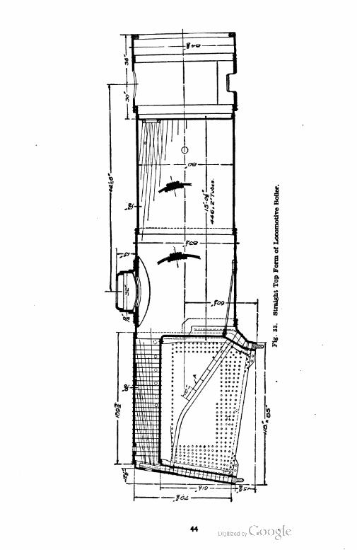
Classification of Boilers as to Form. Locomotive boilers are
classified as to form as follows:
Straight top, Fig. 33, which has a cylindrical shell of uniform diameter
from the fire-box to the smoke-box.
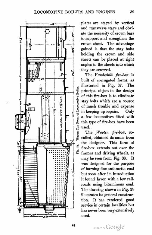
Wagon top, Fig. 34, which has a conical or sloping course of plates next
to the fire-box and tapering down to the circular courses.
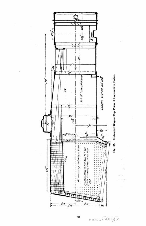
Extended wagon top, Fig. 35, which has one or more circular courses be
tween the fire-box and the sloping courses which taper to the diameter of the
main shell.
Classification of Boilers as to Fire=Box Used. Boilers are fre
quently referred to also and designated by the type of fire-box con
tained, such as Belpaire, Woolen, and Vanderbilt. This designation
does not in any way conflict with the classification of different types
of boilers already given but refers to the general character of the fire
box; that is, the boiler may be classified as a straight top boiler and at
the same time a Wooten fire-box. Since this is true it is necessary
to know the distinction between the Belpaire, the Wooten, and the
Vanderbilt types of fire-box.
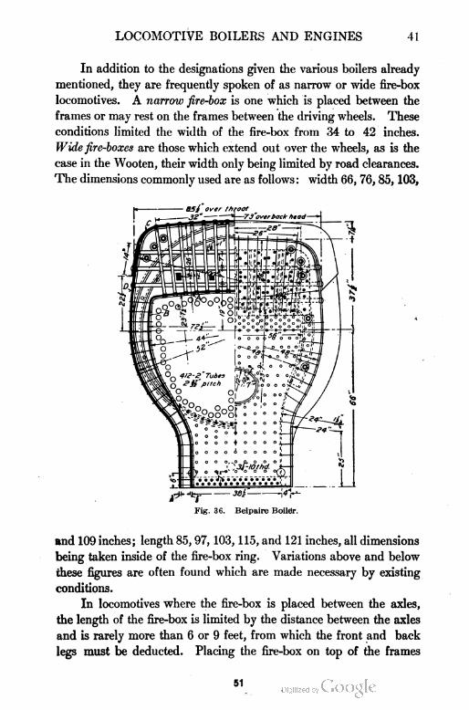
The Belpaire boiler, as illustrated in Fig. 36, has a fire-box with
a flat crown sheet A jointed to(the side sheets B by a curve of short
radius. The outside sheet C and the upper part of the outside sheets
D are flat and parallel to those of the fire-box. These flat DaraUal
48
LOCOMOTIVE BOILERS AND ENGINES 39
plates are stayed by vertical
and transverse stays and obvi
ate the necessity of crown bars
to support and strengthen the
crown sheet. The advantage
gained is that the stay bolts
holding the crown and side
sheets can be placed at right
angles to the sheets into which
they are screwed.
The Vanderbilt fire-box is
built of corrugated forms, as
illustrated in Fig. 37. The
principal object in the design
of this fire-box is to eliminate
stay bolts which are a source
of much trouble and expense
in keeping up repairs. Only
a few locomotives fitted with
this type of fire-box have been
used. .
The Woolen fire-box, so-
called, obtained its name from
the designer. This form of
fire-box extends out over the
frames and driving wheels, as
may be seen from Fig. 38. It
was designed for the purpose
of burning fine anthracite coal
but soon after its introduction
it found favor with a few rail
roads using bituminous coal.
The drawing shown in Fig. 39
illustrates its general construc
tion. It has rendered good
service in certain localities but
has never been very extensively
used.
49
50
LOCOMOTIVE BOILERS AND ENGINES 41
In addition to the designations given the various boilers already
mentioned, they are frequently spoken of as narrow or wide fire-box
locomotives. A narrow fire-box is one which is placed between the
frames or may rest on the frames between the driving wheels. These
conditions limited the width of the fire-box from 34 to 42 inches.
Wide fire-boxes are those which extend out over the wheels, as is the
case in the Wooten, their width only being limited by road clearances.
The dimensions commonly used are as follows : width 66, 76, 85, 103,
Fig. 36. Belpaire Boiler.
and 109 inches; length 85, 97, 103, 115, and 121 inches, all dimensions
being taken inside of the fire-box ring. Variations above and below
these figures are often found which are made necessary by existing
conditions.
In locomotives where the fire-box is placed between the axles,
the length of the fire-box is limited by the distance between the axles
and is rarely more than 6 or 9 feet, from which the front and back
legs must be deducted. Placing the fire-box on top of the frames
91

52
LOCOMOTIVE BOILERS AND ENGINES 43
makes any length possible, the length being governed by the capa
bility of the fireman to throw the coal to the front end of the fire-box.
Flues. From the sectional view of the boiler illustrated in Fig.
32 and Fig. 44, it is evident that a large part of the boiler is composed
of flues or tubes. The flues give to the boiler the largest part of its
heating surface. It is the flues which largely affect the life of the
boiler and, therefore, the life of the locomotive, for this reason it is
quite necessary to properly install and maintain them. A targe
amount of the repair costs is directly traceable to the flues. This is
especially true in localities where water is found which causes scale
to form on the flues from to \ inch in thickness, thus causing
unequal expansion and contraction and overheating. These condi-
Pig. 38. Engine with Wooten Fire-Box.
tions cause the joints to break at the flue sheets. Cold air entering the
fire-box door is another source of flue trouble. It is to these details
that careful attention must be given in order to alleviate flue failures.
Flues should be made of the best quality of charcoal iron, lap-welded,
and subjected to severe tests before being used. They must be ac
curately made, perfectly round and smooth, must fill standard gauges
perfectly, must be free from defects such as cracks, blisters, pits,welds,
etc., and must be uniform in thickness throughout except at the weld
where Tihr of an inch additional thickness may be allowed. The
present practice is to use tubes of from 2 to 2\ inches in diameter.
They vary in length from about 15 to 20 feet, the length depending on
the construction of the boiler and locomotive as a whole. The tubes
53

54
LOCOMOTIVE BOILERS AND ENGINES 45
are supported at each end by letting them extend through the tube
sheets. It is in the setting of the tubes that great care should be
exercised. The tube sheets must be carefully aligned and the hole
drilled through and reamed. These holes are usually made .j^
of an inch larger in diameter than the outside diameter of the tubes.
The tubes should be made not less than \ nor more than f inch
longer than the gauge distance over the front and back flue sheets.
All back ends of tubes should be turned and beaded, and at least
ten per cent of those in the front end. The number of tubes used
varies according to the type and size of the locomotive but usually
from 300 to 500 are employed. The flue sheets are made thicker
than the other sheets of the boiler in order to give as wide a bearing
surface for the tubes as possible. They are usually ■§ inch thick.
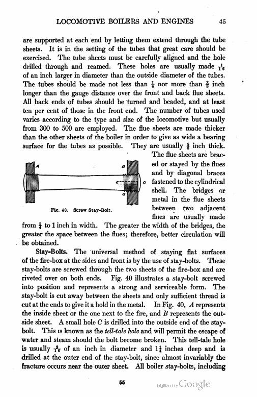
The flue sheets are brac
ed or stayed by the flues
and by diagonal braces
c fastened to the cylindrical
shell. The bridges or
metal in the flue sheets
Fig. 40. screw stay-Bolt. between two adjacent
flues are usually made
from f to 1 inch in width. The greater the width of the bridges, the
greater the space between the flues; therefore, better circulation will
be obtained.
Stay=Bolts. The universal method of staying flat surfaces
of the fire-box at the sides and front is by the use of stay-bolts. These
stay-bolts are screwed through the two sheets of the fire-box and are
riveted over on both ends. Fig. 40 illustrates a stay-bolt screwed
into position and represents a strong and serviceable form. The
stay-bolt is cut away between the sheets and only sufficient thread is
cut at the ends to give it a hold in the metal. In Fig. 40, A represents
the inside sheet or the one next to the fire, and B represents the out
side sheet. A small hole C is drilled into the outside end of the stay-
bolt. This is known as the tell-tale hole and will permit the escape of
water and steam should the bolt become broken. This tell-tale hole
is usually of an inch in diameter and 1^ inches deep and is
drilled at the outer end of the stay-bolt, since almost invariably the
fracture occurs near the outer sheet. All boiler stay-bolts, including
65
46 LOCOMOTIVE BOILERS AND ENGINES
radial stays, have 12 Whitworth standard threads per inch. The
most common cause of stay-bolts breaking is the bending at the point
B, Fig. 40, due to the expansion of the sheets A and B. The sheet
A, being next to the fire, is kept at a much higher temperature while
the boiler is at work than the sheet B, which is subjected to the com
paratively cool temperature of the atmosphere. This causes the
plates A and B to have a movement relative to each other due to un
equal expansion. The breakage is greatest at points where the
greatest amount of movement takes place. As the two sheets are
rigidly fastened to the mud ring, it is evident that the variation of
expansion must start from that point; hence, the greatest vertical
variation will be found at the top of the fire-box. In like manner, the
back heads are securely fastened by stay-bolts so that horizontal varia
tion must start at the
back-end; consequent
ly the greatest hori
zontal variation will
be found at the front
end of the fire-box.
The result of these two
expansions will, there
fore, be greatest at the upper portion of the front end. It is there
that the greatest number of staybolt breakages occur.
In order to avoid these bending stresses, a number of different
forms of flexible stay-bolts have been designed. One form of these
is shown in Fig. 41. The stay-bolt proper, A, has a ball formed
on one end and a thread cut on the other. A plug B sets over the
ball and forms a socket in which the latter can turn. As the stay-
bolt is free to revolve in the plug, there is no necessity of the thread
of the stay-bolt being cut in unison with the thread on the plug.
Such a stay-bolt as this permits the inner sheet of the fire-box to move
to and fro relative to the outer sheet without bending the outer end
of the stay-bolt. Flexible stay-bolts when used are placed in what is
known as the zone of fracture. Fig. 42 and Fig. 43 illustrate the
application of flexible stay-bolts to a wide fire-box. Fig. 42 shows
five rows of flexible stay-bolts at each end of the fire-box and four rows
at the bottom parallel to the mud ring. It should be remembered,
however, that this is one installation only and that the arrangement
Fig. 41. Flexible Stay-Bolt.
66
LOCOMOTIVE BOILERS AND ENGINES 47
in all cases may vary but this illustration is representative of
good practice. Another illustration is shown in Fig. 45. Here the
Fig. 42. Boiler, Showing Use of PlexiblelStay-Bolts.
flexible stay-bolts are shown by shaded circles. It is evident from
Fig. 43 that all the stays in the throat sheet are flexible, which is a
Fig. 43. Boiler, Showing Use of Flexible Stay-Bolts.
very good arrangement since the stay-bolts in the throat sheet are
subjected to very severe strains. On some railroads, flexible stay-
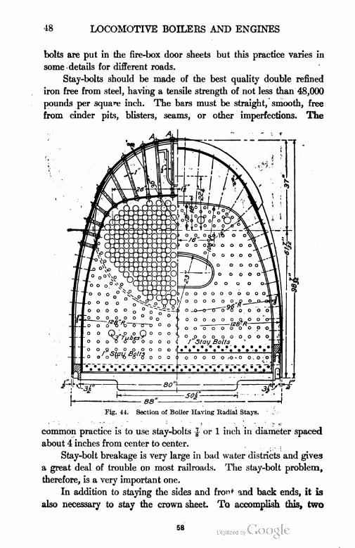
48 LOCOMOTIVE BOILERS AND ENGINES
bolts are put in the fire-box door sheets but this practice varies in
some details for different roads.
Stay-bolts should be made of the best quality double refined
iron free from steel, having a tensile strength of not less than 48,000
pounds per square inch. The bars must be straight, smooth, free
from cinder pits, blisters, seams, or other imperfections. The
Fig. 44. Section of Boiler Having Radial Stays.
common practice is to use stay-bolts £ or 1 inch in diameter spaced
about 4 inches from center to center.
Stay-bolt breakage is very large in bad water districts and give3
a great deal of trouble on most railroads. The stay-bolt problem,
therefore, is a very important one.
In addition to staying the sides and front and back ends, it is
also necessary to stay the crown sheet. To accomplish this, two
58
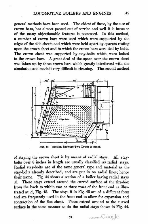
LOCOMOTIVE BOILERS AND ENGINES 49
general methods have been used. The oldest of these, by the use of
crown bars, has almost passed out of service and well it is because
of the many objectionable features it possessed. In this method,
a number of crown bars were used which were supported by the
edges of the side sheets and which were held apart by spacers resting
upon the crown sheet and to which the crown bars were tied by bolts.
The crown sheet was supported by stay-bolts which were bolted
to the crown bars. A great deal of the space over the crown sheet
was taken up by these crown bars which greatly interferred with the
circulation and made it very difficult in cleaning. The second method
Fig. 45. Section Showing Two Types of Stays.
of staying the crown sheet is by means of radial stays. All stay-
bolts over 8 inches in length are usually classified as radial stays.
Radial stay-bolts are of the same general type and material as the
stay-bolts already described, and are put in on radial lines; hence
their name. Fig. 44 shows a section of a boiler having radial stays
A. These stays extend around the curved surface of the fire-box
from the back to within two or three rows of the front end as illus
trated at A, Fig. 45. The stays B in Fig. 45 are of a different form
and are frequently used in the front end to allow for expansion and
contraction of the flue sheet. These extend around to the curved
surface in the same manner as do the radial stays shown in Fig. 44.
59
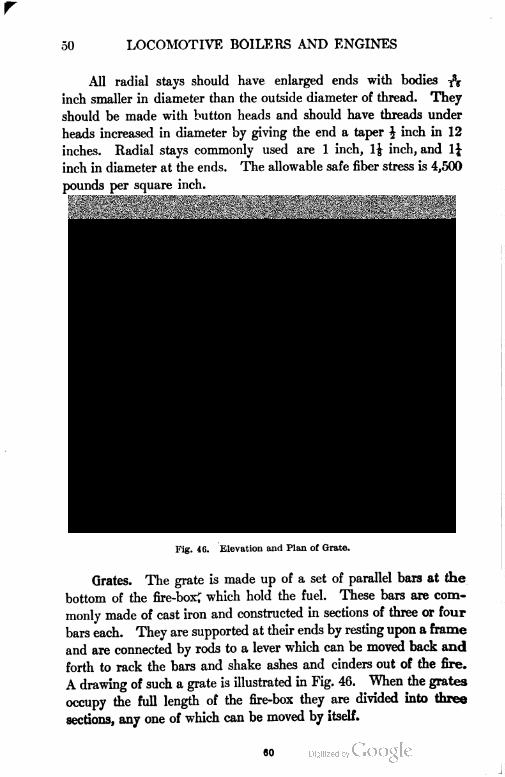
50 LOCOMOTIVE BOILERS AND ENGINES
All radial stays should have enlarged ends with bodies 7V
inch smaller in diameter than the outside diameter of thread. They
should be made with button heads and should have threads under
heads increased in diameter by giving the end a taper J inch in 12
inches. Radial stays commonly used are 1 inch, 1\ inch, and 1J
inch in diameter at the ends. The allowable safe fiber stress is 4,500
pounds per square inch.
Fig. 46. Elevation and Plan of Grate.
Grates. The grate is made up of a set of parallel bars at the
bottom of the fire-box^ which hold the fuel. These bars are com
monly made of cast iron and constructed in sections of three or four
bars each. They are supported at their ends by resting upon a frame
and are connected by rods to a lever which can be moved back and
forth to rack the bars and shake ashes and cinders out of the fire.
A drawing of such a grate is illustrated in Fig. 46. When the grates
occupy the full length of the fire-box they are divided into three
sections, any one of which can be moved by itself.
60
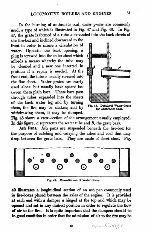
LOCOMOTIVE BOILERS AND ENGINES 51
In the burning of anthracite coal, water grates are commonly
used, a type of which is illustrated in Fig. 47 and Fig. 48. In Fig.
47, the grate is formed of a tube a expanded into the back sheets of
the fire-box and inclined downward to the
front in order to insure a circulation of
water. Opposite the back opening, a
plug is screwed into the outer sheet which
affords a means whereby the tube may
be cleaned and a new one inserted in
position if a repair is needed. At the
front end, the tube is usually screwed into
the flue sheet. Water grates are rarely
used alone but usually have spaced be
tween them plain bars. These bars pass
through tubes expanded into the sheets
of the back water leg and by turning
them, the fire may be shaken; and by
withdrawing them, it may be dumped.
Fig. 48 shows a cross-section of the arrangement usually employed.
In this figure, A represents the water tube and B, the grate bars.
Ash Pans. Ash pans are suspended beneath the fire-box for
the purpose of catching and carrying the ashes and coal that may
drop between the grate bars. They are made of sheet steel. Fig.
Fig. 47. Details of Water Grate
for Anthracite Coal.
o o o
Fig. 48. Cross-Section of Water Grate.
49 illustrates a longitudinal section of an ash pan commonly used
in fire-boxes placed between the axles of the engine. It is provided
at each end with a damper a hinged at the top and which may be
opened and set in any desired position in order to regulate the flow
of air to the fire. It is quite important that the dampers should be
in good condition in order that the admission of air to the fire may be
61
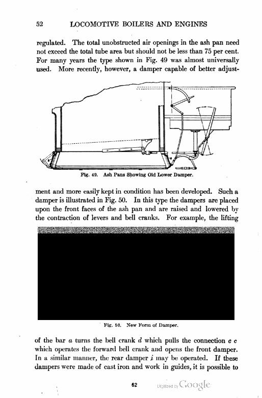
52 LOCOMOTIVE BOILERS AND ENGINES
regulated. The total unobstructed air openings in the ash pan need
not exceed the total tube area but should not be less than 75 per cent.
For many years the type shown in Fig. 49 was almost universally
used. More recently, however, a damper capable of better adjust-
Fig. 49. Ash Pans Showing Old Lower Damper.
ment and more easily kept in condition has been developed. Such a
damper is illustrated in Fig. 50. In this type the dampers are placed
upon the front faces of the ash pan and are raised and lowered by
the contraction of levers and bell cranks. For example, the lifting
Fig. 50. New Form of Damper.
of the bar a turns the bell crank d which pulls the connection c c
which operates the forward bell crank and opens the front damper.
In a similar manner, the rear damper i may be operated. If these
dampers were made of cast iron and work in guides, it is possible to
62
LOCOMOTIVE BOILERS AND ENGINES 53
have the construction such that when closed they will be practically
air tight.
Brick Arches. A brick arch is an arrangement placed in the
fire-box to effect a better combustion and to secure a more even dis
tribution of the hot gases in. their passage through the tubes. Fig.
33 illustrates a longitudinal section of the fire-box fitted with a brick
arch A. Its method of action is very simple. It acts as a mixer of
the products of combustion with the air and as a reflector of the radiant
heat of the fire and. the escaping gases. It is maintained at a very
high temperature and in this condition meets the air and gases as
they come in contact with it and turns them back to the narrow open
ing above. By this action it maintains a temperature sufficiently
high to burn with the smallest possible quantity of air all the car
bonic oxide and the hydrocarbons that arise from the coal. It thus
effects a very considerable saving in the cost of running, does away
to a great extent with the production of smoke, and develops a high
calorific power in comparatively small fire-boxes. This is a valuable
property since it is possible for the boiler to utilize the heat value of
the coal to the greatest possible extent. The bricks are usually about
4 or 5 inches thick and are ordinarily supported either by water tubes,
as shown in Fig. 33 and Fig. 45, or by brackets in the form of angle-
irons riveted to the side sheets. The disadvantage accruing from
the use of the brick arch is that it is somewhat expensive to maintain
because of the rapid deterioration and burning away of the material.
Smoke=Box and Front End Arrangement. By the term front
end is meant all that portion of the boiler beyond the front tube sheet
and includes the cylindrical shell of the boiler and all the parts con
tained therein such as the steam or branch pipes, exhaust nozzle,
netting, diaphragm, and draft or petticoat pipes. These parts
referred to above are illustrated in the sectional view shown in Fig. 32.
The Steam or Branch Pipes. These pipes, 33, follow closely
the contour of the shell and connect the T-head, 34, with the steam
passage leading to the cylinder and conduct the steam from the dry-
pipe to both the right and the left cylinders.
Exhaust Nozzle. The exhaust nozzle is the passage through
which the steam escapes from the cylinders to the stack.
Netting. The netting, 26, is a coarse wire gauze placed in the
front end which prevents large cinders from being thrown out by the
63
LOCOMOTIVE BOILERS AND ENGINES
action of the exhaust and thereby reduces the chances for fires being
started along the right of way.
Diaphragm. The diaphragm or deflector plate, 27, is an iron
plate placed obliquely over a portion of the front end of the flues
which deflects the flue gases downward before entering the stack,
thus equalizing to a great extent the draft in the different flues. This
deflector plate may be adjusted to deflect the gases more or less as
desired.
Draft Pipes. The petticoat or draft pipes, 36, employed to
increase the draft may be used singly or in multiple and raised or
lowered as desired.
Draft. The front end must be regarded as an apparatus for
doing work. It receives power for doing this work from the exhaust
steam from the cylinders. The work which it performs consists in
drawing air through the ash pan, grates, fire, fire door, and other
openings, then continues its work by drawing the gases of com
bustion through the flues of the boiler into the front end, then forcing
them out through the stack into the atmosphere. In order that this
work may be accomplished, a pressure less than the atmosphere
must be maintained in the smoke-box. This is accomplished'through
the action of the exhaust jet in the stack. The difference in pressure
between the atmosphere and the smoke-box is called draft.
Under the conditions of common practice, the exhaust jet does
not fill the stack at or near the bottom but touches the stack only
when it is very near the top. The action of the exhaust jet is to en
train the gases of the smoke-box. A jet of steam flowing steadily
from the exhaust tip when the engine is at rest produces a draft that
is in every way similar to that obtained with the engine running.
The jet acts to induce motion in the particles of gas which imme
diately surround it and also to enfold and to entrain the gases which
are thus made to mingle with the substance of the jet itself.
The induced action, illustrated in Fig. 51, is by far the most
important. The arrows in this figure represent the direction of the
currents surrounding the jet. It will be seen that the smoke-box
gases tend to move toward the jet and not toward the base of the
stack; that is, the jet by the virtue of its high velocity and by its
contact with certain surrounding gases gives motion to the particles
close about it and these moving on with the jet make room for other
64
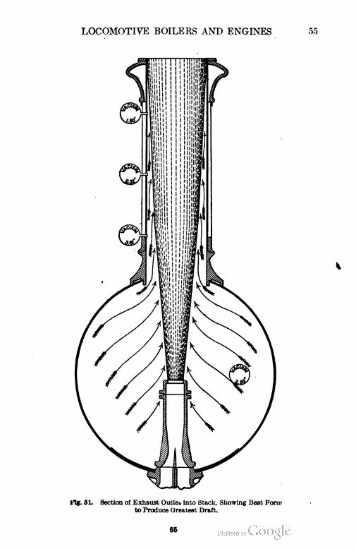
LOCOMOTIVE BOILERS AND ENGINES
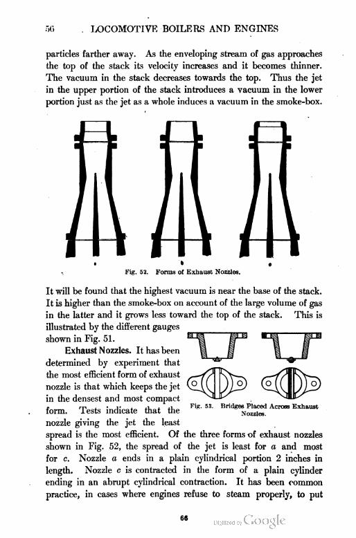
50 LOCOMOTIVE BOILERS AND ENGINES
particles farther away. As the enveloping stream of gas approaches
the top of the stack its velocity increases and it becomes thinner.
The vacuum in the stack decreases towards the top. Thus the jet
in the upper portion of the stack introduces a vacuum in the lower
portion just as the jet as a whole induces a vacuum in the smoke-box.
, Fig. 52. Forms of Exhaust Nozzles.
It will be found that the highest vacuum is near the base of the stack.
It is higher than the smoke-box on account of the large volume of gas
in the latter and it grows less toward the top of the stack. This is
illustrated by the different gauges
shown in Fig. 51.
Exhaust Nozzles. It has been
determined by experiment that
the most efficient form of exhaust
nozzle is that which keeps the jet
in the densest and most compact
form. Tests indicate that the
nozzle giving the jet the least
spread is the most efficient. Of the three forms of exhaust nozzles
shown in Fig. 52, the spread of the jet is least for a and most
for c. Nozzle a ends in a plain cylindrical portion 2 inches in
length. Nozzle c is contracted in the form of a plain cylinder
ending in an abrupt cylindrical contraction. It has been common
practice, in cases where engines refuse to steam properly, to put
Fig. 53. Bridges Placed Across Exhaust
Nozzles.
60
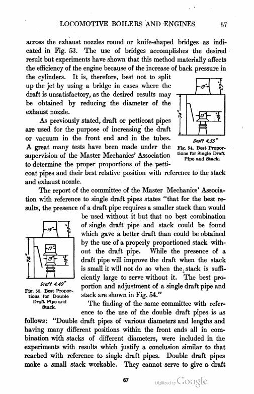
LOCOMOTIVE BOILERS AND ENGINES 57
Draft 4.55"
Fig. 54. Best Propor
tions for Single Draft
Pipe and Stack.
across the exhaust nozzles round or knife-shaped bridges as indi
cated in Fig. 53. The use of bridges accomplishes the desired
result but experiments have shown that this method materially affects
the efficiency of the engine because of the increase of back pressure in
the cylinders. It is, therefore, best not to split
up the jet by using a bridge in cases where the
draft is unsatisfactory, as the desired results may
be obtained by reducing the diameter of the
exhaust nozzle.
As previously stated, draft or petticoat pipes
are used for the purpose of increasing the draft
or vacuum in the front end and in the tubes.
A great many tests have been made under the
supervision of the Master Mechanics' Association
to determine the proper proportions of the petti
coat pipes and their best relative position with reference to the stack
and exhaust nozzle.
The report of the committee of the Master Mechanics' Associa
tion with reference to single draft pipes states "that for the best re
sults, the presence of a draft pipe requires a smaller stack than would
be used without it but that no best combination
of single draft pipe and stack could be found
which gave a better draft than could be obtained
by the use of a properly proportioned stack with
out the draft pipe. While the presence of a
draft pipe will improve the draft when the stack
is small it will not do so when the. stack is suffi
ciently large to serve without it. The best pro
portion and adjustment of a single draft pipe and
stack are shown in Fig. 54."
The finding of the same committee with refer
ence to the use of the double draft pipes is as
follows: "Double draft pipes of various diameters and lengths and
having many different positions within the front ends all in com
bination with stacks of different diameters, were included in the
experiments with results which justify a conclusion similar to that
reached with reference to single draft pipes. Double draft pipes
make a small stack workable. They cannot serve to give a draft
1
■irA
Draft 4.40
Fig. 55. Best Propor
tions for Double
Draft Pipe and
Stack.
67
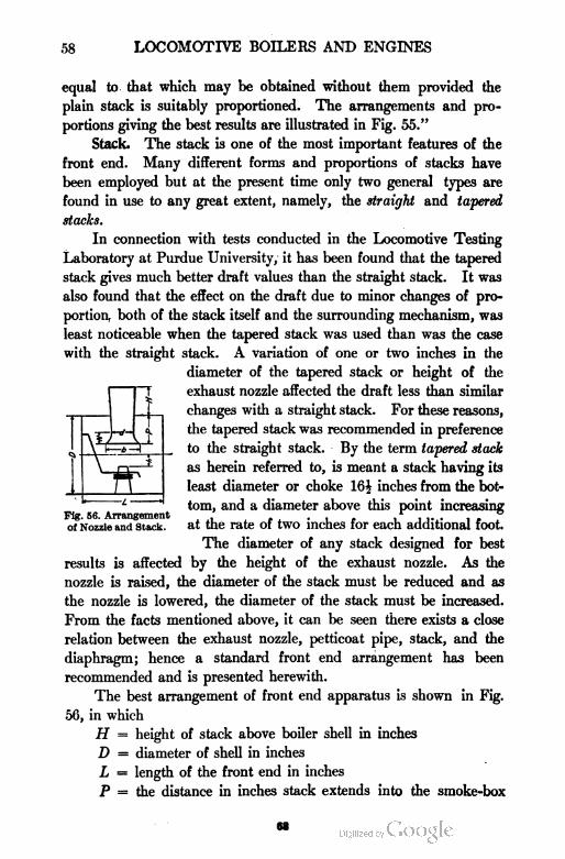
58 LOCOMOTIVE BOILERS AND ENGINES
equal to that which may be obtained without them provided the
plain stack is suitably proportioned. The arrangements and pro
portions giving the best results are illustrated in Fig. 55."
Stack. The stack is one of the most important features of the
front end. Many different forms and proportions of stacks have
been employed but at the present time only two general types are
found in use to any great extent, namely, the straight and tapered
stacks.
In connection with tests conducted in the Locomotive Testing
Laboratory at Purdue University, it has been found that the tapered
stack gives much better draft values than the straight stack. It was
also found that the effect on the draft due to minor changes of pro
portion both of the stack itself and the surrounding mechanism, was
least noticeable when the tapered stack was used than was the case
with the straight stack. A variation of one or two inches in the
diameter of the tapered stack or height of the
exhaust nozzle affected the draft less than similar
changes with a straight stack. For these reasons,
the tapered stack was recommended in preference
to the straight stack. By the term tapered stack
as herein referred to, is meant a stack having its
least diameter or choke 16\ inches from the bot
tom, and a diameter above this point increasing
of Nozzle and stack, at the rate of two inches for each additional foot.
The diameter of any stack designed for best
results is affected by the height of the exhaust nozzle. As the
nozzle is raised, the diameter of the stack must be reduced and as
the nozzle is lowered, the diameter of the stack must be increased.
From the facts mentioned above, it can be seen there exists a close
relation between the exhaust nozzle, petticoat pipe, stack, and the
diaphragm; hence a standard front end arrangement has been
recommended and is presented herewith.
The best arrangement of front end apparatus is shown in Fig.
56, in which
H = height of stack above boiler shell in inches
D = diameter of shell in inches
L = length of the front end in inches
P = the distance in inches stack extends into the smoke-box
M
LOCOMOTIVE BOILERS AND ENGINES 59
N = distance in inches from base of stack to choke
b = width of stack in inches at the base
d = diameter of stack in inches at the choke
h — distance in inches of the nozzle below the center line
of smoke-box
In order to obtain the best results, H and h should be made as
great as possible while the other principal dimensions should be as
follows :
d = .21 D + .16 k
b = 2 d or .5 D
P = .32 D
N = .22 D
Rate of Combustion. It is a well-known fact that each pound of
fuel is capable of giving out a certain definite amount of heat. There
fore, the more rapid the combustion, the greater the amount of heat
produced in a given time. In stationary boilers, where the grate is
practically unlimited, the rate of combustion per square foot of grate
area per hour varies from 15 to 25 pounds. In locomotives, however,
where the grate area is limited, the fuel consumption is much greater,
rising at times as high as 200 pounds per square foot of grate area per
hour. This rapid combustion results in a great loss of heat and a
reduction in the amount of water evaporated per pound of coal. It
has been shown that when coal is burned at the rate of 50 pounds
per square foot of grate area per hour, 8£ pounds of water may be
evaporated for each pound of coal. While if the rate of combustion
is increased to 180 pounds per square foot of grate area per hour,
the evaporation will fall off to about five pounds, a loss of water
evaporated per pound of coal of nearly 40 per cent. This loss may
be due to a failure of the heating surface to absorb properly the in
creased volume of heat passing over them, or to the imperfect
combustion of the fuel on the grate, or it may be due to a combination
of these causes.
The results of experiments show that the lower the rate of com
bustion the higher will be the efficiency of the furnace, the conclusion
being that very high rates of combustion are not desirable and con
sequently that the grate of a locomotive should be made as large as
possible so that exceptionally high rates of combustion will not be
necessary.
69
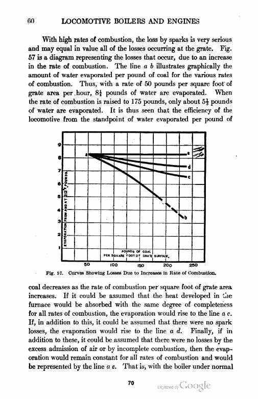
00 LOCOMOTIVE BOILERS AND ENGINES
With high rates of combustion, the loss by sparks is very serious
and may equal in value all of the losses occurring at the grate. Fig.
57 is a diagram representing the losses that occur, due to an increase
in the rate of combustion. The line a b illustrates graphically the
amount of water evaporated per pound of coal for the various rates
of combustion. Thus, with a rate of 50 pounds per square foot of
grate area per hour, 8\ pounds of water are evaporated. When
the rate of combustion is raised to 175 pounds, only about 5J pounds
of water are evaporated. It is thus seen that the efficiency of the
locomotive from the standpoint of water evaporated per pound of
a
— —
— d
OUND8
s
*■"■»»
1
saVa
<oz
.
3<
K
'RATION
EVAPC
POUNDS OF COALQUAftE FOOT OF CRATEPER S
1 1
SURFAC E,
150 (00 150 200 2SO
Fig. 57. Cloves Showing Losses Due to Increases in Rate of Combustion.
coal decreases as the rate of combustion per square foot of grate area
increases. If it could be assumed that the heat developed in the
furnace would be absorbed with the same degree of completeness
for all rates of combustion, the evaporation would rise to the line a c.
If, in addition to this, it could be assumed that there were no spark
losses, the evaporation would rise to the line a d. Finally, if in
addition to these, it could be assumed that there were no losses by the
excess admission of air or by incomplete combustion, then the evap
oration would remain constant for all rates of combustion and would
be represented by the line a e. That is, with the boiler under normal
70
LOCOMOTIVE BOILERS AND ENGINES 61
conditions, the area ab c represents the loss occasioned by deficient
heating surface; the area a c d represents that caused by spark
losses; and the area ad e represents that due to excessive amounts
of air and by imperfect combustion.
Spark Losses. From the diagram shown in Fig. 57, it is evident
that one of the principal heat losses is that of sparks. By the term
sparks is meant the small particles of partially burned coal which
are drawn through the flues and ejected through the stack by the
action of the exhaust. In the operation of a locomotive, it has been
demonstrated that the weight of sparks or cinders increases with the
rate of combustion and may reach a value of from 10 to 15 per cent
of the total weight of coal fired. Damage suits frequently arise, due
to fires started by cinders thrown from the stack of the locomotive.
Experiments have shown, however, that sparks from a locomotive
will not be likely to start fires beyond the right of way.
High Steam Pressures. With the development of high-power
locomotives came the use of high steam pressures. At first, only very
low pressures were carried but soon 200 pounds pressure per square
inch became very common and 220 and 225 not unusual. But with
the increase of pressure there came an increase in trouble due to
bad water, leaky flues, and an increase in incidental leaks in the
boiler. All of these factors affected the performance of the locomo
tive. To determine to what extent the economic performance of the
boiler was affected by an increase of steam pressure and also the
most economical steam pressure to use, a series of tests were carried
out at Purdue University. The following are the conclusive results as
read before the Western Railway Club by Dean W. F. M. Goss :
THB EFFECT OF DIFFERENT PRESSURES UPON
BOILER PERFORMANCE
1. The evaporative efficiency of a locomotive boiler is but slightly.
affected by changes in pressure between the limits of 120 pounds and 240 pounds.
2. Changes in steam pressure between the limits of 120 pounds and
240 pounds will produce an effect upon the efficiency of the boiler which will
be less than one-half pound of water per pound of coal.
3. It is safe to conclude that changes of no more than 40 or 50 pounds
in pressure will produce no measurable effect upon the evaporative efficiency
of the modern locomotive boiler.
71
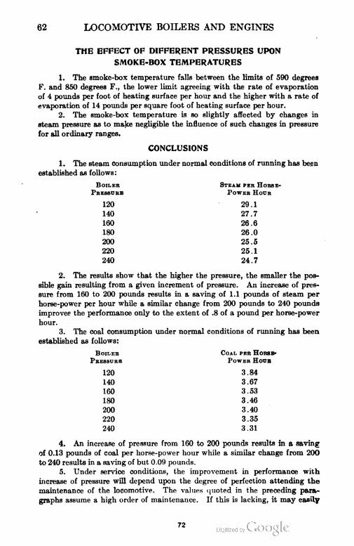
62 LOCOMOTIVE BOILERS AND ENGINES
THE EFFECT OF DIFFERENT PRESSURES UPON
SMOKE-BOX TEMPERATURES
1. The smoke-box temperature falls between the limits of 590 degrees
F. and 850 degrees F., the lower limit agreeing with the rate of evaporation
of 4 pounds per foot of heating surface per hour and the higher with a rate of
evaporation of 14 pounds per square foot of heating surface per hour.
2. The smoke-box temperature is so slightly affected by changes in
steam pressure as to make negligible the influence of such changes in pressure
for all ordinary ranges.
CONCLUSIONS
1. The steam consumption under normal conditions of running has been
established as follows:
Boiler Steam per Horse-
Pressure Power Hocr
120 29.1
140 27.7
160 26.6
180 26.0
200 25.5
220 25.1
240 24.7
2. The results show that the higher the pressure, the smaller the pos
sible gain resulting from a given increment of pressure. An increase of pres
sure from 160 to 200 pounds results in a saving of 1.1 pounds of steam per
horse-power per hour while a similar change from 200 pounds to 240 pounds
improves the performance only to the extent of .8 of a pound per horse-power
hour.
3. The coal consumption under normal conditions of running has been
established as follows:
Boiler Coal per Horse-
Pressure Power Hour
120 3.84
140 3.67
160 3.53
180 3.46
200 3.40
220 3.35
240 3.31
4. An increase of pressure from 160 to 200 pounds results in a saving
of 0.13 pounds of coal per horse-power hour while a similar change from 200
to 240 results in a saving of but 0.09 pounds.
5. Under service conditions, the improvement in performance with
increase of pressure will depend upon the degree of perfection attending the
maintenance of the locomotive. The values quoted in the preceding para
graphs assume a high order of maintenance. If this is lacking, it may easily
72
LOCOMOTIVE BOILERS AND ENGINES 63
happen that the saving which is anticipated through the adoption of higher
pressures will entirely disappear.
6. The difficulties to be met in the maintenance both of boiler and
cylinders increase with increase of pressure.
7. The results supply an accurate measure by which to determine the
advantage of increasing the capacity of a boiler. For the development of
a given power, any increase in boiler capacity brings its return in improved
performance without adding to the cost of maintenance or opening any new
avenues for incidental losses. As a means of improvement it is more certain
than that which is offered by increase of pressure.
8. As the scale of pressure is ascended an opportunity to further in
crease the weight of a locomotive should in many cases find expression in the
design of a boiler of increased capacity rather than in one of higher pressures.
9. Assuming 180 pounds pressure to have been accepted as standard
and assuming the maintenance to be of the highest order, it will be found
good practice to utilize any allowable increase in weight by providing a larger
boiler rather than by providing a stronger boiler to permit higher pressures.
10. Whenever the maintenance is not of the highest order, the standard
running pressures should be below 180 pounds.
11. Where the water which must be used in boilers contains foaming
or scale-making admixtures, best results are likely to be secured by fixing
the pressure below the limit of 180 pounds.
12. A simple locomotive using saturated steam will render good and
efficient service when the running pressure is as low as 160 pounds. Under
most favorable conditions, no argument is to be found in the economical
performance of a machine which can justify the use of pressures greater than
200 pounds.
Heating Surface. While the points thus far considered are more
or less important in their bearing in the generation of steam, yet the
amount of heating surface is, as a rule, the most important. As pre
viously stated, the lower the rate of combustion per square foot of
heating surface, the higher will be the rate of evaporation per pound of
coal. The ratio of the heating surface of the flues to that of the fire
box varies greatly, in some cases being only 9 to 1 while in others it
is found as great as 18 to 1. There is perhaps a correct value for this
ratio, but at the present time it is unknown. The relation existing
between the total heating surface and the grate area varies between
wide limits for different cases. Table III, taken from the Proceedings
of the Master Mechanics' Association for 1902, gives the ratio of
heating surface to grate area in passenger and freight locomotives
burning various kinds of fuel.
73
64 LOCOMO'; E BOILERS AND ENGINES
TABLE III
Ratio of Heating Surface to Grate Area
Fuel
Passenger Locomotive Freight Locomotive
Simple Compound Simple Compound
Free Burning
Bituminous65 to 90 75 to 95 70 to 85 65 to 85
Average Bituminous 50 to 65 60 to 75 45 to 70 50 to 65
Slow Burning
Bituminous40 to 50 35 to 60 35 to 45 45 to 50
Bituminous, Slack, and
Free Burning Anthracite35 to 40 30 to 35 30 to 35 40 to 45
Low Grade Bituminous,
Lignite, and Slack28 to 35 24 to 30 25 to 30 30 to 40
From the foregoing, it is evident
that it is exceedingly difficult to
determine just how much heating
surface a locomotive boiler should
have to give the best results. As a
rule, they are made as large as
possible so long as the total allow
able weight of the locomotive is not
exceeded. This is not, however, a
scientific rule to follow but it is safe
to say that the value of no locomo
tive has ever been impaired by
having too much heating surface.
The greater the boiler power, the
higher will be the speed which can
be maintained. It is important
that the boiler be covered with a
good lagging in order to prevent loss
of heat due to radiation.
Superheaters. When steam
is admitted to the cylinder it
meets the cylinder walls, the temperature of which is less than that
of the entering steam, and there results an interchange of heat.
Fig. 58. Pielock Superheater.
74
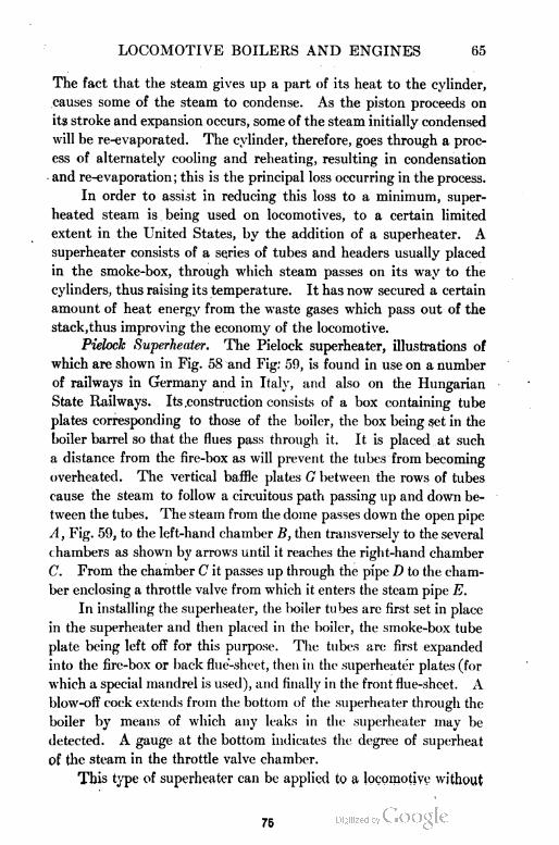
LOCOMOTIVE BOILERS AND ENGINES 65
The fact that the steam gives up a part of its heat to the cylinder,
causes some of the steam to condense. As the piston proceeds on
its stroke and expansion occurs, some of the steam initially condensed
will be re-evaporated. The cylinder, therefore, goes through a proc
ess of alternately cooling and reheating, resulting in condensation
and re-evaporation; this is the principal loss occurring in the process.
In order to assist in reducing this loss to a minimum, super
heated steam is being used on locomotives, to a certain limited
extent in the United States, by the addition of a superheater. A
superheater consists of a series of tubes and headers usually placed
in the smoke-box, through which steam passes on its way to the
cylinders, thus raising its temperature. It has now secured a certain
amount of heat energy from the waste gases which pass out of the
stack,thus improving the economy of the locomotive.
Pielock Superheater. The Pielock superheater, illustrations of
which are shown in Fig. 58 and Fig: 59, is found in use on a number
of railways in Germany and in Italy, and also on the Hungarian
State Railways. Its .construction consists of a box containing tube
plates corresponding to those of the boiler, the box being set in the
boiler barrel so that the flues pass through it. It is placed at such
a distance from the fire-box as will prevent the tubes from becoming
overheated. The vertical baffle plates G between the rows of tubes
cause the steam to follow a circuitous path passing up and down be
tween the tubes. The steam from the dome passes down the open pipe
A, Fig. 59, to the left-hand chamber B, then transversely to the several
chambers as shown by arrows until it reaches the right-hand chamber
C. From the chamber C it passes up through the pipe D to the cham
ber enclosing a throttle valve from which it enters the steam pipe E.
In installing the superheater, the boiler tubes are first set in place
in the superheater and then placed in the boiler, the smoke-box tube
plate being left off for this purpose. The tubes are first expanded
into the fire-box or back flue-sheet, then in the superheater plates (for
which a special mandrel is used), and finally in the front flue-sheet. A
blow-off cock extends from the bottom of the superheater through the
boiler by means of which any leaks in the superheater may be
detected. A gauge at the bottom indicates the degree of superheat
of the steam in the throttle valve chamber.
This type of superheater can be applied to a locomotive without
75
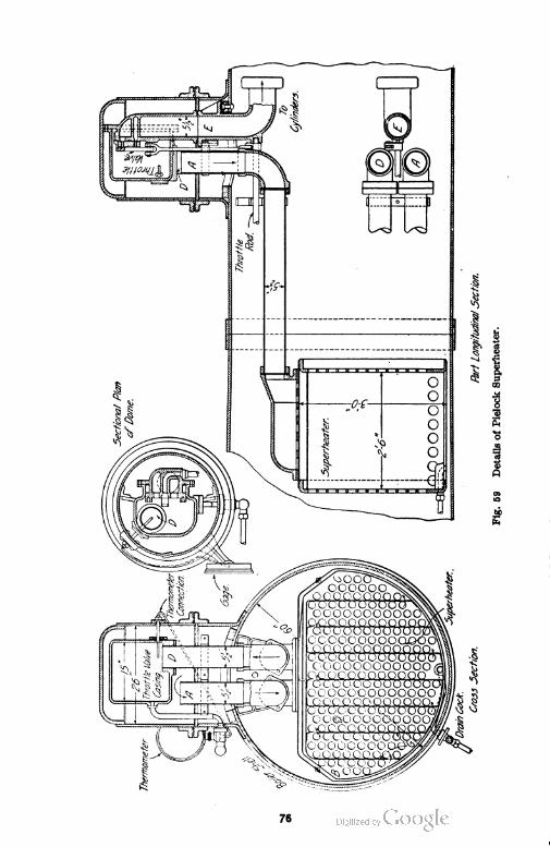
76
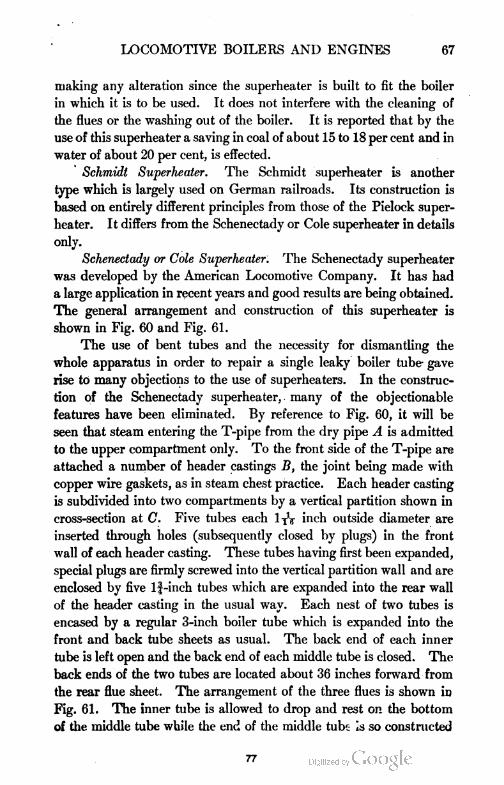
LOCOMOTIVE BOILERS AND ENGINES 67
making any alteration since the superheater is built to fit the boiler
in which it is to be used. It does not interfere with the cleaning of
the flues or the washing out of the boiler. It is reported that by the
use of this superheater a saving in coal of about 15 to 18 per cent and in
water of about 20 per cent, is effected.
Schmidt Superheater. The Schmidt superheater is another
type which is largely used on German railroads. Its construction is
based on entirely different principles from those of the Pielock super
heater. It differs from the Schenectady or Cole superheater in details
only.
Schenectady or Cole Superheater. The Schenectady superheater
was developed by the American Locomotive Company. It has had
a large application in recent years and good results are being obtained.
The general arrangement and construction of this superheater is
shown in Fig. 60 and Fig. 61.
The use of bent tubes and the necessity for dismantling the
whole apparatus in order to repair a single leaky boiler tube- gave
rise to many objections to the use of superheaters. In the construc
tion of the Schenectady superheater, many of the objectionable
features have been eliminated. By reference to Fig. 60, it will be
seen that steam entering the T-pipe from the dry pipe A is admitted
to the upper compartment only. To the front side of the T-pipe are
attached a number of header castings B, the joint being made with
copper wire gaskets, as in steam chest practice. Each header casting
is subdivided into two compartments by a vertical partition shown in
cross-section at C. Five tubes each l^V inch outside diameter are
inserted through holes (subsequently closed by plugs) in the front
wall of each header casting. These tubes having first been expanded,
special plugs are firmly screwed into the vertical partition wall and are
enclosed by five lj-inch tubes which are expanded into the rear wall
of the header casting in the usual way. Each nest of two tubes is
encased by a regular 3-inch boiler tube which is expanded into the
front and back tube sheets as usual. The back end of each inner
tube is left open and the back end of each middle tube is closed. The
back ends of the two tubes are located about 36 inches forward from
the rear flue sheet. The arrangement of the three flues is shown in
Fig. 61. The inner tube is allowed to drop and rest on the bottom
of the middle tube while the end of the middle tube is so constructed
77
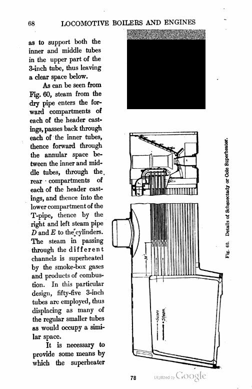
68 LOCOMOTIVE BOILERS AND ENGINES
as to support both the
inner and middle tubes
in the upper part of the
3-inch tube, thus leaving
a clear space below.
As can be seen from
Fig. 60, steam from the
dry pipe enters the for
ward compartments of
each of the header cast
ings, passes back through
each of the inner tubes,
thence forward through
the annular space be
tween the inner and mid
dle tubes, through the.
rear • compartments of
each of the header cast
ings, and thence into the
lower compartment of the
T-pipe, thence by the
right and left steam pipe
D and E to the^cylinders.
The steam in passing
through the different
channels is superheated
by the smoke-box gases
and products of combus
tion. In this particular
design, fifty-five 3-inch
tubes are employed, thus
displacing as many of
the regular smaller tubes
as would occupy a simi
lar space.
It is necessary to
provide some means by
which the superheater
78
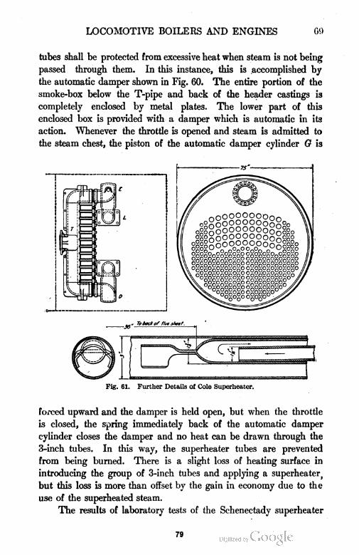
LOCOMOTIVE BOILERS AND ENGINES Gfl
tubes shall be protected from excessive heat when steam is not being
passed through them. In this instance, this is accomplished by
the automatic damper shown in Fig. 60. The entire portion of the
smoke-box below the T-pipe and back of the header castings is
completely enclosed by metal plates. The lower part of this
enclosed box is provided with a damper which is automatic in its
action. Whenever the throttle is opened and steam is admitted to
the steam chest, the piston of the automatic damper cylinder G is
( '
Fig. 61. Further Details of Cole Superheater.
forced upward and the damper is held open, but when the throttle
is closed, the spring immediately back of the automatic damper
cylinder closes the damper and no heat can be drawn through the
3-inch tubes. In this way, the superheater tubes are prevented
from being burned. There is a slight loss of heating surface in
introducing the group of 3-inch tubes and applying a superheater
but this loss is more than offset by the gain in economy due to the
use of the superheated steam.
The results of laboratory tests of the Schenectady superheater
79
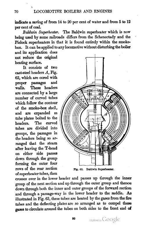
70 LOCOMOTIVE BOILERS AND ENGINES
indicate a saving of from 14 to 20 per cent of water and from 5 to 12
per cent of coal.
Baldwin Superheater. The Baldwin superheater which is now
being used by some railroads differs from the Schenectady and the
Pielock superheaters in that it is found entirely within the smoke-
box. It can be applied to any locomotive without disturbing the boiler
and its application does
not reduce the original <j 1 ^
heating surface.
It consists of two
cast-steel headers A, Fig.
62, which are cored with
proper passages and
walls. These headers
are connected by a large
number of curved tubes
which follow the contour
of the smoke-box shell,
and are expanded in
tube plates bolted to the
headers. The curved
tubes are divided into
groups, the passages in
the headers being so ar
ranged that the steam
after leaving the T-head
on either side passes
down through the group
forming the outer four
rows of the rear section Flg. 62. Baldwin superheater,
of superheater tubes, then
crosses over in the lower header and passes up through the inner
group of the next section and up through the outer group and thence
down through both the inner and outer groups of the forward section
and through a passage-way in the lower header to the saddle. As
illustrated in Fig. 63, these tubes are heated by the gases from the fire
tubes and the deflecting plates are so arranged as to compel these
gases to circulate around the tubes on both sides to the front end of
so

81
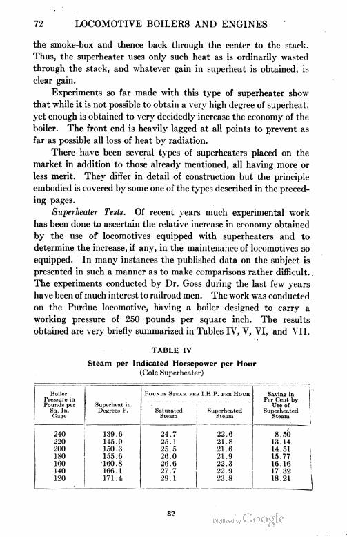
72 LOCOMOTIVE BOILERS AND ENGINES
the smoke-box and thence back through the center to the stack.
Thus, the superheater uses only such heat as is ordinarily wasted
through the stack, and whatever gain in superheat is obtained, is
clear gain.
Experiments so far made with this type of superheater show
that while it is not possible to obtain a very high degree of superheat,
yet enough is obtained to very decidedly increase the economy of the
boiler. The front end is heavily lagged at all points to prevent as
far as possible all loss of heat by radiation.
There have been several types of superheaters placed on the
market in addition to those already mentioned, all having more or
less merit. They differ in detail of construction but the principle
embodied is covered by some one of the types described in the preced
ing pages.
Superheater Tests. Of recent years much experimental work
has been done to ascertain the relative increase in economy obtained
by the use of locomotives equipped with superheaters and to
determine the increase, if any, in the maintenance of locomotives so
equipped. In many instances the published data on the subject is
presented in such a manner as to make comparisons rather difficult.
The experiments conducted by Dr. Goss during the last few years
have been of much interest to railroad men. The work was conducted
on the Purdue locomotive, having a boiler designed to carry a
working pressure of 250 pounds per square inch. The results
obtained are very briefly summarized in Tables IV, V, VI, and VII.
TABLE IV
Steam per Indicated Horsepower per Hour
(Cole Superheater)
Boiler Pounds Steam per I.H.P. per Hour Saving inPressure in Per Cent byPounds per Superheat in Use of
Sq. In. Degrees F. Saturated Superheated SuperheatedGage Steam Steam Steam
1
240 139.6 24.7 22.6 8.50
220 14.5.0 25.1 21.8 13.14
200 150.3 25.5 21.6 14.51
180 155.6 26.0 21.9 15.77
160 160.8 26.6 22.3 16.16
140 166.1 . 27.7 22.9 17.32
120 171.4 29.1 23.8 18.21 |
82
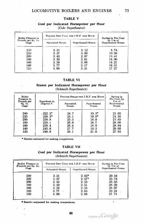
LOCOMOTIVE BOILERS AND ENGINES 73
TABLE V
Coal per Indicated Horsepower per Hour
(Cole Superheater)
. Pounds Dry Coai. pee I.H.P. per HourBoiler Pressure inPounds per Sq. In.
Gage
Saving in Per Cent
Saturated Steam Superheated Steamby Use of
Superheated Steam
240 3.31 3.12 5.74.
220 3.37 3.00 10.98
200 3.43 2.97 13.41
180 3.50 3.01 14.00
160 3.59 3.08 14.21
140 3.77 3.17 19.51
120 4.00 3.31 17.27
TABLE VI
Steam per Indicated Horsepower per Hour
(Schmidt Superheater)
BoilerPressure inPounds per
Pounds Steam per I.H.P. per Hour Saving inPer Cent by.
Use ofSuperheated
Steam
Superheat inDegrees F.Sq. In. Saturated
Steam
Superheated
Gage St earn
240 .222.2* 24.7 19 . 5* 21.05
220 226.5* 25.1 19.0* 24.30
200 230.8 25.5 18.9 25.89
. - 180 235.1 26.0 18.7 28.08
160 239.4 26.6 18.9 28.94
140 243.8 27.7 19,5 29.60
120 248.6 29.1 21.0 27.83
* Results estimated for making comparisons.
TABLE VII
Coal per Indicated Horsepower per Hour
(Schmidt Superheater)
Boiler Pressure inPounds per Sq. In.
Gage
Pounds Dry Coal vv.it I.H.P. per Hour Savins in Per Centby Use of
Superheated SteamSaturated Steam Superheated Steam
240 3.31 2.63* 20.54
220 3.37 2.57* 23.74
200 3.43 2.55 25.65
180 3.50 2.51 28.28
160 3.59 2 . 55 28.97
140 3.77 ■ 2.63 30.24
120 4.00 2.89 27.75
* Results estimated for making comparisons.
83
74 LOCOMOTIVE BOILERS AND ENGINES
The results presented in Tables IV to VII were all obtained
at a uniform speed of 30 miles per hour, and may be briefly stated
as follows:
(a) With the locomotive equipped with a Cole superheater a
saving was effected, over values obtained with saturated steam,
in steam used per I.H.P. per hour of from 8.5 to 18.21 per cent,
and in coal per I.H.P. per hour of from 5.74 to 17.25 per cent.
(b) With the locomotive equipped with a Schmidt superheater
the saving of steam used per I.H.P. per hour varied from 21.05
to 29.60 per cent, while the saving in coal used per I.H.P. per
hour varied from 20.54 to 30.24 per cent.
(c) The superheat in the branch pipe just before entering the
cylinders, varied from 139.7 to 171.4 degrees F., when the Cole
superheater was used, and from 222.2 to 248.6 degrees F., when
the Schmidt superheater was used,
The higher efficiency obtained of the Schmidt superheater over the
Cole superheater is partially accounted for by the fact that the total
heating surface of the Schmidt amounted to 325 square feet, while
that of the Cole was only 193 square feet.
In conclusion, it may be stated that the superheating simple
locomotive will reduce the steam and coal consumption to that
required by the compound locomotive. It will operate efficiently
on comparatively low steam pressures, and its maximum possible
power is considerably beyond that of the simple locomotive using
saturated steam. Many complaints have been made by operators
relative to difficulty experienced in securing proper lubrication of
the valve, etc., when using superheated steam. It has been demon
strated, however, that this difficulty can be overcome by the exercise
of good judgment in the use of and proper amount and grade of
lubricating oil.
Locomotive Boiler Design. The design of locomotive boilers
and engines is a very deep subject—one requiring much thought and
study. Limited space prevents going into a discussion of the reasons
for the adoption of different designs. The following formulae for
the calculation of thickness of plates, spacing of rivets, etc., are given.
Some of these formulae, while being semi-empirical, are based on
theoretical assumptions and represent modern practice in the design
9*
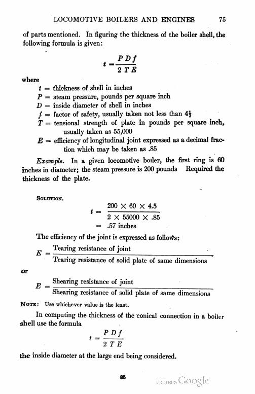
LOCOMOTIVE BOILERS AND ENGINES 75
of parts mentioned. In figuring the thickness of the boiler shell, the
following formula is given :
M PDf
2 T E
where
t = thickness of shell in inches
P = steam pressure, pounds per square inch
D = inside diameter of shell in inches
/ = factor of safety, usually taken not less than i\
T = tensional strength of plate in pounds per square inch,
usually taken as 55,000
E =» efficiency of longitudinal joint expressed as a decimal frac
tion which may be taken as .85
Example. In a given locomotive boiler, the first ring is 60
inches in diameter; the steam pressure is 200 pounds Required the
thickness of the plate.
Solution.
200 X 60 X 4.5
2 X 55000 X .85
.57 inches
The efficiency of the joint is expressed as follows:
Tearing resistance of joint
ti-
CS
E
Tearing resistance of solid plate of same dimensions
Shearing resistance of joint
Shearing resistance of solid plate of same dimensions
Note : Use whichever value is the least.
In computing the thickness of the conical connection in a boiler
shell use the formula
t = —
2 T E
the inside diameter at the large end being considered.
85
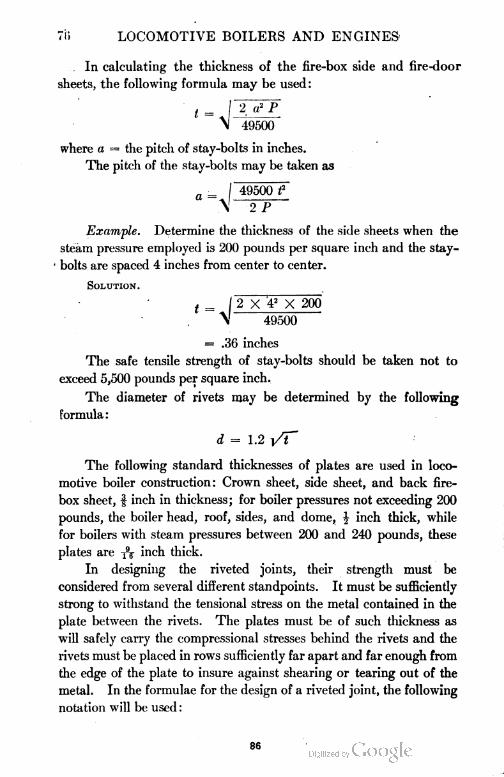
70 LOCOMOTIVE BOILERS AND ENGINES
In calculating the thickness of the fire-box side and fire-door
sheets, the following formula may be used:
t = | 2 a? P
\ 49500
where a = the pitch of stay-bolts in inches.
The pitch of the stay-bolts may be taken as
a = I 49500 f
\ 2 P
Example. Determine the thickness of the side sheets when the
steam pressure employed is 200 pounds per square inch and the stay-
■ bolts are spaced 4 inches from center to center.
Solution.
t = | 2 X 42 X 200
\ 49500
= .36 inches
The safe tensile strength of stay-bolts should be taken not to
exceed 5,500 pounds per square inch.
The diameter of rivets may be determined by the following
formula:
d = 1.2 i/T"
The following standard thicknesses of plates are used in loco
motive boiler construction: Crown sheet, side sheet, and back fire
box sheet, | inch in thickness; for boiler pressures not exceeding 200
pounds, the boiler head, roof, sides, and dome, J inch thick, while
for boilers with steam pressures between 200 and 240 pounds, these
plates are inch thick.
In designing the riveted joints, their strength must be
considered from several different standpoints. It must be sufficiently
strong to withstand the tensional stress on the metal contained in the
plate between the rivets. The plates must be of such thickness as
will safely carry the compressional stresses behind the rivets and the
rivets must be placed in rows sufficiently far apart and far enough from
the edge of the plate to insure against shearing or tearing out of the
metal. In the formulae for the design of a riveted joint, the following
notation will be used :
86
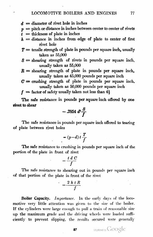
LOCOMOTIVE BOILERS AND ENGINES 77
d = diameter of rivet hole in inches
p = pitch or distance in inches between center to center of rivets
t = thickness of plate in inches
h = distance in inches from edge of plate to center of first
rivet hole
T = tensile strength of plate in pounds per square inch, usually
taken as 55,000
S = shearing strength of rivets in pounds per square incht
usually taken as 55,000
R = shearing strength of plate in pounds per square inch,
usually taken as 45,000 pounds per square inch
C = crushing strength of plate in pounds per square inch,
usually taken as 50,000 pounds per square inch
/ = factor of safety usually taken not less than 4$
The safe resistance in pounds per square inch offered by one
rivet to shear
- .7854 d?j-
The safe resistance in pounds per square inch offered to tearing
of plate between rivet holes
~(p-d)tj
The safe resistance to crushing in pounds per square inch of the
portion of the plate in front of rivet
/ d C
f
The safe resistance to shearing out in pounds per square inch
of that portion of the plate in front of the rivet
2 h t B
Boiler Capacity. Importance. In the early days of the loco
motive very little attention was given to the size of the boiler.
If the cylinders were large enough to pull a train of reasonable size
up the maximum grade and the driving wheels were loaded suffi
ciently to prevent slipping, the results secured were generally
87
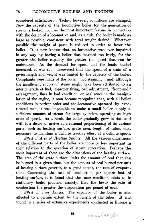
78 LOCOMOTIVE BOILERS AND ENGINES
considered satisfactory. Today, however, conditions are changed.
Now the capacity of the locomotive boiler for the generation of
steam is looked upon as the most important feature in connection
with the design of a locomotive and, as a rule, the boiler is made as
large as possible, consistent with total weight desired. Wherever
possible the weight of parts is reduced in order to favor the
boiler. It is now known that no locomotive was ever impaired
in any way by having a boiler that steamed too freely, for the
greater the boiler capacity the greater the speed that can be
maintained. As the demand for speed and the loads hauled
increased, it was soon discovered that the speed of a train of a
given length and weight was limited by the capacity of the boiler.
Complaints were made of the boiler "not steaming", and, although
the insufficient supply of steam might have been attributed to an
inferior grade of fuel, improper firing, bad adjustment, "front end"
arrangement, flues in bad condition, or negligence in the manipu
lation of the engine, it soon became recognized that, with all boiler
conditions in perfect order and the locomotive operated by expe
rienced men, it was impossible to make a small boiler supply a
sufficient amount of steam for large cylinders operating at high
rates of speed. As a result the boiler gradually grew in size, and
with it a desire to arrive at a rational proportioning of its various
parts, such as heating surface, grate area, length of tubes, etc.,
necessary to maintain a definite tractive effort at a definite speed.
Effect of Area of Heating Surface. All the various dimensions
of the different parts of the boiler are more or less important in
their relation to the question of steam generation. Perhaps the
most important of these are the dimensions of the heating surface.
The area of the grate surface limits the amount of coal that can
be burned in a given time, but the amount of coal burned per unit
of heating surface governs, to a great extent, the rate of evapora
tion. Concerning the rate of combustion per square foot of
heating surface, it is found that the same condition exists as in
stationary boiler practice, namely, that the lower the rate of
combustion the greater the evaporation per pound of coal.
Effect of Tube Length. The capacity of the boiler is also
affected to a certain extent by the length of the tubes. It was
found in a series of extensive experiments conducted in Europe a
68
LOCOMOTIVE BOILERS AND ENGINES 79
number of years ago that the most economical length of tubes
was 14 feet. This length was found with a draft in the fire-box of
3 inches of water. In the United States a much higher draft is
employed and for this reason much longer tubes can be used.
Tubes over 20 feet in length are now quite common. As long as
the temperature of the gases in the smoke-box is above that
corresponding to the pressure of steam in the boiler there will be
heat transferred from the front end of the tubes to the water in
the boiler. Increasing the length of the tubes will, of course,
reduce the draft in the fire-box and, as a result, the amount of coal
burned will be reduced. For this reason the tubes should be
of a definite length for maximum efficiency.
Effect of Scale. The transmission of heat through the tubes
and fire-box sheets is dependent to a large extent on the condition
of the inner surfaces. If they are covered with a thin layer of
scale, the heat transmitted will be materially reduced. Experi
ments conducted in 1898 on the Illinois Central Railroad gave
some very interesting results on the effect of scale on the steaming
capacity of a locomotive boiler. Tests were first made on a loco
motive which had been in service 21 months. After the test the
engine was sent to the shops and received new tubes and a thor
ough cleaning. The total weight of scale removed from the boiler
was 485 pounds and it had an average thickness on the principal
heating surfaces of inch. After the engine had received the
cleaning and new tubes, a second test was conducted in which
the same coal per square foot of heating surface was burned as in the
first test. The result of the second test showed the steam-making
capacity of the boiler to have been increased 13 per cent.
Effect of Radiation. The loss of heat from the outer surface
of a locomotive boiler by radiation and the ultimate effect on its
capacity are items worthy of consideration. The heat lost in this
manner is so great with an unprotected boiler shell that it is neces
sary to use some form of insulating material to minimize the loss.
Covering a boiler with insulating material is more necessary with
high pressure than with low pressure because of the greater tem
perature difference. Results of tests of boiler covering reported to
the Master Mechanics' Association in 1898 show that a loss of 0.34
B.t.u. per square foot of radiating surface per hour per degree
89
80 LOCOMOTIVE BOILERS AND ENGINES
difference in temperature was obtained by the use of mineral wool,
while under the same conditions with a lagging of wood and sheet
iron the loss was increased to 1.10 heat units. In both cases the
temperature difference was reckoned between the temperature of
the steam in the boiler and that of the surrounding air. The
results show a saving of 0.76 B.t.u. in favor of the mineral wool
lagging. Let us consider a boiler carrying steam at 200 pounds
per square inch gage pressure, which represents a temperature of
388° F. Assuming the temperature of the atmosphere to be 32° F.,
this represents a temperature difference of 356 degrees. Assume
further a locomotive boiler having an outside surface of 600 square
feet. The heat of vaporization per pound of steam at 200 pounds
per square inch gage pressure is 838 B.t.u. The pounds of steam
condensed in the boiler per hour due to radiation in case a wood
lagging is used, in excess of the amount that would be condensed
if mineral wool were used, is equal to
0.76X600X356
833 93
Assuming that the steam consumption per i.h.p.hr. is 20 pounds,
the above figure represents 9.6 horsepower.
The foregoing figures represent results obtained in still air.
The radiation losses are increased very much when the locomotive
is in service. This fact is demonstrated by the results of tests
conducted on the Chicago and Northwestern Railway in' 1899.
The locomotive employed had 219 square feet of covered boiler
surface and 139 square feet uncovered. Assuming, for this type
of engine, the steam consumption per i.h.p.hr. to be 26 pounds,
the results of the tests showed a condensation representing a horse
power of 4.5 when at rest and 9 when being pushed at a rate of 28
miles per hour.
Boiler Horsepower. In the foregoing we have considered the
determination of the greatest amount of steam which a locomotive
boiler can produce and it is evident that the boiler capacity limits
the work that can be performed by the engine. Under some
circumstances it is more convenient to express the boiler capacity
in terms of an evaporative unit. The term "boiler horsepower'? is
such a unit, but the use of this expression is sometimes misleading
90
LOCOMOTIVE BOILERS AND ENGINES 81
in speaking of the capacity of a locomotive, for a given boiler will
produce a greater horsepower with a compound than with a simple
engine and with an early and economical cut-off than with a later
and more wasteful one.
A boiler horsepower, as defined by the American Society of.
Mechanical Engineers, is the production of 30 pounds of steam per
hour at a gage pressure of 70 pounds per square inch evaporated
from a feed-water temperature of 100° F. This is considered
equivalent to the evaporation of 34J pounds of water per hour
from a temperature of 212° F. into steam at the same temperature.
91

r
LOCOMOTIVE BOILERS AND
ENGINES
PART II
THE LOCOMOTIVE ENGINE
In studying the conditions affecting the performance of the
engine proper, the amount of lead, outside lap, and inside clearance
must be taken into consideration.
Lead. By lead is meant the amount the steam port is open
when the engine is on dead center or when the piston is at the begin
ning of its stroke. This amount varies from 0 to \ of an inch in
practice. By having the proper amount of lead, a sufficient amount of
steam behind the piston is assured at the beginning of the stroke and
assists in maintaining the steam pressure until the steam port is closed
and the steam is thereby cut off. It also serves to promote smooth
running machinery. Any admission of steam behind the piston
before the end of the stroke results in negative work, hence the amount
of lead should be limited and largely controlled by the speed of the
machine.
Outside Lap. By the term outside lap is meant the amount the
valve overlaps the outside edges of the steam ports when it is in its
central position. One of the effects of increasing outside lap is to
cause cut-off to take place earlier in the stroke, other conditions
remaining unchanged. If, however, the amount of lap is increased
and it is desired to maintain the same cut-off, the stroke of the valve
must be increased. Within certain limits, outside lap increases the
rapidity with which the valve opens the steam port, resulting in a
freer admission of steam. The range of cut-off is decreased as the
lap is increased, other conditions remaining the same.
When the cut-off is short, the exhaust is hastened, an effect which
diminishes as the cut-off is lengthened. The amount by which the
steam port is uncovered by the exhaust cavity of the slide valve is
93
84 LOCOMOTIVE BOILERS AND ENGINES
increased as the cut-off is shortened. Other things remaining con
stant the changing of any one of the events of stroke causes a corre
sponding change to a greater or less degree of each of the other events.
Inside Clearance. By the expression inside clearance is meant
the amount the steam port is uncovered by the exhaust cavity of the
valve when the valve is in its central position. Formerly it was cus
tomary to have an inside lap of about TV of an inch but in recent
years in the development of engines which require a free exhaust at
high speeds, the inside lap was reduced until now there is in some
cases from | to ^ inches inside clearance. The effect of changing
a valve from inside lap to inside clearance, other things remaining un-
Fig. 64. Standard Stephenson Valve Gear.
changed, is to hasten release and delay compression and hence to
increase the interval in which the exhaust port remains open. It also
permits a greater extent of exhaust port opening. As a consequence,
the exhaust is freer and the back pressure is reduced, giving an ad
vantage in the operation of the engine, which is desired at high speeds.
Experiments have shown that an increase in inside clearance for high
speeds will bring about an increase in the power of the locomotive,
but an increase in inside clearance at slow speeds entails a loss of
power and a decrease in efficiency. The loss in power at low speeds,
due to inside clearance, is greater at short cut-offs and diminishes as
the cut-off is increased. Tests have shown that at moderate speeds,
say, 40 to 50 miles per hour, all disadvantages are overcome.
VALVE MOTION
Requirements. The valve motion of a locomotive engine must
meet the following regulations:
94
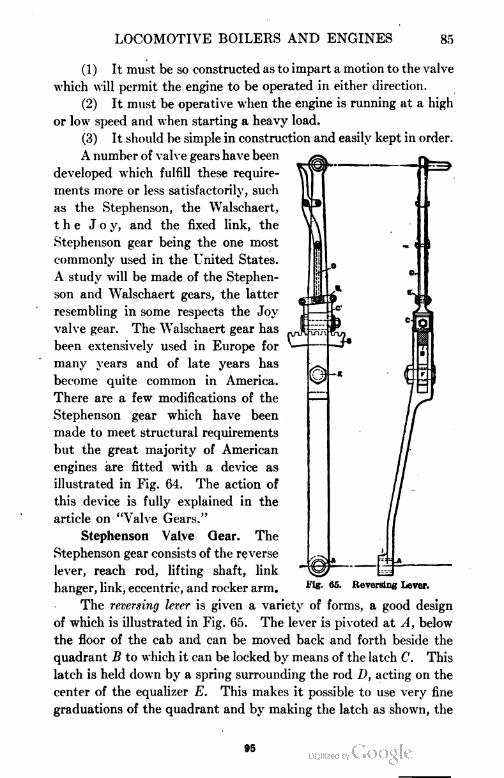
LOCOMOTIVE BOILERS AND ENGINES 85
(1) It must be so constructed as to impart a motion to the valve
which will permit the engine to be operated in either direction.
(2) It must be operative when the engine is running at a high
or low speed and when starting a heavy load.
(3) It should be simple in construction and easily kept in order.
A number of valve gears have been
developed which fulfill these require
ments more or less satisfactorily, such
as the Stephenson, the Walschaert,
the Joy, and the fixed link, the
Stephenson gear being the one most
commonly used in the United States.
A study will be made of the Stephen
son and Walschaert gears, the latter
resembling in some respects the Joy
valve gear. The Walschaert gear has
been extensively used in Europe for
many years and of late years has
become quite common in America.
There are a few modifications of the
Stephenson gear which have been
made to meet structural requirements
but the great majority of American
engines are fitted with a device as
illustrated in Fig. 64. The action of
this device is fully explained in the
article on "Valve Gears."
Stephenson Valve Gear. The
Stephenson gear consists of the reverse
lever, reach rod, lifting shaft, link
hanger, link, eccentric, and rocker arm.
The reversing lever is given a variety of forms, a good design
of which is illustrated in Fig. 65. The lever is pivoted at A, below
the floor of the cab and can be moved back and forth beside the
quadrant B to which it can be locked by means of the latch C. This
latch is held down by a spring surrounding the rod D, acting on the
center of the equalizer E. This makes it possible to use very fine
graduations of the quadrant and by making the latch as shown, the
Fig. 65. Reversing Lever.
95
86 LOCOMOTIVE BOILERS AND ENGINES
cut-off can be regulated by practically what amounts to half notches
The reach rod, or reversing rod, is fastened to the reversing lever
at F and consists of a simple piece of flat iron having a jaw at one end
by which it serves to connect the reversing lever and the lifting shaft
K, shown in Fig. 64.
The lifting shaft, shown at K, Fig. 64, consists of a shaft held
in brackets usually bolted to the engine frames to which are connected
three arms, one being vertical and to which is attached the reach rod,
and two horizontal ones from which the links are suspended.
The link hanger is a flat bar with a boss on each end. It
carries the link by means of a pin attached to the link saddle, illus
trated in Fig. 64.
The link, Fig. 64, is an open device held by the saddle and
fitted with connections for the eccentric rod.
The eccentrics, Fig. 64, usually of cast iron, are fitted to the main
driving axle.
The rocker arm, Fig. 64, consists of a shaft to which two arms
are connected, the lower one of which is attached to the link block and
the upper to the valve stem.
Setting the Valves. This is a comparatively simple operation but
one requiring great care. On account of the angularity of the rods,
it is impossible to adjust any link motion to give equal cut-off at all
points for both strokes of the piston. The most satisfactory arrange
ment is one which provides for an equalization of the lead and cut-off
at mid-gear. But even this will cause a variation of cut-off of from § to
\ of one per cent in the full gear part of the cut-off and at other points.
In setting the valves upon a locomotive, some means must be
employed for turning the main driving wheels. This is usually ac
complished by mounting the main drivers upon small rollers which
can be turned by a ratchet or motor without moving the locomotive
as a whole. If a set of rollers are not available, the locomotive may
be moved to and fro by using pinch bars.
Before undertaking the setting of the valves, the length of the
valve rod must be adjusted. To do this, set the upper rocker arm
vertical if the valve seat is horizontal; if inclined, the rocker arm
must be placed perpendicular to the plane of the valve seat. Next
adjust the length of the valve rod so that it will connect with the rocker
arm and the valve when the valve is in its central position. The
98
LOCOMOTIVE BOILERS AND ENGINES 87
next step is to locate the dead center points which points give the
position of the crank on the dead center. It is very essential that this
be done very accurately since a small movement of the crank at this
position moves the piston but very little while the same movement
causes a comparatively large movement of the valve. Hence, if the
dead center points are not accurately located, the valves will not be
set so accurately as they otherwise would be. To locate the dead
center points, proceed as follows: First, secure a tram d as shown
in Fig. 66. This tram should be made of a steel rod about \ inch in
diameter having each end pointed, hardened, and tempered so as to
retain a sharp point. With a center punch, make a center e on some
fixed portion of the frame in such a position that when one point of
Fig. 66. Diagram for Locating Dead-Center Points.
the tram is in the center e, the other pointed end can be made to de
scribe lines on the main driver. To locate the forward dead center,
turn the driver ahead until the crank has almost reached the center
line as shown in the position A B, Fig. 66; that is, when the cross-
head is, say, \ inch from the extreme point of its travel. With the
parts in this position, place the tram point in e as shown and locate
the point a on the driver, and describe the line //on the crosshead
and guide. Next turn the driver ahead until the crank passes the
dead center and the lines / / again coincide, when a second point c
is marked by means of the tram at the same distance from the center
of the axle as the point a. With a pair of dividers locate the mid-
position b between a and c. In setting the valves for the head end,
the required dead center will be located when one tram point is in the
center e and the other in the center b. The dead-center point for the
back stroke is located in the same manner as just described. An
attempt to place the engine on dead center by measurements taken
97
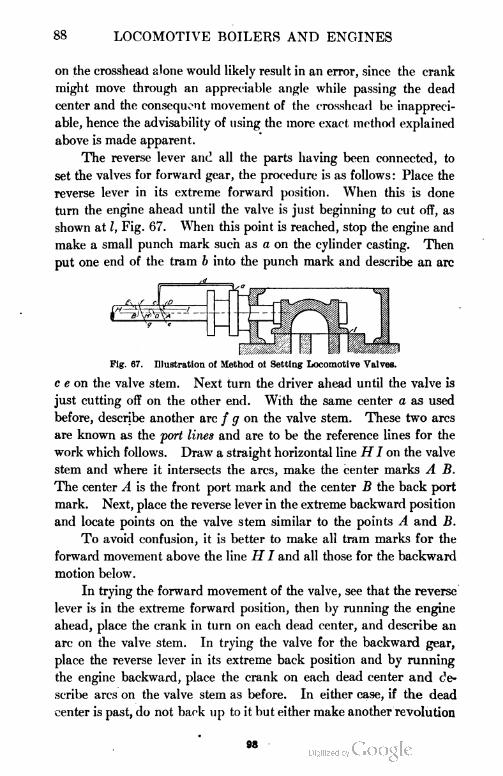
88 LOCOMOTIVE BOILERS AND ENGINES
on the crosshead alone would likely result in an error, since the crank
might move through an appreciable angle while passing the dead
center and the consequent movement of the crosshead be inappreci
able, hence the advisability of using the more exact method explained
above is made apparent.
The reverse lever and all the parts having been connected, to
set the valves for forward gear, the procedure is as follows : Place the
reverse lever in its extreme forward position. When this is done
turn the engine ahead until the valve is just beginning to cut off, as
shown at I, Fig. 67. When this point is reached, stop the engine and
make a small punch mark such as a on the cylinder casting. Then
put one end of the tram b into the punch mark and describe an arc
Fig. 67. Illustration of Method ot Setting Locomotive Valves.
c e on the valve stem. Next turn the driver ahead until the valve is
just cutting off on the other end. With the same center a as used
before, describe another arc / g on the valve stem. These two arcs
are known as the port lines and are to be the reference lines for the
work which follows. Draw a straight horizontal line H I on the valve
stem and where it intersects the arcs, make the center marks A B.
The center A is the front port mark and the center B the back port
mark. Next, place the reverse lever in the extreme backward position
and locate points on the valve stem similar to the points A and B.
To avoid confusion, it is better to make all tram marks for the
forward movement above the line H I and all those for the backward
motion below.
In trying the forward movement of the valve, see that the reverse
lever is in the extreme forward position, then by running the engine
ahead, place the crank in turn on each dead center, and describe an
arc on the valve stem. In trying the valve for the backward gear,
place the reverse lever in its extreme back position and by running
the engine backward, place the crank on each dead center and de
scribe arcs on the valve stem as before. In either case, if the dead
center is past, do not back up to it but either make another revolution
M
LOCOMOTIVE BOILERS AND ENGINES 89
o jht ;ngine or back beyond it some distance, then approach it from
tha pvjper direction. This must be done in order to eliminate all
lost motion.
These trial tram lines should be compared with the port marks
when the engine is placed in the forward and backward gear.
If the trial tram lines fall outside of the port marks, so much
lead is indicated, while if they fall within the port marks, so much
negative lead is indicated.
It is customary for railroad companies to set the valves on their
locomotives to give equal lead. The method commonly employed
is presented herewith. Having the reverse lever in the extreme
forward notch, run the engine ahead, stopping it on the forward dead
center. With the tram b in the center a, Fig. 67, describe the arc D
above the line H I. Next turn the engine ahead until the back dead
center is reached ; using the tram b again with a center at a, describe
the arc E above the line H I. With dividers, find a mid-point 0
between E and D. If the center 0 is ahead of the point M, which is
midway between the port marks A and B, the eccentric blades which
control the forward motion must be shortened an amount equal to
the distance between M and 0. When this is done, the lead will be
equalized. If it is desired to increase the lead, move the forward
eccentric toward the crank. To decrease the lead, move the forward
eccentric away from the crank. After all of these changes have been
made, repeat the operation in order to check the results. If this does
not give the desired results, correct the error by repeating the pro
cess and continue by trial until the conditions sought for are
obtained.
To set the valves for the back motion, proceed in the same man
ner as that described for the forward motion, all the changes being
made on the eccentric blades and eccentric which control the back
ward motion.
In all that has been said regarding the setting of the Stephenson
valve gear, it is assumed that the gear is one having open rods; that is,
one in which the rods are open, not crossed when the eccentrics face
the link.
Walschaert Valve Gear. The Walschaert valve gear is illus
trated by the line diagram in Fig. 68-a. Fig. 68-b shows its applica
tion to a Consolidation freight locomtive. From a study of Fig. 68-a
99
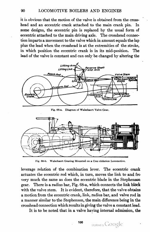
90 LOCOMOTIVE BOILERS AND ENGINES
it is obvious that the motion of the valve is obtained from the cross-
head and an eccentric crank attached to the main crank pin. In
some designs, the eccentric pin is replaced by the usual form of
eccentric attached to the main driving axle. The crosshead connec
tion imparts a movement to the valve which in amount equals the lap
plus the lead when the crosshead is at the extremities of the stroke,
in which position the eccentric crank is in its mid-position. The
lead of the valve is constant and can only be changed by altering the
Fig. 68-a. Diagram of Walschasrt Valve Gear.
Fig. 68-b. Walschaert Gearing Mounted on a Consolidation Locomotive.
leverage relation of the combination lever. The eccentric crank
actuates the eccentric rod which, in turn, moves the link to and fro
very much the same as does the eccentric blade in the Stephenson
gear. There is a radius bar, Fig. 68-a, which connects the link block
with the valve stem. It is evident, therefore, that the valve obtains
a motion from the eccentric crank, link, radius bar, and valve rod in
a manner similar to the Stephenson, the main difference being in the
crosshead connection which results in giving the valve a constant lead.
It is to be noted that in a valve having internal admission, the
100
LOCOMOTIVE BOILERS AND ENGINES 91
radius bar connects with a combination lever above the valve rod
connection, as shown in Fig. 68-b, and that in a valve having external
admission, the connection is made below the valve rod, as illustrated
in Fig. 68-a; also, in a valve having internal admission, the eccentric
crank follows the main crank, while in a case where the valve has
external admission, it precedes the main crank. Theoretically, the
eccentric crank is 90 degrees from the main crank but because of the
angularity of the eccentric rod, it is usually two or three degrees more.
The Walschaert gear is operated by a reverse lever in the same
manner as the Stephenson gear. In the Stephenson gear, a move
ment of the reverse lever causes the link to be raised or lowered, the
link block remaining stationary, whereas in the Walschaert gear, the
link remains stationary and the link block is raised or lowered. From
a study of the two gears, it may be stated that the chief point of dif
ference is that the Walschaert gives a constant lead for all cut-offs,
whereas the Stephenson gives a different lead for different cut-offs.
The following steps given by the American Locomotive Com
pany for adjusting the Walschaert valve gear are presented:
1. The motion must be adjusted with the crank on the dead centers by
lengthening or shortening the eccentric rod until the link takes such a position
as to impart no motion to the valve when the link block is moved from its extreme
forward to its extreme backward position. Before these changes in the eccentric
are resorted to, the length of the valve stem should be examined, as it may be
of advantage to plane off or line under the foot of the link support which might
correct the length of both rods, or at least only one of these would need to be
changed.
2. The difference between the two positions of the valve on the forward
and back centers is the lead and lap doubled and it cannot be changed except
by changing the leverage relations of the combination lever.
3. A given lead determines the lap or a given lap determines the lead,
and it must be divided for both ends as desired by lengthening or shortening the
valve spindle.
4. Within certain limits, this adjustment may be made by shortening or
lengthening the radius bar but it is desirable to keep the length of this bar equal
to the radius of the link in order to meet the requirements of the first condition.
5. The lead may be increased by reducing the lap, and the cut-off point
will then be slightly advanced. Increasing the lap introduces the opposite
effect on the cut-off. With good judgment, these qualities may be varied to
offset other irregularities inherent in transforming rotary into lineal motion.
6. Slight variations may be made in the cut-off points as covered by
the preceding paragraph but an independent adjustment cannot be made except.
by shifting the location of the suspension point which is preferably determined
by a model.
101
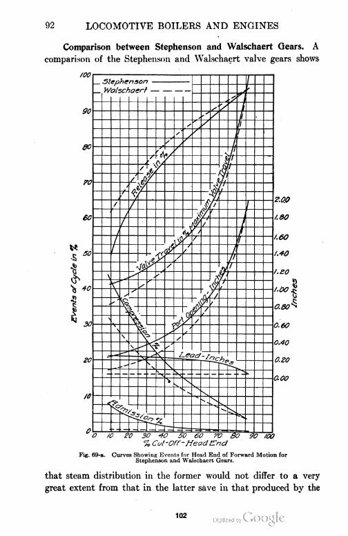
92 LOCOMOTIVE BOILERS AND ENGINES
Comparison between Stephenson and Walschaert Gears. A
comparison of the Stephenson and Walschaert valve gears shows
O Id eb 30 40 50 60 TV 80 90 /CO
% Cut-Off-HeadEnd
Fig. 69-a. Curves Showing Events for Head End of Forward Motion forStephenson and Walschaert Gears.
that steam distribution in the former would not differ to a very
great extent from that in the latter save in that produced by the
102
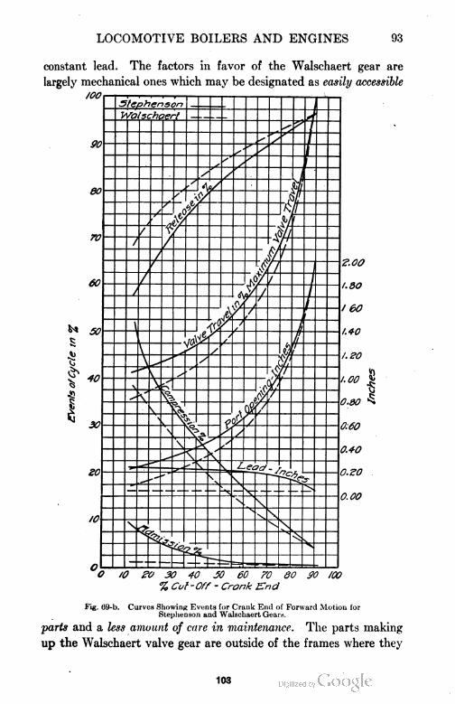
LOCOMOTIVE BOILERS AND ENGINES 93
constant lead. The factors in favor of the Walschaert gear are
largely mechanical ones which may be designated as easily accessible
O /O eo 30 40 JO 60 70 80 SO /CO
% Cut -Off - Crank End
Fig. 69-b. Curves Showing Events for Crank End of Forward Motion forStephenson and Walschaert Gears.
parts and a less amount of care in maintenance. The parts making
up the Walschaert valve gear are outside of the frames where they
103
94 LOCOMOTIVE BOILERS AND ENGINES
TABLE VIII
Comparative Dimensions of Stephenson and Walschaert Gears
Stephenson WalschaertGear Geab
D-Slide D-Slide
1.0 1.0
1.0 1 .0
0 0
0 0
A
X
1 1
6 6
24 24
96 96
60
46
Type of valve
Steam lap in inches, H.E. . .
Steam lap in inches, C.E
Exhaust lap in inches, H.E
Exhaust lap in inches, C.E
Lead at full gear in inches
Lead at mid gear in inches
Width of port in inches. .
Maximum valve travel in inches . .
Stroke of piston in inches.
Length of connecting rod in inches
Radius of link arc in inches
Length of radius rod in inches. . . .
can be easily reached in case of breakdowns and necessary repairs.
Another advantage accruing from this fact is that the space between
the frames is left open permitting bracing, which protects and
strengthens the frames. This is not possible when the Stephenson
gear is used. The smaller number of moving parts, hardened pins,
and accessible bearings in the Walschaert gear result in fewer and
less expensive repairs.
A study of the action of a valve on a given locomotive, when
operated by means of a Walschaert gear and also a Stephenson gear,
gave the results shown graphically in Figs. 69-a and 69-b. The
Fig. 69-c. Walschaert Valve Gear Mounted on Consolidated Freight Locomotive.
results were taken from Zeuner diagrams, drawn to represent the
steam distribution given by each gear. The general dimensions of
104
LOCOMOTIVE BOILERS AND ENGINES 95
the two gears, taken from designs prepared for use on a given loco
motive are shown in Table VIII.
The conditions for both the head end and crank end of the
forward motion, in both Stephenson and Walschaert gears are
represented in Figs. 69-a and 69-b. Each event of the cycle—valve
travel, port opening, and lead—is plotted with reference to the cut-off.
As can be seen, the Walschaert gear gives for all cut-off positions a
later admission, later release, later compression, less lead, less port
opening, and less valve travel than does the Stephenson gear. With
the exception perhaps of lead, the differences are negligibly small for
all cut-off positions beyond 50 per cent. With cut-off positions
less than 50 per cent, however, these differences increase quite
rapidly.
The Walschaert gear is applied to a locomotive in several ways,
each having its own advantages. The method illustrated in Fig.
69-c gives the student a general idea how the scheme is worked
out and applied in connection with a consolidative freight loco
motive.
Valves. Until recent years the valve ordinarily used on loco
motives was the plain slide valve, partially balanced. In the plain
slide valve the full steam chest pressure is exerted over the whole
of the back surface of the valve. The balancing of a valve consists
in removing a portion of this pressure, thus decreasing the frictional
resistance of the valve on its seat. The percentage of this pressure
that is removed, or the amount of balance, varies from 45 to 90 per
cent of the total face of the valve, and the average in practice is
about 65 per cent. In the valve shown in Fig. 70, the balance is
69 per cent. The pinch of the packing ring on the cone slightly
increases the pressure of the valve on its seat.
In Fig. 70, the valve, 1, is of the ordinary D type driven by the
yoke, 2, which is forged as a part of the valve stem. To the back of
the valve is bolted a circular plate, 3, having a cone turned thereon.
On this cone is fitted a loose ring, 4, the inner face of which is beveled
to the same degree as the taper of the cone. The ring is cut at one
point and is, therefore, flexible. The open space at the cut in the
ring is covered by an L-shaped clip which is placed on the outside and
fastened to one end of the ring, the other end of the ring remaining
free. This L-shaped clip reaches to the top of the ring at the outside
106
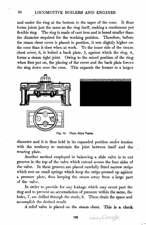
96 LOCOMOTIVE BOILERS AND ENGINES
and under the ring at the bottom to the taper of the cone. It thus
forms joints just the same as the ring itself, making a continuous yet
flexible ring. The ring is made of cast iron and is bored smaller than
the diameter required for the working position. Therefore, before
the steam chest cover is placed in position, it sets slightly higher on
the cone than it does when at work. To the inner side of the steam
chest cover, 6, is bolted a back plate, 5, against which the ring, 4,
forms a steam tight joint. Owing to the raised position of the ring
when first put on, the placing of the cover and the back plate forces
the ring down over the cone. This expands the former to a larger
Fig. 70. Plain Slide Valve.
diameter and it is thus held in its expanded position under tension
with the tendency to maintain the joint between itself and the
wearing plate.
Another method employed in balancing a slide valve is to cut
grooves in the top of the valve which extend across the four sides of
the valve. In these grooves are placed carefully fitted narrow strips
which rest on small springs which keep the strips pressed up against
a pressure plate, thus keeping the steam away from a large part
of the valve.
In order to provide for any leakage which may occur past the
ring and to prevent an accumulation of pressure within the same, the
holes, 7, are drilled through the studs, S. These drain the space and
accomplish the desired result.
A relief valve is placed on the steam chest. This is a check
106
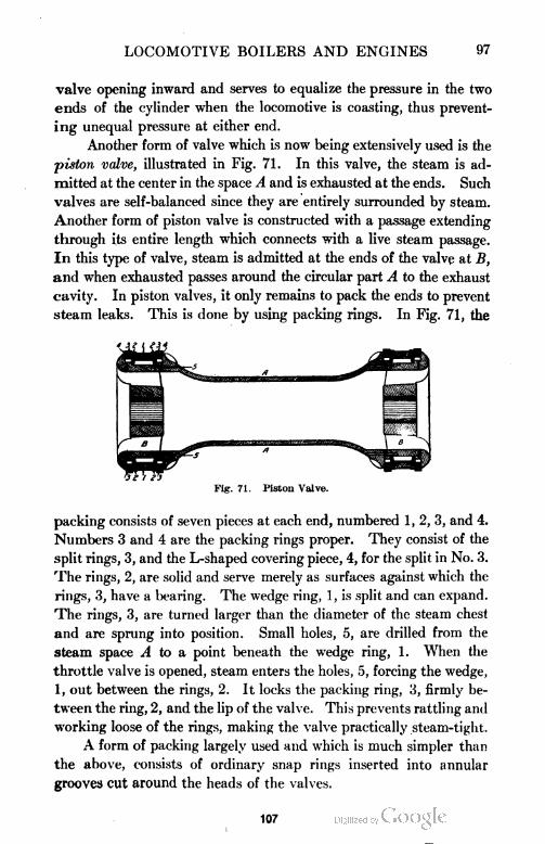
LOCOMOTIVE BOILERS AND ENGINES 97
valve opening inward and serves to equalize the pressure in the two
ends of the cylinder when the locomotive is coasting, thus prevent
ing unequal pressure at either end.
Another form of valve which is now being extensively used is the
piston valve, illustrated in Fig. 71. In this valve, the steam is ad
mitted at the center in the space A and is exhausted at the ends. Such
valves are self-balanced since they are entirely surrounded by steam.
Another form of piston valve is constructed with a passage extending
through its entire length which connects with a live steam passage.
In this type of valve, steam is admitted at the ends of the valve at B,
and when exhausted passes around the circular part A to the exhaust
cavity. In piston valves, it only remains to pack the ends to prevent
steam leaks. This is done by using packing rings. In Fig. 71, the
Fig. 71. Piston Valve.
packing consists of seven pieces at each end, numbered 1, 2, 3, and 4.
Numbers 3 and 4 are the packing rings proper. They consist of the
split rings, 3, and the L-shaped covering piece, 4, for the split in No. 3.
The rings, 2, are solid and serve merely as surfaces against which the
rings, 3, have a bearing. The wedge ring, 1, is split and can expand.
The rings, 3, are turned larger than the diameter of the steam chest
and are sprung into position. Small holes, 5, are drilled from the
steam space A to a point beneath the wedge ring, 1. When the
throttle valve is opened, steam enters the holes, 5, forcing the wedge,
1, out between the rings, 2. It locks the packing ring, 3, firmly be
tween the ring, 2, and the lip of the valve. This prevents rattling and
working loose of the rings, making the valve practically steam-tight.
A form of packing largely used and which is much simpler than
the above, consists of ordinary snap rings inserted into annular
grooves cut around the heads of the valves.
107
98 LOCOMOTIVE BOILERS AND ENGINES
Valve Friction. Of the many different parts of a locomotive
which have been studied from the scientific standpoint, few parts
have been given more attention than the main steam valve.
When the valves were small and steam pressures were not high,
the force necessary to move the valve when in operation was not
very great. With the pressures employed today and the sizes of
steam ports found on our modern locomotives, the reduction of
valve friction becomes a very important matter. From an exami
nation of Figs. 70 and 71, it is an easy matter to see that the
more completely a valve is balanced, the less work will be required
to move it back and forth when in service.
Valve Tests to Determine Friction. The question was consid
ered such an important one that the Master Mechanics' Associa
tion appointed a committee to investigate different types of valves
under conditions of service. The committee conducted its experi
mental work, in 1896, upon the locomotive testing plant at Purdue
University, Lafayette, Indiana. The Purdue locomotive, known as
Schenectady No. 1, was used, having cylinders 17 inches in diam
eter by 24 inches stroke. The ports were 16 inches long, the steam
port being 1J and the exhaust port 2| inches wide. The bridges
were 1| inches wide. The valve had a maximum travel of 5| inches,
steam lap, f-inch, exhaust lap, ^j-inch, and was set with a t^-inch lead,
with the reverse lever in its full forward position, and a ^-inch
negative lead, with the reserve lever in its full backward position.
Four different slide valves were tested as follows: unbalanced
D-valve, Richardson balanced valve, American balanced valve
with single balance ring, and American balanced valve with two
balance rings. A fluid dynamometer was placed in position
between the valve stem and rocker arm in such a manner as to
measure the force necessary to overcome the friction of the valve
when operated under different conditions. The valves weighed
78, 85§, 79 j, and 84 pounds, respectively. The weight of the
dynamometer was 105 pounds and that of the valve yoke
37 pounds. The Richardson valve had 56 per cent of the area of
the valve face balanced by the use of flat strips held against the
balance plate by springs. The American valves had 61| and 66
per cent of their areas balanced by using single and double
balancing rings, respectively.
108
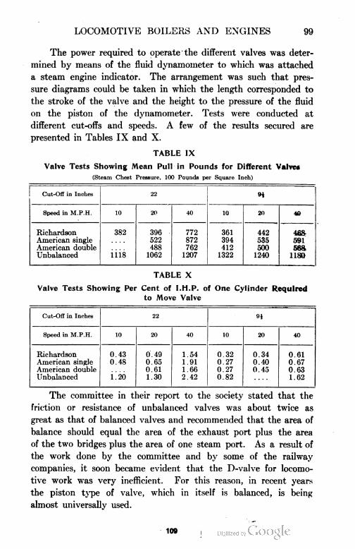
LOCOMOTIVE BOILERS AND ENGINES 99
The power required to operate the different valves was deter
mined by means of the fluid dynamometer to which was attached
a steam engine indicator. The arrangement was such that pres
sure diagrams could be taken in which the length corresponded to
the stroke of the valve and the height to the pressure of the fluid
on the piston of the dynamometer. Tests were conducted at
different cut-offs and speeds. A few of the results secured are
presented in Tables IX and X.
TABLE IX
Valve Tests Showing Mean Pull in Pounds for Different Valves
(Steam Chest Pressure. 100 Pounds per Square Inch)
Cut-Off in Inches 22 9i
Speed in M.P.H. 10 20 40 10 20 40
Richardson 382 396 772 361 442 468
American single 522 872 394 535 591
American double 488 762 412 500 568
Unbalanced 1118 1062 1207 1322 1240 1180
TABLE X
Valve Tests Showing Per Cent of I.H.P. of One Cylinder Required
to Move Valve
Cut-Off in Inches 22 n
Speed in M.P.H. 10 20 40 10 20 40
Richardson 0.43 0.49 1.54 0.32 0.34 0.61
American single 0.48 0.65 1.91 0.27 0.40 0.67
American double 0.61 1.66 0.27 0.45 0.63
Unbalanced i.20 1.30 2.42 0.82 1.62
The committee in their report to the society stated that the
friction or resistance of unbalanced valves was about twice as
great as that of balanced valves and recommended that the area of
balance should equal the area of the exhaust port plus the area
of the two bridges plus the area of one steam port. As a result of
the work done by the committee and by some of the railway
companies, it soon became evident that the D-valve for locomo
tive work was very inefficient. For this reason, in recent years
the piston type of valve, which in itself is balanced, is being
almost universally used.
109
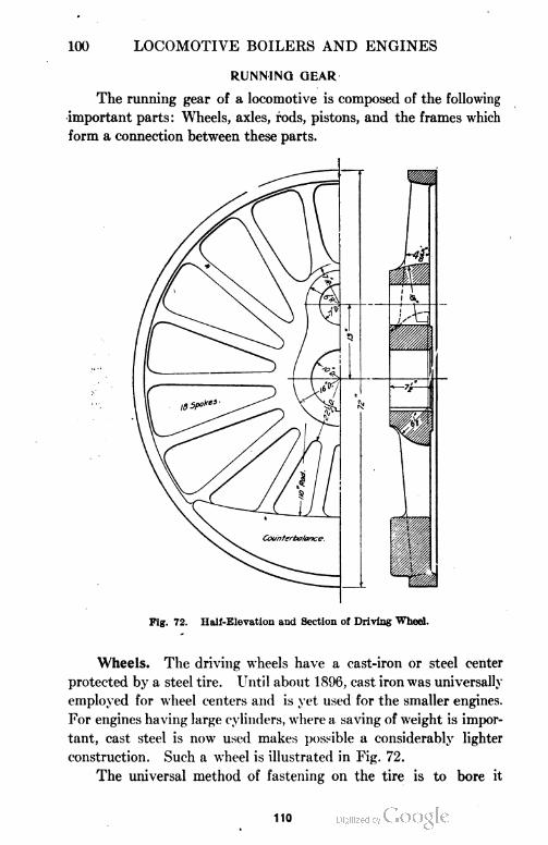
100 LOCOMOTIVE BOILERS AND ENGINES
RUNNING GEAR
The running gear of a locomotive is composed of the following
important parts: Wheels, axles, rods, pistons, and the frames which
form a connection between these parts.
Fig. 72. Half-Elevation and Section of Driving Wheel.
Wheels. The driving wheels have a cast-iron or steel center
protected by a steel tire. Until about 1896, cast iron was universally
employed for wheel centers and is yet used for the smaller engines.
For engines having large cylinders, where a saving of weight is impor
tant, cast steel is now used makes possible a considerably lighter
construction. Such a wheel is illustrated in Fig. 72.
The universal method of fastening on the tire is to bore it
110
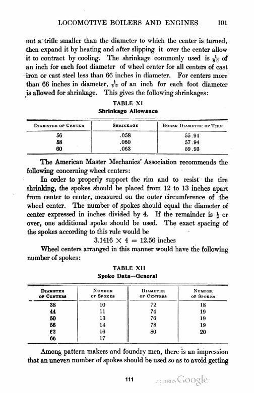
LOCOMOTIVE BOILERS AND ENGINES 101
out a trifle smaller than the diameter to which the center is turned,
then expand it by heating and after slipping it over the center allow
it to contract by cooling. The shrinkage commonly used is of
an inch for each foot diameter of wheel center for all centers of cast
iron or cast steel less than 66 inches in diameter. For centers more
than 66 inches in diameter, TV of an inch for each foot diameter
is allowed for shrinkage. This gives the following shrinkages:
TABLE XI
Shrinkage Allowance
Diameter of Center Shrinkage Bored Diameter of Tire
56 .058 55.94
58 .060 57.94
60 .063 59.93
The American Master Mechanics' Association recommends the
following concerning wheel centers:
In order to properly support the rim and to resist the tire
shrinking, the spokes should be placed from 12 to 13 inches apart
from center to center, measured on the outer circumference of the
wheel center. The number of spokes should equal the diameter of
center expressed in inches divided by 4. If the remainder is \ or
over, one additional spoke should be used. The exact spacing of
the spokes according to this rule would be
3.1416 X 4 = 12.56 inches
Wheel centers arranged in this manner would have the following
number of spokes :
TABLE XII
Spoke Data—General
Diameter Number Diameter Number
op Centers of Spokes op Centers of Spokes
38 10 72 18
44 n 74 19
50 13 76 19
56 14 78 19
e? 16 80 20
66 17
Among pattern makers and foundry men, there is an impression
that an uneven number of spokes should be used so as to avoid getting
111
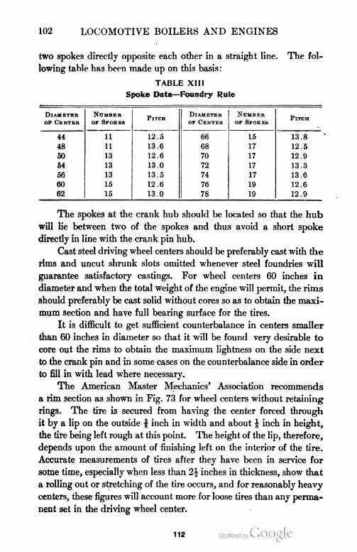
102 LOCOMOTIVE BOILERS AND ENGINES
two spokes directly opposite each other in a straight line. The fol
lowing table has been made up on this basis :
TABLE XIII
Spoke Data—Foundry Rule
Diameter NumberPitch
Diameter NumberPitch
Of Center of Spokes of Center of Spokes
44 11 12.5 66 15 13.8
48 11 13.6 68 17 12.5
50 13 12.6 70 17 12.9
54 13 13.0 72 17 13.3
56 13 13.5 74 17 13.6
60 15 12.6 76 19 12.6
62 15 13.0 78 19 12.9
The spokes at the crank hub should be located so that the hub
will lie between two of the spokes and thus avoid a short spoke
directly in line with the crank pin hub.
Cast steel driving wheel centers should be preferably cast with the
rims and uncut shrunk slots omitted whenever steel foundries will
guarantee satisfactory castings. For wheel centers 60 inches in
diameter and when the total weight of the engine will permit, the rims
should preferably be cast solid without cores so as to obtain the maxi
mum section and have full bearing surface for the tires.
It is difficult to get sufficient counterbalance in centers smaller
than 60 inches in diameter so that it will be found very desirable to
core out the rims to obtain the maximum lightness on the side next
to the crank pin and in some cases on the counterbalance side in order
to fill in with lead where necessary.
The American Master Mechanics' Association recommends
a rim section as shown in Fig. 73 for wheel centers without retaining
rings. The tire is secured from having the center forced through
it by a lip on the outside f inch in width and about £ inch in height,
the tire being left rough at this point. The height of the lip, therefore,
depends upon the amount of finishing left on the interior of the tire.
Accurate measurements of tires after they have been in service for
some time, especially when less than 2\ inches in thickness, show that
a rolling out or stretching of the tire occurs, and for reasonably heavy
centers, these figures will account more for loose tires than any perma
nent set in the driving wheel center.
112
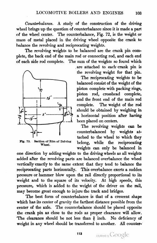
LOCOMOTIVE BOILERS AND ENGINES 103
Counterbalance. A study of the construction of the driving
wheel brings up the question of counterbalance since it is made a part
of the wheel center. The counterbalance, Fig. 72, is the weight or
mass of metal placed in the driving wheel opposite the crank to
balance the revolving and reciprocating weights.
The revolving weights to be balanced are the crank pin com
plete, the back end of the main rod or connecting rod, and each end
of each side rod complete. The sum of the weights so found which
are attached to each crank pin is
the revolving weight for that pin.
The reciprocating weights to be
balanced consist of the weight of the
piston complete with packing rings,
piston rod, crosshead complete,
and the front end of the main rod
complete. The weight of the rod
should be obtained by weighing in
a horizontal position after having
been placed on centers.
The revolving weights can be
counterbalanced by weights at
tached to the wheel to which they
belong, while the reciprocating
weights can only be balanced in
one direction by adding weights to the driving wheels as all weights
added after the revolving parts are balanced overbalance the wheel
vertically exactly to the same extent that they tend to balance the
reciprocating parts horizontally. This overbalance exerts a sudden
pressure or hammer blow upon the rail directly proportional to its
weight and to the square of its velocity. At high speeds, this
pressure, which is added to the weight of the driver on the rail,
may become great enough to injure the track and bridges.
The best form of counterbalance is that of a crescent shape
which has its center of gravity the farthest distance possible from the
center of the axle. The counterbalance should be placed opposite
the crank pin as close to the rods as proper clearance will allow.
The clearance should be not less than f inch. No deficiency of
weight in any wheel should be transferred to another. All counter-
Section of Rim of Driving
Wheel.
113
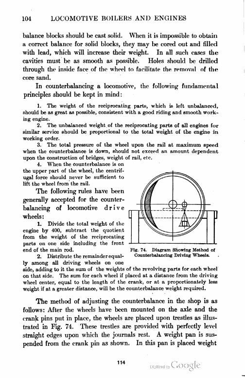
104 LOCOMOTIVE BOILERS AND ENGINES
balance blocks should be cast solid. When it is impossible to obtain
a correct balance for solid blocks, they may be cored out and filled
with lead, which will increase their weight. In all such cases the
cavities must be as smooth as possible. Holes should be drilled
through the inside face of the wheel to facilitate the removal of the
core sand.
In counterbalancing a locomotive, the following fundamental
principles should be kept in mind:
1. The weight of the reciprocating parts, which is left unbalanced,
should be as great as possible, consistent with a good riding and smooth work
ing engine.
2. The unbalanced weight of the reciprocating parts of all engines for
similar service should be proportional to the total weight of the engine in
working order.
3. The total pressure of the wheel upon the rail at maximum speed
when the counterbalance is down, should not exceed an amount dependent
upon the construction of bridges, weight of rail, etc.
4. When the counterbalance is on
the upper part of the wheel, the centrif
ugal force should never be sufficient to
lift the wheel from the rail.
The following rules have been
generally accepted for the counter
balancing of locomotive drive
wheels:
1. Divide the total weight of the
engine by 400, subtract the quotient
from the weight of the reciprocating
parts on one side including the front
end of the main rod.
2. Distribute the remainder equal
ly among all driving wheels on one
side, adding to it the sum of the weights of the revolving parts for each wheel
on that side. The sum for each wheel if placed at a distance from the driving
wheel center, equal to the length of the crank, or at a proportionately less
weight if at a greater distance, will be the counterbalance weight required.
The method of adjusting the counterbalance in the shop is as
follows: After the wheels have been mounted on the axle and the
crank pins put in place, the wheels are placed upon trestles as illus
trated in Fig. 74. These trestles are provided with perfectly level
straight edges upon which the journals rest. A weight pan is sus
pended from the crank pin as shown. In this pan is placed weight
Fig. 74. Diagram Showing Method oi
Counterbalancing Driving Wheels.
114
LOCOMOTIVE BOILERS AND ENGINES 105
enough to just balance the wheels in such a position that a horizontal
line will pass through the center of the axle and crank pin and counter
balance on one wheel, and a vertical line will pass through the axle
and crank pin centers of the other side, the crank being above. The
amount of weight thus applied, including the pan and the wire by
which it is suspended, gives the equivalent counterbalance at crank
radius available for balancing the parts. This weight found must
not exceed that found to be necessary by the formula. Should the
counterbalance be left with extra thickness, the extra weight can be
turned off with little trouble after the trial described has been com
pleted. This process should be repeated for the opposite side.
The weight of the reciprocating parts should be kept as low as
possible, consistent with good design. Locomotives with rods dis
connected and removed should not be handled in trains running at
high rates of speed because of the danger arising from damage to the
track and bridges, due to the hammer blow.
Axles. Driving and engine truck axles are made of open hearth
steel, having a tensile strength not less than 80,000 pounds per square
inch. Modern practice requires that axles conform to the tests and
standards adopted by the American Railway Master Mechanics'
Association and the American Society for Testing Materials. One
axle is required to be tested from each heat. The test piece may be
taken from the end of any axle with a hollow drill, the hole made by
the drill to be not more than 2 inches in diameter nor more than 4£
inches deep. This test piece is to be subjected to the physical and
chemical tests provided for in the code of the societies mentioned
above.
All forgings must be free from seams, pipes, and other defects,
and must conform to the drawings furnished by the company. The
forgings, when specified, must be weighed, turned with a flat nosed
tool, and cut to exact length and centered with 60 degree centers.
All forgings not meeting the above requirements or which are found
to be defective in machining and which cannot stand the physical
chemical tests will be rejected at the expense of the manufacturers.
The above requirements, while intended for driving axles, apply
in a general way to engine truck axles. Axles are forged from steel .
billets, of the proper size to conform to the size of the axles as re
quired for standard gauge work.
115
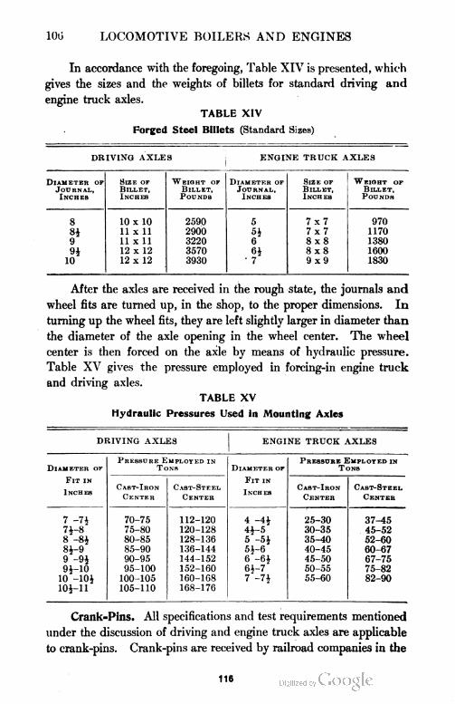
100 LOCOMOTIVE BOILERS AND ENGINES
In accordance with the foregoing, Table XIV is presented, which
gives the sizes and the weights of billets for standard driving and
engine truck axles.
TABLE XIV
Forged Steel Billets (Standard Sizes)
DRIVING AXLES ENGINE TRUCK AXLES
Diameter of Size of Weight of Diameter of Size of Weight of
Journal, Billet, Billet, Journal, Billet, Billet,
Inches Inches Pounds Inches Inches Pounds
8 10 X 10 2590 5 7x7 970
81 11 x 11 2900 Si 7x7 1170
9 11 x 11 3220 6 8x8 1380
9* 12 x 12 3570 6i 8x8 1600
10 12 x 12 3930 ' 7 9x9 1830
After the axles are received in the rough state, the journals and
wheel fits are turned up, in the shop, to the proper dimensions. In
turning up the wheel fits, they are left slightly larger in diameter than
the diameter of the axle opening in the wheel center. The wheel
center is then forced on the axle by means of hydraulic pressure.
Table XV gives the pressure employed in forcing-in engine truck
and driving axles.
TABLE XV
Hydraulic Pressures Used In Mounting Axles
DRIVING AXLES
Pressure Employed inTons
ENGINE TRUCK AXLES
Pressure Employed inTonsDiameter of
Fit in
Inches
Diameter of
Fit in
Inch esCast-Iron
Center
Cast-Steel
Center
Cast-Iron
Center
Cast-Steel
Center
7 -7J
71-8
70-75
75-80
80-85
85-90
90-95
95-100
100-105
105-110
112-120
120-128
128-136
136-144
144-152
152-160
160-108
168-176
4 -4J
41-5
25-30
30-35
35-40
40-45
45-50
50-55
55-60
37-45
45-52
52-60
60-67
67-75
75-82
82-90
8 -81
8*-9
5 -51
51-6
9 -91
91-10
6 -61
61-7
10 -101
101-11
7 -71
Crank-Pins. All specifications and test requirements mentioned
under the discussion of driving and engine truck axles are applicable
to crank-pins. Crank-pins are received by railroad companies in the
116
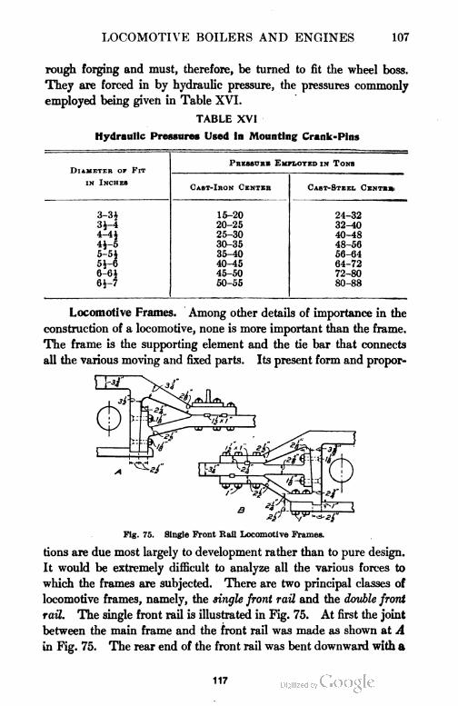
LOCOMOTIVE BOILERS AND ENGINES 107
rough forging and must, therefore, be turned to fit the wheel boss.
They are forced in by hydraulic pressure, the pressures commonly
employed being given in Table XVI.
TABLE XVI
Hydraulic Pressures Used In Mounting Crank-Pins
DlAMETER OF FitPressure Employed in Tonb
in InchesCast-Iron Center Cast-Steel Center
3-3* 15-20 24-32
3*-4 20-25 32-40
4-4i 25-30 40-48
4i-5 30-35 48-56
5-5* 35-40 56-64
5J-6 40-45 64-72
6-6* 45-50 72-80
6i-7 60-55 80-88
Locomotive Frames. Among other details of importance in the
construction of a locomotive, none is more important than the frame.
The frame is the supporting element and the tie bar that connects
all the various moving and fixed parts. Its present form and propor-
Fig. 75. Single Front Rail Locomotive Frames.
tions are due most largely to development rather than to pure design.
It would be extremely difficult to analyze all the various forces to
which the frames are subjected. There are two principal classes of
locomotive frames, namely, the single front rail and the double front
rail. The single front rail is illustrated in Fig. 75. At first the joint
between the main frame and the front rail was made as shown at A
in Fig. 75. The rear end of the front rail was bent downward with a
117
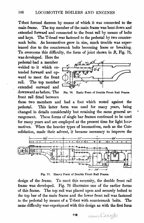
108 LOCOMOTIVE BOILERS AND ENGINES
T-foot formed thereon by means of which it was connected to the
main frame. The top member of the main frame was bent down and
extended forward and connected to the front rail by means of bolts
and keys. The T-head was fastened to the pedestal by two counter
sunk bolts. As locomotives grew in size, much trouble was exper
ienced due to the countersunk bolts becoming loose or breaking.
To overcome this difficulty, the form of joint shown in B, Fig. 75,
was developed. Here the
pedestal had a member
welded to it which ex
tended forward and up
ward to meet the front
rail. The top member
extended outward and
downward as before. The
front rail fitted between
these two members and
pedestal. This latter
Fig. 76. Early Form of Double Front Rail Frame.
had a foot which rested against the
form was used for many years, being
changed in details considerably but retaining the same general ar
rangement. These forms of single bar frames continued to be used
for many years and are employed at the present time for light loco
motives. When the heavier types of locomotives, such as the Con
solidation, made their advent, it became necessary to improve the
Fig. 77. Heavy Form of Double Front Rail Frame.
design of the frame. To meet this necessity, the double front rail
frame was developed. Fig. 76 illustrates one of the earlier forms
of this frame. The top rail was placed upon and securely bolted to
the top bar of the main frame and the lower front rail was fastened
to the pedestal by means of a T-foot with countersunk bolts. The
same difficulty was experienced with this design as with the first form
118

119
110 LOCOMOTIVE BOILERS AND ENGINES
of the single front rail type, namely, the breaking of the bolts fastening
the lower bar to the pedestal. This led to experiments being tried
which resulted in many stages of advancement until a heavy and serv
iceable design was developed, as shown in Fig. 77. In this design
the pedestal has a bar welded to it on which the lower front rail rests
and to which it is connected by means of bolts and keys. The top
front rail rests on top of the top main frame and extends back beyond
the pedestal, thus giving room for the use of more bolts. The design
shown in Fig. 77 is the one largely used on all heavy locomotives, it
being slightly changed in detail for the various types.
In addition to the two general types of bar locomotive frames
which are made of wrought iron or mild steel, a number of cast-steel
frames are being used. The general make-up of the cast-steel frame
does not differ materially from that of the wrought iron except in the
cross-section of the bars. The bar frame is rectangular or square in
cross-section whereas the sections of cast-steel frames are usually
made in the form of an I.
Cylinder and Saddle. The cylinder and saddle for a simple
locomotive, illustrated in Fig. 78, are constructed of a good quality
of cast iron.' The casting is usually made in two equal parts but it
is not uncommon to find the saddle formed of one casting, each
cylinder being bolted to it, making three castings in all. Fig. 78
illustrates the two-piece casting commonly used. The two castings
are interchangeable and are securely fastened together by bolts of
about inches in diameter. The part of the casting known as the
saddle is the curved portion A, which fits the curved surface of the
smoke-box of the boiler. This curved surface after being carefully
chipped and fitted to the smoke-box is then securely fastened to it by
means of bolts. This connection must not only be made very securely
but air tight as well, in order that the vacuum in the smoke-box may
be maintained. In the cross-sectional view, the live steam passage
B and exhaust passage C are shown. The steam enters the passage
B from the branch pipe and travels to the steam chest from which it
is admitted into the cylinder through the steam ports F. After
having completed its work in the cylinder, it passes through the ex
haust port G into the exhaust passage C to the stack. The cylinder
casting is fastened to the frames of the locomotive as well as to the
120
LOCOMOTIVE BOILERS AND ENGINES 111
boiler. D and E show the connection of the saddle casting to the
frame. In this case a frame having a double front rail is used, each
bar being securely bolted to the casting.
The Piston and Rods. The pistons of locomotives vary greatly
in details of construction but the general idea is the same in all cases.
Since the pistons receive all the power the locomotive delivers, they
must be strongly constructed and steam tight. All pistons consist
of a metal disk mounted on a piston rod which has grooves on the
outer edges for properly holding the packing rings. The pistons are
Fig. 79. Piston and Rods of Modern Locomotives.
commonly made of cast iron, but where great strength is required,
steel is now being used. Fig. 79 illustrates the present tendency in
design. The cylindrical plate is made of cast-steel and the packing
rings, two in number, are made of cast iron. The packing rings are
of the snap ring type and are free to move in the grooves.
As can be seen, the rim is widened near the bottom in order to
provide a greater wearing surface. Fig. 79 also clearly shows the
method used in fastening the piston to the piston rod. The piston
rod is made of steel and has a tapered end which fits into the cross
121
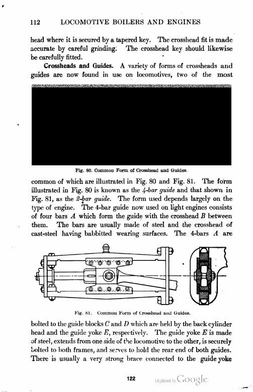
112 LOCOMOTIVE BOILERS AND ENGINES
head where it is secured by a tapered key. The crosshead fit is made
accurate by careful grinding. The crosshead key should likewise
be carefully fitted.
Crossheads and Guides. A variety of forms of crossheads and
guides are now found in use on locomotives, two of the most
Fig. 80. Common Form of Crosshead and Guides.
common of which are illustrated in Fig. 80 and Fig. 81. The form
illustrated in Fig. 80 is known as the 4-bar guide and that shown in
Fig. 81, as the 2-bar guide. The form used depends largely on the
type of engine. The 4-bar guide now used on light engines consists
of four bars A which form the guide with the crosshead B between
them. The bars are usually made of steel and the crosshead of
cast-steel having babbitted wearing surfaces. The 4-bars A are
Fig. 81. Common Form ut Crosshead and Guides.
bolted to the guide blocks C and D which are held by the back cylinder
head and the guide yoke E, respectively. The guide yoke E is made
of steel, extends from one side of the locomotive to the other, is securely
bolted to both frames, and serves to hold the rear end of both guides.
There is usually a very strong brace connected to the guide yoke
122
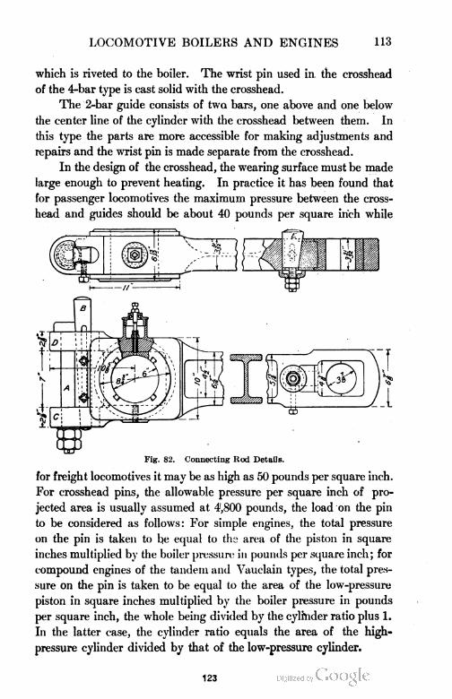
LOCOMOTIVE BOILERS AND ENGINES 113
which is riveted to the boiler. The wrist pin used in the crosshead
of the 4-bar type is cast solid with the crosshead.
The 2-bar guide consists of two bars, one above and one below
the center line of the cylinder with the crosshead between them. In
this type the parts are more accessible for making adjustments and
repairs and the wrist pin is made separate from the crosshead.
In the design of the crosshead, the wearing surface must be made
large enough to prevent heating. In practice it has been found that
for passenger locomotives the maximum pressure between the cross-
head and guides should be about 40 pounds per square inch while
Fig. 82. Connecting Rod Details.
for freight locomotives it may be as high as 50 pounds per square inch.
For crosshead pins, the allowable pressure per square inch of pro
jected area is usually assumed at 4,800 pounds, the load on the pin
to be considered as follows: For simple engines, the total pressure
on the pin is taken to be equal to the area of the piston in square
inches multiplied by the boiler pressure in pounds per square inch; for
compound engines of the tandem and Vauclain types, the total pres
sure on the pin is taken to be equal to the area of the low-pressure
piston in square inches multiplied by the boiler pressure in pounds
per square inch, the whole being divided by the cylinder ratio plus 1.
In the latter case, the cylinder ratio equals the area of the high-
pressure cylinder divided by that of the low-pressure cylinder.
123
114 LOCOMOTIVE BOILERS AND ENGINES
Connecting or Main Rods. Connecting or main rods are made
of steel, the section of which is that of an I. The I-section gives the
greatest strength with a minimum weight of metal. Fig. 82 illus
trates modern practice in the design of connecting rods for a heavy
locomotive. The design for passenger locomotives is quite similar
to that shown. Aside from the general dimensions and weight of the
rod, there are to be noted some important details in the manner in
which the brasses are held and the means provided for adjusting them.
The older forms of rods had a stub end at the crank pin end with a
strap bolted to the rod. A key was used in adjusting the brasses.
Pig. 83. Side Hod.
With the building of locomotives of greater capacity, this construction
was found to be weak. The connecting rod shown in Fig. 82 has
passed through several stages in the process of its development. The
crank end is slotted, the brasses being fitted between the upper and
lower jaw. The brasses are held in place by a heavy cotter A and a
key B. The cotter is made in a form which prevents the spread of
the jaws C and D. The adjustment of the brasses is made by means
of the key B in the usual way. The brasses at the crosshead end are
adjusted by the wedge E. The oil cups are forged solidly on the rod.
The Parallel or Side Rods. The parallel or side rods are also
made with an I-section in order to obtain a maximum strength with
a minimum weight of metal. Fig. 83 illustrates the form of side
124
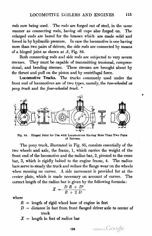
LOCOMOTIVE BOILERS AND ENGINES 115
rods now being used. The rods are forged out of steel, in the same
manner as connecting rods, having oil cups also forged on. The
enlarged ends are bored for the brasses which are made solid and
forced in by hydraulic pressure. In case the locomotive is one having
more than two pairs of drivers, the side rods are connected by means
of a hinged joint as shown at A, Fig. 84.
Both connecting rods and side rods are subjected to very severe
stresses. They must be capable of transmitting tensional, compres-
sional, and bending stresses. These stresses are brought about by
the thrust and pull on the piston and by centrifugal force.
Locomotive Trucks. The trucks commonly used under the
front end of locomotives are of two types, namely, the two-wheeled or
pony truck and the four-wheeled truck. *
Fig. 84. Hinged Joint for Use with Locomotives Having More Than Two Pairs
of Drivers.
The pony truck, illustrated in Fig. 85, consists essentially of the
two wheels and axle, the frame, 1, which carries the weight of the
front end of the locomotive and the radius bar, 2, pivoted to the cross
bar, 3, which is rigidly bolted to the engine frame, 4. The radius
bars serve to steady the truck and reduce the flange wear on the wheels
when running on curves. A side movement is provided for at the
center plate, which is made necessary on account of curves. The
correct length of the radius bar is given by the following formula :
Y = DR + 1)2
R + 2 D
where
R = length of rigid wheel base of engine in feet
D = distance in feet from front flanged driver axle to center of
truck
X = length in feet of radius bar
125
116 LOCOMOTIVE BOILERS AND ENGINES
The usual method of applying the weight to a pony truck is by
means of the equalizing lever, 5. The fulcrum, 6, of this equalizing
lever is located under the cylinders where the weight is applied. The
front end of the equalizing lever is carried by the pin, 8, which, in
Fig. 85. Pony or Two-Wheeled Truck.
turn, is carried by the sleeve, 9, and transmits the load to the center
plate while the rear end of the lever is supported by means of the cross
lever, 10, which is carried by the driving wheel springs.
The four-wheeled truck is constructed in a number of different
ways, one ofwhich is illustrated in Fig. 86. The construction is simple,
consisting of a rectangular frame, A, carrying a center plate, B. As
in the case of the pony truck, the journals are inside of the wheels.
126
LOCOMOTIVE BOILERS AND ENGINES 117
118 LOCOMOTIVE BOILERS AND ENGINES
The truck, which is pivoted on the center plate, carries the front-end
of the locomotive and serves as a guide for the other wheels of the
locomotive.
The object in using a trailing truck, as stated earlier in this
work, is to make possible the wide fire box which is necessary in
certain types of locomotives. Two different types of trailing trucks
are used and both have proven successful. One has an inside bearing,
as illustrated in Fig. 87, and the other an outside bearing, as shown in
Fig. 88. The former is perhaps the simpler of the two. The latter has
a broad supporting base which improves the riding qualities of the
locomotive.
Kig. 88. Trailing Truck with Outside Bearings.
The radial trailing truck with inside bearings, Fig. 87, is fitted
with a continuous axle box, A, with journal bearings at each end, these
being provided at the frame pedestals with front and back wearing
surfaces formed to arcs of concentric circles of suitable radii. To
the lower face of the continuous axle box is attached a spring housing,
B, fitted with transverse coiled springs having followers and fitted
with horizontal thrust rods, C, which extend to the pedestal tie bars.
These thrust bars terminate in ball and socket connections at each
end. This combination of springs and thrust rods permits the truck
to travel in a circular path and also permits the continuous axle box
to rise and fall relatively to the frames. Motion along the circular
128
LOCOMOTIVE BOILERS AND ENGINES 119
arcs is limited by stops at the central spring casing, the springs tend
ing to bring the truck to its normal central position when the locomo
tive passes upon a tangent from a curve. The load is transmitted to
the continuous axle box through cradles on which the springs and
equalizers bear, hardened steel sliding plates being interposed as wear
ing surfaces immediately over the journal bearings. The cradles
are guided vertically by guides attached to the locomotive frames.
The radial trailing truck with outside bearings, as illustrated
in Fig. 88, has journal boxes A rigidly attached to the frame, the
forward rails of which converge to a point in which the pivot pin B
is centered. The pin is fixed in a cross brace secured between the
engine frames. The trailing truck frame extends back of the journal
boxes in the form of the letter U at the center of which a spring
housing C is mounted, containing centering springs and followers,
performing the same functions as those of the radial truck with inside
bearings, already described. The load in this case is transmitted
to the journal boxes by springs which are vertically guided. Hardened
rollers are generally used between what would otherwise be sliding
surfaces. These rollers rest upon double inclined planes which tend
to draw the truck to its normal and central position when displaced
laterally as on a curve. The mutual action of these rollers and
inclined planes is to furnish a yielding resistance to lateral displace
ment with a tendency to return to the normal position.
The Tender. The tender of a locomotive is used to carry the
coal and water supply for the boiler. It is carried on two four-
wheeled trucks having a frame work of wood or steel, the latter being
mostly used at the present time. This frame supports the tank in
which the water is stored, which, in the case of passenger and freight
locomotives, is usually constructed in the shape of the letter U, the
open end of which faces the fire door. The open space between the
legs of the U is used for coal storage. The water is drawn from the
tank near the two front corners. In these two front corners are placed
tank valves which are connected by means of the tank hose and pipes
to the two injectors. Near the back end of the tank is a manhole
which permits a man to enter the inside to make repairs. This
opening is also used in filling the tank at water towers. Tanks are
made of open hearth steel, usually about \ of an inch in thickness,
the sheets being carefully riveted together to prevent leaks. The
129
120 LOCOMOTIVE BOILERS AND ENGINES
interior of the tank is well braced and contains baffle plates which
prevent the water from surging back and forth, due to curves and
shocks in the train itself. The tank is firmly bolted to the frame.
Many of the engines designed for southern and western traffic
burn oil and, as a rule, the railroads themselves furnish the specifica
tions for the oil-burning equipment. Cylindrical tanks are used on
the tender with the water tank forward, as a rule. Otherwise, the
tender design is the same as for coal-burning locomotives.
The capacity of tenders has been increased as the locomotives
which they serve have grown in size and power. Modern heavy
locomotive tenders have a water capacity of from 3,000 to 9,000 gal
lons and a coal capacity of from 5 to 16 tons.
On switching engines, the back end of the tank is frequently
made sloping in order to permit the engineer to see the track near the
engine when running backward. Frequently a tool box is placed
near the rear of the tank in which may be kept jacks, replacers, etc.
A tool box for small tools and signals is usually placed at the front
of the tender on either side. The coal is prevented from falling out
at the front end by using gates or boards dropped into a suitably
constructed groove. On locomotives used on northern railroads,
the tanks are provided with a coil of steam pipes by means of which
the water can be warmed and prevented from freezing.
Locomotive Stokers. The amount of water a locomotive boiler
is capable of evaporating is limited by a number of conditions. It
is possible to construct a locomotive of such dimensions that it would
be capable of burning an amount of coal which would be physically
impossible for a fireman to handle. Furthermore, the different
methods of firing a locomotive by hand, as practiced by many
firemen, are frequently very uneconomical and result in a great loss
of fuel. Again, there are certain heavy freight runs on some rail
roads which require two firemen in order to get the train through
on schedule time.
The above reasons and many others which might be mentioned
have resulted in a demand for some form of automatic or mechanical
stoker for locomotive work. In the last ten or fifteen years, much
experimental work has been done along this line and a number of
different types of stokers have been developed which have met with
some success.
130
LOCOMOTIVE BOILERS AND ENGINES 121
A locomotive stoker to be successful should meet the following
requirements :
(a) It should be able to handle any desired quantity of coal and
at the same time call for less physical effort on the part of
the fireman than is required in hand firing.
(b) It should be able to successfully handle any grade of coal.
(c) It should be able to maintain full steam pressure under all
conditions.
(d) It should not become inoperative under ordinary conditions
of service.
(e) Its construction should permit of hand firing to meet emergency
conditions.
Of the many types of locomotive stokers which have been
developed and tried out, the following makes are characteristic
and will serve for illustration.
Chain Grate Stoker. The chain grate stoker, invented as early
as 1850, was thought at first to have solved the smoke problem.
It was used to a limited extent in and about New York City, but
for various reasons was soon abandoned. Its construction was quite
similar to our present-day chain grate commonly used in power-
plant work. It was mounted on wheels and could be drawn out
of the fire-box on a track. Coal was shoveled into a hopper by the
fireman and the chain grate was operated by a small auxiliary steam
engine.
Hanna Locomotive Stoker. The Hanna locomotive stoker, devel
oped by W. T. Hanna, is so constructed that the entire apparatus
is readily applicable to any locomotive and is placed in the cab.
It makes use of the ordinary fire door as a place through which the
coal is jetted into the fire-box. It is operated by a small double-
acting twin-engine placed in the floor of the cab, which serves to
drive a screw propeller, which in turn causes the coal to be pushed
upward and forward through a large pipe leading to the fire door.
The engine can be reversed by means of a reversing valve, which
changes the main valve from outside admission to inside admission.
Coal is shoveled into a hopper and from the hopper it is carried
by the stoker mechanism to a distributing plate immediately inside
of the fire door. From the distributing plate, the coal is thrown into
the fire-box by the action of a number of steam jets which radiate
131
122 LOCOMOTIVE BOILERS AND ENGINES
from a central point on the plate. The speed of the small operating
engine controls the rate of firing. Deflector and guide plates,
located just inside of the fire door, are so arranged and under control
of the fireman that the coal can be placed on any portion of the grate
desired.
This stoker requires much physical work on the part of the
fireman, since the coal must be broken into small lumps and the
hopper kept filled. The larger lumps of coal will be deposited near
the rear part of the grate, the finer particles being blown to the front
portion. Much of the finer particles of coal will burn as dust and
a part will be drawn through the flues without being burned at all.
Street Mechanical Stoker. The Street mechanical stoker con
sists of a small steam engine bolted to the top and left side of the
back head of the boiler, which drives a worm gear and operates a
chain conveyor. The conveyor bucket elevates the crushed coal
from a hopper below and drops it on a distribution plate, located
just inside of the fire door. From the distributing plate the coal
is thrown into the fire-box by an intermittent steam jet, which is
under the control of the fireman. There is a coal crusher on the
tender, which is driven by another small steam engine. The coal,
after being crushed, falls down a 45-degree inclined spout to the
hopper below the deck. Some of the later designs use a screw
propeller to carry the crushed coal from the tender to the hopper.
The Street stoker does not require a great amount of physical work
by the fireman. The large lumps of coal will fall near the rear por
tion of the grate as in the case of the Hanna stoker.
Crawford Mechanical Underfeed Stoker. The Crawford mechan
ical underfeed stoker, invented by D. F. Crawford, S.M.P. of the
Pennsylvania Lines west of Pittsburgh, has been tried out on the
Pennsylvania Lines and has given very satisfactory service. This
stoker takes coal from beneath the tender and by means of a con
veyor carries it forward to a hopper. From the hopper, two plungers,
placed side by side, push the coal still farther ahead where two other
plungers, one on each side, cause the coal to be pushed up through
narrow openings to the ordinary shaking grate. Both the conveyor
and the plungers are operated by a steam cylinder, containing a
piston operated by the ordinary nine and one-half-inch Westing-
house air-pump steam valve. The conveyor consists of a series
132
LOCOMOTIVE BOILERS AND ENGINES 123
of hinged partitions, or doors, which carry the coal in one direction
and slide over it when the motion is reversed. If the conveyor for
any reason should become inoperative, a door in the deck can be
opened and coal shoveled into the hopper below. If the stoking
device should become inoperative, then coal can be fired by hand ,
in the usual way. This stoker requires a minimum amount of
physical labor from the fireman. It can be applied to any locomo
tive, but only at considerable cost. Its application reduces the
grate area to a certain extent and thus reduces the steaming capacity
of the boiler.
DESIGN OF PARTS OF THE ENGINE
The design of the parts of the locomotive engine proper, like
that of the boiler, is a subject which cannot be handled properly
in the space allotted in this book. These designs are the result of
a gradual development of the proper proportions based upon the
tests of each part in actual service. The specifications for materials
and workmanship are rigidly drawn and as carefully lived up to, for
in railroad service the chances for failure of any part of the engine,
because of the excessive vibration, are many, and the destructive
effect of such failure is out of all proportion to the original manufac
turing expense. These conditions, therefore, make perfect action
and excessive reliability prime necessities in engine design. A few
formulas, for the most part based on rational assumptions, are pre
sented for the calculation of some of the most important parts.
Axles. The stress in the axles is combined in many ways. The
principal stresses are, first, bending stresses due to the steam pressure
on the piston; second, bending stresses due to the dead weight of the
engine; third, torsional or shearing stresses due to unequal adhesion of
the wheels on the rails; and fourth, bending stresses due to the action
of the flanges on the rails while rounding curves. Let
W= the area of the piston in square inches multiplied by the
boiler pressure in pounds per square inch
L\ = the lever arm in inches or the distance from the center of
the main or connecting rod to the center line of the
frame
0 =the lever arm in inches or the distance from the center
of the side rod to the center line of the frame
1S3
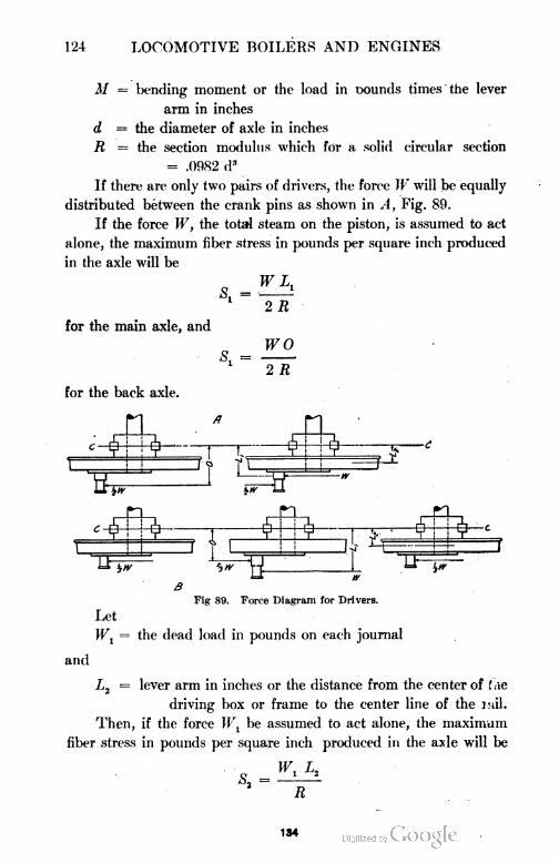
124 LOCOMOTIVE BOILERS AND ENGINES
M = bending moment or the load in oounds times the lever
arm in inches
d = the diameter of axle in inches
R = the section modulus which for a solid circular section
= .0982 d3
If there are only two pairs of drivers, the force W will be equally
distributed between the crank pins as shown in A, Fig. 89.
If the force W, the total steam on the piston, is assumed to act
alone, the maximum fiber stress in pounds per square inch produced
in the axle will be
WL,
S. =
for the main axle, and
S,
2 R
WO
2 R
for the back axle.
5s
Fig 89. Force Diagram for Drivers.
Let
Wt = the dead load in pounds on each journal
and
L2 = lever arm in inches or the distance from the center of ( ae
driving box or frame to the center line of the mil.
Then, if the force W1 be assumed to act alone, the maximum
fiber stress in pounds per square inch produced in the axle will be
O 12
R
184
LOCOMOTIVE BOILERS AND ENGINES 125
Let
L3 = the crank radius, or one-half the length of the stroke in
inches.
If the twisting of the axle alone is considered, the torsional or
shearing stress in pounds per square inch produced in the axle will be
W L,
2 R
Because of certain existing conditions which affect the amount
of torsion or twisting of the axle, only one-half of the theoretical
stress should be used, as it is not probable that under any circum
stances could more be transmitted by the axle to the opposite side.
Let
D = the diameter of drivers in inches
F = the centrifugal force in pounds
W2= the weight in pounds of the moving mass of wheels plus the
weight carried by them
g = the acceleration of gravity in feet per second = 32 . 2
r = the radius of curvature of the track in feet
v = the velocity of the locomotive in feet per second
If the action on a curve alone is considered, the maximum fiber
stress in pounds per square inch produced in the axle will be
F D
2 R
where
Considering all stresses acting together, we get the resultant
maximum fiber stress in pounds per square inch in the axle to be
where
In this equation, the bending stress due to the centrifugal force
while rounding curves does not appear since it is assumed that this
will neutralize that due to the dead load on the axle.
The following allowable fiber stresses in pounds per square inch
have been used in successful designs:
135
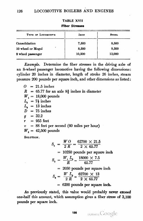
126 LOCOMOTIVE BOILERS AND ENGINES
TABLE XVII
Fiber Stresses
Ttpe or Locomotive Iron Steel
Consolidation 7,500 8,500
10 wheel or Mogul 8,500 9,500
8 wheel passenger 10,500 13,000
Example. Determine the fiber stresses in the driving axle of
an 8-wheel passenger locomotive having the following dimensions:
cylinder 20 inches in diameter, length of stroke 26 inches, steam
pressure 200 pounds per square inch, and other dimensions as listed :
0 =21.5 inches
R = 65.77 for an axle 8f inches in diameter
Wx = 18,000 pounds
L2 = 1\ inches
La = 13 inches
D = 75 inches
g = 32.2
r = 955 feet
v =88 feet per second (60 miles per hour)
Wi = 42,500 pounds
Solution .
= W0 - 62700 X 21.5
1 ~ 2 R 2 X 65.77
= 10250 pounds per square inch
„ W, L2 _ 18000 X 7.5
R ~ 65.77
= 2050 pounds per square inch
„ W L3 62700 X 13
3 2 R " 2 X 65.77
= 6200 pounds per square inch.
As previously stated, this value would probably never exceed
one-half this amount, which assumption gives a fiber stress of 3,100
pounds per square inch.
136
LOCOMOTIVE BOILERS AND ENGINES 127
F =Wt v2 42500 X (88)2
r g 955 X 32.2
= 10700 pounds
S = F D - 10700 X 75
4 2R ~ 2 X 65.77
— 6055 pounds per square inch
The flange pressure would probably not exceed one-third of
the total centrifugal force, the remainder being absorbed by the
elevation of the outer rail. If- this were true, then
= = 2018 pounds per square inch
o
which, as can be seen, just about neutralizes the stress due to the
dead weight.
sr = V(s,)* + (s2)2
= V102502 + 20502
10450 pounds per square inch
Therefore,
10450 I (10450)2 (3100)2
2 + \ 4 + 2
= 10990 pounds per square inch
Therefore, an 8f steel axle is large enough for an 8-wheel passen
ger locomotive since the allowable fiber stress of 13,000 pounds per
square inch is not exceeded.
If the locomotive under consideration was one having three pairs
of drivers instead of two, the total piston pressure would be distributed
as shown in B, Fig. 78.
Crank Pins. Crank pins are calculated for strength by the
following methods:
In A, B, and C, Fig. 90, is shown the manner in which the forces
act on the crank pins of three different types of locomotives.
137
128 LOCOMOTIVE BOILERS AND ENGINES
Let
W
S
L
M
d
R
= the boiler pressure in pounds per square inch, times area
of the piston in square inches
= the safe fiber stress in pounds per square inch
= the lever arm in inches or the distance from the face of the
wheel to the center of the main rod
= maximum moment in inch pounds or force in pounds
times the lever arm in inches
= the force in pounds transmitted to the side rod
= the diameter of crank pin in inches
= the side rod lever arm in inches or the distance from the
face of the wheel center to the center line of the side rod
= the section modulus of the crank pin which for a circular
section = .0982 d3
/? b c
Fig. 90. Action of Force on Crank Pins in Different Types of Locomotives.
Having given the above conditions, we may write
M = W L
and
M
R
M
.0982 d?
From this last equation
d3 =M
.0982 S
Finally, substituting the value of M we get
d = 'yjW L
.0982 S
This equation nlay be used in finding the diameter of the main
crank pin on any type of locomotive when the loads and lever arms
are known and the safe fiber stress has been assumed. It should
be remembered, however, that for an S-wheeled locomotive it is
138
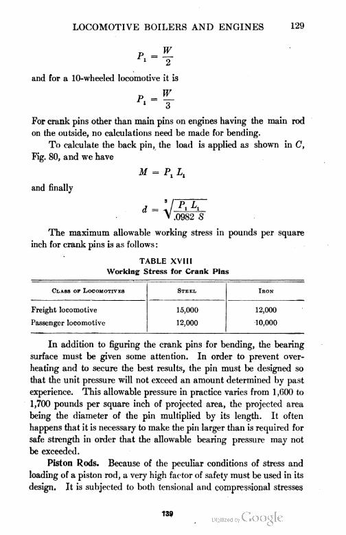
LOCOMOTIVE BOILERS AND ENGINES 129
and for a 10-wheeled locomotive it is
For crank pins other than main pins on engines having the main rod
on the outside, no calculations need be made for bending.
To calculate the back pin, the load is applied as shown in C,
Fig. 80, and we have
M = Pl L,
and finally
V .0982 S
The maximum allowable working stress in pounds per square
inch for crank pins is as follows :
TABLE XVIII
Working Stress for Crank Pins
Class of Locomotives Steel Iron
Freight locomotive 15,000 12,000
Passenger locomotive 12,000 10,000
In addition to figuring the crank pins for bending, the bearing
surface must be given some attention. In order to prevent over
heating and to secure the best results, the pin must be designed so
that the unit pressure will not exceed an amount determined by past
experience. This allowable pressure in practice varies from 1,600 to
1,700 pounds per square inch of projected area, the projected area
being the diameter of the pin multiplied by its length. It often
happens that it is necessary to make the pin larger than is required for
safe strength in order that the allowable bearing pressure may not
be exceeded.
Piston Rods. Because of the peculiar conditions of stress and
loading of a piston rod, a very high factor of safety must be used in its
design. It is subjected to both tensional and compressional stresses
f89
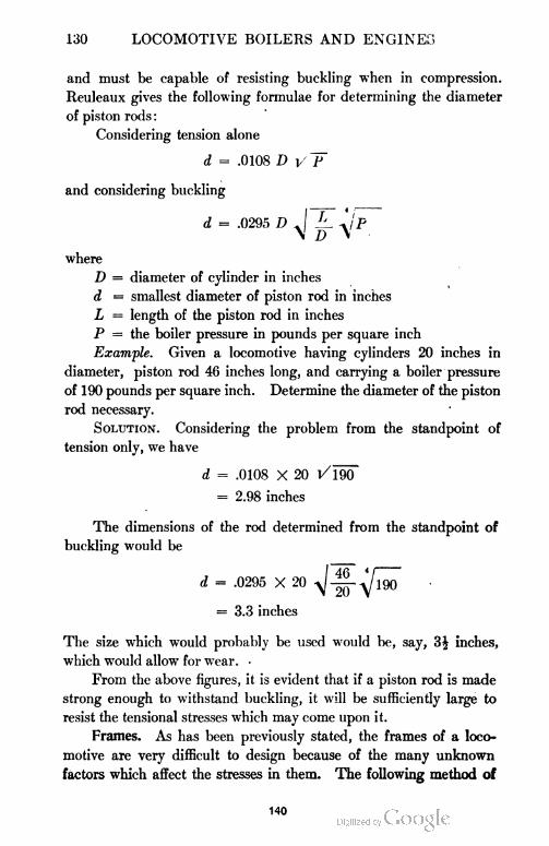
130 LOCOMOTIVE BOILERS AND ENGINES
and must be capable of resisting buckling when in compression.
Reuleaux gives the following formulae for determining the diameter
of piston rods :
Considering tension alone
d = .0108 D y T
and considering buckling
d = .0295 D J k. Jp
\ D \
where
D = diameter of cylinder in inches
d = smallest diameter of piston rod in inches
L = length of the piston rod in inches
P = the boiler pressure in pounds per square inch
Example. Given a locomotive having cylinders 20 inches in
diameter, piston rod 46 inches long, and carrying a boiler pressure
of 190 pounds per square inch. Determine the diameter of the piston
rod necessary.
Solution. Considering the problem from the standpoint of
tension only, we have
d = .0108 X 20 Vl90
= 2.98 inches
The dimensions of the rod determined from the standpoint of
buckling would be
d = .0295 X 20 ^il^o"
= 3.3 inches
The size which would probably be used would be, say, 3J inches,
which would allow for wear. ■
From the above figures, it is evident that if a piston rod is made
strong enough to withstand buckling, it will be sufficiently large to
resist the tensional stresses which may come upon it.
Frames. As has been previously stated, the frames of a loco
motive are very difficult to design because of the many unknown
factors which affect the stresses in them. The following method of
140
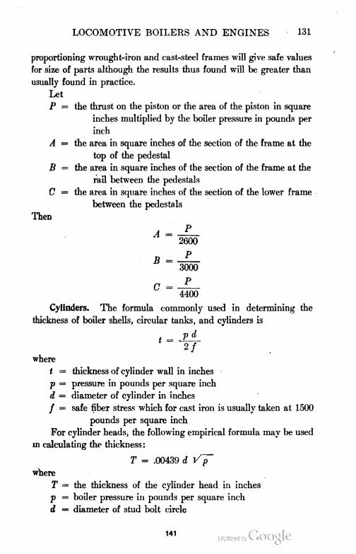
LOCOMOTIVE BOILERS AND ENGINES 131
proportioning wrought-iron and cast-steel frames will give safe values
for size of parts although the results thus found will be greater than
usually found in practice.
Let
P — the thrust on the piston or the area of the piston in square
inches multiplied by the boiler pressure in pounds per
inch
A = the area in square inches of the section of the frame at the
top of the pedestal
B = the area in square inches of the section of the frame at the
rail between the pedestals
C = the area in square inches of the section of the lower frame
between the pedestals
Then
D
A =
B =
C =
2600
P
3000
P
4400
Cylinders. The formula commonly used in determining the
thickness of boiler shells, circular tanks, and cylinders is
where
t = thickness of cylinder wall in inches
p = pressure in pounds per square inch
d = diameter of cylinder in inches
/ = safe fiber stress which for cast iron is usually taken at 1500
pounds per square inch
For cylinder heads, the following empirical formula may be used
in calculating the thickness :
T = .00439 d V~f
where
T = the thickness of the cylinder head in inches
p = boiler pressure in pounds per square inch
d — diameter of stud bolt circle
141
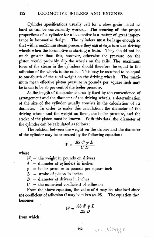
132 LOCOMOTIVE BOILERS AND ENGINES
Cylinder specifications usually call for a close grain metal as
hard as can be conveniently worked. The securing of the proper
proportions of a cylinder. for a locomotive is a matter of great impor
tance in locomotive design. The cylinders must be large enough so
that with a maximum steam pressure they can always turn the driving
wheels when the locomotive is starting s» train. They should not be
much greater than this, however, otherwise the pressure on the
piston would probably slip the wheels on the rails. The maximum
force of the steam in the cylinders should therefore be equal to the
adhesion of the wheels to the rails. This may be assumed to be equal
to one-fourth of the total weight on the driving wheels. The maxi
mum mean effective piston pressure in pounds per square inch mav
be taken to be 85 per cent of the boiler pressure.
As the length of the stroke is usually fixed by the convenience of
arrangement and the diameter of the driving wheels, a determination
of the size of the cylinder usually consists in the calculation of its
diameter. In order to make this calculation, the diameter of the
driving wheels and the weight on them, the boiler pressure, and the
stroke of the piston must be known. With this data, the diameter of
the cylinder can be calculated as follows:
The relation between the weight on the drivers and the diameter
of the cylinder may be expressed by the following equation :
.85 <P p L
C D
where
W = the weight in pounds on drivers
d ' = diameter of cylinders in inches
V =boiler pressure in pounds per square inch
L = stroke of piston in inches
D = diameter of drivers in inches
C = the numerical coefficient of adhesion
From the above equation, the value of d may be obtained since
trie coefficient of adhesion C may be taken as .25. The equation th<"
becomes
.25 D
from which
142
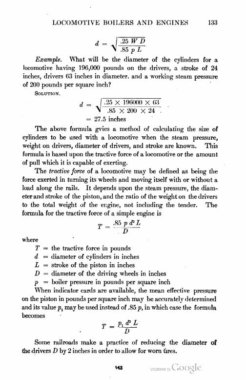
LOCOMOTIVE BOILERS AND ENGINES 133
d = J -25 W D
\ .85 p L
Example. What will be the diameter of the cylinders for a
locomotive having 196,000 pounds on the drivers, a stroke of 24
inches, drivers 63 inches in diameter, and a working steam pressure
of 200 pounds per square inch?
Solution.
d = I .25 X 106000 X 63
\ .85 X 200 X 24 .
= 27.5 inches
The above formula gvies a method of calculating the size of
cylinders to be used with a locomotive when the steam pressure,
weight on drivers, diameter of drivers, and stroke are known. This
formula is based upon the tractive force of a locomotive or the amount
of pull which it is capable of exerting.
The tractive force of a locomotive may be defined as being the
force exerted in turning its wheels and moving itself with or without a
load along the rails. It depends upon the steam pressure, the diam
eter and stroke of the piston, and the ratio of the weight on the drivers
to the total weight of the engine, not including the tender. The
formula for the tractive force of a simple engine is
T = -85 V & L
D
where
T = the tractive force in pounds
d = diameter of cylinders in inches
L = stroke of the piston in inches
D = diameter of the driving wheels in inches
p = boiler pressure in pounds per square inch
When indicator cards are available, the mean effective pressure
on the piston in pounds per square inch may be accurately determined
and its value pt may be used instead of .85 p, in which case the formula
becomes
T = Pl — -
D
Some railroads make a practice of reducing the diameter of
the drivers D by 2 inches in order to allow for worn tires.
<4S
134 LOCOMOTIVE BOILERS AND ENGINES
In the case of a two-cylinder compound locomotive, the formula
for tractive force is
= .85 p (d,f L■ , + (iyo
where
D = the diameter of the drivers in inches
= diameter of low-pressure cylinder in inches
d2 = diameter of high-pressure cylinder in inches
Train Resistance. The resistance offered by a train per ton of
weight varies with the speed, the kind of car hauled, the condition
of the track, journals and bearings, and atmospheric conditions.
Taking the average condition as found upon American railroads,
the train resistance is probably best represented by the Engineering
News formula
r = 4- + 2
4
in which
R = the resistance in pounds per net ton (2000 pounds) of load
S = speed in miles per hour
The force for starting is, however, about 20 pounds per ton which
falls to 5 pounds as soon as a low rate of speed is obtained. The
resistance due to grades is expressed by the formula
R' = 0.38 M
in which
R' = the resistance in pounds per net ton of load
M = grade in feet per mile
The resistance due to curves is generally taken at from .5 to .7
pounds per ton per degree of curvature. Taking the latter value
and assuming that locomotives on account of their long rigid wheel
base produce double the resistance of cars, we have
R" = .7 C for cars, and
R" = 1.4 C for locomotives
in which
R" = the resistance in pounds per net ton due to curvature
C — the curvature in degrees
Considerable resistance is offered by wind but this is of such a
144
LOCOMOTIVE BOILERS AND ENGINES 135
nature that calculations are extremely difficult to make which would
be of any practical value.
The resistances mentioned above do not take into account that
due to the acceleration of the train. This may be expressed by the
formula
R'" = .0132 v2
in which
v = the speed in miles per hour attained in one mile when
starting from rest, being uniformly accelerated
R'" = resistance in pounds per net ton due to acceleration
Locomotive Rating. Since the locomotive does its work most
economically and efficiently when working to its full capacity, it
becomes necessary to determine how much it can handle. The de
termination of the weight of the train which a locomotive can handle
is called the rating. This weight will vary for the same locomotive
under different conditions. The variation is caused by the difference
in grade, curvature, temperature conditions of the rail, and the amount
of load in the cars. The variation due to the differences of car re
sistance arising from a variation of the conditions of the journals and
lubrication is neglected because of the assumption of a general average
of resistance for the whole.
The usual method of rating locomotives at present is that of
tonnage. That is to say, a locomotive is rated to handle a train,
weighing a certain number of tons, over a division. This is preferred
to a given number of loaded or empty cars because of the indefinite
variation in the weights of the loads and the cars themselves.
In the determination of a locomotive rating there are several
factors to be considered, namely, the power of the locomotive,
adhesion to the rail, resistance of the train including the normal
resistance on a level, and that due to grades and curves, value of
momentum, effect of empty cars, and the effect of the weather and
seasons.
The power of a locomotive and its adhesion to the rails has
already been considered. From the formula given, the tractive power
can be calculated very closely from data already at hand.
There are three methods in use for obtaining the proper tonnage
rating. First, a practical method which consists in trying out each
class of engine on each critical or controlling part of the division
145
136 LOCOMOTIVE BOILERS AND ENGINES
and continuing the trials until the limit is reached. Second, a more
rapid and satisfactory method is to determine the theoretical rating.
Third, the most satisfactory method is, first, to determine the theo
retical rating and then to check the results by actual trials.
The value of the momentum of a train is a very important ele
ment in the determination of the tonnage rating of locomotives on most
railroads. In mountainous regions, with long heavy grades, there
is little opportunity to take advantage of momentum, while on un
dulating roads, it may be utilized to the greatest advantage. An
approach to a grade at a high velocity when it can be reduced in
ascending the same, enables the engine to handle greater loads than
would otherwise be possible without such assistance. Hence, stops,
crossings, curves, water tanks, etc., will interfere with the make-up
of a train if so located as to prevent the use of momentum. It is
necessary, therefore, to keep all these points in mind when figuring
the rating of a locomotive for handling trains over an undulating
division.
The ordinary method of allowing for momentum is to deduct
the velocity head from the total ascent and consider the grade easier
by that amount.
For example : Suppose that a one per cent grade 5,000 feet long
is so situated that trains could approach it at a high speed. The
total rise of the grade would be 50 feet but 15 feet of that amount
could be overcome by the energy of the train, leaving 35 feet that the
train must be raised or lifted by the engine. The grade in which the
rise is 35 feet in 5,000 would be a 0.7 per cent grade, so that if the
engine could exert sufficient force to overcome the train resistance and
that due to a 0.7 per cent grade, the train could be lifted the remain
der of the height by its kinetic energy. In this case, the 5,000 feet of one
per cent grade could be replaced by a grade of 0.7 per cent 5,000
feet long, and the effect on the load hauled by the engine would be
the same if in the latter case the energy of the train were not taken
into account. Since the height to which the kinetic energy raises
the train is independent of the length of the grade, its effect becomes
far less when the grades are long than when short. Thus, for a one per
cent grade 1,000 feet long, the total rise being only 10 feet, the kinetic
energy would be more than sufficient to raise the weight of the train
up the entire grade leaving only the frictional resistance to be over
146
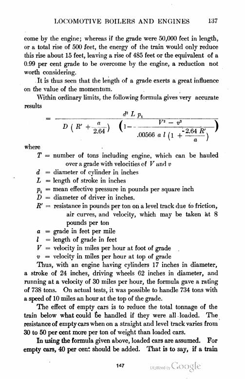
LOCOMOTIVE BOILERS AND ENGINES 137
come by the engine; whereas if the grade were 50,000 feet in length,
or a total rise of 500 feet, the energy of the train would only reduce
this rise about 15 feet, leaving a rise of 485 feet or the equivalent of a
0.99 per cent grade to be overcome by the engine, a reduction not
worth considering.
It is thus seen that the length of a grade exerts a great influence
on the value of the momentum.
Within ordinary limits, the following formula gives very accurate
results
= lAli
U \a + 2.64 ) V ,-2.64/1'. /
.00566 a I [\ -\ . ^
where
T = number of tons including engine, which can be hauled
over a grade with velocities of V and v
d = diameter of cylinder in inches
L = length of stroke in inches
Pj = mean effective pressure in pounds per square inch
D = diameter of driver in inches.
R' = resistance in pounds per ton on a level track due to friction,
air curves, and velocity, which may be taken at 8
pounds per ton
a = grade in feet per mile
I = length of grade in feet
V = velocity in miles per hour at foot of grade
v = velocity in miles per hour at top of grade
Thus, with an engine having cylinders 17 inches in diameter,
a stroke of 24 inches, driving wheels 62 inches in diameter, and
running at a velocity of 30 miles per hour, the formula gave a rating
of 738 tons. On actual tests, it was possible to handle 734 tons with
a speed of 10 miles an hour at the top of the grade.
The effect of empty cars is to reduce the total tonnage of the
train below what could &e handled if they were all loaded. The
resistance of empty cars when on a straight and level track varies from
30 to 50 per cent more per ton of weight than loaded cars.
In using the formula given above, loaded cars are assumed. For
empty cars, 40 per cent should be added. That is to say, if a train
147
138 LOCOMOTIVE BOILERS AND ENGINES
is composed of empty and loaded cars and is found to have a certain
resistance, 40 per cent should be added to the portion of resistance
due to the empty cars.
There is considerable difference of opinion regarding the allow
ance which should be made for the conditions of weather, etc. The
following is a fair allowance which has been found to give satisfactory
results in practice: Seven per cent reduction for frosty or wet rails;
fifteen per cent reduction for from freezing to zero temperature;
and twenty per cent reduction for from zero to twenty degrees below.
The use of pushing or helping engines over the most difficult
grades of an undulating track will increase the train load and thus
reduce the cost of transportation.
LOCOMOTIVE APPLIANCES
In order to enable the engineer to operate and control a loco
motive successfully and economically a certain number of fittings
on the locomotive are necessary. These fittings consist chiefly of the
safety valves, whistle, steam gauge, lubricator, water gauges, blower,
throttle valve, injector, air brake, and signal apparatus.
Safety Valves. The universal practice at present is to use at
least two safety valves of the pop type upon every locomotive boiler.
On small locomotives where clearances will permit, the safety valves
are placed in the dome cap. On large locomotives where the available
height of the dome is limited, the safety valves are usually placed on
a separate turret. When limiting heights will not permit the use of
turrets, the safety valves may be screwed directly into the roof of the
boiler.
The construction of a good safety valve is such that when it is
raised, the area for the escape of steam is sufficient to allow it to
escape as rapidly as it is formed, and that as soon as the pressure has
fallen a pre-determined amount, it will close.
It should be so designed that it can neither be tampered with
nor get out of order. It must act promptly and efficiently and not be
affected by the motion of the locomotive. These conditions are all
fulfilled in the type of valve shown in section in Fig. 91. In this
design, the valve a rests on the seat b b and is held down by a spindle
c, the lower end of which rests on the bottom of a hole in the valve a.
A helical spring d rests on a collar on the spindle. The pressure on the
148
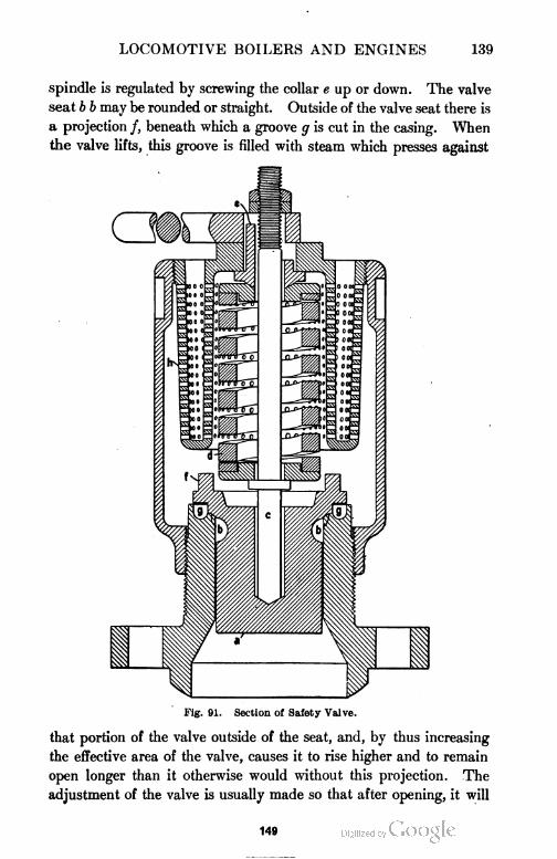
LOCOMOTIVE BOILERS AND ENGINES 139
spindle is regulated by screwing the collar e up or down. The valve
seat b b may be rounded or straight. Outside of the valve seat there is
a projection /, beneath which a groove g is cut in the casing. When
the valve lifts, this groove is filled with steam which presses against
Fig. 91. Section of Safety Valve.
that portion of the valve outside of the seat, and, by thus increasing
the effective area of the valve, causes it to rise higher and to remain
open longer than it otherwise would without this projection. The
adjustment of the valve is usually made so that after opening, it will
149
140 LOCOMOTIVE BOILERS AND ENGINES
permit steam to escape until the pressure in the boiler is about 4
pounds below the normal pressure. The steam escaping through
the small holes h, is muffled, thus avoiding great annoyance.
Another form of safety valve which is being largely used is that
shown in Fig. 92. The principle of its operation is the same as that
just described. It is said to be very quiet and yet gives effective
relief. It is being adopted by several railroads.
The Injector. The injector may be defined as an apparatus for
forcing water into a steam boiler in which a jet of steam imparts
its energy to the water and thus forces
it into the boiler against boiler pres
sure. Injectors are now universally
employed for delivering the feed water
to the boiler. Two injectors are always
used, either one of which should have
a capacity sufficient to supply the
boiler with water under ordinary
working conditions. They are located
one on either side of the boiler. In
jectors may be classified as lifting
and non-lifting, the former being
most commonly used. The lifting in
jector is placed above the high water
line in the tank, therefore in forcing
water into the boiler, it lifts the water
through a height of a few feet. The
non-lifting injector is placed below the
bottom of the water tank, hence the water flows to the injector by
reason of gravitation.
There are a great many different injectors on the market. All
work upon the same general principle, differing only in the details of
construction. One type only will be described, namely, the Sellers
injector illustrated in Fig. 93.
Sellers Injector. To operate this injector, the method of proce
dure is as follows: Draw starting lever, 33, slowly. If the water
supply is hot, draw the lever about one inch and after the water
is lifted, draw the lever out the entire distance. The cam lever, 34,
must be in the position shown. To stop the injector, push the starting
Fig. 92. Another Form of
Safety Valve.
150

151
142 LOCOMOTIVE BOILERS AND ENGINES
lever in. To regulate the amount of flow of water after the injector
has been started, adjust the regulating handle, 41. If it is desired
to use the injector as a heater, place the cam lever, 34, in the rear
position and pull the starting lever slowly.
The injector is not a sensitive instrument but requires care to
keep it in working condition. It should be securely connected to the
boiler in easy reach of the engineer. All joints must be perfectly
tight to insure good working conditions. All pipes, hose connections,
valves, and strainers must be free from foreign matter. Most failures
of injectors are due largely to the presence of dirt, cotton, waste, etc.,
in the strainers. It is not possible to mention in detail all circum
stances which produce injector failures but the complaints com
monly heard are as follows:
1. The injector refuses to lift the water promptly, or not at
all.
2. The injector lifts the water but refuses to force it into the
boiler. It may force a part of the water into the boiler, the remainder
being lost in the overflow.
Unless these failures are due to the wearing out of the nozzles
which may be renewed at any time, they may be largely avoided by
keeping in mind the following points:
All pipes, especially iron ones, should be carefully blown out with steam
before the injector is attached, the scale being loosened by tapping the pipes
with a hammer.
All valves should be kept tight and all spindles kept tightly packed.
When a pipe is attached to the overflow, it should be the size called for
by the manufacturer.
The suction pipe must be absolutely tight since any air leak reduces the
capacity of the injector.
The delivery pipe and boiler check valve must be of ample dimen
sions.
The suction pipes, hose, and tank valve connections must be of ample
size and the hose free from sharp kinks and bends.
The strainer should be large enough to give an ample supply of water
even if a number of the holes are choked.
The injector is one of the most important boiler appliances, for
upon the ability of the injector to promptly supply the necessary
water depends the movement of trains. It is, therefore, very neces
sary to keep the injector in perfect repair by following the hints
given above.
152
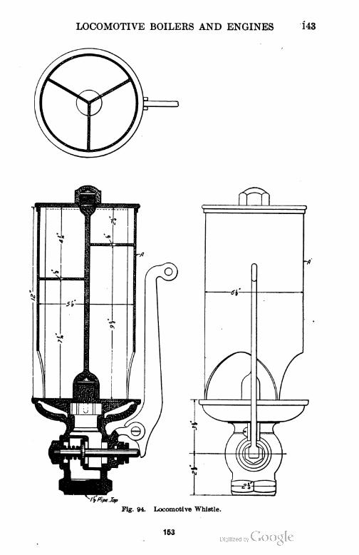
LOCOMOTIVE BOILERS AND ENGINES
144 LOCOMOTIVE BOILERS AND ENGINES
The Whistle. The whistle is used for signaling purposes and
consists of a thin circular bell, Fig. 94, closed at the top and sharp at
the lower edge. Steam is allowed to escape from a narrow circular
orifice directly beneath the edge of the bell. A part of the escaping
steam enters the interior of the bell and sets up vibrations therein.
The more rapid these vibrations, the higher the tone of the whistle.
The tone is affected by the size of the bell and the pressure of the steam.
The larger the bell, the lower will be the tone. The higher the steam
pressure, the higher the tone. In order to avoid the shrill noise of the
common whistle, chime whistles are commonly used, one type of
which is illustrated in Fig. 94. In this illustration the bell is divided
into three compartments of such proportions that the tones harmonize
and give an agreeable chord.
Steam Gauges. The usual construction of the steam gauge will
not be presented here but reference is made to the instruction paper
on "Boiler Accessories."
Water Gauges. Water gauges are also fully explained in the
instruction paper on "Boiler Accessories."
The Blower. The blower consists merely of a steam pipe leading
from and fitted with a valve in the cab to the stack where it is turned
upward. The end of this pipe is formed into a nozzle. The es
caping steam gives motion to the air exactly as already explained for
the exhaust and thus induces a draft through the fire-box. It is used
when the fire is to be forced while the engine is standing.
Throttle Valve. The throttle valve now in universal use is some
form of a double-seated poppet valve, as illustrated in Fig. 95. In
this type, two valves a and b are attached to a single stem, the upper
valve being slightly the larger. The lower valve b is of such a diam
eter that it will just pass through the seat of the valve a. The steam,
therefore, exerts a pressure on the lower face of b and the upper face
of a. As the area of a is the greater, the resultant tendency is to hold
the valve closed. The valve is, therefore, partially balanced. It
will be difficult to open large throttle valves such as are now used on
locomotives carrying high steam pressures, with the ordinary direct
form of leverage. In such cases, it will be necessary to give a strong,
quick jerk to the throttle lever before the valve can be moved from
its seat. The arrangement of leverage shown in Fig. 95 obviates this
difficulty. The rod c connects with a lever in the cab and comrauni
154
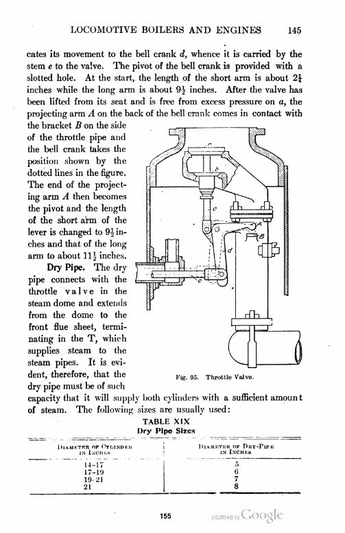
LOCOMOTIVE BOILERS AND ENGINES 145
cates its movement to the bell crank d, whence it is carried by the
stem e to the valve. The pivot of the bell crank is provided with a
slotted hole. At the start, the length of the short arm is about 2\
inches while the long arm is about 9J inches. After the valve has
been lifted from its seat and is free from excess pressure on a, the
projecting arm A on the back of the bell crank comes in contact with
the bracket B on the side
of the throttle pipe and
the bell crank takes the
position shown by the
dotted lines in the figure.
The end of the project
ing arm A then becomes
the pivot and the length
of the short arm of the
lever is changed to 9.̂ in
ches and that of the long
arm to about 11 1 inches.
Dry Pipe. The dry
pipe connects with the
throttle valve in the
steam dome and extends
from the dome to the
front flue sheet, termi
nating in the T, which
supplies steam to the
steam pipes. It is evi
dent, therefore, that the
dry pipe must be of such
capacity that it will supply
of steam
Fig. 95. Throttle Valve.
joth cylinders with a sufficient amount
The following sizes are usually used:
TABLE XIX
Dry Pipe Sires
Diameter of Oylindeh
in Inch km
Diameter of Dry-Pipein Inches
14-17 5
17-19 (i
19-21 7
21 8
155

1 55
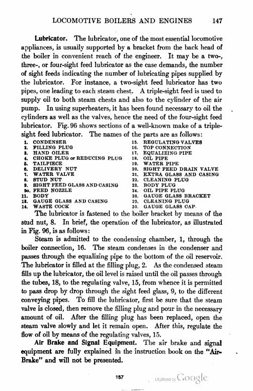
LOCOMOTIVE BOILERS AND ENGINES 147
Lubricator. The lubricator, one of the most essential locomotive
appliances, is usually supported by a bracket from the back head of
the boiler in convenient reach of the engineer. It may be a two-,
three-, or four-sight feed lubricator as the case demands, the number
of sight feeds indicating the number of lubricating pipes supplied by
the lubricator. For instance, a two-sight feed lubricator has two
pipes, one leading to each steam chest. A triple-sight feed is used to
supply oil to both steam chests and also to the cylinder of the air
pump. In using superheaters, it has been found necessary to oil the
cylinders as well as the valves, hence the need of the four-sight feed
lubricator. Fig. 96 shows sections of a well-known make of a triple-
sight feed lubricator. The names of the parts are as follows:
1. CONDENSER 15. REGULATING VALVES
2. FILLING PLUG 16. TOP CONNECTION
3. HAND OILER 17. EQUALIZING PIPE
4. CHOKE PLUG or REDUCING PLUG 18. OIL PIPE
6. TAILPIECE 19. WATER PIPE
6. DELIVERY NUT 20. SIGHT FEED DRAIN VALVE
7. WATER VALVE 21. EXTRA GLASS AND CASING
8. STUD NUT 22. CLEANING PLUG
9. SIGHT FEED GLASS AND CASING 23. BODY PLUG
9a. FEED NOZZLE 24. OIL PIPE PLUG
11. BODY 28. GAUGE GLASS BRACKET
13. GAUGE GLASS AND CASING 29. CLEANING PLUG
14. WASTE COCK 30. GAUGE GLASS CAP
The lubricator is fastened to the boiler bracket by means of the
stud nut, 8. In brief, the operation of the lubricator, as illustrated
in Fig. 96, is as follows :
Steam is admitted to the condensing chamber, 1, through the
boiler connection, 16. The steam condenses in the condenser and
passes through the equalizing pipe to the bottom of the oil reservoir.
The lubricator is filled at the filling plug, 2. As the condensed steam
fills up the lubricator, the oil level is raised until the oil passes through
the tubes, 18, to the regulating valve, 15, from whence it is permitted
to pass drop by drop through the sight feed glass, 9, to the different
conveying pipes. To fill the lubricator, first be sure that the steam
valve is closed, then remove the filling plug and pour in the necessary
amount of oil. After the filling plug has been replaced, open the
steam valve slowly and let it remain open. After this, regulate the
flow of oil by means of the regulating valves, 15.
Air Brake and Signal Equipment. The air brake and signal
equipment are fully explained in the instruction book on the "Air-
Brake" and will not be presented.
157
148 LOCOMOTIVE BOILERS AND ENGINES
RAILWAY SIGNALING ,
Railway signaling is a very important subject and one to which
a great deal of attention has been directed in recent years; it is by
no means a new subject, however, nor has its development been
rapid. It early became evident that signals are necessary in govern
ing the movement of trains, so we find that as the traffic and speed
of trains increased, the demand for improvements in signaling, like
wise increased.
Although there are a great many kinds of signals on the market,
they may all be classed under four general types, namely, audible,
movable, train, and fixed signals. The audible signal is well known
as the bell, whistle, and torpedo.
Whistle Signals. One long blast of the whistle is the signal for
approaching stations, railroad crossings, and junctions. (Thus .)
One short blast of the whistle is the signal to apply the brakes
to stop. (Thus —.)
Two long blasts of the whisle is the signal to release the brakes.
(Thus .)
Two short blasts of the whistle is an answer to any signal unless
otherwise specified. (Thus .)
Three long blasts of the whistle to be repeated until answered
is the signal that the train has parted. (Thus .)
Three short blasts of the whistle when the train is standing, to
be repeated until answered, is a signal that the train will back. (Thus
Four long blasts of the whistle is a signal to call in the flagman
from the west or south. (Thus .)
Four long, followed by one short blast of the whistle, is the signal
to call in the flagman from the east or north. (Thus
Four short blasts of the whistle is the engineman's call for signals
from switch tenders, watchmen, trainmen, and others. (Thus
—-.)
One long and tlu.ee short blasts of the whistle is a signal to the
flagman to go back and protect the rear of the train. (Thus
One long, followed by two short blasts of the whistle, is the
signal to be given by trains when displaying signals for a following
158
LOCOMOTIVE BOILERS AND ENGINES 149
train to call the attention of trains of the same or inferior class to
the signals displayed. (Thus .)
Two long followed by two short blasts of the whistle is the signal
for approaching road crossings at grade. (Thus .)
A succession of short blasts of the whistle is an alarm for persons
or cattle on the track and calls the attention of trainmen to the danger
ahead.
Bell Cord Signals. One short pull of the signal cord when the
train is standing is the signal to start.
Two pulls of the signal cord when the train is running is the
signal to stop at once.
Two pulls of the signal cord when the train is standing is the
signal to call in the flagman.
Three pulls of the signal cord when the train is running is the
signal to stop at the next station.
Three pulls of the signal cord when the train is standing is the
signal to back the train.
Four pulls of the signal cord when the train is running is the
signal to reduce the speed.
When one blast of the signal whistle is heard while a train is
running, the engineer must immediately ascertain if the train has
parted, and, if so, take great precaution to prevent the two parts of
the train from coming together in a collision.
Movable Signals. Movable signals are used to govern the
movement of trains in switching and other service where demanded.
They are made with flags, lanterns, torpedoes, fusees, and by hand.
The following signals have been adopted as a standard code by the
American Railway Association:
Flags of the proper color must be used by day and lamps of the
proper color by night or whenever from fog or other cause, the day
signals cannot be clearly seen.
Red signifies danger and is a signal to stop.
Green signifies caution and is a signal to go slowly.
White signifies safety and is a signal to continue.
Green and white is a signal to be used to stop trains at flag stations
for passengers or freight.
Blue is a signal to be used by car inspectors and repairers and
signifies that the train or cars so protected must not be moved.
159
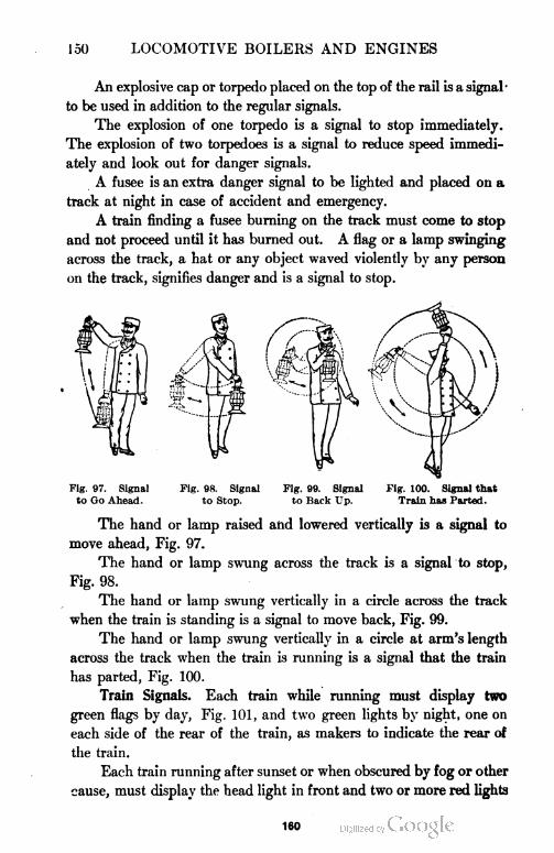
150 LOCOMOTIVE BOILERS AND ENGINES
An explosive cap or torpedo placed on the top of the rail is a signal
to be used in addition to the regular signals.
The explosion of one torpedo is a signal to stop immediately.
The explosion of two torpedoes is a signal to reduce speed immedi
ately and look out for danger signals.
A fusee is an extra danger signal to be lighted and placed on a
track at night in case of accident and emergency.
A train finding a fusee burning on the track must come to stop
and not proceed until it has burned out. A flag or a lamp swinging
across the track, a hat or any object waved violently by any person
on the track, signifies danger and is a signal to stop.
Fig. 97. Signal Fig. 98. Signal Fig. 99. Signal Fig. 100. Signal that
to Go Ahead. to Stop. to Back Up. Train has Parted.
The hand or lamp raised and lowered vertically is a signal to
move ahead, Fig. 97.
The hand or lamp swung across the track is a signal to stop,
Fig. 98.
The hand or lamp swung vertically in a circle across the track
when the train is standing is a signal to move back, Fig. 99.
The hand or lamp swung vertically in a circle at arm's length
across the track when the train is running is a signal that the train
has parted, Fig. 100.
Train Signals. Each train while running must display two
green flags by day, Fig. 101, and two green lights by night, one on
each side of the rear of the train, as makers to indicate the rear of
the train.
Each train running after sunset or when obscured by fog or other
cause, must display the head light in front and two or more red lights
160
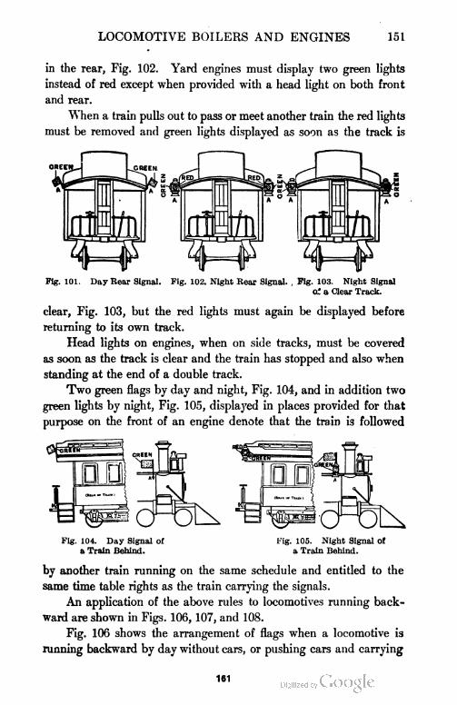
LOCOMOTIVE BOILERS AND ENGINES 151
in the rear, Fig. 102. Yard engines must display two green lights
instead of red except when provided with a head light on both front
and rear.
When a train pulls out to pass or meet another train the red lights
must be removed and green lights displayed as soon as the track is
Pig. 101. Day Rear Signal. Fig. 102. Night Rear Signal. , Fig. 103. Night Signal
oi a Clear Track.
clear, Fig. 103, but the red lights must again be displayed before
returning to its own track.
Head lights on engines, when on side tracks, must be covered
as soon as the track is clear and the train has stopped and also when
standing at the end of a double track.
Two green flags by day and night, Fig. 104, and in addition two
green lights by night, Fig. 105, displayed in places provided for that
purpose on the front of an engine denote that the train is followed
Fig. 104. Day Signal of Fig. 105. Night Signal Of
a Train Behind. a Train Behind.
by another train running on the same schedule and entitled to the
same time table rights as the train carrying the signals.
An application of the above rules to locomotives running back
ward are shown in Figs. 106, 107, and 108.
Fig. 106 shows the arrangement of flags when a locomotive is
running backward by day without cars, or pushing cars and carrying
161
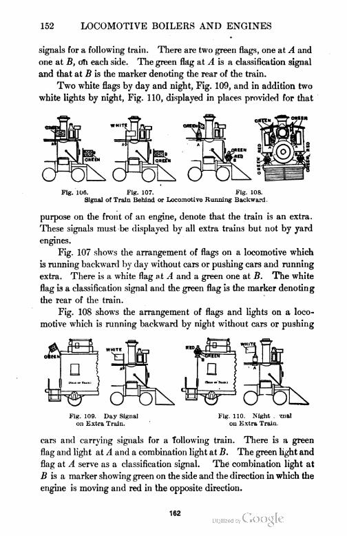
152 LOCOMOTIVE BOILERS AND ENGINES
signals for a following train. There are two green flags, one at A and
one at B, oh each side. The green flag at A is a classification signal
and that at B is the marker denoting the rear of the train.
Two white flags by day and night, Fig. 109, and in addition two
white lights by night, Fig. 110, displayed in places provided for that
Fig. 106. Fig. 107. Fig. 108.
Signal of Train Behind or Locomotive Running Backward.
purpose on the front of an engine, denote that the train is an extra.
These signals must be displayed by all extra trains but not by yard
engines.
Fig. 107 shows the arrangement of flags on a locomotive which
is running backward by day without cars or pushing cars and running
extra. There is a white flag at A and a green one at B. The white
flag is a classification signal and the green flag is the marker denoting
the rear of the train.
Fig. 108 shows the arrangement of flags and lights on a loco
motive which is running backward by night without cars or pushing
Fig. 109. Day Signal Fig. 110. Night . mal
on Extra Train. on Extra Train.
cars and carrying signals for a following train. There is a green
flag and light at A and a combination light at B. The green light and
flag at A serve as a classification signal. The combination light at
B is a marker showing green on the side and the direction in which the
engine is moving and red in the opposite direction.
162

LOCOMOTIVE BOILERS AND ENGINES 153
At B there is a com-
VVHITE
Fig. 110 shows the arrangement of flags and lights on a train
running forward by night and running extra. There is a white flag
and white light at A as a classification signal,
bination light. This combination light shows
green to the sides and front of the train and
red to the rear.
Fig. Ill shows the arrangement of flags
and lights on a locomotive running backward
by night without cars or pushing cars and run
ning extra. There are white flags and white
lights at A A as classification signals. At B
B there are combination lights showing green
on the sides and the direction in which the
engine is running, and red in the opposite
direction. The combination lights serve as
markers.
Fig. 112 shows the arrangement of green marker flags on the
rear of the tender of a locomotive which is moving forward by day
without cars.
Fig. 113 shows the arrangement of combination lights used as
markers on the rear of the tender of a locomotive which is running
forward at night without cars. The combination light shows green
at the sides and front and red at the back.
Fig. 114 shows the arrangement of lights on the rear of the tender
Fig. 111.
Night Signal on Locomo
tive Running Backward,
as an Extra.
GREEN
GREEN
- *
RED
GREEN GREEN-WHITE
MJ IF
Fig. 11L'. Fig. 113. Fig. 114.
Signals on Tender for Engine Running Without Cars.
of a locomotive which is running backward by night. There is a single
white light at A.
Fig. 115 shows the arrangement of lights on a passenger train
which is being pushed by an engine at night. There is a white light
at A on the front of the leading truck.
163
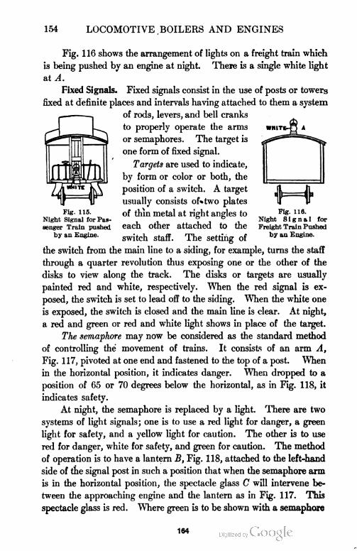
154 LOCOMOTIVE.BOILERS AND ENGINES
WHITl
Fig. 115.
Night Signal for Pas
senger Train pushed
by an Engine.
f=4
Pig. 116.
Night Signal for
Freight Train Pushed
by an Engine.
Fig. 116 shows the arrangement of lights on a freight train which
is being pushed by an engine at night. There is a single white light
at A.
Fixed Signals. Fixed signals consist in the use of posts or towers
fixed at definite places and intervals having attached to them a system
of rods, levers, and bell cranks
to properly operate the arms
or semaphores. The target is
one form of fixed signal.
Targets are used to indicate,
by form or color or both, the
position of a switch. A target
usually consists of»two plates
of thin metal at right angles to
each other attached to the
switch staff. The setting of
the switch from the main line to a siding, for example, turns the staff
through a quarter revolution thus exposing one or the other of the
disks to view along the track. The disks or targets are usually
painted red and white, respectively. When the red signal is ex
posed, the switch is set to lead off to the siding. When the white one
is exposed, the switch is closed and the main line is clear. At night,
a red and green or red and white light shows in place of the target.
The semaphore may now be considered as the standard method
of controlling the movement of trains. It consists of an arm A,
Fig. 117, pivoted at one end and fastened to the top of a post. When
in the horizontal position, it indicates danger. When dropped to a
position of 65 or 70 degrees below the horizontal, as in Fig. 118, it
indicates safety.
At night, the semaphore is replaced by a light. There are two
systems of light signals; one is to use a red light for danger, a green
light for safety, and a yellow light for caution. The other is to use
red for danger, white for safety, and green for caution. The method
of operation is to have a lantern B, Fig. 118, attached to the left-hand
side of the signal post in such a position that when the semaphore arm
is in the horizontal position, the spectacle glass C will intervene be
tween the approaching engine and the lantern as in Fig. 117. This
spectacle glass is red. WTiere green is to be shown with a semaphore
164
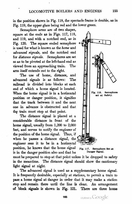
LOCOMOTIVE BOILERS AND ENGINES 155
in the position shown in Fig. 118, the spectacle frame is double, as in
Fig. 119, the upper glass being red and the lower green.
Semaphore arms are of two shapes,
square at the ends as in Figs. 117, 118,
and 119, and with a notched end, as in
Fig. 120. The square ended semaphore
is used for what is known as the home and
advanced signals, and the notched end
for distance signals. Semaphores are set
so as to be pivoted at the left-hand end as
viewed from an approaching train. The
arm itself extends out to the right.
The use of home, distance, and
advanced signals is as follows: The
railroad is divided into blocks at each
end of which a home signal is located.
When the home signal is in a horizontal
position or danger position, it signifies
that the track between it and the next
one in advance is obstructed and that
the train must stop at that point.
The distance signal is placed at a
considerable distance in front of the
home signal, usually from 1,200 to 2,000
feet, and serves to notify the engineer of
the position of the home signal. Thus, if
when he passes a distance signal, the
engineer sees it to be in a horizontal
position, he knows that the home signal
is in the danger position also and that he
must be prepared to stop at that point unless it be dropped to safety
in the meantime. The distance signal should show the cautionary
light signal at night.
The advanced signal is used as a supplementary home signal.
It is frequently desirable, especially at stations, to permit a train to
pass a home signal at danger in order that it may make a station
stop and remain there until the line is clear. An arrangement
of block signals is shown in Fig. 121. There are three home
Fig. 117. Semaphore Set at
Danger Signal.
165
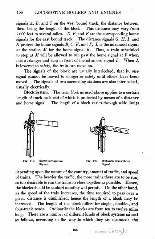
156 LOCOMOTIVE BOILERS AND ENGINES
signals A, B, and C on the west bound track, the distance between
them being the length of the block. This distance may vary from
1 ,000 feet to several miles. D, E, and F are the corresponding home
signals for the east bound track. The distance signals G, H, I, and
K protect the home signals B, C, E, and F; L is the advanced signal
at the station M for the home signal B. Thus, a train scheduled
to stop at M will be allowed to run past the home signal at B when
it is at danger and stop in front of the advanced signal L. When L
is lowered to safety, the train can move on.
The signals of the block are usually interlocked, that is, one
signal cannot be moved to danger or safety until others have been
moved. The signals of two succeeding stations are also interlocked,
usually electrically.
Block System. The term block as used above applies to a certain
length of track each end of which is protected by means of a distance
and home signal. The length of a block varies through wide limits
Fig. 119. Home Semaphore Fig. 120. Distance Semaphore
Signal. Signal.
depending upon the nature of the country, amount of traffic, and speed
of trains. The heavier the traffic, the more trains there are to be run,
so it is desirable to run the trains as close together as possible. Hence,
the blocks should be as short as safety will permit. On the other hand,
as the speed of the train increases, the time required to pass over a
given distance is diminished, hence the length of a block may be
increased. The length of the block differs for single-, double-, and
four-track roads. Ordinarily the blocks are from ten to twelve miles
long. There are a number of different kinds of block systems named
as follows, according to the way in which they are operated: the
166
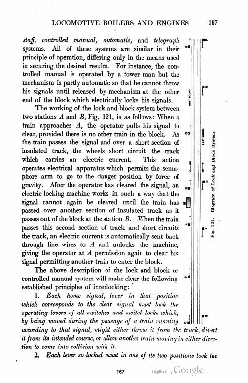
LOCOMOTIVE BOILERS AND ENGINES 157
J
J
staff, controlled manual, automatic, and telegraph
systems. All of these systems are similar in their
principle of operation, differing only in the means used
in securing the desired results. For instance, the con
trolled manual is operated by a tower man but the
mechanism is partly automatic so that he cannot throw
his signals until released by mechanism at the other
end of the block which electrically locks his signals.
The working of the lock and block system between
two stations A and B, Fig. 121, is as follows: When a
train approaches A, the operator pulls his signal to
clear, provided there is no other train in the block. As
the train passes the signal and over a short section of
insulated track, the. wheels short circuit the track
which carries an electric current. This action
operates electrical apparatus which permits the sema
phore arm to go to the danger position by force of
gravity. After the operator has cleared the signal, an
electric locking machine works in such a way that the
signal cannot again be cleared until the train has
passed over another section of insulated track as it
passes out of the block at the station B. When the train
passes this second section of track and short circuits
the track, an electric current is automatically sent back
through line wires to A and unlocks the machine,
giving the operator at A permission again to clear his
signal permitting another train to enter the block.
The above description of the lock and block or
controlled manual system will make clear the following
established principles of interlocking:
1. Each home signal, lever in that position
which corresponds to the clear signal must lock the
operating levers of all switches and switch locks which,
by being moved during the passage of a train running
according to that signal, might either throw it from the track, divert
it from its intended course, or allow another train moving in either direc
tion to come into collision with it.
2. Each lever so locked must in one of its two positions lock the
.J
J
167
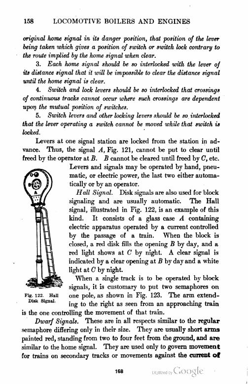
158 LOCOMOTIVE BOILERS AND ENGINES
original home signal in its danger position, that position of the lever
being taken which gives a position of switch or switch lock contrary to
the route implied by the home signal when clear.
3. Each home signal should be so interlocked with the lever of
its distance signal that it will be impossible to clear the distance signal
until the home signal is clear.
4. Switch and lock levers should be so interlocked that crossings
of continuous tracks cannot occur where such crossings are dependent
upon the mutual position of switches.
5. Switch levers and other locking levers should be so interlocked
that the lever operating a switch cannot be moved while that switch is
locked.
Levers at one signal station are locked from the station in ad
vance. Thus, the signal A, Fig. 121, cannot be put to clear until
freed by the operator at B. B cannot be cleared until freed by C, etc.
Levers and signals may be operated by hand, pneu
matic, or electric power, the last two either automa-
J) tically or by an operator.
Hall Signal. Disk signals are also used for block
signaling and are usually automatic. The Hall
signal, illustrated in Fig. 122, is an example of this
kind. It consists of a glass case A containing
electric apparatus operated by a current controlled
by the passage of a train. When the block is
closed, a red disk fills the opening B by day, and a
red light shows at C by night. A clear signal is
indicated by a clear opening at B by day and a white
light at C by night.
When a single track is to be operated by block
signals, it is customary to put two semaphores on
one pole, as shown in Fig. 123. The arm extend
ing to the right as seen from an approaching train
is the one controlling the movement of that train.
Dwarf Signals. These are in all respects similar to the regular
semaphore differing only in their size. They are usually short arms
painted red, standing from two to four feet from the ground, and are
similar to the home signal. They are used only to govern movement
for trains on secondary tracks or movements against the current of
Fig. 122. Hall
Disk Signal.
168
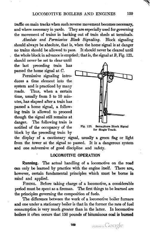
LOCOMOTIVE BOILERS AND ENGINES 159
traffic on main tracks when such reverse movement becomes necessary,
and where necessary in yards. They are especially used for governing
the movement of trains in backing out of train sheds at terminals.
Absolute and Permissive Block Signaling. Block signaling
should always be absolute, that is, when the home signal is at danger
no trains should be allowed to pass. It should never be cleared until
the whole block in advance is emptied ; that is, the signal at B, Fig. 121,
should never be set to clear until
the last preceding train has
passed the home signal at C.
Permissive signaling intro
duces a time element into the
system and is practiced by many
roads. Thus, when a certain
time, usually from 5 to 10 min
utes, has elapsed after a train has
passed a home signal, a follow
ing train is allowed to proceed
though the signal still remains at
danger. The following train is
notified of the occupancy of the
block by the preceding train by
the display of a cautionary signal, usually a green flag or light
from the tower at the signal so passed. It is a dangerous system
and one subversive of good discipline and safety.
LOCOMOTIVE OPERATION
Running. The actual handling of a locomotive on the road
can only be learned by practice with the engine itself. There are,
however, certain fundamental principles which must be borne in
mind and applied.
Firing. Before taking charge of a locomotive, a considerable
period must be spent as a fireman. The first things to be learned are
the principles governing the composition of fuels.
The difference between the work of a locomotive boiler furnace
and one under a stationary boiler is that in the former the rate of fuel
consumption is very much greater than in the latter. In locomotive
boilers it often occurs that 150 pounds of bituminous coal is burned
Fig. 123. Semaphore Block Signal
for Single Track.
169
160 LOCOMOTIVE BOILERS AND ENGINES
per square foot of grate area per hour while a consumption of 200
pounds per square foot per hour is not unusual.
Different fuels require different treatment in the fire-box.
Bituminous coal is the most common fuel used on American
railroads. It varies so much in chemical composition and heat value
that no fixed rule for burning it can be laid down. The work of the
fireman varies more or less with each grade of coal used. Ordinarily,
the fuel bed should be comparatively thin. It may vary in thickness
from 6 to 10 inches or even more, depending on the work the locomo
tive is called upon to perform. The fuel bed should be of sufficient
thickness to prevent its being lifted from the grate under the in
fluence of the draft created by the exhaust.
In order to obtain the best results, the stoking must be very
nearly constant. Three shovelfuls at a time have been found to give
very good results. The fire door should be closed between each
shovelful so as to be only open on the latch. This delivers air to
complete the combustion of the hydrocarbon gases which are dis
tilled the moment the fresh coal strikes the incandescent fuel. In
placing the fuel in the fire-box, it is well to heap it up slightly in the
corners and allow the thinnest portion of the bed to be in the center
of the grate. The frequency of the firing depends upon the work
the engine is called upon to do.
The fire should always be cleaned at terminals and when the
grade is favorable the slice bar may be used and the clinker removed
through the furnace door while running.
Anthracite coal. In using anthracite coal, it is best, whenever
possible, to do the stoking on favorable grades and at stations. The
thickness of the fuel bed varies in size with the kind of coal used. It
may vary from three inches with fine pea and buckwheat coal to 10
inches with large lumps. The fuel should be evenly distributed over
the entire grate. The upper surface of an anthracite coal fire must
never be disturbed by the slice bar while the engine is working.
When it is necessary to use the slice bar, it should be done only when
there is ample time after its completion to enable the fire to come up
again and be burning vigorously before the engine resumes work.
Feeding the Boiler. Feeding the boiler is a matter requiring
skill and judgment, especially where the locomotive is being worked
to its full capacity. The injector is now the universal means em
170
LOCOMOTIVE BOILERS AND ENGINES 161
ployed for feeding the locomotive boiler. Where it is possible, the
most satisfactory way is to use a constant feed which will be average
for the entire trip. In this way the water level will rise and fall but
will always be sufficient to cover the crown sheet. Under no cir
cumstances should the water level be allowed to fall below the lower
gauge cock.
Where a constant feed cannot be used, the injector may be
worked to its full capacity on favoring grades and at station stops.
This will give a storage of water to be drawn upon when the engine is
working to its full capacity on adverse grades. Under such circum
stances, the stopping of the feed may enable the fire to maintain the
requisite steam pressure, whereas the latter might fall if the injector
were to be kept at work. Further, the use of the injector on down
grades and at stations keeps down the steam pressure and prevents
the loss of heat by the escape of steam through the safety valves when
the fire is burning briskly and the engine is not working.
The Use of Steam. The manner in which an engineer uses
the steam in the cylinders is one of the controlling elements in
the economical use of coal. In starting, the reverse lever must be
thrown forward so that steam is admitted to the cylinders for as great
a portion of the stroke of the piston as the design of the valve motion
will permit. As the speed increases, the lever should be drawn back,
thus shortening the cut-off. It will usually be found that when the
engine is not overloaded, a higher speed will be attained and main
tained with a short than with a long cut-off. The reason is that with
a late cut-off, so much steam is admitted to the cylinder that it can
not be exhausted in the time allowed, resulting in an excessive back
pressure which retards the speed.
Experiments have proven, however, that it is not economical
to use a cut-off which occurs earlier than one-fourth stroke, for when
the cut-off occurs earlier than this, the cylinder condensation will
more than offset the saving effected by the increased expansion so
obtained. For this reason when the engine is running under such con
ditions that a cut-off earlier than one-fourth stroke can be used with
the throttle wide open, it may be better to keep the point of cut-off
at one-fourth stroke and partially close the throttle, thus wiredrawing
the steam. The wiredrawing of the steam serves to superheat it to a
limited extent and thus to diminish the cylinder condensation which
171
162 LOCOMOTIVE BOILERS AND ENGINES
would occur were saturated steam at the same pressure being used.
When running with the throttle valve closed, the reverse lever
should be set to give the maximum travel to the valve in order to pre
vent the wearing of the shoulders on the valve seats.
Learning the Road. Learning the road is one of the most
important things for the engineer to accomplish. He must know
every grade, curve, crossing, station approach, bridge, signal and
whistle or bell post on the division over which he runs. He must
know them on dark and stormy nights as well as in the daytime. He
must always know where he is and never be at the slightest loss as to
his surroundings. He must not only know where every water tank
is located but should also make himself familiar with the qualities of
the various waters they contain. Then when he has a choice of
places at which to take water he may choose that containing the
mallest amount of scale-forming matter.
Grades. In the learning of a road an intimate knowledge of the
grades is of the first importance to the engineer. He must know
what his engine can handle over them, how it must be handled
when on them, and how they must be approached. An engine will
frequently be able to take a train over a grade if it has a high speed
at the foot, whereas if a stop or slackening of the speed were to be
made at the foot of the grade it would be impossible to surmount it
with the entire train.
Handling Trains. Handling trains over different profiles of
track requires different methods. On adverse grades, the work is
probably the simplest. In such conditions the train is stretched out
to its fullest extent. Every car is pulling back and the checking of the
movement of the front of the train meets with an immediate response
throughout the whole train. The grade also prevents sudden ac
celeration at the front. It is, therefore, necessary merely to keep the
engine at work.
On favoring grades, the whole train when drifting is crowding
down upon the locomotive and is likely to be bunched or closed together.
Under these conditions, it is necessary to apply the air brakes which
are at the front end and keep them applied so as to hold the speed
under control and prevent the train from running away. Care should
be taken in the application of the driving wheel brakes on long down
grades lest the shoes heat the tires and cause them to become loose.
172
LOCOMOTIVE BOILERS AND ENGINES 163
The greatest danger of injury to a train arises in passing over
ridges and through sags. First, in leaving an adverse grade in passing
over a ridge to a favoring grade, the engineer must be careful not to
accelerate the front end of the train too rapidly lest it break in two
before the rear end has crossed the summit. There is greater danger,
however, in running through a dip where the grade changes from a
favoring to an adverse one. Where brakes have been applied at the
rear of the train and the slack prevented the train from becoming
bunched, there is not the same danger as when the brakes have been
applied at the front of the train. In the latter case, if the engineer
is not careful in pulling out the slack, the train may be parted. Acci
dents of this class will be minimized if in every case the slack is taken
up slowly. A steady pull will not break the draft rigging of the car,
whereas a sudden jerk may pull it out.
In case a train does break in two, the engine and front portion
should be kept in motion until the rear portion has been stopped.
In so doing a collision may be avoided. Where air brakes are applied
to the entire train, the rear portion will stop first owing to the pro
portional increase of weight and momentum of the locomotive.
Freight trains require on the whole more careful handling than
passenger trains. There is more slack in the couplings of the former
than in the latter and the trains are much longer, consequently the
shocks at the rear of a freight train, due to variation in speed, are
much more severe than on passenger trains. The system of handling,
while practically the same for both classes, requires more care in order
to avoid accidents with a freight train than with a passenger train.
The End of the Run. When the run has been finished,
the engineer should make a careful inspection of all parts of the
engine so as to be able to report any repairs which may be needed in
order to fit the locomotive for the next run. The roundhouse hostler
should then take the engine and have the tender loaded with coal,
the tank filled with water, and the fire cleaned. The engine should
then be put over the pit in the roundhouse, carefully wiped, and again
inspected for defects.
Inspection. The inspection of locomotives should be thorough.
It should embrace the condition of every exposed wearing surface and
the behavior of every concealed one. All bolts and nuts should be
examined to ascertain if they are tight. The netting in the front end
173
164 LOCOMOTIVE BOILERS AND ENGINES
should be examined at frequent intervals to make sure that it is not
burned out. The stay-bolts should be inspected periodically in order
that those broken may be replaced. Wheels and all parts of the run
ning gear and mechanism should be carefully scrutinized for cracks
or other defects.
Cleaning. Cleaning the engine should be done after every trip,
since dust and dirt may cover defects which may be serious and
ultimately cause a disaster.
Repairs. Repairs of a minor nature can be made in the round
house and should receive prompt attention. Roundhouse repairs
include such work as the replacing of the netting in the smoke-box,
cleaning of nozzles, expanding and caulking leaky flues, refitting the
side and connecting rod brasses, refitting valve seats, regrinding
leaky cab fittings, adjusting driving box wedges, repairing ash pans,
replacing grates, renewing brake shoes, resetting valves, repairing
water tanks, and sometimes may be extended to the re-boring of
cylinders. To this list must also be added the regular work of re
newing all packing and cleaning out the boiler.
Emergencies. Emergencies are constantly arising in locomotive
running where a breakage of some part should be repaired while on
the road. The part affected and the extent of the fracture has much
to do with the possibility of running the engine home under its own
steam. A few methods of dealing with the more common breakages
will be given.
Broken Side Rods. If a side rod breaks, the ends of the broken
rod should be disconnected and the rod on the opposite side of the
engine should be removed. An attempt should never be made to run
a locomotive with only one side rod connected as the engine would be
badly out of balance and trouble would arise when the driver at
tempted to pass the dead center.
Broken Connecting Rod. If a connecting rod is broken without
injury to the cylinder, the crosshead and piston should be blocked
at one end of the stroke and the broken parts of the rod removed.
The removal of the side rods depends upon the extent of injury to the
crank pin on the broken side. All side rods should be left in position
if the crank pin on the broken side is uninjured, otherwise all should
be removed. The valve rod should be disconnected from the rocker
arm and the valve stem clamped with the valve in the central position.
174
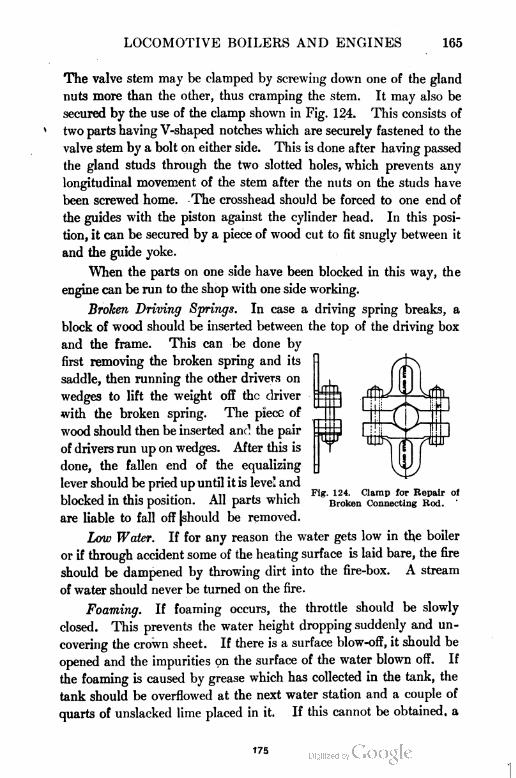
LOCOMOTIVE BOILERS AND ENGINES 165
The valve stem may be clamped by screwing down one of the gland
nuts more than the other, thus cramping the stem. It may also be
secured by the use of the clamp shown in Fig. 124. This consists of
two parts having V-shaped notches which are securely fastened to the
valve stem by a bolt on either side. This is done after having passed
the gland studs through the two slotted holes, which prevents any
longitudinal movement of the stem after the nuts on the studs have
been screwed home. The crosshead should be forced to one end of
the guides with the piston against the cylinder head. In this posi
tion, it can be secured by a piece of wood cut to fit snugly between it
and the guide yoke.
When the parts on one side have been blocked in this way, the
engine can be run to the shop with one side working.
Broken Driving Springs. In case a driving spring breaks, a
block of wood should be inserted between the top of the driving box
and the frame. This can be done by
first removing the broken spring and its
saddle, then running the other drivers on
wedges to lift the weight off the driver
with the broken spring. The piece of
wood should then be inserted and the pair
of drivers run up on wedges. After this is
done, the fallen end of the equalizing
lever should be pried up until it is level and
blocked in this position. All parts which
are liable to fall off |should be removed.
Low Water. If for any reason the water gets low in the boiler
or if through accident some of the heating surface is laid bare, the fire
should be dampened by throwing dirt into the fire-box. A stream
of water should never be turned on the fire.
Foaming. If foaming occurs, the throttle should be slowly
closed. This prevents the water height dropping suddenly and un
covering the crown sheet. If there is a surface blow-off, it should be
opened and the impurities on the surface of the water blown off. If
the foaming is caused by grease which has collected in the tank, the
tank should be overflowed at the next water station and a couple of
quarts of unslacked lime placed in it. If this cannot be obtained, a
Fig. 124. Clamp for Repair of
Broken Connecting Rod.
175
166 LOCOMOTIVE BOILERS AND ENGINES
piece of blue vitriol, which may be obtained at almost any telegraph
office, may be placed in the hose back of the screen.
Broken Steam Chest. In case a steam chest becomes fractured,
either the lower joint of the steam pipe on the side of the accident
should be pried open and a blind wooden gasket inserted, or the steam
chest and valve should be removed and a piece of board laid over the
steam openings and firmly clamped in position by the studs of the
steam chest.
The above are a few of the accidents which may occur on the
road. To prepare for emergencies, the best method is to study the
locomotive and devise means of making temporary repairs for every
accident imaginable, then when the accident does occur, the remedy
can be promptly applied.
TRAIN RULES
The American Railway Association has adopted a uniform code
of train rules which have been accepted by the railroads of the United
States. These rules briefly stated are as follows :
All trains are designated as regular or extra and may consist of
one or more sections. An engine without cars in service on the road is
considered a train.
All trains are classified with regard to their priority of right to
the track.
A train of an inferior class must in all cases keep out of the way
of a train of a superior class.
On a single track all trains in one direction specified in the time
table have the absolute right of track over trains of the same class running
in the opposite direction.
When trains of the same class meet on a single track, the train
not having the right of track must take the siding and be clear of the
main track before the leaving of the opposite train.
When a train of inferior class meets a train of a superior class
on a single track, the train of inferior class must take the siding and
clear the track for the train of superior class five minutes before its
leaving.
A train must not leave a station to follow a passenger train until
five minutes after the departure of such passenger train unless some
form of block signaling is used.
176
LOCOMOTIVE BOILERS AND ENGINES 167
Freight trains following each other must keep not less than five
minutes apart unless someform of block signaling is used.
No train must arrive at or leave a station in advance of its sched
uled time.
When a passenger train is delayed at any of its usual stops more
than — minutes, the flagman must go back with a danger signal and
protect his train, but if it stops at any unusual point, the flagman must
immediately go back far enough to be seen from a train moving in the
same direction when it is at least —feet from the rear of his own train.
When it is necessary to protect the front of the train, the same
precautions must be observed by the flagman. If the fireman is unable
to leave the engine, the front brakeman must be sent in his place.
When a freight train is detained at any of its usual stops more
than — minutes, where the rear of the train can be plainly seen from
a train moving in the same direction at a distance of at least — feet,
the flagman must go back with danger signals not less than — feet,
and as much farther as may be necessary to protect his train but if
the rear of his train cannot be plainly seen at a distance of at least —
feet, or if it stops at any point which is not its usual stopping place,
the flagman must go back not less than — feet, and if his train should
be detained until within ten minutes of the time of a passenger train
moving in the same direction, he must be governed by rule No. 99.
Rule No. 99 provides that when a train is stopped by an accident
or obstruction, the flagman must immediately go back with danger
signals to stop any train moving in the same direction. At a point —
feet from the rear of his train, he must place one torpedo on the rail. He
must then continue to go back at least —feet from the rear of his train
and place two torpedoes on the rail ten yards apart (one rail length),
when he may return to a point —feet from the rear of his train, where
he must remain until recalled by the whistle of his engine. But if a
passenger train is due within ten minutes, he must remain until it
arrives. When he comes in, he will remove the torpedo nearest to the
train but the two torpedoes must be left on the rail as a caution signal
to any train following.
When it is necessary for a freight train on a double track to turn
out on to the opposite track to allow a passenger train running in the
same direction to pass, and the passenger train running in the opposite
direction is due, a flagman must be sent back with a danger signal as
177
168 LOCOMOTIVE BOILERS AND ENGINES
provided in Rule No. 99 not less than — feet in the direction of the
following train and the other train must not cross over until one of the
passenger trains arrive. Should the following passenger train arrive
first, a flagman must be sent forward on the opposite track with danger
signals as provided in Rule No. 99, not less than —feet in the direction
of the overdue passenger train before crossing over. Great caution
must be used and good judgment is required to prevent detention to
either passenger train. The preference should always be given the
passenger train of superior class.
If a train should part while in motion, trainmen must use great
care to prevent the detached parts from coming into collision.
Regular trains twelve hours or more behind their scheduled time
lose all their rights.
All messages or orders respecting the movement of trains or the con-
dition of track or bridges must be in writing.
Passenger trains must not display signals for a following train
without an order from the Superintendent, nor freight trains without
an order from the Yard Master.
Great care must be exercised by the trainmen of a train approaching
a station where any train is receiving or discharging passengers.
Engine men must observe trains on the opposite track and if they
are running too closely together, call attention to the fact.
No person will be permitted to ride on an engine except the engine-
man, fireman, and other designated employes in the discharge of their
duties without a written order from the proper authorities.
Accidents, detentions of trains, failure in the supply of water or
fuel, or defects in the tracks or bridges must be promptly reported by
telegraph to the Superintendent.
No train shall lea ve a station without a signal from its conductor.
Conductors and engine men will be held equally responsible for
the violation of any rides governing the safety of their trains and they
must take every precaution for the protection of their trains even if not
provided for by the rules.
In case of doubt or uncertainty, no risks should be taken.
TIME TABLES
Time tables are the general law governing the arrival and
leaving time of all regular trains at all stations and are issued from
178
LOCOMOTIVE BOILERS AND ENGINES 169
time to time as may be necessary. The time given for each train
on the time table is the scheduled time of such trains.
Each time table from the moment it takes effect supersedes the
preceding time table and all special relations relating thereto and
trains shall run as directed thereby, subject to the rules. All
regular trains running according to the preceding time table shall,
unless otherwise directed, assume the times and rights of trains of
corresponding numbers on the new time table.
On the time table, not more than two sets of figures are
shown for a train at any point. When two times are shown, the
earlier is the arriving time and the later the leaving time. When
one time is shown, it is the leaving time unless otherwise indicated.
Regular meeting or passing points are indicated on the time
table.
The words "Daily," "Daily except Sunday," etc., printed at
the head and foot of a column in connection with a train indicate
how it shall be run. The figures given at intermediate stations
shall not be taken as indicating that a train will stop, unless the
rules require it.
Trains are designated by numbers indicated on the time table.
LOCOMOTIVE TROUBLES AND REMEDIES
OPERATING PROBLEMS
Distinctive Features of Locomotive. A new locomotive is very
much like any other new piece of machinery, in that, if care has
been used in its construction by experienced mechanics, it should
operate in a satisfactory manner when properly handled. In a
few respects it differs very materially from other steam power
plants. First, when it is in operation it is not stationary but
moves from place to place on a suitably constructed track. This
feature alone requires a form of construction peculiar to its kind.
As a result we find that the different movable parts involved are
far greater in number than in other power plants of equal power
and are included in much less space. Second, because of the large
number of parts the chances for wear are much greater than in
ordinary power plants, and on this account it is not to be
expected that a locomotive will operate as quietly after it has been
179
170 LOCOMOTIVE BOILERS AND ENGINES
in service for some time as it otherwise would. Then again it
must be borne in mind that it is impossible to obtain perfect
track conditions, and for this reason the various parts cannot
be safely "set up" as snugly as would be possible under ideal
conditions.
There are so many points which naturally should come under
Troubles and Remedies that it will be possible to mention only a
few of the more important.
Pounds. For convenience of expression it will probably
simplify matters to refer to all disagreeable and annoying jerks
and sounds familiar to the locomotive engineer and fireman as
"pounds". By different individuals these characteristic sounds
may be referred to as clicks, knocks, jerks, thumps, pounds,
bumps, thrashes, etc. In actual practice they are sometimes very
difficult to locate. If a serious pound is neglected or disregarded,
it may be the cause of ultimately disabling the locomotive.
Because of this fact an effort should be made to locate all trouble
some pounds and report them promptly, for by so doing the engi
neer will relieve himself of further responsibility. An experienced
locomotive engineer naturally becomes familiar with all the
various sounds produced by a locomotive when in operation and
can very often locate a pound which develops suddenly by the
particular sound. Perhaps one of the most difficult pounds to
locate is one caused by a loose piston. Improvements made in
more recent locomotives reduce the chances for the development of
such pounds very materially. When they do develop, they often
will deceive old experienced operators. They usually develop
rather suddenly and sound as if there was much lost motion
somewhere, when as a matter of fact the exact amount of lost
motion may be exceedingly small. Such a pound will probably be
taken for a loose driving box or crosshead.
Locating Pound. Having detected an unusual knock or
pound, it should be located and corrected at the first opportunity.
When it has been determined from which side of the locomotive
the pound issues, it can be definitely located in the following
manner: Block the driving wheels as securely as possible with
the crank-pin on the side in question at the top quarter and have the
fireman open the throttle slightly, to give the cylinders a little
180
LOCOMOTIVE BOILERS AND ENGINES 171
steam, and then reverse the engine a few times while an examina
tion is made of -the various points where a pound is liable to
develop. The crank pin is placed on the upper quarter because
in that position the parts are freer to move than with it at any
other point. If it were placed at either dead center, steam could
be admitted at but one dead center, no matter where the reverse
lever was placed.
Causes of Pounds. Pounds may result from improper lubri
cation of various parts, such as the valve and piston, main axle,
main crank-pin, and crosshead, or lost motion in the reciprocating
parts. Pounds will also result from loose wedges, loose knuckles,
wedges down or stuck, broken engine frame, cylinders loose on
frame, loose pedestal braces, imperfect fitting of shoes and wedges,
loose oil cellars, and shoulders worn on either the shoes or wedges
or on both. At times when the boiler is priming badly, water in
sufficient quantities may enter the cylinder and cause pounds and
endanger the safety of the parts. Improper valve setting or
adjustment may be the cause of pounds or noises of different
character. In this case the usual cause would most probably be
too late admission or too great compression. Other conditions
remaining the same, admission should increase as the speed
increases. In order to determine whether or not the valve adjust
ment is responsible for unusual noises or knocks, it will usually
be necessary to take indicator diagrams from which a study can
be made of the steam distribution.
The valve gear or reversing mechanism is frequently the cause
of numerous rattling noises. The valve gears commonly employed
embody a number of pins, links, movable parts, etc., which become
worn and result in lost motion. The wear on any one part may
not be very noticeable, but in the aggregate the lost motion may
be quite large. The locomotive engineer can usually locate the
badly worn parts when the locomotive is stationary by having
the fireman throw the reverse lever first forward then backward,
repeating the operation as often as necessary, while inspecting the
various parts. This method would probably not disclose lost
motion which might exist in the eccentrics.
The side rods cannot be operated successfully if adjusted too
snugly. For this reason they are made to work with freedom and
181
172 LOCOMOTIVE BOILERS AND ENGINES
frequently produce a rattling sound. This rattling should not
be confused with a pound.
Steam Waste. The steam necessary to do the work in the
cylinders required in hauling a train of a given tonnage at a given
speed is very often augmented by wastes of various kinds, which
should be reduced to a minimum. These wastes may be due to
improper care of the engine, either on the road or in the round
house or both, to improper manipulation when on the road, and to
the use of bad water. Still other wastes may be due to high steam
pressures and high rates of evaporation.
Waste from Piston and Valve Rods. The most common
sources of leakage are steam blows. When these occur into the
atmosphere from the piston and valve rods, it is quite noticeable,
and they may constitute a very great loss, especially where high
steam pressures are employed. Besides being a direct loss, iflider
certain conditions the presence of the steam in the air may obstruct
the view ahead, making operation more hazardous. Anything
which causes undue vibration of the piston and valve rods will
eventually cause leaky packing. For this reason the guides should
be kept in proper adjustment to prevent vertical movement of the
crosshead. In engines using piston valves with inside admission, there
will ordinarily not be trouble by steam leaks around the valve rods.
Waste from Cylinder and Valve Piston Packing. It sometimes
happens that losses occur due to steam blowing past the packing
rings of the cylinder piston or the valve. Indicator cards will
usually show such leaks, but as a rule they can be detected by
the sound of the exhaust. Such steam blows are more difficult
to locate in compound than in simple engines. A practical
method of detecting steam blows past the cylinder and valve piston
packings consists in blocking the engine in different positions
of the crank and noting the presence or absence of steam at
the cylinder cocks or stack.
Waste Due to Priming. The use of water which causes
priming eventually causes steam blows. Priming is frequently
so serious that the whistle cannot be blown without closing the
throttle in order to reduce the water level in the boiler. In
aggravated cases where water is carried over into the cylinders,
it not only endangers the cylinder heads, etc., but sooner or later
182
LOCOMOTIVE BOILERS AND ENGINES 173
injures the piston and valve packing, piston and valve rod packing
and valve seat, causing leaks and serious waste of steam.
Waste from Safety Valve. Another common waste of steam
occurs through the safety valve, caused oftentimes by a careless
manipulation of the fire. Such losses occur most frequently
when the locomotive is standing on a siding or coasting. This
may seem to be a small matter, but if we consider a road using
1000 locomotives per day and each fireman permitting the safety
valve to blow on an average of 10 minutes per day, the amount of
steam wasted daily would approximate 1,000,000 pounds, which
would represent a waste of fuel per day of about 75 tons. Such
waste can be reduced to a minimum by the intelligent manipula
tion of the injectors, dampers, and fire door.
Care of Boiler. Importance. The life of a locomotive boiler
depends largely upon the systematic and intelligent attention it
receives and the particular locality in which it is used. The time
elapsing between cleanings and washings varies between wide
limits with different roads and different localities, depending
largely upon the character of the service and water used. The
proper blowing out by the engineer in order to prevent undue
concentration of material in solution is of much importance.
Some roads require this blowing out to be done while running and
others at terminal points. The removal of sediment or sludge,
such as soft scale, mud, etc., can best be accomplished at termi
nals after the water has had time to become more quiet.
Much importance is attached to the manner of cooling down
and washing out. When done hurriedly the boiler usually suffers.
The following directions for washing and cleaning boilers are
abstracted from instructions furnished employes by one of our
well-known railroads.
Cooling Boiler. Boilers should be thoroughly cooled before
being washed. When cooled in the natural way, the steam should
be blown off and the water retained above the top of the crown
sheet and allowed to stand until the temperature of the steel in
the fire-box is reduced to about 90° F., after which time the
water may be drawn off and the boiler washed. When the loco
motive cannot be spared from service long enough to be cleaned
in this manner, the following plan should be carried out.
183
174 LOCOMOTIVE BOILERS AND ENGINES
After the steam pressure has dropped considerably, start
the injector and continue filling the boiler until the injector will
no longer operate. Then connect the water pressure hose to the
feed hose between the engine and tender and fill the boiler full,
permitting steam to blow through some outlet at the top of the
boiler. Next open the blow-off cock or valve and permit the water
to escape, but at a rate less than that entering from the water hose,
so as to keep the boiler completely filled. Continue the process
until the fire-box sheet has been reduced in temperature to about
90° F., at which time shut off the water, open all plugs, and allow
the boiler to completely empty.
Washing Boiler. Washing may now be begun by first wash
ing the flues by the side holes opposite the front end of the crown
sheet. Next wash the top of the crown sheet at the front end,
then between the rows of crown bars, if provided, and bolts,
directing the stream toward the back end of the crown sheet.
After washing through the holes near the front end of the crown
sheet, continue washing through the holes, in order, toward
the back end of the crown sheet, in such a manner as to work the
mud and scale from the crown sheet toward the side and back
legs of the boiler and thus prevent depositing it on the back ends
of the flues. Continue washing, using the holes in the boiler
head, with the swivel attachment on the hose, working from the
front to the rear, endeavoring to thoroughly wash the top of
the boiler as well as all stays and the crown sheet.
Next wash the back end of the flues through suitably located
holes and afterward the water space between the back head and
the door sheet through the holes in the back head, using the angle
nozzle. The inside arch flues should also be washed thoroughly
from the back head and scraped with the proper form of scraper.
If washout plugs are provided in the front flue sheet, wash
through them, using a long pipe nozzle of sufficient length to reach
the back flue sheet. If the holes are among the flues, the nozzle
should be a bent one and should be revolved as it is drawn from
the back end toward the front.
Now wash through the holes near the check valves at the
front end of the boiler, using straight and angle nozzles with
swivel connection. Then wash through the holes in the bottom
184
LOCOMOTIVE BOILERS AND ENGINES 175
of the barrel near the rear end, using the straight nozzle directly
against the flues and reaching as far as possible in all directions.
Both the straight and bent nozzles should now be used through
the front hole in the bottom of the barrel, in the same manner as
before, to clean the flues and the space between the flues and
the barrel.
After washing the barrel completely, clean the back end of
the arch flues, making sure they are free from scale. Next by
using bent nozzles in the side and corner holes of the water legs,
thoroughly clean the side sheets and finally clean off all scale
and mud from the mud ring by means of straight nozzles in the
corner holes. It should not be assumed that because the water
runs clear from the boiler that it is clean and free from scale.
Carefully examine all spaces with a rod and light and, if neces
sary, use a pick, steel scraper, or other suitable tool in removing
the accumulation of scale.
Drifting. In operating a locomotive on the road the engine
frequently runs with a closed throttle, as is the case in bringing
the train to a stop or when "dropping" down grades. This con
dition is known and spoken of as drifting. Under such circum
stances there may be little or no steam in the cylinders yet the
effects of expansion and compression will be present. As a result,
if the reverse lever is set near the central position the compression
will be relatively high and expansion will be carried so far that a
vacuum will result which will draw gases and cinders from the
"front end" through the exhaust pipe into the cylinders. It is
easily seen that the presence of smoke and cinders in the cylinders
may prove to be a serious matter.
To prevent the conditions just described from arising, the
reverse lever, when drifting, should be carried in the full position
corresponding to the direction of travel, for in this position a
vacuum will probably not be formed and no foreign matter will
enter the cylinders. As a safeguard against damaged cylinders
and valves both steam chests should be fitted with relief valves.
Such valves are applied one to each steam chest and are arranged
to open inwardly and admit atmospheric air whenever the pres
sure in the steam chest falls below that of the atmosphere and to
close suddenly when the throttle is opened. They should be con
186
176 LOCOMOTIVE BOILERS AND ENGINES
structed to open by gravity so when once opened they will remain
open and will not be worn out by being rapidly opened and closed
during the drifting period. It is important that they be made of
ample size to admit air freely, otherwise at high speeds a vacuum
might be formed in the steam chests and smoke and cinders still
be drawn into the cylinders.
Fuel Waste. Leaks or wastes of steam or hot water are
always a direct drain upon the coal pile from which no benefit
is received. The different ways in which steam is wasted, which
were considered under Steam Waste, constitute a loss of fuel.
The presence of scale on the heating surface of the boiler reduces
the amount of heat which could otherwise be transmitted, thus
requiring more coal to be burned, which is a waste of fuel. There
are other large wastes of fuel in which steam plays no part, such
as the generation of smoke and carbon monoxide, the emission of
sparks, and the loss of coal which never enters the fire door.
Waste from Smoke. Of all the losses attending the firing of
bituminous coal that due to the generation of smoke attracts the
most attention since it is so readily seen because of its color.
When such coal is thrown into a hot furnace the lighter hydro
carbons are distilled off first, and if an insufficient .supply of
oxygen is .furnished to completely burn them, smoke will be
observed coming from the stack. The actual heat loss in carbon
contained in the smoke is small as compared to that in the carbon
monoxide gas formed. Both of these losses are due to an insuffi
cient supply of oxygen furnished by the air. The presence of
smoke indicates a shortage of air and for this reason is a valuable
guide to efficient firing. The temperature must be maintained
sufficiently high to burn the gases as they are driven off the
coal. No part of the fire-box should be permitted to become
chilled, and in order to maintain a uniform temperature over the
entire surface of the fire, the coal must be evenly distributed. To
insure rapid burning, the large pieces of coal should be broken up
so as to present a more nearly uniform size. An alert and efficient
fireman will endeavor to take advantage of the physical character
istics of the road and will fire lightly and regularly, keeping the
fire door slightly open for a few seconds, if necessary, to admit
sufficient air to burn the lighter gases which are driven off. The
186
LOCOMOTIVE BOILERS AND ENGINES 177
steam gage should be constantly watched and the supply of air
regulated as far as possible by the dampers. Much good will
result from the engineer co-operating with the fireman in handling
the locomotive in an intelligent manner and informing him from
time to time of his intended movements.
Waste from Sparks. The loss in cinders and small pieces of
coal being ejected through the stack is quite large. In extreme
cases it may reach 10 or 15 per cent of the total weight of the coal
fired. The heating value of these sparks, as they are usually
termed, varies between 70 and 90 per cent of the coal as at first
fired. Sparks are not only wasteful of coal but are very dangerous
to property in the immediate vicinity of the track. For these
reasons the fireman should endeavor at all times to handle his
fire in such a manner as to minimize the amount of sparks formed,
and the netting in the front end should be kept in constant repair
to prevent large holes from forming which would permit large
quantities of sparks to be thrown out.
LOCOMOTIVE BREAKDOWNS
Possible Causes. In the operation of a railroad it, is of great
importance that trains should be kept running on schedule as
nearly as possible. It frequently happens, however, that accidents
to the locomotive of greater or less consequence prevent trains
from maintaining their schedules, which in many instances could
be avoided by a little forethought on the part of the engineer.
The efficient engineer who inspects his engine regularly for loose
bolts, nuts, and keys, looks for defects, and carefully examines
any cracks, flaws, etc., is seldom troubled with annoying and
sometimes dangerous accidents while on the road. Breakdowns
will, of course, occur at times even though all precautionary
measures have been taken. Space will not permit of reference to
the many different accidents which may occur. The following list
contains those most commonly experienced:
1. Collision of two approaching trains
2. Collision of a moving with a standing train
3. Collision of trains at the crossing of two tracks
4. Running into an open drawbridge
5. Engine running with no one on it to bring it under control
6. Derailment of the front truck, drivers, or tender
187
178 LOCOMOTIVE BOILERS AND ENGINES
7. Explosion of the boiler
8. Collapse of a flue ,
9. Overheated crown sheet
10. Running into an open switch at too great a speed
11. Blowing out of a bolt or cock or any accident which leaves
a hole in the boiler for the escape of steam or water
12. Failure of the injectors or check valves
13. Breaking or bursting of a cylinder, cylinder head, steam
chest, or steam pipe
14. Breaking or bending of a crank pin or connecting rod
15. Breaking of a tire, wheel, or axle
16. Breaking of a spring, spring hanger, or equalizer
17. Breaking of a frame
18. Failure of any part of the valve gear
19. Failure of the throttle valve
20. Breaking of the smoke-box front or door
21. Failure of the connection between the engine and tender or
between the tender and first car
22. Failure of the air pump or braking apparatus
In case of an accident it is assumed that the engineer will
first comply with his book of rules in regard to signals, flagman,
etc., and will not overlook or neglect the boiler while working on
a disabled engine. If the locomotive has left the track and is
in such a position that the crown sheet is exposed, the fire should
be killed at once if at all possible. This can be accomplished by
throwing dirt, gravel, etc., into the fire-box. If water is convenient
it can be used, but with great care.
Collisions. Duties of Engineer. When it is seen that a col
lision is about to occur the first move of the engineer should be to
stop the train if possible by shutting off the steam and applying
the brakes in emergency. If the brakes on the locomotive are
known to be impaired in any way then the engine should be
reversed, sand being used to give the maximum amount of resist
ance. When reversing the engine at high speeds, care must be
used to prevent damage to the various parts.
The most common form of collision is what is known as a
rear-end collision, that is, a collision of trains running in the same
direction. It usually happens when the train ahead stops and
fails to send back a flagman or the flagman does not go back far
enough. In all cases of collision it is the duty of the engineer
188
LOCOMOTIVE BOILERS AND ENGINES 179
to remain on the locomotive until after he has applied all possible
means of checking the speed of the train. This is especially true
if it is a passenger train where the lives of numerous passengers
are in danger. On seeing danger ahead, the engineer should
first close the throttle valve, then apply the brakes in emergency.
It is important that the throttle be closed in case a collision is
inevitable, because if it is left open and the collision does not
happen to totally disable the engine, it will of its own power crush
through the wreckage and do additional damage.
Runaway Locomotive. Sometimes a locomotive will run away
while standing in a yard or on a siding, with no responsible
person on it to keep it under control. The collisions which some
times result in such cases prove very destructive. In order to
prevent a locomotive running away in such a manner, the throttle
valve should always be carefully closed, the cylinder cocks should
be opened, and the reverse lever placed in its central position.
Under such conditions if the throttle should be opened by acci
dent, the engine would not start and any leakage of the throttle
would not accumulate in the cylinder but would escape to the
atmosphere through the cylinder cocks.
Derailments. If the locomotive leaves the rails for any
reason whatsoever, the throttle valve should be closed and the
brakes applied. As soon as the locomotive has come to a stop,
protection should be made against approaching or following trains.
If the locomotive remains in an upright position and the crown
sheet and flues are protected by being covered with water, the
fire need not be drawn. In case they are exposed the fire should
be drawn, or covered with dirt, gravel, or fine coal, or quenched
with water. If not off too badly or too far away from the track,
the engine can usually be made to help itself on without the aid
of another by using blocking under the wheels and by the aid of
"replacers". The engine can, as a rule, be placed on the track
easier by moving it in a direction opposite to that in which it
ran off.
If conditions are such that the locomotive cannot help itself
on the track, it will probably be necessary to secure the assistance
of another. If it is too great a distance from the track or over on
its side, it will be necessary to send for the wrecking crew.
188
180 LOCOMOTIVE BOILERS AND ENGINES
Explosion of Boiler. It is not always possible to determine
the real cause of a boiler explosion, since it sometimes happens
that all evidence is obliterated. It has been said that all boiler
explosions are due to the fact "that the pressure inside the boiler
is greater than the strength of the material of which the boiler is
constructed". Failure is due to one of two causes, namely,
insufficient strength to withstand the ordinary working pressures,
or a gradual increase of pressure in excess of that which it was
designed to carry.
Lack of strength may be due to incorrect design, defective
material and workmanship, or reduction in size of plates, stays,
etc., due to corrosion, wear and tear, and neglect. Overpressure
is usually due to defective safety valves or to safety valves set
by pressure gages which indicate pressures much less than the real
amount.
Collapse of Flue. If a flue collapses while in service, the
escaping steam and water will usually extinguish the fire. When
the pressure is reduced sufficiently, an iron or wood plug can
usually be driven into the ends of the tube in question, which will
effect an emergency repair and permit the locomotive to return
under its own steam. It may be necessary to run under a reduced
steam pressure. The injectors should be used in reducing the
pressure to make sure of plenty of water being kept in the boiler.
Iron plugs are preferable but, if they are not at hand, wood plugs
may be used. The iron plugs are placed with a long bar. The
wood plugs are made on the end of a pole and partially cut off,
so that when placed they can easily be broken off. The plug will
burn slightly but not to any great extent inside the end of the flue.
If the failure occurs in a flue located back of the steam pipes, it
may be necessary to let the boiler cool down before the temporary
repair can be made. If the steam obscures the back end of the
flue, it sometimes can be drawn up the stack by starting
the blower.
If a fitting is accidentally broken off, permitting steam or
water to blow out, or if a hole is made in any way which permits
the escape of steam or water, either can be temporarily repaired in
the manner indicated above. Metal plugs are preferable but wood
can be used if necessary. In plugging flues or any holes where
190
LOCOMOTIVE BOILERS AND ENGINES 181
steam or water is escaping, care must be exercised to prevent
being struck by the plug in case it blows out.
Disconnecting after Breakdown. The disconnecting of one
side of a locomotive usually implies that the machine is to con
tinue its journey. It is made necessary by an accident to a cylin
der piston, piston rod, steam chest, valve gear, connecting rod, etc.
As an example, let it be assumed that a locomotive has met with
an accident and one of the cylinder castings is broken. The work
that must be done in order that the locomotive may continue its
journey is explained in the following:
Method of Procedure. If the crank-pin, connecting rod, and
crosshead are uninjured, they need not be removed, but the piston
rod should be disconnected from the crosshead and the piston and
all removed from the cylinder. If, however, any of the above-
mentioned parts are injured and will not function properly, then
the main or connecting rod must be taken down on the injured
side. In removing the rod care should be exercised to keep all
the rod attachments in place as that will be of much assistance when
replacing the rod. Next move the piston to the back end of the
cylinder as far as it will go and fasten securely by placing wood
blocks between the guides so as to fill the space between the cross-
head and the end of the guide bars. As a safeguard the wood
blocks should be secured by means of rope to prevent them from
falling out of position should they become loosened. On some
types of locomotives it may not be possible to block the piston
in the extreme backward position because of a lack of clearance.
In such cases the crosshead should be blocked in the forward
position. The back position should be used whenever possible,
because if the crosshead became loose in that position and was
shot forward it would do less damage than if freed from the
forward position. After the crosshead is securely blocked, the valve
rod should be disconnected from the rocker and valve stem and
the valve moved to its central position so as to cover both steam
ports and prevent steam from entering the cylinder. By opening
the cylinder cocks and slowly admitting steam by means of the
throttle valve, it can be known whether or not the valve is cor
rectly located. If not properly located steam will blow from one
of the cylinder cocks. If no steam is discharged at either cylinder
191
182 LOCOMOTIVE BOILERS AND ENGINES
cock it is probably correctly set. When it has been correctly set
the position of the valve must be secured by clamping the valve
stem and wedging or tying it in place. With these changes
properly made, the locomotive should be able tb proceed on its
way with but one side doing work.
In case of injury to both sides the locomotive would not be
able to proceed under its own power. The connecting rods may be
removed from both sides if the conditions demand it, but the side
rods should not be removed unless seriously damaged. When the
locomotive is proceeding with one side only doing work and it is
necessary to remove one or more of the side rods because of
injury, the corresponding side rods on the other side should also
be removed. Under such conditions the speed of the locomotive
should be kept very low because of the effect of the counterbalance
on the track.
When both sides are disconnected and the locomotive is being
towed back to the shop, attention must be given to proper drain
ing of the various pipes, etc., if the temperature is below the
freezing point. It is never necessary to remove the eccentric
straps unless it becomes so on account of some injury.
The accidents to a locomotive when in service are numerous.
Some may be more serious than others. Space does not permit
covering all the possible emergency repairs which it may be neces
sary to apply. In most cases the character of the breakdown
will suggest the remedy.
DUTIES OF LOCOMOTIVE ENGINEER*
WATCHING HIS ROAD
Acquaintance with Route of Prime Importance. To the casual
observer a locomotive runner has a fairly easy billet. Perhaps not
one person in a hundred of those who see him sitting in his cab,
complacently awaiting the signal to start his train, has any idea of
the multiplicity of his duties.
Of course, as a prerequisite to all his other functions comes
the care of his engine, either standing or under way, but inter
woven with this knowledge are other matters of detail, for
* The following observations on Locomotive Driving were prepared by John H. Jallings,
Mechanical Engineer, Chicago.
192
LOCOMOTIVE BOILERS AND ENGINES 183
example, an intimate knowledge of his time table as it applies
to the different parts of his run. This he must have learned so
thoroughly that he can instantly say how long it should take to
travel on schedule time between any two points in his run. To
be able to accomplish this it is absolutely essential that the engi
neer know the grades, the curves, the switches, the sidings, the
crossings, the stations, and the semaphores he will have to go
over or pass en route. This means that he will have to know them
thoroughly, both backward and forward, for having completed
his run today he will have to return by Ithe same route tomorrow,
in which case all these items will come to him in reverse order.
These features have such an important bearing on the success
ful performance of his duties that, were he ever so skillful in the
care of his engine, he would be quite incompetent to take his
engine and train over another route which was unfamiliar to him.
This statement may seem somewhat paradoxical, yet it is
absolutely true and in our development we will try to make the
reason clear.
Regulating Steam Supply. There is no type of boiler which
has to supply such an abundance of steam on short notice as that
of the locomotive. Nevertheless, with all its capabilities, conditions
frequently arise during the run which test its capacity to the
limit and make it absolutely necessary to conserve the boiler
resources.
Preparing for Grade. Thus on approaching a heavy up-grade,
the skillful engineer will see that his fireman so stokes his fire
that there is a thick bed of fuel on the grates and will himself
pump water into his boiler to as high a level as can be carried
with safety; all this must be accomplished just before the engine
arrives at the foot of the grade. While climbing the grade the
feed water is shut off, the furnace door is kept closed, and
the throttle opened just far enough to enable the engine to mount
the grade on schedule time, making it without unnecessary strain
or labor.
If these precautions are neglected, the fireman will have to
shovel fuel so hard during the climb that he will become exhausted
before the summit of the grade is reached; this drawback, coupled
with the large losses in steaming capability due to opening the
193
184 LOCOMOTIVE BOILERS AND ENGINES
furnace door for the purpose of stoking, will prevent the engine
from maintaining the requisite head of steam for making this part
of the run on schedule time.
Good Firing Practice. Theoretically, no air should be permitted
to enter the furnace that does not pass through the fire but in
practice this cannot be accomplished, because every time the fire
door is opened it admits a large volume of cold air which passes
over (not through) the fire directly into the tubes, tending to cool
the water and decreasing the boiler's steaming capacity, For this
reason, the stoking should always be done a very few shovelsful at
a time and the fire door quickly closed to give the fire a little
time for recuperation before re-firing. Another very essential duty
of the fireman in stoking is to watch for holes in the fire. For
various reasons, some portions of the bed of fuel will burn out
quicker than the rest, and wherever this occurs it leaves a hole
through which air will pass in greater volume than through the
rest of the fire; as this air is comparatively cooler than if it had
forced its way through the burning fuel, it has the same effect on
the steam-making power of the boiler as the open fire door,
though not to the same extent. Hence, the skillful fireman, on
opening his furnace door, will look for these holes and fill them
with fuel when he fires; if more of them appear than he can fill at
one time he must stoke more frequently.
The bed of fuel should be kept, as far as possible, at a
uniform thickness of about 10 to 12 inches although some engines
are designed for a heavier bed than this. The coal is usually
broken into pieces of to 3 inches and enough for one stoking is
laid on the deck of the engine before the fire door; the shovel
is also heaped full and held ready before the fire door is opened,
thus accomplishing the firing as quickly as possible.
Taking Advantage of Downgrade. It will readily be seen
from the preceding description how essential it is that the driver
and his fireman should know the exact location of the grades and
the necessity for due preparation.
Of course on the return trip the same grade will have to be
retraversed but with all the running conditions reversed. In this
case the throttle should be closed, the train running down hill
without steam, and the reverse lever should be thrown forward
194
LOCOMOTIVE BOILERS AND ENGINES 185
into the last notch of the quadrant; this gives the cylinder valves
full stroke in order to equalize the wear on the valve face as much
as possible, for at this time the absence of any lubricant between
the valve and cylinder face is liable to cause more rapid wear than
under ordinary working conditions. Under such conditions in
former days, it was a part of the fireman's duty to walk out on
the foot board and tallow the valves, that is, to introduce a
lubricant through a tallow cup in the steam chest cover.
Today, most engines are fitted with sight-feed lubricators which
feed cylinder oil constantly to the valves and cylinders while the
engine is in motion under steam.
The attentive engineer will also take advantage of this
opportunity to replenish the water in his boiler, if necessary,
because he can pump up while not using steam and at the same
time prevent the pressure in the boiler from rising to the blowing-
off point. In the interests of economical operation, such a condi
tion is to be avoided but may easily arise when no steam is being
used and with fuel burning on the grate bars. For this reason
the damper should be closed, care having been taken before reach
ing the downgrade to let the fuel bed get thin. On its way
down, the fire can be cleaned and fresh fuel added in readiness to
resume steam-making as soon as the level is reached again.
Curves. The exact location 01 every curve on the run must
be known to a certainty, first, because it is essential, in order to
avoid derailment and for general safety that the speed of the train
be slackened below the normal while passing around curves. All
curves are constructed with the outer rail some inches higher than
the inner rail, the exact amount being determined by the radius
of the curve and the speed with which the train should make
the curve. This tilting of the train counteracts to some extent the
centrifugal force developed in rounding the curve but this precau
tion must be supplemented by slackening the speed also. Again,
many curves occur in cuts, that is, at places where it has been
found essential, in making the roadbed, to cut through a small
hill so as to preserve the uniformity of the grade. Sometimes
a curve will occur in a woods or at the entrance to a forest,
and it would be manifestly dangerous to approach and enter such
a place without giving warning of the approach of the train.
195
186 LOCOMOTIVE BOILERS AND ENGINES
Hence it is the rule, when approaching a curve, to sound the
whistle before arriving at the curve. This precaution is more
especially essential if it be a single track road.
Switches. A knowledge and a clear remembrance of the loca
tion of all switches and sidings are necessary because of the
liability of a switch onto the main line being left open through
neglect or willfulness. Therefore, the driver on approaching a
switch observes first of all the position of the switch target, next
the position of the rails, never trusting to the target alone, for
sometimes rods connecting the target with the track get discon
nected or bent; the engineer can see very clearly whether the track
he is running on forms one continuous line past the switch or not.
He should, at the same time, assure himself that the frog and wing
rails have not become misplaced. These are conditions that do not
very often arise but when they do the consequences are so terri
ble, if not seen in time, that it pays to be on the lookout .for them
constantly. The main point is to have the train well in hand at
all times, and to this end speed must be reduced when passing
switches or the ends of sidings. All station yards have a number
of switches, and it is customary to slow down while going through
them, more especially if intending to stop there. But many trains
pass through the smaller towns without stopping and must also
frequently pass sidings at certain places on the line between
stations and all these places must be watched closely by the driver.
In order to do this properly, he must know beforehand when he is
about to approach them.
Culverts and Bridges. The location of every culvert and
every bridge must be known and a keen lookout kept for any
derangement in connection with them. Swing and draw bridges
are usually guarded by a semaphore, and it is the rule on nearly
all roads that every train shall come to a FULL STOP about
200 feet from the bridge approach and await the dropping of the
semaphore arm before proceeding, and then only at a slow speed
until the bridge has been crossed.
Running Time. It is considered an unpardonable offense for
an engine driver to arrive at a station ahead of time though some
roads do allow one minute variation. This latter is not material,
provided it is borne in mind and the rule lived up to; the idea is
196
LOCOMOTIVE BOILERS AND ENGINES 187
to have the right of way clear before the arrival of the train, for
otherwise a very embarrassing result may ensue.
For these reasons it is very essential that the engine driver
make himself thoroughly acquainted with his time table. He
must not only know the exact time he is due at any station on
his run, but he must know by rote just the number of miles
between stations, mentally calculating the necessary speed of his
train and seeing that his engine meets the requirements between
stops. These speeds vary because of road conditions, and proper
allowance must be made for grades, curves, conditions of road
bed, etc., otherwise it will be impossible for him to meet the
requirements. Hence, the driver automatically registers in his
mind certain landmarks along the road—a house here, a certain
tree there, a hill, a stream, or a huge bowlder at other places—and
he gets to know that he should pass each one of them at a given
time going in one direction or the other. He also knows that a
certain curve, a culvert, a siding, or a bridge lies one mile, a half-
mile, or a quarter-mile beyond one or the other of his landmarks
and by these indications he knows it is time for him to perform
certain of the duties already described.
Block Signals. Many roads, especially in the older portions of
this country where the traffic is heavy, use a double track extend
ing for 80 or 90 miles outside some of the large cities and often
all the way between important cities. Wherever double track is
used, the block system of signals is installed, thus relieving the
engine driver of many of the anxieties connected with running
trains on a single track road and making the road safe for
traffic.
It is not within the province of this article to discuss block
signals except as to their effect on the duties of the man who
watches over the destinies of the train committed to his care.
Briefly, the right of way is divided into sections called blocks and
at the commencement and end of every block there is a manually
or automatically operated signal over each track; unless the driver
sees that his signal shows the way is clear he must not enter a
new block. On approaching a station, he must also look for the
signals showing way clear and on arriving at a station must
observe the semaphore arm projecting from the front of the
197
188 LOCOMOTIVE BOILERS AND ENGINES
station over the track; it may be that orders are awaiting him,
which it is his duty to read and follow.
It will readily be seen from the above description of a portion
of a locomotive driver's duties why it is essential to the proper
performance of his work that he should know the mad. thoroughly.
CARE OF LOCOMOTIVE
Watching His Engine. While the engineer is attending to the
matters just enumerated he must not neglect his engine. It
would be a difficult matter to decide which of the numerous
features to be watched are the most important but it goes without
saying that the steam pressure and the water in the boiler are
those which will require the most constant watching because they
are liable to change, in fact are constantly changing unless fore
sight is used to keep" them normal. In addition to these points, he
must be eternally on the lookout for the condition of the working
parts of the machine he is operating. To give a clear idea of the
the conditions under which his machine is working, we will assume
that he is running a passenger train and that his average speed
between stations is 50 miles per hour and that the driving wheels
are 5J feet in diameter.
Oiling Parts. Now at a speed of 50 miles per hour the engine
would have to make 260 revolutions per minute and all the recipro
cating parts of the engine, such as the crossheads, the rock shaft,
the .pistons and rods, the valve stems and valves, the links and
lifters, would vibrate just twice this number of times. This is
very rapid motion for such heavy parts and there is a liability of
great wear in these parts unless they are kept properly lubricated.
The only time the engine man can get the opportunity of supply
ing them with oil is while his engine is standing, and usually the
stops are short. Heace, he must see that these parts are provided
with large oil cups holding a good supply of oil and feeding
oil to the working parts of the machine in an exact and very
regular manner. Lack of space will not permit a description here
of the various devices in use, but whether the cups are made to
feed through the medium of a spring, of reciprocating parts, or of
capilliary attraction, the engineer must be thoroughly familiar with
their operation; in his leisure time in the roundhouse he should
198
LOCOMOTIVE BOILERS AND ENGINES 189
see to it that the oiling devices are so adjusted that they will
perform their required functions while the engine is on the road.
Some of the moving parts require more oil than others and the
feed of the various oil cups must be set to suit the requirements;,
if any cup should feed too fast, it will waste the lubricant and
probably will run out of oil too soon, or if too slow the moving
part will run dry and cut.
All engines are provided with two oils, one of a heavy body
for such places as the pedestal boxes in which the axles of the
driving wheels run and on the journals of which there is an
enormous pressure, and the other a light oil for the connecting
rods, guides, links, lifters, .eccentrics, rock and tumbling shafts.
The pedestal boxes have a large reservoir called a cellar and a
means of keeping the oil always against the lower part of the
journal and hence these parts do not require such constant watch
ing. The other parts mentioned, however, have to be watched
constantly and the amount of watchfulness required is not always
the same for the different parts at all times, for weather conditions
frequently influence them. For instance, certain parts—such as
the eccentric straps, the guides, the links, and lifters—in ordinary
weather or on damp cool days will run very smooth and cool while
on a hot dry dusty day they will need careful watching; the dust
raised from the roadbed by the rapid motion of the engine over
it will be quite considerable and a large amount of it will settle on
these parts in the form of grit which will cut the parts badly
unless the oil feed is liberal and frequently replenished. For all
these reasons, the careful man will, when his train stops at a
station for a minute or two, jump down from his cab with his
oil can and walk round his engine, touching the ends of the
driving axles, the crank pins, etc., with the back of his left
hand to ascertain if their temperature is normal and at the same
time replenishing the oil cups if found necessary. He does not
oil every part in this way each time but divides them up mentally
into groups, oiling one group at one stopping place and another at
some future time; nor does he go through the oiling process at
every station unless these are quite far apart. Experience teaches
him about how often to do it, a good 'maxim being to oil too
often rather than sparingly until he has learned just how much
199
190 LOCOMOTIVE BOILERS AND ENGINES
is needed and how often. The back of the hand is used to try
the temperature of the bearing because it is considered more sen
sitive than the palm or the ends of the fingers owing to the
absence of calloused skin.
Very few engineers travel without a supply of flour of sulphur
to use in case of a hot box.
On the Road. Starting. On starting out from a station the
reverse lever is thrown forward into or nearly to the last notch in
the quadrant. The cylinder cocks are opened and, when the signal
comes to start, steam is admitted to the cylinders and the engine
starts slowly. After running a short distance so that the train has
acquired some momentum and the cylinders have become warmed,
the cylinder cocks are closed and the reverse lever is pulled up
several notches on the quadrant. This has the effect of making
the travel of the valve shorter, of giving more lead to the valve,
and of cutting off the supply of steam to each end of the cylinders
before the end of the stroke; at the same time the throttle is
opened a little wider. The effect of all this is to cause the steam
to impinge on the pistons at the beginning of each stroke with
more force and in greater volume, with the result that the engine
picks up, or increases its speed; when this condition has been
attained, the reverse lever is pulled up a few more notches and the
throttle opened a little wider until the desired speed has been
attained.
Running at Speed. Now while this is being done the engine
man does not for one moment take his eyes off the right of way;
he is watching the track, the semaphores, and everything before
him. Having gotten safely away from the station yard and out on
the main track, he then has time to look at the pressure and
water gages, etc., a glance being sufficient to show him if every
thing is as it should be. He may seat himself or he may stand on
the foot board, as suits his convenience, but the careful man
will, in either position, keep his hand almost constantly on the
reverse lever; this is his means of knowing if his motion is working
right. By this term is meant that part of the mechanism which
operates the cylinder or distributing valves, such as the eccentric
rods, the links, the lifters, etc. Should anything happen to any of
these parts it can be instantly detected if his hand is on the
200
LOCOMOTIVE BOILERS AND ENGINES 191
reverse lever. In addition to this, the engineer's attention is
directed to the main and side rods on his side of the engine and to
the beat of the exhaust steam as it escapes from the smokestack.
An experienced engine man, listening to the exhaust of his own
engine or of an engine at a distance, can tell at once whether the
valves are working square. He can discern at once by the pulsations
of the engine he is riding on, if all the parts are working in unison.
The attentive and careful man never allows his mind to
wander for a moment from these symptoms for it is imperative,
in case of emergency, that he act quickly. To this end he devotes
a portion of his leisure time to thinking up what will be the
best course of action in certain emergencies, going over care
fully every possible occurrence that might take place and what
should best be done under the circumstances. These matters he
commits carefully to memory so that when the emergency arises
he will act instantly without reflection, for when the time arrives
to act there is no time to reflect or consider, and unless he is
prepared beforehand he will be lost. Consequently, whenever a
fellow craftsman meets with a casualty he is interested to learn all
the details, including the course of action taken under the circum
stances and the criticisms of those who are experienced in such
matters. . This gradually educates his mind to such a point that
when anything happens to his engine he acts automatically much
more quickly than anyone can think.
Making Adjustments En Route. The pedestal boxes, brasses
on the connecting rods, eccentric straps, and other moving parts
are usually adjusted by the engineer while en route because these
matters cannot be attended to in the shop. A knocking connect
ing or side rod must be tightened up a very little at a time until
the knock is all taken out; if tightened up all at once it would
heat, so it is adjusted a little at a time until it runs quietly. The
side, or parallel, rods can never be made to run as closely keyed
up as the connecting rods because they do not need to be and
because a certain amount of looseness is desirable. These rods are
always fitted with about j^-inch side play between the collars on
the pins because in rounding a curve, the driving and trailing
wheels are not exactly in line and if the brass boxes in these rods
fitted snug between the collars on the pins they would jam and
201
192 LOCOMOTIVE BOILERS AND ENGINES
become sprung. Hence, when the engine is standing and he sees
that on one side of the engine the pins of these wheels are in a
horizontal position, he takes hold of the rod in the middle and
tries it to see if it will move freely sidewise.
The proper length of a side rod, between center and center
of boxes, should be identical with the distance between center
and center of the axles of these wheels and if a little adjustment
is required for the pedestal boxes, the centers of both rod and
axles should be trammed to see if they agree. But this is a job
for the shop man.
Any other derangements noticed by the engineer are reported
by him to the shop foreman for attention by his staff.
End of Run. At the termination of his run the engineer
should come into his last station with a thin fire on his grates and
just enough steam to make the roundhouse. Whether he leaves
his engine at this point depends on the relative locations of the
depot and roundhouse. In some localities the engineer must take
his train into the yards and shunt it into a siding before he leaves
it; in others his engine is taken charge of by a man from the round
house, called a hostler, who takes the engine direct to the roundhouse
while a switching engine does the shunting of the train.
When, however, the engineer returns to take out his train
again he carefully looks the engine over to see that everything is in
adjustment—all oil cups filled and working, fire in good shape,
steam and air pressures right, and the hose couplings properly
connected. He should also look into his sand box (this should
really be done in the roundhouse) to see that his supply of sand
is sufficient and dry enough to run out if required. When he has
tried his air to see if the brakes are working, he is ready for
another start.
202

1

AIR BRAKES
PART I
INTRODUCTION
Braking an Outgrowth of Speed. The development of the many
accessory appliances with which the rolling stock of our railways is
fitted has been the subject of a great deal of study and investigation.
Of the many appliances which have received careful and systematic
study, the braking apparatus is one of the most important.
The time when the question of braking first received attention
dates back farther than the time when highways became sufficiently
well made and well maintained to permit of vehicles being drawn at
a moderate rate of speed. When wheeled vehicles, drawn at speeds
of ten or fifteen miles per hour, first made their appearance, it was
found necessary to provide means by which they could be easily and
quickly stopped in case of emergency. The first carts and wagons,
built for agricultural purposes, were of such construction that the
resistance of the earth and axle were sufficient to bring them to rest
in a reasonable length of time on ordinary roads. In cases of steep
grades, the motion was retarded by one or both wheels being locked
With chains, or by a stone or piece of timber being chained to the axle
and dragged along the ground behind the vehicle.
It is interesting to note that the question of braking has steadily
increased in importance as the demand for higher speed has increased.
This applies equally well to all classes of vehicles, including railway
trains, street and interurban cars, automobiles, and wagons. The
first forms of braking apparatus adopted have formed the basis of
almost all brake appliances since employed for the same vehicles.
Early Forms of Brake. Stagecoach Type. Perhaps one of the
first forms of brake used was that found on the early stagecoach.
It consisted of an iron shoe which was chained to the fore part of the
coach, and it was used only on steep grades. To apply this brake,
the shoe was removed from its hook under the carriage and placed on
205
2 AIR BRAKES
the ground in front of the rear wheel in such a position that the wheel
would roll on it. As the wheel rolled on the shoe, the chain became
taut, with the result that both the shoe and wheel slid over the
surface of the ground.
First Railroad Type. A railroad is known to have existed as
early as 1630, although it would hardly be called by that name today.
The construction of the track, as well as that of the cars, was almost
entirely of wood. Even with this crude construction it was found
necessary to provide a brake to control the speed of the cars on the
slight grades. The form of brake devised to meet the conditions
consisted of a wooden lever pinned to the frame of the car at one end
in such a manner as to permit of its being pressed against the tread
of the wheel by hand. When not in use, the lever was held off the
wheel by means of a chain. The principle employed here in resisting
the motion of the car is the same as that employed today on all
railroads, namely, of applying the braking or resisting force to the
periphery of the wheel.
Developments Due to Steam Locomotive. As railroads increased
in number and their construction improved, braking apparatus
became more and more a necessity. As a result, inventors brought
out a number of simple braking appliances. The question of braking,
however, did not become a very important or a very serious one
until the advent of the steam locomotive. Previous to its coming,
the cars were small and were drawn by animals, and the speeds were
low; but, with the steam locomotive in existence, an efficient brake
became an absolute necessity.
This problem received the close attention of inventors and
investigators; and, at the close of 1870, the automatic, electro
magnetic, steam, vacuum, and air brakes were found in use on the
railroads in the United States. These types of brakes differed
chiefly in the manner in which the braking power was obtained.
Other devices were invented, but could not stand the test of actual
practice and did not come into prominence.
Cramer Spring Type. It might be interesting to note briefly
one or two rather unique types of brakes not included in any class
yet mentioned. The Cramer brake, brought out in 1853, might be
mentioned as one of these. Its principal feature consisted of a spiral
spring, which was connected to the brake staff at the end of each
206
AIR BRAKES 0
car. This spring was wound up by the brakeman before leaving
the station, and the brake apparatus on each car was under the
control of the engineer through the medium of a cord. This cord
was connected to the mechanism of the several brakes and passed
through the cars, terminating in the cab on the engine. The engineer,
desiring to stop his train, would shut off the steam and give the
cord a pull, which action resulted in releasing the coil springs on
the various cars and applied the brakes by winding up the brake
chains.
Loughridge Chain Type. The Loughridge chain brake, another
unique brake, was introduced in 1855. This brake consisted of a
combination of rods and chains which extended from a winding
drum under the engine throughout the entire length of the train.
This continuous chain joined other chains under each car, which, in
turn, were connected to the brake levers. The winding drum located
under the engine was connected by a worm gear to a small friction
wheel. In operating the brake, a lever in the cab was thrown which
brought the small friction wheel in contact with the periphery of one
of the driving wheels, thereby causing the drum to rotate and wind
up the chain. The movement of the chain, which was experienced
throughout the entire length of the train, served to actuate levers
and rods under each car which, in turn, applied the brake shoes to
the treads of the wheels.
Hand Types. The early types of hand brakes underwent many
changes as years went on and as experience suggested improvements.
Although during many years of early railroading, the braking on all
trains was done by hand, nevertheless there was a constant desire
and demand for a practical automatic brake. The rather crude and
inefficient types already referred to were obtained only after a great
many failures. Since about .1870, all forms of brakes have' differed
chiefly in but one respect, that is, in the appliances which are used
in operating the foundation brake gear. The foundation brake gear
is made up of the rods, levers, pins, and beams located under the
frame of the car, the operation of which causes the brake shoes to be
pressed against the periphery or tread of the wheel. The present
scheme of applying the brake shoe to the periphery of the car wheel—
which was in use long before the first locomotive made its appear
ance—later experience has proved to be the most practicable.
207
4 AIR BRAKES
Many forms of brakes were devised prior to the year 1840, but,
at that time, few locomotives were equipped with braking apparatus.
About this period, however, when the locomotive tender began to
take on some definite form, we find the tender fitted with braking
appliances. Previously, when brakes were provided, they were
usually found fitted to the cars only. It is only within the last
thirty-five years that locomotives have been built with brakes fitted
to the drivers. Today it is not uncommon to find all wheels on
both the locomotive and the tender equipped with braking apparatus.
First Westinghouse Air Type. In 1869, the first Westinghcuse
air brake made its appearance. This brake is now referred to as
the "straight air brake". It was not an automatic brake. It con
sisted chiefly of a steam-driven air compressor and storage reservoir
located on the engine; a pipe line extending from this reservoir
throughout the length of the train, a brake cylinder on each car, and
a valve located in the cab for controlling the brake mechanism.
The train line was connected between cars by means of flexible
rubber hose with suitable couplings. Each car was fitted with a
simple cast-iron brake cylinder and piston located underneath the
frame, the piston rod of which connected with the brake rigging in
such a manner that, when air was admitted into the cylinder, the
piston was pushed outward and the brake thereby applied. In
operating the brake, air was admitted into the train line from the
storage reservoir by means of a three-way cock located in the cab.
The air was conducted to the brake cylinder under the various cars
by means of the train pipe. The release of the brakes was accom
plished by discharging the air in the various brake cylinders and
the train pipe into the atmosphere through the three-way cock in
the cab. This was the simplest and most efficient brake invented
up to the time of its appearance, and was adopted by many railroad
companies in this country.
Westinghouse Plain Automatic. The straight air-brake system,
however, possessed three very objectionable features: First, in
case of a break-in-two or of a hose bursting, the brake at once became
inoperative; second, it was very slow to respond in applying and
releasing the brakes; and, third, the brakes on cars nearest the
engine were applied first, causing jamming and surging of the carst
which sometimes proved destructive to the equipment. In order
208
AIR BRAKES 5
to overcome these undesirable qualities, Mr. George Westinghouse
invented the Westinghouse automatic air brake in 1872. This form
of brake, which has since gone out of service on steam railroads,
was known as the "plain automatic air brake". This brake retained
the principal features of the straight air brake, but in addition,
each car was provided with an air reservoir, which supplied the air
for operating its particular brake cylinder. The charging of this
auxiliary reservoir with air, the admitting of this air into the brake
cylinder, and the discharge of the air from the brake cylinder to the
atmosphere, were accomplished by an ingenious device known as the
triple valve. A detailed description of this valve will be given later.
Vacuum Brake. The vacuum brake was also invented in the
year 1872, but, on account of its many undesirable features, it never
gained very great prominence in this country. This brake was
spoken of as the "plain vacuum brake", and was followed later by
the "automatic vacuum brake". The principal parts of the air
brake were, in general, embodied in the vacuum brake. One marked
difference existed, however, in that, instead of an air compressor,
an ejector was installed on the locomotive, which exhausted the air
from the train pipe when the system was in operation.
At the close of the year 1885, there could be found in use on
the railroads of the United States a number of different types of
brakes. These could be grouped into two general classes: con
tinuous, or air brakes, and independent, or buffer brakes. In the
buffer brake, the brake shoes were actuated by rods and levers,
which in turn received their motion from the movement of the draw
bar. It is easily seen that, with such a variety of different forms of
braking apparatus, it would be impossible to control a train properly
if it were made up of cars from different railroads having different
brake systems.
Work of Master Car Builders' Association. Interchangeable
Brake System. The one agency which has had an important part
in bringing the braking appliances of our railroads to the present
high standard of perfection is the Master Car Builders' Association.
This association, realizing the increasing demand for the interchange
of cars, saw the need of interchangeable brake systems. It was
principally through the research of their committees that the brake
systems of today are interchangeable and efficient.
209
6 AIR BRAKES
The first experiment conducted by the committee in 1886 clearly
showed that any further attempt to use the independent or buffer
brake was not desirable, on account of the severe shocks resulting
when stopping the train. The effect of the report of the committee
was the withdrawal of this type of brake from the attention of the
railroad officials. This left almost the entire field open to the con
tinuous or air-brake system. The committee continued its work
the following year and, from the results of a large number of tests,
reported that the best type of brake for long freight trains was one
operated by air in which the valves were actuated by electricity.
This type of brake stopped the train in the shortest possible dis
tance, reduced all attending shocks to a minimum, was released
instantaneously, and could be applied gradually. Although the
results of tests pointed to the superiority of the air brake in which
the valves were operated by electricity, yet it is only recently that
a successful system has been adopted.
From the time of these tests, the different brake companies
turned their attention to the style of brake represented by the
Westinghouse "automatic air-brake" system. In this system, the
most important parts are the triple valve, located on the brake
cylinder of each car, and the controlling, or engineer's brake valve,
located in the cab. By the year 1893, a number of triple valves and
engineer's brake valves had been placed on the market and repre
sentative ones were exhibited at the Columbian Exposition in
Chicago in that year.
Triple-Valve Tests. The committee of the Master Car Builders'
Association, being conscious of the fact that the actions of the valves
made by the different companies were so widely different, proposed
a series of tests of triple valves and asked the different companies
to submit valves for the said tests. The object of the proposed tests
was to obtain data from which a code of tests for triple valves could
be formulated which would be satisfactory to all parties concerned.
The ultimate aim of the committee was to secure triple valves which
would operate with the same ultimate effect when subjected to
identical conditions, and which would operate successfully when
intermingled with each other in a train.
Such tests were conducted on a specially constructed air-brake
testing track in the year 1894. Five companies responded with
210

AIR BRAKES 7
valves for the series of tests, of which the valves representing the
Westinghouse and New York companies gave the best results.
From the results obtained the committee prepared a code of tests
for triple valves, which code was soon after adopted by the association
as standard. As a result of this action, makers of air-brake apparatus
endeavored to produce triple valves which would give results as
specified in the code. This naturally led to interchangeable air
brake systems—one of the objects which the committee hoped to
attain. Many triple-valve tests have since been made, and the
211

8 AIR BRAKES
code has been changed from time to time to meet new conditions
which have developed.
Studying the Air Brake. Air-brake study should be carried on
from two standpoints, namely, the theoretical and the practical,
keeping them as closely associated as possible.
First, the name of every complete part of the air-brake apparatus
212
AIR BRAKES 9
and its connections on the engine, tender, and car should be learned.
The next thing to be taken up is the function of each part, but
neglecting the interior mechanism, ports, passages, etc. In other
words, one should learn how the air brake looks on the outside and
how it is connected, as shown in Figs. 1, 2, and 3, as this is the basic
principle of installation of all automatic railway air brakes now in
service. Until this is so well learned that it can be pictured in the
mind without reference to the engine, car, or illustration, the
213
10 AIR BRAKES
student is not ready to study the interior construction and opera
tion of any part.
Today there are mainly two air-brake systems in general use
on steam railroads in this country, namely, the Westinghouse system
and the New York system. A few years ago the two systems were
quite different, the construction and operation of the different valves
being worked out on entirely different principles. Today the
various parts comprising the two systems are so much alike in both
appearance and principle of operation that the layman cannot
distinguish any difference. For this reason it seems advisable to
confine the work entirely to a discussion of the Westinghouse system.
WESTINGHOUSE AIR-BRAKE SYSTEM*
GENERAL CHARACTERISTICS OF SYSTEM
Brakes are used to prevent the movement of cars or engines
when at rest and, when in motion, to control the speed while descend
ing grades or to stop when it is desired to do so. These results are
obtained through friction resulting from pressing the brake shoes
against the wheel faces or treads. An air brake is one in which
compressed air instead of hand power is used to cause the brake-
shoe pressure.
Essential Elements. The automatic air brake has the follow
ing ten important parts which, with their connections, are shown
in Figs. 1, 2, and 3.
1. A steam-driven air pump or compressor located on the engine to compress
the air for use in the brake system and signal system when used.
2. A main reservoir located somewhere on the engine or tender for the
following purposes: (a) to receive and store the air compressed by the pump
or compressor; (b) to act as a cooler for the compressed air and to catch the
moisture and oil which are precipitated from the air by cooling; (c) to act as
a storage chamber for excess pressure or backing volume for the purpose of
releasing the brakes and recharging the air-brake system.
3. An engineer's brake valve, located in t he cab in easy reach of the engineer,
with feed valve attachment, through which (a) Air from the main reservoir
may be admitted to the brake pipe either (1) direct, as when charging the train
or releasing the brakes; and (2) through the feed valve, as when running over
the road and maintaining pressure in the system, (b) Air from the brake pipe
*In presenting the discussion and description of the Westinghouse system, free use has
been made, where necessary, of literature on the subject published by the Westinghouse
Company.
214
AIR BRAKES 11
may be allowed to escape to atmosphere when applying the brakes, (c) The
flow of air to or from the brake pipe and brake system may be prevented, as
when holding the brakes applied.
4. A double-pointed air gage, so connected that one hand indicates the
main-reservoir pressure and the other indicates the brake-pipe pressure.
5. An air-pump or compressor governor to control the operation of the
pump by automatically decreasing or closing off the steam supply to the pump
to prevent the accumulation of more than the predetermined main-reservoir
pressure.
6. A brake pipe, including branch pipe, flexible hose, and couplings,
which connects the engineer's brake valve and the conductor's valve, with the
triple valve on each car. Angle and cut-out cocks are provided in the brake
pipe on each car, the former for opening or closing the brake pipe at any desired
point in the train, and the latter to cut out, or in, individual triple valves.
7. A triple value on each vehicle, to which the brake pipe, the auxiliary
reservoir, and the brake cylinder are connected by separate openings and which,
by connecting these openings, control the flow of air between these parts so as
to enable the auxiliary reservoir to be charged and the brakes to be applied
and released. The functions of the triple valve may be briefly stated as fol
lows: (a) When charging and maintaining the pressure in the brake system
(1) to permit air to flow from the brake pipe to the auxiliary reservoir; (2) to
prevent air from flowing from the auxiliary reservoir to the brake cylinder; and
(3) to keep the brake cylinder open to the atmosphere, (b) When applying
the brakes (1) to close communication from the brake pipe to the auxiliary
reservoir; (2) to close communication from the brake cylinder to the atmos
phere; and (3) to permit air to flow from the auxiliary reservoir to the brake
cylinder, (c) When holding the brakes applied, to close all communications
between the brake pipe, auxiliary reservoir, brake cylinder, and atmosphere,
(d) When releasing the brakes and recharging the system: (1) to keep the
brake cylinder open to the atmosphere; (2) to permit the air to flow from the
brake pipe to the auxiliary reservoir; and (3) to prevent air from flowing from
the auxiliary reservoir to the brake cylinder.
8. An auxiliary reservoir, in which the compressed air is stored for apply
ing the brake on its individual car.
9. A brake cylinder provided with a leather-packed piston and piston
rod connected with the brake levers in such a manner that when the piston
is moved by the air pressure the brakes are applied.
10. A pressure-retaining valve, not shown in either Figs. 1, 2, or 3, but
connected to the exhaust or discharge port of the triple valve. In its ordinary
or cut-out position it permits the brake-cylinder pressure to be freely discharged
to the atmosphere, but when cut in, as required when descending heavy grades,
it retards the discharge of air from the brake cylinder down to a predetermined
amount, and then retains that amount when the triple valve is in its release;
position.
The operation of these parts referred to above will be described
in detail under the proper heading later in the work.
The triple valve performs its various functions by variations
between brake-pipe and auxiliary-reservoir pressures. If the brake
215
12 AIR BRAKES
pipe pressure is made the higher of the two, then the triple valve
will move to a position for releasing the brake and charging the
auxiliary reservoir. But if the auxiliary-reservoir pressure is
made higher than that in the brake pipe—a condition obtainable
only through reducing the brake-pipe pressure by the engineer's
brake valve or conductor's valve, burst hose or pipe, or train parting
—then the triple valve will move to a position for brake appli
cation.
Definition of Terms. Increase in Brake-Pipe Pressure. When
ever air is passing into the brake pipe more rapidly than it is escap
ing so as to produce a raise in pressure, it means a brake-pipe pres
sure increase, and will cause the triple valves to release the brakes
and recharge the brake system; but the student must bear in mind
that there are two sources of drain on the brake pipe which will
operate to prevent an increase in pressure, namely, leakage from
the brake pipe through any of its many connections, and also by
feeding into the auxiliary reservoirs. All of these losses must
be overcome before a raise in brake-pipe pressure can be obtained.
The brake-pipe pressure is maintained by a piece of apparatus
known as a feed valve, which forms a part of the engineer's brake
valve. This feed valve automatically supplies the brake-pipe
losses as fast as they take place through any source whatever,
provided the handle of the engineer's brake valve is kept in running
position.
Brake-Pipe Reduction. The term "brake-pipe reduction" means
that air is escaping or being discharged from the brake pipe faster
than it is being supplied. Therefore, it must be understood that
losses from the brake pipe which are not supplied will constitute
a brake-pipe reduction and will cause the triple valves to move
toward application position.
Lap. The term "lap" is used to designate the position of the
engineer's brake valve, triple valve, or distributing valve, in which
all operative ports are closed to the air in any direction.
Brake Application. By brake application is meant a sufficient
reduction of brake-pipe pressure, no matter how made, to cause the
triple valves to move to application position and, if made through
the service position of the engineer's brake valve, may consist of one
or more brake-pipe reductions.
216
AIR BRAKES 13
Service Application. Service application is accomplished by a
gradual reduction of brake-pipe pressure, so as to cause the triple
valves to assume this position and produce the desired result, such
as is made by operators for a known train stop or slow down.
Emergency Application. Emergency application is accomplished
by a quick, heavy reduction of brake-pipe pressure which will cause
the triple valves to assume the emergency position and produce quick
action, such as is made by operators with the brake valve, or by
train men with the conductor's valve, for the purpose of saving life
or property. It is also made automatically whenever the brake
pipe is broken or the train parts.
Operation of Westinghouse Air Brake. When the brakes are
in operating condition, the pump governor is usually set to maintain
a pressure of 90 pounds in the main reservoir. The feed valve
is set to maintain a pressure of 70 pounds in the brake pipe when
the engineer's brake valve is in running position. The operation
of the brake is controlled by the engineer's brake valve, which has
five fixed positions for its handle. These positions named in order,
beginning from the left, are: release, running, lap, service, and
emergency.
To make a service application of the brakes, the handle of
the engineer's brake valve is placed in service position, thereby
closing connection between the main reservoir and the brake pipe
and permitting air to escape from the brake pipe to the atmosphere
through ports in the valve. The handle of the engineer's brake
valve is left in this position for a short time only, when it is placed
in the lap position.
In the lap position, all working ports are closed and the brakes
are held applied.
When it is desired to release the brake after either a service
or an emergency application, the handle of the engineer's brake
valve is placed in release position. In this position, direct connec
tion is made between the main reservoir and the brake pipe. The
handle of the brake valve is left in this position only long enough
to insure the release of all of the triple valves and then it is placed
in running position. This is done to prevent an overcharged brake
pipe. The brakes will release when the engineer's brake valve is
placed in running position, but they will do so very slowly.
217
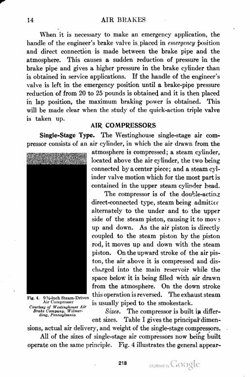
14 AIR BRAKES
When it is necessary to make an emergency application, the
handle of the engineer's brake valve is placed in emergency position
and direct connection is made between the brake pipe and the
atmosphere. This causes a sudden reduction of pressure in the
brake pipe and gives a higher pressure in the brake cylinder than
is obtained in service applications. If the handle of the engineer's
valve is left in the emergency position until a brake-pipe pressure
reduction of from 20 to 25 pounds is obtained and it is then placed
in lap position, the maximum braking power is obtained. This
will be made clear when the study of the quick-action triple valve
is taken up.
AIR COMPRESSORS
Single=Stage Type. The Westinghouse single-stage air com
pressor consists of an air cylinder, in which the air drawn from the
atmosphere is compressed; a steam cylinder,
located above the air cylinder, the two being
connected by a center piece; and a steam cyl
inder valve motion which for the most part is
contained in the upper steam cylinder head.
The compressor is of the double-acting
direct-connected type, steam being admittec
alternately to the under and to the upper
side of the steam piston, causing it to mov i
up and down. As the air piston is directly
coupled to the steam piston by the piston
rod, it moves up and down with the steam
piston. On the upward stroke of the air pis
ton, the air above it is compressed and dis
charged into the main reservoir while the
space below it is being filled with air drawn
from the atmosphere. On the down stroke
this operation is reversed. The exhaust steam
is usually piped to the smokestack.
Sizes. The compressor is built i» differ
ent sizes. Table I gives the principal- dimen
sions, actual air delivery, and weight of the single-stage compressors.
All of the sizes of single-stage air compressors now being built
operate on the same principle. Fig. 4 illustrates the general appear
Fig. 4. 9 ]/2-mch Steam-Driven
Air Compresser
Courtesy of Westinghouse Air
Brake Company, Wilmer-ding, Pennsylvania
218
AIR BRAKES 15
TABLE I
General Dimensions, Capacity, and Weight of Westinghouse Standard
Steam-Driven Air Compressors
Diameter of Steam Cylinder 8 in. 9J in. 11 in.
Diameter of Air Cylinder 8 in. 9J in. 11 in.
Stroke 10 in. 10 in. 12 in.
Steam Admission Pipe 1. in. 1 in. 1 in.
Steam Exhaust Pipe li in. li in.
li in.
in.
Air Admission Pipe ■ li in.li in.
Air Delivery Pipe li in. li in. in.
Nominal Speed, single strokes per
minute 120 120 100
Actual capacity in cu. ft. of free air
per min. actually delivered when
operating continuously, at above
speed, against 100 pounds pressure 20 cu. ft. 28 cu. ft. 45 cu. ft.
Over-all Dimensions: Height 421 in. 42i in. 511 in.
(Approximate)
Width 18 in. 18i in. 22 in.
Depth 13| in. 14i in. 16 in.
Average Net Weight 450 lb. 525 lb. 850 lb.
ance of the 95-inch size. Views of the compressor, with steam and
air cylinders and valve mechanism in section, are shown in Figs.
5 and 6. Figs. 7 and 8 are distorted or "diagrammatic" illustrations
designed to show as clearly as possible the connections of the various
ports and passages but not the actual construction of the parts.
Method of Action in Steam End of Compressor. Considering
first the steam end of the compressor, and referring to the above-
mentioned figures, steam from the supply enters at the connection
marked "from boiler", Fig. 6 (or "steam inlet", Figs. 7 and 8),
and flows through the passageways a and a2 (see also Fig. 5), to
the chamber A, above the main valve 83 and between the pistons
77 and 79, and through passage e to chamber C, in which is reversing
valve 72. The supply and exhaust of steam to and from the steam
cylinder is controlled by the main valve 83, which is a D type of
slide valve. It is operated by the two pistons, 77 and 79, of unequal
diameters and connected by the stem 81. The movement of these
two pistons and the main valve is controlled by the reversing valve
72, which is in turn operated by the main steam piston 65, by means
of the reversing rod 71 and the reversing plate 69. As will be
seen from the following description, the duty of the reversing valve
72 is to alternately admit or discharge steam from chamber D
219
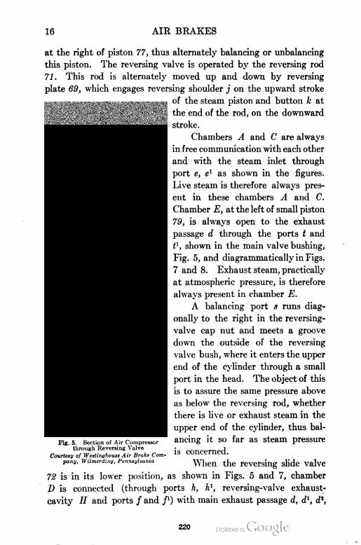
16 AIR BRAKES
at the right of piston 77, thus alternately balancing or unbalancing
this piston. The reversing valve is operated by the reversing rod
71. This rod is alternately moved up and down by reversing
plate 69, which engages reversing shoulder j on the upward stroke
of the steam piston and button k at
the end of the rod, on the downward
stroke.
Chambers A and C are always
in free communication with each other
and with the steam inlet through
port e, e1 as shown in the figures.
Live steam is therefore always pres
ent in these chambers A and C.
Chamber E, at the left of small piston
79, is always open to the exhaust
passage d through the ports t and
t1, shown in the main valve bushing,
Fig. 5, and diagrammatically in Figs.
7 and 8. Exhaust steam, practically
at atmospheric pressure, is therefore
always present in chamber E.
A balancing port s runs diag
onally to the right in the reversing-
valve cap nut and meets a groove
down the outside of the reversing
valve bush, where it enters the upper
end of the cylinder through a small
port in the head. The object of this
is to assure the same pressure above
as below the reversing rod, whether
there is live or exhaust steam in the
upper end of the cylinder, thus bal
ancing it so far as steam pressure
is concerned.
When the reversing slide valve
72 is in its lower position, as shown in Figs. 5 and 7, chamber
D is connected (through ports h, h1, reversing-valve exhaust-
cavity H and ports / and /') with main exhaust passage d, d1, d2,
Fig. 5. Section of Air Compressorthrough Reversing Valve
Courtesy of Westinghouse Air Brake Company, Wilmerding, Pennsylvania
220
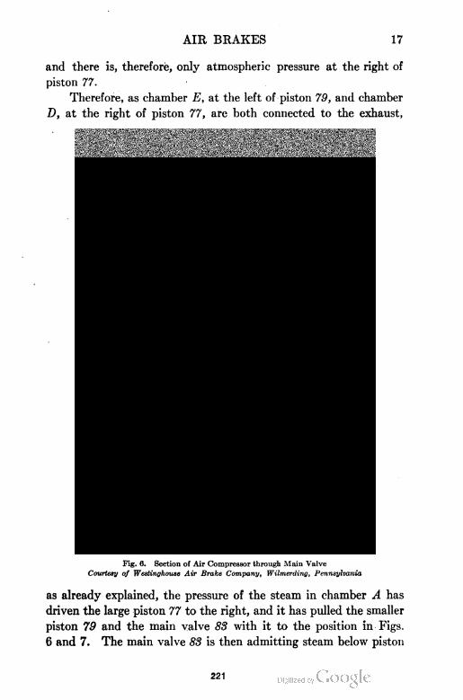
AIR BRAKES 17
and there is, therefore, only atmospheric pressure at the right of
piston 77.
Therefore, as chamber E, at the left of piston 79, and chamber
D, at the right of piston 77, are both connected to the exhaust,
Fig. 6. Section of Air Compressor through Main Valve
Courtesy of Westinghouse Air Brake Company, Wilmerding, Pennsylvania
as already explained, the pressure of the steam in chamber A has
driven the large piston 77 to the right, and it has pulled the smaller
piston 79 and the main valve 83 with it to the position in Figs.
6 and 7. The main valve 83 is then admitting steam below piston
221
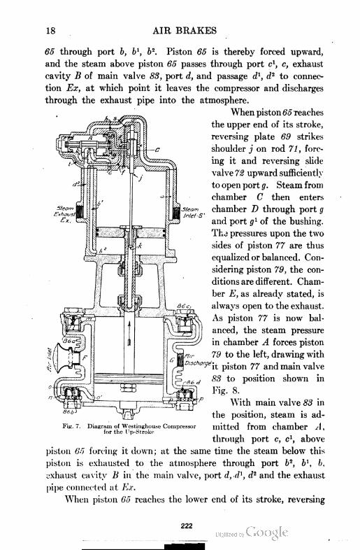
18 AIR BRAKES
65 through port b, bl, b2. Piston 65 is thereby forced upward,
and the steam above piston 65 passes through port c1, c, exhaust
cavity B of main valve 83, port d, and passage dl, d2 to connec
tion Ex, at which point it leaves the compressor and discharges
through the exhaust pipe into the atmosphere.
When piston 65 reaches
the upper end of its stroke,
reversing plate 69 strikes
shoulder j on rod 71 , forc
ing it and reversing slide
valve 72 upward sufficiently
to open port g. Steam from
chamber C then enters
chamber D through port g
and port g1 of the bushing.
Th.3 pressures upon the two
sides of piston 77 are thus
equalized or balanced. Con
sidering piston 79, the con
ditions are different. Cham
ber E, as already stated, is
always open to the exhaust.
As piston 77 is now bal
anced, the steam pressure
in chamber A forces piston
79 to the left, drawing with
it piston 77 and main valve
88 to position shown in
Fig. 8.
With main valve 83 in
the position, steam is ad-
Fin. 7. Diagram of Westinghouae Compressor Illittt'd from chamber A ,for the Up-Stroke
through port c, c1, above
piston 65 forcing it down; at the same time the steam below this
piston is exhausted to the atmosphere through port b2, b\ b,
exhaust cavity B in the main valve, port d, d1, d2 and the exhaust
pipe connected at Ex.
When piston 65 reaches the lower end of its stroke, reversing
222
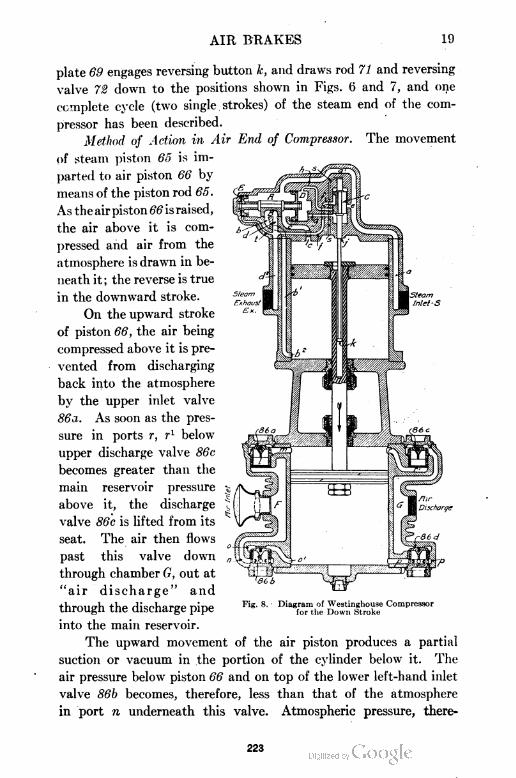
AIR BRAKES 19
The movement
plate 69 engages reversing button k, and draws rod 71 and reversing
valve 72 down to the positions shown in Figs. 6 and 7, and one
complete cycle (two single strokes) of the steam end of the com
pressor has been described.
Method of Action in Air End of Compressor.
of steam piston 65 is im
parted to air piston 66 by
means of the piston rod 65.
As the air piston 66 is raised,
the air above it is com
pressed and air from the
atmosphere is drawn in be
neath it; the reverse is true
in the downward stroke.
On the upward stroke
of piston 66, the air being
compressed above it is pre
vented from discharging
back into the atmosphere
by the upper inlet valve
86a. As soon as the pres
sure in ports r, rl below
upper discharge valve 86c
becomes greater than the
main reservoir pressure
above it, the discharge
valve 86c is lifted from its
seat. The air then flows
past this valve down
through chamber G, out at
"air discharge" and
through the discharge pipe
into the main reservoir.
The upward movement of the air piston produces a partial
suction or vacuum in the portion of the cylinder below it. The
air pressure below piston 66 and on top of the lower left-hand inlet
valve 86b becomes, therefore, less than that of the atmosphere
in port n underneath this valve. Atmospheric pressure, there-
Fig, s. Diagram of Westinghouse Compressorfor the Down Stroke
223
20 AIR BRAKES
fore, raises valve 86b from its seat, and atmospheric air is drawn
through strainer 106 at "air inlet", into chamber F, and port n
below the inlet valve 86b, thence past that valve through ports
o and o1 into the lower end of the air cylinder, filling same. Air
cannot enter this part of the cylinder by flowing back from the
reservoir through D and G and lower discharge valve 86d, since
this valve is held to its seat by the main-reservoir pressure above it.
The lower inlet valve 86b seats
by its own weight as soon as
the up-stroke of the air piston
66 is completed.
On the downward stroke
of the compressor, the effect
just described is reversed, the
air below piston 66 being com
pressed and forced out through
ports p and p1 past lower dis
charge valve 86d and through
chamber G and the air discharge
pipe into the main reservoir. At
the same time air is being drawn
in from the atmos phere through
"air inlet" throi r. ft chamber/'
and port I1, uprje.- inlet valve
86a and ports m and m1 into
the upper end of the air cylinder
above the air piston 66.
Two=Stage Type. The
Westinghouse two-stage air com
pressor, known as the "85-inch
cross-compound compressor", is
controlled or operated by a valve gear quite similar to that used in
the single-stage type. The following description covers in a general
way the chief differences in the operation of the two types of com
pressors:
Comparison with Single-Stage Type. The cress-compound
pump is coming into use as a result of the growing demand for more
air on long freight trains. Its capacity is about three and one-half
Fig. 9. 8H-Inch Cross-Compound Compressor, Showing Air-Inlet Side
Courtesy of Westinghouse Air Brake Company,Wilmerding, Pen nsylva nia
224
AIR BRAKES 21
times that of the 9J-inch pump shown in Fig. 4. As illustrated in
Figs. 9 and 10, this pump is of the duplex type, having two steam
Fig. 10. Vertical Section of Westinghouse 8H-Inch Cross-Compound Compressor
and two air cylinders arranged with the steam cylinders above
and the air cylinders below. The high-pressure steam cylinder
is 8| inches in diameter, and the low-pressure 14J inches in diameter,
225
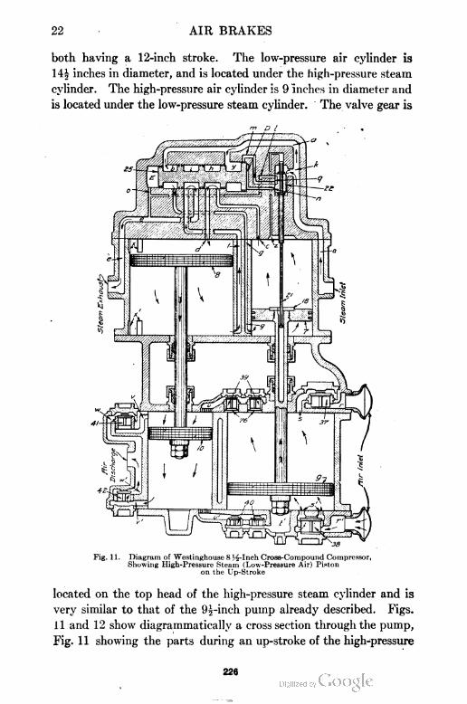
22 AIR BRAKES
both having a 12-inch stroke. The low-pressure air cylinder is
Uh inches in diameter, and is located under the high-pressure steam
cylinder. The high-pressure air cylinder is 9 inches in diameter and
is located under the low-pressure steam cylinder. The valve gear is
m D I
Fig. 11. Diagram of Westinghouse 8H-Inch Cross-Compound Compressor,Showing High-Pressure Steam (Low-pressure Air) Piston
on the Up-Stroke
located on the top head of the high-pressure steam cylinder and is
very similar to that of the 9|-inch pump already described. Figs.
11 and 12 show diagrammatically a cross section through the pump,
Fig. 11 showing the parts during an up-stroke of the high-pressure
226
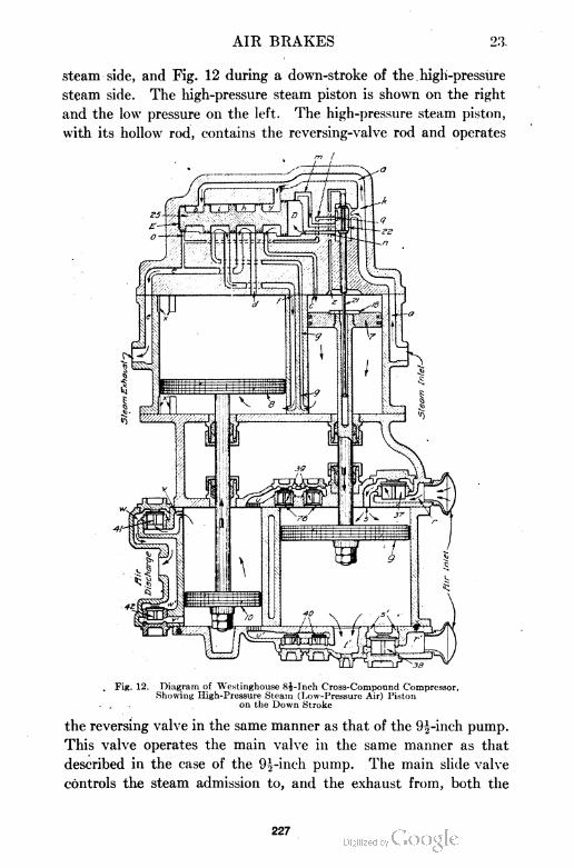
AIR BRAKES 23,
steam side, and Fig. 12 during a down-stroke of the . high-pressure
steam side. The high-pressure steam piston is shown on the right
and the low pressure on the left. The high-pressure steam piston,
with its hollow rod, contains the reversing-valve rod and operates
m I1 !_
. Fig. 12. Diagram of Westinghouse 8i-Inch Cross-Compound Compressor,Showing High-Pressure Steam (Low-Pressure Air) Piston
4 on the Down Stroke
the reversing valve in the same manner as that of the 9|-inch pump.
This valve operates the main valve in the same manner as that
described in the case of the 9|-inch pump. The main slide valve
controls the steam admission to, and the exhaust from, both the
227
24 AIR BRAKES
high- and the low-pressure steam cylinders. It is provided with
an exhaust cavity and, in addition, has four steam ports in its face.
The two outer and one of the intermediate ports communicate
with cored passages extending longitudinally in the valve, which
serve to make the connection between the high- and the low-
pressure cylinders during the expansion of steam from one to the
other. The other port controls the admission of steam to the high-
pressure cylinder.
The valve seat has five ports. Of these, the two outside,
shown in Figs. Jl and 12, lead to the upper and to the lower ends
of the high-pressure steam cylinder. The second and fourth from
the right lead to the upper and to the lower ends of the low-
pressure steam cylinder; and the middle one leads to the exhaust.
By following the arrows in Figs. 11 and 12, the flow of air and
steam through the pump can be easily traced.
The principle of compounding employed in this pump enables
it to compress air much more economically than is possible with
the simple, or single-stage, compressor.
Special Air Strainer. The air strainer ordinarily furnished
with compressors is simple and. in many respects is entirely satis-
Fig. 12a. Westin^house Special Fig. 12b. Sectional View of West-"Fifty-Four" Air Strainer inghouse Special "Fifty-Four"
Air Strainer
factory. But when a strainer of great capacity and efficiency is
desired, the special "Fifty-Four" air strainer can be secured. This
strainer is named from its relatively large suction area of 54 square
228
AIR BRAKES 25
inches. The outward appearance and general construction of this
air strainer are illustrated in Figs. 12a and 12b.
The large capacity of this strainer permits the free passage
of air at a low velocity without imposing additional work on the
compressor. The dust, dirt, etc., are caught and held at the outer
surface of the strainer proper and much of the foreign matter thus
collected is jolted out as the locomotive moves along the track.
The over-all dimensions are approximately 10 inches by 14 inches.
It consists of an inner strainer of perforated galvanized sheet
steel and an outer strainer of coarse galvanized wire mesh, the
space between being well packed with curled hair. A galvanized
sheet-iron shell 3, Fig. 12b, surrounds the strainer proper and
prevents clogging due to oil, water, etc., coming directly in contact
with it. It is easily and quickly removed for cleaning and repairs
without disturbing any of the pipe connections. This strainer
should be installed in a vertical position with the open end down
ward. It can be bolted under the running board at some pro
tected point where it can receive clean dry air. It should never
be installed where a steam leak would saturate the intake air.
Air=Cylinder Lubrication. Method. Proper lubrication of the
air cylinder is often neglected. However, for efficient operation
this should receive careful attention. In ordinary installations to
oil the air cylinder, open the oil cock (see oiL cock 98, Fig. 5) to
blow out any dirt which may have collected, then close it and fill
with valve oil and, on the down stroke of the piston, open the
cock to allow the oil to be drawn into the cylinder. The cock
should be closed before the beginning of the up stroke. This
operation can be most easily carried out when the speed of the
pump is moderate and the air pressure low. Valve oil only should
be used in the air cylinder, as a lighter oil will not last and may
prove dangerous. The use of a very heavy oil soon clogs and
restricts the air passages and causes the compressor to labor and
heat unduly. The amount of oil to use and at what intervals
must be left to the judgment of the operator.
Non-Automatic Oil Cups. If too much oil is used, trouble
may be experienced due to the oil passing into the system. To
overcome this difficulty, the equipment furnished with the cross-
compound compressors includes two non-automatic oil cups, one
229
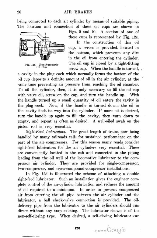
26 AIR BRAKES
being connected to each air cylinder by means of suitable piping.
The location and connection of these oil cups are shown in
Figs. 9 and 10. A section of one of
these cups is represented by Fig. 12c.
In the construction of this oil
cup, a screen is provided, located in
the bottom, which prevents any dirt
in the oil from entering the cylinder.
Fig. i2c. Non-Automatic The oiI CUP is dosed by a tight-fitting
0,1 Cup screw cap. When the handle is turned,
a cavity in the plug cock which normally forms the bottom of the
oil cup deposits a definite amount of oil in the air cylinder, at the
same time preventing air pressure from reaching the oil chamber.
To oil the cylinder, then, it is only necessary to fill the oil cup
with valve oil, screw on the cap, and turn the handle up. With
the handle turned up a small quantity of oil enters the cavity in
the plug cock. Now, if the handle is turned down, the oil in
the cavity finds its way into the cylinder. If more oil is desired,
turn the handle up again to fill the cavity, then turn down to
empty, and repeat as often as desired. A well-oiled swab on the
piston rod is very essential.
Sight-Feed Lubricators. The great length of trains now being
handled by many railroads calls for sustained performance on the
part of the air compressors. For this reason many roads consider
sight-feed lubricators for the air cylinders very essential. These
are conveniently located in the cab and connected in the piping
leading from the oil well of the locomotive lubricator to the com
pressor air cylinder. They are provided for single-compressor,
two-compressor, and cross-compound-compressor installations.
In Fig. 12d is illustrated the scheme of attaching a double
sight-feed lubricator. Such an installation gives the engineer com
plete control of the air-cylinder lubrication and reduces the amount
of oil required to a minimum. In order to prevent compressed
air from entering the oil pipe between the air cylinder and the
lubricator, a ball check-valve connection is provided. The oil-
delivery pipe from the lubricator to the air cylinders should run
direct without any trap existing. The lubricator shown is of the
non-self-closing type. When desired, a self-closing lubricator can
230
AIR BRAKES 27
be furnished which automatically closes as soon as the engineer
removes his hand from the operating lever.
Shop and Road Tests. Test of Capacity of Compressors. A
recent ruling of the Interstate Commerce Commission for the
inspection and testing of steam locomotives and tenders requires
that the compressor or compressors shall be tested for capacity by
231
28 AIR BRAKES
means of the orifice method as orten as conditions may require,
but not less than once every three months. The 9f-inch single-
stage compressor must make not more than 120 single strokes per
minute in maintaining a pressure of 60 pounds in the main reser
voir against a ii-inch orifice. The 1 1-inch single-stage compressor
must make not more than 100 single strokes per minute in main
taining a main-reservoir pressure of 60 pounds against a j^-inch
orifice. The 8.5-inch cross-compound two-stage compressor must
make not more than 100 single strokes per minute in maintaining
a main-reservoir pressure of 60 pounds against a ^-inch orifice.
For altitudes of over 1000 feet, the speed of all types of compres
sors may be increased 5 single stokes per minute for each 1000 feet
increase in altitude.
In making these tests the main reservoir should be drained
and, after all valves are properly set, depending on the equipment
being used, its connections tested for leakage. The pressure in the
reservoir should be bled down to 62 or 63 pounds and sufficient
time given for the temperatures to become equalized and the
pressure to reduce to 60 pounds. From this point the time and
pressure drop should be taken. The drop in pressure should not
exceed 2 pounds during one minute. If it exceeds this amount,
the test should not be made until the leakage has been reduced
to this limit.
The small disc containing the orifice can be used with any
suitable holder, which can conveniently be attached to the main-
reservoir drain cock with as short a connection as possible. The
gage for indicating the pressure on the orifice should be connected
between the orifice and reservoir. When all is in readiness the
compressor should be started and the pressure in the main reser
voir raised to slightly below 60 pounds. At this point the drain
cock to the orifice should be opened and the steam supply to the
compressor regulated until the pressure on the gage near the orifice
reads 60 pounds. The single strokes per minute made by the com
pressor should then be counted. If the number of single strokes per
minute do not fall within the limit specified by the Interstate
Commerce Commission for the particular type of compressor
being used, then the compressor should be rejected and returned to
the shop for repairs.
232
AIR BRAKES 29
SPEED CURVES
OF THE9X"X SH"X 10- AND 11"X 11"X 12" STEAM DRIVENAIR COMPRESSORS OPERATING AGAINST 59 AND
66 LBS. AIR PRESSURE RESPECTIVELY.THESE CURVES TO BE USED AS BASIS FOR TESTING
THE STEAM END OF THE ABOVE COMPRESSORS.
II* X II* X IS* COIII* X II* X 12* COMPRESSOR 66 LBS. AIR PRESSURE.
METHOD OF TEST AND USE OF CURVES.OPEN COMPRESSOR STEAM THROTTLE. REGULATE THE MAIN
RESERVOIR AIR PRESSURE TO THE VALUE CIVEN IN CONNECTIONWITH THE PROPER OURVE. NOTE THE COMPRESSOR SPEED ANDTHE BOILER PRESSURE. THE OBSERVED SPEED SHOULD BE COMPARED TO THE SPEED ClVEN 9V THE CURVE FOR THE SAME STEAMPRESSURE AS THAT OBSERVEDEXAMPLE - SUPPOSE A ey COMPRESSOR IS UNOER TEST C8SCRVATIONS SHOW THAT THE SPI £0 IS 4S SINGLE STROKES PER MINUTEACAINST 59 LBS AIR PRESSURE AT 121 LBS BdLER PRESSURE.THE 9-. CURVE ClVCS 124 SINGLE STROKES PER MlNUTE AS THESPEED WHIOH THE COMPRESSOR SHOULD MAKE IF IN AVERAGEGOOD CONDITION AND OPERATINC UNOER THE OBSERVED CONDITIONS.
STEAM PRESSURE LBS
Fig. 12c. Test Curves of 9J-Inch aud 11-Inch Single-Stage Compressors
SPEED CURVE
OF THE8)fj CROSS COMPOUND STEAM DRIVEN AIR COMPRESSOR
OPERATING AGAINST S3 LBS. AIR PRESSURE.THIS CURVE TO BE USED AS BASIS FOR TESTING
THE STEAM END OF THE COMPRESSOR.
mm
METHOD OF TEST AND USE OF CURVE.
OPEN COMPRESSOR STEAM THROTTLE, REGULATE THE MAINRESERVOIR AIR PRESSURE TO S3 LBS., NOTE COMPRESSOR SPEEOAND THE BOILER PRESSURE. THE OBSERVED SPEED SHOULD BE
COMPARED TO THE SPEED GIVEN BY THE CURVE FOR THE SAME8TEAM PRESSURE AS THAT OBSERVED.
EXAMPLE:- SUPPOSE OBSERVATIONS SHOW THAT THE SPEEO IS 100SINGLE STROKES PER MINUTE ACAINST 53 LBS. AIR PRESSURE AT
122 LBS. BOILER PRESSURE. THE CURVE GIVES 104 SINGLE STROKESPER MINUTE AS THE SPEEO WHIOH THE COMPRESSOR SHOULDMAKE IF IN AVERAGE GOOD CONDITION AND OPERATING UNDERTHE OBSERVED CONDITIONS.
200HO MO IN
STEAM PRESSURE .LBS.
Fig. 12f. Test Curve of 8}-Inch Cross-Compound Two-Stage Air Compressor
233
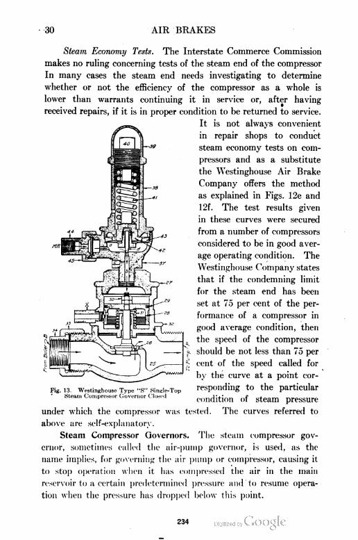
30 AIR BRAKES
Steam Economy Tests. The Interstate Commerce Commission
makes no ruling concerning tests of the steam end of the compressor
In many cases the steam end needs investigating to determine
whether or not the efficiency of the compressor as a whole is
lower than warrants continuing it in service or, after having
received repairs, if it is in proper condition to be returned to service.
It is not always convenient
in repair shops to conduct
steam economy tests on com
pressors and as a substitute
the Westinghouse Air Brake
Company offers the method
as explained in Figs. 12e and
12f. The test results given
in these curves were secured
from a number of compressors
considered to be in good aver
age operating condition. The
Westinghouse Company states
that if the condemning limit
for the steam end has been
set at 75 per cent of the per
formance of a compressor in
good average condition, then
the speed of the compressor
should be not less than 75 per
cent of the speed called for
by the curve at a point cor
responding to the particular
condition of steam pressure
under which the compressor was tested. The curves referred to
above are self-explanatory.
Steam Compressor Governors. The steam compressor gov
ernor, sometimes called the air-pump governor, is used, as the
name implies, for governing the air pump or compressor, causing it
to stop operation when it has compressed the air in the main
reservoir to a certain predetermined pressure and to resume opera
tion when the pressure has dropped below this point.
Fig. 13. Westinghouse Type "S" Single-TopSteam Compressor Governor Closed
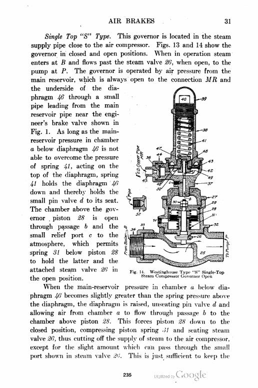
AIR BRAKES 31
Single Top "S" Type. This governor is located in the steam
supply pipe close to the air compressor. Figs. 13 and 14 show the
governor in closed and open positions. When in operation steam
enters at B and flows past the steam valve 26, when open, to the
pump at P. The governor is operated by air pressure from the
main reservoir, which is always open to the connection MR and
the underside of the dia
phragm 46 through a small
pipe leading from the main
reservoir pipe near the engi
neer's brake valve shown in
Fig. 1. As long as the main-
reservoir pressure in chamber
a below diaphragm 46 is not
able to overcome the pressure
of spring 4U acting on the
top of the diaphragm, spring
41 holds the diaphragm Ifi
down and thereby holds the
small pin valve d to its seat.
The chamber above the gov
ernor . piston 28 is open
through passage b and the
small relief port c to the
atmosphere, which permits
spring 31 below piston 28
to hold the latter and the
attached steam valve 26 in
the open position.
When the main-reservoir pressure in chamber a below dia
phragm 46 becomes slightly greater than the spring pressure above
the diaphragm, the diaphragm is raised, unseating pin valve d and
allowing air from chamber a to flow through passage b to the
chamber above piston 28. This forces piston 28 down to the
closed position, compressing piston spring 31 and seating steam
valve 26, thus cutting off the supply of steam to the air compressor,
except for the slight amount which can pass through the small
port shown in steam valve 26. This is just sufficient to keep the
Fig; 14. Westinnhouse Type "S" Single-TopSteam Compressor Governor Open
235
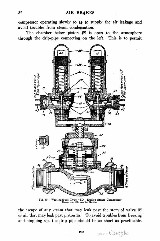
32 AIR BRAKES
compressor operating slowly so as to supply the air leakage and
avoid troubles from steam condensation.
The chamber below piston 28 is open to the atmosphere
through the drip-pipe connection on the left. This is to permit
Fig. 15. Westinghouse Type "SD" Duplex Steam CompressorGovernor Shown in Section
the escape of any steam that may leak past the stem of valve 26
or air that may leak past piston 28. To avoid troubles from freezing
and stopping up, the drip pipe should be as short as practicable.
236
AIR BRAKES 33
The governor is adjusted by means of adjusting nut Jfi,
which regulates the pressure of spring 41 upon the diaphragm.
To change the adjustment of the governor, remove cap nut 39 and
screw down or back off regulating nut Ifl to increase or lower the
main-reservoir pressure, replacing nut 39 after making this adjust
ment. The governor is usually set to cut off at 90 pounds main-
reservoir pressure.
For years the "S" governor was the standard but it has
practically been superseded by governors of improved design.
Double-Top or Duplex "SD" Type., This type of governor has
been developed to operate in connection with the engineer's brake
valve, permitting the air pump to anticipate demands upon the
main reservoir and to have an excess pressure stored there for
releasing brakes and charging trains of greater length than the
usual main-reservoir capacity will permit. It is arranged to obtain
what is known as "duplex main-reservoir regulation". As shown
in Fig. 15, the "duplex" governor is the same as the "S" type of
governor except that two regulating portions or "tops" are used,
with a T or "Siamese" fitting to connect them to the steam
portion of the governor. The adjustment of the two heads varies
according to local conditions, but is usually 90 pounds for the
"low-pressure" and 120 pounds for the "high-pressure" top.
The low-pressure top, on the left, is connected to a port in
the brake valve through which air from the main-reservoir port
flows to the feed valve when the brake-valve handle is in running
position. When running over the road, therefore, with the brakes
released, the low-pressure top of the governor controls the opera
tion of the air compressor in the same manner as has been described
for the "S" type of governor, and the high-pressure top does
not operate at all. When an application of the brakes is made,
however, the relation of the brake-valve ports is changed so as to
shut off the supply of air to the underside of the diaphragm of the
low-pressure governor top, and its pin valve d remains held to its
seat. Meanwhile, air from the main-reservoir pipe can flow direct
to the connection marked MR of the high-pressure governor top
and to the chamber beneath its diaphragm. This governor top
will consequently control the operation of the air compressor as
described for the "S" type of governor until the brakes are released
237
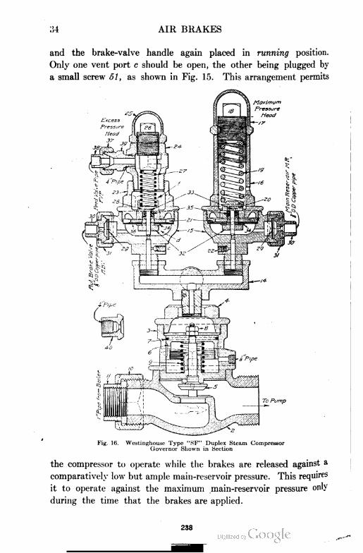
34 AIR BRAKES
and the brake-valve handle again placed in running position.
Only one vent port c should be open, the other being plugged by
a small screw 51, as shown in Fig. 15. This arrangement permits
Fig. 16. Westinghouse Type "SF" Duplex Steam CompressorGovernor Shown in Section
the compressor to operate while the brakes are released against a
comparatively low but ample main-reservoir pressure. This requires
it to operate against the maximum main-reservoir pressure only
during the time that the brakes are applied.
238
AIR BRAKES 35
Double-Top "SF" Type. The principal difference between the
"SD" and "SF" types is in the arrangement of the low-pressure
head, or, as it is called in the "SF" governor, the "excess-pressure"
head, Fig. 16. The low-pressure head of the "SD" governor is
arranged to maintain a fixed main-reservoir pressure during the
times that the brakes are released, while the excess-pressure head
of the "SF" governor maintains a fixed "excess" of main-reservoir
pressure over the brake-pipe pressure under the same conditions.
The high- or maximum-pressure heads of both types are alike.
The excess-pressure head of the "SF" governor has two air
connections. That marked A B V corresponds to the similar
connection of the "SD" governor. That marked FVP leads from
the feed-valve pipe, so that air, at whatever pressure the feed
valve is adjusted for, is always present in chamber / above
diaphragm 28. The total pressure on the top of diaphragm 28 is,
therefore, the pressure in the feed-valve pipe plus the pressure of
spring 27, which is usually adjusted for 20 pounds. The main-
reservoir pressure in chamber d below diaphragm 28 will, therefore,
not be able to raise the diaphragm and its pin valve, and thus
shut off the compressor, until it has risen about 20 pounds above
the pressure determined by the feed-valve setting. Consequently,
whether the setting of the feed valve be changed by accident or
design, the same excess pressure, 20 pounds, is always maintained.
In the operation of the steam and air pistons of the governor,
the total pressure on top of diaphragm 28 is always feed-valve
pressure plus 20 pounds instead of a fixed pressure, as in the
former types. With the feed valve set for 70 pounds, about 90
pounds main-reservoir pressure would be maintained.
Main Reservoir. The use of the main reservoir is for storing
an abundant air supply to be used in charging and releasing the
brakes. The main reservoir should have a capacity of not less
than 35,000 cubic inches on passenger engines and not less than
50,000 cubic inches on freight. The main reservoir is usually
placed on the engine but sometimes on the tender, the latter
necessitating two extra pipe connections between the engine and
the tender, which is not good practice. To divide the main reser
voir and place half on each side under the running board is better.
The air is then delivered to one side and taken out of the other,
239
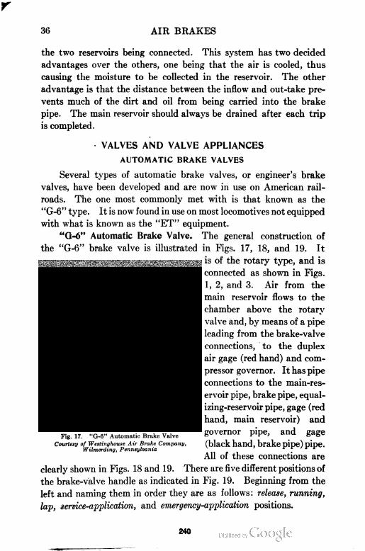
36 AIR BRAKES
the two reservoirs being connected. This system has two decided
advantages over the others, one being that the air is cooled, thus
causing the moisture to be collected in the reservoir. The other
advantage is that the distance between the inflow and out-take pre
vents much of the dirt and oil from being carried into the brake
pipe. The main reservoir should always be drained after each trip
is completed.
VALVES AND VALVE APPLIANCES
AUTOMATIC BRAKE VALVES
Several types of automatic brake valves, or engineer's brake
valves, have been developed and are now in use on American rail
roads. The one most commonly met with is that known as the
"G-6" type. It is now found in use on most locomotives not equipped
with what is known as the "ET" equipment.
"Q=6" Automatic Brake Valve. The general construction of
the "G-6" brake valve is illustrated in Figs. 17, 18, and 19. It
is of the rotary type, and is
connected as shown in Figs.
1, 2, and 3. Air from the
main reservoir flows to the
chamber above the rotary
valve and, by means of a pipe
leading from the brake-valve
connections, to the duplex
air gage (red hand) and com
pressor governor. It has pipe
connections to the main-res
ervoir pipe, brake pipe, equal
izing-reservoir pipe, gage (red
hand, main reservoir) and
governor pipe, and gage
(black hand, brake pipe) pipe.
All of these connections are
clearly shown in Figs. 18 and 19. There are five different positions of
the brake-valve handle as indicated in Fig. 1 9. Beginning from the
left and naming them in order they are as follows : release, running,
lap, service-application, and emergency-application positions.
Fig. 17. "G-6" Automatic Brake Valve
Courtesy of Westinghouse Air Brake Company,Wilmerding, Pennsylvania
240
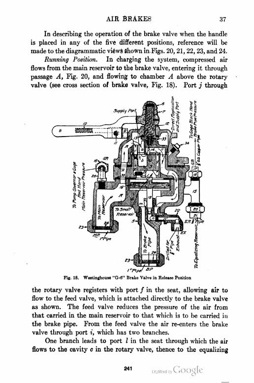
AIR BRAKES 37
In describing the operation of the brake valve when the handle
is placed in any of the five different positions, reference will be
made to the diagrammatic views shown in. Figs. 20, 21, 22, 23, and 24.
Running Position. In charging the system, compressed air
flows from the main reservoir to the brake valve, entering it through
passage A, Fig. 20, and flowing to chamber A above the rotary
valve (see cross section of brake valve, Fig. 18). Port j through
Fig. 18. Westinghouse "G-6" Brake Valve in Release Position
the rotary valve registers with port / in the seat, allowing air to
flow to the feed valve, which is attached directly to the brake valve
as shown. The feed valve reduces the pressure of the air from
that carried in the main reservoir to that which is to be carried in
the brake pipe. From the feed valve the air re-enters the brake
valve through port i, which has two branches.
One branch leads to port I in the seat through which the air
flows to the cavity c in the rotary valve, thence to the equalizing
241
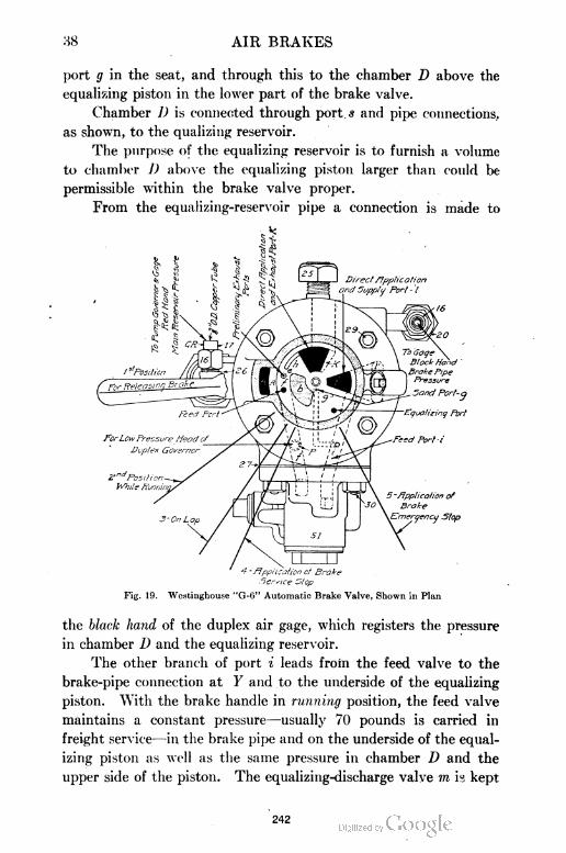
38 AIR BRAKES
port g in the seat, and through this to the chamber D above the
equalizing piston in the lower part of the brake valve.
Chamber D is connected through port s and pipe connections.,
as shown, to the qualizing reservoir.
The purpose of the equalizing reservoir is to furnish a volume
to chamber D above the equalizing piston larger than could be
permissible within the brake valve proper.
From the equalizing-reservoir pipe a connection is made to
-flpplicalicn of Brake
Service Stop
Fig. 19. Westinghouse "G-G" Automatic Brake Valve, Shown in Plan
the black hand of the duplex air gage, which registers the pressure
in chamber D and the equalizing reservoir.
The other branch of port i leads from the feed valve to the
brake-pipe connection at Y and to the underside of the equalizing
piston. With the brake handle in running position, the feed valve
maintains a constant pressure—usually 70 pounds is carried in
freight service—in the brake pipe and on the underside of the equal
izing piston as well as the same pressure in chamber D and the
upper side of the piston. The equalizing-discharge valve m is kept.
242
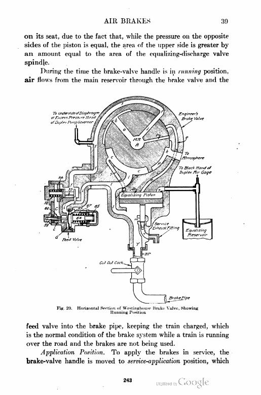
AIR BRAKES 39
on its seat, due to the fact that, while the pressure on the opposite
sides of the piston is equal, the area of the upper side is greater by
an amount equal to the area of the equalizing-discharge valve
spindle.
During the time the brake-valve handle is in running position,
air flows from the main reservoir through the brake valve and the
Fig. 20. Horizontal Section of Westinghouse Brake Valve, ShowingKunning Position
feed valve into the brake pipe, keeping the train charged, which
is the normal condition of the brake system while a train is running
over the road and the brakes are not being used.
Application Position. To apply the brakes in service, the
brake-valve handle is moved to service-application position, which
243
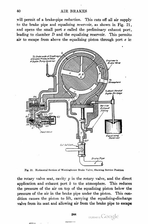
40 AIR BRAKES
will permit of a brake-pipe reduction. This cuts off all air supply
to the brake pipe and equalizing reservoir, as shown in Fig. 21,
and opens the small port e called the preliminary exhaust port ,
leading to chamber D and the equalizing reservoir. This permits
air to escape from above the equalizing piston through port e in
Fig. 21. Horizontal Section of Westinghousc Brake Valve, Showing Service Position
the rotary valve seat, cavity p in the rotary valve, and the direct
application and exhaust port k to the atmosphere. This reduces
the pressure of the air on top of the equalizing piston below the
pressure of the air in the brake pipe under the piston. This con
dition causes the piston to lift, carrying the equalizing-discharge
valve from its seat and allowing air from the brake pipe to escape
244
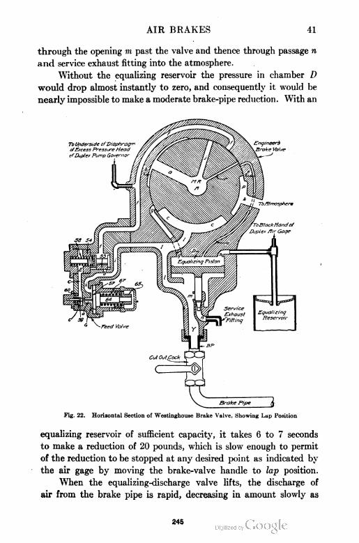
AIR BRAKES 41
through the opening m past the valve and thence through passage n
and service exhaust fitting into the atmosphere.
Without the equalizing reservoir the pressure in chamber D
would drop almost instantly to zero, and consequently it would be
nearly impossible to make a moderate brake-pipe reduction. With an
Fig. 22. Horizontal Section of Westinghouse Brake Valve, Showing Lap Position
equalizing reservoir of sufficient capacity, it takes 6 to 7 seconds
to make a reduction of 20 pounds, which is slow enough to permit
of the reduction to be stopped at any desired point as indicated by
the air gage by moving the brake-valve handle to lap position.
When the equalizing-discharge valve lifts, the discharge of
air from the brake pipe is rapid, decreasing in amount slowly as
245
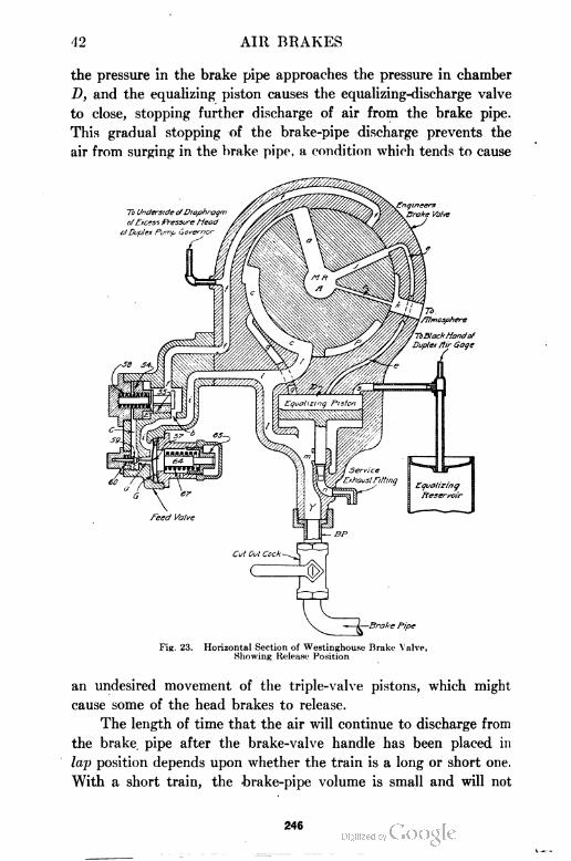
42 AIR BRAKES
the pressure in the brake pipe approaches the pressure in chamber
D, and the equalizing piston causes the equalizing-discharge valve
to close, stopping further discharge of air from the brake pipe.
This gradual stopping of the brake-pipe discharge prevents the
air from surging in the brake pipe, a condition which tends to cause
Fig. 23. Horizontal Section of Westinghou.se Brake Valve,Showing Release Position
an undesired movement of the triple-valve pistons, which might
cause some of the head brakes to release.
The length of time that the air will continue to discharge from
the brake pipe after the brake-valve handle has been placed in
lap position depends upon whether the train is a long or short one.
With a short train, the brake-pipe volume is small and will not
246
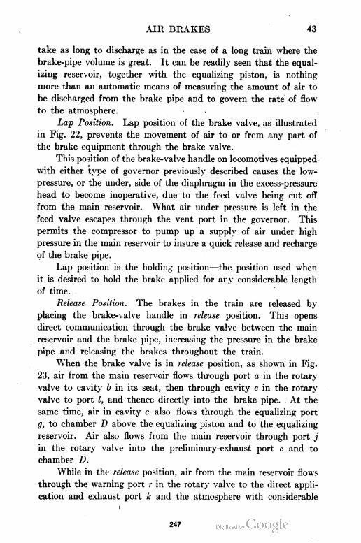
AIR BRAKES 43
take as long to discharge as in the case of a long train where the
brake-pipe volume is great. It can be readily seen that the equal
izing reservoir, together with the equalizing piston, is nothing
more than an automatic means of measuring the amount of air to
be discharged from the brake pipe and to govern the rate of flow
to the atmosphere.
Lap Position. Lap position of the brake valve, as illustrated
in Fig. 22, prevents the movement of air to or from any part of
the brake equipment through the brake valve.
This position of the brake-valve handle on locomotives equipped
with either type of governor previously described causes the low-
pressure, or the under, side of the diaphragm in the excess-pressure
head to become inoperative, due to the feed valve being cut off
from the main reservoir. What air under pressure is left in the
feed valve escapes through the vent port in the governor. This
permits the compressor to pump up a supply of air under high
pressure in the main reservoir to insure a quick release and recharge
of the brake pipe.
Lap position is the holding position—the position used when
it is desired to hold the brake applied for any considerable length
of time.
Release Position. The brakes in the train are released by
placing the brake-valve handle in release position. This opens
direct communication through the brake valve between the main
reservoir and the brake pipe, increasing the pressure in the brake
pipe and releasing the brakes throughout the train.
When the brake valve is in release position, as shown in Fig.
23, air from the main reservoir flows through port a in the rotary
valve to cavity b in its seat, then through cavity c in the rotary
valve to port I, and thence directly into the brake pipe. At the
same time, air in cavity c also flows through the equalizing port
g, to chamber D above the equalizing piston and to the equalizing
reservoir. Air also flows from the main reservoir through port j
in the rotary valve into the preliminary-exhaust port e and to
chamber D.
While in the release position, air from the main reservoir flows
through the warning port r in the rotary valve to the direct appli
cation and exhaust port A; and the atmosphere with considerable
247
44 AIR BRAKES
noise. This loud exhaust indicates to the engineer that the handle
of the brake is in release position and attracts his attention in case
the handle is left in that position by mistake.
After the handle has been in release position the proper length
of time, it is moved to the running position, which closes the warning
port, stops the direct flow of air from the main reservoir to the
Fig. 24. Horizontal Section of Westinghouse Brake Valve,Showing Emergency Position
brake pipe, chamber D, and the equalizing reservoir, and opens the
supply of air to these parts through the feed valve. In this position,
the brake pipe, chamber D, and the equalizing reservoir are charged
up and maintained at the standard pressure by the feed valve.
The brakes can be released and the brake pipe and system
re-charged by placing the brake-valve handle in running position
248
AIR BRAKES 45
directly without first being placed in release position, but a much
longer time will be required.
Emergency-Application Position. When it is desired to make
the shortest possible stop, the brake-valve handle is placed in emer
gency position, as illustrated in Fig. 24. In this position the brake
pipe is opened directly to the atmosphere through the large port I,
cavity c, and port k, causing a sudden and rapid drop in brake-pipe
pressure. In this position, cavity p in the rotary valve connects
Fig. 25. "H-6" Automatic Brake Valve
Courtesy of Westinghouse Air Brake Company,Wilmerding, Pennsylvania
the feed port / and the preliminary exhaust port e to the exhaust
port k, thus allowing the air in the feed port, chamber D, and the
equalizing reservoir to escape to the atmosphere. The whole
emergency-application action depends solely upon the suddenness
of the brake-pipe reduction.
"H=6" Automatic Brake Valve. The "H-6" automatic brake
valve not only performs the functions of the "G-6" brake valve
but has some additional features necessary for its use in connection
with the "No. 6" distributing valve and the "S-6" independent
249
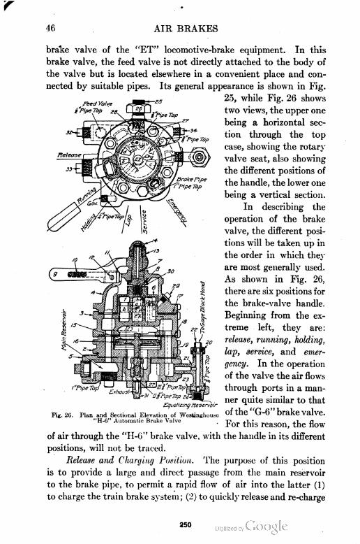
46 AIR BRAKES
Feed Valve
i'pipeTop eg
brake valve of the "ET" locomotive-brake equipment. In this
brake valve, the feed valve is not directly attached to the body of
the valve but is located elsewhere in a convenient place and con
nected by suitable pipes. Its general appearance is shown in Fig.
25, while Fig. 26 shows
two views, the upper one
being a horizontal sec
tion through the top
case, showing the rotary
valve seat, also showing
the different positions of
the handle, the lower one
being a vertical section.
In describing the
operation of the brake
valve, the different posi
tions will be taken up in
the order in which they
are most generally used.
As shown in Fig. 26,
there are six positions for
the brake-valve handle.
Beginning from the ex
treme left, they are:
release, running, holding,
lap, service, and emer
gency. In the operation
of the valve the air flows
through ports in a man
ner quite similar to that
of the "G-6" brake valve.
For this reason, the flow
of air through the "H-6" brake valve, with the handle in its different
positions, will not be traced.
Release and Charging Position. The purpose of this position
is to provide a large and direct passage from the main reservoir
to the brake pipe, to permit a rapid flow of air into the latter (1)
to charge the train brake system; (2) to quic kly release and re-charge
/"FipeTa,
Fig. 26.
'Si'Pipe Tap
Equalizing Reservoir
Plan and Sectional Elevation of Westinghouse"H-6" Automatic Brake Valve
250
AIR BRAKES 47
the brake; but (3) not to release the locomotive brakes if they
are applied. If the handle is allowed to remain in this position,
the brake system would be charged to main-reservoir pressure.
To avoid this, the handle must be moved to running or holding
position. To prevent the engineer from forgetting this, a small port
' discharges feed-valve-pipe air to the atmosphere in release position.
Running Position. This is the proper position of the brake-
valve handle (1) when the brakes are charged and ready for use;
(2) when the brakes are not being operated; and (3) to release
the locomotive brakes. This position affords a large direct passage
from the feed-valve pipe to the brake pipe, so that the latter will
charge up to the pressure for which the feed valve is adjusted.
If the brake valve is in running position when uncharged cars
are cut in, or if, after a heavy brake application and release, the
handle of the automatic brake valve is returned to running position
too soon, the governor will stop the compressors until the difference
between the hands on duplex gage No. 1, Fig. 92, is less than 20
pounds. The stopping of the compressor from this cause calls
the engineer's attention to the seriously wrong operation on his
part, as running position results in delay in charging and is liable
to cause some brakes to stick. Release position should be used
until all brakes are released and nearly charged.
Service Position. This position gives a gradual reduction
of brake-pipe pressure to cause a service application. The gradual
reduction of brake-pipe pressure is to prevent quick action, and
the gradual stopping of this discharge is to prevent the pressure
at the head end of the brake pipe being built up by the air flow
ing from the rear, which might cause some of the head brakes to
"kick-off".
Lap Position. This position is used while holding the brakes
applied after a service application until it is desired either to make
a further brake-pipe reduction or to release the brakes. All ports
are closed and the excess-pressure head of the governor is made
inoperative, permitting the pump to increase the main-reservoir
pressure to the pressure at which the high-pressure head will cause
it to stop.
Release Position. This position is used for releasing the train
brakes after an application without releasing the locomotive brakes.
251
48 AIR BRAKES
When the brake-pipe pressure has been increased sufficiently to
cause this, the handle of the brake valve should be moved to either
running or holding position; the former when it is desired to release
the locomotive brakes, and the latter when they are to be still held
applied.
Holding Position. This position is so named because the
locomotive brakes are held applied while the train brakes are being
released and their auxiliary reservoirs recharged to feed-valve pres
sure. The only difference between the running and holding posi
tions is that in the former the locomotive brakes are released, while
in the latter they are held applied.
Emergency Position. This position is used (1) when the most
prompt and heavy application of the brakes is required, and (2)
to prevent loss of main reservoir air and insure that the brakes
remain applied in event of a burst hose, a break-in-two, or the
opening of a conductor's valve. Plug 29, Fig. 26, is placed in the
top of the case at a point to fix the level- of an oil bath in which the
rotary valve operates. Valve oil should be used.
"S=6" Independent Brake Valve. The general appearance
of this valve is shown in Fig. 27. Fig. 28 shows two views of the
"S-6" brake valve; the lower one
being a vertical section through
the center of the valve, and the
upper one a horizontal section
through the valve body, show
ing the rotary valve seat and the
different positions of the valve
handle. There are five positions
of the brake-valve handle which,
beginning from the extreme left,
Fig. 27. Westinghouse "S-6" Independent afe : ™UaSe> inning, lap, slow ap-
Brake Valve plication, and quick application.
This brake valve is used in connection with the "H-6" auto
matic brake valve and is to permit the engineer to operate the
locomotive or independent brakes through the distributing valve
independently of the train brakes.
Running Position. This is the position that the independent
brake valve should occupy at all times when the independent brake
252
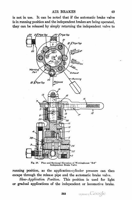
AIR BRAKES 49
is not in use. It can be noted that if the automatic brake valve
is in running position and the independent brakes are being operated,
they can be released by simply returning the independent valve to
Fig. 28. Plan and Sectional Elevation of Westinghouse "S-6"Independent Brake Valve
running position, as the application-cylinder pressure can then
escape through the release pipe and the automatic brake valve.
Slow-Application Position. This position is used for light
or gradual applications of the independent or locomotive brake.
253
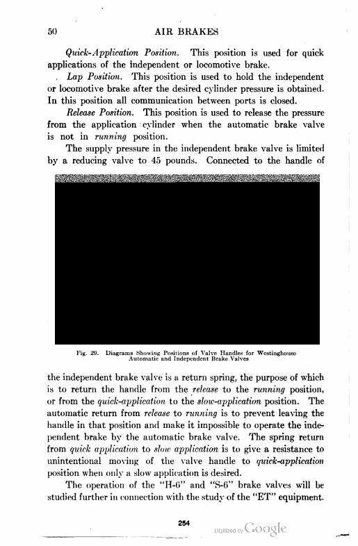
50 AIR BRAKES
Quick-Application Position. This position is used for quick
applications of the independent or locomotive brake.
Lap Position. This position is used to hold the independent
or locomotive brake after the desired cylinder pressure is obtained.
In this position all communication between ports is closed.
Release Position. This position is used to release the pressure
from the application cylinder when the automatic brake valve
is not in running position.
The supply pressure in the independent brake valve is limited
by a reducing valve to 45 pounds. Connected to the handle of
Diagrams Showing Positions of Valve Handles for WestinghouscAutomatic and Independent Brake Valves
the independent brake valve is a return spring, the purpose of which
is to return the handle from the release to the running position,
or from the quick-application to the slow-application position. The
automatic return from release to running is to prevent leaving the
handle in that position and make it impossible to operate the inde
pendent brake by the automatic brake valve. The spring return
from quick application to slow application is to give a resistance to
unintentional moving of the valve handle to quick-application
position when only a slow application is desired.
The operation of the "H-6" and "S-6" brake valves will be
studied further in connection with the study of the "ET" equipment.
254
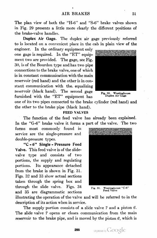
AIR BRAKES 51
Fig. 30. WestinghouseDuplex Air Gage
The plan view of both the "H-6" and "S-6" brake valves shown
in Fig. 29 presents a little more clearly the different positions of
the brake-valve handles.
Duplex Air Gage. The duplex air gage previously referred
to is located on a convenient place in the cab in plain view of the
engineer. In the ordinary equipment only
one gage is required. In the "ET" equip
ment two are provided. The gage, see Fig.
30, is of the Bourdon type and has two pipe
connections to the brake valve, one of which
is in constant communication with the main
reservoir (red hand) and the other is in con
stant communication with the, equalizing
reservoir (black hand). The second gage
furnished with the "ET" equipment has
one of its two pipes connected to the brake cylinder (red hand) and
the other to the brake pipe (black hand).
FEED VALVES
The function of the feed valve has already been explained.
In the "G-6" brake valve it forms a part of the valve. The two
forms most commonly found in
service are the single-pressure and
double-pressure types.
"C = 6" Single = Pressure Feed
Valve. This feed valve is of the slide-
valve type and consists of two
portions, the supply and regulating
portions. Its appearance detached
from the brake is shown in Fig. 31.
Figs. 32 and 33 show actual sections
taken through the spring box and
through the slide valve. Figs. 34
and 35 are diagrammatic sections
illustrating the operation of the valve and will be referred to in the
description of its action when in service.
The supply portion consists of a slide valve 7 and a piston 6.
The slide valve 7 opens or closes communication from the main
reservoir to the brake pipe, and is moved by the piston 6, which is
Fig. 31. Westinghouse "C-6"Feed Valve
295
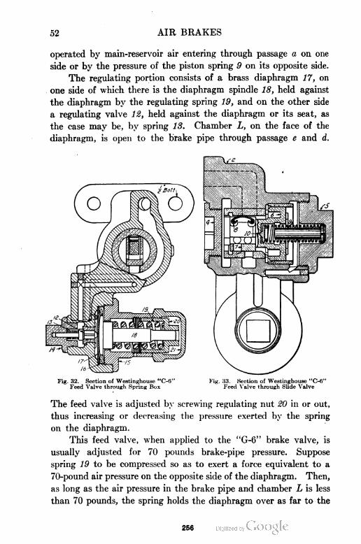
52 AIR BRAKES
operated by main-reservoir air entering through passage a on one
side or by the pressure of the piston spring 9 on its opposite side.
The regulating portion consists of a brass diaphragm 17, on
one side of which there is the diaphragm spindle 18, held against
the diaphragm by the regulating spring 19, and on the other side
a regulating valve 12, held against the diaphragm or its seat, as
the case may be, by spring 13. Chamber L, on the face of the
diaphragm, is open to the brake pipe through passage e and d.
Fig. 32. Section of Westinghouse "C-6" Fig. 33. Section of Westinghouse "C-6"Feed Valve through Spring Box Feed Valve through Slide Valve
The feed valve is adjusted by screwing regulating nut 20 in or out,
thus increasing or decreasing the pressure exerted by the spring
on the diaphragm.
This feed valve, when applied to the "G-6" brake valve, is
usually adjusted for 70 pounds brake-pipe pressure. Suppose
spring 19 to be compressed so as to exert a force equivalent to a
70-pound air pressure on the opposite side of the diaphragm. Then,
as long as the air pressure in the brake pipe and chamber L is less
than 70 pounds, the spring holds the diaphragm over as far to the
256
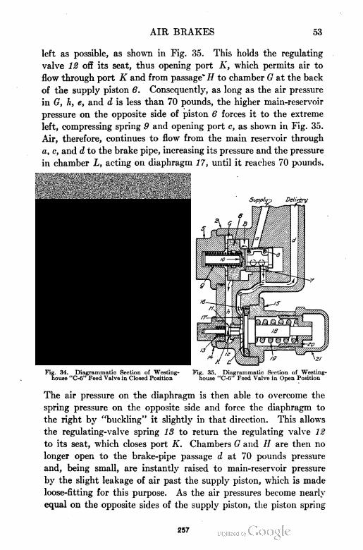
AIR BRAKES 53
left as possible, as shown in Fig. 35. This holds the regulating
valve 12 off its seat, thus opening port A', which permits air to
flow through port K and from passage* // to chamber G at the back
of the supply piston 6. Consequently, as long as the air pressure
in G, h, e, and d is less than 70 pounds, the higher main-reservoir
pressure on the opposite side of piston 6 forces it to the extreme
left, compressing spring 9 and opening port c, as shown in Fig. 35.
Air, therefore, continues to flow from the main reservoir through
a, c, and d to the brake pipe, increasing its pressure and the pressure
in chamber L, acting on diaphragm 17, until it reaches 70 pounds.
34. Diagrammatic Section of Westing- Fig. 35. Diagrammatic Section of Westing-louse "C-6" Feed Valve in Closed Position house "C-6" Feed Valve in Open Position
The air pressure on the diaphragm is then able to overcome the
spring pressure on the opposite side and force the diaphragm to
the right by "buckling" it slightly in that direction. This allows
the regulating-valve spring 18 to return the regulating valve 12
to its seat, which closes port K. Chambers G and // are then no
longer open to the brake-pipe passage d at 70 pounds pressure
and, being small, are instantly raised to main-reservoir pressure
by the slight leakage of air past the supply piston, which is made
loose-fitting for this purpose. As the air pressures become nearly
equal on the opposite sides of the supply piston, the piston spring
257
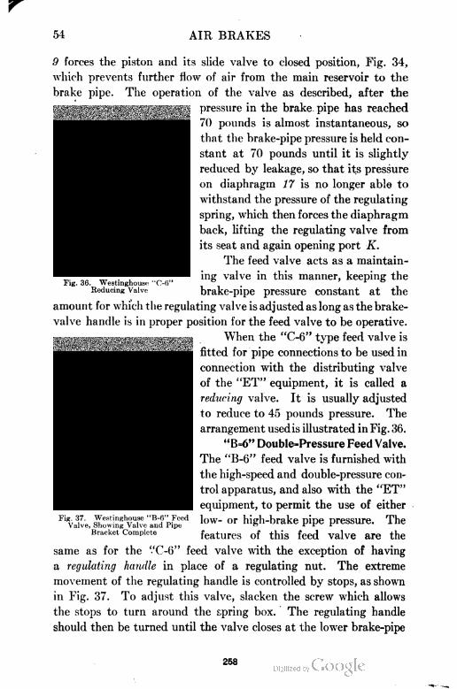
54 AIR BRAKES
Fig. 36. Westinghouso "C-6"Reducing Valve
9 forces the piston and its slide valve to closed position, Fig. 34,
which prevents further flow of air from the main reservoir to the
brake pipe. The operation of the valve as described, after the
pressure in the brake pipe has reached
70 pounds is almost instantaneous, so
that the brake-pipe pressure is held con
stant at 70 pounds until it is slightly
reduced by leakage, so that its pressure
on diaphragm 17 is no longer able to
withstand the pressure of the regulating
spring, which then forces the diaphragm
back, lifting the regulating valve from
its seat and again opening port K.
The feed valve acts as a maintain
ing valve in this manner, keeping the
brake-pipe pressure constant at the
amount for which the regulating valve is adjusted as long as the brake-
valve handle is in proper position for the feed valve to be operative.
When the "C-6" type feed valve is
fitted for pipe connections to be used in
connection with the distributing valve
of the "ET" equipment, it is called a
reducing valve. It is usually adjusted
to reduce to 45 pounds pressure. The
arrangement used is illustrated inFig. 36.
"B=6" Double=Pressure Feed Valve.
The "B-6" feed valve is furnished with
the high-speed and double-pressure con-
trol apparatus, and also with the "ET"
equipment, to permit the use of either
low- or high-brake pipe pressure. The
features of this feed valve are the
same as for the "C-6" feed valve wTith the exception of having
a regulating handle in place of a regulating nut. The extreme
movement of the regulating handle is controlled by stops, as shown
in Fig. 37. To adjust this valve, slacken the screw which allows
the stops to turn around the spring box. The regulating handle
should then be turned until the valve closes at the lower brake-pipe
Fig. 37. Westinghouse "B-fi" FeedValve, Showing Valve and Pipe
Bracket Complete
258
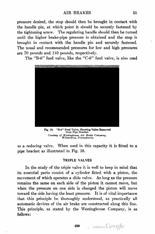
AIR BRAKES 55
pressure desired, the stop should then be brought in contact with
the handle pin, at which point it should be securely fastened by
the tightening screw. The regulating handle should then be turned
until the higher brake-pipe pressure is obtained and the stop is
brought in contact with the handle pin and securely fastened.
The usual and recommended pressures for low and high pressures
are 70 pounds and 110 pounds, respectively.
The "B-6" feed valve, like the "C-6" feed valve, is also used
Fig. 38. "B-6" Feed Valve, Showing Valve Removedfrom Pipe Bracket
Courtesy of Westinghouse Air Brake Company,Wilmerding, Pennsylvania
as a reducing valve. When used in this capacity it is fitted to a
pipe bracket as illustrated in Fig. 38.
TRIPLE VALVES
In the study of the triple valve it is well to keep in mind that
its essential parts consist of a cylinder fitted with a piston, the
movement of which operates a slide valve. As long as the pressure
remains the same on each side of the piston it cannot move, but
when the pressure on one side is changed the piston will move
toward the side having the least pressure. It is of vital importance
that this principle be thoroughly understood, as practically all
automatic devices of the air brake are constructed along this line.
This principle, as stated by the Westinghouse Company, is as
follows:
259
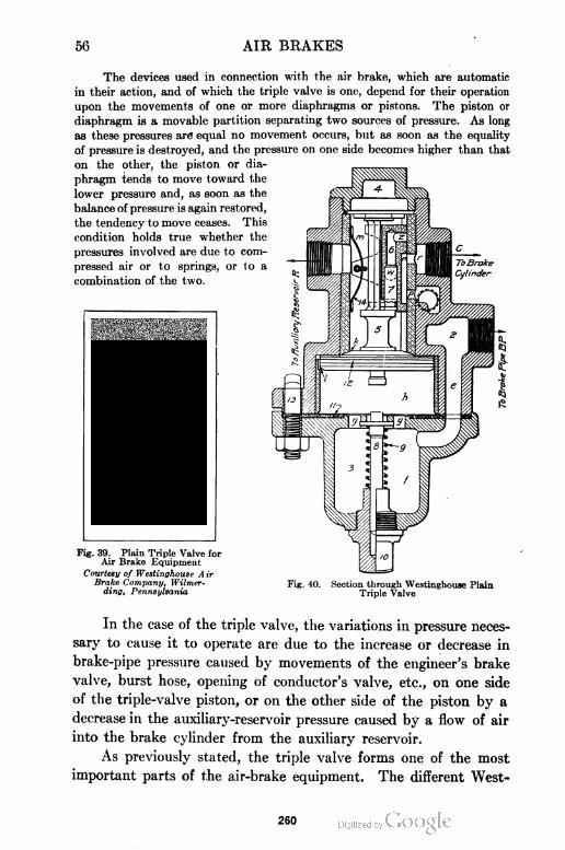
56 AIR BRAKES
The devices used in connection with the air brake, which are automatic
in their action, and of which the triple valve is one, depend for their operation
upon the movements of one or more diaphragms or pistons. The piston or
diaphragm is a movable partition separating two sources of pressure. As long
as these pressures are equal no movement occurs, but as soon as the equality
of pressure is destroyed, and the pressure on one side becomes higher than that
on the other, the piston or dia
phragm tends to move toward the
lower pressure and, as soon as the
balance of pressure is again restored,
the tendency to move ceases. This
condition holds true whether the
pressures involved are due to com
pressed air or to springs, or to a
combination of the two.
Fig. 39. Plain Triple Valve forAir Brake Equipment
Courtesy of Westinghouse A irBrake Company, Wilmer-
ding, Pennsylvania
Fig. 40. Section through Westinghouse PlainTriple Valve
In the case of the triple valve, the variations in pressure neces
sary to cause it to operate are due to the increase or decrease in
brake-pipe pressure caused by movements of the engineer's brake
valve, burst hose, opening of conductor's valve, etc., on one side
of the triple-valve piston, or on the other side of the piston by a
decrease in the auxiliary-reservoir pressure caused by a flow of air
into the brake cylinder from the auxiliary reservoir.
As previously stated, the triple valve forms one of the most
important parts of the air-brake equipment. The different West
260
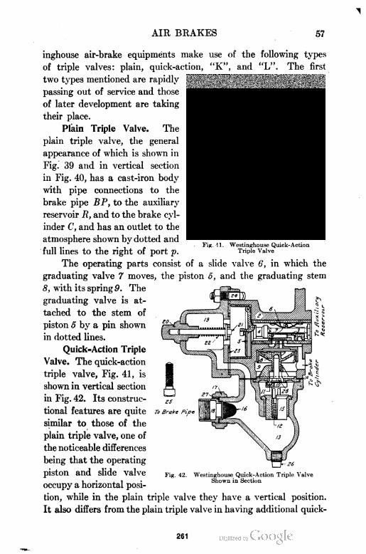
AIR BRAKES 57
Fig. 11. Westinghouse Quick-ActionTriple Valve
inghouse air-brake equipments make use of the following types
of triple valves: plain, quick-action, "K", and "L". The first
two types mentioned are rapidly
passing out of service and those
of later development are taking
their place.
Plain Triple Valve. The
plain triple valve, the general
appearance of which is shown in
Fig. 39 and in vertical section
in Fig. 40, has a cast-iron body
with pipe connections to the
brake pipe BP, to the auxiliary
reservoir R, and to the brake cyl
inder C, and has an outlet to the
atmosphere shown by dotted and
full lines to the right of port p.
The operating parts consist of a slide valve 6, in which the
graduating valve 7 moves, the piston 5, and the graduating stem
8, with its spring 9. The
graduating valve is at
tached to the stem of
piston 5 by a pin shown
in dotted lines.
Quick=Action Triple
Valve. The quick-action
triple valve, Fig. 41, is
shown in vertical section
in Fig. 42. Its construc
tional features are quite
similar to those of the
plain triple valve, one of
the noticeable differences
being that the operating
piston and slide valve
occupy a horizontal posi
tion, while in the plain triple valve they have a vertical position.
It also differs from the plain triple valve in having additional quick-
To Brake
Fig. 42. Westinghouse Quick-Action Triple ValveShown in Section
261
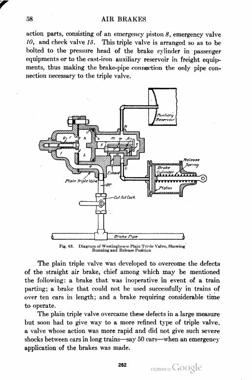
58 AIR BRAKES
action parts, consisting of an emergency piston 8, emergency valve
10, and check valve 15. This triple valve is arranged so as to be
bolted to the pressure head of the brake cylinder in passenger
equipments or to the cast-iron auxiliary reservoir in freight equip
ments, thus making the brake-pipe connection the only pipe con
nection necessary to the triple valve.
Fig. 43. Diagram of Westinghouse Plain Triole Vaive, ShowingRunning and Release Position
The plain triple valve was developed to overcome the defects
of the straight air brake, chief among which may be mentioned
the following: a brake that was inoperative in event of a train
parting; a brake that could not be used successfully in trains of
over ten cars in length; and a brake requiring considerable time
to operate.
The plain triple valve overcame these defects in a large measure
but soon had to give way to a more refined type of triple valve,
a valve whose action was more rapid and did not give such severe
shocks between cars in long trains—say 50 cars—when an emergency
application of the brakes was made.
262
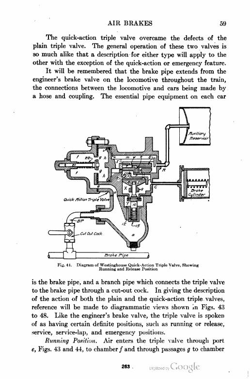
AIR BRAKES 59
The quick-action triple valve overcame the defects of the
plain triple valve. The general operation of these two valves is
so much alike that a description for either type will apply to the
other with the exception of the quick-action or emergency feature.
It will be remembered that the brake pipe extends from the
engineer's brake valve on the locomotive throughout the train,
the connections between the locomotive and cars being made by
a hose and coupling. The essential pipe equipment on each car
Fi,;. 44. Diagram of Westinghouse Quick-Action Triple Valve, ShowingRunning and Release Position
is the brake pipe, and a branch pipe which connects the triple valve
to the brake pipe through a cut-out cock. In giving the description
of the action of both the plain and the quick-action triple valves,
reference will be made to diagrammatic views shown in Figs. 43
to 48. Like the engineer's brake valve, the triple valve is spoken
of as having certain definite positions, such as running or release,
service, service-lap, and emergency positions.
Running Position. Air enters the triple valve through port
e, Figs. 43 and 44, to chamber / and through passages g to chamber
263
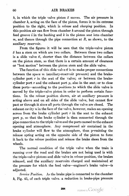
60 AIR BRAKES
h, in which the triple valve piston 5 moves. The air pressure in
chamber h, acting on the face of the piston, forces it to its extreme
position to the right, which is release and charging position. In
this position air can flow from chamber h around the piston through
feed groove i in the bushing and k in the piston seat into chamber
m, and thence through the pipe connection at R, as shown, to the
auxiliary reservoir.
From the figures it will be seen that the triple-valve piston
5 has a stem on which are two collars. Between these two collars
is a slide valve 6, shorter than the distance between the collars
on the piston stem, so that there is a certain amount of clearance
or "lost motion" between the piston stem and the slide valve.
The function of this slide valve 6 is to make proper connections
between the space m (auxiliary-reservoir pressure) and the brake-
cylinder port r in the seat of the valve; or between the brake-
cylinder port r and the exhaust port p, also in the seat; or to close
these ports—according to the positions to which the slide valve is
moved by the triple-valve piston in order to perform certain func
tions. In the release position shown, air at auxiliary pressure is
acting above and on all sides of the slide valve, but cannot flow
past or through it since all ports through the valve are closed. The
exhaust cavity n in the face of the valve, however, makes an opening
across from the brake cylinder port r in the seat to the exhaust
port p, so that the brake cylinder is then connected through the
pipe connection to the triple valve and the ports named to the exhaust
opening and atmosphere. Any compressed air contained in the
brake cylinder will flow to the atmosphere, thus permitting the
release spring acting on the opposite side of the piston to force
it back to the release position and release the brake shoes from the
wheels.
The normal condition of the triple valve when the train is
running over the road and the brakes are not being used is with
the triple-valve pistons and slide valve in release position, the brakes
released, and the auxiliary reservoirs charged and maintained at
the pressure for which the feed valve—engineer's brake valve—is
adjusted.
Service Position. As the brake pipe is connected to the chamber
h, Fig. 45, of each triple valve, a reduction in brake-pipe pressure
264
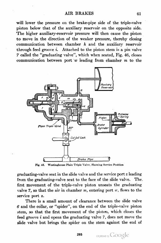
AIR BRAKES 61
will lower the pressure on the brake-pipe side of the triple-valve
piston below that of the auxiliary reservoir on the opposite side.
The higher auxiliary-reservoir pressure will then cause the piston
to move in the direction of the weaker pressure, thereby closing
communication between chamber h and the auxiliary reservoir
through feed groove i. Attached to the piston stem is a pin valve
7 called the "graduating valve", which when seated, Fig. 46, closes
communication between port w leading from chamber m to the
Fig. 45. Westinghouse Plain Triple Valve, Showing Service Position
graduating-valve seat in the slide valve and the service port z leading
from the graduating-valve seat to the face of the slide valve. The.
first movement of the triple-valve piston unseats the graduating
valve 7, so that the air in chamber m, entering port w, flows to the
service port z.
There is a small amount of clearance between the slide valve
6 and the collar, or "spider", on the end of the triple-valve piston
stem, so that the first movement of the piston, which closes the
feed groove i and opens the graduating valve 7, does not move the
slide valve but brings the spider on the stem against the end of
265
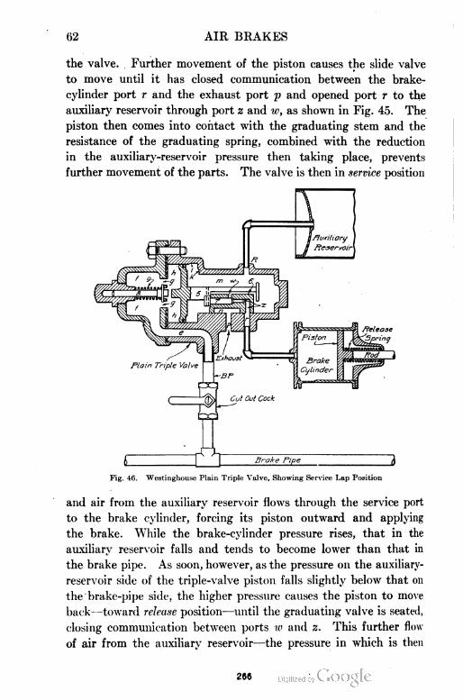
62 AIR BRAKES
the valve. Further movement of the piston causes the slide valve
to move until it has closed communication between the brake-
cylinder port r and the exhaust port p and opened port r to the
auxiliary reservoir through port 2 and w, as shown in Fig. 45. The
piston then comes into contact with the graduating stem and the
resistance of the graduating spring, combined with the reduction
in the auxiliary-reservoir pressure then taking place, prevents
further movement of the parts. The valve is then in service position
Fig. 46. Westinghouse Plain Triple Valve, Showing Service Lap Position
and air from the auxiliary reservoir flows through the service port
to the brake cylinder, forcing its piston outward and applying
the brake. While the brake-cylinder pressure rises, that in the
auxiliary reservoir falls and tends to become lower than that in
the brake pipe. As soon, however, as the pressure on the auxiliary-
reservoir side of the triple-valve piston falls slightly below that on
the brake-pipe side, the higher pressure causes the piston to move
back—toward release position—until the graduating valve is seated,
closing communication between ports w and 2. This further flow
of air from the auxiliary reservoir—the pressure in which is then
266
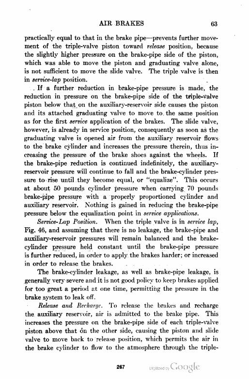
AIR BRAKES 63
practically equal to that in the brake pipe—prevents further move
ment of the triple-valve piston toward release position, because
the slightly higher pressure on the brake-pipe side of the piston,
which was able to move the piston and graduating valve alone,
is not sufficient to move the slide valve. The triple valve is then
in service-lap position.
. If a further reduction in brake-pipe pressure is made, the
reduction in pressure on the brake-pipe side of the triple-valve
piston below that on the auxiliary-reservoir side causes the piston
and its attached graduating valve to move to. the same position
as for the first service application of the brakes. The slide valve,
however, is already in service position, consequently as soon as the
graduating valve is opened air from the auxiliary reservoir flows
to the brake cylinder and increases the pressure therein, thus in
creasing the pressure of the brake shoes against the wheels. If
the brake-pipe reduction is continued indefinitely, the auxiliary-
reservoir pressure will continue to fall and the brake-cylinder pres
sure to rise until they become equal, or "equalize". This occurs
at about 50 pounds cylinder pressure when carrying 70 pounds
brake-pipe pressure with a properly proportioned cylinder and
auxiliary reservoir. Nothing is gained in reducing the brake-pipe
pressure below the equalization point in service applications.
Service-Lap Position. When the triple valve is in service lap,
Fig. 46, and assuming that there is no leakage, the brake-pipe and
auxiliary-reservoir pressures will remain balanced and the brake-
cylinder pressure held constant until the brake-pipe pressure
is further reduced, in order to apply the brakes harder; or increased
in order to release the brakes. . .
The brake-cylinder leakage, as well as brake-pipe leakage, is
generally very severe and it is not good policy to keep brakes applied
for too great a period at one time, permitting the pressure in the
brake system to leak off.
Release and Recharge. To release the brakes and recharge
the auxiliary reservoir, air is admitted to the brake pipe. This
increases the pressure on the brake-pipe side of each triple-valve
piston above that on the other side, causing the piston and slide
valve to move back to release position, which permits the air in
the brake cylinder to flow to the atmosphere through the triple
267
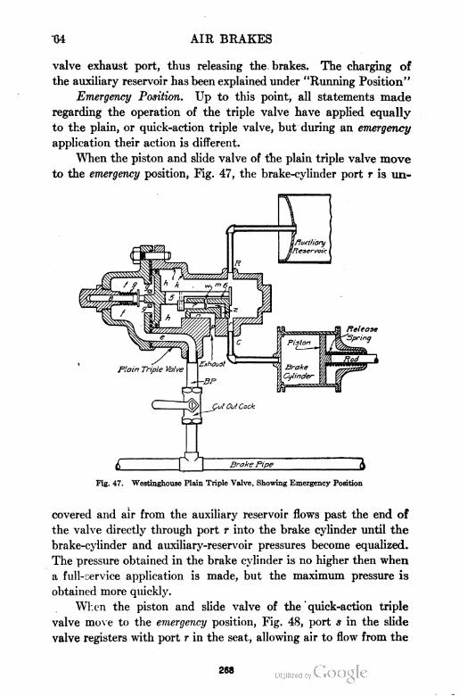
"64 AIR BRAKES
valve exhaust port, thus releasing the brakes. The charging of
the auxiliary reservoir has been explained under "Running Position"
Emergency Position. Up to this point, all statements made
regarding the operation of the triple valve have applied equally
to the plain, or quick-action triple valve, but during an emergency
application their action is different.
When the piston and slide valve of the plain triple valve move
to the emergency position, Fig. 47, the brake-cylinder port r is un
rig. 47. Westinghouse Plain Triple Valve, Showing Emergency Position
covered and air from the auxiliary reservoir flows past the end of
the valve directly through port r into the brake cylinder until the
brake-cylinder and auxiliary-reservoir pressures become equalized.
The pressure obtained in the brake cylinder is no higher then when
a full-service application is made, but the maximum pressure is
obtained more quickly.
When the piston and slide valve of the ' quick-action triple
valve move to the emergency position, Fig. 48, port s in the slide
valve registers with port r in the seat, allowing air to flow from the
268
AIR BRAKES 65
auxiliary reservoir to the brake cylinder. Port s is small, however,
and in this position the slide valve also opens port t in its seat,
allowing air to flow from chamber m through port t to the chamber
above the emergency piston 8. The other side of emergency piston
8 is connected to the brake cylinder, in which there is no air pressure,
consequently the emergency piston is forced downward, pushing
the emergency valve 10 from its seat and allowing air in chamber Y
above the check valve 15 to flow past the emergency valve 10 to
chamber X and the brake-cylinder. Brake-pipe air in a below the
Fig. 48. Westinghouse Quick-Action Triple Valve, Showing Emergency Position
check valve 15, then raises the check valve and flows to the
brake cylinder through the passages mentioned. During an emer
gency application, therefore, the quick-action triple valve supplies
air to the brake cylinder from the brake pipe as well as from the
auxiliary reservoir.
Approximately 60-pound brake-cylinder pressure is obtained
on emergency applications, the air from the brake pipe increasing
the cylinder pressure about 20 per cent above the maximum obtain
able with a full-service application.
269
66 AIR BRAKES
This "venting" the brake-pipe pressure into the brake-cylinder
aids the speed of an emergency application, as each triple valve
reduces the brake-pipe pressure sufficiently to set the next triple
valve in the train to emergency.
The release after an emergency application is obtained in the
same manner as for a service-application release.
The plain triple valve is now only used for locomotives in
freight and switching service that are not equipped with the "ET"
distributing valve.
Type "K" Freight Triple Valve. The standard form of quick-
action triple valve commonly used in freight service has until
recently proved very satisfactory. In the last few years, however,
with heavier locomotives capable of handling 100-car trains fitted
with air-brake equipment, they have failed to meet all the require
ments. Realizing the changed conditions and the importance of
meeting them, the Westinghouse Company has developed and
perfected the "K" triple valve.
Objections to Other Valves Overcome by "A" Type. Some of
the undesirable features of the standard quick-action triple valve,
which the "K" triple overcomes are as follows:
(a) The failure of a portion of the brakes in a long train to apply.
(b) A complete release of the brakes at the forward end of the train
before the brake-pipe pressure which has brought this about can reach the triple
valves near the end of the train. This action permits the slack to run out hard,
and creates excessive strains on the draft gears, often resulting in a break-
in-two.
(c) Overcharging the auxiliary reservoirs at the forward end of the train
while releasing the brakes. The result of this action is a reapplication of the
forward brakes when the brake-valve handle is placed in running position.
The outward appearance of the "K" triple valve when attached
to the auxiliary reservoir is so much like the standard quick-action
triple that a thin web is cast on the top part of the body as a dis
tinguishing mark. The designating mark "K-l" or "K-2" is also
cast on the side of the body. The "K" triple is made in two sizes
—the "K-l" for use with the 8-inch freight-car brake cylinder,
and the "K-2" with the 10-inch freight-car brake cylinder, Fig. 49.
This "K" triple valve embodies every feature possessed by the
standard quick-action triple valve and three additional ones,
namely, quick service, uniform release, and uniform re-charge. It
270
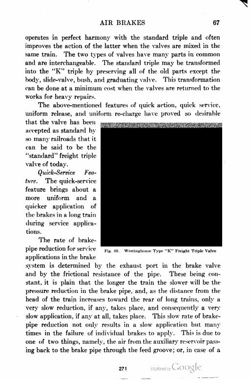
AIR BRAKES G7
operates in perfect harmony with the standard triple and often
improves the action of the latter when the valves are mixed in the
same train. The two types of valves have many parts in common
and are interchangeable. The standard triple may be transformed
into the "K" triple by preserving all of the old parts except the
body, slide-valve, bush, and graduating valve. This transformation
can be done at a minimum cost when the valves are returned to the
works for heavy repairs.
The above-mentioned features of quick action, quick service,
uniform release, and uniform re-charge have proved so desirable
that the valve has been
accepted as standard by
so many railroads that it
can be said to be the
"standard" freight triple
valve of today.
Quick-Service Fea
ture. The quick-service
feature brings about a
more uniform and a
quicker application of
the brakes in a long train
during service applica
tions.
The rate of brake-
pipe reduction for service
applications in the brake
system is determined by the exhaust port in the brake valve
and by the frictional resistance of the pipe. These being con
stant, it is plain that the longer the train the slower will be the
pressure reduction in the brake pipe, and, as the distance from the
head of the train increases toward the rear of long trains, only a
very slow reduction, if any, takes place, and consequently a very
slow application, if any at all, takes place. This slow rate of brake-
pipe reduction not only results in a slow application but many
times in the failure of individual brakes to apply. This is due to
one of two things, namely, the air from the auxiliary reservoir pass
ing back to the brake pipe through the feed groove; or, in case of a
Fig. 49. Westinghnuse Type "K" Freight Triple Valve
271
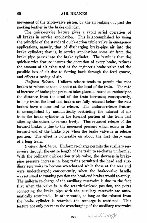
68 AIR BRAKES
movement of the triple-valve piston, by the air leaking out past the
packing leather in the brake cylinder.
The quick-service feature gives a rapid serial operation of
all brakes in service application. This is accomplished by using
the principle of the standard quick-action triple valve in emergency
applications, namely, that of discharging brake-pipe air into the
brake cylinder; that is, in service applications some air from the
brake pipe passes into the brake cylinder. The result is that the
quick-service feature insures the operation of every brake, reduces
the amount of air exhausted at the engineer's brake valve and the
possible loss of air due to flowing back through the feed groove,
and effects a saving of air.
Uniform Release. Uniform release tends to permit the rear
brakes to release as soon as those at the head of the train. The rate
of increase of brake-pipe pressure takes place more and more slowly as
the distance from the head of the train increases; consequently,
in long trains the head end brakes are fully released before the rear
brakes have commenced to release. The uniform-release feature
is accomplished by automatically restricting the exhaust of air
from the brake cylinder in the forward portion of the train and
allowing the others to release freely. This retarded release of the
forward brakes is due to the increased pressure which exists in the
forward end of the brake pipe when the brake valve is in release
position. The effect is noticeable on about the first thirty cars
of a long train.
Uniform Re-Charge. Uniform re-charge permits the auxiliary res
ervoirs through the entire length of the train to re-charge uniformly.
With the ordinary quick-action triple valve, the slowness in brake-
pipe pressure increase in long trains permitted the head end aux
iliary reservoirs to become overcharged while those at the rear end
were undercharged; consequently, when the brake-valve handle
was returned to running position the head-end brakes would re-apply.
The uniform re-charge of the auxiliary reservoirs is due to the fact
that when the valve is in the retarded-release position, the ports
connecting the brake pipe with the auxiliary reservoir are auto
matically restricted. In other words, as long as the exhaust from
the brake cylinder is retarded, the recharge is restricted. This
feature not only prevents the overcharging of the auxiliary reservoirs
272
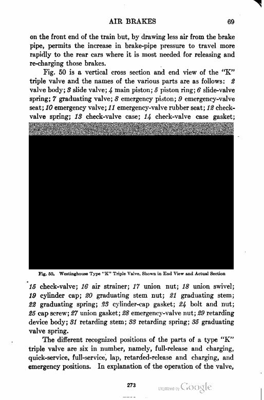
AIR BRAKES 69
on the front end of the train but, by drawing less air from the brake
pipe, permits the increase in brake-pipe pressure to travel more
rapidly to the rear cars where it is most needed for releasing and
re-charging those brakes.
Fig. 50 is a vertical cross section and end view of the "K"
triple valve and the names of the various parts are as follows: 2
valve body; 3 slide valve; 4 main piston; 5 piston ring; 6 slide-valve
spring; 7 graduating valve; 8 emergency piston; 9 emergency-valve
seat; 10 emergency valve; 11 emergency-valve rubber seat; 12 check-
valve spring; 13 check-valve case; 14 check-valve case gasket;
Fig. 50. Westinghouse Type "K" Triple Valve, Shown in End View and Actual Section
15 check-valve; 16 air strainer; 17 union nut; 18 union swivel;
19 cylinder cap; 20 graduating stem nut; 21 graduating stem;
22 graduating spring; 23 cylinder-cap gasket; 24 bolt and nut;
25 cap screw; 27 union gasket; 28 emergency-valve nut; 29 retarding
device body; 31 retarding stem; S3 retarding spring; 35 graduating
valve spring.
The different recognized positions of the parts of a type "K"
triple valve are six in number, namely, full-release and charging,
quick-service, full-service, lap, retarded-release and charging, and
emergency positions. In explanation of the operation of the valve,
273
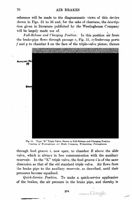
70 AIR BRAKES
reference will be made to the diagrammatic views of this device
shown in Figs. 51 to 56 and, for the sake of clearness, the descrip^
tion given in literature published by the Westinghouse Company
will be largely made use of. .
Full-Release and Charging Position. In this position air from
the brake-pipe flows through passage c,. Fig. 51, cylinder-cap ports
/ and g to chamber h on the face of the triple-valve piston; thence
Fig. 51. Type "K" Triple Valve, Shown in Full-Release and Charging Position
Courtesy of Westinghouse Air Brake Company, Wilmerding, Pennsylvania
through feed groove i, now open, to chamber R above the slide
valve, which is always in free communication with the auxiliary
reservoir. In the "K" triple valve, the feed groove i is of the same
dimension as that of the old standard triple valve. Air flows from
the brake pipe to the auxiliary reservoir, as described, until their
pressures become equalized.
Quick-Service Position. To make a quick-service application
of the brakes, the air pressure in the brake pipe, and thereby in
274
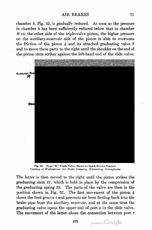
AIR BRAKES 71
chamber h, Fig. 52, is gradually reduced. As soon as the pressure
in chamber h has been sufficiently reduced below that in chamber
B on the other side of the triple-valve piston, the higher pressure
on the auxiliary-reservoir side of the piston is able to overcome
the friction of the piston 4 and its attached graduating valve 7
and to move these parts to the right until the shoulder on the end of
the piston stem strikes against the left-hand end of the slide valve.
Auxiliary Reservoir
R
Brake Cylinder
c
fpIPE TAP
Brake Pipe
BP
Fig. 52. Type "K" Triple Valve, Shown in Quick-Service Position
Courtesy of Westinghouse Air Brake Company, Wilmerding, Pennsylvania
The latter is then moved to the right until the piston strikes the
graduating stem 21, which is held in place by the compression of
the graduating spring 22. The parts of the valve are then in the
position shown in Fig. 52. The first movement of the piston 4
closes the feed groove % and prevents air from feeding back into the
brake pipe from the auxiliary reservoir, and at the same time the
graduating valve opens the upper end of port z in the slide valve.
The movement of the latter closes the connection between port r
275
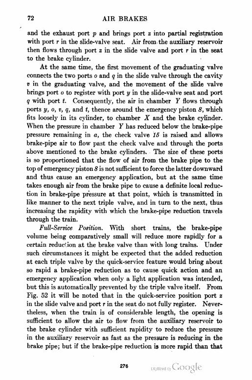
72 AIR BRAKES
and the exhaust port p and brings port z into partial registration
with port r in the slide-valve seat. Air from the auxiliary reservoir
then flows through port z in the slide valve and port r in the seat
to the brake cylinder.
At the same time, the first movement of the graduating valve
connects the two ports o and q in the slide valve through the cavity
v in the graduating valve, and the movement of the slide valve
brings port o to register with port y in the slide-valve seat and port
q with port t. Consequently, the air in chamber Y flows through
ports y, o, v, q, and t, thence around the emergency piston 8, which
fits loosely in its cylinder, to chamber X and the brake cylinder.
When the pressure in chamber Y has reduced below the brake-pipe
pressure remaining in a, the check valve 15 is raised and allows
brake-pipe air to flow past the check valve and through the ports
above mentioned to the brake cylinders. The size of these ports
is so proportioned that the flow of air from the brake pipe to the
top of emergency piston 8 is not sufficient to force the latter downward
and thus cause an emergency application, but at the same time
takes enough air from the brake pipe to cause a definite local reduc
tion in brake-pipe pressure at that point, which is transmitted in
like manner to the next triple valve, and in turn to the next, thus
increasing the rapidity with which the brake-pipe reduction travels
through the train.
Full-Service Position. With short trains, the brake-pipe
volume being comparatively small will reduce more rapidly for a
certain reduction at the brake valve than with long trains. Under
such circumstances it might be expected that the added reduction
at each triple valve by the quick-service feature would bring about
so rapid a brake-pipe reduction as to cause quick action and an
emergency application when only a light application was intended,
but this is automatically prevented by the triple valve itself. From
Fig. 52 it will be noted that in the quick-service position port z
in the slide valve and port r in the seat do not fully register. Never
theless, when the train is of considerable length, the opening is
sufficient to allow the air to flow from the auxiliary reservoir to
the brake cylinder with sufficient rapidity to reduce the pressure
in the auxiliary reservoir as fast as the pressure is reducing in the
brake pipe; but if the brake-pipe reduction is more rapid than that
276
AIR BRAKES 73
of the auxiliary reservoir, which may be the case on short trains,
the difference in pressure on the two sides of piston 4 becomes
sufficient to slightly compress the graduating spring and moves
the slide valve to the position shown in Fig. 53 called full service.
In this position, quick-service port y is closed, so that no air flows
from the brake pipe to the brake cylinder; also, in full-service posi
tion ports 2 and r are fully open, allowing the auxiliary-reservoir
Fig. 53. Type "K" Valve Shown in Full-Service Position
Courtesy of Westinghouse Air Brake Company, Wilmerding, Pennsylvania
pressure to reduce more rapidly, so as to keep pace with the more
rapid brake-pipe reduction.
Lap Position. When the brake-pipe reduction ceases, air
continues to flow from the auxiliary reservoir through ports z and
r to the brake cylinder until the pressure in the chamber R becomes
enough less than that of the brake pipe to cause piston 4 and grad
uating valve 7 to move to the left until the shoulder on the piston
stem strikes the right-hand end of slide valve 3. As the friction
277
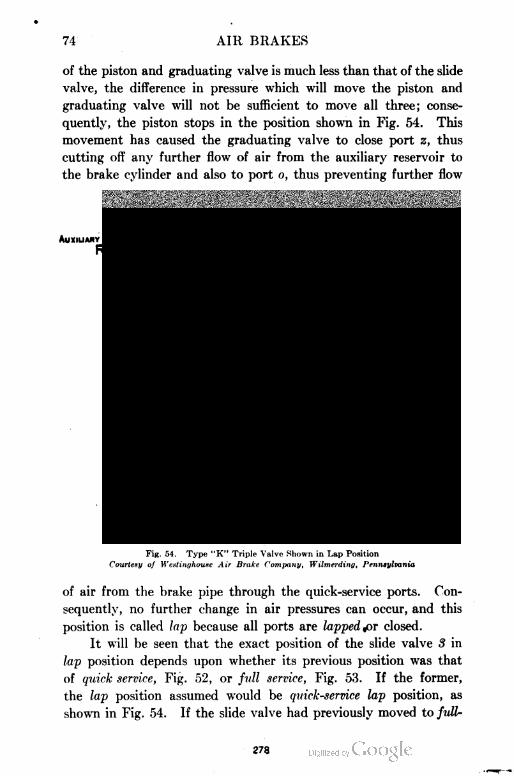
74 AIR BRAKES
of the piston and graduating valve is much less than that of the slide
valve, the difference in pressure which will move the piston and
graduating valve will not be sufficient to move all three; conse
quently, the piston stops in the position shown in Fig. 54. This
movement has caused the graduating valve to close port z, thus
cutting off any further flow of air from the auxiliary reservoir to
the brake cylinder and also to port o, thus preventing further flow
FiR. 54. Type "K" Triple Valve Shown in Lap Position
Courtesy of Westinghouxc Air Brake Company, Wilmerding, Pennsylvania
of air from the brake pipe through the quick-service ports. Con
sequently, no further change in air pressures can occur, and this
position is called lap because all ports are lapped jar closed.
It will be seen that the exact position of the slide valve 3 in
lap position depends upon whether its previous position was that
of quick service, Fig. 52, or full service, Fig. 53. If the former,
the lap position assumed would be quick-service lap position, as
shown in Fig. 54. If the slide valve had previously moved to full
278
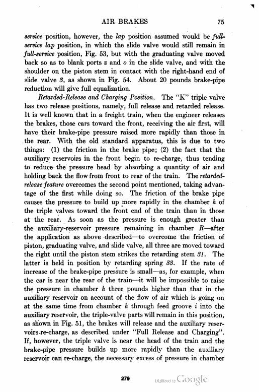
AIR BRAKES 75
service position, however, the lap position assumed would be full-
service lap position, in which the slide valve would still remain in
full-service position, Fig. 53, but with the graduating valve moved
back so as to blank ports z and o in the slide valve, and with the
shoulder on the piston stem in contact with the right-hand end of
slide valve 3, as shown in Fig. 54. About 20 pounds brake-pipe
reduction will give full equalization.
Retarded-Release and Charging Position. The "K" triple valve
has two release positions, namely, full release and retarded release.
It is well known that in a freight train, when the engineer releases
the brakes, those cars toward the front, receiving the air first, will
have their brake-pipe pressure raised more rapidly than those in
the rear. With the old standard apparatus, this is due to two
things: (1) the friction in the brake pipe; (2) the fact that the
auxiliary reservoirs in the front begin to re-charge, thus tending
to reduce the pressure head by absorbing a quantity of air and
holding back the flow from front to rear of the train. The retarded-
release feature overcomes the second point mentioned, taking advan
tage of the first while doing so. The friction of the brake pipe
causes the pressure to build up more rapidly in the chamber h of
the triple valves toward the front end of the train than in those
at the rear. As soon as the pressure is enough greater than
the auxiliary-reservoir pressure remaining in chamber R—after
the application as above described—to overcome the friction of
piston, graduating valve, and slide valve, all three are moved toward
the right until the piston stem strikes the retarding stem 31. The
latter is held in position by retarding spring 33. If the rate of
increase of the brake-pipe pressure is small—as, for example, when
the car is near the rear of the train—it will be impossible to raise
the pressure in chamber h three pounds higher than that in the
auxiliary reservoir on account of the flow of air which is going on
at the same time from chamber h through feed groove i into the
auxiliary reservoir, the triple-valve parts will remain in this position,
as shown in Fig. 51, the brakes will release and the auxiliary reser
voirs-re-charge, as described under "Full Release and Charging".
If, however, the triple valve is near the head of the train and the
brake-pipe pressure builds up more rapidly than the auxiliary
reservoir can re-charge, the necessary excess of pressure in chamber
279
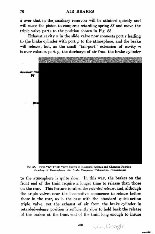
76 AIR BRAKES
h over that in the auxiliary reservoir will be attained quickly and
will cause the piston to compress retarding spring 33 and move the
triple valve parts to the position shown in Fig. 55.
Exhaust cavity n in the slide valve now connects port r leading
to the brake cylinder with port p to the atmosphere, and the brake
will release; but, as the small "tail-port" extension of cavity n
is over exhaust port p, the discharge of air from the brake cylinder
Auxiliary Reservoir _
R
QUAKE Cylinder
c
Brake Pipe
BP
Fig. 55. Typo "K" Triple Valve Shown in Retarded-Release and Charging Position
Courtesy of Westinghouse Air Brake Company, Wilmerding, Pennsylvania
to the atmosphere is quite slow. In this way, the brakes on the
front end of the train require a longer time to release than those
on the rear. This feature is called the retarded release, and, although
the triple valves near the locomotive commence to release before
those in the rear, as is the case with the standard quick-action
triple valve, yet the exhaust of air from the brake cylinder in
retarded-release position is sufficiently slow to hold back the release
of the brakes at the front end of the train long enough to insure
280
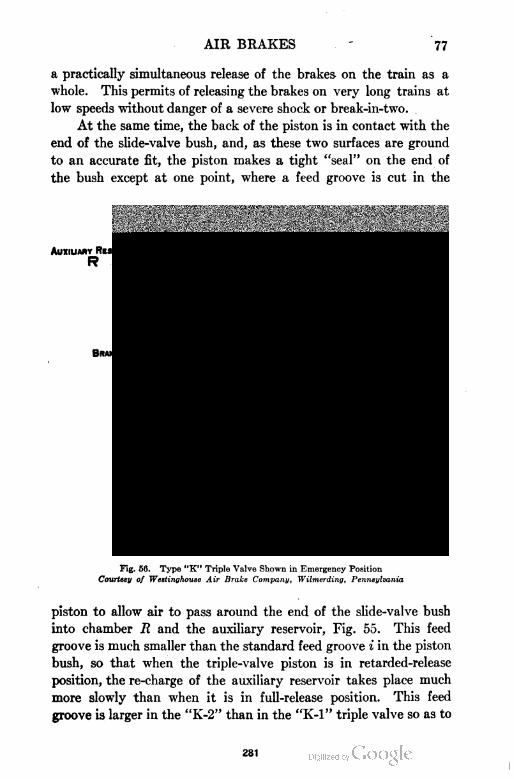
AIR BRAKES 77
a practically simultaneous release of the brakes on the train as a
whole. This permits of releasing the brakes on very long trains at
low speeds without danger of a severe shock or break-in-two.
At the same time, the back of the piston is in contact with the
end of the slide-valve bush, and, as these two surfaces are ground
to an accurate fit, the piston makes a tight "seal" on the end of
the bush except at one point, where a feed groove is cut in the
Auxiliary Reservoir
R
Brake Cylinder
C
Brake Pipe
BP
Fig. 56. Type "K" Triple Valve Shown in Emergency Position
Courtesy of Westingkouse Air Brake Company, Wilmerding, Pennsylvania
piston to allow air to pass around the end of the slide-valve bush
into chamber R and the auxiliary reservoir, Fig. 55. This feed
groove is much smaller than the standard feed groove i in the piston
bush, so that when the triple-valve piston is in retarded-release
position, the re-charge of the auxiliary reservoir takes place much
more slowly than when it is in full-release position. This feed
groove is larger in the "K-2" than in the "K-l" triple valve so as to
281
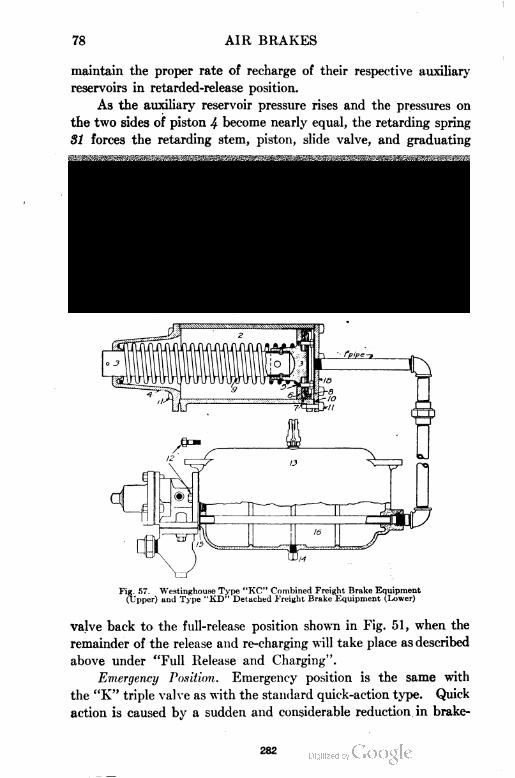
78 AIR BRAKES
maintain the proper rate of recharge of their respective auxiliary
reservoirs in retarded-release position.
As the auxiliary reservoir pressure rises and the pressures on
the two sides of piston 4 become nearly equal, the retarding spring
31 forces the retarding stem, piston, slide valve, and graduating
Fig. 57. Westinghouse Type "KC" Combined Freight Brake Equipment(Upper) and Type "KD" Detached Freight Brake Equipment (Lower)
valve back to the full-release position shown in Fig. 51, when the
remainder of the release and re-charging will take place as described
above under "Full Release and Charging".
Emergency Position. Emergency position is the same with
the "K" triple valve as with the standard quick-action type. Quick
action is caused by a sudden and considerable reduction in brake
282
AIR BRAKES 79
pipe pressure below that in the auxiliary reservoir, no matter hew
caused. This fall in break-pipe pressure causes the difference
in pressure on the two sides of piston 4 to increase very rapidly,
so that by the time the piston has traveled to its full-service position,
as already explained, there is sufficiently higher pressure on the
auxiliary-reservoir side of the triple-valve piston to cause it to
compress the graduating spring 22, forcing back the stem and
spring until the piston seats firmly against the gasket 28, as shown
in Fig. 56. The resulting movement of the slide valve opens port, t
in the slide-valve seat and allows air from the auxiliary reservoir
to flow to the top of emergency piston 8, forcing the latter down
ward and opening emergency valve 10. The pressure in chamber
Y, being thereby instantly relieved, allows the brake-pipe pressure
to raise the check valve 15 and flow rapidly through the chambers
Y and X to the brake cylinder until brake-cylinder and break-
pipe pressures nearly equalize, when the check valve is forced to
its seat by the check-valve spring, preventing the pressure in the
cylinders from escaping back into the brake pipe again. The
emergency valve, being held open by the emergency piston, will
consequently return to its seat when the auxiliary-reservoir and
brake-cylinder pressures have nearly equalized. At the same time,
port s in the slide valve registers with port r in the slide-valve seat
and allows air from the auxiliary reservoir to flow to the brake
cylinder. But the size of ports s and r is such that comparatively
little air gets through them before the brake pipe has stopped venting
air into the brake cylinder. This sudden discharge of brake-pipe
air into the brake cylinder has the same effect on the next triple
valve as would be caused by a similar discharge of brake-pipe air
to the atmosphere. In this way each triple valve applies the next.
The release after an emergency is effected in exactly the same
manner as after a service application, but requires longer time,
owing to the high brake-cylinder and auxiliary pressures and lower
brake-pipe pressures.
Fig. 57 illustrates two different types of freight-brake equip
ment in which the type "K" triple valve is used. The lower figure
represents the equipment usually found installed on steel hopper-
bottom coal and coke cars, while the upper figure shows that usually
found on wood box and gondola cars.
283
80 AIR BRAKES
Type "L" Triple Valve. The type "L" triple valve is the
outcome of a demand for a brake capable of handling heavy fast
passenger trains with a greater degree of safety, flexibility, and
comfort of passengers than the standard quick-action triple valve
could give. It is used in connection with what is known as the
L. N. Passenger Car equipment.
In order that trains may be controlled easily and smoothly
when running at either high or low speeds, and that stops may
Fig. 58. Type "L" Triple Valve, Showing Safety Valve in Place
Courtesy of Westinghouse Air Brake Company,Wilmerding, Pennsylvania
be made quickly and with the least liability of wheel sliding, the
brake apparatus must provide the following essential features of
operation :
(a) A small brake-pipe reduction must give a moderate brake-cylinder
pressure and a moderate but uniform retardation on the train as a whole.
(b) It must be possible to make a heavy-service reduction quickly but
without liability of quick action.
284
AIR BRAKES 81
(c) It must be possible to graduate the release as well as the application
of the brakes.
(d) To insure the ability to obtain brake applications in rapid succession
and to full power, a quick recharging of the auxiliary reservoirs is necessary.
This feature also enables the engineer to handle long trains in heavy grade work
with a much greater factor of safety than heretofore and eliminates the need
for pressure-retaining valves.
For high-speed trains a high brake-cylinder pressure available
Fig. 59. Type "L" Triple Valve, Showing By-Pass Piston Cap
Courtesy of Westinghouse Air Brake Company,Wilmerding, Pennsylvania
for emergency application is imperative, in order to provide a
maximum braking power when the shortest possible stop is required.
New Features in "L" Type. The following new features tre
incorporated in the new Type "L" triple valve:
(1) Quick recharge (of auxiliary reservoirs), making it possible to obtain
full braking power almost immediately after a release has been made.
(2) Quick service, by which a very quick serial service action of the brakes
throughout the train is obtained, similar to that in emergency applications
but less in degree.
285

82 AIR BRAKES
(3) Graduated release, which permits of partly or entirely releasing the
brakes on the entire train at will. This permits of the best method of braking,
namely, a heavy application at high speed, gradually reduced as the speed
becomes moderate, with just enough brake-cylinder pressure left to complete
the stop.
286
AIR BRAKES 83
(4) High emergency-cylinder pressure, which greatly increases the available
braking power over that obtained with a full-service reduction. As with the
quick-action triple valve, the brake-pipe air is vented into the brake cylinder.
The high emergency-cylinder pressure is made possible by using air from a
supplementary reservoir, a reservoir about 1\ times the capacity of the aux
iliary reservoir in addition to that from the auxiliary reservoir. The use of
the supplementary reservoir also makes possible the graduated-release feature.
Two illustrations of the Type "L" triple valve are given in
Figs. 58 and 59. Fig. 58 is a side view showing the safety valve in
place. Fig. 59 is the opposite side of the valve 'showing the by-pass
piston cap.
Fig. 60 shows two vertical cross sections of the Type "L"'
triple valve with all parts numbered, the names of the parts being
as follows: 2 valve body; 8 slide valve; 4 piston; 5 piston ring;
6 slide-valve spring; 7 graduating valve; 8 emergency-valve piston;
9 emergency-valve seat; 10 emergency valve; 11 rubber seat for
emergency valve; 12 check valve spring; 18 check-valve case;
14 check-valve case gasket; 15 check-valve; 16 emergency-valve
nut; 17 graduating-valve spring; 18 cylinder cap; 19 graduating-
spring nut; 20 graduating sleeve; 21 graduating spring; 22 cylinder-
cap gasket; 23 bolt and nut for cylinder cap; 24 bolt and nut for
check-valve case; 25 by-pass piston; 26 by-pass piston ring; 27
by-pass valve; 28 by-pass-valve seat; 29 by-pass-valve spring;
30 by-pass-valve cap; 31 by-pass-piston cap; 32 strainer; 33 safety
valve; 34 end cap.
The Type "L" triple valve is built in three sizes for use in
connection with brake cylinders of different sizes as follows: Triple
valve "L-l" for 8- and 10-inch cylinders; "L-2" for 12- and 14-inch
cylinders; "L-3" for 16- and 18-inch cylinders.
The "L" triple valve has several recognized positions quite
similar to those mentioned for other triple valves already described.
In explanation of the operation of the valve, reference will be made
for the sake of clearness to the diagrammatic views shown in Figs.
61 to 64. In these figures certain parts are referred to by the use
of abbreviations as follows : B.P. (brake pipe); S.R. (supplementary
reservoir); B.C. (brake cylinder); A.R. (auxiliary reservoir); S.V.
(safety valve); EX. (exhaust).
Release and Charging Position. The valve is illustrated in
release and charging position in Fig. 61.
287
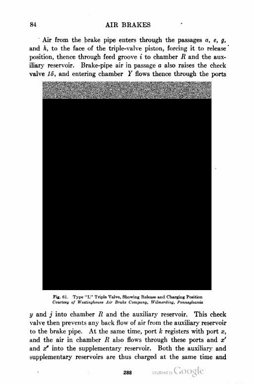
84 AIR BRAKES
Air from the brake pipe enters through the passages a, e, g,
and h, to the face of the triple-valve piston, forcing it to release '
position, thence through feed groove i to chamber R and the aux
iliary reservoir. Brake-pipe air in passage a also raises the check
valve 15, and entering chamber Y flows thence through the ports
Fig. 61. Type "L" Triple Valve, Showing Release and Charging Position
Courtesy of Westinghouse Air Brake Company, Wilmerding, Pennsylvania
y and j into chamber R and the auxiliary reservoir. This check
valve then prevents any back flow of air from the auxiliary reservoir
to the brake pipe. At the same time, port k registers with port x,
and the air in chamber R also flows through these ports and x'
and x" into the supplementary reservoir. Both the auxiliary and
supplementary reservoirs are thus charged at the same time and
288
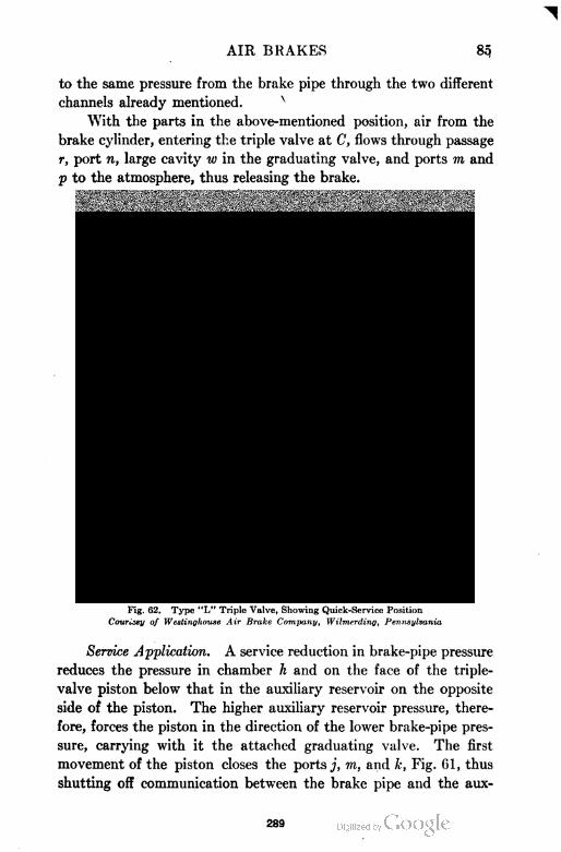
AIR BRAKES
to the same pressure from the brake pipe through the two different
channels already mentioned.
With the parts in the above-mentioned position, air from the
brake cylinder, entering the triple valve at C, flows through passage
r, port n, large cavity iv in the graduating valve, and ports m and
p to the atmosphere, thus releasing the brake.
Fig. 62. Type "L" Triple Valve, Showing Quick-Service Position
Couriisy of Westinghouse Air Brake Company, Wilmerding, Pennsylvania
Service Application. A service reduction in brake-pipe pressure
reduces the pressure in chamber h and on the face of the triple-
valve piston below that in the auxiliary reservoir on the opposite
side of the piston. The higher auxiliary reservoir pressure, there
fore, forces the piston in the direction of the lower brake-pipe pres
sure, carrying with it the attached graduating valve. The first
movement of the piston closes the ports j, m, and k, Fig. 61, thus
shutting off communication between the brake pipe and the aux
289
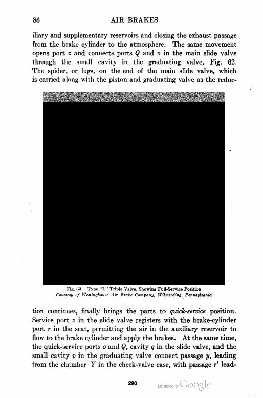
86 AIR BRAKES
iliary and supplementary reservoirs and closing the exhaust passage
from the brake cylinder to the atmosphere. The same movement
opens port z and connects ports Q and o in the main slide valve
through the small cavity in the graduating valve, Fig. 62.
The spider, or lugs, on the end of the main slide valve, which
is carried along with the piston and graduating valve as the redue-
Fig. 63. Type "L" Triple Valve, Showing Full-Service Position
Courteny of Westinghouse Air Brake Company, Wilmerding, Pennsylvania
tion continues, finally brings the parts to quick-service position.
Service port z in the slide valve registers with the brake-cylinder
port r in the seat, permitting the air in the auxiliary reservoir to
flow to the brake cylinder and apply the brakes. At the same time,
the quick-service ports o and Q, cavity q in the slide valve, and the
small cavity v in the graduating valve connect passage y, leading
from the chamber Y in the check-valve case, with passage r' lead
290
AIR BRAKES 87
ing to the brake cylinder. This allows air from the brake pipe to
lift the check valve and flow through the above-named ports to
the brake cylinder. This constitutes the quick-service action of
the triple valve, in that it causes a slight but definite reduction in
break-pipe pressure locally at each valve. The amount of air
vented from the brake pipe to the cylinder through the quick-service
ports is not great in amount: first, because the ports and passages
are small; and, second, because in the movement of slide valve 8
to full-service position the quick-service port y is restricted as it
approaches this position and is completely closed just before the
service port z is fully open. The amount by which the service
port is opened depends in any given case upon the rate of reduction
in break-pipe pressure as compared with that of the auxiliary reser
voir. If the former is at first rapid as compared with the latter,
which would be the case with short trains, the higher auxiliary-
reservoir pressure moves the piston at once to full-service position,
shown in Fig. 63, thus automatically cutting out the quick-service
feature where it is not needed.
When in full-service position, the service port z is fully open
and the quick-service port o is closed. This stops the flow of air
from the brake pipe to the brake cylinder and the quick-service
action ceases. The graduating spring is slightly compressed in the
full-service position. In any case where the brake-pipe reduction
is so rapid that the quick-service feature is of no advantage, the
difference of pressure on the two sides of the triple-valve piston
becomes at the same time sufficient to compress the graduating
spring and automatically close the quick-service port. But if
the brake-pipe reduction is less rapid or slow, as in the case of long
trains or moderate-service reductions, a partial opening only of
the service port is sufficient to preserve a balance between the pres
sure on the two sides of the triple-valve piston. The service port
connecting the auxiliary reservoir to the brake cylinder is much
larger than the quick-service port connecting the brake pipe to
tne brake cylinder. This serves to effectually prevent an emer
gency application being obtained when only a service application
is desired.
During the time the slide valve 3 remains in quick- or full-
service position the cavity q connects the brake-cylinder port r'
291
88 AIR BRAKES
with port b leading to the safety valve, which is ordinarily set for
62 pounds. In event of the brake-cylinder pressure rising to 62
pounds, the safety valve acts and prevents further pressure increase
in the brake cylinder.
Lap Position. After sufficient reduction of brake-pipe pres
sure has taken place to apply the brake to the desired amount,
the flow of air from the auxiliary reservoir to the brake cylinder
will reduce the pressure on the reservoir side of the triple-valve
piston slightly below the brake-pipe pressure. The slightly excess
pressure, together with the slightly compressed graduating spring,
will move the piston and graduating valve to lap position. In
this position all ports are blanked by the graduating valve, and the
air flowing to the brake cylinder will be stopped. The slight differ
ence in pressure which caused the piston to move is not sufficient
to move the slide valve 3 when the piston-stem shoulder comes in
contact with the slide valve. Therefore, there is no further move
ment of triple-valve parts until conditions are changed.
The lap position of the slide valve 3 is determined by the position
previous to lap. The graduating valve is the only valve moved
in obtaining lap position; so if the slide valve is in quick-service or
full-service position, the lap position obtained will be quick-service
lap or full-service lap.
Release and Recharge. When the brake-pipe pressure is in
creased to release the brake, the pressure on the brake-pipe side
of the piston causes the piston to move, and with it the slide valve
and graduating valve, to the extreme right, as shown in Fig. 61.
In this position the air in the brake cylinder is exhausted through
ports r and n, the large cavity w in the graduating valve and port m
to the exhaust passage p and atmosphere, as previously described.
Meanwhile, the auxiliary reservoir is being recharged from the brake
pipe through the ports y and j and feed groove i. At the same time,
port x, leading from the supplementary reservoir, is open through
port k to the auxiliary reservoir. The air, which was prevented
from leaving the supplementary reservoir by movement of the slide
valve to service position, now flows into the auxiliary reservoir
and helps to recharge it.
During the time the slide valve is in release position, the pres
sures on the brake pipe and auxiliary reservoir sides of the triple
282
AIR BRAKES 89
valve piston are always balanced. This is of importance, as it
insures a quick response of the brakes to any reduction or increase
in brake-pipe pressure irrespective of what operation may have
occurred immediately preceding. The supplementary reservoir is at
the same time being re-charged, as has been previously explained.
Fig. 64. Type "L" Triple Valve, Showing Emergency Position
Courtesy of Westinghouse Air Brake Company, Wilmerding, Pennsylvania
Graduated Release. Suppose that, after the brakes have been
applied, only sufficient air is permitted to flow into the brake pipe
to move piston 4 with the slide and graduating valve to release
position, and the engineer's brake-valve handle is then returned
to lap position. Then the flow of air from the supplementary
293
90 AIR BRAKES
reservoir through ports x and k to the auxiliary reservoir continuing
after the rise in break-pipe pressure has ceased will raise the pressure
on the auxiliary-reservoir side of the triple-valve piston slightly
above that on the break-pipe side and cause the piston and its
attached graduating valve to move to the left to graduated release-
lap position.
In this position the graduating valve closes the exhaust port
m, Fig. 61, thus preventing further flow of air from the brake cylinder
to the atmosphere. It also closes port k—which prevents further
recharging of the auxiliary reservoir from the supplementary reser
voir—and port j and feed groove i, which cuts off the supply of air
from the brake pipe to the auxiliary reservoir. Thus the brake is
only partly released and a portion of the air pressure originally
in the brake cylinder still remains there. In this way the brake
may be released in a series of steps or graduations.
Emergency Position. When the brake-pipe pressure is reduced
suddenly, or its reduction continues to be more rapid than that of
the auxiliary-reservoir pressure, the piston is forced to the extreme
left and compresses the graduating spring. The parts are then in
emergency position, as shown in Fig. 64. In this position air from
the auxiliary reservoir enters the brake-cylinder passage r through
the port s in the main slide valve, instead of port z as in service
application. Port t in the seat is also uncovered by the end of
the main slide valve, thus admitting air from the auxiliary reservoir
through port t to the top of the emergency piston. The air pressure
thus admitted to the top of this piston pushes it down and forces
the rubber-seated emergency valve from its seat. This allows the
brake-pipe air in passage a to lift the emergency check valve and
flow through chambers Y and X to the brake cylinder C in the
ordinary way. At the same time, port d in the main slide valve
registers with port c in the seat. This allows air from behind the
by-pass piston to flow through ports c, d, and n to r' and the brake
cylinder. As there is no pressure in the brake cylinder at this
instant, the by-pass piston with its attached by-pass valve is forced
upward, diagrammatically (or inward, actually) by the auxiliary-
reservoir pressure acting on the lower (or outer) side of the piston.
The air in the supplementary reservoir then flows past this valve
into the passageway leading to the auxiliary reservoir. It thereby
294
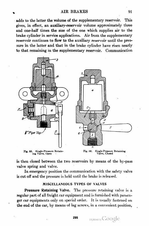
AIR BRAKES 91
adds to the latter the volume of the supplementary reservoir. This
gives, in effect, an auxiliary-reservoir volume approximately three
and one-half times the size of the one which supplies air to the
brake cylinder in service applications. Air from the supplementary
reservoir continues to flow to the auxiliary reservoir until the pres
sure in the latter and that in the brake cylinder have risen nearly
to that remaining in the supplementary reservoir. Communication
U x
Fig. 65. Single-Pressure Retain- Fig. 06. Single-Pressure Retaininging Valve, Open - Valve, Closed
is then closed between the two reservoirs by means of the by-pass
valve spring and valve.
In emergency position the communication with the safety valve
is cut off and the pressure is held until the brake is released.
MISCELLANEOUS TYPES OF VALVES
Pressure Retaining Valve. The pressure retaining valve is a
regular part of all freight car equipment and is furnished with passen
ger car equipments only on special order. It is usually fastened on
the end of the car, by means of lag screws, in a convenient position,
295
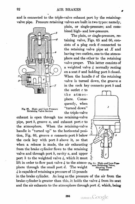
92 AIR BRAKES
and is connected to the triple-valve exhaust port by the retaining-
valve pipe. Pressure retaining valves are built in two types: namely,
plain, or single-pressure; and com
bined high- and low-pressure.
The plain, or single-pressure, re
taining valve, Figs. 65 and 66, con
sists of a plug cock 6 connected to
the retaining valve pipe at X and
having two outlets, one to the atmos
phere and the other to the retaining
valve proper. This latter consists of
a weighted valve 4 normally resting
on a seat 2 and holding port b closed.
When the handle 5 of the retaining
valve is turned down, the groove a
in the cock key connects port b and
the outlet c to
the atmos
phere. Conse
quently, when
"turned down"
the triple-valve
exhaust is open through tne retaining-valve
pipe, port b, groove a, and exhaust port c to
the atmosphere. When the retaining-valve
handle is "turned up" to the horizontal posi
tion, Fig. 66, groove a connects port b below
the cock key with port b above it, so that
when a release is made, the air exhausting
from the brake cylinder flows to the retaining
valve and through port b, cavity a, and upper
port b to the weighted valve 4, which it must
lift in order to flow past valve 4 to the atmos- Fig.
phere through the small port d. The weight
4 is capable of retaining a pressure of 15 pounds
in the brake cylinder. As long as the pressure of the air from the
brake cylinder is greater than this, it holds the valve 4 from its seat
and the air exhausts to the atmosphere through port d, which, being
Fig. 67. High- and Low-PressureRetaining Valve Section
. 0^ . High- and Low-Pressure Retaining Valve,
Showing ThreePositions
296
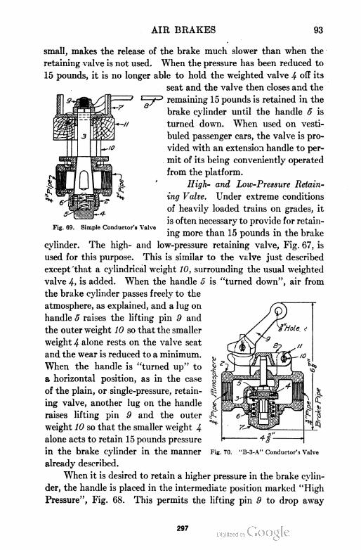
AIR BRAKES 93
Simple Conductor's Valve
small, makes the release of the brake much slower than when the
retaining valve is not used. When the pressure has been reduced to
15 pounds, it is no longer able to hold the weighted valve 4 off its
seat and the valve then closes and the
remaining 15 pounds is retained in the
brake cylinder until the handle 5 is
turned down. When used on vesti-
buled passenger cars, the valve is pro
vided with an extension handle to per
mit of its being conveniently operated
from the platform.
High- and Low-Pressure Retain
ing Valve. Under extreme conditions
of heavily loaded trains on grades, it
is often necessary to provide for retain
ing more than 15 pounds in the brake
cylinder. The high- and low-pressure retaining valve, Fig. 67, is
used for this purpose. This is similar to the valve just described
except 'that a cylindrical weight 10, surrounding the usual weighted
valve 4, is added. When the handle 5 is "turned down", air from
the brake cylinder passes freely to the
atmosphere, as explained, and a lug on
handle 5 raises the lifting pin 9 and
the outer weight 10 so that the smaller
weight 4 alone rests on the valve seat
and the wear is reduced to a minimum.
When the handle is "turned up" to
a horizontal position, as in the case
of the plain, or single-pressure, retain
ing valve, another lug on the handle
raises lifting pin 9 and the outer
weight 10 so that the smaller weight 4
alone acts to retain 15 pounds pressure
in the brake cylinder in the manner
already described.
When it is desired to retain a higher pressure in the brake cylin
der, the handle is placed in the intermediate position marked "High
Pressure", Fig. 68. This permits the lifting pin 9 to drop away
Fig. 70. "B-3-A" Conductor'3 Valve
297
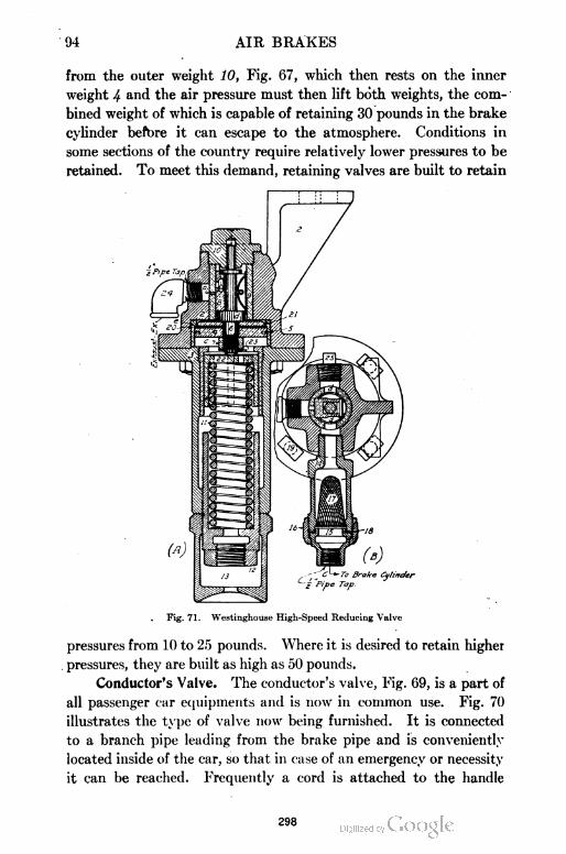
94 AIR BRAKES
from the outer weight 10, Fig. 67, which then rests on the inner
weight 4 and the air pressure must then lift both weights, the com
bined weight of which is capable of retaining 30 pounds in the brake
cylinder before it can escape to the atmosphere. Conditions in
some sections of the country require relatively lower pressures to be
retained. To meet this demand, retaining valves are built to retain
Fig. 71. Westinghouse High-Speed Reducing Valve
pressures from 10 to 25 pounds. Where it is desired to retain higher
pressures, they are built as high as 50 pounds.
Conductor's Valve. The conductor's valve, Fig. 69, is a part of
all passenger car equipments and is now in common use. Fig. 70
illustrates the type of valve now being furnished. It is connected
to a branch pipe leading from the brake pipe and is conveniently
located inside of the car, so that in case of an emergency or necessity
it can be reached. Frequently a cord is attached to the handle
298
AIR BRAKES 95
which runs the entire length of the car and permits of the opening
of the valve with the least possible delay. The valve most commonly
used is of the non-self-closing plug-cock type. When the valve is
opened, it permits air from the
brake pipe to escape freely to
the atmosphere, causing a
quick-action application of all
brakes in the train. After
making a stop in this manner,
the valve must be closed be
fore the brake pipe and sys
tem can be re-charged and the
brakes released.
High-Speed Reducing
Valve. It has been known
for a good many years that as
the speed of the train is in
creased, the maximum brake-
shoe pressure may also be in
creased without danger . of
skidding the wheels. That is,
a train going at a speed of 80
miles an hour would require a
much greater brake-shoe pres
sure to skid the wheels than a
train going 5 miles an hour.
This fact has been taken ad
vantage of in the design of
the high-speed brake equip
ment. Instead of carrying a
brake-pipe pressure of 70
pounds, a much higher pres
sure is used, the usual pres
sure being 110 pounds. When
a full-service application is
made, about 85 pounds pressure is obtained in the brake cylinder.
If this pressure were allowed to continue in the brake cylinder until
the train stopped, there would be danger of skidding the wheels. In
299
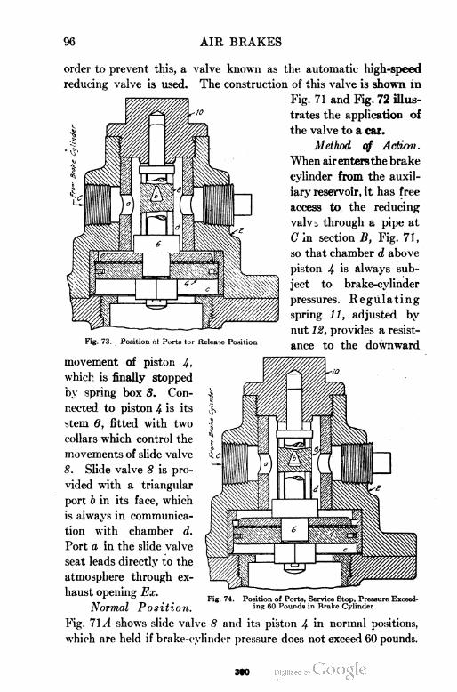
96 AIR BRAKES
order to prevent this, a valve known as the automatic high-speed
reducing valve is used. The construction of this valve is shown in
Fig. 71 and Fig 72 illus
trates the application of
the valve to a car.
Method of Action .
When air entersthe brake
cylinder from the auxil
iary reservoir, it has free
access to the reducing
valvi through a pipe at
C in section B, Fig. 71,
so that chamber d above
piston 4 is always sub
ject to brake-cylinder
pressures. Regulating
spring 11, adjusted by
nut 12, provides a resist
ing. 73 Position ol Ports lor Release Position &nce to the downward
movement of piston 4.
which is finally stopped
by spring box 8. Con
nected to piston 4 is its
stem 6, fitted with two
collars which control the
movements of slide valve
8. Slide valve 8 is pro
vided with a triangular
port b in its face, which
is always in communica
tion with chamber d.
Port a in the slide valve
seat leads directly to the
atmosphere through ex
haust opening Ex.
Normal Position.
Fig. 71^1 shows slide valve 8 and its piston 4 in normal positions,
which are held if brake-cylinder pressure does not exceed 60 pounds.
Fig. 74. Position of Ports, Service Stop, Pressure Exceeding 60 Pounds in Brake Cylinder
300
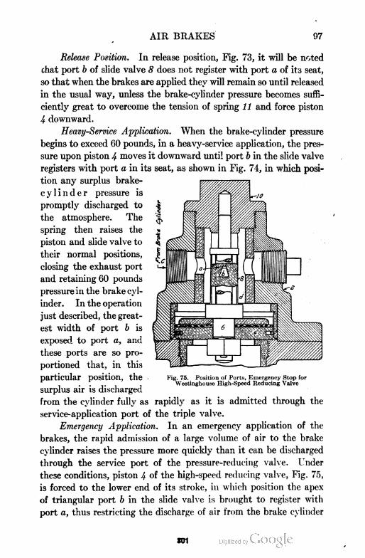
AIR BRAKES 97
Release Position. In release position, Fig. 73, it will be noted
chat port b of slide valve 8 does not register with port a of its seat,
so that when the brakes are applied they will remain so until released
in the usual way, unless the brake-cylinder pressure becomes suffi
ciently great to overcome the tension of spring 11 and force piston
4 downward.
Heavy-Service Application. When the brake-cylinder pressure
begins to exceed 60 pounds, in a heavy-service application, the pres
sure upon piston 4 moves it downward until port b in the slide valve
registers with port a in its seat, as shown in Fig. 74, in which posi
tion any surplus brake-
cylinder pressure is
promptly discharged to
the atmosphere. The
spring then raises the
piston and slide valve to
their normal positions,
closing the exhaust port
and retaining 60 pounds
pressure in the brake cyl
inder. In the operation
just described, the great
est width of port b is
exposed to port a, and
these ports are so pro
portioned that, in this
particular position, the
surplus air is discharged
from the cylinder fully as rapidly as it is admitted through the
service-application port of the triple valve.
Emergency Application. In an emergency application of the
brakes, the rapid admission of a large volume of air to the brake
cylinder raises the pressure more quickly than it can be discharged
through the service port of the pressure-reducing valve. Under
these conditions, piston 4 oi the high-speed reducing valve, Fig. 75,
is forced to the lower end of its stroke, in which position the apex
of triangular port b in the slide valve is brought to register with
port a, thus restricting the discharge of air from the brake cylinder
Fig. 75. Position of Ports, Emergency Stop forWestinghouse High-Speed Reducing Valve
301
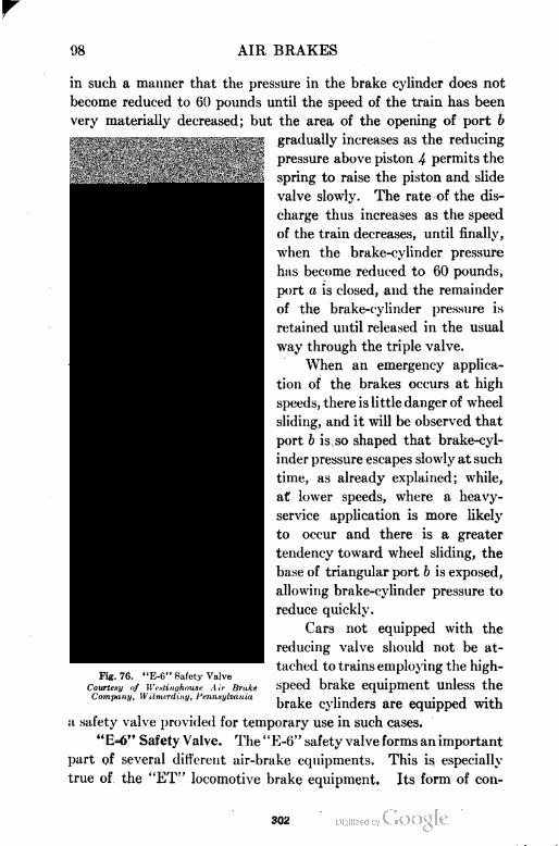
98 AIR BRAKES
in such a manner that the pressure in the brake cylinder does not
become reduced to 60 pounds until the speed of the train has been
very materially decreased; but the area of the opening of port b
gradually increases as the reducing
pressure above piston 4 permits the
spring to raise the piston and slide
valve slowly. The rate of the dis
charge thus increases as the speed
of the train decreases, until finally,
when the brake-cylinder pressure
has become reduced to 60 pounds,
port a is closed, and the remainder
of the brake-cylinder pressure is
retained until released in the usual
way through the triple valve.
When an emergency applica
tion of the brakes occurs at high
speeds, there is little danger of wheel
sliding, and it will be observed that
port b is so shaped that brake-cyl
inder pressure escapes slowly at such
time, as already explained; while,
at lower speeds, where a heavy-
service application is more likely
to occur and there is a greater
tendency toward wheel sliding, the
base of triangular port b is exposed,
allowing brake-cylinder pressure to
reduce quickly.
Cars not equipped with the
reducing valve should not be at
tached to trains employing the high
speed brake equipment unless the
brake cylinders are equipped with
a safety valve provided for temporary use in such cases.
"E=6" Safety Valve. The "E-6" safety valve forms an important
part of several different air-brake equipments. This is especially
true of the "ET" locomotive brake equipment. Its form of con
Fig. 76. "E-6" Safety Valve
Courtesy of Westinghouse Air BrakeCompany, Wilmerding, Pennsylvania
302
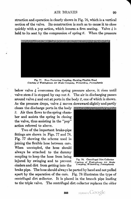
AIR BRAKES 99
struction and operation is clearly shown in Fig. 76, which is a vertical
section of the valve. Its construction is such as to cause it to close
quickly with a pop action, which insures a firm seating. Valve 4 is
held to its seat by the compression of spring 6. When the pressure
Fig. 77. Hose Protecting Coupling, Showing Flexible Head
Courtesy of Westinghouse Air Brake Company, Wilmerding, Pennsylvania
below valve 4 overcomes the spring pressure above, it rises until
valve stem 5 is stopped by cap nut 3. The air in discharging passes
around valve 4 and out at ports in the body 2, one of which is shown.
As the pressure drops, valve 4 moves downward slightly and partly
closes the discharge ports in the body
2. Air then flows to the spring cham
ber and assists the spring in closing
the valve, thus assisting in the "pop"
action referred to above.
Two of the important brake-pipe
fittings are shown in Figs. 77 and 78,
Fig. 77 showing the scheme used in
joining the flexible hose between cars.
When uncoupled, the hose should
always be attached to the dummy
coupling to keep the hose from being
injured by swinging and to prevent
cinders and dirt from getting into the
brake pipe. The hose should always be parted by hand and not pulled
apart by the separation of the cars. Fig. 78 illustrates the type of
centrifugal dirt collector. It is placed in the branch pipe leading
to the triple valve. The centrifugal dirt collector replaces the older
Fig. 78. Centrifugal Dirt Collector
Courtesy of Westinghouse Air BrakeCompany, Wilmerding, Pennsylvania
303
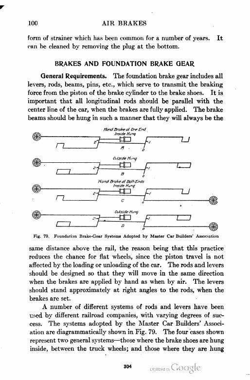
100 AIR BRAKES
form of strainer which has been common for a number of years. It
can be cleaned by removing the plug at the bottom.
BRAKES AND FOUNDATION BRAKE GEAR
General Requirements. The foundation brake gear includes all
levers, rods, beams, pins, etc., which serve to transmit the braking
force from the piston of the brake cylinder to the brake shoes. It is
important that all longitudinal rods should be parallel with the
center line of the car, when the brakes are fully applied. The brake
beams should be hung in such a manner that they will always be the
HandBrake af 0ne End
ziqf^ Inside Hunij
hop r u
rz_
Outside Hung
HOD
t—7
HandBrake at BothEnds
Inside Hung
n_
73 DP £7
I 7
Outside Hung
HOD C ZZZ7
Fig. 79. Foundation Brake-Gear Systems Adopted by Master Car Builders' Association
same distance above the rail, the reason being that this practice
reduces the chance for flat wheels, since the piston travel is not
affected by the loading or unloading of the car. The rods and levers
should be designed so that they will move in the same direction
when the brakes are applied by hand as when by air. The levers
should stand approximately at right angles to the rods, when the
brakes are set.
A number of different systems of rods and levers have been
used by different railroad companies, with varying degrees of suc
cess. The systems adopted by the Master Car Builders' Associ
ation are diagrammatically shown in Fig. 79. The four cases shown
represent two general systems—those where the brake shoes are hung
inside, between the truck wheels; and those where they are hung
304
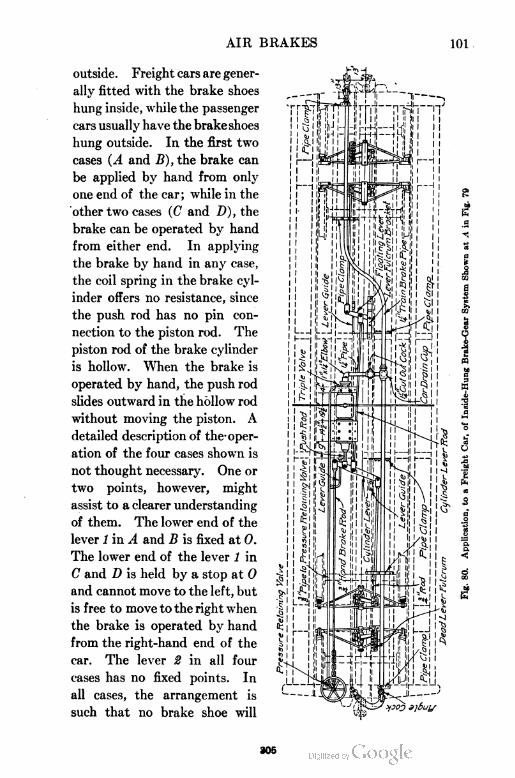
AIR BRAKES
outside. Freight cars are gener
ally fitted with the brake shoes
hung inside, while the passenger
cars usually have the brakeshoes
hung outside. In the first two
cases (A and B), the brake can
be applied by hand from only
one end of the car; while in the
other two cases (C and D), the
brake can be operated by hand
from either end. In applying
the brake by hand in any case,
the coil spring in the brake cyl
inder offers no resistance, since
the push rod has no pin con
nection to the piston rod. The
piston rod of the brake cylinder
is hollow. When the brake is
operated by hand, the push rod
slides outward in the hollow rod
without moving the piston. A
detailed description of the- oper
ation of the four cases shown is
not thought necessary. One or
two points, however, might
assist to a clearer understanding
of them. The lower end of the
lever 1 in A and B is fixed at 0.
The lower end of the lever 1 in
C and D is held by a stop at 0
and cannot move to the left, but
is free to move to the right when
the brake is operated by hand
from the right-hand end of the
car. The lever 2 in all four
cases has no fixed points. In
all cases, the arrangement is
such that no brake shoe will
305
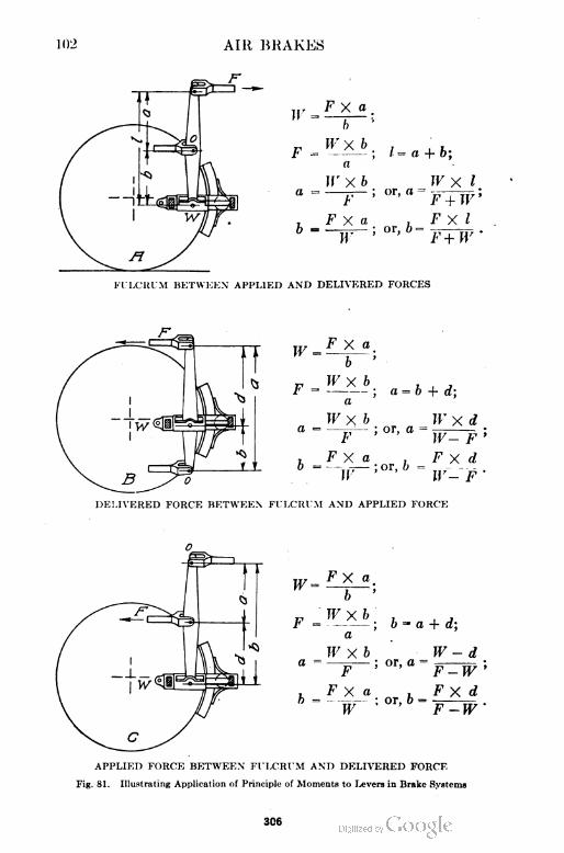
1012 AIR BRAKES
306
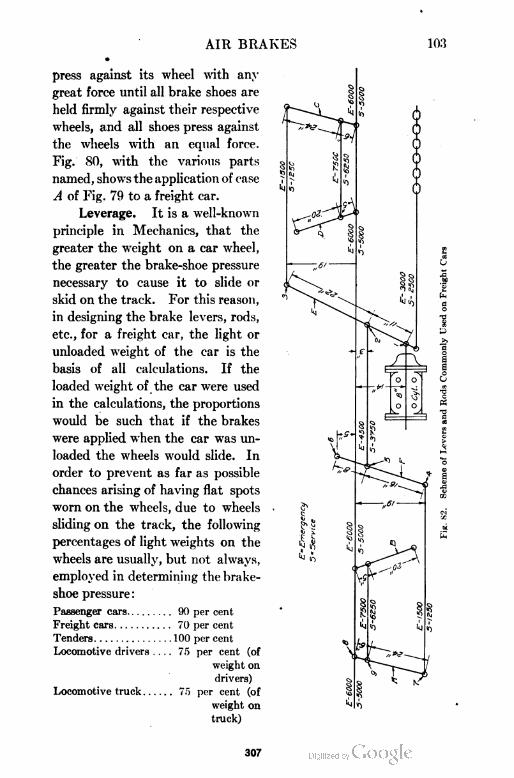
AIR BRAKES 103
press against its wheel with any
great force until all brake shoes are
held firmly against their respective
wheels, and all shoes press against
the wheels with an equal force.
Fig. 80, with the various parts
named, shows the application of case
A of Fig. 79 to a freight car.
Leverage. It is a well-known
principle in Mechanics, that the
greater the weight on a car wheel,
the greater the brake-shoe pressure
necessary to cause it to slide or
skid on the track. For this reason,
in designing the brake levers, rods,
etc., for a freight car, the light or
unloaded weight of the car is the
basis of all calculations. If the
loaded weight of the car were used
in the calculations, the proportions
would be such that if the brakes
were applied when the car was un
loaded the wheels would slide. In
order to prevent as far as possible
chances arising of having flat spots
worn on the wheels, due to wheels
sliding on the track, the following
percentages of light weights on the
wheels are usually, but not always,
employed in determining the brake-
shoe pressure :
Passenger cars 90 per cent
Freight cars 70 per cent
Tenders 100 per cent
Locomotive drivers .... 75 per cent (of
weight on
drivers)
Locomotive truck 75 per cent (of
weight on
truck)
307
104 AIR BRAKES
It is frequently found necessary to change these percentages in
order to meet special conditions which arise.
In calculating the brake-shoe pressure of any car the following
three things must be known: First, the diameter of the brake cyl
inder and its maximum pressure; second, the sizes and positions of
all levers in the system; and third, a working knowledge of the
theorem of moments as used in Mechanics.
The principle or theorem of moments may briefly be stated as
follows: The product of the force applied at one pin and its perpen
dicular distance from the fulcrum pin is equal to the product of the
force delivered at the other pin and its perpendicular distance from the
fulcrum pin. This principle has been applied to the three different
classes of levers, and the forces and distances worked out; Fig. 81.
The chief difficulty the amateur experiences is in locating the fulcrum
pin. In A, B, and C, Fig. 81, the fulcrum pin is located at 0, the
force applied is F, and the force delivered is W. In any case, if the
pull F on the lever is known, the brake-shoe pressure W can be
determined.
Fig. 82 represents diagrammatically the scheme of levers End
rods commonly used on freight cars. All distances of rods from Ihe
center line of the car are taken when the levers are at right angles
to it. The brake cylinder on a certain freight car, taken as an
illustration, is 8 inches in diameter, and has an area of about 50 square
inches. If the maximum brake-cylinder pressure in emergency
applications is 60 pounds, the total pressure delivered to the push
rod would be 50 X 60, or 3000 pounds. This 3000 pounds is trans
mitted to the lever E at the pin 1 . The lever E is of the class shown
in B, Fig. 81, and its fulcrum is at the pin 8. Applying the formula
gives 4500 pounds delivered at the pin 2. This 4500 pounds is trans
mitted to the lever F, which is of the class shown in C, Fig. 81, and
its fulcrum is at the pin 6. Applying the formula gives 1500 pounds
delivered at the pin 4. This 1500 pounds is transmitted to the
lever A, which -is of the class shown in A, Fig. 81, and its fulcrum is
at the pin 9. Applying the formula gives 6000 pounds delivered t »
the brake beam at the pin 8. In a similar manner the other brake-
beam pressures can be determined. In the figure, the calculation
has been carried through for both service and emergency appli
cations.
306
AIR BRAKES 105
It is seen that 6000 pounds is transmitted to the middle of each
of the four brake beams. Each brake shoe will then receive a pres
sure of 3000 pounds. Since there are eight wheels, the. total braking
pressure will be 8X3000, or 24,000 pounds. This total braking pres
sure must not. exceed 70 per cent of the unloaded weight of the car.
Fig. 83. Automatic Slack-Adjure.'
Automatic Slack=Adjuster. Full braking pressure will be
secured as long as the maximum allowable brake-cylinder pressure
can be maintained. Since the brake-cylinder pressure depends
upon the length of stroke of the piston, it follows that the stroke of
Fig. 84. Part Sectional View of Automatic Slack-Adjuster
the piston should be kept as nearly constant as possible. The
greater the stroke, the less the pressure. The stroke of the piston
should be kept at about 8 inches. As the brake shoes and various
connections wear, the stroke of the piston is increased, and the pres-
309
100 AIR BRAKES
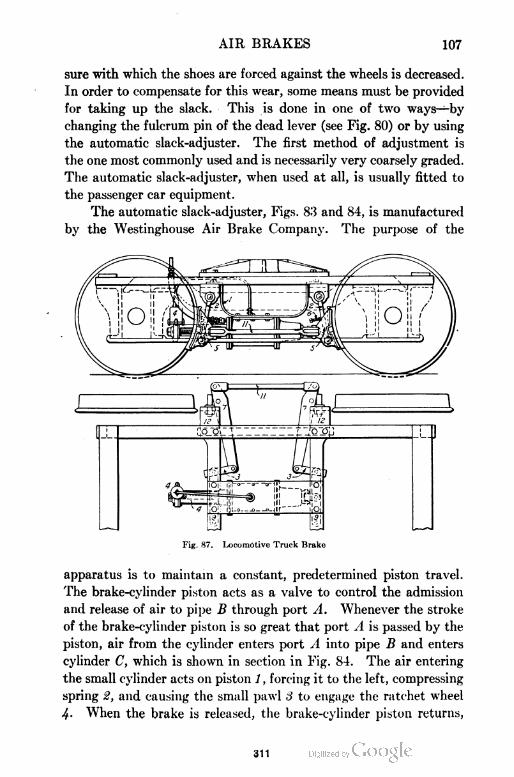
AIR BRAKES 107
sure with which the shoes are forced against the wheels is decreased.
In order to compensate for this wear, some means must be provided
for taking up the slack. This is done in one of two ways—by
changing the fulcrum pin of the dead lever (see Fig. 80) or by using
the automatic slack-adjuster. The first method of adjustment is
the one most commonly used and is necessarily very coarsely graded.
The automatic slack-adjuster, when used at all, is usually fitted to
the passenger car equipment.
The automatic slack-adjuster, Figs. 83 and 84, is manufactured
by the Westinghouse Air Brake Company. The purpose of the
Fig. 87. Locomotive Truck Brake
apparatus is to maintain a constant, predetermined piston travel.
The brake-cylinder piston acts as a valve to control the admission
and release of air to pipe B through port A. Whenever the stroke
of the brake-cylinder piston is so great that port A is passed by the
piston, air from the cylinder enters port A into pipe B and enters
cylinder C, which is shown in section in Fig. 84. The air entering
the small cylinder acts on piston 1 , forcing it to the left, compressing
spring 2, and causing the small pawl 3 to engage the ratchet wheel
4- When the brake is released, the brake-cylinder piston returns,
311
108 AIR BRAKES
and air in the small cylinder C escapes to the atmosphere through
pipe B and port A, thus permitting spring # to force piston 1 to its
normal position. In so doing, pawl 3 turns the ratchet wheel 4 on
screw 5, and thereby draws the fulcrum end of lever 6 slightly nearer
the slack-adjuster cylinder C. Each operation of piston 1, as just
described, reduces the brake-cylinder piston travel about fa of an
inch. When piston 1 is in its normal position, the outer end of
pawl 3 is lifted, permitting screw 5 to be turned by hand.
Locomotive Driver Brakes. The brakes are applied to the
drivers of a locomotive in two general ways—by the outside equalized
system, Fig. 85, and by cams, Fig. 86. The former scheme has
practically replaced the latter, because of its simple design and
adjustment. • In the system, Fig. 85, the levers are proportioned so
that each wheel receives the same braking pressure. If the brake
cylinders are each 14 inches in diameter and the cylinder pressure
is 50 pounds, the pressure delivered at pin A is about 7650
pounds, while that on each wheel is 10,200 pounds. These values
vary for different locomotives. The stroke of the piston is regulated
by the adjustment mechanism at B.
The action of the cam-driver brake is shown in Fig. 86. When
air is admitted to the brake cylinder, the piston is forced downward.
This action pushes down the crosshead cams, which force the brake
shoes against the drivers. The piston travel is controlled by adjust
ing the cam nut on each cam.
Locomotive Truck Brakes. In certain types of locomotives, a
considerable proportion of the weight of the locomotive is carried
on the truck. It follows, that in order to develop the full braking
power of the locomotive, a well-designed truck brake should be
provided. The type of brake shown in Fig. 87 is now quite com
mon. It is fitted with an automatic slack-adjuster, but this feature
is not so important here as on the car equipment.
312


AIR BRAKES
PART II
MODERN BRAKE EQUIPMENT
FUNDAMENTAL TYPES
High=Speed Brake Equipment. The high-speed brake equip
ment, Fig. 88, is a modification of the quick-action brake and can be
used in passenger service. The parts not found on the ordinary
equipment are as follows: Type "E" safety valve, high-speed
reducing valve, reversing cock, feed-valve bracket, and an additional
feed valve.
Action of Reversing Cock. The locomotive equipment may be
changed from the quick-action to the high-speed brake by simply
turning the reversing-cock handle. When this handle is in the posi
tion opposite to that shown in Fig. 88, the 70-pound feed valve is in
service, so that the locomotive is ready to operate the ordinary
quick-action brake; when the brake-valve handle is in running posi
tion, 70 pounds pressure is carried in the brake pipe, and the com
pressor will slow down when main-reservoir pressure reaches 90
pounds. If, however, the brake-valve handle is in lap, service, or
emergency-application position, main-reservoir pressure is cut off
from the excess-pressure head, and the compressor will continue to
operate until the main-reservoir pressure reaches the limit set by the
maximum pressure head, to insure available pressure promptly to
release and re-charge the brakes on long and heavy trains.
If the reversing-cock handle be turned to the position shown,
the 110-pound feed valve will become operative, giving 110 pounds
brake-pipe pressure, which results in a corresponding increase in
main-reservoir pressure depending upon the adjustment of the
maximum pressure head of the governor.
Principles Involved. The principles involved in the high-speed
brake are (a) the friction between the brake shoe and the wheel,
315
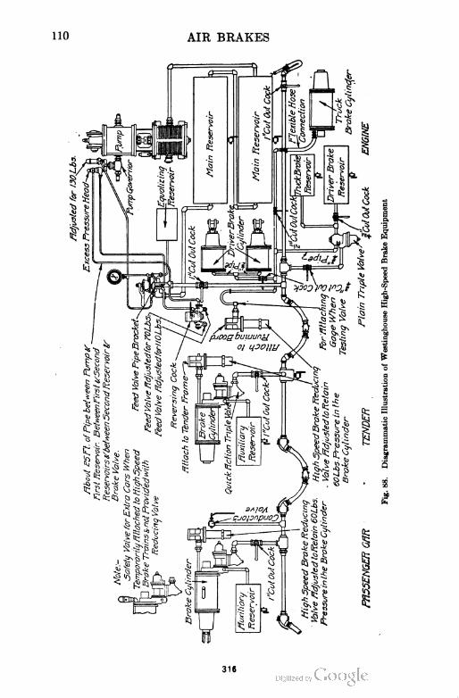
HIV
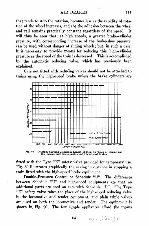
AIR BRAKES 111
that tends to stop the rotation, becomes less as the rapidity of rota
tion of the wheel increases, and (b) the adhesion between the wheel
and rail remains practically constant regardless of the speed. It
will thus be seen that, at high speeds, a greater brake-cylinder
pressure, with corresponding increase of the brake-shoe pressure,
can be used without danger of sliding wheels; but, in such a case,
it is necessary to provide means for reducing this high-cylinder
pressure as the speed of the train is decreased. This is accomplished
by the automatic reducing valve, which has previously been
explained.
Cars not fitted with reducing valves should not be attached to
trains using the high-speed brake unless the brake cylinders are
Guick Melion Brake
I I I I I I Iniqh 5peed Drake
1 ' "ITSB 400 600 800 10CO l?CO 1400 1600 1800 L'OCO 1^00 £400 £600 £300 3000
Lenglh cfSlop in feel
Fig. 89. Diagram Showing Minimum Length of Stop for Train of Engine andSix Coaches with Quick-Action and High-Speed Brakes
fitted with the Type "E" safety valve provided for temporary use.
Fig. 89 illustrates graphically the saving in distance in stopping a
train fitted with the high-speed brake equipment.
Double-Pressure Control or Schedule "U". The differences;
between Schedule "U" and high-speed equipments are that no<
additional parts are used on cars with Schedule "U". The Type.
"E" safety valve takes the place of the high-speed reducing valve
in the locomotive and tender equipment, and plain triple valves
are used on both the locomotive and tender. The equipment is
shown in Fig. 90. The few simple appliances afford the means,
417
112 AIR BRAKES
whereby the engineer can change the brake-pipe and main-reservoir
pressure from one predetermined standard to another at will.
The equipment is particularly adapted for use upon heavy
grades where "empties" are hauled up the grade and "loads" down.
318
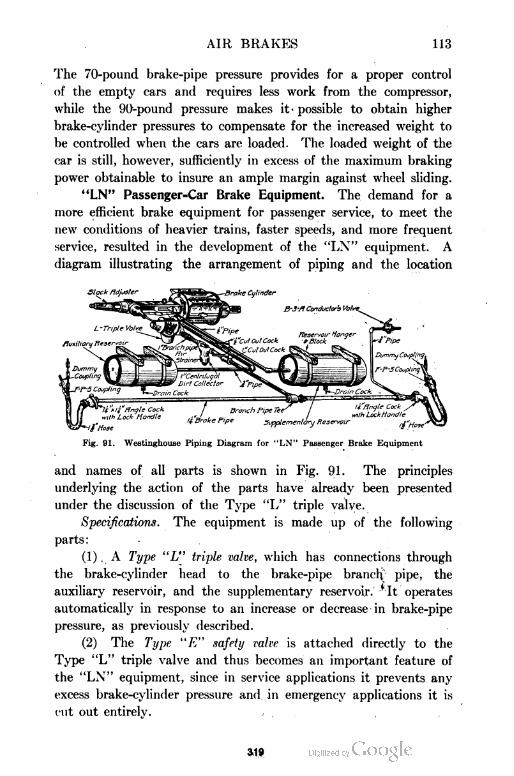
AIR BRAKES 113
The 70-pound brake-pipe pressure provides for a proper control
of the empty cars and requires less work from the compressor,
while the 90-pound pressure makes it- possible to obtain higher
brake-cylinder pressures to compensate for the increased weight to
be controlled when the cars are loaded. The loaded weight of the
car is still, however, sufficiently in excess of the maximum braking
power obtainable to insure an ample margin against wheel sliding.
"LN" Passenger=Car Brake Equipment. The demand for a
more efficient brake equipment for passenger service, to meet the
new conditions of heavier trains, faster speeds, and more frequent
service, resulted in the development of the "LN" equipment. A
diagram illustrating the arrangement of piping and the location
Fig. 91. Westinghouse Piping Diagram for "LN" Passenger Brake Equipment
and names of all parts is shown in Fig. 91. The principles
underlying the action of the parts have already been presented
under the discussion of the Type "L" triple valve.
Specifications. The equipment is made up of the following
parts :
(1) . A Type "L" triple valve, which has connections through
the brake-cylinder head to the brake-pipe branch pipe, the
auxiliary reservoir, and the supplementary reservoir, 'it operates
automatically in response to an increase or decrease in brake-pipe
pressure, as previously described.
(2) The Type "E" safety valve is attached directly to the
Type "L" triple valve and thus becomes an important feature of
the "LN" equipment, since in service applications it prevents any
excess brake-cylinder pressure and in emergency applications it is
cut out entirely. , ,
319
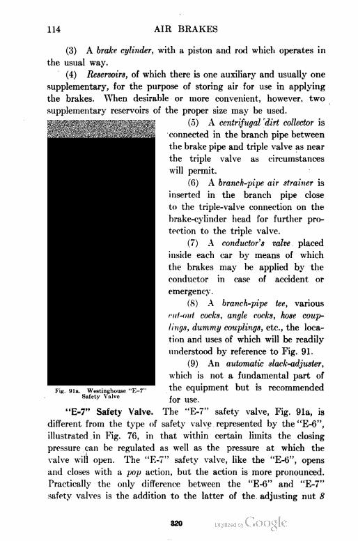
114 AIR BRAKES
(3) A brake cylinder, with a piston and rod which operates in
the usual way.
(4) Reservoirs, of which there is one auxiliary and usually one
supplementary, for the purpose of storing air for use in applying
the brakes. When desirable or more convenient, however, two
supplementary reservoirs of the proper size may be used.
(5) A centrifugal dirt collector is
connected in the branch pipe between
the brake pipe and triple valve as near
the triple valve as circumstances
will permit.
(6) A branch-pipe air strainer is
inserted in the branch pipe close
to the triple-valve connection on the
brake-cylinder head for further pro
tection to the triple valve.
(7) A conductor s valve placed
inside each car by means of which
the brakes may be applied by the
conductor in case of accident or
emergency.
(8) A branch-pipe tee, various
cut-oid cocks, angle cocks, hose coup
lings, dummy couplings, etc., the loca
tion and uses of which will be readily
understood by reference to Fig. 91.
(9) An automatic slack-adjuster,
which is not a fundamental part of
the equipment but is recommended
for use.
"E=7" Safety Valve. The "E-7" safety valve, Fig. 91a, is
different from the type of safety valve represented by the "E-6",
illustrated in Fig. 76, in that within certain limits the closing
pressure can be regulated as well as the pressure at which the
valve will open. The "E-7" safety valve, like the "E-6", opens
and closes with a pop action, but the action is more pronounced.
Practically the only difference between the "E-6" and "E-7"
safety valves is the addition to the latter of the adjusting nut 8
320
AIR BRAKES 115
and the jam nut 9. Chamber E is open to the atmosphere at
all times, but the ports / in the body are small and restrict the
exhaust to such an extent that the pressure accumulates very
rapidly and assists spring 6 in forcing valve 4 quickly to its
seat.
In order to adjust the safety valve for the maximum, or
opening, pressure which, in the case of the "LN" equipment, is
62 pounds, remove the cap nut 3 and screw down or back off
regulating nut 7 as required, after which replace cap nut 3. The
minimum, or closing, pressure used in the "LN" equipment is
58 pounds and can be adjusted by changing the size of the atmos
pheric exhaust ports /, using regulating nut 8. After making this
adjustment, the jam nut 9 should be screwed down snug.
The high-emergency cylinder pressure with the graduated
release feature, as explained under the discussion of the "L" triple
valve, makes it possible to use the equipment as a high-speed
brake and obtain better results when carrying 90 pounds brake-
pipe pressure than when using 110 pounds pressure with the old
standard equipment in steam-road service. Increasing the brake-
pipe pressure, therefore, gives a more powerful brake if desired.
No. 6 "ET" LOCOMOTIVE BRAKE EQUIPMENT
It has been shown that a single modern locomotive possessed
a possible braking power of one-tenth of a 50-car freight train,
one-eighth of a 12-car Pullman train, one-fourth of a 10-car
passenger train, and one-third of a 6-car passenger train. These
figures would indicate that the locomotive brake equipment should
be developed to the highest degree. The first step taken in this
direction was the development of the combined automatic and
straight-air equipment for locomotives. This system was greatly
simplified and improved by the more recent development of the
so-called "ET" locomotive brake equipment.
Functions and Advantages. The No. 6 "ET" (engine and ten
der) equipment possesses all the functions which are now required
in locomotive brake service; it can be applied to any locomotive
without change or modification of any of its parts. The locomotive
so equipped may be used in any kind of service, such as high-speed
passenger, double-pressure control, ordinary passenger or freight, or
321
116 AIR BRAKES
switching service, without change or adjustment of the brake appa
ratus. Its important advantages are as follows:
The locomotive brakes may be used with or independently of the train
brakes and this without regard to the position of the locomotive in the train.
They may be applied with any desired pressure between the minimum
and t he maximum, and this pressure will be automatically maintained in the
locomotive brake cylinders regardless of leakage from them and of variation in
piston travel, undesirable though these defects are, until released by the brake
valve.
They can be graduated on or off with either the automatic or the inde
pendent brake valves; hence, in all kinds of service the train may be handled
without shock or danger of parting, and in passenger service smooth, accurate
stops can be made with greater ease than was heretofore possible.
Arrangement of Piping, Etc. The general arrangement of
piping, etc., is shown diagrammatically in Fig. 92. The names of
the various parts composing the equipment are :
(a) The air compressor to conpress the air. The main reservoirs in which to
store and cool the air and collect water and dirt.
(b) A duplex compressor governor to control the compressor when the pressures
for which it is regulated are obtained.
(c) A distributing valve, and small double-chamber reservoir to which it is
attached, placed on the locomotive to perform the functions of triple valves,
auxiliary reservoirs, double check valves, high-speed reducing valves, etc.
(d) Two brake valves—the automatic to operate the locomotive and train brakes,
and the independent to operate the locomotive brakes only.
(e) A feed valve to regulate the brake-pipe pressure.
(f) A reducing valve to reduce the pressure for the independent brake valve and
for the air-signal system when used.
(g) Two duplex air gages—one, to indicate equalizing-reservoir and main-
reservoir pressures; the other, to indicate brake-pipe and locomotive brake-
cylinder pressures.
(h) Driver, tender, and truck brake cylinders, cut-out cocks, air strainers, hose
couplings, fittings, etc., incidental to the piping, for purposes readily under
stood.
Names of Pipes. In order to simplify the description of the
different parts of the equipment, the following names of pipes are
given which are shown in Fig. 92 :
Discharge Pipe: Connects the air compressor to the first main reservoir.
Connecting Pipe: Connects the two main reservoirs.
Main Reservoir Pipe: Connects the second main reservoir to the automatic
brake valve, distributing valve, feed valve, reducing valve, and compressor
governor.
Feed Valve Pipe: Connects the feed valve to the automatic brake valve.
Excess-Pressure Pipe: Connects the feed-valve pipe to the upper connection
of the excess-pressure head of the compressor governor.
322
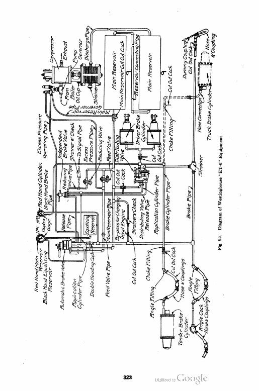
118 AIR BRAKES
Excess-Pressure Operating Pipe: Connects the automatic brake valve to the
lower connection of the excess-pressure head of the compressor governor.
Reducing Valve Pipe: ' Connects the reducing valve to the independent brake
valve, and to the signal system, when used.
Brake Pipe: Connects the automatic brake valve with the distributing valve
and all triple valves on the cars in the train.
Brake-Cylinder Pipe: Connects the distributing valve with the driver, tender,
and truck-brake cylinders.
Application Cylinder Pipe: Connects the application cylinder of the distributing
valve to the independent and automatic brake valves.
Distributing Valve Release Pipe: Connects the application-cylinder exhaust
port of the distributing valve to the automatic brake valve through the
independent brake valve.
In some installations the automatic brake valve is provided
with a pipe bracket to which the feed valve is directly attached,
thus eliminating the feed-valve pipe and the excess-pressure pipe.
Manipulation of Equipment. Positions of Automatic and Inde
pendent Brake Valves. The automatic brake valve has six fixed
positions for its handle—release, running, holding, lap, service, and
emergency; while the independent brake valve has but five—release,
running, lap, slow-application, and quick-application.
General Directions. The following directions for the manipu
lation of the equipment are abbreviated from that furnished by the
manufacturers and applies to modern equipment. They are not
intended to apply rigidly to all individual cases or conditions:
When not in use, carry the handles of both brake valves in running position.
To apply the brakes in service, move the handle of the automatic brake
valve to the service position, making the required brake-pipe reduction, then
back to lap position, which is the one for holding all the brakes applied.
To make a smooth and accurate two-application passenger stop, make the
first application sufficiently heavy to bring the speed of the train down to about
15 miles per hour at a convenient distance from the stopping point, then release
as explained in the following paragraph and re-apply as required to make the
desired stop, the final release being made as explained below.
Passenger Service. In making the first release of a two-application stop,
the brake-valve handle should be moved to release position and then quickly
back to running position, where it should be allowed to remain for an instant—
first, to permit the pressures in the equalizing reservoir and brake pipe to equalize;
and second, to release part of the driver brake-cylinder pressure—then moved to
lap position and from there to service position, as required. In passenger service,
the time the handle is in release position should be only momentary; but the
time in running position should be governed by the conditions existing for each
particular case, such as the length of train, kind of reduction made, time avail
able, and so on.
324
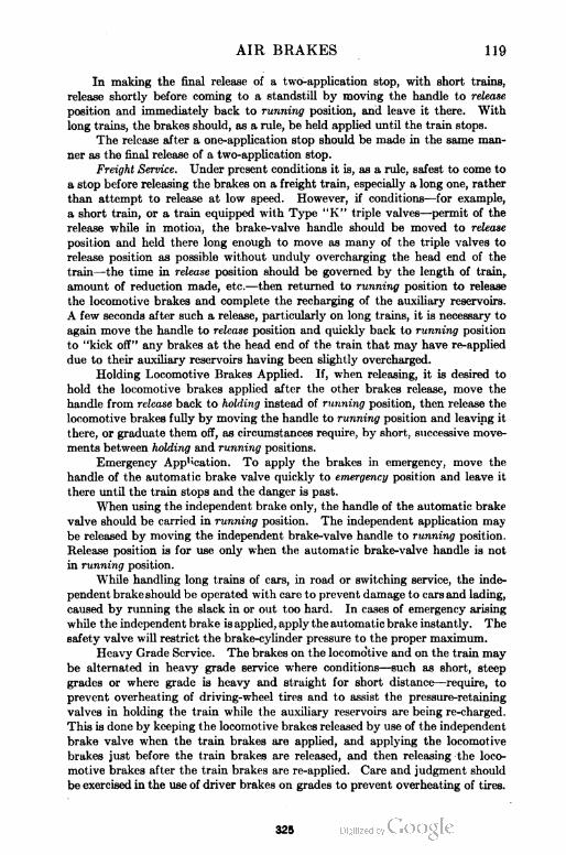
AIR BRAKES 119
In making the final release of a two-application stop, with short trains,
release shortly before coming to a standstill by moving the handle to release
position and immediately back to running position, and leave it there. With
long trains, the brakes should, as a rule, be held applied until the train stops.
The release after a one-application stop should be made in the same man
ner as the final release of a two-appUcation stop.
Freight Service. Under present conditions it is, as a rule, safest to come to
a stop before releasing the brakes on a freight train, especially a long one, rather
than attempt to release at low speed. However, if conditions—for example,
a short train, or a train equipped with Type "K" triple valves—permit of the
release while in motion, the brake-valve handle should be moved to release
position and held there long enough to move as many of the triple valves to
release position as possible without unduly overcharging the head end of the
train—the time in release position should be governed by the length of train,
amount of reduction made, etc.—then returned to running position to release
the locomotive brakes and complete the recharging of the auxiliary reservoirs.
A few seconds after such a release, particularly on long trains, it is necessary to
again move the handle to release position and quickly back to running position
to "kick off" any brakes at the head end of the train that may have re-applied
due to their auxiliary reservoirs having been slightly overcharged.
Holding Locomotive Brakes Applied. If, when releasing, it is desired to
hold the locomotive brakes applied after the other brakes release, move the
handle from release back to holding instead of running position, then release the
locomotive brakes fully by moving the handle to running position and leaving it
there, or graduate them off, as circumstances require, by short, successive move
ments between holding and running positions.
Emergency App,;cation. To apply the brakes in emergency, move the
handle of the automatic brake valve quickly to emergency position and leave it
there until the train stops and the danger is past.
When using the independent brake only, the handle of the automatic brake
valve should be carried in running position. The independent application may
be released by moving the independent brake-valve handle to running position.
Release position is for use only when the automatic brake-valve handle is not
in running position.
While handling long trains of cars, in road or switching service, the inde
pendent brake should be operated with care to prevent damage to cars and lading,
caused by running the slack in or out too hard. In cases of emergency arising
while the independent brake is applied, apply the automatic brake instantly. The
safety valve will restrict the brake-cylinder pressure to the proper maximum.
Heavy Grade Service. The brakes on the locomo'tive and on the train may
be alternated in heavy grade service where conditions—such as short, steep
grades or where grade is heavy and straight for short distance—require, to
prevent overheating of driving-wheel tires and to assist the pressure-retaining
valves in holding the train while the auxiliary reservoirs are being re-charged.
This is done by keeping the locomotive brakes released by use of the independent
brake valve when the train brakes are applied, and applying the locomotive
brakes just before the train brakes are released, and then releasing the loco
motive brakes after the train brakes are re-applied. Care and judgment should
be exercised in the use of driver brakes on grades to prevent overheating of tires.
325
120 AIR BRAKES
Release Position of Independent Brake Valve. When all brakes are applied
automatically, to graduate off or entirely release the locomotive brakes only, use
release position of the independent brake valve.
The red hand of gage No. 2, Fig. 92, will show at all times the pressure
in the locomotive brake cylinders, and this hand should be watched in brake
manipulation.
Release position of the independent brake valve will release the locomotive .
brakes under any and all conditions.
Use of Automatic Brake Valve for Holding and Grade Work. The auto
matic brakes should never be used to hold a locomotive or a train while standing
even where the locomotive is not detached, for longer than ten minutes, and not
for such time if the grade is very steep or the condition of the brakes is not good.
The safest method is to hold with hand brakes only and keep the auxiliary
reservoirs fully charged so as to guard against a start from brakes leaking off
and to be ready to obtain any part of full braking power immediately on starting.
The independent brake is a very important safety feature in this connec
tion, as it will hold a locomotive with a leaky throttle or quite a heavy train on
a fairly steep grade if, as the automatic brakes are released, the slack is pre
vented from running in or out—depending on the tendency of the grade—and
giving the locomotive a start. To illustrate: The best method to make a stop
on a descending grade is to apply the independent brake heavily as the stop is
being completed, thus bunching the train solidly; then, when stopped, place and
leave the handle of the independent brake valve in application position; then
release the automatic brakes and keep them charged. Should the independent
brake be unable to prevent the train from starting, the automatic brakes will
become sufficiently recharged to make an immediate stop; in such an event
enough hand brakes should at once be applied as are necessary to hold the train.
Many runaways and some serious wrecks have resulted through failure to com
ply with the foregoing instructions.
When leaving the engine, while doing work about it, or when it is standing
at a coal chute or water plug, always leave the independent brake-valve handle
in application position.
After Emergency Application not Controlled by Engineer. After an
emergency application of the brakes, while running over the road, due to any
cause other than intended by the operating engineer himself:
(1) In passenger service, move the brake-valve handle to emergency
position at once and leave it there until the train stops.
(2) In freight service, move the brake-valve handle to lap position and
let it remain there until the train stops. .,
This is to prevent loss qf main-reservoir pressure and insure the brakes
remaining applied until released by the engineer in charge of the train. After
the train stops, the cause of the application should be located and remedied
before proceeding.
More than One Locomotive on Train. Where there are two or more loco
motives in a train, the instructions already given remain unchanged so far as the
leading locomotive, or the locomotive from which the brakes are being operated,
is concerned. On all other locomotives in the train, however, the double-heading
cock under the automatic brake valve must be closed and the automatic and
independent brake-valve handles carried in running position.
S26
AIR BRAKES 121
Air Strainer and Check Valve. The location of the air
strainer and check valve in the piping system of the No. 6 "ET"
equipment is shown at the left center in Fig. 92. This part of the
apparatus is known as the dead engine feature. A section of this
fixture is shown in Fig. 92a, which illustrates its scheme of opera
tion. Its function is to permit the operation of the locomotive
brakes when the compressor on a locomotive in a train is for am
reason inoperative.
The cut-out cock, located near the air strainer and check
valve, should be kept closed except in the case of a dead engine,
as these parts are not required at any other time. With the
cut-out cock open, air from the brake pipe enters at the opening
BP, passes through the curled hair strainer 5, lifts check valve 4,
Fig. 92a. Combined Air Strainer and Cheek Valve
Courtesy Westinghouse Air Brake Company, Wilmerding, Pennsylvania
which is held to its seat by a strong spring 2; it then passes
through the choke bushing and out at MR to the main reservoir,
thus providing air pressure for operating the brakes on the dead
locomotive. The double-heading cock should be closed and the
handle of each brake valve should be carried in running position.
The strainer protects the check valve and choke bushing from
collections of dirt. The spring 2 insures the proper seating of the
check valve and, while assuring ample pressure to operate the
locomotive brakes, keeps the pressure in the main reservoir some
what lower than the brake-pipe pressure, thereby reducing any
leakage therefrom. The choke bushing prevents a sudden drop in
brake-pipe pressure and the application of the train brakes, which
would otherwise occur with an uncharged main reservoir cut-in
to a charged brake pipe.
327
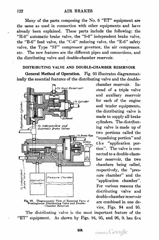
122 AIR BRAKES
Many of the parts composing the No. 6 "ET" equipment are
the same as used in connection with other equipments and have
already been explained. These parts include the following: the
"H-6" automatic brake valve, the "S-6" independent brake valve,
the "B-6" feed valve, the "C-6" reducing valve, the "E-6" safety
valve, the Type "SF" compressor governor, the air compressor,
etc. The new features are the different pipes and connections, and
the distributing valve and double-chamber reservoir.
DISTRIBUTING VALVE AND DOUBLE-CHAMBER RESERVOIR
General Method of Operation. Fig. 93 illustrates diagrammat-
ically the essential features of the distributing valve and the double-
chamber reservoir. In
stead of a triple valve
and auxiliary reservoir
for each of the engine
and tender equipments,
the distributing valve is
made to supply all brake
cylinders. The distribut
ing valve is made up of
two portions called the
"equalizing portion" and
the "application por
tion". The valve is con
nected to a double-cham
ber reservoir, the two
chambers being called,
respectively, the "pres
sure chamber" and the
"application chamber".
For various reasons the
distributing valve and
double-chamber reservoir
are combined in one de
vice, Figs. 94 and 95.
The distributing valve is the most important feature of the
"ET" equipment. As shown by Figs. 94, 95, and 96, it has five
32ft
AIR BRAKES 123
Fig. 94. No. 6 Distributing Valve and Double-Chamber Reservoir.MR, Main-Reservoir Pipe; 4, Distributor Valve Release Pipe; *, Application-Cylinder Pipe; CYLS, Brake-Cylinder Pipe; BP, Brake Pipe
Fig. 95. No. 6 Distributing Valve and Double-Chamber Reservoir, with PressureChamber Cut Away
Courteay of Westinghouse Air Brake Company, Wilmerding, Pennsylvania
329
124 AIR BRAKES
pipe connections. Fig. 96 is a vertical section of the actual valve.
For the sake of clearness, the distributing valve together with the
double-pressure chamber may be considered as a miniature brake
set, consisting of the equalizing portion representing the triple
valve; the pressure chamber, the auxiliary reservoir; and the appli
cation portion always having practically the same pressure in its
ens.
Fin. 96. Section of No. 6 Distributing Valve
Courtesy of Wc.il inghouse Air Brake Company, Wilmerding, Pennsylvania
cylinder as that in the brake cylinders. The equalizing portion and
pressure chamber are used in automatic applications only; reduc
tions of brake-pipe pressure cause the equalizing valve to connect
the pressure chamber to the application chamber and cylinder,
allowing air to flow from the former to the latter. The upper slide
valve, connected to the piston rod of the application portion, admits
air to the brake cylinders and is called the "application valve",
while the lower one releases the air from the brake cylinders and is
330
AIR BRAKES 125
called the "exhaust valve". As the air admitted to the brake cyl
inders comes directly from the main reservoirs, the supply is prac
tically unlimited. Any pressure in the application cylinder will
force the application piston to close the exhaust valve, open the
application valve, and admit air from the main reservoirs to the
Fig. 97. Release Position, Automatic or Independent Connections forDistributing Valve
Courtesy of Westinghouse Air Brake Company, Wilmerdiiig, Pennsylvania
locomotive brake cylinders until their pressure equals or slightly
exceeds that in the application cylinder; whereupon the application
piston and valve will be returned to lap position, closing the appli
cation valve. Also any variation of application-cylinder pressure
will be exactly duplicated in the locomotive brake cylinders, and the
resulting pressure maintained regardless of any brake-cylinder
331
126 AIR BRAKES
leakage. The operation of this locomotive brake, therefore, depends
upon the admitting of air to and the releasing of air from the appli
cation cylinder—in independent applications, directly by means of
the independent brake valve; in automatic applications, by means
of the equalizing portion and the air pressure stored in the pressure
chamber.
The well-known principle embodied in the quick-action triple
valve, by which it gives a high braking power in emergency appli
cations and a sufficiently lower one in full-service applications to
provide a desired protection against wheel sliding, is embodied in
the "No. 6" distributing valve. In describing the operation of the
valve, reference will be made to the nine diagrammatic views shown
in Figs. 97 to 106. For convenience, the chambers of the reservoir
are indicated at the bottom as being a part of the valve.
Automatic Brake Operation
Charging. Referring to Fig. 97, which shows the parts in the
release position, it will be seen that as chamber p is connected to the
brake pipe, brake-pipe air flows through the feed groove v over the
top of piston 26 into the chamber above equalizing valve 31, and
through port o to the pressure chamber, until the pressures on both
sides of the piston are equal.
Service. When the engineer wishes to make a service applica
tion by the use of the automatic brake valve, the brake-pipe pressure
in chamber p is reduced, the amount of this reduction depending
on the degree with which it is desired to set the brakes. This action
causes a difference in pressure on the two sides of piston 26, which
causes the piston to move toward the right until it occupies the
position shown in Fig. 98. The first movement of piston 26 closes
the feed groove v, and at the same time moves the graduating valve
28 until it uncovers the upper end of the port z in the equalizing
valve 31. As piston 26 continues its movement toward the right,
the shoulder on the end of its stem comes in contact with the left
end of equalizing valve 31, which is then also moved to the right
until the projecting piece on the right of the piston strikes the equal
izing piston graduating sleeve 44. The initial tension of the gradu
ating spring 46 prevents further movement of the piston and attached
parts, unless an emergency application has been made, as explained
882
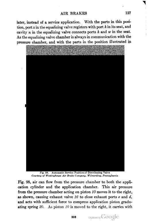
AIR BRAKES 127
later, instead of a service application. With the parts in this posi
tion, port z in the equalizing valve registers with port h in its seat, and
cavity n in the equalizing valve connects ports h and w in the seat.
As the equalizing valve chamber is always in communication with the
pressure chamber, and with the parts in the position illustrated in
Fig. 98. Automatic Service Position of Distributing Valve
Courtesy of Westinghouse Air Brake Company, Wilmerding, Pennsylvania
Fig. 98, air can flow from the pressure chamber to both the appli
cation cylinder and the application chamber. This air pressure
from the pressure chamber acting on piston 10 moves it to the right,
as shown, causing exhaust valve 16 to close exhaust ports e and d,
and acts with sufficient force to compress application piston gradu
ating spring 20. As piston 10 is moved to the right, it carries with
333
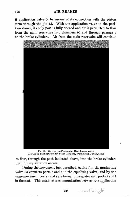
128 AIR BRAKES
it application valve 5, by means of its connection with the piston
stem through the pin 18. With the application valve in the posi
tion shown, its only port is fully opened and air is permitted to flow
from the main reservoirs into chambers bb and through passage c
to the brake cylinders. Air from the main reservoirs will continue
Fig. 99. Service-Lap Position for Distributing Valve
Courtesy of Westinghouse Air Brake Company, Wilmerding, Pennsylvania
to flow, through the path indicated above, into the brake cylinders
until full equalization occurs.
During the movement just described, cavity t in the graduating
valve 28 connects ports r and s in the equalizing valve, and by the
same movement ports r and s are brought to register with ports h and /
in the seat. This establishes communication between the application
334
AIR BRAKES 129
cylinder and the safety valve, which, being set at 68 pounds (three
pounds above the maximum obtained in an emergency application
from 70 pounds brake-pipe pressure), limits the brake-cylinder
pressure to this amount.
The amount of pressure resulting in the application cylinder
for a certain brake-pipe service reduction depends on the compara
tive volumes of the pressure chamber, application cylinder, and its
chamber. These volumes are such that with 70 pounds in the
pressure chamber they will equalize at about 50 pounds.
Service Lap. When the brake-pipe reduction is not sufficient
to cause a full-service application, the conditions described above
continue until the pressure in the pressure chamber is reduced
enough below that in the brake pipe to cause piston 26 to force
graduating valve 28 to the left until stopped by the shoulder on the
piston stem striking the right-hand end of equalizing valve 81, the
position indicated in Fig. 99 and known as service lap. In this
position, graduating valve 28 has closed port z so that no more air
can flow from the pressure chamber to the application cylinder and
chamber. It also has closed port s, cutting off communication to
the safety valve, so that any possible leak in the latter cannot reduce
the application-cylinder pressure, and thus similarly affect the pres
sure in the brake cylinders. The flow of air past application valve
5 to the brake cylinders continues until their pressure slightly exceeds
that in the application cylinder, when the higher pressure and appli
cation-piston graduating spring together force piston 10 to the left,
Fig. 99,' thereby closing port b. Further movement is prevented
by the resistance of exhaust valve 16 and the application-piston
graduating spring having expanded to normal position.
From the above description it will be seen that application
piston 10 has application-cylinder pressure on one side g and brake-
cylinder pressure on the other. When either pressure varies, the
piston will move toward the lower. Consequently, if pressure in
chamber b is reduced by brake-cylinder leakage, the pressure main
tained in the application cylinder g will force piston 10 to the right,
opening application valve 6 and again admitting air from the main
reservoirs to the brake cylinders until the pressure in chamber b is
again slightly above that in the application cylinder g, when the
piston again moves back to lap position.
335
130 AIR BRAKES
Automatic Release. When the automatic brake-valve handle
is placed in release position, and the brake-pipe pressure in chamber
p is thereby increased above that in the pressure chamber, equalizing
piston 26 moves to the left, carrying with it equalizing valve 31
and graduating valve 28 to the position shown in Fig. 97. The
feed groove v now being open permits the pressure in the pressure
chamber to feed up until it is equal to that in the brake pipe, as before
described. This action does not release the locomotive brakes
because it does not discharge application-cylinder, pressure. The
release pipe is closed by the rotary valve of the automatic brake
valve, and the application-cylinder pipe is closed by the rotary
valves of both brake valves. To release the locomotive brakes, the
automatic brake valve must be moved to running position. The
release pipe is then connected by the rotary valve to the atmosphere
and, as exhaust cavity k in the equalizing valve 31 connects ports
i, w, and h in the valve seat, the air in the application cylinder and
chamber will escape. As this pressure reduces, the brake-cylinder
pressure will force application piston 10 to the left until exhaust
valve 16 uncovers exhaust ports d and e, allowing brake-cylinder
pressure to escape, Fig. 97, or in case of graduated release, to reduce
in like amount to the reduction in the application-cylinder pressure.
Emergency. When a sudden and heavy brake-pipe reduction
is made, as in an emergency application, the air pressure in the
pressure chamber forces equalization piston 26, Fig. 100, to the
right with sufficient force to compress equalizing-piston graduating
spring 46, and to seat against the leather gasket beneath cap 23.
This movement causes equalizing valve 31 to uncover port h in the
seat without opening port w, making a direct opening from the
pressure chamber to the application cylinder only, so that they
quickly become equalized. This cylinder volume, being small and
connected with that of the pressure chamber at 70 pounds pressure,
equalizes at about 65 pounds. Also, in this position of the auto
matic brake valve, a small port in the rotary valve allows air from
the main reservoirs to feed into the application-cylinder pipe, and
thus to the application cylinder. The application cylinder is
now connected to the safety valve through port h in the seat, cavity
q and port r in the equalizing valve, and port I in the seat. Cavity
q and port r in the equalizing valve are connected by a small port,
336
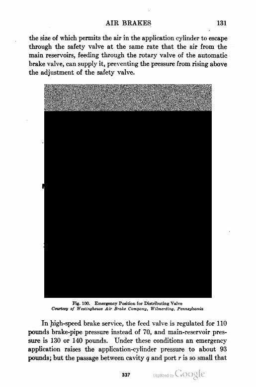
AIR BRAKES 131
the size of which permits the air in the application cylinder to escape
through the safety valve at the same rate that the air from the
main reservoirs, feeding through the rotary valve of the automatic
brake valve, can supply it, preventing the pressure from rising above
the adjustment of the safety valve.
Fig. 100. Emergency Position for Distributing Valve
Courtesy of Westinghouse Air Brake Company, Wilmerding, Pennsylvania
In high-speed brake service, the feed valve is regulated for 110
pounds brake-pipe pressure instead of 70, and main-reservoir pres
sure is 130 or 140 pounds. Under these conditions an emergency
application raises the application-cylinder pressure to about 93
pounds; but the passage between cavity q and port r is so small that
337
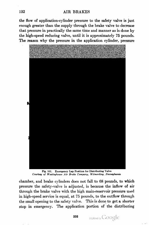
132 AIR BRAKES
the flow of application-cylinder pressure to the safety valve is just
enough greater than the supply through the brake valve to decrease
that pressure in practically the same time and manner as is done by
the high-speed reducing valve, until it is approximately 75 pounds.
The reason why the pressure in the application cylinder, pressure
Fig. 101. Emergency Lap Position for Distributing Valve
Courtesy of Westinghouse Air Brake Company, Wilmerding, Pennsylvania
chamber, and brake cylinders does not fall to 68 pounds, to which
pressure the safety-valve is adjusted, is because the inflow of air
through the brake valve with the high main-reservoir pressure used
in high-speed service is equal, at 75 pounds, to the outflow through
the small opening to the safety valve. This is done to get a shorter
stop in emergency. The application portion of the distributing
338
AIR BRAKES 133
valve operates similarly, but more quickly than in service application.
Emergency Lap. The movable parts of the valve remain in
the position shown in Fig. 100 until the brake-cylinder pressure
slightly exceeds the application-cylinder pressure, when the appli
cation piston and application valve move back to the position
known as "emergency lap" as shown in Fig. 101 .
The release after an emergency is brought about by the same
manipulation of the automatic brake valve as that following service
application, but the effect on the distributing valve is somewhat
different. When the equalizing piston, equalizing valve, and gradu
ating valve are forced to the release position by the increased brake-
pipe pressure in chamber p, the application chamber—pressure in
which is zero—is connected to the application cylinder, having
emergency pressure therein through port w, cavity k, and port h.
The pressure in the application cylinder at once expands into the
application chamber until these pressures are equal, which results
in the release of brake-cylinder pressure until it is slightly less than
that in the application cylinder and chamber. Consequently, in
releasing after an emergency (using the release position of the auto
matic brake valve), the brake-cylinder pressure will automatically
reduce to about 15 pounds, where it will remain until the auto
matic brake-valve handle is moved to running position.
If the brakes are applied by a conductor's valve, a burst hose,
or parting of train, the movement of equalizing valve 31 breaks the
connection between ports h and i through cavity k, so that the brakes
will apply and remain applied until the brake-pipe pressure is
restored. The handle of the automatic brake valve should be imme
diately moved to emergency position to prevent a loss of main-
reservoir pressure.
Independent Brake Operation
Independent Application. When the handle of the independent
brake valve is moved to either slow- or quick-application position,
air from the main reservoir, limited by the reducing valve to a maxi
mum of 45 pounds, is allowed to flow to the application cylinder,
forcing application piston 10 to the right as shown in Fig. 102.
This movement causes application valve 5 to open its port and
allow air from the main reservoirs to flow into chambers bb and
through passage c to the brake cylinders, as in an automatic appl:
339
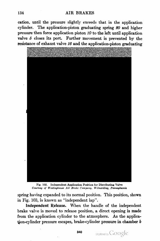
134 AIR BRAKES
cation, until the pressure slightly exceeds that in the application
cylinder. The application-piston graduating spring 20 and higher
pressure then force application piston 10 to the left until application
valve 5 closes its port. Further movement is prevented by the
resistance of exhaust valve 16 and the application-piston graduating
Fig. 102. Independent Application Position for Distributing Valve
Courtesy of Westinghouse Air Brake Company, Wilmerding, Pennsylvania
spring having expanded to its normal position. This position, shown
in Fig. 103, is known as "independent lap".
Independent Release. When the handle of the independent
brake valve is moved to release position, a direct opening is made
from the application cylinder to the atmosphere. As the applica
tion-cylinder pressure escapes, brake-cylinder pressure in chamber b
340
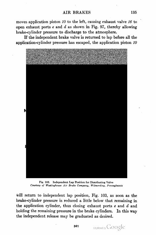
AIR BRAKES 135
moves application piston 10 to the left, causing exhaust valve 16 to
open exhaust ports e and d as shown in Fig. 97, thereby allowing
brake-cylinder pressure to discharge to the atmosphere.
If the independent brake valve is returned to lap before all the
application-cylinder pressure has escaped, the application piston 10
Fig. 103. Independent Lap Position for Distributing Valve
Courtesy of Westinghouse Air Brake Company, Wilmerding, Pennsylvania
will return to independent lap position, Fig. 103, as soon as the
brake-cylinder pressure is reduced a little below that remaining in
the application cylinder, thus closing exhaust ports e and d and
holding the remaining pressure in the brake cylinders. In this way
the independent release may be graduated as desired.
341
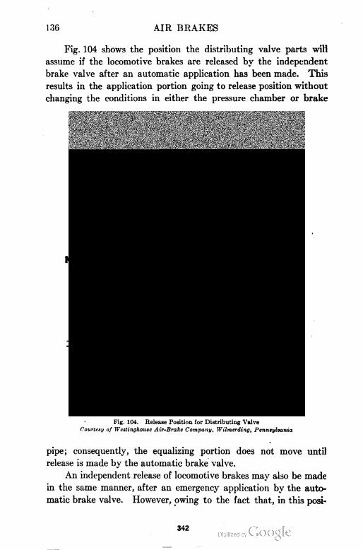
13G AIR BRAKES
Fig. 104 shows the position the distributing valve parts will
assume if the locomotive brakes are released by the independent
brake valve after an automatic application has been made. This
results in the application portion going to release position without
changing the conditions in either the pressure chamber or brake
Fig. 104. Release Position for Distributing Valve
Courtesy of Westinghouse Air-Brake Company, Wilmerding, Pennsylvania
pipe; consequently, the equalizing portion does not move until
release is made by the automatic brake valve.
An independent release of locomotive brakes may also be made
in the same manner, after an emergency application by the auto
matic brake valve. However, owing to the fact that, in this posi
342
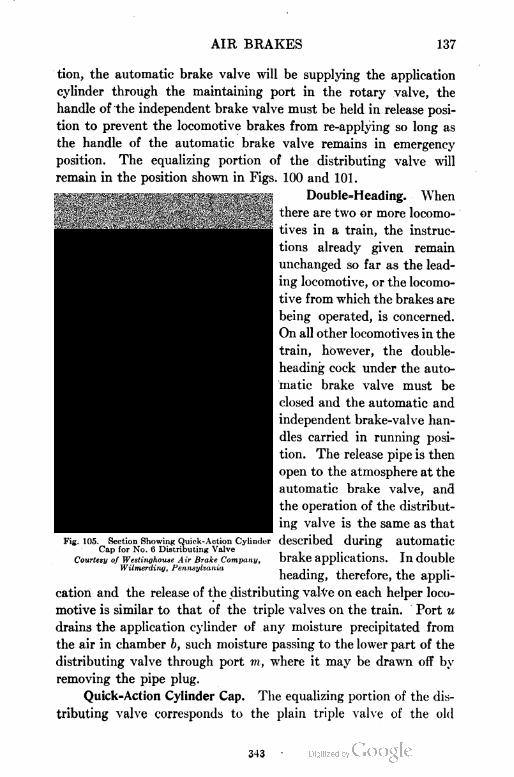
AIR BRAKES 137
tion, the automatic brake valve will be supplying the application
cylinder through the maintaining port in the rotary valve, the
handle of the independent brake valve must be held in release posi
tion to prevent the locomotive brakes from re-applying so long as
the handle of the automatic brake valve remains in emergency
position. The equalizing portion of the distributing valve will
remain in the position shown in Figs. 100 and 101.
Double=Heading. When
there are two or more locomo
tives in a train, the instruc
tions already given remain
unchanged so far as the lead
ing locomotive, or the locomo
tive from which the brakes are
being operated, is concerned.
On all other locomotives in the
train, however, the double-
heading cock under the auto
matic brake valve must be
closed and the automatic and
independent brake-valve han
dles carried in running posi
tion. The release pipe is then
open to the atmosphere at the
automatic brake valve, and
the operation of the distribut
ing valve is the same as that
described during automatic
brake applications. In double
heading, therefore, the appli
cation and the release of the distributing valve on each helper loco
motive is similar to that of the triple valves on the train. Port u
drains the application cylinder of any moisture precipitated from
the air in chamber b, such moisture passing to the lower part of the
distributing valve through port m, where it may be drawn off by
removing the pipe plug.
Quick=Action Cylinder Cap. The equalizing portion of the dis
tributing valve corresponds to the plain triple valve of the old
Fig. 105. Section Showing Quick-Action CylinderCap for No. (5 Distributing Vaive
Courtesy of Westinghouse A ir Brake Company,Wilmerding, Pennsylvania
343
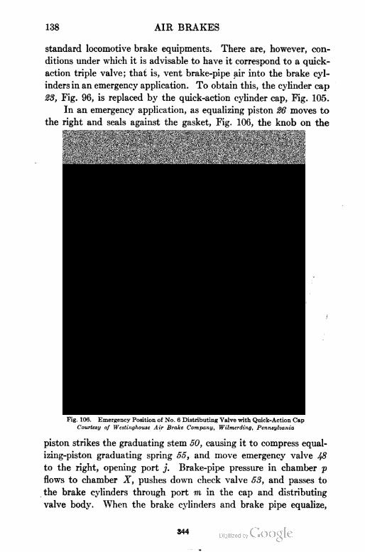
138 AIR BRAKES
standard locomotive brake equipments. There are, however, con
ditions under which it is advisable to have it correspond to a quick-
action triple valve; that is, vent brake-pipe air into the brake cyl
inders in an emergency application. To obtain this, the cylinder cap
23, Fig. 96, is replaced by the quick-action cylinder cap, Fig. 105.
In an emergency application, as equalizing piston 26 moves to
the right and seals against the gasket, Fig. 106, the knob on the
Fig. 106. Emergency Position of No. 6 Distributing Valve with Quick-Action Cap
Courtesy of Westinghouse Air Brake Company, Wilmerding, Pennsylvania
piston strikes the graduating stem 50, causing it to compress equal
izing-piston graduating spring 55, and move emergency valve 48
to the right, opening port j. Brake-pipe pressure in chamber p
flows to chamber X, pushes down check valve 53, and passes to
the brake cylinders through port m in the cap and distributing
valve body. When the brake cylinders and brake pipe equalize,
344
AIR BRAKES 139
check valve 53 is forced to its seat by spring 54, thus preventing air
in the brake cylinders from flowing back into the brake pipe. When
a release of the brakes occurs and piston 26 is moved back to its
normal position, Fig. 97, spring 55 forces graduating stem 50 and
emergency valve Ifi back to the position shown in Fig. 105.
"PC" PASSENGER BRAKE EQUIPMENT
Characteristics. The "PC" passenger brake equipment was
designed for fast passenger service and for cars weighing as high
as 150,000 pounds. Briefly stated, the requirements recognized as
essential in a satisfactory brake for this modern service are as follows:
(a) Automatic in action.
(b) Efficiency not materially affected by unequal piston travel or brake-cylinder
leakage.
(c) Certainty and uniformity of service action.
(d) Graduated release.
(e) Quick re-charge and consequent ready response of brakes to any brake-pipe
reduction made at any time.
(f) Maximum possible rate of re-charging the brake pipe alone.
(g) Predetermined and fixed flexibility of service operation.
(h) Maximum sensitiveness to release, consistent with stability, combined with
minimum sensitiveness to the inevitable fluctuations in brake-pipe pressure
tending to cause undesired light-service applications, brakes creeping on, etc.,
and yet guard against the attainment of too high a difference of pressure
between the brake pipe and the pressure chamber (auxiliary reservoir).
(i) Full emergency pressure obtainable at any time after a service application,
(j) Full emergency pressure applied automatically after any predetermined
brake-pipe reduction has been made after equalization,
(k) Emergency braking power approximately 100 per cent greater than the
maximum obtainable in service applications.
(1) Maximum brake-cylinder pressure obtained in the least possible time,
(m) Maximum brake-cylinder pressure maintained throughout the stop,
(n) Brake rigging designed for maximum efficiency.
(0) Adaptability to all classes and conditions of service.
Special Features of "PC" Equipment. The construction and
principle of operation of the "PC" brake equipment is such as to
permit of the fulfillment of all of the above requirements. The
features which may be mentioned as being peculiar to the equipment
are as follows:
(1) Graduated release and quick re-charge obtained as with previous improved
types of triple valves.
(2) Certainty and uniformity of service action.
(3) Quick rise in brake-cylinder pressure.
346
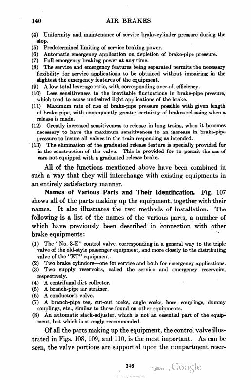
140 AIR BRAKES
(4) Uniformity and maintenance of service brake-cylinder pressure during the
stop.
(5) Predetermined limiting of service braking power.
(6) Automatic emergency application on depletion of brake-pipe pressure.
(7) Full emergency braking power at any time.
(8) The service and emergency features being separated permits the necessary
flexibility for service applications to be obtained without impairing in the
slightest the emergency features of the equipment.
(9) A low total leverage ratio, with corresponding over-all efficiency.
(10) Less sensitiveness to the inevitable fluctuations in brake-pipe pressure,
which tend to cause undesired light applications of the brake.
(11) Maximum rate of rise of brake-pipe pressure possible with given length
of brake pipe, with consequently greater certainty of brakes releasing when a
release is made.
(12) Greatly increased sensitiveness to release in long trains, when it becomes
necessary to have the maximum sensitiveness to an increase in brake-pipe
pressure to insure all valves in the train responding as intended.
' (13) The elimination of the graduated release feature is specially provided for
in the construction of the valve. This is provided for to permit the use of
cars not equipped with a graduated release brake.
All of the functions mentioned above have been combined in
such a way that they will interchange with existing equipments in
an entirely satisfactory manner.
Names of Various Parts and Their Identification. Fig. 107
shows all of the parts making up the equipment, together with their
names. It also illustrates the two methods of installation. The
following is a list of the names of the various parts, a number of
which have previously been described in connection with other
brake equipments:
(1) The "No. 3-E" control valve, corresponding in a general way to the triple
valve of the old-style passenger equipment, and more closely to the distributing
valve of the "ET" equipment.
(2) Two brake cylinders—one for service and both for emergency applications.
(3) Two supply reservoirs, called the service and emergency reservoirs,
respectively.
(4) A centrifugal dirt collector.
(5) A branch-pipe air strainer.
(6) A conductor's valve.
(7) A branch-pipe tee, cut-out cocks, angle cocks, hose couplings, dummy
couplings, etc., similar to those found on other equipments.
(8) An automatic slack-adjuster, which is not an essential part of the equip
ment, but which is strongly recommended.
Of all the parts making up the equipment, the control valve illus
trated in Figs. 108, 109, and 110, is the most important. As can be
seen, the valve portions are supported upon the compartment reser-
346

347
142 AIR BRAKES
voir, which is bolted to the underframing of the car. The compart
ment reservoir is made up of the pressure chamber, application
chamber, and the reduction-limiting chamber. The equalizing and
Fig. 108. Westinghouse "3-E" Control Valve, Showing Side View
application portions of the compartment reservoir correspond to
those of the "ET" equipment. The location and size of the pipe con
nections are more clearly shown in the outline drawings, Figs. Ill
and 112. Actual sections of the control valve and compartment
reservoir are shown in Figs. 113,
114, and 115, having all of the parts
numbered. The following five par
agraphs are arranged to assist in
identifying the various parts:
Equalizing Portion: 2 Equalizing
body; 3 Release piston; 4 Release slide
valve; 5 Release slide-valve spring; 6 Re
lease graduating valve; 7 Release gradu
ating-valve spring; 8 Release piston-cap
nut; 9 Release piston ring; 10 Release cyl
inder cap; 11 Release cylinder-cap gasket;
12 Square-head cap screw; 13 Release pis
ton graduating sleeve; 1 4 Release piston
graduating spring; 15 Release piston grad
uating nut; 16 Chock valve; 17 Check- _ ~ _ . ,valve cap nut; 18 Direct and graduated F*
release cap; 19 Stud and nut for direct
and graduated release cap; 20 Equalizing piston; 21 Equalizing piston ring
(large) ; 22 Equalizing slide valve; 23 Equalizing slide-valve spring; 24 Equalizing
graduating valve; 25 Equalizing graduating-valve spring; 26 Large equalizing
cylinder cap ; 27 Large equalizing cylinder-cap gasket; 28 Square-head cap screw;
29 Equalizing piston-stop sleeve; 30 Equalizing piston-stop spring; 31 Equali
zing graduating nut; 32 Equalizing piston ring (small); 33 Small equalizing cyl
inder cap; 34 Gasket for small equalizing cylinder cap; 35 Square-head cap
screw; 36 Cap nut for small equalizing cylinder cap; 37 Small equalizing pis-
348
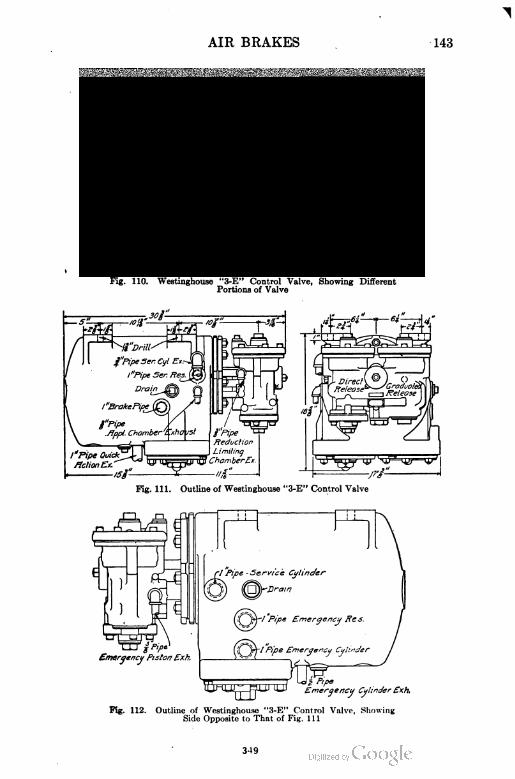
AIR BRAKES 143
Fig. 110. Westinghouse "3-E" Control Valve, Showing DifferentPortions of Valve
Fig. 111. Outline of Westinghouse "3-E" Control Valve
Fig. 112. Outline of Westinghouse "3-E" Control Valve, ShowingSide Opposite to That of Fig. Ill
3-19
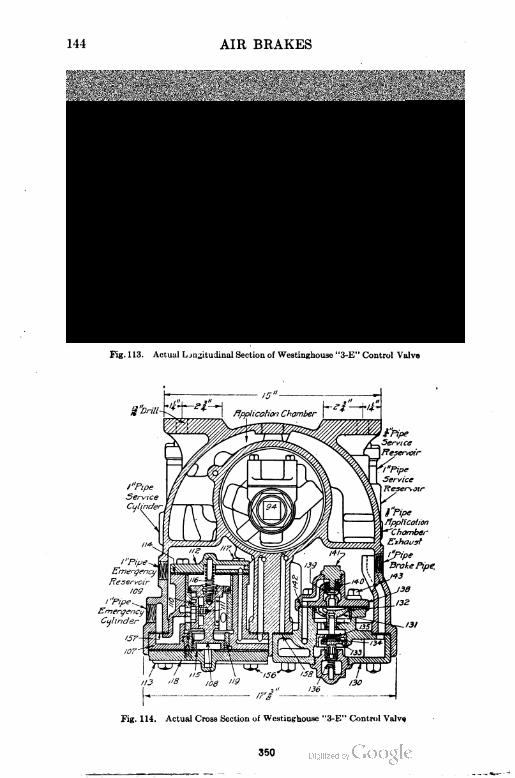
144 AIR BRAKES
AIR BRAKES 145
ton bush; 38 Service-reservoir charging valve; 39 Charging-valve piston
ring; Ifi Charging-valve piston ring; 41 Charging-valve seat; 42 Charging-valve
washer; 43 Internal charging-valve nut; 44 External charging-valve nut; 45
Gasket for direct and graduated release cap.
Application Portion: 75 Body; 76
Piston stem; 77 Piston ring (small); 78
Piston head; 79 Piston seal; 80 Piston
ring (large); 81 Piston follower; 82 Pis
ton-packing leather; 83 Piston-paeking
leather expander; 84 Piston nut; 8h~ Pis-
t on cotter ; 86 Exhaust valve ; 87 Exhaust-
valve spring; 88 Application valve; 89
Application-valve spring ; 90 Application-
piston bolt; 91 Spring box; 92 Piston-
spring sleeve; 93 Piston spring; 94 Grad
uating nut; 95 Application-valve cover;
96 Application-valve cover gasket; 97
Square-head screw for application-valve
cover.
Emergency Portion : 107 Body ; 108
Piston complete! 109 Piston ring; 110
Slide valve; 111 Slide-valve spring; 112
Small cylinder cap; 113 Large cylinder
cap; 114 Small cylinder-cap gasket; 115
Large cylinder cap gasket ; 116 Piston
spring; 117 Square-head cap screw for
small cylinder cap ; 118 Oval fillister head
cap screw; 119 Emergency-piston bush.
Quick-Action Portion: 130 Body;
131 Piston complete; 132 Piston ring;
133 Quick-action valve; / 34 Quick-action
valve seat; 135 Quick-action valve nut; 136 Quick-action valve spring; 137
Quick-action valve cap nut; 138 Quick-action valve cover; 139 Quick-action
closing valve; / 40 Quick-action closing valve spring; 141 Cover cap nut; 142
Cover gasket; 143 Square-head cap screw for cover.
Reservoir: 153 Triple-compartment reservoir; 154 Cap nut; 155 Stud
with hex. nut; 156 Stud with hex. nut; 157 Emergency-cylinder gasket; 158
Quick-action cylinder gasket ; 159 Large reservoir gasket; 160 Equalizing-cylinder
gasket.
CONTROL VALVE
Fig. 116 is presented to assist in gaining a clearer idea of the
location of the parts in the different portions of the control valve.
On account of the complicated construction of the "No. 3-E" control
valve, reference will be made to the diagrammatic views shown in
Figs. 117 to 131, in explaining its action.
Fig. 117 shows all of the ports and operative parts of the control
valve in normal position. This is the position which the various
parts of the valve would occupy with all parts properly assembled,
but before any air has been admitted to the brake pipe.
It will be noted that the direct- and graduated-release cap is
shown in its graduated-release position. Just below it is shown the
position which the cap occupies when adjusted for direct instead of
Fig. 115. Section through EqualisingPortion of Westinghouse "3-E"
Control Valve
351
146 AIR BRAKES
graduated release. In all the succeeding views, except Fig. 129,
the cap is considered to be adjusted for graduated release. Fig.
A Service Cylinder Exhaust.B Service Reservoir.C Upper Side of Equalizing
Pressure.D Application-Chamber Exhaust.E Not Used.F Lower Side of Quick-Action Closing Valve.H Reduction-Limiting Chamber.I Large Emergency Piston.J Emergency Reservoir.K Back Side of Application Piston.L Small Emergency Piston.Af Application Chamber.N Service-Brake Cylinder.0 Pressure Chamber.X Emergency-Cylinder Exhaust.Y Port Connecting Emergency Brake Cylinder with
Quick-Action Valve.Z Port Leading from Service-Brake Cylinder to
Emergency Valve.
All Holes Not Designated Are Bolt Holes.
Fig. 116. Diagrams of Flanges and Seats for Westinghouse "3-E"Control-Valve Portions
Equalizing Grad. Spring EettaseGrad Spring PressureChamberCheck Valve' ~4~L 3 Equalizing gfe. Release
CheckValve WZ&Pision ff?ppChamEx. f5erCylEx. fSerRea.
EqualizingSlop Spring Emerg. Pislon Ex.7 r Jposilion for Gmd.R&
Direcl & Grad.ReI. Cap$Posilion forHired Keif
■Ser.Cyll f ^EmerC^lf Quick.
Emerg. Cut. Ex. Emerj.
Fig. 117. Normal Position of Westingho,use "3-E" Control Valve
129 with the accompanying explanation refers to the operation of
the valve with the cap adjusted for direct release.
352
AIR BRAKES 147
Release and Charging Position
Fig. 118 shows only those parts and ports which are operative
while the brake is being released and the pressure chamber and
emergency and service reservoirs are being charged.
Charging Empty Equipment. In charging the empty equip
ment, air from the brake pipe entering the control valve at the point
indicated passes to chambers B and A and forces the equalizing and
release pistons of the equalizing portion, with their attached valves,
to release position. Brake-pipe air then passes from chamber B,
lifting the equalizing check valve, and by way of the equalizing slide
Equalizing Grad.
Spring-
ReleaseGrad. Spring
Equalizing.Piston Stop
Emergency PislonEx.Equalizing SlopSpring DirecliGmd.ffel.t
Posilion for Grad.Pelea'se Ser.CyP. J Enrr.Cyl.y
Emerg.Cyl.Ex. Emerg.Pes.
Fig. 118. Release Position, Charging-Pressure Chamber, Emergency andService Reservoirs for Westinghouse "3-E" Control Valve
valve into chamber D. Air from chamber D then flows through
the equalizing graduating and slide valve—so shown in the dia
grammatic drawing for the sake of clearness. In this and a number
of instances following, this port in actual valves opens past the end
of instead of through the graduating valve, past the emergency-
reservoir check valve, and thence in two directions: (1) to chamber
jR and to the emergency reservoir, and (2) through the equalizing
slide valve to two different ports, one connecting to the service-
reservoir charging valve and thence to the service reservoir; the
other by way of the direct- and graduated-release cap and through
353
118 AIR BRAKES
the release slide valve and past the end of the release graduating
valve to chamber E.
Air from the brake pipe and chamber B also flows through
feed groove i and charges chamber E. From chamber E, the air
flows by way of the equalizing slide valve in two directions: (1)
to the pressure chamber direct (which is thus charged to brake-pipe
pressure), and (2) to chamber K. With substantially the same
pressures (brake-pipe pressure as explained) in chambers G and K,
and a lower pressure (service-reservoir pressure) in chamber //, the
service-reservoir charging valve remains in the position shown in
Fig. 117, being held in this position until the re-charging is com
pleted, since chamber K is relatively small and the ports leading
to it of ample capacity to charge it more quickly than the pressure
can be built up in chambers G and H.
Release Connections. Referring to Fig. 117, it will be noted
that the pressure-chamber check valve prevents the air in chamber
E from flowing directly to the pressure chamber, but allows a free
passage of air in the opposite direction.
Chamber F at the small end of the equalizing piston is connected
through the release slide valve to the emergency-piston exhaust and
atmosphere, thus holding the equalizing piston and its valves posi
tively in release position. Chamber S at the small end of the
emergency piston is connected through the release slide valve to
the emergency-piston exhaust and the atmosphere in release posi
tion, thus holding the emergency piston and its valve positively in
the proper position.
The reduction-limiting chamber is connected through the
equalizing slide valve to the reduction-limiting chamber exhaust
and atmosphere. The application chamber and chamber C are
connected through the release slide valve and graduating valve to
the application-chamber exhaust port leading to the atmosphere.
The service brake cylinder is connected through the exhaust
slide valve of the application portion to the service brake-cylinder
exhaust port leading to the atmosphere. The emergency brake
cylinder is connected through the emergency slide valve to the
emergency-cylinder exhaust port leading to the atmosphere.
It will be noted that Fig. 117 and some that follow show a small
cavity in the release graduating valve. This cavity is connected to
354
AIR BRAKES 149
the emergency-piston exhaust in all positions of the valve, but has
no other connection. The purpose of this caVity is merely to insure
that, under all conditions, there will be sufficient differential pres
sure acting on the graduating valve to hold it to its seat.
Service Application
(a) Preliminary Service Position. With the equipment fully
charged as explained above, the result of a service reduction in brake-
pipe pressure will be to lower the pressure in chambers A and B
oelow that in chambers D and E, thus creating a differential pres-
Equalizing Grad Spring Release Grad Pressure Chamber
Spring ^—» Release Check ValvesSenCyl.Ex.
Equalizing
Piston Stop .
Equalizing Stop Spring
PirectuGrod Rel. Cap
Ser Cyl?
'ABrake Pipe
Emerg. Cyl\'Emerg. Slide Valve
Emerg. Cut £V. Emerg. Jfes.
Fiir. 119. Preliminary Service Position of Westinnhonse "3-E" Control Valve
sure on the equalizing and release pistons. Since chamber F is open
to the atmosphere, Fig. 118, the release piston will move on a much
less differential than the equalizing piston. There is a small amount
of lost motion between release piston and release graduating valve,
and somewhat more between release piston and release slide valve
so that during the first movement of the release piston, the release
slide valve still remains in its release position, thus keeping chamber
F open through the emergency-piston exhaust port to the atmos
phere. The release piston, therefore, is the first to move when a
brake-pipe reduction is made and it carries with it the release gradu™
ating valve and finally moves the release slide valve to the position
355
150 AIR BRAKES
shown in Fig. 119, called preliminary service position. In this position
the piston has closed the feed groove i (which is therefore not shown
in Fig. 119) and just touches the release graduating-piston sleeve.
The function of the valve in this position is to close the port
leading from the application chamber to the atmosphere (which is
therefore not shown in Fig. 119), to close the port connecting cham
ber F to the emergency-piston exhaust, and to open this latter port,
connecting chamber E past the end of the release graduating valve
and through the release slide valve to chamber F. Pressure-cham
ber air is, therefore, free to flow past the pressure-chamber check
Equalizing^
Gradualing
Spring
R.leose Fissure Chamber
l Piston Check Valve
EqualizingGradualing"
Valve
Reduclion
Equalizing.
Piston Slop
EqualizingStop Spring
Fig,
-Service CylinderEx.
DirectvGraduoted Release Cop
i BrakePipe
^Emerg. Slide Valve
Service Culinder\\ ^EmergencyReservoir
Emergency CylinderEx./ Emergency Cylinder
120. Secondary Service Position of Westinghouse "3-E" Control Valve
valve to chamber F, thus balancing the pressures in chambers F and
D on the opposite sides of the small end of the equalizing piston.
This position, it should be understood, is assumed only momen
tarily and should be regarded as the first stage only of the complete
movement of the parts from release and charging to the service
position of the parts.
(b) Secondary Service Position. The balancing of the pres
sures in chambers F and D, as explained, permits the equalizing
piston to move in accordance with the difference of pressure already
existing between chambers D and A. When the shoulder on the
end of the piston stem comes in contact with the equalizing slide
356
AIR BRAKES 151
valve, as shown in Fig. 120, a connection is momentarily made from
the emergency reservoir through the equalizing slide valve and past
the end of (although shown as through in the view) the graduating
valve to chamber D. The purpose of this connection is to prevent
a drop in pressure in chamber D which would otherwise take place
on account of the movement (displacement) of the equalizing piston.
The displacement of the equalizing piston is sufficiently great, com
pared with the volume of chamber D, to require the provision just
explained.
At the same time, the pressure chamber is connected through
the equalizing slide valve and graduating valve to chamber D, thus
Equalizing Grad.Spring
Release Grad. Pressure Chamber
.ck Valve
Equaltc'n,
i BrakePipe
Emerg.slide Valve
SerCgl..
Emerg. Cgl. En. Emerg. f?es.
Fig. 121. Service Position of Westinghouse "3-E" Control Valve
keeping the pressures in these two chambers equal. The other
connections remain as explained under the heading "Preliminary
Service Position".
(c) Service Position. The differential between the brake-
pipe pressure in chamber A and the pressure in chamber D (pressure-
chamber pressure as explained) is sufficient to move the equalizing
piston and its valves past the intermediate secondary service posi
tion into service position, Fig. 121, in which the equalizing piston
just touches the equalizing graduating-spring sleeve.
Chambers F and D are in communication by way of a feed port
around the small end of the equalizing piston. The pressure cham
357
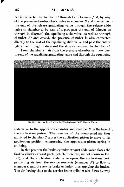
152 AIR BRAKES
ber is connected to chamber D through two channels, first, by way
of the pressure-chamber check valve to chamber E and thence past
the end of the release graduating valve through the release slide
valve to chamber D by way of a port past the end of (shown as
through in diagram) the equalizing slide valve, as well as through
chamber F; and second, the pressure chamber is also connected
directly to the seat of the equalizing slide valve and past the end of
(shown as through in diagram) the slide valve direct to chamber D.
JYom chamber D, air from the pressure chamber can flow past
the end of the equalizing graduating valve and through the equalizing
Equalising Grad
Spring ~
Equalizing.
Pilion Stop
Release Grad
Spring
Equalizing SlopSpring DirectVGrad Rel Cap
Fig. 122. Service Lap Position for Westinghouse "3-E" Control Valve
SerCyl.-~* J Emerg.Cqt
Emeng. Cut Ex. Emeng Res.
jBrotrePipe
Slide Votve
slide valve to the application chamber and chamber C on the face of
the application piston. The pressure of the compressed air thus
admitted to chamber C causes the application piston to move to its
application position, compressing the application-piston spring in
so doing.
In this position the brake-cylinder exhaust slide valve closes the
brake-cylinder exhaust ports (which, therefore, are not shown in Fig.
121), and the application slide valve opens the application port,
permitting air from the service reservoir (chamber N) to flow to
chamber 0 and the service brake cylinder, thus applying the brakes.
The air flowing thus to the service brake cylinder also flows by way
353
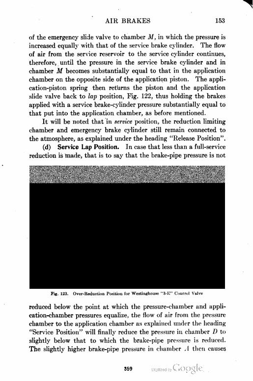
AIR BRAKES 153
of the emergency slide valve to chamber M, in which the pressure is
increased equally with that of the service brake cylinder. The flow
of air from the service reservoir to the service cylinder continues,
therefore, until the pressure in the service brake cylinder and in
chamber M becomes substantially equal to that in the application
chamber on the opposite side of the application piston. The appli
cation-piston spring then returns the piston and the application
slide valve back to lap position, Fig. 122, thus holding the brakes
applied with a service brake-cylinder pressure substantially equal to
that put into the application chamber, as before mentioned.
It will be noted that in service position, the reduction limiting
chamber and emergency brake cylinder still remain connected to
the atmosphere, as explained under the heading "Release Position".
(d) Service Lap Position. In case that less than a full-service
reduction is made, that is to say that the brake-pipe pressure is not
Equalizing Grad
Spring
Release Grad Pressure Chamber
Check Valve
EqualizingPiston—-
Sen Res.Charging Valvi
Equalizing
Grad Valve
Pirect&Grad Ftel CapEqualizing Slop Spring.
^SrakeP)pe
I Slide Valve
Emerq Cgl Ex
Fig. 123. Over-Reduction Position for Westinghouse "3-E" Control Valve
reduced below the point at which the pressure-chamber and appli
cation-chamber pressures equalize, the flow of air from the pressure
chamber to the application chamber as explained under the heading
"Service Position" will finally reduce the pressure in chamber D to
slightly below that to which the brake-pipe pressure is reduced.
The slightly higher brake-pipe pressure in chamber A then causes
559
154 AIR BRAKES
the equalizing piston and graduating valve to return to their service
lap positions, Fig. 122, and close communication from the pressure
to the application chamber, holding whatever pressure was built
up in chamber C and the application chamber.
It will be plain that any decrease in brake-cylinder pressure,
due to leakage, will now reduce the pressure in chamber M below
that which is bottled up in the application chamber (chamber C).
The differential pressure thus established on the application piston
will cause it to move again toward its service position and open the
application valve port, as shown in Fig. 123, just enough to supply
a sufficient amount of air from the service reservoir to the service
brake cylinder to restore the depleted brake-cylinder pressure to
its original amount, following which the application valve will be
again lapped as already explained. In this way, the brake-cylinder
pressure will be maintained constant, regardless of leakage, up to
the capacity of the service reservoir.
The release piston and graduating valve may or may not return
to their lap positions at the same time as, and in a manner similar
to the movement of, the application piston and valves, but they
perform no function in either case. Otherwise the parts remain
the same as in service position.
(e) Over=Reduction Position. If the brake-pipe reduction is
carried below the point at which the pressure and application cham
bers equalize—86 pounds when using 110 pounds brake-pipe pres
sure and 54 pounds with 70 pounds brake-pipe pressure—such an
over-reduction results in lowering the pressure in chamber A below
that in chamber D (pressure-chamber pressure). The equalizing
piston consequently moves beyond its service position, Fig. 121,
carrying with it the equalizing slide valve and graduating valve to
what is called the over-reduction position.
The relative resistances of the release and equalizing graduating
springs is such that the release piston and its valves still remain as
in service, although for the moment the same differential between
pressure-chamber and brake-pipe pressure is acting upon the release
piston as was sufficient to move the equalizing piston and its valves
to the over-reduction position.
The result is that air from the pressure chamber—which is still
connected to chamber D in substantially the same manner as
360
AIR BRAKES 155
explained under "Service Position"—now flows past the end of
the equalizing graduating valve and through the equalizing slide
valve to the reduction-limiting chamber instead of to the applica
tion chamber as in service position.
The reduction-limiting chamber being at atmospheric pressure
permits the pressure in the pressure chamber (and chambers E and
D) to drop, in accordance with the continued over-reduction of brake-
pipe pressure, to the point of equalization of the reduced pressure-
chamber pressure and the reduction-limiting chamber pressure.
Otherwise the condition of the pressures in the reservoirs and brake
cylinders controlled by the control valve is unchanged, except that
in the movement of the equalizing slide valve to over-reduction posi
tion, Fig. 123, a connection is made from the application chamber
and chamber C by way of the equalizing slide valve to the top
(chamber G) of the service-reservoir charging valve, and from
chamber D (pressure-chamber pressure) past the end of the
equalizing graduating valve and through the equalizing slide valve to
chamber K. Since the pressure in the pressure chamber is being
reduced, while that in the application chamber and service reservoir
is equalized, or practically so, at about 86 pounds pressure, the ser
vice-reservoir charging valve is not lifted, but is held down to its seat.
With the parts in this position, it will be noted that the service
reservoir and the application chamber are separated only by the
ring in the small end of the service-reservoir charging valve. If
there is any slight leakage which tends to cause a drop in applica
tion-chamber pressure—which is relatively small compared with
the service-reservoir volume—the air in the service reservoir will
gradually find its way around the ring in the small end of the service-
reservoir charging valve and prevent any material drop in applica
tion-chamber pressure, thus practically eliminating the possibility
of the brakes gradually leaking off, due to application-chamber
leakage. The application valve port is shown partly open, supply
ing brake-cylinder leakage, as already explained.
(f) Over-Reduction Lap Position. Provided the brake-pipe
reduction is not carried below the equalizing point of the pressure
chamber and reduction-limiting chamber, a slight reduction of the
pressure in the pressure chamber (and chambers D and E) below that
held in the brake pipe, resulting from the continued flow of air from
361
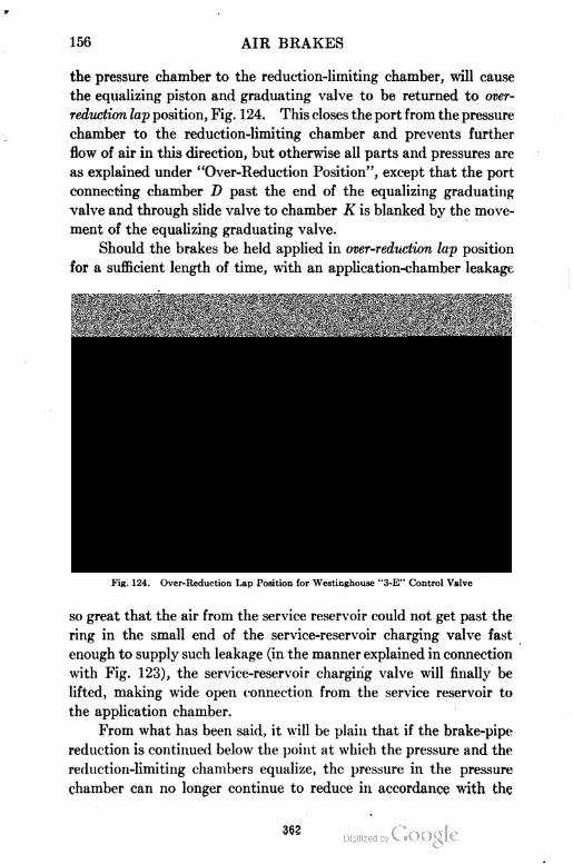
156 AIR BRAKES
the pressure chamber to the reduction-limiting chamber, will cause
the equalizing piston and graduating valve to be returned to over
reduction lap position, Fig. 124. This closes the port from the pressure
chamber to the reduction-limiting chamber and prevents further
flow of air in this direction, but otherwise all parts and pressures are
as explained under "Over-Reduction Position", except that the port
connecting chamber D past the end of the equalizing graduating
valve and through slide valve to chamber K is blanked by the move
ment of the equalizing graduating valve.
Should the brakes be held applied in over-reduction lap position
for a sufficient length of time, with an application-chamber leakage
Equalizing Grad
Spring
Egualizing
Piston
Sen Res.-Charqinq Valv
L
Equalizing^Grad Valve
ReduclionLimilingChamberEx.
EqualizingSlide Valve
Release
Grad-ValveK.
EqualizingPislonStop'
EguahzwqStopSpring DiredvGrad. Ret Cop
|BrakeP-pe
Ser Cyl. J EmerCylEmerg.Cyl.Ex.
Emerq. Slide ValveEmerg.Res
Fig. 124. Over-Reduction Lap Position for Westinghousc "3-E" Control Valve
so great that the air from the service reservoir could not get past the
ring in the small end of the service-reservoir charging valve fast
enough to supply such leakage (in the manner explained in connection
with Fig. 123), the service-reservoir charging valve will finally be
lifted, making wide open connection from the service reservoir to
the application chamber.
From what has been said, it will be plain that if the brake-pipe
reduction is continued below the point at which the pressure and the
reduction-limiting chambers equalize, the pressure in the pressure
chamber can no longer continue to reduce in accordance with the
362
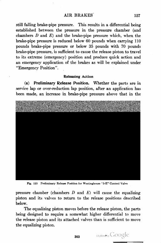
AIR BRAKES 157
still falling brake-pipe pressure. This results in a differential being
established between the pressure in the pressure chamber (and
chambers D and E) and the brake-pipe pressure which, when the
brake-pipe pressure is reduced below 60 pounds when carrying 110
pounds brake-pipe pressure or below 35 pounds with 70 pounds
brake-pipe pressure, is sufficient to cause the release piston to travel
to its extreme (emergency) position and produce quick action and
an emergency application of the brakes as will be explained under
"Emergency Position".
Releasing Action
(a) Preliminary Release Position. Whether the parts are in
service lap or over-reduction lap position, after an application has
been made, an increase in brake-pipe pressure above that in the
equalizing Qrad
. Spril
EqualiziVision Stop
Release uradSpring^ rra* Release
PressureChamber
Check Valve
equalizing SloPSpr,n9 ^f^j^,'^
4Brake Pipe
Emerg. Slide Valve
Sen Cqt. 'emerg. Cut \
emerg. Cul. Ex Emery. Res.
Fig. 125 Preliminary Release Position for Westinghouse "3-E" Control Valve
pressure chamber (chambers D and E) will cause the equalizing
piston and its valves to return to the release positions described
below.
The equalizing piston moves before the release piston, the parts
being designed to require a somewhat higher differential to move
the release piston and its attached valves than is sufficient to move
the equalizing piston.
363
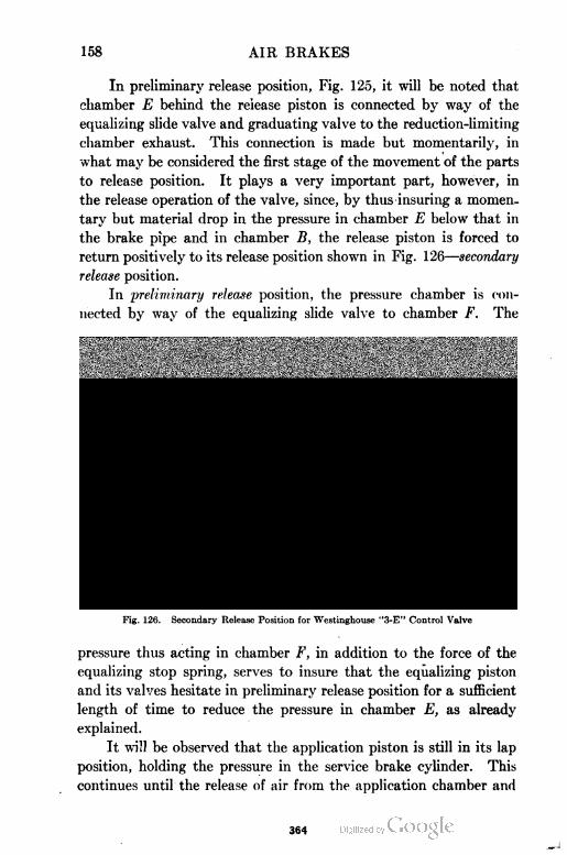
158 AIR BRAKES
In preliminary release position, Fig. 125, it will be noted that
chamber E behind the release piston is connected by way of the
equalizing slide valve and graduating valve to the reduction-limiting
chamber exhaust. This connection is made but momentarily, in
what may be considered the first stage of the movement of the parts
to release position. It plays a very important part, however, in
the release operation of the valve, since, by thus insuring a momen
tary but material drop in the pressure in chamber E below that in
the brake pipe and in chamber B, the release piston is forced to
return positively to its release position shown in Fig. 126—secondary
release position.
In preliminary release position, the pressure chamber is con
nected by way of the equalizing slide valve to chamber F. The
Equalizing Oraa.Spring.
Pressure Chamber
Check Value
Fig. 126.
Posilion forGrad. Release SenCyif \Emer.Cgl
Emera. Cyl £x.
Secondary Release Position for Westinghouse "3-E" Control Valve
j Brake Pipe
'merq. Slide Valve
Emerg. F?es.
pressure thus acting in chamber F, in addition to the force of the
equalizing stop spring, serves to insure that the equalizing piston
and its valves hesitate in preliminary release position for a sufficient
length of time to reduce the pressure in chamber E, as already
explained.
It will be observed that the application piston is still in its lap
position, holding the pressure in the service brake cylinder. This
continues until the release of air from the application chamber and
364
AIR BRAKES 159
chamber C, which does not take place until the parts move to the
next stage in the release movement—secondary release position.
Fig. 126.
In the movement of the equalizing slide valve to preliminary
release position, the reduction chamber is connected to the reduc
tion-chamber exhaust port and the atmosphere, and so remains until
the parts again move to over-reduction position or beyond.
Although there are other connections made in the preliminary
release position as shown in Fig. 125, they perform no particular
function other than has already been described, and consequently
do not need to be again referred to.
(b) Secondary Release Position. In the movement of the
parts to release position, the next stage, following the preliminary
release position is called the secondary release position, Fig. 126. It
will be seen from the illustration that the venting of the air from
chamber E through the equalizing slide valve and graduating valve
to the reduction-limiting chamber exhaust has resulted in the rela
tively higher brake-pipe pressure moving the release piston and its
valves to their release positions, although for an instant the equaliz
ing piston and its valves still remain as shown in Fig. 125—prelimin
ary release position.
With the release piston and its valves in the position shown in
Fig. 126, a connection is made from chamber F through the release
slide valve to the emergency-piston exhaust. At the same time the
pressure chamber is connected by way of the equalizing slide valve
to the same port which connects chamber F to the atmosphere.
This tends to maintain the pressure in chamber F temporarily so as
to insure the connection from chamber E to the atmosphere being
held open, as explained above, until the release piston and its valves
are entirely back in their release positions. In so moving, however,
the release slide valve is gradually increasing the size of the open
ing from chamber F to the atmosphere, until a point is reached
where the pressure in chamber F is lowered sufficiently to permit
the differential pressure already acting on the equalizing piston to
start this piston toward its release position. The resulting move
ment of the equalizing slide valve restricts and finally stops entirely
the flow of air from the pressure chamber to chamber F, the pressure
in which is, therefore, rapidly exhausted to the atmosphere through
365
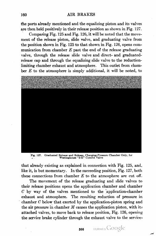
160 AIR BRAKES
the ports already mentioned and the equalizing piston and its valves
are then held positively in their release position as shown in Fig. 127.
Comparing Fig. 125 and Fig. 126, it will be noted that the move
ment of the release piston, slide valve, and graduating valve from
the position shown in Fig. 125 to that shown in Fig. 126, opens com
munication from chamber E past the end of the release graduating
valve, through the release slide valve and direct- and graduated-
release cap and through the equalizing slide valve to the reduction-
limiting chamber exhaust and atmosphere. This outlet from cham
ber E to the atmosphere is simply additional, it will be noted, to
Equalizinq Grad
Spr
Release Grod. Spring
Eoualizing*'^jzzz& Pt'-yalve [HI H iPislon
flpp.Cham.Ex. 5er.CylEx. Sen Red.
Equalizing.Pislon
SenTtes.ChangingValve
Equalizing^Grad. Valve
Reduclion
LimilingChamber Ex
EqualizingSlide Valve
Release
Grad. Valve
Equalizing
Pislon Stop
Equalizing Slop 5pn
Posilion for Grad. ReleaseEmerg.CylEx. Emerg.Res
Brake Pipe
Emerg slide Vatve
Fig. 127. Graduated Release and Release, Charging-Pressure Chamber Only, forWestinghouse "3-E" Control Valve
that already existing as explained in connection with Fig. 125, and,
like it, is but momentary. In the succeeding position, Fig. 127, both
these connections from chamber E to the atmosphere are cut off.
The movement of the release graduating and slide valves to
their release positions opens the application chamber and chamber
C by way of the valves mentioned to the application-chamber
exhaust and atmosphere. The resulting reduction of pressure in
chamber C below that exerted by the application-piston spring and
the air pressure in chamber M causes the application piston, with its
attached valves, to move back to release position, Fig. 126, opening
the service brake cylinder through the exhaust valve to the service
366
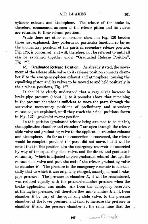
AIR BRAKES 161
cylinder exhaust and atmosphere. The release of the brake is,
therefore, commenced as soon as the release piston and its valves
are returned to their release positions.
While there are other connections shown in Fig. 126 besides
those just explained, they perform no particular function, so far as
the momentary position of the parts in secondary release position,
Fig. 126, is concerned, and will, therefore, not be referred to until all
can be explained together under "Graduated Release Position",
Fig. 127.
(c) Graduated Release Position. As already stated, the move
ment of the release slide valve to its release position connects cham
ber F to the emergency-piston exhaust and atmosphere, causing the
equalizing piston and its valves to be moved to and held positively in
their release positions, Fig. 127.
It should be clearly understood that a very slight increase in
brake-pipe pressure (about 1\ to 2 pounds) above that remaining
in the pressure chamber is sufficient to move the parts through the
successive momentary positions of preliminary and secondary
release as just explained, until they reach their final positions shown
in Fig. 127—graduated release position.
In this position (graduated release being assumed to be cut in),
the application chamber and chamber C are open through the release
slide valve and graduating valve to the application-chamber exhaust
and atmosphere. So far as this connection is concerned, the release
would be complete provided the parts did not move, but it will be
noted that in this position also the emergency reservoir is connected
by way of the equalizing slide valve, and the direct- and graduated-
release cap (which is adjusted to give graduated release) through the
release slide valve and past the end of the release graduating valve
to chamber E. The pressure in the emergency reservoir is substan
tially that to which it was originally charged, namely, normal brake-
pipe pressure. The pressure in chamber E, it will be remembered,
was reduced equally with the pressure-chamber pressure when the
brake application was made. Air from the emergency reservoir,
at the higher pressure, will therefore flow into chamber E and, from
chamber E by way of the equalizing slide valve, to the pressure
chamber, at the lower pressure, and tend to increase the pressure in
chamber E and the pressure chamber at the same time that the
367
162 AIR BRAKES
brake-pipe pressure in chamber B is being increased. If the pres
sure in chamber E rises faster than that in chamber B, the higher
pressure which will soon be built up in chamber E will tend to move
the release piston and graduating valve over toward graduated-
release lap position, Fig. 128, and either partially restrict or wholly
stop the flow of air from the application chamber to the atmosphere,
and from the emergency reservoir to chamber E. If the brake-
pipe pressure is increased very slowly, the relatively rapid increase
of pressure in chamber E may cause the release piston and graduat
ing valve to graduate the release as explained in connection with
Equalizing Grad
Spring^
Release Grad Spring flpp ChamberEx. Sen Pes.
Equalizing.Piston Slop
Equalizing Slop Spring pirecil/Grad Rel. dp ^
Fbsihon for Qrad Release "lerg.Cyl. ^
Cyi.Ex. Emerg.Ri
iBrakePipe
'zTmerg. Slide Valve
Fig. 128. Graduated-Release Lap Position for Westinghouse "3-E" Control Valve
Fig. 128. If the rate of rise of brake-pipe pressure is not slow enough
to permit this action, the parts will move toward the position shown
in Fig. 128 sufficiently to so restrict the flow of air from the emer
gency reservoir to chamber E as to adjust the rate of rise of pressure
in chamber E to correspond to that of the brake pipe and chamber
B, in which case the release of air from the application chamber will
be correspondingly prolonged.
The escape of air from the application chamber and chamber
C to the atmosphere, as already explained in connection with Fig.
126, results in the application-piston spring and brake-cylinder
pressure acting in chamber M moving the application piston with
368
AIR BRAKES 163
its vulve back from their lap position, as shown in Fig. 125, to their
release position, as shown in Figs. 125 and 127, in which position air
from the brake cylinder is exhausted to the atmosphere by way of
the exhaust valve and service-cylinder exhaust port. Whether the
brake-cylinder pressure is entirely or only partially released depends
upon whether the exhaust air from the application chamber and
chamber C is partial or complete. This has already been referred
to and will be further mentioned in connection with Fig. 128. It
will be noted that in Figs. 125, 126, and 127, the reduction-limiting
chamber is connected to the reduction-limiting chamber exhaust and
atmosphere through the equalizing slide valve, and that in Figs.
126 and 127 chamber S is connected through the release slide valve
to the emergency-piston exhaust and atmosphere, so that the air in
these chambers is completely exhausted to the atmosphere when
either a graduated or direct release is made.
Referring to Fig. 127, it will be noted that chamber E is con
nected to chamber K and that air from the emergency reservoir has
access to chamber G. These connections being opened by the
movement of the equalizing slide valve to its release.position, whether
or not the service-reservoir charging valve will be opened and permit
the re-charging of the service reservoir to begin at once will depend
on the relative pressures in the pressure chamber and emergency
and service reservoirs.. With the ordinary manipulation of the
brake, the service-reservoir charging valve will remain closed, Fig.
127, preventing the air from the emergency reservoir reaching the
service reservoir, and the pressure chamber only will be re-charged
until its pressure has been increased to within about 5 pounds of
that in the emergency reservoir.
As already indicated, if the brake pipe is fully re-charged without
a graduation of the release being made, the parts will remain in the
positions shown in Fig. 127 and the release will be complete and with
out graduations. The only change which takes place while such a
release is being made is the movement of the service-reservoir charg
ing valve from the position shown in Fig. 127 to that shown in Fig.
118, which should properly be regarded as illustrating the final
stage in the re-charging of the equipment of which Fig. 127 illustrates
the initial stage. That is to say, at first the pressure chamber alone
is re-charged and this re-charge is accomplished from the emergency
369
164 AIR BRAKES
reservoir only, without any air being drawn for this purpose from
the brake pipe. The air which is supplied through the brake valve
to the brake pipe is, therefore, given every possible advantage and
opportunity to accomplish what is intended when the brake-valve
handle is moved to release position, namely, to release the brakes
by causing an increase of pressure sufficient to accomplish this,
throughout the entire length of the brake pipe. After the release
has been thoroughly established in this manner, the re-charging of
the reservoirs to their original pressure takes place as explained in
connection with Fig. 118.
(d) Release Lap Position. If, however, the brake-pipe pres
sure is not fully restored, a graduation of release being made, that is,
if the brake pipe is partially re-charged and the brake-valve handle
then returned to lap position, the continued flow of air from the
emergency reservoir to pressure chamber and chamber E will tend
to increase the pressure in the pressure chamber and chamber E
above that of chamber B which is now stationary, causing the release
piston and graduating valve to move over until the shoulder on the
end of the release piston stem comes in contact with the release
slide valve, Fig. 128. This closes the exhaust from the application
chamber to the atmosphere and prevents further flow of air from
the emergency reservoir to the pressure chamber and chamber E.
The flow of air from the service brake cylinder to the atmos
phere (continuing as explained in connection with Fig. 127), will at
once reduce the pressure in chamber M below that now retained in
chamber C by the small amount which is sufficient to cause the
application piston to move over to the position shown in Fig. 128,
in which the exhaust valve is closed, thus preventing further release
of air from the service brake cylinder. The other connections
remain as already explained
(e) Release and Charging Pressure Chamber and Emergency
and Service Reservoirs. The gradual release of brake-cylinder pres
sure may be continued as explained above, Fig. 128, until the pres
sures in the emergency reservoir and pressure chamber have become
equal. On account of the relatively large volume of the emergency
reservoir compared with that of the pressure chamber, this equaliza
tion will not take place until the pressure chamber has been re
charged to within about 5 pounds of the brake-pipe pressure carried.
370
AIR BRAKES 165
Beyond this point, whatever small amount of pressure may remain
in the service brake cylinder is released entirely and the emergency
and service reservoirs, as well as the pressure chamber, are re-charged
from the brake pipe as described in connection with Fig. 128.
(f) Direct Release and Charging Position. Up to this point,
the direct- and graduated-release cap has been assumed to be in the
position for graduated release. Fig. 129 corresponds to Fig. 127,
except that the direct- and graduated-release cap is adjusted for
direct release. It will be noted that there is now no connection from
the emergency reservoir to the pressure chamber or chamber E.
Consequently the pressure chamber is being re-charged only by air
Equalizing Qrad.
Spring 1
Release Grad Spring
, Release SenRes.
Equolizim
Piston
J>
Sen Res.ChanginqValve\Equelizir JGrad Valve
ReduclionLimiling
GhamberEx.
Equalizing.Slide Valve
Release\
Grad Valve
Equalizing.
Piston Slop
Equalizing5lop5pnng D,reclxGrad.RelOop \
Fbsilion forDirecl Release SerCylj Emerg.Cyiy
Eme.ng.Cyl.JEx.
Fig. 129. Direct Release, Charging Pressure Chamber Only, for Westinghouse "3-W"Control Valve
from the brake pipe going through feed groove i to chamber E, and
thence by way of the equalizing slide valve to the pressure chamber.
The pressure in chamber E cannot, therefore, increase above that in
chamber B, and the release piston, graduating valve, and slide valve
remain in the position shown in Fig. 129.
With the direct- and graduated-release cap adjusted for direct
release, it will be noted from Fig. 129 that the application chamber
and chamber C are open through the release slide valve to a port
connecting through the direct- and graduated-release cap to the
application-chamber exhaust and atmosphere. This affords an out
371
166 AIR BRAKES
let from the application chamber to the atmosphere which cannot
be closed as long as the release slide valve remains in the position
shown, even though the release piston and graduating valve should,
from any cause, be moved back so that the release graduating valve
would partially or entirely restrict the application-chamber release
port, which is also shown to be open through the release graduating
valve in Fig. 129. Moreover, it will be noted that there are two
outlets from the application chamber to the atmosphere when the
valve is adjusted for direct release as compared with one when
graduated release is cut in.
Emergency Position
(a) Quick=Action Valve Venting. When the brake-pipe pres
sure is reduced faster than at the predetermined rate for service
Equalizing Grc
Spring
Release Grad. Pressure Chamber
Check Valve Sen Res.
PressureChamber
Equalizing^
Piston Stop
Emerq.PistonEx. , .Egualizing Stop Spring DirectisGradRel.Cap
i.Cyl.Ex. EmergMes.
Fig. 130. Emergency Position, Quick-Action Valve Venting, for Westinghouse "3-E
Control Valve
applications, or if the brake-pipe reduction should be continued
below the point at which the pressure and reduction-limiting cham
bers equalize (as explained under "Over-Reduction Position"), the
differential pressure acting on the release and equalizing pistons
becomes sufficient to move them to their extreme or emergency posi
tions, Fig. 13Q.
In this position, air from the emergency reservoir flows directly
to chamber E and from chamber E to the under side of the quick
372
AIR BRAKES 167
action closing valve. Chamber T, above the quick-action closing
valve, is connected to the emergency brake-cylinder port in which
there is no pressure, even though a full-service application of the
brakes may have just preceded the emergency application.
The higher pressure on the under side of the quick-action closing
valve, therefore, raises this valve and air flows to chamber W above
the quick-action piston, forcing the latter down and opening the
quick-action valve against brake-pipe pressure in chamber Y. As
soon as the quick-action valve is unseated in this manner, air from
the brake pipe flows past the quick-action valve to the quick-action
exhaust and atmosphere, causing a local venting of brake-pipe air
and transmitting the quick application serially throughout the train.
Air from the emergency reservoir flowing to chamber E also
flows directly to the application chamber and chamber C, which
forces the application piston and its valve over into their extreme
positions, opening the service reservoir through the application slide
valve and chamber 0 to the service brake cylinder, thus permitting
the pressures in the service reservoir and service brake cylinder to
equalize.
At the same time chamber P, above the large emergency piston,
is connected through the release slide valve to the emergency-piston
exhaust and atmosphere, permitting the emergency-reservoir pres
sure in chamber R to force the emergency piston and its slide valve
upward to their emergency positions.
In this position of the emergency parts, the emergency reservoir
is connected past the end of the emergency slide valve to the emer
gency brake cylinder, thus permitting the pressures in the emergency
reservoir and brake cylinder to equalise. Chamber R is also con
nected through the emergency slide valve to the service cylinder
port, which permits equalization of the service and emergency reser
voirs and brake cylinders.
It will be noted that in this position the emergency slide valve
opens a port which connects chamber M, behind the application
piston, through the emergency slide valve to emergency cylinder
exhaust. This, in connection with the admission of air from the
emergency reservoir to the application chamber and chamber C, as
already explained, still further insures a quick and positive move
ment of the application piston and its valves to emergency position.
373
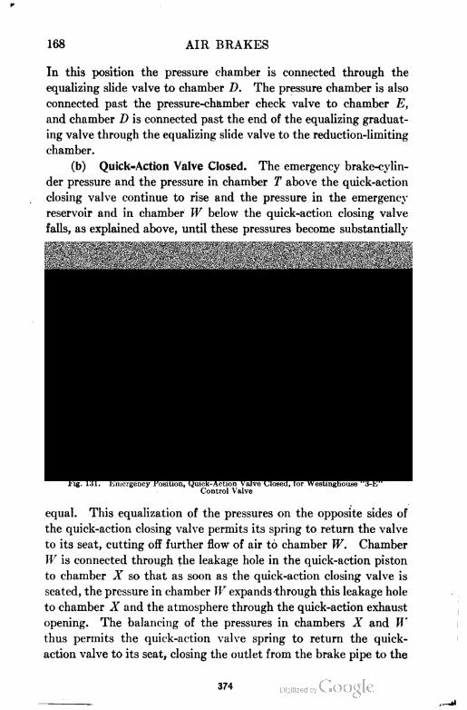
168 AIR BRAKES
In this position the pressure chamber is connected through the
equalizing slide valve to chamber D. The pressure chamber is also
connected past the pressure-chamber check valve to chamber E,
and chamber D is connected past the end of the equalizing graduat
ing valve through the equalizing slide valve to the reduction-limiting
chamber.
(b) Quick=Action Valve Closed. The emergency brake-cylin
der pressure and the pressure in chamber T above the quick-action
closing valve continue to rise and the pressure in the emergency
reservoir and in chamber W below the quick-action closing valve
falls, as explained above, until these pressures become substantially
Equalizing firedSpring N
EquolizinqPiston 5top
Elmer Piston £>Equalizing 3top5prmq
Direr t A Orad Ps I. CopE/ver Piston r StfrCull \EmerCyl\ QuickflclionEx
Quick firtion Voire
Emer Slide Vbli/e EmerCqt Ex Emer.Res.
Fig. 131. Emergency Position, Quick-Action Valve Closed, for Westinghouse "3-E"Control Valve
equal. This equalization of the pressures on the opposite sides of
the quick-action closing valve permits its spring to return the valve
to its seat, cutting off further flow of air to chamber W. Chamber
W is connected through the leakage hole in the quick-action piston
to chamber X so that as soon as the quick-action closing valve is
seated, the pressure in chamber W expands through this leakage hole
to chamber X and the atmosphere through the quick-action exhaust
opening. The balancing of the pressures in chambers X and W
thus permits the quick-action valve spring to return the quick-
action valve to its seat, closing the outlet from the brake pipe to the
374
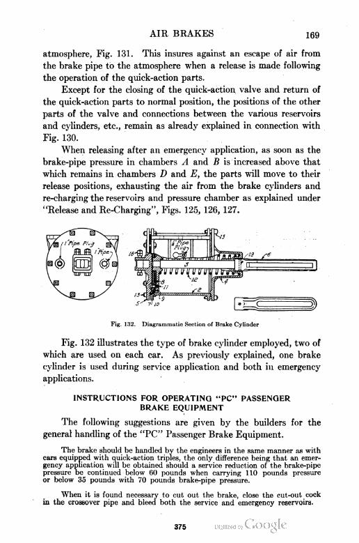
AIR BRAKES 169
atmosphere, Fig. 131. This insures against an escape of air from
the brake pipe to the atmosphere when a release is made following
the operation of the quick-action parts.
Except for the closing of the quick-action valve and return of
the quick-action parts to normal position, the positions of the other
parts of the valve and connections between the various reservoirs
and cylinders, etc., remain as already explained in connection with
Fig. 130.
When releasing after an emergency application, as soon as the
brake-pipe pressure in chambers A and B is increased above that
which remains in chambers D and E, the parts will move to their
release positions, exhausting the air from the brake cylinders and
re-charging the reservoirs and pressure chamber as explained under
"Release and Re-Charging", Figs. 125, 126, 127.
Fig. 132. Diagrammatic Section of Brake Cylinder
Fig. 132 illustrates the type of brake cylinder employed, two of
which are used on each car. As previously explained, one brake
cylinder is used during service application and both in emergency
applications.
INSTRUCTIONS FOR OPERATING "PC" PASSENGER
BRAKE EQUIPMENT
The following suggestions are given by the builders for the
general handling of the "PC" Passenger Brake Equipment.
The brake should be handled by the engineers in the same manner as with
cars equipped with quick-action triples, the only difference being that an emer
gency application will be obtained should a service reduction of the brake-pipe
pressure be continued below 60 pounds when carrying 110 pounds pressure
or below 35 pounds with 70 pounds brake-pipe pressure.
When it is found necessary to cut out the brake, close the cut-out cock
in the crossover pipe and bleed both the service and emergency reservoirs.
375
170 AIR BRAKES
Should it become necessary to bleed the brake when the engine is detached,
or air connection is not made, first bleed the brake pipe and then bleed both
the service and the emergency reservoirs.
The two sets of cylinder levers are connected to the same truck pull rods
as stated above. Therefore, when a service application of the brake is made,
the push-rod end of the emergency-cylinder lever will move the same distance
as the push-rod end of the service-cylinder lever, but the crosshead being slotted,
the piston of the emergency cylinder will not move. Consequently, the fact
that the emergency-cylinder crosshead is in release position does not indicate
that the air brakes are released. To determine this, look at the ends of either
the service- or emergency-cylinder levers.
Whenever it is necessary to change the adjustment of the automatic slack-
adjuster, it is imperative that the crossheads of the two adjusters be left at
the same distance from their respective brake-cylinder heads, in order that
the piston travel of the two cylinders in emergency application will be the same.
The various exhaust openings referred to in the following are plainly
marked on the outline drawings.
The quick-action exhaust is the one-inch opening in the bottom of the
control-valve reservoir. Should there be a continual blow at this opening,
make an emergency application and then release; if the blow continues, remove
the quick-action portion and substitute a new or repaired portion or repair
the quick-action valve seat, which will be found defective. The quick-action
portion is at the left hand when facing the equalizing portion.
There are three control-valve exhaust openings—two on the equalizing
portion and one on the side of the control-valve reservoir, all tapped for f-inch
pipe.
Should there be a blow at the application-chamber exhaust (f-inch exhaust
opening on side of the control-valve reservoir) with the brakes applied or released,
it indicates a defective equalizing portion, and a new one, or one that has been
repaired, should be substituted.
Should there be a blow at the reduction-limiting chamber exhaust (f-inch
exhaust on left side of equalizing portion) in release or service position, it indi
cates a defective application portion, and a new one, or one that has been re
paired, should be substituted. This portion is located back of the equalizing
portion inside the reservoir. If the blow occurs only after 30 pounds brake-pipe
reduction, it indicates a defective emergency-reservoir check valve (the middle
check valve in the equalizing portion) and a new one, or one that has been
repaired should be substituted. If the blow does not cease, it indicates a de
fective equalizing portion, and a new one, or one that has been repaired, should
be substituted.
Should there be a blow at the emergency-piston exhaust (f-inch exhaust
on the right-hand side of the equalizing portion), make a 15-pound brake-pipe
reduction and lap the brake valve. If the blow ceases, it indicates that the
emergency piston is defective, and a new portion or one that has been repaired,
should be substituted. If the blow does not cease, it indicates that the equalizing
portion is defective, and a nsw one, or one that has been repaired, should be
substituted.
A hard blow at the service brake-cylinder exhaust (tapped for f-inch pipe
and located at the left side of the control-valve reservoir) with the brakes applied
indicates that the application portion is defective, and a new one, or one that
has been repaired, should be substituted. This portion is located back of the
equalizing portion inside the reservoir. If this blow occurs when the brakes
are released, it indicates either a defective application or emergency portion,
376
AIR BRAKES 171
and a new one or a repaired portion, as found to be required on investigation,
should be substituted.
A hard blow at the emergency-cylinder exhaust (tapped for J-inch pipe
and located on the bottom of the control-valve reservoir) with the brakes either
applied or released indicates a defective emergency portion, and a new one, or
one that has been repaired, should be substituted.
If the trouble described in the five paragraphs immediately preceding is
not overcome by the remedies therein suggested, remove the application portion
and examine its gasket, as a defect in same may be the cause of the difficulty.
When removing the application, emergency, and quick-action portions,
their respective gaskets should remain on the reservoir. On removing the equal
izing portion, its gasket should remain on the application portion, except when
the application portion is shipped to and from points where triple valves are
cared for.
When applying the different portions, the gaskets should be carefully
examined to see that no ports are restricted, and that the gasket is not defective
between ports. See also that all nuts are drawn up evenly to prevent uneven
seating of the parts.
On the front and at the center of the equalizing portion is located the
directs and graduated-release cap (held by a single stud) on which is the pointer.
The position of this pointer indicates whether the valve is adjusted for direct
release or graduated release. This cap should be adjusted for either direct or
graduated release according to the instructions issued by the railroad.
Recent Improvements in Brake Equipment. In addition to the
different brake equipments described, mention might be made of
two other equipments which have just recently been tried out.
One of these is the Westinghouse Electro-Pneumatic Brake Equip
ment with the Type "U" standard universal valve, for use in
passenger service. The other is the Empty and Load Freight Brake
Equipment. The results of tests conducted on each of these equip
ments has been satisfactory in every way, but the apparatus has not
at the present time been very widely used.
WESTINGHOUSE TRAIN AIR-SIGNAL SYSTEM
Essentials of Air=Signal System. A train signal system is very
essential in maintaining fast schedules with passenger trains, its
object being to furnish a means of communication between the
trainmen and enginemen. The most common form used is the
pneumatic, and is made up of the following principal parts :
(1) A |-inch signal pipe, which extends throughout the length of
the train, being connected between cars by flexible hose and
suitable couplings.
(2) A reducing valve, which is located on the engine, and which
877
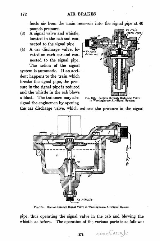
172 AIR BRAKES
feeds air from the main reservoir into the signal pipe at 40
pounds pressure. to Main
(3) A signal valve and whistle,
located in the cab and con
nected to the signal pipe.
(4) A car discharge valve, lo
cated on each car and con
nected to the signal pipe.
The action of the signal
system is automatic. If an acci
dent happens to the train which
breaks the signal pipe, the pres
sure in the signal pipe is reduced
and the whistle in the cab blows
a blast. The trainmen may also
signal the enginemen by opening
the car discharge valve, which reduces the pressure in the signal
Fig. 133. Section through Reducing Valvein Westinghouse Air-Signal System
To Whistle
Fig. 134. Section through Signal Valve in Westinghouse Air-Signal System
pipe, thus operating the signal valve in the cab and blowing the
whistle as before. The operation of the various parts is as follows :
378
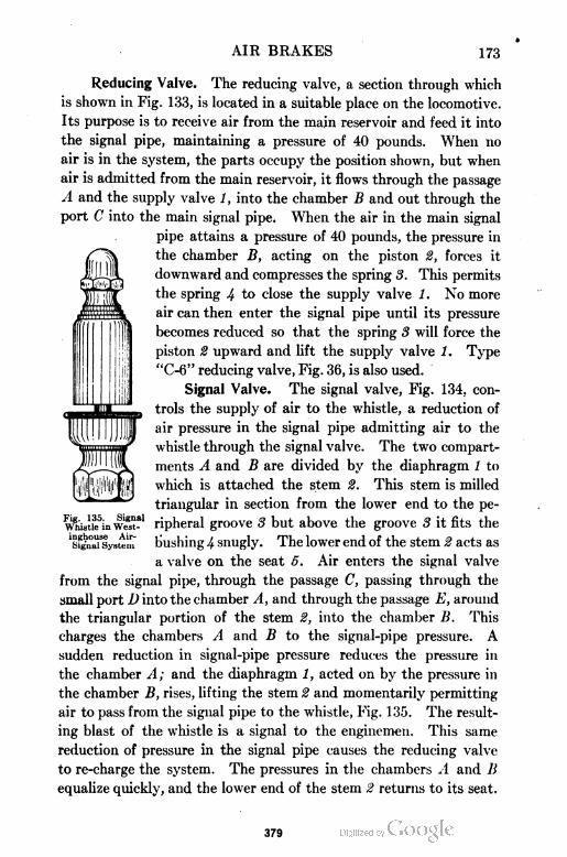
AIR BRAKES 173
Reducing Valve. The reducing valve, a section through which
is shown in Fig. 133, is located in a suitable place on the locomotive.
Its purpose is to receive air from the main reservoir and feed it into
the signal pipe, maintaining a pressure of 40 pounds. When no
air is in the system, the parts occupy the position shown, but when
air is admitted from the main reservoir, it flows through the passage
A and the supply valve 1, into the chamber B and out through the
port C into the main signal pipe. When the air in the main signal
pipe attains a pressure of 40 pounds, the pressure in
the chamber B, acting on the piston 2, forces it
downward and compresses the spring 3. This permits
the spring 4 to close the supply valve 1. No more
air can then enter the signal pipe until its pressure
becomes reduced so that the spring 3 will force the
piston 2 upward and lift the supply valve 1. Type
"C-6" reducing valve, Fig. 36, is also used.
Signal Valve. The signal valve, Fig. 134, con
trols the supply of air to the whistle, a reduction of
air pressure in the signal pipe admitting air to the
whistle through the signal valve. The two compart
ments A and B are divided by the diaphragm 1 to
which is attached the stem 2. This stem is milled
triangular in section from the lower end to the pe-
whistkfin wST' ripheral groove 3 but above the groove 3 it fits the
Isfgniusystem bushing 4 snugly. The lower end of the stem 2 acts as
a valve on the seat 5. Air enters the signal valve
from the signal pipe, through the passage C, passing through the
small port D into the chamber A, and through the passage E, around
the triangular portion of the stem 2, into the chamber B. This
charges the chambers A and B to the signal-pipe pressure. A
sudden reduction in signal-pipe pressure reduces the pressure in
the chamber A; and the diaphragm 1, acted on by the pressure in
the chamber B, rises, lifting the stem 2 and momentarily permitting
air to pass from the signal pipe to the whistle, Fig. 135. The result
ing blast of the whistle is a signal to the enginemen. This same
reduction of pressure in the signal pipe causes the reducing valve
to re-charge the system. The pressures in the chambers A and B
equalize quickly, and the lower end of the stem 2 returns to its seat.
379
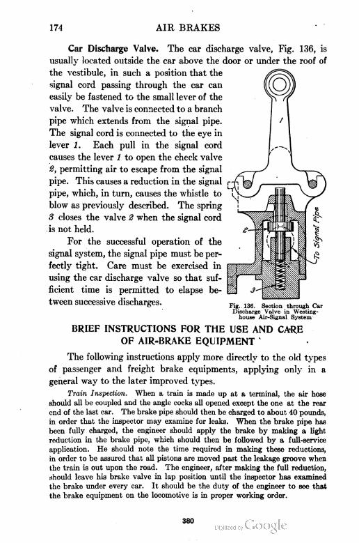
174 AIR BRAKES
Car Discharge Valve. The car discharge valve, Fig. 136, is
usually located outside the car above the door or under the roof of
the vestibule, in such a position that the
signal cord passing through the car can
easily be fastened to the small lever of the
valve. The valve is connected to a branch
pipe which extends from the signal pipe.
The signal cord is connected to the eye in
lever 1. Each pull in the signal cord
causes the lever 1 to open the check valve
2, permitting air to escape from the signal
pipe. This causes a reduction in the signal
pipe, which, in turn, causes the whistle to
blow as previously described. The spring
3 closes the valve 2 when the signal cord
is not held.
For the successful operation of the
signal system, the signal pipe must be per
fectly tight. Care must be exercised in
using the car discharge valve so that suf
ficient time is permitted to elapse be
tween successive discharges.
BRIEF INSTRUCTIONS FOR THE USE AND CARE
OF AIR-BRAKE EQUIPMENT k
The following instructions apply more directly to the old types
of passenger and freight brake equipments, applying only in a
general way to the later improved types.
Train Inspection. When a train is made up at a terminal, the air hose
should all be coupled and the angle cocks all opened except the one at the rear
end of the last car. The brake pipe should then be charged to about 40 pounds,
in order that the inspector may examine for leaks. When the brake pipe has
been fully charged, the engineer should apply the brake by making a light
reduction in the brake pipe, which should then be followed by a full-service
application. He should note the time required in making these reductions,
in order to be assured that all pistons are moved past the leakage groove when
the train is out upon the road. The engineer, after making the full reduction,
should leave his brake valve in lap position until the inspector has examined
the brake under every car. It should be the duty of the engineer to see that
the brake equipment on the locomotive is in proper working order.
Fig. 136. Section through CarDischarge Valve in Westing-
house Air-Signal System
380
AIR BRAKES 175
Running Test. In passenger service, when a locomotive has been changed
or a train made up, the engineer should make a running test within a mile of
the station, as follows: A brake-pipe reduction of about 5 pounds should be
made. If the brakes are felt to be applying and the time of the discharge is
proportional to the number of cars in the train, the engineer will conclude that
the brake is in proper working order. It is well, also, to make this test on
approaching hazardous places.
Service Applications. In making a service application of the brakes, the
first reduction should be about 5 pounds on a train of cars 30 or less, and about
7 pounds on a train exceeding 30 cars. This will insure the travel of all pistons
beyond the leakage groove. Subsequent reductions of from two to three pounds
can be made to increase the braking power, if desired. A reduction of 25 to
30 pounds will make a full-service application.
In stopping a passenger train, at least two applications should be used;
the first should reduce the speed of the train to about 8 miles an hour, when the
train is within two or three car lengths of the point at which the train is to be
stopped. Moving the brake-valve handle to release position for only sufficient
time to release all brakes, then returning it to lap position, will make it possible
for a second light application to stop the train. Just before all stops of passenger
trains, except exact-position stops at water stations and coal chutes, the brakes
should be released to avoid shocks to passengers. This release should be made
on the last revolution of the drivers. If it should be made too soon and the
train keep on moving, the engineer's brake valve should be moved to service
position until the train stops.
In making stops of freight trains, the best practice is to shut off the steam
and allow the slack to run in before applying the brakes. The stop should be
made with one application of the brakes. After the first reduction is made, if
there are any leaks in the brake pipe, the braking force will be increased, and
any subsequent reduction should be made less, in order to make up for these
leaks. In stopping a long freight train at water stations and coal chutes, it
is best to stop short of the place, cut off, and run up with the locomotive alone.
On a freight train, where the locomotive is not equipped with the straight
air brake or the "ET" equipment, the brakes should not be released when the
speed of the train is 10 miles per hour or less. If this is done, the brakes in the
front of the train may release, and, as the slack runs out, the train may part.
If the locomotive is equipped with straight air or "ET" equipment, the train
brakes can be released after the locomotive brakes are set, without danger of
parting the train.
Emergency Applications. The emergency application should never be
used, except in case of an emergency. If the necessity arises, an emergency
application may be made after a service reduction of about 15 pounds. In
case an emergency is caused by the train parting, hose bursting, or the conductor's
valve being opened, the engineer should place his valve on lap, in order to save
the main-reservoir air.
Use of Sand. The use of sand increases the braking power of a train and
should be made in emergency stops. If sand is used in service stops, it should
be supplied some time before the brakes are applied in order to have sand under
the entire train. If, for any reason, the wheels should skid, do not apply the
sand as it will produce flat spots on the wheels.
381
176 AIR BRAKES
Pressure Retaining Valve. In holding trains on grades, a part or all of
the retaining valves are set to maintain air pressure in the brake cylinder. If
only part are set, those in the front of the train should be used.
Backing Up Trains. In backing up long freight trains, the train should
be stopped by the hand brakes on the leading end of the train, for the reason
that if air were used, the brakes would apply on the cars near the engine and
the leading cars might cause a break-in-two.
In backing up a passenger train, where the train is controlled by a man on
the leading car by means of an angle cock, the engineer's valve should be in
running position. This gives the man on the rear of the train full control of
the brakes. As soon as the engineer feels the brake apply, he should place his
valve on lap.
Double-Heading. When two or more locomotives are coupled in the same
train, the brakes are operated by the leading locomotive. The cut-out cocks
in the brake pipe just below the engineer's valve on all locomotives but the
first should be closed. The pumps on all engines should be kept running.
Conductor's Brake Valve. A conductor's brake valve is located on each
passenger car. The purpose of this valve is that the conductor may stop the
train in case of emergency; if the engineer's brake valve should fail to operate,
he may signal the conductor to apply the brakes by opening the valve.
Use of Angle Cocks. In setting a car out of a train, first release the brakes,
then close the angle cock on both sides of the hose to be disconnected, and finally
disconnect the hose by hand. Before leaving a car on the side track, the air
brakes should first be released by opening the release valve on the auxiliary
reservoir; and if the car is on a grade, the hand brake should be set.
The angle cock should not be opened on the head end of a train while the
locomotive is detached. When connecting a locomotive to the train that is
already charged with air, the angle cock at the rear of the tender should be
opened first to allow the hose to become charged and thus prevent a slight
reduction in the brake pipe, which might set the brakes. All angle cocks upon
charged brake pipes should be opened slowly.
Cutting Out Brakes. If the brake equipment on any car is defective, it
may be cut out by closing the cut-out cock in the branch pipe leading from the
brake pipe to the triple valve. The release valve on the auxiliary reservoir
should be opened to discharge the air. Never more than three cars with their
brakes cut out should be placed together in a train on account of the emergency
feature being unable to skip more than this number.
Air Pump. The air pump should be run slowly with the drain-cocks
open unt il the steam cylinder becomes warm and sufficient air-pressure has been
attained to cushion the air, after which time the throttle may be fully opened.
The lubricator should be in operation as soon as possible after starting, and the
swab on the piston rod should be kept well oiled. The air cylinder should
receive oil each trip. Valve oil should be used, and it should be inserted through
the oil cup provided for that purpose, and not through the air strainer.
Engineer's Brake Valve. With the handle in running position, the main-
reservoir pressure should be maintained at 90 pounds or as high as needed,
and the brake pipe at 70 or 110 pounds, depending on the system. This requires
that the springs in the pump governor and feed valve must be carefully adjusted
and that no leaks exist between ports in the rotary valve. The rotary valve
382
AIR BRAKES 177
should be cleaned and oiled when necessary; and if leaks exist, the valve should
be scraped to a fit.
Triple Valve and Brake Cylinders. The triple valve and brake cylinders
should receive an occasional cleaning and oiling in order that they may be relied
upon to fulfill their function. In cleaning the cylinder, special attention should
be given to removing any deposit in the leakage groove. The walls of the cylinder
should be coated with suitable oil or grease, and all bolts in the cylinder head
and follower should be kept tight.
In cleaning the triple valve, a common practice is to place the removable
parts in kerosene until the other parts and the brake cylinder have been cleaned.
The parts are then removed, cleaned, oiled, and replaced. Special care should
be given to the slide valve and its seat, and to the graduating valve. All lint
should be removed before replacing the parts. The piston packing ring should
never be removed, except for renewing. A few drops of oil is all that is necessary
for lubricating the entire triple valve. No oil should be permitted to get upon
the gaskets or rubber-seated valve. The graduating-valve and check-valve
Bprings should be examined and, if necessary, renewed.
AIR BRAKES AS APPLIED TO ELECTRIC CARS
GENERAL SURVEY OF SYSTEMS DEVELOPED
That electric street cars and interurban cars should be equipped
with reliable and efficient braking apparatus is a well-established
fact, which is emphasized by the frequency of accidents on roads
where poorly constructed braking appliances are used. The modern
electric car is several times heavier than cars used a decade, ago and
speeds have increased remarkably, yet we frequently find cars fitted
with braking apparatus but little better than that used in the days
of the horse car. Of recent years, the most progressive roads have
given much attention to the construction of their equipment in order
to insure the safety of their passengers and, as a result, braking
appliances have been greatly improved.
Hand Brakes. The hand brake was the first form of brake
used on electric cars and is still used in many of the smaller cities.
It is also found today on many cars fitted with air brakes, to be used
in case of necessity. The early forms of hand brakes consisted of a
brake staff located at either end of the car, having a chain connected
to the lower end of the staff. As the handle turned, the chain was
wound up on the staff, and the resulting motion actuated the rods
and levers which brought the brake shoes in contact with the wheels.
383
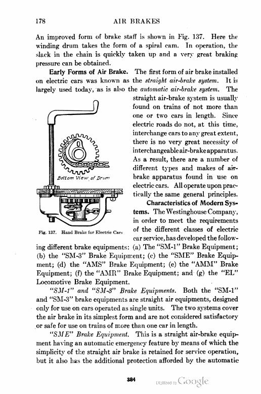
178 AIR BRAKES
An improved form of brake staff is shown in Fig. 137. Here the
winding drum takes the form of a spiral cam. In operation, the
slack in the chain is quickly taken up and a very great braking
pressure can be obtained.
Early Forms of Air Brake. The first form of air brake installed
on electric cars was known as the straight air-brake system. It is
largely used today, as is also the automatic air-brake system. The
ing different brake equipments: (a) The "SM-1" Brake Equipment;
(b) the "SM-3" Brake Equipment; (c) the "SME" Brake Equip
ment; (d) the "AMS" Brake Equipment; (e) the "AMM" Brake
Equipment; (f) the "AMR" Brake Equipment; and (g) the "EL"
Locomotive Brake Equipment.
"SM-1" and "SMS" Brake Equipments. Both the "SM-1"
and "SM-3" brake equipments are straight air equipments, designed
only for use on cars operated as single units. The two systems cover
the air brake in its simplest form and are not considered satisfactory
or safe for use on trains of more than one car in length.
"SME" Brake Equipment. This is a straight air-brake equip
ment having an automatic emergency feature by means of which the
simplicity of the straight air brake is retained for service operation,
but it also has the additional protection afforded by the automatic
straight air-brake system is usually
found on trains of not more than
one or two cars in length. Since
electric roads do not, at this time,
interchange cars to any great extent,
there is no very great necessity of
interchangeable air-brake apparatus.
As a result, there are a number of
different types and makes of ai.r-
brake apparatus found in use on
electric cars. All operate upon prac
tically the same general principles.
Fig. 137. Hand Brake for Electric Cars
Characteristics of Modern Sys=
terns. The Westinghouse Company,
in order to meet the requirements
of the different classes of electric
car service, has developed the follow
884
AIR BRAKES 179
application of the brake in case of a break-in-two or the bursting of
a hose. It is designed for use on trains of not more than two cars
in length.
"AMS" Brake Equipment. The "AMS" equipment is designed
for use on cars running either singly or in not more than two-car
trains, in city or slow-speed service. It combines the safety features
of an automatic brake with the ease and flexibility of manipulation
of the straight air system. A simple form of plain triple valve is
used, having a quick re-charging feature.
"AMM" Brake Equipment. The "AMM" equipment is con
structed for use on cars operated in trains of not more than three
cars in length. It is especially well adapted for both city and high
speed interurban service. It is designed to provide for quick and
flexible operation of the brakes on a single car unit by the straight
air-brake system with the added feature of an immediate change to
automatic brake operation whenever two or three cars make up
the train.
"AMR" Brake Equipment. The "AMR" equipment is designed
for use on trains of not more than five cars in length. It is designed
for either city or high-speed interurban service and is strictly an
automatic brake system. This equipment possesses such advan
tages as quick service, emergency, graduated release, and quick
re-charging features.
"EL" Locomotive Brake Equipment. The development of the
modern high-power electric locomotive for handling both freight and
passenger traffic at terminals and for service on electrified steam
railroads created a demand for a thoroughly reliable and efficient
brake which would embody the desirable features of the Westing-
house No. 6 "ET" equipment. Accordingly . the No. 14 "EL"
locomotive brake equipment was developed, which is an adaptation
of the No. 6 "ET" equipment to the conditions of electric service.
The important and general features of this equipment may be
obtained by reference to the description of the "ET" equipment,
pages 110 to 132, Part II.
As the space allotted to this subject is limited, only one electric
car system will be described—the Westinghouse "SME" brake
equipment. This system is chosen because it represents in a
general way many systems now in common use.
385
180 AIR BRAKES
DETAILS OF "SME" BRAKE EQUIPMENT
Features of "SME" System. As previously mentioned, this
equipment is essentially a straight air-brake equipment having
an automatic emergency feature. The simplicity of the straight
air brake is available for ordinary service operation, while the addi
tional safety features of the automatic application of the brake is
provided in case of a break-in-two, bursting of a hose, etc. The
system is designed for use on trains of not more than two cars in
length. The chief features of the equipment when using the Type
"D" emergency valve, as set forth in the manufacturer's pamphlets
are as follows :
(a) Straight air operation for service stops.
(b) Brake cylinder release operates locally, i.e., through the emergency valve
on each car.
(c) Prompt service application and release operations due to design of the
emergency valve.
(d) Automatic maintenance of brake cylinder leakage.
(e) Uniform brake cylinder pressure, independent of variations in piston travel
or leakage.
(f) Practically uniform compressor labor insured without the necessity of a
governor synchronizing system.
(g) Automatic application of the brakes in case of ruptured piping, burst hose,
or parting of the train.
(h) Retarded release after an emergency application, as a penalty to discourage
the unnecessary use of this feature.
(i) One size of emergency valve for any size of brake cylinder.
(j) Possibility of conductor setting the brakes in emergency by means of
conductor's valve.
Principal Working Parts. The system is composed of the
following principal parts, which are located on the motor car:
(a) A motor-driven air compressor which furnishes the compressed air for use
in the brake system.
(b) An electric compressor governor which automatically controls the opera
tion of the compressor between predetermined minimum and maximum
pressures.
(c) A fuse box, fuse, and two snap switches in the line from the trolley to the
governor and air compressor, protecting the latter from any excessive flow
of current and enabling the current supply to the compressor to be entirely
cut off when desired.
(d) Two main reservoirs to which the compressed air is delivered from the air
compressor, where it is cooled and stored for use in the brake system. Where
the climatic conditions render it necessary, a radiating pipe should be installed
between the compressor and the first reservoir and between the two reservoits
to assist in the cooling process.
386
AIR BRAKES 181
(e) A check valve installed between the main reservoirs and the emergency
valve, to prevent a back flow of air into the main reservoirs when two motor
cars are operated together. This being the case, each compressor is required
to supply the air used for braking purposes on its own car.
(f) A safety valve connected to the first main reservoir, which protects against
excessive main-reservoir pressure should the compressor governor, for any
reason, become inoperative.
(g) Two brake valves, one at each end of the car, through which (1) air is
allowed to charge the emergency pipe and to exhaust from the straight air
application and release pipe when releasing the brakes; (2) air enters the
straight air application and release pipe when applying the brakes; (3) the
flow of air to or from the brake system may be prevented, as when the brakes
are being held applied; and (4) the air in the emergency pipe is allowed to
escape to the atmosphere in emergency applications.
(h) An exhaust muffler placed under the platform to deaden the brake valve
exhaust.
(i) Just below the brake valve a pipe leads from the emergency pipe to the
black hand connection of the duplex air gage, which hand shows main-reser
voir pressure, as the emergency pipe is always charged to main-reservoir
pressure, except when an emergency application of the brakes is made, as
explained later.
The red hand of the duplex air gage is connected either to the brake cylinder
direct or to the piping so as to show brake cylinder pressure.
(j). An emergency valve, connected to the brake cylinder head (or pipe bracket
if used) which (1) controls the flow of air from the reservoirs to the brake
cylinder when applying the brakes; (2) controls the flow of air from the
brake cylinder to the atmosphere when releasing the brakes; and (3) automati
cally maintains brake cylinder pressure against leakage, keeping it constant
when holding the brakes applied.
(k) A brake cylinder, with a piston and rod so connected through the brake levers
and rods to the brake shoes that, when the piston is forced outward by air
pressure, this force is transmitted through said rods and levers to the brake
shoes and applies them to the wheels.
(1) A conductor's valve" (furnished when ordered) located inside each car,
enabling the conductor to apply the brakes if necessary.
(m) Various cut-out cocks, air strainers, hose couplings, dummy couplings,
etc., the location and uses of which will be readily understood from the
explanations which follow.
(n) While not a part of the air-brake apparatus proper, the car is usually.
equipped with two air alarm whistles, one at each end of the car, to be used
as a warning of approach, with the necessary whistle valves and cut-out
cocks.
Two lines of pipe—the emergency pipe and the straight air application
and release pipe—extend the entire length of the car and train, when two or
more cars are coupled together, being provided with suitable hose and coup
lings at the ends of the cars. The cut-out cocks in these pipes, located just
back of the hose connections, should always be enclosed at each end of a
single car or train and always open between cars which are being operated
together as a train.
387
182 AIR BRAKES
Equipment on Non-Motor Trailers. The equipment of a non-
motor trailer car consists of a brake cylinder, auxiliary reservoir,
emergency valve, straight air application and release pipe, and
emergency pipe, all of which, except the auxiliary reservoir, have
been described above.
In addition, an auxiliary reservoir is used on a non-motor
trailer car to furnish an independent supply of air for applying the
brakes on that car when an application is made. The auxiliary
reservoir pipe is connected to the emergency valve in the same
manner as is the main reservoir supply pipe on a motor car. The
auxiliary reservoir is charged from the emergency pipe by way of
the emergency valve.
OPERATION RULES FOR "SME" BRAKE EQUIPMENT
The following rules furnished by the Westinghouse Company
for operating the "SME" brake equipment are intended to cover in
a condensed form the important instructions to be observed in
handling this equipment in service.
Charging. Before starting the air compressor, see that the following
cocks are closed: the drain cocks in the reservoirs; the cut-out cocks (if used)
under the non-operative brake valves, also under the whistles not to be operated;
and the cut-out cocks in the emergency and straight air pipes at the head and
rear end of the car, or of the trains when two cars are coupled together.
See that the following cocks are open: the cut-out cock, if any is used,
in the emergency pipe under the brake valve to be operated; governor cut-out
cock; the cut-out cock under the whistles to be operated; and all the emergency
pipe and straight air pipe cut-out cocks between cars.
See that all hand brakes are fully released. The fuse in the compressor
circuit must be in place and must be "live".
Place the handle of the brake valve to be operated—all other brake valves
being in lap position—in release position and start the compressor by closing
the switches in the compressor circuit on each motor car.
Do not attempt to move the car until the gage shows full main-reservoir
pressure.
Running. Keep the brake valve handle in release position when not being
used. In event of sudden danger, move the brake-valve handle quickly to
emergency position, at the extreme right, and leave it there until the car has
stopped and the danger is past.
If the brakes apply while running over the road, due to bursting of hose,
etc., move the brake-valve handle to emergency position at once, to prevent
loss of main-reservoir pressure, and leave it there until the car or train stops
and the danger is past. The cause of the application should be located and
remedied before proceeding.
888
AIR BRAKES 183
Service Application. To apply brakes for an ordinary stop, move the
brake-valve handle to either one-car service position or two-car service position
depending upon the conditions existing and results desired. When the desired
brake-cylinder pressure has been obtained, as shown by the red hand of the air
gage, the brake-valve handle should be placed in lap position, where it should
remain until it is desired either to release the brakes or to make a heavier appli
cation.
How heavy an application should be made, and whether a full application
should be made at once or the brakes graduated on, depends upon the circum
stances in each particular case—such as the speed and weight of the train,
condition of the rails, grade, kind of stop desired, and regard for the comfort
of the passengers.
Because the retarding effect of a given brake-cylinder pressure is greater
at low speeds, this fact will result in an abrupt stop, with perhaps danger to lading,
discomfort to passengers, or slid flat wheels. With high speeds, however, a
heavy initial application should be made in order to obtain the most effective
retardation possible when the momentum of the car is greatest. If the brakes
are applied lightly at first and the braking pressure increased as the speed of the
car diminishes, it not only makes a longer stop, but the high brake-cylinder
pressure at the end of the stop will be likely to produce a rough stop, slid wheels,
and to result in loss of time.
The best possible stop will be made when the brakes are applied as hard,
at the very start, as the speed, the conditions of the rails, and the comfort of
the passengers will permit, and then graduated off as the speed of the car is
reduced, so that at the end of the stop little or no pressure remains in the brake
cylinder.
To properly weigh all these varying factors in every stop becomes, after
a little practice, an act of unconscious judgment. Careful attention to cause
and effect at the very start and a real desire to improve are the most necessary
qualifications in order to become expert in handling this or any other form of
brake equipment.
Holding Brakes Applied. The brake-valve handle should be left in lap
position until it is desired either to release the brakes or to apply them with
greater force. If the car is to be left standing with the brakes applied for any
length of time, the air brakes should be released and the hand brakes set.
Release. The brakes are released, as with any straight air brake, by placing
the brake-valve handle in release position and leaving it there, if it is desired
to fully release the brakes; or, if it is desired to graduate or partially release
the brakes, by moving the handle to release position for a moment, then back
to lap position, repeating this operation until the car is brought to rest, only
enough pressure being retained in the brake cylinder at the end of the stop to
prevent the wheels from rolling.
Emergency. Should it become imperative to stop in the shortest possible
time and distance, to save life or avoid accident, move the handle quickly from
whatever position it may be in to emergency position, which is at the extreme
right, and allow it to remain there until the car stops and the danger is past.
When releasing after an emergency application, it will be observed that
the release takes place slowly. This is intentional, the equipment being so
designed that when such a release is made, a fixed period of time must elapse
389
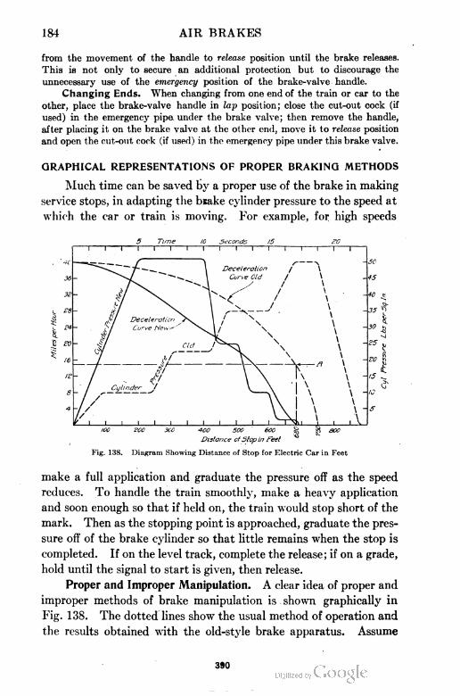
18-1 AIR BRAKES
from the movement of the handle to release position until the brake releases.
This is not only to secure an additional protection but to discourage the
unnecessary use of the emergency position of the brake-valve handle.
Changing Ends. When changing from one end of the train or car to the
other, place the brake-valve handle in lap position; close the cut-out cock (if
used) in the emergency pipe under the brake valve; then remove the handle,
after placing it on the brake valve at the other end, move it to release position
and open the cut-out cock (if used) in the emergency pipe under this brake valve.
GRAPHICAL REPRESENTATIONS OF PROPER BRAKING METHODS
Much time can be saved by a proper use of the brake in making
service stops, in adapting the bnake cylinder pressure to the speed at
which the car or train is moving. For example, for high speeds
5 Tune ID Seconds 15 £0t 1 1 1 1 1 1 1 1 1 1 1 i r—i 1 r
100 200 300 400 500 ' eoo § g eoo
Distance cfSlop in Feel *
Fig. 138. Diagram Showing Distance of Stop for Electric Car in Feet
make a full application and graduate the pressure off as the speed
reduces. To handle the train smoothly, make a heavy application
and soon enough so that if held on, the train would stop short of the
mark. Then as the stopping point is approached, graduate the pres
sure off of the brake cylinder so that little remains when the stop is
completed. If on the level track, complete the release; if on a grade,
hold until the signal to start is given, then release.
Proper and Improper Manipulation. A clear idea of proper and
improper methods of brake manipulation is shown graphically in
Fig. 138. The dotted lines show the usual method of operation and
the results obtained with the old-style brake apparatus. Assume
390
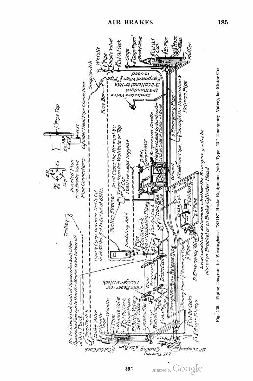
AIR BRAKES 185
5
-2.
391
186 AIR BRAKES
the speed to be 40 m. p. h. when the application is begun. The
brake is applied in a series of steps or graduations so that in about
16 to 17 seconds, maximum cylinder pressure has been reached; but
meanwhile the train has been brought nearly to a standstill with
the highest brake-cylinder pressure being developed at the time the
speed is lowest and, consequently, with great tendency on the part
of the wheels to slide, making it necessary to get rid of this high-
cylinder pressure at once or come to a stop with an unpleasant jerk.
A stop by this method is made in say 750 feet.
The full lines illustrate the proper method and show what is
possible in the way of smoothness of stop, accuracy of stop, saving
of time, and freedom from tendency to wheel sliding. The maxi
mum cylinder pressure is obtained at once when the speed of the
train is highest and the holding power of the brakes least effective.
At the end of about ten seconds, when the speed has been reduced
to say 20 m.p.h. and the brakes are "taking hold" more powerfully,
a part of the cylinder pressure is released—enough (25 pounds)
being retained in the cylinder to maintain as high a rate of decelera
tion as possible without danger of sliding of wheels. This operation
is repeated as may be necessary to keep the retarding force (brake-
cylinder pressure) in its proper relation to the decreasing speed of
the train. A stop by this method is made in say 680 feet—70 feet
shorter than by the improper method—and plainly with much
greater smoothness, less tendency to wheel sliding, in shorter time,
and with the brake-cylinder pressure nearly or completely exhausted
and the system practically fully re-charged.
Fig. 140. Piping Diagram for Westinghouse "SME" Brake Equipment (withType "D" Emergency Valve) for Trailer Car
392
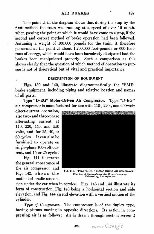
AIR BRAKES 187
The point A in the diagram shows that during the stop by the
first method the train was running at a speed of over 15 m.p.h.
when passing the point at which it would have come to a stop, if the
second and correct method of brake operation had been followed.
Assuming a weight of 160,000 pounds for the train, it therefore
possessed at the point A about 1,200,000 foot-pounds or 600 foot-
tons of energy, which would have been harmlessly dissipated had the
brakes been manipulated properly. Such a comparison as this
shows clearly that the question of which method of operation to pur
sue is not of theoretical but of vital and practical importance.
DESCRIPTION OF EQUIPMENT
Figs. 139 and 140, illustrate diagrammatically the "SME'
brake equipment, including piping and relative location and names
of all parts.
Type "D=EG" Motor=Driven Air Compressor. Type "D-EG"
air compressor is manufactured for use with 110-, 220-, and 600-volt
direct-current operation,
also two- and three-phase
alternating current at
110, 220, 440, and 550
volts, and for 25, 40, or
60 cycles. It can also be
furnished to operate on
single-phase 100-volt cur
rent, and 15 or 25 cycles.
Fig. 141 illustrates
the general appearance of
the air compressor and
Fig. 142, shows the
method of cradle suspen
sion under the car when in service. Figs. 143 and 144 illustrate its
form of construction, Fig. 143 being a horizontal section and side
elevation, and Fig. 144 an end elevation with a vertical section of the
cylinder.
Type of Compressor. The compressor is of the duplex type,
having pistons moving in opposite directions. Its action in com
pressing air is as follows: Air is drawn through suction screen 4
Fig. 141. Type "D-EG" Motor-Driven Air Compressor
Courtesy of Westinghouse Air Brake Company,Wilmerding, Pennsylvania
393
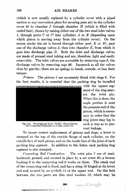
188 AIR BRAKES
(which is now usually replaced by a cylinder cover with a piped
suction to any convenient place for securing pure air) in the cylinder
cover 25 to chamber ./ through chamber H (which is filled with
curled hair), thence by raising either one of the two steel inlet valves
/, through ports C or C1 into cylinders A or B (depending upon
which piston is moving away from the cylinder cover). On the
return stroke the air is forced through either port A' or K1, past
one of the discharge valves 2, then into chamber E, from which it
goes into discharge pipe D. Both the inlet and discharge valves
are made of pressed steel tubing and are, therefore, light and easily
removable. The inlet valves are accessible by removing caps 3, the
discharge valves by removing caps 26. Inasmuch as all the valves
close by gravity, there are no springs to break, corrode, or lose their
temper.
Pistons. The pistons 5 are accurately fitted with rings 6. For
the best results, it is essential that the packing ring be installed
with the square seg
ment of the ring near
est the wrist pin.
When this is done, the
angle portion is next
the pressure end of the
piston, which is neces
sary in order that the
ring joints may lap in
Fig. 142. Westinghouse Type "D-EG" Motor-Driven SUch a W3V 3S tO pre-. Air Compressor Suspended in Cradle under Car * 1
vent leakage.
To insure correct replacement of pistons and rings, a letter is
stamped at the top of the outside flange of each cylinder, on the
outside face of each piston, and on the inside face of the joint of each
packing ring segment. In addition to this letter, each packing ring
segment is also stamped.
Connecting Rod Construction. The wrist pins 7 are of steel,
hardened, ground, and secured in place by a set screw 30; a bronze
bushing 8 in the connecting rod 9 works on them. The crank end
of the connecting rod is lined, and has a strap 10 hinged at its lower
end and secured by an eyebolt 11 at the upper end. On this bolt
between the two parts are thin steel washers 12, which may be
394
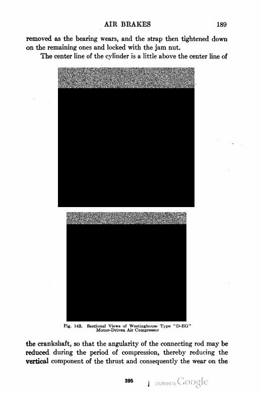
AIR BRAKES 189
removed as the bearing wears, and the strap then tightened down
on the remaining ones and locked with the jam nut.
The center line of the cylinder is a little above the center line of
Fig. 143. Sectional Views of Westinghouse Type "D-EG"Motor-Driven Air Compressor
the crankshaft, so that the angularity of the connecting rod may be
reduced during the period of compression, thereby reducing the
vertical component of the thrust and consequently the wear on the
J395
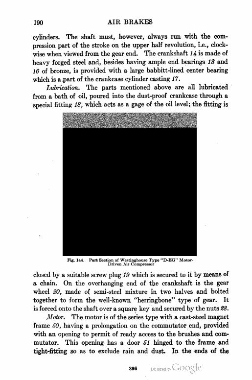
190 AIR BRAKES
cylinders. The shaft must, however, always run with the com
pression part of the stroke on the upper half revolution, i.e., clock
wise when viewed from the gear end. The crankshaft 14 is made of
heavy forged steel and, besides having ample end bearings 13 and
16 of bronze, is provided with a large babbitt-lined center bearing
which is apart of the crankcase cylinder casting 17.
Lubrication. The parts mentioned above are all lubricated
from a bath of oil, poured into the dust-proof crankcase through a
special fitting 18, which acts as a gage of the oil level; the fitting is
JUR DISCHARGE.
Fig. 144. Part Section of Westinghouse Type "D-EG" Motor-Driven Air Compressor
closed by a suitable screw plug 19 which is secured to it by means of
a chain. On the overhanging end of the crankshaft is the gear
wheel 20, made of semi-steel mixture in two halves and bolted
together to form the well-known "herringbone" type of gear. It
is forced onto the shaft over a square key and secured by the nuts 28.
Motor. The motor is of the series type with a cast-steel magnet
frame 50, having a prolongation on the commutator end, provided
with an opening to permit of ready access to the brushes and com
mutator. This opening has a door 51 hinged to the frame and
tight-fitting so as to exclude rain and dust. In the ends of the
396
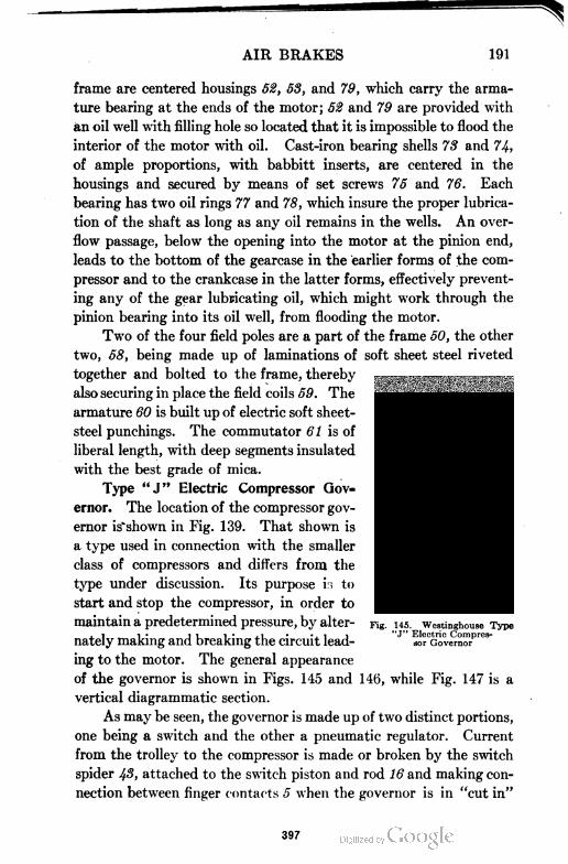
AIR BRAKES 191
frame are centered housings 52, 53, and 79, which carry the arma
ture bearing at the ends of the motor; 52 and 79 are provided with
an oil well with filling hole so located that it is impossible to flood the
interior of the motor with oil. Cast-iron bearing shells 73 and 74,
of ample proportions, with babbitt inserts, are centered in the
housings and secured by means of set screws 75 and 76. Each
bearing has two oil rings 77 and 78, which insure the proper lubrica
tion of the shaft as long as any oil remains in the wells. An over
flow passage, below the opening into the motor at the pinion end,
leads to the bottom of the gearcase in the earlier forms of the com
pressor and to the crankcase in the latter forms, effectively prevent
ing any of the gear lubricating oil, which might work through the
pinion bearing into its oil well, from flooding the motor.
Two of the four field poles are a part of the frame 50, the other
two, 58, being made up of laminations of soft sheet steel riveted
together and bolted to the frame, thereby
also securing in place the field coils 59. The
armature 60 is built up of electric soft sheet-
steel punchings. The commutator 61 is of
liberal length, with deep segments insulated
with the best grade of mica.
Type "J" Electric Compressor Gov
ernor. The location of the compressor gov
ernor is'shown in Fig. 139. That shown is
a type used in connection with the smaller
class of compressors and differs from the
type under discussion. Its purpose i.i to
start and stop the compressor, in order to
maintain a predetermined pressure, by alter
nately making and breaking the circuit lead
ing to the motor. The general appearance
of the governor is shown in Figs. 145 and 146, while Fig. 147 is a
vertical diagrammatic section.
As may be seen, the governor is made up of two distinct portions,
one being a switch and the other a pneumatic regulator. Current
from the trolley to the compressor is made or broken by the switch
spider ^3, attached to the switch piston and rod 16 and making con
nection between finger contacts 5 when the governor is in "cut in"
145. Westinghouse Type'J" Electric Compres
sor Governor
397
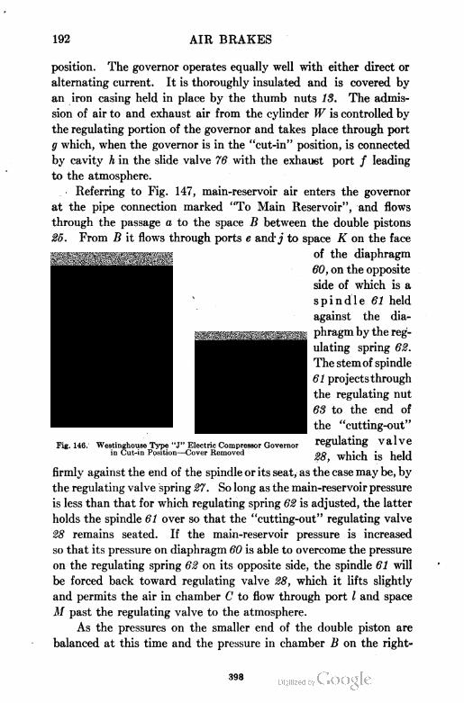
192 AIR BRAKES
position. The governor operates equally well with either direct or
alternating current. It is thoroughly insulated and is covered by
an iron casing held in place by the thumb nuts IS. The admis
sion of air to and exhaust air from the cylinder W is controlled by
the regulating portion of the governor and takes place through port
g which, when the governor is in the "cut-in" position, is connected
by cavity h in the slide valve 76 with the exhaust port / leading
to the atmosphere.
Referring to Fig. 147, main-reservoir air enters the governor
at the pipe connection marked "To Main Reservoir", and flows
through the passage a to the space B between the double pistons
25. From B it flows through ports e and j to space K on the face
firmly against the end of the spindle or its seat, as the case may be, by
the regulating valve spring 27. So long as the main-reservoir pressure
is less than that for which regulating spring 62 is adjusted, the latter
holds the spindle 61 over so that the "cutting-out" regulating valve
28 remains seated. If the main-reservoir pressure is increased
so that its pressure on diaphragm 60 is able to overcome the pressure
on the regulating spring 62 on its opposite side, the spindle 61 will
be forced back toward regulating valve 28, which it lifts slightly
and permits the air in chamber C to flow through port I and space
M past the regulating valve to the atmosphere.
As the pressures on the smaller end of the double piston are
balanced at this time and the pressure in chamber B on the right-
Fig. 146. Westinghouse Type "J" Electric Compressor Governorin Cut-in Position—Cover Removed
of the diaphragm
60, on the opposite
side of which is a
spindle 61 held
against the dia
phragm by the reg
ulating spring 62.
The stemof spindle
61 projects through
the regulating nut
63 to the end of
the "cutting-out"
regulating valve
28, which is held
398
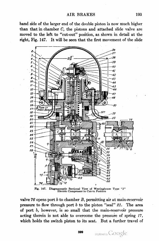
AIR BRAKES 193
hand side of the larger end of the double piston is now much higher
than that in chamber C, the pistons and attached slide valve are
moved to the left to "cut-out" position, as shown in detail at the
right, Fig. 147. It will be seen that the first movement of the slide
Fig. 147. Diagrammatic Sectional View of Westinghouse Type "J"Electric Compressor in Cut-in Position
valve 76 opens port b to chamber B, permitting air at main-reservoir
pressure to flow through port b to the piston "seal" 21. The area
of port b, however, is so small that the main-reservoir pressure
acting therein is not able to overcome the pressure of spring 17,
which holds the switch piston to its seat. But a further travel of
399
194 AIR BRAKES
the slide valve opens port g, which allows air at main-reservoir
pressure to flow to the air cylinder W, thus breaking the "seal"
of the piston and the main-reservoir pressure then acts on the entire
area of the piston, causing it to move outward very rapidly and break
the circuit. By having port b open before port g, a free flow of
high-pressure air to the space W below the switch piston is insured
and a "quick-break" obtained, which eliminates any tendency to
cut out slowly. During this movement the air above the switch
piston is compressed, and forced through ports y and z in the hollow
rod to the atmosphere. The ports z are so placed that they pass
the ends of the contact fingers just when the circuit is broken and
the quick piston movement causes the air in X to be expelled with
such force as to make an effective and complete pneumatic blow-out.
In this position of the slide valve 76 it will also be seen that
cavity h connects port e to the exhaust port / and atmosphere,
thus relieving diaphragm 60 of pressure and permitting the regulat
ing valve 28 to seat. Air from chamber C can then no longer escape
to the atmosphere and it rapidly becomes equal in pressure to that
in chamber B (due to flow of air through the small leakage port
shown in the large double piston). Both ends of the double piston
are then balanced and the parts remain in "cut-out" position until
the governor is "cut-in" as follows: A branch from port a permits
air at main-reservoir pressure to flow through port q to p and the
space 0 on the face of diaphragm 71, on the opposite side of which
is a . spindle 67 held against the diaphragm by the "cutting-in"
regulating spring 70. The stem of the spindle projects through
the regulating nut 68 and the "cutting-in" regulating valve 65
is held against the end of the stem by the regulating valve spring 66.
So long, therefore, as the main-reservoir pressure on the face of the
diaphragm 71 is greater than the pressure of the regulating spring
70 on its opposite side, the regulating valve 65 will be held to its
seat by the stem of spindle 67 and the port n is then closed.
After the governor has been "cut-out" as explained above and
the main-reservoir pressure falls to such a point that the air pressure
on diaphragm 71 is no longer able to overcome the pressure of the
regulating spring 70 on its opposite side, the latter moves the spindle
over so as to permit the regulating valve spring 66 to raise the
regulating valve 65 slightly from its seat. This permits the air
400
AIR BRAKES 195
in chamber D, back of the smaller end of the double piston, to escape
through port n and past the regulating valve 65 to the atmosphere.
The larger end of the double piston is balanced at this time and the
pressure in chamber B, therefore, forces the smaller piston back
to the position shown in Fig. 147, carrying with it the large piston
and slide valve, exhausting the air from the air cylinder W through
ports g and h and exhaust port / to the atmosphere, and allowing the
piston spring 17 to force the piston 16 and the circuit closer 1$
back to "cut-in" position. It will be seen from the illustration
that when the double piston moves to "cut-in" position, as explained,
a projection boss on the outside face of the small piston closes the
connection between chamber D and port n, so that the pressure
in D has no escape when the governor is cut in. Chamber D is
very small and as the small piston and its packing ring, when fitted
as tight as is practicable, are still not absolutely air-tight, the slight
leakage past the small piston soon equalizes the pressures in D
and B, and, as the pressures in C
and B are also equal, both double
pistons are again balanced and the
parts remain in "cut-in" position
until the governor is "cut-out" as
already explained.
The governor is adjusted for a
cutting-in pressure of 50 pounds and
a cutting-out pressure of 65 pounds.
Type "M=18" Brake Valve.
The "M-18" brake valve, Fig. 148,
is of the rotary type and it is fitted
with a removable handle. A top Fig. 148. Westinghouse "M-18"
view of the valve, Fig. 149, shows
the different position of the handle, while a vertical section illustrates
the arrangement of the ports, etc. The positions of the handle, named
from left to right are, release, lap, one-car service, two-car service, and
emergency position. The pipe connections are as follows:
(a) Straight air application and release pipe, leading to the emergency valve.
(b) Emergency pipe, which also leads to the emergency valve.
(c) Brake valve exhaust pipe, leading to the exhaust muffler under the platform.
(d) Reservoir pipe, leading to the emergency valve and to which the reservoir
is connected through the check valve.
401
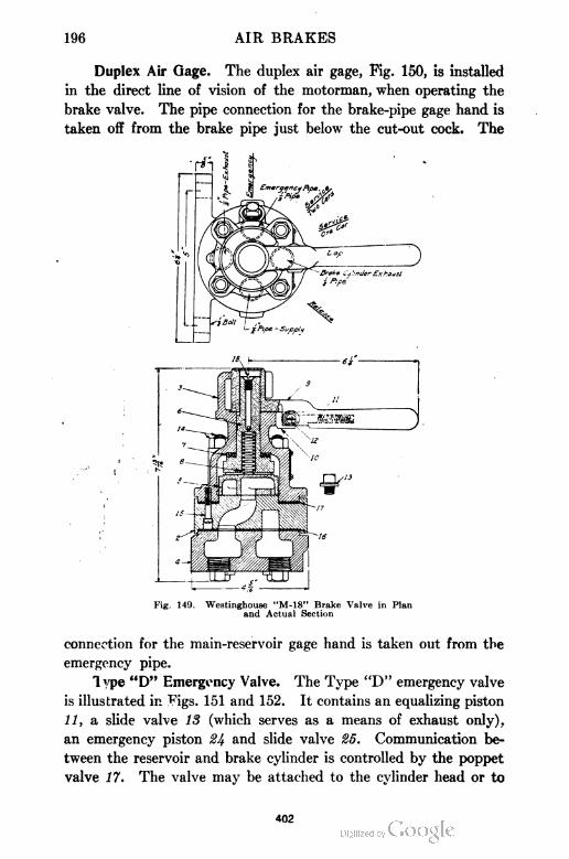
196 AIR BRAKES
Duplex Air Gage. The duplex air gage, Fig. 150, is installed
in the direct line of vision of the motorman, when operating the
brake valve. The pipe connection for the brake-pipe gage hand is
taken off from the brake pipe just below the cut-out cock. The
Fig. 149. Westinghouse "M-18" Brake Valve in Planand Actual Section
connection for the main-reservoir gage hand is taken out from the
emergency pipe.
Type "D" Emergency Valve. The Type "D" emergency valve
is illustrated in Figs. 151 and 152. It contains an equalizing piston
11, a slide valve 13 (which serves as a means of exhaust only),
an emergency piston 24 and slide valve 25. Communication be
tween the reservoir and brake cylinder is controlled by the poppet
valve 17. The valve may be attached to the cylinder head or to
402
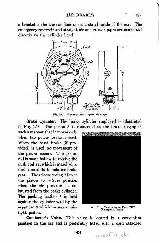
AIR BRAKES 197
a bracket under the car floor or on a stand inside of the car. The
emergency reservoir and straight air and release pipes are connected
directly to the cylinder head.
Fig. 150. Westinghouse Duplex Air Gage
Brake Cylinder. The brake cylinder employed is illustrated
in Fig. 153. The piston 8 is connected to the brake rigging in
such a manner that it moves only
when the power brake is used.
When the hand brake (if pro
vided) is used, no movement of
the piston occurs. The piston
rod is made hollow to receive the
push rod 14, which is attached to
the levers of the foundation brake
gear. The release spring 9 forces
the piston to release position
when the air pressure is ex
hausted from the brake cylinder.
The packing leather 7 is held
against the cylinder wall by the
expander 8 which insures an air
tight piston.
Conductor's Valve. This valve is located in a convenient
position in the car and is preferably fitted with a cord attached
Fig. 151. Westinghouse Type "D"Emergency Valve
403
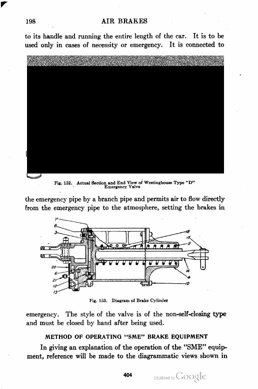
198 AIR BRAKES
to its handle and running the entire length of the car. It is to be
used only in cases of necessity or emergency. It is connected to
Fig. 152. Actual Section and End View of Westinghouse Type "D"Emergency Valve
the emergency pipe by a branch pipe and permits air to flow directly
from the emergency pipe to the atmosphere, setting the brakes in
Fig. 153. Diagram of Brake Cylinder
emergency. The style of the valve is of the non-self-closing type
and must be closed by hand after being used.
METHOD OF OPERATING "SME" BRAKE EQUIPMENT
In giving an explanation of the operation of the "SME" equip
ment, reference will be made to the diagrammatic views shown in
404
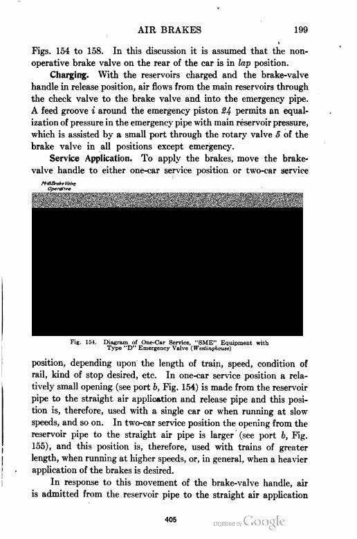
AIR BRAKES 199
Figs. 154 to 158. In this discussion it is assumed that the non-
operative brake valve on the rear of the car is in lap position.
Charging. With the reservoirs charged and the brake-valve
handle in release position, air flows from the main reservoirs through
the check valve to the brake valve and into the emergency pipe.
A feed groove i around the emergency piston 24 permits an equal
ization of pressure in the emergency pipe with main reservoir pressure,
which is assisted by a small port through the rotary valve 5 of the
brake valve in all positions except emergency.
Service Application. To apply the brakes, move the brake-
valve handle to either one-car service position or two-car service
M.lSBrake Voire
position, depending upon the length of train, speed, condition of
rail, kind of stop desired, etc. In one-car service position a rela
tively small opening (see port b, Fig. 154) is made from the reservoir
pipe to the straight air application and release pipe and this posi
tion is, therefore, used with a single car or when running at slow
speeds, and so on. In two-car service position the opening from the
reservoir pipe to the straight air pipe is larger (see port b, Fig.
155), and this position is, therefore, used with trains of greater
length, when running at higher speeds, or, in general, when a heavier
application of the brakes is desired.
In response to this movement of the brake-valve handle, air
is admitted from the reservoir pipe to the straight air application
Fig. 154. Diagram of One-Car Service, "SME" Equipment with
Type "D" Emergency Valve (Westinghouse)
405
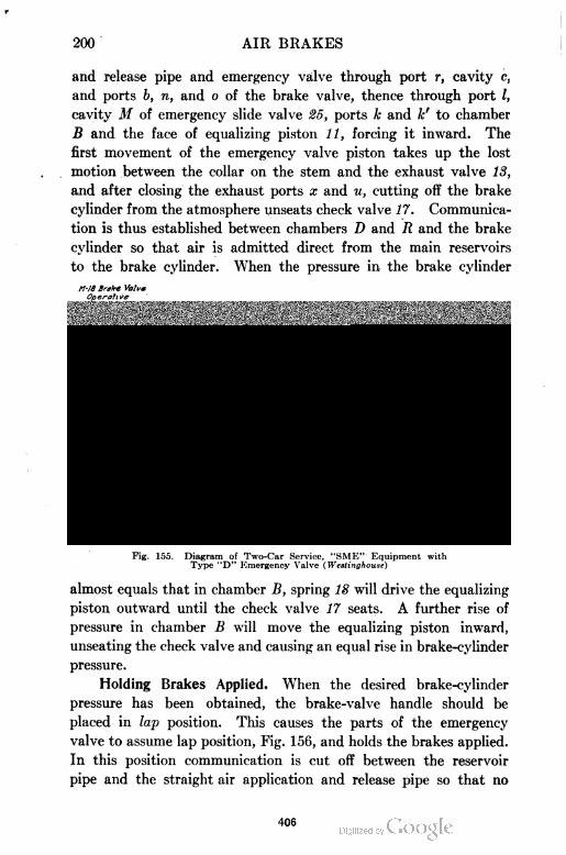
200 AIR BRAKES
and release pipe and emergency valve through port r, cavity c,
and ports b, n, and o of the brake valve, thence through port I,
cavity M of emergency slide valve 25, ports k and k' to chamber
B and the face of equalizing piston 11, forcing it inward. The
first movement of the emergency valve piston takes up the lost
motion between the collar on the stem and the exhaust valve 13,
and after closing the exhaust ports x and u, cutting off the brake
cylinder from the atmosphere unseats check valve 17. Communica
tion is thus established between chambers D and R and the brake
cylinder so that air is admitted direct from the main reservoirs
to the brake cylinder. When the pressure in the brake cylinder
M-18 Brake ValveOperative
Fig. 155. Diagram of Two-Car Service, "SME" Equipment withType "D" Kmergeney Valve (Westinghouse)
almost equals that in chamber B, spring 18 will drive the equalizing
piston outward until the check valve 17 seats. A further rise of
pressure in chamber B will move the equalizing piston inward,
unseating the check valve and causing an equal rise in brake-cylinder
pressure.
Holding Brakes Applied. When the desired brake-cylinder
pressure has been obtained, the brake-valve handle should be
placed in lap position. This causes the parts of the emergency
valve to assume lap position, Fig. 156, and holds the brakes applied.
In this position communication is cut off between the reservoir
pipe and the straight air application and release pipe so that no
406
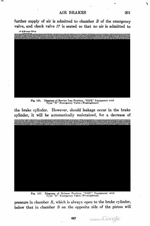
AIR BRAKES 201
further supply of air is admitted to chamber B of the emergency
valve, and check valve 17 is seated so that no air is admitted to
M-18Brake ValveOperalive
Fig. 15G. Diagram of Service Lap Position, "SME" Equipment withType "D" Emergency Valve (Westinghouse)
the brake cylinder. However, should leakage occur in the brake
cylinder, it will be automatically maintained, for a decrease of
M-18Brake Valve
Fig. 157. Diagram of Release Position, "SME" Equipment withType "D" Emergency Valve ( Westinghouse)
pressure in chamber R, which is always open to the brake cylinder,
below that in chamber B on the opposite side of the piston will
407
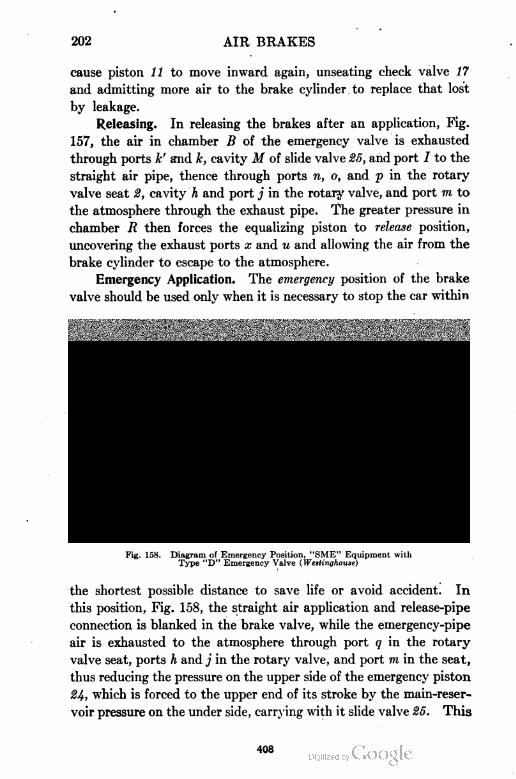
202 AIR BRAKES
cause piston 11 to move inward again, unseating check valve 17
and admitting more air to the brake cylinder to replace that lost
by leakage.
Releasing. In releasing the brakes after an application, Fig.
157, the air in chamber B of the emergency valve is exhausted
through ports h' and k, cavity M of slide valve 25, and port I to the
straight air pipe, thence through ports n, o, and p in the rotary
valve seat 2, cavity h and port j in the rotary valve, and port m to
the atmosphere through the exhaust pipe. The greater pressure in
chamber R then forces the equalizing piston to release position,
uncovering the exhaust ports x and u and allowing the air from the
brake cylinder to escape to the atmosphere.
Emergency Application. The emergency position of the brake
valve should be used only when it is necessary to stop the car within
Fig. 158. Diagram of Emergency Position, "SME" Equipment withType "D" Emergency Valve ( Westinghouse)
the shortest possible distance to save life or avoid accident. In
this position, Fig. 158, the straight air application and release-pipe
connection is blanked in the brake valve, while the emergency-pipe
air is exhausted to the atmosphere through port q in the rotary
valve seat, ports h and j in the rotary valve, and port m in the seat,
thus reducing the pressure on the upper side of the emergency piston
24, which is forced to the upper end of its stroke by the main-reser
voir pressure on the under side, carrying with it slide valve 25. This
408
AIR BRAKES 203
cuts off the straight-air pipe connection and admits air from the '
main reservoirs through ports d and d', k and k', to chamber B,
forcing piston 11 to its extreme inner position. This action opens
the check valve 17 wide and permits the air from the main reservoir
to flow rapidly into the brake cylinder until the pressures equalize.
In the same way also, should a hose burst or uncouple, or pipe
break, the resulting rapid drop in emergency pipe pressure will
insure an emergency application of the brakes as described.
Upon restoring the pressure in the emergency pipe by placing
the brake-valve handle in release position, the equalized pressure
on either side of the emergency piston 24 permits spring 20 to return
the piston to its normal position, thus releasing the pressure back
of the equalizing piston through the straight air pipe and brake valve
to the atmosphere, at the same time allowing brake-cylinder air to
escape through the exhaust ports x and u in the emergency valve.
Axle=Driven Compressor Equipment. Axle-driven compressors
are now practically extinct. When used, a slight change in the
piping is necessary from that above described. Since the com
pressor is mounted on the truck and has some movement relative
to the car frame which carries the reservoir, flexible hose connections
are necessary to make connections to the reservoir and also to the
compressor regulator. A small reservoir is also used which receives
air from the compressor. This small reservoir is connected to the
main reservoir by a pipe containing a regulating valve. The air
attains a pressure of about 35 pounds in the small reservoir before
any air passes into the main reservoir. This 35-pound pressure in
the small reservoir is attained while the car runs about 100 yards
and is available for applying the brakes. This always insures air
for operating the brakes, if the car previously runs a short distance.
With this exception, the piping would be the same, and no further
description is thought necessary.
Storage Air=Brake Equipment. If a car is fitted with a storage
air-brake equipment, no compressor is installed on the car. The
compressed air which is used for braking is carried on the car in large
reservoirs. The general scheme of a storage equipment is shown in
Fig. 159, which illustrates an obsolete type of the straight air-brake
system as applied to a single car. Two large reservoirs connected
by a one-inch pipe carry air at high pressure. These reservoirs
409

r
410
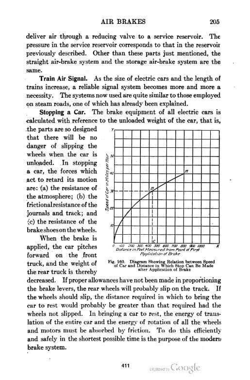
AIR BRAKES 205
deliver air through a reducing valve to a service reservoir. The
pressure in the service reservoir corresponds to that in the reservoir
previously described. Other than these parts just mentioned, the
straight air-brake system and the storage air-brake system are the
same.
Train Air Signal. As the size of electric cars and the length of
trains increase, a reliable signal system becomes more and more a
necessity. The systems now used are quite similar to those employed
on steam roads, one of which has already been explained.
Stopping a Car. The brake equipment of all electric cars is
calculated with reference to the unloaded weight of the car, that is,
the parts are so designed
that there will be no
danger of slipping the
wheels when the car is
unloaded. In stopping
a car, the forces which
act to retard its motion
are: (a) the resistance of
the atmosphere; (b) the
frictional resistance of the
journals and track; and
(c) the resistance of the
brake shoes on the wheels.
When the brake is
applied, the car pitches
forward on the front
truck, and the weight of
the rear truck is thereby
decreased. If proper allowances have not been made in proportioning
the brake levers, the rear wheels will probably slip on the track. If
the wheels should slip, the distance required in which to bring the
car to rest would probably be greater than that required had the
wheels not slipped. In bringing a car to rest, the energy of trans
lation of the entire car and the energy of rotation of all the wheels
and motors must be absorbed by friction. To do this efficiently
and safely in the shortest possible time is the purpose of the modern
brake system.
0 i00 P00 300 400 500 600 roo 600 900 I00ODistance in Feet Measured from Point cf first
fipplicalion of Broke
Fig. 160. Diagram Showing Relation between Speedof Car and Distance in Which Stop Can Be Made
after Application of Brake
411
206 AIR BRAKES
The average person who rides on street and interurban cars
knows nothing as to the distance in which these cars can be
stopped. "In what distance can a modern double-truck electric
car be stopped?" is a question which is frequently asked. In
answer to this question, Fig. 160 has been prepared. A great
many experiments have been made in stopping cars, with varying
results. The chief factors which affect the results of such tests are
the condition of the rails and the character of the material com
posing the brake shoes. Fig. 160 shows graphically the relation
between the distance required to stop a car and the speed (in miles
per hour) at the instant the brake was applied. It represents the
average result of a large number of experiments with a double-
truck car fitted with a brake equipment as described in the
preceding pages. With perfect conditions, the curve ABO would
fall above that shown, while with very poor conditions, it
would fall lower. The value of the diagram is made apparent by
the following application:
Example. Find the distance in which a double-truck electric car may be
stopped, if the power is shut off and the brake applied while running at a
speed of 30 miles per hour.
Solution. Starting on the vertical line O Y at 30 miles per hour, follow
the horizontal line to the right until the curve A BO is reached at the point B.
From point B, follow the vertical line downward until the horizontal line OX
is reached at the point C. This point C indicates the difference in feet in which
the car may be stopped, which in this instance is 440 feet. In the same way,
the stopping distances may be determined for cars running at any speed.
AIR-BRAKE TROUBLES AND REMEDIES
STEAM-CAR AIR BRAKES
High Reliability of Air=Brake Mechanism. The importance
of the air brake in both freight and passenger equipment cannot be
overestimated. Were it not for the high standard of perfection of
the present braking systems, the relatively fast schedules of our
modern passenger trains as well as those of freight service would
not be possible. A failure of some part of the air-brake equipment
to function properly is often given as the cause of accidents which
occur on the road. True as this may be, there are of course
many accidents on the road with which the condition of the brak
ing apparatus has nothing to do. The development of the modern
412
AIR BRAKES 207
braking apparatus has reached such a high stage that, notwith
standing the adverse conditions under which the equipment often
operates, it can safely be said that it is almost always in operating
condition. To prevent the occasional failure of the brake system
to properly perform its duty, it is desirable to point out where
the troubles are most likely to appear.
Disorders of Air Compressors. The compressor is an impor
tant part of the air-brake system and must be kept in perfect
working condition. Without its use the brake system is worthless.
For this reason it is important that it be given proper attention in
the matter of lubrication, repairs, etc. The Westinghouse Com
pany gives the following directions for remedying disorders of
the compressor:
Compressor Refuses to Start. Cause: Insufficient oil, from
scant or no feed; water in cylinder; worn main-piston rings; or
rust having accumulated during time compressor has lain idle.
Remedy: Shut off steam, take off cap nut, put in a tablespoonful
of valve oil (not too much), let the oil soak down for one or two
minutes, and then turn on steam quickly. In many cases when
the compressor will not start when steam is first turned on, if
steam is then turned off and allowed to remain off for one or two
minutes and then turned on quickly, it will start without the use
of any oil except that from the lubricator.
Compressor Groans. Cause: (1) Air cylinder needs oil.
Remedy: (1) Put some valve oil in air cylinder and saturate piston
swab with valve oil, then replace it on the rod. Cause: (2) Steam
cylinder needs oil. Remedy: (2) Increase lubricator feed. Leakage
past the air-piston packing rings or past a discharge valve causes
heating, destroys lubrication, and results in groaning. Piston-rod
packing dry and binding is another cause of groaning.
Uneven Strokes of Compressor. Cause: (1) Probably leak
age past air-piston packing rings and sticky air valves: (2) unequal
lift of air valves; (3) clogged discharge valve passages; or (4)
leaky air valves. Remedy: Locate cause, if possible, and correct
it by cleaning out clogged or dirty passages, adjusting lift of
valves, or replacing leaky valves or rings.
Slow in Compressing Air. Cause: (1) Leakage past the air-
piston packing rings, due to poor fit or wear in cylinder or rings;
(2) valves and passages dirty; or (3) air-suction strainer clogged.
Remedy: (1) and (2): To determine which is causing the trouble,
obtain about 90 pounds air pressure, reduce the speed to from
40 to 60 single strokes per minute, then listen at the "air inlet"
413
208 AIR BRAKES
and note if air is drawn in during only a portion of each stroke
and if any blows back. If the latter, an inlet valve is leaking.
If the suction does not continue until each stroke is nearly com
pleted, then there is leakage past the air-piston packing rings or
back from the main reservoir past the air-discharge valves. The
leaking of one of these valves will cause an uneven, stroke.
Remedy: (3) Clean strainer thoroughly.
Compressor Erratic in Action. Cause: Worn condition of valve
motion. Remedy: Renew it.
Compressor Heats. Cause: (1) Air passages are clogged;
(2) leakage past air-piston packing rings; or (3) the discharge
valves have insufficient lift. Remedy: (1) Clean air passages;
(2) renew air-piston rings; (3) regulate lift of discharge valves to
inch on the 85-inch and to A inch on the lOJ-inch com
pressor. A compressor in perfect condition will become exces
sively hot and is liable to be damaged if run very fast and
continuously for a long time.
Compressor Pounds. Cause: (1) Air piston is loose; (2)
compressor either not well secured to boiler or causes some
adjacent pipe to vibrate; (3) the reversing valve plate 18 is loose;
or (4) the reversing rod or plate may be worn so that the motion
of compressor is not reversed at the proper time. Remedy:
Repair and renew worn parts and tighten loose connections.
Disorders of Air Compressor Governors. The failure of any
one of the three different types of compressor governors, previously
described, to function properly is usually due to one of two causes:
either the governor fails to stop the compressor when the desired
pressure has been reached; or, when the compressor is stopped, the
governor fails to start it upon a slight reduction of pressure.
In correcting troubles which have been reported in connection
with the use of such governors, the Westinghouse Company has
issued the following instructions:
If the cutting-out pressure gradually increases without any
change having been made in the adjustment of the governor, it is
probable that dirt has accumulated on the pin valve or its seat,
thus slightly raising the valve and increasing the compression of
the regulating spring.
If the governor fails to stop the compressor when the desired
pressure has been reached, examine the drip-pipe connection to see
that it has not frozen or become closed. Also, if the small hole in
the spring box becomes closed and there is a slight leakage of air
past the diaphragm, pressure may accumulate above the latter
414
AIR BRAKES 209
sufficiently to prevent the pin from raising and stopping the
compressor.
If, after being stopped by the governor, the compressor fails to
start upon a slight reduction in air pressure, examine the pin
valve for leakage at the relief port c, when the air pressure is a
few pounds less than that for which the governor is regulated.
Also, if the relief port itself should become stopped up, the com
pressor would fail to start when the air pressure fell.
Keep all parts of the mechanism clean, particularly the
strainers 29, Fig. 16, in the air connections. Keep the joints at
the stem unions absolutely tight to prevent any escape of oil or
steam. Oil will escape with even no sign of steam leakage, and
the compressor . is thereby deprived of part of its lubrication.
Maintenance of Air Compressor. Heating Air Cylinders.
One of the most important problems of maintenance of the
air compressor is the heating of the air cylinder or cylinders
incident to the compression of the air. The continual operation of
a compressor at high speeds or against excessive pressures results
in relatively high temperatures. The effect of these high tem
peratures is to burn the lubricating oil used in the air cylinders
and ultimately destroy its lubricating qualities and cause groaning
and cutting of the air cylinders. In addition to these more
noticeable features, it also fills the discharge passages with deposits
from the burnt oil, produces undesirable condensation of moisture
throughout the brake system, and reduces to a very large extent
the over-all efficiency of the compressor. Care should be exercised
that the speed of the compressor does not exceed 140 single
strokes per minute, and this speed should be maintained for but
short periods of time as, if continued for any very great length
of time, it will cause excessive heating. If the class of service
requires such a speed in order to maintain the desired pressure,
it is an indication that the compressor should be replaced by a
larger one or that an additional compressor should be installed.
From the foregoing it is seen that it is desirable first, that the
compressor should be of ample capacity; second, that it should be
well lubricated and otherwise maintained in good working con
dition; and third, that all leakage from any source whatsoever
should be minimized in every practical way.
Leaks in Stuffing Box. One of the most serious leaks often
occurs in the air-cylinder stuffing box. Such, a leak not only
415
210 AIR BRAKES
greatly decreases the amount of air delivered but, on account of
the faster speed required, increases the heating effect. It may
also, through the loss of the air cushion, cause the pump to pound.
In tightening the packing gland to reduce air leakage, use care not
to bind the rod, since to do so will damage not only the packing
but the rod as well. Exercise care not to cross the gland nut
threads and use a well-oiled swab on the rod.
In cases where two compressors are installed on the loco
motive, the separate throttles should be kept wide open and the
speed regulated by the main compressor throttle, the idea being
to divide the work equally between each compressor.
Broken Air Valves. When necessary to replace a broken air
valve on the road or under conditions where proper fitting cannot
be made, the temporary valve should be replaced at the very first
opportunity by one properly fitted, joint ground, and with lift
adjusted to inch. The Westinghouse Company furnishes a
small air valve lift gage to be used in determining the proper lift
of all air valves.
Leaky Air Valves and Piston. Leaky air valves and a leaky
air piston may cause the compressor to run hot and inefficiently.
The condition of the valves and piston may be determined by the
following simple tests:
To test for leaky inlet valves, operate the compressor slowly
against full main-reservoir pressure and listen carefully at the air
inlet. If the valves blow it will be easily distinguishable.
To test for leaky discharge valves, operate the compressor until
full main-reservoir pressure is attained, then close the throttle and
stop the compressor. Now open the oil cup, if this type of oiler
is used, and hold your finger over it. If the top discharge valve
is leaking the air will be noticed to blow out continuously. If an
automatic or sight-feed oiling system is used instead of the oil cup,
the oil pipe union near the air cylinder can be opened and the test
made as with the oil cup. To test for the bottom discharge valve,
remove the bottom plug and examine for leaks the same as before.
The bottom plug should be removed before testing the top
discharge valve, as a leaky bottom valve and leaky piston would
et air blow from the oil cup in the same way as a. leak from the
top discharge valve.
416
AIR BRAKES 211
To test for a leaky air piston, operate the compressor at a
speed of, say, 40 strokes per minute, and open the oil cup or oil
pipe, as the case may be, and note whether or not a gush of air
is discharged on the down stroke. Such an indication means a
bad leak in the air-piston packing ring.
When such tests reveal leaks in the air valves and air piston,
they should be reported at once and repairs made at the first
opportunity.
In making repairs to the steam cylinder of a compressor, never
remove or replace the upper cylinder head with the reversing valve
rod in place. Such a practice usually results in bending the rod, and
a bent rod will probably sooner or later cause a compressor failure.
Sounds as Indications of Faults. A compressor cannot com
press more air than it draws into the cylinder, and not even
this much if the air inlet passages are obstructed and if there is
any leakage to the atmosphere about the air cylinder. For these
reasons the engineer should give attention occasionally to the
character of the sound issuing from the air inlet when the com
pressor is working slowly under control of the governor. If a
hissing noise or poor or weak suction is detected on either or both
strokes, it should be reported and suitable repairs made.
A click, pound, thud, or noise of unusual character, noticed
when the compressor is operating under normal conditions, may
indicate a loose piston, deranged valve gear, or some other serious
fault and should be reported at the first opportunity.
Obstructions in Strainer. A steam leak in the immediate
vicinity of the air inlet should be repaired at once as this increases
the danger of moisture passing over into the brake system and
causing trouble. It is of great importance that the suction strainer
be kept clean and free from dirt. A slightly clogged strainer
greatly reduces the capacity of the compressor, especially at the
higher speeds. A seriously or completely obstructed strainer, such
as is caused by the accumulation of frost, will increase the speed
of the compressor and prevent the compressor from raising or
maintaining the desired main-reservoir pressure.
Cleaning Air Cylinder. The Westinghouse Air Brake Com
pany gives the following directions concerning cleaning and washing
the air cylinder of their compressors:
417
212 AIR BRAKES
"It is an aid to good operation to thoroughly clean the air
cylinder and its passages at least three or four times a year by
circulating through them a hot solution of lye or potash in the
proportion of 2 pounds of potash to 1 gallon of water. This
should always be followed by sufficient clean hot water to
thoroughly rinse out the cylinder and passages, after which a
liberal supply of valve oil should be given the cylinder. Suitable
tanks and connections for performing the operation can easily be
arranged in portable form. Never put kerosene oil in the air
cylinder to clean it."
Care of Triple Valve. Installing Triple Valve. The triple
valve, being the most important of all the various parts that go to
make up the modern freight-car brake equipment, should be
located with care in order to have it free from obstructions which
would render inspection or removal difficult. It should be con
veniently located above the general level of the piping which, in
turn, should be carefully planned to avoid pockets in which
moisture might collect. If the question of piping layout is not
given proper attention, trouble will be experienced in cold weather
from water freezing at different points and possibly in the triple
valve.
The tee in the brake pipe at the point where the branch pipe
is taken off should point upward rather than horizontally or down
ward, because this arrangement will prevent moisture which may
be deposited in the brake pipe from passing over into the branch
pipe and from thence to the triple valve. The centrifugal dirt
collector has proved to be very efficient in removing dirt and
moisture from the piping of the air-brake system, but since
excessive deposit of moisture in the piping system is, sometimes
occasioned by locomotives having insufficient reservoir capacity or
cooling pipe to insure precipitation of the water before passing to
the brake system, it is advisable to take the added precaution of
taking off the branch pipe from the top of the brake pipe.
What has been said concerning the piping arrangement and
installation of the triple valve on freight cars also applies to
passenger cars. u,«
Removal of Scale. All the piping should be thoroughly hanajHiered
and blown out in order to loosen and remove all scale and: foreign
matter before the triple valve is connected. This precaution is
418
AIR BRAKES 213
especially important in new installations, and after the piping is
complete, it should be tested under pressure with soapsuds and
made tight.
Repair of Triple Valve. The removable parts of the triple
valve should never be removed while the valve is attached to a car.
If the valve is not functioning properly it should be removed and
repaired on a bench by a competent workman. Any attempt to
open triple valves while still attached to cars is sure to result in a
great many failures because of injuries by careless handling and
because of dirt getting inside the pipes or parts.
Weighted Retaining Valve. The weighted retaining valve,
which is practically a part of the triple valve, must be installed in
a vertical position, accessible for repairing and for use when the
train is in motion. It should be cleaned but not oiled every time
the triple valve receives attention.
Lubrication of Triple Valve. Under ordinary conditions of
service the triple valve should be cleaned and lubricated at least
once a year. The proper interval can best be determined by
careful inspection. ' A valve subjected to severe conditions of
service and exposure to extreme weather conditions, dirt, etc., will
need more frequent cleaning and oiling than one which has been
more or less protected and not subjected to hard usage. After
the valve has been removed from the car and opened, all the parts
should be made free of all oil, gum, or grease by the use of gasoline
or benzine.
The face of the graduating valve, both the upper and lower
surfaces of the slide valve, the slide-valve seat and the upper por
tion of the bushing, where the slide-valve spring bears, should be
lubricated with a high grade of very fine dry pure graphite. The
graphite should be well rubbed in so that as much as possible will
adhere to the surface and fill the pores of the brass and leave a
very light thin coating of graphite.
The graphite can best be applied by using a stick about 8
inches long having a small piece of chamois glued to one end.
Dip the skin-covered end in dry graphite and rub on the surfaces
in question. After rubbing, a light blow of the stick on the side
of the slide-valve seat will leave the desired coating of loose
graphite. When the work is completed, the slide valve and its
419
214 AIR BRAKES
seat must be entirely free from oil or grease. Care .should be
taken in handling the parts after lubrication that the hands do not
come in contact with the lubricated parts and remove the thin
coating of graphite.
The piston ring and the bushing in which it works should be
very sparingly lubricated by first pushing the piston to release
position and applying a drop or two of light oil to the circumfer
ence of the piston bushing, or cylinder, spreading it over the sur
face as uniformly as possible and then moving the piston back and
forth several times to insure proper distribution of this oil on the
wall, or inner surface, of the cylinder. There should be no free
oil left on the parts. Care should be exercised not to permit any
oil to get on the gaskets or rubber-seat valves. No lubricant
should be used on the quick-action parts of the triple valve.
The general scheme which should be followed in the lubrica
tion of all types of triple valves, distributing valves, etc., is the
same as that just presented.
Lubrication of Brake Cylinder. In cleaning the brake cylinder
and piston care should be exercised to remove all lint, free the
leakage groove of any deposit, and thoroughly clean the expander
ring, packing leather, and piston. In lubricating the cylinder
special attention should be given to the thorough lubrication of
the top of the cylinder, as well as the bottom, and the inside of the
packing leather where the expander ring rests. A good lubricant
specially prepared for the purpose should be used. Special
examination should be made to see that the follower nuts are tight,
as they frequently become loosened.
Lubrication of Brake Valve. It is essential for satisfactory
performance that the brake valve or valves receive occasional
cleaning and lubricating. A good grade of graphite grease has
been found to give the best results for use on the brake valve and
rotary valves whenever it can be conveniently applied, as when
assembling after overhauling and repairs. Graphite grease is not
convenient for use as a lubricant, however, after the brake is
assembled. In such cases a good grade of oil should be used, but
very sparingly. The equalizing piston may be lubricated in much
the same manner as the main piston of a triple valve, by pushing
it to its normal position and applying a drop or two of oil to the
420
AIR BRAKES 215
inner surface of the piston bushing, spreading it as uniformly as
possible, then moving the piston up and down several times to
insure a proper distribution of the oil. There should be no free oil
on the parts and no oil should be permitted to get on the
gaskets.
Air Leaks in Type "K" Triple Valve. The Type "K" triple
valve, like all other air valves, will sometimes develop air leaks
which may make necessary the cutting out of the air-brake
equipment of the car on which the defective triple valve is located.
This is accomplished, as previously explained, by closing the cut
out cock in the brake-pipe branch pipe and bleeding the auxiliary
reservoir. The most serious defects which might occur on the
road are, viz, air leaks in the slide valve, check valve, valve-case
gasket, triple-valve body gasket, emergency valve, main-piston
packing ring, auxiliary-reservoir tube, and broken graduating spring.
If an air blow is noticed from the triple-valve exhaust, it
indicates a leak either from the brake pipe or auxiliary reservoir.
To determine from which source, cut out the brake by closing the
brake-pipe branch-pipe cut-out cock. If the brake applies and the
blow stops, it indicates a leak from the brake pipe. If the blow
continues and the brake does not apply, it indicates a leak from
the auxiliary reservoir.
An auxiliary-reservoir blow is caused by a leaky slide valve,
triple-valve body gasket, or the auxiliary-reservoir tube. A leaky
slide valve will usually cause a blow when the triple valve is in
either release or application position, while a leaky body gasket
or auxiliary-reservoir tube will cause a blow only when the triple
valve is in release position.
A brake-pipe blow is caused either by a leaky emergency
valve or the check valve case gasket.
A leaky main-piston packing ring may prevent the brake from
applying on a light reduction on a long train, or if the brake
applies may prevent a proper release.
A broken graduating spring may cause undesired quick
action, depending upon the conditions of the triple valve and the
rate of brake-pipe reduction. If the triple valve is dry and
gummy or the brake pipe is reduced at too rapid a rate through
leakage or otherwise, quick action is almost sure to result.
421
216 AIR BRAKES
A broken retarding spring permits the triple-valve piston to
move to retarded release position and results in a slow release of
the brake.
The triple valve will not produce a buzzing sound if in good
condition. Such a noise indicates that the emergency valve is
leaking, in which case there will be a blow at the exhaust. This
can sometimes be remedied by jarring the valve. When this does
not stop the buzz, apply the brake in emergency, by parting the
hose and opening the angle cock quickly, then release the brake by
connecting up the hose, and repeat the operation , if necessary.
This process may dislodge the dirt or foreign matter and permit
the valve to seat properly. In case it does not, then the brake
should be cut out.
Broken Pipe Connections. Accidents sometimes happen to
the brake piping system which may make inoperative a part or
the whole of the entire brake system. These accidents are most
likely to occur to the locomotive brake piping system. Perhaps
the most complicated system is that of the No. 6 "ET" locomotive
brake equipment, and for this reason a discussion of the effect of
broken pipes in this system and emergency repairs will be given.
' Broken Main-Reservoir Pipe. If a break that renders a tem
porary repair impossible should occur in the main-reservoir pipe
between the reservoir and the branch to the distributing valve, the
locomotive brakes cannot be applied by either brake valve except
when a quick-action cap is used on the distributing valve, and
then only in emergency. The pressure obtained in the brake
cylinder in the latter case is due entirely to the air vented through
the quick-action cap from the brake cylinder. If the break
occurs between the brake valve and branch pipe leading to the
distributing valve, both ends of the pipe should be plugged. The
locomotive brakes can then be operated in the usual manner by
means of the independent brake valve.
Broken Main-Reservoir Branch Pipe. In case of a break in
the branch pipe from the main-reservoir pipe to the distributing
valve between the main-reservoir pipe and the cut-out cock, the
main-reservoir end of the break should be plugged and the cut-out
cock closed. In this condition the locomotive brakes become
inoperative, but the train brakes can be operated in the usual manner.
422
AIR BRAKES 217
If the branch pipe leading to the feed valve and reduction
valve should become broken, both broken ends should be plugged.
Under this condition the independent brake valve and the signal
system become inoperative. The running position (for releasing
and recharging the train brakes) and the holding position of the
automatic brake valve and the excess-pressure head of the com
pressor governor will be cut out also. There being no air pressure
on top of the independent rotary valve to hold it to its seat, it
will be impossible to secure an automatic application of the loco
motive brakes. Under such circumstances the handle of the
independent brake valve should be moved to the slow-application
position before applying the brakes and permitted to remain there
until it is desired to again release the locomotive brakes, when it
should be returned to the running position. The train brakes
must be released and recharged with the handle of the. automatic
brake valve in release position. The locomotive brakes can be
released by moving the handle- of the automatic brake valve to
running position or by placing the handle of the independent
brake valve in release position. Since the feed valve will be
inoperative, the excess-pressure operating pipe should be closed by
a blind gasket placed in the union at the governor. This cuts out
the excess-pressure head of the governor so that the maximum-
pressure head jcontrols the compressor. In order to prevent too
high a brake-pipe pressure with the handle of the automatic brake
valve in release position, it will be necessary to throttle the com
pressor by hand.
If the break occurs between the reducing valve and the branch
pipe leading to the feed valve, plug on both sides of the break.
In this condition the independent brake valve and signal system
are cut out, but the locomotive and train brakes can still be
operated by the automatic brake valve, although in so doing the
independent brake valve must be manipulated as explained above.
If the pipe should be broken beyond the feed valve or the
reducing valve it will not be necessary to plug the ends of the
pipe, as the same result can be secured by turning the adjusting
nut until the regulating spring is sufficiently loose to cause the
blow to cease. The break can be handled in another manner by
regulating the adjusting nut, as just described, plugging the broken
423
218 AIR BRAKES
end of the pipe toward the independent brake valve and the
exhaust port of this valve. The handle of the independent brake
valve should then be kept in running position. With this arrange
ment the locomotive brakes as well as those of the train can be
operated by the automatic brake valve.
Broken Brake Pipe. The brake-pipe branch to the dis
tributing valve is probably more often broken than all others. In
case of such an accident the end of the pipe leading from the
brake pipe should be plugged and the pressure chamber drained.
Under these conditions, the train brakes can be operated as usual,
but the locomotive brakes cannot be operated except by the use of
the independent brake valve and the release position of the valve
handle must always be used in releasing them.
If the break is ahead of the branch pipe to the distributing
valve, the end of the pipe toward the distributing valve may be
plugged without affecting the operation of the brake.
When the break occurs between the branch pipe to the
distributing valve and the branch pipe to the automatic brake
valve, both ends of the pipe should be plugged. In this condition
the locomotive brakes will be inoperative by the automatic brake
valve but the train brakes can be operated as usual. The loco
motive brakes will be operative by means of the' independent
brake valve.
If the brake pipe is broken ahead of the cut-out cock of the
pilot section and it is necessary to couple to a train ahead of the
locomotive instead of at the rear, a combination hose must be used
to connect the brake hose to the signal hose at the rear of the
tender, the angle and cut-out cocks opened, and the cut-out cock
in the supply line to the signal system closed. At the pilot end,
another combination hose must be used to connect the signal hose
to the brake hose of the car and the angle and cut-out cocks
opened. With this arrangement both the locomotive and train
brakes can be operated as desired. A similar plan can be used
if such a break occurs at the rear of the tender instead of at the
front end of the locomotive.
If the brake pipe becomes broken under the tender the
combination hose will permit the signal pipe to be used as a brake
pipe in the manner described above.
424
AIR BRAKES 219
Broken Brake Cylinder Pipe. A broken brake cylinder pipe
will permit the escape of main-reservoir air to the atmosphere
whenever the locomotive brakes are applied and may cause the
release of one or more of the brakes depending on the point at which
the break occurs. In such a case, if the break cannot be repaired,
the cut-out cock leading to the broken pipe should be closed. If the
break occurs near the distributing-valve reservoir, close the cut-out
cock in the main-reservoir pipe leading' to the distributing valve.
Broken Application Cylinder Pipe. If the application cylinder
pipe is broken, plug the pipe on the distributing-valve side of the
break. If the break occurs between the distributing valve and the
tee to the independent and automatic brake valves, the locomotive
brakes cannot be applied with the independent brake valve and
the emergency maintaining feature is lost. In such a case,
however, the locomotive brakes can be applied as usual by the
automatic brake valve and released with the valve in the running
position. If the break occurs between the tee and the automatic
brake valve, the independent brake can be applied and released as
usual, but the emergency maintaining feature is lost. If the break
is located between the independent brake valve and the tee, the
locomotive brakes cannot be applied by the independent brake
valve, but the emergency maintaining feature is retained.
Broken Distributing-Valve Release Pipe. A failure of the
distributing-valve release pipe merely renders inoperative the
holding feature of the automatic brake valve. If the release pipe
breaks between the two brake valves, the locomotive brakes can
be held applied while the train brakes are being released and
recharged by placing the handle of the independent brake valve in
lap position; the locomotive brakes can then be released by return
ing the handle of the independent brake valve to running position.
The broken release pipe may be plugged on the distributing-valve
side and the locomotive brakes can then be released with the inde
pendent brake valve in release position. If the pipe is broken
between the distributing valve and the independent brake valve,
plug the broken pipe on the distributing valve side. Then the
locomotive brakes can be held applied as indicated above, but to
release them the handle of the independent brake valve must be
placed in release position.
425
220 AIR BRAKES
Broken Equalizing-Reservoir Pipe. If the equalizing-reservoir
pipe becomes broken, it should be plugged at the brake-valve
union. The brake-pipe service exhaust should also be plugged.
Under these conditions, to apply the brakes, move the handle of
the automatic brake valve very gradually towards emergency
position until the desired service reduction is secured, when the
handle should be gradually returned to lap position.
Broken Excess-Pressure Operating Pipe. Should the excess-
pressure operating pipe become broken, place the handle of the
automatic brake valve in lap position and plug the broken pipe on
the brake-valve side. Under these conditions the compressor will
be controlled by the maximum-pressure head of the governor.
Broken Excess-Pressure Pipe. With a broken excess-pressure
pipe the compressor will not operate when the main-reservoir
pressure is greater than about 20 pounds. Under these circum
stances the broken pipe on the feed valve side should be plugged
and a blind gasket placed in the excess-pressure operating pipe.
With this arrangement the excess-pressure head of the governor is
rendered inoperative and the compressor is under control of the
maximum-pressure head of the governor.
Broken Pipe to Maximum-Pressure Head of Governor. In case
the pipe to the maximum-pressure head of the governor is broken,
it should be plugged on the main-reservoir side. With the handle
of the automatic brake valve in release, running, or holding position
the excess-pressure head of the governor will control the main-
reservoir pressure. However, when the handle of the automatic
brake valve is in lap, service, or emergency position, since the
maximum-pressure head of the governor is rendered inoperative,
the compressor must be controlled by hand in order to prevent an
excessive main-reservoir pressure.
ELECTRIC=CAR AIR BRAKES
Instructions Applying to All Systems. As has already been
stated in the text proper, a survey of the available literature on the
subject of Air Brakes for Electric Cars, reveals the fact that a
great many systems are being used. Many of these systems are
quite similar in their method of operation. The Westinghouse
"SME" brake equipment represents one form of modern air-brake
426
AIR BRAKES 221
system for electric-car service which has given highly satisfactory
results. Much of the matter presented on the preceding pages
applies in a general way to this system.
The remaining pages refer more directly to the "SME" brake
equipment but in some cases apply equally well to other systems.
Train Tests. As a safeguard against accidents caused by
defective air-brake equipment, it is recommended that the following
three tests be carried out before the train is sent out on the road.
It is assumed that all valves, connections, etc., have received
proper attention and that the system is charged with air and the
governor has stopped the compressor.
Test No. 1 consists in first applying the brakes in service from
the head car and returning the handle to lap position. The
inspector or conductor should then pass, at once, along the side
of the train and note whether the piston of each brake cylinder
has moved out sufficiently to indicate that the brakes are set on
all cars. Should any brake release after the service application,
while the brake-valve handle is still in lap position, it probably
would be due to the brake valve not being properly lapped,
a leaky rotary valve, or a leaky brake cylinder piston packing
leather. Any improper brake action developed during this test
should be corrected before proceeding further.
Test No. 2 should immediately follow Test No. 1 and consists
in releasing the brakes by placing the handle of the brake valve in
release position. With the brake-valve handle held in this position
the inspector should return along the side of the train and
examine all push rods to ascertain whether or not they have
all fully released and whether all brake shoes hang free of the
wheels.
Test No. 3 consists in making an emergency application with
the brake valve and also with the conductor's valve to determine
if proper action is secured. It is usually considered safe to assume
that the brakes will apply in emergency properly if Test No. 1 is
satisfactory, but it is safest to also make Test No. 3 to make sure
that no obscure causes exsist which would render inoperative this
important feature of the brake.
Cutting Out Brakes. Small leaks or temporary inconveniences
are not sufficient causes for cutting out brakes and thus reducing
427
222 AIR BRAKES
the braking power of the train. All brakes should remain cut-in
unless it is absolutely impossible to operate them safely.
Coupling Cars. Much time can be saved if the cut-out cocks
at the ends of the cars are opened slowly when coupling cars. If
the valves are opened quickly an emergency application will be
obtained which requires a certain length of time to release. By
opening the cocks slowly this action will be prevented and less
time will be lost.
Switching Cars. In setting a car out of a train, first close
the emergency and straight-air application and release the pipe
cut-out cocks ahead of and behind the couplings to be separated,
then separate the couplings by hand and attach the hose to the
dummy couplings. Never permit the hose couplings to be pulled
apart, as this practice always results in defective hose couplings
and eventually unsatisfactory brake operation.
Before setting the hand brake on the car which has been set
out of the train, make sure that the air brake has first been released.
Rail Sanding. The use of sand should begin if practicable
before the brakes are applied, for if the brakes are set and the
wheels begin to slide the application of sand will probably not
cause them to revolve again and flat spots on the wheels will
result. In such cases it is the best practice to release the brakes
slightly at the moment of applying the sand, after which a much
higher brake-cylinder pressure can be used without causing
skidding of the wTheels. When sand is used the rails should be
continuously sanded until the stop is made or the brakes released.
Unexpected Brake Applications. Occasionally the brakes may
apply unexpectedly due to conditions over which the motorman
has no control. Such applications may be caused by the train
parting, a bursted hose, or some accident to the piping system.
When such applications occur, the motorman should place the
handle of the brake valve in emergency position, where it should
remain until the train stops and an examination is made and the
trouble located and, if possible, remedied.
In case an emergency pipe or straight-air application- and
release-pipe hose bursts, it can be replaced by an extra hose,
if one is carried, or by one taken from the front or rear end of the
train. If it is impossible to replace the bursted hose in the
428
AIR BRAKES 223
emergency pipe or if the emergency pipe itself is ruptured, thus
rendering the brakes in the rear thereof inoperative, close the
emergency pipe and straight-air pipe cut-out cocks immediately
ahead of and behind the point of rupture. Then, if the car
concerned is a motor car, release the brakes thus cut out by
placing the handle of one of the brake valves on that car in release
position and cut out the compressor by means of the snap switch.
However, should the rupture occur on a non-motor trailer,
release the brakes thus cut out by opening and leaving open the
auxiliary-reservoir drain cock and proceed with the train. The
hand brakes on the disabled car should be tested and someone
assigned to operate them should it become necessary.
If the straight-air pipe becomes broken, close the cut-out
cocks in that pipe ahead of and behind the point of rupture. In
such a case the brakes on the car in question will be operative
only in emergency applications.
Effect of Air Leaks. It is easily seen that leaks will produce
results not intended or desired by the motorman, both during a
straight-air application of the brake and while holding the brakes
applied with the handle of the brake valve in lap position. Leaks
will not only interfere with the accuracy and smoothness of the
stop but will also impose an additional heavy duty upon the
compressor. For these reasons air leakage should be kept at a
minimum and reported as soon as detected. It should be the duty
of the motorman to notice as carefully as possible the action of
the compressor governor and pressure gages, as much better
results can be secured if they are in proper adjustment.
429
REVIEW QUESTIONS
l430
REVIEW QUESTIONS
ON THE SUBJECT OF
LOCOMOTIVE BOILERS AND ENGINES
1. In what respect did the first locomotives differ from the
modern locomotive?
2. Explain Whyte's system of classification.
3. What is a compound locomotive? Give its advantages.
4. What methods are in use for supporting the crown sheet?
5. What was the name of the first locomotive built in
America? When was it constructed?
6. Give the names of some of the early locomotives built
in America?
7. Describe the action of exhaust steam in creating draft
in the front end.
8. Name the types of fire-boxes commonly used.
9. What created the demand for a wide fire-box?
10. Determine the principal dimensions of a tapered stack
for a locomotive boiler 70 inches in diameter, the nozzle being 2
inches below the center of the smoke box.
11. Compute the thickness of the sheets of a straight-top
locomotive boiler, 70 inches in diameter, carrying a boiler pressure
of 200 pounds per square inch, the pitch of the stay bolts being
4 inches.
PART I
12. What parts comprise the front end of a locomotive?
431
REVIEW QUESTIONS
ON THE SUBJECT OF
LOCOMOTIVE BOILERS AND ENGINES
PART II
1. What effect does the changing of a valve from inside lap
to inside clearance have on the events of the stroke?
2. What pressure in tons would be required to force a cast
steel driving wheel center on an 8-in. axle? What allowance is
commonly made for tire shrinkage?
3. State briefly how the dead center points are located.
4. What two types of valve gears are generally used in this
country?
5. State the advantages and disadvantages of each.
6. What is the resistance, due to grade only, of a freight
train weighing 2,000,000 pounds, moving up a grade of .9 of one
per cent? Ans. 18,000 pounds.
7. What is the resistance, due to acceleration only, of a
train weighing 200 tons that is accelerated from a speed of 50 to
one of 60 miles an hour in a distance of one mile?
Ans. 264 pounds.
8. State the two different forms of locomotive frames in use
and give the principal features of each.
9. What is the tractive power of a simple locomotive having
cylinders 18 inches in diameter, a piston stroke of 24 inches, driv
ing wheels 62 inches in diameter, and working under a boiler
pressure of 200 lbs. per sq. in.? Ans. 21,321.
10. What is meant by the terms lead, outside lap, and inside
clearance?
432
REVIEW QUESTIONS
ON THE SUBJECT OF
AIR BRAKES
PART I
1. What are the three main objections to the straight air
brake system?
2. Name the important parts used in the Westinghouse
system.
3. What are the two sources of drain on the brake pipe
which will tend to prevent an increase in pressure?
4. Give the positions of the ordinary Westinghouse engi
neer's brake valve, and tell what occurs in each position.
5. Describe the Westinghouse single-stage air compressor.
6. Give causes and remedies for the following disorders
of the compressor: Compressor refuses to start; slow in compress
ing air; compressor pounds; compressor heats; compressor erratic
in action.
7. What is the principal difference between "SD" and "SF"
types of compressor governors?
8. You are operating the compressor and after having been
stopped by the governor the compressor fails to start upon a
slight reduction of air pressure. What would be the possible
cause for this?
9. In what position is the brake-valve handle placed in
order to make the shortest possible stop?
10. Give the principles upon which, the Westinghouse plain
triple valve operates.
11. Explain how the quick-action triple valve overcomes
the defects of the plain triple valve.
12. Sketch the Westinghouse plain triple valve, showing
service position.
13. Sketch the Westinghouse quick-action triple valve,
showing emergency position.
14. In the Type "K" triple valve, how is the rate of brake-
pipe reduction for service application determined?
433
REVIEW QUESTIONS
ON THE SUBJECT OF
AIR BRAKES
PART II
1. State the principle involved in the operation of the high
speed brake equipment.
2. Name the parts comprising the "LN" passenger car
brake equipment.
3. Give the advantages of the No. 6^ "ET" equipment.
4. What should be the position of the automatic and inde
pendent brake-valve handle on the second engine when double
heading?
5. What are the features which are peculiar to the "PC"
equipment?
6. State in a general way the rules for operating the "PC"
passenger brake equipment.
7. What are the essential parts of an air-signal system?
8. What is the purpose of the conductor's brake valve?
9. Give in a general way the rules for train inspection.
10. Describe the proper brake manipulation in freight
service on heavy grades.
11. Give the office of the distributing valve on "ET" equip
ment.
12. Describe the process of charging empty equipment by
means of the control valve.
13. Give the general relation of the different parts of the
control valve in the graduated release position.
434
INDEX
The page numbers of this volume will be found at the bottom of the pages;
the numbers at the top refer only to the section.
A
Action of steam in operating a
locomotive 45
Air-brake equipment, instructions for
use and care of 380
air pump 382
backing up trains 382
conductor's brake valve 382
cutting out brakes 382
double-heading 382
emergency applications 381
engineer's brake valve 382
pressure retaining valves 382
running test 381
service applications 381
train inspection 380
triple valve and brake cylin
ders 383
use of angle cocks 382
use of sand 381
Air-brake troubles and remedies 412
electric-car air brakes 426
coupling cars 428
cutting out brakes 427
instructions apply to all sys
tems 426
rail sanding 428
switching cars 428
train tests 427
unexpected brake applications 428
steam-car air brakes 412
air leaks in type "K" triple
valve 421
broken pipe connections 422
care of triple valve 418
disorders of air compressor
governors 414
disorders of air compressors 413
Note.—For page numbers see foot of pages.
Page
Air-brake troubles and remedies (con
tinued)
steam-car air brakes
high reliability of air-brake
mechanism 412
maintenance of air compressor 415
Air brakes 205-429
air compressors 218
air cylinder lubrication 229
main reservoir 239
shop and road tests 231
single-stage type 218
special air strainer 228
steam compressor governors 234
two-stage type 224
applied to electric cars 383
description of "SME" equip
ment 393
details of "SME" equipment 386
general survey of systems 383
graphical representations of
proper braking methods 390
method of operating "SME"
equipment 404
operation rules for "SME"
equipment 388
brakes and foundation brake gear 304
braking an outgrowth of speed 205
early forms of brake 205
Cramer spring type 206
developments due to steam
locomotive 206
first railroad type 206
hand types 207
Loughridge chain type 207
stagecoach type 205
first Westinghouse air type 208
general characteristics of system 214
435
2 INDEX
Page Page
- brakes (continued) Air brakes (continued)
general characteristics of system modern brake equipment
definition of terms 216 recent improvements 377
brake application 216 studying the air brake 212
brake-pipe reduction 210 train air-signal system 377
emergency application 217 troubles and remedies 412
increase in brake-pipe vacuum brake 209
pressure 216 valves and valve appliances 240
lap 216 automatic brake valves 240
service application 217 conductor's valve 298
essential elements 214 duplex air gage 255
air pump or compressor "E-6" safety valve 302
governor 215 feed valves 255
auxiliary reservoir 215 high-speed reducing valve 299
brake cylinder 215 pressure retaining valve 295
brake pipe 215 triple valves 259
double-pointed air gage 215 Westinghouse plain automatic 208
engineer's brake valve 214 work of Master Car Builders'
main reservoir 214 Association 209
pressure retaining valve 215 interchangeable brake system 209
steam-driven air pump 214 triple-valve tests 210
triple valve 215 Air brakes applied to electric
operation of brakes 217 cars 383--412
instructions for use and care of details of "SME" brake equip
equipment 380 ment 386
modern brake equipment 315 description of equipment 393
control valve 351 graphical representations of
emergency position 372 proper braking methods 390
release and charging posi method of operating equip
tion 353 ment 404
releasing action 363 operation rules for equipment 388
service application 355 general survey of systems 383
distributing valve and double- characteristics of modern
chamber reservoir 328 systems 384
automatic brake operation 332 early forms 384
independent brake opera hand brakes 383
tion 339 Air compressor for air-brake sys
double-pressure control or tem 218, 413
Schedule "U" 317 air cylinder lubrication 229
"E-7" safety valve 320 method 229
"ET-6" locomotive equipment 321 nonautomatic oil cups 229
high-speed equipment 315 sight-feed lubricators 230
"LN" passenger-car equip disorders of 413
ment 319 main reservoir 239
"PC" passenger brake equip maintenance of 415
ment 345 shop and road tests 231
instructions for operating 375 capacity 231
Note.—For page numbers see foot of pages.
436
INDEX 3
Page
Air compressor for air-brake system
(continued)
shop and road tests
steam economy . 234
single-stage type 218
method of action in air end
of compressor 223
method of action in steam end
of compressor 219sizes ■ 218
special air strainer 228
steam compressor governor 234, 414
disorders of 414
two-stage type 224
comparison with single-stage
type 224
Air cylinder lubrication 229
Air pump or compressor, steam-
driven 214
Air strainer and check valve 327
"AMM" electric-car brake equip
ment 385
"AMR" electric-car brake equipment 385
"AMS" electric-car brake equipment 385
Ash pans 61
Automatic air-brake system 384
Automatic brake operation 332
Automatic brake valves 240
"G-6" type 240
"H-6" type 249
"S-6" independent type 252
Automatic slack-adjuster 309
Auxiliary reservoir 215
Axle-driven compressor equipment 409
Axles 115, 133
B
"B-fl" double-pressure feed valve 258
Baldwin superheater 80
Bell cord signals 159
Block system of signaling 166, 197
Blower 154
Boiler horsepower 90
Boiler performance, effect of different
pressures upon 71
Brake cylinder 215, 403
Brakes and foundation brake gear 304
Note.—For page numbers see foot of pagex.
Page
Brakes and foundation brake gear
(continued)
automatic slack-adjuster 309
general requirements 304
leverage 307
locomotive driver brakes 312
locomotive truck brakes 312
Brick arches 63
C
"C-6" single-pressure feed valve 255
Car discharge valve 380
Chain grate stoker 131
Cole superheater 77
Collisions 188
Combustion, rate of 69
Compound locomotive 30
Conductor's valve 298, 403
Connecting or main rods 124
Control valve 351
emergency position 372
quick-action valve closed 374
quick-action valve venting 372
release and charging position 353
charging empty equipment 353
release connections 354
releasing action 363
direct-release and charging
position 371
graduated-release position 367
preliminary release position 363
release and charging pressure
chamber and emergency
and service reservoirs 370
release lap position 370
secondary release position 365
service application 355
over-reduction lap position 361
over-reduction position 360
preliminary service position 355
secondary service position 356
service lap position 359
service position 357
Crank pins 116, 137
Crawford mechanical underfeed
stoker 132
Crossheads and guides 122
437
4 INDEX
Page
Cylinder cap, quick-action 343
Cylinder and saddle for locomotive
engines 120
Cylinders 141
D
"D" emergency valve 402
"D-EG" motor-driven air compressor 393
Derailments 189
Diaphragm 64
Distributing valve and double-
chamber reservoir 328
automatic brake operation 332
automatic release 336
charging 332
emergency 336
emergency lap 339
service 332
service lap 335
general method of operation 328
independent brake operation 339
double-heading 343
independent application 339
independent release 340
quick action cylinder cap 343
Double-pointed air gage 215
Double-pressure control or Sched
ule "U" 317
Draft 64
Draft pipes 64
Dry pipe 155
Duplex air gage 255, 402
E
"E-6" safety valve 302
"EL" electric-locomotive brake equip
ment • 385
Electric-car air brakes 383, 426
details of "SME" system 386
modern systems 384
troubles and remedies 426
Engine design 133
axles 133
crank pins 137
cylinders 141
frames <. 140
piston rods 139
Note.—For parie numbers see fool of pages.
Page
Engineer's brake valve 214
"ET-6" locomotive brake equipment 321
air strainer and check valve 327
arrangement of piping 322
functions and advantages 321
manipulation of equipment 324
general directions 324
freight service 325
passenger service 324
positions of automatic and in
dependent brake valves 324
names of pipe 322
Exhaust nozzle 63, 66
Feed valves 255
"B-6" double-pressure type 258
"C-6" single-pressure type 255
"Fifty-four" air strainer 228
Fire-box 48
Firing a locomotive 169
Fixed signals 164
Flues 53
Fuel waste in a locomotive 186
G
"G-6" automatic brake valve 240
Governor, air pump or compres
sor 215, 234, 414
disorders of 414
Grates 60
"H-6" automatic brake valve 249
Hand brakes on electric cars 383
Hanna locomotive stoker 131
Heating surface 73
High-speed brake equipment 315
High-speed reducing valve 299
High steam pressures 7]
Independent brake operation 339
Injector 150
Inside clearance 94
Interchangeable brake system 209
438
INDEX 5
Page
J
"J" electric compressor governor 397
L
Lap 216
Lead 93
Leverage 307
"LN" passenger-ear brake equipment 319
Locomotive, care of 198
end of run 202
oiling parts 198
on the road 200
making adjustments en route 201
running at speed 200
starting 200
watching engine 198
Locomotive appliances 148
blower 154
dry pipe 155
injector 150
lubricator 157
safety valves 148
steam gages 154
throttle valve 154
water gages 154
whistle 154
Locomotive boiler capacity 87
Locomotive boiler design 84
Locomotive boilers 48, 183, 190
ash pans 61
brick arches 63
capacity 87
care of 183
classification of 48
definition of 48
design of 84
diaphragm 64
draft 64
draft pipes 64
exhaust nozzle 63, 66
explosion of 190
flues 53
grates 60
heating surface 73
high steam pressures 71
netting 63
rate of combustion 69
Note.—For pay numbers sir foot of pages.
Page
Locomotive boilers (continued)
smoke-box and front end arrange
ment 63
spark losses 71
stack 68
stay bolts 55
steam or branch pipes 63
superheaters 74
Locomotive boilers and engines 11-202
classification of 20
historical development 11
Locomotive breakdowns 187
causes 187
collapse of flue 190
collisions 188
derailments 189
disconnecting after breakdown 191
Locomotive driver brakes 312
Locomotive engines 93
connecting or main rods 124
crossheads and guides 122
cylinder and saddle 120
design of parts 133
frames 117
inside clearance 94
lead 93
outside lap 93
piston and rods 121
running gear HO
side rods 124
stokers 130
tender ' 129
trucks 125
valve friction 108
valve motion 94
valves 105
Locomotive frames 117, 140
Locomotive operation 169, 179
acquaintance with route 192
block signals 197
care of locomotive 198
cleaning 174, 184
culverts and bridges 196
curves 195
emergencies 174, 179
breakdowns 187
broken connecting rod 174
439
6 INDEX
Page
Locomotive operation (continued)
emergencies
broken driving springs 175
broken side rods 174
broken steam chest 176
foaming 175
low water 175
troubles and remedies 179
firing 169, 194
grades 172, 193
inspection 173
repairs 174
running 169, 200
feeding the boiler 170
running time 196
switches 196
use of steam 171, 193
Locomotive rating 145
Locomotive stokers 130
chain grate 131
Crawford 132
Hanna 131
Street 132
Locomotive troubles and reme
dies 174, 179
boiler care 183
breakdowns 187
distinctive features of locomotive 179
drifting 185
emergencies 174
fuel waste 186
pounds 180
steam waste 182
Locomotive truck brakes 312
Locomotive trucks 125
Lubrication of air cylinder 229
Lubrication of locomotive 198
Lubrication of triple valve 419
Lubricator 157
M
"M-18" brake valve 401
Main reservoir 214, 239
Master Car Builders' Association,
work of 209
interchangeable brake system 209
triple-valve tests 210
Nate.—For page numbers see foot of pages.
Page
Modern air-brake equipment 315
control valve 351
distributing valve and double-
chamber reservoir 328
double-pressure control or Sched
ule "U" 317
"E-7" safety valve 320
"ET-6" equipment 321
high-speed 315
principles involved 315
reversing cock, action of 315
instructions for use and care of 380
"LN" passenger car equipment 319
"PC" passenger equipment 345
recent improvements 377
Movable signals 159
Netting
Oiling locomotive
Outside lap
N
0
63
198
93
"PC" passenger brake equipment 345
application portion 351
characteristics 345
control valve 351
emergency portion 351
equalizing portion 348
instructions for operating 375
names of various parts and their
identification 346
quick-action portion 351
reservoir 351
special features 345
Pielock superheater 75
Pipe connections, broken 422
Piston rods 121, 139
Plain triple valve 261
Pounds in a locomotive 180
Pressure retaining valve 215, 295
Q
Quick-action cylinder cap 343
Quick-action triple valve 261
Quick-action valve 374
440
INDEX7
Page Page
R "SME" electric-car brake equipment
Radiation, loss of heat through 89 (continued)
Rails, sanding of 428 method of °Peratmg equipment
Railway signaling 158 holdlng brakes aPPlied 406
bell cord signals 159 releasing 408
block system 166 service application 405
fixed signals 164 stopping a car 411
movable signals 159 storaSe air-brake equipment 409
train signals 160 tram alr slSnal 411
Reducing valve 379 operation rules 388
Reversing cock, action of 315 changing ends 390
Running gear 110 charging 388
emergency 389
g holding brakes applied 389
release 389
"S" air compressor governor 235 running 388
"S-6" independent brake valve 252 service application 389
Scale, effect of 89 principal parts 380
Schenectady or Cole superheater 77 Smoke-box and front end arrange-
Schmidt superheater 77 ment 63
"SD" air compressor governor 237 Smoke-box temperatures, effect of
Sellers injector 150 different pressures upon 72
"SF" air compressor governor 239 Spark losses 71
Side rods 124 Stacks 68
Signal valve 379 Starting locomotive 200
Single-stage air compressors 218 Stay bolts ■ 55
"SM-1" and "SM-3" electric-car Steam, action of 45
brake equipment 384 Steam compressor governors 234
"SME" electric-car brake equip- double-top or duplex "SD" type 237
ment 384, 386 double-top "SF" type 239
brake cylinder 403 single-top "S" type 235
conductor's valve 403 Steam or branch pipes 63
"D" emergency valve 402 Steam gages 154
"D-EG" motor-driven air com- Steam supply, regulating 171, 193
pressor 393 Steam waste in a locomotive 182
Duplex air gage 402 Stephenson valve gear 95
equipment on non-motor trailers 388 Stokers, locomotive 130
features 386 Storage air-brake equipment 409
graphical representations of proper Straight air-brake system 384
braking methods 390 Street mechanical stoker 132
"J" electric compressor governor 397 Superheaters 74
"M-18" brake valve 401 tests of 82
method of operating equipment 404
axle-driven compressor equip- T
ment 409 Tables
charging 405 axle mounting, hydraulic pressures
emergency application 408 used in 116 ■
Nole.—For pagf number* .sw foot of paties.
441
s INDEX
Page
Tables (continued)
comparative dimensions of Steph
enson and Walschaert
gears 104
crank-pin mounting, hydraulic
pressures used in 117
crank-pins, working stress for 139
dry pipe sizes 155
fiber stresses 136
forged steel billets 116
heating surface, ratio of to grate
area 74
locomotives, classification of 21
locomotives, comparison of English
and American 20
shrinkage allowance 111
spoke data, foundry rule 112
spoke data, general 111
superheater tests 82, 83
valve tests 109
Westinghouse air compressors,
data for 219
Tender 129
Tests of air compressors 231
Throttle valve 154
Time tables 178
Tractive force 143
Train air signal 411
Train air-signal system 377
car discharge valve 380
essentials of 377
reducing valve 379
signal valve 379
Train resistance 144
Train rules 176
Train signals 160
Triple valves 210, 215, 259, 418
care of 418
plain 261
quick-action 261
tests of 210
type "K" 270
air leaks in 421
type "L" 284
Note.—For page numbers see foot of pages.
Page
Troubles and remedies of air brakes 412
Troubles and remedies of locomo-
tive 174, 179
Two-stage air compressors 224
Type "K" freight triple valve 270
Type "L" triple valve 284
V
Vacuum brake 209
Valve friction 108
Valve motion 94
Valves 105
Valves and valve appliances 240
automatic brake valves 240
feed valves 255
miscellaneous types 295
conductor's 298
"E-6" safety 302
high-speed reducing 299
pressure retaining 295
W
Walschaert valve gear 99
Water gages 154
Water grates 61
Westinghouse air-brake system 214--383
Westinghouse electric-car air-brake
systems 384
"AMM" equipment 385
"AMR" equipment 385
"AMS" equipment 385
"EL" locomotive equipment 385
"SM-1" equipment 384
"SM-3" equipment 384
"SME" equipment 384
details of 386
Westinghouse plain automatic air
brake 208
Westinghouse straight air brake 208
Wheels 110
Whistle 154
Whistle signals 158
442


Related Documents