Materials 2019, 12, 1398; doi:10.3390/ma12091398 www.mdpi.com/journal/materials Article Cyclic Response of Steel Fiber Reinforced Concrete Slender Beams: An Experimental Study Constantin E. Chalioris*, Parthena-Maria K. Kosmidou and Chris G. Karayannis Reinforced Concrete and Seismic Design of Structures Laboratory, Civil Engineering Department, School of Engineering, Democritus University of Thrace, Xanthi 67100, Greece; [email protected] (C.G.K.); [email protected] (P.-M.K.K.) * Correspondence: [email protected]; Tel.: +30-25410-79632 Received: 06 April 2019; Accepted: 25 April 2019; Published: 29 April 2019 Abstract: Reinforced concrete (RC) beams under cyclic loading usually suffer from reduced aggregate interlock and eventually weakened concrete compression zone due to severe cracking and the brittle nature of compressive failure. On the other hand, the addition of steel fibers can reduce and delay cracking and increase the flexural/shear capacity and the ductility of RC beams. The influence of steel fibers on the response of RC beams with conventional steel reinforcements subjected to reversal loading by a four-point bending scheme was experimentally investigated. Three slender beams, each 2.5 m long with a rectangular cross-section, were constructed and tested for the purposes of this investigation; two beams using steel fibrous reinforced concrete and one with plain reinforced concrete as the reference specimen. Hook-ended steel fibers, each with a length-to-diameter ratio equal to 44 and two different volumetric proportions (1% and 3%), were added to the steel fiber reinforced concrete (SFRC) beams. Accompanying, compression, and splitting tests were also carried out to evaluate the compressive and tensile splitting strength of the used fibrous concrete mixtures. Test results concerning the hysteretic response based on the energy dissipation capabilities (also in terms of equivalent viscous damping), the damage indices, the cracking performance, and the failure of the examined beams were presented and discussed. Test results indicated that the SFRC beam demonstrated improved overall hysteretic response, increased absorbed energy capacities, enhanced cracking patterns, and altered failure character from concrete crushing to a ductile flexural one compared to the RC beam. The non-fibrous reference specimen demonstrated shear diagonal cracking failing in a brittle manner, whereas the SFRC beam with 1% steel fibers failed after concrete spalling with satisfactory ductility. The SFRC beam with 3% steel fibers exhibited an improved cyclic response, achieving a pronounced flexural behavior with significant ductility due to the ability of the fibers to transfer the developed tensile stresses across crack surfaces, preventing inclined shear cracks or concrete spalling. A report of an experimental database consisting of 39 beam specimens tested under cyclic loading was also presented in order to establish the effectiveness of steel fibers, examine the fiber content efficiency and clarify their role on the hysteretic response and the failure mode of RC structural members. Keywords: steel fiber reinforced concrete (SFRC); slender beams; cyclic loading; hysteretic response; failure mode; tests. 1. Introduction Reinforced concrete (RC) beams with inadequate transverse reinforcement exhibit a lack of ductility and fail in a rather brittle manner due to the weak tensile resistance and the reduced deflection capacity in the presence of cracks. These weaknesses can be overwhelmed by the addition of steel fibers as shear resistance mass reinforcement, which can reduce and delay cracking and ameliorate the overall performance of RC members. It is known that concrete reinforced with discrete, short, and randomly distributed fibers is a composite material with considerable cracking resistance

Welcome message from author
This document is posted to help you gain knowledge. Please leave a comment to let me know what you think about it! Share it to your friends and learn new things together.
Transcript
Materials 2019, 12, 1398; doi:10.3390/ma12091398 www.mdpi.com/journal/materials
Article
Cyclic Response of Steel Fiber Reinforced Concrete Slender Beams: An Experimental Study
Constantin E. Chalioris*, Parthena-Maria K. Kosmidou and Chris G. Karayannis
Reinforced Concrete and Seismic Design of Structures Laboratory, Civil Engineering Department,
School of Engineering, Democritus University of Thrace, Xanthi 67100, Greece; [email protected]
(C.G.K.); [email protected] (P.-M.K.K.)
* Correspondence: [email protected]; Tel.: +30-25410-79632
Received: 06 April 2019; Accepted: 25 April 2019; Published: 29 April 2019
Abstract: Reinforced concrete (RC) beams under cyclic loading usually suffer from reduced
aggregate interlock and eventually weakened concrete compression zone due to severe cracking
and the brittle nature of compressive failure. On the other hand, the addition of steel fibers can
reduce and delay cracking and increase the flexural/shear capacity and the ductility of RC beams.
The influence of steel fibers on the response of RC beams with conventional steel reinforcements
subjected to reversal loading by a four-point bending scheme was experimentally investigated.
Three slender beams, each 2.5 m long with a rectangular cross-section, were constructed and tested
for the purposes of this investigation; two beams using steel fibrous reinforced concrete and one
with plain reinforced concrete as the reference specimen. Hook-ended steel fibers, each with a
length-to-diameter ratio equal to 44 and two different volumetric proportions (1% and 3%), were
added to the steel fiber reinforced concrete (SFRC) beams. Accompanying, compression, and
splitting tests were also carried out to evaluate the compressive and tensile splitting strength of the
used fibrous concrete mixtures. Test results concerning the hysteretic response based on the energy
dissipation capabilities (also in terms of equivalent viscous damping), the damage indices, the
cracking performance, and the failure of the examined beams were presented and discussed. Test
results indicated that the SFRC beam demonstrated improved overall hysteretic response, increased
absorbed energy capacities, enhanced cracking patterns, and altered failure character from concrete
crushing to a ductile flexural one compared to the RC beam. The non-fibrous reference specimen
demonstrated shear diagonal cracking failing in a brittle manner, whereas the SFRC beam with 1%
steel fibers failed after concrete spalling with satisfactory ductility. The SFRC beam with 3% steel
fibers exhibited an improved cyclic response, achieving a pronounced flexural behavior with
significant ductility due to the ability of the fibers to transfer the developed tensile stresses across
crack surfaces, preventing inclined shear cracks or concrete spalling. A report of an experimental
database consisting of 39 beam specimens tested under cyclic loading was also presented in order
to establish the effectiveness of steel fibers, examine the fiber content efficiency and clarify their role
on the hysteretic response and the failure mode of RC structural members.
Keywords: steel fiber reinforced concrete (SFRC); slender beams; cyclic loading; hysteretic response;
failure mode; tests.
1. Introduction
Reinforced concrete (RC) beams with inadequate transverse reinforcement exhibit a lack of
ductility and fail in a rather brittle manner due to the weak tensile resistance and the reduced
deflection capacity in the presence of cracks. These weaknesses can be overwhelmed by the addition
of steel fibers as shear resistance mass reinforcement, which can reduce and delay cracking and
ameliorate the overall performance of RC members. It is known that concrete reinforced with discrete,
short, and randomly distributed fibers is a composite material with considerable cracking resistance
Materials 2019, 12, 1398 2 of 21
due to the ability of the fibers to transfer the developed tensile stresses across crack surfaces (crack-
bridging). The properties and the structural behavior of steel fiber reinforced concrete (SFRC) under
compression, tension, flexure, shear, and torsion have been studied usually under monotonic tests,
as next presented in the following subsections.
1.1. Compression and Tensile Behavior of Steel Fiber Reinforced Concrete (SFRC)
SFRC under compression exhibits increased strength only in mixtures with a high amount and
adequate aspect ratio of fibers, whereas it exhibits a rather marginal contribution of the fibers on the
compressive strength in most of the examined cases [1–6]. Nevertheless, significant improvement of
the post-cracking stress–strain compressive behavior with noticeable toughness and a ductile
response even in low volumetric proportions of fibers has been revealed [7–10]. A significant increase
in the SFRC compressive strength is achieved in mixtures with at least 3% volume fraction of steel
fibers [11,12].
The flexural tensile behavior of SFRC has been studied by using three- or four-point bending
tests of small-scaled notched prismatic specimens. The majority of the experimental studies pointed
out the favorable influence of the added steel fibers on the post-cracking regime [13]. Further, fibrous
concrete mixtures with a high percentage of fibers showed an enhanced overall performance and a
re-hardening response after cracking [2,14–16]. Furthermore, long steel fibers proved more effective
than the short ones to ameliorate the flexural response at large deflections in terms of strength,
deformation capacity, toughness, and cracking behavior [17]. Similar concluding remarks concerning
the splitting tensile strength of SFRC have also been derived from extensive data of splitting tests
performed on cylinders [18–20] and cubes [5,15]. The favorable influence of steel fiber orientation on
tensile strength increase has been highlighted through splitting and flexural tensile tests on
magnetically driven concrete and mortar cube specimens [21].
The orientation distribution effect of the added steel fibers has also been examined in the post-
cracking tensile behavior of SFRC through tests of specially fabricated specimens subjected to direct
tension and by applied different casting methods of the fresh mixtures [22]. It has been found that
distribution and orientation of fibers greatly influence the overall performance of fibrous concrete.
For this purpose, X-ray computed tomography techniques have recently been developed and
experimentally verified, which can evaluate the microstructural parameters along with the
orientation distribution and the concentration of the short fibers added in cementitious matrices as
mass reinforcement [23,24]. The results of these novel techniques also confirmed that the post-
cracking tensile response of fibrous concrete significantly depends on the elastic behavior of the
uncracked regions of the composite material located between the cracking areas [25,26]. Micro-cracks
are initially formed, propagating into localized macro-cracks after overcoming the elastic response.
Hence, although fibers practically do not affect the pre-cracking behavior, it has long been recognized
that SFRC exhibits increased strength and an ameliorated response after the formation of cracks due
to direct tensile loading [27].
Uniaxial tests of prismatic specimens under direct tension revealed that the addition of an
adequate amount of short steel fibers mainly increase the tensile load capacity, whereas longer steel
fibers enlarge the ultimate tensile deformation [28]. However, SFRC with inadequate dosage of steel
fibers demonstrated a negligible increase in the tensile strength and limited improvement in the post-
cracking behavior [27]. Thus, a critical volume fraction of steel fibers has been proposed in order to
design high-performance fibrous concrete mixtures that achieve strain hardening under direct
tension with advanced ductility and energy absorption capacity [29–31], such as ultra-high
performance SFRC [32]. Nevertheless, dispersion of long steel fibers with higher volumetric
proportions was found to be problematic [33] with regard to the fine workability properties of fibrous
mixtures with short lengths [34] or even microfilament steel fibers that were 13 mm long [35].
Recent analytical studies associate the tensile performance and the fracture properties of SFRC
with the fiber-to-concrete interface behavior, which can be calibrated by pullout tests [36,37]. Unified
formulations and simplified analytical approaches for the simulation of the overall bond behavior of
fibers embedded in concrete and the prediction of the tensile response of SFRC members after
Materials 2019, 12, 1398 3 of 21
cracking have also been proposed [38,39], which have been calibrated, validated or based on various
pullout tests and numerical models [40–42]. However, due to the various available shapes, types,
materials, and dimensions of fibers, along with the different mechanical properties of the
cementitious mixtures, their bond characteristics also vary. Thus, there are no widely accepted or
reliable constitutive tensile models that can be applied broadly in SFRC members [43]. Consequently,
an interesting alternative approach has been developed by Gribniak et al. [44], which uses an inverse
technique to derive average stress–strain relationships from a wide range of experimental moment–
curvature curves of flexural SFRC members.
Further, the mechanical recovery of high-performance steel fiber reinforced concrete under
uniaxial tensile loading has been investigated by [45,46]. It was found that fibrous concrete mixtures
subjected to direct tension present multiple micro-cracks with fine crack widths, which offers an
important self-healing capability [46]. The width of the developed cracks along with the type of sand
and the added fibers are the main parameters that influence the self-healing capacity by generating
improved interfacial bond conditions [45]. Further, a hybrid fiber reinforcing system containing
polyethylene and steel fibers showed more enhanced recovery characteristics since, even in cracks
with rather large width, the bond in the crack region around the longer steel fiber was bridged,
controlled, and densified by the shorter polyethylene fiber [46].
1.2. Reinforced Concrete (RC) Structural Members with Steel Fibers in Shear and/or Flexure
Shear-critical RC structural members usually exhibit brittle catastrophic failure due to the
apparent weakness of concrete in tension, which is commonly compensated by the presence of an
adequate amount of steel stirrups. The advantageous characteristics of SFRC inspired researchers to
investigate the use of short fibers as mass reinforcement against shear instead of conventional
transverse steel reinforcement. The full or even partial replacement of stirrups is crucial in RC joints
and deep, torsional, and coupling beams, where design criteria require a high ratio of shear
reinforcement that leads to the extremely short spacing of stirrups and/or to the use of cumbersome
reinforcement systems such as spirals, cross inclined bars, diagonal reinforcement, etc. [47–50]. Thus,
at least in the critical sections of these shear-vulnerable RC members, the use of steel fibers could lead
to reduced reinforcement congestion [19,51–53].
Several experimental works demonstrated the feasibility of substituting a significant amount of
stirrups for an adequate volume fraction of short steel fibers, achieving comparable load capacities at
the first shear cracking and at the maximum shear strength in RC beams [54–58]. Smarzewski [59,60]
examined the synergetic positive effect of steel and polypropylene fibers in deep RC beams in order
to replace conventional steel reinforcement. Zhao et al. [61] highlighted the favorable influence of
steel fibers on the stiffness, the shear capacity, and the deformation of shear-critical RC beams, along
with the reduction in crack width, height, and strains of concrete and stirrup across the diagonal
section. Further, Chalioris [62] proposed an efficient analytical method to evaluate the proper dosage
and type of steel fibers that should be added to concrete to replace a desirable number of stirrups and
to satisfy pre-set strength and ductility requirements in shear-critical RC members. Furthermore,
analytical models have also been developed to evaluate the total shear strength of concrete beams
reinforced with steel fibers and longitudinal reinforcing bars, with or without stirrups [63–65].
Moreover, the well-known softened truss model was properly modified to implement the
contribution of steel fibers on the shear strength of SFRC members [66,67].
For many years, researchers have been studying the effectiveness of steel fibers on the flexural
behavior of RC structural members and it has long been acknowledged that they improved bending
moment strength, ductility, failure toughness, and energy absorption capacity. Flexural cracking
performance of SFRC beams with longitudinal steel reinforcing bars also appears to be enhanced
with increased crack number, reduced crack width and height, restricted crack propagation, and
delayed concrete spalling [68–70]. It has also been demonstrated that deformed or hook-ended steel
fibers with higher aspect ratios can increase cracking resistance, energy dissipation, and ductility
index most effectively [71,72]. Further, a recent experimental study revealed that even straight and
short mill-cut steel fibers with a rather low aspect ratio equal to 40 added to a volume fraction up to
Materials 2019, 12, 1398 4 of 21
2% were capable of enhancing sectional flexural stiffness and increasing ductility related to the lateral
deformations of RC columns under eccentric compression [73].
The implementation of feasible constitutive stress–strain relationships of SFRC under
compression and tension in numerical analysis of concrete cross-sections reinforced with steel
reinforcing bars and fibers provides rational and accurate predictions of the flexural response in
terms of bending moment versus curvature analytical curves [31]. Further, the ability of steel fibers
to control flexural cracking and to prevent concrete spalling inspired researchers to use SFRC in
deficient and in blast-damaged RC beams that had been strengthened using externally bonded
carbon fiber-reinforced polymer sheets, in order to avoid rip-off failure of the concrete cover, to
prevent premature failures, to increase ductility, and to ensure structural integrity [74–77].
1.3. Cyclic Response of Reinforced Concrete (RC) Structural Members with Steel Fibers
The behavior of RC members under cyclic loading is significantly influenced by the fact that
each concrete layer is subjected to alternate tension and compression stresses. Tests have shown that
RC specimens under reversal loading suffer from degraded aggregate interlock and intensive
cracking at both tension and compression zones that reduce concrete shear strength and weaken
compression zones, resulting in a premature, catastrophic brittle failure [78–80]. The addition of steel
fibers into the concrete mixture of flexural beams [72,79,81–85], columns [69,80]), and joints [52,86]
has been proposed and examined as an alternative or additional reinforcement for seismic resistance
of structures. Due to the tensile stress transfer ability of the fibers, SFRC under cyclic deformations
exhibits satisfactory resistance to the formation, propagation, and widening of cracks, improved post-
cracking behavior, and an ameliorated energy dissipation capability.
Daniel and Loukili [81] suggested that the use of steel fibers in flexural fibrous concrete beams
with different longitudinal reinforcement ratios can be efficient to prevent an early development of
macro-cracks during the pre-peak stage and enhances the energy absorption over both the elastic and
inelastic stages. Tests by Campione and Mangiavillano [72] demonstrated that the addition of fibers
increases the load-bearing capacity of the examined specimens, ensures more ductile behavior, and
reduces degradation effects under cyclic deformations, especially in beams with increased concrete
cover thickness.
Further, Harajli and Gharzeddine [82] investigated the influence of steel fibers on the bond
performance of spliced steel bars in normal and high strength concrete. The experimental results
showed that the existence of steel fibers delayed the formation and propagation of splitting cracks
along the spliced region and increased the absorbed energy of the SFRC beams, resulting in a less
brittle failure. Cyclic tests in concrete beams with high-strength steel reinforcement by Tavallali et al.
[85] showed that the addition of steel fibers significantly reduced the maximum crack width of both
flexural and shear cracks regarding the non-fibrous concrete beams.
Parra-Montesinos and Chompreda [83] investigated the experimental behavior of SFRC beams
with and without steel transverse reinforcement. Results from the tests showed that the fibrous
concrete specimens presented a pure strain-hardening behavior with advanced damage tolerance
developing multiple flexural and diagonal cracks. Chalioris [84] investigated the influence of steel
fibers in shear-critical RC beams with and without steel transverse reinforcement under reversal
loading. Steel fibrous beams demonstrated improved overall shear performance with increased shear
strength, ameliorated pre-crack and post-crack behavior, and enhanced energy dissipation
capabilities compared to the non-fibrous specimens.
Cyclic experiments in a two-span continuous column performed by Kotsovos et al. [69] showed
that specimens with steel fibers satisfied the performance requirements of Eurocodes for concrete
strength up to 60 MPa, as the existence of steel fibers enhanced the overall performance of the
specimens regarding ultimate strength and the observed failure mode. The addition of steel fibers in
concrete columns with advanced high-steel longitudinal reinforcement was experimentally
investigated by Lepage et al. [80]. Results from these tests showed the efficiency of steel fibers by
reducing the amount of spalling of the concrete cover and altering the mode of failure from buckling
of the compression bars to fracture of the tension bars.
Materials 2019, 12, 1398 5 of 21
1.4. Research Significance
The aforementioned literature review reveals that the majority of the conducted research is
focused on the behavior of SFRC specimens under monotonic loading, whereas the cyclic response
of SFRC members has been rarely investigated with regard to the plethora of the monotonically tested
ones. Cyclic testing of RC beams with steel fibers is quite limited and has preliminary and exploratory
character so far. Also, the hysteretic performance of such structural members is greatly influenced by
several parameters which even independently have not been thoroughly clarified yet. Various
combinations of conventional reinforcement (steel bars and stirrups) with steel fibers result in
different contributions of the added fibers to the flexural and shear capabilities of SFRC beams. The
type, the aspect ratio, and the volumetric proportion of the fibers also affect the overall structural
performance.
Thus, although there are some widely accepted findings concerning the favorable influence of
the added steel fibers on the post-cracking behavior of SFRC members under reversal deformations,
there are still several issues that require further and systematic investigation. The dual contribution
of fibers to the increase of the flexural and the shear strength of SFRC beams under different load-
bearing mechanisms and the ability of steel fibers to alter the failure mode of the structural member
under certain circumstances are some examples of research gaps.
Further, the recent increased interest for the application of SFRC in retrofitting applications of
deficient and/or damaged RC structural members under seismic reversal excitations and the lack of
relative experimental studies are the main motives behind this work.
In this work, the influence of steel fibers on the cyclic hysteretic response of slender RC beams
was experimentally investigated. Three slender beams, each 2.5 m long with a rectangular cross-
section, were constructed and tested under reversal deformations.
Hook-ended steel fibers, each with a length-to-diameter ratio equal to 44 and two different
contents (1% and 3%), were added to the steel fiber reinforced concrete (SFRC) beams. Accompanying
compression and splitting tests were also carried out in order to acquire full stress–strain
relationships of the plain and the fibrous mixtures. Test results concerning the hysteretic response
based on the energy dissipation capabilities, the damage indices, the cracking performance, and the
failure of the examined beams are presented and discussed in later sections. Special attention is given
to comprehend the observed failure modes and to associate the experimental results of this study
with the test data of relevant published works from the literature. A systematic report of an
experimental database consisting of 39 beam specimens tested under cyclic loading is also presented
herein in order to clarify the effectiveness of steel fibers and their role on the hysteretic response and
the failure mode of RC structural members.
This paper contributes to the limited existing literature on cyclic tests of RC beams with steel
fibers, providing detailed experimental data of beams with a rather high amount of steel fibers (3%)
that has not been examined before. An additional innovation of this paper regarding the existing
experimental studies is the thorough demonstration of the available relevant tests in order to compare
the experimental results and to derive new quantitative concluding remarks concerning the cyclic
performance of SFRC beams.
2. Steel Fiber Reinforced Concrete
2.1. Materials
The concrete mixture used in this study consisted of a general-purpose ordinary Portland type
cement (type CEM II 32.5 N, Greek type pozzolan cement containing 10% fly ash), crushed and
natural river sand with a high fineness modulus, crushed stone aggregates with a maximum size of
16 mm, and water, in a mass proportion of 1:3.62:2.67:0.55, respectively. Further, 1 L retarder
(Pozzolith 134 CF) per 1 m3 concrete was added to the mix in order to slow the rate of the concrete
setting.
The steel fibers added to the fibrous concrete mixtures (see Figure 1) were hook-ended fibers to
enhance the anchorage of the fiber in the matrix. The dimensions of the used fibers are an aspect ratio
Materials 2019, 12, 1398 6 of 21
(length-to-diameter ratio) equal to f / df = 44 mm/1 mm = 44, as shown in Figure 2a. Two different
steel fiber volumetric proportions, Vf, were chosen; 1% or 80 kg per 1 m3 concrete and 3% or 240 kg
per 1 m3 concrete. The nominal yield tensile strength of the fibers was 1000 MPa.
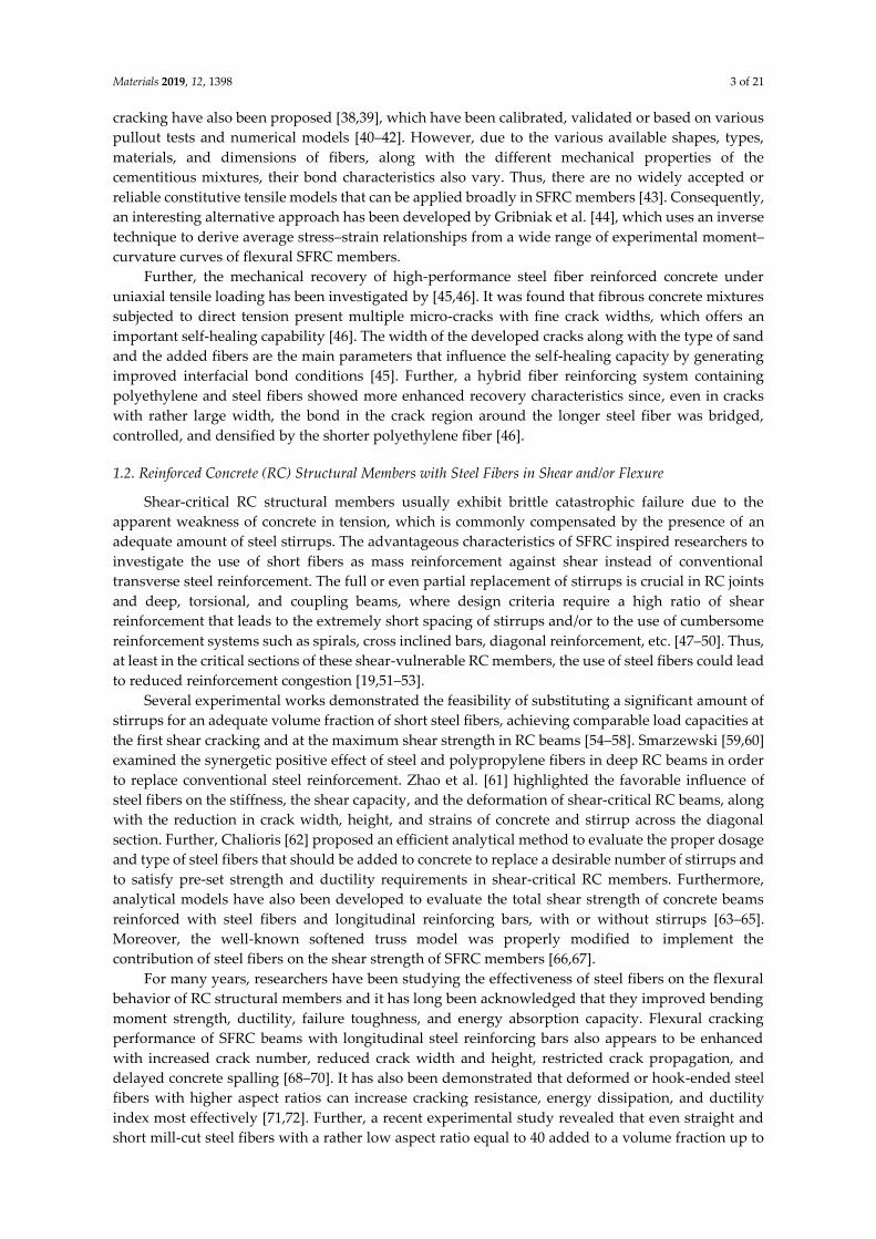
Figure 1. Preparation stages of steel fiber reinforced concrete: (a) Pouring of ready-mix concrete
gradually into the pan type mixer; (b) and (c) gradual addition of the steel fibers into the fresh concrete
mixture during stirring; (d) final homogeneous wet steel fiber reinforced concrete mixture.
2.2. Mix Preparation
The mix preparation of the steel fiber reinforced concrete (SFRC) was carried out using a pan
type concrete mixer (see Figure 1). Two different SFRC mixtures were produced with steel fiber
volume fractions, Vf, equal to 1% and 3%, respectively. Special attention was given to the 3% SFRC
mixture in order to ensure flowability of the fresh mixture and uniformity of fiber distribution, since
it is known that high fiber content (≥1.5%) can decrease mechanical properties of concrete [35].
The ready-mix concrete was poured into the pan type mixer in three stages (Figure 1a-d). The
steel fibers were first dispersed clump-free by hand and added steadily in small amounts into the
fresh concrete mixture during stirring in order to prevent clump formation (Figure 1b,c). Stirring
continued gradually, ensuring that the produced mixture would obtain uniform material
consistency, adequate workability, and homogeneous fiber distribution (Figure 1d). The freshly
prepared SFRC mixtures were placed in the cylinders and the molds of the specimens and adequately
vibrated. During mixing and casting of the fresh mixtures, no steel fiber segregation was observed.
2.3. Compression and Splitting Tests
Standard concrete cylinders with a diameter to height ratio of 150/300 mm were cast from the
plain concrete (PC) batch and from the batches of each SFRC mixture (Vf = 1% and Vf = 3%). Three
specimens from each batch were tested under axial compression and three specimens under splitting
(b)
(c)
(a)
(d)
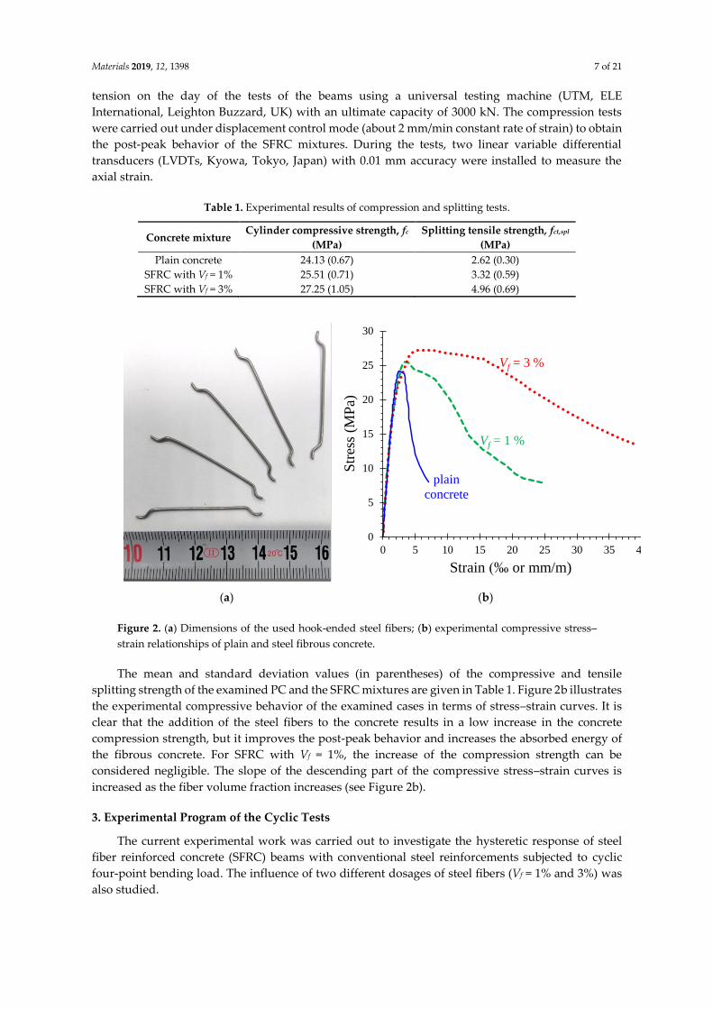
Materials 2019, 12, 1398 7 of 21
tension on the day of the tests of the beams using a universal testing machine (UTM, ELE
International, Leighton Buzzard, UK) with an ultimate capacity of 3000 kN. The compression tests
were carried out under displacement control mode (about 2 mm/min constant rate of strain) to obtain
the post-peak behavior of the SFRC mixtures. During the tests, two linear variable differential
transducers (LVDTs, Kyowa, Tokyo, Japan) with 0.01 mm accuracy were installed to measure the
axial strain.
Table 1. Experimental results of compression and splitting tests.
Concrete mixture Cylinder compressive strength, fc
(MPa)
Splitting tensile strength, fct,spl
(MPa)
Plain concrete 24.13 (0.67) 2.62 (0.30)
SFRC with Vf = 1% 25.51 (0.71) 3.32 (0.59)
SFRC with Vf = 3% 27.25 (1.05) 4.96 (0.69)
(a) (b)
Figure 2. (a) Dimensions of the used hook-ended steel fibers; (b) experimental compressive stress–
strain relationships of plain and steel fibrous concrete.
The mean and standard deviation values (in parentheses) of the compressive and tensile
splitting strength of the examined PC and the SFRC mixtures are given in Table 1. Figure 2b illustrates
the experimental compressive behavior of the examined cases in terms of stress–strain curves. It is
clear that the addition of the steel fibers to the concrete results in a low increase in the concrete
compression strength, but it improves the post-peak behavior and increases the absorbed energy of
the fibrous concrete. For SFRC with Vf = 1%, the increase of the compression strength can be
considered negligible. The slope of the descending part of the compressive stress–strain curves is
increased as the fiber volume fraction increases (see Figure 2b).
3. Experimental Program of the Cyclic Tests
The current experimental work was carried out to investigate the hysteretic response of steel
fiber reinforced concrete (SFRC) beams with conventional steel reinforcements subjected to cyclic
four-point bending load. The influence of two different dosages of steel fibers (Vf = 1% and 3%) was
also studied.
0
5
10
15
20
25
30
0 5 10 15 20 25 30 35 40
Str
ess
(MP
a)
Strain (‰ or mm/m)
Vf = 3 %
plain
concrete
Vf = 1 %
Materials 2019, 12, 1398 8 of 21
3.1. Specimens’ Characteristics
The experimental program included three (3) slender beams, each 2.5 m long, tested in cyclic
loading. One beam was constructed using plain concrete as the reference beam (non-fibrous specimen
denoted as “B-P”) and two beams using SFRC containing 1% and 3% steel fibers (specimens “B-F1”
and “B-F3”, respectively).
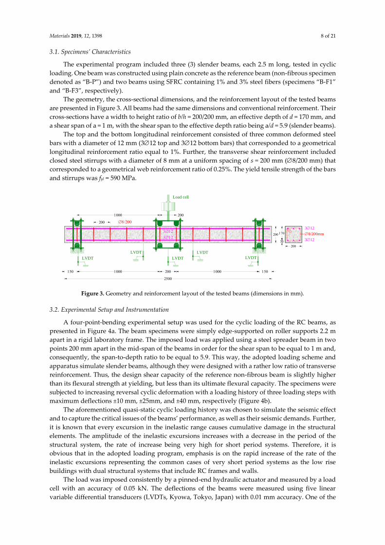
The geometry, the cross-sectional dimensions, and the reinforcement layout of the tested beams
are presented in Figure 3. All beams had the same dimensions and conventional reinforcement. Their
cross-sections have a width to height ratio of b/h = 200/200 mm, an effective depth of d = 170 mm, and
a shear span of a = 1 m, with the shear span to the effective depth ratio being a/d = 5.9 (slender beams).
The top and the bottom longitudinal reinforcement consisted of three common deformed steel
bars with a diameter of 12 mm (312 top and 312 bottom bars) that corresponded to a geometrical
longitudinal reinforcement ratio equal to 1%. Further, the transverse shear reinforcement included
closed steel stirrups with a diameter of 8 mm at a uniform spacing of s = 200 mm (8/200 mm) that
corresponded to a geometrical web reinforcement ratio of 0.25%. The yield tensile strength of the bars
and stirrups was fyl = 590 MPa.
Figure 3. Geometry and reinforcement layout of the tested beams (dimensions in mm).
3.2. Experimental Setup and Instrumentation
A four-point-bending experimental setup was used for the cyclic loading of the RC beams, as
presented in Figure 4a. The beam specimens were simply edge-supported on roller supports 2.2 m
apart in a rigid laboratory frame. The imposed load was applied using a steel spreader beam in two
points 200 mm apart in the mid-span of the beams in order for the shear span to be equal to 1 m and,
consequently, the span-to-depth ratio to be equal to 5.9. This way, the adopted loading scheme and
apparatus simulate slender beams, although they were designed with a rather low ratio of transverse
reinforcement. Thus, the design shear capacity of the reference non-fibrous beam is slightly higher
than its flexural strength at yielding, but less than its ultimate flexural capacity. The specimens were
subjected to increasing reversal cyclic deformation with a loading history of three loading steps with
maximum deflections ±10 mm, ±25mm, and ±40 mm, respectively (Figure 4b).
The aforementioned quasi-static cyclic loading history was chosen to simulate the seismic effect
and to capture the critical issues of the beams’ performance, as well as their seismic demands. Further,
it is known that every excursion in the inelastic range causes cumulative damage in the structural
elements. The amplitude of the inelastic excursions increases with a decrease in the period of the
structural system, the rate of increase being very high for short period systems. Therefore, it is
obvious that in the adopted loading program, emphasis is on the rapid increase of the rate of the
inelastic excursions representing the common cases of very short period systems as the low rise
buildings with dual structural systems that include RC frames and walls.
The load was imposed consistently by a pinned-end hydraulic actuator and measured by a load
cell with an accuracy of 0.05 kN. The deflections of the beams were measured using five linear
variable differential transducers (LVDTs, Kyowa, Tokyo, Japan) with 0.01 mm accuracy. One of the
8/200mm
312
312
Load cell
LVDT
LVDTLVDT
LVDTLVDT
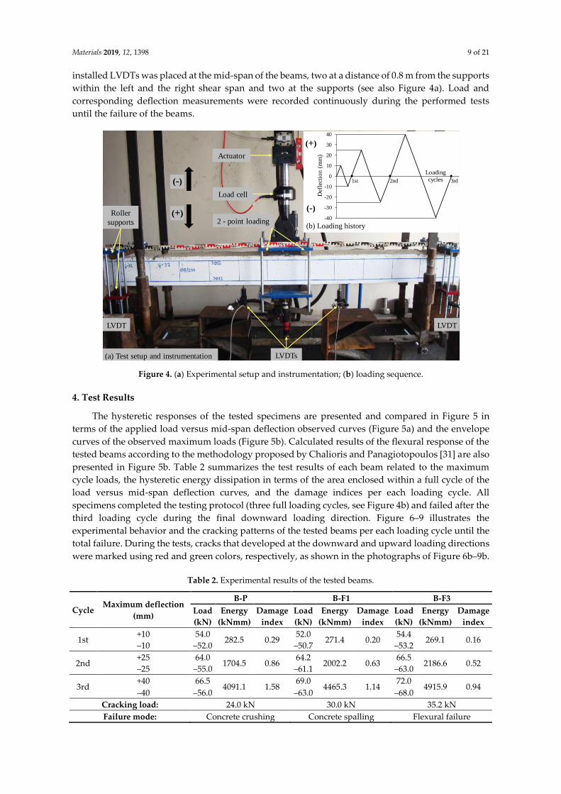
Materials 2019, 12, 1398 9 of 21
installed LVDTs was placed at the mid-span of the beams, two at a distance of 0.8 m from the supports
within the left and the right shear span and two at the supports (see also Figure 4a). Load and
corresponding deflection measurements were recorded continuously during the performed tests
until the failure of the beams.
Figure 4. (a) Experimental setup and instrumentation; (b) loading sequence.
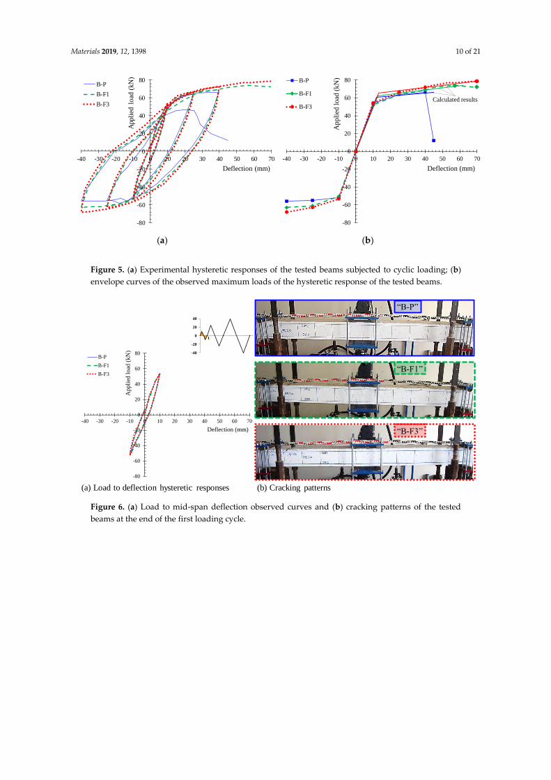
4. Test Results
The hysteretic responses of the tested specimens are presented and compared in Figure 5 in
terms of the applied load versus mid-span deflection observed curves (Figure 5a) and the envelope
curves of the observed maximum loads (Figure 5b). Calculated results of the flexural response of the
tested beams according to the methodology proposed by Chalioris and Panagiotopoulos [31] are also
presented in Figure 5b. Table 2 summarizes the test results of each beam related to the maximum
cycle loads, the hysteretic energy dissipation in terms of the area enclosed within a full cycle of the
load versus mid-span deflection curves, and the damage indices per each loading cycle. All
specimens completed the testing protocol (three full loading cycles, see Figure 4b) and failed after the
third loading cycle during the final downward loading direction. Figure 6–9 illustrates the
experimental behavior and the cracking patterns of the tested beams per each loading cycle until the
total failure. During the tests, cracks that developed at the downward and upward loading directions
were marked using red and green colors, respectively, as shown in the photographs of Figure 6b–9b.
Table 2. Experimental results of the tested beams.
Cycle Maximum deflection
(mm)
B-P B-F1 B-F3
Load
(kN)
Energy
(kNmm)
Damage
index
Load
(kN)
Energy
(kNmm)
Damage
index
Load
(kN)
Energy
(kNmm)
Damage
index
1st +10 54.0
282.5 0.29 52.0
271.4 0.20 54.4
269.1 0.16 –10 –52.0 –50.7 –53.2
2nd +25 64.0
1704.5 0.86 64.2
2002.2 0.63 66.5
2186.6 0.52 –25 –55.0 –61.1 –63.0
3rd +40 66.5
4091.1 1.58 69.0
4465.3 1.14 72.0
4915.9 0.94 –40 –56.0 –63.0 –68.0
Cracking load: 24.0 kN 30.0 kN 35.2 kN
Failure mode: Concrete crushing Concrete spalling Flexural failure
2 - point loading
Load cell
Roller
supports
LVDT
Actuator
LVDT
LVDTs(a) Test setup and instrumentation
(-)
(+)-40
-30
-20
-10
0
10
20
30
40
Def
lect
ion (
mm
)
Loading
cycles1st 2nd 3rd
(b) Loading history
(+)
(-)
Materials 2019, 12, 1398 10 of 21
(a) (b)
Figure 5. (a) Experimental hysteretic responses of the tested beams subjected to cyclic loading; (b)
envelope curves of the observed maximum loads of the hysteretic response of the tested beams.
Figure 6. (a) Load to mid-span deflection observed curves and (b) cracking patterns of the tested
beams at the end of the first loading cycle.
-80
-60
-40
-20
0
20
40
60
80
-40 -30 -20 -10 0 10 20 30 40 50 60 70
Appli
ed l
oad
(kN
)
Deflection (mm)
B-P
B-F1
B-F3
-80
-60
-40
-20
0
20
40
60
80
-40 -30 -20 -10 0 10 20 30 40 50 60 70
Ap
pli
ed l
oad
(k
N)
Deflection (mm)
B-P
B-F1
B-F3
Calculated results
“B-P”
“B-F1”
“B-F3”
-40
-20
0
20
40
1 2 3
(b) Cracking patterns(a) Load to deflection hysteretic responses
-80
-60
-40
-20
0
20
40
60
80
-40 -30 -20 -10 0 10 20 30 40 50 60 70
Ap
pli
ed l
oad
(k
N)
Deflection (mm)
B-P
B-F1
B-F3
Materials 2019, 12, 1398 11 of 21
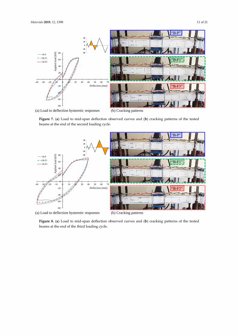
Figure 7. (a) Load to mid-span deflection observed curves and (b) cracking patterns of the tested
beams at the end of the second loading cycle.
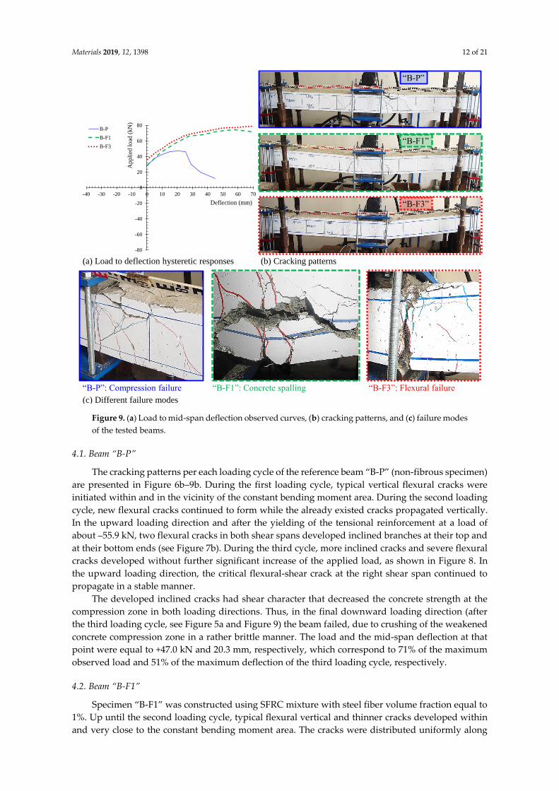
Figure 8. (a) Load to mid-span deflection observed curves and (b) cracking patterns of the tested
beams at the end of the third loading cycle.
-40
-20
0
20
40
1 2 3
“B-P”
“B-F1”
“B-F3”
(b) Cracking patterns(a) Load to deflection hysteretic responses
-80
-60
-40
-20
0
20
40
60
80
-40 -30 -20 -10 0 10 20 30 40 50 60 70
Ap
pli
ed l
oad
(k
N)
Deflection (mm)
B-P
B-F1
B-F3
-40
-20
0
20
40
1 2 3
“B-P”
“B-F1”
“B-F3”
(b) Cracking patterns(a) Load to deflection hysteretic responses
-80
-60
-40
-20
0
20
40
60
80
-40 -30 -20 -10 0 10 20 30 40 50 60 70
Ap
pli
ed l
oad
(k
N)
Deflection (mm)
B-P
B-F1
B-F3
Materials 2019, 12, 1398 12 of 21
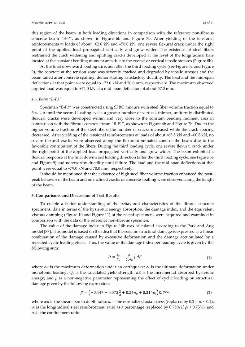
Figure 9. (a) Load to mid-span deflection observed curves, (b) cracking patterns, and (c) failure modes
of the tested beams.
4.1. Beam “B-P”
The cracking patterns per each loading cycle of the reference beam “B-P” (non-fibrous specimen)
are presented in Figure 6b–9b. During the first loading cycle, typical vertical flexural cracks were
initiated within and in the vicinity of the constant bending moment area. During the second loading
cycle, new flexural cracks continued to form while the already existed cracks propagated vertically.
In the upward loading direction and after the yielding of the tensional reinforcement at a load of
about –55.9 kN, two flexural cracks in both shear spans developed inclined branches at their top and
at their bottom ends (see Figure 7b). During the third cycle, more inclined cracks and severe flexural
cracks developed without further significant increase of the applied load, as shown in Figure 8. In
the upward loading direction, the critical flexural-shear crack at the right shear span continued to
propagate in a stable manner.
The developed inclined cracks had shear character that decreased the concrete strength at the
compression zone in both loading directions. Thus, in the final downward loading direction (after
the third loading cycle, see Figure 5a and Figure 9) the beam failed, due to crushing of the weakened
concrete compression zone in a rather brittle manner. The load and the mid-span deflection at that
point were equal to +47.0 kN and 20.3 mm, respectively, which correspond to 71% of the maximum
observed load and 51% of the maximum deflection of the third loading cycle, respectively.
4.2. Beam “B-F1”
Specimen “B-F1” was constructed using SFRC mixture with steel fiber volume fraction equal to
1%. Up until the second loading cycle, typical flexural vertical and thinner cracks developed within
and very close to the constant bending moment area. The cracks were distributed uniformly along
“B-P”: Compression failure “B-F1”: Concrete spalling “B-F3”: Flexural failure
(c) Different failure modes
“B-P”
“B-F1”
“B-F3”
(b) Cracking patterns(a) Load to deflection hysteretic responses
-80
-60
-40
-20
0
20
40
60
80
-40 -30 -20 -10 0 10 20 30 40 50 60 70
Ap
pli
ed l
oad
(k
N)
Deflection (mm)
B-P
B-F1
B-F3
Materials 2019, 12, 1398 13 of 21
this region of the beam in both loading directions in comparison with the reference non-fibrous
concrete beam “B-P”, as shown in Figure 6b and Figure 7b. After yielding of the tensional
reinforcements at loads of about +62.0 kN and –58.0 kN, one severe flexural crack under the right
point of the applied load propagated vertically and grew wider. The existence of steel fibers
restrained the crack widening and splitting cracks developed at the level of the longitudinal bars
located at the constant bending moment area due to the excessive vertical tensile stresses (Figure 8b).
At the final downward loading direction after the third loading cycle (see Figure 5a and Figure
9), the concrete at the tension zone was severely cracked and degraded by tensile stresses and the
beam failed after concrete spalling, demonstrating satisfactory ductility. The load and the mid-span
deflections at that point were equal to +72.0 kN and 70.0 mm, respectively. The maximum observed
applied load was equal to +74.0 kN at a mid-span deflection of about 57.0 mm.
4.3. Beam “B-F3”
Specimen “B-F3” was constructed using SFRC mixture with steel fiber volume fraction equal to
3%. Up until the second loading cycle. a greater number of vertical, thinner, uniformly distributed
flexural cracks were developed within and very close to the constant bending moment area in
comparison with the fibrous concrete beam “B-F1”, as shown in Figure 6b and Figure 7b. Due to the
higher volume fraction of the steel fibers, the number of cracks increased while the crack spacing
decreased. After yielding of the tensional reinforcements at loads of about +65.5 kN and –60.8 kN, no
severe flexural cracks were observed along the flexure-dominated zone of the beam due to the
favorable contribution of the fibers. During the third loading cycle, one severe flexural crack under
the right point of the applied load propagated vertically and grew wider. The beam exhibited a
flexural response at the final downward loading direction (after the third loading cycle, see Figure 5a
and Figure 9) and noteworthy ductility until failure. The load and the mid-span deflections at that
point were equal to +79.0 kN and 70.0 mm, respectively.
It should be mentioned that the existence of high steel fiber volume fraction enhanced the post-
peak behavior of the beam and no inclined cracks or concrete spalling were observed along the length
of the beam.
5. Comparisons and Discussion of Test Results
To enable a better understanding of the behavioral characteristics of the fibrous concrete
specimens, data in terms of the hysteretic energy absorption, the damage index, and the equivalent
viscous damping (Figure 10 and Figure 11) of the tested specimens were acquired and examined in
comparison with the data of the reference non-fibrous specimen.
The value of the damage index in Figure 10b was calculated according to the Park and Ang
model [87]. This model is based on the idea that the seismic structural damage is expressed as a linear
combination of the damage caused by excessive deformation and the damage accumulated by a
repeated cyclic loading effect. Thus, the value of the damage index per loading cycle is given by the
following sum:
𝐷 =𝛿𝑀
𝛿𝑢+
𝛽
𝑄𝑦𝛿𝑢∫𝑑𝐸, (1)
where δM is the maximum deformation under an earthquake; δu is the ultimate deformation under
monotonic loading; Qy is the calculated yield strength; dE is the incremental absorbed hysteretic
energy; and β is a non-negative parameter representing the effect of cyclic loading on structural
damage given by the following expression:
𝛽 = (−0.447 + 0.073𝑎
𝑑+ 0.24𝑛𝑜 + 0.314𝜌ℓ) 0. 7
𝜌𝑤 , (2)
where a/d is the shear span to depth ratio; no is the normalized axial stress (replaced by 0.2 if no < 0.2);
ρℓ is the longitudinal steel reinforcement ratio as a percentage (replaced by 0.75% if ρℓ < 0.75%); and
ρw is the confinement ratio.
Materials 2019, 12, 1398 14 of 21
From the observed load versus mid-span deflection envelopes of the tested specimens in Figure
5b, it can be deduced that the addition of steel fibers improves the overall behavior of the specimens
“B-F1” and “B-F3” with regard to the non-fibrous reference beam “B-P”. Due to the existence of steel
fibers, the first cracking load increased (see Table 2), confirming the efficiency of the fibers to delay
the propagation of the macro-cracks. Further, the addition of the fibers prevented the formation of
inclined cracks along the length of the fibrous specimens in both loading directions by increasing the
tensile strength of concrete and the shear capacity of the beam and, consequently, by altering the
brittle failure to a ductile flexural failure. Further increase of the amount of steel fibers from 1% to 3%
resulted in a noteworthy ductility until failure (see Figure 5–9 and Table 2).
The lower amount of the steel fibers used in the “B-F1” beam seemed to be inefficient in bridging
the tensile cracks developed at the level of the longitudinal reinforcing bars, due to the degradation
of the steel–concrete bond performance and the beam failure due to concrete spalling. Nevertheless,
the addition of a higher volume fraction of steel fibers in “B-F3” prevented the propagation of
horizontal cracking, resulting in a typical flexural failure (see also Figure 9).
The deterioration of the steel–concrete bond performance in RC members under cyclic loading was
first investigated and discussed by Popov [88]. When reverse load was applied, internal tensile cracks
developed around the reinforcing bars and at both sides of their ribs. During the repeated application
of the cyclic load, these cracks opened and closed according to the loading direction. At a higher level
of the applied load, a gap between the ribs of the steel bars and the surrounding concrete formed and
the bars began to move back and forth through a small distance rather freely, which revealed the
deterioration of the steel–concrete bond. The existence of the steel fibers improved the steel–concrete
bond performance, as also highlighted by Daniel and Loukili [81] and Hameed et al. [79].
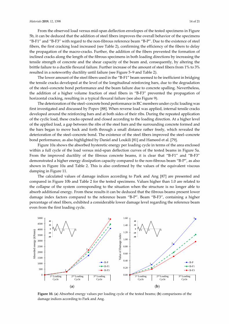
Figure 10a shows the absorbed hysteretic energy per loading cycle in terms of the area enclosed
within a full cycle of the load versus mid-span deflection curves of the tested beams in Figure 5a.
From the improved ductility of the fibrous concrete beams, it is clear that “B-F1” and “B-F3”
demonstrated a higher energy dissipation capacity compared to the non-fibrous beam “B-P”, as also
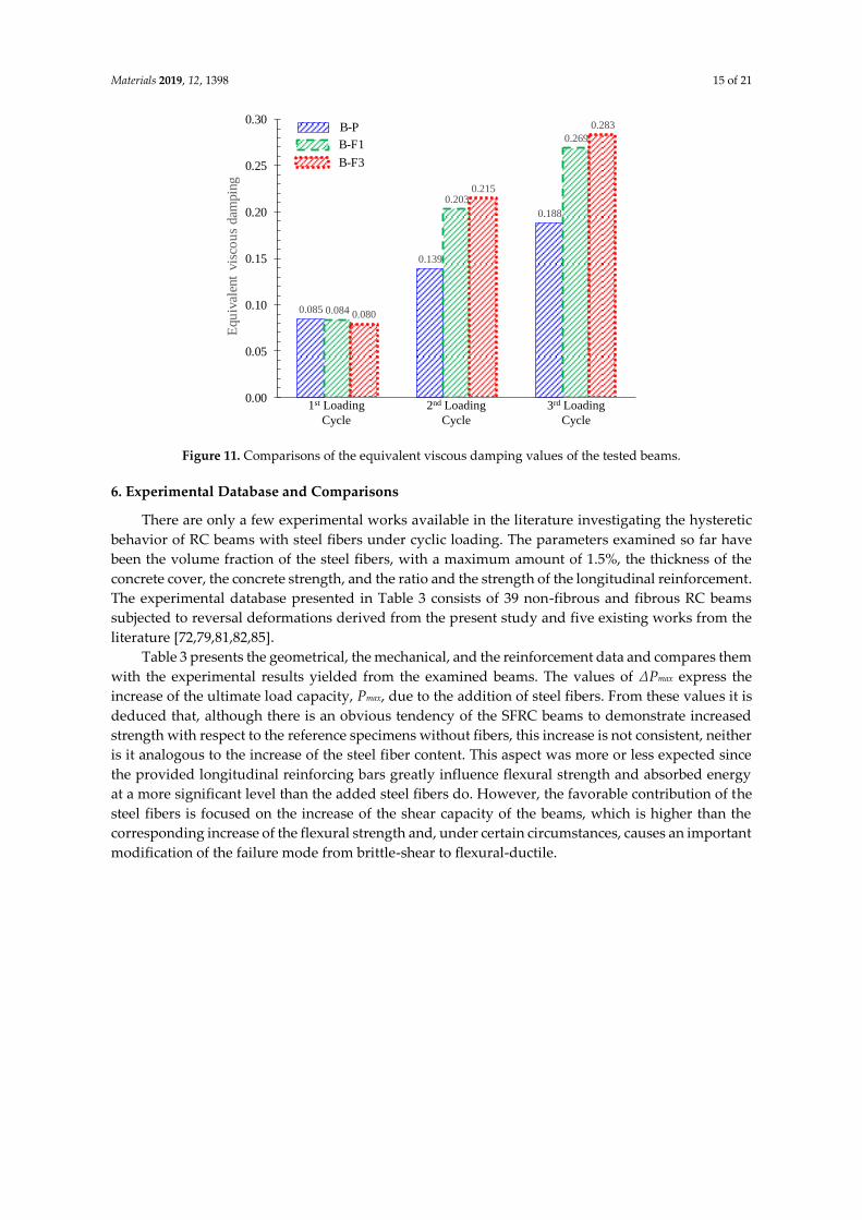
shown in Figure 10a and Table 2. This is also confirmed by the values of the equivalent viscous
damping in Figure 11.
The calculated values of damage indices according to Park and Ang [87] are presented and
compared in Figure 10b and Table 2 for the tested specimens. Values higher than 1.0 are related to
the collapse of the system corresponding to the situation when the structure is no longer able to
absorb additional energy. From these results it can be deduced that the fibrous beams present lower
damage index factors compared to the reference beam “B-P”. Beam “B-F3”, containing a higher
percentage of steel fibers, exhibited a considerable lower damage level regarding the reference beam
even from the first loading cycle.
(a)
(b)
Figure 10. (a) Absorbed energy values per loading cycle of the tested beams; (b) comparisons of the
damage indices according to Park and Ang.
0
500
1000
1500
2000
2500
3000
3500
4000
4500
5000
Ab
sord
ed e
ner
gy (
kN
mm
)
B-P
B-F1
B-F3
1st Loading
Cycle
1
2
3
-40
-20
0
20
40
1 2 3
2nd Loading
Cycle
3rd Loading
Cycle
0.00
0.20
0.40
0.60
0.80
1.00
1.20
1.40
1.60
Val
ue
of
Dam
age
ind
ex
B-P
B-F1
B-F3
1st Loading
Cycle
1
2
3
-40
-20
0
20
40
1 2 3
2nd Loading
Cycle
3rd Loading
Cycle
Materials 2019, 12, 1398 15 of 21
Figure 11. Comparisons of the equivalent viscous damping values of the tested beams.
6. Experimental Database and Comparisons
There are only a few experimental works available in the literature investigating the hysteretic
behavior of RC beams with steel fibers under cyclic loading. The parameters examined so far have
been the volume fraction of the steel fibers, with a maximum amount of 1.5%, the thickness of the
concrete cover, the concrete strength, and the ratio and the strength of the longitudinal reinforcement.
The experimental database presented in Table 3 consists of 39 non-fibrous and fibrous RC beams
subjected to reversal deformations derived from the present study and five existing works from the
literature [72,79,81,82,85].
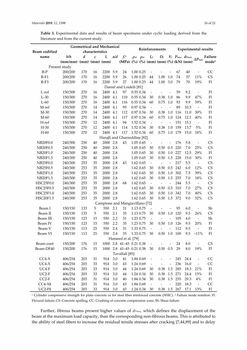
Table 3 presents the geometrical, the mechanical, and the reinforcement data and compares them
with the experimental results yielded from the examined beams. The values of ΔPmax express the
increase of the ultimate load capacity, Pmax, due to the addition of steel fibers. From these values it is
deduced that, although there is an obvious tendency of the SFRC beams to demonstrate increased
strength with respect to the reference specimens without fibers, this increase is not consistent, neither
is it analogous to the increase of the steel fiber content. This aspect was more or less expected since
the provided longitudinal reinforcing bars greatly influence flexural strength and absorbed energy
at a more significant level than the added steel fibers do. However, the favorable contribution of the
steel fibers is focused on the increase of the shear capacity of the beams, which is higher than the
corresponding increase of the flexural strength and, under certain circumstances, causes an important
modification of the failure mode from brittle-shear to flexural-ductile.
1st Loading
Cycle
0.085
0.139
0.188
0.084
0.203
0.269
0.080
0.215
0.283
0.00
0.05
0.10
0.15
0.20
0.25
0.30
Equ
ival
ent
vis
cou
s dam
pin
g
B-P
B-F1
B-F3
2nd Loading
Cycle
3rd Loading
Cycle
Materials 2019, 12, 1398 16 of 21
Table 3. Experimental data and results of beam specimens under cyclic loading derived from the
literature and from the current study.
Beam codified
name
Geometrical and Mechanical
characteristics Reinforcements Experimental results
b/h
(mm/mm)
d
(mm)
c
(mm)
L
(mm)
a/d
fc1
(MPa)
ρsl
(%)
ρst
(%)
Lf
(mm)
Df
(mm)
Vf
(%)
Pmax
(kN)
dPmax
(mm) ΔPmax
Failure
mode2
Present study
B-P 200/200 170 16 2200 5.9 24 1.00 0.25 - - - 67 40 - CC
B-F1 200/200 170 16 2200 5.9 26 1.00 0.25 44 1.00 1.0 74 57 11% CS
B-F3 200/200 170 16 2200 5.9 27 1.00 0.25 44 1.00 3.0 79 70 19% Fl
Daniel and Loukili [81]
L-ref 150/300 270 16 2400 4.1 97 0.55 0.34 - - - 59 9.2 - Fl
L-30 150/300 270 16 2400 4.1 110 0.55 0.34 30 0.38 1.0 86 9.9 47% Fl
L-60 150/300 270 16 2400 4.1 116 0.55 0.34 60 0.75 1.0 93 9.9 59% Fl
M-ref 150/300 270 14 2400 4.1 95 0.97 0.34 - - - 89 10.3 - Fl
M-30 150/300 270 14 2400 4.1 112 0.97 0.34 30 0.38 1.0 116 11.0 30% Fl
M-60 150/300 270 14 2400 4.1 117 0.97 0.34 60 0.75 1.0 124 12.1 40% Fl
H-ref 150/300 270 12 2400 4.1 94 1.52 0.34 - - - 151 15.1 - Fl
H-30 150/300 270 12 2400 4.1 114 1.52 0.34 30 0.38 1.0 159 13.7 5% Fl
H-60 150/300 270 12 2400 4.1 117 1.52 0.34 60 0.75 1.0 179 15.0 18% Fl
Harajli and Gharzeddine [82]
NB20F0.0 240/300 250 40 2000 2.8 43 1.05 0.65 - - - 176 5.8 - CS
NB20F0.5 240/300 250 40 2000 2.8 1.05 0.65 30 0.50 0.5 220 7.0 25% CS
NB20F1.0 240/300 250 40 2000 2.8 1.05 0.65 30 0.50 1.0 227 12.5 29% Fl
NB20F1.5 240/300 250 40 2000 2.8 1.05 0.65 30 0.50 1.5 228 15.0 30% Fl
NB25F0.0 240/300 253 35 2000 2.8 43 1.62 0.65 - - - 217 5.5 - CS
NB25F0.5 240/300 253 35 2000 2.8 1.62 0.65 30 0.50 0.5 242 6.0 12% CS
NB25F1.0 240/300 253 35 2000 2.8 1.62 0.65 30 0.50 1.0 302 7.5 39% CS
NB20F1.5 240/300 253 35 2000 2.8 1.62 0.65 30 0.50 1.5 255 7.0 18% CS
HSC25F0.0 240/300 253 35 2000 2.8 68 1.62 0.65 - - - 244 5.5 - CS
HSC25F0.5 240/300 253 35 2000 2.8 1.62 0.65 30 0.50 0.5 310 7.0 27% CS
HSC25F1.0 240/300 253 35 2000 2.8 1.62 0.65 30 0.50 1.0 342 7.0 40% CS
HSC20F1.5 240/300 253 35 2000 2.8 1.62 0.65 30 0.50 1.5 372 9.0 52% CS
Campione and Mangiavillano [72]
Beam I 150/150 133 5 550 2.1 31 1.13 0.75 - - - 95 6.0 - Sh
Beam II 150/150 133 5 550 2.1 35 1.13 0.75 30 0.50 1.0 120 9.5 26% CS
Beam III 150/150 123 15 550 2.2 31 1.23 0.75 - - - 105 4.0 - Sh
Beam IV 150/150 123 15 550 2.2 35 1.23 0.75 30 0.50 1.0 126 9.5 20% Fl
Beam V 150/150 113 25 550 2.4 31 1.33 0.75 - - - 112 9.5 - Fl
Beam VI 150/150 113 25 550 2.4 35 1.33 0.75 30 0.50 1.0 100 9.5 –11% Fl
Hameed et al. [79]
Beam-cont 150/200 176 15 1000 2.8 41–45 0.21 0.38 - - - 24 8.0 - CS
Beam-DF40 150/200 176 15 1000 2.8 41–45 0.21 0.38 30 0.50 0.5 29 8.0 19% Fl
Tavallali [85]
CC4-X 406/254 203 31 914 3.0 41 1.84 0.69 - - - 245 24.4 - CC
UC4-X 406/254 203 33 914 3.0 43 1.24 0.69 - - - 236 16.0 - CC
UC4-F 406/254 203 33 914 3.0 44 1.24 0.69 30 0.38 1.5 285 18.3 21% Fl
UC2-F 406/254 203 33 914 3.0 44 1.24 0.34 30 0.38 1.5 271 24.4 15% Fl
CC2-F 406/254 203 31 914 3.0 40 1.84 0.34 30 0.38 1.5 255 29.3 4% Fl
CC4-X$ 406/254 203 31 914 3.0 43 1.84 0.69 - - - 220 18.3 - CC
UC2-F$ 406/254 203 33 914 3.0 43 1.24 0.34 30 0.38 1.5 267 17.1 13% Fl
1 Cylinder compressive strength for plain concrete or for steel fiber reinforced concrete (SFRC). 2 Failure mode notation: Fl:
Flexural failure; CS: Concrete spalling; CC: Crushing of concrete compression zone; Sh: Shear failure.
Further, fibrous beams present higher values of dPmax, which defines the displacement of the
beam at the maximum load capacity, than the corresponding non-fibrous beams. This is attributed to
the ability of steel fibers to increase the residual tensile stresses after cracking [7,44,89] and to delay
Materials 2019, 12, 1398 17 of 21
cracking and, consequently, increase the deformation capability of the beams, even in reversal
loading conditions.
Furthermore, according to the experimental results presented in Table 3, it can also be concluded
that the thickness of concrete cover influences the efficiency of the steel fibers and the nature of the
observed failure mode. The majority of the non-fibrous beams failed in a rather brittle manner
dominated by shear failure or by concrete crushing or failed due to concrete spalling. The failure
mode of the fibrous specimens with sufficient thickness of concrete cover and adequate steel fiber
volume fraction (greater than 1.5%, which could be considered as a recommended lower content level
of fibers) is flexural with satisfactory ductility. Otherwise, the beams tend to fail due to concrete
spalling. It is also noted that, in the majority of the examined cases, the addition of steel fibers in a
dosage equal to or less than 1% seems to be insufficient to improve the failure mode of the SFRC
beams and to alter it from brittle to ductile. Further, the enhanced flexural behavior with noticeable
ductility of concrete beams reinforced with bars and steel fibers is also attributed to the ability of steel
fibers to significantly increase tension-stiffening stresses [90].
An additional conclusion that can also be deduced from the comparison of the test results of
Table 3 is that the usage of steel fibers could be more efficient by taking extra care to choose the right
thickness of concrete cover with the appropriate combination of a rather high steel fiber volumetric
proportion.
7. Concluding Remarks
The experimental investigation has been conducted in this paper to investigate the influence of
steel fibers on the cyclic hysteretic response of slender RC beams. The following conclusions can be
drawn within the scope of this study:
Based on the hysteretic responses, the cracking, and the failure modes of the tested beams, it can
be deduced that the overall performance of the RC beams with steel fibers was improved with
respect to the behavior of the reference specimen without fibers, confirming most of the known
aspects.
The non-fibrous reference specimen demonstrated shear diagonal cracking failing in a rather
brittle manner, whereas the SFRC beam with 1% steel fibers failed after concrete spalling with
satisfactory ductility. Moreover, it is stressed that the SFRC beam with 3% steel fibers exhibited
an improved cyclic response, since no inclined cracks of shear nature or concrete spalling were
observed along the length of the beam that failed due to flexure with significant ductility.
The lower amount of the steel fibers seemed to be inefficient to bridge the tensile cracks
developed at the level of the longitudinal reinforcing bars due to the degradation of the steel–
concrete bond performance and, consequently, SFRC demonstrated concrete spalling. The
addition of a higher volume fraction of steel fibers (3%) prevented the propagation of horizontal
cracking, resulting in a pronounced flexural failure with enhanced post-peak hysteretic behavior
in terms of strength, ductility, cracking performance, absorbed energy capability, and equivalent
viscous damping.
The obtained increase of the first cracking load due to the addition of steel fibers in dosage 1%
and 3% was found to be 25% and 47%, respectively. Further, although the increase of the ultimate
load during the third cycle of the SFRC beams with 1% and 3% fibers was only 4% and 8%,
respectively (downward loading direction), and 13% and 21%, respectively (upward loading
direction), compared to the reference beam, the increase of the load-bearing capacity at failure
was 61% and 72% for the SFRC beams with 1% and 3% steel fibers, respectively.
Based on the calculated values of damage indices, it can be deduced that the fibrous beams
presented lower damage index factors than the corresponding non-fibrous reference specimen.
Further, the SFRC beam containing 3% steel fibers exhibited a considerable lower damage level
regarding the reference specimen even from the first loading cycle.
A systematic report of an experimental database consisting of 39 beams tested under cyclic
loading was also presented in order to clarify the effectiveness of steel fibers and their role on
the hysteretic response and the failure mode of RC structural members. Although the amount of
Materials 2019, 12, 1398 18 of 21
the examined specimens was rather limited to derive sound conclusions, it was found that the
favorable influence of steel fibers on the overall performance can be achieved by taking extra
care to choose the right thickness of concrete cover with a rather high amount of steel fibers
(1.5% seems an appropriate lower volume content level of steel fibers).
Author Contributions: All authors contributed extensively to this study, discussed the results and reviews,
prepared the manuscript, and agreed to the amendments at all stages of the paper. P.-M.K.K. and C.E.C.
performed the tests under the supervision of C.G.K., who designed the experiments.
Acknowledgments: The contribution of A. Droutsas to the construction of the specimens and to the
experimental procedure during his undergraduate diploma thesis, along with the technical support of S. Kellis
and V. Kanakaris, Laboratory and Technical Employees of the Reinforced Concrete and Seismic Design of
Structures Laboratory, is greatly appreciated.
Conflicts of Interest: The authors declare no conflict of interest.
References
1. Wang, R.; Gao, X. Relationship between flowability, entrapped air content and strength of UHPC mixtures
containing different dosage of steel fiber. Appl. Sci. 2016, 6, 216.
2. Caggiano, A.; Gambarelli, S.; Martinelli, E.; Nisticò, N.; Pepe, M. Experimental characterization of the post-
cracking response in hybrid steel/polypropylene fiber-reinforced concrete. Constr. Build. Mater. 2016, 125,
1035–1043.
3. Caggiano, A.; Folino, P.; Lima, C.; Martinelli, E.; Pepe, M. On the mechanical response of hybrid fiber
reinforced concrete with recycled and industrial steel fibers. Constr. Build. Mater. 2017, 147, 286–295.
4. Simoes, T.; Octavio, C.; Valença, J.; Costa, H.; Dias-da-Costa, D.; Júlio, E. Influence of concrete strength and
steel fiber geometry on the fiber/matrix interface. Compos. Part B Eng. 2017, 122, 156–164.
5. Smarzewski, P. Effect of curing period on properties of steel and polypropylene fiber reinforced ultra-high
performance concrete. Mater. Sci. Eng. 2017, 245.
6. Shon, C.-S.; Mukashev, T.; Lee, D.; Zhang, D.; Kim, J.R. Can common reed fiber become an effective
construction material? Physical, mechanical, and thermal properties of mortar mixture containing common
reed fiber. Sustainability 2019, 11, 903.
7. Rizzuti, L.; Bencardino, F. Effects of fiber volume fraction on the compressive and flexural experimental
behavior of SFRC. Contemp. Eng. Sci. 2014, 7, 379–390.
8. Lee, S.-C.; Oh, J.-H.; Cho, J.-Y. Compressive behavior of fiber-reinforced concrete with end-hooked steel
fibers. Materials 2015, 8, 1442–1458.
9. Perceka, W.; Liao, W.-C.; Wang, Y.-D. High strength concrete columns under axial compression load:
Hybrid confinement efficiency of high strength transverse reinforcement and steel fibers. Materials 2016, 9,
264.
10. Song, W.; Yin, J. Hybrid effect evaluation of steel fiber and carbon fiber on the performance of the fiber
reinforced concrete. Materials 2016, 9, 704.
11. Chalioris, C.E.; Liotoglou, F.A. Tests and simplified behavioral model for steel fibrous concrete under
compression. In Advances in Civil Engineering and Building Materials IV; Chang, S.-Y., Al Bahar, S.K., Husain,
A.-A.M., Zhao, J., Eds.; CRC Press/Balkema: Leiden, The Netherlands, 2015; pp. 195–199.
12. Saidani, M.; Saraireh, D.; Gerges, M. Behavior of different types of fiber reinforced concrete without
admixture. Eng. Struct. 2016, 113, 328–334.
13. Bencardino, F.; Rizzuti, L.; Spadea, G.; Swamy, R.N. Implications of test methodology on post-cracking and
fracture behavior of steel fiber reinforced concrete. Compos. Part B Eng. 2013, 46, 31–38.
14. Caggiano, A.; Cremona, M.; Faella, C.; Lima, C.; Martinelli, E. Fracture behavior of concrete beams
reinforced with mixed long/short steel fibers. Constr. Build. Mater. 2012, 37, 832–840.
15. Smarzewski, P.; Barnat-Hunek, D. Fracture properties of plain and steel-polypropylene fiber reinforced
high-performance concrete. Mater. Technol. 2015, 49, 563–571.
16. Simoes, T.; Costa, H.; Dias-da-Costa, D.; Júlio, E. Influence of fibers on the mechanical behavior of fiber
reinforced concrete matrixes. Constr. Build. Mater. 2017, 137, 548–556.
17. Yoo, D.-Y.; Banthia, N.; Lee, J.-Y.; Yoon, Y.-S. Effect of fiber geometric property on rate dependent flexural
behavior of ultra-high-performance cementitious composite. Cem. Concr. Compos. 2018, 86, 57–71.
Materials 2019, 12, 1398 19 of 21
18. Song, P.S.; Hwang, S. Mechanical properties of high-strength steel fiber-reinforced concrete. Constr. Build.
Mater. 2004, 18, 669–673.
19. Chalioris, C.E.; Karayannis, C.G. Effectiveness of the use of steel fibers on the torsional behavior of flanged
concrete beams. Cem. Concr. Compos. 2009, 31, 331–341.
20. Lin, W.-T.; Wu, Y.-C.; Cheng, A.; Chao, S.-J.; Hsu, H.-M. Engineering properties and correlation analysis of
fiber cementitious materials. Materials 2014, 7, 7423–7435.
21. Xue, W.; Chen, J.; Xie, F.; Feng, B. Orientation of steel fibers in magnetically driven concrete and mortar.
Materials 2018, 11, 170.
22. Choi, M.S.; Kang, S.-T.; Lee, B.Y.; Koh, K.-T.; Ryu, G.-S. Improvement in predicting the post-cracking tensile
behavior of ultra-high performance cementitious composites based on fiber orientation distribution.
Materials 2016, 9, 829.
23. Herrmann, H.; Pastorelli, E.; Kallonen, A.; Suuronen, J.-P. Methods for fiber orientation analysis of X-ray
tomography images of steel fiber reinforced concrete (SFRC). J. Mater. Sci. 2016, 51, 3772—3783.
24. Trofimov, A.; Mishurova, T.; Lanzoni, L.; Radi, E.; Bruno, G.; Sevostianov, I. Microstructural analysis and
mechanical properties of concrete reinforced with polymer short fibers. Int. J. Eng. Sci. 2018, 133, 210–218.
25. Eik, M.; Puttonen, J.; Herrmann, H. The effect of approximation accuracy of the orientation distribution
function on the elastic properties of short fiber reinforced composites. Compos. Struct. 2016, 148, 12–18.
26. Mishurova, T.; Rachmatulin, N.; Fontana, P.; Oesch, T.; Bruno, G.; Radi, E.; Sevostianov, I. Evaluation of
the probability density of inhomogeneous fiber orientations by computed tomography and its application
to the calculation of the effective properties of a fiber-reinforced composite. Int. J. Eng. Sci. 2018, 122, 14–29.
27. Bentur, A.; Mindess, S. Fiber Reinforced Cementitious Composites: Modern Concrete Technology Series, 2nd ed.;
Taylor & Francis: New York, NY, USA, 2007; p. 624.
28. Olivito, R.S.; Zuccarello, F.A. An experimental study on the tensile strength of steel fiber reinforced
concrete. Compos. Part B Eng. 2010, 41, 246–255.
29. Karayannis, C.G. Nonlinear analysis and tests of steel-fiber concrete beams in torsion. Struct. Eng. Mech.
2000, 9, 323–338.
30. Naaman, A.E. Engineered steel fibers with optimal properties for reinforcement of cement composites. J.
Adv. Concr. Technol. 2003, 1, 241–252.
31. Chalioris, C.E.; Panagiotopoulos, T.A. Flexural analysis of steel fiber-reinforced concrete members. Comput.
Concr. 2018, 22, 11–25.
32. Wille, K.; El-Tawil, S.; Naaman, A.E. Properties of strain hardening ultra-high performance fiber reinforced
concrete (UHP-FRC) under direct tensile loading. Cem. Concr. Compos. 2014, 48, 53–66.
33. Ding, X.; Li, C.; Han, B.; Lu, Y.; Zhao, S. Effects of different deformed steel-fibers on preparation and
properties of self-compacting SFRC. Constr. Build. Mater. 2018, 168, 471–481.
34. Guerini, V.; Conforti, A.; Plizzari, G.A.; Kawashima, S. Influence of steel and macro-synthetic fibers on
concrete properties. Fibers 2018, 6, 47.
35. Zhou, Y.; Xiao, Y.; Gu, A.; Lu, Z. Dispersion, workability and mechanical properties of different steel-
microfiber-reinforced concretes with low fiber content. Sustainability 2018, 10, 2335.
36. Caggiano, A.; Xargay, H.; Folino, P.; Martinelli, E. Experimental and numerical characterization of the bond
behavior of steel fibers recovered from waste tires embedded in cementitious matrices. Cem. Concr. Compos.
2015, 62, 146–155.
37. Montero-Chacón, F.; Cifuentes, H.; Medina, F. Mesoscale characterization of fracture properties of steel
fiber-reinforced concrete using a lattice–particle model. Materials 2017, 10, 207.
38. Caggiano, A.; Martinelli, E. A unified formulation for simulating the bond behavior of fibers in
cementitious materials. Mater. Des. 2012, 42, 204–213.
39. Vougioukas, E.; Papadatou, M. A model for the prediction of the tensile strength of fiber-reinforced
concrete members, before and after cracking. Fibers 2017, 5, 27.
40. Shannag, M.J.; Brincker, R.; Hansen, W. Pullout behavior of steel fibers from cement-based composites.
Cem. Concr. Res. 1997, 27, 925–936.
41. Karayannis, C.G. Analysis and experimental study for steel fiber pullout from cementitious matrices. Adv.
Compos. Lett. 2000, 9, 243–256.
42. Georgiadi-Stefanidi, K.; Mistakidis, E.; Pantousa, D.; Zygomalas, M. Numerical modeling of the pull-out of
hooked steel fibers from high-strength cementitious matrix, supplemented by experimental results. Constr.
Build. Mater. 2010, 24, 2489–2506.
Materials 2019, 12, 1398 20 of 21
43. Kaklauskas, G.; Gribniak, V.; Bacinskas, D. Inverse technique for deformational analysis of concrete beams
with ordinary reinforcement and steel fibers. Procedia Eng. 2011, 14, 1439–1446.
44. Gribniak, V.; Kaklauskas, G.; Kwan, H.; Bacinskas, D.; lbinas, D. Deriving stress–strain relationships for
steel fiber concrete in tension from tests of beams with ordinary reinforcement. Eng. Struct. 2012, 42, 387–
395.
45. Kim, D.J.; Kang, S.H.; Ahn, T.-H. Mechanical characterization of high-performance steel-fiber reinforced
cement composites with self-healing effect. Materials 2014, 7, 508–526.
46. Nishiwaki, T.; Kwon, S.; Homma, D.; Yamada, M.; Mihashi, H. Self-healing capability of fiber-reinforced
cementitious composites for recovery of watertightness and mechanical properties. Materials 2014, 7, 2141–
2154.
47. Tsonos, A.G. Steel fiber high-strength reinforced concrete: A new solution for earthquake strengthening of
old R/C structures. WIT Trans. Built Environ. 2009, 104, 153–164.
48. Chalioris, C.E.; Karayannis, C.G. Experimental investigation of RC beams with rectangular spiral
reinforcement in torsion. Eng. Struct. 2013, 56, 286–297.
49. Chalioris, C.E.; Bantilas, K.E. Shear strength of reinforced concrete beam-column joints with crossed
inclined bars. Eng. Struct. 2017, 140, 241–255.
50. Chalioris, C.E.; Kosmidou, P.-M.K.; Papadopoulos, N.A. Investigation of a new strengthening technique
for RC deep beams using carbon FRP ropes as transverse reinforcements. Fibers 2018, 6, 52.
51. Canbolat, B.A.; Parra-Montesinos, G.J.; Wight, J.K. Experimental study on the seismic behavior of high-
performance fiber-reinforced cement composite coupling beams. ACI Struct. J. 2005, 102, 159–166.
52. Abbas, A.A.; Mohsin, S.M.S.; Cotsovos, D.M. Seismic response of steel fiber reinforced concrete beam-
column joints. Eng. Struct. 2014, 59, 261–283.
53. Ma, K.; Qi, T.; Liu, H.; Wang, H. Shear behavior of hybrid fiber reinforced concrete deep beams. Materials
2018, 11, 2023.
54. Furlan, S., Jr.; Bento de Hanai, J. Shear behavior of fiber reinforced concrete beams. Cem. Concr. Compos.
1997, 19, 359–366.
55. Cucchiara, C.; Mendola, L.; Papia, M. Effectiveness of stirrups and steel fibers as shear reinforcement. Cem.
Concr. Compos. 2004, 26, 777–786.
56. Juárez, C.; Valdez, P.; Durán, A.; Sobolev, K. The diagonal tension behavior of fiber reinforced concrete
beams. Cem. Concr. Compos. 2007, 29, 402–408.
57. Chalioris, C.E.; Sfiri, E.F. Shear performance of steel fibrous concrete beams. Procedia Eng. 2011, 14, 2064–
2068.
58. Lee, J.-Y.; Shin, H.-O.; Yoo, D.-Y.; Yoon, Y.-S. Structural response of steel-fiber-reinforced concrete beams
under various loading rates. Eng. Struct. 2018, 156, 271–283.
59. Smarzewski, P. Hybrid fibers as shear reinforcement in high-performance concrete beams with and
without openings. Appl. Sci. 2018, 8, 2070.
60. Smarzewski, P. Analysis of failure mechanics in hybrid fiber-reinforced high-performance concrete deep
beams with and without openings. Materials 2019, 12, 101.
61. Zhao, J.; Liang, J.; Chu, L.; Shen, F. Experimental study on shear behavior of steel fiber reinforced concrete
beams with high-strength reinforcement. Materials 2018, 11, 1682.
62. Chalioris, C.E. Analytical approach for the evaluation of minimum fiber factor required for steel fibrous
concrete beams under combined shear and flexure. Constr. Build. Mater. 2013, 43, 317–336.
63. Kim, K.S.; Lee, D.H.; Hwang, J.H.; Kuchma, D.A. Shear behavior model for steel fiber-reinforced concrete
members without transverse reinforcements. Compos. Part B Eng. 2012, 43, 2324–2334.
64. Zhang, F.; Ding, Y.; Xu, J.; Zhang, Y.; Zhu, W.; Shi, Y. Shear strength prediction for steel fiber reinforced
concrete beams without stirrups. Eng. Struct. 2016, 127, 101–116.
65. Lee, D.H.; Han, S.-J.; Kim, K.S.; LaFave, J.M. Shear capacity of steel fiber-reinforced concrete beams. Struct.
Concr. 2017, 18, 278–291.
66. Colajanni, P.; Recupero, A.; Spinella, N. Generalization of shear truss model to the case of SFRC beams with
stirrups. Comput. Concr. 2012, 9, 227–244.
67. Hwang, J.-H.; Lee, D.H.; Ju, H.; Kim, K.S.; Seo, S.-Y.; Kang, J.-W. Shear behavior models of steel fiber
reinforced concrete beams modifying softened truss model approaches. Materials 2013, 6, 4847–4867.
68. Bafghi, M.A.B.; Amini, F.; Nikoo, H.S.; Sarkardeh, H. Effect of steel fiber and different environments on
flexural behavior of reinforced concrete beams. Appl. Sci. 2017, 7, 1011.
Materials 2019, 12, 1398 21 of 21
69. Kotsovos, G.; Zeris, C.; Kotsovos, M. The effect of steel fibers on the earthquake-resistant design of
reinforced concrete structures. Mater. Struct. 2007, 40, 175–188.
70. Soutsos, M.N.; Le, T.T.; Lampropoulos, A.P. Flexural performance of fiber reinforced concrete made with
steel and synthetic fibers. Constr. Build. Mater. 2012, 36, 704–710.
71. Barros, J.A.; Figueiras, J.A. Flexural behavior of SFRC: Testing and modeling. ASCE J. Mater. Civ. Eng. 1999,
11, 331–339.
72. Campione, G.; Mangiavillano, M.L. Fibrous reinforced concrete beams in flexure: Experimental
investigation, analytical modelling and design considerations. Eng. Struct. 2008, 30, 2970–2980.
73. Li, C.; Geng, H.; Deng, C.; Li, B.; Zhao, S. Experimental investigation on columns of steel fiber reinforced
concrete with recycled aggregates under large eccentric compression load. Materials 2019, 12, 445.
74. Gribniak, V.; Arnautov, A.K.; Norkus, A.; Tamulenas, V.; Gudonis, E.; Sokolov, A. Experimental
investigation of the capacity of steel fibers to ensure the structural integrity of reinforced concrete
specimens coated with CFRP sheets. Mech. Compos. Mater. 2016, 52, 401–410.
75. Gribniak, V.; Arnautov, A.K.; Norkus, A.; Kliukas, R.; Tamulenas, V.; Gudonis, E.; Sokolov, A.V. Steel
fibers: Effective way to prevent failure of the concrete bonded with FRP sheets. Adv. Mater. Sci. Eng. 2016,
pp. 10.
76. Gribniak, V.; Tamulenas, V.; Ng, P.-L.; Arnautov, A.K.; Gudonis, E.; Misiunaite, I. Mechanical behavior of
steel fiber-reinforced concrete beams bonded with external carbon fiber sheets. Materials 2017, 10, 666.
77. Lee, J.-Y.; Shin, H.-O.; Min, K.-H.; Yoon, Y.-S. Flexural assessment of blast-damaged RC beams retrofitted
with CFRP sheet and steel fiber. Int. J. Polym. Sci. 2018, 2018, 2036436.
78. Kotsovos, M.D.; Baka, A.; Vougioukas, E. Earthquake-resistant design of reinforced concrete structures:
Shortcomings of current methods. ACI Struct. J. 2003, 100, 11–18.
79. Hameed, R.; Duprat, F.; Turatsinze, A.; Sellier, A.; Siddiqi, Z.A. Behavior of reinforced fibrous concrete
beams under reversed cyclic loading. Pak. J. Eng. Appl. Sci. 2011, 9, 1–12.
80. Lepage, A.; Tavallali, H.; Pujol, S.; Rautenberg, J.M. High-performance steel bars and fibers as concrete
reinforcement for seismic-resistant frames. Adv. Civ. Eng. 2012, 2012, 450981.
81. Daniel, L.; Loukili, A. Behavior of high-strength fiber-reinforced concrete beams under cyclic loading. ACI
Struct. J. 2002, 99, 248–256.
82. Harajli, M.H.; Gharzeddine, O. Effect of steel fibers on bond performance of steel bars in NSC and HSC
under load reversals. J. Mater. Civ. Eng. 2007, 19, 864–873.
83. Parra-Montesinos, G.J.; Chompreda, P. Deformation capacity and shear strength of fiber-reinforced cement
composite flexural members subjected to displacement reversals. ASCE J. Struct. Eng. 2007, 133, 421–431.
84. Chalioris, C.E. Steel fibrous RC beams subjected to cyclic deformations under predominant shear. Eng.
Struct. 2013, 49, 104–118.
85. Tavallali, H.; Lepage, A.; Rautenberg, J.M.; Pujol, S. Concrete beams reinforced with high-strength steel
subjected to displacement reversals. ACI Struct. J. 2014, 111, 1037–1048.
86. Tsonos, A.-D.G. Ultra-high-performance fiber reinforced concrete: An innovative solution for
strengthening old R/C structures and for improving the FRP strengthening method. WIT Trans. Eng. Sci.
2009, 64, 273–284.
87. Park, Y.-J.; Ang, A.H.-S. Mechanistic seismic damage model for reinforced concrete. ASCE J. Struct. Eng.
1985, 111, 722–739.
88. Popov, E.P. Bond and anchorage of reinforcing bars under cyclic loading. ACI Struct. J. 1984, 81, 340–349.
89. Meskenas, A.; Kaklauskas, G.; Daniunas, A.; Bacinskas, D.; Jakubovskis, R.; Gribniak, V.; Gelazius, V.;
Determination of the stress-crack opening relationship of SFRC by an inverse analysis. Mech. Compos. Mater.
2014, 49, 685–690.
90. Gribniak, V.; Kaklauskas, G.; Torres, L.; Daniunas, A.; Timinskas, E.; Gudonis, E. Comparative analysis of
deformations and tension-stiffening in concrete beams reinforced with GFRP or steel bars and fibers.
Compos. Part B Eng. 2013, 50, 158–170.
© 2019 by the authors. Licensee MDPI, Basel, Switzerland. This article is an open access
article distributed under the terms and conditions of the Creative Commons Attribution
(CC BY) license (http://creativecommons.org/licenses/by/4.0/).
Related Documents