Department of Electrical and Electronic Engineering Communications and Array Processing Group Cyclic Pre fi x-Free MC-CDMA Arrayed MIMO Communication Systems Ho Huat Peh A thesis submitted in fulfilment of requirements for the degree of Doctor of Philosophy of Imperial College London and the Diploma of the Imperial College 2009 Supervisors: Professor A. Manikas, Imperial College London Professor L. W.-C. Wong, National University of Singapore Professor T.-T. Tjhung, A*STAR, Singapore

Welcome message from author
This document is posted to help you gain knowledge. Please leave a comment to let me know what you think about it! Share it to your friends and learn new things together.
Transcript

Department of Electrical and Electronic Engineering
Communications and Array Processing Group
Cyclic Prefix-Free MC-CDMA ArrayedMIMO Communication Systems
Ho Huat Peh
A thesis submitted in fulfilment of requirementsfor the degree of
Doctor of Philosophy of Imperial College Londonand the
Diploma of the Imperial College
2009
Supervisors:Professor A. Manikas, Imperial College London
Professor L. W.-C. Wong, National University of SingaporeProfessor T.-T. Tjhung, A*STAR, Singapore
Abstract
The objective of this thesis is to investigate MC-CDMA MIMO systems where
the antenna array geometry is taken into consideration. In most MC-CDMA
systems, cyclic pre�xes, which reduce the spectral e¢ ciency, are used. In order
to improve the spectral e¢ ciency, this research study is focused on cyclic pre�x-
free MC-CDMA MIMO architectures.
Initially, space-time wireless channel models are developed by considering the
spatio-temporal mechanisms of the radio channel, such as multipath propaga-
tion. The spatio-temporal channel models are based on the concept of the array
manifold vector, which enables the parametric modelling of the channel.
The array manifold vector is extended to the multi-carrier space-time array
(MC-STAR) manifold matrix which enables the use of spatio-temporal signal
processing techniques. Based on the modelling, a new cyclic pre�x-free MC-
CDMA arrayed MIMO communication system is proposed and its performance
is compared with a representative existing system. Furthermore, a MUSIC-type
algorithm is then developed for the estimation of the channel parameters of the
received signal.
This proposed cyclic pre�x-free MC-CDMA arrayed MIMO system is then
extended to consider the e¤ects of spatial di¤usion in the wireless channel. Spatial
di¤usion is an important channel impairment which is often ignored and the
failure to consider such e¤ects leads to less than satisfactory performance. A
subspace-based approach is proposed for the estimation of the channel parameters
and spatial spread and reception of the desired signal.
Finally, the problem of joint optimization of the transmit and receive beam-
forming weights in the downlink of a cyclic pre�x-free MC-CDMA arrayed MIMO
communication system is investigated. A subcarrier-cooperative approach is used
for the transmit beamforming so that there is greater �exibility in the allocation
of channel symbols. The resulting optimization problem, with a per-antenna
transmit power constraint, is solved by the Lagrange multiplier method and an
iterative algorithm is proposed.
2
Contents
Abstract 2
Contents 3
List of Figures 6
List of Tables 9
List of Publications 10
Acknowledgements 11
Abbreviations and Acronyms 13
List of Symbols 15
Notation 17
1 Introduction 191.1 Channel Dispersion . . . . . . . . . . . . . . . . . . . . . . . . . . 201.2 Multi-Carrier Modulation . . . . . . . . . . . . . . . . . . . . . . 22
1.2.1 OFDM . . . . . . . . . . . . . . . . . . . . . . . . . . . . . 251.2.2 MC DS-CDMA . . . . . . . . . . . . . . . . . . . . . . . . 271.2.3 MC-CDMA . . . . . . . . . . . . . . . . . . . . . . . . . . 291.2.4 Guard Intervals and Cyclic Pre�xes . . . . . . . . . . . . . 301.2.5 Crest Factor . . . . . . . . . . . . . . . . . . . . . . . . . . 351.2.6 General Objective . . . . . . . . . . . . . . . . . . . . . . . 36
1.3 Multiple-Input Multiple-Output . . . . . . . . . . . . . . . . . . 371.4 Antenna Array Signal Processing . . . . . . . . . . . . . . . . . . 401.5 Summary and Thesis Organization . . . . . . . . . . . . . . . . . 42
2 Space-Time Channel and System Architecture Modelling 452.1 Antenna Array Manifold Vector . . . . . . . . . . . . . . . . . . . 462.2 Space-Time Channel Modelling . . . . . . . . . . . . . . . . . . . 49
2.2.1 Scalar-Input Scalar-Output (SISO) Channel . . . . . . . . 532.2.2 Scalar-Input Vector-Output (SIVO) Channel . . . . . . . . 542.2.3 Vector-Input Scalar-Output (VISO) Channel . . . . . . . . 552.2.4 Vector-Input Vector-Output (VIVO) Channel . . . . . . . 562.2.5 Vector-Input Scalar-Output Multiple Access (VISO MA)
Channels . . . . . . . . . . . . . . . . . . . . . . . . . . . 57
3

CONTENTS 4
2.2.6 Vector-Input Vector-Output Multiple Access (VIVO MA)Channels . . . . . . . . . . . . . . . . . . . . . . . . . . . 58
2.3 Space-Time System Architecture . . . . . . . . . . . . . . . . . . 602.3.1 Receiver Front-End Temporal Windowing . . . . . . . . . 66
2.4 Summary . . . . . . . . . . . . . . . . . . . . . . . . . . . . . . . 68
3 Space-Time Cyclic Pre�x-free MC-CDMA Array-Based MIMOSystem 703.1 Introduction . . . . . . . . . . . . . . . . . . . . . . . . . . . . . . 723.2 Cyclic Pre�x-free MC-CDMA Arrayed MIMO Transmitter . . . . 743.3 Received Signal . . . . . . . . . . . . . . . . . . . . . . . . . . . . 76
3.3.1 MC-STAR Manifold Matrix . . . . . . . . . . . . . . . . . 773.4 Receiver Weights . . . . . . . . . . . . . . . . . . . . . . . . . . . 80
3.4.1 RAKE Receiver . . . . . . . . . . . . . . . . . . . . . . . . 803.4.2 MMSE Receiver . . . . . . . . . . . . . . . . . . . . . . . . 813.4.3 Subspace-Based Receiver . . . . . . . . . . . . . . . . . . . 82
3.5 Space-Time Parameter Estimation for Asynchronous MultipathPropagation . . . . . . . . . . . . . . . . . . . . . . . . . . . . . . 83
3.6 Simulation Studies . . . . . . . . . . . . . . . . . . . . . . . . . . 893.6.1 Detection Performance . . . . . . . . . . . . . . . . . . . . 903.6.2 Space-Time Parameter Estimation . . . . . . . . . . . . . 96
3.7 Summary . . . . . . . . . . . . . . . . . . . . . . . . . . . . . . . 101
4 Di¤used Channel Estimation and Reception for Cyclic Pre�x-free MC-CDMA Arrayed MIMO System 1024.1 Introductory Background . . . . . . . . . . . . . . . . . . . . . . . 1034.2 Di¤used-VIVO Channel Model . . . . . . . . . . . . . . . . . . . . 106
4.2.1 Space-di¤used Vector Channel Model . . . . . . . . . . . . 1074.3 Received Signal . . . . . . . . . . . . . . . . . . . . . . . . . . . . 109
4.3.1 Di¤used MC-STAR Manifold Vector . . . . . . . . . . . . 1094.4 Channel Estimation and Reception . . . . . . . . . . . . . . . . . 112
4.4.1 Estimation of Spatial Spread . . . . . . . . . . . . . . . . . 1144.5 Receiver Weights . . . . . . . . . . . . . . . . . . . . . . . . . . . 1154.6 Simulation Studies . . . . . . . . . . . . . . . . . . . . . . . . . . 116
4.6.1 Channel Estimation using the Proposed Method . . . . . . 1164.6.2 Reception using the Di¤used Channel Framework . . . . . 120
4.7 Summary . . . . . . . . . . . . . . . . . . . . . . . . . . . . . . . 126
5 Joint Beamforming in Downlink Cyclic Pre�x-free MC-CDMAArrayed MIMO System 1275.1 Introductory Background . . . . . . . . . . . . . . . . . . . . . . . 1285.2 Downlink Cyclic Pre�x-free MC-CDMA Arrayed MIMO Transmit-
ter . . . . . . . . . . . . . . . . . . . . . . . . . . . . . . . . . . . 1325.2.1 PAPR and Transmit Power Requirement . . . . . . . . . . 1365.2.2 Received Signal . . . . . . . . . . . . . . . . . . . . . . . . 137
5.3 Joint Transmit-Receive Beamformer Optimization . . . . . . . . . 1395.4 Simulation Studies . . . . . . . . . . . . . . . . . . . . . . . . . . 1425.5 Summary . . . . . . . . . . . . . . . . . . . . . . . . . . . . . . . 146

CONTENTS 5
6 Conclusions and Future Work 1486.1 Thesis Summary . . . . . . . . . . . . . . . . . . . . . . . . . . . 1486.2 List Of Contributions . . . . . . . . . . . . . . . . . . . . . . . . . 1526.3 Suggestions for Future Work . . . . . . . . . . . . . . . . . . . . . 155
A E¤ect of Multipath Channels on MC Systems 160A.1 Intersymbol Interference . . . . . . . . . . . . . . . . . . . . . . . 161A.2 Intrasymbol Interference (Intercarrier Interference) . . . . . . . . 162A.3 Non-ideal e¤ects in MC systems . . . . . . . . . . . . . . . . . . . 163
A.3.1 Carrier Frequency and Phase O¤sets . . . . . . . . . . . . 164A.3.2 FFT Window Location O¤set . . . . . . . . . . . . . . . . 165A.3.3 Phase noise . . . . . . . . . . . . . . . . . . . . . . . . . . 166A.3.4 Sampling frequency o¤set . . . . . . . . . . . . . . . . . . 167A.3.5 Non-Linear Circuits in the Transmitter and Receiver . . . 167
B Mathematical Derivations 169B.1 Derivation of Transmit Beamforming Matrix . . . . . . . . . . . . 169B.2 Derivation of Lagrange Multiplier . . . . . . . . . . . . . . . . . . 172B.3 Derivation of Receive Beamforming Matrix . . . . . . . . . . . . . 174
References 175

List of Figures
1.1 Comparison of single-carrier modulation and multi-carrier modu-lation systems: (a) frequency spectra of transmitted signals and(b) frequency spectra of received signals. . . . . . . . . . . . . . . 24
1.2 Simpli�ed baseband OFDM modulator. . . . . . . . . . . . . . . . 261.3 Block diagram of IDFT (IFFT) implementation of a baseband
OFDM modulator. . . . . . . . . . . . . . . . . . . . . . . . . . . 271.4 Simpli�ed baseband MC DS-CDMA modulator. . . . . . . . . . . 281.5 Block diagram of IDFT (IFFT) implementation of a baseband MC
DS-CDMA modulator. . . . . . . . . . . . . . . . . . . . . . . . . 281.6 Simpli�ed baseband MC-CDMA modulator. . . . . . . . . . . . . 291.7 Block diagram of IDFT (IFFT) implementation of a baseband MC-
CDMA modulator. . . . . . . . . . . . . . . . . . . . . . . . . . . 301.8 Multi-antenna communications systems classi�cation. . . . . . . . 381.9 Narrowband beamformer structure. . . . . . . . . . . . . . . . . . 41
2.1 Illustration of the planewave propagation model based on the jth
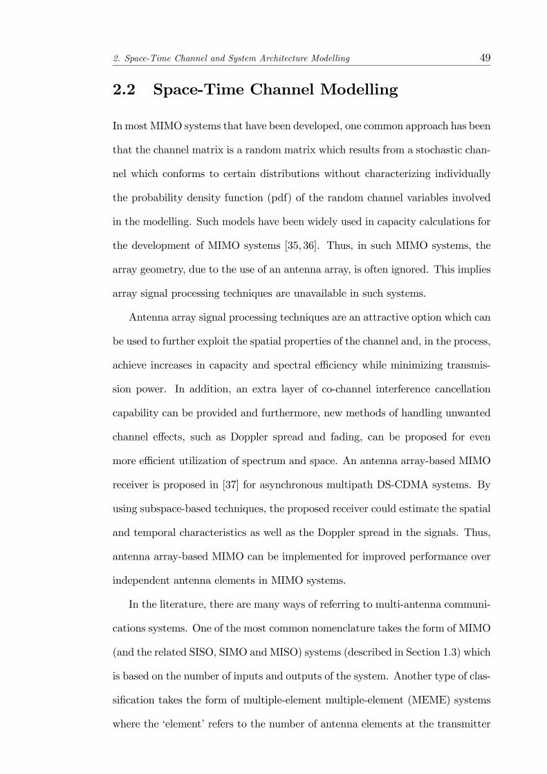
path of the ith user. . . . . . . . . . . . . . . . . . . . . . . . . . . 472.2 Space-time channel classi�cation based on scalar input/output and
vector input/output of the channel. . . . . . . . . . . . . . . . . 522.3 Scalar-Input Scalar-Output (SISO) channel model. . . . . . . . . 532.4 Scalar-Input Vector-Output (SIVO) channel model. . . . . . . . . 542.5 Vector-Input Scalar-Output (VISO) channel model for an array-
based system. . . . . . . . . . . . . . . . . . . . . . . . . . . . . 552.6 Vector-Input Vector-Output (VIVO) channel model. . . . . . . . 562.7 VISO MA-1 channel model where M users, each equipped with a
single antenna, transmit to a single antenna receiver. . . . . . . . 582.8 VISO MA-2 channel model whereM users, each equipped with an
antenna array, transmit to a single antenna receiver. . . . . . . . . 582.9 VIVO MA-1 channel model where M users, each equipped with a
single antenna, transmit to a receiver equipped with an antennaarray. . . . . . . . . . . . . . . . . . . . . . . . . . . . . . . . . . . 59
2.10 VIVO MA-2 channel model whereM users, each using an antennaarray, transmit to a receiver employing an antenna array. . . . . . 60
2.11 System architecture for Chapter 3. . . . . . . . . . . . . . . . . . 632.12 System architecture for Chapter 4. . . . . . . . . . . . . . . . . . 642.13 System architecture for Chapter 5. . . . . . . . . . . . . . . . . . 652.14 Discretizer and tapped delay line (TDL) structure in receiver front-
end. . . . . . . . . . . . . . . . . . . . . . . . . . . . . . . . . . . 66
6

LIST OF FIGURES 7
2.15 Illustration of the channel symbols captured by a tapped delay line(TDL) of length 2Tcs. . . . . . . . . . . . . . . . . . . . . . . . . . 67
3.1 System Architecture of a cyclic pre�x-free arrayed MIMO commu-nication system (Figure 2.11 which is reproduced here for ease ofreference). . . . . . . . . . . . . . . . . . . . . . . . . . . . . . . . 71
3.2 Structure of the transmitter in a cyclic pre�x-free MC-CDMA ar-rayed MIMO system (transmitter terminal in Figure 3.1). . . . . . 75
3.3 Bank of preprocessors required for the formation of the 2-dimensionalSTARMUSIC spectrum to obtain estimates of the spatio-temporalchannel parameters. . . . . . . . . . . . . . . . . . . . . . . . . . 88
3.4 Comparison of the signal constellations produced by the receiversunder consideration at SNR = 10dB for a (2,2) cyclic pre�x-freeMC-CDMA arrayed MIMO system. a) MMSE receiver for pro-posed system, b) RAKE receiver for proposed system, c) Subspace-based receiver for proposed system, d) MMSE receiver for referencesystem [54]. . . . . . . . . . . . . . . . . . . . . . . . . . . . . . . 92
3.5 Comparison of the BER performance of the (2,2) cyclic pre�x-free MC-CDMA arrayed MIMO communication system with theMIMO-OFDM based reference system [54]. . . . . . . . . . . . . . 93
3.6 Comparison of the BER performance of the (2,3) cyclic pre�x-free MC-CDMA arrayed MIMO communication system with theMIMO-OFDM based reference system [54]. . . . . . . . . . . . . . 94
3.7 Comparison of the BER performance of the (2,4) cyclic pre�x-free MC-CDMA arrayed MIMO communication system with theMIMO-OFDM based reference system [54]. . . . . . . . . . . . . . 94
3.8 Comparison of the BER performance of the (2,5) cyclic pre�x-free MC-CDMA arrayed MIMO communication system with theMIMO-OFDM based reference system [54]. . . . . . . . . . . . . . 95
3.9 System capacity comparison of the arrayed MIMO system withthe reference system [54] as the number of receive antennas is in-creased. . . . . . . . . . . . . . . . . . . . . . . . . . . . . . . . . 95
3.10 Spatial-temporal spectrum showing only 5 out of 7 multipaths ofthe frequency-selective fading channel in a (2,4) cyclic pre�x-freeMC-CDMA arrayedMIMO system. Only co-directional paths havebeen successfully resolved. . . . . . . . . . . . . . . . . . . . . . . 98
3.11 Spatial-temporal spectrum showing all the 7 multipaths of thefrequency-selective fading channel in a (2,4) cyclic pre�x-free MC-CDMA arrayed MIMO system. 2 overlapping arrays of length 3are used for the spatial smoothing process and the co-delay pathsare successfully resolved. . . . . . . . . . . . . . . . . . . . . . . . 99
3.12 Spatial-temporal spectrum showing both multipaths (which areclosely located in both time and space) of the frequency-selectivefading channel in a (2,4) cyclic pre�x-free MC-CDMA arrayedMIMO system. . . . . . . . . . . . . . . . . . . . . . . . . . . . . 100
4.1 Scattering propagation channel for a MIMO (VIVO) system. . . . 1074.2 Di¤used-VIVO channel for arrayed MIMO systems with transmit
and receive antenna arrays of small aperture. . . . . . . . . . . . . 108
LIST OF FIGURES 8
4.3 2D MUSIC spectrum for a (3,5) cyclic pre�x-free MC-CDMA ar-rayed MIMO system at SNR = 0dB. . . . . . . . . . . . . . . . . 118
4.4 Standard deviation of DOA estimates versus spatial spread of mul-tipath at input SNR of 20dB (ULA). . . . . . . . . . . . . . . . . 119
4.5 Standard deviation of DOA estimates versus spatial spread of mul-tipath at input SNR of 20dB (UCA)1. . . . . . . . . . . . . . . . . 120
4.6 Standard deviation of DOA estimates versus input SNR for spatialspreads of 5� and 10� (ULA). . . . . . . . . . . . . . . . . . . . . 121
4.7 Standard deviation of DOA estimates versus input SNR for spatialspreads of 5� and 10� (UCA). . . . . . . . . . . . . . . . . . . . . 122
4.8 SNIRout versus input SNR plots for decorrelating reception basedon di¤used STAR and point-source STAR in a channel with 6�
spatial di¤usion. . . . . . . . . . . . . . . . . . . . . . . . . . . . 1234.9 SNIRout versus spatial spread for decorrelating reception based
on di¤used STAR and point-source STAR at input SNR of 20dB(ULA). . . . . . . . . . . . . . . . . . . . . . . . . . . . . . . . . 124
4.10 SNIRout versus near-far ratio for decorrelating reception based ondi¤used STAR and point-source STAR at input SNR of 20dB(ULA) and 6� spatial di¤usion. . . . . . . . . . . . . . . . . . . . 125
5.1 An illustration of a multi-user MIMO downlink with 3 users. . . . 1335.2 MC-CDMA modulation and transmit beamforming for the ith user. 1345.3 Study of convergence of the proposed algorithm with transmit SNR
= 0, 8, 16dB in a (6; 4; 2) cyclic pre�x-free MC-CDMA arrayedMIMO system (Nsc = 15). . . . . . . . . . . . . . . . . . . . . . . 143
5.4 BER performance of the the proposed iterative algorithm andthe eigendecomposition-based transmit precoding with RAKE orMMSE receiver equalization for a (6,4,2) cyclic pre�x-free MC-CDMA arrayed MIMO system. . . . . . . . . . . . . . . . . . . . 145
5.5 BER performance of the the proposed iterative algorithm andthe eigendecomposition-based transmit precoding with RAKE orMMSE receiver equalization for a (10,4,2) cyclic pre�x-free MC-CDMA arrayed MIMO system. . . . . . . . . . . . . . . . . . . . 145
5.6 Average probability of clipping of transmitted MC-CDMA signalfrom each transmitter antenna with target Pclipping = 0.1 and 0.01for various transmit SNR (Nsc = 7). . . . . . . . . . . . . . . . . . 146
List of Tables
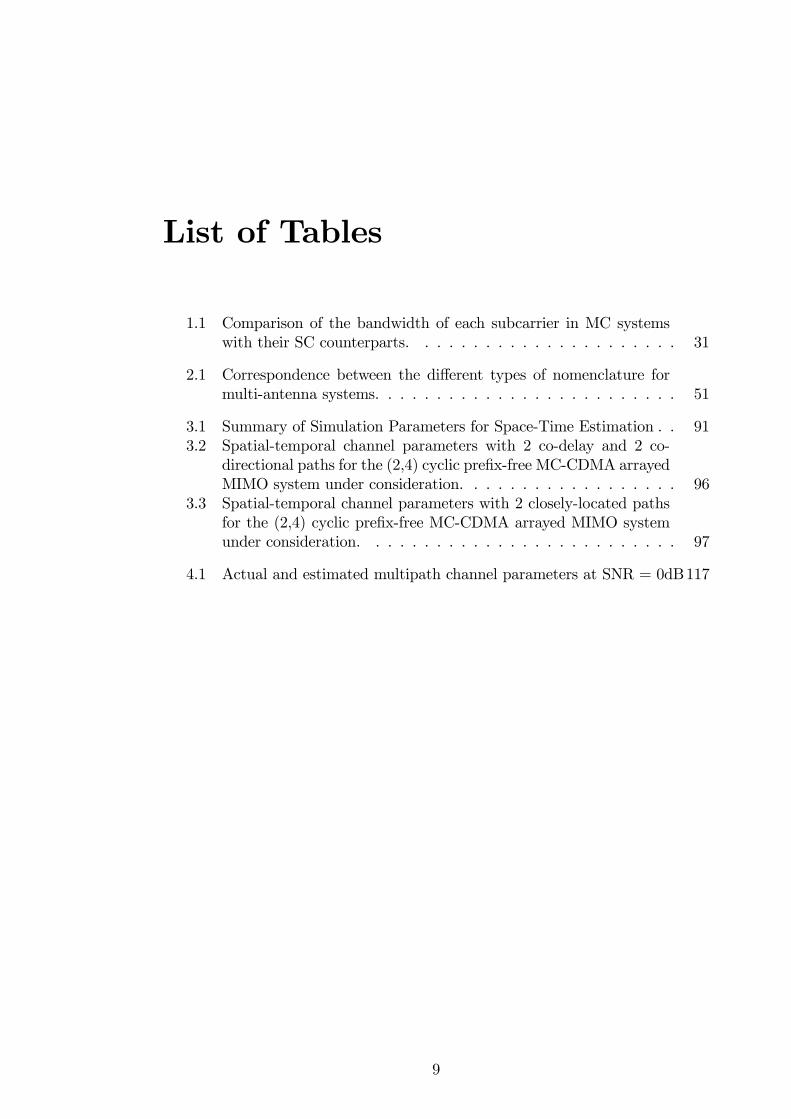
1.1 Comparison of the bandwidth of each subcarrier in MC systemswith their SC counterparts. . . . . . . . . . . . . . . . . . . . . . 31
2.1 Correspondence between the di¤erent types of nomenclature formulti-antenna systems. . . . . . . . . . . . . . . . . . . . . . . . . 51
3.1 Summary of Simulation Parameters for Space-Time Estimation . . 913.2 Spatial-temporal channel parameters with 2 co-delay and 2 co-
directional paths for the (2,4) cyclic pre�x-free MC-CDMA arrayedMIMO system under consideration. . . . . . . . . . . . . . . . . . 96
3.3 Spatial-temporal channel parameters with 2 closely-located pathsfor the (2,4) cyclic pre�x-free MC-CDMA arrayed MIMO systemunder consideration. . . . . . . . . . . . . . . . . . . . . . . . . . 97
4.1 Actual and estimated multipath channel parameters at SNR = 0dB117
9
List of Publications
� H. H. Peh, A. Manikas, T. T. Tjhung and W.-C. Wong, "An Investigative
Study of Cyclic Pre�x-free MC-CDMA Arrayed MIMO Communication
Systems," Proceedings of the International Symposium on Wireless Perva-
sive Computing 2007, Feb. 2007.
� F. Rashid, H. H. Peh and A. Manikas, "Di¤used Channel Estimation and
Reception for Cyclic Pre�x-free MC-CDMA Arrayed-MIMO Communica-
tion Systems," International Journal of Wireless Information Networks,
Aug. 2008
� H. H. Peh, A. Manikas, T. T. Tjhung andW.-C. Wong. "Joint Transmitter-
Receiver Beamforming in Downlink Cyclic Pre�x-free Spatio-Temporal MC-
CDMA," Submitted to IEEE International Conference on Communications
2009 Wireless Communications Symposium.
10

Acknowledgements
This completion of this thesis would not have possible without the guidance and
advice of my supervisors. First and foremost, I would like to thank Professor
Athanassios Manikas. It was through him that I was �rst introduced to the �eld
of array communications and processing. It is a great privilege for me to have him
as my supervisor, enjoy his enthusiastic leadership, and bene�t from his expertise.
In addition, I would like to thank Professors Anthony G. Constantinides, Wai-
Choong Wong and Tjeng Thiang Tjhung for their invaluable feedback on my
work.
I have learnt so many di¤erent topics relating to signal processing through
the many insightful discussions with my colleagues, too many to be mentioned
individually, and I am grateful for these ful�lling exchanges. I am also indebted
to the Agency for Science, Technology and Research (A*STAR), Singapore for
providing the funding for my studies at Imperial College London.
The support of my family and friends has been essential to me. In particular,
I thank my parents who have provided a wealth of encouragement throughout all
of my academic pursuits, from my early school days until the present time. You
helped to inspire in me the determination needed to complete this doctorate.
Lastly but most importantly, I wish to thank my wife, Lilian, for her love
and support throughout the course of the research and writing of this thesis.
Your encouragement helped sustain me during those di¢ cult periods when the
11

Acknowledgements 12
prospects of producing a �nished thesis seemed impossible.

Abbreviations and Acronyms
3G third generation
4G fourth generation
AWGN additive white Gaussian noise
BPSK binary phase shift keying
BER bit error rate
CCI co-channel interference
CDMA code division multiple access
(I)DFT (inverse) discrete Fourier transform
DBPSK di¤erential binary phase-shift keying
DQPSK di¤erential quaternary phase-shift keying
DS-CDMA direct sequence code division multiple access
(I)FFT (inverse) fast Fourier transform
FIR �nite impulse response
ICI intercarrier interference
ISI intersymbol interference
MAI multiple-access interference
MC-CDMA multi-carrier code division multiple access
MC-DS-CDMA multicarrier direct sequence code division multiple access
MIMO multiple-input multiple-output
MISO multiple-input single-output
13

Abbreviations and Acronyms 14
MUSIC multiple signal classi�cation
MMSE minimum mean squared error
OFCDM orthogonal frequency code division multiplexing
OFDM orthogonal frequency division multiplexing
PAPR peak-to-average power ratio
PN pseudo-noise
QoS quality-of-service
QPSK quaternary phase-shift keying
SIC succesive interference cancellation
SIMO single-input multiple-output
SISO single-input single-output
SIVO scalar-input vector-output
SNR signal-to-noise-ratio
SNIR signal-to-noise-plus-interference-ratio
TDD time-division duplex
UCA uniform circular array
ULA uniform linear array
V-BLAST vertical-Bell Labs layered space-time
VIVO vector-input vector-output
ZF zero-forcing
List of Symbols
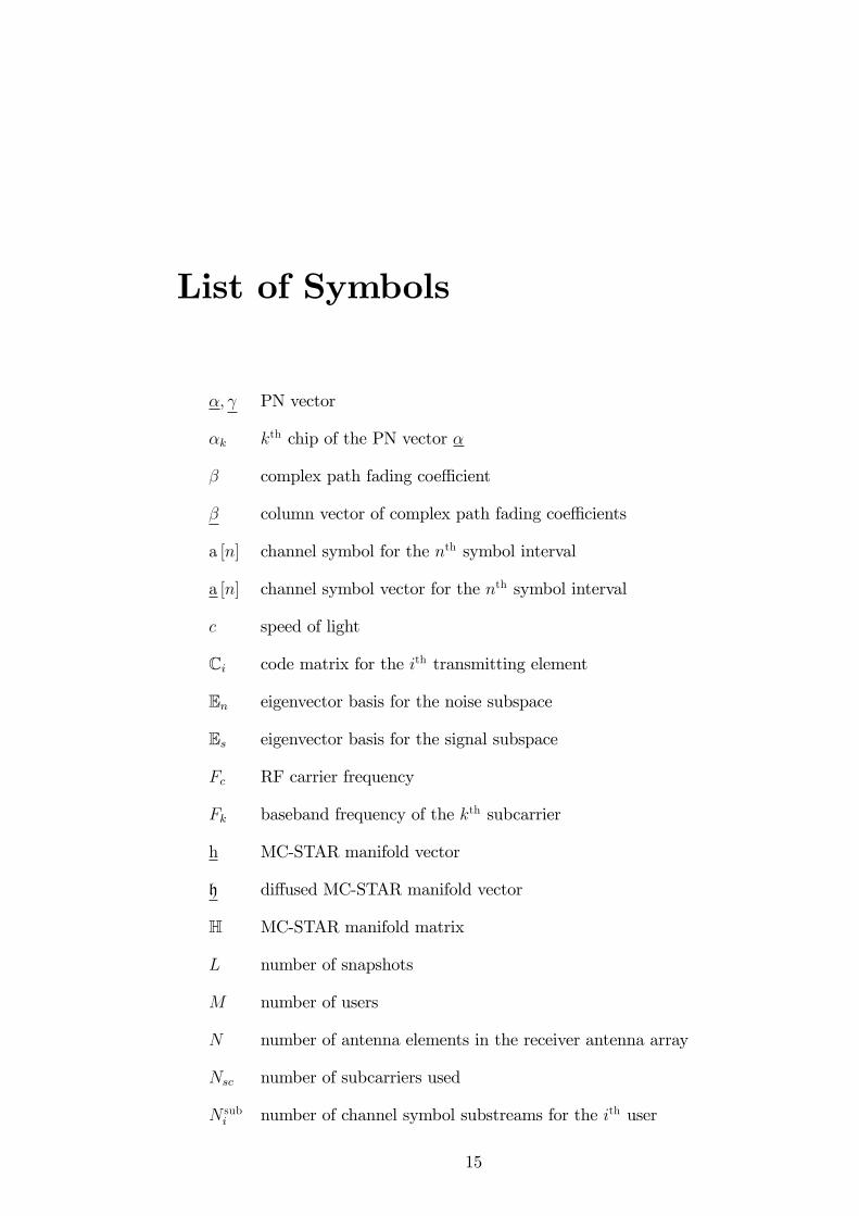
�; PN vector
�k kth chip of the PN vector �
� complex path fading coe¢ cient
� column vector of complex path fading coe¢ cients
a [n] channel symbol for the nth symbol interval
a [n] channel symbol vector for the nth symbol interval
c speed of light
Ci code matrix for the ith transmitting element
En eigenvector basis for the noise subspace
Es eigenvector basis for the signal subspace
Fc RF carrier frequency
Fk baseband frequency of the kth subcarrier
h MC-STAR manifold vector
h di¤used MC-STAR manifold vector
H MC-STAR manifold matrix
L number of snapshots
M number of users
N number of antenna elements in the receiver antenna array
Nsc number of subcarriers used
N subi number of channel symbol substreams for the ith user
15
List of Symbols 16
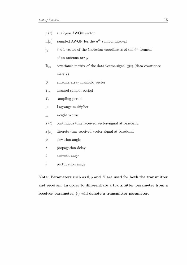
n (t) analogue AWGN vector
n [n] sampled AWGN for the nth symbol interval
ri 3� 1 vector of the Cartesian coordinates of the ith element
of an antenna array
Rxx covariance matrix of the data vector-signal x(t) (data covariance
matrix)
S antenna array manifold vector
Tcs channel symbol period
Ts sampling period
� Lagrange multiplier
w weight vector
x (t) continuous time received vector-signal at baseband
x [n] discrete time received vector-signal at baseband
� elevation angle
� propagation delay
� azimuth angle
~� pertubation angle
Note: Parameters such as �; � and N are used for both the transmitter
and receiver. In order to di¤erentiate a transmitter parameter from a
receiver parameter, (�) will denote a transmitter parameter.

Notation
Z Set of integers
R Field of real numbers
C Field of complex numbers
Ef�g Expectation operator
a; A Scalar
a; A Column Vector
A;A Matrix
jAj Magnitude of A
jjAjj Euclidian norm of the vector A
jjAjj Frobenius norm of the matrix A
Ab Element by element power
exp(A) Element by element exponential of vector A
[A]i ith element of the vector A
(�)� Complex conjugate
(�)T Transpose
(�)H Hermitian transpose
(�)y pseudoinverse
Kronecker product
� Hadamard product
� Hadamard division
17

Notation 18
IN Identity matrix of N �N dimension
OM�N Zero matrix of M �N dimension
1N N � 1 vector of all ones
0N N � 1 vector of all zeros
�N;k N � 1 vector with 1 at the kth element and 0s elsewhere
JN N �N downshifting matrix
coli (A) selection of the ith column of A
diag(A) Diagonal matrix with the vector A as the leading diagonal
diag(A) Column vector with elements the diagonal elements of the matrix (A)
tr(A) Trace of the matrix A
P[A] Projection operator onto the range space of A
P?[A] Complementary projection operator of the matrix A

Chapter 1
Introduction
With the introduction of 3G communications systems, there has been a dra-
matic increase in the variety of applications that are available to mobile users
and these applications are often multi-media intensive, such as video phone calls.
The prevalence of such data rate-hungry applications thus puts an upward pres-
sure on the data rates in wireless communications systems. As such, in future
4G systems, even higher data rates, expected to be 10 to 100 times the target
data rate in 3G systems, are to be anticipated in order to satisfy the data rate
requirements to support such multi-media intensive applications. However, chan-
nel impairments, such as frequency-selectivity, present an obstacle to achieving
such high data rates. In addition, the existence of high system overheads, such
as pilot or training signals required for channel identi�cation or synchronization,
results in a reduction in the amount of resources that are available for the transfer
of information through the wireless medium and contributes to a lower data rate
that can be achieved.
However, with such high data rates, transmissions through the wireless medium
become more susceptible to frequency selective fading as the signal bandwidth
becomes greater than the channel coherence bandwidth. In addition, the wireless
medium often subjects the transmitted signals to e¤ects such as multipath and
19
1. Introduction 20
multiple access and co-channel interference, making high data rates above 100
Mbps di¢ cult to achieve. Mobility of the users also introduces time selective
fading through Doppler spread which makes the accurate demodulation of the
received signals more di¢ cult.
With such high target data rates, multi-carrier (MC) modulation techniques
are promising candidates to be implemented in 4G systems. MC techniques, such
as orthogonal frequency division multiplexing (OFDM), can alleviate the fre-
quency selective fading experienced by high data rate (wideband) signals. Such
methods involve de-multiplexing the original signal stream onto a number of sub-
carriers, each with a lower data rate, so that each subcarrier would not be subject
to frequency selective fading. Multiple-input multiple-output (MIMO) systems
is another emerging communication technique which is capable of enhancing the
achievable user data rate. Due to the possible gains in spectral e¢ ciency that
both MC techniques and MIMO systems promise, it is anticipated that these two
techniques will be combined in 4G systems so as to bring out a synergistic e¤ect
on the spectral e¢ ciency in 4G systems.
1.1 Channel Dispersion
In general, a wireless channel is multipath dispersive and time-varying due to the
combined e¤ects of re�ection, di¤raction and scattering. Thus, the propagation of
radio signals through the wireless channel results in an alteration of the received
signal. Measurements of the power of the received signal often exhibit two types
of characteristics:
� Large-scale fading: This is due to path loss and shadowing e¤ects and is
observed through the variations in the average received power level. Path
loss increases logarithmically with the distance between the transmitter
1. Introduction 21
and receiver, while shadowing describes the attenuation e¤ects due to the
surrounding environmental clutter.
� Small-scale fading: Rapid �uctuations of the received signal over very short
time durations or over very short distances. This is due to the superposition
of multipath signals at the receiver which produces a resultant signal that
varies widely in amplitude and phase over small time intervals or distances.
Small-scale fading can be divided into a number of di¤erent categories based
on the delay spread and Doppler spread of the channel. Delay spread is due to the
existence of multipath signals with di¤erent time delays. The transmitted signals
typically arrive at the receiver with independent phase, time and amplitude which
results in large variations in the envelope of the received signal. The delay spread
is de�ned as the maximum excess delay between the �rst and last arrived path
components, during which the signal power falls to some threshold level below
that of the strongest received power. Coherence bandwidth, which is the inverse
of the delay spread, refers to the frequency separation at which the attenuation
of two frequency-domain samples of the channel becomes decorrelated. Thus,
coherence bandwidth is a measure of the frequency-selectivity of the channel. If
the coherence bandwidth is larger than the bandwidth of the received signal, a
�at fading channel occurs. In a �at fading channel, the amplitude of the received
signal varies over time but the spectrum of the transmitted signal is preserved.
However, if the signal bandwidth is larger than the coherence bandwidth (i.e.
the symbol period is lesser than the delay spread), intersymbol interference (ISI)
occurs and the multipath fading is frequency-selective.
Doppler spread, on the other hand, is dependent upon the coherence time
of the channel. Coherence time, which is the inverse of the Doppler spread, is
1. Introduction 22
de�ned as the time separation at which the amplitudes of two samples of the
channel becomes decorrelated. Thus, coherence time is a measure of the time
duration for which the channel can be assumed to be approximately constant. If
the coherence time is less than a symbol period, time-selective fading occurs and
this results in a fast fading channel. This corresponds to a Doppler spread in the
frequency domain and a distortion of the transmitted baseband pulse shape. On
the other hand, in a slow fading channel, the coherence time is greater than a
symbol period so that the channel is invariant for the duration of a transmitted
signal.
1.2 Multi-Carrier Modulation
In the previous section, it is seen that the time and frequency dispersions of a
signal are dependent on the coherence bandwidth and coherence time of the chan-
nel, respectively, as well as the bandwidth and duration of the signal. Hence, for
a particular channel, the amount of distortion observed in the signal depends on
the design of the signal. In order to overcome frequency-selective channels and
the associated ISI of such channels, MC modulation schemes, such as OFDM,
Multi-Carrier Direct Sequence Code Division Multiple Access (MC DS-CDMA)
and Multi-Carrier Code Division Multiple Access (MC-CDMA) have been pro-
posed. MC-CDMA is a type of multiple access scheme that is a combination of
Direct Sequence Code Division Multiple Access (DS-CDMA) and OFDM [1, 2].
In contrast to DS-CDMA systems, each chip of the PN sequence modulates a
di¤erent subcarrier for MC-CDMA systems and it has been shown that for the
forward link, MC-CDMA has better multipath suppression capabilities than DS-
CDMA [3]. Moreover, MC-CDMA was shown to be capable of supporting more
users than DS-CDMA in [4].
1. Introduction 23
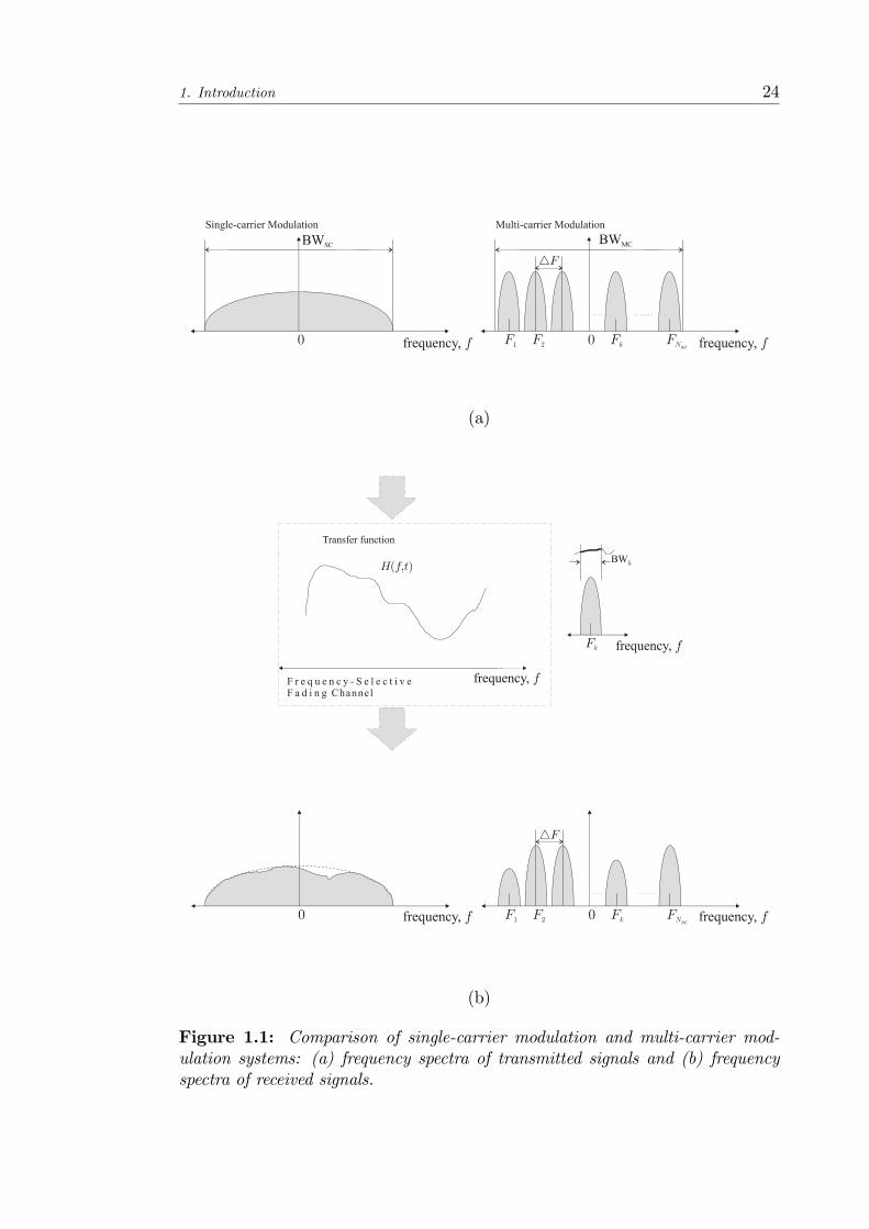
A MC modulation scheme employs a set of subcarriers to transmit the in-
formation symbols in parallel over the channel. This is equivalent to the division
of the available channel bandwidth into a number of subchannels and the band-
width of each subcarrier is su¢ ciently narrow so that the frequency response
characteristics of the subchannels are approximately �at. Figure 1.1(a) illus-
trates the comparison of the frequency spectrum of the transmitted signal in a
MC modulation system with that of the transmitted signal in a single-carrier
(SC) modulation system and it can be seen that the spectrum of the transmitted
signal of a MC modulation system is composed of a number of subcarriers which
have a narrowband spectrum. Figure 1.1 also illustrates the e¤ect of a frequency-
selective fading channel on the received signal in both SC and MC modulation
systems. As shown in Figure 1.1(b), the spectrum of the received signal for a MC
modulation system implies that a MC modulation system only requires a simple
one-step equalization for each subcarrier whereas adaptive equalization is needed
for a SC modulation system.
In addition, MC modulation schemes o¤er an advantage over single-carrier
(SC) modulation schemes in terms of narrowband frequency interference since not
all frequency subbands will be a¤ected by the interference. Orthogonal subcarri-
ers, which allows the subcarriers�spectra to overlap without causing interference,
are often employed in an MC modulation scheme so that a higher level of spectral
e¢ ciency can be achieved. This is because the guardbands that are necessary to
allow individual demodulation of non-orthogonal subcarriers will no longer be
necessary. As long as the orthogonality of the subcarriers is maintained, it is still
possible to recover the individual subcarriers� signals despite their overlapping
spectrums.
In addition, since the system�s data throughput is the sum of throughput of all
the parallel channels, the data rate per subchannel is only a fraction of the data
1. Introduction 24
(a)
(b)
Figure 1.1: Comparison of single-carrier modulation and multi-carrier mod-ulation systems: (a) frequency spectra of transmitted signals and (b) frequencyspectra of received signals.
1. Introduction 25
rate of a conventional SC system having the same throughput. This implies that
MC systems which support high data rates can be designed while maintaining
symbol durations much longer than the channel�s memory. This is equivalent to
the signal bandwidth being smaller than the coherence bandwidth of the channel.
For instance, consider a SC modulation scheme with a symbol duration of Tcs
which corresponds to a signal bandwidth of 1Tcs. However, in a OFDM system
with Nsc subcarriers, the resultant OFDM symbol duration becomes NscTcs and
this implies a signal bandwidth of 1NscTcs
at each subcarrier. Thus, for a given
channel, the bandwidth of the OFDM system has the possibility of being smaller
than the coherence bandwidth of the channel. This implies that for the same
channel, each subcarrier of the OFDM system experiences a frequency �at fading
channel while in the SC system, a frequency-selective fading channel is observed.
The details of the OFDM, MC DS-CDMA and MC-CDMA transmitters are now
examined in detail.
1.2.1 OFDM
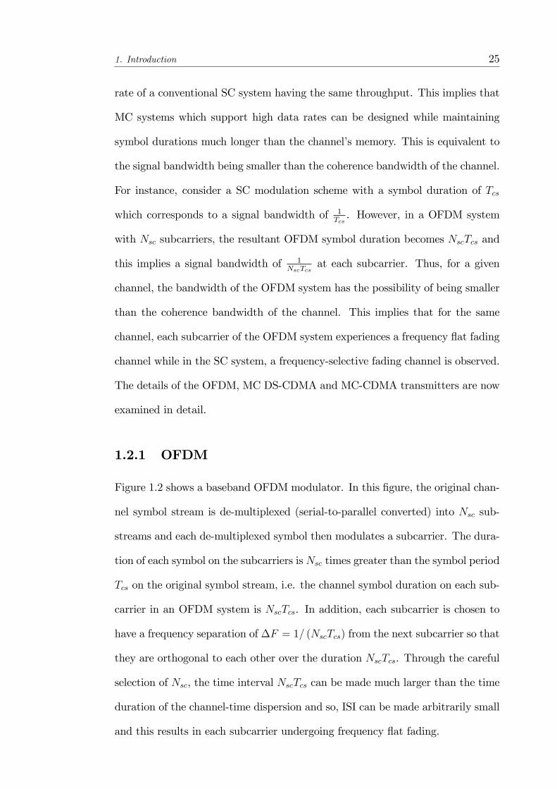
Figure 1.2 shows a baseband OFDM modulator. In this �gure, the original chan-
nel symbol stream is de-multiplexed (serial-to-parallel converted) into Nsc sub-
streams and each de-multiplexed symbol then modulates a subcarrier. The dura-
tion of each symbol on the subcarriers is Nsc times greater than the symbol period
Tcs on the original symbol stream, i.e. the channel symbol duration on each sub-
carrier in an OFDM system is NscTcs. In addition, each subcarrier is chosen to
have a frequency separation of �F = 1= (NscTcs) from the next subcarrier so that
they are orthogonal to each other over the duration NscTcs. Through the careful
selection of Nsc, the time interval NscTcs can be made much larger than the time
duration of the channel-time dispersion and so, ISI can be made arbitrarily small
and this results in each subcarrier undergoing frequency �at fading.
1. Introduction 26
Figure 1.2: Simpli�ed baseband OFDM modulator.
The idea behind the analog implementation of OFDM can be extended to the
digital domain by using the discrete Fourier Transform (DFT) and its counterpart,
the inverse discrete Fourier Transform (IDFT). These mathematical operations
are widely used for transforming data between the time-domain and frequency-
domain. These transforms are interesting from the OFDM perspective because
they can viewed as mapping data onto orthogonal subcarriers, see Figure 1.3. For
example, the IDFT is used to take in frequency-domain data and convert it to
time-domain data. Thus, the IDFT correlates the frequency-domain input data
with its orthogonal basis functions, which are sinusoids at certain frequencies.
This correlation is equivalent to mapping the input data onto the sinusoidal basis
functions.
In practice, OFDM systems are implemented using a combination of fast
Fourier Transform (FFT) and inverse fast Fourier Transform (IFFT) blocks that
are mathematically equivalent but more e¢ cient versions of the DFT and IDFT,
respectively. An OFDM system treats the source symbols (e.g. the QPSK or
QAM symbols that would be present in a single carrier system) at the transmitter
as though they are in the frequency-domain. These symbols are used as the
inputs to an IFFT block that brings the signal into the time-domain. This is

1. Introduction 27
Figure 1.3: Block diagram of IDFT (IFFT) implementation of a basebandOFDM modulator.
shown in Figure 1.3 where the IFFT takes in Nsc symbols at a time. Each input
symbol acts like a complex weight for the corresponding sinusoidal basis function.
Since the input symbols are complex, the value of the symbol determines both
the amplitude and phase of the sinusoid for that subcarrier. The IFFT output
is the summation of all Nsc sinusoids. Thus, the IFFT provides a simple way
to modulate data onto Nsc orthogonal subcarriers and the block of Nsc output
samples from the IFFT make up a single OFDM symbol. The output of the IDFT
operation is then parallel-to-serial converted. A guard interval or cyclic pre�x is
then inserted at the beginning of this OFDM symbol block. The resulting symbol
block is then digital-analog converted for subsequent transmission.
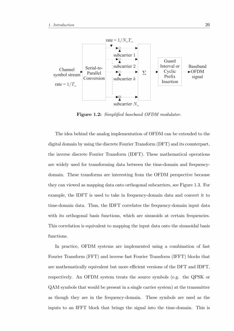
1.2.2 MC DS-CDMA
An MC DS-CDMA system was �rst proposed in [5] which assigned a di¤erent
channel symbol to each of the Nsc subcarriers. However, MC DS-CDMA has
developed so that the most common de�nition considers a single channel sym-
bol transmitted over every subcarrier, which provides frequency diversity at the
receiver [6]. This is shown in Figure 1.4 where the symbol stream is spread by
a PN-signal of length Nc before modulating Nsc subcarriers in parallel and the
subcarrier separation is equal to the chip rate. Note that NcNsc = Nc; where Nc
1. Introduction 28
is the length of the PN sequence used in a corresponding SC DS-CDMA system.
Due to the MC modulation involved, a MC DS-CDMA modulator can also be
implemented with the IFFT and this is shown in Figure 1.5.
Figure 1.4: Simpli�ed baseband MC DS-CDMA modulator.
Figure 1.5: Block diagram of IDFT (IFFT) implementation of a baseband MCDS-CDMA modulator.
If each subchannel is assumed to be �at fading then multicarrier demodulation
followed by despreading and diversity combining will yield the decision variables.
In this case, the performance is very similar to that of SC DS-CDMA. Alterna-
tively, if the system is designed so that the subchannels are frequency-selective
and a RAKE receiver is used for each subcarrier, then performance gains are
possible even though some intersubcarrier interference occurs [7].

1. Introduction 29
1.2.3 MC-CDMA
Figure 1.6 illustrates a baseband MC-CDMA modulator with Nsc subcarriers. As
seen in Figure 1.6, the channel symbol is repeated Nsc times and each copy is
multiplied by a corresponding chip of a pseudo-noise (PN) code sequence [8]. The
resultant Nsc signals then modulate the subcarriers in parallel and these mod-
ulated subcarriers are summed up to produce the baseband MC-CDMA signal.
Figure 1.6: Simpli�ed baseband MC-CDMA modulator.
The subcarriers are made to be orthogonal to each other over the channel
symbol period by setting the frequency separation between two neighboring sub-
carriers to be equal to a multiple of the symbol rate, 1Tcs. Due to MC-CDMA�s
similarity with OFDM, MC-CDMAmodulators can also be implemented with the
IFFT. This is shown in Figure 1.7 where the Nsc copies of the channel symbol,
after being multiplied by the PN sequence, are passed into the IDFT block. It
is obvious that MC-CDMA is the frequency domain equivalence of DS-CDMA,
where the spreading is carried out in the frequency domain, instead of the time
domain. Due to the �frequency-domain�spreading, each subcarrier carries a nar-
rowband signal of duration Tcs. This is in contrast to DS-CDMA in which �time-
domain�spreading is carried out and the single carrier carries a wideband signal
as the chip duration is TcsNcand Nc = Nsc denotes the processing gain. As such,
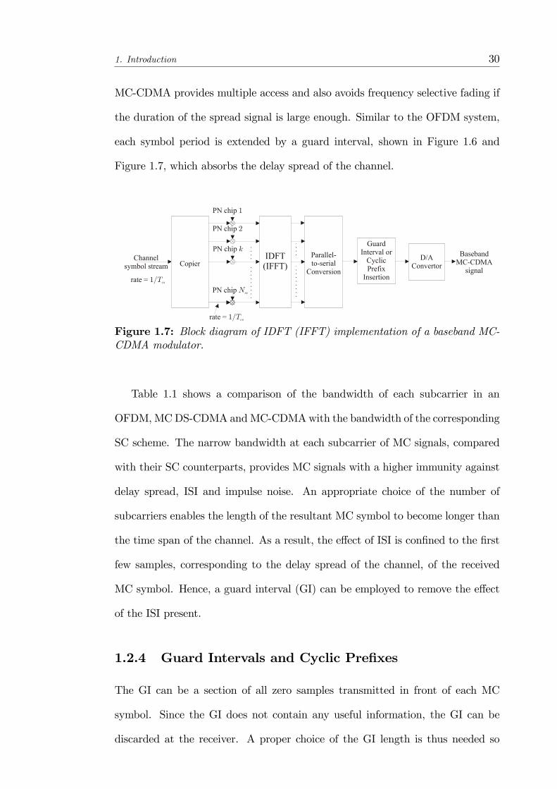
1. Introduction 30
MC-CDMA provides multiple access and also avoids frequency selective fading if
the duration of the spread signal is large enough. Similar to the OFDM system,
each symbol period is extended by a guard interval, shown in Figure 1.6 and
Figure 1.7, which absorbs the delay spread of the channel.
Figure 1.7: Block diagram of IDFT (IFFT) implementation of a baseband MC-CDMA modulator.
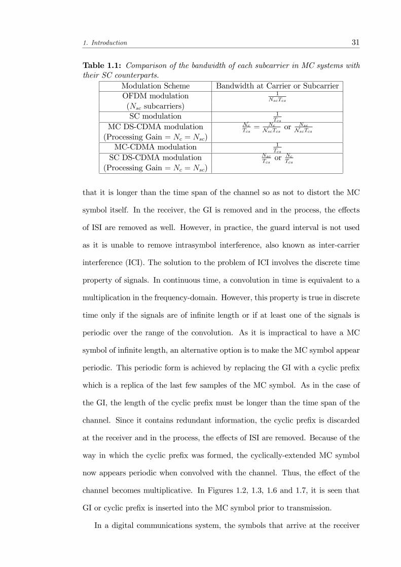
Table 1.1 shows a comparison of the bandwidth of each subcarrier in an
OFDM,MCDS-CDMA andMC-CDMAwith the bandwidth of the corresponding
SC scheme. The narrow bandwidth at each subcarrier of MC signals, compared
with their SC counterparts, provides MC signals with a higher immunity against
delay spread, ISI and impulse noise. An appropriate choice of the number of
subcarriers enables the length of the resultant MC symbol to become longer than
the time span of the channel. As a result, the e¤ect of ISI is con�ned to the �rst
few samples, corresponding to the delay spread of the channel, of the received
MC symbol. Hence, a guard interval (GI) can be employed to remove the e¤ect
of the ISI present.
1.2.4 Guard Intervals and Cyclic Pre�xes
The GI can be a section of all zero samples transmitted in front of each MC
symbol. Since the GI does not contain any useful information, the GI can be
discarded at the receiver. A proper choice of the GI length is thus needed so
1. Introduction 31
Table 1.1: Comparison of the bandwidth of each subcarrier in MC systems withtheir SC counterparts.
Modulation Scheme Bandwidth at Carrier or SubcarrierOFDM modulation 1
NscTcs
(Nsc subcarriers)SC modulation 1
Tcs
MC DS-CDMA modulation NcTcs= Nc
NscTcs orNsc
NscTcs(Processing Gain = Nc = Nsc)MC-CDMA modulation 1
Tcs
SC DS-CDMA modulation NscTcs
or NcTcs
(Processing Gain = Nc = Nsc)
that it is longer than the time span of the channel so as not to distort the MC
symbol itself. In the receiver, the GI is removed and in the process, the e¤ects
of ISI are removed as well. However, in practice, the guard interval is not used
as it is unable to remove intrasymbol interference, also known as inter-carrier
interference (ICI). The solution to the problem of ICI involves the discrete time
property of signals. In continuous time, a convolution in time is equivalent to a
multiplication in the frequency-domain. However, this property is true in discrete
time only if the signals are of in�nite length or if at least one of the signals is
periodic over the range of the convolution. As it is impractical to have a MC
symbol of in�nite length, an alternative option is to make the MC symbol appear
periodic. This periodic form is achieved by replacing the GI with a cyclic pre�x
which is a replica of the last few samples of the MC symbol. As in the case of
the GI, the length of the cyclic pre�x must be longer than the time span of the
channel. Since it contains redundant information, the cyclic pre�x is discarded
at the receiver and in the process, the e¤ects of ISI are removed. Because of the
way in which the cyclic pre�x was formed, the cyclically-extended MC symbol
now appears periodic when convolved with the channel. Thus, the e¤ect of the
channel becomes multiplicative. In Figures 1.2, 1.3, 1.6 and 1.7, it is seen that
GI or cyclic pre�x is inserted into the MC symbol prior to transmission.
In a digital communications system, the symbols that arrive at the receiver

1. Introduction 32
have been convolved with the time-domain channel impulse response. In order
to undo the convolutional e¤ects of the channel, another convolution must be
performed at the receiver using a time-domain �lter known as an equalizer. The
equalizer processes symbols in order to adapt its response in an attempt to remove
the e¤ects of the channel and the length of the equalizer needs to be on the order
of the time span of the channel. Such an equalizer can be expensive to implement
in hardware and often requires a large number of symbols in order to adapt its
response for a good performance.
In MC systems, the time-domain signal is still convolved with the chan-
nel response. However, the data will ultimately be transformed back into the
frequency-domain by the DFT in the receiver. Because of the periodic nature of
the cyclically-extended MC symbol, this time-domain convolution results in the
multiplication of the spectrum of the MC signal with the frequency response of
the channel. The result is that symbol at each subcarrier will be multiplied by
a complex number equal to the channel�s frequency response at that subcarrier�s
frequency. Thus, each received subcarrier experiences a complex gain due to
the channel. An equalizer consisting of a single complex multiplication for each
subcarrier can then be employed to undo these e¤ects.
After the removal of the cyclic pre�x, DFT is performed on the remaining
received signal samples to demodulate the received signal. Due to the use of guard
intervals and multiple subcarriers, MC systems are highly sensitive to time and
frequency o¤sets. As such, time and frequency synchronization algorithms must
be performed to ensure that OFDM has good performance. Time and frequency
synchronization have often been performed with the use of pilot signals [9], leading
to a loss of spectral e¢ ciency as the pilot symbols use up valuable bandwidth.
In [10], pilot symbols are used by the receiver for the acquisition and tracking of
the carrier frequency. Pilot symbols have also been used for channel estimation

1. Introduction 33
in MC-CDMA systems and much research has been done on the structure of
pilot signals so that better performance can be achieved. For instance, in [11],
the pilot signals are designed, using the weighted least squares (WLS) criterion,
to have good signal-to-noise-plus-interference ratio (SNIR) and peak-to-average
power ratio (PAPR) properties. The resulting pilot signals can be used for both
synchronization and channel estimation purposes.
Besides using pilot symbols, the cyclic pre�x can also be used to provide the
synchronization. By removing the reliance on pilot signals, the system overhead
is reduced and higher spectral e¢ ciency is achieved. In [12], the cyclic pre�x
was used to perform joint maximum likelihood (ML) time and frequency o¤set
estimation for non-dispersive channels. This removed the need for pilot symbols
to be used for carrier frequency synchronization and delay estimation. The use
of the cyclic pre�x for estimating the delay spread and the power of the multi-
path signals was also proposed in [13]. However, the proposed method assumes
a sparse multipath channel where the delayed signals have a large separation be-
tween them. Hence, the performance of the proposed method degrades when the
multipaths are spaced closely together. Besides the use of cyclic pre�x, it has
been proposed that zero-padding can be used instead, where zero symbols are
appended in place of the cyclic pre�x [14,15]. Zero-padding allows symbol recov-
ery and �nite impulse response (FIR) equalization of FIR channels regardless of
the channel zero locations. However, such a method brings about an increase in
receiver complexity as FIR �lters will have to be used.
Although pilot symbols and cyclic pre�x have been used for channel esti-
mation, blind channel estimation techniques are much more attractive as they
can completely remove the need for pilot signals or carriers and achieve higher
spectral e¢ ciency. In [16], a blind synchronization and carrier frequency o¤set
estimator is proposed which introduces cyclostationarity into OFDM signals by

1. Introduction 34
using time-frequency guard regions, pulse shaping or subcarrier weighting. Be-
sides compensating for the timing and frequency o¤sets caused by the channel,
estimation of the gain on each subcarrier also has to be performed. To remove
the reliance on pilot symbols, a DBPSK-based MC-CDMA system was proposed
in [17] for the downlink where the channel estimation is not carried out and the
data symbols are recovered by making use of the property of the DBPSK mod-
ulation involved. However, the use of the proposed method is limited to the
downlink where the transmission can be synchronous. Other than relying on the
use of pilot symbols, subspace-based techniques are an attractive alternative. A
subspace approach was proposed in [18] which makes use of virtual carriers in
OFDM systems to carry out the estimation of the channel.
Although the presence of a cyclic pre�x in a MC system enables the ISI e¤ects
of a channel to be removed by the receiver, its use lowers the spectral e¢ ciency
of the system. In order to improve the spectral e¢ ciency of the system, cyclic
pre�x-free MC-CDMA systems are of interest and these have been investigated
in [19, 20]. In addition, in [21], a cyclic pre�x-free MC-CDMA system is pro-
posed where the uplink �nite impulse response (FIR) channel is estimated using
subspace-based techniques. The method proposed is capable of estimating the
channel up to a complex coe¢ cient. However, in the method presented, there is
an assumption that it is possible to obtain ISI-free received signal vectors from
the received signals. Thus, there will have to be a certain degree of timing ac-
quisition implemented in the receiver. However, the removal of the cyclic pre�x
has an adverse e¤ect on the near-far resistance property of MC-CDMA systems.
In [22], it was shown that a cyclic pre�x-based MC-CDMA system, with a reduc-
tion in spectral e¢ ciency, has much better near-far resistance capability than a
cyclic pre�x-free MC-CDMA system.
For multiuser applications of MC-CDMA, performance is severely reduced

1. Introduction 35
even though the users are di¤erentiated by their spreading codes. This is because
the spreading codes only introduce a phase-shift of 0 or � in the subcarriers.
As such, training-based or non-blind systems have to be used to attain a good
performance. Moreover, synchronization of the users is required. Performance in
asynchronous multiuser situations can be improved by the application of multi-
user detection. In [23], a blind decorrelating detector based on subspace tech-
niques is proposed for an asynchronous multi-user environment, while in [24], a
blind subspace-based channel estimator and linear MMSE detector was proposed.
However, the performance of the proposed receivers is limited by the assumption
that the desired user is synchronized as this implies that synchronization to the
desired user has to be performed.
In this thesis, the proposed communication systems are assumed to be oper-
ating in a channel with a delay spread equal to one channel symbol period. As
such, due to the cyclic pre�x-free nature of the MC modulation involved, the sig-
nal duration of the resultant MC-CDMA symbol in the proposed system is half
of the signal duration in a conventional MC-CDMA system, which makes use of
a cyclic pre�x to overcome the frequency selectivity of the channel.
1.2.5 Crest Factor
All transmitters and receivers in communications systems contain devices such
as ampli�ers which have non-linear transfer functions. These non-linearities cre-
ate an additional performance limitation. The receiver performance is typically
limited by distortion generated in the input ampli�er or mixer in the presence of
strong undesired signals. On the other hand, the performance of the transmitter
is limited by power ampli�er linearity. A MC signal is made up of multiple simul-
taneous signals that, when combined together, have a higher peak signal level.
Thus, for a given average power, MC signals result in an increase in the peak-to-
1. Introduction 36
average power ratio (PAPR) of the signal, known also as crest factor (CF) of the
signal, which are related as:
PAPR = (CF)2 =�peak valuerms value
�2In multi-carrier systems, the PAPR value is often expressed in terms of statis-
tics because of the low probability that all subcarriers will simultaneously reach
peak amplitude, although the simultaneous peak amplitude value is large. These
higher peak amplitude levels will create more severe distortion than a single car-
rier system even if the average power levels are the same. The higher distortion
increases the SNR needed to maintain adequate performance. Linearity require-
ments in both the receiver and transmitter must be adjusted or �backed o¤�to
account for this increase in PAPR value. The PAPR value, and also the amount of
linearity compensation, depends on a number of parameters such as the number
of subcarriers and the level of SNR that must be maintained. Peak suppression
techniques that have been proposed include coding, phase rotation and clipping.
Thus, MC modulation schemes, such as OFDM and MC-CDMA, are suscep-
tible to the high PAPR problem. In [25], it is shown that a proper selection of the
spreading codes used in a MC-CDMA system is capable of reducing the PAPR
to a larger extent than the use of block coding to reduce the PAPR in an OFDM
system.
1.2.6 General Objective
In this thesis, asynchronous cyclic pre�x-free MC-CDMA systems are of interest
due to the removal of reliance on the cyclic pre�x as valuable signalling time
can be used for the transmission of information instead. Moreover, MC-CDMA,
in contrast with OFDM, has the potential to support more users on the same
set of subcarriers due to code multiplexing in the form of CDMA. A discussion
1. Introduction 37
on channel impairments that a¤ect the performance of MC systems is presented
in Appendix A. The cyclic pre�x-free MC-CDMA system will be investigated in
conjunction with MIMO systems, which will be described next.
1.3 Multiple-Input Multiple-Output
Multiple-input and multiple-output (MIMO) refers to the use of multiple anten-
nas at both the transmitter and receiver to improve communication performance
since it o¤ers signi�cant increases in data throughput and link range without
additional bandwidth or transmit power. This is achieved by higher spectral e¢ -
ciency and link reliability or diversity. However, MIMO is a general term for such
multiple-antenna systems and other types of systems can be obtained by varying
the number of antennas at transmitter and receiver. A multiple-input single-
output (MISO) system results when the receiver has a single antenna while a
single-input multiple-output (SIMO) system refers to the case where the trans-
mitter has a single antenna. The simplest case, which occurs when neither the
transmitter nor receiver have multiple antennas, is referred to as a single-input
single-output (SISO) system. Figure 1.8 shows the four possible types of commu-
nications systems.
It has been shown in [26] that, contrary to common perception, the presence
of multipath is an advantage in far-�eld MIMO systems and at high signal-to-
noise ratios (SNRs), the capacity can be multiplied by adding antennas to both
sides of the wireless link. As such, MIMO systems are an attractive option that
can be used to realize the data rates that are required for future systems. MIMO
systems are capable of bringing about such gains in capacity due to a combination
of the following factors: array gain, diversity gain, spatial multiplexing gain, and
interference reduction [27]:

1. Introduction 38
a) Single-Input Single-Output(SISO) system.
b) Single-Input Multiple-Output(SIMO) system.
c) Multiple-Input Single-Output(MISO) system.
d) Multiple-Input Multiple-Output(MIMO) system.
Figure 1.8: Multi-antenna communications systems classi�cation.
� Array gain - refers to the increase in average receive signal-to-noise ratio
(SNR) due to a coherent combining e¤ect;
� Diversity gain - which is de�ned as the increase in signal-to-interference
ratio due to some diversity scheme, or howmuch the transmission power can
be reduced when a diversity scheme is introduced, without a degradation
in performance.
� Spatial multiplexing gain - refers to a linear increase in capacity, without
additional power or bandwidth expenditure, as a result of transmitting
independent data signals from individual antennas; and
� Interference reduction - refers to the use of the di¤erence in spatial signa-
tures amongst users to reduce the interference to the desired user.
Transmit or receive array gain is dependent on the number of transmit and re-
ceive antennas as well as the availability of channel knowledge at the transmitter
and receiver, respectively. For the receiver, channel knowledge can be obtained
through blind channel estimation techniques or through the use of training se-
quences. On the other hand, channel knowledge can be made available at the

1. Introduction 39
transmitter through feedback from the receiver. However, this assumes that the
channel has the same characteristics in both the uplink and downlink, such as
in time division duplex (TDD) systems. In MIMO systems, diversity gain is
achieved in the form of spatial diversity and it is the least costly form of di-
versity as it does not involve the use of valuable bandwidth or signalling time,
which occurs in the case of frequency and time diversity, respectively. At the
receiver of a MIMO or SIMO system, the incoming signals can be combined after
some processing so that the performance of the receiver can be improved. In
the absence of channel knowledge, transmit diversity can be attained by using
space-time coding techniques such as space-time block codes (STBCs) [28, 29].
However, in the Alamouti scheme [28], it is assumed that the transmitted signals
undergo frequency �at fading and the channel is constant over at least two con-
secutive symbol periods. Moreover, channel knowledge must be made available
to the receiver to carry out decoding of the received signal. Hence, there is a need
to transmit orthogonal pilot symbols from each transmitting antenna so that the
channel characteristics from each antenna to the receiver can be estimated. This
results in a waste of valuable bandwidth. In [29], the Alamouti scheme is extended
to MIMO systems with more than two transmitter elements through orthogonal
space-time block codes.
Spatial multiplexing is another MIMO transmission technique method that
can be used to overcome the lack of channel information at the transmitter.
Spatial multiplexing is a transmission technique in MIMO wireless communica-
tion to transmit independent and separately encoded data signals from each of
the multiple transmit antennas. Therefore, the space dimension is reused, or
multiplexed, more than once, leading to spatial multiplexing gain. An example
of such a scheme is vertical Bell Labs layered space-time (V-BLAST) architec-
ture [30, 31, 32]. The V-BLAST architecture is a simple spatial multiplexing
1. Introduction 40
scheme proposed for the �at-fading MIMO channel to support high rate data
transmission. From the implementation perspective, V-BLAST is an attractive
technique as each transmit antenna transmits an independently encoded data
stream with equal transmission rate and power and the receiver detects each sub-
stream through successive cancellation. In simulations carried out, it was observed
that spectral e¢ ciencies of 20 - 40 bps/Hz can be achieved at SNRs from 24 to
34 dB. However, one drawback of the scheme is that accurate channel estimates
must be obtained so that an accurate replica of the received substream prior to
detection can be reproduced. This can then facilitate accurate cancellation of the
replica, leading to better detection of the remaining substreams. On the other
hand, in successive cancellation schemes, the receiver su¤ers from error propaga-
tion when errors are made in the detection of the substream. Another bene�t of
MIMO systems is that the multiple antennas at the receiver can exploit the spa-
tial characteristics of the desired signal and co-channel signals and in the process,
reduce the interference experienced by the desired signal.
1.4 Antenna Array Signal Processing
In mobile communication systems, the existence of multiple access interference
(MAI) and co-channel interference (CCI) limit the ability to improve the perfor-
mance of the system. The use of an antenna array introduces array gain into the
receiver which allows the receiver to make use of diversity combining (or beam-
forming) to improve its performance in overcoming the problem of fading in radio
channels and makes use of the fact that the signals arriving at di¤erent locations
fade at di¤erent rates. An antenna array is composed of a number of antenna
elements that form an array system of a given geometry and measurements are
taken with respect to the array reference point. Also, the beam pattern of the
1. Introduction 41
antenna array depends on the geometry, amplitude and phase excitation of the
elements.
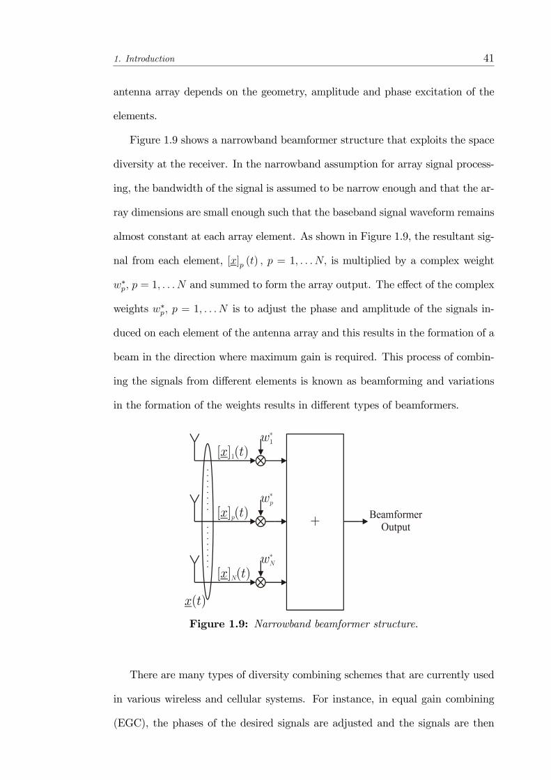
Figure 1.9 shows a narrowband beamformer structure that exploits the space
diversity at the receiver. In the narrowband assumption for array signal process-
ing, the bandwidth of the signal is assumed to be narrow enough and that the ar-
ray dimensions are small enough such that the baseband signal waveform remains
almost constant at each array element. As shown in Figure 1.9, the resultant sig-
nal from each element, [x]p (t) ; p = 1; : : : N; is multiplied by a complex weight
w�p; p = 1; : : : N and summed to form the array output. The e¤ect of the complex
weights w�p; p = 1; : : : N is to adjust the phase and amplitude of the signals in-
duced on each element of the antenna array and this results in the formation of a
beam in the direction where maximum gain is required. This process of combin-
ing the signals from di¤erent elements is known as beamforming and variations
in the formation of the weights results in di¤erent types of beamformers.
Figure 1.9: Narrowband beamformer structure.
There are many types of diversity combining schemes that are currently used
in various wireless and cellular systems. For instance, in equal gain combining
(EGC), the phases of the desired signals are adjusted and the signals are then

1. Introduction 42
combined in-phase after equal weighting. In a selection diversity combiner, the
signal from one of the antennas is selected for processing. The selection is per-
formed based on a pre-de�ned criteria such as the power of the desired signal, the
total power or the signal-to-interference ratio (SIR) at each antenna. This is in
contrast to maximal ratio combining (MRC) where the weights are applied in pro-
portion to the signal-to-noise ratio (SNR) and the weighted signals are combined
in-phase. The MRC diversity combiner, which is equivalent to the Wiener-Hopf
beamformer, su¤ers from a degradation in its resolution capabilities as the SNR
is reduced. This implies that closely located interference may not be cancelled
e¤ectively. This has led to the development of super-resolution beamformers in
which the resolution capabilities are independent of the SNR. However, super-
resolution beamformers require the knowledge of the direction-of-arrivals (DOAs)
of the incident signals and this information can be obtained from subspace-based
techniques such as the Multiple Signal Classi�cation (MUSIC) algorithm [33].
In the MUSIC algorithm, the array manifold is formulated as a set of all pos-
sible array responses and the array response is a function of the parameters to be
estimated. The intersection of the array manifold with the signal subspace ob-
tained from the array measurements then yield the estimates of the parameters of
interest. Other subspace-based estimation algorithms include Estimation of Sig-
nal Parameters via Rotational Invariance Technique (ESPRIT) and the Weighted
Subspace Fitting (WSF) approach.
1.5 Summary and Thesis Organization
This thesis investigates the use of an antenna array in an asynchronous MC-
CDMA MIMO system where the cyclic pre�x is omitted from the MC-CDMA
modulation in order to conserve valuable bandwidth, which is a valuable resource
1. Introduction 43
in future communications systems (4G and beyond). However, the lack of a cyclic
pre�x in MC-CDMAmodulation implies that the ISI e¤ects cannot be removed by
the receiver and so, the resultant MC-CDMA signals would be susceptible to ISI
in a frequency-selective fading channel. Such e¤ects can be ameliorated through
the use of antenna arrays as these provide additional space-time processing ca-
pabilities which are not available to systems that assume the use of independent
antenna elements.
The main objective of the thesis is to design array receivers that are applica-
ble for cyclic pre�x-free MC-CDMA arrayed MIMO systems and are capable of
overcoming the ISI arising from not using cyclic pre�xes. The organization of the
thesis is as follows:
� In Chapter 2, the concept of the array manifold vector is introduced. The
use of the array manifold vector enables the spatial information to be incor-
porated into the channel model. This leads to the introduction of space-time
channel models. A distinction is made between array-based and non-array-
based multiple antenna systems. Both the diagrammatic and mathemat-
ical representations of these models are provided. This modelling forms
the basic mathematical framework for later formulation in the subsequent
chapters.
� In Chapter 3, a subspace-based receiver is proposed for a cyclic pre�x-free
MC-CDMA MIMO system. The MIMO system investigated here consid-
ers the case where antenna arrays are employed at both the transmitter
and receiver. The proposed receiver achieves ISI cancellation for the cyclic
pre�x-free MC-CDMA system and its performance is shown to be superior
than that of a representative existing system which relies on cyclic pre-
�xes and ignores the array geometry. In order to reduce system overheads,

1. Introduction 44
a blind subspace-based channel estimation technique is used to obtain the
channel parameters required for the formation of the receiver weight matrix.
� In Chapter 4, the phenomenon of spatial scattering in a cyclic pre�x-free
MC-CDMAMIMO system with antenna arrays at both ends of the wireless
link is addressed. Due to the spatial scattering, a di¤used channel, where
each path is made up of a cluster of inseparable paths, results. By taking
the spatial scattering e¤ects into consideration, it is seen that the proposed
channel estimation technique outperforms a channel estimator that ignores
the e¤ects of spatial scattering. In addition, a decorrelating receiver is de-
vised to cope with the e¤ect of a di¤used channel.
� In Chapter 5, the downlink of a multi-user cyclic pre�x-free MC-CDMA
MIMO system is considered and the problem of the joint optimization of
the transmitter and receiver beamforming weights is addressed. Antenna
arrays are assumed to be employed at the transmitter as well as at each
user terminal. Lagrange multipliers are used in the optimization problem
which seeks to minimize the mean square error (MSE) of all users subject
to constraints in the PAPR of each transmitter antenna. An iterative al-
gorithm is proposed for the determination of the transmitter and receiver
beamforming weights.
� In Chapter 6, the thesis is concluded. The contributions of the work in this
thesis are outlined and potential future research areas are identi�ed.
Chapter 2
Space-Time Channel and System
Architecture Modelling
In this chapter, the concept of the array manifold vector is �rst introduced which
provides a basis for the subsequent derivation of the parametric channel models
that are applicable for the array-based MIMO systems that are considered in this
thesis. The parametric channel models that are developed form the basis for the
subsequent channel estimation and reception algorithms proposed in Chapters
3 to 5 of the thesis. In addition, the general framework of cyclic pre�x-free
MC-CDMA arrayed MIMO communication systems is presented and its core
components are outlined. A detailed modelling of each of these components will
be provided in the subsequent corresponding chapters.
45

2. Space-Time Channel and System Architecture Modelling 46
2.1 Antenna Array Manifold Vector
In order to exploit the spatial properties of the channel, an antenna array is
implemented at the front-end of the receiver. This can be further extended to
the case when the transmitter is similarly equipped with an antenna array. A
mathematical model of the spatial information provided by the antenna array
is obtained through the use of the array manifold vector, which is a function
of a number of channel parameters, including the array geometry, the carrier
frequency and the direction-of-arrival (DOA) of each multipath.
Figure 2.1 shows an illustration of the planewave propagation model of the
planewave signals in real 3-D space. In this thesis, a narrowband array model
is assumed to be valid as the array aperture is small enough such that the time
required for the propagating wave to pass through the array is signi�cantly lesser
than the symbol duration [34]. Assume that the jth path of the ith user arrives at
the reference point of the antenna array from the direction��ij,�ij
�, where � and
� denotes the azimuth and elevation angles, respectively. Thus, the real 3 � 1
unit-vector uij, pointing towards the direction��ij,�ij
�, can be written as
uij =�cos (�ij) cos
��ij�; sin (�ij) cos
��ij�; sin
��ij� �T
(2.1)
Thus, taking the kth subcarrier in a MC system into consideration, the relative
phase variation at the pth antenna element with respect to the reference point of
the antenna array can be expressed as
exp
��j 2�
c(Fc + Fk) r
Tp uij
�(2.2)
where rp 2 R3�1 denotes the Cartesian coordinates, in metres, of the location
of the pth antenna element, c denotes the speed of light and Fc and Fk denote
the carrier frequency and kth subcarrier frequency, respectively, with Fk = k�F
and �F denotes the subcarrier separation. The wavenumber vector kijk is now

2. Space-Time Channel and System Architecture Modelling 47
Figure 2.1: Illustration of the planewave propagation model based on the jth pathof the ith user.
introduced as
kijk =2� (Fc + Fk)
cuij (2.3)
which can be rewritten as follows:
kijk =2� (Fc + Fk)
cuij
=2�Fcc
�1 +
FkFc
�uij
=2�Fcc
�1 +
k4FFc
�uij (2.4)
Thus, when the carrier frequency Fc is much greater than the maximum subcarrier
frequency in a MC system, i.e. maxk
�k4FFc
�! 0, the wavenumber vector kijk can
be simpli�ed to be independent of the subcarrier frequency Fk; 8k: Thus, for all
subcarriers, the wavenumber vector can be represented by
kij ,2�Fcc
uij ' kijk8k (2.5)

2. Space-Time Channel and System Architecture Modelling 48
Hence, for an antenna array with N omnidirectional elements, the array man-
ifold vector associated with the jth path of the ith user�s DOA��ij; �ij
�is given
by
Sij , S��ij; �ij
�= exp
��j�rT1 kij; r
T2 kij; : : : ; r
TNkij
�T�= exp
��j�rTkij
��2 CN�1 (2.6)
where r = [r1; r2; : : : ; rN ] =�rx; ry; rz
�Tis a 3 � N matrix with its pth column
corresponding to the location rp of its pth antenna element. Note that Equation
2.6 is applicable for all subcarriers in a MC system due to the simpli�cation that
has been performed in Equation 2.5. The set of array response vectors (manifold
vectors), fS (�,�)8�; � 2 [0; 2�]g forms the array manifold. Typically, the signals
are assumed to be on the (x; y)-plane, i.e. �ij = 0�. Thus, the array manifold
vector, as shown in Equation 2.6 can be simpli�ed to
Sij = exp��j�
�rx cos �ij + ry sin �ij
��2 CN�1
where the sensor location is measured in units of half-wavelength, i.e. �c2, where
�c =cFc.
2. Space-Time Channel and System Architecture Modelling 49
2.2 Space-Time Channel Modelling
In most MIMO systems that have been developed, one common approach has been
that the channel matrix is a random matrix which results from a stochastic chan-
nel which conforms to certain distributions without characterizing individually
the probability density function (pdf) of the random channel variables involved
in the modelling. Such models have been widely used in capacity calculations for
the development of MIMO systems [35, 36]. Thus, in such MIMO systems, the
array geometry, due to the use of an antenna array, is often ignored. This implies
array signal processing techniques are unavailable in such systems.
Antenna array signal processing techniques are an attractive option which can
be used to further exploit the spatial properties of the channel and, in the process,
achieve increases in capacity and spectral e¢ ciency while minimizing transmis-
sion power. In addition, an extra layer of co-channel interference cancellation
capability can be provided and furthermore, new methods of handling unwanted
channel e¤ects, such as Doppler spread and fading, can be proposed for even
more e¢ cient utilization of spectrum and space. An antenna array-based MIMO
receiver is proposed in [37] for asynchronous multipath DS-CDMA systems. By
using subspace-based techniques, the proposed receiver could estimate the spatial
and temporal characteristics as well as the Doppler spread in the signals. Thus,
antenna array-based MIMO can be implemented for improved performance over
independent antenna elements in MIMO systems.
In the literature, there are many ways of referring to multi-antenna communi-
cations systems. One of the most common nomenclature takes the form of MIMO
(and the related SISO, SIMO and MISO) systems (described in Section 1.3) which
is based on the number of inputs and outputs of the system. Another type of clas-
si�cation takes the form of multiple-element multiple-element (MEME) systems
where the �element�refers to the number of antenna elements at the transmitter

2. Space-Time Channel and System Architecture Modelling 50
or receiver. In this classi�cation, single-element single-element (SESE), single-
element multiple-element (SEME), multiple-element single-element (MESE) and
MEME systems correspond to the SISO, SIMO, MISO and MIMO systems, re-
spectively.
However, in this thesis, the classi�cation of the multi-antenna systems based
on the nature of the input signal is preferred. In particular, the multi-antenna
systems are classi�ed according to whether a single signal or a set of more than
one signals enters or leaves the system and these are referred to as scalar-signal
and vector-signal, respectively. Thus, the classi�cation of the space-time wireless
channels is based on the number of inputs and outputs of the channel, using the
terms
� Scalar-input (output) to denote a single-input (output); and
� Vector-input (output) to denote a set of more than one inputs (outputs).
Such a classi�cation enables a closer mathematical representation of the sys-
tem and this facilitates the parametric modelling of such multi-antenna systems.
The various types of multi-antenna systems classi�cation is shown in Table 2.1
to illustrate the equivalence between the di¤erent types of nomenclature.
The various space-time channel models for both single user and multi-user sys-
tems, which are classi�ed based on the structure of the signal, can be summarized
as shown in Figure 2.2. Thus,
� Scalar-Input Scalar-Output (SISO) channel : e.g. In a single user system,
single antenna elements are employed at both ends of the transmission link;
� Scalar-Input Vector-Output (SIVO) channel : e.g. In a single user system,
a single antenna and an antenna array is employed at the transmitter and
receiver, respectively;
� Vector-Input Scalar-Output (VISO)channel : e.g. Based on Figure 2.2, in
the case of a single user system, a VISO channel is formed when an antenna

2. Space-Time Channel and System Architecture Modelling 51
Table2.1:Correspondencebetweenthedi¤erenttypesofnomenclatureformulti-antennasystems.
NumberofInputs/Outputs
NumberofElements
StructureofSignal
Single-InputSingle-Output(SISO)
Single-ElementSingle-Element(SESE)
Scalar-InputScalar-Output(SISO)
Single-InputMultiple-Output(SIMO)
Single-ElementMultiple-Element(SEME)
Scalar-InputVector-Output(SIVO)
Multiple-InputSingle-Output(MISO)
Multiple-ElementSingle-Element(MESE)
Vector-InputScalar-Output(VISO)
Multiple-InputMultiple-Output(SISO)Multiple-ElementMultiple-Element(MEME)Vector-InputVector-Output(VIVO)
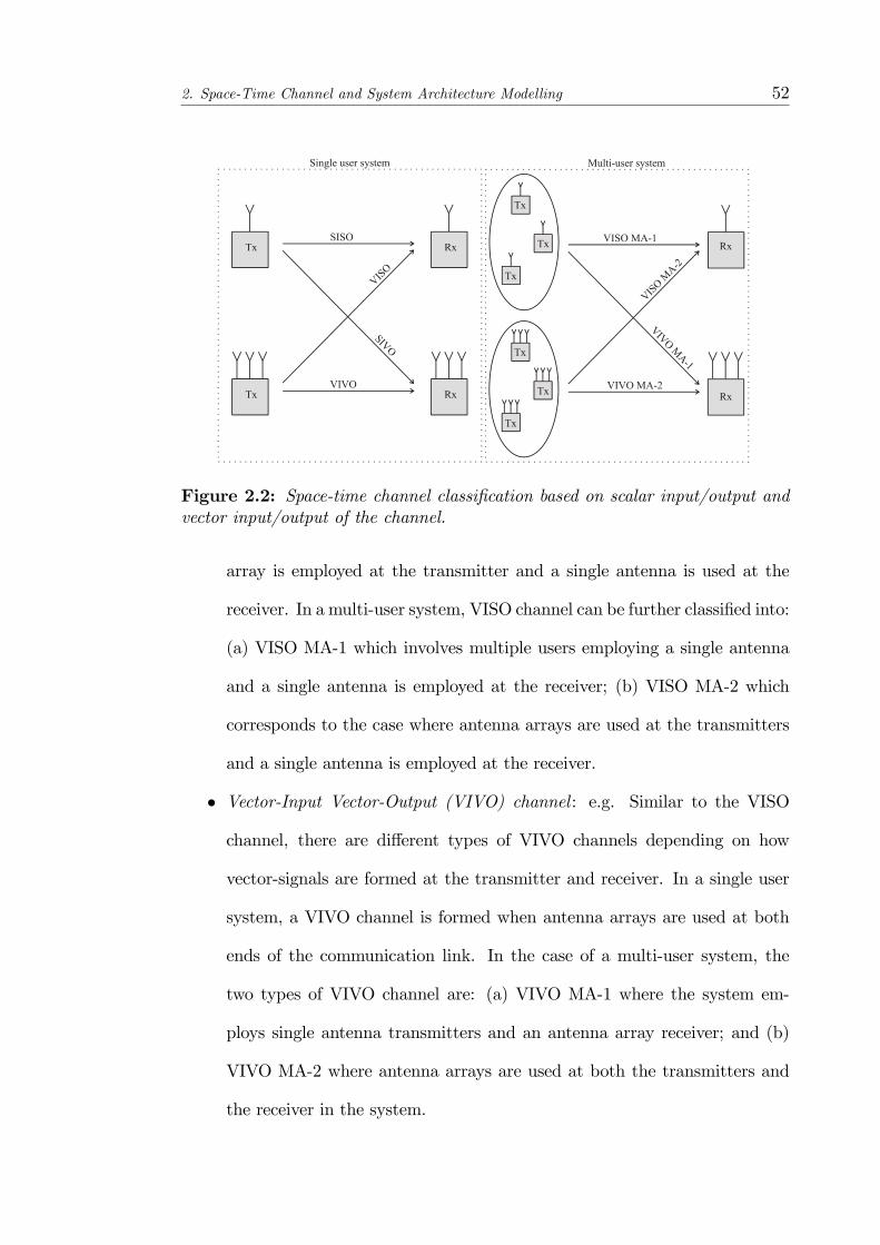
2. Space-Time Channel and System Architecture Modelling 52
Figure 2.2: Space-time channel classi�cation based on scalar input/output andvector input/output of the channel.
array is employed at the transmitter and a single antenna is used at the
receiver. In a multi-user system, VISO channel can be further classi�ed into:
(a) VISO MA-1 which involves multiple users employing a single antenna
and a single antenna is employed at the receiver; (b) VISO MA-2 which
corresponds to the case where antenna arrays are used at the transmitters
and a single antenna is employed at the receiver.
� Vector-Input Vector-Output (VIVO) channel : e.g. Similar to the VISO
channel, there are di¤erent types of VIVO channels depending on how
vector-signals are formed at the transmitter and receiver. In a single user
system, a VIVO channel is formed when antenna arrays are used at both
ends of the communication link. In the case of a multi-user system, the
two types of VIVO channel are: (a) VIVO MA-1 where the system em-
ploys single antenna transmitters and an antenna array receiver; and (b)
VIVO MA-2 where antenna arrays are used at both the transmitters and
the receiver in the system.
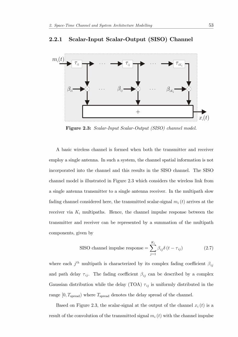
2. Space-Time Channel and System Architecture Modelling 53
2.2.1 Scalar-Input Scalar-Output (SISO) Channel
Figure 2.3: Scalar-Input Scalar-Output (SISO) channel model.
A basic wireless channel is formed when both the transmitter and receiver
employ a single antenna. In such a system, the channel spatial information is not
incorporated into the channel and this results in the SISO channel. The SISO
channel model is illustrated in Figure 2.3 which considers the wireless link from
a single antenna transmitter to a single antenna receiver. In the multipath slow
fading channel considered here, the transmitted scalar-signal mi (t) arrives at the
receiver via Ki multipaths. Hence, the channel impulse response between the
transmitter and receiver can be represented by a summation of the multipath
components, given by
SISO channel impulse response =KiXj=1
�ij� (t� � ij) (2.7)
where each jth multipath is characterized by its complex fading coe¢ cient �ij
and path delay � ij. The fading coe¢ cient �ij can be described by a complex
Gaussian distribution while the delay (TOA) � ij is uniformly distributed in the
range [0; Tspread) where Tspread denotes the delay spread of the channel.
Based on Figure 2.3, the scalar-signal at the output of the channel xi (t) is a
result of the convolution of the transmitted signalmi (t) with the channel impulse
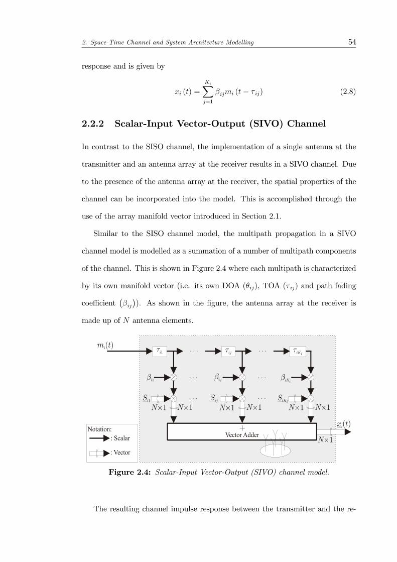
2. Space-Time Channel and System Architecture Modelling 54
response and is given by
xi (t) =
KiXj=1
�ijmi (t� � ij) (2.8)
2.2.2 Scalar-Input Vector-Output (SIVO) Channel
In contrast to the SISO channel, the implementation of a single antenna at the
transmitter and an antenna array at the receiver results in a SIVO channel. Due
to the presence of the antenna array at the receiver, the spatial properties of the
channel can be incorporated into the model. This is accomplished through the
use of the array manifold vector introduced in Section 2.1.
Similar to the SISO channel model, the multipath propagation in a SIVO
channel model is modelled as a summation of a number of multipath components
of the channel. This is shown in Figure 2.4 where each multipath is characterized
by its own manifold vector (i.e. its own DOA (�ij), TOA (� ij) and path fading
coe¢ cient��ij�). As shown in the �gure, the antenna array at the receiver is
made up of N antenna elements.
Figure 2.4: Scalar-Input Vector-Output (SIVO) channel model.
The resulting channel impulse response between the transmitter and the re-

2. Space-Time Channel and System Architecture Modelling 55
ceiver is given by
SIVO channel impulse response =KiXj=1
�ijSij� (t� � ij) (2.9)
In this case, the vector-signal at the output of the channel xi (t) can be expressed
as
xi (t) =
KiXj=1
�ijSijmi (t� � ij) (2.10)
2.2.3 Vector-Input Scalar-Output (VISO) Channel
In the VISO channel model, the transmitter is equipped with an antenna array
while the receiver employs a single antenna. An illustration of the VISO channel
model is shown in Figure 2.5 for a point-to-point communication system with an
antenna array of N elements at the transmitter and a single antenna array at
the receiver. In this case, the transmit array manifold vector is denoted by Sij,
which is similarly de�ned as in Equation 2.6. The transmit array manifold vector,
similar to its counterpart �the receive array manifold vector, is a function of the
channel parameters associated with the transmitter antenna array. This includes
the transmitter antenna array geometry and the direction-of-departures (DODs)
of the channel.
Figure 2.5: Vector-Input Scalar-Output (VISO) channel model for an array-based system.
Based on Figure 2.5, the VISO channel impulse response function can be
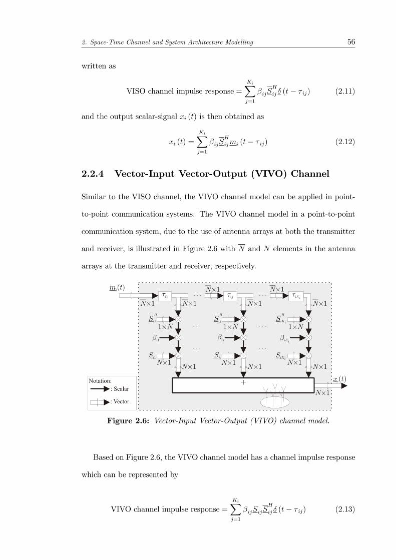
2. Space-Time Channel and System Architecture Modelling 56
written as
VISO channel impulse response =KiXj=1
�ijSH
ij � (t� � ij) (2.11)
and the output scalar-signal xi (t) is then obtained as
xi (t) =
KiXj=1
�ijSH
ijmi (t� � ij) (2.12)
2.2.4 Vector-Input Vector-Output (VIVO) Channel
Similar to the VISO channel, the VIVO channel model can be applied in point-
to-point communication systems. The VIVO channel model in a point-to-point
communication system, due to the use of antenna arrays at both the transmitter
and receiver, is illustrated in Figure 2.6 with N and N elements in the antenna
arrays at the transmitter and receiver, respectively.
Figure 2.6: Vector-Input Vector-Output (VIVO) channel model.
Based on Figure 2.6, the VIVO channel model has a channel impulse response
which can be represented by
VIVO channel impulse response =KiXj=1
�ijSijSH
ij � (t� � ij) (2.13)
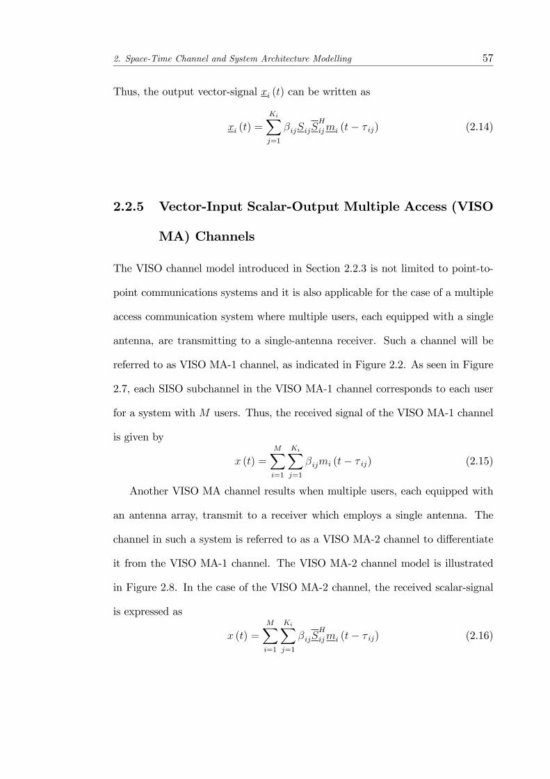
2. Space-Time Channel and System Architecture Modelling 57
Thus, the output vector-signal xi (t) can be written as
xi (t) =
KiXj=1
�ijSijSH
ijmi (t� � ij) (2.14)
2.2.5 Vector-Input Scalar-Output Multiple Access (VISO
MA) Channels
The VISO channel model introduced in Section 2.2.3 is not limited to point-to-
point communications systems and it is also applicable for the case of a multiple
access communication system where multiple users, each equipped with a single
antenna, are transmitting to a single-antenna receiver. Such a channel will be
referred to as VISO MA-1 channel, as indicated in Figure 2.2. As seen in Figure
2.7, each SISO subchannel in the VISO MA-1 channel corresponds to each user
for a system with M users. Thus, the received signal of the VISO MA-1 channel
is given by
x (t) =MXi=1
KiXj=1
�ijmi (t� � ij) (2.15)
Another VISO MA channel results when multiple users, each equipped with
an antenna array, transmit to a receiver which employs a single antenna. The
channel in such a system is referred to as a VISO MA-2 channel to di¤erentiate
it from the VISO MA-1 channel. The VISO MA-2 channel model is illustrated
in Figure 2.8. In the case of the VISO MA-2 channel, the received scalar-signal
is expressed as
x (t) =MXi=1
KiXj=1
�ijSH
ijmi (t� � ij) (2.16)
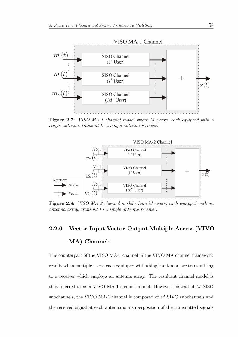
2. Space-Time Channel and System Architecture Modelling 58
Figure 2.7: VISO MA-1 channel model where M users, each equipped with asingle antenna, transmit to a single antenna receiver.
Figure 2.8: VISO MA-2 channel model where M users, each equipped with anantenna array, transmit to a single antenna receiver.
2.2.6 Vector-Input Vector-OutputMultiple Access (VIVO
MA) Channels
The counterpart of the VISO MA-1 channel in the VIVO MA channel framework
results when multiple users, each equipped with a single antenna, are transmitting
to a receiver which employs an antenna array. The resultant channel model is
thus referred to as a VIVO MA-1 channel model. However, instead of M SISO
subchannels, the VIVO MA-1 channel is composed of M SIVO subchannels and
the received signal at each antenna is a superposition of the transmitted signals

2. Space-Time Channel and System Architecture Modelling 59
from each antenna via multipath fading. This is illustrated in Figure 2.9. Thus,
the received signal of the VIVO MA-1 channel is given by
x (t) =
MXi=1
KiXj=1
�ijSijmi (t� � ij) (2.17)
Figure 2.9: VIVO MA-1 channel model where M users, each equipped with asingle antenna, transmit to a receiver equipped with an antenna array.
In addition, similar to the VISO MA-2 channel, a VIVOMA-2 channel, shown
in Figure 2.10, arises when multiple users, each equipped with an antenna array,
transmit to a receiver equipped with an antenna array. Thus, the VIVO MA-2
channel output is given by
x (t) =MXi=1
KiXj=1
�ijSijSH
ijmi (t� � ij) (2.18)

2. Space-Time Channel and System Architecture Modelling 60
Figure 2.10: VIVO MA-2 channel model whereM users, each using an antennaarray, transmit to a receiver employing an antenna array.
2.3 Space-Time System Architecture
A wireless communication system is made up of three fundamental blocks:
� the transmitter;
� the radio channel; and
� the receiver.
In Section 2.2, various types of wireless channel models, based on the
scalar/vector notation, have been presented. In the transmitter, the baseband
signal is upconverted to the carrier frequency prior to transmission. The received
signal is then downconverted to baseband in the receiver. However, without
any loss of generality, baseband transmission will be assumed in this thesis. The
space-time channel model represents the propagation of the baseband transmitted
scalar-signal mi (t) or vector-signal mi (t) from the transmitter to the receiver.
The modelling of the transmitter and receiver blocks will now be presented so as
to obtain a holistic view of the system architecture.
First, a single user MIMO system is shown in Figure 2.11 where antenna ar-
rays of N and N elements are used at the transmitter and receiver, respectively.
The use of an antenna array at the receiver is in contrast with conventional
2. Space-Time Channel and System Architecture Modelling 61
MIMO systems which ignore the array geometry, i.e. the antenna elements are
viewed as a collection of independent multiple elements instead of an antenna
array. The MIMO system illustrated in Figure 2.11 is termed as an arrayed
MIMO system in order to distinguish it from conventional MIMO systems which
ignore the e¤ects of the array geometry. At point-A of the transmitter, spa-
tial multiplexing is performed and the data stream is �rst demultiplexed into N
substreams (one substream per array element). The resultant vector-signal then
undergoes cyclic pre�x-free MC-CDMA modulation to form the baseband vector-
signalm (t). The signalm (t) is then transmitted via theN element antenna array
(point-C). The continuous transmitted signal propagates via a number of multi-
paths before reaching the receiver. As shown in Figure 2.11, the relevant channel
model is the VIVO channel model, as described in Figure 2.6.
The task of the receiver is to capture the data and process it accordingly
so that the information signals can be recovered. The use of an antenna array
at the receiver can signi�cantly increase the channel capacity by exploiting the
spatial diversity [38] for example, to combat fading and to perform interference
cancellation. The continuous signal x (t) is passed and stored in the bank of
tapped delay lines (TDLs) to obtain the 2NL-dimensional discretized signal x[n]
at point-E in Figure 2.11. In Chapter 3, the channel estimation and weight
formation block at the receiver will be studied extensively. The details of the
TDL block will be presented subsequently as it is a common feature among the
three system architectures that are presented in this thesis for Chapters 3, 4 and
5.
In contrast with the MIMO system presented in Figure 2.11, the architecture
shown in Figure 2.12 for Chapter 4 considers the extension of the VIVO channel
to the di¤used-VIVO channel, where each multipath is composed of a cluster of
spatially inseparable paths instead of a single path (i.e. point-source). The details

2. Space-Time Channel and System Architecture Modelling 62
of the di¤used-VIVO channel model is examined closely in Chapter 4 and it will
be shown that the di¤used-VIVO channel can be simpli�ed to a form similar
to that of the VIVO channel. It can be seen that the transmitter structures
in Figures 2.11 and 2.12 are similar. The receiver, based on the di¤used-VIVO
channel model, performs the estimation of the channel parameters, which includes
the DOA, TOA and spatial spread, of the channel. In addition, a decorrelating
receiver is introduced for the receiver weight matrix.
When channel state information (CSI) is available at the transmitter, ad-
vanced signal processing techniques can be applied at both the transmitter and
receiver for jointly optimizing the system performance. The problem under con-
sideration is joint transmitter-receiver (Tx-Rx) beamforming over the VIVO MA-
2 (reverse link) channel which will be investigated in Chapter 5. The system
architecture is illustrated in Figure 2.13. Figure 2.13 shows an M user cyclic
pre�x-free MC-CDMA arrayed MIMO downlink system with N transmit anten-
nas at the base station and N receive antennas at each receiver terminal. Each
user�s symbol stream is �rst demultiplexed into N subi substreams 8i = 1; : : : ;M .
The resultant vector-signals ai [n] 8i = 1; : : : ;M , with dimensions N subi � 1 then
undergo cyclic pre�x-free MC-CDMA modulation before being transmitted to-
gether at point-E. The wireless channel is based on the VIVO MA-2 (reverse
link) channel model and is composed of a set of VIVO channels, as described
in Figure 2.10. At the ith user, the interference is removed from the discretized
signal xi[n] (point-G) by applying the receive beamformer Wi 8i = 1; : : : ;M .

2. Space-Time Channel and System Architecture Modelling 63
Figure2.11:System
architectureforChapter3.

2. Space-Time Channel and System Architecture Modelling 64
Figure2.12:System
architectureforChapter4.
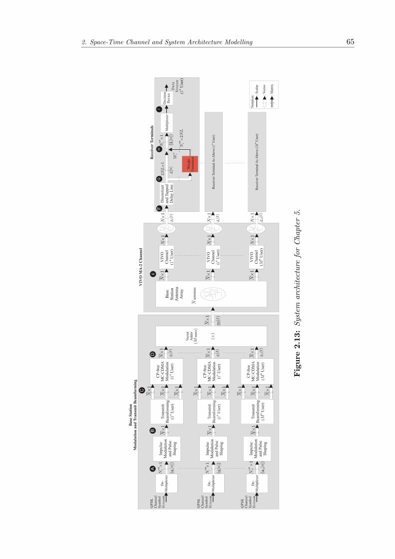
2. Space-Time Channel and System Architecture Modelling 65
Figure2.13:System
architectureforChapter5.

2. Space-Time Channel and System Architecture Modelling 66
2.3.1 Receiver Front-End Temporal Windowing
It is clear from Figures 2.11, 2.12 and 2.13 that the receivers employ an antenna
array ofN antenna elements. In order to extend the receiver to include space-time
processing capabilities, TDLs are employed at each antenna of the antenna array
and this is shown in Figure 2.14. The baseband received signal x(t) is observed
at point-D (in Figures 2.11 and 2.12) and at point-F (in Figure 2.13) as shown.
The asynchronous receiver makes use of a bank of N TDLs, each corresponding
to each antenna element, to capture the full contribution of the channel symbol
of interest.
Figure 2.14: Discretizer and tapped delay line (TDL) structure in receiver front-end.
At the receiver front-end, the signal from each antenna is sampled with a rate
of 1Ts, where Ts = Tcs
qNscand q is the oversampling factor. As such, L = qNsc
samples are obtained per channel symbol period Tc _s. However, without any loss
of generality, q is assumed to be 1; i.e. no oversampling is performed, in this
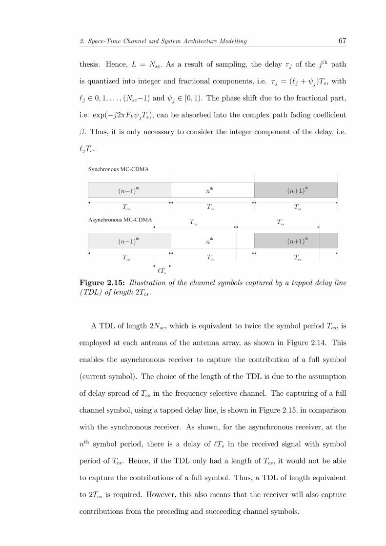
2. Space-Time Channel and System Architecture Modelling 67
thesis. Hence, L = Nsc: As a result of sampling, the delay � j of the jth path
is quantized into integer and fractional components, i.e. � j = (`j + j)Ts, with
`j 2 0; 1; : : : ; (Nsc�1) and j 2 [0; 1). The phase shift due to the fractional part,
i.e. exp(�j2�Fk jTs), can be absorbed into the complex path fading coe¢ cient
�. Thus, it is only necessary to consider the integer component of the delay, i.e.
`jTs.
Figure 2.15: Illustration of the channel symbols captured by a tapped delay line(TDL) of length 2Tcs.
A TDL of length 2Nsc, which is equivalent to twice the symbol period Tcs, is
employed at each antenna of the antenna array, as shown in Figure 2.14. This
enables the asynchronous receiver to capture the contribution of a full symbol
(current symbol). The choice of the length of the TDL is due to the assumption
of delay spread of Tcs in the frequency-selective channel. The capturing of a full
channel symbol, using a tapped delay line, is shown in Figure 2.15, in comparison
with the synchronous receiver. As shown, for the asynchronous receiver, at the
nth symbol period, there is a delay of `Ts in the received signal with symbol
period of Tcs. Hence, if the TDL only had a length of Tcs, it would not be able
to capture the contributions of a full symbol. Thus, a TDL of length equivalent
to 2Tcs is required. However, this also means that the receiver will also capture
contributions from the preceding and succeeding channel symbols.
2. Space-Time Channel and System Architecture Modelling 68
The details of the sampling carried out in the tapped delay lines are also
shown in Figure 2.14. Through the use of the TDLs, 2Nsc samples are obtained
from each TDL. The 2Nsc samples from each tapped delay line for the nth symbol
period are then concatenated to form a vector x [n] of length 2NNsc in Figure
2.14 which is read at a rate of 1Tcs. Thus, the output of the TDLs can be expressed
as
x [n] =
2666666664
x1 [n]
x2 [n]
...
xN [n]
37777777752 C2NNsc�1 (2.19)
where xp [n] denotes the vector of length 2Nsc from the pth tapped delay line.
2.4 Summary
In this chapter, the concept of the array manifold vector has been introduced. In
addition, the array manifold vector is simpli�ed to be independent of the subcar-
rier frequency for MC modulation schemes. This is based on the assumption that
the maximum subcarrier frequency is much smaller than the carrier frequency.
Hence, the e¤ect of the subcarrier frequency on the array manifold vector can be
ignored.
The mathematical modelling of the space-time fading channel models, which
can be classi�ed into four main categories based on the structure of the input or
output signals, has also been presented with the channel impulse response derived
for each channel type. These have been further extended to the case of multiple
access systems. It is shown that the space-time channel plays an important role
in transforming the signal from the transmitter-end to the receiver-end. The
development of the communication system architecture involves the integration
of three basic building blocks: the transmitter, the propagation channels and

2. Space-Time Channel and System Architecture Modelling 69
the receiver and each of these fundamental units may vary in the designing of a
space-time system architecture.
In the frequency-selective fading channel considered in Figures 2.11, 2.12 and
2.13, it has been assumed that the delay spread of the channel is equivalent to
the symbol period. This implies that if cyclic pre�xes are used in the MC-CDMA
modulation, a cyclic pre�x of length equal to one channel symbol period will
be required. Hence, for the channel considered here, the use of a cyclic pre�x
will result in a huge loss in signalling time. Thus, cyclic pre�x-free MC-CDMA
modulation will be used in this thesis in conjunction with arrayed MIMO systems.

Chapter 3
Space-Time Cyclic Pre�x-free
MC-CDMA Array-Based MIMO
System
This chapter addresses the problems of channel estimation and reception for the
cyclic pre�x-free MC-CDMA MIMO system presented in Figure 2.11, which is
reproduced in Figure 3.1 for ease of reference. In order to reduce the system
overheads, a blind channel estimation algorithm is of interest as resources that
are used for the transmission of pilot signals can be used for the transmission of
information instead. A parametric approach is taken in the channel estimation
process where the space-time parameters of the channel are estimated. This is in
contrast to non-parametric channel estimation techniques where the composite
channel response, i.e. the channel matrix in MIMO systems, is estimated instead.
In addition to the joint space-time parameter estimator, linear receivers are
also presented based on the model of the array-based MIMO system. The pro-
posed system, as shown in Figure 3.1, makes use of a demultiplexer to distribute
the channel symbols among the transmitter antenna elements. In contrast to V-
BLAST systems, a linear receiver architecture is favoured over SIC techniques so70

3. Space-Time Cyclic Pre�x-free MC-CDMA Array-Based MIMO System 71
Figure3.1:System
Architectureofacyclicpre�x-freearrayedMIMOcommunicationsystem
(Figure2.11whichisreproducedherefor
easeofreference).
3. Space-Time Cyclic Pre�x-free MC-CDMA Array-Based MIMO System 72
that the problem of error propagation can be avoided. The linear weight matrix
is applied to the output of the discretizer and tapped delay lines and the result is
then multiplexed and passed into the decision device. A subspace-based receiver,
which aims to cancel the ISI present in the system, is proposed. Furthermore,
the RAKE and MMSE receivers are upgraded to spatio-temporal RAKE and
spatio-temporal MMSE, respectively. The e¤ectiveness of the joint estimation
process is supported by simulation results and the performance of the proposed
subspace-based receiver is compared with that of spatio-temporal RAKE and
MMSE receivers.
3.1 Introduction
In MC-CMDA systems, the use of cyclic pre�xes to overcome the e¤ects of the
frequency-selective fading channel reduces the spectral e¢ ciency of the system.
Thus, cyclic pre�x-free MC-CDMA systems are of interest. Note that cyclic
pre�x-free MC-CDMA systems have been investigated also in [39] by Nabhane
and Poor for, however, synchronous systems. Furthermore, in [40], a similar cyclic
pre�x-free MC-CDMA system is considered where, by performing time-domain
equalization, it is shown to have a much better performance than the conventional
frequency-domain equalization.
Due to the sensitivity of MC-CDMA systems to timing and frequency o¤sets,
channel estimation is an integral part of a MC-CDMA system and this can be
carried out with blind, or non-blind, techniques. Non-blind techniques, as the
name implies, make use of pilot or training symbols to obtain the estimates of
the channel. An example of such pilot-assisted channel estimation for a MC-
CDMA MIMO system can be found in [41] where the channel estimation of the
channel matrix is viewed as an extension of the SISO channel estimator for each
3. Space-Time Cyclic Pre�x-free MC-CDMA Array-Based MIMO System 73
receive antenna.
However, as a result of the demand for high data rates in future commu-
nications for 4G and beyond, the reduction of system overheads is one of the
objectives of this work. Thus, in the channel estimation for MC-CDMA MIMO
systems, which is a likely candidate for 4G systems, semi-blind or blind channel
techniques are an attractive alternative as such techniques reduce or remove the
need for pilot or training symbols to be used for the estimation of the channel.
A number of blind channel estimation techniques have been proposed for
MC-CDMA MIMO systems and subspace-based methods are a common feature
of these blind channel estimation techniques. In [42], blind channel estimation
techniques, based on eigendecomposition, have been proposed for the estimation
of the channel impulse response in a MC-CDMA MIMO system which make use
of STBCs. However, due to the subspace-based method used, a scalar ambiguity
exists in the estimate of the CIR. In [43], a semi-blind subspace-based method
was proposed to overcome the problem of scalar ambiguity. The proposed method
requires some pilot symbols in order to resolve the scalar ambiguity inherent in
subspace-based methods, but the number of pilot symbols used is much less than
methods which are entirely pilot-based. It is shown that the proposed method
is capable of resolving the scalar ambiguity through the use of only one training
symbol. It must be noted that the systems proposed in [42, 43] are not array-
based systems and thus, array signal processing techniques are not available in
such systems. In contrast, in [44], a uniform linear array is implemented at the
receiver. Thus, in addition to the CIR, the DOA of each user, as observed at the
linear array at the receiver, is also estimated through the use of an ESPRIT-like
algorithm. The obtained DOA information can then be used for beamforming to
improve the performance of the system.
Due to the e¤ectiveness of subspace-based channel estimation algorithms, the
3. Space-Time Cyclic Pre�x-free MC-CDMA Array-Based MIMO System 74
proposed channel estimation technique is also subspace-based. However, instead
of estimating the CIR of the MIMO channel, the channel parameters are estimated
instead. The receiver terminal is thus designed to obtain estimates of the DOAs
and TOAs of the multipaths impinging on its antenna array. The knowledge
of these channel parameters can then be used in the design of the receiver for
improved performance.
3.2 Cyclic Pre�x-freeMC-CDMAArrayedMIMO
Transmitter
The structure of the transmitter in a cyclic pre�x-free MC-CDMA arrayed MIMO
system is illustrated in Figure 3.2. As shown in this �gure, the transmitter is
equipped with N antenna elements. It is assumed that channel information is
not available at the transmitter. Thus, the incoming channel symbols are demul-
tiplexed among the transmitter antenna elements for transmission. The channel
symbol stream is demultiplexed into N channel symbol substreams to obtain the
nth channel symbol vector length N given by
fa[n] 2 CN�1;8n 2 Zg and a[n] =�a1[n]; : : : ; ap[n]; : : : ; aN [n]
�Twhere each com-
ponent fap[n], p 2 1; : : : ; Ng, has a symbol period of Tcs. The vector sequence
fa [n] ;8ng at point-A is then converted, through impulse modulation and pulse
shaping, into the vector waveform, observed at point-B, which is de�ned as:
a[n]c (t� nTcs) ; nTcs � t < (n+ 1)Tcs (3.1)
where c(t) is the rectangular pulse of duration Tcs.
The signal vector, given by Equation 3.1, is then MC-CDMA modulated, as
indicated in Figure 3.2. Due to the use of code diversity in the transmitter [45,46],
each pth element of Equation 3.1 is assigned an unique PN sequence �p of length
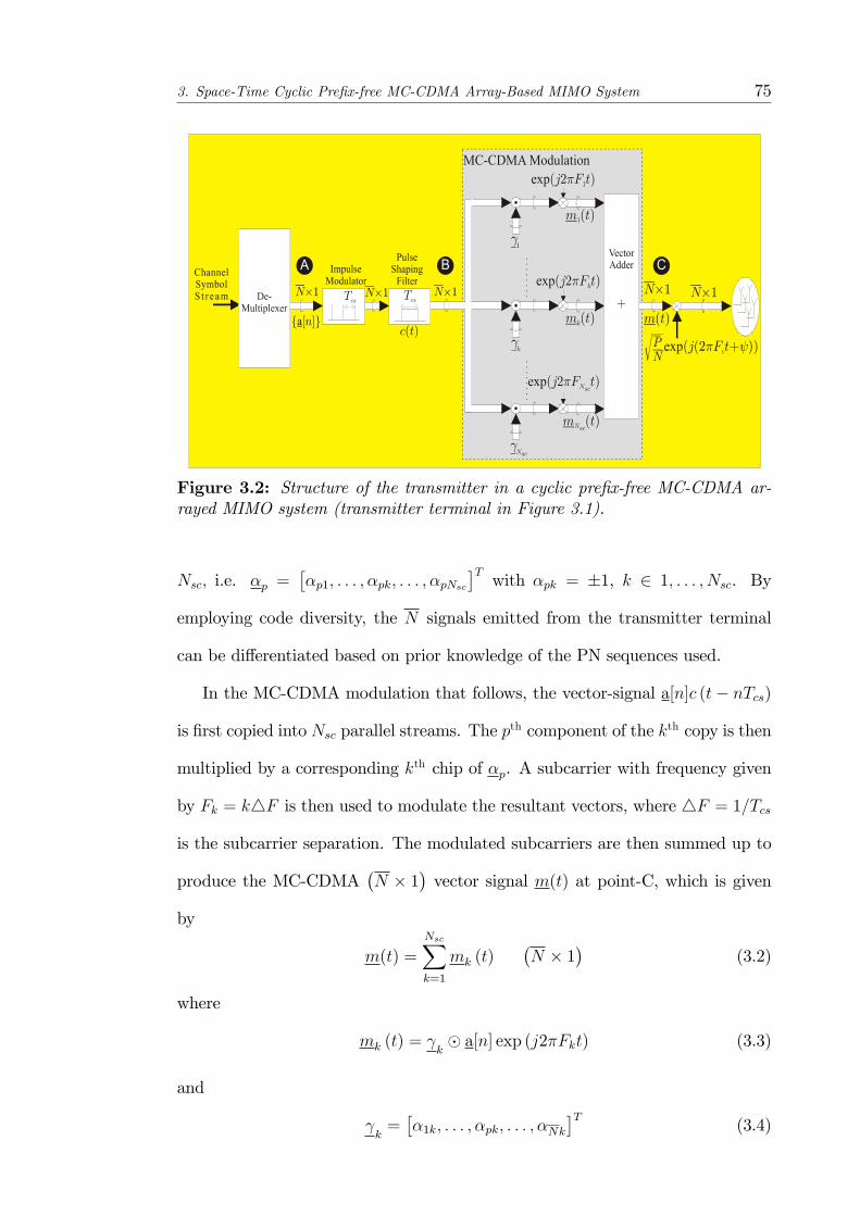
3. Space-Time Cyclic Pre�x-free MC-CDMA Array-Based MIMO System 75
Figure 3.2: Structure of the transmitter in a cyclic pre�x-free MC-CDMA ar-rayed MIMO system (transmitter terminal in Figure 3.1).
Nsc; i.e. �p =��p1; : : : ; �pk; : : : ; �pNsc
�Twith �pk = �1, k 2 1; : : : ; Nsc. By
employing code diversity, the N signals emitted from the transmitter terminal
can be di¤erentiated based on prior knowledge of the PN sequences used.
In the MC-CDMA modulation that follows, the vector-signal a[n]c (t� nTcs)
is �rst copied into Nsc parallel streams. The pth component of the kth copy is then
multiplied by a corresponding kth chip of �p. A subcarrier with frequency given
by Fk = k4F is then used to modulate the resultant vectors, where 4F = 1=Tcs
is the subcarrier separation. The modulated subcarriers are then summed up to
produce the MC-CDMA�N � 1
�vector signal m(t) at point-C, which is given
by
m(t) =
NscXk=1
mk (t)�N � 1
�(3.2)
where
mk (t) = k� a[n] exp (j2�Fkt) (3.3)
and
k=��1k; : : : ; �pk; : : : ; �Nk
�T(3.4)
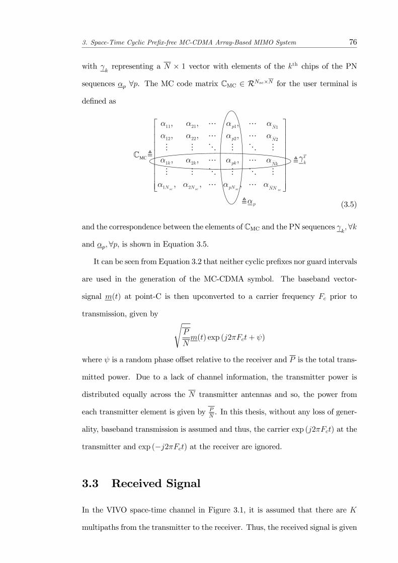
3. Space-Time Cyclic Pre�x-free MC-CDMA Array-Based MIMO System 76
with krepresenting a N � 1 vector with elements of the kth chips of the PN
sequences �p 8p. The MC code matrix CMC 2 RNsc�N for the user terminal is
de�ned as
(3.5)
and the correspondence between the elements of CMC and the PN sequences k;8k
and �p;8p, is shown in Equation 3.5.
It can be seen from Equation 3.2 that neither cyclic pre�xes nor guard intervals
are used in the generation of the MC-CDMA symbol. The baseband vector-
signal m(t) at point-C is then upconverted to a carrier frequency Fc prior to
transmission, given by sP
Nm(t) exp (j2�Fct+ )
where is a random phase o¤set relative to the receiver and P is the total trans-
mitted power. Due to a lack of channel information, the transmitter power is
distributed equally across the N transmitter antennas and so, the power from
each transmitter element is given by PN. In this thesis, without any loss of gener-
ality, baseband transmission is assumed and thus, the carrier exp (j2�Fct) at the
transmitter and exp (�j2�Fct) at the receiver are ignored.
3.3 Received Signal
In the VIVO space-time channel in Figure 3.1, it is assumed that there are K
multipaths from the transmitter to the receiver. Thus, the received signal is given
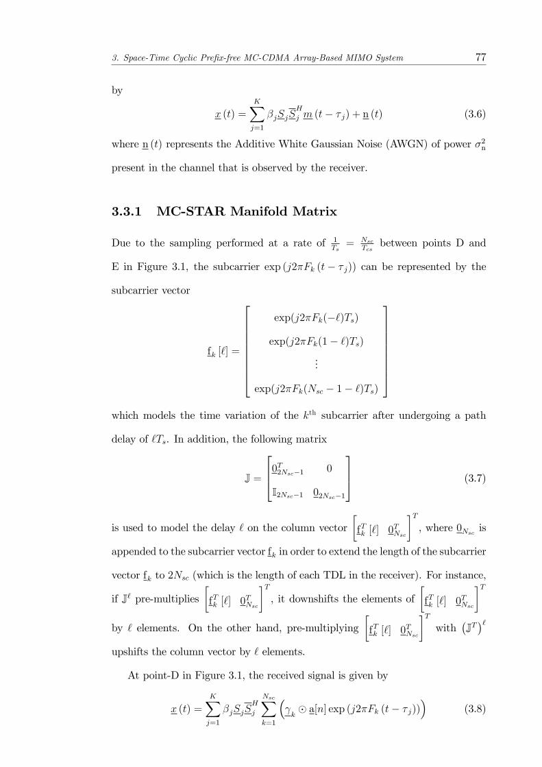
3. Space-Time Cyclic Pre�x-free MC-CDMA Array-Based MIMO System 77
by
x (t) =
KXj=1
�jSjSH
j m (t� � j) + n (t) (3.6)
where n (t) represents the Additive White Gaussian Noise (AWGN) of power �2n
present in the channel that is observed by the receiver.
3.3.1 MC-STAR Manifold Matrix
Due to the sampling performed at a rate of 1Ts= Nsc
Tcsbetween points D and
E in Figure 3.1, the subcarrier exp (j2�Fk (t� � j)) can be represented by the
subcarrier vector
fk [`] =
2666666664
exp(j2�Fk(�`)Ts)
exp(j2�Fk(1� `)Ts)
...
exp(j2�Fk(Nsc � 1� `)Ts)
3777777775which models the time variation of the kth subcarrier after undergoing a path
delay of `Ts. In addition, the following matrix
J =
2640T2Nsc�1 0
I2Nsc�1 02Nsc�1
375 (3.7)
is used to model the delay ` on the column vector�fTk [`] 0
TNsc
�T, where 0Nsc is
appended to the subcarrier vector fk in order to extend the length of the subcarrier
vector fk to 2Nsc (which is the length of each TDL in the receiver). For instance,
if J` pre-multiplies�fTk [`] 0
TNsc
�T, it downshifts the elements of
�fTk [`] 0
TNsc
�Tby ` elements. On the other hand, pre-multiplying
�fTk [`] 0
TNsc
�Twith
�JT�`
upshifts the column vector by ` elements.
At point-D in Figure 3.1, the received signal is given by
x (t) =KXj=1
�jSjSH
j
NscXk=1
� k� a[n] exp (j2�Fk (t� � j))
�(3.8)
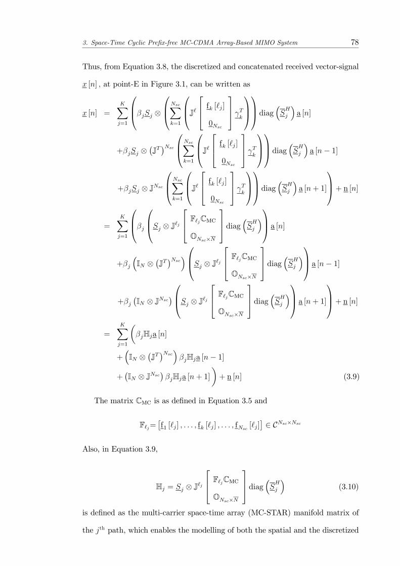
3. Space-Time Cyclic Pre�x-free MC-CDMA Array-Based MIMO System 78
Thus, from Equation 3.8, the discretized and concatenated received vector-signal
x [n] ; at point-E in Figure 3.1, can be written as
x [n] =KXj=1
0B@�jSj 0B@NscXk=1
0B@J`264 fk [`j]0Nsc
375 Tk
1CA1CA diag �SHj � a [n]
+�jSj �JT�Nsc0B@NscX
k=1
0B@J`264 fk [`j]0Nsc
375 Tk
1CA1CA diag �SHj � a [n� 1]
+�jSj JNsc
0B@NscXk=1
0B@J`264 fk [`j]0Nsc
375 Tk
1CA1CA diag �SHj � a [n+ 1]
1CA+ n [n]
=KXj=1
0B@�j0B@Sj J`j
264 F`jCMCONsc�N
375 diag �SHj �1CA a [n]
+�j
�IN
�JT�Nsc�0B@Sj J`j
264 F`jCMCONsc�N
375 diag �SHj �1CA a [n� 1]
+�j�IN JNsc
�0B@Sj J`j264 F`jCMCONsc�N
375 diag �SHj �1CA a [n+ 1]
1CA+ n [n]=
KXj=1
��jHja [n]
+�IN
�JT�Nsc�
�jHja [n� 1]
+�IN JNsc
��jHja [n+ 1]
�+ n [n] (3.9)
The matrix CMC is as de�ned in Equation 3.5 and
F`j=�f1 [`j] ; : : : ; fk [`j] ; : : : ; fNsc [`j]
�2 CNsc�Nsc
Also, in Equation 3.9,
Hj = Sj J`j
264 F`jCMCONsc�N
375 diag �SHj � (3.10)
is de�ned as the multi-carrier space-time array (MC-STAR) manifold matrix of
the jth path, which enables the modelling of both the spatial and the discretized
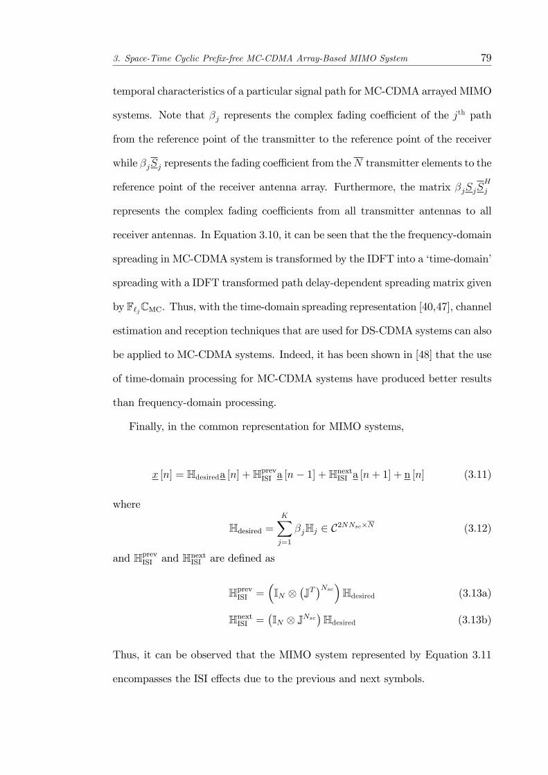
3. Space-Time Cyclic Pre�x-free MC-CDMA Array-Based MIMO System 79
temporal characteristics of a particular signal path for MC-CDMA arrayed MIMO
systems. Note that �j represents the complex fading coe¢ cient of the jth path
from the reference point of the transmitter to the reference point of the receiver
while �jSj represents the fading coe¢ cient from theN transmitter elements to the
reference point of the receiver antenna array. Furthermore, the matrix �jSjSH
j
represents the complex fading coe¢ cients from all transmitter antennas to all
receiver antennas. In Equation 3.10, it can be seen that the the frequency-domain
spreading in MC-CDMA system is transformed by the IDFT into a �time-domain�
spreading with a IDFT transformed path delay-dependent spreading matrix given
by F`jCMC. Thus, with the time-domain spreading representation [40,47], channel
estimation and reception techniques that are used for DS-CDMA systems can also
be applied to MC-CDMA systems. Indeed, it has been shown in [48] that the use
of time-domain processing for MC-CDMA systems have produced better results
than frequency-domain processing.
Finally, in the common representation for MIMO systems,
x [n] = Hdesireda [n] +HprevISI a [n� 1] +HnextISI a [n+ 1] + n [n] (3.11)
where
Hdesired =KXj=1
�jHj 2 C2NNsc�N (3.12)
and HprevISI and HnextISI are de�ned as
HprevISI =�IN
�JT�Nsc�Hdesired (3.13a)
HnextISI =�IN JNsc
�Hdesired (3.13b)
Thus, it can be observed that the MIMO system represented by Equation 3.11
encompasses the ISI e¤ects due to the previous and next symbols.
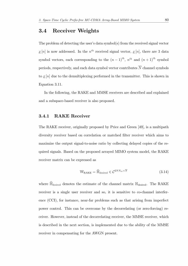
3. Space-Time Cyclic Pre�x-free MC-CDMA Array-Based MIMO System 80
3.4 Receiver Weights
The problem of detecting the user�s data symbol(s) from the received signal vector
x [n] is now addressed. In the nth received signal vector, x [n], there are 3 data
symbol vectors, each corresponding to the (n� 1)th, nth and (n+ 1)th symbol
periods, respectively, and each data symbol vector contributes N channel symbols
to x [n] due to the demultiplexing performed in the transmitter. This is shown in
Equation 3.11.
In the following, the RAKE and MMSE receivers are described and explained
and a subspace-based receiver is also proposed.
3.4.1 RAKE Receiver
The RAKE receiver, originally proposed by Price and Green [49], is a multipath
diversity receiver based on correlation or matched �lter receiver which aims to
maximize the output signal-to-noise ratio by collecting delayed copies of the re-
quired signals. Based on the proposed arrayed MIMO system model, the RAKE
receiver matrix can be expressed as
WRAKE = bHdesired 2 C2NNsc�N (3.14)
where bHdesired denotes the estimate of the channel matrix Hdesired. The RAKEreceiver is a single user receiver and so, it is sensitive to co-channel interfer-
ence (CCI), for instance, near-far problems such as that arising from imperfect
power control. This can be overcome by the decorrelating (or zero-forcing) re-
ceiver. However, instead of the decorrelating receiver, the MMSE receiver, which
is described in the next section, is implemented due to the ability of the MMSE
receiver in compensating for the AWGN present.
3. Space-Time Cyclic Pre�x-free MC-CDMA Array-Based MIMO System 81
3.4.2 MMSE Receiver
The MMSE linear receiver can be viewed as a solution which takes into account
the relative importance of each interfering signal and the background noise present
in the channel. This is in contrast to both the single-user matched �lter receiver
which is designed to cancel the background white noise as well as the decorrelating
receiver which ignores the e¤ect of the background noise while attempting to
eliminate the interference present.
The MMSE receiver, as the name implies, minimizes the output mean square
error (MSE) and it is obtained through the following optimization problem:
W = argminWtr (E) (3.15)
The matrix E denotes the MSE matrix, which is given by
E = En�a [n]�WHx [n]
� �a [n]�WHx [n]
�Ho(3.16)
= IN �WHHdesired �HHdesiredW+WHRxxW
where it has been assumed that a [n� 1], a [n] and a [n+ 1] are uncorrelated and
Rxx denotes the data covariance matrix, which is given by
Rxx = HHH + �2nI2NNsc
The di¤erentiation of tr (E) with respect toW and equating the result to 0 results
in
2RxxW�2Hdesired = 0
Thus, the closed form solution to the above optimization problem is then given
by
W = R�1xxHdesired (3.17)
=�HHH + �2nI2NNsc
��1Hdesired

3. Space-Time Cyclic Pre�x-free MC-CDMA Array-Based MIMO System 82
The MMSE receiver is then described as follows
WMMSE =�bHbHH + �2nI2NNsc
��1 bHdesired 2 C2NNsc�N (3.18)
where
bH = hbHprevISI ;bHdesired; bHnextISI
i(3.19)
Thus, the pre-multiplication of x [n] byWHMMSE will produce the decision variable
vector, a [n] ; for the current symbol vector, a [n].
3.4.3 Subspace-Based Receiver
In addition to the RAKE and MMSE receivers described earlier, a subspace-based
receiver is now introduced. The proposed subspace-based receiver, which was �rst
introduced in [50], is designed with the aim of suppressing the interference, i.e.
ISI, present in the received signal, x [n], of the proposed MIMO system. Thus,
the proposed method seeks to project the ISI components in x [n] onto their
complementary subspace. This is achieved through the use of the ISI complement
projection matrix, P?ISI, which is de�ned as
P?ISI = I2NNsc�bHISI �bHHISIbHISI��1 bHHISI (3.20)
where bHISI denotes the estimate of the channel matrix of the ISI signals and it isgiven by
bHISI = hbHprevISI ;bHnextISI
i(3.21)
bHISI, or equivalently bHprevISI and bHnextISI , can be easily obtained from the estimate of
the channel matrix (bHdesired) of the current symbol period based on the relationsgiven in Equations 3.13 for the MIMO system. Thus, P?ISI, as de�ned by Equation
3.20, is a complement projection matrix of bHISI. The subspace-based receiverweight matrix is then de�ned as
Wsubspace = P?ISIbHdesired �bHHdesiredP?ISIbHdesired��1 2 C2NNsc�N (3.22)

3. Space-Time Cyclic Pre�x-free MC-CDMA Array-Based MIMO System 83
In Equation 3.22, P?ISI projects the estimated bHdesired to be orthogonal to the ISIsubspace, thereby suppressing the ISI in the decision variable vector, a [n].
Using the subspace-based weight matrix, the decision variable vector ba [n] isthen given by
ba [n] = WHsubspacex [n]
=
INz }| {�HHdesiredP?ISIHdesired
��1HHdesiredP?ISIHdesireda [n]+
ON�Nz }| {�HHdesiredP?ISIHdesired
��1HHdesiredP?ISIHprevISI a [n� 1]
+
ON�Nz }| {�HHdesiredP?ISIHdesired
��1HHdesiredP?ISIHnextISI a [n+ 1]
+�HHdesiredP?ISIHdesired
��1HHdesiredP?ISIn [n]= a [n] +
�HHdesiredP?ISIHdesired
��1HHdesiredP?ISIn [n] (3.23)
where it has been assumed that the perfect knowledge of the matrix Hdesired is
available. Moreover, it can be observed that the ISI complement projection ma-
trix, P?ISI; operates directly on the matrix Hdesired and so, the multiplication of
x [n] by Wsubspace has the e¤ect of nulling the e¤ects of the ISI matrices. It
can be observed in Equation 3.23 that the subspace-based receiver enables the
cancellation of the ISI e¤ects from the received signal.
3.5 Space-Time Parameter Estimation for Asyn-
chronous Multipath Propagation
It can be seen from the previous section in Equations 3.14, 3.18 and 3.22 that the
knowledge of the matrices Hdesired, bHprevISI and bHnextISI are needed for the formulation
of the receiver weight matrices. This implies that the estimation of the channel
parameters is required for the reconstruction of the matrices Hdesired, bHprevISI and
3. Space-Time Cyclic Pre�x-free MC-CDMA Array-Based MIMO System 84
bHnextISI . In this section, a channel estimation technique is proposed for the esti-
mation of the channel parameters, in particular, the DOA and TOA. In order to
obtain the estimates of the DOA and TOA, knowledge of the PN-sequence of one
of the elements of the transmitter antenna array is required.
The received signal vector, from Equation 3.11, can be rewritten as
x [n] =
KXj=1
�j�Sj��phpjap [n]| {z }
TOI
+
NXp=1;p 6=p
KXj=1
�j�Sj��phpjap [n]| {z }
CCI
+HprevISI a [n� 1] +HnextISI a [n+ 1]| {z }ISI
+ n [n] (3.24)
where it is assumed that the pth transmitter antenna is the antenna whose PN
sequence will be used for the estimation of the channel parameters. In Equation
3.24,�Sj��phpj corresponds to the p
th column of Hj; where the vector hpj is given
by
hpj = Sj J`j
264 F`j�p0Nsc
375 2 C2NNsc�1 (3.25)
The vector hpj is referred to as the MC-STAR manifold vector for the jth path of
the pth antenna element.
It can be observed from Equation 3.24 that the �rst term is the term of
interest (TOI), the second term represents the co-channel interference (CCI) due
to the remaining�N � 1
�transmitter antennas while the third and fourth terms
represent the ISI e¤ects and AWGN, respectively. In the desired term, the MC-
STAR manifold vectors corresponding to the K paths of the pth transmitter
antenna are shown to be linearly combined by the fading coe¢ cient vector �j and
the complex conjugate of the pth element of the transmit array manifold vector
for the jth path,�Sj��p. Thus, the pth transmitter contributes a desired signal
subspace of only one dimension to the overall signal subspace. As a result, it is not
possible to estimate the pth transmitter antenna�s space-time channel parameters
(DOAs and TOAs) using signal subspace techniques such as MUSIC [33].

3. Space-Time Cyclic Pre�x-free MC-CDMA Array-Based MIMO System 85
A solution, which makes use of the concept of the preprocessor scheme intro-
duced in [51], is now proposed to overcome the �coherence�problem caused by the
linear combination of the MC-STAR manifold vectors. A matrix is �rst de�ned
as:
Cp =
264J0264F0�p0Nsc
375 ; J1264F1�p0Nsc
375 ; : : : ; : : : ; JNsc�1264FNsc�1�p
0Nsc
375375 (3.26)
where F`j � F` when `j = `. Thus, Cp contains all the correspondingly down-
shifted FFT transformed delay-dependent PN-sequences associated with the pth
transmit antenna. Based on Cp in Equation 3.26, a preprocessor matrix Pp` can
be formed by
Pp` = IN P? [Cp`] (3.27)
where Cp` is formed from the matrix Cp by removing its (`+ 1)th column. In
Equation 3.27, P? [Cp`] denotes the projection matrix onto the complementary
subspace of Cp`.
The preprocessor matrix Pp` is then applied to the signal x [n] given by Equa-
tion 3.24 to obtain
zp` [n] = Pp`x [n]
where the preprocessor matrix Pp` can be observed to be applied directly to the
matrices Hdesired, HprevISI and HnextISI . Thus, for the pth transmit antenna element,
the preprocessor matrix Pp` will be able to null its MC-STAR manifold vectors
contained in Hdesired which do not have the same delay and at the same time,
transform the MC-STAR manifold vectors which correspond to the delay `.
The e¤ect of Pp` on the MC-STAR manifold vectors of the pth transmitter
element is illustrated through the following example by considering paths with
delay lTs. Consider the TOI in Equation 3.24, which can be written as
�hp1; : : : ; hpj; : : : ; hpK
� h�1�S1��p; : : : ; �j
�Sj��p; : : : ; �K
�SK��p
iTap [n]

3. Space-Time Cyclic Pre�x-free MC-CDMA Array-Based MIMO System 86
instead.
In the simple case of a single path with delay corresponding to lTs and paths
with a delay of lTs are to be detected, the preprocessor Ppl is used and so, the
e¤ect of Ppl on the K MC-STAR manifold vectors of the pth transmitter is given
by
Ppl�hp1; : : : ; hpj; : : : ; hpK
�
=
8>>>><>>>>:[
(j�1) termsz }| {02Nsc ; 02Nsc ; : : : ; 02Nsc ;Pplhpj;
(K�j) termsz }| {02Nsc : : : ; 02Nsc ]; if `pj = l (transformation)
[02Nsc ; 02Nsc ; : : : ; 02Nsc| {z }(j�1) terms
; 02Nsc ; 02Nsc : : : ; ; 02Nsc| {z }(K�j) terms
]; if `pj 6= l;8j (simpli�cation)(3.28)
Thus, it is clear from Equation 3.28 that only paths with delay equal to lTs (if
any) will exist in the preprocessed signal vector zil [n]. This is because all vectors
hpj; 8j; with `pj 6= l will be in the null space of the preprocessor matrix Ppl. In
addition to the simpli�cation/transformation of hpj, 8j, as shown in Equation
3.28, Ppl also has the e¤ect of transforming the vectors hpj;8p8j; p 6= p due to
the code diversity employed in the transmitter. The matrices HprevISI and HnextISI are
also transformed. Thus,
zpl [n] =KXj=1
�j�Sj��pPplhpjap [n]| {z }
transformed TOI
+NX
p=1;p6=p
KXj=1
�j�Sj��pPplhpjap [n]| {z }
transformed CCI
+PplHprevISI a [n� 1] + PplHnextISI a [n+ 1]| {z }transformed ISI
+ Ppln [n] (3.29)
It is assumed, without any loss of generality, that the angle of elevation �
is equal to zero for all signals that impinge on the receive antenna array. This
implies that all signals are located within the (x; y)-plane. As such, the MC-
STAR manifold vector is only dependent on the azimuth � and delay `. The aim
of the channel estimation algorithm is thus to obtain estimates of the parameters
(�; `).
The locus of all transformed MC-STAR manifold vectors, over the parameter
space of �, thus gives rise to a 1-dimensional continuum and the intersection of the
3. Space-Time Cyclic Pre�x-free MC-CDMA Array-Based MIMO System 87
signal subspace with this manifold curve will provide the required spatial channel
parameters for the pth transmitter antenna. In order to obtain the signal subspace
from the received signal, the covariance matrix of the preprocessed signal vector
zp` [n] is �rst obtained by
Rzzpl = E�zpl [n] z
Hpl [n]
(3.30)
The eigendecomposition of the preprocessed covariance matrix Rzzpl is then car-
ried out to partition the observation space of Rzzp` into the signal and noise sub-
spaces. The Akaike Information Criterion (AIC) or Minimum Description Length
(MDL) criterion [52] can be used to separate the signal and noise subspaces.
If a bank of preprocessors Pp`, ` = 0; 1; : : : ; (Nsc � 1) is implemented at the
receiver, a two-dimensional cost function over the parameters ` and � can be
obtained, which is given by
�p (`; �) =
0B@Sj (�) J`264F`�p0Nsc
3751CAH
Pp`Pp`
0B@Sj (�) J`264F`�p0Nsc
3751CA
0B@Sj (�) J`264F`�p0Nsc
3751CAH
Pp`bEnp`bEHnp`Pp`0B@Sj (�) J`
264F`�p0Nsc
3751CA8`; �
(3.31)
for the pth transmitter antenna. bEnpl denotes the estimated noise subspace of thecorresponding preprocessed covariance matrix Rzzp` . Thus, a two-dimensional
search of �p (`; �) will produce the required estimates ^ and �, which are given
by the location of the peaks of �p (`; �), for the pth transmitter antenna. The
proposed system is shown in Figure 3.3 for the pth transmitter antenna in an
arrayed MIMO system with N antennas at the transmitter.
It must be noted here that the proposed space-time multipath channel esti-
mation algorithm described above considers the case where there are no co-delay

3. Space-Time Cyclic Pre�x-free MC-CDMA Array-Based MIMO System 88
Figure3.3:
Bankofpreprocessorsrequiredfortheformationofthe2-dimensionalSTARMUSICspectrum
toobtainestimatesofthe
spatio-temporalchannelparameters.
3. Space-Time Cyclic Pre�x-free MC-CDMA Array-Based MIMO System 89
paths in the space-time multipath channel for each transmitter. Due to the nature
of the preprocessor matrix used, the resultant transformed MC-STAR manifold
vectors of co-delay paths will be linearly combined if co-delay paths are present
in the space-time multipath channel for the transmitter antenna of interest. This
is because the transformed MC-STAR manifold vectors with the same path delay
will remain in the preprocessed received signal vector zp` [n]. In order to resolve
this �coherence�problem that arises from co-delay paths, spatial smoothing [53]
has be performed on the preprocessed received signal vector zp` [n] prior to the
construction of the cost function �p (`; �). However, this is only applicable if a
ULA is applied at the receiver.
3.6 Simulation Studies
In this section, several examples are presented to demonstrate the feasibility of
the proposed cyclic pre�x-free MC-CDMA arrayed MIMO system. Consider a
cyclic pre�x-free MC-CDMA arrayed MIMO system with an uniform linear array
at both the transmitter and receiver and in both antenna arrays, an antenna
separation of half wavelength is assumed. Such a system shall be referred to as
(N;N) cyclic pre�x-free MC-CDMA arrayed MIMO system. Gold sequences of
lengthNsc are used and due to code diversity, each transmitter antenna is assigned
a unique Gold sequence. The system is assumed to operate in a frequency-
selective fading channel with channel length Nsc. Thus, the maximum path delay
of the channel is (Nsc � 1)Ts. The DOAs, �, and DODs, �; are assumed to
be uniformly distributed over [0�; 180�) while the path delays, `; are uniformly
distributed over [0Ts; (Nsc � 1)Ts].

3. Space-Time Cyclic Pre�x-free MC-CDMA Array-Based MIMO System 90
3.6.1 Detection Performance
The detection capability of the proposed subspace-based receiver is �rst compared
with the RAKE and MMSE receivers described in Section 3.4 for the proposed
cyclic pre�x-free MC-CDMA arrayed MIMO communications system. The num-
ber of antenna elements in the antenna array of the transmitter is �xed at N = 2
while the number of antenna elements in the receiver antenna array are varied
from 2 to 5. Gold sequences of length 7 are used for the PN sequences and the
number of paths with distinct time delays is assumed to be 3, i.e. K = 3. In
addition, the channel is assumed to be slowly time-varying so that the channel
can be assumed to be quasi-stationary over each run.
In order to evaluate the performance of the proposed system, a reference
MIMO system is also studied in order to compare their performance. The refer-
ence system is based on the model proposed in [54]. The reference model assumes
the use of independent antenna elements for a MIMO-OFDM system. Due to the
use of OFDM in the reference system instead of MC-CDMA, the symbols on each
subcarrier in the reference OFDM system are re-interpreted as the PN sequence-
modi�ed symbols in a MC-CDMA system. Also, in order to mitigate the e¤ects
of the multipath channel, a cyclic pre�x of length Nsc � 1 is used for the refer-
ence system. In the receivers of both the proposed and reference systems, perfect
knowledge of the channel parameters are assumed to be available. A MMSE
receiver is used for the receiver of the reference system to provide a basis for com-
parison. For the receivers of both the proposed and reference systems, perfect
knowledge of the channel parameters are assumed to be available. For the refer-
ence system, a MMSE receiver is used to study the performance of the system.
The simulation parameters are summarized in Table 3.1.
The constellation plots of the detected symbols for the receivers under con-
sideration obtained for one simulation run at a SNR of 10dB are shown in Figure

3. Space-Time Cyclic Pre�x-free MC-CDMA Array-Based MIMO System 91
Table 3.1: Summary of Simulation Parameters for Space-Time EstimationParameter Value
No. of Transmitter Antennas, N 2No. of Receiver Antennas, N 2; 3; 4; 5No. of paths, K 3Processing Gain, Nsc 7PN-codes Gold sequences
3.4 for a (2; 2) cyclic pre�x-free MC-CDMA arrayed MIMO system. From Figure
3.4, it can be observed that the proposed subspace-based receiver has compa-
rable performance to that of the MMSE receiver and both the subspace-based
and MMSE receivers have superior performance over the RAKE receiver. The
reference system is observed to have similar performance as the RAKE receiver.
Figure 3.5 shows the BER performance of the proposed system with three
di¤erent types of receivers, as described earlier, as well as the BER curve of the
reference system. The BER performance curves are obtained by averaging over
20,000 simulation runs of 20,000 bits each. It can be seen that the performance of
the subspace-based receiver is only slightly worse than that of the MMSE receiver.
However, the MMSE receiver requires additional knowledge of the variance of the
AWGN present in the channel. Among the three receivers, the RAKE receiver
performs the worst, approaching an error �oor after a signal-to-noise ratio (SNR)
of 10dB. In comparison with the reference system, the proposed system performs
much better, especially for the subspace-based and MMSE receivers. At a BER
of 10�4, the proposed system, using the subspace-based or MMSE receivers, has
a gain of about 8dB over the reference system. However, when compared to
the RAKE receiver, the reference system outperforms it at SNRs above 10dB,
although the reference system has worse performance at SNRs below 10dB.
The BER performance curves for the (2,3), (2,4) and (2,5) cyclic pre�x-free
MC-CDMA arrayed MIMO system is next compared with the reference system, as
shown in Figures 3.6, 3.7 and 3.8, respectively. It can be observed that increasing
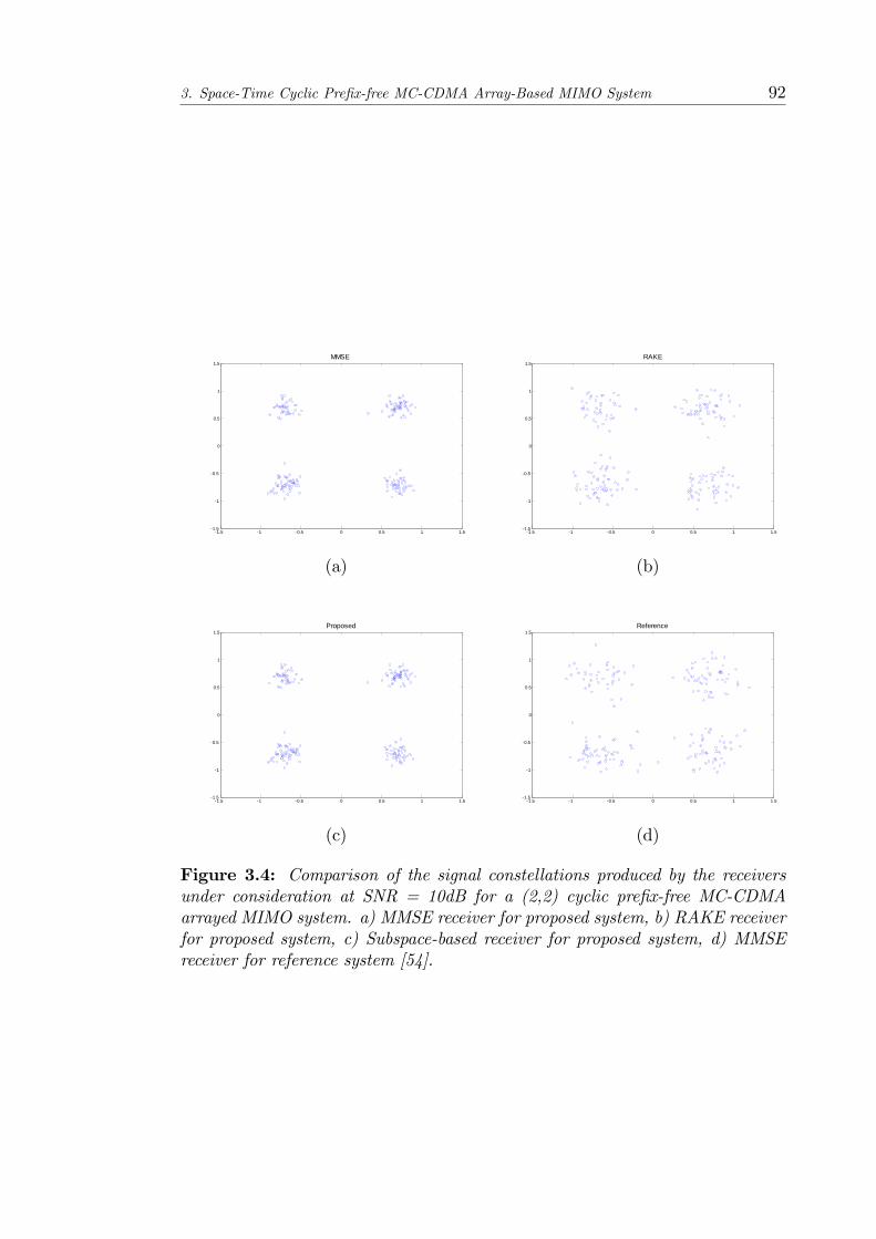
3. Space-Time Cyclic Pre�x-free MC-CDMA Array-Based MIMO System 92
1.5 1 0.5 0 0.5 1 1.51.5
1
0.5
0
0.5
1
1.5MMSE
(a)
1.5 1 0.5 0 0.5 1 1.51.5
1
0.5
0
0.5
1
1.5RAKE
(b)
1.5 1 0.5 0 0.5 1 1.51.5
1
0.5
0
0.5
1
1.5Proposed
(c)
1.5 1 0.5 0 0.5 1 1.51.5
1
0.5
0
0.5
1
1.5Reference
(d)
Figure 3.4: Comparison of the signal constellations produced by the receiversunder consideration at SNR = 10dB for a (2,2) cyclic pre�x-free MC-CDMAarrayed MIMO system. a) MMSE receiver for proposed system, b) RAKE receiverfor proposed system, c) Subspace-based receiver for proposed system, d) MMSEreceiver for reference system [54].
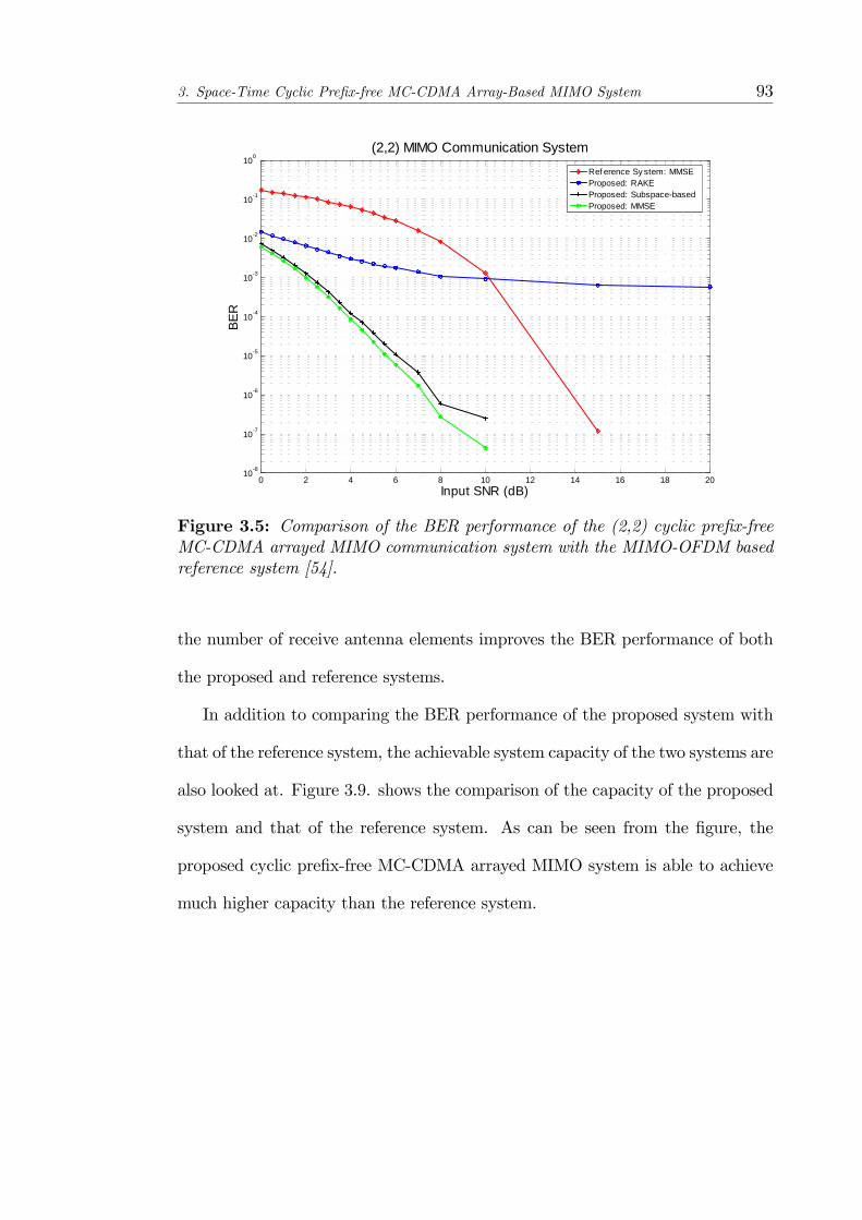
3. Space-Time Cyclic Pre�x-free MC-CDMA Array-Based MIMO System 93
0 2 4 6 8 10 12 14 16 18 20108
107
106
105
104
103
102
101
100
Input SNR (dB)
BER
(2,2) MIMO Communication SystemRef erence Sy stem: MMSEProposed: RAKEProposed: SubspacebasedProposed: MMSE
Figure 3.5: Comparison of the BER performance of the (2,2) cyclic pre�x-freeMC-CDMA arrayed MIMO communication system with the MIMO-OFDM basedreference system [54].
the number of receive antenna elements improves the BER performance of both
the proposed and reference systems.
In addition to comparing the BER performance of the proposed system with
that of the reference system, the achievable system capacity of the two systems are
also looked at. Figure 3.9. shows the comparison of the capacity of the proposed
system and that of the reference system. As can be seen from the �gure, the
proposed cyclic pre�x-free MC-CDMA arrayed MIMO system is able to achieve
much higher capacity than the reference system.
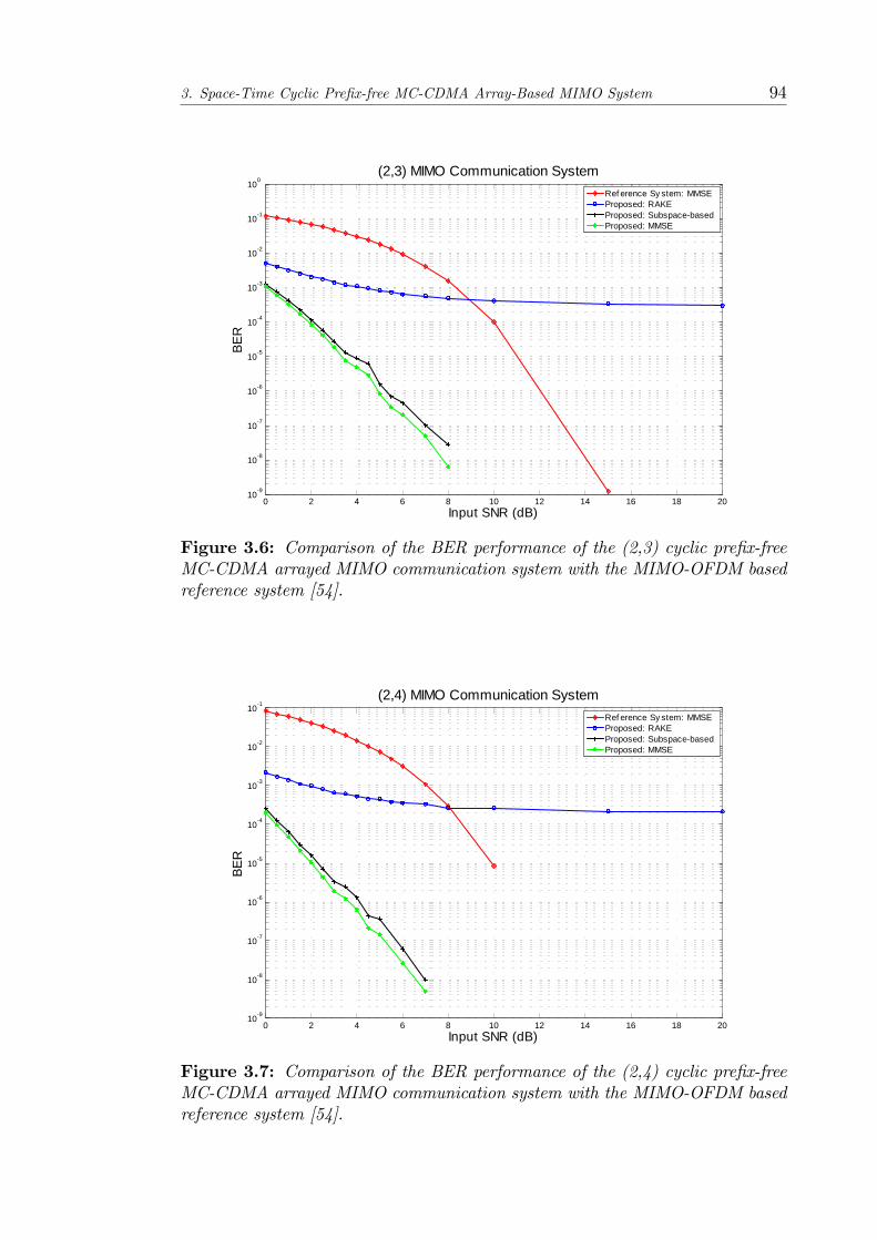
3. Space-Time Cyclic Pre�x-free MC-CDMA Array-Based MIMO System 94
0 2 4 6 8 10 12 14 16 18 20109
108
107
106
105
104
103
102
101
100
Input SNR (dB)
BER
(2,3) MIMO Communication SystemRef erence Sy stem: MMSEProposed: RAKEProposed: SubspacebasedProposed: MMSE
Figure 3.6: Comparison of the BER performance of the (2,3) cyclic pre�x-freeMC-CDMA arrayed MIMO communication system with the MIMO-OFDM basedreference system [54].
0 2 4 6 8 10 12 14 16 18 20109
108
107
106
105
104
103
102
101
Input SNR (dB)
BER
(2,4) MIMO Communication SystemRef erence Sy stem: MMSEProposed: RAKEProposed: SubspacebasedProposed: MMSE
Figure 3.7: Comparison of the BER performance of the (2,4) cyclic pre�x-freeMC-CDMA arrayed MIMO communication system with the MIMO-OFDM basedreference system [54].
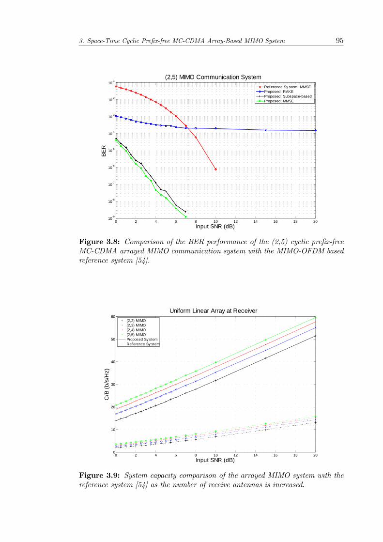
3. Space-Time Cyclic Pre�x-free MC-CDMA Array-Based MIMO System 95
0 2 4 6 8 10 12 14 16 18 20109
108
107
106
105
104
103
102
101
Input SNR (dB)
BER
(2,5) MIMO Communication SystemRef erence Sy stem: MMSEProposed: RAKEProposed: SubspacebasedProposed: MMSE
Figure 3.8: Comparison of the BER performance of the (2,5) cyclic pre�x-freeMC-CDMA arrayed MIMO communication system with the MIMO-OFDM basedreference system [54].
0 2 4 6 8 10 12 14 16 18 200
10
20
30
40
50
60
Input SNR (dB)
C/B
(b/s
/Hz)
Uniform Linear Array at Receiver(2,2) MIMO(2,3) MIMO(2,4) MIMO(2,5) MIMOProposed Sy stemRef erence Sy stem
Figure 3.9: System capacity comparison of the arrayed MIMO system with thereference system [54] as the number of receive antennas is increased.

3. Space-Time Cyclic Pre�x-free MC-CDMA Array-Based MIMO System 96
Table 3.2: Spatial-temporal channel parameters with 2 co-delay and 2 co-directional paths for the (2,4) cyclic pre�x-free MC-CDMA arrayed MIMO systemunder consideration.
Path TOA (Ts) DOA (�) Path Fading Coe¢ cientj `j �j �j;
����� = 11 28 25 0:1659 + j0:27332 13 113 0:1764 + j0:40703 18 100 0:3983 + j0:16304 18 38 0:2116 + j0:18035 25 130 0:1911� j0:39846 8 130 0:4627� j0:09487 20 60 0:0323� j0:1385
3.6.2 Space-Time Parameter Estimation
The performance of the space-time multipath channel estimation algorithm is
now investigated for a (2,4) cyclic pre�x-free MC-CDMA arrayed MIMO system.
PN sequences of length Nsc = 31 are used. In order to estimate the channel
parameters, the receiver is assumed to collect 500 QPSK channel symbols for
processing. In addition, the channel is assumed to be slowly time-varying so that
the channel can be assumed to be quasi-stationary over each observation interval
and the signal-to-noise ratio (SNR) at the receiver is assumed to be 20dB.
The space-time channel parameters during a particular observation interval
are listed in Table 3.2. In order to investigate the performance of the channel
estimation in co-delay and co-directional situations, it can be seen from Table 3.2
that paths 3 and 4 in the channel have the same delay of 18Ts. In addition, paths
5 and 6 demonstrate the co-directional situation where both paths have a DOA
of 130�.
The 2-D MUSIC spectrum, obtained from the 2-D cost function given by
Equation 3.31, is shown in Figure 3.10 for the case where spatial smoothing is
not performed prior to the construction of the 2-D MUSIC cost function. It can
be seen that only 5 peaks are present in the 2-D MUSIC spectrum obtained.
Inspection of the 2-D MUSIC spectrum reveals that the peaks are non-existent
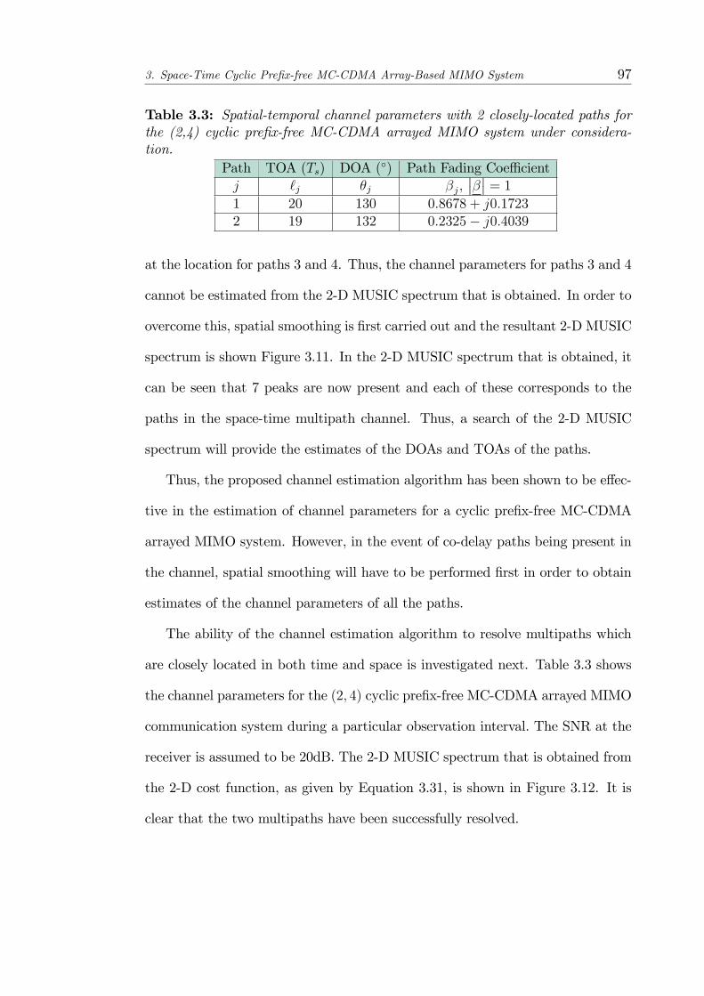
3. Space-Time Cyclic Pre�x-free MC-CDMA Array-Based MIMO System 97
Table 3.3: Spatial-temporal channel parameters with 2 closely-located paths forthe (2,4) cyclic pre�x-free MC-CDMA arrayed MIMO system under considera-tion.
Path TOA (Ts) DOA (�) Path Fading Coe¢ cientj `j �j �j;
����� = 11 20 130 0:8678 + j0:17232 19 132 0:2325� j0:4039
at the location for paths 3 and 4. Thus, the channel parameters for paths 3 and 4
cannot be estimated from the 2-D MUSIC spectrum that is obtained. In order to
overcome this, spatial smoothing is �rst carried out and the resultant 2-D MUSIC
spectrum is shown Figure 3.11. In the 2-D MUSIC spectrum that is obtained, it
can be seen that 7 peaks are now present and each of these corresponds to the
paths in the space-time multipath channel. Thus, a search of the 2-D MUSIC
spectrum will provide the estimates of the DOAs and TOAs of the paths.
Thus, the proposed channel estimation algorithm has been shown to be e¤ec-
tive in the estimation of channel parameters for a cyclic pre�x-free MC-CDMA
arrayed MIMO system. However, in the event of co-delay paths being present in
the channel, spatial smoothing will have to be performed �rst in order to obtain
estimates of the channel parameters of all the paths.
The ability of the channel estimation algorithm to resolve multipaths which
are closely located in both time and space is investigated next. Table 3.3 shows
the channel parameters for the (2; 4) cyclic pre�x-free MC-CDMA arrayed MIMO
communication system during a particular observation interval. The SNR at the
receiver is assumed to be 20dB. The 2-D MUSIC spectrum that is obtained from
the 2-D cost function, as given by Equation 3.31, is shown in Figure 3.12. It is
clear that the two multipaths have been successfully resolved.
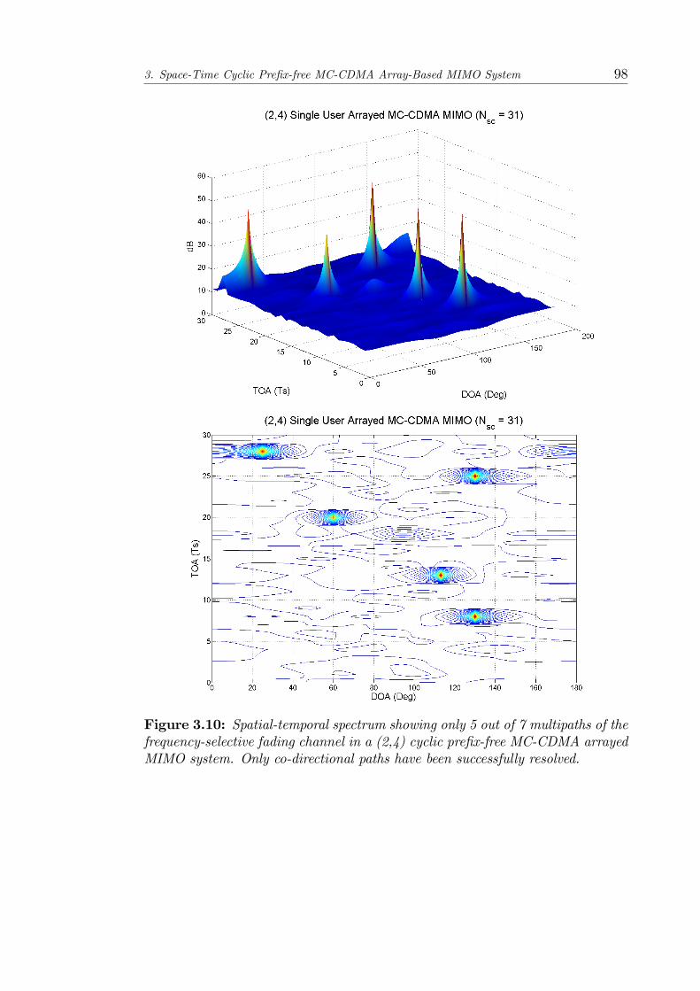
3. Space-Time Cyclic Pre�x-free MC-CDMA Array-Based MIMO System 98
Figure 3.10: Spatial-temporal spectrum showing only 5 out of 7 multipaths of thefrequency-selective fading channel in a (2,4) cyclic pre�x-free MC-CDMA arrayedMIMO system. Only co-directional paths have been successfully resolved.
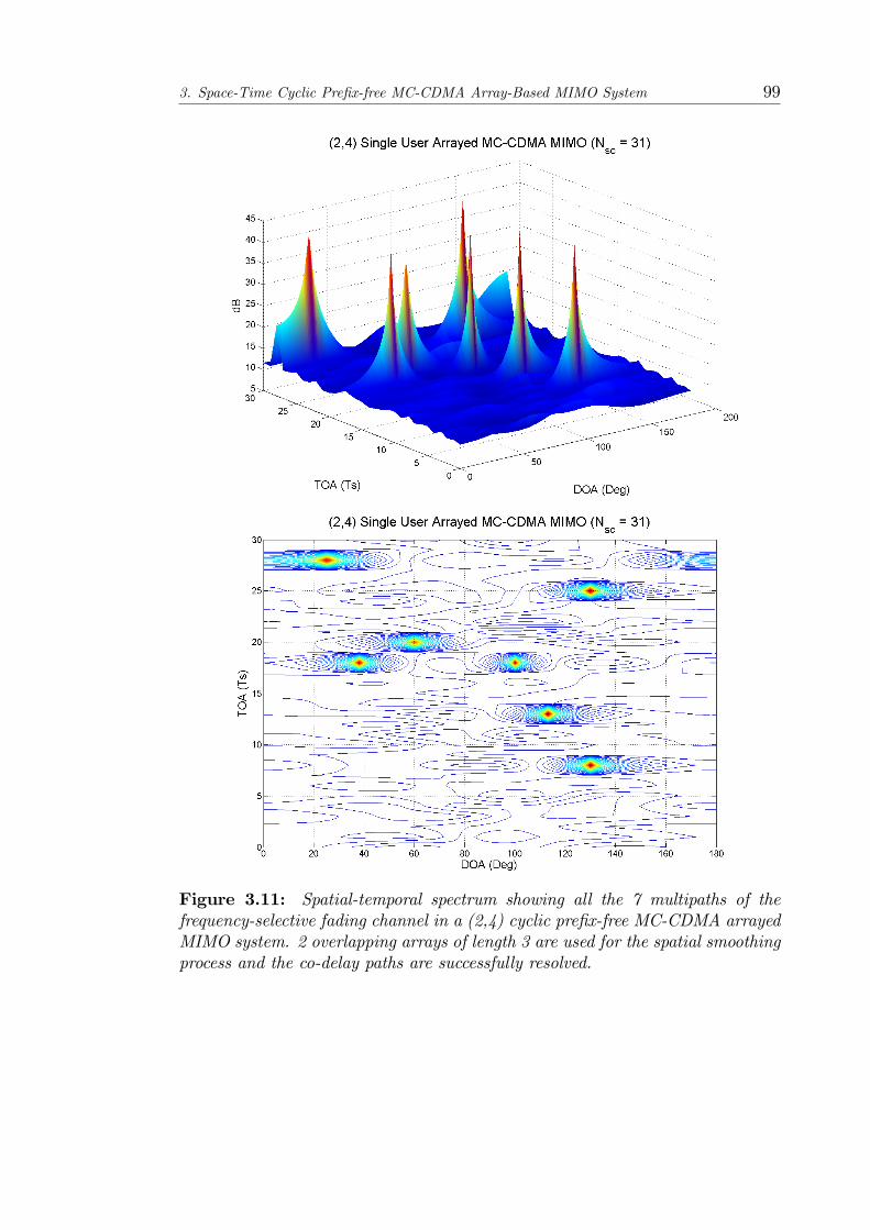
3. Space-Time Cyclic Pre�x-free MC-CDMA Array-Based MIMO System 99
Figure 3.11: Spatial-temporal spectrum showing all the 7 multipaths of thefrequency-selective fading channel in a (2,4) cyclic pre�x-free MC-CDMA arrayedMIMO system. 2 overlapping arrays of length 3 are used for the spatial smoothingprocess and the co-delay paths are successfully resolved.
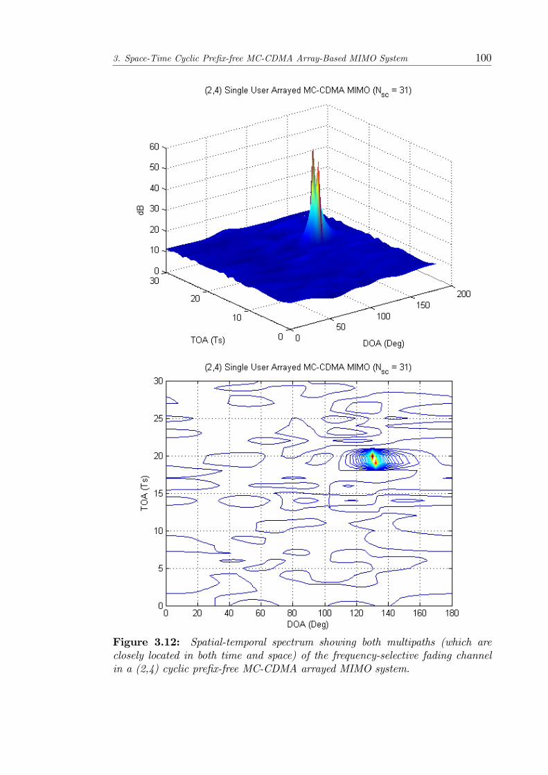
3. Space-Time Cyclic Pre�x-free MC-CDMA Array-Based MIMO System 100
Figure 3.12: Spatial-temporal spectrum showing both multipaths (which areclosely located in both time and space) of the frequency-selective fading channelin a (2,4) cyclic pre�x-free MC-CDMA arrayed MIMO system.

3. Space-Time Cyclic Pre�x-free MC-CDMA Array-Based MIMO System 101
3.7 Summary
The detection capabilities of the RAKE, MMSE and proposed subspace-based
receivers in a cyclic pre�x-free MC-CDMA arrayed MIMO system have been
compared with that of a reference system and it has been observed that the
array-based receivers have much better performance than the reference system.
In addition, the BER performance has also been investigated and it has been
shown that the inclusion of an antenna array at the receiver results in a far
superior BER performance than the reference system. Moreover, it was seen that
the subspace-based receiver has a similar BER performance to that of the MMSE
receiver. The comparison of the proposed cyclic pre�x-free MC-CDMA arrayed
MIMO system with the reference system has also shown that the lack of cyclic
pre�x in the MC-CDMA signals used does not result in a worse performance than
a system in which cyclic pre�xes are used.
A space-time multipath channel estimation algorithm for asynchronous array-
based MC-CDMA MIMO systems has also been presented in this chapter. The
proposed algorithm only requires knowledge of the PN-sequence of the transmitter
whose channel is to be estimated and it makes use of the concept of the MC-STAR
manifold vector for the formulation of the preprocessor matrix so that the space-
time channel estimation process can be carried out. The number of multipaths
that can be resolved by the proposed channel estimation algorithm ability is
not limited by the number of sensors available in the antenna array due to the
inclusion of the temporal domain.
Chapter 4
Di¤used Channel Estimation and
Reception for Cyclic Pre�x-free
MC-CDMA Arrayed MIMO
System
The problem of a spatially di¤used vector channel for a cyclic pre�x-free MC-
CDMA arrayed MIMO system is addressed in this chapter. Based on the MC-
STAR manifold vector framework, a model for the spatially-di¤used vector chan-
nel is extended from the non-di¤used vector channel model.
The di¤usion process is an important channel impairment and failure to con-
sider the e¤ect of spatial di¤usion will result in a deterioration in performance.
Thus, the behavior of a spatially di¤used channel is studied in consideration of
parameter estimation and reception problems in a cyclic pre�x-free MC-CDMA
arrayed MIMO system. The transmitter structure of the system under consider-
ation is identical to that introduced in Chapter 3. In this chapter, the MC-STAR
manifold vector introduced in Chapter 3 is extended to the �spatially-di¤used�
102
4. Di¤used Channel Estimation and Reception for Cyclic Pre�x-free MC-CDMA Arrayed
MIMO System 103
MC-STAR manifold vector appropriate for spatially-di¤used channels. In the
modelling of the spatially di¤used channel, localized scattering is assumed to oc-
cur for each multipath. Hence, a di¤used vector channel model of the wireless
channel is presented. The derived channel model is then utilized together with
the subspace-based channel estimation algorithm proposed in Chapter 3 such
that the structure of the di¤used channel is fully exploited to enhance the esti-
mation performance of previously proposed joint channel parameter estimation
(multipath DOA, TOA and Spread) for asynchronous MC�CDMA systems.
4.1 Introductory Background
Channel measurements have shown that each multipath in wideband systems
undergoes localized scattering and arrives at the receiver array through a narrow
angular region. Thus, in practical wireless channels, scattering of the multipaths
invalidates the point-source assumption used by conventional algorithms. This
is especially true in an urban or suburban setup where the transmitted signal
often su¤ers multiple re�ections, di¤raction and scattering which will result in a
di¤usion of the signal. Several experiments have been carried out in [55,56,57,58]
to underscore the importance of signal di¤usion. Also, it is shown in [55] that the
presence of di¤used signals has a negative e¤ect on the beamforming performance
of the receiver. Thus, there is a degradation in performance when conventional
array signal processing techniques are applied in di¤used channels as these are
based on a point source channel model.
In a MIMO communication system, the frequency selective channel is often
modeled by assuming that each multipath has distinct spatial and temporal signa-
tures. Thus, each multipath appears at the receiver�s antenna array as a point-like
source [27]. A similar assumption has also been made for the array-based MIMO

4. Di¤used Channel Estimation and Reception for Cyclic Pre�x-free MC-CDMA Arrayed
MIMO System 104
systems considered thus far. Moreover, the capacity gains that can be possibly
attained in MIMO systems do not take into consideration the e¤ect of signal scat-
tering [27] and it has been shown in [59,60] that the capacity gains promised in
MIMO systems is adversely a¤ected by the e¤ect of scattering in MIMO channels.
As such, it is important to address the scattering e¤ect in MIMO channels so that
a proper evaluation of MIMO systems in practical channels can be obtained. For
instance, scattering models for MIMO systems have been proposed in [61,62] so
that the scattering e¤ect can be studied.
As a result of the channel di¤usion, conventional parametric channel estima-
tion methods such as MUSIC do not provide accurate estimates of the channel
parameters [63]. Thus, channel estimation algorithms appropriate for di¤used
channels will also have to be developed. Several MUSIC-based channel estimation
algorithms have been proposed for the estimation of the nominal channel para-
meters for di¤used sources. For instance, Valaee et al [64] proposed the DSPE
(Distributed Signal Parameter Estimation) algorithm which involves the mini-
mization of a norm of the transformed noise eigenvectors in the signal subspace
and it is required that the spatial distribution of the distributed signal belongs
to a parametric class. The DISPARE (Dispersed Signal Parametric Estimation)
algorithm proposed by Meng et al [65] is based on the weighted projection of
the eigenvectors of the signal covariance matrix onto the estimated quasi-noise
subspace. The algorithm is shown to perform well with an assumption that the
signal is uniformly distributed even when the actual distribution is otherwise.
However, the algorithm is limited by the requirement of apriori knowledge of the
number of sources. Another MUSIC-based algorithm is proposed in [66] where
Wu et al introduces the vec-MUSIC algorithm which makes use of the properties
of mathematical operators to obtain a geometric representation of the covariance
matrix of the vectorized outer-product of the data. At the expense of higher com-
4. Di¤used Channel Estimation and Reception for Cyclic Pre�x-free MC-CDMA Arrayed
MIMO System 105
putational e¢ ciency, the vec-MUSIC algorithm is able to identify both spread and
point-like sources. Thus far, the DISPARE, DSPE and vec-MUSIC algorithms
do not consider the angular spread of the di¤used source.
The estimation of the nominal DOA as well as the angular spread has been
considered in [67] where the estimation process is decoupled and the estimates of
the nominal DOA and angular spread are obtained through two successive one-
dimensional minimizations. The proposed method by Besson et al [67] combines a
covariance matching estimation method with the extended invariance principle in
the estimation process. However, it is shown in [68] that an ambiguity exists in the
estimation of the nominal DOA in the method proposed by Besson et al [67] and a
constraint is added by Zoubir et al in [68] to resolve the inherent ambiguity. With
the estimates of the nominal DOA and angular spread, beamforming techniques
such as the broad-null beamformer proposed in [69] can then be used for the
reception process.
Existing literature on di¤used multipath vector channels focuses mainly on
DS-CDMA based wireless communication systems. In [70], a di¤used channel
framework for DS-CDMA systems is presented and a subspace approach is pro-
posed to estimate vector channels having di¤usion in the spatial domain. Two
receiver techniques for DS-CDMA systems are proposed in [71] to e¤ectively re-
move the perturbation due to such multipath spatial di¤usion. However, no such
work has been reported in the literature for multi-carrier MIMO systems oper-
ating in spatially di¤used multipath channels. This study characterizes the spa-
tially di¤used multipath vector channel for a cyclic pre�x-free MC-CDMA arrayed
MIMO system and proposes a subspace-based channel estimation algorithm that
is blind and robust. The estimated channel parameters are subsequently used to
formulate the receiver weight vector.

4. Di¤used Channel Estimation and Reception for Cyclic Pre�x-free MC-CDMA Arrayed
MIMO System 106
4.2 Di¤used-VIVO Channel Model
Due to the scattering of the multipaths, each multipath arrives at the receiver as
a composition of multiple inseparable paths. Each of these paths has a distinct
path coe¢ cient, DOA and TOA and the inseparability of the paths is due to the
space (DOA) and time (TOA) separation being so small such that the receiver
system cannot identify them. Thus, these inseparable paths can be grouped
together to form a cluster where each cluster appears to arrive at the receiver
with a nominal DOA and TOA. The nominal DOAs and TOAs correspond to
the directions and time delays from which the receiver observes the maximum
signal strength. The channel parameters (e.g. DOA, TOA) of the rays within
each cluster are statistically distributed around the nominal channel parameters
of that cluster. The di¤usion as seen by the receiver system is due to these
spatio-temporally unresolvable point-like paths that arrive at the receiver after
di¤use re�ection through perturbations with respect to the nominal DOAs and
TOAs respectively. The temporal dispersion of the paths within each cluster
has been shown to follow an exponential distribution function and exponentially
decay away from the nominal TOA [72]. On the other hand, the spatial dispersion
observed within each cluster follows a Gaussian distribution. Thus, signals arrive
at the receiver through multiple clusters and, in addition to the nominal DOA
and TOA, each cluster is also characterized by its temporal and spatial spread.
A scattering propagation channel is shown in Figure 4.1 for an arrayed MIMO
system. It can be seen from the �gure that as a result of scattering, the jth cluster
is made up of multiple paths, each with its own DOA and TOA.
A di¤used channel model suitable for a MC-CDMA arrayed MIMO system
is now introduced. However, with the presence of a rich scattering environment
close to the receiver array, space-di¤used propagation gives rise to spatially unre-
solvable point-like rays that arrive at the receiver after di¤use re�ection through

4. Di¤used Channel Estimation and Reception for Cyclic Pre�x-free MC-CDMA Arrayed
MIMO System 107
Figure 4.1: Scattering propagation channel for a MIMO (VIVO) system.
perturbations with respect to the nominal DOAs [73]. Thus, the vector channel
arising from the spatial spread of multipaths is termed as a spatially di¤used
vector channel. In the di¤used channel model considered here, it is assumed
that each multipath cluster is subject to coherent local scattering such that the
temporal di¤usion within the cluster can be ignored.
4.2.1 Space-di¤used Vector Channel Model
The model of the spatially di¤used wireless channel for an arrayed MIMO system
is presented in Figure 4.2, where the transmitted vector-signal m (t) arrives at
the receiver via K di¤used multipath clusters. The modelling of the jth cluster is
shown in detail in Figure 4.2. As shown, each multipath becomes a cluster of rays
and each cluster is made up ofWj space-time inseparable point-like rays [72]. The
�gure shows that the lth ray of the jth cluster has a path coe¢ cient �jl (which
is common for all subcarriers of the lth ray), direction-of-arrival (DOA) �jl and

4. Di¤used Channel Estimation and Reception for Cyclic Pre�x-free MC-CDMA Arrayed
MIMO System 108
time-of-arrival (TOA) � j. Also, Sjl , S(�jl) is the receiver array manifold vector
for the jth cluster�s lth ray arriving at an angle of �jl, and is a function of the
receiver array geometry. Due to the spatial di¤usion of the channel, the DOA
of the ray �jl has a perturbation element ~�jl about nominal DOA �j such that
�jl = �j + ~�jl.
Figure 4.2: Di¤used-VIVO channel for arrayed MIMO systems with transmitand receive antenna arrays of small aperture.
Based on Figure 4.2, the baseband signal-vector at the output of the antenna
array receiver, through a di¤used channel, can be expressed as
Di¤used-VIVO Channel Impulse Response =KXj=1
WjXl=1
�jlSjlSH
j �(t� � j) (4.1)
In contrast, for a non-di¤used (i.e. point source) channel, the channel impulse
response for an arrayed MIMO system is given by:
Point Source VIVO Channel Impulse Response =KXj=1
�jSjSH
j �(t� � j) (4.2)

4. Di¤used Channel Estimation and Reception for Cyclic Pre�x-free MC-CDMA Arrayed
MIMO System 109
4.3 Received Signal
The baseband received vector-signal of a cyclic pre�x-free MC-CDMA arrayed
MIMO system, through a di¤used channel, is thus given by
x(t) =
KXj=1
WjXl=1
�jlSjlSH
j m(t� � j) + n(t)
=
KXj=1
WjXl=1
�jlSjlSH
j
NscXk=1
mk(t� � j) + n(t) (4.3)
Based on the model of the discretized received signal vector for a point source
channel in Chapter 3, the discretized received signal vector, observed at point-E
in Figure 2.12, can be expressed as
x[n] =NXp=1
KXj=1
WjXl=1
0B@�jl �Sj��p0B@Sjl J`j
264F`j�p0Nsc
3751CA ap[n] (4.4)
+�jl�Sj��p
0B@Sjl �JT �Nsc J`j264F`j�p0Nsc
3751CA ap[n� 1]
+�jl�Sj��p
0B@Sjl JNscJ`j264F`j�p0Nsc
3751CA ap[n+ 1]
1CA+ n[n]:where
�Sj��pdenotes the conjugated pth element of the transmit array manifold
vector due to the jth path.
4.3.1 Di¤used MC-STAR Manifold Vector
A �rst order Taylor series approximation of the array manifold vector about the
nominal DOA can be written as:
S (�jl) = S��j + ~�jl
�= S(�j) + ~�jl _S(�j) (4.5)

4. Di¤used Channel Estimation and Reception for Cyclic Pre�x-free MC-CDMA Arrayed
MIMO System 110
where _S(�) represents the �rst derivative of S(�) with respect to �. Thus, the
�rst term of Equation 4.4 can be re-written as
NXp=1
KXj=1
WjXl=1
�Sj��p
0B@�jlS(�j) J`j264F`j�p0Nsc
375+ �jl~�jl _S(�j) J`j
264F`j�p0Nsc
3751CA ap[n]
(4.6)
=NXp=1
KXj=1
�pj
264S(�j) J`j264F`j�p0Nsc
375 ; _S(�j) J`j264F`j�p0Nsc
375375264 1'j
375 ap[n]:and the parameters �pj and 'j are de�ned as
�pj =�Sj��p
WjXl=1
�jl (4.7)
'j =
WjXl=1
�jl~�jl
WjXl=1
�jl
(4.8)
The factor �pj in Equation 4.7 is a random variable that represents the net channel
fading coe¢ cient whereas the random variable 'j is the normalized spreading
factor associated with each multipath cluster. It can be observed from Equation
4.8 that, for a large spatial perturbation ~�jl, the spreading factor tends to be
large when the corresponding channel coe¢ cients are large. Moreover, due to the
Laplacian distribution of the power levels of the spatially spread paths, the power
levels associated with the paths having a higher spatial spread is much smaller
then the paths corresponding to the nominal DOAs. Thus, the spreading factor
'j can be used as a measure of the spatial di¤usion inherent in each multipath
cluster.
Thus, in the di¤used channel model, the di¤used MC-STAR manifold vector
hpjis di¤erent than the standard point-source MC-STAR manifold vector hpj (in

4. Di¤used Channel Estimation and Reception for Cyclic Pre�x-free MC-CDMA Arrayed
MIMO System 111
Equation 3.25), and is represented by
hpj
=
264S(�j) J`j264F`j�p0Nsc
375 ; _S(�j) J`j264F`j�p0Nsc
375375264 1'j
375 (4.9)
=
0B@Mj J`j
264F`j�p0Nsc
3751CA p
j
where Mj =hS(�j) ; _S(�j)
iand p
j=
�1 'j
�Tis the spread factor of the jth
multipath cluster. It is important to point out here that for the point-source
assumption 'j = 0, and Equation 4.9 reduces to the point-source MC-STAR
manifold vector given by Equation 3.25.
Thus, the received vector x [n] for the current symbol period can be written
as
x [n] =NXp=1
KXj=1
�j�Sj��phpjap [n] + n [n] (4.10)
The nth symbol vector, x [n] ; is thus composed of linear combination of hpj�s and
�j�s weighted by the pth element of S
H
j for the nth input channel symbol.
The received signal vector, taking into account the contributions of the pre-
vious and next channel symbols, is then given by
x [n] =
KXj=1
�Hj�j diag
�SH
j
�a [n]
+�IN
�JT�Nsc�
Hj�j diag�SH
j
�a [n� 1]
+�IN JNsc
�Hnextj �j diag
�SH
j
�a [n+ 1]
�+ n [n] (4.11)
where
Hj =hh1j; : : : ; h
pj; : : : ; h
Nj
idenotes the collection of the N di¤used MC-STAR manifold vectors for the jth
path. In addition, a [n] = [a1 [n] ; : : : ; ap [n] ; : : : ; aN [n]]T denotes the current chan-
nel symbol vector.
4. Di¤used Channel Estimation and Reception for Cyclic Pre�x-free MC-CDMA Arrayed
MIMO System 112
In a more compact form,
x [n] = Hdesireda [n] +HprevISI a [n� 1] +HnextISI a [n+ 1] + n [n] (4.12)
where
Hdesired =KXj=1
Hj�j diag�SH
j
�; (4.13)
HprevISI =
KXj=1
�IN
�JT�Nsc�
Hj�j diag�SH
j
�(4.14a)
=�IN
�JT�Nsc�Hdesired
HnextISI =KXj=1
�IN JNsc
�Hnextj �j diag
�SH
j
�(4.14b)
=�IN JNsc
�Hdesired
In Equation 4.12, Hdesired denotes the channel matrix of the current symbol
period, while HprevISI and HnextISI , as de�ned in Equation 4.14, denote the channel
matrices of the ISI present in a cyclic pre�x-free MC-CDMA arrayed MIMO
system.
4.4 Channel Estimation and Reception
The proposed blind channel estimation for the di¤used vector channel makes use
of the preprocessor matrix introduced in Section 3.5. As before, it is assumed
that the pth transmit antenna is the antenna of interest and the corresponding
channel parameters are to be estimated. However, due to the structure of the
arrayed MIMO system, the estimation of the channel parameters for the pth
transmit antenna is equivalent to the estimation of the channel parameters for all
antennas. Thus, the preprocessor matrix Pp`, de�ned by Equation 3.27, is then
applied to the signal x [n] given by Equation 4.4 to obtain
zp` [n] = Pp`x [n] (4.15)
4. Di¤used Channel Estimation and Reception for Cyclic Pre�x-free MC-CDMA Arrayed
MIMO System 113
The multiplication of the received signal x [n] by Pp` nulls the channel vectors,
given by hpj, which do not have the same delay and at the same time, transforms
the channel vectors which correspond to the delay `. In addition, the channel
vectors of the remaining transmit antenna elements, i.e. hpj8p; p 6= p, will be
transformed.
As a result of the transformation performed by the Pp`, the locus of all
transformed di¤used MC-STAR manifold vectors will result in a 4-dimensional
(`; �; �; ') continuum and the intersection of the signal subspace with this man-
ifold will provide the required channel parameters. The projection of the vector0B@Mj J`
264F`�p0Nsc
3751CA p
j, normalized to have unity norm, onto the estimated noise
subspace of the preprocessed spatio-temporal covariance matrix Rp;` enables the
following subspace cost function to be obtained:
�1 (`; �; �; ') =
pHj
0B@Mj J`
264F`�p0Nsc
3751CAH
Pp`bEnp`bEHnp`Pp`0B@Mj J`
264F`�p0Nsc
3751CA p
j
pHj
0B@Mj J`
264F`�p0Nsc
3751CAH
Pp`Pp`
0B@Mj J`
264F`�p0Nsc
3751CA p
j
(4.16)
where bEnp` is the estimated noise subspace obtained from the eigendecomposi-
tion of the (`+ 1)th preprocessed spatio-temporal covariance matrix, given by
Rzzp` = E�zp` [n] z
Hp` [n]
. It can be observed from Equation 4.16 that an ex-
haustive search over all possible values of (`; �; �; ') will produce all the required
channel parameters `, �, � and '. The values of (`; �; �; ') at which the minimum
points occur thus provide the estimates for (`; �; �; '). However, since Mjpj 6= 0,
the search over all possible combinations of (`; �; �; ') can be avoided by �rst
minimizing �1 with respect to ` and � . This is achieved by searching for the

4. Di¤used Channel Estimation and Reception for Cyclic Pre�x-free MC-CDMA Arrayed
MIMO System 114
minimum generalized eigenvalue of (D;B) given by
D=
0B@Pp`0B@Mj J`
264F`�p0Nsc
3751CA1CAH
bEnp`bEHnp`0B@Pp`
0B@Mj J`
264F`�p0Nsc
3751CA1CA (4.17)
=
264d11 d12
d21 d22
375
B=
0B@Pp`0B@Mj J`
264F`�p0Nsc
3751CA1CAH0B@Pp`
0B@Mj J`
264F`�p0Nsc
3751CA1CA (4.18)
=
264b11 b12
b21 b22
375It can be easily seen from Equations 4.17 and 4.18 that D and B are 2 � 2
matrices. Thus, an e¢ cient alternative method of minimizing �1 over (`; �) is
given by
�2 (`; �) =
X�rX 2 � 4 det
�B�det�D�
2 det�B� (4.19)
where
X =�d11b22 + d22b11 � d12b21 � d21b12
�(4.20)
Thus, the K minimum points of �2 will produce the K (`; �) pairs of the multi-
paths. The spread factor p for a particular cluster can then be obtained from the
generalized eigenvector corresponding to the minimum eigenvalue �2;min.
4.4.1 Estimation of Spatial Spread
In order to estimate the spatial spread of the multipath, the �rst order Taylor
series approximation in Equation 4.6 is �rst rewritten as
S(�) + ' _S(�) = S(�) + Re (') _S(�) + j Im (') _S(�) (4.21)
� S(� +Re (')) + j Im (') _S(�)

4. Di¤used Channel Estimation and Reception for Cyclic Pre�x-free MC-CDMA Arrayed
MIMO System 115
Thus, it can be seen from Equation 4.21 that the angular perturbation away from
the nominal DOA can be approximated by Re ('). Hence, the mean of jRe (')j
can be approximated by the standard deviation �� of the angular perturbation
~� [74]:
E fjRe (')jg = �� (4.22)
In channels with small angular spreads, a uniform distribution can be assumed
for the pdf of the angular spread of the cluster and so, the total angular spread
4 is obtained by
� =p12E fjRe (')jg (4.23)
However, as ' is the normalized spreading factor, it can be replaced by the
second component of the minimum eigenvector of the minimum eigenvalue of the
generalized eigendecomposition of (D;B), expressed as
p (2) =�2;minb11 � d11
d12 � �2;minb12(4.24)
Therefore, the estimate of the cluster spatial spread is given by
� =p12E
(������2;minb11 � d11
d12 � �2;minb12
�����)
(4.25)
4.5 Receiver Weights
Once the space-di¤used vector channel parameters, i.e. nominal DOAs �j�s, nom-
inal TOAs `j�s and spatial spread factors 'j�s, for all the clusters have been es-
timated using the above approach, the receiver weight vector can be formulated
using the concept of di¤used MC-STAR manifold vector given in Equation 4.9.
By de�ning the estimated composite channel vector hpas a linear combination of
estimated di¤used MC-STAR vector hpj�s
hp,
KPj=1
�pjhpj (4.26)
4. Di¤used Channel Estimation and Reception for Cyclic Pre�x-free MC-CDMA Arrayed
MIMO System 116
the estimated composite channel matrix bH can be written asbH = [H1;H2; :::;HN ] (4.27)
with Hp =hhprevp
; hp; hnextp
i, hprev
p=
�IN
�JT�Nsc�
hp
and
hnextp
=�IN JNsc
�hp. A linear space-time decorrelating receiver is used to eval-
uate the performance of the proposed di¤used channel estimation approach. The
weight vector that decorrelates the data transmitted by the pth transmit antenna
is then given by
wp = col3p�1
�(bHy)T� (4.28)
where colp (A) selects the pth column of A, (�)y gives the pseudo-inverse and bH isthe estimated composite channel matrix.
4.6 Simulation Studies
Simulations are carried out for a (3,5) cyclic pre�x-free MC-CDMA arrayed
MIMO system operating in a spatially di¤used channel. Gold sequences of length
31 are used and the channel symbols are assumed to be QPSK modulated. The
signals are assumed to be in the x-y plane and so, elevation �j = 0� for all signals.
4.6.1 Channel Estimation using the Proposed Method
First, the estimation of the channel parameters using the proposed method is
investigated. The (3,5) cyclic pre�x-free MC-CDMA arrayed MIMO system is
assumed to operate in an invariant AWGN channel with SNR= 0dB. The received
signal is assumed to be composed of 7 multipaths and these parameters are shown
in Table 4.1. Each multipath is also assumed to be a cluster of 100 inseparable
multipaths which are spatially spread around the nominal DOA by 5�. Data is
collected over an observation interval of 500 symbol periods and the parameters

4. Di¤used Channel Estimation and Reception for Cyclic Pre�x-free MC-CDMA Arrayed
MIMO System 117
are estimated from a 2-dimensional search of the 2-D MUSIC and the estimation
results are presented in Table 4.1. As shown in Table 4.1, the estimated DOAs
and TOAs agree well with the simulated values and they can be used to estimate
the channel accurately.
The 2-D MUSIC spectrum results, obtained by �2 in Equation 4.19, are shown
in Figure 4.3. The MUSIC spectrum in Figure 4.3 shows 7 peaks which correspond
to the user�s nominal DOAs and TOAs. The estimates of the spatial spread of
each cluster are also shown in Table 4.1 and these are estimated by evaluating
Equation 4.25 over 50 observation intervals. However, some of the estimates of
the spatial spread angles di¤er slightly from the actual spread of 5�. This is due
to �nite sample e¤ects in the estimation of the signal covariance matrix and a
small number of observation intervals used in the estimation.
Table 4.1: Actual and estimated multipath channel parameters at SNR = 0dBPath
Parameters 1 2 3 4 5 6 7Nom. DOD (�) 31 50 62 140 74 111 35Nom. DOA (�) 65 130 40 100 120 40 80Est. DOA (�) 65:5 129:7 40:7 99:6 119:3 40:1 80:0Nom. TOA (Ts) 3 4 10 29 16 20 24Est. TOA (Ts) 3 4 10 29 16 20 24Nom. Spread (�) 5:0 5:0 5:0 5:0 5:0 5:0 5:0Est. Spread (�) 3:4 5:0 7:7 4:6 4:5 8:8 5:0
Next, the performance of the proposed di¤used channel estimator is compared
against an estimator which does not take into account the spatial spread of the
channel, i.e. given by Equation 3.31 in Chapter 3 and the estimates are obtained
from the location of the peaks in the two-dimensional MUSIC spectrum obtained.
A cluster is assumed �xed at DOA of 90� and TOA of 7Ts and the standard
deviation of the nominal DOA estimates, over 100 independent runs, is computed
for di¤erent values of spatial spread at SNR = 20dB. Figure 4.4 and Figure 4.5
shows the standard deviation performance for a uniform linear array (ULA) and
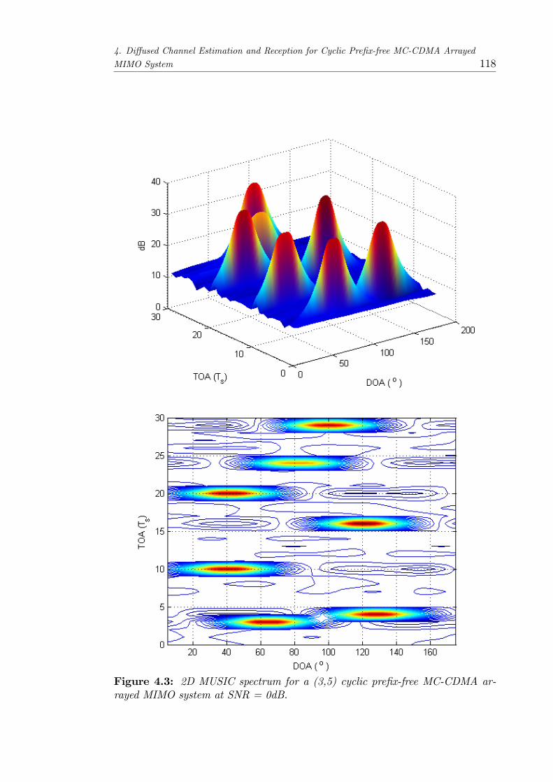
4. Di¤used Channel Estimation and Reception for Cyclic Pre�x-free MC-CDMA Arrayed
MIMO System 118
Figure 4.3: 2D MUSIC spectrum for a (3,5) cyclic pre�x-free MC-CDMA ar-rayed MIMO system at SNR = 0dB.

4. Di¤used Channel Estimation and Reception for Cyclic Pre�x-free MC-CDMA Arrayed
MIMO System 119
Figure 4.4: Standard deviation of DOA estimates versus spatial spread of mul-tipath at input SNR of 20dB (ULA).
a uniform circular array (UCA), respectively. From the �gures, it can be observed
that the performance of the proposed estimation approach based on the di¤used
channel model is much better than methods based on the point-source channel
model (which ignores the spatial spread of the multipaths).
The performance of the proposed di¤used channel estimator is also compared
with the performance of the point-source channel model estimator at spatial
spreads of 5� and 10� for di¤erent values of SNR when a cluster is assumed
�xed at DOA of 90� and TOA of 7Ts. Figure 4.6 shows the standard deviation
results, obtained over 100 independent runs, for the case of a uniform linear array
at the receiver while Figure 4.7 shows the results for a uniform circular array. As
shown in the �gures, the proposed estimator for the di¤used channel has a better
performance than the estimator that ignores the spatial spread in the channel.
However, it can be observed that the performance of the proposed di¤used chan-

4. Di¤used Channel Estimation and Reception for Cyclic Pre�x-free MC-CDMA Arrayed
MIMO System 120
Figure 4.5: Standard deviation of DOA estimates versus spatial spread of mul-tipath at input SNR of 20dB (UCA)1.
nel estimator does not vary greatly as the SNR increases. This is due to the
interference from the other antennas at the transmitter terminal which limits the
performance of the estimator.
4.6.2 Reception using the Di¤used Channel Framework
Numerical results are now presented to observe the e¤ect of spatial di¤usion
on arrayed MC-CDMA reception and to highlight the key bene�ts of using the
proposed di¤used channel modelling and estimation approach. Once the space-
di¤used channel parameters have been estimated, the receiver weight vector can
be formulated using the estimated parameters. Two scenarios are compared: in
the �rst case the receiver ignores spatial di¤usion by using the point-source chan-
nel model, whereas in the second case, the di¤used channel model is used. The re-
1The std deviation of the DOA estimate is di¤erent from 0 at an angular spread of 0 due tonumerical errors.
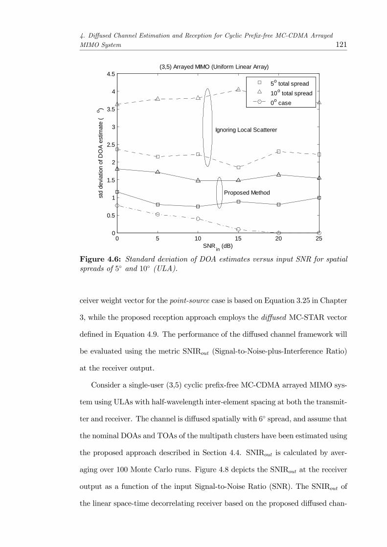
4. Di¤used Channel Estimation and Reception for Cyclic Pre�x-free MC-CDMA Arrayed
MIMO System 121
0 5 10 15 20 250
0.5
1
1.5
2
2.5
3
3.5
4
4.5
SNR in (dB)
std
devi
atio
n of
DO
A e
stim
ate
(o )
(3,5) Arrayed MIMO (Uniform Linear Array)
5o total spread10o total spread0o case
Ignoring Local Scatterer
Proposed Method
Figure 4.6: Standard deviation of DOA estimates versus input SNR for spatialspreads of 5� and 10� (ULA).
ceiver weight vector for the point-source case is based on Equation 3.25 in Chapter
3, while the proposed reception approach employs the di¤used MC-STAR vector
de�ned in Equation 4.9. The performance of the di¤used channel framework will
be evaluated using the metric SNIRout (Signal-to-Noise-plus-Interference Ratio)
at the receiver output.
Consider a single-user (3,5) cyclic pre�x-free MC-CDMA arrayed MIMO sys-
tem using ULAs with half-wavelength inter-element spacing at both the transmit-
ter and receiver. The channel is di¤used spatially with 6� spread, and assume that
the nominal DOAs and TOAs of the multipath clusters have been estimated using
the proposed approach described in Section 4.4. SNIRout is calculated by aver-
aging over 100 Monte Carlo runs. Figure 4.8 depicts the SNIRout at the receiver
output as a function of the input Signal-to-Noise Ratio (SNR). The SNIRout of
the linear space-time decorrelating receiver based on the proposed di¤used chan-

4. Di¤used Channel Estimation and Reception for Cyclic Pre�x-free MC-CDMA Arrayed
MIMO System 122
0 5 10 15 20 250
0.5
1
1.5
2
2.5
3
3.5
4
4.5
5
SNR in (dB)
std
devi
atio
n of
DO
A e
stim
ate
(o )
(3,5) Arrayed MIMO (Uniform Circular Array)
5o total spread10o total spread0o case
Ignoring Local Scatterer
Proposed Method
Figure 4.7: Standard deviation of DOA estimates versus input SNR for spatialspreads of 5� and 10� (UCA).
nel model increases linearly with input SNR. Although the channel is severely
di¤used spatially, the proposed approach models the di¤used channel accurately
to cancel the di¤used channel interference and yield good performance. However,
the decorrelating receiver based on point-source channel model starts to devi-
ate from a linear trend at a relatively low input SNR of around 15 dB, due to
uncanceled di¤used channel interference.
The impact of varying degrees of spatial di¤usion on the SNIRout performance
of MC-CDMA arrayed MIMO reception is now considered. Assuming an input
SNR of 20dB, the spatial spread is varied from 0� to 10� and the SNIRout is
observed at the receiver output, as shown in Figure 4.9. It can be seen that
reception based on the di¤used STAR framework is robust to any changes in
the spatial spread. Point-source channel model does not take into account the
spatial di¤usion of the multipath clusters, and hence fails to model the wireless

4. Di¤used Channel Estimation and Reception for Cyclic Pre�x-free MC-CDMA Arrayed
MIMO System 123
Figure 4.8: SNIRout versus input SNR plots for decorrelating reception based ondi¤used STAR and point-source STAR in a channel with 6� spatial di¤usion.
channel accurately. Therefore, reception based on the point-source STAR shows
degradation with increasing spatial spread. On the other hand, the di¤used
channel model considers the spatial di¤usion of the multipath clusters and gives
better SNIRout performance.
Finally, the near-far performance of the proposed di¤used STAR based recep-
tion is studied by considering the uplink of a multiple access MC-CDMA arrayed
MIMO system, with 3 co-channel arrayed users communicating with a receiver ar-
ray. The transmitters are each equipped with 3-element ULAs, while the receiver
ULA contains 5 antenna elements. An input SNR of 20dB and spatial di¤u-
sion with 6� spread is assumed. Figure 4.10 shows the variation of the SNIRout
as the signal power of the interfering arrayed users increases exponentially. It
can be observed the power imbalance causes the decorrelating receiver SNIRout
to depreciate. However, di¤used STAR-based reception comprehensively outper-
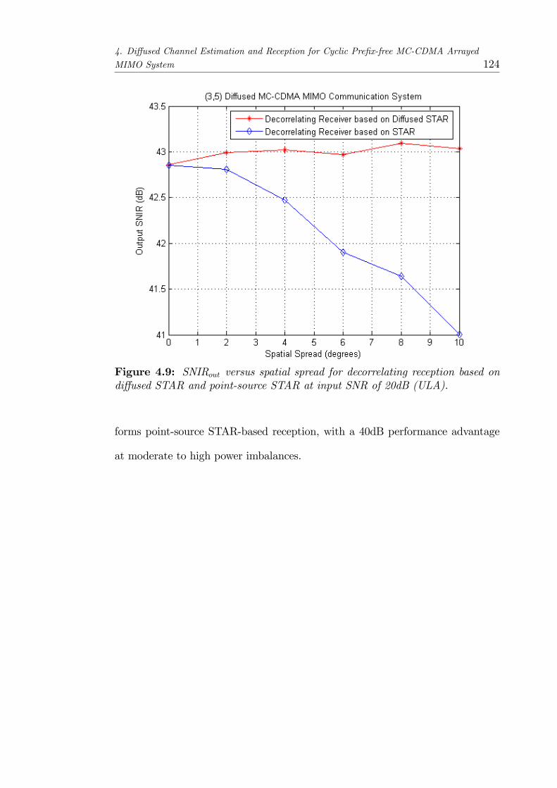
4. Di¤used Channel Estimation and Reception for Cyclic Pre�x-free MC-CDMA Arrayed
MIMO System 124
Figure 4.9: SNIRout versus spatial spread for decorrelating reception based ondi¤used STAR and point-source STAR at input SNR of 20dB (ULA).
forms point-source STAR-based reception, with a 40dB performance advantage
at moderate to high power imbalances.
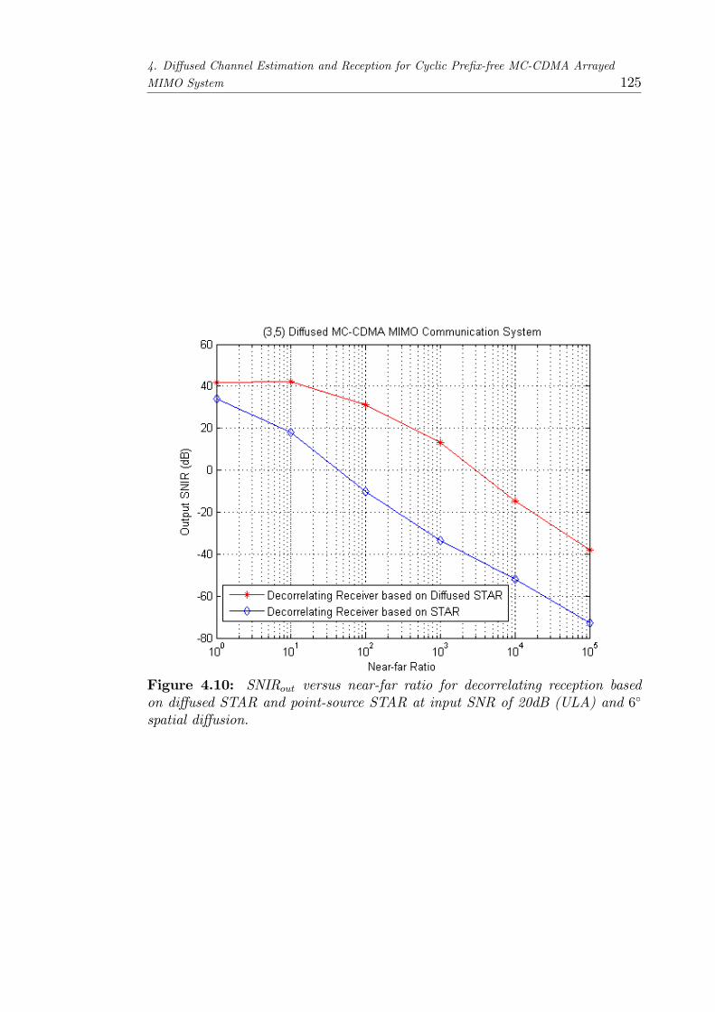
4. Di¤used Channel Estimation and Reception for Cyclic Pre�x-free MC-CDMA Arrayed
MIMO System 125
Figure 4.10: SNIRout versus near-far ratio for decorrelating reception basedon di¤used STAR and point-source STAR at input SNR of 20dB (ULA) and 6�
spatial di¤usion.

4. Di¤used Channel Estimation and Reception for Cyclic Pre�x-free MC-CDMA Arrayed
MIMO System 126
4.7 Summary
In this chapter, a di¤used channel framework for a cyclic pre�x-free MC-CDMA
arrayed MIMO communication system is presented. Localized scattering is as-
sumed to occur for each multipath; hence the wireless channel is modeled as a
spatially di¤used vector channel. Thus, the point source MC-STAR manifold
vector is extended to the di¤used MC-STAR manifold vector so that the e¤ects
of the spatially di¤used vector channel can be accurately modeled. A robust
blind estimation method is presented to estimate the parameters of the spatially
di¤used channel, followed by reception based on these parameters.
The proposed subspace-based channel estimation algorithm jointly estimates
DOAs, TOAs and spread angles of spatially di¤used multipaths of a user in a
cyclic pre�x-free MC-CDMA arrayed MIMO system. This is achieved by making
use of the structure of the di¤used channel. Moreover, it is shown that the
proposed channel estimation method has better performance than an estimator
which ignores the localized scattering in the channel. However, the performance
of the proposed method is limited by the interference resulting from the other
antennas at the transmitter terminal.
Point-source reception that ignores the presence of spatial di¤usion is also
compared to reception based on the di¤used channel model. A linear space-time
decorrelating receiver is proposed and reception based on the proposed di¤used
channel approach yields better SNIRout performance than reception that ignores
the presence of spatial di¤usion.

Chapter 5
Joint Beamforming in Downlink
Cyclic Pre�x-free MC-CDMA
Arrayed MIMO System
The work in this chapter extends the single user cyclic pre�x-free MC-CDMA ar-
rayed MIMO system (i.e. a point-to-point communication system) to a multi-user
system and focuses on the downlink of a cyclic pre�x-free MC-CDMA arrayed
MIMO communications system where the base station transmits simultaneously
to multiple users. Due to the interference present in such a system, joint opti-
mization of the transmitter and receiver beamforming weights is used to improve
the performance of the system. The joint optimization of the transmitter and re-
ceiver weights allows the transmitter pre-coding and receiver decoding weights to
be optimized for the system conditions, thus enabling a higher data throughput
for the system. Thus, it o¤ers an advantage over transmitter-only, or receiver-
only beamforming. Moreover, the computational burden can be distributed over
both ends of the transmission link.
An iterative joint optimization algorithm, which seeks to minimize the overall
MSE of the multi-user system, is thus developed in this chapter. In contrast127

5. Joint Beamforming in Downlink Cyclic Pre�x-free MC-CDMA Arrayed MIMO System 128
to previous joint optimization algorithms that have been developed for MIMO
systems, the proposed algorithm takes into consideration the geometry of the
antenna array. Thus, the inherent space-time structure of the multipath and
multiple access channels can be exploited more e¤ectively with the added infor-
mation provided by the array manifold vector. Moreover, instead of a subcarrier-
noncooperative approach, a subcarrier-cooperative approach is taken here. This
implies that the subcarriers are not required to be orthogonal. Thus, there can
be a �exibility in the allocation of channel symbols among the subcarriers and
transmitter antennas to overcome channel fading e¤ects.
Due to the multi-carrier nature of the system, the proposed algorithm also
seeks to reduce the probability of clipping of the transmitted signals from each
antenna. This is achieved by making use of the relation between the probability
of clipping and the average transmit signal power of each antenna. The joint op-
timization of the precoding and equalization matrices is thus performed with the
goal of minimizing the overall MSE of the system, subject to a power constraint
of the transmitter power of each antenna element.
5.1 Introductory Background
In the downlink of a multi-user MIMO system, a base station communicates
to multiple users simultaneously, i.e. a point-to-multi-point system. This re-
sults in interference among the users. A method to improve the performance of
each receiver is through the implementation of multi-user detection (MUD) tech-
niques [75] at each receiver to improve the performance of the detection process.
However, such techniques are computationally intensive and they are thus not
suited for implementation in the receivers where computational power is limited.
Thus, instead of the implementation of MUD techniques at each of the re-
5. Joint Beamforming in Downlink Cyclic Pre�x-free MC-CDMA Arrayed MIMO System 129
ceivers, the interference between users can be reduced through the use of transmit
precoding when channel information is available at the transmitter. The chan-
nel information can be obtained in a number of ways. For instance, the channel
reciprocity of time division duplex (TDD) systems can be used to obtain the
channel information from the channel information estimated during the uplink.
Alternatively, the channel information can be fed back from the receivers to the
transmitter through a feedback channel. The use of a feedback channel implies
that system overheads are increased albeit with a potential improvement in sys-
tem performance. Transmit precoding (or beamforming) has the advantage of
transferring the computational load from the receivers to the base station which
is better equipped to perform computationally intensive algorithms. Thus, the re-
ceivers can then be simpli�ed and make use of simple detection techniques. This
leads to a reduction in power consumption in the receivers.
A nonlinear approach to transmit precoding can be found in the form of dirty
paper coding (DPC) developed by Costa [76] which was shown to achieve capacity
for the multi-user MIMO system in [77]. In such a method, the transmitter, being
pre-equipped with the knowledge of the interference in a channel, designs a code to
pre-compensate for the interference. However, DPC-based methods make use of
unconventional coding techniques such as non-linear coding and high-dimensional
lattices which leads to increased complexity at both the transmitter and receivers.
As such, linear transmit beamforming is a more attractive option.
Transmit precoding (or beamforming) has been studied extensively for multi-
user MIMO systems. One common approach is through the use of zero-forcing
(ZF) criteria in the design of the precoding matrix. Such methods have been
separately proposed in [78] by Spencer et al and in [79] by Choi and Murch. The
objective of ZF precoding is to null the interference that is present at each re-
ceiver. This is thus equivalent to block diagonalization (BD) which decomposes
5. Joint Beamforming in Downlink Cyclic Pre�x-free MC-CDMA Arrayed MIMO System 130
a multi-user MIMO downlink channel into multiple parallel independent single-
user MIMO downlink channels. However, ZF-based precoding is limited by the
restriction that the number of transmit antennas must be larger than the sum
of receive antennas. This condition is required in order to provide the necessary
degrees of freedom to ensure that the interference is nulled at each receiver and
also results in a limit to the number of users that can be supported simultane-
ously. In order to overcome the restriction on the number of transmit and receive
antennas in such ZF-based precoding schemes, Tarighat et al [80] propose to min-
imize the interference instead of nulling it and the proposed algorithm determines
the transmit beamforming vectors by solving a generalized eigendecomposition
problem. Alternatively, as proposed by Yoo and Goldsmith in [81], the users can
be separated into di¤erent groups so that the restriction on the number of an-
tennas is met by each group and these groups are further separated by assigned
time slots. The application of transmit beamforming has also been explored in
the downlink of MC-CDMA systems. For instance, in [82], Sälzer and Mottier
show that the application of transmit beamforming to separate the users in space
for the downlink of a multi-user MISO MC-CDMA system combined with simple
detection in the receivers resulted in a superior performance when compared with
conventional systems using MUD. A subcarrier-noncooperative approach, in which
beamforming is performed on each subcarrier separately, is used in the method
proposed by Sälzer and Mottier.
In order to further improve the system performance, joint optimization of the
transmitter and receiver weights is a further development that is explored. The
joint optimization of the transmitter and receiver weights allows the transmitter
pre-coding and receiver decoding weights to be optimized for the system condi-
tions, thus enabling a higher data throughput for the system. The optimization
problem for single user MIMO systems has been investigated in [83,84,85]. In [83],
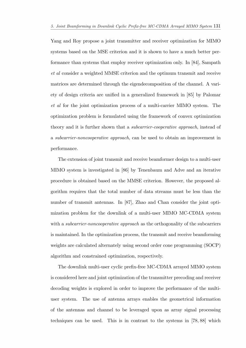
5. Joint Beamforming in Downlink Cyclic Pre�x-free MC-CDMA Arrayed MIMO System 131
Yang and Roy propose a joint transmitter and receiver optimization for MIMO
systems based on the MSE criterion and it is shown to have a much better per-
formance than systems that employ receiver optimization only. In [84], Sampath
et al consider a weighted MMSE criterion and the optimum transmit and receive
matrices are determined through the eigendecomposition of the channel. A vari-
ety of design criteria are uni�ed in a generalized framework in [85] by Palomar
et al for the joint optimization process of a multi-carrier MIMO system. The
optimization problem is formulated using the framework of convex optimization
theory and it is further shown that a subcarrier-cooperative approach, instead of
a subcarrier-noncooperative approach, can be used to obtain an improvement in
performance.
The extension of joint transmit and receive beamformer design to a multi-user
MIMO system is investigated in [86] by Tenenbaum and Adve and an iterative
procedure is obtained based on the MMSE criterion. However, the proposed al-
gorithm requires that the total number of data streams must be less than the
number of transmit antennas. In [87], Zhao and Chan consider the joint opti-
mization problem for the downlink of a multi-user MIMO MC-CDMA system
with a subcarrier-noncooperative approach as the orthogonality of the subcarriers
is maintained. In the optimization process, the transmit and receive beamforming
weights are calculated alternately using second order cone programming (SOCP)
algorithm and constrained optimization, respectively.
The downlink multi-user cyclic pre�x-free MC-CDMA arrayed MIMO system
is considered here and joint optimization of the transmitter precoding and receiver
decoding weights is explored in order to improve the performance of the multi-
user system. The use of antenna arrays enables the geometrical information
of the antennas and channel to be leveraged upon as array signal processing
techniques can be used. This is in contrast to the systems in [78, 88] which

5. Joint Beamforming in Downlink Cyclic Pre�x-free MC-CDMA Arrayed MIMO System 132
ignore the antenna array geometry. The precoding and decoding matrices are
designed to minimize the overall mean-squared-error (MSE) of the system subject
to a transmit power constraint. In addition, for multi-carrier based systems, the
peak-to-average power ratio (PAPR) is an important area of concern as the peak
transmit power, often limited by regulatory or application restrictions [89], would
have to be clipped when the threshold is exceeded. The PAPR, and hence average
transmit power, of multi-carrier signals is closely related to the probability of
clipping [90, 91]. Furthermore, it has been shown in [85] that the probability of
clipping of an OFDM signal can be reduced through the imposition of a constraint
on the transmitted power. Thus, the optimization process also seeks to reduce the
probability of clipping of the transmitted signals from each antenna by making
use of the relation between the probability of clipping and the average transmit
signal power of each antenna.
5.2 Downlink Cyclic Pre�x-freeMC-CDMAAr-
rayed MIMO Transmitter
An overview of the downlink of a multi-user MIMO system is shown in Figure 5.1
where, for illustration, 3 users are depicted and the base station is simultaneously
transmitting to the group of users. It can be observed that each user is a¤ected by
co-channel interference due to the transmitted signals for the other users. Joint
optimization of the transmitter and receiver weights is thus required to minimize
this inter-user interference.
The system architecture of a downlink cyclic pre�x-free MC-CDMA arrayed
MIMO system is shown in Figure 2.13. As shown in Figure 2.13, the base station
is equipped with an antenna array of N elements, while each receiver terminal
has an N element antenna array. In the base station, MC-CDMA modulation
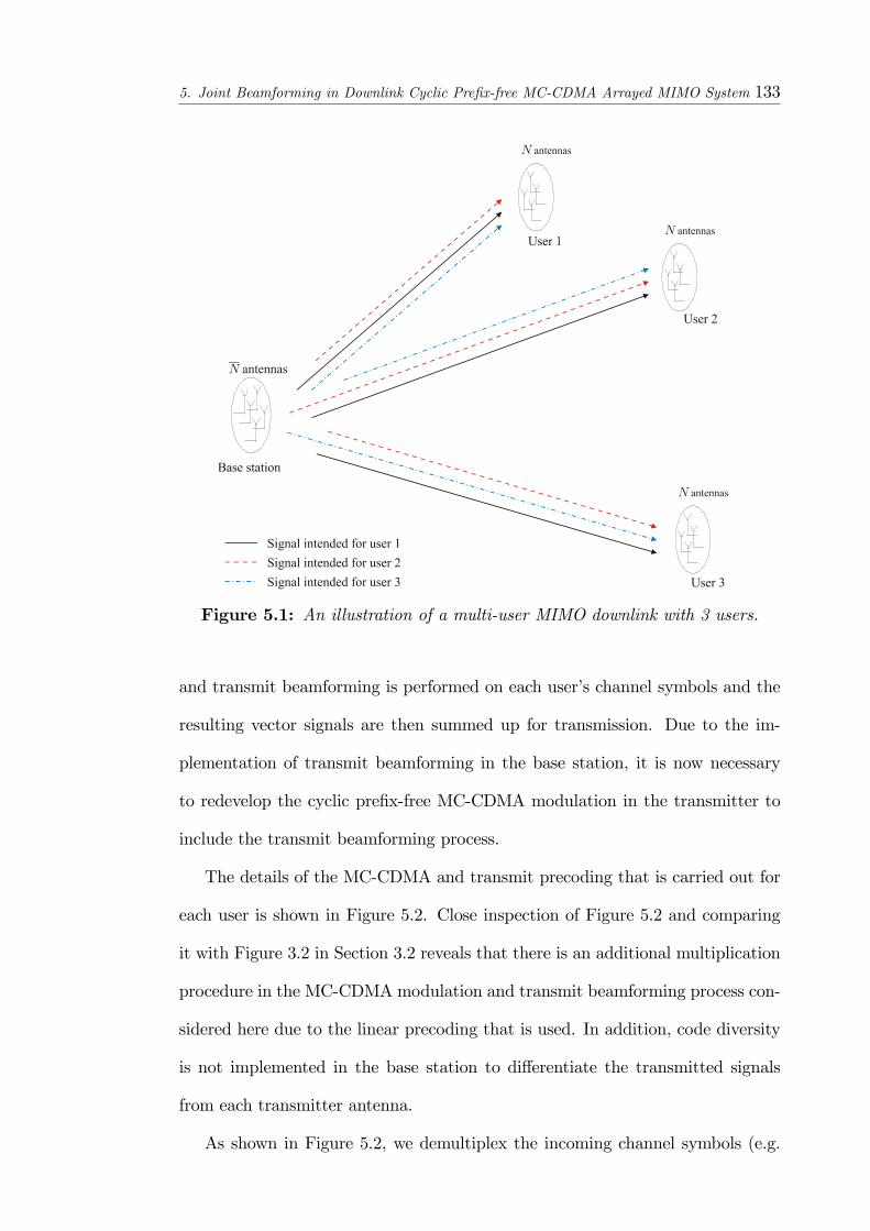
5. Joint Beamforming in Downlink Cyclic Pre�x-free MC-CDMA Arrayed MIMO System 133
Figure 5.1: An illustration of a multi-user MIMO downlink with 3 users.
and transmit beamforming is performed on each user�s channel symbols and the
resulting vector signals are then summed up for transmission. Due to the im-
plementation of transmit beamforming in the base station, it is now necessary
to redevelop the cyclic pre�x-free MC-CDMA modulation in the transmitter to
include the transmit beamforming process.
The details of the MC-CDMA and transmit precoding that is carried out for
each user is shown in Figure 5.2. Close inspection of Figure 5.2 and comparing
it with Figure 3.2 in Section 3.2 reveals that there is an additional multiplication
procedure in the MC-CDMA modulation and transmit beamforming process con-
sidered here due to the linear precoding that is used. In addition, code diversity
is not implemented in the base station to di¤erentiate the transmitted signals
from each transmitter antenna.
As shown in Figure 5.2, we demultiplex the incoming channel symbols (e.g.
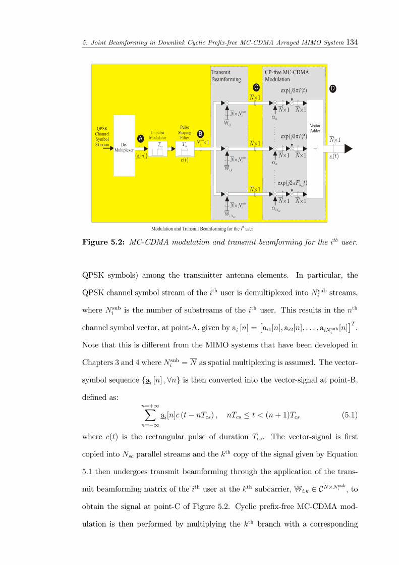
5. Joint Beamforming in Downlink Cyclic Pre�x-free MC-CDMA Arrayed MIMO System 134
Figure 5.2: MC-CDMA modulation and transmit beamforming for the ith user.
QPSK symbols) among the transmitter antenna elements. In particular, the
QPSK channel symbol stream of the ith user is demultiplexed into N subi streams,
where N subi is the number of substreams of the ith user. This results in the nth
channel symbol vector, at point-A, given by ai [n] =�ai1[n]; ai2[n]; : : : ; aiNsub
i[n]�T.
Note that this is di¤erent from the MIMO systems that have been developed in
Chapters 3 and 4 whereN subi = N as spatial multiplexing is assumed. The vector-
symbol sequence fai [n] ;8ng is then converted into the vector-signal at point-B,
de�ned as:n=+1Xn=�1
ai[n]c (t� nTcs) ; nTcs � t < (n+ 1)Tcs (5.1)
where c(t) is the rectangular pulse of duration Tcs. The vector-signal is �rst
copied into Nsc parallel streams and the kth copy of the signal given by Equation
5.1 then undergoes transmit beamforming through the application of the trans-
mit beamforming matrix of the ith user at the kth subcarrier, Wi;k 2 CN�Nsubi , to
obtain the signal at point-C of Figure 5.2. Cyclic pre�x-free MC-CDMA mod-
ulation is then performed by multiplying the kth branch with a corresponding
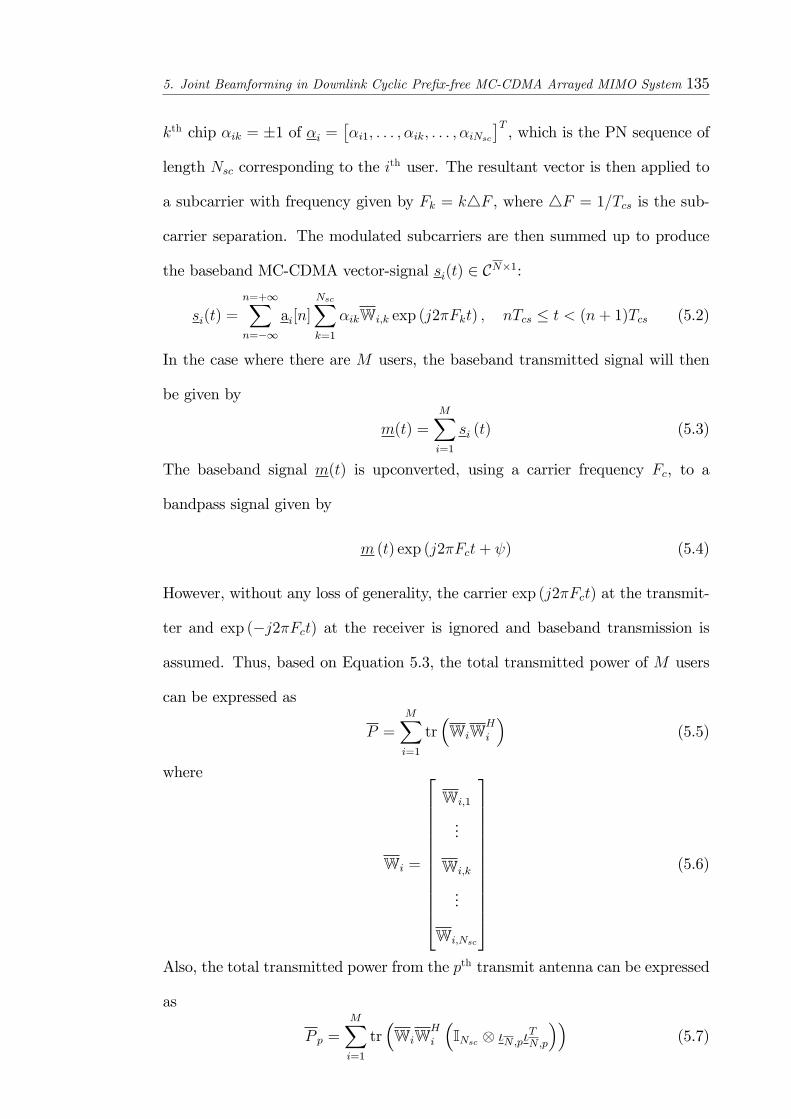
5. Joint Beamforming in Downlink Cyclic Pre�x-free MC-CDMA Arrayed MIMO System 135
kth chip �ik = �1 of �i =��i1; : : : ; �ik; : : : ; �iNsc
�T, which is the PN sequence of
length Nsc corresponding to the ith user. The resultant vector is then applied to
a subcarrier with frequency given by Fk = k4F , where 4F = 1=Tcs is the sub-
carrier separation. The modulated subcarriers are then summed up to produce
the baseband MC-CDMA vector-signal si(t) 2 CN�1:
si(t) =n=+1Xn=�1
ai[n]NscXk=1
�ikWi;k exp (j2�Fkt) ; nTcs � t < (n+ 1)Tcs (5.2)
In the case where there are M users, the baseband transmitted signal will then
be given by
m(t) =
MXi=1
si (t) (5.3)
The baseband signal m(t) is upconverted, using a carrier frequency Fc, to a
bandpass signal given by
m (t) exp (j2�Fct+ ) (5.4)
However, without any loss of generality, the carrier exp (j2�Fct) at the transmit-
ter and exp (�j2�Fct) at the receiver is ignored and baseband transmission is
assumed. Thus, based on Equation 5.3, the total transmitted power of M users
can be expressed as
P =
MXi=1
tr�WiW
H
i
�(5.5)
where
Wi =
26666666666664
Wi;1
...
Wi;k
...
Wi;Nsc
37777777777775(5.6)
Also, the total transmitted power from the pth transmit antenna can be expressed
as
P p =MXi=1
tr�WiW
H
i
�INsc �N;p�
TN;p
��(5.7)
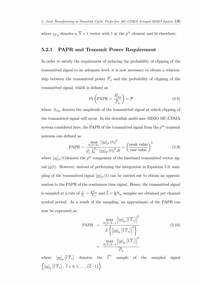
5. Joint Beamforming in Downlink Cyclic Pre�x-free MC-CDMA Arrayed MIMO System 136
where �N;p denotes a N � 1 vector with 1 at the pth element and 0s elsewhere.
5.2.1 PAPR and Transmit Power Requirement
In order to satisfy the requirement of reducing the probability of clipping of the
transmitted signal to an adequate level, it is now necessary to obtain a relation-
ship between the transmitted power P p and the probability of clipping of the
transmitted signal, which is de�ned as
Pr
�PAPR >
A2clip
P p
�= P (5.8)
where Aclip denotes the amplitude of the transmitted signal at which clipping of
the transmitted signal will occur. In the downlink multi-user MIMO MC-CDMA
system considered here, the PAPR of the transmitted signal from the pth transmit
antenna can de�ned as
PAPR =max0�t<Tcs
j[m]P (t)j2
1Tcs
R Tcs0j[m]P (t)j
2 dt=
�peak valuerms value
�2(5.9)
where [m]P (t)denotes the pth component of the baseband transmitted vector sig-
nal m(t). However, instead of performing the integration in Equation 5.9, sam-
pling of the transmitted signal [m]P (t) can be carried out to obtain an approxi-
mation to the PAPR of the continuous time signal. Hence, the transmitted signal
is sampled at a rate of 1T s= qNsc
Tcsand L = qNsc samples are obtained per channel
symbol period. As a result of the sampling, an approximate of the PAPR can
now be expressed as:
PAPR =
max0�`<L�1
���[m]p �` T s����2E����[m]p �` T s����2� (5.10)
=
max0�`<L�1
���[m]p �` T s����2P p
where [m]p�` T s
�denotes the `
thsample of the sampled signaln
[m]p�` T s
�; ` 2 0; 1; : : : ;
�L�1
�o.
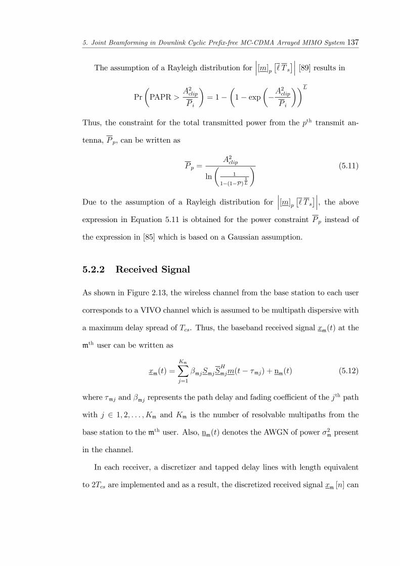
5. Joint Beamforming in Downlink Cyclic Pre�x-free MC-CDMA Arrayed MIMO System 137
The assumption of a Rayleigh distribution for���[m]p �` T s���� [89] results in
Pr
�PAPR >
A2clip
P i
�= 1�
�1� exp
��A2clip
P i
��LThus, the constraint for the total transmitted power from the pth transmit an-
tenna, P p, can be written as
P p =A2clip
ln
�1
1�(1�P)1L
� (5.11)
Due to the assumption of a Rayleigh distribution for���[m]p �` T s����, the above
expression in Equation 5.11 is obtained for the power constraint P p instead of
the expression in [85] which is based on a Gaussian assumption.
5.2.2 Received Signal
As shown in Figure 2.13, the wireless channel from the base station to each user
corresponds to a VIVO channel which is assumed to be multipath dispersive with
a maximum delay spread of Tcs. Thus, the baseband received signal xm(t) at the
mth user can be written as
xm(t) =
KmXj=1
�mjSmjSH
mjm(t� �mj) + nm(t) (5.12)
where �mj and �mj represents the path delay and fading coe¢ cient of the jth path
with j 2 1; 2; : : : ; Km and Km is the number of resolvable multipaths from the
base station to the mth user. Also, nm(t) denotes the AWGN of power �2m present
in the channel.
In each receiver, a discretizer and tapped delay lines with length equivalent
to 2Tcs are implemented and as a result, the discretized received signal xm [n] can

5. Joint Beamforming in Downlink Cyclic Pre�x-free MC-CDMA Arrayed MIMO System 138
be expressed as
xm [n] =
MXi=1
KmXj=1
NscXk=1
�mjSmj 0BBBBBBBBBBBBBBBB@
�ik�JT�Nsc J`mj
264fk [`mj]0Nsc
375SHmj �Wi;kai [n� 1]�
+�ikJ`mj
264fk [`mj]0Nsc
375SHmj �Wi;kai [n]�
+�ik (J)Nsc J`mj
264fk [`mj]0Nsc
375SHmj �Wi;kai [n+ 1]�
1CCCCCCCCCCCCCCCCA+nm [n] (5.13)
A single path of the received signal (jth path, say) from the ith user can thus be
written as:
jth path of ith user�s contribution to xm [n]
=NscXk=1
�mjSmj
0B@�ikJ`mj264 fk [`mj]
0Nsc
375SHmj �Wi;kai [n]�1CA
= �mjSmj
0B@J`mj264 F`mj diag (�i)
ONsc�Nsc
3751CA�INsc S
H
mj
�Wiai [n]
= �mjHm;ijWiai [n] (5.14)
where for the sake of clarity, only the current channel symbol vector ai [n] is
considered and
Hm;ij = Smj
0B@J`mj264 F`mj diag (�i)
ONsc�Nsc
3751CA�INsc S
H
mj
�(5.15)
denotes the MC-STAR manifold matrix for the jth path of ith user, as observed at
the mth user, while F`mj =�f1 [`mj] ; : : : ; fk [`mj] ; : : : ; fNsc [`mj]
�. Hm;ij is a function
of the receive and transmit array manifold vectors, Smj and Smj, respectively,
and the path delay `mj for the jth path as observed at the mth user as well as

5. Joint Beamforming in Downlink Cyclic Pre�x-free MC-CDMA Arrayed MIMO System 139
the PN sequence of the ith user. Thus, Hm;ij encompasses the spatial-temporal
channel characteristics (DOA and TOA) for the received signal at the mth and
blind channel estimation algorithms such as that in Chapter 3 can be used to
obtain estimates of the spatial-temporal channel parameters andWi is as de�ned
in Equation 5.6. Thus, the received signal at the mth user can be written as
xm [n] =MXi=1
KmXj=1
�mj
0BBBBB@�JT�Nsc Hm;ijWiai [n� 1]
+Hm;ijWiai [n]
+ (J)Nsc Hm;ijWiai [n+ 1]
1CCCCCA+ nm [n]
=MXi=1
0BBBBB@Vm;i�I3 Wi
�2666664ai [n� 1]
ai [n]
ai [n+ 1]
3777775
1CCCCCA+ nm [n] (5.16)
where Vm;i =�Hprevm;i Hm;i Hnextm;i
�and Hm;i, Hprevm;i and Hnextm;i are de�ned as
Hm;i =KmXj=1
�mjHm;ij
Hprevm;i =�IN
�JT�Nsc�Hm;i ; Hnextm;i =
�IN JNsc
�Hm;i
In the mth receiver, the receive beamforming weight, WHm , is used to obtain the
soft decision variable vector, bam [n], which is given bybam [n] =WH
mxm [n] (5.17)
5.3 Joint Transmit-Receive Beamformer Opti-
mization
The joint transmit-receive optimization algorithm is now presented and in the
optimization process, it is assumed that the base station and receivers have perfect
channel knowledge. The objective of the optimization process is to determine the
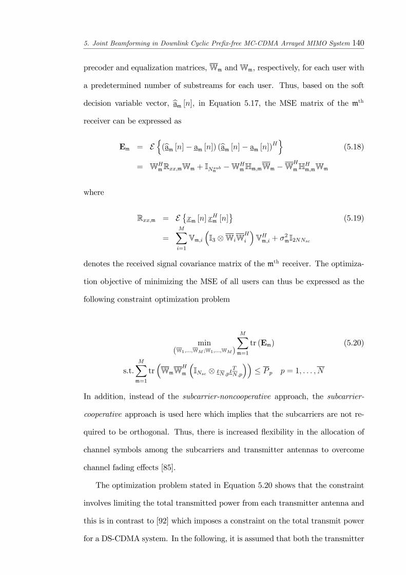
5. Joint Beamforming in Downlink Cyclic Pre�x-free MC-CDMA Arrayed MIMO System 140
precoder and equalization matrices,Wm andWm, respectively, for each user with
a predetermined number of substreams for each user. Thus, based on the soft
decision variable vector, bam [n], in Equation 5.17, the MSE matrix of the mthreceiver can be expressed as
Em = En(bam [n]� am [n]) (bam [n]� am [n])Ho (5.18)
= WHmRxx;mWm + INsub
m�WH
mHm;mWm �WH
mHHm;mWm
where
Rxx;m = E�xm [n]x
Hm [n]
(5.19)
=MXi=1
Vm;i�I3 WiW
H
i
�VHm;i + �2mI2NNsc
denotes the received signal covariance matrix of the mth receiver. The optimiza-
tion objective of minimizing the MSE of all users can thus be expressed as the
following constraint optimization problem
min(W1;:::;WM ;W1;:::;WM)
MXm=1
tr (Em) (5.20)
s.t.MXm=1
tr�WmW
H
m
�INsc �N;p�
TN;p
��� P p p = 1; : : : ; N
In addition, instead of the subcarrier-noncooperative approach, the subcarrier-
cooperative approach is used here which implies that the subcarriers are not re-
quired to be orthogonal. Thus, there is increased �exibility in the allocation of
channel symbols among the subcarriers and transmitter antennas to overcome
channel fading e¤ects [85].
The optimization problem stated in Equation 5.20 shows that the constraint
involves limiting the total transmitted power from each transmitter antenna and
this is in contrast to [92] which imposes a constraint on the total transmit power
for a DS-CDMA system. In the following, it is assumed that both the transmitter
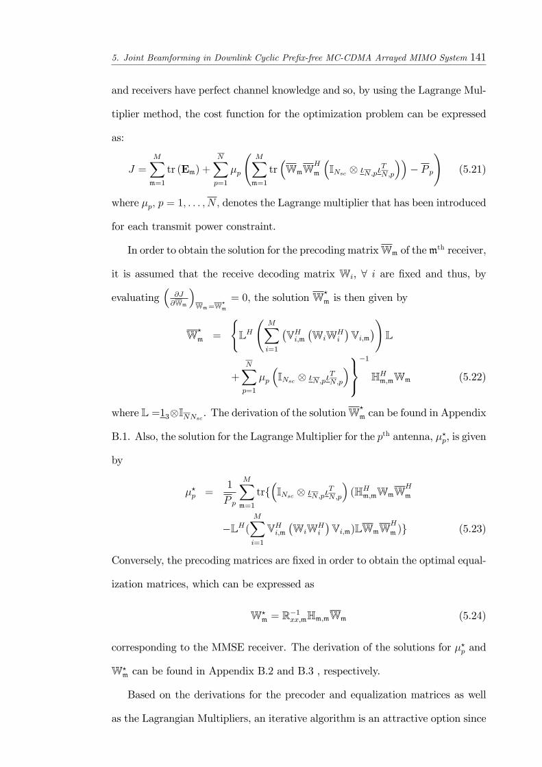
5. Joint Beamforming in Downlink Cyclic Pre�x-free MC-CDMA Arrayed MIMO System 141
and receivers have perfect channel knowledge and so, by using the Lagrange Mul-
tiplier method, the cost function for the optimization problem can be expressed
as:
J =MXm=1
tr (Em) +
NXp=1
�p
MXm=1
tr�WmW
H
m
�INsc �N;p�
TN;p
��� P p
!(5.21)
where �p; p = 1; : : : ; N; denotes the Lagrange multiplier that has been introduced
for each transmit power constraint.
In order to obtain the solution for the precoding matrixWm of themth receiver,
it is assumed that the receive decoding matrix Wi, 8 i are �xed and thus, by
evaluating�
@J@Wm
�Wm=W
?m
= 0, the solution W?
m is then given by
W?
m =
(LH
MXi=1
�VHi;m
�WiWH
i
�Vi;m
�!L
+NXp=1
�p
�INsc �N;p�
TN;p
�9=;�1
HHm;mWm (5.22)
where L =13INNsc . The derivation of the solutionW?
m can be found in Appendix
B.1. Also, the solution for the Lagrange Multiplier for the pth antenna, �?p, is given
by
�?p =1
P p
MXm=1
trf�INsc �N;p�
TN;p
�(HHm;mWmW
H
m
�LH(MXi=1
VHi;m�WiWH
i
�Vi;m)LWmW
H
m )g (5.23)
Conversely, the precoding matrices are �xed in order to obtain the optimal equal-
ization matrices, which can be expressed as
W?m = R�1xx;mHm;mWm (5.24)
corresponding to the MMSE receiver. The derivation of the solutions for �?p and
W?m can be found in Appendix B.2 and B.3 , respectively.
Based on the derivations for the precoder and equalization matrices as well
as the Lagrangian Multipliers, an iterative algorithm is an attractive option since

5. Joint Beamforming in Downlink Cyclic Pre�x-free MC-CDMA Arrayed MIMO System 142
the precoder and equalization matrices as well as the Lagrangian Multipliers are
dependent on each other. Thus, the joint optimization process can be performed
iteratively.
1. Initialization: (iterative index i = 0) the precoder matrix for each user,
Wm is �rst initialized as
W(i=0)
m =
sP
MN subm
UNsubm
m
where the columns of UNsubm
m are the general eigenvectors corresponding
to the N subm largest general eigenvectors of the matrix HHm;mHm;m. The
coe¢ cientq
PMNsub
mis required to ensure an equal distribution of power to
each user and substream.
2. The equalization matrixW(i)m is then calculated for each user m = 1; : : :M
based on Equation. 5.24
3. Using the ith precoder and equalization matrices, the Lagrangian multipli-
ers �(i)p ; p = 1; : : : N are then calculated using Equation. 5.23.
4. The equalization matrices and Lagrangian multipliers obtained in the pre-
vious 2 steps are used to update the precoder matrices W(i+1)
m by using
Equation. 5.22.
5. Replace i with i+1 and repeat Steps 2� 4 until a convergence criterion is
satis�ed.
5.4 Simulation Studies
The performance of the proposed iterative joint optimization algorithm is investi-
gated in this section. The transmitter is assumed to be equipped with an uniform
linear array (ULA) of N = 4 elements while the receivers are each equipped with
a ULA of N = 2 elements, all with half-wavelength spacing. Each user is assigned
a Gold sequence and N subi = 2 8i. It is also assumed that the transmitted signal

5. Joint Beamforming in Downlink Cyclic Pre�x-free MC-CDMA Arrayed MIMO System 143
arrives at each receiver via Ki = 4 multipaths. The DOD and DOA associated
with each path are assumed to be uniformly distributed over [0; 180�) while the
path delay is assumed to be uniformly distributed over [0; (Nsc � 1)Ts]. A block
of 250 channel symbols is collected for processing at each time, during which the
channel is assumed to be stationary and both the transmitter and receivers have
access to the channel state information.
The convergence behavior of the proposed iterative algorithm is �rst studied
for a cyclic pre�x-free MC-CDMA arrayed MIMO system with M = 6 users,
hereafter known as (6; 4; 2), i.e.�M;N;N
�cyclic pre�x-free MC-CDMA arrayed
MIMO system. The convergence behavior is investigated for di¤erent transmit
SNR values, de�ned as P�2. Figure 5.3 shows the average MSE per substream per
user as a function of the iterative process. It can be seen that the convergence
property of the proposed iterative algorithm improves with the transmit SNR.
0 5 10 15 20 25 30 35 400
0.05
0.1
0.15
0.2
0.25
0.3
0.35Convergence of the Joint Optimization Iterative Process
Aver
age
MSE
per
sub
stre
am
Iteration
Transmit SNR = 0dBTransmit SNR = 8dBTransmit SNR = 16dB
Figure 5.3: Study of convergence of the proposed algorithm with transmit SNR= 0, 8, 16dB in a (6; 4; 2) cyclic pre�x-free MC-CDMA arrayed MIMO system(Nsc = 15).
In Figure 5.4, the BER performance of the iterative joint optimization algo-

5. Joint Beamforming in Downlink Cyclic Pre�x-free MC-CDMA Arrayed MIMO System 144
rithm is compared with the transmit precoding scheme described in Step 1 of
the proposed algorithm coupled with equalization matrices based on RAKE and
MMSE receivers for a (6; 4; 2) MIMO MC-CDMA system while Figure 5.5 shows
the BER performance for a (10; 4; 2) MIMO MC-CDMA system. The precoder
and decoder matrices are obtained from 30 iterations. In Figure 5.4, and 5.5, the
e¤ect of frequency diversity is also investigated by considering the use of Gold
sequences of length 7 and 15 in the simulations. As shown in the �gures, the
iterative process results in a much better BER performance compared to the case
where the precoder and decoder matrices are not obtained jointly. This is because
of the adaptation of the precoder and decoder matrices, according to the system
conditions, during the optimization process. In addition, it has been shown that
with frequency diversity, the BER performance of the proposed iterative approach
can be improved.
The probability of clipping of the transmitted MC-CDMA signal for various
transmit SNR for a (6,4,2) cyclic pre�x-free MC-CDMA arrayed MIMO system
with Nsc = 15 is next shown in Figure 5.6. It is assumed that the transmitted
signal is oversampled by a factor of 4 so that the sampled transmitted signal can
approximate the continuous time signal. It can be seen that the iterative process
results in a lower probability of clipping of the transmitted signal compared to
the non-iterative case.
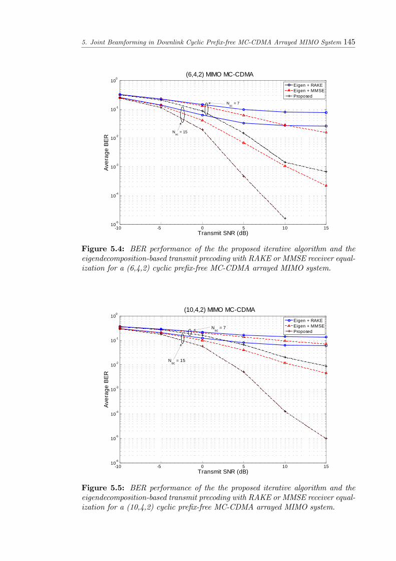
5. Joint Beamforming in Downlink Cyclic Pre�x-free MC-CDMA Arrayed MIMO System 145
10 5 0 5 10 15105
104
103
102
101
100
Transmit SNR (dB)
Aver
age
BER
(6,4,2) MIMO MCCDMAEigen + RAKEEigen + MMSEProposed
Nsc
= 7
Nsc
= 15
Figure 5.4: BER performance of the the proposed iterative algorithm and theeigendecomposition-based transmit precoding with RAKE or MMSE receiver equal-ization for a (6,4,2) cyclic pre�x-free MC-CDMA arrayed MIMO system.
10 5 0 5 10 15106
105
104
103
102
101
100
Transmit SNR (dB)
Aver
age
BER
(10,4,2) MIMO MCCDMAEigen + RAKEEigen + MMSEProposed
Nsc
= 7
Nsc
= 15
Figure 5.5: BER performance of the the proposed iterative algorithm and theeigendecomposition-based transmit precoding with RAKE or MMSE receiver equal-ization for a (10,4,2) cyclic pre�x-free MC-CDMA arrayed MIMO system.
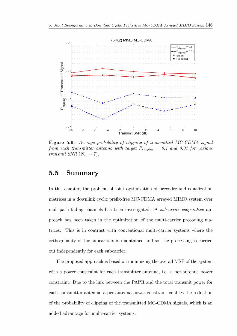
5. Joint Beamforming in Downlink Cyclic Pre�x-free MC-CDMA Arrayed MIMO System 146
10 8 6 4 2 0 2 4 6 8 10103
102
101
100
Transmit SNR (dB)
Pcl
ippi
ng o
f Tra
nsm
itted
Sig
nal
(6,4,2) MIMO MCCDMAP
clipping = 0.1
Pclipping
= 0.01
EigenProposed
Figure 5.6: Average probability of clipping of transmitted MC-CDMA signalfrom each transmitter antenna with target Pclipping = 0.1 and 0.01 for varioustransmit SNR (Nsc = 7).
5.5 Summary
In this chapter, the problem of joint optimization of precoder and equalization
matrices in a downlink cyclic pre�x-free MC-CDMA arrayed MIMO system over
multipath fading channels has been investigated. A subcarrier-cooperative ap-
proach has been taken in the optimization of the multi-carrier precoding ma-
trices. This is in contrast with conventional multi-carrier systems where the
orthogonality of the subcarriers is maintained and so, the processing is carried
out independently for each subcarrier.
The proposed approach is based on minimizing the overall MSE of the system
with a power constraint for each transmitter antenna, i.e. a per-antenna power
constraint. Due to the link between the PAPR and the total transmit power for
each transmitter antenna, a per-antenna power constraint enables the reduction
of the probability of clipping of the transmitted MC-CDMA signals, which is an
added advantage for multi-carrier systems.

5. Joint Beamforming in Downlink Cyclic Pre�x-free MC-CDMA Arrayed MIMO System 147
In the proposed algorithm, the Lagrange Multiplier method is used to obtain
solutions for the transmit and receive beamforming matrixes. The resulting solu-
tions for the transmit and receive beamforming matrices as well as the Lagrange
multipliers enables a iterative solution to be used as the equations obtained ex-
hibit an interdependence.

Chapter 6
Conclusions and Future Work
In this thesis, the application of antenna arrays in MIMO systems is investigated
with an emphasis onMC-CDMA-based systems. The combination of multi-carrier
modulation with MIMO techniques is expected to be a key feature in future 4G
systems due to the various bene�ts that are provided by each component and thus,
MIMOMC-CDMA systems form the basis for the work in this thesis. However, in
the MC-CDMAmodulation scheme considered here, cyclic pre�xes are not used so
that the system overheads can be reduced. A gradual development of the array-
based MIMO MC-CDMA systems is presented and the MIMO systems under
consideration progress from a single user system, i.e. a point-to-point system, to
a multi-user system. A summary of the work presented in the previous chapters
is now provided together with a list of contributions. In addition, suggestions on
the further development of the work that has been presented are given.
6.1 Thesis Summary
In Chapter 1, a discussion of the characteristics of MC modulation techniques is
presented. In addition, a review of MIMO signaling techniques, such as spatial
multiplexing, is provided. In order to harness the spatial information that is
148

6. Conclusions and Future Work 149
present in MIMO systems, antenna arrays, instead of multiple antenna elements,
are of interest and so, the concept of antenna array signal processing is introduced.
In Chapter 2, the concept of the array manifold vector is introduced. The ar-
ray manifold vector enables the parametric modelling of the channel parameters.
Based on the array manifold vector, space-time channel models are then intro-
duced. The various space-time channel models are de�ned based on the structure
of the input and output signals. The system architecture of the asynchronous
array-based MC-CDMA MIMO systems that are considered in this thesis are
then presented. In the receivers, a bank of TDLs is employed so as to equip the
receiver with space-time processing capabilities. The system models presented
herein provides a framework for the detailed investigations in the subsequent
chapters.
The problem of space-time reception and channel estimation for a single user
cyclic pre�x-free MC-CDMA arrayed MIMO system is then investigated in Chap-
ter 3. A subspace-based receiver is developed based on the proposed system
model. The proposed receiver seeks to null the ISI e¤ects in the received signal
and it requires the same degree of information as the RAKE receiver. The perfor-
mance of the proposed receiver is compared with the RAKE and MMSE and it is
demonstrated that the proposed receiver has a similar performance as the MMSE
receiver and is superior to the RAKE receiver. In addition, the performance of
the cyclic pre�x-free MC-CDMA arrayed MIMO system is compared with an ex-
isting MC-CDMA MIMO system (which is non-array based and makes use of
cyclic pre�xes) and the proposed cyclic pre�x-free MC-CDMA arrayed MIMO
system is shown to have a superior performance than the reference system. This
is despite the presence of ISI in the proposed system whereas as the reference
system is not susceptible to such e¤ects. Thus, system overheads are reduced
without a loss in performance.
6. Conclusions and Future Work 150
In order to obtain the estimates of the channel parameters, the channel esti-
mation algorithm is developed based on the concept of the MC-STAR manifold
vector. For a speci�c transmitter antenna whose space-time channel parameters
are to be estimated, a delay-dependent preprocessor matrix is de�ned for each
delay and the preprocessor matrix that is obtained is then used to transform the
MC-STAR manifold vectors with the same delay for the speci�c transmitter an-
tenna. The preprocessor is designed to null the MC-STARmanifold vectors which
do not have the same delay for the transmitter antenna under consideration and
these MC-STAR manifold vectors are removed from the signal subspace. At the
same time, the MC-STAR manifold vectors arising from the co-channel interfer-
ence (CCI), resulting from the remaining transmitter antenna elements, as well as
the ISI are transformed by the preprocessor matrix. However, the transformation
of the desired MC-STAR manifold vectors is di¤erent from the transformation
of the CCI and ISI MC-STAR manifold vectors. The proposed algorithm thus
exploits this property and makes use of a MUSIC-type cost function to obtain
the estimates of the space-time channel parameters for the desired transmitter
antenna. The proposed algorithm is demonstrated to be capable of identifying
greater number of coherent multipaths than the number of antenna elements.
In Chapter 4, the point-source channel model for a cyclic pre�x-free MC-
CDMA arrayed MIMO system is extended to a di¤used-source channel model
which considers the e¤ects of localized scattering. As a result, the point-source
MC-STARmanifold vector is extended to the di¤used MC-STARmanifold vector.
The di¤used MC-STAR vector manifold is obtained from a �rst order Taylor series
approximation of the array manifold vector about the nominal DOA. The di¤used
MC-STAR manifold vector that is developed enables the spatially-di¤used mul-
tipath channel characteristics to be completely captured in the received signal
model. A subspace-based channel estimation algorithm, which also makes use of
6. Conclusions and Future Work 151
the preprocessor matrix developed in Chapter 3, is then developed to obtain the
estimates of the DOA, TOA and spatial spread. The proposed algorithm is not
limited by the number of antennas and it allows the estimates of the parameters
of more multipaths than the number of antenna elements to be obtained. More-
over, it is shown that the proposed algorithm can has better performance than
an algorithm which ignores the e¤ects of local scattering in the channel.
A decorrelating receiver is then developed for the di¤used channel and it
is shown to have much better performance than a receiver which ignores the
scattering present in the channel. The superior performance of the proposed
receiver is also validated for the uplink of a multi-user cyclic pre�x-free MC-
CDMA arrayed MIMO system in which near-far e¤ects are present.
The problem of joint transmitter-receiver beamforming in the downlink of a
multi-user cyclic pre�x-free MC-CDMA arrayed MIMO system is next investi-
gated in Chapter 5. The work is based on the assumption that channel informa-
tion is available at the base station and the optimization objective is to minimize
the overall MSE of the system subject to a transmit power constraint. In addi-
tion, the link between the transmit power of each transmitter antenna and the
PAPR (and consequently, the probability of clipping of the transmitted signal) is
used to reduce the PAPR and hence, the probability of clipping, of the transmit-
ted signals from each transmit antenna. The optimization problem is solved with
the Lagrange Multiplier method and an iterative algorithm for the determination
of the transmit and receive beamforming matrices is introduced. This is a result
of the inter-dependence between the transmit and receive beamforming matrices.
It is shown that the iterative process brings about a much performance than if
the transmit and receive beamforming matrices were not optimized. In addition,
it is demonstrated that the probability of clipping of the transmitted signal is
indeed reduced by the per-antenna transmit power constraint.
6. Conclusions and Future Work 152
6.2 List Of Contributions
The list below is a summary of the main results and contributions presented in
this thesis:
� Development of a new space-time signal processing framework based on the
STAR manifold vector concept, which is a function of various parameters
such as DOA, DOD, array geometry and carrier frequency, for asynchro-
nous cyclic pre�x-free MC-CDMA arrayed MIMO systems that operate
over frequency selective channels. The MC-STAR manifold matrix, thus
developed, encompasses the spatial and temporal information of the space-
time channel for the cyclic pre�x-free MC-CDMA arrayed MIMO system.
Due to the cyclic pre�x-free nature of the considered system, the ISI e¤ects
are present in the received signal and so, such e¤ects are modeled in the
received signal so that the ISI e¤ects can be removed by the receiver for an
improved performance.
� A single-user space-time receiver is developed based on the model of the
cyclic pre�x-free MC-CDMA arrayed MIMO system that has been de-
veloped. The proposed subspace-based receiver aims to cancel the inter-
symbol interference in a MIMO system by projecting the ISI e¤ects onto
the complementary subspace and so, nulling the ISI contributions in the
received signal. The proposed receiver is shown to have comparable per-
formance as that of a MMSE receiver. In addition, the proposed cyclic
pre�x-free MC-CDMA arrayed MIMO system has been shown to have su-
perior performance compared to a conventional MC-CDMAMIMO system,
which employs cyclic pre�xes and ignores the antenna array geometry.
� A blind channel estimation algorithm is developed which provides the spa-

6. Conclusions and Future Work 153
tial and temporal parameters for each path in a multipath frequency-
selective fading channel for the transmit antenna under consideration. The
transformation is speci�ed by the PN-sequence of the desired antenna. The
signal processing is carried out in a transform domain which isolates and
transforms the MC-STAR manifold vectors with a speci�ed delay. The pro-
posed algorithm is capable of identifying a greater number of multipaths,
including co-directional paths, than the number of antenna elements. How-
ever, in the event of co-delay paths, spatial smoothing is required to resolve
the coherence between the co-delay paths. Due to the assumption of code
diversity, the channel estimation algorithm can be used for multi-user sys-
tems as well.
� Investigation of the e¤ects of local scattering in a cyclic pre�x-free MC-
CDMA arrayed MIMO system. Localized scattering is an important chan-
nel impairment in practical systems which cannot be ignored. In order
to investigate the e¤ect of a di¤used channel for a cyclic pre�x-free MC-
CDMA arrayed MIMO system, the �spatially-di¤used�STAR manifold vec-
tor, which is approximated as a function of the array manifold vector and
its �rst derivative, is introduced to represent the spatial di¤usion of the
channel.
� The channel estimation algorithm that is previously proposed for a point-
source cyclic pre�x-free MC-CDMA arrayed MIMO system is adapted for
the spatially-di¤used cyclic pre�x-free MC-CDMA arrayed MIMO system.
The algorithm jointly estimates the spread, DOA and TOA of the multi-
paths in a spatially di¤used channel.

6. Conclusions and Future Work 154
� A linear space-time decorrelating receiver is developed based on the esti-
mates of the channel parameters of the di¤used channel and it is shown to
have a better performance than a receiver which ignores the spatial di¤u-
sion of the channel. The e¤ectiveness of the receiver is also veri�ed for the
uplink of a multi-user cyclic pre�x-free MC-CDMA arrayed MIMO system
which su¤ers from near-far e¤ects.
� The joint optimization of the transmit and receive beamforming weights for
the downlink of a multi-user cyclic pre�x-free MC-CDMA arrayed MIMO
system is investigated for the purpose of improving system performance. A
Lagrange multiplier method is used to obtain a solution for the optimiza-
tion problem and subsequently, an iterative algorithm is developed.
� A subcarrier-cooperative approach is taken in the modelling of the transmit
beamforming weights. This is in contrast to the commonly used subcarrier-
noncooperative approach in which the subcarrier weights are obtained sep-
arately.
� The relationship between the transmit power of an antenna, the probability
of clipping and the peak-to-average power ratio (PAPR) is used to lower
the probability of clipping of the transmitted multi-carrier signals from each
transmit antenna. As such, per-antenna power constraint is imposed for the
joint optimization problem.

6. Conclusions and Future Work 155
6.3 Suggestions for Future Work
Time-Varying Channels
The array-based MIMO systems considered in this thesis are developed based on
the assumption that the terminals are stationary. As a result, Doppler e¤ects,
and hence time-varying channels, which arise from the mobility of the terminals
have been ignored. In future 4G systems, the mobility of the users is an important
factor in determining the achievable data rates. A system architecture which takes
the Doppler e¤ect into consideration will enable the development of a receiver that
can cope with the requirements of a time-varying channel.
Spatio-temporally Di¤used Channel
The investigation of a temporally-di¤used channel and subsequently, spatio-temporally
di¤used channels for MC-CDMA MIMO systems. In such channels, the multi-
paths appear di¤used in both space and time at the receiver and are a more ac-
curate re�ection of the practical situation. The consideration of the spatial and
temporal di¤usion of the multipaths will lead to a more robust receiver which is
capable of estimating the channel parameters associated with such channels.
Array Uncertainties
� Carrier Frequency O¤set - The presence of carrier frequency o¤set in the
system is another important phenomenon that can be investigated. In
the presence of a carrier frequency o¤set, the received signal is inaccurately
downconverted and so, the residual frequency component will translate into
a time-varying received signal. Thus, accurate estimates of the carrier fre-
quency o¤set will be required so that downconversion of the received signal
can be performed accurately.

6. Conclusions and Future Work 156
� Calibration Uncertainties - The proposed arrayed MIMO systems have as-
sumed that the antenna arrays have been properly calibrated. However,
array uncertainties, due to deviation of the true array characteristics or pa-
rameters from their nominal values, will introduce errors into the system.
Such errors, if ignored, would degrade the performance of the system either
slowly or abruptly. Thus, the design of robust receivers which are capable
of overcoming such errors in the calibration are an attractive option.
Extension of MC-CDMA to OFCDM
The MC-CDMA modulation that has been considered in this thesis restricts the
number of subcarriers to be equal to the length of the spreading sequence. Thus,
the extension of the MC-CDMA MIMO systems to Orthogonal Frequency and
Code Division Multiplexing (OFCDM) MIMO systems will result in more �exible
system due to the high scalability of OFCDM systems in possible transmission
rates. Thus, OFCDM systems can support low to high information transmission
rates my employing code, time and frequency division multiplexing. However,
the extension of the MC-CDMA system to an OFCDM system implies that the
MC-STAR manifold vector that has been introduced in this thesis will have to be
modi�ed to be applicable for an OFCDM system. In addition, two-dimensional
spreading has been proposed for OFCDM systems [93] and so, the investigation
of the integration of antenna arrays in such OFCDM systems is an area that can
be looked at.
6. Conclusions and Future Work 157
Near-�eld Communications
Plane wave propagation, due to far-�eld communications, has been assumed for
the array systems considered thus far. The consideration of near-�eld commu-
nications, which is characterized by spherical wave propagation, will introduce
additional diversity to the system. This implies that the interference cancellation
properties of the receiver can be improved by leveraging on the additional infor-
mation available. However, this means that the channel estimation problem is
made more complex due to the additional parameters that have to be estimated.
Hence, a simpli�cation of the channel estimation problem for such systems is
necessary.
Combination of Various Channel E¤ects
The vector channel estimation and reception algorithms presented in this the-
sis are designed for separate channel e¤ects. However, a combination of these
separate scenarios have yet to be investigated. For instance, the Doppler e¤ect
on di¤used sources, or the polarization e¤ect on di¤used sources, or the Doppler
e¤ect on spherical wave propagation, are some of the potential areas of research.
Thus, a channel estimator can be devised to be integrated at the front-end of the
receivers to cope with a multitude of such channel e¤ects.
However, in these cases, it is expected that the cost function for each of its
corresponding channel estimation algorithms will consequently become a multi-
dimensional problem. Hence, further simpli�cation to reduce the dimension of
the search is required. This could be achieved by some novel means of merging
either the polarization / di¤used / Doppler / spherical wave propagation para-
meters together in the eigenvector component of the cost function. A uni�ed
architectural framework that is capable of considering such composite channels
using a generalized cost function would also pose some of the challenging research

6. Conclusions and Future Work 158
problems.
Multi-Rate Systems
In 4G systems, di¤erent users are expected to have di¤erent data rate require-
ments due to the diverse multimedia applications available such as high speed
video transmissions and low rate voice communications. As such, the resultant
4G systems would have to be designed to cope with the di¤erent rates required
for the wide spectrum of services available. The design of the receiver for such a
multi-rate system gives rise to several challenges. For instance, it is di¢ cult to
exploit the interference structure for interference cancellation in such multi-rate
systems. Hence, receivers that are suitable for such multi-rate systems are of
interest. Moreover, complications arise in the channel estimation process with
such multi-rate systems. Thus, the design of blind channel estimation algorithms
may not be feasible and semi-blind channel estimation algorithms may have to
be used instead.
Joint Optimization with QoS Requirements
In addition to multi-rate systems, it is also plausible that the quality-of-service
(QoS) required by each user in a 4G system is di¤erent. Thus, the joint optimiza-
tion of the transmit and beamforming weights, which in Chapter 5 focused on
the minimization of the overall mean-squared-error (MSE) of the system, would
have to focus on satisfying the di¤erent QoS requirements of each user. In multi-
carrier modulation systems, the PAPR is also an important parameter in practical
systems. As such, the investigation of the joint optimization with di¤erent QoS
requirements, while ensuring that the PAPR is kept within an acceptable range,
is a possible research problem. Moreover, when coupled with a multi-rate system
as envisioned for 4G systems, a challenging problem arises with a multitude of

6. Conclusions and Future Work 159
issues that have to be addressed.
Appendix A
E¤ect of Multipath Channels on
MC Systems
One view of the inverse discrete Fourier transform (IDFT) is that the IDFT per-
forms a correlation of its input signal with each of the sinusoidal basis functions.
Hence, at a certain frequency where the input signal has some energy, the corre-
lation of the input signal and the basis sinusoid of the corresponding frequency
will be produce a peak. Thus, the IDFT can be used in the transmitter employ-
ing MC technique to map an input signal onto a set of orthogonal subcarriers,
i.e. the orthogonal basis functions of the IDFT. Conversely, the discrete Fourier
transform (DFT) is employed again at the MC receiver to process the received
subcarriers. The signals from the subcarriers are then combined to form an es-
timate of the source signal from the transmitter. The orthogonal nature of the
subcarriers is thus exploited in MC schemes with powerful results. As the basis
functions of the DFT are uncorrelated, the correlation performed in the DFT for
a speci�c subcarrier only produces energy for that corresponding subcarrier while
the energy from other subcarriers does not appear in the output of the correlation
process. This separation of signal energy is the reason that the spectrums of the
subcarriers spectrums in MC schemes can overlap without causing interference.
160
A. E¤ect of Multipath Channels on MC Systems 161
A discussion of the e¤ect of multipath channels on MC systems and a subsequent
discussion of the sources of non-ideal e¤ects in such systems now follows.
A major problem in most wireless systems is the presence of a multipath
channel which is due to the transmitted signal being re�ected o¤of several objects.
As a result, multiple delayed versions of the transmitted signal arrive at the
receiver. The multiple versions of the signal result in a distortion of the received
signal. This results in two problems for an MC system. The �rst problem is ISI.
This problem occurs when the received MC signal is distorted by the previously
transmitted MC symbol. The e¤ect is similar to the intersymbol interference that
occurs in a SCM system. However, in SCM systems, the interference is typically
attributed to several other symbols instead of just the previous symbol as the
symbol period in SCM systems is typically much shorter than the time span of
the channel while the typical MC symbol period is much longer than the time
span of the channel. The second problem is unique to MC systems and is known
as intrasymbol interference, which is the result of interference amongst a given
MC symbol�s own subcarriers.
A.1 Intersymbol Interference
In a MC system, by choosing an appropriate value for the number of subcarriers,
the length of the resultant MC symbol becomes longer than the time span of the
channel. Thus, because of this con�guration, the e¤ect of ISI is the distortion
of the �rst few samples, corresponding to the time span of the channel, of the
received MC symbol. As only the �rst few samples of the symbol are distorted,
a guard interval can be employed to remove the e¤ect of the ISI present. For
instance, the guard interval (GI) can be a section of all zero samples transmitted
in front of each MC symbol. Since the GI does not contain any useful information,

A. E¤ect of Multipath Channels on MC Systems 162
the GI can be discarded at the receiver. Thus, a proper choice of the GI length
such that it is longer than the time span of the channel ensured that the MC
symbol itself will not be distorted. As a result, by discarding the guard interval,
the e¤ects of ISI are removed as well.
A.2 Intrasymbol Interference (Intercarrier In-
terference)
The guard interval is not used in practical systems because it does not prevent
an MC symbol from interfering with itself. This type of interference is called
intrasymbol interference, also known as intercarrier interference (ICI). The so-
lution to the problem of ICI involves the discrete time property of signals. In
continuous time, a convolution in time is equivalent to a multiplication in the
frequency-domain. However, this property is true in discrete time only if the
signals are of in�nite length or if at least one of the signals is periodic over the
range of the convolution. As it is impractical to have a MC symbol of in�nite
length, the alternative option is to make the MC symbol appear periodic. This
periodic form is achieved by replacing the guard interval with something known
as a cyclic pre�x (CP) which is a replica of the last few samples of the MC sym-
bol. As in the case of the GI, the length of the CP must be longer than the
time span of the channel. Since it contains redundant information, the CP is
discarded at the receiver and so, the e¤ects of ISI are removed. Because of the
way in which the CP was formed, the cyclically-extended MC symbol now ap-
pears periodic when convolved with the channel. Thus, the e¤ect of the channel
becomes multiplicative.
In a digital communications system, the symbols that arrive at the receiver
have been convolved with the time-domain channel impulse response. In order

A. E¤ect of Multipath Channels on MC Systems 163
to undo the convolutional e¤ects of the channel, another convolution must be
performed at the receiver using a time-domain �lter known as an equalizer. The
equalizer processes symbols in order to adapt its response in an attempt to remove
the e¤ects of the channel and the length of the equalizer needs to be on the order
of the time span of the channel. Such an equalizer can be expensive to implement
in hardware and often requires a large number of symbols in order to adapt its
response for a good performance.
In MC systems, the time-domain signal is still convolved with the chan-
nel response. However, the data will ultimately be transformed back into the
frequency-domain by the DFT in the receiver. Because of the periodic nature of
the cyclically-extended OFDM symbol, this time-domain convolution results in
the multiplication of the spectrum of the MC signal with the frequency response
of the channel. The result is that the symbol at each subcarrier will be multiplied
by a complex number equal to the channel�s frequency response at that subcar-
rier�s frequency. Thus, each received subcarrier experiences a complex gain due
to the channel. A frequency-domain equalizer is thus employed to undo these ef-
fects. The frequency-domain equalizer consists of a single complex multiplication
for each subcarrier and is much simpler than a time-domain equalizer.
A.3 Non-ideal e¤ects in MC systems
A brief discussion of the causes of non-ideal e¤ects in an MC system is now
presented and a detailed examination of the issues listed here can be obtained
from [94, 95]. Due to the relation between multi-carrier modulation and Fourier
transforms, the result of these e¤ects are explained using Fourier transform theory.
A. E¤ect of Multipath Channels on MC Systems 164
A.3.1 Carrier Frequency and Phase O¤sets
In practical systems, the local oscillator (LO) frequency at the receiver is typically
di¤erent from the LO frequency at the transmitter. This results in a carrier
frequency o¤set. A carrier tracking loop can be used to adjust the receiver�s
LO frequency in order to match the transmitter�s LO frequency as closely as
possible so that the carrier frequency o¤set (CFO) can be reduced as much as
possible. An intuitive understanding of the e¤ect of a CFO can be explained
by Fourier Transform theory. The CFO can be expressed mathematically by
multiplying the received time-domain signal by a complex exponential whose
frequency is equal to the amount of the carrier frequency o¤set. Thus, the CFO
is equivalent to a frequency shift in the received signal spectrum. This results in a
loss of orthogonality of the subcarriers as the subcarriers are no longer orthogonal
and the bins of the IDFT will no longer line up with the peaks of the received
signal�s pulses. The result is a distortion called inter-bin interference. Inter-bin
interference occurs when energy from one bin spills over into adjacent bins and
this energy distorts the a¤ected subcarriers.
This e¤ect is referred to as DFT leakage in Fourier Transform theory. This
o¤set results in a loss of orthogonality, and the zero-crossings of the non-zero
subcarrier�s spectrum no longer line up with the FFT bins. In a practical system
where almost all of the subcarriers would be actively used for transmitting data,
a given subcarrier would experience inter-bin interference due to energy from all
of the other active subcarriers in the system. Based on the central limit theorem,
which states that the sum of a large number of random processes will result in a
signal that has a Gaussian distribution, the inter-bin interference can be viewed
as additive Gaussian noise which lowers the e¤ective SNR of the system. The
e¤ect of a carrier frequency o¤set can be corrected by multiplying the signal by a
correction factor which would be a sinusoid with a frequency that is ideally equal

A. E¤ect of Multipath Channels on MC Systems 165
to the amount of the carrier frequency o¤set. Various carrier tracking algorithms
exist that can adaptively determine the frequency that will correct for the o¤set.
Besides a LO frequency o¤set, it is also possible to have an LO phase o¤set,
separate from an LO frequency o¤set. The two o¤sets can occur together or either
one can be present by itself. As the name implies, an LO phase o¤set occurs when
there is a di¤erence between the phase of the LO output and the phase of the
received signal. This e¤ect can be represented mathematically by multiplying
the time-domain signal by a complex exponential with a constant phase. This
results in a constant phase rotation for all of the subcarriers in the frequency
domain. Thus, the constellation points for each subcarrier experience the same
degree of rotation. This can be corrected by the frequency-domain equalizer if
the phase rotation is small as long as the rotation does not lead to a rotation of
the constellation points beyond the symbol decision regions. In the case of large
phase rotations, a carrier tracking loop can be used to correct such e¤ects.
A.3.2 FFT Window Location O¤set
Another non-ideal e¤ect that can occur in practical MC systems is an FFT win-
dow location o¤set. In practical MC systems, a correlation operation is often
performed with a known preamble sequence located at the beginning of the trans-
mission. This correlation operation enables the synchronization of the receiver
with the received MC symbol boundaries. However, the synchronization process
is usually not perfect and so, inaccuracies in the synchronization process still re-
main, and such errors appear as an o¤set in the FFT window location. The result
is that the samples sent to the FFT will not line up exactly with the corresponding
MC symbol.
The implication of a large o¤set is that part of the samples will be from one
MC symbol, while the rest of the samples will be from another MC symbol. This

A. E¤ect of Multipath Channels on MC Systems 166
results in a severe distortion of the received subcarrier�s constellations. However, a
robust synchronization algorithm can be used to prevent such large o¤sets and an
FFT window location o¤set of just a few samples will occur. The presence of the
cyclic pre�x in MC systems enables a small o¤set to be present without taking
samples from more than one MC symbol. However, even an o¤set of just one
sample will create some degree of distortion. From Fourier transform theory, the
o¤set can be viewed as a shift in time. Thus, when the FFT window location o¤set
does not go beyond a MC symbol boundary, this shift in time is equivalent to a
linearly increasing phase rotation in the frequency-domain constellations. Thus,
constellations on subcarriers corresponding to low frequencies will be rotated
slightly, whereas constellations on higher-frequency subcarriers will experience a
larger rotation. The correction of FFT window location o¤sets is often carried
out by performing a time-domain correlation with a known training sequence
embedded in the transmitted signal and the location of the peak of the correlation
allows the receiver to synchronize itself with the incoming signal.
A.3.3 Phase noise
During the frequency conversion stage, noise can also be added to the signal as the
local oscillator used in the converter will inherently have some phase noise which
is due to an uncertainty in the actual frequency or phase of the signal. This phase
noise will be transferred to the desired signal. Phase noise is usually shaped and
is primarily concentrated near the carrier frequency of the signal. A MC signal
set contains multiple subcarriers, each of which is a smaller percentage of the
total frequency bandwidth than in a single carrier system. Hence, phase noise
occupies a smaller percentage of the bandwidth in a SCM system. Thus, phase
noise causes a larger degradation in the performance of a MC system more than in
a single carrier system. Phase noise e¤ects in a MC system can be separated into
A. E¤ect of Multipath Channels on MC Systems 167
two categories: phase noise maintained within one subcarrier spacing and phase
noise that extends across subcarrier spacings. Phase noise within one subcarrier
spacing essentially has a similar but scaled e¤ect as for the single carrier system.
On the other hand, phase noise that extends across subcarrier spacings results in
demodulation errors. Pilot subcarriers are often used to overcome handle phase
noise in MC systems and these pilot subcarriers are generated by the IFFT and
can be used to provide a stable phase reference for the receiver circuitry. However,
the use of pilot subcarriers lowers the achievable data rate of the system because
these subcarriers are no longer available to transmit data.
A.3.4 Sampling frequency o¤set
A sampling frequency o¤set occurs when the analog-to-digital converter output is
sampled either too fast or too slow. When sampling is performed at a frequency
higher than the Nyquist frequency, a contracted spectrum results. Conversely,
sampling at a frequency lower than the Nyquist frequency results in an expanded
spectrum which can cause an aliasing of the spectrum to occur. The presence
of sampling frequency o¤set results in inter-bin interference since the expansion
or contraction of the spectrum prevents the received subcarriers from lining up
with the FFT bin locations. A sampling frequency o¤set can be corrected by
generating an error term that is used to drive a sampling rate converter.
A.3.5 Non-Linear Circuits in the Transmitter and Re-
ceiver
All transmitters and receivers in communications systems contain devices such
as ampli�ers which have non-linear transfer functions. These non-linearities cre-
ate an additional performance limitation. The receiver performance is typically
A. E¤ect of Multipath Channels on MC Systems 168
limited by distortion generated in the input ampli�er or mixer in the presence of
strong undesired signals. On the other hand, the performance of the transmit-
ter is limited by power ampli�er linearity. A MC signal is made up of multiple
simultaneous signals that, when combined together, have a higher peak signal
level. Thus, for a given average power, MC signals result in an increase in the
peak-to-average power ratio (PAPR) of the signal. In multi-carrier systems, the
PAPR value is often expressed in terms of statistics because of the low probabil-
ity that all subcarriers will simultaneously reach peak amplitude, although the
simultaneous peak amplitude value is large. These higher peak amplitude levels
will create more severe distortion than a single carrier system even if the aver-
age power levels are the same. The higher distortion increases the SNR needed
to maintain adequate performance. Linearity requirements in both the receiver
and transmitter must be adjusted or �backed o¤�to account for this increase in
PAPR value. The PAPR value, and also the amount of linearity compensation,
depends on a number of parameters such as the number of subcarriers and the
level of SNR that must be maintained. Peak suppression techniques that have
been proposed include coding, phase rotation and clipping.
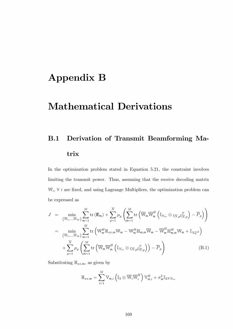
Appendix B
Mathematical Derivations
B.1 Derivation of Transmit Beamforming Ma-
trix
In the optimization problem stated in Equation 5.21, the constraint involves
limiting the transmit power. Thus, assuming that the receive decoding matrix
Wi, 8 i are �xed, and using Lagrange Multipliers, the optimization problem can
be expressed as
J = min(W1;:::;WM)
MXm=1
tr (Em) +
NXp=1
�p
MXm=1
tr�WmW
H
m
�INsc �N;p�
TN;p
�� P p
�!
= min(W1;:::;WM)
MXm=1
tr�WH
mRxx;mWm �WHmHm;mWm �W
H
mHHm;mWm + INsubm
�
+
NXp=1
�p
MXm=1
tr�WmW
H
m
�INsc �N;p�
TN;p
��� P p
!(B.1)
Substituting Rxx;m, as given by
Rxx;m =MXi=1
Vm;i�I3 WiW
H
i
�VHm;i + �2mI2NNsc
169

B. Mathematical Derivations 170
into Equation B.1 yields
J = min(W1;:::;WM)
MXm=1
tr�WH
m
�XM
i=1Vm;i
�I3 WiW
H
i
�VHm;i + �2mI2NNsc
�Wm
�WHmHm;mWm �W
H
mHHm;mWm + INsubm
�+
NXp=1
�p
�XM
m=1tr�WmW
H
m
�INsc �N;p�
TN;p
��� P p
�(B.2)
J = min(W1;:::;WM)
MXm=1
tr�WH
m
�XM
i=1Vm;i
�I3 WiW
H
i
�VHm;i
�Wm + �2mWH
mWm
�WHmHm;mWm �W
H
mHHm;mWm + INsubm
�+
NXp=1
�p
�XM
m=1tr�WmW
H
m
�INsc �N;p�
TN;p
��� P p
�(B.3)
In order to obtain the optimal solutionWm;8m; it is necessary to derive the �rst
derivative of J with respect toWm;8m, i.e. @J@Wm
.Based on Equation B.3, the @J@Wm
thus be obtained as:
@J
@Wm
= 2
MXi=1
LH�VHi;m
�WiWH
i
�Vi;m
�L
!Wm
�2HHm;mWm + 2NXp=1
�p
�INsc �N;p�
TN;p
�Wm (B.4)
where L = 13 INNsc . The optimal local solution W?
m can be obtained by evalu-
ating�
@J@Wm
�Wm=W
?m
= 0 and so,
2
MXi=1
LH�VHi;m
�WiWH
i
�Vi;m
�L
!W?
m
�2HHm;mWm + 2NXp=1
�p
�INsc �N;p�
TN;p
�W?
m = 0 (B.5)
Hence,0@ MXi=1
LH�VHi;m
�WiWH
i
�Vi;m
�L+
NXp=1
�p
�INsc �N;p�
TN;p
�1AW?
m = HHm;mWm
(B.6)

B. Mathematical Derivations 171
and �nally,
W?
m =
MXi=1
LH�VHi;m
�WiWH
i
�Vi;m
�L (B.7)
+
NXp=1
�p
�INsc �N;p�
TN;p
�1A�1
HHm;mWm 8m (B.8)

B. Mathematical Derivations 172
B.2 Derivation of Lagrange Multiplier
The derivative of J with respect to �p can be expressed as
@J
@�p=
MXm=1
tr�WmW
H
m
�INsc �N;p�
TN;p
��� P p
Letting
@J
@�p= 0
results in
MXm=1
tr�WmW
H
m
�INsc �N;p�
TN;p
��� P p = 0
MXm=1
tr�WmW
H
m
�INsc �N;p�
TN;p
��= P p
which corresponds to the power constraint requirement. Thus, Equation B.5
can be modi�ed to become MXi=1
LH�VHi;m
�WiWH
i
�Vi;m
�L
!WmW
H
m
�HHm;mWmWH
m +NXp=1
�p
�INsc �N;p�
TN;p
�WmW
H
m = 0 (B.9)
To obtain the expression for �p; the factor�INsc �N;p�
TN;p
�multiplied to the
above expression to yield
�INsc �N;p�
TN;p
� MXi=1
LH�VHi;m
�WiWH
i
�Vi;m
�L
!WmW
H
m
��INsc �N;p�
TN;p
�HHm;mWmW
H
m + �p
�INsc �N;p�
TN;p
�WmW
H
m = 0 (B.10)
as
�INsc �N;p�
TN;p
��INsc �N;p�
TN;p
�=
8><>:�INsc �N;p�
TN;p
�; if p = p
0NNsc�NNsc ; if p 6= p;8p

B. Mathematical Derivations 173
Taking the trace and summation over M users results in
MXm=1
tr
�INsc �N;p�
TN;p
� MXi=1
LH�VHi;m
�WiWH
i
�Vi;m
�L
!WmW
H
m
!
�MXm=1
tr��INsc �N;p�
TN;p
�HHm;mWmW
H
m
�+
MXm=1
tr��p
�INsc �N;p�
TN;p
�WmW
H
m
�= 0 (B.11)
MXm=1
tr
�INsc �N;p�
TN;p
� MXi=1
LH�VHi;m
�WiWH
i
�Vi;m
�L
!WmW
H
m
!
�MXm=1
tr��INsc �N;p�
TN;p
�HHm;mWmW
H
m
�+ �pP p = 0 (B.12)
Thus, replacing p with p; the solution for the Lagrange multiplier �?p; 8p; can
be expressed as
�?p =1
P p
MXm=1
tr��INsc �N;p�
TN;p
��HHm;mWmW
H
m
�LH�XM
i=1VHi;m
�WiWH
i
�Vi;m
�LWmW
H
m
��8p (B.13)
B. Mathematical Derivations 174
B.3 Derivation of Receive Beamforming Matrix
The derivation of the receive beamforming matrix can be obtained in a similar
way as the transmit beamforming matrix. The transmit beamforming matrix is
assumed to be �xed and so, the derivative of J , as shown in Equation B.3, with
respect to Wm can be expressed as:
@J
@Wm
= 2
MXi=1
Vm;i�I3 WiW
H
i
�VHm;i
!Wm � 2Hm;mWm + 2�
2mI2NNscWm
(B.14)
The solution for the receive beamforming matrix, W?m; 8m, can thus be obtained
by de�ning �@J
@Wm
�Wm=W?
m
= 0 (B.15)
which results in
2
MXi=1
Vm;i�I3 WiW
H
i
�VHm;i
!W?m � 2Hm;mWm + 2�
2mI2NNscW?
m = 0 (B.16)
Thus,
Wm =
MXi=1
Vm;i�I3 WiW
H
i
�VHm;i + �2mI2NNsc
!�1Hm;mWm
= R�1xx;mHm;mWm 8m (B.17)
It can be seen from Equation B.17 that the solution for the receive beamforming
matrix corresponds to a MMSE receiver.
References
[1] N. Yee, J.-P. Linnartz, and G. Fettweis, �Multicarrier CDMA in IndoorWire-
less Radio Networks,� in 2nd IEEE International Symposium on Personal,
Indoor and Mobile Radio Communications, 1993. PIMRC 1993., vol. 1, Sep-
tember 1993, pp. 109�113.
[2] A. C. McCormick and E. A. Al-Susa, �Multicarrier CDMA for future gen-
eration mobile communication,�Electronics & Communication Engineering
Journal, vol. 14, no. 2, pp. 52�60, April 2002.
[3] S. Abeta, H. Atarashi, M. Sawahashi, and F. Adachi, �Coherent
multicarrier/DS-CDMA and MC-CDMA for broadband packet wireless ac-
cess,�2000 IEEE 51st Vehicular Technology Conference Proceedings, 2000.
VTC 2000-Spring Tokyo., vol. 3, pp. 1918�1922, 2000.
[4] S. Abeta, H. Atarashi, and M. Sawahashi, �Forward link capacity of coherent
DS-CDMA and MC-CDMA broadband packet wireless access in a multi-cell
environment,�52nd Vehicular Technology Conference, 2000. IEEE VTS-Fall
VTC 2000., vol. 5, pp. 2213�2218, 2000.
[5] V. M. DaSilva and E. S. Sousa, �Multicarrier orthogonal cdma signals for
quasi-synchronous communication systems,�Selected Areas in Communica-
tions, IEEE Journal on, vol. 12, no. 5, pp. 842�852, June 1994.
175
REFERENCES 176
[6] S. Kondo and B. Milstein, �Performance of multicarrier ds cdma systems,�
Communications, IEEE Transactions on, vol. 44, no. 2, pp. 238�246, Febru-
ary 1996.
[7] E. A. Sourour and M. Nakagawa, �Performance of orthogonal multicarrier
cdma in a multipath fading channel,�Communications, IEEE Transactions
on, vol. 44, no. 3, pp. 356�367, March 1996.
[8] S. Hara and R. Prasad, �Overview of multicarrier CDMA,�IEEE Commu-
nications Magazine, vol. 35, no. 12, pp. 126�133, December 1997.
[9] T. M. Schmidl and D. C. Cox, �Robust frequency and timing synchronization
for OFDM,� IEEE Transactions on Communications, vol. 45, no. 12, pp.
1613�1621, December 1997.
[10] M. Luise and R. Reggiannini, �Carrier frequency acquisition and tracking for
OFDM systems,� IEEE Transactions on Communications, vol. 44, no. 11,
pp. 1590�1598, November 1996.
[11] Y. Hyunseok and L. Yong-Hwan, �Design of pilot signal for MC-CDMA
uplink systems,�IEEE International Conference on Communications, 2004,
vol. 5, pp. 2889�2893, 2004.
[12] J. J. van de Beek, M. Sandell, and P. O. Borjesson, �ML estimation of
time and frequency o¤set in OFDM systems,�IEEE Transactions on Signal
Processing, vol. 45, no. 7, pp. 1800�1805, July 1997.
[13] C. R. N. Athaudage and A. D. S. Jayalath, �Delay-spread estimation using
cyclic-pre�x in wireless OFDM systems,� IEE Proceedings - Communica-
tions, vol. 151, no. 6, pp. 559�566, December 2004.
[14] B. Muquet, W. Zhengdao, G. B. Giannakis, M. de Courville, and P. Duhamel,
�Cyclic pre�xing or zero padding for wireless multicarrier transmissions?�

REFERENCES 177
IEEE Transactions on Communications, vol. 50, no. 12, pp. 2136�2148, De-
cember 2002.
[15] G. B. Giannakis, �Filterbanks for blind channel identi�cation and equal-
ization,� IEEE Signal Processing Letters, vol. 4, no. 6, pp. 184�187, June
1997.
[16] H. Bölcskei, �Blind estimation of symbol timing and carrier frequency o¤-
set in wireless OFDM systems,� IEEE Transactions on Communications,
vol. 49, no. 6, pp. 988�999, June 2001.
[17] A. C. McCormick, P. M. Grant, and G. J. R. Povey, �A di¤erential
phase-shift keying multicarrier code division multiple access system with an
equal gain combining receiver,�IEEE Transactions on Vehicular Technology,
vol. 49, no. 5, pp. 1907�1917, 2000.
[18] C. Li and S. Roy, �Subspace-based blind channel estimation for OFDMby ex-
ploiting virtual carriers,�IEEE Transactions on Wireless Communications,
vol. 2, no. 1, pp. 141�150, January 2003.
[19] D. Ikonomou and L. Vandendorpe, �Performance comparison of receivers for
the up-link of cyclic pre�xed and non-pre�xed MC-CDMA systems,�The
13th IEEE International Symposium on Personal, Indoor and Mobile Radio
Communications, 2002., vol. 2, pp. 829�833, 2002.
[20] L. Chengyang and S. Roy, �Subspace based blind detector for multi-carrier
CDMA with virtual carriers over dispersive channels,�Conference Record of
the Thirty-Fourth Asilomar Conference on Signals, Systems and Computers,
2000., vol. 1, pp. 813�817, 2000.
[21] X. Wu, Q. Yin, and J. Zhang, �Subspace-based estimation method of uplink
FIR channel in MC-CDMA system without cyclic pre�x over frequency-
REFERENCES 178
selective fading channel,�in IEEE International Symposium on Circuits and
Systems, 2002. ISCAS 2002., vol. 1, May 2002, pp. 213�216.
[22] Y. Xiaodong, Y. Xiaodong, and H. H. Fan, �Near-far resistance of multi-
carrier CDMA systems,�in Conference Record of the Thirty-Sixth Asilomar
Conference on Signals, Systems and Computers, 2002., H. H. Fan, Ed., vol. 2,
2002, pp. 1448�1452.
[23] G. Zhang, G. Bi, and L. Zhang, �Blind multiuser detection for asynchronous
MC-CDMA systems without channel estimation,� IEEE Transactions on
Vehicular Technology, vol. 53, no. 4, pp. 1001�1013, July 2004.
[24] J. Wu, Y. Wang, and K. K. M. Cheng, �Blind channel estimation based on
subspace for multicarrier CDMA,�in IEEE VTS 53rd Vehicular Technology
Conference, 2001. VTC 2001 Spring., vol. 4, May 2001, pp. 2374�2378.
[25] C. Byoung-Jo, K. Ee-Lin, and L. Hanzo, �Crest-factor study of MC-CDMA
and OFDM,�IEEE VTS 50th Vehicular Technology Conference, 1999. VTC
1999 - Fall., vol. 1, pp. 233�237, 1999.
[26] G. G. Raleigh and J. M. Cio¢ , �Spatio-temporal coding for wireless com-
munication,� IEEE Transactions on Communications, vol. 46, no. 3, pp.
357�366, March 1998.
[27] A. J. Paulraj, D. A. Gore, R. U. Nabar, and H. Bolcskei, �An overview of
MIMO communications - a key to gigabit wireless,�Proceedings of the IEEE,
vol. 92, no. 2, pp. 198�218, February 2004.
[28] S. M. Alamouti, �A simple transmit diversity technique for wireless com-
munications,�IEEE Journal on Selected Areas in Communications, vol. 16,
no. 8, pp. 1451�1458, October 1998.
REFERENCES 179
[29] V. Tarokh, H. Jafarkhani, and A. R. Calderbank, �Space-time block
codes from orthogonal designs,�IEEE Transactions on Information Theory,
vol. 45, no. 5, pp. 1456�1467, July 1999.
[30] P. Wolniansky, G. Foschini, G. Golden, and R. Valenzuela, �V-blast: an
architecture for realizing very high data rates over the rich-scattering wireless
channel,� 1998 URSI International Symposium on Signals, Systems, and
Electronics, 1998. ISSSE 98., pp. 295�300, 29 Sep-2 Oct 1998.
[31] G. J. Foschini, G. D. Golden, R. A. Valenzuela, and P. W. Wolniansky,
�Simpli�ed processing for high spectral e¢ ciency wireless communication
employing multi-element arrays,�IEEE Journal on Selected Areas in Com-
munications, vol. 17, no. 11, pp. 1841�1852, 1999.
[32] G. J. Foschini, �Layered Space-Time Architecture for Wireless Communica-
tion in a Fading Environment When Using Multi-Element Antennas,�Bell
Laboratories Technical Journal, pp. 41�59, October 1996.
[33] R. Schmidt, �Multiple emitter location and signal parameter estimation,�
IEEE Transactions on Antennas and Propagation [legacy, pre - 1988],
vol. 34, no. 3, pp. 276�280, 1986.
[34] L. C. Godara, Smart Antennas. CRC Press LLC, 2004.
[35] X. Hao, D. Chizhik, H. Huang, and R. Valenzuela, �A generalized space-time
multiple-input multiple-output (MIMO) channel model,�Wireless Commu-
nications, IEEE Transactions on, vol. 3, no. 3, pp. 966�975, 2004.
[36] D. Gesbert, H. Bolcskei, D. A. Gore, and A. J. Paulraj, �Outdoor MIMO
wireless channels: models and performance prediction,� Communications,
IEEE Transactions on, vol. 50, no. 12, pp. 1926�1934, 2002.

REFERENCES 180
[37] J. W. P. Ng and A. Manikas, �MIMO array DS-CDMA system: a blind space-
time-Doppler estimation/reception,� in IEEE International Conference on
Acoustics, Speech, and Signal Processing, 2004. Proceedings. (ICASSP �04).,
vol. 2, May 2004, pp. 337�340.
[38] B. D. V. Veen and K. M. Buckley, �Beamforming: a versatile approach to
spatial �ltering,�ASSP Magazine, IEEE, vol. 5, no. 2, pp. 4�24, 1988.
[39] W. Nabhane and H. V. Poor, �Blind joint equalization and multiuser de-
tection in dispersive MC-CDMA/MC-DS-CDMA/MT-CDMA channels,�in
MILCOM 2002. Proceedings, vol. 2, 2002, pp. 814�819.
[40] W. Xiaojun, Y. Qinye, Z. Hanguo, and D. Ke, �Time-domain multiuser
detection for MC-CDMA systems without cyclic pre�x,�IEEE International
Conference on Communications, 2002. ICC 2002., vol. 2, pp. 921�925, 2002.
[41] P. Marques and A. Gameiro, �Uplink MIMO channel estimation for beyond
3G systems,�Fifth IEE International Conference on 3G Mobile Communi-
cation Technologies, 2004. 3G 2004., pp. 203�207, 2004.
[42] D. Ke, Y. Qinye, and T. Hongbo, �Uplink channel estimation for space-time
block coded multiple-input multiple-output MC-CDMA systems,�IEEE In-
ternational Symposium on Circuits and Systems, 2005. ISCAS 2005., pp.
5738�5741, 2005.
[43] X. Hu and Y. H. Chew, �Performance of space-time block coded system
over frequency selective fading channel using semi-blind channel estimation
technique,�in 2003 IEEE Wireless Communications and Networking, 2003.
WCNC 2003., vol. 1, 2003, pp. 414�419.
[44] D. Ke, Y. Qinye, L. Ming, and Z. Yanxing, �Blind uplink channel and DOA
estimator for space-time block coded MC-CDMA system with uniform linear
REFERENCES 181
array,�2004 IEEE 59th Vehicular Technology Conference, 2004. VTC 2004-
Spring., vol. 1, pp. 69�73, 2004.
[45] H. Huang, H. Viswanathan, and G. J. Foschini, �Multiple antennas in cellu-
lar CDMA systems: transmission, detection, and spectral e¢ ciency,� IEEE
Transactions on Wireless Communications, vol. 1, no. 3, pp. 383�392, July
2002.
[46] Z. Li and M. Latva-aho, �Spatial transmit diversity techniques for MC-
CDMA systems,� 2002 IEEE Seventh International Symposium on Spread
Spectrum Techniques and Applications, vol. 1, pp. 155�159, 2002.
[47] G. P. Fettweis, A. Nahler, and J. Kuhne, �A time domain view to multi-
carrier spread spectrum,� IEEE Sixth International Symposium on Spread
Spectrum Techniques and Applications, 2000, vol. 1, pp. 141�144, 2000.
[48] L. Sanguinetti, I. Cosovic, and M. Morelli, �Channel estimation for MC-
CDMA uplink transmissions with combined equalization,�IEEE Journal on
Selected Areas in Communications, vol. 24, no. 6, pp. 1167�1178, 2006.
[49] R. Price and P. E. Green, �A communication technique for multipath chan-
nels,�Proceedings of the IRE, vol. 46, no. 3, pp. 555�570, 1958.
[50] D. J. Sadler and A. Manikas, �Blind reception of multicarrier DS-CDMA
using antenna arrays,� IEEE Transactions on Wireless Communications,
vol. 2, no. 6, pp. 1231�1239, November 2003.
[51] A. Manikas and M. Sethi, �A space-time channel estimator and single-user
receiver for code-reuse DS-CDMA systems,� IEEE Transactions on Signal
Processing, vol. 51, no. 1, pp. 39�51, 2003.

REFERENCES 182
[52] M. Wax and T. Kailath, �Detection of signals by information theoretic crite-
ria,�IEEE Transactions on Acoustics, Speech, and Signal Processing, vol. 33,
no. 2, pp. 387�392, 1985.
[53] T.-J. Shan, M. Wax, and T. Kailath, �On spatial smoothing for direction-
of-arrival estimation of coherent signals,� IEEE Transactions on Acoustics,
Speech, and Signal Processing, vol. 33, no. 4, pp. 806�811, Aug 1985.
[54] H. Bölcskei, D. Gesbert, and A. J. Paulraj, �On the capacity of OFDM-
based spatial multiplexing systems,� IEEE Transactions on Communica-
tions, vol. 50, no. 2, pp. 225�234, 2002.
[55] K. I. Pedersen, P. E. Mogensen, and B. H. Fleury, �Spatial channel charac-
teristics in outdoor environments and their impact on BS antenna system
performance,�48th IEEE Vehicular Technology Conference, 1998. VTC 98.,
vol. 2, pp. 719�723, 1998.
[56] A. Kuchar, J. P. Rossi, and E. Bonek, �Directional macro-cell channel char-
acterization from urban measurements,� IEEE Transactions on Antennas
and Propagation, vol. 48, no. 2, pp. 137�146, 2000.
[57] Y. Oda and T. Taga, �Clustering of local scattered multipath components in
urban mobile environments,� IEEE 55th Vehicular Technology Conference,
2002. VTC Spring 2002., vol. 1, pp. 11�15, 2002.
[58] M. Larsson, �Spatio-temporal channel measurements at 1800 MHz for adap-
tive antennas,�IEEE 49th Vehicular Technology Conference, 1999, pp. 376�
380, 1999.
[59] A. S. Y. Poon, D. N. C. Tse, and R. W. Brodersen, �Impact of scattering on
the capacity, diversity, and propagation range of multiple-antenna channels,�

REFERENCES 183
IEEE Transactions onInformation Theory, vol. 52, no. 3, pp. 1087�1100,
2006.
[60] B. S. Khatri, �E¤ect on capacity of clustering in indoor MIMO channels,�
IEE Seminar on MIMO: Communications Systems from Concept to Imple-
mentations (Ref. No. 2001/175), pp. 15/1�15/7, 2001.
[61] K. I. Pedersen, J. B. Andersen, J. P. Kermoal, and P. Mogensen, �A sto-
chastic multiple-input-multiple-output radio channel model for evaluation
of space-time coding algorithms,�IEEE 52nd Vehicular Technology Confer-
ence, 2000. IEEE VTS-Fall VTC 2000., vol. 2, pp. 893�897, 2000.
[62] C. Oestges, V. Erceg, and A. J. Paulraj, �A physical scattering model for
MIMO macrocellular broadband wireless channels,� IEEE Journal on Se-
lected Areas in Communications,, vol. 21, no. 5, pp. 721�729, 2003.
[63] T. P. Jantti, �The in�uence of extended sources on the theoretical perfor-
mance of the MUSIC and ESPRIT methods: narrow-band sources,� 1992
IEEE International Conference on Acoustics, Speech, and Signal Processing,
1992. ICASSP-92., vol. 2, pp. 429�432, 1992.
[64] S. Valaee, B. Champagne, and P. Kabal, �Parametric localization of distrib-
uted sources,� IEEE Transactions on Signal Processing, vol. 43, no. 9, pp.
2144�2153, 1995.
[65] Y. Meng, P. Stoica, and K. M. Wong, �Estimation of the directions of arrival
of spatially dispersed signals in array processing,�IEE Proceedings - Radar,
Sonar and Navigation, vol. 143, no. 1, pp. 1�9, 1996.
[66] Q. Wu, K. M. Wong, Y. Meng, and W. Read, �DOA Estimation of Point and
Scattered Sources - Vec-Music,� IEEE Seventh SP Workshop on Statistical
Signal and Array Processing, 1994., pp. 365�368, 1994.
REFERENCES 184
[67] O. Besson and P. Stoica, �Decoupled estimation of DOA and angular spread
for a spatially distributed source,�IEEE Transactions on Signal Processing,
vol. 48, no. 7, pp. 1872�1882, 2000.
[68] A. Zoubir, Y. Wang, and P. Charge, �On the ambiguity of COMET-EXIP
algorithm for estimating a scattered source,�IEEE International Conference
on Acoustics, Speech, and Signal Processing, 2005. Proceedings. (ICASSP
�05)., vol. 4, pp. iv/941�iv/944, 2005.
[69] P. D. Karaminas and A. Manikas, �Super-resolution broad null beamform-
ing for cochannel interference cancellation in mobile radio networks,�IEEE
Transactions on Vehicular Technology, vol. 49, no. 3, pp. 689�697, 2000.
[70] T. S. Naveendra and A. Manikas, �Subspace receiver techniques for DS-
CDMA systems in space di¤used vector channels,�WSEAS Transactions on
Communications, vol. 3, no. 2, pp. 590�594, April 2004.
[71] T. S. Naveendra and A. Manikas, �Blind estimation of di¤used multipath
vector channels for DS-CDMA systems,� 1st International Symposium on
Wireless Communication Systems 2004, pp. 41�45, September 2004.
[72] K. I. Pedersen, P. E. Mogensen, and B. H. Fleury, �A stochastic model of
the temporal and azimuthal dispersion seen at the base station in outdoor
propagation environments,� IEEE Transactions on Vehicular Technology,
vol. 49, no. 2, pp. 437�447, March 2000.
[73] R. J. Piechocki, J. P. McGeehan, and G. V. Tsoulos, �A new stochastic
spatio-temporal propagation model (SSTPM) for mobile communications
with antenna arrays,�IEEE Transactions on Communications, vol. 49, no. 5,
pp. 855�862, May 2001.

REFERENCES 185
[74] D. Astely and B. Ottersten, �The e¤ects of local scattering on direction of
arrival estimation with MUSIC,� IEEE Transactions on Signal Processing,
vol. 47, no. 12, pp. 3220�3234, 1999.
[75] S. Verdu, Multiuser Detection. New York, NY, USA: Cambridge University
Press, 1998.
[76] M. Costa, �Writing on dirty paper,� IEEE Transactions on Information
Theory, vol. 29, no. 3, pp. 439�441, 1983.
[77] H. Weingarten, Y. Steinberg, and S. Shamai, �The capacity region of the
Gaussian MIMO broadcast channel,�International Symposium on Informa-
tion Theory, 2004. ISIT 2004. Proceedings., p. 174, 2004.
[78] Q. H. Spencer, A. L. Swindlehurst, and M. Haardt, �Zero-forcing meth-
ods for downlink spatial multiplexing in multiuser MIMO channels,� IEEE
Transactions on Signal Processing, vol. 52, no. 2, pp. 461�471, 2004.
[79] U. Lai and R. D. Murch, �A transmit preprocessing technique for multiuser
MIMO systems using a decomposition approach,� IEEE Transactions on
Wireless Communications, vol. 3, no. 1, pp. 20�24, 2004.
[80] A. Tarighat, M. Sadek, and A. H. Sayed, �A multi user beamforming scheme
for downlink MIMO channels based on maximizing signal-to-leakage ratios,�
IEEE International Conference on Acoustics, Speech, and Signal Processing,
2005. Proceedings. (ICASSP �05)., vol. iii, no. 9, pp. 1129�1132, 2005.
[81] Y. Taesang and A. Goldsmith, �Optimality of zero-forcing beamforming with
multiuser diversity,� 2005 IEEE International Conference on Communica-
tions, 2005. ICC 2005., vol. 1, pp. 542�546, 2005.
REFERENCES 186
[82] T. Salzer and D. Mottier, �Transmit beamforming for SDMA in multi-carrier
CDMA downlink on a per subcarrier basis,�10th International Conference
on Telecommunications, 2003. ICT 2003., vol. 1, pp. 793�798, 2003.
[83] Y. Jian and S. Roy, �On joint transmitter and receiver optimization
for multiple-input-multiple-output (MIMO) transmission systems,� IEEE
Transactions on Communications, vol. 42, no. 12, pp. 3221�3231, 1994.
[84] H. Sampath, P. Stoica, and A. Paulraj, �Generalized linear precoder and
decoder design for MIMO channels using the weighted MMSE criterion,�
IEEE Transactions on Communications, vol. 49, no. 12, pp. 2198�2206, 2001.
[85] D. P. Palomar, J. M. Cio¢ , and M. A. Lagunas, �Joint Tx-Rx beamform-
ing design for multicarrier MIMO channels: a uni�ed framework for convex
optimization,� IEEE Transactions on Signal Processing, vol. 51, no. 9, pp.
2381�2401, 2003.
[86] A. J. Tenenbaum and R. S. Adve, �Joint multiuser transmit-receive opti-
mization using linear processing,�IEEE International Conference on Com-
munications, 2004, vol. 1, pp. 588�592, 2004.
[87] S. C. Chan and S. H. Zhao, �Transmit/receive beamformer design and power
control in MIMO MC-CDMA systems,� 2006 IEEE International Sympo-
sium on Circuits and Systems, 2006. ISCAS 2006. Proceedings., p. 4, 2006.
[88] S. Serbetli and A. Yener, �Transceiver optimization for multiuser mimo sys-
tems,�Signal Processing, IEEE Transactions on, vol. 52, no. 1, pp. 214�226,
2004.
[89] S. H. Han and J. H. Lee, �An overview of peak-to-average power ratio re-
duction techniques for multicarrier transmission,� IEEE Wireless Commu-
nications, vol. 12, no. 2, pp. 56�65, April 2005.

REFERENCES 187
[90] H. Ochiai and H. Imai, �On the distribution of the peak-to-average power
ratio in OFDM signals,� IEEE Transactions on Communications, vol. 49,
no. 2, pp. 282�289, 2001.
[91] D. J. G. Mestdagh and P. M. P. Spruyt, �A method to reduce the probability
of clipping in DMT-based transceivers,� IEEE Transactions on Communi-
cations, vol. 44, no. 10, pp. 1234�1238, 1996.
[92] X. Wang and A. Manikas, �Joint linear precoder-decoder optimization over
mimo-cdma multipath channels,� in Personal, Indoor and Mobile Radio
Communications, 2007. PIMRC 2007. IEEE 18th International Symposium
on, 2007, pp. 1�5.
[93] N. Maeda, Y. Kishiyama, H. Atarashi, and M. Sawahashi, �Variable spread-
ing factor-OFCDM with two dimensional spreading that prioritizes time
domain spreading for forward link broadband wireless access,� in The
57th IEEE Semiannual Vehicular Technology Conference, 2003. VTC 2003-
Spring., vol. 1, April 2003, pp. 127�132.
[94] R. van Nee and R. Prasad, OFDM for Wireless Multimedia Communications.
Norwood, MA, USA: Artech House, Inc., 2000.
[95] R. Prasad, OFDM for Wireless Communications Systems. Norwood, MA,
USA: Artech House, Inc., 2004.
Related Documents