CVS Series YD & YS Control Valves The CVS Series YD/YS Control Valves are a 3-way cage guided design, suitable for on/off service, or throttling applications. The CVS Series YD is a balanced design for service requiring general converging/diverging applications. The CVS Series YS in an unbalanced design suitable for converging applications. The CVS Series YS may also be used in diverging ON/OFF service. Flow characteristic is Linear. Standard shutoff classification is Class IV. Standard body material is LCC, WCB/WC9 CF8M also available CVS Series YD – 3 Inch Head Office 3900 101 Street Edmonton, Alberta T6E 0A5 Canada Office: (780) 437-3055 Fax: (780) 436-5461 Calgary Sales Office 3516 114 Avenue SE Calgary, Alberta T2Z 3V6 Canada Office: (403) 250-1416 Fax: (403) 291-9487 Website: www.cvs-controls.com Email: [email protected]

Welcome message from author
This document is posted to help you gain knowledge. Please leave a comment to let me know what you think about it! Share it to your friends and learn new things together.
Transcript
CVS Series YD & YS
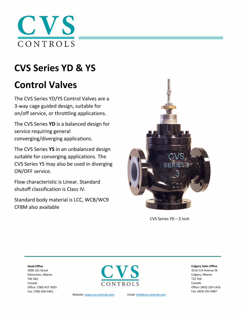
Control Valves The CVS Series YD/YS Control Valves are a
3-way cage guided design, suitable for
on/off service, or throttling applications.
The CVS Series YD is a balanced design for
service requiring general
converging/diverging applications.
The CVS Series YS in an unbalanced design
suitable for converging applications. The
CVS Series YS may also be used in diverging
ON/OFF service.
Flow characteristic is Linear. Standard
shutoff classification is Class IV.
Standard body material is LCC, WCB/WC9
CF8M also available
CVS Series YD – 3 Inch
Head Office
3900 101 Street
Edmonton, Alberta
T6E 0A5
Canada
Office: (780) 437-3055
Fax: (780) 436-5461
Calgary Sales Office
3516 114 Avenue SE
Calgary, Alberta
T2Z 3V6
Canada
Office: (403) 250-1416
Fax: (403) 291-9487
Website: www.cvs-controls.com Email: [email protected]

SPECIFICATIONS
WCC Steel and Stainless Steel:
Available in 2 through 6 inch, Class 150, 300, 600, RF (Raised Face) or RTJ (Ring Type Joint) per ASME B16.34
latest edition
Flow Characteristic:
Linear
Flow Direction:
Series YS – Orientation Plug Down, Bottom Port Closed
Converging Service flow is right to left, Diverging Service flow is left to right.
Series YD: Bottom port is common
Plug Down, Left Port Closed Position:
Converging Service flow is right to bottom, Diverging Service is bottom port to right.
Plug Up, Right Port Closed:
Converging Service flow is left port to bottom, Diverging Service is bottom port to left.
Intermediate Plug Positions
Converging Service may be from both left and right ports to bottom port, capacities proportionate to plug
travel. Diverging Service flow is from the bottom port to both the left and right ports, capacities split
proportionately to plug travel.
Shutoff Classification:
Series YD and Series YS – Class IV standard
Approximate Shipping Weights:
2 Inch – 85 lbs (39kg)
3 inch – 150 lbs (68kg)
4 inch – 240 lbs (109kg)
6 inch – 500 lbs (227kg)
Yoke Boss and Stem Diameter for Mounting Actuator
Valve Size - Inch
Valve Stem and Yoke Boss Diameter
Standard Optional
Yoke Boss Stem Yoke Boss Stem
Inches
2, 3, and 4 2 – 13/16 1/2 3 – 9/16 3/4
6 3 – 9/16 3/4 5 1
mm
2, 3, and 4 71 12.7 90 19.1
6 90 19.1 127 25.4

INSTALLATION
• Always follow proper safety guidelines and lockout procedures while installing or performing any
maintenance. Use proper personal protective equipment and ensure any additional process and safety
guidelines are followed
1. Prior to installing the valve, or assembly, inspect all components for debris and or any damage that
may have occurred during shipping.
2. Ensure process lines are clean and free of debris or foreign materials.
3. Always follow proper piping bolting or welding practices when installing the valve assembly. Use
suitable gaskets between the valve and pipeline flanges as required.
4. Never exceed maximum working pressures/temperature limits.
5. Should maintenance or inspections require continuous service, install a 3 valve by pass in order to
isolate the valve assembly during inspections and maintenance.
6. Note flow direction as indicated by the arrows on the valve and install accordingly.
- Common port for the Series YD is the bottom port, while the common port for the series YS is the
left handed port as shown by the direction arrow plate.
7. Both series of valves may be installed in any orientation, the recommended orientation is with the
actuator vertical above the valve.
Valve Body Sizes and End Connections
Valve Size Steel or Stainless Steel Cast Iron
2 NPT, Class 150, 300 or 600 Raised Face or Ring Type Joint flanged, Buttweld, or Socket Weld
NPT, Class 125 Flat Face, or Class 250 Raised Face
3, 4, and 6 Class 150, 300, or 600 Raised Face or Ring Type Joint flanged, or Buttweld
Class 125 Flat face, or Class 250 Raised Face
Flow Direction:

MAINTENANCE
Valves and its components are subject to normal wear and tear. Service, inspection and maintenance
frequency may depend on the severity of service condition.
• Always follow proper safety guidelines and lockout procedures while installing or performing any
maintenance. Use proper personal protective equipment and ensure any additional process and safety
guidelines are followed.
• Use a bypass valve to isolate the valve from the process. Ensure all pressure has been relieved from
both sides of the valve.
• Disconnect operating lines providing a signal to the actuator to ensure the valve cannot open or close
suddenly.
If an optional lubricator is used for PTFE, composition or additional packings that may require lubrication, it
will be installed in place of the pipe plug. Do not lubricate packing used in process temperatures above 500oF
(260oC), or in oxygen service. Use a good quality silicon-based lubricant. To operate the lubricator, turn the
cap screw clockwise in order to push the lubricant into the packing box.
PACKING MAINTENANCE
The following instructions cover maintenance for PTFE V Ring packing. Similar method may also be used for
PTFE composition packing. Composition packing is possible to replace without removing the actuator from the
valve because of the split ring configuration.
Special attention should be used when installing graphite ribbon/filament packing to avoid trapping air
between the rings. Install only one ring at a time, do not force the packing ring below the bottom of the
packing box chamber. When a ring is added, the stack should not be pushed further than the thickness of
adding each ring.
1. Remove the actuator and bonnet.
2. Remove the valve stem and valve plug assembly.
3. Remove packing flange nuts, packing flange, wiper ring and packing follower.
4. Remove the old packing using a packing hook or similar. Pay attention to avoid damaging the packing
box walls. Alternatively, the packing may be pushed out through the bottom of the bonnet.
5. Clean and inspect packing box and metal components.
6. Inspect additional components prior to reinstalling the bonnet on the valve assembly.
7. Install new packing as required according to the correct packing arrangement. Take care to not damage
the packing while installing.
8. Install packing flange and packing flange nuts.
For spring loaded PTFE V ring type packing: tighten the packing flange nuts so the shoulder on
the packing follower contacts the bonnet.
For Graphite packing: tighten the packing flange nuts in accordance with the recommended
torque values. Loosen off the packing nuts, the tighten once again to the minimum
recommended torque value.
For other packing types: tighten the packing flange nuts, alternating in small increments, until
either packing nut reaches the minimum recommended torque. Then tighten the other packing
flange nut, ensuring the flange is level and to a 90-degree angle with the valve stem.
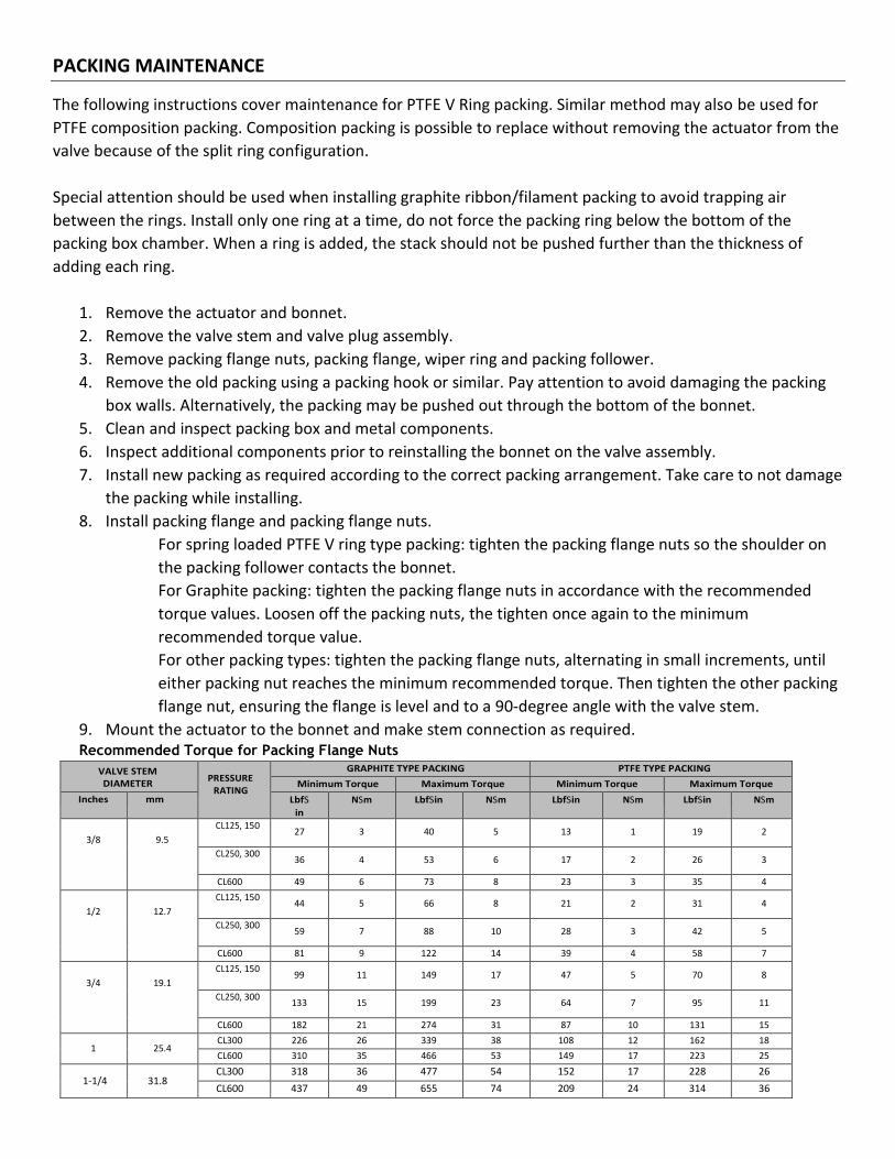
9. Mount the actuator to the bonnet and make stem connection as required. Recommended Torque for Packing Flange Nuts
VALVE STEM DIAMETER
PRESSURE RATING
GRAPHITE TYPE PACKING PTFE TYPE PACKING
Minimum Torque Maximum Torque Minimum Torque Maximum Torque
Inches mm LbfS
in
NSm LbfSin NSm LbfSin NSm LbfSin NSm
3/8
9.5
CL125, 150 27 3 40 5 13 1 19 2
CL250, 300 36 4 53 6 17 2 26 3
CL600 49 6 73 8 23 3 35 4
1/2
12.7
CL125, 150 44 5 66 8 21 2 31 4
CL250, 300 59 7 88 10 28 3 42 5
CL600 81 9 122 14 39 4 58 7
3/4
19.1
CL125, 150 99 11 149 17 47 5 70 8
CL250, 300 133 15 199 23 64 7 95 11
CL600 182 21 274 31 87 10 131 15
1 25.4 CL300 226 26 339 38 108 12 162 18
CL600 310 35 466 53 149 17 223 25
1-1/4 31.8 CL300 318 36 477 54 152 17 228 26
CL600 437 49 655 74 209 24 314 36
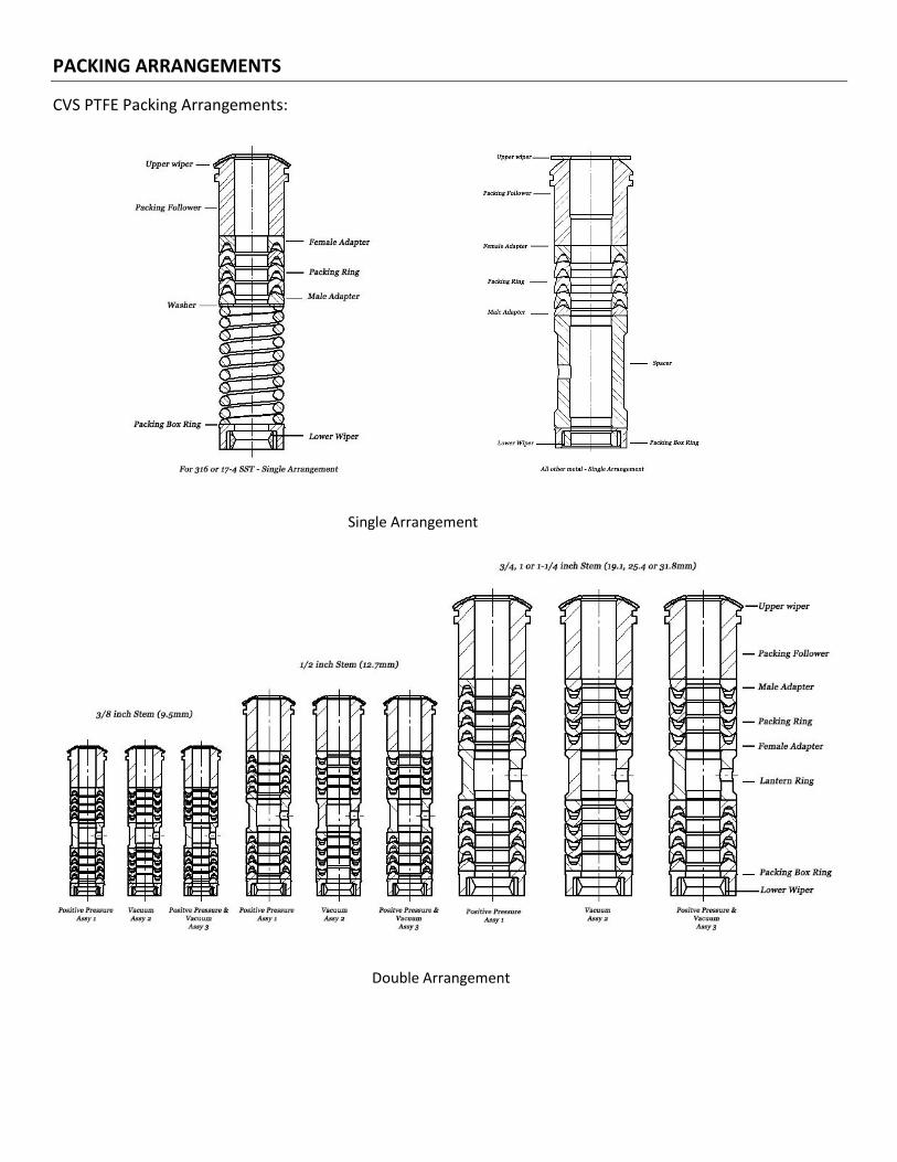
PACKING ARRANGEMENTS
CVS PTFE Packing Arrangements:
Single Arrangement
Double Arrangement

PACKING ARRANGEMENTS
CVS PTFE/Composition Packing Arrangements:
TRIM MAINTENANCE
*Follow proper safety and lockout procedures prior to any inspection or maintenance to avoid personal injury.
Disassembly:
1. Ensure control valve has been properly isolated from line pressure and pressure has been released
from both sides of the valve. Disconnect actuator supply pressure.
2. Disconnect the actuator stem connector and remove the actuator locknut that secures the actuator to
the valve. The actuator may now be lifted from the valve.
3. Remove the nuts that secure the bonnet flange
4. Lift the bonnet, valve plug and stem out as one assembly. Pay attention to not damage the outer
portion of the cage, sealing or seating as surface nicks or damage may cause leakage.
5. Loosen off the packing flange nuts, and take the valve stem and plug out through the bottom of the
bonnet. Remove the cage and seat components from the valve plug and stem. Should the stem show
signs of wear or damage which require replacement, remove the drive pin securing the stem and plug,
and unscrew the stem from the plug.
6. Internal components of the bonnet may now be disassembled for inspection or replacement as
required.
7. For Standard CVS Series YD – Replace the cage seal, seal ring, and backup ring as part of an assembly
group.
8. The remaining trim components may now be removed and replaced as required after inspection.

Assembly:
CVS Series YD - Standard
1. Prior to assembly, ensure all is clear and clean of debris. Use a cloth to wipe all sealing surfaces. Use
new gaskets, seals, and shim when reassembling.
2. Install Seat Ring Gasket, then set the Seat Ring on top of the Seat Ring Gasket.
3. Place the Lower Cage into the valve. Narrow end of the cage should point downward, ensure the cage
fits over the raised portion of the seat ring.
4. Place O-Ring cage seal over the bottom of the upper cage, into the cage groove.
5. The Backup Ring, and Seal Ring may now be placed into the inner groove of the upper cage.
6. If installing a new Stem, screw the Stem into the Valve Plug until tight to the Valve Plug.
7. Locate the pin hole in the Valve Plug in order to drill a hole into the stem and secure with drive pin.
8. Tap a new Drive Pin into the plug and stem in order to secure.
9. Set the Upper Cage over the Plug and Stem Assembly. Pay attention to not damage the Seal Ring.
10. Place the complete assembly into the Valve. Use a steady pressure to the top of the cage for its
position inside the valve. Ensure the upper cage rests into the lower cage and the cage seal did not get
damaged.
11. Install the Spiral Wound Gasket, Shim, and Bonnet Gasket over the Upper Cage
12. Mount the Bonnet on the Valve. If equipped with a lubricator or pipe plug, install so the pipe plug or
lubricator is parallel with the pipeline.
13. Use an appropriate lubricant/anti seize on the valve stud bolts. Install Valve Stud Nuts onto the valve
studs and follow proper bolting practice. Tightening in a criss cross pattern. Repeat torque procedure
for a proper seal until none of the nuts will continue to tighten to recommended torque values.
14. Mount the Actuator to the Bonnet and make up the stem connection. Reconnect supply as required.
Valve Plug and Stem - Pin Drill Size
Valve Series Stem Connection - Inch (mm) Drill Size - Inch
Series YD and Series YS
3/8 (9.5) 3/32
1/2 (12.7) 1/8
3/4 (19.1) 3/16
1 (25.4) 1/4
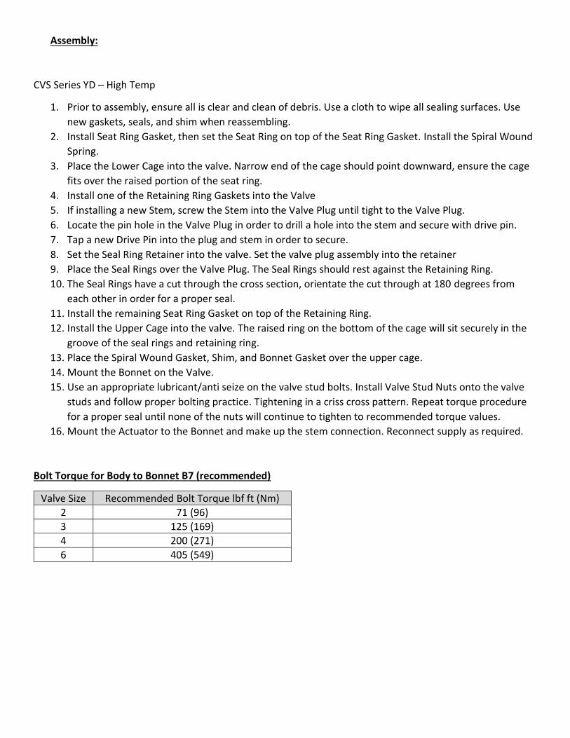
Assembly:
CVS Series YD – High Temp
1. Prior to assembly, ensure all is clear and clean of debris. Use a cloth to wipe all sealing surfaces. Use
new gaskets, seals, and shim when reassembling.
2. Install Seat Ring Gasket, then set the Seat Ring on top of the Seat Ring Gasket. Install the Spiral Wound
Spring.
3. Place the Lower Cage into the valve. Narrow end of the cage should point downward, ensure the cage
fits over the raised portion of the seat ring.
4. Install one of the Retaining Ring Gaskets into the Valve
5. If installing a new Stem, screw the Stem into the Valve Plug until tight to the Valve Plug.
6. Locate the pin hole in the Valve Plug in order to drill a hole into the stem and secure with drive pin.
7. Tap a new Drive Pin into the plug and stem in order to secure.
8. Set the Seal Ring Retainer into the valve. Set the valve plug assembly into the retainer
9. Place the Seal Rings over the Valve Plug. The Seal Rings should rest against the Retaining Ring.
10. The Seal Rings have a cut through the cross section, orientate the cut through at 180 degrees from
each other in order for a proper seal.
11. Install the remaining Seat Ring Gasket on top of the Retaining Ring.
12. Install the Upper Cage into the valve. The raised ring on the bottom of the cage will sit securely in the
groove of the seal rings and retaining ring.
13. Place the Spiral Wound Gasket, Shim, and Bonnet Gasket over the upper cage.
14. Mount the Bonnet on the Valve.
15. Use an appropriate lubricant/anti seize on the valve stud bolts. Install Valve Stud Nuts onto the valve
studs and follow proper bolting practice. Tightening in a criss cross pattern. Repeat torque procedure
for a proper seal until none of the nuts will continue to tighten to recommended torque values.
16. Mount the Actuator to the Bonnet and make up the stem connection. Reconnect supply as required.
Bolt Torque for Body to Bonnet B7 (recommended)
Valve Size Recommended Bolt Torque lbf ft (Nm)
2 71 (96)
3 125 (169)
4 200 (271)
6 405 (549)

Assembly:
CVS Series YS
1. Prior to assembly, ensure all is clear and clean of debris. Use a cloth to wipe all sealing surfaces. Use
new gaskets, and shim when reassembling.
2. Install Seat Ring Gasket, then set the Lower Seat Ring on top of the Seat Ring Gasket. Install the Spiral
Wound Spring
3. Place the Lower Cage into the valve. Narrow end of the cage should point downward, ensure the cage
fits over the raised portion of the seat ring.
4. Install the Upper Seat Ring Gasket into the valve.
5. If installing a new Stem, screw the Stem into the Valve Plug until tight to the Valve Plug.
6. Locate the pin hole in the Valve Plug in order to drill a hole into the stem and secure with drive pin.
7. Tap a new Drive Pin into the plug and stem in order to secure.
8. Set the Upper Cage over the Plug and Stem Assembly. Pay attention to not damage the Seal Ring.
9. Place the complete assembly into the Valve. Use a steady pressure to the top of the cage for its
position inside the valve. Ensure the upper cage rests into the lower cage and the cage seal did not get
damaged.
10. Install the Spiral Wound Gasket, Shim, and Bonnet Gasket over the Upper Cage
11. Mount the Bonnet on the Valve. If equipped with a lubricator or pipe plug, install so the pipe plug or
lubricator is parallel with the pipeline.
12. Use an appropriate lubricant/anti seize on the valve stud bolts. Install Valve Stud Nuts onto the valve
studs and follow proper bolting practice. Tightening in a criss cross pattern. Repeat torque procedure
for a proper seal until none of the nuts will continue to tighten to recommended torque values.
13. Mount the Actuator to the Bonnet and make up the stem connection. Reconnect supply as required.
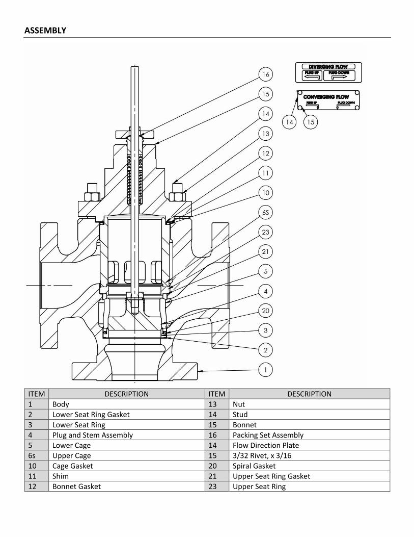
ASSEMBLY
ITEM DESCRIPTION ITEM DESCRIPTION
1 Body 13 Nut
2 Lower Seat Ring Gasket 14 Stud
3 Lower Seat Ring 15 Bonnet
4 Plug and Stem Assembly 16 Packing Set Assembly
5 Lower Cage 14 Flow Direction Plate
6s Upper Cage 15 3/32 Rivet, x 3/16
10 Cage Gasket 20 Spiral Gasket
11 Shim 21 Upper Seat Ring Gasket
12 Bonnet Gasket 23 Upper Seat Ring

DIMMENSIONS
PARTS
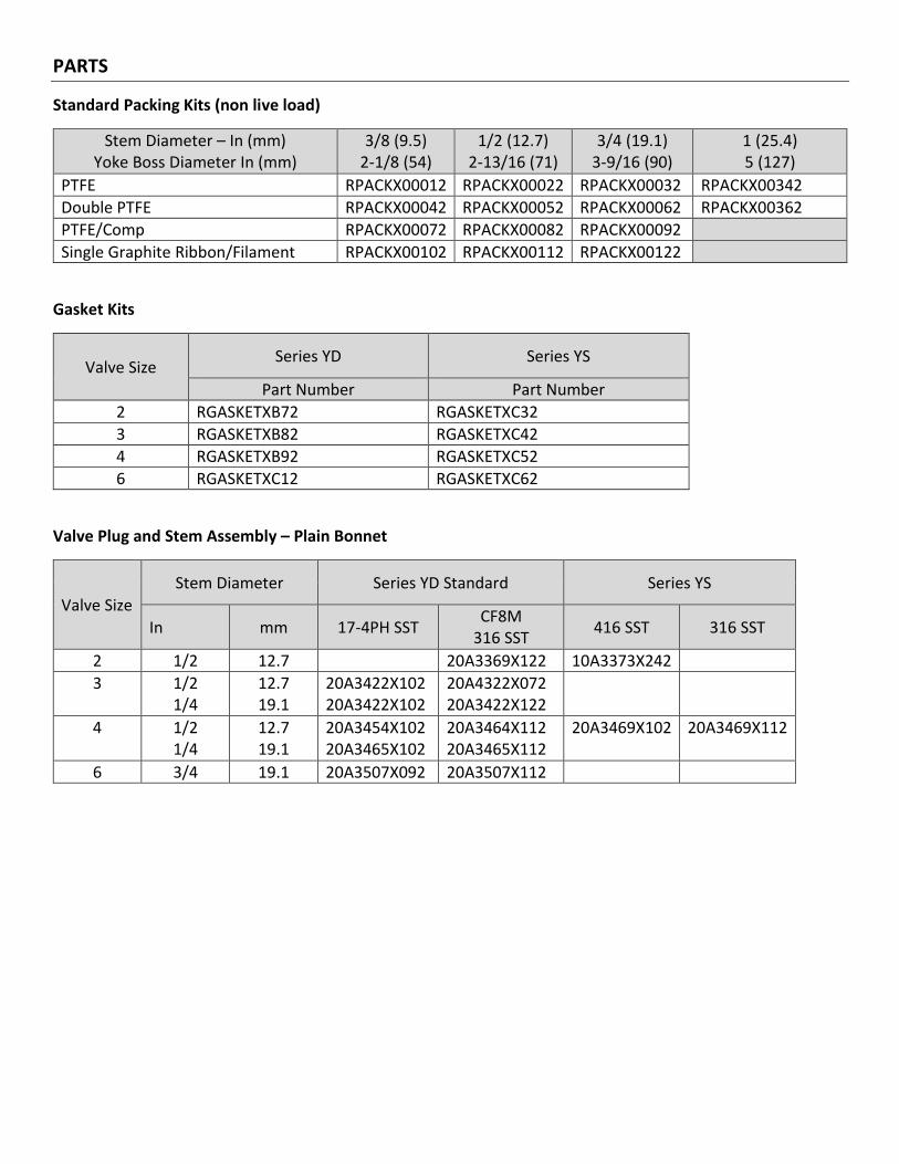
Standard Packing Kits (non live load)
Stem Diameter – In (mm) Yoke Boss Diameter In (mm)
3/8 (9.5) 2-1/8 (54)
1/2 (12.7) 2-13/16 (71)
3/4 (19.1) 3-9/16 (90)
1 (25.4) 5 (127)
PTFE RPACKX00012 RPACKX00022 RPACKX00032 RPACKX00342
Double PTFE RPACKX00042 RPACKX00052 RPACKX00062 RPACKX00362
PTFE/Comp RPACKX00072 RPACKX00082 RPACKX00092
Single Graphite Ribbon/Filament RPACKX00102 RPACKX00112 RPACKX00122
Gasket Kits
Valve Size Series YD Series YS
Part Number Part Number
2 RGASKETXB72 RGASKETXC32
3 RGASKETXB82 RGASKETXC42
4 RGASKETXB92 RGASKETXC52
6 RGASKETXC12 RGASKETXC62
Valve Plug and Stem Assembly – Plain Bonnet
Valve Size
Stem Diameter Series YD Standard Series YS
In mm 17-4PH SST CF8M
316 SST 416 SST 316 SST
2 1/2 12.7 20A3369X122 10A3373X242
3 1/2 1/4
12.7 19.1
20A3422X102 20A3422X102
20A4322X072 20A3422X122
4 1/2 1/4
12.7 19.1
20A3454X102 20A3465X102
20A3464X112 20A3465X112
20A3469X102 20A3469X112
6 3/4 19.1 20A3507X092 20A3507X112

PARTS
Upper Cage – Series YD/YS, Standard
Valve Size
Series YS Upper Cage Series YD Upper Cage
CF8M (316SST)
17-4PH SST CF8M (316SST)
2 20A3376X012 20A3376X022
3 20A3431X012 20A3431X022
4 2U740748932 20A3473X012 20A3476X022
6 20A3516X012 20A3522X022
Lower Cage – Series YD/YS Standard
Valve Size
Lower Cage All Trim Styles
17-4PH SST CF8M
(316SST)
2 20A3381X012 20A3381X022
3 20A3434X012 20A3434X022
4 20A3476X012 20A3476X022
6 20A3522X012 20A3522X022
Upper and Lower Seat Rings
Valve Size
Upper Seat Ring Lower Seat Ring
Series YS Series YD - Standard Series YS and YD High Temp
416 SST 316 SST 416 SST 316 SST 416 SST
2 10A3393X012 10A3391X012
3 10A3446X012 10A3446X022
4 10A3489X012 10A3489X022 103488X012 10A3488X022
6 11A9076X012 11A9076X022
Seals – Series YD only – Seal Ring/Backup Ring
Valve Size
Series YD - Standard
Seal Ring Backup Ring
PTFE
Fluorocarbon 0 to 400oF
-18 to 204oC
2 10A3388X012 10A3389X032
3 10A3442X012 10A34443X032
4 10A3484X012 10A3485X032
6 10A3530X012 10A3531X032
PARTS
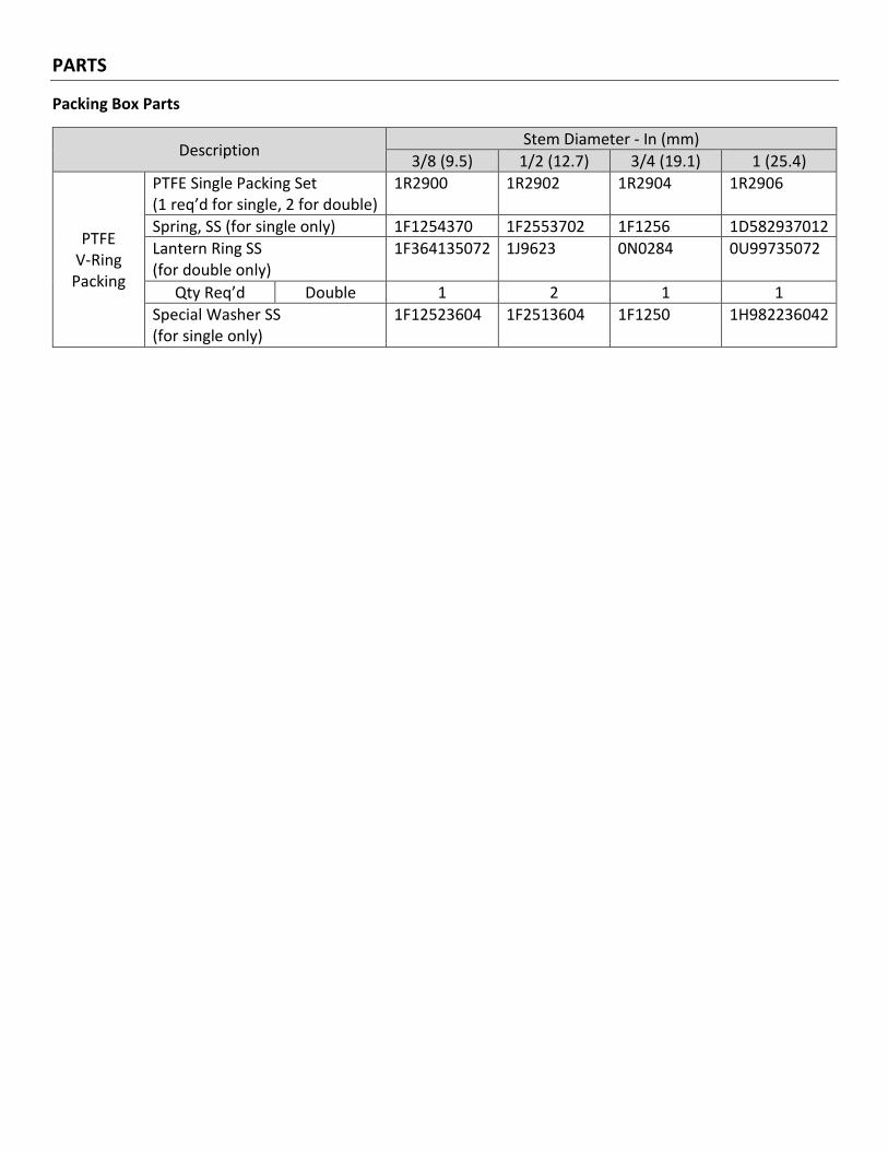
Packing Box Parts
Description Stem Diameter - In (mm)
3/8 (9.5) 1/2 (12.7) 3/4 (19.1) 1 (25.4)
PTFE V-Ring
Packing
PTFE Single Packing Set (1 req’d for single, 2 for double)
1R2900 1R2902 1R2904 1R2906
Spring, SS (for single only) 1F1254370 1F2553702 1F1256 1D582937012
Lantern Ring SS (for double only)
1F364135072 1J9623 0N0284 0U99735072
Qty Req’d Double 1 2 1 1
Special Washer SS (for single only)
1F12523604 1F2513604 1F1250 1H982236042
Head Office
3900 101 Street
Edmonton, Alberta
T6E 0A5
Canada
Office: (780) 437-3055
Fax: (780) 436 5461
Calgary Sales Office
205, 2323 – 32 Avenue NE
Calgary, Alberta
T2E 6Z3
Canada
Office: (403) 250-1416
Fax: (403) 291-9487
Website: www.cvs-controls.com Email: [email protected]
November 2020
Related Documents


![]Ys}˝‡—dUeconweb.ucsd.edu/~v2crawford/Camerer_Ch1intro.pdf]Ys}˝‡—dU ... d(d](https://static.cupdf.com/doc/110x72/613063f61ecc515869441112/-ysaa-v2crawfordcamererch1intropdf-ysaadu-dd.jpg)