HAL Id: hal-03518059 https://hal.archives-ouvertes.fr/hal-03518059 Submitted on 8 Jan 2022 HAL is a multi-disciplinary open access archive for the deposit and dissemination of sci- entific research documents, whether they are pub- lished or not. The documents may come from teaching and research institutions in France or abroad, or from public or private research centers. L’archive ouverte pluridisciplinaire HAL, est destinée au dépôt et à la diffusion de documents scientifiques de niveau recherche, publiés ou non, émanant des établissements d’enseignement et de recherche français ou étrangers, des laboratoires publics ou privés. Cutting performance of laser assisted diamond turning of calcium fluoride with different crystal orientations Charan Bodlapati, Di Kang, Jayesh Navare, Robert Turnbull, yuxiang Zhong, Hossein Shahinian To cite this version: Charan Bodlapati, Di Kang, Jayesh Navare, Robert Turnbull, yuxiang Zhong, et al.. Cutting perfor- mance of laser assisted diamond turning of calcium fluoride with different crystal orientations. Applied optics, Optical Society of America, 2021, 60 (9), pp.2465-2470. 10.1364/AO.415265. hal-03518059

Welcome message from author
This document is posted to help you gain knowledge. Please leave a comment to let me know what you think about it! Share it to your friends and learn new things together.
Transcript
HAL Id: hal-03518059https://hal.archives-ouvertes.fr/hal-03518059
Submitted on 8 Jan 2022
HAL is a multi-disciplinary open accessarchive for the deposit and dissemination of sci-entific research documents, whether they are pub-lished or not. The documents may come fromteaching and research institutions in France orabroad, or from public or private research centers.
L’archive ouverte pluridisciplinaire HAL, estdestinée au dépôt et à la diffusion de documentsscientifiques de niveau recherche, publiés ou non,émanant des établissements d’enseignement et derecherche français ou étrangers, des laboratoirespublics ou privés.
Cutting performance of laser assisted diamond turningof calcium fluoride with different crystal orientations
Charan Bodlapati, Di Kang, Jayesh Navare, Robert Turnbull, yuxiang Zhong,Hossein Shahinian
To cite this version:Charan Bodlapati, Di Kang, Jayesh Navare, Robert Turnbull, yuxiang Zhong, et al.. Cutting perfor-mance of laser assisted diamond turning of calcium fluoride with different crystal orientations. Appliedoptics, Optical Society of America, 2021, 60 (9), pp.2465-2470. �10.1364/AO.415265�. �hal-03518059�

Experimental observations on cuttingperformance of laser assisted diamond turningof calcium fluoride with different crystalorientationsCHARAN BODLAPATI,1 DI KANG,1 JAYESH NAVARE,1 ROBERTTURNBULL,1 YUXIANG ZHONG,1 AND HOSSEIN SHAHINIAN1,*
1Micro-LAM, Inc., 5960 S Sprinkle Road, Portage, MI 49002, USA*[email protected]
Abstract: In this paper single point diamond turning (SPDT) of single crystal CaF2 usingµ-LAM process is studied. The paper focuses on how crystal orientation of the workpiece caninfluence tool wear and e�ciency of the cutting process. Cutting experiments were performedon single crystal CaF2 with <100>, <111> and <211> crystal orientations. The tool failed atthe smallest cutting distance for <111> crystal orientation whereas the tool failure on <100>orientation occurred at the longest cutting length. Tool life for cutting the <211> and <111>crystal orientations was found to be 92% and 67% to that of tool life during cutting <100>orientation. To explain the results obtained, an anisotropic model based on schmid’s law wasused. It is shown that an inverse correlation between the resistance to plastic deformation andmaximum cutting distance without inducing any brittle fracture can be established.
© 2021 Optical Society of America under the terms of the OSA Open Access Publishing Agreement
1. Introduction
SPDT process has enabled e�cient mass production of freeform and aspherical optics. Being adeterministic process, SPDT is more e�cient for mid to large volume optics production thantraditional optical fabrication techniques like grinding and polishing. In a typical SPDT setup,single crystal diamonds with a defined cutting edge are used as cutting tools. High degree ofvibration isolation and thermal stability coupled with high end optical encoders enable nanometerlevel positional repeatability of the machine axes [1–3].
The main limitation of SPDT is the restricted number of machinable materials. Machinabilityrefers to the ability to achieve ductile material removal without significant tool wear. InitiallySPDT was only used to cut soft metals and plastics, but later diamond turning of single crystalmaterials like Ge, Si etc. was investigated [4–6]. Tool wear and brittle fractured zones werethe main problems with SPDT of IR optics like Si and CaF2 [7, 8]. Brittle fractured zones onsurface of optics implicates highly deformed grains beneath the surface which is detrimental tomechanical and optical performance [9].
CaF2 has up to 90% transmission in both IR and UV wavelength ranges [10]. It has a veryhigh Abbe number and low dispersion which makes the design of narrow-band laser beam guidesystems with CaF2 optical elements quite feasible. It is particularly well suited for manufacturinglenses, preproduction lithographic lenses, prisms and mirrors for dark field imaging systems,large-scale microlithography systems and excimer lasers [11].
Studies on machining di�erent single crystal materials suggest that crystal orientation of theworkpiece material a�ects shear angle and cutting forces. Single crystal materials like CaF2
exhibit brittle fractured zones on the surface [8]. This behavior is attributed to di�erent crystalorientations having di�erent cleavage planes [12,13]. Literature [14–17] also suggest that thecrystallographic structure of CaF2 a�ects the brittle-ductile transition zone and surface qualityof the machined optic. Degree of priority between slipping deformation or brittle fracture is

determined by crystal orientation. Slipping deformation is the main mechanism to create anoptical surface. [16] has studied the anistropic behavior of the crystal can impact the criticaldepth of cut for ductile material removal.
The capability of machining <211> crystal oriented calcium fluoride crystal using the µ-LAMprocess was studied in [18]. It was shown that the µ-LAM system can achieve improved form,cosmetics and promote ductile material removal. This work is focused on building upon theexisting literature and to determine how the laser assisted machining of CaF2 is a�ected by itscrystallographic properties. The study is specifically focused on how the process responds tothree di�erent crystal orientation of the workpiece material.
2. Previous work
The µ-LAM process uses an IR laser directed at the cutting edge of the tool. The laser deliverysystem consists of a series of optics that direct the 1 µm wavelength Nd:YAG laser towards thetool edge, and is embedded in a custom designed tool post (OPTIMUST+1) shown in Figure 1(b).It is speculated that absorbed laser power thermally softens the material and facilitates ductilematerial removal, see Figure 1(a). The localized heating due to laser is limited to an area of <300 µm ⇥ 300 µm, most of the heat absorbed by the material is dissipated through the chips [19].
The tool post consists of a tool holder and an assembly holding the laser delivery opticalsystem (LDOS). The tool height with respect to the spindle centerline can be adjusted usinga di�erential screw mechanism embedded in the tool post. The assembly holding the LDOScomprises of micrometers that allow the alignment of laser beam with respect to the tool edge.
Fig. 1. (a) Overview of µ-LAM process (b) OPTIMUST+1 tool post
The µ-LAM process has proved to enhance the cutting performance of IR materials like Silicon,Ge and ZnS [19–21]. Machining of single-crystal Si samples using the µ-LAM process exhibitedlittle to no brittle fracture on the surface and the potential of extending the diamond tooling lifeby 150% [19]. Machining germanium using the µ-LAM process produced lower post machiningresidual stresses on the surface relative to conventional diamond turning. [20].
In [22], convex sample of single crystal CaF2 was machined to demonstrate a direct comparisonbetween conventional diamond turning and the µ-LAM process . The form error data is shownin Figure 2 [22]. The brittle fracture pattern near the center was far more severe when the partwas machined with conventional diamond turning, see Figure 2(a) and 2(b). With conventionaldiamond turning, clear defects and zones exhibiting brittle fractures were seen. The improvedsurfaces of the materials with the addition of the µ-LAM process, implied that the local heatingof the laser, facilitated the ductile cutting of CaF2.

Fig. 2. Form error measurements for the CaF2 sample. (a) without µ-LAM (b) withµ-LAM [22]
In [18], a set of cutting experiments with conventional diamond turning and with the µ-LAMprocess was performed on a <211> crystal oriented CaF2 with identical machining conditions.The part machined with the µ-LAM process had smaller brittle fracture zones, see Figure 3 [18].Figure 3 suggest that the overall forces during machining the sample using the µ-LAM processwere lower. It was shown that the µ-LAM process can achieve improved form, cosmetics andpromote ductile material removal.
Fig. 3. Form error measurements for the CaF2 sample. (a) without µ-LAM (b) withµ-LAM [18]
3. Experimental equipment
3.1. Test bed
The testing was done on a Nanotech 250 ultraprecision lathe (UPL), shown in Figure 4 (a).Nanotech 250 consists of 2 axis – X and Z which were computerized numerically controlled with200 mm travel. The positional repeatability of the stages was less than 10 nm. Vibrations duringmachining were minimized using the active and passive damping system. The workpiece samplewas mounted on a PI IS0 5.5-PG high speed air-bearing spindle. The spindle had a maximumrpm of 10,000. The laser unit was controlled with a laser control module (LCM) shown beside

Nanotech 250 UPL in Figure 4 (a). Figure 4 (b) shows the OPTIMUST+1 tool post mounted onthe machine table. The repeatability of laser spot exiting the tool was achieved using alignmentand calibration procedures outlined in [17].
Fig. 4. Experimental setup. (a) LCM integrated with Nanotech 250 UPL (b) test bedwith OPTIMUST+1 tool post
3.2. Test samples
Three CaF2 samples with di�erent crystal orientations were used. The details about the samplesare listed in Table 1. Siemens D5000 X-ray di�ractometer (XRD) with Cu KU radiation at 20 kVand 5 mA was used to measure the crystal orientation of the CaF2 samples. The beam size wasapproximately 2 mm ⇥ 12 mm.
Table 1. Test samples
Sample Crystal orientation Diameter (mm) Geometry
S1 <100> 25 Flat
S2 <111> 32 Flat
S3 <211> 64 Flat
All samples were pre-diamond turned to ensure that the surfaces were free of tilt, grindingmarks and any other surface defects.
3.3. Machining conditions
Three diamond tools with identical geometries were used. Before each test, a brass witnesssample was cut to correct for tool o�sets in horizontal and vertical directions with respect to centerof the spindle. The tool o�sets were less than 1 µm. The test conditions and cutting parametersare listed in Table 2. As the feed was di�erent, the results of the study are presented relativeto the track length. The feed for S1 and S2 was lower compared to S3 due to the emergenceof brittle fracture zones on S1 and S2 at higher feeds. The tests were concluded when brittlefracture zones on the surface were visible under a 15 W observation fluorescent lamp.

Table 2. Testing conditions
SampleTool
radius(mm)
SpindleRPM
Feed(mm/min)
Depth of cut(µm)
Laserpower(W)
Cuttingfluid
S1 0.5 4500 3.375 1 2 OMS
S2 0.5 4500 3.375 1 2 OMS
S3 0.5 4500 4.5 1 2 OMS
3.4. Metrology
The surface roughness measurements were taken using a Zygo ZeGage PRO HR white lightinterferometer. Fourth order Chebyshev polynomials were removed from all the measurements.The measurements were taken using 20⇥ Mirau objective with a lateral resolution of 434 nm anda detector resolution of 1000⇥1000 pixels. To quantify the impact of the machining tests on thesurface roughness of the samples, three statistical parameters - RMS (Sq) of the surface, skewness(Ssk) of the data, and kurtosis (Sku) were used. The roughness measurements were taken afterevery two cycles of cutting. Multiple surface roughness measurements with a minimum samplesize of 3 per sample were taken. All the surface roughness statistics were averaged and presentedin section 4.
4. Results
Machined surfaces were inspected under a 15 W observation fluorescent lamp. Brittle fracturezones were observed on S2 at a shorter track length, followed by S3. Brittle fracture zones on S1were observed at larger track length.
Fig. 5. (a) RMS surface roughness vs track length (b) kurtosis vs track length (c)Skewness vs track length

Figure 5(a),(b) and (c) shows the evolution of the surface roughness statistical metrics withthe cutting track length for all three samples. The RMS surface roughness was same at smallertrack lengths for three crystal orientations but RMS surface roughness on <111> orientation washigher at much shorter track length (6.4 km) compared to <100> (10.4 km) and <211> (9.6 km).Figure 5(a) shows the variation of RMS surface roughness with track length. At smaller tracklength, RMS surface roughness values for S1, S2 and S3 were identical. However, at the theconclusion of testing, surface roughness of S2 increased by approximately 400% compared to<100> and <211>.
Ssk and Sku data for <111> crystal orientation was larger relative to other orientations evenfor small track lengths (<2.5 km), see Figures 5(b) and 5(c). Figure 5(b) shows the variation ofkurtosis with track length. S1 and S3 showed similar trend throughout the testing but kurtosis ofS2 was 166 times higher than the other two samples. Figure 5(c) shows the variation of skewnesswith track length. Ssk values for S2 showed an upward trend with a slope of 1.84 per km of tracklength, unlike consistent Ssk values for S1 and S3. Larger values of Ssk and Sku indicate anuneven distribution of height data, indicating the existence of outliers or fractured zones on thesurface, which are in agreement with visual inspections of the surface.
The diamond cutting edge was imaged after completing the experiments to assess the tool wear.Figure 6(a), 6(b) and 6(c) show the tool wear after cutting samples S1, S2 and S3 respectively.Thetotal track length on sample S1 and S3 was 10.4 km and 9.6 km respectively, whereas the tracklength on sample S2 was 6.4 km. For <100> orientation, the tool cut 62% more than the tool thatcut <111> orientation. For <211> orientation, the tool cut 50% more than the tool that cut <111>orientation, see Figure 6. Height of the wear land on clearance face was measured to be 2.24 µm,1.48 µm and 1.76 µm for <100>, <111> and <211> orientations respectively.
Fig. 6. Tool wear on CaF2 samples (a) S1 <100> (b) S2 <111> and (c) S3 <211> afterconclusion of the tests
5. Crystal anisotropy model and explanation of results
Tool wear and surface roughness data suggest that di�erent orientations have varied cuttingperformances. A model was developed to provide a physical explanation that varied crystalorientation cause variation in cutting performance. This model can be used to correlate thesurface roughness and tool wear results obtained to crystallographic orientation. The modelcompares the resolved shear stress on the sample as the tool is rotated across the surface atall possible tool angles. The stresses generated due to cutting forces (in all the directions) areresolved on to the most active slip plane of single crystal CaF2 using Schmid’s law [23]. Plasticdeformation initiates due to movement of dislocations along slip planes in a crystal [24]. The setof slip planes and associated slip directions constitute a slip system. For CaF2, a cubic crystalwith a body-centered structure, {100}<100> is the most active slip system [25–29]. The schmidfactor tensor can be calculated as shown in equation 1 [23].

"̃ =12((Yp
) ⌦ Yd) + (Yp ⌦ Yd) )) (1)
where Yp is the unit vector of the normal of the slip plane, and Yd is the unit vector of the slipdirection.
Fig. 7. Illustration of coordinate system, stress tensor, and rotation angles U, V and Wusing a sample with a <111> (surface normal) crystal orientation.
Figure 7 shows the global coordinate system and the slip plane for a <111> oriented sample.It should be noted that bunge euler convention was used to represent crystal orientation in themodel [30, 31]. The rotation matrix ('̃) is used to transform the stresses from the machinecoordinate system (global) to the slip plane (local) coordinate system based on euler angles. '̃ iscalculated as follows [32].
'̃ = (⌫̃⇠̃⇡̃)) (2)
where B,C and D are transformation tensors that rotates a given vector from the machinecoordinate system to local coordinate system. B,C and D are calculated using following relationsfor rotations U, V and W respectively.
⌫̃=
266666664
cosU � sinU 0
sinU cosU 0
0 0 1
377777775⇠̃=
266666664
1 0 0
0 cos V � sin V
0 sin V cos V
377777775⇡̃=
266666664
cos W � sin W 0
sin W cos W 0
0 0 1
377777775V is the angle between the orientation of the crystal plane and the slip plane, W is the angle
between the slip plane and the slip direction. U corresponds to the angle between the surfacenormal and the point of application of force on the surface (see Figure 7). V and W angles fordi�erent CaF2 crystal orientations are listed in Table 3.

Table 3. Euler angles for di�erent crystal orientations
Crystal orientation V W
<100> 0° 0°
<211> 35.3° 45°
<111> 54.74° 45°
To estimate the cutting induced stresses on the workpiece, cutting and thrust forces werecalculated using Arcona’s empirical force model [33]. The model estimates the cutting force (�2)and thrust force (�C ) using equations 3 and 4.
�2 =��2
3
⇣ cot(q)p3
+ 1⌘+ µ� 5
⇣4.1�
r�
⇢
⌘(3)
�C = µ⇣��2
3
⇣ cot(q)p3
+ 1⌘+ � 5
⇣4.1�
r�
⇢
⌘(4)
where � is the knoop hardness, �2 is uncut chip area, µ is coe�cient of friction, � 5 is contactarea between the tool’s flank face and machined surface and ⇢ is the Young’s modulus. Basedon the experimental work of marsh [34] thrust force is about 150% of cutting force in SPDT ofcrystalline materials such as CaF2. Using the force ratio, the shear angle (q) was calculated to be24°. The ratio of �2 to �C calculated using equations 3 and 4, was 0.72.where µ is calculated using the following relation [33]
µ =cos q �
sin qp
3cos qp
3+ sin q
(5)
� 5 is calculated using the following relation [33]
� 5 = ! 0⇣A + F + 2B
3 tan(X)⌘
(6)
where ! 0 is tool-chip contact area projected onto the surface (see Figure 8).A is tool nose radius. which is 0.5 mm.F is the flank wear land, is 100 µm based on measured micrsocopic image from the tool nose.B is spring back of the surface after being deformed, estimated to be 0.03% of depth of cut [35,36].X is clearance angle of the tool, which is 10°.

Fig. 8. Tool-chip interface for non-overlapping cutting geometry, cutting direction outof the page [33]
Table 4 lists the values of the terms in equations 3 and 4 to calculate �2 and �C .
Table 4. Parameter values used in equation 4 and 5
Parameter Value
� (#/<<2) 1552 [35]
µ 1.19
�2 (<<2) 1e-6
� 5 (<<2) 1e-2
⇢ (#/<<2) 75800 [35]
The contact area � 5 >> �2 , thus the stress due to thrust force (fII) is negligible whencompared to the shear cutting stress (fGI). The stress tensor is normalized with respect to fGI .Therefore, (f̃) can be expressed as shown below.
f̃ =
266666664
0 0 0
0 0 1
0 1 0
377777775The rotated stress tensor (f̃0) for a specific orientation is given by equation 7 [32].
f̃0 = '̃ · f̃ · '̃) (7)
The resolved shear stress (g') can be computed at each rotation angle U from 0°to 360°usingequation 8, i.e. Schmids law.
g' = f̃0 : "̃ (8)
The critical resolved shear stress (g') per unit applied stress for six active slip systems of CaF2 ateach possible angular position of the diamond tool with respect to the surface of the workpiece isplotted in Figure 9.
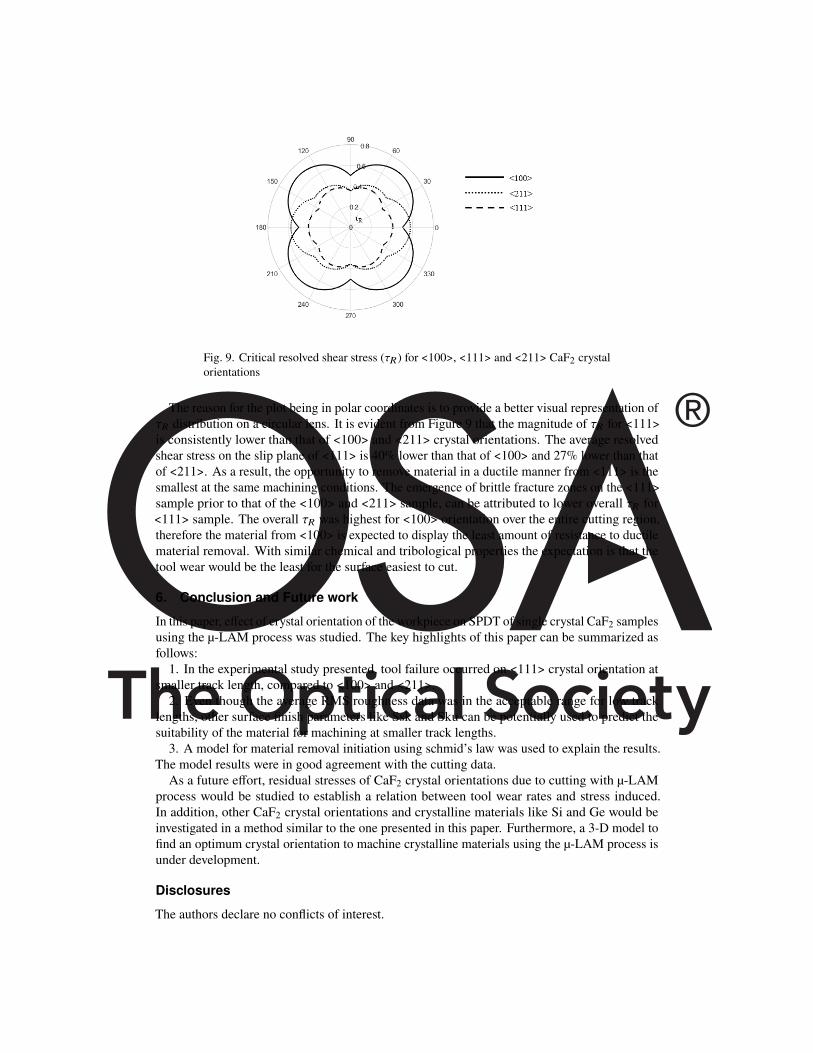
Fig. 9. Critical resolved shear stress (g') for <100>, <111> and <211> CaF2 crystalorientations
The reason for the plot being in polar coordinates is to provide a better visual representation ofg' distribution on a circular lens. It is evident from Figure 9 that the magnitude of g' for <111>is consistently lower than that of <100> and <211> crystal orientations. The average resolvedshear stress on the slip plane of <111> is 40% lower than that of <100> and 27% lower than thatof <211>. As a result, the opportunity to remove material in a ductile manner from <111> is thesmallest at the same machining conditions. The emergence of brittle fracture zones on the <111>sample prior to that of the <100> and <211> sample, can be attributed to lower overall g' for<111> sample. The overall g' was highest for <100> orientation over the entire cutting region,therefore the material from <100> is expected to display the least amount of resistance to ductilematerial removal. With similar chemical and tribological properties the expectation is that thetool wear would be the least for the surface easiest to cut.
6. Conclusion and Future work
In this paper, e�ect of crystal orientation of the workpiece on SPDT of single crystal CaF2 samplesusing the µ-LAM process was studied. The key highlights of this paper can be summarized asfollows:
1. In the experimental study presented, tool failure occurred on <111> crystal orientation atsmaller track length, compared to <100> and <211>.
2. Even though the average RMS roughness data was in the acceptable range for low tracklengths, other surface finish parameters like Ssk and Sku can be potentially used to predict thesuitability of the material for machining at smaller track lengths.
3. A model for material removal initiation using schmid’s law was used to explain the results.The model results were in good agreement with the cutting data.
As a future e�ort, residual stresses of CaF2 crystal orientations due to cutting with µ-LAMprocess would be studied to establish a relation between tool wear rates and stress induced.In addition, other CaF2 crystal orientations and crystalline materials like Si and Ge would beinvestigated in a method similar to the one presented in this paper. Furthermore, a 3-D model tofind an optimum crystal orientation to machine crystalline materials using the µ-LAM process isunder development.
Disclosures
The authors declare no conflicts of interest.

References1. J. Bryan, “Design and construction of an ultraprecision 84 inch diamond turning machine,” Precis. Eng. 1, 13–17
(1979).2. T. T. Saito, “Diamond turning of optics,” Opt. Eng. 15, 155431 (1976).3. J. Bryan, “International status of thermal error research (1990),” CIRP annals 39, 645–656 (1990).4. T. Nakasuji, S. Kodera, S. Hara, H. Matsunaga, N. Ikawa, and S. Shimada, “Diamond turning of brittle materials for
optical components,” CIRP annals 39, 89–92 (1990).5. W. Blackley and R. Scattergood, “Ductile-regime machining model for diamond turning of brittle materials,” Precis.
engineering 13, 95–103 (1991).6. T. Leung, W. Lee, and X. Lu, “Diamond turning of silicon substrates in ductile-regime,” J. materials processing
technology 73, 42–48 (1998).7. R. G. Jasinevicius, J. G. Duduch, and A. J. Porto, “Investigation on diamond turning of silicon crystal-generation
mechanism of surface cut with worn tool,” J. Braz. Soc. Mech. Sci. 23, 241–252 (2001).8. X. C. Luo, J. N. Sun, W. L. Chang, and J. M. Ritchie, “Single point diamond turning of calcium fluoride optics,” in
Key Engineering Materials, vol. 516 (Trans Tech Publ, 2012), pp. 408–413.9. J. Yan, T. Asami, H. Harada, and T. Kuriyagawa, “Fundamental investigation of subsurface damage in single
crystalline silicon caused by diamond machining,” Precis. Eng. 33, 378–386 (2009).10. A. A. Kaminskii, Laser crystals: their physics and properties, vol. 14 (Springer, 2013).11. J. Ewing, “Excimer lasers at 30 years,” Opt. photonics news 14, 26–31 (2003).12. W. Lee, S. To, and C. Cheung, “E�ect of crystallographic orientation in diamond turning of copper single crystals,”
Scripta materialia (2000).13. Z. Yuan, W. Lee, Y. Yao, and M. Zhou, “E�ect of crystallographic orientation on cutting forces and surface quality in
diamond cutting of single crystal,” CIRP annals 43, 39–42 (1994).14. L. Chen, L. Hu, C. Xiao, Y. Qi, B. Yu, and L. Qian, “E�ect of crystallographic orientation on mechanical removal of
caf2,” Wear 376, 409–416 (2017).15. J. Yan, J. Tamaki, K. Syoji, and T. Kuriyagawa, “Single-point diamond turning of caf 2 for nanometric surface,” The
Int. J. Adv. Manuf. Technol. 24, 640–646 (2004).16. X. Chen, J. Xu, H. Fang, and R. Tian, “Influence of cutting parameters on the ductile-brittle transition of single-crystal
calcium fluoride during ultra-precision cutting,” The Int. J. Adv. Manuf. Technol. 89, 219–225 (2017).17. Y. Namba, N. Ohnishi, S. Yoshida, K. Harada, K. Yoshida, and T. Matsuo, “Ultra-precision float polishing of calcium
fluoride single crystals for deep ultra violet applications,” CIRP Annals 53, 459–462 (2004).18. C. Bodlapati, J. Navare, D. Zaytsev, D. Kang, H. Mohammadi, D. Ravindra, M. Arlt, and H. Shahinian, “E�ect of
laser-assisted diamond turning (micro-lam) on non-optimally oriented calcium fluoride crystal,” 34th ASPE Annu.Meet. (2019).
19. H. Shahinian, J. Navare, D. Zaytsev, and D. Ravindra, “Microlaser assisted diamond turning of precision siliconoptics,” Opt. Eng. 58, 092607 (2019).
20. H. Shahinian, K. Di, J. Navare, C. Bodlapati, D. Zaytsev, and D. Ravindra, “Ultraprecision laser-assisted diamondmachining of single crystal ge,” Precis. Eng. (2020).
21. J. Navare, D. Kang, D. Zaytsev, C. Bodlapati, D. Ravindra, and H. Shahinian, “Experimental investigation on thee�ect of crystal orientation of diamond tooling on micro laser assisted diamond turning of zinc sulfide,” ProcediaManuf. 48, 606–610 (2020).
22. H. Shahinian, J. Navare, D. Zaytsev, S. Kode, F. Azimi, and D. Ravindra, “E�ect of laser-assisted diamond turning(micro-lam) on form and finish of selected ir crystals,” in 33rd annual meeting of American Society for PrecisionEngineering, Las Vegas, Nevada, (2018), pp. 1–5.
23. E. Schmid and W. Boas, Kristallplastizität: mit besonderer Berücksichtigung der Metalle, vol. 17 (Springer-Verlag,2013).
24. A. F. Liu, Mechanics and mechanisms of fracture: an introduction (ASM International, 2005).25. S. Azami, H. Kudo, Y. Mizumoto, T. Tanabe, J. Yan, and Y. Kakinuma, “Experimental study of crystal anisotropy
based on ultra-precision cylindrical turning of single-crystal calcium fluoride,” Precis. Eng. 40, 172–181 (2015).26. Y. J. Lee, A. Chaudhari, J. Zhang, and H. Wang, “Thermally assisted microcutting of calcium fluoride single crystals,”
in Simulation and experiments of material-oriented ultra-precision machining, (Springer, 2019), pp. 77–102.27. Y. Mizumoto and Y. Kakinuma, “Revisit of the anisotropic deformation behavior of single-crystal caf2 in orthogonal
cutting,” Precis. Eng. 53, 9–16 (2018).28. Y. Mizumoto, T. Aoyama, and Y. Kakinuma, “Basic study on ultraprecision machining of single-crystal calcium
fluoride,” Procedia Eng. 19, 264–269 (2011).29. A. Munoz, A. Domínguez-Rodríguez, and J. Castaing, “Slip systems and plastic anisotropy in caf 2,” J. materials
science 29, 6207–6211 (1994).30. H.-J. Bunge, Texture analysis in materials science: mathematical methods (Elsevier, 2013).31. “File:eulerangles.svg - wikimedia commons,” https://commons.wikimedia.org/wiki/File:
Eulerangles.svg. (Accessed on 04/07/2020).32. D. Depriester, “Computing euler angles with bunge convention from rotation matrix,” (2018).33. C. Arcona and T. A. Dow, “An empirical tool force model for precision machining,” ASME. J. Manuf. Sci. Eng.
(1998).

34. E. R. Marsh, B. P. John, J. A. Couey, J. Wang, R. D. Grejda, and R. R. Vallance, “Predicting surface figure in diamondturned calcium fluoride using in-process force measurement,” J. Vac. Sci. & Technol. B: Microelectron. NanometerStruct. Process. Meas. Phenom. 23, 84–89 (2005).
35. “Caf2_en.cdr,” http://www.tydexoptics.com/pdf/caf2.pdf. (Accessed on 04/07/2020).36. M. J. Chen and W. B. Jiang, “Analysis of mechanical property of crystal caf2 and e�ects of tool rake angle on ductile
machining process,” in Advanced Materials Research, vol. 126 (Trans Tech Publ, 2010), pp. 891–896.
View publication statsView publication stats
Related Documents