CUTTER SUCTION DREDGER 500 LIST OF EQUIPMENT CSD 500/2007/01 DREDGING CUTTER SUCTION DREDGER 500 This leaflet is a brief summary from the original specification, which can be sent on request Specifications are subject to modification without notice. DAMEN DREDGING EQUIPMENT Edisonstraat 32 3861 NE Nijkerk Member of the DAMEN SHIPYARDS GROUP P.O. Box 1021 3860 BA Nijkerk The Netherlands No part of this leaflet may be reproduced in any form, by print, photo print, microfilm, or any other means, without written permission from Damen Dredging Equipment. phone fax [email protected] www.damendredging.com +31 (0)33 247 40 40 +31 (0)33 247 40 60 HULL AND SUPERSTRUCTURE ■ The dredger is dismountable in main pontoon, four side pontoons, operating cabin, cutter ladder, gantry and spud poles, which permits easy transportation by road, rail or ship to nearly any location ■ Heavy duty coupling system with hooks at hull bottom and bolt connection on deck level, making (dis)assembly on land or afloat possible in a very short time and an easy way ■ Three separate engine room hatches for optimal maintenance of engines and dredge pump ■ Collision bulkhead at the aft of the main pontoon ■ Double bollard on fore and aft and one single in the middle at each side of the dredger ■ Store with large hatch, wooden floor and shelves, and lighting ■ Chequered aluminium floor plates in engine room ■ Removable railing made of stanchions and stainless steel wires ■ Marine coating system and cathodic protection for inland- and seawater use OPERATING CABIN ■ Very spacious operating cabin, easily accommodating 2/3 persons. The cabin is ergonomic designed according to the latest insights ■ Standard equipped with air- conditioning and heating ■ Mounted on shock absorbers to minimise vibration and noise levels ■ Constructed of steel and well insulated ■ Two ergonomic designed control panels with a dredge master chair in between ■ Dark tinted double glassed windows all around of which one can be opened, providing excellent view of all essential deck equipment ■ Window wiper at front- and aft window DREDGE EQUIPMENT ■ High efficiency dredge pump, built up with Ni-hard4 wearing plates and pump casing and Bainitic Nodulair impeller ■ The shaft is sealed using a mechanical seal ■ Cutter shaft supported by roller bearings mounted in an oil filled casing ■ The slow running hydraulic cutter motor is well protected in the cutter unit ■ Well designed cutter with replaceable wear resistant pick points or chisels ■ Straight suction pipe for optimal suction performance and low wearing characteristics ■ Inspection piece with hatch in front of dredge pump ENGINE ROOM MACHINERY ■ Latest model Caterpillar engines, complying with IMO regulations ■ Closed freshwater cooling system for engines with box coolers ■ Engines can be started from control panel both in engine room and in operating cabin ■ Dredge pump driven through a gearbox, with electric/hydraulic clutch operated from the operating cabin ■ Various auxiliary equipment, such as generator, bilge-, cooling water pumps, electric driven fans DECK MACHINERY ■ Side wire winches operated with proportional constant tension system, guaranteeing a stable cutter process ■ Spud poles which are hoisted by hydraulic cylinders. Operation including slow fall from operating cabin. Slow fall operation is also possible manually, at the spud hoisting cylinders HYDRAULIC INSTALLATION ■ All hydraulic motors and cylinders are operated by two variable axial piston pumps driven by the auxiliary engine. The system includes: stainless steel tank, all required electric operated valves, filters, gauges etc. ELECTRIC INSTALLATION ■ The dredge pump engine is started by its own battery set. The set is charged by the alternator of the dredge pump engine. The other two 24 VDC battery sets are charged by the alternator of the auxiliary engine. One set for starting the auxiliary engine and the other for the instrumentation and emergency lighting. The 230/400 VAC installation for the general lighting, electric pumps, ventilation etc. is fed by the generator. The generator is driven by the auxiliary engine. The power distribution board is placed in the engine room. Communication between operating cabin and engine room is done over a PLC bus system. Electric connections between cabin and main pontoon with multi-pin socket for quick (dis) assembly without the possibility of wrong connections. AUXILIARIES ■ Mooring lines, life saving equipment, navigation equipment ■ Set of tools including impeller hook and boatswain’s inventory ■ Start up spare parts LIST OF STANDARD EQUIPMENT GENERAL ■ Hull certification for sheltered waters ■ De-/increase cutter depth ■ Anchor boom installation ■ Spud carriage pontoon ■ Plain suction installation including jet water pump ■ Swivel connection for discharge pipeline ■ Jib crane for changing pump- and spare parts ■ Anchors ■ Day accommodation ■ Toilet facility ■ Navigation, search and deck lights for working at night ■ Valves in dredge pipes: • Non-return valve in discharge • pipe • Hydraulic operated valve in • suction/ discharge pipe • Automatic vacuum relief valve • in suction pipe DREDGING INSTRUMENTATION ■ Production calculation, existing of: • Velocity meter • Concentration meter • Yield indicator ■ Electronic revolution counter dredge pump ■ Dredge Profile Indicator ■ Positioning/ survey systems LIST OF OPTIONAL EQUIPMENT

Welcome message from author
This document is posted to help you gain knowledge. Please leave a comment to let me know what you think about it! Share it to your friends and learn new things together.
Transcript

CUTTER SUCTION DREDGER 500LIST OF EQUIPMENT
CSD
500
/200
7/01
DREDGING
CUTTER SUCTION DREDGER 500
This leaflet is a brief summaryfrom the original specification,which can be sent on request
Specifications are subject tomodification without notice.
D A M E N D R E D G I N G E Q U I P M E N T
Edisonstraat 323861 NE Nijkerk
Member of the DAMEN SHIPYARDS GROUP
P.O. Box 10213860 BA Nijkerk
The Netherlands
No part of this leaflet may be reproduced in any form, by print, photo print, microfilm, or any other means, without written permission from Damen Dredging Equipment.
phonefax
+31 (0)33 247 40 40+31 (0)33 247 40 60
HULL AND SUPERSTRUCTURE■ The dredger is dismountable in
main pontoon, four side pontoons,operating cabin, cutter ladder,gantry and spud poles, whichpermits easy transportation byroad, rail or ship to nearly anylocation
■ Heavy duty coupling system withhooks at hull bottom and boltconnection on deck level, making(dis)assembly on land or afloatpossible in a very short time andan easy way
■ Three separate engine roomhatches for optimal maintenanceof engines and dredge pump
■ Collision bulkhead at the aft ofthe main pontoon
■ Double bollard on fore and aftand one single in the middle ateach side of the dredger
■ Store with large hatch, woodenfloor and shelves, and lighting
■ Chequered aluminium floor platesin engine room
■ Removable railing made ofstanchions and stainless steelwires
■ Marine coating system andcathodic protection for inland-and seawater use
OPERATING CABIN■ Very spacious operating cabin,
easily accommodating 2/3persons. The cabin is ergonomicdesigned according to the latestinsights
■ Standard equipped with air-conditioning and heating
■ Mounted on shock absorbers to minimise vibration and noiselevels
■ Constructed of steel and wellinsulated
■ Two ergonomic designed controlpanels with a dredge master chairin between
■ Dark tinted double glassed
windows all around of which one can be opened, providingexcellent view of all essentialdeck equipment
■ Window wiper at front- and aftwindow
DREDGE EQUIPMENT■ High efficiency dredge pump,
built up with Ni-hard4 wearingplates and pump casing andBainitic Nodulair impeller
■ The shaft is sealed using amechanical seal
■ Cutter shaft supported by rollerbearings mounted in an oil filledcasing
■ The slow running hydraulic cuttermotor is well protected in thecutter unit
■ Well designed cutter withreplaceable wear resistant pickpoints or chisels
■ Straight suction pipe for optimalsuction performance and lowwearing characteristics
■ Inspection piece with hatch infront of dredge pump
ENGINE ROOM MACHINERY■ Latest model Caterpillar engines,
complying with IMO regulations■ Closed freshwater cooling system
for engines with box coolers ■ Engines can be started from
control panel both in engineroom and in operating cabin
■ Dredge pump driven through agearbox, with electric/hydraulicclutch operated from theoperating cabin
■ Various auxiliary equipment, suchas generator, bilge-, coolingwater pumps, electric driven fans
DECK MACHINERY■ Side wire winches operated with
proportional constant tensionsystem, guaranteeing a stablecutter process
■ Spud poles which are hoisted byhydraulic cylinders. Operationincluding slow fall from operatingcabin. Slow fall operation is alsopossible manually, at the spudhoisting cylinders
HYDRAULIC INSTALLATION■ All hydraulic motors and cylinders
are operated by two variable axialpiston pumps driven by theauxiliary engine. The systemincludes: stainless steel tank, allrequired electric operated valves,filters, gauges etc.
ELECTRIC INSTALLATION■ The dredge pump engine is
started by its own battery set.The set is charged by thealternator of the dredge pumpengine. The other two 24 VDCbattery sets are charged by thealternator of the auxiliary engine.One set for starting the auxiliaryengine and the other for theinstrumentation and emergencylighting. The 230/400 VACinstallation for the generallighting, electric pumps,ventilation etc. is fed by thegenerator. The generator is driven by the auxiliary engine.The power distribution board isplaced in the engine room.Communication betweenoperating cabin and engine roomis done over a PLC bus system.Electric connections betweencabin and main pontoon withmulti-pin socket for quick (dis)assembly without the possibilityof wrong connections.
AUXILIARIES■ Mooring lines, life saving
equipment, navigation equipment■ Set of tools including impeller
hook and boatswain’s inventory■ Start up spare parts
LIST OF STANDARD EQUIPMENT
GENERAL■■ Hull certification for sheltered
waters■■ De-/increase cutter depth■■ Anchor boom installation■■ Spud carriage pontoon ■■ Plain suction installation including
jet water pump■■ Swivel connection for discharge
pipeline■■ Jib crane for changing pump- and
spare parts
■■ Anchors■■ Day accommodation■■ Toilet facility■■ Navigation, search and deck
lights for working at night■■ Valves in dredge pipes:
• Non-return valve in discharge• pipe• Hydraulic operated valve in • suction/ discharge pipe• Automatic vacuum relief valve • in suction pipe
DREDGING INSTRUMENTATION■■ Production calculation, existing of:
• Velocity meter• Concentration meter • Yield indicator
■■ Electronic revolution counterdredge pump
■■ Dredge Profile Indicator■■ Positioning/ survey systems
LIST OF OPTIONAL EQUIPMENT
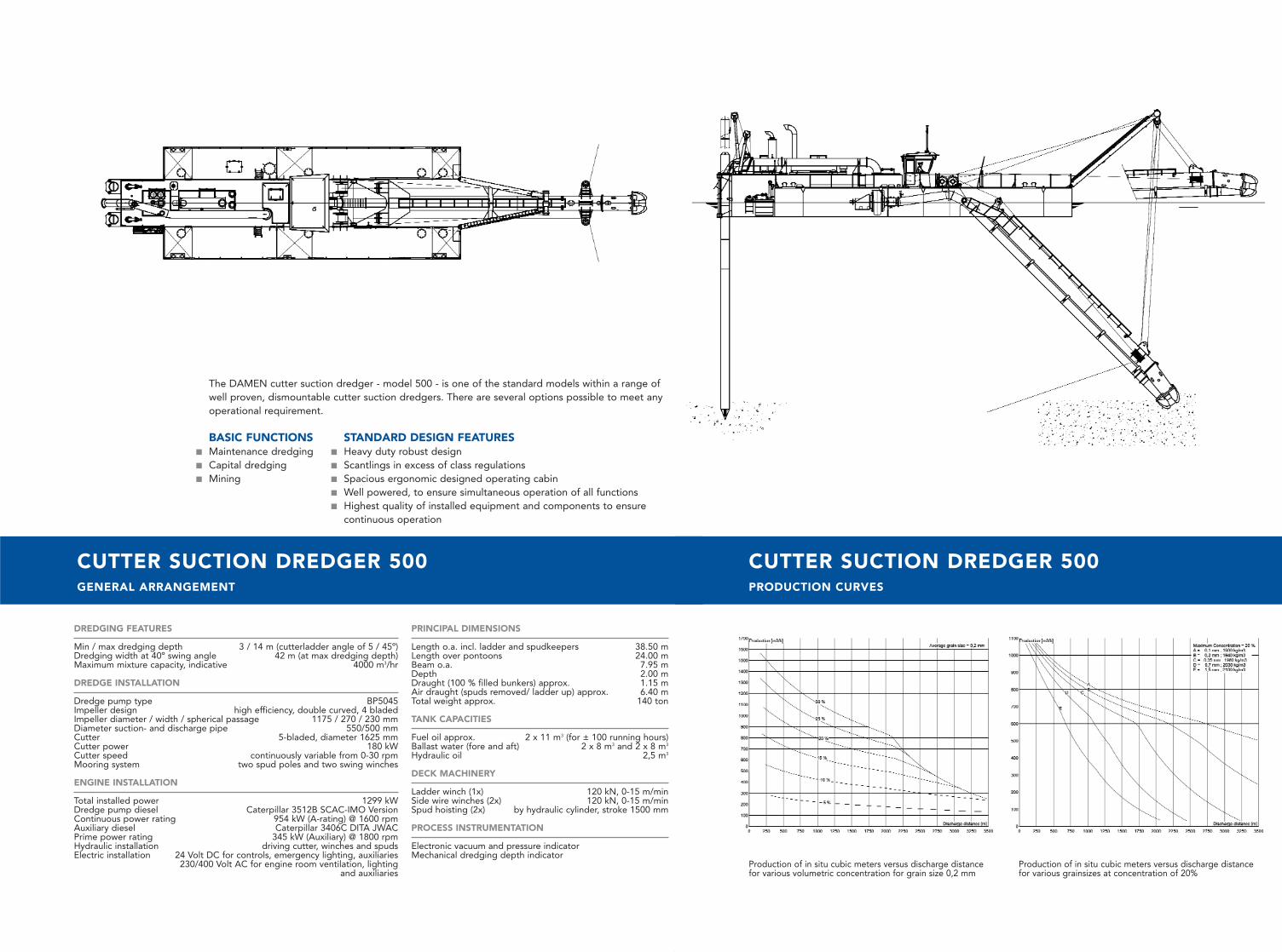
CUTTER SUCTION DREDGER 500GENERAL ARRANGEMENT
DREDGING FEATURES
Min / max dredging depth 3 / 14 m (cutterladder angle of 5 / 45º)Dredging width at 40º swing angle 42 m (at max dredging depth)Maximum mixture capacity, indicative 4000 m3/hr
DREDGE INSTALLATION
Dredge pump type BP5045Impeller design high efficiency, double curved, 4 bladedImpeller diameter / width / spherical passage 1175 / 270 / 230 mmDiameter suction- and discharge pipe 550/500 mmCutter 5-bladed, diameter 1625 mmCutter power 180 kW Cutter speed continuously variable from 0-30 rpmMooring system two spud poles and two swing winches
ENGINE INSTALLATION
Total installed power 1299 kWDredge pump diesel Caterpillar 3512B SCAC-IMO VersionContinuous power rating 954 kW (A-rating) @ 1600 rpmAuxiliary diesel Caterpillar 3406C DITA JWACPrime power rating 345 kW (Auxiliary) @ 1800 rpmHydraulic installation driving cutter, winches and spudsElectric installation 24 Volt DC for controls, emergency lighting, auxiliaries
230/400 Volt AC for engine room ventilation, lighting and auxiliaries
PRINCIPAL DIMENSIONS
Length o.a. incl. ladder and spudkeepers 38.50 mLength over pontoons 24.00 mBeam o.a. 7.95 mDepth 2.00 mDraught (100 % filled bunkers) approx. 1.15 mAir draught (spuds removed/ ladder up) approx. 6.40 mTotal weight approx. 140 ton
TANK CAPACITIES
Fuel oil approx. 2 x 11 m3 (for ± 100 running hours)Ballast water (fore and aft) 2 x 8 m3 and 2 x 8 m3
Hydraulic oil 2,5 m3
DECK MACHINERY
Ladder winch (1x) 120 kN, 0-15 m/minSide wire winches (2x) 120 kN, 0-15 m/minSpud hoisting (2x) by hydraulic cylinder, stroke 1500 mm
PROCESS INSTRUMENTATION
Electronic vacuum and pressure indicatorMechanical dredging depth indicator
CUTTER SUCTION DREDGER 500PRODUCTION CURVES
The DAMEN cutter suction dredger - model 500 - is one of the standard models within a range ofwell proven, dismountable cutter suction dredgers. There are several options possible to meet anyoperational requirement.
BASIC FUNCTIONS■ Maintenance dredging ■ Capital dredging ■ Mining
STANDARD DESIGN FEATURES■ Heavy duty robust design■ Scantlings in excess of class regulations■ Spacious ergonomic designed operating cabin■ Well powered, to ensure simultaneous operation of all functions ■ Highest quality of installed equipment and components to ensure
continuous operation
Production of in situ cubic meters versus discharge distancefor various volumetric concentration for grain size 0,2 mm
Production of in situ cubic meters versus discharge distancefor various grainsizes at concentration of 20%
Related Documents


