Models: VVV / VVH Geothermal Heat Pump • R-410A Refrigerant • 2.5, 4.0, 6.0 Ton Variable Speed Customer Manual

Welcome message from author
This document is posted to help you gain knowledge. Please leave a comment to let me know what you think about it! Share it to your friends and learn new things together.
Transcript

Models: VVV / VVH Geothermal Heat Pump
• R-410A Refrigerant • 2.5, 4.0, 6.0 Ton Variable Speed
Customer Manual

Customer Manual 5.2.1
2

Customer Manual 5.2.1
3

Customer Manual 5.2.1
Change is in the Air
You are about to experience a level of comfort and efficiency that many people
don’t even know exist.
4

Customer Manual 5.2.1
Thank You! Your investment Helps Everyone!
Your decision to own a Hydro-Temp system puts you in a unique position. Geothermal
heat-pumps are known for being GREEN, however green usually means giving something up. In your case not only will you be helping the environment now and for the future, you are providing yourself with the most comfortable indoor environment available today. It is
not often you can make an impact on others by providing for yourself.
5

Customer Manual 5.2.1
Thank you for purchasing your new Hydro-Temp geothermal heat pump. For your convenience please take a minute to record some critical information that could be very beneficial in the future. Customer Name: ___________________ Customer Phone Number: ____________ Dealer Name:______________________ Dealer Phone Number:_______________ Date of Installation: _________________ Model number: _____________________ Warranty Information: _______________ Serial number _____________________ Ground loop / Well Water information:
� Well Water: Gallons per minute ________ Discharge into ______________________ � Horizontal Loop: # of Circuits _____ Circuit length one way _____ft Average depth_____ft � Vertical Loop: # of Circuits ______ Circuit length one way ____ft � Pond Loop: # of Circuits ______ Total length per Circuit ____ft Depth where sunk _____ft � Other__________________________
Use this area to make a rough drawing of the loop in relation to the home.
One block equals ________ feet
Notes: ____________________________________________________________________________________________________________________________________________________________________________________________________________________________________________________________________________________________________________________________________________________________________________________________________________________________________________________________________________________________________________________________________________________________________________________________________________________________________________________________________________________________________________
6
Customer Manual 5.2.1
TABLE OF CONTENTS
CONTACT INFORMATION: .......................................................................................................................................................... 9
1.0 TRANSPORTATION & STORAGE ..................................................................................................................................... 9
2.0 ELECTRICAL HAZARD WARNINGS ................................................................................................................................. 9
3.0 PREVENTATIVE MAINTENANCE .................................................................................................................................... 10
4.1 PROTOSTAR / TOUCH SCREEN INSTRUCTIONS ........................................................................................................ 12
4.2 ZONE SENSOR / T-STAT ..................................................................................................................................................... 27
7

Customer Manual 5.2.1
MODEL NOMENCLATURE
V X X 1 XXXX X X X 1 X X XXX
SERIES: C = COMMERSIAL R = RESIDENTIAL V = V-STAR
UNIT BTU OUTPUT: BTU X 1000
CONFIGURATION: C = CORNER CONSOLE H = HORIZONTAL L = LONG CONSOLE N = NARROW CONSOLE O = COMPACT HORIZONTAL P = COMPACT VERTICAL R = ROOF TOP S= SPLIT V= VERTICAL W = WATER TO WATER F = COUNTER FLOW
COMPRESSOR SPEEDS: A = SINGLE SPEED B = TWO SPEED C = THREE SPEED D = FOUR SPEED E = FIVE SPEED F = SIX SPEED G = SEVEN SPEED H = EIGHT SPEED M = MULTI-SPEED V = VARIABLE X = NON-APPLICABLE
AIR FLOW DIRECTION: X= Unknown at the time of submittal A = UPFLOW-RIGHT RETURN B = UPFLOW-LEFT RETURN C = UPFLOW-BACK RETURN D = UPFLOW-TOP RETURN E = UPFLOW FRONT (CORNER CONSOLE ONLY) F = HORIZONTAL FLOW-RIGHT RETURN G = HORIZONTAL FLOW-LEFT RETURN H = HORIZONTAL FLOW-BACK RETURN I = HORIZONTAL FLOW/ FRONT J = COUNTER FLOW-RIGHT RETURN K = COUNTER FLOW-LEFT RETURN L = COUNTER FLOW-COUNTER RETURN M = COUNTER FLOW-BACK RETURN N = END RETURN & SUPPLY – LEFT RETURN, RIGHT SUPPLY O = END RETURN & SUPPLY – RIGHT RETURN, LEFT SUPPLY
WATER SOURCE: W = OPEN LOOP/WELL WATER C = CLOSED LOOP T = COOLING TOWER X = IF NON-APPLICABLE
STRIP HEAT: XXX = NO STRIP HEAT 005 = 5KW 010 = 10KW 015 = 15KW 020 = 20KW OR TOTAL KW
REFRIGERANT: 1 = R410A 2 = R22 3 = R134A 4 = R407C X = IF NON-APPLICABLE
Microprocessor: X = TERMINAL STRIP 1 = GEORGIA CONTROL/HYDRO-TEMP 2 = AUTOMATED LOGIC/583 3 = AUTOMATED LOGIC/6126 4 = END USER DDC
VOLTAGE/PHASE: 1 = 208/230V-1 PHASE 2 = 115V-1PHASE 3 = 208/230V-3 PHASE 4 = 460V-3 PHASE 5 = 575V-3 PHASE 6 = 265/277V-1 PHASE 7 = 380V - 3 PHASE
HOT WATER OPTIONS: X = NO HOT WATER B = DESUPERHEATER AND INFLOOR* C = DESUPERHEATER AND POOL HEATING* D = DESUPERHEATER E = HYDROZONE AND DESUPERHEATER* F = HYDROZONE AND INFLOOR* G = HYDROZONE AND POOL HEATING* H = HYDROZONE I = INFLOOR J = INFLOOR AND POOL HEATING* O = DHW PRIORITY AND HYDROZONE* P = DHW PRIORITY Q = DHW PRIORITY AND INFLOOR* R = DHW PRIORITY AND POOLING HEATING* S = POOL HEATING (SELECT ONLY ONE) *THIS OPTION IS NOT AVAILABLE IN CONSOLE OR COMPACT MODELS
WATER PLUMBING LOCATION: R = WATER THROUGH RIGHT SIDE L = WATER THROUGH LEFT SIDE B = WATER THROUGH BACK C = WATER THROUGH BOTTOM T = WATER THROUGH TOP F = WATER THROUGH THE FRONT X = NO WATER/UNKNOWN PLUMBING LOCATION
8

Customer Manual 5.2.1 All rights reserved
Hydro-Temp™ Corporation has compiled this manual with care; however Hydro-Temp™ does not warrant that the information in this manual is free of errors. Hydro-Temp™ reserves the right to change any portion of this manual without notice. The appearance of any technical data or editorial material in this manual does not constitute endorsement, warranty, or guarantee by Hydro-Temp™ of any product, service, process, procedure, design, or the like. The user assumes the entire risk of the use of any information in this manual.
Hydro-Temp™ Corporation P.O. Box 566 3636 Hwy 67 South Pocahontas, AR 72455 870-892-8343 www.Hydro-Temp.com Do not install, operate, or maintain this equipment before carefully reading the instruction manual. Additional copies of this manual are available from the installing dealer or from Hydro-Temp™ Corporation. Save these and any other operating instructions for yourself and any future owners of this equipment. 1.0 Transportation & Storage Move and store units in an upright position. Do not stack units. Inspect shipment for shipping damage and check packing slip for accuracy. Any equipment or cartons in question should be removed from the packing and physically inspected. If any damage is detected, the carrier should make a note on the delivery slip acknowledging the damage. During freezing conditions special consideration should be made to prevent unit damage. If a unit is taken to the job site or put in storage, anti-freeze will need to be pumped into the water coils to prevent freezing. Failure to do this will void warranty.
There are no end user maintenance items inside the cabinet of the unit. If the unit operates unusually or develops a leak, turn off all electrical power to unit and call your service technician.
ELECTRIC SHOCK CAN KILL!!
• Always protect yourself and others. Always turn off system power before removing panels. Some units may have more than one or two power supplies.
• Keep all covers and panels in place at all times. Do not open panel/doors. Removing panel/doors present an Electric shock and/or pinch hazard.
• Do not stick hands into return or any other opening. • All repairs, electrical or mechanical, should be attempted only by trained Hydro-Temp™ technicians. In
the event of a unit problem, do not reset the equipment before correcting the problem. Equipment failure due to resetting without first correcting the problem will not be covered by the warranty.
• The presence of water around the base of the unit constitutes an electrical hazard. Turn off the power to the unit as soon as water leakage is discovered and call a service technician immediately.
9

Customer Manual 5.2.1 STRIP HEAT WARNING:
• On systems with auxiliary/emergency heat strips, be aware that the heat strip contactor may be wired on
a separate circuit. Systems with more than 10 KW will require two power supplies to power the strip heat. Therefore, up to three breakers (normally 1 double pole breaker for the compressor and blower section and possible 2 double pole breakers for the strip heaters) must be shut off before removing panels and servicing the unit.
• All breakers/fuses supplying power to this equipment should be clearly labeled at time of installation. • All wiring and plumbing should be done in strict accordance with local and national codes and
ordinances.
• Be aware of thermostat setting. In some cases, programmable thermostats will mistakenly be programmed to set the temperature back when not desired. Check the programming to insure the correct time of day and desired temperature is programmed or set the thermostat on hold. Which will stop the programming and allow a constant setting.
• Keep a clean air filter on your unit. Air filters need to be changed once every 30 days. Always buy the best air filter available. Air filters can be purchased through Hydro-Temp™ if necessary. Hydro-Temp™ recommends a lifetime electrostatic air filter that can be taken out once a month and cleaned by back flushing / washing with water. If filter is not changed / cleaned on a regular basis expensive air coil cleaning may be required during preventative maintenance checks. On the first of every month the “CK Filter” button will appear on the main screen of the Protostar thermostat as a reminder to clean or replace the air filter. Press this button for instructions on how to reset the filter indicator after the filter has be cleaned or replaced. This feature can be turned off in the customer settings.
• Give the unit an occasional visual check. Look for water around the base of the unit and listen for any unusual noises.
• Closed loop systems are a sealed system unless an auto purge tank is used. If totally sealed they require no physical maintenance short of visual inspection for leaks. If your system was installed with an auto purge tank / kit it is recommended to check the fluid level in the tank once a month when you replace the air filter. Ensure the fluid level in the tank is between ½ and ¾ of the way full. It should be rare to have to add fluid after the first year. If you are required to add fluid more than a few times after
10
Customer Manual 5.2.1 the first year contact the installing dealer to have the anti-freeze levels checked. Never fill more than ¾ of the way full to prevent over flow.
IMPORTANT NOTICE: UNITS THAT UTILIZE GROUND LOOPS MUST MAINTAIN A MINIMUM OF 20% METHANOL OR 25% PROPYLENE GLYCOL AS AN ANTIFREEZE SOLUTION IN THE
UNIT AND GROUND LOOP AT ALL TIMES. FAILURE TO DO SO WILL ALLOW REFRIGERANT TEMPERATURES TO DROP, CAUSING INTERNAL FREEZING OF THE UNIT TO OCCUR, CAUSING SEVERE DAMAGE TO THE UNIT. DAMAGE TO THE UNIT CAUSED BY FAILURE TO MAINTAIN PROPER ANTIFREEZE LEVELS IS NOT COVERED UNDER WARRANTY. • Open loop systems require well water to be pumped through the system. For this reason Hydro-Temp
recommends the installing dealer to install isolation valves and a water strainer on the entering water line feeding water to the Hydro-Temp system. Be aware of the location of these components in the event the strainer needs to be cleaned more often than once a year during your preventive maintenance check. Be aware of all isolation valves so cleaning can be done with minimal water spillage. It’s a good idea to be familiar with the location of the isolation valves in the event of a major water leak. All open loop systems have a discharge water line that discharges the water to a discharge well, creek, pond, etc. Check local state and county codes for proper discharge of water. Be aware of discharge location and check occasionally to insure proper drainage is occurring. During the winter, insure discharge is protected from freezing. Do not attach any kind of sprinkler to the end of the discharge water line as the increase in back pressure will result in decreased water flow and damage the Hydro-Temp system.
• Fan motors are permanently lubricated and do not need further lubrication. Motors and fan assemblies will be inspected on a yearly basis for wear during preventative maintenance checks.
• DHW plumbing consist of a closed recirculating loop which is purged free of air by the installing dealer. If any maintenance or hot water tank replacement is done, insure the DHW plumbing is properly purged of air. Consult with your installing dealer before draining the hot water tank for proper procedures.
• During your annual preventative maintenance check, inspect the drain pans for debris to avoid condensate tubing blockage. Tubing needs to be checked at both ends to ensure blockage doesn’t clog up the pipe from the inside or outside of the house if exposed.
• If the system is equipped with a ultra-violet light, the bulb will need to be replaced every 18 months. Due to the hazard of UV exposure, the bulb should only be replaced by a trained professional.
• Most systems are now equipped with controllers that allow for a system lock out feature. If the system trips a protective limit switch 3 consecutive times the system will lockout. If the system locks out power will need to be cycled to reset the lockout. Before resetting the lockout you must always insure the problem causing the lockout has been repaired. If unsure consult your installing dealer before resetting the lockout.
• Be aware of all breaker locations. Some systems may have two breakers for the compressor section. If the system is equipped with auxiliary heat a separate breaker will be needed to supply power to auxiliary heat strips.
11

Customer Manual 5.2.1
ADDITIONAL REMINDERS: Chemicals, cleaners, inhibitors or other products that corrode or attack copper (such as Trisodium Phosphate) should never be placed into the water circulation loop(s) connected to the Hydro-Temp equipment or stored in the same room as the Hydro-Temp equipment. Failure to follow this requirement will void the equipment warranty. Protect the Hydro-Temp™ unit from freezing temperatures. If the system is in your attic or outside special precautions may need to be taken to ensure freeze protection. The Hydro-Temp™ unit should never be exposed to a dirty or dusty air environment. Dust, such as sawdust or sheet rock dust, can damage the electrical components, fan motor, and air coil on the unit. Simply place a cover (tarp, etc.) over the unit when construction or any other dust producing job is being done in the area of the Hydro-Temp™ unit. Never run the system during construction. Not only will sheet rock dust plug up and cause damage to the air coil but it will also accumulate in the duct system and slowly be blown out over the years. • If the unit is ever moved from its original location, never lay it on its side. Never jar or drop the unit during
transport. This is a sealed refrigeration system; rough handling may cause the system to develop a leak. Once removed, protect the system from freezing. Anti-freeze may need to be flushed into the plumbing. When being reinstalled, anti-freeze levels will need to be checked.
• All plumbing from the Hydro-Temp system to the hot water tank may require a licensed plumber. If any repairs are ever needed, insure all plumbing is done / maintained with copper tubing only. Do not use PVC, CPVC, PEX or any other plastic pipe.
• Keep an accurate service record. Keep a copy of all service reports with this booklet.
4.0 Controls and Thermostat On systems with controllers a master switch is located on the front right corner of the unit. The purpose of the switch is to disable the unit from running without turning off the power. Caution MUST be taken when opening the unit for service work as the master switch does not disconnect power. The unit is still powered with the master switch off. This switch is useful when needing to shut down the system for filter replacement or system operation is not needed but thermostats are to remain powered. 4.1 Protostar / Touch Screen Instructions
The Protostar touch screen is the standard thermostat used for Zone one or the primary thermostat in a no zone system for all V-Star systems with the advanced controller. All of Hydro-Temp’s system functions and settings are accessible through the Protostar advanced control. System status, set points, installer settings, factory settings, alarms, and logs are all accessible through the Protostar thermostat. Installer settings and factory settings are separately password protected to prevent inadvertent changes.
12

Customer Manual 5.2.1
Screen Navigation At the top left hand corner of every page you will find these two buttons. The only exception is the home screen which does not have the “Home” button
The “Home” Button will return you to the Home screen.
The left arrow or “Previous” button will return you to your previous screen
The bottom row will show navigation buttons including a fault and Check Filter button that will only be shown if the system is in a fault / check filter condition. (Neither Fault nor check filter button shown below)
The Hydro-Temp unit has built in diagnostic features to inform the end user when an issue occurs. If a fault occurs, simply press the fault button and the fault screen will indicate which fault has occurred. In some cases repeated faults will lock out the unit's compressor in order to protect the unit. All faults should be addressed by contacting your installing dealer so the system fault can be addressed by correcting the indicated issue. Home Screen
From the home screen you will see current room temp, current humidity, up and down arrows to adjust heating and cooling set points, Mode switch to set zone from off, heat, cool, emergency heat or auto. If multiple zones then the damper position will be displayed. At the bottom right the percentage of the compressor running and on/off state will be displayed. It will be displayed in blue if on in cooling and orange if on in heating. Just above that will be the fan status on/off. If the optional strip heaters are energized SH will appear just above the Fan status in red. The CK Filter button will show on the first of every month to serve as
a reminder to clean or replace the air filter. Press the button for instructions on how to reset the filter indicator.
Adjusting Zone / System Mode
To select the Zone mode press the button as shown. A pop-up window will be displayed to either choose between Auto, Heat, Cool, off, or E-heat.
Auto Mode: This mode will allow the unit to automatically switch between heating and cooling. Heat Mode: When this mode is selected the unit will only run when heating is required. Cool Mode: When this mode is selected the unit will only run when cooling is required. Off Mode: This mode will prevent the unit from running in either the heating or cooling modes. E-heat: This mode will cycle the optional strip heaters as needed to provide heat. The compressor will be locked off. Used for emergency heat only
As a suggestion when using the Auto mode, keep the set-point between heating and
cooling no closer than 4 degrees (i.e. 72 degrees heating and 76 degrees cooling). This will prevent undesirable switching between heating and cooling modes during days when both heating and cooling could occur. For best operation it is recommended to dedicate the units operation to heating or cooling as required.
13
Customer Manual 5.2.1
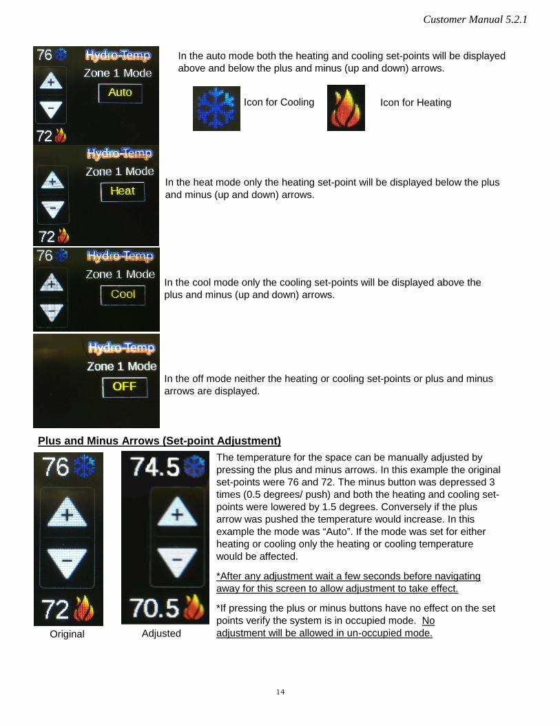
In the auto mode both the heating and cooling set-points will be displayed above and below the plus and minus (up and down) arrows.
Icon for Cooling Icon for Heating
In the heat mode only the heating set-point will be displayed below the plus and minus (up and down) arrows.
In the cool mode only the cooling set-points will be displayed above the plus and minus (up and down) arrows.
In the off mode neither the heating or cooling set-points or plus and minus arrows are displayed.
Plus and Minus Arrows (Set-point Adjustment) The temperature for the space can be manually adjusted by pressing the plus and minus arrows. In this example the original set-points were 76 and 72. The minus button was depressed 3 times (0.5 degrees/ push) and both the heating and cooling set-points were lowered by 1.5 degrees. Conversely if the plus arrow was pushed the temperature would increase. In this example the mode was “Auto”. If the mode was set for either heating or cooling only the heating or cooling temperature would be affected.
*After any adjustment wait a few seconds before navigating away for this screen to allow adjustment to take effect.
*If pressing the plus or minus buttons have no effect on the set points verify the system is in occupied mode. No adjustment will be allowed in un-occupied mode. Adjusted Original
14
Customer Manual 5.2.1
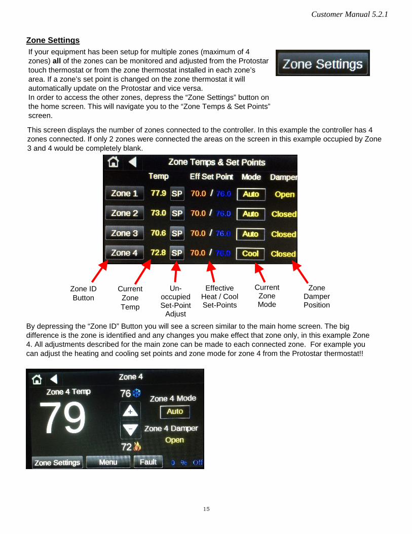
Zone Settings If your equipment has been setup for multiple zones (maximum of 4 zones) all of the zones can be monitored and adjusted from the Protostar touch thermostat or from the zone thermostat installed in each zone’s area. If a zone’s set point is changed on the zone thermostat it will automatically update on the Protostar and vice versa. In order to access the other zones, depress the “Zone Settings” button on the home screen. This will navigate you to the “Zone Temps & Set Points” screen.
This screen displays the number of zones connected to the controller. In this example the controller has 4 zones connected. If only 2 zones were connected the areas on the screen in this example occupied by Zone 3 and 4 would be completely blank.
Zone ID Button
Current Zone Temp
Un-occupied Set-Point
Adjust
Effective Heat / Cool Set-Points
Current Zone Mode
Zone Damper Position
By depressing the “Zone ID” Button you will see a screen similar to the main home screen. The big difference is the zone is identified and any changes you make effect that zone only, in this example Zone 4. All adjustments described for the main zone can be made to each connected zone. For example you can adjust the heating and cooling set points and zone mode for zone 4 from the Protostar thermostat!!
15

Customer Manual 5.2.1
The “Un-occupied Set-Point Adjust” Button allows for the adjustment of the base un-occupied temperature set-points. Press each temperature box and a numerical keypad will pop up to adjust each of the set-points. This temperature set point will be the base set point and any adjustments made from the zone home screen (“plus” or “minus” arrows) will be added / subtracted from this value. These set points will rarely need adjusting. Any room temperature adjustments needed should always be done from the zone’s HOME SCREEN. The factory default settings for the occupied set points are 70 for heating and 76 for cooling. It is highly recommended to keep the cooling set-point 4 - 6 degrees warmer than the heating set-point. Note the microprocessor will not allow the difference between the heating and cooling set-points to be any closer than two degrees.
The Current Mode can also be adjusted in the same manner as it could be adjusted from the home screen. Each zone can be set separately for desired mode or set to off if no heating or cooling is needed.
Effective Set-point
The effective set-point shown on this screen is the calculated temperature the unit is trying to achieve. The effective set-point for each zone is calculated individually. The zone effective set point is the base set-point entered using the “SP” button on the [zone temps and set points] screen and any plus or minus adjustments that have been made using the “plus” and “minus” arrows on the home screen. The effective set-point shown on this screen will reflect any smart set point adjustment delays.
Smart Set Point Adjustment Should a set point adjustment be made, some instances will occur where the effective set point will change at a rate of only five degree per hour (adjustable in the dealer settings screen). This is critical to keep the compressor from ramping up unnecessarily to high speed when someone adjusts the thermostat set point or the unit comes out of setback. For example, if the zone temperature is 75 degrees and the zone cooling set point is lowered from 76 degrees to 70 degrees, the effective set point will drop quickly to the zone temperature (in this example 75 degrees) then slowly continue to drop after that at a rate of 5 degrees per hour. This programming will initiate a response from the equipment when adjustment is made but prevents the V-Star compressor from ramping up into a higher speed (capacity) then necessary. The lower the compressor speed the unit is running at, the higher the unit’s efficiency.
16
Customer Manual 5.2.1
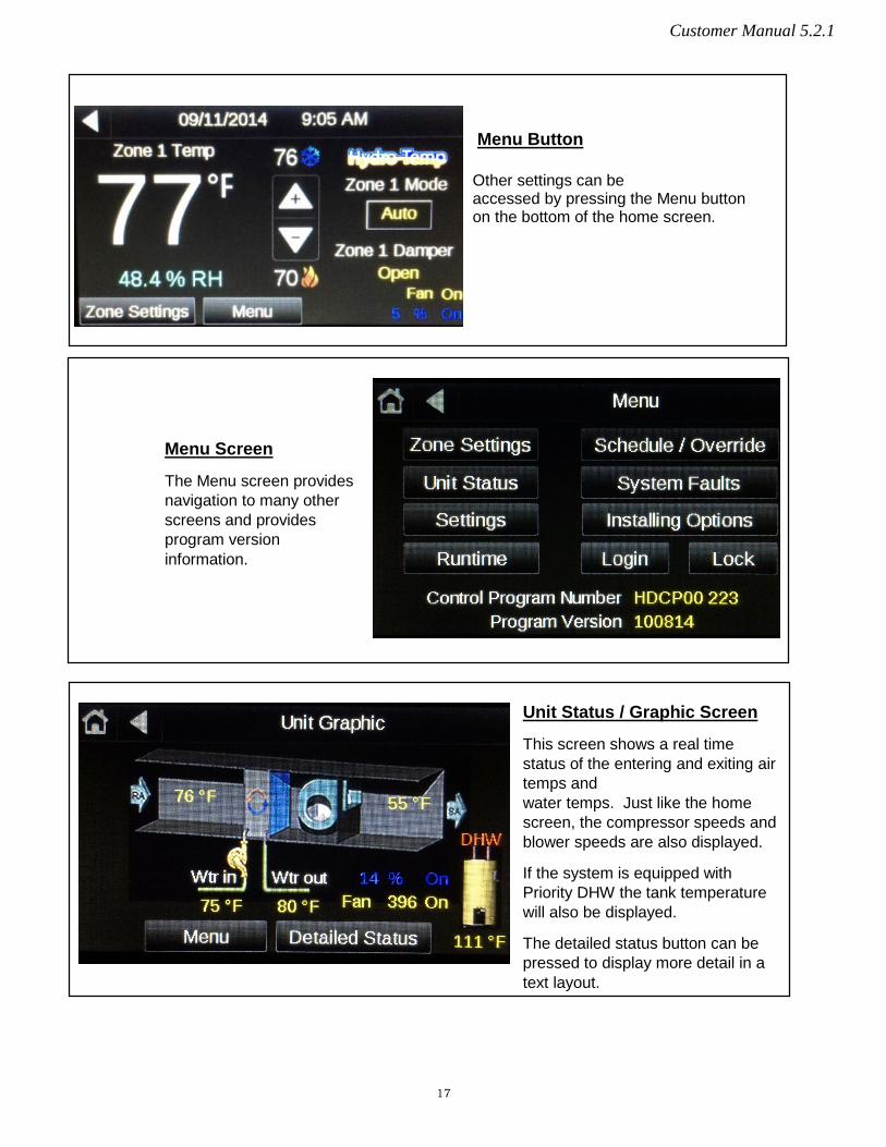
Menu Button
Other settings can be accessed by pressing the Menu button on the bottom of the home screen.
Menu Screen
The Menu screen provides navigation to many other screens and provides program version information.
Unit Status / Graphic Screen
This screen shows a real time status of the entering and exiting air temps and water temps. Just like the home screen, the compressor speeds and blower speeds are also displayed.
If the system is equipped with Priority DHW the tank temperature will also be displayed.
The detailed status button can be pressed to display more detail in a text layout.
17
Customer Manual 5.2.1
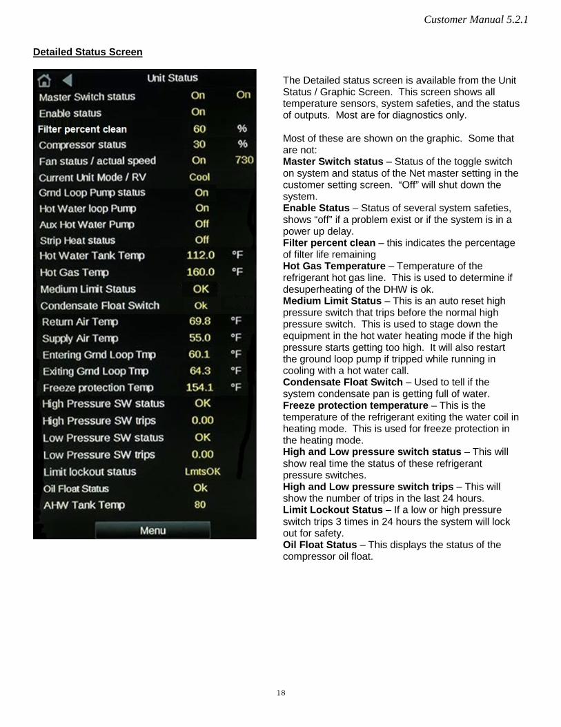
Detailed Status Screen
The Detailed status screen is available from the Unit Status / Graphic Screen. This screen shows all temperature sensors, system safeties, and the status of outputs. Most are for diagnostics only. Most of these are shown on the graphic. Some that are not: Master Switch status – Status of the toggle switch on system and status of the Net master setting in the customer setting screen. “Off” will shut down the system. Enable Status – Status of several system safeties, shows “off” if a problem exist or if the system is in a power up delay. Filter percent clean – this indicates the percentage of filter life remaining Hot Gas Temperature – Temperature of the refrigerant hot gas line. This is used to determine if desuperheating of the DHW is ok. Medium Limit Status – This is an auto reset high pressure switch that trips before the normal high pressure switch. This is used to stage down the equipment in the hot water heating mode if the high pressure starts getting too high. It will also restart the ground loop pump if tripped while running in cooling with a hot water call. Condensate Float Switch – Used to tell if the system condensate pan is getting full of water. Freeze protection temperature – This is the temperature of the refrigerant exiting the water coil in heating mode. This is used for freeze protection in the heating mode. High and Low pressure switch status – This will show real time the status of these refrigerant pressure switches. High and Low pressure switch trips – This will show the number of trips in the last 24 hours. Limit Lockout Status – If a low or high pressure switch trips 3 times in 24 hours the system will lock out for safety. Oil Float Status – This displays the status of the compressor oil float.
18

Customer Manual 5.2.1
The customer setting screen provides the following settings: Net Master: Must be “on” for the system to run. This provides the customer a “software method” of shutting down the system. Net Occupied: Forces the system to be occupied all the time. If this is “ON” and the jumper in the electrical box is on, the system will remain at occupied set points all the time. This is the recommended setup for all v-star systems. Fan Circulation selection and Fan Circulation Speed setting: These settings are used for fan circulation mode. Check Filter - days till ch req: This setting sets the frequency in days that the “CK Filter” indicator will show on the home screen. 30 days is the default. Set this to 0 to disable the check filter indicator. Enable Strip Assist: With this setting turned “on”, the strip heaters will run to supplement the system in the heating mode as needed. If this setting is turned to “Eheat only” the strip heater will only run if a system fault is detected during a heating call or if the unit is set to the emergency heat mode (E.Heat). System running on Generator: When this setting is set to “Yes”, another set point will appear labeled "Generator system limit”. The default setting for limiting the system is “30%”. This means that when this setting is set to “YES”, the system will be limited to 30%. It is important to note this setting needs to be manually selected when the system is being powered from a generator. If this setting is selected as “Yes”, the system will never exceed the limit set point and the strip heat will be disabled. If the generator being used is large enough to handle the system at 100% the "Generator system limit" can be increased accordingly.
DHW Priority (on/off): This setting turns on / off the domestic hot water option. When turned off other settings pertaining to the DHW will disappear. When turned back on navigation away from this screen then back will force the settings back on the screen. DHW Settings if DHW Priority is set to on: DHW Priority Start Temp—This is the temp the system will turn on and start making hot water DHW Priority Stop Temp—This is the temp the system will heat up to and turn off. DHW Priority Max Temp—This temp setting is the max the system will heat the water when desuperheating and providing free hot water. Desuperheating takes place when the system is heating hot water while heating or cooling the space. DHW stage 2 temp—This setting stages the system up to maximum compressor speed if the hot water tank temperature drops this much below the DHW start temp. For example in the screen shot above if the tank temp drops below 112 the system will start in Priority hot water generation mode with the compressor in stage 1 (factory preset speed). If the tank temperature continues to drop below 107 (priority start temp – DHW stage 2 temp) the system will ramp the compressor up to stage 2 (factory preset speed). DHW water sampling – This setting when turned on will occasionally start the DHW pump to circulate water to sample the temperature if the tank temperature sensor is placed on the DHW water in line. Another setting will allow one to set the frequency (in seconds) the pump will run and the time (in seconds) the pump will run before a temperature sample will be read from the sensor. The sensor will only be read during that time. After the temperature is read the pump will turn off if no hot water is needed. Use this setting with caution. It’s always best to leave this setting off and mount the tank temperature sensor on the tank. If an optional AHW (Auxiliary Hot Water) source is needed additional AHW settings will appear below the DHW settings. These will include AHW Priority on/off, AHW Priority start, AHW Priority stop, and AHW Priority Max temp.
Customer Setting Screen
19

Customer Manual 5.2.1
A few other buttons are available to the end user / homeowner. System Faults, Runtime, and Lock. The Installing Options page is password protected and is only used during the initial equipment installation and commissioning.
Other Items on the Menu Page
The thermostat lock screen will display the code needed to unlock the screen. If the code is anything other than 1234 (adjustable in factory settings) the screen will lock and go to the home screen. No adjustments will be allowed. Only the unlock button will show on the home screen. To unlock press the unlock button and enter the unlock code (1234). A help screen is provide at the bottom to explain how the lock screen works.
The Runtime Screen shows the accumulated system run time. This is divided up into total hours run in heat, total hours run in cool, total hours run in DHW, total hours run in AHW, total hours run in E-heat, and total accumulated run time. In the Runtime Screen we divide this up even more to show the compressor runtime in increments of percentage the compressor has run in heat and cool. With this you can determine how hard your system is having to work to keep you comfortable. Hydro-Temps ultimate goal is to have the unit operate for long periods of time at the lowest compressor percentage possible to provide the exact amount of heating / cooling needed for the home or building. This will allow the unit to create a more comfortable environment while operating at the highest possible efficiency.
The Fault screen will display the current system status in plain text and the status of any time delays that are active. If no faults are detected the screen will simply read “No Faults”. Other possible faults may be Low or High pressure switch, Freeze fault, Sensor Failure, Master off, Temp diff fault, Low or high limit lock out, or V-star drive Fault. The Timers will normally read 0.0 minutes unless a delay is active. If the air filter indicator is active red text labeled “Clean or replace filter” and a reset button will appear.
20
Customer Manual 5.2.1
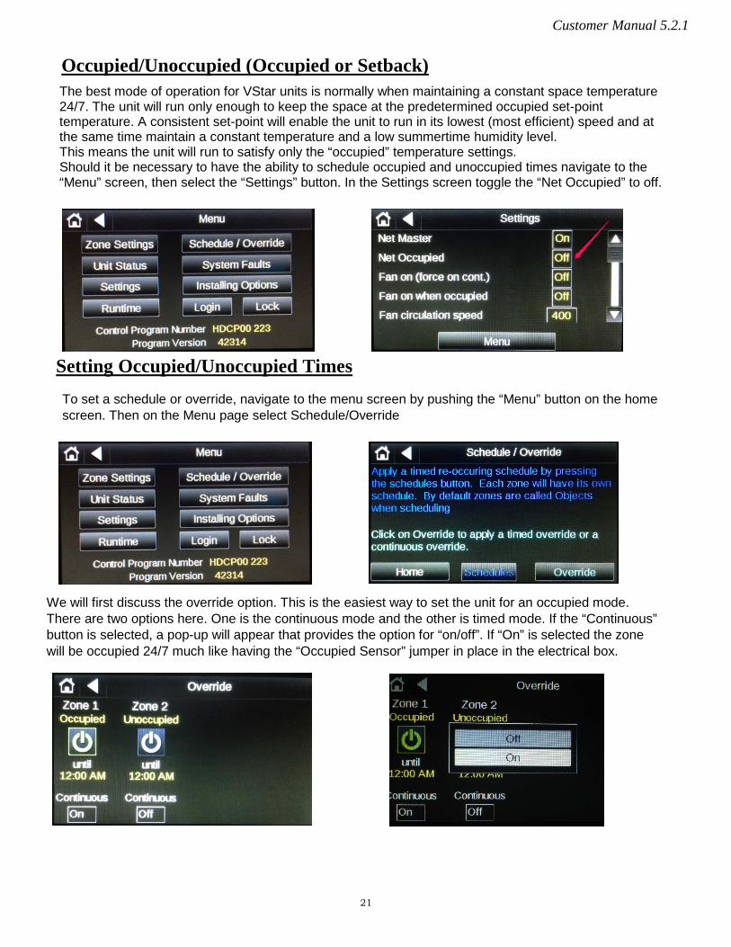
Occupied/Unoccupied (Occupied or Setback) The best mode of operation for VStar units is normally when maintaining a constant space temperature 24/7. The unit will run only enough to keep the space at the predetermined occupied set-point temperature. A consistent set-point will enable the unit to run in its lowest (most efficient) speed and at the same time maintain a constant temperature and a low summertime humidity level. This means the unit will run to satisfy only the “occupied” temperature settings. Should it be necessary to have the ability to schedule occupied and unoccupied times navigate to the “Menu” screen, then select the “Settings” button. In the Settings screen toggle the “Net Occupied” to off.
To set a schedule or override, navigate to the menu screen by pushing the “Menu” button on the home screen. Then on the Menu page select Schedule/Override
We will first discuss the override option. This is the easiest way to set the unit for an occupied mode. There are two options here. One is the continuous mode and the other is timed mode. If the “Continuous” button is selected, a pop-up will appear that provides the option for “on/off”. If “On” is selected the zone will be occupied 24/7 much like having the “Occupied Sensor” jumper in place in the electrical box.
Setting Occupied/Unoccupied Times
21
Customer Manual 5.2.1
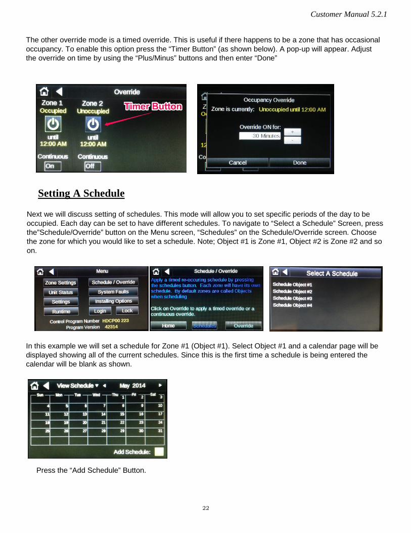
The other override mode is a timed override. This is useful if there happens to be a zone that has occasional occupancy. To enable this option press the “Timer Button” (as shown below). A pop-up will appear. Adjust the override on time by using the “Plus/Minus” buttons and then enter “Done”
Setting A Schedule
Next we will discuss setting of schedules. This mode will allow you to set specific periods of the day to be occupied. Each day can be set to have different schedules. To navigate to “Select a Schedule” Screen, press the”Schedule/Override” button on the Menu screen, “Schedules” on the Schedule/Override screen. Choose the zone for which you would like to set a schedule. Note; Object #1 is Zone #1, Object #2 is Zone #2 and so on.
In this example we will set a schedule for Zone #1 (Object #1). Select Object #1 and a calendar page will be displayed showing all of the current schedules. Since this is the first time a schedule is being entered the calendar will be blank as shown.
Press the “Add Schedule” Button.
22

Customer Manual 5.2.1
It is a good idea to provide a name for the schedule you are setting up. In this example the schedule was name “Morning”. This was accomplished by pressing on the name area, typing in the desired name and pressing “Done”.
The next step is to choose an “On Schedule” or an “OFF Schedule”. Most of the time an On Schedule is chosen, however if the desired schedule was to place the unit into an unoccupied mode, overriding a previous schedule the “OFF Schedule” can be chosen.
Continuing the scheduling process, the type of schedule needs to be chosen. The most common schedule would be a weekly schedule. The dated schedule would be used for specific dates. This is usually used once a general schedule has been set-up and an exception such as a holiday or a special event occurs. The continuous schedule is the least common schedule type. The continuous schedule puts the unit into a 24/7 occupied mode for a specified date range.
In this example the “Weekly” type will be discussed. To select the schedule type, depress the “Type” button and choose weekly. Then press “Next”.
23

Customer Manual 5.2.1
The next step is to select the time of day for the schedule. Press either the “Starts” or “Ends” button and the following screen will appear. For this example the Start time is 5:00 AM and the End time is 10:00 AM. This means the unit will react to occupied temperatures between 5:00 and 10:00 AM.
After the times have been set and “Done” has been entered, the days of the week for this schedule can be entered. In the example the weekdays have been chosen. If more than one event is required per day the question “Does this schedule have a date range?” must be answered “Yes”. If the answer is “No” only one schedule can be entered per day. For this example a long term date range was chosen to reduce the repeated programming time and allow for more than one schedule per day.
24
Customer Manual 5.2.1
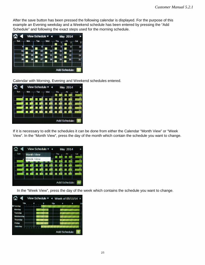
After the save button has been pressed the following calendar is displayed. For the purpose of this example an Evening weekday and a Weekend schedule has been entered by pressing the “Add Schedule” and following the exact steps used for the morning schedule.
Calendar with Morning, Evening and Weekend schedules entered.
If it is necessary to edit the schedules it can be done from either the Calendar “Month View” or “Week View”. In the “Month View”, press the day of the month which contain the schedule you want to change.
In the “Week View”, press the day of the week which contains the schedule you want to change.
25
Customer Manual 5.2.1
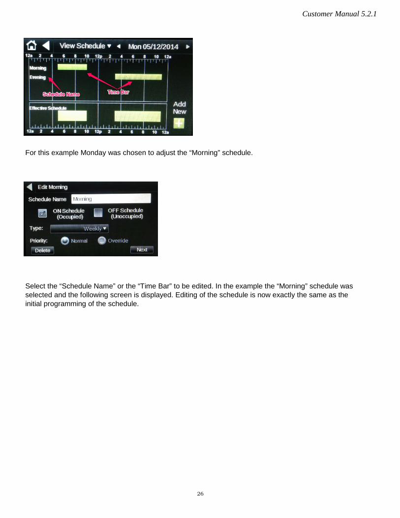
For this example Monday was chosen to adjust the “Morning” schedule.
Select the “Schedule Name” or the “Time Bar” to be edited. In the example the “Morning” schedule was selected and the following screen is displayed. Editing of the schedule is now exactly the same as the initial programming of the schedule.
26
Customer Manual 5.2.1
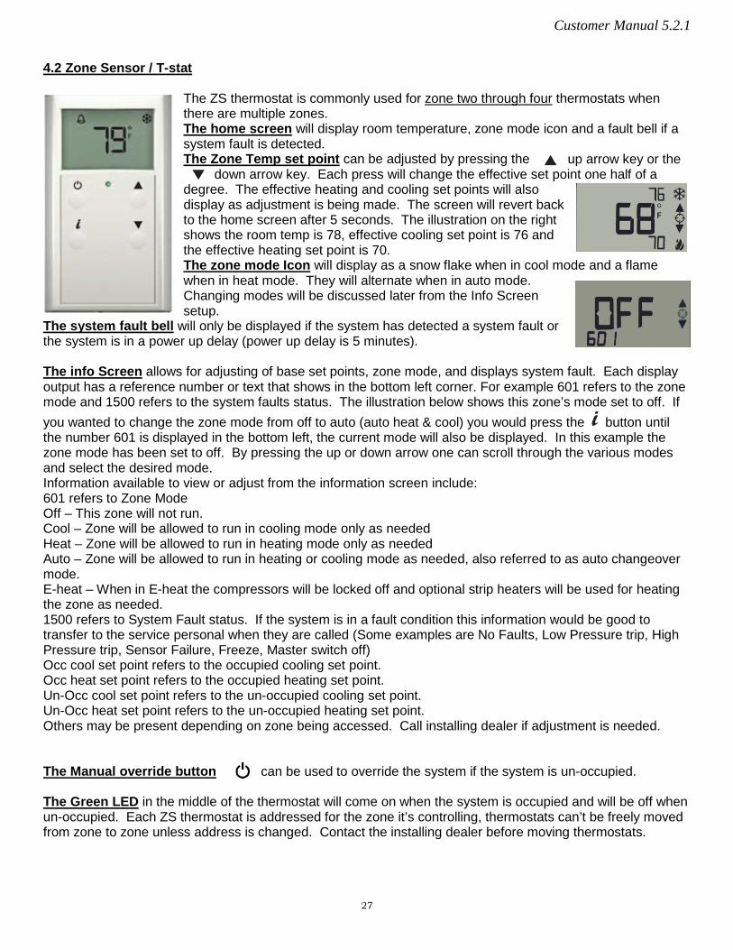
4.2 Zone Sensor / T-stat
The ZS thermostat is commonly used for zone two through four thermostats when there are multiple zones. The home screen will display room temperature, zone mode icon and a fault bell if a system fault is detected. The Zone Temp set point can be adjusted by pressing the up arrow key or the
down arrow key. Each press will change the effective set point one half of a degree. The effective heating and cooling set points will also display as adjustment is being made. The screen will revert back to the home screen after 5 seconds. The illustration on the right shows the room temp is 78, effective cooling set point is 76 and the effective heating set point is 70. The zone mode Icon will display as a snow flake when in cool mode and a flame when in heat mode. They will alternate when in auto mode. Changing modes will be discussed later from the Info Screen setup.
The system fault bell will only be displayed if the system has detected a system fault or the system is in a power up delay (power up delay is 5 minutes). The info Screen allows for adjusting of base set points, zone mode, and displays system fault. Each display output has a reference number or text that shows in the bottom left corner. For example 601 refers to the zone mode and 1500 refers to the system faults status. The illustration below shows this zone’s mode set to off. If you wanted to change the zone mode from off to auto (auto heat & cool) you would press the button until the number 601 is displayed in the bottom left, the current mode will also be displayed. In this example the zone mode has been set to off. By pressing the up or down arrow one can scroll through the various modes and select the desired mode. Information available to view or adjust from the information screen include: 601 refers to Zone Mode Off – This zone will not run. Cool – Zone will be allowed to run in cooling mode only as needed Heat – Zone will be allowed to run in heating mode only as needed Auto – Zone will be allowed to run in heating or cooling mode as needed, also referred to as auto changeover mode. E-heat – When in E-heat the compressors will be locked off and optional strip heaters will be used for heating the zone as needed. 1500 refers to System Fault status. If the system is in a fault condition this information would be good to transfer to the service personal when they are called (Some examples are No Faults, Low Pressure trip, High Pressure trip, Sensor Failure, Freeze, Master switch off) Occ cool set point refers to the occupied cooling set point. Occ heat set point refers to the occupied heating set point. Un-Occ cool set point refers to the un-occupied cooling set point. Un-Occ heat set point refers to the un-occupied heating set point. Others may be present depending on zone being accessed. Call installing dealer if adjustment is needed. The Manual override button can be used to override the system if the system is un-occupied. The Green LED in the middle of the thermostat will come on when the system is occupied and will be off when un-occupied. Each ZS thermostat is addressed for the zone it’s controlling, thermostats can’t be freely moved from zone to zone unless address is changed. Contact the installing dealer before moving thermostats.
27
Related Documents
![HEATING CIRCUIT CONTROLLER WITH SOLID FUEL BOILER2].pdf · Tkcp - Boiler return temp. sensor Tpod - Feeder temp. sensor TZ - Fuel tank cover closure sensor (opened on opening the](https://static.cupdf.com/doc/110x72/5cd7630888c9935d038d0ee9/heating-circuit-controller-with-solid-fuel-boiler-2pdf-tkcp-boiler-return.jpg)


