Mitglied der Helmholtz-Gemeinschaft Joint European Summer School for Fuel Cell and Hydrogen Technology Heraklion, Crete 21st September 2012 Solid Oxide Fuel Cells Current Research & Development Issues Robert Mücke Forschungszentrum Jülich GmbH, Institute of Energy and Climate Research (IEK-1: Materials Synthesis and Processing) 2 Robert Mücke, Joint European Summer School for Fuel Cell and Hydrogen Technology Higher cell performce / lower temperatures thin-film technology new materials (next generation) Higher stack performce contacting the cell Industrialization Scalable and cheap manufacturing, materials, components Overview of Research Fields Long-term stability >40.000h protective coatings accelerated testing Cycling reoxidation, thermal, electrical load Fuel issues coking, sulphur System / Balance of plant operating the stack suiteable components stack sealing Material solution Materials / design / processing of cell & stacks System solution System / BoP / operating conditions

Welcome message from author
This document is posted to help you gain knowledge. Please leave a comment to let me know what you think about it! Share it to your friends and learn new things together.
Transcript
Mitg
lied
der
He
lmho
ltz-G
eme
insc
haft
Joint European Summer School for Fuel Cell and Hydrogen TechnologyHeraklion, Crete21st September 2012
Solid Oxide Fuel Cells
Current Research & Development
IssuesRobert Mücke
Forschungszentrum Jülich GmbH, Institute of Energy and Climate Research(IEK-1: Materials Synthesis and Processing)
2 Robert Mücke, Joint European Summer School for Fuel Cell and Hydrogen Technology
Higher cell performce/ lower temperatures
thin-film technologynew materials
(next generation)
Higher stack performcecontacting the cell
IndustrializationScalable and cheap
manufacturing,materials, components
Overview of Research Fields
Long-term stability>40.000h
protective coatingsaccelerated testing
Cyclingreoxidation, thermal,
electrical load
Fuel issuescoking, sulphur
System / Balance of plant
operating the stacksuiteable components
stack sealing
Material solutionMaterials / design /
processing of cell & stacks
System solutionSystem / BoP /
operating conditions
3 Robert Mücke, Joint European Summer School for Fuel Cell and Hydrogen Technology
1. Increasing the Cell Perfomance
2. Cell vs. Stack Performance
3. Long term stability / Degradation
4. Stack Sealing
5. Reoxidation
6. Fuel & Fuel impurities
7. Metall Supported Cells (MSC)
8. Mass Manufacturing
Contents
4 Robert Mücke, Joint European Summer School for Fuel Cell and Hydrogen Technology
1. Increasing the Cell Performance

5 Robert Mücke, Joint European Summer School for Fuel Cell and Hydrogen Technology
What has been reachedVery high single cell performance
ASC single cells, 16 cm², H2+3%H2O, low uF
with year of measurement
optimization of
• materials
• processing
• cell design
6 Robert Mücke, Joint European Summer School for Fuel Cell and Hydrogen Technology
NiO / 8mol% Y2O3-ZrO2 (8YSZ)
8mol% Y2O3-ZrO2 (8YSZ)
La0.58Sr0.4Co0.2Fe0.8O3-δ (LSCF)
Ce0.8Gd0.2O2-δ (CGO)
Anode
Electrolyte
Sr-barrier layer
Cathode
SEM of fracture surface of Type B cell
Screen printed & sintered barrier layer

7 Robert Mücke, Joint European Summer School for Fuel Cell and Hydrogen Technology
Alternative Manufacturing RoutesPhysical Vapor DepositionPhysical Vapor Deposition
(Electron Beam PVD, Sputtering)
SubstrateHeater (up to 800°C)
Electron Beamvery thin PVD layers => low ASR
PVD electrolyte
VSC electrolyte
VSC = vacuum slip castJordan-Escalona, PhD thesis
Anode
Anode
Cathode
Cathode
8 Robert Mücke, Joint European Summer School for Fuel Cell and Hydrogen Technology
O2
Adsorption
Dissoziation
Diffusion
O2-
YSZ
LSFCLSFC
Reduction
Volumediffusion
disadvantage
Reaction with YSZ forming SrZrO3
StrontiumDiffusion
7 m
LSFC
YSZ
SrZrO3
Reaction of LSCF with YSZ Electrolyte
solution
Interlayer Ce0.8Gd0.2O1.9
CGO

9 Robert Mücke, Joint European Summer School for Fuel Cell and Hydrogen Technology
EDX scanSr enrichment
Sr Ce
Screen printedCGO
(TS=1300 °C)
cathode
YSZ electrolyte
1 m
(TS=1040 °C)
1 m
CGO PVD 800 °C
YSZ
1.2.
3.
1. Sr diffusion to YSZ, not with PVD barrier2. Solid state solution of CGO and YSZ, not found with PVD barrier3. Microstructure: • Screen printed + sintered: sponge-like structure
longer pathways for O2–
• PVD layers: laminar, tight contact between
YSZ and CGO layer (less CGO/LSCF contact)
Screen Printed CGO Barrier Layersvs. PVD Layers
10 Robert Mücke, Joint European Summer School for Fuel Cell and Hydrogen Technology
0.0 0.2 0.4 0.6 0.8 1.0 1.2
0.6
0.7
0.8
0.9
1.0
1.1
current density (A/cm2)
EB-PVD, 800 °C EB-PVD, 400 °C
Toperation
=700 °C
Ce0.8
Gd0.2
O2-
Ce0.9
Gd0.1
O2-
sputtered, 400 °C
sinteredCGO layers
CGO layers by PVD
800 °C 700 °C
0.0 0.2 0.4 0.6 0.8 1.0 1.2
0.8
0.9
1.0
1.1
Ce0.8
Gd0.2
O2-
Ce0.9
Gd0.1
O2-
sputtered, 400 °C EB-PVD, 400 °C EB-PVD, 800 °C
cell
volta
ge
(V
)
current density (A/cm2)
sinteredCGO layers
CGO layers by PVD
TOperation
=800 °C
• PVD CGO performs significantly better than sintered CGO barrier,especially at lower operating temperatures
• at 700°C: sintered: 1.0 A/cm²; PVD barrier: 1.7 A/cm² (@0.7V)• Ce0.8Gd0.2O2- performs better than Ce0.9Gd0.1O2-
Temperature of operation:
Different CGO Barrier LayersElectrochemical Performance
11 Robert Mücke, Joint European Summer School for Fuel Cell and Hydrogen Technology
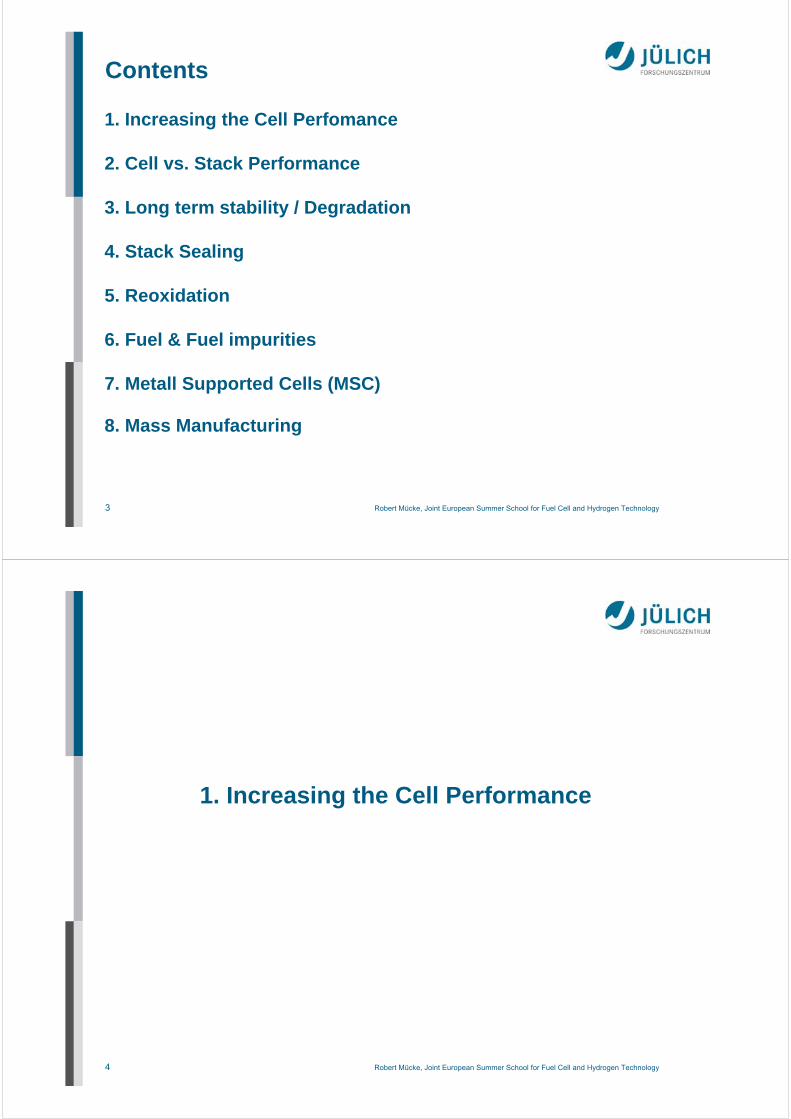
Nanoscaled Electrolyte Aging
Top surface Fracture surface
PVD layers produced at 800°C, annealed at 1040°C:decrease of grain boundaries => volume shrinkage =>layers become porous or crack
relevant for operational conditions, if process temperature is below operating point
12 Robert Mücke, Joint European Summer School for Fuel Cell and Hydrogen Technology
650 700 750 800 850 900
0
50
100
150
200
100 m 10 m 1 m 0.1 m
Cal
cu
late
d A
SR
[mc
m2 ]
Temperature [oC]
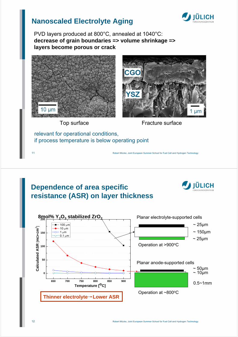
~ 150µm
~ 25µm
~ 25µm
~ 50µm~ 10µm
0.5~1mm
Planar electrolyte-supported cells
Operation at >900oC
Operation at ~800oCThinner electrolyte→Lower ASR
Planar anode-supported cells
8mol% Y2O3 stabilized ZrO2
Dependence of area specific resistance (ASR) on layer thickness

13 Robert Mücke, Joint European Summer School for Fuel Cell and Hydrogen Technology
Coatings of Nano-Suspensionsand Sols
1. Coatingspin- or dip-coating
2. Dryingconversion of polymeric solinto gel layer
3. Thermal annealingconversion of gel layer intoceramic layer (calcination and sintering)
vertical tangential
dip coating spin coating
14 Robert Mücke, Joint European Summer School for Fuel Cell and Hydrogen Technology
Sol-Gel Synthesis
OR = alkoxy group
Zr
OR
OR
O
OR
R
H O2H+
Hydrolysis
F. Hauler, T. van Gestel, S. Vieweger, IEK-1 (FZ Jülich)Burggraat & Cot, Inorganic Membrane Science and Technology
nano-suspension: ~40-100 nmpolymeric sol: 5-15 nm
15 Robert Mücke, Joint European Summer School for Fuel Cell and Hydrogen Technology
Sol-Gel Synthesis
nano-suspension: ~40-100 nmpolymeric sol: 5-15 nm
Zr
OR
OR
O
OR
H
Zr
OR
OROH
OR
2+
Condensation
F. Hauler, T. van Gestel, S. Vieweger, IEK-1 (FZ Jülich)Burggraat & Cot, Inorganic Membrane Science and Technology
16 Robert Mücke, Joint European Summer School for Fuel Cell and Hydrogen Technology
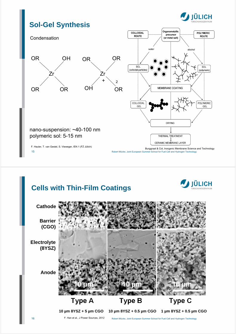
Cells with Thin-Film Coatings
F. Han et al., J Power Sources, 2012
Anode
Electrolyte(8YSZ)
Barrier(CGO)
Cathode
10 µm 8YSZ + 5 µm CGO 10 µm 8YSZ + 0.5 µm CGO 1 µm 8YSZ + 0.5 µm CGO

17 Robert Mücke, Joint European Summer School for Fuel Cell and Hydrogen Technology
Cells with ~1 m electrolyte layer, sputtered CGO layer & LSCF cathode
550 600 650 700 750 800 850 9000.5
1.0
1.5
2.0
2.5
3.0
Cur
rent
Den
city
70
0m
V [A
/cm
2]
Temperature [oC]
Cells G3-1Cells G3-2Cells G3-3
Type B
Type C
Thin-Film Electrolytewith LSCF Cathode
ASC single cells, 16 cm², H2+3%H2O, low uF
Currently stacks running(ASC stacks withlowest ASR in Jülich)
18 Robert Mücke, Joint European Summer School for Fuel Cell and Hydrogen Technology
550 600 650 700 750 800 850 9000.5
1.0
1.5
2.0
2.5
3.0
3.5
4.0
4.5
5.0
Cur
rent
Den
city
70
0m
V [A
/cm
2]
Temperature [oC]
Cells with 5~10 m thick electrolyte layer, sputtered CGO layer & LSC cathode
Cells with ~1 m electrolyte layer, sputtered CGO layer & LSC* cathode*SOFC600 developed by EU project SOFC600
NiO/8YSZ anode substrate
NiO/8YSZ anode
8YSZ electrolyte
Screen-printed LSCF cathode
Sputtered CGO layer
Screen-printed LSC cathode8YSZ polymeric sol-gel layer
8YSZ nano-suspension layer
8YSZ nano-suspension layer
Sputtered CGO layer
Screen-printed LSC cathode
Type B
Type C
ASC single cells, 16 cm², H2+3%H2O, low uF
Thin-Film Electrolytewith LSC Cathode
Advantage of LSC vs. LSCF:Highest total conductivity
Drawback:Large CTE
LSCF ~ 15-17 ppm/K
LSC ~ 20-21 ppm/K
substrate ~ 12-13 ppm/K
further target: 400°C SOFC

19 Robert Mücke, Joint European Summer School for Fuel Cell and Hydrogen Technology
400°C SOFC
Carbon coking, metallic corrosion renders 450-600°C temperature window difficult
400°C would allow to use methanol (decomposes above)
from ASR considerations: 100 nm 8YSZ or 1 µm CGO electrolyte would be sufficient
cathode (LSC)
GDC membrane8YSZ/ScSZ insulat.
anode(Ni/8SZ)
cathode (LSC)
GDC membrane8YSZ/ScSZ insulat.
anode(Ni/GDC)
GDC Sr barrier
extremely smooth/defect free substrates are needed
new electrodes are needed
not necessary,if Tmanufacturing <1000°C(solid state reaction above)
20 Robert Mücke, Joint European Summer School for Fuel Cell and Hydrogen Technology
High Conducting Electrolyte Materialsfor Electrolyte Supported Fuel Cells
0.5 A/cm²0.7 A/cm²~ 0.3 A/cm²Typical cellperformance, 0.7V, 850°C, H:H2O=1:1
6.5 S/m (44%)26 S/m (16%)2 S/m (52%)850°C (Substges)
10.3 ppm/K10.1 ppm/K11.2 ppm/KRT..850°C
665 MPa250 MPa1000 MPaBending strength
Y2O3, Sc2O3, CeO210mol% Sc2O3
1mol% CeO2
3mol% Y2O3ZrO2 stabilized with
YScSZ10Sc1CeSZ3YSZMaterial
Source: Kerafol, Eschenbach, Germany
First tests of using LSCF instead of LSM cathodes.

21 Robert Mücke, Joint European Summer School for Fuel Cell and Hydrogen Technology
2. Cell vs. Stack Performance
22 Robert Mücke, Joint European Summer School for Fuel Cell and Hydrogen Technology
2. Cell vs. Stack Performance
ASC single cells, 16 cm², H2+3%H2O, low uF
with year of measurement
–30%
Typical lossfrom cell to stack test:30-70%
in a stack

23 Robert Mücke, Joint European Summer School for Fuel Cell and Hydrogen Technology
Cathode Current Collector
electricconductivity
50 S/cm
25 S/cm
porosity
45%
20%
Interconnect
Interconnect
Cellcurrent collector
current flowoxygen transport
~1-3 mm
pure LSM
8YSZ/LSM10-15µm
~50 µm
A lot of cell performanceis lost in cell contacting inside the stack (30-70%), due to contacting area + contact resistances
24 Robert Mücke, Joint European Summer School for Fuel Cell and Hydrogen Technology
Contacting with milled interconnects
anodesubstrate
electrolyte
cathode
contactlayer interconnect
land
porous contact layer by perovskites(e.g. lanthanum manganese cobalt copper oxide)
•optimize channel/land structure by modeling•use wet coatings (e.g. by screen printing)•apply large compressive loads
gap betweencontact layer/interconnect:preparation artefact
25 Robert Mücke, Joint European Summer School for Fuel Cell and Hydrogen Technology
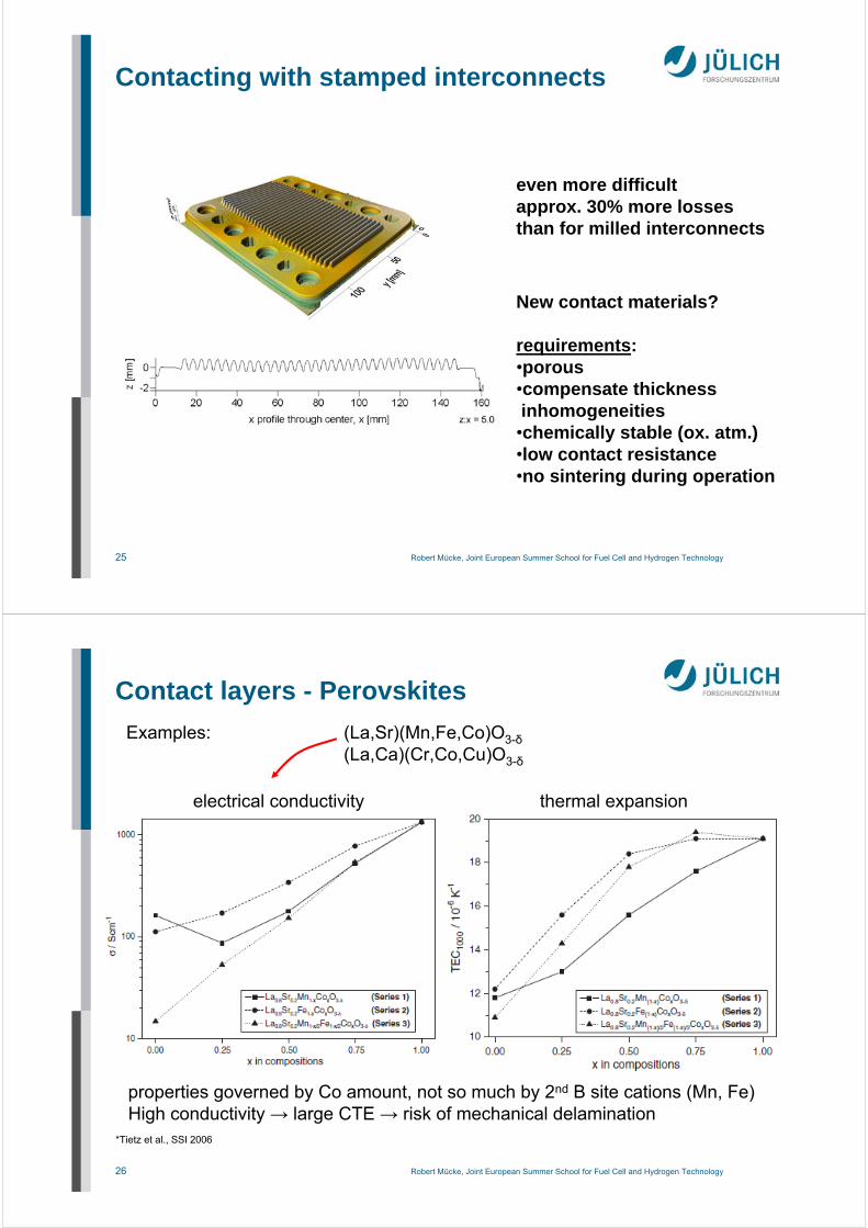
Contacting with stamped interconnects
even more difficultapprox. 30% more lossesthan for milled interconnects
New contact materials?
requirements:•porous•compensate thickness inhomogeneities•chemically stable (ox. atm.)•low contact resistance•no sintering during operation
26 Robert Mücke, Joint European Summer School for Fuel Cell and Hydrogen Technology
Examples: (La,Sr)(Mn,Fe,Co)O3-δ(La,Ca)(Cr,Co,Cu)O3-δ
electrical conductivity
*Tietz et al., SSI 2006
Contact layers - Perovskites
thermal expansion
properties governed by Co amount, not so much by 2nd B site cations (Mn, Fe)High conductivity → large CTE → risk of mechanical delamination

27 Robert Mücke, Joint European Summer School for Fuel Cell and Hydrogen Technology
Contact layers - Perovskites
Tietz et al., Mater. Sci. Eng. B 150 (2008), 135-140
Formation of interface reaction zone
1: formation of Cr2O3 layer2: Cr2O3 (Cr,Mn)3O4 double layer
released Cr → CaCrO4dense layer of decomposed perovskites ontop of protective layer
3: Mn depletion in protective layergrow of CaCrO4, Ca free perovskite
4: further grow of scales
contact layer
protective layer
interconnect
LaMnCoCu basedlayers:Cu depletion other timeno further problemswith dense MCF protective layers(Cr barrier)
28 Robert Mücke, Joint European Summer School for Fuel Cell and Hydrogen Technology
3. Long Term Stability

29 Robert Mücke, Joint European Summer School for Fuel Cell and Hydrogen Technology
single repeating unit
interconnect
interconnect
oxide scale
Cr protection layer
cathode contact layer
MEA
anode contact
sealing
oxide scale
‘‘internal causes‘‘ = interactions / changes within the stack components
*N.H.Menzler et al. Ceram.Eng.Sci.Proc. 2008
Sources of Degration
30 Robert Mücke, Joint European Summer School for Fuel Cell and Hydrogen Technology
Cell Degradation due to Presence ofInterconnect Steel (Cr poisoning)
temperature: 800 °C
current density: 0.30 A/cm²fuel: H2 (1.0 l/min) + 3% H2Ooxidant: air (1.0 l/min)
Time [h]
Cel
l vo
ltag
e [
V]

31 Robert Mücke, Joint European Summer School for Fuel Cell and Hydrogen Technology
Meachnisms of Cr-Poisoning
LSM cathodesreaction at electrolyte interface(1) blockage of tri phase boundaries (see below) or (2) formation o Cr2O3+ (Cr,Mn)3O4insulating layer between cathode and electrolyte
Cr
Sr
Cr
LSCF cathodesvapor phase transport and
reaction at cathode surface
Cathode degradation currently dominant in cells
F. Tietz, FZJ
32 Robert Mücke, Joint European Summer School for Fuel Cell and Hydrogen Technology
Longest running planar SOFC stack so far short-stacks F1002-95 and 97
current density: 500 mA/cm²
700°C
700°C
failure of temperature
control
only failure causing any lossof power to a cell (or stack) (thus far)
failure of electronic
load
with WPS-protective layerLSCF-cathode
L. Blum et al., 10th European SOFC Forum Lucerne 2012, A1205

33 Robert Mücke, Joint European Summer School for Fuel Cell and Hydrogen Technology
Average cell voltages as function of date for short-stacks F1002-95 and 97
current density: 500 mA/cm²
700°C43,867 h
17,660 h
700°C
16 mV/kh 6 mV/kh
Post test analysis: revealed only small alteration and interaction.
# glass microstructure showed no phase changes# cell microstructure appeared to be only slightly modified# metallic parts out of Crofer22APU showed some
dot-like corrosion, but in general exhibited good bondingoxide layers of micrometres thickness
10 mV/kh
Mean voltagedegradation:1%V/kh
6 mV/kh
with WPS-protective layerLSCF-cathode
10 mV/kh
L. Blum et al., 10th European SOFC Forum Lucerne 2012, A1205
34 Robert Mücke, Joint European Summer School for Fuel Cell and Hydrogen Technology
Wet powder sprayed (WPS) protective layers (Cr barrier)
Risoe
protective layer(MnOx) + contact layer
Layer homogeneity

35 Robert Mücke, Joint European Summer School for Fuel Cell and Hydrogen Technology
Risoe interconnect
protective layer(MnOx)
contact layer(LCC)
land
channel
Layer homogeneity Wet powder sprayed layers are porous (significant Cr permeation)Chemical reactions and sintering take place
Wet powder sprayed (WPS) protective layers (Cr barrier)
36 Robert Mücke, Joint European Summer School for Fuel Cell and Hydrogen Technology
Atmospheric plasma sprayed (APS) protection layers
MnCo1.9Fe0.1O4 (MCF spinel)very dense microstructureexpected to suppres Cr diffusionmore efficiently
contact layer (WPS)
protective layer (WPS)
Interconnect steel
microstructure after stack sealing
37 Robert Mücke, Joint European Summer School for Fuel Cell and Hydrogen Technology
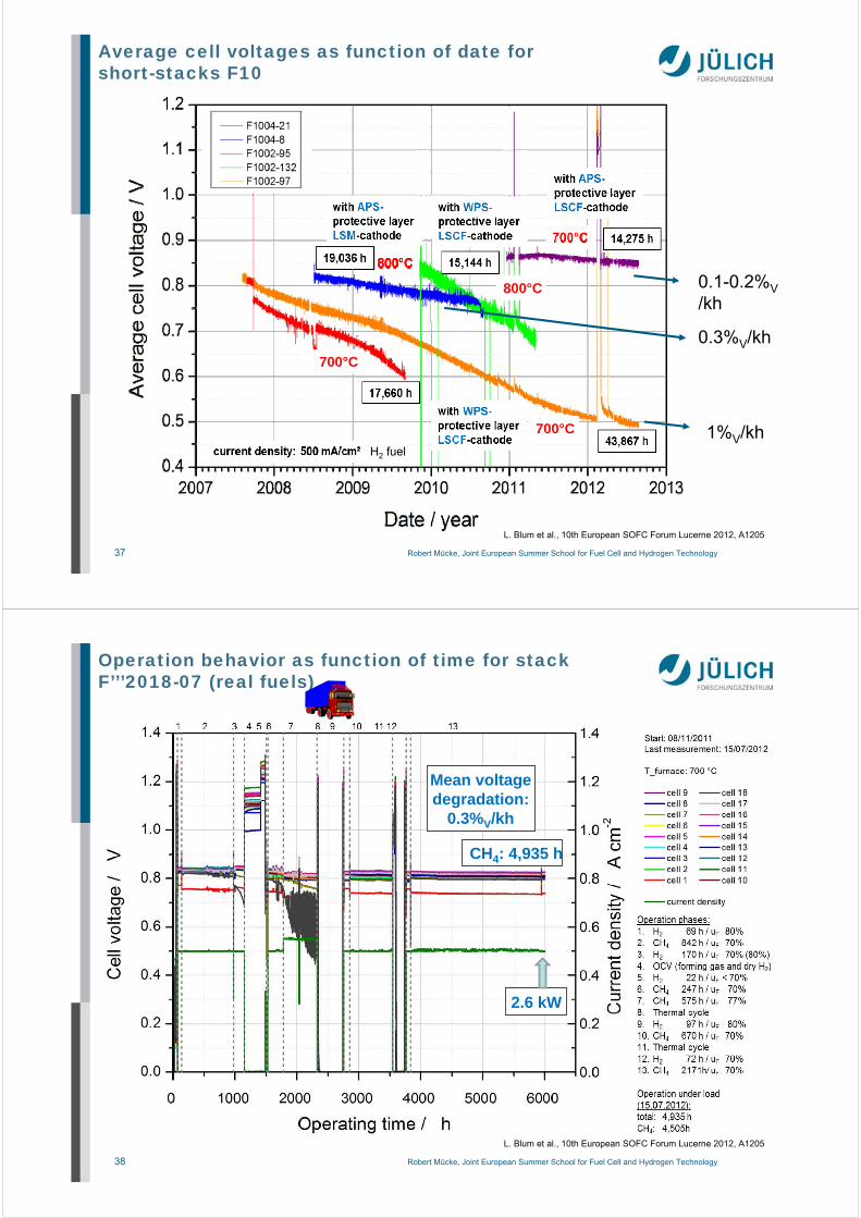
Average cell voltages as function of date for short-stacks F10
700°C
800°C
700°C
1%V/kh
0.3%V/kh
0.1-0.2%V/kh
L. Blum et al., 10th European SOFC Forum Lucerne 2012, A1205
H2 fuel
38 Robert Mücke, Joint European Summer School for Fuel Cell and Hydrogen Technology
Operation behavior as function of time for stack F’’’2018-07 (real fuels)
Mean voltagedegradation:
0.3%V/kh
2.6 kW
CH4: 4,935 h
L. Blum et al., 10th European SOFC Forum Lucerne 2012, A1205

39 Robert Mücke, Joint European Summer School for Fuel Cell and Hydrogen Technology
current density: 500 mA/cm²
Average cell voltages as function of date for short-stacks F1002-132 and F1004-08
4 mV/kh0.5%V/kh
with APS-protective layerLSM-cathode
19,036 h
800°C
with WPS-protective layerLSCF-cathode
15,144 h
800°C
Post test analysis: Manganese diffusion from the LSM cathode into the 8YSZ electrolyte was observed in all cells local accumulation of Manganese at the grain
boundaries of the YSZ crack growth fracture of one cell
15 mV/kh2.2%V/kh
Post test analysis: # increased amount of
chromium was found in the cathode # the protective layer on the interconnect plate at the cathode side was much more porous
L. Blum et al., 10th European SOFC Forum Lucerne 2011, A1205
40 Robert Mücke, Joint European Summer School for Fuel Cell and Hydrogen Technology
Post test analysis of stack with APS protective coating + LSM cathode
Malzbender et al., Journal of Power Sources 201 (2012) 196– 203
c)
MCF before operation MCF after 19,000 h operation
+ healing of as sprayed splat boundaries+ Cr2O3 ~3µm (no spallation/delamination)+ with almost no Fe+ no Cr in contact layer+ almost no Cr in MCF
– MCF becomes partly porous, cracked– MCF slightly depleted of Co, increase
of Mn, Cr=> origin of residual degradation?
t=19,000hj=0.5A/cm²uF=40%H2 / 3% H2O
41 Robert Mücke, Joint European Summer School for Fuel Cell and Hydrogen Technology
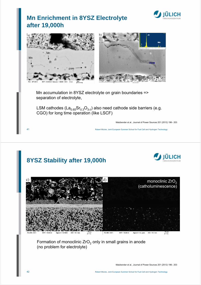
Mn Enrichment in 8YSZ Electrolyteafter 19,000h
Malzbender et al., Journal of Power Sources 201 (2012) 196– 203
Mn accumulation in 8YSZ electrolyte on grain boundaries => separation of electrolyte,
LSM cathodes (La0.65Sr0.3O3-) also need cathode side barriers (e.g. CGO) for long time operation (like LSCF)
42 Robert Mücke, Joint European Summer School for Fuel Cell and Hydrogen Technology
8YSZ Stability after 19,000h
monoclinic ZrO2(catholuminescence)
Formation of monoclinic ZrO2 only in small grains in anode(no problem for electrolyte)
Malzbender et al., Journal of Power Sources 201 (2012) 196– 203
43 Robert Mücke, Joint European Summer School for Fuel Cell and Hydrogen Technology
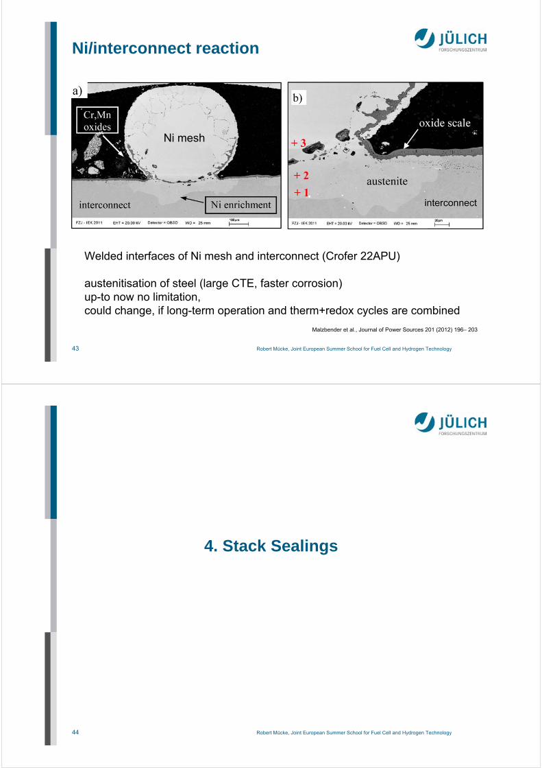
Ni/interconnect reaction
Ni mesh
Malzbender et al., Journal of Power Sources 201 (2012) 196– 203
Welded interfaces of Ni mesh and interconnect (Crofer 22APU)
austenitisation of steel (large CTE, faster corrosion)up-to now no limitation, could change, if long-term operation and therm+redox cycles are combined
44 Robert Mücke, Joint European Summer School for Fuel Cell and Hydrogen Technology
4. Stack Sealings
45 Robert Mücke, Joint European Summer School for Fuel Cell and Hydrogen Technology
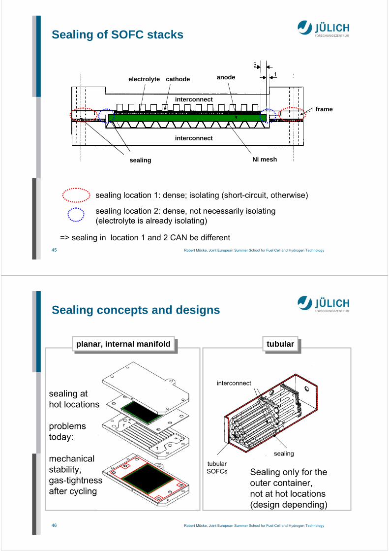
Ni-Netz
electrolyte cathode anode
Ni meshsealing
frame
interconnect
interconnect
sealing location 1: dense; isolating (short-circuit, otherwise)
sealing location 2: dense, not necessarily isolating(electrolyte is already isolating)
=> sealing in location 1 and 2 CAN be different
Sealing of SOFC stacks
46 Robert Mücke, Joint European Summer School for Fuel Cell and Hydrogen Technology
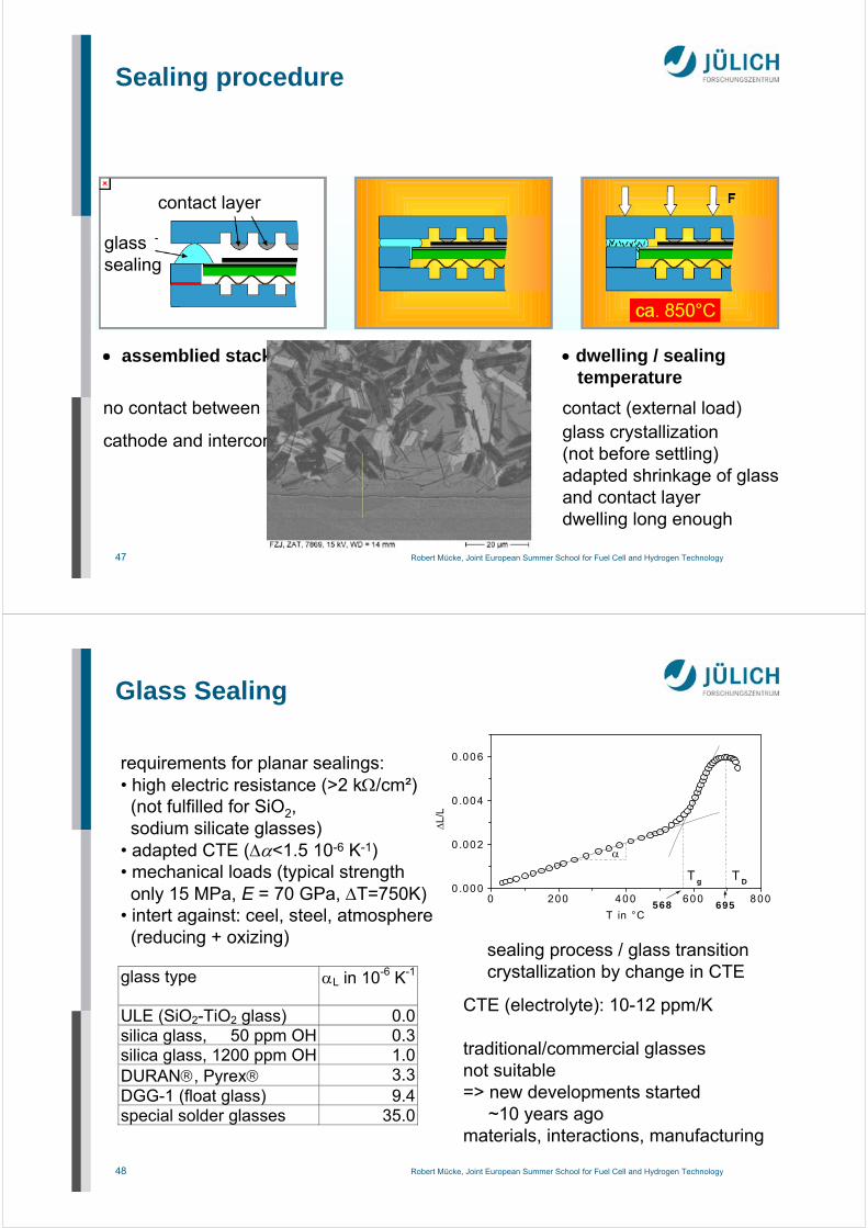
planar, internal manifoldplanar, internal manifold
sealing athot locations
problemstoday:
mechanicalstability,gas-tightnessafter cycling
Sealing concepts and designs
tubulartubular
interconnect
tubularSOFCs
sealing
Sealing only for theouter container,not at hot locations(design depending)
47 Robert Mücke, Joint European Summer School for Fuel Cell and Hydrogen Technology
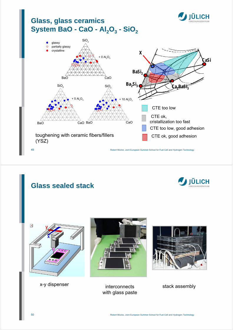
assemblied stack
no contact between
cathode and interconnect
heat-up
burning organic(T < 500°C)glass softeningfirst interconnect/cellcontacts
dwelling / sealingtemperature
contact (external load)glass crystallization(not before settling)adapted shrinkage of glassand contact layerdwelling long enough
Sealing procedure
glasssealing
contact layer
48 Robert Mücke, Joint European Summer School for Fuel Cell and Hydrogen Technology
requirements for planar sealings:• high electric resistance (>2 k/cm²)(not fulfilled for SiO2, sodium silicate glasses)
• adapted CTE (<1.5 10-6 K-1)• mechanical loads (typical strengthonly 15 MPa, E = 70 GPa, T=750K)
• intert against: ceel, steel, atmosphere(reducing + oxizing)
Glass Sealing
0 200 400 600 8000 .000
0 .002
0 .004
0 .006
Tg
695568
TD
L/L
T in °C
glass type L in 10-6 K-1
ULE (SiO2-TiO2 glass) 0.0silica glass, 50 ppm OH 0.3silica glass, 1200 ppm OH 1.0DURAN, Pyrex 3.3DGG-1 (float glass) 9.4special solder glasses 35.0
sealing process / glass transitioncrystallization by change in CTE
CTE (electrolyte): 10-12 ppm/K
traditional/commercial glasses not suitable=> new developments started
~10 years agomaterials, interactions, manufacturing
49 Robert Mücke, Joint European Summer School for Fuel Cell and Hydrogen Technology
CTE ok, cristallization too fast
CTE too low, good adhesion
CTE too low
CTE ok, good adhesion
BaSi2
CaSi
Ba2Si3
X
Ca2BaSi3
CaOBaO
SiO2 glassy
partially glassy crystalline
+ 5 Al2O3
BaO CaO
SiO2
+ 0 Al2O
3
+ 10 Al2O
3
BaO CaO
SiO2
Glass, glass ceramicsSystem BaO - CaO - Al2O3 - SiO2
toughening with ceramic fibers/fillers(YSZ)
50 Robert Mücke, Joint European Summer School for Fuel Cell and Hydrogen Technology
x-y dispenser interconnectswith glass paste
stack assembly
Glass sealed stack

51 Robert Mücke, Joint European Summer School for Fuel Cell and Hydrogen Technology
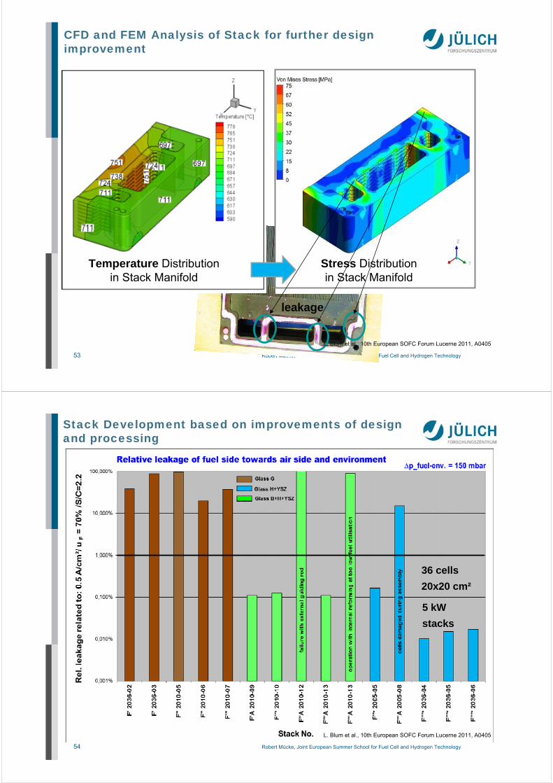
Stack Development based on improvements of design and processing
Improvement due to:
•Changes in
- design
- processing
- operation
•Combination of two
different glass sealing
materials for cell and
manifold
L. Blum et al., 10th European SOFC Forum Lucerne 2011, A0405
52 Robert Mücke, Joint European Summer School for Fuel Cell and Hydrogen Technology
Measured temperature distribution in a 1 kW stack (10 layers 20x20 cm²) from fuelin to fuelout (= airin) in case of different fuel gases and fuel utilization uF
L. Blum et al., 10th European SOFC Forum Lucerne 2011, A0405
53 Robert Mücke, Joint European Summer School for Fuel Cell and Hydrogen Technology
CFD and FEM Analysis of Stack for further design improvement
Temperature Distributionin Stack Manifold
Stress Distributionin Stack Manifold
leakage
L. Blum et al., 10th European SOFC Forum Lucerne 2011, A0405
54 Robert Mücke, Joint European Summer School for Fuel Cell and Hydrogen Technology
Stack Development based on improvements of design and processing
5 kW
stacks
L. Blum et al., 10th European SOFC Forum Lucerne 2011, A0405
36 cells
20x20 cm²

55 Robert Mücke, Joint European Summer School for Fuel Cell and Hydrogen Technology
Application of Sealing of ASCs
dispenser screen printing
stamped, tape-cast foils
Kerafol, HC StarckD. Federmann, S. Groß, ZAT, FZ Jülich
characteristics:
dispenser: very flexible, slow, not scalablescreen printing: fast, flexible, special screens for large thicknesses (0.3 .. 0.5 mm)stencil printing: large thicknesses,
requires very flat supportstamped foils: basic shapes very accurate, shrinkage due to large amount of organics, limited material efficiency (recycling)
stencil printing
(metallic mask and blade)
56 Robert Mücke, Joint European Summer School for Fuel Cell and Hydrogen Technology
Metallic Brazing
SOFC
B. Kuhn, PhD Thesis, FZ Jülich, 2009
interconnect
Cr/Fe/Cu mixed oxides
CuO
Cr/Fe mixed oxides
Cr/Mn/Femixed oxidesCu/Fe/Mn
mixed oxides
Cr/Cu/Mnmixed oxides Reactive air brazing, RAB (Ag based,
CuO as reactive component) after stack test
Cusolu-ted
cathode side, airpO2=21 kPa
anode side H2pO2=10-13 Pa
brazingsolder
• reaction zone of classical RAB solders lead to mechanical failure→ pure Ag (without CuO) more difficult to wet, but better stability• especially reducing condition lead to aging• pre-oxidation of interconnect steel necessary• interconnect brazing => insulation layer necessary (e.g. by thermal spraying,difficult to make completely "brazing solder" dense)

57 Robert Mücke, Joint European Summer School for Fuel Cell and Hydrogen Technology
MetalsMetals
massive sealingAg wire,
structures sealingsE ringC ringO ring
stamped sealings
interconnect steallaser cut / stamped
SOFC
Interkonnect
F
F
Alternative Compressible Sealings
58 Robert Mücke, Joint European Summer School for Fuel Cell and Hydrogen Technology
MetalsMetals
massive sealingAg wire,
structures sealingsE ringC ringO ring
stamped sealings
interconnect steallaser cut / stamped
mica powderin pastes / mica paper
ceramic powder withbinder/paper
MicaMica CeramicsCeramics
Alternative Compressible Sealings
Bram et al., J. Power Sources 2004
thermiculite

59 Robert Mücke, Joint European Summer School for Fuel Cell and Hydrogen Technology
MetalsMetals
massive sealingAg wire,
structures sealingsE ringC ringO ring
stamped sealings
interconnect steallaser cut / stamped
mica powderin pastes
mica paper + binder
mica paper + binder
and metallic inlay
AB2(X,Si)4O10(O,F,OH)2
A=K; X=AlB=Zn,Cr,V,Ti,Mn,Mg
cut / laser cut / stamped
ceramic powder withbinder
cermic paper withceramic filler
(e.g. fiber felts)
Global Thermoelectric2002
Al2O3, SiO2, Al2O3-SiO2cut / laser cut
MicaMica CeramicsCeramics
combinations possible
Alternative Compressible Sealings
Bram et al., J. Power Sources 2004
60 Robert Mücke, Joint European Summer School for Fuel Cell and Hydrogen Technology
MetalsMetals
works with realisticloads (< 5 N/mm)leak-rates < 2,410-4
hPadm³/smm
elastic recoveryneglectible
significant creep thickness fillings (Glimmer)
insulation layernecessary
high leakages evenwith high loads(> 28,6 N/mm)
highest elasticrecovery (800°C) approx. 50 - 60 µm for thickness 1 mm
no creep (pure mica),stability problems
incapsulation
high leakages evenwith high loads(> 28,6 N/mm)
low elastic recovery(800°C) approx. 10 - 20 µmfor thickness 1 mm
further deformation(creep, fiberrearrangement)
little overal potential
MicaMica CeramicsCeramics
combination of metallic sealing(structured) and mica filling
Alternative Compressible Sealings

61 Robert Mücke, Joint European Summer School for Fuel Cell and Hydrogen Technology
5. ReoxidationSystem or Material Solution?
62 Robert Mücke, Joint European Summer School for Fuel Cell and Hydrogen Technology
Manufacturing:
Oxidized state8 YSZ + NiO
Operation:
Reduced state8 YSZ + Ni
Morphology change of NiO !!!
Re-oxidation during operation:
Oxidized state8 YSZ + NiO (volume expansion)
Ni may re-oxidize to NiO underbad operation conditions likeingress of air on anode side(leakage, cleaning reformerby burning C deposits)
J. Malzbender et al., Solid State Ionics 176 (2005), 2201-2203.
Addition of Ni as NiO => ceramic procesing- small particle sizes- sintering on air
NiO => Ni under anodicconditions;formation of current paths
Ni-CermetsReoxidation

63 Robert Mücke, Joint European Summer School for Fuel Cell and Hydrogen Technology
Manufacturing:
Oxidized state8 YSZ + NiO
Operation:
Reduced state8 YSZ + Ni
Morphology change of NiO !!!
Re-oxidation during operation:
Oxidized state8 YSZ + NiO (volume expansion)
Ni may re-oxidize to NiO underbad operation conditions likeingress of air on anode side(leakage, cleaning reformerby burning C deposits)
J. Malzbender et al., Solid State Ionics 176 (2005), 2201-2203.
Addition of Ni as NiO => ceramic procesing- small particle sizes- sintering on air
NiO => Ni under anodicconditions;formation of current paths
Ni-CermetsReoxidation
oxidized (as manufactured) reoxidized (during operation)
64 Robert Mücke, Joint European Summer School for Fuel Cell and Hydrogen Technology
electrolyte cracks after re-oxidation
stress
Ni-CermetsReoxidation
top viewintragranular cracks
δtensile sress >
StrengthYSZ + δresidual compressive stress
(~ 1000 MPa)

65 Robert Mücke, Joint European Summer School for Fuel Cell and Hydrogen Technology
Damages due to ReoxidationAnode Supported Cells
A. Weber, in J. Garche (Ed.), Encyclopedia of Electrochemical Power Sources, Oxford: Elsevier, (2009).
Different types of ASCs after 100 redox cycles800°C (50x 1min air flow, 50x 10min air flow)
66 Robert Mücke, Joint European Summer School for Fuel Cell and Hydrogen Technology
Ni-CermetsReoxidation Studies on ASCs (Half-Cells)
If a fixed amount of air has to pass the anode, the damage is less• the lower the temperature• the faster the flow• the denser the substrate
the system (BOP) has to provide a solution
M. Ettler, PhD Thesis, 2009E. Ivers-Tiffée et al. inHandbook of Fuel Cell, Vol. 6, Chap. 64
Flow rate [l/min]
Deg
ree
of
Reo
xid
atio
n[%
]
porosityporosity
first cracks in electrolyte
Temperature [°C]
air flow
Deg
ree
of
Reo
xid
atio
n[%
]
Deg
ree
ofR
eoxi
dat
ion
[%]
Flow rate [l/min]

67 Robert Mücke, Joint European Summer School for Fuel Cell and Hydrogen Technology
ReoxidationComparison between ASCs and ESCs
E. Ivers-Tiffée et al. in Handbook of Fuel Cell, Vol. 6, Chap. 64
partly catastrophic damage in ASCs progressing damage in ESCs (~50%)
redox cycle 1-50: 1min air flow, cycle 51-100: 10 min air flow
68 Robert Mücke, Joint European Summer School for Fuel Cell and Hydrogen Technology
Perovskite Anode Materials
A B
SYT
YSZ
NiO
Q. Ma, IEK-1, FZJ
e.g. Sr0.89Y0.07Ti1.1O3–δ (SYT)
in Ar/4%H2
0.8 1.2 1.6 2.0 2.4 2.810
100
1000
10000800 600 400 200
SrYTiO3 (bulk) SrYTiO3 (30% porös) Ni/8YSZ (30% porös)
1000/T [K–1]
Leitf
ähig
keit
[S/c
m]
no Ni-Cermet is fully redoxstable new materials
• acceptable conductivity• no reoxidation(but Ti valence change Ti3+ Ti4+)
• 3% NiO infiltrated for catalytic activity

69 Robert Mücke, Joint European Summer School for Fuel Cell and Hydrogen Technology
Typical iV-characteristics of the SYT based cells (5.0 x 5.0 cm2) (tested in KIT )
0.0 0.3 0.6 0.9 1.2 1.5 1.8 2.1
0.6
0.7
0.8
0.9
1.0
1.1
1.2
V
olta
ge
(V
)
Current density (A cm-2)
850oC
800oC
750oC
700oC
650oC
600oC
Current-voltage curves of the cell for six different temperatures ranging from 600 to 850°C. The OCV of the cell is 1.09V at 800oC. The power output is 1.22 A cm-2 at 0.7 V and 800oC
The actual data for all the tested cells so far varied from 1.0 to 1.5 A cm-2 at 0.7 V and 800 °C.
70 Robert Mücke, Joint European Summer School for Fuel Cell and Hydrogen Technology
Redox stability of SYT based single cells (5.0 x 5.0 cm2)
0 10 20 30 40 500.0
0.3
0.6
0.9
1.2
1.5
1.8
Cur
ren
t de
nsi
ty a
t 0.7
V
Re-dox cycles n
800oC
Current density at 0.7 V of a cell in dependence of the number of redox cycles at 800°C. Test protocol for one redox cycle: 10 min in air and 2 h in H2.
0 50 100 150 20060
70
80
90
100750oC
OC
V a
nd C
urre
nt d
ensi
ty a
t 0.7
V (
%)
Redox cycles n
OCV
I (0.7V)
OCV and current density at 0.7 V of a cell in dependence of the number of redox cycles at 750 °C. after 200 redox cycles, the OCV only decreased by 1.3 %, the performance of the cell decreased by 35 %. Test protocol for one redoxcycle: Solid dot: 10 min in air and 10 min in H2. Hollow dot: 5 h in air and 5 h in H2.
71 Robert Mücke, Joint European Summer School for Fuel Cell and Hydrogen Technology
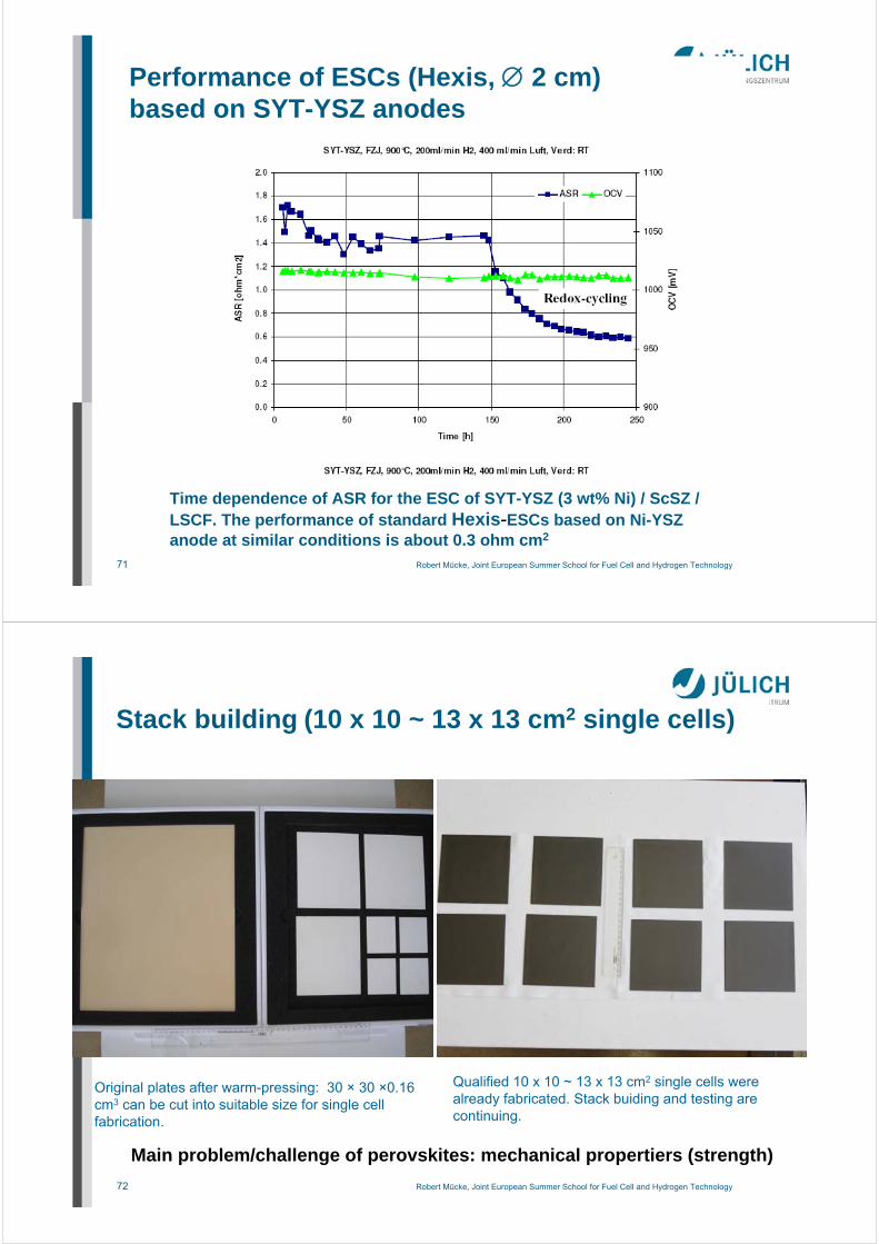
Performance of ESCs (Hexis, 2 cm)based on SYT-YSZ anodes
Time dependence of ASR for the ESC of SYT-YSZ (3 wt% Ni) / ScSZ / LSCF. The performance of standard Hexis-ESCs based on Ni-YSZanode at similar conditions is about 0.3 ohm cm2
72 Robert Mücke, Joint European Summer School for Fuel Cell and Hydrogen Technology
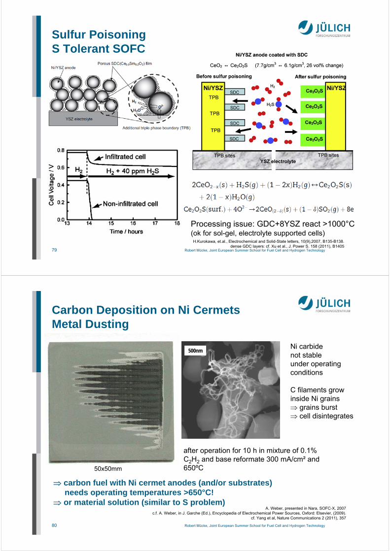
Stack building (10 x 10 ~ 13 x 13 cm2 single cells)
Original plates after warm-pressing: 30 × 30 ×0.16 cm3 can be cut into suitable size for single cellfabrication.
Qualified 10 x 10 ~ 13 x 13 cm2 single cells werealready fabricated. Stack buiding and testing arecontinuing.
Main problem/challenge of perovskites: mechanical propertiers (strength)

73 Robert Mücke, Joint European Summer School for Fuel Cell and Hydrogen Technology
6. Fuel and Fuel Impurities
74 Robert Mücke, Joint European Summer School for Fuel Cell and Hydrogen Technology
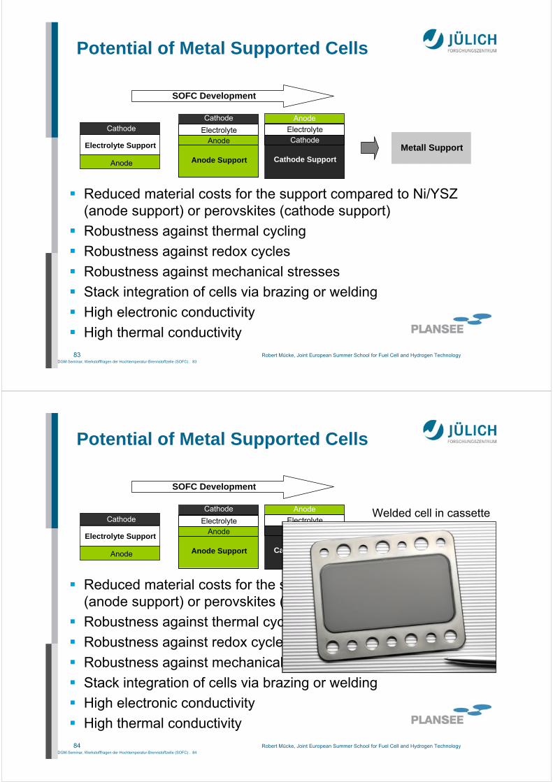
Sulfur Poisoning
S present in all fuels(upto 5000 ppm in American diesel, 2000 ppm in doemstic fuel oil, 10 ppm in [cleaned] natural gas)
Irreversible destruction of Ni anodefor large S amount
NexTech Marials
Rasmussen et al., J. Power Sources 191 (2009) , 534
degradation & partly recoveryfor small S amounts

75 Robert Mücke, Joint European Summer School for Fuel Cell and Hydrogen Technology
Sulfur PoisoningReactions
S adsorption on catalyst (Ni) surface (dominant <50 ppm)
Reaction with Ni
Rasmussen et al., J. Power Sources 191 (2009) , 534
adsorbed S (1) hinders H2/H2O diffusion, and (2) stops CO shift reaction(carbon part of fuel does not contribute to performance anymore)
76 Robert Mücke, Joint European Summer School for Fuel Cell and Hydrogen Technology
Sulfur PoisoningSurface Generation / Operating Conditions
J.H.Wang, et.al., Journal of Power Sources, 176 (2008), 23cf. J.H.Wang, et.al., Electrochem. Comm., 9 (2007), 2212
O2+S→SO2½O2+Ni→NiO
S+2O2–→SO2+4e−
Favorable:Drawback:
H2O+S → H2+SO2H2O+Ni → H2+NiO
S regeneration:(1) increase fuel untilization, (2) increase O2– concentration at TPB(3) introduce O2, (4) H2O to the anode, (5) increase temperature

77 Robert Mücke, Joint European Summer School for Fuel Cell and Hydrogen Technology
Ceramic anodes infiltrated with Ni still affected => approaches:
(1) ceramic anodes without Ni(2) MeS anodes (low performance, CO poisoning)(3) Electrolytes that allow ectrochemical oxidation of S
Sulfur PoisoningS Tolerant SOFC
ScSZ instead of YSZ (provide O2– for S oxidation)
L.Yang, et.al., Science, 326, 2009, 126-129.
new electrolyte materialsBaZr0.1Ce0.7Y0.1Yb0.1O3-δ
K.Sasaki, et.al., J. of The Electrochem. Soc., 153(11),2006, A2023-A2029.
78 Robert Mücke, Joint European Summer School for Fuel Cell and Hydrogen Technology
approaches:
(4) Coat Ni surface (Nb2O5, BaO)
(5) Infiltrate traditional Ni/8YSZ cermets
Sulfur PoisoningS Tolerant SOFC
K. Sasaki, et al., J. Electrochem. Soci. 153 (11) (2006) A2023–A2029
Cell voltage drop withvarious additivesimpregnated in porousanode at 200mAcm−2
(800°C, H2S concentration = 20 ppm, H2/CO 100:0, electrolyte/SSZ, anode/Ni–YSZ + impregnated additives)
79 Robert Mücke, Joint European Summer School for Fuel Cell and Hydrogen Technology
Sulfur PoisoningS Tolerant SOFC
H.Kurokawa, et.al., Electrochemical and Solid-State letters, 10(9),2007, B135-B138.dense GDC layers: cf. Xu et al., J. Power S. 158 (2011), B1405
Processing issue: GDC+8YSZ react >1000°C(ok for sol-gel, electrolyte supported cells)
80 Robert Mücke, Joint European Summer School for Fuel Cell and Hydrogen Technology
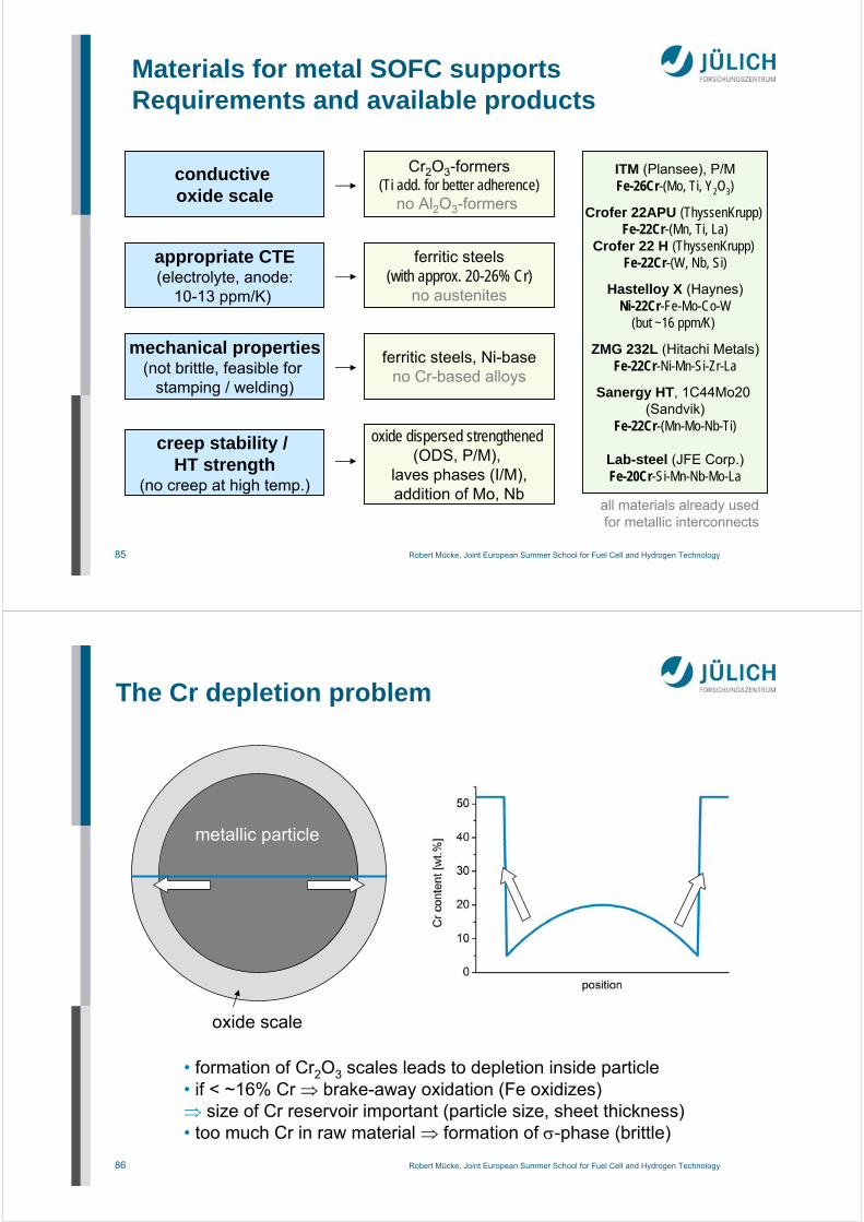
Carbon Deposition on Ni CermetsMetal Dusting
after operation for 10 h in mixture of 0.1% C2H2 and base reformate 300 mA/cm² and 650ºC
A. Weber, presented in Nara, SOFC-X, 2007c.f. A. Weber, in J. Garche (Ed.), Encyclopedia of Electrochemical Power Sources, Oxford: Elsevier, (2009).
cf. Yang et al, Nature Communications 2 (2011), 357
carbon fuel with Ni cermet anodes (and/or substrates)needs operating temperatures >650°C!
or material solution (similar to S problem)
500nmNi carbidenot stableunder operatingconditions
C filaments growinside Ni grains grains burst cell disintegrates
50x50mm

81 Robert Mücke, Joint European Summer School for Fuel Cell and Hydrogen Technology
7. Metal Supported Cells (MSC)
82 Robert Mücke, Joint European Summer School for Fuel Cell and Hydrogen Technology
APUs on the road
KOHLER Diesel APUKohler Power Systems
1 or 2 cylinder diesel (0.35-0.7L)(air or water cooled)
3.5-12.5 kW68-71 dB
120-300L, 110-250kg
Delphi SOFC APU (ASC)5kW announced for 2012
15% less fuel than diesel APUrequires low-sulfur diesel
el ~ 30% (diesel, 40% with nat. gas)Top=700°C
incl. independent vehicle heater
http://www.sae.org/mags/aei/INTER/8222http://www.kohlerpower.com one target application for MSCs
83 Robert Mücke, Joint European Summer School for Fuel Cell and Hydrogen TechnologyDGM-Seminar, Werkstofffragen der Hochtemperatur-Brennstoffzelle (SOFC) . 83
Reduced material costs for the support compared to Ni/YSZ (anode support) or perovskites (cathode support)
Robustness against thermal cycling
Robustness against redox cycles
Robustness against mechanical stresses
Stack integration of cells via brazing or welding
High electronic conductivity
High thermal conductivity
Anode Support
Electrolyte
Cathode
AnodeElectrolyte Support
Cathode
Anode Cathode Support
Electrolyte
Anode
CathodeMetall Support
SOFC Development
Potential of Metal Supported Cells
84 Robert Mücke, Joint European Summer School for Fuel Cell and Hydrogen TechnologyDGM-Seminar, Werkstofffragen der Hochtemperatur-Brennstoffzelle (SOFC) . 84
Reduced material costs for the support compared to Ni/YSZ (anode support) or perovskites (cathode support)
Robustness against thermal cycling
Robustness against redox cycles
Robustness against mechanical stresses
Stack integration of cells via brazing or welding
High electronic conductivity
High thermal conductivity
Anode Support
Electrolyte
Cathode
AnodeElectrolyte Support
Cathode
Anode Cathode Support
Electrolyte
Anode
CathodeMetall Support
SOFC Development
Potential of Metal Supported Cells
Welded cell in cassette
85 Robert Mücke, Joint European Summer School for Fuel Cell and Hydrogen Technology
Materials for metal SOFC supports Requirements and available products
conductive oxide scale
appropriate CTE(electrolyte, anode:
10-13 ppm/K)
Cr2O3-formers(Ti add. for better adherence)
no Al2O3-formers
ferritic steels(with approx. 20-26% Cr)
no austenites
mechanical properties(not brittle, feasible for
stamping / welding)
ferritic steels, Ni-baseno Cr-based alloys
oxide dispersed strengthened(ODS, P/M),
laves phases (I/M),addition of Mo, Nb
creep stability / HT strength
(no creep at high temp.)
ITM (Plansee), P/MFe-26Cr-(Mo, Ti, Y2O3)
Crofer 22APU (ThyssenKrupp) Fe-22Cr-(Mn, Ti, La)
Crofer 22 H (ThyssenKrupp) Fe-22Cr-(W, Nb, Si)
Hastelloy X (Haynes)Ni-22Cr-Fe-Mo-Co-W
(but ~16 ppm/K)
ZMG 232L (Hitachi Metals)Fe-22Cr-Ni-Mn-Si-Zr-La
Sanergy HT, 1C44Mo20 (Sandvik)
Fe-22Cr-(Mn-Mo-Nb-Ti)
Lab-steel (JFE Corp.)Fe-20Cr-Si-Mn-Nb-Mo-La
all materials already usedfor metallic interconnects
86 Robert Mücke, Joint European Summer School for Fuel Cell and Hydrogen Technology
The Cr depletion problem
metallic particle
oxide scale
• formation of Cr2O3 scales leads to depletion inside particle• if < ~16% Cr brake-away oxidation (Fe oxidizes) size of Cr reservoir important (particle size, sheet thickness)• too much Cr in raw material formation of -phase (brittle)

87 Robert Mücke, Joint European Summer School for Fuel Cell and Hydrogen Technology
Break-away oxidationInfluence of Cr reservoir
200 400 600 800 1000 1200
time [h]
0.0
0.5
1.0
1.5
2.0
2.5
3.0
3.5
mas
s ch
ange
[mg/
cm²]
0.00.10.20.30.40.50.60.70.80.91.0
mas
s ch
ange
[mg/
cm²]
200 400 600 800 1000 1200
time [h]
900°C
800°C
2.0mm
0.5mm
0.3mm
0.1mm
weight change during oxidation of Crofer22 APU sheets (var. thickness)
break-away oxidation
2.0mm0.5mm0.3mm
0.1mm
Huczkowski et al., Materials and Corrosion 55, 825
coarser microstructure in metal support preferable(may be more difficult to coat etc.)
100 µm
breakawayoxidation(Fe oxides)
88 Robert Mücke, Joint European Summer School for Fuel Cell and Hydrogen TechnologySeite 88
PLANSEE SE - Facts and Figures
Plansee AG,Austria
Rhodius,Germany
Technetics,USA
Bekaert,Belgium
Supplier
~ 50~ 90~ 80~ 85Porosity
~ 1,0~ 1,0~ 1,8~ 1,0Thickness
Fe-26Cr (Y2O3)Fe-22Cr-0,5MnFe-22Cr-5Al-0,1YNiM aterial
Sintered plateKnit fabricFoamsFeltsSubstrate
200µm
300 µm
Plansee AG,Austria
Rhodius,Germany
Technetics,USA
Bekaert,Belgium
Supplier
~ 50~ 90~ 80~ 85Porosity
~ 1,0~ 1,0~ 1,8~ 1,0Thickness
Fe-26Cr (Y2O3)Fe-22Cr-0,5MnFe-22Cr-5Al-0,1YNiM aterial
Sintered plateKnit fabricFoamsFeltsSubstrate
200µm200µm
300 µm300 µm
Source: DLR
MSC SupportsManufacturing Routes (I)
Th. Franco, Plansee
[mm]
[%]

89 Robert Mücke, Joint European Summer School for Fuel Cell and Hydrogen Technology
Interdiffusion Issues
metal substrate
anode Ni
Cr Fe
Franco et. al, ECS Trans. 7 (1), (2007) 771–780
plasma sprayed anode + electrolyte
Ni Cr
Fe-Ni austenitic phase formed (large CTE ~17-20 ppm/K)leads to cumber / delamination / bad performance
90 Robert Mücke, Joint European Summer School for Fuel Cell and Hydrogen Technology
Diffusion Barrier Layers
Sintering
Plasma-spraying
Inherent growing oxide scales
PVD/CVD
diffusion barrier layer diffusion barrier coating
layer must be porous
high electrical conductivity
coating must be dense
lower conductivity can becompensated by using thin coatings
91 Robert Mücke, Joint European Summer School for Fuel Cell and Hydrogen Technology
Seite 91
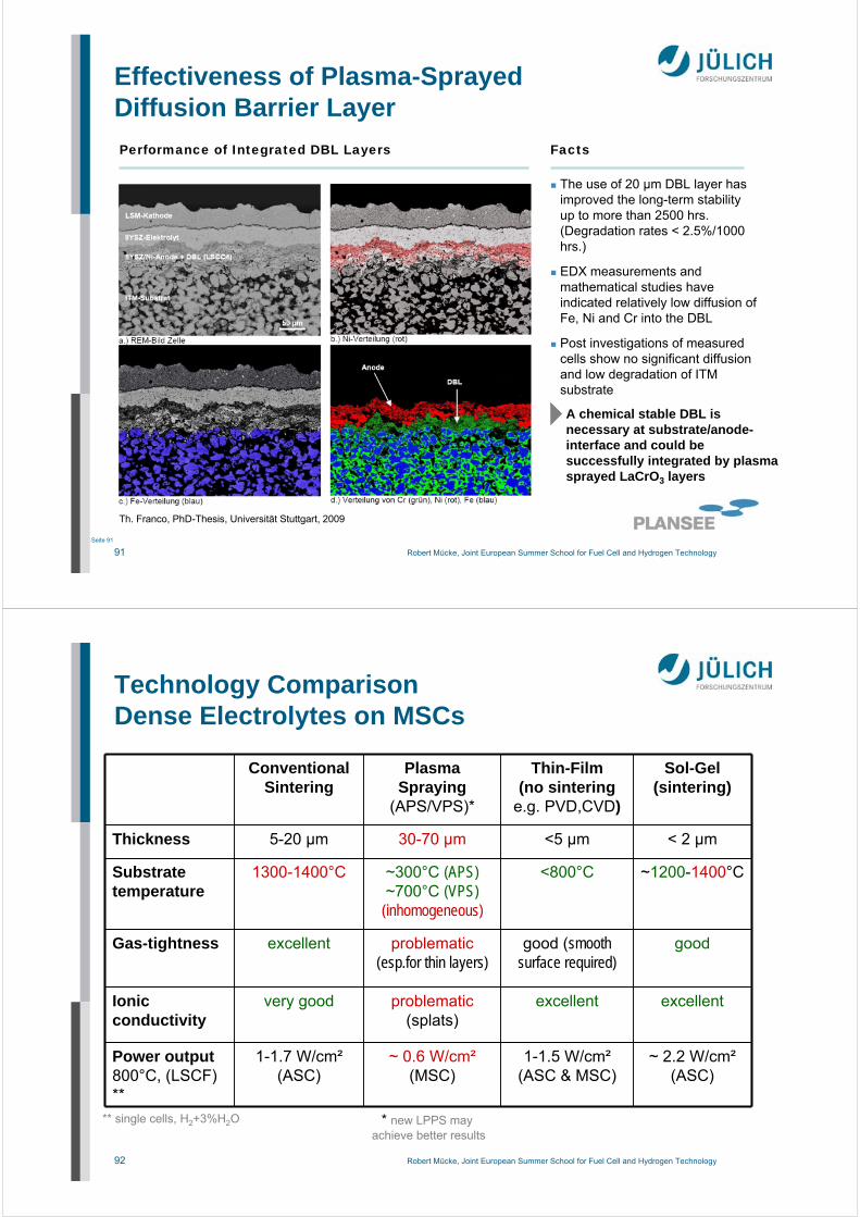
Facts
The use of 20 µm DBL layer has improved the long-term stability up to more than 2500 hrs.(Degradation rates < 2.5%/1000 hrs.)
EDX measurements and mathematical studies have indicated relatively low diffusion of Fe, Ni and Cr into the DBL
Post investigations of measured cells show no significant diffusion and low degradation of ITM substrate
Performance of Integrated DBL Layers
1st Gen MSC – Latest results
A chemical stable DBL is necessary at substrate/anode-interface and could be successfully integrated by plasma sprayed LaCrO3 layers
Th. Franco, PhD-Thesis, Universität Stuttgart, 2009
Effectiveness of Plasma-Sprayed Diffusion Barrier Layer
92 Robert Mücke, Joint European Summer School for Fuel Cell and Hydrogen Technology
Technology ComparisonDense Electrolytes on MSCs
Conventional Sintering
Plasma Spraying
(APS/VPS)*
Thin-Film(no sintering
e.g. PVD,CVD)
Sol-Gel(sintering)
Thickness 5-20 µm 30-70 µm <5 µm < 2 µm
Substrate temperature
1300-1400°C ~300°C (APS)~700°C (VPS)
(inhomogeneous)
<800°C ~1200-1400°C
Gas-tightness excellent problematic(esp.for thin layers)
good (smooth surface required)
good
Ionicconductivity
very good problematic(splats)
excellent excellent
Power output800°C, (LSCF) **
1-1.7 W/cm²(ASC)
~ 0.6 W/cm²(MSC)
1-1.5 W/cm²(ASC & MSC)
~ 2.2 W/cm²(ASC)
** single cells, H2+3%H2O * new LPPS may achieve better results

93 Robert Mücke, Joint European Summer School for Fuel Cell and Hydrogen Technology
Anode Coating TechniquesPlasma Spraying
energy transfer to samplesis less than with sintering(e.g. interesting for metallic substrates)
~15000°C
Substratesurface
<200..400°C(APS)
<600..800°C(VPS)
Atmospherical Plasma Spraying (APS) in airVacuum Plasma Spraying (VPS) in low pressure
94 Robert Mücke, Joint European Summer School for Fuel Cell and Hydrogen Technology
Plasma Sprayed Microstructures
difficulties in plasma spraying
• only larger thicknesses (>=30µm)
• inhomogeneous layers
• coarse microstructure
• bad transversal conductivity due to inter-splat cracks in the layer
Atmospheric Plasma Spraying (APS)
vacuum slip-cast anode 1400°C/5h
95 Robert Mücke, Joint European Summer School for Fuel Cell and Hydrogen Technology
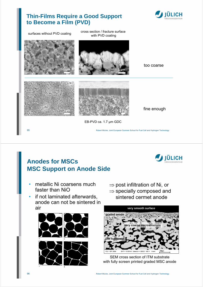
Thin-Films Require a Good Supportto Become a Film (PVD)
EB-PVD ca. 1.7 µm GDC
too coarse
fine enough
surfaces without PVD coating
1 µm
cross section / fracture surfacewith PVD coating
1 µm 1 µm
1 µm
96 Robert Mücke, Joint European Summer School for Fuel Cell and Hydrogen Technology
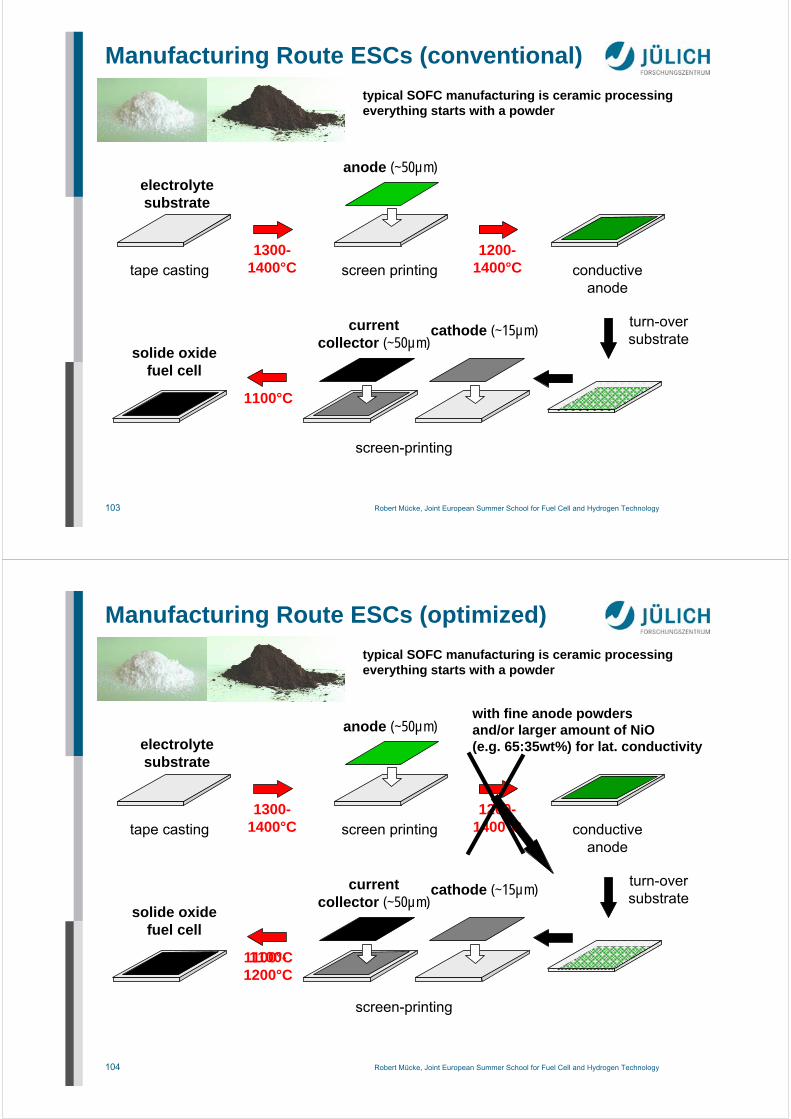
Anodes for MSCsMSC Support on Anode Side
• metallic Ni coarsens muchfaster than NiO
• if not laminated afterwards, anode can not be sintered in air
post infiltration of Ni, or specially composed and
sintered cermet anode
graded anode
ITM substrate
very smooth surface
very coarse microstructure
SEM cross section of ITM substratewith fully screen printed graded MSC anode

97 Robert Mücke, Joint European Summer School for Fuel Cell and Hydrogen Technology
Cathodes for MSCsMSC Support on Anode Side
• can not be sintered in air• LSCF loses approx. 30%
performance withoutsintering
use unsintered high performance cathode(deal with thermal expansion mismatch)
gain +20-30%
gain +10-20%
ASC performance gain from LSCF (sintered) to LSC (unsintered) cathode
98 Robert Mücke, Joint European Summer School for Fuel Cell and Hydrogen Technology
Possible Manufacturing Routeof MSCs with Thin-Film Electrolyte
Franco et al.: SOFC-XII, 2011

99 Robert Mücke, Joint European Summer School for Fuel Cell and Hydrogen Technology
MSC with Similar Stack Performance like ASCs
Rüttinger, Mücke et al.: SOFC-XII, 2011
800°C,H2+Ar/10%H2O
MSC with thin layers:same power output likestate-of-the-art ASC in a stack
100 Robert Mücke, Joint European Summer School for Fuel Cell and Hydrogen TechnologySeite 100
P. Bance et al, J. Power Sources 131 (2004) 86-90N.P. Brandon et al., J. Fuel Cell Sci. Technol. 1 (2004), 61-65
1.4509 (17%Cr, Ti-Nb Fe) T ≤ 600°C steel substrate ~200µm
anode ~10µm
electrolyte ~10-20µm
cathode ~10µm
contact layer~25µm
(LSCF/CGO)
CGO10 T ≤ 600°C
400 mW cm–2
570°C (H2)
Electro-phoretic Deposition + Sinteringof Electrolyte (Ceres Power)

101 Robert Mücke, Joint European Summer School for Fuel Cell and Hydrogen TechnologySeite 101
P. Blennow et al. 9th European Solid Oxide Fuel Cell Forum, Lucerne, 2010, 16-1
anode: CGO20 + 10%Nipost-infiltrated
electrolyte: tape castScYSZ
substrate: tape cast22% Cr = Sanergy class steel
1. electrolyte/substratelaminated
2. co-fired(Ar/H2)3. anode post-infiltrated4. calcin. (350°C/2h air)5. LSC-cathode screen printing
(formerly LSCF/CGO)
up-to 3.0A/cm² at 800°C H2(1cm² act. cell area)100 redox cyclesca. 5%/1000h V degr.
@ 655°C 0,25Acm–2
Lamination, Post-Infiltration of Anode(Risoe, Denmark)
102 Robert Mücke, Joint European Summer School for Fuel Cell and Hydrogen Technology
8. Industrial Manufacturing(Costs and Scalability)
103 Robert Mücke, Joint European Summer School for Fuel Cell and Hydrogen Technology
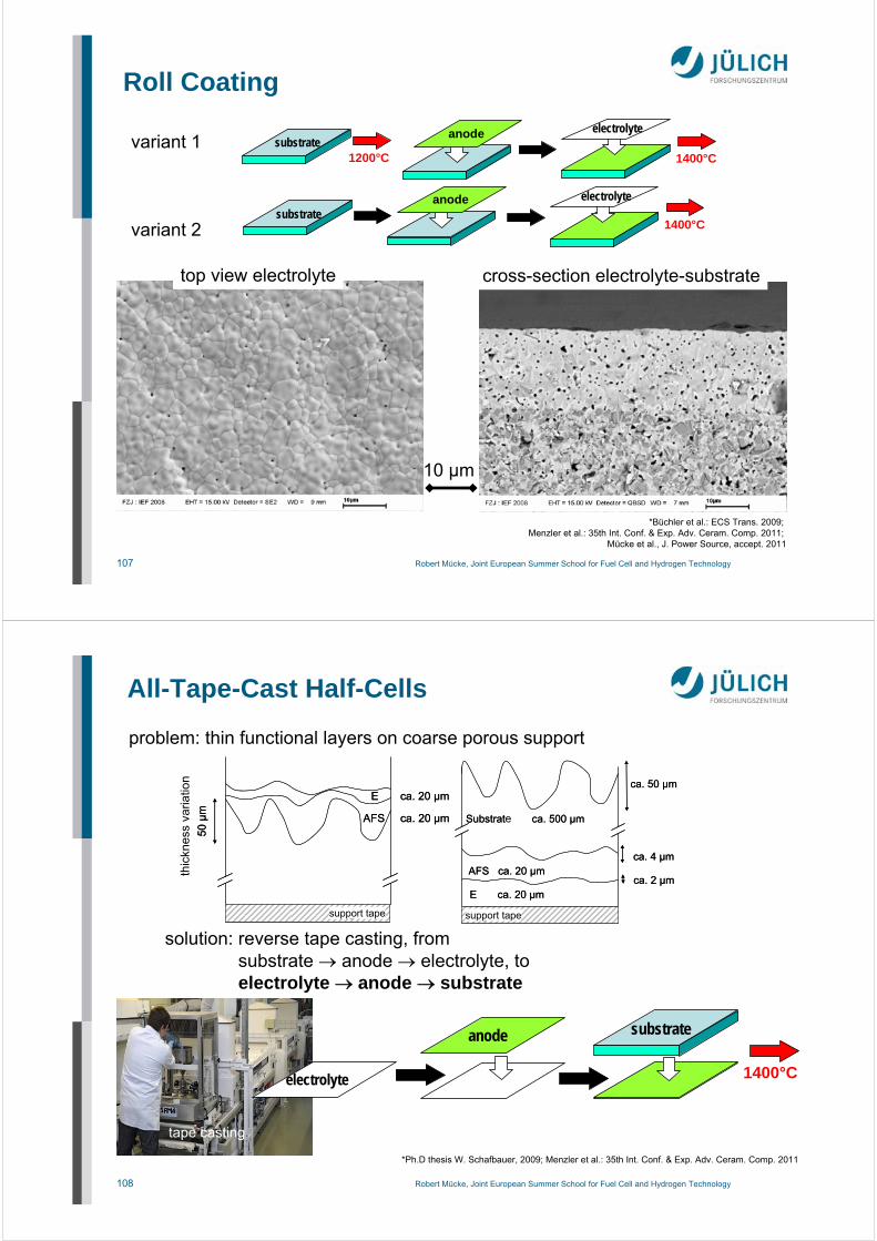
Manufacturing Route ESCs (conventional)
anode (~50µm)
tape casting screen printing
cathode (~15µm)currentcollector (~50µm)
solide oxidefuel cell
screen-printing
1300-1400°C
1100°C
typical SOFC manufacturing is ceramic processingeverything starts with a powder
1200-1400°C conductive
anode
turn-oversubstrate
electrolytesubstrate
104 Robert Mücke, Joint European Summer School for Fuel Cell and Hydrogen Technology
Manufacturing Route ESCs (optimized)
anode (~50µm)
tape casting screen printing
cathode (~15µm)currentcollector (~50µm)
solide oxidefuel cell
screen-printing
1300-1400°C
1100°C
typical SOFC manufacturing is ceramic processingeverything starts with a powder
1200-1400°C conductive
anode
turn-oversubstrate
with fine anode powdersand/or larger amount of NiO(e.g. 65:35wt%) for lat. conductivity
1100-1200°C
electrolytesubstrate

105 Robert Mücke, Joint European Summer School for Fuel Cell and Hydrogen Technology
Manufacturing Route ESCs (optimized)
electrolytesubstrate
anode (~50µm)
tape casting screen printing
cathode (~15µm)currentcollector (~50µm)
solide oxidefuel cell
screen-printing
1300-1400°C
typical SOFC manufacturing is ceramic processingeverything starts with a powder
turn-oversubstrate
with fine anode powdersand/or larger amount of NiO(e.g. 65:35wt%) for lat. conductivity
1100-1200°C
106 Robert Mücke, Joint European Summer School for Fuel Cell and Hydrogen Technology
Scale-up from dozen (lab-scale) via thousands(small series) to millions (mass manufacturing)question: is screen printing the technique of choice?
answer: presumably not; because much equipmentnecessary(high invest costs) single layer deposition istime consuming(screen kneeling, printing, screen lifting)
alternatives:continuous technologies likeroll-coating or curtaincoating
reverse roll coater
*Büchler et al.: ECS Trans. 2009; Menzler et al.: 35th Int. Conf. & Exp. Adv. Ceram. Comp. 2011; Mücke et al., J. Power Sources, 2011
Continuous Coating Technology
applicator roll
transport roll
liquortrough
doctor blade
lick roll
substrate
dip roll
coating speeds:5 m/min (cell test)…60 m/min (lab machine)…500 m/min (industry)
107 Robert Mücke, Joint European Summer School for Fuel Cell and Hydrogen Technology
variant 1
variant 2
substrate1200°C
electrolyte
1400°C
anode
electrolyteanodesubstrate
1400°C
top view electrolyte cross-section electrolyte-substrate
10 µm
Roll Coating
*Büchler et al.: ECS Trans. 2009; Menzler et al.: 35th Int. Conf. & Exp. Adv. Ceram. Comp. 2011;
Mücke et al., J. Power Source, accept. 2011
108 Robert Mücke, Joint European Summer School for Fuel Cell and Hydrogen Technology
problem: thin functional layers on coarse porous support
Dic
kens
chw
an
kung
50
µm
E ca. 20 µm
AFS ca. 20 µm
Trägerfolie
Dic
kens
chw
an
kung
50
µm
E ca. 20 µm
AFS ca. 20 µm
Trägerfolie
ca. 2 µmAFS ca. 20 µm
ca. 4 µm
ca. 50 µm
Trägerfolie
E ca. 20 µm
Substrat ca. 500 µm
ca. 2 µmAFS ca. 20 µm
ca. 4 µm
ca. 50 µm
Trägerfolie
E ca. 20 µm
Substrat ca. 500 µm
tape casting
solution: reverse tape casting, fromsubstrate anode electrolyte, toelectrolyte anode substrate
anode
electrolyte
substrate
1400°C
thic
knes
sva
riatio
n
support tape support tape
e
All-Tape-Cast Half-Cells
*Ph.D thesis W. Schafbauer, 2009; Menzler et al.: 35th Int. Conf. & Exp. Adv. Ceram. Comp. 2011

109 Robert Mücke, Joint European Summer School for Fuel Cell and Hydrogen Technology
substrate1200°C
anode electrolyte
1400°C
cathodecurrent
collector
~ 1050°CSOFC
Coat-Mix-powderr+
warm pressing
de-bindering+
pre-sintering
vacuumslip
casting
1000°C
calcination vacuumslip
csating
end-firingelectrolyte
half-cell
lasercutting
screen printing screen printing
sinteringcathode
flatteninghalf cell
(1350°C) summary 2003:4 thermal treatments3 manufacturing technologies, thereunder2 dis-continuous processes (pressing, VSC)
Summary: Innovative Cell Manufacturing
110 Robert Mücke, Joint European Summer School for Fuel Cell and Hydrogen Technology
substrate1200°C
anode electrolyte
1400°C
cathodecurrent
collector
~ 1050°CSOFC
Coat-Mix-powderr+
warm pressing
de-bindering+
pre-sintering
vacuumslip
casting
1000°C
calcination vacuumslip
csating
end-firingelectrolyte
half-cell
lasercutting
screen printing screen printing
sinteringcathode
flatteninghalf cell
(1350°C) summary 2003:4 thermal treatments3 manufacturing technologies, thereunder2 dis-continuous processes (pressing, VSC)
anode
electrolyte 1400°C
cathodecurrent
collector
~ 1050°C
finalSOFC
half cell
substrate
t a p e c a s t i n gor
r o l l c o a t i n g + t a p e c a s t i n g
r o l l c o a t i n g
summary 2010:2 thermal treatments1 or 2 manufacturing techniques(all of them mass manufacturing)
Summary: Innovative Cell Manufacturing

111 Robert Mücke, Joint European Summer School for Fuel Cell and Hydrogen Technology
Summary
Bring SOFC to the people(real life applications)
long term stability(40,000-80,000h stationary,5,000-15,000h mobile appl.)
accelerated testing (requires understanding)
real field operation (sulfur, high uF,
combine loads/cycle), most test capacity
lower the costs(industrial manufacturing)
may allow cheap replaceable modules
Next generation SOFC
new materials, e.g. ceramic anode,
metallic substrate
thin film technologies400°C SOFC
(new electrodes)
prove feasability formanufacturing and
operation (a button cellis not enough)
(but keepthe
runningsystem)
112 Robert Mücke, Joint European Summer School for Fuel Cell and Hydrogen Technology
Acknowledgements
Special thanks for graphics and providing results are due to
Dr. Thomas Fraco (Plansee SE)Prof. E. Ivers-Tiffée • Dr. André Weber (IWE Karlsruhe)Dr. Martin Bram • Dr. Manuel Ettler • D. Federmann •Dr. Izaak C. Finke • Dr. S.M. Groß • Dr. V.A.C. Haanappel •Dr. L.G.J. de Haart • Dr. Feng Han • Dr. Natividat Jordan-Escalona •Dr. Norbert H. Menzler • Dr. Wolfgang Schafbauer •Dr. Frank Tietz • Dr. Sven Uhlenbruck • Dr. Tim Van Gestel •Prof. Robert Vaßen • Sebastian Vieweger(all FZ Jülich)
The former fuel cell project team under Dr. Robert Steinberger-Wilckens.The SOFC group of IEK-1 in Jülich under Dr. H.-P. Buchkremer (and formerlyProf. D. Stöver).
Related Documents