Current Matching Control System for Multi-Terminal DC Transmission to Integrate Offshore Wind Farms J. Zhu, C. Booth, G.P. Adam Department of Electrical and Electronic Engineering, University of Strathclyde, Glasgow G1 1XW, UK. Email: [email protected] Keywords: HVDC, voltage source converter, multi-terminal DC, control. Abstract The inherent features of Voltage Source Converters (VSCs) are attractive for practical implementation of Multi-Terminal HVDC transmission systems (MTDC). MTDC can be used for large-scale integration of offshore wind power with onshore grids. However, many of the control strategies for MTDC that have been proposed previously for offshore wind farm integration depend on local control of the wind turbine generators. This paper proposes a new control strategy, termed Current Matching Control (CMC), which can be used with any number of converter terminals, and is independent of the types of wind turbines used within each wind farm. The proposed CMC matches the current reference of the grid side converter to that of the wind farm side converters. In order to achieve such current matching, a telecommunication system will be required to facilitate calculations of the grid side current references to be carried out in real time. To validate the performance of the proposed control strategy, a generic four-terminal MTDC network, which integrates two offshore wind farms with two mainland grids, is simulated and results relating to several steady state and transient scenarios are presented. 1 Introduction There has been a tremendous pace of development of large- scale offshore wind farms in recent years. It is anticipated that there will be an approximate increase of 26.6 GW in aggregate generation capacity over the period from 2009/10 to 2016/17 in the UK, 11.7 GW of which will be contributed by wind power [1]. More broadly, the European Wind Energy Association has, in its “high wind” scenario, a target of 180 GW from wind energy sources in by 2020, of which 35 GW will be sourced from offshore wind installations. This capacity target for offshore wind increases to 120 GW by 2030 [2]. These targets, if they are achieved, will have great impact on power transmission design, planning, construction and operation. Many offshore wind farms will require long- distance power transmission systems. AC may not be suitable due to high power losses o ver longer distances. Classical line- current-commutated (LCC) HVDC transmission has been used for many HVDC installations [3], but is not well suited to MTDC, in comparison to VSC. A summary of the advantages of VSC over LCC is listed below: VSC has a smaller footprint which facilitates offshore installations of reduced platform size [3]; LCC requires large filtering components; VSC provides additional reactive power support and AC voltage regulation for wind farms connected to weak AC systems, and possesses black-start capability; VSC improves wind farm AC fault ride-through capability and facilitates Grid Code compliance at reduced costs [4]; Power reversal can be achieved in VSC without changing the DC voltage polarity, facilitating the realisation of a flexible MTDC transmission system. MTDC transmission systems have attracted much attention for wind farm integration [5][6][7]. Firstly, MTDC reduces converter numbers when compared to numerous point-to- point HVDC solutions. Secondly, it is conceivable that, due to limited correlations of weather systems in geographically dispersed wind farm locations, the overall variability of wind power may be reduced by interconnecting many geographically-dispersed wind farm systems via a large-area MTDC system, thus increasing the overall availability of energy. In future, energy storage devices may be integrated with MTDC system [1], which further supports energy availability and quality of supply. MTDC is also being proposed as the means of interconnecting independent large- scale AC power systems, (e.g. European super-grid proposal [5] to promote the interconnection of Norwegian hydro, French nuclear, Sahara solar and North sea wind power into a common MTDC) to resolve local power shortages or congestion, to enable international power sharing, and to provide an excellent level of overall power system reliability. As discussed in [5], there are many challenging obstacles to the introduction of MTDC. The control system for an MTDC must be robust, coordinated and reliable, as problems with one terminal have the potential to affect the entire MTDC network. A number of control strateg ies are proposed [6] [8][9] which will be introduced later. These strategies remain at the modelling and testing stages of development. Critical concerns about these strategies are the controllability and reliability of MTDC systems, as most of the proposed strategies manage an MTDC system without use of communications between terminals. The proposed current matching control strategy employs minimal (in terms of required traffic and bandwidth) telecommunications between terminals in an MTDC network. While there may be concerns

Welcome message from author
This document is posted to help you gain knowledge. Please leave a comment to let me know what you think about it! Share it to your friends and learn new things together.
Transcript
8/3/2019 Current Matching Control System for Multi-Terminal DC Transmission to Integrate Offshore Wind Farms
http://slidepdf.com/reader/full/current-matching-control-system-for-multi-terminal-dc-transmission-to-integrate 1/6
Current Matching Control System for Multi-Terminal DC
Transmission to Integrate Offshore Wind Farms
J. Zhu, C. Booth, G.P. Adam Department of Electrical and Electronic Engineering,
University of Strathclyde, Glasgow G1 1XW, UK.
Email: [email protected]
Keywords: HVDC, voltage source converter, multi-terminalDC, control.
Abstract
The inherent features of Voltage Source Converters (VSCs)are attractive for practical implementation of Multi-TerminalHVDC transmission systems (MTDC). MTDC can be usedfor large-scale integration of offshore wind power withonshore grids. However, many of the control strategies forMTDC that have been proposed previously for offshore windfarm integration depend on local control of the wind turbinegenerators.
This paper proposes a new control strategy, termed CurrentMatching Control (CMC), which can be used with anynumber of converter terminals, and is independent of thetypes of wind turbines used within each wind farm. Theproposed CMC matches the current reference of the grid sideconverter to that of the wind farm side converters. In order toachieve such current matching, a telecommunication systemwill be required to facilitate calculations of the grid sidecurrent references to be carried out in real time. To validatethe performance of the proposed control strategy, a genericfour-terminal MTDC network, which integrates two offshorewind farms with two mainland grids, is simulated and resultsrelating to several steady state and transient scenarios arepresented.
1 Introduction
There has been a tremendous pace of development of large-scale offshore wind farms in recent years. It is anticipated thatthere will be an approximate increase of 26.6 GW inaggregate generation capacity over the period from 2009/10to 2016/17 in the UK, 11.7 GW of which will be contributedby wind power [1]. More broadly, the European Wind EnergyAssociation has, in its “high wind” scenario, a target of 180GW from wind energy sources in by 2020, of which 35 GWwill be sourced from offshore wind installations. Thiscapacity target for offshore wind increases to 120 GW by2030 [2].
These targets, if they are achieved, will have great impact onpower transmission design, planning, construction andoperation. Many offshore wind farms will require long-distance power transmission systems. AC may not be suitabledue to high power losses over longer distances. Classical line-current-commutated (LCC) HVDC transmission has been
used for many HVDC installations [3], but is not well suitedto MTDC, in comparison to VSC. A summary of theadvantages of VSC over LCC is listed below:
VSC has a smaller footprint which facilitates offshoreinstallations of reduced platform size [3];
LCC requires large filtering components; VSC provides additional reactive power support and AC
voltage regulation for wind farms connected to weak ACsystems, and possesses black-start capability; VSC improves wind farm AC fault ride-through
capability and facilitates Grid Code compliance atreduced costs [4];
Power reversal can be achieved in VSC without changingthe DC voltage polarity, facilitating the realisation of aflexible MTDC transmission system.
MTDC transmission systems have attracted much attentionfor wind farm integration [5][6][7]. Firstly, MTDC reducesconverter numbers when compared to numerous point-to-point HVDC solutions. Secondly, it is conceivable that, due tolimited correlations of weather systems in geographically
dispersed wind farm locations, the overall variability of windpower may be reduced by interconnecting manygeographically-dispersed wind farm systems via a large-areaMTDC system, thus increasing the overall availability of energy. In future, energy storage devices may be integratedwith MTDC system [1], which further supports energyavailability and quality of supply. MTDC is also beingproposed as the means of interconnecting independent large-scale AC power systems, (e.g. European super-grid proposal[5] to promote the interconnection of Norwegian hydro,French nuclear, Sahara solar and North sea wind power into acommon MTDC) to resolve local power shortages orcongestion, to enable international power sharing, and to
provide an excellent level of overall power system reliability.As discussed in [5], there are many challenging obstacles tothe introduction of MTDC. The control system for an MTDCmust be robust, coordinated and reliable, as problems withone terminal have the potential to affect the entire MTDCnetwork. A number of control strategies are proposed [6][8][9] which will be introduced later. These strategies remainat the modelling and testing stages of development. Criticalconcerns about these strategies are the controllability andreliability of MTDC systems, as most of the proposedstrategies manage an MTDC system without use of communications between terminals. The proposed currentmatching control strategy employs minimal (in terms of
required traffic and bandwidth) telecommunications betweenterminals in an MTDC network. While there may be concerns
8/3/2019 Current Matching Control System for Multi-Terminal DC Transmission to Integrate Offshore Wind Farms
http://slidepdf.com/reader/full/current-matching-control-system-for-multi-terminal-dc-transmission-to-integrate 2/6
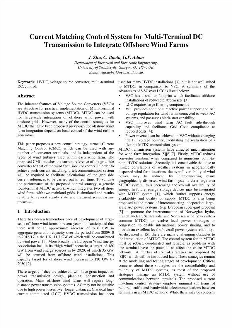
Fig.1 The test MTDC system configuration
over use of communications, modern telecommunicationtechnologies are increasingly highly developed, reliable andredundant [10]. Furthermore, risk can be mitigated byemploying redundancy, through continuous monitoring of telecommunications channels, and ensuring operation cancontinue, albeit in a less efficient fashion, if telecommunications is lost. Operation of the scheme is basedon measurement (discretely, with a step of 1-2ms in thisexample) of the total DC current provided by wind farm siderectifiers (i.e. WFR1 and WFR2 in Fig.1) and allocation(matching) of this current across the inverters, according to apre-determined sharing factor. This is described in moredetail in Section 4. The scheme also provides further
protection for the entire MTDC system by monitoring the DCvoltage. Finally, the system can operate if thetelecommunication system fails, but accurate sharing of theinverter currents may not be possible.
2 MTDC system configuration
MTDC topology design may vary depending on specificsituations (e.g. the locations of grid connection points andoffshore wind farms, available undersea cable routes). Fig.1presents a four terminal MTDC system for wind farmintegration, which utilises bi-polar cables R5 with nominal DCvoltage of 200 kV (± 100 kV). On the offshore side, two wind
farms are connected via two voltage source neutral-pointclamped rectifiers (WFR1, WFR2). On the onshore side, twogrid-connected inverters (GCI 3, GCI 4) feed power to twoindependent 2000 MVA equivalent AC power systems. AllVSCs are rated at 200 MVA. Targets of converter controldiffer for WFR1 and WFR2, implementing frequency and ACvoltage control at the point of common connection (PCC )with wind farms, while GCI 3 and GCI 4 are equipped with acurrent controller and DC voltage regulator respectively, inaddition to AC voltage/or reactive power control.
2.1 AC/DC interaction for a VSC
Instead of presenting an in-depth study of the VSC controlsystem formulae, such as those presented [9] and [7], this
paper focuses on the dynamics of AC and DC interaction,which is dictated by the converter control. As the controlsystem for VSC employs vector control in the synchronousrotating reference frame dq, the current references id_ref andiq_ref which are derived by the commanded active power Pcomm and reactive power Qcomm, are given in equation (1). In therotating reference frame, the d -axis voltage V d , aligned withone of three phases, is equal to the magnitude of AC voltage,and the q-axis voltage V q is zero.
,ref ref
comm commd q
d d
P Qi i
V V (1)
Once the current references id_ref and iq_ref are generated, theinner current control loops adjust the actual id and iq values tobe in accordance with the computed reference values. Thisprocess takes a short period to complete and is determined bythe natural frequency of the converter control dynamic inLaplace equation (2), which contains the proportional gain(k p) and the integral gain (k i) of the proportional-and-integral(PI) controller, reactor inductance ( L) and resistance ( R):
2
p i
p iref
k k dq L L
R k k dq
L L
i
i s s
(2)
From the DC side perspective of the VSC in Fig.2, the DCvoltage udc across the converter or the output capacitors, theDC current idc injected by the converter, and the current ic conducted by the DC cables, are related as shown in equation(3). The capacitors are charged (or discharged) to possess acertain DC voltage. The current idc injected to the MTDCnetwork by the converter is calculated from AC side PCC currents id and iq, pulse-width-modulation index M andconverter terminal voltage angle with respect to the PCC
voltage, using equation (4):
dcdc c
duC i i
dt
(3)
cos sindc d qi Mi Mi (4)
8/3/2019 Current Matching Control System for Multi-Terminal DC Transmission to Integrate Offshore Wind Farms
http://slidepdf.com/reader/full/current-matching-control-system-for-multi-terminal-dc-transmission-to-integrate 3/6
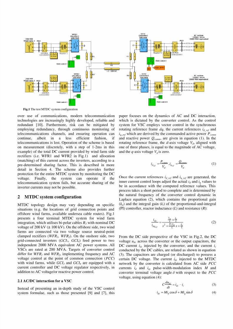
2.2 Equivalent MTDC circuit
As demonstrated in Section 2.1, the DC property of individual
VSCs in the MTDC can be represented as a “controlled” current source, shown in the equivalent circuit in Fig.(2). Theextremely small inductance and capacitance of the DCnetwork with respect to direct current are neglected.
As the focus of this section is on the analysis of DC network behaviour, it is essential to analyse the effect of the variationin DC current idc from one converter station, on either its DCvoltage and/or the DC voltage at other stations. Taking WFR1 as an example, a control action to increase WFR1 current idc1 will quickly charge its DC capacitors and boost its DCvoltage udc1 to a higher value, based on equation (3). Thehigher udc1 with respect to other DC node voltages acts to
supply the conducted current ic1 into the MTDC network. Theincreased current ic1 charges capacitors at other nodes, untilthe voltage levels at all the nodes reach a new higherequilibrium value. The rectifier DC voltage is slightly higherthan the inverter voltage so that current flows from rectifiernode(s) to inverter node(s). The magnitude of individualconverter DC voltage depends on two elements: (a) theconducted current though the node; (b) the resistancesbetween the nodes.
Thus, it can be concluded that a temporary current mismatchbetween rectifier and inverter in the MTDC results in anoverall DC voltage variation. As the converter controlsystems use DC voltage information to function, it isdesirable to quickly address any DC current surplus (byincreasing exported current) or DC current shortage (byreducing exported current), so that a stable DC voltageoperating point for the MTDC system will be realised.Communications between rectifier and inverter nodes in thesystem is therefore critical to the operation of this scheme.
3 Previously reported MTDC control
strategies
Historically, there have been two distinct control strategies
used to facilitate power dispatch from DC to AC systems,
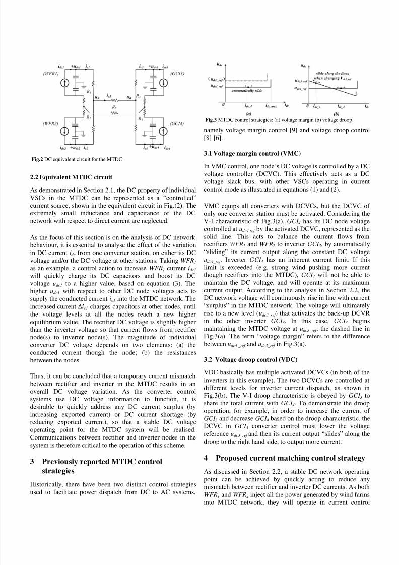
namely voltage margin control [9] and voltage droop control[8] [6].
3.1 Voltage margin control (VMC)
In VMC control, one node’s DC voltage is controlled by a DCvoltage controller (DCVC). This effectively acts as a DCvoltage slack bus, with other VSCs operating in currentcontrol mode as illustrated in equations (1) and (2).
VMC equips all converters with DCVCs, but the DCVC of only one converter station must be activated. Considering theV-I characteristic of Fig.3(a), GCI 4 has its DC node voltagecontrolled at udc4 ref by the activated DCVC, represented as thesolid line. This acts to balance the current flows fromrectifiers WFR1 and WFR2 to inverter GCI 3, by automatically“sliding” its current output along the constant DC voltageudc4_ref . Inverter GCI 4 has an inherent current limit. If thislimit is exceeded (e.g. strong wind pushing more currentthough rectifiers into the MTDC), GCI 4 will not be able tomaintain the DC voltage, and will operate at its maximumcurrent output. According to the analysis in Section 2.2, the
DC network voltage will continuously rise in line with current“surplus” in the MTDC network. The voltage will ultimatelyrise to a new level (udc3_ref ) that activates the back-up DCVRin the other inverter GCI 3. In this case, GCI 3 beginsmaintaining the MTDC voltage at udc3_ref , the dashed line inFig.3(a). The term “voltage margin” refers to the differencebetween udc4 _ref and udc3_ref in Fig.3(a).
3.2 Voltage droop control (VDC)
VDC basically has multiple activated DCVCs (in both of theinverters in this example). The two DCVCs are controlled atdifferent levels for inverter current dispatch, as shown in
Fig.3(b). The V-I droop characteristic is obeyed by GCI 3 toshare the total current with GCI 4. To demonstrate the droopoperation, for example, in order to increase the current of GCI 3 and decrease GCI 4 based on the droop characteristic, theDCVC in GCI 3 converter control must lower the voltagereference udc3_ref and then its current output “slides” along thedroop to the right hand side, to output more current.
4 Proposed current matching control strategy
As discussed in Section 2.2, a stable DC network operatingpoint can be achieved by quickly acting to reduce anymismatch between rectifier and inverter DC currents. As both
WFR1 and WFR2 inject all the power generated by wind farmsinto MTDC network, they will operate in current control
Fig.2 DC equivalent circuit for the MTDC
Fig.3 MTDC control strategies: (a) voltage margin (b) voltage droop
8/3/2019 Current Matching Control System for Multi-Terminal DC Transmission to Integrate Offshore Wind Farms
http://slidepdf.com/reader/full/current-matching-control-system-for-multi-terminal-dc-transmission-to-integrate 4/6
mode. GCI 3 and GCI 4 will operate using the proposed CMCin order to address the shortcomings of the VMC and VDCcontrol, regarding DC current mismatch that may arise duringchanges in wind power generation. The detailed operation of the scheme is now presented.
4.1 Converter operating states
To facilitate the development of the proposed controlstrategy, it is important to understand VSC operating stateswith their control references in the MTDC system. Thefollowing equations (5) and (6) are given, referring to Fig.2:
1 1 1 2 2 2S dc c dc cu u R i u R i (5)
3 3 3 4 4 4S dc c dc cu u R i u R i (6)
uS is the sending end voltage and u R is the voltage at thereceiving end of the DC link. ic1 to ic4 are the rectifier andinverter currents as shown in Fig.2. R5 is given by:
5 5S R cu u R i (7)
ic5 is the current through the DC link as shown in Fig.2.Kirchhoff’s current law dictates that:
1 2 3 4 0dc dc dc dci i i i (8)
As demonstrated in VMC and VDC, GCI 4 has its DCVCactivated to control DC voltage at udc4; the other convertersWFR1, WFR2 and GCI 3 control their currents at idc1 idc2 andidc3 respectively. Therefore, by combining equation (5), (6),(7) and (8), the following converter operating state matrix,which incorporates DC network resistance, can be derived:
1 11 4 5 4 5 4
2 24 5 4 5 4
3 34 4 3 4
4 4
1
1
( ) 1
1 1 1 0
dc dc
dc dc
dc dc
c dc
u i R R R R R R
u i R R R R R
u i R R R R
i u
(9)
4.2 Current matching control principle
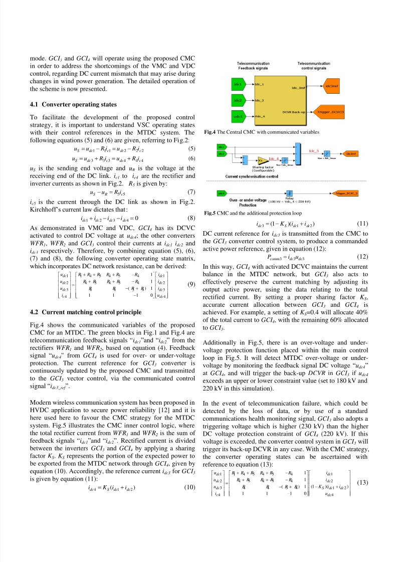
Fig.4 shows the communicated variables of the proposedCMC for an MTDC. The green blocks in Fig.1 and Fig.4 aretelecommunication feedback signals “idc1”and “idc2” from therectifiers WFR1 and WFR2, based on equation (4). Feedback signal “udc4” from GCI 4 is used for over- or under-voltageprotection. The current reference for GCI 3 converter iscontinuously updated by the proposed CMC and transmittedto the GCI 3 vector control, via the communicated controlsignal “idc3_ref ”.
Modern wireless communication system has been proposed inHVDC application to secure power reliability [12] and it ishere used here to favour the CMC strategy for the MTDCsystem. Fig.5 illustrates the CMC inner control logic, wherethe total rectifier current from WFR1 and WFR2 is the sum of feedback signals “idc1”and “idc2”. Rectified current is dividedbetween the inverters GCI 3 and GCI 4 by applying a sharingfactor K S. K S represents the portion of the expected power tobe exported from the MTDC network through GCI 4, given byequation (10). Accordingly, the reference current idc3 for GCI 3 is given by equation (11):
4 1 2( )dc S dc dci K i i (10)
3 1 2(1 )( )dc S dc dci K i i (11)
DC current reference for idc3 is transmitted from the CMC tothe GCI 3 converter control system, to produce a commandedactive power reference, given in equation (12):
3 3 3comm dc dcP i u (12)
In this way, GCI 4 with activated DCVC maintains the currentbalance in the MTDC network, but GCI 3 also acts toeffectively preserve the current matching by adjusting itsoutput active power, using the data relating to the total
rectified current. By setting a proper sharing factor K S,accurate current allocation between GCI 3 and GCI 4 isachieved. For example, a setting of K S=0.4 will allocate 40%of the total current to GCI 4, with the remaining 60% allocatedto GCI 3.
Additionally in Fig.5, there is an over-voltage and under-voltage protection function placed within the main controlloop in Fig.5. It will detect MTDC over-voltage or under-voltage by monitoring the feedback signal DC voltage “udc4”
at GCI 4, and will trigger the back-up DCVR in GCI 3 if udc4 exceeds an upper or lower constraint value (set to 180 kV and220 kV in this simulation).
In the event of telecommunication failure, which could bedetected by the loss of data, or by use of a standardcommunications health monitoring signal, GCI 3 also adopts atriggering voltage which is higher (230 kV) than the higherDC voltage protection constraint of GCI 4 (220 kV). If thisvoltage is exceeded, the converter control system in GCI 3 willtrigger its back-up DCVR in any case. With the CMC strategy,the converter operating states can be ascertained withreference to equation (13):
1 11 4 5 4 5 4
2 24 5 4 5 4
3 1 24 4 3 4
4 4
1
1
(1 )( )( ) 1
1 1 1 0
dc dc
dc dc
dc S dc dc
c dc
u i R R R R R R
u i R R R R R
u K i i R R R R
i u
(13)
Fig.4 The Central CMC with communicated variables
Fig.5 CMC and the additional protection loop
8/3/2019 Current Matching Control System for Multi-Terminal DC Transmission to Integrate Offshore Wind Farms
http://slidepdf.com/reader/full/current-matching-control-system-for-multi-terminal-dc-transmission-to-integrate 5/6
5 Performance Evaluation
For the performance evaluation of the proposed CMCstrategy, a generic four-terminal MTDC network with eachconverter station rated at 200MVA is simulated in Matlab
SimPowerSystems [14], as shown in Fig.1. The central CMCunit is placed in an independent block from the convertercurrent control systems of each of the four converters. DCcable resistances are obtained from typical HVDC cableparameters [15] and copper resistivity at 0 in [16]. Thisresults in modelled resistance values of 1.61 for R2 and R4,0.32 for R1 and R3, and 1.94 for R5. The performance of the MTDC using the proposed CMC is examined, understeady state and fault conditions. Several events have beensimulated, and details are listed in Table 1.
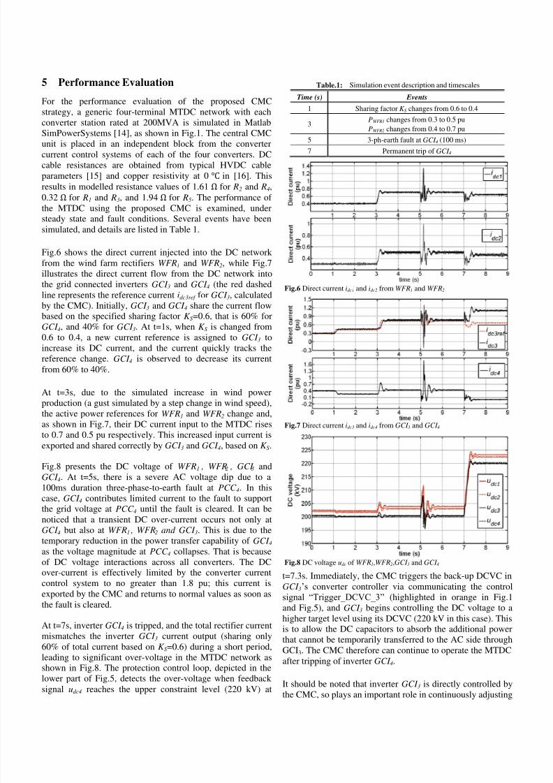
Fig.6 shows the direct current injected into the DC network from the wind farm rectifiers WFR1 and WFR2, while Fig.7
illustrates the direct current flow from the DC network intothe grid connected inverters GCI 3 and GCI 4 (the red dashedline represents the reference current idc3ref for GCI 3, calculatedby the CMC). Initially, GCI 3 and GCI 4 share the current flowbased on the specified sharing factor K S=0.6, that is 60% forGCI 4, and 40% for GCI 3. At t=1s, when K S is changed from0.6 to 0.4, a new current reference is assigned to GCI 3 toincrease its DC current, and the current quickly tracks thereference change. GCI 4 is observed to decrease its currentfrom 60% to 40%.
At t=3s, due to the simulated increase in wind powerproduction (a gust simulated by a step change in wind speed),
the active power references for WFR1 and WFR2 change and,as shown in Fig.7, their DC current input to the MTDC risesto 0.7 and 0.5 pu respectively. This increased input current isexported and shared correctly by GCI 3 and GCI 4, based on K S.
Fig.8 presents the DC voltage of WFR1 , WFR2 , GCI 3 andGCI 4. At t=5s, there is a severe AC voltage dip due to a100ms duration three-phase-to-earth fault at PCC 4. In thiscase, GCI 4 contributes limited current to the fault to supportthe grid voltage at PCC 4 until the fault is cleared. It can benoticed that a transient DC over-current occurs not only atGCI 4 but also at WFR1 , WFR2 and GCI 3. This is due to thetemporary reduction in the power transfer capability of GCI 4
as the voltage magnitude at PCC 4 collapses. That is becauseof DC voltage interactions across all converters. The DCover-current is effectively limited by the converter currentcontrol system to no greater than 1.8 pu; this current isexported by the CMC and returns to normal values as soon asthe fault is cleared.
At t=7s, inverter GCI 4 is tripped, and the total rectifier currentmismatches the inverter GCI 3 current output (sharing only60% of total current based on K S=0.6) during a short period,leading to significant over-voltage in the MTDC network asshown in Fig.8. The protection control loop, depicted in thelower part of Fig.5, detects the over-voltage when feedback
signal udc4 reaches the upper constraint level (220 kV) at
t=7.3s. Immediately, the CMC triggers the back-up DCVC inGCI 3’s converter controller via communicating the controlsignal “Trigger_DCVC_3” (highlighted in orange in Fig.1and Fig.5), and GCI 3 begins controlling the DC voltage to ahigher target level using its DCVC (220 kV in this case). Thisis to allow the DC capacitors to absorb the additional powerthat cannot be temporarily transferred to the AC side throughGCI3. The CMC therefore can continue to operate the MTDCafter tripping of inverter GCI 4.
It should be noted that inverter GCI 3 is directly controlled bythe CMC, so plays an important role in continuously adjusting
Table.1: Simulation event description and timescales
Time (s) Events
1 Sharing factor K S changes from 0.6 to 0.4
3PWFR1 changes from 0.3 to 0.5 pu
PWFR2 changes from 0.4 to 0.7 pu
5 3-ph-earth fault at GCI 4 (100 ms)
7 Permanent trip of GCI 4
Fig.6 Direct current idc1 and idc2 from WFR1 and WFR2
Fig.7 Direct current idc3 and idc4 from GCI 3 and GCI 4
Fig.8 DC voltage udc of WFR1,WFR2,GCI 3 and GCI 4
8/3/2019 Current Matching Control System for Multi-Terminal DC Transmission to Integrate Offshore Wind Farms
http://slidepdf.com/reader/full/current-matching-control-system-for-multi-terminal-dc-transmission-to-integrate 6/6
its DC current export to ensure the DC network currentbalance, as shown by the red dashed line in Fig7. InverterGCI 4, with its DCVC activated, acts as the DC side “slack bus” to maintain voltage stability in the MTDC system, and italso contributes to power dispatch in conjunction withinverter GCI 3. There is minimal DC voltage variationthroughout the entire simulation process, with amplitudes of ±10 kV, until the activation of the DCVC at GCI 3 at t=7.3s dueto the loss of GCI 4. From this point forward, the DC currentthrough GCI 3 is not controlled by the CMC, and itautomatically acts to balance the MTDC network current, asshown by the GCI 3 DC current reference (red dashed line)and actual DC current in Fig.7.
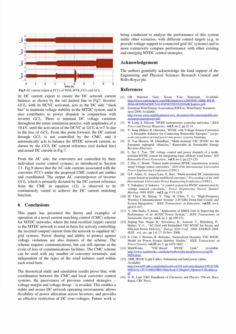
From the AC side, the converters are controlled by theirindividual vector control systems, as introduced in Section2.1. Fig.9 shows that the AC-side currents associated with theconverter PCC s under the proposed CMC control are stables
and coordinated. The output AC current/power of inverterGCI 3, which is primarily dictated by the DC current referencefrom the CMC in equation (12), is observed to becontinuously varied to achieve the DC current matchingfunction.
6 Conclusions
This paper has presented the theory and examples of operation of a novel current matching control (CMC) schemefor MTDC networks, where the total rectified (input) currentto the MTDC network is used as basis for actively controllingthe inverted (output) current from the network to supplied AC
grid systems. Power sharing and ability to protect againstvoltage violations are also features of the scheme. Thescheme requires communications, but can still operate in theevent of loss of communications facilities. The CMC schemecan be used with any number of converter terminals, andindependent of the types of the wind turbines used withineach wind farm.
The theoretical study and simulation results prove that, withcoordination between the CMC and local converter controlsystems, the passiveness of previous control strategies – voltage margin and voltage droop – is avoided. This enables astable and secure DC network operating environment, allows
flexibility of power allocation across inverters, and providesan effective restriction of DC over-voltages. Future work is
being conducted to analyse the performance of this systemunder other scenarios, with different control targets (e.g. toprovide voltage support to connected grid AC systems) and tomore extensively compare performance with other existingand emerging MTDC control strategies.
Acknowledgement
The authors gratefully acknowledge the kind support of theEngineering and Physical Sciences Research Council andRolls-Royce plc.
References
[1] GB National Grid, Seven Year Statement. Available:http://www.nationalgrid.com/NR/rdonlyres/A2095E9F-A0B8-4FCB-8E66-6F698D429DC5/41470/NETSSYS2010allChapters.pdf .
[2] European Wind Energy Association (EWEA), Wind Enery Scenariosup to 2030. Available:http://www.ewea.org/fileadmin/ewea_documents/documents/publications/reports/purepower.pdf.
[3] W. Long, S. Nilsson. "HVDC transmission: yesterday and today," IEEE
Power and Energy Magazine, vol.5, no.2, pp.22-31.
[4] Y. Jiang-Häfner, R. Ottersten. "HVDC with Voltage Source Converters – A Desirable Solution for Connecting Renewable Energies," Large-scale integration of wind power into power systems, Germany.
[5] D. Van Hertem, M. Ghandhari. “Multi-terminal VSC HVDC for theEuropean supergrid: obstacles,” Renewable & Sustainable EnergyReviews (Elsevier).
[6] L. Xu, L. Yao. "DC voltage control and power dispatch of a multi-terminal HVDC system for integrating large offshore wind farms," IET Renewable Power Generation , vol.5, no.3, pp.223-233.
[7] J. Zhu, C. Booth. "Future multi-terminal HVDC transmission systemsusing Voltage source converters," 2010 45th International UniversitiesPower Engineering Conference (UPEC).
[8]
G.P. Adam, O. Anaya-Lara, G. Burt. "Multi-terminal DC transmissionsystem based on modular multilevel converter," Proceedings of the 44th International Universities Power Engineering Conference (UPEC) .
[9] T. Nakajima, S. Irokawa. "A control system for HVDC transmission byvoltage sourced converters," Power Engineering Society Summer Meeting, 1999. IEEE , vol.2, pp.1113-1119.
[10] M. Chen, M. Huang, Y. Ting, H. Chen, T. Li. "High-FrequencyWireless Communications System: 2.45-GHz Front-End Circuit andSystem Integration," IEEE Transactions on Education, vol.53, no.4,pp.631-637.
[11] A. Abu-Siada, S. Islam. "Application of SMES Unit in Improving thePerformance of an AC/DC Power System," , IEEE Transactions on Sustainable Energy, vol.2, no.2, pp.109-121.
[12] Jiuping Pan; Nuqui, R.; Srivastava, K.; Jonsson, T.; Holmberg, P.;Hafner, Y.-J.; , "AC Grid with Embedded VSC-HVDC for Secure andEfficient Power Delivery," Energy 2030 Conf., 2008. ENERGY 2008.
IEEE , vol., no., pp.1-6, 17-18 Nov. 2008.[13] S. Cole, J. Beerten, R. Belmans. "Generalized Dynamic VSC MTDC
Model for Power System Stability Studies," IEEE Transactions on Power Systems, vol.25, no.3, pp.1655-1662.
[14] MathWorks. "VSC-Based HVDC Link," Available:http://www.mathworks.com/help/toolbox/physmod/powersys/ug/f8-9059.html.
[15] ABB, HVDC Light Cables- Submarine and land power cables,Available:http://www05.abb.com/global/scot/scot245.nsf/veritydisplay/1591f139098f62e5c1257154002f9801/$file/hvdc%20light%20power%20cables.pdf .
[16] D. R. Lide. CRC Handbook of Chemistry and Physics 75th ed. BocaRaton, CRC Press.
Fig.9 AC current output at PCC s of WFR1,WFR2,GCI 3 and GCI 4
Related Documents