Renewal Parts RP01400001E Effective October 2017 Supersedes February 2009 Contents Description Page Procedure for identifying panelboard type 2 Procedure for identifying renewal parts 2 Distributor ordering instructions 2 Eaton satellite plants 3 PRL1a, 2a parts Connector kits, vertical breakers 4 Connector kits, lug assemblies 5 Connector kits, horizontally mounted, PRL1a 8 Neutral assemblies 11 Ground assemblies 15 Service entrance bonding jumper kits 15 Service entrance main breaker kits 15 Deadfront covers 16 Special trim locks 18 EZ trim locks 18 Fastrim clamps and hardware kits 18 PRL3a parts Connector kits assemblies 19 Ground assemblies 20 Service entrance bonding jumper kits 20 Service entrance main breaker kits 20 Deadfront covers 20 Description Page PRL4 parts Vented cover assemblies and side gutter covers 23 Blank covers 24 Breaker connector kits 24 Fusible connector kits 25 Breaker retrofit kits 26 Fusible retrofit kits 27 PRL1a, 2a, 3a EZ trims and enclosures 27 PRL1a, 2a, 3a special trims and enclosures 28 PRL4 special trims and enclosures 29 Type 12/3R enclosures 30 Ordering procedure 30 PRL5P parts Chassis layout 31 Breaker adapter unit catalog numbers 32 Branch breaker information 32 Main or through-feed lugs 33 Neutrals and grounds 34 Boxes, trims, and filler plates 34 PRL1a, 2a-LX column panelboards 35 Pow-R-Command 35 Additional services 35 Current Eaton panelboards PRL1a PRL1a-LX PRL2a PRL2a-LX PRL3a PRL4B PRL4F PRL5P Pow-R-Command

Welcome message from author
This document is posted to help you gain knowledge. Please leave a comment to let me know what you think about it! Share it to your friends and learn new things together.
Transcript

Renewal Parts RP01400001EEffective October 2017 Supersedes February 2009
ContentsDescription Page
Procedure for identifying panelboard type . . . . . . 2Procedure for identifying renewal parts . . . . . . . . 2
Distributor ordering instructions . . . . . . . . . . . . 2Eaton satellite plants . . . . . . . . . . . . . . . . . . . . . . . 3
PRL1a, 2a partsConnector kits, vertical breakers . . . . . . . . . . . . . . 4Connector kits, lug assemblies . . . . . . . . . . . . . . . 5Connector kits, horizontally mounted, PRL1a . . . . 8Neutral assemblies . . . . . . . . . . . . . . . . . . . . . . . 11Ground assemblies . . . . . . . . . . . . . . . . . . . . . . . 15Service entrance bonding jumper kits . . . . . . . . . 15Service entrance main breaker kits . . . . . . . . . . . 15Deadfront covers . . . . . . . . . . . . . . . . . . . . . . . . . 16Special trim locks . . . . . . . . . . . . . . . . . . . . . . . . . 18EZ trim locks . . . . . . . . . . . . . . . . . . . . . . . . . . . . 18Fastrim clamps and hardware kits . . . . . . . . . . . . 18
PRL3a partsConnector kits assemblies . . . . . . . . . . . . . . . . . 19Ground assemblies . . . . . . . . . . . . . . . . . . . . . . . 20Service entrance bonding jumper kits . . . . . . . . . 20Service entrance main breaker kits . . . . . . . . . . . 20Deadfront covers . . . . . . . . . . . . . . . . . . . . . . . . . 20
Description Page
PRL4 partsVented cover assemblies and side gutter covers . . . . . . . . . . . . . . . . . . . . . . . . 23Blank covers . . . . . . . . . . . . . . . . . . . . . . . . . . . . 24Breaker connector kits . . . . . . . . . . . . . . . . . . . . 24Fusible connector kits . . . . . . . . . . . . . . . . . . . . . 25Breaker retrofit kits . . . . . . . . . . . . . . . . . . . . . . . 26Fusible retrofit kits . . . . . . . . . . . . . . . . . . . . . . . . 27PRL1a, 2a, 3a EZ trims and enclosures . . . . . . . 27PRL1a, 2a, 3a special trims and enclosures . . . . 28PRL4 special trims and enclosures . . . . . . . . . . . 29Type 12/3R enclosures . . . . . . . . . . . . . . . . . . . . 30Ordering procedure . . . . . . . . . . . . . . . . . . . . . . . 30
PRL5P partsChassis layout . . . . . . . . . . . . . . . . . . . . . . . . . . . 31Breaker adapter unit catalog numbers . . . . . . . . 32Branch breaker information . . . . . . . . . . . . . . . . . 32Main or through-feed lugs . . . . . . . . . . . . . . . . . . 33Neutrals and grounds . . . . . . . . . . . . . . . . . . . . . 34Boxes, trims, and filler plates . . . . . . . . . . . . . . . 34PRL1a, 2a-LX column panelboards . . . . . . . . . . . 35Pow-R-Command . . . . . . . . . . . . . . . . . . . . . . . . . 35Additional services . . . . . . . . . . . . . . . . . . . . . . . 35
Current Eaton panelboards
PRL1a PRL1a-LX PRL2a PRL2a-LX PRL3a PRL4B PRL4F PRL5P Pow-R-Command

2
Renewal Parts RP01400001EEffective October 2017
Current Eaton panelboards
EATON www.eaton.com
Table 1. Product history time lineProduct 1985 1990 1995 Present
PRL1a, 2a Oct. 1996PRL3a Mar. 1994
PRL4B/F Oct. 1987PRL5P Aug. 1995
PRL1a, 2a-LX Dec. 1997
Pow-R-CommandE Mar. 1996
Procedure for identifying panelboard typeThe current line of Pow-R-Line CE panelboards was introduced in 1993 .
A panelboard is identified by data found on the nameplate . Pow-R-Line C panelboard nameplates are different in appearance, but all have the same critical information:• Ampere rating of the main• Ampere rating of the neutral• Type of service (phase/wire)• Manufacturing location• Type of panel• General order number
In the event the nameplate is missing, it may still be possible to identify the panel type by location of the neutral bar . Figure 1 shows the position of the neutral in the panelboard .
Gutter
Neutral N
Main
Gutter
N
Gutter
Pow-R-Line1a, 2a
Pow-R-Line3a
Pow-R-Line4B/F �
Figure 1. Position of the neutral in the panelboard
aPRL4F panels with vertical-mounted main switch will have the neutral mounted at the opposite end the main.
Box width may also help identify the panelboard type . Standard width for PRL1a, PRL2a, and PRL3a is 20 .00 inches (508 .0 mm) . PRL4 standard widths are 24 .00, 36 .00, and 44 .00 inches (609 .6, 914 .4, and 1117 .6 mm) .
n WARNINGHAZARDOUS VOLTAGE WILL CAUSE SEVERE INJURY OR DEATH. TURN OFF POWER SUPPLY TO EQUIPMENT BEFORE WORKING ON IT.
Procedure for identifying renewal parts
1. Identify the type of panelboard, i .e ., PRL1a, PRL2a, PRL3a, PRL4, PRL5P by reading the nameplate . Follow the procedure listed to the left .
2. Refer to the listing below and turn to the proper section in this document to identify standard parts .
Description Page
PRL1a and PRL2a . . . . . . . . . . . . . . . . . . . . . . . . . . . . . . . . . . . . 4Trim locks . . . . . . . . . . . . . . . . . . . . . . . . . . . . . . . . . . . . . . . . . . 18Trim clamps . . . . . . . . . . . . . . . . . . . . . . . . . . . . . . . . . . . . . . . . 18PRL3a . . . . . . . . . . . . . . . . . . . . . . . . . . . . . . . . . . . . . . . . . . . . 19PRL4 . . . . . . . . . . . . . . . . . . . . . . . . . . . . . . . . . . . . . . . . . . . . . 23Special trims and enclosures . . . . . . . . . . . . . . . . . . . . . . . . . . . 29PRL5P . . . . . . . . . . . . . . . . . . . . . . . . . . . . . . . . . . . . . . . . . . . . 31PRL1a-LX and PRL2a-LX (column width) . . . . . . . . . . . . . . . . . 35Pow-R-Command . . . . . . . . . . . . . . . . . . . . . . . . . . . . . . . . . . . . 35
3. This book identifies those replacement parts most frequently ordered and which are readily available from stock . These parts can be ordered by style or catalog number to speed up processing and delivery .
Distributor ordering instructions
1. Specify part by style/part number .
2. Refer to PL01400001E for pricing information . Discount Symbol CE9 applies .
3. Turn to page 3 to locate nearest satellite plant .
4. Enter the order on the satellite plant via mail, fax, or phone .
5. Selling policy 25-000 applies .

3
Renewal Parts RP01400001EEffective October 2017
Current Eaton panelboards
EATON www.eaton.com
Eaton satellite plants
Hartford
Westampton
Baltimore
Atlanta
Houston
Dallas
Seattle
LosAngeles
San Francisco
Phoenix
Denver
Chicago
St. Louis
NashvilleRaleigh
Cleveland
Figure 2. Satellite plants
Atlanta 7000 Highlands Parkway SE Suite 102 Smryna, GA 30082 678 .309 .4260
Baltimore 7451 Coca Cola Drive Suite C Hanover, MD 21076 410 .796 .7777
Chicago 230 Windy Point Drive Glendale Heights, IL 60139 630 .260 .6303
Cleveland 12875 Corporate Drive Unit E Parma, OH 44130 216 .265 .3284
Dallas 631 Westport Parkway Suite 100 Grapevine, TX 76051 817 .251 .6733
Denver 2450 Airport Road Suite C Aurora, CO 80011 303 .366 .2080
Hartford 40A International Drive Windsor, CT 06095 860 .298 .1305
Houston 14825 Northwest Freeway Suite 100 Houston, TX 77040 713 .744 .7530
Los Angeles–P&S 13201 Dahlia Street Suite 300 Fontana, CA 92337 919 .428 .8903
Nashville 1421 Gould Boulevard Suite C La Vergne, TN 37086 615 .287 .3200
Phoenix 560 N 54th Street Suite 1 Chandler, AZ 85226 480 .449 .4222
Raleigh 9400 Globe Center Drive Suite 121 Morrisville, NC 27560 919 .544 .7074
St. Louis 56 Soccer Park Road Fenton, MO 63026 636 .717 .3500
San Francisco 20923 Cabot Boulevard Hayward, CA 94545 510 .784 .8981
Seattle 1604 15th Street SW Suite 114 Auburn, WA 98001 253 .833 .5021
Westampton 96 Stemmers Lane Westampton, NJ 08060 609 .835 .4230

4
Renewal Parts RP01400001EEffective October 2017
Current Eaton panelboards
EATON www.eaton.com
PRL1a, 2a parts sectionDescription Page
Connector kits, vertical breakers . . . . . . . . . . . . . . . . . . . . . . . . . . . . 4Connector kits, lug assemblies . . . . . . . . . . . . . . . . . . . . . . . . . . . 5–7Connector kits, horizontally mounted . . . . . . . . . . . . . . . . . . . . . 8–10Neutral assemblies . . . . . . . . . . . . . . . . . . . . . . . . . . . . . . . . . . .11–14Ground assemblies . . . . . . . . . . . . . . . . . . . . . . . . . . . . . . . . . . . . . 15Service entrance bonding jumper kits . . . . . . . . . . . . . . . . . . . . . . . 15Service entrance main breaker kits . . . . . . . . . . . . . . . . . . . . . . . . . 15Deadfront covers . . . . . . . . . . . . . . . . . . . . . . . . . . . . . . . . . . . . .16–17Panelboard special trim locks . . . . . . . . . . . . . . . . . . . . . . . . . . . . . 18Panelboard EZ trim locks . . . . . . . . . . . . . . . . . . . . . . . . . . . . . . . . . 18Panelboard Fastrim clamps and screw-on hardware kits . . . . . . . . 18
PRL1a, 2a connector kits
Table 2. Vertical breaker assemblies
Device type a Device mounting
Three-phase Single-phase
Tin-plated aluminum connector
Silver-plated copper connector
Tin-plated aluminum connector
Silver-plated copper connector
Catalog number
F-Frame b (100 A maximum)
Top fed KB13AFT KB13SFT KB11AFT KB11SFTBottom fed KB13AFB KB13SFB KB11AFB KB11SFB
F-Frame c (225 A maximum)
Top fed KB23AFT KB23SFT KB21AFT KB21SFTBottom fed KB23AFB KB23SFB KB21AFB KB21SFB
J-Frame Top fed KB43AJT KB43SJT KB41AJT KB41SJTBottom fed KB43AJB KB43SJB KB41AJB KB41SJB
K-Frame Top fed KB43AKT KB43SKT KB41AKT KB41SKTBottom fed KB43AKB KB43SKB KB41AKB KB41SKB
aOrder main or sub-feed breaker separately when ordering above connector kits.bEHD, FD, HFD, FDC.cFD, HFD, FDC, ED, EDH, EDC.
KB11AFT KB13AFT
5
Renewal Parts RP01400001EEffective October 2017
Current Eaton panelboards
EATON www.eaton.com
Table 3. 100 A lug assemblies
Lug typePanel lug options a
Wire size range
Quantity per phase
Three-phase Single-phase
Tin-plated aluminum connector
Silver-plated copper connector
Tin-plated aluminum connector
Silver-plated copper connector
Catalog number
Aluminum/copper mechanical
STD #14–1/0 1 KL13AMS KL13SMS KL11AMS KL11SMSSFL #14–1/0 2 KL13AMF KL13SMF KL11AMF KL11SMFOVS #6–300 kcmil 1 KL13AMO KL13SMO KL11AMO KL11SMO
Crimp STD #1–1/0 1 KL13AVS KL13SVS KL11AVS KL11SVSSFL #1–1/0 2 KL13AVF KL13SVF KL11AVF KL11SVFOVS 2/0–300 kcmil 1 KL13AVO KL13SVO KL11AVO KL11SVO
Copper mechanical STD #14–1/0 1 — KL13SCS — KL11SCSSFL #14–1/0 2 — KL13SCF — KL11SCFOVS #6–250 kcmil 1 — KL13SCO — KL11SCO
aSTD = Standard lugs. Use for main or through-feed. SFL = Sub-feed lugs. OVS = Oversize lugs. Use for main or through-feed.
KL13AMS KL11AVS

6
Renewal Parts RP01400001EEffective October 2017
Current Eaton panelboards
EATON www.eaton.com
Table 4. 225 A lug assemblies
Lug typePanel lug options a
Wire size range
Quantity per phase
Three-phase Single-phase
Tin-plated aluminum connector
Silver-plated copper connector
Tin-plated aluminum connector
Silver-plated copper connector
Catalog number
Aluminum/copper mechanical
STD #6–300 kcmil 1 KL23AMS KL23SMS KL21AMS KL21SMSSFL #6–300 kcmil 2 KL23AMF KL23SMF KL21AMF KL21SMFOVS 4/0–500 kcmil 1 KL23AMO KL23SMO KL21AMO KL21SMO
Crimp STD 2/0–300 kcmil 1 KL23AVS KL23SVS KL21AVS KL21SVSSFL 2/0–300 kcmil 2 KL23AVF KL23SVF KL21AVF KL21SVFOVS 4/0–500 kcmil 1 KL23AVO KL23SVO KL21AVO KL21SVO
Copper mechanical STD #6–250 kcmil 1 — KL23SCS — KL21SCSSFL #6–250 kcmil 2 — KL23SCF — KL21SCFOVS 1/0–600 kcmil 1 — KL23SCO — KL21SCO
aSTD = Standard lugs. Use for main or through-feed. SFL = Sub-feed lugs. OVS = Oversize lugs. Use for main or through-feed.
KL23AMS KL21AVS

7
Renewal Parts RP01400001EEffective October 2017
Current Eaton panelboards
EATON www.eaton.com
Table 5. 400 A lug assemblies
Lug typePanel lug options a
Wire size range
Quantity per phase
Three-phase Single-phase
Tin-plated aluminum connector
Silver-plated copper connector
Tin-plated aluminum connector
Silver-plated copper connector
Catalog number
Aluminum/copper mechanical
STD 4/0–500 kcmil 2 KL43AMS KL43SMS KL41AMS KL41SMSSFL — — — — — —OVS 3/0–750 kcmil 2 KL43AMO KL43SMO KL41AMO KL41SMO
Crimp STD 4/0–500 kcmil 2 KL43AVS KL43SVS KL41AVS KL41SVSSFL — — — — — —OVS 500–750 kcmil 2 KL43AVO KL43SVO KL41AVO KL41SVO
Copper mechanical STD 1/0–600 kcmil 1 — — — —SFL — — — — — —OVS 1/0–600 kcmil 1 — KL43SCO — KL41SCO
aSTD = Standard lugs. Use for main or through-feed. SFL = Sub-feed lugs. OVS = Oversize lugs. Use for main or through-feed.
KL43AMS KL43AVS
Table 6. 600 A lug assemblies
Lug type
Panel lug options a
Wire size range
Quantity per phase
Three-phase connectors Single-phase connectors
Tin-plated aluminum
Bare copper
Silver-plated copper
Tin-plated copper
Tin-plated aluminum
Bare copper
Silver-plated copper
Tin-plated copper
Catalog number
Aluminum/ copper mechanical
STD 4/0–500 kcmil 2 — KL63CMS KL63SMS KL63TMS — KL61CMS KL61SMS KL61TMSSFL — — — — — — — — — —OVS 3/0–750 kcmil 2 — KL63CMO KL63SMO KL63TMO — KL61CMO KL61SMO KL61TMO
Crimp STD 4/0–500 kcmil 2 — KL63CVS KL63SVS KL63TVS — KL61CVS KL61SVS KL61TVSSFL — — — — — — — — — —OVS 500–750 kcmil 2 — KL63CVO KL63SVO KL63TVO — KL61CVO KL61SVO KL61TVO
Copper mechanical
STD 1/0–600 kcmil 1 — — — — — — — —SFL — — — — — — — — — —OVS 1/0–600 kcmil 1 — — — — — — — —
aSTD = Standard lugs. Use for main or through-feed. SFL = Sub-feed lugs. OVS = Oversize lugs. Use for main or through-feed.

8
Renewal Parts RP01400001EEffective October 2017
Current Eaton panelboards
EATON www.eaton.com
PRL1a horizontally mounted connector kit assemblies
Table 7. Bolt-on QUICKLAGT breaker assemblies
Breaker frame
Drawing number a
Branch circuit quantity
Three-phase Single-phase
Tin-plated aluminum connector
Silver-plated copper connector
Tin-plated aluminum connector
Silver-plated copper connector
Item number
BA, BAB, QBH, QBGF, QBHGF, QBGFEP, QBHGFEP
1C96608 12 G01 G03 G05 G0718 G09 G11 G13 G1530 G17 G19 G21 G2342 G25 G27 G29 G3148 G33 G35 G37 G3954 G41 G43 G45 G4772 G49 G51 G53 G5596 G57 G59 G61 G63
aOrder the basic drawing number, along with the equivalent G–number that’s needed.
otee:N When determining branch circuit quantity, remember: 1 . QUICKLAG breakers with shunt trips require one additional circuit . 2 . ULT listed lighting and appliance (CTL) panelboards cannot exceed 42 electrically connected circuits in a single enclosure . 3 . When bare copper is specified, use the silver-plated groups . 4 . Order breakers separately with connector kit.
1C96608G01 1C96608G05

9
Renewal Parts RP01400001EEffective October 2017
Current Eaton panelboards
EATON www.eaton.com
Table 8. Plug-in QUICKLAG breaker assemblies
Breaker frame
Drawing number a
Branch circuit quantity
Three-phase Single-phase
Tin-plated aluminum connector
Silver-plated copper connector
Tin-plated aluminum connector
Silver-plated copper connector
Item number
HQP, QPHW, QHPX, QPGF, QPHGF, QPGFEP, QPHGFEP
2C11642 12 — G03 — G0718 — G11 — G1530 — G19 — G2342 — G27 — G3148 — G35 — G3954 — G43 — G4772 — G51 — G5596 — G59 — G63
aOrder the basic drawing number, along with the equivalent G–number that’s needed.
otee:N When determining branch circuit quantity, remember: 1 . QUICKLAG breakers with shunt trips require one additional circuit . 2 . UL listed lighting and appliance (CTL) panelboards cannot exceed 42 electrically connected circuits in a single enclosure . 3 . When aluminum is specified, use the silver-plated groups . 4 . The sum of the horizontally twin-mounted breakers shall not exceed 140 A . 5 . Order breakers separately with connector kit.
2C11642G03 2C11642G07
10
Renewal Parts RP01400001EEffective October 2017
Current Eaton panelboards
EATON www.eaton.com
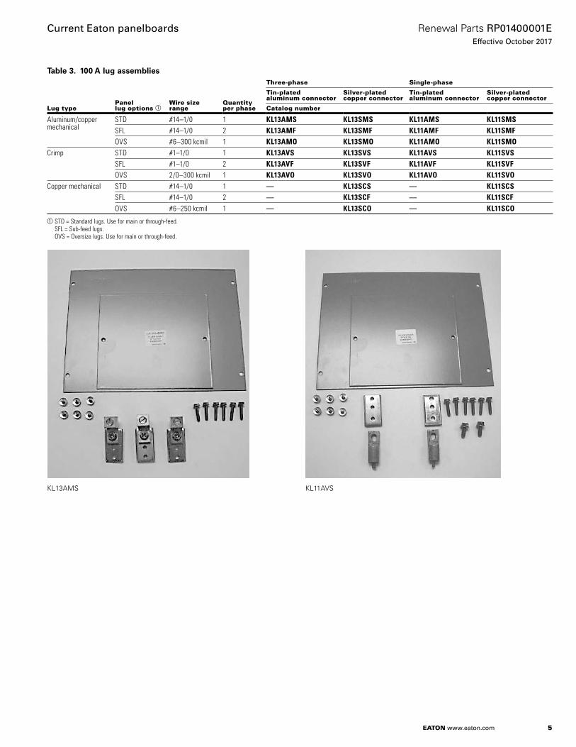
Table 9. GB, GHB, GHQ, GHBS breaker assemblies
Breaker frame
Drawing number a
Branch circuit quantity
Three-phase Single-phase
Tin-plated aluminum connector
Silver-plated copper connector
Tin-plated aluminum connector
Silver-plated copper connector
Item number
GB, GHB, GHQ, GHBS 1C96609 12 G01 G03 G05 G0718 G09 G11 G13 G1530 G17 G19 G21 G2342 G25 G27 G29 G3148 G33 G35 G37 G3954 G41 G43 G45 G4772 G49 G51 G53 G5596 G57 G59 G61 G63
aOrder the basic drawing number, along with the equivalent G–number that’s needed.
otee:N When determining branch circuit quantity, remember: 1 . QUICKLAG breakers with shunt trips require one additional circuit . 2 . UL listed lighting and appliance (CTL) panelboards cannot exceed 42 electrically connected circuits in a single enclosure . 3 . When bare copper is specified, use the silver-plated groups . 4 . Order breakers separately with connector kit.
1C96609G01

11
Renewal Parts RP01400001EEffective October 2017
Current Eaton panelboards
EATON www.eaton.com
PRL1a, 2a neutral assemblies
Table 10. 100 A neutral assemblies a
Panel main bus ampere rating
Neutral rating Lug type
Drawing number b
Panel lug options c
Wire size range Quantity
Tin-plated aluminum connector
Silver-plated copper connector
Item number
100 100% Mechanical 1C96646 STD #14–1/0 1 G02 G03SFL/TFL #14–1/0 2 G05 G07OVS #6–300 kcmil 1 G09 G11
Crimp 42C4050 STD #1–1/0 1 G01 G03SFL/TFL #1–1/0 2 G05 G07OVS 2/0–300 kcmil 1 G09 G11
Copper 1C96648 STD #14–1/0 1 — G03SFL/TFL #14–1/0 2 — G07OVS #6–250 kcmil 1 — G11
200% Mechanical 1C96649 STD #6–300 kcmil 1 G02 G03SFL/TFL #6–300 kcmil 2 G06 G07OVS 4/0–500 kcmil 1 G09 G11
Crimp 42C4051 STD 2/0–300 kcmil 1 G01 G03SFL/TFL 2/0–300 kcmil 2 G05 G07OVS 4/0–500 kcmil 1 G09 G11
Copper 1C96651 STD #6–250 kcmil 1 — G03SFL/TFL #6–250 kcmil 2 — G07OVS 1/0–600 kcmil 1 — G11
aThe assemblies shown on this page are for panelboards that mount in 30.00–90.00-inch (762.0–2286.0 mm) high enclosures only. Reference page 14 for assemblies for panelboards that mount in 21.00–27.00-inch (533.4–685.8 mm) high enclosures.
bOrder the basic drawing number, along with the equivalent G–number that’s needed.cSTD = Standard lugs.
SFL/TFL = Sub-feed and through-feed lugs. OVS = Oversize lugs.
1C96646G01

12
Renewal Parts RP01400001EEffective October 2017
Current Eaton panelboards
EATON www.eaton.com
Table 11. 225 A neutral assemblies a
Panel main bus ampere rating
Neutral rating Lug type
Drawing number b
Panel lug options c
Wire size range Quantity
Tin-plated aluminum connector
Silver-plated copper connector
Item number
225 100% Mechanical 1C96649 STD #6–300 kcmil 1 G02 G03SFL/TFL #6–300 kcmil 2 G06 G07OVS 4/0–500 kcmil 1 G09 G11
Crimp 42C4051 STD 2/0–300 kcmil 1 G01 G03SFL/TFL 2/0–300 kcmil 2 G05 G07OVS 4/0–500 kcmil 1 G09 G11
Copper 1C96651 STD #6–250 kcmil 1 — G03SFL/TFL #6–250 kcmil 2 — G07OVS 1/0–600 kcmil 1 — G11
200% Mechanical 1C96652 STD 4/0–500 kcmil 2 G01 G03SFL/TFL — — G05 G07OVS 3/0–750 kcmil 2 G09 G11
Crimp 42C4052 STD 4/0–500 kcmil 2 G01 G03SFL/TFL — — G05 G07OVS 500–750 kcmil 2 G09 G11
Copper 1C96654 STD 1/0–600 kcmil 1 — G03SFL/TFL — — — G07OVS 1/0–600 kcmil 1 — G11
aThe assemblies shown on this page are for panelboards that mount in 30.00–90.00-inch (762.0–2286.0 mm) high enclosures.bOrder the basic drawing number, along with the equivalent G–number that’s needed.cSTD = Standard lugs.
SFL/TFL = Sub-feed and through-feed lugs. OVS = Oversize lugs.
1C96649G01

13
Renewal Parts RP01400001EEffective October 2017
Current Eaton panelboards
EATON www.eaton.com
Table 12. 400 A neutral assemblies a
Panel main bus ampere rating
Neutral rating Lug type
Drawing number b
Panel lug options c
Wire size range Quantity
Tin-plated aluminum connector
Silver-plated copper connector
Item number
400 100% Mechanical 1C96652 STD 4/0–500 kcmil 2 G01 G03SFL/TFL — — G05 G07OVS 3/0–750 kcmil 2 G09 G11
Crimp 42C4052 STD 4/0–500 kcmil 2 G01 G03SFL/TFL — — G05 G07OVS 500–750 kcmil 2 G09 G11
Copper 1C96654 STD 1/0–600 kcmil 1 — G03SFL/TFL — — — G07OVS 1/0–600 kcmil 1 — G11
aThe assemblies shown on this page are for panelboards that mount in 30.00–90.00-inch (762.0–2286.0 mm) high enclosures.bOrder the basic drawing number, along with the equivalent G–number that’s needed.cSTD = Standard lugs.
SFL/TFL = Sub-feed and through-feed lugs. OVS = Oversize lugs.
1C96652G01
Table 13. 600 A neutral assemblies a
Panel main bus ampere rating
Neutral rating Lug type
Drawing number b
Circuit quantity
Panel lug options c
Tin-plated aluminum connector
Bare copper
Silver-plated copper connector
Tin-plated copper connector
Item number
600 100% Mechanical 1C96652 42 or less STD — G02 G03 G04TFL — G06 G07 G08OVS — G10 G11 G12OVS W/ TFL — G26 G27 G28
Anderson — 42 or less STD — — — —TFL — — — —OVS — — — —
Burndy 42C4052 42 or less STD — G02 G03 G04TFL — G06 G07 G08OVS — G10 G11 G12
Copper — 42 or less STD — — — —TFL — — — —OVS — — — —
Greater than 42 STD — — — —TFL — — — —OVS — — — —
aThe assemblies shown on this page are for panelboards that mount in 30.00–90.00-inch (762.0–2286.0 mm) high enclosures.bOrder the basic drawing number, along with the equivalent G–number that’s needed.cSTD = Standard lugs.
SFL/TFL = Sub-feed and through-feed lugs. OVS = Oversize lugs.
14
Renewal Parts RP01400001EEffective October 2017
Current Eaton panelboards
EATON www.eaton.com
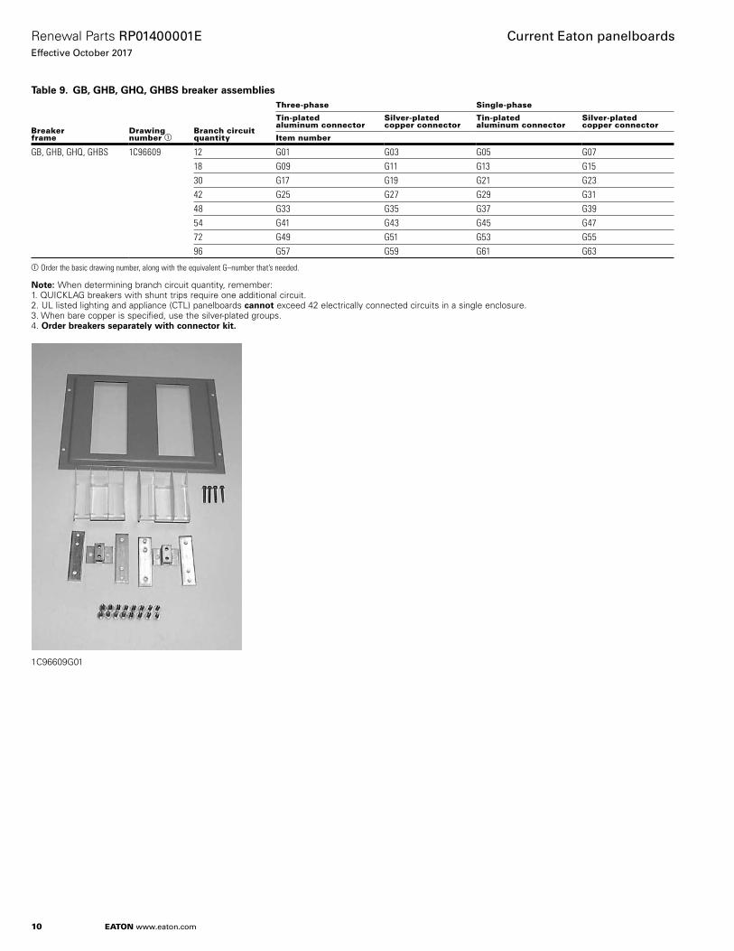
Table 14. 100 A neutral assemblies for 21.00–27.00-inch (533.4–685.8 mm) high enclosures only a
Panel main bus ampere rating
Neutral rating Lug type
Drawing number b
Panel lug options c
Wire size range Quantity
Tin-plated aluminum connector
Silver-plated copper connector
Item number
100 100% Mechanical 1C96645 STD #14–1/0 1 G01 G03SFL/TFL #14–1/0 2 G05 G07OVS — — — —
Crimp — STD — — — —SFL/TFL — — — —OVS — — — —
Copper — STD — — — —SFL/TFL — — — —OVS — — — —
200% Mechanical 1C97022 STD #6–300 kcmil 1 G01 G03SFL/TFL #6–300 kcmil 2 G05 G07OVS — — — —
Crimp — STD — — — —SFL/TFL — — — —OVS — — — —
Copper — STD — — — —SFL/TFL — — — —OVS — — — —
aThe assemblies shown on this page are for panelboards that mount in 21.00–27.00-inch (533.4–685.8 mm) high enclosures only. Reference page 11 for assemblies for panels that mount in 36.00, 48.00, 60.00, 72.00, and 90.00-inch (914.4, 1219.2, 1524.0, 1828.8, and 2286.0 mm) high enclosures.
bOrder the basic drawing number, along with the equivalent G–number that’s needed.cSTD = Standard lugs.
SFL/TFL = Sub-feed and through-feed lugs. OVS = Oversize lugs.
1C96645G01

15
Renewal Parts RP01400001EEffective October 2017
Current Eaton panelboards
EATON www.eaton.com
PRL1a, 2a ground assemblies
Table 15. Standard groundDrawing number a
Enclosure height in inches (mm) Bar material
Item number
5158C05 24.00 (609.6) Aluminum/copper G01Copper G03
36.00 (914.4), 48.00 (1219.2), 60.00 (1524.0), 72.00 (1828.8), 90.00 (2286.0)
Aluminum/copper G02Copper G04
aOrder the basic drawing number, along with the equivalent G–number that’s needed (example: 5158C05G01).
5158C05G01
5158C05G02
Table 16. Isolated groundDrawing number a
Enclosure height in inches (mm) Bar material
Item number
2C11296 24.00 (609.6) Aluminum/copper G01Copper G02
36.00 (914.4), 48.00 (1219.2), 60.00 (1524.0), 72.00 (1828.8), 90.00 (2286.0)
Aluminum/copper G03Copper G04
aOrder the basic drawing number, along with the equivalent G–number that’s needed (example: 5158C05G01).
PRL1a, 2a service entrance bonding jumper kits
Table 17. PRL1a, 2a service entrance bonding jumper kits
Drawing number a
Panel ampere rating
Tin-plated aluminum
Bare copper
Silver-plated copper
Tin-plated copper
Item number
Mechanical main lugs or main breakers
4180B62 100–225 G01 G02 G03 G044180B62 400–600 G05 G06 G07 G08Compression (crimp) main lugs
4180B62 100–225 G09 G10 G11 G124180B62 400–600 G13 G14 G15 G16Copper main lugs
4180B62 100–225 — G18 G19 G204180B62 400–600 — G22 G23 G24
aOrder the basic drawing number, along with the equivalent G–number that’s needed (example: 5158C05G01).
4180B62G01
PRL1a, 2a service entrance main breaker kits
Table 18. PRL1a, 2a service entrance main breaker kits
DescriptionCircuit breaker frame
Catalog number
Service entrance barrier for LG and KD LG/KD PRLSEBLGKDService entrance barrier for JD JD PRLSEBJDService entrance barrier for FD FD PRLSEBFDService entrance barrier for GHB GHB PRLSEBGHB
SE barrier kit FD_016

16
Renewal Parts RP01400001EEffective October 2017
Current Eaton panelboards
EATON www.eaton.com
PRL1a, 2a deadfront covers
otee:N Does not apply to PRL4 sub-chassis .
Table 19. AssemblyAssembly drawing number a
Standard enclosure height in inches (mm)
24.00 (609.6) 36.00 (914.4) 42.00 (1066.8) 48.00 (1219.2) 60.00 (1524.0) 72.00 (1828.8) 90.00 (2286.0)
1C96638 G01 G02 G07 G03 G04 G05 G06
aOrder the basic drawing number, along with the equivalent G–number that’s needed (example: 1C96638G01).
1C96638G01
Table 20. Vertically mounted devicesMounting arrangement Device/frame Drawing number a Mounting position Item number
Vertical 100 A MLO, SFL, TFL or F-Frame (100 A maximum)
4180B03 Top H01Bottom H01
225 A MLO, SFL, TFL or F-Frame (225 A maximum)
4180B61 Top H01Bottom H01
400 A MLO, SFL, TFL or J-Frame 4180B04 Top H01Bottom H02
400 A MLO, TFL or K-Frame 4180B05 Top H01Bottom H02
Blank covers in inches (mm) 1.00 (25.4) 4180B08 — H012.00 (50.8) — H023.00 (76.2) — H034.00 (101.6) — H045.00 (127.0) — H056.00 (152.4) — H067.00 (177.8) — H078.00 (203.2) — H089.00 (228.6) — H0910.00 (254.0) — H1011.00 (279.4) — H1112.00 (304.8) — H1213.00 (330.2) — H1314.00 (355.6) — H1415.00 (381.0) — H1516.00 (406.4) — H16
aOrder the basic drawing number, along with the equivalent H–number that’s needed (example: 4180B03H01).
4180B08H03 4180B03H01

17
Renewal Parts RP01400001EEffective October 2017
Current Eaton panelboards
EATON www.eaton.com
Table 21. Horizontally mounted devicesMounting arrangement Device/frame Drawing number a Branch circuit quantity Item number Quantity required
Horizontal BA, BAB, QBH,QBGF, QBHGF,QBGFEP, QBHGFEP
1C96619 12 H01 118 H02 130 H04 142 H06 148 H03 254 H03 and H04 1 each72 H05 296 H07 2
GB, GHB, GHQ, GHBS 1C96620 12 H01 118 H02 130 H04 142 H06 148 H03 254 H03 and H04 1 each72 H05 296 H07 2
aOrder the basic drawing number, along with the equivalent H–number that’s needed (example: 1C96619H01).
1C96619H01 1C96620H01
Table 22. Filler coversDevice/frame Drawing number Item number
F, J, K a 4180B52 H01QUICKLAG, GB, GHB b 5155C62 H01
aFiller covers are required in addition to deadfront cover whenever MLO, SFL or TFL are specified.bFiller covers are required in addition to deadfront cover whenever a branch provision is specified.
5155C62H01 4180B52H01

18
Renewal Parts RP01400001EEffective October 2017
Current Eaton panelboards
EATON www.eaton.com
Panelboard special trim locksPanelboard trims use different trim locks . See pictures below for styles and part numbers . Contact your nearest satellite for availability on the styles listed below . See page 3 for satellite listings .
Table 23. Panelboard special trim locksDescription Catalog number
For use on left-handed door (hinged on left side) K80522For use on right-handed door (hinged on right side) K80133T–Handle lock, at one time used on all trims over 48.00 inches (1219.2 mm) in height Also used on outdoor NEMAT 12/3R trims
K80429
Used on PRL4 lighting and power panels as standard 1A32258H03Used on PRL1, 2, 3 and PRL1a, 2a, 3a lighting panels as standard; WEM 2 key
5155C81G01
K80522 K80133
5155C81G01 K80429
1A32258H03
Panelboard EZ trim locksPanelboard EZ trims use different trim locks . See Table 24 and pictures below for styles and part numbers . Contact your nearest satellite for availability . See page 3 for satellite listings .
Table 24. Panelboard EZ trim locksDescription Size Catalog number
Lock 24–48 inches 5155C81G03Lock and latch 54–60 inches 5155C81G03/5155C81G05Lock and latch 72–90 inches 5155C81G04/5155C81G06
EZ trim latch without keyEZ trim lock with key
Panelboard Fastrim clamps and screw-on hardware kitsFor panelboard trim clamps, contact your nearest satellite for availability on the styles listed below . See page 3 for satellite listings .
Table 25. Panelboard Fastrim clamps and screw-on hardware kitsDescription Style number
Trim clamps—used on PRL1a, 2a, 3a Fastrims (6 per bag) 2C11641G02Trim screws—used on PRL1a, 2a, 3a, 4B standard trim (10 per bag) 5157C83G06Chassis mounting hardware bag—PRL1a, 2a, 3a panels 7499A48G04
2C11641G02
5157C83G06
7499A48G04
19
Renewal Parts RP01400001EEffective October 2017
Current Eaton panelboards
EATON www.eaton.com
PRL3a parts sectionDescription Page
Connector kit assemblies . . . . . . . . . . . . . . . . . . . . . . . . . . . . . . . . 19Ground assemblies . . . . . . . . . . . . . . . . . . . . . . . . . . . . . . . . . . . . . 20Service entrance kits . . . . . . . . . . . . . . . . . . . . . . . . . . . . . . . . . . . . 20Deadfront covers . . . . . . . . . . . . . . . . . . . . . . . . . . . . . . . . . . . . 20–22
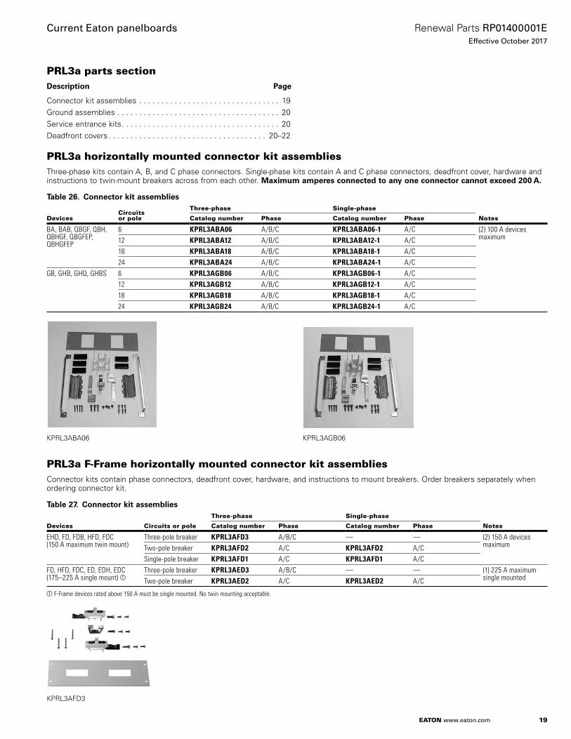
PRL3a horizontally mounted connector kit assembliesThree-phase kits contain A, B, and C phase connectors . Single-phase kits contain A and C phase connectors, deadfront cover, hardware and instructions to twin-mount breakers across from each other . Maximum amperes connected to any one connector cannot exceed 200 A.
Table 26. Connector kit assemblies
DevicesCircuits or pole
Three-phase Single-phase
NotesCatalog number Phase Catalog number Phase
BA, BAB, QBGF, QBH, QBHGF, QBGFEP, QBHGFEP
6 KPRL3ABA06 A/B/C KPRL3ABA06-1 A/C (2) 100 A devices maximum12 KPRL3ABA12 A/B/C KPRL3ABA12-1 A/C
18 KPRL3ABA18 A/B/C KPRL3ABA18-1 A/C24 KPRL3ABA24 A/B/C KPRL3ABA24-1 A/C
GB, GHB, GHQ, GHBS 6 KPRL3AGB06 A/B/C KPRL3AGB06-1 A/C12 KPRL3AGB12 A/B/C KPRL3AGB12-1 A/C18 KPRL3AGB18 A/B/C KPRL3AGB18-1 A/C24 KPRL3AGB24 A/B/C KPRL3AGB24-1 A/C
KPRL3ABA06 KPRL3AGB06
PRL3a F-Frame horizontally mounted connector kit assembliesConnector kits contain phase connectors, deadfront cover, hardware, and instructions to mount breakers . Order breakers separately when ordering connector kit .
Table 27. Connector kit assemblies
Devices Circuits or pole
Three-phase Single-phase
NotesCatalog number Phase Catalog number Phase
EHD, FD, FDB, HFD, FDC(150 A maximum twin mount)
Three-pole breaker KPRL3AFD3 A/B/C — — (2) 150 A devices maximumTwo-pole breaker KPRL3AFD2 A/C KPRL3AFD2 A/C
Single-pole breaker KPRL3AFD1 A/C KPRL3AFD1 A/CFD, HFD, FDC, ED, EDH, EDC(175–225 A single mount) a
Three-pole breaker KPRL3AED3 A/B/C — — (1) 225 A maximum single mountedTwo-pole breaker KPRL3AED2 A/C KPRL3AED2 A/C
aF-Frame devices rated above 150 A must be single mounted. No twin mounting acceptable.
KPRL3AFD3

20
Renewal Parts RP01400001EEffective October 2017
Current Eaton panelboards
EATON www.eaton.com
PRL3a ground assemblies
Table 28. PRL3a ground assemblies
Material
Standard Isolated
Catalog number
Aluminum/copper 5158C05G02 2C11296G02Copper only 5158C05G04 2C11296G04
5158C05G02
PRL3a service entrance bonding jumper kits
Table 29. PRL3a service entrance bonding jumper kits
Style number a
Panel ampere rating
Tin-plated aluminum
Bare copper
Silver-plated copper
Tin-plated copper
Item number
Mechanical main lugs or main breakers
5078A98 100 G01 G02 G03 G04250–600 G13 G14 G15 G16
Crimp main lugs
5078A98 100 G05 G06 G07 G08250–600 G17 G18 G19 G20
Copper main lugs
5078A98 100 G09 G10 G11 G12250–600 G21 G22 G23 G24
aWhen ordering, use complete style number (example: 100 A tin-plated aluminum 5078A98G01).
5078A98G01
PRL3a service entrance main breaker kits
Table 30. PRL3a service entrance main breaker kits
DescriptionCircuit breaker frame
Catalog number
Service entrance barrier for LG and KD LG/KD PRLSEBLGKDService entrance barrier for JD JD PRLSEBJDService entrance barrier for FD FD PRLSEBFDService entrance barrier for GHB GHB PRLSEBGHB
SE Barrier Kit FD_016
PRL3a deadfront covers
Table 31. Assembly a
Style number b
Chassis height/item number
14X 23X 31X 40X 53X
6559C59 G01 G02 G03 G04 G05
aAssembly groups include the frame only (two rails and two end covers). Reference page 22 for specific device covers. All connector kits ship with a deadfront cover for that device.
bWhen ordering, use complete style number (example: 14X high assembly 6559C59G01).
6559C59G01

21
Renewal Parts RP01400001EEffective October 2017
Current Eaton panelboards
EATON www.eaton.com
PRL3a vertical devices deadfront covers
Table 32. Vertical mounting position
Device/frameTrip unit type
Style number a
“X” space required
Item number
Without lock-offs a
With lock-offs a
EHD, FD, FDB, HFD, FDC, ED, EDH, EDC (top) b — 4176B68 7X H01 H03EHD, FD, FDB, HFD, FDC, ED, EDH, EDC (bottom) b — 7X H04 H05FD, HFD, FDC, ED, EDH (top) c — 4180B93 10X H01 H03FD, HFD, FDC, ED, EDH (bottom) c — 10X H04 H05J-Frame (bottom) — 4176B60 14X H01 H02J-Frame (top) — 14X H03 H04K-Frame (bottom) Thermal-mag. 4176B61 15X H01 H02K-Frame (bottom) Electronic 15X H03 H04K-Frame (top) Thermal-mag. 15X H05 H06K-Frame (top) Electronic 15X H07 H08L-Frame (bottom) Thermal-mag. 4176B51 17X H01 H02L-Frame (bottom) Electronic 17X H03 H04L-Frame (top) Thermal-mag. 17X H05 H06L-Frame (top) Electronic 17X H07 H08FB-P (top only) — 4176B70 9X H02 H02LA-P (top only) — 4176B57 21X H01 H01FCL — 4176B70 9X H01 H01LCL (top) — 4176B56 21X H01 H02LCL (bottom) — 21X H03 H04Neutral/blank cover — 4176B72 1X H01 —
2X H023X H034X H045X H056X H067X H078X H089X H0910X H1011X H1112X H12
J-Frame sub-feed twin bottom — 4176B79 20X H01 H02 (2 L/O)H03 (1 L/O RT)H04 (1 L/O LT)
J-Frame sub-feed twin top — 4176B79 20X H05 H05 (2 L/O)H07 (1 L/O RT)H08 (1 L/O LT)
PT363 (top) — 4180B79 7X H01 —PT363 (bottom) — 7X H02PT364 (top) — 9X H03PT364 (bottom) — 9X H04
aWhen ordering covers, order complete style and item numbers (example: 4176B68H01).b4/0 maximum acceptable terminal size.c300 kcmil maximum acceptable terminal size.
J main 4176B60H04
Neutral blank cover 4176B72H04

22
Renewal Parts RP01400001EEffective October 2017
Current Eaton panelboards
EATON www.eaton.com
PRL3a horizontal devices deadfront covers
Table 33. Horizontal mounting positionDevice/frame Device poles Style number a Total circuit quantity “X” space required Item number
EHD, FD, FDB, HFD, FDC (twin mounted)
1, 2 or 3 4178B08 6 3X H0112 6X H0218 9X H0324 12X H0430 15X H0536 18X H0642 21X H0748 24X H08
EHD, FD, FDB, HFD, FDC(twin mounted)
1 or 2 4179B39 4 2X H018 4X H0212 6X H0316 8X H0420 10X H0524 12X H0628 14X H0732 16X H08
EHD, FD, FDB, HFD, FDC (twin mounted)
1 4179B40 2 1X H01
FD, HFD, FDC, ED, EDH, EDC (single mounted)
3 4179B41 3 3X H01
FD, HFD, FDC, ED, EDH, EDC (single mounted)
2 4179B42 2 2X H01
CA, CAH, HCA 3 4176B66 3 3X H01CA, CAH, HCA 2 4176B80 2 2X H01BA, BAB, BABRP, BABRSPQBH, QBGF, QBGFEP, QBHGFEP
1, 2 or 3 4176B67 6 3X H0112 5X H0218 8X H0324 10X H04
GB, GHB, GHBS,GHBGFEP, HGHB, GHQ
1, 2 or 3 4176B69 6 3X H0112 5X H0218 8X H0324 10X H04
Pow-R-Command Controller — 4180B91 — 5X H01Pow-R-Command Expansion — 4180B91 — 7X H02
16X H03
aWhen ordering covers, order complete style and item number (example: 4178B08H01).
PRL3a deadfront cover blank fillers
Table 34. PRL3a deadfront cover blank fillersDevice/frame Poles Style number
F-Frame 1, 2 or 3 4178B06H01C-Frame 2 6555C40H01C-Frame 3 6555C41H01QUICKLAG, GB, GHB, GHBS 1, 2 or 3 5155C62H01
BAB Cover 4176B67H01
23
Renewal Parts RP01400001EEffective October 2017
Current Eaton panelboards
EATON www.eaton.com
PRL4 parts sectionDescription Page
Vented cover assemblies . . . . . . . . . . . . . . . . . . . . . . . . . . . . . . . . . 23Blank covers . . . . . . . . . . . . . . . . . . . . . . . . . . . . . . . . . . . . . . . . . . 24Breaker connector kits . . . . . . . . . . . . . . . . . . . . . . . . . . . . . . . . . . 24Fusible connector kits . . . . . . . . . . . . . . . . . . . . . . . . . . . . . . . . . . . 25Breaker and fusible switch retrofit kits . . . . . . . . . . . . . . . . . . . 26–27PRL1a, 2a, 3a EZ trims and enclosures . . . . . . . . . . . . . . . . . . . . . 27PRL4 special trims and enclosures . . . . . . . . . . . . . . . . . . . . . . . . . 29Type 12/3R enclosures . . . . . . . . . . . . . . . . . . . . . . . . . . . . . . . . . . 30
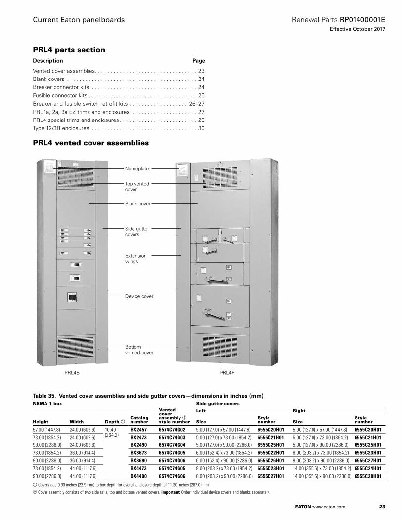
PRL4 vented cover assemblies
Nameplate
Top vented cover
Blank cover
Side gutter covers
Extension wings
Device cover
Bottom vented cover
PRL4B PRL4F
Table 35. Vented cover assemblies and side gutter covers—dimensions in inches (mm)NEMA 1 box
Vented cover assembly b style number
Side gutter covers
Height Width Depth aCatalog number
Left Right
SizeStyle number Size
Style number
57.00 (1447.8) 24.00 (609.6) 10.40 (264.2)
BX2457 6574C74G02 5.00 (127.0) x 57.00 (1447.8) 6555C20H01 5.00 (127.0) x 57.00 (1447.8) 6555C20H0173.00 (1854.2) 24.00 (609.6) BX2473 6574C74G03 5.00 (127.0) x 73.00 (1854.2) 6555C21H01 5.00 (127.0) x 73.00 (1854.2) 6555C21H0190.00 (2286.0) 24.00 (609.6) BX2490 6574C74G04 5.00 (127.0) x 90.00 (2286.0) 6555C25H01 5.00 (127.0) x 90.00 (2286.0) 6555C25H0173.00 (1854.2) 36.00 (914.4) BX3673 6574C74G05 6.00 (152.4) x 73.00 (1854.2) 6555C22H01 8.00 (203.2) x 73.00 (1854.2) 6555C23H0190.00 (2286.0) 36.00 (914.4) BX3690 6574C74G06 6.00 (152.4) x 90.00 (2286.0) 6555C26H01 8.00 (203.2) x 90.00 (2286.0) 6555C27H0173.00 (1854.2) 44.00 (1117.6) BX4473 6574C74G05 8.00 (203.2) x 73.00 (1854.2) 6555C23H01 14.00 (355.6) x 73.00 (1854.2) 6555C24H0190.00 (2286.0) 44.00 (1117.6) BX4490 6574C74G06 8.00 (203.2) x 90.00 (2286.0) 6555C27H01 14.00 (355.6) x 90.00 (2286.0) 6555C28H01
aCovers add 0.90 inches (22.9 mm) to box depth for overall enclosure depth of 11.30 inches (287.0 mm).bCover assembly consists of two side rails, top and bottom vented covers. Important: Order individual device covers and blanks separately.

24
Renewal Parts RP01400001EEffective October 2017
Current Eaton panelboards
EATON www.eaton.com
PRL4 blank coversUsed to cover blank space on chassis . All PRL4 cover heights are measured in “X” units . 1X equals 1 .38 inches (35 .1 mm) .
Table 36. PRL4 blank covers
Cover size
Style number
24.00-inch (609.6 mm)width box
36.00, 44.00-inch (914.4, 1117.6 mm)width box
1X 6554C01H01 6554C02H012X 6554C01H02 6554C02H023X 6554C01H03 6554C02H034X 6554C01H13 6554C02H135X 6554C01H14 6554C02H146X 6554C01H04 6554C02H047X 6554C01H05 6554C02H059X 6554C01H06 6554C02H0610X 6554C01H07 6554C02H0711X 6554C01H08 6554C02H0812X 6554C01H09 6554C02H0913X 6554C01H10 6554C02H1015X 6554C01H11 6554C02H1120X 6554C01H12 6554C02H12
Neutral
1200 A MLO
Twin-mounted breakers
Breaker provision
Space only
PRL4B Interior
PRL4 breaker connector kitsBreaker connector kits
Each kit includes copper connectors, mounting brackets, covers, hardware, and instructions for mounting breaker(s) in a PRL4 . Breakers are not included. Contact your local satellite plant for availability and application information (see page 3) .
Connector kit
Each kit includes copper connectors mounting brackets, cover, hardware, and instructions .
Connector kit
Table 37. Breaker connector kits
Breaker frame
Space required
PolesMounting type
Connector kit catalog number
Inches (mm) “X”
EHD, FD, HFD 2.75 (69.9)
2X 1 a Twin KPRL4FD1EHD, FD, FDB, HFD, FDC 2 Twin KPRL4FD2ED, EDH, EDC 2 Twin KPRL4ED2EHD, FD, FDB, HFD, FDC 4.13
(104.9)3X 3 Twin KPRL4FD
FCL, FB-P, FD/LFD 3 Twin KPRL4FBPED, EDH, EDC 3 Twin KPRL4EDJD, JDB, HJD, JDC 2, 3 Single KPRL4JDSJD, JDB, HJD, JDC 2, 3 Twin KPRL4JDT b
DK, KD, KDB, HKD, KDC 5.50 (139.7)
4X 2, 3 Single KPRL4KDSDK, KD, KDB, HKD, KDC 2, 3 Twin KPRL4KDT c
CKD, CHKD 2, 3 Single KPRL4CKD d
LCL 8.25 (209.5)
6X 2, 3 Single KPRL4LCL b
LA-P 2, 3 Single KPRL4LAP b
LD, LDB, HLD, LDC, CLD, LC 2, 3 Single KPRL4LD b
MDL, HMDL 2, 3 Single KPRL4MC b
NB-P 2, 3 Single KPRL4NBP c
CND, CHND 3 Single KPRL4CND cd
ND, HND 2, 3 Single KPRL4ND b
aTwo sets of twin-mounted single-pole breakers.b36.00-inch (914.4 mm) minimum box width required.c44.00-inch (1117.6 mm) box width required.dRequires density rated bus in existing panel chassis.

25
Renewal Parts RP01400001EEffective October 2017
Current Eaton panelboards
EATON www.eaton.com
Hardware kit
Each kit includes mounting bracket(s) and mounting hardware only . Use the appropriate connector kit catalog number and add an “H” to designate hardware only (example: KPRL4FD-H) .
Hardware kit
Standard ground bus
Copper bus with (3) 6–300 kcmil lugs plus a 24-circuit terminal bar with #14–1/0 wire range .
6572C746G01
PRL4 fusible connector kitsFusible switch connector kits
Each kit includes copper connectors, extension wings (when required), hardware, and instructions to mount a fusible switch . Switches are not included . Contact your local satellite plant for availability and application information (see page 3) .
Table 38. Fusible switch connector kitsSwitch height
Switch ampere rating
Three-pole switch
Connector kitInches (mm)
“X” space required
240 V 600 V
Catalog number
5.50 (139.7)
4X 30–30 FDPWT3211R FDPWT3611R —60–60 FDPWT3222R FDPWT3622R KPRL44X a
100–100 FDPWT3233R — —6.88 (174.8)
5X 100–100 — FDPWT3633R KPRL45X1
8.25 (209.6)
6X 200 FDPBS324R FDPBS364R KPRL4B6XS200–200 FDPBT3244R FDPBT3644R KPRL4B6XT b
12.38 (314.5)
9X 400 FDPW325R FDPW365R KPRL4W9X
15.13 (384.3)
11X 600 FDPW326R FDPW366R KPRL4W11X800 FDPW327 FDPW367 KPRL4W11X b
20.63 (524.0)
15X 1200 FDPW328 FDPW368 KPRL4W15X b
aThese connector kits will fit the FDP and FDPW switches.b44.00-inch (1117.6 mm) box width required for both R and J fuse applications.

26
Renewal Parts RP01400001EEffective October 2017
Current Eaton panelboards
EATON www.eaton.com
PRL4 breaker and fusible switch retrofit kitsBreaker retrofit kits
Each kit includes one breaker, copper connectors, covers, hardware, and instructions to mount in a PRL4 .
Table 39. Breaker retrofit kitsBreaker frame
Frame ampere rating
Trip range
Mounting type
EHD 100 15–100 TwinFDB 15–100 TwinFD 15–100 TwinHFD 15–100 TwinFDC 15–100 TwinFCL 15–100 TwinFB-P 15–100 TwinFDB 150 110–150 TwinFD 225 110–225 TwinHFD 110–225 TwinFDC 110–225 TwinED 100–225 TwinEDH 100–225 Twin EDC 100–225 TwinJD 250 70–250 Twin/singleHJD 70–250 Twin/singleJDC 70–250 Twin/singleDK 400 100–400 Twin/singleKD 100–400 Twin/singleHKD 100–400 Twin/singleKDC 100–400 Twin/singleCKD 100–400 SingleLCL 125–400 SingleLA-P 70–400 SingleLD 600 300–600 SingleCLD 300–600 SingleHLD 300–600 SingleCHLD 300–600 SingleLDC 300–600 SingleCLDC 300–600 SingleMDL 800 300–800 SingleCMDL 300–800 SingleHMDL 300–800 SingleCHMDL 300–800 SingleND 1200 600–1200 SingleCND 600–1200 SingleHND 600–1200 SingleCHND 600–1200 SingleNDC 600–1200 SingleCNDC 600–1200 Single
How to order a breaker retrofit kit by catalog number
Use “KPRL4” prefix and add catalog number of breaker as shown below . Use suffix “T” or “S” to denote twin or single mounting . Twin-mounting indicates that one set of connectors is required to mount two breakers (of similar frames) opposite one another . Retrofit kit includes one breaker only, for either single or twin-mounted applications .
Table 40. Catalog numbering system—breaker retrofit kit
Breaker retrofit kit
KPRL4 KD 3 400 S
Designates KPRL4 connector kit
Number of poles
2 = Two-pole3 = Three-pole
Breaker frame
Ampere rating
T = TwinS = Single

27
Renewal Parts RP01400001EEffective October 2017
Current Eaton panelboards
EATON www.eaton.com
Fusible retrofit kits
Each kit includes a three-pole switch, copper connectors, extension wings (if required), hardware, and instructions to horizontally mount in a PRL4 .
Table 41. Fusible retrofit kitsSwitch ampere rating Switch type Mounting type
30–30 FDPW Twin60–60 FDPW Twin100–100 FDPW Twin100 FDPW Single200 FDPB Single200–200 FDPB Twin400 FDPW Single600 FDPW Single800 FDPW Single1200 FDPW Single
How to order a fusible retrofit kit by catalog number
Use “KPRL4” prefix and add catalog number of appropriate switch (refer to page 26 for three-pole switch catalog number) .
Examplee: The retrofit kit catalog number for a 600 V, 100 A twin FDPW switch is:
Table 42. Catalog numbering system—fusible retrofit kit
PRL1a, 2a, 3a EZ trims and enclosuresEZ trim
PRL1a, 2a, and PRL3a EZ trim and EZ box meet code requirements for both Type 1 standards . Features include a door-in-door standard with no exposed hardware and laser-cut trim with rounded corners . For EZ boxes and EZ trims, refer to page 28.
Examplee: EZT2048 and EZB2048 .
EZ trim
KPRL4 FDPW T 3 6 33 R
Designates PRL4 connector
3 = Three-pole
Switch type
FDPWFDPB
R = R fuseJ = J fuseT = T fuseT = Twin
S = Single Volts
2 = 2406 = 600
11 = 30–3022 = 60–6033 = 100–10044 = 200–2004 = 2005 = 4006 = 6007 = 8008 = 1200

28
Renewal Parts RP01400001EEffective October 2017
Current Eaton panelboards
EATON www.eaton.com
Table 43. EZ trim
Encl. height
Box Trim
Unpainted PaintedUnvented surface mounted
Unvented flush mounted
Vented surface mounted
Vented flush mounted
Catalog number
Style number
Catalog number
Style number
Catalog number
Style number
Catalog number
Style number
Catalog number
Style number
Catalog number
Style number
24 EZB2024R 42C1999G01 EZBP2024R 42C1999G13 EZT2024S 42C4255G01 EZT2024F 42C4258G01 EZTV2024S 42C4261G01 EZTV2024F 42C4264G0130 EZB2030R 42C1999G02 EZBP2030R 42C1999G14 EZT2030S 42C4255G02 EZT2030F 42C4258G02 EZTV2030S 42C4261G02 EZTV2030F 42C4264G0236 EZB2036R 42C1999G03 EZBP2036R 42C1999G15 EZT2036S 42C4255G03 EZT2036F 42C4258G03 EZTV2036S 42C4261G03 EZTV2036F 42C4264G0342 EZB2042R 42C1999G04 EZBP2042R 42C1999G16 EZT2042S 42C4255G04 EZT2042F 42C4258G04 EZTV2042S 42C4261G04 EZTV2042F 42C4264G0448 EZB2048R 42C1999G05 EZBP2048R 42C1999G17 EZT2048S 42C4255G05 EZT2048F 42C4258G05 EZTV2048S 42C4261G05 EZTV2048F 42C4264G0554 EZB2054R 42C1999G06 EZBP2054R 42C1999G18 EZT2054S 42C4255G06 EZT2054F 42C4258G06 EZTV2054S 42C4261G06 EZTV2054F 42C4264G0660 EZB2060R 42C1999G07 EZBP2060R 42C1999G19 EZT2060S 42C4255G07 EZT2060F 42C4258G07 EZTV2060S 42C4261G07 EZTV2060F 42C4264G0772 EZB2072R 42C1999G09 EZBP2072R 42C1999G21 EZT2072S 42C4255G09 EZT2072F 42C4258G09 EZTV2072S 42C4261G09 EZTV2072F 42C4264G0990 EZB2090R 42C1999G12 EZBP2090R 42C1999G24 EZT2090S 42C4255G12 EZT2090F 42C4258G12 EZTV2090S 42C4261G12 EZTV2090F 42C4264G12
PRL1a, 2a, 3a special trims and enclosuresFastrim
Used when concealed trim-mounting hardware is required for PRL1a, 2a, and PRL3a . Trim clamps are included and shipped with the trim . Order by adding the letter “F” to the standard trim catalog number . Add 20% to standard trim list price .
Examplee: LT2072S becomes LTF2072S .
For trim clamps only, refer to page 18 .
Fastrim
Door-in-door
Piano hinge on the right side of the trim provides access to the wiring gutters without requiring removal of the trim . Order by adding the letters “DD” to the standard trim catalog number . Add 20% to standard trim list price .
Examplee: LT2072S becomes LTDD2072S .
Door-in-door
Ventilated trim
Required on 600 A and above panels only . Order by adding the letter “V” to the standard trim catalog number . Add 10% to standard trim list price .
Examplee: LT2072S becomes LTV2072S .
Ventilated trim

29
Renewal Parts RP01400001EEffective October 2017
Current Eaton panelboards
EATON www.eaton.com
Type 12/3R enclosures
The complete enclosure consists of a box and trim . The enclosure meets code requirements for both Type 12 (dust-tight) and Type 3R (rainproof) standards . Features include a laser-cut trim with rounded corners, concealed hinges, and a T-handle lock . Gasketing is provided around the trim door .
The box is gasketed and made from code gauge steel with dripshield and is painted ANSI-61 .
Table 44. Type 12/3R enclosures for PRL1a, 2a, 3aBox dimensions in inches (mm) Catalog number
Height Width Depth Box Trim
24.00 (609.6) 20.00 (508.0) 6.00 (152.4) VWPB2024 LWPT202436.00 (914.4) 20.00 (508.0) 6.00 (152.4) VWPB2036 LWPT203648.00 (1219.2) 20.00 (508.0) 6.00 (152.4) VWPB2048 LWPT204860.00 (1524.0) 20.00 (508.0) 6.00 (152.4) VWPB2060 LWPT206072.00 (1828.8) 20.00 (508.0) 6.00 (152.4) VWPB2072 LWPT207290.00 (2286.0) 20.00 (508.0) 6.00 (152.4) VWPB2090 LWPT2090
Type 12/3R enclosures
PRL4 special trims and enclosuresDoor-in-door trim
Door-in-door trim
A piano hinge on the right side of the trim provides access to the wiring gutter without requiring the removal of the trim . When used with a standard PRL4 box, a special mounting channel must be used to add extra depth to the enclosure .
An extra depth box, not requiring a mounting channel, is another available option . Contact your local satellite for ordering information .
Table 45. Special trims and enclosures
Standard box catalog number
Mounting channel style number
Door-in-door trim catalog number
Surface Flush
BX2457 8708C82G02 LDD2457STW LDD2457FTW
BX2473 8708C82G03 LDD2473STW LDD2473FTW
BX2490 8708C82G04 LDD2490STW LDD2490FTW
BX3673 8708C82G05 LDD3673STW LDD3673FTWBX3690 8708C82G06 LDD3690STW LDD3690FTWBX4473 8708C82G07 LDD4473STW LDD4473FTWBX4490 8708C82G08 LDD4490STW LDD4490FTW

30
Renewal Parts RP01400001EEffective October 2017
Current Eaton panelboards
EATON www.eaton.com
Type 12/3R enclosures
Type 12, 24 .00 inches Type 3R, 36 .00 inches (609 .6 mm) wide (914 .4 mm) wide
PRL4 enclosures are available in both Type 12 (dust-tight) and Type 3R (rainproof) designs . The 24 .00-inch (609 .6 mm) wide enclosure includes a single hinged door while the 36 .00-inch (914 .4 mm) wide is provided with double hinged doors .
The side gutter covers are an integral part of the box in all styles . Sizes and catalog numbers are shown in Table 46 .
Table 46. Type 12/3R enclosuresEnclosure dimensions in inches (mm) Catalog number
Height Width Depth Type 3R Type 12
57.00 (1447.8) 24.00 (609.6) 13.90 (353.1) RPC2457 DPC245773.00 (1854.2) 24.00 (609.6) 13.90 (353.1) RPC2473 DPC247390.00 (2286.0) 24.00 (609.6) 13.90 (353.1) RPC2490 DPC249073.00 (1854.2) 36.00 (914.4) 13.90 (353.1) RPC3673 DPC367390.00 (2286.0) 36.00 (914.4) 13.90 (353.1) RPC3690 DPC3690
Ordering procedureStep 1
Select the correct part or branch device . When selecting, you need to know the following:• Panelboard type• Amperage• System voltage• Available short-circuit rating• Number of poles available• Size and number of wires per phase• “X” space required
Step 2
Refer to the 5P panelboard layout on page 31 to verify the amount of “X” space available .
Step 3
Create a 5P breaker unit catalog number, by following the instructions on page 32, or order the catalog number for parts on page 33 and page 34 .
Step 4
Determine if extra filler covers are required . Additional filler covers may be necessary to fill the unused space . Refer to page 34 for filler plate information .

31
Renewal Parts RP01400001EEffective October 2017
Current Eaton panelboards
EATON www.eaton.com
PRL5P parts sectionDescription Page
Chassis layout . . . . . . . . . . . . . . . . . . . . . . . . . . . . . . . . . . . . . . . . . 31Breake assemblies catalot numbers . . . . . . . . . . . . . . . . . . . . . . . . 32Branch devices . . . . . . . . . . . . . . . . . . . . . . . . . . . . . . . . . . . . . 32–33Main or through-feed lugs . . . . . . . . . . . . . . . . . . . . . . . . . . . . . . . . 33Neutrals and grounds . . . . . . . . . . . . . . . . . . . . . . . . . . . . . . . . . . . 34Box, trim, and deadfront filler plates . . . . . . . . . . . . . . . . . . . . . . . . 34
PRL5P chassis layout
6X
Two-poleEHD, FD, FDB, HFD, FDC, ED, EDH, EDC
Three-pole Three-poleEHD, FD, FDB, HFD, FDC,
ED, EDH, EDCTwo-pole Two-pole
EHD, FD, FDB, HFD,FDC, ED, EDH, EDC
EHD, FD, FDB, HFD,FDC, ED, EDH, EDC
Blank Wireway
FDB, EDH, HFD, FDC,ED, EHD, EDC, FD
Three-poleThree-poleFDB, EDH, HFD, FDC,ED, EHD, EDC, FD
Filler plate
Two- or three-poleJD, HJD, JDC
Two- or three-poleDK, KD, HKD, KDB
Filler plate
Neutral—No “X” space required top or bottom
Two-poleEHD, FD, FDB, HFD, FDC, ED, EDH, EDC
EHD, FD, FDB, HFD, FDC,ED, EDH, EDC
Blank Wireway
2-PoleEHD, FD, FDB, HFD,FDC, ED, EDH, EDC
2-PoleEHD, FD, FDB, HFD,FDC, ED, EDH, EDC
Blank wireway
Two- or three-poleHLD, LDC, LD
800 A MDL, HMDLMain or branch
800 A ND, HND, NDCMain or Branch
1200 A ND, HND, NDCMain or branch
Main lug or branch lug unit 600 A, (2) 600 kcmil 800 A, (3) 800 kcmil1200A, (4) 750 kcmil
2X
3X
2X
2X
3X
4X
3X
3X
6X
6X
6X
7X
2X
3X
2X
2X
3X
4X
6X
6X
6X
7X
10(254.0)
48(1219.2)
10(254.0)10
(254.0)
2X
2X
3X
3X
3X
1X-6X
6X
4X
6X
8X
Neutral—No “X” space requiredtop or bottom
Two-poleEHD, ED, EDH, EDC, FD, FDB, HFD, FDC
EHD, FD, FDB, HFD, FDC,ED, EDC, EDH
Two-pole Two-pole
Three-pole Three-pole
EHD, FD, FDB, HFD, FDC,ED, EDC, EDH
FDB, ED, HFD, FDC,EHD, EDC, FD
FDB, ED, HFD, FDC,EHD, EDC, FD
Three-poleEHD, FD, FDB, HFD, FDC,
ED, EDH, EDC
Two- or three-poleJD, HJD, JDC
Bus cover
Two- or three-poleDK, KD, HKD, KDB
Main or branch
2- or 3-PoleLD, HLD, LDC
Main or branch
800A MDL, HMDLMain only
400 A, 600 A and 800 AMain lug or branch lug
400 A, (1) 750 kcmil or (2) 300 kcmil600 A, (2) 750 kcmil800 (3) 600 kcmil
10(254.0)
10(254.0)
7(177.8)
30(762.0)
Single-bus interior in30-inch (762.0 mm) wide enclosure
Double-bus interior mounted in48-inch (1219.2 mm) wide enclosure
10(254.0)
10(254.0)
Figure 3. PRL5P chassis layout—dimensions in inches (mm)
a If used as a main device, must be mounted at the neutral end of panel.bFixed bus covers are required for unused spaces if NECT six-circuit disconnect rule is to be met.
cBlank wireway fillers are required opposite any dual breaker unit.dOne “X” = 1.38 inches (35.1 mm).

32
Renewal Parts RP01400001EEffective October 2017
Current Eaton panelboards
EATON www.eaton.com
PRL5P breaker assemblies catalog numbers
Table 47. Catalog numbering system—5P single or twin breakers with adapters
A plug-on unit is a complete assembly with a circuit breaker and mounting adapter to mount on a 5P panelboard .
Single indicates units that may be mounted in a single or double bus panel, and twin indicates double bus panels only . See Table 50 and Table 51 .
Table 48. Catalog numbering system—5P dual breakers with adapters
Any two F-Frame breakers listed may be mounted on the same 2X or 3X dual breaker adapter .
Dual breaker adapters may be used in single or double bus panels . Dual breaker adapters can NOT be mounted across from another adapter in a double bus panel . See Table 52 .
Branch devicesSingle-pole breakers in single adapter units . Include two or three single-pole 15–60 A assembled on one unit . (One X = 1 .38 inches [35 .1 mm])
Table 49. Single-pole breakers in single adapter units
Breakertype
Ampere rating
Interrupting rating (kA sym.) “X” space required120 Vac 240 Vac 277 Vac 125 Vdc
EHD 15–60 — — 14 10 2XFD 15–60 — — 25 10 2XHFD 15–60 — — 65 10 2XEHD 15–60 — — 14 10 3XFD 15–60 — — 25 10 3XHFD 15–60 — — 65 10 3X
Table 50. Two- and three-pole breakers in single adapter units
Breakertype
Ampere rating
Interrupting rating (kA sym.) “X” space required240 Vac 480 Vac 600 Vac 250 Vdc
ED 100–225 65 — — — 3XEDH 100–225 100 — — — 3XEDC 100–225 200 — — — 3XEHD 15–60 18 14 — 10 3XEHD 70–100 18 14 — 10 3XFD 15–60 65 25 18 10 3XFD 70–100 65 25 18 10 3XFD 110–225 65 25 18 10 3XHFD 15–60 100 65 25 22 3XHFD 70–100 100 65 25 22 3XHFD 110–225 100 65 25 22 3XFDC 15–60 200 100 35 22 3XFDC 70–100 200 100 35 22 3XFDC 110–225 200 100 35 22 3XJD, JDB 70–225 65 35 18 10 3XJD, JDB 70–225 65 35 18 10 3XHJD 250 100 65 25 22 3XHJD 70–225 100 65 25 22 3XJDC 250 200 100 35 22 3XJDC 70–225 200 100 35 22 3XDK 100–400 65 — — — 4XKD, KDB 250–400 65 35 25 10 4XHKD 250–400 100 65 35 22 4XKDC 250–400 200 100 50 22 4XLD, LDB 300–600 65 35 25 22 6XHLD ab 300–600 100 65 35 25 6XLDC 300–600 200 100 50 25 6XMDL ab 400–800 65 50 25 22 6XHMDL ab 400–800 100 65 35 25 6XND 400–1200 65 50 25 — 6XHND ab 400–1200 100 65 35 — 6XNDC 400–1200 200 100 50 — 6X
aFor use only in double bus chassis panelboards.b100% rated breakers are NOT available in 5P panelboards.
5P FD 3 0060 M S B
Panelboard
BreakerAmpere rating
Mounting
T = TwinS = Single
Connection
B = BranchC = CombinationM = Main
Trip unit
E = ElectronicG = Ground faultM = Thermal-magnetic
Phasing
2 = AB3 = ABC4 = ABL or BCR5 = BCL or ABR
5P 3 EDH 200 FDB 060
Panelboard
Amperes Breaker frame
Amperes
Phasing
2 = AB3 = ABC4 = ABL or BCR5 = BCL or ABR
Breaker frame

33
Renewal Parts RP01400001EEffective October 2017
Current Eaton panelboards
EATON www.eaton.com
Dual breaker adapters—Any two breakers listed in Table 52 may be mounted on the same 2X or 3X dual breaker adapter .
Dual breaker adapters may be used in single or double bus chassis . Dual breaker adapters can NOT be mounted across from another in a double bus chassis . (One X = 1 .38 inches [35 .1 mm]) .
Table 51. Dual breaker adapters
Breaker type
Ampere rating
Interrupting rating (kA sym.) “X” space required240 Vac 480 Vac 600 Vac 250 Vdc
ED 100–225 65 — — — 3XEDH 100–225 100 — — — 3XEDC 100–225 200 — — — 3XEHD 15–60 18 14 — 10 3XEHD 70–100 18 14 — 10 3XFD 15–60 65 25 18 10 3XFD 70–100 65 25 18 10 3XFD 110–225 65 25 18 10 3XHFD 15–60 100 65 25 22 3XHFD 70–100 100 65 25 22 3XHFD 110–225 100 65 25 22 3XFDC 15–60 200 100 35 22 3XFDC 70–100 200 100 35 22 3XFDC 110–225 200 100 35 22 3X
5PFD30060MSB 5P3EDH200FDB060
PRL5P main or through-feed lugs
Table 52. PRL5P main or through-feed lugs
DescriptionAmpere rating
Wire size range
“X” space required
Catalog number
Single bus chassis mounting
Ampere lug unit 400 (1) 1/0–500 or (2) 1/0–250 kcmil
8X 5PLUG3400SC
Ampere lug unit 600 (2) 1/0–500 kcmil 8X 5PLUG3600SCAmpere lug unit 800 (2) #2–500 or
(3) #2–400 kcmil8X 5PLUG3800SC
Double bus chassis mounting
1200 A lug unit 600–1200 (4) #4–750 kcmil 7X 5PLUG31200TC
5PLUG3800SC 5PLUG31200TC

34
Renewal Parts RP01400001EEffective October 2017
Current Eaton panelboards
EATON www.eaton.com
PRL5P neutrals and groundsNeutral assembly
5PN800A
Table 53. Neutral assemblies with lugsIncoming number of cables and wire size Catalog number
(4) 250–500 kcmil 800 A aluminum/copper 5PN800A(4) 250–500 kcmil 800 A copper 5PN800C(4) 250–500 kcmil 1200 A aluminum/copper 5PN1200A(4) 250–500 kcmil 1200 A copper 5PN1200C
Table 54. Additional lugs for neutral assembliesDescription Catalog number
(1) 1/0–750 kcmil or (2) 1/0–300 kcmil aluminum/copper 5PNL400(2) 250–500 kcmil aluminum/copper 5PNL600(3) 3/0–750 kcmil aluminum/copper 5PNL800(4) 3/0–750 kcmil aluminum/copper 5PNL1200Ground bar type
1200 A aluminum/copper 5PG1200A1200 A copper 5PG1200C
Ground bar assemblies
5PG1200A
Table 55. Grounded “B” phase adapter kitsAmpere rating Main device Catalog number
Single bus chassis
400 Main lugs 5PCGBLUG400S600 Main lugs 5PCGBLUG600S600 LD breaker 5PCGBLD600S800 Main lugs 5PCGBLUG800SDouble bus chassis
800 MD breaker 5PCGBMD800T1200 Main lugs 5PCGBLUG1200T1200 ND breaker 5PCGBND1200T
PRL5P box, trim, and deadfront filler plates
Table 56. PRL5P box, trim, and deadfront filler plates
Chassis “X” factor
Catalog number
Back box Trim Trim door kit
Single bus chassis—30.00-Inch (762.0 mm) wide box
24X 5PB2430G 5PT2430S 5PD24S32X 5PB3230G 5PT3230S 5PD32S40X 5PB4030G 5PT4030S 5PD40SDouble bus chassis—48.00-Inch (1219.2 mm) wide box
24X 5PB2448G 5PT2448S 5PD24T32X 5PB3248G 5PT3248S 5PD32T40X 5PB4048G 5PT4048S 5PD40T
Table 57. Deadfront filler plates
Vertical “X” increment
Catalog number
Single bus chassis a Double bus chassis
1X 5PFP1S 5PFP1T2X 5PFP2S 5PFP2T3X 5PFP3S 5PFP3T4X 5PFP4S 5PFP4T5X 5PFP5S 5PFP5T6X 5PFP6S 5PFP6T
aThese fillers are also used across from a breaker unit in a double bus chassis.
5PT2430S 5PD24S
5PFP3S 5PFP3T
35
Renewal Parts RP01400001EEffective October 2017
Current Eaton panelboards
EATON www.eaton.com
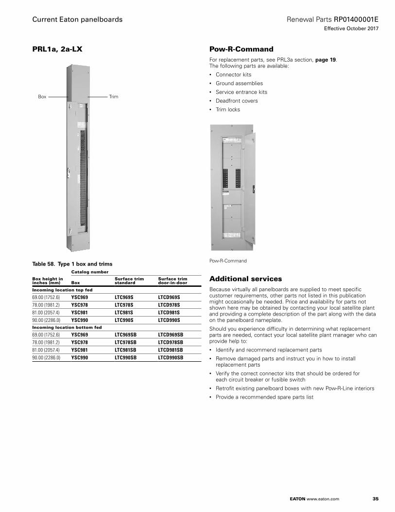
PRL1a, 2a-LX
Box Trim
Table 58. Type 1 box and trims
Box height in inches (mm)
Catalog number
BoxSurface trim standard
Surface trim door-in-door
Incoming location top fed
69.00 (1752.6) YSC969 LTC969S LTCD969S78.00 (1981.2) YSC978 LTC978S LTCD978S81.00 (2057.4) YSC981 LTC981S LTCD981S90.00 (2286.0) YSC990 LTC990S LTCD990SIncoming location bottom fed
69.00 (1752.6) YSC969 LTC969SB LTCD969SB78.00 (1981.2) YSC978 LTC978SB LTCD978SB81.00 (2057.4) YSC981 LTC981SB LTCD981SB90.00 (2286.0) YSC990 LTC990SB LTCD990SB
Pow-R-CommandFor replacement parts, see PRL3a section, page 19 . The following parts are available:• Connector kits• Ground assemblies• Service entrance kits• Deadfront covers• Trim locks
Pow-R-Command
Additional servicesBecause virtually all panelboards are supplied to meet specific customer requirements, other parts not listed in this publication might occasionally be needed . Price and availability for parts not shown here may be obtained by contacting your local satellite plant and providing a complete description of the part along with the data on the panelboard nameplate .
Should you experience difficulty in determining what replacement parts are needed, contact your local satellite plant manager who can provide help to:• Identify and recommend replacement parts• Remove damaged parts and instruct you in how to install
replacement parts• Verify the correct connector kits that should be ordered for
each circuit breaker or fusible switch• Retrofit existing panelboard boxes with new Pow-R-Line interiors• Provide a recommended spare parts list

Eaton1000 Eaton BoulevardCleveland, OH 44122United StatesEaton .com
© 2017 EatonAll Rights ReservedPrinted in USAPublication No . RP01400001E / Z19610October 2017
Eaton is a registered trademark.
All other trademarks are property of their respective owners.
Current Eaton panelboards
Renewal Parts RP01400001EEffective October 2017
Related Documents