ELECTRICAL ELECTRONICS COMMUNICATION INSTRUMENTATION Control Systems Tutorial 3

Welcome message from author
This document is posted to help you gain knowledge. Please leave a comment to let me know what you think about it! Share it to your friends and learn new things together.
Transcript
ELECTRICAL ELECTRONICS COMMUNICATION INSTRUMENTATION
Control Systems
Tutorial 3

ELECTRICAL ELECTRONICS COMMUNICATION INSTRUMENTATION
Today’s class
• Rotational System with gears• Electromechanical systems• Equation To SFG

ELECTRICAL ELECTRONICS COMMUNICATION INSTRUMENTATION
Problem 1 Gears

ELECTRICAL ELECTRONICS COMMUNICATION INSTRUMENTATION
Rotational System with gears
• A toothed wheel that works with others to alter the relation between the speed of a driving system.
• Used to attain mechanical matching of motor to load.
ELECTRICAL ELECTRONICS COMMUNICATION INSTRUMENTATION
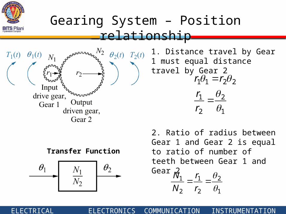
Gearing System – Position relationship
1. Distance travel by Gear 1 must equal distance travel by Gear 2
1
2
2
1
2211
r
r
rr
2. Ratio of radius between Gear 1 and Gear 2 is equal to ratio of number of teeth between Gear 1 and Gear 2
1
2
2
1
2
1
r
r
N
N
Transfer Function

ELECTRICAL ELECTRONICS COMMUNICATION INSTRUMENTATION
Gearing System – Torque relationship
1. Assume work generated by Gear 1 is equal to work consumed by Gear 2
2211
21
TT
WW
2. From previous result
2
1
2
1
1
2
2
1
2211
N
N
T
T
T
T
TT
Transfer Function

ELECTRICAL ELECTRONICS COMMUNICATION INSTRUMENTATION
1. Decide the input and the output2. Draw free body diagram of the inertia3. Convert time function to frequency-domain4. Obtain the transfer function
Modeling Steps:
Example 1

ELECTRICAL ELECTRONICS COMMUNICATION INSTRUMENTATION
Step 2: Input and Output Variables
Angular position of input shaft θ1(t)
Output variable:
Input variable:
Angular position of input shaft θ2(t)
Output variable:

ELECTRICAL ELECTRONICS COMMUNICATION INSTRUMENTATION
1
212
2
1
21222
)(N
NTKDsJs
N
NTKDJ
Step 3. Equations
ELECTRICAL ELECTRONICS COMMUNICATION INSTRUMENTATION
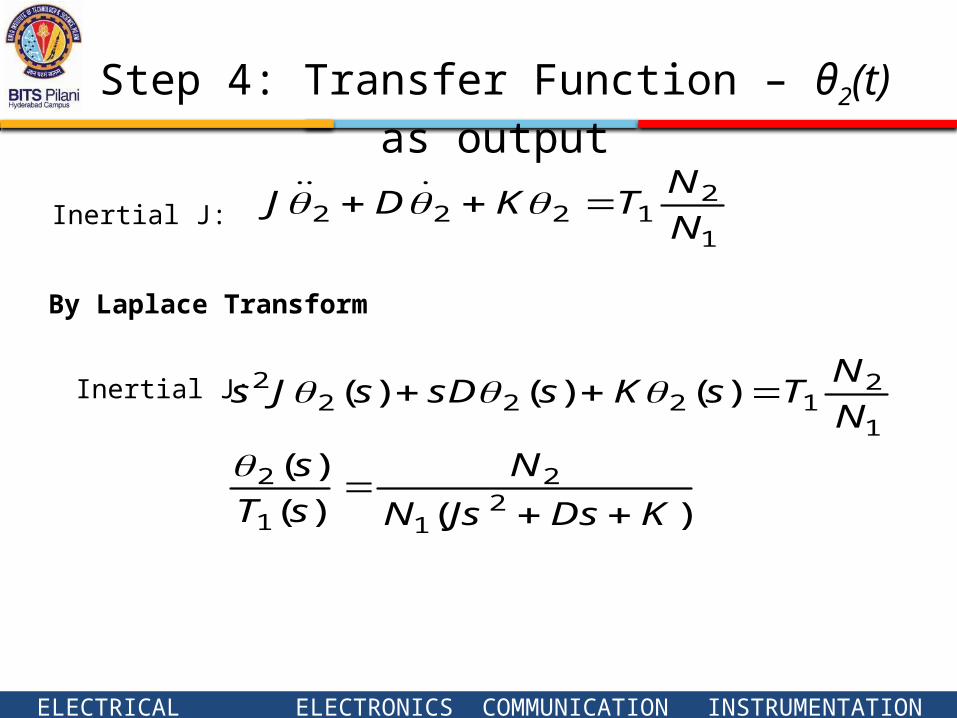
Step 4: Transfer Function – θ2(t) as output
Inertial J:
By Laplace Transform
Inertial J:
)()(
)(
)()()(
21
2
1
2
1
21222
2
KDsJsN
N
sT
s
N
NTsKssDsJs
1
21222 N
NTKDJ
ELECTRICAL ELECTRONICS COMMUNICATION INSTRUMENTATION
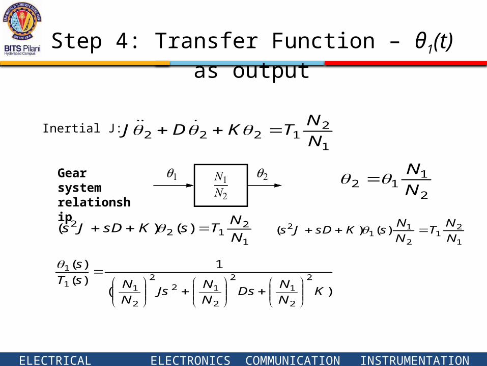
Step 4: Transfer Function – θ1(t) as output
Inertial J:
Gear system relationship
)(
1
)(
)(2
2
12
2
122
2
11
1
KN
NDs
N
NJs
N
NsT
s
1
21222 N
NTKDJ
2
112 N
N
1
212
2 )()(N
NTsKsDJs
1
21
2
11
2 )()(N
NT
N
NsKsDJs
ELECTRICAL ELECTRONICS COMMUNICATION INSTRUMENTATION
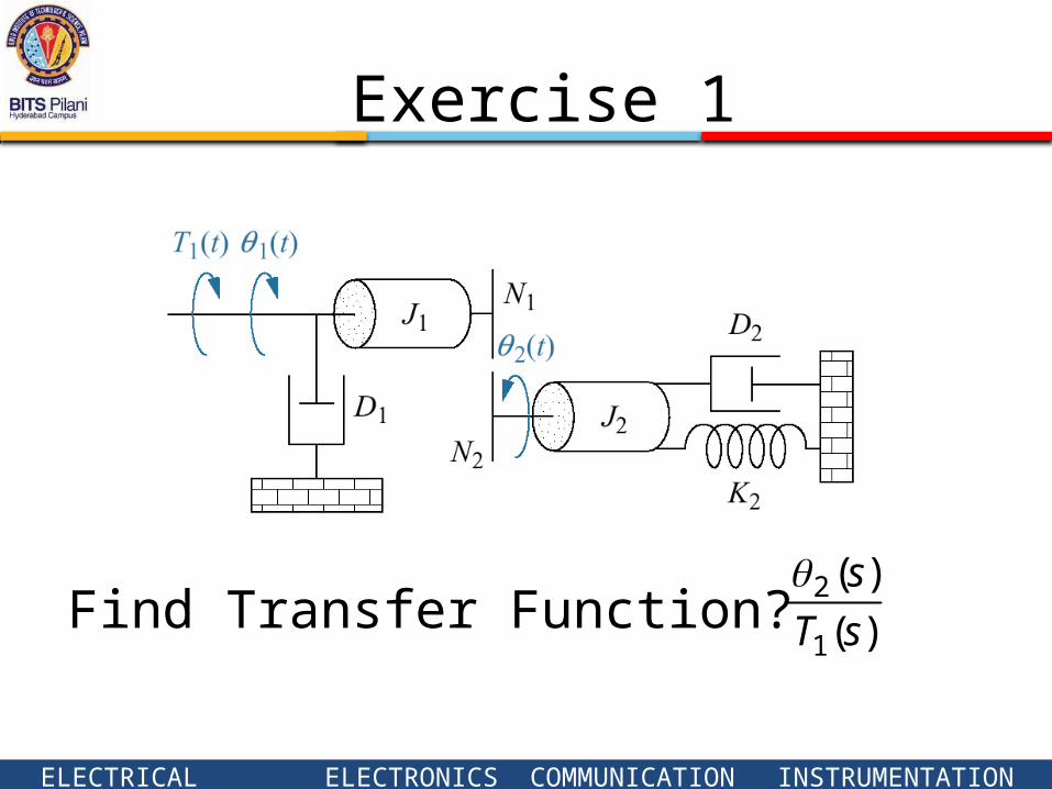
Exercise 1
Find Transfer Function? )(
)(
1
2
sT
s

ELECTRICAL ELECTRONICS COMMUNICATION INSTRUMENTATION
Problem 2 electromechanical system

ELECTRICAL ELECTRONICS COMMUNICATION INSTRUMENTATION
Find the transfer function X(s)/Ei(s) for the system shown above. Hint: find the electromechanical equation
Problem 2

ELECTRICAL ELECTRONICS COMMUNICATION INSTRUMENTATION
𝐸𝑖 (𝑠 )=𝑅 𝐼 1 (𝑠)+ 1𝐶𝑠 [ 𝐼1 (𝑠 )− 𝐼2 (𝑠 ) ]
Writing equations in frequency domain
𝑠 𝐿𝐼2 (𝑠 )+ 1𝐶𝑠 [ 𝐼 2 (𝑠)− 𝐼 1 (𝑠) ]=−𝐸𝑏 (𝑠 )=−𝑠 𝐾1𝑋 (𝑠)
Problem 2
𝑃 (𝑠 )=𝐾 2 𝐼2 (𝑠 )= (𝑀𝑠2+𝐹𝑠+𝐾 ) 𝑋 (𝑠 )
𝐼 2 (𝑠)=(𝑀𝑠2+𝐹𝑠+𝐾 ) 𝑋 (𝑠 )
𝐾 2
ELECTRICAL ELECTRONICS COMMUNICATION INSTRUMENTATION
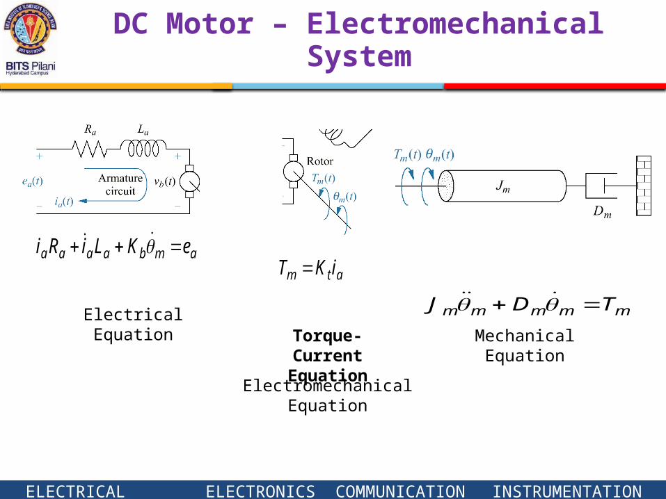
DC Motor – Electromechanical System
Torque-CurrentEquation
mmmmm TDJ
Mechanical Equation
ambaaaa eKLiRi
Electrical Equation
atm iKT
ElectromechanicalEquation

ELECTRICAL ELECTRONICS COMMUNICATION INSTRUMENTATION
DC motor example
)()()()( sEKssLssIRsI abmaaaa
)()()(2 sTssDsJs mmmmm
)()( sIKsT atm
Equations in Frequency domain
Related Documents