CS/EE 3700 : Fundamentals of Digital System Design Chris J. Myers Lecture 2: Intro. to Logic Circuits Chapter 2

Welcome message from author
This document is posted to help you gain knowledge. Please leave a comment to let me know what you think about it! Share it to your friends and learn new things together.
Transcript

CS/EE 3700 : Fundamentals of Digital System Design
Chris J. Myers
Lecture 2: Intro. to Logic Circuits
Chapter 2
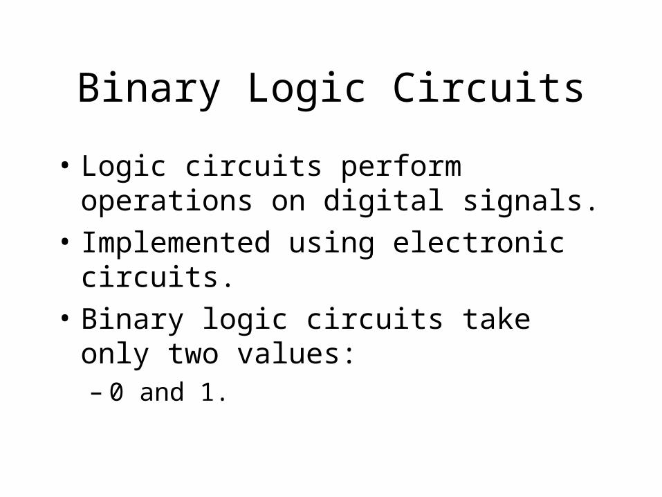
Binary Logic Circuits
• Logic circuits perform operations on digital signals.
• Implemented using electronic circuits.
• Binary logic circuits take only two values: – 0 and 1.
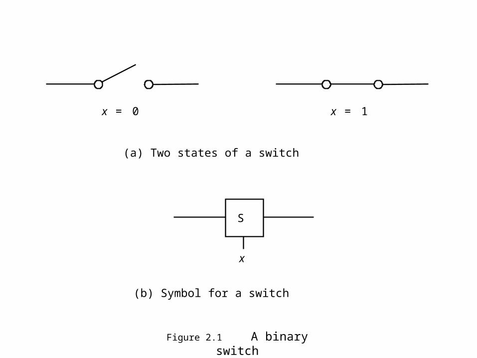
Figure 2.1 A binary switch
x 1 = x 0 =
(a) Two states of a switch
S
x
(b) Symbol for a switch

Figure 2.2 A light controlled by a switch
(a) Simple connection to a battery
S
x
(b) Using a ground connection as the return path
L Battery Light
x Power supply
S
L
L(x) = x
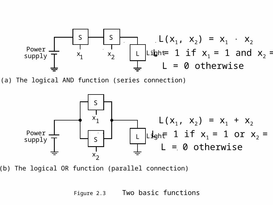
Figure 2.3 Two basic functions
(a) The logical AND function (series connection)
S
x1 LPowersupply
S
x2
S
x1
LPowersupply S
x2
(b) The logical OR function (parallel connection)
Light
Light
L(x1, x2) = x1 x2
L = 1 if x1 = 1 and x2 = 1
L = 0 otherwise
L(x1, x2) = x1 + x2
L = 1 if x1 = 1 or x2 = 1
L = 0 otherwise

Figure 2.4 A series-parallel connection
S
x 1
L Power supply S
x 2
Light
S
x 3
L(x1, x2, x3) = (x1 + x2) x3

Figure 2.5 An inverting circuit
S x L
Power supply
R
L(x) = x
L = 1 if x = 0
L = 0 if x = 1

Figure 2.6 A truth table for AND and OR

Figure 2.7 Three-input AND and OR

x 1 x 2
x n
x 1 x 2 x n + + + x 1 x 2
x 1 x 2 +
x 1 x 2
x n
x 1 x 2
x 1 x 2 x 1 x 2 x n
(a) AND gates
(b) OR gates
x x
(c) NOT gateFigure 2.8 The basic gates
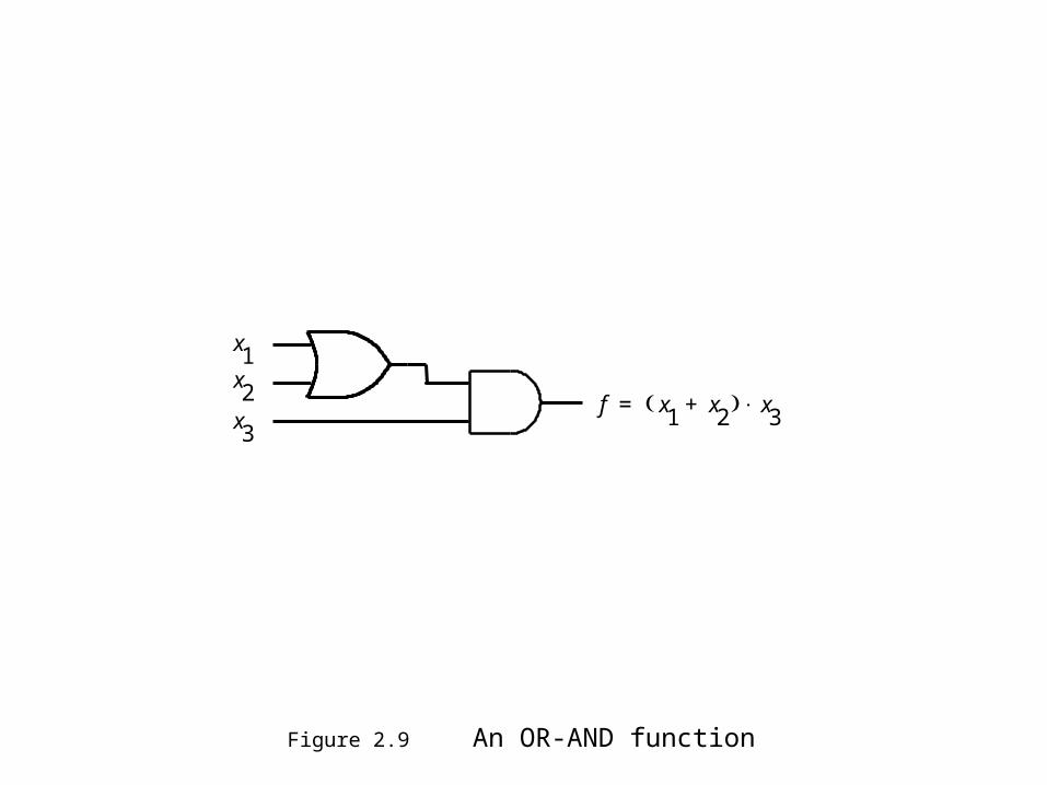
Figure 2.9 An OR-AND function
x 1 x 2 x 3
f x 1 x 2 + x 3 =

x 1
x 2
1 1 0 0
f
0 0 0 1
1 1 0 1
0 0 1 1
0 1 0 1
(a) Network that implements f x 1 x
1 x 2 + =
x 1
x 2
f x 1
x 2
, ( )
0
1
0
1
0
0
1
1
1
1
0
1
(b) Truth table for f
A
B
Figure 2.10 a Logic network

1 0
1 0
1 0
1 0
1 0
x 1
x 2
A
B
f Time
(c) Timing diagram
1 1 0 0 0 0 1 1
1 1 0 1 0 1 0 1 g
x 1
x 2
(d) Network that implements g x 1 x 2 + =
Figure 2.10 b Logic network

Boolean Algebra
• 1849, George Boole published a scheme for describing logical thought and reasoning.
• In 1930s, Claude Shannon applied Boolean algebra to describe circuits built w/switches.
• Boolean algebra provides the theoretical foundation for digital design.

Axioms of Boolean Algebra
1. 0 0 = 0 1 + 1 = 1
2. 1 1 = 1 0 + 0 = 0
3. 0 1 = 1 0 = 0 1 + 0 = 0 + 1 = 1
4. if x = 0 then x = 1 if x = 1 then x = 0

Single-Variable Theorems
5. x 0 = 0 x + 1 = 1
6. x 1 = x x + 0 = x
7. x x = x x + x = x
8. x x = 0 x + x = 1
9. x = x

Principle of Duality
• Axioms and theorems listed in pairs to show principle of duality.
• Given a logic expression, its dual is found by exchanging + operators and operators and 0s ands 1s.
• The dual of any true statement is true.

2- and 3-Variable Properties
10a. x y = y x Commutative
10b. x + y = y + x
11a. x (y z) = (x y) z Associative
11b. x + (y + z) = (x + y) + z
12a. x (y + z) = x y + x z Distributive
12b. x + y z = (x + y) (x + z)
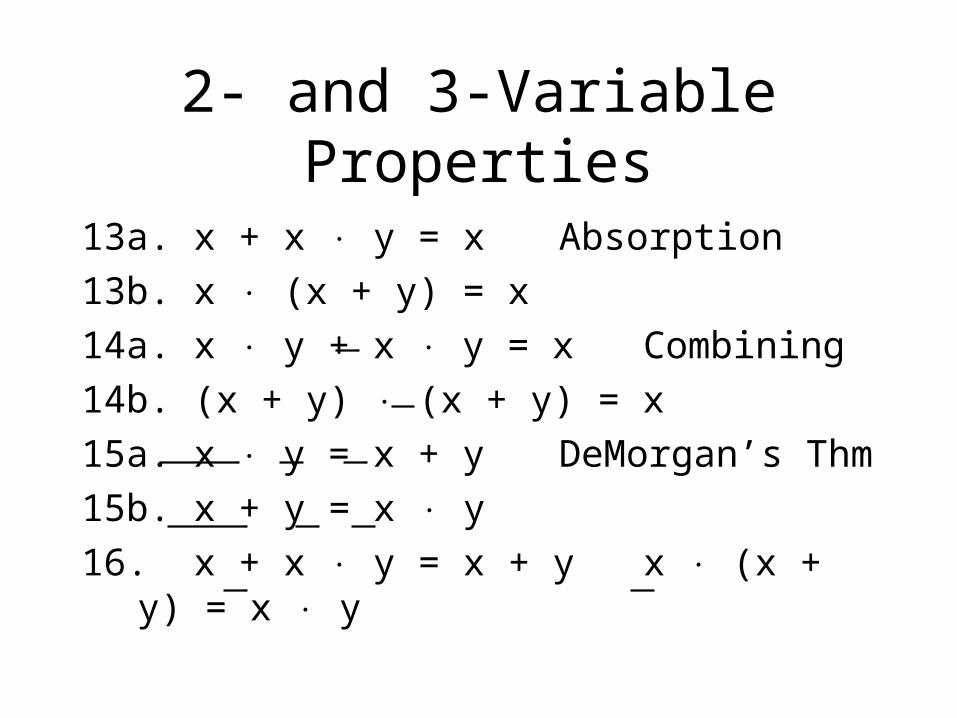
2- and 3-Variable Properties
13a. x + x y = x Absorption
13b. x (x + y) = x
14a. x y + x y = x Combining
14b. (x + y) (x + y) = x
15a. x y = x + y DeMorgan’s Thm
15b. x + y = x y
16. x + x y = x + y x (x + y) = x y

Figure 2.11 Proof of DeMorgan’s theorem

(x1 + x3) (x1 + x3) = x1 x3 + x1 x3

x1 x3 + x2 x3 + x1 x3 + x2 x3 = x1 x2 + x1 x2 + x1 x2

Figure 2.12 The Venn diagram representation
x y
z
x
x y x y x x
x
(a) Constant 1 (b) Constant 0 (c) Variablex
(d) (e) (f)
(g) (h)
x x y x y +
x y z + x y
y
x

Figure 2.13 Verification of the distributive property
x y
z
x y
z
x y
z
x y
z
x y
z
x y
z
x x y
x y x + z x y z +
(a) (d)
(c) (f)
x z y z + (b) (e)

Figure 2.14 Verification example
x y
z
y x
z
x y
z
x y y z
x y x + z
x z
x y
z
x y
x y x + z y z +
x y
z
x z
y
z
x
y
z
x
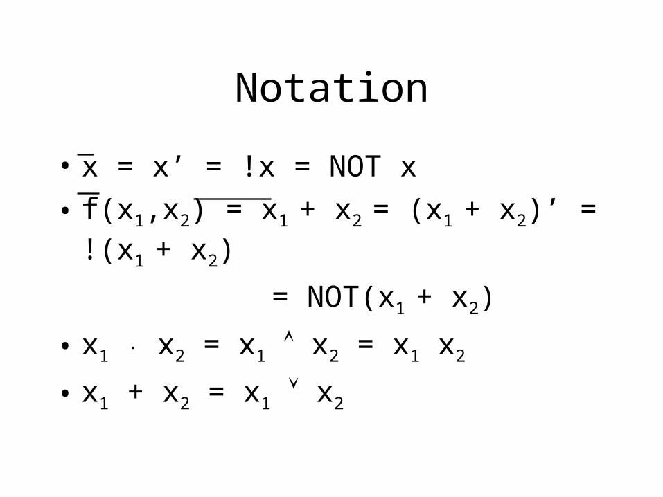
Notation
• x = x’ = !x = NOT x
• f(x1,x2) = x1 + x2 = (x1 + x2)’ = !(x1 + x2)
= NOT(x1 + x2)
• x1 x2 = x1 x2 = x1 x2
• x1 + x2 = x1 x2

Precedence of Operations
• In absence of parentheses, operations are performed in this order: NOT, AND, OR.
x1 x2 + x1’ x2’ = (x1 x2) + ((x1’) (x2’))
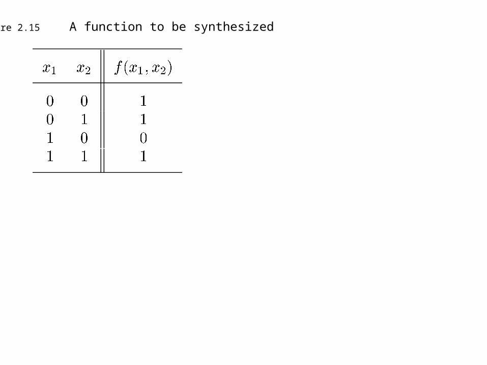
Figure 2.15 A function to be synthesized

f
(a) Canonical sum-of-products
f
(b) Minimal-cost realization
x 2
x 1
x 1
x 2
Figure 2.16 Two implementations of a function

Figure 2.17 Three-variable Minterms and Maxterms

Figure 2.18 A three-variable function

f
(a) A minimal sum-of-products realization
x1
x2
x3

Figure 2.18 A three-variable function

f
(b) A minimal product-of-sums realization
x2
x1x3

Figure 2.20 Truth table for a three-way light controller

Figure 2.21 SOP implementation of the three-way light controller
f
(a) Sum-of-products realization
x 1 x 2 x 3

Figure 2.21 POS implementation of the three-way light controller
(b) Product-of-sums realization
f
x 1
x 2
x 3

0 0 0 0
0 0 1 0
0 1 0 1
0 1 1 1
1 0 0 0
1 0 1 1
1 1 0 0
1 1 1 1
(a) Truth table
f
x 1
x 2
s
f
s
x 1
x 2
0
1
(c) Graphical symbol
(b) Circuit
0
1
(d) More compact truth-table representation
s x1 x2 f (s, x1, x2)
f (s, x1, x2)s
x1
x2
Figure 2.22 Multiplexer

Design Entry
• Truth tables– Practical for only small circuits.
• Schematic capture– Interconnect symbols in some library.– Facilitates hierarchical design.– Good for larger circuits.– Difficult to use for very large circuits.

Figure 2.23 Screen capture of the Waveform Editor
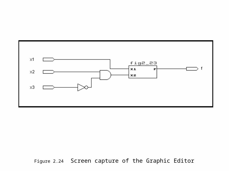
Figure 2.24 Screen capture of the Graphic Editor
Design Entry (cont)
• Hardware description languages (HDLs).– Similar to a programming language.– VHDL and Verilog HDL are IEEE standards.– Provide design portability.– Allow for sharing and design reuse.– Support hierarchical design.– Can be combined with schematics.

Synthesis
• Logic synthesis, or logic optimization, is process to translate a truth table, schematic, or VHDL code into a network of logic gates.
• What makes a circuit good depends on the application.
• Converting logic description to a physical design entails technology mapping and layout synthesis.

Functional Simulation
• A functional simulator is used to determine if designed circuit operates correctly.
• User provides inputs values to the circuit.
• Simulator determines circuits response.
• User checks responses against required.
• A timing simulator can be used to check the performance of a design.

Figure 2.25 The first stages of a CAD system
Desi
gn c
once
pti
on
Tru
th t
able
Tru
th t
able
V
HD
LSch
em
ati
c ca
ptu
re
Sim
ple
synth
esi
s(s
ee s
ect
ion 2
.8.2
) Tra
nsl
ati
on
Merg
e
Boole
an e
quati
ons
INIT
IAL
SYN
TH
ESIS
TO
OLS
DESIG
N E
NTR
Y
Desi
gn c
orr
ect
?
Logic
synth
esi
s, p
hysi
cal desi
gn,
tim
ing s
imula
tion
Funct
ional si
mula
tion
No
Yes
(see s
ect
ion 4
.12
)
VHDL - Very high speed integrated circuit hardware description language
• Original IEEE standard adopted in 1987.
• Revised standard in 1993.
• Originally used for documentation and simulation.
• Now, it is also used for synthesis.
• Very complex language, but only a subset is needed to design wide range of circuits.

Representing Digital Signals
• Each logic signal in a circuit is a data object in the VHDL code.
• Data objects in VHDL are assigned types.
• A simple type is BIT which is used for objects that can only take 2 values: 0 and 1.
• Other data types are introduced later.

Figure 2.26 A simple logic function and corresponding VHDL code
f
x3
x1x2

Figure 2.30 VHDL code for a four-input function
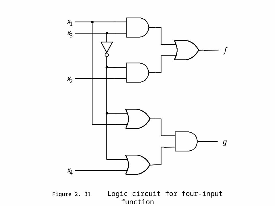
f
g
x 3
x 1
x 2
x 4
Figure 2. 31 Logic circuit for four-input function

How NOT to Write VHDL Code
• Novice tempted to write code with lots of variables and loops.
• This code style is difficult to relate to the circuit and should be avoided.
• Good guideline is that if designer cannot determine what circuit is doing from code, then circuit synthesized likely will be wrong

Concluding Remarks
• Introduced concept of logic circuits.– Implemented using logic gates.– Described with Boolean algebra.
• Briefly introduced CAD tools.
Related Documents