1 Synthesis and Place & Route Synopsys design compiler Cadence Encounter Digital Implementation System (EDI) CS/ECE 6710 Tool Suite Synopsys Design Compiler Cadence EDI Cadence Composer Schematic Cadence Virtuoso Layout CCAR AutoRouter Your Library Verilog sim Verilog sim Behavioral Verilog Structural Verilog Circuit Layout LVS Layout-XL Design Compiler Synthesis of behavioral to structural Three ways to go: 1. Type commands to the design compiler shell Start with syn-dc and start typing 2. Write a script Use syn-script.tcl as a starting point 3. Use the Design Vision GUI Friendly menus and graphics... Design Compiler – Basic Flow 1. Define environment target libraries – your cell library synthetic libraries – DesignWare libraries link-libraries – libraries to link against 2. Read in your structural Verilog Usually split into analyze and elaborate 3. Set constraints timing – define clock, loads, etc. Design Compiler – Basic Flow 4. Compile the design compile or compile_ultra Does the actual synthesis 5. Write out the results Make sure to change_names Write out structural verilog, report, ddc, sdc files beh2str – the simplest script! # beh2str script set target_library [list [getenv "LIBFILE"]] set link_library [concat [concat "*" $target_library] $synthetic_library] read_file -f verilog [getenv "INFILE"] #/* This command will fix the problem of having */ #/* assign statements left in your structural file. */ set_fix_multiple_port_nets -all -buffer_constants compile -ungroup_all check_design #/* always do change_names before write... */ redirect change_names { change_names -rules verilog -hierarchy - verbose } write -f verilog -output [getenv "OUTFILE"] quit

Welcome message from author
This document is posted to help you gain knowledge. Please leave a comment to let me know what you think about it! Share it to your friends and learn new things together.
Transcript

1
Synthesis and Place & Route
Synopsys design compiler Cadence Encounter Digital
Implementation System (EDI)
CS/ECE 6710 Tool Suite Synopsys
Design Compiler
Cadence EDI
Cadence Composer Schematic
Cadence Virtuoso Layout
CCAR AutoRouter
Your Library
Verilog sim
Verilog sim
Behavioral Verilog
Structural Verilog
Circuit Layout
LVS
Layout-XL
Design Compiler
Synthesis of behavioral to structural Three ways to go:
1. Type commands to the design compiler shell Start with syn-dc and start typing
2. Write a script Use syn-script.tcl as a starting point
3. Use the Design Vision GUI Friendly menus and graphics...
Design Compiler – Basic Flow
1. Define environment target libraries – your cell library synthetic libraries – DesignWare libraries link-libraries – libraries to link against
2. Read in your structural Verilog Usually split into analyze and elaborate
3. Set constraints timing – define clock, loads, etc.
Design Compiler – Basic Flow
4. Compile the design compile or compile_ultra Does the actual synthesis
5. Write out the results Make sure to change_names Write out structural verilog, report, ddc, sdc
files
beh2str – the simplest script! # beh2str script set target_library [list [getenv "LIBFILE"]] set link_library [concat [concat "*" $target_library] $synthetic_library] read_file -f verilog [getenv "INFILE"] #/* This command will fix the problem of having */ #/* assign statements left in your structural file. */ set_fix_multiple_port_nets -all -buffer_constants compile -ungroup_all check_design #/* always do change_names before write... */ redirect change_names { change_names -rules verilog -hierarchy -
verbose } write -f verilog -output [getenv "OUTFILE"] quit

2
.synopsys_dc.setup set SynopsysInstall [getenv "SYNOPSYS"]
set search_path [list . \ [format "%s%s" $SynopsysInstall /libraries/syn] \ [format "%s%s" $SynopsysInstall /dw/sim_ver] \ ] define_design_lib WORK -path ./WORK set synthetic_library [list dw_foundation.sldb] set synlib_wait_for_design_license [list "DesignWare-Foundation"] set link_library [concat [concat "*" $target_library] $synthetic_library] set symbol_library [list generic.sdb]
What beh2str leaves out...
Timing! No clock defined so no target speed No input drive defined so assume infinite drive No output load define so assume something
syn-script.tcl /uusoc/facility/cad_common/local/class/6710/F11/synopsys
#/* search path should include directories with memory .db files */ #/* as well as the standard cells */ set search_path [list . \ [format "%s%s" SynopsysInstall /libraries/syn] \ [format "%s%s" SynopsysInstall /dw/sim_ver] \ !!your-library-path-goes-here!!] #/* target library list should include all target .db files */ set target_library [list !!your-library-name!!.db] #/* synthetic_library is set in .synopsys_dc.setup to be */ #/* the dw_foundation library. */ set link_library [concat [concat "*" $target_library] $synthetic_library]
syn-script.tcl #/* below are parameters that you will want to set for each design */ #/* list of all HDL files in the design */ set myFiles [list !!all-your-structural-Verilog-files!! ] set fileFormat verilog ;# verilog or VHDL set basename !!basename!! ;# Name of top-level module set myClk !!clk!! ;# The name of your clock set virtual 0 ;# 1 if virtual clock, 0 if real clock #/* compiler switches... */ set useUltra 1 ;# 1 for compile_ultra, 0 for compile
#mapEffort, useUngroup are for #non-ultra compile...
set mapEffort1 medium ;# First pass - low, medium, or high set mapEffort2 medium ;# second pass - low, medium, or
high set useUngroup 1 ;# 0 if no flatten, 1 if flatten
syn-script.tcl #/* Timing and loading information */ set myPeriod_ns !!10!! ;# desired clock period (sets speed goal) set myInDelay_ns !!0.25!! ;# delay from clock to inputs valid set myOutDelay_ns !!0.25!! ;# delay from clock to output valid set myInputBuf !!INVX4!! ;# name of cell driving the inputs set myLoadLibrary !!Lib!! ;# name of library the cell comes from set myLoadPin !!A!! ;# pin that outputs drive
#/* Control the writing of result files */ set runname struct ;# Name appended to output files
syn-script.tcl #/* the following control which output files you want. They */ #/* should be set to 1 if you want the file, 0 if not */ set write_v 1 ;# compiled structural Verilog file set write_ddc 0 ;# compiled file in ddc format set write_sdf 0 ;# sdf file for back-annotated timing sim set write_sdc 1 ;# sdc constraint file for place and route set write_rep 1 ;# report file from compilation set write_pow 0 ;# report file for power estimate
3
syn-script.tcl # analyze and elaborate the files analyze -format $fileFormat -lib WORK $myfiles elaborate $basename -lib WORK -update current_design $basename # The link command makes sure that all the required design # parts are linked together. # The uniquify command makes unique copies of replicated modules. link uniquify # now you can create clocks for the design if { $virtual == 0 } {
create_clock -period $myPeriod_ns $myClk } else { create_clock -period $myPeriod_ns -name $myClk }
syn-script.tcl # Set the driving cell for all inputs except the clock # The clock has infinite drive by default. This is usually # what you want for synthesis because you will use other # tools (like SOC Encounter) to build the clock tree (or define it by hand). set_driving_cell -library $myLoadLibrary -lib_cell $myInputBuf \
[remove_from_collection [all_inputs] $myClk] # set the input and output delay relative to myclk set_input_delay $myInDelay_ns -clock $myClk \
[remove_from_collection [all_inputs] $myClk] set_output_delay $myOutDelay_ns -clock $myClk [all_outputs] # set the load of the circuit outputs in terms of the load # of the next cell that they will drive, also try to fix hold time issues set_load [load_of [format “%s%s%s%s%s” $myLoadLibrary \ "/" $myInputBuf "/" $myLoadPin]] [all_outputs] set_fix_hold $myClk
syn-script.tcl # now compile the design with given mapping effort # and do a second compile with incremental mapping # or use the compile_ultra meta-command if { $useUltra == 1 } {
compile_ultra } else { if { $useUngroup == 1 } { compile -ungoup_all -map_effort $mapEffort1 compile -incremental_mapping -map_effort $mapEffort2 } else { compile -map_effort $mapEffort1 compile -incremental_mapping -map_effort $mapEffort2 } }
syn-script.tcl # Check things for errors check_design report_constraint -all_violators set filebase [format "%s%s%s" $basename "_" $runname] # structural (synthesized) file as verilog if { $write_v == 1 } {
set filename [format "%s%s" $filebase ".v"] redirect change_names { change_names -rules verilog \ -hierarchy -verbose } write -format verilog -hierarchy -output $filename
} # write the rest of the desired files... then quit
Using Scripts
Modify syn-script.tcl or write your own syn-dc –f scriptname.tcl Make sure to check output!!!!
Using Design Vision
You can do all of these commands from the design vision gui if you like
syn-dv Follow the same steps as the script
Set libraries in your own .synopsys_dc.setup analyze/elaborate define clock and set constraints compile write out results

4
Setup
File ->Setup
analyze/elaborate File -> Analyze
File ->Elaborate
Look at results... Define clock
attributes -> specify clock
Also look at other attributes...
Compile
Design -> Compile Ultra
Timing Reports
Timing -> Report Timing Path
5
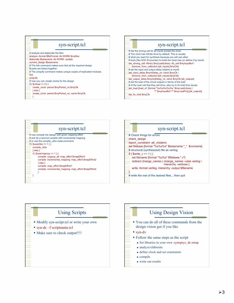
Write Results
File -> Save As...
change_names
Or, use syn-dv after script...
syn-dc –f mips.tcl results in .v, .ddc, .sdc, .rep files Read the .ddc file into syn-dv and use it to
explore timing...
syn-dv with mips_struct.v
File -> Read
Endpoint slack...
Timing -> Endpoint Slack
Path Slack
Timing -> Path Slack
Encounter Digital Implementation System
Need structural Verilog, .sdc, library.lib, library.lef
make a new dir for edi... <design>.conf is also very helpful
use UofU_soc.conf as starting point. And Default.view
Usual warnings about scripting... UofU_edi.tcl is the generic script .../local/class/6710/F11/cadence/EDI

6
cad-edi Flow
1. Import Design .v, .sdc, .lib, .lef – can put this in a file.conf and
Default.view 2. Power plan
rings, stripes, row-routing (sroute)
3. Placement place cells in the rows
4. Timing optimization – preCTS
cad-edi Flow
5. Synthesize clock tree use your buf or inv footprint cells
6. timing optimization – postCTS 7. global routing
NanoRoute 8. timing optimization – postRoute 9. Add filler cells 10. Write out results
.def, _soc.v, .spef, .sdc, .lef
Design Import Using a conf file
Put the load information into a .conf file Load it up without having to re-type Also need a Default.view file
UofU_edi.conf # global rda_Input # ######################################################### # Here are the parts you need to update for your design ######################################################### # # Your input is structural verilog. Set the top module name # and also give the .sdc file you used in synthesis for the # clock timing constraints. set rda_Input(ui_netlist) {!!filename!!.v} set rda_Input(ui_topcell) {!!TopCellName!!} set rda_Input(ui_timingcon_file) {!!filename!!.sdc}
UofU_edi.conf # # Leave min and max empty if you have only one timing library # (space-separated if you have more than one) set rda_Input(ui_timelib) {!!filename!!.lib} set rda_Input(ui_timelib,min) {} set rda_Input(ui_timelib,max) {} # # # Set the name of your lef file or files # (space-separated if you have more than one). set rda_Input(ui_leffile) {!!filename!!.lef}
7
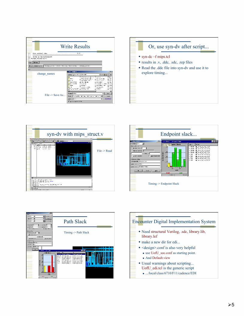
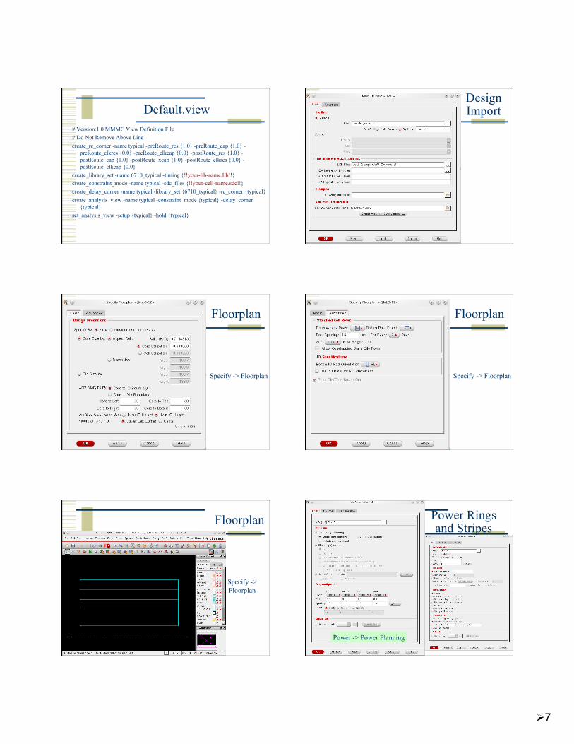
Default.view # Version:1.0 MMMC View Definition File # Do Not Remove Above Line create_rc_corner -name typical -preRoute_res {1.0} -preRoute_cap {1.0} -
preRoute_clkres {0.0} -preRoute_clkcap {0.0} -postRoute_res {1.0} -postRoute_cap {1.0} -postRoute_xcap {1.0} -postRoute_clkres {0.0} -postRoute_clkcap {0.0}
create_library_set -name 6710_typical -timing {!!your-lib-name.lib!!} create_constraint_mode -name typical -sdc_files {!!your-cell-name.sdc!!} create_delay_corner -name typical -library_set {6710_typical} -rc_corner {typical} create_analysis_view -name typical -constraint_mode {typical} -delay_corner
{typical} set_analysis_view -setup {typical} -hold {typical}
Design Import
Floorplan
Specify -> Floorplan
Floorplan
Specify -> Floorplan
Floorplan
Specify -> Floorplan
Power Rings and Stripes
Power -> Power Planning

8
Sroute to
connect things
up
Route -> Sroute
Place cells
Place -> Place cells...
pre-CTS timing optimization
Timing -> Optimization
Clock Tree Synthesis clock -> create clock tree spec
clock ->Synthesize clock tree
Display Clock Tree post-CTS optimization

9
NanoRoute
Route -> NanoRoute -> Route
Routed circuit
Routed circuit postRoute optimization
Timing -> Optimization
Add Filler
Place -> Filler -> Add...
Write Results...
Design -> Save -> Netlist
Design -> Save -> DEF

10
Encounter Scripting
Usual warnings – know what’s going on! Use top.tcl as a starting point
And the other .tcl files it calls...
EDI has a floorplanning stage that you may want to do by hand write another script to read in the floorplan and
go from there... Use encounter.cmd to see the text versions of
what you did in the GUI...
top.tcl
# set the basename for the config and floorplan files. This # will also be used for the .lib, .lef, .v, and .spef files... set basename “mips"
# set the name of the filler cells - you don't need a list # if you only have one set fillerCells FILL #set fillerCells [list FILL FILL2]
top.tcl
# These set the percent utilization target (how dense should # the cells be placed), and the gap for routing between rows. # These are good starting values for small macros. Larger or # more complex macros will likely need a lowered usepct or # larger rowgap or both. set usepct 0.65 ;# percent utilization in placing cells set rowgap 30 ;# gap between pairs of std cell rows
# "aspect" sets the shape of the floorplan: less than 1.0 # is landscape, greater than 1.0 is portrait, 1.0 is square set aspect 0.60 ;# aspect ratio of overall cell
top.tcl ############################################################# # You may not have to change things below this line - but check! # # You may want to do floorplanning by hand in which case you # have some modification to do! #############################################################
# Set some of the power and stripe parameters - you can change # these if you like - in particular check the stripe space (sspace) # and stripe offset (soffset)! set pwidth 9.9 ;# power rail width set pspace 1.8 ;# power rail space set swidth 4.8 ;# power stripe width set sspace 123 ;# power stripe spacing set soffset 120 ;# power stripe offset to first stripe set coregap 30.0 ;# gap between the core and the power rails
top.tcl # # Set the flag for SOC to automatically figure out buf, inv, etc. set dbgGPSAutoCellFunction 1
# Import design and floorplan # If the config file is not named $basename.conf, edit this line. loadConfig $basename.conf 0 commitConfig
top.tcl # source the files that operate on the circuit source fplan.tcl ;# create the floorplan (might be done by hand...) source pplan.tcl ;# create the power rings and stripes source place.tcl ;# Place the cells and optimize (pre-CTS) source cts.tcl ;# Create the clock tree, and optimize (post-CTS) source route.tcl ;# Route the design using nanoRoute source verify.tcl ;# Verify the design and produce output files exit
11
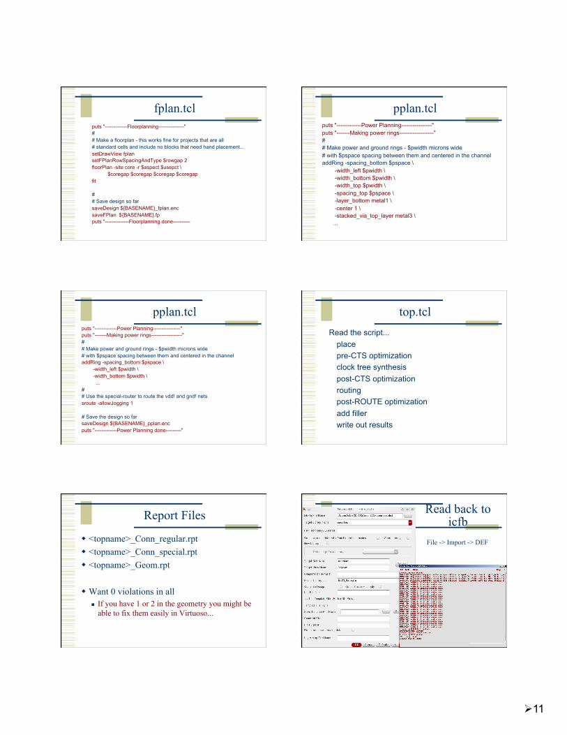
fplan.tcl puts "-------------Floorplanning---------------" # # Make a floorplan - this works fine for projects that are all # standard cells and include no blocks that need hand placement... setDrawView fplan setFPlanRowSpacingAndType $rowgap 2 floorPlan -site core -r $aspect $usepct \ $coregap $coregap $coregap $coregap fit
# # Save design so far saveDesign ${BASENAME}_fplan.enc saveFPlan ${BASENAME}.fp puts "--------------Floorplanning done----------
pplan.tcl puts "-------------Power Planning----------------" puts "-------Making power rings------------------" # # Make power and ground rings - $pwidth microns wide # with $pspace spacing between them and centered in the channel addRing -spacing_bottom $pspace \ -width_left $pwidth \ -width_bottom $pwidth \ -width_top $pwidth \ -spacing_top $pspace \ -layer_bottom metal1 \ -center 1 \ -stacked_via_top_layer metal3 \ ...
pplan.tcl puts "-------------Power Planning----------------" puts "-------Making power rings------------------" # # Make power and ground rings - $pwidth microns wide # with $pspace spacing between them and centered in the channel addRing -spacing_bottom $pspace \ -width_left $pwidth \ -width_bottom $pwidth \ ... # # Use the special-router to route the vdd! and gnd! nets sroute -allowJogging 1
# Save the design so far saveDesign ${BASENAME}_pplan.enc puts "-------------Power Planning done---------"
top.tcl Read the script...
place pre-CTS optimization clock tree synthesis post-CTS optimization routing post-ROUTE optimization add filler write out results
Report Files
<topname>_Conn_regular.rpt <topname>_Conn_special.rpt <topname>_Geom.rpt
Want 0 violations in all If you have 1 or 2 in the geometry you might be
able to fix them easily in Virtuoso...
Read back to icfb
File -> Import -> DEF

12
Change abstract to layout cellviews Edit -> Search
DRC, Extract
Import Verilog
File -> Import -> Verilog
LVS...
Schematic view LVS Result
Yay!
Summary
Behavioral -> Structural -> Layout Can be automated by scripting, but make
sure you know what you’re doing on-line tutorials for TCL
Google “tcl tutorial”
Synopsys documentation for design_compiler encounter.cmd (and documentation) for EDI
End up with placed and routed core layout or BLOCK for later use...
Related Documents