A.R. Hurson 323 CS Building Database Systems ER Model

Welcome message from author
This document is posted to help you gain knowledge. Please leave a comment to let me know what you think about it! Share it to your friends and learn new things together.
Transcript

A.R. Hurson323 CS Building
Database SystemsER Model

Database DesignData model is a group of concepts that helps to
specify the structure of a database and a set ofassociated operations allowing data retrievaland data manipulation.
Database Systems
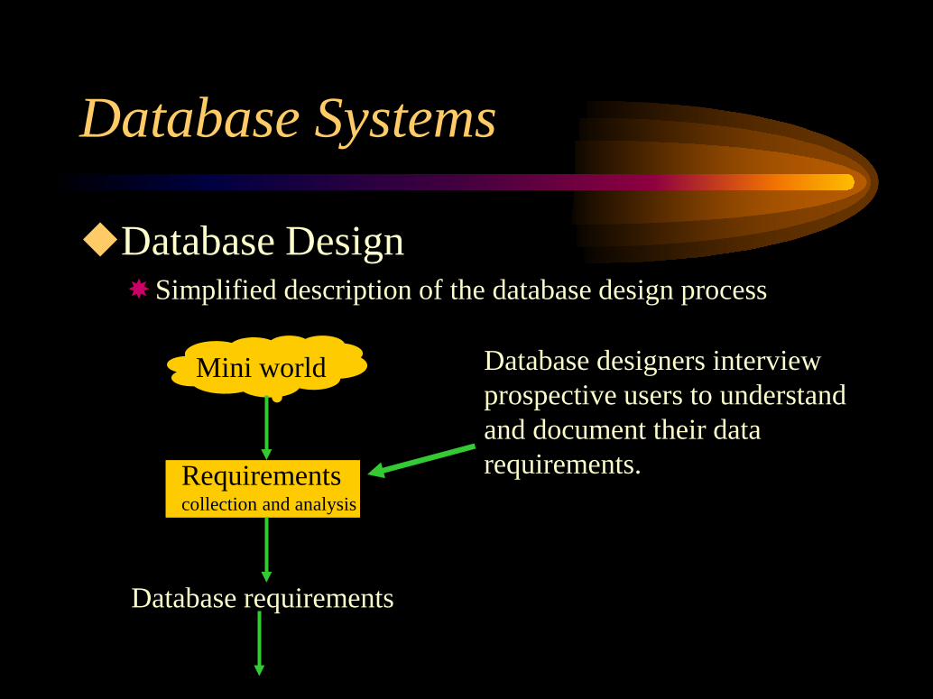
Database DesignSimplified description of the database design process
Mini world
Requirementscollection and analysis
Database requirements
Database designers interview prospective users to understand and document their data requirements.
Database Systems

Database DesignSimplified description of the database design process
Conceptual design
Conceptual Schema
Data Model MappingDBMS Specific
DBMS Independent
A high level conceptual datamodel to capture database requirementsCaptures concise
description of the datarequirements, includingdata type, constraints, and operations
Database Systems

Database DesignSimplified description of the database design process
Data Model MappingDBMS Specific
DBMS Independent
Conceptual Schemain the specific data model
Physical design
Internal design
Actual implementation
Database Systems

Database Design — An exampleThe database keeps track of Employees,
Departments, and Projects.After the requirements collection and analysis,
database designers came up with the followingdescription:The company is organized into departments. Each
department has a name, a number, and a manager. Weneed to keep track of starting data of the manager,managing a department. A department may be in severallocations.
Database Systems

Database Design — An exampleA department controls several projects, each
project is identified by a name, a number, and asingle location.Each employee is represented by a name, SSN,
an address, sex, and birth date. An employee isassigned to a department, he/she may beworking on several projects which are notnecessarily controlled by the same department.Direct supervisor of each employee and thenumber of hours he/she working on a project isalso recorded.
Database Systems

Database Design — An exampleAn employee’s dependent (s) is (are) needed to
be recorded — name, sex, birth date, andrelationship.
Database Systems

Entity Relationship (ER) modelThe Entity Relationship (ER) model is a
high level conceptual data model.The ER model allows us to represent the
data description in a graphical format. Thisgraphical format, will go through severalrefinements. Then we need to considerperformance issues and design of logicalschema.
Database Systems

In ER model data is defined as entities,relationships, and attributes.
Database Systems

Entity Relationship (ER) modelAn entity is the basic object in an ER model.
An entity is a ‘thing’ in the real world — anentity could physically exist (like a person)or could conceptually exist (like a job).An entity has some properties, attributes,
that describe it. Each attribute will assumeits value from a domain.
Database Systems

e1
Name = John Smith
Home Phone = 814 123 4567
Address = 2311 Kirby, State College, PA 16801
Age = 35
Database Systems
An entity and its attributes
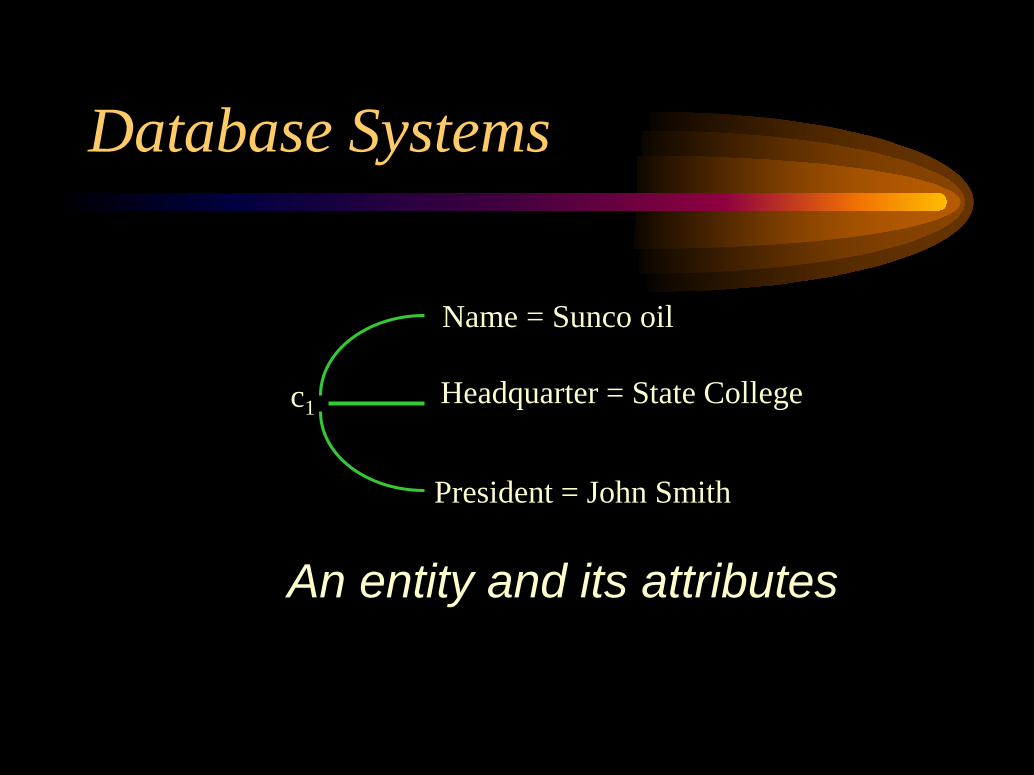
c1
President = John Smith
Name = Sunco oil
Headquarter = State College
Database Systems
An entity and its attributes

Entity Relationship (ER) modelAn attribute can be a composite attribute
(like an address) or a single (atomic)attribute (like age). A composite attributecan form a hierarchical structure based on aset of composite or atomic attributes.
Database Systems

Address
Street Address
Number Street Apartment Number
City State Zip code
Database Systems

Entity Relationship (ER) modelAn attribute can be of single-valued, multi-
valued, derived, or complex type.Component of a composite attributes are
grouped within ( ) and multi-valued attributeis represented by {}.
Database Systems

Entity Relationship (ER) model
This example shows an entity (person) whohas multiple houses and each house hasmultiple phones.
Database Systems
{Address_phone ( {Phone (Area_code, Phone_number) },Address (Street_address (Number, Street, Appartment_number), City, State, Zip_code)

Database Systems
Entity Relationship (ER) modelA set of entities that have the same attributes
are called an entity type. Each entity type isrepresented by a name and a list of attributes— these two are called entity type schema.Collection of entities of a particular entity
type is called an entity set or entitycollection.

SCHEMA(intension)
INSTANCES(extension)
EmployeeName, Age, Salary
CompanyName, Headquarter, President
e1 •John Smith, 55, 80K
e2 •Fred Brown, 40, 30K
e3 •Judy Clark, 25, 35K
•••
c1 •Sunco oil, State College, John Smith
c2 •Microsoft, Seattle, Bill Gates
•••
Database Systems

In ER model:An entity type is represented as a rectangular box,An attribute is represented as an oval attached to its
entity type,Composite attribute is attached to its components,Multi-value attribute is represented as a double
ovals.
Database Systems

Entity Relationship (ER) model — an exampleInitial Conceptual Design: Based on the
requirements listed before and our definitions, wewill define four entity types:An entity type DEPARTMENT with attributes;
Name, Number, Location, Manager, ManagerStartDateHere Location is multi-valued and attributes Name andNumber are the keys.
Database Systems

Entity Relationship (ER) model — an exampleAn entity type PROJECT with attributes;
Name, Number, Location, ControllingDepartmentHere Name and Number are the keys.
An entity type EMPLOYEE with attributes;Name (FName, MInit, LName), SSN, Sex, Address,Salary, BithDate, Department, Supervisor, {WorksOn(Project, Hours)}Here both Name and Address are composite attributesand WorksOn is Multi-valued.
Database Systems

Entity Relationship (ER) model — an example
An entity type DEPENDENT with attributes;Employee, DependentName, Sex, BirthDate,
Relationship
Note that in addition to the attribute values ofentities that belong to those entity types, we arealso interested in relationships among theentities.
Database Systems

Entity Relationship (ER) modelIn addition to the attribute values of the
entities that belongs to the entity types, inER model we are also interested inrelationships among the entities. Arelationship is an association between two ormore entities.A set of similar relationships can be
collected together to form a relationship set.
Database Systems

Entity Relationship (ER) modelA relationship can be thought of as a set of n-
tuples:{(e1, e2, …,en) | e1∈E1, e2∈E2,…, en∈En}
where ei is an entity and Ei is an entity set.Note, several relationship sets may involve the
same entity sets.
Database Systems

Entity Relationship (ER) modelA relationship of type R among n entity
types E1, E2 , …, En is a set of associationsamong entities from these types.Formally, R is a set of relationship instances
ri, where each ri associates n individualentities (e1, e2, …,en), and each entity ej in riis a member of entity type Ej, 1 ≤ j ≤ n.
Database Systems

Entity Relationship (ER) modelEach of the entity type Ej is said to participate
in the relationship type R, and similarly eachindividual entities e1, e2, …,en is said toparticipate in the relationship instance ri = (e1,e2, …,en).In ER diagrams, relationship types are
displayed as diamond-shape boxes, connectedby straight lines to the rectangular boxesrepresenting the participating entity types.
Database Systems

e1•e2 •e3 •e4 •e5 •
•••
• d1• d2• d3
•••
r2
r3
r5
r4
r1
A binary relationship type
WORKS-FOREMPLOYEE DEPARTMENT
Database Systems

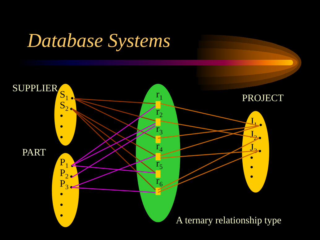
Entity Relationship (ER) modelDegree of a Relationship Type — The
degree of a relationship type is the number ofparticipating entity types.A relationship type of degree two is called
binary and of degree three is called ternary.In general, a ternary relationship type
represents more information than threebinary relationship types.
Database Systems
S1 •S2 ••••
P1 •P2 •P3 ••••
r1
r3
r2
r4
r5
r6
J1 •
J2 •J3 ••••
A ternary relationship type
PROJECTSUPPLIER
PART
Database Systems

Entity Relationship (ER) modelRole names and recursive relationships —
the role name signifies the role that aparticipating entity from the entity type playsin each relationship instance. For example,in the WORKS-FOR relationship type,EMPLOYEE plays the role of the workerand DEPARTMENT plays the role ofemployer.
Database Systems

Entity Relationship (ER) modelIn some instances the same entity type
participates more than once in a relationshiptype in different roles. Such a relationshiptype is called recursive relationship type.
Database Systems

r2
r3
r5
r4
r1
r6
e1 •e2 •e3 •e4 •e5 •e6 •e7 ••••
12
122
2
2
2 1
1
EMPLOYEE SUPERVISOR1 shows the supervisor role2 shows the supervisee role
e1 is the supervisor of e2,e3e4 is the supervisor of e6,e7e5 is the supervisor of e4,e1
Database Systems

Constraints on Relationship typesCertain conditions (constraints) limit the possible
contributions of entries participating in relationshipinstances. These constraints are determined by theunderlying ‘mini-world’.As an example, assume that an employee works
just for a department. This constraint should bereflected in the schema. In the following, severaltypes of relationship constraints that occursrelatively very frequently are discussed.
Database Systems

Constraints on Relationship typesCardinality ratio in a binary relationship
specifies the number of relationshipinstances that an entity instance canparticipate in. The possible cardinality ratiosare: 1:1, 1:N, and M:N.In graphical representation of ER model,
cardinality ratios are displayed as 1, M, N onthe diamonds.
Database Systems

Constraints on Relationship typesParticipation Constraints and Existence
Dependencies specifies whether the existence of anentity depends on its being related to another entityvia a relationship type.There are two types of participation constraints:TotalPartial
Database Systems
Constraints on Relationship typesTotal Participation Constraints — If a company
policy states that every employee must work for adepartment, then an employee entity can exist onlyif it participates in a WORKS-FOR relationshipinstance.Total participation (Existence dependency) means
that every entity in ‘the total set’ of employeeentities must be related to a department entity viaWORKS-FOR.
Database Systems

Constraints on Relationship typesOn the other hand, we do not expect that every
employee be a manager. So the participation ofEMPLOYEE in the MANAGES relationshiptype is partial — meaning that some or ‘part of’employee entities are related to a departmententity via MANAGES, but not necessarily all.In ER diagram, total and partial participation
are represented by double line and single line,respectively.
Database Systems

Constraints on Relationship typesKey Constraint: The restriction that each
department has at most one manager is anexample of a key constraint.Key constraint implies that each department
entity appears in at most one MANAGESrelationship in any allowable instance ofMANAGES.
Database Systems

Constraints on Relationship typesKey constraint is represented by an arrow from
the entity type to the relationship type in an ERdiagram — intuitively, the arrow indicates thatgiven a Department entity, we can uniquelydetermine the MANAGES relationship in whichit appears.
Database Systems

Attributes of relationship typesRelationship types can also have attributes,
similar to those of entity types.Note, attributes of 1:1 or 1:N relationship types
can be migrated to one of the participatingentity types. For 1:N relationship type, arelationship attribute can be migrated only tothe entity type at the N-side of the relationship.
Database Systems

Constraints on Relationship typesWeak entity type are those entity types that do not have
key attributes of their own. In contrast, regular entitytypes are called strong entity types.
Entities belonging to a weak entity type are identifiedby being related to specific entities from another entitytype (identifying or owner entity type) in combinationwith some of their attribute values.
Database Systems

Constraints on Relationship typesA weak entity type normally has a partial key
— a set of attributed that can uniquely identifyweak entities within the same owner entity.In ER diagram, both a weak entity type and its
identifying relationship type are distinguishedby double line boxes and diagrams. The partialkey attribute is underlined with a dashed ordotted line.
Database Systems

ER Design for the COMPANY Database.Recall from our earlier discussion, the
COMPANY database was defined as:
Database Systems

An entity type DEPARTMENT with attributes;Name, Number, Location, Manager, ManagerStartDate
An entity type PROJECT with attributes;Name, Number, Location, ControllingDepartment
An entity type EMPLOYEE with attributes;Name (FName, MInit, LName), SSN, Sex, Address,Salary, BithDate, Department, Supervisor, {WorksOn(Projecr, Hours)}An entity type DEPENDENT with attributes;
Employee, DependentName, Sex, BirthDate,Relationship
Database Systems

The design of this database, now can be refinedby:Changing the attributes that represent relationships
into relationship types.Defining the cardinality ratio and participation
constraints.Removing the redundant attributes.
Database Systems

Consequently we will have the followingrelationship types:MANAGES, a 1:1 relationship type between
EMPLOYEE and DEPARTMENT. Where,– EMPLOYEE participation is partial– DEPARTMENT participation is not clear, after revisiting
the users, a conclusion was made that a department musthave a manager which implies a total participation.
– Finally, the attribute StartDate is assigned to thisrelationship type.
Database Systems

WORKS-FOR, a 1:N relationship type betweenDEPARTMENT and EMPLOYEE. Bothparticipations are total.CONTROLS, a 1:N relationship type between
DEPARTMENT and PROJECT. Participation ofPROJECT is total.SUPERVISION, a 1:N relationship type between
EMPLOYEE and EMPLOYEE. Both participationsare determined to be partial — not every employeeis a supervisor and not every employee has asupervisor.
Database Systems

WORKS-ON, an M:N relationship type withattribute Hours — a PROJECT can have severalemployees working on it.DEPENDENT-OF, a 1:N relationship type between
EMPLOYEE and DEPENDENT, it is also theidentifying relationship for the weak entity typeDEPENDENT. Participation of EMPLOYEE ispartial, whereas that of DEPENDENT is total.

Now, redundant attributes must be removed.This includes:Manager and ManagerStartDate from
DEPARTMENT,ControllingDepartment from PROJECT,Department, Supervisor, and WORKS-ON from
EMPLOYEE, andEmployee from DEPENDENT.
Database Systems
Note that it is important to have the leastamount of redundancy when we design theconceptual schema. If some redundancy isdesired, at the storage level or at the user viewlevel, it will be introduced later.
Database Systems
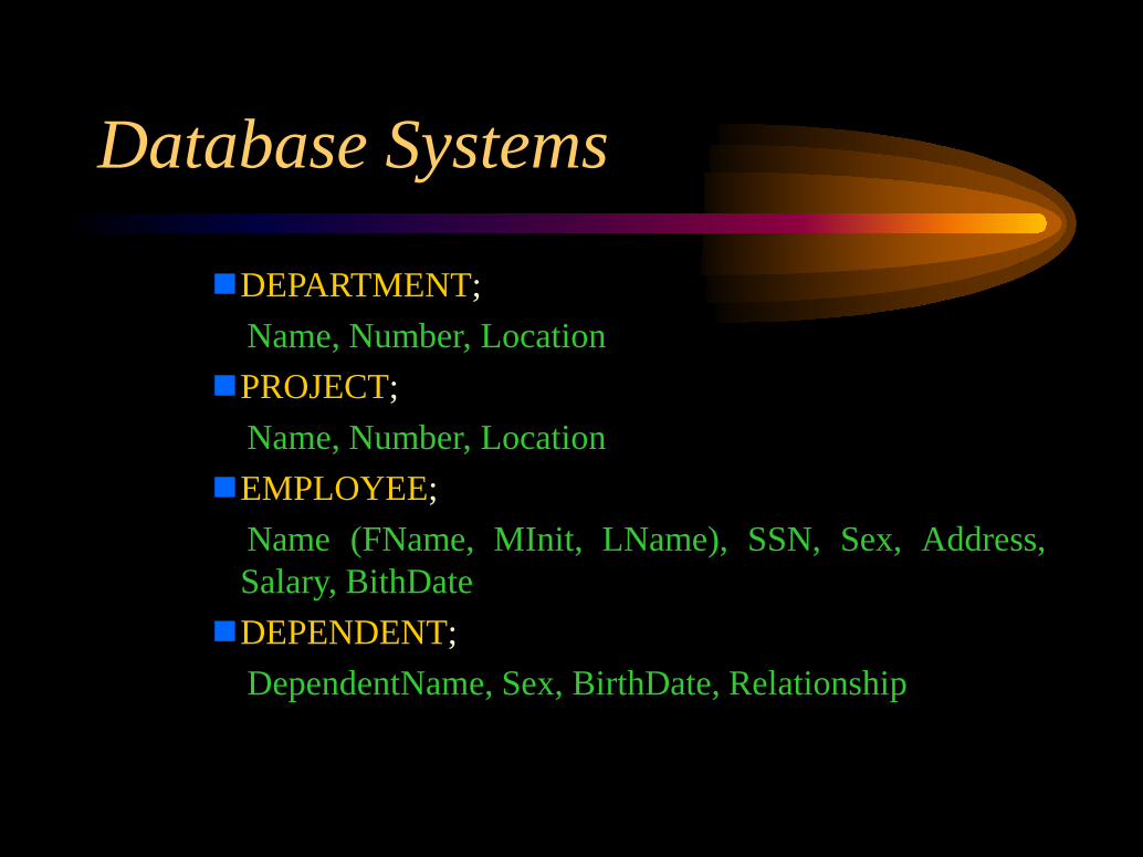
DEPARTMENT;Name, Number, Location
PROJECT;Name, Number, Location
EMPLOYEE;Name (FName, MInit, LName), SSN, Sex, Address,Salary, BithDateDEPENDENT;
DependentName, Sex, BirthDate, Relationship
Database Systems

ER model notations
Entity type Weak Entity type
Relationship type IdentifyingRelationship type
Attribute Key Attribute
Database Systems

ER model notations
Multi-valued Attribute
Composite Attribute
Derived Attribute
Database Systems

ER model notations
E1E2R Total representation of E2
in R
E1E2R
1N Cardinality ratio 1: N for
E1: E2 in R
ER(min, max)
Structural constraint (min,max)on participation of E in R
Database Systems

Relationship types of degree higher than twoIn general, a relationship type R of degree n
will have n edges in an ER diagram, oneconnecting R to each participating entity type.
Database Systems

PART
SUPPLYSUPPLIER PROJECT
SName Quantity ProjName
PartNo
Database Systems

The following diagram shows three binaryrelationship types. However, though closelyrelated, it is not semantically equivalent to theprevious ternary relationship type.
Database Systems

PART
SUPPLYSUPPLIER PROJECT
SName Quantity ProjName
PartNo USES
CAN-SUPPLY
M
N
M
M N
N
Database Systems

COURSE
OFFERSINSTRUCTOR SEMESTER
INname
Semester Year
CNumberCAN-TEACH
OFFERED-DURING
TAUGHT-DURING
Sem-Year
Database Systems

Refer to the previous example, a relationshipinstance (i, s, c) should not exist in OFFERSunless an instance (i, s) exists in TAUGHT-DURING, an instance (s, c) exists inOFFERED-DURING, and an instance (i, c)exists in CAN-TEACH. However, the reverse isnot always true.
Database Systems
Related Documents


