1 OMRON Corporation CS/CJ Series HOST Link Driver 1 System Configuration ....................................................................................................... 3 2 Selection of External Device .......................................................................................... 13 3 Example of Communication Setting ............................................................................... 14 4 Setup Items .................................................................................................................... 52 5 Cable Diagram ............................................................................................................... 57 6 Supported Device......................................................................................................... 105 7 Device Code and Address Code .................................................................................. 110 8 Error Messages ............................................................................................................ 112

Welcome message from author
This document is posted to help you gain knowledge. Please leave a comment to let me know what you think about it! Share it to your friends and learn new things together.
Transcript

1
OMRON Corporation
CS/CJ Series HOST Link Driver
1 System Configuration....................................................................................................... 3
2 Selection of External Device .......................................................................................... 13
3 Example of Communication Setting ............................................................................... 14
4 Setup Items .................................................................................................................... 52
5 Cable Diagram ............................................................................................................... 57
6 Supported Device......................................................................................................... 105
7 Device Code and Address Code.................................................................................. 110
8 Error Messages............................................................................................................ 112
CS/CJ Series HOST Link Driver
GP-Pro EX Device/PLC Connection Manual 2
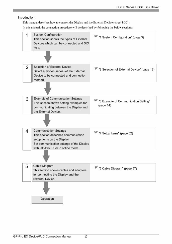
Introduction
This manual describes how to connect the Display and the External Device (target PLC).
In this manual, the connection procedure will be described by following the below sections:
1 System Configuration
This section shows the types of External
Devices which can be connected and SIO
type.
"1 System Configuration" (page 3)
2 Selection of External Device
Select a model (series) of the External
Device to be connected and connection
method.
"2 Selection of External Device" (page 13)
3 Example of Communication Settings
This section shows setting examples for
communicating between the Display and
the External Device.
"3 Example of Communication Setting" (page 14)
4 Communication Settings
This section describes communication
setup items on the Display.
Set communication settings of the Display
with GP-Pro EX or in offline mode.
"4 Setup Items" (page 52)
5 Cable Diagram
This section shows cables and adapters
for connecting the Display and the
External Device.
"5 Cable Diagram" (page 57)
Operation
CS/CJ Series HOST Link Driver
GP-Pro EX Device/PLC Connection Manual 3
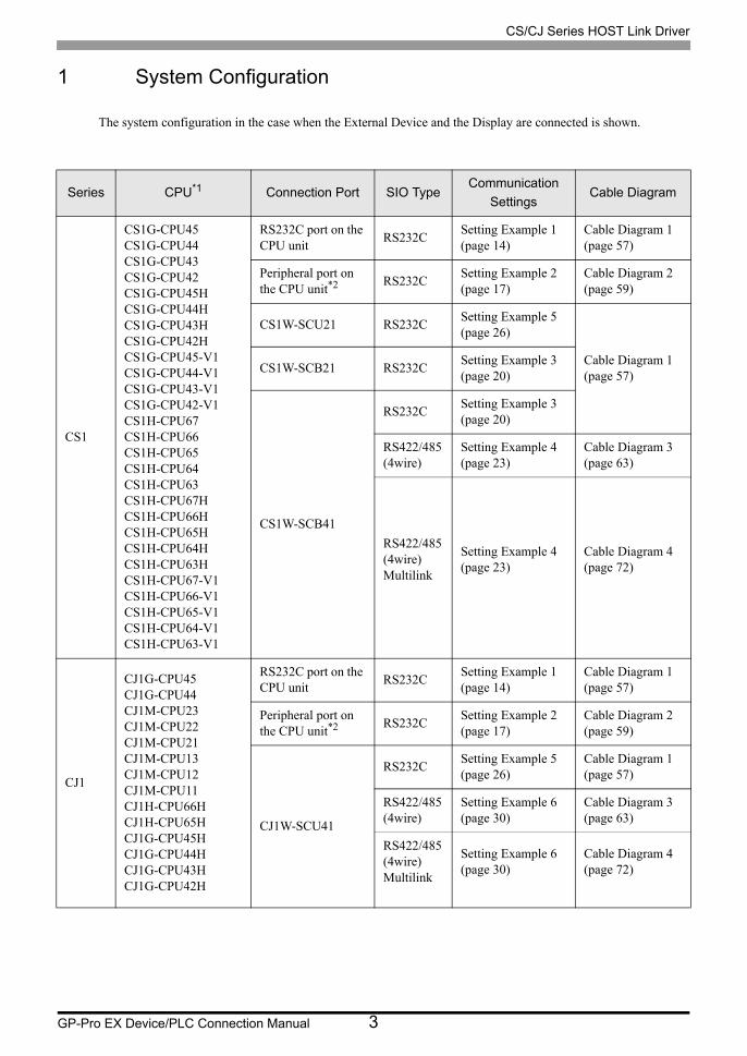
1 System Configuration
The system configuration in the case when the External Device and the Display are connected is shown.
Series CPU*1 Connection Port SIO TypeCommunication
SettingsCable Diagram
CS1
CS1G-CPU45CS1G-CPU44CS1G-CPU43CS1G-CPU42CS1G-CPU45HCS1G-CPU44HCS1G-CPU43HCS1G-CPU42HCS1G-CPU45-V1CS1G-CPU44-V1CS1G-CPU43-V1CS1G-CPU42-V1CS1H-CPU67CS1H-CPU66CS1H-CPU65CS1H-CPU64CS1H-CPU63CS1H-CPU67HCS1H-CPU66HCS1H-CPU65HCS1H-CPU64HCS1H-CPU63HCS1H-CPU67-V1CS1H-CPU66-V1CS1H-CPU65-V1CS1H-CPU64-V1CS1H-CPU63-V1
RS232C port on the CPU unit
RS232CSetting Example 1 (page 14)
Cable Diagram 1 (page 57)
Peripheral port on the CPU unit*2 RS232C
Setting Example 2 (page 17)
Cable Diagram 2 (page 59)
CS1W-SCU21 RS232CSetting Example 5 (page 26)
Cable Diagram 1 (page 57)
CS1W-SCB21 RS232CSetting Example 3 (page 20)
CS1W-SCB41
RS232CSetting Example 3 (page 20)
RS422/485(4wire)
Setting Example 4 (page 23)
Cable Diagram 3 (page 63)
RS422/485(4wire)Multilink
Setting Example 4 (page 23)
Cable Diagram 4 (page 72)
CJ1
CJ1G-CPU45CJ1G-CPU44CJ1M-CPU23CJ1M-CPU22CJ1M-CPU21CJ1M-CPU13CJ1M-CPU12CJ1M-CPU11CJ1H-CPU66HCJ1H-CPU65HCJ1G-CPU45HCJ1G-CPU44HCJ1G-CPU43HCJ1G-CPU42H
RS232C port on the CPU unit
RS232CSetting Example 1 (page 14)
Cable Diagram 1 (page 57)
Peripheral port on the CPU unit*2 RS232C
Setting Example 2 (page 17)
Cable Diagram 2 (page 59)
CJ1W-SCU41
RS232CSetting Example 5 (page 26)
Cable Diagram 1 (page 57)
RS422/485(4wire)
Setting Example 6 (page 30)
Cable Diagram 3 (page 63)
RS422/485(4wire)Multilink
Setting Example 6 (page 30)
Cable Diagram 4 (page 72)

CS/CJ Series HOST Link Driver
GP-Pro EX Device/PLC Connection Manual 4
CJ2
CJ2H-CPU68-EIPCJ2H-CPU67-EIPCJ2H-CPU66-EIPCJ2H-CPU65-EIPCJ2H-CPU64-EIP
RS232C serial port on the CPU unit
RS-232CSetting Example 11 (page 46) Cable Diagram 1
(page 57)CJ1W-SCU21CJ1W-SCU21-V1
RS-232CSetting Example 5 (page 26)
CJ1W-SCU31-V1
RS422/485(4wire)
Setting Example 6 (page 30)
Cable Diagram 3 (page 63)
RS422/485(4wire)Multilink
Setting Example 6 (page 30)
Cable Diagram 4 (page 72)
CJ1W-SCU41CJ1W-SCU41-V1
RS-232CSetting Example 5 (page 26)
Cable Diagram 1 (page 57)
RS422/485(4wire)
Setting Example 6 (page 30)
Cable Diagram 3 (page 63)
RS422/485(4wire)Multilink
Setting Example 6 (page 30)
Cable Diagram 4 (page 72)
CJ2H-CPU68CJ2H-CPU67CJ2H-CPU66CJ2H-CPU65CJ2H-CPU64CJ2M-CPU15CJ2M-CPU14CJ2M-CPU13CJ2M-CPU12CJ2M-CPU11
RS232C serial port on the CPU unit
RS-232CSetting Example 11 (page 46)
Cable Diagram 1 (page 57)
CJ1W-SCU21-V1 RS-232CSetting Example 5 (page 26)
Cable Diagram 1 (page 57)
CJ1W-SCU31-V1
RS422/485(4wire)
Setting Example 6 (page 30)
Cable Diagram 3 (page 63)
RS422/485(4wire)Multilink-
Setting Example 6 (page 30)
Cable Diagram 4 (page 72)
CJ1W-SCU41-V1
RS-232CSetting Example 5 (page 26)
Cable Diagram 1 (page 57)
RS422/485(4wire)
Setting Example 6 (page 30)
Cable Diagram 3 (page 63)
RS422/485(4wire)Multilink
Setting Example 6 (page 30)
Cable Diagram 4 (page 72)
Series CPU*1 Connection Port SIO TypeCommunication
SettingsCable Diagram
CS/CJ Series HOST Link Driver
GP-Pro EX Device/PLC Connection Manual 5
CJ2
CJ2M-CPU35CJ2M-CPU34CJ2M-CPU33CJ2M-CPU32CJ2M-CPU31
CJ1W-SCU21-V1 RS-232CSetting Example 5 (page 26)
Cable Diagram 1 (page 57)
CJ1W-SCU31-V1
RS422/485(4wire)
Setting Example 6 (page 30)
Cable Diagram 3 (page 63)
RS422/485(4wire)Multilink
Setting Example 6 (page 30)
Cable Diagram 4 (page 72)
CJ1W-SCU41-V1
RS-232CSetting Example 5 (page 26)
Cable Diagram 1 (page 57)
RS422/485(4wire)
Setting Example 6 (page 30)
Cable Diagram 3 (page 63)
RS422/485(4wire)Multilink
Setting Example 6 (page 30)
Cable Diagram 4 (page 72)
Series CPU*1 Connection Port SIO TypeCommunication
SettingsCable Diagram
CS/CJ Series HOST Link Driver
GP-Pro EX Device/PLC Connection Manual 6
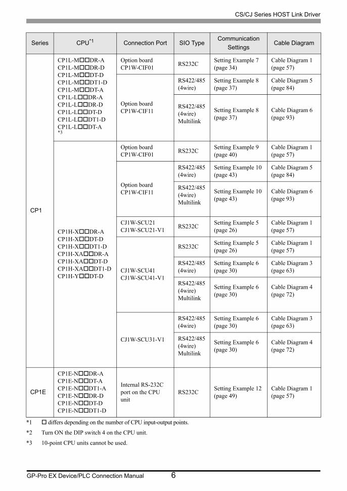
CP1
CP1L-MDR-ACP1L-MDR-DCP1L-MDT-DCP1L-MDT1-DCP1L-MDT-ACP1L-LDR-ACP1L-LDR-DCP1L-LDT-DCP1L-LDT1-DCP1L-LDT-A*3
Option boardCP1W-CIF01
RS232CSetting Example 7 (page 34)
Cable Diagram 1 (page 57)
Option boardCP1W-CIF11
RS422/485(4wire)
Setting Example 8 (page 37)
Cable Diagram 5 (page 84)
RS422/485(4wire)Multilink
Setting Example 8 (page 37)
Cable Diagram 6 (page 93)
CP1H-XDR-ACP1H-XDT-DCP1H-XDT1-DCP1H-XADR-ACP1H-XADT-DCP1H-XADT1-DCP1H-YDT-D
Option boardCP1W-CIF01
RS232CSetting Example 9 (page 40)
Cable Diagram 1 (page 57)
Option boardCP1W-CIF11
RS422/485(4wire)
Setting Example 10 (page 43)
Cable Diagram 5 (page 84)
RS422/485(4wire)Multilink
Setting Example 10 (page 43)
Cable Diagram 6 (page 93)
CJ1W-SCU21CJ1W-SCU21-V1
RS232CSetting Example 5 (page 26)
Cable Diagram 1 (page 57)
CJ1W-SCU41CJ1W-SCU41-V1
RS232CSetting Example 5 (page 26)
Cable Diagram 1 (page 57)
RS422/485(4wire)
Setting Example 6 (page 30)
Cable Diagram 3 (page 63)
RS422/485(4wire)Multilink
Setting Example 6 (page 30)
Cable Diagram 4 (page 72)
CJ1W-SCU31-V1
RS422/485(4wire)
Setting Example 6 (page 30)
Cable Diagram 3 (page 63)
RS422/485(4wire)Multilink
Setting Example 6 (page 30)
Cable Diagram 4 (page 72)
CP1E
CP1E-NDR-ACP1E-NDT-ACP1E-NDT1-ACP1E-NDR-DCP1E-NDT-DCP1E-NDT1-D
Internal RS-232C port on the CPU unit
RS232CSetting Example 12 (page 49)
Cable Diagram 1 (page 57)
*1 differs depending on the number of CPU input-output points.
*2 Turn ON the DIP switch 4 on the CPU unit.
*3 10-point CPU units cannot be used.
Series CPU*1 Connection Port SIO TypeCommunication
SettingsCable Diagram

CS/CJ Series HOST Link Driver
GP-Pro EX Device/PLC Connection Manual 7
• When the time of GP4000 series is automatically updated in [Clock Update Settings] of GP-Pro
EX, there are some restrictions as shown below.
For details on [Clock Update Settings], refer to GP-Pro EX Reference Manual.
•CP1L, CP1E and CJ2H does not support automatic update of the time. Specify [Customize] in
[Clock Update Settings].

CS/CJ Series HOST Link Driver
GP-Pro EX Device/PLC Connection Manual 8
Connection Configuration
• 1:1 Connection
• 1:n Connection
• Access beyond network
You can access beyond maximum 3 levels of network.
• n:1 Connection (Multilink connection)
• The maximum number of connectable Displays is 16 units. However, keeping performance in
consideration, the number of Displays that can be substantially used is up to 4.
CS/CJ Series HOST Link Driver
GP-Pro EX Device/PLC Connection Manual 9
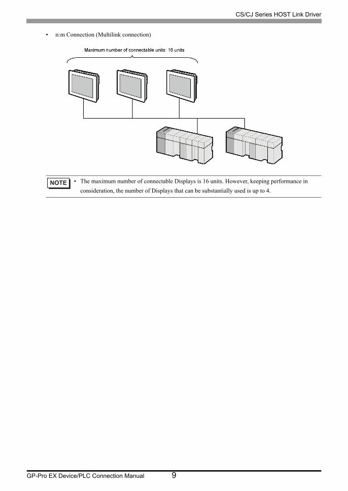
• n:m Connection (Multilink connection)
• The maximum number of connectable Displays is 16 units. However, keeping performance in
consideration, the number of Displays that can be substantially used is up to 4.
CS/CJ Series HOST Link Driver
GP-Pro EX Device/PLC Connection Manual 10
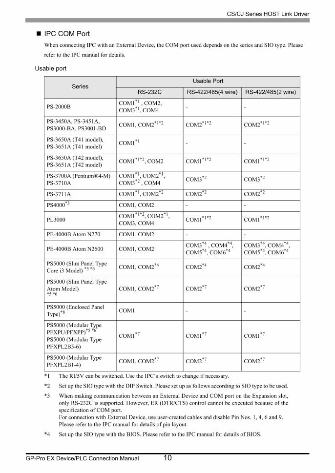
IPC COM Port
When connecting IPC with an External Device, the COM port used depends on the series and SIO type. Please
refer to the IPC manual for details.
Usable port
SeriesUsable Port
RS-232C RS-422/485(4 wire) RS-422/485(2 wire)
PS-2000BCOM1*1 , COM2, COM3*1, COM4
*1 The RI/5V can be switched. Use the IPC’s switch to change if necessary.
- -
PS-3450A, PS-3451A,PS3000-BA, PS3001-BD
COM1, COM2*1*2 COM2*1*2 COM2*1*2
PS-3650A (T41 model),PS-3651A (T41 model)
COM1*1 - -
PS-3650A (T42 model),PS-3651A (T42 model)
COM1*1*2, COM2 COM1*1*2 COM1*1*2
PS-3700A (Pentium®4-M)PS-3710A
COM1*1, COM2*1, COM3*2 , COM4
*2 Set up the SIO type with the DIP Switch. Please set up as follows according to SIO type to be used.
COM3*2 COM3*2
PS-3711A COM1*1, COM2*2 COM2*2 COM2*2
PS4000*3
*3 When making communication between an External Device and COM port on the Expansion slot, only RS-232C is supported. However, ER (DTR/CTS) control cannot be executed because of the specification of COM port.For connection with External Device, use user-created cables and disable Pin Nos. 1, 4, 6 and 9.Please refer to the IPC manual for details of pin layout.
COM1, COM2 - -
PL3000COM1*1*2, COM2*1, COM3, COM4
COM1*1*2 COM1*1*2
PE-4000B Atom N270 COM1, COM2 - -
PE-4000B Atom N2600 COM1, COM2COM3*4 , COM4*4, COM5*4, COM6*4
*4 Set up the SIO type with the BIOS. Please refer to the IPC manual for details of BIOS.
COM3*4, COM4*4, COM5*4, COM6*4
PS5000 (Slim Panel Type Core i3 Model) *5 *6 COM1, COM2*4 COM2*4 COM2*4
PS5000 (Slim Panel Type Atom Model) *5 *6
COM1, COM2*7 COM2*7 COM2*7
PS5000 (Enclosed Panel Type)*8 COM1 - -
PS5000 (Modular Type PFXPU/PFXPP)*5 *6
PS5000 (Modular Type PFXPL2B5-6)
COM1*7 COM1*7 COM1*7
PS5000 (Modular Type PFXPL2B1-4)
COM1, COM2*7 COM2*7 COM2*7
CS/CJ Series HOST Link Driver
GP-Pro EX Device/PLC Connection Manual 11
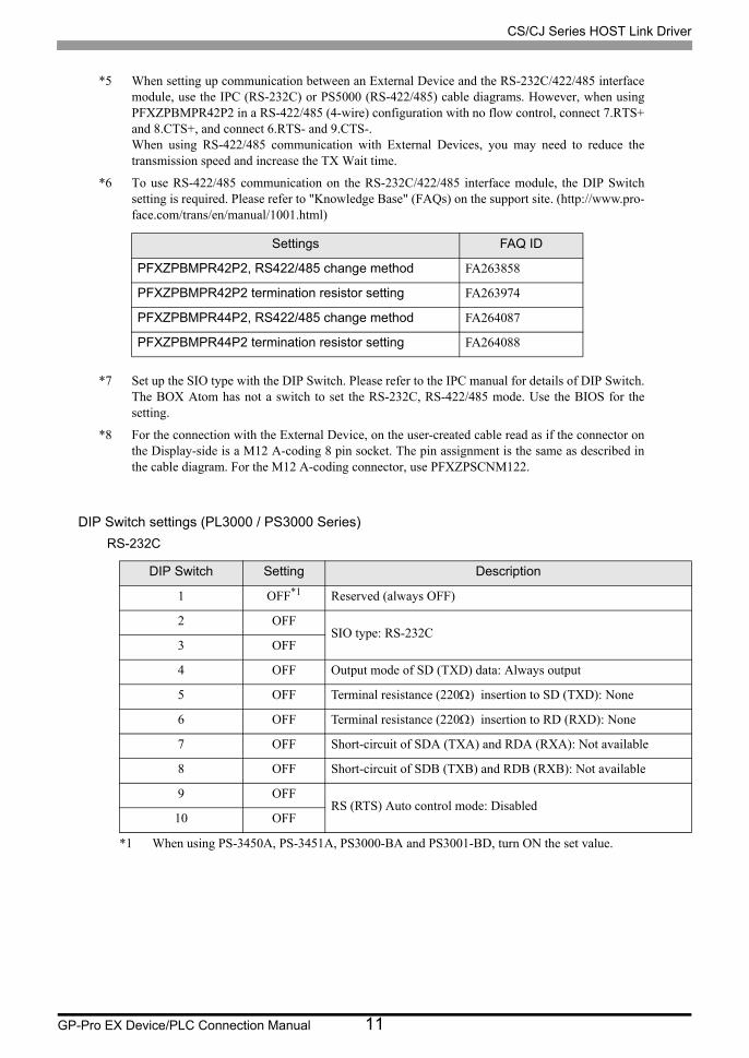
DIP Switch settings (PL3000 / PS3000 Series)
RS-232C
*5 When setting up communication between an External Device and the RS-232C/422/485 interface module, use the IPC (RS-232C) or PS5000 (RS-422/485) cable diagrams. However, when using PFXZPBMPR42P2 in a RS-422/485 (4-wire) configuration with no flow control, connect 7.RTS+ and 8.CTS+, and connect 6.RTS- and 9.CTS-.When using RS-422/485 communication with External Devices, you may need to reduce the transmission speed and increase the TX Wait time.
*6 To use RS-422/485 communication on the RS-232C/422/485 interface module, the DIP Switch setting is required. Please refer to "Knowledge Base" (FAQs) on the support site. (http://www.pro- face.com/trans/en/manual/1001.html)
*7 Set up the SIO type with the DIP Switch. Please refer to the IPC manual for details of DIP Switch.The BOX Atom has not a switch to set the RS-232C, RS-422/485 mode. Use the BIOS for the setting.
*8 For the connection with the External Device, on the user-created cable read as if the connector on the Display-side is a M12 A-coding 8 pin socket. The pin assignment is the same as described in the cable diagram. For the M12 A-coding connector, use PFXZPSCNM122.
DIP Switch Setting Description
1 OFF*1
*1 When using PS-3450A, PS-3451A, PS3000-BA and PS3001-BD, turn ON the set value.
Reserved (always OFF)
2 OFFSIO type: RS-232C
3 OFF
4 OFF Output mode of SD (TXD) data: Always output
5 OFF Terminal resistance (220) insertion to SD (TXD): None
6 OFF Terminal resistance (220) insertion to RD (RXD): None
7 OFF Short-circuit of SDA (TXA) and RDA (RXA): Not available
8 OFF Short-circuit of SDB (TXB) and RDB (RXB): Not available
9 OFFRS (RTS) Auto control mode: Disabled
10 OFF
Settings FAQ ID
PFXZPBMPR42P2, RS422/485 change method FA263858
PFXZPBMPR42P2 termination resistor setting FA263974
PFXZPBMPR44P2, RS422/485 change method FA264087
PFXZPBMPR44P2 termination resistor setting FA264088
CS/CJ Series HOST Link Driver
GP-Pro EX Device/PLC Connection Manual 12
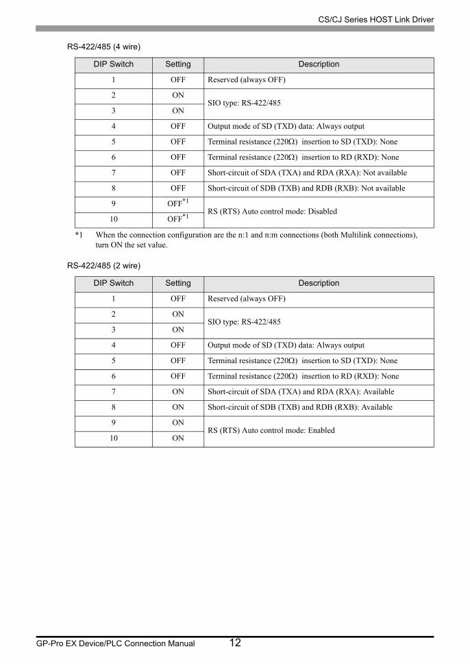
RS-422/485 (4 wire)
RS-422/485 (2 wire)
DIP Switch Setting Description
1 OFF Reserved (always OFF)
2 ONSIO type: RS-422/485
3 ON
4 OFF Output mode of SD (TXD) data: Always output
5 OFF Terminal resistance (220) insertion to SD (TXD): None
6 OFF Terminal resistance (220) insertion to RD (RXD): None
7 OFF Short-circuit of SDA (TXA) and RDA (RXA): Not available
8 OFF Short-circuit of SDB (TXB) and RDB (RXB): Not available
9 OFF*1
*1 When the connection configuration are the n:1 and n:m connections (both Multilink connections), turn ON the set value.
RS (RTS) Auto control mode: Disabled10 OFF*1
DIP Switch Setting Description
1 OFF Reserved (always OFF)
2 ONSIO type: RS-422/485
3 ON
4 OFF Output mode of SD (TXD) data: Always output
5 OFF Terminal resistance (220) insertion to SD (TXD): None
6 OFF Terminal resistance (220) insertion to RD (RXD): None
7 ON Short-circuit of SDA (TXA) and RDA (RXA): Available
8 ON Short-circuit of SDB (TXB) and RDB (RXB): Available
9 ONRS (RTS) Auto control mode: Enabled
10 ON
CS/CJ Series HOST Link Driver
GP-Pro EX Device/PLC Connection Manual 13
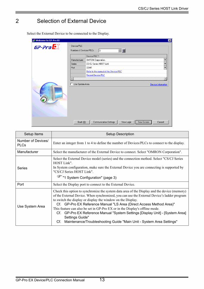
2 Selection of External Device
Select the External Device to be connected to the Display.
Setup Items Setup Description
Number of Devices/PLCs
Enter an integer from 1 to 4 to define the number of Devices/PLCs to connect to the display.
Manufacturer Select the manufacturer of the External Device to connect. Select "OMRON Corporation".
Series
Select the External Device model (series) and the connection method. Select "CS/CJ Series HOST Link".In System configuration, make sure the External Device you are connecting is supported by "CS/CJ Series HOST Link".
"1 System Configuration" (page 3)
Port Select the Display port to connect to the External Device.
Use System Area
Check this option to synchronize the system data area of the Display and the device (memory) of the External Device. When synchronized, you can use the External Device’s ladder program to switch the display or display the window on the Display.
Cf. GP-Pro EX Reference Manual "LS Area (Direct Access Method Area)"This feature can also be set in GP-Pro EX or in the Display's offline mode.
Cf. GP-Pro EX Reference Manual "System Settings [Display Unit] - [System Area] Settings Guide"
Cf. Maintenance/Troubleshooting Guide "Main Unit - System Area Settings"
CS/CJ Series HOST Link Driver
GP-Pro EX Device/PLC Connection Manual 14
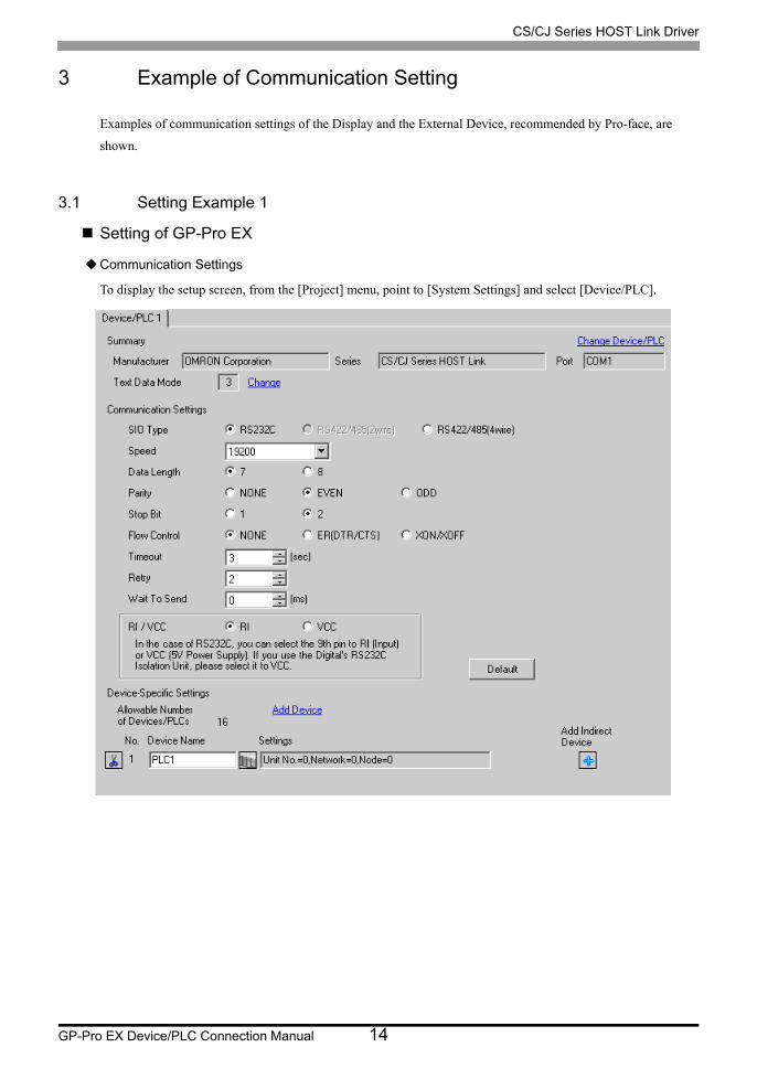
3 Example of Communication Setting
Examples of communication settings of the Display and the External Device, recommended by Pro-face, are
shown.
3.1 Setting Example 1
Setting of GP-Pro EX
Communication Settings
To display the setup screen, from the [Project] menu, point to [System Settings] and select [Device/PLC].
CS/CJ Series HOST Link Driver
GP-Pro EX Device/PLC Connection Manual 15
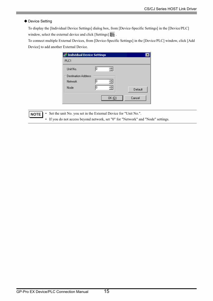
Device Setting
To display the [Individual Device Settings] dialog box, from [Device-Specific Settings] in the [Device/PLC]
window, select the external device and click [Settings] .
To connect multiple External Devices, from [Device-Specific Settings] in the [Device/PLC] window, click [Add
Device] to add another External Device.
• Set the unit No. you set in the External Device for "Unit No.".
• If you do not access beyond network, set "0" for "Network" and "Node" settings.

CS/CJ Series HOST Link Driver
GP-Pro EX Device/PLC Connection Manual 16
Setting of External Device
Click the [HOST Link Port] tab from the [PLC Settings] of the ladder software for the communication settings of
the HOST link port (RS232C port on CPU) and set as below.
Notes
• Do not set the duplicate node address in the same network address group.
Setup Items Settings
Speed 19200
Parameter 7,2,E
Mode HOST link
DIP Switch*1
*1 Use the DIP switch on the front of the unit for setting.
SW1: OFFSW5: OFFSW7: OFFSW8: OFF
Unit No. Option
Source Network Address*2
*2 Parameter used when you access beyond network. Set in the routing table of "CX-Net Network Configuration". Please refer to the manual of the External Device for more details.
Option
Node Address Setting Rotary Switch*3
*3 Parameter used when you access beyond network. Set with the rotary switch on the front of the Controller Link unit used for access beyond network.
Option

CS/CJ Series HOST Link Driver
GP-Pro EX Device/PLC Connection Manual 17
3.2 Setting Example 2
Setting of GP-Pro EX
Communication Settings
To display the setup screen, from the [Project] menu, point to [System Settings] and select [Device/PLC].

CS/CJ Series HOST Link Driver
GP-Pro EX Device/PLC Connection Manual 18
Device Setting
To display the [Individual Device Settings] dialog box, from [Device-Specific Settings] in the [Device/PLC]
window, select the external device and click [Settings] .
To connect multiple External Devices, from [Device-Specific Settings] in the [Device/PLC] window, click [Add
Device] to add another External Device.
• Set the unit No. you set in the External Device for "Unit No.".
• If you do not access beyond network, set "0" for "Network" and "Node" settings.
CS/CJ Series HOST Link Driver
GP-Pro EX Device/PLC Connection Manual 19
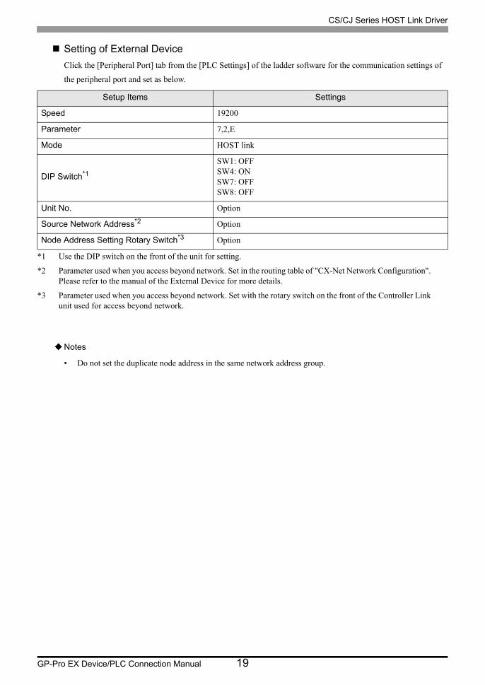
Setting of External Device
Click the [Peripheral Port] tab from the [PLC Settings] of the ladder software for the communication settings of
the peripheral port and set as below.
Notes
• Do not set the duplicate node address in the same network address group.
Setup Items Settings
Speed 19200
Parameter 7,2,E
Mode HOST link
DIP Switch*1
*1 Use the DIP switch on the front of the unit for setting.
SW1: OFFSW4: ONSW7: OFFSW8: OFF
Unit No. Option
Source Network Address*2
*2 Parameter used when you access beyond network. Set in the routing table of "CX-Net Network Configuration". Please refer to the manual of the External Device for more details.
Option
Node Address Setting Rotary Switch*3
*3 Parameter used when you access beyond network. Set with the rotary switch on the front of the Controller Link unit used for access beyond network.
Option

CS/CJ Series HOST Link Driver
GP-Pro EX Device/PLC Connection Manual 20
3.3 Setting Example 3
Setting of GP-Pro EX
Communication Settings
To display the setup screen, from the [Project] menu, point to [System Settings] and select [Device/PLC].

CS/CJ Series HOST Link Driver
GP-Pro EX Device/PLC Connection Manual 21
Device Setting
To display the [Individual Device Settings] dialog box, from [Device-Specific Settings] in the [Device/PLC]
window, select the external device and click [Settings] .
To connect multiple External Devices, from [Device-Specific Settings] in the [Device/PLC] window, click [Add
Device] to add another External Device.
• Set the unit No. you set in the External Device for "Unit No.".
• If you do not access beyond network, set "0" for "Network" and "Node" settings.
CS/CJ Series HOST Link Driver
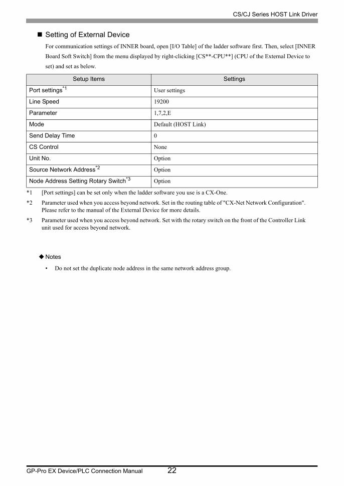
GP-Pro EX Device/PLC Connection Manual 22
Setting of External Device
For communication settings of INNER board, open [I/O Table] of the ladder software first. Then, select [INNER
Board Soft Switch] from the menu displayed by right-clicking [CS**-CPU**] (CPU of the External Device to
set) and set as below.
Notes
• Do not set the duplicate node address in the same network address group.
Setup Items Settings
Port settings*1
*1 [Port settings] can be set only when the ladder software you use is a CX-One.
User settings
Line Speed 19200
Parameter 1,7,2,E
Mode Default (HOST Link)
Send Delay Time 0
CS Control None
Unit No. Option
Source Network Address*2
*2 Parameter used when you access beyond network. Set in the routing table of "CX-Net Network Configuration". Please refer to the manual of the External Device for more details.
Option
Node Address Setting Rotary Switch*3
*3 Parameter used when you access beyond network. Set with the rotary switch on the front of the Controller Link unit used for access beyond network.
Option
CS/CJ Series HOST Link Driver
GP-Pro EX Device/PLC Connection Manual 23
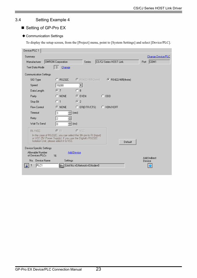
3.4 Setting Example 4
Setting of GP-Pro EX
Communication Settings
To display the setup screen, from the [Project] menu, point to [System Settings] and select [Device/PLC].

CS/CJ Series HOST Link Driver
GP-Pro EX Device/PLC Connection Manual 24
Device Setting
To display the [Individual Device Settings] dialog box, from [Device-Specific Settings] in the [Device/PLC]
window, select the external device and click [Settings] .
To connect multiple External Devices, from [Device-Specific Settings] in the [Device/PLC] window, click [Add
Device] to add another External Device.
• Set the unit No. you set in the External Device for "Unit No.".
• If you do not access beyond network, set "0" for "Network" and "Node" settings.
CS/CJ Series HOST Link Driver
GP-Pro EX Device/PLC Connection Manual 25
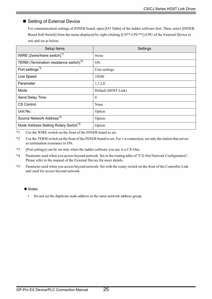
Setting of External Device
For communication settings of INNER board, open [I/O Table] of the ladder software first. Then, select [INNER
Board Soft Switch] from the menu displayed by right-clicking [CS**-CPU**] (CPU of the External Device to
set) and set as below.
Notes
• Do not set the duplicate node address in the same network address group.
Setup Items Settings
WIRE (2wire/4wire switch)*1
*1 Use the WIRE switch on the front of the INNER board to set.
4wire
TERM (Termination resistance switch)*2
*2 Use the TERM switch on the front of the INNER board to set. For 1:n connection, set only the station that serves as termination resistance to ON.
ON
Port settings*3
*3 [Port settings] can be set only when the ladder software you use is a CX-One.
User settings
Line Speed 19200
Parameter 1,7,2,E
Mode Default (HOST Link)
Send Delay Time 0
CS Control None
Unit No. Option
Source Network Address*4
*4 Parameter used when you access beyond network. Set in the routing table of "CX-Net Network Configuration". Please refer to the manual of the External Device for more details.
Option
Node Address Setting Rotary Switch*5
*5 Parameter used when you access beyond network. Set with the rotary switch on the front of the Controller Link unit used for access beyond network.
Option

CS/CJ Series HOST Link Driver
GP-Pro EX Device/PLC Connection Manual 26
3.5 Setting Example 5
Setting of GP-Pro EX
Communication Settings
To display the setup screen, from the [Project] menu, point to [System Settings] and select [Device/PLC].

CS/CJ Series HOST Link Driver
GP-Pro EX Device/PLC Connection Manual 27
Device Setting
To display the [Individual Device Settings] dialog box, from [Device-Specific Settings] in the [Device/PLC]
window, select the external device and click [Settings] .
To connect multiple External Devices, from [Device-Specific Settings] in the [Device/PLC] window, click [Add
Device] to add another External Device.
• Set the unit No. you set in the External Device for "Unit No.".
• If you do not access beyond network, set "0" for "Network" and "Node" settings.
CS/CJ Series HOST Link Driver
GP-Pro EX Device/PLC Connection Manual 28
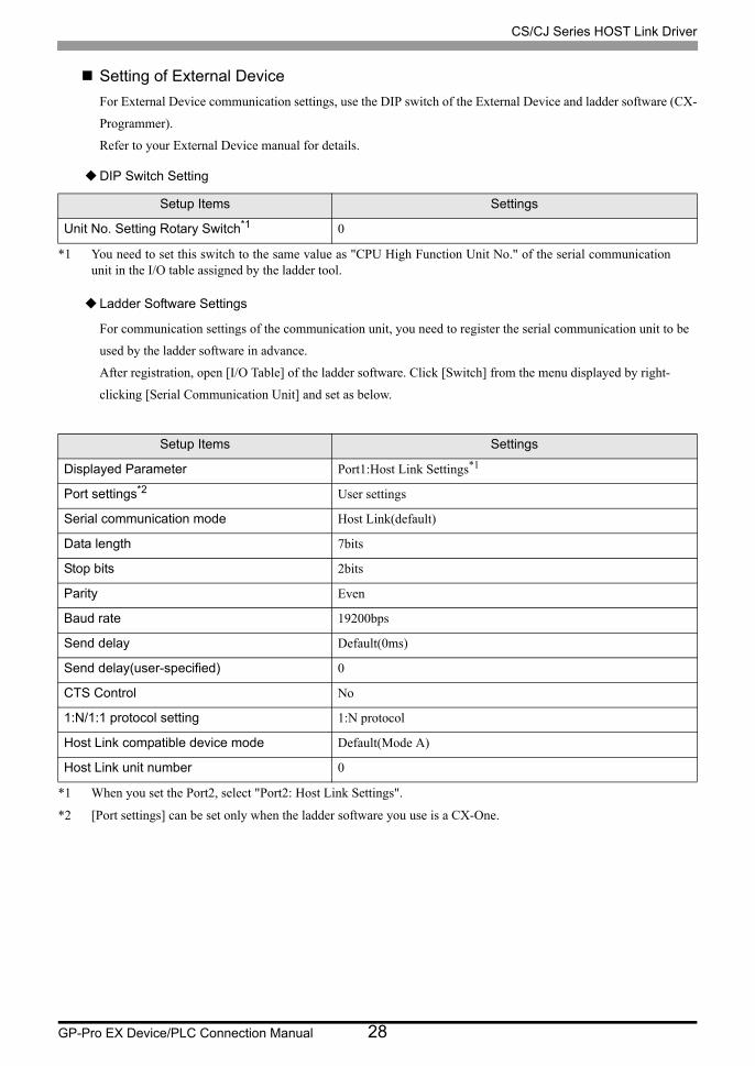
Setting of External Device
For External Device communication settings, use the DIP switch of the External Device and ladder software (CX-
Programmer).
Refer to your External Device manual for details.
DIP Switch Setting
Ladder Software Settings
For communication settings of the communication unit, you need to register the serial communication unit to be
used by the ladder software in advance.
After registration, open [I/O Table] of the ladder software. Click [Switch] from the menu displayed by right-
clicking [Serial Communication Unit] and set as below.
Setup Items Settings
Unit No. Setting Rotary Switch*1
*1 You need to set this switch to the same value as "CPU High Function Unit No." of the serial communication unit in the I/O table assigned by the ladder tool.
0
Setup Items Settings
Displayed Parameter Port1:Host Link Settings*1
*1 When you set the Port2, select "Port2: Host Link Settings".
Port settings*2
*2 [Port settings] can be set only when the ladder software you use is a CX-One.
User settings
Serial communication mode Host Link(default)
Data length 7bits
Stop bits 2bits
Parity Even
Baud rate 19200bps
Send delay Default(0ms)
Send delay(user-specified) 0
CTS Control No
1:N/1:1 protocol setting 1:N protocol
Host Link compatible device mode Default(Mode A)
Host Link unit number 0
CS/CJ Series HOST Link Driver
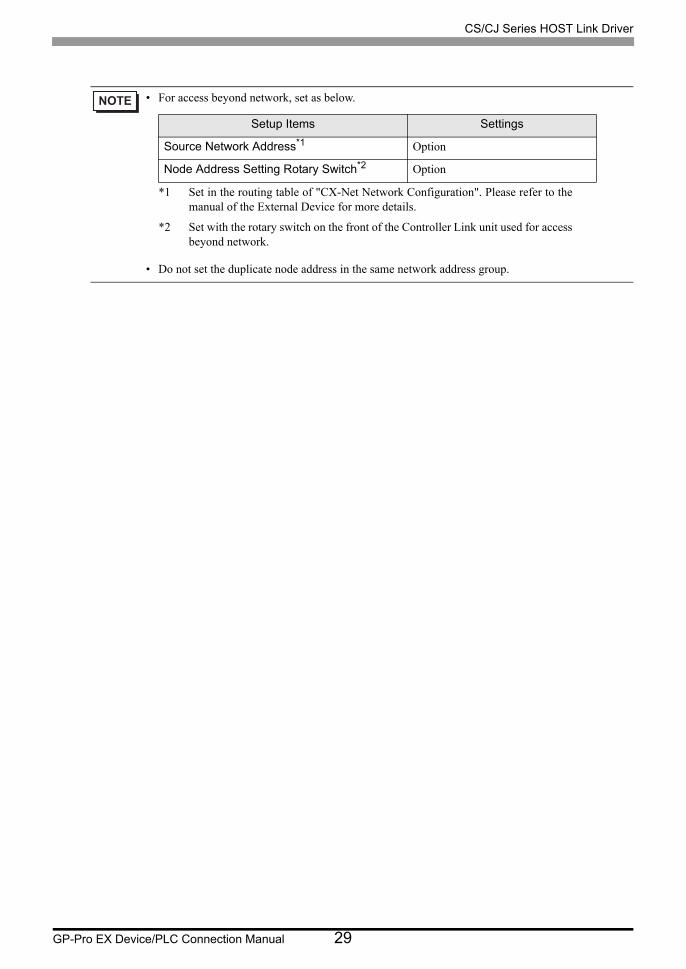
GP-Pro EX Device/PLC Connection Manual 29
• For access beyond network, set as below.
• Do not set the duplicate node address in the same network address group.
Setup Items Settings
Source Network Address*1
*1 Set in the routing table of "CX-Net Network Configuration". Please refer to the manual of the External Device for more details.
Option
Node Address Setting Rotary Switch*2
*2 Set with the rotary switch on the front of the Controller Link unit used for access beyond network.
Option

CS/CJ Series HOST Link Driver
GP-Pro EX Device/PLC Connection Manual 30
3.6 Setting Example 6
Setting of GP-Pro EX
Communication Settings
To display the setup screen, from the [Project] menu, point to [System Settings] and select [Device/PLC].

CS/CJ Series HOST Link Driver
GP-Pro EX Device/PLC Connection Manual 31
Device Setting
To display the [Individual Device Settings] dialog box, from [Device-Specific Settings] in the [Device/PLC]
window, select the external device and click [Settings] .
To connect multiple External Devices, from [Device-Specific Settings] in the [Device/PLC] window, click [Add
Device] to add another External Device.
• Set the unit No. you set in the External Device for "Unit No.".
• If you do not access beyond network, set "0" for "Network" and "Node" settings.

CS/CJ Series HOST Link Driver
GP-Pro EX Device/PLC Connection Manual 32
Setting of External Device
For External Device communication settings, use the DIP switch of the front of the Serial Communication unit
and ladder software (CX-Programmer).
Refer to your External Device manual for details.
DIP Switch Setting
Ladder Software Settings
For communication settings of the communication unit, you need to register the serial communication unit to be
used by the ladder software in advance.
After registration, open [I/O Table] of the ladder software. Click [Switch] from the menu displayed by right-
clicking [Serial Communication Unit] and set as below.
Setup Items Settings
Unit No. Setting Rotary Switch*1
*1 You need to set this switch to the same value as "CPU High Function Unit No." of the serial communication unit in the I/O table assigned by the ladder tool.
0
WIRE (2wire/4wire switch) 4wire
TERM (Termination resistance switch)*2
*2 For 1:n connection, set only the station that serves as termination resistance to ON.
ON
Setup Items Settings
Displayed Parameter Port1:Host Link Settings*1
*1 When you set the Port2, select "Port2: Host Link Settings".
Port settings*2
*2 [Port settings] can be set only when the ladder software you use is a CX-One.
User settings
Serial communication mode Host Link(default)
Data length 7bits
Stop bits 2bits
Parity Even
Baud rate 19200bps
Send delay Default(0ms)
Send delay(user-specified) 0
CTS Control No
1:N/1:1 protocol setting 1:N protocol
Host Link compatible device mode Default(Mode A)
Host Link unit number 0

CS/CJ Series HOST Link Driver
GP-Pro EX Device/PLC Connection Manual 33
• For access beyond network, set as below.
• Do not set the duplicate node address in the same network address group.
Setup Items Settings
Source Network Address*1
*1 Set in the routing table of "CX-Net Network Configuration". Please refer to the manual of the External Device for more details.
Option
Node Address Setting Rotary Switch*2
*2 Set with the rotary switch on the front of the Controller Link unit used for access beyond network.
Option
CS/CJ Series HOST Link Driver
GP-Pro EX Device/PLC Connection Manual 34
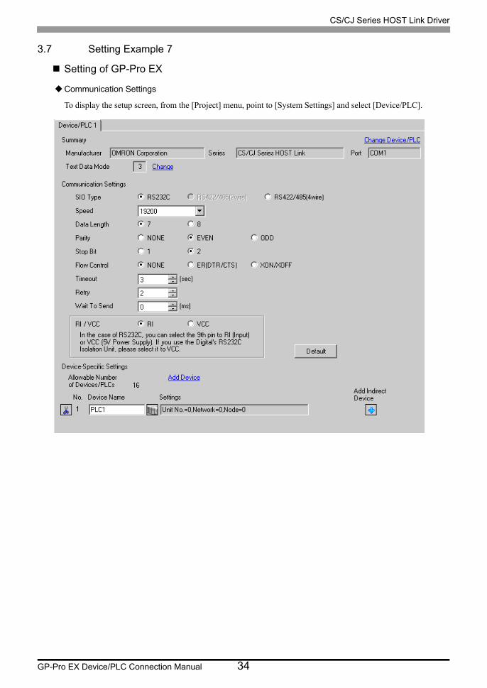
3.7 Setting Example 7
Setting of GP-Pro EX
Communication Settings
To display the setup screen, from the [Project] menu, point to [System Settings] and select [Device/PLC].

CS/CJ Series HOST Link Driver
GP-Pro EX Device/PLC Connection Manual 35
Device Setting
To display the [Individual Device Settings] dialog box, from [Device-Specific Settings] in the [Device/PLC]
window, select the external device and click [Settings] .
To connect multiple External Devices, from [Device-Specific Settings] in the [Device/PLC] window, click [Add
Device] to add another External Device.
• Set the unit No. you set in the External Device for "Unit No.".
• If you do not access beyond network, set "0" for "Network" and "Node" settings.

CS/CJ Series HOST Link Driver
GP-Pro EX Device/PLC Connection Manual 36
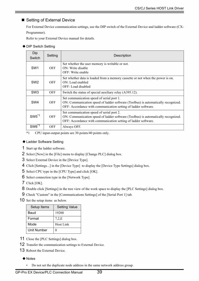
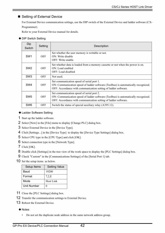
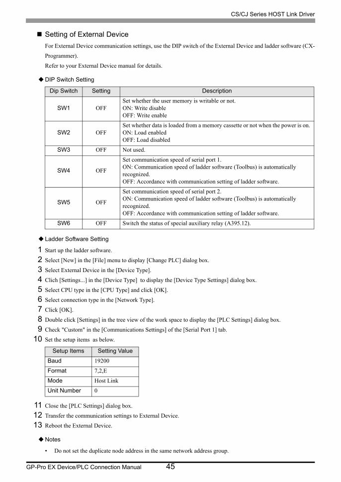
Setting of External Device
For External Device communication settings, use the DIP switch of the External Device and ladder software (CX-
Programmer).
Refer to your External Device manual for details.
DIP Switch Setting
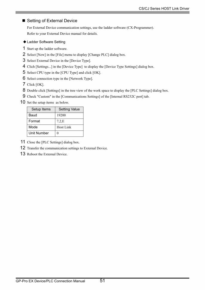
Ladder Software Setting
1 Start up the ladder software.
2 Select [New] in the [File] menu to display [Change PLC] dialog box.
3 Select External Device in the [Device Type].
4 Clich [Settings...] in the [Device Type] to display the [Device Type Settings] dialog box.
5 Select CPU type in the [CPU Type] and click [OK].
6 Select connection type in the [Network Type].
7 Click [OK].
8 Double click [Settings] in the tree view of the work space to display the [PLC Settings] dialog box.
9 Check "Custom" in the [Communications Settings] of the [Serial Port 1] tab.
10 Set the setup items as below.
11 Close the [PLC Settings] dialog box.
12 Transfer the communication settings to External Device.
13 Reboot the External Device.
Notes
• Do not set the duplicate node address in the same network address group.
Dip
SwitchSetting Description
SW1 OFFSet whether the user memory is writable or not.ON: Write disableOFF: Write enable
SW2 OFFSet whether data is loaded from a memory cassette or not when the power is on. ON: Load enabledOFF: Load disabled
SW3 OFF Switch the status of special auxiliary relay (A395.12).
SW4 OFFSet communication speed of serial port 1.ON: Communication speed of ladder software (Toolbus) is automatically recognized.OFF: Accordance with communication setting of ladder software.
SW5*1
*1 CPU input-output points are 30 points/40 points only.
OFFSet communication speed of serial port 2.ON: Communication speed of ladder software (Toolbus) is automatically recognized.OFF: Accordance with communication setting of ladder software.
SW6*1 OFF Always OFF.
Setup Items Setting Value
Baud 19200
Format 7,2,E
Mode Host Link
Unit Number 0
CS/CJ Series HOST Link Driver
GP-Pro EX Device/PLC Connection Manual 37
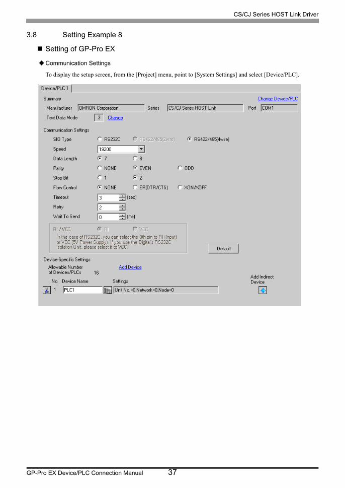
3.8 Setting Example 8
Setting of GP-Pro EX
Communication Settings
To display the setup screen, from the [Project] menu, point to [System Settings] and select [Device/PLC].

CS/CJ Series HOST Link Driver
GP-Pro EX Device/PLC Connection Manual 38
Device Setting
To display the [Individual Device Settings] dialog box, from [Device-Specific Settings] in the [Device/PLC]
window, select the external device and click [Settings] .
To connect multiple External Devices, from [Device-Specific Settings] in the [Device/PLC] window, click [Add
Device] to add another External Device.
• Set the unit No. you set in the External Device for "Unit No.".
• If you do not access beyond network, set "0" for "Network" and "Node" settings.
CS/CJ Series HOST Link Driver
GP-Pro EX Device/PLC Connection Manual 39
Setting of External Device
For External Device communication settings, use the DIP switch of the External Device and ladder software (CX-
Programmer).
Refer to your External Device manual for details.
DIP Switch Setting
Ladder Software Setting
1 Start up the ladder software.
2 Select [New] in the [File] menu to display [Change PLC] dialog box.
3 Select External Device in the [Device Type].
4 Clich [Settings...] in the [Device Type] to display the [Device Type Settings] dialog box.
5 Select CPU type in the [CPU Type] and click [OK].
6 Select connection type in the [Network Type].
7 Click [OK].
8 Double click [Settings] in the tree view of the work space to display the [PLC Settings] dialog box.
9 Check "Custom" in the [Communications Settings] of the [Serial Port 1] tab.
10 Set the setup items as below.
11 Close the [PLC Settings] dialog box.
12 Transfer the communication settings to External Device.
13 Reboot the External Device.
Notes
• Do not set the duplicate node address in the same network address group.
Dip
SwitchSetting Description
SW1 OFFSet whether the user memory is writable or not.ON: Write disableOFF: Write enable
SW2 OFFSet whether data is loaded from a memory cassette or not when the power is on. ON: Load enabledOFF: Load disabled
SW3 OFF Switch the status of special auxiliary relay (A395.12).
SW4 OFFSet communication speed of serial port 1.ON: Communication speed of ladder software (Toolbus) is automatically recognized.OFF: Accordance with communication setting of ladder software.
SW5*1
*1 CPU input-output points are 30 points/40 points only.
OFFSet communication speed of serial port 2.ON: Communication speed of ladder software (Toolbus) is automatically recognized.OFF: Accordance with communication setting of ladder software.
SW6*1 OFF Always OFF.
Setup Items Setting Value
Baud 19200
Format 7,2,E
Mode Host Link
Unit Number 0

CS/CJ Series HOST Link Driver
GP-Pro EX Device/PLC Connection Manual 40
3.9 Setting Example 9
Setting of GP-Pro EX
Communication Settings
To display the setup screen, from the [Project] menu, point to [System Settings] and select [Device/PLC].

CS/CJ Series HOST Link Driver
GP-Pro EX Device/PLC Connection Manual 41
Device Setting
To display the [Individual Device Settings] dialog box, from [Device-Specific Settings] in the [Device/PLC]
window, select the external device and click [Settings] .
To connect multiple External Devices, from [Device-Specific Settings] in the [Device/PLC] window, click [Add
Device] to add another External Device.
• Set the unit No. you set in the External Device for "Unit No.".
• If you do not access beyond network, set "0" for "Network" and "Node" settings.
CS/CJ Series HOST Link Driver
GP-Pro EX Device/PLC Connection Manual 42
Setting of External Device
For External Device communication settings, use the DIP switch of the External Device and ladder software (CX-
Programmer).
Refer to your External Device manual for details.
DIP Switch Setting
Ladder Software Setting
1 Start up the ladder software.
2 Select [New] in the [File] menu to display [Change PLC] dialog box.
3 Select External Device in the [Device Type].
4 Clich [Settings...] in the [Device Type] to display the [Device Type Settings] dialog box.
5 Select CPU type in the [CPU Type] and click [OK].
6 Select connection type in the [Network Type].
7 Click [OK].
8 Double click [Settings] in the tree view of the work space to display the [PLC Settings] dialog box.
9 Check "Custom" in the [Communications Settings] of the [Serial Port 1] tab.
10 Set the setup items as below.
11 Close the [PLC Settings] dialog box.
12 Transfer the communication settings to External Device.
13 Reboot the External Device.
Notes
• Do not set the duplicate node address in the same network address group.
Dip
SwitchSetting Description
SW1 OFFSet whether the user memory is writable or not.ON: Write disableOFF: Write enable
SW2 OFFSet whether data is loaded from a memory cassette or not when the power is on. ON: Load enabledOFF: Load disabled
SW3 OFF Not used.
SW4 OFFSet communication speed of serial port 1.ON: Communication speed of ladder software (Toolbus) is automatically recognized.OFF: Accordance with communication setting of ladder software.
SW5 OFFSet communication speed of serial port 2.ON: Communication speed of ladder software (Toolbus) is automatically recognized.OFF: Accordance with communication setting of ladder software.
SW6 OFF Switch the status of special auxiliary relay (A395.12).
Setup Items Setting Value
Baud 19200
Format 7,2,E
Mode Host Link
Unit Number 0

CS/CJ Series HOST Link Driver
GP-Pro EX Device/PLC Connection Manual 43
3.10 Setting Example 10
Setting of GP-Pro EX
Communication Settings
To display the setup screen, from the [Project] menu, point to [System Settings] and select [Device/PLC].

CS/CJ Series HOST Link Driver
GP-Pro EX Device/PLC Connection Manual 44
Device Setting
To display the [Individual Device Settings] dialog box, from [Device-Specific Settings] in the [Device/PLC]
window, select the external device and click [Settings] .
To connect multiple External Devices, from [Device-Specific Settings] in the [Device/PLC] window, click [Add
Device] to add another External Device.
• Set the unit No. you set in the External Device for "Unit No.".
• If you do not access beyond network, set "0" for "Network" and "Node" settings.
CS/CJ Series HOST Link Driver
GP-Pro EX Device/PLC Connection Manual 45
Setting of External Device
For External Device communication settings, use the DIP switch of the External Device and ladder software (CX-
Programmer).
Refer to your External Device manual for details.
DIP Switch Setting
Ladder Software Setting
1 Start up the ladder software.
2 Select [New] in the [File] menu to display [Change PLC] dialog box.
3 Select External Device in the [Device Type].
4 Clich [Settings...] in the [Device Type] to display the [Device Type Settings] dialog box.
5 Select CPU type in the [CPU Type] and click [OK].
6 Select connection type in the [Network Type].
7 Click [OK].
8 Double click [Settings] in the tree view of the work space to display the [PLC Settings] dialog box.
9 Check "Custom" in the [Communications Settings] of the [Serial Port 1] tab.
10 Set the setup items as below.
11 Close the [PLC Settings] dialog box.
12 Transfer the communication settings to External Device.
13 Reboot the External Device.
Notes
• Do not set the duplicate node address in the same network address group.
Dip Switch Setting Description
SW1 OFFSet whether the user memory is writable or not.ON: Write disableOFF: Write enable
SW2 OFFSet whether data is loaded from a memory cassette or not when the power is on. ON: Load enabledOFF: Load disabled
SW3 OFF Not used.
SW4 OFF
Set communication speed of serial port 1.ON: Communication speed of ladder software (Toolbus) is automatically recognized.OFF: Accordance with communication setting of ladder software.
SW5 OFF
Set communication speed of serial port 2.ON: Communication speed of ladder software (Toolbus) is automatically recognized.OFF: Accordance with communication setting of ladder software.
SW6 OFF Switch the status of special auxiliary relay (A395.12).
Setup Items Setting Value
Baud 19200
Format 7,2,E
Mode Host Link
Unit Number 0
CS/CJ Series HOST Link Driver
GP-Pro EX Device/PLC Connection Manual 46
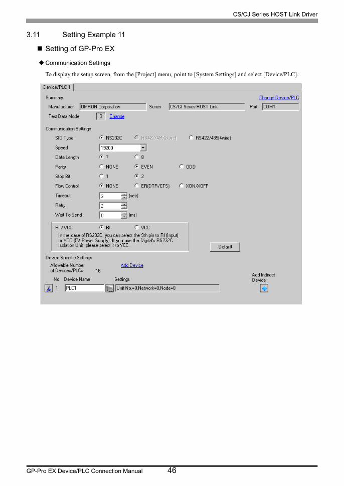
3.11 Setting Example 11
Setting of GP-Pro EX
Communication Settings
To display the setup screen, from the [Project] menu, point to [System Settings] and select [Device/PLC].

CS/CJ Series HOST Link Driver
GP-Pro EX Device/PLC Connection Manual 47
Device Setting
To display the [Individual Device Settings] dialog box, from [Device-Specific Settings] in the [Device/PLC]
window, select the external device and click [Settings] .
To connect multiple External Devices, from [Device-Specific Settings] in the [Device/PLC] window, click [Add
Device] to add another External Device.
• Set the unit No. you set in the External Device for "Unit No.".
• If you do not access beyond network, set "0" for "Network" and "Node" settings.
CS/CJ Series HOST Link Driver
GP-Pro EX Device/PLC Connection Manual 48
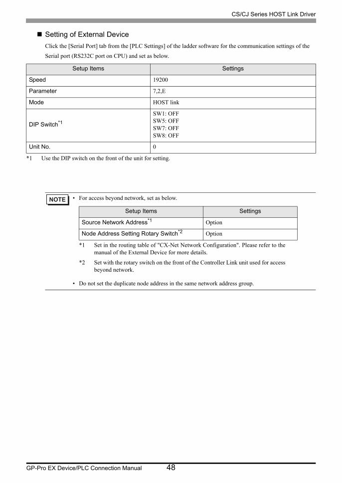
Setting of External Device
Click the [Serial Port] tab from the [PLC Settings] of the ladder software for the communication settings of the
Serial port (RS232C port on CPU) and set as below.
Setup Items Settings
Speed 19200
Parameter 7,2,E
Mode HOST link
DIP Switch*1
*1 Use the DIP switch on the front of the unit for setting.
SW1: OFFSW5: OFFSW7: OFFSW8: OFF
Unit No. 0
• For access beyond network, set as below.
• Do not set the duplicate node address in the same network address group.
Setup Items Settings
Source Network Address*1
*1 Set in the routing table of "CX-Net Network Configuration". Please refer to the manual of the External Device for more details.
Option
Node Address Setting Rotary Switch*2
*2 Set with the rotary switch on the front of the Controller Link unit used for access beyond network.
Option

CS/CJ Series HOST Link Driver
GP-Pro EX Device/PLC Connection Manual 49
3.12 Setting Example 12
Setting of GP-Pro EX
Communication Settings
To display the setup screen, from the [Project] menu, point to [System Settings] and select [Device/PLC].

CS/CJ Series HOST Link Driver
GP-Pro EX Device/PLC Connection Manual 50
Device Setting
To display the [Individual Device Settings] dialog box, from [Device-Specific Settings] in the [Device/PLC]
window, select the external device and click [Settings] .
To connect multiple External Devices, from [Device-Specific Settings] in the [Device/PLC] window, click [Add
Device] to add another External Device.
• Set the unit No. you set in the External Device for "Unit No.".
• If you do not access beyond network, set "0" for "Network" and "Node" settings.
CS/CJ Series HOST Link Driver
GP-Pro EX Device/PLC Connection Manual 51
Setting of External Device
For External Device communication settings, use the ladder software (CX-Programmer).
Refer to your External Device manual for details.
Ladder Software Setting
1 Start up the ladder software.
2 Select [New] in the [File] menu to display [Change PLC] dialog box.
3 Select External Device in the [Device Type].
4 Clich [Settings...] in the [Device Type] to display the [Device Type Settings] dialog box.
5 Select CPU type in the [CPU Type] and click [OK].
6 Select connection type in the [Network Type].
7 Click [OK].
8 Double click [Settings] in the tree view of the work space to display the [PLC Settings] dialog box.
9 Check "Custom" in the [Communications Settings] of the [Internal RS232C port] tab.
10 Set the setup items as below.
11 Close the [PLC Settings] dialog box.
12 Transfer the communication settings to External Device.
13 Reboot the External Device.
Setup Items Setting Value
Baud 19200
Format 7,2,E
Mode Host Link
Unit Number 0
CS/CJ Series HOST Link Driver
GP-Pro EX Device/PLC Connection Manual 52
4 Setup Items
Set communication settings of the Display with GP-Pro EX or in offline mode of the Display.
The setting of each parameter must be identical to that of External Device.
"3 Example of Communication Setting" (page 14)
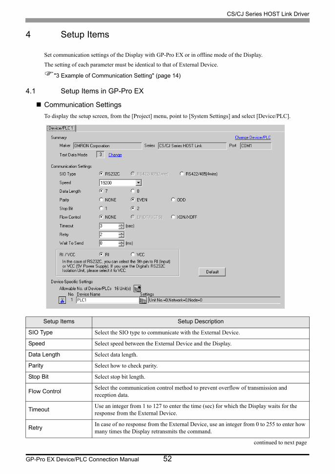
4.1 Setup Items in GP-Pro EX
Communication Settings
To display the setup screen, from the [Project] menu, point to [System Settings] and select [Device/PLC].
Setup Items Setup Description
SIO Type Select the SIO type to communicate with the External Device.
Speed Select speed between the External Device and the Display.
Data Length Select data length.
Parity Select how to check parity.
Stop Bit Select stop bit length.
Flow ControlSelect the communication control method to prevent overflow of transmission and reception data.
TimeoutUse an integer from 1 to 127 to enter the time (sec) for which the Display waits for the response from the External Device.
RetryIn case of no response from the External Device, use an integer from 0 to 255 to enter how many times the Display retransmits the command.
continued to next page
CS/CJ Series HOST Link Driver
GP-Pro EX Device/PLC Connection Manual 53
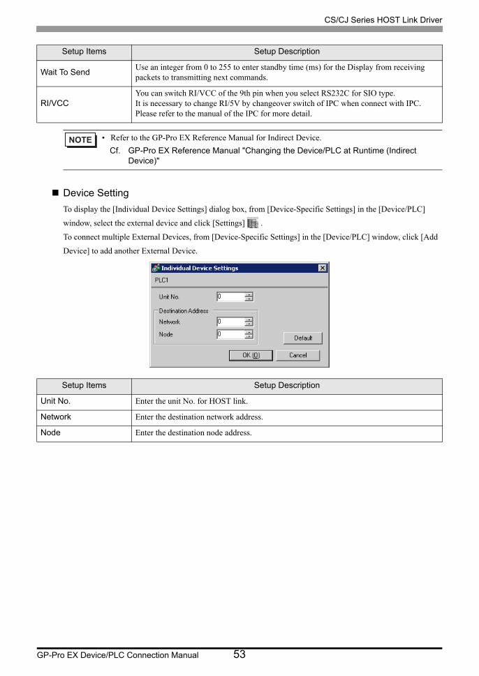
Device Setting
To display the [Individual Device Settings] dialog box, from [Device-Specific Settings] in the [Device/PLC]
window, select the external device and click [Settings] .
To connect multiple External Devices, from [Device-Specific Settings] in the [Device/PLC] window, click [Add
Device] to add another External Device.
Wait To SendUse an integer from 0 to 255 to enter standby time (ms) for the Display from receiving packets to transmitting next commands.
RI/VCCYou can switch RI/VCC of the 9th pin when you select RS232C for SIO type.It is necessary to change RI/5V by changeover switch of IPC when connect with IPC. Please refer to the manual of the IPC for more detail.
• Refer to the GP-Pro EX Reference Manual for Indirect Device.
Cf. GP-Pro EX Reference Manual "Changing the Device/PLC at Runtime (Indirect Device)"
Setup Items Setup Description
Unit No. Enter the unit No. for HOST link.
Network Enter the destination network address.
Node Enter the destination node address.
Setup Items Setup Description
CS/CJ Series HOST Link Driver
GP-Pro EX Device/PLC Connection Manual 54
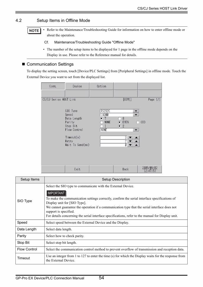
4.2 Setup Items in Offline Mode
Communication Settings
To display the setting screen, touch [Device/PLC Settings] from [Peripheral Settings] in offline mode. Touch the
External Device you want to set from the displayed list.
• Refer to the Maintenance/Troubleshooting Guide for information on how to enter offline mode or
about the operation.
Cf. Maintenance/Troubleshooting Guide "Offline Mode"
• The number of the setup items to be displayed for 1 page in the offline mode depends on the
Display in use. Please refer to the Reference manual for details.
Setup Items Setup Description
SIO Type
Select the SIO type to communicate with the External Device.
To make the communication settings correctly, confirm the serial interface specifications of Display unit for [SIO Type].We cannot guarantee the operation if a communication type that the serial interface does not support is specified.For details concerning the serial interface specifications, refer to the manual for Display unit.
Speed Select speed between the External Device and the Display.
Data Length Select data length.
Parity Select how to check parity.
Stop Bit Select stop bit length.
Flow Control Select the communication control method to prevent overflow of transmission and reception data.
TimeoutUse an integer from 1 to 127 to enter the time (s) for which the Display waits for the response from the External Device.
CS/CJ Series HOST Link Driver
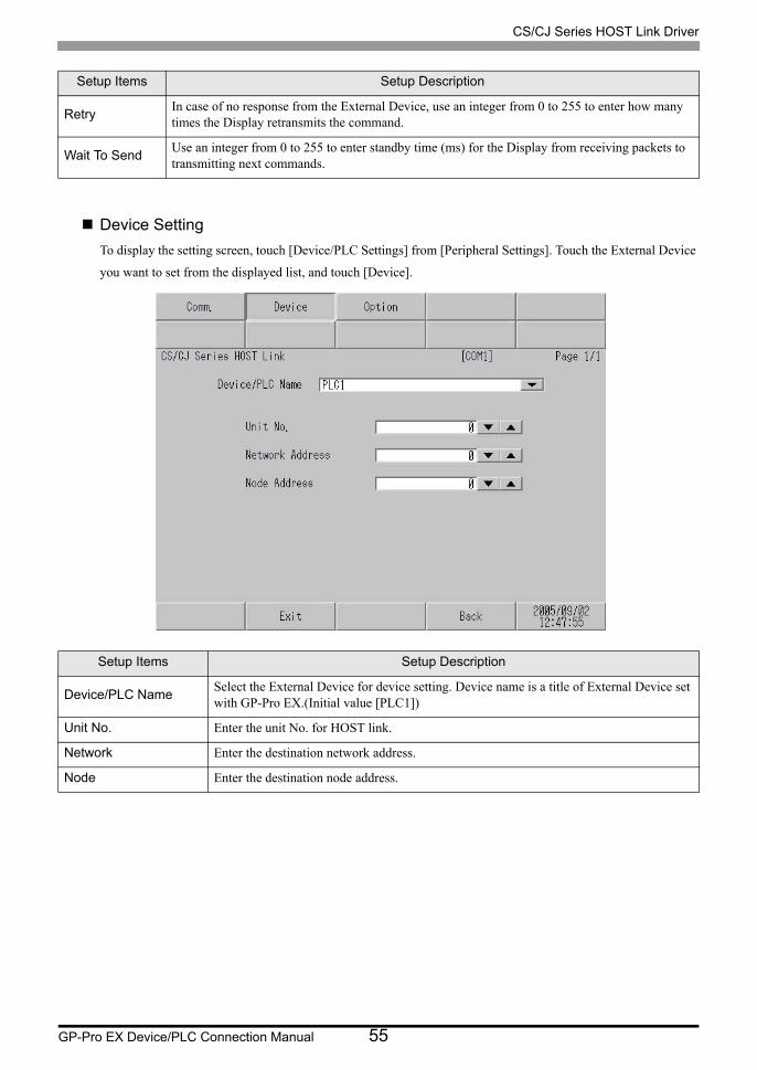
GP-Pro EX Device/PLC Connection Manual 55
Device Setting
To display the setting screen, touch [Device/PLC Settings] from [Peripheral Settings]. Touch the External Device
you want to set from the displayed list, and touch [Device].
RetryIn case of no response from the External Device, use an integer from 0 to 255 to enter how many times the Display retransmits the command.
Wait To SendUse an integer from 0 to 255 to enter standby time (ms) for the Display from receiving packets to transmitting next commands.
Setup Items Setup Description
Device/PLC NameSelect the External Device for device setting. Device name is a title of External Device set with GP-Pro EX.(Initial value [PLC1])
Unit No. Enter the unit No. for HOST link.
Network Enter the destination network address.
Node Enter the destination node address.
Setup Items Setup Description
CS/CJ Series HOST Link Driver
GP-Pro EX Device/PLC Connection Manual 56
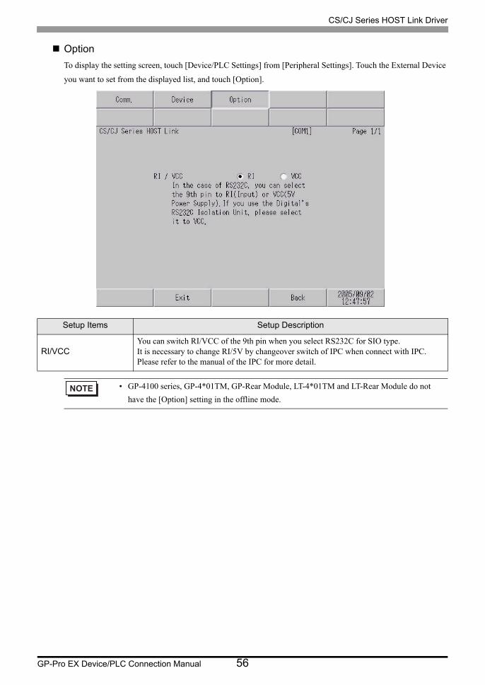
Option
To display the setting screen, touch [Device/PLC Settings] from [Peripheral Settings]. Touch the External Device
you want to set from the displayed list, and touch [Option].
Setup Items Setup Description
RI/VCCYou can switch RI/VCC of the 9th pin when you select RS232C for SIO type.It is necessary to change RI/5V by changeover switch of IPC when connect with IPC. Please refer to the manual of the IPC for more detail.
• GP-4100 series, GP-4*01TM, GP-Rear Module, LT-4*01TM and LT-Rear Module do not
have the [Option] setting in the offline mode.
CS/CJ Series HOST Link Driver
GP-Pro EX Device/PLC Connection Manual 57
5 Cable Diagram
The following cable diagrams may be different from cable diagrams recommended by External Device
Manufacturer.
Please be assured there is no operational problem in applying the cable diagram shown in this manual.
• The FG pin of the External Device body must be grounded according to your country’s applicable standard.
Refer to your External Device manual for details.
• SG and FG are connected inside the Display. When connecting the External Device to SG, design your system
to avoid short-circuit loops.
• Connect an isolation unit if the communication is not stable due to noise or other factors.
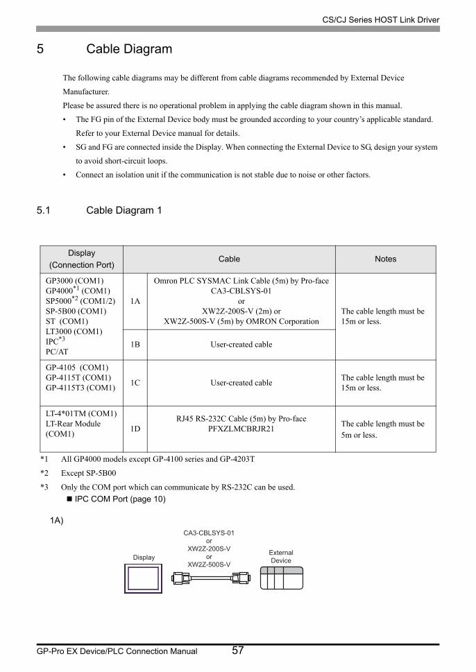
5.1 Cable Diagram 1
1A)
Display
(Connection Port)Cable Notes
GP3000 (COM1)GP4000*1 (COM1)SP5000*2 (COM1/2)SP-5B00 (COM1)ST (COM1)LT3000 (COM1)IPC*3
PC/AT
*1 All GP4000 models except GP-4100 series and GP-4203T
*2 Except SP-5B00
*3 Only the COM port which can communicate by RS-232C can be used.
IPC COM Port (page 10)
1A
Omron PLC SYSMAC Link Cable (5m) by Pro-faceCA3-CBLSYS-01
orXW2Z-200S-V (2m) or
XW2Z-500S-V (5m) by OMRON CorporationThe cable length must be 15m or less.
1B User-created cable
GP-4105 (COM1)GP-4115T (COM1)GP-4115T3 (COM1)
1C User-created cableThe cable length must be 15m or less.
LT-4*01TM (COM1)LT-Rear Module (COM1)
1DRJ45 RS-232C Cable (5m) by Pro-face
PFXZLMCBRJR21The cable length must be 5m or less.
DisplayExternal
Device
CA3-CBLSYS-01
or
XW2Z-200S-V
or
XW2Z-500S-V
CS/CJ Series HOST Link Driver
GP-Pro EX Device/PLC Connection Manual 58
1B)
1C)
1D)
• The cable length must be 15m or less.
• The cable length must be 15m or less.
Display
D-sub 9 pin (socket) ShieldExternal Device sideD-sub 9 pin (plug)
Pin Signalname
2
3
4
5
9
1
Display side
Pin Signalname
3
2
7
8
5
SD(TXD)
RD(RXD)
RS(RTS)
CS(CTS)
SG
SD(TXD)
RD(RXD)
RS(RTS)
CS(CTS)
SG
FG
Display
Signalname
ShieldExternal Device sideD-sub 9 pin (plug)
Pin Signalname
2
3
4
5
9
1
SD(TXD)
RD(RXD)
RS(RTS)
CS(CTS)
SG
SD(TXD)
RD(RXD)
RS(RTS)
CS(CTS)
SG
FG
Terminal blockDisplay side
Display
External Device sideD-sub 9 pin (plug)
Pin Signalname
2
3
4
5
9
1
SD(TXD)
RD(RXD)
RS(RTS)
CS(CTS)
SG
FG
RXD
TXD
PFXZLMCBRJR21
GND
CS/CJ Series HOST Link Driver
GP-Pro EX Device/PLC Connection Manual 59
5.2 Cable Diagram 2
Display
(Connection Port)Cable Notes
GP3000 (COM1)GP4000*1 (COM1)SP5000*2 (COM1/2)SP-5B00 (COM1)ST (COM1)LT3000 (COM1)IPC*3
PC/AT
*1 All GP4000 models except GP-4100 series and GP-4203T
*2 Except SP-5B00
*3 Only the COM port which can communicate by RS-232C can be used.
IPC COM Port (page 10)
2A
User-created cable+
CS1W-CN225 (2m) or CS1W-CN625 (6m) by OMRON Corporation The cable length must be
15m or less.
2B
User-created cable+
CS1W-CN226 (2m) or CS1W-CN626 (6m) by OMRON Corporation
GP-4105 (COM1)GP-4115T (COM1)GP-4115T3 (COM1)
2C
User-created cable+
CS1W-CN225 (2m) or CS1W-CN625 (6m) by OMRON Corporation The cable length must be
15m or less.
2D
User-created cable+
CS1W-CN226 (2m) or CS1W-CN626 (6m) by OMRON Corporation
LT-4*01TM (COM1)LT-Rear Module (COM1)
2E
RJ45 RS-232C Cable (5m) by Pro-facePFXZLMCBRJR21
+CS1W-CN225 (2m) or CS1W-CN625 (6m)
by OMRON Corporation The cable length must be 11m or less.
2F
RJ45 RS-232C Cable (5m) by Pro-facePFXZLMCBRJR21
+CS1W-CN226 (2m) or CS1W-CN626 (6m)
by OMRON Corporation

CS/CJ Series HOST Link Driver
GP-Pro EX Device/PLC Connection Manual 60
2A)
2B)
• The cable length must be 15m or less.
• The cable length must be 15m or less.
Display
D-sub 9 pin (socket)
D-sub 25 pin (socket)for Peripheral PortConnection Cable
User-created cable
CS1W-CN225or
CS1W-CN625
Pin Signalname
3
2
7
8
5
SD(TXD)
RD(RXD)
RS(RTS)
CS(CTS)
SG
Pin Signalname
2
3
4
5
7
1
SD(TXD)
RD(RXD)
RS(RTS)
CS(CTS)
SG
FG
Display side
Display
D-sub 9 pin (socket)
D-sub 9 pin (plug)for Peripheral PortConnection Cable
User-created cable
CS1W-CN226or
CS1W-CN626
Pin Signalname
SD(TXD)
RD(RXD)
RS(RTS)
CS(CTS)
SG
2
3
7
8
5
Display side
Pin Signalname
SD(TXD)
RD(RXD)
RS(RTS)
CS(CTS)
SG
2
3
7
8
5
CS/CJ Series HOST Link Driver
GP-Pro EX Device/PLC Connection Manual 61
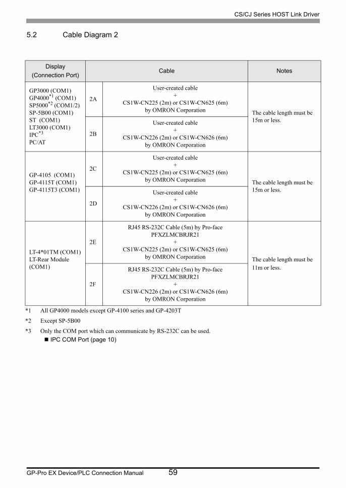
2C)
2D)
2E)
• The cable length must be 15m or less.
• The cable length must be 15m or less.
Display
D-sub 25 pin (socket)for Peripheral PortConnection Cable
User-created cable
CS1W-CN225or
CS1W-CN625
Signalname
SD(TXD)
RD(RXD)
RS(RTS)
CS(CTS)
SG
Pin Signalname
2
3
4
5
7
1
SD(TXD)
RD(RXD)
RS(RTS)
CS(CTS)
SG
FG
Terminal blockDisplay side
Display
D-sub 9 pin (plug)for Peripheral PortConnection Cable
User-created cable
CS1W-CN226or
CS1W-CN626
Signalname
SD(TXD)
RD(RXD)
RS(RTS)
CS(CTS)
SG
Pin Signalname
SD(TXD)
RD(RXD)
RS(RTS)
CS(CTS)
SG
2
3
7
8
5
Terminal blockDisplay side
DisplayPin Signal
name
2
3
4
5
7
1
SD(TXD)
RD(RXD)
RS(RTS)
CS(CTS)
SG
FG
RXD
TXD
PFXZLMCBRJR21
GNDCS1W-CN225
orCS1W-CN625
D-sub 25 pin (socket)for Peripheral PortConnection Cable
CS/CJ Series HOST Link Driver
GP-Pro EX Device/PLC Connection Manual 62
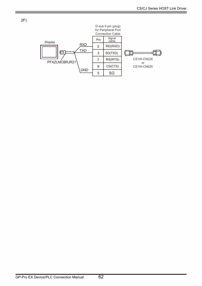
2F)
DisplayPin Signal
name
2
3
7
8
5
SD(TXD)
RD(RXD)
RS(RTS)
CS(CTS)
SG
RXD
TXD
PFXZLMCBRJR21
GND
D-sub 9 pin (plug)for Peripheral PortConnection Cable
CS1W-CN226or
CS1W-CN626
CS/CJ Series HOST Link Driver
GP-Pro EX Device/PLC Connection Manual 63
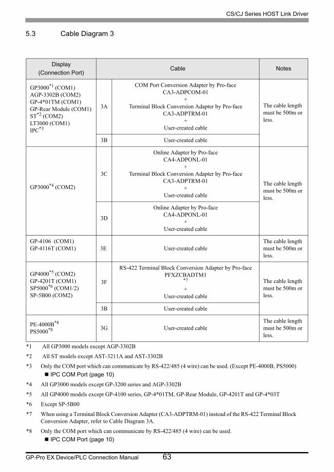
5.3 Cable Diagram 3
Display
(Connection Port)Cable Notes
GP3000*1 (COM1)AGP-3302B (COM2)GP-4*01TM (COM1)GP-Rear Module (COM1)ST*2 (COM2)LT3000 (COM1)IPC*3
*1 All GP3000 models except AGP-3302B
*2 All ST models except AST-3211A and AST-3302B
*3 Only the COM port which can communicate by RS-422/485 (4 wire) can be used. (Except PE-4000B, PS5000)
IPC COM Port (page 10)
3A
COM Port Conversion Adapter by Pro-faceCA3-ADPCOM-01
+Terminal Block Conversion Adapter by Pro-face
CA3-ADPTRM-01+
User-created cable
The cable length must be 500m or less.
3B User-created cable
GP3000*4 (COM2)
*4 All GP3000 models except GP-3200 series and AGP-3302B
3C
Online Adapter by Pro-faceCA4-ADPONL-01
+Terminal Block Conversion Adapter by Pro-face
CA3-ADPTRM-01+
User-created cable
The cable length must be 500m or less.
3D
Online Adapter by Pro-faceCA4-ADPONL-01
+User-created cable
GP-4106 (COM1)GP-4116T (COM1) 3E User-created cable
The cable length must be 500m or less.
GP4000*5 (COM2)GP-4201T (COM1)SP5000*6 (COM1/2)SP-5B00 (COM2)
*5 All GP4000 models except GP-4100 series, GP-4*01TM, GP-Rear Module, GP-4201T and GP-4*03T
*6 Except SP-5B00
3F
RS-422 Terminal Block Conversion Adapter by Pro-facePFXZCBADTM1
*7
+User-created cable
*7 When using a Terminal Block Conversion Adapter (CA3-ADPTRM-01) instead of the RS-422 Terminal Block Conversion Adapter, refer to Cable Diagram 3A.
The cable length must be 500m or less.
3B User-created cable
PE-4000B*8
PS5000*8
*8 Only the COM port which can communicate by RS-422/485 (4 wire) can be used.
IPC COM Port (page 10)
3G User-created cableThe cable length must be 500m or less.

CS/CJ Series HOST Link Driver
GP-Pro EX Device/PLC Connection Manual 64
• Please turn ON the termination resistance switch on the PLC.• Set the 2wire/4wire toggle switch to 4wire.• Note that pole A and pole B are reversely named for the Display and the External
Device.

CS/CJ Series HOST Link Driver
GP-Pro EX Device/PLC Connection Manual 65
3A)
• 1:1 connection
• 1:n connection
• When the display unit you use is an IPC, turn ON the DIP switch 6 to insert the termination
resistance.
• The cable length must be 500m or less.
DisplayCA3-ADPCOM-01
CA3-ADPTRM-01
Terminationresistance220Ω 1/4W
TerminalblockSignalname
ShieldExternal Device sideD-sub 9 pin (plug)
Pin Signalname
User-created cable
SDB
SDA
RDB
RDA
FG
2
1
8
6
Shell
RDA
RDB
SDA
SDB
TERMRX
SG
FG
DisplayCA3-ADPCOM-01
CA3-ADPTRM-01
TerminalblockSignalname
ShieldExternal Device sideD-sub 9 pin (plug)
Pin Signalname
Shield
Pin Signalname
External Device sideD-sub 9 pin (plug)
User-created cable
Terminationresistance220Ω 1/4W SDB
SDA
RDB
RDA
FG
SDB
SDA
RDB
RDA
FG
2
1
8
6
Shell
2
1
8
6
Shell
RDA
RDB
SDA
SDB
TERMRX
SG
FG

CS/CJ Series HOST Link Driver
GP-Pro EX Device/PLC Connection Manual 66
3B)
• 1:1 connection
• 1:n connection
• When the display unit you use is an IPC, turn ON the DIP switch 6 to insert the termination
resistance.
• The cable length must be 500m or less.
Display
D-sub 9 pin (socket)
Pin Signalname
ShieldExternal Device sideD-sub 9 pin (plug)Termination
resistance220Ω 1/4W
RDA
RDB
SDA
SDB
CSB
ERB
CSA
ERA
1
2
3
7
6
9
8
4
Display side
Signal name
SDARDB
SDB
RDA
2
6
18
Pin
FGShell
Display
D-sub 9 pin (socket) Shield External Device sideD-sub 9 pin (plug)
Pin Signalname
ShieldExternal Device side
D-sub 9 pin (plug)Terminationresistance220Ω 1/4W
RDA
RDB
SDA
SDB
CSB
ERB
CSA
ERA
1
2
3
7
6
9
8
4
Display side
Signal name
SDARDB
SDB
RDA
2
6
18
Pin
FGShell
Signal name
SDARDB
SDB
RDA
2
6
18
Pin
FGShell
CS/CJ Series HOST Link Driver
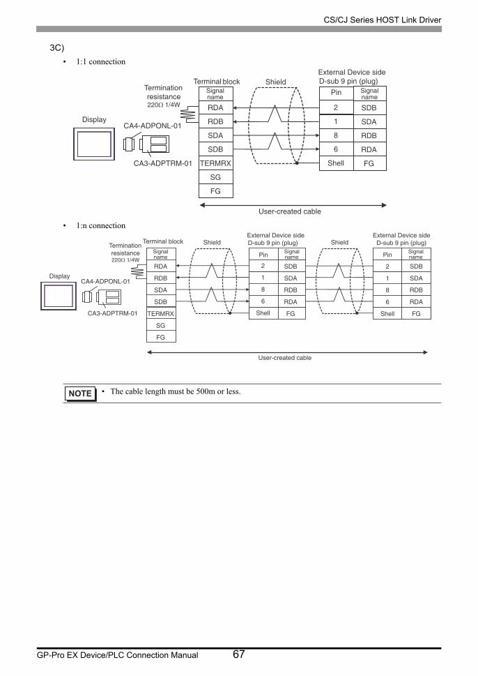
GP-Pro EX Device/PLC Connection Manual 67
3C)
• 1:1 connection
• 1:n connection
• The cable length must be 500m or less.
DisplayCA4-ADPONL-01
CA3-ADPTRM-01
Terminal blockSignalname
ShieldExternal Device sideD-sub 9 pin (plug)
Pin Signalname
User-created cable
Terminationresistance220Ω 1/4W RDA
RDB
SDA
SDB
TERMRX
SG
FG
SDB
SDA
RDB
RDA
FG
2
1
8
6
Shell
DisplayCA4-ADPONL-01
CA3-ADPTRM-01
Terminal block
Signalname
ShieldExternal Device sideD-sub 9 pin (plug)
Pin Signalname
ShieldExternal Device side
D-sub 9 pin (plug)
Pin Signalname
User-created cable
Terminationresistance220Ω 1/4W
RDA
RDB
SDA
SDB
TERMRX
SG
FG
SDB
SDA
RDB
RDA
FG
2
1
8
6
Shell
SDB
SDA
RDB
RDA
FG
2
1
8
6
Shell

CS/CJ Series HOST Link Driver
GP-Pro EX Device/PLC Connection Manual 68
3D)
• 1:1 connection
• 1:n connection
• The cable length must be 500m or less.
Display
CA4-ADPONL-01
D-sub 9 pin (plug)
Pin Signalname
ShieldExternal Device sideD-sub 9 pin (plug)
Pin Signalname
User-created cable
Terminationresistance220Ω 1/4W
RDA
RDB
SDA
SDB
SDB
SDA
RDB
RDA
FG
2
1
8
6
Shell
2
7
3
8
Display
CA4-ADPONL-01
D-sub 9 pin (plug)
Pin SignalnamePin Signal
name
ShieldExternal Device sideD-sub 9 pin (plug)
Pin Signalname
ShieldExternal Device sideD-sub 9 pin (plug)
User-created cable
Terminationresistance220Ω 1/4W
RDA
RDB
SDA
SDB
SDB
SDA
RDB
RDA
FG
2
1
8
6
Shell
SDB
SDA
RDB
RDA
FG
2
1
8
6
Shell
2
7
3
8
CS/CJ Series HOST Link Driver
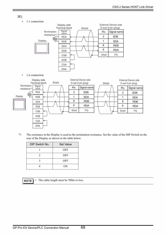
GP-Pro EX Device/PLC Connection Manual 69
3E)
• 1:1 connection
• 1:n connection
*1 The resistance in the Display is used as the termination resistance. Set the value of the DIP Switch on the rear of the Display as shown in the table below.
DIP Switch No. Set Value
1 OFF
2 OFF
3 OFF
4 ON
• The cable length must be 500m or less.
Display
Signalname
ShieldExternal Device sideD-sub 9 pin (plug)
Terminationresistance*1
RDA
RDB
SDA
SDB
CSB
ERB
CSA
ERA
Terminal blockDisplay side
Signal name
SDARDB
SDB
RDA
2
6
18
Pin
FGShell
Display
ShieldExternal Device sideD-sub 9 pin (plug)
Signalname
ShieldExternal Device side D-sub 9 pin (plug)
Terminationresistance*1
RDA
RDB
SDA
SDB
CSB
ERB
CSA
ERA
Terminal blockDisplay side
Signal name
SDARDB
SDB
RDA
2
6
18
Pin
FGShell
Signal name
SDARDB
SDB
RDA
2
6
18
Pin
FGShell
CS/CJ Series HOST Link Driver
GP-Pro EX Device/PLC Connection Manual 70
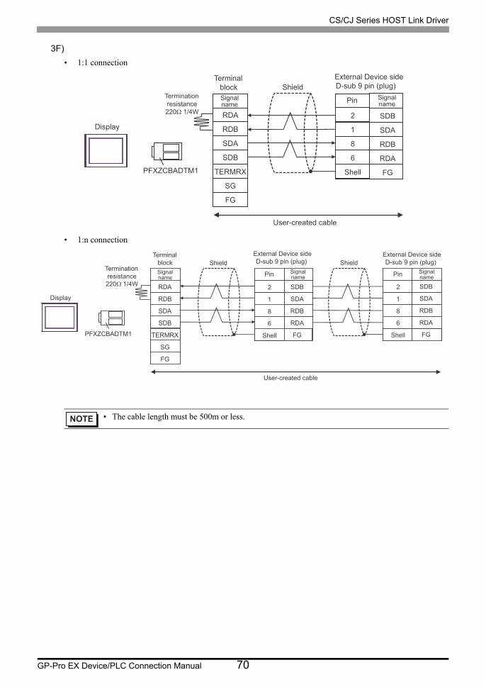
3F)
• 1:1 connection
• 1:n connection
• The cable length must be 500m or less.
Display
PFXZCBADTM1
Terminationresistance220Ω 1/4W
TerminalblockSignalname
ShieldExternal Device sideD-sub 9 pin (plug)
Pin Signalname
User-created cable
SDB
SDA
RDB
RDA
FG
2
1
8
6
Shell
RDA
RDB
SDA
SDB
TERMRX
SG
FG
Display
PFXZCBADTM1
TerminalblockSignalname
ShieldExternal Device sideD-sub 9 pin (plug)
Pin Signalname
Shield
Pin Signalname
External Device sideD-sub 9 pin (plug)
User-created cable
Terminationresistance220Ω 1/4W SDB
SDA
RDB
RDA
FG
SDB
SDA
RDB
RDA
FG
2
1
8
6
Shell
2
1
8
6
Shell
RDA
RDB
SDA
SDB
TERMRX
SG
FG
CS/CJ Series HOST Link Driver
GP-Pro EX Device/PLC Connection Manual 71
3G)
• 1:1 connection
• 1:n connection
• When the display unit you use is an IPC, turn ON the DIP switch 6 to insert the termination
resistance.
• The cable length must be 500m or less.
Display
D-sub 9 pin (socket)
Pin Signalname
ShieldExternal Device sideD-sub 9 pin (plug)Termination
resistance220Ω 1/4W
Rx+
Rx+
Tx+
Tx-
NC
NC
NC
NC
3
4
2
1
6
9
8
7
Display side
Signal name
SDARDB
SDB
RDA
2
6
18
Pin
FGShell
Display
D-sub 9 pin (socket) Shield External Device sideD-sub 9 pin (plug)
Pin Signalname
ShieldExternal Device sideD-sub 9 pin (plug)Termination
resistance220Ω 1/4W
Rx+
Rx-
Tx+
Tx-
NC
NC
NC
NC
3
4
2
1
6
9
8
7
Display side
Signal name
SDARDB
SDB
RDA
2
6
18
Pin
FGShell
Signal name
SDARDB
SDB
RDA
2
6
18
Pin
FGShell
CS/CJ Series HOST Link Driver
GP-Pro EX Device/PLC Connection Manual 72
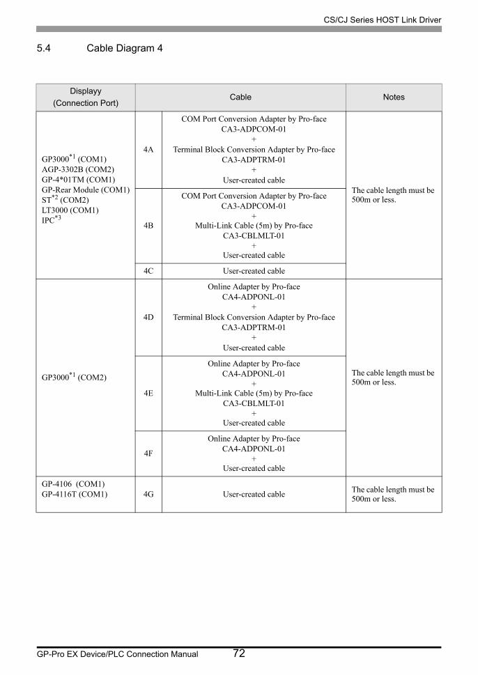
5.4 Cable Diagram 4
Displayy
(Connection Port)Cable Notes
GP3000*1 (COM1)AGP-3302B (COM2)GP-4*01TM (COM1)GP-Rear Module (COM1)ST*2 (COM2)LT3000 (COM1)IPC*3
4A
COM Port Conversion Adapter by Pro-faceCA3-ADPCOM-01
+Terminal Block Conversion Adapter by Pro-face
CA3-ADPTRM-01+
User-created cableThe cable length must be 500m or less.
4B
COM Port Conversion Adapter by Pro-faceCA3-ADPCOM-01
+Multi-Link Cable (5m) by Pro-face
CA3-CBLMLT-01+
User-created cable
4C User-created cable
GP3000*1 (COM2)
4D
Online Adapter by Pro-faceCA4-ADPONL-01
+Terminal Block Conversion Adapter by Pro-face
CA3-ADPTRM-01+
User-created cable
The cable length must be 500m or less.
4E
Online Adapter by Pro-faceCA4-ADPONL-01
+Multi-Link Cable (5m) by Pro-face
CA3-CBLMLT-01+
User-created cable
4F
Online Adapter by Pro-faceCA4-ADPONL-01
+User-created cable
GP-4106 (COM1)GP-4116T (COM1) 4G User-created cable
The cable length must be 500m or less.
CS/CJ Series HOST Link Driver
GP-Pro EX Device/PLC Connection Manual 73
GP4000*4 (COM2)GP-4201T (COM1)SP5000*5 (COM1/2)SP-5B00 (COM2)
4H
RS-422 Terminal Block Conversion Adapter by Pro-face
PFXZCBADTM1*6
+User-created cable
The cable length must be 500m or less.
4I
Multi-Link Cable (5m) by Pro-facePFXZCBCBML1
*7
+User-created cable
4C User-created cable
PE-4000B*8
PS5000*8 4J User-created cable The cable length must be 500m or less.
*1 All GP3000 models except AGP-3302B
*2 All ST models except AST-3211A and AST-3302B
*3 Only the COM port which can communicate by RS-422/485 (4 wire) can be used. (Except PE-4000B, PS5000)
IPC COM Port (page 10)
*4 All GP4000 models except GP-4100 series, GP-4*01TM, GP-Rear Module, GP-4201T and GP-4*03T
*5 Except SP-5B00
*6 When using a Terminal Block Conversion Adapter (CA3-ADPTRM-01) instead of the RS-422 Terminal Block Conversion Adapter, refer to Cable Diagram 4A.
*7 When using a Multilink Cable (CA3-CBLMLT-01) instead of the Multilink Cable, refer to Cable Diagram 4B.
*8 Only the COM port which can communicate by RS-422/485 (4 wire) can be used.
IPC COM Port (page 10)
Displayy
(Connection Port)Cable Notes

CS/CJ Series HOST Link Driver
GP-Pro EX Device/PLC Connection Manual 74
4A)
• n:1 connection
• The cable length must be 500m or less.
CA3-ADPTRM-01
CA3-ADPCOM-01
CA3-ADPTRM-01
CA3-ADPCOM-01
RDA
RDB
SDA
SDB
SG
TRM
RDA
RDB
SDA
SDB
SG
FG
2
1
8
6
Shield Shield
User-created cable
SDB
SDA
RDB
RDA
FG
Terminationresistance220Ω 1/4W
Terminalblock
Signal name
Terminalblock
Signal name Pin
External Device sideD-Sub 9 pin (plug)
Signal name
Connectorshell
Display Display
CS/CJ Series HOST Link Driver
GP-Pro EX Device/PLC Connection Manual 75
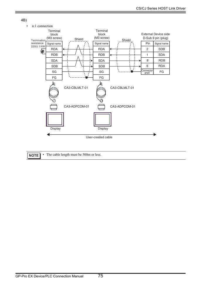
4B)
• n:1 connection
• The cable length must be 500m or less.
CA3-CBLMLT-01
CA3-ADPCOM-01
CA3-CBLMLT-01
CA3-ADPCOM-01
RDA
RDB
SDA
SDB
SG
FG
RDA
RDB
SDA
SDB
SG
FG
1
2
6
8
SDA
SDB
RDA
RDB
FG
Terminationresistance220Ω 1/4W
Terminalblock
(M3 screw)
Signal name
Terminalblock
(M3 screw)
Signal nameShield
Pin
External Device sideD-Sub 9 pin (plug)
Signal name
Connectorshell
Shield
User-created cable
Display Display
CS/CJ Series HOST Link Driver
GP-Pro EX Device/PLC Connection Manual 76
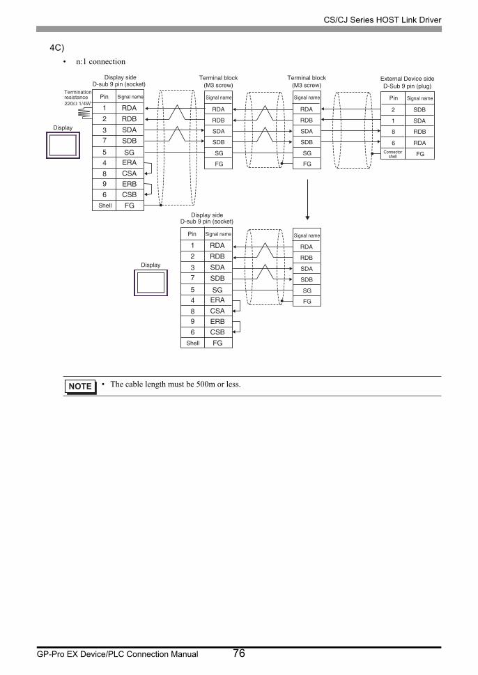
4C)
• n:1 connection
• The cable length must be 500m or less.
RDA
RDB
CSA
SDA
SDB
SGERA
5
2
1
8
73
4
96
ERBCSBFG
RDA
RDB
SDA
SDB
FG
SG
RDA
RDB
SDA
SDB
FG
SG
1
2
6
8
RDA
RDB
CSA
SDA
SDB
SGERA
5
2
1
8
73
4
96
ERBCSBFG
RDA
RDB
SDA
SDB
FG
SG
SDA
SDB
RDA
RDB
FG
Terminationresistance220Ω 1/4W
Display
Signal name
D-sub 9 pin (socket)
Pin
Shell
Display
Signal name
D-sub 9 pin (socket)
Pin
Shell
Signal name
Terminal block(M3 screw)
Signal name
Terminal block(M3 screw)
Signal name
Connectorshell
Pin
External Device sideD-Sub 9 pin (plug)
Signal name
Display side
Display side
CS/CJ Series HOST Link Driver
GP-Pro EX Device/PLC Connection Manual 77
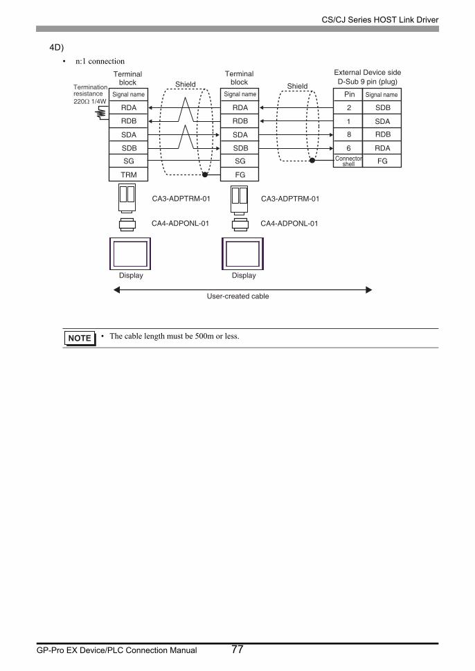
4D)
• n:1 connection
• The cable length must be 500m or less.
CA3-ADPTRM-01
CA4-ADPONL-01
CA3-ADPTRM-01
CA4-ADPONL-01
RDA
RDB
SDA
SDB
SG
TRM
RDA
RDB
SDA
SDB
SG
FG
1
2
6
8
SDA
SDB
RDA
RDB
FG
Shield Shield
User-created cable
Terminationresistance220Ω 1/4W
Terminalblock
Signal name
Terminalblock
Signal name Pin
External Device sideD-Sub 9 pin (plug)
Signal name
Connectorshell
Display Display
CS/CJ Series HOST Link Driver
GP-Pro EX Device/PLC Connection Manual 78
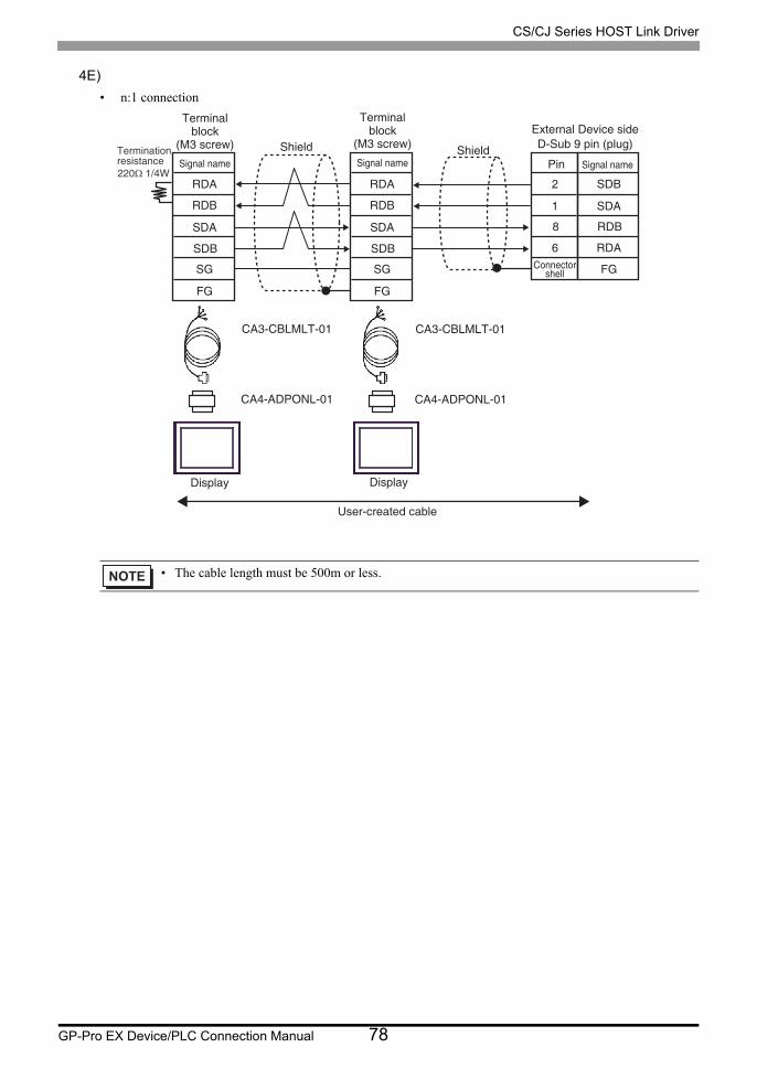
4E)
• n:1 connection
• The cable length must be 500m or less.
CA3-CBLMLT-01
CA4-ADPONL-01
CA3-CBLMLT-01
CA4-ADPONL-01
RDA
RDB
SDA
SDB
SG
FG
RDA
RDB
SDA
SDB
SG
FG
1
2
6
8
SDA
SDB
RDA
RDB
FG
Shield Shield
User-created cable
Terminationresistance220Ω 1/4W
Terminalblock
(M3 screw)
Signal name Pin
External Device sideD-Sub 9 pin (plug)
Signal name
Connectorshell
Display Display
Terminalblock
(M3 screw)
Signal name
CS/CJ Series HOST Link Driver
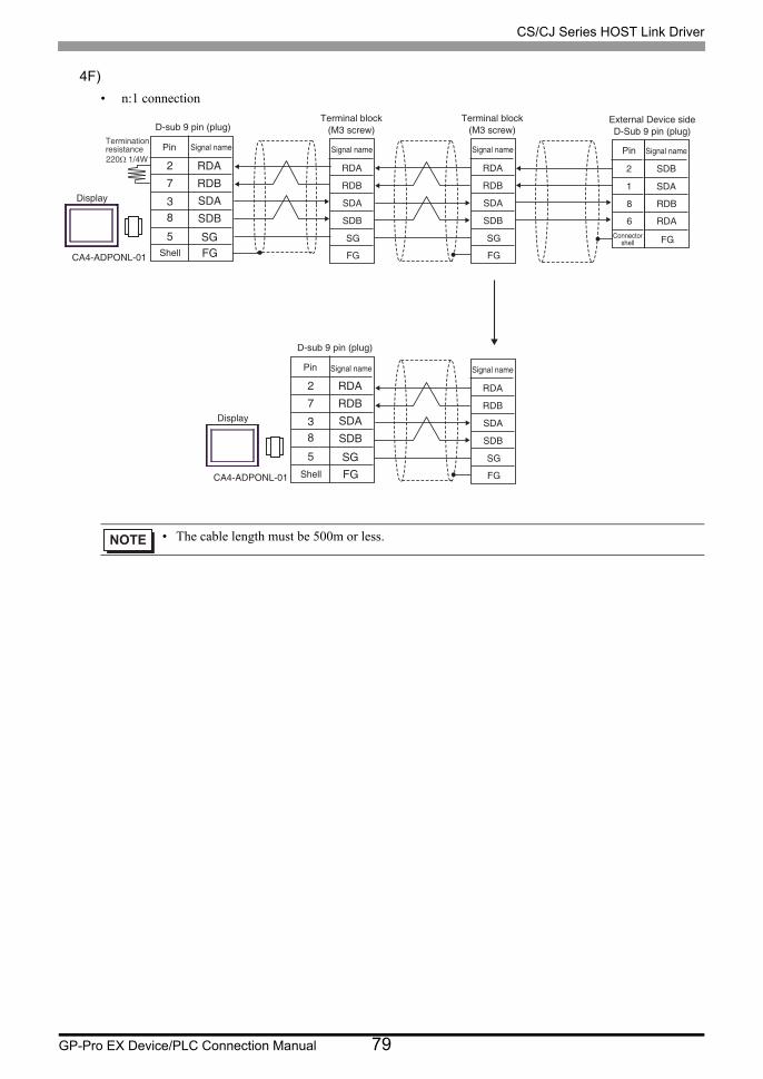
GP-Pro EX Device/PLC Connection Manual 79
4F)
• n:1 connection
• The cable length must be 500m or less.
RDA
RDBSDA
SDB
SG5
7
2
83
FG
Display
Signal name
D-sub 9 pin (plug)
Pin
Shell
RDA
RDB
SDA
SDB
FG
SG
Signal name
Terminal block(M3 screw)
RDA
RDB
SDA
SDB
FG
SG
Signal name
Terminal block(M3 screw)
1
2
6
8
Connectorshell
Pin
External Device sideD-Sub 9 pin (plug)
RDA
RDBSDA
SDB
SG5
7
2
83
FG
Display
Signal namePin
Shell
RDA
RDB
SDA
SDB
FG
SG
Signal name
D-sub 9 pin (plug)
CA4-ADPONL-01
CA4-ADPONL-01
SDA
SDB
RDA
RDB
FG
Signal nameTerminationresistance220Ω 1/4W
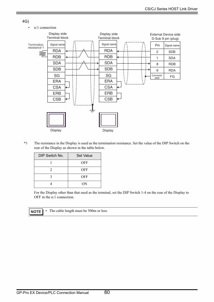
CS/CJ Series HOST Link Driver
GP-Pro EX Device/PLC Connection Manual 80
4G)
• n:1 connection
*1 The resistance in the Display is used as the termination resistance. Set the value of the DIP Switch on the rear of the Display as shown in the table below.
For the Display other than that used as the terminal, set the DIP Switch 1-4 on the rear of the Display to OFF in the n:1 connection.
DIP Switch No. Set Value
1 OFF
2 OFF
3 OFF
4 ON
• The cable length must be 500m or less.
RDA
RDB
CSA
SDA
SDB
SGERA
ERBCSB
1
2
6
8
RDA
RDB
CSA
SDA
SDB
SGERA
ERBCSB
SDA
SDB
RDA
RDB
FG
Terminationresistance*1
Signal name
Display
Signal name
Connectorshell
Pin
External Device sideD-Sub 9 pin (plug)
Signal name
Terminal blockDisplay side
Terminal blockDisplay side
Display
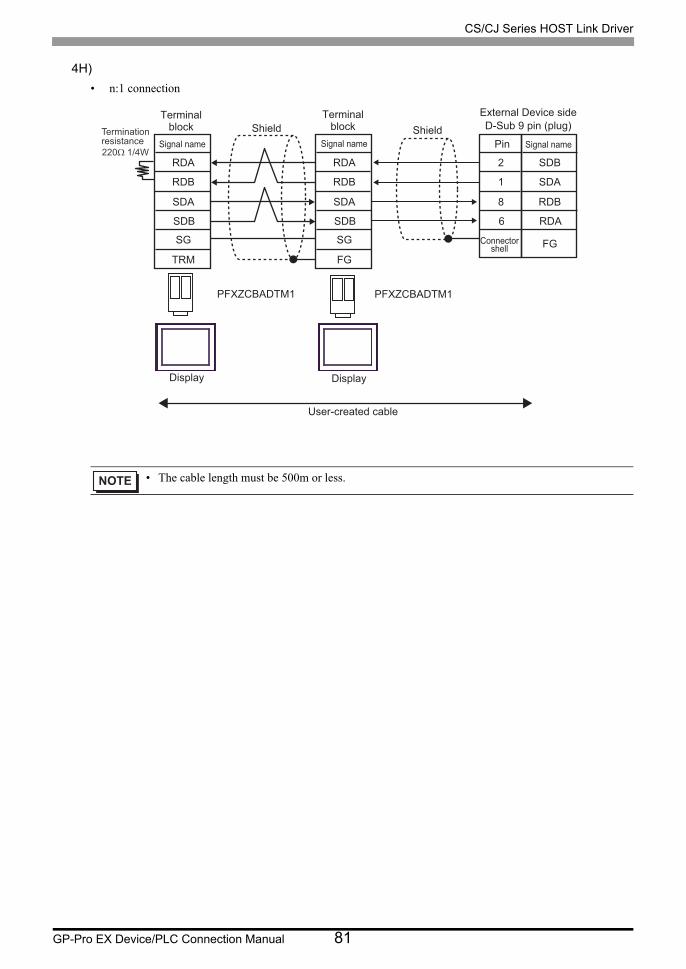
CS/CJ Series HOST Link Driver
GP-Pro EX Device/PLC Connection Manual 81
4H)
• n:1 connection
• The cable length must be 500m or less.
PFXZCBADTM1 PFXZCBADTM1
RDA
RDB
SDA
SDB
SG
TRM
RDA
RDB
SDA
SDB
SG
FG
2
1
8
6
Shield Shield
User-created cable
SDB
SDA
RDB
RDA
FG
Terminationresistance220Ω 1/4W
Terminalblock
Signal name
Terminalblock
Signal name Pin
External Device sideD-Sub 9 pin (plug)
Signal name
Connectorshell
Display Display

CS/CJ Series HOST Link Driver
GP-Pro EX Device/PLC Connection Manual 82
4I)
• n:1 connection
• The cable length must be 500m or less.
PFXZCBCBML1 PFXZCBCBML1
RDA
RDB
SDA
SDB
SG
FG
RDA
RDB
SDA
SDB
SG
FG
1
2
6
8
SDA
SDB
RDA
RDB
FG
Terminationresistance220Ω 1/4W
Terminalblock
(M3 screw)
Signal name
Terminalblock
(M3 screw)
Signal nameShield
Pin
External Device sideD-Sub 9 pin (plug)
Signal name
Connectorshell
Shield
User-created cable
Display Display
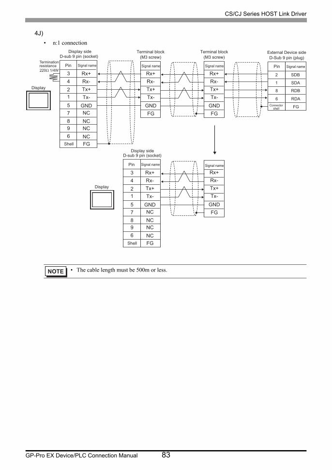
CS/CJ Series HOST Link Driver
GP-Pro EX Device/PLC Connection Manual 83
4J)
• n:1 connection
• The cable length must be 500m or less.
Rx+
Rx-Tx+
Tx-
GND
Rx+
Rx-Tx+
Tx-
FG
GND
Rx+
Rx-Tx+
Tx-
FG
GND
Rx+
Rx-Tx+
Tx-
FG
GND
NC
NCNC
NC
Rx+
Rx-Tx+
Tx-
GNDNC
NCNC
NC
5
4
3
8
12
7
96
FG
1
2
6
8
5
4
3
8
12
7
96
FG
SDA
SDB
RDA
RDB
FG
Terminationresistance220Ω 1/4W
Display
Signal name
D-sub 9 pin (socket)
Pin
Shell
Display
Signal name
D-sub 9 pin (socket)
Pin
Shell
Signal name
Terminal block(M3 screw)
Signal name
Terminal block(M3 screw)
Signal name
Connectorshell
Pin
External Device sideD-Sub 9 pin (plug)
Signal name
Display side
Display side

CS/CJ Series HOST Link Driver
GP-Pro EX Device/PLC Connection Manual 84
5.5 Cable Diagram 5
Display
(Connection Port)Cable Notes
GP3000*1 (COM1)AGP-3302B (COM2)GP-4*01TM (COM1)GP-Rear Module (COM1)ST*2 (COM2)LT3000 (COM1)IPC*3
*1 All GP3000 models except AGP-3302B
*2 All ST models except AST-3211A and AST-3302B
*3 Only the COM port which can communicate by RS-422/485 (4 wire) can be used. (Except PE-4000B, PS5000)
IPC COM Port (page 10)
5A
COM Port Conversion Adapter by Pro-faceCA3-ADPCOM-01
+Terminal Block Conversion Adapter by Pro-face
CA3-ADPTRM-01+
User-created cable
The cable length must be 500m or less.
5B User-created cable
GP3000*4 (COM2)
*4 All GP3000 models except GP-3200 series and AGP-3302B
5C
Online Adapter by Pro-faceCA4-ADPONL-01
+Terminal Block Conversion Adapter by Pro-face
CA3-ADPTRM-01+
User-created cable
The cable length must be 500m or less.
5D
Online Adapter by Pro-faceCA4-ADPONL-01
+User-created cable
GP-4106 (COM1)GP-4116T (COM1) 5E User-created cable
The cable length must be 500m or less.
GP4000*5 (COM2)GP-4201T (COM1)SP5000*6 (COM1/2)SP-5B00 (COM2)
*5 All GP4000 models except GP-4100 series, GP-4*01TM, GP-Rear Module, GP-4201T and GP-4*03T
*6 Except SP-5B00
5F
RS-422 Terminal Block Conversion Adapter by Pro-facePFXZCBADTM1
*7
+User-created cable
*7 When using a Terminal Block Conversion Adapter (CA3-ADPTRM-01) instead of the RS-422 Terminal Block Conversion Adapter, refer to Cable Diagram 5A.
The cable length must be 500m or less.
5B User-created cable
PE-4000B*8
PS5000*8
*8 Only the COM port which can communicate by RS-422/485 (4 wire) can be used.
IPC COM Port (page 10)
5G User-created cableThe cable length must be 500m or less.

CS/CJ Series HOST Link Driver
GP-Pro EX Device/PLC Connection Manual 85
• Please turn ON the termination resistance switch on the PLC.• Set the 2wire/4wire toggle switch to 4wire.• Note that pole A and pole B are reversely named for the Display and the External
Device.
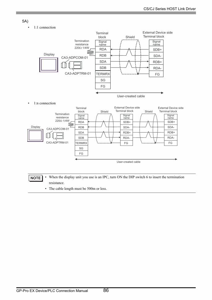
CS/CJ Series HOST Link Driver
GP-Pro EX Device/PLC Connection Manual 86
5A)
• 1:1 connection
• 1:n connection
• When the display unit you use is an IPC, turn ON the DIP switch 6 to insert the termination
resistance.
• The cable length must be 500m or less.
DisplayCA3-ADPCOM-01
CA3-ADPTRM-01
Terminationresistance220Ω 1/4W
TerminalblockSignalname
ShieldExternal Device sideTerminal block
Signalname
User-created cable
SDB+
SDA-
RDB+
RDA-
FG
RDA
RDB
SDA
SDB
TERMRX
SG
FG
FG
DisplayCA3-ADPCOM-01
CA3-ADPTRM-01
TerminalblockSignalname
ShieldExternal Device sideTerminal block
Signalname
ShieldSignalname
External Device sideTerminal block
User-created cable
Terminationresistance220Ω 1/4W SDB+
SDA-
RDB+
RDA-
SDB+
SDA-
RDB+
RDA-
RDA
RDB
SDA
SDB
TERMRX
SG
FG
FG
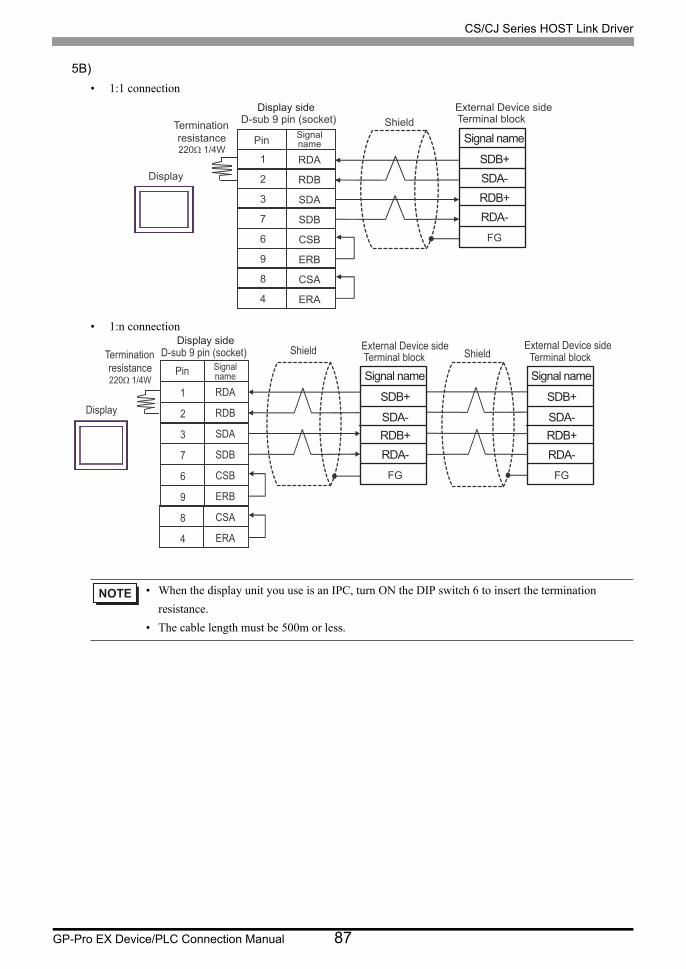
CS/CJ Series HOST Link Driver
GP-Pro EX Device/PLC Connection Manual 87
5B)
• 1:1 connection
• 1:n connection
• When the display unit you use is an IPC, turn ON the DIP switch 6 to insert the termination
resistance.
• The cable length must be 500m or less.
Display
D-sub 9 pin (socket)
Pin Signalname
ShieldExternal Device sideTerminal blockTermination
resistance220Ω 1/4W
RDA
RDB
SDA
SDB
CSB
ERB
CSA
ERA
1
2
3
7
6
9
8
4
Display side
Signal name
SDA-
RDB+
SDB+
RDA-
FG
Display
D-sub 9 pin (socket) Shield External Device sideTerminal block
Pin Signalname
ShieldExternal Device sideTerminal blockTermination
resistance220Ω 1/4W
RDA
RDB
SDA
SDB
CSB
ERB
CSA
ERA
1
2
3
7
6
9
8
4
Display side
Signal name
SDA-RDB+
SDB+
RDA-
FG
Signal name
SDA-RDB+
SDB+
RDA-
FG

CS/CJ Series HOST Link Driver
GP-Pro EX Device/PLC Connection Manual 88
5C)
• 1:1 connection
• 1:n connection
• The cable length must be 500m or less.
DisplayCA4-ADPONL-01
CA3-ADPTRM-01
Terminal blockSignalname
ShieldExternal Device sideTerminal block
Signalname
User-created cable
Terminationresistance220Ω 1/4W RDA
RDB
SDA
SDB
TERMRX
SG
FG
SDB+
SDA-
RDB+
RDA-
FG
DisplayCA4-ADPONL-01
CA3-ADPTRM-01
Terminal block
Signalname
ShieldExternal Device sideTerminal block
Signalname
ShieldExternal Device sideTerminal block
Signalname
User-created cable
Terminationresistance220Ω 1/4W
RDA
RDB
SDA
SDB
TERMRX
SG
FG
SDB+
SDA-
RDB+
RDA-
FG
SDB+
SDA-
RDB+
RDA-
FG
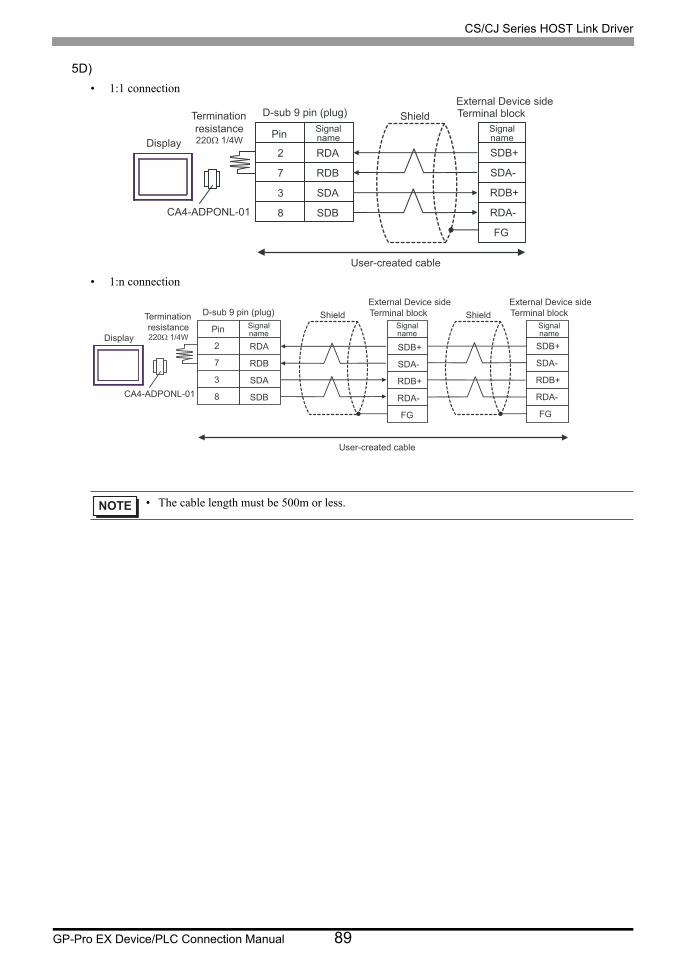
CS/CJ Series HOST Link Driver
GP-Pro EX Device/PLC Connection Manual 89
5D)
• 1:1 connection
• 1:n connection
• The cable length must be 500m or less.
Display
CA4-ADPONL-01
D-sub 9 pin (plug)
Pin Signalname
ShieldExternal Device sideTerminal block
Signalname
User-created cable
Terminationresistance220Ω 1/4W
RDA
RDB
SDA
SDB
SDB+
SDA-
RDB+
RDA-
FG
2
7
3
8
Display
CA4-ADPONL-01
D-sub 9 pin (plug)SignalnamePin Signal
name
ShieldExternal Device sideTerminal block
Signalname
ShieldExternal Device sideTerminal block
User-created cable
Terminationresistance220Ω 1/4W
RDA
RDB
SDA
SDB
SDB+
SDA-
RDB+
RDA-
FG
SDB+
SDA-
RDB+
RDA-
FG
2
7
3
8
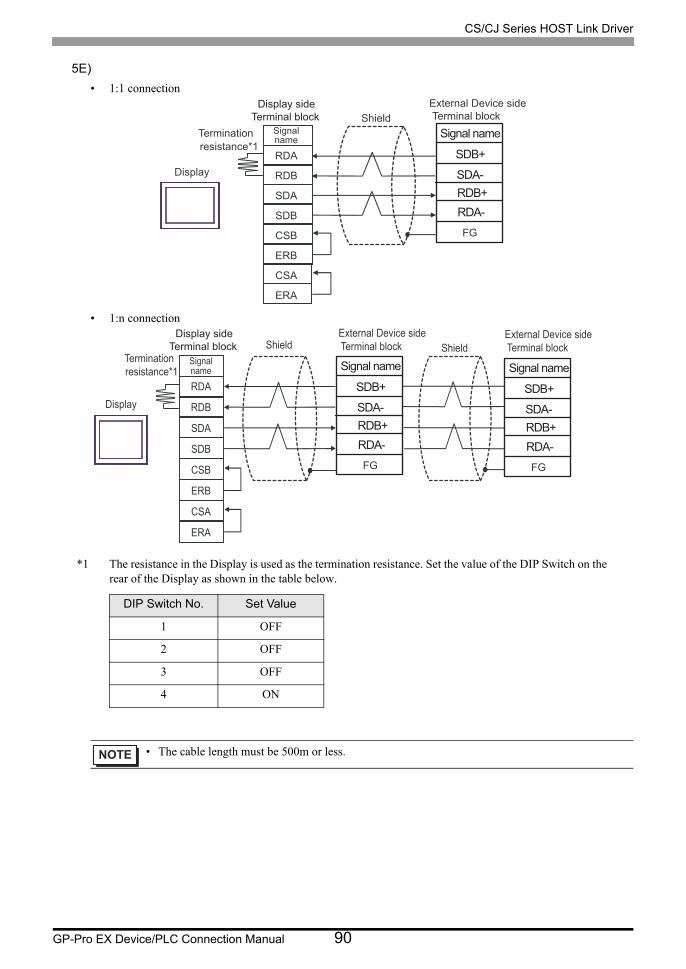
CS/CJ Series HOST Link Driver
GP-Pro EX Device/PLC Connection Manual 90
5E)
• 1:1 connection
• 1:n connection
*1 The resistance in the Display is used as the termination resistance. Set the value of the DIP Switch on the rear of the Display as shown in the table below.
DIP Switch No. Set Value
1 OFF
2 OFF
3 OFF
4 ON
• The cable length must be 500m or less.
RDB+
FG
Signal name
SDA-
SDB+
RDA-
Display
Signalname
ShieldExternal Device sideTerminal block
Terminationresistance*1
RDA
RDB
SDA
SDB
CSB
ERB
CSA
ERA
Terminal blockDisplay side
RDB+
FG
Display
ShieldExternal Device sideTerminal block
Signalname
ShieldExternal Device sideTerminal block
Terminationresistance*1
RDA
RDB
SDA
SDB
CSB
ERB
CSA
ERA
Terminal blockDisplay side
Signal name
SDA-
SDB+
RDA-RDB+
FG
Signal name
SDA-
SDB+
RDA-
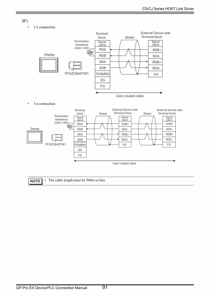
CS/CJ Series HOST Link Driver
GP-Pro EX Device/PLC Connection Manual 91
5F)
• 1:1 connection
• 1:n connection
• The cable length must be 500m or less.
Display
PFXZCBADTM1
Terminationresistance220Ω 1/4W
TerminalblockSignalname
ShieldExternal Device sideTerminal block
Signalname
User-created cable
SDB+
SDA-
RDB+
RDA-
FG
RDA
RDB
SDA
SDB
TERMRX
SG
FG
Display
PFXZCBADTM1
TerminalblockSignalname
ShieldExternal Device sideTerminal block
Signalname
ShieldSignalname
External Device sideTerminal block
User-created cable
Terminationresistance220Ω 1/4W SDB+
SDA-
RDB+
RDA-
FG
SDB+
SDA-
RDB+
RDA-
FG
RDA
RDB
SDA
SDB
TERMRX
SG
FG
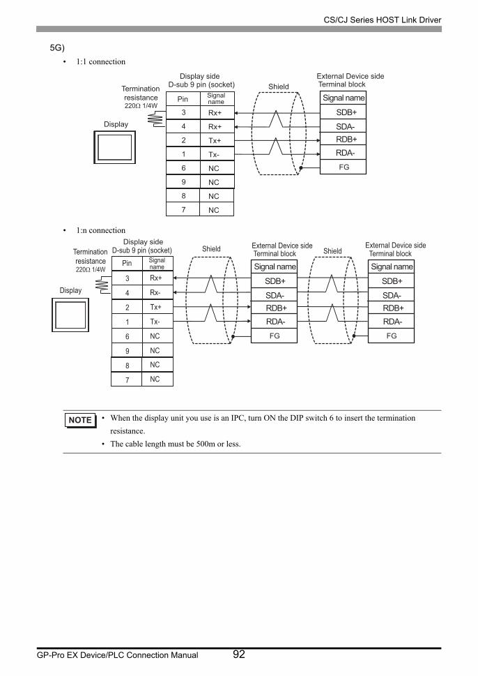
CS/CJ Series HOST Link Driver
GP-Pro EX Device/PLC Connection Manual 92
5G)
• 1:1 connection
• 1:n connection
• When the display unit you use is an IPC, turn ON the DIP switch 6 to insert the termination
resistance.
• The cable length must be 500m or less.
Display
D-sub 9 pin (socket)
Pin Signalname
ShieldExternal Device sideTerminal blockTermination
resistance220Ω 1/4W
Rx+
Rx+
Tx+
Tx-
NC
NC
NC
NC
3
4
2
1
6
9
8
7
Display side
Signal name
SDA-RDB+
SDB+
RDA-
FG
Display
D-sub 9 pin (socket) Shield External Device sideTerminal block
Pin Signalname
ShieldExternal Device sideTerminal blockTermination
resistance220Ω 1/4W
Rx+
Rx-
Tx+
Tx-
NC
NC
NC
NC
3
4
2
1
6
9
8
7
Display side
Signal name
SDA-RDB+
SDB+
RDA-
FG
Signal name
SDA-RDB+
SDB+
RDA-
FG

CS/CJ Series HOST Link Driver
GP-Pro EX Device/PLC Connection Manual 93
5.6 Cable Diagram 6
Displayy
(Connection Port)Cable Notes
GP3000*1 (COM1)AGP-3302B (COM2)GP-4*01TM (COM1)GP-Rear Module (COM1)ST*2 (COM2)LT3000 (COM1)IPC*3
6A
COM Port Conversion Adapter by Pro-faceCA3-ADPCOM-01
+Terminal Block Conversion Adapter by Pro-face
CA3-ADPTRM-01+
User-created cableThe cable length must be 500m or less.
6B
COM Port Conversion Adapter by Pro-faceCA3-ADPCOM-01
+Multi-Link Cable (5m) by Pro-face
CA3-CBLMLT-01+
User-created cable
6C User-created cable
GP3000*1 (COM2)
6D
Online Adapter by Pro-faceCA4-ADPONL-01
+Terminal Block Conversion Adapter by Pro-face
CA3-ADPTRM-01+
User-created cable
The cable length must be 500m or less.
6E
Online Adapter by Pro-faceCA4-ADPONL-01
+Multi-Link Cable (5m) by Pro-face
CA3-CBLMLT-01+
User-created cable
6F
Online Adapter by Pro-faceCA4-ADPONL-01
+User-created cable
GP-4106 (COM1)GP-4116T (COM1) 6G User-created cable
The cable length must be 500m or less.

CS/CJ Series HOST Link Driver
GP-Pro EX Device/PLC Connection Manual 94
GP4000*4 (COM2)GP-4201T (COM1)SP5000*5 (COM1/2)SP-5B00 (COM2)
6H
RS-422 Terminal Block Conversion Adapter by Pro-face
PFXZCBADTM1*6
+User-created cable
The cable length must be 500m or less.
6I
Multi-Link Cable (5m) by Pro-facePFXZCBCBML1
*7
+User-created cable
6C User-created cable
PE-4000B*8
PS5000*8 6J User-created cable The cable length must be 500m or less.
*1 All GP3000 models except AGP-3302B
*2 All ST models except AST-3211A and AST-3302B
*3 Only the COM port which can communicate by RS-422/485 (4 wire) can be used. (Except PE-4000B, PS5000)
IPC COM Port (page 10)
*4 All GP4000 models except GP-4100 series, GP-4*01TM, GP-Rear Module, GP-4201T and GP-4*03T
*5 Except SP-5B00
*6 When using a Terminal Block Conversion Adapter (CA3-ADPTRM-01) instead of the RS-422 Terminal Block Conversion Adapter, refer to Cable Diagram 6A.
*7 When using a Multilink Cable (CA3-CBLMLT-01) instead of the Multilink Cable, refer to Cable Diagram 6B.
*8 Only the COM port which can communicate by RS-422/485 (4 wire) can be used.
IPC COM Port (page 10)
Displayy
(Connection Port)Cable Notes
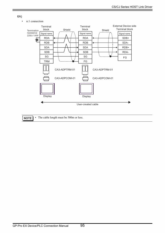
CS/CJ Series HOST Link Driver
GP-Pro EX Device/PLC Connection Manual 95
6A)
• n:1 connection
• The cable length must be 500m or less.
CA3-ADPTRM-01
CA3-ADPCOM-01
CA3-ADPTRM-01
CA3-ADPCOM-01
RDA
RDB
SDA
SDB
SG
TRM
RDA
RDB
SDA
SDB
SG
FG
Shield Shield
User-created cable
SDB+
SDA-
RDB+
RDA-
FG
Terminationresistance220Ω 1/4W
Terminalblock
Signal name
Terminalblock
Signal name
External Device sideTerminal block
Signal name
Display Display
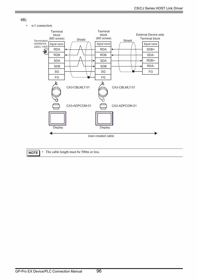
CS/CJ Series HOST Link Driver
GP-Pro EX Device/PLC Connection Manual 96
6B)
• n:1 connection
• The cable length must be 500m or less.
CA3-CBLMLT-01
CA3-ADPCOM-01
CA3-CBLMLT-01
CA3-ADPCOM-01
RDA
RDB
SDA
SDB
SG
FG
RDA
RDB
SDA
SDB
SG
FG
SDA-
SDB+
RDA-
RDB+
FG
Terminationresistance220Ω 1/4W
Terminalblock
(M3 screw)
Signal name
Terminalblock
(M3 screw)
Signal nameShield
External Device sideTerminal block
Signal nameShield
User-created cable
Display Display
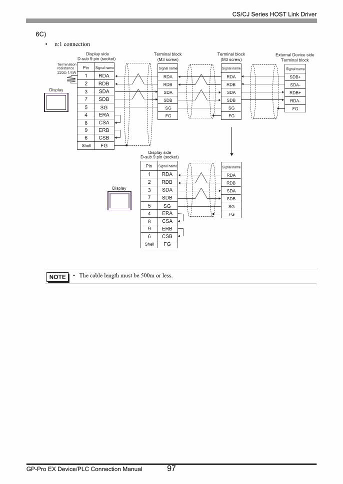
CS/CJ Series HOST Link Driver
GP-Pro EX Device/PLC Connection Manual 97
6C)
• n:1 connection
• The cable length must be 500m or less.
RDA
RDB
CSA
SDA
SDB
SGERA
5
2
1
8
73
4
96
ERBCSBFG
RDA
RDB
SDA
SDB
FG
SG
RDA
RDB
SDA
SDB
FG
SG
RDA
RDB
CSA
SDA
SDB
SGERA
5
2
1
8
73
4
96
ERBCSBFG
RDA
RDB
SDA
SDB
FG
SG
SDA-
SDB+
RDA-
RDB+
FG
Terminationresistance220Ω 1/4W
Display
Signal name
D-sub 9 pin (socket)
Pin
Shell
Display
Signal name
D-sub 9 pin (socket)
Pin
Shell
Signal name
Terminal block(M3 screw)
Signal name
Terminal block(M3 screw)
Signal name
External Device sideTerminal block
Signal name
Display side
Display side
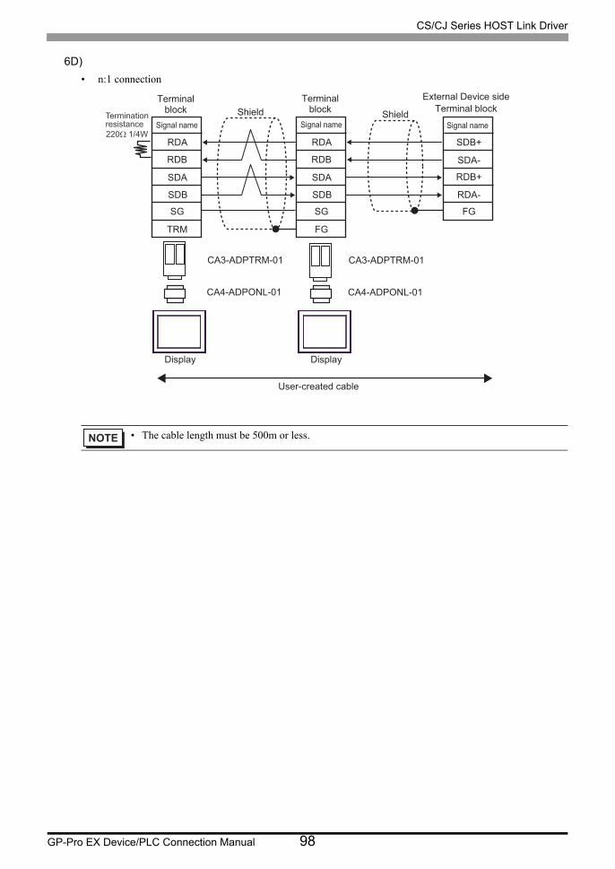
CS/CJ Series HOST Link Driver
GP-Pro EX Device/PLC Connection Manual 98
6D)
• n:1 connection
• The cable length must be 500m or less.
CA3-ADPTRM-01
CA4-ADPONL-01
CA3-ADPTRM-01
CA4-ADPONL-01
RDA
RDB
SDA
SDB
SG
TRM
RDA
RDB
SDA
SDB
SG
FG
SDA-
SDB+
RDA-
RDB+
FG
Shield Shield
User-created cable
Terminationresistance220Ω 1/4W
Terminalblock
Signal name
Terminalblock
Signal name
External Device sideTerminal block
Signal name
Display Display
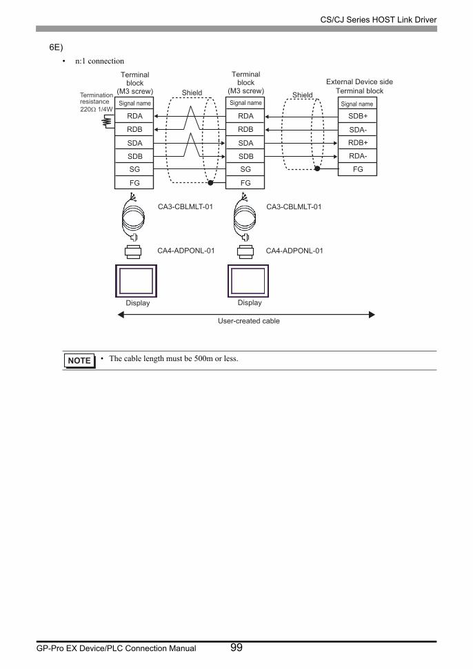
CS/CJ Series HOST Link Driver
GP-Pro EX Device/PLC Connection Manual 99
6E)
• n:1 connection
• The cable length must be 500m or less.
CA3-CBLMLT-01
CA4-ADPONL-01
CA3-CBLMLT-01
CA4-ADPONL-01
RDA
RDB
SDA
SDB
SG
FG
RDA
RDB
SDA
SDB
SG
FG
SDA-
SDB+
RDA-
RDB+
FG
Shield Shield
User-created cable
Terminationresistance220Ω 1/4W
Terminalblock
(M3 screw)
Signal name
External Device sideTerminal block
Signal name
Display Display
Terminalblock
(M3 screw)
Signal name
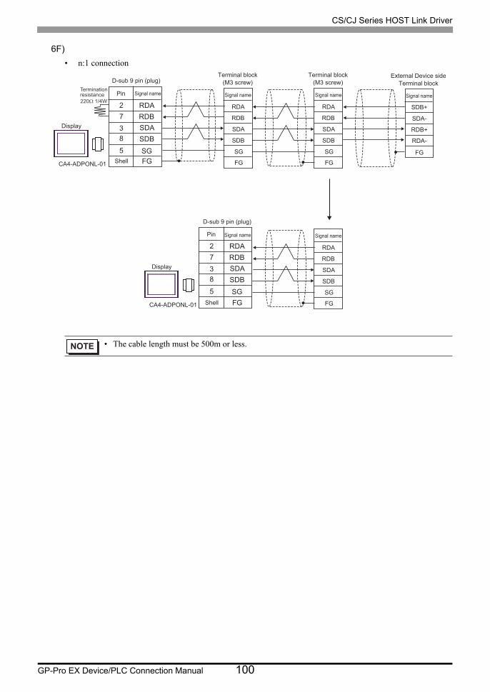
CS/CJ Series HOST Link Driver
GP-Pro EX Device/PLC Connection Manual 100
6F)
• n:1 connection
• The cable length must be 500m or less.
RDA
RDBSDA
SDB
SG5
7
2
83
FG
Display
Signal name
D-sub 9 pin (plug)
Pin
Shell
RDA
RDB
SDA
SDB
FG
SG
Signal name
Terminal block(M3 screw)
RDA
RDB
SDA
SDB
FG
SG
Signal name
Terminal block(M3 screw)
External Device sideTerminal block
RDA
RDBSDA
SDB
SG5
7
2
83
FG
Display
Signal namePin
Shell
RDA
RDB
SDA
SDB
FG
SG
Signal name
D-sub 9 pin (plug)
CA4-ADPONL-01
CA4-ADPONL-01
SDA-
SDB+
RDA-
RDB+
FG
Signal nameTerminationresistance220Ω 1/4W
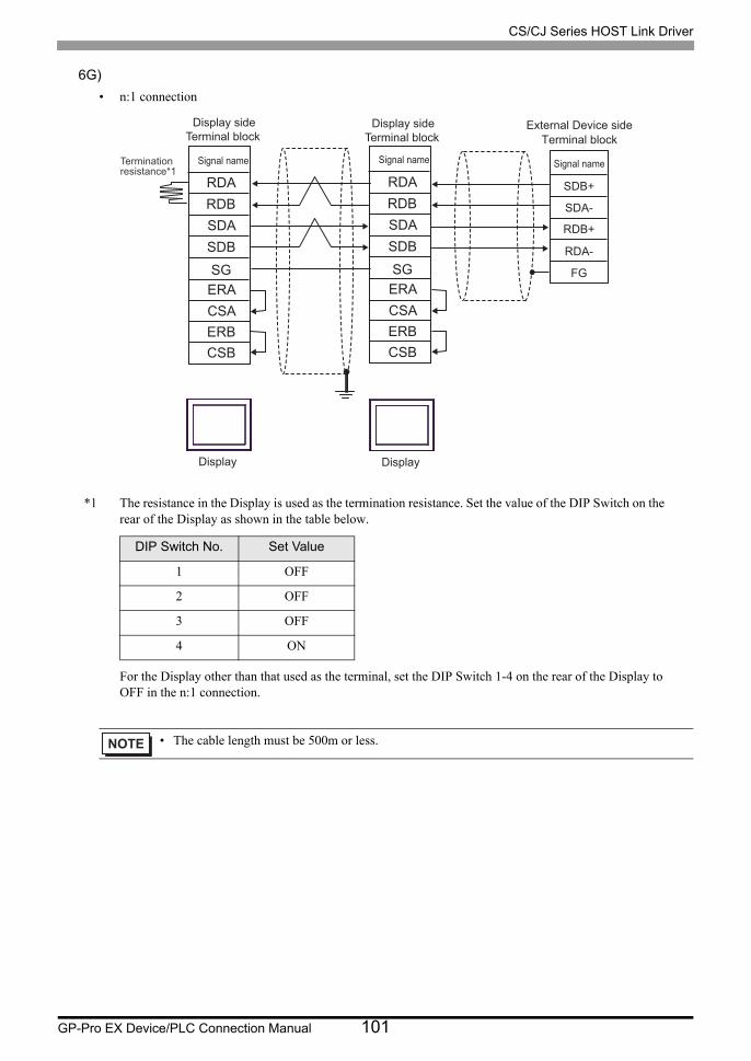
CS/CJ Series HOST Link Driver
GP-Pro EX Device/PLC Connection Manual 101
6G)
• n:1 connection
*1 The resistance in the Display is used as the termination resistance. Set the value of the DIP Switch on the rear of the Display as shown in the table below.
For the Display other than that used as the terminal, set the DIP Switch 1-4 on the rear of the Display to OFF in the n:1 connection.
DIP Switch No. Set Value
1 OFF
2 OFF
3 OFF
4 ON
• The cable length must be 500m or less.
RDA
RDB
CSA
SDA
SDB
SGERA
ERBCSB
RDA
RDB
CSA
SDA
SDB
SGERA
ERBCSB
SDA-
SDB+
RDA-
RDB+
FG
Terminationresistance*1
Signal name
Display
Signal name
External Device sideTerminal block
Signal name
Terminal blockDisplay side
Terminal blockDisplay side
Display
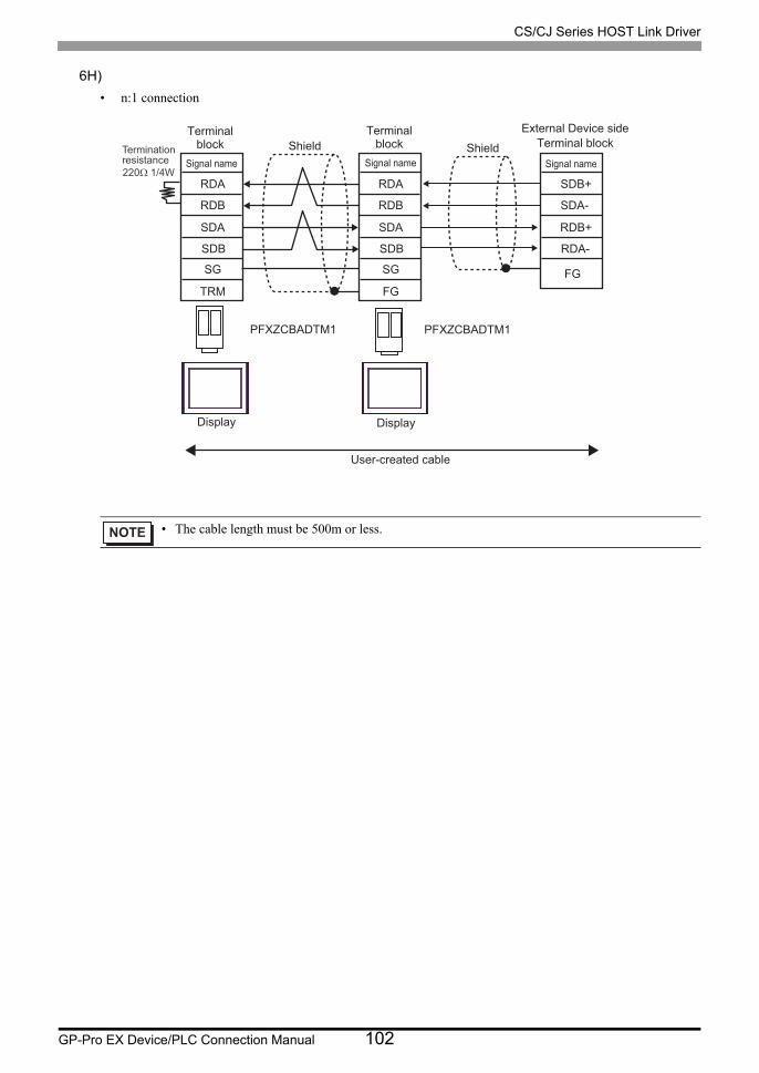
CS/CJ Series HOST Link Driver
GP-Pro EX Device/PLC Connection Manual 102
6H)
• n:1 connection
• The cable length must be 500m or less.
PFXZCBADTM1 PFXZCBADTM1
RDA
RDB
SDA
SDB
SG
TRM
RDA
RDB
SDA
SDB
SG
FG
Shield Shield
User-created cable
SDB+
SDA-
RDB+
RDA-
FG
Terminationresistance220Ω 1/4W
Terminalblock
Signal name
Terminalblock
Signal name
External Device sideTerminal block
Signal name
Display Display
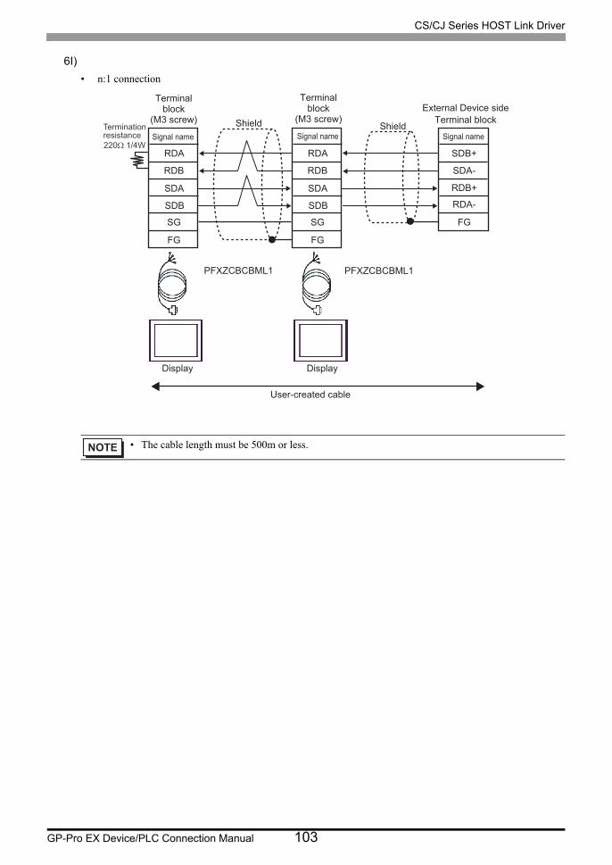
CS/CJ Series HOST Link Driver
GP-Pro EX Device/PLC Connection Manual 103
6I)
• n:1 connection
• The cable length must be 500m or less.
PFXZCBCBML1 PFXZCBCBML1
RDA
RDB
SDA
SDB
SG
FG
RDA
RDB
SDA
SDB
SG
FG
SDA-
SDB+
RDA-
RDB+
FG
Terminationresistance220Ω 1/4W
Terminalblock
(M3 screw)
Signal name
Terminalblock
(M3 screw)
Signal nameShield
External Device sideTerminal block
Signal nameShield
User-created cable
Display Display
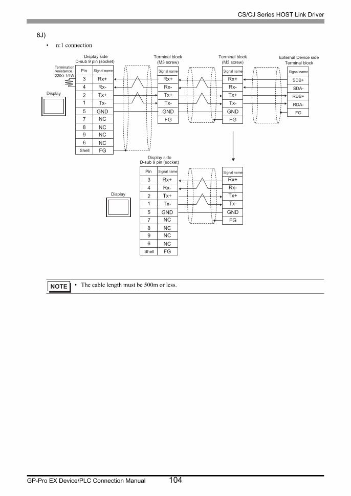
CS/CJ Series HOST Link Driver
GP-Pro EX Device/PLC Connection Manual 104
6J)
• n:1 connection
• The cable length must be 500m or less.
Rx+
Rx-Tx+
Tx-
GND
Rx+
Rx-Tx+
Tx-
FG
GND
Rx+
Rx-Tx+
Tx-
FG
GND
Rx+
Rx-Tx+
Tx-
FG
GND
NC
NCNC
NC
Rx+
Rx-Tx+
Tx-
GNDNC
NCNC
NC
5
4
3
8
12
7
96
FG
5
4
3
8
12
7
96
FG
SDA-
SDB+
RDA-
RDB+
FG
Terminationresistance220Ω 1/4W
Display
Signal name
D-sub 9 pin (socket)
Pin
Shell
Display
Signal name
D-sub 9 pin (socket)
Pin
Shell
Signal name
Terminal block(M3 screw)
Signal name
Terminal block(M3 screw)
Signal name
External Device sideTerminal block
Signal name
Display side
Display side
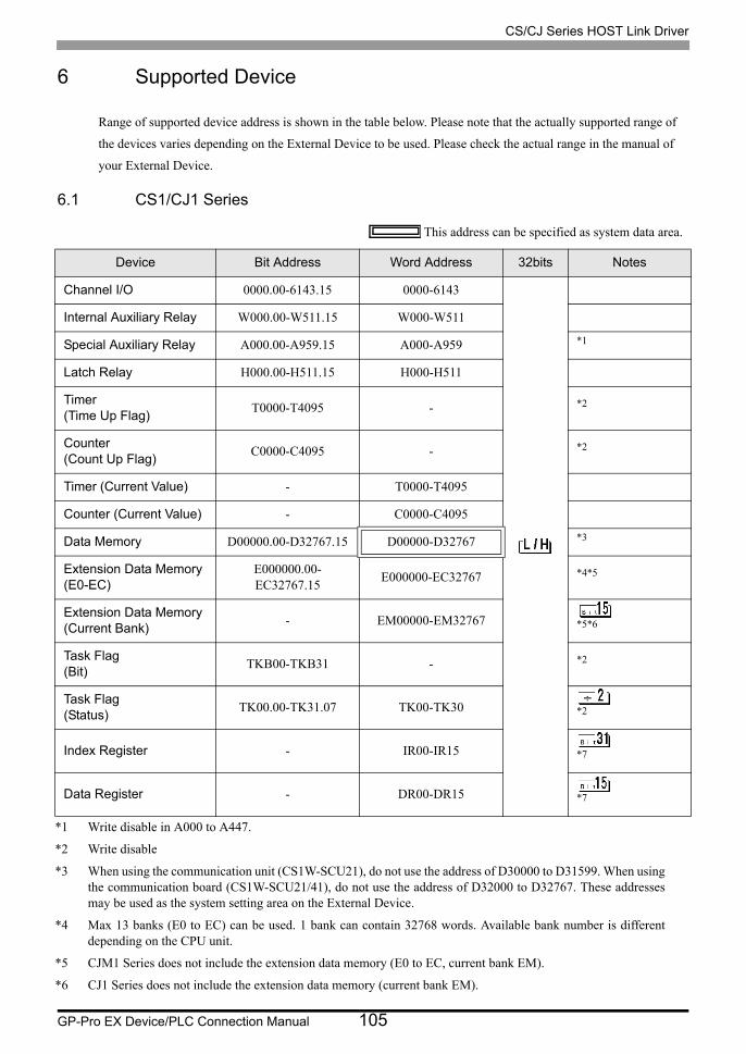
CS/CJ Series HOST Link Driver
GP-Pro EX Device/PLC Connection Manual 105
6 Supported Device
Range of supported device address is shown in the table below. Please note that the actually supported range of
the devices varies depending on the External Device to be used. Please check the actual range in the manual of
your External Device.
6.1 CS1/CJ1 Series
This address can be specified as system data area.
Device Bit Address Word Address 32bits Notes
Channel I/O 0000.00-6143.15 0000-6143
Internal Auxiliary Relay W000.00-W511.15 W000-W511
Special Auxiliary Relay A000.00-A959.15 A000-A959 *1
*1 Write disable in A000 to A447.
Latch Relay H000.00-H511.15 H000-H511
Timer(Time Up Flag)
T0000-T4095 - *2
*2 Write disable
Counter(Count Up Flag)
C0000-C4095 - *2
Timer (Current Value) - T0000-T4095
Counter (Current Value) - C0000-C4095
Data Memory D00000.00-D32767.15 D00000-D32767 *3
*3 When using the communication unit (CS1W-SCU21), do not use the address of D30000 to D31599. When using the communication board (CS1W-SCU21/41), do not use the address of D32000 to D32767. These addresses may be used as the system setting area on the External Device.
Extension Data Memory(E0-EC)
E000000.00-EC32767.15
E000000-EC32767 *4*5
*4 Max 13 banks (E0 to EC) can be used. 1 bank can contain 32768 words. Available bank number is different depending on the CPU unit.
*5 CJM1 Series does not include the extension data memory (E0 to EC, current bank EM).
Extension Data Memory(Current Bank)
- EM00000-EM32767
*5*6
*6 CJ1 Series does not include the extension data memory (current bank EM).
Task Flag(Bit)
TKB00-TKB31 - *2
Task Flag(Status)
TK00.00-TK31.07 TK00-TK30 *2
Index Register - IR00-IR15 *7
Data Register - DR00-DR15 *7
CS/CJ Series HOST Link Driver
GP-Pro EX Device/PLC Connection Manual 106
*7 You cannot write during RUN.
• Please refer to the GP-Pro EX Reference Manual for system data area.
Cf. GP-Pro EX Reference Manual "LS Area (Direct Access Method Area)"• Please refer to the precautions on manual notation for icons in the table.
"Manual Symbols and Terminology"
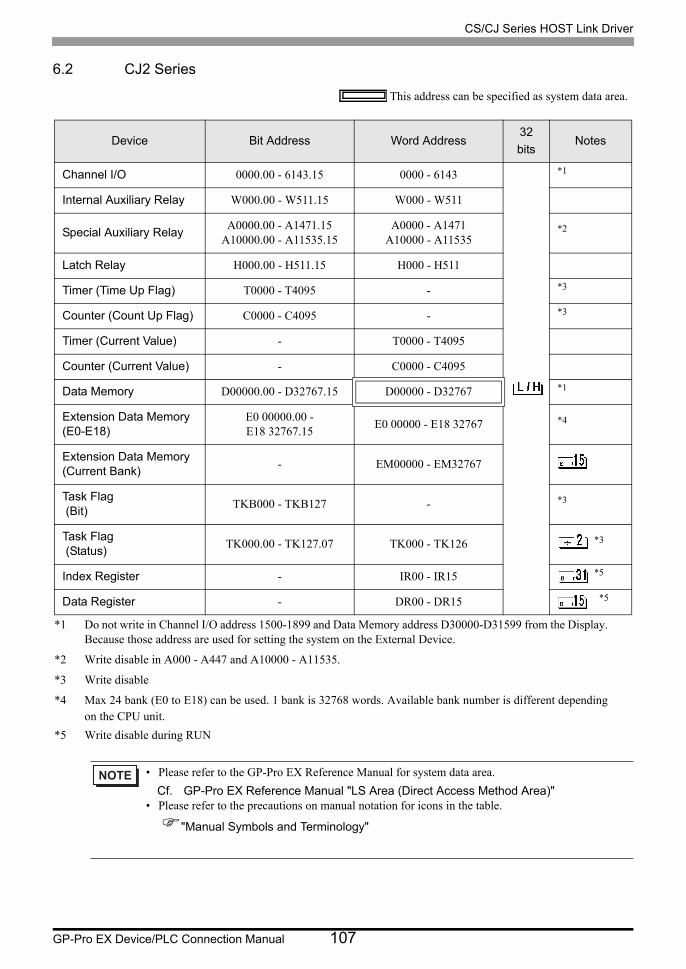
CS/CJ Series HOST Link Driver
GP-Pro EX Device/PLC Connection Manual 107
6.2 CJ2 Series
This address can be specified as system data area.
Device Bit Address Word Address32
bitsNotes
Channel I/O 0000.00 - 6143.15 0000 - 6143 *1
*1 Do not write in Channel I/O address 1500-1899 and Data Memory address D30000-D31599 from the Display. Because those address are used for setting the system on the External Device.
Internal Auxiliary Relay W000.00 - W511.15 W000 - W511
Special Auxiliary RelayA0000.00 - A1471.15
A10000.00 - A11535.15A0000 - A1471
A10000 - A11535*2
*2 Write disable in A000 - A447 and A10000 - A11535.
Latch Relay H000.00 - H511.15 H000 - H511
Timer (Time Up Flag) T0000 - T4095 - *3
*3 Write disable
Counter (Count Up Flag) C0000 - C4095 - *3
Timer (Current Value) - T0000 - T4095
Counter (Current Value) - C0000 - C4095
Data Memory D00000.00 - D32767.15 D00000 - D32767 *1
Extension Data Memory(E0-E18)
E0 00000.00 - E18 32767.15
E0 00000 - E18 32767 *4
*4 Max 24 bank (E0 to E18) can be used. 1 bank is 32768 words. Available bank number is different depending on the CPU unit.
Extension Data Memory(Current Bank)
- EM00000 - EM32767
Task Flag (Bit)
TKB000 - TKB127 - *3
Task Flag (Status)
TK000.00 - TK127.07 TK000 - TK126 *3
Index Register - IR00 - IR15 *5
*5 Write disable during RUN
Data Register - DR00 - DR15 *5
• Please refer to the GP-Pro EX Reference Manual for system data area.
Cf. GP-Pro EX Reference Manual "LS Area (Direct Access Method Area)"• Please refer to the precautions on manual notation for icons in the table.
"Manual Symbols and Terminology"
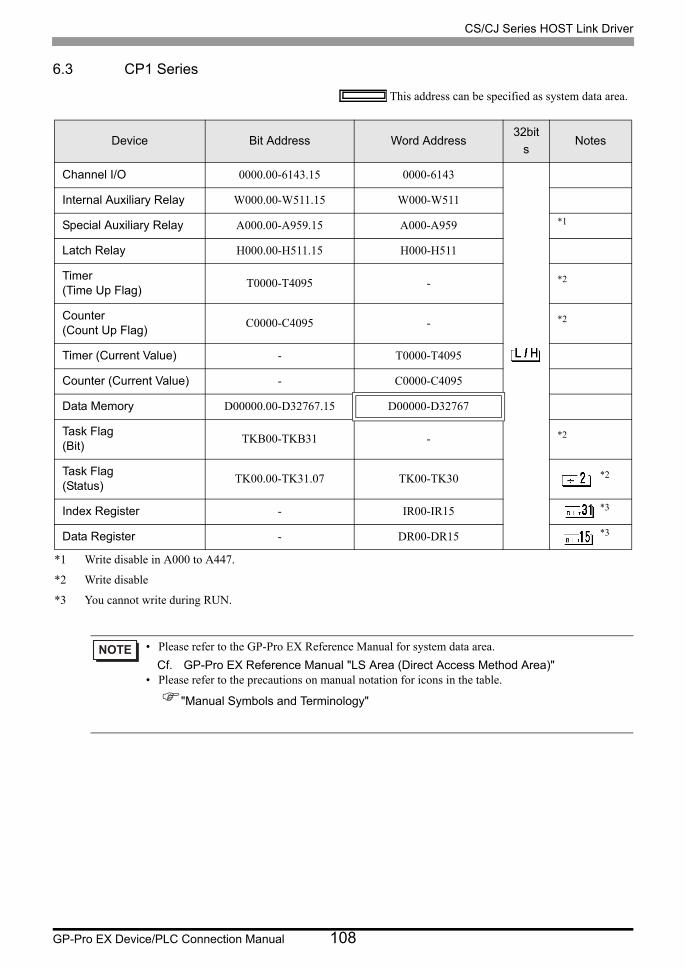
CS/CJ Series HOST Link Driver
GP-Pro EX Device/PLC Connection Manual 108
6.3 CP1 Series
This address can be specified as system data area.
Device Bit Address Word Address32bit
sNotes
Channel I/O 0000.00-6143.15 0000-6143
Internal Auxiliary Relay W000.00-W511.15 W000-W511
Special Auxiliary Relay A000.00-A959.15 A000-A959 *1
*1 Write disable in A000 to A447.
Latch Relay H000.00-H511.15 H000-H511
Timer(Time Up Flag)
T0000-T4095 - *2
*2 Write disable
Counter(Count Up Flag)
C0000-C4095 - *2
Timer (Current Value) - T0000-T4095
Counter (Current Value) - C0000-C4095
Data Memory D00000.00-D32767.15 D00000-D32767
Task Flag(Bit)
TKB00-TKB31 - *2
Task Flag(Status)
TK00.00-TK31.07 TK00-TK30 *2
Index Register - IR00-IR15 *3
*3 You cannot write during RUN.
Data Register - DR00-DR15 *3
• Please refer to the GP-Pro EX Reference Manual for system data area.
Cf. GP-Pro EX Reference Manual "LS Area (Direct Access Method Area)"• Please refer to the precautions on manual notation for icons in the table.
"Manual Symbols and Terminology"
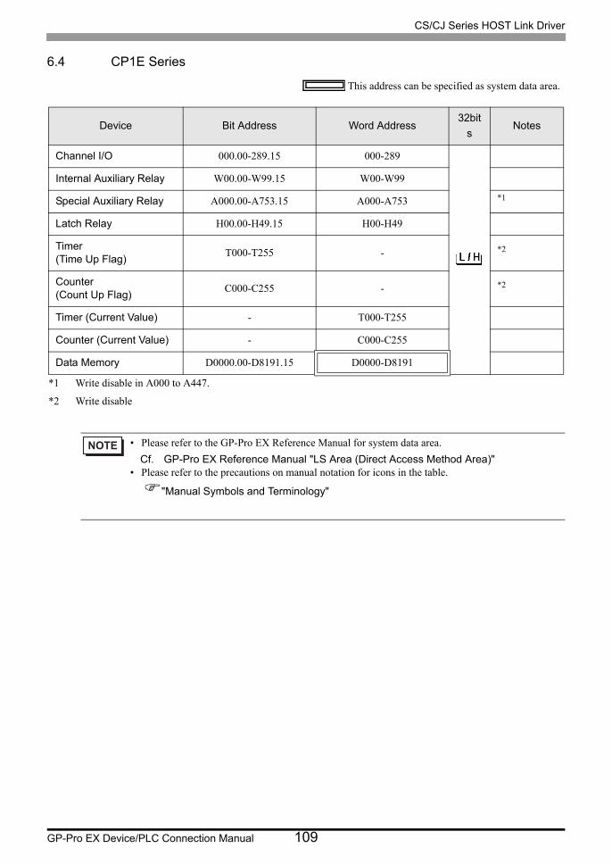
CS/CJ Series HOST Link Driver
GP-Pro EX Device/PLC Connection Manual 109
6.4 CP1E Series
This address can be specified as system data area.
Device Bit Address Word Address32bit
sNotes
Channel I/O 000.00-289.15 000-289
Internal Auxiliary Relay W00.00-W99.15 W00-W99
Special Auxiliary Relay A000.00-A753.15 A000-A753 *1
*1 Write disable in A000 to A447.
Latch Relay H00.00-H49.15 H00-H49
Timer(Time Up Flag)
T000-T255 - *2
*2 Write disable
Counter(Count Up Flag)
C000-C255 - *2
Timer (Current Value) - T000-T255
Counter (Current Value) - C000-C255
Data Memory D0000.00-D8191.15 D0000-D8191
• Please refer to the GP-Pro EX Reference Manual for system data area.
Cf. GP-Pro EX Reference Manual "LS Area (Direct Access Method Area)"• Please refer to the precautions on manual notation for icons in the table.
"Manual Symbols and Terminology"
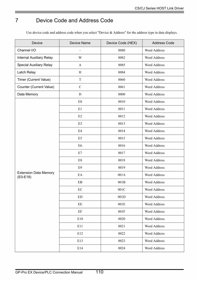
CS/CJ Series HOST Link Driver
GP-Pro EX Device/PLC Connection Manual 110
7 Device Code and Address Code
Use device code and address code when you select "Device & Address" for the address type in data displays.
Device Device Name Device Code (HEX) Address Code
Channel I/O - 0080 Word Address
Internal Auxiliary Relay W 0082 Word Address
Special Auxiliary Relay A 0085 Word Address
Latch Relay H 0084 Word Address
Timer (Current Value) T 0060 Word Address
Counter (Current Value) C 0061 Word Address
Data Memory D 0000 Word Address
Extension Data Memory(E0-E18)
E0 0010 Word Address
E1 0011 Word Address
E2 0012 Word Address
E3 0013 Word Address
E4 0014 Word Address
E5 0015 Word Address
E6 0016 Word Address
E7 0017 Word Address
E8 0018 Word Address
E9 0019 Word Address
EA 001A Word Address
EB 001B Word Address
EC 001C Word Address
ED 001D Word Address
EE 001E Word Address
EF 001F Word Address
E10 0020 Word Address
E11 0021 Word Address
E12 0022 Word Address
E13 0023 Word Address
E14 0024 Word Address
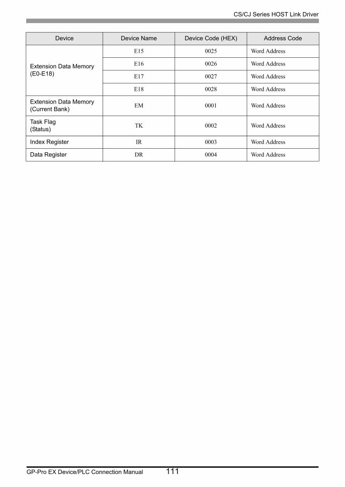
CS/CJ Series HOST Link Driver
GP-Pro EX Device/PLC Connection Manual 111
Extension Data Memory(E0-E18)
E15 0025 Word Address
E16 0026 Word Address
E17 0027 Word Address
E18 0028 Word Address
Extension Data Memory(Current Bank)
EM 0001 Word Address
Task Flag(Status)
TK 0002 Word Address
Index Register IR 0003 Word Address
Data Register DR 0004 Word Address
Device Device Name Device Code (HEX) Address Code
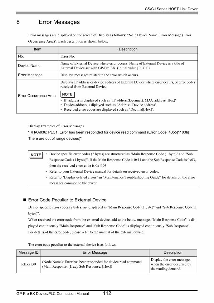
CS/CJ Series HOST Link Driver
GP-Pro EX Device/PLC Connection Manual 112
8 Error Messages
Error messages are displayed on the screen of Display as follows: "No. : Device Name: Error Message (Error
Occurrence Area)". Each description is shown below.
Display Examples of Error Messages
"RHAA036: PLC1: Error has been responded for device read command (Error Code: 4355[1103h]
There are out of range devises)"
Error Code Peculiar to External Device
Device specific error codes (2 bytes) are displayed as "Main Response Code (1 byte)" and "Sub Response Code (1
bytes)".
When received the error code from the external device, add to the below message. "Main Response Code" is dis-
played continuously "Main Response" and "Sub Response Code" is displayed continuously "Sub Response".
For details of the error code, please refer to the manual of the external device.
The error code peculiar to the external device is as follows.
Item Description
No. Error No.
Device NameName of External Device where error occurs. Name of External Device is a title of External Device set with GP-Pro EX. (Initial value [PLC1])
Error Message Displays messages related to the error which occurs.
Error Occurrence Area
Displays IP address or device address of External Device where error occurs, or error codes received from External Device.
• IP address is displayed such as "IP address(Decimal): MAC address( Hex)".• Device address is diplayed such as "Address: Device address".• Received error codes are displayed such as "Decimal[Hex]".
• Device specific error codes (2 bytes) are structured as "Main Response Code (1 byte)" and "Sub
Response Code (1 bytes)". If the Main Response Code is 0x11 and the Sub Response Code is 0x03,
then the received error code is 0x1103.
• Refer to your External Device manual for details on received error codes.
• Refer to "Display-related errors" in "Maintenance/Troubleshooting Guide" for details on the error
messages common to the driver.
Message ID Error Message Description
RHxx130(Node Name): Error has been responded for device read command (Main Response: [Hex], Sub Response: [Hex])
Display the error message, when the error occurred by the reading demand.

CS/CJ Series HOST Link Driver
GP-Pro EX Device/PLC Connection Manual 113
RHxx131(Node Name): Error has been responded for device write command (Main Response: [Hex], Sub Response: [Hex])
Display the error message, when the error occurred by the write demand.
Message ID Error Message Description

CS/CJ Series HOST Link Driver
GP-Pro EX Device/PLC Connection Manual 114
Related Documents

![OMRON Corporation: CS/CJ Series HOST Link...GP-Pro EX Device/PLC Connection Manual 7 • When the time of GP4000 series is automatically updated in [Clock Update Settings] of GP-Pro](https://static.cupdf.com/doc/110x72/5eb8ba88ff5232176426d8ba/omron-corporation-cscj-series-host-link-gp-pro-ex-deviceplc-connection-manual.jpg)


